Wurth Elelctronics Product Training Module about coupled inductors ...
Wurth Elelctronics Product Training Module about coupled inductors ...
Wurth Elelctronics Product Training Module about coupled inductors ...

You also want an ePaper? Increase the reach of your titles
YUMPU automatically turns print PDFs into web optimized ePapers that Google loves.
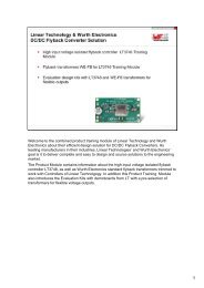
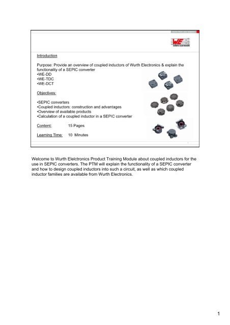
Welcome to <strong>Wurth</strong> <strong>Elelctronics</strong> <strong>Product</strong> <strong>Training</strong> <strong>Module</strong> <strong>about</strong> <strong>coupled</strong> <strong>inductors</strong> for the<br />
use in SEPIC converters. The PTM will explain the functionality of a SEPIC converter<br />
and how to design <strong>coupled</strong> <strong>inductors</strong> into such a circuit, as well as which <strong>coupled</strong><br />
inductor families are available from <strong>Wurth</strong> Electronics.<br />
1
Before going in detail <strong>about</strong> couple <strong>inductors</strong> for SEPIC converters, a SEPIC<br />
converter must be defined. SEPIC stands for Single Ended Primary Inductance<br />
Converter, and this circuit offers the possibility to use the function of a buck and<br />
boost regulator in one circuit<br />
A buck converter regulates a high voltage into a smaller voltage, so input voltage is<br />
greater than output voltage. For example, like a car charger for a cell phone, 12V is<br />
converted down to 5V.<br />
A boost converter regulates a small voltage into a higher voltage, so input is smaller than<br />
output voltage. As an example: an LED driver with a 3V input converts to a 9V output.<br />
2
Typical SEPIC applications are battery operated equipments and handheld devices<br />
powered by a battery. In addition, SEPIC is being used in NiMH charger applications, as<br />
well as, LED Drivers & DC Power Supplies with a wide range of input voltages.<br />
3
On this slide, you can see a typical layout of a SEPIC converter from Linear Technology<br />
which uses two 22µH <strong>inductors</strong>, or L1 and L2, in the circuit. The capacitor, C6, basically<br />
splits the windings in a primary and a secondary. This design can now be done like<br />
shown in this example by using 2 individual <strong>inductors</strong> with 22µH, but there are clear<br />
advantages when using one of <strong>Wurth</strong> Electronics <strong>coupled</strong> <strong>inductors</strong> in this design. The<br />
construction and the advantages of a <strong>coupled</strong> inductor will be shown on the next slides.<br />
4
A <strong>coupled</strong> inductor basically consists of two identiical windings wound onto one core.<br />
The important criteria is that the windings are exactly identical to generate the coupling<br />
effect in a SEPIC converter.<br />
5
From an economical standpoint, the use of <strong>coupled</strong> <strong>inductors</strong> saves cost and reduces<br />
the size of the BOM. It also helps to save actual PCB real estate, due to the usage of<br />
one component with 2 integrated windings. From a technical standpoint the advantages<br />
of a <strong>coupled</strong> inductor are as follows:<br />
If L1 and L2 are closely <strong>coupled</strong>, the ripple current is divided between them , and the<br />
required inductance is halved. In some applications, there is even close to zero ripple<br />
current due to the use of a <strong>coupled</strong> inductor. This also results in a simpler EMI filtering<br />
and smaller input capacitor. In addition, the DCR of the <strong>inductors</strong> can also be reduced.<br />
For example, two 47µH single <strong>inductors</strong> can be replaced with one <strong>coupled</strong> inductor<br />
of 22µH per winding, potentially allowing for the selection of a smaller inductor, or one<br />
the same size that has lower DCR and higher current handling.<br />
6
<strong>Wurth</strong> Electronics‘s WE-DD series is one of the industry‘s most used <strong>coupled</strong> inductor<br />
families. The great advantages of this family are the flexibility in size. The WE-DD series<br />
offers two standard footprints: 7x7 and 12x12mm, each with different heights to find the<br />
right part by taking maximum heights, max currents or targeted DCR resistances in<br />
measurement. The WE-DD series is available with a crossed, as well as a straight, pin<br />
layout. An overview is shown on the next slide.<strong>Wurth</strong> Electronics‘s WE-DD series has<br />
maximum current handling capabilities of 8.6A DC current and up to 18A in saturation<br />
current. Besides in SEPIC converters, the WE-DDs can also be used in CUK topologies,<br />
non-isolated flyback applications and switching regulators with a second, unregulated<br />
output voltage.<br />
7
As mentioned previously, the WE-DD series is available in 7x7mm and 12x12mm, with a<br />
staight-pin layout, and in the size 12x12mm with a crossed layout. The parts with a<br />
crossed layout have a higher leakage inductance due to the winding structure, where the<br />
straight-pin layouts have a lower leakage. The need of low or high leakage is defined by<br />
the IC used in the SEPIC convterter. It is recommended to follow the winding layout<br />
suggested on the reference design of the IC manufacturer.<br />
8
In addition to the WE-DD, <strong>Wurth</strong> Electronics is offering a new generation of low-profile<br />
<strong>coupled</strong> <strong>inductors</strong> made for applications where board space or height is restricted.<br />
Besides the low profile, other key features of the WE-TDC series are low self losses, low<br />
leakage inductances, and high mechanical stability due to the 4 large landing pads<br />
which get soldered to the board. The WE-TDC has current handling capabilities of 4.5A<br />
DC current and up to 14A in saturation current. In addition to SEPIC converters, the WE-<br />
DDs can also be used in CUK or ZETA topologies, non-isolated flyback applications and<br />
switching regulators with a second unregulated output voltage.<br />
9
The WE-DCT series is <strong>Wurth</strong> Electronics‘s series for larger-current SEPIC applications<br />
and finds its usage often also as a 1:1 transformer. The very low RDC and core losses<br />
go back to the specially trimmed WE-PERM core material, which has proven its<br />
outstanding performance in other high current inductor families of <strong>Wurth</strong> Electronics.<br />
Due to the WE-PERM material, the WE-DCT has a very stable (soft) saturation behavior,<br />
which guarantees, even at max conditions, a great performance. The WE-DCT has<br />
current handling capabilities of 14.5A DC currents and up to 120A in saturation current.<br />
Besides in SEPIC converters, the WE-DDs can also be used in CUK topologies, solar<br />
inverters and high-power switching regulators.<br />
10
In order to design an effecient SEPIC converter, it is crucial to design the right inductor<br />
into your circuit. It is best to do it with a practical example:<br />
The SEPIC converter, in our case, has a flexible input of 5-24V and needs to deliver a<br />
stable 12V output. The current output is 0.7A with a calculated ripple of 20%.<br />
Of course, there are always 2 ways to calculate the inductor for the SEPIC converter.<br />
First is to calculate the formula of an inductor for switching regulators.<br />
<strong>Wurth</strong> Electronics recommends calculating the SEPIC converter in the Inductor Selector<br />
Calculation Tool for DC/DC Converters. That process is shown in the next slides.<br />
11
The <strong>Wurth</strong> Electronics Component Selector is an all-in-one magnetics design tool for<br />
calculating ceramic <strong>inductors</strong> for RF circuits, chip bead ferrites for filter applications,<br />
transformers for DC/DC flyback topologies, and <strong>inductors</strong> for DC/DC converters. You<br />
can easily access the tool at www.we-online.com/toolbox or by downloading it straight<br />
from the ‚tools & support‘ tab of <strong>Wurth</strong> Electronics supplier portal on<br />
www.digikey.com/wurth.<br />
After opening the software tool just click on Inductor Selector.<br />
12
A new design window opens up, and by clicking on ‚settings‘, a new DC/DC converter<br />
topology opens. Simply select the correct topology (SEPIC Converter, in this example),<br />
and enter values of the SEPIC converter. Before clicking on ‚apply‘, select upfront if the<br />
calculation should be done with single <strong>inductors</strong> or one <strong>coupled</strong> inductor. In this example<br />
we use ‚Coupled L‘. Then click ‚apply‘.<br />
13
After calculating the SEPIC converter topology, the program suggests the <strong>inductors</strong><br />
which fit best electronically into the circuit. The list can then be further optimized by<br />
taking DCR or mechanical dimensions into consideration. Below, the example with a<br />
<strong>coupled</strong> inductor pre-setting shows an example using two individual <strong>inductors</strong>. The<br />
inductance value of the <strong>coupled</strong> inductor is exactly half of the individual inductor. In this<br />
example, it is clearly shown that by choosing a <strong>coupled</strong> inductor, the DCR can be<br />
reduced significantly (67mOhm vs. 2x72mOhm). All products shown in the inductor<br />
selector tool are catalog products. For <strong>Wurth</strong> Electronics, this means available in stock,<br />
short lead times for production volume and outstanding quality. All products are also<br />
stocked at Digi-Key.<br />
14
In Summary, a SEPIC converter is used in applications with a flexible input voltage<br />
range, which needs a stable output of a certain voltage. Such applications are battery<br />
operated devices, NiMH chargers and LED driver applications. <strong>Wurth</strong> Electronics is<br />
offering a full range of <strong>coupled</strong> <strong>inductors</strong> for such applications: WE-DD, WE-TDC and<br />
WE-DCT series. All products shown are available in stock at digikey.com.<br />
Additionally, <strong>Wurth</strong> Electronics offers an easy-to-use design software for magnetics<br />
design, which allows calculation of a <strong>coupled</strong> inductor for a SEPIC converter within<br />
seconds.<br />
15