DELTA VFD-M sorozatú frekvenciaváltó - Motor-Systems Kft.
DELTA VFD-M sorozatú frekvenciaváltó - Motor-Systems Kft.
DELTA VFD-M sorozatú frekvenciaváltó - Motor-Systems Kft.

Create successful ePaper yourself
Turn your PDF publications into a flip-book with our unique Google optimized e-Paper software.
1. FEJEZET – ÁTVÉTEL VIZSGÁLAT<br />
<strong>VFD</strong>-M Sorozat<br />
Ezek a <strong>VFD</strong>-M típusú <strong>frekvenciaváltó</strong>k kiszállítás előtt szigorú teszteken és különböző<br />
ellenőrzéseken mennek keresztül. Kérlek azért te is ellenőrizd le a következő dolgokat:<br />
Átvétel<br />
Ellenőrizd, hogy a csomag tartalmazza-e a következőket: Inverter, Felhasználói<br />
kézikönyv.<br />
Ellenőrizd, hogy az áru nem sérült-e meg a szállítás ideje alatt.<br />
Ellenőrizd, hogy az adattáblának megfelelő típusú terméket rendeltél.<br />
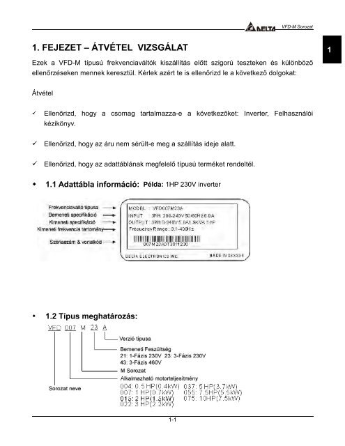
1.1 Adattábla információ: Példa: 1HP 230V inverter<br />
1.2 Típus meghatározás:<br />
1-1<br />
1
<strong>VFD</strong>-M Sorozat<br />
1.3 Szériaszám magyarázat:<br />
1-2<br />
Amennyiben az adattábla<br />
információja nem egyezik a<br />
te általad választott<br />
típuséval, akkor azt jelezd<br />
azonnal a kereskedőnél.
1.4 KÜLSŐ ALKATRÉSZEK ÉS JELZÉSEK:<br />
1-3<br />
<strong>VFD</strong>-M Sorozat<br />
1
<strong>VFD</strong>-M Sorozat<br />
1-4
2. FEJEZET – RAKTÁROZÁS ÉS BEÉPÍTÉS<br />
2.1 Raktározás<br />
<strong>VFD</strong>-M Sorozat<br />
Az invertert tartsd a zárt eredeti dobozában a felszerelés idejéig. A teljes idejű garancia<br />
megtartása érdekében az alábbi leírásoknak megfelelően tárold, amennyiben hosszabb ideig<br />
nem kerül beszerelésre:<br />
Tárold tiszta száraz helyen. Ne tedd ki direkt napsugárzásnak.<br />
-20 ° C - +60 ° C Közötti hőmérsékleten raktározd.<br />
0% - 90% páratartalmú páralecsapódás-mentes helyen raktározd.<br />
86 kPA - 106kPA közötti nyomású helyen raktározd..<br />
2.2 Környezeti feltételek<br />
Működés<br />
Levegő hőmérséklet: -10 ° C - +50 ° C (14 ° F - 122 ° F),<br />
5.5 kW: -10 ° C - +40 ° C (14 ° F - 104 ° F)<br />
Relatív páratartalom: 0% - 90%, lecsapódásmentes<br />
Környezeti nyomás: 86 - 106 kPa<br />
Beépítési magasság: 1000m alatt<br />
Megengedett rezgésszint: Max. 9.80 m/s 2 (1G) - 20Hz –nél kevesebb<br />
Max. 5.88 m/s 2 (0.6G) / 20Hz - 50Hz<br />
Raktározás Hőmérséklet: -20 ° C - +60 ° C (-4 ° F – 140 ° F)<br />
Relatív páratartalom: Kevesebb, mint 90%, lecsapódásmentes.<br />
Környezeti nyomás: 86 - 106 kPa<br />
Szállítás Hőmérséklet: -20 ° C - +60 ° C (-4 ° F – 140 ° F)<br />
Relatív páratartalom: Kevesebb, mint 90%, lecsapódásmentes<br />
Környezeti nyomás: 86 - 106 kPa<br />
Megengedett rezgésszint: Max. 9.80 m/s 2 (1G) kisebb mint 20Hz, Max.<br />
5.88 m/s 2 (0.6G) / 20Hz - 50Hz<br />
Szennyeződési osztály 2: - gyári felhasználásra megfelelő.<br />
2-1<br />
2
<strong>VFD</strong>-M Sorozat<br />
2.3 Beépítés:<br />
A nem megfelelő inverter beépítés nagyban csökkentheti az inverter élettartamát. Figyelmesen<br />
vedd szemügyre a beépítés helyet, hogy az alábbi követelményeknek 100% -ig megfeleljen.<br />
A rossz helyválasztás akár a garancia megvonását is okozhatja!!<br />
Ne szereld fel az invertert fűtőberendezés közelébe vagy direkt napsütötte helyre.<br />
Ne építsd be az invertert, olyan helyre, ahol nagy a külső hőmérséklet, a páratartalom, a<br />
rezgés vagy a korrózív gáztartalom.<br />
Függőleges helyzetben építsd be a <strong>frekvenciaváltó</strong>t. Ne takard el semmivel a hűtőlevegő<br />
áramát.<br />
Az inverter hőt termel. Hagyj elég helyet a <strong>frekvenciaváltó</strong> körül a hő eltávozásához, ahogy<br />
azt az alábbi ábra is mutatja:<br />
2-2
3. Fejezet - BEKÖTÉS<br />
Nagyfeszültség<br />
Mielőtt kinyitná a <strong>frekvenciaváltó</strong>t:<br />
VESZÉLY<br />
Húzza, ki vagy kösse le a hálózati áramforrásról.<br />
<strong>VFD</strong>-M Sorozat<br />
Várjon 5 percet, mielőtt elkezdené a szerelést, hogy a DC Busz kondenzátora kisüljön.<br />
A képviselet előzetes írásos engedélye nélkül bármilyen elektromos vagy mechanikus<br />
szerkezeti változtatás a <strong>frekvenciaváltó</strong>n a garancia azonnali megszűnését jelenti.<br />
Rövidzárlati ellenálló képesség:<br />
A bekötéshez olyan kábelt használj, ami képes legalább az 5,000 rms szimmetrikus amper<br />
átvitelére. A 460 V –os modelleknél a max. 480 V és a 230 V –os modelleknél max. 240V<br />
lehetséges.<br />
Általános bekötési információ<br />
Alkalmazott kódok<br />
Minden <strong>VFD</strong>-M inverter megfelel a Underwriters Laboratories, Inc. (UL) és a kanadai<br />
Canadian Underwriters Laboratories (cUL) előírásainak, és ebből adódóan szintén megfelel a<br />
National Electrical Code (NEC) és a Canadian Electrical Code (CEC) szabványoknak is.<br />
Ahhoz, hogy a bekötés szintén megfeleljen a UL és a cUL követelményeinek, kérlek kövesd<br />
az ebben a fejezetben lévő utasításokat. Kérlek a bekötésnél, vedd figyelembe az inverter<br />
oldalán lévő specifikus adatoknak megfelelő bekötési értékeket is.<br />
A vonali biztosíték specifikációnál a “B” részben javasolt az előírt biztosíték használat (az U.L.<br />
szabvány ezt megköveteli).<br />
3-1<br />
3
<strong>VFD</strong>-M Sorozat<br />
3.1 Alap bekötési ábra<br />
3-2
3.2 Hálózati bekötés<br />
<strong>VFD</strong>-M Sorozat<br />
Alkatrész Magyarázat<br />
Hálózati áram Kérlek, olvasd el figyelmesen az A<br />
– mellékletet a hálózati<br />
követelményekkel kapcsolatban.<br />
Kismegszakító Bekapcsoláskor nagy felfutó áram<br />
keletkezhet. Kérlek, olvasd el a<br />
B – mellékletet a megfelelő<br />
biztosíték kiválasztása érdekében.<br />
A kismegszakító opcionális.<br />
Mágnes-<br />
kapcsoló<br />
(Opcionális)<br />
Hálózati<br />
fojtó<br />
(Opcionális)<br />
zavarszűrő<br />
(Opcionális)<br />
Fék ellenállás<br />
(Opcionális)<br />
3-3<br />
Kérjük, ne használja a mágneses<br />
kapcsolót mint az inverter ki- be-<br />
kapcsolója, ez csökkenti az<br />
inverter működési élettartamát.<br />
A hálózati tényező növeléséhez<br />
ajánlott. 1000kVA felett erősen<br />
javasolt a használata. Fontos,<br />
hogy az egység ne legyen<br />
messzebb, mint 10m az invertertől<br />
.<br />
Az elektromágneses interferencia<br />
csökkentéséhez szükséges.<br />
A motor megállási idejének<br />
csökkentéséhez használatos.<br />
Kérjük lépjen kapcsolatba a<br />
területi képviselőjével a megfelelő<br />
típus kiválasztása miatt.<br />
Megjegyzés: Kérlek, nézd meg a B mellékletet a helyes kismegszakító kiválasztásához.<br />
3
<strong>VFD</strong>-M Sorozat<br />
3.3 Vezérlő terminál bekötése (Gyári beállítás)<br />
Terminál kód Terminál név Megjegyzés<br />
RA – RC Múlti – Funkciós kimeneti kontaktus<br />
RB – RC Múlti – Funkciós kimeneti kontaktus<br />
MO1 -MCM Multi-Funkciós PHC kimenet Lásd Pr.45<br />
Lásd Pr.46 Relé kimenő kontakt<br />
RA-RC (N. nyitott - kapcsolat)<br />
RB-RC (N. zárt - kapcsolat)<br />
RJ – 11 Soros kommunikációs csatlakozás RS-485 kommunikációs interfész<br />
+10V - GND Áram csatlakozó (+10 V)<br />
AVI - GND Analóg feszültség frekv. Parancs 0 - +10 V (Max. kimenő Frekvencia) Bemenet<br />
ACI - GND Analóg áramerősség frekv. parancs 4 – 20mA (Max. kimenő Frekvencia) Kimenet<br />
AFM - GND Analóg frekvencia / áramerősség<br />
mérő műszer<br />
M0 - GND Multi-Funkciós külső bemenet<br />
M1 - GND Multi-Funkciós bemenet 1<br />
től<br />
től<br />
M5 - GND Multi-Funkciós bemenet 5<br />
0 ~ +10 V (Max. kimenő Frekvencia) Kimenet<br />
Lásd Pr.38 - Pr.42<br />
Megjegyzés: Használj árnyékolt csavart érpárú vezetékeket a vezérlő kábeleknek.<br />
Fontos, hogy minden kábel jól elkülönüljön egymástól. A földelési kábelt csak a<br />
<strong>frekvenciaváltó</strong>hoz kösd. Ne kösd a földet mindkét a kábel mindkét végéhez.<br />
3-4
3.4 Hálózati áram bekötési diagramm<br />
<strong>VFD</strong>-M Sorozat<br />
Megjegyzés: Használj jelölő gyűrűket a terminálokba kötött kábeleken a helyes<br />
bekötés megkönnyítéséhez.<br />
Terminál típusok<br />
Terminál kód Terminálok megnevezése<br />
R/L1, S/L2, T/L3 Hálózati áram bekötési pontok (Három fázis)<br />
U/T1, V/T2, W/T3 <strong>Motor</strong> bekötési pontok<br />
B2 – B1 Fék ellenállás bekötési pontjai (opcionális)<br />
Földelési pont<br />
Vezeték típusa: 75 o C rézkábel<br />
Típus neve Max.<br />
Áram<br />
(bemene<br />
t /<br />
3-5<br />
kimenet)<br />
Vezeték<br />
keresztmetszet<br />
AWG (mm 2 )<br />
004M21B(1-fázis) 6.3A 12-14 (3.3-2.1)<br />
004M21B(3-fázis) 2.9A 12-14 (3.3-2.1)<br />
007M21B(1-fázis) 11.5A 12-14 (3.3-2.1)<br />
007M21B(3-fázis) 7.6A 12-14 (3.3-2.1)<br />
015M21B(1-fázis) 15.7A 12 (3.3)<br />
015M21B(3-fázis) 8.8A 12-14 (3.3-2.1)<br />
022M21A(1-fázis) 27A 8 (8.4)<br />
022M21A(3-fázis) 12.5A 8-12 (8.4-3.3)<br />
037M23A 19.6A 8-10 (8.4-5.3)<br />
055M23A 28A 8 (8.4)<br />
007M43B 4.2A 12-14 (3.3-2.1)<br />
015M43B 5.7A 12-14 (3.3-2.1)<br />
022M43B 6.0A 12-14 (3.3-2.1)<br />
037M43A 8.5A 8-14 (8.4-2.1)<br />
055M43A 14A 8-12 (8.4-3.3)<br />
075M43A 23A 8-10 (8.4-5.3)<br />
Nyomaték<br />
kgf-cm<br />
(in-lbf)<br />
14<br />
(12)<br />
15<br />
(13)<br />
14<br />
(12)<br />
15<br />
(13)<br />
3
<strong>VFD</strong>-M Sorozat<br />
3.5 Bekötési megjegyzések: Kérlek, olvasd el figyelmesen a bekötés előtt.<br />
1. ! Veszély: Ne kössd a hálózati kábelt az inverter U/T1, V/T2, W/T3 kapcsaira, mert ez<br />
károsodást okozhat a berendezésben.<br />
2. ! Figyelem: Ellenőrizd, hogy minden csavar meg van húzva az előírt nyomatékkal.<br />
3. A bekötés alatt tarts be a helyi szabványnak megfelelő szerelési utasítást a balesetek<br />
elkerülése céljából.<br />
4. Ellenőrizd, hogy minden védelmi eszköz (megszakító vagy biztosíték) megfelelően van<br />
bekötve az inverter és a hálózati csatlakozás között.<br />
5. Győződjön meg róla, hogy a kábelek jól csatlakoznak, és hogy az inverter megfelelően le<br />
van földelve.<br />
6. Használjon a szabványnak megfelelő földelő kábelt a lehető legrövidebb hosszban.<br />
7. Több inverter is berakható egy helyre. Ebben az esetben mindegyiket le kell külön földelni<br />
a fő földelő vezetékhez. A földelési kábeleket lehet párhuzamosan is kötni, mint azt az<br />
ábra is mutatja. Ellenőrizd, hogy a földelési kábelekben ne legyen hurokkötés!!<br />
8. Ha az inverter kimenő kapcsai U/T1, V/T2, és W/T3 a motor csatlakozási pontokra U, V,<br />
és W, sorrendbe lettek bekötve, akkor a motor óra járásával ellentétesen fog forogni (a<br />
motor tengelyoldaláról nézve), ha az előre forgási parancs van kiadva. Az ellentétes<br />
forgási irány beállításához, cseréld meg bármelyik két motorkábel vezetéket.<br />
3-6
<strong>VFD</strong>-M Sorozat<br />
9. Ellenőrizd, hogy a hálózati áramforrás képes legyen a megfelelő nagyságú feszültség és<br />
áramerősség szolgáltatására.<br />
10. Ne köss be, és ne távolíts el vezetéket a <strong>frekvenciaváltó</strong>ból, ha az áram alatt van.<br />
11. Ne vizsgáld az alkatrészeket, ha a belső “CHARGE” lámpa világít, szüntesd meg a<br />
hálózati áramot.<br />
12. Ne mérd a jeleket az inverter áramkörén, ha az működik.<br />
13. Az egyfázisú <strong>frekvenciaváltó</strong>k esetén, a hálózati kábelt bemeneti három<br />
csatlakozási pont közül bármelyik két pontra kötheted R/L1, S/L2, T/L3.<br />
Megjegyzés: Ez a <strong>frekvenciaváltó</strong> nem használható 1 fázisú motorok üzemeltetéséhez.<br />
14. Vezesd a vezérlő és hálózati kábeleket külön csatornába. Ne keresztezd őket 90 fokban.<br />
15. Ha EMI zavarszűrő szükséges az esetleges interferenciacsökkentésre, akkor azt kösd be<br />
a lehető legközelebb a <strong>frekvenciaváltó</strong>hoz. Az elektromágneses interferencia a vivő<br />
frekvencia csökkentésével is lehetséges.<br />
16. Ha az inverter beépítési helyzetéhez közel fojtótekercs is beépítésre kerül, úgy kérjük,<br />
hogy a Zavarszűrőt a lehető legközelebb helyezze el a U/T1, V/T2, W/T3 terminálokhoz.<br />
17. Ha külső földelés megszakadás elleni védelmet használ, akkor az áramerősséget az<br />
érzékelőn 200mA állítsd, és a felismerés érzékenysége ne legyen kevesebb, mint 0.1<br />
másodperc a nem valós hibajelzések elkerülése érdekében.<br />
3-7<br />
3
<strong>VFD</strong>-M Sorozat<br />
3.6 <strong>Motor</strong> kiválasztási segédlet<br />
1. Kérjük, vegye figyelembe, hogyha hagyományos motort működtet <strong>frekvenciaváltó</strong>val<br />
akkor az energiaveszteség nagyobb lesz mintha inverteres használatra készült motort<br />
használna.<br />
2. Kerülje a meghajtott motoroknál a túl alacsony sebességet. Ebben az esetben a motor<br />
tengelyén lévő ventilátor nem tud elégséges levegőt szállítani a hűtéshez és így a<br />
berendezés károsodása, léphet fel.<br />
3. A terhelést csökkenteni kell a motoron, ha a motor alacsony sebességen működik.<br />
3-8
4. FEJEZET DIGITÁLIS VEZÉRLŐ MŰKÖDTETÉSÉ<br />
4.1 A digitális vezérlő leírása<br />
<strong>VFD</strong>-M Sorozat<br />
A digitális vezérlő két részből áll: Kijelző panel és vezérlő gombok. A kijelző panel a<br />
<strong>frekvenciaváltó</strong> működési és beállítási paraméterek, megjelenítését szolgálja. A vezérlő<br />
gombok pedig a paraméterek és kijelzendő adatok változtatását szolgálják.<br />
4-1<br />
4
MODE<br />
ENTER<br />
RUN<br />
STOP<br />
RESET<br />
<strong>VFD</strong>-M Sorozat<br />
Funkció / Program<br />
A “mode” gomb megnyomásával váltani tud a kijelzőn megjelenítendő aktuális<br />
értékek típusai között : frekvencia, áramerősség, referencia érték stb.<br />
Enter<br />
Az “ENTER” megnyomásával az inverter elmenti a kijelzőn kiírt paraméter<br />
értékeket.<br />
Run<br />
Az inverter indítására szolgál. Ennek a gombnak nincs jelentősége ha külső<br />
vezérlőről egységről vezérelik a <strong>frekvenciaváltó</strong>t.<br />
Stop / Reset<br />
A <strong>frekvenciaváltó</strong> programjának megállítására szolgál. Ha az inverter hiba miatt állt<br />
le, akkor először keresse meg a hibát, majd ezzel a gombbal tudja a hiba után<br />
ismételt alapbeállításba hozni a berendezést.<br />
Fel / Le<br />
A fel és le gombok használatával lehet a kijelzett paraméter értékét változtatni.<br />
Továbbá használható még a különböző működési értékek vagy paraméterek<br />
közötti lépetésre. Megnyomva a fel vagy le gombot növelhetjük vagy<br />
csökkenthetjük a megváltoztatni kívánt mértékegységeket. A gyorsabb haladás<br />
érdekébe tartsd lenyomva a gombot.<br />
4.2 A LED kijelző magyarázata<br />
4-2
4.3 A kijelzőn megjelenő szövegek magyarázata<br />
Kiírt üzenet Leírás<br />
Kimenő frekvencia kijelzése<br />
Az aktuális jelenlegi frekvencia kijelzése. Ami az U, V, és W<br />
kimeneteken megjelenik.<br />
Ügyfél által beírt mértékegység (v), hol v = H x Pr.-65.<br />
Számolási érték (c).<br />
Az U, V, és W kimeneti pontokon mért áramerősség<br />
A belső PLC által végrehajtott aktuális lépés száma<br />
Beállított paraméter<br />
Az aktuális érték elmentése a kiválasztott funkciónál.<br />
Az inverter forgási irányát mutatja – ELŐRE<br />
Az inverter forgási irányát mutatja - HÁTRA<br />
<strong>VFD</strong>-M Sorozat<br />
“End” Felirat megjelenése jelzi, hogy az inverter elfogadta a bevitt<br />
parmétert. Amikor az új adat bevitelre került a gép automatikusan<br />
azt tárolja a memóriájába. A beállítandó érték módosításához<br />
kérem használja a és a gombokat.<br />
“Err” a hibás adatbevitelt mutatja<br />
4-3<br />
4
<strong>VFD</strong>-M Sorozat<br />
4.4 A LC-M02E típusú digitális vezérlő működése<br />
Az aktuális mért paraméterek kijelzése:<br />
Paraméter érték beállítás:<br />
4-4
A hibaüzenet nyugtázása és törlése:<br />
A frekvencia változtatásához a következőképpen kell eljárni:<br />
Megjegyzés: A Pr.00 –ás paramétert d00 –ra kell állítani ahhoz, hogy digitális vezérlőről<br />
lehessen működtetni.<br />
4-5<br />
<strong>VFD</strong>-M Sorozat<br />
4
<strong>VFD</strong>-M Sorozat<br />
A különböző menük között így lehet lépkedni:<br />
Indication after<br />
power on<br />
Press<br />
key to select the<br />
parameter number<br />
Press<br />
or<br />
Key<br />
Press<br />
Key<br />
Change FWD or<br />
REV operation<br />
glisten<br />
lighten<br />
Parameter values<br />
setting monitor<br />
Press<br />
key to select the<br />
parameter number<br />
Press<br />
Key<br />
Press<br />
Key<br />
Change to reserve<br />
operation.<br />
Parameter value<br />
is 01<br />
Press<br />
Key<br />
Press<br />
Key<br />
The setting is<br />
completed<br />
Press<br />
Key<br />
"End":The new has<br />
been automatically<br />
stored in the internal<br />
memory.<br />
"Err": Enter value is<br />
illegal.<br />
AC driver<br />
Press<br />
Key<br />
Parameter setting<br />
monitor<br />
Display the<br />
parameter number<br />
automatically.<br />
Frequency setting.<br />
decelerates the<br />
motor according<br />
to the time set.<br />
Stop mode<br />
4-6<br />
lighten<br />
glisten<br />
lighten
5. Fejezet PARAMÉTER BEÁLLÍTÁSOK<br />
: Az ilyen szimbólummal jelölt paraméterek menetközben is állíthatók.<br />
Pr.00 A frekvencia vezérlés forrása Alaphelyzet: 00<br />
Beállítás 00 A frekvencia a digitalis vezérlővel szabályozható. (LC-M02E)<br />
<strong>VFD</strong>-M Sorozat<br />
01 A frekvencia a beépített potencióméterrel szabályozható. (LC-M02E)<br />
02 A frekvencia 0 / +10 V bemeneten kersztül vezérelhető<br />
03 A frekvencia 4 / 20mA bemenet keresztül vezérelhető<br />
04 A frekvencia az RS-485 –ös kommunikációs interfészen kersztül<br />
vezérelhető<br />
Pr.01 A vezélési utasitás forrása Alaphelyzet: 00<br />
Beállítás 00 Parancs kiadása a digitalis vezérlőn keresztül.<br />
01 Parancs kiadása külső vezérlőn keresztül. A digitalis panel STOP<br />
gombja aktív.<br />
02 Parancs kiadása külső vezérlőn keresztül. A digitalis panel STOP<br />
gombja inaktív.<br />
03 Parancs kiadása az RS – 485 –ös interfészen keresztül. A digitális<br />
panel STOP gombja aktív.<br />
04 Parancs kiadása az RS – 485 –ös interfészen keresztül. A digitális<br />
panel STOP gombja inaktív.<br />
Lásd Pr.38 - Pr.42 a részletek miatt.<br />
Pr.02 Megállás módja Alaphelyzet: 00<br />
Beállítás 00 Sebességcsökentéssel<br />
01 Szabad kifutsással<br />
Ez a parameter a motor megállítására vonatkozik, mikor az inverter érvényes STOP<br />
utasítást kap.<br />
1. Sebességcsökkentéssel: A motor lassít a minimum kimenő frekvenciára (Pr.08) és megáll<br />
az előre meghatározott Pr.11 vagy Pr13. lassítási idő szerint.<br />
2. Szabad kifutással: A motor a leállási utasítást követően szabadon forog a teljes megállásig.<br />
5-1<br />
5
<strong>VFD</strong>-M Sorozat<br />
Freq.<br />
<strong>Motor</strong><br />
Speed<br />
Hz<br />
Stops according<br />
to deceleration<br />
time<br />
Time<br />
Freq.<br />
<strong>Motor</strong><br />
Speed<br />
Operation<br />
command ON ON<br />
OFF OFF<br />
Ramp<br />
Hz<br />
Coast<br />
Free running<br />
to stop<br />
Megjegyzés: A motor megállítási módját rendszerint az alkamazás módja vagy a rendszer<br />
követelmények határozzák meg.<br />
Pr.03 Maximális kimenő frekvencia Alaphelyzet: 60.00<br />
Beállítás 50.00 - 400.0 Hz Egység: 0.1Hz<br />
Ez a parméter az inverter maximális kimenő frekvenciaáját határozza meg. Minden<br />
Time<br />
analog bemenet (0 - +10V, 4 - 20mA) ennek a fügvényébe lesz skálázva a működési<br />
tartomány.<br />
Pr.04 Maximális feszültség frekvenica (Alap frekvencia) Alaphelyzet: 60.00<br />
Beállítás 10.00 - 400.0Hz Egység: 0.1Hz<br />
Ezt az értéke a motor adatáblájának megfelelően kell beállítani. A maximális feszültség<br />
frekvencia a Volt / Herz arányból határozható meg.<br />
Például: Ha a névleges feszültség 460VAC és a maximális feszültség frekvencia 60 Hz –re<br />
van állítva, akkor a <strong>frekvenciaváltó</strong> egy állandó 7.66 –os aránnyal fog dolgozni. A beállított<br />
értéknek egyenlőnek vagy nagyobbnak kell lennie, mint a Középponti frekvencia érték.<br />
(Pr.06).<br />
Pr.05 Maximális kimenő feszültség (Vmax)<br />
Beállítás 230V sorozat 0.1 - 255.0V Alaphelyzet: 220.0<br />
460V sorozat 0.1 - 510.0V Alaphelyzet: 440.0<br />
5-2
<strong>VFD</strong>-M Sorozat<br />
Ez a parameter a Maximális kimenő feszültséget határozza meg az inverternél. A<br />
maximális kimenő feszültség paraméternek kisebbnek vagy egyenlőnek kell lennie a<br />
névleges feszültséghez képest ami a motor adapttábláján szerepel. TA beállított<br />
értéknek egyenlőnek vagy nagyobbnak kell lennie, mint a Középponti feszültség<br />
(Pr.07).<br />
Pr.06 Középponti frekvencia Alaphelyzet: 1.50<br />
Beállítás 0.10 to 400.0Hz Egység: 0.1Hz<br />
Ez a parameter határozza meg a Középponti feszültségét a V/F görbének. Ezzel a<br />
beállítással a V/F arány változtatható a minimum- és a középponti- frekvencia<br />
tartományban. Ennek az értéknek egyenlőnek vagy nagyobbnak kell lennie, mint a<br />
minimum kimenő frekvencia (Pr.08) és egyenlőnek vagy kevesebbnek, mint a<br />
MAximális feszültség frekvencia (Pr.04).<br />
Pr.07 Középponti feszültség<br />
Beállítás 230V sorozat 0.1 - 255.0V Alaphelyzet: 10.0<br />
460V sorozat 0.1 - 510.0V Alaphelyzet: 20.0<br />
Ezzel a paraméterrel a középponti feszültség állítható be a V/F görbén belül. Így<br />
meghatározható a V/F aránya a Min. és a Középponti frekvencia között.<br />
Ennek a paraméternek egyenlőnek vagy nagyobbnak kell lennie a Minimális<br />
kimenő feszültség (Pr.09) értékével és egyenlőnek vagy kevesebbnek kell lennie a<br />
Max. kimenő feszültség (Pr.05) értékével.<br />
Pr.08 Minimális kimenő frekvencia Alaphelyzet: 1.50<br />
Beállítás 0.10 to 20.00Hz Egység: 0.1Hz<br />
Ezzel a praméterrel lehet beállítani a minimális kimenő frekvenciát. Ennek a<br />
praméternek egyenlőnek vagy kevesebbnek kell lennie, mint a középponti<br />
frekvencia (Pr.06).<br />
Pr.09 Minimális kimenő feszültség<br />
Beállítás 230V sorozat 0.1 - 50.0V Alaphelyzet: 10.0<br />
460V sorozat 0.1 - 100.0V Alaphelyzet: 20.0<br />
Ezzel a paraméterrel a minimális kimenő feszültséget állíthatod be. Ennek az értéknek<br />
kevesebbnek vagy egyenlőnek kell lennie a középponti feszültséggel (Pr.07).<br />
5-3<br />
5
<strong>VFD</strong>-M Sorozat<br />
Voltage<br />
Pr.05<br />
Pr.07<br />
Pr.09<br />
Pr.05<br />
Pr.07<br />
Pr.09<br />
0 Pr.06<br />
Pr.08<br />
Voltage<br />
Voltage<br />
Pr.05<br />
Pr.07<br />
Pr.09<br />
Pr.03<br />
Pr.04<br />
Frequency<br />
Pr.08 Pr.06 Pr.04<br />
Frequency<br />
Pr.03<br />
Custom V/F Curve<br />
Pr.08 Pr.06 Pr.04 Pr.03<br />
Fan/Pump V/F Curve<br />
5-4<br />
Frequency
Általánosan használt V/F beállítás<br />
(1) General Purpose<br />
<strong>Motor</strong> Spec. 60Hz<br />
220<br />
10<br />
V<br />
1.5<br />
(2) Fans and Pumps<br />
220<br />
50<br />
10<br />
60.0 f<br />
<strong>Motor</strong> Spec. 60Hz<br />
V<br />
1.5 30 60.0f<br />
Factory Settings<br />
Pr.03<br />
Pr.04<br />
Pr.05<br />
Pr.06<br />
Pr.07<br />
Pr.08<br />
Pr.09<br />
60.0<br />
60.0<br />
220.0<br />
1.5<br />
10.0<br />
1.5<br />
10.0<br />
V<br />
220<br />
10<br />
1.5<br />
50.0 f<br />
Pr.03<br />
Pr.04<br />
Pr.05<br />
Pr.06<br />
Pr.07<br />
Pr.08<br />
Pr.09<br />
<strong>VFD</strong>-M Sorozat<br />
<strong>Motor</strong> Spec. 50Hz<br />
No. Set value No. Set value<br />
Factory Settings<br />
No. Set value<br />
Pr.03 60.0<br />
Pr.04 60.0<br />
Pr.05 220.0<br />
Pr.06 30<br />
Pr.07 50.0<br />
Pr.08 1.5<br />
Pr.09 10.0<br />
(3) High Starting Torque<br />
<strong>Motor</strong> Spec. 60Hz Factory Settings<br />
V<br />
220<br />
23<br />
18<br />
1.5 3 60.0f<br />
No. Set value<br />
Pr.03 60.0<br />
Pr.04 60.0<br />
Pr.05 220.0<br />
Pr.06 3<br />
Pr.07 23.0<br />
Pr.08 1.5<br />
Pr.09 18.0<br />
5-5<br />
220<br />
50<br />
10<br />
220<br />
23<br />
14<br />
<strong>Motor</strong> Spec. 50Hz<br />
V<br />
1.3 25 50.0f<br />
<strong>Motor</strong> Spec. 50Hz<br />
V<br />
1.3 2.2 60.0f<br />
50.0<br />
50.0<br />
220.0<br />
1.3<br />
12.0<br />
1.3<br />
12.0<br />
No. Set value<br />
Pr.03 50.0<br />
Pr.04 50.0<br />
Pr.05 220.0<br />
Pr.06 25<br />
Pr.07 50.0<br />
Pr.08 1.3<br />
Pr.09 10.0<br />
No. Set value<br />
Pr.03 50.0<br />
Pr.04 50.0<br />
Pr.05 220.0<br />
Pr.06 2.2<br />
Pr.07 23.0<br />
Pr.08 1.3<br />
Pr.09 14.0<br />
5
<strong>VFD</strong>-M Sorozat<br />
Pr.10 Gyorsítási idő 1<br />
Pr.11 Lassítási idő 1<br />
Pr.12 Gyorsítási idő 2<br />
Pr.13 Lassítási idő 2<br />
Alaphelyzet: 10.0<br />
Alaphelyzet: 10.0<br />
Alaphelyzet: 10.0<br />
Alaphelyzet: 10.0<br />
Beállítás 0.1 - 600.0 sec vagy 0.01 - 600.0 sec Egység: 0.1 v. 0.01 sec<br />
Pr.10. Ezzel a paraméterrel azt az időt határozhatod meg, hogy mennyi idő alatt<br />
gyorsítson fel 0 Hz –ről a maximális kimenő frekvenciára (Pr.03). Az értéke mindig<br />
lineáris, kivéve ha az S –görbe funkció aktiválva van.<br />
Pr.11. Ezzel a parméterrel azt az időt határozhatod meg, hogy mennyi idő alatt lassítson<br />
le a maximális kimenő frekvenciáról (Pr. 03) 0 Hz –re. Az értéke mindig lineáris, kivéve ha<br />
az S –görbe funkció aktiválva van.<br />
A másodlagos Gyorsítás / Lassítás funkció a fent említett leírással megegyezően<br />
működik. Ekkor a multi funkciós bemeneti terminálnál ki kell választani ezt a funkciót és<br />
terminált le kell zárni 2. Gyorsítsá / Lassítás –ra. Lásd : Pr.38 – Pr.42.<br />
Az alábbi ábra mutatja a 0 Hz –től a Maximális kimenő frekvenciáig a Gyorsítási /<br />
Lassítási időt. Feltételezve, hogy a maximális frekvencia (Pr.03) 60 Hz, és a indítási<br />
frekvencia (Pr.08) 1.0 Hz és a felfutási / lefutási idő 10 másodperc. Ebben az esetben az<br />
aktuális felfutási ideje az inverternek 9.83 másodperc és alefutási ideje szintén 9.83<br />
másodperc.<br />
5-6
Frequency<br />
Max.<br />
Output<br />
Freq.<br />
Pr.10<br />
or<br />
Pr. 12<br />
Acceleration Time<br />
Time<br />
Pr.11<br />
or<br />
Pr. 13<br />
Deceleration Time<br />
Actual Acceleration/Deceleration Time=<br />
<strong>VFD</strong>-M Sorozat<br />
Acceleration/Deceleration Time x(Master Freq.-Min.Output Freq.)<br />
5-7<br />
Max. Output Freq.<br />
5
<strong>VFD</strong>-M Sorozat<br />
Pr.14 Gyorsítási S-görbe Alaphelyzet: 00<br />
Beállítás 00 - 07<br />
Ezt a paramétert akkor érdemes használni, ha a Gyorsításnál / Lassításnál egy finomabb<br />
motor felpörgést akarunk elérni. Ha az alap értéke a Pr.11 –nek 0 vagyis alaphelyzetben<br />
van, akkor a Pr.14 mind a Gyorsításra és Lassításra eggyaránt vonatkozik. Ha a Pr.111 –<br />
et bármilyen más értékre állítjuk át mint “0” akkor a Pr.14 a gyorsításra és a Pr.111 a<br />
lassításra fog csak vonatkozni.<br />
Freq.<br />
Pr.15 Léptetési Gyorsítás / Lassítás idő<br />
Acceleration/Deceleration characteristics<br />
(1), (2) Disabling S curve<br />
(3), (4) Enabling S curve<br />
Alaphelyzet: 1.0 sec<br />
Beállítás 0.1 - 600.0 sec v. 0.01 - 600.0 sec Egység: 0.1 v. 0.01 sec<br />
Ez a parameter a léptetési módnál a gyorsítási / lassítási idő állítására szolgál.<br />
Pr.16 Léptetési frekvencia<br />
Alaphelyzet: 6.00 Hz<br />
Beállítás 0.00 - 400.0 Hz Egység: 0.1 Hz<br />
A léptetési funkciót a Multi-funkciós bemeti terminálnál (M1-M5) lehet kiválasztani, ha az<br />
a Léptetési funkcióra van felprogramozzva. Ha a Léptetési funkció “zárva” van, akkor az<br />
inverter gyorsítani fog a minimális kimenő frekvenciáról (Pr.08) a léptető frekvenciára<br />
(Pr.16). Ha a léptető terminál “nyitva” van, akkor az inverter Lassítani fog a Léptető<br />
frekvenciáról egészen 0 –ig. A felfutási / lefutási idő így a léptetési felfutási / lefutási idő<br />
által van meghatározva (Pr.15). Működés alatt, az inverter nem hajt végre léptető<br />
parancsot és más parancs végrehajtása is tíltva van, kivéve az ELŐRE, HÁTRA és<br />
STOP gombok használata a digitális vezérlőn.<br />
5-8
Jog<br />
Freq.<br />
Pr.16<br />
Frequency<br />
Pr. 15 Pr. 15<br />
Acceleration Time Deceleration Time<br />
Jog operation<br />
command ON OFF<br />
Pr.17 1. Léptető sebesség frekvencia<br />
Pr.18 2. Léptető sebesség frekvencia<br />
Pr.19 3. Léptető sebesség frekvencia<br />
Pr.20 4. Léptető sebesség frekvencia<br />
Pr.21 5. Léptető sebesség frekvencia<br />
Pr.22 6. Léptető sebesség frekvencia<br />
Pr.23 7. Léptető sebesség frekvencia<br />
Time<br />
Alaphelyzet: 0.00 Hz<br />
Alaphelyzet: 0.00 Hz<br />
Alaphelyzet: 0.00 Hz<br />
Alaphelyzet: 0.00 Hz<br />
Alaphelyzet: 0.00 Hz<br />
Alaphelyzet: 0.00 Hz<br />
Alaphelyzet: 0.00 Hz<br />
Beállítás 0.00 - 400.0Hz Egység: 0.1 Hz<br />
<strong>VFD</strong>-M Sorozat<br />
A Multi-Funkciós bemeneti terminál (Pr38. – Pr.42) az inverter Multi-sebesség funkció<br />
kiválasztására szolgál. A sebességet a Pr.17 – Pr.23 funkciókkal tudod meghatározni.<br />
A Multi-sebesség funkció Pr.17 – Pr.23 párhuzamban van a Pr.78, Pr.79, Pr.81 és Pr.87<br />
funkciókkal a multi-sebesség hajtá vezérléshez.<br />
Pr.24 Hátraforgási működés engedélyezése Alaphelyzet: 00<br />
Beállítás 00 Engedélyezi a hátraforgási irányt<br />
01 Tíltja a hátraforgási irányt<br />
Ez a parameter a motor hátraforgathatósági funkciójának beállítására szolgál.<br />
5-9<br />
5
<strong>VFD</strong>-M Sorozat<br />
Pr.25 Túlfeszültség elleni védelem<br />
Beállítás 230V sorozat 330-450Vdc Alaphelyzet: 390<br />
460V sorozat 660-900Vdc Alaphelyzet: 780<br />
00 funkció tiltva<br />
A lassításnál felléphet egy olyan jelenség, hogy a DC BUSZ túllépi a maximálisan<br />
megengedett feszültséget a motor áramvisszatermelése miatt. Ha ez a funkció<br />
engedélyezve van, akkor az inverter leállítja a lassítást és egy állandó kimenő frekvenciát<br />
fog adni a motor felé. Ha viszont a feszültség eközben lecsökken a már megengedhető<br />
értékre, akkor a <strong>frekvenciaváltó</strong> tovább fojtatja a lassítás a már elért frekvenciáról a<br />
beállított értékre a már előre megadott paraméterek alpján.<br />
Megjegyzés: Közepesen nagy terheléseknél ilyen fajta jelenség nem észlelhető, ami<br />
túlfeszültséget okozhatna. Csak olyan helyzetben állhat fenn, ha a nagyon nagy forgó<br />
tömegeket kell gyorsan fékezni. Ilyenkor az inverter automatikusan megnyújtja a<br />
fékezési időt. Ha ez a megoldás nem lehetséges, ebben az esetben fék ellenállást kell<br />
beszerelni a dinamikus fékezés megvalósítsához.<br />
DC bus voltage<br />
Over-voltage<br />
detection<br />
level<br />
output<br />
Freq.<br />
time<br />
Over-voltage Stall Prevention<br />
Pr.26 Túláram elleni védelem - Gyorsításkor Alaphelyzet: 150%<br />
time<br />
Beállítás 20 - 200% Egység: 1%<br />
00 Funkció tiltva<br />
A 100% -os állás a <strong>frekvenciaváltó</strong> névleges kimenő áramerősségével egyenlő érték.<br />
Bizonyos esetekben, az inverter áramfelvétele hirtelen megnőhet és elérheti a max.<br />
megengedett értéket, amit a Pr.26. –ban be lett állítva. Ezt általában hirtelen gyorsítás<br />
vagy túl nagy pillanatnyi terhelés okozhatja. Ha eza funkció engedélyezve van, akkor az<br />
inverter, megállítja a gyorsítást, és egy frekvenciaszinten beáll, addíg amíg az<br />
áramfelvétel értéke újból vissza nem esik a megengedett érték alá. Ha ez megtörtént,<br />
akkor az inverter tovább folytatja a gyorsítást a már előre beállított értékek szerint.<br />
5-10
Pr.27 Over-Current Stall Prevention during Operation Alaphelyzet: 150%<br />
Settings 20 to 200% Egység: 1%<br />
00: disable<br />
<strong>VFD</strong>-M Sorozat<br />
During the steady-state operation with motor load rapidly increasing, the AC drive output<br />
current may exceed the limit specified in Pr.27. When this occurs, the output frequency<br />
will decrease to maintain a constant motor speed. The drive will accelerate to the steady-<br />
state output frequency only when the output current drops below the level specified by<br />
Pr.27.<br />
over-current<br />
detection<br />
level<br />
output<br />
frequency<br />
Output current<br />
over-current Stall Prevention<br />
during Acceleration<br />
time<br />
over-current<br />
detection<br />
level<br />
Pr.27<br />
time<br />
output current<br />
output<br />
freq.<br />
time<br />
time<br />
Over-current Stall Prevention<br />
during Operation<br />
Pr.28 DC Fékrezés áram szintje Alaphelyzet: 00<br />
Beállítás 00 - 100% Egység: 1%<br />
Ezzel a paraméterrel meghatározhatja a fékezési áramfelvételt a motoron az indítás és<br />
megállítás ideje alatt. Amikor a DC fékezési áramot állítja be, kérem vegye figyelembe,<br />
hogy a 100% érték = a motor névleges áramfelvételével. Javasolt, hogy alacsony értékkel<br />
kezdje a DC fék beállítását, és majd növelje a megfelelő nyomaték szintjének eléréséig.<br />
Pr.29 DC Fékezési idő az indításnál Alaphelyzet: 0.0<br />
Beállítás 0.0 to 5.0 sec Egység: 0.1sec<br />
5-11<br />
5
<strong>VFD</strong>-M Sorozat<br />
Ez a paraméter a DC fék This parameter determines the duration of time that the DC<br />
Braking Current will be applied to the motor during the AC drive start-up. DC Braking will<br />
be applied for the time set in this parameter until the Minimum Frequency is reached<br />
during acceleration.<br />
Pr.30 DC Braking Time during Stopping Alaphelyzet: 0.0<br />
Beállítás 0.0 to 25.0 sec Egység: 0.1sec<br />
This parameter determines the duration of time that the DC braking voltage will be applied<br />
to the motor during stopping. If stopping with DC Braking is desired, then Pr.02 must be<br />
set to RAMP to stop (0.0).<br />
Pr.31 Start-Point for DC Braking Alaphelyzet: 0.00<br />
Beállítás 0.00 to 60.00Hz Egység: 0.1sec<br />
This parameter determines the frequency when DC Braking will begin during<br />
Note:<br />
deceleration.<br />
Master<br />
Frequency<br />
Min. output<br />
Freq.<br />
Operation<br />
command<br />
Pr.29<br />
ON<br />
DC Braking Current %<br />
Pr.28<br />
Pr.31<br />
OFF<br />
Start-point<br />
for DC<br />
braking<br />
time(s)<br />
Pr.30<br />
1. DC Braking during Start-up is used for loads that may move before AC drive starts, such<br />
as fans and pumps. These loads may also be moving in the wrong direction. Under such<br />
circumstances, DC Braking can be executed to hold the load in position before applying a<br />
forward motion.<br />
5-12
<strong>VFD</strong>-M Sorozat<br />
2. DC Braking during stopping is used to decrease stopping time and also to hold a stopped<br />
load in position. For high inertial loads, a dynamic braking resistor may be needed for<br />
quick decelerations.<br />
Pr.32 Momentary Power Loss Operation Selection Alaphelyzet: 00<br />
Beállítás 00 Operation stops after momentary power loss<br />
01 Operation continues after momentary power loss speed search starts<br />
with the Master Frequency reference value<br />
02 Operation continues after momentary power loss Speed search starts<br />
with the min frequency<br />
Pr.33 Maximum Allowable Power Loss Time Alaphelyzet: 2.0 sec<br />
Beállítás 0.3 to 5.0 sec Egység: 0.1sec<br />
During a power loss, if the power loss time is less than the time defined by this parameter,<br />
the AC drive will resume operation. If the Maximum Allowable Power Loss Time is<br />
exceeded, the AC drive output is then turned off.<br />
Pr.34 Base-Block Time for Speed Search Alaphelyzet: 0.5 sec<br />
Beállítás 0.3 to 5.0 sec Egység: 0.1sec<br />
When a momentary power loss is detected, the AC drive turns off for a specified time<br />
interval determined by Pr.34 before resuming operation. This time interval is called Base-<br />
Block. This parameter should be set to a value where the residual output voltage due to<br />
regeneration is nearly zero, before the drive resumes operation.<br />
This parameter also determines the searching time when performing external Base-Block<br />
and Fault Reset (Pr.72).<br />
Pr.35 Maximum Speed Search Current Level Alaphelyzet: 150<br />
Beállítás 30 to 200% Egység: 1%<br />
5-13<br />
5
<strong>VFD</strong>-M Sorozat<br />
Following a power failure, the AC drive will start its speed search operation, only if the<br />
output current is greater than the value determined by Pr.35. When the output current is<br />
less than that of Pr.35, the AC drive output frequency is at a “speed synchronization<br />
point”. The drive will start to accelerate or decelerate back to the operating frequency at<br />
which it was running prior to the power failure.<br />
Input<br />
Power<br />
Output<br />
Power<br />
Output<br />
Voltage<br />
Allowable Max. Power Loss Time<br />
Pr.33<br />
Pr.32=1<br />
Speed search starts with<br />
the Master Frequency<br />
Baseblock<br />
Time<br />
Pr.34<br />
speed synchronization<br />
detection<br />
speed search<br />
Allowable Max. power loss time<br />
Pr.33<br />
Pr.32=2<br />
Speed search starts with<br />
minimum output frequency<br />
Baseblock<br />
Time<br />
Pr.34<br />
Pr.36 Upper Bound of Output Frequency Alaphelyzet: 400<br />
Beállítás 0.10 Hz to 400.0 Hz Egység: 0.1Hz<br />
This parameter must be equal to or greater than the Lower Bound of Output Frequency<br />
(Pr.37).<br />
Pr.37 Lower Bound of Output Frequency Alaphelyzet: 0 Hz<br />
Beállítás 0.00 Hz to 400.0 Hz Egység: 0.1Hz<br />
The Upper/Lower Bound is to prevent operation error and machine damage.<br />
If the Upper Bound of Output Frequency is 50Hz and the Maximum Output Frequency is<br />
60Hz, the Maximum Output Frequency will be limited to 50Hz.<br />
If the Lower Bound of Output Frequency is 10Hz, and the Minimum Output Frequency<br />
(Pr.08) is set at 1.0Hz, then any Command Frequency between 1-10Hz will generate a<br />
10Hz output from the drive.<br />
This parameter must be equal to or less than the Upper Bound of Output Frequency.<br />
5-14
output frequency<br />
Pr.36<br />
Pr.37<br />
Input Freq.<br />
Pr.38 Multi-funkciós bemeneti csatlakozás (M0, M1) Alaphelyzet: 00<br />
Beállítások:<br />
Beállítás 00 M0: ELŐRE/STOP, M1: HÁTRA/STOP<br />
01 M0: HÁTRA/STOP, M1: ELŐRE/HÁTRA<br />
02 M0, M1, M2: 3 vezetékes működtetési mód<br />
00: Két vezetékes működtetés: Csak a Pr.38 –t kell 0 –ra állítani.<br />
FWD/STOP<br />
REV/STOP<br />
M0 "Open": Stop, "Close": FWD Run<br />
M1 "Open": Stop, "Close":REV Run<br />
GND<br />
01: Két vezetékes működtetés: Csak a Pr.38 –t kell állítani 1 -re<br />
RUN/STOP<br />
REV/FWD<br />
M0 "Open": Stop, "Close": Run<br />
M1 "Open": FWD, "Close":REV<br />
GND<br />
<strong>VFD</strong>-M Sorozat<br />
Note: Multi-function Input Terminal M0 does not have its own parameter designation. M0<br />
must be used in conjunction with M1 to operate two and three wire control.<br />
5-15<br />
5
<strong>VFD</strong>-M Sorozat<br />
02 Három vezetékes vezérlés: Csak a Pr.38 –t kell 2 –re állítani.<br />
STOP RUN<br />
RUN/FWD<br />
M0 Run command, Runs when "close"<br />
M2 Stop command, stops when "Open"<br />
M1 REV/FWD Run selection<br />
"Open": FWD Run<br />
"Close": REV Run<br />
GND<br />
Note: When 2 is selected for Pr.38, the value in Pr.39 will be ignored.<br />
Pr.39 Multi-funkciós bemeneti terminál (M2) Alaphelyzet: 05<br />
Pr.40 Multi-funkciós bemeneti terminál (M3) Alaphelyzet: 06<br />
Pr.41 Multi-funkciós bemeneti terminál (M4) Alaphelyzet: 07<br />
Pr.42 Multi-funkciós bemeneti terminál (M5) Alaphelyzet: 08<br />
Beállítás 00 - 32<br />
Paraméter és Funkció táblázat::<br />
Érték Funkció Érték Funkció<br />
00 No Function 01 WG OFF (N.O.) (it is enable during<br />
running)<br />
02 WG OFF (N.C.) (it is enable during<br />
running)<br />
03 External Fault (N.O.)<br />
04 External Fault (N.C.) 05 External Reset<br />
06 Multi-Step Speed Command 1 07 Multi-Step Speed Command 2<br />
08 Multi-Step Speed Command 3 09 Jog Operation<br />
10 Accel/Decel Speed Inhibit 11 First or Second Accel/Decel Time<br />
Selection<br />
12 External Base Block (N.O.)<br />
13 External Base Block (N.C.)<br />
(Normally Open Contact Input)<br />
(Normally Close Contact Input)<br />
14 Increase Master Frequency 15 Decrease Master Frequency<br />
16 Run PLC Program 17 Pause PLC Program<br />
18 Counter Trigger Signal 19 Counter Reset<br />
20 No Function 21 RESET Command (N.C)<br />
22 Control Place: External Terminal 23 Control Place: Keypad<br />
24 Control Place: Communication 25 Parameter Lock (Write disable, Read is<br />
5-16
<strong>VFD</strong>-M Sorozat<br />
26 PID Disable (N.O.) 27<br />
always 0)<br />
PID Disable (N.C.)<br />
28 The Second Source of Frequency 29 Forward (contact is open) / Reverse<br />
Command<br />
(contact is close)<br />
30 One-Shot PLC Run 31 Index Input Signal<br />
32 Virtual Timer Input<br />
5-17<br />
5
Magyarázat:<br />
<strong>VFD</strong>-M Sorozat<br />
00: nincs funkció társítva<br />
01, 02: when it is set to 01 or 02, AC drive will stop outputting immediately. If there is start<br />
signal after disabling, the output will start from the minimum frequency.<br />
03, 04 Külső hiba: Parameter values 3, 4 program Multi-Function Input Terminals: M1<br />
(Pr.38), M2 (Pr.39), M3 (Pr.40), M4 (Pr.41) or M5 (Pr.42) to be<br />
External Fault (E.F.) inputs.<br />
E.F.(N.O.)<br />
setting by 3<br />
E.F(N.C.)<br />
setting by 4<br />
Mx "Close": Operation available.<br />
Mx "Open":Operation available.<br />
GND<br />
Note: When an External Fault input signal is received, the AC drive output will turn off, the<br />
drive will display “ E.F.” on Digital Keypad, and the motor will free run. Normal<br />
operation can resume after the External Fault is cleared and the AC drive is reset.<br />
05 Külső Reset:<br />
Parameter value 5 programs a Multi-Function Input Terminal: M1 (Pr.38), M2 (Pr.39), M3<br />
(Pr.40), M4 (Pr.41) or M5 (Pr.42) to be an External Reset.<br />
RESET<br />
setting by 5<br />
Mx "Close": Operation avalilable<br />
GND<br />
Note: the External Reset has the same function as the Reset key on the Digital keypad. It<br />
is to reset the drive after a fault.<br />
06, 07, 08 Multi-Step Speed Command:<br />
Parameter values 06, 07, 08 programs any three of the following Multi-Function Input<br />
Terminals: M1 (Pr.38), M2 (Pr.39), M3 (Pr.40), M4 (Pr.41) or M5 (Pr.42) for Multi-step<br />
Speed Command function.<br />
5-18
d6 Multi-step 1<br />
d7 Multi-step 2<br />
d8 Multi-step 3<br />
Mx "Close": Operation available<br />
Mx "Close": Operation available<br />
Mx "Close": Operation available<br />
GND<br />
<strong>VFD</strong>-M Sorozat<br />
Note: These three inputs select the multi-step speeds defined by Pr.17 to Pr.23 as shown in<br />
the following diagram. Pr.78 to Pr.87 can also control output speed by programming the<br />
AC drive’s internal PLC function.<br />
Master Freq.<br />
Mx1-GND<br />
Mx2-GND<br />
Mx3-GND<br />
Operation<br />
Command<br />
Freq.<br />
09 Léptetési működés vezérlése:<br />
Pr.17<br />
Pr.21<br />
Step 1<br />
Step 5<br />
Pr.22<br />
Pr.18<br />
Step 2<br />
Step 6<br />
Pr.20<br />
Pr.19<br />
Step 4<br />
Step 3<br />
Pr.23<br />
Step 7<br />
ON ON<br />
ON ON<br />
ON<br />
ON ON<br />
ON ON<br />
ON ON ON ON<br />
Time<br />
Parameter value 09 programs Multi-Function Input Terminal: M1 (Pr.38), M2 (Pr.39), M3<br />
(Pr.40), M4 (Pr.41) or M5 (Pr.42) for Jog control.<br />
9 jog operation<br />
command<br />
Mx "Close": Operation available<br />
GND<br />
Note: Jog operation programmed by 9 can only be initiated while the motor is stopped. (Refer<br />
to Pr.15, Pr.16.)<br />
10 Accel/Decel Speed Inhibit:<br />
5-19<br />
OFF<br />
5
<strong>VFD</strong>-M Sorozat<br />
Parameter value 10 programs Multi-Function Input Terminal: M1 (Pr.38), M2 (Pr.39), M3<br />
(Pr.40), M4 (Pr.41) or M5 (Pr.42) for Accel/Decel Inhibit. When the command is received,<br />
acceleration and deceleration is stopped and the AC drive maintains a constant speed.<br />
Mx-GND<br />
Operation<br />
command<br />
Frequency<br />
Accel inhibit<br />
Master Frequency<br />
Accel inhibit<br />
Actual operation frequency<br />
Decel<br />
inhibit<br />
Decel<br />
inhibit<br />
ON ON ON ON<br />
ON<br />
11 First or Second Accel/Decel Time Selection:<br />
Parameter value 11 programs a Multi-Function Input Terminal: M1 (Pr.38), M2 (Pr.39), M3<br />
(Pr.40), M4 (Pr.41) or M5 (Pr.42) to control selection of First or Second Accel/Decel time.<br />
(Refer to Pr.10 to Pr.13.)<br />
Frequency<br />
Master<br />
FrequencyPr.10<br />
Mx-GND<br />
operation<br />
command<br />
Mx "Close": 2nd Accel/Decel<br />
Mx set 11 "Open": 1st Accel/Decel<br />
1st<br />
Accel/<br />
Decel<br />
ON<br />
GND<br />
Pr.11 Pr.12 Pr.13 Pr.10 Pr.13<br />
2nd<br />
Accel/<br />
Decel<br />
ON<br />
1st<br />
Accel<br />
ON ON<br />
5-20<br />
2nd<br />
Decel<br />
ON<br />
OFF<br />
Time<br />
OFF<br />
Time
12, 13 External Base Block:<br />
<strong>VFD</strong>-M Sorozat<br />
Parameter values 12, 13 program Multi-Function Input Terminals: M1 (Pr.38), M2 (Pr.39),<br />
M3 (Pr.40), M4 (Pr.41) or M5 (Pr.42) for external Base Block control. Value 12 is for<br />
normally open (N.O.) input, and value 13 is for a N.C. input.<br />
B.B.(N.O.)<br />
setting by 12<br />
B.B.(N.C.)<br />
setting by 4<br />
Mx "Close": Operation available.<br />
Mx "Open":Operation available.<br />
GND<br />
Note: When a Base-Block signal is received, the AC drive will stop all output and the motor<br />
will free run. When base block control is deactivated, the AC drive will start its speed<br />
search function and synchronize with the motor speed, and then accelerate to Master<br />
Frequency.<br />
External<br />
base-block<br />
signal<br />
Output<br />
frequency<br />
Output<br />
voltage<br />
Capacitor<br />
discharge<br />
Allowable max. power loss time<br />
Pr.33<br />
Pr.32=1<br />
Speed search starts with the<br />
reference value<br />
Low voltage Pr.34<br />
Min. base-block time<br />
Low voltage<br />
14, 15 Frekvencia Nöselés / Csökkentés:<br />
Speed synchronization<br />
detection<br />
Speed search operation<br />
A 14, 15 paraméter értékek beállítják a Multi-Funkciós bemeneti terminált: M1 (Pr. 38), M2<br />
(Pr. 39), M3 (Pr. 40), M4 (Pr. 41) vagy M5 (Pr. 42) –t, hogy növeljék / csökkentsék a<br />
frekvenciát minden egyes alakalommal, mikor bemeneti jel érkeik a terminálon keresztül.<br />
5-21<br />
5
<strong>VFD</strong>-M Sorozat<br />
UP<br />
setting by 14<br />
DOWN<br />
setting by 15<br />
Mx "Close": Freq. will increase<br />
by one unit.<br />
Mx "Open":Freq. will decrease<br />
by one unit.<br />
GND<br />
5-22
16, 17 PLC vezérlési funkciók:<br />
<strong>VFD</strong>-M Sorozat<br />
Parameter value 16 programs Multi-Function Input Terminal: M1 (Pr.38), M2 (Pr.39), M3<br />
(Pr.40), M4 (Pr.41) or M5 (Pr.42) to enable the AC drive internal PLC program. Parameter<br />
value 17 programs an input terminal to pause the PLC program.<br />
PLC operation<br />
setting by 16<br />
setting by 17<br />
Mx "Close": Run PLC.<br />
Mx "Open":Pause PLC.<br />
GND<br />
Note: Pr.17 to Pr.23, Pr.78, Pr. 79, Pr.81 to Pr.87 define the PLC program. Another related<br />
function is “30 One-Shot PLC Run”, it can be set to use not-latched contact to be<br />
run signal.<br />
18 Counter Trigger:<br />
Parameter value 18 programs Multi-Function Input Terminal: M1 (Pr.38), M2 (Pr.39), M3<br />
(Pr.40), M4 (Pr.41) or M5 (Pr.42) to increase the AC drive’s internal counter. When an<br />
input is received, the counter is increased by 1.<br />
Trigger<br />
18 counter<br />
trigger signal<br />
input.<br />
Mx counter value increase by<br />
1 when closed.<br />
GND<br />
Note: The Counter Trigger input can be connected to an external Pulse Signal Generator to<br />
count a processing step or unit of material. See the diagram below.<br />
Indication value<br />
(Pr.64=1)<br />
Counter trigger signal<br />
Multi-function input terminal<br />
Signal output with Pr.97<br />
counter value is attained.<br />
Signal output with Pr.96<br />
counter value is attained.<br />
(Pr.97=3)<br />
(Pr.45/46)<br />
(Pr.96=5)<br />
(Pr.45/46)<br />
5-23<br />
2ms<br />
2ms<br />
The trigger timing<br />
can't be less than<br />
2ms.(
<strong>VFD</strong>-M Sorozat<br />
19 Számláló Reset:<br />
Parameter value 19 programs Multi-Function Input Terminal: M1 (Pr.38), M2 (Pr.39), M3<br />
(Pr.40), M4 (Pr.41) or M5 (Pr.42) to reset the counter.<br />
20 Parameter Disable:<br />
Reset counter<br />
19 reset the<br />
counter value.<br />
Mx "close": reset counter.<br />
GND<br />
Enter value (20) to disable any Multi-Function Input Terminal: M1 (Pr.38), M2 (Pr.39), M3<br />
(Pr.40), M4 (Pr.41) or M5 (Pr.42)<br />
Note: The purpose of this function is to provide isolation for unused Multi-Function Input<br />
Terminals. Any unused terminals should be programmed to 20 to insure they have no<br />
effect on drive operation.<br />
22 Vezérlőhely: I/O / 23 Vezérlőhely: Digitális vezérlő / 24<br />
Vezérlőhely: Kommunikációs interfész<br />
Enter value (22, 23, 24) to force control command to external terminal, keypad or<br />
communication. This function can be used to divide the function of manual/auto operation,<br />
remote/near-end control. When these three functions are used at the same time, the priority is<br />
22 Control Place: I/O > 23 Control Place: Keypad > 24 Control Place: Communication.<br />
25 Parameter Lock (Write disable, Read is always 0)<br />
This function will disable write function and all the content of read are 0. The application is<br />
for customer having a key to control the operator to modify parameters or modify the<br />
parameter by improper use.<br />
26 PID Funkció letiltása (N.O.) / 27 PID Funkció letiltása (N.C.)<br />
These functions can make the PID control pause. It is usually used on the manual<br />
operation or function test of water pump or wind power generator and recover the PID<br />
function when the system is normal.<br />
28 A frekvencia parancs kiadásának 2. forrása<br />
5-24
<strong>VFD</strong>-M Sorozat<br />
This function is used with Pr. 142. The application is for customers select the different<br />
frequency source in different mode.<br />
29 Előre forgás (Nyitott kapcsolat) / Hátra forgás (Zárt kapcsolat)<br />
This function has high priority to set the direction of run (If “Pr. 24 inhibit REV function” is<br />
not set). No mater what the present direction of run is, the contact N.O. is forward and the<br />
contact N.C. is reverse after setting this function.<br />
The priority of setting the direction is Pr. 24 > setting 29 of Pr. 39-Pr42 > Pr. 38.<br />
31 Index Input Signal<br />
This function is used with Pr. 149-Pr. 151. The position where AC drive stops will be<br />
regarded as the zero position and it will move to the angle that Pr. 150 sets.<br />
32 Counter Incremented by Drive Output Frequency<br />
This counter will count according to the speed of output frequency.<br />
Note: You can select settings 00~02 of Pr.38 to set multi-function terminals (M0, M1). The<br />
settings 00~32 of Pr. 39-Pr.42 can be used to set multi-function terminals (M2-M5) but<br />
the settings can’t be used repeatedly at one time (besides settings 20). There is no<br />
order to set the multi-function terminal, you can set these five terminals by yourself.<br />
Pr.43 Analóg kimeneti jel<br />
Alaphelyzet: 00<br />
Beállítás 00 Analóg frekvencia mérő (0 – a Max. kimenő frekvenciáig)<br />
01 Analóg áramerősség mérő (0 - 250% -ig az inverter névleges<br />
áramfelvételéhez képes)<br />
02 Visszacsatolási jel (0 - 100%)<br />
03 Kimenő teljesítmény (0 - 100%)<br />
This parameter selects Output Frequency, current, PID feedback or output power to be<br />
displayed using the 0 to10V AFM output.<br />
Pr.44 Analóg kimenet jelerősítése<br />
Factory Setting: 100<br />
Settings 00 to 200% Egység: 1%<br />
5-25<br />
5
<strong>VFD</strong>-M Sorozat<br />
The parameter sets the voltage range of analog output signal, on output terminal AFM.<br />
AFM GND<br />
+ -<br />
Analog Frequency Meter<br />
AFM GND<br />
+ -<br />
Analog Current Meter<br />
The analog output voltage is directly proportional to the output frequency of the AC drive. With<br />
the factory setting of 100%, the Maximum Output Frequency (Pr.03) of the AC drive<br />
corresponds to +10VDC analog voltage output. (The actual voltage is about +10VDC, and<br />
can be adjusted by Pr.44)<br />
The analog output voltage is directly proportional to the output current of the AC drive. With<br />
the factory setting of 100%, the 2.5 times rated current of the AC drive corresponds to +10<br />
VDC analog voltage output. (The actual voltage is about +10 VDC, and can be adjusted by<br />
Pr.44)<br />
Note: Any type of voltmeter can be used. If the meter reads full scale at a voltage less than 10<br />
volts, then Pr.44 should be set by the following formula:<br />
Pr.44 = ((meter full scale voltage)/10)×100%<br />
For Example: When using the meter with full scale of 5 volts, adjust Pr.44 to 50%<br />
Pr.45 Multi-function Output Terminal 1 (Photocoupler output) Factory Setting: 00<br />
Pr.46 Multi-function Output Terminal 2 (Relé kimenet) Factory Setting: 07<br />
Beállítás 00 - 24<br />
Function Table List:<br />
Beállítás Funkciók Beállítás Funkciók<br />
00 AC Drive Operational 13 Terminal Count Value Attained<br />
01 Maximum Output Frequency<br />
Attained<br />
14 Preliminary Counter Value Attained<br />
02 Zero speed 15 Warning (PID feedback loss,<br />
communication error)<br />
03 Over-Torque detection 16 Below the Desired Frequency<br />
04 Base-Block (B.B.) Indication 17 PID supervision<br />
05 Low-Voltage Indication 18 Over voltage supervision<br />
5-26
<strong>VFD</strong>-M Sorozat<br />
06 AC Drive Operation Mode 19 Over Heat supervision<br />
07 Fault Indication 20 Over Current stall supervision<br />
08 Desired Frequency Attained 21 Over voltage stall supervision<br />
09 PLC Program Running 22 Forward command<br />
10 PLC Program Step Completed 23 Reverse command<br />
11 PLC Program Completed 24 Zero Speed (Include Drive Stop)<br />
12 PLC Operation Paused<br />
Function Explanations:<br />
00 AC drive operational: the terminal will be activated when there is an output from the<br />
drive.<br />
01 Maximum Output Frequency Attained: the terminal will be activated when the AC<br />
drive attains Maximum Output Frequency.<br />
02 Nulla sebesség: the output will be activated when Command Frequency is lower than<br />
the Minimum Output Frequency.<br />
03 Túl – nyomaték felismerés: the output will be activated as long as the over-torque is<br />
detected. Pr.61 determines the Over-Torque detection level.<br />
04 Base-Block (B.B.) Indication: the output will be activated when the output of the AC<br />
drive is shut off by external Baseblock.<br />
05 Alacsony feszültség figyelés: the output will be activated when low voltage is<br />
detected.<br />
06 AC Drive Operation Mode: the output will be activated when the operation of the AC<br />
drive is controlled by External Control Terminals.<br />
07 Hiba figyelés: the output will be activated when faults occur (oc, ov, oH, oL, oL1, EF,<br />
cF3, HPF, ocA, ocd, ocn, GF).<br />
08 Desired Frequency Attained: the output will be activated when the desired frequency<br />
(Pr.47) is attained.<br />
09 PLC Program futás: the output will be activated when the PLC program is running.<br />
10 PLC Program lépés végrehajtva: the output will be activated for 0.5 sec. when each<br />
multi-step speed is attained.<br />
5-27<br />
5
<strong>VFD</strong>-M Sorozat<br />
11 PLC Program lefutott: the output will be activated for 0.5 sec. when the PLC<br />
program cycle has completed.<br />
12 PLC Program futása megállítva: the output will be activated when PLC operation is<br />
paused.<br />
13 Terminal Count Value Attained: counter reaches Terminal Count Value.<br />
14 Preliminary Count Value Attained: counter reaches Preliminary Count Value.<br />
15 Figyelmeztetés (PID feedback loss, communication error): The contact will be<br />
“close” when PID feedback loss or communication is error.<br />
16 Below the Desired Frequency: the contact will be “close” when output frequency is<br />
less than desired frequency.<br />
17 PID supervision: the contact will be “close” when PID offset exceeds the setting of<br />
P126 and P127.<br />
18 Over voltage supervision: the contact will be “close” before over voltage. It will be<br />
activated at 370Vdc in 230V series and at 740Vdc in 460 series.<br />
19 Over Heat supervision: the contact will be “close” before 90°C.<br />
20 Over Current stall supervision: the contact will be “close” before exceeding the<br />
setting of P26/P27.<br />
21 Over voltage stall supervision: the contact will be “close” before exceeding the<br />
setting of P25.<br />
22 Előreforgás parancs: the contact will be “close” with forward command.<br />
23 Hátraforgás parancs: the contact will be “close” with reverse command.<br />
24 Nulla sebesség (Include Drive Stop): the contact will be “close” when the setting<br />
frequency is less than min. frequency or drive stop.<br />
Multi-function indication<br />
output terminals.<br />
AC 250V 2A<br />
DC 30V 2A<br />
Multi-function PHC<br />
output terminals.<br />
PHC<br />
480VDC 50mA<br />
RA<br />
RB<br />
RC<br />
MO1<br />
MCM<br />
Faults indication.<br />
Power indication.<br />
5-28<br />
BZ<br />
LT<br />
LT<br />
AC/DC<br />
Pre-set freq. attained<br />
Power source<br />
Plus terminals<br />
Power 48VDC<br />
50mA<br />
Minus terminal
Pr.47 Desired Frequency Attained<br />
<strong>VFD</strong>-M Sorozat<br />
Factory Setting: 0.00<br />
Settings 0.00 to 400.0 Hz Egység: 0.1Hz<br />
If a Multi-function output terminal is set to function as Desired Frequency Attained (Pr.45<br />
or 46=09), then the output will be activated when the programmed frequency is attained.<br />
Freq.<br />
Max. Output<br />
Freq.<br />
Detection range<br />
+ -2Hz<br />
Detection<br />
range<br />
+ - 4Hz<br />
Desired Freq. Detection<br />
Pr.47<br />
Preset Freq.<br />
Attained<br />
Indication<br />
Pr.45 to<br />
Pr.46<br />
Desired Freq.<br />
Attained<br />
Indication<br />
Pr.45 & Pr.46<br />
OFF<br />
OFF<br />
Pr.48 Adjust Bias of External Input Frequency<br />
ON<br />
ON<br />
OFF<br />
range<br />
-2Hz<br />
Time<br />
OFF<br />
Desired Freq. Attained & Preset Freq. Attained<br />
Factory Setting: 0.00 Hz<br />
Settings 0.00 to 100.0% Unit: 0.1Hz<br />
This parameter provides a frequency offset for analog input.<br />
Pr.49 Potentiometer Bias Polarity ( Factory Setting: 00<br />
Settings 00 Positive Bias<br />
01 Negative Bias<br />
This parameter sets the potentiometer Bias Frequency to be positive or negative.<br />
Pr.50 Potentiometer Frequency Gain ( Factory Setting: 100.0<br />
Settings 0.10 to 200.0% Unit: 1%<br />
This parameter sets the ratio of analog input vs frequency output.<br />
5-29<br />
5
<strong>VFD</strong>-M Sorozat<br />
Pr.51 Potenciométeres hátraforgatás engedélyezése Factory Setting: 00<br />
Settings 00 Reverse Motion Disable in negative bias<br />
01 Reverse Motion Enable in negative bias<br />
Pr.48 to Pr.51 are used when the source of frequency command is the analog signal (0 to<br />
+10V DC or 4 to 20mA DC). Refer to the following examples.<br />
5-30
Példa 1:<br />
<strong>VFD</strong>-M Sorozat<br />
The following is the most common method. Setting Pr.00 to 1 (0 to +10V signal) or 2 (4 to<br />
20mA current signal) to use potentiometer on keypad or potentiometer/current signal of<br />
external terminal to set frequency.<br />
Max.<br />
Output Pr.03<br />
Freq.<br />
60Hz<br />
Példa 2:<br />
0Hz 0V<br />
4mA<br />
5V<br />
12mA<br />
10V<br />
20mA<br />
Factory Settings<br />
Pr.03=60Hz--Max. output Freq.<br />
Pr.48=0%--bias adjustment<br />
Pr.49=0 -- bias polarity<br />
Pr.50=100% -- pot. freq. gain<br />
Pr.51=0 -- REV disable in<br />
negative bias<br />
30<br />
0<br />
Hz<br />
60<br />
0V 10V<br />
Potentiometer Scale<br />
In this example with the potentiometer set to 0V the Output Frequency is 10 Hz. The mid-<br />
point of the potentiometer becomes 40 Hz. Once the Maximum Output Frequency is reached<br />
any further increase of the potentiometer will not increase output frequency. (If you want to<br />
use the range of 60Hz, please refer to the example 3.) The value of external input<br />
voltage/current 0-8.33V (4-13.33mA) corresponds to the setting frequency 0-60Hz.<br />
Max.<br />
Output Pr.03<br />
Freq.<br />
40<br />
60Hz<br />
Factory Settings<br />
10Hz<br />
Bias<br />
Adjustment<br />
0Hz 0V<br />
4mA<br />
Példa 3:<br />
5V<br />
12mA<br />
10V<br />
20mA<br />
Pr.03=60Hz--Max. output Freq.<br />
Pr.48=16.7%-- bias adjustment<br />
Pr.49=0 -- bias polarity<br />
Pr.50=100% -- pot. freq. gain<br />
Pr.51=0 -- REV motion disable in<br />
negative bias<br />
10<br />
Hz<br />
0V 10V<br />
60<br />
Potentiometer Scale<br />
It is<br />
60Hz<br />
in this<br />
range.<br />
The example also shows the popular method. The whole scale of the potentiometer can be<br />
used as desired. In addition to signals of 0 to 10V and 4 to 20mA, the popular voltage signals<br />
also include signals of 0 to 5V, 20 to 4mA or that under 10V. Regarding the setting, please<br />
refer to the following examples.<br />
5-31<br />
5
Max.<br />
Output<br />
Freq. Pr.03<br />
60Hz<br />
10Hz<br />
Bias<br />
Adjustment<br />
Példa 4:<br />
<strong>VFD</strong>-M Sorozat<br />
-2V 0Hz 0V 10V<br />
XV 4mA<br />
20mA<br />
Pr. 50 =<br />
10V<br />
X 100% = 83.3%<br />
12V<br />
Negative bias:<br />
60-10Hz<br />
10V<br />
XV = 100<br />
50<br />
=<br />
10-0Hz<br />
XV<br />
= 2V<br />
Pr.48 =<br />
2<br />
X 100%<br />
10<br />
35<br />
0<br />
Hz 60<br />
0V 10V<br />
Potentiometer Scale<br />
This example shows a potentiometer range of 0 to 5 Volts. In addition to adjust gain, you also<br />
can set Pr. 03 to 120Hz.<br />
Max.<br />
Output Pr.03<br />
Freq.<br />
60Hz<br />
Példa 5:<br />
Gain adjustment<br />
Factory Settings<br />
30Hz<br />
Pr.03=60Hz--Max. output Freq.<br />
Pr.48=0.0% bias adjustment<br />
Pr.49=0 -- bias polarity<br />
Pr.50=200% -- pot. freq. gain<br />
Pr.51=0 -- REV motion disable<br />
in negative bias<br />
0<br />
0V<br />
Hz<br />
60<br />
5V<br />
0Hz 0V 5V Calculation of gain Potentiometer Scale<br />
10V )X100% = 200%<br />
5V<br />
In this example a 1-volt negative bias is used. In a noisy environment, it is advantageous to<br />
use negative bias to provide a noise margin (1V in this example).<br />
Max.<br />
Output Pr.03<br />
Freq.<br />
60Hz<br />
Factory Settings<br />
54Hz<br />
Pr.03=60Hz--Max. output Freq.<br />
Pr.48=10.0% -- bias adjustment<br />
Pr.49=1 -- bias polarity<br />
Pr.50=100% -- pot. freq. gain<br />
Pr.51=0 -- Rev. motion disable<br />
in negative bias<br />
0Hz<br />
Negative<br />
0V<br />
bias 6Hz<br />
1V 10V<br />
5-32<br />
It's 0Hz<br />
within 0<br />
this<br />
range.<br />
0V<br />
30<br />
24<br />
Hz<br />
54<br />
10V<br />
Potentiometer Scale
Példa 6:<br />
<strong>VFD</strong>-M Sorozat<br />
In this example, a negative bias is used to provide a noise margin. Also a potentiometer<br />
frequency gain is used to allow the Maximum Output Frequency to be reached.<br />
Példa 7:<br />
Max.<br />
Output<br />
Freq.<br />
Pr.03<br />
60Hz<br />
0Hz<br />
Negative 0V 1V<br />
bias 6.6Hz<br />
10V<br />
Bias adjustment<br />
Factory Settings<br />
Pr.03=60Hz--Max. output Freq.<br />
Pr.48=10%--bias adjustment<br />
Pr.49=1 -- bias polarity<br />
Pr.50=111% -- pot. freq. gain<br />
Pr.51=0 -- REV. motion disable<br />
in negative bias<br />
Calculation of gain<br />
Pr.50=( 10V<br />
9V )X100%=111%<br />
It's 0Hz<br />
within 0<br />
this<br />
range.<br />
0V<br />
27<br />
Hz<br />
60<br />
10V<br />
Potentiometer Scale<br />
Ennél a példánál a potencióméter úgyvan beállítva, hogy a motort egyszerre mindkét irányba<br />
lehessen forgatni. A motor áll, ha a pot.méter pont középen áll és jobbra vagy balra<br />
forgatással előre/hátra fog forogni. Ez a beállítás használva a külsö Előr/Hátra parancs nem<br />
működik.<br />
Példa 8:<br />
Pr.03<br />
60Hz<br />
30Hz<br />
0V 0Hz<br />
Max.Output Freq.<br />
FWD Factory Settings<br />
Pr.03=60Hz--Max. output Freq.<br />
Pr.48=50%--bias adjustment<br />
REV.<br />
0<br />
FWD.<br />
5V 10V Pr.49=1 -- bias polarity<br />
REV<br />
30Hz<br />
60Hz<br />
Pr.50=200% -- pot. freq. gain<br />
Pr.51=1 -- REV motion disable<br />
in negative bias<br />
60 60<br />
Hz<br />
0V 10V<br />
Potentiometer Scale<br />
In this example, the option of anti-slope is shown. Anti-slope is used in an application where<br />
control of pressure, temperature, or flow is needed. Under a high pressure or flow situation, a<br />
sensor will generate a large signal such as 20 mA or 10V. With anti-slope enable, the large<br />
signal will slow or stop the AC drive. The limit in this application is can’t change the direction<br />
of run. For AC drive, it just can run in reverse direction.<br />
5-33<br />
5
<strong>VFD</strong>-M Sorozat<br />
Max.<br />
Output Pr.03<br />
Freq.<br />
60Hz<br />
0Hz<br />
0V<br />
4mA<br />
anti-slope<br />
10V<br />
20mA<br />
Pr.52 <strong>Motor</strong> névleges áramfelvétele<br />
Factory Settings<br />
Pr.03=60Hz--Max. output Freq.<br />
Pr.48=100%--bias adjustment<br />
Pr.49=1 -- bias polarity<br />
Pr.50=100% -- pot. freq. gain<br />
Pr.51=1 -- REV. motion enable<br />
in negative bias<br />
30<br />
60<br />
0V Hz<br />
0<br />
10V<br />
4mA 20mA<br />
Potentiometer Scale<br />
Factory Setting: FLA<br />
Settings 30.0% FLA to 120.0% FLA Unit: 0.1A<br />
This parameter must be set according to the nameplate of AC drive. The factory setting<br />
will be set by the rated power of AC drive. You can use this parameter to limit the output<br />
current of motor to prevent overheat. Using the following method to calculate the<br />
percentage entered in this parameter. (no-load current < rated current of motor
Pr.55 Slip Kompenzáció<br />
Beállítás 0.00 - 10.00<br />
Alaphelyzet: 0.00<br />
<strong>VFD</strong>-M Sorozat<br />
When providing an asynchronous induction motor, load on the AC drive will increase<br />
causing an increase in slip. This parameter may be used to compensate the nominal slip<br />
within a range of 0 to 10. When the output current of the AC drive is greater than the<br />
motor no-load current (Pr.53), the AC drive will adjust its output frequency according to<br />
this parameter.<br />
Pr.56 Lefoglalva<br />
Pr.57 Inverter névleges áramfelvétalének kijelzése Alaphelyzet: ##.#<br />
Beállítás Nincs<br />
Ez a paraméter az inverter névleges áramfelvétalét írja ki a kijelzőre. Pr. 80 ugyanezt<br />
kiírja a modelszámmal együtt. Nézd meg a Pr. 80 –as funkciót a további információért.<br />
Pr.58 Elektronikus túlterhelés elleni védelem Alaphelyzet: 02<br />
Beállítás 00 Standard <strong>Motor</strong> (Saját hűtésű motor)<br />
01 Inverter <strong>Motor</strong> (Kényszerhűtéses motor)<br />
02 Kikapcsolva<br />
This function is used to limit the output power of the AC drive when powering a “self-<br />
cooled motor” at low speed.<br />
Pr.59 Electronikus <strong>Motor</strong> túlterhelés elleni védelem Factory Setting: 60<br />
Beállítás 30 to 300sec Unit: 1 second<br />
The parameter determines the time required activating the I 2 t electronic thermal motor<br />
overload function. The graph below shows I 2 t curves for 150% output power for 1 minute.<br />
5-35<br />
5
<strong>VFD</strong>-M Sorozat<br />
Operation<br />
time(min)<br />
5<br />
4<br />
3<br />
2<br />
1<br />
60Hz or more<br />
50Hz<br />
10Hz<br />
5Hz<br />
Load<br />
factor<br />
(%)<br />
0 20 40 60 80 100 120 140 160 180 200<br />
Pr.60 Túl-nyomaték felismerési mód Alaphelyzet: 00<br />
Beállítás 00 Over-Torque detection disabled.<br />
01 Enabled during constant speed operation and continues until the<br />
Continuous Time Limit (Pr.62) is reached.<br />
02 Enabled during constant speed operation and halted after detection.<br />
03 Enabled during acceleration and continues before Continuous<br />
Output Time Limit (Pr.62) is reached.<br />
04 Enabled during acceleration and halted after Over-Torque detection.<br />
Pr.61 Túl-nyomaték felismerési szint Alaphelyzet: 150<br />
Beállítás 30 - 200% Egység: 1%<br />
A setting of 100% is proportional to the Rated Output Current of the drive.<br />
This parameter sets the Over-Torque Detection level in 1% increments. (The AC drive<br />
rated current is equal to 100%.)<br />
Pr.62 Túl-nyomaték felismerési idő Alaphelyzet: 0.1sec<br />
Beállítás 0.0 - 10.0sec Egység: 0.1 sec<br />
This parameter is used to define the run mode of AC drive after over-torque detection.<br />
When output current is large than over-torque detection level (Pr.61), over-torque<br />
detection time (Pr.62) is time out and the multi-function terminals is set to over-torque<br />
detection indication, this contact will be “close”. (Please refer to Pr. 45 and Pr.46)<br />
Pr.63 Loss of ACI (4-20mA) Factory Setting: 00<br />
5-36
Settings 00 Decelerate to 0 Hz<br />
01 Stop immediately and display "EF"<br />
02 Continue operation by last freq. Command<br />
Pr.64 User Defined Function for Display Factory Setting: 06<br />
Settings 00 Displays AC drive output frequency (Hz)<br />
01 Display User-defined output Frequency H*Pr.65<br />
02 Kimenő feszültség (E)<br />
03 DC Bus Voltage (u)<br />
04 PV (i)<br />
05 Displays the value of the internal counter (c)<br />
06 Displays the setting Frequency (F)<br />
07 Displays the parameter setting (P)<br />
08 Reserved<br />
09 Output Current (A)<br />
10 Display program operation (0. xxx), Fwd, or Rev<br />
The parameter can be set to display the user-defined value. (where v = H x Pr.65 )<br />
Pr.65 “K” állandó<br />
Alaphelyzet: 1.00<br />
Beállítás 0.01 - 160.0 Egység: 0.01<br />
Ez a K állandó egy szorzó tényező az ügyfél által kijelezendő értékhez.<br />
A kijelzendő érték a következő képpen számítható:<br />
Kijelzett érték = Kimenő frekvencia x K<br />
<strong>VFD</strong>-M Sorozat<br />
A kijelző csak négyjegű szám kimutatására képes. Nagyobb szám kijelzéséhez használd<br />
a Pr. 65 –ös funkciót. The display windows uses decimal points to signify numbers up to<br />
three digits as illustrated next page:<br />
Kijelző Number Represented<br />
9999 The absence of a decimal point indicates a four-digit integer.<br />
999.9 A signal decimal point between the middle and the right-most numbers is a true<br />
decimal point. For example, the number 123.4 would be displayed as “123.4”.<br />
9999. A single decimal point after the right-most number is not a true decimal point;<br />
5-37<br />
5
<strong>VFD</strong>-M Sorozat<br />
instead it indicates that a zero follows the right-most number. For example, the<br />
number 12340 would be displayed as “1234.”<br />
999.9. Two decimal points (one between the middle and the right-most numbers, and one<br />
after the right-most number) are not true decimal points; instead they indicate that<br />
two zeros follow the right-most number. For example, the number 345600 would be<br />
displayed as “345.6.”.<br />
Pr.66 Kommunikációs frekvencia Alaphelyzet: 0.00<br />
Beállíáts 0.00 - 400.0 Hz Egység: 0.1 Hz<br />
Ezzel a paraméterrel lehet beállítani a frekvenciát, ha az inverter a kommunikációs<br />
interfészen keresztül van vezérelve.<br />
Pr.67 Tiltott frekvenica 1 Factory Setting: 0.00<br />
Pr.68 Tiltott frekvencia 2 Factory Setting: 0.00<br />
Pr.69 Tiltott frekvencia 3 Factory Setting: 0.00<br />
Beállítás 0.00 - 400.0 Hz Unit: 0.1 Hz<br />
Ezzel a három paraméterrel meghatározhatod azokat a frekvenciákat, amit működés<br />
közben el szeretnél kerülni. These three parameters determine the three Skip<br />
Frequencies that in conjunction with Pr.70, Skip Frequency Band, will cause the AC motor<br />
drives to skip operation at each frequency band. Note: Pr.67 > Pr.68 > Pr.69.<br />
Pr.70 Skip Frequency Band Factory Setting: 0.00<br />
Settings 0.00 to 20.00 Hz Unit: 0.1 Hz<br />
This parameter determines the frequency band for a given Skip Frequency. Half of the<br />
Skip Frequency Band is above the Skip Frequency and the other half is below.<br />
Programming this parameter to 0.1 disables all skip frequencies.<br />
5-38
output<br />
freq.<br />
Pr.67<br />
Pr.68<br />
Pr.69<br />
Decelerating<br />
skip freq.<br />
set point<br />
0<br />
Accelerating<br />
Adjustable<br />
range<br />
Speed command<br />
freqency<br />
Pr.70<br />
Freq. to<br />
be jumped<br />
Pr.71 PWM Vivő frekvencia Factory Setting: 15<br />
Settings 01-15<br />
Correspondent 1KHz-15KHz (1-9kHz in sensorless vector control mode)<br />
The parameter can set the carrier frequency of PWM (Pulse-Width Modulated) output.<br />
Vivő frekvencia Akusztikus zaj Electromagnetic<br />
1KHz<br />
15KHz<br />
Significant<br />
Minimal<br />
Noise, Leakage<br />
Current<br />
Minimal<br />
Significant<br />
<strong>VFD</strong>-M Sorozat<br />
Heat Dissipation<br />
Minimal<br />
Significant<br />
From the above table, we see that the carrier frequency of PWM output has a significant<br />
influence on the electromagnetic noise, heat dissipation of the AC drive, and the acoustic<br />
noise to the motor.<br />
Pr.72 Automatikus újraindítás hiba után Alaphelyzet: 00<br />
Beállítás 00 - 10<br />
After fault occurs (allowable faults: over-current OC, over-voltage OV), the AC drive can<br />
be reset/restarted automatically up to 10 times. Setting this parameter to 0 will disable the<br />
reset/restart operation after any fault has occurred. When enabled, the AC drive will<br />
restart with speed search, which starts at the Master Frequency. To set the fault recovery<br />
time after a fault, please see (Pr.34) base-block time for speed search.<br />
5-39<br />
5
<strong>VFD</strong>-M Sorozat<br />
Pr.73 Jelenlegi hiba naplózása Factory Setting: 00<br />
Pr.74 A 2. legtöbbet előforduló hiba naplózása Factory Setting: 00<br />
Pr.75 A 3. legtöbbet előforduló hiba naplózása Factory Setting: 00<br />
Beállítás 00 (no fault occurred )<br />
01 Túláram (oc)<br />
02 Túlfeszültség (ov)<br />
03 Túlmelegedés (oH)<br />
04 Túlterhelés (oL)<br />
05 Túlterhelsé 1 (oL1)<br />
06 Külső hiba (EF)<br />
07 CPU hiba 1 (CF1)<br />
08 CPU hiba 3 (CF3)<br />
09 Hardware védelmi hiba (HPF)<br />
10 Túláram gyorsítás alatt (OCA)<br />
11 Túláram lassítás alatt (OCd)<br />
12 Over-current during steady state operation (OCn)<br />
13 Földelési vagy biztosíték hiba (GFF)<br />
14 Alacsony feszültség (not record)<br />
15 3 Phase Input Power Loss<br />
16 CPU hiba (CF2)<br />
17 External Base-Block (bb)<br />
18 Túlterhelés 2 (oL2)<br />
19 Auto Adjustable accel/decel failure (cFA)<br />
20 Software védelmi code hiba (codE)<br />
Pr.76 Paraméterzárolás és konfigurálás Alaphelyzet: 00<br />
Beállítás 00 Minden paraméter változtatható és olvasható<br />
01 Minden paraméter csak olvasható<br />
02-08 Foglalt<br />
10 Minden parmétert az alaphelyzetre állít vissza. RESET<br />
Ezzel a funkcióval lehet RESET –elni a <strong>frekvenciaváltó</strong>t. Így minden parameter az eredeti<br />
gyári állapotba kerül beállításra.<br />
Pr.77 Time for Auto Reset the Restart Times after Fault Factory Setting: 60.0<br />
Settings 0.1 to 600.0 sec Unit: 0.1 second<br />
5-40
<strong>VFD</strong>-M Sorozat<br />
If there is no fault in the period of this setting, it will reset the rest restart times that used<br />
after fault to the setting of restart times.<br />
Pr.78 PLC működési módja Factory Setting: 00<br />
Settings 00 PLC mód kikapcsolása<br />
01 Egy programm ciklust hajt végre<br />
02 Folyamatos programm ciklus végrhajtás<br />
03 Lépésről lépésre hajtja végre a programmot (“STOP” –al minden<br />
lépésnél)<br />
04 Continuously execute program cycles step by step (separated by<br />
“STOP”)<br />
This parameter selects the mode of PLC operation for the AC drive. The PLC program<br />
can be used in lieu of any External Controls, Relays or Switches. The AC drive will<br />
change speeds and directions according to the user’s desired programming.<br />
Example 1 (Pr.78 =01): Execute one cycle of the PLC program. Its relative parameter<br />
settings are:<br />
1 Pr.17 to Pr.23: 1st to 7th step speed (sets the frequency of each step speed)<br />
2 Pr.38 to Pr.42: Multi-Function Input Terminals (set one multi-function terminal as 16- PLC<br />
auto-operation).<br />
3 Pr.45 to Pr.46: Multi-Function Output Terminals (set a Multi-Function Terminal as 09-PLC<br />
operation indication, 10-one cycle in PLC auto mode or 11-PLC operation fulfillment<br />
attainment).<br />
4 Pr.78: PLC mode.<br />
5 Pr.79: Direction of operation for Master Frequency and 1st to 7th step speed.<br />
6 Pr.81 to Pr.87: operation time setting of Master Frequency and 1st to 7th step speeds.<br />
Example 1 (Pr.78 = 01) Execute one cycle through the PLC program:<br />
5-41<br />
5
<strong>VFD</strong>-M Sorozat<br />
Master<br />
Freq.<br />
Frequency<br />
60Hz<br />
50Hz<br />
40Hz<br />
30Hz<br />
20Hz<br />
15Hz<br />
10Hz<br />
0Hz<br />
Program operation<br />
command<br />
Program operation<br />
output indication<br />
Program step<br />
complete<br />
Program operation<br />
completed<br />
Pr.17<br />
Pr.81<br />
Pr.18<br />
Pr.19<br />
Pr.82 Pr.83 Pr.84<br />
Pr.20<br />
Pr.21<br />
Pr.85<br />
Master freq.=10Hz<br />
Pr.17=10 Hz Pr.42=16<br />
Pr.18=20 Hz Pr.45=09<br />
Pr.19=40 Hz Pr.46=10<br />
Pr.20=60 Hz * Pr.78=01<br />
Pr.21=50 Hz Pr.79=00<br />
Pr.22=30 Hz<br />
Pr.23=15 Hz<br />
Pr.22<br />
Pr.86 Pr.87<br />
Pr.23<br />
Pr.81=1.0<br />
Pr.82=1.2<br />
Pr.83=1.5<br />
Pr.84=1.5<br />
Pr.85=0.8<br />
Pr.86=1.7<br />
Pr.87=1.7<br />
Note: The above diagram shows one complete PLC cycle. To restart the cycle, turn the PLC<br />
Program input off and then back on.<br />
Example 2 (Pr.78 = 02) Continuously executes program cycles:<br />
The diagram below shows the PLC program stepping through each speed and then<br />
automatically starting again. To stop the PLC program, either pause or stop the program.<br />
(Refer to Pr.38 to Pr.42 value 17 and 18)<br />
Frequency<br />
60Hz<br />
50Hz<br />
40Hz<br />
30Hz<br />
20Hz<br />
15Hz<br />
10Hz<br />
0Hz<br />
Program step<br />
complete<br />
Program operation<br />
completed<br />
Pr.17<br />
Pr.81<br />
Pr.18<br />
Pr.19<br />
Pr.82 Pr.83 Pr.84<br />
Pr.20<br />
5-42<br />
Pr.21<br />
Pr.85<br />
Master freq.=10Hz<br />
Pr.17=10 Hz Pr.42=16<br />
Pr.18=20 Hz Pr.45=09<br />
Pr.19=40 Hz Pr.46=10<br />
Pr.20=60 Hz * Pr.78=01<br />
Pr.21=50 Hz Pr.79=00<br />
Pr.22=30 Hz<br />
Pr.23=15 Hz<br />
Pr.22<br />
Pr.86 Pr.87<br />
Pr.23<br />
Pr.17<br />
Pr.81=1.0<br />
Pr.82=1.2<br />
Pr.83=1.5<br />
Pr.84=1.5<br />
Pr.85=0.8<br />
Pr.86=1.7<br />
Pr.87=1.7<br />
Pr.18<br />
Pr.81 Pr.82
Example 3 (Pr.78 = 03) Execute one cycle step by step:<br />
<strong>VFD</strong>-M Sorozat<br />
This example shows how the PLC function can perform one cycle at a time, within a complete<br />
cycle. Each step will use the accel/decel times in Pr.10 to Pr.13. It should be noted that the<br />
time interval for each step is reduced due to the time for acceleration and deceleration.<br />
Frequency<br />
60Hz<br />
50Hz<br />
40Hz<br />
30Hz<br />
20Hz<br />
15Hz<br />
10Hz<br />
0Hz<br />
Program step<br />
complete<br />
Program operation<br />
completed<br />
Pr.17<br />
Pr.18<br />
Pr.19<br />
Pr.20<br />
Note: operating time for each step is 10 times<br />
the settings of Pr.81 to Pr.87.<br />
Pr.21<br />
Pr.17=10 Hz<br />
Pr.18=20 Hz<br />
Pr.19=40 Hz<br />
Pr.20=60 Hz<br />
Pr.21=50 Hz<br />
Pr.22=30 Hz<br />
Pr.23=15 Hz<br />
Pr.22<br />
Pr.42=16<br />
Pr.45=09<br />
Pr.46=10<br />
* Pr.78=03<br />
Pr.79=00<br />
Pr.23<br />
t t Pr.83 t t t Pr.86 t t<br />
Pr.81 Pr.82<br />
Pr.84<br />
Pr.87<br />
Pr.85<br />
Example 4 (Pr.78 = 04) Continuously executes program cycles step by step:<br />
Pr.81=1.0<br />
Pr.82=1.2<br />
Pr.83=1.5<br />
Pr.84=1.5<br />
Pr.85=0.8<br />
Pr.86=1.7<br />
Pr.87=1.7<br />
In this explanation, the PLC program runs continuously step by step. Also shown are<br />
examples of steps in the reserve direction.<br />
FWD<br />
REV<br />
Frequency<br />
60Hz<br />
50Hz<br />
40Hz<br />
15Hz<br />
10Hz<br />
0Hz<br />
20Hz<br />
30Hz<br />
Pr.17<br />
Pr.82 t<br />
Pr.81 t<br />
Pr.83<br />
Pr.18<br />
Pr.19<br />
Pr.20<br />
Pr.21<br />
t t t<br />
Pr.84<br />
Pr.85<br />
5-43<br />
Note: operating time for each step is 10 times<br />
the settings of Pr.81 to Pr.87.<br />
Pr.17=10 Hz<br />
Pr.18=20 Hz<br />
Pr.19=40 Hz<br />
Pr.20=60 Hz<br />
Pr.21=50 Hz<br />
Pr.22=30 Hz<br />
Pr.23=15 Hz<br />
Pr.86<br />
Pr.22<br />
t<br />
Pr.42=16<br />
Pr.45=09<br />
Pr.46=10<br />
* Pr.78=04<br />
* Pr.79=34<br />
Pr.23<br />
Pr.87<br />
t<br />
Pr.81=1.0<br />
Pr.82=1.2<br />
Pr.83=1.5<br />
Pr.84=1.5<br />
Pr.85=0.8<br />
Pr.86=1.7<br />
Pr.87=1.7<br />
Pr.17<br />
Pr.81<br />
Time<br />
5
<strong>VFD</strong>-M Sorozat<br />
Example 5 (Pr.78 = 01) Execute one cycle through the PLC program:<br />
In this example, the PLC program runs continuously. It should be noted that the times of<br />
reserve motion may be shorter than expected, due to the accel/decel time.<br />
FWD<br />
REV<br />
Frequency<br />
60Hz<br />
50Hz<br />
40Hz<br />
15Hz<br />
10Hz<br />
0Hz<br />
20Hz<br />
30Hz<br />
Pr.17<br />
Pr.81<br />
Pr.82<br />
Pr.18<br />
Pr.83<br />
Pr.19<br />
Pr.84<br />
Pr.20<br />
5-44<br />
Pr.21<br />
Pr.85<br />
Note: operating time for each step is 10 times<br />
the settings of Pr.81 to Pr.87.<br />
Pr.17=10 Hz<br />
Pr.18=20 Hz<br />
Pr.19=40 Hz<br />
Pr.20=60 Hz<br />
Pr.21=50 Hz<br />
Pr.22=30 Hz<br />
Pr.23=15 Hz<br />
Pr.86<br />
Pr.22<br />
Pr.42=16<br />
Pr.45=09<br />
Pr.46=10<br />
* Pr.78=01<br />
* Pr.79=34<br />
Pr.87<br />
Pr.23<br />
Pr.81=1.0<br />
Pr.82=1.2<br />
Pr.83=1.5<br />
Pr.84=1.5<br />
Pr.85=0.8<br />
Pr.86=1.7<br />
Pr.87=1.7<br />
Time
<strong>VFD</strong>-M Sorozat<br />
Application Note:<br />
Changing the value of Jog parameters 15 and 16 will interrupt PLC program execution.<br />
PLC program execution will not be interrupted when and other parameter values are<br />
changed.<br />
Pr.79 PLC Előre / Hátra forgatás Alaphelyzet: 00<br />
Beállítás 00 - 127<br />
This parameter controls the direction of motion for the multi-speed Pr.17 to Pr.23 and the<br />
Master Frequency. The original direction of Master Frequency will become invalid.<br />
Note: The equivalent 7-bit number is used to program the forward/reverse motion for each of<br />
the 8 speed steps (including Master Frequency). The binary notation for the 7-bit<br />
number must be translated into decimal notation and then be entered.<br />
Setting example:<br />
Weights<br />
Bit<br />
Weights<br />
Bit<br />
Direction<br />
7<br />
0<br />
6<br />
1<br />
5<br />
0<br />
7<br />
4<br />
0<br />
6<br />
3<br />
0<br />
5<br />
2<br />
1<br />
4<br />
1<br />
0<br />
3<br />
2<br />
1<br />
0=Forward<br />
1=Reverse<br />
0=Forward<br />
1=Reverse<br />
Direction of 1st speed for Pr.17<br />
Direction of 2nd speed for Pr.18<br />
Direction of 3rd speed for Pr.19<br />
Direction of 4th speed for Pr.20<br />
Direction of 5th speed for Pr.21<br />
Direction of 6th speed for Pr.22<br />
Direction of 7th speed for Pr.23<br />
Forward motion of Pr.17 multi-speed1<br />
Reverse motion of Pr.18 multi-speed2<br />
Forward motion of Pr.19 multi-speed3<br />
Forward motion of Pr.20 multi-speed4<br />
Forward motion of Pr.21 multi-speed5<br />
Reverse motion of Pr.22 multi-speed6<br />
Forward motion of Pr.23 multi-speed7<br />
The setting value=bit7 x 2 6 +bit6 x 2 5 +bit5 x 2 4 +bit4 x 2 3 +bit3 x 2 2 +bit2 x 2 1 +bit1 x 2 0<br />
= 0 x 2 6 +1 x 2 5 +0 x 2 4 +0 x 2 3 +0 x 2 2 +1 x 2 1 +0 x 2 0<br />
= 0+32+0+0+0+2+0+0<br />
= 34<br />
Pr.80 Gyártói model információ Alaphelyzet: ##<br />
Beállítás 00 <strong>VFD</strong>004M23A/21A,21B (230V 3-Phase/1-Phase 0.5Hp)<br />
01 <strong>VFD</strong>004M43B (460V 3-Phase 0.5Hp)<br />
02 <strong>VFD</strong>007M23A/21A,21B (230V 3-Phase/1-Phase 1.0Hp)<br />
03 <strong>VFD</strong>007M43B (460V 3φ 1.0HP)<br />
5-45<br />
5
<strong>VFD</strong>-M Sorozat<br />
04 <strong>VFD</strong>015M21A, 21B/23A (230V 1φ/3φ 2.0HP)<br />
05 <strong>VFD</strong>015M43B (460V 3φ 2.0HP)<br />
06 <strong>VFD</strong>022M21A/21B/23A (230V 1φ/3φ 3.0HP)<br />
07 <strong>VFD</strong>022M43B (460V 3φ 3.0HP)<br />
08 <strong>VFD</strong>037M23A (230V 3φ 5.0HP)<br />
09 <strong>VFD</strong>037M43A (460V 3φ 5.0HP)<br />
10 <strong>VFD</strong>055M23A (230V 3φ 7.5HP)<br />
11 <strong>VFD</strong>055M43A (460V 3φ 7.5HP)<br />
13 <strong>VFD</strong>075M43A (460V 3φ 10HP)<br />
Ez a paraméter információkat tartalmaz az inverterről: Típusszám. (csak olvasásra).<br />
Pr.80 és Pr.57 közötti kapcsolat:<br />
230V 3(/1( 0.5HP = 2.5A<br />
230V 3(/1( 1.0HP = 5.0A 460V 3( 1.0HP = 3.0A<br />
230V 3(/1( 2.0HP = 7.0A 460V 3( 2.0HP = 4.0A<br />
230V 3( 3.0HP = 10.0A 460V 3( 3.0HP = 5.0A<br />
230V 3( 5.0HP = 17.0A 460V 3( 5.0HP = 8.2A<br />
230V 3( 7.5HP = 25.0A 460V 3( 7.5HP = 13.0A<br />
460V 3( 10HP = 18.0A<br />
Pr.81 Time Duration of 1st Step Speed (correspond to Pr.17) Factory Setting: 00<br />
Pr.82 Time Duration of 2nd Step Speed (correspond to Pr.18) Factory Setting: 00<br />
Pr.83 Time Duration of 3rd Step Speed (correspond to Pr.19) Factory Setting: 00<br />
Pr.84 Time Duration of 4th Step Speed (correspond to Pr.20) Factory Setting: 00<br />
Pr.85 Time Duration of 5th Step Speed (correspond to Pr.21) Factory Setting: 00<br />
Pr.86 Time Duration of 6th Step Speed (correspond to Pr.22) Factory Setting: 00<br />
Pr.87 Time Duration of 7th Step Speed (correspond to Pr.23) Alaphelyzet: 00<br />
Settings 00 to 9999 second Unit: 1 sec<br />
Pr.81 to Pr.87 correspond to operation time of each Multi-step speed defined by Pr.17 to<br />
Pr.23.<br />
Note: If a parameter is set to “0” (0 Sec), the corresponding step will be skipped. This is<br />
commonly used to reduce number of program steps.<br />
Pr.88 Kommunikációs cím Alaphelyzet: 01<br />
Beállítás 01 - 254<br />
5-46
<strong>VFD</strong>-M Sorozat<br />
Ha az inverter Rs 485 –ö keresztül kommunikál, akkor a komunikációs címet ezen a<br />
címen keresztül kell beállítani.<br />
Pr.89 Adatátviteli sebesség Alaphelyzet: 01<br />
Beállítás 00 Baud rate 4800 (adatátviteli sebesség: bit / sec)<br />
01 Baud rate 9600 (adatátviteli sebesség: bit / sec)<br />
02 Baud rate 19200 (adatátviteli sebesség: bit / sec)<br />
03 Baud rate 38400 (adatátviteli sebesség: bit / sec)<br />
Users can set parameters and control the operation of the AC drive via the RS-485 serial<br />
interface of a personal computer. This parameter is used to set the transmission speed<br />
between the computer and AC drive.<br />
Pr.90 Transmission Fault Treatment Factory Setting: 03<br />
Settings 00 Warn and Continue Operating<br />
01 Warn and RAMP to Stop<br />
02 Warn and COAST to Stop<br />
03 Keep Operation without Warning<br />
Pr.91 Idő túllépés észlelés Factory Setting: 0.0<br />
Beállítás 0.1 to 120.0 sec<br />
0.0 disable<br />
This parameter is used for ASCII mode. When this parameter is set to 01, indicates that<br />
the over-time detection is enable, the time slot between each character cannot exceed<br />
500 ms.<br />
Pr.92 Kommunikációs protokol Alaphelyzet: 00<br />
Beállítás 00 Modbus ASCII mode, <br />
1. Computer vezérlés<br />
01 Modbus ASCII mode, <br />
02 Modbus ASCII mode, <br />
03 Modbus RTU mode, <br />
04 Modbus RTU mode, <br />
05 Modbus RTU mode, <br />
There is a built-in RS-485 serial interface, marked (RJ-11 Jack) on the control terminal<br />
block, for <strong>VFD</strong> Series. The pins are defined below:<br />
5-47<br />
5
<strong>VFD</strong>-M Sorozat<br />
6 1<br />
1: +15V<br />
2: GND<br />
3: SG-<br />
4: SG+<br />
5: NC<br />
6: for communication<br />
Each <strong>VFD</strong>-M AC drive has a pre-assigned communication address specified by Pr.88.<br />
The computer then controls each AC drive according to its communication address.<br />
<strong>VFD</strong>-M can be setup to communicate on Modbus networks using one of the following<br />
modes: ASCII (American Standard Code for Information Interchange). Users can select<br />
the desired mode along with the serial port communication protocol in Pr.92 and Pr.113.<br />
Code Meaning:<br />
ASCII mode:<br />
Each 8-bit data is the combination of two ASCII characters. For example, a 1-byte data:<br />
64 Hex, shown as ‘64’ in ASCII, consists of ‘6’ (36Hex) and ‘4’ (34Hex).<br />
Character ‘0’ ‘1’ ‘2’ ‘3’ ‘4’ ‘5’ ‘6’ ‘7’<br />
ASCII code 30H 31H 32H 33H 34H 35H 36H 37H<br />
Character ‘8’ ‘9’ ‘A’ ‘B’ ‘C’ ‘D’ ‘E’ ‘F’<br />
ASCII code 38H 39H 41H 42H 43H 44H 45H 46H<br />
RTU mode:<br />
Each 8-bit data is the combination of two 4-bit hexadecimal characters. For example, 64<br />
Hex.<br />
2. Adatfromátum<br />
2.1 10-bit karakter keret (7-bit karakter):<br />
5-48
( 7.N.2 : Pr.92=0)<br />
Start<br />
bit<br />
( 7.E.1: Pr.92=1)<br />
Start<br />
bit<br />
( 7.O.1:Pr.92=2)<br />
Start<br />
bit<br />
0 1 2 3 4 5 6<br />
Stop Stop<br />
bit bit<br />
7-bit character<br />
10-bit character frame<br />
0 1 2 3 4 5 6<br />
Even Stop<br />
parity bit<br />
7-bit character<br />
10-bit character frame<br />
0 1 2 3 4 5 6<br />
Odd Stop<br />
parity bit<br />
7-bit character<br />
10-bit character frame<br />
2.2 11-bit karakter keret (8-bit karakter):<br />
( 8.N.2:Pr.92=3)<br />
Start<br />
bit<br />
( 8.E.1:Pr.92=4)<br />
Start<br />
bit<br />
( 8.O.1:Pr.92=5)<br />
Start<br />
bit<br />
3. Kommunikációs protokol<br />
3.1 Kommunikációs adat keret:<br />
STX ADR ADR CMD CMD<br />
0 1 2 3 4 5 6<br />
8-data bits<br />
11-bits character frame<br />
0 1 2 3 4 5 6<br />
8-data bits<br />
11-bits character frame<br />
0 1 2 3 4 5 6<br />
8-data bits<br />
11-bits character frame<br />
7<br />
7<br />
7<br />
Stop<br />
bit<br />
Even<br />
parity<br />
Odd<br />
parity<br />
Stop<br />
bit<br />
Stop<br />
bit<br />
Stop<br />
bit<br />
0 1 ...... N-1 N ETX CHK<br />
<strong>VFD</strong>-M Sorozat<br />
CHK<br />
1 0 1 0<br />
1 0<br />
02H Cím CMD Adat karakterek 03H Check Sum<br />
3.2 ASCII mode:<br />
STX Start karakter: (3AH)<br />
ADR 1<br />
ADR 0<br />
CMD 1<br />
CMD 0<br />
Kommunikációs cím:<br />
8-bit cím address consists of 2 ASCII codes<br />
5-49<br />
5
RTU mode:<br />
<strong>VFD</strong>-M Sorozat<br />
STX Start karakter: (3AH)<br />
DATA (n-1) Adat tartalom:<br />
……<br />
DATA 0<br />
n x 8-bit data consist of 2n ASCII codes.<br />
n≦25 maximum of 50 ASCII codes<br />
LRC CHK 1<br />
LRC CHK 0<br />
END 1<br />
END 0<br />
LRC check sum:<br />
8-bit check sum consists of 2 ASCII codes<br />
END characters:<br />
END 1 = CR (0DH), END 0 = LF (0AH)<br />
START A silent interval of more than 10 ms<br />
ADR Communication address:<br />
8-bit address<br />
CMD Command code:<br />
DATA (n-1)<br />
…….<br />
DATA 0<br />
CRC CHK Low<br />
CRC CHK High<br />
8-bit command<br />
Contents of data:<br />
n×8-bit data, n ‘1’=31H, ‘0’=30H<br />
RTU mode: (ADR)=10H<br />
3.4 CMD (Command code) and DATA (data characters)<br />
The format of data characters depends on the command code. The available command<br />
codes are described as followed: Command code: 03H, read N words. The maximum<br />
value of N is 12. For example, reading continuous 2 words from starting address<br />
2102H of AMD with address 01H.<br />
5-50
ASCII mode:<br />
Parancs üzenet: Válasz üzenete:<br />
STX ‘:’ STX ‘:’<br />
ADR 1 ‘0’<br />
ADR 1 ‘0’<br />
‘1’<br />
‘1’<br />
ADR 0<br />
ADR 0<br />
CMD 1 ‘0’<br />
CMD 1 ‘0’<br />
CMD 0<br />
‘3’<br />
CMD 0<br />
‘3’<br />
Starting data ‘2’<br />
Number of data ‘0’<br />
address ‘1’<br />
(Count by byte)<br />
‘4’<br />
‘0’<br />
Content of starting ‘1’<br />
‘2’<br />
data address ‘7’<br />
Number of data<br />
(Count by word)<br />
LRC CHK 1<br />
LRC CHK 0<br />
END 1<br />
END 0<br />
2102H<br />
‘0’ ‘7’<br />
‘0’ ‘0’<br />
‘0’<br />
Content of data ‘0’<br />
‘2’<br />
address 2103H ‘0’<br />
‘D’ ‘0’<br />
‘7’ ‘0’<br />
CR<br />
LF<br />
LRC CHK 1<br />
LRC CHK 0<br />
END 1<br />
END 0<br />
RTU mode:<br />
Command message: Response message:<br />
ADR 01H ADR 01H<br />
CMD 03H CMD 03H<br />
Starting data<br />
address<br />
Number of data<br />
(count by word)<br />
21H<br />
02H<br />
00H<br />
02H<br />
CRC CHK Low 6FH<br />
CRC CHK High F7H<br />
Command code: 06H, write 1 word<br />
5-51<br />
Number of data<br />
(Count by byte)<br />
Content of data<br />
address 2102H<br />
04H<br />
‘7’<br />
‘1’<br />
CR<br />
LF<br />
17H<br />
70H<br />
Content of data 00H<br />
address 2103H 00H<br />
CRC CHK Low FEH<br />
CRC CHK High 5CH<br />
<strong>VFD</strong>-M Sorozat<br />
5
<strong>VFD</strong>-M Sorozat<br />
For example, writing 6000(1770H) to address 0100H of AMD with address 01H.<br />
ASCII mód:<br />
Command message: Response message:<br />
STX ‘:’ STX ‘:’<br />
ADR 1 ‘0’ ADR 1 ‘0’<br />
ADR 0 ‘1’ ADR 0 ‘1’<br />
CMD 1 ‘0’ CMD 1 ‘0’<br />
CMD 0 ‘6’ CMD 0 ‘6’<br />
Data address ‘0’<br />
‘1’<br />
‘0’<br />
‘0’<br />
‘1’<br />
‘7’<br />
‘7’<br />
‘0’<br />
Data address ‘0’<br />
‘1’<br />
‘0’<br />
‘0’<br />
Data content ‘1’<br />
‘7’<br />
‘7’<br />
‘0’<br />
LRC CHK 1 ‘7’ LRC CHK 1 ‘7’<br />
LRC CHK 0 ‘1’ LRC CHK 0 ‘1’<br />
END 1 CR END 1 CR<br />
END 0 LF END 0 LF<br />
RTU mód:<br />
Parancs üzenet: Válasz üzenet:<br />
ADR 01H ADR 01H<br />
CMD 06H CMD 06H<br />
Data address 01H<br />
Data address 01H<br />
00H<br />
00H<br />
Data content 17H<br />
Data content 17H<br />
70H<br />
70H<br />
CRC CHK Low 86H CRC CHK Low 86H<br />
CRC CHK High 22H CRC CHK High 22H<br />
3.5 CHK (check sum)<br />
ASCII mód:<br />
LRC (Longitudinal Redundancy Check) is calculated by summing up, module 256, the<br />
values of the bytes from ADR1 to last data character then calculating the hexadecimal<br />
representation of the 2’s-complement negation of the sum.<br />
For example, reading 1 word from address 0401H of the AC drive with address 01H<br />
STX ‘:’<br />
5-52
RTU mód:<br />
ADR 1<br />
ADR 0<br />
CMD 1<br />
CMD 0<br />
Starting data<br />
address<br />
‘0’<br />
‘1’<br />
‘0’<br />
‘3’<br />
‘0’<br />
‘4’<br />
‘0’<br />
‘1’<br />
Adatok száma ‘0’<br />
‘0’<br />
‘0’<br />
LRC CHK 1<br />
LRC CHK 0<br />
END 1<br />
END 0<br />
‘1’<br />
‘F’<br />
‘6’<br />
CR<br />
LF<br />
ADR 01H<br />
CMD 03H<br />
Starting address 21H<br />
02H<br />
Number of data 00H<br />
02H<br />
(count by word)<br />
CRC CHK Low 6FH<br />
CRC CHK High F7H<br />
01H+03H+04H+01H+00H+01H=0AH, the 2’scomplement<br />
negation of 0AH is F6H.<br />
CRC (Cyclical Redundancy Check) is calculated by the following steps:<br />
Step 1: Load a 16-bit register (called CRC register) with FFFFH.<br />
<strong>VFD</strong>-M Sorozat<br />
Step 2: Exclusive OR the first 8-bit byte of the command message with the low order byte of<br />
the 16-bit CRC register, putting the result in the CRC register.<br />
Step 3: Shift the CRC register one bit to the right with MSB zero filling. Extract and examine<br />
the LSB.<br />
Step 4: If the LSB of CRC register is 0, repeat step 3, else Exclusive or the CRC register<br />
5-53<br />
5
<strong>VFD</strong>-M Sorozat<br />
with the polynomial value A001H.<br />
Step 5: Repeat step 3 and 4 until eight shifts have been performed. When this is done, a<br />
complete 8-bit byte will have been processed.<br />
Step 6: Repeat steps 2 to 5 for the next 8-bit byte of the command message.<br />
Continue doing this until all bytes have been processed. The final contents of the CRC<br />
register are the CRC value. When transmitting the CRC value in the message, the upper<br />
and lower bytes of the CRC value must be swapped, i.e. the lower order byte will be<br />
transmitted first.<br />
The following is an example of CRC generation using C language. The function takes two<br />
arguments:<br />
Unsigned char* data a pointer to the message buffer<br />
Unsigned char length the quantity of bytes in the message buffer<br />
The function returns the CRC value as a type of unsigned integer.<br />
Unsigned int crc_chk(unsigned char* data, unsigned char length){<br />
}<br />
int j;<br />
unsigned int reg_crc=0xFFFF;<br />
while(length--){<br />
}<br />
reg_crc ^= *data++;<br />
for(j=0;j>1) ^ 0xA001;<br />
}else{<br />
}<br />
reg_crc=reg_crc >>1;<br />
return reg_crc;<br />
5-54
3.6 Címzési lista:<br />
<strong>VFD</strong>-M Sorozat<br />
The contents of available addresses are shown as below:<br />
Tartalom Cím Funkció<br />
AC drive 00nnH 00 means parameter group, nn means parameter number, for<br />
Parameters<br />
example, the address of Pr.100 is 0064H. Referencing to<br />
chapter 5 for the function of each parameter. When reading<br />
parameter by command code 03H, only one parameter can<br />
be read at one time.<br />
Parancs 2000H Bit 0-1 00: Nincs funkció<br />
Olvasás/Írás<br />
01: Stop<br />
10: Indítás<br />
11: Léptetés + Indítás<br />
Bit 2-3 Lefoglalva<br />
Bit 4-5 00: Nincs funkció<br />
01: ELŐRE<br />
10: HÁTRA<br />
11: Irányváltás<br />
Bit 6-15 Lefoglalva<br />
2001H Frekvencia parancs<br />
2002H Bit 0 1: EF (Külső hiba) bekapcsolva<br />
Bit 1 1: Reset – Minden alaphelyzetbe áll vissza<br />
Bit 2-15 Lefoglalva<br />
5-55<br />
5
<strong>VFD</strong>-M Sorozat<br />
Tartalom Cím Funkció<br />
Állapot kijelzés –<br />
csak olvasásra<br />
2100H Hibakód:<br />
00: Nem történt hiba<br />
01: Túláram (oc)<br />
03: Túlmelegedés (oH)<br />
04: Inverter túlterhelés (oL)<br />
05: <strong>Motor</strong> túlterhelés (oL1)<br />
06: Külső hiba (EF)<br />
07: CPU hiba (cF1)<br />
08: CPU vagy analóg áramköri hiba (cF3)<br />
09: Hardware védelmi hiba (HPF)<br />
10: Az áramerősség x2 túllépte a névleges áramot<br />
gyorsításkor (ocA)<br />
11: Az áramerősség x2 túllépte a névleges áramot lassításkor<br />
(ocd)<br />
12: Az áramerősség x2 túllépte a névleges áramot készenléti<br />
módban (ocn)<br />
13: Földelési hiba (GF)<br />
14: Alacsonyfeszültség (Lv)<br />
15: Lefoglalva<br />
16: CPU hiba1 (cF2)<br />
17: Base block<br />
18: Túlterhelés (oL2)<br />
19: Automatikus Gyorsítás / Lassítási hiba (cFA)<br />
20: Software védelem bekapcsolva (codE)<br />
2101H Frekvenciaváltó állapota<br />
Bit 0-1 00: RUN LED light off, STOP LED light up<br />
01: RUN LED blink, STOP LED light up<br />
10: RUN LED light up, STOP LED blink<br />
11: RUN LED light up, STOP LED light off<br />
Bit 2 01: Jog active<br />
Bit 3-4 00: REV LED light off, FWD LED light up<br />
01: REV LED blink, FWD LED light up<br />
10: REV LED light up, FWD LED blink<br />
11: REV LED light up, FWD LED light off<br />
Bit 5-7 Lefoglalva<br />
Bit 8 1: Frekvencia vezérlése a kommunikácós csatornán<br />
Bit 9 1: Frekvencia vezérlése külső vezérlőről<br />
Bit 10 1: Operation command controlled by communication<br />
5-56
3.7 Communication program of PC:<br />
<strong>VFD</strong>-M Sorozat<br />
The following is a simple example of how to write a communication program for Modbus<br />
ASCII mode on a PC by C language.<br />
#include<br />
#include<br />
#include<br />
#include<br />
#define PORT 0x03F8 /* the address of COM1 */<br />
/* the address offset value relative to COM1 */<br />
#define THR 0x0000<br />
#define RDR 0x0000<br />
#define BRDL 0x0000<br />
#define IER 0x0001<br />
#define BRDH 0x0001<br />
#define LCR 0x0003<br />
#define MCR 0x0004<br />
#define LSR 0x0005<br />
#define MSR 0x0006<br />
unsigned char rdat[60];<br />
/* read 2 data from address 2102H of AC drive with address 1 */<br />
unsigned char tdat[60]={':','0','1','0','3','2','1','0',’2', '0','0','0','2','D','7','\r','\n'};<br />
void main(){<br />
int i;<br />
outportb(PORT+MCR,0x08); /* interrupt enable */<br />
outportb(PORT+IER,0x01); /* interrupt as data in */<br />
outportb(PORT+LCR,(inportb(PORT+LCR) | 0x80));<br />
/* the BRDL/BRDH can be access as LCR.b7==1 */<br />
outportb(PORT+BRDL,12); /* set baudrate=9600, 12=115200/9600*/<br />
outportb(PORT+BRDH,0x00);<br />
outportb(PORT+LCR,0x06); /* set protocol, =06H<br />
=1AH, =0AH<br />
=07H, =1BH<br />
=0BH */<br />
for(i=0;i
<strong>VFD</strong>-M Sorozat<br />
}<br />
i=0;<br />
while(!kbhit()){<br />
if(inportb(PORT+LSR) & 0x01){ /* b0==1, read data ready */<br />
rdat[i++]=inportb(PORT+RDR); /* read data form RDR */<br />
} } }<br />
Pr.93 Accel 1 to Accel 2 Frequency Transition Factory Setting: 0.00<br />
Pr.94 Decel 1 to Decel 2 Frequency Transition Factory Setting: 0.00<br />
Settings 0.01 to 400.0 Hz Unit: 0.10 Hz<br />
0.00 disable<br />
This function can be used to set the switch time of Accel/Decel 1 and Accel/Decel 2 by<br />
this parameter without external terminals. The priority of this parameter is higher than the<br />
time of Accel/Decel 1 and Accel/Decel 2.<br />
Pr.95 Automatikus energia-megtakarítás Alaphelyzet: 00<br />
Beállítás 00 Automatikus energiatakarékos üzemmód kikapcsolása<br />
01 Automatikus energiatakarékos üzemmód bekapcsolása<br />
Ha az automatikus energiatakarékos üzemmód be van kapcsolva a <strong>frekvenciaváltó</strong><br />
Gyorsításkor / Lassításkor maximális feszültségen dolgozik. Állandó sebességnél viszont<br />
az inverter kiszámolja az optimális kimenő feszültséget a terhelés számára. Ezzel akár<br />
30% -os különbséget is elérhetünk a maximális kimenő feszültséghez képes. Ennek a<br />
funkciónak a használatát nem javasoljuk olyan helyeken, ahol a terhelés állandóan<br />
változik vagy a hajtás a határértékre van méretezve, mert így a funkció állandóan ki – be<br />
kapcsol és nagyon kevés lesz az energia megtakarítás.<br />
5-58
Output Voltage<br />
100%<br />
70%<br />
Pr.96 Count Down Completion<br />
Settings 00 to 9999<br />
Frequency base<br />
With energy-saving enabled, the<br />
drive automatically adjust the output<br />
voltage based on the output power<br />
level. The maximum output voltage<br />
reduction is 30%.<br />
Output voltage<br />
Factory Setting: 00<br />
<strong>VFD</strong>-M Sorozat<br />
This parameter defines the terminal count value for the <strong>VFD</strong>-M internal counter. The<br />
counter can be incremented by a low-to-high transition on a selected Multi-Function Input<br />
Terminal: M1 or M2. Upon completion of the count, if Pr.45 is programmed to 13, the<br />
Multi-Function Output Terminal (MO1) will be closed. If Pr.46 is programmed to 13, the<br />
Multi-Function Relay Contact RA, RB, RC will be closed.<br />
Pr.97 Preset Count Down Completion<br />
Settings 00 to 9999<br />
Factory Setting: 00<br />
This parameter sets a preliminary count value for the internal counter. The counter can be<br />
incremented by a low-to-high transition on one of the programmed Multi-Function Input<br />
Terminals: M1 or M2. The count starts at 01. When it reaches the preliminary count value<br />
and the selected Multi-Function Output Terminal will be closed (Pr.45 = 14). Preliminary<br />
Count can be used to initiate an external event before the “terminal count” is reached.<br />
(See Pr.38, 39, 40, 41, 42, 45, and 46 for further details.)<br />
Pr.98 A bekapcsolástól számított összes idő számolása (napok) Csak olvasásra<br />
Beállítás 00 - 65535 napok<br />
Pr.99 A bekapcsolástól számított összes idő számolása<br />
(percben)<br />
Beállítás 00 - 1440 percek<br />
5-59<br />
Csak olvasásra<br />
5
<strong>VFD</strong>-M Sorozat<br />
Pr.100 Software Verzió Csak olvasásra<br />
Ez a paraméter megmutatja a <strong>frekvenciaváltó</strong>n lévő szoftver verzió adatait. Ez az adat<br />
csak kiolvasható - nem állítható át.<br />
Pr.101 Automatikus Gyorsítás / Lassítás Alaphelyzet: 00<br />
Beállítás 00 Lineáris Gyorsítás / Lassítás<br />
01 Automatikus gyorsítás, lineáris lassítás<br />
02 Lineáris gyorsítás, automatikus lassítás<br />
03 Automatikus gyorsítás / lassítás<br />
04 Automatikus gyorsítás / lassítás (Kérlek nézd át a Pr.10 – Pr.13 ig a<br />
paramétereket az idők beállításához)<br />
Ha ez a paraméter 03 –ra van állítva, az inverter a leggyorsabban és legsimábban fogja<br />
a motor Gyorsítani / Lassítani, melyhez automatikus önmagának hozzáigazítja az<br />
időket.<br />
Ez a paraméter 5 típusú möködést határozhat meg:<br />
00 Linear acceleration and deceleration (operation by Pr.10, Pr.11, or Pr.12, Pr.13<br />
acceleration/deceleration time)<br />
01<br />
02<br />
03<br />
04<br />
Automatic acceleration, linear deceleration (Operation by automatic<br />
acceleration, Pr.11 or Pr.13 deceleration time).<br />
Linear acceleration and automatic deceleration (Operation by automatic<br />
deceleration time, Pr.10 or Pr.12 acceleration time).<br />
Automatic acceleration, deceleration (Operation by AC drive auto adjustable<br />
control)<br />
If this parameter is set to 04, Accel/Decel time will be equal to or more than<br />
parameter Pr.10 ~Pr.13.<br />
This parameter is not suitable for using with braking unit.<br />
Pr.102 Automatikus feszültségszabályozás (AVR) Alaphelyzet: 00<br />
Beállítás 00 AVR funkció engedélyezve<br />
5-60
01 AVR funkció tiltva<br />
02 AVR funkció tiltva STOP parancs esetére<br />
03 AVR function tltva lassítási parancs esetére<br />
<strong>VFD</strong>-M Sorozat<br />
AVR function automatically regulates the AC drive output voltage to the Maximum Output<br />
Voltage (Pr.03). For instance, if Pr.03 is set at 200 VAC and the input voltage is at 200V<br />
to 264VAC, then the Maximum Output Voltage will automatically be regarded to 200 VAC.<br />
Without AVR function, the Maximum Output Voltage may vary between 180V to 264VAC,<br />
due to the input voltage varying between 180V to 264 VAC.<br />
Selecting program value 2 enables the AVR function and also disables the AVR function<br />
during deceleration. This offers a quicker deceleration.<br />
Pr.103 Auto-Tuning - <strong>Motor</strong> paraméterezés Alaphelyzet: 00<br />
Beállítás 00 Tiltva<br />
01 Auto tuning R1<br />
02 Auto tuning R1 + nincs terhelési tesz<br />
Ha a 02 re állítod, akkor a motoron nem lehet terhelés alatt.<br />
Pr.104 R1 Érték Factory Setting: 00<br />
Beállítás 00 - 65535mΩ<br />
This parameter can be used to set the resistor value of motor. The resistor value can be<br />
input by this parameter or set by Pr. 103.<br />
Pr.105 Inverter vezérlési módja Factory Setting: 00<br />
Beállítás 00 V/F vezérlés<br />
01 Szenzornélküli vektoros vezérlés<br />
Pr.106 Névleges Slip Factory Setting: 3.0<br />
Beállítás 0.00 to 10.00 Hz Unit: 0.01Hz<br />
The calculation is in the following:<br />
Example: The rated speed of 4 poles/3 φ/ 60Hz/ 220V on the nameplate is 1710RPM. The<br />
rated slip is 60-(1710/(120/P))=3Hz. (P is the polar number of motor)<br />
5-61<br />
5
<strong>VFD</strong>-M Sorozat<br />
Pr.107 Vector Voltage Filter Factory Setting: 10<br />
Settings 5 to 9999 Unit: 2ms<br />
Pr.108 Vector Slip Compensation Filter Factory Setting: 50<br />
Settings 25 to 9999 Unit: 2ms<br />
This parameter is the low-pass filter in the vector control.<br />
Example: Pr. 107 = 10 X 2ms =20ms, Pr. 108 = 50 X 2 ms =100ms.<br />
Pr.109 Selection for Zero Speed Control Factory Setting: 00<br />
Settings 00 No output<br />
01 Control by DC voltage<br />
This parameter is used to select the output method in zero speed. If it is set to 01, it will<br />
use the voltage set in Pr.110 to be holding torque.<br />
Pr.110 Voltage of Zero Speed Control Factory Setting: 5.0<br />
Settings 0.0 to 20.0 % of Max. output voltage (Pr.05) Unit: 0.1%<br />
This parameter should be used with Pr.109.<br />
Example: if Pr.05 = 100 and this parameter is set to 20.0, the level of output voltage is<br />
100 X 20.0% = 20.<br />
Pr.111 Lassítási S-görbe Factory Setting: 00<br />
Settings 00 to 07<br />
This parameter can be set to select a deceleration S-curve. The deceleration S curve is<br />
independent of Pr.14. When Pr.111=0, then Pr.14 sets the deceleration S-curve.<br />
Note: From the diagram shown below, the original setting accel/decel time will be for<br />
reference when the function of the S-curve is enabled. The actual accel/decel time<br />
will be determined based on the S-curve selected (1 to 7).<br />
Pr.112 External Terminal Scanning Time Factory Setting: 01<br />
Settings 01 to 20<br />
Unit: 2msec<br />
This function can screen the signal on I/O terminals when the CPU malfunctions due to<br />
external transients. Factory setting of the scanning time is 2msec and if it is set to 02, the<br />
scanning time is 2 x 2 =4 msec.<br />
5-62
Pr.113 Hiba utáni újraindítási mód (oc, ov, BB) Factory Setting: 01<br />
Beállítás 00 None speed search<br />
<strong>VFD</strong>-M Sorozat<br />
01 Continue operation after fault speed search from speed reference<br />
02 Continue operation after fault speed search from Minimum speed<br />
This parameter is used to select the restart method when over current, over voltage and<br />
B.B.<br />
Pr. 114 Hűtő ventillátor működési módja<br />
Alaphelyzet: 02<br />
Beállítás 00 A ventillátor az inverter leállása után 1 min. –nel kikapcsol<br />
01 Csak az inverter tényleges működés alatt forog<br />
02 Mindig működik<br />
03 Lefoglalva<br />
Pr. 115 PID Set Point Selection Factory Setting: 00<br />
Targeted<br />
value<br />
Settings 00 Disable<br />
+<br />
-<br />
01 Keypad (based on Pr.00 setting)<br />
02 AVI1 (external 0-10V)<br />
03 AVI2 (external 4-20mA)<br />
04 PID set point (Pr.125)<br />
P<br />
Pr.117<br />
I<br />
Pr.118<br />
D<br />
Pr.119<br />
LPF<br />
Pr.135<br />
+<br />
Upper Bound +<br />
of Integral<br />
Value +<br />
Pr.120<br />
Definition of<br />
Detection Value<br />
AVI( Pr.128~Pr.130 )<br />
ACI( Pr.131~Pr.133 )<br />
5-63<br />
Limit of PID<br />
Output<br />
Frequency<br />
Pr.122<br />
One Time<br />
Delay<br />
Pr.121<br />
Selection of<br />
Detection value<br />
Pr.116<br />
Frequency<br />
Command<br />
5
<strong>VFD</strong>-M Sorozat<br />
Pr. 116 PID Visszacsatolási terminál kiválasztása Factory Setting: 00<br />
Settings 00 Input positive PID feedback, PV from AVI (0 to 10V)<br />
01 Input negative PID feedback, PV from AVI (0 to 10V)<br />
02 Input positive PID feedback, PV from ACI (4 to 20mA)<br />
03 Input negative PID feedback, PV from ACI (4 to 20mA)<br />
Select an input terminal to serve as the PID feedback position. Please verify the<br />
feedback position is different from the Frequency Set Point position.<br />
Negative feedback = positive targeted value – detective value. Positive feedback =<br />
negative targeted value + detective value.<br />
Pr. 117 Arányossági Gain (P) Factory Setting: 1.0<br />
Settings 0.0 to 10.0<br />
This parameter determines the gain of the feedback loop. If the gain is large, the<br />
response will be strong and immediate (If the gain is too large, vibration may occur). If<br />
the gain is small, the response will be weak and slow.<br />
If I=0.0 and D=0.0, it is only used for proportional control.<br />
Pr. 118 Integrális idő (I) Factory Setting: 1.00<br />
Settings 0.01 to 100.00 sec Unit: 0.01sec<br />
0.00 disable<br />
This parameter determines the speed of response for the PID feedback loop. If the<br />
integral time is long, the response will be slow. If the integral time is short, the response<br />
will be quick. Be careful not to set (I) too small, since a rapid response may cause<br />
oscillation in the PID loop.<br />
Pr. 119 Differenciális idő (D) Factory Setting: 0.00<br />
Settings 0.00 to 1.00 sec Unit: 0.01sec<br />
This parameter determines the damping effect for the PID feedback loop. If the<br />
differential time is long, any oscillation will quickly subside. If the differential time is short,<br />
the oscillation will subside slowly.<br />
Pr. 120 Integration’s Upper Bound Frequency Factory Setting: 100 %<br />
Settings 00 to 100 %<br />
5-64
<strong>VFD</strong>-M Sorozat<br />
This parameter determines the integration’s upper frequency limit while operating in the<br />
PID feedback loop. (Limit = Pr.03×Pr.120). During a fast Integration response, it is<br />
possible for the frequency to spike beyond a reasonable point. This parameter will limit<br />
this frequency spike.<br />
Pr. 121 Egyszeri késleltetés Factory Setting: 0.0<br />
Settings 0.0 to 2.5 sec Unit: 0.1sec<br />
0.0 disable<br />
PI Control: controlled by the P action only, and thus, the deviation cannot be eliminated<br />
entirely. To eliminate residual deviations, the P + I control will generally be utilized. And<br />
when the PI control is utilized, it could eliminate the deviation incurred by the targeted<br />
value changes and the constant external interferences. However, if the I action is<br />
excessively powerful, it will delay the responding toward the swift variation. The P action<br />
could be used solely on the loading system that possesses the integral components.<br />
PD Control: when deviation occurred, the system will immediately generate some<br />
operation load that is greater than the load generated single handedly by the D action to<br />
restrain the increment of the deviation. If the deviation is small, the effectiveness of the P<br />
action will be decreasing as well. The control objects include occasions with integral<br />
component loads, which are controlled by the P action only, and sometimes, if the integral<br />
component is functioning, the whole system will be vibrating. On such occasions, in order<br />
to make the P action’s vibration subsiding and the system stabilizing, the PD control could<br />
be utilized. In other words, this control is good for use with loadings with no braking<br />
functions over the processes.<br />
PID Control: Utilize the I action to eliminate the deviation and the D action to restrain the<br />
vibration, thereafter, combine with the P action to construct the PID control. Use of the<br />
PID method could obtain a control process with no deviations, high accuracies and a<br />
stable system.<br />
Pr. 122 PID Frequency Output Command limit Factory Setting: 00<br />
Settings 00 to 110 %<br />
This parameter determines the limit of the PID Command frequency. If this parameter is<br />
set to 20%, then the maximum output frequency while in the PID operation will be (20% x<br />
Pr.01-00).<br />
5-65<br />
5
<strong>VFD</strong>-M Sorozat<br />
Pr. 123 Visszacsatolási jel felismerési ideje Factory Setting: 60.0<br />
Settings 0.1 to 3600 sec Unit: 0.1sec<br />
0.0 disable<br />
This parameter defines the detection time for the loss of a feedback analog signal. The<br />
drive will follow the operating procedure programmed in Pr.124 if the feedback signal is<br />
lost for more than the time set in Pr.123.<br />
Pr. 124 Feedback Signal Fault Treatment Factory Setting: 00<br />
Settings 00 Warn and RAMP to stop<br />
01 Warn and COAST to stop<br />
This parameter selects the operation of the drive upon a loss of PID feedback signal.<br />
Pr. 125 PID beállítási érték forrása Factory Setting: 0.00<br />
Settings 0.00 to 400.0Hz<br />
This parameter is used to set the position of target value when Pr. 115 is set to 04.<br />
Pr. 126 PID Offset Level Factory Setting: 10.0<br />
Settings 1.0 to 50.0 %<br />
This parameter is used to set the offset between target value and feedback.<br />
Pr. 127 Detection Time of PID Offset Factory Setting: 5.0<br />
Settings 0.1 to 300.0 sec<br />
This parameter is used to set the detection time of PID offset.<br />
Pr. 128 Minimum Referenciaérték Factory Setting: 0.0<br />
Settings 0.0 to 10.0 V Unit: 0.1V<br />
This parameter is used to set the AVI input voltage that corresponds to minimum<br />
frequency.<br />
5-66
<strong>VFD</strong>-M Sorozat<br />
Pr. 129 Maximális Referenciaérték Factory Setting: 10.0<br />
Settings 0.0 to 10.0 V<br />
This parameter is used to set the AVI input voltage that corresponds to maximum<br />
frequency.<br />
Pr. 130 Inverter referencia jel AVI (0-10V) Alaphelyzet: 00<br />
Settings 00 Not Inverted<br />
01 Inverted<br />
If this parameter is set to 01, 0V corresponds to 0Hz in Pr.128 and Pr.129 will become to<br />
0V corresponds to 60Hz.<br />
Pr. 131 Minimum Referencia érték (0-20mA) Factory Setting: 4.0<br />
Beállítás 0.0 - 20.0mA Unit: 0.1mA<br />
This parameter is used to set the ACI input frequency that corresponds to minimum<br />
frequency.<br />
Pr. 132 Maximális Referenciaérték (0-20mA) Factory Setting: 20.0<br />
Settings 0.0 to 20.0mA Unit: 0.1mA<br />
This parameter is used to set the ACI input frequency that corresponds to maximum<br />
frequency.<br />
Pr. 133 Inverts Reference Signal (0-20mA) Factory Setting: 00<br />
Settings 00 Not Inverted<br />
01 Inverted<br />
If this parameter is set to 01, 4mA corresponds to 0Hz in Pr.132 and Pr.133 will become<br />
to 0mA corresponds to 60Hz.<br />
The main function of Pr.128-Pr.133 is for users to define the range of output frequency<br />
according to feedback sensor when setting analog frequency or PID feedback control. For<br />
example, if feedback sensor is 4mA-20mA but the output frequency corresponds to AC<br />
drive that user need is 5mA-18mA, at this time, user can set Pr.131 to 5mA and Pr.132 to<br />
18mA.<br />
5-67<br />
5
<strong>VFD</strong>-M Sorozat<br />
Pr. 134 Analog Input Delay Filter for Set Point Factory Setting: 50<br />
Settings 00 to 9999 Unit: 2ms<br />
Pr. 135 Analog Input Delay Filter for Feedback Signal Factory Setting: 5<br />
Settings 00 to 9999 Unit: 2ms<br />
These two parameters are used to set the analog input delay filter in set point or feedback<br />
signal.<br />
Pr. 136 Alvási periódusidő Alaphelyzet: 0.0<br />
Beállítás 0.0 - 6550. sec Egység: 0.1sec<br />
Pr. 137 Alvási frekvencia Alaphelyzet: 0.0<br />
Beállítás 0.00 to 400.0 Hz Egység: 0.10Hz<br />
Pr. 138 Felébredési frekvencia Alaphelyzet: 0.0<br />
Beállítás 0.00 to 400.0 Hz Egység: 0.10Hz<br />
These parameters determine sleep functions of the AC drive. If the command frequency<br />
falls below the sleep frequency, for the specified time in Pr.136, then the drive will shut off<br />
the output and wait until the command frequency rises above Pr.138. Please see the<br />
below diagram.<br />
Pr. 138<br />
Wake Up<br />
Frequency<br />
Pr. 137<br />
Sleep<br />
Frequency<br />
Frequency Command<br />
Sleep Period<br />
Pr. 136<br />
Actual output frequency<br />
Pr. 139 Treatment for Counter Attained Factory Setting: 00<br />
Settings 00 Continue Operation<br />
01 Stop Immediately and display E.F.<br />
This parameter is used to set the treatment after the counter attains the value that set in<br />
Pr.96.<br />
Pr. 140 External Up/Down Selection<br />
5-68<br />
0Hz<br />
Factory Setting: 00
Settings 00 By Fixed Mode (Like keypad mode)<br />
01 By Accel or Decel Time<br />
<strong>VFD</strong>-M Sorozat<br />
This parameter is used to the set the up/down frequency mode when Pr.39-Pr.42 is set to<br />
14 and 15. If this parameter is set to 01, up/down frequency is activated according to the<br />
time of acceleration/deceleration and contact close.<br />
Pr. 141 Save the Set Point of Frequency<br />
Settings 00 Not Save<br />
01 Save<br />
Factory Setting: 01<br />
This parameter is used to set if it needs to save frequency setting before power off.<br />
Pr. 142 The Second Source of Frequency Command<br />
Settings 00 Keypad Up/Down<br />
01 Keypad Potentiometer<br />
02 AVI (0-10V)<br />
03 ACI (4-20mA)<br />
04 RS485<br />
This parameter is used when Pr.39-Pr.42 is set to 28.<br />
Factory Setting: 00<br />
Pr. 143 Software Braking Level Unit: 0V<br />
Settings 230V series 370 to 450 Vdc Factory setting: 380.0<br />
460V series 740 to 900 Vdc Factory setting: 760.0<br />
This parameter sets the level for dynamic braking to enable. The value must be higher<br />
than the steady state DC-BUS voltage, otherwise the braking transistor will have a 100%<br />
duty. At 100% duty the transistor and resistor will most likely fail.<br />
Pr. 144 Accumulative <strong>Motor</strong> Operation Day Read Only<br />
Settings 00-65535 Days<br />
Pr. 145 Accumulative <strong>Motor</strong> Operation Time (Min.) Read Only<br />
Settings 00-1440 Minutes<br />
These parameters display the accumulative time of motor operation. It won’t reset to zero<br />
due to parameter reset to factory and won’t re-calculate due to exceed 65535 days.<br />
5-69<br />
5
<strong>VFD</strong>-M Sorozat<br />
Pr. 146 Line Start Lockout Factory Setting: 00<br />
Settings 00 Disable<br />
01 Enable<br />
When enabled, the AC drive will not start when powered up with run commands applied.<br />
To start in Line Start Lockout mode, the AC drive must see the run command go from stop<br />
to run after power up. When Line Start Lockout is disable (also known as Auto-Start), the<br />
drive will start when powered-up with run commands applied.<br />
Pr. 147 Decimal Number of Accel / Decel Time Factory Setting: 00<br />
Settings 00 One Decimal<br />
01 Two Decimals<br />
It is used to set the decimal number of accel/decel time. It can be used for Acceleration /<br />
Deceleration Time 1, Acceleration / Deceleration Time 2 and JOG Acceleration /<br />
Deceleration Time.<br />
Pr. 148 <strong>Motor</strong> pólus számainak beállítása Factory Setting: 04<br />
Beállíáts 02 - 20<br />
Pr. 149 Gear Ratio for Simple Index Function Factory Setting: 200<br />
Settings 4 to 1000<br />
Pr. 150 Index Angle for Simple Index Function Factory Setting: 180.0<br />
Settings 00.0 to 360.0<br />
Pr. 151 Deceleration Time for Simple Index Function Factory Setting: 0.00<br />
Settings 0.00 to 100.00 sec<br />
0.00 Disable<br />
This parameter should be used with Pr. 39-Pr.42 (setting 31).<br />
Example:<br />
5-70
Pr. 152 Skip Frequency Width Alaphelyzet: 0.00<br />
Beállítás 0.00 to 400.00Hz<br />
Pr. 153 Bias Frequency Width Alaphelyzet: 0.00<br />
Beállítás 0.00 to 400.00Hz<br />
Frequency of Δ top point Fup= master frequency F + Pr.152 + Pr.153.<br />
Frequency of Δ down point Fdown= master frequency F – Pr.152 – Pr.153.<br />
5-71<br />
<strong>VFD</strong>-M Sorozat<br />
5
<strong>VFD</strong>-M Sorozat<br />
Master Pr.10, 12<br />
Frequency<br />
(F)<br />
Pr. 154 Lefoglalva<br />
Pr.11, 13<br />
Pr.152<br />
Double Pr. 153<br />
Fdown<br />
Pr. 155 Kompenzációs állandó, motor stabilitási problémákhoz. Alaphelyzet: 0.0<br />
Beállítás 0.1 - 5.0 (javasolt 2.0)<br />
0.0 Kikapcsolva<br />
Ezzel a paraméterrel javítani tudjuk a nem egyenletes áramerősség problémákat.<br />
( Nagyobb frekvenciáknál, ezt a parmétert akár 0.0 -ra is állíthatod, és növeld a Pr 155.<br />
paramétert, ha 30HP –s vagy nagyobb motorteljesítményt használsz alacsony<br />
frekvencián (javasolt érték 2.0).<br />
5-72<br />
Fup
Iramko <strong>Kft</strong>.. <strong>VFD</strong>-M Sorozat<br />
6. FEJEZET – KARBANTARTÁS<br />
A modern <strong>frekvenciaváltó</strong>k folyamatos működésű elektronikus technológiát tartalmaznak,<br />
ennek ellenére a meghibásodás elkerülése érdekébe szükségesnek tartjuk, hogy<br />
időszakosan (havonta) elvégezz egy megelőző karbantartás is. Ezzel természetesen a<br />
<strong>frekvenciaváltó</strong> élettartama is megnő. Minden alkalommal az ellenőrzés előtt, légy szíves<br />
kapcsold le az invertert a hálózatról. Várj legalább 10 másodpercet a kijelző kialvása után,<br />
és ellenőrizd DC voltmérővel a B1 és a GND között a feszültséget.<br />
6.1 Ismétlődő ellenőrzések<br />
Alap ellenőrzések az esetleges abnormális üzem felismeréséhez:<br />
1. Akkor is, ha a motor megfelelően működik.<br />
2. Akkor is, ha a működési környezet normális.<br />
3. Akkor is, ha a hűtő rendszer tökéletes.<br />
4. Akkor, ha nem szokványos rezgés vagy hang hallatszik működés közben.<br />
5. Akkor, ha a motor túlmelegedik működés közben.<br />
6. Mindig ellenőrizd, a bementi feszültséget voltmérővel.<br />
6.2 Ismétlődő karbantartás<br />
! FIGYELEM! Kapcsold le a hálózatról, mielőtt hozzákezdenél!<br />
1. Húzd meg mindig a rezgésből vagy hőmérséklet ingadozás okából kilazult csavarokat az<br />
inverteren.<br />
2. Cseréld ki a korrodált vagy sérült csavarokat, kábeleket.<br />
6-1<br />
6
Iramko <strong>Kft</strong>.. <strong>VFD</strong>-M Sorozat<br />
3. Ellenőrizd a szigetelések ellenállását Meg-Ohm mérővel.<br />
4. Gyakran ellenőrizd, és ha kell, cseréld a kondenzátorokat és reléket.<br />
5. Ha az invertert hosszú ideig folyamatosan használod, akkor kapcsold le mindig a<br />
hálózatról legalább kétévente egyszer, és ellenőrizd, hogy minden megfelelően működik-<br />
e. Hogy ténylegesen le tudd ellenőrizni az invertert, kapcsold le a motort és helyezd áram<br />
alá az invertert legalább 5 órán keresztül vagy tovább, mielőtt újra üzemszerűen akarod<br />
használni<br />
6. Tisztítsd le minden szennyeződéstől az invertert. Takarításnál kérlek, figyelj oda jobban a<br />
szellőző nyílásokra és PCB-re is. Mindig tartsd tisztán ezeket a részeket, mert különben<br />
a hosszútávú üzemeltetés közben ezek problémát okozhatnak.<br />
6-2<br />
6
8. Fejezet Paraméterek összegzése<br />
: Az így jelzett paraméterek menetközben is megváltoztathatók<br />
<strong>VFD</strong>-M Sorozat<br />
Paraméterek Parancs Beállítási lehetőségek Gyári beállítás<br />
Pr.00 Frekvencia parancs 00: Frekvencia parancs kiadása a<br />
00<br />
kiadásának forrása digitalis vezérlőn keresztül (LC-M02E)<br />
Pr.01 Vezérlési parancs<br />
kadásának helye<br />
01: Frekvencia parancs kiadása a<br />
beépített potencióméteren keresztül<br />
02: Frekvencia parancs kiadása a<br />
0 - 10 V bemeneten keresztül<br />
03: Frekvencia parancs kiadása a<br />
4 -20mA bemeneten keresztül<br />
04: Frekvencia parancs kiadása az RS-<br />
485 –ös kommunikációs interfészen<br />
keresztül<br />
00: Vezérlési prancsok kiadása a<br />
digitalis vezérlőről<br />
01: Vezérlési parancsok kiadása külső<br />
vezérlőről, a beépített vezérlő STOP<br />
gombja aktív.<br />
02: Vezérlési parancsok kiadása külső<br />
vezérlőről, a beépített vezérlő STOP<br />
gombja nem aktív.<br />
03: Vezérlési parancsok kiadása az RS<br />
485 –ös kommunikációs interfészen<br />
keresztül, STOP aktív<br />
04: Vezérlési parancsok kiadása az RS<br />
485 –ös kommunikációs interfészen<br />
keresztül, STOP nem aktív<br />
Pr.02 STOP mód 00: Ramp stop<br />
01: Coast Stop<br />
00<br />
Pr.03 Maximális kimeneti<br />
Frekvencia<br />
50.00 - 400.0 Hz 60.00<br />
Pr.04 Maximális feszültség<br />
Frekvencia<br />
10.00 - 400.0Hz 60.00<br />
(Alap Frekvencia)<br />
Pr.05 Maximális kimeneti<br />
feszültség<br />
Pr.06 Középponti<br />
Frekvencia<br />
Középponti<br />
Pr.07<br />
Feszültség<br />
230V: 0.1 - 255.0V 220.0<br />
460V: 0.1 - 510.0V 440.0<br />
0.10 - 400.0Hz 1.50<br />
230V: 0.1 - 255.0V 10.0<br />
460V: 0.1 to 510.0V 20.0<br />
8-1<br />
00<br />
8
<strong>VFD</strong>-M Sorozat<br />
Paraméterek Parancs Beállítási lehetőségek Gyári beállítás<br />
Pr.08 Minimális kimeneti<br />
Frekvencia<br />
0.10 - 20.00Hz 1.50<br />
Pr.09 Minimális kimeneti 230V: 0.1 - 50.0V 10.0<br />
feszültség<br />
460V: 0.1 - 100.0V 20.0<br />
Pr.10 Gyorsítási idő 1 0.1 - 600.0 sec vagy 0.01 - 600.0 sec 10.0<br />
Pr.11 Lassítási idő 1 0.1 - 600.0 sec vagy 0.01 - 600.0 sec 10.0<br />
Pr.12 Gyorsítási idő 2 0.1 - 600.0 sec vagy 0.01 - 600.0 sec 10.0<br />
Pr.13 Lassítási idő 2 0.1 - 600.0 sec vagy 0.01 - 600.0 sec 10.0<br />
Pr.14 Gyorsítási S görbe 00 - 07 00<br />
Pr.15 Jog<br />
Gyorsítási/Lassítási<br />
idő<br />
0.1 - 600.0 sec vagy 0.01 - 600.0 sec 1.0<br />
Pr.16 Jog Frekvencia 0.00 - 400.0 Hz 6.00<br />
Pr.17 1 Lépcsős seb. Frek. 0.00 - 400.0Hz 0.00<br />
Pr.18 2 Lépcsős seb. Frek. 0.00 - 400.0Hz 0.00<br />
Pr.19 3 Lépcsős seb. Frek. 0.00 - 400.0Hz 0.00<br />
Pr.20 4 Lépcsős seb. Frek. 0.00 - 400.0Hz 0.00<br />
Pr.21 5 Lépcsős seb. Frek. 0.00 - 400.0Hz 0.00<br />
Pr.22 6 Lépcsős seb. Frek. 0.00 - 400.0Hz 0.00<br />
Pr.23 7 Lépcsős seb. Frek. 0.00 - 400.0Hz 0.00<br />
Pr.24 Hátraforgatási mód 00: Hátraforgatás Engedélyezve<br />
00<br />
engedélyezése<br />
01: Hátraforgatás Tiltva<br />
Pr.25 Túl-feszültség 00: Tiltva<br />
390<br />
védelem - átbilenés<br />
ellen<br />
230V: 330 - 450 Vdc<br />
780<br />
Pr.26 Túl-áram védelem –<br />
átbillenés ellen<br />
460V: 00: Tiltva 660 - 900 Vdc<br />
150<br />
Pr.27<br />
gyorsításkor<br />
Túl-áram védelem -<br />
átbillenés ellen<br />
20% - 200%<br />
00: Tiltva<br />
150<br />
működés közben 20% - 200%<br />
Pr.28 DC Fékezés áram<br />
szintje<br />
00 - 100 % 00<br />
Pr.29 DC Fékezés<br />
indításkor<br />
0.0 - 5.0 sec 0.0<br />
Pr.30 Megállítás 0.0 - 25.0 sec 0.0<br />
Pr.31 DC Fék indítási<br />
pontja<br />
0.00 - 60.00 Hz 0.00<br />
8-2
<strong>VFD</strong>-M Sorozat<br />
Paraméterek Parancs Beállítási lehetőségek Gyári beállítás<br />
Pr.32 Pillanatnyi<br />
00: Inverter leállítása pill.<br />
00<br />
áramkimaradás áramkimaradás esetén<br />
Pr.33 Maximálisan<br />
megengedhető<br />
áramkimaradási<br />
idő<br />
Pr.34 Base-Block Time for<br />
Speed Search<br />
Pr.35 Maximális sebesség<br />
keresési áram szint<br />
Pr.36 Kimeneti Frekvencia<br />
felső határ<br />
Pr.37 Kimeneti frekvencia<br />
alsó határ<br />
Pr.38 Multi-funkciós<br />
bemeneti terminál<br />
(M0,M1)<br />
01: Áramkimaradás után sebesség<br />
szinkronizálás – beállított frekvenciára<br />
02: Áramkimaradás után sebesség<br />
szinkronizálás – minimum frekvenciára<br />
0.3 - 5.0 sec<br />
2.0<br />
0.3 - 5.0 sec 0.5<br />
30 - 200 % 150<br />
0.10 Hz - 400.0 Hz 400.0<br />
0.00 Hz - 400.0 Hz 0.00<br />
00:M0: ELŐRE/STOP,M1: HÁTRA/STOP<br />
01: M0: FORGÁS/STOP,<br />
M1: ELŐRE/HÁTRA<br />
02: M0, M1, M2: 3-vezetékes vezérlési<br />
mód<br />
8-3<br />
00<br />
8
<strong>VFD</strong>-M Sorozat<br />
Paraméterek Parancs Beállítási lehetőségek<br />
00: Nincs Funkció<br />
Gyári beállítás<br />
Pr.39<br />
Pr.40<br />
Pr.41<br />
Pr.42<br />
Multi-funkciós<br />
bemeneti Terminál<br />
(M2)<br />
Multi-funkciós<br />
bemeneti Terminál<br />
(M3)<br />
Multi-funkciós<br />
bemeneti Terminál<br />
(M4)<br />
Multi-funkciós<br />
bemeneti Terminál<br />
(M5)<br />
01: WG OFF (N.O.) (it is enable during<br />
running)<br />
02: WG OFF (N.C.) (it is enable during<br />
running)<br />
03: Külső hiba (normálisan nyitott) N.O.<br />
04: Külső hiba (normálisan zárt) N.C<br />
05: RESET<br />
06: Több lépcsős sebesség parancs 1<br />
07: Több lépcsős sebesség parancs 2<br />
08: Több lépcsős sebesség parancs 3<br />
09: Jog működés<br />
10: Accel/Decel Speed Inhibit<br />
11: First or Second Accel/Decel Time<br />
12: Base-block (B.B.) (N.O)<br />
8-4<br />
05<br />
06<br />
07<br />
08
<strong>VFD</strong>-M Sorozat<br />
Paraméterek Parancs Beállítási lehetőségek<br />
13: Base-block (B.B.) (N.C)<br />
Gyári beállítás<br />
Pr.43 Analóg kimeneti jel<br />
14: Frekvencia növelés<br />
15: Frekvencia csökkentés<br />
16: PLC Program futtatása<br />
17: PLC program pillanat állj<br />
00<br />
Pr.44 Analóg kimenet<br />
erősítés<br />
18: Counter Trigger Signal<br />
19: Számláló RESET<br />
20: Nincs funkció<br />
21: RESET parancs (N.C)<br />
22: Vezérlési hely: I/O<br />
23: Vezérlési hely: Digitális kijelző<br />
24: Vezérlési hely: Kommunikáció<br />
25: Paraméter lezárás (Írás tiltva,<br />
Olvasás mindig 0)<br />
26: PID Tiltás (N.O.)<br />
27: PID Tiltás (N.C.)<br />
28: Frekvencia parancs kiadásának<br />
második forrása<br />
29: ELŐRE (Kontaktus nyitva) / HÁTRA<br />
(Kontaktus zárva)<br />
30: One-Shot PLC Run<br />
31: Index input signal<br />
32: Counter Incremented by Drive Output<br />
Frequency<br />
00: Analóg Frekvencia mérő (0 –<br />
Maximális kimeneti frekvenciáig)<br />
01: Analog áramerőség mérő (0 - 250%<br />
of the rated AC drive current)<br />
02: Visszacsatolási jel (0 - 100%)<br />
100<br />
03: Kimenő teljesítmény (0 - 100%)<br />
00 - 200 %<br />
00: Inverter működési állapot jelzése 00<br />
01: Maximum Output Frequency Attained<br />
02: Zéró Sebesség<br />
03: Túl-nyomaték felismerése<br />
04: Base-Block (B.B) jelzés<br />
05: Alacsony feszültség felismerése<br />
06: AC Inverter működési mód<br />
07: Hibajelzés<br />
08: Kívánt frekvencia elérve<br />
09: PLC Program fut<br />
8-5<br />
8
<strong>VFD</strong>-M Sorozat<br />
Paraméterek Parancs Beállítási lehetőségek<br />
10: PLC Program Lépés végrehajtva<br />
Gyári beállítás<br />
Pr.47 Beállított Frekvencia<br />
elérése<br />
11: PLC Program Végrehajtva<br />
12: PLC működési mód szünetel<br />
13: A terminál számlálási értéke elérve<br />
14: Preliminary Counter Value Attained<br />
15: Warning (PID feedback loss,<br />
communication error)<br />
16: Below the Desired Frequency<br />
0.00<br />
Pr.48 Adjust Bias of<br />
External Input<br />
Frequency<br />
Pr.49 Potenciométer<br />
polaritása<br />
( Pr.50 Potentiometer<br />
Frequency Gain<br />
Pr.51 Potenciométeres<br />
hátra fogás<br />
engedélyezés<br />
17: PID supervision<br />
18: Over voltage supervision<br />
19: Over Heat supervision<br />
20: Over Current stall supervision<br />
21: Over voltage stall supervision<br />
22: Előre parancs<br />
23: Hátra parancs<br />
24: Zéró sebesség (Stop – megállás is)<br />
0.00 - 400.0 Hz<br />
0.00 - 100.0% 0.00<br />
00: Pozitív erősítés 00<br />
01: Negatív erősítés<br />
0.10 - 200.0% 100.0<br />
00: Reverse Motion Disable in<br />
negative bias<br />
01: 30.0% Reverse FLA Motion - 120.0% Enable FLA in negative bias<br />
( Pr.52 <strong>Motor</strong> névleges<br />
FLA<br />
árama<br />
00%FLA - 99%FLA<br />
Pr.53 <strong>Motor</strong><br />
terhelésmentes<br />
árama<br />
00 – 10 0.4*FLA<br />
Pr.54 Nyomaték<br />
kompenzáció<br />
0.00 - 10.00 00<br />
Pr.55 Szlip kompenzáció 0.00<br />
Pr.56 Foglalva ##.#<br />
8-6<br />
00
<strong>VFD</strong>-M Sorozat<br />
Paraméterek Parancs Beállítási lehetőségek Gyári beállítás<br />
Pr.57 AC Inverter névleges áramfelvétel értékének kijelzése 00:<br />
Stand<br />
ard<br />
<strong>Motor</strong><br />
(ventil<br />
ator<br />
hűtés<br />
Pr.58 Electronic Thermal Overload Relay 01: Inverter<br />
<strong>Motor</strong><br />
(kényszerhűté<br />
Pr.59 Elektronikus hő<br />
karakterisztika<br />
Pr.60 Túl-nyomaték<br />
felismerési mód<br />
Pr.61 Túl-nyomaték<br />
felismerési szint<br />
Pr.62 Túl-nyomaték<br />
felismerési idő<br />
Pr.63 ACI jelvesztés (4-<br />
20mA)<br />
02: Nem aktív<br />
30 - 300 sec<br />
00: Túl-nyomaték felismerés tiltva<br />
01: Enabled during constant speed<br />
operation and continues until the<br />
Continuous Time Limit (Pr.62) is<br />
02: Enabled during constant speed<br />
operation and halted after detection.<br />
03: Enabled during acceleration and<br />
continues before Continuous Output<br />
Time Limit (Pr.62) is reached.<br />
04: Enabled during acceleration and<br />
halted after Over-Torque detection.<br />
30 - 200 %<br />
ses motor)<br />
0.0 - 10.0 másodperc<br />
00: Lassítás 0 Hz –re 0.1<br />
01: Azonnali megállás és “EF” hibakód<br />
kiírása<br />
8-7<br />
60<br />
00<br />
150<br />
00<br />
es)<br />
02<br />
8
(<br />
(<br />
<strong>VFD</strong>-M Sorozat<br />
Paraméterek Parancs Beállítási lehetőségek<br />
02: Folytatja a működést az utolsó<br />
Frekvencia parancs értékén<br />
00: Írja ki az inverter kimeneti<br />
Frekvenciáját (Hz)<br />
Gyári beállítás<br />
Pr.64 Felhasználó által 01: Írja ki az ügyfél specifikus<br />
beállított funkció kimeneti Frekvenciát H*Pr.65<br />
Pr.65<br />
“K” állandó<br />
Pr.66 Kommunikációs<br />
frekvencia<br />
02: Kimenő Feszültség (E)<br />
03: DC Bus Feszültség (u_)<br />
04: PV (i)<br />
05: Írja ki a belső számláló értékét (c)<br />
06: Írja ki a beállítási Frekvenciát<br />
(F v. o=%)<br />
07: Írja ki a paraméter beállítás kódját<br />
(Pr.00)<br />
Lefoglalva<br />
09: Kimeneti áramerősség (A)<br />
10: Írja ki a program működését (0.xxx),<br />
Fwd, vagy Rev<br />
0.01 - 160.0<br />
0.00 - 400.0 Hz<br />
06<br />
1.00<br />
0.00 - 400.0 Hz 0.00<br />
8-8
<strong>VFD</strong>-M Sorozat<br />
Paraméterek Parancs Beállítási lehetőségek Gyári beállítás<br />
Pr.67 Tiltott frekvencia 1 0.00 - 400.0 Hz 0.00<br />
Pr.68 Tiltott frekvencia 2 0.00 - 400.0 Hz 0.00<br />
Pr.69 Tiltott frekvencia 3 0.00 - 20.00 Hz 0.00<br />
Pr.70 Skip Frequency Band 01 - 15 0.00<br />
Pr.71 PWM Carrier<br />
Frequency<br />
Pr.72 Automatikus<br />
újraindítás hiba után<br />
00 - 10 15<br />
00: Nincs hiba naplózás 00<br />
Pr.73 Jelenlegi hiba kód 01: Túláram (oc) 00<br />
Pr.74 2. legjellemzőbb<br />
hibakód<br />
Pr.75 3. legjellemzőbb<br />
hibakód<br />
02: Túlfeszültség (ov)<br />
03: Túlmelegedés (oH)<br />
04: Túlterhelés (oL)<br />
05: Túlterhelés 1 (oL1) 00<br />
8-9<br />
00<br />
8
<strong>VFD</strong>-M Sorozat<br />
Paraméterek Parancs Beállítási lehetőségek Gyári beállítás<br />
06: Külső hiba (EF)<br />
Pr.76 Paraméter lezárás<br />
és konfigurálása<br />
Pr.77 Time for Auto Reset<br />
the Restart Times in<br />
Abnormality<br />
Pr.78 PLC Működési mód<br />
07: CPU hiba 1 (CF1)<br />
08: CPU hiba 3 (CF3)<br />
09: Hardware védelmi hiba (HPF)<br />
10: Túláram a gyorsítás alatt (oca)<br />
11: Túláram a lassítási alatt (ocd)<br />
12: Over-current during steady state<br />
operation (ocn)<br />
13: Földelési vagy biztosíték hiba (GFF)<br />
14: Alacsony Feszültség (not record)<br />
15: 3 Bemeneti fáziskiesés<br />
16: EPROM hiba (CF2)<br />
17: External interrupt allowance(bb)<br />
18: Túlterhelés 2 (oL2)<br />
19: Automatikusan gyorsítási / lassítási<br />
hiba (CFA)<br />
20: CPU öndiagnózis hiba (codE)<br />
00: Minden paraméter olvasásra/állításra<br />
állítva<br />
01: Minden paraméter csak olvasásra 00<br />
02-08: Lefoglalva<br />
10: Minden paraméter gyári állapotra<br />
történő visszaállítása<br />
0.1 - 600.0 sec<br />
00: PLC mód Tiltása<br />
60.0<br />
01: Egy programciklus végrehajtása 00<br />
8-10
<strong>VFD</strong>-M Sorozat<br />
Paraméterek Parancs Beállítási lehetőségek Gyári beállítás<br />
02: Programciklusok folyamatos<br />
Pr.79<br />
végrehajtása<br />
03: Egy programciklus lépésről – lépésre<br />
történő végrehajtása<br />
00<br />
PLC ELŐRE/HÁTRA 04: Egy programciklus lépésről – lépésre<br />
Mozgás<br />
történő végrehajtása<br />
00 – 127<br />
Pr.80 Gyártói Modell<br />
Információ<br />
Pr.81 1. léptetési<br />
sebesség<br />
időtartama<br />
Pr.82 2. léptetési<br />
sebesség<br />
időtartama<br />
Pr.83 3. léptetési<br />
sebesség<br />
időtartama<br />
Pr.84 4. léptetési<br />
sebesség<br />
időtartama<br />
00: <strong>VFD</strong>004M21A, 21B/23A (230V 1φ/3φ<br />
0.5HP)<br />
01: <strong>VFD</strong>004M43B (460V 3( 0.5HP) ##<br />
02: <strong>VFD</strong>007M21A, 21B/23A (230V 1(/3(<br />
1.0HP)<br />
03: <strong>VFD</strong>007M43B (460V 3( 1.0HP)<br />
04: <strong>VFD</strong>015M21A, 21B/23A (230V 1(/3(<br />
2.0HP)<br />
05: <strong>VFD</strong>015M43B (460V 3( 2.0HP)<br />
06: <strong>VFD</strong>022M21A/21B/23A (230V 1(/3(<br />
3.0HP)<br />
07: <strong>VFD</strong>022M43B (460V 3( 3.0HP)<br />
08: <strong>VFD</strong>037M23A (230V 3( 5.0HP)<br />
09: <strong>VFD</strong>037M43A (460V 3( 5.0HP)<br />
10: <strong>VFD</strong>055M23A (230V 3( 7.5HP)<br />
11: <strong>VFD</strong>055M43A (460V 3( 7.5HP)<br />
13: <strong>VFD</strong>075M43A (460V 3( 10HP)<br />
00<br />
00 - 9999<br />
00 - 9999<br />
00 - 9999 00<br />
00 - 9999 00<br />
00 - 9999 00<br />
8-11<br />
8
<strong>VFD</strong>-M Sorozat<br />
Paraméterek Parancs Beállítási lehetőségek Gyári beállítás<br />
Pr.85 5. léptetési<br />
sebesség<br />
időtartama<br />
00 - 9999 00<br />
Pr.86 6. léptetési<br />
sebesség<br />
időtartama<br />
00 - 9999 00<br />
Pr.87 7. léptetési<br />
sebesség<br />
időtartama<br />
01 - 254 00<br />
Pr.88 Kommunikációs<br />
címek<br />
00: Baud : 4800 01<br />
Pr.89 Átviteli sebesség 01: Baud : 9600 01<br />
Pr.90 Transmission Fault<br />
Pr.91<br />
Treatment<br />
Időtúllépés<br />
felismerés<br />
02: Baud : 19200<br />
03: Baud : 38400<br />
00: Figyelmeztetés és működés<br />
folytatása<br />
01: Warn and RAMP to Stop<br />
02: Warn and COAST to Stop<br />
03: Folyamatos működés<br />
figyelmeztetés nélkül<br />
0.0: Tiltva<br />
0.1 - 120.0 sec<br />
8-12<br />
03<br />
0.0
<strong>VFD</strong>-M Sorozat<br />
Paraméterek Parancs Beállítási lehetőségek<br />
00: MODBUS ASCII mód, <br />
Gyári beállítás<br />
Pr.92<br />
Pr.93<br />
Kommunikációs<br />
protokoll<br />
Accel 1 to Accel 2<br />
Frequency<br />
Transition<br />
01: MODBUS ASCII mód, 00<br />
02: MODBUS ASCII mód, <br />
03: MODBUS RTU mód, <br />
04: MODBUS RTU mód, <br />
05: MODBUS RTU mód, <br />
0.01 - 400.0<br />
0.00: Tiltva<br />
0.1 - 400.0<br />
0.00: Tiltva<br />
8-13<br />
0.00<br />
8
<strong>VFD</strong>-M Sorozat<br />
Paraméterek Parancs Beállítási lehetőségek Gyári beállítás<br />
Pr.94 Decel 1 to Decel 2 00: Automatikus energia-takarékos 0.00<br />
Frequency<br />
Transition<br />
mód tiltva<br />
Pr.95 Auto Energy 01: Automatikus energia-takarékos 00<br />
Saving<br />
mód engedélyezve<br />
( Pr.96 Counter<br />
Countdown<br />
Complete<br />
( Pr.97 Preset counter<br />
countdown<br />
Pr.98 Total Time Count<br />
from Power On<br />
(napok)<br />
Pr.99 Total Time Count<br />
from Power On<br />
(Percek)<br />
00 - 9999<br />
00 - 9999<br />
00<br />
00 - 65535 nap 00<br />
00 - 1440 Csak<br />
olvasható<br />
## Csak<br />
olvasható<br />
Pr.100 Software Verzió 00: Linear Accel/Decel 00<br />
Pr.101 Auto Adjustable Accel/Decel 01: Auto<br />
Accel, Linear<br />
Pr.102 Automatikus<br />
feszültség<br />
szabályozás (AVR)<br />
Pr.103 Auto tune <strong>Motor</strong><br />
Paraméterek<br />
Pr.104 R1 érték<br />
02: Linear Accel, Auto Decel<br />
03: Automatikus Gyorsítás / Lassítás<br />
04: Linear Accel/Decel Stall<br />
Prevention during Deceleration<br />
00: AVR funkció engedélyezve<br />
01: AVR funkció Tiltva<br />
02: AVR funckció Tiltva ha megáll<br />
03: AVR funckció tiltva lassításkor<br />
00: Tiltva<br />
01: Auto tunning- R1<br />
02: Auto tunning R1 + nincs terhelő<br />
teszt<br />
00 – 65535<br />
00: V/F Vezérlés<br />
Decel<br />
Pr.105 Vezérlési mód 01: Szenzornélküli vektoros vezérlés 00<br />
Pr.106 Névleges szlip<br />
0.00 - 10.00 Hz<br />
5 - 9999 (per 2ms)<br />
8-14<br />
00<br />
00<br />
00<br />
3.00
<strong>VFD</strong>-M Sorozat<br />
Paraméterek Parancs Beállítási lehetőségek Gyári beállítás<br />
Pr.107 Vektor Feszültség<br />
Filter<br />
25 - 9999 (per 2ms) 10<br />
Pr.108 Vektor Szlipkompenzációs<br />
Filter<br />
00: Nincs kimenet 50<br />
Pr.109 Selection for Zero<br />
Speed Control<br />
01: DC feszültség szabályozással 00<br />
Pr.110 Zéró sebesség<br />
vezérlés<br />
feszültsége<br />
0.0 - 20.0 % a Max. kimeneti<br />
feszültséghez képest (Pr.05)<br />
00 – 07<br />
Pr.111 Lassítási S-görbe 01 – 20 00<br />
Pr.112 External Terminal<br />
Scanning Time<br />
Pr.113<br />
Hiba utáni<br />
újraindítási mód<br />
(oc, ov, BB)<br />
( Pr.114 Hűtőventillátor<br />
vezérlési módja<br />
Pr.115 PID Set Point<br />
Selection<br />
Pr.116 PID Feedback<br />
Terminal Selection<br />
5.0<br />
00: Nincs sebesség keresés 01<br />
01: Continue operation after fault speed<br />
search from speed reference<br />
02: Continue operation after fault speed<br />
search from Minimum speed<br />
00: Ventillátor kikpacsolása 1 percel az<br />
inverter leállása után<br />
01: AC Inverter megy, ventilator működik /<br />
inverter leáll, ventilator leáll<br />
02: Mindig működik<br />
03: Lefoglalva<br />
00: Tiltva<br />
01: Dig. Vezérlő (Pr.00 beállítás szerint)<br />
02: AVI 1 (külső 0-10V)<br />
03: AVI 2 (külső 4-20mA)<br />
04: PID et point (Pr.125)<br />
00: Input positive PID feedback, PV from<br />
AVI (0 to 10V)<br />
01: Bemenet negatív PID visszacsatolás, PV<br />
az AVI bemenetről (0 - 10V)<br />
8-15<br />
01<br />
02<br />
00<br />
00<br />
8
<strong>VFD</strong>-M Sorozat<br />
Paraméterek Parancs Beállítási lehetőségek Gyári beállítás<br />
Pr.117 Proportional Gain<br />
(P)<br />
02: Bemenet pozitív PID visszacsatolás, PV<br />
az ACI bemenetről (4 - 20mA)<br />
03: Bemenet negatív PID visszInput<br />
negativacsatolás, PV az ACI bemenetről(4 to<br />
20mA)<br />
0.0 - 10.0<br />
0.00: Tiltva<br />
Pr.118 Integrális idő (I)<br />
0.01 - 100.0 sec<br />
0.00 - 1.00 sec 1.00<br />
Pr.119 Differenciális idő<br />
(D)<br />
00 - 100 % 0.00<br />
Pr.120 Integration’s Upper<br />
Bound Frequency<br />
0.0 - 2.5 sec 100 %<br />
Pr.121 1 –szeri késés 00 - 110 % 0.0<br />
Pr.122 PID Frequency<br />
Output Command<br />
Limit<br />
Pr.123 Visszacsatolási jel<br />
felismerési ideje<br />
0.0: Tiltva<br />
1.0<br />
100<br />
0.1 - 3600 sec<br />
00: Warn and RAMP to stop 60.0<br />
Pr.124 Feedback Signal<br />
Fault Treatment<br />
01: Warn and COAST to stop<br />
0.00 - 400.0Hz<br />
00<br />
Pr.125<br />
Source of PID Set<br />
Point<br />
1.0 - 50.0 %<br />
0.00<br />
Pr.126 PID Offset Level 0.1 - 300.0 sec 10.0<br />
Pr.127 Detection Time of<br />
PID Offset<br />
Pr.128 Minimális<br />
referencia érték<br />
Pr.129 Maximális<br />
referencia érték<br />
Pr.130 Referencia jel<br />
invertálása<br />
AVI (0-10V)<br />
Pr.131 Minimális<br />
referencia érték (4-<br />
20mA)<br />
0.0 - 10.0 V 5.0<br />
0.0 - 10.0 V 0.0<br />
00: Nincs invertálva 10.0<br />
01: Invertálva 00<br />
0.0 - 20.0mA<br />
0.0 - 20.0mA<br />
8-16<br />
4.0
<strong>VFD</strong>-M Sorozat<br />
Paraméterek Parancs Beállítási lehetőségek Gyári beállítás<br />
Pr.132 Maximális<br />
referencia érték (4-<br />
20mA)<br />
00: Not inverted 20.0<br />
Pr.133 Referencia jel<br />
invertálása (4-<br />
20mA)<br />
01: Inverted<br />
00 - 9999 (per 2ms)<br />
00<br />
Pr.134 Analog Input Delay<br />
Filter for Set Point<br />
00 - 9999 (per 2ms)<br />
50<br />
Pr.135 Analog Input Delay<br />
Filter for Feedback<br />
Signal<br />
0.0 - 6550. sec 5<br />
Pr.136 Alvási periódus 0.00 - 400.0 Hz 0.0<br />
Pr.137 Alvási frekvencia 0.00 - 400.0 Hz 0.00<br />
Pr.138 Ébredési<br />
frekvencia<br />
Pr.139 Treatment for<br />
Counter Attained<br />
( Pr.140 External Up/Down<br />
Selection<br />
( Pr.141 Save the Set Point<br />
of Frequency<br />
(<br />
Pr.142 A másodlagos<br />
frekvenciaparancs<br />
kiadásának forrása<br />
Pr.143 Software Barking<br />
Level<br />
Pr.144 Összes működési<br />
idő ( Nap )<br />
00: Folyamatos működés 0.00<br />
01: Stop Immediately and display E.F. 00<br />
00: By Fixed Mode (Like keypad mode)<br />
01: By Accel or Decel Time<br />
00: Nincs mentés<br />
01: Mentés<br />
00: digitalis vezérlő Fel/Le gombjai<br />
01: Beépített Potencióméter<br />
02: AVI (0-10V)<br />
03: ACI (4-20mA)<br />
04: RS485<br />
230V<br />
460V<br />
370-450 Vdc<br />
Csak<br />
olvasás<br />
740-900 Vdc 380.0<br />
ra<br />
Csak<br />
olvasá<br />
sra<br />
8-17<br />
00<br />
01<br />
00<br />
760.0<br />
8
<strong>VFD</strong>-M Sorozat<br />
Paraméterek Parancs Beállítási lehetőségek Gyári beállítás<br />
Pr.145 Összes működési<br />
idő ( Perc )<br />
00: Tiltva<br />
Pr.146 Line start Lockout 01: Engedélyezve 00<br />
Pr.147 Decimal Number of<br />
Accel / Decel Time<br />
00: 1 decimális<br />
01: 2 decimális<br />
02 – 20<br />
Pr.148 <strong>Motor</strong> pólusainak<br />
száma<br />
4 - 1000 04<br />
Pr.149 Hajtómű áttétel a<br />
sima index<br />
funkcióhoz<br />
00.0 - 360.0 200<br />
Pr.150 Index szög a sima<br />
index funkcióhoz<br />
0.00 - 100.00 sec 180.0<br />
Pr.151 Lassítási idő a<br />
sima index<br />
funkcióhoz<br />
0.00 - 400.0Hz 0.00<br />
Pr.152 Skip Frequency<br />
Width<br />
0.00 - 400.0Hz 0.00<br />
Pr.153 Bias Frequency<br />
Width<br />
0.00<br />
Pr.154 Lefoglalva 0.0: Tiltva<br />
Pr.155 <strong>Motor</strong> instabilitási kompenzációs állandó 0.1 -<br />
5.0<br />
(javas<br />
olt<br />
d2.0)<br />
8-18<br />
00
Feszültségi osztály 230V Sorozat<br />
Modell szám <strong>VFD</strong>-□□□M 004 007 015 022 037 055<br />
Max. motor teljesítmény (KW) 0.4 0.75 1.5 2.2 3.7 5.5<br />
Max. motor teljesítmény (HP) 0.5 1.0 2.0 3.0 5.0 7.5<br />
Névl. kimeneti kapacitás<br />
(KVA)<br />
1.0 1.9 2.7 3.8 6.5 9.5<br />
Névleges kimeneti áram (A) 2.5 5.0 7.0 10 17 25<br />
Max. Kimenti feszültség (V) Arányos a bementi feszültséggel<br />
Névleges frekvencia (Hz) 0.1 - 400 Hz<br />
Kimeneti értékek<br />
Bementi értékek<br />
Vezérlési karakterisztika<br />
Működtetési karakterisztika<br />
Névleges feszültség 180 - 264 VAC<br />
Frekvencia tolerancia 50/60 Hz ±5%<br />
1-fázis / 3-fázis 3-fázis<br />
Egy (3-fázisú bementi áram) 2.9 7.6 8.8 12.5 -- --<br />
Névleges bementi áram 6.3/3.2 11.5/6.3 15.7/9.0 27/15 19.6 28<br />
<strong>VFD</strong>-M Sorozat<br />
Vezérlési rendszer SPWM (Szinuszos Pulzus modulációval) (vivő frekvencia 1kHz~15kHz)/<br />
Szenzor nélküli vektoros vezérlés<br />
Kimeneti frekvencia tartomány 0.1Hz<br />
Túlterhelési tartomány 150% a névleges áramfelvételének 1 percen keresztül<br />
Gyorsítási/Lassítási idő 0.1 - 600 másodperc (Független Gyorsítási/Lassítási idő állítás)<br />
Nyomaték karakterisztika Automatikus nyomatéktartás, automatikus szlipkompenzáció,<br />
indítónyomaték 150% 5Hz- en.<br />
V/F karakterisztika Állítható V/F karakterisztika<br />
Leállás megelőzési szint % -ban állítható a névleges áramfelvételhez viszonyítva<br />
Frekvencia<br />
beállítás<br />
Vezérlési<br />
jel beállítás<br />
Digitális vezérlő gombokkal vagy potencióméterrel<br />
Külső jel Potencióméter-5KΩ/0. 5 W, 0 - +10VDC vagy 0 - +5V (bemeneti impedancia 47<br />
kΩ), RS-485 interfész, 4 - 20mA (kimeneti impedancia 250Ω), többfukciós<br />
bemenetek 1 – 5.<br />
Digitális vezérlő RUN, STOP, FWD / REV gombokkal<br />
Külső jel FWD/STOP, REV/STOP (RUN/STOP, FWD/REV), 3-vezetékes vezérlés,<br />
soroskábel kommunikáció<br />
Többfunkciós bemeneti jel 6 sebességlépcső , léptetés, gyorsítás/ lassítás tiltása, első/ második gyorsítás/<br />
lassítás kiválasztás, számláló, külső alapjel, PLC mód.<br />
Többfunkciós kimeneti jel Működésjel, frekvenciaemelkedés, előírt frekvencia, nullától különböző<br />
sebesség, alapjel, abnormális működésjelzés, helyi/ távjelzés, PLC mód,<br />
alacsony feszültség.<br />
Analóg kimeneti jel Analog frekvencia/ áramerősségjel kimenet.<br />
Egyéb funkciók AVR – autómatikus feszültség szabályozás, S- gyorsítási görbe, Túlfeszültség,<br />
Túláram átbillenési védelem, Abnormális fékezés jelzése, tartófrekvencia<br />
állíthatóság, adatbázis beállítás, kimeneti frekvencia beállítás, pillanatnyi<br />
áramkimaradáskor újraindítás, frekvenci határok beállítása, Paraméter beállítás/<br />
törlés, frekvencia bemenet kiválasztása, fordított iránytiltás, stb.<br />
Védelem Öndiagnosztika, Túlfeszültség, Túláram, Alacsonyfeszültség,<br />
Túlterhelés, Túlmelegedés, Külső hiba, Elektronikus hő, földelési hiba.<br />
Hűtési rendszer Kényszerhűtés (3HP)<br />
A-1
Környezet<br />
<strong>VFD</strong>-M Sorozat<br />
Beépítési hely Max. 1000 m vagy alatta, tartsa távol a korrózív gázoktól, folyadéktól és portól<br />
Szennyeződési osztály 2<br />
Környezeti hőmérséklet -10°C - 50°C<br />
Raktározási hőmérséklet<br />
-10°C - 40°C - 5. 5 kW –tól és felette<br />
-20°C - 60°C<br />
Környezeti páratartalom 90% alatti (nem mártható vízbe)<br />
Rezgés 9. 80665 m/s2 (1G) Kevesebb, mint 20Hz, 5. 88m/s2 (0. 6G) 20 - 50Hz<br />
Feszültség osztály 460V Sorozat<br />
Modell szám <strong>VFD</strong>-□□□M 007 015 022 037 055 075<br />
Max. motor teljesítmény (KW) 0.75 1.5 2.2 3.7 5.5 7.5<br />
Max. motor teljesítmény (HP) 1.0 2.0 3.0 5.0 7.5 10<br />
Névl. kimeneti kapacitás (KVA) 2.3 3.1 3.8 6.2 9.9 13.7<br />
Névleges kimeneti áram (A) 3.0 4.0 5.0 8.2 13 18<br />
Max. Kimenti feszültség (V) Arányos a bemenő feszültséggel<br />
Névleges frekvencia (Hz) 0.1 - 400 Hz<br />
Kimeneti értékek<br />
Bementi értékek<br />
Vezérlési karakterisztika<br />
Működtetési karakterisztika<br />
Névleges feszültség 3-fázis<br />
342 - 528 VAC<br />
Frekvencia tolerancia 50/60 Hz ±5%<br />
Egy (3-fázisú bementi áram) 4.2 5.7 6.0 8.5 14 23<br />
Vezérlési rendszer SPWM (szinuszos pulzus szélesség moduláció) (vivőfrekvencia<br />
1kHz~15kHz)/ szenzoros vektorszabályozás<br />
Kimeneti frekvencia tartomány 0.1Hz<br />
Túlterhelési tartomány 150% a névleges áramfelvételének 1 percen keresztül<br />
Gyorsítási/ Lassítási idő 0.1 - 600 másodperc (Független Gyorsítási/Lassítási idő állítás)<br />
Nyomaték karakterisztika Automatikus nyomaték beállítás, automatikus szlipkompenzáció,<br />
indítónyomaték 150% 5Hz- en.<br />
V/F karakterisztika Állítható V/F karakterisztika<br />
Leállás megelőzési szint % -ban állítható a névleges áramfelvételhez viszonyítva<br />
Frekvencia<br />
beállítás<br />
Vezérlési jel<br />
beállítás<br />
Digitális vezérlő Fel/le gombokkal vagy potencióméterrel<br />
Külső jel Potencióéter-5KΩ/0. 5 W, 0 - +10VDC vagy 0 - +5V (bemeneti<br />
impedancia 47 kΩ), RS-485 interfész, 4 - 20mA (bemeneti impedancia<br />
250Ω), többfukciós bemenetek 1 – 5.<br />
Digitális vezérlő RUN, STOP, FWD / REV gombokkal<br />
Külső jel FWD/STOP, REV/STOP (RUN/STOP, FWD/REV), 3-vezetékes<br />
vezérlés, soroskábel kommunikáció<br />
Többfunkciós bemeneti jel 6 sebességlépcső , léptetés, gyorsítás/ lassítás tiltása, első/ második<br />
gyorsítás/ lassítás kiválasztás, számláló, külső alapjel, PLC mód.<br />
Többfunkciós kimeneti jel Működésjel, frekvenciaemelkedés, előírt frekvencia, nullától különböző<br />
alapjel, abnormális működésjelzés, helyi/ távjelzés, PLC mód, alacsony<br />
feszültség.<br />
Analóg kimeneti jel Analog frekvencia/ áramerősségjel kimenet.<br />
Egyéb funkciók AVR – autómatikus feszültség szabályozás, S-görbe, Túlfeszültség, Túláram<br />
átbillenési védelem, Abnormális fékezés jelzése, tartófrekvencia állíthatóság,<br />
adatbázis beállítás, kimeneti frekvencia beállítás, pillanatnyi áramkimaradáskor<br />
újraindítás, frekvenci határok beállítása, Paraméter beállítás/ törlés, frekvencia<br />
bemenet kiválasztása, fordított iránytiltás, stb.<br />
A-2
Környezet<br />
<strong>VFD</strong>-M Sorozat<br />
Védelem Öndiagnosztika, Túlfeszültség, Túláram, Alacsonyfeszültség,<br />
Hűtési eljárás<br />
Túlterhelés, Túlmelegedés, Külső hiba, Elektronikus hő, földelési hiba.<br />
Kényszerhűtés (3HP)<br />
Telepítési környezet Max. 1000 m vagy alatta, tartsa távol a korrózív gázoktól, folyadéktól és portól<br />
Szennyeződési osztály 2<br />
Környezeti hőmérséklet -10°C - 50°C<br />
-10°C - 40°C - 5. 5 kW –tól és felette<br />
Működési hőmérséklet -20°C to 60°C<br />
Környezeti páratartalom 90% alatti (nem mártható vízbe)<br />
Rezgés 9. 80665 m/s 2 (1G) Kevesebb, mint 20Hz, 5. 88m/s 2 (0. 6G) 20 - 50Hz<br />
Megjegyzés: A jelbemenetre ne kösse a háromfázisú hálózatot.<br />
A-3
MÉRETEK<br />
DIGITÁLIS VEZÉRLŐ<br />
Mértékegység: mm [inch]<br />
C-1<br />
<strong>VFD</strong>-M Sorozat<br />
C
<strong>VFD</strong>-M Sorozat<br />
Digitális vezérlő – Felfogató panel A<br />
Mértékegység: mm [inch]<br />
C-2
Digitális vezérlő – Felfogató panel B<br />
Mértékegység: mm [inch]<br />
C-3<br />
<strong>VFD</strong>-M Sorozat<br />
C
<strong>VFD</strong>-M Sorozat<br />
FD004M21A.<strong>VFD</strong>004M23A.<br />
FD007M21A.<strong>VFD</strong>007M23A.<br />
FD015M21A.<strong>VFD</strong>015M23A.<br />
EV:07<br />
<strong>VFD</strong>004M21A 0.4 kW (0.5 HP) 230V / 1-fázis vagy 3-fázis<br />
<strong>VFD</strong>007M21A 0.75 kW (1.0 HP) 230V / 1-fázis vagy 3-fázis<br />
<strong>VFD</strong>015M21A 1.5 kW (2.0 HP) 230V / 1-fázis vagy 3-fázis<br />
<strong>VFD</strong>004M23A 0.4 kW (0.5 HP) 230V / 3-fázis<br />
<strong>VFD</strong>007M23A 0.75 kW (1.0 HP) 230V / 3-fázis<br />
<strong>VFD</strong>015M23A 1.5 kW (2.0 HP) 230V / 3-fázis<br />
Mértékegység: mm [inch]<br />
30.5 [1.20]<br />
85.0 [3.35]<br />
74.0 [2.91]<br />
14.0 [0.55]<br />
5.0[ 0.2]<br />
130.5 [5.14]<br />
141.5 [5.57]<br />
10.0 [0.39]<br />
C-4<br />
10.0 [0.39]<br />
113.0 [4.45]<br />
2.0 [0.08]<br />
10.0 [0.39]<br />
49.0 [1.93]<br />
蔡 至 仲<br />
06/18-
<strong>VFD</strong>004M21B 0.4 kW (0.5 HP) 230V / 1-fázis vagy 3-fázis<br />
<strong>VFD</strong>007M21B 0.75 kW (1.0 HP) 230V / 1-fázis vagy 3-fázis<br />
<strong>VFD</strong>007M43B <strong>VFD</strong>004M21B.<strong>VFD</strong>007M43B.<strong>VFD</strong>022M23B<br />
0.75 kW (1.0 HP) 460V / 3-fázis<br />
<strong>VFD</strong>015M21B <strong>VFD</strong>007M21B.<strong>VFD</strong>015M43B.<br />
1.5 kW (2.0 HP) 230V / 1-fázis vagy 3-fázis<br />
<strong>VFD</strong>015M43B 1.5 kW (2.0 HP) 460V / 3-fázis<br />
<strong>VFD</strong>015M21B.<strong>VFD</strong>022M43B<br />
<strong>VFD</strong>022M23B 2.2 kW (3.0 HP) 230V / 3-fázis<br />
<strong>VFD</strong>022M43B 2.2 kW (3.0 HP) 460V / 3-fázis<br />
REV:0<br />
Mértékegység: mm [inch]<br />
100.0 [3.94]<br />
89.0 [3.50]<br />
14.0 [0.55]<br />
23.0 [0.91]<br />
4.5[ 0.18]<br />
140.0 [5.51]<br />
10.0 [0.39]<br />
151.0 [5.94]<br />
10.5 [0.41]<br />
C-5<br />
116.5 [4.59]<br />
10.0 [0.39]<br />
2.0 [0.08]<br />
<strong>VFD</strong>-M Sorozat<br />
蔡 至 仲<br />
06/18-03'<br />
45.0 [1.77]<br />
<strong>VFD</strong>02<br />
REV:0<br />
C
<strong>VFD</strong>055M43A.<strong>VFD</strong>075M43A<br />
<strong>VFD</strong>-M Sorozat<br />
<strong>VFD</strong>022M21A 2.2 kW (3.0 HP) 230V / 1-fázis vagy 3-fázis<br />
<strong>VFD</strong>037M23A 3.7 kW (5.0 HP) 230V / 3-fázis<br />
<strong>VFD</strong>037M43A 3.7 kW (5.0 HP) 460V / 3-fázis<br />
<strong>VFD</strong>055M23A 5.5 kW (7.5 HP) 230V / 3-fázis<br />
<strong>VFD</strong>055M43A 5.5 kW (7.5 HP) 460V / 3-fázis<br />
<strong>VFD</strong>075M43A 7.5 kW (10 HP) 460V / 3-fázis<br />
REV:05<br />
Mértékegység: mm [inch]<br />
235.0 [9.25]<br />
46.9 [1.85]<br />
125.0 [4.92]<br />
110.0 [4.33]<br />
15.0 [0.59]<br />
5.8[ 0.23]<br />
205.0 [8.07]<br />
220.0 [8.66]<br />
15.0 [0.59]<br />
8.2 [0.32]<br />
C-6<br />
2.5 [0.10]<br />
166.3 [6.55]<br />
10.5 [0.41]<br />
蔡 至 仲<br />
06/18-03'<br />
88.5 [3.48]
<strong>DELTA</strong> ELECTRONICS, INC.<br />
<strong>VFD</strong>-M sorozat<br />
EC Megfelelőségi bizonylat<br />
az alacsony feszültségű 73/23/EEC és a 93/68/EEC direktíva<br />
szerint<br />
A következő termékcsoportra:<br />
AC <strong>frekvenciaváltó</strong><br />
(Terméknév)<br />
<strong>VFD</strong>004M21B, <strong>VFD</strong>004M23A, <strong>VFD</strong>007M21B, <strong>VFD</strong>007M23A, <strong>VFD</strong>007M43B,<br />
<strong>VFD</strong>015M21B, <strong>VFD</strong>015M23A, <strong>VFD</strong>015M43B, <strong>VFD</strong>022M21A, <strong>VFD</strong>022M23B,<br />
<strong>VFD</strong>022M43B, <strong>VFD</strong>037M23A, <strong>VFD</strong>037M43A, <strong>VFD</strong>055M23A, <strong>VFD</strong>055M43A,<br />
<strong>VFD</strong>075M43A<br />
(Típus név)<br />
A fent felsorolt termékek megfelelnek a 73/23/ECC - elektromos berendezések<br />
meghatározott feszültséghatárán belül - és 93/68/EEC nemzetközi direktívának.<br />
Ezeknél a direktívák meghatározásánál a következő szabványokat vették<br />
figyelembe:<br />
EN 50178<br />
A következő gyártó / importáló felelős ezért a kinyilatkoztatásért:<br />
Delta Electronics, Inc.<br />
(Cég név)<br />
31-1, Shien Pan Road, Kuei San Industrial Zone, Taoyuan Shien, Taiwan 333<br />
(Cég címe)<br />
D-1<br />
D
<strong>VFD</strong>-M Sorozat<br />
<strong>DELTA</strong> ELECTRONICS, INC.<br />
EC Megfelelőségi bizonylat<br />
az elektromágnese kompatibilitásra a 73/23/EEC és a 93/68/EEC<br />
direktíva szerint<br />
A következő berendezésre:<br />
AC Frekvenciaváltó<br />
(Termék név)<br />
<strong>VFD</strong>004M21B, <strong>VFD</strong>004M23A, <strong>VFD</strong>007M21B, <strong>VFD</strong>007M23A, <strong>VFD</strong>007M43B,<br />
<strong>VFD</strong>015M21B, <strong>VFD</strong>015M23A, <strong>VFD</strong>015M43B, <strong>VFD</strong>022M21A, <strong>VFD</strong>022M23B,<br />
<strong>VFD</strong>022M43B, <strong>VFD</strong>037M23A, <strong>VFD</strong>037M43A, <strong>VFD</strong>055M23A, <strong>VFD</strong>055M43A,<br />
<strong>VFD</strong>075M43A<br />
(Modell meghatározás)<br />
A fent felsorolt termékek megfelelnek a 73/23/ECC és 93/68/EEC nemzetközi<br />
direktívában előírt elektromágneses megfelelősségnek. Ezeknél a direktívák<br />
meghatározásánál a következő szabványokat alkalmazták:<br />
EN61800-3, EN55011, EN50081-2, EN50082-2, EN61000-4-2, EN61000-4-3,<br />
EN61000-4-4, EN61000-4-5, EN61000-4-6, EN61000-4-8<br />
A következő gyártó / importőr felelős a kinyilatkoztatásért:<br />
Delta Electronics, Inc.<br />
(Cég név)<br />
31-1, Shien Pan Road, Kuei San Industrial Zone, Taoyuan Shien, Taiwan 333<br />
(Cég címe)<br />
D-2