Manual AN-PE90A - Atrexx.com
Manual AN-PE90A - Atrexx.com
Manual AN-PE90A - Atrexx.com

You also want an ePaper? Increase the reach of your titles
YUMPU automatically turns print PDFs into web optimized ePapers that Google loves.
<strong>AN</strong>TENNA SYSTEMS<br />
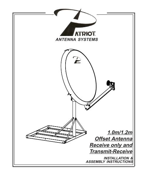
1.0m/1.2m<br />
Offset Antenna<br />
Receive only and<br />
Transmit-Receive<br />
INSTALLATION &<br />
ASSEMBLY INSTRUCTIONS
This PATRIOT <strong>AN</strong>TENNA equipment is warranted to be free from defects in material and workmanship under normal<br />
use and service. PATRIOT <strong>AN</strong>TENNA shall repair or replace defective equipment, at no charge, or at its option, refund<br />
the purchase price, if the equipment is returned to PATRIOT <strong>AN</strong>TENNA not more than twelve (12) months after<br />
shipment. Removal or reinstallation of equipment and its transportation shall not be at cost of PATRIOT <strong>AN</strong>TENNA<br />
except PATRIOT <strong>AN</strong>TENNA shall return repaired or replaced equipment freight prepaid.<br />
This Warranty shall not apply to equipment which has been repaired or altered in any way so as to affect its stability<br />
or durability, or which has been subject to misuse, negligence or accident. This Warranty does not cover equipment<br />
which has been impaired by severe weather conditions such as excessive wind, ice, storms, lightning, or other natural<br />
occurrences over which PATRIOT <strong>AN</strong>TENNA has no control, and this Warranty shall not apply to equipment which<br />
has been operated or installed other than in accordance with the instructions furnished by PATRIOT <strong>AN</strong>TENNA.<br />
Claimants under this Warranty shall present their claims along with the defective equipment to PATRIOT <strong>AN</strong>TENNA<br />
immediately upon failure. Non<strong>com</strong>pliance with any part of this claim procedure may invalidate this warranty in whole or<br />
in part.<br />
THIS WARR<strong>AN</strong>TY IS EXPRESSLY IN LIEU OF ALL OTHER AGREEMENTS <strong>AN</strong>D WARR<strong>AN</strong>TIES, <strong>AN</strong>Y IMPLIED<br />
WARR<strong>AN</strong>TY OF MERCH<strong>AN</strong>TABILITY OR FITNESS FOR A PARTICULAR PURPOSE IS LIMITED IN DURATION<br />
TO THE DURATION OF THIS WARR<strong>AN</strong>TY. PATRIOT <strong>AN</strong>TENNA DOES NOT AUTHORIZE <strong>AN</strong>Y PERSON TO<br />
ASSUME FOR IT THE OBLIGATIONS CONTAINED IN THIS WARR<strong>AN</strong>TY <strong>AN</strong>D PATRIOT <strong>AN</strong>TENNA NEITHER<br />
ASSUMES NOR AUTHORIZES <strong>AN</strong>Y REPRESENTATIVE OR OTHER PERSON TO ASSUME FOR IT <strong>AN</strong>Y OTHER<br />
LIABILITY IN CONNECTION WITH THE EQUIPMENT DELIVERED OR PROVIDED.<br />
IN NO EVENT SHALL PATRIOT <strong>AN</strong>TENNA BE LIABLE FOR <strong>AN</strong>Y LOSS OF PROFITS, LOSS OF USE, INTERRUP-<br />
TION OF BUSINESS, OR INDIRECT, SPECIAL OR CONSEQUENTIAL DAMAGES OF <strong>AN</strong>Y KIND.<br />
In no event shall PATRIOT <strong>AN</strong>TENNA be liable for damages in an amount greater than the purchase price of the<br />
equipment.<br />
Some states do not allow limitations on how long an implied warranty lasts, or allow the exclusion or limitation of<br />
incidental or consequential damages, so the above limitations or exclusions may not apply to you.<br />
PATRIOT <strong>AN</strong>TENNA has the right to void the warranty when the antenna is installed by someone other then a certified<br />
installer.<br />
2<br />
LIMITED TWELVE (12) MONTH WARR<strong>AN</strong>TY<br />
Product Serial Number- _________________<br />
Date Purchased- ____________<br />
Patriot Antenna Systems<br />
704 North Clark Street<br />
Albion, MI 49224 USA<br />
Tel: (517)629-5990<br />
Fax: (517)629-6690<br />
E-mail: info@sepatriot.<strong>com</strong>
INSTALLATION OF THIS PRODUCT SHOULD BE PERFORMED ONLY BY A PROFESSIONAL IN-<br />
STALLER <strong>AN</strong>D IS NOT RECOMMENDED FOR CONSUMER D.I.Y. (DO-IT-YOURSELF) INSTALLATIONS.<br />
WATCH FOR WIRES! Installation of this product near power lines is dangerous. For your<br />
own safety, follow these important safety rules.<br />
1. Perform as many functions as possible on the ground.<br />
2. Watch out for overhead power lines. Check the distance to the power lines before starting<br />
installation. We re<strong>com</strong>mend you stay a minimum of 6 meters (20 feet) from all power lines.<br />
3. Do not use metal ladders.<br />
IMPORT<strong>AN</strong>T!!!<br />
D<strong>AN</strong>GER!!!<br />
4. Do not install antenna or mast assembly on a windy day.<br />
5. If you start to drop antenna or mast assembly, get away from it and let if fall.<br />
6. If any part of the antenna or mast assembly <strong>com</strong>es in contact with a power line, call your<br />
local power <strong>com</strong>pany. DO NOT TRY TO REMOVE IT YOURSELF! They will remove it<br />
safely.<br />
7. Make sure that the mast assembly is properly grounded.<br />
WARNING!!!<br />
Assembling dish antennas on windy days can be dangerous. Because of the antenna surface,<br />
even slight winds create strong forces. For example, a 1.0m antenna facing a wind of<br />
32 km/h (20 mph) can undergo forces of 269 N (60 lbs.). Be prepared to safely handle these<br />
forces at unexpected moments. Do not attempt to assemble, move or mount dish on windy<br />
days or serious, even fatal accidents may occur. PATRIOT <strong>AN</strong>TENNA SYSTEMS is not responsible<br />
or liable for damage or injury resulting from antenna installations.<br />
WARNING!!!<br />
Antennas improperly installed or installed to an inadequate structure are very susceptible<br />
to wind damage. This damage can be very serious or even life threatening. The owner and<br />
installer assumes full responsibility that the installation is structurally sound to support all<br />
loads (weight, wind & ice) and properly sealed against leaks. PATRIOT <strong>AN</strong>TENNA SYSTEMS<br />
will not accept liability for any damage caused by a satellite system due to the many unknown<br />
variable applications.<br />
3
INTRODUCTION<br />
Thank you for purchasing your Patriot Commercial Antenna. We trust that you will find this to be a<br />
well designed product that will provide many years of reliable service. This manual covers the<br />
assembly and installation of the 1.0m/1.2m Antenna System. Read this manual thoroughly before<br />
beginning assembly. For best results in the assembly process. Perform each step in the same<br />
sequence as listed in this manual. Record the serial number of the unit on to page 2 for future<br />
reference and read the warranty information. The serial number can be found on the antenna back<br />
structure.<br />
UNPACKING <strong>AN</strong>D INSPECTION<br />
Shipping cartons should be unpacked and contents checked for damaged or missing parts. Should<br />
there be any parts that are damaged or missing, please contact technical support for replacement.<br />
SITE SELECTION<br />
The main objective of conducting a site survey utilizing a <strong>com</strong>pass and inclinometer is to choose<br />
a mounting location on the ground that will give you the greatest amount of swing for azimuth and<br />
elevation for present as well as future use. A thorough preinstallation site survey is strongly re<strong>com</strong>mended<br />
because it can alert you to any “look angle”, soil, wind or other problems.<br />
The first and most important consideration when choosing a prospective antenna site is whether<br />
or not the area can provide an acceptable “look angle” to the satellite. A site with a clear, unobstructed<br />
view facing south, southeast is required. Your antenna site must be selected in advance<br />
so that you will be able to receive the strongest signal available. Also consider obstructions that<br />
may occur in the future such as the growth of trees.<br />
It is important to conduct an on-site survey with a portable antenna or with a <strong>com</strong>pass and clinometer<br />
to avoid interference, obstructions, etc.<br />
When selecting “look angle”, be sure to observe and take readings approximately 10 deg to the left<br />
and right, above and below your selected “look angle”.<br />
Before Ground Pole Installation, the soil type should be checked because soil conditions vary<br />
widely in <strong>com</strong>position and load bearing capacity. A soil check will help you to determine the type<br />
and size of foundation required to provide a stable base for the antenna.<br />
Before digging is done, information regarding the possibility of underground telephone lines, power<br />
lines, storm drains, etc., in the excavation area should be obtained from the appropriate agency.<br />
As with any other type of construction, a local building permit may be required before installing an<br />
antenna. It is the property owner’s responsibility to obtain any and all permits. Ground mounts are<br />
certified for 125 mph wind survival.<br />
4
13<br />
17<br />
18<br />
14<br />
16<br />
22<br />
19<br />
16<br />
12<br />
*<br />
2<br />
24<br />
18<br />
33<br />
1<br />
3<br />
4<br />
10 17<br />
11<br />
21<br />
9<br />
16<br />
33<br />
19<br />
*<br />
24<br />
12<br />
21<br />
16<br />
20<br />
25<br />
26<br />
15<br />
16<br />
18<br />
17<br />
18<br />
8<br />
7<br />
27<br />
25<br />
12<br />
5<br />
6<br />
28<br />
29<br />
30<br />
31<br />
Parts and Hardware<br />
PLACE (ITEM#33) SPACERS, INBETWEEN (ITEM #1)<br />
*<br />
REFLECTOR,1.0m <strong>AN</strong>D (ITEM #3) BACK STRUCTURE,1.0m.<br />
ITEM PART NO. DESCRIPTION<br />
QTY.<br />
1 210001 Reflector, 1.0m<br />
1<br />
2 212001<br />
Reflector, 1.2m<br />
1<br />
3 210002<br />
Back Structure, 1.0m (pre-assembled to reflector)<br />
1<br />
4 212002<br />
Back Structure, 1.2m (pre-assembled to reflector)<br />
1<br />
5 210003<br />
Feed Boom, 1.0m<br />
1<br />
6<br />
7<br />
212003<br />
210081<br />
Feed Boom, 1.2m<br />
Bracket, Azimuth<br />
1<br />
1<br />
8 210080<br />
Bracket, 3” Pipe<br />
2<br />
9 1RSP02740(2 7/8”)1RSP03040(3”) Mast Pipe, 2 7/8” or 3” O.D. (not included)<br />
1<br />
10 210083<br />
Upper Clevis, Elevation<br />
1<br />
11 210082<br />
Lower Clevis, Elevation<br />
1<br />
12 HWD Prebag H1101<br />
Plastic Plugs<br />
3<br />
13 HWD Prebag H1101<br />
1/2-20 Thread, Elevation Rod 13”<br />
1<br />
14 HWD Prebag H1101<br />
Adjusting Nut, 1/2” thread 2” long<br />
1<br />
15 HWD Prebag H1101<br />
Fine AzEl Adjusting bolt (pre-assembled)<br />
1<br />
16 HWD Prebag H1101<br />
3/8” SAE Flat Washer<br />
27<br />
17 HWD Prebag H1101<br />
1/2” SAE Flat Washer<br />
4<br />
18<br />
19<br />
HWD Prebag H1101<br />
HWD Prebag H1101<br />
3/8-NYL INST L/N<br />
1/2-20 Fin Hex Nut<br />
15<br />
3<br />
20 HWD Prebag H1101<br />
1/4-20 Fin Hex Nut<br />
5<br />
21 HWD Prebag H1101<br />
3/8-16 x 1 1/2 Carr. Bolt, G-2<br />
4<br />
22 HWD Prebag H1101<br />
3/8-16 x 7/8 HCS, G-2<br />
8<br />
23 HWD Prebag H1101<br />
3/8-16 x 2 HCS, G-2 (pre-assembled)<br />
1<br />
24 HWD Prebag H1101<br />
3/8-16 x 3 HCS, G-2<br />
3<br />
25 HWD Prebag H1101<br />
1/4-20 x 1 SOC Cap SC<br />
5<br />
26 PE0400A<br />
Feed Holder, Top<br />
1<br />
27 PE0400B<br />
Feed Holder, Bottom<br />
1<br />
28 TXFD-KA/KUR<br />
Ku Rx only, Feed Assembly (Optional)<br />
1<br />
29 TX - FDOMTKUL<br />
Ku Tx/Rx XPol, Feed Assembly (Optional)<br />
1<br />
30 TXFD-DPLCOPOL/TXFD-KUL Ku Tx/Rx CoPol, Feed Assembly (Optional)<br />
1<br />
31 TXFD-OMTKAL<br />
Ka Tx/Rx Linear Pol, Feed Assembly (Optional)<br />
1<br />
32<br />
33<br />
TXFD-OMTPLKA<br />
3HM11100<br />
Ka Tx/Rx Circular Pol, Feed Assembly (Optional)<br />
SPACERS (1.0m ONLY)<br />
1<br />
2<br />
32<br />
5
Assembly tools required<br />
1- 1/4” allen wrench (supplied)<br />
1- 5/32” allen wrench<br />
2- Combination wrench -3/4”<br />
2- Combination wrenches - 9/16”<br />
2- Combination wrenches - 1/2”<br />
2- Combination wrenches - 7/16”<br />
1- 9/16 ratcheting wrench for<br />
Fine Az-El Adjustment<br />
1- Inclinometer (for sighting in)<br />
1- Compass (for sighting in)<br />
In-Ground Mast Foundation<br />
Preinstallation materials checklist<br />
Grounding Rod Clamp & Grounding Block - As required by<br />
National Electric Code or local codes.<br />
Ground Wire - #10 solid copper or as required by National<br />
Electric Code or local codes.<br />
Coaxial Cable (Size & Length required).<br />
Concrete - (See Ground Pole section below).<br />
#3 Rebar - (See Ground Pole section below). Deformed<br />
steel per ASTM A615, grade 40 or 60.<br />
Steel Mast: L=72”; 2-7/8” (73mm) or 3”(76mm)O.D. Tubing Plumb within 1deg.<br />
Concrete: 3000 psi at 28 days, poured against undisturbed soil<br />
(Allow concrete 24 hour set time before installation of antenna)<br />
Soil Bearing Capacity > 2000 psf.<br />
Ground the Antenna to meet applicable local Codes.<br />
48” min.<br />
48”<br />
10”<br />
Mast Pipe<br />
2-7/8” or 3” O.D.<br />
36” min.<br />
Grade<br />
Anti-Twist Rebar<br />
5/8” Diam. x 9”<br />
-Universal mount/wall mount #CHA-WR300 for 1.0m only (optional) not shown.<br />
6
Non-Penetrating Mount (optional)<br />
1. Assemble the Non-Penetrating mount per the supplied instructions to provide the mast for<br />
the mount installation.<br />
2. Refer to the ballast chart for the required ballast to be placed in the Non-Pen Ballast Trays.<br />
NOTE: Higher elevation angles can use less ballast. If there are any possible future elevation<br />
adjustments that could result in a lower elevation angle use the 22 deg elevation angle from<br />
the chart for the ballast requirement!<br />
100cm Ballast Chart<br />
Elevation<br />
(deg)<br />
80 100 125<br />
22 259 480 826<br />
40 202 374 644<br />
60 116 216 372<br />
28 lb<br />
4x8x16 Block<br />
9 blocks per tray<br />
Ballast Required (lbs)<br />
Wind Speed (mph)<br />
120cm Ballast Chart<br />
Dual Tray<br />
Elevation Ballast Required (lbs)<br />
(deg)<br />
Wind Speed (mph)<br />
80 100 125<br />
22 411 733 1236<br />
40 321 572 964<br />
60 185 330 556<br />
* Installations in excess of 100 mph wind<br />
speed requirement are to be tethered.<br />
*<br />
*<br />
*<br />
Add-on Dual Tray<br />
(if necesary)<br />
7
8<br />
* SPECIAL WIND REGIONS:<br />
Records or experience indicates that the wind speeds are higher in mountainous terrain, gorges, and ocean promontories and shall be examined<br />
for unusual wind conditions. Contact your local meteorological authority and a local civil or professional engineer if your installation is in one of<br />
these areas.
Az-El Mount Assembly<br />
1. Using the hardware illustrated, assemble<br />
the Pipe brackets, Azimuth<br />
bracket, and Clevis bracket as shown.<br />
Azimuth<br />
Bracket<br />
D<br />
D<br />
E<br />
D<br />
E<br />
E<br />
A<br />
E<br />
E<br />
D<br />
A<br />
DE<br />
B<br />
B<br />
E<br />
A<br />
F<br />
A<br />
D<br />
A<br />
E<br />
D<br />
E<br />
E<br />
DE<br />
E<br />
D<br />
D<br />
E<br />
5x<br />
A<br />
C<br />
Clevis<br />
Pipe<br />
Bracket<br />
4x<br />
B<br />
11x<br />
D<br />
1x<br />
C<br />
18x<br />
E<br />
1x<br />
F<br />
9
Mount Assembly<br />
1. Attach the Antenna-Back Structure<br />
Assy to the Azimuth Bracket using<br />
the illustrated hardware.<br />
2. Add the Elevation adjustment<br />
hardware and Upper Clevis using the<br />
hardware shown.<br />
10<br />
5X<br />
1X<br />
10X<br />
2X<br />
4X<br />
4X<br />
3X<br />
Note: Two of these<br />
bolts are to be used<br />
on the Feed Support<br />
Tube. Refer to Pg. 8
Feed Assembly<br />
1. Attach the relevant Feed Assembly.<br />
2. Insert the Feed Assembly into the Feed holder and assemble to the Feed Support Tube<br />
using the hardware illustrated below.<br />
NOTE: 2 nuts slide into the back of the Feed Holder.<br />
3. Insert plastic plug into end of feed support tube.<br />
5x<br />
Plug<br />
Rx<br />
Port<br />
Tx<br />
Port<br />
5x<br />
Feed<br />
Support<br />
Tube<br />
Feed Horn<br />
Feed<br />
Holder<br />
Rx Port<br />
Tx Port<br />
Rx Port<br />
Rx Port<br />
Rx Port<br />
Tx Port<br />
Rx Port<br />
Tx Port<br />
Tx Port<br />
32<br />
30<br />
31<br />
Refer to page 5 for more<br />
information of Feed Assemblies.<br />
29<br />
28<br />
11
Feed Adjustment (Polarity tuning)<br />
NOTE: Linear Polarity systems only<br />
1. Adjust the Feed to the appropriate skew angle<br />
using the provided scale reference.<br />
NOTE: Refer to the chart below for polarization<br />
angle. Elevation and polarity are both dependent<br />
on site azimuth and the difference between satellite<br />
and site longitude.<br />
NOTE: Some satellites have a slant angle with respect<br />
to the satellite belt angle. Contact the satellite<br />
operator for details.<br />
Feed Rotation Chart<br />
Install site west Install site East<br />
of satellite of satellite<br />
CW CCW Northern Hemisphere<br />
CCW CW Southern Hemisphere<br />
12<br />
BUC<br />
LNB<br />
CCW<br />
CW<br />
Polarity<br />
Scale<br />
Reading<br />
Points
Antenna Pointing<br />
NOTE: The Reflector contains a 22 degree offset look angle. Therefore, when the reflector aperture is<br />
perpendicular to the ground, the antenna is actually looking 22 degrees in elevation.<br />
All mount hardware should be firm, but not tight.<br />
.<br />
1. Adjust the reflector up or down in elevation by turning the two 1/2” hex nuts at the Clevis until the desired<br />
elevation is measured (taking reading from the face of the reflector).<br />
Elevation of Satellite above horizon = Measured angle from face of reflector plus 22.<br />
2. Azimuth Adjustment: With the electronics set to acquire the satellite, rotate the antenna in azimuth until<br />
the satellite is found. Roughly obtain the strongest signal and tighten the hardware on the Pipe Brackets.<br />
NOTE: If signal is not found on first pass of Azimuth, adjust elevation up or down in 2 deg increments until<br />
signal is found.<br />
3. Peak the satellite signal by fine adjustments made in both azimuth and elevation until the optimum<br />
singal is acheived.<br />
Note: With Azimuth hardware snug (loose enough to allow adjustment), turning the Azimuth bolt allows + 3<br />
deg fine adjustment.<br />
Azimuth<br />
Adjustment<br />
Bolt<br />
4. Tighten all mount hardware<br />
When turning the<br />
Azimuth Adjustment<br />
Bolt,this nut must turn<br />
with it. If not, Tighten<br />
until firm.<br />
Azimuth<br />
Bracket<br />
Inclinometer<br />
Location<br />
Azimuth<br />
Hardware<br />
(4) Area’s<br />
Elevation<br />
Adjustment<br />
5. Patriot re<strong>com</strong>mends the use of cross pol nulling using a spectrum analyzer during TX/RX installations.<br />
After tightening the azimuth and elevation hardware, peak the co-pol signal using the spectrum analyzer.<br />
Then rotate the feed assemble roughly 90 degrees to obtain a cross pol null. Fine tune the null. The scale<br />
on the feed horn can be used with the tick mark on feed holder top or the seam between feed holder top<br />
and bottom. The tick mark and seam are 90 deg. apart.Note that changes may be necessary to the<br />
resolution and video bandwitdh to bring the signal above the noise floor. Note the angle of optimum cross<br />
pol null. Rotate the feed back exactly 90 degrees and tighten the feed clamp.<br />
Nut<br />
13
Grounding<br />
Grounding Antenna Feed Cables<br />
1. Ground antenna feed cables in<br />
accordance with current National<br />
Electric code and local electric<br />
codes. The illustration shows a<br />
typical grounding method.<br />
Clamps that provide a solid connection<br />
between ground wire and a<br />
ground source should be used.<br />
Grounding Non-Penetrating<br />
Mount Frame (if applicable)<br />
1. Ground the Non-Penetrating<br />
mount frame. The illustration<br />
shows a typical grounding method.<br />
Refer to the NEC Section 810 and<br />
local electric codes for specific instructions<br />
on grounding the remaining<br />
end of the ground wire.<br />
14<br />
Non-Pen<br />
Frame<br />
Ground Block<br />
NEC Section 810<br />
Ground Wire<br />
NEC Section 810<br />
External<br />
Toothed<br />
Washer<br />
Ground<br />
Lug<br />
Coaxial<br />
Cable<br />
(to LNB)<br />
1/4” Tapping<br />
Bolt
We are Cal-Amp’s LARGEST<br />
STOCKING DISTRIBUTOR!<br />
No Long Lead Times...<br />
No Drop Ship Fees...<br />
High Inventory...<br />
Great Prices...<br />
Equipment From The Industry’s Leading<br />
Satellite Equipment<br />
Manufacturer’s<br />
Available Together - In One Place...<br />
W e A l s o O f f e r P r o d u c t s f r o m t h e f o l l o w i n g :<br />
Complete line of Quality Feedhorns,<br />
Receivers and Accessories - from a<br />
name you trust<br />
Prevent Snow & Ice from accumlulating<br />
on your system with a De-Icing System.<br />
Looking to increase your<br />
satellite’s reception? Try<br />
upgrading your feed<br />
system to a Multi-Beam<br />
Feed. Receive up to 4<br />
simultaneous satellites<br />
Offset VSAT<br />
& DBS Antennas Available!<br />
Toll Free 1-800-470-3510<br />
Durable Snow Covers for Commercial<br />
Antennas as well as Home System -<br />
Keep snow from interfering with your<br />
signal.<br />
Complete line of Antenna Controllers,<br />
Positioners and Software for your<br />
motorized applications.<br />
Products Also Avaliable from:<br />
• ADL General Instruments<br />
Baird Norsat<br />
Drake Standard Comm<br />
DX Thomson-Saginaw<br />
Force Wegner<br />
15
Specifications<br />
Electrical<br />
Tx Band(GHz)<br />
Rx Band(GHz)<br />
Tx Gain dBi (Midband)<br />
Rx Gain dBi (Midband)<br />
Efficiency<br />
Side Lobes<br />
Cross Polarization (on axis)<br />
Ku Band Ka Band<br />
1.0m - 1.2m 1.0m - 1.2m<br />
13.75 - 14.50<br />
10.70 - 12.75<br />
41.90 - 43.50<br />
40.30 - 41.80<br />
70%<br />
ITU-580-5<br />
35dB<br />
Mechanical<br />
Antenna Size 1.0m (39.4”) 1.2m (47.3”)<br />
Offset Angle 22 degrees<br />
F/D 0.635<br />
Operational Wind 50mph<br />
Survival Wind 125mph<br />
Operational Temp -40 to 140 F<br />
Survival Temp -60 to 180 F<br />
Rain Operational = 1/2in./hr<br />
Survival = 3in./hr<br />
Ice 1 in. Radial -or-<br />
1/2 in. + 60mph wind<br />
Pole Size 2-7/8” or 3” OD<br />
<strong>AN</strong>TENNA SYSTEMS<br />
704 North Clark Street<br />
Albion, MI 49224 USA<br />
Tel: (517)629-5990<br />
Fax: (517)629-6690<br />
E-mail: info@sepatriot.<strong>com</strong><br />
Web site: www.sepatriot.<strong>com</strong><br />
29.50 - 30.00<br />
19.70 - 20.20<br />
48.10 - 49.70<br />
44.60 - 46.00<br />
65%<br />
Rev-01-05-04