

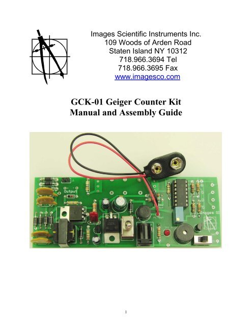
GCK-01 Geiger Counter Kit Manual and Assembly Guide
GCK-01 Geiger Counter Kit Manual and Assembly Guide
GCK-01 Geiger Counter Kit Manual and Assembly Guide

Create successful ePaper yourself
Turn your PDF publications into a flip-book with our unique Google optimized e-Paper software.
Images Scientific Instruments Inc.<br />
109 Woods of Arden Road<br />
Staten Isl<strong>and</strong> NY 10312<br />
718.966.3694 Tel<br />
718.966.3695 Fax<br />
www.imagesco.com<br />
<strong>GCK</strong>-<strong>01</strong> <strong>Geiger</strong> <strong>Counter</strong> <strong>Kit</strong><br />
<strong>Manual</strong> <strong>and</strong> <strong>Assembly</strong> <strong>Guide</strong><br />
1
This kit can utilize a variety of GM tubes, so depending upon a GM tube's availability you can choose<br />
one that is readily available <strong>and</strong> in your price range.<br />
Once assembled this <strong>Geiger</strong> counter outputs audible click <strong>and</strong> will blink a LED with each radioactive<br />
particle it detects. In addition it has two digital outputs that may be connected to a number of accessory<br />
instruments; a data logger, Digital Meter adaptor that outputs an approximate radiation level, RS-232<br />
adaptor to plot radioactivity on a PC, <strong>and</strong> true r<strong>and</strong>om number generator, in addition to an analog meter<br />
adaptor that can approximate 3 radiation ranges: 0 to 1 mR/hr, 0-10 mR/hr <strong>and</strong> 0-100 mR/hr.<br />
This assembled <strong>Geiger</strong> counter is compatible to the Radiation Network software.<br />
What is Radioactivity<br />
Radioactivity is the spontaneous emission of energy from the nucleus of certain atoms. The most<br />
familiar radioactive material is uranium.<br />
There are three forms of energy associated with radioactivity; alpha, beta <strong>and</strong> gamma radiation. The<br />
classifications were originally determined according to the penetrating power of the radiation, see figure<br />
1. Depending upon your GM tube selection our <strong>Geiger</strong> counter can detect the three types of radiation;<br />
alpha, beta <strong>and</strong> gamma radiation.<br />
Figure 1<br />
Alpha rays are the nuclei of helium atoms, two protons <strong>and</strong> two neutrons bound together. Alpha<br />
rays have a net positive charge. Alpha particles have weak penetrating ability, a couple of inches of air or<br />
a few sheets of paper can effectively block them.<br />
Beta rays were found to be electrons, identical to the electrons found in atoms. Beta rays have a<br />
net negative charge. Beta rays have a greater penetrating power than Alpha rays <strong>and</strong> can penetrate 3mm<br />
of aluminum.<br />
2
Gamma rays are high-energy photons. This has the greatest penetrating power being able to pass<br />
through several centimeters of lead <strong>and</strong> still be detected on the other side. Thick lead is needed to<br />
attenuate gamma radiation.<br />
<strong>Geiger</strong> Mueller Tube<br />
<strong>Geiger</strong> Mueller tubes are simple devices that detect <strong>and</strong> measure the intensity of radioactivity.<br />
The original design by H. <strong>Geiger</strong> <strong>and</strong> E.W. Mueller in 1928 hasn’t changed very much. The basic sensor<br />
functioning remains the same.<br />
A cut away drawing of a typical <strong>Geiger</strong> Mueller (GM) tube is shown in figure 2. The wall of the<br />
GM tube is a thin metal (cathode) cylinder surrounding a center electrode (anode). The metal wall of the<br />
GM tube serves as the cathode of the GM Tube. The front of the tube is a thin Mica window sealed to the<br />
metal cylinder. The thin mica window allows the passage <strong>and</strong> detection of the weak penetrating alpha<br />
particles. The GM tube is first evacuated then filled with Neon, Argon plus a Halogen gas.<br />
Figure 2<br />
Our GM tube is put into an initial state (ready to detect a radioactive particle), by applying +<br />
500-volt potential to the anode (center electrode) through a ten mega ohm current limiting resistor. A<br />
470K-ohm resistor is connected to the metal wall cathode of the tube <strong>and</strong> to ground. The top of the 470K<br />
resistor is where we see our pulse signal whenever a radioactive particle is detected.<br />
In its initial state the GM tube has a very high resistance. However, when a radioactive particle<br />
passes through the GM tube, it ionizes the gas molecules in its path <strong>and</strong> creates a momentary conductive<br />
path in the gas. This is analogous to the vapor trail left in a cloud chamber by a particle. In the GM tube,<br />
the electron liberated from the atom by the particle, <strong>and</strong> the positive ionized atom both move rapidly<br />
towards the high potential electrodes of the GM tube. In doing so they collide with <strong>and</strong> ionize other gas<br />
atoms, creating a momentary avalanche of ionized gas molecules. And these ionized molecules create a<br />
3
small conduction path allowing a momentary pulse of electric current to pass through the tube allowing<br />
us to detect the particle.<br />
This momentary pulse of current appears as a small voltage pulse across the 470 K ohm resistor.<br />
The halogen gas quickly quenches the ionization <strong>and</strong> the GM tube returns to its high resistance state<br />
ready to detect more radioactivity.<br />
Dead Time<br />
For the short amount of time the GM tube is detecting one particle, if another radioactive particle<br />
enters the tube it will not be detected. This is called dead time. The maximum dead time for the LND 712<br />
GM tube is 90 microseconds (or .00009 seconds). There is a mathematical formula for adjusting a <strong>Geiger</strong><br />
counter read out to compensate for the GM tube’s dead time. Different GM tubes have different dead<br />
times.<br />
Count Rate vs. Dose Rate<br />
Each output pulse from the GM tube is a count. The counts per second give an approximation of<br />
the strength of the radiation field. Typically a GM tube is calibrated using either a cesium-137 or colbalt-<br />
60 radiation source. The chart is shown in figure 3 is a typical response curve for a generic GM tube.<br />
Each GM tube will have its own response curve to radiation. For many of the GM tubes available on<br />
Ebay, the response curve is not available.<br />
Measurement of Radiation<br />
Figure 3<br />
There are a few scales that one can use to measure radiation. Depending upon your application, one scale<br />
may be better than the others.<br />
4
Radiation Measurements<br />
Roentgen: Is the measurement of energy produced by Gamma or X-Ray radiation in a<br />
cubic centimeter of air. It is abbreviated with the capital "R". One milliroentgen, abbreviated "mR" is<br />
one-thous<strong>and</strong>th of a roentgen. One microroentgen, abbreviated “uR” is one-millionth of a roentgen.<br />
RAD: Radiation Absorbed Dose. Original measuring unit for expressing the absorption of all types of<br />
ionizing radiation (alpha, beta, gamma, neutrons,etc) into any medium. One rad is equivalent to the<br />
absorption of 100 ergs of energy per gram of absorbing tissue.<br />
REM: Roentgen Equivalent Man is a measurement that correlates the dose of any radiation to the<br />
biological effect of that radiation. Since not all radiation has the same biological effect, the dosage is<br />
multiplied by a "quality factor" (Q). For example, a person receiving a dosage of gamma radiation will<br />
suffer much less damage than a person receiving the same dosage from alpha particles, by a factor of<br />
three. So alpha particles will cause three times more damage than gamma rays. Therefore, alpha radiation<br />
has a quality factor of three. Following is the Q factor for a few radiation types<br />
Radiation: Quality Factor (Q)<br />
Beta, Gamma <strong>and</strong> X-rays 1<br />
Thermal Neutrons 3<br />
Fast n, a, <strong>and</strong> protons 10<br />
Heavy <strong>and</strong> recoil nuclei 20<br />
The difference between the rad <strong>and</strong> rem is that the rad is a measurement of the radiation absorbed by the<br />
material or tissue. The rem is a measurement of the biological effect of that absorbed radiation.<br />
For general purposes most physicists agree that the Roentgen, Rad <strong>and</strong> Rem may be considered<br />
equivalent.<br />
The curie is a unit of radioactivity, its symbol (Ci). It is defined by the amount radioactive decays per<br />
second. 1Ci = 3.7 x 10^10 decays per second.<br />
When you purchase a radioactive isotope source, it will be rate in microcuries (uCi) (one millionth of a<br />
curie).<br />
System International (SI) of Units<br />
The System International of unit for radiation measurements is now the official<br />
system of measurements. This system uses the “gray” (Gy) <strong>and</strong> “sivert” (Sv) for<br />
absorbed dose <strong>and</strong> equivalent dose respectively.<br />
The conversion from one system to another is simple:<br />
1 Sv = 100 rem 1 rem = .<strong>01</strong> Sv<br />
1 mSv = 100 mR (mrem) 1 mR = .<strong>01</strong> mSv<br />
1 Gy = 100 rad 1 rad = .<strong>01</strong> Gy<br />
1mGy = 100 mrad 1 mrad = .<strong>01</strong> mGy<br />
5
The SI derivative of the curie is the becquerel (Bq) (pronounced: 'be-kə-rel) which equals one decay per<br />
second.<br />
How Much Radiation is Safe?<br />
In the United States the U.S. Nuclear Regulatory Commission (NRC) determines what radiation exposure<br />
level is considered safe. Occupational exposure for worker is limited to 5000 mrem per year. For the<br />
general population, the exposure is 500 mrem above background radiation in any one year. However for<br />
long term, multi-year exposure, 100 mrem above background radiation is the limit set per year.<br />
Let’s extrapolate the 100 mrem number to an hourly radiation exposure rate. There are 365 days/yr x 24<br />
hr/day equals 8760 hours. Divide 100 mrem by 8760 hours equals .<strong>01</strong>14 mrem/hr or 11.4/hr microrem.<br />
This is an extremely low radiation level. The background radiation in my lab hovers around 32 uR/hr.<br />
Am I in trouble? No. Typically background radiation in the United States averages 300 mrem/yr, or 34<br />
microrem/hr. The NRC specifications is for radiation above this 34 urem/hr background radiation.<br />
Notice that my lab readings are in microrad (uR/hr) <strong>and</strong> the exposure limit is given in microrem<br />
(urem/hr). I do not know what type of radiation (a , b or y) the geiger counter is reading in my lab at any<br />
particular instant, so I do not know the Q factor of the radiation <strong>and</strong> therefore can not calculate the mrem.<br />
However for general purposes I consider them the one <strong>and</strong> the same. The digital <strong>Geiger</strong> counters I use<br />
are calibrated using a Cs-137 radioactive source. Therefore the highest accuracy in reading radiation<br />
levels will be from Cs-137 sources.<br />
Common Radiation Exposure (General Population)<br />
Exposure Source Dose(conventional) Dose (SI)<br />
Flight from LA to NY 1.5 mrem .<strong>01</strong>5 mSv<br />
Dental X-ray 9 mrem .09 mSv<br />
Chest X-ray 10 mrem 0.1 mSv<br />
Mammogram 70 mrem 0.7 mSv<br />
Background Radiation 620 mrem/year 6.2 mSv/year<br />
Background radiation consists of three sources; Cosmic radiation from the sun <strong>and</strong> stars. Terrestrial<br />
radiation from low levels of uranium, thorium, <strong>and</strong> their decay products in the soil, air <strong>and</strong> water. Internal<br />
radiation from radioactive potassium-40, carbon-14, lead-210, <strong>and</strong> other isotopes found inside our bodies.<br />
Testing for Radioactive Contamination<br />
For this test to be as sensitive as possible it is recommended that the GM tube be sensitive to alpha, beta<br />
<strong>and</strong> gamma radiation.<br />
<strong>Geiger</strong> counters can only test for gross radioactive contamination levels that will show up above<br />
background radiation levels. Low level radioactive contamination may be effectively hidden within the<br />
natural "noise" of background radiation <strong>and</strong> not discernable using a <strong>Geiger</strong> counter. Therefore for low<br />
level radioactive contamination <strong>Geiger</strong> counters are not the proper test instruments. With this disclaimer<br />
in place, this is the procedure to test for radioactive contamination that presents a increase in the<br />
background radiation. Step one; first establish the background radiation level.<br />
6
To establish background radioactivity level, record the pulses (Counts) received per minute (CPM). The<br />
greater the number of minutes you count the more accurate will be you background radiation reading.<br />
Average the CPM reading to determine a approximate background radiation level for your<br />
area. The highest <strong>and</strong> lowest CPM count will establish your minimum <strong>and</strong> maximum CPM. These<br />
numbers will establish a baseline so that you will be able to determine if the background radiation has<br />
changed, or to detect trace amounts of radioactive materials.<br />
If you look at the data I obtained from the Data Logger discussed later, in the Excel spread sheet my<br />
average CPM reading, based on 298 samples, was 16 CPM. The Minimum CPM was 6 <strong>and</strong> the Maximum<br />
CPM 28.<br />
To run a test position the probe (or <strong>Geiger</strong> counter) very close to the top surface of the material you are<br />
testing, <strong>and</strong> run the counter recording the CPM output. The longer the run obtaining CPM data, the more<br />
accurate the results.<br />
Compare the radiation output of your sample under test to your establish background radiation.<br />
Images does not make any warranties (express or implied) about the radiation information<br />
provided here for your use. All information provided should be considered experimental. Safety<br />
<strong>and</strong> health issues <strong>and</strong> concerns involving radioactive contamination should be addressed,<br />
confirmed <strong>and</strong> verified with local <strong>and</strong> national government organizations or recognized experts in<br />
this field.<br />
<strong>Geiger</strong> <strong>Counter</strong> Schematic<br />
The circuit is shown in figure 4. The HV section of the circuit is built around a single<br />
transistorized (TIP3055) ringing choke converter that has been around for years. This<br />
particular derivative of the circuit was designed by Sam Evans to minimize current<br />
draw. The important element in this circuit is the transformer.<br />
In this configuration, the primary winding of the transformer <strong>and</strong> the feedback winding<br />
of the transformer are arranged so that the circuit begins a sustaining oscillation when<br />
power is applied. If you checked the output of the oscillator you would find the<br />
waveform’s duty cycle is symmetrical.<br />
The primary oscillation amplitude is around 6Vat 14.1kHz. This gets amplified with<br />
the large step-up ratio of the transformer <strong>and</strong> we obtain about 325V(p-p) across the<br />
secondary. The current consumption is about 5ma.<br />
A simple voltage multiplier is used to boost up this voltage in steps to give a final DC<br />
of about 600V DC.<br />
The high voltage output from this stage is regulated by zener diodes. Here the user can decide<br />
which zener diodes regulators to use to vary the regulated DC output. There are three zener diode<br />
positions on the pc board, D8, D9 <strong>and</strong> D10. If one uses 200V zeners in each position the regulated output<br />
is 600 volts. Using 100 volt zeners in each position the regulated output is 300 volts. Using (2) 200V<br />
zeners <strong>and</strong> (1) 100 volt zener provides 500 VDC regulated output<br />
7
Figure 4<br />
8
In the latest revision of the PC Board there is a jumper J1 that shorts out the D8 zener. By putting 200<br />
volt zener diodes in the D9 <strong>and</strong> D10 position <strong>and</strong> a 100 volt zener in the D8 position you can change the<br />
regulated output to the GM tube from 500 VDC to 400 VDC by adding a jumper.<br />
So its easy to vary the regulated output from 300 to 600 VDC depending upon the voltage required of<br />
their GM tube.<br />
Assuming a 500 VDC output <strong>and</strong> a LND712 GM tube the 500-volt regulated output is fed to the anode<br />
of the GM tube through a current limiting 10 mega-ohm resistor R5. The 10 mega-ohm resistor limits the<br />
current through the GM tube <strong>and</strong> helps quench the avalanched ionization when a radioactive particle is<br />
detected.<br />
The cathode of the tube is connected to a 1 meg potentiometer <strong>and</strong> a 100K resistor. Each time a<br />
particle is detected a voltage pulse is generated across this resistance. The pulse is fed from the wiper of<br />
the potentiometer to the inverting input to a 339 comparator.<br />
The comparator cleans up the pulse <strong>and</strong> down streams it to the three other comparators. The output of the<br />
second comparator feeds to the base of a 2N3904 transistor. The transistor powers an LED <strong>and</strong> speaker<br />
so that each time a particle is detected the LED blinks <strong>and</strong> the speaker clicks.<br />
The other comparator outputs are available for use by the user via Screw terminals on the edge of the<br />
board.<br />
Alternative Audio Output: To create a more pronounced click you can use the alternative audio<br />
output section. The pulse signal from the comparator is a trigger to the 555 Timer. The timer is set up in<br />
monostable mode that stretches out the pulse received on its trigger. The output pulse from the timer<br />
flashes the LED <strong>and</strong> outputs an audible click to the speaker via pin 3.<br />
Construction<br />
You may hardwire this circuit to a breadboard or use the available PCB board. Although you do<br />
not need the PCB, the PCB will may construction easier, see figure 5.<br />
Figure 5<br />
9
When using the PC board its merely a matter of mounting <strong>and</strong> soldering the components in their proper<br />
position. All the parts are outlined on the top silk screen, see figure 5.<br />
Begin by mounting <strong>and</strong> soldering all the resistors, see figure 6.<br />
Figure 6<br />
R2 - 33 ohm (color code - orange, orange, black, gold),<br />
R3 <strong>and</strong> R7 - 1 meg-ohm (color code - brown, black, green, gold),<br />
*R4 - 470 K-ohm (color code - yellow, purple, yellow, gold),<br />
*R5 - 10 meg-ohm (color code brown, black, blue, gold),<br />
R8-R11 <strong>and</strong> R14 - 10K-ohm (color code - brown, black, orange, gold),<br />
R12 - 150 ohms (color code - brown, green, brown, gold)<br />
R13 - 100 K-ohm (color code - brown, black, yellow, gold)<br />
*These resistor values will change depending upon the specific GM tube used. Default values are for the<br />
LND712 GM Tube.<br />
Customizing circuit for GM Tube.<br />
The two resistors R4 <strong>and</strong> R5 need to be matched to your GM tube also. R5 is the anode resistor. The<br />
anode resistor prevents too much current from passing through the tube when the tube detects a<br />
radioactive particle. This resistor can vary between 2.2 mega-ohms <strong>and</strong> 10 mega-ohms for different GM<br />
tubes. You need to read the specifications on your particular tube. The Cathode resistor is R4 <strong>and</strong> may<br />
vary between 47 K ohm to 1 mega-ohms for different GM tubes. The voltage pulse across this resistor is<br />
fed to the comparator.<br />
Zener Diodes<br />
Mount <strong>and</strong> solder diodes D1 through to D11. Make sure to orientate the line on the diodes with the line<br />
on the silk screen diode drawing on the printed circuit board.<br />
D1, D2, D3, D4, D5, <strong>and</strong> D6 - 1N4007<br />
D7 - 5.1V Zener<br />
D8 - 100V Zener<br />
10
D9 <strong>and</strong> D10 - 200V Zener (* See text)<br />
D11 - LED<br />
The longer lead on the LED (D11) is the positive lead. Make sure the positive lead is inserted into the<br />
pad toward the bottom of the pc board (on the round side of the silk screen LED outline). Next mount<br />
<strong>and</strong> solder the 14 pin IC socket, see figure 7.<br />
Figure 7<br />
In addition to adjusting the resistors to the GM tube, you can also adjust the voltage to the GM tube.<br />
Depending upon the zener diodes used, you can vary the voltage between 400 <strong>and</strong> 600 volts. The zener<br />
diodes (D8, D9 <strong>and</strong> D10) to provide the regulation of the voltage delivered to the GM Tube.<br />
The zener diodes provided with the kit are D8 - 100 volts, D9 <strong>and</strong> D10 - 200 volts. With this diode set<br />
you can vary the voltage to either 400 volts or 500 volts to the GM tube. Keeping jumper J1 open will<br />
provide 500 VDC to the GM tube. Shorting jumper J1, shorts out diode D8 <strong>and</strong> provides 400 VDC to the<br />
GM tube.<br />
If you required 600 VDC, diodes D8 to D10 ought to be made 200 zener diodes. Keeping jumper J1 open<br />
provides 500 VDC to the GM tube. Shorting jumper J1, shorts out diode D8 <strong>and</strong> provides 400 VDC to<br />
the GM tube.<br />
Next install the regulator 7805 <strong>and</strong> the 3055 (or H1061) transistor. Insert components on the pc board<br />
<strong>and</strong> bend them into place BEFORE soldering, see figure 8. Mount <strong>and</strong> solder capacitors :<br />
C1 - 0.1µF<br />
C2 - 1000µF-16V,<br />
C3 <strong>and</strong> C4 - 10µF-16V,<br />
C5, C6, C7 <strong>and</strong> C8 - 0.<strong>01</strong>µF - 1KV.<br />
Mount <strong>and</strong> solder mini-step-up transformer T1.<br />
Mount <strong>and</strong> solder the 14 pin IC socket U4.<br />
11
Figure 8<br />
Finishing Board Construction<br />
Mount <strong>and</strong> solder U2 <strong>and</strong> Q2. Making sure their profile matches the silk screen outline of these parts<br />
before soldering. Next mount <strong>and</strong> solder the bridge rectifier U3. Align the positive terminal of the bridge<br />
rectifier with the + pad on the pc board. Mount <strong>and</strong> solder the P2 external power supply connector.<br />
Mount <strong>and</strong> solder S1 toggle switch. Mount <strong>and</strong> solder on-off slide switch for the speaker. Next mount<br />
<strong>and</strong> solder the piezoelectric speaker. The long lead on the speaker is positive <strong>and</strong> should be inserted into<br />
the + pad on the pc board. Mount <strong>and</strong> solder the 1-meg-ohm potentiometer in the R6 position on the PC<br />
board. Next solder the 9V battery clip to the PC board. The red wire is soldered to the P1 + Bat pad. The<br />
black wire is soldered to P3 -Bat pad. Finish the board by mounting <strong>and</strong> soldering the two pin header in<br />
the J1 position. Your board should appear as in figure 9.<br />
12
Figure 9<br />
Insert the LM339 into the 14 pin socket., see figure 10. Align notch on IC as shown in the figure 10.<br />
Figure 10<br />
Attaching GM Tube(s)<br />
With the board completed its time to attach the GM tube. The <strong>Geiger</strong> Muller tubes have two<br />
leads. For the LND 712 the lead connected to the metal sides of the tube is the ground. This is soldered to<br />
the (-) GM terminal on the PC board, see figure 11, left circuit. The center terminal of the GM tube has a<br />
removable solder lead. Remove the lead, solder 1.5” of wire to <strong>and</strong>. Reattach the lead to the center<br />
13
terminal of the GM tube. Take the opposite end of the wire <strong>and</strong> solder to the (+) GM terminal on the PC<br />
board.<br />
Figure 11<br />
The 712 <strong>Geiger</strong> Mueller tube's front mica window is delicate <strong>and</strong> should be protected by a<br />
screen. An open screen will protect the tube <strong>and</strong> at the same time allow the detection of alpha particles to<br />
pass through the front mica window.<br />
The large <strong>and</strong> small glass GM tube in center position in figure 11 requires an anode resistor (R5)<br />
of 3.3 mega ohms <strong>and</strong> a cathode resistor (R4) of 470K ohms. The regulated voltage required for these<br />
tubes is 400 volts DC. You need to adjust the zener diodes in the regulator section to provide this voltage,<br />
by shorting the jumper J1.<br />
The small GM tube, the right h<strong>and</strong> circuit in figure 11 may be mounted to the PC board <strong>and</strong> strapped<br />
down using a few pieces of scrap wire. After securing with a wire a small amount of glue or epoxy can be<br />
dabbed on the wire tube assembly for added support . Each end of the GM tube has a wire soldered to its<br />
end <strong>and</strong> the wire soldered into one of the side holes.<br />
In my tests, the larger of the glass GM tube is more sensitive to gamma radiation than the<br />
smaller glass gm tube due to its greater detection volume <strong>and</strong> area.<br />
.<br />
Radioactive Sources<br />
Uranium ore is available from a number of sources including e-bay. See suppliers list:<br />
14
A more reliable source is to purchase a radioactive source. Small amounts of radioactive<br />
materials are available for sale encased in 1 inch diameter by ¼" thick plastic disks. The disks are<br />
available to the general public license exempt. This material outputs radiation in the micro-curie range<br />
<strong>and</strong> has been deemed by the U.S. Federal government to be license free <strong>and</strong> safe.<br />
The cesium-137 is a good gamma ray source. The cesium 137 has a half-life of 30 years.<br />
Adjusting sensitivity of <strong>Geiger</strong> counter- Check Out<br />
You will need to adjust the sensitivity of the <strong>Geiger</strong> counter. This is accomplished using<br />
potentiometer R6. Step one, turn on the <strong>Geiger</strong> counter. Step two, make sure the speaker switch is turned<br />
on. Step three, if you have a radiation source bring it very close to the GM tube. Step four, adjust R6<br />
until you hear clicking <strong>and</strong> see the LED blink. Each radioactive particle detected will cause the <strong>Geiger</strong><br />
counter to click <strong>and</strong> flash the LED. Depending upon the sensitivity of your GM tube, each click<br />
represents the detection of one of the radioactive rays; alpha, beat or gamma.<br />
If you do not have a radioactive source background radiation, from natural sources on earth <strong>and</strong> cosmic<br />
rays will cause the <strong>Geiger</strong> counter to click. In my corner of the world I have a background radiation that<br />
triggers the counter on average 16 Counts Per Minute (CPM). Adjust R6 until you hear approximately 16<br />
counts per minute. While the average CPM in my area is 16, the actual counts vary between a min count<br />
of 6 CPM <strong>and</strong> a maximum of 28 CMP.<br />
The clicking can get annoying when performing some nuclear experiments so an on-off speaker switch is<br />
available to turn off the speaker.<br />
ACCESSORIES:<br />
In this section I will look at the accessories one use with this <strong>Geiger</strong> <strong>Counter</strong>.<br />
Data Loggers - Digital Output<br />
This <strong>Geiger</strong> <strong>Counter</strong> has two digital outputs that outputs a +3-5V pulse with each detection of a<br />
radioactive particle. I have tested the Lascar DataQ EL-USB-5 Data Logger, see figure 12.<br />
Figure 12<br />
For anyone interested in data loggers you need to look for in a data logger that counts events. Setting up<br />
this data logger is simple. Install the program <strong>and</strong> USB driver on your PC. Install the battery (provided)<br />
in the EL-USB-5. Plug the data logger into a free USB port. Run the installed program. On the first<br />
screen, see figure 13, hit the green button to set up USB Data logger:<br />
15
Figure 13<br />
The next screen, figure 14, select Count events option:<br />
Figure 14<br />
The next screen, figure 15, select rising edge <strong>and</strong> Flash red LED on event = OFF.<br />
Figure 15<br />
16
The next screen, figure 16, is the voltage range. While the device outputs 4-5 volts TTL, the data logger<br />
loads down the output to about 2.8 volts. So it's necessary to use the 0 - 3V range.<br />
Figure 16<br />
The next screen, figure 17, is the time increment. Remember the data logger can count up to 32,510<br />
events in a time increment with a maximum data rate of 100 events per second (with the LED off). I<br />
choose a one minute increment.<br />
Figure 17<br />
The next few screens are self explanatory.<br />
Connecting the Data Logger to the <strong>Geiger</strong> <strong>Counter</strong>.<br />
The Datalogger has two alligator clip wires we attach the <strong>Geiger</strong> <strong>Counter</strong>'s digital output too. The red<br />
wire connects to one of the digital outputs <strong>and</strong> the black ground wire attaches to the circuit ground, see<br />
figure 18.<br />
17
Figure 18<br />
Once your data is recorded, you reconnect the Logger to the computer <strong>and</strong> save the recorded test data as a<br />
text file. I recorded 298 minutes of background data. The instructions to import the text data into an<br />
Excel spread sheet are provided in the Data Logger instructions. Once the data is inputted into Excel it<br />
can be manipulated <strong>and</strong> graphed, see figure 19 below. The average Count Per Minute (CPM) was 16 with<br />
a min count of 6 CPM <strong>and</strong> a maximum of 28 CMP.<br />
Figure 19<br />
18
DMAD - Three accessories in one<br />
The Digital Meter Adaptor is a combination of three accessories see figure 20. Primarily it is a digital<br />
meter that counts the pulses per second (CPS) from the <strong>Geiger</strong> counter <strong>and</strong> gives you an equivalent<br />
radiation level. It may also be set to count pulses per minute (CPM) <strong>and</strong> output an equivalent radiation<br />
value.<br />
Secondly it is a true r<strong>and</strong>om number generator. It uses the r<strong>and</strong>om time interval between radioactive<br />
particle detections to generate true r<strong>and</strong>om numbers. The RNG may be set to a range of r<strong>and</strong>om number<br />
generated from : 1 to 2, 1 to 4, 1 to 8, 1 to 16, 1 to 32, 1 to 64, 1 to 128 by<br />
selection switch setting.<br />
It also outputs the CPS data serially which can be read by a PC for graphing <strong>and</strong> data logging.<br />
Figure 20<br />
Radiation Network Software:<br />
19<br />
To connect the<br />
Figure 21<br />
DMAD to the<br />
<strong>Geiger</strong> counter, we<br />
wire a 3.5 MM<br />
socket to the digital<br />
output. See figure<br />
output connects to<br />
the red wire to the socket, <strong>and</strong> the ground to the<br />
ground. The DMAD is sold with a 3.5MM male to<br />
male cable. One end of the cable plugs into the<br />
digital input of the DMAD <strong>and</strong> the other end<br />
plugs into the socket we just wired to the digital<br />
output.<br />
Figure 22
Analog Meter<br />
For those who want to join the Radiation Network<br />
(http://www.radiationnetwork.com/) the software <strong>and</strong> hardware is<br />
compatible with our <strong>Geiger</strong> <strong>Counter</strong>. The radiation software is sold with<br />
an adapter cable, see figures 22 <strong>and</strong> 23. The 3.5MM plug plugs into the<br />
same socket used by the DMAD adapter.<br />
Figure 23<br />
A electronic analog meter adds versatility to the <strong>Geiger</strong> <strong>Counter</strong> device by providing a visual indication<br />
of the intensity of the radiation field. The analog meter is set up with a three position single pole switch.<br />
For the LND-712 the ranges available are 0-1 mR/hr, 0-10 mR/hr <strong>and</strong> 0-100mR/hr.<br />
For the GMT-02 the ranges available are 0-1 mR/hr, 0-10 mR/hr <strong>and</strong> 0-50mR/hr.<br />
The analog meter requires a 5Volt power supply that we can obtain off the board. The input to the meter<br />
is connected to one of the digital outputs <strong>and</strong> the ground to the meter circuit connects to <strong>Geiger</strong> counter<br />
ground.<br />
The schematic for the meter section is shown in figure 24<br />
Figure 24<br />
I built this meter on a bread board <strong>and</strong> attached it to one of the <strong>Geiger</strong> <strong>Counter</strong> Circuits. Or you can<br />
purchase the Analog Meter kit from Images SI Inc, see figure 25. Power for the meter is taken from the<br />
5V on the main <strong>GCK</strong>-<strong>01</strong> board, plus a ground. The input to the analog meter is one of the digital outputs<br />
on the <strong>GCK</strong>-<strong>01</strong> main board.<br />
20
Calibration of Electronic Analog Meter<br />
We can use a simple procedure to get a ball park calibration for the electronic analog meter. The<br />
difficulty in calibrating the meter has much to do with the variables in play. The tube's response can vary<br />
+/- 20 %. The strength of the radioactive source can also vary in addition to variance in our electronic<br />
components. All these factor affect accuracy. With this being said we can proceed to get that ball park<br />
approximation for our meter.<br />
This calibration procedure uses a 10 uCi CS-137 source, see parts list. The source is held at specific<br />
distances from the GM tube for each range. When calibrating a range the pots are adjusted to give to give<br />
full meter. For calibrating the GMT-<strong>01</strong> tube (LND712) see figure 26.<br />
21<br />
Figure 26<br />
Figure 25
With the three position switch in position 1, see meter schematic, adjust pot V3 for full scale, this is 0-1<br />
mR/hr. Moving to switch position 2, adjust pot V2 to give full scale on electronic meter, this is the range<br />
0-10 mR/hr. Moving to switch position 3, adjust pot V1 to give full scale on electronic meter, this is the<br />
range 0-100 mR/hr.<br />
GM Tube GMT-<strong>01</strong> (LND712) GMT-02 GMT-06<br />
0-1 mR/hr 6" 6.5" 0.5"<br />
0-10 mR/hr 2.5" 1.6" 0.25"<br />
0-100 mR/hr* 0.5" 0.25" 0.0"<br />
The procedure is the same for the GMT-02, however in position 3, full scale is 0-50 mR/hr, see figure 27.<br />
The procedure is the same for the GMT-06, however this tube has not been tested extensively enough to<br />
guage the mR/hr. So the mR/hr for this tube is not known.<br />
Once you have your <strong>Geiger</strong> <strong>Counter</strong> calibrated you may want to consider placing the circuit inside a case,<br />
see figure 28.<br />
Figure 28<br />
22<br />
Figure 27<br />
In order to secure the<br />
components properly inside a<br />
case, the switches must be<br />
removed from the PC board<br />
<strong>and</strong> replaced with toggle<br />
switches wired to the PCB<br />
with about 6 inches of wire.<br />
These switches can then be<br />
mounted to the front case
Mounting all the components inside the case with front controls see figure 29. In this configuration I used<br />
the case horizontally rather than vertically as in the lead photograph. You have the option of mounting<br />
the components any way you desire.<br />
Parts List<br />
(1) PCB Printed Circuit Board<br />
(4) 0.<strong>01</strong>µF 1KV C5 C6 C7 C8<br />
(1) 0.1µF C1<br />
(2) 10µF 16V C3 C4<br />
(1) 1000µF 16V C2<br />
(6) 1N4007 D1, D2, D3, D4 , D5, D6<br />
(3) 200V Zener D8 D9 D10 (* See text)<br />
(1) 5.1V Zener D7<br />
(1) LED D11<br />
(1) PJ108 P2<br />
(1) 2N3904 Q2<br />
(1) TIP3055 Q1 (alternate transistor H1061)<br />
23
(2) 1meg ¼W R7, R3<br />
(1) 1.8 M ohms ¼W R5<br />
(1) 33 ohms ¼W R2<br />
(2) 100 K ohms ¼W R13, R4<br />
(1) 100 ohms ¼W R12<br />
(5) 10K ¼W R8, R9, R10, R11, R14<br />
500K P36W R6<br />
Switch Toggle S1<br />
Switch Slide S2<br />
(1) Transformer T1<br />
Full-Wave Bridge Rect. U3<br />
LE33 TO92R U2<br />
LM339 DIP14 U4<br />
7805 TO220 U1<br />
SPK Piezo speaker<br />
Components that are sold separately:<br />
GMT-<strong>01</strong> $99.95<br />
GMT-02 $74.95<br />
GMT-06 $ 49.95<br />
Mini Step-up transformer $ 12.00<br />
<strong>Geiger</strong> <strong>Counter</strong> PCB $ 10.00<br />
Radioactive Sources:<br />
Uranium Ore $39.95<br />
CS-137 Source (5 uCi) $84.00 * Drop shipped from different location<br />
CS-137 Source (10 uCi) $125.00* Drop shipped from different location<br />
Electronic Analog Meter $ 22.95<br />
Radiation Network Software $79.00<br />
Order from:<br />
Images Company<br />
109 Woods of Arden Road<br />
Staten Isl<strong>and</strong> NY 10312<br />
718-966-3694 Tele<br />
718-966-3695 Fax<br />
on the Internet at:<br />
http://www.imagesco.com<br />
Helpful Links<br />
U.S. Nuclear Regulatory Commission<br />
24
http://www.nrc.gov/<br />
CDC - Center for Disease Control maintains a radiation emergency web site:<br />
http://www.bt.cdc.gov/radiation/index.asp#clinicians<br />
Health Physics Society<br />
http://www.hps.org<br />
U.S. Environmental Protection Agency<br />
http://www.epa.gov/radiation<br />
25