Geotechnical and Materials Engineering Standards for Bridge ...
Geotechnical and Materials Engineering Standards for Bridge ...
Geotechnical and Materials Engineering Standards for Bridge ...

You also want an ePaper? Increase the reach of your titles
YUMPU automatically turns print PDFs into web optimized ePapers that Google loves.
Province of British Columbia<br />
Ministry of Transportation <strong>and</strong> Highways<br />
<strong>Geotechnical</strong> <strong>and</strong> <strong>Materials</strong> <strong>Engineering</strong><br />
St<strong>and</strong>ards <strong>for</strong> <strong>Bridge</strong> Foundation<br />
Investigations<br />
January, 1991
Ministry of Transportation <strong>and</strong> Highways<br />
<strong>Geotechnical</strong> <strong>and</strong> <strong>Materials</strong> <strong>Engineering</strong><br />
Victoria, B.C.<br />
Geetechnical <strong>and</strong> <strong>Materials</strong> <strong>Engineering</strong> St<strong>and</strong>ards<br />
<strong>for</strong> <strong>Bridge</strong> Foundation Invesrigations<br />
January, 1991<br />
Prepared by:<br />
K.F. Rimer<br />
<strong>Geotechnical</strong> <strong>Engineering</strong><br />
Technitcian<br />
D. R. Lister, P. Eng.<br />
Senior Terrain Evaluation Engineer<br />
C. B. Kern, P. Eng.<br />
Senior <strong>Geotechnical</strong> Engineer
TABLE: OF CONTENTS<br />
SECTION 1 - GEOTECHNICAL FOUNDATION INVESTIGATION REPORT OUTLINE<br />
SECTION 2 - 8.5 * 11 SUWWRY LOG (AUTOCAD PROTOTYPE GHSUMlOO)<br />
Preparation St<strong>and</strong>ards<br />
Pro j ect Inf omation<br />
Drilling Details<br />
Depth<br />
Sample Type<br />
Blowcount<br />
Sample Recovery<br />
Shear Strength<br />
Rock Quality Designation<br />
Gradat ion<br />
Index Properties<br />
Classification<br />
Descriptfon<br />
Other Tests<br />
Reproduction Requirements<br />
2.14 ... AutoCAD in<strong>for</strong>mation<br />
2.15. . . Examples<br />
S ep. Appendix A - <strong>Materials</strong> Classification Legend <strong>and</strong> Definition of<br />
Aggregates<br />
Appendix B - Excerpts from Canadian Foundation Manual <strong>and</strong> Soil<br />
Mechanics in <strong>Engineering</strong> Practice<br />
Appendix C - Draft Summary Log Form (H-181) <strong>and</strong> Metric Conversion<br />
Tab 1 e<br />
SECTION 3 - S W Y<br />
LOG DRAWING A1 SIZE (AUTOCAD PROTOTYPE GHBASEIB)<br />
3.0 .... Preparation St<strong>and</strong>ards<br />
3.1 .... Legend<br />
3.2..,. In<strong>for</strong>mation Notes<br />
3.3 .... Title Block <strong>and</strong> Signing Instructions<br />
3.3a ... St<strong>and</strong>ard T itle Block (In-House)<br />
3.3b ... St<strong>and</strong>ard Title Block (Consultant)<br />
3.4 .... Reproduction <strong>and</strong> Storage Requirements<br />
3.5 .... AutoCAD in<strong>for</strong>mation<br />
3.6 .... Examples
SECTION 4 - FOUNDATION INVESTIGATION D WING A1 SIZE SHEET<br />
(AUTOCAD PROTOTYPE GHBASEIA)<br />
Preparation St<strong>and</strong>ards<br />
Plan<br />
Profile<br />
Key Map<br />
Legend<br />
Title Block<br />
Reproduction <strong>and</strong> Storage Requirements<br />
Detail Drawings<br />
4.8 .... AutoCN) In<strong>for</strong>mation<br />
4.9. . . . AutoCAD Test Hole Logs<br />
4.16.. . Examples<br />
SECTION 5 - BRIDGE BRANCH SITE PLAN CONTRACT DRAWING AT SIZE SHEET<br />
5.0 .... Requirements<br />
5.1 .... Example<br />
SECTION 6 - CONTACTS<br />
6.0 .... <strong>Geotechnical</strong> <strong>and</strong> <strong>Materials</strong> <strong>Engineering</strong> Staff Listing<br />
6.1 .... Drafting Services<br />
SECTION 7 - GEOTECHNICAL AND MATERIALS ENGINEERING AUTOCAD LIBRARY DISKS<br />
Appendix A - <strong>Materials</strong> Classification Legend <strong>and</strong> Definition of<br />
Aggregates<br />
Appendix B - Excerpts from Canadian Foundation Manual <strong>and</strong><br />
Soil Mechanics in <strong>Engineering</strong> Practice<br />
Appendix C - Draft Sumrnary Log Form <strong>and</strong> Metric Conversion Table<br />
Appendix D - Disk <strong>and</strong> File Naming<br />
Appendix E - Rock Core Logs<br />
Appendix F - Cone Holes<br />
Appendix G - Becker Hammer
SECTION 1<br />
Report Outline
SECTION 1 - GEOTECHNICAL FOUNDATION INVESTIGATION REPORT OUTLINE (GUIDE)<br />
(10 - 8 112" X 11" copies of report required)<br />
2. INTRODUCTION/SITE DESCRIPTION - Reasons <strong>for</strong> study, scope of study<br />
- Date of <strong>and</strong> source of request<br />
- Location of proposed structure<br />
- Maj or geological <strong>and</strong> geographical<br />
features<br />
- Previous work in area (if applicable)<br />
3. GEOLOmpERRAIN<br />
- Description of terrain<br />
- Surficial geology/glacial history<br />
- Bedrock geology<br />
- Natural hazards<br />
4. INVESTIGATION<br />
- M5nistry <strong>Geotechnical</strong> Engineer approval<br />
required <strong>for</strong> site invastigation methods<br />
- Site inspection, drilling,<br />
test pitting, cone penetration, etc.<br />
- Rationale - explain how method<br />
adequately determines ground<br />
conditions<br />
5. GEOUND CONDITIONS<br />
- Description af soil <strong>and</strong> rock<br />
<strong>and</strong> engineering properties,<br />
possible strata, ground water<br />
problems<br />
6 GEOTECHNICAL EVALUATION - Discussion of ground conditions<br />
<strong>and</strong> how they effect foundation<br />
7. DESIGN RECOMMENDATIONS - Pile types, lengths, sizes, load<br />
capacities<br />
- Footing type, size, bearing capacity<br />
- Stability of embanfonents/f eotings<br />
- Settlement of embanhents/footings<br />
- Special problems related to<br />
foundation/soil interaction<br />
8. CONSTRUCTION RECOMMENDATIONS - Discussion of sequence of construction<br />
- Pile installation method, hammer<br />
requirements, etc.<br />
- Duration of stage construction<br />
Construction Monitoring,settlement<br />
plates, piezorneters, slope indicators,<br />
movement hubs,pile driving analysis, etc.<br />
9. APPENDICES - Summary Logs 8.5 X 11"<br />
(see examples Section 2.15)<br />
- Foundation Lnvestigativn drawin6<br />
(see examples Section 4.10)<br />
- Photos
SECTION 2<br />
Summary Log
SECTION 2 - 8.5 * 11" SUMHARP LOG<br />
2.0 .... PREPARATION STANDARDS<br />
Prepare using AutoCAD Release 10 <strong>and</strong> <strong>Geotechnical</strong> <strong>and</strong> <strong>Materials</strong><br />
<strong>Engineering</strong> AutoCAD Prototype (GHSUM100).<br />
In unusual circumstances, Summary Log <strong>for</strong>mats different than the,<br />
Ministry st<strong>and</strong>ard (AutoCAD - GHSlJMl00) may be used w ith the<br />
approval of the Kinistry <strong>Geotechnical</strong> Project Engineer. Also, See<br />
Appendix E, F, <strong>and</strong> G.<br />
See 2.14 - AutoCAD in<strong>for</strong>mation<br />
See 2.15 - Examples<br />
See Appendix E, F, G <strong>for</strong> Rock Core Logs, Becker Boles <strong>and</strong> Cone<br />
Holes in<strong>for</strong>mation.<br />
2.1 .... PROJECT INFORMATION (top <strong>and</strong> bottom of sheet)<br />
- Test Hole No. (Year - Hole No.) eg. 90-1<br />
- Project Name<br />
- Location (Station <strong>and</strong> Offset) <strong>and</strong>/or (Easting <strong>and</strong> Northing)<br />
- Elevation<br />
- Driller or Drilling Firm<br />
- Drilling Method or Drill Type<br />
- Dates (yy-m-dd/dd)<br />
- <strong>Geotechnical</strong> <strong>and</strong> <strong>Materials</strong> <strong>Engineering</strong> File No.<br />
- Prepared By eg. KFR-TAO (initials)<br />
- Sheet # of .#<br />
2.2 .... DRILLING DETAILS<br />
- >I00 Blowcount Details<br />
- Water Table <strong>and</strong> Date<br />
- Artesian Pressure Nored<br />
- Instrumentation Depths <strong>and</strong> Notes<br />
- Other Drilling Details<br />
2.3 .... DEPTH (metres - scale 1:100)<br />
- Sheet 1 ( 0-18m)<br />
- Sheet 2 (18-36m)<br />
- Sheet 3 (36-54111)<br />
- Sheet 4 (54-72m)
2.4 .... SAMPLE TYPE<br />
- A - Auger<br />
- C - Core<br />
- D - Dennison<br />
- S - Split Spoon<br />
- T - Shelby Tube<br />
- V - Wash<br />
- Other (specify)<br />
- Sample driven distance is graphically shown<br />
(raunded LO the nearest tenth of metre]<br />
- St<strong>and</strong>ard Penetration Test (ASTM 1586)<br />
- Blowcounts over 100 are represented by >lo0<br />
- Blowcounts over 100 are detailed in drilling details column<br />
2.6 .... SAMPLE RECOVERY<br />
Soil - (metres)<br />
Rock - (metres or 8 )<br />
2.7a ... SHEAR STRENGTH (kPa)<br />
U - Unconfined Compressinn<br />
Pv - Field Vane<br />
Lv - Laboratory Vane<br />
R - Remoulded<br />
2.7b ... ROCK QUALITY DESIGNATION (%)<br />
Shear Strength column can double as Rock Quality Designation C%)<br />
column by changing talumn heading. (See 2.15 - Examples)
2.8. ... GRADATION (%) TOTAL - Id0<br />
- Visual identification (V.Ifs) of samples are required on all<br />
samples when sufficient recoveries ate obtained.<br />
- Gravel<br />
- S<strong>and</strong><br />
- Fines (Silt <strong>and</strong> Clay)<br />
- Organic matter content noted in description column<br />
2.9 .... INDEX PROPERTIES<br />
WL - Liquid Limit<br />
wP - Plastic Limit<br />
W - Water Content<br />
- Do sufficient Atterberg Limit Tests to determine classification<br />
of fine-grained soils, see ASTM D421, Section 4. Moisture<br />
Content Tests are not necessary <strong>for</strong> coarse grained soils.<br />
- Soil Classification Symbols to be shown individually or far<br />
soils having 5-12% passing -075 sieve, a dual symbol hyphenated<br />
<strong>and</strong> plus to indicate mixture or layering of soil<br />
(eg. GP-GH+SB) (IvntSC3)<br />
- Modified Unified Soil Classification Chart (see Appendix A)<br />
- Driller's interpretation to be enclosed in brackets where<br />
applicable<br />
2-11.., DESCRIPTION<br />
- Sokl description as in Canadian Foundation <strong>Engineering</strong> Manual.<br />
2nd Edition, Part 1, Section 3.1.3 <strong>and</strong> Soil Mechanics in<br />
<strong>Engineering</strong> Practice <strong>for</strong> relation of consistency of<br />
clay to number of blows on sampling spoon, when undrained<br />
shear strength is unknown<br />
- Rock strength classification as in Canadian Foundation<br />
<strong>Engineering</strong> Manual Part 1. Section 3.2.4.1, Table 3.4<br />
- Nouns to be capitalized<br />
- COBBLES <strong>and</strong> Large BOULDERS to be noted (capitalized)<br />
with encountered dimension in millimeters<br />
See Appendix B - Excerpts from Canadian Foundation <strong>Engineering</strong><br />
Manual <strong>and</strong> Soil Mcchanics in engineering<br />
practice<br />
See 2.15 - <strong>Geotechnical</strong> <strong>and</strong> <strong>Materials</strong> <strong>Engineering</strong><br />
examples.
2.12... OTHER. TESTS<br />
M - Mechanical Analys f s<br />
Q.R. S . - Triaxial Compressfon<br />
C - Consolidation<br />
DS - Direct Shear<br />
2.13 ... REPRODUCTION AND STORAGE REQUIREMENTS<br />
- 8.5 * 11" copies of Summary Logs to be included in Geoteclhnical<br />
Report<br />
- See Summary Log Drawing Sheet instructions <strong>for</strong> preparing<br />
drawing <strong>for</strong> <strong>Bridge</strong> Contract (See Section 3)<br />
2.14... CEOTECNNICAL ENGINEERING AUTOCAD SUMMARY LOG<br />
(8.5" x II" - 4 sheets, 0 m - 72 m)<br />
PROTOTYTE FILE NAME: - GHSUM100<br />
MAD FILENAMl?: FILENAME - GHS'IJM100 (item 1 on main Autocad menu)<br />
VIEWS: 0, 18, 36, 54 full sheets<br />
5, 10, 15, 20, 25, 30, 35, 40, 45, 50, 55, 60, 65, 70 partial<br />
sheets<br />
MYERS : GOFORM<br />
GOTEXT<br />
18 m to 36 m (Sheet 2, View 18)<br />
36 m to 54 rn (Sheet 3, View 36)<br />
54 m to 72 m (Sheet 4, View 54)<br />
LISP: IN - - LISP routine which inserts the following blocks<br />
simply by multiplying the depth by 10.<br />
e.g. 30 inserts block at 3.0 m<br />
e.g. 76 inserts block at 7.6 m<br />
BLOCKS : - Type in appropriate in<strong>for</strong>mation with each block on<br />
the proper text layer,<br />
T - TITLE - insert block T at depth of 0<br />
- array title far sheets 2, 3 <strong>and</strong> 4 when hole is<br />
greater then 18.0 m (distance factor of -180)<br />
- change arrayed title to appropriate text layer<br />
(GWTEXT eg. G18TEXT)<br />
- attedit sheet # of #
SO<br />
S1<br />
52 = SAMPLES - SO used <strong>for</strong> samples driven greater than 1.0m<br />
53 in conjunction with block S <strong>and</strong> samples<br />
54 with dual results.<br />
S 5 - S1 to S10 are <strong>for</strong> samples driven .Im to 1.0rn.<br />
5 6<br />
s 7<br />
S8<br />
S9<br />
s10<br />
S - SINGLE LINE<br />
- delinates sample boundaries greater than 1.0m,<br />
repeat <strong>for</strong> top <strong>and</strong> bottom of sample<br />
E - END OF HOLE<br />
- defines hole which has reached required depth<br />
<strong>and</strong> depth (m)<br />
R = REFUSAL<br />
B = BOUNDARY<br />
- defines depth which hole was terminated due to<br />
material density <strong>and</strong> depth (m)<br />
- defines material boundary <strong>and</strong> depth (m)<br />
DB - DASHED BOUNDARY<br />
- shoes approximate material boundary <strong>and</strong> depth<br />
(m>.<br />
JB1 <strong>and</strong> JB2 .I JOGGED BOUNDARY<br />
- defines material boundary <strong>and</strong> depth (m) with<br />
extra space in description column<br />
WT-M -- Water Table Measured<br />
WT-E - Water Table Estimated<br />
WT-A - Water Table with two text lines <strong>for</strong> Artesian Source<br />
- shows water table, <strong>and</strong> date.<br />
D = DESCRIPTION<br />
- inserts 4 lines of text <strong>for</strong> describing material<br />
type, approximately 35 characters per line.<br />
BL = BLOWCOUNT DETAILS<br />
- sub heading <strong>for</strong> Drilling Details column when<br />
blowcounts are greater than 100.
FOR EDITING BLOCKS<br />
- set vax - ATTDIA (1)<br />
- corn<strong>and</strong> - DDATTE<br />
PLOT: 1 = 1 (freeze unwanted layers)<br />
--<br />
- PLOT VIEW 0 or 18, 36, 54 <strong>for</strong> 8.5" x 11" plots<br />
- WBLaCK <strong>for</strong> insertion onto A1 size drawing.<br />
- Pen sizes are:<br />
red - 0.25<br />
yellow - 0.35<br />
green - 0.50<br />
cyan - 0.70
GEOTECHNICAL ENGINEERING AUTOCAD SUMMARY LOG (Scale 1:20)<br />
(8.5" x 11" - 1 sheet, 0 rn - 3.6 m) 90/06/11)<br />
PROTOTYPE FILE N m : GHSW20<br />
LOAD FILENAME: FILENAME - GHSUMZO (item I on main AutoCAD menu)<br />
VIEWS : 0 - full sheets<br />
T, 1, 2, 3 - partial sheets<br />
LAYERS : GO FORM<br />
GOTEXT<br />
BLOCKS :<br />
T - TITLE<br />
SO5<br />
S15<br />
525 = SAMPLES<br />
535<br />
S45<br />
S55<br />
S6S<br />
S75<br />
585<br />
S95<br />
S - SINGLE LINE<br />
R - REFUSAL<br />
- LISP routine which inserts the following<br />
blocks simply by multiplying the depth by 10.<br />
e.g. 15 inserts black at 1.5m<br />
e.g. 32 inserts block at 3.2m<br />
Type in appropriate in<strong>for</strong>mation with each black<br />
on text layer.<br />
- insert block T at depth of 0<br />
- SO used <strong>for</strong> samples driven greater than l.0m<br />
in conjunction with block S <strong>and</strong> samples with<br />
dual results.<br />
- SO5 to S10 are <strong>for</strong> samples driven 0.05m to<br />
1.Qm.<br />
- defines sample boundaries greater than 1.0m,<br />
repeat <strong>for</strong> top <strong>and</strong> bottom of ,sample.<br />
- defines hole which has reached required dcpth<br />
<strong>and</strong> depth (m) .<br />
- defines depth which hole was terminated due to<br />
material density <strong>and</strong> depth (m).
PLOT :<br />
B - BOUNDARY<br />
- defines defined material boundary <strong>and</strong> depth<br />
Cm> -<br />
DB - DASHED BOUNDARY<br />
- shows approximate material boundary <strong>and</strong> depth<br />
(m> *<br />
JB1 <strong>and</strong> JB2 - JOGGED BOUNDARY<br />
- deftnes material boundary <strong>and</strong> depth (m) with<br />
extra space <strong>for</strong> description.<br />
VT-M - Water Table Measured<br />
WT-E - Water Table Estimated<br />
WT-A - Water Table with two text lines <strong>for</strong> Artesian Source<br />
- shows water table <strong>and</strong> date.<br />
D - DESCRIPTION<br />
- inserts 4 Lines of text <strong>for</strong> describing material typc,<br />
approximately 35 characters per line.<br />
BL - BLOWCOUNT DETAILS<br />
- sub heading <strong>for</strong> Drilling Details column when blowcounts<br />
are greater than 100.<br />
FOR EDITING BLOCKS<br />
set var - ATTDIR (1)<br />
comm<strong>and</strong> - DDATTE<br />
1 - 1 (freeze unwanted layers)<br />
- PLOT VIEW 0 8.5" x 11" plot<br />
- WWCK <strong>for</strong> insertion onto AT sizes drawing.<br />
- Pen sizes are:<br />
red - 0.25<br />
yellow - 0.35<br />
green - 0.50<br />
cyan - 0.70
t<br />
TEST HOLE LOG<br />
Ministry of Transportation<br />
Geoiechnicol <strong>and</strong> TEST HOE N~ '<br />
<strong>and</strong> Highways <strong>Materials</strong> Branch 89-3<br />
Project SQUllAX BRIDGE ##I<br />
Locotion STA. 7+80.4, 6.1 m RT., (in river) Elevation 341.661<br />
Dn'llw D. ROBERTS Method DiAMONP DRILL Dates 89-01-14/16<br />
h - Gradotjon X Index C<br />
killing z & &-:<br />
= .9<br />
~ * ssg g<br />
G<br />
Details - PrOprtirj - Descfiprion<br />
ir e<br />
Z - E E 3." g<br />
t<br />
g<br />
- g z z<br />
w<br />
U v7<br />
& , E & & E S E M W ~ W 2<br />
n<br />
E<br />
2 -<br />
rn<br />
U 5<br />
-<br />
- 1<br />
([;PI GRAVEL -<br />
- -<br />
-<br />
-17<br />
-<br />
Loose SAND, some to trace<br />
gravel, trace silt, subround<br />
SAMPLE TYPE SHE4R STRENGTH kPa TESTS<br />
A - Auger U - Unconfined Compressi~n M - Mechanical Analysis<br />
C - Core Fv - Field Vane Q,R,5 - Triaxiol Compression<br />
D - Dtnison Lv - Lab Vann C - Consolidation<br />
5 - Split Spoon R - Remoulded DS - Direct Shear-<br />
T - Shelby Tube WI,Wp - Uquid, Plostlc Limits<br />
W - Wash W - Moisture Cantant<br />
Blowcount - Stondord Penetration Test (ASTM 1956)<br />
16.0m END OF HOLE -<br />
Driller interpretation in -<br />
brackets -<br />
FILE No.<br />
01-22-50<br />
DRAWN BY:<br />
- Km<br />
SHEET of<br />
01 01
A - Aupr U - Unconfined Compression M - Mechonicol Analysis<br />
C-Ccrc Fv - Field Vane Q,R,S - Triuxia[ Compression<br />
D - DcnSson Lv - Lab Vane C - Consolidation<br />
S - Sph Spoon R - Rtmmlded DS - Direct Shear,<br />
T - %by Tube 9 w - Lquid, pIas11c Limits<br />
W-WOS~ ' Pw - Moisture Content<br />
Blowcount - St<strong>and</strong>ard Penetration Test (EM 1956)<br />
Elevation 353.8m<br />
01-22-80<br />
h<br />
DRAWN BY:<br />
IG/Kmm<br />
SHEET of<br />
01 02
TEST HOLE LOG<br />
Geotechnicol <strong>and</strong><br />
Mderiols flronch<br />
EST HOLE No.<br />
90-2<br />
project fRaSfR IWER BRIDGE No. 109, NE4K CHURN CRLK<br />
locdllon STA 2H86.4, .ern RT. EFevdtisn 326.1 2m<br />
hiller D.fWEKTS Method ROTART ORlU Dotes 90-03-03<br />
- 6mddon X Index<br />
w<br />
Dnlring n - E<br />
y %<br />
hpertjes<br />
Details -<br />
g<br />
F- w r<br />
. e<br />
Descriptf on<br />
.<br />
= e<br />
!E<br />
g L ~ -<br />
uI<br />
g g.""c<br />
w<br />
lowc count E E m s 6 a E s E 'L 'P<br />
g u<br />
<strong>and</strong> COBBLES to 18Omm<br />
<strong>and</strong> COBBLES to 12Qmm<br />
b - Auger U - Unconfined Compression M - Mechanical Anolysis<br />
C - Core Fv - meld Vane Q,R,S - Triaxiul Compression<br />
D - Dcnison Lv - Lob Vane C - Consolidation<br />
S - Split Spoon R - Remoulded DS - Direct Shear,<br />
T - Shelby Tube<br />
- Liquid, plast~c Limits<br />
- Moistcre Content<br />
W - Wash<br />
Blowcount - Stendord Penetration Test (ASTM 1956)<br />
WL"Wi<br />
3 L.7<br />
0)<br />
*<br />
L<br />
01-22-43<br />
DRAWN BY:<br />
BKIKMSCAD<br />
SHEET of<br />
01 02<br />
w<br />
5<br />
0
Mderiols Branch 90-2<br />
Project W E R RIVER BRIDGE No. 109, NEAR CHURN CREEK<br />
Location<br />
Driller<br />
STA 20+86,4, .Sm RT.<br />
D. ROBERTS Method ROTARY DRILL<br />
OevatEofi<br />
Dates<br />
326.1 2m<br />
90-0343<br />
# &<br />
s<br />
Blowcount, 18.4~1 -<br />
Details - 1 g<br />
d<br />
that he couldn't sample<br />
26.5m END OF HOLE<br />
A - Auger U - Unconfined Compression kt - Mechanical Analysis ol-22-43<br />
C - Core Fv - field Vane Q.R.5 - Triowiol Compression<br />
Q - Dtnison Lv - Lab Vane C - ConsoHdation<br />
S - $lit Spoon R - Remoulded DS - Direct Shear-<br />
T - Shelby Tube w w Liquid, plastic Limits<br />
L'<br />
WLW&<br />
1 Moisture Content<br />
flowcount - Siurdord Penetration Test (ASTM 1956)<br />
-<br />
-<br />
DRAWN BY:<br />
.BK/KLASSW<br />
SHEET of<br />
02 02
SECTlON 3<br />
Summary Log Contract Drawing
SECTION 3 - SIJmARY LOG DRAWING SHEET CAutoCAD prototype GHBASEIB)<br />
(<strong>for</strong> inclusion with <strong>Bridge</strong> Branch Contract Dzawinp)<br />
3.0.... PREPARATION STANDARDS<br />
Prepare using AutoCAD Release 10 <strong>and</strong> <strong>Geotechnical</strong> <strong>and</strong> <strong>Materials</strong><br />
EngLneering AutoCAD Prototype (GHBASElB)<br />
Contract drawings using Sunrmary Log <strong>for</strong>mats (approved) which arc<br />
different than the Ministry st<strong>and</strong>ard <strong>and</strong> not compatible w ith<br />
AutoCAD can be composed by attaching logs on a base sheet.<br />
(GHBASEIB). Original drawings can be created by copying onto<br />
heavy weight vellum using a large size copier.<br />
- 6 - 8.5" * 11" summary test hole log sheets per A1 drawing sheet<br />
maximum<br />
- Do not mix bridge projects on the same, drawing sheet<br />
See 3.5 .... AutoCAD in<strong>for</strong>mation<br />
See 3.6 .... Examples<br />
3.1. . . . MATERIALS CLASSIFICATION LEGEND<br />
See Appendix A (GLEGml)<br />
3.2.... INFOFXATION NOTES<br />
NOTE: 1. The soil <strong>and</strong> groundwater conditions shown are<br />
representative at the test hole locations on the dates<br />
indicated. Conditions ancountered during construction<br />
may vary. Cobble <strong>and</strong> boulder sizes are driller's<br />
estimate of the dimension encountered.<br />
NOTE: 2. Field <strong>and</strong> laboratory logs are available <strong>for</strong> viewing at<br />
<strong>Geotechnical</strong> <strong>and</strong> <strong>Materials</strong> <strong>Engineering</strong> in Victoria.<br />
(Phone No. 387-1881)<br />
NOTE: 3. Gradation <strong>and</strong> classification are based on a visual<br />
estimate unless otherwise noted under "other tests".<br />
NOTE: 4 . BR - Bedrock<br />
Intact Rock Strength (See Canadian Foundation Manual,<br />
2nd Edition, page 35.)
3.3... . GEOTECHNrlCAL AND MATERIALS ENGINEERING TITLE BLOCK (GHTITLEl)<br />
AND SIGNING INSTRUCTIONS (See 3.3a <strong>and</strong> 3.3b)<br />
- Type of Drawing ( S m Y MGS)
I[ Province<br />
I SCALE NOTE 13<br />
Province of British Columbia<br />
MINISTRY OF TRANSPORTATION AND HIGHWAYS<br />
GEOTECHNICAL AND MATERIALS ENGINEERING<br />
HIGHWAY DISIRICT; HIGHWAY or ROAD NAME<br />
NOTE I PROJECT NAME<br />
DRAWING TYPE<br />
PROJECT BOUNDARIES or GEOGRAPHIC LOCATION<br />
PREPARED BY R E ~ ~ E D accwTm ~ D R CUNSTRUCTIW<br />
NOTE 2 NOTE 3 NOTE 4 . . .<br />
tikc?&' kb7EKH~iCk'i i~% &k. &IFF* M~C~'AV iu&&~<br />
oman mrm / sues' '<br />
PATE DATE I DATE<br />
DESIGNED 1 NOTE 5 1 NOTE 5 H E M M No. NOTE B PRRIECT No. DRAVWG No.<br />
WECKW ] NOTE 6 ] NOTE 6 1 ~9 No. I 1 ,,fir ,, t-<br />
WCEL PRINE BEARING PRMOUS LElXR f<br />
N.T.S.<br />
NOTE 1 - PROJECT NAME AND SPECIFIC DRAWING INfORMATlON<br />
NOTE 2 - SENIOR DESIGNER SIGNS AND DATES<br />
NOTE 3 - HEADQUARTERS DRAWINGS - DIRECTOR SIGNS AND DATES<br />
REGIONAL DRAW!NGS - MANAGER, PROFESSIONAL SERVICES SIGNS & DATES<br />
DISTRICT DRAWINGS - DISTRICT ff IGHWAY MANAGER SIGNS AND DATES<br />
NOTE 4 - HILADQUARTERS DRAWINGS AND MAJOR PROJECTS - CHIEF HIGHWAY ENGINEER<br />
SIGNS AND DATES<br />
REGIONAL AND DISTRICT PROJECTS - REGIONAL DIRECTOR SIGNS AND DATES<br />
(Notes 3 & 4 Change hties Accordingly)<br />
NOTE 5 - DESIGNER INITIALS AND DATES<br />
NOTE 6 - CHECKER INITIALS AND DATES<br />
NOTE 7 - DRAnSf ERSON INITIALS AND DATES<br />
NOTE 8 - NEGATIVE AND CAD NUMBER (assigned by Branch Stuff)<br />
NOTE 9 - GEOJECHNICAL AND MATERIALS ENGINEERING CORRESPONDENCE FILE NUMBER<br />
NOTE tO - CONTRACT DOCUMENTS PROJECT NUMBER<br />
NOTE 11 - HIGHWAY REGION NUMBER (Project Location) [I - 61<br />
NOTE '12 - BRIDGE: NUMBER AND SHEET NUMBER OF CONTRACT DRAWINGS<br />
(~ssigned by <strong>Bridge</strong> Branch or Structural Designer)<br />
NOTE 13 - BAR SCALE<br />
of British Columbia STANDARD A1 TEU BLOCK<br />
Ministry of Tmnsportdion <strong>and</strong> Highw~ys IN-HOUSE FORM4T<br />
GEOTECHNICAC <strong>and</strong> MATERIALS AND IN~UCTIOMS
NOTE 14<br />
DRAWING TYPE<br />
PROJECT BOUNDARIES or GEOGWHIC LOCATION<br />
NOTE 1 - PROJECT NAME AND SPECIFIC DRAWING INFORMATION<br />
NOTE 2 - SENIOR DESIGN CONSULTANT SIGNS AND DATES<br />
NOTE 3 - HEADQUARTERS DRAWINGS - DlRECTOR SIGNS AND DATES<br />
REGIONAL DRAWINGS - MANAGER, PROFESSlONAL SERVICES SIGNS & DATES<br />
DISTRICT DRAWINGS - DISTRICT HIGHWAY MANAGER SIGNS AND DATES<br />
NOTE 4 - HEADQUARTERS DRAWINGS AND MAJOR PROJECTS - CHIEF HIGHWAY ENGINEER<br />
SIGNS AND DATES<br />
REGIONAL AND DISTRICT PROJECTS - REGIONAL DIRECTOR SIGNS AND DATES<br />
(Notes 3 & 4 Change Titles Accordingly)<br />
NOTE 5 - DESIGNER INITIALS AND DATES<br />
NOTE 6 - CHECKER INITIALS AND DATES<br />
NOTE 7 - DRARSPERSON (NITIALS AND DATES<br />
NOTE 8 - NEGATIVE AND CAD NUMBER (assigned by Branch Staff)<br />
NOTE 9 - GEOTECHNICAL AND MATERIALS ENGINEERING CORRESPONDENCE FILE NUMBER<br />
NOTE 10 - CONRACT DOCUMENTS PROJECT NUMBER<br />
NOTE 11 - HIGHWAY REGION NUMBER (Project Locotion) [I - 61<br />
NOTE 12 - BRIDGE NUMBER AND SHEET NUMBER OF CONTRACT DRAWINGS<br />
(Assigned by <strong>Bridge</strong> Branch or Structural Designer)<br />
NOTE I 3 - BAR SCALE<br />
NOTE 14 - CONSULTANTS COMPANY NAME, ADDRESS AND LOGO (thaw layer GCONSULT)
3.4... . REPRODUCTION AND STORAGE REQUIREMENTS<br />
- 1 - Fullsize Original A1 Size (vellum) <strong>for</strong> <strong>Bridge</strong> contract<br />
- 1 - Fullsize copy <strong>for</strong> <strong>Geotechnical</strong> <strong>and</strong> MaterTals<br />
<strong>Engineering</strong> Drawing Starage<br />
- 2 - 5.25 Floppy Disks (preferably Dysan 1.2M)<br />
far <strong>Geotechnical</strong> <strong>and</strong> <strong>Materials</strong> <strong>Engineering</strong> Storage<br />
3.5 .... SUMMARY LOG DRAWING (A1 SIZE) AUTOCAD INFOXMATION<br />
(<strong>for</strong> inclusion with <strong>Bridge</strong> Contract Drawings)<br />
PROTOTYPE FILE NAME: GHBASElB<br />
LOAD FILENAME: FILENAME - GHBASElB (item 1 On main AutoCAD<br />
menu)<br />
VIEWS : T - zooms title block<br />
Plot - A1 size sheet<br />
TAYERS: GHBASEl - Base Sheet<br />
GHTITLEl - Title Block<br />
GCONSULT - Box above Title Block <strong>for</strong> Consultants Name,<br />
Address <strong>and</strong> hgo<br />
GHT 1 TREV - Revision Box (frozen until required, move if<br />
necessary)<br />
GWTSTINS - Summary Logs insertion points (freeze be<strong>for</strong>e<br />
final plot)<br />
GTESTHOLE - Summary logs inserted on this layer<br />
GLEGEND 1 - <strong>Materials</strong> Classification Legend (GLECENDl)<br />
thaw be<strong>for</strong>e final plot<br />
INSERT: WBLOCKED 8.5 x 11" Summary Logs insert onto Layer<br />
GTESTHOLE using upper left comer of 8.5 x 11" sheet<br />
as insertion point.<br />
BLOCKS :<br />
GHTITLEl - TITLE TEXT<br />
- insert on layer GHTITLEl @ 0,0 <strong>and</strong> type<br />
in appropriate fn<strong>for</strong>mation.<br />
GLEGENDI - MATERIALS CLASSIFICATION LEGEND<br />
- thaw layer GLEGENDl be<strong>for</strong>e final plot<br />
GHTITREV - REVISION TEXT<br />
- insert on layer CHTLTREV @ 0,Q <strong>and</strong> type<br />
in appropriate in<strong>for</strong>mation.<br />
PLOT :<br />
- - Freeze layer GTSTINS be<strong>for</strong>e final plot<br />
- use view PLOT<br />
-1-1<br />
- Pen sizes<br />
red -0.25<br />
yellow - 0.35<br />
green - 0.50<br />
cyan - 0.70
C - Con.&lidation<br />
os - hr.c~ %.or<br />
w - ".I.!".<br />
26.5m END OF HOLE<br />
I - Spm S- I - DRAWN BY:<br />
l.mo3d.6<br />
T - 5h.W Tub.<br />
y.wp - Mud. PIawUs LM(. Y f f l / w<br />
W - W0.h<br />
cen1.nt<br />
SHEET of<br />
&.cow4 - Sf& PmlmGon Ted (1STV 1516) 02 02<br />
MATERIALS CLASSIFICATION LEGEND<br />
I MAJOR<br />
DIVISIONS lsyMBoLl SOIL TYPE I<br />
1 TOPSOIL / TS I TOPSOIL WITH ROOTS. ETC. I<br />
. -<br />
ROCK FRAGMEN~S AND COBBLES. PmncLE<br />
'OBBLES SB SIZE 75mm TO JOOmm<br />
BOlJLDERS LB BOULDERS. PNITICLE SIZE DKR 300mm<br />
--- - -. - - - -- --<br />
BEDROCK BR BFoRoCK<br />
FOR, SOIL5 IIAWIIC 5 - 12% PSSIllC ,075 SIEVE. USE DUN WOOL<br />
'CMI: CCI: SM1: sc1: 12 - 2 0 '<br />
CM7: CC2: SM2: SC2: 20 - 30%<br />
CIA* CC3; 5143: SCJ: 30 - ' .075mm 'IM<br />
40%<br />
CM4: CC4: SM4: SC*; 40 - 50% ,<br />
CANCEL PRlHTS BELRlNC PRMWS LErTFR<br />
-<br />
f
6<br />
Dniw reporb m). dense<br />
CWKL riih URGE BWUKRS<br />
<strong>and</strong> COBBLES lo 12Omm<br />
, OH<br />
0<br />
V)<br />
W 0<br />
MATERIALS CLASSlflCATlON LEGEND<br />
GW<br />
0 sw<br />
SOIL TYPE I<br />
wfu CRU)ED CRAMCS OR CRAbTL-UND<br />
MIXTURES, < 5% FINES<br />
POORLY-GRADED CRAW OR GRAVEL-SAND<br />
CLAYEY CRAMLS. CRAVEL-SANO-CW<br />
WELL-GFMW SANDS OR GRAMUY WOS.<br />
< 5% FINES<br />
,&, 03 POORLY-GRADED SANDS OR CIUMUY<br />
C0 SP SANOS. < 5% FINES<br />
Q SILTY SANDS<br />
2<br />
0<br />
W o<br />
2<br />
0<br />
0 3<br />
=z<br />
Sr<br />
-a<br />
a!<br />
ORGANIC<br />
SOILS<br />
I TOPSOIL 1 TS I TOPSOIL WITH ROOTS. ETC. I<br />
BOULDERS<br />
ML<br />
CL<br />
OL<br />
M,<br />
SB<br />
LB<br />
BEDROCK I BR 1 BEDROCK<br />
FOR SOILS HAMNC 5 - 12% PASSING .075 SIEVE. USE WAL SIUBOC<br />
'GMl; CCl; SMl; SC1: 12 - 20% 1<br />
CM2: GC2: SM2: SC2: 20 - 30%<br />
GMJ; CC3; SU3: SU: 30 - 40%<br />
GMI; GC* SMI; SC* 40 - SOX<br />
INORWIC SILTS AN0 VERY flNE WOS.<br />
ROCK fLOUR. SlLlY OR CIAW FlNE WOS<br />
OR CLAYEY SILTS WITH SUCW PUSlCllY<br />
INORGANIC CLAYS OF LOW TO UWIUM<br />
Pl.ASllCIPI. GRAEUY CUE. WDY<br />
CLAIS. SILTY CLAYS. LEAN CUYS<br />
ORWIC SILTS AN0 ORCAMC SILT-CUYS<br />
OF LOW PWnClTY<br />
INORGANIC SILTS. MICACEWS OR DUTOM-<br />
ACWS FINE WOY OR S, SMS.<br />
PWnC SILTS<br />
ORGANIC CLAYS OF UEOIVM TO HIGH<br />
PMClM ORGANIC SILTS<br />
PEAT AND OTHER HIGHLY ORWIC XHLS<br />
ROCK FRACMENE AN0 COBBILS. PNVICLE<br />
SIZE 75mm TO 300mm<br />
BOUWERS. P ~ c L E SeE OMR 3othwn<br />
GENERAL NOTES<br />
NOTE 1) The soil <strong>and</strong> groundwater condtions shown are<br />
representative of the test hole locations only.<br />
Conditions encountered during construction may<br />
vary. Cobble <strong>and</strong> boulder sizes are driller's<br />
estimate of the dimension encountered.<br />
NOTE 2) Field logs <strong>and</strong> laboratory logs are available<br />
<strong>for</strong> viewing at <strong>Geotechnical</strong> <strong>and</strong> <strong>Materials</strong><br />
<strong>Engineering</strong> in Victoria. (Phone No. 387-1881)<br />
NOTE 3) Gradotion <strong>and</strong> classification are based on a<br />
yisuol estimate unless otherwise noted under<br />
other tests".<br />
NOTE 4) BR - Bedrock<br />
Intact Rock Strength (See Canadian Foundation<br />
Manual. 2nd Edition. page 35.)<br />
Province of British Columbia<br />
MINISTRY OF TRANSPORTATION AND HIGHWAYS<br />
CEOTECHNICAL AND MATERIAIS ENGINEERING<br />
SOUTH CARIB00 DISTRICT, MEADOW CREEK ROAD<br />
FRASER RIVER BRIDGE No. 109<br />
TEST HOLE LOGS<br />
NEAR CHURN CREEK<br />
q .<br />
n<br />
/<br />
LCC(MMCD mmcaomvcm<br />
&d-<br />
. . . . . . . . . .<br />
Mlc 9.--+-=r Mlc<br />
Pmcm Na -Yr -
SECTION 4<br />
Foundation Investigation Drawing
SECTION 4 - FOTTNDATION INVESTIGATION DRAWING (AutoCAD Prototype GHBASElA)<br />
(<strong>for</strong> inclusion in <strong>Geotechnical</strong> Report at approximately 4 J R<br />
reduction, 11" X 17")<br />
4.0 .... PREPARATION STANDARDS<br />
Preferred method of drafting, AutoCbD Release 10 <strong>and</strong> <strong>Geotechnical</strong><br />
<strong>and</strong> <strong>Materials</strong> <strong>Engineering</strong> St<strong>and</strong>ards.<br />
See 4.8 <strong>and</strong> 4.9 - AutoCAD infoxmation<br />
See 4.10 - Examples<br />
4.1 .... PLAN (show test hole locations <strong>and</strong> pertinent in<strong>for</strong>mation)<br />
- Control Line with Stationing<br />
- Test Hole Locations <strong>and</strong> Number<br />
- Existing <strong>and</strong> Proposed <strong>Bridge</strong> Outline<br />
- Proposed Approach Fill Outline <strong>and</strong> Rip Rap<br />
- Existing <strong>and</strong> Proposed Highways, Roads <strong>and</strong> Railway, etc.<br />
- Existing <strong>and</strong> Proposed Utiliti~s <strong>and</strong> Existing Buildings<br />
- Water Levels <strong>and</strong> Drainage Features<br />
- Contours (.5m or 1.0m intervals)<br />
- Other Entities which may influence Foundation Design<br />
(eg. old picrs or abutments, temporary detours, rock outcrops)<br />
- North Arrow<br />
- Appropriate labeling of Features<br />
- Scale (metric)<br />
- Small Structures (1:100) or (1:250)<br />
- Large Structures (1:250)<br />
4.2 .... PROFILE (including test hole Logs)<br />
- Test hole Logs to include (see 4.9)<br />
- Station, Offset, Elevation <strong>and</strong> Test Hole No.<br />
- Water Table <strong>and</strong> Date<br />
- Log (conclusion of log to be designated End or Refusal)<br />
- Soil Classification symbols<br />
- Disturbed, Undisturbed <strong>and</strong> Cored samples<br />
- Blowcounts<br />
- Attebesgs (wL, wP, W)<br />
- Proposed <strong>Bridge</strong> Structure when available<br />
- Groundline along Control Line <strong>and</strong> Ffnished Grade<br />
- Axis Showing Stationing <strong>and</strong> Elevation<br />
- Water Levels of River (extreme, high <strong>and</strong> current)<br />
- Scale same as plan (natural)
4.3.... KEY MAP (appropriate scale to define location of site)<br />
- Towns <strong>and</strong> Cities<br />
- Highways, Roads, <strong>and</strong> RaFlways<br />
- Lakes, Rivers <strong>and</strong> Creeks<br />
- Briage Site noted<br />
4.4 .... MATERIALS CLASSIFICATIOW LEGEND (GLEEEND11<br />
See Appendix A<br />
4.5.... GEOTECHNICAL AND MATERIALS ENGINEERING TITLE BLOCK (GHTITLEI)<br />
AND SIGNING INSTRUCTIONS (See 3.3n <strong>and</strong> 3.3b3<br />
- Type of Drawing (FOUNDATION INVESTIGATION)<br />
- This drawing currently is not included in <strong>Bridge</strong> Contract,<br />
there<strong>for</strong>e signing by Ministry Executive <strong>and</strong> drawing number are<br />
not required.<br />
4.6 .... REPRODUCTION AND STORAGE REQUIREMENTS<br />
- 1 - Fullsize original A1 Size (vellum) <strong>for</strong> Geotcehnical <strong>and</strong><br />
<strong>Materials</strong> <strong>Engineering</strong> Drawing Storage<br />
-10 - Paper Copies Approximately 47% <strong>for</strong> inclusion in <strong>Geotechnical</strong><br />
Report (11" X 17")<br />
- 2 - 5.25 Floppy Disk (Preferably Dysan 1.2M) <strong>for</strong> Gcotechnical<br />
<strong>and</strong> <strong>Materials</strong> storage<br />
4.7 ..., DETAIL DRAWINGS<br />
- Other detailed drawings maybe required to define a specific site<br />
such as cross sections, offset profiles <strong>and</strong> construction details,<br />
etc.
4.8 .... FOUNDATION INVESTIGATION AWTOCAD INFORMATION {GHBASElA)<br />
LAYER NAME<br />
0<br />
CRCO<br />
GYCO<br />
GGCO<br />
GCCO<br />
GRDA<br />
GYDA<br />
GGDA<br />
G CDA<br />
STANDARD LAYERS GUIDE<br />
COLOR<br />
red<br />
yellow<br />
green<br />
cyan<br />
red<br />
yellow<br />
green<br />
cyan<br />
LINETYPE<br />
Cont inuus<br />
I1<br />
I1<br />
dashed<br />
n<br />
CYCE yellow center<br />
CRTXT<br />
rnXT<br />
GGTXT<br />
GCTXT<br />
PLAN:<br />
red<br />
yellow<br />
green<br />
cyan<br />
CENTERLINE - GYCE, GYCO<br />
n<br />
n<br />
continuous<br />
n<br />
CONTOURS - GRCO, GYCQ<br />
BRIDGE OUTLINE -<br />
- Existing - GYDA<br />
- Proposed - GGGO<br />
if proposed bridge outline not available, use CYCO <strong>for</strong><br />
existing bridge outline<br />
ROADWAY -<br />
- Paved - GGCQ<br />
- Gravel - GGDA<br />
- Shoulder - GYQA<br />
WATER LEVELS -<br />
- Water Level - GGDA<br />
- High Water Mark - CrYDA<br />
- Extreme W.M. - GYDA<br />
TESTHOLES - GGCO<br />
PROFILE :<br />
BRIDGE - GTCO<br />
GROUNDLINE - GGCO<br />
GRADE - GYCO<br />
WATER LEVELS - GYDA
KEY MAP:<br />
TESTHOLES - GYCO<br />
AXIS - GfCQ<br />
MAIN ROADS -<br />
Existing - GGCQ Proposed - GGDA<br />
SECONDARY ROADS -<br />
Existing - GYCO Proposed - GYDA<br />
RIVERS AND LAKES - GYCO<br />
CREEKS - GRCO<br />
BOIiDERS - GCCO<br />
LEGEND: - thaw layer GLEGENDl<br />
TEXT :<br />
TITLES - GGTXT<br />
NOTATIONS - GRTXT, GYTXT, GGTXT<br />
2.0 mm - GRTXT - Romans<br />
n<br />
2,s - GYTXT -<br />
n<br />
3.5 - GGTXT -<br />
n<br />
5.0 mm - GCTXT -<br />
WATER FEATUKES:<br />
2.0 mm - GRTXT - Romans<br />
n<br />
2.5 m - GYTXT<br />
3.5 mm - GGTXT - 15O slope - RomanC<br />
5.0 mm - GCTXT - 15O slope - ?I<br />
6.9 - GEOTECHNICAL AWTOCAD TEST HOLE LOGS FOR DWWINGS<br />
(Scales 1~50,<br />
1:100, 1:200, 1:250)<br />
PROTOTWE FILE NAME: GHUIGSO, GHLOG100, GnWG200, GHLOG250<br />
LOAD FILENAME: FILENAME - PROTOTYPE (item 1 on AutoCAD main<br />
-<br />
menu, new drawing)<br />
eg. 90-1 - GHLOG200<br />
VIEWS: 0, 5, 10, 15, 20, 25, 30, 35, 40, 45, 50, 55, 60, 65, 70<br />
(depth in meters)<br />
LAYERS: 0<br />
LISP: IN - LISP routine which inserts the following<br />
blocks simply by multiplying the depth by 10.<br />
eg. 50 inserts block @ 5.0 m<br />
119 inserts block @ 11.9 m<br />
(Use AutoCAD insert comm<strong>and</strong> to insert block -<br />
LOG )
BLOCKS: To prepare a test hole log which is mirrored, type.<br />
[- Lj following each block name.<br />
eg. LOCN-L<br />
UD6 -L<br />
- Test Hole label (verticle)<br />
insert at depth 0<br />
- MCN - Location, metre <strong>and</strong> blow count<br />
- 1LX)CA - Location, metre, blow count <strong>and</strong><br />
atterberg symbols<br />
- Test Hole Labels (Horizontal)<br />
- LocN-H - Socation, metre <strong>and</strong> blowcounts<br />
- LocA-A - Location, metre, blowcount<br />
<strong>and</strong> atterberg symbols<br />
LQG - TEST HOLE LOG OUTLINE (USE AutoCAD insert comm<strong>and</strong>}<br />
- insert @ 0,O on layer 0<br />
(X - scale Factor - 1)<br />
(Y - scale Factor - depth of holc)<br />
eg, Y scale Factor 2.9 creates a test hole<br />
log 2.9 metres deep.<br />
E = EMI) OF HOLE<br />
- defines test hole which has reached<br />
required depth <strong>and</strong> depth (n).<br />
l? = REFUSAL<br />
- defines depth which hole was terminated due<br />
to material density encountered <strong>and</strong><br />
depth (m) .<br />
B = BOUNDARY<br />
- shows defined material boundary <strong>and</strong><br />
depth (m).<br />
DB - DASHED BOUNDARY<br />
- shows approximats material boundary <strong>and</strong><br />
depth (m) .<br />
WT-M - WATER TABLE MEASURED <strong>and</strong> date<br />
WT-E = WATER TABLE ESTIMATED <strong>and</strong> date<br />
WT-A - WATER TAELE ARTESIAN <strong>and</strong> date<br />
DO - DISTUREEP SAMPLES<br />
Dl - DO used <strong>for</strong> disturbed samples driven greater<br />
D2 than 1.0m or samples wfth dual results<br />
D3<br />
D4<br />
D5 - Dl to Dl0 are <strong>for</strong> disturbed samples driven<br />
D6 .Im to I.Om<br />
D7<br />
D8<br />
D9<br />
Dl0
UD1 - UNDISTURBED SAMPLES<br />
UD2<br />
UD3<br />
UD4 - same as above<br />
UD5 but with undksturbed samples<br />
UD 6<br />
UD7<br />
UD8<br />
UD9<br />
UDlO<br />
P - Piezometer<br />
- insert @ tip elevation<br />
WBLOCK: - each test hole log <strong>for</strong> insertion into drawing.<br />
- insert into drawing with the following<br />
Scale Factors.<br />
GHLOGSO 1:50 Scale - Scale Factor of 2<br />
GHLOGLOO 1:100 Scale - Scale Factor of 1<br />
GHMG200 1:200 Scale - Scale Factor of .5<br />
GIiMG250 1:250 Scale - Scale Factor of -4
W<br />
z<br />
1 o+oo 10+20<br />
A<br />
PROFILE<br />
PLAN<br />
MCAVATED<br />
10+40 STA. 10+46 (P -., . -/<br />
SAND AND GRAVEL M 300mm<br />
LIFTS COMPACTED TO 95%<br />
STANDARO PROCTOR DENSIN<br />
t' 4<br />
MINIMUM 150mm UNCOMPACTED SAND AND<br />
GRAVEL BEDDING OVER 150mm SAND AND<br />
CRAVEL (75mm MINUS) COMPACTED TO<br />
951. STANDARD PROCTOR DENSITY.<br />
SECTION A-A<br />
SCALE: 1:25D<br />
-<br />
FINISHED GRADE APPROX. -2.00<br />
4 SAND AND GRAVEL IN 3OOmm<br />
LIFTS COMPACTED TO 95Z<br />
STANDARO PROCTOR DENSITY<br />
x I<br />
: ,<br />
C.L<br />
I f BRIDGE \ 1<br />
r 6250x3910 SSP PIPE ARCH KEY MAP<br />
SCALE: N.T.S.<br />
6250x3910 SSP PlPE ARCM<br />
\ \ \ WELL COMPACTED FOUNDATION SURFACE<br />
\4<br />
INLET FOUWED STRUCTURE ON WELL<br />
COMPACED EXCAVATED<br />
SIIRFACL<br />
MATERIALS CLASSIFICATION LEGEND<br />
DIVISIONS IsyMBOd SOIL TYPE I<br />
GW<br />
WELL GRADED CRAW OR GRAVEL--SAND<br />
MIXIURES. < 5% FINES<br />
POORLY-GRADED CRAVEIS OR CRAWL-SAND<br />
C, sw<br />
$g<br />
CLAYEY GRAVELS. GRAVEL-SAND-CLAY<br />
WELL-GRADED SANDS OR GRAVELLY SANDS.<br />
< 5% FINES<br />
4<br />
0<br />
SILN SANDS s"* SAND-SILT MIXTURES<br />
CLAYEY SANOS "* SAND-CLAY MIYIURES<br />
5<br />
INORGANIC SILTS AND MIW FINE SANDS.<br />
ML 0<br />
2 fs<br />
E Sr CL<br />
0 "2 W OL<br />
ROCK FLOUR. SILN OR CLAYEY flNE SANM<br />
OR CLAYEY SILTS WITH SLIGHT P m c m<br />
INORGANIC CLAYS OF LOW TO MEDIUM<br />
PUSTICITY. CRAWLY CLAYS. SANDY<br />
CLAYS. SlLM CLAYS. LEAN CLAYS<br />
ORGANIC SILTS AND ORGANIC SILT-CLAYS<br />
OF LOW PUmCm<br />
INORGANIC SILTS. MICACEOUS OR DUTOM-<br />
t -5 MH ACEOUS FINE SANDY DR SILM SOILS,<br />
LL<br />
PWnC SILTS<br />
INORGANIC CLAYS OF HIGH PLMTIWTY.<br />
ORGANIC cwn OF MEDILIM TO HIGH<br />
Og;fzC<br />
TOPSOIL<br />
Pt<br />
TS<br />
PEAT AND OTHER HIGHLY OR,, SOILS<br />
~ ~ ~ m s oROOTS, n RC.<br />
SB<br />
ROCK FRAGMENTS AND COBBLES. PARTICLE<br />
SIZE 75mm TO 300mm<br />
BOULDERS LB BOUWERS. PARTICLE SEE M R 3Mhnm<br />
BEDROCK BR -. . BEDROCK<br />
FOR SOILS HAWNG 5 - 12% PASSING .D75 SIM. USE DUAL MlBOL<br />
*CMl; CC1; SM1: SC1: 12 - 20% I<br />
GMZ GCZ SMZ; scr 20 - 30%<br />
UNCOMPACTED SAND AND CRAVR BEDDING (75mm<br />
MINUS) FINE GRADED TO SHAPE OF BOTTOM OF PlPE MCH 1 CM% CCS: SM~: SCJ; 30 - 40% I<br />
4<br />
( GM4: CC4; 5144: SC4: 40 -<br />
'<br />
50% J<br />
SAND AND GRAVEL (75mm MINUS) PLACED ALTERNATELY<br />
IN 150mm LlRS ON BOTH SIDES OF THE PIPE AND REV. 19-12-01<br />
COMPACTED TO 100% STANDARD PROCTOR DENSIM.<br />
SECTION B-B<br />
SCALE: 1:100<br />
Hardy BET Limited<br />
S- O A O m<br />
I<br />
--<br />
I<br />
I<br />
Province of British Columbia<br />
@) MINISTRY OF TRANSPORTATION AND HIGHWAYS<br />
GEOTECHNICAL AND MATERLALS ENGINEERING<br />
CENTRAL ISIAND DISTRICT: HIGHWAY No.4<br />
HIRSCH CREEK BRIDGE<br />
FOUNDATION INVESTIGATION<br />
KENNEDY LAKE<br />
MTT MTT I MTT<br />
WWED 40( 198 -/P-25 NEUTIVE Ha. 92.148 P(UECT Ya -r*. -<br />
DlEUICD I *<br />
,-/#-A- W WP CW928U<br />
OR*W \US&/ 90-10-23 mt NO. Ol-81-35 ~RCEIO( ~c I
1060<br />
STA.<br />
I Ii I I<br />
KEY MAP<br />
SCALE: N.T.S.<br />
MATERIALS CIASSIRCATION LEGEND I<br />
MAJOR<br />
lotyIs1ot~s bmBO~I SOIL W E I I<br />
I TOPSOIL I TS 1 TOPSOIL MM ROOTS. ETC I<br />
FOR SOILS HAWNC 5 - 12X PASSING .075 SIEM. USE DUAL SWBOL<br />
'GMI: GCl: SM1: SCl: 12 - 20% 1<br />
CU2 GC2: SU2: SC2: 20 - 30%<br />
GUS: GCJ; SU3: SCS: 30 - 40%<br />
GMQ GCQ SUI: SCI: U) - 50%<br />
REV. 89-12-01<br />
SCALE 1:250 4.10<br />
Province of British Columbia<br />
MINISTRY OF TRANSPORTATION AND HIGHWAYS<br />
GEOTECHNICAL AND MATERIALS ENGINEERING I<br />
EAST KOOTENAY. HIGHWAY No. 3<br />
OLSON OVERHEAD No. 2265<br />
FOUNDATION INVESTIGATION<br />
UQMD II &=cum ma co~r-<br />
..... ... ...... .. ... .... . .. . .. . .. . .. ... . . .. . .. . .. . .. . ... . . asDlarwn/annsolr - m a<br />
MTC MTC<br />
kusScbnI .c-ci-01 FIL YO. rn--ll--*J
SECTION 5<br />
<strong>Bridge</strong> Branch Site Plan
SECTION 5 - BRIDGE BRANCH SITE PUN CONTRACT DRAWING<br />
5.0 .... REQUIREMENTS<br />
In<strong>for</strong>m structural designer of test hole locations, number <strong>and</strong><br />
collar elevation <strong>for</strong> inclusion on Bridga Contract S ite Plan<br />
drawing,<br />
See 5.1 - Example
SECTION 6<br />
<strong>Geotechnical</strong> Personnel
SECTION 6 - CONTACTS<br />
6.0 .... GEOTECHNICAL AND MATERIMS ENGINEERING STAFF<br />
- Turgut Ersoy, P. Eng. 356-0390<br />
Manager <strong>Geotechnical</strong> Engineer<br />
- Kirby Rimer 387 - 7706<br />
Geotechnfcal <strong>Engineering</strong> Technician<br />
DESIGN SECTION<br />
- Bryan Kern, P. Eng. 387-7704<br />
Sen<strong>for</strong> <strong>Geotechnical</strong> Engineer<br />
- Shannon Tao, P. Eng. 387-7705<br />
<strong>Geotechnical</strong> Engineer<br />
- Ivan Grof, P. Eng. 387-7701<br />
<strong>Geotechnical</strong> Engineer<br />
TERRAIN SECTION<br />
- Don Lister, P. Eng. 387-7703<br />
Senior Terrain Evaluation Engineer<br />
- Rob Buchanan 387 -7702<br />
Senior Terrain Analyst<br />
GENERAL PHONE NUFIBER<br />
FACSIMILE<br />
ADDRESS <strong>Geotechnical</strong> <strong>and</strong> <strong>Materials</strong> <strong>Engineering</strong> Branch<br />
Ministry of Transportatfon<br />
<strong>and</strong> Highways<br />
4A - 940 Blanshard Street<br />
Victoria, B.C.<br />
V8W 3E6
6.1 .... DMFTIHG SERVICES<br />
Klas GAD Drafting Specialties<br />
4954 Wesley Road<br />
Victoria, B.C., V8Y 1Y9<br />
Phone No.: 658-5537<br />
Attention: Wes or Shelley Klassen<br />
The above firm prepares <strong>Geotechnical</strong> AutoCAD drawings.<br />
Their charge rate is approximately $30.00/hx.
SECTION 7<br />
AutoCAD Library Disks
APPENDIX A<br />
Legend <strong>and</strong> Definition of Aggregates
MATERIALS CLASSIFICATION LEGEND<br />
GM2; GC2; SM2; SC2; 20 - 30%<br />
GM3; GC3; SM3; SC3; 30 - 40%<br />
SOIL P(PE<br />
SANDY OR SILTY SOILS,<br />
PASSlNG .075mm SINE<br />
REV. 90-04-26
APPENDIX A - DEFINITIONS FOR AGGREGATES<br />
As the nominal dimensions <strong>for</strong> U. S. St<strong>and</strong>ard sieves <strong>for</strong> #4 <strong>and</strong> a200<br />
sieves are 4.75 mm <strong>and</strong> 0.075 mm respectively, the sizes indicated in my memo<br />
dated 14 December have been revised accordlnglp. The terms "Mineral Filler"<br />
<strong>and</strong> "Fknes" have also been deleted. The revised definitions are as follows:<br />
MINERAL: A naturally <strong>for</strong>med inorganic solid having a definite chemical<br />
composition (includes ice but axclu&s water or mercury).<br />
MINERAL AGGREGATE: An aggregation of s<strong>and</strong>, gravel, crushed rack, slag or<br />
other material of mineral composition, used in combination with a binding<br />
medium to <strong>for</strong>m bituminous <strong>and</strong> postl<strong>and</strong> cement concrete, or alone as base<br />
course, filters, or as other construction material.<br />
SAND: The mineral aggregate, smaller than 4.75 mm (#4 US st<strong>and</strong>ard sicve<br />
opening) <strong>and</strong> larger than 0.075 mm (#ZOO US st<strong>and</strong>ard sieve opening) in diamctcr<br />
GRAVEL: The mineral agcregaLe, smaller than 75 mm <strong>and</strong> lar~er than 4.75 rmn in<br />
diameter.<br />
COBRT,E: The mineral aggregate, smaller than 300 mm <strong>and</strong> larger than 75 m in<br />
diameter .<br />
LARGE BOULDER: The mineral aggregate, larger than 300 nun in diameter.<br />
DEBRIS: Inorganic <strong>and</strong>/or organic material deposited by the action of gravity<br />
or water. The inorganic material may range in size from boulders several<br />
metres in diameter to smaller size rntneral aggregates ranging from cobbles to<br />
silt <strong>and</strong> clay sizes, <strong>and</strong> rhe organic matesial may range from whole trees to<br />
mulch,<br />
SILT, CLAY, MINERAL DUST: Mineral soil particles smaller than 0.075 mm in<br />
dime ter.
APPENDlX B<br />
References
TABLE 3.1<br />
COMPACTNESS CONDITION OF SANDS FROM STAllDAR.D PENETRATION TESTS<br />
Compactness SPT N- index<br />
condition (blows per 0.3 m)<br />
Very loose<br />
Loose<br />
Compact<br />
Dense<br />
Very dense<br />
0 - 4<br />
4 - 10<br />
10 - 30<br />
30 - 50<br />
Over 50<br />
(From Canadian Foundation Manual)<br />
TABLE 45.2<br />
RELATION OF CONSISTENCY OF CLAY, NUMBER OF BLOWS N ON SAMPLTNG SPOON<br />
Consistency Very Soft Fim Stiff Very Hard<br />
Soft Stiff<br />
(From Soil Mechanics in <strong>Engineering</strong> Practice)
3.1.3 IABORATORY IDENTIFICATION TESTS<br />
T ~ A results of the grain-size tesr are used to classify the soil<br />
bcyond the rough separation into fine grained <strong>and</strong> coarse grained.<br />
The classification is based on amounts by weight within the<br />
respective grain-size fractions, as follows:<br />
-<br />
noun GRAVEL, SAND, SILT, CLAY >50%<br />
I' <strong>and</strong>" <strong>and</strong> gravel, <strong>and</strong> silt, etc. >35%<br />
adjective gravelly, s<strong>and</strong>y, silty, clayey 20 - 352<br />
etc.<br />
"some " some s<strong>and</strong>, some silt, etc. 10 - 20%<br />
It trace" trace s<strong>and</strong>, trace silt, etc. 1 - 10%<br />
(From Canadian Foundation Manual)<br />
TABLE 3.3<br />
CONSISTENCY AND SRW STRENGTH OF COHESIVE SOILS<br />
Consistency Undrained shear streng~h {kPa)<br />
Very soft<br />
Soft<br />
Firm<br />
Stiff<br />
Very stiff<br />
Hard<br />
(From Canadian Foundation Manual)
TABLE 3.4<br />
CLASSIFICATION OF ROCK WITH REGARD TO STRENGTH<br />
Strength FLe ld Range of unconfined<br />
Grade identif lcation compressive strcngth<br />
Classification method (MPa)<br />
RO Extremely Idented by thumbnail < 1<br />
weak<br />
R1 Very weak Crumbles under firm<br />
blows of geological<br />
hammar; can be peeled<br />
with a pocket knife<br />
R2 Wcak rock Can be peeled by a pocket<br />
R3 Medium<br />
strong<br />
R4 Strong<br />
knife with difficulty;<br />
shallow indentations made<br />
by a firm blow with point<br />
of geological hammer<br />
Cannot bc scraped or<br />
peeled with a pocket knife;<br />
specimen can be fractured<br />
with a single firm blow<br />
of geological hammer<br />
Specimen requires more<br />
than one blow of gealo~ical<br />
hammer to fracture<br />
R5 Very Specimen requires many<br />
strong blows of geological<br />
hammer to fracture<br />
R6 Extremely Speclmencanonlybe<br />
strong chipped by the geological<br />
hammer<br />
(From Canadian Foundation Manual)
Table 3.5.<br />
CtASSZFfCATION OF ROCK WITH REGARD TO SPACING OF DISCONTINUITIES<br />
Spacing classificatian Spacing width (m)<br />
Extremely close<br />
Very close<br />
Close<br />
Moderately close<br />
Wide<br />
Very wide<br />
Extremely wide<br />
(From Canadian Foundation Manual)
APPENDIX C<br />
Draft Summary Log
Ministry of Transportation TEST HOLE LOG<br />
<strong>and</strong> Hlghways <strong>Materials</strong> Branch<br />
Project<br />
Location<br />
T - Shelby Tvba<br />
w:. W,<br />
Blowcwn - - ~aud. mastic ~lmm<br />
mard RncWm Tesl (ASTM 1586)<br />
W - r n w - Sheet - of -<br />
mmre Comenr<br />
HI 01 (REV 08,12) H-290.
ft. - m<br />
26 - 7.9<br />
27 - 8.2<br />
28 - 8.5<br />
29 - 8.8<br />
30 - 9.1<br />
31 - 9.5<br />
32 - 9.8<br />
33 - 10.1<br />
34 - 10.4<br />
35 - 10.7<br />
36 - 11.0<br />
37 - 11.3<br />
38 - 11.6<br />
39 - 11.9<br />
40 - It.;!<br />
41 - 12.5<br />
42 - 12.8<br />
43 - 13.1<br />
44 - 13.4<br />
45 - 13.7<br />
46 - 14.0<br />
47 - 14.3<br />
48 - 14.6<br />
49 - 14.9<br />
50 - 15.2<br />
in. - m<br />
211 - .05<br />
4" - .I0<br />
6" - .15<br />
in. - m<br />
8" - .20<br />
10" - -25<br />
12" - .30<br />
ft. - m<br />
76 - 23.2<br />
77 - 23.5<br />
78 - 23.8<br />
79 - 24.1<br />
80 - 24.4<br />
8'1 - 24.7<br />
82 - 25.0<br />
83 - 25.3<br />
84 - 25.6<br />
85 - 25.9<br />
86 - 26.2<br />
B7 - 26.5<br />
B8 - 26.8<br />
89 - 27.1<br />
W - 27.4<br />
91 - 27.7<br />
92 - 28.0<br />
93 - 28.4<br />
94 - 28.7<br />
95 - 29.0<br />
P& - 29.3<br />
97 - 29.6<br />
98 - 29.9<br />
in. - rn<br />
14" - .36<br />
16" - -41<br />
18" - .46<br />
in. - m<br />
20" - .51<br />
22" - .56<br />
26" - -61<br />
ft. - m<br />
126 - 38.4<br />
127 - 38.7<br />
128 - 39.0<br />
129 - 39.3<br />
130 - 59.6<br />
131 - 39.9<br />
132 - 40.2<br />
133 - 40.5
APPENDIX P<br />
Disk <strong>and</strong> File Naming
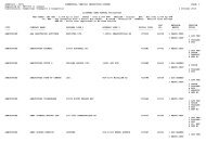
FILE NAMING (AutoCAD)<br />
Files are identified using Branch Identifier (G), Region # (1 - 6 or H<br />
<strong>for</strong> Headquarters or 0 <strong>for</strong> Operations), Technician or Firm desPparion<br />
(K), Five character Negative, Drawing number or other five character<br />
designation.<br />
eg. GHK92689<br />
5 or 6 Character Negative or Drawing<br />
Number<br />
Technician or Firm designation (optional)<br />
Highway Region # (I - 6 or H or 0)<br />
G <strong>for</strong> Branch designation<br />
- 2 - 5.25" Floppy Disks (preferably Dysan 1.2H).<br />
- One A1 size drawing per disk <strong>and</strong> related blocks<br />
- Enter disk <strong>and</strong> file name in project job listing (<strong>Geotechnical</strong> Branch)<br />
DISK LAREL<br />
DISK =EL - First line of disk label to be<br />
FILE NAME assigned by Geatechnical Branch<br />
PROJECT NAME<br />
llIGHWAY OR ROAD NAME<br />
FIRM NAME OR CONSULTANT
APPENDIX E<br />
Rack Core Log
APPENDIX E - ROCK CORE LOG<br />
Rock Core hgs are required when bedrock structure is<br />
pertinent to foundatfon design. Currently, Ministry Rock Core Logs<br />
are prepared manually using the following <strong>for</strong>mat <strong>and</strong> examples. In<br />
unusual ciscumstanc~s sther <strong>for</strong>mats may be used with permission of<br />
the Ministry <strong>Geotechnical</strong> Project Engineer.<br />
The Mlnistry computerized Rock Core Log has been scheduled<br />
to be included in our system in the spring of 1991.
Ministry of Transportation ROCK CORE LOG Geottchnical <strong>and</strong><br />
<strong>and</strong> Highways <strong>Materials</strong> Branch<br />
Hole No.<br />
Project - . . -<br />
Location - Elevation I<br />
Driller Method Dates -. - . -- I<br />
CORERECOVERY R.Q.D.<br />
Length of core 00 Sum core lengths>100 mm<br />
ROCK STRENGTH (MPa)<br />
ROEdremelywesk 250<br />
MW Moderately<br />
HW Highly<br />
CW Completely<br />
US Reatdual Soil<br />
File NO.<br />
Drawn By:<br />
Sheet - of -<br />
H 482 HB-793
Hinfstry of Transportation <strong>and</strong> Highways<br />
Ceotechnieal <strong>and</strong> Haterfals Branch<br />
Vlctaria, British Columbia<br />
ROCK CORE LOG<br />
D. R. Lister, P. Eng.<br />
<strong>Geotechnical</strong> Engineer<br />
October 1987
lNTRODUCTION<br />
The Dimond Drilling Lug of Test Boring <strong>for</strong>m H482 that has been used<br />
<strong>for</strong> rock cores is obsolete. For some t ime a new log has been considered.<br />
The new <strong>for</strong>m is similar in many respects to the Test Hole Log Hl81.<br />
In producing this new <strong>for</strong>m, I have drawn extensively on the references<br />
Listed at the end aE the report <strong>and</strong> have used the preliminary work of<br />
E . Hayden <strong>and</strong> V . Eisbrenner . Lngs from various geatechnlcal consul tanrs<br />
have also been reviewed. The top of the log is like the tap of the Test<br />
Hole Log but blank spaces <strong>for</strong> hole orientation (inclination <strong>and</strong><br />
dksection), name of person logging the Cora <strong>and</strong> date of logging, have<br />
been added. The log itself consists of 11 columns; the purpose of each<br />
is described below. The bottom of the log contains a brief explanation<br />
of some of the column headings.<br />
LBc DESCRTPTION<br />
DRILLING DETAIfS - This column records in<strong>for</strong>mation associated wfth<br />
the actual drilling of the hole. The type of drill, core<br />
barrel <strong>and</strong> bit are nosed along with the length of casing <strong>and</strong><br />
type of drilling fluid. The water table <strong>and</strong> location of<br />
piczometers, if installed, are also noted.<br />
DEP"SN - Depth in metres along the hole from the collar. Conversion<br />
from drillers imperial units used by the driller may be<br />
necessary. Normal practfce is to use one divisian on the log<br />
per metre.<br />
I.,
CORE RECOVERY - During the drklling process, the bit cuttings are<br />
removed by the drilling fluid <strong>and</strong> the core sample passes into<br />
the core barrel. Some of the core sample may be lost by<br />
erosion of soft or friable material resulting in a reduction in<br />
diameter <strong>and</strong>/or length of core. The material placed in the<br />
core box from each core run is the recovered core. If none of<br />
the sample is Lost by erosion then the core recovery is 100%.<br />
Core recovery is measured by length <strong>and</strong> expressed as a<br />
percentage of the core run length.<br />
CORE CONDITION - The state of the core recovered can be described<br />
as solid, braken, very broken, shattered, or rounded pieces.<br />
In some cases, poor quality Cora may be the result of the<br />
. .<br />
drilling method but usually reflects the state of the rock mass.<br />
DISCONTIWI'SY SPACING - This is another quantitative description of<br />
the natural break in the rock mass. It is count of the number<br />
of natural di~continuities per mdt length.<br />
Discontinuity Spacing - No. of discontirmitics/metre<br />
A classkfication of rock vtth regard to discontfnulty spacing<br />
has been devsloped 3,
Svacinm Classfdtiation<br />
Extremely close<br />
Very elose<br />
Close<br />
Mcderately close<br />
Wide<br />
Very vide<br />
Extremely wide<br />
S ~ s e Width b la1<br />
< 0.02<br />
0.02 - 0.06<br />
0.06 - 0.20<br />
0-2 - 0.6<br />
0.6 - 2.0<br />
2 - 6.0<br />
> 6.0<br />
ROCK QUALIn DESIGNATION - The Rock Qualf ey ~eslgnation~ (FtQD) is<br />
an indirect measure of the number of fractures <strong>and</strong> the amount of<br />
softening or alteration in a rock mass. It is obtained from the<br />
rock cores by summing up the length of core recovered, covntfng<br />
only those pfeces 05 sound core that are 1 0 b or more in<br />
I. '<br />
length. The RQD value is expressed as a percentage <strong>and</strong> is the<br />
ratio of the,summed core lengths to the total core length (core<br />
sun). The classiffcation according to the RQD-value is given<br />
below.<br />
ROD Classifi-atioq<br />
Very poor quality<br />
Poor q ulf ty<br />
Fair quality<br />
Good quality<br />
Excellent quality
If the core is broken by h<strong>and</strong>ling or during drilling (i.e. the<br />
fracture surfaces ere fresh irregular breaks rather than natural joint<br />
surfaces); the fresh broken pieces should be fitted together <strong>and</strong> counted<br />
as one piece. Some judgement is necessary in the case of thinly bedded<br />
sedimentary rocks <strong>and</strong> foliated metamorphic rocks, <strong>and</strong> the method is not<br />
so precise in these eases as it is <strong>for</strong> igneous rocks, thick-bedded<br />
limestones, s<strong>and</strong>stones, etc. However, the system has been applied<br />
successfully even <strong>for</strong> shales, although it 1s necessary t o log the cores<br />
immediately upon removing them from the core barrel, be<strong>for</strong>e air-slaking<br />
<strong>and</strong> cracking can begfn.<br />
The procedure obviously penalizes rock masses where core recovery Ps<br />
poor. Th5.s is appropriate because poor core recovery usually reflects<br />
poor quality rock. Paar drilling equipment <strong>and</strong> techniques can also<br />
cause poor recovery. Fox this reason, double-tube core barrels of at<br />
least NX size (54 mm in diameter) must be used, snd proper supemision<br />
of drilling is imperative.<br />
As simple as the procedure appears, it has been found that, as an<br />
indicator of general quality of rock <strong>for</strong> engtntering purposes, the<br />
RQD-value I s more sensittve <strong>and</strong> consistent than grass percentage core<br />
recovery.
INTACT ROCK STRENGTH - Although rack masses are non-isotropic <strong>and</strong> the<br />
main feature of their weakness 1s the strength along<br />
discontinuities, it is oftcn useful to have some in<strong>for</strong>mation<br />
about tha uniaxial cc~pressive strength of the intact rock.<br />
The tabla below gives seven grades of rock strength <strong>and</strong> simple<br />
methods of identification. These grades have been based on<br />
results of unconfined compressive stkength tests <strong>for</strong> which<br />
st<strong>and</strong>ard methods have been ruggcsted3,<br />
Strength Fleld Rgnge of unconfined<br />
Grsds Classification Identification Compressive strength<br />
Hethad INf a3<br />
RO Extremely vesk Idtnted by thumbnail < 1<br />
R1 Very weak Crumbles under firm 1 - 5<br />
blows of gtologfcal .<br />
hzmtr; can b6 petlcd<br />
with a pocket knifa<br />
R2 Weak rock Can ba peeled by a pocket<br />
knife vith difficuity;<br />
shallov indentations mads<br />
by a fim blow with point<br />
of gcalogical hammer<br />
R3 Hedim strong Cannot be scraped or<br />
peeled vlth a pocket hife;<br />
spechen can be fractured<br />
vith a single firm blow<br />
. of geological hamer.<br />
R4 Strong Specimen requires more SO - 100<br />
than one blow of geolog-<br />
ical h-er to fracture<br />
R5 Very strong Spechen requires many 100 - 250<br />
blows of geological h-er<br />
to fracture:<br />
R6 Extremely strong Specben can only be<br />
chipped by a geological<br />
hammer
WEATHERING - These ore two main results of weathering: mechanical<br />
disintegration <strong>and</strong> chemical decampos ition2 - Generally, both<br />
effects act together but, depending on the climate. one may ba<br />
dominant. Chemical alteration alshoufi not a <strong>for</strong>m of weathering<br />
may also be considered hare. Mechanical veatherfng results in<br />
the opening of discontinuities. the <strong>for</strong>ming of new fractures,<br />
the opening of grain boundaries <strong>and</strong> the fracture of mineral<br />
grains. Chemical weathering results En discolouration of rock<br />
<strong>and</strong> leads to the eventual decomposition of silicate minerals to<br />
clay minerals, The state of weathering can be described<br />
according to the following table.<br />
BIZ pescrivtlon Grade<br />
Fresh Po visible sign o f rock material<br />
weathering: perhaps slight dis-<br />
colouration on major discontfnuity<br />
surfaces.<br />
Slightly Discolouration indicates weathering If<br />
weathered of rock material <strong>and</strong> discontinuity<br />
surfaces. All the rock material may<br />
be discoloured by weathering <strong>and</strong> may be<br />
somewhat weaker externally than in its<br />
fresh condition.<br />
Moderately<br />
weathered<br />
Highly<br />
weathered<br />
Completely<br />
weathered<br />
Residual<br />
soil<br />
Zess than half of the rock oxaterial is If1<br />
decomposed <strong>and</strong>/or dksintegreted to a soil.<br />
Fresh or discoloured rack is present either<br />
as a e~ntknu~us framework or as carestones.<br />
Hore than half of the rock material<br />
is decomposed <strong>and</strong>/or diskntegrated to<br />
a soil. Fresh or discoloured rock is<br />
present either as a continuous frame-<br />
work or as corestones.<br />
All rock material is deeomposcd<br />
<strong>and</strong><strong>for</strong> dia tntegrated to a soil.<br />
The original mass structure is still<br />
largely intact. All rock material is<br />
converted t o sofl. The miss structure<br />
<strong>and</strong> material fabric are destroyed. There<br />
is a large change in volume, but the soil<br />
has not been significantly transported.
STRUCTURAL DLSCONTINUXTY DESCRIPTION - A discontinuity is a general<br />
term <strong>for</strong> any mechanical discontinuity in a rack mars having zero<br />
or low tensile strength. It is the collective term <strong>for</strong> moss<br />
types of joints, bedding planes, schfstosity planes, shear<br />
zones, cleavage <strong>and</strong> faults .<br />
Discontinuities can be described according to the following<br />
parameters:<br />
Orientation - dip from long axis of the core<br />
Form - overall shape of the discontinuity which may be<br />
planar, undulating, stepped or ixregular. This<br />
parameter may be dtfficult to determine from a piece<br />
of core.<br />
Roughness - surface roughness of the discontinuity which can be<br />
polished, smooth, rough or slickensided.<br />
Infilling - material that separates the rock walls of the<br />
discontinuity is usually weaker than the intact rock.<br />
Typical infilling materials are clay gouge, breccia,<br />
calcite <strong>and</strong> quartz<br />
A graphic structural log can be produced as part of the<br />
structural description. Appropriate abbreviations <strong>and</strong> symbols<br />
are noted below.<br />
4-.<br />
Roughness - Polished<br />
Smooth<br />
Rough<br />
Slickensided<br />
Inf illing<br />
Form<br />
- Clay Gouge CE<br />
Calcite Ca<br />
Quartz Qz<br />
Rust Stained Rt<br />
Breccia Bs<br />
- Planar<br />
Undulating<br />
Stepped<br />
Irregular<br />
Discontinuity - Fault (zone) fdz)<br />
Joint J<br />
Shear (zone) s(z)<br />
. Bedding B<br />
Cleavage C<br />
Ye In Y
ROCK S WOL - A symbolic log showing rock type C can be prepared.<br />
Suggested symbols ere listed below Suitable<br />
tetraset shading numbers are fncludeh.<br />
Limestone LT 243<br />
S<strong>and</strong>s tone LT 912<br />
Greywaeke LT 164<br />
Siltstone LT 153<br />
Shale LT 122<br />
Breccia LT 970<br />
Pyroclastic LT 356<br />
Coarse Grained Igneous LT 959<br />
Medium Grained Igneous LT 131
Fine Grained lgneous<br />
Coarse Grained Metamorphic LT 95<br />
Hedium Grained He tamorphic LT 368<br />
Fine Grained Metamorphic LT 189<br />
... 111..*,. ..... 11.1.1<br />
.* ,,....,*<br />
.** I,., 1 1<br />
ROCK HASS DESCRIPTION - This column is far a general descfption of<br />
thi rock mass. The intact rock should be described according to its<br />
colour, grain size, fabxic, texture <strong>and</strong> rock type, Grain size<br />
refers to the average dimension of the mineral or rock fragments.<br />
For sedimentary rocks the size ranges used <strong>for</strong> sofla are<br />
appropriafe. Coarse graEned igneous <strong>and</strong> metamorphic rocks have a<br />
grain, slze greater than 2 mm <strong>and</strong> fine grained igneous <strong>and</strong><br />
metamorphic rocks have grain sizes less than .O6 m.<br />
The texture of a rock Is its general physical appearance including<br />
the geometric aspects of the component particles or crystals. t.g.<br />
sLze, shape <strong>and</strong> arrangement of the sedimentary particles or the<br />
crystalliniv or granularity of an igneous rock. Fabrfc refers<br />
specifically to the arrangement of the grains, In sedimentary rocks,<br />
ft is the orientation of discrete particles arid in crystallina rocks<br />
<strong>for</strong> the pattern produced by the shapes <strong>and</strong> orientation of the
crystalline <strong>and</strong> non-crystalline parts. The fabric of sedimentary<br />
rocks 1s often related to the mode of deposition <strong>and</strong> hence bedding.<br />
Bedding fs usually considered as a stmcture <strong>and</strong> should ba described<br />
in tha structural log, although a general statement about the layer<br />
thickness is appropriate in the rock mass description. Typical<br />
textural terms include porphyritic, crystalline, granular, amorphous<br />
<strong>and</strong> glassy. The principal rock name should ba in capital letters<br />
e.g. calcareous SANDSTONE. This colrcmn can also be used <strong>for</strong><br />
additional structural dcscriptlon or to ra -emphas iza the degree of<br />
weathering.<br />
TESTS - Results af either fnsim or laboratory testa can be<br />
recorded in this column.<br />
OTHFX INF'ORHATION - Jn addition to the log itself, it is preferable to<br />
&e photographs of the core. Two or three<br />
photographs (1000 x 1500 mm) along the core box<br />
joined together 5n a strip produces a suitable<br />
size picture.<br />
British St<strong>and</strong>ards Institution, Code of Practice <strong>for</strong> Site<br />
Investigations BS 5930:1981.<br />
Brown, E. T. Rock Characterization, Testing <strong>and</strong> knitaring ,<br />
International Society <strong>for</strong> Rock Mechanics, 1981.<br />
3 Canadian <strong>Geotechnical</strong> Socicrty . Canadf gn Foundation <strong>Engineering</strong><br />
Manual, 2nd Edit ion, 1985.<br />
Gcolagieal Society <strong>Engineering</strong> Group Warkin6 Parv. The bgging of<br />
Rock Cores <strong>for</strong> <strong>Engineering</strong> Arrposes. Quarterly Journal of<br />
<strong>Engineering</strong> Geology, Vo1.3 No 1, 1970.
SVCHLY YlUGEOE<br />
MIN m snm GES<br />
Pmgth of<br />
Sum rn kngthr > lOhm<br />
IM1<br />
corn run<br />
x 100 R1 Very wwk 1-5 SW Shghtly<br />
/en@ of tort run<br />
R2 Il'eak 5-25 KW Ud~oteIy PREPARED BY:<br />
R3 Uedm shy 25-54 FA' Highly J'P, / wC4a DISCOEmNUIM SPACHG R4 Skong 50-lD2 CW Cornpl&dy<br />
Ho. d fractvm/m R5 Verj stmng 100-250 RS Residual So! SHE0 of<br />
RB Extrerneb stmnp >250 03 03-
APPENDIX F<br />
Cone Holes
APPENDIX F - CONE LOG<br />
Sites requiring investigatzon using cone equipment arc<br />
co-ordinated through our Operations Division, Burnahy. Contact<br />
person is Don Gillespie.<br />
Cone Logs <strong>for</strong> reports <strong>and</strong> contract drawings are required to<br />
be prepared at a scale of 1:100.<br />
See the following examples <strong>and</strong> in<strong>for</strong>mation.
flFnlstry nf Transpartatton CONE PENETROMETER LOG Geotaehn l eal <strong>and</strong><br />
<strong>and</strong> HIghvsys Hatar f a1 s Branch<br />
Project RICHMOND E-W FREEWAY Ft le No<br />
Location STA. 103+98, 0.5m RT. Elevation 1.550<br />
Eng 1 nee r F MRXIMCHUK Date FEB 13 1905-<br />
(SCALE 1:100)<br />
PORE PRESSURE<br />
HOLE NO<br />
85-01
Hin!stry of Transportmtlon CONE PENETROMETER LOG Caotsehnlzal <strong>and</strong><br />
<strong>and</strong> Highways Hatsrl el t Branch<br />
Prajtct RICHMOND E-W FREEWAY File No<br />
STA. 103+98, 0.5%- RT.<br />
Loeat I on EIevat {on 1.550<br />
Eng i nee, F MRXIMCHUK Date FEB 13 1905<br />
TIP RESISTRNCE W a<br />
C SCALE 1:100)<br />
PORE PRESSURE HPn<br />
HOLE NO<br />
85-01
Ulnlstry af Transportation CONE PENETROMETER LOG Caotechn i eal <strong>and</strong><br />
<strong>and</strong> Hfghways Matarl als Brnneh<br />
Pra ject RICHMOND E-W FREEWAY - File No<br />
Loc at ion STA. 103-8, 0.5m RT. Elevation 1.550<br />
Engineer F MRXIMCHUK Date FEB 13 1905<br />
TIP RESISTRNCE MPa<br />
B 5 10 15 2B 25 30<br />
FRICTION RATIO f<br />
HOLE NO<br />
85-0 f<br />
(SCALE 1:100)<br />
PORE PRESSURE HPa
Q<br />
Province of Ministry of<br />
Tansportation<br />
4 - British Columbia <strong>and</strong> Highwrys<br />
-8L<br />
Kirby Rimer<br />
<strong>Geotechnical</strong> <strong>Engineering</strong> Technician<br />
VICTORIA<br />
RE: CFT Output<br />
MEMORANDUM<br />
December 7, 1990<br />
3149 Production Way<br />
Burnaby, B.C.<br />
V5A 3H1<br />
Our CPT outputs are still in the proeeae of being upgraded to a PC<br />
environment but our present output includes:<br />
1. Field Plots: See example #1.<br />
Theee plots have no flexibility in scale.<br />
2. HP Plots: See example #2.<br />
These plots are hard copy only on 81/2" x 11" paperlmylar. They<br />
can be 1, 2 or 3 boxes <strong>and</strong> have stepwise variable depth <strong>and</strong><br />
pressure scales.<br />
3. ASCII files:<br />
PC <strong>for</strong>mat field depth <strong>and</strong> pressure readings.<br />
4. Listing: See example #3.<br />
These are field lFstFngs <strong>and</strong> also include pore pressure data w ith<br />
t ime .<br />
5. Pore Pressure - Time Data.<br />
Field listings or interpreted data are available.<br />
Our future developments include:<br />
1. PC/HP plots: See example #4.<br />
These plots have flexible depth scale, pressure scales, <strong>for</strong>mat (#<br />
boxes) ~sientation on 81/2 x 11" paper <strong>and</strong> if requested<br />
interpretat ion.<br />
<strong>for</strong>:<br />
Don Gilleapie<br />
GeotechnFcaE Engineer<br />
Manager, <strong>Geotechnical</strong> Operations
EXAMPLE #I
Htnfstry of Transportation<br />
CONE PENETROMETER LOG<br />
Gaotechni cal Operations<br />
<strong>and</strong> Highways In-Si tu Testing<br />
Project File No<br />
EXAMPLE #2<br />
TIP RESISTRNCE MPa FRICTION RESfSfANCE kPa FRICTION RRTIO %<br />
HOLE NO<br />
Cocat i on Eltvat ion<br />
Engineer GILLESPIE Date -.-<br />
12/01/90 11:35
UNOING DRTR IN FILE 5 12/08/90 12:45<br />
. -<br />
GfNEER : GILLESPIE LOCRTJUN : WEDDER TZf<br />
NE ID : NSlBB STD JOB # : R<br />
nlstry of Trans~ortakio~~ <strong>and</strong> diqhways<br />
~tcchr~ical <strong>and</strong> Mate*-1 als Er-anch<br />
TI? ES!STPE<br />
(W/a*21<br />
-8.2<br />
2.<br />
3.9<br />
1.19<br />
8.46<br />
0.63<br />
El. 20<br />
E, 19<br />
d. 75<br />
Be64<br />
8.57<br />
0.75<br />
6 87<br />
0.55<br />
e* 47<br />
0.23<br />
0.44<br />
8.39<br />
A 43<br />
!a, 57<br />
0.3<br />
0.14<br />
P. i?9<br />
8.64<br />
8. BB<br />
8.81<br />
8*84<br />
0. e5<br />
0. @a<br />
Bell<br />
8.83<br />
8.6<br />
B. e5<br />
la. 07<br />
B. M<br />
B. ll<br />
B. J1<br />
e. ie<br />
e. ed<br />
0. &<br />
EXAMPLE #3
MINISTRY OF TRANSPORTATION AND HIGHWAYS<br />
Sita tocationr LANGLEY RAIL CPT Data n 06/10/86 Page Not 1 / 1<br />
On Site LOCI vacuum eatur. Cone Usadt IYB STQ POREPRESS Comrnantml:<br />
PORE PRESSURE<br />
U (m. of water)<br />
SLEEVE FRICTION<br />
(tam-1<br />
MNE BEARING<br />
Oc [b)<br />
FRICTION RATIO<br />
Rf I%)<br />
Depth Increment r .025 m MOX Depth r 18.9 m<br />
EXAMPLE #4
APPENDIX G<br />
Becker Hammer
APPENDIX G - BECKER HAMMER<br />
Becker Hammers are not normally used by the Hinistry.<br />
However, their use may be approved <strong>for</strong> particular sites. The<br />
following log is an example only. (Courtesy of Colder Assoc.)
I<br />
I<br />
RECORD OF BO<br />
Iscation {See figure Z 1<br />
Bore hare r y ~<br />
e $~[ker X~n?m&r//,!? ~$4<br />
Sampler Honmcs Wi. . .. ;kg., Drop . ..m.<br />
€LEV.<br />
DEPTH<br />
metres1<br />
DEscRrPTtr3N<br />
. .<br />
a g m<br />
" Z<br />
2-1<br />
U)