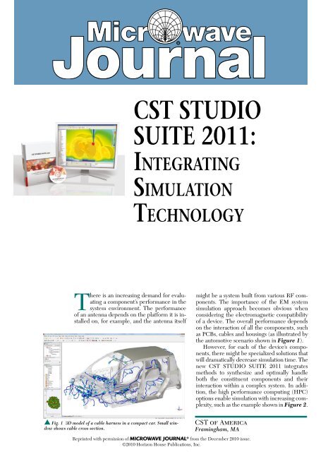
CST STUDIO SUITE 2011: Integrating Simulation Technology
CST STUDIO SUITE 2011: Integrating Simulation Technology
CST STUDIO SUITE 2011: Integrating Simulation Technology

You also want an ePaper? Increase the reach of your titles
YUMPU automatically turns print PDFs into web optimized ePapers that Google loves.
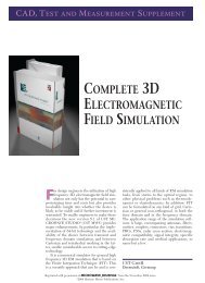
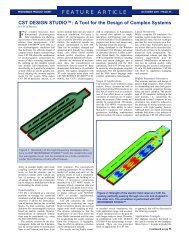
There is an increasing demand for evaluating<br />
a component’s performance in the<br />
system environment. The performance<br />
of an antenna depends on the platform it is installed<br />
on, for example, and the antenna itself<br />
s Fig. 1 3D model of a cable harness in a compact car. Small window<br />
shows cable cross section.<br />
<strong>CST</strong> <strong>STUDIO</strong><br />
<strong>SUITE</strong> <strong>2011</strong>:<br />
InTEgraTIng<br />
SImUlaTIOn<br />
TEChnOlOgy<br />
might be a system built from various RF components.<br />
The importance of the EM system<br />
simulation approach becomes obvious when<br />
considering the electromagnetic compatibility<br />
of a device. The overall performance depends<br />
on the interaction of all the components, such<br />
as PCBs, cables and housings (as illustrated by<br />
the automotive scenario shown in Figure 1).<br />
However, for each of the device’s components,<br />
there might be specialized solutions that<br />
will dramatically decrease simulation time. The<br />
new <strong>CST</strong> <strong>STUDIO</strong> <strong>SUITE</strong> <strong>2011</strong> integrates<br />
methods to synthesize and optimally handle<br />
both the constituent components and their<br />
interaction within a complex system. In addition,<br />
the high performance computing (HPC)<br />
options enable simulation with increasing complexity,<br />
such as the example shown in Figure 2.<br />
<strong>CST</strong> of America<br />
Framingham, MA<br />
Reprinted with permission of MICROWAVE JOURNAL ® from the December 2010 issue.<br />
©2010 Horizon House Publications, Inc.
FREqUENCy DOMAIN sOLVER WIth CURVED<br />
ELEMENts<br />
With version <strong>2011</strong>, the <strong>CST</strong> MICROWAVE<br />
<strong>STUDIO</strong> (<strong>CST</strong> MWS) frequency domain solver will feature<br />
curved tetrahedral mesh elements of high geometrical<br />
orders. In comparison to using simpler curvilinear<br />
elements (first order curved elements), which often suffer<br />
from the creation of inaccuracies in the mesh representation,<br />
higher order curved elements deliver a much<br />
smoother representation of arbitrary surfaces.<br />
As with all mesh adaptation schemes, simulations will<br />
only converge to the correct results if mechanisms such<br />
as True Geometry Adaptation are used. These actually<br />
improve the representation of the input model continuously,<br />
rather than simply refining the first discretization of<br />
the model. The higher order curved elements will also be<br />
available for the <strong>CST</strong> MWS eigenmode solver and the fast<br />
resonant solver.<br />
ELECtRICALLy LARgE stRUCtUREs<br />
HPC can greatly benefit the simulation of very complex<br />
structures, like the one shown in Figure 2, but switching<br />
from standard volume methods such as FIT or FEM to<br />
surface-based integral equation or ray tracing methods is<br />
often the more efficient approach for electrically very large<br />
structures. <strong>CST</strong> MWS features an integral equation solver<br />
using the multilevel fast multipole method (MLFMM)<br />
for structure sizes of up to about 1,000 wavelengths and<br />
an asymptotic solver based on the shooting bouncing ray<br />
method for even larger structures.<br />
Both solvers can now use farfields as excitation sources.<br />
These farfields can be computed by other <strong>CST</strong> MWS<br />
solvers including the transient or frequency domain solvers.<br />
This makes the calculation of an installed antenna’s<br />
farfield possible, even for an electrically very large structure,<br />
such as the ship shown in Figure 3. <strong>CST</strong> MWS<br />
<strong>2011</strong> also allows the importing of more than one farfield<br />
source, thus enabling the computation of the coupling<br />
between several antennas, or of the combined farfield of<br />
multiple antennas.<br />
For radar scattering simulations, the structure can be simultaneously<br />
illuminated by multiple sources, the properties<br />
of which can be set by means of an excitation list. This<br />
enables the simulation of arbitrarily polarized incident<br />
waves from different directions. The asymptotic solver<br />
benefits from the inclusion of surface impedance models<br />
for the simulation of coatings or seawater.<br />
sENsItIVIty AND yIELD ANALysIs<br />
<strong>CST</strong> MWS transient solver provides efficient computation<br />
of broadband S-parameters and field results in one<br />
single simulation run. In version <strong>2011</strong>, sensitivity analysis<br />
can evaluate the S-parameter dependencies on various<br />
model parameters on the basis of this single broadband<br />
simulation. Further evaluations for different model parameter<br />
sets can be derived without restarting the full-wave<br />
simulation. Hence, yield analysis for complex three dimensional<br />
(3D) models is available at virtually no additional<br />
computational cost.<br />
OptIMIzAtION<br />
The newly implemented trust region framework uses<br />
Product Feature<br />
s Fig. 2 Computation on a GPU cluster dramatically reduces simulation<br />
time for this crosstalk analysis.<br />
s Fig. 3 Bistatic RCS of a destroyer at 16.8 GHz.<br />
parametric models to find optimal solutions for the given<br />
goals, without rerunning expensive 3D simulations. By<br />
employing the sensitivity information provided by both<br />
of the general purpose electromagnetic solvers of <strong>CST</strong><br />
MWS—time and frequency domain—the number of 3D<br />
simulations and, therefore, the optimization time can be<br />
cut down dramatically.<br />
MULtIphysICs<br />
<strong>CST</strong> MPHYSICS <strong>STUDIO</strong> computes thermal and mechanical<br />
effects. While not fully integrated in the design<br />
environment, in version <strong>2011</strong> the temperature calculated<br />
from the electromagnetic losses can be used to change<br />
the material parameters for a consecutive electromagnetic<br />
field simulation. <strong>CST</strong> MPHYSICS <strong>STUDIO</strong> now also features<br />
a thermal solver on a tetrahedral grid.<br />
EMC/EMI<br />
<strong>CST</strong> <strong>STUDIO</strong> <strong>SUITE</strong> <strong>2011</strong> improves the integration of<br />
<strong>CST</strong> CABLE <strong>STUDIO</strong> and the <strong>CST</strong> MWS TLM solver<br />
(formerly <strong>CST</strong> MICROSTRIPES) into the <strong>CST</strong> design
environment. Users interested in the analysis of radiated<br />
emissions and susceptibility will benefit from a single unified<br />
environment for all EMC related modeling tasks, including<br />
greatly simplified model set up and simulation.<br />
In pre-processing, the definition of compact equivalent<br />
aperture models and cable harnesses can be performed in<br />
<strong>CST</strong>’s familiar design environment. Coupling between the<br />
full 3D electromagnetic field and cable solvers enables direct<br />
transient simulation of susceptibility problems in systems<br />
containing complex cable bundles, including shielded<br />
twisted pairs (see Figure 2).<br />
sIgNAL AND pOWER INtEgRIty<br />
For high accuracy and to address layouts with non-planar<br />
elements such as wirebonds, a full 3D simulation is<br />
often necessary. <strong>CST</strong> offers import filters to layout tools of<br />
leading EDA vendors, such as Cadence®, Mentor Graphics®<br />
or Zuken. All these links open the layout in the EM<br />
design environment before setting up and running simulations.<br />
Product Feature<br />
In a major collaborative project, a link has been created<br />
that allows Cadence layout engineers to stay within their<br />
familiar environment while performing a full wave 3D extraction<br />
and EM analysis in the background. Results are<br />
back annotated to the Cadence environment, thus simplifying<br />
the engineering workflow.<br />
<strong>CST</strong> <strong>STUDIO</strong> <strong>SUITE</strong> version <strong>2011</strong> is addressing the<br />
challenges of modern electromagnetic system design by<br />
tightly integrating the latest in simulation technology within<br />
an intuitive user interface. Streamlined workflows are<br />
enabling real world problems to be tackled and solved in<br />
a virtual environment, ultimately leading to an accelerated<br />
and more cost-effective design cycle.<br />
Cst of America,<br />
Framingham, MA<br />
(508) 665-4400,<br />
e-mail: info@cst.com,<br />
www.cst.com.<br />
RS No. 300
For more information or to request a trial license,<br />
please contact your local area representative.<br />
<strong>CST</strong> AG – European Headquarters<br />
Bad Nauheimer Str. 19<br />
64289 Darmstadt<br />
Germany<br />
<strong>CST</strong> of America®, Inc. – US Headquarters<br />
492 Old Connecticut Path, Suite 505<br />
Framingham, MA 01701<br />
United States<br />
info@cst.com<br />
http://www.cst.com