LED IMPORTANT SAFETY INSTRUCTIONS - Acuity Brands
LED IMPORTANT SAFETY INSTRUCTIONS - Acuity Brands
LED IMPORTANT SAFETY INSTRUCTIONS - Acuity Brands

Create successful ePaper yourself
Turn your PDF publications into a flip-book with our unique Google optimized e-Paper software.
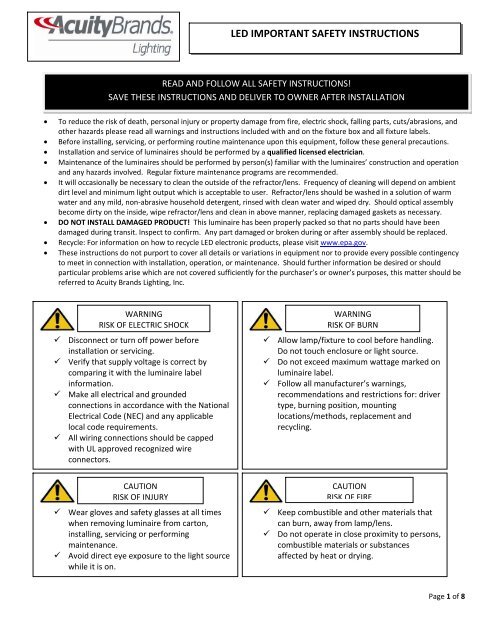
<strong>LED</strong> <strong>IMPORTANT</strong> <strong>SAFETY</strong> <strong>INSTRUCTIONS</strong><br />
READ AND FOLLOW ALL <strong>SAFETY</strong> <strong>INSTRUCTIONS</strong>!<br />
SAVE THESE <strong>INSTRUCTIONS</strong> AND DELIVER TO OWNER AFTER INSTALLATION<br />
• To reduce the risk of death, personal injury or property damage from fire, electric shock, falling parts, cuts/abrasions, and<br />
other hazards please read all warnings and instructions included with and on the fixture box and all fixture labels.<br />
• Before installing, servicing, or performing routine maintenance upon this equipment, follow these general precautions.<br />
• Installation and service of luminaires should be performed by a qualified licensed electrician.<br />
• Maintenance of the luminaires should be performed by person(s) familiar with the luminaires’ construction and operation<br />
and any hazards involved. Regular fixture maintenance programs are recommended.<br />
• It will occasionally be necessary to clean the outside of the refractor/lens. Frequency of cleaning will depend on ambient<br />
dirt level and minimum light output which is acceptable to user. Refractor/lens should be washed in a solution of warm<br />
water and any mild, non‐abrasive household detergent, rinsed with clean water and wiped dry. Should optical assembly<br />
become dirty on the inside, wipe refractor/lens and clean in above manner, replacing damaged gaskets as necessary.<br />
• DO NOT INSTALL DAMAGED PRODUCT! This luminaire has been properly packed so that no parts should have been<br />
damaged during transit. Inspect to confirm. Any part damaged or broken during or after assembly should be replaced.<br />
• Recycle: For information on how to recycle <strong>LED</strong> electronic products, please visit www.epa.gov.<br />
• These instructions do not purport to cover all details or variations in equipment nor to provide every possible contingency<br />
to meet in connection with installation, operation, or maintenance. Should further information be desired or should<br />
particular problems arise which are not covered sufficiently for the purchaser’s or owner’s purposes, this matter should be<br />
referred to <strong>Acuity</strong> <strong>Brands</strong> Lighting, Inc.<br />
WARNING<br />
RISK OF ELECTRIC SHOCK<br />
Disconnect or turn off power before<br />
installation or servicing.<br />
Verify that supply voltage is correct by<br />
comparing it with the luminaire label<br />
information.<br />
Make all electrical and grounded<br />
connections in accordance with the National<br />
Electrical Code (NEC) and any applicable<br />
local code requirements.<br />
All wiring connections should be capped<br />
with UL approved recognized wire<br />
connectors.<br />
CAUTION<br />
RISK OF INJURY<br />
Wear gloves and safety glasses at all times<br />
when removing luminaire from carton,<br />
installing, servicing or performing<br />
maintenance.<br />
Avoid direct eye exposure to the light source<br />
while it is on.<br />
WARNING<br />
RISK OF BURN<br />
Allow lamp/fixture to cool before handling.<br />
Do not touch enclosure or light source.<br />
Do not exceed maximum wattage marked on<br />
luminaire label.<br />
Follow all manufacturer’s warnings,<br />
recommendations and restrictions for: driver<br />
type, burning position, mounting<br />
locations/methods, replacement and<br />
recycling.<br />
CAUTION<br />
RISK OF FIRE<br />
Keep combustible and other materials that<br />
can burn, away from lamp/lens.<br />
Do not operate in close proximity to persons,<br />
combustible materials or substances<br />
affected by heat or drying.<br />
Page 1 of 8
CAUTION: RISK OF PRODUCT DAMAGE<br />
<strong>LED</strong> <strong>IMPORTANT</strong> <strong>SAFETY</strong> <strong>INSTRUCTIONS</strong><br />
Never connect components under load.<br />
Do not mount or support these fixtures in a manner that can cut the outer jacket or damage wire<br />
insulation.<br />
Never connect an <strong>LED</strong> product directly to a dimmer pack. <strong>LED</strong> fixtures must be powered directly off a<br />
switched circuit.<br />
Unless individual product specifications deem otherwise: Allow for some volume of airspace around<br />
fixture. Avoid covering <strong>LED</strong> fixtures with insulation, foam, or other material that will prevent convection<br />
or conduction cooling.<br />
Unless individual product specifications deem otherwise: Maximum ambient temperature is 90°C. Do<br />
not operate fixture at temperatures higher than this.<br />
Unless individual product specifications deem otherwise: Never mount in places where fixture will be<br />
exposed to rain, high humidity, extreme temperature changes or restricted ventilation.<br />
<strong>LED</strong> products are Polarity Sensitive. Ensure proper Polarity before installation.<br />
Electrostatic Discharge (ESD): ESD can damage <strong>LED</strong> fixtures. Personal grounding equipment must be<br />
worn during all installation or servicing of the unit.<br />
Do not touch individual electrical components as this can cause ESD, shorten lamp life, or alter<br />
performance.<br />
There are no user serviceable parts inside the unit. Do not rewire, reconfigure, or modify the unit or<br />
attempt any repairs yourself. Additionally, field replacement of the <strong>LED</strong> assembly or lamps is not<br />
allowed by UL standards at this time. In the unlikely event your unit may require service, stop using the<br />
unit immediately and contact an ABL representative.<br />
All luminaires that contain electronic devices that generate frequencies above 9kHz from any component within the luminaire<br />
comply with one of the following Part 15 of the FCC Rules. Operation is subject to the following two conditions:<br />
(1) This device may not cause harmful interference<br />
(2) This device must accept any interference received, including interference that may cause undesired operation.<br />
This device complies with Part 18 of the FCC Rules but may cause interference with cordless and cell phones, radios, televisions, and<br />
other electronic devices. To correct the problem move the device away from the luminaire or plug into a different outlet.<br />
This product may cause interference to radio equipment and should not be installed near maritime safety communications<br />
equipment or other critical navigation or communications equipment operating between 0.45‐30MHz.<br />
Failure to follow any of these instructions could void product warranties. For a complete listing of product Terms and<br />
Conditions, please visit www.acuitybrands.com.<br />
Our <strong>Brands</strong> Indoor/Outdoor Indoor Lighting Outdoor Lighting Controls<br />
Lithonia Lighting Gotham American Electric Lighting DARK TO LIGHT<br />
Carandini Mark Architectural Lighting Antique Street Lamps Lighting Control & Design<br />
Holophane Peerless Hydrel ROAM<br />
RELOC Renaissance Lighting Tersen Sensor Switch<br />
Winona Lighting Synergy<br />
<strong>Acuity</strong> <strong>Brands</strong> Lighting, Inc. assumes no responsibility for claims arising out of improper or careless installation or handling of its products.<br />
ABL <strong>LED</strong> General Warnings, Form No. 503.203<br />
© 2010 <strong>Acuity</strong> <strong>Brands</strong> Lighting, Inc. All rights reserved. 12/01/10<br />
Page 2 of 8
INSTALLATION <strong>INSTRUCTIONS</strong><br />
6VLR (6” Non‐IC Commercial <strong>LED</strong> Remodel Frame‐In),<br />
REAL6C (6” <strong>LED</strong> Trim Module)<br />
Prior to installing the fixture, disconnect ALL power supplies to the unit. TYPE NON-IC INSTALLATION ONLY: No<br />
insulation may be placed over the top of/or within 3” (76mm) of the fixture.<br />
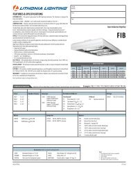
EXISTING CEILING INSTALLATION – 6VLR<br />
1. Remove TSA6 (Torsion Spring Adaptor) from frame by removing (2)<br />
screws. (see Figure 1)<br />
2. As Shown in Figure 2, insert rough-in frame slot first through the ceiling<br />
hole cutout.<br />
3. Attach (4) ARC Clips provided spaced equally around perimeter of<br />
rough-in aperture as shown in Figure 3. Note: Holes around perimeter<br />
of aperture for screws (provided by others) for attaching to ceilings<br />
thicker than ¾”.<br />
4. Reinstall TSA6 onto frame with (2) screws. Note: Opening of TSA6<br />
faces the J-Box. (see Figure 1).<br />
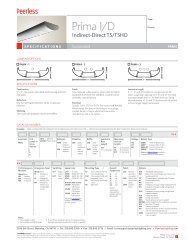
WIRING INSTALLATION<br />
Figure 2<br />
Prior to wiring the fixture, disconnect ALL power supplies to the unit. Make all wiring connections inside the junction box.<br />
This fixture should be wired in accordance with NEC and applicable local codes and ordinances.<br />
1. Remove the snap-on junction box captive door.<br />
2. Pry out the desired knockout with a flat blade screwdriver for hard<br />
wire access.<br />
3. Driver Black wire connects to Line Voltage. Driver White wire<br />
connects to the Neutral wire. The Ground wire connects to the<br />
Bare Copper wire connected to the junction box. Bundle all wire<br />
into junction box. (see Figure 4)<br />
4. If dimming this fixture, connect gray and violet leads from driver to<br />
compatible low voltage switch wires from dimmer. Low voltage<br />
wires (gray and violet) must be run to each fixture that is intended<br />
to be controlled by the dimming switch. Wires supplied by others.<br />
5. Close the snap-on junction box captive door.<br />
Figure 3<br />
Figure 1<br />
Figure 4<br />
Lithonia Downlighting Part No. CJ5201103 Rev. A<br />
One Lithonia Way / Conyers, GA 30012 ©2008 <strong>Acuity</strong> <strong>Brands</strong> Lighting, Inc., 06/11<br />
800‐315‐4935 / www.lithonia.com Page 3 of 8
REALITY <strong>LED</strong> TRIM MODULE INSTALLATION<br />
INSTALLATION <strong>INSTRUCTIONS</strong><br />
6VLR (6” Non‐IC Commercial <strong>LED</strong> Remodel Frame‐In),<br />
REAL6C (6” <strong>LED</strong> Trim Module)<br />
1. Locate the flexible conduit connector with the orange plug and snap the orange plug to the mating connector in the<br />
trim. Push the orange connector inside through the hole of the Reality trim module and snap the flexible conduit<br />
connector into the top of the reality trim.<br />
2. Compress the springs on the side of the Reality trim and insert them into the brackets on the inside of the recessed<br />
housing.<br />
3. Gently press upward until the trim flange is snug against the ceiling.<br />
Lithonia Downlighting Part No. CJ5201103 Rev. A<br />
One Lithonia Way / Conyers, GA 30012 ©2008 <strong>Acuity</strong> <strong>Brands</strong> Lighting, Inc., 06/11<br />
800‐315‐4935 / www.lithonia.com Page 4 of 8
INSTRUCCIONES DE INSTALACIÓN<br />
6VLR (Sistema empotrado de remodelación para <strong>LED</strong> de 6 in de uso comercial<br />
para techos no aislados), REAL6C (Módulo adaptador de <strong>LED</strong> de 6 in)<br />
Antes de instalar el accesorio, desconecte TODAS las fuentes de energía que alimentan la unidad. COLOQUE<br />
ÚNICAMENTE EN TECHOS NO AISLADOS: No se debe colocar aislamiento sobre la parte superior del accesorio<br />
ni dentro de una distancia de 3 in (76 mm) con respecto a este.<br />
INSTALACIÓN AL TECHO EXISTENTE – 6VLR<br />
1. Retire TSA6 (adaptador del resorte de torsión) del marco; para ello, retire los<br />
(2) tornillos. (Consulte la figura 1).<br />
2. Como muestra la figura 2, primero introduzca la ranura del marco de montaje<br />
en la muesca del orificio del techo.<br />
3. Coloque los (4) sujetadores ARC proporcionados dejando el mismo espacio<br />
alrededor del perímetro de las aberturas del marco como muestra la figura 3.<br />
Nota: Los orificios del perímetro de la abertura para los tornillos<br />
(proporcionados por terceros) de sujeción al techo deben ser superiores a ¾<br />
in.<br />
4. Vuelva a instalar TSA6 en el marco; para ello, coloque (2) tornillos. Nota: La<br />
abertura de TSA6 debe mirar hacia la caja de unión. (Consulte la figura 1).<br />
INSTALACIÓN DEL CABLEADO<br />
Figura 2<br />
Figura 3<br />
Antes de cablear el accesorio, desconecte TODAS las fuentes de energía que alimentan la unidad. Realice todas las<br />
conexiones de cableado dentro de la caja de unión. Este accesorio debe cablearse de acuerdo con el Código Eléctrico<br />
Nacional y los códigos y ordenanzas locales correspondientes.<br />
1. Retire la puerta estática de la caja de unión con diseño a presión.<br />
2. Extraiga la pieza desmontable deseada haciendo palanca con un<br />
destornillador de punta plana para obtener acceso a los cables.<br />
3. El cable negro del equilibrador se conecta a la tensión de línea. El<br />
cable blanco del equilibrador se conecta al conductor neutro. El<br />
conductor de tierra se conecta al conductor de cobre desnudo<br />
conectado a la caja de unión. Junte todos los cables y colóquelos<br />
dentro de la caja de unión. (Consulte la figura 4).<br />
Figura 4<br />
4. Para reducir la intensidad de la luz de este montaje, conecte el cable<br />
gris y el cable violeta del conductor a los cables del conmutador con bajo voltaje compatible del reductor de intensidad de<br />
luz. Los cables con bajo voltaje (gris y violeta) se deben instalar en cada montaje que se desee controlar a través del<br />
conmutador de reducción de intensidad de luz. Los cables son proporcionados por terceros.<br />
5. Cierre la puerta estática de la caja de unión con diseño a presión<br />
Figura 1<br />
Lithonia Downlighting Part No. CJ5201103 Rev. A<br />
One Lithonia Way / Conyers, GA 30012 ©2008 <strong>Acuity</strong> <strong>Brands</strong> Lighting, Inc., 06/11<br />
800‐315‐4935 / www.lithonia.com Page 5 of 8
INSTALACIÓN DEL MÓDULO ADAPTADOR <strong>LED</strong> REALITY<br />
INSTRUCCIONES DE INSTALACIÓN<br />
6VLR (Sistema empotrado de remodelación para <strong>LED</strong> de 6 in de uso<br />
comercial para techos no aislados), REAL6C (Módulo adaptador de <strong>LED</strong> de 6<br />
in)<br />
1. Ubique el conector del conducto portacables flexible con el enchufe naranja y cierre el enchufe naranja a presión en<br />
el conector de acoplamiento ubicado en el adaptador. Empuje el conector naranja hacia adentro a través del orificio<br />
del módulo adaptador Reality y cierre a presión el conector del conducto portacables flexible en la parte superior del<br />
adaptador Reality.<br />
2. Presione los resortes ubicados en el lateral del adaptador Reality e insértelos en las ménsulas que se encuentran<br />
dentro de la carcasa empotrada.<br />
3. Presione suavemente hacia arriba hasta que el reborde del adaptador de iluminación directa quede ajustado contra<br />
el techo.<br />
Lithonia Downlighting Part No. CJ5201103 Rev. A<br />
One Lithonia Way / Conyers, GA 30012 ©2008 <strong>Acuity</strong> <strong>Brands</strong> Lighting, Inc., 06/11<br />
800‐315‐4935 / www.lithonia.com Page 6 of 8
DIRECTIVES D’INSTALLATION<br />
6VLR (Module d’encadrement DEL commercial de rénovation<br />
Non‐IC 6 po), REAL6C (Module garniture DEL, 6 po)<br />
Avant d’installer le luminaire, débrancher toute alimentation électrique de l’unité. POUR INSTALLATION DE TYPE NON-IC<br />
SEULEMENT : Aucun matériau isolant ne peut être placé sur le dessus ou à moins de 3 po (76 mm) de l’appareil.<br />
INSTALLATION DANS UN PLAFOND EXISTANT — 6VLR<br />
1. Enlever le TSA6 (adaptateur à ressorts de torsion) du cadre en enlevant<br />
les (2) vis. (Figure 1)<br />
2. Tel que montré à la Figure 2, insérer le cadre d’installation, la fente en<br />
premier, à travers l’ouverture découpée dans le plafond.<br />
3. Fixer les (4) pinces ARC fournies, disposées autour du périmètre de<br />
l’ouverture à espace égal tel qu’à la Figure 3. Note : Les trous autour du<br />
périmètre de l’ouverture sont pour les vis (fournies par d’autres) utilisées<br />
pour fixer l’unité à un plafond d’une épaisseur excédant ¾ po.<br />
4. Remettre le TSA6 sur le cadre à l’aide de (2) vis. Note : L’ouverture du<br />
TSA6 est face à la boîte de jonction. (Figure 1)<br />
INSTALLATION DU CÂBLAGE<br />
Figure 2<br />
Avant d’effectuer le raccordement de l’appareil, débrancher toute alimentation électrique de l’unité. Effectuer toutes les<br />
connexions à l’intérieur de la boîte de jonction. Cet appareil doit être câblé conformément au NEC et à tous les codes et<br />
réglementations applicables localement.<br />
1. Enlever la porte encliquetable de la boîte de jonction.<br />
2. Dégager la débouchure voulue à l’aide d’un tournevis à<br />
lame plate pour permettre l’accès au câblage.<br />
3. Le fil noir du ballast doit être connecté à la tension secteur.<br />
Le fil blanc du ballast doit être connecté au fil neutre. Le fil<br />
de terre doit être connecté au fil de cuivre nu relié à la boîte<br />
de jonction. Grouper tous les fils dans la boîte de jonction (Figure 4).<br />
4. Pour la gradation de cet appareil, connecter les fils gris et violet du<br />
pilote aux fils homologues de commutation basse tension du gradateur. Les fils basse tension (gris et violet) doivent<br />
être acheminés à chaque appareil qui doit être commandé par la gradation. Les fils sont fournis par d'autres.<br />
5. Refermer la porte encliquetable de la boîte de jonction.<br />
Figure 3<br />
Figure 1<br />
Figure 4<br />
Lithonia Downlighting Part No. CJ5201103 Rev. A<br />
One Lithonia Way / Conyers, GA 30012 ©2008 <strong>Acuity</strong> <strong>Brands</strong> Lighting, Inc., 06/11<br />
800‐315‐4935 / www.lithonia.com Page 7 of 8
INSTALLATION DU MODULE GARNITURE DEL REALITY<br />
DIRECTIVES D’INSTALLATION<br />
6VLR (Module d’encadrement DEL commercial de rénovation<br />
Non‐IC 6 po), REAL6C (Module garniture DEL, 6 po)<br />
1. Trouver le connecteur de conduit souple muni d’une fiche orange et encliqueter la fiche au connecteur homologue de<br />
la garniture. Pousser le connecteur orange à l’intérieur par le trou du module garniture Reality et encliqueter le<br />
connecteur de conduit souple à l’intérieur du dessus de la garniture Reality.<br />
2. Comprimer les ressorts sur le côté de la garniture Reality et les insérer dans les ferrures situées à l’intérieur du boîtier<br />
encastré.<br />
3. Pousser délicatement la garniture vers le haut jusqu’à ce que la bordure soit appuyée contre le plafond.<br />
Lithonia Downlighting Part No. CJ5201103 Rev. A<br />
One Lithonia Way / Conyers, GA 30012 ©2008 <strong>Acuity</strong> <strong>Brands</strong> Lighting, Inc., 06/11<br />
800‐315‐4935 / www.lithonia.com Page 8 of 8