Technical Proposal for the Design, Construction ... - GSI
Technical Proposal for the Design, Construction ... - GSI
Technical Proposal for the Design, Construction ... - GSI

Create successful ePaper yourself
Turn your PDF publications into a flip-book with our unique Google optimized e-Paper software.
LOI Identification Nº21. [ * obtained from <strong>the</strong> FAIR project team]<br />
1<br />
FAIR- PAC: make cross<br />
where applicable<br />
APPA [ X ]<br />
NUSTAR [ * ]<br />
QCD [ * ]<br />
Date: 15/01/2005<br />
<strong>Technical</strong> <strong>Proposal</strong> <strong>for</strong> <strong>the</strong> <strong>Design</strong>, <strong>Construction</strong>, Commissioning and Operation of <strong>the</strong><br />
SPARC Project: Stored Particle Atomic Physics Collaboration at <strong>the</strong> FAIR Facility<br />
The SPARC Collaboration<br />
Abstract: The future international accelerator Facility <strong>for</strong> Antiproton and Ion Research has key<br />
features that offer a wide range of new and challenging opportunities <strong>for</strong> atomic physics and related<br />
fields. In SPARC we plan experiments in two major research areas: collision dynamics in strong<br />
electromagnetic fields and fundamental interactions between electrons and heavy nuclei up to bare<br />
uranium. In <strong>the</strong> first area we will use <strong>the</strong> relativistic heavy ions <strong>for</strong> a wide range of collision studies.<br />
In <strong>the</strong> extremely short, relativistically enhanced field pulses, <strong>the</strong> critical field limit (Schwinger limit)<br />
<strong>for</strong> lepton pair production can be surpassed by orders of magnitudes and a breakdown of<br />
perturbative approximations <strong>for</strong> pair production is expected. The detection methods of reaction<br />
microscopes will give <strong>the</strong> momentum of all fragments when atoms or molecules are disintegrating in<br />
strong field pulses of <strong>the</strong> ions. This allows to explore <strong>the</strong> regimes of multi-photon processes that are<br />
still far from being reached with high-power lasers. For medium and low energies, <strong>the</strong> cooler rings<br />
NESR - a "second-generation" ESR – and <strong>the</strong> low-energy ring LSR, with optimized features and<br />
novel installations such as an ultra-cold electron target will be exploited <strong>for</strong> collision studies.<br />
Fundamental atomic processes can be investigated in a kinematically complete fashion <strong>for</strong> <strong>the</strong><br />
interaction of cooled heavy-ions up to bare uranium with photons, electrons and atoms. These<br />
studies extend into <strong>the</strong> low-energy regime where <strong>the</strong> atomic interactions are dominated by strong<br />
perturbations and quasi-molecular effects.<br />
The o<strong>the</strong>r class of experiments will focus on structure studies of selected highly-charged ion species,<br />
a field which is still largely unexplored. The properties of stable and unstable nuclei will become<br />
accessible by atomic physics techniques along with precision tests of quantum electrodynamics<br />
(QED) in extremely strong electromagnetic fields. Different complementary approaches will be<br />
used: coherent excitation by channeling of relativistic ions, electron-ion recombination, electron and<br />
photon spectroscopy. All of <strong>the</strong>se give hi<strong>the</strong>rto unreachable accuracies. The relativistic Doppler<br />
boost of optical or X-UV laser photons into <strong>the</strong> X-ray regime can now be applied to precision<br />
spectroscopy at high-Z and to laser-cool <strong>the</strong> relativistic heavy ions to extremely low temperature.<br />
Due to <strong>the</strong> expected gain in luminosity, this may have a considerable impact on accelerator<br />
technology. Ano<strong>the</strong>r important scenario <strong>for</strong> this class of experiments will be <strong>the</strong> slowing-down,<br />
trapping and cooling of particles in <strong>the</strong> ion trap facility HITRAP. This will enable not only highaccuracy<br />
experiments in <strong>the</strong> realm of atomic and nuclear physics but as well highly-sensitive tests of<br />
<strong>the</strong> Standard Model.<br />
Spokesperson, email, telephone number<br />
Reinhold Schuch, University of Stockholm schuch@physto.se, +46 855378621
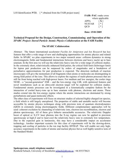
Figure A 1. Overview of <strong>the</strong> existing and planned accelerator facilities; locations of <strong>the</strong> future areas<br />
<strong>for</strong> atomic physics experiments are indicated.<br />
SIS100/300: Laser cooling and spectroscopy installation that will mostly be using Li-like very heavy<br />
ions. The set up exploits <strong>the</strong> Doppler boost of optical Laser photons in <strong>the</strong> rest frame of <strong>the</strong> counterpropagating<br />
ions to <strong>the</strong> XUV regime.<br />
High Energy Cave <strong>for</strong> AP/Biophysics/Materials Research: In this cave <strong>the</strong> experiments in atomic<br />
physics and applications in radiobiology, space and materials research with extracted beams from<br />
SIS12 or SIS100 will be per<strong>for</strong>med.<br />
NESR is <strong>the</strong> "second-generation" ESR with optimized features and novel experimental installations.<br />
The NESR will serve also as an accumulator and storage/cooler ring both <strong>for</strong> ions and antiprotons.<br />
A large variety of experimental set-ups and installations <strong>for</strong> atomic physics experiments will be<br />
made here.<br />
AP Low-Energy Cave/FLAIR Building: This building is devoted to experiments with decelerated,<br />
low-energetic highly-charged ions and antiprotons. The experimental area will be served by <strong>the</strong><br />
NESR. In <strong>the</strong> building, different installations (e.g. <strong>the</strong> Low-Energy Storage Ring LSR and <strong>the</strong> Ultralow<br />
energy Storage Ring USR) are located. From <strong>the</strong> LSR <strong>the</strong> ions can be actively slowed down,<br />
even to rest using <strong>the</strong> trap facility HITRAP. The installations will be shared with <strong>the</strong> FLAIR<br />
collaboration and <strong>for</strong> detailed descriptions of <strong>the</strong> LSR and USR we refer to <strong>the</strong> FLAIR TP.<br />
2
ARGENTINA<br />
Pablo D. Fainstein<br />
Centro Atomico Bariloche<br />
Collaborating Individuals and Institutions<br />
AUSTRIA<br />
Joachim Burgdoerfer, Christoph Lemell, Shuhei Yoshida<br />
Vienna University of Technolgy<br />
Friedrich Aumayr, Hannspeter Winter<br />
Institut fuer Allgemeine Physik, TU Wien<br />
CANADA<br />
Gerald Gwinner<br />
University of Manitoba<br />
Marko Horbatsch<br />
York University<br />
Jens Dilling<br />
TRIUMF National Laboratory Vancouver<br />
CHINA<br />
Xiantang Zeng<br />
China Institute of Atomic Energy, Beijing<br />
Jianguo Wang<br />
Institute of Applied Physics and Computational Ma<strong>the</strong>matics, Beijing<br />
Chongyang Chen<br />
Institute of Modern Physics, Fudan University, Shanghai<br />
Xiaohong Cai, Xinwen Ma, Baoren Wei, Feng Shou Zhang, Xiaolong Zhu<br />
Institute of Modern Physics, Chinese Academy of Sciences, Lanzhou<br />
Dajun Ding<br />
Institute of Atomic and Molecular Physics, Jilin University, Jilin<br />
Chen Ximeng<br />
Lanzhou University, Lanzhou<br />
Ji Chen, Lin-fan Zhu<br />
University of Science and Technology of China, Hefei<br />
Kelin Gao<br />
Wuhan Institute of Physics and Ma<strong>the</strong>matics, Wuhan<br />
Chenzhong Dong<br />
Physics Department, Northwest Normal University<br />
Yaming Zou<br />
Applied Ion Beam Physics Laboratoy, Fudan University<br />
CROATIA<br />
Krunoslav Pisk, Tihomir Suric<br />
Ruder Boskovic Institute, Zagreb<br />
3
CZECH REPUBLIC<br />
Oldrich Renner<br />
Institute of Physics, Czech Academy of Sciences<br />
DENMARK<br />
Lars Bojer Madsen<br />
Department of Physics and Astronomy, University of Aarhus<br />
EGYPT<br />
Hassan Hanafy, Tarek Mohamed<br />
Physics Department, Beni-Suef Faculty of Science<br />
FRANCE<br />
Bruno Manil, Hermann Rothard<br />
CIRIL Ganil<br />
Alexandre Simionovici<br />
Ecole Normale Superieure – Lyon<br />
Denis Dauvergne<br />
Institut de Physique Nucléaire de Lyon<br />
Emily Lamour, Jean-Pierre Rozet<br />
Groupe de Physique des Solides<br />
Eric-Olivier Le Bigot<br />
Univ. P. & M. Curie et Ecole Normale Supérieure<br />
GERMANY<br />
Alexander Herlert, Gerrit H. Marx, Lutz Schweikhard<br />
Ernst Moritz Arndt Universität Greifswald<br />
Gerhard Baur, Detlev Gotta, Thomas Krings, Davor Protic, Frank Rathmann<br />
Forschungszentrum Jülich<br />
John Briggs, Ulrich Jentschura<br />
Freiburg University<br />
Dietrich Beck, Frank Becker, Thomas Beier, Heinrich F. Beyer, Michael Block, Fritz Bosch, Angela<br />
Braeuning-Demian, Carsten Brandau, Peter Egelhof, Alexandre Gumberidze, Thomas Hahn, Frank<br />
Herfurth, H.-Jürgen Kluge, Christophor Kozhuharov, Thomas Kühl, Dieter Liesen, Rido Mann, Paul<br />
Mokler, Manas Mukherjee, Wolfgang Quint, Saidur Rahaman, Rodolfo Sanchez, Haik Simon, Thomas<br />
Stöhlker, Marco Tomasseli, Sergiy Trotsenko, Christine Weber<br />
<strong>GSI</strong>, Darmstadt<br />
Harald Bräuning, Alfred Müller, Stefan Schippers<br />
Institut für Atom- und Molekülphysik, Justus-Liebig-Universität Gießen<br />
Werner Scheid<br />
Institut für Theoretische Physik der Universität Gießen<br />
Dietrich Habs, Ulrich Schramm<br />
Sektion Physik, LMU Munich<br />
Daniel Fischer, Christoph H. Keitel, Michael Lestinsky, Robert Moshammer, Sascha Reinhardt, Guido<br />
Saathoff, Frank Sprenger, Joachim Ullrich, Carsten Welsch, Andreas Wolf<br />
Max-Planck-Institut für Kernphysik, Heidelberg<br />
Oleg Yu. Andreev, Guenter Plunien, Ralf Schützhold, Gerhard Soff, Andrei Volotka<br />
4
Institut für Theoretische Physik, TU Dresden<br />
Wilfried Nörtershäuser<br />
Tübingen University<br />
Reinhard Dörner, Siegbert Hagmann, Horst Schmidt-Böcking, Kurt Ernst Stiebing<br />
IKF, J.W.v.Goe<strong>the</strong> Universität Frankfurt am Main<br />
Hartmut Backe, Slobodan Djekic, Gerhard Huber, Sergej Karpuk, Christian Novotny, Stefan Stahl,<br />
Manuel Vogel<br />
Institut für Physik, Universität Mainz<br />
Josef Anton, Burkhard Fricke, Stephan Fritzsche, Wolf-Dieter Sepp, Andrey Surzhykov<br />
Institut für Physik, Universität Kassel<br />
Tom Kirchner<br />
Institut für Theoretische Physik, TU Clausthal<br />
Andreas Fleischmann<br />
Kirchhoff-Institut für Physik, Universität Heidelberg<br />
Andreas Zilges<br />
TU Darmstadt<br />
Volker Dangendorf<br />
Physikalisch-Technische Bundesanstalt<br />
Doris Jakubassa-Amundsen<br />
Ma<strong>the</strong>matics Institute, University of Munich, 80333 Munich<br />
Günter Zwicknagel<br />
Theoretische Physik, Universität Erlangen<br />
Gerd Röpke<br />
Institut für Physik, Universität Rostock<br />
Joerg Eichler<br />
Hahn-Meitner-Institut Berlin<br />
Alejandro Saenz<br />
Humboldt-Universität zu Berlin<br />
Eckhart Förster<br />
Institute <strong>for</strong> Optics, Jena University<br />
GREECE<br />
Theo Zouros<br />
University of Crete and IESL-FORTH<br />
HUNGARY<br />
Béla Sulik, Karoly Tokesi<br />
Inst. of Nuclear Research (ATOMKI), Debrecen<br />
INDIA<br />
Krishnamurthy Manchikanti, Deepak Mathur, Lokesh Tribedi<br />
Tata Institute of Fundamental Research<br />
Punita Verma<br />
Vaish College, Rohtak<br />
Tapan Nandi, C P Safvan<br />
Nuclear Science Centre, New Delhi<br />
5
Brij Suri<br />
Bhabha Atomic Research Centre<br />
Debasis Mitra<br />
Saha Institute of Nuclear Physics<br />
ITALY<br />
Gaetano Lanzano<br />
Inst. Naz. Fisica Nucleare, Dip. di Fisica, Catania<br />
JAPAN<br />
Yasunori Yamazaki<br />
University of Tokyo & Atomic Physics Laboratory RIKEN, Wako<br />
JORDAN<br />
Feras Afaneh, Rami Ali<br />
Hashemite University<br />
MEXICO<br />
Carmen Cisneros<br />
CCF Universidad Nacional Autónoma de México<br />
POLAND<br />
Dariusz Banas, Marek Pajek,<br />
Institute of Physics, Swietokrzyska Academy<br />
Stefan Samek, Andrzej Warczak<br />
Institute of Physics, Jagiellonian University<br />
Krzysztof Pachucki<br />
Institute of Theoretical Physics, Warsaw University<br />
Zbigniew Stachura<br />
Institute of Nuclear Physics of Polish Academy of Sciences<br />
Jacek Rzadkiewicz<br />
The Soltan Institute For Nuclear Studies<br />
ROMANIA<br />
Constantin Ciortea, Dana Elena Dumitriu, Alexandru Enulescu, Daniela Fluerasu, Liviu Constantin<br />
Penescu, Aimee Theodora Radu<br />
NIPNE National Institute <strong>for</strong> Physics and Nuclear Engineering<br />
RUSSIA<br />
Leonid Presnyakov, Viatcheslav Shevelko<br />
Lebedev Physical Institute, Moscow<br />
Oleg Yu Andreev, Anton Artemyev, Igor Goidenko, Leonti N. Labzowsky, Andrei Nefiodov, Vladimir<br />
Shabaev, Vladimir Yerokhin<br />
Institute of Physics, St. Petersburg State University<br />
Vitaly Pal'Chikov<br />
Institute of Metrology <strong>for</strong> Time and Space at VNIIFTRI<br />
6
Lyudmila Bureyeva<br />
Institute of Spectroscopy of <strong>the</strong> RAS<br />
Victor Varentsov<br />
V.G.Khlopin Radium Institute, St.Petersburg<br />
Vsevolod Balashov<br />
Institute of Nuclear Physics, Moscow State University<br />
Evgenii Drukarev<br />
Petersburg Nuclear Physics Institute<br />
SERBIA AND MONTENEGRO<br />
Bratislav Marinkovic<br />
Institute of Physics, Belgrade<br />
SPAIN<br />
Gustavo Garcia<br />
CSIC<br />
SWEDEN<br />
Ingvar Lindgren, Sten Salomonson<br />
Chalmers University of Technology and Goteborg University<br />
Eva Lindroth, Stojan Madzunkov, Szilard Nagy, Reinhold Schuch, György Vikor<br />
Stockholm University<br />
Glans Peter<br />
Mid-Sweden University<br />
Roger Hutton<br />
Lund University<br />
Guillermo Andler, Lars Bagge, Håkan Danared, Mats Engström, Anders Källberg, Leif Liljeby, Patrik<br />
Löfgren, Andras Paál, K.-G. Rensfelt, Ansgar Simonsson<br />
Örjan Skeppstedt<br />
Manne Siegbahn Laboratory MSL<br />
SWITZERLAND<br />
Klaus Blaum<br />
CERN<br />
Jean-Claude Dousse<br />
Department of Physics, University Fribourg<br />
Kai Hencken, Dirk Trautmann<br />
Institut für Physik, Universität Basel<br />
UNITED KINGDOM<br />
Robert Potvliege<br />
Department of Physics, The University of Durham<br />
Fred Currell<br />
Queen's University, Belfast<br />
Daniel Segal, Richard Thompson, Danyal Winters<br />
Imperial College<br />
7
UNITED STATES<br />
Thomas Schenkel, Dieter Schneider, Sven Toleikis<br />
Lawrence Berkeley National Laboratory<br />
Steven Manson<br />
Georgia State University<br />
Robert DuBois, Michael Schulz<br />
University of Missouri Rolla<br />
Michael Fogle, Joseph Macek<br />
Oak Ridge National Laboratory<br />
Emanuel Kamber<br />
Western Michigan University<br />
Eric Silver<br />
Harvard-Smithsonian Center <strong>for</strong> Astrophysics<br />
Christian Enss<br />
Brown University, Physics Department<br />
Erhard Gaul<br />
Univeristy of Texas at Austin<br />
Patrick Richard<br />
Kansas State University<br />
Daniel Wolf Savin<br />
Columbia Astrophysics Laboratory, Columbia University<br />
John Tanis<br />
Western Michigan University<br />
UZBEKISTAN<br />
Davron Matrasulov, Khamdam Rakhimov<br />
Heat Physics Department of <strong>the</strong> Uzbek Academy of Sciences<br />
Spokesperson: Reinhold Schuch schuch@physto.se +46 855378621<br />
Deputy: Andrzej Warczak ufwarcza@cyf-kr.edu.pl +48 126324 888 5658<br />
Contact person @ <strong>GSI</strong> Thomas Stöhlker t.stoehlker@gsi.de +49 6159 712712<br />
8
A INTRODUCTION AND OVERVIEW......................................................................................................................12<br />
A 1 PHYSICS CASE .........................................................................................................................................................12<br />
A 2 COMPETITIVENESS...................................................................................................................................................14<br />
A 3 EXPERIMENTAL CONCEPTS AND REQUIREMENTS......................................................................................................15<br />
B SYSTEMS .....................................................................................................................................................................18<br />
B 1 LASER INTERACTIONS WITH RELATIVISTIC AND HIGHLY-CHARGED IONS AT SIS 100/300 .......18<br />
B 1 1 GENERAL INFRASTRUCTURE OF THE SIS LASER EXPERIMENTS.............................................................................18<br />
B 1 2 TRIGGER, DACQ, CONTROLS ...............................................................................................................................21<br />
B 1 3 BEAM REQUIREMENTS ..........................................................................................................................................21<br />
B 1 4 PHYSICS PERFORMANCE........................................................................................................................................22<br />
B 2 ATOMIC PHYSICS WITH ION BEAMS FROM SIS12/100...............................................................................23<br />
B 2 1 THE HIGH-ENERGY ATOMIC PHYSICS CAVE.........................................................................................................23<br />
B 2 1.1 The Charge State Spectrometer....................................................................................................................23<br />
B 2 1.2 Resonant Coherent Excitation in Crystals at Relativistic Energies .............................................................24<br />
B 2 1.3 Pair Production and Electron Capture in Relativistic Atomic Collisions....................................................27<br />
B 3 ATOMIC PHYSICS EXPERIMENTS WITH STORED AND COOLED IONS AT THE NESR ....................31<br />
B 3 1 EXPERIMENTAL INSTALLATIONS ...........................................................................................................................31<br />
B 3 1.1 Electron Target (Second Electron Cooler)...................................................................................................32<br />
B 3 1.2 The Internal Target ......................................................................................................................................35<br />
B 3 1.3 High-Resolution Photon Spectrometers .......................................................................................................38<br />
B 3 1.4 Electron Spectroscopy at <strong>the</strong> Internal Target...............................................................................................53<br />
B 3 1.5 Extended Reaction Microscope ....................................................................................................................57<br />
B 3 1.6 Laser Experiments at <strong>the</strong> NESR ...................................................................................................................64<br />
B 3 2 TRIGGER, DACQ, CONTROLS, ON-LINE/OFF-LINE COMPUTING...........................................................................73<br />
B 3 2.1 Electron Target ............................................................................................................................................73<br />
B 3 2.2 Internal Target .............................................................................................................................................73<br />
B 3 2.3 Photon Spectroscopy....................................................................................................................................73<br />
B 3 2.4 Electron Spectrometer at <strong>the</strong> Internal Target...............................................................................................74<br />
B 3 2.5 Extended Reaction Microscope ....................................................................................................................74<br />
B 3 2.6 Laser Experiments........................................................................................................................................75<br />
B 3 3 BEAM/TARGET REQUIREMENTS ...........................................................................................................................75<br />
a) Beam specifications:.............................................................................................................................................75<br />
b. Running Scenario .................................................................................................................................................76<br />
B3 4 PHYSICS PERFORMANCE........................................................................................................................................79<br />
B 3 4.1 Electron Target ............................................................................................................................................79<br />
B 3 4.2 Internal Target .............................................................................................................................................81<br />
B 3 4.3 Photon Spectroscopy....................................................................................................................................84<br />
B 3 4.4 Electron Spectrometer at <strong>the</strong> Internal Target...............................................................................................89<br />
B 3 4.5 Extended Reaction Microscope ....................................................................................................................89<br />
B 3 4.6 Laser Experiments at <strong>the</strong> NESR ..................................................................................................................90<br />
B 4 ATOMIC PHYSICS WITH DECELERATED AND EXTRACTED HIGHLY CHARGED IONS................93<br />
B 4 1 INFRASTRUCTURE AND EXPERIMENTS...................................................................................................................93<br />
B 4 1.1 Low-energy highly charged ion experimental area at FLAIR......................................................................97<br />
B 4 1.2 HITRAP......................................................................................................................................................102<br />
B 4 2 EXPERIMENTS .....................................................................................................................................................103<br />
B 4 2.1 Precision Spectroscopy of Slow HCI with <strong>the</strong> Reaction Microscope .........................................................103<br />
B 4 2.2 Ion-Surface Interaction Experiments at HITRAP/Low-energy Cave A ......................................................105<br />
B 4 2.3 X-ray Measurements at HITRAP/Low-energy Cave A ...............................................................................107<br />
B 4 2.4 g-Factor Measurements .............................................................................................................................108<br />
B 4 2.5 Mass Measurements ...................................................................................................................................111<br />
B 4 2.6 Laser Experiments......................................................................................................................................113<br />
B 4 3 TRIGGER, DACQ, CONTROLS, AN-LINE/OFF-LINE COMPUTING..........................................................................116<br />
B 4 4 BEAM/TARGET REQUIREMENTS LOW-ENERGY CAVE/ HITRAP.........................................................................116<br />
B 4 4.1 Beam specifications....................................................................................................................................116<br />
B 4 4.2 Running scenario........................................................................................................................................117<br />
9
B 5 PHYSICS PERFORMANCE ........................................................................................................................................118<br />
B 5 1 The Low Energy Cave ...................................................................................................................................118<br />
B 5 2 HITRAP.........................................................................................................................................................118<br />
C IMPLEMENTATION AND INSTALLATION......................................................................................................120<br />
C 1 LASER INTERACTIONS WITH HIGHLY RELATIVISTIC AND HIGHLY CHARGED IONS AT SIS 100/300......................120<br />
C 1 1 Cave and Annex Facilities ...........................................................................................................................120<br />
C 1 2 Detector –Machine Interface .......................................................................................................................120<br />
C 1 3 Assembly and installation ............................................................................................................................121<br />
C 2 ATOMIC PHYSICS WITH ION-BEAMS FROM SIS12/SIS100.....................................................................................122<br />
C 2 1 Cave and Annex Facilities ...........................................................................................................................122<br />
C 2 2 Detector –Machine Interface .......................................................................................................................123<br />
C 2 3 Assembly and Installation ............................................................................................................................124<br />
C 3 EXPERIMENTS WITH STORED AND COOLED IONS AT THE NESR ...........................................................................125<br />
C 3 1 Electron Target ............................................................................................................................................125<br />
C 3 2 Internal Target .............................................................................................................................................127<br />
C 3 3 Photon Spectroscopy....................................................................................................................................131<br />
C 3 4 Electron Spectrometer at <strong>the</strong> Internal Target ..............................................................................................133<br />
C 3 5 Extended Reaction Microscope....................................................................................................................134<br />
C 3 6 Laser Spectroscopy ......................................................................................................................................137<br />
C 4 COOLED, DECELERATED AND EXTRACTED IONS....................................................................................................141<br />
C 4 1 Low-Energy Experimental Area...................................................................................................................141<br />
C 4 2 Implementation and Installation: HITRAP ..................................................................................................143<br />
C 4 3 Experiments with HCI...................................................................................................................................146<br />
D COMMISSIONING ..................................................................................................................................................148<br />
D 1 LASER SPECTROSCOPY AND LASER COOLING AT SIS100/300 ..............................................................................148<br />
D 2 ION-BEAMS FROM SIS12/SIS100..........................................................................................................................148<br />
D 3 ATOMIC PHYSICS EXPERIMENTS AT THE NESR....................................................................................................148<br />
D 3 1 Electron Target............................................................................................................................................148<br />
D 3 2 Internal Jet-Target.......................................................................................................................................149<br />
D 3 3 Photon Spectroscopy....................................................................................................................................149<br />
D 3 4 Electron Spectroscopy at <strong>the</strong> Internal Target ..............................................................................................150<br />
D 3 5 Extended Reaction Microscope....................................................................................................................150<br />
D 3 6 Laser Experiments .......................................................................................................................................150<br />
D 4 COOLED, DECELERATED AND EXTRACTED IONS....................................................................................................151<br />
D 4 1 The Low-Energy Cave .................................................................................................................................151<br />
D 4 2 HITRAP........................................................................................................................................................151<br />
E OPERATION.............................................................................................................................................................152<br />
E 1 LASER INTERACTIONS WITH HIGHLY RELATIVISTIC AND HIGHLY CHARGED IONS AT SIS100/300.......................152<br />
E 2 ION BEAMS FROM SIS12/100 ................................................................................................................................152<br />
E 3 ATOMIC PHYSICS AT THE NESR............................................................................................................................153<br />
E 3 1 Electron Cooler............................................................................................................................................153<br />
E 3 2 Internal Target .............................................................................................................................................153<br />
E 3 3 Photon Spectroscopy....................................................................................................................................153<br />
E 3 4 Electron Spectrometer at <strong>the</strong> Internal Target...............................................................................................154<br />
E 3 5 Reaction Microscope....................................................................................................................................154<br />
E 3 6 Laser Experiments........................................................................................................................................154<br />
E 4 COOLED, DECELERATED AND EXTRACTED IONS....................................................................................................154<br />
E 4 1 The Low-Energy AP Cave ............................................................................................................................154<br />
E 4 2 HITRAP........................................................................................................................................................155<br />
F SAFETY .....................................................................................................................................................................157<br />
F 1 LASER SPECTROSCOPY AND LASER COOLING AT SIS100/300 ...............................................................................157<br />
F 2 ION-BEAMS FROM SIS12/SIS100 ..........................................................................................................................157<br />
F 3 ATOMIC PHYSICS EXPERIMENTS AT THE NESR.....................................................................................................157<br />
F 3 1 Electron Target ............................................................................................................................................157<br />
F 3 2 Internal Target .............................................................................................................................................158<br />
F 3 3 Photon Spectroscopy....................................................................................................................................158<br />
F 3 4 Electron Spectrometer at <strong>the</strong> Internal Target...............................................................................................158<br />
F 3 5 Extended Reaction Microscope....................................................................................................................158<br />
10
F 3 6 Laser Spectroscopy ......................................................................................................................................158<br />
F 4 COOLED, DECELERATED AND EXTRACTED IONS ...................................................................................................159<br />
F 4 1 The Low-Energy AP Cave ............................................................................................................................159<br />
F 4 2 HITRAP........................................................................................................................................................159<br />
G ORGANISATION AND RESPONSIBILITIES, PLANNING (WORKING PACKAGES: WP)..................161<br />
A. WBS- WORKING PACKAGE BREAK DOWN STRUCTURE .............................................................................................162<br />
B. STRUCTURE OF EXPERIMENT MANAGEMENT ...........................................................................................................163<br />
C. RESPONSIBILITIES AND OBLIGATIONS ......................................................................................................................166<br />
SUMMARY OF RESOURCE REQUIREMENTS ....................................................................................................................168<br />
TABLES: RESOURCE PLANNING FOR THE INDIVIDUAL WORKING PACKAGES................................................................170<br />
H RELATION TO OTHER PROJECTS ..............................................................................................................222<br />
I OTHER ISSUES.................................................................................................................................................223<br />
A THE FLAIR BUILDING ..............................................................................................................................................223<br />
1 The Low-energy Storage Ring, LSR.....................................................................................................................225<br />
2 The Synchrotron ..................................................................................................................................................226<br />
3 Subsystems...........................................................................................................................................................226<br />
B TRIGGER, DACQ, CONTROLS, AN-LINE/OFF-LINE COMPUTING ...............................................................................228<br />
C IMPLEMENTATION AND INSTALLATION.....................................................................................................................229<br />
D COMMISSIONING.......................................................................................................................................................233<br />
E OPERATION...............................................................................................................................................................234<br />
F SAFETY.....................................................................................................................................................................234<br />
G ORGANIZATION AND RESPONSIBILITIES....................................................................................................................234<br />
J REFERENCES AND ACKNOWLEDGEMENTS..................................................................................................239<br />
11
A Introduction and Overview<br />
A 1 Physics Case<br />
At <strong>the</strong> proposed new accelerator Facility <strong>for</strong> Antiproton and Ion Research <strong>the</strong> investigation of<br />
extreme atomic conditions becomes accessible with highly-charged very-heavy ions over an energy<br />
range from rest to <strong>the</strong> relativistic regime. These studies are needed <strong>for</strong> our understanding of <strong>the</strong><br />
processes ongoing in extreme states of matter, as <strong>the</strong> majority of matter in <strong>the</strong> universe exists as<br />
stellar plasmas. There high temperatures, high atomic charge states and highest field strengths<br />
prevail. Conditions that become available at FAIR will provide <strong>the</strong> highest intensities of relativistic<br />
beams of both stable and unstable heavy nuclei, in combination with <strong>the</strong> strongest electromagnetic<br />
fields, thus allowing extending atomic spectroscopy virtually up to <strong>the</strong> limits of atomic matter. In <strong>the</strong><br />
different accelerator structures, <strong>the</strong> ions, after having stripped off most of <strong>the</strong>ir electrons can be<br />
decelerated basically to rest. The wide ranges of ion energies and electromagnetic field strengths<br />
that will become available are demonstrated in Figure A 2.<br />
Figure A 2. Ion energies and Lorentz factors γ that can be obtained with <strong>the</strong> different FAIR<br />
facilities. The adiabadicity value η = 1 (specific kinetic ion energy corresponding to <strong>the</strong> mean<br />
velocity <strong>for</strong> an electron bound with EBK in <strong>the</strong> uranium K shell) is indicated. On <strong>the</strong> right hand scale<br />
<strong>the</strong> electric field strengths that are reached in collisions, in bound states and with lasers are shown.<br />
Atomic physics research with highly-charged heavy-ion beams at <strong>the</strong> new <strong>GSI</strong> facility can be<br />
associated mainly with four types of experimental studies:<br />
a. Highly relativistic heavy ions will be employed <strong>for</strong> a wide range of atomic collision studies<br />
involving photons, electrons and atoms, <strong>for</strong> getting rapidly varying strong fields in <strong>the</strong> interaction.<br />
One goal of future experiments will be <strong>the</strong> measurement of <strong>the</strong> complete momentum balance in<br />
relativistic collisions both in transverse and in longitudinal direction by detecting <strong>the</strong> emitted<br />
electrons/positrons in coincidence with <strong>the</strong> recoiling target ion. From measuring <strong>the</strong> momenta of<br />
both <strong>the</strong> electrons/positrons and <strong>the</strong> recoil ion with high accuracy, direct in<strong>for</strong>mation on <strong>the</strong><br />
correlated many-lepton dynamics can be obtained.<br />
An understanding of <strong>the</strong>se collision phenomena is required <strong>for</strong> all lines of research in atomic<br />
physics, in material research, <strong>for</strong> irradiation of living cells (radiobiology), and <strong>for</strong> accelerator<br />
technology. For example, <strong>the</strong> electron-positron pair production with <strong>the</strong> electron created in a bound<br />
12
state of one of <strong>the</strong> colliding ions – <strong>the</strong> so called bound-free pair production – changes <strong>the</strong> charge<br />
state of that ion. This is one of <strong>the</strong> main loss processes <strong>for</strong> ions in relativistic heavy-ion colliders.<br />
Relativistic ions will also exploit <strong>the</strong> large Doppler boost <strong>for</strong> trans<strong>for</strong>ming laser photons to <strong>the</strong> Xray<br />
regime.<br />
b. High-energy beams will be utilized <strong>for</strong> achieving high stages of ionization up to bare uranium<br />
nuclei. Experiments will focus on structure studies <strong>for</strong> <strong>the</strong>se ion species, a field being still largely<br />
unexplored. Despite <strong>the</strong> enormous success of QED in predicting <strong>the</strong> properties of electrons in weak<br />
fields, a precise test in <strong>the</strong> strong-field limit where novel phenomena might show up, is still pending.<br />
Accurate measurements of electron binding energies are very well suited to deduce characteristic<br />
QED phenomena in strong fields. Along with <strong>the</strong> precise determination of binding energies,<br />
measurements of <strong>the</strong> g factor of <strong>the</strong> bound electron in highly-charged ions provide a sensitive test of<br />
<strong>the</strong> magnetic sector of bound-state QED calculations in strong electromagnetic fields. It is planned<br />
to measure <strong>the</strong> g factor of an electron in <strong>the</strong> 1s-state of a hydrogen-like ion and in <strong>the</strong> 2s-state of a<br />
lithium-like ion. Thereby, it can be expected that <strong>the</strong> uncertainty of <strong>the</strong> nuclear size correction drops<br />
out and <strong>the</strong> full experimental accuracy can be exploited <strong>for</strong> QED tests with high precision.<br />
Dielectronic recombination (DR) of ions, having at least one electron, with free electrons turned out<br />
to be a novel and sensitive tool <strong>for</strong> precise structure studies. The possibility of producing highlycharged<br />
heavy ions and of storing and cooling <strong>the</strong>m in a storage ring opened a new window <strong>for</strong> <strong>the</strong><br />
investigation of <strong>the</strong> recombination of ions and electrons at low relative velocities. In this resonant<br />
process a free electron is captured and <strong>the</strong> excess energy excites one of <strong>the</strong> bound electrons to a<br />
higher state. The DR measurements provide in<strong>for</strong>mation on both electron-electron interactions in <strong>the</strong><br />
presence of a strong central field and on <strong>the</strong> ionic structure of <strong>the</strong> investigated species.<br />
In addition, new fields will be opened <strong>for</strong> <strong>the</strong>se studies by <strong>the</strong> intensities of unstable nuclei that<br />
become available.<br />
c. Fundamental atomic physics studies and model-independent determination of nuclear properties<br />
with stable as well as radioactive atoms in well-defined charge states will be per<strong>for</strong>med, applying<br />
atomic physics methods. An important scenario <strong>for</strong> this class of experiments will be <strong>the</strong> slowingdown,<br />
trapping and cooling of particles in <strong>the</strong> ion-trap facility HITRAP. In highly-charged ions<br />
precise calculations of <strong>the</strong> atomic structure can be per<strong>for</strong>med. In addition, <strong>the</strong>re are neardegeneracies<br />
of levels of opposite parity. The most advantageous situation probably occurs in heavy<br />
helium-like ions near Z = 64 and Z = 92, due to almost degenerated 2 3 P0 and 2 1 S0 states with<br />
opposite parity. In atoms with non-zero nuclear spin <strong>the</strong> hyperfine and weak quenching effects are<br />
mixed. This leads to an unusually large asymmetry of <strong>the</strong> delayed photon emission by polarized ions<br />
which can be measured in beam-foil type experiments. The potential of <strong>the</strong> new <strong>GSI</strong> facility <strong>for</strong><br />
<strong>the</strong>se studies is obvious since <strong>the</strong> energy splitting between <strong>the</strong> 3 P0 und 1 S0 states depends on <strong>the</strong><br />
nuclear size and can be minimized by selecting <strong>the</strong> appropriate isotope. Thereby <strong>the</strong> parity violating<br />
effects can be amplified strongly. The prerequisite <strong>for</strong> this type of experiments is a polarized ion<br />
beam. Quite recently, promising schemes <strong>for</strong> <strong>the</strong> polarization of stored highly-charged ions and of<br />
<strong>the</strong> measurement of <strong>the</strong> degree of <strong>the</strong> polarization have been presented. This scenario will enable<br />
high-accuracy experiments in <strong>the</strong> realm of atomic and nuclear physics, as well as highly-sensitive<br />
tests of <strong>the</strong> Standard Model.<br />
d. Low energy beams of high-Z few-electron ions from an additional “low energy” storage ring<br />
(“LSR”) behind <strong>the</strong> NESR will be employed <strong>for</strong> collisions characterized by very large Sommerfeld<br />
parameters. In this domain of strong perturbations, <strong>the</strong> ionization mechanism is unclear.<br />
Experiments are essential to address <strong>the</strong> fundamental question of <strong>the</strong> nature of <strong>the</strong> ionization<br />
mechanism at threshold which is, surprisingly enough, still open. No perturbation <strong>the</strong>ories are<br />
13
applicable and corresponding experiments will be best suited to test <strong>the</strong> predictive power of <strong>the</strong> most<br />
advanced ab initio <strong>the</strong>ories.<br />
The combination of ultra-intense laser pulses and highly charged ions will open a completely<br />
unique field of research. In <strong>the</strong> strong electrical field created in <strong>the</strong> focus of ultra-high intensity<br />
lasers, <strong>the</strong> Coulomb potential of atoms or low-charge ions is sufficiently depressed to allow bound<br />
electrons to escape over <strong>the</strong> potential barrier or to tunnel through it. This is not <strong>the</strong> case <strong>for</strong> heavy<br />
and highly-charged ions where <strong>the</strong> binding field strength is still much higher than <strong>the</strong> applied fieldstrength<br />
produced in <strong>the</strong> focus of <strong>the</strong> most intense present-day lasers. Distinctly different from <strong>the</strong><br />
case of low-charged ions where <strong>the</strong> processes induced by <strong>the</strong> intense laser field saturate due to <strong>the</strong><br />
onset of field-ionization, no such saturation is expected <strong>for</strong> highly-charged, high-Z ions.<br />
Consequently, high-Z ions will allow one to enter a completely new regime <strong>for</strong> <strong>the</strong> study of <strong>the</strong><br />
interaction of intense laser fields with matter.<br />
A 2 Competitiveness<br />
At high, relativistic energies, <strong>the</strong> FAIR facility will be unique by providing <strong>the</strong> heaviest ions over a<br />
wide energy range from 1 to 30 GeV/u. In <strong>the</strong> special case of pair production <strong>the</strong>re are very few and<br />
only inclusive measurements of pair production available in <strong>the</strong> intermediate relativistic regime of a<br />
few GeV/u. Here, even <strong>the</strong> target charge dependence is not well understood, whereas at extreme<br />
energies, in <strong>the</strong> region beyond hundred GeV/u, <strong>the</strong>re is good agreement between <strong>the</strong>ory and<br />
experiment. The new facility will be worldwide <strong>the</strong> only one capable of filling this important gap.<br />
Utilizing <strong>the</strong> high luminosity of <strong>the</strong> future <strong>GSI</strong> facility, beyond inclusive cross section studies also<br />
differential aspects of atomic processes at high energies become accessible, <strong>for</strong> which <strong>the</strong><br />
electromagnetic interaction differs significantly from <strong>the</strong> low-energy regime. A measurement of <strong>the</strong><br />
impact parameter dependence <strong>for</strong> both inner-shell ionization and excitation processes will enable <strong>the</strong><br />
separation of <strong>the</strong> longitudinal and <strong>the</strong> transversal field contributions to <strong>the</strong> interaction. For such<br />
investigations, precise spectroscopy of photons as well as of electrons and positrons is required. The<br />
photon and electron emission gives <strong>the</strong> details of <strong>the</strong> specific excitation mechanism in those fields.<br />
One may also mention <strong>the</strong> possibility to search <strong>for</strong> recombination followed by e + -e - pair production<br />
instead of photon emission. This higher-order process, requiring high collision energies, is similar to<br />
dielectronic recombination, but with one electron being excited from <strong>the</strong> negative continuum into a<br />
bound state<br />
The new facility will provide intense beams of stable and unstable isotopes up to uranium at <strong>the</strong><br />
highest charge states. At <strong>the</strong> NESR storage ring <strong>the</strong>se ions can be stored and cooled at energies of<br />
760 MeV/u down to 4 MeV/u and at <strong>the</strong> LSR even down to 0.5 MeV/u. For <strong>the</strong> low-energetic ions<br />
(below 100 MeV/u) <strong>the</strong> possibility to extract <strong>the</strong>m into <strong>the</strong> dedicated low-energy Cave exists. These<br />
storage rings in <strong>the</strong>ir combination with <strong>the</strong> facilities installed have a decisive advantage over o<strong>the</strong>r<br />
experimental techniques as <strong>the</strong>y allow to address fundamental process which become feasible at this<br />
time only in inverse kinematics: fully differential photoionization cross sections - including<br />
polarization - <strong>for</strong> <strong>the</strong> heaviest ions in arbitrary charge states, recombination, complete differential<br />
cross sections <strong>for</strong> <strong>the</strong> short wavelength limit of electron-nucleus bremsstrahlung and fully<br />
differential (e,2e) cross sections <strong>for</strong> ions by mapping <strong>the</strong> complete momentum balance of all emitted<br />
particles. Also, <strong>the</strong> combination of <strong>the</strong>se very heavy, highly-charged ions with <strong>the</strong> low collision<br />
energies, where <strong>the</strong> Sommerfeld parameter q/v becomes very large, is an additional unique feature<br />
not available at any o<strong>the</strong>r machine.<br />
A singular opportunity is given by <strong>the</strong> combination of <strong>the</strong> SIS 12/100/300, <strong>the</strong> NESR storage ring<br />
and <strong>the</strong> PHELIX laser facility. In contrast to <strong>the</strong> typical experimental situation in gas targets, <strong>the</strong><br />
14
storage ring provides precise control of <strong>the</strong> initial ion species and diagnostics of <strong>the</strong> final states of<br />
<strong>the</strong> ions and of ejected electrons on <strong>the</strong> single-event level. This will enable research at truly<br />
undisturbed single-ion condition, where <strong>the</strong> only interacting partners will be <strong>the</strong> laser field, <strong>the</strong><br />
highly charged ion, and <strong>the</strong> detached electron.<br />
The proposed FAIR facility with its intense heavy ion beams, in combination with novel<br />
experimental techniques such as excitation by X-ray or laser photons, mono-energetic electron<br />
beams, high-resolution spectrometers, or channelling in crystals gives world-wide unique<br />
opportunities <strong>for</strong> atomic spectroscopy. This will enable <strong>the</strong> exploration of <strong>the</strong> fundamental QED<br />
corrections to binding energies, magnetic moments, and <strong>the</strong> magnetic interactions in strong fields.<br />
The new accelerator complex at <strong>GSI</strong> will enable ano<strong>the</strong>r important step by a large increase of <strong>the</strong><br />
photon frequency range and by allowing spectroscopy <strong>for</strong> a wide variety of radioactive beams that is<br />
not available o<strong>the</strong>rwise. The present limitations <strong>for</strong> <strong>the</strong> application of wavelength-restricted lasers<br />
will most certainly be widely removed. For instance, in <strong>the</strong> SIS300 ring <strong>the</strong> accessible transition<br />
energy range will be increased considerably due to a large Doppler shift. Spectroscopy in <strong>the</strong> NESR,<br />
although limited in <strong>the</strong> energy range, will be a key instrument <strong>for</strong> frontier experiments on highlycharged<br />
ions and radioactive isotopes. Fur<strong>the</strong>rmore, a completely new regime of laser cooling of<br />
heavy relativistic highly-charged ions can be opened.<br />
The HITRAP Facility where highly-charged ions can be brought practically to rest will be <strong>the</strong> only<br />
facility world-wide where bare U nuclei can be trapped in a strong magnetic field. The highlycharged<br />
ions will be cooled down to cryogenic temperatures. There <strong>the</strong> g-factor of a single electron<br />
bound in <strong>the</strong> potential of an arbitrary stable or unstable nucleus like 238 U nucleus and o<strong>the</strong>rs can be<br />
determined. Measurements of <strong>the</strong> hyperfine splitting (HFS) in hydrogen-like ions will give<br />
in<strong>for</strong>mation about <strong>the</strong> distribution of <strong>the</strong> nuclear magnetization within <strong>the</strong> nucleus. By optical<br />
pumping within <strong>the</strong> HFS-levels of <strong>the</strong> ground state, <strong>the</strong> nuclear spins of radioactive nuclides can be<br />
polarized with high efficiency, opening unique possibilities to study questions of <strong>the</strong> Standard<br />
Model of fundamental interactions.<br />
Finally it has to be stressed that currently several heavy-ion beam factories are planned, or under<br />
construction or already in <strong>the</strong> commission phase worldwide. In <strong>the</strong> first line RIA (USA), MUSES<br />
(Riken, Japan) and HIRFL (Lanzhou, China) have to be mentioned in this context. Presently, traps<br />
but no ion storage-cooler rings are <strong>for</strong>eseen at RIA. There<strong>for</strong>e, atomic physics experiments<br />
comparable to those planned <strong>for</strong> <strong>the</strong> NESR are missing <strong>the</strong>re. The plans at MUSES and HIRFL in<br />
<strong>the</strong> realm of atomic physics, on <strong>the</strong> o<strong>the</strong>r hand, cover a ra<strong>the</strong>r similar spectrum. However, due to<br />
<strong>the</strong> comparatively low energies <strong>for</strong>eseen <strong>for</strong> <strong>the</strong>se facilities, <strong>the</strong> achievable intensity of highlycharged<br />
heavy ions (e.g. bare uranium) should be <strong>the</strong>re significantly smaller than that expected at<br />
<strong>the</strong> new <strong>GSI</strong> facility.<br />
A 3 Experimental concepts and requirements<br />
Figure A 1 shows an overview of <strong>the</strong> different experimental installations of SPARC at FAIR. First<br />
we give here very short descriptions of <strong>the</strong>se installations, and <strong>the</strong>n list <strong>the</strong> different experimental<br />
requirements.<br />
The following major installations will be developed and used by SPARC:<br />
SIS100/300: Laser cooling and spectroscopy installation that will mostly use Li-like very heavy<br />
ions. The set up exploits <strong>the</strong> Doppler boost of optical Laser photons in <strong>the</strong> rest frame of <strong>the</strong> counterpropagating<br />
ions to <strong>the</strong> XUV regime.<br />
High Energy Cave <strong>for</strong> AP/Biophysics/Materials Research: In this cave atomic physics<br />
experiments and applications in radiobiology, space and materials research with extracted beams<br />
15
from SIS12 or SIS100 will be per<strong>for</strong>med. The investigation will concentrate on atomic structure<br />
(resonant coherent excitation) and collision studies at moderate and high-relativistic energies<br />
(ionization, capture, and pair production) as well as on irradiation of individual samples <strong>for</strong><br />
biological or solid material research.<br />
New Experimental Storage Ring NESR – a “second generation ESR” New possibilities will be<br />
opened up by instrumentations such as <strong>the</strong> second electron target and <strong>the</strong> electron collider. The<br />
intense beams of highly charged, radioactive ions makes novel experiments possible.<br />
NESR is <strong>the</strong> "second-generation" ESR with optimized features and novel experimental installations.<br />
The NESR will serve also as an accumulator and storage/cooler ring both <strong>for</strong> ions and antiprotons.<br />
Compared to all <strong>the</strong> o<strong>the</strong>r heavy ion storage rings currently under construction, <strong>the</strong> NESR will be <strong>the</strong><br />
most flexible one, providing intense beams up to bare uranium. This warrants a leading position also<br />
with respect to o<strong>the</strong>r advanced projects. A large variety of experimental set-ups and installations <strong>for</strong><br />
atomic physics experiments will be made here. For atomic structure investigations and QED tests<br />
<strong>the</strong> electron target, internal target, electron-, and X-ray spectrometers will be used. Recombination<br />
studies will be done with <strong>the</strong> specially designed electron target. Collision experiments are planned at<br />
<strong>the</strong> internal target with electron-, recoil-, and X-ray- spectrometers.<br />
FLAIR Building / AP Low-Energy Cave: This building is devoted to experiments with<br />
decelerated, low-energetic highly-charged ions and antiprotons. The experimental area will be<br />
served by <strong>the</strong> NESR. In <strong>the</strong> building, different installations (e.g. <strong>the</strong> Low-Energy Storage Ring LSR,<br />
<strong>the</strong> Ultra-low energy Storage Ring USR, and HITRAP) are located. From <strong>the</strong> LSR <strong>the</strong> ions can be<br />
actively slowed down, even to rest using <strong>the</strong> trap facility HITRAP. The installations will be shared<br />
with <strong>the</strong> FLAIR collaboration and <strong>for</strong> detailed descriptions of <strong>the</strong> LSR and USR see section I of this<br />
report and <strong>the</strong> FLAIR TP.<br />
The parameter requirements by <strong>the</strong> experiments:<br />
Laser Spectroscopy and Laser Cooling at SIS100/300 needs Li-like and Na-like ions up to<br />
uranium with up to γ=30. For <strong>the</strong> spectroscopy part, <strong>the</strong> ion number is not critical, one could get<br />
results even <strong>for</strong> as little as 100 ions in SIS. High beam intensities are required <strong>for</strong> <strong>the</strong> cooling<br />
experiments. For interaction experiments of ultra-intense laser pulses with extracted bunches <strong>the</strong> AP<br />
or PP high energy caves might be used.<br />
For Atomic Physics with Ion-Beams from SIS12/SIS100 to <strong>the</strong> low-energy AP cave <strong>the</strong> beam<br />
requirements are intensities of 10 9 ions per spill at 1 GeV and decreasing numbers to higher energies<br />
<strong>for</strong> radiation safety. A spill length of 1s and a beam spot of less <strong>the</strong>n 10 mm on target is needed.<br />
The Atomic Physics Experiments with Stored and Cooled Ions at <strong>the</strong> NESR have a variety of<br />
installations and projects with following requirements:<br />
The number of ions per cycle should reach 10 10 at medium Z. The momentum spread after electron<br />
cooling is supposed to be less than 10 -4 . The beam energy should range from 760 MeV/u to <strong>the</strong> low<br />
energy limit, reached by deceleration to 3 MeV/u. Fast and slow beam extraction is needed. The<br />
lifetimes of stored ions are of utmost importance. Thus, an excellent vacuum of 10 -11 mbar is<br />
needed.<br />
The electron target should have an ultra-cold electron beam. The resulting energy spreads should<br />
be as low as a few 10 meV at collision energies below 1 eV and smaller than 5 eV at 100 keV. One<br />
should reach 300 keV in <strong>the</strong> center-of momentum frame.<br />
Photon Spectrometer such as crystal spectrometers <strong>for</strong> soft and hard X-rays (3–120 keV), lowtemperature<br />
calorimeter and Compton polarimeter will be installed. An Electron Spectrometer <strong>for</strong><br />
16
electrons from 100 keV to MeV energy and an Extended Reaction Microscope <strong>for</strong> imaging recoils<br />
and slow and fast electrons in <strong>the</strong> range of meV should operate at <strong>the</strong> Internal Target.<br />
For Atomic Physics with Cooled, Decelerated and Extracted Ions beams up to U with maximum<br />
intensity (typical 10 8 ions per spill) or lowest energy from NESR are transported to <strong>the</strong> FLAIR<br />
building. There one should get <strong>the</strong> ions down to 3 MeV/u into <strong>the</strong> AP Cave <strong>for</strong> collision and<br />
spectroscopy experiments. Additionally to NESR, ions can be slowed down in <strong>the</strong> LSR to 0.3<br />
MeV/u. HITRAP is fed by ions up to bare uranium. Experimental investigation of highly charged<br />
ions, solid interactions, collisions, and X-ray spectroscopy will here be per<strong>for</strong>med.<br />
17
B Systems<br />
B 1 Laser Interactions with Relativistic and Highly-Charged Ions at SIS 100/300<br />
B 1 1 General infrastructure of <strong>the</strong> SIS laser experiments<br />
Laser interaction with highly-charged ions stored in SIS100/300 benefits tremendously from <strong>the</strong><br />
relativistic Doppler boost experienced in <strong>the</strong> ion rest frame when counter-propagating beams are<br />
used. This advantage is twofold: on <strong>the</strong> one hand, <strong>the</strong> Doppler boost will increase <strong>the</strong> peak intensity<br />
in laser-ion interaction experiments at ultra-high intensities and shorten <strong>the</strong> pulse length in <strong>the</strong> ion<br />
rest frame <strong>for</strong> ultra-fast spectroscopy. On <strong>the</strong> o<strong>the</strong>r hand, this boost will allow <strong>for</strong> <strong>the</strong> use of standard<br />
laser systems in <strong>the</strong> visible range <strong>for</strong> <strong>the</strong> optical excitation of ground-state transitions of highlycharged<br />
ions in <strong>the</strong> X-ray range. Precision spectroscopy of heavy few-electron systems will become<br />
possible, complementary to <strong>the</strong> X-ray laser experiments proposed to be per<strong>for</strong>med at NESR, as well<br />
as laser cooling, a unique cooling technique <strong>for</strong> relativistic ion beams. As both classes of<br />
experiments will require <strong>the</strong> same technical equipment, <strong>the</strong> TP <strong>for</strong> LoI #18 (laser cooling) will be<br />
included in <strong>the</strong> TP of SPARC.<br />
The cooling and spectroscopy experiments are per<strong>for</strong>med inside <strong>the</strong> synchrotrons. Laser beams have<br />
to be merged with <strong>the</strong> stored ion beams over a length of preferentially several 10m. As <strong>the</strong><br />
superconducting dipole-magnets do not allow <strong>for</strong> a tangential access, an additional deflection system<br />
has to be implemented. Details of this system are part of <strong>the</strong> necessary R&D of this project<br />
embedded in <strong>the</strong> not yet completed design of <strong>the</strong> ring lattices. The location of <strong>the</strong> interaction region<br />
is restricted to areas, where access to <strong>the</strong> tunnel is possible and where <strong>the</strong> experiment does not<br />
interfere with <strong>the</strong> normal synchrotron operation.<br />
Figure B1 1. a) Anticipated scenario <strong>for</strong> an overlay of ion and laser beams at SIS100/300 using two<br />
bumper magnets and three focusing magnet assemblies. As a compromise, a small crossing angle<br />
might be acceptable <strong>for</strong> test experiments at SIS 100. b) General setup <strong>for</strong> interaction studies of highintensity<br />
laser pulses with <strong>the</strong> stored or <strong>the</strong> extracted ion beam, emphasizing <strong>the</strong> passage of <strong>the</strong> ion<br />
beam through <strong>the</strong> laser focusing device.<br />
Interaction experiments with ultra-high intensity lasers will take place in a similar geometry, except<br />
that <strong>the</strong> laser interaction will be limited to a tiny focal area close to <strong>the</strong> entrance window. As <strong>for</strong><br />
tight focusing of <strong>the</strong> laser pulse a focal length of a few 10 cm is required, such experiments demand<br />
<strong>the</strong> positioning of <strong>the</strong> focusing mirror inside <strong>the</strong> vacuum system of <strong>the</strong> synchrotron. For perfectly<br />
parallel beams <strong>the</strong> ion beam has to pass through a hole in <strong>the</strong> optics as sketched in Figure B1 1.<br />
Alternatively, experiments might take place on <strong>the</strong> extracted bunch in <strong>the</strong> high-energy cave.<br />
The laser systems required <strong>for</strong> cooling and in-beam spectroscopy has to be placed in a dedicated<br />
laser building located above <strong>the</strong> access tunnel. A vacuum laser beam-line has to connect this<br />
building with <strong>the</strong> SIS tunnel and space <strong>for</strong> <strong>the</strong> alignment of <strong>the</strong> laser beam and <strong>for</strong> <strong>the</strong> detection of<br />
<strong>the</strong> back-scattered photons has to be provided inside <strong>the</strong> tunnel.<br />
18
The cooling efficiency will be detected with standard synchrotron diagnostics like beam-profile<br />
monitors and Schottky-noise detectors. The spectroscopy experiments require a high resolution Xray<br />
spectrometer as, o<strong>the</strong>rwise, <strong>the</strong> absolute accuracy of <strong>the</strong> experiment would be determined by <strong>the</strong><br />
limited knowledge of <strong>the</strong> ion energy. Additionally, charge changing detectors at <strong>the</strong> inner side of <strong>the</strong><br />
ring are desirable behind <strong>the</strong> interaction region when high intensity (fs) lasers are applied <strong>for</strong> <strong>the</strong><br />
study of ionization dynamics.<br />
Figure B1 2. Setup <strong>for</strong> combined laser-excitation X-ray spectroscopy experiments showing <strong>the</strong> laser<br />
excitation at known photon energy and <strong>the</strong> measurement of <strong>the</strong> energy of <strong>the</strong> backscattered photon.<br />
a. Simulations The behaviour of <strong>the</strong> ion beam when subject to <strong>the</strong> strong narrowband cooling <strong>for</strong>ce<br />
will be simulated as part of <strong>the</strong> R&D phase of <strong>the</strong> project. In parallel, laser cooling experiments at<br />
lower beam energies will be continued at ESR.<br />
b. Radiation Hardness For <strong>the</strong> cooling experiments <strong>the</strong> only devices needed inside <strong>the</strong> SIS tunnel<br />
are mirrors and opto-mechanics. For both components we do not expect problems concerning<br />
radiation hardness exceeding those concerning <strong>the</strong> ring components <strong>the</strong>mselves. For <strong>the</strong> precision<br />
spectroscopy of <strong>the</strong> emitted 10-20 keV photons, co-propagating with <strong>the</strong> ion beam, <strong>the</strong> situation is<br />
more complicated. The X-ray spectrometer is likely to be exposed to high radiation doses, especially<br />
in normal operation periods between experiments. A possible solution is <strong>the</strong> use of radiation hard Xray<br />
optics and crystal monochromators in combination with position sensitive detectors located in a<br />
shielded area. This concept has to be evaluated in detail once <strong>the</strong> planning of <strong>the</strong> interaction region<br />
is done.<br />
c. <strong>Design</strong><br />
Interaction Region<br />
Merging <strong>the</strong> ion beam and <strong>the</strong> laser beams over a straight section of al least several 10 m requires an<br />
additional deflection of <strong>the</strong> ion beam with one or two pairs of additional dipole magnets as depicted<br />
above. The design of this section will depend on <strong>the</strong> final design of <strong>the</strong> synchrotron lattice. With<br />
some compromises, overlap with a slight crossing angle might be possible using <strong>the</strong> synchrotron<br />
magnets <strong>for</strong> test experiments at SIS100.<br />
Laser Systems<br />
It is planned to rely on commercial solid-state laser systems that can be adapted to <strong>the</strong> experimental<br />
requirements, supplemented by external frequency doubling units running at a UV wavelength of<br />
about 260nm. For cooling, a combination of a broad band and possibly pulsed laser with a cw laser<br />
running at <strong>the</strong> same wavelength is planned. This laser system is based on <strong>the</strong> one used in current<br />
19
laser cooling experiments and will be fur<strong>the</strong>r developed and tested at ESR and NESR experiments.<br />
For spectroscopic applications conventional pulsed lasers tunable over a wider range can be used.<br />
For ultra-high intensity laser interaction two different approaches have to be prepared: Experiments<br />
outside <strong>the</strong> ring in one of <strong>the</strong> high energy caves will utilize <strong>the</strong> PHELIX laser. For this scenario,<br />
laser cooling has to be used <strong>for</strong> <strong>the</strong> preparation of highest density bunches. Inside <strong>the</strong> ring, novel<br />
ultra-short pulse sources like <strong>the</strong> Munich LWS systems have to be used. These have to be developed<br />
toge<strong>the</strong>r with MPQ/LMU Munich and o<strong>the</strong>r collaborators.<br />
Spectrometer<br />
An X-ray spectrometer with a resolution of typically 10 -5 has to be developed, which will operate<br />
inside <strong>the</strong> tunnel behind <strong>the</strong> interaction region. It will most likely consist of a crystal spectrometer<br />
and a shielded detector.<br />
Particle Detectors<br />
For <strong>the</strong> measurement of charge-changing processes and <strong>the</strong> determination of <strong>the</strong> trajectory of <strong>the</strong> ion<br />
beam, detectors have to be incorporated into <strong>the</strong> SIS100/300 design that are capable of detecting<br />
single ions.<br />
d. <strong>Construction</strong><br />
Lasers<br />
The construction of <strong>the</strong> laser systems will start with prototypes in <strong>the</strong> laboratories of <strong>the</strong> responsible<br />
partners and is based on existing systems, that will be continuously improved in test beam-times at<br />
<strong>GSI</strong>.<br />
Spectrometer<br />
The construction of <strong>the</strong> spectrometer will be per<strong>for</strong>med at a later stage by <strong>the</strong> responsible partners.<br />
e. Acceptance Tests and Milestones<br />
Laser Cooling<br />
Test experiments at ESR 2004-2007<br />
SIS lattice simulations <strong>for</strong> overlap of ion and laser beam 2005<br />
Simulations of laser cooled high-intensity highly-charged ion beams 2005-2006<br />
Completion of <strong>the</strong> Cooling/Spectroscopy Laser System 2008<br />
Installation and tests at SIS100 2009-2010<br />
Laser Spectroscopy<br />
Test of X-ray detectors 2005-2007<br />
<strong>Design</strong> of spectrometer 2007<br />
Installation and tests at SIS100 2009-2010<br />
Interaction with ultra-intense laser pulses<br />
Test experiments at highly charged low-energy ions 2005-2007<br />
Test experiments at ESR energies 2006-2008<br />
PHELIX beam line design 2007<br />
Setup at <strong>the</strong> SIS100/300 site 2008-2010<br />
<strong>Construction</strong> of ultra-fast laser 2009<br />
f. Calibration<br />
The X-ray spectrometer will be calibrated by off-line measurements.<br />
g. Requests <strong>for</strong> Test Beams<br />
20
For a continuous development of <strong>the</strong> laser systems and <strong>the</strong> cooling technique, beam times with Lilike<br />
ions of about 2 x 2 weeks at <strong>the</strong> low-energy storage rings (ESR, NESR) and at <strong>the</strong> HHT cave at<br />
SIS 12 /SIS 100 <strong>for</strong> high intensity experiments are required. With respect to laser spectroscopy<br />
additional 2 x 2 weeks at <strong>the</strong> low-energy storage rings (ESR, NESR).<br />
B 1 2 Trigger, DACQ, Controls<br />
For all pulsed laser-ion interactions, a phase-sensitive synchronisation with <strong>the</strong> circulating ion bunch<br />
and <strong>the</strong> laser pulse is mandatory. Concepts <strong>for</strong> this synchronization with short pulse lasers are<br />
currently developed in <strong>the</strong> context of <strong>the</strong> PHELIX project and are well-known from ESR laser<br />
experiments. However, as <strong>the</strong> pulse structure of <strong>the</strong> synchrotron is given, <strong>the</strong> necessary R&D is on<br />
<strong>the</strong> laser side and can be per<strong>for</strong>med off-line.<br />
B 1 3 Beam Requirements<br />
a. Beam specifications For <strong>the</strong> laser-cooling and in-beam spectroscopy beams of Li-like and Na-like<br />
heavy ions are required at relativistic energies, samples are given in <strong>the</strong> LoI#18 (laser cooling).<br />
Additionally, hydrogen-like ions and o<strong>the</strong>r charge states will be required <strong>for</strong> interaction studies with<br />
ultra-short, ultra-intense lasers. The beams have to be bunched at variable bucket depth and energy;<br />
yet, no unusual beam properties are required. For proof-of-principle cooling experiments and<br />
spectroscopy experiments low currents are sufficient, yet <strong>the</strong>re is no upper limit.<br />
Merging <strong>the</strong> laser and ion beams is a crucial issue so that control over <strong>the</strong> ion beam position on a<br />
0.1mm and sub-mrad scale is mandatory within <strong>the</strong> interaction region.<br />
The stripping of <strong>the</strong> heavy ions into Li-like charge states has to be per<strong>for</strong>med behind <strong>the</strong> synchrotron<br />
SIS 12 and care has to be taken not to strip off all electrons. For a uranium sample energy of 500<br />
MeV/u <strong>the</strong> charge state distribution is calculated <strong>for</strong> a variable stripper thickness in <strong>the</strong> following<br />
graph (Figure B1 3), showing a good efficiency <strong>for</strong> <strong>the</strong> desired charge-state.<br />
fraction<br />
0,7<br />
0,6<br />
0,5<br />
0,4<br />
0,3<br />
0,2<br />
0,1<br />
0,0<br />
bare<br />
H-like<br />
He-like<br />
Li-like<br />
Be-like<br />
B-like<br />
C-like<br />
N-like<br />
O-like<br />
F-like<br />
uranium => carbon; 500 MeV/u<br />
20 40 60 80 100<br />
stripper thickness (mg/cm 2 )<br />
Figure B1 3. Calculated charge state distribution <strong>for</strong> initial uranium 28+ ions at 500 MeV/u<br />
penetrating through a carbon stripper foil. For a foil thickness of about 40 mg/cm 2 <strong>the</strong> yield of Lilike<br />
uranium ions reaches its maximum. The same calculations were per<strong>for</strong>med <strong>for</strong> <strong>the</strong> design of <strong>the</strong><br />
current carbon stripper foils at <strong>the</strong> ESR. Here, <strong>for</strong> Li-like uranium ions at 400 MeV/u yields of<br />
about 40% have been obtained.<br />
b. Running Scenario A typical experiment will require 1 to 2 weeks of beam time. A combination of<br />
cooling and spectroscopy experiments might be practical. The laser cooling experiments will require<br />
a number of beam times at different lithium-like ions <strong>for</strong> optimisation. The aim of <strong>the</strong> spectroscopy<br />
experiment is to cover lithium-like ions across <strong>the</strong> chart of nuclides, and to determine isotopic<br />
21
effects between stable isotopes. It is anticipated that o<strong>the</strong>r experiments will use laser-cooled beams<br />
(plasma physics, interaction with ultra-intense lasers etc.). There<strong>for</strong>e, at least 2 to 3 beam times per<br />
year are envisioned.<br />
B 1 4 Physics Per<strong>for</strong>mance<br />
Laser cooling of highly charged ions in <strong>the</strong> SIS100/300 holds <strong>the</strong> promise of producing ultimate<br />
beam quality in terms of temperature, divergence and density. Even beam crystallisation might<br />
become possible due to <strong>the</strong> favourable lattice symmetry of <strong>the</strong> synchrotron. Especially <strong>for</strong><br />
experiments at <strong>the</strong> luminosity limit, like <strong>the</strong> investigation of nuclear effects due to <strong>the</strong> interaction<br />
with well focused, ultra-intense laser pulses, this combination will considerably facilitate <strong>the</strong><br />
planned experiments.<br />
The efficiency of laser cooling of highly charged heavy ions increases with <strong>the</strong> beam energy due to<br />
<strong>the</strong> relativistic Doppler shift and <strong>the</strong> associated photon momentum transfer, and <strong>the</strong> faster electronic<br />
transitions of highly charged ions, as pointed out in detail in LoI #18 (laser cooling). For <strong>the</strong> sample<br />
ion 238 U 89+ <strong>the</strong> cooling time <strong>for</strong> a reduction of <strong>the</strong> relative momentum spread of 10 -4 will be of <strong>the</strong><br />
order of 1-10s, depending on <strong>the</strong> available laser power and laser line-width. The final momentum<br />
spread that can be reached will strongly depend on <strong>the</strong> intrinsic heating mechanisms, that have to be<br />
numerically studied and compared to <strong>the</strong> planned test experiments. In principle, a relative<br />
momentum spread of <strong>the</strong> order of 10 -8 can be reached due to <strong>the</strong> width of <strong>the</strong> transition.<br />
For laser spectroscopy of Li- and Na-like ions it has to be pointed out, that <strong>the</strong> complete periodic<br />
system can be investigated at SIS300. Already with uncooled ion beams (momentum spread 10 -4 )<br />
<strong>the</strong> accuracy of <strong>the</strong> transition energies can be systematically increased by at least one order of<br />
magnitude. Due to <strong>the</strong> high revolution frequency of <strong>the</strong> ions, <strong>the</strong> high excitation probability when<br />
using a conventional pulsed laser as also planned <strong>for</strong> <strong>the</strong> cooling, and <strong>the</strong> complete solid angle <strong>for</strong><br />
<strong>the</strong> detection in <strong>for</strong>ward direction, a count rate on <strong>the</strong> X-ray detector of little less than 1 Hz can be<br />
expected <strong>for</strong> single ions. Recording a full spectrum will take of <strong>the</strong> order of one hour <strong>for</strong> only some<br />
10 ions. Thus, <strong>for</strong> stable isotopes, count rate should not be any problem.<br />
The interaction of ultra-short pulses with relativistic beams will benefit two-fold by <strong>the</strong> relativistic<br />
velocity: <strong>the</strong> interaction time in <strong>the</strong> internal reference frame is shortened by a factor γ, and , at <strong>the</strong><br />
same time, <strong>the</strong> energy of <strong>the</strong> photons is increased by <strong>the</strong> same factor. The effect on <strong>the</strong> pulse length<br />
by more than one order of magnitude represents an important qualitative factor in atto-second<br />
applications. The same is true <strong>for</strong> <strong>the</strong> increase of <strong>the</strong> photon energy. The resulting increase of <strong>the</strong><br />
interaction intensity will allow <strong>the</strong> use of smaller lasers or can be utilized to reach into an intensity<br />
regime that o<strong>the</strong>rwise is not attainable within <strong>the</strong> technical limits.<br />
22
B 2 Atomic Physics with Ion Beams from SIS12/100<br />
B 2 1 The High-Energy Atomic Physics Cave<br />
The experiments in atomic physics and applications in radiobiology, space and materials research<br />
with extracted beams from SIS 12 or SIS100 will be per<strong>for</strong>med in <strong>the</strong> new "High-energy Atomic<br />
Physics Cave". The investigation will concentrate on atomic structure and collision studies at<br />
moderate and high-relativistic energies as well as on irradiation of individual samples <strong>for</strong> biological<br />
or solid material research. In addition, it is planned to test <strong>the</strong> radiation sensitivity of large electronic<br />
components (e.g. microprocessors) of space crafts, and to calibrate detector systems <strong>for</strong> cosmic<br />
radiation studies. The details of <strong>the</strong> experiments in radiobiology and space and materials research<br />
are described in <strong>the</strong> "Letter of Intent <strong>for</strong> Applications of Relativistic Ions in Radiobiology and Space<br />
Research" and in <strong>the</strong> "Letter of Intent <strong>for</strong> Materials Research". The Materials Research LoI proposes<br />
<strong>the</strong> study primarily of two subjects: (1) Heavy ion-induced modifications of solids that are exposed<br />
to extremely high pressures, and (2) Analysis of material modifications induced by relativistic heavy<br />
ions. As a fur<strong>the</strong>r topic (3) Desorption caused by beam-wall interactions is added. Experiments<br />
concerning this subject could be useful, since it is open whe<strong>the</strong>r all problems related to rest-gas<br />
generation by intense high-energy beams will be solved when FAIR has started to operate.<br />
In <strong>the</strong> present <strong>Technical</strong> <strong>Proposal</strong> we will discuss only <strong>the</strong> atomic physics aspects of <strong>the</strong> planned<br />
high-energy experimental area, while those of <strong>the</strong> closely related experiments in radiobiology,<br />
space, and materials research will be presented in a separate TP.<br />
The overall properties of <strong>the</strong> cave, which is shown schematically in Figure B2 1 will be very similar<br />
to those of <strong>the</strong> existing Cave A at SIS 12. It is to note that <strong>the</strong> linear dimensions given are only<br />
preliminary.<br />
Figure B2 1. Schematic graph of <strong>the</strong> experimental area <strong>for</strong> atomic physics, materials research and biophysics using<br />
beams from SIS12/100.<br />
B 2 1.1 The Charge State Spectrometer<br />
For atomic physics experiments with highly-charged, few-electron ions <strong>the</strong> cave will be equipped<br />
with a charge state spectrometer allowing <strong>for</strong> charge state separation behind a reaction target <strong>for</strong><br />
beam energies up to about 1 GeV/u (≈ 20 Tm). For this purpose, beside a beam line from SIS100<br />
also a direct beam line from SIS12 to <strong>the</strong> cave has to be installed. The current experimental program<br />
in Cave A has shown, that life-time measurements and experiments on precise photon and electron<br />
spectroscopy and on channelling strongly profit from coincidence measurements with <strong>the</strong> final<br />
projectile charge state. Here, beam intensities of up to 10<br />
23<br />
9 ions/spill with spill lengths of <strong>the</strong> order of<br />
1 sec are required.
For atomic physics experiments at even higher beam energies of up to ≈ 10 GeV/u, e.g. resonant<br />
coherent excitation using channelling techniques and investigation of different channels <strong>for</strong> pair<br />
production, no charge state separation is <strong>for</strong>eseen and <strong>the</strong> desired beam intensity amounts to 10 8<br />
ions/spill.<br />
a. Simulations<br />
Ion-optical calculations <strong>for</strong> <strong>the</strong> charge state spectrometer are still going on.<br />
It is planned to operate <strong>the</strong> spectrometer at ion energies up to about 1 GeV/u (≈ 20 Tm). Also at this<br />
energy it should be possible, to separate bare, hydrogen-, helium-, and lithium-like U ions.<br />
Preliminary ion-optical calculations show that a momentum dispersion of about 10 mm/% is<br />
sufficient <strong>for</strong> <strong>the</strong> separation.<br />
b. Radiation Hardness<br />
does not apply<br />
c. <strong>Design</strong><br />
For <strong>the</strong> design of <strong>the</strong> cave and of <strong>the</strong> spectrometer it is important to consider <strong>the</strong> needs of o<strong>the</strong>r<br />
experiments in <strong>the</strong> cave, especially of <strong>the</strong> biophysics/space and materials research behind <strong>the</strong><br />
spectrometer and of channelling experiments in front of it. Since irradiations of larger samples are<br />
planned, sufficient space <strong>for</strong> a magnetic scanner has to be reserved. In <strong>the</strong> design also sufficient<br />
space <strong>for</strong> <strong>the</strong> power supply of <strong>the</strong> quadrupoles and <strong>the</strong> dipole has to be <strong>for</strong>eseen. The dispersion<br />
needed can be achieved by a combination of a quadrupole doublet and a dipole magnet.<br />
Since <strong>the</strong> FRS will be demounted in <strong>the</strong> next years, an optimal solution with regard to dispersion and<br />
costs would be <strong>the</strong> use of existing quadrupoles and a 30° dipole magnet from <strong>the</strong> FRS which have a<br />
dispersion of 25 mm/%. In addition, <strong>the</strong> dipole magnet can be equipped with a vacuum chamber<br />
allowing <strong>for</strong> straight passage to <strong>the</strong> biophysics/space and materials research area. Detailed ionoptical<br />
calculations have to be per<strong>for</strong>med in order to find <strong>the</strong> best possible arrangement.<br />
d. <strong>Construction</strong><br />
The charge state spectrometer will be provided by <strong>GSI</strong>.<br />
e. Acceptance Tests<br />
does not apply<br />
f. Calibration<br />
Calibrations of charge state will be done with beam, starting from selected bare ions.<br />
g. Requests <strong>for</strong> Test Beams<br />
Commissioning of <strong>the</strong> spectrometer (in total about 2 weeks).<br />
B 2 1.2 Resonant Coherent Excitation in Crystals at Relativistic Energies<br />
When an ion is channeled in a crystal, it is exposed to a periodic excitation in <strong>the</strong> screened Coulomb<br />
field of <strong>the</strong> aligned atoms of <strong>the</strong> target. Resonant Coherent Excitation (RCE) can occur if <strong>the</strong><br />
frequency of this excitation matches <strong>the</strong> frequency of an internal electromagnetic transition f via <strong>the</strong><br />
following relation (axial channeling) f = k γv/d, where γ is <strong>the</strong> Lorentz factor, v <strong>the</strong> ion velocity, d<br />
<strong>the</strong> inter-atomic distance along <strong>the</strong> considered axis, and k an integer number.<br />
24
Figure B2 2. Transmitted fraction of Ar 17+ ions [Na03]<br />
Atomic RCE has been studied in crystal channeling conditions, which has lead to extensive work by<br />
several groups in <strong>the</strong> world [Az03]. One remarkable outcome of <strong>the</strong>se experiments is <strong>the</strong> highresolution<br />
spectroscopy that can be achieved in <strong>the</strong> measurement of <strong>the</strong> transition energies, and <strong>the</strong>ir<br />
perturbation by <strong>the</strong> static electric field felt by an ion inside ordered matter.<br />
The high-energy cave offers excellent conditions <strong>for</strong> a high resolution goniometer set-up <strong>for</strong><br />
resonant coherent excitation (RCE) studies of atomic and nuclear levels in beams with relativistic<br />
energies from SIS100; <strong>the</strong> location provides <strong>for</strong> well collimated beams a long drift distance<br />
following <strong>the</strong> charge separating dipole magnet (see fig. B2.1).<br />
In <strong>the</strong> following we distinguish <strong>the</strong> two proposals nuclear RCE and atomic REC.<br />
Nuclear Resonant Coherent Excitation<br />
With <strong>the</strong> beam energies available in <strong>the</strong> high-energy cave, one can reach <strong>the</strong> resonance energies <strong>for</strong><br />
<strong>the</strong> first excited level of 238 U (∆E=44.9 keV), which gives <strong>for</strong> <strong>the</strong> axis of tungsten (d=2.74<br />
Å):<br />
Fundamental k=1: E=8.36 GeV/u<br />
k=2: E=3.78 GeV/u<br />
k=3: E=2.29 GeV/u<br />
The first excited level of 238 U is one example among <strong>the</strong> possible candidates.<br />
The principle of this experiment is quite simple: One measures de-excitation gamma emission, in<br />
coincidence with <strong>the</strong> transmitted nucleus, as a function of <strong>the</strong> incidence energy and crystal<br />
orientation. For this part of <strong>the</strong> channeling program, <strong>the</strong> high energy cave could be used, without<br />
using <strong>the</strong> charge analysis magnet.<br />
Atomic Resonant Coherent Excitation<br />
The methods used <strong>for</strong> <strong>the</strong>se investigations are:<br />
• Channelling of relativistic heavy ions and observation of a decrease of <strong>the</strong> charge state<br />
survival fraction in resonance with an atomic excitation.<br />
• Observation of characteristic X-ray emission when a resonance with an atomic excitation is<br />
hit.<br />
It is seen that at 10 GeV/u Pb 81+ (1s) <strong>the</strong> electron can be excited from <strong>the</strong> 1s to <strong>the</strong> 2p state with <strong>the</strong><br />
third order resonance. For exciting 1s to <strong>the</strong> 2p of U 91+ (1s) at 10GeV/u, one needs <strong>the</strong> 4 th order<br />
resonance.<br />
25
a. Simulations<br />
Concerning high energy channelling: critical angles <strong>for</strong> channelling at relativistic energies are of <strong>the</strong><br />
order of 10 -4 rad. Thus <strong>the</strong> incoming beam angular divergence should be smaller.<br />
If <strong>the</strong> beam extracted from SIS100 does not match this condition, this requires a set of slits in <strong>the</strong><br />
transfer beam line from SIS100 to <strong>the</strong> high energy cave, which could allow one to reach <strong>the</strong><br />
following conditions at <strong>the</strong> target:<br />
1. A beam spot size of 5 mm radius or less.<br />
2. An angular divergence much smaller than <strong>the</strong> critical channelling angles (typically one needs<br />
rms values of less than 10 -4 rad in x and y to per<strong>for</strong>m reliable atomic and nuclear RCE).<br />
b. Radiation Hardness<br />
From experiments in <strong>the</strong> existing Cave A and at <strong>the</strong> FRS it can be concluded that up to energies of<br />
about 1 GeV/u radiation will cause no damage of <strong>the</strong> detectors. The situation at higher energies has<br />
still to be investigated. Uranium with fluxes in <strong>the</strong> order of to 10 9 particles per spill irradiations of<br />
<strong>the</strong> crystal may occur. Sample moving techniques may have to be used <strong>for</strong> long-time irradiations.<br />
c. <strong>Design</strong><br />
For reaching <strong>the</strong> requirements of <strong>the</strong> beam angular spread, it may be necessary to set <strong>the</strong> slits<br />
separated by about 100m, without focusing devices in between. Also, <strong>the</strong> beam monitoring is<br />
essential <strong>for</strong> such experiments. Beam profilers should be placed inside <strong>the</strong> high energy cave: one as<br />
close as possible to <strong>the</strong> target, a second one at <strong>the</strong> end of <strong>the</strong> beam line at 0°, and a third one at <strong>the</strong><br />
end of <strong>the</strong> deviated beam line. The Lyon group can provide <strong>the</strong> following channelling chamber and<br />
<strong>the</strong> goniometer:<br />
Figure B2 3. A schematic drawing of <strong>the</strong> high precision goniometer.<br />
d. <strong>Construction</strong><br />
The high-precision goniometers required <strong>for</strong> crystal alignment will be provided by <strong>the</strong> collaborating<br />
groups from Lyon (IN2P3, France) and Tokyo (RIKEN, Japan).<br />
e. Acceptance Tests<br />
does not apply<br />
f. Calibration<br />
does not apply<br />
26
g. Requests <strong>for</strong> Test Beams<br />
Commissioning of <strong>the</strong> goniometers (in total about 2 weeks).<br />
B 2 1.3 Pair Production and Electron Capture in Relativistic Atomic Collisions<br />
In <strong>the</strong> high-energy cave it is planned to measure free multiple pair production up to energies of 10<br />
GeV/u, <strong>the</strong> vacuum capture process through pair production (ECPP) up to around 1.3 GeV/u and dielectronic<br />
capture by pair production (DECPP) at around 1.2 GeV/u.<br />
We plan <strong>the</strong> following experimental schemes:<br />
The cross section <strong>for</strong> DECPP is proportional to <strong>the</strong> target atomic number ZT, similar to radiative<br />
electron capture. In contrast, it should have a clear resonance behaviour. We estimate that it should<br />
be observable in an U 92+ - fixed target collision experiment at Ekin ≈ 1.2 GeV/u. It should clearly<br />
show up as double electron capture accompanied, by <strong>the</strong> emission of a positron. The width of <strong>the</strong><br />
peak is given by <strong>the</strong> Compton profile (assuming that <strong>the</strong> momentum of <strong>the</strong> emitted positron is<br />
fixed). With <strong>the</strong> same set-up we can measure <strong>the</strong> ECPP cross section by selecting single capture in<br />
coincidence with an emitted positron. For determining capture into excited states, we plan to<br />
measure capture in coincidence with characteristic X-rays pf <strong>the</strong> projectile.<br />
For detecting multiple pairs with high efficiency, <strong>the</strong> target recoils should be analyzed toge<strong>the</strong>r with<br />
multiple positrons, or multiple electron-positron pairs. So far, <strong>the</strong> collaboration could not identify<br />
<strong>the</strong> most suitable double-lepton spectrometer, that covers a large momentum band simultaneously. It<br />
is our intention to investigate <strong>the</strong> different options fur<strong>the</strong>r <strong>for</strong> finding <strong>the</strong> most efficient solution.<br />
a. Simulations<br />
In <strong>the</strong> following we give some count rate estimates <strong>for</strong> different processes described above:<br />
In a first step we plan to use solid targets <strong>for</strong> high target electron density, and to measure<br />
92+<br />
91+<br />
+<br />
U + ZT<br />
→ U + e<br />
92+<br />
91+<br />
+ −<br />
U + ZT<br />
→ U + e + e<br />
U<br />
92+<br />
91+<br />
+<br />
+ C → U + e<br />
in coincidence, and as function of <strong>the</strong> target thickness. With 1.2 GeV/u U 92+ ions <strong>the</strong> following<br />
cross sections are estimated by interpolation between measured and calculated values<br />
[Ru93,Va92,Be97a,Va97,Kr98,Va00,Ar03]:<br />
σREC σDECPP σECPP σNRC σION<br />
C target 26 barn 40 µbarn 600 µb barn 3 mb barn 100 b barn<br />
Au target 340 b 500 µbarn 1.4 barn 1000 barn 10 kbarn<br />
where σREC is <strong>the</strong> radiative capture cross section, σDECPP is <strong>the</strong> di-electronic capture by pair<br />
production, σECPP is <strong>the</strong> vacuum capture cross section, σNRC denotes <strong>the</strong> non-radiative, and σION <strong>the</strong><br />
K-electron ionization cross section. With a beam intensity of 10 7 s -1 and target thickness of 10 19 cm -<br />
2 -10 21 cm -2 and <strong>the</strong> above estimated cross sections one can expect <strong>the</strong> following count rates<br />
(detection efficiency close to 100%):<br />
27
C target: 1<br />
60 −<br />
dN ECPP<br />
≈ s<br />
dt<br />
Au target: 1<br />
1400 −<br />
≈ s<br />
dt<br />
28<br />
dN DECPP<br />
dt<br />
1<br />
4 −<br />
≈ s<br />
dN ECPP dN DECPP<br />
−1<br />
dt<br />
≈ 0.<br />
5s<br />
b Radiation hardness<br />
The high-energy cave is designed <strong>for</strong> taking 10 9 ions per spill at 1 GeV/u and less <strong>for</strong> higher<br />
energies, according to radiation shielding requirements. The charge state spectrometer and detectors<br />
as well as o<strong>the</strong>r experimental instruments will be able to handle this irradiation. The targets are<br />
usually very thin and <strong>the</strong> count rate is low (see above).<br />
c <strong>Design</strong><br />
The experiments will use <strong>the</strong> standard installations in <strong>the</strong> high-energy cave. The charge spectrometer<br />
has to allow charge-state separation up to 1.3 GeV/u. X-ray detection systems will be available (see<br />
B3 ). The design of <strong>the</strong> recoil and e + -e - spectrometer needs still to be done. Several concepts were<br />
discussed, however, <strong>the</strong> most suitable scheme is not found yet.<br />
d. <strong>Construction</strong><br />
The construction of <strong>the</strong> e + -e - spectrometer is planned to be started in 2006.<br />
e. Acceptance test<br />
does not apply<br />
f. Calibration<br />
The calibrations of X-ray detectors, recoil and e + -e - spectrometers will to be done at every run.<br />
2 Trigger, DACQ, Controls, On-line/Off-line Computing<br />
The existing acquisition system at <strong>GSI</strong> satisfies <strong>the</strong> requirements <strong>for</strong> <strong>the</strong> relatively simple channeling<br />
experiments with a few X-ray detectors at <strong>the</strong> target, and <strong>the</strong> detection of transmitted particles. The<br />
system is also sufficient <strong>for</strong> experiments with <strong>the</strong> spectrometer, in which typically atomic lifetimes<br />
in a beam-foil arrangement and energies of X-rays or electrons <strong>for</strong> precise spectroscopy are<br />
measured which strongly profit from coincidence measurements with <strong>the</strong> final charge state of <strong>the</strong><br />
projectiles.<br />
3 Beam/Target Requirements<br />
From <strong>the</strong> experiments with <strong>the</strong> magnetic spectrometer presently installed in Cave A it can be<br />
concluded that <strong>the</strong> beam spot on target should be ≤ 1 cm at intensities of up to 10 9 ions per spill with<br />
a spill length of about 1 sec <strong>for</strong> coincidence experiments. The channeling experiments have <strong>the</strong><br />
strongest requirements to beam quality: beam spot size
4 Physics Per<strong>for</strong>mance<br />
4.1. Nuclear Resonant Coherent Excitation<br />
So far nuclear RCE has never been observed. One reason is <strong>the</strong> much weaker probability <strong>for</strong><br />
Coulomb excitation of a nucleus than <strong>for</strong> an electronic transition. Ano<strong>the</strong>r reason is that very high<br />
ion energies are required to excite <strong>the</strong> first levels on a stable nucleus, that are at least above ten keV.<br />
With <strong>the</strong> intense, high-energy heavy-ion beams, <strong>the</strong> FAIR facility at <strong>GSI</strong> will provide a unique<br />
opportunity to explore nuclear RCE.<br />
From a fundamental point of view, exciting a nucleus by <strong>the</strong> virtual photons of a periodic crystal<br />
lattice is complementary to laser excitation. The excitation strength at <strong>the</strong> resonance can be studied<br />
in detail as a function of impact parameter inside <strong>the</strong> crystal channels. This method could open<br />
interesting perspectives concerning in-flight spectroscopy of exotic nuclei at <strong>the</strong> super fragment<br />
separator.<br />
4.2. Atomic Resonant Coherent Excitation<br />
The high accuracy and resolution that can be reached makes this method to a crystal-assisted virtual<br />
photon spectroscopy with relativistic heavy ions. Due to <strong>the</strong> high energies available in <strong>the</strong> highenergy<br />
cave, atomic excitations of <strong>the</strong> 1s electron up to H-like U can be reached in higher harmonics<br />
of RCE. The following physical issues are of importance:<br />
1. Channelling and semi-channelling of relativistic heavy ions, where <strong>the</strong> crystal field behaves like<br />
mono-energetic virtual photons.<br />
2. High resolution virtual photon spectroscopy of a few electron heavy ions with a precision of<br />
ppm.<br />
3. Observation of Rabi oscillations with <strong>the</strong> intense virtual X-rays.<br />
Figure B4 14 shows <strong>the</strong> kinetic energies <strong>for</strong> <strong>the</strong> different orders of <strong>the</strong> resonant 1s – 2p transitions in<br />
Si .<br />
Figure B4 14. Resonance energies of 1s-2p transitions <strong>for</strong> 1 st (purple), 2 nd (blue), 3 rd (light blue), 4 th (green), 5 th (orange),<br />
and 6 th (red) order. It is seen that 30GeV/u U 91+ (1s) can be excited from <strong>the</strong> 1s to <strong>the</strong> 2p state with <strong>the</strong> first order<br />
resonance.<br />
4.3. Pair Production and Electron Capture in Relativistic Atomic Collisions<br />
In peripheral collisions of high-Z systems at sufficient high energies, huge transient field pulses are<br />
generated that lead to large cross section <strong>for</strong> production of free electron-positron pairs. The<br />
29
transverse electric and magnetic components of <strong>the</strong> electromagnetic fields associated with <strong>the</strong><br />
moving ion charge increases steadily with γ. With U beams from SIS100 with γ =10 field strengths<br />
of 10 18 V/cm, far above <strong>the</strong> critical Schwinger field strength, are reached.<br />
Figure B2 5. Schematic view of <strong>the</strong> di-electronic capture by pair production (DECPP).<br />
Capture from pair production, <strong>the</strong> so-called vacuum capture process, ECPP, increases, in contrary to<br />
all o<strong>the</strong>r capture mechanisms, with beam energy. At sufficient high energies it is <strong>the</strong> dominant<br />
capture mechanism [Ru93.Kr98]. There are ongoing ef<strong>for</strong>ts to understand <strong>the</strong> pair production and<br />
capture process, particularly in <strong>the</strong> ‘non-pertubative regime’. This regime is at energies below<br />
approximately 20 GeV/u and high projectile and target nuclear charges. The non-pertubative regime<br />
is mainly caused by effects from combined charge of projectile and target. This leads diving of <strong>the</strong><br />
most strongly bound energy levels into <strong>the</strong> negative continumm. At small impact parameters also<br />
multiple pair production should occur with high probability. The unitarity rule could be violated and<br />
multiple pairs would be direct experimental signatures <strong>for</strong> <strong>the</strong> non-pertubative character of <strong>the</strong> pair<br />
production. Occurrence of multiple pairs would also largely influence <strong>the</strong> ECPP cross section. There<br />
has been an extensive debate on <strong>the</strong> role of capture into excited states [Be97a, Va97, Kr98, Va00].<br />
This question is not solved yet by a direct measurement. Capture into excited states and multi-step<br />
ionization via exited states can become an important contribution to <strong>the</strong> cross section at energies<br />
between 1-10 GeV/u..<br />
An additional process can occur where two electrons are captured quasi-resonant, by exciting <strong>the</strong><br />
negative continuum to emit a positron (DECPP, Fig. 4.1). The captured electron provides <strong>the</strong> energy<br />
<strong>for</strong> pair <strong>for</strong>mation.. It is analog to <strong>the</strong> ‘negative-continuum dielectronic recombination’ proposed by<br />
Artemyev et al. recently [Ar03]. That process can enhance <strong>the</strong> vacuum capture cross section<br />
additionally and is highly non-pertubative. Its first detection can be possible with <strong>the</strong> charge<br />
separator in <strong>the</strong> high-energy cave.<br />
30
B 3 Atomic Physics Experiments with Stored and Cooled Ions at <strong>the</strong> NESR<br />
B 3 1 Experimental Installations<br />
The New Experimental Storage Ring NESR with its instrumentation <strong>for</strong> atomic physics experiments<br />
is shown in Figure B3 1. The NESR can be supplied with highly-charged heavy ions from SIS 12<br />
and with exotic nuclei from SFRS. At <strong>the</strong> gas jet target ion-atom reaction mechanisms as well as <strong>the</strong><br />
ionic structure will be studied; beyond X-ray spectroscopy, 0-degree electron spectroscopy, recoilion-momentum<br />
spectroscopy, and laser spectroscopy will be applied here. At <strong>the</strong> electron target <strong>the</strong><br />
atomic assisted electron-electron interaction will be studied. Here also laser techniques and X-ray<br />
spectroscopy will support <strong>the</strong> experiments. At <strong>the</strong> electron collider electron pulses will interact<br />
head-on with laser pulses producing <strong>for</strong>ward emitted X-ray pulses. Moreover, <strong>the</strong> highly-charged<br />
heavy ions can be decelerated in <strong>the</strong> NESR down to <strong>the</strong> MeV/u region and extracted toward a fixed<br />
target area. There, atomic reactions with highly-charged ions at low velocities will be per<strong>for</strong>med;<br />
also here X-ray spectroscopic and laser techniques will be applied. In <strong>the</strong> HITRAP facility attached<br />
to <strong>the</strong> fixed target area <strong>the</strong> ions can be decelerated down to almost rest and captured into a trap<br />
system <strong>for</strong> precision measurements.<br />
Figure B3 1. The New Experimental Storage Ring NESR with its instrumentation <strong>for</strong> atomic physics<br />
experiments.<br />
31
B 3 1.1 Electron Target (Second Electron Cooler)<br />
The NESR will be equipped with a dedicated ultracold electron target <strong>for</strong> precise electron-ion<br />
collision studies. It will be operated independently from beam cooling tasks and will be optimized<br />
with respect to high resolution and sensitivity. The target will be located in straight injection section<br />
of <strong>the</strong> NESR (Fig, B3 1).<br />
Figure B3 2 Schematical drawing of <strong>the</strong> electron target. The electron beam is produced by a<br />
<strong>the</strong>rmal cathode. In order to obtain ultracold electrons in <strong>the</strong> interaction section <strong>the</strong> beam is<br />
adiabatically expanded and adiabatically accelerated.<br />
Purpose of <strong>the</strong> Equipment:<br />
The main advantages of a dedicated electron target at NESR are fourfold:<br />
1. Improvement of <strong>the</strong> resolution and of <strong>the</strong> sensitivity of dielectronic recombination (DR)<br />
measurements: During <strong>the</strong> measurements, <strong>the</strong> energy and <strong>the</strong> energy spread of <strong>the</strong> ion beam are<br />
kept in a narrow range by <strong>the</strong> main electron cooler at NESR. This improves <strong>the</strong> energy<br />
resolution and <strong>the</strong> precision at high DR energies. Additionally, <strong>the</strong> new cooler will be equipped<br />
with adiabatic expansion and adiabatic acceleration. In o<strong>the</strong>r words, both <strong>the</strong> transversal as well<br />
as <strong>the</strong> longitudinal temperature of <strong>the</strong> electrons will be significantly lower than those of <strong>the</strong><br />
presently available electron cooler. This leads to a strongly improved resolution both at low as<br />
well as at high relative electron energies in <strong>the</strong> c.m. system, and thus to better signal to noise<br />
ratio. It also allows <strong>for</strong> measurements of DR resonances with sub-eV energies, <strong>for</strong> which <strong>the</strong><br />
sensitivity of <strong>the</strong> system is extremely high.<br />
2. It makes possible DR measurements of high-energy transitions: Such measurements are not<br />
possible with one cooler, since it is not possible to swiftly and precisely ramp <strong>the</strong> cooler voltage<br />
up and down between potentials that have to differ by more than 100kV. As mentioned earlier,<br />
measurements of KLL, KLM KLN, and higher DR-resonances in H-like uranium will push open<br />
a new window of opportunities to study QED-interference effects of overlapping resonances.<br />
3. Low-energy second electron cooler <strong>for</strong> decelerated heavy ions: For measurements that will need<br />
decelerated ions stored in <strong>the</strong> NESR or extracted low energy beams, as <strong>for</strong> instance FLAIR or<br />
32
AGATHA, <strong>the</strong> availability of an additional electron cooler at low energies shortens significantly<br />
<strong>the</strong> deceleration and/or extraction cycles.<br />
4. Improvement of <strong>the</strong> duty cycle of DR measurements: Without a dedicated electron target a DR<br />
measurement has to use a cooler <strong>for</strong> a short period of time as a target followed by a short period<br />
of time <strong>for</strong> cooling. The duty cycle of <strong>the</strong> measurement is usually ≤ 50% and <strong>the</strong> ion beam is not<br />
cooled during <strong>the</strong> measurement. With a dedicated electron target, a separate electron cooler<br />
cools <strong>the</strong> ion beam continuously, and <strong>the</strong> DR measurements are per<strong>for</strong>med at <strong>the</strong> electron target<br />
with nearly 100% duty cycle. This also shortens <strong>the</strong> time needed to study short-lived radioactive<br />
isotopes.<br />
Basic requirements:<br />
Based on <strong>the</strong> experience, R&D and tests of <strong>the</strong> present equipments available at ESR, SIS, TSR (both<br />
electron cooler as well as electron target), CRYRING and—last but not least—in Novosibirsk<br />
(including <strong>the</strong> electron cooler built <strong>for</strong> Lanzhou) <strong>the</strong> basic requirements and specifications of <strong>the</strong><br />
NESR-electron target will be as follows:<br />
(i) Requirement <strong>for</strong> <strong>the</strong> stability of <strong>the</strong> main NESR electron cooler at lower voltages: A feasibility<br />
study <strong>for</strong> a cooler in <strong>the</strong> energy range between 2 and 450 kV is being per<strong>for</strong>med in Novosibirsk. For<br />
DR experiments at low relative velocity differences, <strong>the</strong> stability of <strong>the</strong> main cooler at energies as<br />
low as 20-30 kV is of great importance. The NESR main cooler group will be contacted in this<br />
matter.<br />
(ii) The maximal sustainable high voltage of <strong>the</strong> electron target needed is 40 kV.<br />
(iii) The final beam size as well as <strong>the</strong> electron current will be tunable. This will be accomplished by<br />
(i) different ratios of <strong>the</strong> B-fields in <strong>the</strong> gun section and in <strong>the</strong> solenoid section and (ii) different<br />
settings of electron extraction and acceleration voltage. This offers high flexibility to optimize <strong>the</strong><br />
electron beam parameters to <strong>the</strong> requirements of individual experiments.<br />
(iv) The envisaged maximal electron current is 1 A. The Heidelberg group will check whe<strong>the</strong>r this<br />
requirement does not conflict with <strong>the</strong> required adiabatic acceleration and—more general—with <strong>the</strong><br />
required low temperature of <strong>the</strong> electron beam. A reduction by a factor 2 (or more?) might be<br />
necessary.<br />
(v) The envisaged (maximal) diameter of <strong>the</strong> electron beam is 3 cm. Similarly as in (iv) this value<br />
has to be checked. A possible reduction of it below 2 cm might result in difficulties <strong>for</strong> <strong>the</strong> breeding<br />
of additional charge states in <strong>the</strong> ring and/or <strong>for</strong> simultaneous measurements of two stored isotopes<br />
or nuclides.<br />
(vi) The maximal solenoid field required is 0.2 T. Such a relatively high magnetic field is necessary<br />
to minimize <strong>the</strong> energy transfer between transverse and longitudinal electron motion. This value<br />
should be communicated to Peter Beller and to <strong>the</strong> NESR crew.<br />
(vii) The planned adiabatic expansion of <strong>the</strong> guiding magnetic field by a factor of 20 would lead to<br />
transversal temperatures of T⊥ ≅ 5 meV. From this, and from <strong>the</strong> previous requirement, it follows<br />
that a superconducting magnet <strong>for</strong> <strong>the</strong> gun section with a max. B-field of 4 T is needed. Presently, it<br />
is not clear whe<strong>the</strong>r values below 2-3 meV are feasible under realistic conditions. A photo cathode is<br />
an option not included in <strong>the</strong> present planning.<br />
(viii) Longitudinal temperatures of T|| ≅ 0.01 – 0.03 meV after adiabatic acceleration are envisaged.<br />
Such low temperatures might require a reduction of <strong>the</strong> maximal electron current. The length of <strong>the</strong><br />
acceleration section is not fixed yet. The available space in <strong>the</strong> building will probably require that<br />
<strong>the</strong> length should not exceed 5 m. The question how to minimize <strong>the</strong> length will be investigated.<br />
(ix) The radius of curvature should be as large as possible in order not to heat <strong>the</strong> electron beam in<br />
<strong>the</strong> toroid section. The available space in <strong>the</strong> building will also make it necessary to keep it below 2<br />
m. This has to be investigated as well.<br />
(x) A length of 4 m <strong>for</strong> <strong>the</strong> solenoid (interaction) section is envisaged <strong>for</strong> better luminosity. This<br />
seems to be feasible if <strong>the</strong> toroid radii are below 2 m. The place available <strong>for</strong> <strong>the</strong> electron target will<br />
apparently be in <strong>the</strong> injection section of NESR.<br />
(xi) A linearity of <strong>the</strong> straight section of better than 0.1 mrad seems to be feasible.<br />
33
(xii) The ion beam has to be parallel to <strong>the</strong> electron beams in <strong>the</strong> cooler and in <strong>the</strong> electron target.<br />
(xiii) Diagnostic tools <strong>for</strong> <strong>the</strong> electron and ion beams in <strong>the</strong> electron target and in <strong>the</strong> cooler are<br />
needed.<br />
(xiv) Previously, a horizontal bending plane <strong>for</strong> <strong>the</strong> electron beam has been discussed. The<br />
difficulties introduced by such a solution to <strong>the</strong> injection of <strong>the</strong> ion beam have been discussed. It<br />
was decided to have a vertical cooler. An additional tower will be needed <strong>for</strong> <strong>the</strong> gun section. (cf.<br />
(viii) and Fig. B3 2.<br />
(xv) The requirement to have both co-propagating as well as counter-propagating electron and ion<br />
beams has been dropped. With a main cooler set at 400 kV, <strong>the</strong> energies needed to study highenergy<br />
dielectronic-recombination resonances are attainable in co-propagating geometry.<br />
Experiments that require higher energies (and, thus, counter-propagating beams) could be per<strong>for</strong>med<br />
under more favorable conditions at <strong>the</strong> electron collider (high energy) or at <strong>the</strong> gas jet target (high<br />
luminosity).<br />
a. Simulations<br />
The design and <strong>the</strong> construction of <strong>the</strong> electron target follow standard patterns of ion-optical<br />
calculations, high-voltage and magnet design. Presently, simulations are being planned <strong>for</strong> <strong>the</strong> gun<br />
section in order to optimize <strong>the</strong> electron current and <strong>for</strong> <strong>the</strong> toroid section in order tostudy <strong>the</strong><br />
heating of <strong>the</strong> electron beam and <strong>the</strong> influence of <strong>the</strong> toroid radius at high energies. The simulations<br />
will be accompanied by measurements at TSR electron target in Heidelberg. For instance, <strong>the</strong><br />
influence of <strong>the</strong> extraction voltage on longitudinal electron temperature will be studied<br />
experimentally with <strong>the</strong> TSR electron target outside <strong>the</strong> storage ring with an installed energy<br />
analyzer. Milestones are (i) <strong>the</strong> final specification of <strong>the</strong> maximal electron current and (ii) <strong>the</strong> final<br />
design value <strong>for</strong> <strong>the</strong> toroid radius. The second task will be accomplished in <strong>the</strong> next months, <strong>the</strong> first<br />
one-this summer.<br />
i. of <strong>the</strong> detectors<br />
The particle detectors are of utmost importance <strong>for</strong> <strong>the</strong> envisioned experiments. In order to simulate<br />
<strong>the</strong> spatial distribution of particles that have captured an electron both <strong>the</strong> ion optics as well as <strong>the</strong><br />
available space in and after <strong>the</strong> dipole sections of <strong>the</strong> ring have to be known in detail. The<br />
simulations will be per<strong>for</strong>med in close collaboration with <strong>the</strong> NESR accelerator group. Additionally,<br />
simulations <strong>for</strong> beam intensity monitors based on <strong>the</strong> ionization of <strong>the</strong> residual gas will be<br />
per<strong>for</strong>med and accompanied by experiments in Lanzhou.<br />
ii. of <strong>the</strong> beam<br />
After <strong>the</strong> ion optical details of <strong>the</strong> NESR are known in detail, <strong>the</strong> questions to be addressed are<br />
mainly <strong>the</strong> stability and <strong>the</strong> temperature of <strong>the</strong> ion beam when <strong>the</strong> cooling energy is in close<br />
proximity to <strong>the</strong> electron target energy. Additionally, <strong>the</strong> problem of having breeding higher charge<br />
states and of investigating cocktail beams will be tackled. Scenarios <strong>for</strong> recycling of charge state<br />
after an electron capture by bunching, accelerating, stripping of an electron in <strong>the</strong> gas jet, and<br />
deceleration are to be considered as well.<br />
b. Radiation Hardness<br />
The radiation hardness of <strong>the</strong> particle detectors is of utmost importance. The cooling suppressed<br />
dilatation of <strong>the</strong> ion beam leads to extremely high particle fluences and poses, thus, a special<br />
challenge to <strong>the</strong> radiation hardness. Gas-filled chambers, diamond detectors, and glass scintillator<br />
detectors will be used. The channel plates of <strong>the</strong> residual gas monitors are not radiation hard and<br />
must not be exposed to a direct beam impact. The electrodes of <strong>the</strong> electron beam position monitors<br />
and especially <strong>the</strong>ir vacuum feedthroughs would not sustain a direct hit of <strong>the</strong> full electron beam<br />
current and have to be protected.It is not planned to use special radiation hard electronics. Based on<br />
<strong>the</strong> ESR experience, no particular precaution <strong>for</strong> standard electronics is needed. This holds both <strong>for</strong><br />
<strong>the</strong> data acquisition modules as well as <strong>for</strong> <strong>the</strong> slow controls. Data from and to electronics on a HV<br />
34
plat<strong>for</strong>ms will be transmitted via light pipes. Special care has to be taken <strong>for</strong> electronics in <strong>the</strong><br />
vicinity of strong magnetic fields, especially if fast ramping is planned.The same holds <strong>for</strong> <strong>the</strong> o<strong>the</strong>r<br />
electrical components nearby. It is important to have <strong>the</strong> HV supplies as close as possible to <strong>the</strong><br />
recipients in order to minimize <strong>the</strong> capacitance of <strong>the</strong> cable connections.<br />
c. <strong>Design</strong><br />
The primary requirements will be finalized in <strong>the</strong> next months. It is planned to have <strong>the</strong> design<br />
studies of <strong>the</strong> main components per<strong>for</strong>med in Novosibirsk. The design of <strong>the</strong> superconducting<br />
magnet could be outsourced if suitable and af<strong>for</strong>dable cryogen-free solution could be found. The<br />
design of <strong>the</strong> vacuum chambers will be done in close collaboration with <strong>the</strong> NESR accelerator<br />
group, with <strong>the</strong> <strong>GSI</strong> vacuum division and with <strong>the</strong> <strong>GSI</strong> central technical division.<br />
d. <strong>Construction</strong><br />
The construction will be organized in a similar way as <strong>the</strong> design. Additionally, special care is to be<br />
taken <strong>for</strong> <strong>the</strong> mechanical stability of <strong>the</strong> high electron gun section.<br />
e. Acceptance Tests<br />
Momentum acceptance tests are needed <strong>for</strong> <strong>the</strong> particle detectors in <strong>the</strong> focal planes of <strong>the</strong> dipole<br />
elements. This has to be per<strong>for</strong>med in dedicated test beam times.<br />
f. Calibration (if needed),<br />
The electron target HV power supply, <strong>the</strong> voltage divider, <strong>the</strong> high-bit DAQ and ADC have to be<br />
calibrated on an absolute scale in very close collaboration with PTB Braunschweig. The anticipated<br />
use of residual gas monitors as SEETRAMs has to be calibrated as a function of ion charge and<br />
velocity as well as of <strong>the</strong> composition and partial pressures of <strong>the</strong> residual gas. This will be initiated<br />
in Lanzhou. The fine-tuning of <strong>the</strong> energy calibration will be done with known transition energies of<br />
lighter species. The calibrants and <strong>the</strong> details of <strong>the</strong> method will be elaborated in Giessen (cf. e.g.<br />
<strong>the</strong> task distribution within <strong>the</strong> collaboration.)<br />
g. requests <strong>for</strong> test beam<br />
Test beams are needed in NESR in order to:<br />
(i) commission <strong>the</strong> target. Any stable beam is suitable.<br />
(ii) to check <strong>the</strong> alignment in <strong>the</strong> straight section. A stored proton beam will allow mapping <strong>the</strong><br />
electron beam. After capturing an electron, <strong>the</strong> neutral hydrogen beam will pass undisturbed <strong>the</strong><br />
dipole section and will be detected with a position sensitive dE/E detectors placed at a distance<br />
suitable <strong>for</strong> reliable ray tracing.<br />
(iii) check <strong>the</strong> alignment of <strong>the</strong> ion and electron beams of both coolers and to establish a suitable<br />
modus operandi.<br />
(iv) investigate <strong>the</strong> stability of <strong>the</strong> ion beam <strong>for</strong> <strong>the</strong> case of an electron target energy close to <strong>the</strong><br />
electron cooler one.<br />
(v) investigate <strong>the</strong> stability and temperature of <strong>the</strong> electron<br />
(vi) targets by measuring known low-lying DR resonances, <strong>the</strong>ir position and line shape.<br />
B 3 1.2 The Internal Target<br />
The NESR will be equipped with a supersonic jet target similar to <strong>the</strong> one already in use at <strong>the</strong> ESR.<br />
Currently, at <strong>the</strong> ESR an internal target with typical atom and/or cluster densities of 10 12 to 10 14 cm -3<br />
is available (compare also Table B3 2). At <strong>the</strong> NESR, however, densities of 10 14 - 10 15 atoms/cm 3<br />
are envisaged <strong>for</strong> <strong>the</strong> light targets hydrogen and helium. This can be accomplished by pre-cooling<br />
<strong>the</strong> gas and <strong>the</strong> Laval nozzle to temperatures much below 50 K (instead of 80 K as currently at <strong>the</strong><br />
ESR). Note, similar targets are already in operation at COSY and CELSIUS, and will also be<br />
installed at <strong>the</strong> CSRe-ring at Lanzhou. In comparison with <strong>the</strong> ESR target, a reduction of <strong>the</strong> jet<br />
diameter of 5 mm to 1 mm is desirable <strong>for</strong> <strong>the</strong> NESR. This will lead to a strong reduction of <strong>the</strong><br />
35
kinematic broadening associated with <strong>the</strong> extended target/beam geometry. The latter is one of <strong>the</strong><br />
most serious limitations <strong>for</strong> <strong>the</strong> accuracy currently achieved in spectroscopy experiments at <strong>the</strong> ESR.<br />
In addition <strong>for</strong> <strong>the</strong> target station and its support structure a design as compact as possible is desired<br />
in order to allow <strong>for</strong> an almost 4π detection geometry <strong>for</strong> recoil ions, photons, and electrons. For <strong>the</strong><br />
latter purpose, one should also aim to increase <strong>the</strong> distance between <strong>the</strong> outlet part and <strong>the</strong> beam<br />
dump from 10 to 15 cm (current value at <strong>the</strong> ESR is 10 cm).<br />
One may anticipate <strong>the</strong> following realisation of <strong>the</strong> planned internal target station <strong>for</strong> <strong>the</strong> NESR. The<br />
variable/smaller target beam diameter (between 1 and 5 mm) might be accomplished by a<br />
modification of <strong>the</strong> skimmer geometry and deserves <strong>for</strong> a detailed investigation. Here one should<br />
aim <strong>for</strong> a skimmer geometry which can be easily adjusted to <strong>the</strong> needs of <strong>the</strong> experiments. These<br />
studies can already be per<strong>for</strong>med using <strong>the</strong> current CELSIUS target. For <strong>the</strong> production <strong>the</strong> high<br />
densities, cooling to low temperatures of <strong>the</strong> gases is needed – a feature not available at <strong>the</strong> present<br />
ESR target system. However, it is available at <strong>the</strong> CELSIUS cluster-jet target system (see Table B3<br />
1).<br />
There<strong>for</strong>e an adaptation of <strong>the</strong> CELSIUS cooling system to <strong>the</strong> present ESR target may allow to<br />
achieve <strong>the</strong> desired densities. The resulting new target station can be commissioned and tested at <strong>the</strong><br />
ESR and may serve as a prototype target <strong>for</strong> <strong>the</strong> NESR.<br />
Table B3 1. Parameters <strong>for</strong> different gases at <strong>the</strong> CELSIUS cluster target [Ek97].<br />
Target gas Z A Pressure Nozzle temp Target thickness<br />
[bar] [K]<br />
[atoms/cm 2 ]<br />
Hydrogen 1 1 1.4 20-35 1.3x10 14<br />
Deuterium 1 2 2.8 20-35 1.3x10 14<br />
Helium 2 4 0.9 20-35 1.6x10 14<br />
Nitrogen 7 14 7.0 105-135 0.9x10 14<br />
Neon 10 20 1.7 40-50 0.9x10 14<br />
Argon 18 40 1.0 115-130 2.9x10 13<br />
Krypton 36 84 0.9 130-145 2.3x10 13<br />
Xenon 54 131 0.8 175-190 1.8x10 13<br />
Table B3 2. Target densities available at <strong>the</strong> ESR [Re97,Kr01].<br />
Target gas Z A Nozzle temp Target thickness<br />
[K]<br />
[atoms/cm 2 ]<br />
Hydrogen 1 1 300 3x10 10<br />
Hydrogen 1 1 80 1x10 13<br />
Helium 2 4 5x10 10<br />
Nitrogen 7 14 5.5x10 12<br />
CH4 C:9 x10 12<br />
36<br />
H:3.6x10 13<br />
Argon 18 40 1.55x10 13<br />
Krypton 36 84 2.15x10 13<br />
Xenon 54 131 ≥5x10 13
Summarizing, <strong>the</strong> following strategy <strong>for</strong> <strong>the</strong> realization of a dense internal target at <strong>the</strong> NESR seems<br />
to be appropriate: to adapt <strong>the</strong> present CELSIUS cooling system to <strong>the</strong> ESR target. This could be<br />
achieved by replacing <strong>the</strong> upper part of <strong>the</strong> internal ESR target. It will allow <strong>for</strong> an installation of an<br />
additional cooling and pumping system. For <strong>the</strong> latter, <strong>the</strong> cryogenic system <strong>for</strong> cooling of <strong>the</strong> gas<br />
and <strong>the</strong> nozzle as well as <strong>the</strong> pumping system of <strong>the</strong> CELSIUS cluster-jet target would be one<br />
possibility. This scenario has <strong>the</strong> advantage to preserve <strong>the</strong> overall per<strong>for</strong>mance of <strong>the</strong> internal ESR<br />
target with respect to <strong>the</strong> very strict vacuum conditions required by <strong>the</strong> operation of <strong>the</strong> ring (overall<br />
vacuum base pressure close to 10 -11 mbar). Finally, one should note that also a liquid mico-jet target<br />
might a fur<strong>the</strong>r interesting option of <strong>the</strong> realisation of a dense internal target, an option which<br />
deserves <strong>for</strong> more detailed investigation [Gr03].<br />
For space requirements, <strong>the</strong> option of a polarized hydrogen target has to be considered. This option<br />
is of particular relevance <strong>for</strong> <strong>the</strong> physics program aiming on <strong>the</strong> test fundamental symmetries.<br />
Milestones<br />
07-2006 per<strong>for</strong>mance tests of a modified skimmer geometry at <strong>the</strong><br />
CELSIUS target<br />
12-2006 adaptation of <strong>the</strong> CELSIUS cooling system to <strong>the</strong> ESR<br />
target<br />
07-2007 per<strong>for</strong>mance test at <strong>the</strong> ESR finished<br />
07-2008 design of <strong>the</strong> new target station<br />
(including support structure etc. )<br />
a. Simulations<br />
The modified ESR target will serve as a prototype target. Using this prototype target, all required<br />
tests <strong>for</strong> <strong>the</strong> final layout and design of <strong>the</strong> NESR target will be per<strong>for</strong>med at <strong>the</strong> current ESR. Also<br />
<strong>the</strong> need <strong>for</strong> differential pumping system <strong>for</strong> <strong>the</strong> NESR due to a possible higher gas load <strong>for</strong> <strong>the</strong><br />
ESR/NESR UHV system must be investigated.<br />
b. Radiation Hardness does not apply<br />
c.+d. <strong>Design</strong> and <strong>Construction</strong><br />
The modified ESR target will serve as a prototype target. Using this prototype target, all required<br />
tests <strong>for</strong> <strong>the</strong> final layout and design of <strong>the</strong> NESR target will be per<strong>for</strong>med at <strong>the</strong> current ESR. The<br />
result we enter in <strong>the</strong> design and construction of <strong>the</strong> new NESR target station.<br />
e. Acceptance Tests<br />
Vacuum requirements (overall vacuum base pressure close to 10 -11 mbar). This is guaranteed by <strong>the</strong><br />
pumping system of <strong>the</strong> ESR internal target station. For <strong>the</strong> case of dense targets, <strong>the</strong> additional use<br />
of apertures must be investigated to allow <strong>for</strong> additional differential pumping along <strong>the</strong> beam line.<br />
f. Calibration does not apply<br />
g. Requests <strong>for</strong> Test Beams<br />
It is planned to per<strong>for</strong>m all <strong>the</strong> required modifications already at <strong>the</strong> present ESR.<br />
37
B 3 1.3 High-Resolution Photon Spectrometers<br />
The study of angular distributions and alignment or polarization effects <strong>for</strong> photon emission induced<br />
by atomic collisions will be addressed by a dedicated photon scattering chamber <strong>for</strong> <strong>the</strong> NESR jet<br />
target (see Figure B3 3). Here, also precision X-ray spectroscopy experiments on H-, He-, and Lilike<br />
high-Z ions will be conducted. This research will take advantage of new advanced detector<br />
devices such as µ-strip or calorimeter detectors currently under development.<br />
Similar to <strong>the</strong> X-ray detection chamber at <strong>the</strong> ESR [St00], <strong>the</strong> chamber will be equipped with<br />
various X-ray view ports allowing <strong>for</strong> a large angular range with respect to <strong>the</strong> ion beam axis. It is<br />
also planned to use <strong>the</strong> X-ray detection setup in combination with <strong>the</strong> reaction microscope and <strong>the</strong><br />
<strong>for</strong>ward electron spectrometer <strong>for</strong> investigation of <strong>the</strong> fundamental process of electron-nucleus<br />
bremsstrahlung.<br />
35 deg 60 deg 90 deg 120 deg<br />
341 mm<br />
jet target<br />
Figure B3 3. Photon detection area at <strong>the</strong> NESR jet target [St00].<br />
B 3 1.3.1 Crystal Spectrometers <strong>for</strong> Hard X Rays (30–120 keV)<br />
38<br />
beam axis<br />
For QED investigations of high-Z one-electron systems <strong>the</strong> K-shell transitions have to be measured<br />
with high accuracy. The FOcusing Compensating Asymmetric Laue (FOCAL) crystal optics [Be04]<br />
has been developed <strong>for</strong> accurate spectroscopy in <strong>the</strong> energy range of approximately 30–120 keV. A<br />
pair of such instruments is presently being assembled at <strong>the</strong> ESR. The parameters of <strong>the</strong> crystal<br />
spectrometers have been optimized as to match present capabilities of position-sensitive X-ray<br />
detectors used in <strong>the</strong>se systems. A schematic layout oft <strong>the</strong> spectrometer principle is given in<br />
Figure B3 4<br />
Figure B3 4. Sketch of <strong>the</strong> FOCAL X-ray optics viewing <strong>the</strong> intersection of gas jet and ion beam.
For a given wavelength two reflections on a curved crystal, employed in <strong>the</strong> asymmetric Laue case,<br />
can be used and <strong>the</strong> spectra are recorded with position-sensitive strip detectors. FOCAL marks <strong>the</strong><br />
transition from energy-dispersive to higher resolution wavelength-dispersive spectroscopy. This<br />
transition accompanied by a substantial drop of <strong>the</strong> overall detection efficiency is facilitated by a<br />
partial trade-off of resolving power <strong>for</strong> efficiency. Within wide limits <strong>the</strong> product of efficiency and<br />
resolving power stays nearly constant. FOCAL has a built-in Doppler compensation. It is <strong>the</strong> only<br />
detection system <strong>for</strong> fast beam sources that is known to be widely independent of <strong>the</strong> source volume<br />
and of fluctuations of <strong>the</strong> source position. This is accomplished by <strong>the</strong> imaging properties of <strong>the</strong><br />
crystal optics adapted to <strong>the</strong> Doppler emission characteristics.<br />
a. Simulations<br />
The system is well characterized both by analytical and numerical calculations and by experimental<br />
tests. A three dimensional ray tracing program was developed that can handle stationary and fast<br />
moving X-ray sources viewed by <strong>the</strong> curved-crystal optics. Test measurements using 169 Yb<br />
calibration sources agree favourably well with <strong>the</strong> calculations. The same holds true <strong>for</strong> first tests<br />
with an Au 79+ beam at β=0.44.<br />
Along with <strong>the</strong> X-ray optical development <strong>for</strong> FOCAL <strong>the</strong> technology of position-sensitive detectors<br />
<strong>for</strong> hard X-rays (see below) was advanced and successfully implemented into a spectrometer design.<br />
Figure B3 5, displaying calculated intensity patterns, demonstrates <strong>the</strong> demand <strong>for</strong> position<br />
resolution in two dimensions.<br />
Figure B3 5. Numerical simulation of <strong>the</strong> intensity pattern in a FOCAL spectrometer<br />
when exposed to a fast-beam (left) or a stationary (right) X-ray source. Note <strong>the</strong> different<br />
scales of <strong>the</strong> ordinates and of <strong>the</strong> abscissae, respectively.<br />
b. Radiation Hardness<br />
The germanium strip detectors mounted inside <strong>the</strong> crystal spectrometers are well shielded by a<br />
collimating system and by a lead cover of <strong>the</strong> instrument. This mainly serves a background<br />
suppression whereas radiation damage by neutrons is not an issue because of <strong>the</strong> low neutron dose<br />
rate observed in <strong>the</strong> ESR and expected <strong>for</strong> <strong>the</strong> NESR.<br />
c+d. <strong>Design</strong> and <strong>Construction</strong><br />
Because <strong>the</strong> apparatus is already in use at <strong>the</strong> ESR <strong>the</strong> design and construction ef<strong>for</strong>t will be very<br />
low <strong>for</strong> transferring <strong>the</strong> equipment to <strong>the</strong> new facilities. Parameters such as crystal dimensions and<br />
radius of curvature can be easily changed and accommodated by <strong>the</strong> present apparatus which<br />
follows a modular design. This also serves <strong>the</strong> purpose of a ra<strong>the</strong>r convenient exchange of apparatus<br />
at <strong>the</strong> experimental site.<br />
e. Acceptance Tests does not apply<br />
39
f+g. Calibration and Request <strong>for</strong> Test Beams<br />
Although <strong>the</strong> spectrometers have a well established wavelength scale, at least one reference line is<br />
needed <strong>for</strong> accurate wavelength measurements. As transfer standards gamma-ray lines of radioactive<br />
isotopes are used. They are mounted in a source positioner that is well shielded by tungsten alloy.<br />
For future measurements it is proposed to implement a specially designed calibration-probe facility<br />
at <strong>the</strong> gas-jet target of <strong>the</strong> storage ring.<br />
B 3 1.3.2 Photon Spectrometers <strong>for</strong> Soft X Rays (3-20 keV)<br />
The measurement of n=2 to 2 transitions in very heavy two- and three-electron systems is important<br />
<strong>for</strong> <strong>the</strong> understanding of relativistic and quantum electrodynamic effects in many-body systems.<br />
From previous studies at low nuclear charge it can be concluded that <strong>the</strong> nonrelativistic part oft <strong>the</strong><br />
transition energy along with electron–electron correlation effects are well understood but<br />
uncertainties remain <strong>for</strong> <strong>the</strong> higher-order QED terms becoming pronounced only at very high Z. For<br />
<strong>the</strong> 1s2p3/2,J=2 → 1s2s1/2,J=0 transition <strong>the</strong> wavelength is near 2.7 Å (4.5 keV), in <strong>the</strong> region of soft<br />
x rays, which is more favourable than <strong>the</strong> VUV where <strong>the</strong> spectra of lower Z ions are located, and<br />
also more attractive than <strong>the</strong> hard X-rays of <strong>the</strong> K-shell transitions. Figure B3 6 displays <strong>the</strong><br />
transition wavelengths <strong>for</strong> <strong>the</strong> two finestructure components J=0 and J=2 as a function of <strong>the</strong> nuclear<br />
charge.<br />
Figure B3 6. Wavelengths <strong>for</strong> <strong>the</strong> 1s2p3/2, J=0 and J=2 → 1s2s1/2, J=0 transitions in helium like<br />
ions as a function of <strong>the</strong> nuclear charge Z.<br />
Reflection-type crystal optics in combination with position-sensitive X-ray detectors are well suited<br />
<strong>for</strong> accurate spectroscopy of <strong>the</strong> a<strong>for</strong>ementioned transitions. Such systems have been widely used<br />
be<strong>for</strong>e <strong>for</strong> o<strong>the</strong>r precision experiments and <strong>the</strong> technology is readily available. Special care has to be<br />
taken to carefully device <strong>the</strong> optics as to accommodate <strong>the</strong> peculiarities of a fast moving source with<br />
its Doppler characteristics.<br />
a. Simulations<br />
Characterization of <strong>the</strong> crystal optics to be used can be per<strong>for</strong>med numerically. The geometries<br />
considered comprise Johann, von Hamos or doubly focusing reflection optics. These instruments<br />
can be of relatively high luminosity with an overall throughput near 10 -6 , and still have a spectral<br />
resolving power close to 10000. In order to preserve this per<strong>for</strong>mance also <strong>for</strong> a fast moving source<br />
as in <strong>the</strong> present application <strong>the</strong> optics have to be optimized with respect to <strong>the</strong> emission<br />
characteristics governed by <strong>the</strong> Doppler effect. This task will be per<strong>for</strong>med by a three-dimensional<br />
ray tracing incorporating also <strong>the</strong> ion beam properties. We plan to use a pair of two spectrometers<br />
40
serving Doppler compensation purposes and redundancy. The feasibility of such an experiment was<br />
already demonstrated a long time ago [Be91] using a Johann geometry. As a result of <strong>the</strong> planned<br />
simulations an optimized detection scheme will be derived eventually even surpassing <strong>the</strong><br />
demonstrated per<strong>for</strong>mance.<br />
b. Radiation Hardness<br />
Favourable position-sensitive X-ray detection devices will be CCD-based silicon detectors. They<br />
can be destroyed by irradiation with a high dose rate of neutrons. For <strong>the</strong> applications proposed <strong>the</strong><br />
detectors will be placed off from <strong>the</strong> ion beam in an environment where <strong>the</strong>y are not exposed to a<br />
high flux of neutrons and where <strong>the</strong>y can be well shielded from background radiation.<br />
c+d. <strong>Design</strong> and <strong>Construction</strong><br />
After an optimized X-ray optical solution has been fixed <strong>the</strong> mechanical design can be undertaken.<br />
The system will consist of a spectrometer that features an X-ray entrance window, a mount <strong>for</strong> <strong>the</strong><br />
curved crystal and a port <strong>for</strong> <strong>the</strong> position-sensitive detector. For a convenient change of <strong>the</strong><br />
wavelength range covered by <strong>the</strong> detector a bisecting mechanism <strong>for</strong> setting <strong>the</strong> Bragg angle should<br />
be incorporated. It will be necessary to keep <strong>the</strong> spectrometer under a moderate vacuum of about 10 -<br />
4 mbar.<br />
e. Acceptance Tests<br />
does not apply<br />
f+g. Calibration and Request <strong>for</strong> Test Beams<br />
The spectrometer will be tested using normal Kα lines induced by electron impact or fluorescence.<br />
Because of <strong>the</strong> presence of satellites <strong>the</strong> shape of <strong>the</strong> Kα spectra is slightly dependent on <strong>the</strong> mode<br />
of excitation. There<strong>for</strong>e an agreed way of excitation has to be followed when using <strong>the</strong>se lines as a<br />
secondary transfer standard. For offline calibration and standardization <strong>the</strong> use of a crystal<br />
monochromator will be considered.<br />
B 3 1.3.3 Calorimetric low-temperature detectors<br />
It has already been demonstrated that calorimetric low temperature detectors (CLTD’s) have, due to<br />
<strong>the</strong>ir operation principle, <strong>the</strong> potential to become a powerful tool <strong>for</strong> high resolution X-ray<br />
spectroscopy (<strong>for</strong> an overview see Ref. [Ge04]). The detection principle of a CLTD is schematically<br />
displayed in Figure B3 7 (<strong>for</strong> details see [Pe99]).<br />
incident x-ray<br />
with energy E<br />
absorber<br />
C<br />
T → T + ∆T<br />
heat sink<br />
41<br />
<strong>the</strong>rmometer<br />
<strong>the</strong>rmal coupling k<br />
Figure B3 7. Operation principle of a calorimetric low temperature detector.<br />
The energy deposited by an incident X-ray leads to a temperature rise of <strong>the</strong> absorber which is read<br />
out by a <strong>the</strong>rmistor. The amplitude of <strong>the</strong> <strong>the</strong>rmal signal being inversely proportional to <strong>the</strong> heat
capacity C, it is obvious that <strong>for</strong> reaching high sensitivity such detectors are to be operated at very<br />
low temperatures.<br />
The potential advantages of calorimetric detectors over conventional ionization detectors are: <strong>the</strong><br />
smaller energy gap <strong>for</strong> <strong>the</strong> creation of an elementary excitation, leading to a better counting statistics<br />
of <strong>the</strong> detected quanta (phonons); <strong>the</strong> more complete energy detection because both, <strong>the</strong> energy<br />
deposited in phonons and in ionization contribute to <strong>the</strong> signal; <strong>the</strong> flexibility in <strong>the</strong> choice of <strong>the</strong><br />
absorber material (to be optimized with respect to <strong>the</strong> detection efficiency); <strong>the</strong> small noise power at<br />
<strong>the</strong> low operating temperatures. There<strong>for</strong>e CLTD’s promise a considerable improvement of <strong>the</strong><br />
energy resolution in combination with a still reasonable detection efficiency.<br />
FET-box<br />
counts/bin<br />
25<br />
20<br />
15<br />
10<br />
5<br />
0<br />
bicyclewheel<br />
photopeak<br />
59.2 59.4 59.6 59.8 60.0<br />
energy [keV]<br />
Figure B3 9. Energy spectrum observed with a calorimetric low-temperature detector with a<br />
0.2 mm² x 47 µm Pb absorber <strong>for</strong> 59.6 keV photons. For <strong>the</strong> photo peak an energy resolution of<br />
∆EFWHM = 65 eV is obtained.<br />
42<br />
cold finger<br />
detectorarray<br />
Figure B3 8. Setup of <strong>the</strong> calorimetric low-temperature detector<br />
<strong>for</strong> hard X-rays developed at <strong>the</strong> University of Mainz [Bl02].
CLTD’s have been recently developed [Bl02] <strong>for</strong> detection of hard X-rays (E ≤ 100 keV) <strong>for</strong><br />
application in Lamb shift experiments at <strong>the</strong> ESR. The detector modules are designed on <strong>the</strong> basis of<br />
silicon microcalorimeters which were developed by <strong>the</strong> Goddard/Wisconsin groups [St96]. The<br />
detector pixels consist of silicon <strong>the</strong>rmistors, which are used as <strong>the</strong>rmometers, and of X-ray<br />
absorbers made from Pb and Sn, glued on <strong>the</strong> top of <strong>the</strong> <strong>the</strong>rmistors by means of an epoxy varnish.<br />
Thermistor arrays consist of 36 pixels each, <strong>the</strong> active area of 1 pixel being about 1 mm 2 . To obtain<br />
a reasonable detection solid angle <strong>the</strong> detector arrays have to be located as close as possible to <strong>the</strong><br />
interaction zone at <strong>the</strong> internal target of <strong>the</strong> storage ring.<br />
To realize this concept a special 3 He/ 4 He-dilution refrigerator with a side arm which fits to <strong>the</strong><br />
internal target geometry was designed (see Figure B3 8). The operating temperature of <strong>the</strong> detectors<br />
may be chosen between 50 mK and 100 mK. The detector per<strong>for</strong>mance typically achieved [Bl02] is<br />
demonstrated in, where <strong>the</strong> energy spectrum obtained <strong>for</strong> a detector with a 0.2 mm 2 x 47 µm Pb<br />
absorber <strong>for</strong> 59.6 keV photons, provided by an 241 Am source, is displayed. For <strong>the</strong> photo peak at<br />
59.6 keV an energy resolution of ∆EFWHM = 65 eV is obtained. This result may be compared to <strong>the</strong><br />
<strong>the</strong>oretical limit of <strong>the</strong> energy resolution <strong>for</strong> a conventional semiconductor detector which is about<br />
∆E ≈ 380 eV <strong>for</strong> 60 keV photons.<br />
For <strong>the</strong> FAIR facility it is also planned to design and build one of a few larger solid angle CLTD’s<br />
<strong>for</strong> high resolution X-ray spectroscopy. It is planned that such detectors will cover <strong>the</strong> full energy<br />
range from a few to 100-200 keV, and will with an active area of 100-200 mm² each combine <strong>the</strong><br />
advantage of high resolving power with large detection efficiency. The future investigations of <strong>the</strong><br />
Mainz/<strong>GSI</strong> group will be made in close collaboration with <strong>the</strong> Heidelberg group. Within this<br />
collaboration it is also planned to consider <strong>the</strong> detection principle of magnetic calorimeters [Fl04],<br />
which bears a large potential, especially <strong>for</strong> <strong>the</strong> detection of high energetic X-rays, as an additional<br />
option <strong>for</strong> <strong>the</strong> investigations within <strong>the</strong> FAIR project. Additional R&D and an explicit design study<br />
are planned <strong>for</strong> <strong>the</strong> near future on this topic.<br />
Figure B3 10.The microcalorimeter spectrum (histogram) obtained from Au 78+ . The spectrum<br />
measured by a germanium detector reduced by a factor of 2000 is superimposed (smooth solid line).<br />
For <strong>the</strong> energy range close to 10 keV, micro-calorimeter systems are know to provide both excellent<br />
energy resolution as well as a high detection efficiency. This makes such a detector in particular<br />
well suited <strong>for</strong> experiments such as <strong>the</strong> proposed 2s-2p laser excitation at SIS300. Recently a<br />
feasibility study <strong>for</strong> micro-calorimeter detectors operating at accelerator beam lines was per<strong>for</strong>med<br />
at <strong>the</strong> ESR storage ring [Si04]. For this test <strong>the</strong> 1 x 3 micro-calorimeter array and its cryostat were<br />
43
completely enclosed in a copper EMI shield. The solid angle subtended by <strong>the</strong> detector at <strong>the</strong> source<br />
was 5 × 10 -8 sr. The shield was equipped with a remotely controlled assembly that positioned<br />
radioactive sources <strong>for</strong> calibration. A one hour integration while <strong>the</strong> ESR and jet target were<br />
operating yielded a background rate equal to zero. We accumulated data <strong>for</strong> a total of 17 hours over<br />
a four day period and collected close to 300 photons; a low number but not surprising <strong>for</strong> an<br />
experiment with a solid angle of 5 × 10 -8 sr at <strong>the</strong> ESR. The spectrum including all of <strong>the</strong>se events is<br />
shown in Figure B3 10 (histogram).<br />
For <strong>the</strong> FAIR facility we plan to build a micro-calorimeter array consisting of 400 pixels; each pixel<br />
will be of <strong>the</strong> type used in <strong>the</strong> feasibility study discussed above. This detector system will be a<br />
replica of <strong>the</strong> 20 x 20 array that <strong>the</strong> group at <strong>the</strong> Harvard-Smithsonian Center <strong>for</strong> Astrophysics<br />
(CfA) is building <strong>for</strong> a hard X-ray balloon flight to measure <strong>the</strong> Ti 44 emission at 68 keV from<br />
supernova explosions [Si01]. The per<strong>for</strong>mance of one of <strong>the</strong>se pixels is shown in Figure B3 11. We<br />
also point out that <strong>the</strong> detector array will not use liquid cryogens or mechanical heat switches that<br />
require intervention from technical personnel <strong>for</strong> <strong>the</strong>ir operation. Ra<strong>the</strong>r, a mechanical cryocooler<br />
will be used to reach 4.2 K and <strong>the</strong> instrument will use electromechanical heat switches. This will<br />
make it possible to operate <strong>the</strong> micro-calorimeter system remotely and continuously without user<br />
intervention.<br />
Figure B3 11. The spectrum of 241 Am measured with <strong>the</strong> microcalorimeter from CfA.<br />
Simulations<br />
i. of <strong>the</strong> detectors<br />
For <strong>the</strong> calorimeter system from Cfa as well as from Mainz, first commissioning experiments have<br />
already been per<strong>for</strong>med at <strong>the</strong> ESR storage ring. This experience enters into <strong>the</strong> design and<br />
construction of new systems. For both spectrometers, beam time request <strong>for</strong> dedicated spectroscopy<br />
experiments at <strong>the</strong> ESR have already been approved.<br />
ii. of <strong>the</strong> beam<br />
44
Monte Carlo simulations have been per<strong>for</strong>med demonstrating <strong>the</strong> advantage of a small target beam<br />
diameter of about 1 mm <strong>for</strong> such spectroscopy experiments.<br />
b. Radiation Hardness<br />
Radiation damage by neutrons is not an issue because of <strong>the</strong> low neutron dose rate observed in <strong>the</strong><br />
ESR and expected <strong>for</strong> <strong>the</strong> NESR.<br />
c+d <strong>Design</strong> and <strong>Construction</strong><br />
<strong>Design</strong> and construction of <strong>the</strong> new calorimeter system will follow closely <strong>the</strong> already developed<br />
prototype detectors which have also been tested at <strong>the</strong> ESR. A fur<strong>the</strong>r extension of <strong>the</strong> amount of<br />
pixel will be of particular interest in future developments.<br />
e. Acceptance Tests<br />
This knowledge will be obtained during experiments at <strong>the</strong> ESR. It is important to note, that <strong>the</strong><br />
target chamber design and <strong>the</strong> target support structure must be adjusted to <strong>the</strong> geometrical constrains<br />
given by calorimeter systems.<br />
f. Calibration (if needed) standard γ-ray calibration sources<br />
g. requests <strong>for</strong> test beam<br />
beam time has already been approved <strong>for</strong> <strong>the</strong> ESR storage ring<br />
B 3 1.3.4 X-ray Optics <strong>for</strong> Photon Spectroscopy<br />
An important part of <strong>the</strong> experimental atomic physics program at NESR is <strong>the</strong> precision X-ray<br />
spectroscopy of photons emitted from radiative electron capture (REC) of ions with atoms at <strong>the</strong><br />
internal gas target or <strong>the</strong> radiative recombination (RR) of ions with free cold electrons in <strong>the</strong> electron<br />
cooler (e-cool), electron target (e-target) and electron collider (e-collider). Intense beams of stored<br />
few-electron or bare ions, up to completely stripped U 92+ , which will be available at <strong>the</strong> NESR,<br />
colliding with cold atomic and electronic beams, offer new possibilities to access both <strong>the</strong> structure<br />
(e.g. QED and relativistic effects) as well as <strong>the</strong> dynamics (e.g. recombination in cold magnetized<br />
plasma) of electron-ion interaction by using <strong>the</strong> latest development in <strong>the</strong> field of X-ray<br />
spectroscopy. In particular, by combining <strong>the</strong> focusing X-ray optics with newly developed detectors,<br />
such as <strong>the</strong> position-sensitive (2D/3D) semiconductor detectors or high resolution (few eV) micro<br />
calorimeters, may provide a new access to precision studies. As an example, <strong>the</strong> polarization of hard<br />
X-ray photons can be measured with 2D/3D position sensitive detectors by exploiting <strong>the</strong> Compton<br />
effect. Similarly, combining <strong>the</strong> X-ray focusing optics with high-resolution, but low-efficiency,<br />
crystal diffraction spectroscopy, high-precision X-ray measurements can be per<strong>for</strong>med at <strong>the</strong> NESR,<br />
which are of fundamental interest (QED effects).<br />
The X-ray optic uses <strong>the</strong> X-ray reflection phenomenon, which behaves differently depending on <strong>the</strong><br />
angle of incidence of X-rays. Namely, <strong>for</strong> incident angles below <strong>the</strong> critical angle θ crit ∝1/<br />
E <strong>the</strong><br />
primary photon beam is totally (≈ 100%) reflected (total external reflection), while <strong>for</strong> <strong>the</strong> angles<br />
θ > θ crit <strong>the</strong> reflection coefficient is much smaller, decreasing with photon energy. For this reason,<br />
usually, <strong>for</strong> θ > θ crit <strong>the</strong> multilayer (or super multilayer) mirrors increasing <strong>the</strong> reflection coefficient<br />
are used, consisting of <strong>the</strong> repeated (N ~ 100-1000) structure high-Z/low-Z material bilayers (e.g.<br />
600 W/Si super multilayer [Be88],[Be97]). Generally, <strong>the</strong> X-ray optics based on <strong>the</strong> total reflection<br />
phenomenon is simpler and more effective (near 100% reflectivity), moreover, <strong>the</strong> polycapillary Xray<br />
optics elements are recently available commercially, which can be directly used as <strong>the</strong> X-ray<br />
focusing elements.<br />
45
For <strong>the</strong> X-ray spectroscopy experiments <strong>for</strong>eseen at <strong>the</strong> NESR <strong>the</strong> following X-ray focusing<br />
instruments are planned to be installed:<br />
1) polycapillary X-ray focusing optics (PXFO) at <strong>the</strong> gas target<br />
2) multilayer X-ray focusing lens (MXFL) at <strong>the</strong> gas target<br />
3) total reflection cylindrical mirror (TRCM) at <strong>the</strong> electron cooler/target<br />
Detailed technical aspects of this X-ray instrumentation are addressed below.<br />
Figure B3 12. A schematic representation of <strong>the</strong> use of an X-ray optics to transfer <strong>the</strong> X-rays<br />
produced in <strong>the</strong> electron cooler to a micro calorimeter located in <strong>the</strong> experimental area without<br />
constraints on <strong>the</strong> amount of floor space.<br />
Figure B3 13 The CFA micro-calorimeter installed <strong>for</strong> a test experiment at <strong>the</strong> internal target of <strong>the</strong><br />
ESR.<br />
The micro-calorimeter (Figure B3 13) can also be used <strong>for</strong> broad-band high-resolution X-ray<br />
measurements from <strong>the</strong> electron cooler region. In order to view <strong>the</strong> pencil-like X-ray source <strong>for</strong>med<br />
by <strong>the</strong> overlap of <strong>the</strong> electron and ion beam, an observation near 0 or 180 degrees is compelling.<br />
With respect to <strong>the</strong> Doppler effect, this is purely velocity sensitive observation geometry. Doppler<br />
uncertainties of photon energies are nearly exclusively determined by <strong>the</strong> uncertainty of <strong>the</strong> beam<br />
46
velocity; <strong>the</strong> angular detector alignment is not critical at all. Since <strong>the</strong> ESR beam line mechanical<br />
structures place physical constraints on <strong>the</strong> location of a micro-calorimeter or even a crystal<br />
spectrometer <strong>for</strong> 0 / 180 degree observations, we propose to use a point-to-point focusing X-ray<br />
optics to transfer <strong>the</strong> X-ray emission from <strong>the</strong> electron cooler region to a region where <strong>the</strong>re is<br />
sufficient space to install <strong>the</strong> spectrometer. The line-of-site connecting <strong>the</strong> electron cooler<br />
interaction region, <strong>the</strong> X-ray optics and <strong>the</strong> micro-calorimeter will be 5 degrees from <strong>the</strong> 0 / 180<br />
degree axis, posing negligible Doppler broadening or shifts in <strong>the</strong> X-ray lines. This is shown in<br />
Figure B3 12.<br />
X-ray Optics <strong>for</strong> Observing X-rays from <strong>the</strong> Electron Cooler<br />
The application of constant spacing spiral X-ray optics started in 1997 in <strong>the</strong> Smithsonian Center <strong>for</strong><br />
Astrophysics. First, a lens was developed that could relay <strong>the</strong> X-rays produced in a scanning<br />
electron microscope (SEM) onto a micro-calorimeter detector located in a cryostat operating at 60<br />
mK. [Si]. Second, <strong>the</strong>re was a need to relay <strong>the</strong> X-rays produced in <strong>the</strong> NIST Electron Beam Ion<br />
Trap onto <strong>the</strong> same microcalorimeter [Si00]. For <strong>the</strong>se purposes a 35 turn, 50 mm diameter spiral<br />
with a constant spacing of 0.635 mm has been designed and built. These two spiral lenses are shown<br />
in Figure B3 14. The plastic is 25 mm wide and is coated with Au.<br />
Figure B3 14. The cylindrical spiral X-ray lens in two sizes used <strong>for</strong> laboratory astrophysics and<br />
microanalysis.<br />
a. Simulations<br />
In Figure B3 15 we compare <strong>the</strong> X-ray intensity at <strong>the</strong> detector with and without <strong>the</strong> spiral lens. For<br />
a laboratory experiment where <strong>the</strong> focal length was one meter, a gain of 300 was obtained at low<br />
energies. The focal lengths and hence <strong>the</strong> energy range are easily changed to fit <strong>the</strong> application<br />
without rebuilding <strong>the</strong> spiral lens. Imaging results are shown in Figure B3 16.<br />
47
Figure B3 15. (Left) X-ray continuum spectra obtained with and without <strong>the</strong> 50 mm diameter spiral<br />
optic. The focal length used <strong>for</strong> this experiment was 1 m (Right). The ratio of <strong>the</strong> two spectra yields<br />
<strong>the</strong> gain provided by using <strong>the</strong> optics.<br />
Figure B3 16. Imaging results using <strong>the</strong> small spiral lens shown in Figure B3 14.<br />
The proposed X-ray focusing optics instrumentation (PXFO, MXFL, TRCM) which will be used in<br />
<strong>the</strong> experiments in <strong>the</strong> NESR needs detailed simulation studies including X-ray source geometry<br />
(point-like source <strong>for</strong> gas-jet/ion-beam and extended liner source <strong>for</strong> merged electron/ion beams), Xray<br />
focusing optics including specular characteristic, and X-ray detector geometry and efficiency.<br />
The goals of <strong>the</strong>se simulations are <strong>the</strong> following:<br />
1. To find optimum solution with respect of available X-ray technology, installation<br />
requirements, costs and instrument per<strong>for</strong>mance.<br />
2. To model <strong>the</strong> response of instruments at experimental conditions (count rates, resolution,<br />
simulated spectra).<br />
3. To find <strong>the</strong> optimized parameters of instruments <strong>for</strong> technical designs.<br />
b. Radiation Hardness<br />
Radiation hardness of X-ray optics <strong>for</strong> NESR seems not to be a problem due to <strong>the</strong> fact that this<br />
instrumentation is not exposed directly to <strong>the</strong> ion beam. On <strong>the</strong> o<strong>the</strong>r hand <strong>the</strong> expected intensities of<br />
X-rays at <strong>the</strong> NESR are small, requiring instead X-ray focusing elements.<br />
c. <strong>Design</strong><br />
In design stage <strong>the</strong> results of <strong>the</strong> simulations will be used as well as <strong>the</strong> contacts with high-tech<br />
companies offering commercially focusing X-ray optics.<br />
48
d. <strong>Construction</strong><br />
<strong>Construction</strong> of polycapillary X-ray focusing optics (PXFO) and total reflection cylindrical mirror<br />
(TRCM) will be ordered by specialized company experienced in manufacturing <strong>the</strong> X-ray optics<br />
elements.<br />
e. Acceptance Tests<br />
The X-ray optics developed <strong>for</strong> X-ray experiments at <strong>the</strong> NESR need special tests of <strong>the</strong>ir quality<br />
(precision of fabrication, surface smoothness, coatings, alignment, specular characteristics, and<br />
focusing ratio). These acceptance tests can be per<strong>for</strong>med using conventional X-ray tube and<br />
synchrotron radiation sources<br />
f. Calibration<br />
On-beam alignment test and calibration of <strong>the</strong> X-ray optics instrumentation is required to check in<br />
situ <strong>the</strong> per<strong>for</strong>mance (focusing, resolution) of <strong>the</strong> constructed focusing elements.<br />
g. Requests <strong>for</strong> Test Beams<br />
Estimated beam time requests is 2 times 2 days beam time per instrument within half a year.<br />
B 3 1.3.5 µ-Strip Solid State Detectors<br />
Future spectroscopy experiments <strong>for</strong> hard X-rays will focus on dedicated transmission crystal<br />
spectrometer in combination with segmented µ-strip germanium X-ray detectors, developed at IKP,<br />
FZ Jülich [Pr01] (see Figure B3 17). As discussed above, a first test experiment was successfully<br />
conducted at <strong>the</strong> ESR in March 2003. Because of <strong>the</strong> expected very low count rate (a few events per<br />
hour) <strong>the</strong> µ-strip detectors are of particular importance. They permit <strong>the</strong> measurement of a position<br />
spectrum at <strong>the</strong> focus of <strong>the</strong> spectrometer which is wide enough to investigate <strong>the</strong> interesting energy<br />
regime simultaneously. In addition, <strong>the</strong> good energy and time resolution of such detectors enables<br />
discrimination against background events.<br />
Figure B3 17. First prototype µ-strip detector currently in operation at <strong>GSI</strong> (position<br />
resolution: 200 µm). The main part of <strong>the</strong> detector system: 200 low dissipation charge<br />
sensitive preamplifiers are placed on both sides of <strong>the</strong> printed board outside <strong>the</strong> cryostat.<br />
Recent experiments at <strong>the</strong> ESR storage ring revealed <strong>the</strong> need <strong>for</strong> two-dimensional strip detectors<br />
with <strong>the</strong>ir inherent advantages concerning spectroscopy and imaging capabilities as well as<br />
polarization sensitivity. For this purpose, a prototype germanium diode (70 mm x 41 mm, 11 mm<br />
thick) with a boron implanted contact and an amorphous Ge contact was developed at IKP FZ-<br />
Jülich [Pr05] (see Figure B3 18). A 128 strip structure on an area of 32 mm x 56 mm with a pitch of<br />
250 µm on <strong>the</strong> front contact (implanted) and 48 strip structure with a pitch of 1167 µm on <strong>the</strong> rear<br />
contact (amorphous Ge) are realized by means of plasma etching. The detector is mounted in a<br />
cryostat which will enable any orientation of <strong>the</strong> detector in respect to a photon source. Since,<br />
49
December 2004 this prototype 2D µ-strip detector is available <strong>for</strong> experiments at <strong>GSI</strong> (Figure B3<br />
19). For a dedicated 1s Lambshift experiment at least two of such detectors will be required.<br />
Figure B3 18. A 128 strip structure on an area of 32 mm x 56 mm with a pitch of 250 µm,<br />
surrounded by a guard-ring, was defined by means of photolithography on <strong>the</strong> implanted p + -<br />
contact. About 16 µm deep and 29 µm wide grooves were created by etching with SF6-plasma to<br />
separate <strong>the</strong> position sensitive elements (strips). On <strong>the</strong> a-Ge-contact 48 strips with a pitch of<br />
1167 µm, also surrounded by a guard-ring, were created using <strong>the</strong> same techniques as <strong>for</strong> <strong>the</strong> p + -<br />
contact. The 11 µm deep grooves were about 30 µm wide.<br />
Figure B3 19. 2D µ-strip detector: A 128 strip structure on an area of 32 mm x 56 mm with a pitch<br />
of 250µm on <strong>the</strong> front contact (implanted) and 48 strip structure with a pitch of 1167 µm on <strong>the</strong> rear<br />
contact (amorphous Ge) are realized with <strong>the</strong> help of plasma etching. The detector is mounted in a<br />
cryostat which will enable any orientation <strong>the</strong> detector in respect to a photon source.<br />
a. Simulations The specifications and <strong>the</strong> design of <strong>the</strong> first prototype 2D detector system are based<br />
on <strong>the</strong> requirements of <strong>the</strong> 1s Lamb shift experiments, i.e. optimized to <strong>the</strong> imaging characteristic of<br />
<strong>the</strong> FOCAL spectrometer obtained from detailed simulations and laboratory tests. The features of<br />
<strong>the</strong> prototype detector will now be checked in first test experiments in detail. These tests will be<br />
per<strong>for</strong>med be<strong>for</strong>e <strong>the</strong> construction of an additional 2D detector needed <strong>for</strong> <strong>the</strong> 1s Lamb shift project.<br />
b. Radiation Hardness<br />
Based on <strong>the</strong> experience gained within <strong>the</strong> various photon spectroscopy experiments at <strong>the</strong> ESR<br />
jettarget, no radiation effects are expected. Radiation damage by neutrons is not an issue because of<br />
<strong>the</strong> low neutron dose rates at heavy ion storage rings.<br />
c+d. <strong>Design</strong> and <strong>Construction</strong><br />
<strong>Design</strong> and construction of <strong>the</strong> new 2D detector will follow closely <strong>the</strong> already applied procedure<br />
<strong>for</strong> <strong>the</strong> prototype 2D detector already available <strong>for</strong> laboratory tests.<br />
e. Acceptance Tests<br />
50
does not apply<br />
f+g. Calibration and Request <strong>for</strong> Test Beams<br />
Test experiments using <strong>the</strong> prototype 2D detector are already planned <strong>for</strong> <strong>the</strong> ESR storage ring. In<br />
addition, <strong>for</strong> <strong>the</strong> accurate determination of <strong>the</strong> response characteristics <strong>for</strong> <strong>the</strong>se detectors (accuracy<br />
in position determination etc.) a beam time request at <strong>the</strong> ESRF synchrotron facility in Grenoble has<br />
been approved. A first run is expected to take place within <strong>the</strong> first half of 2005.<br />
B 3 1.3.6 Compton Polarimeter <strong>for</strong> Hard X-rays<br />
Particle and photon polarization phenomena occurring <strong>for</strong> relativistic heavy-ion beams in collisions<br />
with matter are of great importance <strong>for</strong> future experimental studies in <strong>the</strong> realm of atomic and<br />
nuclear physics. Very recently detailed <strong>the</strong>oretical investigations predicted that <strong>the</strong> process of<br />
radiative recombination may even reveal <strong>the</strong> degree of polarization of <strong>the</strong> particles involved in <strong>the</strong><br />
interaction (electrons or ions) [Fr04,Su05], provided an experimental tool is available to measure<br />
precisely <strong>the</strong> orientation of <strong>the</strong> photon polarization vector with respect to <strong>the</strong> scattering plane.<br />
Experimentally, this topic can now be addressed with high efficiency by this new generation of 2D<br />
solid state detectors capable to provide energy as well as position in<strong>for</strong>mation <strong>for</strong> <strong>the</strong> detected<br />
photons in <strong>the</strong> energy regime above 100 keV [St03]. Polarization measurements can <strong>the</strong>n be<br />
per<strong>for</strong>med with a large efficiency by exploiting <strong>the</strong> dependence of <strong>the</strong> differential Compton<br />
scattering cross-section on <strong>the</strong> linear polarization of <strong>the</strong> initial photon. This is depicted in Figure B3<br />
20, where <strong>the</strong> Compton scattering distribution <strong>for</strong> K-RR into <strong>the</strong> K-shell of bare uranium (400<br />
MeV/u U 92+ → N2 collisions) [St03] as observed at an observation angle of 90 degree is given.<br />
Figure B3 20. The left side of <strong>the</strong> figure shows <strong>the</strong> intensity pattern <strong>for</strong> Compton scattering of K-<br />
RR photons, observed at 90 0 observation angle. The blue and <strong>the</strong> red area refer to <strong>the</strong> intensity<br />
which was measured within and perpendicular to <strong>the</strong> scattering plane, respectively [St04,Ta04].<br />
The complete intensity distribution <strong>for</strong> Compton scattering is depicted on <strong>the</strong> right side [Ta04].<br />
The anisotropic intensity distribution observed in <strong>the</strong> figure points to a strong polarization of <strong>the</strong><br />
K-RR radiation in <strong>the</strong> scattering plane.<br />
For accurate polarimetry of photons in <strong>the</strong> energy range of 50 keV up to 500 keV, we plan <strong>the</strong><br />
development of a Compton telescope system consisting out of a 2D Si(Li) detector in combination<br />
with a 2D Ge(i) spectrometer. Recent success in <strong>the</strong> development of large-area Si(Li) orthogonalstrip<br />
detectors achieved at <strong>the</strong> Laboratory <strong>for</strong> Semiconductor Detectors at IKP (FZ-Jülich) has<br />
revealed <strong>the</strong>ir capability <strong>for</strong> applications in Compton-effect-based instruments. An inherent<br />
advantage of silicon is <strong>the</strong> dominance of Compton scattering in relation to <strong>the</strong> photoeffect. In<br />
51
silicon, Compton scattering dominates over photo absorption already at energy close to 50 keV<br />
whereas <strong>for</strong> germanium this crossover takes place at about 120 keV. There<strong>for</strong>e, a Compton telescope<br />
using both a 2D Si(Li) <strong>for</strong> Compton scattering and a 2D Ge(i) systems <strong>for</strong> an effective stopping of<br />
<strong>the</strong> Compton scattered photon appears to be an ideal solution <strong>for</strong> photon polarimetry. Note that by<br />
this system <strong>for</strong> <strong>the</strong> very first time also inner shell bound-bound transitions in heavy atoms/ions (40<br />
keV to 100 keV) can be addressed in polarisation studies. More general, such a device can also be<br />
used as Compton imager allowing to access a wide range of applications (medical imaging, highenergy<br />
astrophysics etc.). For <strong>the</strong> particular case of accelerators and ion storage rings one<br />
challenging application of <strong>the</strong> imaging capability of such devises would be <strong>the</strong> effective control of<br />
<strong>the</strong> exact ion beam target interaction point. Finally we like to emphasize <strong>the</strong> combination of twodimensionally<br />
segmented semiconductor detectors with an electronic readout system which allows<br />
<strong>for</strong> time and energy measurement <strong>for</strong> each individual strip (alternatively one may also consider a<br />
pulse-shape processing). This enables via a drift time measurement to obtain a 3D position<br />
in<strong>for</strong>mation <strong>for</strong> <strong>the</strong> photon interaction point within <strong>the</strong> detector. For a pixel size (strip pitch) of 2<br />
mm, an accuracy <strong>for</strong> <strong>the</strong> third dimension of about 0.5 mm at 122 keV seems to be a realistic goal.<br />
For <strong>the</strong> Compton telescope under discussion (see Figure B3 21) we aim <strong>for</strong> <strong>the</strong> following<br />
specifications: a set of 32x32 orthogonal strips with a pitch of 2 mm <strong>for</strong> both of <strong>the</strong> crystals (Si(Li)<br />
and Ge(i)). For <strong>the</strong> crystal thicknesses a value of 2 cm is desired.<br />
Figure B3 21. A Compton telescope system consisting out of a 2D/3D Si(Li) detector in combination<br />
with a 2D/3D Ge(i) spectrometer. The telescope has <strong>the</strong> following specification: 32x32 orthogonal<br />
strips with a pitch of 2 mm <strong>for</strong> both of <strong>the</strong> crystals (Si(Li) and Ge(i)).<br />
a. Simulations Detailed simulations based on experiments and laboratory tests using a 4x4<br />
germanium pixel detector were per<strong>for</strong>med within <strong>the</strong> PHD <strong>the</strong>sis of S. Tashenov [Ta05]. The results<br />
were cross- checked on <strong>the</strong> basis of <strong>the</strong> EGS4 code.<br />
b. Radiation Hardness<br />
Radiation damage by neutrons is not an issue because of <strong>the</strong> low neutron dose rate observed in <strong>the</strong><br />
ESR and expected <strong>for</strong> <strong>the</strong> NESR.<br />
c+d. <strong>Design</strong> and <strong>Construction</strong><br />
<strong>Design</strong> and construction of <strong>the</strong> new 2D detector will follow closely <strong>the</strong> already applied procedure<br />
<strong>for</strong> <strong>the</strong> prototype 2D detector already available <strong>for</strong> laboratory tests. In particular, we will take<br />
advantage of <strong>the</strong> great experience in <strong>the</strong> design and construction of Compton polarimeter already<br />
collected at <strong>the</strong> Laboratory <strong>for</strong> Semiconductor Detectors at IKP (FZ-Jülich) [Pr05].<br />
e. Acceptance Tests does not apply<br />
f+g. Calibration and Request <strong>for</strong> Test Beams<br />
Test experiments using <strong>the</strong> prototype 2D detector are already planned <strong>for</strong> <strong>the</strong> ESR storage ring. In<br />
52
addition, <strong>for</strong> <strong>the</strong> accurate determination of <strong>the</strong> response characteristics <strong>for</strong> <strong>the</strong>se detectors (accuracy<br />
in position determination, polarization sensitivity etc.) beam times will be requested at <strong>the</strong> ESRF<br />
synchrotron facility in Grenoble (see also section 1.3.5).<br />
B 3 1.4 Electron Spectroscopy at <strong>the</strong> Internal Target<br />
With <strong>the</strong> new facilities, nuclear excitations in a broad range and in selective ways can be per<strong>for</strong>med<br />
with stored bare ions or with ions carrying only one or few electrons. The precise measurement of<br />
conversion electron energies allows determination of electronic ground state binding energies at a<br />
level of ~ 3 ppm resulting in QED tests at a level of ~2 x 10 -3 <strong>for</strong> <strong>the</strong> 1s self energy in heavy ions. In<br />
this case <strong>the</strong> natural-line-width problem of excited atomic states is absent. Fur<strong>the</strong>rmore, from<br />
conversion coefficients, <strong>the</strong> electronic wave function at <strong>the</strong> site of <strong>the</strong> nucleus can be probed in <strong>the</strong><br />
high Z regime as well as <strong>the</strong> influence of neighbour electrons via selected ionic charges.<br />
New insight into nuclear de-excitation schemes <strong>for</strong> radioactive and excited bare nuclei is expected<br />
from conversion electron spectroscopy [Ma88,Be99,Li03]. With <strong>the</strong> controlled way of selected<br />
ionic species toge<strong>the</strong>r with particular nuclear states, <strong>the</strong> conversion decay can be studied at sensitive<br />
boundaries. These boundaries are adjusted by HFS-levels, selected electronic multiplet<br />
configurations (core + Rydberg state, core excited levels, externally applied magnetic or electric<br />
fields…). It will reveal details of <strong>the</strong> involved nuclear transition matrix elements, transition<br />
multipolarities, and spin-parity relations. The future facility offers a large variety of combinations of<br />
nuclear and ionic states.<br />
A zero degree electron spectrometer will be employed at <strong>the</strong> NESR internal target which takes<br />
advantage of <strong>the</strong> swift ion emitter’s solid angle trans<strong>for</strong>mation into <strong>the</strong> laboratory frame. This will<br />
enable high resolution studies of electrons resulting from atomic or nuclear processes in <strong>the</strong> range up<br />
to 1 MeV. Low cross section events with small emitted electron energy can be favorably measured<br />
with high sensitivity and resolution. Figure B3 22 displays <strong>the</strong> concept of our electron spectrometer<br />
system. The first of two main components [Ma88] is a dispersion-free 270 o dipole magnet with a<br />
large momentum acceptance of δp/p ~ 2.5. Electrons within a solid angle of ~ 1% are transported<br />
through a <strong>for</strong>ward acceptance angle of ±2 o with respect to <strong>the</strong> projectile direction onto an<br />
intermediate focus outside and perpendicular to <strong>the</strong> beam line. A large acceptance results from a<br />
close distance of 150 mm to <strong>the</strong> interacting zone (internal gas jet) and a gap spacing of <strong>the</strong> dipole as<br />
required by <strong>the</strong> necessary vertical beam extension of greater than 80 mm. In horizontal direction, <strong>the</strong><br />
dispersion plane, a beam extension of 250 mm is covered.<br />
Figure B3 23 shows <strong>the</strong> acceptance efficiency in dependence of <strong>the</strong> electron energy Ecm in <strong>the</strong><br />
emitter’s frame. A solid state detector (Si-detector) allows fast measurements at low energy<br />
resolution as defined stringently by <strong>the</strong> kinematical broadening from <strong>the</strong> large angular acceptance.<br />
This resolution is adjustable by collimators at <strong>the</strong> expense of solid angle acceptance. For<br />
measurements with high resolution a second spectrometer replaces <strong>the</strong> solid state detector. A<br />
magnetic analyzer of large dispersion (r -1/2 – field, radius ~ 1 m, momentum resolution δp/p < 10 -4 ,<br />
reproducibility ~ 10 -5 ) with angle-limiting collimator slits will be used. For 100 keV electrons a field<br />
strength of ~ 10 G has to be controlled at a level of
Figure B3 22. The 270 o dipole transport magnet, <strong>the</strong> high resolution double focusing spectrometer,<br />
beam compensating magnets, gas jet target position, electron gun <strong>for</strong> calibration and alternative<br />
solid detector (<strong>the</strong> numbers are given in mm).<br />
54
Efficiency %<br />
100<br />
80<br />
60<br />
40<br />
20<br />
E proj.= 500 MeV/u<br />
200 MeV/u<br />
0<br />
0 10 20 30 40<br />
Electron energy E / keV<br />
cm<br />
Figure B3 23. Acceptance of transport magnets as function of emitter electron energy <strong>for</strong> two<br />
projectile energies.<br />
a. Simulations and milestones<br />
Simulations of <strong>the</strong> electron optical properties of <strong>the</strong> instrument will be per<strong>for</strong>med using a suitable<br />
program (OPERA) <strong>for</strong> transport calculations. In parallel, <strong>the</strong> geometrical construction and design<br />
will be conducted. Additionally, distoritons of <strong>the</strong> ions beam trajectory caused by <strong>the</strong> magnetic field<br />
of <strong>the</strong> spectrometer. This will allow to calculate and to design (per<strong>for</strong>mance and geometry) an<br />
additional compensation magnet. Once is handling such a simulation program, it will be used<br />
likewise <strong>for</strong> calculating and investigating <strong>the</strong> electron transport properties of <strong>the</strong> second part of<br />
spectrometer system, <strong>the</strong> high resolution instrument. A best choice between an iron free magnetic<br />
double focusing spectrometer and an iron based type as <strong>the</strong> BILL spectrometer [Ma78] will be made<br />
after <strong>the</strong>se calculations are done.<br />
Immediately after <strong>the</strong> transport magnet is calculated and designed <strong>the</strong> magnet parts will be<br />
purchased. In connection with <strong>the</strong> technical spectrometer design a suitable scattering chamber fitting<br />
to <strong>the</strong> spectrometer per<strong>for</strong>mance and also covering additionally best possibilities <strong>for</strong> coincident Xray<br />
observations will be designed and constructed. This technical design work implements<br />
necessarily construction of frames and supports too, also with respect to <strong>the</strong> internal gas jet target.<br />
Time line: Dec. 2006.<br />
After <strong>the</strong> transport magnet is built it is time to have a first practical test of its imaging properties.<br />
Power supplies, standard electronics <strong>for</strong> controlling <strong>the</strong> magnet, electron detector will be ordered<br />
(and delivered) until ~ end of 2007. Ei<strong>the</strong>r a simplified test vacuum chamber will be built and will<br />
be ready at that time to do <strong>the</strong> test, or <strong>the</strong> original target chamber <strong>for</strong> <strong>the</strong> NESR is already available.<br />
The test will be per<strong>for</strong>med at any closed laboratory place at <strong>GSI</strong> by using radioactive conversion<br />
electron sources at some discrete energies above 100 keV and by using a low current electron gun<br />
<strong>for</strong> Ee below 100 keV. Additionally, both sources allow energy calibration of <strong>the</strong> spectrometer<br />
system. This simple test does not require noticeable ef<strong>for</strong>ts under radiation safety aspects.<br />
At this stage 2007 / 2008 <strong>the</strong> developing of an efficient electron detector <strong>for</strong> energies at a range from<br />
few keV up to
The second part of <strong>the</strong> spectrometer system, <strong>the</strong> high resolution spectrometer (HRS), will be<br />
investigated by simulations until 2006. Depending on <strong>the</strong> concept, construction and technical design<br />
<strong>for</strong> <strong>the</strong> field pole shoes (field carrying bodies) and <strong>for</strong> <strong>the</strong> defined UHV-vacuum vessels (including<br />
proper support structures) will be conducted until 2008. During 2008, UHV – valves, pumps, control<br />
electronics, and parts of <strong>the</strong> HRS will be ordered and purchased.<br />
Mounting and tests of <strong>the</strong> HRS are expected to take place in 2008 / 2009. In addition, tests will be<br />
per<strong>for</strong>med <strong>for</strong> <strong>the</strong> HRS separately and in combination with <strong>the</strong> transport magnet. Quality and<br />
precision tests, e.g. <strong>the</strong> reproducibility and <strong>the</strong> sensitivity on external (varying) fields must be<br />
conducted. Calibrations will be done with electron sources as described above.<br />
b. Radiation Hardness<br />
For <strong>the</strong> electron spectrometer system inside <strong>the</strong> NESR (and at <strong>the</strong> HESR) with <strong>the</strong> considered lepton<br />
detectors including <strong>the</strong> necessary standard electronics we do not expect problems due to general<br />
radiation during ring operation.<br />
c. <strong>Design</strong><br />
For analyzing electrons in <strong>for</strong>ward direction a two stage magnetic electron spectrometer device will<br />
be designed with respect to a maximum solid angle acceptance balanced with a highest achievable<br />
momentum resolution. For designing <strong>the</strong> first part (transporter magnet, Figure B3 22) trajectory<br />
calculations will be per<strong>for</strong>med. This also defines <strong>the</strong> design of <strong>the</strong> best geometry of target chamber<br />
which also has to fulfill <strong>the</strong> conditions <strong>for</strong> <strong>the</strong> gas jet target, beam volume operation and flanges <strong>for</strong><br />
additional detectors (X-ray, recoil ions) and <strong>for</strong> an electron gun <strong>for</strong> calibration. Likewise<br />
compensation magnets to correct beam trajectory disturbance will be designed. The design of <strong>the</strong><br />
high resolution spectrometer (HRS) follows after simulations of trajectory calculations have been<br />
per<strong>for</strong>med.<br />
d. <strong>Construction</strong><br />
With <strong>the</strong> results from design studies <strong>the</strong> defined construction of <strong>the</strong> components of spectrometer<br />
system will be per<strong>for</strong>med by experts of <strong>the</strong> collaboration (see chapter G).<br />
e. Acceptance Tests<br />
Manufactored parts (chamber, transporter- and correcting magnets, HRS, calibration electron gun<br />
etc.) will be tested step by step at a laboratory place at <strong>GSI</strong> and carried by <strong>the</strong> collaboration. Besides<br />
<strong>the</strong> functionality of components <strong>the</strong> UHV compatibility will be proofed by <strong>the</strong> UHV group.<br />
f. Calibration<br />
at first calibrations of instrumental components will be conducted during <strong>the</strong> acceptance test. This<br />
probes instrumental sensitivity, resolution, reproducibility, position sensitive detector. β-calibration<br />
sources and electron gun will be used. During operation with ion projectiles, known electron<br />
emission energies and cross sections from .atomic excitation, capture and ionization reactions are<br />
available. In particular, kinematical line shifts and line doubling from discrete projectile emitter<br />
lines and “cusp”-electrons are good calibrators.<br />
g. Requests <strong>for</strong> Test Beams<br />
After <strong>the</strong> spectrometer components have been tested with calibration electron sources test beams of<br />
2 x 4 days at <strong>the</strong> ESR is requested in order to proceed <strong>the</strong> commissioning phase. This will detect<br />
possible unexpected effects in operation with storage ring beams.<br />
56
B 3 1.5 Extended Reaction Microscope<br />
We propose to build an extended reaction microscope <strong>for</strong> operation in <strong>the</strong> NESR of <strong>the</strong> future FAIR<br />
complex. The instrument consists of a large solid angle recoil and electron momentum spectrometer<br />
<strong>for</strong> recoiling target ions and slow electrons (described in B3.1.5) combined with an imaging <strong>for</strong>ward<br />
electron spectrometer <strong>for</strong> fast projectile-emitted electrons (described in B3.1.5). Main goals <strong>for</strong><br />
experiments at this time encompass kinematically complete investigations of<br />
a) atomic fragmentation/ multiple ionization and <strong>the</strong> associated many-electron continua in<br />
collisions induced by very highly charged ions which are characterized by very rapidly varying<br />
e-m fields with transient E-field amplitudes up to 2x10 16 V/cm.<br />
b) <strong>the</strong> nature of <strong>the</strong> ionization process in <strong>the</strong> non-perturbative regime in ion atom collisions close<br />
to threshold <strong>for</strong> very large Sommerfeld parameters q/v.<br />
c) (e,2e) electron impact ionization of ions.<br />
d) <strong>the</strong> short wavelength limit of <strong>the</strong> fundamental process of electron nucleus Bremsstrahlung.<br />
Experiments under a) can be investigated by <strong>the</strong> core reaction microscope alone, while those under<br />
b) and c) can only be investigated by <strong>the</strong> combination of core reaction microscope with <strong>the</strong> imaging<br />
<strong>for</strong>ward electron spectrometer; experiments under d) will use <strong>the</strong> imaging <strong>for</strong>ward electron<br />
spectrometer in combination with segmented HP Ge detectors.<br />
B 3 1.5.1 Large Solid Angle Spectrometer <strong>for</strong> Recoil Ions and Low Energy Electrons<br />
An Extended Reaction Microscope design has been chosen <strong>for</strong> <strong>the</strong> experiments on fundamental<br />
processes of ionization and Bremsstrahlung as <strong>the</strong>se instruments combine in a unique fashion a very<br />
large solid angle with vector momentum identification of all reaction products. Thus, <strong>the</strong>y are best<br />
suited <strong>for</strong> kinematically complete measurements of single and multiple ionization and excitation<br />
processes in <strong>the</strong> categories of ion-atom and electron-ion collisions. Such measurements necessarily<br />
cover a very large range of momentum transfers and require magnetic spectrometers <strong>for</strong> both<br />
electrons (from meV to MeV energies) and <strong>for</strong> <strong>the</strong> recoil ions.<br />
The spectrometer is designed to serve experiments in <strong>the</strong> NESR and <strong>the</strong> LSR, as experiments in <strong>the</strong><br />
respective rings do not demand change of detector configurations. For <strong>the</strong> experimental location at<br />
<strong>the</strong> LSR a supersonic jet gas target is required of a similar per<strong>for</strong>mance as <strong>the</strong> one to be installed at<br />
<strong>the</strong> NESR. In <strong>the</strong> LSR due to a greater proximity of <strong>the</strong> last skimmer of <strong>the</strong> jet to <strong>the</strong> target zone <strong>the</strong><br />
required target density can be achieved with significantly more moderate means.<br />
In <strong>the</strong> standard strictly linear longitudinal configuration of <strong>the</strong> reaction microscope [Ul03], [Ul97]<br />
(see Table B3 3) a small longitudinal magnetic B-field and a longitudinal electric extraction E-field<br />
are generated around <strong>the</strong> target zone by a pair of Helmholtz coils and resistive potential plates,<br />
respectively. Low-energy electrons with an energy from few meV up to 1000 eV and recoil ions<br />
with initial energies of typically meV are extracted from <strong>the</strong> target zone with small extraction<br />
voltages of approximately 30V and <strong>the</strong>n guided along <strong>the</strong> magnetic field lines onto 2D positionsensitive<br />
detectors positioned a few degrees from <strong>the</strong> primary beam direction. In experiments at<br />
relativistic velocities <strong>the</strong> pertinent projectile inner shell ionization cross sections are typically a few<br />
barn. However, associated target ionization cross sections (e.g. He) are typically of <strong>the</strong> order 10 -15<br />
cm 2 [Ko02].The almost unsurpassed collection efficiency of a reaction microscope entails a severe<br />
complication: <strong>the</strong> total ionization cross section is almost universally dominated by processes with<br />
minimum momentum transfer q. So electrons with high multiplicity and very low energy in <strong>the</strong>ir<br />
respective emitter frame (i.e. laboratory frame <strong>for</strong> ionized target atoms and projectile frame <strong>for</strong><br />
ionized projectiles, respectively) and low-energy recoil ions constitute <strong>the</strong> overwhelming share of<br />
57
charged particles produced in <strong>the</strong>se collisions. This needs to be taken into consideration when<br />
designing spectrometers with near 4π solid angle, as proposed here <strong>for</strong> <strong>the</strong> reaction microscope.<br />
a. Simulations<br />
Experiments under consideration cover <strong>the</strong> coincident detection of scattered projectiles, electrons<br />
with energies between meV and approx. 1 MeV and recoiling target ions with energies in <strong>the</strong> range<br />
of meV.<br />
i. of <strong>the</strong> detectors<br />
Large area 2D electron detectors with high position resolution have to be developed which match<br />
<strong>the</strong> electro-optical properties of <strong>the</strong> spectrometers, particularly taking into consideration <strong>the</strong> one-toone<br />
mapping of electron and recoil vector momenta. It is planned to focus on <strong>the</strong> triple layer Hex-<br />
Anode design due to <strong>the</strong>ir spatial resolving power of fractions of a mm and an increased efficiency<br />
in multihit resolution.<br />
ii. of <strong>the</strong> beam , electrons and recoil ion trajectories<br />
It is <strong>the</strong> goal to derive initial momenta and momentum correlations between particles participating in<br />
<strong>the</strong> collision, so a straight<strong>for</strong>ward kinematic relation of <strong>the</strong>ir detection location on 2D position<br />
sensitive detectors plus time of flight TOF of all particles is essential. All electrons with energies ≤<br />
1keV and recoiling target ions are guided by common E- and B- fields onto <strong>the</strong>ir respective<br />
detectors. For this purpose we have begun numerical simulation studies using <strong>the</strong> OPERA code <strong>for</strong><br />
trajectories of electrons and ions in different sets of two large aperture toroidal magnetic guiding<br />
systems <strong>for</strong> low-energy electrons and recoil ions, respectively. These calculations <strong>for</strong> a variety of<br />
coil configurations will result in an optimal geometric B-field design. The physics needs determine<br />
<strong>the</strong> targeted precision: <strong>the</strong> azimuthal angular resolution <strong>for</strong> electrons in <strong>the</strong> low energy-electron<br />
branch (scattering plane) of <strong>the</strong> reaction microscope is determined by time resolution and<br />
longitudinal B-field, this puts constraints on useful geometric target dimensions; <strong>the</strong> simultaneous<br />
determination of <strong>the</strong> relative azimuthal angle of fast and slow electrons in (e,2e) experiments <strong>for</strong><br />
example determines <strong>the</strong> scattering plane.<br />
b. Radiation Hardness<br />
Additional adverse conditions in storage ring environments with beam energies up to few 100<br />
MeV/u such as secondary ions produced with very large range of kinetic energies etc. contribute to<br />
a significant level of background seen by all those detectors, which are situated physically close to<br />
<strong>the</strong> orbiting beam (i.e. few cm to <strong>the</strong> orbiting beam). It is <strong>the</strong>re<strong>for</strong>e important to remove <strong>the</strong> large<br />
area 2D position sensitive detectors <strong>for</strong> low-energy electrons and recoiling target ions from <strong>the</strong><br />
direct view of <strong>the</strong> target zone or at least from <strong>the</strong> proximity of <strong>the</strong> coasting beams.<br />
The experience at <strong>the</strong> ESR advises to particularly address <strong>the</strong> problem of HF noise interfering with<br />
channelplate detectors (Figure B3 24) and <strong>the</strong> associated fast electronics. Careful shielding of all<br />
signal paths from <strong>the</strong>ir origin at detectors in <strong>the</strong> vicinity of <strong>the</strong> target zone is mandatory; <strong>the</strong><br />
complete shielding of channelplate based detectors is complex when a significant loss in detection<br />
efficiency is to be avoided. We found that <strong>for</strong> experiments in environments where also short-pulse<br />
lasers are involved several nested shieldings of detectors are necessary.<br />
58
electron<br />
spectrometer<br />
fluorescence<br />
detection<br />
59<br />
gas jet<br />
ESR<br />
beam<br />
X-ray chamber or<br />
reaction microscope<br />
with Helmholtz coils<br />
Figure B3 24. The present ESR target area is built up of modular components: <strong>the</strong> gas-jet system is<br />
adapted to a versatile exchangeable chamber. In <strong>the</strong> current configuration, a recoil ion and electron<br />
momentum spectrometer at <strong>the</strong> middle part allows a kinematical analysis of low-energy recoil ions<br />
and low energy electrons in combination with a <strong>for</strong>ward electron spectrometer <strong>for</strong> electrons emitted<br />
in a narrow cone around <strong>the</strong> projectile direction. All components are separately placed and<br />
removable outside of <strong>the</strong> target area. This allows <strong>for</strong> an easy access of different detector systems<br />
(e.g. photon spectrometer) to <strong>the</strong> collision centre. For <strong>the</strong> NESR, an even higher flexibility will be<br />
obtained <strong>for</strong> components with considerably larger apertures.<br />
c. <strong>Design</strong><br />
In spectrometers with near 4π efficiency <strong>the</strong> largest reaction cross section involved determines <strong>the</strong><br />
rate at which particles are registered in any detector. Thus, electrons due to target ionization may<br />
overload <strong>the</strong> low energy electron detectors and mask any electron from lower cross section<br />
processes. It so appears that <strong>the</strong> large dynamic range of cross sections involved in <strong>the</strong>se studies<br />
makes it necessary, particularly <strong>for</strong> projectile ionization experiments, to part with <strong>the</strong> conventional<br />
concept of a purely linear TOF design <strong>for</strong> low energy electrons and recoil ions in <strong>the</strong> reaction<br />
microscope. Based on <strong>the</strong> results of <strong>the</strong> electron- and ion optical calculations a final decision about<br />
<strong>the</strong> geometry will be made. As <strong>the</strong> conventional concept works exceedingly well in single pass<br />
operation and <strong>for</strong> single ionization (SI) of systems with low binding energies [Ul03] as <strong>the</strong> cross<br />
sections under study are of a magnitude comparable to He ionization a flexible solutions <strong>for</strong> field<br />
configurations is under study.<br />
We will -among o<strong>the</strong>r options- investigate configurations which are slight modifications of <strong>the</strong><br />
successful standard configuration where <strong>the</strong> extraction E-field/ guiding B-field are parallel but<br />
configured at an angle of typically 10 0 with respect to <strong>the</strong> projectile axis. On <strong>the</strong> o<strong>the</strong>r hand, in order<br />
to assure optimal background free per<strong>for</strong>mance and unambiguous attribution of electrons and recoil<br />
ions detected with <strong>the</strong> respective process under investigation magnetically dispersive toroidal<br />
configurations will be studied thus preserving largely <strong>the</strong> longitudinal extraction configuration<br />
originally chosen by Ullrich and co-workers [Ul97]. For this purpose we have begun numerical<br />
simulation studies using <strong>the</strong> OPERA code <strong>for</strong> trajectories of electrons and ions in a set of two large<br />
aperture toroidal magnetic guiding systems <strong>for</strong> low-energy electrons and recoil ions (see Figure B3<br />
25), respectively. These will be used <strong>for</strong> studies of relativistic and QED effects in kinematically<br />
complete electron impact ionization of H-like U 91+ [Ke99],[Na99].<br />
d. <strong>Construction</strong><br />
It is planned to build a small pilot instrument after completion of <strong>the</strong> ion/electro-optical design<br />
phase to be implemented and extensively tested at <strong>the</strong> UNILAC. <strong>Technical</strong> aspects as <strong>the</strong> question
of materials to be used in a UHV environment with typical pressures of 1 10 -11 mbar will benefit<br />
greatly from <strong>the</strong> current instrument scheduled to be implemented in <strong>the</strong> ESR in fall 2005.<br />
Table B3 3. Some tentative Properties of <strong>the</strong> Recoil and Electron Momentum Spectrometer Section<br />
of <strong>the</strong> Extended Reaction Microscope.<br />
Electric extraction field typ. 5 V/cm<br />
Magnetic guiding field typ. ≤ 50G<br />
recoil detector size 80 mm Ø<br />
recoil detector solid angle dΩ ∼ 4π<br />
momentum resolution ∆p/p ∼ few10 -2<br />
low energy electrons energy<br />
meV to1000eV<br />
cross section beam/jet ≤3 x 3 mm<br />
60<br />
dΩ ∼ 4π<br />
∆p/p ∼ 10 -2<br />
Figure B3 25. Combined recoil and low energy electron spectrometer as part of <strong>the</strong> Extended<br />
Reaction Microscope in <strong>the</strong> NESR. The <strong>for</strong>ward imaging electron spectrometer will be following<br />
directly downstream to <strong>the</strong> right. The large difference in momenta of <strong>the</strong> slow (very much below 1<br />
keV) and <strong>the</strong> fast electron helps to minimize possible effects of <strong>the</strong> toroidal coils on <strong>the</strong> fast electrons<br />
moving with near projectile velocity<br />
e. Acceptance Tests<br />
Individual parts <strong>for</strong>eseen to be manufactured by external enterprises will undergo extensive testing<br />
by <strong>the</strong> UVH group as is current practice <strong>for</strong> every instrument to be implemented in <strong>the</strong> ESR.<br />
f. Calibration<br />
Calibration of <strong>the</strong> instrument is most reliably per<strong>for</strong>med via standard well known atomic ionization<br />
and capture reaction. The addition of a fast pulsed electron gun greatly facilitates this procedure.<br />
g. Requests <strong>for</strong> Test Beams<br />
Extensive test experiments using various beams from <strong>the</strong> UNILAC will be executed with <strong>the</strong> pilot<br />
instrument to map all essential parameters.<br />
B 3 1.5.2 Imaging Fast Forward Electron Spectrometer<br />
For kinematically complete spectroscopic studies of electrons ionized out of <strong>the</strong> projectile and <strong>for</strong><br />
kinematically complete studies of <strong>the</strong> electron – nucleus Bremsstrahlung process [Ja03,Ha04]<br />
(where an electron appears captured into <strong>the</strong> projectile continuum) an imaging <strong>for</strong>ward electron
spectrometer is required to map vector momenta of electrons with velocities close to <strong>the</strong> projectile<br />
velocity i.e. with energies up to approximately one MeV.<br />
In projectile ionization <strong>the</strong> electron ionized out of <strong>the</strong> projectile carries little momentum with respect<br />
to <strong>the</strong> projectile nucleus as processes with minimum momentum transfer dominate ionization<br />
processes. Thus, <strong>the</strong>se electrons appear in <strong>the</strong> laboratory with nearly <strong>the</strong> projectile velocity and with<br />
emission angles close to 0 0 with respect to <strong>the</strong> beam axis. For high resolution spectroscopy of such<br />
electrons an imaging magnetic spectrometer matching <strong>the</strong> reaction microscope will be designed <strong>for</strong><br />
<strong>for</strong>ward electrons emitted with 0 0 ± 6 0 around <strong>the</strong> projectile beam axis and ve ~ vProjectile to ve ~<br />
2vProjectile. The requirements <strong>for</strong> this <strong>for</strong>ward electron spectrometer are determined by its purpose of<br />
operation: reconstruction of <strong>the</strong> primary vector momenta of electrons ionized out of <strong>the</strong> projectile<br />
after momentum analysis. The in<strong>for</strong>mation on <strong>the</strong> scattering plane is contained in <strong>the</strong> respective<br />
azimuthal angles of <strong>the</strong> fast electron in <strong>the</strong> imaging <strong>for</strong>ward electron spectrometer and ei<strong>the</strong>r <strong>the</strong><br />
slow electron mapped in <strong>the</strong> core reaction microscope, or <strong>the</strong> x ray photon, respectively, detected in<br />
a 3D position sensitive pixel detector in <strong>the</strong> case of <strong>the</strong> fundamental process of electron nucleus<br />
Bremsstrahlung. The anisotropy in <strong>the</strong> azimuthal distribution appears imaged onto 2D position<br />
sensitive electron detectors.<br />
a. Simulations<br />
In <strong>the</strong> following we only discuss <strong>the</strong> configuration of <strong>the</strong> electron spectrometer and will not address<br />
<strong>the</strong> X-ray detectors needed additionally <strong>for</strong> <strong>the</strong> fundamental process of <strong>the</strong> electron nucleus<br />
Bremsstrahlung; <strong>the</strong> 3d position sensitive pixel detectors are extensively discussed in <strong>the</strong> section of<br />
photon detectors and <strong>the</strong>ir sensitivity <strong>for</strong> determining <strong>the</strong> polarization of <strong>the</strong> detected photon is an<br />
additional powerful tool in <strong>the</strong> study of <strong>the</strong> dynamics of Bremsstrahlung. Only <strong>the</strong> electron<br />
spectrometer and its detector is discussed here.<br />
i. of <strong>the</strong> detectors <strong>for</strong> electrons<br />
The range of electron energies to be covered by <strong>the</strong> <strong>for</strong>ward spectrometer is ~ 50keV to ~ 1MeV<br />
corresponding to maximum specific energies of ~ 800 MeV/u. The lower part of this range is well<br />
covered by channelplate-based 2D-position sensitive detectors with spatial resolution of fractions of<br />
a mm and a multihit capability; <strong>the</strong>se detectors are based on <strong>the</strong> hexagonal anode design of<br />
Roentdek. We plan to extend <strong>the</strong> usefulness of <strong>the</strong>se current, extremely powerful 2D position<br />
sensitive multihit-capable electron detectors from presently 50 keV to 1 MeV electron kinetic<br />
energy; we will test converters with appropriate negative electron affinity <strong>for</strong> which highly efficient<br />
generation of low energy electrons from incident high energy electrons has been reported. Initial<br />
tests simply using an appropriately biased plate in front of a Chevron configuration and a 207 Bi<br />
source providing electron energies of ~500 keV and ~1 MeV show very encouraging results. At <strong>the</strong><br />
same time o<strong>the</strong>r designs <strong>for</strong> position sensitive detectors covering <strong>the</strong> upper energy range, like<br />
diamond detectors and Si-Pin diode detectors, will be studied <strong>for</strong> multihit capabilities.<br />
ii. of <strong>the</strong> beam , trajectories of <strong>for</strong>ward emitted electrons<br />
The requirements of reconstruction of <strong>the</strong> vector momenta of all emitted electrons from a collision<br />
event under investigation and establishing <strong>the</strong>ir mutual relation translate into electron optics which<br />
permit an option <strong>for</strong> a telescopic mode with magnification |Mx| = |My| = 1. This can be met e.g. by a<br />
design which consists of a 60° dipole magnet, a large-aperture quadrupole triplet followed by<br />
ano<strong>the</strong>r 60° dipole. Table B3 4 lists parameters of an instrument currently implemented in <strong>the</strong> ESR<br />
which is conceptually similar to <strong>the</strong> one planned <strong>for</strong> <strong>the</strong> NESR, however <strong>the</strong> new instrument will be<br />
designed with a larger acceptance solid angle. In ano<strong>the</strong>r mode of operation this spectrometer shall<br />
only momentum analyze electrons with high resolution and map <strong>the</strong>m onto a detector.<br />
In <strong>the</strong> telescopic mode - mainly used in conjunction with <strong>the</strong> reaction microscope or in experiments<br />
on <strong>the</strong> fundamental process of electro- nucleus Bremsstrahlung- it permits that <strong>for</strong> electrons <strong>the</strong><br />
collision plane and momentum and emission direction of all particles emerging from an ionization<br />
61
event is reconstructed by means of a two-dimensional, position-sensitive detector. Electron beam<br />
optics calculations with <strong>the</strong> MIRKO code have already started, a sample trajectory calculation as<br />
per<strong>for</strong>med <strong>for</strong> <strong>the</strong> current ESR spectrometer is given in Figure B3 26. Calculations with <strong>the</strong> higher<br />
order GICO [Gi] code will follow.<br />
Figure B3 26. Electron transport through current ESR imaging <strong>for</strong>ward electron spectrometer onto<br />
2D position sensitive electron detector.<br />
b. Radiation Hardness<br />
The only part of <strong>the</strong> instrument close to <strong>the</strong> coasting ion beam is <strong>the</strong> first dipole magnet of <strong>the</strong><br />
spectrometer. With its aperture designed not to obstruct <strong>the</strong> circulating beams no particular need<br />
exceeding those of standard NESR beam line elements are <strong>for</strong>eseen. The two-dimensional position<br />
sensitive detector <strong>for</strong> energetic electrons with energies up to 1 MeV is situated approximately 2m<br />
from <strong>the</strong> beam line and no background particle can reach it with less than two collisions with <strong>the</strong><br />
vacuum vessel. All types of two-dimensional position sensitive detector configurations under<br />
consideration, CP-based detectors, Si-PIN detectors etc. have been established to per<strong>for</strong>m well under<br />
<strong>the</strong>se circumstances or much more adverse environments.<br />
62
Figure B3 27. Top view on <strong>the</strong> jet target area with <strong>the</strong> current ESR 0 0 imaging electron<br />
spectrometer. The space requirements of one arm of <strong>the</strong> FOCAL high resolution X-ray crystal<br />
spectrometer are indicated by <strong>the</strong> footprint. The new instrument will conceptually have optical<br />
properties closely related to <strong>the</strong> above imaged one.<br />
c. <strong>Design</strong><br />
The electro-optics calculations <strong>for</strong> <strong>the</strong> <strong>for</strong>ward spectrometer will determine <strong>the</strong> geometry <strong>for</strong> <strong>the</strong><br />
dipole magnets, i.e. deflection angle etc. We weigh <strong>the</strong> option of transporting broader momentum<br />
bands with <strong>the</strong> advantage of increased coincidence efficiency against <strong>the</strong> higher momentum<br />
resolution; this flexibility of design can be accomplished, when <strong>the</strong> deflection sense of <strong>the</strong> second<br />
dipole can be switched. A flexible chamber <strong>for</strong> <strong>the</strong> second dipole is to be designed to facilitate such<br />
changes without major rebuilds.<br />
Dipole magnets and <strong>the</strong> large aperture quadrupole triplet will be manufactured by external<br />
commercial enterprises following <strong>the</strong> electro-optical design needed. Remaining vacuum chambers<br />
and frames may be designed and built in-house. A schematic view of <strong>the</strong> present <strong>for</strong>ward electron<br />
spectrometer as currently implemented in <strong>the</strong> ESR jet target region is given in Figure B3 27. This<br />
new instrument is intended to allow <strong>the</strong> covering of a much larger phase space of <strong>the</strong> projectile<br />
continuum than previously possible.<br />
Table B3 4. Parameters of present ESR 0 0 Imaging Electron Spectrometer associated with recoiland<br />
electron momentum spectrometer.<br />
60 0 Dipol-Quad.Triplet-60 0 Dipole<br />
detector : 2D position sensitive multi-hit capable<br />
electron detector (80mmØ)<br />
aperture: 250mm(horiz.) x 100mm(vert.)<br />
Radius of curvature: reff = 229mm (measured)<br />
rcalc = 226mm<br />
electron energy range 10 keV – 600keV<br />
acceptance angle 0 0 ± 3 0 minimum<br />
momentum resolution p/∆p ~1600<br />
telescopic mode |Mx| = |My|=1<br />
d. <strong>Construction</strong><br />
63
The electro-optical elements will be designed and <strong>the</strong>n manufactured by outside commercial vendors<br />
following standard procedures of <strong>the</strong> <strong>GSI</strong> magnet group. Hardware like magnet stands and frames,<br />
collimating slits, vacuum chambers and all associated fittings can be purchased commercially or be<br />
built in house.<br />
e. Acceptance Tests<br />
The magnet group will per<strong>for</strong>m all standard tests and field mappings on <strong>the</strong> site of <strong>the</strong> manufacturer<br />
and subsequently at <strong>GSI</strong> to establish that <strong>the</strong> modules of <strong>the</strong> instrument con<strong>for</strong>m to <strong>the</strong><br />
specifications.<br />
f.+g. Calibration and Requests <strong>for</strong> Test Beams<br />
The instrument will after completion of acceptance tests be energy-calibrated using beta-sources.<br />
The electro-optical per<strong>for</strong>mance will be tested as well during this procedure. Be<strong>for</strong>e implementation<br />
into <strong>the</strong> storage ring <strong>the</strong> spectrometer will undergo extensive tests on <strong>the</strong> background suppression<br />
with beams at <strong>the</strong> low energy Cave A<br />
B 3 1.6 Laser Experiments at <strong>the</strong> NESR<br />
The NESR will be one of <strong>the</strong> work-horses <strong>for</strong> atomic physics experiments with highly-charge stable<br />
and radioactive ions. The situation at <strong>the</strong> cooler-storage ring especially favors <strong>the</strong> direct application<br />
of laser techniques to <strong>the</strong> accelerated heavy-ion beams. This has been exploited at <strong>the</strong> ESR <strong>for</strong><br />
precision experiments on highly-charged ions, <strong>for</strong> laser cooling, and <strong>for</strong> <strong>the</strong> study of photon-assisted<br />
charge changing transitions in <strong>the</strong> cooler. The properties of <strong>the</strong> NESR, and its function within <strong>the</strong><br />
FAIR accelerator facility will offer unique possibilities <strong>for</strong> several laser experiments. The scope of<br />
possible experiments will be dramatically expanded due to <strong>the</strong> capability to produce intense<br />
radioactive beams, <strong>the</strong> higher beam velocity as compared to <strong>the</strong> ESR, and additional features like<br />
e.g. <strong>the</strong> electron collider installation. Toge<strong>the</strong>r with <strong>the</strong> fur<strong>the</strong>r improved detection possibilities <strong>for</strong><br />
particles and photons around <strong>the</strong> ring this will enable completely new experiments, exploring <strong>the</strong><br />
electromagnetic interaction in extreme fields and <strong>the</strong> interplay of electronic and nuclear excitations<br />
as well as ground state properties of radioactive ions.<br />
Experiments will <strong>the</strong>re<strong>for</strong>e reach into four different regimes of laser interactions:<br />
1. Visible laser interaction at medium intensities <strong>for</strong> precision spectroscopy, targeting tests of<br />
Special Relativity and QED.<br />
2. Visible laser interaction at ultra-high intensities <strong>for</strong> <strong>the</strong> study of electronic and nuclearelectronic<br />
phenomena at high bound-electron energies.<br />
3. X-ray laser spectroscopy of lithium-like radioactive ions <strong>for</strong> <strong>the</strong> determination of nuclear<br />
properties.<br />
4. Production of hard X-rays by Thomson backscattering in <strong>the</strong> electron collider.<br />
The SPARC proposal denotes <strong>the</strong> following laser proposals <strong>for</strong> this location:<br />
1. Laser spectroscopy and laser optical pumping of <strong>the</strong> ground-state hyperfine structure.<br />
2. X-ray laser spectroscopy of Li-like ions.<br />
3. Precision laser spectroscopy as a test of Special Relativity.<br />
4. Interaction of ultra-high intensity laser pulses with heavy ions.<br />
5. Use of Thomson backscattering from <strong>the</strong> electron collider <strong>for</strong> <strong>the</strong> production of energetic<br />
photons.<br />
64
B 3 1.6.1 Laser Spectroscopy and Laser Optical Pumping of <strong>the</strong> Ground-State Hyperfine<br />
Structure<br />
Laser spectroscopy of <strong>the</strong> ground state hyperfine structure of highly charged ions was per<strong>for</strong>med on<br />
selected cases at <strong>the</strong> ESR (Figure B3 28). It has <strong>the</strong> potential to provide high precision data on <strong>the</strong><br />
QED effects in highly charged systems with an accuracy exceeding 10 -6 of first order QED. So far<br />
<strong>the</strong> usefulness is restricted by <strong>the</strong> problem to discriminate against nuclear contributions. At NESR<br />
<strong>the</strong> availability of intense beams of radioactive isotopes will allow <strong>the</strong> separation of <strong>the</strong>se, and in<br />
return also provide a sensitive method to determine <strong>the</strong> nuclear magnetic moment and its<br />
distribution in radioactive species. Through <strong>the</strong> effect of optical pumping laser excitation can also be<br />
used as a method to create polarization of <strong>the</strong> nucleus relative to <strong>the</strong> axis of <strong>the</strong> laser.<br />
a. Simulations<br />
i. of <strong>the</strong> detectors<br />
The photon detector used will be similar to <strong>the</strong> one used at ESR. Recent improvements have<br />
tried to use novel photo diodes instead of photo multipliers, and improved light collection.<br />
This requires fur<strong>the</strong>r work. Optical pumping will be detected by a special X-ray detection<br />
after recombination in <strong>the</strong> gas jet. This scheme has been verified in recent experiments at <strong>the</strong><br />
ESR. Simulations <strong>for</strong> different types and degrees of polarization have to be per<strong>for</strong>med.<br />
ii. of <strong>the</strong> beam<br />
At ESR, <strong>the</strong> ion beam in <strong>the</strong> excitation/detection region has to be parallel to better than 0.1<br />
mrad. It would be desirable to have beams of less than 5 mm diameter available. Practicable<br />
beam parameters have to be verified.<br />
b. Radiation Hardness<br />
Is sufficiently known from o<strong>the</strong>r ESR experiments. Tests with novel photo diodes might be<br />
necessary.<br />
c. <strong>Design</strong><br />
It is planned to use <strong>the</strong> left straight section (gas-jet target section) and lower straight section as both<br />
excitation and detection region. There<strong>for</strong>e, at each side of this section, two observation windows <strong>for</strong><br />
<strong>the</strong> incoming and <strong>for</strong> <strong>the</strong> outcoming laser beam have to be installed. Moreover, some space <strong>for</strong> laser<br />
beam arrangements and <strong>for</strong> laser beam stabilization should be <strong>for</strong>eseen in front of <strong>the</strong> optical<br />
windows at <strong>the</strong> NESR location.<br />
A (removable) detection section of at least 1.5 m <strong>for</strong> <strong>the</strong> installation of (three) photomultipliers has<br />
to be included, in order to detect photon signals vertical to <strong>the</strong> ion beam propagation. Because of an<br />
asymmetric expansion of <strong>the</strong> fluorescence light at such high ion velocities, also mirrors have to be<br />
built in <strong>the</strong> ion beam region at <strong>the</strong> photomultiplier locations <strong>for</strong> a better detection of optical signals.<br />
65
Figure B3 28. Bakeable mirror and detection set-up inside <strong>the</strong> VUHV-vacuum as realized in <strong>the</strong> ESR<br />
The required control of <strong>the</strong> overlapping of <strong>the</strong> laser beam with <strong>the</strong> ion beam should not only be<br />
achieved by <strong>the</strong> use of photomultipliers, but also by <strong>the</strong> use of scrapers which have to be installed in<br />
<strong>the</strong> experiment region <strong>for</strong> <strong>the</strong> determination of <strong>the</strong> ion beam position.<br />
d. <strong>Construction</strong><br />
Two detection sections, beam position controls, laser window arrangements with injection mirror<br />
and position control have to be prepared <strong>for</strong> installation at <strong>the</strong> NESR<br />
e. Acceptance Tests<br />
Milestones are:<br />
• Ion beam simulation 2005.<br />
• Test experiments at ESR 2006-2008.<br />
• <strong>Design</strong> of detection section (2.phase: tests at ESR) 2007.<br />
• <strong>Design</strong> of laser installation 2007.<br />
• Acceptance test of detection section including test of <strong>the</strong> optical quality and UHV<br />
requirements 2008.<br />
• Acceptance test of entrance window section including test of <strong>the</strong> optical quality and UHV<br />
requirements 2009.<br />
• Completion of laser installation 2009.<br />
f. Calibration<br />
Self calibrating, <strong>the</strong> experiment will result also in a reference value <strong>for</strong> <strong>the</strong> beam velocity<br />
g. Requests <strong>for</strong> Test Beams<br />
A pre-stage of <strong>the</strong> experiment is proposed at <strong>the</strong> ESR.<br />
B 3 1.6.2 X-ray Laser Spectroscopy of Li-Like Ions<br />
66
η<br />
0,9<br />
0,8<br />
0,7<br />
0,6<br />
0,5<br />
0,4<br />
0,3<br />
0,2<br />
rigidity<br />
cooler voltage<br />
52 62 72<br />
nuclear charge Z<br />
82 92<br />
67<br />
14,7 nm<br />
13,9 nm<br />
12 nm<br />
Figure B3 29. Excitation spectrum of lithium-like uranium. The 2s1/2 to 2p1/2 transition<br />
energy of 280 eV is within <strong>the</strong> range of laser-pumped X-ray lasers which will be capable of a<br />
reasonable repetition rate and intensity in <strong>the</strong> near future The photon energy is strongly<br />
shifted by <strong>the</strong> Doppler effect. This reduces <strong>the</strong> requirement <strong>for</strong> <strong>the</strong> X-ray laser.<br />
X-ray laser spectroscopy of Li-like heavy ions is a promising tool to provide data on <strong>the</strong> charge<br />
radius and nuclear moments <strong>for</strong> a large variety of stable and radioactive isotopes. Due to <strong>the</strong> large<br />
Doppler shift <strong>the</strong> 2 S – 2 P transition in all Li-like ions up to Li-like uranium can be reached with<br />
state-of-<strong>the</strong>-art X-ray lasers (Figure B3 20). A prototype laser system in Ni-like zirconium was<br />
recently demonstrated at <strong>the</strong> PHELIX laser. Using <strong>the</strong> transient traveling-wave excitation scheme<br />
intense lasing was achieved at less than 5 J input energy, giving a perspective <strong>for</strong> pumping at<br />
relatively high repetition rate.<br />
a. Simulations<br />
i. of <strong>the</strong> detectors<br />
The experiment requires <strong>the</strong> efficient detection of X-ray photons in <strong>the</strong> range between 100 keV and<br />
900 keV. For this a special detection section of L ~ 1.5 m has to be designed, requiring extensive<br />
ray-tracing simulations.<br />
ii. of <strong>the</strong> beam<br />
Requirements <strong>for</strong> <strong>the</strong> beam quality are: Diameter < 5 mm, divergence < 0.1 mrad . A specific<br />
problem of <strong>the</strong> NESR is <strong>the</strong> merging of <strong>the</strong> laser and ion beam, due to <strong>the</strong> still undefined supraconducting<br />
dipole magnets.<br />
b. Radiation Hardness<br />
Background influence on <strong>the</strong> life time of <strong>the</strong> detector has to be studied<br />
c. <strong>Design</strong><br />
It is planned to use <strong>the</strong> left straight section (gas-jet target section) as both excitation and detection<br />
region. For this experiment, <strong>the</strong> X-ray laser beam has to be transported from <strong>the</strong> laser to <strong>the</strong> NESR<br />
in a vacuum tube. This has to be designed to fit toge<strong>the</strong>r with <strong>the</strong> NESR dipole magnets.<br />
Considerable design ef<strong>for</strong>t has to go into <strong>the</strong> optimisation of <strong>the</strong> X-ray laser. Goal is <strong>the</strong><br />
improvement of <strong>the</strong> beam quality and <strong>the</strong> repetition rate.<br />
d. <strong>Construction</strong>
Set-up of <strong>the</strong> laser and <strong>the</strong> laser beam pass will require massive ef<strong>for</strong>t. Although a prototype laser at<br />
56 eV was demonstrated at PHELIX, development towards higher photon energy and higher<br />
repetition rate is necessary. An international collaboration pursuing <strong>the</strong>se goals has been <strong>for</strong>med.<br />
Figure B3 30. X-ray laser set-up at PHELIX laser providing 56 eV photon energy.<br />
e. Acceptance Tests<br />
Milestones are:<br />
• Ion beam simulation 2005<br />
• <strong>Design</strong> of detection section (2.phase: tests at ESR) 2005<br />
• <strong>Design</strong> and test of laser installation 2005<br />
• Test experiments at ESR 2006-2008<br />
• Acceptance test of detection section including test of <strong>the</strong> optical quality and UHV<br />
requirements 2008<br />
• Acceptance test of entrance window section including test of <strong>the</strong> optical quality and UHV<br />
requirements 2009<br />
• Completion of laser installation 2009<br />
f.+g. Calibration and Requests <strong>for</strong> Test Beams<br />
Test beams have to be made available at <strong>the</strong> ESR (extracted beam in <strong>the</strong> "Re-injection tunnel", in<br />
front of <strong>the</strong> HITRAP experiment.<br />
B 3 1.6.3 Precision Laser Spectroscopy as a Test of Special Relativity<br />
An Ives-Stilwell experiment at NESR is expected to improve <strong>the</strong> upper limit <strong>for</strong> <strong>the</strong> time dilation<br />
test parameter α by two orders of magnitude to <strong>the</strong> 10 -9 level. Beyond <strong>the</strong> kinematical test of special<br />
relativity <strong>the</strong>se precision experiments at high velocity relative to <strong>the</strong> (apparent and dark) masses of<br />
our galaxy are unique <strong>for</strong> probing any velocity dependent mass change of <strong>the</strong> electrons in <strong>the</strong> fast<br />
moving ions.<br />
a. Simulations<br />
i. of <strong>the</strong> detectors<br />
Not applicable<br />
ii. of <strong>the</strong> beam<br />
A necessary precondition is <strong>the</strong> investigation of possibilities to prepare beams of applicable<br />
ion species in <strong>the</strong> new scenario. For <strong>the</strong> ESR, a proposal to prepare and accelerate singly<br />
68
charge Li-ions in <strong>the</strong> meta-stable state is under preparation. For <strong>the</strong> NESR <strong>the</strong> transport of<br />
such ions through SIS 100 to <strong>the</strong> NESR has to be studied. At ESR, <strong>the</strong> ion beam in <strong>the</strong><br />
excitation/detection region has to be parallel to better than 0.1 mrad.<br />
b. Radiation Hardness<br />
Is sufficiently known from o<strong>the</strong>r ESR experiments<br />
c. <strong>Design</strong><br />
It is planned to use <strong>the</strong> left straight section (gas-jet target section) and lower straight section as both<br />
excitation and detection region as in <strong>the</strong> case of M1 spectroscopy. Additional space <strong>for</strong> laser beam<br />
arrangements and <strong>for</strong> laser beam stabilization should be <strong>for</strong>eseen in front of <strong>the</strong> optical windows at<br />
<strong>the</strong> NESR location. Fur<strong>the</strong>rmore, <strong>the</strong> implementation of <strong>the</strong> experiment into <strong>the</strong> NESR requires:<br />
• The injection of two counter-propagating laser beams with high optical quality in at least<br />
one straight section. The two beams have strongly different wavelengths in <strong>the</strong> near-IR and<br />
<strong>the</strong> deep UV (120 nm).<br />
• Control of <strong>the</strong> position and overlay of <strong>the</strong> ion- and laser-beam.<br />
• Insertion of at least two spatially separated detection sections into <strong>the</strong> straight section.<br />
In addition a suitable arrangement <strong>for</strong> <strong>the</strong> preparation of an applicable low-charged ion beam has to<br />
be designed.After <strong>the</strong> choice of <strong>the</strong> ion to be used, <strong>the</strong> laser systems have to be designed<br />
d. <strong>Construction</strong><br />
Two detection sections, beam position controls, laser window arrangements with injection mirror<br />
and position control have to be prepared <strong>for</strong> installation at <strong>the</strong> NESR.<br />
e. Acceptance Tests<br />
Milestones are:<br />
• Ion and laser beam simulation 2005<br />
• Test experiments at ESR 2005-2007<br />
• <strong>Design</strong> of detection section (2.phase: tests at ESR) 2005<br />
• <strong>Design</strong> and test of laser installation 2007<br />
• Acceptance test of detection section including test of <strong>the</strong> optical quality and UHV<br />
requirements 2008<br />
• Acceptance test of entrance window section including test of <strong>the</strong> optical quality and UHV<br />
requirements 2009<br />
• Completion of laser installation 2009<br />
f. Calibration<br />
Self calibrating, <strong>the</strong> experiment will result also in a reference value <strong>for</strong> <strong>the</strong> beam velocity<br />
g. Requests <strong>for</strong> Test Beams<br />
A pre-stage of <strong>the</strong> experiment is proposed at <strong>the</strong> ESR. With this experiment specific issues<br />
concerning <strong>the</strong> high ion energy and <strong>the</strong> availability of ions in suitable metastable states have to be<br />
tested.<br />
B 3 1.6.4 Interaction of Ultra-High Intensity Laser Pulses with Heavy Ions<br />
In highly charged ions <strong>the</strong> binding field is much higher than <strong>the</strong> field strength even <strong>the</strong> most intense<br />
lasers can produce. Never<strong>the</strong>less <strong>the</strong> electrons within <strong>the</strong> ion and <strong>the</strong> interacting electrons in <strong>the</strong> case<br />
of an additional external target are subject to strong accelerations. This means that processes that<br />
69
would normally saturate due to <strong>the</strong> inset of field-ionization will be allowed to reach into a new<br />
regime. In <strong>the</strong> case of <strong>the</strong> ion itself, this applies to <strong>the</strong> generation of high harmonics, limited only by<br />
<strong>the</strong> threshold of photoionization by <strong>the</strong> generated high-energy photons. An important factor,<br />
different to <strong>the</strong> situation at rest, will be <strong>the</strong> relativistic ion velocity.<br />
In <strong>the</strong> case of electron-ion collisions, <strong>the</strong> massive modification by <strong>the</strong> relativistic acceleration of <strong>the</strong><br />
electrons will dominate <strong>the</strong> interaction characteristics.<br />
a. Simulations<br />
i. of <strong>the</strong> detectors<br />
The photon detector used will be similar to <strong>the</strong> one used at ESR. Detectors <strong>for</strong> charge<br />
changed ions, electrons and o<strong>the</strong>r particles will be necessary. It is understood, that such<br />
detectors will be available. Particle trajectories have to be studied to verify usefulness.<br />
ii. of <strong>the</strong> beam<br />
The laser beam has to be focused to obtain ultra-high intensities. This requires entrance<br />
windows allowing entrance close to <strong>the</strong> beam with some small interaction angle. Optimum<br />
arrangement has to be verified.<br />
b. Radiation Hardness<br />
The intense laser pulse can create EMI pulses when hitting surfaces. This has to be avoided by direct<br />
coupling into <strong>the</strong> vacuum.<br />
c. <strong>Design</strong><br />
It is planned to use <strong>the</strong> left straight section (gas-jet target section) and lower straight section as both<br />
excitation and detection region. Some space <strong>for</strong> laser beam arrangements and <strong>for</strong> laser beam<br />
focalization should be <strong>for</strong>eseen in front of <strong>the</strong> entrance sections at <strong>the</strong> NESR location.<br />
d. <strong>Construction</strong><br />
Two detection sections, beam position controls, laser entrance ports with injection mirror and<br />
position control have to be prepared <strong>for</strong> installation at <strong>the</strong> NESR<br />
e. Acceptance Tests<br />
Milestones are:<br />
• Ion beam simulation 2005<br />
• <strong>Design</strong> of detection section 2006<br />
• <strong>Design</strong> and test of laser installation 2007<br />
• Test experiments at EBIT 2005-2008<br />
• Acceptance test of entrance section including test of <strong>the</strong> optical beam quality and UHV<br />
requirements 2009<br />
• Completion of laser installation 2009<br />
f. Calibration<br />
not applicable<br />
g. Requests <strong>for</strong> Test Beams<br />
The test will be done off-line at EBIT, after installation laser test at NESR without ion beam will be<br />
necessary.<br />
B 3 1.6.5 Use of Thomson Backscattering from <strong>the</strong> Electron Collider <strong>for</strong> <strong>the</strong> Production of<br />
Energetic Photons<br />
Back-scattering of ultra-intense laser pulses from <strong>the</strong> electrons in <strong>the</strong> electron-collider section<br />
provides an attractive capability to produce energetic X-rays in <strong>the</strong> MeV domain (Figure B3 31).<br />
70
The intensity of <strong>the</strong> X-ray source is in principal only limited by <strong>the</strong> number of electrons in <strong>the</strong><br />
electron bunches, which could reach into <strong>the</strong> 10 11 regime. The photon energy is given by <strong>the</strong> twice<br />
Doppler-shifted original photon energy by EX-ray = 4 γ 2 Ephoton.<br />
The geometry of <strong>the</strong> electron collider will allow to have a perfect geometrical overlap of <strong>the</strong>se<br />
photons with <strong>the</strong> stored ions, favorable <strong>for</strong> interaction studies.<br />
Figure B3 31. Backscattering of laser light from relativistic electrons produces energetic X-rays in<br />
<strong>the</strong> MeV regime.<br />
a. Simulations<br />
i. of <strong>the</strong> detectors:<br />
The experiment requires <strong>the</strong> efficient detection of X-ray photons in <strong>the</strong> range between 100 keV and<br />
5 MeV. For this a special detection section of L ~ 1.5 m has to be designed, requiring extensive raytracing<br />
simulations<br />
ii. of <strong>the</strong> beam:<br />
Requirements <strong>for</strong> <strong>the</strong> beam quality are: The electron beam has to be merged with <strong>the</strong> down-focused<br />
laser beam at a beam size below 100 micrometer.<br />
b. Radiation Hardness<br />
Background influence on <strong>the</strong> life time of <strong>the</strong> detector has to be studied.<br />
c. <strong>Design</strong><br />
It is planned to use <strong>the</strong> electron scattering section. For this experiment, <strong>the</strong> ultra-high intensity laser<br />
beam has to be merged with <strong>the</strong> electron beam in <strong>the</strong> NESR in a vacuum tube. This has to be<br />
designed to fit toge<strong>the</strong>r with <strong>the</strong> NESR dipole magnets. Considerable design ef<strong>for</strong>t has to go into <strong>the</strong><br />
optimisation of <strong>the</strong> ultra-high intensity laser. Goal is <strong>the</strong> improvement of <strong>the</strong> beam quality and <strong>the</strong><br />
repetition rate.<br />
d. <strong>Construction</strong><br />
Besides <strong>the</strong> laser system itself, which will probably be a variant of <strong>the</strong> pumping laser <strong>for</strong> <strong>the</strong> X-ray<br />
laser, <strong>the</strong> laser entrance and exit windows <strong>for</strong> <strong>the</strong> ultra-intense laser have to be implemented into <strong>the</strong><br />
NESR vacuum. Close to <strong>the</strong> laser entrance also <strong>the</strong> detection <strong>for</strong> <strong>the</strong> detection and analysis of <strong>the</strong><br />
backscattered photons has to be mounted. For <strong>the</strong> alignment diagnostics detectors will be used in<br />
common with <strong>the</strong> electron and ion beams.<br />
e. Acceptance Tests<br />
Vacuum compatibility of <strong>the</strong> laser injection section has to be proven. Laser power has to exceed 50<br />
TWatt.<br />
f. Calibration<br />
does not apply<br />
71
g. Requests <strong>for</strong> Test Beams<br />
Tests without <strong>the</strong> ion beam have to be scheduled. Properties of <strong>the</strong> electron collider have to be<br />
verified.<br />
72
B 3 2 Trigger, DACQ, Controls, On-line/Off-line Computing<br />
B 3 2.1 Electron Target<br />
The complexity of <strong>the</strong> trigger <strong>for</strong> <strong>the</strong> planned DR experiments is based on <strong>the</strong> complex multilayer<br />
integration of <strong>the</strong> ring components and of <strong>the</strong> detector signals and controls of <strong>the</strong> experiment. This<br />
can be easily demonstrated as follows: Synchronization signals from <strong>the</strong> CR and NESR kickers<br />
signal <strong>the</strong> beginning of a new stack. The cooling of <strong>the</strong> beam has to be signaled consecutively.<br />
During <strong>the</strong> stacking and during <strong>the</strong> cooling, <strong>the</strong> ramps <strong>for</strong> <strong>the</strong> next series of measurements are<br />
transmitted to <strong>the</strong> electron target controls. The algorithms to calculate <strong>the</strong> steps and <strong>the</strong> time<br />
windows of <strong>the</strong> ramps take into account <strong>the</strong> proper scanning of <strong>the</strong> expected resonances with<br />
emphases on relevant region of interest. After <strong>the</strong> beam is cooled, <strong>the</strong> HV of <strong>the</strong> electron target is<br />
swept accordingly, and its values—checked <strong>for</strong> consistency—are nothing but <strong>the</strong> relevant abscissa<br />
of <strong>the</strong> measurement. The ordinate is given by <strong>the</strong> number of particles that were Bρ-analyzed by <strong>the</strong><br />
next NESR dipole section and detected by a particle detector, which is part of <strong>the</strong> ring ancillaries.<br />
Every step of <strong>the</strong> ramp is time-differentially normalized to <strong>the</strong> ion intensity, measured by <strong>the</strong> NESR<br />
ion-current trans<strong>for</strong>mer and/or by <strong>the</strong> residual gas position monitor used as a SEETRAM. The<br />
values are double-checked by <strong>the</strong> rate of ions that have captured one electron in <strong>the</strong> main cooler,<br />
corrected by <strong>the</strong> background measured with <strong>the</strong> particle detectors after <strong>the</strong> o<strong>the</strong>r dipole sections.<br />
Note that <strong>the</strong> trigger is a combination of deterministic and stochastic signals and that some of <strong>the</strong><br />
signals are pertinent to a second-level trigger. A comprehensive example of such a signal is <strong>the</strong> FFT<br />
of a Schottky noise, where <strong>the</strong> time needed <strong>for</strong>e a record is unequivocally given by <strong>the</strong> Fourier's<br />
inequity. In o<strong>the</strong>r words, <strong>the</strong> trigger, DACQ, and <strong>the</strong> controls of <strong>the</strong> measurement are to a high and<br />
complex degree interlaced with <strong>the</strong> accelerator controls. Thus, <strong>the</strong> future development of <strong>the</strong><br />
accelerator controls should be done in close collaboration with <strong>the</strong> experiments in order to define<br />
and standardize interfaces, protocols, campus timing and standard system time stamps, as well as<br />
master-slave relations of <strong>the</strong> particular subsystems.<br />
B 3 2.2 Internal Target<br />
The internal target should provide gate/veto signals <strong>for</strong> <strong>the</strong> experiments which reflect <strong>the</strong> status of<br />
<strong>the</strong> jet. In addition in<strong>for</strong>mation about <strong>the</strong> jet density should be provided. Also into should be<br />
possible to have a event controlled target operation, events defined by <strong>the</strong> NESR operation.<br />
B 3 2.3 Photon Spectroscopy<br />
Crystal Spectrometers <strong>for</strong> Soft and Hard X Rays<br />
Electronics and computing demands <strong>for</strong> spectrometer controls are very moderate. Resources are<br />
mainly needed <strong>for</strong> <strong>the</strong> operation of several two-dimensional germanium strip detectors. The<br />
necessary ef<strong>for</strong>t will be specified below. The X-rays are measured in coincidence with ions having<br />
lost one charge unit in <strong>the</strong> beam–gas interaction. There<strong>for</strong>e an operating particle detector is needed.<br />
Calorimeter<br />
DSP based DAQ have already been developed by <strong>the</strong> Cfa and <strong>the</strong> Mainz detector groups and<br />
adjusted <strong>for</strong> <strong>the</strong> characteristics of <strong>the</strong> individual calorimeter systems.<br />
X-ray optics <strong>for</strong> photon spectroscopy<br />
Standard electronics and DACQ systems as well as computing facilities, which are/will be available<br />
at <strong>GSI</strong>/FAIR are required<br />
µ-Strip Solid State Detectors<br />
<strong>for</strong> <strong>the</strong> operation of <strong>the</strong> µ-strip solid state detectors it is planned to process 128 channels (strips) of<br />
<strong>the</strong> individual detector system. The electronic readout will be based on a VME system (ADC, TDC<br />
73
and CFT) using in addition NIM amplifiers and fast amplifiers with high integration density (16<br />
channels per module). The settings of <strong>the</strong> amplifiers, pre-amplifiers and CFT modules will be<br />
managed by slow controls. Currently, one prototype system is already in preparation at <strong>GSI</strong>. In<br />
addition, data transfer and processing will be based on <strong>the</strong> MBS system developed at <strong>GSI</strong>. Slow<br />
controls are required <strong>for</strong> <strong>the</strong> HV settings/control as well as <strong>for</strong> liquid nitrogen filling and<br />
temperature controls. For <strong>the</strong> latter a Labview based control system will be used.<br />
Polarimeter <strong>for</strong> Hard X-rays<br />
Polarimetry and imaging in <strong>the</strong> hard X-ray regime based on segmented strip detectors with a pitch of<br />
2mm it is desired to develop a pulse shape sensitive data acquisition system allow to improved <strong>the</strong><br />
position sensitivity ab at least a factor of 4 compared to crystal segmentation. The latter required<br />
both hardware and software development. The system to be developed will be based on <strong>the</strong> fast,<br />
continuous sampling of <strong>the</strong> detector signals and on <strong>the</strong> on-line digital signal processing. This system<br />
is modular and allows <strong>for</strong> easy scaling. A 16 channel board is <strong>the</strong> basic unit and a first prototype is<br />
already available. Each read-out channel is composed of amplifier, analogue to digit converter and<br />
memory. Digital data are sent with one multi-wire cable from all boards to <strong>the</strong> DSP-based VME<br />
module. The DSP runs an algorithm allowing <strong>for</strong> measurement of interesting physical parameters,<br />
e.g. energy, time, position of <strong>the</strong> absorbed photon. Thus, it is possible to reconstruct, with high<br />
resolution, a three dimensional event in <strong>the</strong> detector volume. The data are <strong>the</strong>n accessed from <strong>the</strong><br />
VME crate controller to be stored on disk.<br />
Features:<br />
• Read-out electronics mounted on <strong>the</strong> detector<br />
• 12-bit ADC <strong>for</strong> each detector channel,<br />
• Low noise pick-up,<br />
• Low channel to channel cross talk,<br />
• Modular construction based on 16-channel board,<br />
• Multi-level buffering, fast data taking,<br />
• Fast digital data transport from <strong>the</strong> detector to <strong>the</strong> VME crate,<br />
• On-line data processing by <strong>the</strong> DSP in <strong>the</strong> VME module,<br />
• Low cost per channel,<br />
The new read-out idea is based on <strong>the</strong> continuous sampling of <strong>the</strong> detector output signals. Front-end<br />
pre-amplifiers connected directly to <strong>the</strong> Ge detector remain beyond <strong>the</strong> scope of <strong>the</strong> project. Output<br />
signals from <strong>the</strong> pre-amplifiers are <strong>the</strong> input signals to <strong>the</strong> proposed system. The system is located as<br />
close to <strong>the</strong> detector as possible. The LEMO type coaxial cables connecting <strong>the</strong> front-end to <strong>the</strong><br />
inputs are short (less than 1m) and have low capacitance. When <strong>the</strong> trigger signal appears, a predefined<br />
number of digital samples taken be<strong>for</strong>e and after <strong>the</strong> trigger signal is stored in <strong>the</strong> FIFO<br />
[First In First Out] memory in each channel. The proposed sampling frequency is 64 MHz – thus a<br />
sample is taken every 15.625 ns. The number of samples collected in <strong>the</strong> FIFO memory associated<br />
with a given trigger is defined by <strong>the</strong> length of <strong>the</strong> time window selectable <strong>the</strong> <strong>the</strong> user. The length<br />
of <strong>the</strong> time window is in <strong>the</strong> range of 0.1 to 4 µs.<br />
B 3 2.4 Electron Spectrometer at <strong>the</strong> Internal Target<br />
This experiment will use standard electronics, control of jet target, cooler signal, bunch signal,<br />
charge changing detectors, general machine operation signals.<br />
B 3 2.5 Extended Reaction Microscope<br />
In experiments with <strong>the</strong> extended reaction microscope low energy electrons with multiplicities<br />
between 1 and 6, recoiling target ions, X-ray photons and charge changed projectiles will be<br />
measured in coincidence. Particle detectors <strong>for</strong> projectiles having lost or captured an electron are<br />
thus needed in a location following <strong>the</strong> first main dipole behind <strong>the</strong> super sonic target.<br />
a) Low Energy Branch of <strong>the</strong> Extended Reaction Microscope<br />
74
For experiments conducted only with <strong>the</strong> Low Energy Branch of <strong>the</strong> Reaction Microscope standard<br />
electronics and data acquisition systems and computing facilities as are available at <strong>GSI</strong> will be<br />
required. Two 2D position sensitive multihit capable detectors <strong>for</strong> electrons and recoiling target ions<br />
and a pixel-segmented X-ray detector will be operated simultaneously. The electronic signal readout<br />
will be based on standard VME systems complemented by standard NIM electrons. It is planned to<br />
base <strong>the</strong> data processing and transfer on <strong>the</strong> MBS system developed at <strong>GSI</strong>.<br />
b) Imaging Forward Electron Spectrometer Branch of <strong>the</strong> Extended Reaction Microscope<br />
Electrons emitted in <strong>the</strong> <strong>for</strong>ward direction with vElectron ≈ vProjectile will be separated from <strong>the</strong><br />
coasting beam in <strong>the</strong> NESR by <strong>the</strong> first dipole magnet. It has been shown with <strong>the</strong> current ESR<br />
spectrometer that <strong>the</strong> already very small effect of <strong>the</strong> dipole magnetic field on <strong>the</strong> coasting beam can<br />
be compensated very well by two deflectors.<br />
B 3 2.6 Laser Experiments<br />
For all pulsed laser-ion interactions, a phase-sensitive synchronization between <strong>the</strong> circulating ion<br />
bunch and <strong>the</strong> laser pulse is mandatory. Concepts <strong>for</strong> this synchronization with short pulse lasers are<br />
currently developed in <strong>the</strong> context of <strong>the</strong> PHELIX project and are well-known from ESR laser<br />
experiments. Detector signals are gated with respect to <strong>the</strong> laser timing and <strong>the</strong> NESR working<br />
conditions. For this a common system <strong>for</strong> timing and data transfer has to exist, similar to <strong>the</strong><br />
situation at <strong>the</strong> ESR.<br />
B 3 3 Beam/Target Requirements<br />
a) Beam specifications: The major interest of <strong>the</strong> planned experiments will be focused on intense<br />
and cooled beams of high-Z heavy and stable nuclides in defined ionic states. Some of <strong>the</strong> planned<br />
studies will require exotic beams produced via projectile fragmentation or projectile fission,<br />
analyzed and separated by <strong>the</strong> Super FRS (SFRS). Ano<strong>the</strong>r class of experiments will deal with<br />
antiprotons. The particles will be cooled down to a coasting beam. In various cases (laser, TOF<br />
experiments, etc.) bunched beams with well-defined bunch structure as well as with reduced number<br />
of bunches will be required. This is also of advantage <strong>for</strong> <strong>the</strong> planned fast extraction. The electron<br />
cooling should be optimized with respect to <strong>the</strong> losses due to electron capture in order to produce<br />
brilliant beams with an optimal low emittance and with an optimal lifetime. Of special interest will<br />
be an excellent definition of <strong>the</strong> beam velocity on an absolute scale. This has to be achieved by<br />
detailed knowledge of <strong>the</strong> electron cooler, based on precise calibration of its high voltage, space<br />
charge, contact potentials, etc. . In addition, <strong>the</strong> position of <strong>the</strong> beam will be very important <strong>for</strong><br />
precise experiments with or without lasers. Strategically positioned moveable scrapers as well as<br />
position sensitive residual gas monitors will be required by various experiments.<br />
The cooling velocity and <strong>the</strong> position definition have to be accompanied by a high-resolution<br />
Schottky noise fast Fourier trans<strong>for</strong>mation (FFT). For <strong>the</strong> experiments with <strong>the</strong> second electron<br />
target, <strong>the</strong> ion beam has to be aligned with <strong>the</strong> electron beams in both coolers. Additionally, <strong>the</strong> ion<br />
beam should merge as concentrically as possible with <strong>the</strong> electron beams. This requires not only<br />
diagnostic tools <strong>for</strong> <strong>the</strong> revolution frequency and <strong>for</strong> <strong>the</strong> ion beam position but also active elements<br />
such as pairs of steerers that will allow eliminating potential misalignments.<br />
In some cases, two or more isotopes and/or charge states will be stored simultaneously, one of <strong>the</strong>m<br />
<strong>for</strong> calibration purposes. In addition, some exotic beams can be recycled, if <strong>the</strong> ions that have<br />
captured an electron are kept in <strong>the</strong> NSR acceptance and—after a sizeable amount of <strong>the</strong>m is<br />
accumulated—are accelerated in a short cycle to higher energies where <strong>the</strong> captured electron can be<br />
stripped by passing through <strong>the</strong> gas-jet target.<br />
On <strong>the</strong> o<strong>the</strong>r hand, some measurements of exotic Li and Be-like ions will have to use <strong>the</strong> electron<br />
cooler to breed <strong>the</strong> higher charge states of exotic species that will be produced at high energies in<br />
SFRS. The energy of <strong>the</strong> beam will vary from very high to a decelerated one, down to four MeV/u.<br />
The high energy will be required to strip effectively <strong>the</strong> K-electrons in <strong>the</strong> high Z-ions whereas <strong>the</strong><br />
lowest ones are best suited <strong>for</strong> minimizing <strong>the</strong> Doppler shift and broadening. All experiments will<br />
75
equire an exact definition of <strong>the</strong> ion current. For <strong>the</strong> higher intensities, a trans<strong>for</strong>mer similar to <strong>the</strong><br />
presently used at ESR and at SIS will be necessary. For <strong>the</strong> lower intensities, new methods are to be<br />
developed, <strong>for</strong> instance SEETRAM-type detectors that make use of <strong>the</strong> ionization of <strong>the</strong> residual<br />
gas. The planned residual gas position sensitive monitors should be fur<strong>the</strong>r developed to serve this<br />
purpose as well. This is of utmost importance <strong>for</strong> all multiscaling experiments, especially <strong>for</strong> <strong>the</strong><br />
investigations of rare radioactive species.<br />
b. Running Scenario<br />
The atomic physics experiments at NESR will use both stable ions from SIS100 as well as<br />
radioactive exotic beams produced by projectile fragmentation and/or fission and selected by Super<br />
FRS. In some experiments, more than one nuclide and/or isotope that fit <strong>the</strong> acceptances of CR and<br />
ESR will be injected. The SIS energies will be optimized with respect to <strong>the</strong> optimal velocity to<br />
produce <strong>the</strong> charge state of interest, with respect to <strong>the</strong> production cross section <strong>for</strong> <strong>the</strong> fragments of<br />
interest, and with respect to <strong>the</strong> resulting beam emittance and ion-optical settings. We assume that<br />
— in analogy to SIS18 — <strong>the</strong> SIS100 bunches will be combined, and one single fast extracted<br />
SIS100 bunch will fill <strong>the</strong> rings up to <strong>the</strong>ir space charge limit. If fragments are produced in Super<br />
FRS, <strong>the</strong>y will be stochastically cooled in CR prior to injection into NESR. Since electron cooling is<br />
needed, <strong>the</strong> lower limit <strong>for</strong> <strong>the</strong> lifetimes of exotic species is usually in <strong>the</strong> region of a few seconds.<br />
The electron cooler will usually cool <strong>the</strong> injected ions first. The ion and electron beams have to be<br />
aligned collinearly in <strong>the</strong> solenoid section at <strong>the</strong> beginning of <strong>the</strong> run. The cooling intensity will be<br />
optimized with respect to <strong>the</strong> anticipated momentum spread of <strong>the</strong> ions and to <strong>the</strong> lifetime of <strong>the</strong><br />
beam due to atomic ion capture. With a UHV of 10 -11 , <strong>the</strong> energy loss and <strong>the</strong> lifetime reduction due<br />
to interactions with <strong>the</strong> residual gas molecules should not play a significant role.<br />
After <strong>the</strong> cooling is completed, fast pneumatic actuators will bring <strong>the</strong> particle and gamma detectors,<br />
<strong>the</strong> slits and scrapers in position. The positions have to be adjusted at <strong>the</strong> beginning of <strong>the</strong> run.<br />
Depending on <strong>the</strong> experiment, <strong>the</strong> gas jet will be turned on or <strong>the</strong> electron target will start its<br />
ramping. The overlap of <strong>the</strong> ion beam with <strong>the</strong> gas jet has to be adjusted at <strong>the</strong> beginning of <strong>the</strong> run.<br />
It is obvious that <strong>the</strong> actuators have to be fast in order to start <strong>the</strong> productive part of <strong>the</strong><br />
measurement with a minimum delay.<br />
The majority of <strong>the</strong> experiments will require injection repetition rates as low as one injection per<br />
minute (or longer) and <strong>the</strong> measurements will be per<strong>for</strong>med with <strong>the</strong> stored beams. Their intensity<br />
decreases mainly due to electron capture in <strong>the</strong> cooler or due to ionization/capture in <strong>the</strong> gas jet<br />
target. The ion beam intensities have to be monitored in a nondestructive way by an ion-current<br />
trans<strong>for</strong>mer <strong>for</strong> higher beam intensities and by o<strong>the</strong>r detectors <strong>for</strong> currents lower than several<br />
µAmps.<br />
Most notably <strong>the</strong> laser experiments will need a bunched beam. In such cases, <strong>the</strong> length of <strong>the</strong> bunch<br />
is expected to be ra<strong>the</strong>r short. Special care should be taken to optimize <strong>the</strong> electron cooling as a<br />
function of <strong>the</strong> ion intensity. Most of <strong>the</strong> laser experiments require an overlap of <strong>the</strong> ion and <strong>the</strong><br />
laser beams. For this, special scrapes will be available.<br />
The DR experiments require co-propagating electron and ion beams in <strong>the</strong> solenoid sections of both<br />
main cooler as well as of <strong>the</strong> electron target. This has to be adjusted by using <strong>the</strong> position monitors<br />
and measurements of <strong>the</strong> revolution frequency by means of Schottky noise analysis. NB, <strong>the</strong><br />
Schottky noise analysis is a diagnostic tool <strong>for</strong> all experiments.<br />
The beam time will be organized in three to four blocks of two to three weeks per year. In each<br />
block, several experiments will be per<strong>for</strong>med. For instance, in one block a DR measurement will use<br />
76
<strong>the</strong> first 5 to 6 days, followed by a week of X-ray measurement at <strong>the</strong> gas target. At that time, <strong>the</strong><br />
electron spectrometers can start taking data as well and continue in <strong>the</strong> last few days with a<br />
dedicated experiment. Since <strong>the</strong> rings will be filled once per minute or even once per several<br />
minutes, <strong>the</strong> NESR experiments will need only a small portion of <strong>the</strong> SIS100 time.<br />
B 3 3.1.1 Electron Target<br />
The basic requirements <strong>for</strong> <strong>the</strong> NESR-electron target have been elaborated in more detail in sections<br />
B 3.1 and will be stressed here as follows:<br />
• Maximal sustainable high voltage of <strong>the</strong> electron target is 40 kV.<br />
• The envisaged maximal electron current is 1 A.<br />
• The envisaged maximal diameter of <strong>the</strong> electron beam is 3 cm.<br />
• The maximal solenoid field required is 0.2 T.<br />
• The planned adiabatic expansion of <strong>the</strong> guiding magnetic field by a factor of 20 would lead to<br />
transversal temperatures of T⊥ ≅ 5 meV.<br />
• For <strong>the</strong> gun section a superconducting magnet of 4 T is needed.<br />
• Longitudinal temperatures of T|| ≅ 0.01 – 0.03 meV after adiabatic acceleration are envisaged.<br />
• The height of <strong>the</strong> acceleration section could reach 8-9 meters above ion beam pipe. This results<br />
in a total height of 10-11 m above <strong>the</strong> floor. There<strong>for</strong>e, an additional tower will be needed <strong>for</strong><br />
<strong>the</strong> gun section.<br />
• The radius of toroid curvature will be below 2 m.<br />
• A length of 4 m <strong>for</strong> <strong>the</strong> solenoid section is envisaged.<br />
• A linearity of <strong>the</strong> straight section of better than 0.1 mrad seems to be feasible.<br />
• The ion beam has to be parallel to <strong>the</strong> electron beams in <strong>the</strong> cooler and in <strong>the</strong> electron target.<br />
• Diagnostic tools <strong>for</strong> <strong>the</strong> electron and ion beams in <strong>the</strong> electron target and in <strong>the</strong> cooler are<br />
needed.<br />
B 3 3.1.2 The internal jet target<br />
The demands of <strong>the</strong> EXL collaboration are basically densities <strong>for</strong> light targets such as H2 and He of<br />
about 10 14 /cm 2 to 10 15 /cm 2 whereas <strong>the</strong> requirements <strong>for</strong> atomic physics are more relaxed and <strong>the</strong><br />
desired areal densities <strong>for</strong> light as well as <strong>for</strong> heavy targets are of <strong>the</strong> order of 10 12 /cm 2 <strong>for</strong> <strong>the</strong><br />
heavier gases and 10 12 /cm 2 to 10 14 /cm 2 <strong>for</strong> <strong>the</strong> light targets. On may also note that both<br />
collaboration are requesting a (possibly variable) jet target diameters in <strong>the</strong> range of 1 to 5 mm. The<br />
1 mm option is essential <strong>for</strong> various experiments. To what extend both requirements (10 14 /cm 2 @ 1<br />
mm target diameter) are compatible needs fur<strong>the</strong>r investigations.<br />
B 3 3.1.3 Photon Spectroscopy<br />
Crystal Spectrometers <strong>for</strong> Hard and Soft X Rays<br />
For <strong>the</strong> spectroscopy experiments at <strong>the</strong> gas-jet target a stable cooled ion beam with a momentum<br />
spread in <strong>the</strong> order of ∆p/p=10 -4 is sufficient. An independent measurement of <strong>the</strong> beam velocity is<br />
mandatory. A nitrogen gas jet with a density of about 10 12 cm -3 and a diameter of about 5 mm is<br />
required.<br />
Calorimeter<br />
Beam specification of <strong>the</strong> calorimeter experiments are basically identical to <strong>the</strong> experimental studies<br />
based on crystal spectrometer systems. The operation of calorimeter <strong>for</strong> X-rays spectroscopy would<br />
profit considerably from a small target beam diameter of about 1 mm. The would significantly<br />
reduce <strong>the</strong> Doppler broadening and would <strong>the</strong>re<strong>for</strong>e guarantee <strong>for</strong> a higher flexibility with respect to<br />
geometrical constrains at <strong>the</strong> internal target. Typically, distances of as close as 10 cm to <strong>the</strong> ion<br />
beam/target interaction point would be desirable. Also one <strong>the</strong> target environment should allow <strong>the</strong><br />
positioning of such detectors not only at 90 0 but I particular in <strong>the</strong> <strong>for</strong>ward hemisphere e.g. at 30 0 .<br />
77
X-ray optics <strong>for</strong> photon spectroscopy<br />
Both <strong>for</strong> tests as well as <strong>for</strong> running <strong>the</strong> planned atomic physics experiments <strong>the</strong> intense and cold<br />
decelerated ion beam of fully stripped uranium ions (U 92+ ) as well as H-like (U 91+ ) and He-like<br />
(U 90+ ) at <strong>the</strong> NESR will be required . These beams have to be cooled at <strong>the</strong> electron cooler. At <strong>the</strong><br />
internal gas target a jet of light noble gas will be used to produce REC X-rays which will be<br />
focused, using polycapilary X-ray optics or multilayer focusing X-ray lens, on <strong>the</strong> high-resolution<br />
microcalorimeter detector.<br />
Polarimeter <strong>for</strong> Hard X-rays<br />
For hard X-ray polarimetry, standard operation of <strong>the</strong> internal target is planned (target species: H2 to<br />
Xe) . For <strong>the</strong> application to polarized ion beams, a bunched structure <strong>for</strong> <strong>the</strong> cooled and stored ion<br />
beams is desirable. In this case <strong>the</strong> experiment would also rely on a dense H2 target.<br />
Electron Spectrometer at <strong>the</strong> Internal Target<br />
For <strong>the</strong> experimental concerns following beam specifications are requested:<br />
focus ≤ 2x2 mm,<br />
intensity: ≈10 8 / spill, beam species: H-like 155 Gd 63+ , 195 Pt 77+ , 212 Bi 82+ , 228 Th 89+ , …bare nuclei<br />
selected and Coulomb excited (merged beam, e - collider, internal target) ,<br />
beam energy: Emin…Emax , CW - mode<br />
energy spread: δEp / Ep ≤10 -4 (cooler operation).<br />
Extended Reaction Microscope<br />
The extended reaction microscope with <strong>the</strong> imaging <strong>for</strong>ward electron spectrometer requires aereal<br />
target densities <strong>for</strong> light targets (H2, He) up to 10 13-14 /cm 2 ; similar values are desirable <strong>for</strong> heavier<br />
targets (N2, Ne, Ar, Kr). In order to achieve <strong>the</strong> intended position and resulting momentum<br />
resolution <strong>for</strong> <strong>the</strong> collision products a geometrical size of <strong>the</strong> jet corresponding to a diameter of<br />
favourably 2mm but not exceeding 5mm is required. Beam cooling is needed to keep <strong>the</strong> momentum<br />
spread below 10 -4 .The beam diameter at <strong>the</strong> target location is desired to be ≈ 2 mm diameter with<br />
less than 1 mrad divergence.<br />
Laser<br />
Beam specifications: (focus, intensity, halo tolerance, beam species, beam energy, Spill Length, CW<br />
or pulsed mode.<br />
For most of <strong>the</strong> spectroscopic experiments, <strong>the</strong> beam has to be unfocused <strong>for</strong> <strong>the</strong> length of <strong>the</strong><br />
interaction region. The beam diameter should be less than 2 mm. The relative beam velocity<br />
variations have to be better than 10 -5 . For <strong>the</strong> interaction at ultra-high intensities, smaller beam<br />
diameter is necessary.<br />
b) Running scenario including exemplary beam time planning in a year: Test beam time of 4 days<br />
will be taken in combination with selected X-ray measurements. The program will be defined<br />
harmonized with o<strong>the</strong>r user aspects (X-rays, recoil ions,..) in order to exploit maximum in<strong>for</strong>mation.<br />
According to <strong>the</strong> large ef<strong>for</strong>t necessary to prepare <strong>the</strong> laser systems, beam alignment and <strong>the</strong><br />
detector suite, a typical laser experiment should not be shorter than 1 week. During this period a<br />
program with different ion charge states or beam energies should be possible. Sharing of <strong>the</strong> beam<br />
with o<strong>the</strong>r experiments at <strong>the</strong> NESR might be acceptable. Each experiment should have at least one<br />
beam time every 2 years, requiring about 3 weeks of beam time per year <strong>for</strong> this group of<br />
experiments.<br />
78
B3 4 Physics Per<strong>for</strong>mance<br />
B 3 4.1 Electron Target<br />
The two main objectives of <strong>the</strong> dielectronic recombination (DR) experiments with <strong>the</strong> new NESR<br />
electron target are: (i) precise studies of ionic structures with an emphasis on QED-Effects and (ii)<br />
studies of <strong>the</strong> nuclear properties—such as isotope shift—with atomic physics methods. The first<br />
case will focus on H-like and/or on few electron high-Z ions, such as Li-like ones. The second<br />
physics case will focus on Li and Be-like chains of heavy isotopes; both stable as well as long-lived<br />
ones (> 10 sec).<br />
Figure B3 32. The center of mass energies of <strong>the</strong> electron-ion colliding systems are shown as a<br />
function of <strong>the</strong> electron target high voltage, i.e. of <strong>the</strong> difference in <strong>the</strong> laboratory kinetic energies of<br />
<strong>the</strong> target electrons and of <strong>the</strong> main cooler electrons. The lower part shows <strong>the</strong> energy spread in eV<br />
in <strong>the</strong> c.m. system per one eV energy uncertainty in <strong>the</strong> lab system also as a function of <strong>the</strong> electron<br />
target high voltage (see text <strong>for</strong> additional in<strong>for</strong>mation).<br />
Common <strong>for</strong> all of <strong>the</strong> planned measurements is <strong>the</strong> very high detection efficiency: All ions, which<br />
have captured an electron in <strong>the</strong> cooler and which stabilize promptly via emission of X-rays,<br />
continue almost undisturbed <strong>the</strong>ir flight in <strong>the</strong> ring and will be separated by <strong>the</strong> next dipole magnet<br />
from <strong>the</strong> main beam. A particle detector placed in (or after) <strong>the</strong> magnet will detect <strong>the</strong>m with<br />
practically 100% efficiency.<br />
Common <strong>for</strong> all <strong>the</strong> experiments is also <strong>the</strong> multiscaling method of measuring spectra: The spectral<br />
range of interest is scanned repeatedly up and down in small steps that are usually smaller than <strong>the</strong><br />
width of <strong>the</strong> response function of <strong>the</strong> apparatus. A 'multiscaling' beam-time reduction factor has to<br />
be taken into account when planning an experiment. The reduction factor equals <strong>the</strong> ratio of <strong>the</strong><br />
spectral range of interest and of <strong>the</strong> width of <strong>the</strong> response function. It should be very strongly<br />
emphasized that a narrow response function is of utmost importance. It is vital to have very cold<br />
electron and ion beams at well-defined energies as planned <strong>for</strong> NESR. This alone would lead to an<br />
extremely good per<strong>for</strong>mance of <strong>the</strong> anticipated measurements of DR resonances, <strong>the</strong>ir positions,<br />
areas, and line shapes. Additionally, <strong>the</strong> good energy resolution due to <strong>the</strong> low beam temperature<br />
79
will be boosted by <strong>the</strong> co-propagating kinematics of <strong>the</strong> electron and ion beams. This can be seen in<br />
Figure B3 32. The upper part of it shows <strong>the</strong> energy in <strong>the</strong> c.m. system as a function of <strong>the</strong> electronion<br />
energy difference in <strong>the</strong> lab. i.e. as a function of <strong>the</strong> applied high voltage <strong>for</strong> <strong>the</strong> electron target<br />
that leads to an energy difference with respect to <strong>the</strong> main cooler electrons. The left hand part shows<br />
<strong>the</strong> low collision energy scenario. As can be seen, several kV have to be applied in <strong>the</strong> laboratory in<br />
order to arrive at electron-ion collision energies of few hundred eV. This is a very big advantage of<br />
<strong>the</strong> method, as can be seen in <strong>the</strong> lower left part of <strong>the</strong> picture: Here, <strong>the</strong> energy spread in <strong>the</strong> c.m.<br />
system divided by <strong>the</strong> energy spread in <strong>the</strong> lab system is shown also as a function of <strong>the</strong> electron-ion<br />
energy difference in <strong>the</strong> lab. To illustrate <strong>the</strong> advantage, a ra<strong>the</strong>r normal high voltage power supply<br />
of <strong>the</strong> 0.01% class could be considered. At 5 kV, <strong>the</strong> HV-uncertainty in <strong>the</strong> lab will run to <strong>the</strong> ra<strong>the</strong>r<br />
large value of 0.5 Volts. In <strong>the</strong> c.m. system, however, this will lead to a sub eV spread of less than<br />
0.05 eV. As can be easily seen, <strong>the</strong> situation becomes better and better <strong>the</strong> lower <strong>the</strong> c.m. energy is.<br />
For <strong>the</strong> high-energy scenario presented on <strong>the</strong> right hand side of <strong>the</strong> figure, <strong>the</strong> motional boost of <strong>the</strong><br />
resolving power vanishes. It should be noted, however, that <strong>the</strong>se energies are needed to study <strong>the</strong><br />
KLL, KLM, KLN, etc resonances in high-Z ions, where <strong>the</strong> natural line widths become as high as<br />
e.c. 35 eV <strong>for</strong> uranium.<br />
Figure B3 33. Energy spread due to <strong>the</strong> transversal and longitudinal electron temperature as a<br />
function of <strong>the</strong> c.m. collision energy.<br />
The energy spread in <strong>the</strong> c.m. system <strong>for</strong> <strong>the</strong> present ESR cooler is compared to <strong>the</strong> one expected<br />
<strong>for</strong> <strong>the</strong> separate NESR electron target in Figure B3 33. Due to <strong>the</strong> planned adiabatic expansion<br />
(green curve), very low c.m. energies will be accessible, and <strong>the</strong> energy resolution (and/or<br />
sensitivity) <strong>the</strong>re will be at least an order of magnitude better than <strong>the</strong> present one (<strong>the</strong> latter being<br />
also remarkably good.) It is also visible that <strong>the</strong> adiabatic acceleration is needed as well, since <strong>the</strong><br />
longitudinal temperature starts playing a role at relatively low c.m. energies. At even higher<br />
collision energies <strong>the</strong> ion beam temperature also starts dominating <strong>the</strong> resolution (blue line <strong>for</strong> dp/p<br />
= 10 -5 ). Since <strong>the</strong> ion-beam temperature can be decreased by decreasing <strong>the</strong> ion beam intensity,<br />
future experiments with very good resolution will be carried out as well. Note that a measuring cycle<br />
starts with a high ion beam intensity, which decreases exponentially in time. Thus, at high collision<br />
energies <strong>the</strong> cycles can be prolonged in order to include low-intensity low energy spread<br />
measurements at <strong>the</strong> end of each NESR filling.<br />
Solely <strong>the</strong> fact, that ionic structure can be scanned with sub eV precision by detecting heavy ions at<br />
relativistic velocities with no photons in sight is worth mentioning again.<br />
The count rate estimates are based on <strong>the</strong> maximal electron current of 0.5 A, on an effective electron<br />
target length of 4 m, and on a multiscaling reduction factor of 1000.<br />
80
The figure of merit <strong>for</strong> <strong>the</strong> low collision energy case is that 10 4 heavy exotic particles are needed in<br />
order to measure sub eV isotopic shifts with reliable statistics in a run of three days. The anticipated<br />
measurement of QED interferences in overlapping resonances at high energies will take longer,<br />
since <strong>the</strong> cross sections in this case are significantly smaller. One to three weeks of measurement<br />
have to be planned, depending on <strong>the</strong> required resolution. As usual, <strong>the</strong> ion beam does not have to be<br />
injected constantly, since stable or long-lived ions can be stored and studied <strong>for</strong> several minutes.<br />
B 3 4.2 Internal Target<br />
The operation of <strong>the</strong> internal target may affect considerably <strong>the</strong> beam lifetimes of <strong>the</strong> stored ion<br />
beams via beam losses caused by atomic charge exchange processes. In general, <strong>the</strong> beam life time<br />
(τ ) <strong>for</strong> cooled and stored ion beams is determined by recombination processes in <strong>the</strong> electron cooler<br />
and charge changing collisions with residual gas atoms / molecules. In addition, <strong>for</strong> <strong>the</strong> case that <strong>the</strong><br />
internal target is used, charge exchange in collisions with <strong>the</strong> gas atoms of <strong>the</strong> jet target must be<br />
considered. Usually, this gives <strong>the</strong> most important contribution to beam losses and determines <strong>the</strong><br />
overall beam lifetime. Target density ρ (p/cm 2 ) and charge exchange rate λ are simply connected by<br />
1<br />
λ = = ρ ⋅ σ ⋅ f where f denotes <strong>the</strong> revolution frequency of <strong>the</strong> circulating ion beam and σ <strong>the</strong><br />
τ<br />
atomic charge-exchange cross-section, respectively.<br />
Assuming a stored beam of bare ions, <strong>the</strong> two most important charge exchange processes <strong>for</strong> bare<br />
ions are Radiative and Non-Radiative Electron Capture (REC and NRC). They exhibit a very<br />
different scaling relation with respect to <strong>the</strong> target nuclear charge ZT and <strong>the</strong> collision velocity v,<br />
respectively. In a non-relativistic treatment, <strong>the</strong> scaling-laws are given by<br />
5 5<br />
5<br />
ZTZP<br />
ZTZP<br />
σREC ∝ σNRC<br />
∝ .<br />
11<br />
5<br />
v<br />
v<br />
where ZP denotes <strong>the</strong> nuclear projectile charge. Consequently, <strong>for</strong> different targets and different<br />
collision velocities <strong>the</strong> two processes play a more or less important role. In general, <strong>for</strong> high<br />
energies and collisions with low-Z targets, REC is <strong>the</strong> dominant process (compare Figure B3 34 <strong>for</strong><br />
data collected at <strong>the</strong> ESR and <strong>the</strong> FRS). In contrast, NRC dominants <strong>for</strong> high-Z targets or low<br />
velocities, e.g. it constitutes <strong>the</strong> most serious limitation <strong>for</strong> experiments dealing with decelerated<br />
heavy-ions.<br />
Figure B3 34. Experimental data collected at ESR and FRS <strong>for</strong> electron pick-up by bare uranium<br />
ions in comparison with <strong>the</strong>oretical predictions [St98]. The data in b) refer to a projectile energy of<br />
295 MeV/u.<br />
81
eam life time [s]<br />
10 5<br />
10 4<br />
10 3<br />
10 2<br />
10 1<br />
cooler +jet [10 14 p/cm 2 ]<br />
cooler +jet [10 15 p/cm 2 ]<br />
0 20 40 60 80 100<br />
82<br />
electron cooler<br />
nuclear projectile charge, Z<br />
Figure B3 35. Beam lifetime estimates as function of ZP. The estimates were per<strong>for</strong>med <strong>for</strong> <strong>the</strong><br />
injection energy of 740 MeV/u, assuming dense H2 targets (red line: 10 15 p/cm 2 ; blue line: 10 14<br />
p/cm 2 ). In addition recombination in <strong>the</strong> cooler section was taken into account. A lifetime <strong>for</strong> NESR<br />
operation without internal target is given in addition.<br />
Meanwhile, based on <strong>the</strong> cross section data collected in a multitude of atomic physics experiments<br />
at <strong>the</strong> ESR, a solid basis <strong>for</strong> <strong>the</strong> estimation of beam lifetimes exist <strong>for</strong> high-energetic as well as <strong>for</strong><br />
decelerated ions [St98] (a program code developed <strong>for</strong> <strong>the</strong> predictions of beam luminosities and<br />
lifetimes <strong>for</strong> stored ion beams is available at http://www.gsi.de/documents/DOC-2004-Nov-<br />
170.html & ELISe TP). As an example, in Figure B3 35 beam-lifetime predictions are presented as<br />
function of ZP. The estimates were per<strong>for</strong>med <strong>for</strong> <strong>the</strong> NESR injection energy of 740 MeV/u and<br />
assuming dense H2 targets (red line: 10 15 p/cm 2 ; blue line: 10 14 p/cm 2 ). Recombination in <strong>the</strong> cooler<br />
section was also taken into account and <strong>the</strong> lifetime without internal target operation is given in<br />
addition in <strong>the</strong> figure. Even <strong>for</strong> <strong>the</strong> high target densities <strong>the</strong> beam lifetimes are still in a manageable<br />
range <strong>for</strong> almost all projectile charges. Also one may add that <strong>the</strong> most important loss process at<br />
high energies, i.e. REC, can be exploited as a beam luminosity monitor (<strong>for</strong> this process a<br />
remarkable agreement between experiments and <strong>the</strong>ory exists). Note that basically 80% of <strong>the</strong> REC<br />
events populate <strong>the</strong> projectile groundstate leading to <strong>the</strong> emission of monochromatic high-energetic<br />
photons which can easily be detected. Also <strong>the</strong> relativistic <strong>for</strong>ward boost of <strong>the</strong> emission is - in <strong>the</strong><br />
case of REC transitions - cancelled by retardation effects. There<strong>for</strong>e, even at relativistic energies a<br />
considerable amount of photons will be detectable at backward angles or at 90 0 .<br />
In <strong>the</strong> following some basic considerations are given, in particular relevant <strong>for</strong> X-ray experiments<br />
and collision studies using <strong>the</strong> internal target. These considerations refer to heavy bare, H- or Helike<br />
ions only.<br />
• High-energies (above 150 MeV/u) and low-Z targets: REC is <strong>the</strong> most important charge exchange<br />
process, populating predominantely <strong>the</strong> groundstate of <strong>the</strong> ions. Due to <strong>the</strong> relatively small capture<br />
cross-section <strong>the</strong> beam lifetimes are only moderately affected. For X-ray experiments relatively<br />
high target densities are needed, e.g. 10 13 p/cm 2 , in order to collect sufficient statistics. Here <strong>the</strong><br />
use of hydrogen as a target gas has <strong>the</strong> advantage of having a small Compton profile. Moreover,<br />
this energy range is in particular well suited <strong>for</strong> polarization studies of <strong>the</strong> REC process.<br />
• Energies (50 to 150 MeV/u): Due to <strong>the</strong> relatively moderate Doppler broadening, this energy<br />
range is of particular relevance <strong>for</strong> X-ray spectroscopy (L →K) transitions. For this purpose a
nitrogen or an argon target provides favourable conditions. Here NRC is <strong>the</strong> dominant capture<br />
process, favouring <strong>the</strong> population of excited projectile states which results in a strong emission of<br />
characteristic projectile X-ray. One can expect to produce up to 10 11 Ly-α photons per day (10 6<br />
per second) emitted into 4π. The target densities to be used are typically of <strong>the</strong> order of 10 12 p/cm 2<br />
and <strong>the</strong> beam lifetimes in <strong>the</strong> range between 30 s and 2 minutes (compare Figure B3 36).<br />
• Energies below 50 MeV/u: The strongly enhanced capture cross section at low-collision energies -<br />
in particular when dealing with heavy targets - favours <strong>the</strong> use of an hydrogen target. For energies<br />
below 10 MeV/u, a hydrogen target with densities in <strong>the</strong> order of 10 12 p/cm 2 is mandatory. Beam<br />
lifetimes are typically below 30 s.<br />
In conclusion one can state that <strong>for</strong> almost every beam energy <strong>the</strong>re is an appropriate setting of <strong>the</strong><br />
target parameters (target species and density) such that <strong>the</strong> photon flux can be adjusted to <strong>the</strong> need<br />
of <strong>the</strong> experiments. Even <strong>for</strong> high resolution devices with efficiencies below 10 -7 , count rates of up<br />
to 1 per minute can be expected.<br />
In contrast to bare, H- or He-like heavy ions, <strong>the</strong> data base <strong>for</strong> charge-change cross-sections <strong>for</strong><br />
many electron systems is ra<strong>the</strong>r small. However, due to <strong>the</strong> large ionization cross-section <strong>the</strong><br />
lifetimes might be reduced by up to a factor of 10 with respect to <strong>the</strong> bare species. On <strong>the</strong> o<strong>the</strong>r<br />
hand, <strong>the</strong>re is a very strong production of characteristic L-shell ∆n=0 transitions (≈4.5 keV in<br />
uranium), when compared to <strong>the</strong> Ly-α emission of H-like conventionally used in experiments at<br />
storage ring.<br />
Figure B3 36. : (left side) X-ray emission of U 91+ produce in U 92+ →N2 collisions at <strong>the</strong> internal<br />
ESR target. For comparison corresponding spectra of decelerated Pb 82+ are displayed <strong>for</strong> Pb 82+<br />
→H2 collisions (right side).<br />
83
B 3 4.3 Photon Spectroscopy<br />
Crystal Spectrometers <strong>for</strong> Hard X Rays (30–120 keV)<br />
A detailed account of <strong>the</strong> spectrometer parameters and of <strong>the</strong> systematic test results are given in<br />
reference [Be04]. In Figure B3 37 representative X-ray spectra from a 169 Yb source are displayed<br />
recorded in scanning mode or with a germanium strip detector.<br />
Table B3 5 shows <strong>the</strong> observed line widths to be in good agreement with <strong>the</strong> <strong>the</strong>oretical estimate.<br />
This is a proof <strong>for</strong> <strong>the</strong> control over <strong>the</strong> crystal parameters. The measured detection efficiency turned<br />
out to somewhat exceed <strong>the</strong> prediction based on Monte Carlo ray-tracing calculations (see Figure B3<br />
38) . Despite <strong>the</strong> low efficiency it was shown that precision measurements will be feasible at <strong>the</strong><br />
ESR with <strong>the</strong> spectrometer parameters chosen. In Figure B3 39 <strong>the</strong> Lyman-α spectrum of hydrogenlike<br />
Au 78+ Figure B3 37. Test spectra recorded with FOCAL in scanning mode (top) or with a germanium<br />
strip detector (bottom).<br />
is displayed. This spectrum was obtained with one FOCAL spectrometer in a test<br />
experiment at <strong>the</strong> ESR showing <strong>the</strong> feasibility of <strong>the</strong> experiment. With <strong>the</strong> advancing detector<br />
developments it will be possible to choose smaller line widths in <strong>the</strong> future by utilizing modified<br />
crystal parameters.<br />
84
Table B3 5. Calculated and observed line widths, in eV, <strong>for</strong> <strong>the</strong> FOCAL crystal spectrometer. The<br />
tests were made in scanning mode.<br />
Crystal Spectrometers <strong>for</strong> Soft X Rays (3–20 keV)<br />
Using a decelerated and cooled ion beam in <strong>the</strong> NESR a primary rate of a few times 10 7 photons per<br />
minute may be expected both at <strong>the</strong> gas-jet target and at <strong>the</strong> electron target or cooler when adjusting<br />
<strong>the</strong> gas density or <strong>the</strong> electron current such that cycle times of typically 2 minutes are realized. With<br />
<strong>the</strong> planned X-ray spectrometers an efficiency of a few times 10 -7 may be accomplished. Based on<br />
<strong>the</strong>se assumptions a rate of more than one event per minute can be expected. Within a reasonable<br />
beam time of about one week systematic effects will limit <strong>the</strong> accuracy ra<strong>the</strong>r than counting<br />
statistics. Although details have to be worked out by means of <strong>the</strong> planned simulations one can<br />
conjecture that <strong>the</strong> X-ray lines can be located to within ±0.05 eV.<br />
For <strong>the</strong> present applications it is essential to have a supply of high quality crystals which are well<br />
characterized. The X-ray Optics Group of Jena University has long-term experience in preparation,<br />
test and use of cylindrical, spherical and toroidal crystals with curvature radii from 0.1 m to 1m.<br />
About 200 bent crystals have been produced by a replica technique [Fo91]. Characterisation of bent<br />
crystal perfection is e.g. shown in Figure B3 40 <strong>for</strong> a cylindrical crystal. Angular misorientation<br />
along a central surface line of <strong>the</strong> cylindrically bent quartz is an order of magnitude smaller than <strong>for</strong><br />
commercially available quartz, both used in reflection 10-10. Spectral resolution of 10000 in X-ray<br />
spectrometers equipped with 1-D or 2-D bent crystals can be reached as shown in simulations of<br />
X-ray spectroscopy of laser produced plasmas [Re04].<br />
85<br />
Figure B3 38. Measured (data<br />
points) and calculated (curve)<br />
detection efficiency <strong>for</strong> one<br />
reflection in a FOCAL<br />
spectrometer with <strong>the</strong> parameters<br />
given in <strong>the</strong> figure and<br />
normalized to a detector width of<br />
100 mm.
Figure B3 40. Projection topography and angular misorientation along <strong>the</strong> central line of<br />
cylindrically bent quartz (100) crystals. For details on crystal production see [Fo91].<br />
86<br />
Figure B3 39. Spectrum of <strong>the</strong><br />
Lyman-a lines of hydrogen-like<br />
gold recorded during a test<br />
experiment at <strong>the</strong> ESR.
X-ray optics <strong>for</strong> photon spectroscopy<br />
The X-ray optics developed <strong>for</strong> <strong>the</strong> atomic physics experiments at <strong>the</strong> NESR, combined with highresolution<br />
X-ray spectrometers (microcalorimeter, crystal spectrometer), will result in substantial<br />
increase of measured event rate, giving thus an access to measure with high precision fine structures<br />
and weak features in <strong>the</strong> X-ray spectra. This experimental progress will improve a quality of <strong>the</strong> test<br />
of QED and relativistic effects in high-Z few-electron ions.<br />
µ-Strip Solid State Detectors see crystal spectrometers <strong>for</strong> hard X-rays<br />
Polarimeter <strong>for</strong> hard X-rays<br />
Figure B3 41. Figure: Angular distribution of Ly-α1 transitions of U 91+ produced by electron<br />
capture (laboratory frame) [St01].<br />
i) Inner shell transitions: inner-shell transitions (e.g. L→ K transitions) produced in heavy-ion<br />
atom collisions may exhibit a pronounced anisotropic emission-characteristics, providing<br />
in<strong>for</strong>mation about <strong>the</strong> magnetic substate population in <strong>the</strong> reaction [St04] (see Figure B3 41).<br />
Consequently, one may also expect a (linear) polarization of <strong>the</strong> photons produced, a subject which<br />
could not be addressed experimentally up to now. However, <strong>for</strong> such studies <strong>the</strong> proposed Compton<br />
polarimeter would be, in particular, a well suited instrument. For 100 keV transition, we can<br />
conservatively assume that typically between 10 5 to 10 6 photons per second can be produced at <strong>the</strong><br />
internal target. This holds true <strong>for</strong> <strong>the</strong> case of electron capture, inner shell excitation or ionization.<br />
Fur<strong>the</strong>rmore, assuming a distance of about 20 cm between detector and target we obtain a solid<br />
angle of about 7x10 -3 of 4π (active area of <strong>the</strong> detector: 3600 mm 2 ). Thus, we expect an average<br />
rate of 10 to 100 events per second. Even <strong>for</strong> a worst case estimate, assuming that <strong>for</strong> only 10% of<br />
<strong>the</strong> absorbed photons <strong>the</strong> Compton recoil electron and <strong>the</strong> Compton photon will be detected, a still<br />
sizable fraction of about 1 to 10 photons per second can be analyzed with respect to <strong>the</strong>ir<br />
polarization.<br />
87
Figure B3 42. Figure: Normally, in photoionization <strong>the</strong> photo-electron is ejected into <strong>the</strong> direction<br />
of <strong>the</strong> electric field vector of <strong>the</strong> photon wave. For high photon energies, however, it has been<br />
predicted that <strong>the</strong> electron is preferentialy emitted along <strong>the</strong> magnetic field vector.<br />
ii) Recombination transitions (REC transitions to <strong>the</strong> ground state, photon energy between 250<br />
keV and 500 keV): In <strong>for</strong>mer experimental studies where a 4x4 pixel detector with an area of 780<br />
mm 2 was used, it was found that a beam time of about 1 day was necessary to obtain a meaningful<br />
result [Ta04,Ta05,St04]. For comparison, we expect <strong>for</strong> <strong>the</strong> proposed detector system an increase in<br />
efficiency by more than a factor of 10 (not taking into account <strong>the</strong> larger active area of <strong>the</strong> new<br />
system). This should allow to conduct such a measurement at one particular observation angle<br />
within 1 hour. One particular topic to be addressed would be <strong>the</strong> so called cross over effect<br />
(compare Figure B3 42). It is predicted that at high energies and <strong>for</strong>ward angles <strong>the</strong> photon<br />
polarization changes its sign (Figure B3 43). For <strong>the</strong> time-reversed situation this would mean that<br />
<strong>the</strong> photo-electron produced is no longer ejected in <strong>the</strong> direction of <strong>the</strong> electric field vector but in <strong>the</strong><br />
direction of <strong>the</strong> magnetic field vector of <strong>the</strong> ionizing photon wave; an effect not observed up to now<br />
but of great relevance <strong>for</strong> high-energetic photon matter interaction.<br />
Figure B3 43. Figure: Predicted linear polarization <strong>for</strong> REC into bare uranium at various collision<br />
energies: black line 20 MeV/u; dotted blue line 400 MeV/u; dashed red line 760 MeV/u.<br />
88
iii) Beam polarization studies by means of REC: For this application <strong>the</strong> same transitions as<br />
discussed in ii) will be exploited. Here it will be important to detect a rotation of <strong>the</strong> polarization<br />
plane with respect to <strong>the</strong> scattering plane [Su05]. Again <strong>the</strong> instrument should allow - within a<br />
relatively short time of about 1 to 3 hours - to measure such a rotation with an accuracy of about 1 0 .<br />
However <strong>the</strong> question how to polarize <strong>the</strong> ion beam must be addressed (see also [Pr03]). Because<br />
within <strong>the</strong> first stage of <strong>the</strong> FAIR development a polarized hydrogen target is not planned, we will<br />
try to apply optical pumping of <strong>the</strong> upper hyperfine level in H-like 207 Bi in order to transfer <strong>the</strong><br />
electronic polarization to nuclear polarization. Whereas this polarization scheme is believed to be<br />
very effective, <strong>the</strong> question on how beam polarization is preserved in <strong>the</strong> ring deserves detailed<br />
investigation. Of course this question will also be answered by this proposed experiment itself.<br />
Note, such investigations are of key relevance <strong>for</strong> experiments under discussion aiming <strong>for</strong> an<br />
investigation of parity violation effects in high-Z He-like ions.<br />
B 3 4.4 Electron Spectrometer at <strong>the</strong> Internal Target<br />
The experiments will start with <strong>the</strong> operation of <strong>the</strong> transport magnet toge<strong>the</strong>r with a solid detector,<br />
achieving a solid angle of 1,5% in <strong>the</strong> laboratory frame with an energy resolution of ≈ 0,1%. This<br />
gives an outline on <strong>the</strong> total electron emission from collisional continua to discrete projectile<br />
electron lines (Auger, conversion), complementary to X-ray decay studies. Gas target densities of<br />
10 11 up to 10 14 atoms/cm 2 and 10 9 stored projectiles will be used reaching luminosities of L~1,6 x<br />
10 29 /cm²s. Accordingly a source rate of 1,6 x 10 5 /s results <strong>for</strong> cross sections of 1 barn. This cross<br />
section applies <strong>for</strong> <strong>the</strong> considered conversion channels from nuclear Coulomb excitation and also <strong>for</strong><br />
relatively weak atomic reaction channels (e - capture, electron excitation and ionization processes)<br />
which, in particular cases, are often several orders of magnitude larger. For applying <strong>the</strong> high<br />
resolution measurement with a small instrumental acceptance of ≈10 -6 , a count rate of ~0,16/s can be<br />
expected <strong>for</strong> a cross section of 1 barn. The enhancement of solid angle trans<strong>for</strong>mation from <strong>the</strong> cm-<br />
into <strong>the</strong> lab –system was not taken into account. For 1 keV emitter electron energy <strong>the</strong> solid angle<br />
enhancement gives an additional factor of ≈77 <strong>for</strong> <strong>the</strong> acceptance. As a result one may expect a<br />
count rate of ~ 120/s. In case of operating <strong>the</strong> first stage magnet alone (with a solid detector and a<br />
corresponding solid angle acceptance of ~1,5%), a tremendous in increase in count rate ob about 10 4<br />
is expected. The kinematical line broadening due to <strong>the</strong> projectile momentum spread is tolerable in<br />
order to determine <strong>the</strong> electron energy with sufficient accuracy. Here a cooled ion beam with δp/p =<br />
10 -4 has been assumed. For resolving hyperfine levels a cooled beam with a momentum spread of<br />
≈10 -5 is desirable.<br />
The beam energy itself can be measured quickly from <strong>the</strong> cusp – electron structure (convoy<br />
electrons) due to a large cross section of <strong>the</strong> projectile ionization channel. For <strong>the</strong> same purpose <strong>the</strong><br />
kinematical line doubling of defined low-energy autoionisation lines can be used.<br />
B 3 4.5 Extended Reaction Microscope<br />
The extended reaction microscope consists of two independent, but matched imaging spectrometers:<br />
a large solid angle TOF spectrograph utilizing guiding E and B fields and an imaging magnetic<br />
electron spectrometer <strong>for</strong> electrons emitted by <strong>the</strong> relativistic projectile into a narrow cone around<br />
<strong>the</strong> beam direction. Three classes of experiments are planned: a) dynamics of multiple ionization of<br />
atomic and molecular targets <strong>for</strong> very strong perturbations, b) fundamental process (e,2e) <strong>for</strong> ions<br />
and <strong>the</strong> kinematically complete cross sections, c) kinematically complete study of <strong>the</strong> short<br />
wavelength limit of <strong>the</strong> electron nucleus Bremsstrahlung.<br />
Due to <strong>the</strong> near 4π effective solid angle of <strong>the</strong> Low Energy Branch <strong>for</strong> electrons and recoiling target<br />
ions and an overall detector efficiency ≈0.5 target ionization can be investigated with very low beam<br />
currents- corresponding to well below 10 3 in <strong>the</strong> storage ring - even with coincident count rates of<br />
few counts /sec. The large target ionization cross section on <strong>the</strong> o<strong>the</strong>r hand leading to uncorrelated<br />
loads exceeding several 10 3 /sec on <strong>the</strong> recoil ion detector are a serious problem when addressing<br />
89
projectile ionization which has <strong>the</strong>oretical cross section many orders of magnitude lower. This<br />
uncorrelated rate seen by <strong>the</strong> recoil ion detector can be reduced to few 10/sec by fast gating of<br />
extraction electrodes with a pulse signaling an electron detected by <strong>the</strong> projectile detector. For <strong>the</strong><br />
imaging <strong>for</strong>ward electron spectrometer <strong>the</strong> laboratory solid angle is small, however, due to <strong>the</strong><br />
kinematic trans<strong>for</strong>mation <strong>for</strong> low energy electrons emitted by <strong>the</strong> projectile nearly <strong>the</strong> entire<br />
projectile centered solid angle is covered <strong>for</strong> projectile centered electron energies even up to few<br />
keV at <strong>the</strong> highest projectile energies. This leads to electron detector singles rates ranging from a<br />
few counts per second to even few10 3 /sec in accordance with <strong>the</strong>oretical cross sections and numbers<br />
measured at <strong>the</strong> ESR. For (e,2e) experiments e-e coincidence from 0.1 to 10/sec(e.g <strong>for</strong> quasiphotoionization.of<br />
Fe 16+ ) , and 0.1/sec <strong>for</strong> electron-photon Bremsstrahlung experiments, e.g. 100<br />
Me/u U 91+ + N2 , are expected.<br />
B 3 4.6 Laser Experiments at <strong>the</strong> NESR<br />
The exceptional properties of NESR allow <strong>for</strong> a wide field of outstanding laser interaction studies.<br />
As <strong>for</strong> <strong>the</strong> o<strong>the</strong>r atomic physics activities, key parameters are <strong>the</strong> excellent beam quality, and <strong>the</strong><br />
availability of radioactive and stable atoms in very high charge states. This gives access to o<strong>the</strong>rwise<br />
unfeasibly clean experiments concerning strong field atomic physics.<br />
A prominent example is <strong>the</strong> precision laser spectroscopy of <strong>the</strong> ground state hyperfine splitting of<br />
hydrogen-like heavy ions. Here, <strong>the</strong> influence of <strong>the</strong> nuclear moment distribution presents a severe<br />
problem to <strong>the</strong> interpretation of <strong>the</strong> results. At <strong>the</strong> NESR, <strong>the</strong>se experiments can be expanded to<br />
include a number of radioactive nuclei, and will allow to disentangle nuclear and atomic effects..<br />
This will be an invaluable impact <strong>for</strong> <strong>the</strong> study of strong field effects in highly charged ions. The<br />
possibility <strong>for</strong> laser excitation of highly charged ions will also be used to polarize <strong>the</strong> stored ions.<br />
Experiments at <strong>the</strong> ESR [Se98] have shown that although <strong>the</strong> hyperfine transitions have an M1<br />
characteristics, reasonable excitation rates can be achieved with moderate pulsed laser systems. With a filling<br />
of <strong>the</strong> ESR of 107 ions detected photon rates exceeding 1 kHz were detected. A typical experiment on one or<br />
two different isotopes will be managed within about 1 week of beam time. The whole program will require a<br />
number of such beam times.<br />
In addition to this line of experiments, <strong>the</strong> large Doppler boost enables to expand <strong>the</strong> typical<br />
working regions of lasers and detectors. This is especially visible in <strong>the</strong> fact, that present soft X-ray<br />
lasers are sufficient to excite Li-like ions up to Li-like uranium, thus providing a general means of<br />
high resolution spectroscopy throughout <strong>the</strong> chart of nuclides. An X-ray laser appropriate <strong>for</strong> such<br />
experiments was recently demonstrated at <strong>the</strong> PHELIX project [Ne04], as shown in Figure B3 44.<br />
Wavelength<br />
Intensität<br />
16000<br />
14000<br />
12000<br />
10000<br />
8000<br />
6000<br />
4000<br />
2000<br />
0<br />
4d - 4p<br />
(22,02 nm)<br />
(56 eV)<br />
Wellenlänge<br />
90<br />
Figure B3 44. Emission<br />
spectrum of a Ni-like<br />
zirconium soft X-ray laser at<br />
<strong>the</strong> PHELIX project. The<br />
emission wavelength of 22 nm<br />
(56eV) will already be<br />
sufficient to excite Li-like ions<br />
at <strong>the</strong> NESR up to Li-like tin.<br />
A similar laser using a silver<br />
target will reach <strong>the</strong> uranium<br />
transition.
Despite <strong>the</strong> much lower laser intensity <strong>the</strong> excitation probability will be nearly as favorable as in <strong>the</strong> case of<br />
<strong>the</strong> hyperfine transitions since one is dealing with allowed E1 transitions. A drawback is presently given by<br />
<strong>the</strong> low repetition rate of <strong>the</strong> X-ray laser, but this can be expected to be removed during <strong>the</strong> coming years.<br />
The o<strong>the</strong>r example, where <strong>the</strong> Doppler effect is exploited, is <strong>the</strong> proposed test of special relativity,<br />
which relies immediately on <strong>the</strong> unique combination of high beam velocity and beam quality. The<br />
measurement principle is illustrated in Figure B3 45.<br />
Previous experiments at <strong>the</strong> ESR and, more particular, at <strong>the</strong> TSR have demonstrated <strong>the</strong> capability<br />
to reach very high resolution. An example with 10 -8 Figure B3 45. Measuring<br />
principle: A two-level transition<br />
in a fast Li+ ion beam is excited<br />
from <strong>for</strong>ward and backward<br />
direction by Doppler-tuned laser<br />
beams. A photomultiplier (PMT)<br />
detects fluorescence.<br />
resolution is given in Figure B3 46. For such a<br />
high accuracy experiment several beam times of about 1 week each will be needed.<br />
A completely new field will be opened by <strong>the</strong> interaction of ultra-intense lasers with <strong>the</strong> highlycharged<br />
relativistic ions. Recent <strong>the</strong>oretical work showed, that both <strong>the</strong> high charge state and <strong>the</strong><br />
relativistic effects increase <strong>the</strong> range of recollision phenomena of laser accelerated bound electrons<br />
[Ch93]. An example is <strong>the</strong> emission of high order harmonics, as shown in Figure B3 47. These<br />
experiments will also benefit from <strong>the</strong> capability of detection single charge changed ions in <strong>the</strong><br />
storage ring. Also <strong>the</strong> laser repetition rate and <strong>the</strong> reaction cross sections are low, this will allow to<br />
produce significant data within 5 – 10 hours of experiment per data point.<br />
91<br />
Figure B3 46. High resolution<br />
spectrum obtained at <strong>the</strong> TSR.<br />
Figure B3 47 Emission rate of<br />
harmonic photons in <strong>the</strong> direction<br />
of propagation of <strong>the</strong> driving<br />
laser pulse as a function of <strong>the</strong><br />
photon energy <strong>for</strong> (a) a Ne 9+ ion<br />
moving at γ = 15 in <strong>the</strong><br />
laboratory frame, and (b) an Ar 7+<br />
ion at rest, as obtained within <strong>the</strong><br />
Coulomb corrected SFA. For<br />
each ion, <strong>the</strong> upper curve shows<br />
<strong>the</strong> results obtained within <strong>the</strong><br />
dipole approximation and <strong>the</strong><br />
lower curve <strong>the</strong> results obtained<br />
without making this<br />
approximation.
An entirely different kind of laser interaction will also be possible at <strong>the</strong> NESR: <strong>the</strong> backscattering<br />
of intense photon pulses at <strong>the</strong> electron collider as illustrated in Figure B3 48. This provides very<br />
intense, short pulses of hard X-rays with an energy of<br />
EX-ray = 4 γ 2 Ephoton.<br />
With <strong>the</strong> proposed geometry where <strong>the</strong> electron beam merges with <strong>the</strong> ion beam, <strong>the</strong> created photons<br />
will also perfectly overlap with <strong>the</strong> ion beam. For electron energies of a few hundred MeV this<br />
gives direct access to <strong>the</strong> spectroscopy of hydrogenic systems and <strong>the</strong> excitation of low-lying<br />
nuclear states. For <strong>the</strong> case of good beam quality, as required also <strong>for</strong> <strong>the</strong> scattering experiments, a<br />
10 -4 energy resolution might be achievable. This will add ano<strong>the</strong>r unique capability to <strong>the</strong><br />
experimental possibilities at NESR.<br />
92<br />
Figure B3 48. Intense bursts of energetic<br />
X-rays (360 keV & harmonics) can be<br />
produced by Thomson scattering of<br />
ultra-high intensity laser pulses in <strong>the</strong><br />
planned electron collider.
B 4 Atomic Physics with Decelerated and Extracted Highly Charged Ions<br />
B 4 1 Infrastructure and Experiments<br />
The experiments which use decelerated and cooled Highly Charged Ions and Antiprotons with<br />
rigidities below 4.5 Tm (Eion < 130 MeV/u and Epbar< 700 MeV) extracted (slow and fast) from <strong>the</strong><br />
NESR will be accommodated in <strong>the</strong> FLAIR building, which is placed in <strong>the</strong> neighbourhood of <strong>the</strong><br />
NESR.<br />
This building (see Figure B4 1) is designed as a complex which includes <strong>the</strong> experimental areas<br />
requested by <strong>the</strong> experiments presented in <strong>the</strong> LoIs submitted by <strong>the</strong> FLAIR and SPARC<br />
collaborations, <strong>the</strong> hall <strong>for</strong> <strong>the</strong> Low-Energy Storage Ring (LSR) an <strong>the</strong> additional areas needed <strong>for</strong><br />
<strong>the</strong> off-line mounting and testing of <strong>the</strong> setups, control and data acquisition rooms, laser labs, power<br />
supplies storage rooms, a small workshop and social rooms. Most of <strong>the</strong> areas will be located in an<br />
auxiliary building connected to <strong>the</strong> FLAIR. The floor space needed only <strong>for</strong> <strong>the</strong> proposed<br />
experimental setups, both <strong>for</strong> pbars and HCI, of about 3200 m 2 , is divided between<br />
- <strong>the</strong> low-energy antiproton experimental areas (41%) : <strong>the</strong> halls F4 to F9<br />
- <strong>the</strong> low energy highly charged ions experimental areas (14%): F1 and F2<br />
- <strong>the</strong> Low-Energy Storage Ring (LSR) (21%): F3<br />
The difference of about 24% of <strong>the</strong> building area is needed <strong>for</strong> <strong>the</strong> beam lines, shielding and access<br />
ways. In Table B4 1 <strong>the</strong> sharing of <strong>the</strong> experimental area between different experiments, as proposed<br />
today, is presented.<br />
The preliminary layout of <strong>the</strong> FLAIR building (only <strong>the</strong> ground floor) presented in <strong>the</strong> Figure B4 1<br />
is based on simulations of <strong>the</strong> beam transport from <strong>the</strong> NESR - parallel and through <strong>the</strong> LSR-<br />
towards <strong>the</strong> experimental areas and partly considers <strong>the</strong> beam parameters requested at different<br />
experimental places. The subsequent deceleration of <strong>the</strong> antiprotons requested by different<br />
experiments (especially <strong>for</strong> trapping) implies a certain relative location of <strong>the</strong> LSR, USR, HITRAP<br />
and <strong>the</strong> experiments. This puts some constraints on <strong>the</strong> building layout (minimum width of about 40<br />
m, minimum length of about 75 m). The final layout depends also on <strong>the</strong> FLAIR location within <strong>the</strong><br />
general FAIR layout and will be established after more detailed beam transport simulations and in<br />
consent with <strong>the</strong> civil construction planner.<br />
The main FLAIR building is planned to be a light construction with a clearance of 10 m. Inside, <strong>the</strong><br />
different experimental areas will be separated by concrete walls of different thicknesses, as imposed<br />
by <strong>the</strong> radiation safety rules (<strong>for</strong> details see Section C4). Although <strong>the</strong> clearance of <strong>the</strong> different<br />
experimental areas will differ, depending on <strong>the</strong> geometry of <strong>the</strong> accommodated setups and <strong>the</strong><br />
ceiling thickness, it is planned to partly use <strong>the</strong> second floor, where it is possible, as storage,<br />
mounting and/or data acquisition rooms.<br />
Additionally, an area of 700 m 2 , mainly on <strong>the</strong> ground floor is requested <strong>for</strong> off-line mounting and<br />
testing, laser labs, control rooms (see section I4).<br />
93
Table B4 1. Experimental areas in <strong>the</strong> FLAIR building.<br />
F1 to F9 areas will be placed on <strong>the</strong> ground floor. Due to <strong>the</strong> trap design (see subsection 4.1.3) part<br />
of <strong>the</strong> experiments using decelerated and stored ions at HITRAP, will be placed on <strong>the</strong> top of <strong>the</strong> F2<br />
cave and request an area F10 of about 140 m 2 .<br />
Nr. Area name Beam parameters Experiment Area Responsible<br />
1. F1 HCI, Eion < 130 MeV/u<br />
from NESR and LSR<br />
2. F2 HCI, Eion = 4 MeV/u<br />
p-bar, E = 4 MeV from<br />
NESR and LSR<br />
3. F3 HCI, E < 15 MeV/u<br />
p-bar E = 30 MeV/u<br />
from NESR<br />
4. F4 p-bar, E < 300 keV<br />
from LSR<br />
5. F5 p-bar, E < 20 keV<br />
from USR<br />
6. F6 p-bar, E < 20 keV to<br />
rest from USR and<br />
HITRAP<br />
7. F7 p-bar, 300 keV < E <<br />
30 MeV from LSR<br />
8. F8 p-bar, 30 MeV < E <<br />
300 MeV from NESR<br />
9. F9 p-bar, E < 20 keV from<br />
USR / HITRAP and<br />
RIBs from SFRS<br />
10. F10 HCI and pbar, in <strong>the</strong><br />
keV energy range from<br />
HITRAP<br />
Interaction of lowenergy<br />
HCI with<br />
composite and solid<br />
targets<br />
94<br />
A. Bräuning-<br />
Demian, <strong>GSI</strong><br />
HITRAP W. Quint, <strong>GSI</strong><br />
Low-energy Storage<br />
Ring (LSR)<br />
Ultra-low Energy<br />
Storage Ring (USR)<br />
Antihydrogen-<br />
Experiment<br />
Antihydrogen-<br />
Experiment<br />
Nuclear and particle<br />
physics with antiprotons<br />
P-bar interaction with<br />
biological probes<br />
Antiprotonic atoms<br />
HCI experiments and<br />
pbar experiments<br />
H. Danared, MSL,<br />
Stockholm<br />
C. Welsch, MPI,<br />
Heidelberg, M.<br />
Grieser MPI<br />
Heidelberg<br />
J. Walz, MPQ<br />
Garching<br />
E. Widmann, S.<br />
Meyer Inst., Wien<br />
D. Grzonka, FZ<br />
Jülich<br />
M. Holzscheiter,<br />
pbar medical,<br />
USA<br />
Y. Yamazaki,<br />
Tokyo<br />
W. Quint, <strong>GSI</strong>
Figure B4 1. Layout of <strong>the</strong> FLAIR building.<br />
95
The low-energy Storage Ring (LSR)<br />
CRYRING (Figure B4 2) is an accelerator facility at <strong>the</strong> Manne Siegbahn Laboratory at Stockholm<br />
University. Its main components are a 52-m-circumference synchrotron and storage ring with<br />
electron cooling, an RFQ, an EBIS ion source, an ECR ion source and ion-source plat<strong>for</strong>m <strong>for</strong> singly<br />
charged ions. CRYRING has been in operation since 1992 <strong>for</strong> experiments mainly in atomic and<br />
molecular physics, but also in accelerator physics and applied physics. In 2002, <strong>the</strong> Swedish<br />
Research Council decided to discontinue <strong>the</strong> funding of <strong>the</strong> facility, and it was agreed with<br />
Stockholm University in 2003 that funding level should reach zero by <strong>the</strong> end of 2006.<br />
Since <strong>the</strong> CRYRING synchrotron has an operating energy range from approximately 300 keV (<strong>for</strong><br />
protons) up to <strong>the</strong> lowest energies that can be reached with <strong>the</strong> NESR ring at FAIR, it is equipped<br />
with an electron cooler, ultra-high vacuum and it has already been operating with acceleration and<br />
deceleration, it has been proposed to move <strong>the</strong> CRYRING to FAIR and to use it as a dedicated<br />
decelerator (Low-energy Storage Ring, LSR) <strong>for</strong> antiprotons and highly charged ions extracted<br />
from <strong>the</strong> NESR. The LSR/CRYRING installation would, in addition to <strong>the</strong> synchrotron, include a<br />
dedicated low-energy injector <strong>for</strong> commissioning of <strong>the</strong> FLAIR facility and its experiments, as well<br />
as <strong>for</strong> training of operators, continuous development of <strong>the</strong> facility and experiments with ions of<br />
o<strong>the</strong>r species than those provided from <strong>the</strong> NESR. We will describe those <strong>the</strong> most relevant<br />
properties of <strong>the</strong> CRYRING to its proposed new role, <strong>the</strong> modifications that will have to be made to<br />
it and <strong>the</strong> requirements on <strong>the</strong> FAIR infrastructure that are needed <strong>for</strong> a re-installation of CRYRING<br />
at FLAIR in section I.<br />
Figure B4 2. Present layout of <strong>the</strong> CRYRING facility at <strong>the</strong> Manne Siegbahn Laboratory.<br />
96
B 4 1.1 Low-energy highly charged ion experimental area at FLAIR<br />
The low-energy experimental area is dedicated to 'off-ring' experiments with decelerated and cooled<br />
highly charged ions extracted from NESR. Due to <strong>the</strong> ultra high vacuum requirements of <strong>the</strong> NESR<br />
and <strong>the</strong> geometrical configuration, with 'in-ring' experiments it is not possible to measure more <strong>the</strong>n<br />
one or two different projectile charge states. For studying HCI-solid interactions, HCI-photon<br />
charge selective coincident measurements are <strong>the</strong> source <strong>for</strong> extremely valuable experimental<br />
in<strong>for</strong>mation about <strong>the</strong> collision dynamics.<br />
The proposed setup will be equipped with a magnetic charge separator <strong>for</strong> HCI, extracted primarily<br />
from <strong>the</strong> NESR, with a maximum rigidity of 4.5 Tm. The design parameters of <strong>the</strong> NESR <strong>for</strong>eseen<br />
<strong>the</strong> possibility to store and cool all ions, up to bare Uranium with a rigidity of up to 13 Tm and A/q<br />
= 2.7. Deceleration down to 3 MeV/u in NESR is designed and regarded as specification <strong>for</strong> <strong>the</strong><br />
hardware components. A slow extraction at betatron resonance or by charge changing processes will<br />
allow long extraction times, with <strong>the</strong> upper limit set by <strong>the</strong> required ion flux on <strong>the</strong> target and <strong>the</strong><br />
intensity of <strong>the</strong> stored beam. For beams of HCI with energies in <strong>the</strong> region of few MeV/u <strong>the</strong> slow<br />
extraction time limit will be given by <strong>the</strong> life time of <strong>the</strong> beam. Fast beam extraction will be also<br />
available. Details about <strong>the</strong> available NESR beam parameters are presented in <strong>the</strong> Table B4 2.<br />
Table B4 2. NESR beam parameters <strong>for</strong> <strong>the</strong> low-energy HCI beams available at <strong>the</strong> low-energy<br />
experimental area at FLAIR.<br />
Ions all ions up to uranium<br />
Energy 3 MeV/u to 130 MeV/u Bρmax = 4.5 Tm<br />
Intensity
The spectrometer should fulfil <strong>the</strong> following requirements:<br />
- magnetic rigidity 4.5 Tm<br />
- large dispersion ~ 10 mm <strong>for</strong> U<br />
- a momentum resolution of about 1%<br />
- possibility to transport up to 20 different charge states to be imagined at <strong>the</strong> focal point by<br />
a 2-D position sensitive detector.<br />
For <strong>the</strong> final design refined calculations of particle tracks in magnetic field are required. These will<br />
be per<strong>for</strong>med <strong>for</strong> <strong>the</strong> design report. The GICO program will be used <strong>for</strong> this task. In parallel, ionoptical<br />
simulations <strong>for</strong> <strong>the</strong> beam transport through <strong>the</strong> whole system will be per<strong>for</strong>med using<br />
MIRGO program. For <strong>the</strong> final design <strong>the</strong> expertise of <strong>the</strong> group around <strong>the</strong> <strong>GSI</strong> Fragment Separator<br />
will be used. The final solution must decide not only about <strong>the</strong> configuration but also about <strong>the</strong><br />
magnet type: normal or superconductor (Milestone).<br />
2. Focal Plane Detector <strong>for</strong> Heavy Ions: The present status and <strong>the</strong> experience accumulated in <strong>the</strong><br />
atomic physics group at <strong>GSI</strong> in HCI detection, point clearly towards a two dimensional position<br />
sensitive detector <strong>for</strong> <strong>the</strong> spectrometer focal plane.<br />
This detector is a very important part of <strong>the</strong> experimental setup and it should mainly fulfil <strong>the</strong><br />
following tasks:<br />
• clear separation of projectile with different charge states and in some cases different energy,<br />
too.<br />
• beam monitoring: to check <strong>the</strong> beam focussing and to unambiguously determine <strong>the</strong> beam<br />
intensity. For <strong>the</strong> intensities available with <strong>the</strong> slow extracted HCI beams- expected<br />
maximum 10 8 Ions/spill stretched over 50 to 100 s - intensity determination via conventional<br />
integration methods (Faraday cup) can not be per<strong>for</strong>med. This must be done using event-byevent<br />
counting. The accuracy of this measurement is very important <strong>for</strong> cross section<br />
measurements relaying on charge state separation.<br />
• high sensitivity all over <strong>the</strong> energy range<br />
• ion detection in <strong>the</strong> lower energy range requires a windowless, high vacuum compatible<br />
detector.<br />
• in some exceptional cases, <strong>for</strong> measurements with ions at <strong>the</strong> high energy end (100 MeV/u<br />
and higher ) it is useful to place <strong>the</strong> detector in air, outside <strong>the</strong> vacuum chamber.<br />
• fast timing <strong>for</strong> coincident measurement.<br />
• simplicity and reliability in use<br />
Starting from all <strong>the</strong>se requirements, following design parameters can be derived:<br />
• Two dimensional position read-out with a resolution in both directions around 0.5 mm or<br />
better. This high position resolution is useful <strong>for</strong> <strong>the</strong> compact beams extracted from <strong>the</strong><br />
storage ring and its final value is strongly coupled to <strong>the</strong> dispersion of <strong>the</strong> dipole magnet and<br />
<strong>the</strong> focussing properties of <strong>the</strong> system. 2D read-out proved to be extremely useful not only<br />
<strong>for</strong> beam monitoring but also <strong>for</strong> data analysis.<br />
• Fast response: an intrinsic time resolution around 1 ns or better is needed <strong>for</strong> coincident<br />
measurements<br />
• Radiation hardness: <strong>for</strong> most of <strong>the</strong> experiments almost <strong>the</strong> whole beam intensity is seen by<br />
<strong>the</strong> detector. Especially <strong>for</strong> <strong>the</strong> heavier ions at lower energy, <strong>the</strong> energy deposition in<br />
material is tremendous (ex. U 92+ at 10 MeV/u losses all his energy of 2.38 GeV in 56 µm<br />
Diamond, ρ = 3.5 g/cm 3 ) and <strong>the</strong> induced material defects are considerable.<br />
• High counting rate: taking into account <strong>the</strong> beam intensity design value <strong>for</strong> Uranium, a<br />
singe-particle count rate capability of up to 10 6 ions/s -1 is required.<br />
• Efficiency: a 100% detection efficiency over <strong>the</strong> whole energy range.<br />
98
• Large area: it is extremely useful to be able to simultaneously measure more charge states.<br />
Considering a separation power <strong>for</strong> <strong>the</strong> dipole magnet of ~10 mm <strong>for</strong> U 92+ / U 91+ and a<br />
minimum number of 6 charge states, a minimum area of 80 x 40 mm 2 must be considered.<br />
Taking all <strong>the</strong>se into account, nei<strong>the</strong>r of <strong>the</strong> today largely used detectors <strong>for</strong> relativistic highly<br />
charged ions such as semiconductors, gas based detectors and scintillators will properly per<strong>for</strong>m. A<br />
completely new choice is offered today by diamond. This insulator is considered as <strong>the</strong> most<br />
important alternative to <strong>the</strong> use of semiconductors. The operating principle is <strong>the</strong> same as <strong>for</strong><br />
semiconductors [Be98]. Its main features are:<br />
• mean energy to produce a pair is ~ 13 eV (compared to 2. 96 eV <strong>for</strong> Ge and 3.62 eV<br />
<strong>for</strong> Si)<br />
• charge collection length is up to 250 µm <strong>for</strong> polycrystalline material.<br />
• fast collection time supported by <strong>the</strong> high break-down field of up to 6 V/µm; this<br />
toge<strong>the</strong>r with <strong>the</strong> collection length give an intrinsic time resolution below 100 ps<br />
• excellent radiation hardness<br />
• versatility <strong>for</strong> different configurations<br />
• af<strong>for</strong>dable price: depending on <strong>the</strong> quality (layer thickness, polishing, homogeneity)<br />
<strong>the</strong> price is between 200 Euro/cm 2 to 1000 Euro/cm 2 and <strong>for</strong> large layers <strong>the</strong> price<br />
goes linear with <strong>the</strong> area.<br />
The CVD technology (Chemical Vapour Deposition) used to produce <strong>the</strong> syn<strong>the</strong>tic diamond allows<br />
today <strong>the</strong> production of good quality diamond layers of 10x10 cm 2 at <strong>the</strong> lowest price.<br />
Starting from this material, we propose to build a new generation of position sensitive detectors not<br />
only <strong>for</strong> <strong>the</strong> use in conjunction with <strong>the</strong> spectrometer, but even <strong>for</strong> beam diagnosis as beam profiler<br />
and position monitor.<br />
Fortunately <strong>GSI</strong> is a front runner in <strong>the</strong> Diamond based detector development [Be01]. In <strong>the</strong> atomic<br />
physics group a one-dimensional position sensitive, 60x40 mm 2 diamond detector is already<br />
available (see Figure B4 3). Used in some experiments [To02],[Ad05] it revealed extremely good<br />
per<strong>for</strong>mances (fast response, 100% detection efficiency <strong>for</strong> 70 MeV/u few electron Bi ions, high<br />
counting rate). Despite this, <strong>the</strong> present design has few drawbacks which make it unsuitable as focal<br />
plane detector <strong>for</strong> <strong>the</strong> future spectrometer, namely <strong>the</strong> low granularity (1.9 mm pitch) and <strong>the</strong> fact<br />
that is was design to be used mainly <strong>for</strong> high energy beams extracted in air, i.e. <strong>the</strong> detector is not<br />
vacuum compatible.<br />
Figure B4 3. One Dimensional position sensitive CVD-Diamond detector presently used by <strong>the</strong><br />
atomic physics group at <strong>GSI</strong>.<br />
Starting from <strong>the</strong>se considerations a new prototype will be designed and built to clarify few points<br />
which are not yet decided:<br />
- which is <strong>the</strong> appropriate structure of <strong>the</strong> 2-D detector: strips or pads?<br />
- what kind of read out will be used: single channel or delay line read-out<br />
99
- front-end electronic: <strong>the</strong> present detector is read out via a special developed broad band, lownoise<br />
charge integrating preamplifier. The signals are <strong>the</strong>n feed into a level discriminator<br />
and scalers. The preamplifiers are connected to each individual strip and are stand alone<br />
external units. For a detector with 200 to 350 individually read out channels a new<br />
preamplifier concept must be developed. The proposed solution <strong>for</strong>esees to use specially<br />
designed integrated electronic chips (e.g. ASICs) mounted directly on <strong>the</strong> detector or as close<br />
as possible to it. This are much smaller compared to <strong>the</strong> actual preamplifiers and <strong>the</strong>re<strong>for</strong>e<br />
<strong>the</strong> handling of <strong>the</strong> detector will simplify. Due to <strong>the</strong> large difference in <strong>the</strong> charge amount<br />
created in <strong>the</strong> diamond by ions with <strong>the</strong> highest and <strong>the</strong> lowest energy, <strong>the</strong> new preamplifiers<br />
must have variable amplification.<br />
- <strong>the</strong> read out will tremendously simplify if it will possible to use <strong>the</strong> delay line technique.<br />
This possibility must be careful investigated because it is closely connected to <strong>the</strong> intrinsic<br />
diamond properties. This method is <strong>for</strong>eseen to be used <strong>for</strong> low energy beams which will be<br />
stopped into <strong>the</strong> diamond.<br />
The prototype will be a 20 x 20 mm area detector with a granularity below 1 mm. With this detector<br />
<strong>the</strong> different read out solutions will be investigated (R&D Milestone).<br />
b. Radiation hardness<br />
The large amount of energy deposited by highly charged ions at intermediate energies poses serious<br />
constraints <strong>for</strong> <strong>the</strong> choice of <strong>the</strong> appropriate detector type. One can think about two scenarios: a<br />
cheap detector which can be replaced without high costs after few experiments or to choose a<br />
radiation hard material with good detection properties and trade <strong>the</strong> cost <strong>for</strong> <strong>the</strong> radiation hardness.<br />
The first choice is <strong>the</strong> one we have already at <strong>GSI</strong>. The present focal plane detector is based on an<br />
80 mm diameter MCP chevron stack. Our experience shows that such a detector looses <strong>the</strong> detection<br />
efficiency after 'seeing' approx. 10 4 U 91+ / microchannel at 20 MeV/u. In average, after tree to four<br />
experiments <strong>the</strong> MCPs must be exchanged.<br />
The choice of <strong>the</strong> Diamond – solution has been triggered by considerations connected to <strong>the</strong> high<br />
risk of radiation damages <strong>for</strong> <strong>the</strong> focal plane detector. Diamond have proved to be extremely<br />
radiation resistive in tests per<strong>for</strong>med width high energy, high intensity beams [Ad00],[Be04a].<br />
However <strong>the</strong>re is an important aspect which needs more investigation: how does <strong>the</strong> diamond<br />
per<strong>for</strong>m under <strong>the</strong> irradiation with slow, highly charged ions? Most of <strong>the</strong> in<strong>for</strong>mation we have<br />
today have been won with minimum ionizing particles (mip) or high energy HCI (few hundred<br />
MeV/u) which deposit a small amount of energy into <strong>the</strong> material. Heavy ions with energy below 50<br />
MeV/u deposit up to <strong>the</strong> whole kinetic energy in a material layer thinner <strong>the</strong>n 400 µm. Taking into<br />
account <strong>the</strong> energy needed to create an electron–ion pair in diamond- 13 eV- <strong>the</strong> energy loss by <strong>the</strong><br />
HCI will produce a huge space charge which locally will polarize <strong>the</strong> diamond. It is not yet clear in<br />
which extent this phenomenon could affect <strong>the</strong> signal <strong>for</strong>mation and finally <strong>the</strong> detector properties.<br />
Using <strong>the</strong> proposed prototype, tests will be per<strong>for</strong>med with beams from <strong>the</strong> existing <strong>GSI</strong> facility:<br />
most of <strong>the</strong> tests could be per<strong>for</strong>med at UNILAC, but also SIS-ESR beams will be required.<br />
c. <strong>Design</strong><br />
The final focal plane detector design will be decided after <strong>the</strong> tests with <strong>the</strong> proposed prototype will<br />
resume (Milestone). These include detector intrinsic properties and tests of <strong>the</strong> associated read-out<br />
electronics. For <strong>the</strong> design of <strong>the</strong> preamplifier a close collaboration with <strong>the</strong> NoRHDia 1 research<br />
collaboration, created around <strong>the</strong> <strong>GSI</strong> diamond detector expert group, is pursued.<br />
d. <strong>Construction</strong><br />
The construction of <strong>the</strong> magnetic spectrometer will be realised at <strong>GSI</strong>, after purchasing <strong>the</strong> magnets.<br />
Depending on <strong>the</strong> final parameter list, <strong>the</strong> needed magnets could be constructed by our Chinese<br />
collaborators from <strong>the</strong> Institute of Modern Physics in Lanzhou.<br />
1 NoRDHia -Novel Radiation Hard CVD Diamond Detectors <strong>for</strong> Hadron Physics: Joint Research Activity in <strong>the</strong> frame<br />
of <strong>the</strong> EU supported Integrated Infrastructure Initiative on Hardon Physicsb (I3HP) (2004 to 2007)<br />
100
The reduced dimensions of <strong>the</strong> focal plane detector <strong>for</strong> HCI will permit to entirely construct it at<br />
<strong>GSI</strong> using <strong>the</strong> <strong>GSI</strong> detector lab infrastructure. Only <strong>the</strong> segmentation of <strong>the</strong> Diamond foil must be<br />
done in a specialized lab, outside <strong>GSI</strong>. Due to <strong>the</strong> fact that more groups are interested in developing<br />
diamond detectors <strong>for</strong> <strong>the</strong> new generation of experiments at FAIR, we hope to find a way to<br />
optimize <strong>the</strong> costs. The collaboration with <strong>the</strong> NoRHDia will be extremely helpful in <strong>the</strong> realisation<br />
of <strong>the</strong> proposed detector.<br />
e: Acceptance Tests does not apply<br />
f. Calibration refer to D4<br />
g. Request <strong>for</strong> test beams<br />
Test Beam Year<br />
Delay–line readout test <strong>for</strong><br />
<strong>the</strong> diamond detector<br />
UNILAC 2005<br />
2-D diamond detector UNILAC and SIS/ESR<br />
2007-2008<br />
prototype<br />
highly charge ion Beams<br />
E
B 4 1.2 HITRAP<br />
The ion trap facility HITRAP – see also <strong>the</strong> Conceptual <strong>Design</strong> Report (CDR) 2001 - will employ<br />
deceleration of heavy highly-charged ions and antiprotons from 4 MeV/u down to cryogenic<br />
temperatures. The HITRAP facility will be installed and operated at <strong>the</strong> ESR storage ring at <strong>the</strong><br />
present <strong>GSI</strong> facility, and <strong>the</strong>n moved to <strong>the</strong> future project, where it is an integral part of <strong>the</strong> FLAIR<br />
facility. HITRAP is a <strong>GSI</strong>-midterm project and is supported within <strong>the</strong> Helmholtz-Gemeinschaft by<br />
'additional funding'. <strong>Technical</strong> and financial details are presented in <strong>the</strong> HITRAP <strong>Technical</strong> <strong>Design</strong><br />
Report, see http://www.gsi.de/documents/DOC-2003-Dec-69-2.pdf.<br />
Ions up to uranium U 92+ at 4 MeV/u will be provided by <strong>the</strong> NESR through a direct beamline<br />
between <strong>the</strong> NESR and <strong>the</strong> HITRAP facility. Antiprotons at 4 MeV will be provided to HITRAP by<br />
<strong>the</strong> LSR (see Figure B4 4). The deceleration in <strong>the</strong> HITRAP facility is per<strong>for</strong>med by a single<br />
Interdigital-H (IH) structure operated at 108.408 MHz, which reduces <strong>the</strong> energy down to 500<br />
keV/u, followed by a Radio-Frequency-Quadrupole (RFQ) structure operated at <strong>the</strong> same frequency<br />
<strong>for</strong> fur<strong>the</strong>r deceleration to 6 keV/u. In order to increase <strong>the</strong> efficiency, two buncher cavities (first<br />
harmonic/second harmonic) will be placed be<strong>for</strong>e <strong>the</strong> IH structure, and ano<strong>the</strong>r one between <strong>the</strong> IH<br />
and <strong>the</strong> RFQ structure. Existing 200-kW RF-tube amplifiers can supply both decelerator structures.<br />
This considerably reduces <strong>the</strong> costs <strong>for</strong> <strong>the</strong> set-up. After <strong>the</strong> RFQ structure, <strong>the</strong> ions and antiprotons<br />
will be trapped and cooled down to cryogenic temperatures by means of electron and resistive<br />
cooling in <strong>the</strong> HITRAP cooler trap.<br />
from<br />
storage<br />
ring<br />
profile grid,<br />
diagnostics<br />
four-gap<br />
buncher<br />
x/y steerers<br />
QP Tripl.<br />
profile grid,<br />
diagnostics<br />
experimental area area<br />
F10<br />
x/y steerers<br />
QP Tripl.<br />
QP Tripl.<br />
three-gap<br />
re-buncher<br />
experiment:<br />
precision<br />
trap<br />
antiprotons, HCI 4 MeV/u → 0.5 MeV/u → 6 keV/u<br />
IH-LINAC RFQ cooler trap<br />
1 m diagnostics<br />
x/y steerers<br />
diagnostics<br />
x/y steerers<br />
diagnostics<br />
solenoid<br />
x/y steerers<br />
Figure B4 4. Outline of HITRAP facility at <strong>the</strong> curren ESR locationt (longitudinal cut along <strong>the</strong><br />
beamline).<br />
The decelerator and <strong>the</strong> trap can be equally well used <strong>for</strong> heavy ions and antiprotons to bring <strong>the</strong>m<br />
down to sub-<strong>the</strong>rmal energies as all components have been carefully designed to be operable in a<br />
q/A range of > 1/3. From <strong>the</strong> cooler trap, <strong>the</strong> particles will be extracted and delivered to heavy-ion<br />
and antiproton physics experiments. Extraction is possible both in DC mode and bunched mode at a<br />
time-averaged rate of 10<br />
102<br />
4 ions/sec and 10 6 antiprotons/sec. Beam transfer takes place in transfer lines<br />
at ultra-high vacuum. Typical extraction voltages will be around 15 kV.<br />
Bunchers, IH, RFQ, and cooler trap will be located in <strong>the</strong> HITRAP cave next to <strong>the</strong> Low-Energy<br />
Cave A. Including sections <strong>for</strong> drifting after re-bunching and <strong>for</strong> differential pumping between <strong>the</strong><br />
RF cavities and <strong>the</strong> UHV of <strong>the</strong> ESR on one side and <strong>the</strong> traps on <strong>the</strong> o<strong>the</strong>r, <strong>the</strong> total length of <strong>the</strong><br />
decelerator section be<strong>for</strong>e <strong>the</strong> cooler trap is planned to be not longer than 16 m. The height of <strong>the</strong><br />
HITRAP cave will be 4 m. The experiments behind <strong>the</strong> cooler trap will be located i) in <strong>the</strong> lowenergy<br />
experimental areas (F5, F6, and F9) and ii) on a plat<strong>for</strong>m on top of <strong>the</strong> HITRAP cave (F10)<br />
in <strong>the</strong> FLAIR building. The necessary supplies and <strong>the</strong> control rooms <strong>for</strong> <strong>the</strong> HITRAP facility will<br />
also be put on <strong>the</strong> plat<strong>for</strong>m on <strong>the</strong> second level.<br />
The experience gained at <strong>the</strong> present <strong>GSI</strong> facility will allow <strong>for</strong> a successful operation of HITRAP<br />
without too many transition losses. Essential is <strong>the</strong> compatibility of HITRAP with <strong>the</strong> future facility<br />
diffusion<br />
valve<br />
x/y steerers<br />
solenoid<br />
90 o- bender<br />
valve<br />
cryogenic<br />
valve<br />
to exp. areas<br />
ground floor
in all major components (decelerator, traps, beamlines). After successful operation at <strong>the</strong> ESR and<br />
<strong>the</strong> final shut-down of this storage ring, <strong>the</strong> HITRAP components will be dismounted and mounted<br />
again at <strong>the</strong> FLAIR facility. Fur<strong>the</strong>r work <strong>for</strong> development will not be required, except adjusting<br />
controls, beam diagnostic tools etc. to <strong>the</strong> <strong>the</strong>n new standard <strong>for</strong> FAIR, which at present does not yet<br />
exist. It is expected that <strong>the</strong>se relatively minor modifications will allow <strong>for</strong> a successful start of <strong>the</strong><br />
experimental work almost immediately after start of operation of <strong>the</strong> NESR and thus contribute to<br />
<strong>the</strong> scientific output of <strong>the</strong> new facility right from <strong>the</strong> beginning.<br />
B 4 2 Experiments<br />
B 4 2.1 Precision Spectroscopy of Slow HCI with <strong>the</strong> Reaction Microscope<br />
The AP Low-energy Cave and <strong>the</strong> HITRAP facility in <strong>the</strong> FLAIR building offer unique possibilities to<br />
study <strong>the</strong> collisions between slow highly charged ions (HCI) up to U 92+ and atomic/molecular targets:<br />
beams of antiprotons and HCI directly extracted <strong>for</strong>m <strong>the</strong> LSR with energies from few MeV/u down to<br />
300keV/u and down to eV beams from HITRAP, in both cases with <strong>the</strong> highest charge states <strong>for</strong> stable<br />
ions and a variety of unstable isotopes, are delivered directly into this Low Energy Cave.<br />
The study of ionization processes near <strong>the</strong> threshold <strong>for</strong> very high Sommerfeld parameters q/v and<br />
charge exchange processes in collisions between ions and atoms/molecules makes it possible to probe<br />
both atomic structure and collision dynamics over a range of parameters not accessible anywhere else<br />
and is of particular interest <strong>for</strong> plasma physics, astrophysics and accelerator physics. In <strong>the</strong> collision<br />
velocity range available in this Cave A <strong>the</strong> charge exchange process dominates at low ion energies (<<br />
few keV/u) and its cross section increases steeply with <strong>the</strong> charge of <strong>the</strong> ion.<br />
We intend to per<strong>for</strong>m precision spectroscopy of HCI with <strong>the</strong> COLTRIMS technique (reaction<br />
microscope). For slow HCI impact on atomic/molecular targets single and multiple electron capture<br />
occur with high probability. Thus, singly and higher excited states of <strong>the</strong> HCI are populated,<br />
allowing <strong>the</strong> <strong>for</strong>mation of strongly inverted systems (”hollow atoms”). The momentum of <strong>the</strong> recoil<br />
ion along <strong>the</strong> projectile beam axis depends on <strong>the</strong> difference between <strong>the</strong> binding energies of <strong>the</strong><br />
active electron in <strong>the</strong> initial and final state, i.e. on <strong>the</strong> Q-value and thus spectroscopic in<strong>for</strong>mation<br />
about <strong>the</strong> energy levels of <strong>the</strong> HCI can be obtained. The excited states of <strong>the</strong> HCI can decay<br />
radiatively and/or by emission of Auger electrons. These electrons as well as <strong>the</strong> photons in <strong>the</strong><br />
optical and X-ray energy range will be detected in coincidence in order to fully understand <strong>the</strong> decay<br />
schemes of <strong>the</strong> HCI. With a beam intensity of 10 4 ions/s, we will carry out single-electron capture<br />
experiments. In an earlier experiment [Fi02] we have achieved a resolution (FWHM) of 0.7 eV and<br />
a precision of 3-300 meV <strong>for</strong> <strong>the</strong> excited energy levels of Ne 6+ (120-170 eV relative to <strong>the</strong> ground<br />
state), which is already competitive with <strong>the</strong> methods of conventional spectroscopy. Our main goal<br />
is to increase <strong>the</strong> momentum resolution by a factor of 10 and to determine <strong>the</strong> excitation levels of <strong>the</strong><br />
HCI with sub-meV precision. In <strong>the</strong> future, provided a beam intensity of 10 5 ions /s and even 10 6<br />
ions /s becomes available, we intend to study in detail <strong>the</strong> rearrangement processes of HCI. For this<br />
purpose, a special multi-hit detector <strong>for</strong> detection of many electrons in coincidence (up to 10<br />
electrons) with extreme time resolution will be developed. In addition, photon detectors <strong>for</strong> <strong>the</strong><br />
optical and X-ray regime will be implemented. This will allow <strong>for</strong> <strong>the</strong> complete investigation of <strong>the</strong><br />
decay channels of strongly inverted systems (”hollow atoms”) by detection of photons in addition to<br />
<strong>the</strong> momenta of emerging ions and electrons.<br />
The present setup allows us to carry out kinematically complete collision experiments with<br />
increased momentum resolution. It consists of a reaction microscope [Ul03] and a projectile analyser<br />
[Fi02] (Figure B4 5). The latter permits to detect <strong>the</strong> charge state of <strong>the</strong> projectile ion after <strong>the</strong><br />
collision with <strong>the</strong> atomic/molecular target in <strong>the</strong> reaction microscope. The whole setup has been<br />
designed, simulated, constructed and tested at <strong>the</strong> Max-Planck-Institut in Heidelberg. Our group has<br />
10 years of extensive experience in designing, building and operating reaction microscopes.<br />
103
Figure B4 5. Proposed set-up <strong>for</strong> precision spectroscopy of HCI with a reaction microscope at <strong>the</strong><br />
HITRAP facility/Low-Energy Cave.<br />
In 2004, our setup has been successfully tested by per<strong>for</strong>ming precision spectroscopy experiments<br />
with HCI extracted from <strong>the</strong> Heidelberg Electron Beam Ion Trap (EBIT). HCI (F 7+ , Ne 10+ , Ar 16+ and<br />
U 64+ ) have been extracted from <strong>the</strong> EBIT at energies of 10-14 keV/q (q is <strong>the</strong> projectile charge) and<br />
have crossed <strong>the</strong> supersonic gas jet of He in <strong>the</strong> reaction microscope. Typical projectile beam<br />
intensities were 10 5 ions /s and 10 4 ions /s, <strong>for</strong> <strong>the</strong> light HCI and <strong>the</strong> U 64+ ions, respectively, after<br />
focussing and collimating on a 1 mm 2 spot in <strong>the</strong> reaction volume. For <strong>the</strong> given target density and<br />
estimated electron capture cross sections, <strong>the</strong>se intensities permit to carry out capture experiments<br />
with satisfactory statistics within a few days. The analysis is still underway. Double and multiple<br />
electron capture events are present in <strong>the</strong> data, as well.<br />
This setup or a similar one is ready to be installed at <strong>the</strong> HITRAP facility/Low-energy CaveA once<br />
our beam requirements (see below) are fulfilled.<br />
Simulations, <strong>Design</strong>, <strong>Construction</strong><br />
The whole setup is already operational. There is no need <strong>for</strong> fur<strong>the</strong>r simulations, design and<br />
construction.<br />
Radiation Hardness (of detectors, of electronics, of electrical components nearby)<br />
Radiation hardness is not an issue at <strong>the</strong> ion beam intensities required <strong>for</strong> our experiment.<br />
Acceptance Tests<br />
Since <strong>the</strong> ion beam provided at HITRAP and at <strong>the</strong> Low-energy Cave has a small emittance, <strong>the</strong><br />
acceptance of our reaction microscope is not a limiting factor <strong>for</strong> <strong>the</strong> overall setup.<br />
Calibration (if needed)<br />
No calibration needed.<br />
requests <strong>for</strong> test beams<br />
The setup has been tested in Heidelberg with HCI from <strong>the</strong> EBIT.<br />
104
No test beams are needed at <strong>GSI</strong> be<strong>for</strong>e <strong>the</strong> final installation in <strong>the</strong> cave.<br />
B 4 2.2 Ion-Surface Interaction Experiments at HITRAP/Low-energy Cave A<br />
a. Experimental scope<br />
We want to build up an experimental set-up to be operated <strong>for</strong> ion-surface experiments using H-,<br />
He-, and Li-like highly charged ions (HCIs). We will investigate <strong>the</strong> filling processes by electron-<br />
and X-ray-spectral features stemming from Hollow Atoms, and fur<strong>the</strong>rmore <strong>the</strong> surface response on<br />
<strong>the</strong> provided ultra-high electric fields. On insulating surfaces we expect to observe signatures from<br />
<strong>the</strong> Trampoline effect meaning that <strong>the</strong> neutralization process can not be completely finished due to<br />
a lack of electrons provided within a sufficient short response time by <strong>the</strong> surface. In addition, we<br />
intend to apply time-of-flight secondary ion/neutral mass spectrometry (HCI-SIMS/SNMS) <strong>for</strong><br />
studying irradiation effects in various materials including fragmentation and modification of<br />
biological systems and HCI-induced surface reactions. Applications of SIMS and SNMS techniques<br />
with HCI are strongly supported by recent findings of high particle emission yields from oxidized<br />
silicon surfaces due to slow HCIs impact. Next to solid insulator and metal targets we will<br />
investigate magnetic properties of thin-films, and beam focussing characteristics of insulating and<br />
semi-conducting nano-capillaries. Lately, insulating nano-capillaries have shown strong guiding and<br />
bending effects when HCI are passing through. Such nano-capillaries will allow fabrication of ion<br />
lenses <strong>for</strong> nanometer size focus working without electromagnetic elements. They also can be used as<br />
filters <strong>for</strong> macro-molecules, and <strong>for</strong> selective bio-organism capture by exploiting <strong>the</strong>ir electric<br />
properties. With extremely highly-charged ions interesting non-linear effects in <strong>the</strong> charge-up<br />
process of <strong>the</strong> capillary surfaces are possible.<br />
To reach <strong>the</strong> proposed goals we develop new electron detection systems allowing us to per<strong>for</strong>m<br />
energy, charge state, and yield measurements with large angle acceptance. Fur<strong>the</strong>rmore, time-offlight<br />
(TOF) spectrometers <strong>for</strong> mass identification of scattered and sputtered ionic and - by including<br />
a post-acceleration stage - neutral particles will be constructed (Figure B4 6). The design of all<br />
detectors takes special care of highest detection efficiencies.<br />
We gratefully acknowledge <strong>the</strong> support in detector development by <strong>the</strong> group of V. Mikoushkin, St.<br />
Petersburg and <strong>the</strong> collaboration with W.M. Arnold Bik (Utrecht) in target preparation.<br />
b. Simulations<br />
Simulations to study detector properties as well as <strong>the</strong> physics behind <strong>the</strong> measured spectra are<br />
required. Simulations <strong>for</strong> <strong>the</strong> detectors have been partly per<strong>for</strong>med with <strong>the</strong> support by V.<br />
Mikoushkins group from St. Petersburg. Concerning <strong>the</strong> electron yield measurements as well as <strong>the</strong><br />
charge and trajectory distributions in order to measure <strong>the</strong> Trampoline effect simulations will be<br />
provided by <strong>the</strong> group of J. Burgdörfer from Vienna. Simulations of <strong>the</strong> ion beam will be per<strong>for</strong>med<br />
by <strong>the</strong> Vienna and <strong>the</strong> KVI group using e.g. <strong>the</strong> program code SIMION. These simulations can only<br />
be per<strong>for</strong>med after all details concerning distances and ion steering components of <strong>the</strong> beam line are<br />
known.<br />
105
Figure B4 6. Schematic view of a typical experimental plane <strong>for</strong> ion-surface experiments.<br />
c. Radiation hardness<br />
Since all experiments will be per<strong>for</strong>med using exclusively low intensity ion beams of low energy,<br />
i.e. smaller than 20keV/u, radiation damage is not an issue.<br />
d. <strong>Design</strong><br />
To soften <strong>the</strong> requirement of beam intensity, a new type of electron spectrometer with a high<br />
acceptance angle is being designed in collaboration with V. Mikoushkin from St. Petersburg. The<br />
work on <strong>the</strong> yield detector is done toge<strong>the</strong>r with <strong>the</strong> group of J. Burgdörfer from Vienna who will<br />
also per<strong>for</strong>m <strong>the</strong> required ion beam simulations. The design of <strong>the</strong> complete experiment will be done<br />
in close collaboration with <strong>the</strong> groups of A. Warczak and R. Pedrys from <strong>the</strong> IP JU Krakow, and R.<br />
Schuch from Stockholm. The Krakow group also takes responsibility <strong>for</strong> <strong>the</strong> TOF-SIMS mass<br />
spectrometer and will deliver an X-ray spectrometer (see a project described elsewhere). A close<br />
collaboration on <strong>the</strong> field of detector development and surface science has been already established<br />
between all <strong>the</strong>se groups.<br />
Our low energy electron measurements require an excellent shielding of outer magnetic fields. This<br />
will be ensured by adding a µ–shielding in <strong>the</strong> recipient. Never<strong>the</strong>less high magnetic fields in <strong>the</strong><br />
vicinity of <strong>the</strong> set-up have to be avoided during testing and operation phase.<br />
e. <strong>Construction</strong><br />
The construction of all necessary parts will be shared among <strong>the</strong> participating groups; <strong>the</strong>re<strong>for</strong>e<br />
frequent contacts/meetings of <strong>the</strong> members will be organized. For <strong>the</strong> design and construction of <strong>the</strong><br />
UHV system including recipient, target transfer, pumping stage, and target preparation facilities <strong>the</strong><br />
KVI group takes responsibility. The required detector systems will be constructed, tested and<br />
mounted to <strong>the</strong> set-up in collaboration with <strong>the</strong> groups mentioned under point (d).<br />
f. Acceptance Tests<br />
The ion-surface experiment is <strong>the</strong> end-user of <strong>the</strong> ion beam, so <strong>the</strong> acceptance will not limit any<br />
o<strong>the</strong>r experiment. We will estimate <strong>the</strong> acceptance of our experiment within <strong>the</strong> ion beam<br />
simulations (see point (b)).<br />
g. Calibration<br />
Calibration might be needed <strong>for</strong> <strong>the</strong> newly designed detectors. It is planned to per<strong>for</strong>m <strong>the</strong>se<br />
106
calibration measurements partly at set-ups in Krakow, Stockholm, and Groningen be<strong>for</strong>e mounting<br />
<strong>the</strong> systems at <strong>the</strong> HITRAP facility/Low-energy Cave A. Here different kinds of ion sources (single<br />
charge, ECR, Molecules, etc.) will be utilized.<br />
h. Request <strong>for</strong> Test Beams<br />
For testing <strong>the</strong> system, aligning <strong>the</strong> target, taking into work <strong>the</strong> new detectors, etc. we require<br />
several test beams, preferably with multiply-charged ions served by an ECR or EBIS source. The<br />
test beams should be of low and high intensity and of variable total energy (ranging from below 1<br />
keV to ≈100 keV). For calibrating <strong>the</strong> TOF system different molecular beams (variable m, q) are<br />
required.<br />
B 4 2.3 X-ray Measurements at HITRAP/Low-energy Cave A<br />
For X-rays studies HITRAP will porovide about 10 5 few-electron or even bare high-Z ions up to<br />
uranium, with a repetition rate close to 10 s. There<strong>for</strong>e, even transitions in H- or He-like high-Z ions<br />
in <strong>the</strong> X-ray regime between 2 keV and 30 keV can be studied by means of high-precision crystal<br />
spectrometers with efficiencies of about ε ≈ 10 -6 . Because <strong>for</strong> X-ray experiments at HITRAP <strong>the</strong><br />
ions are basically at rest, such experiments would also profit considerably from <strong>the</strong> use of X-ray<br />
optics such as discussed <strong>for</strong> <strong>the</strong> NESR experiments. This would result in substantially increased<br />
soild angle (at least an order of magnitude) .Even more promising would be <strong>the</strong> use of state of <strong>the</strong> art<br />
high-resolution calorimeter systems in combination with X-ray optics where an overall efficiency of<br />
close to 10 -3 appears to be achievable [Eg96],[Si03] (see Photon Spectroscopy in section B3).<br />
We propose to place <strong>the</strong> experimental target chamber in <strong>the</strong> position shown in Figure B4 4. This<br />
target chamber should be equipped with an open, well collimated, differentially pumped gas target.<br />
It is expected to have an areal target density of about 10 11 atoms/cm 2 . The beam line should be<br />
equipped with an electrostatic charge state analyzer which is crucial <strong>for</strong> <strong>the</strong> experiment.<br />
Beams of highly charged ions should be extracted from <strong>the</strong> cooler trap and delivered to <strong>the</strong><br />
collisions chamber with energies in <strong>the</strong> range of 0.1 – 20 keV/q and with intensities of 10 5 particles<br />
every 10 sec. It is assumed to have an ion beam with a diameter of 3-5 mm at <strong>the</strong> target. With a<br />
vacuum in <strong>the</strong> range of 10 -10 to 10 -11 mbar in <strong>the</strong> beam line and at <strong>the</strong> maximal distance between <strong>the</strong><br />
cooler trap and <strong>the</strong> target chamber of about 10 m, a sufficient charge-state purity of <strong>the</strong> beam is<br />
guaranteed.<br />
According to [Ja85], a single-electron-capture cross section of about 10 -12 cm 2 is expected <strong>for</strong><br />
capture into highly charged uranium from multi-electron target atoms.<br />
The aim of this work is to build, test and bring into operation elements of <strong>the</strong> collision chamber<br />
(differentially pumped gas target, electrostatic charge state analyzer, collimators, slits, movable Xray<br />
detector holders). In addition, development of special solid-state detectors is <strong>for</strong>eseen. This<br />
particular contribution is described separately in part 2.8 – Photon detector development.<br />
Simulations<br />
Simulations of <strong>the</strong> beam trajectories in <strong>the</strong> target area as well as in <strong>the</strong> electrostatic charge state<br />
analyzer are crucial <strong>for</strong> precise, efficient and background free X-ray detection. Mainly single<br />
particle trajectory tracking codes will be used, as e.g. SIMION. This program is based on a Runge-<br />
Kutta (4 th order) iteration technique to calculate magnetic and electrostatic fields from a given<br />
electrode geometry by solving <strong>the</strong> Poisson equation.<br />
<strong>Design</strong><br />
The design of elements mentioned above will be made in close collaboration with <strong>GSI</strong>, Stockholm<br />
and KVI groups. They have extensive experience in designing such components of <strong>the</strong> setup. It is<br />
expected, that <strong>the</strong> design requires about two man-years.<br />
107
<strong>Construction</strong><br />
The construction of <strong>the</strong> elements is planned to be per<strong>for</strong>med at <strong>the</strong> workshop of <strong>the</strong> Physics Institute<br />
of <strong>the</strong> University in Cracow as well as at <strong>the</strong> workshop of <strong>the</strong> PREVAC Company, one of <strong>the</strong> leading<br />
workshops of this profile in Poland.<br />
Tests and calibration<br />
Here, tests of <strong>the</strong> differentially pumped gas cell are required under stringent vacuum conditions.<br />
Calibration of target densities <strong>for</strong> different gases is also planned.<br />
B 4 2.4 g-Factor Measurements<br />
It is intended to develop and operate a cryogenic Penning trap setup <strong>for</strong> high-precision<br />
measurements of magnetic moments (g-factors). The measurement principle can be used both <strong>for</strong> <strong>the</strong><br />
determination of electronic g-factors in single highly-charged ions and of <strong>the</strong> free protonic and<br />
antiprotonic g-factor. The aimed experimental uncertainty is a few parts in 10 -9 . Similar highprecision<br />
measurements of electronic g-factors in hydrogen-like ions have been per<strong>for</strong>med be<strong>for</strong>e,<br />
however only on light, hydrogen-like ions. Never<strong>the</strong>less, already with <strong>the</strong>se ions it was possible to<br />
obtain interesting results. Apart from tests of quantum electrodynamics in <strong>the</strong> presence of strong<br />
fields, fundamental constants like <strong>the</strong> electron mass or <strong>the</strong> fine-structure constant and also nuclear<br />
parameters can be determined with outstanding accuracy [Be02]. Recently, measurements on 12 C 5+<br />
[He00],[Ha00] and 16 O 7+ [Ve04] have been used to determine <strong>the</strong> electron mass four times more<br />
precise than be<strong>for</strong>e [Be02a],[Ye02].<br />
The present kind of g-factor measurement is based on <strong>the</strong> “continuous Stern-Gerlach effect” [We02]<br />
and relies on high-precision measurements of trapping frequencies of single, hydrogen-like ions<br />
stored in a Penning trap [Br86].<br />
Since <strong>the</strong> g-factor of an electron bound in a hydrogen-like ion is subject to various effects in reach of<br />
<strong>the</strong>oretical calculations [Pe96], it is possible to benchmark <strong>the</strong>se with high sensitivity. Most<br />
prominently, <strong>the</strong>se are bound-state QED, nuclear volume and nuclear recoil effects. In particular, <strong>the</strong><br />
suggested experiment will yield as benefits:<br />
• A comparison of measured g-factors with <strong>the</strong>oretical predictions will test <strong>the</strong> corresponding<br />
bound-state QED calculations. Since <strong>the</strong> stringency of such a test scales roughly with <strong>the</strong><br />
nuclear charge Z squared it is of interest to per<strong>for</strong>m measurements also on medium-heavy<br />
such as 40 Ca 19+ [Vo] and heavy ions such as 238 U 91+ [Pe96], [Vo].<br />
• Assuming <strong>the</strong> validity of <strong>the</strong> QED calculations, <strong>the</strong> comparison of <strong>the</strong>ory and experiment<br />
leads to <strong>the</strong> determination of fundamental constants such as <strong>the</strong> electron mass or <strong>the</strong> finestructure<br />
constant α as <strong>the</strong> most imprecise values when comparing experiment and <strong>the</strong>ory.<br />
This has been partly demonstrated already [Be02a], [Ye02] and fur<strong>the</strong>r improvements are at<br />
hand.<br />
• Measurement of <strong>the</strong> Zeeman splitting on odd isotopes of hydrogen-like ions leads to nuclear<br />
magnetic moments without any correction by diamagnetic shielding. For <strong>the</strong> first time, this<br />
would provide a test of calculation of shielding constants <strong>for</strong> neutral or singly ionised atoms<br />
which up to now serve as <strong>the</strong> only source <strong>for</strong> nuclear magnetic moments. This led to several<br />
mistakes in <strong>the</strong> past, as discussed in [Gu98]. A possible difference of <strong>the</strong> nuclear magnetic<br />
moments between hydrogen-like ions and systems having many electrons may lead to <strong>the</strong><br />
observation of <strong>the</strong> influence of <strong>the</strong> electron cloud on <strong>the</strong> nuclear wave functions.<br />
• Comparisons of electronic g-factors in hydrogen-like and lithium-like ions allow <strong>for</strong> <strong>the</strong><br />
separation of nuclear structure effects. At <strong>the</strong> same time electron correlation effects in Li-like<br />
systems can be observed [Sh02].<br />
• Comparison of cyclotron frequencies of single ions in <strong>the</strong> same magnetic field of <strong>the</strong> Penning<br />
trap leads to mass comparisons of heavy highly charged ions at <strong>the</strong> 10 -10 level of precision.<br />
108
This was already demonstrated <strong>for</strong> carbon and oxygen [He00], [Ha00], [Ve04]. It also serves<br />
<strong>for</strong> <strong>the</strong> determination of electron binding energies in a series of charge states starting from<br />
hydrogen-like to singly ionised systems. This tests ab-initio calculations of atomic structure.<br />
In <strong>the</strong> planned setup, a single ion will be stored in a cryogenic Penning Trap, which is located in <strong>the</strong><br />
homogeneous part of <strong>the</strong> magnetic field produced by a superconducting NMR-magnet.<br />
2,5 m<br />
Penning trap<br />
arrangement<br />
Helium Inlet/Oulet<br />
109<br />
room temperature<br />
electronics<br />
vacuum<br />
77K shield<br />
lq. Nitrogen<br />
lq. Helium, 4K<br />
cryogenic detection<br />
electronics<br />
trap chamber<br />
magnet coil<br />
beam line / injection<br />
beam control<br />
Figure B4 7. Schematic drawing of <strong>the</strong> experimental setup.<br />
A magnetic field strength of around 4T inside <strong>the</strong> trap (Figure B4 7) will ensure <strong>the</strong> radial<br />
confinement of <strong>the</strong> ion, while <strong>the</strong> axial trapping is per<strong>for</strong>med in an electric potential minimum of<br />
several eV⋅ q. The ion motion under this condition is a superposition of three individual trapping<br />
frequencies which can be measured independently in a non-destructive way and with high precision<br />
by resonant detection in electronic resonance circuits with high quality factors. Experimentally, <strong>the</strong><br />
g-factor is obtained from <strong>the</strong> relation<br />
ωL<br />
m q<br />
g = 2 ,<br />
ωC<br />
M e<br />
where ωL is <strong>the</strong> Larmor precession frequency of <strong>the</strong> electron spin around <strong>the</strong> magnetic field, ωC is<br />
<strong>the</strong> cyclotron frequency of <strong>the</strong> ion, m is <strong>the</strong> electron’s mass, M is <strong>the</strong> mass of <strong>the</strong> ion, and q is <strong>the</strong><br />
ion’s electric charge. The frequency ratio ωL/ωC is determined by irradiation of microwaves of a<br />
frequency ωMW and a scan of <strong>the</strong> spin flip probability as a function of ωMW/ωC. The ratio with <strong>the</strong><br />
maximum spin flip probability, ωL/ωC, yields <strong>the</strong> g-factor. Spin-flip detection is per<strong>for</strong>med by<br />
transport of <strong>the</strong> ion to one of <strong>the</strong> traps in which <strong>the</strong> magnetic field homogeneity is influenced by<br />
using ferromagnetic elements. In such an inhomogeneous field, <strong>the</strong> trapping frequencies depend on<br />
<strong>the</strong> spin orientation. By using <strong>the</strong> “continuous Stern-Gerlach effect” [He00] <strong>the</strong> spin direction can be<br />
determined. The ion is transported back and <strong>the</strong> next microwave frequency is applied, thus scanning<br />
<strong>the</strong> Larmor resonance.
It can be assumed that <strong>the</strong> relative precision reached in measurements on hydrogen-like carbon and<br />
oxygen,<br />
12 5+<br />
C : g=2.001 041 596 3 (10)(44) [He00], [Ha00] and<br />
16 7+<br />
O : g=2.000 047 026 8 (15)(44) [Ve04],<br />
can be reproduced <strong>for</strong> all ions up to 238 U 91+ . The larger uncertainty <strong>for</strong> both given numbers is caused<br />
by <strong>the</strong> tabulated mass of <strong>the</strong> electron and <strong>the</strong> smaller indicates <strong>the</strong> experimental precision.<br />
Improvements in this experimental precision of up to a factor of five and a reduced measurement<br />
time of roughly one order of magnitude seem possible from <strong>the</strong> recent experiences in <strong>the</strong> field<br />
[Vo],[Ve04a],[St].<br />
1 Operation at HITRAP<br />
The scenario <strong>for</strong> <strong>the</strong> experiments at HITRAP looks as follows: A bunch of hydrogen-like ions is<br />
ejected from <strong>the</strong> experimental storage ring ESR, decelerated to several keV/u and finally cooled in<br />
<strong>the</strong> Cooler trap of <strong>the</strong> HITRAP facility. After this procedure, <strong>the</strong>y are extracted from <strong>the</strong> Cooler trap,<br />
transported in a cryogenic beam line and injected into <strong>the</strong> present Penning trap setup. After<br />
capturing <strong>the</strong> ions, <strong>the</strong> trap will be separated from <strong>the</strong> external source by a cryogenic valve to<br />
maintain a cryogenic vacuum below 10 -14 mbar in <strong>the</strong> trapping region. This is required to avoid ion<br />
loss by electron capture in collisions with background gas. A single ion is prepared by adiabatic<br />
lowering of <strong>the</strong> trapping potential and subsequent selective excitation of <strong>the</strong> few remaining ions.<br />
This ion will be cooled to <strong>the</strong> ambience temperature in all degrees of freedom by <strong>the</strong> technique of<br />
resistive cooling, using superconducting resonance circuits tuned to <strong>the</strong> ion oscillation frequencies.<br />
In order to per<strong>for</strong>m a g-factor measurement, <strong>the</strong> “continuous Stern-Gerlach effect” can be applied<br />
and microwaves can be used to obtain a Larmor resonance as described above. A simultaneous<br />
measurement of <strong>the</strong> cyclotron and spin resonance frequencies yields <strong>the</strong> value <strong>for</strong> <strong>the</strong> g-factor. High<br />
precision at <strong>the</strong> 10 -10 level can be obtained by separating <strong>the</strong> determination of <strong>the</strong> spin direction from<br />
<strong>the</strong> measurement region with a homogeneous field by adiabatic transport of <strong>the</strong> ion between <strong>the</strong>se<br />
two positions in a special double-trap structure [Ha00].<br />
It has to be stressed that up to now, only <strong>the</strong> planned HITRAP facility can provide heavy highly<br />
charged ions sufficiently cold to be injected into <strong>the</strong> present Penning trap setup.<br />
Simulations<br />
The ion motion in <strong>the</strong> trap system and technical requirements <strong>for</strong> ion injection will be studied in<br />
simulations. It is especially necessary to study <strong>the</strong> ion motion inside <strong>the</strong> high-precision Penning trap<br />
and <strong>the</strong> ion injection into <strong>the</strong> Penning trap system with respect to in-flight-capture of externally<br />
produced ions. Mainly single particle trajectory tracking codes will be used, as e.g. SIMION. This<br />
program is based on a Runge-Kutta (4 th order) iteration technique to calculate magnetic and<br />
electrostatic fields from a given electrode geometry by solving <strong>the</strong> Poisson equation.<br />
Radiation Hardness<br />
Since <strong>the</strong> high-precision g-factor measurements are per<strong>for</strong>med with a single trapped ion, radiation<br />
hardness is not an issue.<br />
<strong>Design</strong><br />
The <strong>Design</strong> will be made by <strong>the</strong> Mainz group in close collaboration with <strong>GSI</strong>. There exists extensive<br />
experience in designing trap setups. It is expected that <strong>the</strong> design will take about two man-years.<br />
<strong>Construction</strong><br />
The basic construction ideas have been described above. It is a very complex setup both with respect<br />
to mechanical precision and to measurement and detection electronics. Similar cryogenic traps are<br />
already under operation at several places (e.g. at Mainz). The Mainz workshop is one of <strong>the</strong> leading<br />
places <strong>for</strong> <strong>the</strong> construction of precision Penning traps and its expertise will be used.<br />
110
Acceptance Tests<br />
The acceptance of <strong>the</strong> Penning trap system is not thought to limit <strong>the</strong> program of <strong>the</strong> proposed setup<br />
since <strong>the</strong> ion beam provided by <strong>the</strong> HITRAP cooler trap has a small beam emittance.<br />
Calibration (if needed)<br />
The only calibration needed is that of <strong>the</strong> magnetic field strength of <strong>the</strong> superconducting magnet.<br />
After installation this will be done first by use of a standard NMR probe. Later, <strong>the</strong> calibration will<br />
be per<strong>for</strong>med by determination of <strong>the</strong> cyclotron frequency of ions with well-known masses.<br />
Requests <strong>for</strong> test beams<br />
In <strong>the</strong> cases where externally produced ions are to be investigated in <strong>the</strong> Penning trap system, an<br />
external ion source may be used <strong>for</strong> tests of <strong>the</strong> ion guidance system. Test beams are not necessarily<br />
required.<br />
B 4 2.5 Mass Measurements<br />
Penning trap system <strong>for</strong> high-precision mass measurements on highly-charged ions<br />
(with its necessary R&D, Prototyping, Tests, Milestones to reach specifications <strong>for</strong> each subproject)<br />
The aim of this work is to build and operate a cryogenic Penning trap mass spectrometer <strong>for</strong> mass<br />
measurements on fundamental particles, as e.g. electron/positron, proton/antiproton, and highly<br />
charged ions with a relative uncertainty of 1·10 -12 . This precision would allow to per<strong>for</strong>m a stringent<br />
test of CPT symmetry by mass ratio measurements of particles/antiparticles and test of QED in<br />
highly-charged ions. Fur<strong>the</strong>rmore a precision of 1⋅10 -12 would allow one to measure <strong>the</strong> binding<br />
energy of highly charged uranium, with one or a few electrons, better than presently achieved by Xray<br />
spectroscopy.<br />
In order to avoid uncertainties due to fluctuations of <strong>the</strong> electromagnetic fields, ion-ion interactions,<br />
and large field inhomogeneities, we plan to build a four-trap system, with two preparation and two<br />
high-precision Penning traps (Figure B4 8). All four miniaturized hyperbolical traps have to be<br />
installed in <strong>the</strong> same superconducting magnet with highest field stability and homogeneity and with<br />
a field strength of at least 7 T. Non-destructive phase-sensitive cyclotron frequency measurements<br />
will be per<strong>for</strong>med simultaneously by storing <strong>the</strong> two resistively cooled ions in different traps but<br />
within <strong>the</strong> same homogeneous region of <strong>the</strong> magnet. After such a measurement, <strong>the</strong> position of <strong>the</strong><br />
ions will be exchanged by using <strong>the</strong> two preparation traps (or a new reloading of <strong>the</strong> traps from <strong>the</strong><br />
preparation traps) and <strong>the</strong> measurement of <strong>the</strong> cyclotron frequency will be repeated. In this way ionion<br />
interactions are avoided and one can expect that magnetic-field changes as well as systematic<br />
errors will cancel to a large extent in <strong>the</strong> measured frequency ratios. At a later stage <strong>the</strong> ion of<br />
interest and <strong>the</strong> reference ion or both ions of interest will be cooled to below mK temperatures by<br />
exchange of energy with an ion (preferably 24 Mg + ) which has been laser cooled to <strong>the</strong> zero-point<br />
state. The laser cooling of 24 Mg + will take place in <strong>the</strong> preparation traps since no extreme field<br />
homogeneity is needed.<br />
111
BENDER<br />
ION SOURCE<br />
FEEDTHROUGHS<br />
DETECTOR<br />
LHe-<br />
RESERVOIR<br />
4 K<br />
7 T - MAGNET - WITH FOUR<br />
HOMOGENEOUS CENTERS<br />
2 PRECISION<br />
2 PREPARATION<br />
TRAPS<br />
112<br />
He - CRYOSTAT WITH<br />
SUPERCONDUCTING INDUCTIVITY<br />
4 K<br />
300 K<br />
DETECTOR<br />
VACUUM<br />
SYSTEM<br />
Figure B4 8. Proposed high-precision mass spectrometer setup at <strong>the</strong> HITRAP facility. The trap<br />
system is installed in a 7 T superconducting magnet. Depending on <strong>the</strong> stored particle (light particle<br />
or highly charged heavy ions) ei<strong>the</strong>r a destructive time-of-flight cyclotron resonance or a nondestructive<br />
Fourier trans<strong>for</strong>m ion cyclotron resonance detection will be used.<br />
Simulations<br />
Simulations are especially necessary to study <strong>the</strong> excitation of <strong>the</strong> ion motion inside <strong>the</strong> hyperbolic<br />
high-precision Penning trap. Detailed simulation studies of <strong>the</strong> ion motion have already been<br />
per<strong>for</strong>med at ISOLTRAP, a Penning trap mass spectrometer <strong>for</strong> short-lived radionuclides at<br />
ISOLDE/CERN.<br />
of <strong>the</strong> detectors<br />
Destructive (time-of-flight ion cyclotron resonance, TOF-ICR) as well as non-destructive detection<br />
techniques (Fourier-trans<strong>for</strong>m ion cyclotron resonance, FT-ICR) will be used to measure <strong>the</strong><br />
cyclotron frequency of <strong>the</strong> stored ions. Both techniques are well known and novel detectors are<br />
presently under construction at <strong>the</strong> Institute of Physics at <strong>the</strong> University of Mainz. Detailed<br />
simulations are not needed.<br />
of <strong>the</strong> beam<br />
Beam simulation is mandatory to reach <strong>the</strong> envisaged accuracy. Mainly single particle trajectory<br />
tracking codes will be used, as e.g. SIMION. This program is based on a Runge-Kutta (4 th order)<br />
iteration technique to calculate magnetic and electrostatic fields from a given electrode geometry by<br />
solving <strong>the</strong> Poisson equation.<br />
Radiation Hardness (of detectors, of electronics,<br />
of electrical components nearby)<br />
Since <strong>the</strong> high-precision mass measurements are per<strong>for</strong>med preferably with a single trapped ion,<br />
radiation hardness is not an issue.<br />
<strong>Design</strong>,<br />
The <strong>Design</strong> will be made in close collaboration with <strong>the</strong> MSU, <strong>GSI</strong>, and Mainz groups. They have<br />
extensive experience in designing trap and detector setups. It is expected, that <strong>the</strong> design including<br />
calculations of <strong>the</strong> field inhomogeneities will take about two man-years.<br />
<strong>Construction</strong><br />
The construction ideas are described in <strong>the</strong> introduction of this section. It is a very complex setup<br />
and a four-trap system has never been built be<strong>for</strong>e. Detailed calculations of <strong>the</strong> magnetic field<br />
distribution are <strong>the</strong>re<strong>for</strong>e required. Cryogenic traps are already under operation at several places<br />
(CERN, MSU, and Mainz). The Mainz workshop is one of <strong>the</strong> leading places <strong>for</strong> <strong>the</strong> construction of<br />
hyperbolical precision Penning traps and its expertise will be used.<br />
Acceptance Tests
A standard acceptance test will be required of <strong>the</strong> magnet manufacturer. After installation of <strong>the</strong> trap<br />
system, off line tests will assure that <strong>the</strong> required per<strong>for</strong>mance is reached. Since <strong>the</strong> traps are being<br />
built within <strong>the</strong> FLAIR/HITRAP collaboration, no <strong>for</strong>mal acceptance tests as such are specified.<br />
Calibration (if needed)<br />
The only calibration needed is <strong>the</strong> calibration of <strong>the</strong> magnetic field strength of <strong>the</strong> trap magnet. This<br />
will be done first using a standard NMR probe by <strong>the</strong> manufacturer. Later <strong>the</strong> calibration will be<br />
per<strong>for</strong>med by <strong>the</strong> determination of <strong>the</strong> cyclotron frequency of stable ions with well-known masses.<br />
To this end, an off-line reference ion source will be installed which provides preferably also highlycharged<br />
ions. Here, carbon or carbon cluster ions provide <strong>the</strong> reference mass of choice [Bl02a] since<br />
<strong>the</strong> unified atomic mass unit is defined as 1/12 of <strong>the</strong> mass of 12 C. Mass measurements on wellknown<br />
masses allow <strong>the</strong> study of <strong>the</strong> accuracy limit of <strong>the</strong> proposed setup [Ke03].<br />
Requests <strong>for</strong> test beams<br />
In order to get <strong>the</strong> precision mass spectrometer operational, <strong>the</strong>re is no external test beam needed.<br />
Stable (highly-charged) ions provided by <strong>the</strong> test ion source will be used to make <strong>the</strong> necessary tests.<br />
B 4 2.6 Laser Experiments<br />
a) Experimental scope<br />
The HITRAP facility offers an exciting new possibility <strong>for</strong> high-precision measurements of <strong>the</strong><br />
ground state hyperfine structure of hydrogen-like systems. The results can be used <strong>for</strong> <strong>the</strong><br />
investigation of <strong>the</strong> nuclear effects or, if <strong>the</strong>se effects can be eliminated or calculated, to measure<br />
QED effects in extreme fields.<br />
In highly-charged ions (HCI), electronic transitions are generally in <strong>the</strong> far UV or X-ray regions of<br />
<strong>the</strong> spectrum. However when Z is high enough (around Z=70) <strong>the</strong> ground-state hyperfine transition<br />
of hydrogen-like systems (which in hydrogen itself has a wavelength of 21 cm) can move into <strong>the</strong><br />
visible. Laser spectroscopy offers <strong>the</strong> possibility of high-accuracy measurements of transition<br />
wavelengths in <strong>the</strong> visible region. The lifetime of <strong>the</strong> transition falls as Z -9 so that it is of <strong>the</strong> order<br />
of ms in <strong>the</strong> visible. A measurement of this transition wavelength gives in<strong>for</strong>mation on <strong>the</strong> QED<br />
corrections to <strong>the</strong> hyperfine energy or on <strong>the</strong> distribution of nuclear magnetisation (Bohr-Weisskopf<br />
effect) if <strong>the</strong> QED corrections are assumed to be correct. The distribution of <strong>the</strong> nuclear<br />
magnetisation is affected by core polarisation and it is a property of <strong>the</strong> nucleus that is not well<br />
understood; its measurement allows critical tests of nuclear models to be per<strong>for</strong>med. In addition,<br />
comparison of measurements made on o<strong>the</strong>r states of HCI allows <strong>the</strong> nuclear effects to be eliminated<br />
so that an accurate measurement of <strong>the</strong> QED effects may also be made.<br />
There are several candidate systems that could be studied at HITRAP. Some of <strong>the</strong>se have already<br />
been studied in storage rings, but <strong>the</strong> potential accuracy of a Penning trap measurement is high<br />
because of <strong>the</strong> elimination of <strong>the</strong> very large Doppler shift due to <strong>the</strong> high velocity of <strong>the</strong> ions in <strong>the</strong><br />
storage ring. At <strong>GSI</strong>, measurements were made in <strong>the</strong> ESR storage ring on 209 Bi 82+ (λ = 244 nm, τ =<br />
0.35 ms) and on 207 Pb 81+ (λ = 1020 nm, τ = 50 ms); measurements were also made at <strong>the</strong> Super-<br />
EBIT on 165 Ho 66+ , 185 Re 74+ and 187 Re 74+ and 205 Tl 80+ . Compared to <strong>the</strong> storage ring and EBIT<br />
measurements, HITRAP offers several distinct advantages:<br />
• No calibration of <strong>the</strong> beam velocity is required<br />
• The ions are held at low temperature and high density<br />
• The resonance is expected to be much narrower, leading to higher precision<br />
• The experiment will be per<strong>for</strong>med in a clean environment with essentially no background<br />
light<br />
• The trap will be designed to have efficient light collection, giving high sensitivity<br />
• A possible extension is to use a laser to optically pump <strong>the</strong> ions, leading to polarisation of <strong>the</strong><br />
nuclear spin and <strong>the</strong> possibility of weak interaction studies.<br />
113
Figure B4 9. Schematic drawing of <strong>the</strong> setup. The UHV chamber contains a split-coil<br />
superconducting magnet, which surrounds <strong>the</strong> spectroscopy Penning trap (Figure B4 10). The<br />
superconducting magnet has a high homogeneous and stable magnetic field on axis (B=6 T) over<br />
<strong>the</strong> entire trap length. The chamber is evacuated by an ion pump (after roughing). The laser beam<br />
coming from <strong>the</strong> left prepares <strong>the</strong> HCI in <strong>the</strong> upper hyperfine state. The fluorescence is detected<br />
perpendicular to <strong>the</strong> beam and transported out of <strong>the</strong> chamber (by fibres) <strong>for</strong> fur<strong>the</strong>r signal analysis,<br />
processing and acquisition.<br />
Figure B4 10. Schematic drawing of <strong>the</strong> spectroscopy Penning trap. This trap will be utilized with<br />
resistive cooling (to assure an ion temperature of ~4 K) and <strong>the</strong> rotating wall technique (to assure a<br />
high density, small ion cloud). Below <strong>the</strong> trap a possible loading procedure is indicated: <strong>the</strong> HCI<br />
enter <strong>the</strong> trap from <strong>the</strong> right, are reflected from <strong>the</strong> left capture electrode, enclosed by <strong>the</strong> right<br />
electrode, localised to <strong>the</strong> trap centre (quadrupole potential) and finally cooled and compressed.<br />
After laser excitation (on axis) <strong>the</strong> fluorescence from <strong>the</strong> upper hyperfine state is detected<br />
perpendicular to <strong>the</strong> laser beam.<br />
b) Simulations<br />
When designed, we will use SIMION to simulate ion transport from <strong>the</strong> cooler trap to <strong>the</strong><br />
spectroscopy trap and use o<strong>the</strong>r programs (under development) to verify <strong>the</strong> rotating wall efficiency.<br />
114
So far, we have already made calculations of <strong>the</strong> trap frequencies, estimated <strong>the</strong> effect of <strong>the</strong> rotating<br />
wall technique, and calculated expected signal rates.<br />
For example: In hydrogen-like 207 Pb 81+ <strong>the</strong> hyperfine splitting of <strong>the</strong> 1s ground state corresponds to a<br />
wavelength of 1020 nm, and <strong>the</strong> upper state lifetime is 50 ms. At 4 K, i.e. in a cryogenic trap, <strong>the</strong><br />
Doppler width of <strong>the</strong> upper hyperfine state (F=1) is only 30MHz. The ion cloud (about 10 5 ions) in<br />
<strong>the</strong> Penning trap can be radially compressed using <strong>the</strong> rotating wall technique. Typical cloud<br />
dimensions are: a cloud length of ~7 mm and a diameter of ~0.8 mm. lf <strong>the</strong> total detection efficiency<br />
is about 4.10 -3 , and <strong>the</strong> experiment is run in a continuous mode, <strong>the</strong> signal on resonance is expected<br />
to be 4.10 3 counts per second. The background signal is expected to be less than 10 2 counts per<br />
second. Alternatively, if <strong>the</strong> laser excitation is pulsed with a duty cycle of say 200 ms, <strong>the</strong> signal<br />
would be around 10 3 counts per second, without any background from scattered laser light. These<br />
values are high enough to allow easy detection and measurement of <strong>the</strong> transition wavelength. Once<br />
<strong>the</strong> signal is seen, this will allow a wavelength determination to an accuracy which far exceeds <strong>the</strong><br />
<strong>the</strong>oretical uncertainties.<br />
c) Radiation hardness<br />
Since all experiments will be per<strong>for</strong>med using exclusively low intensity ion beams of low energy,<br />
i.e. smaller than 1 keV/u, radiation damage is not an issue.<br />
d) <strong>Design</strong><br />
The design of elements mentioned above will be done in London, at Imperial College. For <strong>the</strong><br />
design of <strong>the</strong> resistive cooling we will work in collaboration <strong>the</strong> Mainz group, since <strong>the</strong>y have<br />
extensive experience in designing such components of <strong>the</strong> setup. It is expected, that <strong>the</strong> design<br />
requires about two man-years.<br />
e) <strong>Construction</strong><br />
The superconducting magnet (cryogen-free) can hopefully be purchased early in <strong>the</strong> project. The<br />
construction of <strong>the</strong> laser setup (including <strong>the</strong> necessary optics), <strong>the</strong> Penning trap (with resistive<br />
cooling) and <strong>the</strong> fluoresence detection will take place at Imperial College in London, with close<br />
consultation with Mainz and <strong>GSI</strong>. We will mainly use <strong>the</strong> workshop facilities available at Imperial.<br />
f) Acceptance tests<br />
Tests of <strong>the</strong> trap, cryogenic electronics and <strong>the</strong> detector will be done at Imperial, using singly<br />
charged ions. We will study systems with equivalent (hyper)fine transitions and similar<br />
characteristics (wavelength and lifetime) and ion cloud parameters.<br />
Tests of extraction of <strong>the</strong> highly charged ions from <strong>the</strong> cooler trap, and transfer (beamline section)<br />
and capture into <strong>the</strong> spectroscopy trap can only be done at <strong>GSI</strong>. These tests should not take too long,<br />
provided <strong>the</strong> parameters of <strong>the</strong> beam extracted from <strong>the</strong> cooler trap are realistic.<br />
g) Calibration<br />
The calibration is fairly straight<strong>for</strong>ward. We will only need to determine/calibrate <strong>the</strong> magnetic field<br />
(Hall probe) and <strong>the</strong> wavelength (wavemeter) of <strong>the</strong> laser.<br />
h) Request <strong>for</strong> test beams<br />
Beams of highly charged ions with medium Z, e.g. 40 Ca 16+ . This will be used <strong>for</strong> optimising <strong>the</strong><br />
capture of ions from a beam and <strong>the</strong> implementation of <strong>the</strong> rotating wall technique <strong>for</strong> increasing <strong>the</strong><br />
density of ions in <strong>the</strong> trap. 40 Ca 16+ is an example of an ion with a very similar charge to mass ratio as<br />
207 Pb 81+ .<br />
A mass measurement program is also proposed at <strong>the</strong> low-energy branch within <strong>the</strong> NUSTAR<br />
project (MATS: Measurements with an advanced trapping system). The main goal of MATS is to<br />
115
per<strong>for</strong>m high-precision mass measurements and trap-assisted spectroscopy measurements on very<br />
short-lived nuclides which are not accessible at HITRAP.<br />
B 4 3 Trigger, DACQ, Controls, An-line/Off-line Computing<br />
Low-energy Cave/HITRAP<br />
The control of <strong>the</strong> experiments per<strong>for</strong>med at <strong>the</strong> Low-energy Cave and HITRAP will be done<br />
locally, in <strong>the</strong> data acquisition rooms of <strong>the</strong> experimental areas. A correlation with <strong>the</strong> accelerator is<br />
needed: a machine signal is desired <strong>for</strong> coincident measurements. The beam transport to <strong>the</strong><br />
experiment must be included into <strong>the</strong> accelerator control. Beam diagnosis elements, slits, vacuum<br />
systems situated inside <strong>the</strong> caves must be under <strong>the</strong> control of <strong>the</strong> experimenters but also connected<br />
to <strong>the</strong> general FAIR (NESR) control. The HITRAP facility needs trigger signals from <strong>the</strong> extraction<br />
kickers of <strong>the</strong> storage rings NESR and LSR <strong>for</strong> exact timing of <strong>the</strong> HITRAP decelerator and <strong>the</strong><br />
cooler trap.<br />
It is desired that also <strong>the</strong> control over <strong>the</strong> whole beam line inside <strong>the</strong> FLAIR building will be<br />
accessible <strong>for</strong> <strong>the</strong> experimenters and also <strong>for</strong> <strong>the</strong> accelerator operators. Especially <strong>for</strong> experiments<br />
using ions from <strong>the</strong> LSR injectors, <strong>the</strong> control over <strong>the</strong> beam must be local accessible from <strong>the</strong><br />
FLAIR building.<br />
Multiparameter data acquisition software is needed: <strong>the</strong> <strong>GSI</strong> support <strong>for</strong> a general plat<strong>for</strong>m is<br />
welcomed and considered necessary especially <strong>for</strong> small experiments.<br />
B 4 4 Beam/Target Requirements Low-Energy Cave/ HITRAP<br />
B 4 4.1 Beam specifications<br />
• highly charged (few electrons) ion beams, up to uranium<br />
• decelerated and cooled in NESR, slowly extracted to <strong>the</strong> experimental area into <strong>the</strong> FLAIR<br />
building<br />
• emittance: 1 x 1 π mm mrad<br />
• energies of 130 MeV/u and lower<br />
• <strong>for</strong> few-electron heavy ions, Eion> 4 MeV/u . For beams from <strong>the</strong> ion injector of <strong>the</strong> LSR (N,<br />
Ar, Kr with intermediate charge state) energies Eion ~ 1 MeV/u<br />
• <strong>for</strong> channeling experiments: halo free, almost parallel beams; especially <strong>for</strong> experiments with<br />
low energy beams; an angular divergence much smaller than <strong>the</strong> critical channeling angles<br />
(typically 0.3 mrad) rms values in x and y<br />
• a beam stability in position at <strong>the</strong> level of 1 mm: this implies a stability of <strong>the</strong> magnet power<br />
supplies at <strong>the</strong> level of 10 -4<br />
• <strong>the</strong> maximum beam intensity is given by <strong>the</strong> NESR parameters and is expected to be up to<br />
10 7 ion / spill <strong>for</strong> decelerated bare uranium. The intensity of <strong>the</strong> extracted beams depends on<br />
<strong>the</strong> extraction energy, ion species and extraction time.<br />
• beam spot on target: ≤ 2 x 2 mm 2<br />
• long pulses: 50 to 200 s<br />
• highly charged heavy-ion beams, up to uranium U 92+ , at 4 MeV/u, from NESR<br />
• antiprotons at 4 MeV from LSR/CRYRING<br />
• decelerated and cooled in NESR or LSR, fast extraction to <strong>the</strong> HITRAP area in <strong>the</strong> FLAIR<br />
building, bunch length ≤ 1 microsecond<br />
• emittance: 1 π mm mrad<br />
• commissioning with beam from <strong>the</strong> ion injectors of <strong>the</strong> LSR at 4 MeV/u, ion species:<br />
protons, H - ions, light highly charged ions, e.g. Ar 16+<br />
• beam stability in position at <strong>the</strong> level of 1 mm, this implies a stability of <strong>the</strong> magnet power<br />
supplies at <strong>the</strong> level of 10 -4<br />
116
• <strong>the</strong> maximum ion beam intensity delivered to HITRAP is given by <strong>the</strong> parameters of NESR<br />
or LSR (see corresponding sections) and is expected to be up to 4×10 7 U 92+ ions every 20 s at<br />
4 MeV/u<br />
• <strong>the</strong> maximum antiproton beam intensity delivered to HITRAP is given by <strong>the</strong> antiproton<br />
production yield at <strong>the</strong> production target and is expected to be up to 4×10 8 antiprotons every<br />
20 s at 4 MeV/u<br />
• beam spot on target: 2 x 2 mm 2<br />
B 4 4.2 Running scenario<br />
1. Scenario <strong>for</strong> one experiment: pulse by pulse, at a time interval given by <strong>the</strong> cooling and<br />
deceleration time in NESR. Blocks of 15 to 25 shifts beam on target. Additional 10 to 12 shifts<br />
should be <strong>for</strong>eseen <strong>for</strong> <strong>the</strong> settings of <strong>the</strong> extraction and transport beam line. At <strong>the</strong> beginning of <strong>the</strong><br />
operation it is advisable to plan one or two beamtimes, after <strong>the</strong> commissioning of <strong>the</strong> beam line of<br />
<strong>the</strong> Low-energy cave Cave and HITRAP, only with <strong>the</strong> purpose of exercising <strong>the</strong> beam transport to<br />
<strong>the</strong> caves. The present experience gained at <strong>the</strong> ESR in <strong>GSI</strong> showed that at <strong>the</strong> beginning <strong>the</strong><br />
transport setting takes longer and on <strong>the</strong> long run such a scenario will shorten <strong>the</strong> time needed <strong>for</strong><br />
this operation during <strong>the</strong> physics experiments.<br />
2. Experimental schedule: Due to <strong>the</strong> availability of an ion source at LSR, most of <strong>the</strong> testing and<br />
commissioning can be done without NESR beam. Commissioning beam time is needed <strong>for</strong> <strong>the</strong><br />
different beam lines, <strong>the</strong> magnetic spectrometer toge<strong>the</strong>r with <strong>the</strong> focal plane detector at <strong>the</strong> lowenergy<br />
cave, and <strong>the</strong> HITRAP decelerator and cooler trap. A final commissioning with NESR ion<br />
beam is also required. Also commissioning and tests of different set-ups must be <strong>for</strong>eseen. Most of<br />
<strong>the</strong>se steps can be per<strong>for</strong>med using only ion beams delivered from <strong>the</strong> LSR.<br />
From <strong>the</strong> technical point of view, two different experiments <strong>for</strong> each beam time block can be<br />
per<strong>for</strong>med in each of <strong>the</strong>se two areas. For all experiments to be per<strong>for</strong>med in <strong>the</strong> low-energy cave,<br />
only <strong>the</strong> target region will be exchanged. With a modular concept of <strong>the</strong> setups a fast exchange of<br />
experiments is possible. Depending on <strong>the</strong> number of applications <strong>for</strong> <strong>the</strong> beam time, at least six<br />
different experiments per year, of 15 to 25 shifts each, can be easily per<strong>for</strong>med in <strong>the</strong> low-energy<br />
cave. The following table presents a tentative beam request <strong>for</strong> <strong>the</strong> years 2011/2012.<br />
Heavy-ions beamtime request at <strong>the</strong> low energy cave / HITRAP<br />
Year Experiment Nr. of<br />
requested<br />
shifts<br />
Beam<br />
2011 Commissioning beam line from LSR 15 Ar/ Kr ions from <strong>the</strong><br />
to Low-energy cave and to HITRAP<br />
ECRIS accelerated in LSR<br />
(including <strong>the</strong> cave beam line up to <strong>the</strong><br />
target point)<br />
energy: few MeV/u<br />
Commissioning magnetic spectrometer 12 Ar/ Kr ions from <strong>the</strong><br />
and focal plane detector at Low-energy<br />
ECRIS accelerated in LSR<br />
cave<br />
E < 10 MeV/u<br />
Commissioning HITRAP decelerator 27 Ar/ Kr ions from <strong>the</strong><br />
and cooler trap<br />
ECRIS accelerated in LSR<br />
E = 4 MeV/u<br />
Commissioning beam line from NESR 30 Hydrogen-like heavy ion<br />
to Low-energy cave and to HITRAP<br />
species (Xe, Pb, U)<br />
20 MeV/u < E < 150<br />
MeV/u<br />
In-beam test of <strong>the</strong> HCI-cluster<br />
interaction experimental setup<br />
10 Ion beam from LSR<br />
2012 Fragmentation and charge exchange 36 H-like U from NESR,<br />
117
processes in HCI-cluster interaction<br />
E < 10 MeV/u and E =<br />
experiment<br />
100 MeV/u<br />
Precision spectroscopy of slow HCI 30 bare U from NESR,<br />
with Reaction Microscope<br />
E = 4 MeV/u<br />
Ion-surface interaction studies 30 bare U from NESR,<br />
E = 4 MeV/u<br />
g-Factor measurements, mass<br />
36 H-like Pb or U from<br />
measurements (can run in parasitic<br />
NESR,<br />
mode, 10%)<br />
E = 4 MeV/u<br />
B 5 Physics Per<strong>for</strong>mance<br />
B 5 1 The Low Energy Cave<br />
In <strong>the</strong> past <strong>the</strong> energy range of few MeV/u <strong>for</strong> few electrons highly charged ions could not be<br />
explored at <strong>the</strong> present ESR. Up to now, no decelerated and cooled highly charged ion beam with<br />
energies below 12 MeV/u was extracted from <strong>the</strong> ESR. One reason <strong>for</strong> this is <strong>the</strong> fact that <strong>for</strong><br />
decelerating fur<strong>the</strong>r down, below this energy, <strong>the</strong> beam must be rebunched due to <strong>the</strong> limited range<br />
of <strong>the</strong> radio frequency cavities of <strong>the</strong> ring. It is proposed and under study, that <strong>the</strong> NESR will be<br />
designed in such a way that <strong>the</strong> deceleration of <strong>the</strong> ions from <strong>the</strong> highest accepted energy to 4<br />
MeV/u will be per<strong>for</strong>med in a continuous way, with a single RFQ covering <strong>the</strong> whole frequency<br />
range. This will improve <strong>the</strong> ring operation and make it easier to decelerate to <strong>the</strong> range of few<br />
MeV/u. In this range, <strong>the</strong> energy loss ∆E/∆x of HCI is very high. By measuring ∆E/∆x ,<br />
additionally to <strong>the</strong> charge state, new in<strong>for</strong>mation about different collision mechanisms (e.g. in<br />
channeling experiments ) can be extracted.<br />
The present magnetic spectrometer used at <strong>GSI</strong>, in cave A, <strong>for</strong> atomic physics experiments was<br />
designed to cover an energy range up to 580 MeV/u; <strong>for</strong> <strong>the</strong> lowest energies of few MeV/u it is not<br />
suited. Due to <strong>the</strong> fact that <strong>the</strong> energy loss of high energy ions in thin targets is not significant, no<br />
projectile momentum selection was pursued in <strong>the</strong> spectrometer design. The proposed spectrometer<br />
with a momentum resolution of about 1% will remedy this drawback..<br />
The Diamond based, new focal plane detector will mainly improve <strong>the</strong> efficiency of <strong>the</strong><br />
experiments: today, due to <strong>the</strong> reduced counting per<strong>for</strong>mance of <strong>the</strong> focal plane detector (max. 20-40<br />
kHz), it is not possible to use <strong>the</strong> maximum intensity offered by <strong>the</strong> ESR (e. g. ~5 x 10 6 U91 + at 30<br />
MeV/u). Usually <strong>the</strong> intensity of <strong>the</strong> cooled, decelerated HCI beams extracted from ESR must be<br />
reduced, depending on <strong>the</strong> energy, by a factor two to ten to avoid <strong>the</strong> overloading of <strong>the</strong> detector and<br />
<strong>the</strong> consequent loss of detection efficiency. Increasing <strong>the</strong> counting rate of <strong>the</strong> projectile detector<br />
beyond few hundred of kHz toward MHz, <strong>the</strong> time needed <strong>for</strong> data acquisition can be reduced by an<br />
appreciable factor. It is expected that at FAIR facility, <strong>the</strong> beam intensity of cooled and decelerating<br />
HCI will increase beyond <strong>the</strong> present ESR values, approaching <strong>the</strong> space charge limit. The expected<br />
intensities <strong>for</strong> in NESR cooled and decelerated U 91+ at ~20 MeV/u lay in <strong>the</strong> region of 10 7 ion/spill.<br />
To be able to fully exploit <strong>the</strong>se beams, a faster detector and a VME based data acquisition are<br />
mandatory <strong>for</strong> <strong>the</strong> future low energy cave.<br />
B 5 2 HITRAP<br />
Highly charged ions and antiprotons will be post-decelerated in <strong>the</strong> HITRAP facility from 4 MeV/u<br />
to energies in <strong>the</strong> range of keV in a linear interdigital H-mode (IH) drift-tube structure followed by<br />
an RFQ decelerator. The beam-ejection energy <strong>for</strong> highly charged ions from <strong>the</strong> NESR and<br />
antiprotons from <strong>the</strong> LSR/Cryring to <strong>the</strong> HITRAP facility will be 4 MeV/u. At <strong>the</strong> existing <strong>GSI</strong><br />
facility, about 10 6 U 92+ ions are to be injected <strong>for</strong> deceleration into HITRAP with a total cycle time<br />
118
of 10 - 20 s. A considerable intensity increase at <strong>the</strong> future FAIR facility is expected because of <strong>the</strong><br />
following two reasons. First, <strong>the</strong> ion beam intensity from NESR will be higher due to higher beam<br />
current from SIS. Second, <strong>the</strong> efficiency of <strong>the</strong> HITRAP facility will be increased by a factor of 2.5<br />
through <strong>the</strong> installation of a second-harmonic buncher be<strong>for</strong>e <strong>the</strong> IH-structure.<br />
Once <strong>the</strong> FLAIR facility will be fully operational, also antiprotons will be decelerated with an<br />
expected average intensity of 10 6 antiprotons per second extracted from <strong>the</strong> HITRAP cooler trap to<br />
<strong>the</strong> experimental areas. The maximum ion or antiproton beam intensity delivered from <strong>the</strong> HITRAP<br />
cooler trap is limited by <strong>the</strong> intensity delivered from NESR or LSR/Cryring, not by <strong>the</strong> space-charge<br />
limit in <strong>the</strong> cooler trap.<br />
A number of unique experiments are <strong>for</strong>eseen at <strong>the</strong> HITRAP facility which will make usage of <strong>the</strong><br />
high-brilliance source of cooled highly charged ions, which is not available at any o<strong>the</strong>r facility in<br />
<strong>the</strong> world. Highly charged ions are planned to be used <strong>for</strong> collision studies with a reaction<br />
microscope. For <strong>the</strong> first time it will be possible to study collisions of single atoms, ions, or<br />
molecules with high charges at low kinetic energies. Similar studies are also planned <strong>for</strong> collisions<br />
of highly charged ions with surfaces and with guidance of highly charged ions through<br />
microcapillaries. For <strong>the</strong>se experiments, a cooled beam of highly charged ions at a well-defined<br />
energy up to several keV is essential. Also high-accuracy experiments are <strong>for</strong>eseen at HITRAP. One<br />
is <strong>the</strong> investigation of a single ion stored in a Penning trap, similar to <strong>the</strong> ongoing g-factor<br />
measurements on carbon- and oxygen ions at Mainz, but employing ions of much higher charges, up<br />
to hydrogen-like uranium. These measurements will provide a test of strong-field quantum<br />
electrodynamics to a new order of magnitude. O<strong>the</strong>r experiments are laser and X-ray spectroscopy<br />
of clouds of trapped ions in order to circumvent <strong>the</strong> difficulties of such measurements on ions of<br />
higher energy in <strong>the</strong> ESR. It is expected that due to missing needs <strong>for</strong> Doppler correction etc, <strong>the</strong><br />
precision of transition energies can be per<strong>for</strong>med much more precisely, thus allowing <strong>for</strong> more<br />
accurate determinations of energy levels and hyperfine structure splitting in highly charged ions. In<br />
addition, HITRAP will also allow <strong>for</strong> <strong>the</strong> investigation of <strong>the</strong> energy levels of highly charged<br />
radioactive ions, which up to are not investigated at any existing facility.<br />
In addition, <strong>the</strong> HITRAP facility will be a high-brilliance source of cooled antiprotons <strong>for</strong> lowenergy<br />
antiproton experiments. In particular, antiproton experiments requiring a high flux of<br />
antiprotons, e.g. CPT-studies with antihydrogen atoms, will benefit from <strong>the</strong> intensities to be<br />
delivered by <strong>the</strong> HITRAP facility (see FLAIR <strong>Technical</strong> <strong>Proposal</strong>).<br />
119
C Implementation and Installation<br />
C 1 Laser Interactions with Highly Relativistic and Highly Charged Ions at SIS 100/300<br />
C 1 1 Cave and Annex Facilities<br />
a. access, floor plan, maxim. floor loading, beam height, crane hook height, alignment fiducials<br />
At ground floor above <strong>the</strong> nor<strong>the</strong>rn SIS tunnel exit a laser lab is required <strong>for</strong> <strong>the</strong> installation of <strong>the</strong><br />
cooling laser system and additional laser systems <strong>for</strong> spectroscopy. It should also provide enough<br />
space <strong>for</strong> <strong>the</strong> later installation of a high-intensity few-cycle laser system. For each laser system<br />
(comprising several lasers and diagnostics) an optical table of about 10m 2 area is required. For a<br />
total of three such laser tables a laser lab of 100m 2 area at a clear hight of 4m is mandatory, not<br />
including space <strong>for</strong> <strong>the</strong> civil infrastructure of <strong>the</strong> laser lab and <strong>the</strong> building. No crane is required in<br />
<strong>the</strong> lab. The laser lab has to be directly connected to <strong>the</strong> access tunnel leading down into <strong>the</strong> SIS<br />
tunnel. Within this access tunnel space is required to transport several laser beams into <strong>the</strong> SIS<br />
tunnel, requiring a free area of 0.5m 2 . For <strong>the</strong> transport of equipment, <strong>the</strong> access tunnel should be<br />
equipped with a crane, capable of handling Euro palettes and a load of about 1000 kg.<br />
At <strong>the</strong> SIS tunnel space has to be provided next to <strong>the</strong> rings (at <strong>the</strong> outer side) <strong>for</strong> <strong>the</strong> installation of<br />
<strong>the</strong> laser ports depending on <strong>the</strong> final layout of <strong>the</strong> merging section, <strong>the</strong> laser beam transport from<br />
<strong>the</strong> access tunnel and <strong>for</strong> <strong>the</strong> X-ray spectrometer.<br />
b. electronic racks<br />
No electronics besides <strong>for</strong> <strong>the</strong> control of <strong>the</strong> laser systems is required. For <strong>the</strong> synchronization of<br />
pulsed laser beams with <strong>the</strong> ion bunch structure and in general <strong>the</strong> storage ring timing, <strong>the</strong> relevant<br />
machine signals have to be available <strong>the</strong>re at <strong>the</strong> laser building.<br />
c. cooling of detectors<br />
For <strong>the</strong> water cooling of all laser systems a maximum load of 100 kW is expected.<br />
d. ventilation<br />
The whole laser lab has to be air conditioned. The temperature fluctuations should be less than<br />
plusminus one degree and humidity has to be controlled, <strong>the</strong> latter not being a critical issue. To<br />
avoid damage of optical components (especially <strong>for</strong> <strong>the</strong> case of short pulse lasers) clean room class<br />
100.000 is mandatory <strong>for</strong> <strong>the</strong> whole laser lab.<br />
e. electrical power supplies<br />
A total electrical power of about 100 kW is required inside <strong>the</strong> laser lab.<br />
f. gas systems<br />
Clean nitrogen <strong>for</strong> vacuum applications (fludding of vacuum laser beam lines) in small amounts and<br />
pressurized air (laser tables and valves) is required.<br />
g. cryo systems<br />
C 1 2 Detector –Machine Interface<br />
a. vacuum<br />
Entrance and exit windows / ports have to be provided <strong>for</strong> <strong>the</strong> merging of <strong>the</strong> laser beam with <strong>the</strong><br />
stored ion beam and <strong>the</strong> detection of scattered X-ray photons. For SIS300 <strong>the</strong>se will be part of<br />
dedicated vacuum chambers described below. At SIS100 ports will be needed that provide a<br />
120
maximum interaction length between laser and ion beams at a slight angle (here no additional<br />
magnets are planned).<br />
b. beam pipe<br />
Depending on <strong>the</strong> magnets that have to be inserted into <strong>the</strong> SIS 300 lattice <strong>for</strong> <strong>the</strong> tilting of <strong>the</strong> beam<br />
in <strong>the</strong> interaction region also <strong>the</strong> beam pipe has to be modified.<br />
c. target, in-beam monitors, in-beam detectors<br />
For <strong>the</strong> cooling <strong>the</strong> usual beam diagnostics <strong>for</strong> <strong>the</strong> longitudinal and <strong>the</strong> transverse phase space in SIS<br />
will be sufficient (Schottky analysis, pick-ups, beam profile monitors). For <strong>the</strong> study of ionization<br />
dynamics with high intensity pulses additional charge changing detectors are required behind <strong>the</strong><br />
interaction region at <strong>the</strong> inner side of <strong>the</strong> rings.<br />
d. timing<br />
Timing between laser pulses and ion beam bunches has to be achieved. Concepts are presently<br />
developed within <strong>the</strong> PHELIX project<br />
e. radiation environment<br />
Radiation problems <strong>for</strong> all installations within <strong>the</strong> SIS 100/300 tunnel have to be evaluated.<br />
Especially <strong>the</strong> detectors <strong>for</strong> <strong>the</strong> X-ray spectrometer have to be studied. Developments <strong>for</strong> radiation<br />
hardened detectors might be necessary<br />
f. radiation shielding<br />
Shielding between <strong>the</strong> SIS100/300 tunnel and <strong>the</strong> laser laboratory has to allow permanent work at<br />
<strong>the</strong> lasers<br />
C 1 3 Assembly and installation<br />
a. Size and weight of detector parts, space requirements<br />
The laser equipment will be completely set up at <strong>the</strong> laser laboratory outside of <strong>the</strong> SIS tunnel. The<br />
experimental set up at <strong>the</strong> tunnel consist mainly <strong>the</strong> laser beam line, laser windows, and <strong>the</strong> X-ray<br />
spectrometer.<br />
The X-ray spectrometer will be prepared separately, and installed - <strong>for</strong> relatively long periods - into<br />
<strong>the</strong> tunnel. A typical dimension will be:<br />
Length 2m<br />
Weight 200 kg<br />
The assembly has to be done outside of <strong>the</strong> SIS tunnel at some appropriate clean workshop.<br />
b. Services and <strong>the</strong>ir connections<br />
The detectors and laser beam line components will be outside of <strong>the</strong> vacuum, and will need<br />
occasional replacement. Mirrors inside <strong>the</strong> vacuum will have to be checked regularly <strong>for</strong> defects.<br />
This can be done visually through <strong>the</strong> entrance window. Replacement means braking of <strong>the</strong> vacuum.<br />
Some detectors will need liquid nitrogen cooling during <strong>the</strong> experiments, or include a water cooled<br />
chiller unit.<br />
c. Installation procedure<br />
All equipment can be dismantled to pieces not larger than an "Europalette" and not heavier than 400<br />
kg. A crane is required to lift this equipment down into <strong>the</strong> SIS tunnel.<br />
121
C 2 Atomic Physics with Ion-Beams from SIS12/SIS100<br />
C 2 1 Cave and Annex Facilities<br />
a. access, floor plan, maxim. floor loading,, beam height, crane hook height, alignment fiducials<br />
The floor plan can be seen in Fig. B2.1. The floor loading is determined by <strong>the</strong> weight of <strong>the</strong><br />
spectrometer of about 80 t if FRS magnets will be installed.<br />
A crane <strong>for</strong> weights of 2 t. Alignment of each part of <strong>the</strong> beam line with an accuracy of 0.1mm.<br />
Store <strong>the</strong> measured values in a database.<br />
b. electronic racks<br />
5 electronic racks (NIM)<br />
c. cooling of detectors (heat produced = heat removed!)<br />
Collective distribution net <strong>for</strong> liquid nitrogen<br />
d. ventilation<br />
e. electrical power supplies<br />
Power supplies <strong>for</strong> <strong>the</strong> magnetic spectrometer, vacuum system, electronic racks<br />
f. gas systems<br />
Pressurized air and N2<br />
g. cryo systems<br />
<strong>for</strong> handling of liquid nitrogen and helium dewars are necessary <strong>for</strong><br />
Annex building: Workspace <strong>for</strong> experiment preparation<br />
For experiment preparation a total floor space of in total 100 m 2 is required in order to cover <strong>the</strong><br />
needs of <strong>the</strong> SPARC.<br />
a. access<br />
maxim. floor loading maximum floor loading amounts to 5 t<br />
beam height does not apply<br />
crane hook height 5 m. For preparation of <strong>the</strong> experimental setups, a 2 t cranes should be<br />
available.<br />
alignment fiducials does not apply<br />
b. electronic racks<br />
<strong>the</strong> power consumption of <strong>the</strong> experiment electronic amounts to 20 kW. In addition 20 kW must be<br />
provided <strong>for</strong> additional equipment.<br />
c. cooling of detectors (heat produced = heat removed!)<br />
does not apply<br />
d. ventilation<br />
<strong>the</strong> tolerance <strong>for</strong> <strong>the</strong> room temperature at <strong>the</strong> experiment is: ±2 o C<br />
e. electrical power supplies<br />
water cooling <strong>for</strong> powers supplies and pumps is needed<br />
122
f. gas systems<br />
supply of try air (nitrogen) and pressurized air is needed<br />
g. cryo systems<br />
<strong>for</strong> <strong>the</strong> use of solid state detectors such as Ge(i) systems, LN2 cooling is required. For this purpose<br />
up to about 1000 l of LN2 will be available by using a few LN2 dewars.<br />
Annex building: Control rooms/Office space<br />
For experiment control a total floor space of 75 m 2 is required in order to cover <strong>the</strong> needs of <strong>the</strong><br />
SPARC collaboration. This floor space consideration takes into account 50 m 2 <strong>for</strong> office space and<br />
25 m 2 of an air conditioned area <strong>for</strong> electronic equipment.<br />
a. access<br />
<strong>the</strong> control rooms should located close to <strong>the</strong> high-energy cave<br />
maxim. floor loading does not apply<br />
beam height does not apply<br />
crane hook height does not apply<br />
b. electronic racks<br />
<strong>the</strong> power consumption of <strong>the</strong> electronic equipment amounts to 20 kW.<br />
c. cooling of detectors<br />
does not apply<br />
d. ventilation<br />
<strong>the</strong> tolerance <strong>for</strong> <strong>the</strong> room temperature <strong>for</strong> <strong>the</strong> area housing <strong>the</strong> electronic equipment ±2 o C<br />
e. electrical power supplies see b.<br />
f. gas systems does not apply<br />
C 2 2 Detector –Machine Interface<br />
a. vacuum<br />
The vacuum system will be built and operated in close collaboration with <strong>the</strong> accelerator vacuum<br />
division, since large parts of <strong>the</strong> system will be used as beam pipes.<br />
b. beam pipe<br />
Beam pipes from SIS12 and SIS100 to <strong>the</strong> high-energy cave are needed <strong>the</strong> length of which depends<br />
on <strong>the</strong> final arrangement and lay-out of <strong>the</strong> cave.<br />
c. target, in-beam monitors, in-beam detectors<br />
For certain experiments with <strong>the</strong> spectrometer, a gas jet target will be needed, o<strong>the</strong>rwise standard<br />
solid-state targets will be used.<br />
1 beam monitor (wire chamber) as close as possible in front of <strong>the</strong> target<br />
1 beam monitor (wire chamber) at <strong>the</strong> end of <strong>the</strong> cave (0°)<br />
1 beam monitor (wire chamber) at <strong>the</strong> image focal point of <strong>the</strong> spectrometer<br />
d. timing<br />
Particle detection in coincidence with signal from accelerators<br />
123
e. radiation environment<br />
f. radiation shielding<br />
The neighboring experimental areas, especially <strong>the</strong> plasma physics cave, have to be equipped with a<br />
radiation shielding such that in <strong>the</strong> high-energy cave can be worked during experiments in those<br />
areas.<br />
C 2 3 Assembly and Installation<br />
a. Size and weight of detector parts, space requirements<br />
The total length of <strong>the</strong> spectrometer is about 10 m and <strong>the</strong> weight is about 80 t, if FRS magnets will<br />
be installed. The first part of <strong>the</strong> cave should have a length of at least 20 m.<br />
b. Services and <strong>the</strong>ir connections<br />
Standard accelerator services <strong>for</strong> <strong>the</strong> magnets, beam transport, and <strong>for</strong> <strong>the</strong> vacuum installations will<br />
be needed.<br />
c. Installation procedure<br />
The FRS dipole magnets can be taken into 4 pieces and each of <strong>the</strong> pieces will brought into <strong>the</strong> cave<br />
on hovercraft-like transporters.<br />
124
C 3 Experiments with Stored and Cooled Ions at <strong>the</strong> NESR<br />
In <strong>the</strong> Figure B3 1 <strong>the</strong> topology of <strong>the</strong> NESR toge<strong>the</strong>r with <strong>the</strong> various experimental installations is<br />
given. A summary of <strong>the</strong> annex facilities needed <strong>for</strong> experiments at <strong>the</strong> NESR is given in Table C3<br />
1.<br />
Table C3 1. Annex Facilities needed <strong>for</strong> experiments at <strong>the</strong> NESR<br />
Workspace <strong>for</strong> experiment preparation 400 m 2<br />
C 3 1 Electron Target<br />
Floor space <strong>for</strong> experiment electronics and<br />
controls<br />
250 m 2<br />
Clean room 20 m 2<br />
Laser laboratory 50 m 2<br />
Storage space <strong>for</strong> equipment and<br />
workshops<br />
125<br />
200 m 2<br />
C 3 1.1 Cave and Annex Facilities, Civil Engineering, Cranes, Elevators, Air Conditioning<br />
(Temperature and Humidity Stability requirements), Cooling, Gases<br />
a. access, floor plan, maximal floor loading, beam height, crane hook height, alignment<br />
fiducials<br />
The electron target will have a straight solenoid section of 4 m, two vertically aligned toroid sections<br />
with a radius of curvature of approximately 2 meters. The acceleration section at <strong>the</strong> gun side will be<br />
not longer than 5 m. At that position <strong>the</strong> building has to have a dedicated tower. The floor plan can<br />
be seen in <strong>the</strong> general NESR floor sketch.<br />
The electron target is an integral part of <strong>the</strong> NESR. The access to it will be normally via <strong>the</strong> NESR<br />
tunnel. The access to <strong>the</strong> high gun section of <strong>the</strong> target will be subject of additional planning after<br />
<strong>the</strong> optimization of <strong>the</strong> gun section length. Depending on <strong>the</strong> length, special mechanical support<br />
might be needed that could hold <strong>the</strong> plat<strong>for</strong>m to access <strong>the</strong> gun magnet. The electron target<br />
components will be brought to <strong>the</strong>ir place via <strong>the</strong> gate at <strong>the</strong> gas jet side.<br />
The weight of <strong>the</strong> electron target will exceed few tons, and <strong>the</strong> floor load will be comparable to <strong>the</strong><br />
o<strong>the</strong>r NESR components. The beam height is given by <strong>the</strong> NESR. Due to <strong>the</strong> relatively high electron<br />
gun section, it is not planned to have a crane that can move over <strong>the</strong> electron target. For <strong>the</strong><br />
assembling, a mobile crane will be hired.<br />
Alignment fiducials are needed <strong>for</strong> <strong>the</strong> target itself as well as <strong>for</strong> <strong>the</strong> alignment of <strong>the</strong> beam scrapers<br />
under vacuum.<br />
b. electronic racks<br />
One medium sized electronic rack will be positioned at <strong>the</strong> gun side and ano<strong>the</strong>r one at <strong>the</strong> collector<br />
side. After each of <strong>the</strong> dipole sections, a pair of medium sized electronic racks will be positioned;<br />
one of <strong>the</strong>m inside <strong>the</strong> ring (ionization side) and <strong>the</strong> o<strong>the</strong>r one outside <strong>the</strong> ring (electron capture<br />
side). The racks after <strong>the</strong> dipoles will be used <strong>for</strong> <strong>the</strong> particle detectors. All electronic racks will<br />
need 10*1.2 kW = 12 kW of clean power that can be supplied also by isolating trans<strong>for</strong>mers.<br />
c. cooling of detectors (heat produced = heat removed!)<br />
The cooling of <strong>the</strong> electronics in <strong>the</strong> a<strong>for</strong>ementioned racks and of <strong>the</strong> HV power supplies will be<br />
done by normal air convection. The power supplies <strong>for</strong> <strong>the</strong> magnets will be water cooled. Centrally<br />
supplied de-ionized water will be used.
d. ventilation<br />
No special ventilation is planned. It is assumed, that <strong>the</strong> NESR tunnel will have adequate ventilation.<br />
e. electrical power supplies<br />
Standard HV power supplies <strong>for</strong> an electron cooler are needed. The solenoid and toroid magnets will<br />
have standard power supplies as well. One fast HV power supply will be needed <strong>for</strong> fast ramps in<br />
<strong>the</strong> range of ± 10 KV.<br />
f. gas systems<br />
Detector gas (Ar-CO2) is needed <strong>for</strong> <strong>the</strong> particle gas counters.<br />
Clean nitrogen will be needed if vacuum chambers are to be vented.<br />
He will be needed <strong>for</strong> <strong>the</strong> super conducting magnet in case a cryogenic free solution is not a<strong>for</strong>dable.<br />
Pressurized air will be needed <strong>for</strong> <strong>the</strong> valves and <strong>for</strong> <strong>the</strong> pneumatic actuators <strong>for</strong> <strong>the</strong> particle<br />
detectors.<br />
g. cryo systems<br />
The super conducting electron gun magnet will be of cryogen-free type if <strong>the</strong> price is a<strong>for</strong>dable.<br />
C3 1.1.2 Detector –Machine Interface<br />
a. vacuum<br />
The electron target is an integral part of <strong>the</strong> NESR vacuum system, with its own valves and baking.<br />
Glass windows to align <strong>the</strong> scrapers with <strong>the</strong> alignment fiducials are needed in <strong>the</strong> at both ends of<br />
<strong>the</strong> straight section.<br />
b. beam pipe<br />
The electron target is an integral part of <strong>the</strong> NESR beam pipe.<br />
c. target, in-beam monitors, in-beam detectors<br />
The electron target is described elsewhere. The beam monitors are <strong>the</strong> residual gas monitors, one<br />
after <strong>the</strong> main cooler and one after <strong>the</strong> electron target, <strong>the</strong> ion current trans<strong>for</strong>mer, and <strong>the</strong> particle<br />
detectors after each dipole section.<br />
d. timing<br />
Campus and standard system timing is of utmost importance <strong>for</strong> all NESR experiments.<br />
e. radiation environment<br />
The electron losses in <strong>the</strong> target matter produce low energy bremsstrahlung that is absorbed by <strong>the</strong><br />
vacuum chamber walls.<br />
f. radiation shielding<br />
As an integral part of <strong>the</strong> NESR <strong>the</strong> electron target is shielded in <strong>the</strong> NESR tunnel.<br />
C 3 1.1.3 Assembly and installation<br />
(Do you intend to assemble your detector/ your experiment elsewhere be<strong>for</strong>e <strong>the</strong> final installation in<br />
<strong>the</strong> cave? Describe <strong>the</strong> process of installing your project, including <strong>the</strong> space needed <strong>for</strong> handling, or<br />
later <strong>for</strong> repairs.)<br />
The electron target components will be brought to <strong>the</strong>ir place via <strong>the</strong> gate at <strong>the</strong> gas jet side. They<br />
will be assembled directly at <strong>the</strong> final place of <strong>the</strong> target and at <strong>the</strong> adjacent place inside <strong>the</strong> ring.<br />
126
The gun section will assembled in <strong>the</strong> adjacent place and erected after <strong>the</strong> support construction is<br />
ready. A mobile crane will be hired. The adjacent place inside <strong>the</strong> ring will be needed <strong>for</strong> future<br />
repairs as well.<br />
a. Size and weight of detector parts, space requirements<br />
The electron target will have a straight solenoid section of 4 m, two vertically aligned toroid sections<br />
with a radius of curvature of approximately 2 meters. The acceleration section at <strong>the</strong> gun side will be<br />
not longer than 5 m. At that position <strong>the</strong> building has to have a dedicated tower. Depending on <strong>the</strong><br />
length, special mechanical support might be needed. The weight of <strong>the</strong> electron target will exceed<br />
few tons.<br />
b. Services and <strong>the</strong>ir connections<br />
The Electron target will be a part of <strong>the</strong> NESR and will be connected primarily to <strong>the</strong> NESR<br />
services. The power supplies will be also part of <strong>the</strong> NESR infrastructure and will be connected to<br />
<strong>the</strong> accelerator slow controls. However, defined interfaces, protocols, and master-slave relations has<br />
to be defined <strong>for</strong> successful experiments with <strong>the</strong> electron target.<br />
c. Installation procedure<br />
Special care should be taken to mount and align <strong>the</strong> electron target in a proper way. The main<br />
components and <strong>the</strong> very high acceleration section will be assembled in <strong>the</strong> adjacent space close to<br />
<strong>the</strong> final position. For mounting and erecting <strong>the</strong> acceleration section a mobile crane will be hired,<br />
<strong>the</strong> light tower ad parts of <strong>the</strong> roof will be temporarily dismantled.<br />
C 3 2 Internal Target<br />
The floor space requirements <strong>for</strong> <strong>the</strong> installation/operation of <strong>the</strong> internal target and <strong>the</strong> experiments<br />
at <strong>the</strong> internal target are summarized in Table C3 1. In detail <strong>the</strong> requirements <strong>for</strong> <strong>the</strong> experimental<br />
area at <strong>the</strong> internal target as derived from <strong>the</strong> proposed experiments of <strong>the</strong> SPARC and EXL<br />
collaboration are:<br />
⋅ distance between beam pipe and <strong>the</strong> outer NESR concrete wall: 5 m<br />
⋅ distance between beam pipe and <strong>the</strong> inner NESR concrete wall: 6 m<br />
⋅ length of <strong>the</strong> experimental area: 19 m<br />
⋅ height experimental area: 7 m<br />
This area will be connected via a 5 m long and 4 m high gate with an annex building, which will<br />
used <strong>for</strong> <strong>the</strong> preparation of <strong>the</strong> various experiments. For this annex building a overall floor space of<br />
400 m 2 is desirable. The space will be shared between <strong>the</strong> SPARC, EXL, and ELISe collaboration.<br />
This scenario will guarantee <strong>for</strong> a fast exchange of experimental equipments used inside <strong>the</strong> NESR<br />
internal target area, so minimizing breaks in beam/target operation caused by changing from one<br />
experiment to ano<strong>the</strong>r. The control rooms used by <strong>the</strong> experiments will be located inside <strong>the</strong> NESR<br />
building as displayed in Figure B3 1. For <strong>the</strong> latter an overall floor space of 250 m 2 is required.<br />
A summary of <strong>the</strong> annex facilities needed <strong>for</strong> experiments at <strong>the</strong> NESR is given in Table C3 1.<br />
127
C 3 2.1 Cave and Annex Facilities: Internal target area at <strong>the</strong> NESR<br />
a. access<br />
Beside <strong>the</strong> standard access gates of <strong>the</strong> NESR, a 5 m wide and 4 m high access gate must be<br />
available <strong>for</strong> <strong>the</strong> movement of heavy equipment into <strong>the</strong> NESR.<br />
maxim. floor loading Maximum floor loading amounts to 30 t<br />
beam height 2 m<br />
crane hook height 7 m<br />
crane at <strong>the</strong> experiment, a 5 t crane should be available<br />
alignment fiducials <strong>the</strong> internal target itself must be adjustable within a tolerance of ± 0.5 mm in<br />
horizontal direction<br />
b. electronic racks<br />
<strong>the</strong> power consumption of <strong>the</strong> experiment electronic amounts to 50 kW. Also, 50 kW must be<br />
provided <strong>for</strong> additional equipment and 50 kW <strong>for</strong> <strong>the</strong> target operation. Clean power and/or isolating<br />
trans<strong>for</strong>mers are needed.<br />
c. cooling of detectors (heat produced = heat removed!)<br />
Water cooling is required <strong>for</strong> <strong>the</strong> power supplies and <strong>the</strong> target. The water <strong>for</strong> <strong>the</strong> power supplies has<br />
to be de-ionized.<br />
d. ventilation<br />
<strong>the</strong> tolerance <strong>for</strong> <strong>the</strong> room temperature at <strong>the</strong> experiment is ±2 o C<br />
e. electrical power supplies<br />
see b.<br />
f. gas systems<br />
<strong>for</strong> <strong>the</strong> operation of <strong>the</strong> target, gases from H2, He, N2 up to Xe will be used. In addition, supply of<br />
pressurized air and dry air (nitrogen) is needed.<br />
g. cryo systems<br />
<strong>for</strong> <strong>the</strong> use of solid state detectors such as Ge(i) systems, LN2 cooling is required. For this purpose<br />
up to about 1000 l of LN2 will be available by using a few LN2 dewars.<br />
Annex building: Control rooms/Office space<br />
For experiment control a total floor space of 250 m 2 is required in order to cover <strong>the</strong> needs of <strong>the</strong><br />
SPARC, EXL and ELISe collaboration. This floor space consideration takes into account 150 m 2 <strong>for</strong><br />
office space and 100 m 2 of an air conditioned area <strong>for</strong> electronic equipment.<br />
a. access<br />
<strong>the</strong> control rooms are planned to be located within <strong>the</strong> NESR building (compare Figure B3 1)<br />
maxim. floor loading does not apply<br />
beam height does not apply<br />
crane hook height does not apply<br />
b. electronic racks<br />
<strong>the</strong> power consumption of <strong>the</strong> electronic equipment amounts to 50 kW.<br />
c. cooling of detectors<br />
does not apply<br />
128
d. ventilation<br />
<strong>the</strong> tolerance <strong>for</strong> <strong>the</strong> room temperature <strong>for</strong> <strong>the</strong> area housing <strong>the</strong> electronic equipment ±2 o C<br />
e. electrical power supplies see b.<br />
f. gas systems does not apply<br />
Annex building: Workspace <strong>for</strong> experiment preparation<br />
For experiment preparation a total floor space of in total 400 m 2 is required in order to cover <strong>the</strong><br />
needs of <strong>the</strong> SPARC and EXL collaboration. Within this building a section of 20 m 2 is needed <strong>for</strong><br />
target controls. Also, a clean room section of 20 m 2 should be located within this annex building .<br />
a. access<br />
(compare Figure B3 1)<br />
maxim. floor loading maximum floor loading amounts to 30 t<br />
beam height does not apply<br />
crane hook height 7 m. For preparation of <strong>the</strong> experimental setups, two 2 t cranes should<br />
be available.<br />
alignment fiducials does not apply<br />
b. electronic racks<br />
<strong>the</strong> power consumption of <strong>the</strong> experiment electronic amounts to 50 kW. In addition 50 kW must be<br />
provided <strong>for</strong> additional equipment.<br />
c. cooling of detectors (heat produced = heat removed!)<br />
does not apply<br />
d. ventilation<br />
<strong>the</strong> tolerance <strong>for</strong> <strong>the</strong> room temperature at <strong>the</strong> experiment is: ±2 o C<br />
e. electrical power supplies<br />
water cooling <strong>for</strong> powers supplies and pumps is needed<br />
f. gas systems<br />
supply of try air (nitrogen) and pressurized air is needed<br />
g. cryo systems<br />
<strong>for</strong> <strong>the</strong> use of solid state detectors such as Ge(i) systems, LN2 cooling is required. For this purpose<br />
up to about 1000 l of LN2 will be available by using a few LN2 dewars.<br />
Clean room<br />
A clean room 20 m 2 (clean room: 100 000) will be located within <strong>the</strong> annex building <strong>for</strong> experiment<br />
preparation.<br />
C 3 2.2 Detector –Machine Interface: Internal target<br />
The internal target must be designed such that <strong>the</strong> gas load produced during target operation does<br />
not affect <strong>the</strong> ultra-high vacuum condition of <strong>the</strong> NESR storage ring (10<br />
129<br />
-11 mbar). In contrast to <strong>the</strong><br />
ESR, <strong>the</strong> density requirements of up to 10 15 1/cm 3 <strong>for</strong> <strong>the</strong> case of H2 may require differential<br />
pumping along <strong>the</strong> beam line. This topic must be <strong>the</strong> subject of detailed R&D studies. For this
purpose, collimators must be available reducing <strong>the</strong> aperture of <strong>the</strong> NESR beam line to about 1cm in<br />
<strong>the</strong> horizontal and vertical plane. Since <strong>the</strong> latter will seriously reduce <strong>the</strong> ring acceptance, <strong>the</strong><br />
collimators must be mounted on fast moveable pressured air devices. Such devices are also intended<br />
to be used <strong>for</strong> <strong>the</strong> particle detectors and scrappers. Moreover, collimators <strong>for</strong> differential pumping<br />
are mandatory <strong>for</strong> <strong>the</strong> case that detectors with a substantial out-gassing rate are used within <strong>the</strong><br />
vacuum system of <strong>the</strong> target zone.<br />
C3 2.3 Assembly and installation<br />
Figure C3 1. A cross section through <strong>the</strong> planned NESR internal target are.<br />
In contrast to <strong>the</strong> ESR installation, it is planned to position <strong>the</strong> root pumps needed just below <strong>the</strong><br />
target area floor. This permits <strong>the</strong> use of a gantry crane intended <strong>for</strong> <strong>the</strong> installation of experimental<br />
equipment, <strong>the</strong> installation of target components, and <strong>for</strong> service and maintenance of <strong>the</strong> target,<br />
respectively. Moreover, <strong>the</strong> design of <strong>the</strong> internal target station and its infrastructure must allow <strong>for</strong><br />
a flexible and fast exchange of <strong>the</strong> target/scattering chambers. In order to minimize <strong>the</strong> exchange<br />
time between different experimental setups a modular concept <strong>for</strong> <strong>the</strong> exchange of chambers is<br />
required. In contrast to <strong>the</strong> present ESR, it must be possible to decouple <strong>the</strong> vacuum of <strong>the</strong> target<br />
environment from <strong>the</strong> UHV system <strong>for</strong> <strong>the</strong> NESR. This would reduce <strong>the</strong> required time periods <strong>for</strong><br />
baking of <strong>the</strong> neighboring beam line elements to a minimum.<br />
For experiment preparation and preparation of <strong>the</strong> scattering chambers, <strong>the</strong> annex facility (see<br />
section above) will be used. Here, all necessary detector installations affecting <strong>the</strong> vacuum system of<br />
<strong>the</strong> chamber will be per<strong>for</strong>med. Thereafter, <strong>the</strong> already evacuated chambers can be moved into <strong>the</strong>ir<br />
position at <strong>the</strong> target ei<strong>the</strong>r by using hover cushion or a rail system. This topic must be a subject of<br />
detailed design study.<br />
130
C 3 3 Photon Spectroscopy<br />
C 3 3.1 Cave and Annex Facilities<br />
All experiment preparations related to photon spectroscopy including test of detector equipment will<br />
be conducted within <strong>the</strong> annex building of <strong>the</strong> NESR.<br />
Crystal Spectrometers <strong>for</strong> Hard X Rays (30–120 keV)<br />
Figure C3 2. Side view of one FOCAL crystal spectrometer assembled <strong>for</strong> a 2 m crystal bending<br />
radius.<br />
A side-view drawing of one FOCAL spectrometer is given in Figure C3 2 showing its major<br />
components. As measured from <strong>the</strong> ion beam it extends about 3.5 m. The overall mass amounts to<br />
about 3 t. The two large components, detector stage and crystal assembly, can be moved on a flat<br />
smooth floor without taking apart <strong>the</strong> units. It would be very helpful if a crane could be used at <strong>the</strong><br />
installation capable of 2 t with a hook height of 3m.<br />
For alignment a telescope support under 90 degrees on ei<strong>the</strong>r side of <strong>the</strong> ion beam is needed. Large<br />
temperature gradients in excess of about 2 K/10h have to be avoided.<br />
There must be sufficient space near <strong>the</strong> detector stage to place <strong>the</strong> supplies <strong>for</strong> <strong>the</strong> operation of <strong>the</strong><br />
position-sensitive X-ray detectors. Three electronic racks plus a 200 l liquid nitrogen tank will be <strong>the</strong><br />
most bulky items required. Details will be specified in <strong>the</strong> detector section of this document.<br />
Crystal Spectrometers <strong>for</strong> Soft X Rays (3–10 keV)<br />
Because <strong>the</strong> bent-crystal module and <strong>the</strong> detector mount are ra<strong>the</strong>r small units of typically less than<br />
20 kg <strong>the</strong> amount of space occupied is not very large. At <strong>the</strong> gas-jet target of <strong>the</strong> NESR <strong>for</strong> example<br />
<strong>the</strong>re should be a provision to set up <strong>the</strong> apparatus near a ±90degree observation angle. Figure 5<br />
shows an experimental scheme <strong>for</strong> a Johann spectrometer. In case of o<strong>the</strong>r geometries, like von<br />
Hamos or double focusing schemes, <strong>the</strong> space requirements are very similar. For <strong>the</strong> soft x rays<br />
beryllium X-ray windows are needed to guarantee a high transmission. To assist optical alignment<br />
131
<strong>the</strong>re should be telescope supports <strong>for</strong> <strong>the</strong> direction perpendicular to <strong>the</strong> ion beam.<br />
Figure C3 3. Side view of a crystal-spectrometer scheme <strong>for</strong> soft x rays.<br />
X-ray Optics<br />
The X-ray optics proposed <strong>for</strong> <strong>the</strong> experiments at <strong>the</strong> NESR, being small size inactive devices, do<br />
not need extra space, civil engineering, conditioning and supplies.<br />
C 3 3.2 Detector–Machine Interface<br />
Crystal Spectrometers <strong>for</strong> Hard X Rays (30–120 keV)<br />
The apparatus does not need any vacuum and will be installed completely separated from <strong>the</strong><br />
accelerator vacuum vessel. For calibration a small movable vacuum pocket with thin stainless-steel<br />
X-ray windows should be implemented allowing to accurately position small probes of radioactive<br />
sources at <strong>the</strong> intersection of ion beam and gas jet.<br />
Crystal Spectrometers <strong>for</strong> Soft X Rays (3–10 keV)<br />
The apparatus to be installed will be separated from <strong>the</strong> accelerator vacuum using beryllium foils as<br />
windows. For <strong>the</strong> side-on observation at <strong>the</strong> gas jet <strong>the</strong> apparatus to be installed will not be<br />
interferring with <strong>the</strong> gas-jet facility.<br />
At <strong>the</strong> electron cooler or at <strong>the</strong> electron target an observation near 0 or 180 degrees is planned. For<br />
this purpose one has to install a curved crystal close to <strong>the</strong> ion beam which needs a special design of<br />
a vacuum pocket with an X-ray window. Details of <strong>the</strong> geometry will be worked out by ray tracing.<br />
Preliminary considerations suggest to have a vacuum chamber down- and up-stream <strong>the</strong> electron<br />
target providing an option <strong>for</strong> installing an analyzer crystal which deflects <strong>the</strong> x rays by an angle that<br />
is within <strong>the</strong> range of 50 to 110 degrees.<br />
X-ray Optics<br />
The polycapillary X-ray focusing optics (PXFO) and <strong>the</strong> multilayer X-ray focusing lens (MXFL)<br />
will be installed outside of <strong>the</strong> vacuum system as <strong>the</strong> elements of X-ray detectors mounted close to<br />
<strong>the</strong> gas target. The total reflection cylindrical mirror (TRCM) will be mounted in <strong>the</strong> ring vacuum<br />
(collinearly with respect of ion beam axis) just after <strong>the</strong> electron target. This solution will assure<br />
132
efficient X-ray focusing on <strong>the</strong> beam axis, possible after <strong>the</strong> straight section of <strong>the</strong> ring (possible offaxis<br />
geometry will also be studied). These arrangements ask <strong>for</strong> taking into account, at <strong>the</strong> vacuum<br />
pipe/chamber designing stage, <strong>the</strong> presence of total reflection cylindrical mirror (TRCM) with<br />
allocated space <strong>for</strong> X-ray off-axis and on-axis (after bending magnet) detectors.<br />
µ-strip detectors, Compton polarimeter, calorimeter<br />
All <strong>the</strong>se detectors have in common that <strong>the</strong> interface to <strong>the</strong> beam lime is defined by <strong>the</strong> scattering<br />
chamber. In general, view ports equipped with thin Beryllium or stainless steel windows are<br />
required.<br />
C 3 3.3 Photon Spectroscopy<br />
Crystal Spectrometers <strong>for</strong> Hard X Rays (30–120 keV)<br />
An area of about 60 m 2 will be needed to assemble and test <strong>the</strong> apparatus prior to <strong>the</strong> final<br />
installation. This area should be equipped with a crane plus <strong>the</strong> supplies needed <strong>for</strong> operation of <strong>the</strong><br />
<strong>the</strong> detectors.<br />
Crystal Spectrometers <strong>for</strong> Soft X Rays (3–10 keV)<br />
The space needed <strong>for</strong> assembling <strong>the</strong> apparatus and <strong>for</strong> offline test measurements could be found in<br />
a shared lab with <strong>the</strong> hard-xray spectroscopy.<br />
X-ray Optics<br />
Be<strong>for</strong>e installation in <strong>the</strong> ring <strong>the</strong> total reflection cylindrical mirror (TRCM) as well as polycapillary<br />
X-ray focusing optics (PXFO) and <strong>the</strong> multilayer X-ray focusing lens (MXFL) will be<br />
tested using stand-alone set-ups. Consequently, <strong>the</strong> quality tested instruments will be installed in <strong>the</strong><br />
ring. The polycapillary and multilayer lenses are small instruments (less ½ meter, less than 1 kg),<br />
while <strong>the</strong> cylindrical mirror (TRCM) (shaped thin metallic pipe: 1m length x 80-100 mm diameter,<br />
weight with mountings/adjustments less than 10 kg). The polycapillary X-ray focusing optics<br />
(PXFO) and <strong>the</strong> multilayer X-ray focusing lens (MXFL) will be installed outside <strong>the</strong> ring vacuum as<br />
<strong>the</strong> X-ray detector components. The total reflection cylindrical mirror (TRCM) has to be mounted in<br />
ring vacuum pipe, collinearly with <strong>the</strong> ion beam axis, next to <strong>the</strong> electron target. Installation of<br />
TRCM needs adjustment and test to be used in <strong>the</strong> experiments.<br />
µ-strip detectors and Compton polarimeter<br />
Assembling of <strong>the</strong> detector systems and per<strong>for</strong>mance tests will take please in <strong>the</strong> annex building of<br />
<strong>the</strong> NESR. The detector will be positioned at <strong>the</strong> experiment location (internal target or electron<br />
target) by cranes. Here dedicated support structures <strong>for</strong> <strong>the</strong> individual detectors systems must be<br />
available allowing <strong>for</strong> an accurate positioning with respect to <strong>the</strong> X-ray view ports.<br />
C 3 4 Electron Spectrometer at <strong>the</strong> Internal Target<br />
standard equipment <strong>for</strong> handling weights of < 1t, space 4 x 5 m around internal target according to<br />
figure of geometry.<br />
a. electronic racks<br />
2x 19” racks<br />
b. cooling of detectors<br />
not applying<br />
c. ventilation<br />
no special need.<br />
133
d. electrical power supplies<br />
< 5 kW (magnets) high voltage (~ 100 kV) – low current (
section area of 3m perpendicular to <strong>the</strong> beam direction. For <strong>the</strong> imaging <strong>for</strong>ward electron<br />
spectrometer—immediately following <strong>the</strong> core reaction microscope—a floor plan of 1.5m length<br />
times 3m <strong>for</strong> <strong>the</strong> instrument plus peripherals as pumps and diagnostic and electronics. Alignment<br />
fiducials on magnets permit positioning with respect to target center using NESR fiducials installed<br />
<strong>for</strong> <strong>the</strong> NESR supersonic jet target.<br />
electron<br />
spectrometer<br />
fluorescence<br />
detection<br />
gas jet<br />
Figure C3 4. Configuration of target area at <strong>the</strong> ESR<br />
135<br />
ESR<br />
beam<br />
X-ray chamber or<br />
reaction microscope<br />
with Helmholtz coils<br />
Figure C3 5. Footprint of jet target area with imaging <strong>for</strong>ward electron spectrometer<br />
a. electronic racks<br />
a rack with space <strong>for</strong> 4 NIM/CAMAC crates is to be positioned in immediate proximity to <strong>the</strong><br />
position sensitive detector of <strong>the</strong> <strong>for</strong>ward spectrometer;<br />
ano<strong>the</strong>r rack with 4NIM/CAMAC crates is to be positioned in immediate proximity of <strong>the</strong> detectors<br />
of <strong>the</strong> core reaction microscope at <strong>the</strong> jet target.<br />
b. cooling of detectors<br />
detectors do not need any provision <strong>for</strong> cooling<br />
c. ventilation : <strong>the</strong> ventilation <strong>for</strong> crates is provided by standard fan units in racks
d. electrical power supplies<br />
<strong>for</strong> crates an electrical power of 4 kW is required. Independently <strong>for</strong> 2 turbomolecular pumps<br />
including <strong>for</strong>epumps and 2 sublimation pumps electric power of approximately 4 kW is required.<br />
e. gas systems<br />
does not apply- <strong>the</strong> experimental setup <strong>for</strong> <strong>the</strong> extended reaction microscope will use <strong>the</strong> supersonic<br />
gas jet installed in <strong>the</strong> NESR target region.<br />
f. cryo systems<br />
does not apply<br />
C 3 5.2 Detector –Machine Interface<br />
a. vacuum<br />
All components of <strong>the</strong> Extended reaction microscope con<strong>for</strong>m to <strong>the</strong> vacuum specs of <strong>the</strong> NESR; <strong>the</strong><br />
imaging <strong>for</strong>ward electron spectrometer will be equipped with turbomolecular and Ti-pumps and will<br />
be designed to con<strong>for</strong>m to <strong>the</strong> specs of <strong>the</strong> NESR<br />
b. beam Pipe<br />
<strong>the</strong> imaging <strong>for</strong>ward electron spectrometer can be separated from <strong>the</strong> main NESR ring via full metal<br />
valves.<br />
c. target, in-beam monitors, in-beam detectors<br />
<strong>the</strong> reaction microscope chamber will contain ports <strong>for</strong> direct target observation using<br />
photomultipliers<br />
d. timing<br />
<strong>the</strong> extended reaction microscope requires fast timing signals from in-ring particle detectors which<br />
detect projectiles which underwent chare changing collisions, from <strong>the</strong> campus timing and system<br />
standard timing<br />
e. radiation environment<br />
no particular provisions are required <strong>for</strong> detectors involved<br />
f. radiation shielding<br />
does not apply<br />
C3 1.5.3 Assembly and installation<br />
a. Size and weight of detector parts, space requirements<br />
<strong>the</strong> parts with <strong>the</strong> most mass will be <strong>the</strong> target chamber with core reaction microscope and <strong>the</strong> two<br />
dipole magnets, all o<strong>the</strong>r parts are significantly less massive:core reaction microscope target<br />
chamber: approximately 150kg<br />
60 degree dipole magnet: 200kg<br />
space: up to 4m along beam line at target chamber; allowing <strong>for</strong> installation of a pair of Helmholtz<br />
coils 2.5m diam, 1.25m apart around <strong>the</strong> center of <strong>the</strong> jet; directly following <strong>the</strong> target chamber <strong>the</strong><br />
first dipole of <strong>the</strong> imaging <strong>for</strong>ward electron spectrometer will require 1.2m length along <strong>the</strong> beam<br />
and 2-3m width.<br />
b. Services and <strong>the</strong>ir connections<br />
As <strong>the</strong> first dipole magnets is inside <strong>the</strong> ring and is traversed by <strong>the</strong> coasting ion beam, its control<br />
must be completely integrated in <strong>the</strong> NESR beam control and guiding/focusing system. It has shown<br />
136
that it is advisable to have all beam optical elements of <strong>the</strong> spectrometer integrated <strong>the</strong> NESR<br />
control system. Signals on magnet field strength from Hall probes are read back into <strong>the</strong> experiment<br />
electronics.<br />
c. Installation procedure<br />
The entire instrument is to be installed inside <strong>the</strong> NESR by <strong>the</strong> NESR technical crew upon all<br />
acceptance tests and calibrations.<br />
C 3 6 Laser Spectroscopy<br />
C 3 6.1 Cave and Annex Facilities, Civil Engineering, Cranes, Elevators, Air Conditioning)<br />
a. access, floor plan, maximal floor loading, beam height, crane hook height, alignment fiducials<br />
The requirements <strong>for</strong> <strong>the</strong> laser experiments can be divided into generally 3 sections, <strong>the</strong> laser beam<br />
transport and entrance port, <strong>the</strong> detector, and <strong>the</strong> laser installation.<br />
a.1. Laser Installations<br />
Laser installations will typically be situated outside of <strong>the</strong> NESR cave. An exception is <strong>the</strong> X-ray<br />
laser: here <strong>the</strong> pump laser will be outside of <strong>the</strong> NESR, but a 2x2 m installation at <strong>the</strong> ring will<br />
produce <strong>the</strong> X-ray radiation. The distance between <strong>the</strong> laser installations and <strong>the</strong> entrance into <strong>the</strong><br />
NESR beam-pipe should not exceed a total length of 50 m. The progress in fiber optic equipment<br />
will allow 100 m distance <strong>for</strong> <strong>the</strong> transport of continuous-laser radiation at a power below 1 Watt.<br />
This equipment can <strong>the</strong>re<strong>for</strong>e possibly be shared with experiments at <strong>the</strong> SFRS.<br />
For <strong>the</strong> installations of pulsed lasers at least 50 m 2 clean and air-conditioned laboratory space has<br />
to be provided within
The requirements <strong>for</strong> <strong>the</strong> laser laboratory are:<br />
⋅ clean-room class 100 000<br />
⋅ temperature stability better 2 C<br />
⋅ if possible at floor level (vibrations)<br />
The <strong>for</strong>eseeable power requirements <strong>for</strong> <strong>the</strong> operation of <strong>the</strong> lasers and <strong>the</strong> electronic equipment is <<br />
30 kW. Most of this power has to be cooled by water cooling, only about 3 kW have to be<br />
considered as heat load <strong>for</strong> <strong>the</strong> air-conditioning. The floor load should allow 500 kg/m 2 .<br />
a.2. Laser Beam Lines<br />
The transport of laser beams differs according to <strong>the</strong> power and pulse characteristics: Continuous<br />
laser radiation in <strong>the</strong> visible and infrared up to 1 Watt can be transported in optical fibers. UV<br />
radiation and pulsed laser sources require transport beam lines with mirrors and lenses, as indicated<br />
in Figure C3 6. Typically <strong>the</strong> beam can be directed through non-evacuated tubes of less than 150<br />
mm outer diameter. Only <strong>for</strong> laser power exceeding 10 TW and <strong>for</strong> deep-UV and X-ray evacuated<br />
beam pipes are necessary. The beam transport lines can easily be protected in a way that no laser<br />
radiation can leak outside. Laser transport tubes and pipes can be uninstalled when not needed.<br />
Mirror stations should be kept as permanent installations due to <strong>the</strong>ir stability requirements.<br />
Permanent precision alignment targets are needed.<br />
a.3. Detector Assemblies<br />
For solid-angle considerations, a typical detector assembly, as depicted in Figure C3 7, should cover<br />
a relatively large section of <strong>the</strong> stored ion beam. At <strong>the</strong> ESR <strong>the</strong> total length of <strong>the</strong> optical detector<br />
assembly is 2 meters, allowing to cover 1 meter of <strong>the</strong> ion beam. In most cases <strong>the</strong> detectors have to<br />
be cooled by liquid nitrogen. This means that a minimum area of about 1.5 m at both sides of <strong>the</strong><br />
detector sections has to be accessible <strong>for</strong> <strong>the</strong> cooling installations electrical supplies, and preamplifier<br />
electronics. The total electrical power will be in <strong>the</strong> range of 3 kW.<br />
b. electronic racks<br />
A control room <strong>for</strong> <strong>the</strong> electronics equipment has to be available outside of <strong>the</strong> NESR cave, and not<br />
too far away. This is even more important <strong>for</strong> <strong>the</strong> laser equipment. For this, a laser laboratory with a<br />
floor space of at least 50 m 2 with good temperature control has to be available.<br />
c. cooling of detectors<br />
Liquid nitrogen Dewars of about 10 l capacity will be mounted, and have to be refilled once a day.<br />
d. ventilation<br />
See requirements laser laboratory (Temperature control, clean room)<br />
e. electrical power supplies<br />
No separate room <strong>for</strong> power supplies is planned.<br />
f. gas systems<br />
Supply of clean, dry nitrogen <strong>for</strong> purging<br />
g. cryo systems<br />
does not apply<br />
C3 1.6.2 Detector–Machine Interface<br />
138
a. Vacuum Installation<br />
The detector sections have to be an integrated into <strong>the</strong> NESR beam-pipe. The experience from <strong>the</strong><br />
ESR suggests to prepare a 2 m long section which can be replaced by a simple tube or a different<br />
equipment within routine vacuum maintenance. Baking of <strong>the</strong> section has to be provided. Some part<br />
Figure C3 7 Detector assembly at <strong>the</strong> ESR (heating sleeve partly opened). The detector enclosure<br />
with <strong>the</strong> dewars on top has to be removed <strong>for</strong> <strong>the</strong> baking procedure.<br />
of <strong>the</strong> detector equipment might have to be demounted <strong>for</strong> <strong>the</strong> baking procedure. Experience with<br />
quartz, glass and LiF windows exists from <strong>the</strong> ESR set-up.<br />
Similar experience exists <strong>for</strong> <strong>the</strong> laser entrance windows. For <strong>the</strong> special case of ultra-high intensity<br />
laser pulses, <strong>the</strong> final separation to <strong>the</strong> UHV condition could be a very thin quartz window<br />
(thickness < 1mm) in <strong>the</strong> convergent part of <strong>the</strong> beam. Such a window would be useful up to<br />
> 10 TW/cm 2 power density, roughly two orders of magnitude higher than at a normal thickness<br />
vacuum window. Laser window and mirrors should be accessible independent of <strong>the</strong> NESR vacuum<br />
by a separating valve. These sections have to be pumped down independently from <strong>the</strong> main<br />
vacuum.<br />
139
Figure C3 8. Thin quartz window as an interface between normal an HV and UHV vacuum <strong>for</strong> <strong>the</strong><br />
injection of ultra-high intensity laser pulses<br />
b. beam pipe<br />
The geometrical situation at <strong>the</strong> NESR is still not fully clarified, since access at <strong>the</strong> dipole magnets<br />
is more restricted than at <strong>the</strong> ESR. For this reason it might be necessary to inject <strong>the</strong> laser beam from<br />
top or bottom and make a final turn by a compact mirror assembly, which could be mounted within<br />
<strong>the</strong> vacuum. The details have to be studied toge<strong>the</strong>r with <strong>the</strong> dipole magnet design. It should be<br />
noted, that a similar problem exists <strong>for</strong> particle detectors.<br />
c. target, in-beam monitors, in-beam detectors<br />
Detectors <strong>for</strong> <strong>the</strong> beam position of both <strong>the</strong> ion and <strong>the</strong> laser beam have to be integrated into <strong>the</strong><br />
NESR.<br />
d. timing<br />
At least <strong>for</strong> <strong>the</strong> pulsed laser interaction, synchronization between <strong>the</strong> circulating bunch and <strong>the</strong> laser<br />
pulse has to be established. Experience from ESR experiments can be used. The procedure requires<br />
a synchronous timing signal from <strong>the</strong> buncher HF. In addition, o<strong>the</strong>r essential beam conditions have<br />
to be available.<br />
C 3 5.3 Assembly and Installation<br />
a. Size and weight of detector parts, space requirements<br />
The detection sections will be prepared separately, and installed – <strong>for</strong> relatively long periods – into<br />
<strong>the</strong> beam line. A typical dimension will be:<br />
Length: 2m<br />
Weight: 200 kg<br />
The assembly has to be done outside of <strong>the</strong> NESR at some appropriate clean workshop.<br />
b. Services and <strong>the</strong>ir connections<br />
Some parts of <strong>the</strong> detectors will be outside of <strong>the</strong> vacuum, and will need occasional replacement.<br />
140
Some detectors will need liquid nitrogen cooling during <strong>the</strong> experiments, or include a water cooled<br />
chiller unit.<br />
Mirrors inside <strong>the</strong> vacuum will have to be checked regularly <strong>for</strong> defects. This can be done visually<br />
through <strong>the</strong> entrance window. In case of defects, replacement requires braki<br />
c. Installation procedure<br />
Installations at <strong>the</strong> NESR vacuum system will be bakeable. The installation will require dismounting<br />
of some of <strong>the</strong> external parts (detectors, mirrors) . Putting <strong>the</strong> detector sections into place will<br />
require some lifting device.<br />
C 4 Cooled, Decelerated and Extracted Ions<br />
C 4 1 Low-Energy Experimental Area<br />
C4 1.1 Cave and Annex Facilities<br />
a. This hall will have an area of 20x8 m 2 where <strong>the</strong> magnetic spectrometer, <strong>the</strong> target chamber and<br />
beam diagnosis elements will be mounted. The proposed positioning of <strong>the</strong> low energy HCI<br />
experimental area inside <strong>the</strong> FLAIR building permits to access beams coming directly from <strong>the</strong><br />
NESR and from <strong>the</strong> LSR. The beam axis inside <strong>the</strong> cave will be placed in 2 m height. The cave<br />
height to <strong>the</strong> ceiling will be 5 m. This height will permit <strong>the</strong> installation of two fix cranes (1000 and<br />
2000 kg) in <strong>the</strong> region of <strong>the</strong> target chamber and close to <strong>the</strong> spectrometer. The floor will have a<br />
maximum loading in <strong>the</strong> region of <strong>the</strong> magnet separator (maximum 2 t/m 2 ). The access into <strong>the</strong> cave<br />
will by permitted through a labyrinth placed on <strong>the</strong> sou<strong>the</strong>rn side of <strong>the</strong> cave, near <strong>the</strong> point where<br />
<strong>the</strong> beam line enter <strong>the</strong> cave.<br />
Alignment fiducials <strong>for</strong> <strong>the</strong> spectrometer, beam line and target chamber, are required. The whole<br />
setup including <strong>the</strong> transport beam line from <strong>the</strong> NESR must be aligned relative to <strong>the</strong> FAIR facility.<br />
For regular alignments of different parts of <strong>the</strong> setups, diagnosis detectors, etc. a telescope placed at<br />
<strong>the</strong> end of <strong>the</strong> chamber having a permanent, reproducible alignment is requested.<br />
b. The cave must accommodate four to six electronic racks <strong>for</strong> detectors read out electronics,<br />
vacuum controlling, remote control of <strong>the</strong> diagnosis elements, etc. For this an area of 6 m 2 is needed.<br />
The estimated electrical power needed in cave <strong>for</strong> electronics is about 12 kW. Additional 10 kW is<br />
needed <strong>for</strong> all o<strong>the</strong>r equipment.<br />
c. For <strong>the</strong> detectors cooling liquid nitrogen must be available. The needed amount will depend on <strong>the</strong><br />
number of detectors used <strong>for</strong> <strong>the</strong> experiment (usually three X-ray detectors). Depending on <strong>the</strong><br />
storage place of <strong>the</strong> solid state X-ray detectors, a permanent source of Liquid nitrogen in <strong>the</strong><br />
neighbourhood is compulsory. The focal plane detector needs no special cooling.<br />
Water cooling <strong>for</strong> <strong>the</strong> magnets and electronic is also needed.<br />
d. The cave must have constant temperature between 19°C to 22°C and a constant humidity of about<br />
65%.<br />
e. Outside <strong>the</strong> cave a storage room <strong>for</strong> <strong>the</strong> magnet power supplies, of about 10 m 2 must be <strong>for</strong>eseen.<br />
In principle, this room can be shared with o<strong>the</strong>r groups working in <strong>the</strong> FAIR building.<br />
.<br />
f. Filtered, compressed air and a gas (Ar/CO2) system <strong>for</strong> <strong>the</strong> automatic filling of <strong>the</strong> multi wire<br />
beam profilers are also needed at this experimental area<br />
141
g. If finally <strong>the</strong> charged spectrometer will be based on a superconducting magnet, a cryo system will<br />
be necessary. The decision about such a system must be discussed with <strong>the</strong> antiproton community<br />
which uses also liquid helium <strong>for</strong> <strong>the</strong>irs setups, including <strong>the</strong> LSR.<br />
An electronic and data acquisition room of 50 m 2 with an electrical power of 20 kV is also needed.<br />
To shorten <strong>the</strong> cabling between <strong>the</strong> cave and this room, it must be placed close to <strong>the</strong> cave. This<br />
room must have a constant temperature of 19°C to 22°C and constant humidity of about 65%.<br />
A small workshop (~ 30 m 2 ) and a clean room of <strong>the</strong> same size can be shared with all o<strong>the</strong>r groups<br />
working in <strong>the</strong> FLAIR building. Also a social room <strong>for</strong> 10 to 15 persons is needed inside <strong>the</strong> FLAIR<br />
building.<br />
C 4 1.2 Detector-Machine Interface<br />
a. vacuum<br />
The vacuum all over <strong>the</strong> cave must be at least as good as <strong>the</strong> vacuum in <strong>the</strong> transport beam line<br />
be<strong>for</strong>e <strong>the</strong> cave: 10 -8 mbar. For ion-surface interaction studies, <strong>the</strong> vacuum inside <strong>the</strong> reaction<br />
chamber should reach <strong>the</strong> 10 -9 mbar region. This requires adequate differential pumping, and UHVcompatible<br />
target chamber setup.<br />
b. beam pipe<br />
The beam pipe will be made out of stainless steel in CF100 standard. In some places, where<br />
diagnosis and slits will be mounted it can be wider <strong>the</strong>n this. Preliminary simulations show that <strong>the</strong><br />
magnet vacuum chamber will be around 160 mm x 80 mm.<br />
To separate <strong>the</strong> different sections of <strong>the</strong> beam line a number of 5 vacuum valves must be installed:<br />
⋅ at <strong>the</strong> cave entrance, to separate <strong>the</strong> cave from <strong>the</strong> NESR beam line<br />
⋅ be<strong>for</strong>e and after <strong>the</strong> target region, to separate it from <strong>the</strong> rest of <strong>the</strong> beam line<br />
at <strong>the</strong> two exits of <strong>the</strong> dipole magnet<br />
At <strong>the</strong> present time we have no final layout of <strong>the</strong> beam line into <strong>the</strong> cave. This is strongly connected<br />
to <strong>the</strong> transport beam line and <strong>the</strong> final design of <strong>the</strong> spectrometer. Only a preliminary simulation<br />
with conditions on <strong>the</strong> focus point of <strong>the</strong> beam was per<strong>for</strong>med. For beam line connection between<br />
<strong>the</strong> Cave and NESR/LSR please refer to section I.<br />
c. target, in-beam monitors, in-beam detectors<br />
The experiments proposed to be per<strong>for</strong>med here <strong>for</strong>esee usually thin solid state targets (~ 1 µm, only<br />
<strong>for</strong> channeling thicknesses of few tens of micrometer are planned), effusive clusters and vapour<br />
target (ex Hg). The density of <strong>the</strong>se targets will barely exceed 10 13 particle/cm 3 .<br />
At least four beam monitors are needed in <strong>the</strong> cave:<br />
- 2 upstream <strong>the</strong> target, separated by around 2 m, <strong>the</strong> second one being as close as possible to <strong>the</strong><br />
target.<br />
- A third one at <strong>the</strong> end of <strong>the</strong> beam line at zero degree exit of <strong>the</strong> dipole magnet, and <strong>the</strong> fourth one<br />
at <strong>the</strong> end of <strong>the</strong> deviated beam line.<br />
none of <strong>the</strong> monitor will be transmission detectors and consequently <strong>the</strong>y will destroys <strong>the</strong> beams,<br />
especially <strong>the</strong> those of lower energies.<br />
d. timing<br />
In this cave slow extracted NESR/LSR heavy ion beams will be used. The experiments will take<br />
every spill and a correlation of <strong>the</strong> data acquisition with <strong>the</strong> beginning and <strong>the</strong> end of <strong>the</strong> spill will<br />
improve <strong>the</strong> accuracy of <strong>the</strong> measurements.<br />
142
e. radiation environment<br />
Although <strong>the</strong> radiation level during <strong>the</strong> experiments will be higher <strong>the</strong>n <strong>the</strong> accepted safety limit, no<br />
tremendous levels are expected here, due to <strong>the</strong> limited beam intensity and energy range. For more<br />
details please refer to section F, Safety.<br />
f. radiation shielding<br />
The aspects connected to <strong>the</strong> radiation hardness of focal plane detector have been mentioned in <strong>the</strong><br />
section B4. No additional shielding <strong>for</strong> <strong>the</strong> particle or X-ray detectors which will be installed at <strong>the</strong><br />
different experiments is <strong>for</strong>eseen. If in some special cases additional shielding of <strong>the</strong> detectors is<br />
needed, mobile Lead walls will be locally installed.<br />
C4 1.3 Assembly and installation<br />
a. size and weight of detector parts, space requirements<br />
The heaviest part of <strong>the</strong> whole setup will be <strong>the</strong> dipole magnet (maximum 9 t). The spectrometer can<br />
be mounted directly in <strong>the</strong> cave.<br />
It is propose to mount <strong>the</strong> experiments outside <strong>the</strong> cave, as smaller units on wheels which can easily<br />
be transported through <strong>the</strong> labyrinth and fixed at <strong>the</strong> target position<br />
c installation procedure<br />
To install large parts into <strong>the</strong> cave, which cannot be introduced through <strong>the</strong> labyrinth, it is proposed<br />
to build <strong>the</strong> end part of <strong>the</strong> cave from movable concrete beams. They can be occasionally removed<br />
and <strong>the</strong> large, heavy parts can be installed using a rails system or some o<strong>the</strong>r equivalent equipment,<br />
available at <strong>GSI</strong>. To install <strong>the</strong> beam line, vacuum systems, beam diagnosis detectors and <strong>the</strong> setups<br />
<strong>for</strong> <strong>the</strong> target region, <strong>the</strong> two fix cranes will be available. For all experiments proposed to be<br />
per<strong>for</strong>med in this cave <strong>the</strong> parts which need to be often exchanged or mounted are weighting less<br />
<strong>the</strong>n 2000 kg and <strong>for</strong> <strong>the</strong> moment no logistical problems are <strong>for</strong>eseen.<br />
During <strong>the</strong> mounting activities per<strong>for</strong>med in <strong>the</strong> cave, no interference with <strong>the</strong> rest of experiments<br />
situated at FLAIR will take place. Mechanical, electrical and vacuum technical assistance from <strong>the</strong><br />
<strong>GSI</strong> infrastructure will be needed be each experiment change.<br />
C 4 2 Implementation and Installation: HITRAP<br />
C 4 2.1 Cave and Annex Facilities<br />
The experiments will be installed on <strong>the</strong> roof of <strong>the</strong> HITRAP and neighboring caves. In total an area<br />
of about 140 m 2 is needed. The free height should not be below 4 m. For <strong>the</strong> g-factor experiment 4.5<br />
m are needed in an area of about 2 x 2 m. All experiments require a roof crane (0.5 – 1 to. max.<br />
load) <strong>for</strong> installation and maintenance. The beam line will be at a height of 1.25 m above floor level.<br />
A part of <strong>the</strong> experimental area needs to be air-conditioned to stabilize <strong>the</strong> room temperature to<br />
better than 1 degree/ 24 h. Additional shielding of <strong>the</strong> experimental area against noise and vibration<br />
is preferable. Detailed floor plans <strong>for</strong> <strong>the</strong> single experiments have been worked out in detail.<br />
a. electronic racks<br />
The place <strong>for</strong> <strong>the</strong> electronic racks is already included in <strong>the</strong> detailed floor plans. There is no extra<br />
space needed. In total about 20 racks will be used <strong>for</strong> experiment control and data acquisition.<br />
b. cooling of detectors (heat produced = heat removed!)<br />
The cooling requirements are very moderate. Only <strong>for</strong> some vacuum pumps and <strong>for</strong> cryopumps<br />
cooling water is needed. The total required cooling is equivalent to about 30kW of 16°C cooling<br />
water.<br />
143
c. ventilation<br />
Apart from a standard air conditioning system <strong>for</strong> a room permanently occupied with people no<br />
additional ventilation is needed.<br />
d. electrical power supplies<br />
At least four 32A/400V connections and 32 16A/400V connection are expected to be necessary.<br />
Fully using <strong>the</strong>se connections would consume electrical power of about 250 kW. However, it is not<br />
realistic that 100% of <strong>the</strong> <strong>the</strong>oretically available power is going to be used; a more realistic rate is<br />
50% and thus 125 kW. The number of connections is also due to conveniences.<br />
e. gas systems<br />
Pressurized air is needed with a pressure of up to 20 bar. Additionally N2 will be used to vent <strong>the</strong><br />
vacuum vessels and to pressurize LN2 vessels. Special gases as <strong>for</strong> instance Ar, Xe or Kr will only<br />
be needed in small amount and can be supplied from gas bottles.<br />
f. cryo systems<br />
A LN2 cooling of <strong>the</strong> target <strong>for</strong> <strong>the</strong> surface interaction studies is required <strong>for</strong> some measurements.<br />
Additional LN2-cooling might be necessary in case of using X-ray detectors. The two<br />
superconducting magnets <strong>for</strong> <strong>the</strong> mass measurement experiment and <strong>the</strong> g-factor experiment need<br />
both LN2 and LHe. Thus, a permanent helium recovery line and a fixed liquid nitrogen line should<br />
be installed and connected to three of <strong>the</strong> experimental areas.<br />
The cryogenic four-trap system <strong>for</strong> mass measurements will be installed in a cryogenic-free cold<br />
head cryostat.<br />
C 4 2.2 Detector –Machine Interface<br />
a. vacuum<br />
Since <strong>the</strong> experiments will be per<strong>for</strong>med with HCI special care on <strong>the</strong> vacuum is required. Baking of<br />
all setups in situ is <strong>for</strong>eseen in order to reach a pressure of ~10 -10 mbar. Inside <strong>the</strong> cryogenic trap<br />
systems, a vacuum of better than 10 -14 mbar is provided by <strong>the</strong> cryopumping effect. The connection<br />
to <strong>the</strong> HITRAP cooler trap will be done via UHV beam lines (10 -10 mbar) in order to keep <strong>the</strong> good<br />
vacuum that is maintained in <strong>the</strong> cooler trap.<br />
b. beam pipe<br />
There is no direct connection of <strong>the</strong> experiments to <strong>the</strong> beam lines coming from <strong>the</strong> storage rings.<br />
The only link is via <strong>the</strong> decelerator/cooler trap setup.<br />
c. target, in-beam monitors, in-beam detectors<br />
Reaction microscope: Beam intensity and/or profile monitors are required to control and optimize<br />
beam transport to <strong>the</strong> reaction microscope, according to <strong>the</strong> beam requirements mentioned above. If<br />
necessary we will provide a set of XY collimating slits located at <strong>the</strong> entrance of <strong>the</strong> reaction<br />
microscope (Figure B4 5).<br />
Surface interaction studies: A good control of <strong>the</strong> ion beam is required to adjust it <strong>for</strong> ion-surface<br />
scattering experiments. In-beam monitors, deflection and focusing elements as close as possible to<br />
<strong>the</strong> experiment are advisable. For precise beam definition, we will include four-fold slit elements in<br />
front of <strong>the</strong> set-up.<br />
X-ray spectroscopy: Multi-Channel-Plate detectors will be used to optimize and control beam<br />
transport between <strong>the</strong> HITRAP cooler trap and <strong>the</strong> X-ray target chamber.<br />
g-Factor measurements: No targets <strong>for</strong>eseen, inexpensive charge collectors (Faraday Cups) <strong>for</strong> use<br />
as in-beam monitors.<br />
Mass measurements: Multi-Channel-Plate detectors will be used to optimize and control beam<br />
transport between <strong>the</strong> HITRAP cooler trap and <strong>the</strong> precision mass spectrometer.<br />
144
d. timing<br />
Standard system timing and campus timing will be needed. The timing will be determined by <strong>the</strong> ion<br />
pulse structure as given by <strong>the</strong> cooler trap which decouples <strong>the</strong> experiments from <strong>the</strong> accelerator<br />
complex and timing. Existing and well investigated timing systems will be used <strong>for</strong> internal timing.<br />
e. radiation environment<br />
The experimental area should be shielded as good as possible against radiation from <strong>the</strong> accelerators<br />
and beam stops etc. in order to minimize <strong>the</strong> background on <strong>the</strong> detectors. This also implies that <strong>the</strong><br />
experimental area is not considered to be a radiation environment presenting hazards to <strong>the</strong> people<br />
working <strong>the</strong>re.<br />
f. radiation shielding<br />
Since <strong>the</strong> experiments are per<strong>for</strong>med with only a few ions no shielding is needed. There is no o<strong>the</strong>r<br />
source of hazardous radiation that needs to be shielded.<br />
C 4 2.3 Assembly and installation<br />
All experimental setups are prepared, i.e. mounted and tested at <strong>the</strong> home institutes.<br />
The reaction microscope and <strong>the</strong> projectile analyzer have been assembled and tested at Max-Planck-<br />
Institute in Heidelberg. The final installation at HITRAP will be done after all parts are tested and<br />
specified. Permanent access is needed.<br />
The Penning trap setup <strong>for</strong> <strong>the</strong> g-factor measurements will be assembled and tested at <strong>the</strong> Institute of<br />
Physics at <strong>the</strong> University of Mainz. The final installation in <strong>the</strong> FLAIR building will be done after<br />
all parts are tested and specified. Permanent access to <strong>the</strong> setup is needed.<br />
The components (equipment) of <strong>the</strong> collision chamber <strong>for</strong> <strong>the</strong> X-ray spectrometry will be assembled<br />
and tested at <strong>the</strong> Institute of Physics of <strong>the</strong> University in Cracow. The final installation at HITRAP<br />
will be done after all parts are tested and specified. Permanent access is needed.<br />
The Penning trap mass spectrometer will be assembled and tested at <strong>the</strong> institute of physics at <strong>the</strong><br />
University of Mainz. The final installation in <strong>the</strong> cave will be done after all parts are tested and<br />
specified.. Permanent access is needed.<br />
a. Size and weight of detector parts, space requirements<br />
The proposed setup <strong>for</strong> <strong>the</strong> reaction measurements consisting of <strong>the</strong> reaction microscope, <strong>the</strong><br />
projectile analyzer, <strong>the</strong> gas jet and <strong>the</strong> vacuum system has a weight of about 600-800 kg.<br />
The largest and heaviest part of <strong>the</strong> surface interaction studies setup is <strong>the</strong> recipient chamber with<br />
approximately 200 kg. All o<strong>the</strong>r parts have less than 100 kg of weight. The recipient will have a<br />
diameter of approximately 80 cm and a height of about 60 cm.<br />
The total weight of pumps and beam line components have a weight of about 100 -200 kg <strong>for</strong> <strong>the</strong> Xray<br />
spectroscopy setup.<br />
The superconducting magnet is <strong>the</strong> heaviest individual piece of <strong>the</strong> g-factor setup and weighs about<br />
800 kg. The cryogenic trap system has a weight of about 40 kg.<br />
Also <strong>for</strong> <strong>the</strong> mass measurement setup <strong>the</strong> superconducting magnet is <strong>the</strong> heaviest part with about<br />
500-800 kg. The cryogenic trap system including FT-ICR detector has a weight of about 300 kg.<br />
Again <strong>the</strong> superconducting magnet is <strong>the</strong> heaviest part with a weight of about 500 to 750kg. Typical<br />
values <strong>for</strong> <strong>the</strong> weight of <strong>the</strong> optical bench lie between 100 and 250kg. It is <strong>the</strong>re<strong>for</strong>e sensible to<br />
assume something in <strong>the</strong> range of 600 to 1000 kg <strong>for</strong> <strong>the</strong> weight of <strong>the</strong> equipment. These two<br />
components comprise <strong>the</strong> bulk of <strong>the</strong> weight <strong>for</strong> our equipment.<br />
b. Services and <strong>the</strong>ir connections<br />
For <strong>the</strong> pumps, constant water flow is required; <strong>the</strong> valves need permanent pressurized air. Yearly<br />
maintenance is required <strong>for</strong> <strong>the</strong> pumping system.<br />
145
The superconducting magnet needs regular service, including twice a week filling of LN2 (liquid<br />
Nitrogen) and about once a month filling of LHe (liquid Helium). A permanent LN2 line and a LHe<br />
recovery line will be requested, also a lifting ramp <strong>for</strong> lifting up <strong>the</strong> liquid Helium vessels regularly<br />
up to <strong>the</strong> magnet, if located above zero-level.<br />
c. Installation procedure<br />
Reaction microscope: As described above, <strong>the</strong> whole device has been first installed and tested at <strong>the</strong><br />
Max-Planck-Institut in Heidelberg. The final installation in <strong>the</strong> cave can be done within one month.<br />
Surface interaction studies: The experiment can be divided in several subcomponents which can be<br />
handled quite independently from each o<strong>the</strong>r. These subcomponents are:<br />
⋅ Installation of recipient including target manipulator and pumping station.<br />
⋅ Installation of transfer and preparation section.<br />
⋅ Mounting of <strong>the</strong> several detectors.<br />
All devices and parts will be tested be<strong>for</strong>e mounting at <strong>the</strong> contributing institutes. It is planned to<br />
install <strong>the</strong> recipient with basic equipment <strong>for</strong> surface preparation and electron detection first. In a<br />
later stage additional features will be added. The basic installation is estimate to require 6 months,<br />
<strong>the</strong> total installing in <strong>the</strong> cage 18 months.<br />
X-ray spectroscopy: The final installation in <strong>the</strong> cave can be done within one year. Stringent<br />
alignment of <strong>the</strong> beam line and all <strong>the</strong> target components is required.<br />
g-Factor measurements: As described above, <strong>the</strong> whole device will be first installed and tested at <strong>the</strong><br />
University of Mainz. The final installation in <strong>the</strong> cave can be done within two years.<br />
Mass measurements: As described above, <strong>the</strong> whole device will be first installed and tested at <strong>the</strong><br />
University of Mainz. The final installation in <strong>the</strong> cave can be done within two years.<br />
Laser spectroscopy: We will assemble <strong>the</strong> trap and equipment be<strong>for</strong>e final installation to <strong>the</strong> cave.<br />
C 4 3 Experiments with HCI<br />
C 4 3.1 Cave and Annex facilities<br />
The setup will be placed in a 20x8 m<br />
146<br />
2 cave. Figure B4 2 shows <strong>the</strong> floor plan of <strong>the</strong> FLAIR building.<br />
The proposed positioning of <strong>the</strong> low energy HCI experimental area inside <strong>the</strong> FLAIR permits to<br />
access beams coming directly from <strong>the</strong> NESR and from <strong>the</strong> LSR. Due to <strong>the</strong>se two options, <strong>the</strong> cave<br />
will be connected to <strong>the</strong> NESR through a beam transport line of approximately 70 m, which will be<br />
shared with <strong>the</strong> HITRAP. The beam line will be placed in 2 m height. The cave clearance (to <strong>the</strong><br />
ceiling) will be 6 m. This height will permit <strong>the</strong> installation of two 500 kg fixed cranes along <strong>the</strong><br />
beam line. For installation of heavier or big parts (<strong>the</strong> spectrometer) <strong>the</strong> cave ceiling must be<br />
temporarily removed so that a stronger external crane can be used.<br />
The loading of <strong>the</strong> floor will not exceed a few tons with a maximum loading in <strong>the</strong> region of <strong>the</strong><br />
magnet separator.<br />
First ion optic calculations <strong>for</strong> <strong>the</strong> beam transport indicate a beam line structure as ( see section I).<br />
The main elements are three dipoles an several quadrupols. Apart of <strong>the</strong> magnets, <strong>the</strong> beam line<br />
must be completed with diagnosis <strong>for</strong> <strong>the</strong> beam transport, slits, valves and vacuum systems. Part of<br />
<strong>the</strong> today <strong>GSI</strong> standard beam diagnosis can be taken. Although it is beam destructive, <strong>for</strong> beam<br />
transport purposes is a good option. The fluorescent screen method, scintillators, and gas profiler are<br />
needed as viewer and beam profile monitors. For beams with energies below 10 MeV/u, gas-filled<br />
chambers of <strong>the</strong> <strong>GSI</strong> standard beam profiler will be difficult to use, due to <strong>the</strong> presence of a window.<br />
More R&D is required in this direction. One solution is <strong>the</strong> digital readout of fluorescent screens,<br />
which will permit <strong>the</strong> determination of <strong>the</strong> beam profile. The accuracy of this measurement is<br />
mainly dependent on <strong>the</strong> screen properties.<br />
For beam-intensity monitoring, a different solution will be sought. The development of <strong>the</strong> focal<br />
plane detector will offer a spin-off also <strong>for</strong> beam diagnosis. Such a detector will per<strong>for</strong>m<br />
simultaneously two tasks, imaging and intensity monitoring.
The beam monitoring aspects will be discussed in <strong>the</strong> larger FLAIR context. It is obvious that<br />
general solutions will be searched <strong>for</strong>. This will assure a general standard and will be cost saving.<br />
For special local requirements (beam energy, beam intensities, in-ring monitoring) special solutions<br />
will be found. There<strong>for</strong>e, a common action with <strong>the</strong> <strong>GSI</strong> Diagnosis Group is anticipated.<br />
The access into <strong>the</strong> cave will be possible through a labyrinth, which is required by <strong>the</strong> radiation<br />
protection. For heavy transports, <strong>the</strong> access of large transports in <strong>the</strong> cave neighborhood has to be<br />
permitted. Also, <strong>the</strong> access from and to <strong>the</strong> data acquisition room and mounting area is needed and it<br />
is required and <strong>the</strong> way must be roofed.<br />
The cave must be ventilated and dispose of standard infrastructure: cooling water, compressed air,<br />
filtered, dry nitrogen and gas system (Ar-CO2) <strong>for</strong> detectors. If <strong>the</strong> spectrometer will consist of a<br />
superconductive magnet, liquid He is also necessary. This aspect will be solved toge<strong>the</strong>r with <strong>the</strong><br />
whole FLAIR community because inside <strong>the</strong> FLAIB building more installations have similar<br />
requirements. A close source of liquid nitrogen is also needed.<br />
Inside <strong>the</strong> cave space, <strong>for</strong> electronic racks (4 to 6) is needed. Additional space in <strong>the</strong> order of a few<br />
m 2 <strong>for</strong> magnet power supplies outside <strong>the</strong> cave, in an accessible place, is needed. Alignment<br />
fiducials <strong>for</strong> <strong>the</strong> alignment of <strong>the</strong> beam transport lines and of <strong>the</strong> spectrometer are needed. The<br />
alignment must be done in connection with <strong>the</strong> FLAIR-FAIR general adjustment.<br />
According to <strong>the</strong> radiation safety regulations, this experimental area must be protected by 1.5 m<br />
thick concrete walls. Simulations per<strong>for</strong>med by <strong>the</strong> <strong>GSI</strong> Safety Group (FLUKA code) indicate that<br />
at <strong>the</strong> end of <strong>the</strong> cave, a beam dump of minimum 1.5 m is requested. The thickness of <strong>the</strong> dump<br />
depends on <strong>the</strong> material which will be used. A sequence of concrete and iron layers results in 1.5 m<br />
<strong>for</strong> 100 MeV/u uranium ions fully stopped in <strong>the</strong> beam dump. The entrance into <strong>the</strong> cave must be<br />
done through a labyrinth and, during <strong>the</strong> experiments through a security gate)<br />
C 4 3.2 Vacuum<br />
From <strong>the</strong> point of view of <strong>the</strong> beam transport at this experimental area, ultra high vacuum without<br />
backing (final pressure of 1 x 10 -8 mbar) should be satisfactory. Dry vacuum pumping systems are<br />
required all over <strong>the</strong> experimental area and along <strong>the</strong> transport beam lines. In <strong>the</strong> target region <strong>for</strong><br />
experiments with clean surfaces and clusters, local pressure in <strong>the</strong> range of 10-9 mbar will be<br />
required. The final decision will be taken in agreement with <strong>the</strong> low-energy antiproton users of <strong>the</strong><br />
FLAIR building. The NESR extraction zone, <strong>the</strong> LSR and <strong>the</strong> low-energy pbar branch will be UHV<br />
zones with a vacuum of 10 -11 mbar or better. A cost-benefit analysis whe<strong>the</strong>r it is convenient to<br />
have regions with different vacuum conditions and how <strong>the</strong>se will influence each o<strong>the</strong>r will be<br />
per<strong>for</strong>med.<br />
C 4 3.3 Assembly and installation<br />
In this cave, different and relative small experiments will be per<strong>for</strong>med. Usually, <strong>the</strong> target region<br />
will change from experimental to experiment. It is planned to mount and test parts of <strong>the</strong> different<br />
experiments in a space placed close to <strong>the</strong> cave. For this purpose, an area of 60 m 2 is necessary<br />
which will serve also as storing place <strong>for</strong> different experimental setups, detectors, electronic. The<br />
parts to be mounted have reduced dimensions. No crane <strong>for</strong> mounting is needed and <strong>the</strong> transport to<br />
<strong>the</strong> experimental place will be done on racks.<br />
147
D Commissioning<br />
D 1 Laser Spectroscopy and Laser Cooling at SIS100/300<br />
a. magnetic field measurements<br />
Not applicable.<br />
b. alignment<br />
The three types of laser experiments have a common structure, with four essential components: <strong>the</strong><br />
laser system, <strong>the</strong> laser beam transport to <strong>the</strong> experiment, <strong>the</strong> combined geometry of laser and ion<br />
beam within <strong>the</strong> synchrotron, and detectors.<br />
Commissioning of <strong>the</strong> laser system is independent of <strong>the</strong> accelerator operation. This is also <strong>the</strong> case<br />
<strong>for</strong> set-up and calibration of <strong>the</strong> X-ray spectrometer. The laser beam transport to <strong>the</strong> experiment is<br />
depending on <strong>the</strong> status of <strong>the</strong> accelerator due to safety procedures and interlocks. It can be<br />
prealigned off-line, but has to be checked prior to operation.<br />
A critical issue is <strong>the</strong> overlap between ion and laser beam within <strong>the</strong> synchrotron. For <strong>the</strong> alignment<br />
procedure targets have to be prepared that allow to preset <strong>the</strong> laser position pointing very close to<br />
<strong>the</strong> anticipated ion beam trajectory. The laser beam will be fixed to this trajectory by an active<br />
feedback system. Finally a precise positioning with an accuracy better than 1 mm is necessary.<br />
A very reliable fine tuning of <strong>the</strong> relative position of ion and laser beam can be established by<br />
observation of fluorescence at two positions with a very large separation. Provided that <strong>the</strong> ion beam<br />
trajectory is within <strong>the</strong> viewing angle of <strong>the</strong> laser entrance windows, <strong>the</strong> alignment can be done only<br />
by laser adjustments.<br />
The positioning of <strong>the</strong> florescence detectors is less demanding.<br />
c. test runs<br />
Test runs are necessary to ensure optimization of <strong>the</strong> stripper foil and <strong>the</strong> fine tuning of <strong>the</strong> beam in<br />
<strong>the</strong> interaction region.<br />
D 2 Ion-Beams from SIS12/SIS100<br />
a. magnetic field measurements<br />
The FRS magnets have been mapped extensively.<br />
b. alignment<br />
The magnetic spectrometer has to be aligned, <strong>the</strong> requirements regarding precision are typically a<br />
few mm. In contrast, <strong>the</strong> alignment of <strong>the</strong> set-ups <strong>for</strong> <strong>the</strong> channelling experiments is ra<strong>the</strong>r<br />
complicated. However, <strong>the</strong> technique is well known from similar experiments in <strong>the</strong> existing Cave<br />
A.<br />
c. test runs<br />
Test runs will be necessary <strong>for</strong> <strong>the</strong> commissioning of <strong>the</strong> magnetic spectrometer. Since <strong>the</strong> operation<br />
of <strong>the</strong> magnets is known in detail from <strong>the</strong> FRS, <strong>the</strong> test runs will probably be ra<strong>the</strong>r short.<br />
D 3 Atomic Physics Experiments at <strong>the</strong> NESR<br />
D 3 1 Electron Target<br />
a. magnetic and electric filed measurements<br />
The magnetic field of <strong>the</strong> solenoid part has to be mapped carefully prior to assembling <strong>the</strong> electron<br />
target in order to check whe<strong>the</strong>r correction coils will be needed.<br />
148
The electron high voltage will have to be calibrated in close collaboration with <strong>the</strong> Physikalisch-<br />
Technische Bundesanstalt PTB in Braunschweig. This holds also <strong>for</strong> <strong>the</strong> lower voltages of <strong>the</strong><br />
450 kV main electron cooler.<br />
The electron beam intensity and intensity distribution will be calibrated with standard methods.<br />
b. alignments<br />
Special care has to be taken to ensure a proper mechanical alignment that runs in parallel with <strong>the</strong><br />
solenoid magnetic filed lines.<br />
Special care has also to be taken to check <strong>the</strong> alignments of <strong>the</strong> ion and electron beams of both<br />
coolers and two establish a suitable modus operandi <strong>for</strong> future measurements.<br />
c. test runs<br />
⋅ The electron target will be commissioned with stable beams in <strong>the</strong> framework of <strong>the</strong> NESR<br />
commissioning.<br />
⋅ Test runs are needed in order to investigate <strong>the</strong> stability of <strong>the</strong> ion beam <strong>for</strong> <strong>the</strong> case of an<br />
electron target energy close to <strong>the</strong> electron cooler one. This is also an R&D task that will be<br />
started at TSR by <strong>the</strong> Heidelberg group in <strong>the</strong> near future.<br />
⋅ Test runs are also needed to investigate <strong>the</strong> stability and <strong>the</strong> transversal temperature of <strong>the</strong><br />
electron targets by measuring known low-lying DR resonances, <strong>the</strong>ir position and line shape.<br />
This will be also done <strong>for</strong> known DR-resonances at higher relative energies <strong>for</strong> <strong>the</strong> determination<br />
of <strong>the</strong> transverse electron temperature as well as of <strong>the</strong> ion beam temperature.<br />
⋅ The calibration of <strong>the</strong> high voltages will be fine tuned with DR resonances that are subject to a<br />
R&D topic of <strong>the</strong> Giessen group (cf. e.g. <strong>the</strong> corresponding chapter with <strong>the</strong> task distribution<br />
among <strong>the</strong> collaboration.)<br />
D 3 2 Internal Jet-Target<br />
A lot of experience exists from <strong>the</strong> operation of <strong>the</strong> internal jet target at <strong>the</strong> ESR. Most of <strong>the</strong> prealignment<br />
and pre-adjustment can be done without ion beams. For <strong>the</strong> final positioning, test runs<br />
with ions are necessary, which can be parasitic toge<strong>the</strong>r with o<strong>the</strong>r experiments.<br />
D 3 3 Photon Spectroscopy<br />
X-ray Spectrometer <strong>for</strong> Hard and Soft X-rays, Calorimeter<br />
Because both spectrometers (including <strong>the</strong> 2D µ-strip detectors) will have been thoroughly explored<br />
during <strong>the</strong> ESR experiments <strong>the</strong>re will only be a short commissioning of one beam time of one week<br />
necessary.<br />
X-ray Optics<br />
Developed X-ray focusing optics after construction and successful quality tests have to be tested inbeam<br />
in <strong>the</strong> NESR ring. In such test measurements mainly X-ray optics alignment and focusing<br />
capabilities will be addressed <strong>for</strong> stored ion beams in <strong>the</strong> ring. For <strong>the</strong>se test it is necessary to have<br />
two times short beam time (2 days) with half a year in between to have additional time to introduce<br />
possible refinements and corrections.<br />
µ-strip detectors (see also X-ray spectrometer <strong>for</strong> hard and soft X-rays)<br />
Test experiments using <strong>the</strong> prototype 2D detector are already planned <strong>for</strong> <strong>the</strong> ESR storage ring. In<br />
addition, <strong>for</strong> <strong>the</strong> accurate determination of <strong>the</strong> response characteristics <strong>for</strong> <strong>the</strong>se detectors (accuracy<br />
in position determination etc.) a beam time request at <strong>the</strong> ESRF synchrotron facility in Grenoble has<br />
been approved. A first run is expected to take place within <strong>the</strong> first half of 2005. Fur<strong>the</strong>r test<br />
experiments will be conducted in a parasitic mode at <strong>the</strong> ESR internal target.<br />
149
Compton Polarimeter<br />
For <strong>the</strong> accurate determination of <strong>the</strong> response characteristics <strong>for</strong> <strong>the</strong> Compton telescope detectors<br />
(accuracy in position determination, polarization sensitivity etc.) beam times will be requested at <strong>the</strong><br />
ESRF synchrotron facility in Grenoble. In addition, fur<strong>the</strong>r test experiments will be conducted in a<br />
parasitic mode at <strong>the</strong> ESR internal target.<br />
D 3 4 Electron Spectroscopy at <strong>the</strong> Internal Target<br />
First <strong>the</strong> spectrometer components will be tested with calibrated electron sources in <strong>the</strong> laboratory<br />
set up place. Than test beams of 2 x 4 days will be requested in order to proceed <strong>the</strong> commissioning<br />
phase. This also will detect possible unexpected effects in operation with storage ring beams.<br />
a) magnetic field measurements<br />
Magnetic fields will be in <strong>the</strong> range of up to 400 Gm and will be controlled by Hall probes. Possible<br />
effects <strong>for</strong> <strong>the</strong> circulating ion beam are compensated by correcting magnets.<br />
b) alignment<br />
Does not apply<br />
c) test runs (compare section B3 1.4)<br />
D 3 5 Extended Reaction Microscope<br />
a) magnetic field measurements<br />
Magnetic field mapping will be part of <strong>the</strong> purchase agreement with <strong>the</strong> manufacturer and will be<br />
confirmed at <strong>the</strong> local <strong>GSI</strong> magnet test facility as has been executed successfully with <strong>the</strong> magnets<br />
<strong>for</strong> <strong>the</strong> current spectrometer.<br />
b) alignment<br />
Alignment tooling will be part of <strong>the</strong> purchasing contract <strong>for</strong> all electro -optical elements as well.<br />
The alignment procedure <strong>for</strong> <strong>the</strong> spectrometer components in location is a well established<br />
procedure.<br />
c) test runs<br />
Test runs will be per<strong>for</strong>med <strong>for</strong> <strong>the</strong> assembled system after <strong>the</strong> appropriate tests of all individual<br />
components have been executed successfully. Test runs with radioactive sources <strong>for</strong> calibration and<br />
confirmation of optical mapping have been per<strong>for</strong>med. After <strong>the</strong>se tests we will request beam<br />
periods of three shifts in location.<br />
D 3 6 Laser Experiments<br />
a) magnetic field measurements<br />
Does not apply<br />
b) alignment<br />
For each of <strong>the</strong> experiments <strong>the</strong> commissioning divides into four sub-tasks:<br />
⋅ Preparation of <strong>the</strong> laser system<br />
⋅ Preparation of laser beam transport and laser safety<br />
⋅ Ensuring overlap between laser and ion / electron beam<br />
⋅ Set-up and test of <strong>the</strong> detector suite<br />
150
The preparation of <strong>the</strong> laser systems is to a large degree independent of <strong>the</strong> storage ring, since most<br />
of <strong>the</strong> laser installations are situated outside of <strong>the</strong> ring. Work inside of <strong>the</strong> NESR cave will only be<br />
necessary in <strong>the</strong> case of <strong>the</strong> ultra-high intensity and X-ray laser experiments, because here <strong>the</strong><br />
(passive) pulse compressor and X-ray laser target have to be close to <strong>the</strong> injection point.<br />
The laser beam transport within <strong>the</strong> NESR cave will be set-up as a remotely controlled and<br />
monitored system. The laser safety installations, shutters and interlocks, are integral part of this<br />
system. Commissioning will require thorough alignment and testing. Due to laser safety issues, this<br />
requires to some part exclusive access to <strong>the</strong> NESR cave.<br />
Experience from <strong>the</strong> ESR and TSR experiments show that a lot of ef<strong>for</strong>t is needed to ensure reliably<br />
a good overlap between ion and laser beam. For this issue it has to be possible to inject <strong>the</strong> laser<br />
beams into <strong>the</strong> NESR experimental sections under conditions, where access to <strong>the</strong> NESR cave is<br />
allowed, i.e. where radiation safety cups are not in <strong>the</strong> beam.<br />
The specific detector suites (optical and X-ray detectors) will be tested be<strong>for</strong>e installation into <strong>the</strong><br />
NESR.<br />
c) test runs<br />
Specific commissioning beam time will be needed to ensure <strong>the</strong> relative positioning of laser and ion<br />
beam. After installation of <strong>the</strong> detectors into <strong>the</strong> beam-line parasitic beam-time should be available<br />
to test and minimize background influence from <strong>the</strong> ion beam.<br />
D 4 Cooled, Decelerated and Extracted Ions<br />
D 4 1 The Low-Energy Cave<br />
The magnetic field of <strong>the</strong> magnets from <strong>the</strong> spectrometer has to be carefully mapped.<br />
If <strong>the</strong> present target hall at <strong>the</strong> SIS18-ESR accelerator will be not decommissioned be<strong>for</strong>e 2009, <strong>the</strong><br />
new magnet spectrometer can be tested in <strong>the</strong> present cave <strong>for</strong> atomic physics experiments with<br />
heavy ion beams from SIS.<br />
Final alignment of <strong>the</strong> spectrometer, beam line and reaction chamber will be per<strong>for</strong>med in <strong>the</strong> new<br />
cave, after installation. The precision in alignment requested <strong>for</strong> <strong>the</strong> channeling experiments is<br />
below mm. For <strong>the</strong> alignment of <strong>the</strong> full setup, <strong>the</strong> help of professionals is demanded.<br />
A preliminary time schedule of <strong>the</strong> commissioning is presented in <strong>the</strong> table in section G 4.<br />
D 4 2 HITRAP<br />
a) Magnetic field measurements<br />
Magnetic field measurements with a NMR or Hall probe are required <strong>for</strong> <strong>the</strong> HITRAP cooler trap<br />
and <strong>the</strong> Penning trap experiments utilizing superconducting magnets. For all <strong>the</strong> o<strong>the</strong>r experiments<br />
such measurements are not required.<br />
b) Alignment:<br />
For <strong>the</strong> HITRAP cooler trap and <strong>the</strong> Penning trap experiments <strong>the</strong> alignment of <strong>the</strong> magnetic-field<br />
axis is very important since <strong>the</strong> injection of <strong>the</strong> highly-charged ions into <strong>the</strong> strong magnetic field is<br />
extremely critical. The HITRAP decelerator requires careful mechanical alignment during <strong>the</strong><br />
production process. Alignment of <strong>the</strong> particle beams will be done by steerer magnets at <strong>the</strong> HITRAP<br />
facility.<br />
The alignment of <strong>the</strong> reaction microscope setup on <strong>the</strong> axis of <strong>the</strong> HCI beam is crucial. For <strong>the</strong> ionsurface<br />
interaction experiments alignment is of great importance to have good beam control. For <strong>the</strong><br />
X-ray spectroscopy <strong>the</strong> alignment of <strong>the</strong> setup is crucial since <strong>the</strong> injection of <strong>the</strong> highly-charged<br />
ions into <strong>the</strong> gas target area is extremely critical. In general standard alignment marks are expected<br />
to be available. However, help by an expert is requested <strong>for</strong> <strong>the</strong> alignment of <strong>the</strong> setup at its final<br />
position in <strong>the</strong> cave.<br />
151
c) Test runs<br />
The HITRAP decelerator and <strong>the</strong> cooler trap will be commissioned with beam from <strong>the</strong> ion injectors<br />
of <strong>the</strong> LSR at 4 MeV/u, ion species: protons, H - ions, and light highly charged ions, e.g. Ar 16+ . Final<br />
commissioning will be done with highly charged heavy-ion beams up to uranium U 92+ at 4 MeV/u<br />
from NESR and with antiprotons at 4 MeV from LSR/CRYRING.<br />
Reaction microscope: After final installation in <strong>the</strong> cave, test runs with any HCI beam of intensity of<br />
at least 10 4 ions/s, focussed on 1 mm 2 are required. Under <strong>the</strong>se conditions, 2 beamtimes of approx.<br />
2 days each would be sufficient. Only a very limited amount of shifts <strong>for</strong> test runs will be requested.<br />
Ion-surface interaction experiments: For beam steering and testing as well as calibrating we will<br />
require several test beams of singly and multiply-charged ions. Also, molecular test beams might be<br />
used <strong>for</strong> calibration of <strong>the</strong> TOF- and of <strong>the</strong> TOF-SIMS mass spectrometer.<br />
X-ray spectroscopy: Test runs: after <strong>the</strong> final alignment a certain amount of shifts (about 20) <strong>for</strong> <strong>the</strong><br />
test runs of <strong>the</strong> gas target, X-ray detectors and charge state analysers will be requested.<br />
g-factor measurements: an external ion source will be used <strong>for</strong> tests of <strong>the</strong> ion guidance system.<br />
Mass measurements: Since all tests can be per<strong>for</strong>med with our off-line ion source or with highlycharged<br />
ions from <strong>the</strong> cooler trap only a very limited amount of shifts <strong>for</strong> test runs will be requested.<br />
Laser spectroscopy: Beams of highly charged ions with medium Z, e.g. 40 Ca 16+ . This will be used <strong>for</strong><br />
optimising <strong>the</strong> capture of ions from a beam and <strong>the</strong> implementation of <strong>the</strong> rotating wall technique <strong>for</strong><br />
increasing <strong>the</strong> density of ions in <strong>the</strong> trap. 40 Ca 16+ is an example of an ion with a very similar charge<br />
to mass ratio as 207 Pb 81+ .<br />
E Operation<br />
E 1 Laser Interactions with Highly Relativistic and Highly Charged Ions at SIS100/300<br />
a. Operation of each of <strong>the</strong> sub-projects<br />
All laser experiments planned at SIS100/300 are in-beam experiments and <strong>the</strong>re<strong>for</strong>e <strong>the</strong> merging of<br />
<strong>the</strong> laser and ion beams in <strong>the</strong> interaction section is crucial. Thus, after setting <strong>the</strong> synchrotron<br />
parameters, an individual optimization of this beam overlap should be possible.<br />
The experiments will be operated from <strong>the</strong> responsible physicists and parameter variations will<br />
mostly occur at <strong>the</strong> laser side. The lasers itself will be set-up in <strong>the</strong> laser laboratory. Ideally, once <strong>the</strong><br />
synchrotron is set, <strong>the</strong> experiments will be controlled from <strong>the</strong> laser lab.<br />
The procedure <strong>for</strong> <strong>the</strong> synchrotron will be similar to a storage ring operation: after injection <strong>the</strong> ions<br />
will be bunched and accelerated to <strong>the</strong> necessary energy. If this energy is reached, <strong>the</strong> beam will be<br />
rebunched synchronized with <strong>the</strong> laser excitation. The typical cooling cycle only takes a few<br />
seconds.<br />
All experiment controls within <strong>the</strong> accelerator tunnel will be remotely controlled and monitored.<br />
Necessary cooling <strong>for</strong> detectors will be done in a way that no refilling is required.<br />
b. auxiliaries and c. Power, gas, cryo<br />
No additional infrastructure (power etc.) is needed besides <strong>for</strong> <strong>the</strong> running of <strong>the</strong> laser lab as<br />
described above.<br />
E 2 Ion Beams from SIS12/100<br />
a) of each of <strong>the</strong> sub-projects<br />
After <strong>the</strong> construction phase <strong>the</strong> oversight over this experimental place should lay in <strong>the</strong><br />
responsibility of SPARC, <strong>the</strong> biophysics and <strong>the</strong> material science collaboration represented by a<br />
cave responsible, permanently located at <strong>GSI</strong>. For <strong>the</strong> preparation, testing and per<strong>for</strong>ming of <strong>the</strong><br />
152
different experiments, <strong>the</strong> responsibility over <strong>the</strong> experimental set-up will be on <strong>the</strong> group itself. It is<br />
requested that <strong>the</strong>se groups get technical support, ei<strong>the</strong>r from <strong>the</strong> SPARC collaboration itself, or<br />
from <strong>the</strong> <strong>GSI</strong> technical infrastructure, if needed. The present experience al <strong>GSI</strong> shows that <strong>the</strong><br />
external groups must be assisted, with hardware and with technical manpower, during <strong>the</strong><br />
experiments.<br />
b. auxiliaries and c. Power, gas, cryo<br />
The cave infrastructure includes power, magnet, cranes, gas, ventilation, water, cryo system,<br />
vacuum controlling, phone, and networking.The experiments will be controlled by <strong>the</strong> experimenters<br />
from <strong>the</strong> local electronic room. For beam adjustments on <strong>the</strong> target, <strong>the</strong> support of <strong>the</strong> operating<br />
team from <strong>the</strong> facility is expected.<br />
E 3 Atomic Physics at <strong>the</strong> NESR<br />
E 3 1 Electron Cooler<br />
The electron target will serve two purposes and will be operated accordingly: (i) as a target <strong>for</strong> DR<br />
experiments and as (ii) second electron cooler. In both cases <strong>the</strong> slow controls will be governed by<br />
<strong>the</strong> accelerator with well-defined interfaces and protocols <strong>for</strong> networking and in<strong>for</strong>mation exchange<br />
with <strong>the</strong> experiments. Common <strong>for</strong> both types of operation is <strong>the</strong> initial concentric alignment of <strong>the</strong><br />
electron and ion beams along <strong>the</strong> solenoid filed lines.<br />
(i) Electron target <strong>for</strong> DR-experiments: In this case, <strong>the</strong> target will be operated in <strong>the</strong> sweeping<br />
mode. In o<strong>the</strong>r words, <strong>the</strong> electron energy will be scanned in steps smaller than <strong>the</strong> response<br />
function of <strong>the</strong> electron target <strong>for</strong> ion recombination. The adiabatic expansion and <strong>the</strong> adiabatic<br />
acceleration, toge<strong>the</strong>r with <strong>the</strong> electron current and <strong>the</strong> diameter of <strong>the</strong> electron beam will be<br />
adjusted to <strong>the</strong> requirements of <strong>the</strong> running experiment.<br />
(ii) Electron target as an electron cooler: In this case, <strong>the</strong> electron target will cool <strong>the</strong> decelerated ion<br />
beam and, thus, improve <strong>the</strong> deceleration duty cycle. In most of <strong>the</strong> cases, <strong>the</strong> adiabatic expansion<br />
and <strong>the</strong> adiabatic acceleration of <strong>the</strong> electrons will not play a role. The electron energy will be given<br />
by <strong>the</strong> ion energy, The electron current and electron beam diameter will be chosen to facilitate a<br />
simplified yet reliable operation. If slow recombination extraction is needed, <strong>the</strong> electron current<br />
will be adopted to this requirement as well.<br />
E 3 2 Internal Target<br />
The internal target is an integral part of <strong>the</strong> NESR beam line/vacuum system and will frequently be<br />
used by experiments. To warrant its availability, regular maintance especially of <strong>the</strong> various<br />
pumping stages, valves and of <strong>the</strong> controls is required.<br />
E 3 3 Photon Spectroscopy<br />
Spectrometer<br />
The operation of all type of solid state detectors will require <strong>the</strong> use of LN filling and control<br />
systems. LN filling and temperature control will be enable by slow control system operating LN<br />
valves and sensors. During experiment, up to 1000 liter of LN will be stored in dewars close to <strong>the</strong><br />
detectors.<br />
Calorimeter<br />
The operation of <strong>the</strong> calorimeter will require <strong>the</strong> use of LHe filling and control systems. LHe filling<br />
and temperature control will be enable by slow control system operating valves and sensors. During<br />
experiment, up to 100 liter of LHe will be stored in dewars close to <strong>the</strong> detectors.<br />
153
X-ray Optics<br />
X-ray optics instrumentation (polycapillary X-ray focusing optics (PXFO), multilayer X-ray<br />
focusing lens (MXFL), total reflection cylindrical mirror (TRCM)) will serve as focusing elements<br />
<strong>for</strong> X-ray detectors and are thus sub-projects <strong>for</strong> corresponding X-ray spectroscopy projects <strong>for</strong><br />
which demands are described separately.<br />
µ-strip detectors and Compton polarimeter<br />
The operation of all type of solid state detectors will require <strong>the</strong> use of LN filling and control<br />
systems. LN filling and temperature control will be enable by slow control system operating LN<br />
valves and sensors. During experiment, up to 1000 liter of LN will be stored in dewars close to <strong>the</strong><br />
detectors.<br />
E 3 4 Electron Spectrometer at <strong>the</strong> Internal Target<br />
The operation of <strong>the</strong> electron spectrometer will proceed at <strong>the</strong> internal gas jet target. After cooling<br />
of selected projectiles (bare, H-, He-, Li- like 155 Gd, 195 Pt etc.), <strong>the</strong> gas jet is switched on (H2, N2,<br />
Xe, He) and <strong>the</strong> magnetic field of <strong>the</strong> spectrometer system is slowely increased (depending on <strong>the</strong><br />
expected electron rate) toge<strong>the</strong>r with <strong>the</strong> correcting field magnets <strong>for</strong> <strong>the</strong> projectiles. The electron<br />
events are recorded also in coincidence with changes of projectile charge states (capture or loss) to<br />
gain collisional in<strong>for</strong>mation. Fur<strong>the</strong>r in<strong>for</strong>mation on atomic reaction channels can be obtained from<br />
coincidences with X-ray detection by a closely placed Ge detector.<br />
E 3 5 Reaction Microscope<br />
The reaction microscope includes magnetic and electric fields and several different detectors, part of<br />
<strong>the</strong>m require LN filling. All experiment control will be remote via fast and slow data links from a<br />
"Meßhütte".<br />
E 3 6 Laser Experiments<br />
a. Operation of each of <strong>the</strong> sub-projects<br />
The laser experiments planned at NESR are in-beam experiments and <strong>the</strong>re<strong>for</strong>e <strong>the</strong> merging of <strong>the</strong><br />
laser and ion beams (resp. Electron beam) in <strong>the</strong> interaction section is crucial. This requires a careful<br />
alignment procedure <strong>for</strong> <strong>the</strong> NESR beam relative to reliable beam markers. The lasers will be set-up<br />
in <strong>the</strong> laser laboratory, with <strong>the</strong> exception of <strong>the</strong> X-ray laser.<br />
After injection <strong>the</strong> ions will be bunched, cooled and accelerated to <strong>the</strong> necessary energy. If this<br />
energy is reached, <strong>the</strong> beam will be rebunched synchronized with <strong>the</strong> laser excitation. The<br />
experiments will be operated from <strong>the</strong> responsible physicists and parameter variations will mostly<br />
occur at <strong>the</strong> laser side. Ideally, once <strong>the</strong> storage ring parameters are set, <strong>the</strong> experiments will be<br />
controlled from <strong>the</strong> laser lab.<br />
All experiment controls within <strong>the</strong> NESR cave will be remotely controlled and monitored.<br />
Necessary cooling <strong>for</strong> detectors will be done in a way that no frequent refilling is required.<br />
b. auxiliaries and c. Power, gas, cryo<br />
No additional infrastructure (power etc.) is needed besides <strong>for</strong> <strong>the</strong> running of <strong>the</strong> laser lab as<br />
described above.<br />
E 4 Cooled, Decelerated and Extracted Ions<br />
E 4 1 The Low-Energy AP Cave<br />
154
a) After <strong>the</strong> construction phase <strong>the</strong> oversight over this experimental place should lay in <strong>the</strong><br />
responsibility of <strong>the</strong> SPARC collaboration represented by a cave responsible, permanently located at<br />
<strong>GSI</strong>. For <strong>the</strong> preparation, testing and per<strong>for</strong>ming of <strong>the</strong> different experiments, <strong>the</strong> responsibility over<br />
<strong>the</strong> experimental set-up will be on <strong>the</strong> group itself. It is requested that <strong>the</strong>se groups get technical<br />
support, ei<strong>the</strong>r from <strong>the</strong> SPARC collaboration itself, or from <strong>the</strong> <strong>GSI</strong> technical infrastructure, if<br />
needed. The present experience al <strong>GSI</strong> shows that <strong>the</strong> external groups must be assisted, with<br />
hardware and with technical manpower, during <strong>the</strong> experiments<br />
The cave infrastructure must be integrated into <strong>the</strong> general FAIR infrastructure (power, magnet,<br />
cranes, gas, ventilation, water, cryo system, vacuum controlling, phone, and networking).<br />
The experiments will be controlled by <strong>the</strong> experimenters from <strong>the</strong> local electronic room. For beam<br />
adjustments on <strong>the</strong> target, <strong>the</strong> support of <strong>the</strong> operating team from <strong>the</strong> facility is expected<br />
It was already mentioned that LSR gives better possibilities <strong>for</strong> testing and commissioning<br />
independent of <strong>the</strong> NESR and <strong>the</strong> SPARC collaboration is planning to use <strong>the</strong>m. For <strong>the</strong> moment no<br />
final decision over <strong>the</strong> operation mode of <strong>the</strong> cave with ion beams delivered by <strong>the</strong> LSR was taken.<br />
The SPARC and FLAIR collaboration will discuss about this aspect also with <strong>the</strong> accelerator group<br />
from <strong>the</strong> <strong>GSI</strong>, be<strong>for</strong>e taking <strong>the</strong> final decision.<br />
b) no special requirements<br />
c) power, gas, cryo please see section C4<br />
E 4 2 HITRAP<br />
a) Operation<br />
After <strong>the</strong> construction phase <strong>the</strong> oversight over <strong>the</strong>se experimental places should lie in <strong>the</strong><br />
responsibility of <strong>the</strong> SPARC collaboration represented by a cave responsible, permanently located at<br />
<strong>GSI</strong>. For <strong>the</strong> preparation, testing and per<strong>for</strong>ming of <strong>the</strong> different experiments, <strong>the</strong> responsibility over<br />
<strong>the</strong> experimental set-ups will be on <strong>the</strong> group itself. It is requested that <strong>the</strong>se groups get technical<br />
support, ei<strong>the</strong>r from <strong>the</strong> SPARC collaboration itself, or from <strong>the</strong> <strong>GSI</strong> technical infrastructure, if<br />
needed. The present experience al <strong>GSI</strong> shows that <strong>the</strong> external groups must be assisted, with<br />
hardware and with technical manpower, during <strong>the</strong> experiments.<br />
The cave infrastructure must be integrated into <strong>the</strong> general FAIR infrastructure (power, magnet,<br />
cranes, gas, ventilation, water, cryo system, vacuum controlling, phone, and networking).<br />
The experiments will be controlled by <strong>the</strong> experimenters from <strong>the</strong> local electronic room. For beam<br />
adjustments on <strong>the</strong> target at low-energy cave and to <strong>the</strong> HITRAP decelerator, <strong>the</strong> support of <strong>the</strong><br />
operating team from <strong>the</strong> facility is expected.<br />
It was already mentioned that LSR gives better possibilities <strong>for</strong> testing and commissioning<br />
independent of <strong>the</strong> NESR, and <strong>the</strong> SPARC collaboration is planning to use <strong>the</strong>m. For <strong>the</strong> moment no<br />
final decision over <strong>the</strong> operation mode of <strong>the</strong> caves with ion beams delivered by <strong>the</strong> LSR was taken.<br />
The SPARC and FLAIR collaborations will discuss this aspect also with <strong>the</strong> accelerator group at<br />
<strong>GSI</strong>, be<strong>for</strong>e taking <strong>the</strong> final decision.<br />
b) auxiliaries<br />
no special requirements<br />
c) power, gas, cryo, etc. (low-energy ion experiments)<br />
Reaction microscope:<br />
⋅ Power: One high-current (32A) plug and 3*4 standard 16 A plugs.<br />
⋅ Gas: at least one line (gases <strong>for</strong>eseen: He, Ne, Ar, N2) with adjustable pressure up to 20 bar.<br />
⋅ Cryo: not needed.<br />
⋅ Cooling water: 2*10 liters / minute (at about 16 °C)<br />
155
⋅ O<strong>the</strong>rs: A pressurized air line <strong>for</strong> valves is needed.<br />
Ion-Surface Interaction Experiments:<br />
⋅ Power: 2 * 4 standard 16A plugs (400V)<br />
⋅ Gas: no requirements<br />
⋅ Cryo: 250 litres of LN2.per week<br />
⋅ Cooling water: 40 litres per min<br />
⋅ O<strong>the</strong>rs: A pressurized air line <strong>for</strong> valves and an exhaust line <strong>for</strong> <strong>the</strong> pre-pumping system are<br />
needed.<br />
X-ray measurements:<br />
⋅ Power: One high-current (32A) plug and 4*4 standard 16 A plugs<br />
⋅ Gas: gas handling system <strong>for</strong> <strong>the</strong> gas target<br />
⋅ Cryo: 100 liters of LN2 per week (running experiment)<br />
⋅ Cooling water: 4*15 liters / minute<br />
⋅ O<strong>the</strong>rs: A pressurized air line <strong>for</strong> valves and an exhaust line <strong>for</strong> <strong>the</strong> pre-pumping system are<br />
needed.<br />
g-Factor measurements:<br />
⋅ Power: One high-current (32A) plug and 3*4 standard 16 A plugs are needed, permanent power<br />
consumption less than 2kW .<br />
⋅ Gas: not needed<br />
⋅ Cryo: The superconducting magnet needs LN2 and LHe cooling. Thus, a permanent helium<br />
recovery line and a liquid nitrogen line should be installed.<br />
⋅ Cooling water <strong>for</strong> turbo pump<br />
⋅ O<strong>the</strong>rs: A pressurized air line <strong>for</strong> valves and an exhaust line <strong>for</strong> <strong>the</strong> pre-pumping system are<br />
needed.<br />
Mass measurements:<br />
⋅ Power: One high-current (32A) plug and 3*4 standard 16 A plugs<br />
⋅ Gas: not needed<br />
⋅ Cryo: 200 liters of LN2 per week and 60 liters of LHe per month<br />
⋅ Cooling water: 3*15 liters / minute<br />
⋅ O<strong>the</strong>rs: A pressurized air line <strong>for</strong> valves and an exhaust line <strong>for</strong> <strong>the</strong> pre-pumping system are<br />
needed.<br />
Laser spectroscopy:<br />
⋅ Power: 70 kW<br />
⋅ Gas: not needed<br />
⋅ Cryo: possibly 200 liters of LN2 per week and 60 liters of LHe per month<br />
Cooling water: 50 litres per min<br />
156
F Safety<br />
F 1 Laser Spectroscopy and Laser Cooling at SIS100/300<br />
a. General safety considerations<br />
In addition to <strong>the</strong> typical risks inherent to experiments within <strong>the</strong> accelerator tunnel (radiation, high<br />
voltage, high magnetic fields, cold surfaces and hazards due to LHe, hot surfaces during bake-out<br />
periods) <strong>the</strong>re is a laser radiation hazard. The primary concern is to restrict laser radiation to <strong>the</strong><br />
necessary beam path. The beam will be typically guided in a tube. Only during alignment laser<br />
radiation can exit <strong>the</strong>se areas. Due to <strong>the</strong> small size of laser entrance windows <strong>the</strong> risk of braking<br />
flanges is small, but has to be watched.<br />
b. Radiation Environment, Safety systems<br />
Safety precautions will be controlled by <strong>the</strong> <strong>GSI</strong> safety engineers. Experiments at SIS100/300 take<br />
place in an environment of very high back ground radioactivity. To avoid unnecessary exposure, <strong>the</strong><br />
equipment in <strong>the</strong> synchrotron tunnel will be remote controlled and monitored. In addition to <strong>the</strong><br />
normal safety systems, access restrictions with interlock function will surround <strong>the</strong> area where laser<br />
radiation is present. Only trained personnel will have access to <strong>the</strong> laser beams in <strong>the</strong> alignment<br />
mode.<br />
F 2 Ion-Beams from SIS12/SIS100<br />
a. General safety considerations<br />
The equipment in <strong>the</strong> experimental area contains some components that add to <strong>the</strong> typical hazard<br />
situation. These are mainly given by high voltage and LN cooling supplies <strong>for</strong> <strong>the</strong> detectors.<br />
b. Radiation Environment, Safety systems<br />
The radiation environment at <strong>the</strong> Atomic Physics cave falls under <strong>the</strong> surveillance of <strong>the</strong> <strong>GSI</strong> safety<br />
engineers. Electrical equipment is required to follow VDE standards. LN cooling supplies create an<br />
additional risk.<br />
F 3 Atomic Physics Experiments at <strong>the</strong> NESR<br />
The radiation hazard at <strong>the</strong> NESR is similar to <strong>the</strong> situation at <strong>the</strong> present ESR. The radiation level<br />
after shut-off of <strong>the</strong> beam is decreasing rapidly, allowing controlled access. The situation in <strong>the</strong> case<br />
of anti-proton operation will be watched. In addition to this radiation, electrical hazard and <strong>the</strong><br />
danger of hot and cold surfaces (bake-out, LN cooling of detectors) has to be watched. The electron<br />
cooler might represent a radiation hazard at voltages exceeding 100 kV.<br />
Laser experiments require special attention.<br />
F 3 1 Electron Target<br />
a. General safety considerations<br />
The electron target requires high-power high-voltage supplies up to 40 kV. In normal operation this<br />
will be well insulated, and also soft X-ray radiation will be sufficiently shielded. For maintenance<br />
situations special care has to be taken.<br />
b. Radiation Environment, Safety systems<br />
Under surveillance of <strong>the</strong> <strong>GSI</strong> safety engineers, access will be restricted in case of maintenance<br />
conditions.<br />
157
F 3 2 Internal Target<br />
a. General safety considerations<br />
The internal target operates with a variety of non-toxic gases. However flammable and explosive<br />
gases such as hydrogen and CH4 require appropriate safety measures. Precautions taken at <strong>the</strong> ESR<br />
installations will also be applied here.<br />
b. Radiation Environment, Safety systems<br />
Sensors will monitor <strong>the</strong> risk by hydrogen leakage and also by nitrogen. An exhaust system will be<br />
installed.<br />
F 3 3 Photon Spectroscopy<br />
a. General safety considerations<br />
Additional safety issues concern high voltage and LN2 supplies <strong>for</strong> <strong>the</strong> detectors as well as <strong>the</strong> use if<br />
liquid Helium. In addition thin Beryllium and stainless steel windows will be used.<br />
b. Radiation Environment, Safety systems<br />
Electrical installation will follow VDE standards. Warning signs and protection equipment will be<br />
provided.<br />
F 3 4 Electron Spectrometer at <strong>the</strong> Internal Target<br />
a. General safety considerations<br />
Additional safety issues concern high voltage and LN supplies <strong>for</strong> <strong>the</strong> detectors.<br />
b. Radiation Environment, Safety systems<br />
Electrical installation will follow VDE standards. Warning signs and protection equipment will be<br />
provided.<br />
F 3 5 Extended Reaction Microscope<br />
a. General safety considerations<br />
Additional safety issues concern high voltage and LN supplies <strong>for</strong> <strong>the</strong> detectors.<br />
b. Radiation Environment, Safety systems<br />
Electrical installation will follow VDE standards. Warning signs and protection equipment will be<br />
provided.<br />
F 3 6 Laser Spectroscopy<br />
a. General safety considerations<br />
The additional hazards in <strong>the</strong> case of laser experiments are high voltage and LN supplies <strong>for</strong> <strong>the</strong><br />
detectors, and <strong>the</strong> laser radiation. The primary concern is to restrict laser radiation to <strong>the</strong> necessary<br />
beam path. The beam will be typically guided in a tube. Only during alignment laser radiation can<br />
exit <strong>the</strong>se areas. Due to <strong>the</strong> small size of laser entrance windows <strong>the</strong> risk of braking flanges is small,<br />
but has to be watched.<br />
b. Radiation Environment, Safety systems<br />
Electrical installation will follow VDE standards. Warning signs and protection equipment will be<br />
provided. Warning signs will signalise <strong>the</strong> presence of laser radiation within <strong>the</strong> enclosed laser<br />
158
tubes, to avoid unintended opening. In <strong>the</strong> case of alignment procedures where laser radiation can<br />
leak out, access into <strong>the</strong> NESR cave will be restricted to authorized personnel.<br />
F 4 Cooled, Decelerated and Extracted Ions<br />
F 4 1 The Low-Energy AP Cave<br />
a. General safety considerations<br />
The hazards possible in <strong>the</strong> cave refer to <strong>the</strong> handling of High Voltages needed to power <strong>the</strong><br />
detectors: up to 10 kV Voltages will be used by different experiments;<br />
thin Be-windows mounted on <strong>the</strong> solid stale detectors or as X-ray windows integrated in <strong>the</strong><br />
experimental setups (usually mounted on <strong>the</strong> target chamber);<br />
thin metal windows of <strong>the</strong> beam gas-profilers <strong>for</strong> <strong>the</strong> experiments using a Reaction Microscope<br />
(see section B3 1.5) ;<br />
a Hg-vapour target will be installed in <strong>the</strong> cave. The poisoning risk will be reduced by <strong>the</strong> fact that<br />
<strong>the</strong> mercury will be finally collected in a cold trap;<br />
magnetic field of <strong>the</strong> spectrometer;<br />
radioactive sources used <strong>for</strong> calibration purpose;<br />
liquid nitrogen;<br />
moving heavy parts, handling <strong>the</strong> cranes.<br />
The access to <strong>the</strong> magnet power supplies must be regulated. Also <strong>the</strong> handling of <strong>the</strong> beam line,<br />
when under vacuum, must be strictly supervised.<br />
b. Radiation Environment<br />
During <strong>the</strong> beam times, <strong>the</strong> access to <strong>the</strong> cave must be regulated according to <strong>the</strong> German safety<br />
rules. The responsibility to implement and control this should lay with <strong>the</strong> <strong>GSI</strong> security and radiation<br />
protection group. The radiation level after shut-off of <strong>the</strong> beam is decreasing rapidly, allowing<br />
controlled access.<br />
c) Safety systems<br />
Systems <strong>for</strong> measuring <strong>the</strong> radiation level in <strong>the</strong> cave must be mounted. To avoid vacuum accidents,<br />
<strong>the</strong> vacuum control system must be equipped with a feed-back option which is able to automatically<br />
close <strong>the</strong> valves to avoid <strong>the</strong> flooding with gas of <strong>the</strong> beam lines and in <strong>the</strong> worst case of <strong>the</strong> whole<br />
facility.<br />
Depending on <strong>the</strong> extension of <strong>the</strong> water cooling system, flow controllers and/or <strong>the</strong>rmometer <strong>for</strong><br />
water and an alarm system are desirable.<br />
F 4 2 HITRAP<br />
a. General safety considerations, Radiation Environment, Safety systems <strong>for</strong> HITRAP facility<br />
During deceleration at HITRAP <strong>the</strong> generation of ionising radiation has to be regarded because of<br />
<strong>the</strong><br />
1. X-ray production by <strong>the</strong> RF fields in <strong>the</strong> cavities and<br />
2. production of neutrons due to <strong>the</strong> unavoidable heavy-ion-beam losses in <strong>the</strong> decelerator<br />
structure.<br />
Whereas <strong>the</strong> X-ray production can cause a substantial radiation exposure of personnel, <strong>the</strong><br />
generation of neutron radiation can usually be neglected because of <strong>the</strong> low number of low energetic<br />
ions slowed down in <strong>the</strong> cavities.<br />
The access to <strong>the</strong> HITRAP area has to be controlled. The expected major component of ionising<br />
radiation in HITRAP will be <strong>the</strong> X-rays produced by <strong>the</strong> cavities operated <strong>for</strong> <strong>the</strong> deceleration of<br />
159
ions coming from <strong>the</strong> NESR. The dose-rate levels are estimated to about 100 µSv/h near <strong>the</strong> cavity<br />
structure. This level implicates <strong>the</strong> installation of a radiation-controlled area due to <strong>the</strong> German<br />
Radiation Protection Ordinance (§ 36 StrlSchV), because <strong>the</strong> level of 3 µSv/h is exceeded. Due to<br />
<strong>the</strong> safety rules at <strong>GSI</strong>/FAIR, no stay of personnel is accepted <strong>for</strong> a dose rate of 100 µSv/h or higher.<br />
There<strong>for</strong>e access to <strong>the</strong> HITRAP cave will only be possible if <strong>the</strong> cavities are switched off. The<br />
access control system will direct <strong>the</strong> admission to <strong>the</strong> HITRAP cave. The dose rates outside <strong>the</strong> cave<br />
and on <strong>the</strong> roof of <strong>the</strong> cave will be negligible during <strong>the</strong> operation. The maximum voltage of <strong>the</strong><br />
cavities will be 650 kV. The shielding of <strong>the</strong> produced x- rays, which have a tenth-value thickness of<br />
about 10 cm <strong>for</strong> normal concrete, is ensured by a total concrete thickness from 80 to 160 cm.<br />
There<strong>for</strong>e <strong>the</strong> expected dose rates caused by <strong>the</strong> X-rays outside <strong>the</strong> shielding are 8 to 16 orders of<br />
magnitude lower than <strong>the</strong> dose rates in <strong>the</strong> vicinity of <strong>the</strong> cavities.<br />
If heavy ions have energies high enough to exceed <strong>the</strong> Coulomb threshold in collisions with nuclei<br />
of <strong>the</strong> target, neutrons can be evaporated from <strong>the</strong> created compound nuclei. Because of <strong>the</strong> low<br />
number of ions which are estimated to 10 6 with a duty cycle of 30 sec, <strong>the</strong> neutron dose rate can be<br />
neglected even <strong>for</strong> lighter ions with a similar average ion current.<br />
The radiation safety of <strong>the</strong> HITRAP area must be controlled by <strong>the</strong> installation of active dose-rate<br />
monitors that are sensitive to photon and neutron radiation. If <strong>the</strong> monitors indicate a dose rate<br />
higher than 3 µSv/h, <strong>the</strong> decelerator will be switched off.<br />
The RF generators with <strong>the</strong> power supplies have to be installed in an "enclosed electrical workshop"<br />
(abgeschlossene elektrische Betriebsstätte). The maximum permissible limits <strong>for</strong> 108.408 MHz<br />
inside this room are <strong>for</strong> <strong>the</strong> power 10 W/m², <strong>for</strong> <strong>the</strong> magnetic field-strength 0.163 A/m and <strong>for</strong> <strong>the</strong><br />
electrical field strength 61.4 V/m. Outside of <strong>the</strong> mentioned room <strong>the</strong> limits are 2 W/m², 0.073 A/m<br />
and 27.5 V/m. These are <strong>the</strong> normal limits and <strong>the</strong>re should be no difficulties to observe <strong>the</strong>m. The<br />
observance of VDE or EU regulations is self-evident. Maintenance and trouble shooting should only<br />
be done by skilled and well-trained personnel.<br />
The plat<strong>for</strong>m on which <strong>the</strong> filling of liquid helium and nitrogen will be done has to be constructed in<br />
such a way that <strong>the</strong> liquids cannot flow into beneath lying rooms. Measuring devices <strong>for</strong> <strong>the</strong> oxygen<br />
content have to be installed in closed areas at <strong>the</strong> place of <strong>the</strong> normal stay during <strong>the</strong> filling<br />
operation and in <strong>the</strong> beneath lying room; <strong>the</strong>se devices have to warn <strong>the</strong> people in case of an oxygen<br />
deficit.<br />
Low-energy heavy-ion experiments:<br />
a. General safety considerations<br />
For <strong>the</strong> reaction microscope <strong>the</strong>re are no safety issues. In <strong>the</strong> ion-surface interaction experiments<br />
some detectors and lens systems work with high voltages. The respective connectors and parts<br />
outside <strong>the</strong> vacuum have to be shielded properly. For <strong>the</strong> X-ray spectroscopy a standard radiation<br />
environment (radiation controlled area) is expected. The Penning trap experiments utilize<br />
superconducting magnets, hence only authorized people are allowed to enter <strong>the</strong> experimental area<br />
due to <strong>the</strong> strong magnetic field. Handling of cryogenic liquids will be per<strong>for</strong>med by authorized<br />
personnel only.<br />
b. Radiation Environment, Safety systems<br />
For all experiments presented <strong>the</strong>re are no special requirements. However, a radiation environment<br />
should be avoided to minimize background in <strong>the</strong> detectors and to allow permanent access by <strong>the</strong><br />
users. For all experiments no special safety systems are required. However, a vacuum protection<br />
system is preferable to prevent unwanted consequences from power and cooling water break downs.<br />
160
G Organisation and Responsibilities, Planning (Working Packages: WP)<br />
SPARC has a special situation that it contains a collection of projects which are driven by different<br />
physics issues. The unifying <strong>the</strong>me is atomic physics with very heavy highly-charged ions. There are<br />
also strong links to o<strong>the</strong>r areas of physics and <strong>the</strong>ir proposals: nuclear physics (NuStar), plasma<br />
physics, anti-matter physics (FLAIR), biophysics, and materials research. This requires an extra<br />
organizational ef<strong>for</strong>t.<br />
The physics issues of SPARC and <strong>the</strong>ir experimental realization requires often different paths and<br />
methods or sometimes even similar experimental approaches. This is can be necessary to reduce<br />
systematic errors in precision experiments or in o<strong>the</strong>r cases that <strong>the</strong> physical processes are complex<br />
enough that <strong>the</strong>y cannot be clarified by a single type of experiment. It also occurs that different<br />
groups have a somewhat different experimental approach to a certain physics problem.<br />
There<strong>for</strong>e it appeared reasonable to divide <strong>the</strong> organizational structure of SPARC into two phases:<br />
Phase 1 is dominated by experimental developments and clearly instrument oriented. For that task<br />
we <strong>for</strong>med working groups which concentrate on an experimental installation or instrument and<br />
carry through its set up. Phase 2 will be experiment, analysis and clearly more physics issue<br />
oriented. In that phase one can <strong>for</strong>esee that working groups may join or o<strong>the</strong>rs maybe <strong>for</strong>med in<br />
order to focus on certain physics issues.<br />
Since approval of <strong>the</strong> FAIR CDR <strong>the</strong> situation has changed <strong>for</strong> SPARC in <strong>the</strong> low-energy facilities<br />
by <strong>the</strong> creation of <strong>the</strong> FLAIR collaboration. Two additional storage rings are being added. The layout<br />
of <strong>the</strong> experimental area is changed. Additional costs appear which are not financed. so far.<br />
From <strong>the</strong> CDR, SPARC had a financial frame that covered <strong>the</strong> beam transport costs to <strong>the</strong> proposed<br />
experiments. With FLAIR, <strong>the</strong> financial issues of LSR and also of <strong>the</strong> more complex beam transport<br />
is not settled. SPARC works closely toge<strong>the</strong>r with FLAIR in trying to solve <strong>the</strong>se problems. In case<br />
it can not be settled <strong>the</strong> original experimental areas, as described in <strong>the</strong> CDR, would be valid.<br />
161
a. WBS- working package break down structure<br />
The following working packages (WP) have been defined by <strong>the</strong> SPARC collaboration.<br />
1 Laser Experiments<br />
(WP 1.1) Laser Cooling /Laser Spectroscopy at SIS100/300<br />
(WP 1.2) High-Intensity Laser<br />
(WP 2.3) Pair Production<br />
2 High-Energy Atomic Physics<br />
(WP 2.1) Cave <strong>for</strong> High-Energy (< 10 GeV/u) Atomic Physics<br />
(WP 2.2) Resonant Coherent Excitation<br />
3 Atomic Physics at NESR<br />
(WP 3.1) Electron Target<br />
(WP 3.2) Dense H2/He Internal Jet Target<br />
(WP 3.3) Spectrometers <strong>for</strong> Hard X-rays<br />
(WP 3.4) Spectrometers <strong>for</strong> Soft X-rays<br />
(WP 3.5) Calorimeter<br />
(WP 3.6) 2D Detector Systems/Compton Polarimeter <strong>for</strong> Hard X-rays<br />
(WP 3.7) X-ray Optics <strong>for</strong> Photon Spectroscopy<br />
(WP 3.8) Spectrometer <strong>for</strong> Conversion and Atomic Electrons<br />
(WP 3.9) Large Solid Angle Spectrometer <strong>for</strong> Recoil Ions and Electrons<br />
(WP 3.10) Imaging Fast Forward Electron Spectrometer<br />
(WP 3.11) Implementation of a Laser Setup<br />
(WP 3.12) Infrastructure/Operation<br />
4 Atomic Physics with Cooled, Decelerated, and Extracted Ions<br />
(WP 4.1) Low-Energy Cave<br />
(WP 4.2) HITRAP Facility<br />
(WP 4.3) Reaction Microscope <strong>for</strong> Slow-HCI<br />
(WP 4.4) Ion-Surface Interaction Experiments<br />
(WP 4.5) X-ray Studies<br />
(WP 4.6) g-Factor Measurements<br />
(WP 4.7) Mass Measurements<br />
(WP 4.8) Laser Experiments<br />
162
. Structure of Experiment Management<br />
Major Country and<br />
Project Representatives<br />
SPARC Collaboration<br />
212 Collaboration Members (80 Institutions, 28 Countries)<br />
Collaboration Board (CB)<br />
At present <strong>the</strong> SPARC collaboration consists of 212 members 80 institutions from 28 countries. The<br />
collaboration has <strong>for</strong>med 12 experimental working groups and 2 <strong>the</strong>oretical groups <strong>for</strong> working<br />
towards a realization of <strong>the</strong> SPARC proposal within <strong>the</strong> FAIR project. Most recent in<strong>for</strong>mation on<br />
<strong>the</strong> status of SPARC collaboration and <strong>the</strong> ongoing activities can be found on <strong>the</strong> internet<br />
representation (http://www.gsi.de/zukunftsprojekt/ experimente/sparc/index_e.html)<br />
The decisions on physics cases and <strong>the</strong> priorities are taken in <strong>the</strong> Collaboration Board (CB). On <strong>the</strong><br />
first SPARC collaboration meeting, Oct. 28.-30. 2004 <strong>the</strong> CB was proposed and confirmed by <strong>the</strong><br />
whole collaboration; a first CB was elected. An election mechanism has to be defined by <strong>the</strong> present<br />
CB that guarantees a reasonable country, institute, and research subject representation A<br />
spokesperson and a deputy are proposed by <strong>the</strong> collaboration board and elected by <strong>the</strong> collaboration.<br />
In addition, <strong>the</strong> <strong>GSI</strong> atomic physics division names a contact (liason) person. This group will be<br />
called <strong>the</strong> Managing Group (MG) and is part of <strong>the</strong> CB.<br />
163<br />
Managing Group (MG)<br />
Spokespersons/<br />
<strong>GSI</strong> Contact<br />
14 Working Groups with Local Contact Persons<br />
Close Contacts with FLAIR, Biology and Material, and EXL<br />
Collaborations <strong>for</strong> Coordination of Installations
Members of <strong>the</strong> Collaboration Board (CB)<br />
J. Briggs<br />
University of Freiburg, Germany<br />
(briggs@tqd1.physik.uni-freiburg.de)<br />
F. Currell<br />
Queens University of Belfast, U.K<br />
(f.j.currell@qub.ac.uk)<br />
D. Dauvergne<br />
Institute de Physique Nucléaire de Lyon, France<br />
(d.dauvergne@ipnl.in2p3.fr)<br />
G. Garcia<br />
CSIC, Madrid, Spain<br />
(g.garcia@imaff.cfmac.csic.es)<br />
K. Hencken<br />
University of Basel, Switzerland<br />
(k.hencken@unibas.ch)<br />
X. Ma<br />
Institute of Modern Physics, Lanzhou, China<br />
(x.ma@gside)<br />
A. Mueller<br />
University of Giessen, Germany<br />
(alfred.mueller@strz.uni-giessen.de)<br />
M. Pajek<br />
Swietokrzyska Academy, Kielce, Poland<br />
(m.pajek@pu.kielce.pl)<br />
V. Shabaev<br />
St. Petersburg State University, Russia<br />
(shabaev@pcqnt1.phys.spbu.ru)<br />
E. Silver<br />
Harvard-Smithsonian Center <strong>for</strong> Astrophysics, USA<br />
(esilver@cfa.harvard.edu)<br />
B. Sulik<br />
ATOMKI, Debrecen, Hungary<br />
(sulik@atomki.hu)<br />
T. Suric<br />
Ruder Boskovic Institute, Zagreb, Croatia<br />
(suric@irb.hr)<br />
J. Ullrich<br />
MPI-K, Heidelberg, Germany<br />
(j.ullrich@mpi-hd.mpg.de)<br />
Y. Yamazaki<br />
Univ. Tokyo & RIKEN, Japan<br />
(yasunori@postman.riken.jp)<br />
R. Schuch (spokesperson) Stockholm University, Sweden<br />
(schuch@physto.se)<br />
A. Warczak (deputy) Jagiellonian University, Cracow, Poland<br />
(ufwarcza@kinga.cyf-kr.edu.pl)<br />
Th. Stöhlker (local contact) <strong>GSI</strong>, Darmstadt, Germany<br />
(t.stoehlker@gsi.de)<br />
164
R. Schuch (spokesperson)<br />
A. Warczak (deputy)<br />
Th. Stöhlker (local contact)<br />
Members of <strong>the</strong> Managing Group (MG)<br />
Working Group<br />
Stockholm University, Sweden<br />
(schuch@physto.se)<br />
Jagiellonian University, Cracow, Poland<br />
(ufwarcza@kinga.cyf-kr.edu.pl)<br />
<strong>GSI</strong>, Darmstadt, Germany<br />
(t.stoehlker@gsi.de)<br />
SPARC Working Groups<br />
165<br />
Local Contact<br />
Laser Spectroscopy and Laser Cooling U. Schramm<br />
High Energetic Ion-Atom Collisions D. Liesen<br />
Electron Target C. Kozhuharov<br />
Target Developments (in ring) Th. Stöhlker<br />
Electron and Electron/Positron Spectrometers R. Mann<br />
Photon and X-ray Spectrometers H. Beyer<br />
Photon Detector Development Th. Stöhlker<br />
Laser/Ion Interaction (intense laser) Th. Kühl<br />
Reaction Microscope S. Hagmann<br />
Setup Developments <strong>for</strong> Slow Ion/Surface Interaction Studies A. Bräuning-Demian<br />
Ion Sources K. Stiebing<br />
Theory: Atomic Structure/Collision Dynamic<br />
T. Beier and S. Fritzsche<br />
(currently acting toge<strong>the</strong>r)<br />
HITRAP/Traps W. Quint<br />
FLAIR-Building A. Bräuning-Demian
c. Responsibilities and Obligations<br />
The collaboration has <strong>for</strong>med sub-groups <strong>for</strong> working towards a realization of <strong>the</strong> experimental<br />
projects. In order to guarantee <strong>the</strong> construction and set-up of <strong>the</strong> various components of <strong>the</strong> project<br />
<strong>the</strong> collaboration <strong>for</strong>med 12 experimental working groups and two <strong>the</strong>oretical groups (see Table<br />
below). These groups have acted and agreed upon responsibilities <strong>for</strong> <strong>the</strong> various tasks during <strong>the</strong><br />
first collaboration meeting. The working groups are responsible <strong>for</strong> <strong>the</strong> different technical parts of<br />
<strong>the</strong> project and are requested to report to <strong>the</strong> Collaboration Board (CB). External expert advice will<br />
be asked <strong>for</strong> when deemed necessary by <strong>the</strong> CB. This created <strong>the</strong> basis <strong>for</strong> this <strong>Technical</strong> <strong>Proposal</strong>.<br />
For each work group, one person at <strong>GSI</strong> or at an institute nearby <strong>GSI</strong> serves as coordinator with a<br />
deputy supporting <strong>the</strong> coordinator. These persons/institutes have named here as responsible/contact<br />
person. The work groups meet and work on <strong>the</strong> various tasks assigned to <strong>the</strong>m and report to <strong>the</strong> CB<br />
(internal written reports will be regularly requested by <strong>the</strong> CB).<br />
Coordination of financial applications, EU applications, national funding, financial contributions are<br />
treated by <strong>the</strong> CB. Working group issues, manpower issues, time-plans, and internal financing are<br />
handled by <strong>the</strong> Managing Group (MG; spokesperson, deputy, and contact (liason) person) and<br />
reported regularly to <strong>the</strong> whole collaboration. Critical decisions on <strong>the</strong>se issues are taken in <strong>the</strong> CB.<br />
Financial issues have been discussed with external collaborators. A well defined commitment has<br />
not yet been reached in all cases.<br />
Funding issues were discussed on <strong>the</strong> collaboration meeting. So far we do not have new definite<br />
commitments of external funding (beyond those programs that are running already). But, several<br />
promising initiatives were started. We are in discussion with <strong>the</strong> management and members of <strong>the</strong><br />
FLAIR collaboration to apply to <strong>the</strong> European Union to <strong>the</strong> call FP6-2004-Infrastructures-5. The I3<br />
(Integrated Infrastructure Initiative) includes Transnational Access, Joint Research Activities, and<br />
Networking. Investment costs could be covered from such a program. There are initiatives by<br />
SPARC members in <strong>the</strong> US to apply <strong>for</strong> a program of "Partnerships <strong>for</strong> International Research and<br />
Education" Program Solicitation NSF 05-533 of <strong>the</strong> National Science Foundation under <strong>the</strong><br />
Directorate <strong>for</strong> Social, Behavioral, and Economic Sciences Office of International Science and<br />
Engineering. Also here it will be applied <strong>for</strong> manpower, travel costs and investments. On <strong>the</strong><br />
national level of <strong>the</strong> FAIR member states, consortia of future users were <strong>for</strong>med. In some of <strong>the</strong>se<br />
consortia SPARC is inculded. It is expected that money will also be given directly from national<br />
funding agencies to support <strong>the</strong> participation in SPARC projects.<br />
166
Responsible Working Group<br />
local contact<br />
High Energetic Ion-Atom Collisions<br />
D. Liesen (<strong>GSI</strong>)<br />
Reaction Microscope<br />
S. Hagmann (<strong>GSI</strong>)<br />
Electron and Electron/Positron<br />
Spectrometers<br />
R. Mann (<strong>GSI</strong>)<br />
Photon and X-ray Spectrometers<br />
H. Beyer (<strong>GSI</strong>)<br />
Photon Detector Development<br />
Th. Stöhlker (<strong>GSI</strong>)<br />
Target Developments (in ring)*<br />
Th. Stöhlker (<strong>GSI</strong>)<br />
Electron Cooler/Target<br />
C. Kozhuharov (<strong>GSI</strong>)<br />
Low Energy Setups<br />
A. Bräuning-Demian (<strong>GSI</strong>)<br />
Traps/HITRAP<br />
W. Quint (<strong>GSI</strong>)<br />
Ion Sources<br />
K. Stiebing (IfK, Frankfurt)<br />
Laser Spectroscopy/Laser Cooling<br />
U. Schramm (LMU, Munich).<br />
Laser/Ion Interaction<br />
(Intense Laser)<br />
Th. Kühl (<strong>GSI</strong>)<br />
Working Packages (WP)<br />
(WP 2.1) Cave <strong>for</strong> High-Energy (< 10 GeV/u) Atomic<br />
Physics<br />
(WP 2.2) Resonant Coherent Excitation<br />
(WP 2.3) Pair Production<br />
(WP 3.9) Large Solid Angle Spectrometer <strong>for</strong> Recoil Ions<br />
and Electrons<br />
(WP 3.10) Imaging Fast Forward Electron Spectrometer<br />
(WP 4.3) Reaction Microscope <strong>for</strong> Slow-HCI<br />
(WP 3.8) Spectrometer <strong>for</strong> Conversion and Atomic<br />
Electrons<br />
(WP 3.3) Spectrometers <strong>for</strong> Hard X-rays<br />
(WP 3.4) Spectrometers <strong>for</strong> Soft X-rays<br />
(WP 3.7) X-ray Optics <strong>for</strong> Photon Spectroscopy<br />
(WP 4.5) X-ray Studies<br />
(WP 3.5) Calorimeter<br />
(WP 3.6) 2D Detector Systems/Polarimeter <strong>for</strong> Hard X-rays<br />
(WP 4.5) X-ray Studies<br />
(WP 3.2) Dense H2/He Internal Jet Target<br />
(WP 3.12) Infrastructure NESR<br />
(WP 3.1) Electron Target<br />
(WP 3.12) Infrastructure NESR<br />
(WP 4.1) Low-Energy Cave<br />
(WP 4.4) Ion-Surface Interaction Experiments<br />
(WP 4.2) HITRAP Facility<br />
(WP 4.6) g-Factor Measurements<br />
(WP 4.7) Mass Measurements<br />
(WP4.8) Laser Experiments<br />
(WP 4.1) Low-Energy Cave<br />
(WP 4.2) HITRAP<br />
(WP 1.1) Laser Cooling<br />
(WP 3.11) Implementation of a Laser Setup<br />
(WP 4.8) Laser Experiments<br />
(WP 1.2) High Intensity Laser<br />
(WP 3.11) Implementation of a Laser Setup<br />
167
In <strong>the</strong> following, first a summary of all resources needed (manpower and investments) <strong>for</strong> <strong>the</strong><br />
realization of <strong>the</strong> various Working Packages is given. Thereafter,<br />
c. Responsibilities and Obligation<br />
d. Cost and Manpower Estimates<br />
e. Schedule and Milestones<br />
are listed separately <strong>for</strong> every Working Package.<br />
Summary of resource requirements<br />
Table G 1 gives <strong>the</strong> summary of <strong>the</strong> resource planning <strong>for</strong> <strong>the</strong> SPARC working packages is given.<br />
The man power requirements stated, are given in full time equivalents FTE and are counted <strong>for</strong> <strong>the</strong><br />
full duration of <strong>the</strong> projects, i.e. 2 persons <strong>for</strong> 4 years are counted as 8 FTE's. The FTE are listed in<br />
three groups: man power provided bei atomic physics division of <strong>GSI</strong>, contribution by <strong>the</strong><br />
collaborating partners, and additional man power requested from <strong>the</strong> FAIR project.<br />
In addition, <strong>the</strong> total capital equipment costs stated by <strong>the</strong> individual working packages are listed.<br />
Also, an estimate of <strong>the</strong> contributions provided by <strong>the</strong> cooperating partners is given. For those<br />
projects where a clear commitment <strong>for</strong> a higher involvement is already made, <strong>the</strong> committed value is<br />
used. It should be noted that all cooperating partners have agreed to apply <strong>for</strong> support from <strong>the</strong>ir<br />
funding agencies. Expectations <strong>for</strong> this procedure and <strong>the</strong> personnel costs contributed by <strong>the</strong> partners<br />
are not included in <strong>the</strong> table.<br />
168
WP Package<br />
Table G 1 A summary of <strong>the</strong> resource planning of <strong>the</strong> Working Groups<br />
costs<br />
FAIR<br />
estimated<br />
Costs<br />
3rd party<br />
169<br />
AP<br />
[FTE]<br />
Collab.<br />
[FTE]<br />
Add.<br />
[FTE]<br />
Total<br />
FTE<br />
Duration<br />
[years]<br />
Laser Experiments 590 0 6.5 20 5 31.5<br />
(1.1) Laser Cooling 330 0 5 5 5 15 5<br />
(1.2) High-Intensity Laser 260 0 1.5 15 0 16.5 5<br />
High-Energy-AP 340 80 4 16 0 20<br />
(2.1) High-Energy 190 0 2 2 0 4 5<br />
(2.2) Res. Coherent Exc. 50 50 1 12 0 13 5<br />
(2,3) Pair Production 100 30 1 2 0 3 5<br />
AP at NESR 5568.9 500 36.5 86 33 155.5<br />
(3.1) Electron Target 1310 0 3 3 3 9 3-4<br />
(3.2) Internal Jet Target 807 0 2 4 4 10 4<br />
(3.3) Spectr. <strong>for</strong> Hard X-rays 60 0 2 2 2 6 3<br />
(3.4) Spectr. <strong>for</strong> Soft X-rays 130 0 2 1 3 6 3<br />
(3.5) Calorimeter 1000 500 4 16 0 20 4<br />
(3.6) 2D / Polarimeter 316.9 0 6 15 3 24 4<br />
(3.7) X-ray Optics 185 0 1 2 1 4 5<br />
(3.8) Electron Spectrometer 255 0 2.5 2.5 2.5 7.5 5<br />
Spectr. <strong>for</strong> Recoil Ions<br />
(3.9)<br />
and Electrons<br />
192 0 2 4 2 8 5<br />
Imaging Fast Forward<br />
(3.10) 228 0.5 3.5 1 5 5<br />
Spectrometer<br />
(3.11) Laser Setup 865 0 9 33 9 51 5<br />
(3.12) Infrastructure/Operation 220 0 2.5 0 2.5 5 5<br />
Cooled. Decel. and<br />
Extracted Ions<br />
3951 2375 18.7 53.6 16.5 88.8<br />
(4.1) FLAIR Building 1 2 2 5 6<br />
(4.2) Low Energy Cave 980 0 3.5 5.6 3.5 12.6 7<br />
(4.3) HITRAP Facility 596 0 9 15 6 30 3<br />
(4.4) Reaction Microscope 65 65 0 1 0.5 1.5 4<br />
(4.5) Ion-Surface Interaction 445 445 2 9 2 13 4<br />
(4.6) X-ray Studies 430 430 0.5 10 0 10.5 5<br />
(4.7) g-Factor Measurements 240 240 1.5 8 2.5 12 5<br />
(4.8) Mass Measurements 650 650 1 1 0 2 5<br />
(4.9) Laser experiments 545 545 0.2 2 0 2.2 5<br />
SUM 10 499,9 2955 65.7 175.6 54.5 295.8 Aver. 4.7
Tables: Resource planning <strong>for</strong> <strong>the</strong> individual Working Packages<br />
c. Responsibilities and Obligations Related to Laser Experiments SIS100/300 (WP 1.1)<br />
Tasks Contributing Groups<br />
Test Experiments (Laser Cooling) at ESR<br />
LMU Munich, <strong>GSI</strong> (AP), Uni<br />
Mainz<br />
SIS Lattice Simulations <strong>for</strong> Interaction Region <strong>GSI</strong> (SIS), LMU Munich<br />
<strong>Construction</strong> of Deflection Magnets and Vacuum Chambers <strong>for</strong><br />
Laser Beam Access<br />
<strong>GSI</strong> (SIS), LMU Munich<br />
Beam Dynamics Simulations of Relativistic Laser Cooled Beams LMU Munich, NN<br />
Development of Cooling and Spectroscopy Laser System<br />
(in Parallel with Test Experiments at ESR)<br />
LMU Munich<br />
Planning and Installation of <strong>the</strong> SIS laser Lab LMU Munich, <strong>GSI</strong> (AP)<br />
Planning and Installation of Laser Beam Line LMU Munich, <strong>GSI</strong> (AP)<br />
Operation LMU Munich,<strong>GSI</strong> (AP)<br />
Test of X-ray Detectors<br />
<strong>GSI</strong> (AP),LMU Munich, Uni<br />
Mainz<br />
X-ray Spectrometer <strong>Design</strong> and <strong>Construction</strong><br />
<strong>GSI</strong> (AP),LMU Munich, Uni<br />
Mainz<br />
Operation <strong>GSI</strong> (AP),LMU Munich<br />
<strong>Design</strong> and <strong>Construction</strong> of Few-Cycle Pulse High-Intensity Laser<br />
MPQ Munich, LMU Munich,<br />
<strong>GSI</strong> (AP)<br />
d. Cost and Manpower Estimates Related to Laser Experiments SIS100/300 (WP 1.1)<br />
Project duration: 5 years<br />
<strong>GSI</strong> (AP) FTE Collab. FTE <strong>GSI</strong> (Add) FTE Total<br />
5 5 5 15<br />
Item Cost Estimate<br />
Two Yb Disc Lasers (CW and Pulsed) 200 k€<br />
Two Frequency Doubling Units 30 k€<br />
Laser Frequency Stabilization (Relative) and Diagnostics 15 k€<br />
Optical Tables, Infrastructure 30 k€<br />
Optics, Opto-Mechanics and Vacuum Manipulators <strong>for</strong> Laser Beam 50 k€<br />
Transport into <strong>the</strong> SIS Tunnel System<br />
Beam Dynamics Simulations 5 k€<br />
SubTotal 330 k€<br />
Modifications to SIS100/300<br />
Deflection Magnets (Including Power Supplies and Vacuum<br />
Chambers)<br />
500 k€<br />
Total 830k€<br />
170
e. Schedule and Milestones Related to Laser Experiments SIS100/300 (WP 1.1)<br />
Milestones:<br />
Milestone Year<br />
SIS 100/300 Lattice Simulations <strong>for</strong> Interaction Region 2005<br />
<strong>Construction</strong> of Deflection Magnets and Vacuum Chambers <strong>for</strong> Laser<br />
Beam Access<br />
2005<br />
Beam Dynamics Simulations of Relativistic Laser Cooled Beams 2006<br />
Test Experiments (Laser Cooling) at ESR Demonstrating Bandwidth<br />
Matching <strong>the</strong> Initial Momentum Spread<br />
2006<br />
Radiation Damage Test of critical components 2007<br />
Development of Cooling and Spectroscopy Laser System (Based on <strong>the</strong><br />
2008<br />
Systems Used at <strong>the</strong> ESR)<br />
X-ray Spectrometer <strong>Design</strong> and <strong>Construction</strong> 2008<br />
Installation of <strong>the</strong> SIS 100/300 Laser Lab 2009<br />
Installation of Laser Beam Line 2009<br />
Schedule:<br />
Task 2005 2006 2007 2008 2009 2010<br />
Laser Cooling<br />
Test Experiments at ESR<br />
SIS lattice simulations<br />
<strong>Construction</strong> SIS components<br />
Laser Cooling simulations<br />
Development laser system<br />
SIS laser lab<br />
Laser beam line<br />
Operation Laser Cooling<br />
Laser Spectroscopy<br />
Radiation Damage Tests<br />
X-ray spectrometer<br />
X-ray set-up installation<br />
Operation X-ray Spectroscopy<br />
171
c. Responsibilities and Obligations Related to High Intensity Laser Experiments (WP 1.2)<br />
Tasks Contributing Groups<br />
MPK Heidelberg, LMU<br />
Simulations and Theory<br />
Munich,<br />
Univ. Durham<br />
Test Experiments at PHELIX<br />
MPQ Munich, LMU Munich,<br />
MPK Heidelberg, <strong>GSI</strong> (AP)<br />
<strong>Design</strong> and <strong>Construction</strong> of Few-Cycle Pulse High-Intensity Laser<br />
MPQ Munich, LMU Munich,<br />
<strong>GSI</strong> (AP)<br />
Planning and Installation of Laser Beam Line SIS Tunnel LMU Munich, <strong>GSI</strong> (AP)<br />
Planning and Installation of Laser Beam External LMU Munich, <strong>GSI</strong> (AP)<br />
Operation<br />
MPQ Munich, LMU Munich,<br />
MPK Heidelberg, <strong>GSI</strong> (AP)<br />
d. Cost and Manpower Estimates Related to High Intensity Laser Experiments (WP 1.2)<br />
Project duration: 5 years<br />
Personnel in Full Time Equivalent (FTE) Required <strong>for</strong> <strong>the</strong> Project:<br />
<strong>GSI</strong> (AP) FTE Collab. FTE <strong>GSI</strong> (Add) FTE Total<br />
1.5<br />
Cost Estimates:<br />
15 0 16.5<br />
Item Cost Estimate<br />
Simulations and Theory 30 k<br />
Focussing Optics 30 k€<br />
Optical Tables, Components, Infrastructure 150 k€<br />
Optics, Opto-Mechanics and Vacuum Manipulators <strong>for</strong> Laser Beam<br />
Transport into <strong>the</strong> SIS Tunnel System<br />
50 k€<br />
Total 260 k€<br />
e. Schedule and Milestones Related to Laser Experiments (WP 1.2)<br />
Milestones:<br />
Milestone Year<br />
Simulation Interaction with Relativistic HCI 2007<br />
Test Experiments at PHELIX 2008<br />
Few-Cycle Pulse High Intensity Laser 2009<br />
Laser Beam Line SIS Tunnel 2009<br />
Laser Beam External 2009<br />
Schedule:<br />
Task 2005 2006 2007 2008 2009 2010<br />
Simulations<br />
Test Experiments at PHELIX<br />
Few-Cycle Pulse High Intensity<br />
Laser<br />
Laser Beam Line SIS Tunnel<br />
Laser Beam External<br />
Operation<br />
172
c. Responsibilities and Obligations Related to High-Energy Cave (WP 2.1)<br />
Tasks Contributing Groups<br />
General Planning of <strong>the</strong> Cave <strong>GSI</strong><br />
Ion Optical Simulation <strong>GSI</strong>, IPN Lyon<br />
Installation <strong>GSI</strong><br />
Commissioning <strong>GSI</strong>, IPN Lyon, RIKEN<br />
d. Cost and Manpower Estimates Related to High-Energy Cave (WP 2.1)<br />
Project duration: 5 years<br />
Personnel in Full Time Equivalent (FTE) required <strong>for</strong> <strong>the</strong> project:<br />
<strong>GSI</strong> (AP) FTE Collab. FTE <strong>GSI</strong> (Add) FTE Total<br />
2 2 0 4<br />
Cost estimates:<br />
Item Cost Estimate<br />
Ion Optical Simulations/Definition of Resolution 50 k€<br />
<strong>Design</strong> of Cave and Infrastructure 20 k€<br />
(Order and Production of Magnet System)* (250 k€)<br />
Installation 100 k€<br />
Commissioning 20 k€<br />
Total 190 k€ (440 k€)*<br />
*(applies only in case that FRS magnets are not available).<br />
e. Schedule and Milestones Related to High-Energy Cave (WP 2.1)<br />
Schedule:<br />
Task 2005 2006 2007 2008 2009 2010 2011<br />
General Planning of <strong>the</strong><br />
Cave<br />
Simulations<br />
Installations<br />
Commissioning<br />
A milestone of project magnetic spectrometer will be <strong>the</strong> planned shut-down of <strong>the</strong> FRS.<br />
173
c. Responsibilities and Obligations Related to Resonant Coherent Excitation (WP 2.2)<br />
Tasks Contributing Groups<br />
<strong>Design</strong> of Goniometer IPN Lyon, RIKEN<br />
Ordering and Assembling IPN Lyon, RIKEN<br />
Tests in Lyon and RIKEN IPN Lyon, RIKEN<br />
Transfer to <strong>GSI</strong> <strong>GSI</strong>, IPN Lyon, RIKEN<br />
Commissioning <strong>GSI</strong>, IPN Lyon, RIKEN<br />
d. Cost and Manpower Estimates Related to Resonant Coherent Excitation (WP 2.2)<br />
Project duration: 5 years<br />
Personnel in Full Time Equivalent (FTE) Required <strong>for</strong> <strong>the</strong> Project:<br />
<strong>GSI</strong> (AP) FTE Collab. FTE <strong>GSI</strong> (Add) FTE Total<br />
1 12 0 13<br />
Cost estimates:<br />
Item Cost Estimate<br />
Goniometer Provided by Lyon and RIKEN Groups 0 k€<br />
Installation 30 k€<br />
Commissioning 20 k€<br />
Total 50 k€<br />
The setups <strong>for</strong> coherent resonant excitation experiments will be provided by <strong>the</strong> Lyon and <strong>the</strong> Riken<br />
group.<br />
e. Schedule and Milestones Related to Resonant Coherent Excitation (WP 2.2)<br />
Schedule:<br />
Task<br />
<strong>Design</strong> of Goniometer<br />
Ordering Components<br />
Assenmbling<br />
Test in Lyon and RIKEN<br />
Transfer to <strong>GSI</strong> and Settings<br />
2005 2006 2007 2008 2009 2010<br />
174
c. Responsibilities and Obligations Related to Pair Production (WP 2.3)<br />
Tasks Contributing Groups<br />
<strong>Design</strong> of Spectrometer <strong>GSI</strong>, Frankfurt, NN<br />
Ordering and Assembling <strong>GSI</strong>, Stockholm, NN<br />
Commissioning <strong>GSI</strong>, Stockholm, NN<br />
d. Cost and Manpower Estimates Related to Pair Production (WP 2.3)<br />
Project duration: 5 years<br />
Personnel in Full Time Equivalent (FTE) Required <strong>for</strong> <strong>the</strong> Project:<br />
<strong>GSI</strong> (AP) FTE Collab. FTE <strong>GSI</strong> (Add) FTE Total<br />
1 2 0 3<br />
Cost estimates:<br />
Item Cost Estimate<br />
Spectrometer 70 k€<br />
Installation 20 k€<br />
Commissioning 10 k€<br />
Total 100 k€<br />
The setups <strong>for</strong> coherent resonant excitation experiments will be provided by <strong>the</strong> Lyon and <strong>the</strong> Riken<br />
group.<br />
e. Schedule and Milestones Related to Pair Production (WP 2.3)<br />
Schedule:<br />
Task<br />
<strong>Design</strong> of Spectrometer<br />
Ordering Components<br />
Assembling<br />
Test<br />
Comissioning<br />
2005 2006 2007 2008 2009 2010<br />
175
c. Responsibilities and Obligations Related to Electron Target (WP 3.1)<br />
Tasks Contributing Groups<br />
General planning and management<br />
Cooperation and coordination of external manufacturers and <strong>GSI</strong><br />
suppliers<br />
Feasibility of 1A electron current.<br />
Expected energy resolution as a function of <strong>the</strong> electron current<br />
Extraction voltage needed <strong>for</strong> <strong>the</strong> high electron currents and its<br />
influence on <strong>the</strong> longitudinal electron temperature<br />
Reasonable length <strong>for</strong> <strong>the</strong> adiabatic acceleration section<br />
Strength of <strong>the</strong> magnetic guiding field with respect to <strong>the</strong> transversallongitudinal<br />
relaxation<br />
MPI-K Heidelberg<br />
Are values <strong>for</strong> <strong>the</strong> transverse electron temperature below 3-5 meV<br />
attainable without much higher technical ef<strong>for</strong>t and complexity?<br />
How does <strong>the</strong> heating of <strong>the</strong> electron beam in <strong>the</strong> toroid section<br />
depend on <strong>the</strong> toroid radius?<br />
Is a value of 2m <strong>for</strong> <strong>the</strong> radius a reasonable one?<br />
What is <strong>the</strong> behavior of <strong>the</strong> ion beam when <strong>the</strong> energies of <strong>the</strong><br />
electron cooler and electron target are very close?<br />
Energy calibration methods<br />
Search <strong>for</strong> suitable low-Z calibration standards.<br />
How exact are <strong>the</strong> known energies?<br />
What are <strong>the</strong> prospects of establishing future calibration standards,<br />
which will also include measurements with photons?<br />
Search <strong>for</strong> suitable pairs of heavy and light ions with very similar<br />
mass to charge ratios that would allow <strong>for</strong> a simultaneous injection<br />
IAMP Giessen<br />
and storing in <strong>the</strong> NESR. The light ion has to have known energies.<br />
Most likely, both ions will be produced in SFRS.<br />
What are <strong>the</strong> natural line widths of calibration resonances with<br />
respect to <strong>the</strong> required transverse temperature of <strong>the</strong> electron beam?<br />
A breeding scheme of higher charge states by consecutive electron<br />
capture is needed, since <strong>the</strong> ions of interest might be produced at high<br />
energies, with no attached electrons.<br />
Residual gas beam profile monitors<br />
Reliability of <strong>the</strong> detector system <strong>for</strong> <strong>the</strong> residual gas beam profile<br />
IMP Lanzhou<br />
monitor<br />
Alternative beam monitoring systems.<br />
<strong>Design</strong> and Manufacturing of <strong>the</strong> main components.<br />
(Note: The project has been discussed as a topic in <strong>the</strong> framework of INP Novosibirsk<br />
a future cooperation with INP Novosibirsk.)<br />
176
d. Cost and Manpower Estimates Related to Electron Target (WP 3.1)<br />
Project duration: 3-4 years<br />
Personnel in Full Time Equivalent (FTE) Required <strong>for</strong> <strong>the</strong> Project:<br />
<strong>GSI</strong> (AP) FTE Collab. FTE <strong>GSI</strong> (Add) FTE Total<br />
3 3 3 9<br />
Cost Estimate.<br />
Item Cost Estimate<br />
General <strong>Design</strong> 20 k€<br />
<strong>Design</strong> of Detector Pockets ( 0 and 180 deg) 10 k€<br />
<strong>Design</strong> of <strong>the</strong> Main Electronic Components (Gun, Electric and<br />
20 k€<br />
Magnetic Field Components)<br />
Manufacturing of Main Electrical Components at Novosibirsk 500 k€<br />
Purchase and Manufacturing of Vacuum Components 30 k€<br />
Superconducting Magnet 260 k€<br />
Purchase of Power Supplies 160 k€<br />
Assembly and First Tests 300 k€<br />
Slow Controls 10 k€<br />
Total 1310 k€<br />
e3. Schedule and Milestones Related to Electron Target (WP 3.1)<br />
Schedule:<br />
Tasks Progression<br />
3-5<br />
Definition of <strong>the</strong> Requirements<br />
months<br />
6-8<br />
General <strong>Design</strong><br />
months<br />
<strong>Design</strong> of <strong>the</strong> Detector Pockets<br />
<strong>Design</strong> of <strong>the</strong> Main Components<br />
6-11<br />
(Gun, El. & Magn. Field<br />
months<br />
Components)<br />
Manufacturing of <strong>the</strong><br />
8-11<br />
Main Components<br />
months<br />
<strong>Technical</strong> <strong>Design</strong> of <strong>the</strong> Vacuum<br />
Chambers<br />
Purchase and Manufacturing of<br />
<strong>the</strong> Vacuum Components<br />
Purchase of <strong>the</strong> Power Supplies<br />
Assembly and First Tests<br />
177<br />
4-7<br />
months<br />
4-9<br />
months
c. Responsibilities and Obligations Related to Internal Target (WP 3.2)<br />
Tasks Contributing Groups<br />
per<strong>for</strong>mance tests of a modified skimmer geometry at <strong>the</strong> CELSIUS<br />
target<br />
TSL, <strong>GSI</strong><br />
adaptation of <strong>the</strong> CELSIUS cooling system to <strong>the</strong> ESR target<br />
TSL, <strong>GSI</strong> (EXL<br />
collaboration)<br />
installation at ESR<br />
TSL, <strong>GSI</strong> (EXL<br />
collaboration)<br />
per<strong>for</strong>mance test at <strong>the</strong> ESR<br />
TSL, <strong>GSI</strong>, (EXL<br />
collaboration)<br />
design of <strong>the</strong> new target station <strong>for</strong> NESR TSL, <strong>GSI</strong>, FZ-Jülich<br />
ordering of new parts, <strong>GSI</strong>, (EXL collaboration)<br />
assembling of new NESR target and per<strong>for</strong>mance test<br />
TSL, <strong>GSI</strong>, (EXL<br />
collaboration)<br />
design of target chambers<br />
TSL, <strong>GSI</strong> (EXL<br />
collaboration)<br />
installation at NESR<br />
TSL, <strong>GSI</strong> (EXL<br />
collaboration)<br />
The Internal Target project <strong>for</strong> <strong>the</strong> NESR is a joint activity toge<strong>the</strong>r with EXL collaboration<br />
d. Cost and Manpower Estimates Related to Related to Internal Target (WP 3.2)<br />
Project duration: 4 years<br />
Personnel in Full Time Equivalent (FTE) Required <strong>for</strong> <strong>the</strong> Project:<br />
<strong>GSI</strong> (AP) FTE Collab. FTE <strong>GSI</strong> (Add) FTE Total<br />
2 4 4 10<br />
Cost Estimates:<br />
Item Cost Estimate<br />
Target Support Structure 50 k€<br />
Vacuum and Target Density Diagnostics 22 k€<br />
Skimmer Chamber 50 k€<br />
Beam Dump 40 k€<br />
Nozzle 10 k€<br />
Cryo Cooling 30 k€<br />
2x Chamber 100 k€<br />
Roots Pumps 40 k€<br />
9x Turbo Pump (1600 l/s)+Controls 220 k€<br />
Valves (Target Chamber/Target) 10 k€<br />
Roughing Pumps 25 k€<br />
6 CF200 Valves (Backeable) 140 k€<br />
Controls, Electronic etc. 70 k€<br />
Total 807 k€<br />
178
e. Schedule and Milestones Related to Internal Target (WP 3.2)<br />
Milestone Year<br />
per<strong>for</strong>mance tests of a modified skimmer geometry at <strong>the</strong> CELSIUS target:<br />
results available<br />
7-2006<br />
CELSIUS cooling system installed at <strong>the</strong> ESR 12-2006<br />
per<strong>for</strong>mance test at <strong>the</strong> ESR finished 07-2007<br />
design of <strong>the</strong> new target station: available 07-2008<br />
design of <strong>the</strong> NESR support structure available 07-2008<br />
design of target chambers finished 07-2008<br />
assembly of NESR target 2009<br />
first test operation of <strong>the</strong> NESR target 2009<br />
Task 2005 2006 2007 2008 2009 2010<br />
Skimmer geometry<br />
Adaptation to <strong>GSI</strong><br />
Optimization and tests at ESR<br />
<strong>Design</strong> of target station<br />
design of support structure<br />
design of target chambers<br />
assembly of NESR target<br />
first test operation of <strong>the</strong> NESR<br />
target<br />
179
c. Responsibilities and Obligations Related to Spectrometers <strong>for</strong> Hard X-rays (WP 3.3)<br />
Tasks Contributing Groups<br />
Assembly <strong>GSI</strong><br />
Test <strong>GSI</strong>, AS Kielce<br />
Optimization <strong>GSI</strong>, AS Kielce<br />
Alignment Procedure <strong>GSI</strong>, Uni Fribourg<br />
Calibration Procedure <strong>GSI</strong>, ESRF Grenoble<br />
X-ray optical adjustments <strong>GSI</strong>, Uni Fribourg<br />
Preparation and Test of Curved Transmission Crystals<br />
d. Cost and Manpower Estimates Related to Spectrometers <strong>for</strong> Hard X-rays (WP 3.3)<br />
Project duration: 3 years<br />
180<br />
<strong>GSI</strong>, ESRF Grenoble, Lyon,<br />
Uni Jena, CIRIL Caen, Uni<br />
Fribourg<br />
Personnel in Full Time Equivalent (FTE) Required <strong>for</strong> <strong>the</strong> Project:<br />
<strong>GSI</strong> (AP) FTE Collab. FTE <strong>GSI</strong> (Add) FTE Total<br />
2 2 2 6<br />
Cost Estimates:<br />
Item (Adjustments of FOCAL to <strong>the</strong> needs at NESR) Cost Estimate<br />
Mechanical Adjustments <strong>for</strong> New Facilities 30 k€<br />
Curved Transmission Crystals 30 k€<br />
Total 60 k€<br />
Running Costs per Year 25 k€<br />
e. Schedule and Milestones Related to Spectrometers <strong>for</strong> Hard X-rays (WP 3.3)<br />
Definition of Milestones<br />
Milestones Month-Year<br />
Completion of Spectrometer Mechanics 07–2004<br />
Characterization of Spectrometer Per<strong>for</strong>mance 12–2005<br />
Tuned Apparatus 12–2005<br />
Established Alignment Scheme 04–2006<br />
Established Calibration Scheme 07–2006<br />
Achievement of Adjustments, FOCAL Ready <strong>for</strong> Transfer 07–2007<br />
Supply of Well Characterized Curved Transmission Crystals 07–2008<br />
Schedule<br />
Tasks 2005 2006 2007 2008<br />
Assembly<br />
Test<br />
Optimization<br />
Alignment Procedure<br />
Calibration Procedure<br />
X-ray Optical Adjustments<br />
Preparation and Test of Curved<br />
Transmission Crystals<br />
Detector Development, see section
c. Responsibilities and Obligations Related to Spectrometers <strong>for</strong> Soft X-rays (WP 3.4)<br />
Tasks Contributing Groups<br />
X-ray Optical Calculation of Reflection and Source Geometry <strong>GSI</strong>, Uni Jena<br />
<strong>Design</strong> Work<br />
Uni Fribourg, CIRIL Caen,<br />
AS Kielce<br />
Selection and Ordering of Components <strong>GSI</strong><br />
Pilot Experiment at <strong>the</strong> ESR <strong>for</strong> U 90+<br />
<strong>GSI</strong>, CIRIL Caen, Uni<br />
Cracow, Uni Fribourg,<br />
ESRF Grenoble, Uni Jena,<br />
FZ Jülich, AS Kielce, Lyon,<br />
Swierk.<br />
<strong>Construction</strong> and Optimization of Components Uni Fribourg, <strong>GSI</strong><br />
Preparation of Crystals, Component Tests<br />
Uni Jena, ESRF Grenoble,<br />
CIRIL Caen<br />
Assembly and Test of Spectrometers AS Kielce, <strong>GSI</strong>, Uni Jena<br />
d. Cost and Manpower Estimates Related to Spectrometers <strong>for</strong> Soft X-rays (WP 3.4)<br />
Project duration: 3 years<br />
Personnel in Full Time Equivalent (FTE) Required <strong>for</strong> <strong>the</strong> Project:<br />
<strong>GSI</strong> (AP) FTE Collab. FTE <strong>GSI</strong> (Add) FTE Total<br />
2 1 3 6<br />
Expected costs <strong>for</strong> <strong>the</strong> realisation of two spectrometers are roughly estimated as follows:<br />
Item Cost Estimate<br />
Spectrometer Mechanics 40 k€<br />
Curved Crystals 20 k€<br />
Position-Sensitive Detectors 40 k€<br />
Electronics 30 k€<br />
Total 130 k€<br />
Running Costs per Year 25 k€<br />
e. Schedule and Milestones Related to Spectrometers <strong>for</strong> Soft X-rays (WP 3.4)<br />
Definition of Milestones<br />
Milestones Month-Year<br />
Numerical Proof of Optimized X-ray Optical Scheme 06-2006<br />
Spectrometer Layout 12-2006<br />
Delivery of Components 03-2007<br />
Experimental Proof of Measurement Scheme (ESR Experiment) 06-2007<br />
Operational Components 02-2008<br />
Certified Crystals 12-2008<br />
Operational Spectrometers 06-2009<br />
181
Schedule<br />
Tasks<br />
X-ray Optical Calculation of<br />
Reflection and Source<br />
Geometry<br />
<strong>Design</strong> Work<br />
Selection and Ordering of<br />
Components<br />
Pilot Experiment at <strong>the</strong> ESR <strong>for</strong><br />
U<br />
2005 2006 2007 2008 2009<br />
90+<br />
<strong>Construction</strong> and Optimization<br />
of Components<br />
Preparation of Crystals,<br />
Component Tests<br />
Assembly and Test of<br />
Spectrometers<br />
182
c. Responsibilities and Obligations Related to Calorimeter WP(3,5)<br />
Working packages <strong>for</strong> Calorimetric Detector from Cfa (soft X-ray calorimeter)<br />
Tasks Contributing Groups<br />
<strong>Design</strong> of 16 channel calorimeter Harvard (Cfa)<br />
Transfer and installation at ESR Harvard, Stockholm, <strong>GSI</strong><br />
Test experiment at ESR Harvard, Stockholm, <strong>GSI</strong><br />
<strong>Design</strong> of 100 channel calorimeter Harvard (Cfa)<br />
Transfer and installation at ESR Harvard, Stockholm, <strong>GSI</strong><br />
Test experiment at ESR Harvard, Stockholm, <strong>GSI</strong><br />
Working packages from Mainz (hard-X-ray calorimeter)<br />
Tasks Contributing Groups<br />
<strong>Design</strong> of 32 channel calorimeter Mainz, <strong>GSI</strong><br />
Transfer and installation at ESR Mainz, <strong>GSI</strong><br />
Test experiment at ESR Mainz, <strong>GSI</strong><br />
<strong>Design</strong> of 96 channel calorimeter Mainz, <strong>GSI</strong>, Heidelberg<br />
Transfer and installation at ESR Mainz, <strong>GSI</strong>, Heidelberg<br />
Test experiment at ESR Mainz, <strong>GSI</strong>, Heidelberg<br />
d. Cost and Manpower Estimates Related to Calorimeter WP(3,5)<br />
Project duration: 4 years<br />
Working packages <strong>for</strong> Calorimetric Detector from Cfa (soft X-ray calorimeter)<br />
<strong>GSI</strong> (AP) FTE Collab. FTE <strong>GSI</strong> (Add) FTE Total<br />
2 8 10<br />
Working packages from Mainz /Heidelberg (hard-X-ray calorimeter)<br />
<strong>GSI</strong> (AP) FTE Collab. FTE <strong>GSI</strong> (Add) FTE Total<br />
2 8 10<br />
Cost Estimates:<br />
Item Cost Estimate<br />
16 channel calorimeter <strong>for</strong> 3 to 30 keV 500 k€<br />
cryostat <strong>for</strong> 96 channel calorimeter 150 k€<br />
96 channel calorimeter: electronics and data aquisition 150 k€<br />
96 channel calorimeter <strong>for</strong> energies up to 80 keV 200 k€<br />
183
e. Schedule and Milestones Related to Calorimeter WP(3,5)<br />
Definition of Milestones<br />
Task (Milestone) Year<br />
16-Pixel calorimeter (Cfa) experiment at ESR<br />
2005<br />
(energies soft X-rays up 30 keV)<br />
8-Pixel Lamb shift experiment (Mainz) at ESR<br />
2006<br />
(energies soft X-rays up 80 keV)<br />
first test experiment (Cfa) with 100 pixel Array<br />
2008<br />
(energies soft X-rays up 30 keV)<br />
first test experiment (Mainz) with 96 pixel Array<br />
(energies soft X-rays up 80 keV)<br />
184<br />
2008<br />
Tasks 2005 2006 2007 2008<br />
16-Pixel calorimeter experiment at<br />
ESR (
c. Responsibilities and Obligations Related to 2D Detector Systems/Polarimeter WP(3,6)<br />
a) 2D-Germanium-Detector<br />
Tasks Contributing Groups<br />
<strong>Design</strong> Studies <strong>for</strong> a 2D Micro-Strip Ge(i) Detector<br />
<strong>GSI</strong>, FZ-Jülich. IKF-<br />
Frankfurt<br />
<strong>Construction</strong> of Detector<br />
<strong>GSI</strong>, FZ-Jülich. IKF-<br />
Frankfurt<br />
Laboratory Test Experiments<br />
<strong>GSI</strong>, Uni Cracow. Swierk,<br />
AS Kielce, IKF-Frankfurt<br />
Adjustment of Electronics to Detector Systems<br />
<strong>GSI</strong>, Uni Cracow. Swierk,<br />
AS Kielce, IKF-Frankfurt<br />
Data Acquisition, Data Analysis <strong>GSI</strong>, Uni Cracow. Swierk<br />
Test Experiments at ESRF and ESR<br />
<strong>GSI</strong>, Uni Cracow. Swierk,<br />
AS Kielce, IKF-Frankfurt<br />
b) Polarimeter <strong>for</strong> hard X-rays<br />
Tasks Contributing Groups<br />
<strong>Design</strong> Studies <strong>for</strong> a Polarimeter-Ge(i) Detector<br />
<strong>GSI</strong>, FZ-Jülich. IKF-<br />
Frankfurt<br />
<strong>Construction</strong> of Detector<br />
<strong>GSI</strong>, FZ-Jülich. IKF-<br />
Frankfurt<br />
Laboratory Test Experiments<br />
<strong>GSI</strong>, Uni Cracow. Swierk,<br />
AS Kielce, IKF-Frankfurt<br />
<strong>Design</strong> and <strong>Construction</strong> of Chip Read Out Electronics/DSP-Board <strong>GSI</strong>, Uni Cracow. Swierk<br />
Test of prototyp electronics <strong>GSI</strong>, Uni Cracow. Swierk<br />
Adjustment of Electronics to Detector Systems<br />
<strong>GSI</strong>, Uni Cracow. Swierk,<br />
AS Kielce, IKF-Frankfurt<br />
Data Acquisition, Data Analysis <strong>GSI</strong>, Uni Cracow. Swierk<br />
Test Experiments at ESRF and ESR<br />
<strong>GSI</strong>, Uni Cracow. Swierk,<br />
AS Kielce, IKF-Frankfurt<br />
185
d. Cost and Manpower Estimates Related to 2D Detector Systems/Polarimeter WP(3,6)<br />
a) Cost Estimates <strong>for</strong> 2D-Germanium-Detector<br />
Project Duration: 3 years<br />
Personnel in Full Time Equivalent (FTE) Required <strong>for</strong> <strong>the</strong> Project:<br />
<strong>GSI</strong> (AP) FTE Collab. FTE <strong>GSI</strong> (Add) FTE Total<br />
3 9 12<br />
Item Cost Estimate<br />
Germanium (72-75 mm Diameter, 18 mm Thick) 4 k€<br />
Cryostat<br />
Dewar 3.5 k€<br />
<strong>Design</strong> and Fabrication (Housing) 9 k€<br />
Fabrication (Detector Holder incl. Gilding) 4.2 k€<br />
Fabrication (Cryostat) 8.5 k€<br />
VAT Valve and Safety Valve 1.5 k€<br />
Ion Getter Pump + Power Supply 2 k€<br />
Sub Total 28.7 k€<br />
Internal Electronics<br />
Printed Circuit Board <strong>for</strong> Preamplifier Mounting 4,2 k€<br />
Preamplifiers 11,2 k€<br />
Capton Foil 1,3 k€<br />
Cables + Plugs 4,7 k€<br />
Sub Total 21.4 k€<br />
Additional Items<br />
Rotation Stage 5 k€<br />
UPS (Emergency Power Supply) 2.5 k€<br />
Detector Support Structure 2 k€<br />
Scroll Pump 3.5 k€<br />
LN Controls (Soft + Hardware) + Dewar 10 k€<br />
Sub Total 23 k€<br />
Total 77.1 k€<br />
Cost estimates <strong>for</strong> 2 complete 128 channel VME based DAQ system.<br />
Item Cost Estimate<br />
VME-Crate 6 k€<br />
NIM-Crate (4 units) 12 k€<br />
RIO3 4.5 k€<br />
Lynx 1 k€<br />
HV-Powersupply 2 k€<br />
ADC (32 ch./mod.) (4 units) 18 k€<br />
TDC (64 ch./mod.) (2 units) 3 k€<br />
CFD (16 ch./mod.) (8 units) 30 k€<br />
MA (16ch./mod.) (8 units) 40 k€<br />
TFA (16ch./mod.) (8 units) 8 k€<br />
Total 124.5 k€<br />
186
) Polarimeter <strong>for</strong> hard X-rays<br />
Project duration: 3 years<br />
Personnel in Full Time Equivalent (FTE) Required <strong>for</strong> <strong>the</strong> Project:<br />
<strong>GSI</strong> (AP) FTE Collab. FTE <strong>GSI</strong> (Add) FTE Total<br />
3 6 3 12<br />
Item Cost Estimate<br />
Germanium 5<br />
Silicon 1<br />
Cryostat<br />
Dewar 4<br />
<strong>Design</strong> and Fabrication (Housing) 10 k€<br />
Fabrication (Detector Holder incl. Gilding) 7 k€<br />
Fabrication (Cryostat) 9 k€<br />
VAT Valve and Safety Valve 2 k€<br />
Ion Getter Pump + Power Supply 2 k€<br />
Sub Total<br />
Internal Electronics<br />
40 k€<br />
Printed Circuit Board <strong>for</strong> Preamplifier Mounting 8 k€<br />
Preamplifiers 12 k€<br />
Capton Foils 2 k€<br />
Cables + Plugs 5 k€<br />
Sub Total<br />
Additional Items<br />
27 k€<br />
Rotation Stage 5 k€<br />
UPS (Emergency Power Supply) 3 k€<br />
Detector Support Structure 2 k€<br />
Scroll Pump 4 k€<br />
LN Controls (Soft + Hardware) + Dewar 10 k€<br />
Sub Total 24 k€<br />
Total<br />
Cost Estimate <strong>for</strong> DSP Electronics<br />
91 k€<br />
Item Cost Estimate<br />
VME-Crate 6 k€<br />
RIO3 4.5 k€<br />
Lynx 1 k€<br />
8xVME board (16 channels) à 1.6 k€<br />
Costs <strong>for</strong> 128 channels<br />
12.8 k€<br />
Total 24.3 k€<br />
187
e. Schedule and Milestones Related 2D Detector Systems/Polarimeter WP(3,6)<br />
a) 2D-Germanium-Detector<br />
Definition of Milestones:<br />
Milestones Month-Year<br />
Operation of an Complete 128 Channel VME Based DAQ System 03–2005<br />
Software Tools <strong>for</strong> On-/Off-Line Analysis 04-2005<br />
Per<strong>for</strong>mance Test of <strong>the</strong> Prototype Detector (Laboratory, ESRF) 07–2005<br />
<strong>Design</strong> Specification <strong>for</strong> New 2D µ–Strip Detector 10-2005<br />
3D Per<strong>for</strong>mance Test with Prototype 2D Detector 12–2005<br />
Operation of an Second Complete 128 Channel VME System 06–2006<br />
Synchronized Operation of <strong>the</strong> Two Independent VME Systems 09-2006<br />
New 2D Detector Available at <strong>GSI</strong> 11-2007<br />
Per<strong>for</strong>mance Test with New 2D Detector 03-2008<br />
Detector Positioning Systems at FOCAL 03-2008<br />
Laboratory Tests of <strong>the</strong> FOCAL Spectrometer Combined with <strong>the</strong> 2D<br />
Detector Systems<br />
08-2008<br />
Final Laboratory Tests of <strong>the</strong> FOCAL Spectrometer Combined with <strong>the</strong><br />
10-2008<br />
2D Detector Systems in Synchron Mode<br />
Schedule:<br />
Tasks 2005 2006 2007 2008 2009<br />
Setup, Programming and Test<br />
of 128 Channel VME Based<br />
DAQ<br />
Development of Data Analysis<br />
Tools, Online Monitoring, etc.<br />
Determination of Detector<br />
Response<br />
Development of 3D Readout<br />
Routine, Calibration,<br />
Laboratory Tests <strong>for</strong><br />
Verification<br />
Setup and Test of Second 128<br />
Channel VME Based DAQ<br />
Reliable Synchronizing of 2<br />
Independent VME Based<br />
DAQs<br />
Fabrication of <strong>the</strong> Second 2D<br />
Detector System<br />
Laboratory Tests of <strong>the</strong> New<br />
2D Detector with New VME<br />
Based DAQ<br />
<strong>Construction</strong> of Detector<br />
Positioning System <strong>for</strong><br />
FOCAL<br />
Resolution Laboratory Tests<br />
of FOCAL with Both<br />
Detectors<br />
Final Tuning,<br />
188
) Polarimeter <strong>for</strong> Hard X-rays<br />
Definition of Milestones:<br />
Milestones Month-Year<br />
<strong>Design</strong> Specification <strong>for</strong> Telescope 07–2005<br />
Software Tools <strong>for</strong> On-/Offline Analysis 01-2007<br />
Compton Telescope Available at <strong>GSI</strong> 07–2006<br />
Per<strong>for</strong>mance Test Using a Standard VME Based DAQ System 10-2006<br />
128 Channel DSP Based Readout System 06–2006<br />
DSP System Adapted to Telescope 12-2006<br />
Software Tools <strong>for</strong> On-/Offline Analysis 01-2007<br />
Analysis Algorithms and Interface to <strong>GSI</strong> DAQ 02-2007<br />
Per<strong>for</strong>mance Test with Telescope 04-2007<br />
Test Experiments at ESRF and ESR 06-2007<br />
Schedule:<br />
Tasks 2005 2006 2007 2008 2009<br />
Calculation and Simulation of<br />
Detector Parameters <strong>for</strong><br />
Polarized Photon Detection<br />
Preparing Data Analysis<br />
Environment, Online<br />
Monitoring, etc.<br />
<strong>Construction</strong> and Fabrication<br />
of <strong>the</strong> Telescope<br />
<strong>Design</strong>, Prototyping and<br />
Fabrication of DSP<br />
Electronics<br />
Adaptation of <strong>the</strong> Available<br />
VME Electronic to <strong>the</strong><br />
Compton Telescope<br />
Developing Analysis<br />
Algorithms <strong>for</strong> DSP<br />
Electronics and Software<br />
Interface to <strong>GSI</strong> DAQ<br />
Environment<br />
Laboratory Tests of Detector<br />
Setup with DSP Electronics<br />
with Respect to Resolution,<br />
Event Reconstruction,<br />
Efficiency,<br />
Final Preparation and<br />
Per<strong>for</strong>mance Tests <strong>for</strong><br />
Beamtime Experiments<br />
189
c. Responsibilities and Obligations Related to X-ray Optics WP(3,7)<br />
Tasks Sub Tasks Contributing Groups<br />
Polycapillary X-ray Focusing<br />
Optics (C) at <strong>the</strong> Gas Target<br />
Development<br />
Manufacturing<br />
Operation<br />
AS Kielce<br />
Multilayer X-ray Focusing Lens<br />
(MXFL) at <strong>the</strong> Gas Target<br />
Development<br />
Manufacturing<br />
Operation<br />
Havard CfA, Camebridge,<br />
USA<br />
Total Reflection Cylindrical Development<br />
Mirror (TRCM) at <strong>the</strong> Electron Manufacturing<br />
AS Kielce<br />
Target Operation<br />
d. Cost and Manpower Estimates Related to X-ray Optics WP(3,7)<br />
Project Duration: 5 years<br />
Personnel in Full Time Equivalent (FTE) Required <strong>for</strong> <strong>the</strong> Project:<br />
<strong>GSI</strong> (AP) FTE Collab. FTE <strong>GSI</strong> (Add) FTE Total<br />
1 2 1 4<br />
Cost Estimates:<br />
Item Cost Estimate<br />
Fabrication of Polycapillary System PXFO 75 k€<br />
Fabrication X-ray Cylindrical Mirror (TRCM) 5 k€<br />
Mechanical Parts 70 k€<br />
Supplementary Optical Equipment 15 k€<br />
Supplies <strong>for</strong> Testbench 20 k€<br />
Total 185 k€<br />
e. Schedule and Milestones Related to X-ray Optics WP(3,7)<br />
Definition of Milestones:<br />
Milestones Month-Year<br />
Completion of Detailed Simulations, Optimized Geometry 07–2006<br />
Parts Ordered 12–2006<br />
Test Setup Completed 03–2007<br />
Results from Tests Analyzed 12–2007<br />
Systems Installed 07–2008<br />
Commissioning Complete 12–2008<br />
Schedule:<br />
Tasks 2005 2006 2007 2008<br />
Detailed Simulation<br />
Fix Parameters, Order Parts<br />
Assembly of Testbench<br />
Measurements on Testbench<br />
Installation<br />
Commissioning<br />
190
c. Responsibilities and Obligations Related to Electron Spectrometer WP(3,8)<br />
Tasks Contributing Groups<br />
<strong>Design</strong> Studies<br />
Uni of Creete Heraklion,<br />
CSIC Madrid<br />
<strong>Construction</strong> of Transport Magnet and Chamber<br />
IMP-Lanzhou, <strong>GSI</strong>, Atomki<br />
Debrecen<br />
Purchase of Detectors, Power Supplies, Controlling Electronics and <strong>GSI</strong>, Atomki Debrecen,<br />
Parts, Mounting and Testing at Laboratory<br />
MPI-K Heidelberg<br />
<strong>Design</strong> and <strong>Construction</strong> of High-Resolution Spectrometer (HRS),<br />
Ordering Parts, Chamber, Valve and Electronics<br />
<strong>GSI</strong>, Atomki Debrecen,<br />
MPI-K Heidelberg,IKF<br />
Frankfurt<br />
<strong>GSI</strong>, Atomki Debrecen,<br />
Mounting and Test HRS<br />
MPI-K Heidelberg, IKF<br />
Frankfurt, Uni Stockholm<br />
d. Cost and Manpower Estimates Related to Electron Spectrometer WP(3,8)<br />
Project Duration: 5 years<br />
Personnel in Full Time Equivalent (FTE) Required <strong>for</strong> <strong>the</strong> Project:<br />
<strong>GSI</strong> (AP) FTE Collab. FTE <strong>GSI</strong> (Add) FTE Total<br />
2.5 2.5 2.5 7.5<br />
Cost Estimates:<br />
Item Cost Estimate<br />
<strong>Design</strong> Studies 5 k€<br />
<strong>Construction</strong> of Transport Magnet and Chamber 10 k€<br />
Purchase of Detectors, Power Supplies, Controlling Electronics and<br />
Parts, Mounting and Testing at Laboratory<br />
90 k€<br />
<strong>Design</strong> and <strong>Construction</strong> of High Resolution Spectrometer (HRS), 120 k€<br />
Ordering Parts, Chamber, Valve and Electronics<br />
Mounting and Test of HRS 30 k€<br />
Total 255 k€<br />
e. Schedule and Milestones Related to Electron Spectrometer WP(3,8)<br />
Schedule<br />
Task Year<br />
<strong>Design</strong> Studies until 2006<br />
<strong>Construction</strong> of Transport Magnet and Chamber end 2006<br />
Purchase of Detectors, Power Supplies, Controlling Electronics and Parts,<br />
Mounting and Testing at Laboratory<br />
2007<br />
<strong>Design</strong> and <strong>Construction</strong> of High Resolution Spectrometer (HRS), 2007 / 2008<br />
Ordering Parts, Chamber, Valve and Electronics<br />
Mounting and Test HRS 2008 /.2009<br />
Ready to Operate 2009<br />
191
c. Responsibilities and Obligations Related to Extended Reaction Microscope WP(3,9)<br />
Tasks Contributing Groups<br />
Recoil- and Low Energy Electron Spectrometer:<br />
Electro-Optical Calculations-Solenoid<br />
Electro-Optical Calculations –Extraction Zone<br />
Prototype Testing<br />
Multihit-Capable 2D-Position Sensitive Detectors <strong>for</strong> Low-Energy<br />
Electrons<br />
2D-Position Sensitive Detectors <strong>for</strong> Recoil Ions<br />
Engineering <strong>Design</strong> <strong>for</strong> UHV-Vacuum Chamber<br />
Procurement<br />
d. Cost and Manpower Estimates Related to Extended Reaction Microscope WP(3,9)<br />
Project Duration: 5 years<br />
Personnel in Full Time Equivalent (FTE) Required <strong>for</strong> <strong>the</strong> Project:<br />
<strong>GSI</strong> (AP) FTE Collab. FTE <strong>GSI</strong> (Add) FTE Total<br />
2<br />
Cost Estimates:<br />
4 2 8<br />
Item Cost Estimate<br />
<strong>Design</strong> Studies 7 k€<br />
Manufacturing /Testing of Small Prototype at <strong>the</strong> UNILAC 20 k€<br />
2D Position Sensitive Detectors <strong>for</strong> Electrons (meV to keV) 20 k€<br />
<strong>Technical</strong> <strong>Design</strong> <strong>for</strong> Toroid-Coils 5 k€<br />
Vacuum Chamber, <strong>Design</strong>-Manufacturing<br />
(contains contribution MPI 30 k€)<br />
60 k€<br />
Manufacturing/Ordering of Toroid-Coils,Solenoid Lenses etc 30 k€<br />
Power Supplies <strong>for</strong> Coils, Solenoid<br />
40 k€<br />
(contains contribution MPI 20 k€)<br />
Electronics/Interface and Adaptation to Storage Ring-Beam Lattice 10 k€<br />
Total 192 k€<br />
e. Schedule and Milestones Related to Extended Reaction Microscope WP(3,9)<br />
Schedule:<br />
Task Year<br />
Electron/Recoil Ion Optical Calculations 2005 - 2006<br />
Model Solenoid configuration in Target Zone 2005 - 2006<br />
Manufacturing /Testing Small Prototype Configs. ( UNILAC) 2005 - 2006<br />
2D Position Sensitive Detectors <strong>for</strong> Electrons (meV to KeV) 2005 - 2006<br />
<strong>Technical</strong> <strong>Design</strong> <strong>for</strong> Toroid-Coils and Lenses 2006 - 2007<br />
Purchase, <strong>Construction</strong>, Commissioning 2008 - 2009<br />
Vacuum Chamber, <strong>Design</strong>-Manufacturing 2008 - 2009<br />
Manufacturing/ Ordering of Toroid-Coils, Solenoid Lenses etc 2008 - 2009<br />
Vacuum System Configuration, Purchase 2008 - 2009<br />
Orders of Power Supplies <strong>for</strong> Coils, Solenoid 2008 - 2009<br />
Electronics/Interface and Adaptation to Storage Ring-Beam Lattice 2008 - 2009<br />
Assembly of Spectrometer + Tests 2008 - 2009<br />
192<br />
MPI-K, Heidelberg, IKF<br />
Frankfurt, JRM - Kansas<br />
State,West.Mich. State<br />
/Kalamazoo, Uni of<br />
Missouri/Rolla, Hash. U. of<br />
Jordan, IMP Lanzhou,<br />
Fudan Univ, CSIC Madrid,<br />
Atomki Debrecen,Uni of<br />
Crete, CCF Mexico
c. Responsibilities and Obligations Related to Imaging Forward Spectrometer WP(3,10)<br />
Tasks Contributing Groups<br />
0° Imaging Forward Electron Spectrometer:<br />
Electro-Optical Calculations<br />
2D Position Sensitive Detector<br />
Engineering <strong>Design</strong><br />
Procurement<br />
193<br />
IKF Frankfurt, GANIL<br />
Caen, Uni of Catania, Uni<br />
of Missouri/Rolla, Uni of<br />
Crete<br />
d. Cost and Manpower Estimates Related to to Imaging Forward Spectrometer WP(3,10)<br />
Project Duration: 5 years<br />
Personnel in Full Time Equivalent (FTE) Required <strong>for</strong> <strong>the</strong> Project:<br />
<strong>GSI</strong> (AP) FTE Collab. FTE <strong>GSI</strong> (Add) FTE Total<br />
0.5 3.5 1.0 5<br />
Cost Estimates:<br />
Item Cost Estimate<br />
Electro-optical Calculations and <strong>Design</strong> Studies 8 k€<br />
<strong>Technical</strong> <strong>Design</strong> <strong>for</strong> Dipols and Quadr.-Lenses 5 k€<br />
2D Position Sensitive Detectors (100 keV to MeV) 25 k€<br />
Configuration of Moveable Calibration Sources 10 k€<br />
<strong>Design</strong> and Manufacturing of Vacuum Chamber, 30 k€<br />
Manufacturing/Ordering of Dipols and Lenses 50 k€<br />
Vacuum System Configuration, Purchase 50 k€<br />
Power Supplies <strong>for</strong> Dipoles and Lenses 40 k€<br />
Electronics/Interface and Adaptation to Storage Ring-Beam Lattice 10 k€<br />
Total 228 k€<br />
e. Schedule and Milestones Related to Imaging Forward Electron Spectrometer WP(3,10)<br />
Task Year<br />
Electron/Recoil Ion Optical Calculations 2005 - 2006<br />
<strong>Technical</strong> <strong>Design</strong> <strong>for</strong> Dipoles, and Triplett - Lenses 2006 - 2007<br />
2D Position Sensitive Detectors (100 keV to MeV) 2006 - 2007<br />
Configuration of Moveable Calibration Sources 2006 - 2007<br />
Vacuum Chamber, <strong>Design</strong>-Manufacturing 2008 - 2009<br />
Manufacturing/ Ordering of Dipoles, 2008 - 2009<br />
Vacuum System Configuration, Purchase 2008 - 2009<br />
Orders of Power Supplies <strong>for</strong> Dipoles and Tripletts 2008 - 2009<br />
Electronics/Interface and Adaptation to Storage Ring-Beam Lattice 2008 - 2009<br />
Assembly of Spectrometer + Tests 2008 - 2009
c. Responsibilities and Obligations Related to Laser Experiments WP(3,11)<br />
Task Contributing Groups<br />
Optical Laser Spectroscopy and Test of Relativity<br />
Definition of <strong>the</strong> Specifications <strong>for</strong> <strong>the</strong> Excitation and Detection<br />
Uni Mainz, <strong>GSI</strong><br />
Region<br />
Specifications <strong>for</strong> <strong>the</strong> ESR Laser Laboratory Uni Paris Sud, MBI<br />
Radiation and Laser Safety <strong>GSI</strong><br />
<strong>Design</strong> and <strong>Construction</strong> of a Detection System <strong>for</strong> Photons in <strong>the</strong><br />
Uni Mainz<br />
Optical Regime<br />
Laser Beamline and Laboratory <strong>for</strong> NESR <strong>GSI</strong>, Uni Paris Sud<br />
Installation of <strong>the</strong> Detection System <strong>GSI</strong>, Uni Mainz<br />
<strong>Design</strong> of a Laser System <strong>for</strong> Optical Spectroscopy Uni Mainz, <strong>GSI</strong><br />
Installation of <strong>the</strong> Laser System Uni Main, <strong>GSI</strong><br />
X-ray Laser Spectroscopy<br />
Development of an X-ray Laser MBI, Uni Paris Sud<br />
Test Experiments at <strong>the</strong> Reinjection Beam Line MBI, <strong>GSI</strong>, Uni Paris Sud<br />
Installation of a Photon Detection System MBI, <strong>GSI</strong>, Uni Paris Sud<br />
Definition of Requirements (R&D) LLNL, LBL, <strong>GSI</strong><br />
Safety Requirements (R&D) <strong>GSI</strong>, TUD<br />
Lasersystem with High Rep. Rate MBI, <strong>GSI</strong><br />
Laser Beam Line <strong>GSI</strong>, MBI<br />
Detection System <strong>for</strong> High Energy Photons <strong>GSI</strong>, FZ-Jülich<br />
Installation of Components <strong>GSI</strong>, MBI, LLNL<br />
Ultra-High laser Fields<br />
<strong>Design</strong> Studies <strong>for</strong> Laser, Electron Beam, Detector (R&D) TUD, LLNL, LBL, <strong>GSI</strong><br />
Test-experiments at <strong>the</strong> ESR Jet-Target (R&D) Uni Stockholm, <strong>GSI</strong><br />
<strong>Design</strong> of Laser Laboratory <strong>GSI</strong>, LLNL<br />
Installation of Laser System<br />
Uni Mainz, LMU Munich,<br />
<strong>GSI</strong><br />
Photon Detection (R&D) Uni Frankfurt<br />
Laser Beam Line <strong>GSI</strong>, LMU Munich<br />
Installation <strong>GSI</strong>, LMU Munich<br />
Installation of Components Uni Mainz, <strong>GSI</strong><br />
194
d. Cost and Manpower Estimates Related of Laser Experiments (WP 3.11)<br />
Project Duration: 5 years<br />
a) Optical Spectroscopy and Test of Relativity<br />
Personnel in Full Time Equivalent (FTE) Required <strong>for</strong> <strong>the</strong> Project:<br />
<strong>GSI</strong> (AP) FTE Collab. FTE <strong>GSI</strong> (Add) FTE Total<br />
3 9 3 15<br />
Cost Estimates:<br />
Item Cost Estimates<br />
Optical Tables 15 k€<br />
Laser System 170 k€<br />
Windows 15 k€<br />
Optical Components 30 k€<br />
Data Taking Equipment 20 k€<br />
Total 250 k€<br />
b) X-ray Laser Spectroscopy<br />
Personnel in Full Time Equivalent (FTE) Required <strong>for</strong> <strong>the</strong> Project:<br />
<strong>GSI</strong> (AP) FTE Collab. FTE <strong>GSI</strong> (Add) FTE Total<br />
3 12 3 18<br />
Cost Estimates:<br />
Item Cost Estimates<br />
Optical Tables 15 k€<br />
Amplifier System 200 k€<br />
Optical Components 50 k€<br />
Vacuum Equipment 25 k€<br />
Total 290 k€<br />
c) Ultra-High Laser Fields and Thomson backscattering<br />
Personnel in Full Time Equivalent (FTE) Required <strong>for</strong> <strong>the</strong> Project:<br />
<strong>GSI</strong> (AP) FTE Collab. FTE <strong>GSI</strong> (Add) FTE Total<br />
3 12 3 18<br />
Cost Estimates:<br />
Item Cost Estimates<br />
Beam Line 150 k€<br />
Adaptive Optics System 50 k€<br />
Focussing System 50 k€<br />
Optical Components 50 k€<br />
Vacuum Equipment 25 k€<br />
Total 325 k€<br />
195
e. Schedule and Milestones Related to Laser Experiments (WP 3.11)<br />
a) Optical Laser Spectroscopy<br />
Schedule:<br />
Task Year<br />
Definition of <strong>the</strong> Specifications <strong>for</strong> <strong>the</strong> Excitation and Detection Region 2004 -2005<br />
Specifications <strong>for</strong> <strong>the</strong> ESR Laser Laboratory 2005<br />
Radiation and Laser Safety 2006<br />
<strong>Design</strong> and <strong>Construction</strong> of a Detection System <strong>for</strong> Photons in <strong>the</strong> Optical 2006 – 2007<br />
Regime<br />
Laser Beamline and Laboratory <strong>for</strong> NESR 2007 – 2008<br />
Installation of <strong>the</strong> Detection System 2008 – 2009<br />
<strong>Design</strong> of a Laser System <strong>for</strong> Optical Spectroscopy 2007 – 2009<br />
Installation of <strong>the</strong> Laser System and Components 2009<br />
b) X-ray laser spectroscopy<br />
Schedule:<br />
Task Year<br />
Development of an X-ray Laser until 2007<br />
Test Experiments at <strong>the</strong> Reinjection Beam Line 2005 – 2007<br />
Installation of a Photon Detection System 2006<br />
Definition of Requirements (R&D ) 2005 – 2006<br />
Safety Requirements (R&D ) 2006<br />
Lasersystem with High Rep. Rate 2006 – 2008<br />
Detectionsystem <strong>for</strong> High Energy Photons 2007 – 2009<br />
Installation of Components 2008 – 2009<br />
c) Ultra-High Laser Fields and Thomson backscattering<br />
Schedule:<br />
Task Year<br />
Test Experiments at <strong>the</strong> EBIT 2005 – 2007<br />
Definition of Requirements (R&D ) 2005 – 2006<br />
Safety Requirements (R&D ) 2006<br />
Lasersystem with High Rep. Rate 2006 – 2008<br />
Laser Beamline and Laboratory <strong>for</strong> NESR 2007 – 2009<br />
Installation of Components 2008 – 2009<br />
196
c.. Responsibilities and Obligations Infrastructure and Maintenance WP(3,12)<br />
The task related to Infrastructure and Maintenance will be shared between <strong>the</strong> electron target and<br />
internal target working groups<br />
d. Cost and Manpower Estimates Infrastructure and Maintenance (WP 3.12)<br />
Project Duration: 5 years<br />
Personnel in Full Time Equivalent (FTE) Required <strong>for</strong> <strong>the</strong> Project:<br />
<strong>GSI</strong> (AP) FTE Collab. FTE <strong>GSI</strong> (Add) FTE Total<br />
2.5 2.5 5<br />
Cost Estimates:<br />
Item Cost Estimate<br />
Standard Detectors <strong>for</strong> Beam/Target diagnostics 60 k€<br />
Slow Controls 10 k€<br />
LN2 Auto-Filling Systems 10 k€<br />
Mechanics 10 k€<br />
X-ray Windows and Viewports 20 k€<br />
Electronics 50 k€<br />
DAQ 20 k€<br />
Scattering Chamber 20 k€<br />
Test of Components at <strong>the</strong> ESR 10 k€<br />
Installation and Commissioning at <strong>the</strong> NESR 10 k€<br />
Total 220 k€<br />
e. Schedule and Milestones Related to Infrastructure and Maintenance (WP 3.12)<br />
Task 2006 2007 2008 2009 2010<br />
definition of requirements<br />
purchase<br />
Assembly<br />
testing<br />
Installation<br />
operation and maintenance<br />
197
c. Responsibilities and Obligations Related to Low-Energy Cave (WP 4.1)<br />
Tasks Contributing Groups<br />
Magnetic spectrometer<br />
<strong>GSI</strong>, JINR Dubna, INP<br />
<strong>Design</strong> of <strong>the</strong> Magnetic Spectrometer<br />
Lyon<br />
Spectrometer <strong>Construction</strong> <strong>GSI</strong>, IMP Lanzhou<br />
<strong>GSI</strong>, Uni. Giessen, IMP<br />
Installation and Commissioning<br />
Lanzhou<br />
The Focal plane detector<br />
<strong>GSI</strong>, Uni. Giessen, INP<br />
<strong>Design</strong> of <strong>the</strong> Focal Plane Detector<br />
Lyon<br />
<strong>GSI</strong>, Hashemite Uni.<br />
Prototype Building and Testing<br />
Amman, NIPNE Bucharest<br />
Final Detector Cconstruction <strong>GSI</strong>, NIPNE Bucharest<br />
<strong>GSI</strong>, NIPNE Bucharest,<br />
Testing and Commissioning<br />
Hashemite Uni. Zarqa<br />
Diagnosis Detector Prototype Based on <strong>the</strong> R&D <strong>for</strong> <strong>the</strong> Focal Plane<br />
<strong>GSI</strong>, NIPNE Bucharest<br />
Detector<br />
The Cave<br />
<strong>Design</strong> and Planning <strong>GSI</strong><br />
Acquisition of <strong>the</strong> Components and <strong>Construction</strong> <strong>GSI</strong><br />
<strong>GSI</strong>, NIPNE Bucharest, Uni<br />
Commissioning<br />
Giessen , Hashemite Uni<br />
Amman, INP Lyon<br />
For commissioning of this area and of all experiments which will be per<strong>for</strong>med here, it is aimed to<br />
install a highly charged ion source as injector into <strong>the</strong> LSR (see section B4, LSR). The task of<br />
coordinating and planning <strong>the</strong> acquisition of such a source will be per<strong>for</strong>med by <strong>the</strong> interested<br />
groups and <strong>the</strong> CRYRING team from Stockholm in collaboration with <strong>GSI</strong>, under <strong>the</strong> leading of K.<br />
Stiebing from Frankfurt University (see working groups).<br />
198
d. Cost and Manpower Estimates Related to Low-Energy Cave (WP 4.1)<br />
Project duration: 7 years<br />
Personnel in Full Time Equivalent (FTE) Required <strong>for</strong> <strong>the</strong> Project:<br />
<strong>GSI</strong> (AP) FTE Collab. FTE <strong>GSI</strong> (Add) FTE Total<br />
3.5 5.6 3.5 12.6<br />
Cost Estimates:<br />
Item Cost Estimate<br />
Focal Plane Detector: Prototype 80 k€<br />
Magnet System and Associated Infrastructure 500 k€<br />
2D-Focal Plane Detector 150 k€<br />
Beam Line in Cave 180 k€<br />
Beam Diagnosis Detector Prototype 25 k€<br />
Reaction Chamber 15 k€<br />
X-ray Detector 30 k€<br />
Total 980 k€<br />
e. Schedule and Milestones Related to Low-Energy Cave (WP 4.1)<br />
a) Spectrometer <strong>for</strong> Ion Beams (3-130 MeV/u), Charge and Momentum Selective<br />
Schedule:<br />
Task Year<br />
Physics Requirements: Definition of <strong>the</strong> <strong>Design</strong> Parameters 2004- 2005<br />
Ion-Optical Simulations 2005-2006<br />
Purchasing of <strong>the</strong> Magnet and Associated Infrastructure 2007-2008<br />
Mounting and Commissioning of <strong>the</strong> Spectrometer in <strong>the</strong> Existing Cave A 2009<br />
Installation of <strong>the</strong> Spectrometer at <strong>the</strong> Final Location 2010-2011<br />
b) 2D Focal Plane Detector<br />
Schedule:<br />
Task Year<br />
Tests of Different Read-Out Methods <strong>for</strong> a 2D Diamond Detector 2004-2005<br />
<strong>Design</strong> of <strong>the</strong> 2D-Detector <strong>for</strong> <strong>the</strong> Focal Plane 2006<br />
<strong>Construction</strong> and Testing of a Prototype 2006-2008<br />
<strong>Construction</strong> of <strong>the</strong> Final Detector and <strong>the</strong> Associated Electronics 2008-2010<br />
c) Beam Lines<br />
Schedule:<br />
Task Year<br />
Final <strong>Design</strong> of <strong>the</strong> NESR - Low Energy Cave and LSR- Low-Energy<br />
2008<br />
Cave Beam Line<br />
Civil <strong>Construction</strong> 2006-2010<br />
Mounting and Commissioning of <strong>the</strong> LSR- Low-Energy Cave Beam Line 2010-2011<br />
Mounting and Commissioning of <strong>the</strong> NESR – Low-energy Cave Beam<br />
Line<br />
2010-2011<br />
d) Beam Diagnostic <strong>for</strong> Slow Heavy Ions<br />
199
Schedule:<br />
Task Year<br />
Feasibility Studies 2007<br />
<strong>Construction</strong> and Testing of a Prototype Detector 2009<br />
<strong>Design</strong> and <strong>Construction</strong> of <strong>the</strong> Beam Diagnostics 2009-2011<br />
Definition of Milestones:<br />
Milestone Year<br />
Definition of <strong>the</strong> Final Parameters of <strong>the</strong> Magnetic Spectrometer End of 2005<br />
Final Decision About <strong>the</strong> Read-Out Method <strong>for</strong> <strong>the</strong> 2D Focal Plane<br />
Beginning 2006<br />
Detector<br />
Final Decision About <strong>the</strong> <strong>Design</strong> of <strong>the</strong> Beam Diagnosis Detector 2008<br />
Test of <strong>the</strong> Detector's Associated Read-out Electronics Completion 2009<br />
Completion of <strong>the</strong> Spectrometer Mounting 2009<br />
Resuming <strong>the</strong> 'in-beam' per<strong>for</strong>mance test of <strong>the</strong> focal plane detector and<br />
associated electronics<br />
2010<br />
Completion of <strong>the</strong> LSR-Cave Beam Line 2011<br />
Completion of <strong>the</strong> Spectrometer Installation and Testing at <strong>the</strong> Final<br />
2011<br />
Location<br />
''Ready-to go' <strong>for</strong> <strong>the</strong> Low-Energy Experimental Area 2011<br />
Completion of <strong>the</strong> NESR-Low-Energy Cave Beam Line 2012<br />
200
c. Responsibilities and Obligations Related to HITRAP (WP 4.2)<br />
Tasks HITRAP Facility Contributing Groups<br />
Second-Harmonic Buncher be<strong>for</strong>e IH-Structure,<br />
Including RF Sender at 216 MHz<br />
Uni Frankfurt, <strong>GSI</strong><br />
Transport of HITRAP Facility from ESR to NESR <strong>GSI</strong><br />
Transport of HITRAP Experiments from ESR to<br />
FLAIR Building<br />
Ext. Collaborators<br />
New Beam Diagnostic Tools According to New FAIR<br />
Standards<br />
<strong>GSI</strong><br />
Safety: Detection Devices <strong>for</strong> Antiprotons <strong>GSI</strong><br />
Incorporation of HITRAP Slow Control System into<br />
<strong>the</strong> New Accelerator Control and Timimg System<br />
<strong>GSI</strong><br />
Beamlines to Antiproton Experiments <strong>GSI</strong>, Ext. Collaborators<br />
Commissioning with LSR/NESR Beams <strong>GSI</strong>, Uni Frankfurt, Univ Mainz<br />
d. Cost and Manpower Estimates Related to HITRAP (WP 4.2)<br />
Project duration: 3 years<br />
Personnel in Full Time Equivalent (FTE) required <strong>for</strong> <strong>the</strong> project:<br />
<strong>GSI</strong> (AP) FTE Collab. FTE <strong>GSI</strong> (Add) FTE Total<br />
9 15 6 30<br />
Cost Estimates:<br />
Item Cost Estimate [k€]<br />
Second-Harmonic Buncher Be<strong>for</strong>e IH-Structure, Including RF Sender at 216<br />
126 k€<br />
MHz<br />
Transport of HITRAP Facility from ESR to NESR 75 k€<br />
Transport of HITRAP Experiments from ESR to FLAIR Building 35 k€<br />
Modification of Beam Lines and Power Supplies <strong>for</strong> Antiprotons 110 k€<br />
New Beam Diagnostic Tools According to New FAIR Standards 65 k€<br />
Safety: Detection Devices <strong>for</strong> Antiprotons 20 k€<br />
Incorporation of HITRAP Slow Control System into <strong>the</strong> New Accelerator<br />
Control and Timing system<br />
165 k€<br />
Total 596 k€<br />
201
e. Schedule and Milestones Related to HITRAP (WP 4.2)<br />
Definition of Milestones<br />
Milestones Month-Year<br />
Second-Harmonic Buncher Be<strong>for</strong>e IH-Structure, Including RF Sender at<br />
216 MHz<br />
2010<br />
Transport of HITRAP Experiments from ESR to FLAIR Building 2011<br />
Commissioning with LSR/NESR Beams 2011/12<br />
Schedule:<br />
Task 2010 2011 2012<br />
Second-Harmonic Buncher Be<strong>for</strong>e IH-Structure,<br />
Including RF Sender at 216 MHz<br />
Transport of HITRAP Facility from ESR to<br />
NESR<br />
Transport of HITRAP Experiments from ESR to<br />
FLAIR Building<br />
New Beam Diagnostic Tools According to New<br />
FAIR Standards<br />
Safety: Detection Devices <strong>for</strong> Antiprotons<br />
Incorporation of HITRAP Slow Control System<br />
into <strong>the</strong> New Accelerator Control and Timing<br />
System<br />
Beam Lines to Antiproton Experiments<br />
Commissioning with LSR/NESR Beams<br />
202
c.. Responsibilities and Obligations Related to Reaction Microscope (WP 4.3)<br />
Tasks Contributing Groups<br />
Recoil- and Low Energy<br />
Electron Spectrometer<br />
Electron-and Ion Optics<br />
Electrostatic Field("Barrel") Electrode <strong>Design</strong><br />
2D Position Sensitive Detectors<br />
Vacuum Configuration<br />
Supersonic-Jet<br />
d. Cost and Manpower Estimates Related to Reaction Microscope (WP 4.3)<br />
Project Duration: 4 years<br />
203<br />
IKF Frankfurt, JRM -<br />
Kansas State Univ., MPI-K<br />
Heidelberg, West.Mich.<br />
State/Kalamazoo, USA<br />
CSIC Madrid, Atomki<br />
Debrecen, Fudan Univ,Uni<br />
of Crete<br />
It is anticipated that <strong>for</strong> <strong>the</strong> reaction microscope of extracted beams of very highly charged ions (e.g.<br />
from LSR) about 80% of <strong>the</strong> parts can be used from recovered spectrometers presently in use at <strong>the</strong><br />
MPI-K, Heidelberg and <strong>the</strong> ESR storage ring.<br />
Personnel in Full Time Equivalent (FTE) Required <strong>for</strong> <strong>the</strong> Project:<br />
<strong>GSI</strong> (AP) FTE Collab. FTE <strong>GSI</strong> (Add) FTE Total<br />
0 1 0.5 1.5<br />
Cost Estimates:<br />
Item Cost Estimate (k€)<br />
Adapt Coltrims chamber from MPI-K 20<br />
2D position sensitive electron detector 30<br />
Hg-Vapour Supersonic Jet 15<br />
Total 65<br />
e. Schedule and Milestones Related to Reaction Microscope (WP 4.3)<br />
Schedule:<br />
Task Year<br />
Adaptation of Vacuum System of MPI-K Reaction Microscope<br />
To LSR UHV-conditions<br />
2006 - 2007<br />
<strong>Technical</strong> <strong>Design</strong> <strong>for</strong> Hg-Supersonic Jet-Oven 2006 - 2007<br />
Manufacturing of Hg Jet 2007 - 2008<br />
Test of Supersonic Hg jet with Reaction Microscope at UNILAC 2008 - 2009<br />
Electronics/Interface and Adaptation to Storage Ring-Beam Lattice 2008 - 2009<br />
Assembly of Spectrometer + Tests at LSR 2009
c.. Responsibilities and Obligations Related to Ion-Surface Interaction Studies (WP 4.4)<br />
Tasks Ion-surface studies Contributing Groups<br />
<strong>Design</strong> and <strong>Construction</strong> of Energy Filter, TOF and<br />
Detector<br />
204<br />
KVI Groningen, IP JU Krakow,<br />
Uni Stockholm, TU. Vienna, St.<br />
Petersburg<br />
Simulation of Detector St. Petersburg, TU Vienna<br />
<strong>Design</strong> and <strong>Construction</strong> of Recipient and Preparation KVI Groningen, IP JU Krakow,<br />
Uni Stockholm<br />
Assembling & Testing<br />
KVI Groningen, IP JU Krakow,<br />
Uni Stockholm<br />
Ion Beam Simulations TU. Vienna<br />
Complete Check of Experiments KVI Groningen, IP JU Krakow,<br />
Uni Stockholm<br />
Installation at HITRAP KVI Groningen, IP JU Krakow,<br />
Uni Stockholm, <strong>GSI</strong><br />
d. Cost and Manpower Estimates Related to Ion-Surface Interaction Studies (WP 4.4)<br />
Project Duration: 4years<br />
Personnel in Full Time Equivalent (FTE) Required <strong>for</strong> <strong>the</strong> Project:<br />
<strong>GSI</strong> (AP) FTE Collab. FTE <strong>GSI</strong> (Add) FTE Total<br />
2 9 2 13<br />
Cost Estimates:<br />
Item Cost Estimate<br />
DAQ System 20 k€<br />
Energy Filters and Electronics 20 k€<br />
TOF and TOF-SIMS Spectrometers + Detectors + Electronics +<br />
80 k€<br />
Acquisition<br />
Yield Detectors + Electronics 30 k€<br />
Recipient Including -Shielding and Peripheries 90 k€<br />
Pumping System (3 Pre- and Turbo-Punps, 2 Ion-Getter Pumps) 75k€<br />
Manipulator <strong>for</strong> Target Control incl. Heating/Cooling/Stepper Motor<br />
50 k€<br />
Control<br />
Preparation Chamber + Transfer System 50 k€<br />
Beam Manipulation / Interface / HV Components 20 k€<br />
Test / Calibration Devices 10 k€<br />
Total 445 k€
e. Schedule and Milestones Related to Ion-Surface Interaction (WP 4.4)<br />
Schedule<br />
Tasks 2005 2006 2007 2008<br />
<strong>Design</strong> of Energy Filter<br />
<strong>Design</strong> of TOF<br />
<strong>Design</strong> of Yield Detector<br />
Simulation of Detector<br />
<strong>Construction</strong> Energy Filter<br />
<strong>Construction</strong> TOF<br />
<strong>Construction</strong> Yield Detector<br />
<strong>Design</strong> Recipient<br />
<strong>Design</strong> Transfer & Preparation<br />
<strong>Construction</strong> Recipient<br />
<strong>Construction</strong> Preparation<br />
Assembling & Testing<br />
Calibration Detectors<br />
Ion Beam Simulations<br />
Interface <strong>Construction</strong><br />
Complete Check Experiments<br />
Installation at HITRAP<br />
205
c.. Responsibilities and Obligations Related to X-ray Studies (WP 4.5)<br />
Tasks Contributing Groups<br />
Gas target design, construction and tests IP JU Krakow, Univ.<br />
Stockholm, <strong>GSI</strong><br />
Charge analyzer design, construction and tests IP JU Krakow, KVI<br />
Groningen, Univ.<br />
Stockholm<br />
Hardware purchase IP JU Krakow<br />
Slits, collimators per<strong>for</strong>mance IP JU Krakow, <strong>GSI</strong><br />
X-ray detector holders IP JU Krakow, KVI<br />
Groningen, Stockholm,<br />
Control system. IP JU Krakow, <strong>GSI</strong><br />
d. Cost and Manpower Estimates Related to X-ray Studies (WP 4.5)<br />
Project duration: 4 years<br />
Personnel in Full Time Equivalent (FTE) required <strong>for</strong> <strong>the</strong> project:<br />
<strong>GSI</strong> (AP) FTE Collab. FTE <strong>GSI</strong> (Add) FTE Total<br />
0.5 10 0 10.5<br />
Cost Estimates:<br />
The Institute of Physics of <strong>the</strong> University in Krakow plans to apply <strong>for</strong> money required to support<br />
assemble of <strong>the</strong> proposed setup <strong>for</strong> X-ray measurements (Ministry of Science in Poland, EU<br />
granting system, Polish-German Science Foundation).<br />
Item Cost Estimate<br />
Gas target design, construction and tests 100 k€<br />
Charge state analysis and detection system design, construction and<br />
40 k€<br />
tests including MCP + channeltron system<br />
X-ray detector holders 30 k€<br />
Slits and collimators 20 k€<br />
Electronics (oscilloscope, power supplies, NIM crates and modules) 60 k€<br />
Vacuum system <strong>for</strong> differential gas target (turbo pumps, pre-pumps,<br />
160 k€<br />
valves)<br />
Control system (LabView based, cards, drivers, PCs) 20 k€<br />
Total 430 k€<br />
206
e. Schedule and Milestones Related to X-ray Studies (WP 4.5)<br />
Definition of Milestones<br />
Milestones Month-Year<br />
Charge analyzer tests 12-2006<br />
Gas target tests 07-2007<br />
Control system 09-2007<br />
Schedule:<br />
Task<br />
Gas target design<br />
Gas target construction<br />
Gas target tests<br />
Charge analyzer design<br />
Charge analyzer construction<br />
Charge analyzer tests<br />
Hardware purchase<br />
Slits, collimators per<strong>for</strong>mance<br />
2005 2006 2007 2008<br />
X-ray detector holders<br />
Control system.<br />
207
c.. Responsibilities and Obligations Related to g-Factor Measurements (WP 4.6)<br />
Tasks Contributing Groups<br />
<strong>Design</strong> and Specification of <strong>the</strong> Trap System Uni Mainz, <strong>GSI</strong><br />
<strong>Design</strong> of <strong>the</strong> Detection Electronics Uni Mainz, Uni Greifswald<br />
Computer Control and Data Acquisition System Uni Mainz, Uni Greifswald<br />
Assembly and Tests of <strong>the</strong> Trap System Uni Mainz, <strong>GSI</strong><br />
Off-Line Test Measurements with Light HCI Uni Mainz, <strong>GSI</strong><br />
Commissioning of Trap System at HITRAP/ESR<br />
Uni Mainz, Uni Greifswald,<br />
Test Experiments at ESR<br />
d. Cost and Manpower Estimates Related to g-Factor Measurements (WP 4.6)<br />
Project duration: 5 years<br />
Personnel in Full Time Equivalent (FTE) Required <strong>for</strong> <strong>the</strong> Project:<br />
<strong>GSI</strong> (AP) FTE Collab. FTE <strong>GSI</strong> (Add) FTE Total<br />
1.5 8 2.5 12<br />
208<br />
<strong>GSI</strong><br />
Uni Mainz, Uni Greifswald,<br />
<strong>GSI</strong><br />
Cost Estimates:<br />
Item Cost Estimate<br />
Trap Setup (OFHC, Sapphire Isolators, Machining) 25 k€<br />
Trap Electronics (Passive Components, High-Precision Power Supplies) 35 k€<br />
Detection (Superconducting Resonators, Cryogenic Preamplifiers,<br />
Amplifiers, Data Acquisition)<br />
42 k€<br />
High-Voltage Isolation, High-Voltage Supply <strong>for</strong> Floating Parts of <strong>the</strong> 55 k€<br />
Complete Setup, High-Voltage Isolating Trans<strong>for</strong>mer <strong>for</strong> Power Supply<br />
Cryogenic Beam Guidance into <strong>the</strong> Trap, Cryogenic Valve 35 k€<br />
Control System (LabView Based, Including GPIB-Cards, PCs) 16 k€<br />
Microwave Equipment 24 k€<br />
Atomic Clock 8 k€<br />
Total 240 k€<br />
e. Schedule and Milestones Related to g-Factor Measurements (WP 4.6)<br />
Milestones Month-Year<br />
Definition of Trap Specifications 08-2005<br />
Trap Machining 09-2006<br />
Trap Installation and Tests 12-2007<br />
g-Factor Measurements 02-2009
Schedule:<br />
Tasks 2005 2006 2007 2008 2009<br />
Definition of Trap<br />
Specifications<br />
Trap Simulation and <strong>Design</strong><br />
Trap Machining<br />
Trap Completion<br />
<strong>Design</strong> of Detection<br />
Electronics<br />
<strong>Design</strong> of Beam Injection<br />
Control System<br />
Beam Transport<br />
Simulation/Calc.<br />
Beam Line Machining<br />
Beam Line Installation<br />
Electronics Installation and<br />
Tests<br />
Trap Installation and Tests<br />
Commissioning at HITRAP<br />
g-Factor Measurements<br />
209
c.. Responsibilities and Obligations Related to Mass Measurements (WP 4.7)<br />
Tasks Contributing Groups<br />
Simulation of Injection/Ejection and Definition of SuMa<br />
<strong>GSI</strong>, Uni Mainz, Uni<br />
Specifications<br />
Greifswald<br />
SuMa Installation and Alignment at Mainz Uni Mainz, Uni Greifswald<br />
Trap Simulation and <strong>Design</strong><br />
<strong>GSI</strong>, Uni Mainz, Uni<br />
Greifswald<br />
Trap Machining Uni Mainz, Uni Greifswald<br />
Trap Installation at Mainz Uni Mainz, Uni Greifswald<br />
<strong>Design</strong> and <strong>Construction</strong> of Detector System and Calibration with Ion <strong>GSI</strong>, Uni Mainz, Uni<br />
Source<br />
Greifswald<br />
Ion Optical <strong>Design</strong> of Injection/Ejection Line, Beam Transport <strong>GSI</strong>, Uni Mainz, Uni<br />
Simulation/Calc.<br />
Greifswald<br />
Control System Development <strong>GSI</strong><br />
Beam Line Machining<br />
<strong>GSI</strong>, Uni Mainz, Uni<br />
Greifswald<br />
Installation of Trap and Detector System at <strong>GSI</strong><br />
<strong>GSI</strong>, Uni Mainz, Uni<br />
Greifswald<br />
Beam Line Installation and Alignment<br />
<strong>GSI</strong>, Uni Mainz, Uni<br />
Greifswald<br />
Commissioning Tests with Off-Line Ion Sources<br />
<strong>GSI</strong>, Uni Mainz, Uni<br />
Greifswald<br />
Accuracy Check, Test Experiment<br />
<strong>GSI</strong>, Uni Mainz, Uni<br />
Greifswald<br />
Experimental Program<br />
<strong>GSI</strong>, Uni Mainz, Uni<br />
Greifswald<br />
d. Cost and Manpower Estimates Related to Mass Measurements (WP 4.7)<br />
Project duration: 5 years<br />
Personnel in Full Time Equivalent (FTE) Required <strong>for</strong> <strong>the</strong> Project:<br />
<strong>GSI</strong> (AP) FTE Collab. FTE <strong>GSI</strong> (Add) FTE Total<br />
1.0 1.0 0.0 2.0<br />
Cost Estimates:<br />
Item Cost Estimate<br />
7 T SC Magnet, 2 Hom Regions, dB/B>10E-10 300 k€<br />
Triple-Trap Setup (OFC, Sapphire Isolators, Machining) 20 k€<br />
Trap Electronics (Frequency Generators, Amplifiers, Power Supplies) 60 k€<br />
Vacuum System (Getter Pumps, Forepumps, Valve, ...) 80 k€<br />
Cryostat <strong>for</strong> Cryogenic Traps 70 k€<br />
FT-ICR Detection (Amplifier, Cryogenic Electronics, ...) 40 k€<br />
TOF Detector (MCP + Channeltron System, GMCA + Electronics)<br />
20 k€<br />
Bender with Optics and Power Supplies 10 k€<br />
Atomic Beam / Ion Sources (Singly-Charged Ions) and Power Supply 10 k€<br />
Control System (LabView Based, Cards, Drivers, PCs) 20 k€<br />
Temperature and Pressure Stabilization 10 k€<br />
Atomic Clock Connection 10 k€<br />
Total 650 k€<br />
210
e. Schedule and Milestones Related to Mass Measurements (WP 4.7)<br />
Schedule:<br />
Tasks / Milestones 2005 2006 2007 2008 2009<br />
Define SuMa Specifications<br />
Oder/Delivery SuMa<br />
SuMa Installation at Mainz<br />
Trap Simulation and <strong>Design</strong><br />
Trap Machining<br />
Trap Completion at Mainz<br />
Detector / Ion Source<br />
<strong>Construction</strong><br />
<strong>Design</strong> Injection/Ejection Line<br />
Control System Development<br />
Beam Transport<br />
Simulation/Calc.<br />
Beam Line Machining<br />
Beam Line Installation<br />
Detector Installation and Tests<br />
Trap Installation and Tests at<br />
<strong>GSI</strong><br />
Accuracy Check<br />
Off-line Mass Measurements<br />
On-line Mass Measurements<br />
211
c.. Responsibilities and Obligations Related to Laser Measurements (WP 4.8)<br />
Tasks Contributing Groups<br />
Definition of Magnet Requirements <strong>GSI</strong>, IC London<br />
Identification Spectral Lines <strong>GSI</strong>, IC London<br />
Purchase Suitable Lasers IC London<br />
Calculation of Trap Parameters, <strong>Design</strong> Trap <strong>GSI</strong>, IC London<br />
<strong>Construction</strong> of Trap IC London<br />
Tests of Trap in London IC London<br />
Installation of Equipment at <strong>GSI</strong> <strong>GSI</strong>, IC London<br />
Interface with Ion Beam <strong>GSI</strong>, IC London<br />
Initial Tests <strong>GSI</strong>, IC London<br />
Commissioning with Off-Line sources, Optimization <strong>GSI</strong>, IC London<br />
Experiments <strong>GSI</strong>, IC London<br />
d. Cost and Manpower Estimates Related to Laser Measurements (WP 4.8)<br />
Project duration: 5 years<br />
Personnel in Full Time Equivalent (FTE) Required <strong>for</strong> <strong>the</strong> Project:<br />
<strong>GSI</strong> (AP) FTE Collab. FTE <strong>GSI</strong> (Add) FTE Total<br />
0.2 2.0 0 2.2<br />
Cost Estimates:<br />
tem Cost Estimate<br />
6 T Cryogen-Free Superconducting Magnet 300 k€<br />
Laser System 100 k€<br />
Vacuum Components + Pumps 50 k€<br />
Detector + Electronics 20 k€<br />
Cryogenic Electronics 15 k€<br />
Computer + Optics Control System 20 k€<br />
Power Supplies + RF 40 k€<br />
Total 545 k€<br />
In <strong>the</strong> estimate it is assumed that <strong>the</strong> beam line to <strong>the</strong> trap is available and provided.<br />
212
e. Schedule and Milestones Related to Mass Measurements (WP 4.8)<br />
Schedule:<br />
Tasks / Milestones 2005 2006 2007 2008 2009<br />
Definition of Magnet<br />
Requirements<br />
Purchase of Magnets<br />
Identification of Spectral<br />
Lines<br />
Purchase of Suitable Lasers<br />
<strong>Design</strong> Trap<br />
Calculation of Trap<br />
Parameters<br />
<strong>Construction</strong> of Trap<br />
Tests of Trap in London<br />
Transport of Setup to <strong>GSI</strong><br />
Installation of Eequipment<br />
Interface to Ion Beam<br />
Initial Tests<br />
Optimization<br />
Off-Line Test Experiments<br />
On-Line Test Experiments<br />
213
G f: Organisation<br />
SPARC Working Groups<br />
Laser spectroscopy and laser cooling Local Contact: U. Schramm<br />
Habs, Dieter LMU Munich, Germany<br />
Huber, Gerhard Mainz University, Germany<br />
Karpuk Sergej Mainz University, Germany<br />
Krausz, F. MPQ<br />
Grisenti, E. IKF, Frankfurt, Germany<br />
Kyrilc, C. Durham University, United Kingdom<br />
Moi, L Florence University, Italy<br />
Potvliege, Robert Durham University, United Kingdom<br />
Schramm, Ulrich LMU Munich, Germany<br />
Schuch, Reinhold Stockholm University, Sweden<br />
Ullrich, Joachim MPI-K, Heidelberg, Germany<br />
High energetic Ion-Atom collisions Local Contact: D. Liesen<br />
Azuma, T. Tokyo Metropolitan Univ., Tokyo, Japan<br />
Baur, Gerhard; IKP Forschungszentrum Juelich; Germany<br />
Braüning,H. Giessen University, Germany<br />
Dauvergne, Denis Institut de Physique Nucléaire de Lyon; France<br />
Dumitriu, Dana NIPNE Bucharest, Romania<br />
Feinstein, Pablo Centro Atomico Bariloche, Argentina<br />
Fricke, Burkhard Kassel University, Germany<br />
Ikeda, T. RIKEN, Wako, Japan<br />
Kambara, T. RIKEN, Wako, Japan<br />
Kanai, Y. RIKEN, Wako, Japan<br />
Komaki, K. Univ. Tokyo, Tokyo, Japan<br />
Kondo, C. Univ. Tokyo, Tokyo, Japan<br />
Mitra, Debasis; Saha Institute of Nuclear Physics; India<br />
Mohamed, Tarek Cairo University; Egypt<br />
Nakai, Y. RIKEN, Wako, Japan<br />
Safvan, C P Nuclear Science Centre; India<br />
Savin, Daniel Wolf Columbia Astrophysics Laboratory, Columbia University; US<br />
Stöhlker, Thomas <strong>GSI</strong>, Darmstadt, Germany<br />
Wei, Baoren IMP, Chinese Academy of Sciences; China<br />
Yamazaki, Yasunori Univ. Tokyo & RIKEN; Japan<br />
214
Working Group: Electron target Local Contact: C. Kozhuharov<br />
Beller, Peter <strong>GSI</strong>, Darmstadt, Germany<br />
Böhm, Sebastian Giessen University, Germany<br />
Brandau, Carsten <strong>GSI</strong>, Darmstadt, Germany<br />
Currell, Fred Queen's University, Belfast, Nor<strong>the</strong>rn Ireland<br />
Danared, Håkan Manne Siegbahn Laboratory, Stockholm, Sweden<br />
Koop, Ivan Budker Institute, Novosibirsk, Russia<br />
Kozhuharov, Christophor <strong>GSI</strong>, Darmstadt, Germany<br />
Lestinsky, Michael Max-Planck-Institut für Kernphysik, Heidelberg, Germany<br />
Ma,Xinwen Institute of Modern Physics, Lanzhou, China,<br />
Müller, Alfred Giessen University, Germany<br />
N.N. ; Queen's University, Belfast, Nor<strong>the</strong>rn Ireland<br />
N.N.: Instytut Fizyki Jądrowej, Cracow, Poland<br />
N.N.; Stockholm University, Sweden<br />
N.N.; Institute of Modern Physics, Lanzhou, China,<br />
Parkhomchuk, Vasily Budker Institute, Novosibirsk, Russia<br />
Schippers, Stefan Giessen University, Germany<br />
Schmidt, Eike Giessen University, Germany<br />
Schuch, Reinhold Stockholm University, Sweden<br />
Shatunov, Yury Budker Institute, Novosibirsk, Russia<br />
Skeppstedt, Örjan Manne Siegbahn Laboratory, Stockholm, Sweden<br />
Skrinsky, Alexander Budker Institute, Novosibirsk, Russia<br />
Sprenger, Frank Max-Planck-Institut für Kernphysik, Heidelberg, Germany<br />
Stachura, Zbigniew Instytut Fizyki Jądrowej, Cracow, Poland<br />
Steck, Markus <strong>GSI</strong>, Darmstadt, Germany<br />
Wolf, Andreas Max-Planck-Institut für Kernphysik, Heidelberg, Germany<br />
Target developments (in ring) Local contact: Th. Stöhlker<br />
Bureyeva, Lyudmila ISR, Moscow, Russia<br />
Currell, Fred Queen's University, Belfast; United Kingdom<br />
Egelhof, Peter <strong>GSI</strong>, Darmstadt, Germany<br />
Ekström, C. Uppsala, Sweden<br />
Jakobsson, B. Lund, Sweden<br />
Ma, Xinwen Institute of Modern Physics, Lanzhou, China,<br />
Popp, Ulrich <strong>GSI</strong> Darmstadt Germany<br />
Rathmann, Frank Institut fuer Kernphysik, Germany<br />
Savin, Daniel Wolf Columbia Astrophysics Laboratory, Columbia University; US<br />
Stöhlker, Thomas <strong>GSI</strong>, Darmstadt, Germany<br />
215
Working Group: Electron Spectroscopy Local Contact: R. Mann<br />
Mann, Rido <strong>GSI</strong>, Darmstadt, Germany<br />
Garcia, Gustavo CSIC, Madrid, Spain<br />
Ma,Xinwen Institute of Modern Physics, Lanzhou, China,<br />
Moshammer, Robert MPI-K, Heidelberg, Germany<br />
Schuch, Reinhold Stockholm University, Sweden<br />
Stiebing, Kurt Ernst IKF, Frankfurt University, Germany<br />
Stöhlker, Thomas <strong>GSI</strong>, Darmstadt; IKF, Frankfurt University, Germany<br />
Sulik, Bela Debrecen Atomki, Hungary<br />
Ullrich, Joachim MPI-K, Heidelberg, Germany<br />
Zouros, Theo J.M. University of Crete and IESL-FORTH; Greece<br />
Working Group: Photon and X-ray spectrometers Local contact: H. Beyer<br />
Banas, Dariusz SA Kielce, Poland<br />
Beyer, Heinrich <strong>GSI</strong>, Darmstadt, Germany<br />
Dörner, Reinhard IKF, Frankfurt University, Germany<br />
Dousse, Jean-Claude Fribourg University, Switzerland<br />
Fleischmann, Andreas Kirchhoff-Institut, Heidelberg University, Germany<br />
Foerster, Eckhart University of Jena, Germany<br />
Gumberidze, Alexandre <strong>GSI</strong>, Darmstadt, Germany<br />
Krings, Thomas FZ-Jülich, Germany<br />
Manil, Bruno CIRIL-GANIL, Caen, France<br />
Pajek, Marek SA Kielce, Poland<br />
Protic, Davor FZ-Jülich, Germany<br />
Samek, Stefan Cracow University, Poland<br />
Sierpowski, Dominik Cracow University, Poland<br />
Silver, Eric Harward-Smithsonian University, USA<br />
Simionovici, Alexandre Ecole Normale Superieure de Lyon, France<br />
Stachura, Zbigniew INP, Cracow, Poland<br />
Stöhlker, Thomas <strong>GSI</strong>, Darmstadt, Germany<br />
Szlachetko, Jakub Fribourg, University<br />
Tashenov, Stanislav <strong>GSI</strong>, Darmstadt, Germany<br />
Warczak, Andrzej Cracow University, Poland<br />
Wehrhan, Ortrud University of Jena, Germany<br />
Weick, Helmut <strong>GSI</strong>, Darmstadt, Germany<br />
216
Working Group: Photon detector development Local contact: Th. Stöhlker<br />
Banas, Dariusz SA Kielce, Poland<br />
Beyer, Heinrich <strong>GSI</strong>, Darmstadt, Germany<br />
Currell, Fred Queen's University, Belfast; United Kingdom<br />
Dörner, Reinhard IKF, Frankfurt University, Germany<br />
Dousse, Jean-Claude Fribourg University, Switzerland<br />
Enss, Christian Heidelberg University, Germany<br />
Egelhof, Peter <strong>GSI</strong>, Darmstadt<br />
Fleischmann, Andreas Kirchhoff-Institut, Heidelberg University, Germany<br />
Gumberidze, Alexandre <strong>GSI</strong>, Darmstadt, Germany<br />
Kajetanowicz, Marcin Cracow University, Poland<br />
Krings, Thomas FZ-Jülich, Germany<br />
Ma, Xinwen IMP Lanzhou, China<br />
Pajek, Marek SA Kielce, Poland<br />
Protic, Davor FZ-Jülich, Germany<br />
Samek, Stefan Cracow University, Poland<br />
Samek, Stefan Jagiellonian University Institute of Physics; Poland<br />
Savin, Daniel Wolf Columbia Astrophysics Laboratory, Columbia University; US<br />
Sierpowski, Dominik Cracow University, Poland<br />
Silver, Eric Harward-Smithsonian University, USA<br />
Stachura, Zbigniew INP, Cracow, Poland<br />
Stöhlker, Thomas <strong>GSI</strong>, Darmstadt, Germany<br />
Szlachetko, Jakub Fribourg, University<br />
Tashenov, Stanislav <strong>GSI</strong>, Darmstadt, Germany<br />
Warczak, Andrzej Cracow University, Poland<br />
Weick, Helmut <strong>GSI</strong>, Darmstadt, Germany<br />
Zou, Yaming Fudan University, Shanghai, China<br />
Working Group: Laser/Ion interaction (intense laser) Local contact: Th. Kühl<br />
Gwinner, Gerald University of Manitoba; Canada<br />
Huber, Gerhard Mainz University, Germany<br />
Karpuk Sergej Mainz University, Germany<br />
Keitel, Christoph H MPI-K, Heidelberg, Germany<br />
Klisnick, A. LIXAM Univ. Paris-Sud, France<br />
Kyrilc, C. Durham University, United Kingdom<br />
Moshammer, Robert MPI-K, Heidelberg, Germany<br />
Nickles, P. Max-Born-Institute Berlin, Germany<br />
Potvliege, Robert Durham University, United Kingdom<br />
Reinhold Schuch Stockholm University, Sweden<br />
Ross, D LIXAM Univ. Paris-Sud, France<br />
Sandner, W. Max-Born-Institute Berlin, Germany<br />
Schneider, Dieter LLNL, US<br />
Ullrich, Joachim MPI-K, Heidelberg, Germany<br />
Zielbauer, B. Max-Born-Institute Berlin, Germany<br />
217
Working Group: Reaction Microscope Local contact: S. Hagmann<br />
Ali, Rami Hash. Univ. of Jordan<br />
Cisneros, Carmen CCF Universidad Nacional Autónoma de México<br />
Dörner Reinhard Inst. f. Kernphysik, Univ. Frankfurt, Germany<br />
Dubois, Robert Univ.of Missouri, Rolla, USA<br />
Garcia, Gustavo CSIC/ Madrid, Spain<br />
Hagmann, Siegbert Inst. f. Kernphysik, Univ. Frankfurt, Germany<br />
Kamber, Emanuel JRM - Kansas State University, USA<br />
Lanzano, Gaetano University of Catania, Italy<br />
Ma, Xinwen Inst. Mod. Phys., Lanzhou, China<br />
Moshammer, Robert MPI-K, Heidelberg, Germany<br />
Richard, Patrick Kansas State University; United States<br />
Rothard, Hermann Ganil, Caen, France<br />
Sulik, Bela Atomki, Debrecen, Hungary<br />
Tanis, John JRM - Kansas State University, USA<br />
Ullrich, Joachim MPI-K, Heidelberg, Germany<br />
Zou, Yaming Fudan University, Shanghai, China<br />
Zouros, Theo J.M. Univ. of Crete, Heraklion, Greece<br />
Working Group: Setup developments <strong>for</strong> slow ion/surface Interaction studies<br />
Local contact: A. Bräuning-Demian<br />
Afaneh, Feras Hashemite University Amann, Jordan<br />
Braüning, Harald Giessen University, Germany<br />
Braüning-Demian, Angela <strong>GSI</strong> Darmstadt, Germany<br />
Ciortea, Constantin NIPNE Bucharest, Romania<br />
Dauvergne,Denis INP Lyon, France<br />
Dumitriu, Dana NIPNE Bucharest, Romania<br />
Enulescu, Alexandru NIPNE Bucharest, Romania<br />
Fluerasu, Daniela NIPNE Bucharest, Romania<br />
Ma, Xinwen IMP Lanzhou, China<br />
Penescu, Liviu Constantin NIPNE Bucharest, Romania<br />
Radu, Aimee Theodora NIPNE Bucharest, Romania<br />
Sava, Tiberiu NIPNE Bucharest, Romania<br />
Shirkov Grigori JINR Dubna, Russia<br />
218
Working Group: Ion Sources Local contact: K. Stiebing<br />
Aumayr, Friedrich TU Wien, Inst. f. Allgemeine Physik; Austria<br />
Braüning,Harald Giessen University, Germany<br />
Bräuning-Demian, A. <strong>GSI</strong> Darmstadt, Germany<br />
Currell, Fred Queen's University, Belfast, Nor<strong>the</strong>rn Ireland<br />
Dumitriu, Dana-Elena NIPNE, Romania<br />
Le Bigot, Eric-Olivier Univ. P. & M. Curie et Ecole Normale Supérieure; France<br />
Savin, Daniel Wolf Columbia Astrophysics Laboratory, Columbia University; US<br />
Schenkel, Thomas E. O. Lawrence Berkeley National Laboratory; United States<br />
Stiebing, Kurt Univ. Frankfurt, Germany<br />
Stöhlker, Thomas <strong>GSI</strong> Darmstadt, Germany<br />
Working Group: HITRAP Local contact: W. Quint<br />
Blaum, Klaus Univ. Mainz/<strong>GSI</strong>, Germany<br />
Block, Michael <strong>GSI</strong> Darmstadt, Germany<br />
Burgdörfer, Joachim Techn. Univ. Vienna, Austria<br />
Dimopoulou, Christina MPI-K Heidelberg, Germany<br />
Djekic, Slobodan Univ. Mainz/<strong>GSI</strong>, Germany<br />
Herfurth, Frank <strong>GSI</strong> Darmstadt, Germany<br />
Kluge, H.-Jürgen <strong>GSI</strong> Darmstadt, Germany<br />
Kozhuharov, Christophor <strong>GSI</strong> Darmstadt, Germany<br />
Morgenstern, Reinhard KVI Groningen, Holland<br />
Quint, Wolfgang <strong>GSI</strong> Darmstadt, Germany<br />
Ratzinger, Ulrich Univ. Frankfurt, Germany<br />
Robin, Abel KVI Groningen, Holland<br />
Schempp, Alwin Univ. Frankfurt, Germany<br />
Schuch Reinhold Stockholm University, Sweden<br />
Schweikhard, Lutz Univ. Greifswald, Germany<br />
Stahl, Stefan Univ. Mainz, Germany<br />
Thompson, Richard Imperial Coll. London, United Kingdom<br />
Ullrich, Joachim MPI-K Heidelberg, Germany<br />
Vogel, Manuel Univ. Mainz, Germany<br />
Warczak, Andrzej IP JU Krakow, Poland<br />
Weber, Christine <strong>GSI</strong>/Univ. Mainz, Germany<br />
Winters, Danyal Imperial Coll. London, United Kingdom<br />
219
Working Group: Theory Local contact: S. Fritzsche, T. Beier<br />
Andreev, Oleg Dresden University, Germany<br />
Anton, Joseph Kassel University, Germany<br />
Artemyev, Anton St. Petersburg University, Russia<br />
Balashov, Vsevolod Moscow University, Russia<br />
Baur, Gerhard FZ-Juelich, Germany<br />
Beier, Thomas <strong>GSI</strong>-Darmstadt, Germany<br />
Briggs, John Freiburg University, Germany<br />
Bureyeva, Lyudmila ISR, Moscow, Russia<br />
Burgdoerfer, Joachim Wien University, Austria<br />
Dong, Chenzhong Physics Department, Northwest Normal University, China<br />
Drukarev, Evgenii NPI, St. Petersburg, Russia<br />
Eichler, Jörg HMI, Berlin, Germany<br />
Fricke, Burkhard Kassel University, Germany<br />
Fritzsche, Stephan Kassel University, Germany<br />
Goidenko, Igor St. Petersburg University, Russia<br />
Hencken, Kai Basel University, Switzerland<br />
Horbatsch, Marko York University, Canada<br />
Jentschura, Ulrich Freiburg University, Germany<br />
Keitel, Christoph H. MPI Kernphysik, Heidelberg, Germany<br />
Kirchner, Tom Clausthal, University, Germany<br />
Labzowsky, Leonti N. St. Petersburg, University, Russia<br />
Lemell, Christoph Vienna Univ. of Technology; Austria<br />
Lindgren, Ingvar Goteborg Univ., Chalmers University of Technology, Sweden<br />
Lindroth, Eva Stockholm University, Sweden<br />
Lisitsa, Valery Kurchatov Institute, Moscow, Russia<br />
Luedde, Hans-Juergen Frankfurt University, Frankfurt, Germany<br />
Macek, Joseph University of Tennessee and ORNL, USA<br />
Nefiodov, Andrei NPI, St. Petersburg, Russia<br />
Pachucki, Krzysztof Warsaw University, Poland<br />
Pisk, Krunoslav Ruder Boskovic Institute, Zagreb, Croatia<br />
Plunien, Guenter Dresden University, Germany<br />
Potvliege, Robert Durham University, United Kingdom<br />
Saenz, Alejandro Humboldt University, Berlin, Germany<br />
Salomonson, Sten Goteborg Univ., Chalmers University of Technology, Sweden<br />
Scheid, Werner Giessen University, Germany<br />
Shabaev, Vladimir St. Petersburg University, Russia<br />
Shevelko, Viatcheslav Lebedev Institute, Moscow, Russia<br />
Suric, Tihomir Ruder Boskovic Institute, Zagreb, Croatia<br />
Surzhykov, Andrey Kassel University, Germany<br />
Trautmann, Dirk Basel University, Switzerland<br />
Voitkiv, Alexander MPI Kernphysik, Heidelberg, Germany<br />
Volotka, Andrei TU Dresden, Russia<br />
Yerokhin, Vladimir St. Petersburg University, Russia<br />
Zwicknagel, Günter Erlangen University, Germany<br />
Feinstein, Pablo Centro Atomico Bariloche, Argentina<br />
Le Bigot, Eric-Olivier Univ. P. & M. Curie et Ecole Normale Supérieure, France<br />
Tokesi, Karoly Inst. of Nuclear Research (MTA ATOMKI), Debrecen, Hungary<br />
Savin, Daniel Wolf Columbia Astrophysics Laboratory, Columbia University; US<br />
Zouros, Theo J.M. University of Crete and IESL-FORTH, Greece<br />
220
A 'Theory Group' has been established to support <strong>the</strong> planned experiements within <strong>the</strong> SPARC. At<br />
present, <strong>the</strong> group contains about 40 members. Although, originally, two working groups were<br />
announced to deal especially with<br />
i) Atomic structure issues including QED and parity violation issues and ii) collisional dynamics<br />
with highly-charged ions.The group is open also to o<strong>the</strong>r research topics in atomic heavy ion<br />
physics. For <strong>the</strong> first years, in particular, it is planned to keep a single 'Theory Group' which is lead<br />
toge<strong>the</strong>r by Stephan Fritzsche (Kassel) and Thomas Beier (<strong>GSI</strong> Darmstadt).<br />
A first overview about <strong>the</strong> current research activities was provided by <strong>the</strong> 1st SPARC Collaboration<br />
Meeting in October 2004. This meeting revealed a wide range of experience in <strong>the</strong>roetical heavy-ion<br />
physics, including <strong>the</strong> following topics:<br />
• QED in few-electron ions and strong fields;<br />
• parity violation effects in heavy few-electron atoms<br />
• radiative and non-radiative electron capture in strong fields;<br />
• relativistic pair production and bremsstrahlung;<br />
• generation and control of polarized ion beams;<br />
• impact ionization and studies of impact-parameter dependences;<br />
• atomic physics with exotic atoms (e.g., anti-hydrogen, pionium);<br />
• limits of <strong>the</strong> semi-classical approximation;<br />
• interactions of ions with light, surfaces, crystals.<br />
Beside <strong>the</strong>se topics, <strong>the</strong> group help in answering questions which arises in <strong>the</strong> plan and set-up of<br />
new experiments as, <strong>for</strong> instance, <strong>the</strong> current need <strong>for</strong> cross section estimates by <strong>the</strong> CBM<br />
experiment.<br />
Special attention in <strong>the</strong> coordination of <strong>the</strong> 'Theory Group' is paid to regular meetings which allow<br />
<strong>the</strong> research teams to present <strong>the</strong> details of <strong>the</strong>ir work. These meetings are intended to be kept<br />
resonable cheap to allow<br />
The participation of students. In Germany, <strong>the</strong>se meetings might be included in <strong>the</strong> Riezlern<br />
meetings which are held at <strong>the</strong> beginning of each year. For Summer 2005, moreover, we envisage a<br />
meeting in or close to St. Petersburg in order to include also <strong>the</strong> Russian students. A fur<strong>the</strong>r<br />
'visibility' of <strong>the</strong> group inside of <strong>the</strong> SPARC collaboration is achieved by a special web-page within<br />
<strong>the</strong> SPARC site (www.physik.uni-kassel.de/~surz/sparc/). There, a table of all groups is provided,<br />
toge<strong>the</strong>r with <strong>the</strong>ir addresses and major research topics as well as <strong>the</strong> links to <strong>the</strong> main homepages<br />
of <strong>the</strong> groups.<br />
Working Group: FLAIR-Building Local contact:A. Bräuning-Demian<br />
Braeuning-Demian, Angela <strong>GSI</strong> Darmstadt, Germany<br />
Danared, Håkan; MSL Stockholm, Sweden<br />
Grieser, M. MPI Heidelberg, Germany<br />
Grzonka, D. FZ Julich, Germany<br />
Holzscheiter, M. pbar medical Los Alamos, USA<br />
Quint, Wolfgang <strong>GSI</strong> Darmstadt, Germany<br />
Wada, M. RIKEN, Japan<br />
Walz, J. MPQ Garching, Germany<br />
Welsch, Carsten MPI Heidelberg ,Germany<br />
Widmann, E. S. Meyer Institut, Vienna, Austria<br />
Yamazaki, Yasunori Tokyo University, Japan<br />
221
H Relation to o<strong>the</strong>r Projects<br />
AP Cave SIS12/100<br />
Atomic physics and applications in radiobiology, space and materials research with extracted beams<br />
from SIS 12 or SIS100 will share <strong>the</strong> same experimental area, i.e. <strong>the</strong> "High-energy Atomic Physics<br />
Cave". There<strong>for</strong>e, <strong>the</strong> infrastructure issues such as detector equipment, vacuum system, chamber<br />
setups will be a <strong>the</strong> subject of a close collaboration among <strong>the</strong> various groups.<br />
NESR<br />
a) The internal target will also be used by <strong>the</strong> EXL collaboration, <strong>the</strong>se groups are in part also<br />
planning <strong>for</strong> a in-ring detector system similar to <strong>the</strong> ones discussed with SPARC. The installation<br />
scheme, see chapter C, was worked out jointly. Also <strong>the</strong> target working group of EXL and SPARC<br />
is joined activity.<br />
b) The electron target will be also used as a second electron cooler <strong>for</strong> low ion-beam energies. The<br />
project is, <strong>the</strong>re<strong>for</strong>e, strongly connected to <strong>the</strong> NESR acceleration project. A NESR deceleration<br />
cycle will be shorter and more efficient if <strong>the</strong> main cooler cools at <strong>the</strong> initial ion energy whereas <strong>the</strong><br />
electron target functions as a cooler at <strong>the</strong> final energy of <strong>the</strong> decelerated beam. Thus, <strong>the</strong> electron<br />
target will be also used not only by <strong>the</strong> o<strong>the</strong>r SPARC experiments at <strong>the</strong> low energy cave and/or<br />
HITRAP, but basically by <strong>the</strong> FLAIR collaboration as well as by those NUSTAR experiments,<br />
which will require extracted low-energy ion beams as, <strong>for</strong> instance, AGATHA. The particle<br />
detectors in <strong>the</strong> NESR will be developed and installed in close collaboration with STORIB of<br />
NUSTAR (e.c. EXL, ELISe, etc.).<br />
FLAIR building<br />
a) Low Energy Cave The common location of <strong>the</strong> low-energy experimental area, HITRAP and all<br />
low-energy antiproton experiments imply a strong correlation between <strong>the</strong> Low-Energy Cave<br />
Working Group and <strong>the</strong> FLAIR collaboration and <strong>the</strong>re is a need <strong>for</strong> a close<br />
coordination/collaboration on <strong>the</strong> technical level. This extends over planning and designing of<br />
common parts, testing and commissioning, sharing of common infrastructure and beam time. For<br />
R&D phase <strong>the</strong> collaboration with CBM and <strong>the</strong> NoRHDia collaborations in <strong>the</strong> field of diamond<br />
detector developing very valuable.<br />
b) LSR<br />
The LSR/CRYRING contribution is included both in <strong>the</strong> FLAIR report and <strong>the</strong> SPARC report.<br />
c) HITRAP<br />
Mass measurements at HITRAP: A mass measurement program is also proposed at <strong>the</strong> low-energy<br />
branch within <strong>the</strong> NUSTAR project (MATS: Measurements with an advanced trapping system). The<br />
main goal of MATS is to per<strong>for</strong>m high-precision mass measurements and trap-assisted spectroscopy<br />
measurements on very short-lived nuclides which are not accessible at HITRAP.<br />
The Laser project at HITRAP will link in with laser spectroscopy in <strong>the</strong> stored ion beam, which we<br />
are also interested in.<br />
222
I O<strong>the</strong>r Issues<br />
A The FLAIR building<br />
Apart of <strong>the</strong>, originally in CDR proposed, atomic physics experiments with decelerated, cooled<br />
highly charged ions (HCI) extracted from <strong>the</strong> NESR, a large number of experiments, promoting<br />
physics topics connected to <strong>the</strong> low-energy antiprotons (pbar) interactions with atoms and<br />
radioactive nuclei have been later proposed. A presentation of <strong>the</strong> physics case of <strong>the</strong>se experiments<br />
is done in <strong>the</strong> Letter of Intent (LoI) submitted by <strong>the</strong> FLAIR collaboration <strong>for</strong> <strong>the</strong> FAIR Project in<br />
January 2004.<br />
All <strong>the</strong>se experiments will use beams extracted from NESR. There<strong>for</strong>e, it was naturally to try to<br />
group all <strong>the</strong>se experiments in a single area, close to <strong>the</strong> NESR. Like this, emerged <strong>the</strong> need of a<br />
larger building which will accommodate ten different experimental areas, where more <strong>the</strong>n 20,<br />
already proposed, experiments will be per<strong>for</strong>med.<br />
Fig. 1 presents <strong>the</strong> layout of this building, as it is today designed. Most of <strong>the</strong> new pbar experiments<br />
need very low energy antiprotons, in <strong>the</strong> range of keV. This limit is far below <strong>the</strong> design parameters<br />
of <strong>the</strong> NESR and to reach it without high losses in beam intensity, a fur<strong>the</strong>r deceleration must be<br />
per<strong>for</strong>med. As already mentioned in section B4 of this report, this task can be successfully<br />
per<strong>for</strong>med by <strong>the</strong> CRYRING, a facility at Manne Siegbahn laboratory at Stockholm University.<br />
Although <strong>the</strong> proposed HCI experiments are not strongly dependent on <strong>the</strong> existence of an additional<br />
decelerator, <strong>the</strong>y can tremendously benefit from using beams from this ring. First of all, <strong>the</strong><br />
HITRAP facility, originally proposed only <strong>for</strong> HCI physics, can start a new physics program at <strong>the</strong><br />
FAIR facility, if beams of 4 MeV antiprotons can be transferred from <strong>the</strong> CRYRING. If provided<br />
with his own ion injectors, as it is today in Stockholm, <strong>the</strong> ring can also accelerate and provide ion<br />
beams <strong>for</strong> tests and commissioning of all experiments, independent on <strong>the</strong> NESR. On long term this<br />
will increase <strong>the</strong> efficiency of using <strong>the</strong> main beams delivered by <strong>the</strong> FAIR accelerator complex.<br />
Some in<strong>for</strong>mation about <strong>the</strong> FLAIR building and <strong>the</strong> CRYRING (fur<strong>the</strong>r referred to as <strong>the</strong> Lowenergy<br />
Storage Ring, LSR) are presented in section B4 of this report. More details are presented in<br />
this section.<br />
223
Figure I 1. Layout of <strong>the</strong> FLAIR building<br />
224
1 The Low-energy Storage Ring, LSR<br />
The layout of <strong>the</strong> ring, as it is today mounted in Stockholm is presented in fig. 2. Fur<strong>the</strong>r are<br />
described properties of <strong>the</strong> ring relevant to <strong>the</strong> FLAIR requirements.<br />
Figure I 2. Present layout of <strong>the</strong> CRYRING facility at <strong>the</strong> Manne Siegbahn Laboratory.<br />
The Low-Energy Injector<br />
Singly Charged Ions<br />
The dedicated low-energy injector <strong>for</strong> LSR/CRYRING will provide protons and H – <strong>for</strong><br />
commissioning of <strong>the</strong> antiproton part of <strong>the</strong> FLAIR facility. Ion sources <strong>for</strong> protons and H – will be<br />
mounted on a high-voltage plat<strong>for</strong>m similar to <strong>the</strong> present MINIS plat<strong>for</strong>m at MSL. For protons and<br />
H – , <strong>the</strong> plat<strong>for</strong>m voltage needs to be 10 kV, and <strong>the</strong> particles will <strong>the</strong>n be accelerated by <strong>the</strong> present<br />
CRYRING-RFQ from 10 keV/u to 300 keV/u, <strong>the</strong> latter being <strong>the</strong> present injection energy in<br />
CRYRING when ions are accelerated in <strong>the</strong> RFQ.<br />
The RFQ is designed <strong>for</strong> ions with mass-to-charge ratios, m/q, between –4 and 4, but ions outside<br />
that range can be transported through <strong>the</strong> RFQ without acceleration, and <strong>the</strong>y are <strong>the</strong>n injected into<br />
<strong>the</strong> ring at <strong>the</strong> energy defined by <strong>the</strong> ion-source plat<strong>for</strong>m voltage. The plat<strong>for</strong>m voltage is at present<br />
usually 40 kV. In this way ions with m/q between 1 and 208 and between –1 and –130 have been<br />
injected into CRYRING.<br />
Highly Charged Ions<br />
The injector will also have an ECR (electron cyclotron resonance) ion source <strong>for</strong> commissioning of<br />
<strong>the</strong> atomic physics part of FLAIR. The CRYRING facility at MSL is presently operating with an<br />
ECR ion source on a 300-kV plat<strong>for</strong>m, injecting through <strong>the</strong> RFQ. Whe<strong>the</strong>r this arrangement will be<br />
225
etained at FLAIR is still a subject of investigation (c.f. Milestones). O<strong>the</strong>r alternatives are a smaller<br />
plat<strong>for</strong>m and/or a new RFQ.<br />
Figure I 3. Fish-eye view of <strong>the</strong> CRYRING synchrotron and its electron cooler.<br />
2 The Synchrotron<br />
It is proposed that <strong>the</strong> CRYRING synchrotron is moved to FLAIR with essentially all its present<br />
components, including magnets, vacuum system, rf system <strong>for</strong> acceleration/deceleration, electron<br />
cooler, diagnostics, power supplies, etc. The only major modifications to be done are to replace <strong>the</strong><br />
injection system with a new one that allows injection of 30 MeV antiprotons from HESR, or ions of<br />
<strong>the</strong> same rigidity, and to add an extraction beamline. In addition, one could think about changing of<br />
a number of old power supplies with new ones of more modern design and better per<strong>for</strong>mances.<br />
CRYRING has a maximum magnetic rigidity of 1.44 Tm, corresponding to 96 MeV (anti)protons.<br />
The minimum rigidity is 0.052 Tm, corresponding to 130 keV (anti)protons, but operation becomes<br />
increasingly difficult below 0.08 Tm or 300 keV (anti)protons due to remanence and hysteresis<br />
effects in <strong>the</strong> ring magnets. Transfer of antiprotons and ions from <strong>the</strong> NESR to LSR/CRYRING is<br />
<strong>for</strong>eseen to take place at <strong>the</strong> rigidity of 30 MeV antiprotons, i.e. 0.80 Tm. The beam from <strong>the</strong> NESR<br />
is cooled at <strong>the</strong> NESR extraction energy, so it can be decelerated immediately after injection into<br />
LSR/CRYRING to an intermediate energy of around 4 MeV/u. At that energy <strong>the</strong> beam will be<br />
electron-cooled <strong>for</strong> one or a few seconds, <strong>the</strong>n decelerated to <strong>the</strong> extraction energy of 300 keV/u,<br />
where it will be electron-cooled again be<strong>for</strong>e actually being extracted. Alternatively, <strong>the</strong> deceleration<br />
cycle can be interrupted at higher energies <strong>for</strong> experiments that need beams above 300 keV/u. As an<br />
example, extraction to HITRAP would take place at 4 MeV/u immediately after electron cooling at<br />
that energy. The optimum sequence <strong>for</strong> deceleration and cooling will be investigated at MSL (c.f.<br />
Milestones).<br />
3 Subsystems<br />
Magnets: The synchrotron has 12 dipole magnets, 36 quadrupole magnets, 12 sextupole magnets<br />
and 12 correction dipoles. These will be moved to FLAIR, toge<strong>the</strong>r with <strong>the</strong>ir power supplies,<br />
essentially without modifications. A particular feature of CRYRING is its two ramping modes: In<br />
<strong>the</strong> fast ramping mode, <strong>the</strong> magnet current can ramp from 10% to 90% of full value, or vice versa, in<br />
150 ms, and in <strong>the</strong> slow mode <strong>the</strong> ramping time is 1 s or longer. The fast ramping requires a higher<br />
rf voltage and is <strong>the</strong>re<strong>for</strong>e not <strong>the</strong> standard mode of operation at present, although it has been used<br />
<strong>for</strong> a small number of experiments where <strong>the</strong> lifetime of <strong>the</strong> ionic state being studied has been very<br />
short.<br />
226
Injection: The present injection system in CRYRING is designed <strong>for</strong> 300 keV/u, and it must thus be<br />
completely redesigned. This design has only begun, and at present a system combining fast injection<br />
of a short antiproton bunch at 30 MeV/u (or ions of <strong>the</strong> same rigidity) and multiturn injection of<br />
low-energy ions from <strong>the</strong> dedicated injector is being considered. The injection channel has a<br />
magnetic septum followed by two short pairs of electrostatic deflectors. The electrostatic deflectors<br />
are active only <strong>for</strong> low-energy injection and compensate <strong>the</strong> thickness of <strong>the</strong> magnetic septum.. The<br />
injection straight section also has four pairs of electrostatic deflectors that produce <strong>the</strong> closed-orbit<br />
de<strong>for</strong>mation needed <strong>for</strong> <strong>the</strong> multiturn injection. There is also a magnetic kicker in a ceramic vacuum<br />
chamber at a suitable betatron phase advance <strong>for</strong> <strong>the</strong> high-energy injection.<br />
Extraction: CRYRING was designed with extraction in mind, and one of <strong>the</strong> straight sections that<br />
are at present used <strong>for</strong> experiments will be rebuilt to house <strong>the</strong> extraction channel with a septum<br />
magnet. Both slow, resonant extraction and fast kicker extraction will be available at all beam<br />
energies. The slow extraction will use a third-order resonance, and <strong>the</strong> sextupoles needed to drive<br />
that resonance are already part of <strong>the</strong> machine. For slow extraction an additional electrostatic septum<br />
on ano<strong>the</strong>r straight section will be needed, and <strong>for</strong> <strong>the</strong> fast extraction a kicker magnet with a ceramic<br />
vacuum chamber must be installed. The new injection and extraction should, as far as possible, use<br />
standardized hardware (septum magnets, kickers, etc.) being developed at <strong>GSI</strong> <strong>for</strong> o<strong>the</strong>r machines of<br />
<strong>the</strong> FAIR facility.<br />
Radio frequency: The acceleration/deceleration in CRYRING uses a non-resonant driven drift tube<br />
ra<strong>the</strong>r than a more common resonant cavity. The drift tube, 2.7 m long, is connected to a power<br />
amplifier providing up to 7.5 kV peak-to-peak on <strong>the</strong> drift tube, or an effective<br />
acceleration/deceleration voltage of 2.5 kV, between 40 kHz and 2.5 MHz. For slow ramping, only<br />
about 1 kV on <strong>the</strong> drift tube is needed. The present installation uses several old power supplies that<br />
will be replaced by new ones be<strong>for</strong>e <strong>the</strong> move to FLAIR. The exact extent of <strong>the</strong> modifications will<br />
depend on <strong>the</strong> need <strong>for</strong> fast ramping at FLAIR.<br />
Electron cooling: The use of electron cooling is necessary to keep <strong>the</strong> beam emittance small during<br />
deceleration. No modifications of <strong>the</strong> present cooler are <strong>for</strong>eseen, and it is planned that <strong>the</strong><br />
superconducting gun solenoid is kept. The superconducting solenoid, allowing larger electron-beam<br />
expansion and lower electron temperature, is not needed <strong>for</strong> cooling of antiprotons. It is, however, of<br />
considerable interest to <strong>the</strong> SPARC community, thus motivating <strong>the</strong> extra cost of handling liquid<br />
helium.<br />
Vacuum: Pumping in CRYRING relies mainly on NEG (non-evapourable getter) pumps, with ion<br />
pumps <strong>for</strong> gases that are not pumped by <strong>the</strong> NEG. There are also turbo-molecular pumps giving<br />
extra pumping speed <strong>for</strong> heavy rest-gas components. The entire vacuum system is bakeable to<br />
300 degrees. The true average pressure in <strong>the</strong> ring (mainly H2) is approximately 1×10 -11 torr,<br />
corresponding to less than 7.5×10 -12 torr nitrogen-equivalent pressure. This pressure is fully<br />
sufficient <strong>for</strong> antiprotons at all energies, but it will limit <strong>the</strong> lifetime of heavy, highly charged ions<br />
to, in some cases, less than 100 ms at <strong>the</strong> lowest energies.<br />
Diagnostics: CRYRING is equipped with sensitive diagnostics of different kinds: In <strong>the</strong> injection<br />
line, and to some extent also in <strong>the</strong> ring, destructive diagnostics such as fluorescent screens, strip<br />
detectors and Faraday cups are used. In <strong>the</strong> ring <strong>the</strong>re are in addition DC and AC beam trans<strong>for</strong>mers<br />
<strong>for</strong> absolute current measurements, electrostatic pickups <strong>for</strong> measuring <strong>the</strong> beam position and also Q<br />
values with <strong>the</strong> help of horizontal and vertical kickers, residual-gas beam profile monitors and a<br />
Schottky detector <strong>for</strong> longitudinal and transverse Schottky signals. These will all be included in <strong>the</strong><br />
move to FLAIR. With <strong>the</strong> exception of instrumentation <strong>for</strong> closed-orbit measurements, <strong>the</strong><br />
diagnostics is fully up-to-date and adequate <strong>for</strong> <strong>the</strong> new role of CRYRING.<br />
227
Power supplies: The ring and <strong>the</strong> injector have a large number of power supplies. The large supplies<br />
<strong>for</strong> <strong>the</strong> ring dipoles, quadrupoles and <strong>the</strong> electron-cooler magnets toge<strong>the</strong>r with switchgear and<br />
trans<strong>for</strong>mers will probably have to be disassembled, moved and reassembled by Imtech Vonk, a<br />
company related to <strong>the</strong> manufacturer Holec. Many of <strong>the</strong> smaller supplies can be moved as <strong>the</strong>y are,<br />
but some are old and must be replaced by new ones. In particular this applies to supplies <strong>for</strong> magnets<br />
in <strong>the</strong> injection line and some supplies used <strong>for</strong> <strong>the</strong> acceleration system. If funding can be obtained<br />
well in advance, <strong>the</strong>se can be installed and commissioned at MSL be<strong>for</strong>e <strong>the</strong> ring is transferred to<br />
FLAIR.<br />
B Trigger, DACQ, Controls, An-line/Off-line Computing<br />
Low-energy Storage Ring LSR<br />
CRYRING has presently its own pc-based control system which was taken into operation in 2003.<br />
The software of <strong>the</strong> control system was developed at Aarhus University, originally <strong>for</strong> use at <strong>the</strong><br />
ASTRID storage ring, and is fully modern. The hardware is based on older standards such as G64<br />
and CAMAC, with some more recent additions based on newer standards. While it will be perfectly<br />
possible to continue running LSR/CRYRING with this system, <strong>the</strong>re ought to be a substantial<br />
advantage in integrating not only <strong>the</strong> LSR/CRYRING controls and diagnostics, but also <strong>the</strong> control<br />
of all beam lines in <strong>the</strong> FLAIR hall into <strong>the</strong> general FAIR control system. For <strong>the</strong> integration of<br />
LSR/CRYRING into <strong>the</strong> FAIR control system, a very coarse and preliminary cost estimate of<br />
2 MEuro has been obtained from <strong>GSI</strong>. This matter will be a subject of fur<strong>the</strong>r discussions with <strong>GSI</strong><br />
(c.f. Milestones).<br />
B beam/target requirements<br />
a. Beam specifications<br />
At present we assume that a cooled beam in NESR with an emittance of 1 π mm mrad or better is<br />
transferred to LSR/CRYRING in a single bunch, and that <strong>the</strong> rigidity of <strong>the</strong> transferred beam is that<br />
of 30 MeV antiprotons. As an alternative, in order to reduce <strong>the</strong> incoherent tune shift in<br />
LSR/CRYRING, <strong>the</strong> NESR beam could be bunched at a higher harmonic, and <strong>the</strong> smaller bunches<br />
could be transferred and decelerated in successive machine cycles of LSR/CRYRING. The spacecharge<br />
limit is discussed fur<strong>the</strong>r in <strong>the</strong> following paragraph. Details of <strong>the</strong> transfer must be<br />
coordinated with <strong>the</strong> NESR team (c.f. Milestones).<br />
b. Intensity Limits<br />
In CRYRING, <strong>the</strong> space-charge limit <strong>for</strong> a coasting beam of protons at 300 keV is N = 1×10 8 ,<br />
assuming ∆Q = –0.02 and ε = 1 π mm mrad. Since a tune shift of –0.02 is quite conservative, 1×10 8<br />
antiprotons is, at a minimum, what LSR/CRYRING should be able to deliver once every NESR<br />
cycle of 20 s, losses during extraction not counted. The space-charge limit is proportional to energy<br />
(non-relativistically), and equilibrium emittances in our case shrink with energy, so one can expect<br />
that <strong>the</strong> number of antiprotons per unit time and emittance increases at least linearly with energy,<br />
provided that sufficient quantities are delivered from NESR.<br />
Recently, some very preliminary tests were made with protons at CRYRING. It was found that <strong>the</strong><br />
electron cooling is sufficiently strong at 300 keV proton energy in order to reach down to<br />
ε = 0.2 π mm mrad in both planes with 1×10<br />
228<br />
8 particles, indicating also that it is possible to store a<br />
beam with a tune shift of around –0.1. As many as 4.7×10 9 particles could be stacked at 300 keV<br />
with emittances in <strong>the</strong> order of 10 π mm mrad, but one cannot expect to be able to decelerate such a<br />
large number of particles.
Some improvement could be obtained if <strong>the</strong> NESR beam is bunched at <strong>the</strong> 4 th harmonic be<strong>for</strong>e<br />
extraction, and <strong>the</strong> four bunches are transferred to LSR/CRYRING and decelerated in four<br />
consecutive machine cycles. Each cycle taking about 5 s, LSR/CRYRING could thus be able to<br />
deliver four batches of 1×10 8 antiprotons, minus extraction losses, within approximately<br />
1 π mm mrad emittance every 40 s.<br />
For highly charged ions, <strong>the</strong> space-charge limit scales with A/Z 2 . The rates <strong>for</strong> intrabeam scattering<br />
and electron cooling also change, such that one can expect that <strong>the</strong> equilibrium emittance, at <strong>the</strong><br />
space-charge limit, does not depend strongly on <strong>the</strong> ion species <strong>for</strong> a given particle velocity. Again,<br />
<strong>the</strong> emittance shrinks with increasing energy. From this scaling, we can find, <strong>for</strong> example, that<br />
1×10 8 antiprotons at 300 keV corresponds to 4×10 7 U 92+ at 4 MeV/u.<br />
C Implementation and Installation<br />
The FLAIR building<br />
The floor plan and a description of <strong>the</strong> building are presented in fig. 1. This plan presents only <strong>the</strong><br />
ground floor of <strong>the</strong> building. In principle, additional place on <strong>the</strong> top of <strong>the</strong> concrete roofs of some<br />
caves will also used <strong>for</strong> experiments, acquisition rooms, laser labs and <strong>for</strong> power supply storage. The<br />
planning of this area in still in making and fur<strong>the</strong>r discussion with <strong>the</strong> civil construction planner are<br />
needed be<strong>for</strong>e <strong>the</strong> final layout can be decided.<br />
The building should be designed to accommodate approximately 10 different experimental areas<br />
with different requirements, different labs, electronic and control rooms, spaces <strong>for</strong> power supplies,<br />
storage areas <strong>for</strong> setups which will share <strong>the</strong> same beam line, social room and access ways between<br />
all <strong>the</strong>se locations. It is very important that all <strong>the</strong>se ways are roofed, so that <strong>the</strong> transport of<br />
different parts can be done in secure conditions and independent on <strong>the</strong> wea<strong>the</strong>r situation. The<br />
building should be accessible through at least one large access door <strong>for</strong> heavy transports. To give <strong>the</strong><br />
possibility to move heavy parts like large magnets or concrete parts, two cranes of 5 tones, each<br />
covering an area of about 25 x 40 m are required: one <strong>for</strong> <strong>the</strong> LSR area and <strong>the</strong> second one <strong>for</strong> <strong>the</strong><br />
low-energy antiprotons experimental areas (F4-F5-F6-F9) where parts of 2 to 5 tones should be<br />
often moved or lifted at <strong>the</strong> second floor level. Taking into account that <strong>the</strong> maximal height of <strong>the</strong><br />
different concrete shielded caves will be 7m, <strong>the</strong> hook height must be in approximately 9.5 m height.<br />
Additional, smaller, up to 2 tones cranes will be mounted in fix positions at <strong>the</strong> different<br />
experimental areas. The beam line height should be all over <strong>the</strong> hall 2 m. This make it easily to<br />
access both sides of <strong>the</strong> beam line, move parts from one side to <strong>the</strong> o<strong>the</strong>r without using cranes and<br />
also offer more ports to mount collimators, valves, diagnosis, etc. Also, due to <strong>the</strong> fact that some<br />
shielding will be movable and during <strong>the</strong> operation time <strong>the</strong> requests <strong>for</strong> <strong>the</strong> size of <strong>the</strong> experimental<br />
areas can change, it is practical to keep <strong>the</strong> floor height at <strong>the</strong> same level all over <strong>the</strong> building. To<br />
make <strong>the</strong> access between <strong>the</strong> mounting areas, laser labs, acquisition rooms and experiments easier,<br />
an access way approximately 2.5 m wide, along <strong>the</strong> building, at least on two sides is strongly<br />
requested (not included into <strong>the</strong> layout presented here). The floor loading depends from experiment<br />
to experiment. More details are presented in <strong>the</strong> description of <strong>the</strong> proposed experiments.<br />
The ion and antiproton beams extracted from <strong>the</strong> NESR will be delivered towards <strong>the</strong> Flair building<br />
via a beam line which, at approximately 25 m behind <strong>the</strong> NESR, will split into two parts: one going<br />
to <strong>the</strong> LSR and <strong>the</strong> second branch going direct to HITRAP (F2), Low –energy HCI area (F1) and F8,<br />
area dedicated to <strong>the</strong> biological studies with antiproton beams. The beams decelerated/accelerated in<br />
<strong>the</strong> LSR will be distributed fur<strong>the</strong>r to <strong>the</strong> experimental places (F1, F2, and F4-F10) through<br />
additional beam lines. In <strong>the</strong> present building design, <strong>the</strong> total length of <strong>the</strong> beam lines is estimated<br />
at about 160 m.<br />
229
Special care must be taken <strong>for</strong> <strong>the</strong> parameters of <strong>the</strong> transported beams. For channelling experiments<br />
parallel beams with a divergence below 0.3 mrad on both directions, well focussed (better <strong>the</strong>n 2 x 2<br />
mm) and halo free are strongly requested. To achieve <strong>the</strong>se parameters in <strong>the</strong> beam quality two sets<br />
of slits much be inserted into <strong>the</strong> beam line as close as possible to <strong>the</strong> NESR. Each set of slits should<br />
consist of two pairs of slits –one horizontal and one vertical- remote controlled by <strong>the</strong> users. The<br />
final beam optics calculations and simulations still to be per<strong>for</strong>med by <strong>the</strong> collaboration should take<br />
into account <strong>the</strong>se devices<br />
.<br />
Also improved beam monitoring, able to determine <strong>the</strong> beam profile in real time with high<br />
accuracy, must be considered <strong>for</strong> this beam line. Specially designed beam monitors should be used<br />
and placed upstream and downstream <strong>the</strong> emittance slits (at least four profilers). These monitors<br />
should be x and y position sensitive, and sensitive to <strong>the</strong> beam intensity. Part of <strong>the</strong> today <strong>GSI</strong><br />
standard beam diagnosis can be overtaken. The fluorescent screen with digital read-out, scintillators<br />
and <strong>the</strong> gas profiler are used as in-beam viewer. The present <strong>GSI</strong> standard is not suited <strong>for</strong> energies<br />
below 10 Mev/u. More R&D is required in this direction. Beam intensity monitors are not available<br />
<strong>for</strong> low intensities highly charged heavy ion beams. We hope that <strong>the</strong> development works <strong>for</strong> <strong>the</strong><br />
focal plane detector will offer a spin-off <strong>for</strong> beam monitoring: a two dimensional position sensitive<br />
detector with 100 % efficiency at high count rate capability (up to few hundred kHz). In this sense<br />
diamond based detectors are very promising <strong>for</strong> <strong>the</strong> beam diagnosis.<br />
Between <strong>the</strong> LSR and <strong>the</strong> low-energy antiproton experimental setups an electrostatic beam line of<br />
approximately 40 m is proposed. This option is possible due to <strong>the</strong> extremely low antiproton energy,<br />
E < 300 keV, and has <strong>the</strong> advantage to be lower in cost <strong>the</strong>n a magnetic one. Lifetime limits of <strong>the</strong><br />
low energy antiprotons impose UVH conditions al over this beam line.<br />
The building must have standard infrastructure: water, electrical power, ventilation, compressed air.<br />
C 1 Cave and Annex Facilities: The Low-energy Storage Ring LSR<br />
a. access, floor plan, maxim. floor loading,, beam height, crane hook height, alignment fiducials<br />
The hall <strong>for</strong> LSR/CRYRING should preferably be big enough to have 3 m free space between <strong>the</strong><br />
ring (which has a diameter of 16.5 m) and <strong>the</strong> walls. Additional space is needed <strong>for</strong> <strong>the</strong> injectors.<br />
The power supplies, except main magnet power supplies, need a floor space of approximately 40 m2<br />
plus some space inside <strong>the</strong> ring. Also, <strong>the</strong> 40 m 2 area could be inside <strong>the</strong> ring, although this would<br />
make access more difficult. Ano<strong>the</strong>r alternative would be on a second floor above <strong>the</strong> ring. At MSL,<br />
<strong>the</strong> main magnet power supplies at present occupy a hall of dimensions 10 × 18 m 2 , which could<br />
perhaps be reduced to 9 × 15 m2 with <strong>the</strong> entrance at an optimal location. The height of this hall is<br />
4 m (with a computer floor at 0.9 m and 3.1 m above that). In addition, switchgear occupy<br />
3.6 × 11 m 2 and trans<strong>for</strong>mers 4 × 7 m 2 , although <strong>the</strong>se need not be located in <strong>the</strong> FLAIR building if<br />
one accepts <strong>the</strong> cost <strong>for</strong> longer cables.<br />
The heaviest parts of CRYRING are <strong>the</strong> dipole magnets with a weight of 4.5 tons each and a<br />
footprint of approximately 1 m 2 . Total weight is estimated to 100 tons.<br />
Beam height of CRYRING is at present 1.5 m, but it is suggested that this be increased to 2.0 m at<br />
FLAIR.<br />
Required crane hook height is approximately 5.5 m and required ceiling height is approximately<br />
6.0 m with 2.0 m beam height.<br />
All relevant magnets are equipped with alignment fiducials, allowing <strong>the</strong> alignment to be checked at<br />
any time provided that <strong>the</strong> fiducials are properly surveyed after initial magnet alignment (c.f. section<br />
D). Alignment issues will put restrictions on <strong>the</strong> positioning of columns <strong>for</strong> roof support inside <strong>the</strong><br />
ring.<br />
b electronic racks<br />
230
See (e).<br />
c. cooling of detectors (heat produced = heat removed!)<br />
The total active power consumption of CRYRING is approximately 1 MW at maximum magnetic<br />
field. A corresponding water-cooling capacity is required at 7 bar and 4 bar overpressure. Also, a<br />
cooling system with 3.5 bar and 10°C is used at present.<br />
d. ventilation<br />
According to a rough estimate, 25 kW is released into <strong>the</strong> air.<br />
e. electrical power supplies<br />
Power supplies consume, at maximum load, 1 MW active power and 3.5 MVA reactive power.<br />
Input voltages are 10 kV, 400 V and 230 V at 50 Hz. Total floor space required by power supplies is<br />
200-250 m 2 (c.f. section C1 a)<br />
f. gas systems<br />
Compressed air in <strong>the</strong> vicinity of LSR/CRYRING is required.<br />
g. cryo systems<br />
The superconducting electron-cooler magnet consumes approximately 50 l of liquid helium per<br />
week.<br />
C 2 Detector-Machine Interface<br />
FLAIR building<br />
a. vacuum<br />
The FLAIR facility, as o whole, interferes with <strong>the</strong> NESR and SFRS through <strong>the</strong> transfer beam lines<br />
(~ 140 m).<br />
Almost half of this length (LSR-F4 towards F9 and LSR-F7) requires Ultra High Vacuum (UHV).<br />
Around <strong>the</strong> beam injection point into <strong>the</strong> LSR <strong>the</strong> high vacuum quality of <strong>the</strong> ring (10 -11 mbar) must<br />
be guaranteed. Due to <strong>the</strong> fact that <strong>the</strong> NESR and LSR have both UHV requirements and between<br />
<strong>the</strong> NESR extraction point and <strong>the</strong> LSR injection point are more <strong>the</strong> 20 m away no special problems<br />
are <strong>for</strong>eseen. The distance between <strong>the</strong> extraction point from <strong>the</strong> LSR and <strong>the</strong> crossing point with<br />
<strong>the</strong> beam line coming from <strong>the</strong> NESR is relatively short – maximum 20 m- and is necessary to<br />
adjust <strong>the</strong> vacuum quality in this region (10 -8 mbar) to <strong>the</strong> LSR requirements.<br />
As a solution <strong>for</strong> this problem two scenarios are currently discussed:<br />
1. <strong>the</strong> beam line connecting <strong>the</strong> LSR with HITRAP and low-energy cave will be a UHV region<br />
over 10 more meters beyond <strong>the</strong> point where <strong>the</strong> LSR beam enters <strong>the</strong> NESR beam line, toward <strong>the</strong><br />
F1/F2.<br />
2. a system of differential pumping, implying short segments with a smaller beam pipe diameter a<br />
additional pumping power<br />
Both solutions have advantages and disadvantages. The final decision will be taken after a careful<br />
cost benefit analysis.<br />
An additional beam line, 60 m long, connecting <strong>the</strong> Super Fragment Separator low-energy branch<br />
(SFRS) with <strong>the</strong> FLAIR building was proposed by <strong>the</strong> Exo-Pbar collaboration (<strong>for</strong> details see<br />
section B1.10.2 in FLAIR <strong>Technical</strong> Report). This beam line should be able to transport low-energy<br />
radioactive beams from SFRS to FLAIR and ions with intermediate energies from LSR toward<br />
SFRS and is proposed to be mounted in between LSR and Ultra-low energy Storage Ring (USR)<br />
locations (F3 and F4 in Figure I 1).<br />
231
. beam pipe<br />
A preliminary design of <strong>the</strong> beam line between <strong>the</strong> NESR and <strong>the</strong> low-energy experimental area<br />
(F1) is presented in Figure I 4. This layout is optimized only <strong>for</strong> heavy ions transport: beams with<br />
<strong>the</strong> energies between 1 and 130 MeV/u and emittances of 1 x 1 π mm mrad can be delivered in both<br />
caves F1 and F2 (HITRAP). Figure I 5 presents <strong>the</strong> x and y envelopes of a U 91+ beam at 100 MeV/u<br />
transported along this beam line with a dispersion presented in Figure I 6. The beam line is<br />
approximately 70 m long and can, in principle, transport also ion beams delivered from <strong>the</strong> LSR.<br />
The main elements are 4 dipoles and 18 quadrupoles. For beam transport, especially <strong>for</strong> low<br />
energies, stabilized power supplies should be used <strong>for</strong> <strong>the</strong>se elements (at low current values).<br />
Figure I 4. The NESR-F1 transport beam line<br />
Figure I 5. MIRKO simulations of <strong>the</strong> envelope of a100 MeV/u Uranium beam transported through<br />
<strong>the</strong> NESR-F1 beam line.<br />
232
Figure I 6. Beam dispersion <strong>for</strong> <strong>the</strong> same beam as in Figure I 5.<br />
For <strong>the</strong> final design <strong>the</strong> antiproton option (to HITRAP and F8) must be included. This will request<br />
bipolar power supplies <strong>for</strong> <strong>the</strong> magnets along <strong>the</strong> line. In principle a vacuum of 1 x10 -8 mbar is<br />
sufficient <strong>for</strong> <strong>the</strong> transport of ions with energies above few MeV/u. For highly charged ion beams<br />
with energies below MeV/u <strong>the</strong> vacuum quality will strongly influence <strong>the</strong> life time and <strong>the</strong> final<br />
beam intensity delivered into <strong>the</strong> caves.<br />
For <strong>the</strong> low-energy antiproton branch an electrostatic beam line is planed <strong>for</strong> <strong>the</strong> transport between<br />
<strong>the</strong> different experiments. The final design of this beam line will be done by <strong>the</strong> FLAIR<br />
collaboration. The geometry of <strong>the</strong>se two lines will define <strong>the</strong> final size of <strong>the</strong> FLAIR building.<br />
Low-energy storage Ring<br />
Same as above<br />
C 3 Assembly and installation<br />
The Low energy Storage-Ring, LSR<br />
It is <strong>for</strong>eseen that CRYRING is moved to <strong>GSI</strong> as soon as <strong>the</strong> FLAIR hall is ready. During <strong>the</strong><br />
installation, resources such as mechanical and electronics workshops will be needed.<br />
D Commissioning<br />
The FLAIR Building<br />
The commissioning of <strong>the</strong> setups installed in <strong>the</strong> FLAIR building will be done by each responsible<br />
group. The commissioning of <strong>the</strong> common parts- LSR and beam lines- must be, finally, discussed<br />
and done in collaboration. In principle almost all commissioning can be done using ions delivered<br />
by <strong>the</strong> LSR and its ion sources. For <strong>the</strong> high energy beam line, connecting <strong>the</strong> NESR with <strong>the</strong> caves<br />
F1, F2, F7 and F8 NESR beam is requested.<br />
The Low-energy Storage Ring, LSR<br />
a. not needed<br />
b. alignment<br />
The initial alignment of CRYRING used a Distometer toge<strong>the</strong>r with calibrated invar wires <strong>for</strong><br />
distance measurements, a level instrument, a <strong>the</strong>odolite and a number of specially made mechanical<br />
devices like targets <strong>for</strong> <strong>the</strong> optical instruments and devices <strong>for</strong> attaching <strong>the</strong> Distometer and its invar<br />
wires to <strong>the</strong> magnets and a central pylon. All <strong>the</strong>se are still available at MSL. Although <strong>the</strong> original<br />
alignment was made using <strong>the</strong> magnet gaps as references, <strong>the</strong>re are also fiducials on <strong>the</strong> top of <strong>the</strong><br />
233
magnets, allowing <strong>the</strong> alignment to be checked after <strong>the</strong> gaps have been filled with vacuum<br />
chambers. The realignment at FLAIR can use much of <strong>the</strong> existing equipment but should be done in<br />
collaboration with <strong>GSI</strong>.<br />
c.Commissioning of LSR/CRYRING, as well as o<strong>the</strong>r equipment in <strong>the</strong> FLAIR building, can be<br />
made using <strong>the</strong> dedicated low-energy injector. This means that commissioning of <strong>the</strong> ring with<br />
protons, H – or highly charged ions can start as soon as assembly and alignment has been completed,<br />
provided that <strong>the</strong> relevant infrastructure in terms of electrical power, cooling water, etc. is available<br />
in <strong>the</strong> FLAIR building. Also <strong>the</strong> control system <strong>for</strong> <strong>the</strong> ring, which preferably is integrated into <strong>the</strong><br />
general FAIR control system (see section B2), must be available. Beam lines, <strong>the</strong> USR ring and<br />
parts of experiments can be commissioned with <strong>the</strong> same ions as soon as <strong>the</strong>y, toge<strong>the</strong>r with controls<br />
and diagnostics, are ready to accept <strong>the</strong> beam from LSR/CRYRING.<br />
E Operation<br />
1 The FLAIR Building<br />
For <strong>the</strong> operation of <strong>the</strong> FLAIR building as an infrastructure entity, <strong>the</strong> responsibility lays with <strong>the</strong><br />
FLAIR/SPARC collaborations. It is strongly requested that this infrastructure will be integrated in<br />
<strong>the</strong> whole FAIR infrastructure (power, cranes, gas, ventilation, water, cryo system, vacuum<br />
controlling, phone, networking, etc.).<br />
2 The Low-energy Storage Ring, LSR<br />
It is advised that operation and control of LSR/CRYRING is coordinated with <strong>the</strong> control <strong>for</strong> o<strong>the</strong>r<br />
accelerators at FAIR, see section B2. For power, gas, cryo, etc., see section C1.<br />
F Safety<br />
1 The FLAIR Building<br />
General safety considerations<br />
The primary hazard is due to <strong>the</strong> radiation environment. The hall will be under <strong>the</strong> surveillance of<br />
<strong>the</strong> <strong>GSI</strong> safety engineers, and measurement and warning systems must be installed in <strong>the</strong><br />
neighbourhood of <strong>the</strong> caves with risk of high radiation level. The crane handling will be done only<br />
in accordance with <strong>the</strong> German safety rules, by trained personnel.<br />
2 The Low-energy Storage Ring, LSR<br />
Mainly, radiation hazards. Protection against high voltages and magnetic fields is installed locally, at<br />
<strong>the</strong> equipment in question. Access to area with large magnet power supplies will probably have to be<br />
restricted according to German regulations, in a similar way as is <strong>the</strong> case in Sweden and <strong>the</strong> Manne<br />
Siegbahn Laboratory at present.<br />
G Organization and Responsibilities<br />
(WP1) FLAIR Building<br />
Due to <strong>the</strong> large number of <strong>the</strong> proposed experiments and <strong>the</strong> diversity of different devices <strong>the</strong><br />
FLAIR building implies a high degree of complexity.<br />
The responsibility <strong>for</strong> <strong>the</strong> FLAIR building is shared by both collaboration SPARC and FLAIR.For<br />
<strong>the</strong> actual phase (internal structure planning) <strong>the</strong> responsibility over <strong>the</strong> FLAIR building is shared by<br />
A. Braeuning-Demian and W. Quint from <strong>GSI</strong>.<br />
234
Tasks Contributing Groups<br />
Data Collection <strong>for</strong> Planning <strong>GSI</strong>, FLAIR Collaboration<br />
Building Planning<br />
<strong>GSI</strong>, FLAIR Collaboration,<br />
MPI-K Heidelberg<br />
Civil <strong>Construction</strong> and Infrastructure Installation<br />
<strong>GSI</strong>, Civil <strong>Construction</strong><br />
Contractor<br />
Final <strong>Construction</strong> Acceptance <strong>GSI</strong>, Collaboration Groups<br />
Mounting of <strong>the</strong> Common Parts (Beam Lines)<br />
SPARC and FLAIR<br />
Collaborations<br />
Although <strong>the</strong> Low-energy antiproton physics was initially not included into <strong>the</strong> Conceptual <strong>Design</strong><br />
Report (CDR) and <strong>the</strong> FLAIR collaboration was <strong>for</strong>med during <strong>the</strong> year 2003, <strong>the</strong> research program<br />
proposed by this collaboration was strongly recommended by <strong>the</strong> APPA-PAC after <strong>the</strong> evaluation of<br />
<strong>the</strong> FLAIR Letter of Intent. Originally, only <strong>the</strong> locations <strong>for</strong> <strong>the</strong> low-energy experimental area <strong>for</strong><br />
highly charged ions extracted from NESR and HITRAP were included in <strong>the</strong> CDR.<br />
(WP 2) Low Energy Storage Ring (LSR)<br />
Most of <strong>the</strong> tasks generate by <strong>the</strong> need to trans<strong>for</strong>m <strong>the</strong> CRYRING into a dedicated antiproton and<br />
highly charged ions decelerator <strong>for</strong> FLAIR (LSR) will be per<strong>for</strong>med at MSL in Stockholm by <strong>the</strong><br />
Swedish operating team.<br />
Tasks Contributing Groups<br />
<strong>Design</strong> of CRYRING modifications<br />
Ordering Components<br />
Installation and Commissioning of <strong>the</strong> Modifications<br />
CRYRING Team at MSL<br />
Disassembly of CRYRING at MSL<br />
Transfer to FLAIR<br />
Reassembly and Alignment at FLAIR<br />
Commissioning with p, H - and HCI<br />
d4. Cost and Manpower Estimates Related to Atomic Physics with Cooled, Decelerated, and<br />
Extracted Ions<br />
(WP 1) FLAIR Building<br />
No final design and cost estimate <strong>for</strong> <strong>the</strong> proposed FLAIR building was available at <strong>the</strong> moment of<br />
final editing of this <strong>Technical</strong> Report (<strong>Proposal</strong>). Mainly, <strong>the</strong> cost <strong>for</strong> <strong>the</strong> FLAIR building can be<br />
separated into <strong>the</strong> civil construction costs (including standard infrastructure) and costs <strong>for</strong> <strong>the</strong><br />
installations used in common by <strong>the</strong> two collaborations (beam lines, LSR).<br />
Project duration: 6 years<br />
235<br />
NN
Personnel in Full Time Equivalent (FTE) Required <strong>for</strong> <strong>the</strong> Project:<br />
<strong>GSI</strong> (AP) FTE Collab. FTE <strong>GSI</strong> (Add) FTE Total<br />
1 2 2 5<br />
(WP 2) Low-Energy Storage Ring (LSR)<br />
The funding that MSL would need to make <strong>the</strong> necessary modifications of CRYRING and move it<br />
to <strong>GSI</strong> is estimated at 4.22 M€, assuming that <strong>the</strong> move will take place in 2009. This number<br />
includes new hardware and services that need to be purchased externally (1.277 M€), manpower to<br />
make <strong>the</strong> modifications and to disassemble <strong>the</strong> machine and move it to <strong>GSI</strong> as well as costs <strong>for</strong><br />
planning <strong>the</strong> project, writing reports, travel, etc. (0.65 M€), costs <strong>for</strong> maintaining <strong>the</strong> equipment at<br />
MSL between 2005 and 2009 (1.68 M€) and a 17% overhead which is <strong>the</strong> standard figure <strong>for</strong><br />
external grants at Stockholm University if rents are paid separately. Everything is in 2004 prices.<br />
The manpower <strong>for</strong> re-assembling and aligning <strong>the</strong> machine at <strong>GSI</strong> and commissioning it with<br />
protons is estimated to cost 1 M€.<br />
Due to <strong>the</strong> fact that <strong>the</strong> present control system is not compatible with <strong>the</strong> <strong>GSI</strong> system, it is expected<br />
that a complete new system must be realized. No realistic cost estimation of a new control system<br />
<strong>for</strong> <strong>the</strong> ring could be done be<strong>for</strong>e <strong>the</strong> submission of <strong>the</strong> proposal. This estimation must be done in<br />
collaboration with <strong>GSI</strong><br />
Project duration: 6 years<br />
Cost Estimates:<br />
Item Cost Estimates<br />
Hardware and Purchased Services 1277 k€<br />
Manpower <strong>for</strong> Modifications and Move 650 k€<br />
Costs <strong>for</strong> Maintaining <strong>the</strong> Ring in Stockholm 2005-2009 1680 k€<br />
Overhead 17% 613 k€<br />
Total 4220 k€<br />
No costs <strong>for</strong> <strong>the</strong> highly charged ions injector are here included. Due to <strong>the</strong> fact that <strong>the</strong> LSR could be<br />
installed in <strong>the</strong> FLAIR building already in 2010, it is strongly desired to have such a source <strong>for</strong><br />
testing and commissioning of <strong>the</strong> setups dedicated to experiments with highly charged ions.<br />
Although <strong>the</strong> advantages of such an ion source in connection with LSR are evident this subject is<br />
still in discussion and no final decision concerning <strong>the</strong> type and funding have been yet made. Two<br />
possible scenarios are discussed:<br />
1. CRYRING will be transferred at <strong>GSI</strong> with <strong>the</strong> present ECR-source (see Section B)<br />
2. In <strong>the</strong> frame of SPARC collaboration, one can try to reuse a functional ECRIS source which<br />
could be overtaken from a research team which does not need it anymore<br />
e4. Schedule and Milestones<br />
(WP 1) FLAIR Building<br />
The time schedule <strong>for</strong> <strong>the</strong> building is mostly imposed by <strong>the</strong> general FAIR planning and financing.<br />
236
Definition of Milestones:<br />
Milestone Year<br />
Completion of <strong>Design</strong> mid 2005<br />
Completion of <strong>the</strong> Civil <strong>Construction</strong> 2010<br />
Installation of Setups starting with 2010<br />
Schedule:<br />
Task<br />
<strong>Design</strong> and Planning<br />
Civil <strong>Construction</strong><br />
Mounting<br />
2005 2006 2007 2008 2009 2010 2011<br />
(WP 2) Low Energy Storage Ring (LSR)<br />
The schedule will depend on <strong>the</strong> time when <strong>the</strong> FLAIR hall will be available. Assuming that<br />
CRYRING can be moved to FLAIR in May of 2009, and that relevant funding can be secured, a<br />
tentative schedule looks as follows:<br />
Definition of Milestones:<br />
Milestone Month - Year<br />
Completion of <strong>the</strong> injection and extraction systems design 05-2007<br />
New injection system in operation at CRYRING 11-2008<br />
CRYRING moves to FLAIR building 05-2009<br />
Commissioning starts at FLAIR 2010<br />
Schedule:<br />
Task<br />
<strong>Design</strong> of CRYRING<br />
Modifications<br />
Ordering Components<br />
Installation and Commissioning<br />
of Modifications<br />
Disassembly of CRYRING at<br />
MSL<br />
Move to FLAIR<br />
Reassembly and Alignment at<br />
FLAIR<br />
Commissioning with p, H<br />
2005 2006 2007 2008 2009 2010<br />
- and<br />
HCI<br />
237
f. Organisation<br />
FLAIR Building<br />
A. Braeuning-Demian, <strong>GSI</strong> Darmstadt, e-mail: a.braeuning-demian@gsi.de<br />
W.Quint, <strong>GSI</strong> Darmstadt, e-mail: w.quint@gsi.de<br />
E. Widmann, S.Meyer Institut, Wien, e-mail: eberhard.widmann@oeaw.ac.at<br />
C. Welsch. MPI Heidelberg, e-mail: Carsten.Welsch@cern.ch<br />
M. Grieser, MPI Heidelberg, e-mail: M.Grieser@mpi-hd.mpg.de<br />
H. Danared, MSL Stockholm, e-mail: danared@msl.se<br />
Y. Yamazaki Tokyo University, e-mail: yasunori@postman.riken.jp<br />
J. Walz, MPQ Garching, e-mail: jcw@mpq.mpg.de<br />
D. Grzonka, FZ Julich, e-mail: d.grzonka@fz-juelich.de<br />
M. Holzscheiter, pbar medical Los Alamos, e-mail: michael.holzscheiter@cern.ch<br />
M. Wada, RIKEN, e-mail: mw@riken.go.jp<br />
238
J References and Acknowledgements<br />
[Ad00] W.Adam et. al. (RD42 Collaboration), Radiation Tolerance of CVD<br />
Diamond Detectors <strong>for</strong> Pions and Protons, Proc. Int. Conf. Rad. Eff. on<br />
Semicon. and Mat., Florence 2000.<br />
[Ar03] A.N. Artemyev et al., Phys. Rev. A 67, (2003) 052711.<br />
[Az03] T.Azuma, Y.Takabayashi, T.Ito, K.Komaki, Y.Yamazaki, E.Takada, and<br />
T.Murakami, Nucl. Instrum.Methods B212 (2003) 397-401 and references<br />
<strong>the</strong>rein.<br />
[Be01] E.Berdermann, K. Blasche, P.Moritz, H. Stelzer, B.Voss, The use of CVD-<br />
Diamond <strong>for</strong> heavy-ion detection, Diamat. 10 (2001) 1770-1777<br />
[Be02] T. Beier et al., Eur. Phys. J. A 15 (2002) 41<br />
[Be02a] T. Beier et al., Phys. Rev. Lett 88 (2002) 011603<br />
[Be04] E. Berdermann, private communication.<br />
[Be88] Beyer, H.F. and D. Liesen, Ray tracing of curved-crystal X-ray optics <strong>for</strong><br />
spectroscopy on fast ion beams. Nuclear Instruments and Methods in<br />
Physics Research, 1988. A272: p. 895-905.<br />
[Be04] Beyer, H.F., et al., FOCAL: X-ray Optics <strong>for</strong> Accurate Spectroscopy.<br />
Spectrochimica Acta Part B: Atomic Spectroscopy, 2004.<br />
[Be91] H.F. Beyer, P. Indelicato, et al. Phys. Rev. A 43(1), (1991) 223-227<br />
[Be96] P. Beiersdorfer, S.R. Elliott, A. Osterheld, Th. Stöhlker, J. Autrey, G.V.<br />
Brown, A.J. Smith, and K. Widmann, Phys. Rev. A53 (1996) 4000<br />
[Be97] Beyer, H.F., Characterization of Transmission-Type Curved-Crystal X-ray<br />
Optics <strong>for</strong> fast Ion-Beam Spectroscopy. NIM A (1997) 400: p. 137-148.<br />
[Be97a] A. Belkacem et al. PRA56, (1997) 2806.<br />
[Be98] E.Berdermann, K. Blasche, P.Moritz, H. Stelzer, F. Zeytouni, <strong>GSI</strong>-Preprint-<br />
98-23<br />
[Be99] F. Becker et al., Eur. Phys. A4, (1999) 103<br />
[Bl02] A. Bleile et al., AIP Conference Proc. 605 (2002) 409<br />
[Bl02a] K. Blaum et al., Eur. Phys. J. A 15 (2002) 245.<br />
[Br86] L.S. Brown and G. Gabrielse, Rev. Mod. Phys. 58 (1986) 233<br />
[Ch93] C. C. Chirila , C. J. Joachain, N. J. Kylstra, R.M. Potvliege, PRL 93, 243603<br />
(2004)<br />
[Da03] Impact parameter dependent electron capture by decelerated U91+ ions at<br />
20 MeV/u using crystal channeling conditions, NIM B, Vol. 205,773(2003)<br />
[Eg96] P. Egelhof et al., Nucl. Instr. Meth. A 370 (1996) 263<br />
[Ek97] C. Ekström, Nuclear Physics A626 (1997) 405c.<br />
[Fi02] D. Fischer et al., J. Phys. B 35 (2002) 1369<br />
[Fl94] A. Fleischmann et al, NIM A 520 (2004), 27<br />
[Fo91] E. Förster, K. Gäbel, I. Uschmann: X-ray microscopy of laser-produced<br />
plasmas with <strong>the</strong> use of bent crystals. Laser and Particle Beams 9 (1991)<br />
135-148<br />
[Fr04] S. Fritzsche, A. Surzhykov, and Th. Stöhlker AIP Vol 697(1), (2003) 102 .<br />
[Ge04] F. Gatti (Editor), Proc. of 10th Int. Workshop on Low Temperature<br />
Detectors (LTD-10), NIM A 520 (2004) 1 - 685<br />
[Gi] www-linux.gsi.de/ weick/gico<br />
[Gr03] R.E Grisenti and J.P. Toennies, Phys. Rev. Lett. 90, 234501 (2003)<br />
[Gu98] M. Gustavsson and A.-M. Mårtensson-Pendrill, Phys. Rev. A 58 (1998)<br />
3611<br />
[Ha00] H. Häffner et al., Phys. Rev. Lett. 85 (2000) 5308<br />
[Ha04] E. Haug, W. Nakel , The Elementary Process of Bremsstrahlung, Lecture<br />
Notes in Physics 73 (2004) World Scientific, River Edge<br />
239
[He00] N. Hermanspahn et al., Phys. Rev. Lett. 84 (2000) 427<br />
[Ja03] D. Jakubaßa-Amundsen, J. Phys. B36 (2003),1971<br />
[Ja85] R.K. Janev, L.P. Presnyakov, V.P. Shevelko, Physics of Highly Charged<br />
Ions, Springer, 1985<br />
[Ke03] A. Kellerbauer et al., Eur. Phys. J. D 22 (2003) 53.<br />
[Ke99] S. Keller et al., Phys. Rev. A59(1999) 1284<br />
[Ko02] H. Kollmus et al. Phys. Rev. Lett. 88, (2002) 103202.<br />
[Kr98] HF Krause et al. Phys. Rev. Lett. 80, (1998)1190.<br />
[Kr01] A. Krämer et al., Nucl. Instr. Meth. B 174, 205 (2001).<br />
[Li03] Yu. Litvinov et al., Physics Letters B573 (2003) 80-85<br />
[Ma78] W. Mampe, K. Schreckenbach, P. Jeuch, B.P.K. Meier, F. Braumantel,<br />
J. Larysz, T. von Egidy, Nuclr. Instr. Meth. 154 (1978), 127-149.<br />
[Ma88] R. Mann, F. Bosch, W. Koenig, C. Kozhuharov, 'High resolution electron<br />
spectrometry on few-electron projectiles at <strong>the</strong> ESR', E004 Letter of Intent<br />
(unpublished)<br />
[Na03] Y. Nakai et al., Nucl. Instr. Meth. in Phys. B 205, (2003) 784.<br />
[Na99] W. Nakel et al Phys. Rep315(1999) 409<br />
[Ne04] P. Neumayer et al., Appl. Phys. B 78 (2004) 957<br />
[Pe96] H. Persson et al., Phys. Rev. A 56 (1996) R2499;<br />
[Pe99] P. Egelhof, Adv. in Solid State Phys. 39 (1999) 61, and references <strong>the</strong>rein.<br />
[Pr01] D. Protic et al., IEEE Trans. Nucl. Sci., vol. 48, no. 4, (2001) 1048<br />
[Pr03] A. Prozorov, L. Labzowsky, D. Liesen and F. Bosh, Phys. Lett. B 574,<br />
(2003), 180-185<br />
[Pr05] D. Protic et al., to be published 2005.<br />
[Re97] H. Reich et. al., Nuclear Physics A626 (1997); 417c<br />
[Re04] O. Renner, S.G. Podorov, O. Wehrhan, E. Förster: Vertical dispersion X-ray<br />
spectrometer with asymmetrically cut crystals. Review of Scientific<br />
Instruments 75 (2004) 4569-4577<br />
[Ru93] K. Rummrich, G. Soff, W. Greiner, PRA47, 216, 1993<br />
[Se98] P. Seelig et al. , Phys. Rev. Lett. 81 (1998) 4824<br />
[Sh02] V. M. Shabaev et al., Phys. Rev. A 65 (2002) 062104<br />
[Si] Silver, E., Schnopper, H. and Ingram, R., US6094471: X-ray diagnostic<br />
system<br />
[Si00] Silver, E. Schnopper, H., Bandler, S., Brickhouse, N., Murray, S., Barbera,<br />
M., Takacs, E., Gillaspy, J., Porto, J., Kink, I., Laming, J.M., Madden, N.,<br />
Landis, D., Beeman J., and Haller , E.E., Astrophysical Journal, 541,495,<br />
2000.<br />
[Si03] E. Silver et al., submitted to Nucl. Instr. Meth. B (2003)<br />
[Si04] E. Silver et al., NIM A520, (2004) 60<br />
[St] S. Stahl et al., submitted to Eur. Phys. J. D<br />
[St00] Th. Stöhlker, O. Brinzanescu, A. Krämer, T. Ludziejewski, X. Ma, P. Swiat,<br />
A. Warczak, AIP Conf . Proc. 506 (2000) 389<br />
[St03] Th. Stöhlker et al., NIM B 205, Pages 210-214 (2003)<br />
[St04] Th. Stöhlker, D. Banas, S. Fritzsche, A. Gumberidze, C. Kozhuharov, X.<br />
Ma, A. Orsic-Muthig, U. Spillmann, D. Sierpowski, A. Surzhykov, S.<br />
Tachenov, A.Warczak, Physica Scripta. Vol. T110, 384-388 (2004)<br />
[St96] C.K Stahle et al., NIM A 370, (1996) 173<br />
[St98] Th. Stöhlker et al., Phys. Rev. A58, 2043 (1998)..<br />
[Su03] A. Surzhykov, Stephan Fritzsche, Th. Stöhlker and S. Tachenov, Physical<br />
Review A 68, 22710 (2003).<br />
[Su05] S. Surzykov et al., submitted to Physical Review Letters (2004).<br />
[Ta04] S. Tachenov et al., <strong>GSI</strong> annual report 2003 (2004)<br />
240
[Ta05] S. Tashenov Ph.D. <strong>the</strong>sis, University of Frankfurt, 2005.<br />
[To02] S. Toleikis, Ph.D Thesis, <strong>GSI</strong> preprint Diss.2002-11.<br />
[Ul03] J. Ullrich et al., Rep. Prog. Phys. 66 (2003) 1463<br />
[Ul97] J. Ullrich et al. J. Phys. B 30(1997),2917<br />
[Va92] R. Vane et al. Physical Review Letters 69, (1992), 1911.<br />
[Va97] R. Vane et al. Phys. Rev. A56, (1997) 3682.<br />
[Va00] R. Vane et al. Phys. Rev. A62, (2000) 010701-1.<br />
[Ve04] J. Verdu et al., Phys. Rev. Lett. 92 (2004) 093002<br />
[Ve04a] J. Verdu et al, Physica Scripta T112 (2004) 68<br />
[Vo] M. Vogel et al., submitted to Nucl. Inst. Meth. B<br />
[We02] G. Werth et al. Adv. At. Mol. Opt. Phys. 48 (2002) 191<br />
[Ye02] V. A. Yerokhin et al. Phys. Rev. Lett. 89 (2002) 143001.; J. Larysz, and T.<br />
von Egidy, NIM 154 (1978) 127-149; Physica Scripta. Vol. T110, 384-388<br />
(2004).; T. Beier et al., Phys. Rev. A 62 (2000) 032510; V.M. Shabaev and<br />
V.A. Yerokhin, Phys. Rev. Lett. 88 (2002) 091801<br />
241