DC-2 Manual - Toft Audio Designs
DC-2 Manual - Toft Audio Designs
DC-2 Manual - Toft Audio Designs
Create successful ePaper yourself
Turn your PDF publications into a flip-book with our unique Google optimized e-Paper software.
1845 W. 169th Street<br />
Gardena, California 90247 USA<br />
TOFT AUDIO DESIGNS<br />
D I S T R I B U T E D B Y P M I A U D I O G R O U P<br />
Place<br />
Stamp<br />
Here
3<br />
2<br />
INSTRUCTION BOOK CONTENTS<br />
About The Designer..................................................................................................2<br />
Product Description..................................................................................................3<br />
Connecting the Unit .................................................................................................3<br />
Input Section.............................................................................................................4<br />
F.E.T. Compressor....................................................................................................5<br />
Troubleshooting........................................................................................................6<br />
Technical Specifications...……………......................……………………………….….7<br />
ABOUT THE DESIGNER<br />
Malcolm <strong>Toft</strong> started his career in the late 60’s as a recording engineer and was the first engineer<br />
to be employed at the famous Trident Recording Studios in London. Among his credits<br />
are the recordings of David Bowie’s ‘Space Oddity’ album, James Taylor’s first album, and<br />
three albums with T-Rex. He was also the mixing engineer on the Beatles ‘Hey Jude’ single.<br />
<strong>Toft</strong> <strong>Audio</strong> <strong>Designs</strong> is manufactured and<br />
marketed under the direction of:<br />
In 1972 Trident studios decided to buy a new recording console and Malcolm was able to<br />
convince the owners that they could in fact build one themselves. From this idea was borne<br />
Trident <strong>Audio</strong> Developments Ltd. that went on to become a leading manufacturer of music<br />
recording consoles. One of the company’s earliest advertising slogans was ‘designed by<br />
recording engineers for recording engineers’. This became a key component of what made<br />
the ‘Trident Sound’ so unique. Coming from a background of being a recording engineer rather<br />
than an electronics engineer, Malcolm has always designed with his ears rather than a text<br />
book and it is this coupled with over thirty years experience that has enabled him to develop<br />
his own ‘philosophy of sound’ that is his trademark.<br />
PMI AUDIO GROUP<br />
USA: 1845 W. 169th Street<br />
Gardena, California 90247<br />
toll free: 877-563-6335<br />
fax: 310-323-9051<br />
Consoles designed by Malcolm have been used to record just about every major artist in the<br />
past three decades, including Elton John, Dire Straits, David Bowie, Rod Stewart and Stevie<br />
Wonder to name but a few. More recently they have been used to record artists such as<br />
Radiohead and Pavarotti. The <strong>Toft</strong> <strong>Audio</strong> range therefore brings with it an historic pedigree,<br />
but what excites Malcolm tremendously is the fact that he is able to offer his designs at a price<br />
that is now affordable to the smaller studios and home recordists.<br />
UK: P.O. Box 358<br />
Torquay, Devon TQ2 5XS<br />
tel: +44 (0) 180 3215111<br />
email: info@pmiaudio.com<br />
CONNECTING THE UNIT<br />
PRODUCT DESCRIPTION<br />
The rear panel of the unit provides both x-l-r and 1/4” jack inputs for<br />
the line input and output of each channel. These connectors use the<br />
standard industry convention of pin 1 ground, pin 2 + and pin 3- for x-l-r<br />
connectors and tip +, ring -, and sleeve ground for jacks. The jacks can<br />
also be connected unbalanced, tip + and sleeve ground. When making<br />
an input connection, the input level control for each channel should be<br />
at minimum. The front panel instrument jack is unbalanced and follows<br />
the same wiring code. The line input is designed to accept balanced or<br />
unbalanced, line level audio signals and is selected via the front panel<br />
‘Instr./Line’ switch.<br />
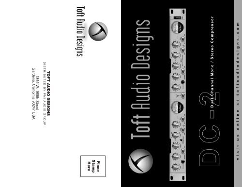
The <strong>DC</strong>-2 provides two channels of instrument/line amplifiers and F.E.T.<br />
compressors. Each compressor can be used independently or linked for<br />
stereo operation. The unit will take the signal from a line level source<br />
or instrument and process it so that it is ready to feed straight into a<br />
recording device such as a computer controlled digital audio workstation<br />
or analog storage device such as a multi-track tape recorder. Each<br />
section can also be inserted into the path of a mixer channel to provide<br />
individual channel compression, or as a linked pair, the two channels<br />
can be placed across the stereo mix.<br />
The outputs from each channel are low impedance and designed to<br />
operate with long cable runs without signal degradation such as loss of<br />
high frequencies. The front panel instrument input is high impedance<br />
designed to work with a wide range of musical instruments such as<br />
guitars, basses and electronic keyboards.<br />
A standard I.E.C. mains inlet is provided for A.C mains power and universal<br />
voltages of either 110 or 240 volts are selectable by rotating the<br />
fuse holder incorporated in the mains inlet socket.<br />
Each of the two sections offer a wide range of control coupled with<br />
extremely high quality analog electronics that have a real pedigree. The<br />
line/instrument amplifier is the same design as used in Malcolm <strong>Toft</strong>’s<br />
top range of recording consoles, while the compressor section borrows<br />
heavily from vintage Trident designs. It can operate as two separate<br />
channels, or by using the compressor ‘couple’ control can be linked so<br />
that the stereo image does not shift when compression is taking place<br />
(more about this in the compressor section). Because of this feature,<br />
it is also possible to connect the <strong>DC</strong>-2 across the final mix to add the<br />
finishing touches as a mastering tool.<br />
The <strong>DC</strong>-2 can be used to provide a pristine signal path of exceptional<br />
quality when required allowing subtle control of the audio path, or it can<br />
be used to add extra punch and dynamics to an otherwise lackluster<br />
signal.<br />
3
4<br />
F.E.T. COMPRESSOR<br />
INPUT SECTION<br />
There are many ways to control or reduce the dynamic range of signal<br />
and these include photo-optical devices where the signal triggers a light<br />
emitting device such as an led which in turn shines on to a photo electric<br />
cell. The cell then varies in resistance according to the light shining<br />
upon it and the more light, the lower the resistance gets. This can then<br />
be used to reduce the signal level and therefore control the dynamic<br />
range. Compressors based on these devices were particularly popular<br />
in the sixties and are known for their characteristic ‘soft’ form of compression.<br />
This is also true of tube based compressors which usually<br />
operate on a ‘variable mu’ principle to control the dynamic range. More<br />
modern developments use either a voltage controlled amplifier which<br />
is very easy to mathematically predict and provides extra facilities such<br />
as ‘hard and soft knee’ compression, or the one we have chosen, the<br />
F.E.T. This way of controlling signal dynamics was particularly popular<br />
in the seventies and has unique characteristics of it’s own. Because<br />
of the nature of the device it can provide extremely fast attack times<br />
and consequently has the ability to really control the dynamics of audio<br />
signal. The design of the compressor is based around a circuit used by<br />
Trident in the early eighties that proved very popular with many recording<br />
studios. Whilst there are many companies producing optical, tube<br />
and vca based compressors, F.E.T based designs are much rarer and<br />
normally very expensive as they need care in setting up. We have been<br />
able to minimize the setup needed and are able to offer the unique<br />
F.E.T. characteristics at an affordable price.<br />
The input section of the <strong>DC</strong>-2 consists of a very high quality line amplifier<br />
designed specifically for professional audio applications. It exhibits near<br />
theoretical minimum noise figures, has an extremely fast transient response<br />
and will handle a wide range of input levels with a frequency response that<br />
extends above 40kHz. The input level can be adjusted continuously over<br />
a wide range and the input control is conveniently calibrated so that in its<br />
center position, the gain is zero.<br />
When connecting a line level signal to the input of the unit, the ‘Instr./Line’<br />
selector switch should be selected to ‘Line’ and the ‘Instr./Line Gain’ control<br />
sets to it’s midway position (‘0’). The ‘Comp’ switch should be set to ‘OUT’<br />
(led extinguished). The V.U meter can be used to monitor the output level<br />
of the unit after having first selected it’s appropriate ‘Meter’ switch (situated<br />
to the left of the meter) to the ‘O/P’ position. The ‘Input’ control should be<br />
set so that signal peaks go just into the red portion of the meter scale and<br />
should never cause the meter to deflect fully right for sustained periods.<br />
This will provide a suitable operating level for the unit and will match other<br />
professional audio equipment. The <strong>DC</strong>-2 is in fact capable of very high<br />
output levels (up to +26dBm) but by setting the level as described above,<br />
adequate overload margins are maintained and there should be no danger<br />
of overloading following equipment.<br />
When using an instrument input, the ‘Instr./Line’ switch should be selected<br />
to ‘Instr.’ and the ‘Input’ control set to its fully anti-clockwise position. The<br />
‘Input’ gain control should be advanced clockwise and in the same way as<br />
described above, the VU meter can be used to set an appropriate level<br />
through the unit.<br />
Stereo Couple Switch<br />
Operating The Compressor<br />
The stereo couple switch links the control voltages of both sections to<br />
reduce image shifting when the <strong>DC</strong>-2 is used as a stereo compressor.<br />
It should be pointed out that like similar other F.E.T compressors such<br />
as the UREI 1176, the couple switch does not make one particular channel<br />
control the other. It is designed so that when both channels have<br />
their ‘Attack’, ‘Ratio’ and ‘Release’ controls set to the same positions,<br />
the channel with the greatest compression will attenuate both channels<br />
rather than just it’s own. This avoids image shift as one signal decreases<br />
in level more than the other and signals for example placed in the<br />
middle of the stereo image appear to move either to the left or right.<br />
All the compressor related controls, ‘Attack’, ‘Release’, ‘Ratio’ and ‘Make<br />
Up Gain’ should first be set to their minimum positions (fully anti-clockwise).<br />
The input level should be set in accordance with the instructions given in<br />
the preceding section ‘Input Section’. This is very important as the compressor<br />
section works on the principle of a fixed ‘threshold’. This is the preset<br />
position at which the compressor starts to operate. Signals below the<br />
‘threshold’ will not be compressed and therefore the circuitry will not operate<br />
at its optimum. The ‘Comp’ switch should be set to the ‘IN’ position (led<br />
illuminated) and the ‘Make Up Gain’ control advanced to its midway point.<br />
Like the ‘Input’ control, this is set up so that in it’s midway position, the unit<br />
is designed to give unity or 0dB gain. The signal on the VU meter should<br />
now read the same whether the ‘Comp’ switch is set to ‘IN’ or ‘OUT’. Now<br />
switch the ‘Gain Reduction’ switch to the left of the meter to ‘G.R.’ (Gain<br />
Reduction). The meter will now indicate ‘0’ whether signal is present or not<br />
and irrespective of signal level. This is because in ‘G.R’ mode the meter is<br />
designed to give an indication of the amount that the signal is being attenuated<br />
by the compressor circuit. Now advance the ‘Ratio’ control slowly and<br />
compression of the signal will take place. On most programme material it<br />
will not be necessary to advance the ratio control very far to get the desired<br />
effect. The ‘Make Up Gain’ control can be advanced clockwise to adjust for<br />
any difference in output level caused by the compressor. The ‘Attack’ and<br />
‘Release’ control settings depend on the nature of the audio signal through<br />
the compressor. For example, a bass guitar is best processed using a<br />
slower attack time (‘Attack’ control advanced clockwise) for example, as the<br />
extremely fast attack time of the compressor may not be desirable on such<br />
a percussive instrument. For vocals, a fast attack time and slow release<br />
could be favoured in order to avoid ‘pumping’ effects common in many<br />
compressors without the range of control that the <strong>DC</strong>-2 offers. In using<br />
compressors, it is very much a case of experimentation to find what suits<br />
different instruments and different program material.<br />
Malcolm <strong>Toft</strong>, Designer<br />
5
6<br />
TROUBLESHOOTING<br />
3) The instrument input doesn’t work.<br />
1) No Power.<br />
Is it connected to the front panel jack socket of the appropriate<br />
channel?<br />
Is the ‘Instr./Line’ switch selected to ‘Instr.’?<br />
Make sure the unit is selected for the correct mains voltage via the selector<br />
incorporated in the mains inlet socket on the back of the unit. Check the<br />
fuse (also in the mains inlet socket) if the unit has been powered with the<br />
wrong voltage.<br />
Check the lead from the instrument.<br />
Check there is a main supply reaching the unit.<br />
Make sure the ‘Input’ control is turned up.<br />
2) The line input doesn’t work.<br />
Is it connected to the correct input on the back of the unit?<br />
Is the ‘Instr./Line’ switch selected to ‘LINE’<br />
4) The compressor doesn’t work.<br />
Make sure the ‘Input’ control is turned up.<br />
Is the ‘Comp In’ switch selected to ‘IN’ ?(led illuminated).<br />
Is the ‘Ratio’ control advanced clockwise?<br />
Is the ‘Make Up Gain’ control advanced clockwise? (set to midway).<br />
Is there enough signal (set by the ‘Mic/Line Gain’ control) to ‘drive’ the<br />
compressor?<br />
<strong>DC</strong>-2 TECHNICAL SPECIFICATIONS<br />
Distortion<br />
Line Input:
TOFT AUDIO DESIGNS LIMITED WARRANTY<br />
replacement by Purchaser of any Product or part thereof shall extend<br />
the warranty period as to the entire Product. The specific warranty on<br />
the repaired part only shall be in effect for a period of ninety (90) days following<br />
the repair or replacement of that part or the remaining period of<br />
the Product warranty, whichever is greater.<br />
THIS PRODUCT IS FOR PROFESSIONAL USE ONLY<br />
PMI <strong>Audio</strong> Group warrants that all products will be free from defects in material<br />
or workmanship:<br />
2. Exclusive Remedy: Acceptance: Purchaser’s exclusive remedy and<br />
PMI’s sole obligation is to supply (or pay for) all labor necessary to<br />
repair any product found to be defective within the warranty period<br />
and to supply, at no extra charge, new or rebuilt replacements for<br />
defective parts. If repair or replacement fails to remedy the defect, then<br />
and only in such an event, shall PMI exchange to Purchaser a new or<br />
reconditioned unit. Purchaser’s failure to make a claim as provided in<br />
paragraph 1 above or continued use of the product shall constitute an<br />
unqualified acceptance of such Product and a waiver by Purchaser of<br />
all claims thereto.<br />
A: For a period of (3) three years from the date of purchase (hereinafter the<br />
labor warranty period), PMI <strong>Audio</strong> Group will repair or replace this Product if<br />
determined to be defective. After the expiration of the labor warranty period,<br />
the Purchaser must pay labor charges.<br />
B: In addition, PMI <strong>Audio</strong> Group will supply, at no charge, replacements for<br />
defective parts for a period of (three years) from the date of purchase. During<br />
the labor warranty period, to repair the Product, Purchaser must return the<br />
defective Product, freight prepaid, or deliver it to PMI <strong>Audio</strong> Group Service<br />
Center. The product to be repaired is to be returned in either its original carton<br />
or a similar package affording an equal degree of protection. PMI <strong>Audio</strong><br />
Group will return the repaired Product freight prepaid to the Purchaser. PMI<br />
<strong>Audio</strong> Group is not obligated to provide Purchaser with a substitute unit during<br />
the warranty period or at any time.<br />
3. Exceptions to Limited warranty: PMI shall have no liability or obligation<br />
to Purchaser with respect to any Product subjected to abuse, improper<br />
use, negligence, accident, modification, failure of the end-user to follow<br />
the operating and maintenance procedures outlined in the users manual,<br />
attempted repair by non-qualified personnel, operation of the unit<br />
outside of the published environmental and electrical parameters, or<br />
if such products original identification (trademark, serial number) markings<br />
have been defaced, altered, or removed. PMI excludes from warranty<br />
coverage, Products sold AS IS and/or WITH ALL FAULTS and excludes<br />
used products which have not been sold by PMI to the Purchaser. PMI<br />
also excludes from warranty coverage consumables such as fuses and<br />
batteries, tubes, etc.<br />
CONDITIONS<br />
4. Proof of purchase: The dealer’s dated bill of sale must be retained as<br />
evidence or the date of purchase and to establish warranty eligibility<br />
1. Notification of claims: Warranty Service: If Purchaser discovers that the<br />
Product has proven defective in material or workmanship, then written notice<br />
with an explanation of the claim shall be given promptly by Purchaser to PMI<br />
but all claims for warranty service must be made within the warranty period. If<br />
after investigation PMI determines that the reported problem was not covered<br />
by the warranty, Purchaser shall pay PMI for the cost of investigating the<br />
problem at its then prevailing time-and-materials rate. No repair or<br />
9
DISCLAIMER OF WARRANTY<br />
OWNERS REGISTRATION CARD<br />
T O B E C O M P L E T E D AT T I M E O F P U R C H A S E<br />
EXCEPT FOR THE FORGOING WARRANTIES, PMI HEREBY DISCLAIMS AND<br />
EXCLUDES ALL OTHER WARRANTIES, EXPRESS OR LIMITED, INCLUDING, BUT<br />
NOT LIMITED TO ANY/OR ALL IMPLIED WARRANTIES OF MERCHANT ABILITY,<br />
Name _____________________________________________<br />
FITNESS FOR A PARTICULAR PURPOSE AND/OR ANY WARRANTY WITH REGARD<br />
TO ANY CLAIM OF INFRINGEMENT THAT MAY BE PROVED IN SECTION 2-312(3)<br />
Date of Purchase ____________________________________<br />
OF THE UNIFORM COMMERCIAL CODE AND/OR IN ANY COMPARABLE STATE<br />
STATUE. PMI HEREBY DISCLAIMS ANY REPRESENTATIONS OR WARRANTY THAT<br />
Serial Number ______________________________________<br />
THE PRODUCT IS COMPATIBLE WITH ANY COMBINATION OF NON-PMI AUDIO<br />
PRODUCTS PURCHASER MAY CHOOSE TO CONNECT TO THE PRODUCT.<br />
Dealer’s Name ______________________________________<br />
LIMITATION ON LIABILITY<br />
THE LIABILITY OF PMI, IF ANY, AND PURCHASER’S SOLE AND EXCLUSIVE REMEDY<br />
R E TA I N F O R Y O U R R E C O R D S<br />
FOR DAMAGES FOR ANY CLAIM OF ANY KIND WHATSOEVER, REGARDLESS OF<br />
THE LEGAL THEORY AND WHETHER ARISING IN TORT OR CONTRACT, SHALL<br />
P L E A S E D I S PAT C H A N D R E T U R N<br />
Y O U R R E G I S T R AT I O N<br />
T O T O F T A U D I O D E S I G N S<br />
OR REGISTER ONLINE AT TOFTAUDIODESIGNS.COM<br />
W I T H I N 1 4 D AY S O F P U R C H A S E<br />
NOT BE GREATER THAN THE ACTUAL PURCHASE PRICE OF THE PRODUCT<br />
WITH RESPECT TO WHICH SUCH CLAIM IS MADE. IN NO EVENT SHALL PMI<br />
BE LIABLE TO PURCHASER FOR ANY SPECIAL, INDIRECT, INCIDENTAL, OR<br />
CONSEQUENTIAL DAMAGES OF ANY KIND INCLUDING, BUT NOT LIMITED<br />
TO, COMPENSATION, REIMBURSEMENT OR DAMAGES ON ACCOUNT OF THE<br />
LOSS OF PRESENT OR PROSPECTIVE PROFITS OR ANY OTHER REASON<br />
WHATSOEVER.<br />
Specifications and model numbers are subject to change without notice<br />
PRODUCT REGISTRATION INFORMATION<br />
PLEASE FILL IN THE BELOW SECTIONS AND RETURN<br />
Name:<br />
Address:<br />
City: State: Zip Code:<br />
Telephone Number: email Address:<br />
Model Purchased: Date Purchased:<br />
Serial Number: Dealer:<br />
Comments:<br />
What magazines do you read to influence your buying decision: (please check all that apply)<br />
Pro Sound News<br />
❏ MIX ❏ Electronic Musician ❏ EQ ❏ Home Recording ❏ Pro <strong>Audio</strong> Review ❏ Recording ❏


