Fig. N1 Cut-away view of - The Rolls-Royce and Bentley Technical ...
Fig. N1 Cut-away view of - The Rolls-Royce and Bentley Technical ...
Fig. N1 Cut-away view of - The Rolls-Royce and Bentley Technical ...

Create successful ePaper yourself
Turn your PDF publications into a flip-book with our unique Google optimized e-Paper software.
<strong>Fig</strong>. <strong>N1</strong> <strong>Cut</strong>-<strong>away</strong> <strong>view</strong> <strong>of</strong> steering b ~x4II<br />
camnd<br />
steering colwnn-earty cars
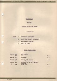
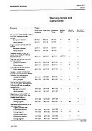
FIG. <strong>N1</strong> CUT-AWAY VIEW OF STEERING BOX-ALL CARS-AND<br />
ST EERlNG COLUMN-EARLY CARS<br />
1 Housing 10 Stub shaft 19 Horn contact<br />
2 Rack-piston end 11 Ball <strong>and</strong> trunnion brush<br />
plug joint 20 Earth contact<br />
3 Rack-piston 12 Safety stalk 21 Inner steering<br />
4 Worm 13 Adjusting plug tube<br />
5 Bleed screw 14 Locking nut 22 Outer steering<br />
6 Rocker shaft 15 Circlip tube<br />
7 Valve body 16 Inner race 23 Inner race<br />
8 Valve spool 17 Horn slip ring 24 Horn contact<br />
9 Torsion bar 18 Earth slip ring 25 Horn button
- k<br />
<strong>Rolls</strong>-<strong>Royce</strong> Silver Shadow B <strong>Bentley</strong> T Series Workshop Manual<br />
Chapter N<br />
Chapter N<br />
POWER ASSISTED STEERING<br />
SYSTEM<br />
Section <strong>N1</strong><br />
THE STEERING COLUMN (early cars)<br />
Lower steering column-To remove<br />
<strong>The</strong> lower steering column is removed from under-<br />
neath the car.<br />
1. Place the car on a ramp then unscrew <strong>and</strong> remove<br />
the two bolts <strong>and</strong> nuts from the in-line joint located<br />
below the toe-board.<br />
3 2. Remove the pinch bolt from the splined clamp<br />
8 C<br />
CR<br />
connecting the column to the steering box input shaft<br />
<strong>and</strong> ease the clamp <strong>of</strong>f the shaft splines.<br />
3. Remove the lower column from the car, taking<br />
care not to extend the lower joint otherwise its internal<br />
components will come apart.<br />
Lower steering column universal joint-<br />
To dismantle<br />
Remove the lower steering column from the car as<br />
described previously under 'Lower steering column-<br />
To remove'.<br />
1. Mark the splined clamp <strong>and</strong> universal joint body<br />
with correlation marks to ensure that on assembly, the<br />
(cars prior to number SRX 6001)<br />
Overhaul<br />
3. Ease both ends <strong>of</strong> the convoluted boot from their<br />
location on the joint body <strong>and</strong> the knuckle end piece.<br />
4. Holding the boot <strong>away</strong> from the joint <strong>and</strong> using<br />
a small screwdriver remove the circlip from the uni-<br />
versal joint <strong>and</strong> ease the ball <strong>and</strong> trunnion assembly<br />
out <strong>of</strong> the housing. Alternatively deflect the joint, as<br />
far as possible parallel to the cross-pin then carefully<br />
pull apart over the circlip which need not be removed.<br />
Note To prevent the bearing <strong>and</strong> retainers<br />
from disintegrating, the housing must be<br />
held so that the trunnion pin assembly<br />
is horizontal as it is removed.<br />
5. Remove the convoluted boot, carefully easing it<br />
over the trunnion buttons.<br />
6. Remove the trunnion buttons, belleville washers,<br />
bearings, retainers <strong>and</strong> thrust washers from the<br />
trunnion pin. <strong>The</strong> individual bearing <strong>and</strong> button as-<br />
semblies should be retained together as assemblies <strong>and</strong><br />
it should be noted from which side <strong>of</strong> the trunnion<br />
pin each was removed.<br />
X<br />
2i<br />
5<br />
same relative positions are maintained.<br />
Lower steering column universal joint-<br />
To inspect<br />
h 2. Slacken <strong>and</strong> remove the clips from either end <strong>of</strong> 1. Wash all components in paraffin <strong>and</strong> dry them<br />
c;<br />
the convoluted boot.<br />
prior to inspection. Inspect the bores <strong>of</strong> the housing
Workshop Manual <strong>Rolls</strong> <strong>Royce</strong> Silver Shadow 8 <strong>Bentley</strong> T Sertes<br />
Chapter IY<br />
for signs <strong>of</strong> wear, pitting or damage. <strong>The</strong> diameter <strong>of</strong><br />
the two outer button location bores should be 1.000 in.<br />
to 1.001 in. (2,54 cm. to 2,542 cm.).<br />
2: <strong>The</strong> trunnion button <strong>and</strong> bearing retainers should<br />
be smooth <strong>and</strong> free from surface defects. <strong>The</strong> inside<br />
<strong>and</strong> outside diameters <strong>of</strong> the retainers should be<br />
0.3937 in. <strong>and</strong> 0.5512 in. (0,998 cm. <strong>and</strong> 1.40 cm.)<br />
respectively.<br />
3. <strong>The</strong> roller bearing <strong>and</strong> the trunnion pin surface<br />
should be smooth <strong>and</strong> free from defects. <strong>The</strong> diameter<br />
<strong>of</strong> the rollers is 0.999 in. to 0.9995 in. (2,5374 cm. to<br />
2,5375 cm.) <strong>and</strong> the trunnion pin diameter at the<br />
bearing areas is 0.39345 in. to 0.3937 in. (0,9983 cm. to<br />
0,9984 cm.).<br />
4. <strong>The</strong> belleville washer should be free from cracks<br />
or distortions. It should have a minimum free height<br />
<strong>of</strong> 0.016 in. (0,041 cm.).<br />
5. <strong>The</strong> trunnion pin should be inspected for position<br />
with a depth micrometer or by placing the knuckle<br />
end between centres <strong>and</strong> checking the pin ends with a<br />
dial test indicator. <strong>The</strong> pin should be within 0.006 in.<br />
(0,0152 cm.) <strong>of</strong> the centre line <strong>of</strong> the knuckle end<br />
piece.<br />
6. If the trunnion pin position is inspected by using<br />
a dial test indicator with the knuckle piece between<br />
centres, it will be necessary to remove the splined<br />
clamp from the end <strong>of</strong> the knuckle. <strong>The</strong> two set-<br />
screws which secure the clamp lie in slotted holes in<br />
the splined coupling flange which provides a small<br />
degree <strong>of</strong> fine adjustment when steering wheel cen-<br />
tralisation is being carried out. It is therefore advisable<br />
to mark the coupling with correlation marks before<br />
disconnecting it to facilitate fitting it in the same<br />
relative position on assembly.<br />
7. In the unlikely event <strong>of</strong> the trunnion pin requiring<br />
replacement, it must be pressed out <strong>and</strong> a new one<br />
pressed in squarely to conform with the above infor-<br />
mation, on central position.<br />
Note Heat should not be applied to remove or<br />
fit a trunnion pin.<br />
<strong>The</strong> interference between the trunnion pin <strong>and</strong><br />
knuckle is 0.003 in. (0,076 mm.).<br />
Steering column universal joint-<br />
To assemble<br />
To assemble the steering column universal joint<br />
reverse the procedure given for its dismantling, noting<br />
the following points.<br />
1. <strong>The</strong> alignment marks previously made on the<br />
body <strong>and</strong> joint housing should be lined up before<br />
entering the pin <strong>and</strong> bearing assembly.<br />
N2<br />
2. On assembly, the trunnion bearings, housing<br />
bores <strong>and</strong> buttons should be lubricated with a liberal<br />
application <strong>of</strong> Retinax 'A' grease, <strong>and</strong> care should be<br />
taken to ensure that the circlip <strong>and</strong> sealing boot are<br />
fitted <strong>and</strong> located correctly. New clips must be used<br />
to attach the boot <strong>and</strong> must hold it tightly.<br />
3. If the splined coupling has been disconnected<br />
from the knuckle piece it must be replaced in its<br />
correct position according to the correlation marks<br />
made before dismantling.<br />
Lower steering column bonded coupling-<br />
To renew<br />
Remove the lower steering column from the car as<br />
previously described under 'Lower steering column-<br />
To remove'.<br />
1. Mark the steering column on both sides <strong>of</strong> the<br />
bonded coupling to ensure that the wheel position<br />
remains unchanged on assembly.<br />
2. Remove the four socket-headed setscrews <strong>and</strong><br />
nuts from the bonded coupling, withdraw the safety<br />
stalk <strong>and</strong> remove the coupling.<br />
3. Fit a new bonded coupling reversing the pro-<br />
cedure given for its removal, noting that the marks<br />
made on each half <strong>of</strong> the column should be lined up<br />
<strong>and</strong> the nuts on the socket-headed screws should be<br />
torque tightened to between 16 lb. ft. <strong>and</strong> 18 lb. ft.<br />
(2,21 kg.m. to 2,48 kg.m.).<br />
Lower steering column-To fit<br />
To fit the lower steering column reverse the procedure<br />
given for its removal, noting the following points.<br />
1. It will be noted that the splined clamp has a flat<br />
machined in the splined bore which corresponds with<br />
a flat machined on the steering box input shaft. This<br />
ensures that the steering wheel position remains un-<br />
changed, provided that the clamp has not been dis-<br />
connected from the universal joint. If the clamp has<br />
been disconnected from the universal joint, the wheel<br />
must be set relative to the steering box (see Steering<br />
wheel-To set).<br />
2. <strong>The</strong> two bolts <strong>and</strong> nuts securing the joint at the<br />
toe-board should be torque tightened to between<br />
16 lb. ft. <strong>and</strong> 18 lb. ft. (2,21 kg.m. <strong>and</strong> 2,48 kg.m.) <strong>and</strong><br />
the splined clazip pinch bolt torque tightened to<br />
between 16 lb. ft. <strong>and</strong> 18 lb. ft. (2,21 kg.m. <strong>and</strong> 2,48<br />
kg.m.).
L -<br />
2<br />
<strong>Rolls</strong>-<strong>Royce</strong> Silver Shadow & Bentlev T Series Workshon Manual<br />
Steering wheel-To remove<br />
1. Remove the gear selector cowling, which is in<br />
two pieces, by unscrewing <strong>and</strong> removing the six<br />
Phillips setscrews located in the cowl lower half; the<br />
upper section <strong>of</strong> the cowl is secured by the four outer<br />
setscrews <strong>and</strong> the lower section by the remaining two<br />
setscrews.<br />
2. Unscrew the three nuts located behind the<br />
steering wheel <strong>and</strong> remove the horn button assembly<br />
from the steering wheel centre.<br />
3. Withdraw the horn contact plate <strong>and</strong> disconnect<br />
the electrical plug.<br />
4<br />
a 4. Unlock the tab washer then unscrew <strong>and</strong> remove<br />
c the nut which secures the steering wheel to the column.<br />
G<br />
e - B<br />
5. Before removing the wheel, the centre <strong>of</strong> the<br />
M<br />
5 column <strong>and</strong> the steering wheel inner boss face should<br />
.- C be suitably marked to ensure that the wheel is replaced<br />
in the same relative position on assembly.<br />
B .-<br />
.- c<br />
2 6. Replace the nut to prevent possible damage to<br />
the threaded end <strong>of</strong> the column, then, using special<br />
tool (RH 7870), extract the wheel. Remove the tool<br />
<strong>and</strong> the wheel securing nut <strong>and</strong> lift <strong>away</strong> the wheel.<br />
B<br />
$<br />
Horn button assembly-To dismantle<br />
Remove the horn button assembly as described above<br />
under 'Steering wheel-To remove'.<br />
2. Remove the button <strong>and</strong> plunger assembly <strong>and</strong><br />
the return spring.<br />
Horn button assembly-To assemble<br />
I . To assemble tlie horn button assembly reverse<br />
the procedure given for its dismantli~lg ensuring that<br />
the rcturn spri~ig <strong>and</strong> the securing circlip are located<br />
correctly. Ligh~ly lubricate the horn button guide<br />
stems with Rocol 204G Ragosine or equivalent grease.<br />
Gearchange selector switch-To remove<br />
(see <strong>Fig</strong>. N2)<br />
Chapter N<br />
3. Remove the two screws retaining the lower half<br />
<strong>of</strong> the cowling to its clamping bracket; remove the<br />
lower half <strong>of</strong> the cowling.<br />
4. Disconnect the indicator lamp.<br />
5. Disconnect the micro-switch(es).<br />
6. Remove the screws securing the switch insulating<br />
plate.<br />
7. Remove the gearchange selector.<br />
Gearchange selector switch-To dismantle<br />
I. Remove the screws securing the micro-switch(es)<br />
to the rear face <strong>of</strong> the base assembly <strong>and</strong> remove the<br />
micro-switch(es).<br />
2. Remove the operating arm from the spindle <strong>of</strong><br />
the quadrant.<br />
3. Remove the single 'Phillips' screw securing the<br />
pointer to the quadrant boss <strong>and</strong> remove the pointer.<br />
Note Care must be taken not to scratch the<br />
pointer or the indicator scale.<br />
4. Remove the two 'Phillips' screws <strong>and</strong> shake-pro<strong>of</strong><br />
washers securing the indicator support bracket to the<br />
two bosses on the base assembly, then remove the<br />
indicator support bracket assembly.<br />
5. kmove the two hexagon-headed 3 B.A. screws<br />
securing the gate assembly to the underside <strong>of</strong> the<br />
3<br />
5<br />
3<br />
I. Depress the button <strong>and</strong> remove the circlip which<br />
secures the button <strong>and</strong> plunger assembly to the<br />
housing.<br />
base.<br />
6. Remove the circlip, clevis pin <strong>and</strong> spring securing<br />
the gear selector lever to the quadrant, then remove the<br />
lever with the gate assembly attached.<br />
a r-<br />
I. Disconnect the battery.<br />
7. Remove the two 'Phillips' screws securing the<br />
phosphor-bronze contact to the base plate. Retain the<br />
two insulating dowels <strong>and</strong> the two insulating strips.<br />
8. Remove the circlip from the other end <strong>of</strong> the<br />
rocking arm.<br />
9. Remcve the rocking arm to quadrant tension<br />
springs; remove the rocking arm assembly.<br />
10. Remove the in. U.N.F. nut <strong>and</strong> washer from<br />
the quadrant spindle <strong>and</strong> remove the quadrant<br />
assembly from the base assembly.<br />
Gearchange selector switch-To assemble<br />
v 2. Remove the screws retaining the upper <strong>and</strong> lower<br />
-4<br />
halves <strong>of</strong> the cowling. <strong>The</strong>se halves should always be 1. Fit the n,;,idrattt assembly onto the base <strong>and</strong> nip<br />
h<br />
L: retained as a set. Carefully remove the upper half <strong>of</strong> the f in. U.N.F. nut <strong>and</strong> washer onto the spindle.<br />
I- the cowling. Check that the quadrant is free to rotate.
Workshop Manual <strong>Rolls</strong> <strong>Royce</strong> Silver Shadow 8 <strong>Bentley</strong> T Series<br />
Chapter #<br />
14 Spring-contact-gearchange<br />
3<br />
selector - - . - - - - .<br />
15 Dowel-insulating (2)<br />
FIG. N2 STEERING COLUMN<br />
16 SUDD~V contact<br />
COWLING ASSEMBLY (R.H. DRIVE CARS)<br />
17 ~eed contact<br />
18 Plate insulating-5 position<br />
(REMOTE GEARCHANGE AND DIRECTION INDICATOR MECHANISMS) arm-reversing lamp<br />
1 Indicator scale 8 Spring-tension-rocking . -<br />
arm 20 Micro-switch<br />
2 Filter-indicator lamp 9 spring-lever-gear selector 21 Bracket micro-switch mounting<br />
3 Bulb holder<br />
10 Quadrant assembly-5 position 22 Clam~earchange<br />
4 Bracket-indicator support<br />
base<br />
5 Cowl halves-upper <strong>and</strong> lower<br />
11 Rocking arm<br />
23 Clamp-cowl to steering column<br />
6 Pointer--gearchange selector 12 Base assembl~+ear Selector 24 Bracket-support assembly-<br />
7 Lever-assembly--gear selector 13 Insulating strips (2) 5 position
<strong>Rolls</strong>-<strong>Royce</strong> Silver Shadow & <strong>Bentley</strong> T Series Workshop Manual<br />
2. Remove the quadrant <strong>and</strong> lubricate the spindle<br />
with Ragosine 204G or equivalent grease. Refit the<br />
quadrant <strong>and</strong> finally tighten the ) in. U.N.F. nut.<br />
3. Do not overtighten the nut, since the bearing<br />
boss tends to spread slightly <strong>and</strong> a tight bearing may<br />
be formed.<br />
4. Fit the rocking arm assembly, then check to<br />
ensure that the roller lines up correctly with the<br />
quadrant detent form.<br />
5. Remove the rocking arm <strong>and</strong> hook the tension<br />
spring onto the anchor pin roller on the underside <strong>of</strong><br />
the quadrant <strong>and</strong> onto the spring anchor on the<br />
underside <strong>of</strong> the rocking arm.<br />
This operation is made easier by rotating the<br />
quadrant anti-clockwise beyond its normal travel, so<br />
that the spring is not under tension. Rotate the<br />
quadrant clockwise whilst holding the rocking arm<br />
clear, then allow the roller to locate on the detent<br />
forms. Fit the spring on the top side <strong>of</strong> the quadrant<br />
<strong>and</strong> rocking arm.<br />
Note Do not fit the retaining clip to the rocking<br />
arm at this stage. (<strong>The</strong>y are difficult to<br />
remove, should the need arise).<br />
6. Move the quadrant to a mid-way position <strong>and</strong><br />
fit the phosphor-bronze contact. This contact is<br />
assembled between two insulating strips which are<br />
located by two insulating dowels. This s<strong>and</strong>wich<br />
assembly is then secured to the quadrant by two<br />
screws <strong>and</strong> washers.<br />
Important Extreme caution must be taken with<br />
the moving contact, so that it is not<br />
bent or damaged in any way.<br />
7. Before fitting the selector lever assembly carry<br />
out the following checks.<br />
Check that the clevis pin will slide through both the<br />
fork end on the lever <strong>and</strong> the holes in the mounting<br />
bosses on the quadrant, then check that the fork end<br />
will slide between these bosses.<br />
8. Lightly smear Ragosine 2040 or equivalent<br />
grease on the outside <strong>of</strong> the fork end, the inside <strong>of</strong> the<br />
bosses, the clevis pin <strong>and</strong> the clevis pin holes, then<br />
locate the fork end in the bosses by the clevis pin <strong>and</strong><br />
fit the spring inside the fork end <strong>and</strong> over the clevis<br />
pin. Push home the pin <strong>and</strong> fit the circlip. Check that<br />
the lever will return easily under the load <strong>of</strong> the spring.<br />
9. Secure the gate assembly to the underside <strong>of</strong> the<br />
base by means <strong>of</strong> the two hexagon-headed 3 B.A.<br />
screws.<br />
Check that, when the position <strong>of</strong> the lever is con-<br />
trolled by the detents, it lines up with the pr<strong>of</strong>ile <strong>of</strong><br />
the gate liner <strong>and</strong> that the extreme positions <strong>of</strong> the<br />
lever are not limited by the gate.<br />
Chapter N<br />
10. Fit the insulating plate complete with the feed<br />
<strong>and</strong> supply contacts fitted to it.<br />
When the unit is screwed down by the three screws,<br />
check that the inside leg <strong>of</strong> the moving contact is<br />
pressing onto the supply contact <strong>and</strong> that at the<br />
extremities <strong>of</strong> its travel the hemispherical head is still<br />
making good contact with the supply contact.<br />
11. Each selection should then be made in turn,<br />
checking that the outside leg on the moving contact<br />
lines up correctly with each <strong>of</strong> the feed contacts.<br />
12. Mount this assembly on the two bosses on the<br />
base by means <strong>of</strong> the two screws <strong>and</strong> shake-pro<strong>of</strong><br />
washers.<br />
13. Fit the blue filter with its flattened end in front<br />
<strong>of</strong> the bulb <strong>and</strong> behind the bracket mounting screw<br />
heads. Bend the radiused top end over the bulb <strong>and</strong><br />
check that it follows the contours <strong>of</strong> the support<br />
bracket.<br />
14. Hold the filter in this position by means <strong>of</strong> a<br />
0.025 in. (0,64 mm.) feeler gauge held from the front<br />
<strong>of</strong> the unit, fit the indicator scale over the support<br />
bracket <strong>and</strong> secure it with two self-tapping screws. <strong>The</strong><br />
scale should drop onto the bracket <strong>and</strong> its lip must<br />
not be forced down.<br />
15. Feed the pointer under the indicator scale, then<br />
with '3 range' selected use a thin-blade 'Phillips' head<br />
screwdriver, to feed the single 5 B.A. screw through<br />
the pointer leg <strong>and</strong> screw it into the quadrant boss.<br />
Care should be takeh not to scratch either the pointer<br />
or the indicator scale.<br />
16. Each selection should then be made <strong>and</strong> the<br />
alignment <strong>of</strong> the pointer checked.<br />
17. Fit the micro-switch(es) onto the two bosses on<br />
the rear face <strong>of</strong> the base assembly. Fit the operating<br />
arm onto the spindle <strong>of</strong> the quadrant. On a car not<br />
fitted with refrigeration set the operating arm so that<br />
the single micro-switch is depressed when the selection<br />
is 'R'. On a car fitted with refrigeration the two micro-<br />
switches require setting so that the fast-idle micro-<br />
switch is depressed just as the selector is engaging 'N'.<br />
Check that the 'R' micro-switch is operated satis-<br />
factorily.<br />
Note On left-h<strong>and</strong> drive cars with refrigeration<br />
the fast-idle cam is engaged in both N<br />
<strong>and</strong> P positions.<br />
18. Fit the. retaining clip to the rocking arm pivot.<br />
19. Lightly smear Ragosine 204G or equivalent<br />
grease on the quadrant detents, then operate the<br />
switch several times to ensure that the Ragosine is<br />
spread evenly.
Workshop Manua/ <strong>Rolls</strong> <strong>Royce</strong> Silver Shadow & Benlley T Series<br />
Chapter N<br />
Gearchange selector switch-To fit Upper steering column-To remove<br />
1. Fit the gearchange selector switch onto the<br />
steering column taking care to locate the switch dowel<br />
in the hole provided.<br />
Note To facilitate assembly it is advisable to<br />
place the bottom cowl clamp on the<br />
steering column before tightening the<br />
selector switch assembly.<br />
2. Connect the insulating pad <strong>and</strong> contact assembly,<br />
the micro-switch(es) <strong>and</strong> the indicator lamp wiring.<br />
3. Fit the lower half <strong>of</strong> the cowling onto its clamp-<br />
ing bracket then fit the upper half <strong>of</strong> the cowling.<br />
Note Care must be taken before tightening the<br />
cowling retaining screws to ensure that<br />
the wiring looms are not trapped between<br />
the cowl <strong>and</strong> cover.<br />
Direction indicator switch-To remove<br />
1. Disconnect the battery.<br />
2. Remove the gearchange selector switch as des-<br />
cribed previously.<br />
3. Disconnect the wiring loom.<br />
1. Remove the steering wheel as previously des-<br />
cribed under 'Upper steering column-To remove'.<br />
2. Disconnect the battery which is located in the<br />
boot.<br />
3. Unscrew <strong>and</strong> remove the two bolts from the in-<br />
line joint situated just below the toe-board in the<br />
engine compartment.<br />
4. Remove the circlip from the lower end <strong>of</strong> the<br />
upper column <strong>and</strong> remove the seal plate.<br />
5. Unplug the steering column wiring looms from<br />
the main fuse box.<br />
6. Disconnect the horn contact wires which are<br />
located pan way up the outer column.<br />
7. Support the steering column <strong>and</strong> unscrew <strong>and</strong><br />
remove the two Allen screws securing the steering<br />
column support clamp cap; remove the cap <strong>and</strong><br />
withdraw the column into the car <strong>and</strong> out through<br />
the door aperture.<br />
Note Care should be taken when manoeuvring<br />
the steering column inside the saloon to<br />
avoid damage to the woodwork <strong>and</strong><br />
trim, etc.<br />
4. Remove the two Allen screws securing the switch<br />
clamp to the column; remove the switch. Upper steering column-To dismantle<br />
Direction indicator switch-To fit<br />
1. Remove the steering wheel gearchange selector<br />
<strong>and</strong> direction indicator switch as previously described.<br />
1. To fit the direction indicator switch reverse the<br />
procedure given for its removal.<br />
Note <strong>The</strong> indicator switch has a dowel in its<br />
2. Remove the two screws securing the horn contact<br />
brush assembly to the column then remove the<br />
assembly.<br />
base which locates ia the steering column 3. Remove the screw securing the earth contact<br />
tube. strip to the column then remove the strip.<br />
1 lnner race<br />
2 Slip ring<br />
3 Earth slip ring<br />
FIG. N3 ASSEMBLY OF INNER STEERING TUBE<br />
4 lnner race<br />
A 28.525 in. f 0.005 in. (72,45 cm. f 0,12 mm.)<br />
B 3.000 in. f 0.01 0 in. (7.62 cm. f 0.25 mm.)
d<br />
b<br />
el<br />
CL<br />
c<br />
<strong>Rolls</strong>-<strong>Royce</strong> Silver Shadow 8 <strong>Bentley</strong> T Series Workshop Manual<br />
Chapter N<br />
4. Using spanners (RH 7871 <strong>and</strong> RH 7872), remove 2. Lubricate the earth contact slip ring with Gulf<br />
the lock-nut <strong>and</strong> plug from the lower end <strong>of</strong> the Elvolube grease or its equivalent.<br />
column, then remove the circlip which retains the<br />
bearing at the upper end <strong>of</strong> the column.<br />
. - - -<br />
5. Holding the column, lower end downwards*<br />
gently tap it around the base to jar the lower bearing<br />
race from its location within the tube.<br />
6. Care must be taken when this operation is<br />
carried out to ensure that as the bearing drops out <strong>of</strong><br />
the tube the ball bearings do not scatter.<br />
7. When this has been accomplished repeat the<br />
operation on the upper bearing, again taking precautions<br />
against losing the ball bearings.<br />
2<br />
'--g - Upper steering column thrust races-<br />
3 To renew<br />
." 0<br />
B<br />
.-<br />
Remove the inner column from the outer tube as<br />
e follow~.<br />
E<br />
1. Discard the felt seals fitted in the thrust races<br />
<strong>and</strong> the seal fitted in the top <strong>of</strong> the steering column.<br />
3. Insert the inner column into the outer tube.<br />
4. Grease the inner races with Rocol T 265 or<br />
equivalent grease <strong>and</strong> plaac 27 ball bearings in the<br />
grease on the bearing track <strong>of</strong> the upper race; the<br />
outer race <strong>and</strong> circlip, then fit the lower balls <strong>and</strong><br />
race in a similar manner. Using spanner (RH 7871),<br />
screw in the end plug until the end float in the column<br />
is just taken up, then using spanner (RH 7872),<br />
tighten the lock-nut. Do not overtighten the end plug<br />
or damage to the races will result. Do not lose balls<br />
between inner <strong>and</strong> outer columns.<br />
5. Fit <strong>and</strong> secure the earth contact strip also the<br />
horn button contact brush assembly to the column.<br />
6. Secure the gearchange selector <strong>and</strong> direction<br />
indicator mechanism clamp to the outer column by<br />
means <strong>of</strong> the two setscrews.<br />
7. Fit the steering wheel as outlined under 'Steering<br />
wheel-To fit <strong>and</strong> set'.<br />
2. . After the column has been removed <strong>and</strong> dis-<br />
Upper steering column-To fit<br />
mantled, remove the bearing races from the inner<br />
column after marking their positions with a pencil 1. To fit the upper steering column reverse the<br />
line. procedure given for its removal under 'Upper steering<br />
3. Press the new races into position on the inner<br />
remove'.<br />
column. <strong>The</strong> races must be positioned to conform<br />
with the dimensions given in <strong>Fig</strong>ure N3; the penci?<br />
00<br />
w<br />
z marks provide a useful guide. Steering wheel-TO fit <strong>and</strong> set<br />
4<br />
- 3<br />
V) 3<br />
Upper steering column-To assemble<br />
1. To fit the steering wheel reverse the procedure<br />
given for its removal. Ensure that the correlation<br />
marks (see Page N3-'Steering wheel-To remove'<br />
1. Fit a new felt seal into the top <strong>of</strong> the outer Operation 5) on the steering wheel inner boss face <strong>and</strong><br />
steering tube <strong>and</strong> into each thrust race. the centre <strong>of</strong> the column are aligned.
<strong>Fig</strong>. N4 <strong>Cut</strong>-<strong>away</strong> <strong>view</strong> - energy absorbing steering<br />
column <strong>and</strong> lower linkage
1 Steering box<br />
2 Pinch bolt-splined flange FIG.<br />
3 Ball <strong>and</strong> trunnion (Detroit) joint<br />
4 Universal joint 12 Earth contact<br />
5 Rubber bonded coupling 13 Rubber bushes (4)-upper n<br />
6 Safety stalk-bonded coupling 14 Tapped plat+upper mount<br />
7 In-line joint-upper column to lower 15 Distance tubes (2)-upper n<br />
linkage 16 Washer-(2)-upper mount<br />
8 Horn button 1 7 Capsule--upper mount<br />
9 Horn contact 18 Upper column mounting bra1<br />
10 Snap connector-horn wires 19 Upper column<br />
11 Horn earth contact 20 Upper column lower inner tu
Earth contact<br />
Rubber bushes (4)-upper mount<br />
Tapped plateupper mount<br />
Distance tubes (2)-upper mount<br />
Washer-(2)-upper mount<br />
Capsule-upper mount<br />
Upper column mounting bracket<br />
I Upper column<br />
1 Upper column lower inner tube<br />
FIG. N4 CUT-AWAY VIEW-ENERGY ABSORBING STEERING COLUMN AND LOWER LINKAGE<br />
21 Injected plastic rivets<br />
22 Upper column upper inner tube<br />
23 Meshed section <strong>of</strong> outer column<br />
24 Plastic outer covering<br />
25 Toe- board grommet<br />
26 Washer--grommet<br />
27 Circlip<br />
28 Column lower mounting point<br />
29 Nut<br />
30 Plain washer<br />
31 Rubber bushes (2)<br />
32 Plain washer<br />
33 Shim washers (as required)<br />
34 Capsule<br />
35 Mounting bracket<br />
36 Washer<br />
37 Column steering wheel securing nut
<strong>Rolls</strong>-<strong>Royce</strong> Silver Shadow 8 <strong>Bentley</strong> T Series Workshop Manual<br />
Section N2<br />
STEERING COLUMN (later L.H.D. cars)<br />
(car number SRX 6001 onwards)<br />
Overhaul<br />
Lower steering column-To remove Lower steering column universal joint-<br />
(sse <strong>Fig</strong>. N4) To dismantle<br />
<strong>The</strong> lower steering column linkage joints are removed If $he universal joint is unserviceable through excesfrom<br />
beneath the car as follows. sive wear <strong>and</strong>/or grease leakage, the joint must be<br />
I. Place the car on a ramp, apply the h<strong>and</strong>brake<br />
<strong>and</strong>/or chock the road wheels.<br />
dismantled <strong>and</strong> a replacement kit fitted, comprising a<br />
crucifornZ seals <strong>and</strong><br />
Proceed as follows.<br />
2. Disconnect the battery leads.<br />
3. From beneath the car, remove the two nuts,<br />
bolts <strong>and</strong> single washer retaining the halves <strong>of</strong> the<br />
in-line joint situated between the upper <strong>and</strong> lower<br />
steering columns.<br />
4. To facilitate assembly, note that the washer<br />
removed, fits beneath the nut <strong>of</strong> the upper bolt. Lower<br />
<strong>and</strong> support the linkage then proceed to disconnect<br />
the opposite end.<br />
5. Remove the pinch bolt <strong>of</strong> the slotted flange<br />
behind the ball <strong>and</strong> trunnion joint where it fits onto<br />
the splined input shaft <strong>of</strong> the steering box.<br />
6. Suitably scribe or mark correlation markings on<br />
the steering box input shaft, clamping plate <strong>and</strong> ball<br />
<strong>and</strong> trunnion joint to facilitate assembly.<br />
7. Remove the lower steering linkage from the car<br />
taking care not to extend the ball <strong>and</strong> trunnion joint<br />
too much.<br />
1. Using circlip pliers remove the circlips which<br />
retain the needle roller bearing races, then using a hide<br />
or wooden mallet, tap the yokes until each bearing in<br />
turn is driven out <strong>of</strong> the yoke eyes. Remove the cruci-<br />
form.<br />
Lower steering column universal joint-<br />
To assemble<br />
1. Smear the bearing surfaces <strong>of</strong> the new cruciform<br />
with grease <strong>and</strong> fit a new seal to the inner end <strong>of</strong> each<br />
surface diameter.<br />
2. Support the cruciform centrally in the yokes,<br />
then carefully press each new bearing assembly into<br />
its respective yoke eye. Each bearing must be pressed<br />
into the yoke such that it clears the circlip groove.<br />
3. Fit each circlip into its respective groove ensuring<br />
that each is fully seated.<br />
Test the joint by moving it through its maximum<br />
angular movement.<br />
\O Lower steering column ball <strong>and</strong> trunnion Lower steering column rubberlbonded<br />
% joint-To dismantle, To inspect, coup1 ing-To renew<br />
d L A To assemble Refer to page N2 <strong>of</strong> Section <strong>N1</strong> except for the<br />
6 Refer to page <strong>N1</strong> <strong>of</strong> Section <strong>N1</strong>. following notes
Workshop Manual <strong>Rolls</strong> <strong>Royce</strong> Silver Shadow 19 Bentlev T Series<br />
Chapter N<br />
<strong>The</strong> coupling <strong>of</strong> cars fitted with the energy absorb-<br />
ing steering column <strong>and</strong> universal (Hardy Spicer)<br />
coupling, is fitted with four setscrews <strong>and</strong> washers.<br />
<strong>The</strong>se are tightened to st<strong>and</strong>ard torque figures quoted<br />
in Chapter P <strong>of</strong> this Manual.<br />
Note that the coupling is fitted with the 'fail safe'<br />
stalk toward the upper link.<br />
Lower steering column assembly-To fit<br />
Reverse the procedure given for its removal, ensuring<br />
that the correlation marks align. Small adjustment<br />
can be made later at the front joint flange with slotted<br />
holes to correct steering wheel spokes alignment.<br />
Upper steering column-To remove<br />
Note Use only the special steering wheel re-<br />
moval tool (RH 7870). Use <strong>of</strong> any other<br />
tool or method might damage <strong>and</strong> pos-<br />
sibly shear the plastic rivets <strong>of</strong> a service-<br />
able steering column rendering it<br />
unserviceable.<br />
Some early service tools (RH 7870) had<br />
a single diameter pressure pad attached<br />
to the lower end <strong>of</strong> the centre screw.<br />
It is essential that a later tool having the<br />
same number be used. This tool has an<br />
extension on the pressure pad measuring<br />
0.500 in. diameter by 0.500 in. length<br />
(12,7 mm. by 12,7 mm.).<br />
1. Disconnect the battery leads.<br />
2. Lower the distribution board (fuse panel) to gain<br />
access to the screws securing the trim fairing <strong>and</strong> knee<br />
pads adjacent to the column; remove the trim fairing<br />
<strong>and</strong> knee pads. <strong>The</strong> trim <strong>and</strong> pads also incorporate<br />
spring clips.<br />
3. Remove the steering column cowling by first<br />
removing the four outer 'Phillips' headed screws.<br />
4. Remove the three screws securing the gearchange<br />
wiring contact plate to the selector; detach the wiring<br />
<strong>and</strong> contact plate from the selector.<br />
5. Remove the top roll trim pad as follows.<br />
(i) Remove the polished veneer facia panels secured<br />
by chromium plated screws. <strong>The</strong> upper screws<br />
<strong>of</strong> the panels also secure the upper edge <strong>of</strong> the<br />
roll.<br />
(ii) Lower the cubby box lid <strong>and</strong> from behind the<br />
forward edge, rt nove two screws.<br />
(iii) Remove the two remaining screws situated<br />
behind the lower edge <strong>of</strong> the roll at each end.<br />
(iv) Remove the roll.<br />
6. Detach the plug from the socket <strong>of</strong> the direction<br />
indicator switch loom.<br />
7. Remove the two remaining screws securing the<br />
cowling lower half to the column; collect the washers<br />
<strong>and</strong> brackets.<br />
8. Remove the three nuts located behind the steering<br />
wheel <strong>and</strong> remove the horn button assembly from the<br />
steering wheel centre.<br />
(i) Withdraw the horn contact plate <strong>and</strong> detach the<br />
horn cable.<br />
9. Unscrew <strong>and</strong> remove the nut <strong>and</strong> washer securing<br />
the wheel to the column.<br />
10. Prior to fitting the steering wheel extraction tool,<br />
scribe suitable markings on the wheel hub <strong>and</strong> column<br />
to facilitate correct alignment on assembly if the<br />
original column is to be refitted.<br />
11. Fit the extraction tool (RH 7870). to the wheel,<br />
the pressure plate bearing centrally on the column<br />
inner tube. It will be necessary to push the horn cable<br />
into the tube.<br />
(i) Remove the steering wheel then remove the<br />
service tool.<br />
12. Detach the horn earth contact from the1 upper<br />
column outer tube.<br />
(i) Remove the screw securing the earth contact<br />
strip to the column <strong>and</strong> remove the strip.<br />
13. Remove the large circlip <strong>and</strong> washer from the<br />
base <strong>of</strong> the upper column.<br />
14. Using an Allen key, remove the screw from the<br />
lower column support; collect the nut, washers <strong>and</strong><br />
any fitted slotted shims.<br />
(i) Using the same Allen key, remove the two<br />
screws from the upper bracket; collect the tapped<br />
plate <strong>and</strong> plain washers. Access to the plate is<br />
from behind the instrument panel.<br />
15. Support the 'detached column <strong>and</strong> remove by<br />
pulling it out <strong>of</strong> the rubber grommet in the toe-board.<br />
No servicing is possible on the upper column <strong>and</strong><br />
if damaged it must be discarded <strong>and</strong> a new column fitted.<br />
Upper steering column-To fit<br />
I. Examine the toe-board rubber grommet <strong>and</strong><br />
renew if necessary.<br />
2. Examine <strong>and</strong> renew if necessary, the four rubber<br />
bushes <strong>of</strong> the upper support bracket <strong>and</strong> ensure that<br />
the two distance tubes are fitted.
t?o//s-fioyce Silver Shadow 8 <strong>Bentley</strong> T Series Workshop Manual<br />
3. Examine <strong>and</strong> renew if necessary, the two rubber<br />
bushes <strong>of</strong> the lower support bracket <strong>and</strong> ensure that<br />
the distance tube is fitted.<br />
4. Examine the large circlip <strong>and</strong> groove into which<br />
it seats at the base <strong>of</strong> the column. <strong>The</strong> circlip <strong>and</strong><br />
groove must be clean <strong>and</strong> free <strong>of</strong> paint, the circlip<br />
should be checked in the groove to see that it will seat<br />
correctly.<br />
5. Fit the column through the rubber grommet in<br />
the toe-board. Take extra care not to knock either<br />
end <strong>of</strong> the inner column, thus causing possible damage<br />
to the injected plastic rivets, rendering the column<br />
unserviceable.<br />
Chapter N<br />
6, Take the weight <strong>of</strong> the column by fitting the two<br />
screws <strong>of</strong> the upper mounting bracket with a washer<br />
fitted to each side <strong>of</strong> the capsule. Pass the screws<br />
through the respective capsules <strong>and</strong> distance tubes<br />
<strong>and</strong> locate <strong>and</strong> finger tighten the tapped plate.<br />
FIG. N5 MOUNTING POINTS-ENERGY<br />
7. Fit the large diameter thick washer to the column<br />
ABSORBING STEERING COLUMN<br />
on the underside <strong>of</strong> the toe-board <strong>and</strong> fit the large<br />
circlip. It is important that the circlip is fully seated<br />
1 Lower mounting point<br />
in its groove on the colnmn. 2 Upper mounting point<br />
8. Fit a washer to either side <strong>of</strong> the lower capsule<br />
<strong>and</strong> slide the screw, from the column side, through<br />
the assembly, i.e. distance piece, rubbers, capsule <strong>and</strong><br />
washers, <strong>and</strong> secure with a plain washer <strong>and</strong> nut.<br />
9. Temporarily fit the knee pads to either side <strong>of</strong><br />
the column. Also, temporarily fit the lower half <strong>of</strong><br />
the cowl on to the column <strong>and</strong> centralise the bottom<br />
edge <strong>of</strong> this with the knee pads. When this position<br />
has been achieved, remove the lower- cowl <strong>and</strong> trim<br />
<strong>and</strong> tighten the upper mounting bracket screws.<br />
10. Making sure that there is no pre-load on the<br />
bolt <strong>of</strong> the lower mounting bracket, measure the gap<br />
between the centre washer <strong>and</strong> the capsule using<br />
feeler gauges, <strong>and</strong> add to the measured gap 0.28 in.<br />
(0,71 mm.) for rubber compression.<br />
Refer to the following chart for washer selection.<br />
Note <strong>The</strong>se washers are slotted to enable them<br />
to be inserted without the necessity <strong>of</strong><br />
having to remove the cap screw.<br />
It is permissible, if there is a shortage <strong>of</strong> slotted<br />
adjustment washers, or, if a large quantity <strong>of</strong> washers<br />
have to be fitted, that a plain washer similar to the<br />
ones fitted beneath the nut <strong>and</strong> head <strong>of</strong> the cap screw<br />
be substituted for every two adjusting washers re-<br />
quired. <strong>The</strong> substitute washer(s) must be situated at<br />
the capsule side <strong>of</strong> the adjusting washers (see inset<br />
N4) thus s<strong>and</strong>wiching the remai~ng washers<br />
between the pb washers. T~ ins* a pl& washer(s)<br />
it will be necessary to withdraw the cap screw.<br />
Washer (shim) selection chart<br />
Measured Clearance<br />
Zer04014 in.<br />
(Zero-O,35 mm.)<br />
0.015 in.4043 in.<br />
(0,38 -.-I ,09 mm)<br />
OW in.4072 in.<br />
(1,ll mm.-1.83 IWII.)<br />
0.073 in.4101 in.<br />
(1,85 mm.-2,57 mm.)<br />
0.102 in.4130 in.<br />
(2,59 n1m.-3,30 m.)<br />
0.131 in.4159 in.<br />
(3.33 mm.-3.94 mm.)<br />
Clearance+0028 in.<br />
(0,7l mm.) for rubber<br />
Compression<br />
0.028 in.4042 in.<br />
(0,70 mm.-1,06 mm.)<br />
0.043 in.4.071 in.<br />
(1,09 mm.-1,80 mm.)<br />
--<br />
0.072 in.4.100 in.<br />
(1.83 1n1~1.-2,54 m .)<br />
0.101 in.4.129 in.<br />
(2,57 mm.-3,27 mm.)<br />
0.130 in.4.158 in.<br />
(3,30 mm.-3.91 mm.)<br />
0.159 in.4187 in.<br />
(3.94 mm.4.75 mm.)<br />
Number <strong>of</strong><br />
Adjusting<br />
Washers<br />
1<br />
2<br />
3<br />
4<br />
5<br />
6
Workshop Manual Ro/ls <strong>Royce</strong> Silver Shadow 8 <strong>Bentley</strong> T Series<br />
Chapter N<br />
1 1. Fit the required adjusting washer@) between<br />
the capsule <strong>and</strong> the centre washer <strong>of</strong> the lower column<br />
support bracket <strong>and</strong> using a torque spanner fitted<br />
with an attachment suitable for tightening cap screws,<br />
torque tighten to 21 lb. ft. (2,90 kg.m.), the cap screw<br />
together with the two cap screws <strong>of</strong> the upper bracket.<br />
12. Fit the steering wheel using the combined ex-<br />
traction <strong>and</strong> insertion tool (RH 7870) remembering<br />
to align the markings inscribed on the column <strong>and</strong><br />
wheel hub prior to removal. Fit the washer <strong>and</strong> torque<br />
tighten the nut to between 25 lb. ft. (3,48 kg.m.) <strong>and</strong><br />
28 lb. ft. (3,87 kg.m.).<br />
Note It is important that the service tool<br />
(RI-I 7870) be used to draw fully, the<br />
wheel on to the splines. On no account<br />
should a mallet, or force be used by the<br />
fitter to partially engage the wheel on to<br />
the column splines. Do not exceed the<br />
torque figure quoted for the steering<br />
wheel securing nut.<br />
13. With the road wheels in the straight-ahead<br />
position, check that the spokes <strong>of</strong> the steering wheel<br />
are centralised. If any misalignment is evident, minor<br />
adjustment can be made at the splined flange clamped<br />
to the steering box input shaft, as follows.<br />
Slacken the two setscrews adjacent to the steering<br />
box <strong>and</strong> rotate the steering wheel sufficiently to cen-<br />
tralise it; re-tighten the setscrews.<br />
14. Fit the horn button <strong>and</strong> plate, steering column<br />
lower cowling, the electrical wiring, the upper cowling,<br />
wooden facia panels, top roll, column fairing, knee<br />
pads <strong>and</strong> trim by reversing the procedure given for<br />
their removal.<br />
Fit the horn earth connection <strong>and</strong> earthing stip to<br />
the upper steering column outer tube.
<strong>Rolls</strong>-Rovce Silver Shadow B <strong>Bentley</strong> T Series Worksho~ Manual<br />
Section N3<br />
STEERING PUMP (Hobourn Eaton) AND HOSES<br />
Steering pump-To remove<br />
1. If the pump is to be dismantled or the pulley<br />
removed from the pump, it is advisable to slacken the<br />
pulley retaining setscrew while the pump is in position<br />
<strong>and</strong> the belts are tight.<br />
2. Slacken the belt adjuster <strong>and</strong> remove the belts.<br />
3. Using a syringe draw <strong>of</strong>f <strong>and</strong> discard the fluid<br />
from the pump.<br />
Note When inserting a syringe take care not to<br />
damage the filter support plate.<br />
4. Clean the area around the pump hose connec-<br />
tions on the steering pump.<br />
5. Disconnect the pump hoses <strong>and</strong> blank the end to<br />
prevent fluid spillage <strong>and</strong> the ingress <strong>of</strong> dirt.<br />
6. To completely drain the pump <strong>of</strong> fluid, place a<br />
container under the discharge pipe <strong>and</strong> rotate the<br />
steering pump by h<strong>and</strong> in the normal direction <strong>of</strong><br />
rotation.<br />
7. Remove the two nuts securing the pump mount-<br />
ing bracket to the engine <strong>and</strong> remove the pump.<br />
Steering pump-To test<br />
If facilities exist, it is advisable to test the pump to<br />
ensure that it is delivering the correct pressure <strong>and</strong><br />
flow.<br />
Test data<br />
Flow 2.2 gal. to 2.5 gal. (10,OO litres to 11,36<br />
litres) per minute at 3,000 (pump) r.p.m. <strong>and</strong><br />
50 lb/sq. in. to 60 lb/sq. in. (331 5 kg/sq. cm.<br />
to 4,218 kg/sq. cm.).<br />
Pressure Min. 1,000 lb/sq. in. (70,30 kg/sq. cm.) at<br />
600 (pump) r.p.m. at no fluid flow.<br />
Max. 1,050 lb/sq. in. (73,82 kg/sq. cm.) at<br />
3,000 (pump) r.p.m. at no fluid flow.<br />
Note <strong>The</strong> pump must not be held at full pres-<br />
sure for more than 5 seconds during Rig<br />
Testing.<br />
If the steering pump is not delivering the correct<br />
pressure <strong>and</strong> flow, check that the flow control valve<br />
is not sticking. If the flow control valve is found to<br />
be operating satisfactorily,. it will be necessary to<br />
dismantle <strong>and</strong> inspect the pump.<br />
Steering pump-To dismantle <strong>and</strong> inspect<br />
For identification <strong>of</strong> detail components refer to<br />
<strong>Fig</strong>ure N7.<br />
1. Thoroughly clean the exterior <strong>of</strong> the pump,<br />
taking care that no foreign matter enters the inlet or<br />
outlet ports.<br />
2. Clamp the pump mounting bracket in a vice<br />
fitted with protective grips.<br />
3. Remove the reservoir cover. Lift <strong>of</strong>f the spring<br />
<strong>and</strong> filter retaining washer <strong>and</strong> withdraw the filter.<br />
4. Fit a in. U.N.F. nut <strong>and</strong> setscrew to the centre<br />
pedestal, tighten the nut <strong>and</strong> remove the pedestal.<br />
5. If this method is unsuccessful, a pair <strong>of</strong> grips may<br />
be used to remove the pedestal. Leave the bolt<br />
screwed in <strong>and</strong> grip on that part <strong>of</strong> the pedestal to<br />
which the bolt is fitted, otherwise it will collapse.<br />
6. Remove any burrs caused by the grips otherwise<br />
the filter retaining washer will not retain the filter in<br />
position.<br />
7. Remove the filter support plate.<br />
8. Remove the setscrew <strong>and</strong> the 9 in. U.N.F.<br />
blanking plug, then withdraw the clamp plate,
Workshop Manual <strong>Rolls</strong> <strong>Royce</strong> Silver Shadow d <strong>Bentley</strong> T Series<br />
Chapter N<br />
1 Filler cap<br />
2 Spring<br />
3 Pedestal stud<br />
4 Filter<br />
5 Filter support plate<br />
6 Sealing ring<br />
7 Clamping plate<br />
8 Reservoir<br />
9 Dowel<br />
10 Banjo adaptor<br />
11 Adaptor bolt<br />
12 Sealing rings<br />
13 Pump body<br />
14 Bush<br />
15 Oil seal<br />
16 Bearing<br />
17 Shaft<br />
18 Pulley<br />
19 Key 27 Roller<br />
20 End plsta 28 Sealing ring<br />
21 Driving pin 29 Rotor<br />
22 Plug 30 Bush<br />
23 Sealing ring 31 Cover<br />
24 Combined oil flow <strong>and</strong> 32 Sealing ring<br />
pressure relief valve 33 Sealing ring<br />
25 Valve spring 34 Distance piece<br />
26 Key-cam ring<br />
35 Sealing ring
<strong>Rolls</strong>-<strong>Royce</strong> Silver Shadow & <strong>Bentley</strong> T Series<br />
Workshop Manual<br />
9. Lift <strong>of</strong>f the reservoir body taking care not to Steering pump-TO assemble<br />
misplace the rubber sealing rings <strong>and</strong> distance plate<br />
located beneath the body.<br />
10. Withdraw the split sleeve from the inlet port <strong>of</strong><br />
the pump, but do not attempt to withdraw the venturi<br />
beneath it. If this is loose, the rotor <strong>and</strong> cam ring will<br />
probably be damaged <strong>and</strong> will cause noisy pump<br />
operation. <strong>The</strong> venturi is an interference fit between<br />
its largest diameter <strong>and</strong> its bore. If it is loose, swell<br />
the interference diameter by pressing a large ball-<br />
bearing into the end <strong>of</strong> the venturi. Examine the<br />
rotor, rollers <strong>and</strong> cam ring for pitting <strong>and</strong> wear <strong>and</strong><br />
renew them if necessary. Also, if the pump makes a<br />
chattering noise, audible from outside the car, the<br />
rotor, rollers <strong>and</strong> cam ring should be renewed.<br />
11. If necessary, remove the pump pulley; take care<br />
to retain the Woodruff key.<br />
12. Using an Allen key unscrew the six socket-<br />
headed screws which secure the two halves <strong>of</strong> the pump<br />
body together.<br />
13. Separate the pump from the cover <strong>and</strong> collect<br />
the sealing ring.<br />
14. Before removing the rotor, rollers <strong>and</strong> cam ring<br />
take note <strong>of</strong> the direction in which the rotor is fitted.<br />
Using a straight edge across the body <strong>of</strong> the pump,<br />
check, with a feeler gauge, the end clearance <strong>of</strong> the<br />
rotor <strong>and</strong> rollers. This should be within the range<br />
0.001 in. to 0.0018 in. (0,025 mm. to 0,046 mm.).<br />
15. Remove the rotor, rollers <strong>and</strong> cam ring from the<br />
pump body, taking care not to misplace the rotor<br />
driving key from the shaft.<br />
- 16. Unscrew the four countersunk-headed screws<br />
<strong>and</strong> remove the bearing retaining plate.<br />
17. Remove the shaft from the housing, then gently<br />
tap the oil seal <strong>of</strong> the housing.<br />
18. Inspect the bearing for wear or damage; if ex-<br />
cessively worn the bearing should be removed from<br />
the shaft <strong>and</strong> a new one fitted.<br />
19. Remove the flow control valve plug from the side<br />
<strong>of</strong> the pump body <strong>and</strong> withdraw the combined flow<br />
control <strong>and</strong> relief valve, taking care to retain the flow<br />
control valve spring.<br />
20. Inspect the pump body <strong>and</strong> cover for wear or<br />
scoring by the rotor; if excessive wear or scoring has<br />
taken place <strong>and</strong> the end clearance <strong>of</strong> the rotor in the<br />
body exceeds 0.0018 in. (0,046 mm.), the body <strong>and</strong><br />
cover should be renewed <strong>and</strong> a matched set <strong>of</strong> rotor,<br />
L. rollers <strong>and</strong> cam ring fitted.<br />
Chapter N<br />
1. Thoroughly clean all parts in paraffin <strong>and</strong> dry<br />
them using a high pressure air line.<br />
2. After greasing the lip <strong>of</strong> the new seal, insert it<br />
into the pump body. Care should be taken not to<br />
damage the seal.<br />
3. Insert the drive-shaft, at the same time turning<br />
it so as to minimise the risk <strong>of</strong> damage to the oil seal.<br />
Tap the bearing into the body, then fit the bearing<br />
retaining plate <strong>and</strong> the four countersunk-headed<br />
screws.<br />
4. Fit the cam ring, ensuring that it is located<br />
correctly on the pin in the pump body.<br />
5. Fit the key <strong>and</strong> slide the rotor on to the shaft.<br />
<strong>The</strong> rotor should be fitted so that when <strong>view</strong>ed from<br />
the rear <strong>of</strong> the pump, the angled face <strong>of</strong> the rotor<br />
blades should face anti-clockwise.<br />
6. Insert the six rollers into the spaces between the<br />
rotor blades. Fit new rubber sealing rings in the<br />
annular groove formed on the end <strong>of</strong> the cam ring<br />
<strong>and</strong> in the recess formed in the flow control by-pass<br />
port.<br />
7. Fit the six Allen setscrews <strong>and</strong> secure the cover<br />
to the pump body. Whilst tightening the setscrews<br />
rotate the shaft to ensure that no binding takes place.<br />
8. Fit the flow control valve spring <strong>and</strong> the com-<br />
bined flow control <strong>and</strong> relief valve into the pump<br />
body, ensuring that it moves freely in its bore.<br />
9. Fit the flow control valve cap using a new '0'<br />
ring.<br />
10. Fit the reservoir to the pump body ensuring that<br />
new sealing rings are fitted to each side <strong>of</strong> the distance<br />
plate. Fit the sleeve into the inlet port <strong>of</strong> the pump,<br />
then using the 2 In. U.N.F. blanking plug <strong>and</strong> the<br />
fb in. U.N.F. setscrews <strong>and</strong> '0' ring secure the reser-<br />
voir firmly to the pump body.<br />
11. Fit the filter support plate <strong>and</strong> the centre pedestal,<br />
then tighten the pedestal (see method given for<br />
removal).<br />
12. Fit the filter, filter retaining washer, spring <strong>and</strong><br />
reservoir cap ensuring that the reservoir cap seal <strong>and</strong><br />
the securing screw seal are in good condithn.<br />
Steering pump-To fit<br />
To fit the steering pump to the engine, reverse the<br />
procedure given for its removal. noting the following<br />
points.<br />
1. After fitting, check the belt tension <strong>and</strong> fill <strong>and</strong><br />
prime the system as described later.
Workshop Manual <strong>Rolls</strong>- <strong>Royce</strong> Silver Shadow 8 <strong>Bentley</strong> T Series<br />
Chapter N<br />
<strong>N1</strong>6<br />
FIG. N7 STEERING BOX HOSE CONNECTIONS<br />
Steering pump hoses<br />
On right-h<strong>and</strong> drive cars, the supply <strong>and</strong> return hoses<br />
connecting the steering pump to the steering box,<br />
drop vertically from the pump to a clip on the upper<br />
triangle lever mounting bracket; from there they pass<br />
across the front engine cross-member, being clipped<br />
to it at two points. A shield is fitted to protect the<br />
hoses from heat given <strong>of</strong>f by the exhaust pipe. From<br />
the front engine cross-member the hoses pass to the<br />
steering box (see <strong>Fig</strong>. N7).<br />
FIG. N8 STEERING PUMP-BELT TENSION CHECK<br />
On left-h<strong>and</strong> drive cars the supply <strong>and</strong> return hoses<br />
connecting the steering pump to the steering box, drop<br />
vertically from the steering pump to the steering box.<br />
<strong>The</strong>y are secured to each other by a plastic clip<br />
mid-way along their length.<br />
With the engine running <strong>and</strong> the road wheels on<br />
the ground, turn the steering from lock-to-lock <strong>and</strong><br />
check that the hoses do not distort.<br />
Maintenance<br />
Steering pump fluid level-To check<br />
1. Start the engine <strong>and</strong> run it at idle-speed <strong>and</strong> if<br />
necessary top-up with the approved fluid (see Chapter<br />
D), until the fluid level is just above the lowest point<br />
<strong>of</strong> the top face <strong>of</strong> the filter.<br />
2. Road test the car.<br />
3. Re-check fluid level.<br />
Note It is <strong>of</strong> the utmost importance that only<br />
clean fluid be used to top-up the steering<br />
pump reservoir.<br />
Filter element-To renew<br />
1. Using a syringe, draw <strong>of</strong>f <strong>and</strong> discard as much<br />
fluid as possible from the pump.<br />
2. Unscrew the setscrew securing the cover then<br />
remove the cover <strong>and</strong> spring; discard the filter elemcnt.<br />
Fit the new element in the pump reservoir.<br />
3. Examine the seal in the cover; renew if necessary.<br />
Care should be taken to ensure that the oil sealing<br />
ring is seating correctly.<br />
4. Fit the cover squarely on to the pump <strong>and</strong><br />
tighten the setscrew.<br />
Belt tension-To check<br />
<strong>The</strong> steering <strong>and</strong> refrigeration pumps are driven by a<br />
matched pair <strong>of</strong> belts from the two front grooves <strong>of</strong><br />
the engine pulley.<br />
1. Check the tension <strong>of</strong> the belts by applying a force<br />
<strong>of</strong> 8 lb. (3,63 kg.) at the centre <strong>of</strong> the run between the<br />
coolant pump <strong>and</strong> steering pump. Each belt should<br />
show a deflection <strong>of</strong> 0.375 in. (933 mm.).<br />
2. If the tension <strong>of</strong> the two belts differs markedly, a<br />
new matched pair <strong>of</strong> beIts should be fitted.<br />
3. To adjust the belts slacken the pump securing<br />
nuts <strong>and</strong> move the pump until the correct belt tension<br />
is obtained; tighten the nuts.<br />
A slipping belt will emit a 'squeal' <strong>and</strong> produces<br />
also 'judder' at the steering wheel, especially when<br />
approaching each full lock.<br />
No dressing <strong>of</strong> any kind should be applied to the<br />
belts to prevent slip.
A'<br />
<strong>Rolls</strong>-<strong>Royce</strong> Silver Shadow B <strong>Bentley</strong> 7 Series Workshop Manual<br />
Priming <strong>and</strong> filling the System<br />
1. Fill the steering pump reservoir with clean fluid<br />
Movement <strong>of</strong> the steering wheel should be repeated<br />
until all the air is expelled. All joints should be<br />
inspected for leaks <strong>and</strong> rectified if necessary.<br />
until the fluid level is just above the top <strong>of</strong> the filter. 4. Finally, return the steering wheel to the central<br />
2. Start the engine <strong>and</strong> run it at 'idle' speed.<br />
3. Move the steering wheel from lock-to-lock in<br />
order to exuel the air from the system. <strong>The</strong> level <strong>of</strong><br />
position <strong>and</strong> check the level <strong>of</strong> the fluid in the steering<br />
pump reservoir.<br />
Note Care should be taken to avoid spilling<br />
fluid on the pump driving belts.<br />
the fluid in the steering pump reservoir must be checked 5. On completion <strong>of</strong> the priming <strong>and</strong> filling operacontinually<br />
<strong>and</strong> kept topped-up to the correct level. tion, the pump belts should again be checked for<br />
A considerable amount <strong>of</strong> noise may be apparent correct tension, the car road tested <strong>and</strong> the fluid level<br />
during the initial priming <strong>of</strong> the system. rechecked.
-<br />
r;<br />
TI<br />
<strong>Rolls</strong>-<strong>Royce</strong> Silver Shadow 6 Bentlev T Series worksho~ Manual<br />
Chapter N<br />
Section N4<br />
STEERING PUMP (SAGINAW), FLUID COOLER<br />
AND HOSES<br />
3<br />
M<br />
a<br />
W<br />
.- C<br />
v<br />
3<br />
c<br />
E<br />
Introduction<br />
This pump was first introduced on cars with full<br />
refrigeration equipment, from the following numbers.<br />
St<strong>and</strong>ard Cars -SRX 2982, SRH 2297, SBX 3002,<br />
SRX 3003, SRX 3005 <strong>and</strong> onwards<br />
Coachbuilt Cars-CRH 3132 <strong>and</strong> onwards<br />
00<br />
\O<br />
Steering pump-To remove<br />
1. If the pump is to be removed for dismantling<br />
purposes, it will first be necessary to remove the pulley.<br />
In order to slacken the pulley retaining nut, use the<br />
tension <strong>of</strong> the pump driving belts to prevent the<br />
2 pulley from rotating while a spanner is used to slacken<br />
1 the nut.<br />
* B<br />
2. Using a syringe, draw <strong>of</strong>f as much fluid as<br />
- 8 possible from the steering pump reservoir into a<br />
container.<br />
3 *<br />
3. Slacken the pump belts by loosening the locking<br />
screw in the slotted adjustment bracket, the nut on<br />
the pivot bracket at the rear <strong>of</strong> the pump <strong>and</strong> the<br />
pressure hose connection at the rear <strong>of</strong> the pump.<br />
Remove the belts.<br />
4. Disconnect the two hoses, one at a time. Mask<br />
or cap the pump orifices for the hoses to prevent<br />
further drainage <strong>of</strong> fluid <strong>and</strong> secure the ends <strong>of</strong> the<br />
hoses in a raised position to prevent fluid drainage<br />
from them. Mask or blank the ends <strong>of</strong> the hoses to<br />
prevent the ingress <strong>of</strong> dirt.<br />
5. Remove the nut, bolt, spring washer <strong>and</strong> chamfered<br />
washer from the top hole <strong>of</strong> the mounting<br />
t-4 brackets.<br />
6<br />
i- *<br />
6. From the rear side <strong>of</strong> the pump, remove the<br />
I- two retaining nuts (the lower one with distance piece).<br />
Overhaul<br />
7. Support the pump <strong>and</strong> remove the locking<br />
setscrew <strong>of</strong> the slotted adjustment bracket. Remove<br />
the pump <strong>and</strong> collect the slotted distance piece located<br />
on a dowel fitted to the p'ump front lower bracket<br />
which remains on the engine.<br />
Steering pump-To dismantle<br />
1. Drain any fluid remaining in the pump.<br />
2. Remove the nut <strong>and</strong> washer frbm the drive-shaft.<br />
Remove the pulley from the keyed shaft. If necessary<br />
use a suitable pulley extractor to remove the pulley.<br />
Never use a hammer to drive the pulley from the shaft<br />
as this will cause damage to the pulley <strong>and</strong> pump.<br />
FIG. N9 STEERING PUMP IN POSITION<br />
1 Refrigeration pump<br />
2 Pressure valve-header tank<br />
3 Steering pump filler cap<br />
4 Steering pump<br />
5 Air injection pump (if fitted)
Worksho~ Manual <strong>Rolls</strong> <strong>Royce</strong> Silver Shadow 8 <strong>Bentley</strong> T Series<br />
Chapter N<br />
FIG. <strong>N1</strong>0 EXPLODED VIEW-STEERING PUMP (SAGINAW) AND MOUNTING BRACKETS<br />
1 Drive-shaft<br />
2 Dowel pins<br />
3 Sealing ring-end plate<br />
4 Sealing ring-pressure plate<br />
5 Shaft lip-type seal<br />
6 Pulley<br />
7 Sealing ring-reservoir<br />
8 Pump housing<br />
9 Sealing ring-reset {oir to<br />
pump housing securing studs<br />
10 Return spring-flow control<br />
valve<br />
11 Combined flow controll<br />
pressure relief valve<br />
12 Securing studs-reservoir to<br />
pump housing<br />
13 Pressure union fitting-pump<br />
{to steering box<br />
14 Pressure fitting<br />
15 sealing rings<br />
16 Combined reservoir/cover<br />
17 End plate retaining ring<br />
18 End plate<br />
19 Pressure plate spring<br />
20 Pressure plate<br />
21 Pump ring, snap ring, vanes<br />
<strong>and</strong> rotor (supplied in kit<br />
form as spares)<br />
22 Thrust plate<br />
23 Pump rear mounting brackets<br />
24 Pump rear pivot bracket-<br />
belt tensioning<br />
25 Pump front pivot bracket-<br />
belt tensioning<br />
26 Pivot bracket distance piece<br />
27 Extension piece<br />
28 Pump front lower mounting<br />
bracket
<strong>Rolls</strong>-<strong>Royce</strong> Silver Shadow 8 <strong>Bentley</strong> T Series Workshop Manual<br />
3. Remove the three setscrews securing the bracket<br />
to the front <strong>of</strong> the pump. Two <strong>of</strong> the setscrews are<br />
fitted with distance pieces, note the positions to<br />
facilitate assembly.<br />
4. Using suitable s<strong>of</strong>t vice grips, lightly clamp the<br />
pump drive-shaft downward in a vice.<br />
5. Remove the union from the pump coverlreser-<br />
voir.<br />
Care must be taken not to exert too much pressure<br />
on the shaft when removing fittings as this may<br />
distort the shaft bearing.<br />
6. Remove the pump rear mounting bracket <strong>and</strong><br />
bolts.<br />
7. Remove the cover/reservoir from the pump<br />
housing by rocking it back <strong>and</strong> forth until it clears<br />
the sealing '0' ring.<br />
8. Remove the sealing '0' rings from the mounting<br />
bolts <strong>and</strong> the union (see <strong>Fig</strong>. Nll).<br />
9. Remove the end plate retaining ring <strong>of</strong> the pump<br />
housing. This is achieved by depressing the retaining<br />
ring using a punch inserted through the 4 in. (3,18<br />
mm.) hole in the pump housing (see <strong>Fig</strong>. <strong>N1</strong>2).<br />
10. When the ring is depressed, remove the ring from<br />
the housing with a screwdriver as shown in <strong>Fig</strong>ure <strong>N1</strong>2.<br />
Withdraw the punch.<br />
11. Remove the end plate. <strong>The</strong> plate is spring-<br />
loaded from beneath <strong>and</strong> will normally seat above the<br />
pump housing level after removal <strong>of</strong> the retaining<br />
ring. If sticking occurs, a slight rocking action will<br />
free the plate.<br />
12. Remove the pump from the vice <strong>and</strong> invert it.<br />
<strong>The</strong> flow control valve <strong>and</strong> valve spring can be col-<br />
lected as they emerge from the bore (see <strong>Fig</strong>. <strong>N1</strong>3).<br />
13. Remove the end plate '0' ring.<br />
14. Invert the pump housing to leave the shaft<br />
uppermost then, using a s<strong>of</strong>t-headed mallet, tap on<br />
the end <strong>of</strong> the shaft until the pressure plate falls free<br />
into the h<strong>and</strong>.<br />
Important DO NOT drive the shaft downward<br />
into the housing more than is neces-<br />
sary to free the pressure plate.<br />
15. Remove the pressure plate, pump ring <strong>and</strong> vanes,<br />
taking care not to drop the smaller components.<br />
16. Reposition the pump housing in the vice with the<br />
open end uppermost.<br />
17. Remove the snap ring (see <strong>Fig</strong>. <strong>N1</strong>4) from the<br />
inner end <strong>of</strong> the drive-shaft then remove the rotor <strong>and</strong><br />
thrust plate.<br />
Chapter rY<br />
FIG. <strong>N1</strong>1 POSITION OF PUMP EXTERNAL SEALING<br />
RINGS<br />
1 '0' ring-cover/reservoir securing studs<br />
2 '0' ring-adaptor-pressure fluid<br />
3 '0' ring-coverlreservoir securing studs<br />
4 '0' ring-cover/reservoir to pump housing<br />
18. Remove the drive-shaft by passing it through the<br />
front <strong>of</strong> the housing.<br />
19. Remove the lip-type seal from the front <strong>of</strong> the<br />
housing only if, on inspection, it is found that it<br />
requires renewal.<br />
<strong>The</strong> dowel pins remain in the pump housing.<br />
FIG. <strong>N1</strong>2 METHOD OF REMOVING END PLATE<br />
RETAINING RING<br />
1 Retaining ring 2 End plate
Workshop Manual <strong>Rolls</strong> <strong>Royce</strong> Silver Shadow 8 <strong>Bentley</strong> T Series<br />
Chapter N<br />
FIG. <strong>N1</strong>3 REMOVING OR FllllNG THE FLOW<br />
CONTROLIRELIEF VALVE<br />
3. Ensure that the pressure plate is flat by checking<br />
it against the abutting surface <strong>of</strong> the pump ring.<br />
Note A high polish is always present on the<br />
inner faces <strong>of</strong> the thrust <strong>and</strong> pressure<br />
plates as a result <strong>of</strong> normal wear. This<br />
must not be confused with scoring.<br />
4. Check the contour surface <strong>of</strong> the pump ring for<br />
extreme wear. Normally there may be some scuff<br />
marks <strong>and</strong> uniform wear. This does not increase pump<br />
noise <strong>and</strong> is not detrimental to its function. However.<br />
if the wear comprises chatter marks or gouges that<br />
can be felt with the finger, renew the pump ring, rotor<br />
<strong>and</strong> rotor vanes (these items are supplied as a set).<br />
5. Check the condition <strong>of</strong> the shaft bearing (bush-<br />
ing).<br />
Note <strong>The</strong> bearing is rarely, if evzr, responsible<br />
for noisy pump operation.<br />
6. Check the flow control valve for burrs or dirt<br />
which may cause the valve to stick in its bore. Check<br />
the bore.<br />
Steering pump-TO inspect 7. Check the small screw on the end <strong>of</strong> the control<br />
valve for tightness. If loose, tighten, but be extremely<br />
1. Clean all components prior to inspection. Apply<br />
an air pressure line to the pump housing to clean out<br />
all the fluid passages.<br />
careful not to damage the machined surfaces.<br />
2. Check the pressure plate, thrust plate <strong>and</strong> rotor<br />
for scoring. Light scoring may be removed by lapping Steering pump-To assemble<br />
- .<br />
with a fine carborundum stone. Heavy scoring<br />
necessitates renewal <strong>of</strong> the component concerned.<br />
1. Before assembly, carefully clean all components<br />
with the exception <strong>of</strong> the '0' rings which should be<br />
k renewed.<br />
Do not immerse the drive-shaft lip-type seal in a<br />
cleaning solvent as this could damage it.<br />
2. Smear the new '0' rings <strong>and</strong> shaft seal with<br />
petroleum jelly to facilitate correct location <strong>and</strong> fitting.<br />
Lubricate the internal metal components to be<br />
assembled with steering fluid.<br />
3. Insert the drive-shaft into the front <strong>of</strong> the pump<br />
housing, the splined end leading <strong>and</strong> passing through<br />
the lip-type seal.<br />
4. Fit the thrust plate over the dowel pins <strong>and</strong> into<br />
position in the housing with the ported face upper-<br />
most, i.e. to the rear <strong>of</strong> the pump housing (see <strong>Fig</strong>.<br />
NI5).<br />
5. Fit the roter to the splines on the shaft with the<br />
counterbore toward the shaft <strong>and</strong> thrust plate. <strong>The</strong><br />
FIG. <strong>N1</strong>4 REMOVING THE ROTOR SNAP RING rotor must be a slide fit on the splines.
6. Position the pump ring on the dowel pins with<br />
the direction <strong>of</strong> rotation arrow (see <strong>Fig</strong>. <strong>N1</strong>6) upper-<br />
most indicating the pump direction <strong>of</strong> rotation.<br />
<strong>The</strong> direction <strong>of</strong> rotation is anti-clockwise when<br />
<strong>view</strong>ed from the pump rear as shown in <strong>Fig</strong>ure <strong>N1</strong>6.<br />
7. Fit the drive-shaft snap ring to retain the rotor.<br />
8. Fit the vanes into the rotor slots with the radiused<br />
edge facing outwards (see <strong>Fig</strong>. <strong>N1</strong>7).<br />
9. Fit the pressure plate '0' ring. Lubricate the<br />
outside diameter <strong>of</strong> the pressure plate with petroleum<br />
jelly to prevent damage to the fitted '0' ring, then<br />
locate it on the dowels, with the port face towards<br />
the pump ring.<br />
<strong>Rolls</strong>-<strong>Royce</strong> Silver Shadow & <strong>Bentley</strong> T Series Workshorr Manual<br />
lo- Apply pressure to the plate at its Outer edges<br />
Chapter #<br />
(see <strong>Fig</strong>. <strong>N1</strong>8). Never apply great pressure or hammer<br />
the centre <strong>of</strong> th8 pressure plate as this will cause per-<br />
FIG, CORRECT POSlTlONlNG OF THRUST<br />
PLATE<br />
manent distortion resulting in pump failure. <strong>The</strong> 1 Dowel pin (2) 2 Thrust plate<br />
pressure plate will compress the seal by approximately<br />
19 in. (1,59 mm.).<br />
21. Fit the pulley on to the shaft, locating the slot<br />
11. Position the pressure plate spring, locating the on the shaft key then fit the waher <strong>and</strong> nut. Partially<br />
leading coil in the groove on the upper side <strong>of</strong> the tighten the nut. <strong>The</strong> nut can be fully tightened only<br />
plate.<br />
when the pump is fitted to the engine complete with<br />
12. Fit the end plate '0' ring into the pump housing<br />
groove.<br />
tightened drive belts.<br />
13. Lubricate the outer diameter <strong>of</strong> the end plate to<br />
prevent damage to the fitted '0' ring. Position the<br />
Steering pump-TO fit<br />
pump under a suitable arbor press (see <strong>Fig</strong>. <strong>N1</strong>9) <strong>and</strong><br />
press the end plate into the housing sufficiently to<br />
allow the retaining ring to be fitted (see <strong>Fig</strong>. NIZ).<br />
1. Before attempting to fit the pump to the engine,<br />
check that all the steering system hoses <strong>and</strong> pipes are<br />
serviceable; renew any that are damaged or appear to<br />
14. Fit the retaining ring ensuring that is is fully have deteriorated.<br />
seated, then remove the pump from the press <strong>and</strong> tap<br />
the end plate to ensure correct seating.<br />
15. Fit the flow control valve <strong>and</strong> spring as shown<br />
in <strong>Fig</strong>. <strong>N1</strong>3.<br />
I 2<br />
16. Fit the smaller '0' ring seals to the stud <strong>and</strong><br />
flow control valve holes.<br />
17. Fit the large '0' ring seal to the groove on the<br />
outer diameter <strong>of</strong> the pump housing then fit the cover/<br />
reservoir.<br />
18. Fit <strong>and</strong> tighten the two studs <strong>and</strong> union.<br />
Note <strong>The</strong> cover/reservoir must be fully seated<br />
prior to tightening the studs <strong>and</strong> union<br />
to prevent damage to the reservoir.<br />
i9. Fit the pump front mounting (adjusting) bracket<br />
using the three setscrews. Two <strong>of</strong> the three setscrews<br />
are fitted with distance pieces.<br />
20. If the existing shaft key requires renewal, support<br />
the drive-shaft by lightly clamping it in a vice then<br />
replace the old key.<br />
FIG. <strong>N1</strong>6 CORRECT POSITIONING OF PUMP RING<br />
1 Arrow on edge <strong>of</strong> pump ring<br />
2 Dowel hole (2)
Workshop Manual <strong>Rolls</strong> <strong>Royce</strong> Silver Shadow 6 <strong>Bentley</strong> T Serles<br />
Chapter N<br />
FIG. <strong>N1</strong>7 PLAN VIEW-ROTOR, VANES AND<br />
PUMP RING<br />
1 Oil transfer hole (2) 4 Radiused edge <strong>of</strong> vane<br />
2 Dowel hole (2) 5 Vane (1 0)<br />
3 Pump ring 6 Rotor<br />
Reverse the procedure adopted for the removal <strong>of</strong><br />
the steering pump, noting the following points.<br />
2. Prior to fitting the pump to the mounting<br />
brackets, connect but do not tighten the pressure hose<br />
to the rear <strong>of</strong> the pump.<br />
3. Ensure that the bolt distance pieces are fitted to<br />
their respective positions.<br />
FIG. <strong>N1</strong>8 FllllNG THE PRESSURE PLATE<br />
4. Tighten the pump driving belts then proceed to<br />
tighten the pulley retaining nut.<br />
5. Adjust the driving belts to the correct tension as<br />
described in 'Belt tension-To check'.<br />
6. Fit <strong>and</strong> tighten the hoses to the rear <strong>of</strong> the pump,<br />
then proceed to prime <strong>and</strong> fill the steering system as<br />
described in 'Priming <strong>and</strong> filling the steering system'.<br />
For reference purposes the hoses connection torque<br />
tightening figures are:<br />
Steering pump pressure connection 25 lb. ft. to 40 lb.<br />
ft. (3,46 kg.m. to 5,53 kg.m.).<br />
Steering box (both connections) 20 lb. ft. to 30 lb. ft.<br />
(2,77 kg.m. to 4,15 kg.m.).<br />
Maintenance<br />
Belt tension-To check (see <strong>Fig</strong>. N20)<br />
A matched pair <strong>of</strong> belts drive the steering <strong>and</strong> refrig-<br />
eration pumps from the two front grooves <strong>of</strong> the<br />
engine pulley.<br />
1. <strong>The</strong> tension <strong>of</strong> these belts when correct is 70 lb.<br />
(31,75 kg.). This is checked by applying a spring<br />
balance load <strong>of</strong> 8 lb. (3,6 kg.) to cause a 8 in. (93<br />
mm.) deflection <strong>of</strong> the belts when applied to a point<br />
midway between the steering <strong>and</strong> refrigeration pumps.<br />
If the tension in one belt differs markedly from the<br />
other, a new matched set must be fitted.<br />
2. To adjust the tension, slacken the setscrew <strong>of</strong> the<br />
slotted swivel bracket at the front <strong>of</strong> the pump, the<br />
nut <strong>and</strong> bolt <strong>of</strong> the bracket to the rear <strong>and</strong> above the<br />
pump <strong>and</strong> slacken the union <strong>of</strong> the supply hose<br />
connected at the rear <strong>of</strong> the pump; move the pump<br />
the required amount. Tighten the setscrew, nut <strong>and</strong><br />
bolt <strong>and</strong> the supply hose union.<br />
Note A slipping belt(s) will emit a 'squeal' <strong>and</strong><br />
produce 'judder' at the steering wheel,<br />
especially when approaching each full<br />
lock.<br />
Dressing <strong>of</strong> any type must not be<br />
applied to the belts to prevent belt slip.<br />
Steering pump fluid level-Routine check <strong>and</strong><br />
correction<br />
1. Remove the filler cap <strong>and</strong> check that the fluid<br />
level is at least up to the 'ADD' mark on the dipstick.<br />
If necessary add steering fluid. Use only the approved<br />
steering fluids quoted on the chart in Chapter D <strong>of</strong><br />
this Manual.
- s<br />
<strong>Rolls</strong>-<strong>Royce</strong> Silver Shadow B <strong>Bentley</strong> 7 Series Workshop Manual<br />
2. Start the engine <strong>and</strong> run until normal operating<br />
temperature is reached (170°F., 77°C.) then stop the<br />
engine.<br />
3. Remove the filler cap <strong>and</strong> check the fluid level<br />
on the dipstick. Add fluid to raise the level to the<br />
'FULL' mark if necessary. Do not overfill. Fit the<br />
filler cap.<br />
Priming <strong>and</strong> filling the steering system<br />
Introduction<br />
Chapter #<br />
la<br />
><br />
4<br />
u<br />
- m<br />
2<br />
W<br />
.- C<br />
'i!<br />
C w<br />
. -<br />
6<br />
<strong>The</strong> Saginaw pump has a tendency to froth the steering<br />
fluid when air is present in the system. <strong>The</strong> following<br />
procedure is intended to reduce this frothing to a<br />
minimum.<br />
If frothing <strong>of</strong> the fluid does occur, the pump will<br />
cavitate <strong>and</strong> emit a harsh buzz. This is quite usual<br />
<strong>and</strong> should cease when all the air is expelled from the<br />
system. When cavitation is audible, the pump must<br />
not be run at high speed otherwise the pump internal<br />
FIG. <strong>N1</strong>9 METHOD OF FITTING THE END CAP<br />
AND RETAINING RING<br />
components may be damaged.<br />
During the filling the pump not<br />
be required to deliver full pressure for more than 5<br />
seconds or damage to the pump may result.<br />
Use only the approved 'steering fluids'; these are<br />
to be found on the Lubrication Chart <strong>of</strong> Chapter D<br />
<strong>of</strong> this Workshop Manual.<br />
While air remains in the system, the fluid will have<br />
a light tan coloured appearance <strong>and</strong> correct steering<br />
action will not be obtained.<br />
6. When satisfied that the fluid is no longer aerated,<br />
return the steering to the centre position <strong>and</strong> run the<br />
engine for two or three minutes, then stop the engine.<br />
Procedure<br />
1. Turn the steering' wheel to the full right-h<strong>and</strong><br />
lock position on right-h<strong>and</strong> drive cars or full left-h<strong>and</strong><br />
lock position on left-h<strong>and</strong> drive cars.<br />
2. Remove the pump filler cap. Add sufficient<br />
clean steering fluid to raise the fluid level in the pump<br />
reservoir to the 'ADD' mark on the dipstick.<br />
3. Start the engine <strong>and</strong> allow it to run at normal<br />
fast-idle. Add more steering fluid to the reservoir to<br />
maintain the level at the 'ADD' mark on the dipstick.<br />
Do not allow the level <strong>of</strong> fluid to fall below the<br />
internal pump housing otherwise air will be pumped<br />
into the system <strong>and</strong> the procedure will become<br />
excessively prolonged.<br />
4. Bleed air from the system by turning the steering FIG. N20 PUMP MOUNTING POINTS AND BELT<br />
wheel slowly from side to side, but do not abut the full TENSIONING ARRANGEMENT<br />
lock stops, as the increased pressure will cause severe<br />
frothing <strong>of</strong> the aerated fluid.<br />
1 Pump rear mountinglpivot bracket<br />
2 Pump front mounting/pivot bracket<br />
5. Maintain the fluid level at the 'ADD' mark. Arrow indicates belt tension checking point
Workshop Manual <strong>Rolls</strong> <strong>Royce</strong> Silver Shadow 6 <strong>Bentley</strong> T Ser~es<br />
Chapter N<br />
7. <strong>The</strong> fluid level indicated on the filler cap dip-<br />
stick should be raised to the 'FULL' mark by the<br />
addition <strong>of</strong> more fluid. Do not overfill. Fit the filler<br />
cap.<br />
Note (1) If the fluid level in the reservoir rises<br />
more than 4 in. (6,35 mm.) when the<br />
engine is switched '<strong>of</strong>f', some residual<br />
air is present in the system <strong>and</strong> the<br />
bleeding operation should be repeated.<br />
(2) Considerable heat is generated in the<br />
steering system during the bleeding<br />
operation therefore it should not be<br />
prolonged for more than 5 minutes.<br />
Steering system hoses <strong>and</strong> pipes<br />
Right-h<strong>and</strong> drive cars (see <strong>Fig</strong>. N2I)<br />
-<br />
<strong>The</strong> return line from the steering box to the fluid<br />
cooler <strong>and</strong> then to the steering pump comprises<br />
lengths <strong>of</strong> flexible <strong>and</strong> rigid pipes connected by wormdrive<br />
clips. <strong>The</strong> rigid pipes are suitably shaped to<br />
follow the intended run.<br />
<strong>The</strong> return pipe connected to the outlet (rearward)<br />
connection <strong>of</strong> the steering box sweeps forward to a<br />
mounting clip at the front end <strong>of</strong> the steering box;<br />
the pipe is rubber sleeved at this point to prevent<br />
metal-to-metal contact. After sweeping upward a<br />
short distance, the rigid pipe ends <strong>and</strong> connects to a<br />
flexible hose which continues the sweep upward to<br />
join a second rigid pipe by the wheel arch.<br />
<strong>The</strong> second rigid pipe turns through 180" <strong>and</strong> sweeps<br />
forward to follow the contour <strong>of</strong> the wheel arch then<br />
downward toward the radiator matrix. <strong>The</strong> pipe then<br />
curves to continue vertically to meet the body crossmember<br />
which crosses between the two front wings<br />
then, through to lie along the crosslnember<br />
to join the cooler inlet (lower) connection.<br />
<strong>The</strong> flexible supply hose, connected to the high pressure<br />
outlet at the rear <strong>of</strong> the steering pump, drops vertically<br />
down the side <strong>of</strong> the engine then, sweeps rearward<br />
along the side <strong>of</strong> the engine to a clip on the rear<br />
mounting point <strong>of</strong> the front suspension upper triangle<br />
A short length <strong>of</strong> flexible hose is used between the<br />
rigid pipe <strong>and</strong> fluid the<br />
levers. <strong>The</strong> hose then curves through 180" <strong>and</strong> sweeps <strong>The</strong> second rigid pipe is clipped at two points, the<br />
forward to connect to the inlet (front) connection <strong>of</strong> first on the wheel arch, the second on the outer end <strong>of</strong><br />
the steering box. the cross-member.<br />
FIG. N21 STEERING SYSTEM PIPES AND HOSES--RIGHT-HAND DRIVE CARS<br />
1 Steering pump 2 Fluid cooler 3 Fluid return line 4 Steering box 5 Pressure hose<br />
Arrows indicate direction <strong>of</strong> flow <strong>of</strong> fluid
<strong>Rolls</strong>-<strong>Royce</strong> Silver Shadow 8 <strong>Bentley</strong> T Series Workshop Manual<br />
<strong>The</strong> return line from the fluid cooler (upper con-<br />
nection) to the steering pump, follows the same run as<br />
the former <strong>and</strong> shares the same clipping points on the<br />
cross-member <strong>and</strong> wheel arch respectively. <strong>The</strong> rigid<br />
pipe joins a flexible hose which in turn sweeps down-<br />
ward <strong>and</strong> inward to the engine then, sweeps upward<br />
to the inlet connection at the rear <strong>of</strong> the pump.<br />
Left-h<strong>and</strong> drive cars (see <strong>Fig</strong>. N22)<br />
<strong>The</strong> flexible supply hose, connected to the high<br />
pressure outlet connection at the rear <strong>of</strong> the steering<br />
pump drops vertically down the engine, sweeps<br />
beneath the engine behind the engine front mounting<br />
cross-member, then sweeps upwards on the left-h<strong>and</strong><br />
side <strong>of</strong> the engine to connect to the inlet (front)<br />
connection <strong>of</strong> the steering box. Three clips secure the<br />
hose to the engine cross-member, one at the centre <strong>and</strong><br />
one at each end. A heat shield is secured to the mem-<br />
ber at its centre between the hose <strong>and</strong> exhaust pipe to<br />
prevent heat transference which would cause damage<br />
to the rubber hose.<br />
<strong>The</strong> return line from the steering box, which com-<br />
prises lengths <strong>of</strong> rigid pipes <strong>and</strong> flexible hoses, com-<br />
menps as a rigid pipe which sweeps forward along<br />
Chapter N<br />
the steering box from the outlet (rear) connection, to a<br />
clip situated at the front <strong>of</strong> the box. <strong>The</strong> pipe, rubber<br />
sleeved at this point in order to prevent metal-to-<br />
metal contact, continues its run <strong>and</strong> sweeps upward<br />
to join a flexible hose which is clipped at one end to the<br />
wheel arch. <strong>The</strong> other end <strong>of</strong> the hose joins a second<br />
rigid pipe in the upper left-h<strong>and</strong> corner <strong>of</strong> the engine<br />
compartment. This pipe curves to lie along the body<br />
cross-member between the front wings to eventually<br />
join up with the inlet (lower) connection <strong>of</strong> the fluid<br />
cooler. <strong>The</strong> pipe is clipped adjacent to, <strong>and</strong> shares a<br />
clip mounting point with the refrigeration system<br />
pipes at the front left-h<strong>and</strong> side <strong>of</strong> the engine com-<br />
partment <strong>and</strong>, after turning through 180" at the end<br />
<strong>of</strong> its run, utilises a short length <strong>of</strong> flexible hose to<br />
adjoin the cooler.<br />
From the fluid cooler (upper) outlet connection,<br />
the return line continues as a short length <strong>of</strong> flexible<br />
hose then, as a rigid pipe which travels along the body<br />
cross-member to the right-h<strong>and</strong> front wing. <strong>The</strong> pipe<br />
is clipped at this point, <strong>and</strong> then turns through 90"<br />
<strong>and</strong> sweeps vertically downward to the wheel arch then<br />
curves to follow the contour <strong>of</strong> the wheel arch to a<br />
point in-line with the steering pump. At this point the<br />
pipe turns inward toward the engine, connects to a<br />
FIG. N22 STEERING SYSTEM PIPES AND HOSES-LEFT-HAND DRIVE CARS<br />
1 Steering pump 2 Fluid cooler 3 Fluid return line 4 Steering box 5 Pressure hose<br />
6 Heat shield<br />
Arrows indicate direction <strong>of</strong> flow <strong>of</strong> fluid
Workshop Manual <strong>Rolls</strong> <strong>Royce</strong> Silver Shadow 8 <strong>Bentley</strong> T Series<br />
Chapter N<br />
flexible hose which sweeps downward <strong>and</strong> finally Momentary aeration <strong>of</strong> the fluid is sometimes<br />
curves upwards to join the pump inlet connection. <strong>The</strong> noticeable under these conditions. Some noise may<br />
rigid pipe is clipped to the wheel arch. also be present under parking conditions.<br />
All cars<br />
Note <strong>The</strong> correct run <strong>of</strong> hoses must be main-<br />
tained in order to prevent kinking <strong>of</strong> the<br />
flexible hoses thus restricting the flow <strong>of</strong><br />
steering fluid.<br />
<strong>The</strong> worm-drive clips <strong>and</strong> pipe con-<br />
nections must be correctly tightened to<br />
prevent fluid leakage.<br />
Metal-to-metal contact between rigid<br />
<strong>and</strong> flexible pipes <strong>and</strong> the car body <strong>and</strong><br />
components must be avoided, except at<br />
the clipping points, to prevent chafing,<br />
rubbing <strong>and</strong> noise transference.<br />
Steering Pump Test Data<br />
Minimum output 1-46 Imp. gallons per minute (1.75<br />
U.S. gallons per minute, 6,64 litres<br />
per minute) <strong>of</strong> fluid at 170°F.<br />
(76-7°C.) when operating at 465<br />
pump r.p.m. against 665 lb/sq. in.<br />
to 735 lb/sq. in. (46,75 kg/sq. cm.<br />
to 51,68 kg/sq. cm.) pressure.<br />
Maximum output 2.33 Imp. gallons per minute (2.80<br />
U.S. gallons per minute, 10,68<br />
litres per minute) <strong>of</strong> fluid at 170°F.<br />
(76-7°C.) when operating at 1500<br />
r.p.m. against 50 lb/sq. in. (3,52<br />
kg./sq. cm.) pressure.<br />
Maximum<br />
r.p.m. (maximum peak speed<br />
sustained speed<br />
to be 7,500 r.p.m.).<br />
<strong>of</strong> - pump -<br />
I 5,800<br />
Pressure relief Opens between 1100 lb/sq. in. (77,34<br />
valve kglsq. cm.) <strong>and</strong> 1200 lb/sq. in.<br />
(84,37 kg/sq. cm.).<br />
Fault Diagnosis<br />
(For quick reference chart see Page N49 <strong>and</strong><br />
onwards)<br />
Pump noise<br />
<strong>The</strong> power steering pump is not completely noiseless.<br />
Some noise may be present whenever the wheels are<br />
on full lock. <strong>The</strong> noise usually becomes greater as<br />
engine speed is increased as is the case when the car<br />
is making a full lock turn. <strong>The</strong> noise is caused by the<br />
system relief valve <strong>and</strong> is normal.<br />
Power steering pump noise can be confused with<br />
noises from other units <strong>of</strong> the car. To determine<br />
whether excessive noise is present in the pump, start<br />
the engine <strong>and</strong> increase the engine speed to 1000<br />
r.p.m. A medium pitch 'moan' is emitted from the<br />
pump which lowers in tone <strong>and</strong> increases in volume<br />
as the steering column is loaded, i.e. the road wheels<br />
are turned toward lock; this is normal. <strong>The</strong> engine<br />
r.p.m. decreases also as the road wheels are turned<br />
from the straight ahead position. This is normal. As<br />
the refrigeration compressor is driven from the same<br />
belts, it will be necessary to determine whether or not<br />
the noise is to be found in the compressor, this can<br />
be achieved by engaging <strong>and</strong> disengaging the com-<br />
pressor clutch.<br />
If it is determined that the excessive noise is present<br />
in the steering pump, the following steps should be<br />
taken in the order given.<br />
1. Check the driving belts for correct tensioning<br />
2. Check the fluid level, filling to the required level<br />
if necessary.<br />
3. Check that the run <strong>of</strong> the hoses is correct.<br />
4. Check for presence <strong>of</strong> air in the fluid. Air will<br />
show up as bubbles or, the fluid will appear frothy or<br />
tan coloured. Small amounts <strong>of</strong> air can cause ex-<br />
tremely noisy operation. If air is present-<br />
(i) Check all fittings <strong>and</strong> bolts for tightness.<br />
(ii) Check the entire system for the source <strong>of</strong> the air<br />
leak. Air can leak into the system at any place<br />
but usually occurs at hoses or pipe connections<br />
or, at the drive-shaft seal.<br />
After each step in an attempt to eliminate air from<br />
the system, the pump should be operated at idle<br />
speed while the road wheels are turned occasionally<br />
from lock-to-lock.<br />
5. If after step (4) there is no air present, insert a<br />
pressure gauge in the high pressure line between the<br />
steering pump <strong>and</strong> steering box. If, when increasing<br />
the engine speed to 1000 r.p.m. with the front wheels<br />
straight-ahead <strong>and</strong> without turning the steering wheel,<br />
the fluid pressure exceeds 125 lb/sq. in. (8,79 kglsq.<br />
cm.) it will be necessary to remove the pump from the<br />
car then dismantle <strong>and</strong> inspect it as outlined under<br />
'Pump-To inspect'.
<strong>Rolls</strong>-<strong>Royce</strong> Silver Shadow & <strong>Bentley</strong> T Series Workshop Manual<br />
Chapter N<br />
Pump leakage in the reservoir between 150°F. (656°C.) <strong>and</strong> 170°F.<br />
1. Tighten all fittings <strong>and</strong> bolts. (76.7"C.) (normal operating temperature).<br />
Note To obtain the fluid temperature required<br />
2. Try to determine the source <strong>of</strong> leakage by for this test, turn the wheels from lockcleaning<br />
the exterior <strong>of</strong> the pump assembly. to-lock several times.<br />
3. Possible sources <strong>of</strong> pump leakage are as follows:<br />
Do not bold the wheels against their<br />
respective lock-stops for any extended<br />
period <strong>of</strong> time.<br />
If the maximum pressure is below specification, this<br />
indicates that a fault is present in the hydraulic circuit.<br />
To determine whether the fault lies in the pump or<br />
control valve, proceed with the second test. It will not<br />
be necessary to proceed with the second test if the<br />
pressure differential between each full lock is more<br />
than 40 lb/sq. in. (2,81 kg/sq. cm.), since this indicates<br />
that the steering box valve is at fault.<br />
Second test-fluid circuit closed<br />
1. Apply the h<strong>and</strong>brake, run the engine at idle speed<br />
(500 r.p.m.), the gear lever in 'P' or 'N' position <strong>and</strong><br />
the refrigeration system switched <strong>of</strong>f.<br />
2. Turn the valve <strong>of</strong> the gauge to the closed position.<br />
Power assistance poor or negligible or pump inoperative Note <strong>The</strong> gauge cut-<strong>of</strong>f valve must be located<br />
1. Check driving belt@) tension. between the gauge <strong>and</strong> steering box.<br />
2. Check <strong>and</strong> fill the pump reservoir <strong>and</strong> bleed the 3. Observe <strong>and</strong> compare the maximum pump pressteering<br />
system.<br />
sure at idle. It should not be less than that specified.<br />
3. &%ermine the source <strong>of</strong> fault, i.e. the pump,<br />
steering box or hoses. Fit the pressure gauge in the<br />
pressure line between the steering pump <strong>and</strong> steering<br />
box.<br />
First test-fluid circuit open<br />
1. Apply the h<strong>and</strong>brake, start the engine then, turn<br />
the steering wheel through full turns from lock-to-lock<br />
holding the wheels momentarily against each lock<br />
stop <strong>and</strong> note the pressure on the gauge. This maxi-<br />
mum pressure reading should not be less than 665<br />
lb/sq. in. (46,75 kgbq. cm.) with the engine idling at<br />
500 r.p.m. (refrigeration system switched <strong>of</strong>f), the gear<br />
selector in 'P' or 'N' position <strong>and</strong> the fluid temperature<br />
Test comparison<br />
By comparing the reading in 3 above, it is possible to<br />
determine whether the fault lies in the pump or<br />
steering box or both.<br />
If the first test is below specification, <strong>and</strong> the<br />
second test is equal or greater to the specification, the<br />
steering box is at fault.<br />
If the first test is below specification, <strong>and</strong> the second<br />
test is not more than 50 lb/sq. in. (33 kg/sq. cm.)<br />
greater, the steering pump is at fault <strong>and</strong> a full in-<br />
spection <strong>of</strong> the pump is necessary.<br />
If the steering box is at fault, refer to Section N5-<br />
<strong>The</strong> Steering Box for overhaul procedure.
<strong>Rolls</strong>-<strong>Royce</strong> Silver Shadow & <strong>Bentley</strong> 7 Series Workshop Manual<br />
Chapter N<br />
THE STEERING BOX (all cars)<br />
Introduction<br />
A higher ratio steering box is now fitted to right-h<strong>and</strong><br />
3. Lubricate the rocking shaft bore <strong>and</strong> single lip<br />
seal with power steering fluid.<br />
drive cars having the following number <strong>and</strong> onwards. 4. Fit the seal into the rocking shaft bore (see <strong>Fig</strong>.<br />
St<strong>and</strong>ard cars 43 15Poachbuilt cars 5023.<br />
<strong>The</strong> difference in ratio is as follows:<br />
Early cars 22.5 : 1 -Later cars 19.3 : 1.<br />
<strong>The</strong> servicing <strong>of</strong> both types <strong>of</strong> box is similar although<br />
there are minor changes to certain internal parts. This<br />
means that some parts usually provided as matched<br />
sets are not interchangeable, although the complete<br />
N29) using seal fitting tool (RH 7779). Do not drive<br />
the seal more than 4 in. (3,18 mm.) above the lip <strong>of</strong><br />
the rocking - shaft bore.<br />
5. Remove the seal fitting tool <strong>and</strong> place one <strong>of</strong> the<br />
steel backing washers over the shaft; drive the seal a<br />
further ) in. (12,7 mm.) into the rocking shaft bore.<br />
unit is interchangeable. Always refer to the current 6. Lubricate the double lip seal with power steering<br />
parts list for differences <strong>and</strong> available parts. fluid <strong>and</strong> fit over the rocking shaft.<br />
7. Drive the seal into the rocking shaft bore until<br />
Steering box rocker shaft seal- the bottom <strong>of</strong> the seal is flush with the retaining ring<br />
To remove (steering box in position) groove.<br />
1. Place the car on a ramp or over a pit. 8. Place the other steel backing washer <strong>and</strong> the<br />
retaining ring in the rocking shaft bore.<br />
2. Remove the pendulum lever as described in<br />
'Steering - box-To remove'. 9. Drive both seals up into the rocking shaft bore<br />
3. Remove the rocking shaft seal retaining ring.<br />
4. Place a container under the steering box to catch<br />
the steering box fluid. Start the engine <strong>and</strong> turn the<br />
steering wheel to full right-h<strong>and</strong> lock (right-h<strong>and</strong> drive<br />
cars) left-h<strong>and</strong> lock (left-h<strong>and</strong> drive cars); fluid pres-<br />
sure will force the seals <strong>and</strong> backing washers out <strong>of</strong><br />
the steering box housing. To prevent fluid loss <strong>and</strong><br />
steering pump wear do not hold the steering wheel in<br />
the full lock position for more than a few seconds at<br />
a time. Stop the engine as soon as the seals are forced<br />
out; inspect the seals for damage.<br />
5. If the outside diameter <strong>of</strong> the seal is scored inspect<br />
the internal bore <strong>of</strong> the steering box housing for<br />
burrs <strong>and</strong> if necessary remove them using a fine emery<br />
stone.<br />
Steering box rocker shaft seal-To fit<br />
(steering box in position)<br />
1. Thoroughly wash the rocking shaft bore <strong>and</strong><br />
splines to remove any particles <strong>of</strong> dirt or metal.<br />
2. Wrap one layer <strong>of</strong> tape around the rocking shaft<br />
splines to prevent damage to the seals as they are<br />
fitted.<br />
until the circlip locates in the circlip groove.<br />
Note Do not drive the seals further than is<br />
necessary for the circlip to engage with<br />
the circlip groove.<br />
Steering box-To remove<br />
1. Place the car on a ramp or over a pit.<br />
2. Disconnect the battery.<br />
3. Using a syringe drain the steering pump (both<br />
types) taking care not to damage the filter support<br />
plate (Hobourn Eaton pump only).<br />
4. Remove the two flexible hoses from the upper<br />
section <strong>of</strong> the steering box housing; blank the hose<br />
ends <strong>and</strong> the steering box ports against the ingress <strong>of</strong><br />
dirt.<br />
5. On left-h<strong>and</strong> drive cars disconnect the hoses<br />
from the two steering box extension pipes.<br />
Note A certain amount <strong>of</strong> fluid will drain from<br />
the two hoses when they are disconnected<br />
from the steering box.<br />
6. Remove the front exhaust pipe <strong>and</strong> silencer<br />
assembly.
Worksho~ Manual <strong>Rolls</strong> Rovce Silver Shadow 6 Bentlev T Serles<br />
Chapter N<br />
FIG. N23 REMOVING END PLUG RETAINING RING<br />
m<br />
7. Remove the lower steering column assembly (see<br />
'Lower steering column assembly-To remove').<br />
8. Support the engine with either a sling or a jack<br />
<strong>and</strong> wooden pad.<br />
9. Remove the two nuts <strong>and</strong> washers securing the<br />
engine front mounting.<br />
10. Remove the nuts <strong>and</strong> bolts securing the steering<br />
box pipes to the engine front cross-member.<br />
11. Remove the split pin <strong>and</strong> nut from the pendulum<br />
lever joint on the steering cross-beam then, using<br />
extractor (RH 8100), partially extract the ball pin<br />
from the lever.<br />
12. Remove the nut securing the pendulum lever to<br />
the rocking shaft; remove pendulum lever using ex-<br />
tractor (RH 8023).<br />
13. Remove the four bolts, nuts <strong>and</strong> washers securing<br />
the engine cross-member to the steering box<br />
<strong>and</strong> the steering idlerldamper housing; remove the<br />
cross-member.<br />
14. Remove the three setscrews <strong>and</strong> washers securing<br />
the steering box to the front suspension sub-frame.<br />
Remove the steering box.<br />
Steering box-Removal <strong>of</strong> major<br />
components<br />
1. Position the steering box assembly in a vice with<br />
the end plug facing upwards.<br />
FIG. N24 INSTALLING RACK-PISTON ARBORTOOL 2. Rotate the end plug retaining ring so that one<br />
IN END OF WORM<br />
end <strong>of</strong> the ring is over the hole in the housing. Spring<br />
one end <strong>of</strong> the ring with a punch to allow a screwdriver<br />
to be inserted <strong>and</strong> lift the ring out (see <strong>Fig</strong>. N23).<br />
FIG. N25 REMOVING ADJUSTER PLUG ASSEMBLY<br />
3. Rotate the stub shaft anticlockwise (left-h<strong>and</strong><br />
drive cars) <strong>and</strong> clockwise (right-h<strong>and</strong> drive cars), until<br />
the rack-piston just forces the end plug out <strong>of</strong> the<br />
housing.<br />
Note Do not rotate the flange any further than<br />
necessary otherwise the balls will fall out<br />
<strong>of</strong> their circuit <strong>and</strong> the rocker shaft teeth<br />
<strong>and</strong> rack-piston will become disengaged.<br />
Remove the end plug <strong>and</strong> discard the '0' ring.<br />
5. Remove the rack-piston end plug using a 3 in.<br />
(1,27 cm.) square drive.<br />
Note To facilitate removal, tap the rack-piston<br />
end plug with a mallet to unseat the<br />
threads. This b important as the end plug<br />
is torque tightened to 50 lb. ft. (6,9 kg.m.)<br />
during initial assembly <strong>and</strong> could break<br />
during removal if not h<strong>and</strong>led carefully.
<strong>Rolls</strong>-<strong>Royce</strong> Silver Shadow & <strong>Bentley</strong> 7 Series Workshop Manual<br />
6. Remove <strong>and</strong> discard the lock-nut from the<br />
rocking shaft adjuster screw.<br />
7. Remove the four screws <strong>and</strong> lock washers which<br />
secure the rocking shaft cover to the housing.<br />
8. Rotate the rocking shaft adjuster screw with an<br />
Allen key until the rocking shaft cover is lifted from<br />
the housing.<br />
9. Separate the rocking shaft cover from the rocking<br />
shaft. Discard the rocking shaft cover '0' ring seal.<br />
10. Turn the coupling flange until the rocking shaft<br />
teeth are centred in the housing.<br />
11. Tap the end <strong>of</strong> the rocking shaft with a s<strong>of</strong>t<br />
mallet <strong>and</strong> slide the rocking shaft out <strong>of</strong> the housing.<br />
12. Insert Rack-piston Arbor (RH 7787), into the<br />
rack-piston against the end <strong>of</strong> the worn shaft. Turn<br />
the coupling flange anti-clockwise, (left-h<strong>and</strong> drive<br />
cars) <strong>and</strong> clockwise (right-h<strong>and</strong> drive cars) while<br />
holding the tool tightly against the worm to force<br />
the rack-piston on to the arbor, then remove the rack-<br />
piston from the gear housing (see <strong>Fig</strong>. N24).<br />
13. Remove the screw retaining the stub shaft to<br />
the coupling flange <strong>and</strong> remove the coupling flange<br />
assembly.<br />
14. Wrap the splines with one thickness <strong>of</strong> tape.<br />
15. Remove the adjuster plug lock-nut by breaking<br />
it loose with a hammer <strong>and</strong> punch, then remove the<br />
lock-nut from the housing.<br />
16. Unscrew the adjuster plug assembly, using<br />
Wrench (RH 7788) (see <strong>Fig</strong>. N25), <strong>and</strong> remove the<br />
adjuster plug assembly together with the valve as-<br />
sembly by pulling out the stub shaft.<br />
17. Remove the worm, the lower thrust bearing, <strong>and</strong><br />
the races from the upper end <strong>of</strong> the housing.<br />
ling box housing, rocking shaft needle<br />
bearing rrnd seals--<br />
To dismantle<br />
1. Remove the rocking shaft seal retaining ring<br />
from the steering box housing <strong>and</strong> withdraw the outer<br />
backing washer.<br />
2. Insert a screwdriver between the outer seal <strong>and</strong><br />
the inner backing washer then prise out the seal <strong>and</strong><br />
remove the backing washer.<br />
3. Insert a screwdriver between the inner seal <strong>and</strong><br />
shoulder <strong>of</strong> the steering box housing <strong>and</strong> prise out the<br />
seal. Care must be taken to prevent damage to the<br />
seal bore. Discard the seals.<br />
Chapter #<br />
FIG. N26 REMOVING AND INSTALLING ROCKER<br />
SHAFT BEARING<br />
4. Inspect the rocking shaft needle bearing <strong>and</strong> if the<br />
rollers are broken or pitted, remove the needle bearing<br />
from the steering box housing using the rocking shaft<br />
bearing extraction <strong>and</strong> insertion tool (RH 7781) (see<br />
<strong>Fig</strong>. N26).<br />
Steering box housing rocking shaft needle<br />
bearings <strong>and</strong> seals-To inspect<br />
1. Inspect the housing bore. If badly scored or<br />
worn, renew the housing.<br />
FIG. N27 REMOVING HOSE CONNECTOR SEAT<br />
WITH BOLT<br />
1 in. bolt <strong>and</strong> nut 2 Flat washer
W~rkshop Manual <strong>Rolls</strong> <strong>Royce</strong> Silver Shadow 19 <strong>Bentley</strong> T Series<br />
Chapter A<br />
2. Inspect the high <strong>and</strong> low pressure line hose<br />
connector seats, the poppet valve <strong>and</strong> seat in the<br />
steering box housing. Renew if they are badly scored,<br />
cracked or distorted.<br />
3. Inspect the ball plug in the valve body end <strong>of</strong> the<br />
housing. If it is leaking or raised above the surface<br />
it should be seated flush or & in. (1,59 mm.) below<br />
the surface. Lightly peen over the end <strong>of</strong> the bore to<br />
secure the ball.<br />
4. Inspect all retaining ring grooves <strong>and</strong> seal sur-<br />
faces for damage or failure.<br />
Hose connectors-To remove<br />
1. To prevent metal particles from becoming lodged<br />
in the valve assembly, pack the inside <strong>of</strong> the connector<br />
seat with petroleum jelly<br />
2. Tap threads in the connector seats using a I% in.<br />
thread tap.<br />
Note Do not tap threads too deeply in the<br />
pressure hose connector seat as the tap<br />
will bottom the poppet valve against the<br />
housing <strong>and</strong> damage it. It is necessary<br />
to tap only 2 or 3 threads deep.<br />
3. Insert a & in. threaded bolt with a nut <strong>and</strong><br />
suitable flat washer into the tapped hole (see <strong>Fig</strong>. N27).<br />
4. To extract the connector seat, prevent the bolt<br />
from rotating while screwing the nut <strong>of</strong>f the bolt. This<br />
will extract the connector from the housing. Discard<br />
the connector seat.<br />
5. Remove <strong>and</strong> discard the poppet valve <strong>and</strong> spring<br />
from the pressure port.<br />
6. Wipe all the petroleum jelly from the housing<br />
<strong>and</strong> clean the housing thoroughly to remove any<br />
metal swarf or dirt.<br />
7. Insert a new poppet valve spring in the pressure<br />
port with its large end downwards.<br />
8. Make sure the spring is seated in the counter-<br />
bore in the pressure port. Insert a new poppet valve<br />
over the spring with its tangs pointing downwards.<br />
Make sure that the valve is centred on the small end<br />
<strong>of</strong> the spring.<br />
9. Fit new connector seats using petroleum jelly to<br />
hold the connector seat on the poppet valve in the<br />
pressure port. Bed the connector seats lightly in place<br />
using valve connector seat insertion tool (RH 7786)<br />
(see <strong>Fig</strong>. N28).<br />
10. Check the operation <strong>of</strong> the valve by pushing<br />
lightly against the valve with a pencil point or small<br />
rod. <strong>The</strong> valve should re-seat itself against the con-<br />
nector seat when the rod is removed.<br />
Steering box housing rocking shaft needle<br />
<strong>and</strong> bearing seals-To assemble<br />
1. Thoroughly clean all the components <strong>and</strong> lub-<br />
ricate them with the approved power steering fluid.<br />
2. If the rocking shaft needle bearing was pre-<br />
viously removed fit new bearings on the end <strong>of</strong> the<br />
rocking shaft bearing extraction <strong>and</strong> insertion tool<br />
(RH 7781) with the letters on the bearing against the<br />
tool. Position the bearing <strong>and</strong> tool in the housing <strong>and</strong><br />
drive the bearing into the housing (see <strong>Fig</strong>. N26). <strong>The</strong><br />
upper edge <strong>of</strong> the bearing should be approximately<br />
0.03 in. (0,762 mm.) below the shoulder in the bore <strong>of</strong><br />
FIG. N28 INSTALLING HOSE CONNECTOR SEAT the housing.
<strong>Rolls</strong>-<strong>Royce</strong> Silver Shadow 8 <strong>Bentley</strong> T Series Workshop Manual<br />
3. Lubricate the rocking shaft bore <strong>and</strong> single lip<br />
rocking shaft seal with the approved power steering<br />
fluid <strong>and</strong> insert the seal into the bore using the rocking<br />
shaft seal insertion tool (RH 7779) (see <strong>Fig</strong>. N29).<br />
Do not drive the seal more than 4 in. (3,18 mm.) below<br />
the face <strong>of</strong> the housing.<br />
4. Remove the insertion tool <strong>and</strong> place a steel<br />
washer on top <strong>of</strong> the seal. Using insertion tool<br />
(RH 7779) drive the seal approximately ) in. (12,7 rnm.)<br />
further into the bore.<br />
5. Lubricate the double lip seal with the approved<br />
power steering fluid <strong>and</strong> insert it into the bore (see<br />
<strong>Fig</strong>. N29). Using rocking shaft seal insertion tool<br />
(RH 7779) drive the seal into the bore until the top<br />
edge <strong>of</strong> the seal is flush with the bottom edge <strong>of</strong> the<br />
circlip groove.<br />
6. Remove the seal insertion tool <strong>and</strong> place a steel<br />
washer <strong>and</strong> circlip over the seal. Using the seal in-<br />
sertion tool drive both seals down into the bore until<br />
the circlip seats into the circlip groove.<br />
Note In order to avoid possible damage to the<br />
sealing surface <strong>of</strong> the lower seal, it is<br />
important that the seals <strong>and</strong> washers are<br />
driven down only far enough to allow the<br />
circlip to seat into the ring groove.<br />
Adjuster plug assembly-To dismantle<br />
1. Remove the thrust bearing retainer with a screw-<br />
driver (see <strong>Fig</strong>. N30), taking care not to score the<br />
needle bearing bore, discard the thrust bearing<br />
retainer.<br />
2. Remove the thrust bearing spacer, thrust bearing<br />
<strong>and</strong> bearing races.<br />
3. Remove <strong>and</strong> discard the adjuster plug '0' ring<br />
seal.<br />
4. Remove the stub shaft seal retaining circlip.<br />
5. Remove <strong>and</strong> discard the combination washer,<br />
dust seal <strong>and</strong> stub shaft fluid seal.<br />
Adjuster plug assembly-To inspect<br />
1. Inspect the needle bearing in the adjuster plug.<br />
If the rollers are broken or pitted, remove the needle<br />
bearing by pressing out from the thrust bearing end,<br />
using the adjuster plug bearing extraction <strong>and</strong> inser-<br />
tion tool (RH 7783) (see <strong>Fig</strong>. N31).<br />
2. Inspect the thrust bearing spacer for cracks.<br />
3. Inspect the thrust bearing rollers for signs <strong>of</strong><br />
wear, pitting, scoring or cracking. If any <strong>of</strong> these<br />
conditions are found, renew the thrust bearing,<br />
bearing races <strong>and</strong> check the condition <strong>of</strong> the thrust<br />
bearing spacer.<br />
Chapter #<br />
FIG. N29 INSTALLING ROCKER SHAFT SEAL<br />
Adjuster plug assembly-To assemble<br />
I. If the adjuster plug needle bearing was previously<br />
removed, fit a new needle bearing on to the adjuster<br />
plug bearing extraction <strong>and</strong> insertion tool (RH 7783)<br />
with the letters on the bearing against the tool.<br />
2. Position the bearing <strong>and</strong> tool over the thrust<br />
bearing end <strong>of</strong> the plug <strong>and</strong> drive the bearing into the<br />
plug (see <strong>Fig</strong>. N31). <strong>The</strong> end <strong>of</strong> the bearing must be<br />
flush with the bottom surface <strong>of</strong> the stub shaft seal<br />
bore.<br />
3. Lubricate the new stub shaft fluid seal with the<br />
approved power steering fluid <strong>and</strong>, using adjuster<br />
plug seal insertion tool (RH 7780) (see <strong>Fig</strong>. N32)<br />
install the seal far enough to provide clearance for the<br />
dust seal <strong>and</strong> retaining ring.<br />
FIG. N30 REMOVING THRUST BEARING RETAINER<br />
N35
Workshop Manual <strong>Rolls</strong> <strong>Royce</strong> Silver Shadow 8 Bentlev T Series<br />
FIG. N31 REMOVING AND INSTALLING<br />
ADJUSTER PLUG NEEDLE BEARING<br />
GQ<br />
4. Lubricate the new dust seal with the approved<br />
power steering fluid <strong>and</strong> install in the plug with the<br />
rubber face outward.<br />
5. Fit the retaining circlip, making certain that it<br />
is correctly seated.<br />
6. Lubricate the new '0' ring seal with the approved<br />
power steering fluid <strong>and</strong> fit it in the groove on the<br />
adjuster plug.<br />
7. Assemble the large outside diameter thrust race<br />
<strong>and</strong> thrust bearing, small thrust race, <strong>and</strong> thrust<br />
bearing spacer on the adjuher plug. Press the needle<br />
bearing into the needle bearing bore using a brass<br />
Note Location <strong>of</strong> circumferential dimples is not<br />
important.<br />
Stub shaft <strong>and</strong> valve<br />
1. <strong>The</strong> complete valve assembly is a precision unit<br />
with selectively fitted parts <strong>and</strong> is hydraulically<br />
balanced during assembly. If replacement <strong>of</strong> any valve<br />
part other than rings <strong>and</strong> seals is necessary, the<br />
complete rotary valve assembly must be renewed as a<br />
To avoid the possibility <strong>of</strong> damage to the assembly,<br />
do not dismantle the valve unless absolutely necessary.<br />
2. If the valve spool damping '0' ring requires<br />
replacement, remove the valve spool as described in<br />
the following paragraphs, renew the '0' ring <strong>and</strong> fit<br />
the spool.<br />
Stub shaft <strong>and</strong> valve-To dismantle<br />
1. Remove <strong>and</strong> discard the worm to cap '0' ring.<br />
2. Remove the spool spring, using a small screw-<br />
driver.<br />
3. Ease the spring on to the bearing diameter <strong>of</strong> the<br />
stub shaft then slide the spring <strong>of</strong>f the stub shaft. Do<br />
not score the bearing surface.<br />
4. Remove the valve spool from the valve body.<br />
Note Clearance between the valve body <strong>and</strong><br />
spool may be as low as 0.0004 in. (0,010<br />
mm.). Slight cocking <strong>of</strong> the spring may<br />
cause it to stick in the valve body.<br />
5. To remove the valve spool hold the valve<br />
assembly in both h<strong>and</strong>s with the stub shaft pointing<br />
downwards. Place the fingers under the valve body<br />
<strong>and</strong> thumbs on the valve body cap, holding it securely<br />
against the valve body. Lightly tap the end <strong>of</strong> the<br />
torsion bar agakst a work bench. This will expose<br />
the spool sufficiently to enable it to be withdrawn<br />
FIG. N32 INSTALLING OIL SEAL from the valve body. Withdraw the spool with a
<strong>Rolls</strong>-<strong>Royce</strong> Silver Shadow 8 <strong>Bentley</strong> T Series Workshop Manual<br />
steady twisting pull to prevent jamming. If slight<br />
sticking occurs, carefully work the spool back into<br />
the valve body. If this does not free the spool it has<br />
become cocked in the valve body bore, <strong>and</strong> no attempt<br />
should be made to force the spool in or out. Continue<br />
to dismantle the valve assembly as follows <strong>and</strong><br />
remove the spool as described later.<br />
6. Remove the stub shaft, torsion bar, <strong>and</strong> valve<br />
cap assembly by holding the valve assembly in both<br />
h<strong>and</strong>s as before, only with the thumbs on the valve<br />
body. Lightly tap the torsion bar against a work<br />
bench. This will dislodge the cap from the valve<br />
body-to-cap pin. <strong>The</strong> stub shaft torsion bar <strong>and</strong> valve<br />
cap assembly can now be removed from the valve body.<br />
7. If the valve spool has become cocked as described<br />
earlier, it can now be freed. Visual inspection<br />
on a flat surface will show in which direction the spool<br />
Chapter /V<br />
/ G 426<br />
FIG. N33 INSTALLING VALVE RING<br />
is cocked. A few very light taps with a light hide<br />
mallet should align the spool in the bore <strong>and</strong> free it. 9. Examine the needle bearing diameter <strong>of</strong> the stub<br />
Note Do not tap the spool with anything shaft. If it is badly worn or scored, the entire valve<br />
metallic. assembly should be renewed.<br />
Stub shaft <strong>and</strong> valve-To inspect<br />
1. If there is evidence that the torsion bar '0' ring<br />
seal inside the stub shaft has been leaking, the entire<br />
valve assembly should be renewed.<br />
2. Check the pin in the valve body that engages the<br />
cap. If it is severely worn, cracked or broken, the<br />
entire valve assembly should be renewed.<br />
3. Check the smaller <strong>of</strong> the two worm pin grooves<br />
in the valve body. If this is severely worn, the entire<br />
valve assembly should be renewed.<br />
4. Check the spool drive pin on the stub shaft. If it<br />
is severely worn, cracked or broken, the entire valve<br />
assembly should be renewed.<br />
5. Examine the spool outside diameter for nicks,<br />
burrs, or badly worn spots. If evidence <strong>of</strong> any <strong>of</strong><br />
these is found, the entire valve assembly should be<br />
renewed. A slight polishing effect on valve surfaces<br />
is normal.<br />
6. Check the fit <strong>of</strong> the spool in the valve body<br />
before inserting the valve spool dam$ing '0' ring seal.<br />
7. When lubricated with the approved power<br />
steering fluid the spool should rotate freely. If binding<br />
or catching occurs the entire valve assembly should be<br />
renewed.<br />
8. Measure the length <strong>of</strong> the spool spring; the free<br />
length should be 0.83 in. (21,O mm.). <strong>The</strong> inner<br />
diameter <strong>of</strong> the top loop <strong>of</strong> the spring should be<br />
between 0.76 in. <strong>and</strong> 0.8 in. (19,44 mm. <strong>and</strong> 20,24 mm.).<br />
Renew the spring if the measurements are not as<br />
specified.<br />
10. Examine the valve body rings, if damaged,<br />
carefully cut the valve rings <strong>and</strong> '0' ring backing seals.<br />
Remove <strong>and</strong> discard them.<br />
Stub shaft <strong>and</strong> valve-To assemble<br />
1. If new valve body ring backing '0' rings seals<br />
are necessary lubricate them with the approved power<br />
steering fluid <strong>and</strong> fit them in the ring grooves on the<br />
valve body. Do not allow the seals to become twisted.<br />
If new valve body rings are necessary, lubricate them<br />
with the approved power steering fluid <strong>and</strong> fit the<br />
valve rings in the ring grooves over the backing '0'<br />
ring seals by carefully slipping the rings over the valve<br />
body (see <strong>Fig</strong>. N33). <strong>The</strong> rings may appear to be loose<br />
in the grooves, but the heat <strong>of</strong> the fluid after assembly<br />
will cause them to tighten.<br />
FIG. N34 INSTALLING STUB SHAFT IN VALVE<br />
BODY
Workshop Manual <strong>Rolls</strong> <strong>Royce</strong> Silver Shadow 6 <strong>Bentley</strong> T Ser~es<br />
Chapter IY<br />
2. Lubricate the new valve spool damping '0' ring 5. Slide the spool spring over the stub shaft <strong>and</strong>,<br />
seal with the approved power steering fluid <strong>and</strong> insert using a small screwdriver, ease the spool spring down<br />
the seal into the valve spool groove. until it is seated in the stub shaft groove.<br />
3. Insert the stub shaft into the valve body, aligning 6. Lubricate the new cap-to-worm '0' ring seal with<br />
the groove in the valve cap with the pin in the valve the approved power steering fluid <strong>and</strong> insert it into<br />
body (see <strong>Fig</strong>. N34). Tap lightly on the cap with a hide the valve body.<br />
mallet until the cap is against the shoulder in the Note Do not fit the upper thrust bearing<br />
valve body, with the valve body pin in the cap groove. assembly to the valve assembly at tMs<br />
Hold these parts together during the remainder <strong>of</strong> the stage.<br />
assembly procedure.<br />
4. Lubricate the valve spool with the approved Rocking shaft gear <strong>and</strong> rocking shaft cover-<br />
power steering fluid <strong>and</strong> slide the spool over the stub To inspect<br />
shaft with the notch towards the valve body. Align<br />
the notch with the spool drive pin in the cap groove<br />
stub <strong>and</strong> carefully engage the spool in the valve body<br />
bore.<br />
1. lnspect the rocking shaft bearing surface in the<br />
rocking shaft cover for excessive wear or scoring. If<br />
badly worn or scored, renew the rocking shaft cover.<br />
Note Because the clearance between the spool 2. Examine the rocking shaft sector teeth <strong>and</strong><br />
<strong>and</strong> valve body is very fine, extreme care<br />
must be taken when assembling these<br />
bearing <strong>and</strong> the seal surface. If excessivkly worn,<br />
pitted or scored, renew the rocking shaft.<br />
parts. Push the spool evenly <strong>and</strong> slowly,<br />
with a slight twisting motion, until it<br />
reaches the drive pin. Rotate the spool<br />
3. Check the rocking shaft for excessive wear or for<br />
a broken spring as follows.<br />
slowly with pressure until the notch en- 4. Clamp the rocking shaft in a vice.<br />
gages the pin. Before pushing the spool<br />
completely in, make sure that the damping<br />
'0' ring seal is evenly distributed in<br />
the spool groove. Slowly push the spool<br />
completely in, taking care not to cut or<br />
pinch the '0' ring seal by inserting the<br />
spool beyond its normal position.<br />
5. Using a torque wrench with a & in. ($56 mm.)<br />
Allen key, measure the torque required to turn the<br />
adjuster screw. <strong>The</strong> torque reading should be between<br />
1 lb. in. <strong>and</strong> 5 lb. in. (0,012 kg.m. <strong>and</strong> 0,173 kg.m.).<br />
If the reading is not within this range, the rocking<br />
shaft must be renewed.<br />
N38<br />
w<br />
FIG. N35 INSTALLING ADJUSTER PLUG<br />
ASSEMBLY<br />
1 Adjuster plug assembly<br />
2 Seal protector<br />
3 Stub shaft<br />
Rack-oiston <strong>and</strong> worm assemblv-<br />
To dismantle<br />
1. Remove the return guide clamp screws <strong>and</strong> re-<br />
move the clamp.<br />
2. Place the assembly on a clean cloth <strong>and</strong> remove<br />
the ball return guides <strong>and</strong> rack-piston arbor (RH 7787).<br />
Make sure that all the 22 balls are caught in the cloth.<br />
Rack-piston <strong>and</strong> worm assembly-<br />
To inspect<br />
1. Inspect the worm <strong>and</strong> rack-piston grooves <strong>and</strong><br />
all the balls for excessive wear or scoring. If either the<br />
worm or the rack-piston require renewal, both must<br />
be renewed as a matched assembly.<br />
2. Inspect the ball return guides, ensuring that the<br />
ends where the balls enter <strong>and</strong> leave the guide are not<br />
damaged.<br />
3. lnspect the lower thrust bearing <strong>and</strong> races for<br />
wear, pitting, scoring or cracking. If any <strong>of</strong> these con-<br />
ditions are found renew the thrust bearing <strong>and</strong> races<br />
<strong>and</strong> check the worm shaft.
<strong>Rolls</strong>-<strong>Royce</strong> Silver Shadow & <strong>Bentley</strong> T Series Workshop Manual<br />
Chapter rY<br />
4. Inspect the rack-piston <strong>and</strong> end plug to ensure the pre-load <strong>of</strong> the worm <strong>and</strong> rack-piston ball as-<br />
that the threads are not damaged. sembly proceed as follows.<br />
5. Inspect the rack-~iston teeth <strong>and</strong> rack-~iston<br />
7. Clamp the rack-piston in a suitably protected vice<br />
outside diameter for abnormal wear, scoring or burrs.<br />
with the worm shaft pointing upwards. Do not<br />
6. Examine the piston ring; if damaged, remove distort the rack-piston by over-tightening the vice.<br />
<strong>and</strong> discard the ring <strong>and</strong> backing '0' ring seal.<br />
8. Place the valve assembly on the worm shaft,<br />
engaging the worm shaft drive pin. Rotate the worm<br />
shaft until it extends 1.25 in. (3,17 cm.) from the rack-<br />
Rack-piston <strong>and</strong> worm assembly- piston to the thrust bearing face. This is the centre<br />
To assemble position.<br />
1. Thoroughly clean the parts <strong>and</strong> lubricate them<br />
9 with the approved power steering fluid.<br />
socket to the stub shaft <strong>and</strong> rotate the wrench several<br />
i 2. Lubricate the new backing '0' ring seal <strong>and</strong> times through an arc <strong>of</strong> approximately 60" in both<br />
5 insert it in the piston ring groove on the rack-piston. directions then take a torque reading. <strong>The</strong> highest<br />
L-2<br />
M Do not allow the seal to become twisted. Fit the new average reading obtained with the worm rotating<br />
C<br />
9. Apply a torque wrench with 2 in. (19,05 mm.)<br />
w<br />
.- C<br />
-E - .- C<br />
&<br />
piston ring into the groove over the '0' ring seal.<br />
3. Insert the worm into the end <strong>of</strong> the rack-piston,<br />
from the end opposite the piston ring, until the worm<br />
is against the rack-piston shoulder.<br />
should be between 1 lb. in. apd 4 lb. in. (0,012 kg.m.<br />
<strong>and</strong> 0,046 kg.m.).<br />
If the reading is below 1 lb. in. (0,012 kg.m.) a new<br />
set <strong>of</strong> balls must be fitted. Service replacement balls<br />
are available in sizes listed in the following chart.<br />
4. Load 16 balls into the guide hole nearest to the Note the ball size stamped on the racLpiston <strong>and</strong><br />
piston ring while rotating the worm anti-clockwise to fit the next size larger balls to increase the pre-load.<br />
feed the balls through the circuit. Alternate black Note If a number cannot be found on the rackballs<br />
with white balls throughout the circuit. piston, the original ball size was 7.<br />
m<br />
Y,<br />
2<br />
I-<br />
5. Apply a liberal amount <strong>of</strong> petroleum jelly to one<br />
ball return guide <strong>and</strong> load the remaining 6 balls into<br />
the guide. Place the outer guide over the balls <strong>and</strong><br />
ball guide <strong>and</strong> insert the guides into the guide holes <strong>of</strong><br />
the rack-piston. Ensure that black ball in the guide is<br />
installed next to the white ball in the rack-piston. <strong>The</strong><br />
A change <strong>of</strong> one ball size (higher size code) will<br />
increase the pre-load approximately 1 lb. in. (0,012<br />
kg.m.). Final pre-load on replacement balls should<br />
be between 2 lb. in. <strong>and</strong> 3 lb. in. (0,023 kg.m. <strong>and</strong><br />
0,035 kg.m.).<br />
10. Remove the valve assembly from the worm.<br />
? r<br />
W<br />
guides should fit loosely.<br />
-<br />
B 6. Place the return guide clamp over the guides <strong>and</strong> 11. Remove the rack-piston from the vice.<br />
L V ] secure it with two screws <strong>and</strong> lockwashers; torque<br />
tighten to 12 lb. ft. (1,66 kg.m.). 12. Insert the rack-piston arbor until it registers<br />
<strong>The</strong> worm groove is ground with a high point in the against the worm shaft <strong>and</strong> turn the rack-piston on to<br />
centre. When the rack-piston passes over this high the arbor. Do not allow the arbor to separate from<br />
point a load <strong>of</strong> between 1 lb. in. <strong>and</strong> 4 lb. in. (0,12 the worm shaft until the rack-piston is fully on the<br />
kg.m. <strong>and</strong> 0,46 kg.m.) should be obtained. To measure arbor.<br />
SIZE CODE MEAN DIA.<br />
Piston ball sizes<br />
I 7 1 028125 in. (0,71437 cm.) 1 0.28120-0-28130 in. (0,71425 cm.4,71450 cm.) I<br />
8<br />
9<br />
10<br />
0.28133 in. (0,71457 cm.)<br />
0.28141 in. (0,71486 cm.)<br />
0.28149 in. (0,71498 cm.)<br />
SIZE RANGE OF BALL<br />
0.28128-0.28138 in. (0,71427 cm.-0,71452 cm.)<br />
0.281 36428146 in. (0,71451 cm.4.71490 cm.)<br />
0.28144-0.28154 in. (0,71485 cm.4,71511 cm.)
Workshop Miinual <strong>Rolls</strong> <strong>Royce</strong> Silver Shadow 8 <strong>Bentley</strong> T Series<br />
Chapter IV<br />
Steering box-To assemble<br />
1. Position the steering box housing in a protected<br />
vice with the adjuster plug end facing upwards.<br />
2. Lubricate the worm shaft, lower thrust bearing,<br />
<strong>and</strong> races with the approved power steering fluid then<br />
position the thrust bearing <strong>and</strong> races on the worm<br />
shaft.<br />
3. Align the valve body drive pin on the worm shaft<br />
with the narrow pin slot on the valve body. Ensure<br />
that the '0' ring seal is fitted between the valve body<br />
<strong>and</strong> the worm head.<br />
4. Position the valve assembly <strong>and</strong> worm shaft in<br />
the housing as an integral unit.<br />
Note Do not push against the stub shaft as<br />
this may cause the stub shaft <strong>and</strong> cap to<br />
pull out the valve body, allowing the<br />
spool seal to slip into the valve body<br />
fluid grooves. <strong>The</strong> valve assembly can<br />
be installed by pushing on the outer<br />
diameter <strong>of</strong> the valve body housing with<br />
the fingers <strong>of</strong> both h<strong>and</strong>s. Ensure that<br />
the white plastic rings are not binding on<br />
the inside <strong>of</strong> the housing. <strong>The</strong> valve<br />
assembly is correctly seated when the<br />
fluid return in the housing is fully visible.<br />
5. Place the adjuster plug seal protector (RH 7782)<br />
over the end <strong>of</strong> the stub shaft.<br />
FIG. N36 INSTALLING RACK-PISTON SEAL<br />
COMPRESSOR<br />
1 Seal compressor 2 Rack-piston arbor<br />
6. Fit the adjuster plug assembly over the end <strong>of</strong> the<br />
stub shaft (see <strong>Fig</strong>. N35). <strong>and</strong> tighten just sufficiently<br />
to make certain that all parts are correctly seated in<br />
the housing. Remove the seal protector (RH 7782).<br />
Note If the seal protector (RH 7782) is re-<br />
moved too soon, the stub shaft seal will<br />
be damaged by the shaft splines.<br />
7. Fit the adjuster plug lock-nut loosely on the<br />
adjuster plug.<br />
Note Do not adjust the thrust bearing pre-<br />
load at this time.<br />
8. Insert rack-piston seal compressor (RH 7785) into<br />
the steering box housing (see <strong>Fig</strong>. N36), holding it<br />
tightly against the shoulder in the housing.<br />
9. Insert the rack-piston into the housing until the<br />
arbor engages with the worm. Turn the stub shaft<br />
clockwise using a 2 in. (19,05 mm.) socket or box spanner<br />
to draw the rack-piston into the housing. When<br />
the piston ring is in the housing piston bore the rackpiston<br />
arbor (RH 7787) <strong>and</strong> the seal compressor<br />
(RH 7785) can be removed.<br />
10. Turn the stub shaft as necessary until the middle<br />
rack groove in the rack-piston is aligned with the<br />
centre <strong>of</strong> the rocking shaft needle bearing. Lubricate<br />
the new side cover '0' ring seal <strong>and</strong> fit it into the groove<br />
in the face <strong>of</strong> the side cover.<br />
11. Secure the rocking shaft cover to the rocking<br />
shaft by screwing the cover to rocking shaft adjuster<br />
screw until the rocking shaft cover bottoms on the<br />
rocking shaft, then back <strong>of</strong>f 4 a turn.<br />
12. Install the rocking shaft so that the centre tooth<br />
in the sector meshes with the centre groove <strong>of</strong> the<br />
rack-piston. Ensure that the rocking shaft cover '0'<br />
ring is in place before pushing the side cover down on<br />
the steering box housing.<br />
13. Fit the rocking shaft cover screws <strong>and</strong> lock<br />
washers <strong>and</strong> torque tighten to 30 lb. ft. (4,148 kg.m.).<br />
Hold the adjuster screw with an Allen key <strong>and</strong> fit the<br />
adjuster lock-nut halfway on to the adjuster screw.<br />
14. Insert the rack-piston end plug into the rack-<br />
piston.<br />
15. Torque tighten the end plug to 50 Ib. ft. (6,91<br />
kg.m.).<br />
16. Lubricate the new end plug '0' ring seal <strong>and</strong><br />
insert it into the groove in the end plug.<br />
17. Insert the end plug into the steering box housing<br />
<strong>and</strong> seat it against the '0' ring seal. Light tapping<br />
with a mallet may be necessary to seat the end plug<br />
correctly.<br />
18. Snap the aid plug retainer ring into place by<br />
h<strong>and</strong>. Light tapping may be required to bottom the<br />
retainer ring securely in the steering box housing.
&<br />
><br />
k<br />
3<br />
b A<br />
M<br />
C<br />
LL!<br />
<strong>Rolls</strong>-<strong>Royce</strong> Silver Shadow & <strong>Bentley</strong> 7 Series Workshop Manual<br />
19. Position the gear assembly with the stub shaft<br />
end uppermost <strong>and</strong> adjust the thrust bearing pre-load<br />
as follows.<br />
20. Using spanner-wrench (RH 7788), lightly tighten<br />
the adjuster plug <strong>and</strong> then back <strong>of</strong>f 4 <strong>of</strong> a turn.<br />
21. Fit a 0 lb. in. to 25 lb. in. (0 kg.m. to 0,288 kg.m.)<br />
torque wrench with a f in. (19,05 mm.) socket to the<br />
stub splines.<br />
22. Rotate the stub shaft to either the left or right<br />
turn stop, then back <strong>of</strong>f from the stop 4 a turn.<br />
23. Rotate the torque wrench in a 45" arc <strong>and</strong> note<br />
the highest reading. Tighten the adjuster plug with<br />
spanner wrench (RH 7788) until there is a pre-load <strong>of</strong><br />
1 Ib. in. to 3 Ib. in. (0,012 kg.rn. to 0,035 kg.m.) higher<br />
than the initial load reading just measured.<br />
24. Securely tighten the adjuster plug lock-nut with<br />
a punch <strong>and</strong> hammer.<br />
25. Check the pre-load to ensure that it still reads<br />
1 lb. in. to 3 lb. in. (0,012 kg.m. to 0,035 kg.m.) higher<br />
than the initial load.<br />
26. Adjust the rocking shaft end play as described in<br />
Operations 27 to 30 inclusive.<br />
27. Rotate the stub shaft from one stop to the other<br />
to locate the centre <strong>of</strong> travel.<br />
28. With the steering box on centre, check the com-<br />
bined ball <strong>and</strong> thrust bearing pre-load with a torque<br />
wrench fitted with a in. (19.05 mm.) point socket<br />
<strong>and</strong> note the highest reading.<br />
29. With the steering box on centre <strong>and</strong> the adjuster<br />
screw lock-nut backed <strong>of</strong>f, adjust the rocking shaft so<br />
that pre-load is 8 Ib. in. to 10 Ib. in. (0,09 kg.m. to<br />
0,12 kg.m.) in excess <strong>of</strong> the total pre-loading <strong>and</strong> drag.<br />
Note <strong>The</strong>se readings should be made by rotat-<br />
ing the torque wrench in a 20" arc. <strong>The</strong><br />
total pre-load <strong>of</strong> the steering box should<br />
not exceed 20 lb. in. (0,23 kg.m.).<br />
30. With the steering box on centre <strong>and</strong> the correct<br />
reading achieved, torque tighten the adjuster screw<br />
lock-nut to 30 Ib. ft. (4,15 kg.m.).<br />
31. Fit the coupling flange assembly to the stub shaft<br />
<strong>and</strong> insert the flange screw to the coupling; torque<br />
tighten the screw to 30 lb. ft. (4,15 kgm.).<br />
Steering box-To fit<br />
1. Secure the steering box to the iront suspension<br />
sub-frame with the three setscrews <strong>and</strong> washers.<br />
2. Fit the front engine cross-member, lower the<br />
engine <strong>and</strong> tighten the front engine mounting nuts.<br />
3. Connect the lower steering link splined coupling<br />
to the steering box input shaft <strong>and</strong> tighten the pinch<br />
bolt. <strong>The</strong> coupling has an internal flat machined on<br />
the splines to correspond with a flat on the steering<br />
box input shaft <strong>and</strong> can only be fitted in one position.<br />
4. Connect the upper steering column link to the<br />
main steering column assembly.<br />
5. Turn the steering wheel to either full lock<br />
position <strong>and</strong> turn back approximately 2& turns.<br />
6. Fit the pendulum lever (pointing to the rear <strong>of</strong><br />
the car) to the rocking shaft; do not tighten the nut on<br />
the rocking shaft.<br />
Note <strong>The</strong> pendulum lever can only be fitted to<br />
the rocking shaft in one position, this<br />
being determined by a number <strong>of</strong> master<br />
splines <strong>and</strong> the steering box 'tight spot'<br />
position.<br />
7. To align the steering box 'tight spot' position<br />
with the road wheels refer to Section N6.<br />
8. Fit the cross-beam ball joint to the pendulum<br />
lever <strong>and</strong> torque tighten the nut to between 29 lb. ft.<br />
<strong>and</strong> 32 Ib. ft. (4,O kg.m. <strong>and</strong> 4,4 kg.m.) <strong>and</strong> fit the split<br />
pin.<br />
Note Do not slacken the nut to fit the split pin.<br />
9. Connect the two flexible hoses to the ports in the<br />
steering box, ensuring that the pressure line is con-<br />
nected to the foremost port.<br />
10. On left-h<strong>and</strong> drive cars fit the flexible hoses to<br />
the steering box extension pipes.<br />
Important If the steering box or steering<br />
housing is disturbed at any time<br />
refer to 'Chapter H-Front sus-<br />
pension settings'.<br />
11. Check the position <strong>of</strong> the steering wheel. If it is<br />
slightly rnis-aligned in the 'straight-ahead' position<br />
slacken the two securing setscrews connecting the<br />
splined flange to the universal knuckle, <strong>and</strong> move the<br />
flange in the slots. Torque tighten the setscrews to<br />
between 29 lb. ft. <strong>and</strong> 32 lb. ft. (4,O kg.m. <strong>and</strong> 4,4<br />
kg.rn.).<br />
12. Ensure that the bolts securing the steering box<br />
to the front suspension sub-frame are torque tightened<br />
to between 42 lb. ft. <strong>and</strong> 45 lb. ft. (5,8 kg.m. <strong>and</strong> 6,2<br />
kg.m.).<br />
13. Fit the packing between the engine stop-plate <strong>and</strong><br />
the engine if the steering box <strong>and</strong> damper are more<br />
than halfway down their slots.<br />
14. Secure the front engine mount to the torque arm;<br />
the torque tightness <strong>of</strong> the two securing bolts should<br />
be 65 lb. ft. (8,98 kg.m.).<br />
15. Check the level <strong>of</strong> the steering pump reservoir<br />
then prime the system as described previously.
Workshop Manual <strong>Rolls</strong> <strong>Royce</strong> Silver Shadow 6 <strong>Bentley</strong> T Ser~es<br />
Chapter N<br />
Checking steering box pre-load<br />
(steering box on car)<br />
1. When the steering gear is thought to be out <strong>of</strong> ad-<br />
justment a quick check can be made by moving the<br />
steering wheel to <strong>and</strong> fro with short slow motions<br />
at the 'on centre' position with the ignition switched<br />
<strong>of</strong>f. Excessive looseness felt or heard indicates that<br />
either the rocking shaft or the thrust bearing requires<br />
adjustment. <strong>The</strong>se adjustments can be made on the<br />
car by using the following procedure.<br />
Thrust bearing pre-load check<br />
(2 turns <strong>of</strong>f-centre)<br />
1. Remove the pendulum lever from the cross-beam<br />
using pendulum lever puller (RH 8100).<br />
2. Turn the steering wheel two turns '<strong>of</strong>f-centre';<br />
just <strong>away</strong> from the stops, <strong>and</strong> use a spring tension<br />
gauge with a piece <strong>of</strong> wire or strong cord to measure<br />
the pull on the steering wheel rim through an arc not<br />
exceeding one inch (see <strong>Fig</strong>. N37). <strong>The</strong> total pull<br />
should be between 4 oz. <strong>and</strong> 12 oz. (0,113 kg. <strong>and</strong> 0,340<br />
kg.) (thrust bearing <strong>and</strong> friction). If the '<strong>of</strong>f-centre'<br />
pull is greater or less than specified, loosen the ad-<br />
juster plug lock-nut <strong>and</strong> back <strong>of</strong>f the adjuster plug<br />
4 <strong>of</strong> a turn using a spanner wrench (RH 7788).<br />
Note If the position <strong>of</strong> the holes in the ad-<br />
juster plug is such that there is insufficient<br />
clearance for using the spanner wrench,<br />
insert a bolt 8 in. (19 mm.) long in one <strong>of</strong><br />
the adjuster plug holes <strong>and</strong> rotate the<br />
coupling flange until the lower flange<br />
contacts the bolt. <strong>The</strong>n back <strong>of</strong>f the<br />
adjuster plug 4 <strong>of</strong> a turn.<br />
FIG. N37 CHECKING THE STEERING BOX<br />
PRE-LOAD<br />
3. Recheck the stcering wheel 'pull' with the wheel<br />
two turns '<strong>of</strong>f-centre'. Adjust the pre-load by tightening<br />
the adjuster plug to obtain 2 oz. to 6 oz. (0,056 kg.<br />
to 0,170 kg.) (at the rim <strong>of</strong> the wheel) in excess <strong>of</strong><br />
the total drag that was just measured with the adjuster<br />
plug backed-<strong>of</strong>f b <strong>of</strong> a turn.<br />
4. Tighten the adjuster plug lock-nut <strong>and</strong> recheck<br />
the pre-load to ensure the plug did not move when the<br />
nut was tightened.<br />
Checking rocking shaft end play (On centre)<br />
1. Find the exact centre <strong>of</strong> the steering wheel travel.<br />
<strong>The</strong> tight spot due to the rocking shaft should extend<br />
for f <strong>of</strong> a turn to either side.<br />
2. With the steering wheel 'on-centre' measure <strong>and</strong><br />
record the total pull through an arc <strong>of</strong> three inches or<br />
less.<br />
This reading should not be more than 36 oz. (1,02<br />
kg.), but should be at least 8 oz. (0,226 kg.) but<br />
never more than 20 oz. (0,566 kg.) more than a<br />
reading taken a turn '<strong>of</strong>f-centre'.<br />
Note On new steering boxes the factory setting<br />
with ball bearing pre-loads <strong>and</strong> new seal<br />
drag may cause a total pull to be as high<br />
as 40 oz. (1,13 kg.). Within the first<br />
100 miles (160 km.) <strong>of</strong> operation the seals<br />
seat themselves <strong>and</strong> the ball bearings<br />
polish the rack-piston <strong>and</strong> worm shaft<br />
grooves sufficiently to meet the service<br />
specifications.<br />
If the rocking shaft end play is not within limits, it<br />
should be adjusted so that 'on-centre' pre-load is<br />
between 16 oz. <strong>and</strong> 18 oz. (0,453 kg. <strong>and</strong> 0,510 kg.)<br />
more than the 4 turn '<strong>of</strong>f-centre' load but still not<br />
more than 36 oz. (1,02 kg.).<br />
3. Adjust the pre-load by loosening the lock-nut<br />
<strong>and</strong> turning the adjusting screws as required. Recheck<br />
the pull after tightening the lock-nut. Check for<br />
rough spots in the rocking shaft sector <strong>and</strong> power<br />
piston rack by turning the wheel a f <strong>of</strong> a turn to the<br />
left <strong>and</strong> a <strong>of</strong> a turn to the right.<br />
4. A visual inspection <strong>of</strong> the gear teeth will reveal<br />
necessary correction, if rough spots are found.<br />
Remember, however, that the teeth are not absolutely<br />
smooth, but are machined to hold lubricant.<br />
5. When the steering adjustments are completed,<br />
remove the spring tension gauge <strong>and</strong> wire or cord<br />
connection. <strong>The</strong>n connect the pendulum lever to the<br />
cross-beam <strong>and</strong> tighten the cross-beam nut to between<br />
35 lb. ft. <strong>and</strong>40lb. ft. (4,83 kg.m. <strong>and</strong> 5,33 kg.m.).
6<br />
- q<br />
b<br />
Steering IinkageTo remove<br />
1. Remove the split pins <strong>and</strong> nuts from the ball<br />
joints on the outer ends <strong>of</strong> the cross-tubes.<br />
2. Using extractor tool (RH 8080) extract the cross-<br />
tubes outer ball pins from the side steering levers.<br />
3. Remove the nut <strong>and</strong> washer which secure the<br />
pendulum lever to the steering box rocking shaft.<br />
4. Unlock the tab washer <strong>and</strong> remove the nut <strong>and</strong><br />
1 Idler lever<br />
2 Cross-beam member<br />
<strong>Rolls</strong>-<strong>Royce</strong> Silver Shadow 8 <strong>Bentley</strong> T Series Workshop Manual<br />
FIG. N38 STEERING LINKAGE AND IDLER/DAMPER<br />
Chapter N<br />
Section N6<br />
STEERING LINKAGE<br />
Overhaul<br />
washer securing the steering idlerldamper lever to the<br />
idlerldamper shaft.<br />
Do not remove the idlerldamper lever from the<br />
steering damper unless absolutely essential, otherwise<br />
the idlerldamper will have to be partially dismantled<br />
to re-position it if a splined lever is not fitted.<br />
5. Remove the linkage from the car.<br />
Note When removing any part <strong>of</strong> the steering<br />
linkage ensure that the rubber seals are<br />
not accidentally damaged by trapping or<br />
impact.<br />
3 Pendulum lever 5 Track rods<br />
4 Steering box 6 Steering idler/damper<br />
N43
Workshop Manual <strong>Rolls</strong> <strong>Royce</strong> Silver Shadow 8 <strong>Bentley</strong> T Series<br />
Chapter rY<br />
Steering linkage-To dismantle<br />
1. <strong>The</strong> linkage can be readily dismantled by re-<br />
moving the split pins <strong>and</strong> nuts from the ball joints<br />
<strong>and</strong> extracting the pins from their sockets using<br />
extractor (RH 8080).<br />
Ball joints-To renew<br />
<strong>The</strong> ball joints are fitted with grease nipples <strong>and</strong> can<br />
be dismantled <strong>and</strong> renewed if necessary.<br />
1. To facilitate removal <strong>of</strong> any link assembly, the<br />
car should be placed on a ramp or over a pit; alter-<br />
natively the front <strong>of</strong> the car should be jacked up.<br />
2. Remove the split pin <strong>and</strong> castellated nut from<br />
the ball pin end, <strong>and</strong> using the special tool (RH 8100),<br />
extract the ball pin from the eye <strong>of</strong> the lever. Remove<br />
the ball pin from the opposite lever eye in a similar<br />
manner.<br />
3. Remove the plug retaining the ball pin <strong>and</strong> collect<br />
the seal washer; the spring, spring seat <strong>and</strong> steel ball<br />
can then be removed together with the ball pin.<br />
4. <strong>The</strong> rubber seals between the socket <strong>and</strong> lever<br />
eye should always be renewed if the joints have been<br />
disturbed.<br />
5. A press must be used to remove <strong>and</strong> fit the ball<br />
seat, which is squarely pressed in position against the<br />
socket shoulder. <strong>The</strong> pressure required to fit the seat<br />
should be between 800 lb. <strong>and</strong> 1250 lb. (402,8 kg. <strong>and</strong><br />
566,9 kg.). It is important not to damage the cham-<br />
fered top edge <strong>of</strong> the seat during the pressing opera-<br />
tion, otherwise the sealing feature <strong>of</strong> the seat will be<br />
destroyed.<br />
6. When the seat has been pressed squarely into<br />
position the ball pin should be lightly lubricated with<br />
an approved grease <strong>and</strong> inserted, followed by the<br />
steel ball, spring seat <strong>and</strong> the spring. Fit the aluminium<br />
joint washer <strong>and</strong> the plug.<br />
7. Repeat this procedure to install any other ball<br />
pins which require renewal.<br />
8. Check that all seal faces are free from burrs,<br />
then fit the seal <strong>and</strong> spring, after applying Roc01 T 265<br />
grease to the seal faces. Ensure that the tapers <strong>of</strong> the<br />
ball pins are free from lubricant, then locate the ball<br />
pin tapers in position; torque tighten the castellated<br />
nuts to between 35 lb. ft. <strong>and</strong> 40 lb. ft. (4,84 kg.m. to<br />
533 kg.m.) <strong>and</strong> fit the split pin.<br />
Note <strong>The</strong> seals fitted to the inner ends <strong>of</strong> the<br />
cross-tubes are not secured to the cross<br />
steering tube track rod ends.<br />
9. Using Wanner grease gun (RH 7202), lubricate<br />
the ball joints with the approved grease (see Chapter<br />
D), until it exudes from the seals.<br />
10. Each joint will require approximately 3 oz. (93<br />
gm.) <strong>of</strong> lubricant for the initial filling operation, but<br />
this quantity will be reduced for periodic servicing.<br />
Note It will be noted that the steering cross-<br />
beam ends have a 20" 'set' <strong>and</strong> if the<br />
cross-beam is removed, care must be<br />
taken to replace it in the correct position<br />
i.e. with the 'set' pointing towards the<br />
rear <strong>of</strong> the car (see <strong>Fig</strong>. N38). Care must<br />
be taken when fitting the track rods to<br />
ensure that the adjustable end is placed<br />
outwards towards the wheels.<br />
11. Both <strong>of</strong> the adjustable ends <strong>of</strong> the track rods are<br />
right-h<strong>and</strong> threaded for adjustment <strong>of</strong> the toe-in.<br />
Toe-in must always be checked whenever any replace-<br />
ment parts have been fitted to the track rods.<br />
Steering idlerldamper-To remove<br />
<strong>The</strong> steering idlerldamper can be removed from the<br />
car without disturbing the rest <strong>of</strong> the steering linkage.<br />
1. Place the car on a ramp.<br />
2. Disconnect the battery.<br />
3. Remove the front exhaust pipe assembly.<br />
4. Support the engine with either a sling or a jack<br />
<strong>and</strong> wooden pad.<br />
5. Remove the two nuts <strong>and</strong> washers securing the<br />
engine front mounting.<br />
6. Remove the nuts <strong>and</strong> bolts securing the steering<br />
box pipes to the front engine cross-member<br />
7. Remove the split pin <strong>and</strong> nut from the idler/<br />
damper lever joint on the steering cross-beam then,<br />
using extractor (RH 8100) partially extract the ball<br />
pin from the lever.<br />
8. Remove the four bolts, nuts <strong>and</strong> washers securing<br />
the engine cross-member to the steering box <strong>and</strong> the<br />
steering idlerldamper housing; remove the cross-<br />
member.<br />
9. Remove the three setscrews <strong>and</strong> washers securing<br />
the steering idlerldamper box to the sub-frame.<br />
Steering idlerldamper-To dismantle<br />
(see <strong>Fig</strong>. N39)<br />
1. Clean the housing to remove all traces <strong>of</strong> dirt.<br />
2. Remove the filler plug <strong>and</strong> the plug from either<br />
end <strong>of</strong> the cylinder bore; drain the fluid.<br />
3. Unscrew <strong>and</strong> remove the washers <strong>and</strong> nuts<br />
securing the ccver <strong>of</strong> the lever access hole then<br />
remove the cover together with the joint. Discard<br />
the joint.
<strong>Rolls</strong>-<strong>Royce</strong> Silver Shadow t9 Bentlev T Series Worksho~ Manual<br />
Chapter N<br />
4. Slacken the actuating lever pinch bolt. 7. Remove the upper bearing cage <strong>and</strong> rollers from<br />
5. Unscrew the four 2 B.A. nuts <strong>and</strong> remove the<br />
washers securing the top cover; remove the cover<br />
together with the joint. Discard the joint.<br />
the housing. -<br />
g. mefully remove the idler,damper shaft <strong>and</strong><br />
lever from the housing <strong>and</strong> collect the chamfered<br />
adjusting washer from the top <strong>of</strong> the shaft.<br />
6. Remove the split pin, nut <strong>and</strong> washer from the 9. Remove the fluid seal from the base <strong>of</strong> the<br />
top <strong>of</strong> the idlerldamper shaft. housing <strong>and</strong> discard it.<br />
Q .. i!:. . ;& .<br />
....<br />
1 Bleed screw 11 Spring<br />
12 Bolt<br />
13 Pin<br />
4 Distance piece 14 Bearing<br />
FIG. N39 STEERING IDLER/ It 5 Stop pin 15 Seal<br />
DAMPER BOX 16 Shaft<br />
17 Idler lever<br />
18 Lever<br />
19 Adjusting washer<br />
20 Bearing
Workshop Manual <strong>Rolls</strong> <strong>Royce</strong> Silver Shadow <strong>Bentley</strong> T Series<br />
Chapter 1<br />
10. Remove the lower bearing cage <strong>and</strong> rollers from<br />
the housing.<br />
1 1. Remove the operating lever.<br />
12. Unscrew the nuts <strong>and</strong> remove the washers<br />
securing the end cover <strong>and</strong> remove the cover together<br />
with the joint. Discard the joint.<br />
Remove the piston assembly from the housing.<br />
Bearings, actuating lever, piston shaft-<br />
To inspect<br />
1. Wash all components thoroughly in parafib<br />
prior to inspection.<br />
2. Inspect the bearings, shaft, operating lever <strong>and</strong><br />
piston assembly for signs <strong>of</strong> excessive wear, scoring or<br />
pitting, <strong>and</strong> renew if necessary.<br />
Note If it is necessary to renew any part <strong>of</strong> the<br />
damper piston, parts may be obtained to<br />
build either a piston half or a complete<br />
piston.<br />
Steering idlerldamper-To assemble<br />
1. Thoroughly clean all parts to be assembled.<br />
2. If it is necessary to renew the bearings, the bear-<br />
ing outer tracks must be pressed from the housing <strong>and</strong><br />
the new ones pressed squarely into position up to<br />
their abutment faces.<br />
3. <strong>The</strong> interference between the housing <strong>and</strong> the<br />
bearing outer tracks should be 0.002 in. (0,051 mm.)<br />
<strong>and</strong> the diameter <strong>of</strong> the upper surface <strong>of</strong> the idler/<br />
damper shaft should be 0.500 in. (12,7 mm.) minus<br />
0-005 in. (0,13 mm.).<br />
4. Fit the Woodruff key, the idlerldamper lever.<br />
lock washer <strong>and</strong> nut to the idlerldamper shaft.<br />
5. Torque tighten the nut to between 80 lb. ft. <strong>and</strong><br />
90 lb. ft. (11,06 kg.m. <strong>and</strong> 12,44 kg.m.) <strong>and</strong> bend over<br />
the lock washer.<br />
6. Fit the two bearing outer races into the idler/<br />
damper housing <strong>and</strong> lightly coat with steering box<br />
fluid.<br />
7. Place the lower thrust bearing on to the idler/<br />
damper shaft.<br />
8. Fit the shaft through the idlerldamper box.<br />
9. Fit the thrust washer with the chamfer facing<br />
the lower thrust bearing.<br />
10. Fit the upper bearing followed by the plain steel<br />
washer <strong>and</strong> castellated nut.<br />
11. <strong>The</strong> pre-load on the bearings is to be adjusted<br />
by altering the thickness <strong>of</strong> the pre-load washer so<br />
that + lb. to 1 lb. (0,227 kg. to 0,454 kg.) pull exerted<br />
at right angles to the idlerldamper lever is required to<br />
rotate the shaft. Hold the assembly with the idler/<br />
damper shaft vertical while making this check.<br />
12. If adjustment is required to alter the pre-load<br />
then it will be necessary to grind the flat surface <strong>of</strong> the<br />
pre-load washer.<br />
13. Having found the adjustment, remove the idler/<br />
damper shaft <strong>and</strong> bearing cages <strong>and</strong> rollers, but do<br />
not mislay the adjusting washer.<br />
14. Fit the lower bearing cage <strong>and</strong> rollers into the<br />
housing <strong>and</strong> then fit the shaft oil seal into the housing.<br />
Piston--To assemble<br />
1. Fit the ball followed by the spring on to its seat<br />
in the piston head.<br />
Note <strong>The</strong> spring is fitted with the small coil<br />
pressing on the ball.<br />
2. Depress the coil spring <strong>and</strong> insert the taper pin<br />
into the piston wall. <strong>The</strong> pin should be pressed in until<br />
the pin head'is below the piston wall surface.<br />
3. Carefully peen over the pin hole.<br />
4. Repeat the above operation for the other piston<br />
half.<br />
5. Fit the piston pads with their maximum width<br />
between the piston skirt extensions.<br />
6. To assemble the two piston halves hold the<br />
piston so that looking at the piston crown the valve<br />
port is at the top.<br />
7. lnsert a bolt in the right-h<strong>and</strong> bore.<br />
8. Repeat this operation for the other piston half.<br />
9. Insert the operating lever stop pin into the outer<br />
hole <strong>of</strong> one <strong>of</strong> the piston halves.<br />
10. Place a distance piece over each bolt <strong>and</strong> join<br />
the piston halves together.<br />
11. Fit a spring <strong>and</strong> nut on each bolt.<br />
12. Tighten the nut <strong>and</strong> fit a welch washer into the<br />
bore groove.<br />
13. Punch the centre <strong>of</strong> the welch washer to flatten<br />
it <strong>and</strong> locate it in its groove.<br />
14. Polish the piston with fine emery strip to remove<br />
any burrs.<br />
15. Fit the piston with the actuator stop pin at the<br />
back opposite the lever cover aperture.<br />
16. Fit the air bleed screw <strong>and</strong> two blanking plugs<br />
<strong>and</strong> aluminium washers.<br />
17. Smear the shaft oil seal with grease (Retinax A).
<strong>Rolls</strong>-<strong>Royce</strong> Silver Shadow & <strong>Bentley</strong> T Series Workshop Manual<br />
18. Fit the pinch bolt <strong>and</strong> nut on to the actuator<br />
lever <strong>and</strong> fit the actuator lever in position between<br />
the piston with the <strong>of</strong>fset to the top <strong>of</strong> the damper.<br />
19. Insert the idlerldamper shaft <strong>and</strong> lever assembly<br />
with the lower bearing in position <strong>and</strong> pass it through<br />
the square in the actuator shaft. Do not damage the<br />
seal while inserting the shaft.<br />
20. <strong>The</strong> idlerldamper shaft should be fitted so that<br />
the Woodruff key is lined up with the split in the<br />
actuator lever.<br />
21. Fit the pre-loading washer, upper bearing,<br />
d washer <strong>and</strong> nut, <strong>and</strong> torque tighten to between 42<br />
's lb. ft. <strong>and</strong> 45 lb. ft. (5,80 kg.m. <strong>and</strong> 6,22 kg.m.).<br />
Tighten to the next nearest split pin hole <strong>and</strong> fit the<br />
t<br />
+<br />
u s<br />
M<br />
c split pin.<br />
22. Torque tighten the pinch bolt on the actuator<br />
4 lever to between 35 lb. ft. <strong>and</strong> 38 lb. ft. (434 kg.m.<br />
.- 0 <strong>and</strong> 5,25 kg.m.).<br />
B CI<br />
.- c 23. Fit the actuator lever access hole cover.<br />
ct:<br />
24. Fit the piston bore end cover.<br />
25. Mount the assembly in its normal operating<br />
position <strong>and</strong> fill it with the approved power steering<br />
fluid to the level <strong>of</strong> the bottom <strong>of</strong> the filler plug. Work<br />
the idlerldamper lever slowly backwards <strong>and</strong> forwards<br />
over its full stroke <strong>and</strong> keep the level <strong>of</strong> fluid topped-<br />
up while doing so. Work the lever to <strong>and</strong> fro until<br />
the fluid level ceases to drop <strong>and</strong> until there is no free<br />
movement around the central position.<br />
00 w<br />
2 26. Fit the filler plug <strong>and</strong> fit the top cover <strong>and</strong> joint.<br />
2<br />
E .d<br />
b 8<br />
Steering idler/damper-To fit<br />
1. Installation <strong>of</strong> the idlerldamper is the reverse<br />
procedure given for its removal.<br />
Note After fitting the steering idlerldamper to<br />
the sub-frame it is important that the<br />
steering geometry is reset as detailed in<br />
Chapter H.<br />
Toe-in-To set<br />
Chapter N<br />
To adjust the toe-in refer to 'Chapter H-Suspension<br />
Settings'.<br />
Aligning the steering box 'tight spot' to<br />
road wheel straight ahead position<br />
1. Place each front wheel on a turntable.<br />
2. Disconnect the pendulum lever ball joint from<br />
the cross-beam using the special tool (RH 8100).<br />
3. Turn the steering wheel to either full lock<br />
position.<br />
4. Turn the steering wheel slowly towards the<br />
opposite lock whilst the second operator attempts to<br />
'rattle' the pendulum lever.<br />
5. Note the position <strong>of</strong> the steering wheel when the<br />
free play in the pendulum lever disappears.<br />
6. Turn the steering to the other full lock position<br />
<strong>and</strong> repeat the above operation.<br />
7. To find the steering box 'tight spot', position the<br />
steering wheel mid-way between the two positions<br />
previously recorded.<br />
8. Note the steering wheel position <strong>and</strong> connect<br />
the pendulum lever ball joint to the cross-beam.<br />
9. Position the steering wheel in the 'tight spot'<br />
position <strong>and</strong> alter the track rods by equal lengths until<br />
the road wheels are in the 'straight ahead' position.<br />
10. Align the steering wheel spokes to the road<br />
wheels 'straight ahead' position.<br />
11. To check the steering geometry (toe-in, lock<br />
stop adjustment <strong>and</strong> castorlcamber angles) refer to<br />
'Chapter H-Suspension settings'.
SYMPTOM<br />
NaisrrtcalsOsystem<br />
1. Steering pump (Hobourn Eaton)<br />
Steering pump (Saginaw)<br />
As in l(a), (b), (c) <strong>and</strong> (dl<br />
above, plus the following:<br />
2. Steering box<br />
3. Steering l ige<br />
<strong>Rolls</strong>- <strong>Royce</strong> Silver Shadow & <strong>Bentley</strong> T Series Workshop Manual<br />
POSSIBLE CAUSE<br />
1. (a) Low fluid level<br />
(b) Loose drive belt(s)<br />
(c) bure hose not correctly fitted<br />
(d) Excessive back pressure due to<br />
partially blocked pipes or resis-<br />
tance to steering gear movement<br />
(e) Scored rotor or rollers<br />
(f) Excessive wear on cam ring<br />
(g) Defective flow control valve<br />
(h) Scored pressure plate<br />
(j) Vanes incorrectly fitted<br />
(k) Vanes sticking in rotor slots<br />
(1) Extreme wear on pump ring<br />
(m) Face <strong>of</strong> thrust plate scored<br />
(n) Scored rotor<br />
2. (a) Incorrect straight ahead adjust-<br />
ment<br />
3. (a) Steering box loose on front sub-<br />
frame<br />
(b) Steering Wge loose<br />
(c) Spool valve flutter on releasing<br />
steering wheel after full lock<br />
turn<br />
Section N7<br />
FAULT DIAGNOSIS<br />
ACTION<br />
1. (a) Fill reservoir to correct level<br />
with an approved fluid <strong>and</strong> bleed<br />
system by operating steering<br />
(b) Correctly adjust drive belt(@<br />
(c) Ensure correct run <strong>of</strong> hose<br />
(d) Locate restriction <strong>and</strong> correct if<br />
neceSSBIy<br />
(e) Renew rotor <strong>and</strong> rollers or fit<br />
new pump if required<br />
(f ) Fit new steering pump<br />
(g) Renew valve<br />
(h) Lap to remove light scoring.<br />
Renew heavily scored wmpon-<br />
ents<br />
(j) Fit vanes correctly<br />
(k) Free by removing burrs or dirt<br />
(1) Renew pump ring, rotor <strong>and</strong><br />
vanes<br />
(m) Lap to remove light scoring.<br />
Renew rotor, vanes <strong>and</strong> pump<br />
ring if rotor is heavily swred.<br />
(n) Lap to remove light scoring.<br />
Renew heavily scored compon-<br />
ents.<br />
2. (a) Correctly adjust tight spot in<br />
straight ahead position<br />
Note A slight rattle may occur<br />
in '<strong>of</strong>fcentre' positions because<br />
<strong>of</strong> increased clearance <strong>of</strong> the<br />
'tight spot'. This is normal<br />
<strong>and</strong> straight ahead clearance<br />
must not be reduced below the<br />
specified limits in an effort to<br />
eliminate the noise<br />
3. (a) Check torque tightness <strong>of</strong> se-<br />
curing bolts<br />
(b) Examine linkage pivot poin!s<br />
for wear. Renew worn parts if<br />
required<br />
(c) Ensure that fluid is correct to<br />
specification. Examine spool<br />
valve '0' rings for correct size<br />
<strong>and</strong> general condition
Workshop Manual <strong>Rolls</strong> <strong>Royce</strong> Silver Shadow 6 <strong>Bentley</strong> T Series<br />
Chapter N<br />
SYMPTOM<br />
E.cedve phy in steerlog<br />
4. Excessive play in steering wheel<br />
Oil leaks<br />
5. Oil leaks from steering box<br />
liige<br />
6. Oil leaks from steering pump<br />
<strong>and</strong> reservoir (Hobourn Eaton)<br />
7. Hoses <strong>and</strong> connections leaking<br />
,<br />
POSSIBLE CAUSE<br />
4. (a) Excessive play in steering linkage<br />
(b) Steering arm backlash in<br />
'straight-ahead' position<br />
(c) Incorrect thrust bearing pre<br />
load<br />
(d) Incorrect worm <strong>and</strong> ball pre-<br />
load<br />
(e) Steering box loose on front sub-<br />
frame<br />
(f) Front wheel bearings incor-<br />
rectly adjusted or worn<br />
(g) Worn check valve in pressure<br />
connection<br />
(h) Steering damper faulty<br />
5. (a) Top cover '0' ring seal leaking<br />
(b) Rocking shaft seals leaking<br />
(c) Housing end plug seals leaking<br />
(d) Rocking shaft backlash adjuster<br />
seal leaking<br />
(e) Torsion h r seal leaking<br />
6. (a) Reservoir cover seal or filler cap<br />
seal leaking due to fluid level<br />
being too high or air in fluid<br />
(b) Reservoir to pump '0' rings<br />
leaking<br />
(c) Flow control valve plug '0'<br />
rings leaking<br />
(d) Steering pump bearing seal<br />
leaking<br />
(e) Reservoir or filler cap seals<br />
damaged<br />
7. (a) Loose hoce connections or dam-<br />
aged '0' rings<br />
(b) Damaged hose<br />
ACTION<br />
4. (a) Adjust steering linkage or renew<br />
parts if required<br />
(b) Correctly adjust rocking shaft<br />
gear backlash<br />
(c) Correctly adjust thrust bearing<br />
preload<br />
(d) Correctly adjust pre-load bet-<br />
ween worm shaft <strong>and</strong> re-<br />
circulating balls<br />
(e) Examine steering boxmountings.<br />
Check torque tightness <strong>of</strong> se-<br />
curing bolts<br />
(f) Correctly adjust bearings or<br />
renew if required<br />
(g) Renew check valve<br />
(h) Renew damper<br />
--<br />
5. (a) Renew seal<br />
(b) Renew seals. Examine shaft fok<br />
damage or wear<br />
(c) Renew seals<br />
(d) Renew seal<br />
(e) Renew seal. Examine torsion<br />
bar for damage<br />
6. (a) Check oil level <strong>and</strong> top-up if<br />
required. Bleed system to remove<br />
air by operating steering. Ex-<br />
mine cap <strong>and</strong> cover for damage<br />
or distortion<br />
(b) Renew '0' rings<br />
(c) Renew '0' rings<br />
(d) Renew seal. Examine shaft for<br />
wear or damage<br />
(e) Renew seals<br />
7. (a) Tighten hose connections. If<br />
tightening fails to cure leak,<br />
examine ends <strong>of</strong> hoses for cracks<br />
or damage. Renew '0' rings if<br />
necessary<br />
(b) Examine hose for fretting. fray-<br />
ing or deterioration. Renew hose<br />
if required. Ensure that correct<br />
hose run is obtained <strong>and</strong> that<br />
hose clips are correctly fitted.<br />
1
SYMPTOM<br />
8. Car pulls to one side or the other<br />
9. Momentary increase in effort<br />
when turning wheel quickly to<br />
right or left<br />
10. Heavy steering<br />
<strong>Rolls</strong>-<strong>Royce</strong> Silver Shadow B <strong>Bentley</strong> T Series Workshop Manual<br />
POSSIBLE CAUSE<br />
8. (a) Front end geometry misaligned<br />
(b) Pump drive belt(s) slipping<br />
(c) Flow control valve sticking<br />
9. (a) Low fluid level in reservoir<br />
(b) Pump drive belt(s) slipping<br />
(c) Heavy internal fluid leak<br />
10. (a) Incorrect tyre pressures<br />
(b) Loose pump drive belt(s)<br />
(c) Low fluid level in reservoir<br />
(d) Lack <strong>of</strong> lubricant in steering<br />
joints<br />
(e) Insufficient fluid pressure<br />
(f) Faulty or obstructed flow con-<br />
trol valve<br />
(g) Incorrect front wheel alignment<br />
Q Excessive castor or toe-in<br />
(i) Incorrect camber angle<br />
(j) Rocking shaft gear too tightly<br />
meshed<br />
(k) Distorted flexible coupling or<br />
defective universal joint<br />
(I) Triangle levers misaligned<br />
(m) Front sub-frame distorted<br />
(n) Kinks in hoses<br />
(0) Obstruction in hose. Imer bore<br />
<strong>of</strong> hose swollen, caused by over-<br />
heated or incorrect fluid<br />
(p) mure loss in steering box<br />
cylinder caused by worn ring or<br />
scored bore<br />
(q) Leakage at valve rings or valve<br />
body to worm seal<br />
ACTION<br />
8. (a) Check steering geometry<br />
Chapter N<br />
@) Correctly adjust steering pump<br />
belt(s)<br />
(c) Examine flow control valve. Re-<br />
new valve if necessary<br />
9. (a) Check fluid level. Top-up if<br />
requued. Examine system for<br />
leaks<br />
(b) Correctly adjust pump drive<br />
belt(s)<br />
(c) Check pump outlet pressure. If<br />
pressure is low renew combined<br />
flow control <strong>and</strong> relief valve. If<br />
pressure remains low, check<br />
system for internal leaks by<br />
dismantling steering box<br />
10. (a) ~h&k <strong>and</strong> correct tyre pressures<br />
(b) Correctly adjust drive belt(s)<br />
(c) Check level <strong>of</strong> fluid in reservoir.<br />
Top-up if required. Examine<br />
system for leaks.<br />
(d) Examine all steering joints.<br />
Grease with approved lubricant<br />
if required<br />
(e) If the preceding checks do not<br />
reveal the cause <strong>of</strong> heavy steering<br />
check pump pressure<br />
(f) Renew or replace if necessary<br />
(g) Check <strong>and</strong> adjust if required<br />
(h) Adjust castor or toe-in to with-<br />
in specified limits<br />
(i) Correct camber angle to within<br />
specified limits<br />
(j) Disconnect track rods at steering<br />
arm. Check steering for stiffness.<br />
Adjust par mesh if required<br />
(k) Examine flexible coupling. Re-<br />
new if necessary. Examine uni-<br />
versal joint in lower steering<br />
column. Renew if necessary<br />
(1) Check wheel castor <strong>and</strong> camber<br />
(m) Check sub-frame for correct<br />
alignment. Correct or renew if<br />
required<br />
(n) Ensure correct run <strong>of</strong> hoses<br />
(0) Renew hose<br />
(p) Overhaul steering box<br />
(q) Overhaul steering box
Workshop Manual <strong>Rolls</strong> <strong>Royce</strong> Silver Shadow B <strong>Bentley</strong> T Series<br />
Chapter N<br />
SYMPTOM<br />
Heavy stt&qpcotttinued<br />
11. Steering wheel side play<br />
12. Horn inoperative<br />
13. Horn blows continuously<br />
14. Steering column noisy in opera-<br />
tion<br />
Notes on steering system nohe<br />
POSSIBLE CAUSE<br />
(r) Spool loose in valve body or<br />
leaking valve body<br />
(s) Damaged check valve in prcs-<br />
sure hose connection<br />
(t) Flow control valve stuck or<br />
inoperative<br />
(u) plumn bearhgs incorrectly ad-<br />
justed<br />
ll.(a) As in lO(u)<br />
12. (a) Sticking. brush or dirty slip ring<br />
on steerlng column<br />
13. (a) Short in horn button switch<br />
assembly in steering wheel centre<br />
14. (a) Dry thrust bearhgs<br />
(b) Dry horn contact<br />
ACTION<br />
(r) Renew valve<br />
(s) Renew check valve<br />
(t) Examine flow control valve.<br />
Renew valve If necessary<br />
(u) Disconnect upper column from<br />
lower column. Correctly adjust<br />
column bearings. Grease bear-<br />
ings with approved lubricant<br />
ll.(a) AsinlO(u)<br />
12. (a) Examine brush <strong>and</strong> spring for<br />
frdom <strong>of</strong> movement<br />
13. (a) Examine horn button. Examine<br />
wires <strong>and</strong> connections. Check<br />
travel <strong>of</strong> horn button<br />
14. (a) Lubricate bearhgs<br />
@) Lubricate horn contact<br />
It is improbable that the hydraulic side <strong>of</strong> the power assisted steering system will be absolutely quiet under all<br />
condihons <strong>and</strong> steering wheel positions. A slight hissing sound may be audible when the car is at parking speeds<br />
<strong>and</strong> attitudes, also when turning the steering wheel with a front road wheel against the kerb.<br />
For fault diagnosis, Saginaw steering pump <strong>and</strong> hoses, refer also to Section N4.
<strong>Rolls</strong>-Rovce Silver Shadow B Bentlev T Series Worksho~ Manual<br />
Tool Number Description<br />
'Wanner' Grease Gun-Steering Linkage<br />
Chapter N<br />
Section N8<br />
WORKSHOP TOOLS<br />
Pliers-Two-way-Circlip <strong>and</strong> Snap Ring-Steering Column <strong>and</strong> wheel<br />
Fitting Tool-Rocking Shaft Seal-Steering Box<br />
Fitting Tool-Adjuster Plug Seal-Steering Box<br />
Extraction <strong>and</strong> Fitting Tool-Rocking Shaft Bearing-Steering Box<br />
Seal Protector-Adjuster Plug Assembly-Steering Box<br />
Extraction <strong>and</strong> Fitting Tool-Adjuster Plug Needle Bearing-Steering Box<br />
Piston Seal Compressor-Steering Box<br />
Fitting Tool-Valve Connector Seat-Steering Box<br />
Piston Arbor-Steering Box<br />
Spanner-Steering Box<br />
Extractor-Steering Wheel<br />
Flat Pin Spanner-Steering Column (For use on noncollapsible columns only)<br />
'C' Spanner-Steering Wheel <strong>and</strong> Column (For use on non-collapsible columns only)<br />
Extractor-Pendulum Lever-Steering Linkage<br />
Extractor-Ball Pin-Track Rods-Steering Linkage<br />
Extractor-Ball Pin-Cross-beam-Steering Linkage