TRUNNION MOUNTED REDUCED AND FULL BORE NELES BALL ...
TRUNNION MOUNTED REDUCED AND FULL BORE NELES BALL ...
TRUNNION MOUNTED REDUCED AND FULL BORE NELES BALL ...

You also want an ePaper? Increase the reach of your titles
YUMPU automatically turns print PDFs into web optimized ePapers that Google loves.
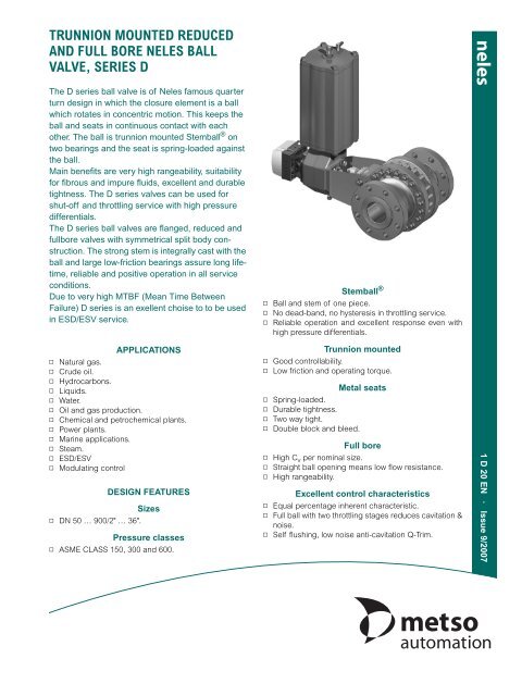
<strong>TRUNNION</strong> <strong>MOUNTED</strong> <strong>REDUCED</strong><br />
<strong>AND</strong> <strong>FULL</strong> <strong>BORE</strong> <strong>NELES</strong> <strong>BALL</strong><br />
VALVE, SERIES D<br />
The D series ball valve is of Neles famous quarter<br />
turn design in which the closure element is a ball<br />
which rotates in concentric motion. This keeps the<br />
ball and seats in continuous contact with each<br />
other. The ball is trunnion mounted Stemball ® on<br />
two bearings and the seat is spring-loaded against<br />
the ball.<br />
Main benefits are very high rangeability, suitability<br />
for fibrous and impure fluids, excellent and durable<br />
tightness. The D series valves can be used for<br />
shut-off and throttling service with high pressure<br />
differentials.<br />
The D series ball valves are flanged, reduced and<br />
fullbore valves with symmetrical split body construction.<br />
The strong stem is integrally cast with the<br />
ball and large low-friction bearings assure long lifetime,<br />
reliable and positive operation in all service<br />
conditions.<br />
Due to very high MTBF (Mean Time Between<br />
Failure) D series is an exellent choise to to be used<br />
in ESD/ESV service.<br />
APPLICATIONS<br />
▫ Natural gas.<br />
▫ Crude oil.<br />
▫ Hydrocarbons.<br />
▫ Liquids.<br />
▫ Water.<br />
▫ Oil and gas production.<br />
▫ Chemical and petrochemical plants.<br />
▫ Power plants.<br />
▫ Marine applications.<br />
▫ Steam.<br />
▫ ESD/ESV<br />
▫ Modulating control<br />
DESIGN FEATURES<br />
Sizes<br />
▫ DN 50 … 900/2" … 36".<br />
Pressure classes<br />
▫ ASME CLASS 150, 300 and 600.<br />
Stemball ®<br />
▫ Ball and stem of one piece.<br />
▫ No dead-band, no hysteresis in throttling service.<br />
▫ Reliable operation and excellent response even with<br />
high pressure differentials.<br />
Trunnion mounted<br />
▫ Good controllability.<br />
▫ Low friction and operating torque.<br />
▫ Spring-loaded.<br />
▫ Durable tightness.<br />
▫ Two way tight.<br />
▫ Double block and bleed.<br />
Metal seats<br />
Full bore<br />
▫ High C v per nominal size.<br />
▫ Straight ball opening means low flow resistance.<br />
▫ High rangeability.<br />
Excellent control characteristics<br />
▫ Equal percentage inherent characteristic.<br />
▫ Full ball with two throttling stages reduces cavitation &<br />
noise.<br />
▫ Self flushing, low noise anti-cavitation Q-Trim.<br />
1 D 20 EN · Issue 9/2007
1<br />
77<br />
16<br />
12<br />
19<br />
20<br />
Mfg plate<br />
7<br />
63<br />
64<br />
5<br />
61<br />
3<br />
64<br />
63<br />
7<br />
62<br />
2<br />
16<br />
15<br />
Standard construction<br />
15<br />
11<br />
62<br />
65<br />
METSO AUTOMATION<br />
EXPLODED VIEW<br />
10<br />
89604<br />
668<br />
69<br />
9<br />
14<br />
18<br />
13 17<br />
7<br />
PARTS LIST<br />
- 2 -<br />
1<br />
77<br />
16<br />
12<br />
19<br />
20<br />
Mfg plate<br />
62<br />
7<br />
63<br />
5<br />
3<br />
7<br />
62<br />
2<br />
16<br />
15<br />
11<br />
65<br />
10 4 668<br />
13 17<br />
15<br />
High temperature construction<br />
69 9 1418<br />
Item Part description Material<br />
1 Body half (female) Stainless steel, ASTM A 351 gr. CF8M Carbon steel, ASTM A 216 gr. WCB<br />
2 Body half (male) Stainless steel, ASTM A 351 gr. CF8M Carbon steel, ASTM A 216 gr. WCB<br />
3 Ball Stainless steel, ASTM A 351 gr. CF8M + Hard chrome<br />
4 Thrust bearing Stainless steel, AISI 316 (Cobalt based alloy bushing in high temperature construction)<br />
5 Trunnion bearing Stainless steel, AISI 316 (Cobalt based alloy bushing in high temperature construction)<br />
7 Seat Stainless steel, AISI 316 + Cobalt based alloy<br />
8 Bonnet Stainless steel, ASTM A 351 gr. CF8M Carbon steel, ASTM A 216 gr. WCB<br />
9 Gland Stainless steel, ASTM A 351 gr. CF8M Carbon steel, ASTM A 216 gr. WCB<br />
10 Key Stainless steel, AISI 329<br />
11 Stud ASTM A 193 gr. B8M ASTM A 320 gr. L7M<br />
12 Hexagon screw or stud ASTM A 193 gr. B8M ASTM A 320 gr. L7M<br />
13 Stud ASTM A 193 gr. B8M ASTM A 320 gr. L7M<br />
14 Stud ASTM A 193 gr. B8M ASTM A 320 gr. L7M<br />
15 Hexagon nut ASTM A 193 gr. B8M ASTM A 194 gr. 2H<br />
16 Hexagon nut ASTM A 193 gr. B8M ASTM A 194 gr. 2H<br />
17 Hexagon nut ASTM A 193 gr. B8M ASTM A 194 gr. 2H<br />
18 Hexagon nut ASTM A 193 gr. B8M ASTM A 194 gr. 2H<br />
19 Identification plate Stainless steel, AISI 304<br />
20 Rivet Stainless steel, AISI 316<br />
60 Bearing PTFE on stainless steel net, standard construction<br />
61 Bearing PTFE on stainless steel net, standard construction<br />
62 Spring/ bellow<br />
Special alloy UNS N07750, in standard construction / EN 10088-1.4418 in high temperature<br />
construction<br />
63 Back seal Fluorocarbon rubber Viton GF<br />
64 Back-up ring Polytetrafluoroethylene (PTFE)<br />
65 Gasket Graphite<br />
66 Gasket Graphite<br />
69 Gland packing Graphite + PTFE<br />
77 Plug Stainless steel, AISI 316<br />
89 Thrust bearing PTFE on stainless steel net
<strong>TRUNNION</strong> <strong>MOUNTED</strong> <strong>FULL</strong> OR <strong>REDUCED</strong> <strong>BORE</strong> <strong>NELES</strong> <strong>BALL</strong> VALVE, SERIES D<br />
p (bar) Temperature (°F)<br />
p (psi) p (bar)<br />
Temperature (°F)<br />
p (psi)<br />
100<br />
120<br />
122 212 302 392 482 572 662 707 752 797<br />
1600<br />
100 122<br />
120<br />
302 482 662 752 842 932 1022 1112<br />
1600<br />
100<br />
80<br />
60<br />
40<br />
20<br />
Product type<br />
Full or reduced bore, trunnion mounted ball valve.<br />
Ball and stem are integrally cast.<br />
Split body design.<br />
Flanged.<br />
Pressure ratings<br />
ASME Class 150, 300 and 600.<br />
Size range fullbore<br />
DN 300 … 900 / 12" - 36" in ASME Class 150.<br />
DN 100 … 900 / 4" - 36" in ASME Class 300.<br />
DN 50 … 600 / 2" - 24" in ASME Class 600.<br />
Size range reduced bore<br />
DN 250 ... 600 / 10" - 24" in ASME Class 150.<br />
DN 200 ... 600 / 8" - 24" in ASME Class 300.<br />
DN 80 ... 600 / 3" - 24" in ASME Class 600.<br />
Larger sizes on request.<br />
Temperature range<br />
-200 °C … +450 °C (+600 °C)<br />
-330 °F … +840 °F (+1100 °F).<br />
Valve body<br />
Design standards<br />
ASME B16.34.<br />
Valve body joint ASME VIII. DIV. 1 APPX 2.<br />
Valve flanges ASME B16.5.<br />
Face-to-face ASME B16.10.<br />
Standard materials<br />
Body ASTM A351 gr. CF8M.<br />
ASTM A216 gr. WCB.<br />
Ball ASTM A351 gr. CF8M + hard chrome or<br />
other special coating with metal seats.<br />
Bearings SS 316 + PTFE net or Cobalt based alloy<br />
Seats AISI 316 + Cobalt based alloy.<br />
AISI 316 + PTFE insert.<br />
Seals/gaskets PTFE, graphite.<br />
Standard bearing construction<br />
Large, low friction bearings.<br />
SS 316 + PTFE net or Cobalt based alloy.<br />
Maximum pressure/Temperature limitations on valve body according to ASME B 16,34<br />
#600<br />
#300<br />
#150<br />
0<br />
0<br />
38 50 100 150 200 250 300 350 375 400 425<br />
Temperature (°C)<br />
TECHNICAL SPECIFICATION<br />
Bolting<br />
B8M/8M with stainless steel body.<br />
L7M/2H or 2MH with carbon steel body.<br />
1400<br />
1200<br />
1000<br />
800<br />
600<br />
400<br />
200<br />
100<br />
80<br />
60<br />
40<br />
20<br />
- 3 -<br />
Standard options<br />
Cryogenic design.<br />
Bonnet extension.<br />
Degreasing.<br />
High temperature design.<br />
Cobalt based hard facing or NiBo ball coating.<br />
Noise/cavitation reduction ball insert; Q-trim design.<br />
Fire safety BS 6755/API 607 (on selected seat designs).<br />
NACE MR-01-03 or MR-01-75 on request.<br />
Material and test certification<br />
EN/DIN 10204-3.1 material certificates for body halves, ball<br />
and bonnet. Tightness test certificate.<br />
Valve testing<br />
Each valve is tested for body integrity and seat tightness.<br />
The body test pressure is 1.5 x PN. The seat test pressure for<br />
metal seated valves in 1.1 x PN. The seat test pressure for<br />
soft seats is 6 bar. The test medium is inhibited water.<br />
Valve tightness<br />
FCI 70-2 class V for metal seats.<br />
FCI 70-2 class VI for soft seats<br />
ISO 5208 rate C or D for metal seats.<br />
API-598 (1970) for soft seats.<br />
Other tigthness rates upon request.<br />
Maximum flow coefficient C v and<br />
flow resistance coefficient<br />
DN / Inch Cv 90° ζ 90° DN / Inch Cv 90° ζ 90°<br />
50 / 2 480 0.06 400 / 16 37700 0.04<br />
80 / 3 1200 0.05 450 / 18 48000 0.03<br />
100 / 4 2120 0.05 500 / 20 59500 0.03<br />
150 / 6 5100 0.05 600 / 24 86300 0.03<br />
200 / 8 9300 0.04 700 / 28 118000 0.03<br />
250 / 10 15200 0.04 750 / 30 136000 0.03<br />
300 / 12 22400 0.04 800 / 32 151000 0.03<br />
350 / 14 28300 0.04 900 / 36 192000 0.03<br />
C v -values measured according to ISA S39.<br />
C v-values for reduced bore available on request.<br />
#600<br />
#300<br />
#150<br />
0<br />
0<br />
38 50 150 250 350 400 450 500 550 600<br />
Temperature (°C)<br />
Material ASTM A216 gr. WCB. Material ASTM A351 gr. CF8M.<br />
1400<br />
1200<br />
1000<br />
800<br />
600<br />
400<br />
200
p (bar) Temperature (°F)<br />
p (psi)<br />
100<br />
40<br />
122 212 302 392<br />
30<br />
20<br />
10<br />
Seat type E<br />
0<br />
0<br />
38 50 100 150 200<br />
Temperature (°C)<br />
METSO AUTOMATION<br />
MAXIMUM ALLOWABLE ∆p IN CONTROL SERVICE<br />
ASME Class 300 & 600<br />
ASME Class 150<br />
▫ PTFE bearings ▫ Chrome plated ball ▫ Metal bearings ▫ Chrome plated ball<br />
Temperature (°F)<br />
p (bar) p (psi)<br />
60<br />
50<br />
40<br />
30<br />
20<br />
10<br />
0<br />
100 122 212 302 392 482 572 662 707 752 842<br />
Seat type B or H<br />
Temperature (°C)<br />
▫ Metal bearings ▫ Chrome plated ball<br />
Note: When Carbide or Nickel Boron coatings are used according<br />
qiven techical limitations max body material P/T<br />
values can be used. Always consider shaft strength.<br />
Note: For reduced bore valves maximum allowable ∆p is based<br />
on ball size (= one size smaller than valve size given in<br />
tables).<br />
▫ PTFE bearings ▫ Chrome plated ball<br />
500<br />
400<br />
300<br />
200<br />
100<br />
MAXIMUM ALLOWABLE ∆p IN SHUT-OFF SERVICE<br />
ASME Class 300, 4" ... 16"<br />
ASME Class 300, 18" ... 24"<br />
ASME Class 150, 2" ... 24"<br />
38 50 100 150 200 250 300 350 375 400 450<br />
p (bar) Temperature (°F)<br />
p (psi)<br />
100<br />
80<br />
60<br />
40<br />
20<br />
0<br />
100 122 212 302 392<br />
1600<br />
Seat type S<br />
Temperature (°C)<br />
ASME Class 600, 2" ... 24"<br />
ASME Class 300, 4" ... 16"<br />
ASME Class 300, 18" ... 24"<br />
ASME Class 150, 2" ... 24"<br />
38 50 100 150 200<br />
800<br />
600<br />
400<br />
200<br />
0<br />
1400<br />
1200<br />
1000<br />
800<br />
600<br />
400<br />
200<br />
0<br />
- 4 -<br />
p (bar) Temperature (°F)<br />
p (psi)<br />
100<br />
40<br />
122 212 302 392 482 572 662 707 752 842<br />
30<br />
20<br />
10<br />
Seat type B<br />
ASME Class 600, 2"... 24"<br />
ASME Class 300, 4" .. 16"<br />
ASME Class 300<br />
18"…24"<br />
ASME Class 150<br />
0<br />
0<br />
38 50 100 150 200 250 300 350 375 400 450<br />
Temperature (°C)<br />
p (bar) Temperature (°F)<br />
p (psi)<br />
100 122 212 302 392 482 572 662 707 752 842<br />
80<br />
60<br />
40<br />
20<br />
0<br />
ASME Class 600, 24"<br />
ASME Class 600, 12" ... 20"<br />
Seat type B or H<br />
ASME Class 600, 2" ... 3"<br />
ASME Class 600, 4" ... 10"<br />
38 50 100 150 200 250 300 350 375 400 450<br />
Temperature (°C)<br />
▫ Metal bearings ▫ Chrome plated ball<br />
Maximum operating pressure differentials for valves in shutoff<br />
or control service depend on valve size, seat design,<br />
bearing design and flow media. Only the most commonly<br />
used material and construction combinations are shown<br />
above.<br />
Valves for applications exceeding +450 °C / +840 °F<br />
temperature limit shall be quoted separately.<br />
Contact your local Metso Automation representative.<br />
500<br />
400<br />
300<br />
200<br />
100<br />
1000<br />
800<br />
600<br />
400<br />
200<br />
0
<strong>TRUNNION</strong> <strong>MOUNTED</strong> <strong>FULL</strong> OR <strong>REDUCED</strong> <strong>BORE</strong> <strong>NELES</strong> <strong>BALL</strong> VALVE, SERIES D<br />
ST<strong>AND</strong>ARD SEAT SELECTION FOR D SERIES VALVES<br />
Soft seat design, seat code T<br />
Size range: DN 50 … 900 / 2" … 36"<br />
Seat material: AISI 316 + PTFE + C25 % insert<br />
O-ring: Viton GF<br />
Spring: UNS N07750<br />
Temperature range: -30 °C … +200 °C / -22 °F … +390 °F.<br />
The standard PTFE-seated design is most suitable for<br />
shut-off service, for temperatures up to +200 °C/+390 °F and<br />
when pressure drop is relatively low and medium does not<br />
contain wearing particles.<br />
On-off metal seated design, seat code S<br />
Size range: DN 50 … 900 / 2" … 36"<br />
Seat material: AISI 316 + Cobalt based alloy.<br />
O-ring: Viton GF<br />
Spring: UNS N07750<br />
Temperature range: -30 °C … +200 °C / -22 °F … +390 °F.<br />
The on-off metal seat is most suitable for high pressure drop<br />
applications and for fluids containing impurities.<br />
Control metal seat design, seat code E<br />
Size range: DN 50 … 900 / 2" … 36"<br />
Seat material: AISI 316 + Cobalt based alloy.<br />
O-ring: Viton GF<br />
Spring: UNS N07750<br />
Temperature range: -30 °C … +200 °C / -22 °F … +390 °F.<br />
The control metal seat features the ejector seat principle.<br />
This seat design is intended for demanding control applications.<br />
- 5 -<br />
High temperature control metal seat design,<br />
seat code B<br />
Size range: DN 50 … 600 / 2" … 24"<br />
Seat material: AISI 316 + Cobalt based alloy.<br />
Seat seal: Graphite<br />
Spring: UNS N07750<br />
Temperature range: -40 °C … +450 °C (+600 °C) /<br />
-40 °F … +840 °F (+1110 °F).<br />
The high temperature metal seat is designed for both on-off<br />
and control applications and is suitable to be used with a<br />
wide range of flow media. The graphite seat seal makes this<br />
design a fire safe construction. Tested to BS 6755 and API<br />
607.<br />
Low and high temperature on-off metal seat,<br />
seat code H<br />
Size range: DN 50 … 600 / 2" … 24"<br />
Seat material: AISI 316 + Cobalt based alloy.<br />
Bellows material: EN 10088-1.4418<br />
Temperature range: -200 °C … +400 °C (+600 °C) /<br />
-330 °F … +750 °F (+1110 °F).<br />
The Cobalt based alloy seat is preloaded with a bellows ring<br />
made of special stainless steel. The bellows acts as a spring<br />
and seal, and also increases the seat pressure at higher<br />
pressure differentials. Designed for demanding on-off applications<br />
containing impurities. Alternative bellows spring<br />
materials are available for temperatures up to +600 °C/<br />
+1110 °F. The bellows seat design is Metso Automation<br />
choice for cryogenic service.
METSO AUTOMATION<br />
With the introduction of Metso Automation Q-Trim control valves, a new generation of low recovery rotary valves was born. The<br />
design was introduced in 1979 and has since been utilized in thousands of applications throughout the world and has been<br />
patented in all major control valve markets.<br />
The Q-Ball technology effectively solves the problems associated with throttling large flow rates; cavitation and noise. It is<br />
based on the versatile Stem-Ball design - offering excellent control stability, rangeability and tightness.<br />
Q-Trim operational principle<br />
The aerodynamic noise reduction and abatement of liquid cavitation are done with a Q-Trim valve by two well-known principles:<br />
Staging the pressure drop across the valve into a series of smaller drops. The lowest trim pressure is raised above the liquid<br />
vapor pressure and cavitation is avoided (pressure dropping below vapor pressure and successive recovery above vapor<br />
pressure). In gas/steam applications, the highest trim velocity (proportional to noise level produced) is reduced dramatically,<br />
resulting in noise reduction.<br />
The division of flow into a number of small jet streams with less power to produce audible noise than a single large flow stream.<br />
Up to 20 dB(A) noise reduction can be achieved with the Q-Trim design, depending on the application. Noise reduction in very<br />
high pressure drop applications can be further enhanced by utilizing diffusors and plate attenuators after the valve or at the<br />
valve outlet.<br />
Rangeability<br />
The attenuators rotate with the rotation of the valve closure element, thereby producing a variable resistance flow path depending<br />
on the opening of the valve. Very small flows can therefore be handled accurately at small openings. Also, particularly with<br />
rotation valves there is no unstable zone in the small openings.<br />
At large openings, rotating attenuators create less resistance (corresponding with the lower pressure drop available for the<br />
control valve at large flows), enabling very large flows to pass through the same valve.<br />
Handling impurities<br />
There are always two types of flow across an attenuator plate in the Q-Trim design: one that goes through the holes and one<br />
that goes along the plates. The flow along the plates flushes away any impurities that might stick to the holes. The larger the<br />
valve opening, the more effective the flushing.<br />
V1<br />
P1<br />
Velocity<br />
difference<br />
Pressure<br />
difference<br />
THE FAMOUS METSO AUTOMATION Q-<strong>BALL</strong> ® PRINCIPLE<br />
Q-Ball<br />
Standard ball valve<br />
Standard ball valve<br />
Q-Ball<br />
- 6 -<br />
V2<br />
P2<br />
Improved pressure recovery means<br />
▫ less cavitation<br />
▫ less noise<br />
▫ less vibration<br />
Less velocity means<br />
▫ less kinetic energy<br />
▫ less noise<br />
▫ less erosion
<strong>TRUNNION</strong> <strong>MOUNTED</strong> <strong>FULL</strong> OR <strong>REDUCED</strong> <strong>BORE</strong> <strong>NELES</strong> <strong>BALL</strong> VALVE, SERIES D<br />
D SERIES VALVES FOR CONTROL SERVICE<br />
In the last 30 years the Metso Automation company has become known for developing innovative, high quality rotary valves for<br />
control service.<br />
One example is the patented special control seat design available in D series construction. This seat design is Metso Automation<br />
general purpose metal seat with following features:<br />
▫ With this seat construction, the seat friction decreases considerably. Thereby better dynamic behavior and smooth and<br />
accurate control are achieved.<br />
▫ There is less wear on the seat and ball surfaces, while tightness remains excellent. The service life of the valves is<br />
considerably increased, also in on-off service.<br />
Valve<br />
Body<br />
P 1<br />
The seating principle in shut-off<br />
The seat works like a normal pressure assisted seat in trunnion mounted ball valves. The upstream pressure is led through the<br />
hole behind the seat, pushing it against the ball. To ensure pressure tightness, the seat is spring energized.<br />
Flow<br />
P 1<br />
Flow<br />
Port<br />
P 1 Back seal Seat ring Body cavity<br />
P VC<br />
Ball<br />
P 1 > P 2<br />
The working principle in control<br />
P VC<br />
P VC < P 2<br />
In control, the high velocity flow passes through the restriction point of the partly open valve. The high velocity creates low<br />
pressure, which is led behind the ball seat through the hole located in the vena contracta. The seat will thus be unloaded.<br />
- 7 -<br />
P 2<br />
P 2
E<br />
N<br />
R<br />
ØO<br />
ØB<br />
D2C, ASME CLASS 150<br />
M<br />
T<br />
D2C, ASME CLASS 150<br />
D2D, ASME CLASS 300<br />
P<br />
K<br />
UL<br />
UNC<br />
A<br />
ØD<br />
S<br />
METSO AUTOMATION<br />
DN<br />
DIMENSIONS<br />
X1<br />
X<br />
ASME CLASS 300<br />
PLUG NPTF PLUG NPTF<br />
TYPE<br />
DN A ØB ØD E K<br />
DIMENSIONS, mm<br />
M N ØO P R S T UL<br />
UNC<br />
PLUG<br />
NPTF<br />
kg<br />
D2C 12 300 610 596 304 586 430 22.22 156 95 104.8 320 236 196 48 1 1/4 1 420<br />
D2C 14 350 686 668 337 650 494 22.22 156 95/105 104.8 354 248 212 52 1 1/4 1 550<br />
D2C 16 400 762 744 387 715 559 22.22 156 95/120 104.8 380 286 240 58 1 1/2 1 720<br />
D2C 18 450 864 814 440 890 737 22.22 156 95/120 104.8 504 242 210 63 1 1/2 1 1300<br />
D2C 20 500 914 904 490 950 770 25.40 180 95/105 116.1 520 242 210 63 1 1/2 1 1500<br />
D2C 24 600 1067 1084 590 1125 920 31.75 205 95/120 133.8 615 318 270 78 2 1 2300<br />
D2C 28 700 1244 1245 692 1266 1041 31.75 225 105/135 149 661 336 275 92 1 3/4 1 3800<br />
D2C 30 750 1295 1318 740 1325 1075 38.10 250 150 166.6 665 410 310 119 2 1/2 1 4400<br />
D2C 36 900 1524 1560 880 1580 1300 38.10 280 165 181.8 799 514 380 148 3 1 6500<br />
TYPE<br />
DIMENSIONS, inch<br />
UNC PLUG<br />
SIZE A ØB ØD E K M N ØO P R S T UL<br />
NPTF<br />
lbs<br />
D2C 12 12 24.02 23.46 11.97 23.07 16.93 0.87 6.14 3.74 4.13 12.60 9.29 7.72 1.89 1 1/4 1 924<br />
D2C 14 14 27.01 26.30 13.27 25.59 19.45 0.87 6.14 3.74/4.13 4.13 13.94 9.76 8.35 2.05 1 1/4 1 1210<br />
D2C 16 16 30.00 29.29 15.24 28.15 22.01 0.87 6.14 3.74/4.72 4.13 14.96 11.26 9.45 2.28 1 1/2 1 1584<br />
D2C 18 18 34.02 32.05 17.32 35.04 29.02 0.87 6.14 3.74/4.72 4.13 19.84 9.53 8.27 2.48 1 1/2 1 2860<br />
D2C 20 20 35.98 35.59 19.29 37.40 30.31 1.00 7.09 3.74/4.13 4.57 20.47 9.53 8.27 2.48 1 1/2 1 3300<br />
D2C 24 24 42.01 42.68 23.23 44.29 36.22 1.25 8.07 3.74/4.72 5.27 24.21 12.52 10.63 3.07 2 1 5060<br />
D2C 28 28 48.98 49.02 27.24 49.84 40.98 1.25 8.86 4.13/5.31 5.87 26.02 13.23 10.83 3.62 1 3/4 1 8360<br />
D2C 30 30 50.98 51.89 29.13 52.17 42.32 1.50 9.84 5.91 6.56 26.18 16.14 12.20 4.69 2 1/2 1 9680<br />
D2C 36 36 60.00 61.42 34.65 62.20 51.18 1.50 11.02 6.50 7.16 31.46 20.24 14.96 5.83 3 1 14300<br />
D2D, ASME CLASS 300<br />
TYPE<br />
DN A ØB ØD E K<br />
DIMENSIONS, mm<br />
M N ØO P R S T X X1 UL<br />
UNC<br />
PLUG<br />
NPTF<br />
kg<br />
D2D 4 100 305 262 100 264 196 9.52 68 40 44.2 157 120 102 – – 29 3/4 1/2 60<br />
D2D 6 150 403 368 152 345 255 12.70 90 55 60.6 186 164 128 – – 37 1 3/4 140<br />
D2D 8 200 502 454 202 424 305 19.05 119 70 78.2 226 198 150 – – 48 1 1/4-8 3/4 240<br />
D2D 10 250 568 558 254 514 368 22.22 146 85 94.6 270 236 176 – – 58 1 1/2-8 1 380<br />
D2D 12 300 648 630 304 586 430 22.22 156 95 104.8 310 262 196 – – 58 1 1/2-8 1 590<br />
D2D 14 350 762 706 337 650 470 25.40 180 105 116.2 338 288 212 – – 65 1 3/4-8 1 770<br />
D2D 16 400 838 792 387 715 510 31.75 205 120 133.8 360 330 240 – – 71 2-8 1 1050<br />
D2D 18 450 914 884 440 890 734 22.22 156 95 104.8 378 292 230 104 – 82 2-8 1 1250<br />
D2D 20 500 991 966 490 950 770 25.40 180 105 116.2 396 292 240 104 – 82 2-8 1 1950<br />
D2D 24 600 1143 1172 590 1125 920 31.75 205 120 133.8 519 396 280 – 74 94 2 1/2-8 1 3100<br />
D2D 28 700 1346 1340 690 1266 1041 31.75 225 135 149 568 400 310 – 74 125 3-8 1 5250<br />
D2D 30 750 1397 1414 740 1325 1075 38.10 250 150 166.6 591 400 310 – 74 125 3-8 1 5500<br />
D2D 36 900 1727 1684 880 1580 1300 38.10 280 165 181.8 705 512 380 – 94 135 3-8 1 8700<br />
TYPE<br />
SIZE A ØB ØD E K<br />
DIMENSIONS, inch<br />
M N ØO P R S T X X1 UL<br />
UNC<br />
PLUG<br />
NPTF<br />
lbs<br />
D2D 4 4 12.01 10.31 3.94 10.39 7.72 0.37 2.68 1.57 1.74 6.18 4.72 4.02 – – 1.14 3/4 1/2 132<br />
D2D 6 6 15.87 14.49 5.98 13.58 10.04 0.50 3.54 2.17 2.39 7.32 6.46 5.04 – – 1.46 1 3/4 308<br />
D2D 8 8 19.76 17.87 7.95 16.69 12.01 0.75 4.69 2.76 3.08 8.90 7.80 5.91 – – 1.89 1 1/4-8 3/4 528<br />
D2D 10 10 22.36 21.97 10.00 20.24 14.49 0.87 5.75 3.35 3.72 10.63 9.29 6.93 – – 2.28 1 1/2-8 1 836<br />
D2D 12 12 25.51 24.80 11.97 23.07 16.93 0.87 6.14 3.74 4.13 12.20 10.31 7.72 – – 2.28 1 1/2-8 1 1298<br />
D2D 14 14 30.00 27.80 13.27 25.59 18.50 1.00 7.09 4.13 4.57 13.31 11.34 8.35 – – 2.56 1 3/4-8 1 1694<br />
D2D 16 16 32.99 31.18 15.24 28.15 20.08 1.25 8.07 4.72 5.27 14.17 12.99 9.45 – – 2.80 2-8 1 2310<br />
D2D 18 18 35.98 34.80 17.32 35.04 28.90 0.87 6.14 3.74 4.13 14.88 11.50 9.06 4.09 – 3.23 2-8 1 2750<br />
D2D 20 20 39.02 38.03 19.29 37.40 30.31 1.00 7.09 4.13 4.57 15.59 11.50 9.45 4.09 – 3.23 2-8 1 4290<br />
D2D 24 24 45.00 46.14 23.23 44.29 36.22 1.25 8.07 4.72 5.27 20.43 15.59 11.02 – 2.91 3.70 2 1/2-8 1 6820<br />
D2D 28 28 52.99 52.76 27.17 49.84 40.98 1.25 8.86 5.31 5.87 22.36 15.75 12.20 – 2.91 4.92 3-8 1 11550<br />
D2D 30 30 55.00 55.67 29.13 52.17 42.32 1.50 9.84 5.91 6.56 23.27 15.75 12.20 – 2.91 4.92 3-8 1 12100<br />
D2D 36 36 69.13 66.30 34.65 62.20 51.18 1.50 11.02 6.50 7.16 27.76 20.16 14.96 – 3.70 5.31 3-8 1 19140<br />
- 8 -<br />
E<br />
R<br />
X<br />
N<br />
ØO<br />
T<br />
M<br />
D1F, ASME CLASS 600<br />
K<br />
UL<br />
UNC<br />
ØB A<br />
P<br />
S<br />
ØD<br />
DN
<strong>TRUNNION</strong> <strong>MOUNTED</strong> <strong>FULL</strong> OR <strong>REDUCED</strong> <strong>BORE</strong> <strong>NELES</strong> <strong>BALL</strong> VALVE, SERIES D<br />
D1F, ASME CLASS 600<br />
TYPE<br />
DN A ØB ØD E K<br />
DIMENSIONS, mm<br />
M N ØO P R S T X UL<br />
UNC<br />
PLUG<br />
NPTF<br />
kg<br />
D1F 2 50 292 206 50 280 234 6.35 46 25 27.8 172 128 80 36 25 5/8-11 1/2 35<br />
D1F 3 80 356 262 77 350 292 9.52 58 35 39.1 212 154 100 42 34 3/4-10 1/2 60<br />
D1F 4 100 432 314 100 392 324 9.52 68 40 44.2 225 158 110 43.7 38 3/4-10 1/2 120<br />
D1F 6 150 559 404 152 495 405 12.70 90 55 60.6 280 200 130 55 46 1-8 3/4 280<br />
D1F 8 200 660 498 202 595 476 19.05 119 70 78.2 325 244 160 68 50 11/4-8 3/4 380<br />
D1F 10 250 787 610 254 730 584 22.22 146 85 94.6 415 244 180 65 62 11/4-8 1 690<br />
D1F 12 300 838 748 302 837 681 22.22 156 95 104.8 437 358 220 92 88 13/4-8 1 1134<br />
D1F 14 350 889 824 340 890 710 25.40 180 105 116.1 454 398 240 91 81 13/4-8 1 1500<br />
D1F 16 400 991 954 390 988 783 31.75 205 120 133.8 482 432 270 104.1 76 2-8 1 2500<br />
D1F 18 450 1092 1090 440 1140 915 31.75 225 135 149 557 506 310 128.7 103 21/2-8 1 3300<br />
D1F 20 500 1194 1176 490 1220 970 38.10 250 150 166.6 596 526 340 129.4 93 21/2-8 1 3880<br />
D1F 24 600 1397 1224 591 1265 985 38.10 280 165 181.8 615 550 368 129.6 106 21/2-8 1 6500<br />
TYPE<br />
SIZE A ØB ØD E K<br />
DIMENSIONS, inch<br />
M N ØO P R S T X UL<br />
UNC<br />
PLUG<br />
NPTF<br />
lbs<br />
D1F 2 2 11.50 8.11 1.97 11.02 9.21 0.25 1.81 0.98 1.09 6.77 5.04 3.15 1.42 0.98 5/8-11 1/2 77<br />
D1F 3 3 14.02 10.31 3.03 13.78 11.50 0.37 2.28 1.38 1.54 8.35 6.06 3.94 1.65 1.34 3/4-10 1/2 132<br />
D1F 4 4 17.01 12.36 3.94 15.43 12.76 0.37 2.68 1.57 1.74 8.86 6.22 4.33 1.72 1.50 3/4-10 1/2 264<br />
D1F 6 6 22.01 15.91 5.98 19.49 15.94 0.50 3.54 2.17 2.39 11.02 7.87 5.12 2.17 1.81 1-8 3/4 616<br />
D1F 8 8 25.98 19.61 7.95 23.43 18.74 0.75 4.69 2.76 3.08 12.80 9.61 6.30 2.68 1.97 11/4-8 3/4 836<br />
D1F 10 10 30.98 24.02 10.00 28.74 22.99 0.87 5.75 3.35 3.72 16.34 9.61 7.09 2.56 2.44 11/4-8 1 1518<br />
D1F 12 12 32.99 29.45 11.89 32.95 26.81 0.87 6.14 3.74 4.13 17.20 14.09 8.66 3.62 3.46 13/4-8 1 2495<br />
D1F 14 14 35.00 32.44 13.39 35.04 27.95 1.00 7.09 4.13 4.57 17.87 15.67 9.45 3.58 3.19 13/4-8 1 3300<br />
D1F 16 16 39.02 37.56 15.35 38.90 30.83 1.25 8.07 4.72 5.27 18.98 17.01 10.63 4.10 2.99 2-8 1 5500<br />
D1F 18 18 42.99 42.91 17.32 44.88 36.02 1.25 8.86 5.31 5.87 21.93 19.92 12.20 5.07 4.06 21/2-8 1 7260<br />
D1F 20 20 47.01 46.30 19.29 48.03 38.19 1.50 9.84 5.91 6.56 23.46 20.71 13.39 5.09 3.66 21/2-8 1 8536<br />
D1F 24 24 55.00 48.19 23.27 49.80 38.78 1.50 11.02 6.50 7.16 24.21 21.65 14.49 5.10 4.17 21/2-8 1 14300<br />
SIGNAL<br />
1/4 NPT<br />
NPT<br />
SUPPLY<br />
1/4 NPT<br />
NPT<br />
V<br />
Ø B<br />
Type<br />
X<br />
DIMENSIONS, mm<br />
G F V J<br />
NPT kg<br />
B1C6 90 260 400 36 283 1/4 4.2<br />
B1C9 110 315 455 43 279 1/4 9.6<br />
B1C11 135 375 540 51 290 3/8 16<br />
B1C13 175 445 635 65 316 3/8 31<br />
B1C17 215 545 770 78 351 1/2 54<br />
B1C20 215 575 840 97 385 1/2 73<br />
B1C25 265 710 1040 121 448 1/2 131<br />
B1C32 395 910 1330 153 525 3/4 256<br />
B1C40 505 1150 1660 194 595 3/4 446<br />
B1C50 610 1350 1970 242 690 1 830<br />
VALVE + ACTUATOR DIMENSIONS<br />
D2C + B1C / B1J, B1JA<br />
D2D + B1C / B1J, B1JA<br />
MOUNTING POSITION A (ST<strong>AND</strong>ARD)<br />
X<br />
K<br />
J<br />
G<br />
F<br />
*) See K dimension from<br />
Valve dimension tables.<br />
Type<br />
X<br />
DIMENSIONS, inch<br />
G F V J<br />
NPT lbs<br />
B1C6 3.54 10.24 15.75 1.42 11.14 1/4 9<br />
B1C9 4.33 12.4 17.91 1.69 10.98 1/4 21<br />
B1C11 5.31 14.76 21.26 2.01 11.42 3/8 35<br />
B1C13 6.89 17.52 25 2.56 12.44 3/8 68<br />
B1C17 8.46 21.46 30.31 3.07 13.82 1/2 119<br />
B1C20 8.46 22.64 33.07 3.82 15.16 1/2 161<br />
B1C25 10.43 27.95 40.94 4.76 17.64 1/2 289<br />
B1C32 15.55 35.83 52.36 6.02 20.67 3/4 564<br />
B1C40 19.88 45.28 65.35 7.64 23.43 3/4 983<br />
B1C50 24.02 53.15 77.56 9.53 27.17 1 1829<br />
Type<br />
X<br />
DIMENSIONS, mm<br />
G F V J<br />
NPT kg<br />
Type<br />
X<br />
DIMENSIONS, inch<br />
G F V J<br />
NPT lbs<br />
B1J, B1JA8 135 420 560 43 279 3/8 17<br />
B1J, B1JA8 5.31 16.54 22.05 1.69 10.98 3/8 37<br />
B1J, B1JA10 175 490 650 51 290 3/8 30 B1J, B1JA10 6.89 19.29 25.59 2.01 11.42 3/8 66<br />
B1J, B1JA12 215 620 800 65 316 1/2 57 B1J, B1JA12 8.46 24.41 31.5 2.56 12.44 1/2 126<br />
B1J, B1JA16 265 760 990 78 351 1/2 100 B1J, B1JA16 10.43 29.92 38.98 3.07 13.82 1/2 220<br />
B1J, B1JA20 395 935 1200 97 358 3/4 175 B1J, B1JA20 15.55 36.81 47.24 3.82 14.09 3/4 386<br />
B1J, B1JA25 505 1200 1530 121 448 3/4 350 B1J, B1JA25 19.88 47.24 60.24 4.76 17.64 3/4 771<br />
B1J, B1JA32 540 1410 1830 153 525 1 671 B1J, B1JA32 21.26 55.51 72.05 6.02 20.67 1 1479<br />
For reduced bore valves dimensional drawings available on request. Generally the body internals are one size smaller as well as actuator size. This offers<br />
remarkably lighter valve/actuator package.<br />
- 9 -
To specify a control valve, make a selection from each designation<br />
below. These codes create a complete valve model<br />
code. The valve model number expresses the standard product<br />
construction.<br />
1 2 3 4 5 6 7 8<br />
Q D2 D A 06 A A E 02<br />
Q-code Product options<br />
Q Low noice trim<br />
1, 2 Valve type & pressure rating<br />
D2C Trunnion mounted, flanged, ASME Class 150.<br />
D2D Trunnion mounted, flanged, ASME Class 300.<br />
D1F Trunnion mounted, flanged, ASME Class 600.<br />
D5C Trunnion mounted, flanged reduced bore, ASME Class 150.<br />
D5D Trunnion mounted, flanged reduced bore, ASME Class 300.<br />
D5F Trunnion mounted, flanged reduced bore, ASME Class 600.<br />
3 Construction type<br />
A Double seated, two way tight, PTFE bearings. -50 °C ... +230 °C.<br />
B<br />
Single seated, one way tight, high temperature,<br />
metal bearings. -50 °C ... +600 °C.<br />
E Single seated, one way tight, PTFE bearings. -50 °C ... +230 °C.<br />
H<br />
Double seated, two way tight, high temperature,<br />
metal bearings. -50 °C ... +600 °C.<br />
C Cryogenic, PTFE bearings, two way tight. Below -50 °C.<br />
Y Special, to be specified.<br />
4 Size (inches)<br />
5, 6 Standard materials<br />
Body (5)<br />
A ASTM A 351 gr. CF8M.<br />
D ASTM A 216 gr. WCB.<br />
Ball (6)<br />
A ASTM A 351 gr. CF8M.<br />
D CF8M + NiBo.<br />
R3 CF8M + carbide<br />
METSO AUTOMATION<br />
HOW TO ORDER<br />
An extensive number of unlisted options and variations are<br />
available. For options not shown, or to enter an order, contact<br />
your local Metso Automation sales representative.<br />
7 Seat type<br />
E Control metal seat.<br />
B High temp. metal seat.<br />
T Soft seat.<br />
S Shut-off metal seat.<br />
H Low/high temp. metal seat.<br />
-30…+200°C /<br />
-22…+390°F<br />
-40…+450°C (+600°C)/<br />
-40…+840°F (+1110°F)<br />
-30…+200°C /<br />
-22…+390°F<br />
-30…+200°C /<br />
-22…+390°F<br />
-200 …+400°C (+600°C)/<br />
-330…+750°F (+1110°F)<br />
-200...+600°C<br />
-330...+1110°F<br />
Subject to change without prior notice.<br />
Metso Automation, Flow Control<br />
Europe, Levytie 6, P.O. Box 310, 00811 Helsinki, Finland. Tel. +358 20 483 150. Fax +358 20 483 151<br />
North America, 44 Bowditch Drive, P.O. Box 8044, Shrewsbury, MA 01545, USA. Tel. +1 508 852 0200. Fax +1 508 852 8172<br />
Latin America, Av. Independéncia, 2500- Iporanga, 18087-101, Sorocaba-São Paulo, Brazil.<br />
Tel. +55 15 3235 9700. Fax +55 15 3235 9748/49<br />
Asia Pacific, 238A Thomson Road, #25-09 Novena Square Tower A, 307684 Singapore. Tel. +65 6511 1011. Fax +65 6250 0830<br />
China, 19/F, the Exchange Beijing, No. 118, Jianguo Lu Yi, Chaoyang Dist, 100022 Beijing, China. Tel. +86-10-6566-6600. Fax +86-10-6566-2575<br />
Middle East, Roundabout 8, Unit AB-07, P.O. Box 17175, Jebel Ali Freezone, Dubai, United Arab Emirates.<br />
Tel. +971 4 883 6974. Fax +971 4 883 6836<br />
www.metsoautomation.com<br />
H3<br />
Low/high temp. metal seat<br />
(carbide coating)<br />
8 Soft seals<br />
02 Body seals graphite and O-rings Viton GF.<br />
03 All seals graphite.