

2000-05 Audi Mk1 TT Vent Boost Gauge - AWE Tuning
2000-05 Audi Mk1 TT Vent Boost Gauge - AWE Tuning
2000-05 Audi Mk1 TT Vent Boost Gauge - AWE Tuning

Create successful ePaper yourself
Turn your PDF publications into a flip-book with our unique Google optimized e-Paper software.
Congratulations on your purchase of the A.W.E. <strong>Tuning</strong> Center <strong>Vent</strong> <strong>Boost</strong> <strong>Gauge</strong> for your <strong>Audi</strong> <strong>TT</strong>.<br />
While the install is fairly straight forward, please review these instructions carefully before attempting installation.<br />
If you do not feel comfortable installing this kit on your own, contact a professional installer in your area.<br />
Estimated install time:<br />
1.5 hrs<br />
Parts list:<br />
1 Preassembled A.W.E. <strong>Tuning</strong> bezel and gauge pod<br />
1 boost hose<br />
1 sender unit with wiring harness<br />
1 gauge wiring harness<br />
1 buzz filter<br />
1 T-fitting<br />
1 10” of additional white wire<br />
2 wiring loop terminal<br />
1 blue butt connector<br />
4 small zip tie<br />
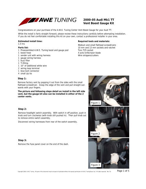
Step 1:<br />
Remove factory vent by popping it out from the sides with the small<br />
flathead screwdriver. Grasp the edge of the vent and pull straight outwards<br />
with your fingers.<br />
The picture and following steps detail an install in the left side<br />
vent, but the gauge kit also can be installed in either of the 2<br />
center vents.<br />
Step 2:<br />
Remove headlight switch assembly. With switch in off position, push in<br />
knob and turn clockwise (with knob still pushed in). Then pull knob out<br />
to remove entire switch assembly.<br />
Disconnect wiring harnesses from rear of the switch assembly.<br />
Step 3:<br />
Remove the fuse panel cover on the end of the dash.<br />
<strong>2000</strong>-<strong>05</strong> <strong>Audi</strong> <strong>Mk1</strong> <strong>TT</strong><br />
<strong>Vent</strong> <strong>Boost</strong> <strong>Gauge</strong> Kit<br />
Required tools and materials:<br />
Medium and small flathead screwdrivers<br />
10 mm and 13 mm sockets and ratchet<br />
Torx T25 socket<br />
X-acto knife/razor blade<br />
Wire strippers/cutters<br />
Figure 1<br />
Figure 2<br />
Figure 3<br />
Copyright 2009, A.W.E. <strong>Tuning</strong>. No part of this document may be reused or duplicated without the express permission of A.W.E. <strong>Tuning</strong>/Secor Ltd. All rights reserved. Rev 3.0<br />
Page 1 of 5
Step 4:<br />
Remove knee bolster panel. Unbolt two T25 torx bolts at arrows below<br />
dash, and three T25 torx bolts at arrows at end of dash in Figure 4.<br />
Pull knee bolster towards rear of car to remove.<br />
Step 5:<br />
Open the hood and remove engine cover. Twist its x-shaped fasteners<br />
90 degrees with a flat head screwdriver to release.<br />
Note: a 180hp <strong>TT</strong> is pictured. A 225hp <strong>TT</strong> will appear slightly<br />
different in the following engine step pictures.<br />
Step 6:<br />
Remove windshield wipers. Place a piece of tape on the windshield<br />
along the blades to ensure accurate reinstallation.<br />
Remove caps at the base of the wiper arms, as in Figure 6, to reveal<br />
13mm nuts. Unbolt nuts.<br />
Close the hood and remove the wiper arms carefully.<br />
Step 7:<br />
Remove the cowling panel below the wipers by grasping at an end of it<br />
and lifting slowly. Unplug the heated washer plugs and washer hose as<br />
shown at arrows in Figure 7 (cowling is already removed and flipped<br />
upside down in picture).<br />
Step 8:<br />
Remove the cover off the white wiring connector box in the corner of<br />
the firewall area under the cowling.<br />
Remove the rubber blanking plug, as shown in Figure 8.<br />
Figure 5<br />
Figure 6<br />
Figure 7<br />
Figure 8<br />
Copyright 2009, A.W.E. <strong>Tuning</strong>. No part of this document may be reused or duplicated without the express permission of A.W.E. <strong>Tuning</strong>/Secor Ltd. All rights reserved. Rev 3.0<br />
Figure 4<br />
Page 2 of 5
Step 9:<br />
With a razor or x-acto knife, cut an “X” in the middle of the rubber<br />
blanking plug.<br />
Insert an end of the silicone hose included with the boost gauge kit, and<br />
slip half of the hose through the plug.<br />
Step 10:<br />
Drop one end of the hose down through the wiring connector box, into<br />
the passenger compartment.<br />
Locate this end of the hose in the passenger compartment and route it<br />
through the relay panel under the dash as shown in Figure 10.<br />
Cut a small piece off the boost hose end, and slip in one end of the enclosed<br />
buzz filter. Attach the cut piece of hose between the filter and<br />
the inlet of the enclosed sender unit. Discard any remaining hardware<br />
in the same bag as the filter. Zip tie the sender unit under the<br />
dash, with the inlet nipple facing downwards to prevent moisture<br />
from accumulating in it.<br />
Step 11:<br />
In the engine compartment, remove the cover for the wiring loom box.<br />
Use a small flat head screwdriver to release the tabs as shown in Figure<br />
11, and remove.<br />
Route the silicone hose through the wiring loom box and out the bottom<br />
of it. Removal of the strut bar can make this job easier.<br />
Step 12:<br />
Remove the 3mm hose from the Fuel Pressure Regulator (FPR) as<br />
shown in Figure 12.<br />
Step 13:<br />
Route the silicone hose through the engine compartment as shown in<br />
Figure 13. Ensure that the hose is not interfering with any exhaust<br />
components or moving items.<br />
Figure 9<br />
Figure 10<br />
Figure 11<br />
Figure 12<br />
Copyright 2009, A.W.E. <strong>Tuning</strong>. No part of this document may be reused or duplicated without the express permission of A.W.E. <strong>Tuning</strong>/Secor Ltd. All rights reserved. Rev 3.0<br />
Figure 13<br />
Page 3 of 5
Step 14:<br />
Cut 2” off the end of the silicone hose from the kit, and slide it over the<br />
end of the FPR fitting. Attach the 3mm FPR hose, the long silicone hose<br />
from the kit, and the 2” piece of hose to the outlets of the T-fitting included<br />
with the kit, as shown in Figure 14. Use the enclosed zip ties on<br />
the hose ends.<br />
Step 15:<br />
Prep the vent housing for gauge installation. Remove the chrome bezel<br />
by gently prying upwards with a plastic trim removal tool or screwdriver<br />
as shown in Figure 15.<br />
Step 16:<br />
Remove the vent fins from the housing, all of which simply pop out.<br />
Remove the vent flap and actuating gear. When finished the vent housing<br />
should appear as shown in Figure 16.<br />
Step 17:<br />
Install the gauge and bezel assembly by lining up the two notches in the<br />
bezel with the matching notches in the vent housing as shown at the<br />
arrow in Figure 17. Note that the two notches are different sizes<br />
Snap the tabs on the edge of the gauge bezel into the center flap slots<br />
on the vent housing. Make sure the gauge assembly is fully seated<br />
against the housing.<br />
Step 18:<br />
Line up the two tabs on the inside of the chrome bezel (shown at the<br />
arrows in Figure 18) with the notches in the vent housing and push<br />
down to snap the bezel back into place.<br />
Figure 14<br />
Figure 15<br />
Figure 16<br />
Figure 17<br />
Figure 18<br />
Copyright 2009, A.W.E. <strong>Tuning</strong>. No part of this document may be reused or duplicated without the express permission of A.W.E. <strong>Tuning</strong>/Secor Ltd. All rights reserved. Rev 3.0<br />
Page 4 of 5
Step 19:<br />
Back in the car, route the sender wiring harness from below the dash up<br />
and through the hole in the dash where the vent installs.<br />
Then route both the gauge wiring harness and the sender harness<br />
through the holes in the side of the vent housing and attach both connectors<br />
to the back of the gauge.<br />
Step 20:<br />
Gently push the boost gauge/vent assembly into the opening in the<br />
dash.<br />
Once seated, ensure that the wiring is not pinched.<br />
Step 21:<br />
Strip and twist together the red, green, and white wires from the gauge<br />
wiring harness. Attach these wires to the enclosed length of red wire<br />
with a butt connector.<br />
With key off, attach this red wire to terminal 75X at arrow A in Figure<br />
17 using an enclosed loop terminal.<br />
Then attach the black gauge harness wire to the grounding point<br />
(brown wires) at arrow B using an enclosed loop terminal.<br />
Double check your work and reassemble everything. Reassembly is<br />
simply the reverse of disassembly.<br />
You’re finished!<br />
Go ahead and test drive your car. A boost gauge is a valuable tool in determining your car’s state of<br />
performance.<br />
Please note that while the air control vent bezel will still rotate with this boost gauge kit, the vent can<br />
no longer be closed.<br />
Any questions of comments, please do not hesitate to contact us:<br />
Figure 19<br />
Figure 20<br />
Figure 21<br />
1-888-565-2257 awe-tuning.com sales@awe-tuning.com<br />
Copyright 2009, A.W.E. <strong>Tuning</strong>. No part of this document may be reused or duplicated without the express permission of A.W.E. <strong>Tuning</strong>/Secor Ltd. All rights reserved. Rev 3.0<br />
A<br />
B<br />
Page 5 of 5
Thank you for choosing A.W.E. <strong>Tuning</strong> as your performance automotive parts supplier. Please remember<br />
that a performance car is only as strong as its weakest link. Therefore, it is vital that you<br />
maintain your vehicle to factory specifications.<br />
By installing or using the purchased product, the Consumer accepts this warranty and<br />
any specific Manufacturer warranties enclosed.<br />
Limited Limited Warranty Warranty<br />
The following warranty is valid only in the United States States. and Canada.<br />
The Manufacturer’s full warranty applies to all products sold.<br />
<strong>AWE</strong> <strong>Tuning</strong><br />
2385C Maryland Rd<br />
Willow Grove, PA 19090<br />
215.658.1670<br />
215.658.1670<br />
www.awe-tuning.com<br />
www.awe-tuning.com<br />
Secor Ltd. (A.W.E. <strong>Tuning</strong>) warrants to the original retail purchaser (Consumer) this A.W.E. product <strong>Tuning</strong> (996<strong>TT</strong>/ <strong>Vent</strong><br />
X50/GT2 <strong>Gauge</strong> Kit exhaust) for 1 year against after the defects purchase for LIFETIME. date for Manufacturer’s defect.<br />
Upon verification of warranty coverage, A.W.E. <strong>Tuning</strong> will repair replace or the replace defective the defective product without product at<br />
charge. their discretion, This is the without only charge. remedy the This Consumer is the only has remedy for any the loss Consumer or damage, has however for any loss arising, or damage, due to<br />
nonconformity however arising, in due or defect to nonconformity of the product. in or This defect warranty of the does product. not cover This warranty consequential does not damage, cover loss<br />
of consequential time or revenues, damage, inconvenience, loss of time or loss revenues, of use of inconvenience, vehicle, damage loss to of the use vehicle of vehicle, or components, damage to or<br />
other the vehicle incidental or components, or indirect damage. or other incidental or indirect damage.<br />
All warranties are void if the product was not installed by a certified auto mechanic, improperly serviced,<br />
modified, or used in a way not intended by the Manufacturer. Use The of Consumer product is in responsible Motorsports<br />
for or Racing ensuring conditions that the is product grounds is installed for warranty in a denial. safe and Motorsports proper manner, and Racing and should is an cease inherently usage abusive of the<br />
product operational immediately condition, if and an unsafe it is impossible or improper to warranty condition for is this noted. type If of an usage. unsafe or improper condition<br />
is noted, the Consumer should then immediately contact the facility where the product was installed<br />
or The A.W.E. Consumer <strong>Tuning</strong>. is responsible for ensuring that the product is installed in a safe and proper manner,<br />
and should cease usage of the product immediately if an unsafe or improper condition is noted. If<br />
Please an unsafe contact or improper us first for condition any warranty is noted, claims the Consumer or explanations should of then this immediately document. contact the facility<br />
where the product was installed or A.W.E. <strong>Tuning</strong> directly.<br />
Please contact the original place of purchase for any warranty claims or explanations of this document.