- Page 1 and 2:
Source: STANDARD HANDBOOK OF MACHIN
- Page 3 and 4:
EVOLUTION OF A SUCCESSFUL DESIGN EV
- Page 5 and 6:
Flywheels are an important machine
- Page 7 and 8:
EVOLUTION OF A SUCCESSFUL DESIGN sp
- Page 9 and 10:
Source: STANDARD HANDBOOK OF MACHIN
- Page 11 and 12:
GLOSSARY OF SYMBOLS CHAPTER 2 A THE
- Page 13 and 14:
(a) A THESAURUS OF MECHANISMS 2.5 (
- Page 15 and 16:
(c) A THESAURUS OF MECHANISMS A THE
- Page 17 and 18:
(g) (l) (c) (e) A THESAURUS OF MECH
- Page 19 and 20:
(a) (g) (c) A THESAURUS OF MECHANIS
- Page 21 and 22:
(a) (c) (e) A THESAURUS OF MECHANIS
- Page 23 and 24:
(e) (a) (i) A THESAURUS OF MECHANIS
- Page 25 and 26:
(b) A THESAURUS OF MECHANISMS (d) A
- Page 27 and 28:
(a) (f) A THESAURUS OF MECHANISMS A
- Page 29 and 30:
(a) A THESAURUS OF MECHANISMS A THE
- Page 31 and 32:
(c) (a) A THESAURUS OF MECHANISMS A
- Page 33 and 34:
(c) (f) (i) A THESAURUS OF MECHANIS
- Page 35 and 36:
A THESAURUS OF MECHANISMS (a) A THE
- Page 37 and 38:
(a) (d) (j) (g) A THESAURUS OF MECH
- Page 39 and 40:
CHAPTER 3 LINKAGES Richard E. Gusta
- Page 41 and 42:
(a) (c) where l = number of links (
- Page 43 and 44:
(a) (c) LINKAGES LINKAGES 3.5 FIGUR
- Page 45 and 46:
Since both sides of (3.5) can be di
- Page 47 and 48:
The driven link d will be at angle
- Page 49 and 50:
LINKAGES FIGURE 3.8 Two positions o
- Page 51 and 52:
LINKAGES LINKAGES 3.13 FIGURE 3.10
- Page 53 and 54:
LINKAGES FIGURE 3.12 Determining th
- Page 55 and 56:
of motion. Proper care in selection
- Page 57 and 58:
4. With O B as vertex, set off a li
- Page 59 and 60:
3. Determine lines S ab(ab) and S a
- Page 61 and 62:
LINKAGES LINKAGES 3.23 3.13 John J.
- Page 63 and 64:
CHAPTER 4 CAM MECHANISMS Andrzej A.
- Page 65 and 66:
FIGURE 4.3 Plate cams with oscillat
- Page 67 and 68:
FIGURE 4.6 Types of follower motion
- Page 69 and 70:
CAM MECHANISMS CAM MECHANISMS 4.7 F
- Page 71 and 72:
CAM MECHANISMS CAM MECHANISMS 4.9 F
- Page 73 and 74:
the motion specification for the ri
- Page 75 and 76:
CAM MECHANISMS CAM MECHANISMS 4.13
- Page 77 and 78:
CAM MECHANISMS 4.15 This is called
- Page 79 and 80:
CAM MECHANISMS CAM MECHANISMS 4.17
- Page 81 and 82:
It is a common rule of thumb to ass
- Page 83 and 84:
CAM MECHANISMS CAM MECHANISMS 4.21
- Page 85 and 86:
CAM MECHANISMS CAM MECHANISMS 4.23
- Page 87 and 88:
For F23 = 0, roller and cam lose th
- Page 89 and 90:
FIGURE 4.20 Programming of cam syst
- Page 91 and 92:
Source: STANDARD HANDBOOK OF MACHIN
- Page 93 and 94:
n5 = N2N4 n2 (5.5) N3N5 and the t
- Page 95 and 96:
5.3 PLANETARY GEAR TRAINS GEAR TRAI
- Page 97 and 98:
GEAR TRAINS 5.7 termini of the velo
- Page 99 and 100:
GEAR TRAINS TABLE 5.1 Solution by T
- Page 101 and 102:
GEAR TRAINS 5.11 TABLE 5.2 Characte
- Page 103 and 104:
FIGURE 5.9 (a) Planetary train; (b)
- Page 105 and 106:
GEAR TRAINS GEAR TRAINS 5.15 (a) (b
- Page 107 and 108:
Source: STANDARD HANDBOOK OF MACHIN
- Page 109 and 110:
Source: STANDARD HANDBOOK OF MACHIN
- Page 111 and 112:
SPRINGS SPRINGS 6.5 close-wound: wo
- Page 113 and 114:
6.3.2 Heat Treatment of Springs Hea
- Page 115 and 116:
SPRINGS 6.9 Downloaded from Digital
- Page 117 and 118:
SPRINGS 6.11 Downloaded from Digita
- Page 119 and 120:
Helical compression springs are str
- Page 121 and 122:
Types of Ends. Four basic types of
- Page 123 and 124:
TABLE 6.5 Typical Properties of Spr
- Page 125 and 126:
SPRINGS SPRINGS 6.19 The rate equat
- Page 127 and 128:
SPRINGS SPRINGS 6.21 FIGURE 6.9 End
- Page 129 and 130:
The fatigue life estimates in Table
- Page 131 and 132:
The spring rate for a rectangular-w
- Page 133 and 134:
SPRINGS 6.27 FIGURE 6.15 Stress cor
- Page 135 and 136:
6.5 HELICAL EXTENSION SPRINGS 6.5.1
- Page 137 and 138:
6.5.2 Initial Tension Initial tensi
- Page 139 and 140:
SPRINGS FIGURE 6.20 Common end conf
- Page 141 and 142:
Dynamic considerations discussed pr
- Page 143 and 144:
SPRINGS SPRINGS 6.37 TABLE 6.14 Tol
- Page 145 and 146:
The number of coils is equal to the
- Page 147 and 148:
SPRINGS SPRINGS 6.41 TABLE 6.17 Com
- Page 149 and 150:
6.7.1 Nomenclature a OD/2, mm (in)
- Page 151 and 152:
Ef Sc = C1 h − 2 2 (1 −µ )Ma
- Page 153 and 154:
SPRINGS SPRINGS 6.47 FIGURE 6.31 Lo
- Page 155 and 156:
Because of production variations in
- Page 157 and 158:
7. h = 1.41t = 1.41(0.054) = 0.076
- Page 159 and 160:
and Design equations are SPRINGS SP
- Page 161 and 162:
6.9 FLAT SPRINGS 6.9.1 Introduction
- Page 163 and 164:
SPRINGS fEb P = ot (6.52) where K =
- Page 165 and 166:
SPRINGS SPRINGS 6.59 TABLE 6.25 Max
- Page 167 and 168:
If unknown, let b/t = 100/1, D2 = 1
- Page 169 and 170:
6.11.2 Design Equations: Rectangula
- Page 171 and 172:
SPRINGS SPRINGS 6.65 FIGURE 6.50 Ty
- Page 173 and 174:
SPRINGS SPRINGS 6.67 FIGURE 6.51 Av
- Page 175 and 176:
used only for centerless ground all
- Page 177 and 178:
CHAPTER 7 FLYWHEELS Daniel M. Curti
- Page 179 and 180:
The energy-storage capacity of a fl
- Page 181 and 182:
FLYWHEELS Since the torque-angle cu
- Page 183 and 184:
7.2.3 Coefficient of Energy Variati
- Page 185 and 186:
7.2.5 Speed-Dependent Torques FLYWH
- Page 187 and 188:
FLYWHEELS FLYWHEELS 7.11 range [7.7
- Page 189 and 190:
and 205 rpm = 2π(205)/60 = 21.468
- Page 191 and 192:
Example 6. An alloy of density 26.6
- Page 193 and 194:
cos (π/8) f4 = =0.340 (7.42) 7.11
- Page 195 and 196:
For a constant-thickness disk witho
- Page 197 and 198:
factor F s = 1.0 for the fully stre
- Page 199 and 200:
FLYWHEELS FLYWHEELS 7.23 (g) (h) (i
- Page 201 and 202:
many composite flywheels shred, for
- Page 203 and 204:
Source: STANDARD HANDBOOK OF MACHIN
- Page 205 and 206: CLUTCHES AND BRAKES CLUTCHES AND BR
- Page 207 and 208: CLUTCHES AND BRAKES CLUTCHES AND BR
- Page 209 and 210: shaft begins to rotate.At the desig
- Page 211 and 212: CLUTCHES AND BRAKES CLUTCHES AND BR
- Page 213 and 214: FIGURE 8.7 Classification of brakes
- Page 215 and 216: 8.1.4 Selecting a Brake CLUTCHES AN
- Page 217 and 218: TABLE 8.2 Selecting the Right Brake
- Page 219 and 220: Similarly, In general, CLUTCHES AND
- Page 221 and 222: IPIL(ΩP −ΩL) tS = (8.10) T(I
- Page 223 and 224: The rate at which heat is generated
- Page 225 and 226: Here ωo = 2π 60 (315) = 33 rad/
- Page 227 and 228: for preliminary design estimates on
- Page 229 and 230: CLUTCHES AND BRAKES FIGURE 8.16 Equ
- Page 231 and 232: drum’s rotation, use the positive
- Page 233 and 234: pmax Px = (θ2 −θ1 + sin θ1 cos
- Page 235 and 236: 8.5.2 Centrifugal Clutches CLUTCHES
- Page 237 and 238: CLUTCHES AND BRAKES FIGURE 8.19 For
- Page 239 and 240: 3. Next the moment arm length for
- Page 241 and 242: CLUTCHES AND BRAKES CLUTCHES AND BR
- Page 243 and 244: CLUTCHES AND BRAKES 8.41 to the dis
- Page 245 and 246: CLUTCHES AND BRAKES Torque Capacity
- Page 247 and 248: For finding the average contact pre
- Page 249 and 250: CLUTCHES AND BRAKES (a) (b) (c) FIG
- Page 251 and 252: CLUTCHES AND BRAKES CLUTCHES AND BR
- Page 253 and 254: Source: STANDARD HANDBOOK OF MACHIN
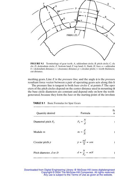
- Page 255: CHAPTER 9 SPUR GEARS Joseph E. Shig
- Page 259 and 260: 9.3 FORCE ANALYSIS In Fig. 9.3 a ge
- Page 261 and 262: SPUR GEARS SPUR GEARS 9.9 TABLE 9.5
- Page 263 and 264: Allowable Bending Stress Number. Th
- Page 265 and 266: 10.1 INTRODUCTION / 10.1 10.2 TYPES
- Page 267 and 268: HELICAL GEARS HELICAL GEARS 10.3 (a
- Page 269 and 270: helical gears are employed, a limit
- Page 271 and 272: contact ratio and the axial overlap
- Page 273 and 274: 10.5.1 Strength and Durability HELI
- Page 275 and 276: HELICAL GEARS FIGURE 10.4 Dynamic f
- Page 277 and 278: HELICAL GEARS HELICAL GEARS 10.13 (
- Page 279 and 280: HELICAL GEARS housing which support
- Page 281 and 282: If the tooth contact pattern at nor
- Page 283 and 284: for external gears; for internal ge
- Page 285 and 286: HELICAL GEARS HELICAL GEARS 10.21 G
- Page 287 and 288: HELICAL GEARS HELICAL GEARS 10.23 F
- Page 289 and 290: HELICAL GEARS HELICAL GEARS 10.25 F
- Page 291 and 292: HELICAL GEARS HELICAL GEARS 10.27 F
- Page 293 and 294: HELICAL GEARS HELICAL GEARS 10.29 F
- Page 295 and 296: HELICAL GEARS HELICAL GEARS 10.31 F
- Page 297 and 298: HELICAL GEARS HELICAL GEARS 10.33 F
- Page 299 and 300: HELICAL GEARS HELICAL GEARS 10.35 F
- Page 301 and 302: Letting Ze = distance on line of ac
- Page 303 and 304: HELICAL GEARS HELICAL GEARS 10.39 H
- Page 305 and 306: HELICAL GEARS 10.41 Downloaded from
- Page 307 and 308:
HELICAL GEARS HELICAL GEARS 10.43 F
- Page 309 and 310:
HELICAL GEARS HELICAL GEARS 10.45 F
- Page 311 and 312:
HELICAL GEARS HELICAL GEARS 10.47 F
- Page 313 and 314:
HELICAL GEARS HELICAL GEARS 10.49 F
- Page 315 and 316:
HELICAL GEARS HELICAL GEARS 10.51 p
- Page 317 and 318:
HELICAL GEARS HELICAL GEARS 10.53 W
- Page 319 and 320:
HELICAL GEARS HELICAL GEARS 10.55 E
- Page 321 and 322:
In most cases the blank temperature
- Page 323 and 324:
CHAPTER 11 BEVEL AND HYPOID GEARS T
- Page 325 and 326:
FIGURE 11.3 Zerol bevel set. (Gleas
- Page 327 and 328:
FIGURE 11.7 Hypoid gear nomenclatur
- Page 329 and 330:
The taper you select depends in som
- Page 331 and 332:
BEVEL AND HYPOID GEARS BEVEL AND HY
- Page 333 and 334:
Hypoid gears are recommended where
- Page 335 and 336:
TABLE 11.1 Material Factors C M BEV
- Page 337 and 338:
11.4.7 Hypoid Offset BEVEL AND HYPO
- Page 339 and 340:
FIGURE 11.16 Selection of spiral an
- Page 341 and 342:
should be hardened and tempered abo
- Page 343 and 344:
BEVEL AND HYPOID GEARS BEVEL AND HY
- Page 345 and 346:
TABLE 11.7 Mean Addendum Factor BEV
- Page 347 and 348:
11.5.4 AGMA References † The foll
- Page 349 and 350:
BEVEL AND HYPOID GEARS TABLE 11.10
- Page 351 and 352:
BEVEL AND HYPOID GEARS TABLE 11.10
- Page 353 and 354:
BEVEL AND HYPOID GEARS area.The rec
- Page 355 and 356:
TABLE 11.12 Load-Distribution Facto
- Page 357 and 358:
BEVEL AND HYPOID GEARS FIGURE 11.21
- Page 359 and 360:
BEVEL AND HYPOID GEARS FIGURE 11.25
- Page 361 and 362:
BEVEL AND HYPOID GEARS FIGURE 11.29
- Page 363 and 364:
BEVEL AND HYPOID GEARS FIGURE 11.33
- Page 365 and 366:
BEVEL AND HYPOID GEARS 11.43 Downlo
- Page 367 and 368:
BEVEL AND HYPOID GEARS FIGURE 11.39
- Page 369 and 370:
BEVEL AND HYPOID GEARS FIGURE 11.43
- Page 371 and 372:
BEVEL AND HYPOID GEARS FIGURE 11.47
- Page 373 and 374:
TABLE 11.15 Allowable Bending Stres
- Page 375 and 376:
BEVEL AND HYPOID GEARS 11.7.3 Axial
- Page 377 and 378:
Pressure lubrication is recommended
- Page 379 and 380:
CHAPTER 12 WORM GEARING K. S. Edwar
- Page 381 and 382:
FIGURE 12.2 Photograph of a worm-ge
- Page 383 and 384:
12.3 VELOCITY AND FRICTION Figure 1
- Page 385 and 386:
where the subscripts are t for the
- Page 387 and 388:
This force is the negative x direct
- Page 389 and 390:
24, from Table 12.3, K m = 0.823 by
- Page 391 and 392:
12.7 DESIGN STANDARDS The American
- Page 393 and 394:
TABLE 12.6 Dimensions of the Gear a
- Page 395 and 396:
Table 12.9 presents a system for st
- Page 397 and 398:
12.8.3 Gear Ratio The gear ratio is
- Page 399 and 400:
12.8.10 Worm Length The effective l
- Page 401 and 402:
CHAPTER 13 POWER SCREWS Rudolph J.
- Page 403 and 404:
FIGURE 13.1 Power screw assembly us
- Page 405 and 406:
POWER SCREWS POWER SCREWS 13.5 TABL
- Page 407 and 408:
POWER SCREWS POWER SCREWS 13.7 The
- Page 409 and 410:
which can be solved for a circular
- Page 411 and 412:
TABLE 13.3 Sizes and Capacities of
- Page 413 and 414:
REFERENCES POWER SCREWS POWER SCREW
- Page 415 and 416:
Source: STANDARD HANDBOOK OF MACHIN
- Page 417 and 418:
CHAPTER 14 BELT DRIVES Wolfram Funk
- Page 419 and 420:
Disadvantages: ● Limited power tr
- Page 421 and 422:
FIGURE 14.2 Multiple-pulley drives.
- Page 423 and 424:
Because µβwπ Fu = F2′(m − 1)
- Page 425 and 426:
The maximum power transmission capa
- Page 427 and 428:
(a) (c) BELT DRIVES BELT DRIVES 14.
- Page 429 and 430:
BELT DRIVES FIGURE 14.11 Pretension
- Page 431 and 432:
BELT DRIVES 14.17 Taking into consi
- Page 433 and 434:
FIGURE 14.15 Multiple-ply belt. BEL
- Page 435 and 436:
4. The manufacturer can supply belt
- Page 437 and 438:
BELT DRIVES FIGURE 14.18 Section of
- Page 439 and 440:
The calculation of belt velocity (p
- Page 441 and 442:
BELT DRIVES The flexibility of the
- Page 443 and 444:
BELT DRIVES BELT DRIVES 14.29 FIGUR
- Page 445 and 446:
transmissible power P is determined
- Page 447 and 448:
BELT DRIVES BELT DRIVES 14.33 The a
- Page 449 and 450:
BELT DRIVES BELT DRIVES 14.35 (a) (
- Page 451 and 452:
(twisting of tension member and its
- Page 453 and 454:
The power transmission capacity of
- Page 455 and 456:
FIGURE 14.33 Comparison of system c
- Page 457 and 458:
CHAPTER 15 CHAIN DRIVES John L. Wri
- Page 459 and 460:
esponding chains in Ref. [15.1], bu
- Page 461 and 462:
TABLE 15.1 Roller-Chain Dimensions
- Page 463 and 464:
CHAIN DRIVES 15.3 SELECTION OF ROLL
- Page 465 and 466:
sprockets may be required. Idler sp
- Page 467 and 468:
CHAIN DRIVES TABLE 15.2 Service Fac
- Page 469 and 470:
Determine Lubrication Type. The typ
- Page 471 and 472:
CHAIN DRIVES CHAIN DRIVES 15.15 TAB
- Page 473 and 474:
CHAIN DRIVES inexpensive, but they
- Page 475 and 476:
TABLE 15.9 Offset Sidebar Chain Dim
- Page 477 and 478:
CHAIN DRIVES CHAIN DRIVES 15.21 Cha
- Page 479 and 480:
CHAIN DRIVES CHAIN DRIVES 15.23 TAB
- Page 481 and 482:
15.6.3 Horsepower Ratings of Offset
- Page 483 and 484:
15.7.3 Silent-Chain Sprockets CHAIN
- Page 485 and 486:
In a drive where the shaft centers
- Page 487 and 488:
CHAIN DRIVES silent-chain size when
- Page 489 and 490:
Source: STANDARD HANDBOOK OF MACHIN
- Page 491 and 492:
7. Misalignment Amount and type of
- Page 493 and 494:
COUPLINGS COUPLINGS 16.5 TABLE 16.1
- Page 495 and 496:
alignment up to 45°. The maximum a
- Page 497 and 498:
FIGURE 16.4 Portion of shaft showin
- Page 499 and 500:
COUPLINGS 16.3.2 Chain, Grid, and B
- Page 501 and 502:
COUPLINGS 16.13 FIGURE 16.11 (a) Si
- Page 503 and 504:
COUPLINGS 16.15 FIGURE 16.16 Hydrau
- Page 505 and 506:
operating radius corresponding to a
- Page 507 and 508:
FIGURE 16.24 A bellows coupling. (S
- Page 509 and 510:
COUPLINGS COUPLINGS 16.21 pression
- Page 511 and 512:
FIGURE 16.30 Bonded type of a shear
- Page 513 and 514:
16.5 UNIVERSAL JOINTS AND ROTATING-
- Page 515 and 516:
COUPLINGS COUPLINGS 16.27 FIGURE 16
- Page 517 and 518:
COUPLINGS The correction factor Ks
- Page 519 and 520:
COUPLINGS COUPLINGS 16.31 Rzeppa Un
- Page 521 and 522:
method of attachment allows a much
- Page 523 and 524:
CHAPTER 17 SHAFTS Charles R. Mischk
- Page 525 and 526:
Geometric fidelity is important to
- Page 527 and 528:
Solution. Equation (17.1) is used.
- Page 529 and 530:
SHAFTS Based on this, the designer
- Page 531 and 532:
SHAFTS 17.9 The dual-entry slope dy
- Page 533 and 534:
SHAFTS SHAFTS 17.11 The prediction
- Page 535 and 536:
17.4 DISTORTION DUE TO TORSION Angu
- Page 537 and 538:
A press fit induces a surface press
- Page 539 and 540:
factor corrected for notch sensitiv
- Page 541 and 542:
The methods of Secs. 17.2 and 17.3
- Page 543 and 544:
REFERENCES 17.1 Joseph E. Shigley a
- Page 545 and 546:
Source: STANDARD HANDBOOK OF MACHIN
- Page 547 and 548:
Source: STANDARD HANDBOOK OF MACHIN
- Page 549 and 550:
ROLLING-CONTACT BEARINGS 18.5 FIGUR
- Page 551 and 552:
FIGURE 18.9 Tapered-roller thrust b
- Page 553 and 554:
ROLLING-CONTACT BEARINGS where C s
- Page 555 and 556:
ROLLING-CONTACT BEARINGS For exampl
- Page 557 and 558:
ROLLING-CONTACT BEARINGS ROLLING-CO
- Page 559 and 560:
age on the bearing per revolution a
- Page 561 and 562:
ROLLING-CONTACT BEARINGS TABLE 18.5
- Page 563 and 564:
deep-groove ball bearings. Self-ali
- Page 565 and 566:
CHAPTER 19 JOURNAL BEARINGS Theo G.
- Page 567 and 568:
Λ Bearing number = (6µω/p a)(R/C
- Page 569 and 570:
TABLE 19.1 Characteristics of Lubri
- Page 571 and 572:
A foil journal bearing (Fig. 19.3l)
- Page 573 and 574:
TABLE 19.2 Physical Properties of J
- Page 575 and 576:
TABLE 19.4 Performance Ratings from
- Page 577 and 578:
Next the candidate materials are gi
- Page 579 and 580:
This equation can be interpreted as
- Page 581 and 582:
JOURNAL BEARINGS where θ 1 and θ
- Page 583 and 584:
In general, volume flow rate per un
- Page 585 and 586:
JOURNAL BEARINGS JOURNAL BEARINGS 1
- Page 587 and 588:
It was proposed that the film press
- Page 589 and 590:
JOURNAL BEARINGS JOURNAL BEARINGS 1
- Page 591 and 592:
JOURNAL BEARINGS JOURNAL BEARINGS 1
- Page 593 and 594:
JOURNAL BEARINGS JOURNAL BEARINGS 1
- Page 595 and 596:
JOURNAL BEARINGS JOURNAL BEARINGS 1
- Page 597 and 598:
L b 1 Sb2 + b3 (L/D) TABLE 19.15 S
- Page 599 and 600:
JOURNAL BEARINGS JOURNAL BEARINGS 1