Digidim 458Mx Chassis Installation Guide - Helvar
Digidim 458Mx Chassis Installation Guide - Helvar
Digidim 458Mx Chassis Installation Guide - Helvar

Create successful ePaper yourself
Turn your PDF publications into a flip-book with our unique Google optimized e-Paper software.
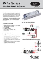
<strong>Digidim</strong> <strong>458Mx</strong> <strong>Chassis</strong><br />
<strong>Installation</strong> <strong>Guide</strong><br />
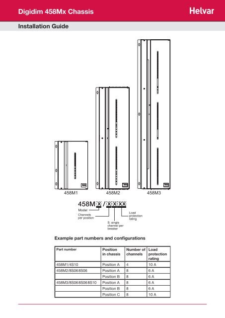
458M1 458M2 458M3<br />
458M x / x x xx<br />
Model<br />
Channels<br />
per position<br />
S: single<br />
channel per<br />
breaker<br />
Part number Position<br />
in chassis<br />
Load<br />
protection<br />
rating<br />
Example part numbers and configurations<br />
Number of<br />
channels<br />
458M1/4S10 Position A 4 10 A<br />
458M2/8S06 8S06 Position A 8 6 A<br />
Position B 8 6 A<br />
458M3/8S06 8S06 8S10 Position A 8 6 A<br />
Position B 8 6 A<br />
Position C 8 10 A<br />
Load<br />
protection<br />
rating
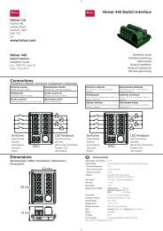
1: Remove Cover, Knockouts (and Blanking Plates)<br />
WARNING: THE BLANKING PLATE(S) PREVENT(S) ACCESS TO MAINS WIRING<br />
WHEN THERE IS NO MODULE CONNECTED.<br />
REMOVE THE BLANKING PLATE(S) ONLY IF YOU ARE ATTACHING A<br />
CONTROL MODULE.<br />
Procedure<br />
1. Open door and remove screws (A and B) from inside door.<br />
2. Remove screws from left of door (C and D)*<br />
Note:<br />
458M1: 2 screws (C and D);<br />
*458M2: 3 screws;<br />
*458M3: 4 screws.<br />
3. Remove cover from chassis.<br />
5. Remove knockouts as required.<br />
4. If attaching a control module, unscrew and remove blanking plate(s).<br />
Note:<br />
458M1: 1 blanking plate;<br />
458M2: 2 blanking plates;<br />
458M3: 3 blanking plates.<br />
6. With the blanking plate(s) removed, the chassis is<br />
ready for a module to be attached (see diagram opposite).<br />
Blanking<br />
plate<br />
Note 1: The diagrams on this page show the 458M1/4S10 <strong>Chassis</strong>.<br />
Covers and knockouts are removed from the 458M2 and 458M3 in a similar way.<br />
Note 2: Use the grommets provided to protect cabling entering the knockouts.<br />
If necessary, the knockout gland plates (on 458M2 and 458M3 types) can be removed to provide<br />
more space for cabling.<br />
2 <strong>Helvar</strong> <strong>Digidim</strong> <strong>Chassis</strong> <strong>458Mx</strong> <strong>Installation</strong> <strong>Guide</strong> Data subject to change without notice<br />
C<br />
D<br />
A<br />
B<br />
Knockouts<br />
Knockouts
2: Mount to Wall<br />
Mounting, Environmental and Clearance Requirements<br />
Mounting<br />
• Mount the chassis vertically on a flat surface.<br />
• Use No.8 or No. 10 screws with a head diameter between 6 mm and 9 mm.<br />
• Use wall plugs if necessary.<br />
• Mount chassis on wall using: 4 screws for the 458M1 and 458M2 chassis.<br />
6 screws for the 458M3 chassis.<br />
Environment<br />
• The ambient temperature must be between 0ºC and 40ºC.<br />
• Air humidity must be between 0% and 90% (non-condensing).<br />
• The area must be adequately ventilated.<br />
• Do NOT install this product in a damp location.<br />
Clearance<br />
• Ensure enough space is left for ventilation and for attaching module(s): 50 mm above, below and to the right of the chassis,<br />
and 100 mm to the left. Refer to the mounting dimensions and clearance diagrams on pages 4 and 5.<br />
• Leave sufficient clearance to allow cables and trunking to be connected.<br />
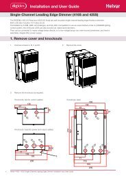
• When a <strong>Helvar</strong> control module (e.g. dimmer unit) is attached, the grilles must NOT be obstructed.<br />
Heat sink<br />
Grilles<br />
Diagram: module grilles and heat sink<br />
<strong>Helvar</strong> <strong>Digidim</strong> <strong>Chassis</strong> <strong>458Mx</strong> <strong>Installation</strong> <strong>Guide</strong> Data subject to change without notice<br />
3
Mounting dimensions and clearance<br />
458M1<br />
458M2<br />
Key:<br />
i = clearance for ventilation<br />
ii = clearance for module(s)<br />
Dimensions:<br />
All dimensions in mm.<br />
4 <strong>Helvar</strong> <strong>Digidim</strong> <strong>Chassis</strong> <strong>458Mx</strong> <strong>Installation</strong> <strong>Guide</strong> Data subject to change without notice
458M3<br />
<strong>Chassis</strong> mounting hole dimensions<br />
R4.5<br />
R3<br />
14<br />
Key:<br />
i = clearance for ventilation<br />
ii = clearance for module(s)<br />
Dimensions:<br />
All dimensions in mm.<br />
<strong>Helvar</strong> <strong>Digidim</strong> <strong>Chassis</strong> <strong>458Mx</strong> <strong>Installation</strong> <strong>Guide</strong> Data subject to change without notice<br />
5
3: Electrical installation<br />
WARNING: BEFORE COMMENCING ANY ELECTRICAL WORK, ISOLATE THE<br />
ELECTRICITY SUPPLY AT THE MAIN DISTRIBUTION BOARD.<br />
Cable sizes and strip lengths<br />
Refer to “Cable Requirements” on page 11 for cable sizes and required strip lengths.<br />
Mains Supply Protection<br />
The mains supply input must be externally protected by an MCB or fuse of a suitable rating.<br />
WARNING: THE SUPPLY INPUT EARTH MUST BE CONNECTED.<br />
Using Spring-Lever Cage Clamp Terminals<br />
Note: The supply earth, supply neutral and output terminals are spring-lever cage clamp terminals.<br />
1. Insert a screwdriver as far as it will go into the terminal release point.<br />
2. Lever the screwdriver back. This opens the cage clamp.<br />
(For output terminals, levering the screwdriver back is unnecessary).<br />
3. With the cage clamp open, cable can be inserted or removed from the terminal.<br />
4. Release the pressure on the screwdriver and then remove it. This closes the<br />
cage clamp. If you have inserted a cable, check that the connection is secure.<br />
6 <strong>Helvar</strong> <strong>Digidim</strong> <strong>Chassis</strong> <strong>458Mx</strong> <strong>Installation</strong> <strong>Guide</strong> Data subject to change without notice
3.1 Connect SDIM Cable Loom to Modules (if applicable)<br />
If you are not wiring a 458M chassis to a <strong>Helvar</strong> module via SDIM, go to the next section.<br />
An SDIM cable loom is attached to the DIN-rail inside the chassis (see Wiring diagrams, page 9).<br />
This can be connected to the SDIM terminals of the control module(s), to enable connection of the module(s) to a <strong>Helvar</strong> Imagine<br />
system (see diagrams below).<br />
Note: If the unit is at either end of the S-DIM cable line, link between terminals ‘TERM’ and ‘B’ for termination<br />
SDIM connection from 458M chassis to 1 control module<br />
to SDIM<br />
terminal<br />
of control<br />
module<br />
to SDIM<br />
terminal<br />
of control<br />
module<br />
to SDIM<br />
terminal<br />
of control<br />
module<br />
to SDIM<br />
terminal<br />
of control<br />
module<br />
to SDIM<br />
terminal<br />
of control<br />
module<br />
to SDIM<br />
terminal<br />
of control<br />
module<br />
Link for termination<br />
(connector is at end of SDIM Cable Line)<br />
Link for termination<br />
(connector is at end of SDIM Cable Line)<br />
A 0 V SC B<br />
Link for termination<br />
(connector is at end of SDIM Cable Line)<br />
A 0 V SC B<br />
DIN-Rail inside<br />
chassis<br />
SDIM connections<br />
Recommended:<br />
Belden 8102 cable<br />
SDIM connection from 458M chassis to 2 control modules<br />
DIN-Rail inside<br />
chassis<br />
SDIM connections<br />
Recommended:<br />
Belden 8102 cable<br />
SDIM connection from 458M chassis to 3 control modules<br />
A 0V SC B<br />
DIN-Rail inside<br />
chassis<br />
SDIM connections<br />
Recommended:<br />
Belden 8102 cable<br />
<strong>Helvar</strong> <strong>Digidim</strong> <strong>Chassis</strong> <strong>458Mx</strong> <strong>Installation</strong> <strong>Guide</strong> Data subject to change without notice<br />
7
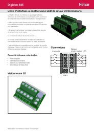
3.2 Connect Loads<br />
Connect the loads to the output terminals, as shown in diagram below.<br />
Note: Refer to separate wiring diagrams for 458M1, 458M2 and 458M3, on page 9.<br />
NEUTRAL<br />
OUTPUTS<br />
1<br />
2<br />
3<br />
4<br />
5<br />
6<br />
7<br />
8<br />
LIVE<br />
OUTPUTS EARTH<br />
3.3 Connect Mains Supply Input<br />
OUTPUT TERMINALS<br />
Dimmed load<br />
Connect the mains supply input to the MCB(s) and earth and neutral terminals, as shown<br />
in the wiring diagrams on page 9.<br />
458M1<br />
Live (L) is connected via the MCBs.<br />
Neutral (N) and earth (E) connections are between the MCBs and Output terminal block.<br />
458M2<br />
Live (L1, L2) connections are via the MCBs.<br />
Neutral and earth connections are at the base of the units, below the SDIM cable loom.<br />
458M3<br />
Live (L1, L2, L3) connections are via the MCBs.<br />
Neutral and earth connections are at the base of the units, below the SDIM cable loom.<br />
Note 1: The bypass terminals allow operation and testing of the lights<br />
and installation wiring, without (a) control module(s) connected<br />
to the chassis.<br />
Note 2: Always dock unused dimmer feeds in bypass connectors.<br />
Note 3: Ensure MCB terminals are clearly identified for load circuit<br />
connection.<br />
Diagram: 458M1 wired<br />
8 <strong>Helvar</strong> <strong>Digidim</strong> <strong>Chassis</strong> <strong>458Mx</strong> <strong>Installation</strong> <strong>Guide</strong> Data subject to change without notice
Wiring diagrams<br />
458M1<br />
458M2<br />
BYPASS<br />
TERMINALS<br />
BYPASS<br />
TERMINALS<br />
BYPASS<br />
TERMINALS<br />
A<br />
NEUTRAL<br />
OUTPUTS<br />
SDIM<br />
cable<br />
loom<br />
NEUTRAL<br />
OUTPUTS<br />
A<br />
NEUTRAL<br />
OUTPUTS<br />
B<br />
SDIM<br />
cable<br />
loom<br />
LIVE<br />
OUTPUTS<br />
EARTH<br />
LOAD<br />
OUTPUT<br />
TERMINALS<br />
LIVE<br />
OUTPUTS EARTH<br />
N<br />
L<br />
E<br />
OUTPUT<br />
TERMINALS<br />
LIVE<br />
OUTPUTS EARTH<br />
OUTPUT<br />
TERMINALS<br />
N<br />
E<br />
M S<br />
AINS U<br />
PPLY<br />
LOAD<br />
L1<br />
(mains)<br />
L2<br />
(mains)<br />
LOAD<br />
M AINS<br />
S<br />
U PPLY<br />
458M3<br />
BYPASS<br />
TERMINALS<br />
BYPASS<br />
TERMINALS<br />
BYPASS<br />
TERMINALS<br />
NEUTRAL<br />
OUTPUTS<br />
NEUTRAL<br />
OUTPUTS<br />
NEUTRAL<br />
OUTPUTS<br />
SDIM<br />
cable<br />
loom<br />
LIVE<br />
OUTPUTS<br />
EARTH<br />
OUTPUT<br />
TERMINALS<br />
LIVE<br />
OUTPUTS EARTH<br />
OUTPUT<br />
TERMINALS<br />
LIVE<br />
OUTPUTS EARTH<br />
OUTPUT<br />
TERMINALS<br />
N<br />
E<br />
LOAD<br />
L1<br />
(mains)<br />
LOAD<br />
L2<br />
(mains)<br />
LOAD<br />
<strong>Helvar</strong> <strong>Digidim</strong> <strong>Chassis</strong> <strong>458Mx</strong> <strong>Installation</strong> <strong>Guide</strong> Data subject to change without notice<br />
A<br />
B<br />
C<br />
L3<br />
(mains)<br />
M S<br />
AINS U<br />
PPLY<br />
9
Dimensions: case<br />
All dimensions in mm.<br />
355<br />
317<br />
178<br />
137<br />
37<br />
273<br />
362<br />
705<br />
178<br />
37<br />
458M1 458M2 458M3<br />
10 <strong>Helvar</strong> <strong>Digidim</strong> <strong>Chassis</strong> <strong>458Mx</strong> <strong>Installation</strong> <strong>Guide</strong> Data subject to change without notice<br />
273<br />
753
Technical Data<br />
Power<br />
Mains supply voltage: 230 VAC / 400 VAC<br />
Protection: MCB type C 10 kA. Rating as specified for individual units.<br />
Supply current: 458M1, 458M2, 458M3 = 63 A (max) for each position (e.g. Positions A and B for 458M2)<br />
Single phase use = 125 A (max)<br />
Note: Supplying multiple blocks of MCBs on the same phase requires this limit because of the<br />
neutral connection.<br />
Conformity and Standards<br />
Safety: EN 60439<br />
IP rating: IP20<br />
Environmental: Complies with WEEE and RoHS directives<br />
<strong>Installation</strong><br />
Mounting: Vertically wall mounted using 4.5 mm mounting holes.<br />
Use No. 8 or No. 10 screws with head diameter of 6 mm to 9 mm.<br />
Mechanical Data<br />
Cable Requirements<br />
Refer to mounting dimensions and clearance diagrams (see pages 4 and 5).<br />
Dimensions (L x W x H): See diagrams on page 10.<br />
Weight: 458M1: 5.9 kg (458M1 including 9 MCBs)<br />
458M2: 12.2 kg (458M2 including 18 MCBs)<br />
458M3: 18.0 kg (458M3 including 27 MCBs)<br />
Operating and Storage Conditions<br />
Ambient Temperature: 0ºC to 40ºC<br />
Storage Temperature: -10°C to 70°C<br />
Relative Humidity: Max 90%, non-condensing<br />
Connection Cable type Strip length<br />
Mains supply: 458M1 Up to 16 mm 2 16-17 mm (N); 12-13 (E)<br />
Mains supply: 458M2 From 6 mm 2 to 35 mm 2 12-14 mm (N), 17 (E)<br />
Mains supply: 458M3 From 6 mm 2 to 35 mm 2 12-14 mm (N), 17 (E)<br />
Channel outputs Solid core: 0.25 mm 2 to 4 mm 2 ;<br />
Stranded: 0.25 mm 2 to 2.5 mm 2<br />
SDIM / DMX Low loss RS485 type;<br />
Multi-stranded, twisted and shielded;<br />
3- or 4-core plus screen;<br />
0.22 to 1.5mm 2 .<br />
Recommended: two twisted pairs (overall screened)<br />
e.g. ‘Belden 8102’.<br />
10-12 mm<br />
Max. length: 1000 m<br />
<strong>Helvar</strong> <strong>Digidim</strong> <strong>Chassis</strong> <strong>458Mx</strong> <strong>Installation</strong> <strong>Guide</strong> Data subject to change without notice<br />
11
12:03:2012<br />
<strong>Helvar</strong> <strong>Digidim</strong> <strong>Chassis</strong> <strong>458Mx</strong> <strong>Installation</strong> <strong>Guide</strong><br />
www.helvar.com<br />
Doc. 7860213, issue 6<br />
Data subject to change without notice