heavy-duty rod ends and spherical bearings - Hirschmann GmbH
heavy-duty rod ends and spherical bearings - Hirschmann GmbH
heavy-duty rod ends and spherical bearings - Hirschmann GmbH

Create successful ePaper yourself
Turn your PDF publications into a flip-book with our unique Google optimized e-Paper software.
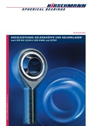
Catalogue GE 0107<br />
HEAVY-DUTY ROD ENDS AND SPHERICAL BEARINGS
2<br />
Heavy-<strong>duty</strong> Rod <strong>ends</strong> <strong>and</strong> Spherical <strong>bearings</strong> from HIRSCHMANN<br />
Rod <strong>ends</strong> <strong>and</strong><br />
Spherical <strong>bearings</strong><br />
mm A million times proved<br />
mm In sizes 2 up to 50 mm<br />
mm Acc. to DIN ISO 122404 (DIN 648K)<br />
<strong>and</strong> Cetop<br />
mm Maintenance free or Relubricatable<br />
mm Hard cromed or stainless steel, sealed<br />
mm Specials to customer requirements<br />
St<strong>and</strong>ard p<strong>rod</strong>ucts
Int<strong>rod</strong>uction<br />
HIRSCHMANN's <strong>rod</strong> <strong>ends</strong> <strong>and</strong> <strong>spherical</strong> <strong>bearings</strong> are<br />
bearing elements which can be used for many applications,<br />
<strong>and</strong> are of the plain bearing type. They have proved their<br />
worth in millions of instances as a design element for<br />
transmitting power between members lying at various angles,<br />
both statically <strong>and</strong> dynamically. The mounting dimensions<br />
of these bearing elements have been fixed in DIN<br />
ISO 12240-4 (648 K). This catalogue reflects the current<br />
state of development <strong>and</strong> manufacture, <strong>and</strong> the information<br />
contained in it supersedes earlier publications. We<br />
reserve the right to make modifications in the course of<br />
p<strong>rod</strong>uct development. Reprints <strong>and</strong> excerpts require our<br />
express permission.<br />
St<strong>and</strong>ard p<strong>rod</strong>ucts:<br />
For all the st<strong>and</strong>ard p<strong>rod</strong>ucts shown in this catalogue, many<br />
variations are possible. Details are given in the text below<br />
the tables of dimensions, e.g. hard-chromed or rustproof inner<br />
ring or outer part, reduced bearing slackness etc.<br />
Specials:<br />
In addition to our st<strong>and</strong>ard p<strong>rod</strong>ucts, we make specials to<br />
customer requirements or to drawing. Examples of our<br />
specials are shown on the rear cover of the catalogue.<br />
Warranty:<br />
All the information contained in this catalogue is the result<br />
of years of experience in the manufacture <strong>and</strong> use of<br />
<strong>rod</strong> <strong>ends</strong> <strong>and</strong> <strong>spherical</strong> <strong>bearings</strong>. Nevertheless, unknown<br />
parameters <strong>and</strong> practical conditions of use can considerably<br />
reduce the validity of these general statements, so<br />
that the user must conduct practical tests. The multitude<br />
of applications for <strong>rod</strong> <strong>ends</strong> <strong>and</strong> <strong>spherical</strong> <strong>bearings</strong> mean<br />
that we cannot accept any liability for the correctness of<br />
our recommendations in individual instances.<br />
Quality according to EN 9100<br />
All HIRSCHMANN GMBH <strong>rod</strong> <strong>ends</strong> <strong>and</strong> <strong>spherical</strong> <strong>bearings</strong><br />
are p<strong>rod</strong>uced using the latest <strong>and</strong> most reliable p<strong>rod</strong>uction<br />
methods, <strong>and</strong> are subject to quality assurance measures<br />
as per EN 9100 both during p<strong>rod</strong>uction <strong>and</strong> in the<br />
p<strong>rod</strong>uct stage.<br />
Advisory service <strong>and</strong> sales:<br />
Our staff <strong>and</strong> the sales engineers at our agencies <strong>and</strong> dealers<br />
in Germany <strong>and</strong> abroad (Page 24/25), all of whom have<br />
their own stocks, would be pleased to assist you at any time.<br />
CONTENTS:<br />
mm Selection 5<br />
mm Technical notes 6–7<br />
mm Checking bearing size 8–9<br />
mm Determining bearing size 10<br />
mm Calculation examples 11<br />
mm Rod <strong>ends</strong><br />
<strong>heavy</strong>-<strong>duty</strong> relubricatable design 12–13<br />
mm Rod <strong>ends</strong><br />
<strong>heavy</strong>-<strong>duty</strong> maintenance-free design 14–15<br />
mm Rod <strong>ends</strong> <strong>heavy</strong>-<strong>duty</strong>,<br />
relubricatable <strong>and</strong> maintenance-free<br />
as per CETOP-Norm 16–17<br />
mm Spherical <strong>bearings</strong> <strong>heavy</strong>-<strong>duty</strong>,<br />
relubricatable <strong>and</strong> maintenance-free 18–19<br />
mm Spherical <strong>bearings</strong> <strong>heavy</strong>-<strong>duty</strong>,<br />
relubricatable <strong>and</strong> maintenance-free<br />
without steel outer ring 20<br />
mm Sealed <strong>rod</strong> <strong>ends</strong><br />
<strong>and</strong> <strong>spherical</strong> <strong>bearings</strong> 21<br />
mm Threaded bolts for <strong>rod</strong> <strong>ends</strong><br />
<strong>and</strong> <strong>spherical</strong> <strong>bearings</strong> 22<br />
mm Applications <strong>and</strong><br />
typical installations 23<br />
mm Form sheets for an inquiry 24-25<br />
mm Advice <strong>and</strong> sales 26–27<br />
HIRSCHMANN <strong>GmbH</strong><br />
3
Special solutions<br />
4<br />
This is only a part of various special p<strong>rod</strong>ucts which we are<br />
manufacturing according to customer requirements or customer drawings.<br />
Coupling <strong>rod</strong> Suspension for damper Rod End made of Titan<br />
Special bearing for ralley sport Vertical bearing for pneumatic cylinder Sealed double Rod End Rod End for sun sail stainless steel
Selection guidelines<br />
Construction Series Design features Application features Page<br />
SFC.. Relubricatable <strong>heavy</strong>-<strong>duty</strong> Universal application at high alter- 12–13<br />
SMC.. design, <strong>rod</strong> <strong>ends</strong> nating <strong>and</strong> shock loads in radial <strong>and</strong> 18<br />
SSC.. <strong>and</strong> <strong>spherical</strong> <strong>bearings</strong> axial directions. Suitable for large<br />
Friction pairing: swings.<br />
Steel/<strong>heavy</strong>-<strong>duty</strong> bronze,<br />
with precision-turned bushing Vmax = 60 m/min.<br />
having extremely high lining<br />
adjustment capability.<br />
SFCP.. Maintenance free Universal application at high constant 14–15<br />
SMCP.. <strong>heavy</strong>-<strong>duty</strong>, <strong>rod</strong> <strong>ends</strong> loads <strong>and</strong> low alternating <strong>and</strong> shock 19<br />
SSCP.. <strong>and</strong> <strong>spherical</strong> <strong>bearings</strong> loads in axial <strong>and</strong> radial directions.<br />
Friction pairing: For difficult lubrication conditions,<br />
Steel/PTFE bronze fabric. high running speeds <strong>and</strong> large swings.<br />
The sliding film is affixed<br />
inside the bushing. This Vmax = 60 m/min.<br />
ensures long service life.<br />
SFC..CETOP CETOP-st<strong>and</strong>ard As for relubricatable or maintenance- 16–17<br />
SFCP..CETOP relubricatable or free <strong>heavy</strong>-<strong>duty</strong> <strong>rod</strong> <strong>ends</strong> <strong>and</strong><br />
maintenance-free <strong>spherical</strong> <strong>bearings</strong>.<br />
<strong>heavy</strong>-<strong>duty</strong> <strong>rod</strong> <strong>ends</strong><br />
Friction pairing:<br />
Steel/<strong>heavy</strong>-<strong>duty</strong> bronze<br />
Steel/PTFE bronze fabric<br />
SC.. Relubricatable or As for relubricatable or maintenance- 20<br />
SCP.. maintenance-free <strong>heavy</strong>- free <strong>heavy</strong>-<strong>duty</strong> <strong>rod</strong> <strong>ends</strong> <strong>and</strong><br />
<strong>duty</strong> <strong>spherical</strong> <strong>bearings</strong> <strong>spherical</strong> <strong>bearings</strong>.<br />
without steel outer ring<br />
Friction pairing:<br />
Steel/<strong>heavy</strong>-<strong>duty</strong> bronze<br />
Steel/PTFE bronze fabric<br />
..2 RS Sealed <strong>rod</strong> <strong>ends</strong>, For use in severe environmental 21<br />
<strong>spherical</strong> <strong>bearings</strong> conditions<br />
Heavy-<strong>duty</strong> <strong>and</strong> maintenance- (dirt, dust, splashing water, etc.)<br />
free <strong>rod</strong> <strong>ends</strong> <strong>and</strong> <strong>spherical</strong><br />
<strong>bearings</strong> of sizes 8-30 can be<br />
supplied with replaceable<br />
sealing sleeves.<br />
..W Threaded bolts for Used as angle joints 22<br />
<strong>rod</strong> <strong>ends</strong> <strong>and</strong> <strong>spherical</strong><br />
<strong>bearings</strong><br />
Heavy-<strong>duty</strong> <strong>and</strong> maintenancefree<br />
<strong>rod</strong> <strong>ends</strong> <strong>and</strong> <strong>spherical</strong><br />
<strong>bearings</strong> of sizes 5–16 <strong>and</strong><br />
20 can be supplied ex stock<br />
with a down riveted threaded<br />
bolt.<br />
5
Technical Notes<br />
Bearing slackness:<br />
Bearing slackness or bearing clearance is the dimension<br />
by which the inner ring can be moved within the bushings<br />
in a radial or axial direction when not installed <strong>and</strong> unlubricated.<br />
Rod <strong>ends</strong> <strong>and</strong> <strong>spherical</strong> <strong>bearings</strong> are manufactured<br />
with differing bearing slackness, as shown in the following<br />
charts, depending on the friction pairing <strong>and</strong> the size<br />
of the bearing. When mounting <strong>bearings</strong>, please note<br />
that the slackness can be reduced to null if necessary,<br />
due to possible differences in tolerance (bearing diameter<br />
to housing bore hole).<br />
The test load is 100 N.<br />
Bearing slackness in lubricated design<br />
(at room temperature)<br />
Radial slackness in μm<br />
Size C2 Normal C3<br />
min max min max min max<br />
2– 4 – – 10 30 – –<br />
5– 8 5 10 10 30 30 60<br />
10–14 10 20 20 40 40 80<br />
16–20 15 25 30 50 50 100<br />
22–30 20 30 40 60 60 120<br />
35–50 40 60 60 90 90 150<br />
Fig. 1<br />
Bearing slackness in maintenance-free design<br />
(at room temperature)<br />
Radial slackness in μm<br />
Size C2 Normal C3<br />
min max min max min max<br />
2– 4 – – 2 4 – –<br />
5–30 – – 5 10 10 20<br />
35–50 – – 10 20 20 40<br />
Fig. 2<br />
The axial slackness is 2 to 3 times the radial slackness<br />
under the same test load (measured at room temperature).<br />
Selection of bearing slackness:<br />
Lubricated design<br />
If there are no special reasons for a reduced bearing<br />
slackness according to C2, the “Normal” radial slackkness<br />
must be selected as it offers the best lubricating<br />
grease distribution with a high bearing contact area.<br />
All <strong>rod</strong> <strong>ends</strong> <strong>and</strong> <strong>spherical</strong> <strong>bearings</strong> are supplied with<br />
“Normal” radial slackness unless otherwise ordered.<br />
Maintenance-free design<br />
These <strong>bearings</strong> are remarkable for their low bearing slackness<br />
<strong>and</strong> a high contact area ratio. Unless otherwise ordered,<br />
the maintenance-free <strong>rod</strong> <strong>ends</strong> are supplied with<br />
“Normal” radial slackness.<br />
If the overall friction movement should be kept low when<br />
several <strong>rod</strong> <strong>ends</strong> or <strong>spherical</strong> <strong>bearings</strong> are used, <strong>bearings</strong><br />
with a radial slackness in accordance with C3 should be<br />
used also.<br />
6<br />
Consideration of the environment:<br />
It is recommendable to apply a stainless or sealed type<br />
when using it in a humid environment.<br />
Accordingly to the individual customer’s requirements, the<br />
<strong>bearings</strong> are delivered in the following special designs:<br />
stainless <strong>and</strong> acid-proof<br />
high temperature-proof<br />
low temperature-proof<br />
etc.<br />
Lubrication:<br />
All relubricatable <strong>rod</strong> <strong>ends</strong> <strong>and</strong> <strong>bearings</strong> are supplied ungreased.<br />
We recommend lubrication with an anticorrosive<br />
Lithium-based pressure-resistant grease or a Lithium-complex<br />
metal soap (multipurpose antifriction bearing grease)<br />
for the temperature range of –20° C to +125° C. For temperatures<br />
above 125° C a high temperature grease must<br />
be used <strong>and</strong> for temperatures below –20° C a low temperature<br />
grease must be used.<br />
Initial lubrication <strong>and</strong> relubrication,<br />
lubrication intervals<br />
Under severe conditions <strong>and</strong> at high load, a temperature<br />
check is recommended shortly after commissioning. If a<br />
temperature rise of 25° C occurs after a running-in time<br />
of approx. 1 hour of operation, immediate lubrication is<br />
necessary. A periodical relubrication is necessary in any<br />
event.<br />
Rod <strong>ends</strong> <strong>and</strong> <strong>spherical</strong> <strong>bearings</strong> under alternate load<br />
from both sides require shorter intervals between lubrication<br />
than <strong>rod</strong> <strong>ends</strong> <strong>and</strong> <strong>spherical</strong> <strong>bearings</strong> under load<br />
from one side only. The lubrication intervals depend on<br />
the individual circumstances <strong>and</strong> on the surrounding<br />
conditions.<br />
The following guideline values apply for the minimum<br />
lubricating periods:<br />
With load from one direction<br />
t = Gh<br />
30<br />
With load from alternating directions<br />
t = Gh<br />
130<br />
t = lubricating period in hours of operation.<br />
G h = duration of use in hours of operation<br />
(see page 9).<br />
Lubricating more often does not have any advantages, furthermore<br />
it can damage the hyd<strong>rod</strong>ynamic balance on the<br />
sliding surface.<br />
If the lubricating periods are not observed, the service life<br />
can decrease.<br />
The <strong>rod</strong> <strong>ends</strong> with female thread are equipped from size 5<br />
upwards with funnel-type lubricating nipples to DIN 3405,<br />
those with thread from size 6 upwards. We can supply other<br />
lubricating nipples on request.<br />
During the running-in time of the maintenance-free types<br />
only a small part of the PTFE is transferred from the<br />
sliding foil to the inner ring. Hereby a smoothing effect<br />
arises. This reduces the friction <strong>and</strong> leads to the longer<br />
durability. A greasy or oily film prevents this smoothing<br />
effect. Thus, we recommend using these elements<br />
without lubrication.
Operating temperature:<br />
All designs can be used without restriction in a temperature<br />
range from –30° C to +120° C. Increasing the operating<br />
temperature reduces the bearing power <strong>and</strong>, thus, the<br />
service life.<br />
Operation at high temperature of relubricatable <strong>rod</strong> <strong>ends</strong><br />
<strong>and</strong> <strong>spherical</strong> <strong>bearings</strong> dep<strong>ends</strong> to a very great extent on<br />
whether the high-temperature lubricating grease used offers<br />
sufficient lubricity at high operating temperatures.<br />
These designs could be used in the short term under low<br />
load <strong>and</strong> with suitable lubrication at temperatures up to<br />
+250° C.<br />
The maintenance-free <strong>bearings</strong> can be used in a temperature<br />
range from –50° C to +150° C (mind the decrease or<br />
the increase of bearing slackness).<br />
Sealed <strong>rod</strong> <strong>ends</strong> <strong>and</strong> <strong>spherical</strong> <strong>bearings</strong> can be used at<br />
temperatures from –20° C to +120° C (sealing sleeves of<br />
Perbunan). For higher temperatures up to +250° C sealing<br />
sleeves can be specially made from fluorelastomer<br />
rubber (Viton ® ).<br />
Moment of friction M:<br />
The moment of friction for <strong>rod</strong> <strong>ends</strong> <strong>and</strong> <strong>spherical</strong> <strong>bearings</strong><br />
can be calculated using the following equation:<br />
M = 5 · 10 -4 · μ · P · K<br />
M = moment of friction [Nm]<br />
μ = friction coefficient of sliding surface<br />
P = dynamically equivalent bearing load [N]<br />
K = inner ring diameter [mm]<br />
Guideline values for the friction coefficient μ<br />
Friction coefficient μ<br />
Bearing type min max<br />
lubricated 0,08 0,15<br />
maintenance-free 0,03 0,10<br />
Fig. 3<br />
The low friction coefficients apply for high loads<br />
(p = 80–100 N/mm 2) at low running speeds<br />
(v = 5–10 m/min). The high friction coefficients are for<br />
low loads (p = 5–10 N/mm 2) at high running speeds<br />
(v = 30–60 m/min).<br />
p = specific surface pressure [N/mm 2]<br />
v = running speed in the lining [m/min]<br />
Viton ® is a registrered trademark of Du Pont Performance<br />
Elastomers.<br />
Bearing capacities:<br />
The dynamic bearing capacity C:<br />
The dynamic bearing capacity C is a characteristic value<br />
for the calculation of the service life of <strong>rod</strong> <strong>ends</strong> <strong>and</strong><br />
<strong>spherical</strong> <strong>bearings</strong> under dynamic load, i.e. having to perform<br />
tilting, swinging or pivoting movements under load.<br />
The dynamic bearing capacity C is based on the values<br />
given in the table for the specific surface pressure k c :<br />
Type of bearing Specific surface pressure kc [N/mm2] lubricated 50<br />
maintenance-free 150<br />
Fig. 4<br />
The static bearing capacity C o :<br />
The static bearing capacity C o represents the maximum<br />
permissible load at which no permanent deformation of<br />
the lining or the outer part occurs. In the case of the<br />
<strong>spherical</strong> bearing, the surrounding components must be<br />
so designed that they prevent any deformation of the bearing.<br />
In the case of <strong>rod</strong> <strong>ends</strong>, C o corresponds to the permissible<br />
load based on the weakest cross-section which results<br />
form the yield point of the outer material, with a safety<br />
factor of 1,2.<br />
The ultimate load is at least 1.5 the permissible C o load.<br />
The axial load-bearing capacity:<br />
The axial load-bearing capacity of the <strong>rod</strong> <strong>ends</strong> <strong>and</strong> the<br />
<strong>spherical</strong> <strong>bearings</strong> is limited by the axial fixing of the bushing<br />
(flanged) in the outer part.<br />
In the case of <strong>spherical</strong> <strong>bearings</strong> without steel outer ring<br />
(types SC.. <strong>and</strong> SCP..), it must be ensured that the axial<br />
bushing support can absorb the forces given in the table<br />
(Fig. 5) both statically <strong>and</strong> dynamically.<br />
The maximum permissible axial load is calculated on the<br />
basis of the values given in the table.<br />
Heavy-<strong>duty</strong> <strong>and</strong> Permissible axial load<br />
maintenance-free dynamic static<br />
series<br />
SFC/SMC/SSC..<br />
Fa perm. [N] Fa perm. [N]<br />
SFRC/SMRC/SSRC.. 0,06 · Co 0,3 · Co SFXC/SMXC/SC.. 0,04 · Co 0,2 · Co Fig. 5<br />
7
Checking bearing size:<br />
To check a bearing size with regard to its static <strong>and</strong> dynamic<br />
load-bearing capacity, the bearing must be investigated<br />
to the following criteria:<br />
Constant dynamic load<br />
Variable dynamic load<br />
Static load<br />
The equivalent bearing loads are calculated from F r <strong>and</strong> F a .<br />
Dynamic load:<br />
The inner ring carries out a swinging or pivoting movement<br />
in relation to the bushing.<br />
8<br />
Fig. 6<br />
Constant dynamic load:<br />
The dynamically equivalent bearing load P for <strong>rod</strong> <strong>ends</strong><br />
<strong>and</strong> <strong>spherical</strong> <strong>bearings</strong> with constant dynamic loads is calculated<br />
as follows:<br />
It is necessary that: F a F a, perm.<br />
F a, perm. as per table (Fig. 5)<br />
The axial factor Y is taken from the following table (Fig. 7).<br />
Intermediate values can be interpolated linearly.<br />
[N]<br />
Load- Fa relation Fr 0,1 0,2 0,3 0,4 0,5 > 0,5<br />
Axial- Y 0,8 1 1,5 2,5 3 not<br />
factor suitable<br />
Fig. 7<br />
Using the calculated value for P, the load ratio f c = C__ P is<br />
formed <strong>and</strong> compared with the values in the table (Fig. 8).<br />
The bearing is overloaded if a value below the limit value<br />
is obtained.<br />
P is also required for calculation of the service life.<br />
Type of bearing fc = C__ P (lower limit)<br />
lubricated 0,5<br />
maintenance-free 1,0<br />
Fig. 8<br />
Variable dynamic load:<br />
For <strong>rod</strong> <strong>ends</strong> <strong>and</strong> <strong>spherical</strong> <strong>bearings</strong> with variable radial<br />
dynamic load, the mean dymanic bearing load Fm from the<br />
individual load steps F1, F2 ... Fn <strong>and</strong> the corresponding time<br />
components q1, q2 ... qn, for instance for three load<br />
steps, are calculated as follows: (Fig. 9)<br />
F m =<br />
P = F r + Y · F a<br />
The dynamic bearing load is:<br />
<br />
P = F m<br />
F2 1 · q1 + F2 2 · q2 + F2 3 · q _____________________________ 3<br />
Q<br />
[N]<br />
[N]<br />
If there is also a constant axial load acting, P is calculated<br />
as follows:<br />
Load F [N]<br />
[N]<br />
In addition F max must be checked for static safety.<br />
For P perm. see “Permission load”.<br />
[N]<br />
Static load:<br />
The inner ring is stationary in relation to the bushing.<br />
Fig. 9<br />
Fig. 10<br />
For <strong>rod</strong> <strong>ends</strong> <strong>and</strong> <strong>spherical</strong> <strong>bearings</strong> with static load, the<br />
statically equivalent bearing load Po is calculated as follows:<br />
Po = Fr + Y · Fa [N]<br />
F<br />
It is necessary that:<br />
a Fa perm. [N]<br />
Fa, perm. as per table (Fig. 5)<br />
The axial factor Y is taken from the table (Fig. 7).<br />
Po must be Pperm.. See “Permissible load” for Pperm. Permissible load P perm.:<br />
Rod<br />
P<br />
Spherical<br />
perm. = Co · b2 · b4 <strong>ends</strong>: <strong>bearings</strong>:<br />
Pperm. = permissible load [N]<br />
Co = static bearing capacity [N]<br />
b2 = temperature factor from table (Fig. 12)<br />
= load factor from table (Fig. 11)<br />
b 4<br />
P = F m + Y · F a<br />
F max P perm.<br />
Time components<br />
P perm. = C o · b 2
Type of load<br />
invariable<br />
pulsating<br />
variable<br />
Fig. 11<br />
The values written in brackets are valid for <strong>rod</strong> <strong>ends</strong> with<br />
male threads <strong>and</strong> lubricating nipples or lubrication holes.<br />
It is necessary that: P P or<br />
perm.<br />
time<br />
time<br />
time<br />
P o P perm.<br />
Service life:<br />
The service life of a <strong>rod</strong> end or <strong>spherical</strong> bearing is a function<br />
of several factors, some of which are difficult to determine.<br />
A precise calculation is therefore not possible.<br />
The calculation method following, which has been proved<br />
correct in many test st<strong>and</strong> trials, gives a relatively accurate<br />
result for the service life. Influences as shocks, vibrations,<br />
soiling etc. are not taken into consideration. This<br />
calculation is based on a total abrasion of the linings of<br />
0.3% of the diameter of the inner ring. The coefficient of<br />
the sliding friction of the linings increases of about 0.25.<br />
Gh =<br />
Gh = service life<br />
C = dynamic bearing capacity<br />
[h]<br />
[N]<br />
P = dynamic equivalent bearing load [N]<br />
K = inner ring diameter [mm]<br />
= swing angle 1 [degrees]<br />
(by pivoting movements = 180°)<br />
b1 · b2 · b3 · 107 ·<br />
C__<br />
K · · f--- P<br />
f = swing frequency [rpm]<br />
b1 = load direction factor (Fig. 12)<br />
b2 = temperature factor (Fig. 12)<br />
b3 = material factor (Fig. 13)<br />
Operating- Load direction Temperature factor<br />
factors factor b1 b2 Load direction Temperature [° C]<br />
Bearing type single alternat. 80 100 150 200 250<br />
direction direction<br />
lubricated 1 2,5 1 1 1 0,8 0,5<br />
maintenancefree<br />
1 0,3 1 1 0,8 0,5 0,3<br />
Fig. 12<br />
Very low loads or running speeds result in a relatively high<br />
arithmetic service life. In practice, with a longer service life,<br />
environmental influences can acquire importance <strong>and</strong> lead<br />
to an error in the results.<br />
Material factor b3<br />
Material factor b3 –– –– –– Maintenance-free bearing<br />
––––––– Lubricated bearing<br />
If the required service life is not obtained, repeat this calculation<br />
with next bearing size up.<br />
Checking of linings for overheating:<br />
Permissible running speed:<br />
The permissible running speed is largely a function of the<br />
surface exerted, the friction pairing, the lubrication <strong>and</strong><br />
cooling if applicable. The heat building up in the bearing is<br />
proportional to the p<strong>rod</strong>uct of surface pressure <strong>and</strong> running<br />
speed. When checking the bearing size, therefore the<br />
p · v value must be determined <strong>and</strong> compared with the<br />
permissible value (Fig. 14). The bearing running speed<br />
must also be checked.<br />
To avoid overheating, the following is necessary:<br />
<br />
NNN ____<br />
mm2 · nmn ____<br />
<br />
p·v (p·v) perm.<br />
min<br />
v v perm.<br />
Load ratio C__ P<br />
[m/min]<br />
p = surface pressure = kc · P __ C<br />
[N/mm2] kc = specific surface pressure (Fig. 4) [N/mm2] v = mean running speed =<br />
1,745 · 10-5 · K · · f [m/min]<br />
Guideline values for the permissible p · v -value<br />
(p · v) perm. perm. running speed<br />
Bearing type<br />
____ N<br />
mm2 m<br />
· ____<br />
min<br />
vperm. [m/min]<br />
swing pivot<br />
lubricated 30 15 60<br />
maintenancefree<br />
80 60<br />
Fig. 13<br />
Fig. 14<br />
9
Determining of the bearing size<br />
Lubricated design<br />
Relative service live ¯G h [h] Relative service live ¯G h [h]<br />
Dynamically equivalent bearing load P [N]<br />
Fig. 15<br />
Maintenance-free design<br />
10<br />
Bearing sizes<br />
lower limit values<br />
Bearing sizes<br />
lower limit values<br />
Dynamically equivalent bearing load P [N]<br />
Fig. 16<br />
The insertion of the relative service life G h as auxiliary<br />
quantity enables a correlation between the relative service<br />
life <strong>and</strong> the dynamically equivalent bearing load to be<br />
represented graphically.<br />
The following equation applies for the relative service life:<br />
¯G h = G h ·<br />
¯G h = relative service life [h]<br />
G h = required service life [h]<br />
= swing angle [degrees]<br />
f = swing frequency [min -1]<br />
b 1 = load direction factor (Fig. 12)<br />
b 2 = temperature factor (Fig. 12)<br />
Example:<br />
A <strong>rod</strong> end with male thread is required for the following<br />
operating conditions:<br />
Alternating dynamic load Fr 1200 N<br />
Swing angle 30°<br />
Swing frequency f 120 rpm<br />
Operating temperature 50° C<br />
Required service life Gh 7000 h<br />
Since the load is alternating, a lubricated design is recommended,<br />
as set forth in the “Selection” section<br />
(page 5). Thus, Fig. 12 gives b 1 = 2.5 <strong>and</strong> b 2 = 1.<br />
Dynamically equivalent bearing load:<br />
P = F r = 1200 N<br />
Relative service life:<br />
_<br />
G h = G h ·<br />
· f<br />
b 1 · b 2<br />
nb · fn ______=<br />
7000 ·<br />
b1· b2 30 _______<br />
· 120<br />
2, 5 · 1 = 10,08 · 106 h<br />
The intersection in Fig. 15 with P = 1200 N <strong>and</strong> _ Gh =<br />
10,08 · 10 6 h results in the bearing size 12. Thus, SMC<br />
12 is chosen.<br />
Checking the <strong>rod</strong> end SMC 12 with regard to the permissible<br />
load Pperm. <strong>and</strong> the service life _ Gh, <strong>and</strong> checking the<br />
lining for overheating <strong>and</strong> determination of the lubricating<br />
intervals is conducted as shown in Example 1, page 11.<br />
The example given in Fig. 16 is the result of the 2nd<br />
calculation example on page 11.
Calculation examples<br />
Example 1:<br />
The conveying lever on a packaging machine is to be moved<br />
via a <strong>rod</strong> end. The designs calls for a size 12 <strong>rod</strong> end.<br />
Values dictated by design:<br />
Alternating constant dynamic radial load F r<br />
1200 N<br />
Swing angle 30°<br />
Swing frequency f 120 rpm<br />
Operating temperature 50° C<br />
Since the load is alternating <strong>and</strong> constant, a lubricated<br />
design is recommended according to the section “Selection”<br />
(page 5), e.g. SMC 12.<br />
Catalogue values:<br />
Dynamic bearing capacity C 13400 N<br />
Static bearing capacity Co 17000 N<br />
Inner ring ∅ K 22.225 mm<br />
Requirements on <strong>rod</strong> end SMC 12:<br />
1. Radial load F r must be smaller than the permissible<br />
load P perm. to avoid permanent deformation.<br />
2. The service life G h, req. should be at least 6000 operating<br />
hours.<br />
Calculation:<br />
Dynamically equivalent bearing load P:<br />
Fa<br />
P = Fr + Y · F __<br />
a |<br />
P = F r = 1200 N<br />
F r<br />
= 000 ____<br />
1200 = 0 | Y = 0<br />
Permissible <strong>rod</strong> end load Pperm. :<br />
Pperm. = Co · b2 · b4 | b2 = 1 (acc. to Fig. 12)<br />
b4 = 0,35 (acc. to Fig. 11)<br />
Pperm. = 17000 · 1 · 0,35 = 5950 N<br />
P = 1200 N < Pperm. = 5950 N (1st requirement met)<br />
Determination of service life G h :<br />
G =<br />
h b1 · b2 · b3 · 107 · C__<br />
K · · f P<br />
b 1 = 2,5 (Fig. 12)<br />
b 2 = 1 (Fig. 12)<br />
b 3 = 2,1 (Fig. 13) | C__ P<br />
[h]<br />
= 13400 _____ = 11,1<br />
1200<br />
G h = 7200 h > G h, req. = 7000 h (2nd requirement met)<br />
Checking of lining for overheating:<br />
p = k c · P__<br />
C [N/mm2]<br />
p = k c = 50 N/mm 2 (acc. to Fig. 4)<br />
p = P__<br />
C<br />
= 1200 _____<br />
13400<br />
= 111 ____ = 0,089<br />
11,1<br />
p = 50 · 0,089 N/mm 2 = 4,45 N/mm 2<br />
v = 1,745 · 10 -5 · K · · f = 1,745 · 10 -5 · 22,225 · 30 · 120 m/min<br />
v = 1,4 m/min < v perm. = 15 m/min (acc. to Fig. 14)<br />
p · v = 4,45 · 1,4 = 6,23 < (p · v) perm. = 30 (Fig. 14)<br />
No overheat<br />
Lubrication interval:<br />
t = Gh ___<br />
130<br />
= 7200 _____ = 55 h<br />
130<br />
Example 2:<br />
A lever of a filling machine is moved via a double-action<br />
pneumatic cylinder. A maintenance-free <strong>rod</strong> end with<br />
mounting dimensions to CETOP is required.<br />
Values dictated by design:<br />
Variable, pulsating, radial, dynamic load<br />
F1 = 2000 N, F2 = 6000 N, F3 = 3000 N. Fmax = 8000 N<br />
q1 = 20%, q2 = 15%, q3 = 65%<br />
Constant axial load Fa 1000 N<br />
Swing angle 25°<br />
Swing frequency f 60 rpm<br />
Operating temperature max. 80° C<br />
Requirements on <strong>rod</strong> end:<br />
1. The dynamically equivalent bearing load P <strong>and</strong> the statically<br />
equivalent bearing load Po must be lower than the<br />
permissible load Pperm. 2. The service life Gh, req. must be at least 11000 operating<br />
hours.<br />
Calculation:<br />
Mean dynamic bearing load F m:<br />
F m =<br />
F m =<br />
<br />
F2 1 · q1 + F2 2 · q2 + F2 3 · q ____________________________________________ 3<br />
Q<br />
<br />
20002 · 20 + 60002 · 15 + 30002 _______________________________________________________________ · 65<br />
= 3471 N<br />
100<br />
Dynamically equivalent bearing load P:<br />
Fa<br />
P = Fm + Y · F __<br />
a || F<br />
m<br />
= 1000 ____ = 0,28<br />
3471<br />
Y = 1,44 (interpolated acc. to Fig. 7)<br />
P = 3471 + 1,44 · 1000 = 4911 N<br />
Determination of relative service life ¯G h:<br />
G _<br />
h = Gh = · f ______<br />
b ·b |<br />
1 2<br />
= 25 | b1 = 1 (Fig. 12)<br />
f = 60 b2 = 1 (Fig. 12)<br />
G _<br />
h = 11000 · 25 __ ·60 ____<br />
1 · 1 = 16,5 · 106 h<br />
On the basis of the chart (Fig. 16) the <strong>rod</strong> end size<br />
calculated is 16<br />
SFCP 16 CETOP is selected (page 17).<br />
Dynamic bearing capacity C 60000 N<br />
Static bearing capacity Co 28500 N<br />
Inner ring Ø K 28,575 mm<br />
Limit value fc = C__ = 60 __ 000<br />
P ____ = 12,2 (correct acc. to Fig. 8)<br />
4911<br />
Permissible road end load Pperm. :<br />
Pperm. = Co · b2 · b4 | b2 = 1 (Fig. 12) | b4 = 0,5 (Fig. 11)<br />
Pperm. = 28 500 · 1 · 0,5 = 14 250 N<br />
<br />
Po = Fmax = 8000 N < Pperm. 1st requirement met<br />
P = 4911 N < Pperm. Determination of service line G h:<br />
G =<br />
h b1 · b2 · b3 ·107 ·<br />
C__<br />
P | b3 = 4,2, für C__ K · · f<br />
P<br />
= 12,2 (Fig. 13)<br />
Gh = 1·1· 4<br />
28,575 · 25 · 60 · 107 · 12,2 = 11900 h<br />
Gh, req. = 11000 h < Gh = 11900 h (2nd requirement met)<br />
11
Relubricatable <strong>heavy</strong>-<strong>duty</strong> <strong>rod</strong> <strong>ends</strong> with female thread<br />
Friction pairing steel on <strong>heavy</strong>-<strong>duty</strong> bronze<br />
12<br />
Series SFC..<br />
Material<br />
Series SFC..<br />
Outer part: Up to size 14 free-cutting steel 1.0718, from<br />
size 16 material 1.0501, galvanized <strong>and</strong> chromalized to<br />
DIN 50961.<br />
Bushings: Cu Sn 8/Cu Zn 40 Al 2 F59, 2.0550.31.<br />
Inner ring: Roller bearing steel 1.3505, hardened, ground<br />
<strong>and</strong> polished.<br />
Series SFXC.. (available from size 5)<br />
Outer part: Material 1.7225 tempered or similar, galvanized<br />
<strong>and</strong> chromalized to DIN 50961.<br />
Bushings: As for SFC..<br />
Inner ring: As for SFC..<br />
Series SFRC.. (available from size 3)<br />
Outer part: Stainless steel 1.4305, from size 16, forged.<br />
Bushings: As for SFC..<br />
Inner ring: As for SFC.. but hard-chromed; if required<br />
stainless steel.<br />
SFXC..<br />
SFRC.. (rustproof)<br />
Angle of misalignment<br />
Bearing capacities Angle of Weight<br />
Series d B C d1 d2 d3 d4 H H1H2 G1 K G SW dynamic C static Co* misalign. each<br />
Ball Thread SFC/SFRC SFXC<br />
SFC.. dia Ø N N N ° g<br />
2 2 4,8 3,6 3,6 9 3,8 4,5 16 20,5 2,5 7 6,000 M2 4 900 1900 –– 16 3<br />
3 3 6 4,5 5,1 12 5 6,5 21 27 3 10 7,937 M3 5,5 1 500 3600/2200 –– 15 7<br />
4 4 7 5,25 6,5 14 6 8,5 24 31 3,5 12 9,520 M4 7 2 260 4500/2700 –– 14 11<br />
5 5 8 6 7,7 18 9 11 27 36 4 10 11,112 M5 9 3 250 6 000 10 000 13 18<br />
6 6 9 6,75 8,9 20 10 13 30 40 5 12 12,700 M6 11 4 300 7 000 12 000 13 27<br />
8 8 12 9 10,4 24 12,5 16 36 48 5 16 15,875 M8 14 7 200 12 000 21 000 13 46<br />
10 10 14 10,5 12,9 28 15 19 43 57 6,5 20 19,050 M10 17 10 000 14 500 28 000 13 78<br />
12 12 16 12 15,4 32 17,5 22 50 66 6,5 22 22,225 M12 19 13 400 17 000 34 000 13 115<br />
14 14 19 13,5 16,8 36 20 25 57 75 8 25 25,400 M14 22 17 000 24 000 46 000 15 170<br />
16 16 21 15 19,3 42 22 27 64 85 8 28 28,575 M16 22 21 600 28 500 55 000 15 230<br />
18 18 23 16,5 21,8 46 25 31 71 94 10 32 31,750 M18x1,5 27 26 000 40 000 66 000 15 320<br />
20 20 25 18 24,3 50 27,5 34 77 102 10 33 34,925 M20x1,5 32 31 500 45 000 76 000 15 420<br />
22 22 28 20 25,8 54 30 37 84 111 12 37 38,100 M22x1,5 32 38 000 52 000 93 000 15 540<br />
25 25 31 22 29,6 60 33,5 42 94 124 12 42 42,850 M24x2 36 47 500 60 000 110 000 15 750<br />
30 30 37 25 34,8 70 40 50 110 145 15 51 50,800 M30x2 41 64 000 81 000 150 000 15 1130<br />
35 35 43 30 40,3 80 49 60 125 165 20 56 59,000 M36x2 50 90 000 95 000 170 000 16 1600<br />
40 40 49 35 44,2 90 57 69 142 187 25 60 66,000 M42x2 60 120 000 130 000 235 000 15 2400<br />
50 50 60 45 55,8 116 65 78 160 218 25 65 82,000 M48x2 65 190 000 235 000 440 000 14 5000<br />
Tolerance<br />
H7<br />
0 0,2<br />
–– –– –– –– –– –– –– 1,0<br />
± 0,12 0,2 0<br />
––<br />
DIN 13<br />
6 H<br />
0<br />
0,3<br />
–– –– –– –– ––<br />
The sizes 2, 3 <strong>and</strong> 4 are not included in DIN ISO 12240-4. *Safety factor Co see page 7<br />
Design<br />
Bearing slackness: Depending on size, between 0.01 <strong>and</strong><br />
0.09 mm radially. With reduced or increased slackness<br />
see page 6. Designation example SFC 10 C 2.<br />
Thread: DIN 13 – 6 H, r.h. or l.h. L.h. thread designation<br />
example SFL C 10. Special threads on request, see pages<br />
16 <strong>and</strong> 17 for CETOP st<strong>and</strong>ard.<br />
Lubricating nipple: Size 5–50 funnel-type DIN 3405, form D.<br />
Stainless inner ring: From size 5 with stainless inner ring<br />
of material 1.4034 possible.<br />
Designation example SFRC 10 IR.<br />
Hard-chromed inner ring: From size 5 with hard-chromed<br />
inner ring (on bearing surface only).<br />
Designation example SFC 10 IH.<br />
Hard-chromed outer part <strong>and</strong> inner ring:<br />
Designation example SFC 10 H.<br />
Sealed design: Sizes 8–30 can be supplied with replaceable<br />
sealing sleeves (see page 21).
Relubricatable <strong>heavy</strong>-<strong>duty</strong> <strong>rod</strong> <strong>ends</strong> with male thread<br />
Friction pairing steel on <strong>heavy</strong>-<strong>duty</strong> bronze<br />
Series SMC..<br />
Material<br />
Series SMC..<br />
Outer part: Up to size 14 free-cutting steel 1.0718, from<br />
size 16 material 1.0501 galvanized <strong>and</strong> chromalized to<br />
DIN 50961.<br />
Bushings: Cu Sn 8/Cu Zn 40 Al 2 F59, 2.0550.31.<br />
Inner ring: Roller bearing steel 1.3505, hardened, ground<br />
<strong>and</strong> polished.<br />
Series SMXC.. (available from size 5)<br />
Outer part: Material 1.7225 tempered or similar, galvanized<br />
<strong>and</strong> chromalized to DIN 50961.<br />
Bushings: As for SMC..<br />
Inner ring: As for SMC..<br />
Series SMRC.. (available form size 3)<br />
Outer part: Stainless steel 1.4305, from size 16 forged.<br />
Bushings: as for SMC..<br />
Inner ring: as for SMC.. but hard-chromed, if required<br />
stainless steel.<br />
SMXC..<br />
SMRC.. (rustproof)<br />
Angle of misalignment<br />
Bearing capacities Angle of Weight<br />
Series d B C d1 d2 H H1G1 K G dynamic C static Co* misalign. each<br />
Ball Thread SMC/SMRC SMXC<br />
SMC.. dia N N N ° g<br />
2 2 4,8 3,65 3,6 9 18 22,5 9 6,000 M2 900 400 –– 16 2<br />
3 3 6,5 4,55 5,1 12 27 33 15 7,937 M3 1 500 1200/700 –– 15 5<br />
4 4 7,5 5,25 6,5 14 30 37 18 9,520 M4 2 260 2000/1200 –– 14 9<br />
5 5 8,5 6,55 7,7 18 33 42 20 11,112 M5 3 250 3 000 6 000 13 14<br />
6 6 9,5 6,75 8,9 20 36 46 22 12,700 M6 4 300 4 000 8 800 13 21<br />
8 8 12,5 9,55 10,4 24 42 54 25 15,875 M8 7 200 8 000 16 000 13 34<br />
10 10 14,2 10,55 12,9 28 48 62 29 19,050 M10 10 000 13 000 26 000 13 58<br />
12 12 16,2 12,25 15,4 32 54 70 33 22,225 M12 13 400 17 000 34 000 13 92<br />
14 14 19,2 13,55 16,8 36 60 78 36 25,400 M14 17 000 24 000 46 000 15 135<br />
16 16 21,2 15,25 19,3 42 66 87 40 28,575 M16 21 600 28 500 55 000 15 205<br />
18 18 23,5 16,55 21,8 46 72 95 44 31,750 M18x1,5 26 000 38 000 66 000 15 285<br />
20 20 25,5 18,55 24,3 50 78 103 47 34,925 M20x1,5 31 500 42 000 76 000 15 370<br />
22 22 28,5 20,55 25,8 54 84 111 51 38,100 M22x1,5 38 000 52 000 93 000 15 475<br />
25 25 31,5 22,55 29,6 60 94 124 57 42,850 M24x2,5 47 500 60 000 110 000 15 650<br />
30 30 37,5 25,55 34,8 70 110 145 66 50,800 M30x2,5 64 000 81 000 150 000 15 1070<br />
35 35 43,2 30,25 40,3 80 140 180 85 59,000 M36x2,2 90 000 95 000 170 000 16 1600<br />
40 40 49,2 35,25 44,2 90 150 195 90 66,000 M42x2,2 120 000 130 000 235 000 15 2300<br />
50 50 60,2 45,25 55,8 116 185 243 105 82,000 M48x2,2 190 000 235 000 440 000 14 4800<br />
Tolerance<br />
±<br />
H7<br />
0,55<br />
0,12<br />
0,2<br />
0,2<br />
–– –– –– ––<br />
1,0<br />
0,5<br />
––<br />
DIN 13<br />
6 g<br />
–– –– –– –– ––<br />
The sizes 3 und 4 are not included in DIN ISO 12240-4. *Safety factor Co see page 7<br />
Design<br />
Bearing slackness: Depending on size between 0.01 <strong>and</strong><br />
0.09 mm radially. With reduced or increased slackness<br />
see page 6. Designation example SMC 10 C 2.<br />
Thread: DIN 13 – 6 g, r.h. or l.h. L.h. thread designation<br />
example SML C 10. Special threads on request.<br />
Lubricating nipple: Size 6–50 funnel-type DIN 3405, form D.<br />
Stainless inner ring: From size 5 stainless steel inner ring<br />
of material 1.4034 possible.<br />
Designation example SMRC 10 IR.<br />
Hard-chromed inner ring: From size 5 available with hardchromed<br />
inner ring (on bearing surface only).<br />
Designation example SMC 10 IH.<br />
Hard-chromed outer part <strong>and</strong> inner ring:<br />
Designation example SMC 10 H.<br />
Sealed design: Sizes 8–30 can be supplied with replaceable<br />
sealing sleeves (see page 19).<br />
13
Maintenance-free <strong>heavy</strong>-<strong>duty</strong> <strong>rod</strong> <strong>ends</strong> with female thread<br />
Friction pairing steel on PTFE bronze fabric<br />
Bearing capacities Angle of Weight<br />
Series d B C d1 d2 d3 d4 H H1H2 G1 K G SW dynamic C static Co* misalign. each<br />
Ball Thread SFCP/SFRCP SFXCP<br />
SFCP.. dia Ø N N N ° g<br />
Material<br />
Series SFCP..<br />
Outer part: Up to size 14 free-cutting steel 1.0718, from<br />
size 16 material 1.0501, galvanized <strong>and</strong> chromalized to<br />
DIN 50961.<br />
Bushings: Cu Sn 8/Cu Zn 40 Al 2 F59, galvanized, lined<br />
with permanently affixed sliding foil, consisting of PTFE<br />
with a bronze supporting fabric.<br />
Inner ring: Roller bearing steel 1.3505, hardened, ground<br />
<strong>and</strong> polished.<br />
Series SFXCP.. (available from size 5)<br />
Outer part: Material 1.7225 tempered or similar, galvanized<br />
<strong>and</strong> chromalized to DIN 50961.<br />
Bushings: As for SFCP..<br />
Inner ring: As for SFCP..<br />
Series SFRCP.. (available from size 3)<br />
Outer part: Stainless steel 1.4305, from size 16 forged.<br />
Bushings: As for SFCP.., if required stainless steel.<br />
Inner ring: As for SFCP.. but hard-chromed; if required<br />
stainless steel<br />
14<br />
Series SFCP..<br />
SFXCP..<br />
SFRCP.. (rustproof)<br />
Angle of misalignment<br />
3 3 6 4,5 5,2 12 5 6,5 21 27 3 10 7,937 M3 5,5 4 700 2700/1600 –– 15 7<br />
4 4 7 5,25 6,5 14 6,5 8,5 24 31 3,5 10 9,520 M4 7 6 700 3500/2000 –– 14 11<br />
5 5 8 6 7,7 18 9 11 27 36 4 10 11,112 M5 9 7 800 6 000 10 000 13 17<br />
6 6 9 6,75 8,9 20 10 13 30 40 5 12 12,700 M6 11 10 900 7 000 12 000 13 25<br />
8 8 12 9 10,4 24 12,5 16 36 48 5 16 15,875 M8 14 18 000 12 000 21 000 13 43<br />
10 10 14 10,5 12,9 28 15 19 43 57 6,5 20 19,050 M10 17 27 000 14 500 28 000 13 75<br />
12 12 16 12 15,4 32 17,5 22 50 66 6,5 22 22,225 M12 19 36 000 17 000 34 000 13 110<br />
14 14 19 13,5 16,8 36 20 25 57 75 8 25 25,400 M14 22 48 000 24 000 46 000 15 160<br />
16 16 21 15 19,3 42 22 27 64 85 8 28 28,575 M16 22 60 000 28 500 55 000 15 210<br />
18 18 23 16,5 21,8 46 25 31 71 94 10 32 31,750 M18x1,5 27 74 000 40 000 66 000 15 305<br />
20 20 25 18 24,3 50 27,5 34 77 102 10 33 34,925 M20x1,5 32 90 000 45 000 76 000 15 400<br />
22 22 28 20 25,8 54 30 37 84 111 12 37 38,100 M22x1,5 32 110 000 52 000 93 000 15 515<br />
25 25 31 22 29,6 60 33,5 42 94 124 12 42 42,850 M24x2 36 136 000 60 000 110 000 15 710<br />
30 30 37 25 34,8 70 40 50 110 145 15 51 50,800 M30x2 41 186 000 81 000 150 000 15 1130<br />
35 35 43 30 40,3 80 49 60 125 165 20 56 59,000 M36x2 50 264 000 95 000 170 000 16 1600<br />
40 40 49 35 44,2 90 57 69 142 187 25 60 66,000 M42x2 60 348 000 130 000 235 000 15 2400<br />
50 50 60 45 55,8 116 65 78 160 218 25 65 82,000 M48x2 65 550 000 235 000 440 000 14 5000<br />
Tolerance<br />
H7<br />
±<br />
0,55<br />
0,12<br />
0,2<br />
0,2<br />
–– –– –– –– –– –– ––<br />
1,0<br />
0<br />
––<br />
DIN 13<br />
6 H<br />
0<br />
0,3<br />
–– –– –– –– ––<br />
The sizes 3 <strong>and</strong> 4 are not included in DIN ISO 12240-4. *Safety factor Co see page 7<br />
Design<br />
Bearing slackness: Depending on size, between 0.002<br />
<strong>and</strong> 0.020 mm radially. See page 6 for precise details.<br />
Designation example SFCP 10 C 2.<br />
Thread: DIN 13 – 6 H, r.h. or l.h. L.h. thread designation<br />
example SFL CP 10. Special thread on request, see pages<br />
16 <strong>and</strong> 17 for CETOP st<strong>and</strong>ard.<br />
Stainless inner ring: From size 5 with stainless inner ring<br />
of material 1.4034 possible.<br />
Designation example SFRCP 10 IR.<br />
Hard-chromed inner ring: From size 5 available with hardchromed<br />
inner ring (on bearing surface only). Designation<br />
example SFCP 10 IH.<br />
Hard-chromed outer part <strong>and</strong> inner ring:<br />
Designation example SFCP 10 H.<br />
Sealed design: Sizes 8–30 can be supplied with replaceable<br />
sealing sleeves (see page 21).
Maintenance-free <strong>heavy</strong>-<strong>duty</strong> <strong>rod</strong> <strong>ends</strong> with male thread<br />
Friction pairing steel on PTFE bronze fabric<br />
Bearing capacities Angle of Weight<br />
Series d B C d1 d2 H H1 G1 K G dynamic C static Co* misalign. each<br />
Ball Thread SMCP/SMRCP SMXCP<br />
SMCP.. dia Ø N N N ° g<br />
3 3 6 4,55 5,1 12 27 33 15 7,937 M3 4 700 900/500 –– 15 5<br />
4 4 7 5,25 6,5 14 30 37 18 9,520 M4 6 700 1500/900 –– 14 9<br />
5 5 8 6 7,7 18 33 42 20 11,112 M5 7 800 3 000 6 000 13 13<br />
6 6 9 6,75 8,9 20 36 46 22 12,700 M6 10 900 4 000 8 800 13 18<br />
8 8 12 9 10,4 24 42 54 25 15,875 M8 18 000 8 000 16 000 13 30<br />
10 10 14 10,5 12,9 28 48 62 29 19,050 M10 27 000 13 000 26 000 13 55<br />
12 12 16 12 15,4 32 54 70 33 22,225 M12 36 000 17 000 34 000 13 85<br />
14 14 19 13,5 16,8 36 60 78 36 25,400 M14 48 000 24 000 46 000 15 125<br />
16 16 21 15 19,3 42 66 87 40 28,575 M16 60 000 28 500 55 000 15 190<br />
18 18 23 16,5 21,8 46 72 95 44 31,750 M18x1,5 74 000 40 000 66 000 15 265<br />
20 20 25 18 24,3 50 78 103 47 34,925 M20x1,5 90 000 45 000 76 000 15 350<br />
22 22 28 20 25,8 54 84 111 51 38,100 M22x1,5 110 000 52 000 93 000 15 450<br />
25 25 31 22 29,6 60 94 124 57 42,850 M24x2 136 000 60 000 110 000 15 610<br />
30 30 37 25 34,8 70 110 145 66 50,800 M30x2 186 000 81 000 150 000 15 1090<br />
35 35 43 30 40,3 80 140 180 85 59,000 M36x2 264 000 95 000 170 000 16 1600<br />
40 40 49 35 44,2 90 150 195 90 66,000 M42x2 348 000 130 000 235 000 15 2300<br />
50 50 60 45 55,8 116 185 243 105 82,000 M48x2 550 000 235 000 440 000 14 4800<br />
Tolerance<br />
±<br />
H7<br />
0,<br />
0,12<br />
0,2<br />
0,2<br />
–– –– –– ––<br />
1,0<br />
0<br />
––<br />
DIN 13<br />
6g<br />
–– –– –– –– ––<br />
The sizes 3 <strong>and</strong> 4 are not included in DIN ISO 12240-4. *Safety factor Co see page 7<br />
Material<br />
Series SMCP..<br />
Outer part: Up to size 14 free-cutting steel 1.0718, from<br />
size 16 material 1.0501, galvanized <strong>and</strong> chromalized to<br />
DIN 50961.<br />
Bushings: Cu Sn 8/Cu Zn 40 Al 2 F59 galvanized, lined<br />
with permanently affixed sliding foil, consisting of PTFE<br />
with a bronze supporting fabric.<br />
Inner ring: Roller bearing steel 1.3505, hardened, ground<br />
<strong>and</strong> polished.<br />
Series SMXCP.. (available from size 5)<br />
Outer part: Material 1.7225 tempered or similar, galvanized<br />
<strong>and</strong> chromalized to DIN 50961.<br />
Bushings: As for SMCP..<br />
Inner ring: As for SMCP..<br />
Series SMRCP.. (available from size 3)<br />
Outer part: Stainless steel 1.4305, from size 16 forged.<br />
Bushings: As for SMCP.., if required stainless steel.<br />
Inner ring: As for SMCP.. but hard-chromed; if required<br />
stainless steel.<br />
Series SMCP..<br />
SMXCP..<br />
SMRCP.. ( rustproof)<br />
Angle of misalignment<br />
Design<br />
Bearing slackness: Depending on size, between 0.002<br />
<strong>and</strong> 0.020 mm radially. See page 6 for precise details.<br />
Designation example SMCP 10 C 2.<br />
Thread: DIN 13 – 6 g, r.h. or l.h. L.h. designation example<br />
SMLCP 10. Special thread on request.<br />
Stainless inner ring: From size 5 with stainless steel inner<br />
ring of material 1.4034 possible.<br />
Designation example SMRCP 10 IR.<br />
Hard-chromed inner ring: From size 5 available with hardchromed<br />
inner ring (on bearing surface only).<br />
Designation example SMCP 10 IH.<br />
Hard-chromed outer part <strong>and</strong> inner ring:<br />
Designation example SMCP 10 H.<br />
Sealed design: Sizes 8–30 can be supplied with replaceable<br />
sealing sleeves (see page 21).<br />
15
Relubricatable <strong>heavy</strong>-<strong>duty</strong> <strong>rod</strong> <strong>ends</strong> for pneumatic cylinders<br />
Friction pairing steel on <strong>heavy</strong> <strong>duty</strong> bronze - Mounting dimensions: CETOP<br />
Bearing capacities Angle of Weight<br />
Series d B C d1 d2 d3 d4 H H1H2 G1 K G SW dynamic C static Co** misalign. each<br />
Ball Thread SFC/SFRC SFXC<br />
Material<br />
Series SFC...CETOP<br />
Outer part: Up to size 14 free-cutting steel 1.0718, from<br />
size 16 material 1.0501, galvanized <strong>and</strong> chromalized to<br />
DIN 50961.<br />
Bushings: Cu Sn 8/Cu Zn 40 Al 2 F59, 2.0550.31.<br />
Inner ring: Roller bearing steel 1.3505, hardened, ground<br />
<strong>and</strong> polished.<br />
Series SFXC...CETOP (available from size 5)<br />
Outer part: Material 1.7225 tempered or similar, galvanized<br />
<strong>and</strong> chromalized to DIN 50961.<br />
Bushings: As for SFC..<br />
Inner ring: As for SFC..<br />
Series SFRC...CETOP (available from size 5)<br />
Outer part: Stainless steel 1.4305, from size 16 forged.<br />
Bushings: As for SFC..<br />
Inner ring: As for SFC.. but hard-chromed; if required<br />
stainless steel.<br />
16<br />
SFC.. dia. Ø N N N ° g<br />
5 5 8 6 7,7 18 9 11 27 36 4 10 11,112 M4 9 3 250 6 000 10 000 13 17<br />
* 6*<br />
* 8*<br />
10 10 14 10,5 12,9 28 15 19 43 57 6,5 20 19,050 M10x1,25 17 10 000 14 500 28 000 13 75<br />
12 12 16 12 15,4 32 17,5 22 50 66 6,5 22 22,225 M12x1,25 19 13 400 17 000 34 000 13 110<br />
16 16 21 15 19,3 42 22 27 64 85 8 28 28,575 M16x1,5 22 21 600 28 500 55 000 15 210<br />
*20*<br />
*25*<br />
30 30 37 25 34,8 70 40 50 110 145 15 51 50,800 M27x2 41 64 000 81 000 150 000 15 1130<br />
*35*<br />
*40*<br />
Series SFC...CETOP<br />
Angle of misalignment<br />
*50*<br />
Tolerance<br />
H7<br />
±<br />
0<br />
0,12<br />
0,2<br />
0,2<br />
–– –– –– –– –– –– ––<br />
1,0<br />
0<br />
––<br />
DIN 13<br />
6 H<br />
0<br />
0,3<br />
–– –– –– –– ––<br />
*Sizes 6, 8, 20, 25 <strong>and</strong> 35 to 50 correspond to the <strong>rod</strong> <strong>ends</strong> on page 12. **Safety factor Co see page 7<br />
Design<br />
Bearing slackness: Depending on size, between 0.002<br />
<strong>and</strong> 0.090 mm radially. With reduced or increased<br />
slackness see page 6. Designation example SFC 10<br />
C 2 CETOP.<br />
Thread: DIN 13 – 6 H, r.h. or l.h. L.h. thread designation<br />
example SFL C 10 CETOP.<br />
Lubricating nipple: Sizes 5–50 funnel-type DIN 3405,<br />
form D.<br />
Stainless inner ring: From size 5 stainless steel inner<br />
ring of material 1.4034 possible.<br />
Designation example SFRC 10 IR CETOP.<br />
Hard-chromed inner ring: From size 5 available with<br />
hard-chromed inner ring (on bearing surface only).<br />
Designation example SFC 10 IH CETOP.<br />
Hard-chromed outer part <strong>and</strong> inner ring:<br />
Designation example SFC 10 H CETOP.<br />
Sealed design: Sizes 8–30 can be supplied with replaceable<br />
sealing sleeves (see page 21).
Maintenance-free <strong>heavy</strong>-<strong>duty</strong> <strong>rod</strong> <strong>ends</strong> for pneumatic cylinders<br />
Friction pairing steel on PTFE bronze fabric Mounting dimensions: CETOP<br />
Bearing capacities Angle of Weight<br />
Series d B C d1 d2 d3 d4 H H1H2 G1 K G SW dynamic C static Co** misalign. each<br />
Ball Thread SFCP/SFRCP SFXCP<br />
SFCP.. dia Ø N N N ° g<br />
* 6*<br />
* 8*<br />
5 5 8 6 7,7 18 9 11 27 36 4 10 11,112 M4 9 7 800 6 000 10 000 13 17<br />
10 10 14 10,5 12,9 28 15 19 43 57 6,5 20 19,050 M10x1,25 17 27 000 14 500 28 000 13 75<br />
12 12 16 12 15,4 32 17,5 22 50 66 6,5 22 22,225 M12x1,25 19 36 000 17 000 34 000 13 110<br />
16 16 21 15 19,3 42 22 27 64 85 8 28 28,575 M16x1,5 22 60 000 28 500 55 000 15 210<br />
*20*<br />
*25*<br />
30 30 37 25 34,8 70 40 50 110 145 15 51 50,800 M27x2 41 186 000 81 000 150 000 15 1130<br />
*35*<br />
*40*<br />
*50*<br />
Tolerance 0,55<br />
H7<br />
± 0,12<br />
0,2<br />
0,2<br />
–– –– –– –– –– –– ––<br />
1,0<br />
0<br />
––<br />
DIN 13<br />
6 H<br />
0<br />
0,3<br />
–– –– –– –– ––<br />
*Sizes 6, 8, 20, 25 <strong>and</strong> 35 to 50 correspond to the <strong>rod</strong> <strong>ends</strong> on page 14. **Safety factor Co see page 7<br />
Material<br />
Series SFCP...CETOP<br />
Outer part: Up to size 14 free-cutting steel 1.0718, from<br />
size 16 material 1.0501, galvanized <strong>and</strong> chromalized to<br />
DIN 50961.<br />
Bushings: Cu Sn 8/Cu Zn 40 Al 2 F59, galvanized, lined<br />
with permanently affixed sliding foil, consisting of PTFE<br />
with a bronze supporting fabric.<br />
Inner ring: Roller bearing steel 1.3505, hardened, ground<br />
<strong>and</strong> polished.<br />
Series SFXCP...CETOP (available from size 5)<br />
Outer part: Material 1.7225 tempered or similar, galvanized<br />
<strong>and</strong> chromalized to DIN 50961.<br />
Bushings: As for SFCP..<br />
Inner ring: As for SFCP..<br />
Series SFRCP...CETOP (available from size 5)<br />
Outer part: Stainless steel 1.4305, from size 16 forged.<br />
Bushings: As for SFCP.., if required stainless steel.<br />
Inner ring: As for SFCP.. but hard-chromed; if required<br />
stainless steel.<br />
Series SFCP...CETOP<br />
Angle of misalignment<br />
Design<br />
Bearing slackness: Depending on size, between 0.002<br />
<strong>and</strong> 0.020 mm radially. See page 6 for precise details.<br />
Designation example SFC 10 C 2 CETOP.<br />
Thread: DIN 13 – 6 H r.h. or l.h. L.h. thread designation<br />
example SFL CP 10 CETOP.<br />
Stainless inner ring: From size 5 with stainless steel<br />
inner ring of material 1.4034 possible.<br />
Designation example SFRCP 10 IR CETOP.<br />
Hard-chromed inner ring: From size 5 available with hardchromed<br />
inner ring (on bearing surface only).<br />
Designation example SFCP 10 IH CETOP.<br />
Hard-chromed outer part <strong>and</strong> inner ring:<br />
Designation example SFCP 10 H CETOP.<br />
Sealed design: Sizes 8–30 can be supplied with replaceable<br />
sealing sleeves (see page 21).<br />
17
Relubricatable <strong>heavy</strong>-<strong>duty</strong> <strong>spherical</strong> <strong>bearings</strong><br />
Friction pairing steel on <strong>heavy</strong>-<strong>duty</strong> bronze<br />
Bearing capacities Angle of- Weight<br />
Series d D B C d1 K<br />
Ball<br />
dynamic C static Co* misalign. each<br />
SSC.. dia N N ° g<br />
Material<br />
Series SSC..<br />
Outer part: Free-cutting steel 1.0718, browned.<br />
Bushings: Cu Sn 8/Cu Zn 40 Al 2 F59.<br />
Inner ring: Roller bearing steel 100 Cr 6, material<br />
1.3505, hardened, ground <strong>and</strong> polished.<br />
Series SSRC.. (available from size 5)<br />
Outer part: Stainless steel, material 1.4305.<br />
Bushings: As for SSC..<br />
Inner ring: As for SSC.. but hard-chromed, if required<br />
stainless steel.<br />
18<br />
Series SSC..<br />
SSRC.. (rustproof)<br />
Angle of misalignment<br />
2 2 9 4,8 3,6 3,6 6,000 900 2 450 16 3<br />
3 3 12 6 4,5 5,2 7,937 1 500 4 200 15 4<br />
4 4 14 7 5,25 6,4 9,520 2 260 5 900 14 6<br />
5 5 16 8 6 7,7 11,112 3 250 19 000 13 9<br />
6 6 18 9 6,75 8,9 12,700 4 300 25 000 13 13<br />
8 8 22 12 9 10,4 15,875 7 200 41 000 13 24<br />
10 10 26 14 10,5 12,9 19,050 10 000 58 000 13 40<br />
12 12 30 16 12 15,4 22,225 13 400 78 000 13 80<br />
14 14 34 19 13,5 16,8 25,400 17 000 100 000 15 110<br />
16 16 38 21 15 19,3 28,575 21 600 125 000 15 130<br />
18 18 42 23 16,5 21,8 31,750 26 000 155 000 15 170<br />
20 20 46 25 18 24,3 34,925 31 500 186 000 15 230<br />
22 22 50 28 20 25,8 38,100 38 000 228 000 15 280<br />
25 25 56 31 22 29,6 42,850 47 500 284 000 15 390<br />
30 30 66 37 25 34,8 50,800 64 000 384 000 15 610<br />
35 35 78 43 30 40,3 59,000 90 000 510 000 16 850<br />
40 40 87 49 35 44,2 66,000 120 000 675 000 15 1420<br />
50 50 108 60 45 55,8 82,000 190 000 1 100 000 14 2630<br />
Tolerance<br />
±<br />
H7 h6**<br />
0<br />
0,12<br />
0<br />
0,2<br />
–– –– –– –– –– ––<br />
**recommended housing hole M 7, see page 6<br />
Sizes 2, 3, 4 will be delivered without oil groove.<br />
*Security factor Co see page 7<br />
Design<br />
Bearing slackness: Depending on size, between 0.01 <strong>and</strong><br />
0.09 mm radially. With reduced or increased slackness<br />
see page 6. Designation example SSC 10 C 2.<br />
Lubrication: Through an annular lubrication groove on the<br />
outer ring.<br />
Stainless inner ring: From size 5 stainless steel inner ring<br />
of material 1.4034 possible.<br />
Designation example SSRC 10 IR.<br />
Hard-chromed inner ring: From size 5 available with hardchromed<br />
inner ring.<br />
Designation example SSC 10 IH.<br />
Sealed design: Sizes 8–30 can be supplied with replaceable<br />
sealing sleeves (see page 21).
Maintenance-free <strong>heavy</strong>-<strong>duty</strong> <strong>spherical</strong> <strong>bearings</strong><br />
Friction pairing steel on PTFE bronze fabric<br />
Series SSCP..<br />
SSRCP.. (rustproof)<br />
Bearing capacities Angle of Weight<br />
Series d D B C d1 K<br />
Ball<br />
dynamic C static Co* misalign. each<br />
SSCP.. dia N N ° g<br />
2 5<br />
3 3 12 6 4,5 5,2 7,937 4 700 7 300 15 4<br />
4 4 14 7 5,25 6,4 9,520 6 700 11 000 14 6<br />
5 5 16 8 6 7,7 11,112 7 800 15 000 13 9<br />
6 6 18 9 6,75 8,9 12,700 10 900 21 000 13 12<br />
8 8 22 12 9 10,4 15,875 18 000 36 000 13 20<br />
10 10 26 14 10,5 12,9 19,050 27 000 53 000 13 35<br />
12 12 30 16 12 15,4 22,225 36 000 71 000 13 75<br />
14 14 34 19 13,5 16,8 25,400 48 000 93 000 15 105<br />
16 16 38 21 15 19,3 28,575 60 000 116 000 15 120<br />
18 18 42 23 16,5 21,8 31,750 74 000 143 000 15 160<br />
20 20 46 25 18 24,3 34,925 90 000 173 000 15 220<br />
22 22 50 28 20 25,8 38,100 110 000 212 000 15 260<br />
25 25 56 31 22 29,6 42,850 136 000 263 000 15 370<br />
30 30 66 37 25 34,8 50,800 186 000 358 000 15 580<br />
35 35 78 43 30 40,3 59,000 264 000 500 000 16 850<br />
40 40 87 49 35 44,2 66,000 348 000 660 000 15 1420<br />
50 50 108 60 45 55,8 82,000 550 000 1 000 000 14 2630<br />
Tolerance<br />
±<br />
H7 h6**<br />
0,<br />
0,12<br />
0<br />
0,2<br />
–– –– –– –– –– ––<br />
**recommended housing hole M 7, see page 6 *Security factor Co see page 7<br />
Sizes 2, 3, 4 will be delivered without oil groove.<br />
Material<br />
Series SSCP..<br />
Outer part: Free-cutting steel 1.0718, browned.<br />
Bushings: Cu Sn 8/Cu Zn 40 Al 2 F59 galvanized, lined<br />
with permanently affixed sliding foil, consisting of PTFE<br />
with a bronze supporting fabric.<br />
Inner ring: Roller bearing steel 100 Cr 6, material<br />
1.3505, hardened, ground <strong>and</strong> polished.<br />
Series SSRCP.. (available from size 5)<br />
Outer part: Stainless steel, material 1.4305.<br />
Bushings: As for SSCP.., if required stainless steel.<br />
Inner ring: As for SSCP.. but hard-chromed, if required<br />
stainless steel.<br />
Angle of misalignment<br />
Design<br />
Bearing slackness: Depending on size, between 0.002<br />
<strong>and</strong> 0.020 mm radially. See page 6 for precise details.<br />
Designation example SSCP 10 C 2.<br />
Stainless inner ring: From size 5 stainless steel inner ring<br />
of material 1.4034 possible.<br />
Designation example SSCP 10 IR.<br />
Hard-chromed inner ring: From size 5 available with hardchromed<br />
inner ring.<br />
Designation example SSCP 10 IH.<br />
Sealed design: Sizes 8–30 can be supplied with replaceable<br />
sealing sleeves (see page 21).<br />
19
Heavy-<strong>duty</strong> <strong>spherical</strong> <strong>bearings</strong><br />
Friction pairing steel on <strong>heavy</strong>-<strong>duty</strong> bronze Steel on PTFE bronze fabric<br />
relubricatable maintenance-free<br />
Bearing cap. Angle of Weight<br />
Series d D1 B C d1 K relubricatable maintenance-free misalign. each<br />
Ball dynamic C static Co* dynamic C static Co* Material<br />
Series SC..<br />
Outer part/bushing: Cu Sn 8.<br />
Inner ring: Roller bearing steel 100 Cr 6, material<br />
1.3505, hardened, ground <strong>and</strong> polished.<br />
Series SCP..<br />
Outer part/bushing: Stainless steel material 1.4305.<br />
Lined <strong>and</strong> covered with sliding foil of PTFE with bronze<br />
supporting fabric.<br />
Inner ring: As for SC..<br />
20<br />
2<br />
3<br />
4<br />
dia N N N N ° g<br />
5 5 13 8 6 7,7 11,112 3 250 15 300 7 800 12 000 13 9<br />
6 6 16 9 6,75 8,9 12,700 4 300 20 000 10 900 17 000 13 10<br />
8 8 19 12 9 10,4 15,875 7 200 33 000 18 000 29 000 13 15<br />
10 10 22 14 10,5 12,9 19,050 10 000 46 000 27 000 42 000 13 25<br />
12 12 26 16 12 15,4 22,225 13 400 63 000 36 000 57 000 13 55<br />
14 14 29 19 13,5 16,8 25,400 17 000 80 000 48 000 75 000 15 70<br />
16 16 32 21 15 19,3 28,575 21600 100 000 60 000 93 000 15 85<br />
18 18 35 23 16,5 21,8 31,750 26 000 124 000 74 000 115 000 15 100<br />
20 20 40 25 18 24,3 34,925 31 500 150 000 90 000 138 000 15 160<br />
22 22 42 28 20 25,8 38,100 38 000 182 000 110 000 170 000 15 180<br />
25 25 47 31 22 29,6 42,850 47 500 227 000 136 000 210 000 15 250<br />
30 30 55 37 25 34,8 50,800 64 000 307 000 186 000 286 000 15 390<br />
35<br />
Series SC.. Series SCP..<br />
40 Sizes 2–4 <strong>and</strong> 35–50 are not available as <strong>spherical</strong> <strong>bearings</strong>.<br />
50<br />
Tolerance<br />
±<br />
H7 h6**<br />
0<br />
0,12<br />
0<br />
0,2<br />
–– –– –– –– –– –– ––<br />
**recommended housing hole M 7, see page 6. *Security factor Co see page 7<br />
Design<br />
Bearing slackness: In the case of SC.. between 0.010<br />
<strong>and</strong> 0.090 mm depending on the size. In the case of<br />
SCP.. between 0.005 <strong>and</strong> 0.010 mm depending on the size.<br />
See page 6 for precise details.<br />
Slackness C3 not possible.<br />
Stainless inner ring: Available with stainless steel inner<br />
ring of material 1.4034.<br />
Designation example SC 10 IR.<br />
Hard-chromed inner ring: Available with hard-chromed<br />
inner ring.<br />
Designation example SC 10 IH.
Sealed <strong>rod</strong> <strong>ends</strong> <strong>and</strong> <strong>spherical</strong> <strong>bearings</strong><br />
SFC/SFCP..2 RS SMC/SMCP..2 RS,<br />
Material<br />
Sealing sleeve: Butadiene acrylnitrile copolymer Viton ®.<br />
Oil <strong>and</strong> ozone resistant, temperature resistant from –25°<br />
to +250° C.<br />
Slip ring: Brass.<br />
Bore bushing: Stainless steel, material 1.4305.<br />
Viton ® is a registered trademark of<br />
DuPont Performance Elastomers.<br />
SSC/SSCP..2 RS<br />
Series 2 RS..<br />
Series d d o A 1 A 2 B 1 B 2 Angle of misa.<br />
..RS °<br />
2<br />
3<br />
4<br />
5<br />
6<br />
8 8 6 10,5 18,5 19 18,5 10<br />
10 10 8 12,5 21,5 21 20 10<br />
12 12 10 14,5 25,5 23 22,5 10<br />
14 14 12 16,5 29,5 26 24,5 12<br />
16 16 14 19 32,5 28 27 12<br />
18 18 16 21 35,5 30 29 12<br />
20 20 18 23 39 32 31 12<br />
22 22 20 25,5 42,5 35 34 12<br />
25 25 22 29 46,5 38 37 12<br />
30 30 25 33,5 55 44 43 12<br />
35<br />
40<br />
50<br />
Sizes 2–6 <strong>and</strong> 35–50 are not available in sealed design.<br />
Tolerance<br />
±<br />
–– H7 –– ––<br />
0<br />
0,2<br />
–– ––<br />
Design<br />
The relubricatable <strong>and</strong> maintenance-free <strong>rod</strong> <strong>ends</strong> <strong>and</strong><br />
<strong>spherical</strong> <strong>bearings</strong> of sizes 8 to 30 can be provided with<br />
replaceable sealing sleeves to protect the bearing from<br />
coarse dirt, dust <strong>and</strong> splashing water.<br />
The elastic sealing sleeve is pulled on the outside over<br />
the specially extended <strong>and</strong> grooved bushing, <strong>and</strong> on the<br />
inside over a slip ring.<br />
Designation example SFC 10.2 RS.<br />
21
Threaded bolts for <strong>rod</strong> <strong>ends</strong> <strong>and</strong> <strong>spherical</strong> <strong>bearings</strong><br />
Series ..W<br />
Series B L1 L2 L3 A M SW<br />
Weight<br />
each<br />
(only bolts)<br />
..W<br />
2<br />
3<br />
4<br />
g<br />
5 5 9 5 11 8 M 5 7 4<br />
Material<br />
Stainless steel, material 1.4305, hexagon bare.<br />
Other materials such as 1.7225 browned. Special dimensions<br />
on request.<br />
22<br />
6 6 10 5,5 13 10 M 6 7 5<br />
8 8 13 6,5 17 13 M 8 11 16<br />
10 10 15 7 21 17 M 10 11 26<br />
12 12 17 7,5 25 20 M 12 14 43<br />
14 14 20 8,5 29 22 M 14 14 67<br />
16 16 22 9,5 33 24 M 16 17 100<br />
18<br />
20 20 26 12 45 35 M 20 22 200<br />
22<br />
25<br />
30<br />
35 Sizes 2-4 <strong>and</strong> 18, 22-50 are not made in series.<br />
40<br />
50<br />
Tolerance<br />
0,1 0,3 0 DlN13<br />
m6 ––<br />
± 0,1 0,3 1,0 6g<br />
The lubricating nipple is on the reverse<br />
Design<br />
All series of <strong>rod</strong> <strong>ends</strong> <strong>and</strong> <strong>spherical</strong> <strong>bearings</strong>, except the<br />
sealed ..2 RS design, can be fitted with threaded bolts<br />
<strong>and</strong> used as angle joints. The bolt is pressed <strong>and</strong> riveted<br />
into the inner ring.<br />
Designation example SF C 10 W.<br />
––
Applications <strong>and</strong> typical installations<br />
Agricultural machinery<br />
Bakery machines<br />
Bottle-washing machines<br />
Brick-making machines<br />
Cardboard-making machines<br />
Cigarette making machines<br />
Construction machines<br />
Conveying systems<br />
Driving machinery<br />
Engine building<br />
Engraving machines<br />
Filling machines<br />
Gas p<strong>rod</strong>ucers<br />
H<strong>and</strong>ling machines<br />
shipbuilding industry<br />
Hydraulic cylinders<br />
Knitting machines<br />
Labeling machines<br />
Leather-working machines<br />
Lifts<br />
Machine tools<br />
Mining machines<br />
Mixing machines<br />
Motor vehicles<br />
Packaging machines<br />
Pneumatic cylinders<br />
Power engineering<br />
Preforming machines<br />
Printing machines<br />
aircraft construction<br />
construction of cars<br />
engine construction<br />
Road-building machinery<br />
Sail planes<br />
Separating equipment<br />
Sewing machines<br />
Signaling equipment<br />
Snow-clearing machines<br />
Spinning machine<br />
Textile machinery<br />
Water turbines<br />
Weighs<br />
Welding machines<br />
Wine-bottling machines<br />
Woodworking machines <strong>and</strong> many more<br />
scales<br />
23
To complete: Company: _________________ Contact: ___________________ Tel.: _____________<br />
Tick where applicable<br />
24<br />
Form A<br />
<br />
<br />
<br />
<br />
<br />
<br />
<br />
<br />
<br />
<br />
<br />
<br />
<br />
<br />
<br />
Form B
To complete: Company: _________________ Contact: ___________________ Tel.: _____________<br />
Tick where applicable<br />
<br />
centre distance =________mm<br />
(outer ring)<br />
(inner ring)<br />
centre distance =_______mm<br />
Adjustable range = +/-_______mm<br />
left h<strong>and</strong> thread<br />
tube with cross hole;<br />
alternative hexagon SW<br />
identification left h<strong>and</strong> thread<br />
(Rod End SM.. 2x)<br />
Material Rod End: _________<br />
Nut M______ DIN439(flat)<br />
Material:__________<br />
centre distance =_______mm<br />
Adjustable range = +/-_______mm<br />
left h<strong>and</strong> thread<br />
(Rod End SF.. 2x)<br />
Material Rod End: _________<br />
Thread bar<br />
Nut M______ DIN439(flat)<br />
Material:__________<br />
Material outer part : _____________<br />
Form A :<br />
Form B :<br />
Material Inner ring : ______________<br />
Material outer ring : _______________<br />
maintenance free : yes no<br />
Angle of misalignment : ____<br />
Quantity : _____<br />
Material outer part : _____________<br />
tube : Ø.............<br />
hexagon : SW .............<br />
Material Inner ring : _____________<br />
Material outer ring : ______________<br />
maintenance free : yes no<br />
sealed :<br />
Angle of misalignment : ____<br />
Quantity : _____<br />
Material thread bar: _______________<br />
Material Inner ring : ______________<br />
Material outer ring : _______________<br />
maintenance free : yes no<br />
sealed :<br />
Angle of misalignment : ____<br />
Quantity : _____<br />
25
26<br />
Advice <strong>and</strong> sales<br />
Through our dealers with their own stock, in:<br />
AUSTRALiA R. R. Fisher & Co. Ltd., P.O.Box 754, Caringbah, N.S.W. 1495,<br />
Fon: (02) 9540-4533, Fax.: (02) 9540-4079, Telex: Steep AA 14459, sydney@rrfischer.com.au<br />
AUSTRIA Haberkorn Ulmer <strong>GmbH</strong>, Modecenterstrasse 7, A-1030 Wien,<br />
Fon: 01-74 074-0, Telefax: 01-74 074-13 89, christian.schuepany@haberkorn.com<br />
BELGIEN/LUXEMBURG RAMAEKERS Transmissions s.a., Small<strong>and</strong>laan 21, 2660 Hoboken (Antwerpen),<br />
Fon: 03-8210404, Fax: 03-8210400, info@ramaekers.be<br />
DENMARK Herstad + Piper A/S, Jernholmen 48c, DK-2650 Hvidovre,<br />
Fon: +45 (36) 7740 00, Fax: +45 (36) 777740, mail@herstad-piper.dk<br />
FINLAND KNORRING OY AB, P.O. Box 20, FIN-0038 Helsinki,<br />
Fon: 09-5 60 41, Fax: 09-5 65 24 63, knorring@co.inet.fi<br />
GREAT BRITAIN MANTEK MANUFACTURING LTD., Holder Road, Aldershot Hampshire GU12 4RH<br />
Fon: 0 12 52-34 33 35, Fax: 0 12 52-34 35 70, sales@mantek.co.uk<br />
ISRAEL Power Transmission Ltd., 12a Barzilay St., POB 2009, Tel Aviv,<br />
Fon: 03-6154 49, Telefax: 03-5 6018 54, ptl@powtra.co.il<br />
NEW ZEALAND R. R. Fisher & Co., Ltd., 13 Spring Street, P.O.Box 23-293, Papatoetoe, Auckl<strong>and</strong>,<br />
Fon: 09-278 40 59, Fax: 09-279 82 86, sales@rrfisher.co.nz<br />
NETHERLANDS Kimman Technische H<strong>and</strong>elsmaatschappij B.V., Boelewerf 10–12, 2987 VD Ridderkerk-Bolnes,<br />
Fon: 0180-46 46 88, Fax: 0180-46 59 38, info@kimman-jisk.nl<br />
NORWAY Merko AS, P.O. Box 63, Va Kasveiens, 1378 Nesbru,<br />
Fon: 47-667780 95, Fax: 47-667780 93, merko@merko.no<br />
SWEDEN Jens S. Transmissioner AB, Box 903, Koppargatan 9, 60119 Norrköping,<br />
Fon: 011-19 80 00, Fax: 011-19 80 50,<br />
USA HIRSCHMANN ENGINEERING USA, INC., 1760 Britannia Drive Unit #1,<br />
Elgin, Illinois 60123, Fon: (847) 468-9700, Fax: (847) 468-9701<br />
info@hirschmannusa.com
Advice <strong>and</strong> sales<br />
Through our dealers with their own stock, in:<br />
BERLIN Weber Industrietechnik Berlin <strong>GmbH</strong> & Co. KG, Motzener Str. 19, 12277 Berlin,<br />
Telefon: (0 30) 72 39 04-0, Telefax: (0 30) 72 39 04 99, info.berlin@rolf-weber-gruppe.de<br />
DUISBURG INDUNORM Bewegungstechnik <strong>GmbH</strong>, Postfach 29 02 27, 47262 Duisburg,<br />
Telefon: (02 03) 76 91-0, Telefax: (02 03) 7 6912 91, bt@indunorm.de<br />
GIESSEN HIRSCHMANN-Verkaufsbüro<br />
Michael Schmidt, Pfingstweg 4, 35305 Grünberg<br />
Telefon: (0 64 00) 95 83 31, Telefax: (0 64 00) 95 83 32, MichaelSchmidt@hirschmanngmbh.com<br />
HAMBURG John & Molt <strong>GmbH</strong>, Norm-, Sonder- und Gelenkantriebe<br />
Biedenkamp 5e, 21509 Glinde,<br />
Telefon: (0 40) 7148 80-0, Telefax: (0 40) 7148 80-50, info@johnmolt.de<br />
HANNOVER Heusinger + Salmon Mangelsdorf <strong>GmbH</strong>, Robert-Hesse-Str. 11, 30827 Garbsen,<br />
Telefon: (0511) 2 79 98-0, Telefax: (0511) 2 79 98 49, verkauf@hs-garbsen.eriks.de<br />
HERFORD MAT Maschinen- und Antriebstechnik H<strong>and</strong>elsgesellschaft mbH,<br />
Lockhauser Str. 227, 32052 Herford, Telefon: (0 52 21) 76 50 50, Telefax: (0 52 21) 76 50 40<br />
MATantriebe@teleos-web.de<br />
STUTTGART Ingenieurbüro Voskamp, Im Rosenhain 16, 71563 Affalterbach bei Stuttgart,<br />
Telefon: (07144) 37123, Telefax: (07144) 3 4417<br />
MÜNCHEN HIRSCHMANN-Verkaufsbüro<br />
Franz Protschka, Dompfaffenweg 9a, 82538 Geretsried,<br />
Telefon: (0 8171) 8973, Telefax: (0 8171) 38 76 28, FranzProtschka@hirschmanngmbh.com<br />
27
PRODUCT OVERVIEW<br />
FIXURING SYSTEM<br />
for Sinking EDM<br />
FIXTURING SYSTEM<br />
for Wire EDM<br />
FIXTURING SYSTEM<br />
for Machine Tools<br />
Representatives, consultants<br />
<strong>and</strong> distributors in:<br />
Australia · Austria<br />
Belgium · Brazil · Bulgaria<br />
Canada · China · Croatia<br />
Czech Republic<br />
Denmark<br />
Finl<strong>and</strong> · France<br />
Great Britain<br />
Hong Kong · Hungary<br />
India · Indonesia · Israel · Italy<br />
Japan · Korea · Malaysia<br />
Netherl<strong>and</strong>s · Norway · New Zeal<strong>and</strong><br />
Philippines · Pol<strong>and</strong> · Portugal<br />
Singapore · Slovakia · Slovenia<br />
Spain · Sweden · Switzerl<strong>and</strong><br />
Taiwan · Thail<strong>and</strong> · Turkey<br />
USA<br />
Please ask for our catalogues.<br />
HIGH-DUTY ROD-ENDS <strong>and</strong><br />
SPHERICAL BEARINGS<br />
FIXTURING Spannsystem SYSTEM<br />
Modular Zero-Point Fixturing System<br />
Stainless Steel ROTARY INDEXING TABLES<br />
<strong>and</strong> A-AXES for Wire <strong>and</strong> Sinking EDM<br />
HIRSCHMANN GMBH · KIRCHENTANNENSTRASSE 9 · D-78737 FLUORN-WINZELN<br />
FON +49 (0)74 02 183-0 · FAX +49 (0)74 02 18310 · www.hirschmanngmbh.com · info@hirschmanngmbh.com