Trouble Shooting Manual of Plasser make work site
Trouble Shooting Manual of Plasser make work site
Trouble Shooting Manual of Plasser make work site

You also want an ePaper? Increase the reach of your titles
YUMPU automatically turns print PDFs into web optimized ePapers that Google loves.
GOVERNMENT OF INDIA<br />
MINISTRY OF RAILWAYS<br />
TROUBLE SHOOTING MANUAL<br />
OF<br />
PLASSER MAKE WORK SITE TAMPER<br />
(08-32)<br />
REPORT NO. TM -117<br />
February-2008<br />
RESEARCH DESIGNS AND STANDARDS ORGANISATION<br />
LUCKNOW-226011
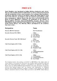
P_R_E_F_A_C_E<br />
A large number <strong>of</strong> On-Track Machines are presently <strong>work</strong>ing on Indian<br />
Railways covering different <strong>work</strong>s related to track maintenance and renewals. To<br />
improve utilization <strong>of</strong> these machines, it is important to reduce their downtime and<br />
repair them in the shortest possible time. In this context, need was felt to develop<br />
<strong>Trouble</strong> <strong>Shooting</strong> <strong>Manual</strong>s for different On-track Machines. The <strong>Trouble</strong> <strong>Shooting</strong><br />
<strong>Manual</strong>s for Continuous Tamping Machine (CSM09-32), Ballast Cleaning Machine<br />
(BCM),Ballast regulating machine (BRM Model 66-4), TTM (UNO) & TTM (DUO), Point<br />
and Crossing Tamping Machine (Unimat), Point and Crossing Changing Machine(T-28)<br />
and Provisional <strong>Trouble</strong> <strong>Shooting</strong> <strong>Manual</strong>s for Dynamic Track Stabilizer (DGS),<br />
Shoulder Ballast Cleaning Machine (FRM-80) and PQRS have already been prepared<br />
and issued. This trouble shooting manual <strong>of</strong> <strong>Plasser</strong> <strong>make</strong> <strong>work</strong> <strong>site</strong> tamper (08-32) is<br />
also an effort in the same direction.<br />
It is hoped that this manual will be quite useful for field staff attending breakdown<br />
<strong>of</strong> machines. However, there is always scope for improvement for which suggestions<br />
may be sent to the undersigned.<br />
Vijay Sharma<br />
Executive Director/TM<br />
Lucknow. RDSO/Lucknow-226011.<br />
February 2008<br />
(i)
EXPLANATORY NOTES<br />
While preparing the <strong>Trouble</strong> <strong>Shooting</strong> <strong>Manual</strong> <strong>of</strong> <strong>Plasser</strong> <strong>make</strong> <strong>work</strong> <strong>site</strong> tamper<br />
(08-32) the terms used and their meanings are explained below:<br />
CHECK - Ensure a specific condition does (or does not) exist.<br />
INSPECT - Look for damage and defects including breakage, distortion cracks,<br />
corrosion and wear, check for leaks, security and that all items are<br />
completed.<br />
REPLACE Remove old parts and substitute with a new or overhauled or<br />
reconditioned part. Fit new or overhauled or reconditioned part in<br />
place <strong>of</strong> missing part.<br />
OVERHAUL - Dismantle, examine, recondition or renew parts as necessary<br />
against given specifications, reassemble, inspect and test.<br />
(ii)
S.<br />
NO.<br />
INDEX<br />
DESCRIPTION PAGE NO.<br />
1. Engine 1-5<br />
2 Machine General 6-33<br />
3. Hydraulic Pump 34-38<br />
4. Hydraulic Relief Valve 39-40<br />
5. Hydraulic Unloader Valve 41<br />
6. Hydraulic Motor 42<br />
7. General Safety Notes 43<br />
8. Acknowledgement. 44<br />
(iii)
I. ENGINE<br />
S.<br />
No.<br />
Faults Probable Causes Remedial Actions<br />
1. Engine does 1. Emergency stop 1. Emergency stop switch should be in<br />
not start switch<br />
pressed.<br />
is release position.<br />
2. No fuel in the 2. Fill fuel in the tank and bleed air from<br />
tank.<br />
fuel system as given in following steps:<br />
3. Shut down<br />
mechanism is<br />
stuck<br />
4. Air in fuel<br />
system.<br />
5. Governor is<br />
stuck.<br />
6. Misconnection <strong>of</strong><br />
starting switch.<br />
i) Loosen the bleed plug on the fuel filter<br />
and operate the priming pump until the<br />
fuel emerges free <strong>of</strong> bubbles. Tighten<br />
the bleed plug.<br />
ii) Then loosen banjo plug on injection<br />
pump and operate the priming pump<br />
until fuel emerges free <strong>of</strong> bubbles.<br />
Tighten the banjo plug.<br />
3. Check the electrical supply at coil. if it is<br />
ok, then lubricate the piston <strong>of</strong> shut down<br />
coil and mechanism with lub oil and<br />
operate it manually. If still not <strong>work</strong>ing,<br />
then coil may be defective. Replace it.<br />
4. Bleed air from fuel system as explained in<br />
item no. 2 above.<br />
5. Replace the complete fuel<br />
injection pump<br />
6. Check starting switch and if any<br />
misconnection is noticed, rectify it.<br />
7. Valve clearance 7. Adjust the valve clearance as given in<br />
is not proper. engine manual.<br />
8. Weak batteries. 8. Check electrolyte level in the batteries.<br />
Terminals should be clean and the<br />
charging system should be <strong>work</strong>ing.<br />
Over-aged batteries should be replaced.<br />
9. Injectors not<br />
functioning<br />
properly.<br />
9. Remove defective injectors and get them<br />
overhauled/calibrated or replace them<br />
with new one.<br />
Page 1 <strong>of</strong> 44
S.<br />
No.<br />
2. Engine<br />
running too<br />
hot.<br />
Faults Probable Causes Remedial Actions<br />
10. Valves not<br />
seating<br />
properly.<br />
1. Coolant level too<br />
low.<br />
2. Defective<br />
thermostat<br />
3. Defective water<br />
pump.<br />
4. V-belt for water<br />
pump needs<br />
adjustment.<br />
5. Oil cooler not<br />
<strong>work</strong>ing properly.<br />
6. Valve clearance<br />
is not proper.<br />
7. Air filter is<br />
choked.<br />
8. RPM <strong>of</strong> coolant<br />
fan is too low.<br />
10. i) Check the valves spring and replace<br />
the broken spring if any.<br />
ii) Lap the valves.<br />
iii) Lap the valve seat, if required.<br />
1. Check coolant level and top up to the<br />
mark in the filler neck.<br />
2. Check thermostat as given in the<br />
following steps:<br />
i) Drain cooling water and catch it for<br />
reuse.<br />
ii) Loosen hose clamps, pull back hoses and<br />
then remove thermostat.<br />
iii) Heat the water in container to approx.<br />
85 o C and place thermostat in it.<br />
Maintain temperature <strong>of</strong> water by<br />
agitating<br />
iv) By short-circuiting and radiator<br />
opening, check whether the<br />
thermostat opens fully. If not, then install<br />
new thermostat.<br />
3. Check/repair the water pump.<br />
4. Check the V-belt tension. To adjust,<br />
release the guide pulley and regulate<br />
tension in the belt. Then tighten the guide<br />
pulley.<br />
If required, replace the V-belt.<br />
5. Repair / replace the Oil Cooler.<br />
6. Adjust the valve clearance as explained<br />
in engine manual.<br />
7. Clean the air filter.<br />
8. Adjust the RPM <strong>of</strong> the motor to 1600.<br />
Check hydraulic system and change<br />
pump and motor if necessary.<br />
Page 2 <strong>of</strong> 44
S.<br />
No.<br />
3. Engine<br />
misfiring<br />
4. Excessive<br />
engine<br />
smoking.<br />
Faults Probable Causes Remedial Actions<br />
9. Water radiator 9. Get the radiator cleaned.<br />
choked.<br />
10.Radiator cap 10. Fit new cap.<br />
missing or worn<br />
out<br />
11. Water hose too 11. Replace the water hose.<br />
old.<br />
1. Dirty fuel filter. 1. Check fuel filters and if necessary<br />
Change it filter.<br />
2. No / less fuel in<br />
tank.<br />
3. Air in fuel<br />
system.<br />
4. Defective<br />
Injector.<br />
5. Valve clearance<br />
is not proper.<br />
6. Fuel injection<br />
timing not<br />
proper.<br />
1. Engine oil level<br />
too high.<br />
2. Fill fuel in the tank and follow steps as<br />
given in s. no.1, item no.2.<br />
3. Bleed air from the fuel system as<br />
explained in s. no.1, item no.2.<br />
4. Remove the defective injector and get<br />
them overhauled/calibrated/ replace with<br />
new one.<br />
5 Adjust valve clearances as given in engine<br />
manual<br />
6. Adjust the timings.<br />
1. Check oil level. For this, draw dipstick<br />
and clean with lint-free cloth. Return<br />
dipstick, wait a little until the oil has<br />
wetted the dipstick. Then remove the<br />
dipstick again and check oil level.<br />
2. Defective injector 2. Follow the s.no.1, item no.9.<br />
3. Valve clearance<br />
is not proper.<br />
4. Air in fuel<br />
system.<br />
5. Clogged air<br />
cleaner.<br />
6. Excessive<br />
carbon on<br />
cylinder head<br />
and piston.<br />
3. Follow the s. no.1, item no.7.<br />
4. Follow the s.no.1, item no.2.<br />
5. Clean the element or change if required.<br />
6. De-carbonise the engine.<br />
Page 3 <strong>of</strong> 44
S.<br />
No.<br />
Faults Probable Causes Remedial Actions<br />
5. Engine stops<br />
6. Engine<br />
knocking<br />
7. Output <strong>of</strong> the<br />
engine too<br />
low<br />
7. Engine<br />
overloaded.<br />
7. Check and reduce the load.<br />
1. No fuel. 1. Fill fuel in the tank and follow the steps<br />
as given in s. no. 1, item no.2.<br />
2. Air in the fuel 2. Bleed air from fuel system as explained in<br />
system.<br />
s. no.1, item no.2.<br />
3. Valve clearances<br />
are not proper.<br />
4. Governor is<br />
stuck.<br />
5. Overheating <strong>of</strong><br />
engine<br />
6. Shut down circuit<br />
fails.<br />
1. Incorrect<br />
Injector setting.<br />
2. Mechanical<br />
damage to<br />
piston/cylinder.<br />
3. Valve clearance<br />
is not proper.<br />
4. Fuel injection<br />
timing is not<br />
proper.<br />
1. Dirty fuel filter<br />
and fuel line.<br />
3. Adjust the valve clearances as explained<br />
in s.no.1, item no.7 above.<br />
4. Replace complete fuel injection pump.<br />
5. Take remedial action as given in s.no.5<br />
below.<br />
6. Check the electrical circuit and repair as<br />
required.<br />
1. Remove the faulty injector and get it<br />
reset or replace it with new one.<br />
2. Get the engine top overhauled.<br />
3. Adjust the valve clearance as given in<br />
engine manual.<br />
4. Correct the timings.<br />
1. Check the fuel filters and if necessary<br />
change it.<br />
2. Air in fuel 2. Bleed the air from system as explained in<br />
system.<br />
s. no.1, item no.2.<br />
3. Defective 3. Remove the defective injectors and get<br />
Injectors.<br />
them overhauled or replace with new one.<br />
4. Valve<br />
4. Adjust the valve clearances as given in<br />
clearances are<br />
not proper.<br />
engine manual.<br />
5. Air filter choked. 5. Clean the air filter element or replace if<br />
required.<br />
Page 4 <strong>of</strong> 44
S.<br />
No.<br />
8. Oil pressure<br />
low.<br />
9. Oil film<br />
present in<br />
crank case<br />
ventilation<br />
10. Engine<br />
speed is<br />
irregular.<br />
Faults Probable Causes Remedial Actions<br />
11. Fuel<br />
consumption<br />
too high.<br />
12. Lube oil<br />
consumption<br />
too high.<br />
6. Improper<br />
compression<br />
7. Governor is<br />
stuck.<br />
1. Dirty lube oil<br />
filter.<br />
6. Engine needs to be top overhauled.<br />
7. Replace the complete fuel injection<br />
pump.<br />
1. Relace the lube oil filter.<br />
2. Oil control valve 2. Repair the control valve or replace it.<br />
not <strong>work</strong>ing.<br />
3. Dirty oil cooler 3. Clean the oil cooler.<br />
1. Incorrect 1. Engine needs to be top overhauled<br />
compression.<br />
2. Lube oil brands. 2. Use lube oil <strong>of</strong> proper brand and grade as<br />
recommended by the OEM.<br />
1. Air in fuel<br />
system<br />
2. Governor is<br />
stuck.<br />
1. Use <strong>of</strong> incorrect<br />
lube oil brand.<br />
2. Incorrect setting<br />
<strong>of</strong> Injector.<br />
3 Incorrect engine<br />
timing.<br />
4. Clogged air<br />
filter.<br />
5. Poor<br />
compression<br />
1. Incorrect lube oil<br />
brand.<br />
1. Bleed air from the system as explained in<br />
s. no.1, item no.2.<br />
2. Replace complete fuel injection pump.<br />
1. Use proper grade and quality lube oil.<br />
2. Overhaul/ Replace the defective injectors.<br />
3. Get the engine timing reset.<br />
4. Clean the air filter.<br />
5. Engine needs to be top overhauled.<br />
1. Use proper grade and quality lube oil as<br />
recommended by OEM.<br />
2. Poor<br />
compression<br />
2. Engine needs to be top overhauled.<br />
3. Oil filter dirty. 3. Replace the filter.<br />
Page 5 <strong>of</strong> 44
II. MACHINE GENERAL<br />
S. Faults Probable<br />
No.<br />
Causes<br />
1. Only L.H.S 1) Mechanical<br />
Tamping<br />
unit is not<br />
coming<br />
downwards<br />
in <strong>work</strong>ing<br />
problem<br />
2) Electrical<br />
problem<br />
Remedial Actions<br />
i) Tamping unit locks may not be removed<br />
physically. Check and do the needful.<br />
ii) Fork <strong>of</strong> L.H.S Tamping depth transducer may<br />
not be in position with mechanical fork <strong>of</strong><br />
tamping bank. Check and do the needful.<br />
a) If lock and fork found O.K .Then by operating<br />
all the electrical switches Q10 should come<br />
on program control. If not so, then problem<br />
may be in electrical circuit. Check it as<br />
follows.<br />
i) Tamping unit selector switch (lowering) may be<br />
towards RHS. If so then input signal X1E will<br />
be coming on program control. Put the switch<br />
in middle position.<br />
ii) Input signal X5A for LHS tamping unit lock<br />
should come on program control. If it is<br />
coming then limit switch for LH Tamping unit<br />
lock may be mull functioning or defective.<br />
Check and do the needful.<br />
iii) Output signal Q68 for <strong>work</strong> system “ON”<br />
should come on program control.<br />
b) Q0B→X0B should come on program control If<br />
not coming on, then do as follows-<br />
i) LHS tamping unit may not be in top position.<br />
For top position input signal X13 should come<br />
on program control and green LED should<br />
glow in PCB 2U21, If not so then adjust the<br />
top position <strong>of</strong> LHS tamping unit by<br />
potentiometer P11 on 2U21, or there may be<br />
any defect in PCB circuit.<br />
ii) Fuse si 1 <strong>of</strong> 2U21 may also be burned. Check<br />
and do the needful.<br />
iii) Check 24V supply at terminal 30Z <strong>of</strong> 2U21. If<br />
it is coming then relay Re3 may not getting<br />
ground signal due to any circuit defect in<br />
PCB. Check and do the needful.<br />
iv) Relay Re3 <strong>of</strong> 2U21 may also be defective.<br />
Check by replacing with new one and do the<br />
needful.<br />
Page 6 <strong>of</strong> 44
S.<br />
No.<br />
Faults Probable<br />
Causes<br />
2. Only R.H.S<br />
Tamping<br />
unit is not<br />
coming<br />
downwards<br />
in <strong>work</strong>ing<br />
3) Hydraulic<br />
problem<br />
1) Mechanical<br />
problem<br />
2) Electrical<br />
problem<br />
Remedial Actions<br />
v) If terminal 30z <strong>of</strong> 2U21 is showing 24V,then<br />
check it at terminal P15 in P.B. No. B50. If it is<br />
not coming there then brown wire <strong>of</strong> cable<br />
50.23 may be damaged in between. Check<br />
and do the needful.<br />
vi) If terminal P15 is not showing the supply, then<br />
check it at coupler <strong>of</strong> proportional valve. If it is<br />
not found there then wire between P15 in B50<br />
and coupler <strong>of</strong> proportional valve is damaged.<br />
Check and do the needful.<br />
vii) If +24V is found at coupler. Then coupler may<br />
be defective. Check and do the needful.<br />
If by operating the coil Is17 <strong>of</strong> proportional<br />
valve for LHS tamping unit lowering manually,<br />
It is not coming down. Then there is hydraulic<br />
problem. Check it as follows-<br />
i) Unloader valve for <strong>work</strong>ing pressure should be<br />
set at 140 bar. It can be checked in hydraulic<br />
pressure gauge on hydraulic control panel at<br />
position “1” <strong>of</strong> pressure gauge selector<br />
ii) Proportional valve for LHS tamping unit<br />
up/down may also be defective. Check it by<br />
manual operation after removing the coupler.<br />
iii) No. 16 pressure pipe for LHS tamping unit<br />
cylinder downwards may also be chocked. It<br />
may be possible due to deposition <strong>of</strong> rubber<br />
at the time <strong>of</strong> new fitment <strong>of</strong> end fitting. Do the<br />
needful.<br />
i) Tamping unit locks may not be removed<br />
physically. Check and do needful.<br />
ii) Fork <strong>of</strong> R.H.S Tamping depth transducer may<br />
not be in position with mechanical fork <strong>of</strong><br />
tamping bank. Check and do the needful.<br />
a) If lock and fork found O.K .Then by operating<br />
all the electrical switches Q11 should come<br />
on program control. If not so, then problem<br />
may be in electrical circuit. Check it as<br />
follows.<br />
Page 7 <strong>of</strong> 44
S.<br />
No.<br />
Faults Probable<br />
Causes<br />
Remedial Actions<br />
ii) Tamping unit selector switch (lowering) may be<br />
towards LHS. If so then input signal X1D will<br />
be coming on program control. Put the switch<br />
in middle position.<br />
iii) Input signal X5B for RHS tamping unit lock<br />
should come on program control. If it is<br />
coming then limit switch for RH Tamping unit<br />
lock may be mull functioning or defective.<br />
Check and do the needful.<br />
iv) Output signal Q68 for <strong>work</strong> system “ON”<br />
should come on program control.<br />
b) Q0B→X0B should come on program control If<br />
not coming, then do as follows-<br />
i) RHS tamping unit may not be in top position.<br />
For top position input signal X14 should come<br />
on program control and green LED should<br />
glow in PCB 2U22, If not so then adjust the<br />
top position <strong>of</strong> RHS tamping unit by<br />
potentiometer P11 on 2U22, or there may be<br />
any defect in PCB circuit.<br />
ii) Fuse si 1 <strong>of</strong> 2U22 may also be burned. Check<br />
and do the needful.<br />
iii) Check 24V supply at terminal 30Z <strong>of</strong> 2U22. If<br />
it is coming then relay Re3 may not getting<br />
ground signal due to any circuit defect in<br />
PCB. Check and do the needful.<br />
iv) Relay Re3 <strong>of</strong> 2U22 may also be defective.<br />
Check by replacing with new one and do the<br />
needful.<br />
v) If terminal 30z <strong>of</strong> 2U22 is showing 24V,then<br />
check it at terminal P16 in P.B. No. B50. If it is<br />
not coming there then brown wire <strong>of</strong> cable<br />
50.25 may be damaged in between. Check<br />
and do the needful.<br />
vi) If terminal P16 is not showing the supply,<br />
then check it at coupler <strong>of</strong> proportional valve.<br />
If it is not found there then wire between P16<br />
in B50 and coupler <strong>of</strong> proportional valve is<br />
damaged. Check and do the needful.<br />
vii) If +24V is found at coupler. Then coupler may<br />
be defective. Check and do the needful.<br />
Page 8 <strong>of</strong> 44
S.<br />
No.<br />
Faults Probable<br />
Causes<br />
3) Hydraulic<br />
problem<br />
3. Machine is<br />
not moving<br />
forward<br />
without<br />
tamping<br />
1) Electrical<br />
Problem<br />
Remedial Actions<br />
If by operating the coil Is18 <strong>of</strong> proportional<br />
valve for RHS tamping unit lowering manually,<br />
It is not coming down. Then there is hydraulic<br />
problem. Check it as follows-<br />
i) Unloader valve for <strong>work</strong>ing pressure should be<br />
set at 140 bar. It can be checked in hydraulic<br />
pressure gauge on hydraulic control panel at<br />
position “1” <strong>of</strong> pressure gauge selector<br />
ii) Proportional valve for RHS tamping unit<br />
up/down may also be defective. Check it by<br />
manual operation after removing the coupler.<br />
iii) No. 16 pressure pipe for RHS tamping unit<br />
cylinder downwards may also be chocked. It<br />
may be possible due to deposition <strong>of</strong> rubber<br />
at the time <strong>of</strong> new fitment <strong>of</strong> end fitting. Do the<br />
needful.<br />
If all concerned electrical control switches are<br />
in ‘ON’ position, then Q08→X08 should come<br />
on program control and machine will move in<br />
forward direction. If not coming, then do as<br />
follows.<br />
i) Working drive direction switch on P.B. No.B2<br />
may be in neutral position. Put it in forward<br />
direction. For this yellow LED for input signal<br />
X22 should glow on program control.<br />
ii) Yellow LED for input signal X11 should glow<br />
on program control. If not so, then peddle<br />
switch for machine drive may malfunctioning.<br />
Check and do the needful.<br />
iii) Fuse si33 for QL3 plate may be blown. Check<br />
and do the needful.<br />
iv) Relay QL30 may be defective. Check by<br />
replacing by new one and do the needful.<br />
v) If all above found OK, then 24V supply should<br />
come at terminal QL30 in P.B.No. B50. If it is<br />
not coming there, then wire <strong>of</strong> cable 2.28<br />
between P.B.no. B2 and B50 may be<br />
damaged. Check and do the needful.<br />
Page 9 <strong>of</strong> 44
S.<br />
No.<br />
Faults Probable<br />
Causes<br />
4. Machine is<br />
not moving<br />
forward<br />
during<br />
tamping<br />
2. Hydraulic<br />
Problem<br />
1) Electrical<br />
Problem<br />
Remedial Actions<br />
vi) If 24V is coming in P.B.No.50 at terminal<br />
QL30, then check it at coupler 1s22 <strong>of</strong> 4-way<br />
valve HY-24RSJ-ET for driving bogie front. If it<br />
is not coming there, then either wire between<br />
B50 and 1s22 may be damaged or coupler<br />
may also be damaged itself. Check and do<br />
the needful.<br />
i) Unloader valve for <strong>work</strong>ing pressure should be<br />
set at 140 bars. It can be checked in hydraulic<br />
pressure gauge on hydraulic control panel at<br />
position’1’ at pressure gauge selector.<br />
ii) 4-way valve HY24RSJ-ET for driving bogie<br />
front may be defective. Check and do the<br />
needful.<br />
iii) Double shock valve HY157.27 for driving<br />
bogie front may be defective. It will be<br />
replaced.<br />
iv) Driving motor <strong>of</strong> driving bogie front<br />
HY916.N.500 may also be defective. Replace<br />
it with new one.<br />
If all concerned electrical control switches are<br />
in ‘ON’ position, then Q08→X08 should come<br />
on program control and machine will move in<br />
forward direction. If not coming, then do as<br />
follows.<br />
i) Working drive direction switch on P.B. No.B2<br />
may be in neutral position. Put it in forward<br />
direction. For this yellow LED for input signal<br />
X22 should glow on program control.<br />
ii) Tamping cycle selector switch should be<br />
towards single insertion or double insertion.<br />
For this X27 or X28 should come on program<br />
control.<br />
iii) Signal Q80→Q’80 should come on<br />
programme control. If not coming, then check<br />
all the condition <strong>of</strong> Q80→Q’80 through logic<br />
program and do the needful.<br />
iv) Signal Q0E→X0E should not come on<br />
programme control. If coming, then check all<br />
the condition through logic program and do<br />
the needful.<br />
Page 10 <strong>of</strong> 44
S.<br />
No.<br />
Faults Probable<br />
Causes<br />
2. Hydraulic<br />
Problem<br />
Remedial Actions<br />
v) Output signal Q68 should come on programme<br />
control. If not coming, then check all the<br />
conditions for Q68 from logic program and do<br />
the needful.<br />
vi) In case <strong>of</strong> double insertion signal Q00→X00<br />
should not come on program control. If<br />
coming, then check all the condition<br />
Q00→X00 through logic program and do the<br />
needful.<br />
vii) Fuse si33 for QL3 plate may be blown. Check<br />
and do the needful.<br />
viii) Relay QL30 may be defective. Check by<br />
replacing by new one and do the needful.<br />
ix) If all above found OK, then 24V supply should<br />
come at terminal QL30 in P.B.No. B50. If it is<br />
not coming there, then wire <strong>of</strong> cable 2.28<br />
between P.B.no. B2 and B50 may be<br />
damaged. Check and do the needful.<br />
x) If 24V is coming in P.B.No.50 at terminal<br />
QL30, then check it at coupler 1s22 <strong>of</strong> 4-way<br />
valve HY-24RSJ-ET for driving bogie front. If it<br />
is not coming there, then either wire between<br />
B50 and 1s22 may be damaged or coupler<br />
may also be damaged itself. Check and do<br />
the needful.<br />
i) Unloader valve for <strong>work</strong>ing pressure should be<br />
set at 140 bars. It can be checked in hydraulic<br />
pressure gauge on hydraulic control panel at<br />
position’1’ at pressure gauge selector.<br />
ii) 4-way valve HY24RSJ-ET for driving bogie<br />
front may be defective. Check and do the<br />
needful.<br />
iii) Double shock valve HY157.27 for driving<br />
bogie front may be defective. It will be<br />
replaced.<br />
iv) Driving motor <strong>of</strong> driving bogie front<br />
HY916.N.500 may also be defective. Replace<br />
it with new one.<br />
Page 11 <strong>of</strong> 44
S. Faults Probable<br />
No.<br />
Causes<br />
5. Machine is 1.Electrical<br />
not moving<br />
reverse<br />
during<br />
<strong>work</strong><br />
Problem<br />
2. Hydraulic<br />
Problem<br />
Remedial Actions<br />
If all concerned electrical control switches are<br />
in ‘ON’ position, then Q09→X09 should come<br />
on program control and machine will move in<br />
reverse direction. If not coming, then do as<br />
follows.<br />
i) Working drive direction switch on P.B. No.B2<br />
may be in neutral position. Put it in reverse<br />
direction. For this yellow LED for input signal<br />
X23 should glow on program control.<br />
ii) Yellow LED for input signal X11 should glow<br />
on program control. If not so, then peddle<br />
switch for machine drive may malfunctioning.<br />
Check and do the needful.<br />
iii) Fuse si33 for QL3 plate may be blown. Check<br />
and do the needful.<br />
iv) Relay QL31 may be defective. Check by<br />
replacing by new one and do the needful.<br />
v) If all above found OK, then 24V supply should<br />
come at terminal QL31 in P.B.No. B50. If it is<br />
not coming there, then wire <strong>of</strong> cable 2.28<br />
between P.B.no. B2 and B50 may be<br />
damaged. Check and do the needful.<br />
vi) If 24V is coming in P.B.No.50 at terminal<br />
QL31, then check it at coupler 1s23 <strong>of</strong> 4-way<br />
valve HY-24RSJ-ET for driving bogie front. If it<br />
is not coming there, then either wire between<br />
B50 and 1s23 may be damaged or coupler<br />
may also be damaged itself. Check and do<br />
the needful.<br />
i) Unloader valve for <strong>work</strong>ing pressure should be<br />
set at 140 bars. It can be checked in hydraulic<br />
pressure gauge on hydraulic control panel at<br />
position’1’ at pressure gauge selector.<br />
ii) 4-way valve HY24RSJ-ET for driving bogie<br />
front may be defective. Check and do the<br />
needful.<br />
iii) Double shock valve HY157.27 for driving<br />
bogie front may be defective. It will be<br />
replaced.<br />
iv) Driving motor <strong>of</strong> driving bogie front<br />
HY916.N.500 may also be defective. Replace<br />
it with new one.<br />
Page 12 <strong>of</strong> 44
S. Faults Probable<br />
No.<br />
Causes<br />
6. Automatic 1. Electrical<br />
lining is out<br />
<strong>of</strong> order<br />
Problem<br />
Remedial Actions<br />
For proper functioning output signal Q1A<br />
should come on program control. If not<br />
coming, then check whether Q0A →X0A is<br />
coming on program control or not, If it is also<br />
not coming then check the electrical circuit as<br />
follows.<br />
i) Q05→X05 should come on programme control,<br />
if not coming then check all conditions for the<br />
same through logic program.<br />
ii) Yellow LED for input signal X3D for lining<br />
control main switch on P.B.No..B7 should<br />
glow on programme control by operating the<br />
switch to ‘ON’ position, if not coming then<br />
either switch may be malfunctioning or<br />
orange/black wire <strong>of</strong> cable no. 2.23 between<br />
P.B. No. B2 and B7 may be damaged. Check<br />
and do the needful.<br />
iii) Measuring system preloading switch may be<br />
in neutral position. It should be towards<br />
LHS/RHS. For this yellow LED for input signal<br />
X4E or X4F should glow on programme<br />
control by operating the switch on P.B.No. B7.<br />
If not coming then either switch may be<br />
malfunctioning or wire <strong>of</strong> cable 2.23 for<br />
connector X4E or X4F may be damaged<br />
between P.B.No. B2 and B7. Check and do<br />
the needful.<br />
iv) LHS and RHS clamp unit should be in down<br />
position. For this yellow LED for input signal<br />
X24 and X25 should glow on program control.<br />
If not, then either blue/white or yellow/white or<br />
both wires <strong>of</strong> cable 50.1 and 50.2 between<br />
P.B.No. B2 and B50 may be damaged or<br />
cable 50.1 and 50.2 between P.B.No. B50<br />
and magnetic sensor for LHS/RHS lifting unit<br />
lower position may be damaged. Check and<br />
do the needful.<br />
v) Yellow LED for input signal 2F should glow on<br />
program control. If not so, then brown/green<br />
wire <strong>of</strong> cable no. 2.23 between P.B.No. B2<br />
and B7 may be damaged. Check and do the<br />
needful.<br />
Page 13 <strong>of</strong> 44
S.<br />
No.<br />
Faults Probable<br />
Causes<br />
7. L.H.<br />
automatic<br />
levelling is<br />
out <strong>of</strong><br />
order<br />
2. Hydraulic<br />
problem<br />
1) Electrical<br />
Problem<br />
Remedial Actions<br />
vi) magnetic sensor for LHS/RHS lifting units<br />
lower position may also be malfunctioning.<br />
Replace the sensor.<br />
vii) By operating all electrical controls <strong>of</strong> lining,<br />
supply should come on terminal R17 in<br />
P.B.No. B50. If it is not coming then either<br />
Green/Red wire <strong>of</strong> cable 7.20 between P.B.<br />
No. B7 and B50 may be damaged or there is<br />
any problem in PCB EK 2286L-00(02) [7U6 ].<br />
Check and do the needful.<br />
viii) If supply is coming at terminal R17 then<br />
check it at coupler 1s15 <strong>of</strong> servo valve for<br />
lining. If it is not coming there then wire <strong>of</strong><br />
cable 50.55 between P.B.No. B50 and servo<br />
coupler may be damaged. Check and do the<br />
needful.<br />
i) If electrical circuit found OK then the servo<br />
valve for lining may be malfunctioning. It may<br />
be reset or will be replaced.<br />
ii) Unloader valve should be set at 140 bar and<br />
safety valve at 175 bar.<br />
Check weather signal Q06→X06 is coming on<br />
program control or not by operating all<br />
electrical controls. If it is coming then electrical<br />
circuit is OK and problem is somewhere else. If<br />
Q06→X06 is not coming then check the<br />
electrical circuit as follows.<br />
i) In put signal X2E should come on program<br />
control. For this yellow LED should glow. If not<br />
so then either switch for levelling control ‘ON’<br />
on P.B. No. B7 may be malfunctioning or<br />
Red/Yellow wire <strong>of</strong> cable 2.23 between<br />
P.B.No. B2 and B7 may be damaged. Check<br />
and do the needful.<br />
ii) Signal Q05→X05 should come on Program<br />
control. If not coming then check all the<br />
conditions for the same from logic program<br />
and do the needful.<br />
iii) Input signal X1E should not come on program<br />
control. For that yellow LED for X1E should<br />
not glow on program control. If glowing then<br />
tamping unit operation switch may be towards<br />
RH or malfunctioning. Check and do the<br />
needful.<br />
Page 14 <strong>of</strong> 44
S.<br />
No.<br />
Faults Probable<br />
Causes<br />
Remedial Actions<br />
iv) Input signal to program control X32 should<br />
not come on program control. For that yellow<br />
LED for X32 should not glow on program<br />
control. If not so, then power driver FT2 on<br />
PCB EK-2041LV.02A (7U2) may be<br />
malfunctioning. It should be replaced.<br />
v) Input indication X48 and X49 for front<br />
measuring trolley and measuring trolley<br />
unlocked should come on program control. If<br />
not then any one limit switch <strong>of</strong> front<br />
measuring trolley and measuring trolley may<br />
be malfunctioning. If so then 24V supply<br />
should come at terminal V3 and V10 in<br />
P.B.No. B7 but limit switch will not operate. In<br />
this case replace the defective limit switch.<br />
vi) Wire no. X48 and/or X49 <strong>of</strong> cable 2.23<br />
between P.B. No.B2 and terminal V3 and/or<br />
V10 in P.B. No.B7 may be damaged. Check<br />
and do the needful.<br />
vii) Wire <strong>of</strong> cable no. 4.4 and 4.5 between<br />
P.B.No. B4 and limit switch for front trolley<br />
RHS/LHS may be damaged. Check and do<br />
the needful.<br />
viii) Wire V10 <strong>of</strong> cable 7.7 and 7.8 between<br />
P.B.No. B7 and limit switch for measuring<br />
trolley RHS/LHS may be damaged. Check<br />
and do the needful.<br />
ix) Input signal X24 for sensor <strong>of</strong> LHS clamp unit<br />
down or X2F for Rail sensor ‘ON’ should<br />
come on program control. If X24 is not<br />
coming on program control, then blue/white<br />
wire X24 <strong>of</strong> cable 2.27 between P.B.No. B2<br />
and B50 may be damaged. Check the<br />
continuity and do the needful.<br />
x) Wire <strong>of</strong> cable 50.1 between P.B.No. B50 and<br />
magnetic sensor for LHS lifting unit may be<br />
damaged. Check and do the needful..<br />
xi) Magnetic sensor for LHS lifting unit may also<br />
be malfunctioning. Replace the sensor.<br />
xii) Q02→X02 should not come on program<br />
control. If coming, then check all the<br />
conditions for the same from program logic.<br />
Page 15 <strong>of</strong> 44
S.<br />
No.<br />
Faults Probable<br />
Causes<br />
8. R.H.<br />
automatic<br />
levelling is<br />
out <strong>of</strong><br />
order<br />
2) Mechanical<br />
Problem<br />
3) Hydraulic<br />
Problem<br />
1) Electrical<br />
Problem<br />
Remedial Actions<br />
xiii) Relay QL2E may also be defective . Check<br />
by replacing with new one.and do the<br />
needful.<br />
xiv) Fuse si 32 may also be blown. If no one<br />
output signal is coming on QL2 plate, fuse<br />
have to be replaced.<br />
xv) If fuse and relay found OK , then yellow<br />
/black wire QL2E between P.B.No. B2 and<br />
B50 may be damaged. Check the continuity<br />
and do the needful.<br />
xvi) QL2E wire between P.B.No. B50 and 4-way<br />
valve HY-10RSG-B for LH Rail clamp lifting<br />
may be damaged. Check and do the needful.<br />
i) Either both front measuring and measuring<br />
trolley or any one may not be unlocked and<br />
lowered properly. Check physically and do the<br />
needful.<br />
ii) LHS levelling chord wire may be broken.<br />
Check and do the needful.<br />
If electrical circuit found OK then check the<br />
hydraulic pressures.<br />
i) Unloader valve should be set at 140 bar.<br />
ii) Safety valve should be set at 175 bar.<br />
iii) Operate the 4-way valve HY10 RSG-B for<br />
LHS lifting unit. If lifting unit is not operating,<br />
then either the valve or concerned servo valve<br />
may be defective. Check and do the needful.<br />
iv) Pressure filter for servo valve <strong>of</strong> LHS lifting<br />
unit may also be choked. Replace the same.<br />
Check weather signal Q07→X07 is coming on<br />
program control or not by operating all<br />
electrical controls. If it is coming then electrical<br />
circuit is OK and problem is somewhere else. If<br />
Q07→X07 is not coming then check the<br />
electrical circuit as follows.<br />
i) In put signal X2E should come on program<br />
control. For this yellow LED should glow. If not<br />
so then either switch for levelling control ‘ON’<br />
on P.B. No. B7 may be malfunctioning or<br />
Red/Yellow wire <strong>of</strong> cable 2.23 between<br />
P.B.No. B2 and B7 may be damaged. Check<br />
and do the needful.<br />
Page 16 <strong>of</strong> 44
S.<br />
No.<br />
Faults Probable<br />
Causes<br />
Remedial Actions<br />
ii) Signal Q05→X05 should come on Program<br />
control. If not coming then check all the<br />
conditions for the same from logic program<br />
and do the needful.<br />
iii) Input signal X1D should not come on program<br />
control. For that yellow LED for X1D should<br />
not glow on program control. If glowing then<br />
tamping unit operation switch may be towards<br />
LH or malfunctioning. Check and do the<br />
needful.<br />
iv) Input signal to program control X33 should not<br />
come on program control. For that yellow<br />
LED for X33 should not glow on program<br />
control. If not so, then power driver FT2 on<br />
PCB EK-2041LV.02A (7U4) may be<br />
malfunctioning. It should be replaced.<br />
v) Input indication X48 and X49 for front<br />
measuring trolley and measuring trolley<br />
unlocked should come on program control. If<br />
not then any one limit switch <strong>of</strong> front<br />
measuring trolley and measuring trolley may<br />
be malfunctioning. If so then 24V supply<br />
should come at terminal V3 and V10 in<br />
P.B.No. B7 but limit switch will not operate. In<br />
this case replace the defective limit switch.<br />
vi) Wire no. X48 and/or X49 <strong>of</strong> cable 2.23<br />
between P.B. No.B2 and terminal V3 and/or<br />
V10 in P.B. No.B7 may be damaged. Check<br />
and do the needful.<br />
vii) Wire <strong>of</strong> cable no. 4.4 and 4.5 between<br />
P.B.No. B4 and limit switch for front trolley<br />
RHS/LHS may be damaged. Check and do<br />
the needful.<br />
viii) Wire V10 <strong>of</strong> cable 7.7 and 7.8 between<br />
P.B.No. B7 and limit switch for measuring<br />
trolley RHS/LHS may be damaged. Check<br />
and do the needful.<br />
ix) Input signal X25 for sensor <strong>of</strong> RHS clamp unit<br />
down or X2F for Rail sensor ‘ON’ should<br />
come on program control. If X24 is not<br />
coming on program control, then yellow/white<br />
wire X25 <strong>of</strong> cable 2.27 between P.B.No. B2<br />
and B50 may be damaged. Check the<br />
continuity and do the needful.<br />
Page 17 <strong>of</strong> 44
S.<br />
No.<br />
Faults Probable<br />
Causes<br />
2) Mechanical<br />
Problem<br />
3) Hydraulic<br />
Problem<br />
Remedial Actions<br />
x) Wire <strong>of</strong> cable 50.2 between P.B.No. B50 and<br />
magnetic sensor for RHS lifting unit may be<br />
damaged. Check and do the needful..<br />
xi) Magnetic sensor for RHS lifting unit may also<br />
be malfunctioning replace the sensor.<br />
xii) Q03→X03 should not come on program<br />
control. If coming, then check all the<br />
conditions for the same from program logic.<br />
xiii) Relay QL2F may also be defective. Check<br />
by replacing with new one.and do the<br />
needful.<br />
xiv) Fuse si 32 may also be blown. If no one<br />
output signal is coming on QL2 plate, fuse<br />
have to be replaced.<br />
xv) If fuse and relay found OK , then blue/black<br />
wire QL2F between P.B.No. B2 and B50 may<br />
be damaged. Check the continuity and do<br />
the needful.<br />
xvi) QL2F wire between P.B.No. B50 and 4-way<br />
valve HY-10RSG-B for RH Rail clamp lifting<br />
may be damaged. Check and do the needful.<br />
i) Either both front measuring and measuring<br />
trolley or any one may not be unlocked and<br />
lowered properly. Check physically and do the<br />
needful.<br />
ii) RHS levelling chord wire may be broken.<br />
Check and do the needful.<br />
If electrical circuit found OK then check the<br />
hydraulic pressures.<br />
i) Unloader valve should be set at 140 bar.<br />
ii) Safety valve should be set at 175 bar.<br />
iii) Operate the 4-way valve HY10 RSG-B for<br />
RHS lifting unit. If lifting unit is not operating,<br />
then either the valve or concerned servo valve<br />
may be defective. Check and do the needful.<br />
iv) Pressure filter for servo valve <strong>of</strong> RHS lifting<br />
unit may also be choked. Replace the same.<br />
Page 18 <strong>of</strong> 44
S. Faults Probable<br />
No.<br />
Causes<br />
9. LHS front 1) Electrical<br />
clamp is problem<br />
not getting<br />
open<br />
2 Hydraulic<br />
problem<br />
Remedial Actions<br />
i) Switch for clamp unit always close should be<br />
in ‘OFF’ position.<br />
ii) Q62→X62 should not come on program<br />
control. If coming then check all the conditions<br />
from program logic and do the needful.<br />
iii) Switch for rear clamp close should be in ‘ON’<br />
position.<br />
iv) Switch for right clamp should be in ‘ON’<br />
position.<br />
v) Q63→X63 should not come on program<br />
control. If coming then check all the conditions<br />
from program logic and do the needful.<br />
vi) If all the above conditions are fulfilling but still<br />
clamps are not getting open then do as<br />
follows.<br />
a) Check 24V at coupler 1s486A <strong>of</strong> 4-way valve<br />
for LH front clamp open/close. If it is found<br />
there, then 4-way valve is stick up or<br />
defective. Check and do needful<br />
b) If 24V is not found at coupler then check it at<br />
terminal QL32 in PB no. B50. If it is found<br />
there then wire between coupler and B50 is<br />
damaged. Check and do needful.<br />
c) If 24V is not found at B50 then either relay<br />
QL32 is defective or wire between B50 and<br />
QL 32 is damaged. Check and do needful.<br />
i) Unloader valve should be set at 140 bar.<br />
ii) Safety valve should be set at 175 bar.<br />
iii) Spool <strong>of</strong> 4-way valve HY6RSJ-B for LHS front<br />
clamp open/close may also be stickup. Check<br />
and do the needful.<br />
Page 19 <strong>of</strong> 44
S. Faults Probable<br />
No.<br />
Causes<br />
10. RHS front 1) Electrical<br />
clamp is problem<br />
not getting<br />
open<br />
2) Hydraulic<br />
problem<br />
Remedial Actions<br />
i) Switch for clamp unit always close should be<br />
in ‘OFF’ position.<br />
ii) Q62→X62 should not come on program<br />
control. If coming then check all the conditions<br />
from program logic and do the needful.<br />
iii) Switch for rear clamp close should be in ‘ON’<br />
position.<br />
iv) Switch for right clamp should be in ‘ON’<br />
position.<br />
v) Q63→X63 should not come on program<br />
control. If coming then check all the conditions<br />
from program logic and do the needful.<br />
vi) If all the above conditions are fulfilling but still<br />
clamps are not getting open then do as<br />
follows.<br />
a) Check 24V at coupler 1s453 <strong>of</strong> 4-way valve for<br />
RH front clamp open/close. If it is found there,<br />
then 4-way valve is stick up or defective.<br />
Check and do the needful<br />
b) If 24V is not found at coupler, then check it at<br />
terminal QL36 in PB no. B50. If it is found<br />
there then wire between coupler and B50 is<br />
damaged. Check and do the needful.<br />
c) If 24V is not found at B50 then either relay<br />
QL36 may be defective or wire between B50<br />
and QL36 may be damaged. Check and do<br />
needful.<br />
i) Unloader valve should be set at 140 bar.<br />
ii) Safety valve should be set at 175 bar.<br />
iii) Spool <strong>of</strong> 4-way valve HY6RSJ-B for RHS front<br />
clamp open/close may also be stickup. Check<br />
and do the needful.<br />
Page 20 <strong>of</strong> 44
S. Faults Probable<br />
No.<br />
Causes<br />
11. LHS rear 1) Electrical<br />
rail clamp problem<br />
is not<br />
getting<br />
open<br />
2) Hydraulic<br />
problem<br />
Remedial Actions<br />
i) Switch for clamp unit always close should be<br />
in ‘OFF’ position.<br />
ii) Q62→X62 should not come on program<br />
control. If coming then check all the conditions<br />
from program logic and do the needful.<br />
iii) Switch for front clamp close should be in ‘ON’<br />
position.<br />
iv) Q63→X63 should not come on program<br />
control. If coming then check all the conditions<br />
from program logic and do the needful. .<br />
v) Switch for right clamp should be in ‘ON’<br />
position.<br />
vi) If all the above conditions are fulfilling but still<br />
clamps are not getting open then do as<br />
follows.<br />
a) Check 24V at coupler 1s487A <strong>of</strong> 4-way valve<br />
for LH rear clamp open/close. If it is found<br />
there, then 4-way valve is stick up or<br />
defective. Check and do the needful<br />
b) If 24V is not found at coupler, then check it at<br />
terminal QL33 in PB no. B50. If it is found<br />
there then wire between coupler and B50 is<br />
damaged. Check and do the needful.<br />
c) If 24V is not found at B50 then either relay<br />
QL33 may be defective or wire between B50<br />
and QL33 may be damaged. Check and do<br />
the needful.<br />
i) Unloader valve should be set at 140 bar.<br />
ii) Safety valve should be set at 175 bar.<br />
iii) Spool <strong>of</strong> 4-way valve HY6RSJ-B for LHS rear<br />
clamp open/close may also be stickup. Check<br />
and do the needful.<br />
Page 21 <strong>of</strong> 44
S. Faults Probable<br />
No.<br />
Causes<br />
12. RHS rear 1) Electrical<br />
rail clamp problem<br />
is not<br />
getting<br />
open<br />
2) Hydraulic<br />
problem<br />
Remedial Actions<br />
i) Switch for clamp unit always close should be<br />
in ‘OFF’ position.<br />
ii) Q62→X62 should not come on program<br />
control. If coming then check all the conditions<br />
from program logic and do the needful. .<br />
iii) Switch for front clamp close should be in ‘ON’<br />
position.<br />
iv) Q63→X63 should not come on program<br />
control. If coming then check all the conditions<br />
from program logic and do the needful.<br />
v) Switch for left clamp should be in ‘ON’<br />
position.<br />
If all the above conditions are fulfilling but still<br />
clamps are not getting open then do as<br />
follows.<br />
a) Check 24V at coupler 1s454 <strong>of</strong> 4-way valve for<br />
RH rear clamp open/close. If it is found there,<br />
then 4-way valve is stick up or defective.<br />
Check and do the needful.<br />
b) If 24V is not found at coupler, then check it at<br />
terminal QL37 in PB no. B50. If it is found<br />
there then wire between coupler and B50 is<br />
damaged. Check and do the needful.<br />
c) If 24V is not found at B50 then either relay<br />
QL37 may be defective or wire between B50<br />
and QL37 may be damaged. Check and do<br />
the needful.<br />
i) Unloader valve should be set at 140 bar.<br />
ii) Safety valve should be set at 175 bar.<br />
iii) Spool <strong>of</strong> 4-way valve HY6RSJ-B for RHS rear<br />
clamp open/close may also be stickup. Check<br />
and do the needful.<br />
Page 22 <strong>of</strong> 44
S. Faults Probable<br />
No.<br />
Causes<br />
13. LHS front 1) Electrical<br />
rail clamp problem<br />
is not<br />
getting<br />
close<br />
2) Hydraulic<br />
problem<br />
Remedial Actions<br />
i) Switch for rear clamp close should be in ‘OFF’<br />
position.<br />
ii) Switch for right clamp should be in ‘OFF’<br />
position<br />
iii) Q62→X62 should come on program control.<br />
If not coming then check all the conditions<br />
from program logic and do the needful.<br />
iv) Q68→X68 should come on program control. If<br />
not coming then check all the conditions from<br />
program logic and do the needful.<br />
If all the above conditions are fulfilling but still<br />
clamps are not getting open then do as<br />
follows.<br />
a) Check 24V at coupler 1s486B <strong>of</strong> 4-way valve<br />
for LH front clamp open/close. If it is found<br />
there, then 4-way valve is stick up or<br />
defective. Check and do needful<br />
b) If 24V is not found at coupler then check it at<br />
terminal QL29 in PB no. B50. If it is found<br />
there then wire between coupler and B50 is<br />
damaged. Check and do needful.<br />
c) If 24V is not found at B50 then either relay<br />
QL29 may be defective or wire between B50<br />
and QL29 may be damaged. Check and do<br />
the needful.<br />
i) Unloader valve should be set at 140 bar.<br />
ii) Safety valve should be set at 175 bar.<br />
iii) Spool <strong>of</strong> 4-way valve HY6RSJ-B for LHS front<br />
clamp open/close may also be stickup. Check<br />
and do the needful.<br />
Page 23 <strong>of</strong> 44
S. Faults Probable<br />
No.<br />
Causes<br />
14. LHS rear 1) Electrical<br />
rail clamp problem<br />
is not<br />
getting<br />
close<br />
2) Hydraulic<br />
problem<br />
Remedial Actions<br />
i) Switch for front clamp close should be in ‘OFF’<br />
position.<br />
ii) Switch for right clamp should be in ‘OFF’<br />
position.<br />
iii) Q62→X62 should come on program control. If<br />
not coming then check all the conditions from<br />
program logic and do the needful.<br />
iv) Q68→X68 should come on program control. If<br />
not coming then check all the conditions from<br />
program logic and do the needful.<br />
v) If all the above conditions are fulfilling but still<br />
clamps are not getting open then do as<br />
follows.<br />
a) Check 24V at coupler 1s487B <strong>of</strong> 4-way valve<br />
for LH rear clamp open/close. If it is found<br />
there, then 4-way valve is stick up or<br />
defective. Check and do the needful<br />
b) If 24V is not found at coupler then check it at<br />
terminal QL2A in PB no. B50. If it is found<br />
there then wire between coupler and B50 is<br />
damaged. Check and do needful.<br />
c) If 24V is not found at B50 then either relay<br />
QL2A may be defective or wire between B50<br />
and QL2A may be damaged. Check and do<br />
the needful.<br />
i) Unloader valve should be set at 140 bar.<br />
ii) Safety valve should be set at 175 bar.<br />
iii) Spool <strong>of</strong> 4-way valve HY6RSJ-B for LHS rear<br />
clamp open/close may also be stickup. Check<br />
and do the needful.<br />
Page 24 <strong>of</strong> 44
S. Faults Probable<br />
No.<br />
Causes<br />
15. RHS front 1) Electrical<br />
rail clamp problem<br />
is not<br />
getting<br />
close<br />
2) Hydraulic<br />
problem<br />
Remedial Actions<br />
i) Switch for front clamp close should be in ‘OFF’<br />
position.<br />
ii) Switch for left clamp should be in ‘OFF’<br />
position.<br />
iii) Q62→X62 should come on program control. If<br />
not coming then check all the conditions from<br />
program logic and do the needful.<br />
iv) Q68→X68 should come on program control. If<br />
not coming then check all the conditions from<br />
program logic and do the needful.<br />
v) If all the above conditions are fulfilling but still<br />
clamps are not getting open then do as<br />
follows.<br />
a) Check 24V at coupler 1s28 <strong>of</strong> 4-way valve for<br />
RH front clamp open/close. If it is found there,<br />
then 4-way valve is stick up or defective.<br />
Check and do the needful<br />
b) If 24V is not found at coupler then check it at<br />
terminal QL3A in PB no. B50. If it is found<br />
there then wire between coupler and B50 is<br />
damaged. Check and do the needful.<br />
c) If 24V is not found at B50 then either relay<br />
QL3A may be defective or wire between B50<br />
and QL3A may be damaged. Check and do<br />
the needful.<br />
i) Unloader valve should be set at 140 bar.<br />
ii) Safety valve should be set at 175 bar.<br />
iii) Spool <strong>of</strong> 4-way valve HY6RSJ-B for RHS rear<br />
clamp open/close may also be stickup. Check<br />
and do the needful.<br />
Page 25 <strong>of</strong> 44
S. Faults Probable<br />
No.<br />
Causes<br />
16. RHS rear 1) Electrical<br />
rail clamp problem<br />
is not<br />
getting<br />
close<br />
2) Hydraulic<br />
problem<br />
Remedial Actions<br />
i) Switch for front clamp close should be in ‘OFF’<br />
position.<br />
ii) Switch for right clamp should be in ‘OFF’<br />
position.<br />
iii) Q62→X62 should come on program control. If<br />
not coming then check all the conditions from<br />
program logic and do the needful.<br />
iv) Q68→X68 should come on program control. If<br />
not coming then check all the conditions from<br />
program logic and do the needful.<br />
v) If all the above conditions are fulfilling but still<br />
clamps are not getting open then do as<br />
follows.<br />
a) Check 24V at coupler 1s29 <strong>of</strong> 4-way valve for<br />
RH rear clamp open/close. If it is found there,<br />
then 4-way valve is stick up or defective.<br />
Check and do the needful<br />
b) If 24V is not found at coupler ,then check it at<br />
terminal QL3B in PB no. B50. If it is found<br />
there then wire between coupler and B50 is<br />
damaged. Check and do the needful.<br />
c) If 24V is not found at B50 then either relay<br />
QL3B may be defective or wire between B50<br />
and QL3B may be damaged. Check and do<br />
the needful.<br />
i) Unloader valve should be set at 140 bar.<br />
ii) Safety valve should be set at 175 bar.<br />
iii) Spool <strong>of</strong> 4-way valve HY6RSJ-B for RHS rear<br />
clamp open/close may also be stickup. Check<br />
and do the needful.<br />
Page 26 <strong>of</strong> 44
S. Faults Probable<br />
No.<br />
Causes<br />
17. LHS 1) Electrical<br />
Outside<br />
squeezing<br />
problem<br />
is out <strong>of</strong><br />
order.<br />
2) Hydraulic<br />
Problem<br />
Remedial Actions<br />
Operate the concerned valve manually. If<br />
squeezing noticed, then problem is electrical.<br />
Check 24V supply at coupler 1s5 <strong>of</strong> solenoid<br />
valve for LHS outside squeezing by operating<br />
all electrical controls. If LHS outside cylinders<br />
are not getting squeezed, then check the<br />
electrical circuit as follows.<br />
i) Check 24V at coupler <strong>of</strong> solenoid 1s5.If it is not<br />
coming there, then check fuse si32 for QL2<br />
plate (2u16). It may be blown.<br />
ii) If fuse found OK, then brown wire <strong>of</strong> cable<br />
no.50.32 between solenoid coupler and B50<br />
may also be damaged. Check the continuity<br />
and do the needful.<br />
iii) If 24V is not found at terminal QL22 in<br />
P.B.NO. B50. Then check the orange/green<br />
wire <strong>of</strong> cable 2.28 between B50 and B2.It may<br />
be damaged. Check the continuity and do the<br />
needful.<br />
iv) If all wires are OK. Then relay QL22 may also<br />
be defective. Check and do the needful.<br />
If by operating the concerned valve,<br />
squeezing is not noticed. Then check the<br />
hydraulic circuit as follows.<br />
i) Check squeezing pressure at position 5 <strong>of</strong> multi<br />
station. It should show 110-125 bar. If not so<br />
then reduction valve HY 55R may not be set<br />
at proper pressure or damaged. Check and<br />
do the needful.<br />
ii) Unloader valve HY511.12 should be set at 150<br />
bar.<br />
iii) Safety valve HY511.08 should be set at 175<br />
bar.<br />
iv) 4-way valve (HY16RSD-ET) may also not<br />
functioning properly. Check and do the<br />
needful.<br />
Page 27 <strong>of</strong> 44
S. Faults Probable<br />
No.<br />
Causes<br />
18. RHS 1) Electrical<br />
Outside<br />
squeezing<br />
problem<br />
is out <strong>of</strong><br />
order.<br />
2) Hydraulic<br />
Problem<br />
Remedial Actions<br />
Operate the concerned valve manually. If<br />
squeezing noticed, then problem is electrical.<br />
Check 24V supply at coupler 1s7 <strong>of</strong> solenoid<br />
valve for RHS outside squeezing by operating<br />
all electrical controls. If RHS outside cylinders<br />
are not getting squeezed, then check the<br />
electrical circuit as follows.<br />
i) Check 24V at coupler <strong>of</strong> solenoid 1s7.If it is<br />
not coming there ,then check Fuse si32 for<br />
QL2 plate (2u16). It may be blown.<br />
ii) If fuse found OK, then brown wire <strong>of</strong> cable<br />
no.50.33 between solenoid coupler and B50<br />
may also be damaged. Check the continuity<br />
and do the needful.<br />
iii) If 24V is not found at terminal QL23 in<br />
P.B.NO. B50. Then check the white/green<br />
wire <strong>of</strong> cable 2.28 between B50 and B2.It may<br />
be damaged. Check the continuity and do the<br />
needful.<br />
iv) If all wires are OK. Then relay QL23 may also<br />
be defective. Check and do the needful.<br />
If by operating the concerned valve,<br />
squeezing is not noticed. Then check the<br />
hydraulic circuit as follows.<br />
i) Check squeezing pressure at position 6 <strong>of</strong> multi<br />
station. It should show 110-125 bar. If not so<br />
then reduction valve HY 55R may not be set<br />
at proper pressure or damaged. Check and<br />
do the needful.<br />
ii) Unloader valve HY511.12 should be set at<br />
150 bar.<br />
iii) Safety valve HY511.08 should be set at 175<br />
bar.<br />
iv) 4-way valve (HY16RSD-ET) may also not<br />
functioning properly. Check and do the<br />
needful.<br />
Page 28 <strong>of</strong> 44
S. Faults Probable<br />
No.<br />
Causes<br />
19. LHS inside 1) Electrical<br />
squeezing problem<br />
is out <strong>of</strong><br />
order.<br />
20. RHS inside<br />
squeezing<br />
is out <strong>of</strong><br />
order.<br />
2) Hydraulic<br />
Problem<br />
1) Electrical<br />
problem<br />
Remedial Actions<br />
Operate the concerned valve manually. If<br />
squeezing noticed, then problem is electrical.<br />
Check 24V supply at coupler 1s62 <strong>of</strong> solenoid<br />
valve for LHS inside squeezing by operating<br />
all electrical controls. If LHS inside cylinders<br />
are not getting squeezed, then check the<br />
electrical circuit as follows.<br />
i) Check 24V at coupler <strong>of</strong> solenoid 1s62.If it is<br />
not coming there, then check Fuse si32 for<br />
QL2 PCB (2u16). It may be blown.<br />
ii) If fuse found OK, then brown wire <strong>of</strong> cable<br />
no.50.34 between solenoid coupler and B50<br />
may also be damaged. Check the continuity<br />
and do the needful.<br />
iii) If 24V is not found at terminal QL24 in<br />
P.B.NO. B50. Then check the violet/green<br />
wire <strong>of</strong> cable 2.28 between B50 and B2.It may<br />
be damaged. Check the continuity and do the<br />
needful.<br />
iv) If all wires are OK. Then relay QL24 may also<br />
be defective. Check and do the needful.<br />
i) Unloader valve HY511.12 should be set at 140<br />
bar.<br />
ii) Safety valve HY511.15 should be set at 175<br />
bar.<br />
iii) 4-way valve (HY16RSD-ET) may also not<br />
functioning properly. Check and do the<br />
needful.<br />
Operate the concerned valve manually. If<br />
squeezing noticed, then problem is electrical.<br />
Check 24V supply at coupler 1s63 <strong>of</strong> solenoid<br />
valve for RHS inside squeezing by operating<br />
all electrical controls. If RHS inside cylinders<br />
are not getting squeezed, then check the<br />
electrical circuit as follows.<br />
i) Check 24V at coupler <strong>of</strong> solenoid 1s63.If it is<br />
not coming there ,then check Fuse si32 for<br />
QL2 PCB (2u16). It may be blown.<br />
ii) If fuse found OK, then brown wire <strong>of</strong> cable<br />
no.50.31 between solenoid coupler and B50<br />
may also be damaged. Check the continuity<br />
and do the needful.<br />
Page 29 <strong>of</strong> 44
S.<br />
No.<br />
Faults Probable<br />
Causes<br />
21. Tamping<br />
Units are<br />
not moving<br />
towards<br />
LHS/RHS<br />
2) Hydraulic<br />
Problem<br />
1) Electrical<br />
problem<br />
2) Hydraulic<br />
problem<br />
Remedial Actions<br />
iii) If 24V is not found at terminal QL25 in<br />
P.B.NO. B50. Then check the grey/green wire<br />
<strong>of</strong> cable 2.28 between B50 and B2.It may be<br />
damaged. Check the continuity and do the<br />
needful.<br />
iv) If all wires are OK. Then relay QL25 may also<br />
be defective. Check and do the needful.<br />
i) Unloader valve HY511.12 should be set at 140<br />
bar.<br />
ii) Safety valve HY511.15 should be set at 175<br />
bar.<br />
iii) 4-way valve (HY16RSD-ET) may also not<br />
functioning properly. Check and do the<br />
needful.<br />
If by operating the concerned valve manually,<br />
T/units are not moving LHS/RHS. Then check<br />
24V at coupler 1s49/1s50 <strong>of</strong> 4-way valve<br />
HY24RSJ-B by operating all the electrical<br />
controls. If it is not coming there, then check<br />
the electrical circuit as follows.<br />
i) Check connector QL20/QL21 in P.B. No. B50.If<br />
it is coming there, then brown wire <strong>of</strong> cable<br />
no. 50.26 between 1s49/1s50 and P.B. No.<br />
B50 may be damaged. Check the continuity<br />
and do the needful.<br />
ii) If 24V is not coming at connector QL20/QL21<br />
in P.B.No. B50. Then check it at connector<br />
QL20/QL21 in P.B.No.B2.If it is coming there,<br />
then red-yellow/brown-green wire <strong>of</strong> cable<br />
no.2.28 between P.B No. B50 may be<br />
damaged. Check the continuity and do the<br />
needful.<br />
iii) Fuse si32 <strong>of</strong> QL2 plate may also be blown.<br />
Check and do the needful.<br />
iv) Relay QL 20/QL21 may also be blown. Check<br />
and do the needful.<br />
i) If by operating the concerned valve manually.<br />
Tamping units are not moving LHS/RHS.<br />
Then spool <strong>of</strong> 4-way valve may be stick up.<br />
Check and do the needful.<br />
ii) Safety valve should be set at 175 bar. Check<br />
and do the needful.<br />
iii) Unloader valve should be set at 140 bar.<br />
Check and do the needful.<br />
Page 30 <strong>of</strong> 44
S. Faults Probable<br />
No.<br />
Causes<br />
22. LHS clamp 1) Electrical<br />
unit is not<br />
going<br />
upward<br />
problem<br />
23. RHS clamp<br />
unit is not<br />
going<br />
upward<br />
2) Hydraulic<br />
problem<br />
1) Electrical<br />
problem<br />
Remedial Actions<br />
If by operating all the electrical controls, LHS<br />
clamp unit is not going upward. Then operate<br />
the coil 1s3 <strong>of</strong> concerned valve manually. If<br />
clamp unit is going upward, then problem is in<br />
electrical circuit. Check it as follows.<br />
i) Check 24V at coupler 1s3 <strong>of</strong> concerned valve.<br />
If it is not found there, then check it at<br />
connector QL2E in P.B.No. B50. If it is coming<br />
there, then brown wire <strong>of</strong> cable no. 50.40<br />
between coil 1s3 and connector QL2E in P.B.<br />
No. B50 may be damaged. Check the<br />
continuity and do the needful.<br />
ii) If 24V is not coming at connector QL2E in P.B.<br />
No. B50.Then check it at connector QL2E in<br />
P.B.No. B2.If it is found there, then<br />
yellow/black wire <strong>of</strong> cable 2.28 may be<br />
damaged. Check and do the needful.<br />
iii) Fuse si32 <strong>of</strong> QL2 plate may be blown. Check<br />
and do the needful.<br />
iv) Relay QL2E may also be blown. Check and<br />
the do needful.<br />
If by operating the concerned valve manually,<br />
LHS clamp unit is not going upward. Then<br />
check the hydraulic circuit as follows.<br />
i) Check servo valve filter indication (LHS) and do<br />
the needful.<br />
ii) Unloader valve HY511.11 should be set at 140<br />
bar.<br />
iii) Safety valve should be set at 175 bar.<br />
If by operating all the electrical controls, RHS<br />
clamp unit is not going upward. Then operate<br />
the coil 1s4 <strong>of</strong> concerned valve manually. If<br />
clamp unit is going upward, then problem is in<br />
electrical circuit. Check it as follows.<br />
i) Check 24V at coupler 1s4 <strong>of</strong> concerned valve.<br />
If it is not found there, then check it at<br />
connector QL2F in P.B.No. B50. If it is coming<br />
there, then brown wire <strong>of</strong> cable no. 50.41<br />
between coil 1s4 and connector QL2F in P.B.<br />
No. B50 may be damaged. Check the<br />
continuity and do the needful.<br />
Page 31 <strong>of</strong> 44
S.<br />
No.<br />
Faults Probable<br />
Causes<br />
24. LHS clamp<br />
unit is not<br />
coming<br />
downward<br />
2) Hydraulic<br />
problem<br />
1) Electrical<br />
problem<br />
Remedial Actions<br />
ii) If 24V is not coming at connector QL2F in P.B.<br />
No. B50.Then check it at connector QL2F in<br />
P.B.No. B2.If it is found there, then blue/black<br />
wire <strong>of</strong> cable 2.28 may be damaged. Check<br />
and do the needful.<br />
iii) Fuse si32 <strong>of</strong> QL2 plate may be blown. Check<br />
and do the needful.<br />
iv) Relay QL2F may also be blown. Check and<br />
do needful.<br />
If by operating the concerned valve manually,<br />
RHS clamp unit is not going upward. Then<br />
check the hydraulic circuit as follows.<br />
i) Check servo valve filter indication (RHS) and<br />
the do needful.<br />
ii) Unloader valve HY511.11 should be set at 140<br />
bar.<br />
iii) Safety valve should be set at 175 bar.<br />
iv) If all above found OK. Then servo valve EL-<br />
T76.00MO may be defective. Check and<br />
adjust the null point or replace it.<br />
If by operating all the electrical controls, LHS<br />
clamp unit is not coming downward. Then<br />
operate the coil 1s8 <strong>of</strong> concerned valve<br />
manually. If clamp unit is coming downward,<br />
then problem is in electrical circuit. Check it<br />
as follows.<br />
i) Check 24V at coupler 1s8 <strong>of</strong> concerned valve.<br />
If it is not found there, then check it at<br />
connector QL2B in P.B.No. B50. If it is coming<br />
there, then brown wire <strong>of</strong> cable no. 50.38<br />
between coil 1s8 and connector QL2B in P.B.<br />
No. B50 may be damaged. Check the<br />
continuity and do the needful.<br />
ii) If 24V is not coming at connector QL2B in P.B.<br />
No. B50.Then check it at connector QL2B in<br />
P.B.No. B2.If it is found there, then<br />
violet/black wire <strong>of</strong> cable 2.28 may be<br />
damaged. Check and do the needful.<br />
iii) Fuse si32 <strong>of</strong> QL2 plate may be blown. Check<br />
and do the needful.<br />
iv) Relay QL2B may also be blown. Check and<br />
the do needful.<br />
Page 32 <strong>of</strong> 44
S.<br />
No.<br />
Faults Probable<br />
Causes<br />
2) Hydraulic<br />
problem<br />
25. RHS clamp<br />
unit is not<br />
coming<br />
downward<br />
1) Electrical<br />
problem<br />
2) Hydraulic<br />
problem<br />
Remedial Actions<br />
If by operating the concerned valve manually,<br />
LHS clamp unit is not coming downward.<br />
Then check the hydraulic circuit as follows.<br />
i) Spool <strong>of</strong> 4-way valve HY10RSG-B for LHS<br />
clamp lifting/ lowering may be stick up. Check<br />
and do the needful.<br />
ii) Unloader valve HY511.11 should be set at 140<br />
bar.<br />
iii) Safety valve HY511.15 should be set at 175<br />
bar.<br />
If by operating all the electrical controls, RHS<br />
clamp unit is not coming downward. Then<br />
operate the coil 1s9 <strong>of</strong> concerned valve<br />
manually. If clamp unit is coming downward,<br />
then problem is in electrical circuit. Check it<br />
as follows.<br />
i) Check 24V at coupler 1s9 <strong>of</strong> concerned valve.<br />
If it is not found there, then check it at<br />
connector QL2C in P.B.No. B50. If it is<br />
coming there, then brown wire <strong>of</strong> cable no.<br />
50.39 between coil 1s9 and connector QL2C<br />
in P.B. No. B50 may be damaged. Check the<br />
continuity and do the needful.<br />
ii) If 24V is not coming at connector QL2C in P.B.<br />
No. B50.Then check it at connector QL2C in<br />
P.B.No. B2.If it is found there, then<br />
green/black wire <strong>of</strong> cable 2.28 may be<br />
damaged. Check and do the needful.<br />
iii) Fuse si32 <strong>of</strong> QL2 plate may be blown. Check<br />
and do the needful.<br />
iv) Relay QL2C may also be blown. Check and<br />
do the needful.<br />
If by operating the concerned valve manually,<br />
RHS clamp unit is not coming downward.<br />
Then check the hydraulic circuit as follows.<br />
i) Spool <strong>of</strong> 4-way valve HY10RSG-B for LHS<br />
clamp lifting/ lowering may be stick up. Check<br />
and do the needful..<br />
ii) Unloader valve HY511.11 should be set at 140<br />
bar.<br />
iii) Safety valve HY511.15 should be set at 175<br />
bar.<br />
Page 33 <strong>of</strong> 44
III. HYDRAULIC PUMP<br />
S.<br />
No.<br />
1.<br />
Faults Probable Causes Remedial Actions<br />
Pump not<br />
delivering<br />
oil.<br />
1. Pump driven in wrong<br />
direction (at the time<br />
<strong>of</strong> new pump fitment,<br />
this problem may<br />
occur).<br />
2. Oil level too low in the<br />
reservoir (if oil level is<br />
very low, aeration may<br />
take place and pump<br />
will not deliver oil).<br />
3. Intake filter/pipe<br />
choked.<br />
4. Air leaks at pump<br />
intake joints.<br />
5. Broken pump shaft or<br />
rotor.<br />
6. Pump speed too slow.<br />
(The delivery rate <strong>of</strong><br />
discharge is<br />
prescribed at a certain<br />
rpm <strong>of</strong> engine. If<br />
engine speed become<br />
less than ideal speed,<br />
it may affect the<br />
proper suction <strong>of</strong> oil).<br />
1. Check the pump rotation by hand<br />
priming. Pour the hydraulic oil into<br />
inlet port and rotate the shaft. See<br />
whether the oil is delivering through<br />
outlet port or not. If not, change the<br />
rotation according to the engine shaft<br />
rotation.<br />
2. Check oil level in reservoir. It should<br />
be above minimum mark. If<br />
necessary, recoup the oil.<br />
3. Clean or replace filter for proper<br />
flow <strong>of</strong> oil.<br />
4. Pour hydraulic oil on intake joints and<br />
on observing abnormal sound, tighten<br />
the intake joint as required.<br />
5. Replace the broken shaft or rotor.<br />
Also align the prime mover shaft<br />
6. Pump should run at prescribed<br />
speed. Engine rpm should be<br />
checked.<br />
7. Dirty suction filter 7. Replace the filter.<br />
8. Faulty suction valve. 8. Repair or change the valve<br />
9. Air in system. 9. Discharge air from the system<br />
Page 34 <strong>of</strong> 44
S.<br />
No.<br />
2. Pump<br />
<strong>make</strong>s<br />
noise<br />
Faults Probable Causes Remedial Actions<br />
10. Pump drive<br />
inoperative<br />
10. i) Replace the broken pump<br />
shaft.<br />
ii) Change defective coupling<br />
11. Adjust clutch<br />
11. Clutch out <strong>of</strong><br />
adjustment.<br />
12. Pump is damaged. 12. Replace with new one.<br />
1. Aeration.<br />
1i) Fill the reservoir with the oil upto<br />
required level to prevent aeration.<br />
ii) Check condition <strong>of</strong> pump shaft seal.<br />
Change, if required.<br />
2. Intake line or suction 2. Clean or replace the filter or<br />
filter partly clogged line.<br />
3. Pump running too<br />
fast.<br />
3. Reduce speed up to prescribed limit.<br />
4. Coupling misaligned 4. Realign the pump shaft and prime<br />
(Due to this bearing<br />
may get damaged,<br />
play at shaft may<br />
develop).<br />
mover shaft<br />
5. Reservoir not vented 5. Air breather screening element<br />
properly.<br />
should be cleaned<br />
6. Suction filter too small<br />
in size.<br />
6. Replace by proper size <strong>of</strong> filter.<br />
7. Air leaks at pump 7. Take action as explained in s.no.1,<br />
intake pipe joints and<br />
air drawn through inlet<br />
line.<br />
item no. 4.<br />
8. Oil viscosity too high. 8. Start the engine for few minutes to<br />
(In cold climate oil warm-up the hydraulic oil used in<br />
viscosity becomes machine for proper flow. Use only<br />
high so no free flow<br />
will take place and<br />
cavitation will occur).<br />
proper grade <strong>of</strong> oil.<br />
9. Cavitation.<br />
9. i) Check condition <strong>of</strong> suction filter and<br />
return line filters. Clean or change<br />
as necessary.<br />
ii) Check clogging <strong>of</strong> inlet line.<br />
Clean or change as necessary.<br />
iii) Check loose fittings on suction<br />
lines. Tighten, if required.<br />
iv) Clean hydraulic tank breather.<br />
Page 35 <strong>of</strong> 44
S.<br />
No.<br />
3 Pump<br />
overheats<br />
Faults Probable Causes Remedial Actions<br />
10. Shaft seal leaks. 10. Replace the seal.<br />
11. Foams in oil. 11. Vent the system.<br />
12. Casing leaks. 12. First tighten bolts, then check for<br />
cracks and sealing.<br />
13. Vane spring broken.<br />
14. Any part <strong>of</strong> pump<br />
defective.<br />
15. Foreign bodies in<br />
suction line.<br />
16. System dirty.<br />
17. Sharp bends in<br />
suction line.<br />
18. Oil temperature too<br />
high.<br />
19. Boost pump failed.<br />
13.Change spring.<br />
14. Replace defective parts.<br />
15. Remove foreign bodies. Flush<br />
the system if required.<br />
16. Flush the system<br />
17 Eliminate or reduce the bends in<br />
suction line.<br />
18.Check the hydraulic circuit. Oil<br />
cooler may be ineffective. Rectify<br />
the failure<br />
19. Check boost pump and repair as<br />
required.<br />
20. Vibration in system 20. Check unusual occurrence in the<br />
system<br />
21. Pump worn out or 21. Pump should be overhauled or<br />
damaged.<br />
replaced.<br />
1. Wrong oil grade. 1. Fill oil as recommended.<br />
2. Oil speed in system<br />
too high.<br />
3. Oil level too low.<br />
2. Install pipes <strong>of</strong> proper size.<br />
3. Fill the oil up to safe level<br />
4. Pump rotor groove 4. Change the worn out parts<br />
worn out<br />
5. Radial or axial loading 5. Loading should be restricted to<br />
too high.<br />
prescribed limit. Check alignment<br />
limit.<br />
6. Initial speed rises 6. Check max. pressure. If needed<br />
replace with larger capacity and<br />
install pipe <strong>of</strong> nominal bore.<br />
Page 36 <strong>of</strong> 44
S.<br />
No.<br />
Faults Probable Causes Remedial Actions<br />
4 Pump<br />
develops no<br />
pressure<br />
5. Speed<br />
loss on<br />
pump.<br />
7. Inadequate cooling 7. Increase cooling capacity<br />
8. Cooling system is dirty. 8. Clean the cooling system.<br />
9. Differential pressure 9. Increase pressure setting <strong>of</strong> relief<br />
too low<br />
valve.<br />
10. Pressure too high 10. Reduce pressure setting<br />
11. Wrong type <strong>of</strong> 11. Replace by appropriate type <strong>of</strong><br />
pressure valve<br />
valve<br />
12. Wrong seal size 12. Replace by suitable size <strong>of</strong> seal.<br />
13. Filter dirty or too<br />
small.<br />
13. Clean filter or replace by larger size.<br />
14.Pump running speed<br />
high<br />
14. Reduce speed<br />
15. Cavitation 15. Bleed the system<br />
16. Foams in oil 16. Vent the system<br />
17. Venting dirty 17 Clean the vents<br />
18. System contaminated 18 Flush the system<br />
19. Sharp bends in 19. Eliminate bends or at least reduce<br />
suction line<br />
them<br />
20 Boost pump failed 20 Check boost pump and repair as<br />
required<br />
1. Wrong pressure<br />
setting<br />
1. Modify the pressure setting<br />
2. Pressure valve spool<br />
stuck<br />
2. Repair/ Replace the valve.<br />
3. Leakage in system 3. Replace defective parts<br />
4. Pump shaft broken 4. Replace shaft<br />
5. System contaminated 5. Flush the system completely.<br />
6.Improper gasket and<br />
seal<br />
6. Replace seals and gaskets<br />
1. Inlet pressure too low. 3. Increase pressure.<br />
4. Outlet pressure too<br />
high.<br />
3.Oil temperature too<br />
high.<br />
2.Check system pressure.<br />
3.Check the circuit.<br />
Page 37 <strong>of</strong> 44
S.<br />
No.<br />
Faults Probable Causes Remedial Actions<br />
6. Pump does<br />
not <strong>work</strong>.<br />
5. Pressure too low. 6. Increase pressure setting.<br />
2. ‘O’ Ring on port plate<br />
defective.<br />
2.Replace ‘O’ Ring.<br />
3. Too much play in the<br />
shaft.<br />
3. Replace bearing.<br />
7. Hydraulic 1. System pressure is 1. Adjust the pressure to the required<br />
oil<br />
overheated<br />
too high.<br />
limit.<br />
7. Dirty oil<br />
8. Clean or change filters and<br />
strainers.<br />
8. Bearing<br />
failure.<br />
3. Fill up the oil to the upper mark.<br />
3. Oil level is low.<br />
4. Hydraulic oil <strong>of</strong> 4. Check oil for proper viscosity. If,<br />
incorrect viscosity. change <strong>of</strong> oil is required, flush the<br />
entire system and change filter<br />
before adding fresh oil.<br />
5. Faulty cooling system. 5. Check oil cooler for trash on out side<br />
cooling surfaces. Clean with air<br />
6. Internal leakage <strong>of</strong><br />
hydraulic oil due to<br />
worn pump, valve,<br />
motor and cylinder.<br />
1. Chips or other<br />
contaminants<br />
bearing.<br />
in<br />
pressure or steam pressure.<br />
6. Overhaul or replace faulty<br />
components.<br />
1. Replace bearings and check intrusion<br />
<strong>of</strong> contaminants.<br />
2. Coupling misaligned. 2. Align prime mover shaft and pump.<br />
3. Inadequate<br />
lubrication.<br />
3. Lubricate system properly.<br />
4. Pump running too<br />
fast.<br />
9. Adjust speed <strong>of</strong> prime mover.<br />
5. Excessive or shock 5. Reduce operating pressure.<br />
loads. (Excessive<br />
loads due to operating<br />
pressure may damage<br />
the bearing).<br />
Page 38 <strong>of</strong> 44
IV. HYDRAULIC RELIEF VALVE<br />
S.<br />
No.<br />
Faults Probable Causes Remedial Actions<br />
1. Erratic pressure. 1. Foreign material in 1. Drain the oil, clean the tank and<br />
the oil.<br />
refill with clean oil.<br />
2. Worn poppet valve or 2. Replace poppet valve or seat<br />
seat.<br />
(oil from pilot stage<br />
will go to tank due to<br />
worn poppet valve or<br />
as required.<br />
seat and pressure<br />
will drop).<br />
3. Piston sticking in 3. Clean piston after dismantling.<br />
main body.<br />
Check free movement after reassembling<br />
.<br />
2. Low pressure or 1. Valve improperly 1. Adjust valve by adjusting knob<br />
no pressure. adjusted.<br />
to proper pressure setting.<br />
3. Excessive noise<br />
or chatter.<br />
2. Vent connection is<br />
open.<br />
3. Balance hole in main<br />
piston choked.<br />
4. Poppet in cover not<br />
seating.<br />
5. Broken or weak<br />
spring.<br />
6. Dirt, chip etc keeps<br />
valve partially open.<br />
1. High oil velocity<br />
through valve.<br />
2. Plug the vent connection.<br />
3. Remove piston and clean the<br />
orifice. Clean the tank and<br />
replace hydraulic oil.<br />
4. Check the poppet condition. If<br />
required, replace it.<br />
5. Replace the spring and again<br />
set the pressure with adjusting<br />
knob.<br />
6. Clean the complete valve.<br />
1. Check valve flow rating. Replace<br />
with larger valve, if necessary.<br />
2. Distorted control 2. Replace spring.<br />
spring.<br />
3. Worn poppet. 3. Replace the poppet.<br />
4. Vent line too long. 4. Replace restrictions e.g. needle<br />
valve or orifice. Plug in vent line<br />
next to the relief valve.<br />
Page 39 <strong>of</strong> 44
S.<br />
No.<br />
Faults Probable Causes Remedial Actions<br />
4. Valve do not<br />
function<br />
5. Valve overheating<br />
5. Valve pressure<br />
setting too close to<br />
that <strong>of</strong> another valve<br />
in circuit.<br />
5. Set relief valve pressure at-least<br />
150 PSI higher than other valves<br />
in circuit.<br />
1. Spool sticks. 1. Clean stuck spool.<br />
2. Water condensation<br />
in system.<br />
3. Oil temperature too<br />
high.<br />
4. Oil speed too high.<br />
5. Internal leakage.<br />
6.Tank line under high<br />
pressure.<br />
2.Check condensed water.<br />
3.Check the function <strong>of</strong> oil cooler<br />
and clean the radiator fins.<br />
4. Check speed <strong>of</strong> the pump.<br />
5.Prevent leakage.<br />
6. Check pressure in tank line.<br />
7. Control line dirty. 7. Clean lines properly.<br />
1. System pressure too<br />
high.<br />
1. Adjust spring pressure.<br />
2. Dirt in the system.<br />
3. Spool sticks.<br />
2.Clean the system.<br />
3.Check and clean spool.<br />
4. Spool defective 4. Check and replace spool, if<br />
defective.<br />
Page 40 <strong>of</strong> 44
V. HYDRAULIC UNLOADER VALVE<br />
S.<br />
No.<br />
Faults Probable Causes Remedial Actions<br />
1. Low or no 1. Orifice <strong>of</strong> main piston 1. Clean the orifice.<br />
pressure.<br />
choked.<br />
2. Fails to<br />
completely<br />
unload pump.<br />
2. Vent connection<br />
open to tank.<br />
3. Safety valve at zero<br />
setting<br />
4. Broken or weak<br />
spring<br />
1. Valve pressure<br />
setting too high.<br />
2. Valve spool binding<br />
in body.<br />
3. Incorrect assembly.<br />
4. Nil or low nitrogen<br />
pressure in the<br />
accumulator.<br />
2. Plug the vent connection.<br />
3. Set the safety valve at proper<br />
pressure.<br />
4. Replace the spring.<br />
1. Set valve at proper pressure.<br />
2. Clean the spool or replace if<br />
required<br />
3. Assemble as per proper<br />
drawing.<br />
4. Check pressure and recharge<br />
the accumulator .<br />
5. Punctured bladder. 5. Change the bladder.<br />
Page 41 <strong>of</strong> 44
VI. HYDRAULIC MOTOR<br />
S.<br />
No.<br />
Faults Probable Causes Remedial Action<br />
1. Motor <strong>make</strong>s<br />
loud<br />
Noise.<br />
1. Vane spring broken. 1. Change the spring.<br />
2. Shaft seal leaks. 2. Replace the seal.<br />
3. Casing leaks. 3. First tighten bolts, then check for<br />
cracks and sealing.<br />
2. Motor overheats<br />
4. Oil temperature too<br />
high.<br />
5. Motor parts<br />
defective.<br />
1. Motor is <strong>of</strong> under<br />
capacity<br />
2. Rotor worn out.<br />
1.<br />
3.<br />
Speed loss on<br />
motor.<br />
3. Inadequate cooling.<br />
4. Pressure too high.<br />
5. Wrong seal size.<br />
1. Inlet pressure too<br />
low.<br />
2.Motor parts defective.<br />
3. Oil temperature too<br />
high<br />
4. Out let pressure too<br />
high<br />
5. Port plate does not<br />
<strong>make</strong> contacts.<br />
4. Check cooling circuits.<br />
5. Replace defective parts.<br />
Tighten bolts uniformly.<br />
1. Install motor <strong>of</strong> proper capacity<br />
2. Change the rotor.<br />
3. Check cooling pump<br />
4. Reduce pressure setting on relief<br />
valve.<br />
5. Replace by suitable seals.<br />
1. Increase pressure by resetting<br />
relief valve.<br />
2. Change defective parts.<br />
3. Check cooling circuit. Hydraulic<br />
oil cooler may be defective.<br />
4. Check the system pressure.<br />
5. Dismantle the motor and repair<br />
as per requirement.<br />
Page 42 <strong>of</strong> 44
GENERAL SAFETY NOTES<br />
Annexure<br />
1. The machine has to be operated as per existing Indian Railways rules and<br />
regulations.<br />
2. The safety <strong>of</strong> yourself and other people is a most important consideration in<br />
the operation and maintenance <strong>of</strong> the machine.<br />
3. Remember the machine is a <strong>work</strong>ing unit, carrying delicate instruments.<br />
Therefore the machine should not be driven at excessive speed over bad<br />
track or turnouts.<br />
4. Always keep your eyes open for other men <strong>work</strong>ing close to the<br />
machine.<br />
5. Do not forget to look out for signals, switches and track obstructions.<br />
6. Remember to <strong>make</strong> sure that all protection equipment and safety devices are<br />
in place on the machine and in <strong>work</strong>ing order especially when it is being<br />
driven from one <strong>site</strong> to another.<br />
7. Always keep the machine clean. Excessive oil or grease on the machine can<br />
cause you to slip or fall and is also a potential fire hazard.<br />
8. Always lock the machine before you leave. Make sure that the machine is<br />
protected in accordance with railways regulations.<br />
9. Whenever you have the opportunity while waiting to get out on a job, do some<br />
<strong>of</strong> the smaller maintenance jobs such as tightening loose nuts and bolts and<br />
cleaning the machine.<br />
10. Do not permit unauthorized persons to operate the machine.<br />
11. It is prohibited to use exposed light or fire on or near the machine.<br />
12. Do not tow the machine if the final drive is engaged.<br />
Page 43 <strong>of</strong> 44
ACKNOWLEDGEMENT<br />
Following <strong>of</strong>ficers and staff have made their valuable contributions in finalization <strong>of</strong><br />
<strong>Trouble</strong> <strong>Shooting</strong> <strong>Manual</strong> <strong>of</strong> <strong>Plasser</strong> <strong>make</strong> Work Site Tamper (08-32 New model).<br />
RAILWAYS<br />
1. Shri. Muslim Ahmad Sr. Instructor/IRTMTC/ALD<br />
2. ‘’ S.K.Dhiman Sr. Instructor/IRTMTC/ALD<br />
3. ‘’ A.K. Gautam SE/TMC/NER<br />
RDSO<br />
1. S/Shri H.C. Pandey Dy. Director/ Track Machines<br />
2. ‘’ ‘’ Mohd. Naeem Siddiqui SE/Engg./TM.<br />
3. ‘’ ‘’ O.P. Malhotra SE/Design/TM<br />
4. ‘’ ‘’ A.N. Srivastava SE/Research/TM.<br />
5. ‘’ ‘’ Prem Kumar SE/Research/TM<br />
Page 44 <strong>of</strong> 44