Drawbar load - Hobby Caravan
Drawbar load - Hobby Caravan
Drawbar load - Hobby Caravan

Create successful ePaper yourself
Turn your PDF publications into a flip-book with our unique Google optimized e-Paper software.
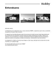
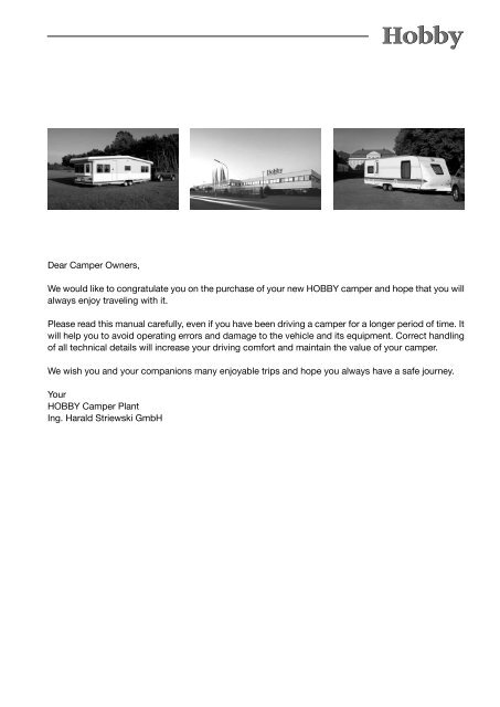
Dear Camper Owners,<br />
We would like to congratulate you on the purchase of your new HOBBY camper and hope that you will<br />
always enjoy traveling with it.<br />
Please read this manual carefully, even if you have been driving a camper for a longer period of time. It<br />
will help you to avoid operating errors and damage to the vehicle and its equipment. Correct handling<br />
of all technical details will increase your driving comfort and maintain the value of your camper.<br />
We wish you and your companions many enjoyable trips and hope you always have a safe journey.<br />
Your<br />
HOBBY Camper Plant<br />
Ing. Harald Striewski GmbH
Table of Contents<br />
1 Introduction ..............................................................................................................01-1<br />
1.1 General information ...........................................................................................01-1<br />
1.2 Markings in these operation instructions ...........................................................01-2<br />
2 Safety ........................................................................................................................02-1<br />
2.1 General information ...........................................................................................02-1<br />
2.2 Before the drive .................................................................................................02-2<br />
2.3 Loading ..............................................................................................................02-4<br />
2.4 Handling Performance .......................................................................................02-6<br />
2.5 After the drive ....................................................................................................02-8<br />
3 Undercarriage and vehicle registration .................................................................03-1<br />
3.1 General information ...........................................................................................03-1<br />
3.2 Safety coupling WS 3000 ..................................................................................03-3<br />
3.3 Locking brake facilities ......................................................................................03-7<br />
3.4 Overrunning equipment and wheel brakes ........................................................03-7<br />
3.5 <strong>Drawbar</strong>s/Longitudinal beams ...........................................................................03-8<br />
3.6 Rotating stanchions ...........................................................................................03-8<br />
3.7 Vehicle registration .............................................................................................03-9<br />
3.8 General inspection .............................................................................................03-9<br />
3.9 Fit for a Speed of 100 km/h .............................................................................03-11<br />
3.10 Definition of mass ............................................................................................03-12<br />
4 Wheels, tires ............................................................................................................04-1<br />
4.1 Tires ...................................................................................................................04-1<br />
4.2 Tire pressure ......................................................................................................04-1<br />
4.3 Profile depth and age of tires .............................................................................04-2<br />
4.4 Rims ...................................................................................................................04-3<br />
4.5 Changing the tire ...............................................................................................04-4<br />
5 Exterior structure ....................................................................................................05-1<br />
5.1 Ventilation and De-aerating ...............................................................................05-1<br />
5.2 Vehicle keys .......................................................................................................05-3<br />
5.3 Service flap ........................................................................................................05-5<br />
5.4 Gas-bottle container flap ...................................................................................05-6<br />
5.5 Toilet flap ............................................................................................................05-6<br />
5.6 Roof and roof rail ...............................................................................................05-7<br />
5.7 Guide rail for outer tent .....................................................................................05-8<br />
5.8 Bicycle rack .......................................................................................................05-8<br />
6 Interior structure ......................................................................................................06-1<br />
6.1 Opening and closing doors and flaps ................................................................06-1<br />
6.2 Media oval ........................................................................................................06-3<br />
6.3 Seat chests and conversion of beds .................................................................06-4<br />
6.4 Children's beds ..................................................................................................06-5<br />
6.5 Windows ............................................................................................................06-6<br />
6.6 Roof bonnets .....................................................................................................06-7
7 Installation of electrical devices ............................................................................07-1<br />
7.1 Safety tips ..........................................................................................................07-1<br />
7.2 Service panel .....................................................................................................07-2<br />
7.3 Electrical supply .................................................................................................07-4<br />
7.4 Function of the electrical supply unit .................................................................07-6<br />
7.5 Changing the taillight bulbs ...............................................................................07-7<br />
7.6 Circuit diagram (exterior) ...................................................................................07-8<br />
7.7 Lighting in the camper .....................................................................................07-10<br />
7.8 Electric floor heating ........................................................................................07-12<br />
8 Water.........................................................................................................................08-1<br />
8.1 Water supply ......................................................................................................08-1<br />
8.2 Warm water supply via Truma-Therme ..............................................................08-3<br />
8.3 Water flushing toilet ..........................................................................................08-5<br />
9 Gas ...........................................................................................................................09-1<br />
9.1 General safety rules for the use of liquid gas facilities ......................................09-1<br />
9.2 Gas supply .........................................................................................................09-3<br />
9.3 Hot-air heating ...................................................................................................09-5<br />
9.4 Hot-air heating with integrated boiler ................................................................09-8<br />
9.5 Refrigerator ......................................................................................................09-13<br />
9.6 Gas cooker ......................................................................................................09-15<br />
9.7 Oven ................................................................................................................09-16<br />
10 Accessories ..............................................................................................................10-1<br />
11 Maintenance and upkeep .......................................................................................11-1<br />
11.1 Maintenance ......................................................................................................11-1<br />
11.2 Ventilation ..........................................................................................................11-2<br />
11.3 Upkeep ..............................................................................................................11-2<br />
11.4 Winter operation ................................................................................................11-7<br />
12 Waste disposal and environmental protection .....................................................12-1<br />
12.1 The environment and mobile travel ...................................................................12-1<br />
13 Technical data ..........................................................................................................13-1<br />
13.1 Tire pressure values ...........................................................................................13-1<br />
13.2 Weights in accordance with 97/27/EG ..............................................................13-1<br />
13.3 Basic equipment................................................................................................13-3<br />
13.4 Technical data ...................................................................................................13-4<br />
13.5 Lighting ..............................................................................................................13-6<br />
Index ............................................................................................................................Ix-1
1. Introduction<br />
1.1 General information<br />
Our campers are continuously being further developed.<br />
Please understand that we reserve the<br />
right to make changes to their equipment, shape<br />
and technology. Therefore, HOBBY shall not be<br />
liable for any claims arising from the contents of<br />
this handbook. The equipment used at the time<br />
of printing is described in this handbook and<br />
should be transferred accordingly to the layouts<br />
of all the different camper variations. Please<br />
understand that we cannot describe all of the<br />
individual variations. Your dealer will be pleased<br />
to answer any special questions regarding the<br />
equipment and technology of your camper.<br />
Your HOBBY camper has been built in accordance<br />
with the latest technology and recognised<br />
safety regulations. Despite all of these safety<br />
measures, it is possible that people may be hurt<br />
or the camper damaged if the safety instructions<br />
in this handbook and the warnings posted on<br />
adhesive labels in the camper are not followed.<br />
Before the first trip<br />
You should certainly familiarize yourself thoroughly<br />
with the contents of this handbook; it is<br />
much more than a reference book.<br />
Fill out the guarantee cards for the built-in appliances<br />
in the separate instructions, and send the<br />
guarantee cads to the respective manufacturers.<br />
In doing so, you secure your right to a guarantee<br />
for all devices.<br />
HOBBY grants a 5-year guarantee<br />
on the watertightness of the camper<br />
in accordance with guarantee conditions.<br />
When you accept the vehicle<br />
you will receive the guarantee booklet,<br />
"Five-Year Guarantee on Watertightness"<br />
from your HOBBY dealer.<br />
Annual leak checks are not free of<br />
charge. Warning: If no leak inspection<br />
is performed, your right to the 5-year<br />
guarantee loses its validity.<br />
01-1
1.2 Markings in these operation instructions<br />
1<br />
Markings in these operation<br />
instructions<br />
The handbook explains the camper as follows:<br />
Texts and illustrations<br />
The texts which accompany illustrations are<br />
found directly to the right of the illustrations. Details<br />
in illustrations (here: entry door) are marked<br />
with position numbers (1).<br />
Lists<br />
- Lists are based on key points and are pre-<br />
ceded by a dash.<br />
Procedural guidelines<br />
• Procedural guidelines are also based on key<br />
points and begin with a round sentence<br />
opener.<br />
Guidelines<br />
Warnings<br />
Guidelines point out important details<br />
which ensure the trouble-free function<br />
of the camper and its equipment.<br />
Please bear in mind that various<br />
models have different equipment;<br />
therefore, varying descriptions are<br />
possible.<br />
Warnings point out dangers which, if<br />
they are not followed, could cause<br />
damage to equipment and/or injury<br />
to persons.<br />
Environmental tips<br />
Environmental tips show possible<br />
ways to reduce strain on the environ-<br />
ment.<br />
01-2
2. Safety<br />
2.1 General information<br />
100 m<br />
Keys<br />
The following keys are provided with the camper:<br />
- Two keys which fit into the following locks:<br />
- entry door,<br />
- service flaps,<br />
- toilet flap.<br />
- gas-bottle container lid<br />
- fresh-water tank lid<br />
Warnings and information labels are<br />
attached both inside and outside the<br />
vehicle. These are meant for your<br />
safety and may not be removed.<br />
Emergency equipment<br />
To be prepared for an emergency, you need at<br />
lest three basic items of rescue equipment (first<br />
aid kit, warning triangle and fire extinguisher)<br />
which you should carry at all times and know<br />
how to use.<br />
- frist aid kit<br />
- warning triangle<br />
- high-visibility vest<br />
Fire prevention measures<br />
• Never leave children unattended in the vehicle.<br />
• Keep flammable materials away from all heating<br />
and cooking appliances.<br />
• Changes to the electrical system, gas system<br />
or built-in devices may only be carried out by<br />
professional, authorised workshops.<br />
• Place a fire extinguisher at the main entry door.<br />
• Ensure that everyone is familiar with the guidelines<br />
on the fire extinguisher.<br />
• Place a fire cover near the gas cooker.<br />
• Keep all escape routes clear.<br />
• Ensure that everyone is familiar with the fire<br />
prevention measures on site.<br />
02-
2.2 Before the drive<br />
02-2<br />
Fighting a fire<br />
• Evacuate all passengers immediately.<br />
• Close the main shut-off valve on the gas<br />
bottle as well as the shut-off valves on gas-<br />
powered appliances.<br />
• Shut off the electrical supply<br />
• Sound alarm and call the fire department.<br />
• Only fight the fire yourself if this is possible<br />
without risk.<br />
As the owner and driver, you are responsible for<br />
the condition of your vehicle. Therefore, you must<br />
note the following points:<br />
Exterior<br />
Go around the carriage and prepare for the drive<br />
as follows:<br />
Preparation of the vehicle<br />
• The camper must be hitched properly (see<br />
guidelines for the safety hitch WS3000).<br />
• Release the handbrake of the camper and<br />
attach the contact-breaking cable to the cou-<br />
pling ball of the base vehicle.<br />
• Tighten the tire bolts after driving the first 50<br />
km.<br />
• Plug the 3-channel plug in the socket of the<br />
base vehicle.<br />
• Inspect the vehicle lighting.<br />
• Turn the winding stanchions and the front<br />
landing wheel upward and secure them.<br />
• Close gas bottles (heating is forbidden while<br />
driving).<br />
• Empty the waste water tank.<br />
• Close gas bottle compartment.<br />
• Adjust outer mirrors on base vehicle.<br />
• Check camper's tire pressure (see tire<br />
pressure table).<br />
• Close all windows.<br />
• Close the service flaps.<br />
• Close and firmly lock roof bonnet.<br />
• Shut off the light on the outer tent.<br />
• Close and secure entry door.<br />
• If necessary, pull the electrical cord to the<br />
230 V mains supply out of the exterior socket.<br />
• If necessary, pull the television antenna in-
ward as far as possible or fold over the satel-<br />
lite dish.<br />
• If necessary, secure the roof <strong>load</strong> and lash it<br />
to prevent slippage.<br />
• If necessary, secure all bicycles and lash them<br />
to prevent slippage, ensuring that they do not<br />
cover any lighting equipment.<br />
• In winter, the roof must be free of snow and<br />
ice before you begin to drive.<br />
Interior<br />
Post a list with all significant weights<br />
and measurements of the carriage in<br />
a highly visible place in the base<br />
vehicle.<br />
You must also prepare the interior of the vehicle.<br />
Preparing the interior:<br />
• Sort all loose objects and store them in their<br />
respective compartments.<br />
• Heavy and/or voluminous objects (e.g. TV/<br />
radio) should be stored safely and secured<br />
against slipping.<br />
• If necessary, redirect refrigerator to 2-volt<br />
operation.<br />
• Shut off all interior lighting.<br />
• Ensure that all fluids, including those in refrigerator,<br />
are secured to prevent leakage.<br />
• Close main valve on gas container and quickclose<br />
valves on all gas-powered appliances.<br />
• Close all doors (incl. refrigerator door),<br />
drawers and flaps tightly.<br />
• Latch the sliding door.<br />
• Lower table and secure it.<br />
Staying in the camper during the<br />
drive is prohibited by law!<br />
02-3
2.3 Loading<br />
02-<br />
Rules for <strong>load</strong>ing:<br />
• Spread the <strong>load</strong> evenly between the left and<br />
right-hand side of the camper. Heavy or bulky<br />
objects belong in the lower storage compartments<br />
and near the axle.<br />
• If your camper has a tandem axle: distribute<br />
the centre of weight between the two axles.<br />
• Never focus the <strong>load</strong> in the camper to the rear<br />
(danger of swinging back and forth).<br />
• Heavy objects should be stowed securely to<br />
prevent them from slipping.<br />
• Lighter objects (clothing) should be stowed in<br />
the wall cupboards.<br />
• You may not always be able to follow the rerecommended<br />
stowing arrangement, because<br />
storage possibilities are distributed throug<br />
hout the entire interior of the camper. If ne-<br />
cessary, stow heavy objects in the base vehi-<br />
cle.<br />
• Lash the roof <strong>load</strong> securely.<br />
• Store baggage in the interior in cupboards<br />
and storage compartments.<br />
• Secure doors and flaps.<br />
• After <strong>load</strong>ing, check total weight and axle<br />
<strong>load</strong>(s) at a public weigh station.<br />
The gross vehicle weight rating in-<br />
dicated in the vehicle documents as<br />
well as the permitted drawbar <strong>load</strong><br />
may not be exceeded. Also note the<br />
permissible drawbar <strong>load</strong> of your<br />
base vehicle.<br />
Providing your base vehicle permits<br />
this and depending on the size of the<br />
camper, you can improve the driving<br />
quality by increasing the drawbar<br />
<strong>load</strong>.<br />
The lower a vehicle's centre of gravity<br />
is, the better its performance in<br />
curves and on the road.
2<br />
3<br />
Stowage areas in the camper<br />
- Light objects (1) such as towels and lightweight<br />
laundry.<br />
- Medium-weight objects (2) such as clothing,<br />
laundry and food.<br />
- Heavy objects (3) such as the outer tent, boat<br />
motor or crates of drinks.<br />
If your camper is equipped with a rear bicycle<br />
rack, the reduction in the drawbar <strong>load</strong> created<br />
by the bicycles must be compensated by the<br />
rest of the <strong>load</strong>.<br />
<strong>Drawbar</strong> <strong>load</strong><br />
You will only achieve optimum driving stability<br />
and decisively increase your safety on the road if<br />
the drawbar <strong>load</strong> has been properly adjusted for<br />
your combination of base vehicle and the camper<br />
being pulled. The drawbar <strong>load</strong> indicates the<br />
power the camper's drawbar exerts on the car's<br />
clutch.<br />
Rules for the drawbar <strong>load</strong>:<br />
• Set the correct drawbar <strong>load</strong> by using, for<br />
example, use a drawbar <strong>load</strong> scale, which is<br />
positioned vertically below the hitch.<br />
• Always check the drawbar <strong>load</strong> before you<br />
start to drive!<br />
• The specified drawbar <strong>load</strong> (see handbook<br />
or type plate) and the permissible overall<br />
mass of the base vehicle and the camper may<br />
not be exceeded!<br />
How to adjust the correct drawbar <strong>load</strong>:<br />
1. Determine the maximum drawbar <strong>load</strong> of your<br />
base vehicle by checking its documentation,<br />
the type plate or the drawbar plate.<br />
2. Your HOBBY camper has a maximum permissible<br />
drawbar <strong>load</strong> of 100 kg.<br />
3. Adjust the drawbar <strong>load</strong> on the camper to the<br />
lower of the two values by <strong>load</strong>ing it carefully.<br />
At the same time, try to make full use of<br />
this value.<br />
4. The lower of the two specified values for the<br />
drawbar <strong>load</strong>, i.e. that of the base vehicle or<br />
the camper, may not be exceeded.<br />
02-5
2.4 Handling Performance Driving<br />
02-<br />
Take a test drive or a safety training course before<br />
the first long drive to better acquaint yourself<br />
with the carriage in driving conditions.<br />
Rules for driving<br />
• Do not underestimate the length of the<br />
carriage.<br />
• Exercise special caution when driving toward<br />
yards and through gates.<br />
• In conditions with strong side winds, slick ice<br />
or wet roads, the carriage could move back<br />
and forth.<br />
• Adjust driving speed to overall street and traffic<br />
conditions.<br />
• Long, lightly sloping roads are potentially<br />
dangerous. Measure your speed from the<br />
outset in such a manner that the carriage can<br />
be accelerated, if necessary, without endan<br />
gering other drivers or pedestrians.<br />
• If the carriage moves back and forth on a<br />
sloping road, brake carefully but rapidly if the<br />
carriage forms a line, i.e. if it is stretched.<br />
• Never increase speed if the carriage becomes<br />
pendulous.<br />
• Do not drive down a hill any faster than you<br />
would drive up one.<br />
• When overtaking or being overtaken by trucks<br />
or buses, the carriage can be caught up in air<br />
suction. This may cause the carriage to swerve<br />
or fishtail.<br />
Driving around curves<br />
Your carriage is considerably longer than a car.<br />
Rules for driving around curves<br />
• Do not take curves too quickly or too sharply!<br />
• Take the curve at a somewhat wider radius<br />
when turning.<br />
• Note that the camper can sheer out of line over<br />
the rear.
Brakes<br />
A trailer carriage behaves differently from an<br />
individual vehicle while braking. Therefore, it is<br />
advis-able (especially for inexperienced drivers)<br />
to conduct several braking tests on a suitable<br />
surface. The braking distance for a carriage is<br />
longer than that of an individual vehicle. The <strong>load</strong><br />
in the caravan also has a significant influence on<br />
the braking distance.<br />
Rules for braking<br />
• Note the longer braking distance on wet<br />
roads.<br />
• When driving down mountains or steep hills,<br />
do not use a higher gear than when driving<br />
uphill.<br />
• Principally, an overrunning brake system<br />
cannot differentiate between a "normal"<br />
braking procedure and driving over a pass,<br />
which lasts for a longer period of time. This<br />
can cause the wheel brakes to heat up<br />
strongly so that, if necessary, you must give<br />
them sufficient time to cool down.<br />
Driving in reverse<br />
Your HOBBY camper has a braking system with<br />
automatic reverse. This makes driving in reverse<br />
possible without activating the overrunning brake.<br />
However, in addition to rolling resistance, the<br />
residual brake force must first be overcome.<br />
The next time the camper moves forward the<br />
braking system will work normally again.<br />
Rules for driving in reverse<br />
• The camper tilts in the opposite direction in<br />
which you steer.<br />
• Use a guide when driving in reverse.<br />
Shunting<br />
Your carriage is significantly larger than a car.<br />
Rules for shunting<br />
• There is a significant blind spot in shunting,<br />
even when the exterior mirrors are properly<br />
adjusted.<br />
• Use a guide when turning into difficult parking<br />
spots.<br />
02-
2.5 After the drive<br />
02-<br />
When positioning the camper manually,<br />
only use the steering handles at<br />
the front and rear ends of the camper.<br />
Never push on the plastic parts<br />
or the walls.<br />
Choosing a parking place<br />
Rules for choosing a parking place:<br />
• The parking place should be as horizontal as<br />
possible.<br />
• Check to see that the entry step is positioned<br />
horizontally (important for refrigerator func<br />
tion).<br />
• Balance the lengthwise slant with the front<br />
landing wheel.<br />
• Balance the crosswise slant by laying appro-<br />
priate boards or a ramp under a wheel.<br />
Do not compensate differences in<br />
height with the lift stanchions.<br />
Securing the vehicle<br />
Rules for securing the vehicle:<br />
• Set the parking brake.<br />
• Only extend the rotating stancions as far as<br />
necessary so that the axle still bears part of<br />
the weight. (The crank is clipped to the bot-<br />
tom of the gas-bottle container.)<br />
• Lay mats under the lifting stanchions when on<br />
soft ground.<br />
• Use stop-blocks to secure the wheels.<br />
Redirecting electrical devices<br />
Rules for redirecting electrical devices<br />
• Open the main shut-off valve on the gas<br />
bottle as well as the shut-off valves on the<br />
gas-powered appliances you require.<br />
• Redirect the refrigerator from 2 V to gas or<br />
230 V; otherwise, the batttery of the base<br />
vehicle could be depleted.
Water installation<br />
Water left standing in the fresh water tank or the<br />
pipes quickly becomes undrinkable.<br />
Therefore, check the water pipes and the freshwater<br />
tank after each use to ensure they are<br />
clean. If necessary, use chemical or biological<br />
disinfectants and rinse well with sufficient fresh<br />
water.<br />
02-
02- 0
3. Undercarriage and vehicle registration<br />
3.1 General information<br />
2<br />
Frame parts and axles are components of the<br />
undercarriage. No technical modifications are<br />
allowed; otherwise, the terms of operation are no<br />
longer valid!<br />
For the sake of traffic safety, the vehicle undercarriage<br />
must be maintained just as conscientiously<br />
as the base vehicle itself. This maintenance<br />
should be carried out by your HOBBY dealer. If<br />
spare parts are required, use only the original<br />
parts designated by the manufacturer.<br />
Generally, campers are not suitable<br />
for pulling by lorries or buses. If this<br />
is done permanently, they will be<br />
damaged.<br />
Greasing and oiling<br />
Regularly examine and grease the sliding parts<br />
and stationary parts of the undercarriage. If the<br />
camper is used seldom, yearly maintenance is<br />
required.<br />
Rules for greasing and oiling<br />
• After every 5,000 kilometers driven, but at<br />
least once a year, grease the swinging lever<br />
bearings on the turning rod spring axle unit.<br />
• Movable parts such as pins and hinged parts<br />
on the hand brake lever and deflexion lever of<br />
the ramp should be oiled lightly.<br />
• Lightly grease the stationary parts on the<br />
case of the overrunning equipment (2) after<br />
every 5,000 kilometres of driving.<br />
IMPORTANT: The friction elements of the<br />
WS 3000 safety hitch may NEVER be oiled<br />
or greased.<br />
• Check from time to time to see that the stationary<br />
parts of the thrust rod are not jammed.<br />
• Clean and oil all movable and stationary parts<br />
regularly.<br />
03-
03-2<br />
The camper's turning rod spring<br />
axle unit is equipped with compact<br />
wheel bearings. The cylinder hub,<br />
compact bearings and axle nuts<br />
form a closed unit. The compact<br />
bearings are free of maintenance<br />
due to their special grease.<br />
The wheel brake may never be<br />
repositioned on the fixing lock or on<br />
the yoke end of the bars!<br />
Only reposition the wheel brake on<br />
the self-securing stationary hexagonal<br />
nut!<br />
You can find further guidelines in<br />
the operating instructions from the<br />
axle supplier.
3.2 Safety coupling<br />
WS 3000<br />
2<br />
3<br />
The camper is equipped with an anti-rolling coupling<br />
in accordance with ISO 11555-1. This safety<br />
coupling stabilises the camper while driving and<br />
ensures better driving performance.<br />
Please note the additional operating instructions<br />
and the manufacturer's safety instructions.<br />
WARNING: The laws of physics<br />
cannot be defied with a safety hitch.<br />
If the limits (of speed and weight conditions)<br />
are exceeded, traction and<br />
cornering force are reduced, which<br />
then becomes the responsibility of<br />
the driver. Therefore, avoid elevated<br />
risks. Please take note of the permitted<br />
drawbar <strong>load</strong> for your base<br />
vehicle.<br />
You will find the current value for the<br />
drawbar <strong>load</strong> of the camper on the<br />
drawbar <strong>load</strong> scales.<br />
Preparation for hitching/unhitching<br />
• To hitch and unhitch, open the tension ball<br />
coupler (lever in position ).<br />
When dealing with higher drawbar<br />
<strong>load</strong>s hitching and unhitching is<br />
simplified by the use of a support<br />
wheel.<br />
Hitching<br />
• The open tension ball coupler is set onto the<br />
coupling ball of the base vehicle. The tension<br />
ball coupler usually closes by applying downward<br />
pressure since the support <strong>load</strong> is<br />
sufficient (lever in position 2).<br />
WARNING: Ensure that the metal of<br />
your ball coupler is bright and free of<br />
grease.<br />
Inspection of hitch<br />
• The hitch is attached properly/closed if the<br />
operation lever is in position (2).<br />
If the WS 3000 is not properly at-<br />
tached to the coupling ball, the<br />
camper can detach from the base<br />
vehicle.<br />
03-3
Fig.<br />
Fig. 2<br />
Fig. 3<br />
03-<br />
2<br />
2<br />
3<br />
Activation of the stabilization system<br />
• To activate the stabilization system, the<br />
operation lever must be moved downward out<br />
of the closed position (2) until it locks in (3).<br />
The spring corpus will become tense in the<br />
process, so that contact pressure is created<br />
on the coupling ball via the friction elements.<br />
Afterward, the operation lever lies approxi-<br />
mately parallel to the drawbar axle. Driving<br />
without the stabilization system is possible,<br />
however, and under certain street conditions,<br />
i.e. in ice and snow, advisable.<br />
Inspection of the stabilization system<br />
• After hitching and activating the stabilization<br />
system, the friction lining can be inspected.<br />
The rating plate (type plate) mounted onto the<br />
operation lever (Figure 2- ) indicates a tri-<br />
angular field marked with +/- signs, parallel to<br />
the slotted hole in the lever which points in the<br />
forward-driving direction. The tension ball<br />
coupler is adjusted on the front side in such<br />
a manner that the cap of a metal pin, visible in<br />
the slotted hole (Fig. 2-2) lies under the "+/-"<br />
signs on the marked side of the triangle.<br />
Shutoff of the stabilization system<br />
• Bring the operation lever slowly upward into<br />
the open position (position 2) to shut off the<br />
system.<br />
Unhitching<br />
• Pull the operation lever slowly upward into the<br />
open position (position ). After releasing the<br />
lighting plug and pull cord, the trailer can<br />
be unhitched from the base vehicle (e.g. with<br />
the help of a drawbar track wheel).<br />
We recommend that you park the trailer with<br />
the tension ball coupler closed if it will not<br />
be used for a significant period of time.<br />
To do this, lift the opration lever while pulling<br />
the ball socket (movable element with friction<br />
lining - Fig. 3.1) forward and slowly<br />
close the service lever.
Fig.<br />
Fig. 5<br />
Maintenance<br />
Coupling ball on base vehicle<br />
Ensure that the coupling ball meets the required<br />
dimensions and is undamaged, clean and free of<br />
grease. When using dacromet-coated (dull silver<br />
anti-corrosion coating) as well as lacquered<br />
coupling balls, the coating must be removed<br />
completely with sandpaper (200-240 grain) so<br />
that it does not create deposits on the friction<br />
lining. The metal surface of the coupling ball<br />
must be bright. A damaged or dirty coupling ball<br />
causes increased wear of the friction linings; a<br />
greasy one greatly diminishes the stabilization<br />
effect. Thinning solvents or spirit are both<br />
suitable for cleaning.<br />
Tension ball coupler<br />
Keep the friction linings inside the tension ball<br />
coupler clean and free of grease (Fig. 5). When<br />
the friction linings are dirty, the surface can be<br />
cleaned with 200-2 0 grain sandpaper. Then<br />
clean with petroleum ether or spirit. All movable<br />
bearings and bolts are easy to grease. By regular<br />
upkeep and maintenance of your WS 3000, you<br />
increase its overall life span, function and safety.<br />
Changing the friction lining<br />
The front friction lining ( ) can be changed in<br />
case of excessive wear. Note the detailed assembly<br />
instructions in the manufacturer's set<br />
of spare parts. The rear friction lining has such<br />
a large dimension that it does not have to be<br />
replaced.<br />
03-5
03-<br />
Noises<br />
Certain noises can occur during the course<br />
of the drive; these noises, however, have no<br />
influence on the operative effectiveness of the<br />
tension ball coupler.<br />
Possible causes of these noises can be:<br />
. a dacromet-coated coupling ball on the<br />
base vehicle,<br />
2. a galvanized coupling ball on the base<br />
vehicle,<br />
3. a damaged or dirty coupling ball on the base<br />
vehicle,<br />
4. dirty friction elements on the tension ball<br />
coupler.<br />
5. the towbar or tie rod in the linings of the over-<br />
running equipment are running dry.<br />
Hints for 1 and 2:<br />
Remove the surface coating of the coupling ball<br />
with sandpaper (200-2 0 grain) and clean with a<br />
thinning solvent or spirit.<br />
for 3:<br />
Polish or clean dirty or damaged coupling balls.<br />
for 4:<br />
Clean the surface of the friction elements with<br />
sandpaper (200-2 0 grain) and then clean with<br />
petroleum ether or spirit.<br />
for 5:<br />
Use a lubricating nipple to grease the linings.<br />
Pull back the shock absorber and grease the<br />
bare towbar.
3.3 Locking brake<br />
facilities<br />
3.4 Overrunning equipment<br />
and wheel<br />
brakes<br />
The components of the brake facilities, particularly<br />
the overrunning equipment, wheel brakes<br />
and towbar were checked in accordance with<br />
the appropriate EU Guidelines and may only be<br />
used in a licensed combination.<br />
If you alter or modify any components of the<br />
brake facilities, the operation permission loses<br />
its validity. Modifications may only be made with<br />
the manufacturer's permission.<br />
Parking the carriage<br />
When parking the carriage, the locking brake of<br />
the camper must be activated.<br />
To lock<br />
• Pull the locking brake lever upward by the<br />
handle ( ) until it locks into place. The locking<br />
brake lever is pressed into the final position<br />
by the gas pressure spring.<br />
To release<br />
• Press the locking brake lever back into the<br />
original position.<br />
Checking the overrunning<br />
equipment:<br />
1. If it is possible to push the towbar more than<br />
halfway (approx. 5 mm) in when the locking brake<br />
has been activated, the braking system must<br />
be regulated immediately by an experienced<br />
shop.<br />
2. To check the reaction point, activate the<br />
locking brake and push the camper backwards<br />
until the hand brake lever is completely tilted.<br />
Then push the safety clutch into the overrunning<br />
equipment. The towbar must extend into the<br />
neutral position by itself by means of the gas<br />
cushion in the hydraulic shock absorber. Should<br />
this procedure take longer than 30 seconds, the<br />
overrunning equipment must be checked by an<br />
experienced shop.<br />
Wheel brakes<br />
The linings of the wheel brakes are wear and tear<br />
parts; therefore, they must be checked every<br />
5,000 km or at least once every year. One sure<br />
03-
3.5 <strong>Drawbar</strong>s/Longitudinal<br />
beams<br />
3.6 Rotating stanchions<br />
03-<br />
sign of strong brake lining wear is described in<br />
the aforementioned check for the overrunning<br />
equipment: if the safety clutch can be pushed in<br />
more than approx. 5 mm. In this case, the wheel<br />
brakes must be regulated by an experienced<br />
shop or, if necessary, the brake shoes must be<br />
renewed.<br />
• When driving downhill on a mountain<br />
pass, check to ensure that the<br />
brakes are cooled sufficiently.<br />
• Put the base vehicle into a lower<br />
gear and drive downhill at slow<br />
speed.<br />
• Stretch the trailer combination as<br />
often as possible to avoid continuous<br />
buffing by the camper.<br />
• Always make use of parking areas<br />
and passing points to give the<br />
brakes a chance to cool off.<br />
The main chassis beam and the towbar are connected<br />
by cone washer bolts (with the exception<br />
of the one-piece chassis). During regular maintenance,<br />
all of the screws must be checked and<br />
retightened, if necessary (105 Nm).<br />
Bent or damaged drawbars must be<br />
replaced immediately. You are not<br />
allowed to repair damaged components.<br />
The rotating stanchions are located in the front<br />
and rear under the camper.<br />
Turning the rotating stanchions outward<br />
• Park the vehicle as horizontally as possible.<br />
• On soft ground, lay a sturdy mat or suitably<br />
sized board under the rotating stanchions to<br />
prevent the camper from sinking.<br />
• Turn the rotating stanchions outward.<br />
The rotating stanchions may only<br />
be used for support, and not for lev-<br />
eling out or raising.<br />
Turning the rotating stanchions inward<br />
• With the crank, turn the rotating stanchions<br />
inward to the horizontal position.
3.7 Vehicle registration<br />
3.8 General inspection<br />
The crank for the rotating stanchions is located<br />
at the front in the gas-bottle container. It is attached<br />
firmly to the bottom of the container.<br />
Every vehicle which uses public roads is subject<br />
to registration. This includes your new camper.<br />
You can register the camper at your local registration<br />
office.<br />
The following documents are required to initiate<br />
the registration process:<br />
- motor vehicle registration certificate, Part II<br />
- insurance card<br />
- personal identification or proof of residence<br />
- possibly, power of attorney to have someone<br />
else register the camper<br />
Please remember to apply for a suitable<br />
"100 km/h" sticker, should you require one.<br />
In accordance with Section 29 of German Road<br />
Traffic Licensing Regulations, your camper must<br />
undergo a major inspection every two years. This<br />
major inspection may be carried out by the TÜV<br />
(Technical Inspection Authority), DEKRA Vehicle<br />
Inspections or another accredited technical support<br />
organisation.<br />
The following documents must be presented at<br />
each inspection:<br />
- motor vehicle registration certificate, Part I<br />
- valid certificate of inspection for gas facilities,<br />
documenting installation. The initial certificate<br />
is located in the service package for the camper.<br />
Vehicle ID number (FIN)<br />
The 17-digit vehicle ID number, legible from the<br />
right, is located either on the front right-hand<br />
side of the forked drawbar (models 400 - 650) or<br />
on the right-hand side of the front crossmember<br />
(models 720/750).<br />
Furthermore, the FIN is etched on the name<br />
plate.<br />
Please have your VIN at hand for any inquiries or<br />
whenever visiting your dealer.<br />
03-
03- 0<br />
Name plate<br />
Permit number<br />
Vehicle ID number (FIN)<br />
Permissible maximum weight<br />
Permissible axle <strong>load</strong>, st axle<br />
Permissible axle <strong>load</strong>, 2nd axle
3.9 Fit for a Speed of 100 km/h<br />
1. Your HOBBY camper is technically equipped for a maximum speed of 100 km/h. Under no<br />
circumstances may this speed be exceeded!<br />
2. Note the permissible maximum speeds for trailer carriages in the country in which you are<br />
travelling!<br />
3. Road traffic regulations in Germany were changed on 22 October 2005. Your camper was<br />
already set to a speed of 100 at the factory, and this has been entered in the camper's<br />
registration documents. Upon request, the 100 km/h sticker will be issued by the road traffic<br />
authority when the camper is initially registered and attached to the back of the vehicle.<br />
4. The following points must be observed, because you are responsible for adhering to them. If<br />
they are not met, the maximum speed for the camper is no more than 80 km/h!<br />
a) The base vehicle must be equipped with an anti-locking system/anti-lock device and may<br />
not exceed an overall mass of 3.5 tons.<br />
b) The camper must be equipped with hydraulic vibration dampers (shock absorbers);<br />
naturally, your new HOBBY camper is equipped with these.<br />
c) The camper's tires may be no more than six years old. They must be marked at least with<br />
an L (= 120 km/h) for the appropriate speed category.<br />
d) The camper must be equipped with a stabilising unit in accordance with ISO 11555-1<br />
(standard in this HOBBY series since 1997).<br />
The overall mass of the camper may not exceed the unladen mass of the car.<br />
5. Free interchangeability of base vehicle and camper:<br />
Different campers may be combined with different base vehicles.<br />
You are responsible for ensuring that the preceding regulations are met if you plan to drive at<br />
100 km/h. Should this not be the case, the maximum speed in Germany is 80 km/h!<br />
6. The correct drawbar <strong>load</strong> gives you more safety:<br />
Please refer to page 02-5 for the recommended drawbar <strong>load</strong>.<br />
03-
3.10 Definition of mass<br />
03- 2<br />
Definition of masses (weights) for<br />
campers<br />
The EU regulation 97/27/EG applies for calculating<br />
the masses (weights) and for the <strong>load</strong>ing<br />
which results from these calculations. The EU<br />
regulations correspnd to a great extent to the<br />
norm DIN EN 1645-2. The terms and basic<br />
calculation elements used in this description are<br />
explained in the following:<br />
1. Gross vehicle weight rating (g.v.w.r.)<br />
The indication of the gross vehicle weight rating<br />
is taken directly from the HOBBY factory. These<br />
weights were calculated as a result of lengthy<br />
and detailed experiments; for safety reasons,<br />
they may not be exceeded.<br />
2. Mass in running order<br />
The mass in running order corrsponds to the<br />
weight of the standard vehicle including all<br />
standard equipment installed at the factory (e.g.<br />
all-inclusive package) plus the basic equipment<br />
(see Item 3).<br />
3. Basic equipment<br />
The basic equipment consists of all objects and<br />
fluids which are necessary for the safe and proper<br />
use of the vehicle. These include the masses<br />
for gas, water and electrical supply (see Item<br />
13.3 for a detailed specification).<br />
4. Additional <strong>load</strong><br />
The additional <strong>load</strong> is the difference between<br />
the "gross vehicle weight rating minus the mass<br />
in running order". The remaining additional <strong>load</strong><br />
must be large enough to cover the weights of<br />
possible additional equipment and personal<br />
equipment.<br />
5. Additional equipment<br />
Additional equipment includes all items not<br />
part of the standard equipment preinstalled in<br />
the HOBBY factory or by the dealer. This also<br />
includes installations by special request.<br />
The mass in running order refers to the vehicle<br />
as originally equipped by the dealer or factory.<br />
This increases accordingly if special equipment<br />
is installed.<br />
Before the first use, we recommend that you<br />
weigh your vehicle on a calibrated vehicle scale.<br />
In this manner, you can determine the maximum<br />
permissible additional <strong>load</strong> for your vehicle.
If you are not sure whether you have<br />
over<strong>load</strong>ed the vehicle, weigh your<br />
vehicle on a public vehicle scale.<br />
Over<strong>load</strong>ing can lead to malfunction<br />
or even tire blowout!<br />
This presents the danger of the<br />
vehicle spinning out of control, which<br />
endangers you as well as other dri-<br />
vers and pedestrians.<br />
03- 3
03-
4. Wheels, tires<br />
4.1 Tires<br />
4.2 Tire pressure<br />
2 3<br />
Only use those tires designated in the registration<br />
documents. Other tire sizes may only be<br />
used with the permission of the manufacturer<br />
(ABE).<br />
• Check tires regularly to ensure that the tread<br />
is worn down evenly; check tread depth;<br />
check for external damages.<br />
• Always use the same make and model of tires<br />
(summer or winter tires).<br />
• Drive carefully on new tires for a stretch of<br />
approx. 00 km to enable them to develop a<br />
full road grip.<br />
Due to the type of construction, the<br />
tires on campers with a tandem axle<br />
may wear out more quickly.<br />
If snow chains are used, note the manufacturer's<br />
assembly instructions.<br />
You may not use snow chains if you<br />
are using tire size 95/70 R 5 C.<br />
Only one tire size is now entered in the motor<br />
vehicle registration certificate, Parts I and II. This<br />
must not necessarily correspond with the size<br />
of the tires mounted on the vehicle. Should you<br />
have any queries, please contact your dealer.<br />
Rules for checking tire pressure:<br />
• Check and fix tire pressure every four weeks<br />
(but at least every three months) and before<br />
every drive.<br />
• If driving on low tire pressure is unavoidable<br />
(i.e., from the campsite to the nearest service<br />
station) you should drive at a maximum<br />
speed of 20 km/h.<br />
• Raise the pressure of the base vehicle's rear<br />
tires by 0.2 bar.<br />
• Tires must be checked when they are cold.<br />
• If tires are checked or the tire pressure cor-<br />
rected when tires are warm, the pressure<br />
must be up to 0.3 bar higher than if the tires<br />
are cold.<br />
Rules for tire pressure:<br />
- correct tire pressure ( )<br />
- tire pressure too low (2)<br />
- tire pressure too high (3)<br />
04-
4.3 Profile depth<br />
and age of tires<br />
04-2<br />
New tires are needed (at the latest) when the<br />
profile depth measures 1.6 mm.<br />
Tires age even when used rarely or<br />
not at all.<br />
Tire manufacturers' recommendation<br />
• Change tires after six years, regardless of<br />
profile depth.<br />
• Avoid striking curbs, potholes or other<br />
obstacles.<br />
Age of tires<br />
If the tire pressure is too low, the tire<br />
can overheat. This can result in<br />
serious damage.<br />
The correct tire pressure is given in<br />
the table on wheels/tire pressure<br />
found under "Technical Information"<br />
or on the labels in the gas-bottle<br />
container and on the wheel cover.<br />
Tires should not be more than 6 years old, because<br />
on the one hand your permission to drive<br />
the camper at 00 km/h will elapse after this<br />
period and, on the other, the material wears out<br />
due to age and if the tires stand too long in one<br />
spot. The 4-digit DOT number on the side of the<br />
tire (if necessary, check the inside) shows the<br />
date of manufacture. The first 2 digits refer to the<br />
week, the last 2 to the year it was manufactured.<br />
Example:<br />
DOT 2207 refers to week 22 in manufacturing<br />
year 2007.
4.4 Rims<br />
Only use rims that are covered by the vehicle<br />
licence. Should you wish to use other rims,<br />
please note the following:<br />
Rules for the use of other rims:<br />
- Size,<br />
- mechanisms,<br />
- compression depth and<br />
- the <strong>load</strong>/bearing capacity must be sufficient<br />
for the permissible total mass.<br />
- The chuck cone of the fastening screw must<br />
correspond to the rim mechanisms.<br />
Modifications can only be made with<br />
the manufacturer's permission.<br />
Rules for wheel screws:<br />
- wheel bolts must first be checked after a<br />
distance of 50 km and then checked during<br />
regular maintenance.<br />
Adjusting torque<br />
- for steel rims: 0 Nm<br />
- for aluminium rims: 20 Nm<br />
WARNING: When changing rims<br />
(steel -> aluminium / aluminium -><br />
steel) ensure that you are using the<br />
correct wheel screws.<br />
04-3
4.5 Changing the tire<br />
04-4<br />
2<br />
Preparing to change the tire<br />
• If possible, only change the tire when the<br />
base vehicle is coupled to the camper.<br />
• Park the trailer carriage on as firm and even a<br />
surface as possible.<br />
• If you have tire trouble on a public road, turn<br />
on your hazard warning signal lights and set<br />
up the warning triangle.<br />
• Base vehicle: Pull the handbrake, set the<br />
wheels straight, put the vehicle in gear or, if<br />
you are driving an automatic, set the gear to<br />
P.<br />
• <strong>Caravan</strong>: Pull the handbrake, leave the sup-<br />
port wheel in its driving position, deactivate<br />
the stabilization system (note: do not open<br />
completely).<br />
• Remove the wheel chocks ( ) from the bottle<br />
compartment.<br />
• To secure the vehicle, place the wheel chock<br />
( ) in front of and behind the wheel that is still<br />
intact.<br />
• Before jacking up the vehicle, turn the wheel<br />
screws once to loosen them, but do not un-<br />
screw them any further.<br />
• The spare tire (not included, Fig. 2) can be<br />
stored in the same compartment at the front<br />
of the camper as the gas container (special<br />
fasteners required).<br />
If the camper has alloy rims, note<br />
that the correct wheel screws are<br />
used when installing the spare tire<br />
affixed to a steel rim.
Warnings for changing the tire:<br />
Only use the specifically designated<br />
jack for the corresponding frame<br />
parts.<br />
For example, on the axle pipe corre-<br />
sponding to the swinging lever group<br />
or on the stringer in the area of the<br />
axle fasteners.<br />
Damage or even an accident result-<br />
ing from the vehicle's toppling over<br />
can occur if the jack is applied to<br />
other parts of the vehicle.<br />
The jack is only to be used for<br />
changing tires. It may not be used<br />
for working under the vehicle!<br />
The rotating stanchions may not be<br />
used as a jack!<br />
The jack is not part of the standard<br />
equipment in this series, and is there<br />
fore not included.<br />
After changing the tire, the wheel<br />
screws must be examined (after a<br />
50 km drive) to ensure that they are<br />
tight enough (tighten if necessary).<br />
Changing the wheel<br />
• Set the corresponding jack onto the axle pipe<br />
of the swinging lever group or on the longitu<br />
dinal beam in the area of the axle attachments<br />
of the wheel to be changed.<br />
• On campers with a double axle, always set<br />
the jack onto the rear axle; a hydraulic jack<br />
(not included) is recommended.<br />
• If the vehicle is parked on soft ground, lay a<br />
stable reinforcement under jack (i.e., a board).<br />
• Lift the vehicle until the wheel is 2 or 3 cm off<br />
the ground.<br />
• Reposition the ratchet jack handle if it should<br />
slant when you jack up the vehicle.<br />
• Remove the wheel fastening screws and the<br />
wheel.<br />
• Attach the spare tire to the hub and adjust it.<br />
• Reattach the wheel screws and tighten them<br />
lightly over the transversal.<br />
04-5
04-6<br />
• Lower the jack and remove it.<br />
• Tighten the wheel fatening screws evenly<br />
with the wheel wrench. The nominal value of<br />
the attachment torque is 0 nm for steel rims<br />
and 20 nm for aluminium rims.<br />
• Release the handbrake and reactivate the<br />
stabilization system.<br />
Tire repair kit<br />
You should have a functional spare<br />
tire available at all times. Therefore,<br />
have the spare tire replaced without<br />
delay.<br />
Do not use the tire repair kit if the tire<br />
was damaged as a result of driving<br />
without air. Small cuts, especially in<br />
the tire tread, can be resealed using<br />
the tire repair kit. Do not remove<br />
foreign objects (such as screws or<br />
nails) from the tire. The tire repair kit<br />
can be used as long as the outside<br />
temperature is approx. -30° C or<br />
higher.<br />
A Shake the bottle. Open the fill hose (1) on the<br />
bottle (foil seal is thereby punctured).<br />
B Unscrew the valve cap from the tire valve.<br />
Remove the valve insert (2) with the valve-<br />
core remover (3). Do not lay the valve insert<br />
(2) down in sand or dirt.<br />
C Pull the stopper (4) from the fill hose (1). Push<br />
the fill hose onto the tire valve.
D Hold the bottle down with the filling tube and<br />
then press them together. Press the entire<br />
bottle contents into the tire. Pull the fill hose<br />
off ( ) and screw the valve insert (2) tightly<br />
into the tire valve with the valve-core remover<br />
(3).<br />
E Open the air hose (5) on the tire valve. Insert<br />
the plug (6) into the cigar lighter socket.<br />
Then pump the tires (Fig. 7). do not operate<br />
the electric air pump longer than 8 minutes!<br />
Danger of overheating! If sufficient air pres-<br />
sure is unattainable, drive 0 meters (either<br />
forward or in reverse) so that the sealant<br />
can be evenly distributed within the tire.<br />
Repeat the pumping process. Resume driving<br />
immediately, so that the sealant can be evenly<br />
distributed within the tire.<br />
Maximum speed: 80 km/h. Drive carefully,<br />
especially in curves.<br />
Check tire pressure after driving 0 minutes.<br />
If the tire pressure has fallen under this<br />
minimum value (8), you may not drive any<br />
further.<br />
If the minimum value is still indicated (8),<br />
correct the tire pressure according to the tire<br />
pressure table in the gas bottle container.<br />
Drive carefully to the nearest mechanic and<br />
have the tire replaced.<br />
Danger of accidents! If the required<br />
tire pressure is still unattainable, the<br />
tire is too severely damaged. In this<br />
case, the tire repair kit can no lon-<br />
ger provide an effective seal. There-<br />
fore, do not drive any further. Notify a<br />
service station or the 24-hour service<br />
hotline.<br />
F Adhere the provided sticker to the combination<br />
instrument within sight of the driver. Dispose<br />
of used tire repair kit at a service station.<br />
Danger of accidents! Have the tires<br />
replaced at the nearest service sta-<br />
tion.<br />
04-7
04-8
5. Exterior structure<br />
5.1 Ventilation and De-aerating<br />
2<br />
Rules for forced ventilation<br />
Proper ventilation and de-aerating of the vehicle<br />
is a prerequisite for ideal living comfort. A draftfree<br />
forced-ventilation system is located in the<br />
floor and a forced de-aerating system is located<br />
in the ceiling which should not be interfered with.<br />
We recommend that you open the<br />
roof bonnets whenever you live in the<br />
camper.<br />
Cooking, wet clothing, etc., produces<br />
vapor. Every person loses up to<br />
35 g of water per hour. Therefore,<br />
depending on the relative humidity,<br />
please ventilate and de-aerate<br />
through the windows and roof bonnets<br />
(see also "Winter operation").<br />
Under no circumstances may the<br />
safety ventilation be shut, not even<br />
slightly.<br />
05-
05-2<br />
2<br />
3<br />
Refrigerator<br />
The ventilation bars provide the refrigerator with<br />
fresh air from outside to ensure sufficient cooling<br />
performance. The ventilation bar is located at the<br />
bottom of the exterior vehicle wall. The de-aeration<br />
bar is located above the ventilation bar.<br />
there is a danger of suffocation if<br />
ventilation openings are blocked!<br />
Therefore, do not block ventilation<br />
openings.<br />
Special cover plates should be used<br />
during winter operation. You can buy<br />
these cover plates from your dealer.<br />
We recommend that you remove the<br />
ventilation bars when outside temperatures<br />
are very high. This creates<br />
a high air circulation on the refrigera<br />
tor and increases cooling capacity.<br />
To remove ventilation bars:<br />
• Turn the screw (3) to the left until it locks.<br />
• First pull the ventilation bar carefully to the<br />
left.<br />
• Then remove the ventilation bar.<br />
Heating element<br />
A ventilation flap provides the heating element<br />
under the floor of the vehicle with fresh air.<br />
The air from the heating element is carried outside<br />
by a flue. The flue is locaed on the roof of<br />
the camper ( ).<br />
There is danger of suffocation if flue<br />
openings are blocked!<br />
Therefore, do not block flue openings.<br />
Ensure unobstructed outflow from<br />
the flue during winter operation.
5.2 Vehicle keys External entry door<br />
External Door lock model a<br />
External Door lock model b<br />
Entry door model a<br />
To open:<br />
• Unlatch the lock with the key.<br />
• Pull the door handle.<br />
• Open the door.<br />
To close:<br />
• Shut the door.<br />
• Turn the key until the latch clicks audibly.<br />
• Turn the key back into the vertical position<br />
and pull it out.<br />
Internal entry door<br />
Model a:<br />
To open:<br />
• Push the handle down towards the green dot,<br />
open the door and allow the handle to spring<br />
back.<br />
To close:<br />
To avoid damage, do not use the<br />
track for the insect screen as assistance<br />
when entering the camper.<br />
The entry door is your escape route<br />
in an emergency. Therefore, never<br />
block the door from the outside!<br />
Only drive when the entry door is<br />
shut.<br />
In this manner, a door locked from<br />
the outside can be opened from the<br />
inside.<br />
• Push the handle up towards the red dot,<br />
press and leave it in this position.<br />
05-3
Entry door model b<br />
Entry door model b<br />
2<br />
05-<br />
3<br />
A<br />
B<br />
5 6<br />
Model b:<br />
To open:<br />
• Reach into the grip plate (A), pull the release<br />
lever, open the door and let go of the lever.<br />
To close:<br />
• Pull the door shut.<br />
• Press the locking button (B).<br />
Stable entry door<br />
The upper (3) and lower (2) parts of the entry<br />
door can be opened and closed separately by<br />
opening the door and then unlocking the upper<br />
part (3) of the door from the lower part.<br />
Unlocking the upper part of the door<br />
Model a:<br />
• Push the bolt ( ) towards the door hinge and<br />
then push outwards. Unlock the upper part of<br />
the door and open it outwards.<br />
• The bolt ( ) will snap back into its original<br />
position when you let it go.<br />
Model b:<br />
• Turn the lever ( ) into a vertical position in<br />
order to separate the upper from the lower<br />
part of the door.<br />
• Open the upper part of the door complete-<br />
ly and press it against the outer wall of the<br />
vehicle. The door catch (5) will snap into its<br />
counterpart (6) on the outer wall of the vehi-<br />
cle and prevent the upper part of the door<br />
from shutting inadvertently.<br />
• The door frame and the lower part of the door<br />
can now be swung back separately from the<br />
upper part of the door and leaned against the<br />
outer wall of the vehicle.
5.3 Service flap<br />
To open:<br />
• Unlock the flap with a key.<br />
• Press the locking button.<br />
• Open the flap by pushing down.<br />
To close:<br />
Never lock the upper part of the door<br />
when the insect screen is closed. The<br />
insect screen must always be open<br />
when you lock the door.<br />
Locking the upper part of the door<br />
Model a:<br />
• Push the bolt ( ) outward.<br />
• Connect the upper part of the door (3) to the<br />
lower part (2).<br />
• Push the bolt ( ) inward or let it snap back<br />
and securely fasten both parts together.<br />
Model b:<br />
• Turn the lever ( ) to a horizontal position in<br />
order to securely connect the upper and low-<br />
er parts of the door.<br />
• To close the whole door, press the handle into<br />
the frame ( ).<br />
Entry step tread<br />
When entering and exiting the vehicle:<br />
• Place step tread in front of the entry door to<br />
the camper.<br />
• Ensure that the step tread is placed on a<br />
level surface; this prevents the step<br />
tread from falling over.<br />
Note the varied tread heights and,<br />
when exiting, ensure you will step<br />
onto firm and even ground.<br />
• Close the flap by pushing it up.<br />
• Press the top left and right-hand corners of<br />
the flap to ensure that all of the existing locks<br />
actually snap into place.<br />
• Use the key to lock the flap.<br />
05-5
5.4 Gas-bottle container flap<br />
5.5 Toilet flap<br />
05-6<br />
2<br />
To open:<br />
• Unlatch the lock ( ) with the key.<br />
• To unlock, turn the knob that pops out in a<br />
counter-clockwise direction and open the<br />
gas-bottle container lid.<br />
To close:<br />
To Open:<br />
• Unlatch the lock ( ) with the key.<br />
• Press the knob (2) and swing the flap to the<br />
side.<br />
To close:<br />
All of the fastenings on the service<br />
flap must lock into place when closing<br />
to ensure that the flap will always be<br />
closed tight. If the flap is not closed<br />
correctly, it could become permanently<br />
deformed, especially when the camper<br />
stands unused for a longer period of<br />
time.<br />
Spray the sealing gaskets of the service<br />
flaps regularly with silicon to ensure<br />
that they will always move easily and<br />
operate reliably.<br />
• Shut the lid of the gas-bottle container.<br />
• Lock the lid by turning the knob in a clockwi-<br />
se direction.<br />
• Latch the lock ( ) with the key.<br />
• Press the knob until it snaps in and secure it.<br />
• Push the toilet flap to the side until it snaps in.<br />
• Latch the lock ( ) with the key.
5.6 Roof and roof rail<br />
Rules for <strong>load</strong>ing the roof rail:<br />
• Fasten the carrier or the cross braces for the<br />
roof <strong>load</strong>s to the roof rail.<br />
• Only store light baggage on the roof.<br />
• Lash the roof <strong>load</strong> sufficiently and secure it<br />
against slippage or falling.<br />
• Do not <strong>load</strong> the roof excessively! The heavier<br />
the roof <strong>load</strong>, the worse the overall handling of<br />
the vehicle.<br />
The maximum permissible <strong>load</strong> for<br />
the roof rail is 50 kg.<br />
Note the maximum permissible axle<br />
burdens. Calculate the measurements<br />
of the roof <strong>load</strong> in relation to<br />
the vehicle height. Post a note of the<br />
total vehicle height in a highly visible<br />
place near the driver. Then you no<br />
longer have to calculate when approaching<br />
bridges and thoroughfares.<br />
Do not cover the waste gas flue.<br />
Rules for the roof <strong>load</strong>:<br />
• Only stand or walk on the roof when the roof<br />
rail is attached. Use only a standardised and<br />
licensed ladder to climb up to the roof.<br />
• The roof has not been made for concentrated<br />
single <strong>load</strong>s. Generously cover the standing<br />
area before you step on the roof. Materials with<br />
a smooth and soft surface, such as a Styrofoam<br />
board, are suitable for this.<br />
The maximum total <strong>load</strong> for the roof<br />
rail is 80 kg!<br />
Be careful when standing on the<br />
roof. There is a great danger that you<br />
will slip if the roof is wet or icy.<br />
05-
5.7 Guide rail for outer tent The guide rail for the outer tent, which is used<br />
to insert the weather strip, is beaded at the rear<br />
of the camper on a level with the taillights as<br />
well as at the lower edge of the front end of the<br />
camper.<br />
5.8 Bicycle carrier<br />
05-8<br />
The filling ribbon of the guide rail for<br />
the outer tent deliberately hangs several<br />
centimetres out of the guide rail<br />
to ensure the rainwater and moisture<br />
will drip off. Never cut off the extra<br />
bit of filling ribbon that hangs out.<br />
The handling of the trailer carriage changes<br />
considerably when the bicycle carrier has been<br />
<strong>load</strong>ed. You should adjust your speed to take<br />
this into consideration:<br />
• Ensure that you make full use of the permitted<br />
towbar <strong>load</strong> when the bicycle carrier has been<br />
<strong>load</strong>ed and correct it accordingly.<br />
• Your critical speed will be dramatically reduced<br />
even if you have <strong>load</strong>ed the bicycle carrier<br />
optimally.<br />
• The driver of the vehicle is responsible for<br />
ensuring that bicycles are fastened securely.<br />
The <strong>load</strong>ing system must be folded up and<br />
secured with the available clips even when it<br />
is not <strong>load</strong>ed.<br />
• Ensure that existing lighting equipment is not<br />
covered partially or completely by the <strong>load</strong>.<br />
The maximum permissible <strong>load</strong> for<br />
the bicycle carrier is 50 kg.
6 Interior structure<br />
6.1 Opening and closing doors and flaps<br />
Stowage cupboards<br />
To open:<br />
• Pull the handle until the flap opens.<br />
To close:<br />
• Press the flap on the handle until you<br />
feel the flap shut.<br />
Furniture doors with handle<br />
Washroom door<br />
• Push the handle to open and shut the door.<br />
Furniture doors with knob<br />
Wardrobe<br />
• Turn the knob to open and shut the door.<br />
06-
06-<br />
3<br />
Furniture doors with sliding<br />
handle<br />
Kitchen cupboards (except Excelsior)<br />
To open:<br />
• Using your thumb and index finger, push the<br />
sliding handle (1) up.<br />
• Pull on the handle until the cupboard door<br />
swings open to the side.<br />
To close:<br />
• Using your thumb and index finger, push the<br />
sliding handle (1) up.<br />
• Using the handle, push the cupboard door<br />
closed.<br />
• To fasten the door, let the sliding handle (1)<br />
snap back in its original position.<br />
Push-lock drawers<br />
Kitchen drawer<br />
To open:<br />
• Press the push-lock (2) until the knob jumps<br />
up.<br />
• Pull on the handle (3) until the drawer slides<br />
out.<br />
To close:<br />
• Using the handle (3), push the drawer closed.<br />
• Press the push-lock (2) until the knob snaps<br />
into place and the drawer is securely shut.<br />
Close all flaps before driving off. This<br />
will prevent accidental opening during<br />
the drive which could cause<br />
objects to fall out.
6.2 Media oval (rotating TV/bar)<br />
3<br />
4<br />
The media oval is a room divider, mounted on a<br />
pivot, which can be used as both a bar and a TV<br />
cupboard for flat screens.<br />
To swing the media oval, pull the catch (1) and,<br />
after swinging out the media oval, press and<br />
snap the catch back into place to secure the<br />
media oval.<br />
The switch ( ) for turning the LED lighting for<br />
the bar on and off is located directly beneath<br />
the media oval next to the 230 V sockets for the<br />
kitchen. In most models, the lighting for the bar<br />
cannot be turned on and off using the control<br />
panel.<br />
The 230 V sockets as well as the antenna terminal<br />
(3) for the television and the receiver are<br />
located underneath the media oval in the top<br />
compartment of the kitchen L-element. The 12<br />
V socket (4) shown in the photo is not included<br />
in standard delivery. (It can be ordered as an<br />
option.)<br />
The cables for the antenna terminals<br />
of both the media oval as well as<br />
the external socket in the outer tent<br />
converge loosely in the wardrobe<br />
to enable you to hook up your TVs<br />
wherever it suits you best.<br />
06-3
6.3 Seat chests and conversion of beds<br />
06-4<br />
3<br />
The seat groups can be converted into comfortable<br />
beds.<br />
Elevating table model<br />
Conversion:<br />
• Remove the seat and back cushions.<br />
• Pull the latch of the table frame upward<br />
and release.<br />
• Pull the latch of the table frame towards<br />
the interior of the vehicle and lower the table.<br />
• Replace the seat cushions and pull themto<br />
the middle of the table.<br />
• Fill the empty spaces with the back cushions.<br />
To do this, turn the back cushions (2) around<br />
and lay them with the wider side against the<br />
front or standing wall.<br />
• The back cushion (3) should be placed ver<br />
tically into the gap to fill the remaining space<br />
in vehicles with a width of 2.5 m.<br />
Ensure that the tabletop, seat chests<br />
and/or covers as well as cushions<br />
are well secured so that nothing falls.
Rear crosswise<br />
seat<br />
right backrest<br />
right seat<br />
6.4 Children's beds<br />
left backrest<br />
left seat<br />
Bed expansion for vehicles with rear seat group<br />
Setting up the beds<br />
• Windows by the children's beds are secured<br />
against accidental opening, to effectively pre<br />
vent children from falling out.<br />
Be careful when using the upper<br />
bed for small children, as there is a<br />
danger that they may fall out. Never<br />
leave small children unattended in<br />
the caravan.<br />
06-5
6.5 Windows<br />
06-6<br />
Hinged windows<br />
To open:<br />
The window can be adjusted to open at varying<br />
degrees:<br />
• Turn the latch into the vertical position.<br />
• Press the window outward until you hear a<br />
click. The window automatically remains in<br />
this position.<br />
To close:<br />
Windows by the children's beds are<br />
secured against accidental opening,<br />
to effectively prevent children from<br />
falling out.<br />
• Lift the window slightly outward so that the<br />
hinge disengages.<br />
• Close the window.<br />
• Turn the latches (1) and (2) into the vertical<br />
position.<br />
Black-out pleating and insect<br />
screens<br />
The shades and insect screens are integrated in<br />
the window frame. The black-out pleating can be<br />
adjusted to any desired position.<br />
To close the black-out pleating:<br />
• Using the handle strip, pull the black-out<br />
pleating to the desired position and let go of<br />
the handle strip. The shade remains in this<br />
position.<br />
To open the black-out pleating:<br />
• Use the handle strip to pull up or down lightly<br />
on the black-out pleating. The shade rolls<br />
upward automatically.
6.6 Roof bonnets<br />
To shut the insect screen:<br />
• Pull the insect screen (3) completely down<br />
with the strap (4) and let go. The screen re<br />
mains in this position.<br />
To open the insect screen:<br />
• Pull the insect screen (3) slightly down with<br />
the strap (4) and then guide it upward. The<br />
screen rolls upward automatically.<br />
Do not let the shade or the insect<br />
screen fly upward!<br />
To avoid consequential damage,<br />
leave the shades and pleatings open<br />
when the caravan is not in use.<br />
Safety instructions<br />
• Never open the roof bonnets in a<br />
strong wind or when it is raining,<br />
hailing, etc., or if the outside temperature<br />
is below -20° C!<br />
• Never use force to open the roof<br />
bonnets if they are frozen or covered<br />
with snow, because you may<br />
break the hinges and the opening<br />
mechanism.<br />
• Before opening, remove snow,<br />
ice or heavy dirt. Make a note of<br />
the required space needed before<br />
opening the roof bonnet under a<br />
tree, in a garage, etc.<br />
• Do not step on the roof bonnet.<br />
• Close and lock roof bonnets before<br />
driving. Open insect screen<br />
and shade (home position).<br />
• Close shade only 3/4 of the way if<br />
the sun shines in strongly; danger<br />
of heat accumulation!<br />
The openings for the forced ventilation<br />
system must always be left<br />
open! Never close or cover forced<br />
ventilation systems!<br />
06-
Large roof bonnet model a<br />
Large roof bonnet model b<br />
06-<br />
During this season and depending on the model<br />
and version, two different types of roof bonnets<br />
will be installed. Please look at the photos<br />
opposite this text to decide which type has been<br />
installed in your camper and note the corresponding<br />
operating instructions.<br />
To open the roof bonnet:<br />
Before opening the roof bonnet, ensure that there<br />
is nothing above the bonnet, e.g. branches.<br />
The bonnet can be opened to an angle of 60°.<br />
Model a:<br />
• Push the crank ejector in the direction of the<br />
engraved arrow. This ejects the crank. Flip the<br />
crank to its user position. Turn the crank in a<br />
clockwise direction to open the bonnet to the<br />
desired position.<br />
In case of an obstacle, the over<strong>load</strong> protection<br />
of the crank will be activated. You will hear a<br />
clear “grating” sound in the crank.<br />
Model b:<br />
• Reach into the opening of the crank case<br />
and flip the crank to its user position. Turn<br />
the crank in a clockwise direction to open<br />
the bonnet to the desired position. Once you<br />
reach the maximum angle of the opening you<br />
will feel definite resistance.<br />
To close the roof bonnet:<br />
Model a:<br />
• Turn the crank in a counter-clockwise direction<br />
until the bonnet is shut and you hear a<br />
definite grating noise. Then flip the crank over<br />
and push it into the crank case. In case of an<br />
obstacle, the over<strong>load</strong> protection of the crank<br />
will be activated. In this case, turn the crank<br />
once more in a counter-clockwise direction<br />
until you can push the crank back into the<br />
crank case.<br />
Model b:<br />
• Turn the crank in a counter-clockwise direction<br />
until the bonnet is shut and you can feel<br />
resistance. In this closed position, the crank<br />
can be folded back into the crank case. The<br />
crank must be folded into the crank case before<br />
you can securely lock the bonnet.
Shade<br />
The shade is infinitely variable; simply pull the<br />
handle to the desired position or until the lock<br />
snaps into the handle of the insect screen.<br />
Opening/closing the insect screen<br />
Push the handle strip of the insect screen<br />
against the handle strip of the pleating until the<br />
lock snaps into the handle strips.<br />
Round roof bonnet<br />
To open:<br />
• Pull the lower end of all three locking mechanisms<br />
(1) towards the middle of the window<br />
and release them.<br />
• Push the full surface of the roof bonnet up<br />
until it locks into place.<br />
To close:<br />
• Close the roof bonnet.<br />
• Press the locking mechanisms (1) firmly until<br />
they lock into place.<br />
06-
06- 0
7. Installation of electrical devices<br />
7.1 Safety tips<br />
The installation of electrical devices in the HOB-<br />
BY camper have been carried out in accordance<br />
with the valid regulations and norms.<br />
Please note:<br />
• Do not remove safety tips and warnings on<br />
the electrical equipment.<br />
• The installation spaces for electrical equip-<br />
ment such as distribution fuse boards, elec-<br />
tric power supply, etc., may not be used as<br />
additional storage spaces.<br />
• If the vehicle is equipped with a battery:<br />
Only accumulators with bound electrolytes<br />
(gel battery) may be installed.<br />
• Turn off all equipment that uses 2 V before<br />
connecting or disconnecting the battery.<br />
• Only authorised specialists may work on the<br />
electric system.<br />
07-
7.2 Service panel<br />
2<br />
3<br />
4<br />
5<br />
6<br />
7<br />
1<br />
11<br />
8 9 10<br />
Push-button Function<br />
1 Heating system On/off switch - red LED shows function.<br />
2 Floor heating On/off switch - red LED shows function.<br />
(not standard equipment)<br />
3 Light in outer tent On/off switch for light in outer tent.<br />
4 Wall lamps On/off switch for lamps.<br />
Holding the push-button activates the dimmer function. Light increases<br />
and decreases.<br />
5 Kitchen lamp On/off switch for lamp.<br />
6 Diffused reflecting lights On/off switch for lamps.<br />
7 Ceiling lamp On/off switch for lamp.<br />
Holding the push-button activates the dimmer function. Light increases<br />
and decreases.<br />
8 Indirect lighting On/off switch for indirect lighting (top).<br />
9 Indirect lighting 2 On/off switch for indirect lighting (bottom).<br />
10 Water tank Filling level of the water tank indicated by means of LED lights located<br />
one above the other.<br />
11 Main switch 1 short press of the switch<br />
Turns off all of the appliances run by the system that are on, memorising<br />
their switching status (switched on/off or dimmed). The therme and<br />
floor heating are not switched off.<br />
Pressing briefly on the switch turns on all the lights again as memorised.<br />
If you press the switch for 5 seconds when turning everything off, all<br />
of the 12 V appliances will be turned off, including the therme and floor<br />
heating.<br />
(Memory is reset.)<br />
General note The main switch is only for the appliances controlled by the system!<br />
All of the other appliances are not controlled or switched by the main<br />
switch, with the exception of all 230 V appliances which are controlled<br />
by the system (floor heating, therme) or appliances that require 12 V<br />
07-2<br />
control voltage (in some cases: refrigerators).
Secondary panel 1<br />
Sleeping area<br />
Push-button Function<br />
Left On/off switch for mounted spotlight on left side of bed.<br />
Holding the push-button activates the dimmer function.<br />
Light increases and decreases.<br />
Centre On/off switch for ceiling lamp over suite.<br />
Holding the push-button activates the dimmer function.<br />
Light increases and decreases.<br />
Right On/off switch for mounted spotlight on right side of bed.<br />
Holding the push-button activates the dimmer function.<br />
Light increases and decreases.<br />
Secondary panel 2<br />
Washroom<br />
Push-button Function<br />
Left On/off switch for mounted spotlight above Porta Potti portable toilet.<br />
Centre (no function)<br />
Right On/off switch for washroom lamp.<br />
Remote control<br />
The remote control allows you to operate the service panel according<br />
to your needs.<br />
(Not part of standard equipment; available as an extra)<br />
07-3
7.3 Electrical supply<br />
07-<br />
3<br />
2<br />
Electricity for the camper can be obtained from<br />
the following connections:<br />
- 230 V mains connection 50 Hz. ( )<br />
- via the base vehicle if it is connected using the<br />
3-pole plug (limited functions)<br />
- via a built-in auxiliary battery (not included).<br />
Everything that uses 2 V, such as lighting,<br />
water supply, etc., is available.<br />
Supply via mains connection<br />
The camper receives its electric power supply via<br />
the 230 V CEE feeder plug on the side wall of the<br />
vehicle.<br />
To connect:<br />
• Turn off the automatic circuit breaker ( ) by<br />
pressing the rocker switch down.<br />
• Grab the bottom of the protective cover of the<br />
exterior socket (1) and flip it up.<br />
• Completely unwind the connecting cable,<br />
insert the plug (2) and snap it into place.<br />
• Turn the automatic circuit breaker ( ) back on.<br />
To disconnect:<br />
• Turn off the automatic circuit breaker ( ) by<br />
pressing the rocker switch down.<br />
• Press the lever (3) in the exterior socket down.<br />
• Pull out the CEE plug (2).<br />
• Press the protective cover of the exterior socket<br />
down until it snaps into place.<br />
The 230 V system is protected by a two-pole<br />
3 A automatic circuit breaker ( ), which is located<br />
in the wardrobe. (Exceptions to this include<br />
special installations such as ultraheat, hot-water<br />
heating, etc. In this case, an additional two-pole<br />
6 A over<strong>load</strong> circuit breaker is installed.)
Rules for the mains connection:<br />
• Use only a 3 x 2.5 mm 2 cable with a maximum<br />
length of 25 m, a CEE plug and connector to<br />
connect the camper to an external 230 V<br />
mains.<br />
If the mains operates via a cable<br />
drum, this must be completely<br />
unwound, as otherwise induction may<br />
cause the cable to heat up and burn.<br />
• If a residual current operated device (special<br />
installations) has been installed in your cam-<br />
per, it must be checked regularly by activating<br />
the test button.<br />
• The 230 V mains connection in the camper<br />
has been designed for a total power<br />
consumption of 2300 W. If additional devices<br />
requiring electricity are connected, such as<br />
water heaters, etc., you must ensure that this<br />
electric power value is not exceeded, taking<br />
other electrical equipment into account that is<br />
in use, e.g. refrigerator, therme, etc.<br />
Assignment of fuses for power<br />
supply<br />
Fuses are assigned as follows (from left to right):<br />
st circuit / 5A<br />
2nd circuit 2 / 5A<br />
3rd circuit 3 / 5A<br />
th circuit / 5A<br />
5th circuit 5 / 7.5A for water supply, oven, etc.<br />
6th circuit 6 / 5A for the charge controller, not<br />
via cut-off relay (not for 00 VA power supply)<br />
07-5
7.4 Function of the<br />
electrical supply unit<br />
07-6<br />
The redirect from battery operation to the mains<br />
connection occurs automatically as soon as a<br />
mains connection is available. The electrical supply<br />
unit converts the external network voltage for<br />
those 2 volt devices present with a converter.<br />
All of the lamps in the camper are run on 2 V<br />
direct current. Only the large electrical devices,<br />
such as the therme, microwave, air conditioning,<br />
etc., are 230 V devices.<br />
Exception: in the Landhaus model, some of the<br />
lamps are run on 230 V.<br />
Your camper also has a combined exterior<br />
socket with an antenna connection. Here, for<br />
example, a television can be hooked up in the<br />
outr tent. The integrated antenna connection can<br />
be used as an entry or exit sleeve, according to<br />
your preference. You can get more detailed information<br />
from your HOBBY dealer (see also 6.2).<br />
Operation via the base vehicle<br />
During the drive, the battery of the base vehicle<br />
takes over the supply of the 2 V devices if<br />
contact 9 of the 3-pole socket system on the<br />
base vehicle is equipped.<br />
2 V operation should be switched off on longer<br />
stopovers and breaks to prevent the vehicle’s<br />
battery from fully discharging.<br />
When running on 2 volts, the refrigerator only<br />
functions if the motor of the base vehicle is<br />
turned on. Contacts 0 and of the 3-pole<br />
socket system.<br />
When operating via the base vehicle, a<br />
maximum of 3 appliances in the camper<br />
can be switched at the same time using<br />
the control panel, in order to reduce<br />
power consumption (exception: campers<br />
equipped with an Autark package).<br />
Always break the electric circuit between<br />
the base vehicle and the camper before<br />
attaching a low voltage supply to the<br />
camper.<br />
This camper series has not been equipped<br />
for internal battery supply.<br />
Please follow the separate instructions for<br />
the "self-sufficient package" equipment,<br />
which are included with the camper's<br />
documents.<br />
If an auxiliary battery is used, it must be replaced<br />
by the same type of battery with the same specification<br />
as the originally installed auxiliary battery,<br />
or as instructed by the manufacturer.
7.5 Changing the taillight bulbs<br />
Carefully remove the protective caps with a<br />
screwdriver.<br />
Remove the four fastening screws with a<br />
crosstip screwdriver.<br />
Now you can remove the taillight from the frame.<br />
Remove the holder by loosening the screw.<br />
The bulbs are now freely accessible.<br />
Put the taillight back together by repeating the<br />
process in reverse.<br />
07-7
7.6 Circuit diagram (exterior)<br />
07-<br />
2 V Electrical Installation for<br />
Vehicle - 200<br />
Side positioning light 5W<br />
LED brake lights<br />
Red clearance light 5W<br />
Red clearance light 5W<br />
Route-indicating signal 2 W<br />
brake lights 2 W<br />
Taillight 0W<br />
Rear fog light 2 W<br />
Number plate light 5W<br />
Front running light with<br />
reflector 5W<br />
e<br />
b<br />
r<br />
a<br />
f<br />
r<br />
e<br />
d<br />
A<br />
N<br />
I<br />
P<br />
Positioning and clearance<br />
light, right<br />
Distribution box 2V<br />
b<br />
l<br />
e<br />
g<br />
1<br />
u<br />
a<br />
l<br />
b<br />
2<br />
Side positioning<br />
light, right<br />
Side positioning<br />
light, left<br />
ß<br />
i<br />
e<br />
w<br />
3<br />
Positioning and<br />
clearance light, left<br />
n<br />
ü<br />
r<br />
g<br />
4<br />
g<br />
n<br />
u<br />
t<br />
h<br />
c<br />
u<br />
e<br />
l<br />
e<br />
b<br />
n<br />
e<br />
h<br />
c<br />
i<br />
e<br />
z<br />
n<br />
n<br />
e<br />
K<br />
d<br />
n<br />
u<br />
Que<br />
rPIN<br />
schni<br />
tt<br />
Ve<br />
rPIN<br />
bra<br />
uche<br />
r mm2 Consumer<br />
in<br />
mm<br />
² Wire colour<br />
1,<br />
5 Fahrtric<br />
htungs<br />
anzeiger,<br />
links<br />
1,<br />
5 Neyellow<br />
belsc<br />
hluß<br />
leuch,5<br />
te<br />
Route-indicating signal, left<br />
2,<br />
25 Masblue<br />
se<br />
( für<br />
Strom<br />
k,5<br />
reis<br />
1Rear<br />
bis<br />
8fog<br />
) light<br />
1,<br />
5 Fahrtric<br />
htungs<br />
anzeiger,<br />
rechts<br />
3 white 2,5 Mass (for electric circuit - )<br />
1,<br />
5 Rechte<br />
Schluß<br />
leuchte,<br />
Umriß<br />
leuchte,<br />
Begrenz<br />
ungsleuc<br />
hte<br />
green ,5 Route-indicating signal, right<br />
n<br />
u<br />
a<br />
r<br />
b<br />
5<br />
n<br />
e<br />
t<br />
h<br />
c<br />
u<br />
e<br />
l<br />
s<br />
m<br />
e<br />
r<br />
B<br />
5<br />
,<br />
1<br />
t<br />
o<br />
r<br />
5 brown ,5 Right taillight, clearance light, running light and number plate light<br />
Linke<br />
Schluß<br />
leuchte,<br />
Umriß<br />
leuchte,<br />
Begrenz<br />
ungsleuc<br />
hte<br />
und<br />
Kennz<br />
eichenbel<br />
euchtung<br />
6 red ,5 Brake lights<br />
Rück<br />
fahrsc<br />
heinwerfer<br />
7 black ,5 Left taillight, clearance light, running light and number plate light<br />
Strom<br />
vers<br />
orgung<br />
( Dauerplus<br />
)<br />
6<br />
black<br />
5<br />
,<br />
1<br />
z<br />
r<br />
a<br />
w<br />
h<br />
c<br />
s<br />
7<br />
white<br />
5<br />
,<br />
1<br />
e<br />
g<br />
n<br />
a<br />
r<br />
o<br />
8<br />
brown<br />
5<br />
,<br />
2<br />
u<br />
a<br />
l<br />
b<br />
9<br />
white/blue<br />
Strom<br />
vers<br />
orgung,<br />
gesteuert<br />
9 blue 2,5 Electric power supply (steady plus)<br />
orange ,5 Reverse light<br />
Zünds<br />
chalter<br />
blue/white<br />
5<br />
,<br />
2<br />
ß<br />
i<br />
e<br />
w<br />
/<br />
u<br />
a<br />
l<br />
b<br />
0<br />
1<br />
blue<br />
0<br />
1<br />
r<br />
ü<br />
f<br />
e<br />
s<br />
s<br />
a<br />
M<br />
5<br />
,<br />
2<br />
t<br />
o<br />
r<br />
/<br />
ß<br />
i<br />
e<br />
w<br />
1<br />
1<br />
white/red<br />
0 blue / white 2,5 Electric power supply, ignition-controlled<br />
Anhängererk<br />
ennung<br />
Mass<br />
e von<br />
3<br />
5<br />
,<br />
1<br />
t<br />
t<br />
e<br />
l<br />
o<br />
i<br />
v<br />
2<br />
1<br />
Mwhite<br />
asse/<br />
red für<br />
9 2,5 Mass for 0<br />
5<br />
,<br />
2<br />
u<br />
a<br />
l<br />
b<br />
/<br />
ß<br />
i<br />
e<br />
w<br />
3<br />
1<br />
2 violet ,5 Trailer number plate, mass from 3<br />
3 Vit/blå 2,5 Mass for 9
Contact Circuit<br />
direction indicator, left<br />
2 fog lamp<br />
3 mass (for circuits through )<br />
direction indicator, right<br />
5 right taillight, silhouette light,<br />
limitation lamp, and license-plate illumination<br />
6 brake lights<br />
7 left taillight, silhouette light,<br />
limitation lamp, and license-plate illumination<br />
9 electrical supply (constant positive)<br />
0 electrical supply, ignition switch controlled<br />
mass for circuit 0<br />
2 mass for trailer recognition<br />
3 mass for circuit 9<br />
"Jäger" outlet (13-poled)<br />
View from connection side<br />
Contacts of sockets in accordance<br />
with DIN 1648-1:97<br />
07-9
7.7 Lighting in the camper<br />
07- 0<br />
can be switched via the control panel<br />
3<br />
2<br />
Surrounding LED spotlights ( ) in the lounge area<br />
(Excelsior: Halogen spotlights)<br />
Corner shelf with integrated lamp can be switched<br />
on/off separately.<br />
Indirect lighting above the stowage cupboards<br />
(3) and dimmable wall lights ( )
5<br />
Indirect lighting (5) above the windows by the<br />
round seating arrangement<br />
Dimmable ceiling lights above the seating arrangement<br />
(depending on the model)<br />
The control panel is used to switch the kitchen<br />
light on and off.<br />
The wardrobe lighting is activated via an integrated<br />
contact switch by opening the wardrobe<br />
doors (cannot be operated using the control panel).<br />
The LED lighting is battery-operated. Before<br />
using this for the first time, you must pull off the<br />
foil that protects the battery contacts.<br />
Two 3 V lithium button cells, size<br />
CR 2025, are used to operate the<br />
wardrobe lighting. If necessary, they<br />
can be replaced through a slot in<br />
the side.<br />
07-
7.8 Electric floor heating<br />
(Not part of standard delivery;<br />
available as an extra)<br />
07- 2<br />
Turn the nose of the bear on the children’s bedside<br />
light to switch it on and off.<br />
This lamp can be dimmed and set to operate as<br />
a night-light (“blue ears”) (cannot be operated<br />
using the control panel). The night-light can be<br />
switched on and off separately using the switch<br />
underneath the children’s bedside light.<br />
The light in the outer tent is switched on and off<br />
using the control panel.<br />
When in use in public traffic, the light<br />
in the outer tent must be switched off.<br />
The heating system is located in the middle<br />
walking space of the floor. It is 60 cm wide; the<br />
length depends on the type of vehicle. This heating<br />
system is not meant to heat the room; instead,<br />
it reduces the loss of heat via the floor.<br />
To turn on the 24 V floor heating:<br />
You will find the switch on the service panel. The<br />
floor heating operates only when the caravan has<br />
been attached to a 230 V power supply.<br />
Technical data:<br />
Voltage 2 V~ from its own 230V/2 V transformer.<br />
Depending on the length of the camper, power<br />
consumption lies between 50W and 320W.<br />
To prevent local hot spots, do not<br />
place objects for a longer period of<br />
time on the floor if the floor heating<br />
system has been turned on. Do not<br />
drill any holes in the floor or screw in<br />
any screws.
8. Water<br />
8.1 Water supply<br />
The entire water system in your caravan<br />
has been manufactured from<br />
food-safe materials. Despite this, we<br />
recommend that you do not use this<br />
water for drinking.<br />
General information<br />
• Water that is suitable for drinking should<br />
always be used with working with food. This<br />
also applies to washing your hands and cleaning<br />
the objects that have come into contact<br />
with food.<br />
• To ensure that the quality of the water is faultless,<br />
the water should be taken directly from<br />
the public drinking water system.<br />
• Under no circumstances should garden hoses,<br />
watering cans and similar materials that<br />
are unsuitable for drinking water be used to<br />
fill the mobile system.<br />
• If the caravan will not be used for a longer<br />
period of time, the entire water system must<br />
be emptied completely.<br />
• After long periods of stagnation, the water<br />
system must be rinsed thoroughly before it is<br />
used again. If you find that it is contaminated,<br />
the material should be disinfected using cleaning<br />
agents that are permitted and suitable.<br />
Function of the water supply<br />
Water is provided to the kitchen and toilet area<br />
via an immersion pump. The immersion pump<br />
functions on electricity:<br />
- via a 2 volt automobile battery if the camper<br />
is connected via a plug to the base vehicle,<br />
- via a transformer if the camper is connected<br />
to the 230 volt main.<br />
Rules for the immersion pump:<br />
- The immersion pump is only suitable for water.<br />
- The immersion pump tolerates temperatures<br />
up to 60° C for a short time.<br />
- Avoid dry runs.<br />
- Protect the pump from freezing.<br />
- Hard blows or hits as well as very dirty water<br />
can destroy the pump.<br />
- The pump can transmit at most 8.5 l/min.<br />
08-
08-2<br />
2<br />
Rolling 22 l fresh water tank with<br />
service flap<br />
The fresh water tank can be rolled or carried.<br />
To add water:<br />
• Open the service flap.<br />
• Remove the screw connector and pull the<br />
immersion pump from the fresh water tank.<br />
• Pull out the canister.<br />
• Add drinking water to the tank.<br />
• Close the tank with the lid when transporting.<br />
To remove water:<br />
• Turn the faucets to "cold" or "hot".<br />
The pump switches on automatically when<br />
operated via electricity.<br />
To empty the tank:<br />
• Open the service flap.<br />
• Pull the immersion pump out of the fresh water<br />
tank.<br />
• Pull out and empty the canister.<br />
Depending on how the camper is outfitted, it can<br />
be delivered with a built-in tank.<br />
Use the measuring cup to fill the 22 l built-in<br />
tank.<br />
Rolling waste water tank<br />
The rolling waste water tank ( ) can be pushed<br />
under the vehicle when parked; it collects waste<br />
water. It has a 22 liter capacity. The waste water<br />
tank can be transported with a fold-out transport<br />
handle to dispose of the contents at the designated<br />
stations.<br />
During the trip, the waste water tank can be stored<br />
in the gas-bottle container to save space.
2<br />
50 l fixed tank from 540 series<br />
onwards<br />
The tank has a volume of 50 liters.<br />
The tank is filled with fresh water by means of<br />
the filler neck (2) on the side wall.<br />
The fresh water filler neck is identified by a blue<br />
screw cap as well as a water faucet symbol on<br />
the lower edge of the frame. The screw cap is<br />
opened and closed by means of the enclosed<br />
key for exterior flap locks and the door of the<br />
structure.<br />
Should the tank overflow, the excess water is<br />
drained off underneath the vehicle by means of<br />
an overflow.<br />
The water can be emptied from the tank by unscrewing<br />
the overflow pipe (3).<br />
8.2 Warm water supply via Truma-Therme<br />
3<br />
Rules for warm water supply:<br />
• Only use water suitable for drinking.<br />
To fill the therme:<br />
Note the user's guide before first<br />
use!<br />
• Open the warm water faucet or set the onelevel<br />
mixer to "warm".<br />
• Leave the faucets open until the Truma-<br />
Therme is filled by blocking the air and hot<br />
water flows.<br />
08-3
08-<br />
3<br />
2<br />
Plan for warm water supply<br />
To remove water:<br />
• The water will be mixed to the desired<br />
temperature according to the position of the<br />
pre-mixing unit.<br />
Emptying the therme:<br />
• Switch off the electricity for the water pump<br />
by pressing the control panel (3) of the main<br />
switch for 5 seconds.<br />
• Open all faucets.<br />
• Set all pre-mixing valves to "warm" if necessary.<br />
• Open the runoff valve ( ).<br />
• Check to see if water runs out.<br />
• Close the runoff valve ( ) after emptying (if<br />
necessary, blow the line out).<br />
Electric operation:<br />
• Use the control panel (see 7.2) to switch on<br />
the therme. The temperature of the water is<br />
regulated to 55° C by means of a thermostat.<br />
• Power consumption: 300 W.<br />
Rules for the therme:<br />
• Use the control panel to switch off this equipment<br />
whenever the camper is not in use.<br />
• Empty the therme at the risk of frost. Frozen<br />
water can cause the therme to burst!<br />
• A depressuriser must be used if the pump is<br />
connected to a central water supply, or on<br />
stronger pumps. The pressure in the therme<br />
may not exceed .2 bar. In addition, a safety<br />
valve or runoff valve ( ) must be used in the<br />
cold water tap.<br />
• We recommend that you do not use the water<br />
from the therme as drinking water.<br />
Never operate the therme electrically<br />
when it is empty.<br />
WARNING:<br />
The block circuit diagram only reflects the function.<br />
Due to the various floor plans, individual<br />
modifications are possible.
8.3 Water flushing toilet<br />
MAX<br />
1<br />
2<br />
3<br />
4<br />
5<br />
Toilets with fixed seat and fresh<br />
water tank<br />
To prepare the toilet<br />
1. Open the service flap on the exterior wall of<br />
your camper.<br />
2. Swing the fill stanchions of the faeces tank in<br />
a 90° arch and remove the water tank extension<br />
(located under the handle closest to the<br />
drain nozzle).<br />
3. Turn the water funnel outwards, remove the<br />
cap and place the extension over the funnel.<br />
Pour the required amount of Thetford toilet<br />
additive into the water tank. This ensures<br />
better flushing and cleansing and keeps the<br />
water in the fresh water tank fresh.<br />
. Fill the water tank with fresh water.<br />
Ensure that the water level is below<br />
the water funnel.<br />
08-5
4 5<br />
08-6<br />
8<br />
9<br />
6<br />
7<br />
5. Remove the extension and return it to its original<br />
position on the faeces tank.<br />
Depending on the amount of space<br />
between the door and the faeces<br />
tank, you can also use a peg to<br />
fasten the extension to the door.<br />
Screw the cap back onto the water<br />
funnel and press it back inside<br />
towards the fresh water tank.<br />
50 ml of water are left in the water<br />
funnel when the water tank is empty.<br />
6. Remove the faeces tank by pulling the holder<br />
clamp up.<br />
7. Pull the faeces tank outward until it clicks.<br />
Tilt it slightly and then pull it out completely.<br />
8. Set the faeces tank upright and turn the pouring<br />
stanchion upward.<br />
9. Turn the lid of the pouring stanchion with the<br />
measuring cup on the inside, and pour the<br />
required amount of toilet-bowl cleaner into<br />
the faeces tank. This prevents odours in the<br />
faeces tank and keeps the inside of the tank<br />
clean. Add about two more litres of water so<br />
that the floor of the faeces tank is completely<br />
covered. Then screw the measuring cup<br />
back onto the pouring stanchion and turn the<br />
pouring stanchion back to its original position.<br />
The measuring cup for the pouring<br />
stanchion is in the same package as<br />
these instructions.<br />
Never pour toilet-bowl cleaner<br />
through the valve or the toilet bowl.<br />
In the faeces tank, the liquid mixes<br />
immediately with water.
10<br />
11<br />
12<br />
13<br />
0. Push the faeces tank through the door back<br />
to its original position.<br />
Do not use force the faeces tank<br />
back in; this could lead to severe<br />
damage.<br />
. Use the securing clamp to ensure that the<br />
faeces tank is locked into place and close<br />
the service flap.<br />
Operation<br />
2. Let some water run into the toilet-bowl by<br />
pressing briefly on the flush knob or open the<br />
valve by turning the lever counterclockwise.<br />
Your Thetford toilet is now ready for use.<br />
3. After use, open the valve (if it is still closed)<br />
by turning the lever counterclockwise. Flush<br />
the toilet by pressing the flush knob for several<br />
seconds. Close the valve after use.<br />
Never leave water in the bowl when<br />
the toilet is not in use. This does not<br />
reduce odours and can only lead to<br />
a blockage.<br />
To avoid blockage, we recommend<br />
you use Aqua Soft, Thetford's fastdissolving<br />
toilet paper.<br />
Emptying the faeces tank:<br />
The faeces tank holds 9 litres. It must be emptied<br />
at the latest when the the level indicator<br />
lights up red. This happens when about 2 litres<br />
are left in the faeces tank (can be used approx.<br />
+/- 3 more times). We recommend that you empty<br />
the faeces tank before.<br />
Never let the faeces tank get too full.<br />
08-7
08-8<br />
14<br />
15<br />
17<br />
238<br />
16<br />
. Ensure that the valve is closed. Open the<br />
service flap on the outside of the camper.<br />
Pull the holder clamp up and remove the<br />
faeces tank.<br />
15. Remove the water tank extension first to prevent<br />
its being lost when emptying the faeces<br />
tank.<br />
6. Place the faeces tank in a vertical position<br />
(tiltable lever on the top, wheels on the bottom).<br />
Press the lever down and move it away<br />
from the faeces tank so that the tank jumps<br />
out of its locked position.<br />
7. Pull the lever up and wheel the faeces tank<br />
to a designated and approved disposal site.<br />
8. Push the lever back. Turn the pouring stanchion<br />
upwards and remove the cap from the<br />
pouring stanchion. Hold the faeces tank in<br />
one hand, using its upper handle, and keep<br />
the other hand on the rear handle, enabling<br />
you to operate the ventilation knob with your<br />
thumb when you empty the tank. To empty<br />
the tank without splashing, press the ventilation<br />
knob carefully while emptying the tank.<br />
After emptying, rinse the tank thoroughly<br />
with water. Use water to clean the valve as<br />
well.<br />
Only press the ventilation knob<br />
when the pouring stanchion is facing<br />
down!
189<br />
22 20<br />
20 2<br />
22 21<br />
18<br />
23<br />
9. If necessary, prepare the toilet once again for<br />
use. Replace the water tank extension in its<br />
original position on the faeces tank. Push the<br />
faeces tank back into the toilet and close the<br />
service flap.<br />
Storage<br />
If you do not plan to use your Thetford toilet for<br />
a longer period of time, it is important that you<br />
follow these instructions first:<br />
Drain the water from your camper's central water<br />
system.<br />
20. Open the valve by turning the lever on the toilet<br />
counterclockwise. Now continue pressing<br />
on the blue knob until no more water runs<br />
into the toilet-bowl. Shut the valve.<br />
21. Open the flap on the outside of the camper<br />
and turn the water funnel outwards. Remove<br />
the cap and empty the water funnel by giving<br />
it a quarter turn counterclockwise.<br />
22. Remove the faeces tank and empty it at a<br />
designated and approved disposal site. Follow<br />
the instructions for cleaning and maintenance.<br />
23. Return the faeces tank to its position and<br />
open the valve by turning the lever on the<br />
toilet to the left.<br />
08-9
08- 0
9. Gas<br />
9.1 General safety rules for the use of liquid gas<br />
facilities<br />
The gas operation pressure is<br />
30 mbar.<br />
Inspection of the gas facilities<br />
• Hae the gas facilities checked by an expert<br />
before the first use.<br />
• The gas facilities should be inspected by<br />
an expert every two years. This inspection<br />
should be documented on the inspection certificate<br />
in accordance with the German Association<br />
of Gas and Water Experts, worksheet<br />
G 607, and EN 949.<br />
• Regulator knobs, hoses and waste gas outlets<br />
should also be inspected.<br />
• We recommend that you replace the safety<br />
regulator knob and hose pipes fter 10 years at<br />
the latest.<br />
• The owner/operator is responsible for arranging<br />
the inspection. This also applies for vehicles<br />
that are not licensed to drive on public<br />
roads.<br />
Installations and modifications<br />
• Installations and modifications may only be<br />
conducted by an expert.<br />
• Only devices with a uniform inlet pressure of<br />
30 mbar may be operated.<br />
• Any change in the gas facilities requires a new<br />
inspection by an expert and written documentation<br />
of this inspection.<br />
Regulator knobs and valves<br />
• Only use those regulator knobs custom-made<br />
for vehicles, with a safety valve. Other regulator<br />
knobs are not permissible in accordance<br />
with the German Association of Gas and Water<br />
Experts, worksheet G 607, and EN 949.<br />
They are not sufficient to tolerate the immense<br />
strain.<br />
Connections on gas pressure regulators<br />
are screwed on counterclockwise.<br />
09-
09-<br />
• Pressure regulators must have a fixed output<br />
pressure of 30 mbar. The requirements of EN<br />
12864, Appendix D, apply accordingly. The<br />
regulator must have a rate of flow of 1.2 kg/h.<br />
• Connect the regulator knobs very carefully by<br />
hand. do not use keys, pliers or similar tools.<br />
• Use the de-icing system (Eis-Ex) for the<br />
regulator knobs when the temperature drops<br />
below 5° C.<br />
Before first use<br />
• Ventilation openings should remain unobstructed.<br />
• If necessary, remove snow from the flue.<br />
• Remove any dirt and snow/debris mixture<br />
from the suction openings under the vehicle<br />
floor; otherwise, the levels of carbon monoxide<br />
could increase to dangerous levels.<br />
• The safety ventilation openings may not be<br />
closed.<br />
• We recommend that you keep a fire extinguisher<br />
that uses drying powder, with a capacity<br />
of at least kg, by the entry door, as well<br />
as a fire blanket by the cooker. Ensure that<br />
everyone is familiar with the fire prevention<br />
measures on site (see also 2.1 General information).<br />
Read the operating instructions from<br />
the manufacturer carefully.<br />
Never use portable cooking or heating<br />
equipment, except for electrical<br />
heating equipment (note the power<br />
consumption), but not radiant heaters,<br />
because these may cause a fire<br />
or risk of suffocation.
9.2 Gas supply<br />
The camper is equipped with propane gas<br />
facilities. These facilities opeate the following<br />
devices:<br />
- cooker<br />
- refrigerator<br />
- heating element<br />
- warm water boiler, if necessary<br />
- special equipment, if necessary<br />
- baking oven, if necessary<br />
Bottle container<br />
The gas-bottle container holds two kg bottles<br />
of propane gas (1). The gas bottles are connected<br />
to the supply line by a safety regulator<br />
hose (2). Each of the bottles are fastened with<br />
two separate belts (3) to the bottom and the<br />
front wall of the gas-bottle container.<br />
Gas bottles may only be carried in<br />
the gas-bottle container.<br />
Rules for the gas-bottle container:<br />
• Before every trip, check that gas bottles are<br />
securely fastened. Place them in an upright<br />
position and shut the valves.<br />
• Re-lash all loose belts.<br />
• Using a leak indicator, inspect the regulator<br />
connection for leaks every time you change a<br />
bottle.<br />
• The gas-bottle container is not suitable for<br />
transporting accessories (e.g. outer tent).<br />
• The main shutoff valves on the gas bottles<br />
must always be easily accessible.<br />
• The ventilation of the gas-bottle container<br />
(gap between the bottom of the bottle container<br />
and the front wall) must not be closed.<br />
• Lock the gas-bottle container to prevent unauthorised<br />
people from obtaining access.<br />
Gas bottles must be closed whenever<br />
you are driving.<br />
09-
The symbols on the gas shutoff<br />
spigots have the following<br />
meanings:<br />
Heating<br />
element<br />
09-4<br />
Baking<br />
oven<br />
Gas<br />
range<br />
Refrigerator<br />
Changing gas bottles:<br />
Never smoke or light open fires when<br />
changing gas bottles. After changing<br />
bottles, check whether gas is escaping<br />
from the points of attachment by spraying<br />
these with a leak indicator.<br />
• Open the flap of the gas-bottle container.<br />
• Shut the main shutoff valve on the gas bottle.<br />
• Manually unscrew the gas pressure regulator<br />
and gas hose from the gas bottle (left-handed<br />
thread).<br />
• Loosen the belts and remove the gas bottle.<br />
• Put full gas bottle back in the bottle container.<br />
• Lash belts securely.<br />
• Manually screw gas pressure regulator and<br />
gas hose onto the gas bottle (left-handed<br />
thread).<br />
• Close the lid of the gas-bottle container.<br />
Shutoff spigots and valves<br />
The gas circulation to the corresponding device<br />
can be cut off with these spigots. The spigots<br />
are marked with stickers for the corresponding<br />
devices.<br />
Place of installation of gas shutoff spigots<br />
• These are located in the kitchen in the upper<br />
drawer.<br />
Rules for shutoff spigots and valves:<br />
• Close all spigots on gas-powered devices<br />
during the drive.<br />
• The gas shutoff spigots shown on the adjoining<br />
photos are closed. To open the valves,<br />
they must be turned to a vertical position.<br />
• No inflammable devices may be in operation<br />
when filling the petrol tank of the base vehicle,<br />
on ferries and in the garage.<br />
If you suspect a leak in the gas<br />
system, you must immediately close<br />
all the shutoff spigots in the camper<br />
and the gas bottle valves in the bottle<br />
compartment.<br />
If you suspect leaks, have your<br />
dealer or another expert inspect for<br />
leaks.<br />
Such an inspection may never be<br />
conducted in the presence of open<br />
flames.
9.3 Hot-air heating<br />
Heating element S 5002 and<br />
S 3002<br />
Heating while driving is forbidden.<br />
- S 5002 model 560 to 750<br />
- S 3002 model 400 to 540 (except 460 LU<br />
Excellent)<br />
Place of installation:<br />
- in the closet or the corner of the flue<br />
Before first use:<br />
• Several air outlet nozzles have been built into<br />
the camper. Pipes lead the hot air to the air<br />
outlet nozzles. Turn the nozzles so that the<br />
hot air is expelled where you want it.<br />
• Check whether the flue is unobstructed. Any<br />
covers must always be removed.<br />
• Before the first ignition, ensure that the batteries<br />
in the automatic ignitor are working<br />
properly.<br />
Operation:<br />
• Open the bottle valve and the quick-close<br />
valve in the gas line.<br />
• Turn the operation handle (1) to the thermostat<br />
position - 0.<br />
• Press the operation handle (1) down until it<br />
locks. The ignition is automatic from this position,<br />
until the flame burns. The ignition spark<br />
is audible. The control light on the automatic<br />
ignitor (2) blinks during ignition.<br />
• Hold the operation handle in for up to 10 seconds,<br />
so that the ignition fuse kicks in.<br />
• If the gas line is filled with air, it can take up to<br />
a minute until the gas is ready to burn. Hold<br />
the operation lever (1) in during this period,<br />
until the flame burns.<br />
Never re-ignite before two minutes<br />
have passed. Otherwise, there is<br />
a danger of deflagration! This also<br />
applies when the flame on an already<br />
operational heating element extinguishes<br />
and is re-ignited.<br />
09-5
09-6<br />
• If the flame extinguishes again, re-ignition<br />
takes place during the closing phase of the<br />
fusible cut-out of the ignition safety switch<br />
(approx. 30 seconds).<br />
• If no flame is ignited, the automatic ignitor<br />
(2) will continue to work until the operation<br />
handle (1) is switched to “0”.<br />
To shut off:<br />
• Turn the operation handle (1) to position "0".<br />
The automatic ignitor is thereby shut off.<br />
• Close the bottle valve and the quick-close<br />
valve if the unit is not used for a longer period<br />
of time.<br />
Changing batteries on the automatic ignitor:<br />
If you cannot hear any ignition sparks or only<br />
hear them in intervals of more than one second,<br />
then you must insert a new battery.<br />
• Ensure that the heating has been switched<br />
off.<br />
• Remove the radiator cover (see Truma operating<br />
instructions).<br />
• Push the cover of the battery compartment<br />
up and exchange the battery (take special<br />
note of plus and minus).<br />
• Close the battery compartment.<br />
• Use only a temperature-resistant (+70° C) and<br />
leakproof mignon battery.<br />
Insert new batteries before the beginning<br />
of each heating season..<br />
Also note the separate operating instructions<br />
from the manufacturer.
Circulation fan<br />
Fig.<br />
Fig.<br />
Fig.<br />
4<br />
The heater in your camper is equipped with a<br />
circulation fan. It circulates the hot air throughout<br />
the interior of the camper. Use the knob to<br />
set the desired heating capacity. This knob (1) is<br />
located in the radiator cover (Fig. 1 and 2).<br />
Adjustment by hand:<br />
• Set the switch to position (1) (Fig. 3).<br />
• Adjust the desired level via the turning knob<br />
(4).<br />
To turn off:<br />
• Set switch to position (2).<br />
Automatic operation:<br />
• Set switch to position (3). The level adjusts it<br />
self continuously to the corresponding release<br />
of warmth by the heating element. The high<br />
est level can be limited by the turning knob.<br />
The adjustment between this value and the<br />
slow-running setting takes place automatical<br />
ly.<br />
If less air is circulated or the noise<br />
from the blower increases, this<br />
means that the ventilation wheel is<br />
dirty. As a rule, the heating elment<br />
casing and vacuum pipe should be<br />
removed from the heating element<br />
approximately every 500 hours of<br />
operation and the ventilation wheel<br />
should be gently cleaned with a thin<br />
brush.<br />
09-7
9.4 Hot-air heating with integrated boiler<br />
09-<br />
(only in 460 LU Excellent)<br />
Heating while driving is forbidden.<br />
The Combi 4 LPG heating is a hot-air heating<br />
system with an integrated hot-water boiler (contents:<br />
10 l).<br />
It is possible to operate the heating system both<br />
with and without water.<br />
Location<br />
• In the left single bed behind the washroom.<br />
Initial operation<br />
• Set the air exit nozzle in the camper so that<br />
the hot air exits where you want it to.<br />
• Check that the flue is unobstructed. Any co-<br />
vers must always be removed.<br />
• Open the gas bottle and the gas shutoff spi-<br />
gots.<br />
Operating device<br />
a) knob for room temperature (1-5)<br />
b) green LED shines: “in operation”<br />
green LED blinks:<br />
“return water” has been activated to reduce<br />
the temperature of the device<br />
c) operating in summer<br />
(water temperature 40° C or 60° C)<br />
d) operating in winter<br />
(heating without controlled water temperature<br />
or with empty water system)<br />
e) operating in winter<br />
(heating with controlled water temperature)<br />
f) knob is “Off”<br />
g) yellow LED shines: “boiler is in warm-up phase”<br />
h) red LED shines, red LED blinks:<br />
“Malfunction” - take XXXXX and carefully clean<br />
fan wheel with a brush.
Frost control<br />
“FrostControl” is a safety or drain valve that<br />
does not operate on electricity. If there is danger<br />
of frost, it automatically empties the contents of<br />
the boiler using a draining stanchion.<br />
If there is excess pressure in the system, the<br />
pressure is automatically equalised intermittently<br />
by means of the safety valve.<br />
k) switch set to “Operation”<br />
m)button set to “Closed”<br />
n) button set to “Empty”<br />
o) draining stanchion (conducted outside<br />
through the floor of the vehicle)<br />
Only when the temperature reaches<br />
approx. 7° C or more at the drain<br />
valve is it possible to close it manually<br />
using the button (setting m) and<br />
then fill the boiler.<br />
When the temperature is under<br />
approx. ° C at the drain valve, it will<br />
open automatically, the button pops<br />
out (setting n) and the water in the<br />
boiler drains off through the draining<br />
stanchion (o).<br />
Operating in summer<br />
• Turn the switch on the operating device to<br />
40° C or 60° C (setting c, operating in summer).<br />
The green (b) and yellow (g) LEDs shine.<br />
After the set temperature for the water (40°C<br />
or 60° C) has been reached, the burner will<br />
turn itself off and the yellow LED (g) will go off.<br />
Operating in winter<br />
• Heating with controlled water temperature:<br />
Turn the switch to operative setting (e). Turn<br />
the knob (a) to the desired setting for the<br />
thermostat (1-5). The green LED (b) for operation<br />
will shine; at the same time, it shows the<br />
setting for the room temperature you have selected.<br />
The yellow LED (g) shows the warm-up<br />
phase for the water. The device automatically<br />
selects the required power setting.<br />
After the room temperature set on the operating<br />
device has been reached, the burner<br />
changes to the lowest setting and heats the<br />
water in the boiler to 60° C. The yellow LED<br />
(g) turns off when the water has reached this<br />
temperature.<br />
09-9
09- 0<br />
• Heating without controlled water temperature:<br />
Turn the switch to operative setting (d).<br />
Turn the knob (a) to the desired setting for the<br />
thermostat (1-5). The green LED (b) for operation<br />
will shine; at the same time, it shows<br />
the setting for the room temperature you have<br />
selected. The yellow LED (g - warm-up phase<br />
for the water) shines only as long as the water<br />
temperature is below 5° C. The device automatically<br />
selects the required power setting.<br />
After the room temperature set on the operating<br />
device has been reached, the burner<br />
turns itself off. The hot-air fan continues to run<br />
at low speed for as long as the exit temperature<br />
(on the fan) is higher than 40° C. If the<br />
boiler has been filled, the water is automatically<br />
heated as well. The water temperature<br />
then depends on the thermal output that is<br />
given off and the heating period required to<br />
reach room temperature.<br />
• Heating with an empty water system: Turn the<br />
switch to operative setting (d). Turn the knob<br />
(a) to the desired setting for the thermostat (1-<br />
5). The green LED (b) for operation will shine;<br />
at the same time, it shows the setting for the<br />
room temperature you have selected.<br />
The yellow LED (g) will shine only when the<br />
temperature in the device is below 5° C. The<br />
device automatically selects the required power<br />
setting. After the room temperature set on<br />
the operating device has been reached, the<br />
burner turns itself off.<br />
To turn off the device:<br />
• Use the switch to turn off the heating (setting<br />
f). The green LED (b) will turn off.<br />
If the green LED (b) blinks after you<br />
switch the heating off, the return<br />
water is activated to reduce the temperature<br />
of the device. This will stop<br />
after a few minutes and the green<br />
LED (b) will turn off.<br />
In case of malfunction, the red LED<br />
(h) will shine. Possible causes of defects<br />
are given in the manufacturer’s<br />
instructions for searching for defects.
Hot-water heating system<br />
(optional; not part of standard delivery)<br />
Filling the boiler<br />
• Close the drain valve by pressing on the button<br />
until it locks in place.<br />
• Turn on the 12 V power supply by means of<br />
the main switch on the control panel.<br />
• Open all of the faucets and set them to “hot”.<br />
Leave them open until the boiler has been<br />
filled by displacement of the air.<br />
If the temperature is below approx.<br />
7° C, turn the heating on first to heat<br />
up the installation space and the<br />
FrostControl on the drain valve. After<br />
a few minutes, when the temperature<br />
at the FrostControl is above 7° C,<br />
you can close the drain valve.<br />
Emptying the boiler<br />
• Turn off the 12 V power supply by means of<br />
the control panel.<br />
• Open the hot water faucets.<br />
• Give the switch on the drain valve a 180° turn<br />
until it locks in place (the button will pop out),<br />
the drain valve opens and the contents of the<br />
boiler are emptied outside.<br />
The Compact 3010 LPG heater is a hot-water<br />
heating system which heats hot water separately<br />
(contents: 8.5 l). It is possible to heat up the heating<br />
system without filling the hot-water heater<br />
with fresh water.<br />
Location<br />
Heating while driving is forbidden.<br />
• In the wardrobe (except in the Landhaus<br />
model).<br />
09-
09-<br />
Important information<br />
• Please read the separate operating instructions<br />
carefully before initial operation of the<br />
heating system.<br />
• Always turn off the main switch for the heating<br />
system whenever the vehicle is not in use.<br />
• If there is danger of frost, always drain off the<br />
fresh water in the hot-water heater.<br />
• You may not start the heating if the device has<br />
not been filled with glycol.<br />
• To make the best possible use of the convection<br />
principle, the air must not be prevented<br />
from circulating throughout the camper, e.g.<br />
behind the back cushions, winter ventilation<br />
slots, in the bed frame and behind the stowage<br />
cupboards.<br />
Modes of operation<br />
• LPG operation<br />
• Heating cartridge operation (230 V)<br />
• Combined LPG and heating cartridge operation<br />
Function modes<br />
• Water heating<br />
• Heating and water heating<br />
• Heating<br />
Operating device<br />
When in the idle position, the device shows<br />
which heating functions have been activated; the<br />
background lighting of the display is off. After<br />
two minutes, the operating device automatically<br />
switches from the set position to the idle position<br />
if no button has been pressed or if the idle<br />
position has been set using the arrows.<br />
Begin by pressing any button. The background<br />
lights up and those functions that can be set will<br />
start to blink. Use the arrows to select the function<br />
you wish to set. Settings are saved automatically.<br />
For further detailed information on<br />
operation, handling and maintaining<br />
the hot-water heating system, please<br />
refer to the separate operating instructions<br />
for “Alde Compact 3010”.
9.5 Refrigerator<br />
Your camper is installed with a refrigerator made<br />
by Dometic or Thetford.<br />
If the external temperature is high, full refrigerating<br />
capacity can only be ensured by means<br />
of sufficient ventilation. If necessary, to achieve<br />
better ventilation, the refrigerator’s ventilation<br />
grille can be removed at the campsite.<br />
Please follow the separate operating<br />
instructions provided by the manufacturer.<br />
Methods of operation<br />
The refrigerator can be operated in three different<br />
ways. The desired mode of operation is set<br />
using the energy source selector switch.<br />
- 12 V operation: electrical supply from the battery<br />
of the base vehicle (ignition lock on),<br />
- 230 V operation: electrical supply from an<br />
external source,<br />
- liquid gas: gas bottles from the camper.<br />
12 V operation<br />
• Set the energy selection switch to battery<br />
operation.<br />
• 12 V operation will only work when the motor<br />
of the base vehicle is running.<br />
• The refrigerator operates without regulating<br />
the thermostat (continuous operation). Therefore,<br />
12 V operation should only serve to<br />
maintain the temperature that has already<br />
been reached.<br />
• To switch off, turn the energy selection switch<br />
to 0.<br />
230 V operation<br />
• Set the energy selection switch to mains operation.<br />
• Use the thermostat to regulate the temperature.<br />
• To switch off, turn the energy selection switch<br />
to 0.<br />
09-
09- 4<br />
Gas operation<br />
• Set the energy selection switch to gas operation.<br />
• Open the main shutoff valve on the gas bottle<br />
and the gas shutoff spigot marked “refrigerator”.<br />
• Turn the thermostat up full and keep it<br />
pressed down. The refrigerator will either<br />
ignite automatically or by using the knob for<br />
manual ignition (depending on your model).<br />
• When it is ignited, let go of the thermostat.<br />
Repeat the previous step if it has not ignited.<br />
• Use the thermostat to regulate the cooling<br />
efficiency.<br />
• To switch off, turn the energy selection switch<br />
to 0.<br />
• Close the main shutoff valve on the gas bottle<br />
and the gas shutoff spigot marked “refrigerator”.<br />
Lock on the refrigerator door<br />
The refrigerator door must always be<br />
kept shut and locked while driving.<br />
There is an automatic lock on the refrigerator<br />
door.<br />
If you close the refrigerator and press the door<br />
firmly shut, it will lock automatically. On Thetford<br />
models, there is an additional safety catch<br />
underneath the refrigerator. Dometic refrigerators<br />
may be additionally secured by means of a<br />
locking bolt on the door.<br />
To prevent mould and unpleasant<br />
odours from arising, also lock the<br />
refrigerator door in the ventilation<br />
position whenever the refrigerator<br />
has been turned off.
9.6 Gas cooker<br />
The kitchen segment of the camper is equipped<br />
with a 3-flame gas cooker.<br />
Before first use:<br />
• Open the bottle valve and the quick-close<br />
valve in the gas line.<br />
• The roof ventilation or the window must be<br />
open while operating the gas cooker.<br />
• Operation handles, which must be pressed to<br />
ignite gas devices, must automatically spring<br />
back into the original position upon release.<br />
• Before using the cooker, the enclosed protective<br />
device (3) must be set up or permanently<br />
attached to provide effective heat insulation<br />
for components and equipment that are at<br />
risk from fire.<br />
Cookers or other devices which use<br />
combustion air from the interior may<br />
never be used to heat the vehicle;<br />
this would cause a potentially lifethreatening<br />
lack of oxygen due to<br />
carbon-monoxide build-up.<br />
The cooker may not be used when<br />
the glass covering is still on it.<br />
Operation<br />
• Open the cover (1).<br />
• Set the turning knob (2) of the desired burner<br />
in the ignition position (large flame) and press.<br />
• Ignite the burner with gas lighter fluid, a<br />
match and/or lighter.<br />
• Hold the turning knob (2) in for an additional<br />
0- 5 seconds.<br />
• Release the turning knob (2) and position it to<br />
the desired setting (large or small flame).<br />
• If the ignition is unsuccessful, repeat the process<br />
from the beginning.<br />
09- 5
9.7 Oven<br />
09- 6<br />
Use potholders or mitts when handling<br />
hot pots, pans and similar objects.<br />
Danger of injury!<br />
Keep the cover (1) open after cooking<br />
for as long as the burners are<br />
still giving off heat.<br />
Do not store easily inflammable<br />
objects such as dish towels, napkins,<br />
etc., near the cooker. use the protective<br />
device on the cooker at all times<br />
when cooking. Danger of fire!<br />
• The ventilation openings on the<br />
oven must never be closed.<br />
• Only operate the oven when it has<br />
been connected to the 230 V mains<br />
(automatic ignition).<br />
• A skylight or window must be<br />
opened when operating the oven.<br />
• The oven door must remain open<br />
while igniting the oven.<br />
• If it has not ignited, repeat this procedure<br />
from step 1.<br />
• Should the flame on the burner accidentally<br />
be extinguished, turn the<br />
switch back to the neutral position<br />
and leave the burner off for at least<br />
one minute before igniting it again.<br />
• Never operate the oven when it is<br />
empty (i.e., without food that is to<br />
be heated).<br />
• The grill (special equipment; not<br />
part of standard delivery) should<br />
never be used for longer than 25<br />
minutes and only operated when<br />
the oven door is open.<br />
• Never use the oven to heat the<br />
camper.
Turning on the oven:<br />
• Switch on the 12 V power supply using the<br />
main switch on the control panel.<br />
• Open the main shutoff valve on the gas bottle<br />
and the gas shutoff spigot marked “oven”.<br />
• Open the oven door completely.<br />
• Position the baking tray or grill so that it is not<br />
in direct contact with the flame.<br />
• Press the switch lightly and set it to the<br />
desired ignition position (oven or grill, if available).<br />
• Press the switch. Gas flows to the burner and<br />
the flame will ignite automatically.<br />
• Press the switch for several seconds until the<br />
safety pilot valve keeps the gas flow open.<br />
• Let go of the switch and turn it to the desired<br />
setting (oven only).<br />
• Close the oven door carefully to prevent the<br />
flame from extinguishing.<br />
Turning off the oven:<br />
• Turn the switch to the neutral position. The<br />
flame will extinguish.<br />
• Close the main shutoff valve on the gas bottle<br />
and the gas shutoff spigot marked “oven”.<br />
09- 7
09-
10. Accessories Note the detailed operation instructions, installation<br />
instructions and circuit diagrams from the<br />
manufacturers when using accessories. These<br />
are located in your service package.<br />
• Any changes to the status of the camper as<br />
delivered by the manufacturer may endanger<br />
driving performance and roadworthiness.<br />
• Any accessories, add-ons, modifications or<br />
mounted parts that have not been approved<br />
by HOBBY may cause damage to the vehicle<br />
and impair its roadworthiness. Even if an<br />
expertise, general type approval or design<br />
approval has been provided for these parts,<br />
this does not ensure the orderly condition of<br />
the product.<br />
• HOBBY cannot accept liability for any<br />
damages caused by parts or changes that<br />
have not been approved by HOBBY.<br />
The following table includes a list of weights for accessories. If these parts are carried in or on the<br />
camper and are not included in the standard scope of delivery, they must be taken into consideration<br />
when determining the full <strong>load</strong>.<br />
Object Weight [kg]<br />
2 cross struts for roof rail 3.0<br />
Accumulator case 2.0<br />
Additional roof bonnet 400 x 400 3.4<br />
Air-conditioning “<strong>Hobby</strong>Cool 25” (Dometic) 25.0<br />
Air-conditioning “Truma Saphir Comfort” 20.0<br />
Alde hot water boiler Compact 3010 14.0<br />
AL-KO spare tire carrier EH 1, model C 7.7<br />
Antenna mast “Teleco” 0.9<br />
Autark package 29.0<br />
Base vehicle anti-theft device “Robstop” 3.0<br />
Bedspread 1.5<br />
Bicycle rack 6.8<br />
Bunk bed, 3-storey 15.0<br />
Carpet (deluxe) 7-10.5<br />
City water connection 0.5<br />
Dometic exhauster hood with fan 3.0<br />
Euro Mover II (tandem) 42.0<br />
Euro Mover II 30.0<br />
Extension to widen single beds 5.0<br />
Folding bed, centred, crosswise 8.0<br />
Floor heating 5.0<br />
Gas, external socket 1.5<br />
Object Weight [kg]<br />
Heavy <strong>load</strong>-bearing supports 1.6<br />
Hot-water heater 27.5<br />
Jack with box 6.0<br />
LCD television multipurpose rack 0.5<br />
Leather furniture 7.0<br />
Ornamental hub cap 2 x 14“ 1.0<br />
Ornamental hub cap 4 x 13“ 2.0<br />
Oven with grill 14.1<br />
Oven without grill (F0300I) 13.5<br />
Regulator 2.8<br />
Residual current operated device 0.3<br />
SAT pivoting mast 2.0<br />
Sat. receiver, digital (“Kathrein”) 3.0<br />
Sound system, “Blaupunkt” 11.5<br />
Spare tire carrier 1.0<br />
Truma additional electric heating “Ultrahead” 2.0<br />
Truma Airmix convenience package 1.0<br />
Truma electric boiler instead of therme 15.0<br />
Truma gas boiler instead of therme 15.0<br />
Truma gas/electric boiler instead of therme 16.0<br />
Truma hot-air system “Isotherm” 3.0<br />
10-1
10-2
11. Maintenance and upkeep<br />
11.1 Maintenance Maintenance intervals<br />
fixed maintenance intervals apply to the camper<br />
and the devices installed in it.<br />
Rules for maintenance intervals<br />
• Have the first maintenance performed by a<br />
HOBBY dealer 12 months after the initial<br />
registration.<br />
• Havve all further maintenance performed<br />
once annually at a HOBBY dealer.<br />
• Have all maintenance on built-in devices<br />
performed in accordance with the corres<br />
ponding maintenance intervals indicated in<br />
the operating instructions.<br />
HOBBY grants a 5-year guarantee on<br />
the absence of leaks in the camper<br />
in accordance with the guarantee<br />
conditions.<br />
the vehicle is to be presented to<br />
your HOBBY dealer once a year for<br />
inspection. After 12 months, the first<br />
inspection for leaks is free of charge.<br />
The inspection of the gas facilities<br />
(subject to extra cost) is to be repeated<br />
every two years by a liquid<br />
gas expert. This inspection is to be<br />
conducted and certified in accordance<br />
with the German Association<br />
of Gas and Water Experts, worksheet<br />
G 607, and EN 1949. The operator is<br />
responsible for scheduling this inspection.<br />
Replace safety regulator knobs and<br />
hoses after 10 years at the latest!<br />
Greasing and oiling<br />
Check and oil the movable and stationary parts<br />
of the vehicle at regular intervals. If the camper is<br />
used seldom, yearly maintenance is required.<br />
11-1
11.2 Ventilation<br />
11.3 Upkeep<br />
11-2<br />
Rules for greasing and oiling:<br />
• Have the swinging lever bearings greased<br />
after every 2,000 to 3,000 kilometers driven.<br />
• Grease the bearing spaces on the casing of<br />
the overrunning system.<br />
• Oil movable parts such as bolts and joints.<br />
• Grease the movable parts of the overrunning<br />
system after every 5,000 kilometers driven.<br />
• Check to see that the stationary parts of the<br />
shearing rod are not jammed.<br />
• Clean and oil all movable and stationary parts<br />
at regular intervals.<br />
For safety reasons, the spare parts<br />
for heating devices must conform<br />
with the manufacturer's instructions.<br />
They must be installed by the manufacturer<br />
or an authorised representative.<br />
Sufficient ventilation and de-aeration of the vehicle<br />
interior is essential to maintaining a comfortable<br />
climate. In addition, corrosion damage<br />
from sweat residue can be avoided.<br />
Sweat residue forms most readily<br />
- in tight spaces,<br />
- from the breath and perspiration of the passen<br />
gers,<br />
- by carrying in damp clothing,<br />
- when operating the gas cooker.<br />
Ensure sufficient air circulation to<br />
prevent damage from the collection<br />
of sweat residue!<br />
Cleaning the exterior<br />
The vehicle should not be washed more often<br />
than necessary.<br />
Only wash the vehicle at specially<br />
designed wash sites.<br />
Use cleaning solvents as sparingly<br />
as possible. Aggressive cleaners<br />
such as rim cleaner pollute our<br />
environment.<br />
Do not use cleaners which contain<br />
solvents.
Rules for cleaning the exterior:<br />
• Rinse the vehicle with a light stream of water.<br />
• Wipe the vehicle down with a soft sponge and<br />
typical shampoo solution.<br />
Rinse the sponge often in the process.<br />
• Afterwards, rinse with a great deal of water.<br />
• Dry the vehicle with a suede cloth.<br />
• Allow the vehicle to stand out in the open<br />
after washing to let it dry.<br />
Dry spotlight and lamp frames thoroughly,<br />
since water can build up in<br />
these areas very easily.<br />
Never use caustic cleaners or cleaners<br />
which contain solvents.<br />
Cleaning with a high-pressure cleaner<br />
Labels and exterior decorations<br />
should not be sprayed directly with a<br />
high-pressure cleaner, because they<br />
may come off.<br />
Note the instructions for the high-pressure cleaner<br />
before washing the camper with it. Keep a<br />
minimum distance of 700 mm between the camper<br />
and the high-pressure nozzle. Note that the<br />
water jet comes out of the cleaning nozzle with a<br />
great deal of pressure. Incorrect use of the highpressure<br />
cleaner can damage the camper. The<br />
temperature of the water must not exceed 60° C.<br />
Keep the water jet constantly moving during the<br />
entire washing process. The water jet must not<br />
be aimed directly at the clearance between the<br />
door frame and door leaf or the window frame<br />
and window leaf, electrical add-ons, pin-and-socket<br />
connectors, gaskets, sealing grill for refrigerator<br />
or the roof bonnets. This can damage the<br />
vehicle or allow water to seep into the interior.<br />
Rules for waxing the surfaces:<br />
• Treat the paint surfaces periodically with wax.<br />
Note the guidelines for use from the wax<br />
manufacturer. We recommend products by<br />
such manufacturers as VALMA, Turtle, Flash<br />
and System.<br />
11-3
11-4<br />
Rules for polishing surfaces:<br />
• In exceptional cases, treat damaged paint sur<br />
faces with polish. We recommend paste polishes<br />
free of solvents.<br />
Do not polish too often since polishing<br />
removes the top layer of paint.<br />
Frequent polishing causes more<br />
damage than it remedies.<br />
Rules for treating tar and resin stains:<br />
• Remove residues from tar and resin as well as<br />
other organic stains with petroleum ether or<br />
spirit.<br />
Do not use aggressive solvents such<br />
as products containing esters or<br />
ketone.<br />
Rules for damage repair:<br />
• All damage should be repaired immediately<br />
to avoid further damage from corrosion. Con<br />
sult your HOBBY dealer.<br />
Undercarriage<br />
The undercarriage of the camper has been<br />
specially coated. Any damage to the protective<br />
coating should be repaired immediately.
Windows and doors<br />
Rules for upkeep:<br />
• Rub the insulation of doors and windows<br />
lightly with talcum.<br />
• Only clean acrylic glass window panes with a<br />
clean, moist sponge and a soft towel. Dry<br />
cleaning can scratch the panes.<br />
Do not use strong and aggressive<br />
cleaners which contain softeners or<br />
solvents!<br />
Talcum is available in auto specialty<br />
stores.<br />
Cleaning the interior<br />
Rules for cleaning seat covers, upholstery<br />
covers and curtains:<br />
• Clean seat covers with a soft brush or vacu-<br />
um cleaner.<br />
• Have heavily soiled upholstery covers and<br />
curtains dry cleaned; do not wash them your-<br />
self!<br />
• Clean with the foam of a gentle detergent if<br />
required.<br />
Rules for cleaning the carpet:<br />
• Clean with a vacuum cleaner or brush.<br />
• If necessary, treat or shampoo with carpet<br />
foam.<br />
Rules for cleaning PVC surfaces:<br />
Sand and dust can damage the surface<br />
of a PVC surface that is walked<br />
on regularly. When in use, clean the<br />
floor daily with a Hoover or broom.<br />
• Clean the surface with a special solvent for<br />
PVC surfaces. Do not place carpets on wet<br />
PVC surfaces. Carpets and PVC surfaces<br />
could stick together.<br />
• Never use chemical cleaners or steel wool,<br />
because they will damage the PVC surface.<br />
Rules for furniture surfaces:<br />
• Clean wooden furniture finishes with a moist<br />
cloth or sponge.<br />
11-5
11-6<br />
• Rub dry with a soft, dust-free cloth.<br />
• Use mild furniture polish.<br />
Rules for cleaning the toilet area:<br />
• Clean with neutral liquid soap and a nonscouring<br />
cloth.<br />
• Do not use a vinegar concentrate to clean the<br />
toilet and the water system or to decalcify the<br />
water system. Vinegar concentrate can damage<br />
gaskets or parts of the system.<br />
Do not use scouring cleaners in the<br />
toilet area either!<br />
Do not pour corrosive cleaners down<br />
the drain. Do not pour boiling water<br />
down the drain. Corrosive cleaners<br />
and boiling water will damage the<br />
drainpipes and siphon traps.<br />
Rules for cleaning the sink:<br />
• Only clean the sink with typical household<br />
cleaners or special stainless steel cleaners.<br />
Accessories<br />
Do not use scouring solvents or<br />
intensive cleaners since these can<br />
scratch the surface!<br />
Rules for upkeep:<br />
• Clean synthetic parts (i.e. bumpers, protective<br />
covers) with warm water (up to 60° C) and<br />
mild household cleaner.<br />
• Clean greasy or oily surfaces with spirit.<br />
• If necessary, grease door hinges and lifting<br />
stanchions.<br />
• Clean the fresh water taps, fresh water tank<br />
and waste water tank annually.<br />
Do not use scouring solvents since<br />
these could scratch the surface!<br />
Remove all spray cans with cleaners<br />
and polishes from the vehicle after<br />
finishing the upkeep! Otherwise,<br />
there is a danger of explosion at<br />
temperatures over 50° C!
11.4 Winter operation<br />
Preparation<br />
Due to the overall vehicle conception, (aluminium<br />
sandwich construction with insulated windows)<br />
your camper is suitable for winter operation.<br />
WARNING: We recommend that you optimise<br />
your camper in accordance with your personal<br />
tastes for winter camping.<br />
Your dealer will gladly advise you in these matters.<br />
Rules for preparation:<br />
• Examine the vehicle for damage to paint or<br />
through rust, and repair if necessary.<br />
• Ensure that no water can seep into the forced<br />
de-aeration system in the floor or into the<br />
heating element.<br />
• Protect the metal parts of the lower floor<br />
against rust with a wax-based protective<br />
agent.<br />
• Preserve lacquered surfaces with a suitable<br />
agent.<br />
Perform all necessary winter-proofing<br />
General rules:<br />
• Only leave the camper in an enclosed space if<br />
this space is dry and well ventilated. Otherwise,<br />
park the camper out in the open.<br />
Rules for inner furnishings:<br />
• Empty and clean the refrigerator. Leave the<br />
refrigerator door open.<br />
• Leave storage spaces and closets open for<br />
ventilation purposes.<br />
• Position cushions and mattresses in such<br />
a way that they do not come into contact with<br />
condensation.<br />
• If necessary, heat the entire camper to prevent<br />
mould build-up from condensation moisture.<br />
• Set up a dehumidifier inside the vehicle and<br />
dry or change the granulate material regularly.<br />
• Disconnect (or ideally, remove) batteries and<br />
check the energy level at least once a month,<br />
recharging if necessary.<br />
• Completely empty the entire water system.<br />
11-7
11-<br />
Winter operation<br />
In the course of winter operation, condensation<br />
forms at low temperatures when the vehicle<br />
is occupied. Sufficient ventilation plays a very<br />
significant role in ensuring a suitable air quality<br />
within the vehicle and preventing damage by<br />
condensation.<br />
Rules for ventilation:<br />
• Set the heating element to the highest position<br />
and open ceiling barriers, curtains and<br />
shades while the vehicle is initially being heated.<br />
In doing this, you ensure optimum ventila<br />
tion and de-aeration.<br />
• Only operate the heating element when the air<br />
circulation unit is on.<br />
• In the morning, remove all cushions, ventilate<br />
all storage compartments and dry moist<br />
spots.<br />
• Install a chimney extension with a minimum<br />
length of 10 cm.<br />
If condensation should build up<br />
somewhere in spite of these preventive<br />
measures, just wipe it away.<br />
Frost protection measures<br />
If the interior is sufficiently heated, it is unlikely<br />
that the fresh water tank, taps and warm water<br />
boiler would freeze. Only fill the fresh water tank<br />
after the vehicle has ben heated. We do recommend,<br />
however, an additional heating element<br />
for the tank when exterior temperatures drop<br />
sharply. Your dealer will show you several possibilities.<br />
(Not included)<br />
Rules for the waste water tank:<br />
• Add antifreeze or table salt to the waste water<br />
in low temperatures.<br />
• Catch waste water outside the vehicle.<br />
• Keep the spout of the waste water tank open.
After the end of the winter<br />
season<br />
Rules for upkeep:<br />
• Carry out a thorough undercarriage wash.<br />
This removes thawing agents (salts, lye resi-<br />
due).<br />
• Clean the exterior of the camper and use<br />
commercially available car wax to preserve<br />
steel parts.<br />
• Should you have installed one, do not forget<br />
to remove the chimney extension.<br />
Only wash the vehicle at specially<br />
designated sites.<br />
Use cleaners as sparingly as possible.<br />
Aggressive cleaners (i.e., rim<br />
cleaner) pollute the environment.<br />
Rules for the exterior structure:<br />
• Turn stanchions down; afterwards, relieve<br />
pressure on wheels and axles.<br />
• Preserve painted exterior surfaces with a suit-<br />
able material.<br />
• Treat the metal parts of the undercarriage with<br />
a wax-based anti-rust agent.<br />
• Cover with tarpaulins, ensuring that ventila-<br />
tion is not obstructed.<br />
• Leave the forced ventilation system open.<br />
• Air the camper thoroughly every three to four<br />
weeks.<br />
Rules for containers:<br />
• Empty and clean the fresh water tank with a<br />
pump, if necessary with a plunger.<br />
• Empty and clean the waste water tank.<br />
• Empty and clean the WC tank.<br />
• Empty the hot-water boiler completely: switch<br />
off the 12 V power supply by means of the<br />
main switch on the control panel and open all<br />
of the water faucets. In addition, we recommend<br />
that you separate the water pump from<br />
the fresh water system.<br />
• Ensure that no water can seep into the forced<br />
ventilation system in the floor and into the<br />
heating element.<br />
Also note the guidelines and operating<br />
instructions from the manufacturers<br />
of all built-in devices.<br />
11-9
11-10
12. Waste disposal and environmental<br />
protection<br />
12.1 The environment and mobile travel<br />
Environmentally sound use<br />
By nature of their activities, camper users bear a<br />
considerable responsibility towards the environment.<br />
Therefore, you should always use your camper in<br />
an environmentally sound manner.<br />
Rules for environmentally sound use:<br />
• Do not interfere with the quietude and cleanli<br />
ness of nature.<br />
• Dispose of waste water, faeces and trash<br />
properly.<br />
• Act as a role model, so that campers are not<br />
stereotyped as environmental polluters.<br />
• If you plan to stay longer in cities and municipalities,<br />
please park in an area that is specifically<br />
marked for trailer combinations. Find<br />
out in advance where these areas are located.<br />
Rules for waste water disposal:<br />
• Only collect waste water in the built-in tanks<br />
or, if absolutely necessary, in similarly suitable<br />
containers!<br />
• Never dispose of waste water in greenery or<br />
in gullies! Street sewer lines often do not lead<br />
to waste water treatment plants.<br />
• Empty the waste water tank as often as<br />
possible, even if it is not yet full (for hygienic<br />
reasons). If possible, rinse the waste water<br />
tank out with fresh water each time after<br />
emptying.<br />
Only empty the faeces tank at designated<br />
sites, never out in the open!<br />
Disposal stations are typically located<br />
at highway rest stops, campsites<br />
or service stations.<br />
12-1
12-2<br />
Rules for the disposal of faeces:<br />
• Only add approved cleaners to the faeces<br />
tank.<br />
The use of other cleaners can be<br />
avoided by the installation of an<br />
active charcoal filter system.<br />
Apply cleaning fluid very sparingly.<br />
Excessive application does not<br />
guarantee the prevention of odour<br />
build-up!<br />
Disposal:<br />
• Never allow the faeces tank to become too<br />
full. Empty the tank immediately, at the latest<br />
when the fill indicator lights up.<br />
• Never dispose of wast water in gullies! Street<br />
sewer lines often do not lead to waste water<br />
treatment plants.<br />
Only empty the faeces tank in the<br />
designated areas, not out in the<br />
open!<br />
Rules for trash disposal:<br />
• Separate trash and bring recycleable mate-<br />
rials to the appropriate collection sites.<br />
• Empty trash containers in designated areas<br />
as often as possible. This prevents unpleasant<br />
odours and trash build-up.<br />
Rules for rest areas:<br />
• Always keep rest areas clean, even if the<br />
mess was created by others.<br />
• Never dispose of your household trash in the<br />
containers provided in rest areas.<br />
• Do not let the motor of your base vehicle run<br />
unnecessarily while standing still. A cold<br />
motor causes a lot of contamination while<br />
idling. The quickest way to reach operating<br />
temperature is while driving.<br />
The preservation of the environment<br />
is not just in the best interests of<br />
nature, but also in the best interests<br />
of all campers!
13. Technical data<br />
13.1 Tire pressure values<br />
As a rule of thumb, it may be assumed that a filled tire suffers a loss of pressure of 0.1 bar every two<br />
months. Check the pressure regularly to avoid damage to tires or a burst.<br />
Tire size Air pressure in bar<br />
155 R 13 C 8PR 4,5<br />
155 R 13 C 6PR 3,8<br />
165 R 13 C 3,8<br />
185 R 14 C 4,5<br />
195/70 R 15 C 4,5<br />
185/70 R 13 3,0<br />
195/70 R 14 3,0<br />
13.2 Weights in accordance with 97/27/EG, 2008<br />
Type Weight Basic Mass in g.v.w.r. Add. <strong>load</strong><br />
empty equipment running<br />
[kg] [kg] order [kg] [kg] [kg]<br />
400 SF De Luxe 892 59 951 1100 149<br />
400 KB De Luxe 900 59 959 1100 141<br />
440 SF De Luxe 982 59 1041 1200 159<br />
450 UF De Luxe 990 59 1049 1200 151<br />
460 UFe De Luxe 1068 59 1127 1300 173<br />
460 LU De Luxe 1117 59 1176 1400 224<br />
495 UL De Luxe 1139 59 1198 1400 202<br />
495 UK De Luxe 1158 59 1217 1400 183<br />
500 KMFe De Luxe 1175 59 1234 1400 166<br />
520 TMF De Luxe 1142 87 1229 1500 271<br />
540 UL De Luxe 1189 87 1276 1500 224<br />
540 UF De Luxe 1193 87 1280 1500 220<br />
540 UK De Luxe 1206 87 1293 1500 207<br />
560 KMFe De Luxe 1342 87 1429 1600 171<br />
400 SF Excellent 901 59 960 1100 140<br />
410 SFe Excellent 1005 59 1064 1200 136<br />
13-1
440 SF Excellent 1001 59 1060 1200 140<br />
450 UF Excellent 997 59 1056 1200 144<br />
460 UFe Excellent 1071 59 1130 1300 170<br />
460 LU Excellent 1131 59 1190 1400 210<br />
495 UL Excellent 1147 59 1206 1400 194<br />
495 UFe Excellent 1155 59 1214 1400 186<br />
500 KMFe Excellent 1183 59 1242 1400 158<br />
540 UL Excellent 1209 87 1296 1500 204<br />
540 UF Excellent 1218 87 1305 1500 195<br />
540 UK Excellent 1230 87 1317 1500 183<br />
540 WLU Excellent 1244 87 1331 1500 169<br />
540 UFe Excellent 1232 87 1319 1500 181<br />
540 UFf Excellent 1210 87 1297 1500 203<br />
560 UL Excellent 1298 87 1385 1600 215<br />
560 UF Excellent 1302 87 1389 1600 211<br />
560 UFe Excellent 1312 87 1399 1600 201<br />
560 UFf Excellent 1297 87 1384 1600 216<br />
560 KMFe Excellent 1353 87 1440 1600 160<br />
560 WLU Excellent 1348 87 1435 1600 165<br />
570 SMF Excellent 1313 87 1400 1600 200<br />
640 SMF Excellent 1532 87 1619 1900 281<br />
540 UL Excelsior 1252 87 1339 1600 261<br />
540 UF Excelsior 1258 87 1345 1600 255<br />
540 UFe Excelsior 1282 87 1369 1600 231<br />
560 UFe Excelsior 1360 87 1447 1600 153<br />
610 UL Excelsior 1496 87 1583 1900 317<br />
610 UF Excelsior 1502 87 1589 1900 311<br />
650 UFf Excelsior 1537 87 1624 1900 276<br />
495 UFe Prestige 1186 59 1245 1500 255<br />
540 UL Prestige 1227 87 1314 1600 286<br />
540 UF Prestige 1230 87 1317 1600 283<br />
540 WLU Prestige 1238 87 1325 1600 275<br />
540 UFe Prestige 1227 87 1314 1600 286<br />
560 UL Prestige 1304 87 1391 1600 209<br />
560 UF Prestige 1307 87 1394 1600 206<br />
560 UKF Prestige 1317 87 1404 1600 196<br />
560 UFe Prestige 1333 87 1420 1600 180<br />
560 KMFe Prestige 1346 87 1433 1600 167<br />
560 WLU Prestige 1351 87 1438 1600 162<br />
610 UL Prestige 1437 87 1524 1800 276<br />
13-2
610 UF Prestige 1443 87 1530 1800 270<br />
650 KFU Prestige 1534 87 1621 1900 279<br />
650 WFU Prestige 1529 87 1616 1900 284<br />
650 UMFe Prestige 1497 87 1584 1900 316<br />
650 KMFe Prestige 1510 87 1597 1900 303<br />
690 SMF Prestige 1758 87 1845 2000 155<br />
720 UML Prestige 1708 87 1795 2000 205<br />
720 UMF Prestige 1716 87 1803 2000 197<br />
720 UKFe Prestige 1740 87 1827 2000 173<br />
750 UMF Landhaus 1967 87 2054 2200 146<br />
750 UML Landhaus 1960 87 2047 2200 153<br />
13.3 Basic equipment<br />
The basic equipment includes all of the equipment objects and fluids that are required for the safe<br />
and correct use of the vehicle.<br />
This includes the weights of:<br />
a) liquid gas supply 400 - 500 520 - 750<br />
b) fluids<br />
c) electric supply<br />
no. of 11 kg gas bottles: 2 2 kg<br />
weight of an aluminium gas bottle: 5.5 5.5 kg<br />
weight of an 11 kg gas bottle: 11 11 kg<br />
Total: 33 33 kg<br />
22 l rolling fresh water tank 22 -- kg<br />
50 l fixed fresh water tank -- 50 kg<br />
connecting cable for low voltage: 4 4 kg<br />
Total basic equipment: 59 87 kg<br />
13-3
13.4 Technical data<br />
Trade Handels- name Techn. Techni-<br />
g.v.w.r. t.z.G. permit- zul. Achse Axle Leading Auflauf- Zugholm Towbar Radbremse Wheel<br />
bezeichnung cal Bez. designation<br />
[kg] Achslast ted axle<br />
<strong>load</strong><br />
einrichtung<br />
equipment<br />
brake<br />
13-4<br />
De Luxe<br />
Excellent<br />
Prestige<br />
Excelsior<br />
400 SF 30 A • • 1100 1100 DB 13 M KFL 12 B One Piece 20-2425/1<br />
400 KB 30 A • 1100 1100 DB 13 M KFL 12 B One Piece 20-2425/1<br />
410 SFe 30 G • 1200 1200 DB 13 M KFL 12 B One Piece 20-2425/1<br />
440 SF 30 F • • 1200 1200 DB 13 M KFL 12 B One Piece 20-2425/1<br />
450 UF 30 B • • 1200 1200 DB 13 M KFL 12 B One Piece 20-2425/1<br />
460 UFe 30 C • • 1300 1300 DB 13 M KFL 12 B One Piece 20-2425/1<br />
460 LU 30 J • • 1400 1350 DB 13 M KFL 12 B One Piece 20-2425/1<br />
495 UFe 30 E • 1400 1400 DB 15 MV/M KF 20 A One Piece 20-2425/1<br />
495 UL 30 D • • 1400 1400 DB 15 MV/M KF 20 A One Piece 20-2425/1<br />
495 UK 30 D • 1400 1400 DB 15 MV/M KF 20 A One Piece 20-2425/1<br />
500 KMFe 30 K • • 1400 1400 DB 15 MV/M KF 20 A One Piece 20-2425/1<br />
520 TMF 30 M • 1500 1500 DB 15 MV/M KF 20 A One Piece 20-2425/1<br />
495 UFe 24 F • 1500 1500 DB 15 MV/M KF 20 A ZHL 15 20-2425/1<br />
540 UL/UF/UK 24 M • • 1500 1500 DB 15 MV/M KF 20 A ZHL 15 20-2425/1<br />
540 UL/UF 24 M • 1600 1600 DB 16 MV KF 20 A ZHL 15 20-2425/1<br />
540 UL/UF 24 A • 1600 1600 DB 16 MV KF 20 A ZHL 15 20-2425/1<br />
540 UFe 24 E • 1500 1500 DB 15 MV/M KF 20 A ZHL 15 20-2425/1<br />
540 UFe 24 E • • 1600 1600 DB 16 MV KF 20 A ZHL 15 20-2425/1<br />
540 WLU 24 J • 1500 1500 DB 15 MV/M KF 20 A ZHL 15 20-2425/1<br />
540 WLU 24 J • 1600 1600 DB 16 MV KF 20 A ZHL 15 20-2425/1<br />
540 UFf 24 K • 1500 1500 DB 15 MV/M KF 20 A ZHL 15 20-2425/1<br />
560 UL/UF 24 B • • 1600 1600 DB 16 MV KF 20 A ZHL 15 20-2425/1<br />
560 UKF 24 B • 1600 1600 DB 16 MV KF 20 A ZHL 15 20-2425/1<br />
560 KMFe 24 C • • • 1600 1600 DB 16 MV KF 20 A ZHL 15 20-2425/1<br />
560 UFf 24 D • 1600 1600 DB 16 MV KF 20 A ZHL 15 20-2425/1<br />
560 UFe 24 G • • • 1600 1600 DB 16 MV KF 20 A ZHL 15 20-2425/1<br />
560 WLU 24 H • • 1600 1600 DB 16 MV KF 20 A ZHL 15 20-2425/1<br />
570 SMF 24 N • 1600 1600 DB 16 MV KF 20 A ZHL 15 20-2425/1<br />
610 UL/UF 27 A • 1800 1000/1000 DB 10 L KF 20 A ZHL 20 20-2425/1<br />
610 UL/UF 27 H • 1900 1000/1000 DB 10 L KF 20 A ZHL 20 20-2425/1<br />
650 UMFe/KMFe 27 B • 1900 1000/1000 DB 10 L KF 20 A ZHL 20 20-2425/1<br />
650 KFU 27 C • 1900 1000/1000 DB 10 L KF 20 A ZHL 20 20-2425/1<br />
640 SMF 27 F • 1900 1000/1000 DB 10 L KF 20 A ZHL 20 20-2425/1<br />
650 UFf 27 J • 1900 1000/1000 DB 10 L KF 20 A ZHL 20 20-2425/1<br />
650 WFU 27 G • 1900 1000/1000 DB 10 L KF 20 A ZHL 20 20-2425/1<br />
690 SMF 19 H • 2000 1050/1050 DB 13 M KF 20 A ZHF 20 20-2425/1<br />
720 UML/UMF 19 D • 2000 1050/1050 DB 13 M KF 20 A ZHF 20 20-2425/1<br />
720 UKFe 19 G • 2000 1050/1050 DB 13 M KF 20 A ZHF 20 20-2425/1<br />
750 UML/UMF 19 E (•) 2200 1200/1200 DB 13 M KF 25 A ZHL 27 C1 20-2425/1<br />
* The size of the tires that were actually mounted may deviate somewhat from this information.
Trade Handels- name<br />
bezeichnung<br />
Tire Reifengr. size<br />
*<br />
Radanschl. Fitting dimensions<br />
Wheel Felge<br />
rim<br />
Luft Air Ges.- Total<br />
[bar] width<br />
Breite<br />
Spur Track<br />
Distance Stütz- towbar Aufbau- Length Länge Length m. Ges.- Total<br />
wheel<br />
weite + track of Länge cara-<br />
length<br />
Gk u. Rl. länge<br />
wheel van<br />
400 SF<br />
195/70 R 14 5/112, ET 30 5½ J x 14 3,0 2200 1950 3620 4112 4705 5902<br />
400 KB 195/70 R 14 5/112, ET 30 5½ J x 14 3,0 2200 1950 3620 4112 4705 5902<br />
410 SFe 195/70 R 14 5/112, ET 30 5½ J x 14 3,0 2300 2050 3731 4384 4977 6174<br />
440 SF<br />
195/70 R 14 5/112, ET 30 5½ J x 14 3,0 2300 2050 3789 4479 5072 6269<br />
450 UF 195/70 R 14 5/112, ET 30 5½ J x 14 3,0 2200 1950 3761 4590 5183 6380<br />
460 UFe 185 R 14 C 5/112, ET 30 5½ J x 14 4,5 2300 2050 3964 4811 5404 6601<br />
460 LU<br />
185 R 14 C 5/112, ET 30 5½ J x 14 4,5 2300 2050 3964 4811 5404 6601<br />
495 UFe 185 R 14 C 5/112, ET 30 5½ J x 14 4,5 2300 2050 4114 5087 5680 6877<br />
495 UL<br />
185 R 14 C 5/112, ET 30 5½ J x 14 4,5 2300 2050 4295 5292 5885 7082<br />
495 UK<br />
185 R 14 C 5/112, ET 30 5½ J x 14 4,5 2300 2050 4295 5292 5885 7082<br />
500 KMFe 185 R 14 C 5/112, ET 30 5½ J x 14 4,5 2300 2050 4248 5369 5962 7165<br />
520 TMF 185 R 14 C 5/112, ET 30 5½ J x 14 4,5 2300 2050 4385 5369 5962 7165<br />
495 UFe 185 R 14 C 5/112, ET 30 5½ J x 14 4,5 2300 2050 4108 5089 5682 6879<br />
540 UL/UF/UK 185 R 14 C 5/112, ET 30 5½ J x 14 4,5 2300 2050 4365 5620 6213 7410<br />
540 UL/UF 185 R 14 C 5/112, ET 30 5½ J x 14 4,5 2300 2050 4365 5620 6213 7410<br />
540 UL/UF 185 R 14 C 5/112, ET 30 5½ J x 14 4,5 2300 2050 4345 5580 6173 7370<br />
540 UFe 185 R 14 C 5/112, ET 30 5½ J x 14 4,5 2300 2050 4305 5580 6173 7370<br />
540 UFe 185 R 14 C 5/112, ET 30 5½ J x 14 4,5 2300 2050 4305 5580 6173 7370<br />
540 WLU 185 R 14 C 5/112, ET 30 5½ J x 14 4,5 2300 2050 4333 5580 6173 7370<br />
540 WLU 185 R 14 C 5/112, ET 30 5½ J x 14 4,5 2300 2050 4333 5580 6173 7370<br />
540 UFf 185 R 14 C 5/112, ET 30 5½ J x 14 4,5 2300 2050 4566 5620 6213 7410<br />
560 UL/UF 185 R 14 C 5/112, ET 30 5½ J x 14 4,5 2500 2250 4441 5800 6393 7571<br />
560 UKF 185 R 14 C 5/112, ET 30 5½ J x 14 4,5 2500 2250 4441 5800 6393 7571<br />
560 KMFe 185 R 14 C 5/112, ET 30 5½ J x 14 4,5 2500 2250 4456 5850 6443 7621<br />
560 UFf 185 R 14 C 5/112, ET 30 5½ J x 14 4,5 2500 2250 4541 5850 6443 7621<br />
560 UFe 185 R 14 C 5/112, ET 30 5½ J x 14 4,5 2500 2250 4367 5800 6393 7571<br />
560 WLU 185 R 14 C 5/112, ET 30 5½ J x 14 4,5 2500 2250 4472 5830 6423 7601<br />
570 SMF 185 R 14 C 5/112, ET 30 6 J x 14 4,5 2500 2250 4541 5850 6443 7621<br />
610 UL/UF 155 R 13 C 4/100, ET 30 4½ J x 13 3,8 2500 2250 4373 6327 6920 8098<br />
610 UL/UF 155 R 13 C 4/100, ET 30 4½ J x 13 3,8 2500 2250 4463 6524 7117 8295<br />
650 UMFe/KMFe 155 R 13 C 4/100, ET 30 4½ J x 13 3,8 2500 2250 4468 6662 7255 8433<br />
650 KFU 155 R 13 C 4/100, ET 30 4½ J x 13 3,8 2500 2250 4555 6712 7305 8483<br />
640 SMF 155 R 13 C 4/100, ET 30 5 J x 13 3,8 2500 2250 4518 6762 7355 8533<br />
650 UFf 155 R 13 C 4/100, ET 30 4½ J x 13 3,8 2500 2250 4595 6712 7305 8483<br />
650 WFU 155 R 13 C 4/100, ET 30 4½ J x 13 3,8 2500 2250 4548 6662 7255 8433<br />
690 SMF 155 R 13 C 4/100, ET 30 5 J x 13 3,8 2500 2250 5026 7400 7993 9171<br />
720 UML/UMF 155 R 13 C 4/100, ET 30 4½ J x 13 3,8 2500 2250 4824 7362 7955 9150<br />
720 UKFe 155 R 13 C 4/100, ET 30 4½ J x 13 3,8 2500 2250 4894 7362 7955 9150<br />
750 UML/UMF 155 R 13 C 4/100, ET 30 4½ J x 13 4,5 2510 2250 4808 8058 8388 9427<br />
* The size of the tires that were actually mounted may deviate somewhat from this information.<br />
13-5
13.5 Lighting<br />
12 V Vehicle lighting<br />
Position Description Voltage Voltage<br />
exterior left blinker 12 21<br />
exterior right blinker 12 21<br />
exterior stationary light 12 5<br />
exterior brake light 12 21<br />
exterior license plate 12 5<br />
exterior silhouette lamp 12 3<br />
exterior side marker lamp 12 3<br />
exterior side marker 12 3<br />
exterior 3rd brake light 12 -<br />
12 V Interior lighting<br />
Lamp Lighting<br />
Ceiling lamp, round, grey 1 x 21W<br />
Ceiling lamp, round, grey 1 x 21W<br />
12 V halogen ceiling lamp 3 x 10W<br />
Panorama roof bonnet, upper 4 x 5W<br />
and lower part<br />
Closet lamp LED<br />
Children's bed lamp 1 x 21W<br />
Washroom lamp 3 x 10W<br />
Corner lamp 2 x 10W<br />
Kitchen lamp, silver, 12 V 3 x 21W<br />
Kitchen lamp, silver, 230/12V 1 x 21W<br />
Built-in spotlight1980/12H/G/chrome 1 x 10W<br />
built-in spotlight with lamp cover 1 x 10W<br />
Built-in spotlight, silver 1 x 5W<br />
Spotlight 1 x 10W<br />
Lamp hanger, silver 1 x 21W<br />
Lamp hanger, alder 1 x 21W<br />
Indirect lighting 3 x B9 3 x 4W<br />
Indirect lighting 5 x B9 5 x 4W<br />
Indirect lighting 6 x B9 6 x 4W<br />
Indirect lighting 7 x B9 7 x 4W<br />
Indirect lighting 7 x B9 7 x 4W<br />
Indirect lighting 10 x B9 10 x 4W<br />
Entry lamp 2x10W<br />
230 V Interior lighting<br />
Lamp Lighting<br />
Ceiling lamp 3 x 15W<br />
Ceiling lamp, round, grey 1 x 25W<br />
Ceiling lamp, round, grey 1 x 25W<br />
Ceiling lamp, round, grey (GB) 1 x 40W<br />
Children's bed lamp 1 x 25W<br />
Kitchen lamp, silver 2 x 25W<br />
Kitchen lamp, silver (GB) 2 x 25W<br />
Kitchen lamp, silver 230/12V 2 x 25W<br />
Spotlight 1934 / dull silver 1 x 30W<br />
Lamp hanger, alder 1 x 40W<br />
Lamp hanger, silver 1 x 40W<br />
13-6
Index<br />
A<br />
Accessories 0-<br />
Additional equipment 03- 2<br />
Additional <strong>load</strong>s 03- 2<br />
Automatic ignitor 09-6<br />
changing the battery 09-6<br />
B<br />
Basic equipment 03- 2, 3-3<br />
Bed conversion 06-4<br />
Bicycle rack 05-8<br />
Boiler 09-8<br />
Brakes 02-7<br />
C<br />
Changing the tire 04-4<br />
Children‘s beds 06-5<br />
Circuit diagram, exterior 07-8<br />
Circulation fan 09-7<br />
Consumers<br />
switching over 02-8<br />
Control panel 07-2<br />
D<br />
Definition of masses 03-11<br />
Doors and flaps<br />
interior 06-<br />
Doors<br />
opening and closing 06upkeep<br />
-5<br />
<strong>Drawbar</strong> <strong>load</strong> 02-5<br />
<strong>Drawbar</strong>s 03-8<br />
Driving 02-6<br />
Driving around curves 02-6<br />
Driving in reverse 02-7<br />
E<br />
Electric floor heating 07-12<br />
Electrical supply 07-4<br />
Emergency equipment 02-<br />
Entry door 05-3<br />
interior 05-3<br />
upper part 05-4<br />
Environmental protection 2-<br />
F<br />
Fighting a fire 02-2<br />
First aid kit 02-<br />
Fit for a Speed of 00 km/h 03-<br />
Fixed tank 08-3<br />
Flaps<br />
opening and closing 06-<br />
Forced ventilation 05-<br />
Fresh water tank 08-2<br />
Function<br />
electrical supply unit 07-6<br />
G<br />
Gas 09<br />
Gas-bottle container 09-3<br />
Gas-bottle container flap 05-6<br />
Gas cooker 09- 5<br />
operating the cooker 09- 5<br />
Gas facilities<br />
inspection 09<br />
Gas supply 09-3<br />
General inspection 03-7<br />
Greasing 03- , -<br />
H<br />
Heating 05-2, 09-5<br />
Hitching/unhitching 03-3<br />
Hot air heating 09-5, 09-8<br />
Hot water heating 09-<br />
Hot water supply 08-3<br />
I<br />
Insect screen 06-6<br />
Inspection of gas facilities 09-<br />
K<br />
Keys to the vehicle 02-<br />
L<br />
Light bulbs<br />
changing the taillight bulbs 07-7<br />
Lighting 07- 0, 3-6<br />
Loading 02-4<br />
Locking brake 03-7<br />
M<br />
Maintenance -2<br />
Major inspection 03-9<br />
Masses, definition 03-12<br />
Media oval 06-3<br />
Ix-
N<br />
Noises 03-6<br />
O<br />
Oiling 03- , -<br />
Outer tent, guide rail 05-8<br />
Oven 09- 6<br />
Overrunning brake facilities 03-7<br />
P<br />
Parking space, selecting 02-8<br />
Power supply 07-4<br />
Push-lock 06-2<br />
R<br />
Refrigerator 05-2, 09- 3<br />
Registration 03-9<br />
Regulator knobs 09-<br />
Remote control 07-3<br />
Rims 04-3<br />
Roof bonnet 06-7<br />
Roof <strong>load</strong> 05-7<br />
Roof rail 05-7<br />
Rotating stanchions 03-8<br />
S<br />
Safety tips 07-<br />
Safety vest 02-<br />
Seat chest 06-4<br />
Secondary panel 07-3<br />
Secondary panel 2 07-3<br />
Service flaps 05-5<br />
Shunting 02-7<br />
Shut-off valves<br />
place of installation 09-4<br />
Step tread 05-5<br />
T<br />
Taillight bulbs 07-7<br />
Technical data<br />
weights 3tire<br />
pressure 3-<br />
Technically permissible total weight 03- 2<br />
Tires 04age<br />
04-2<br />
pressure 04repair<br />
kit 04-6<br />
Ix-2<br />
Toilet flap 05-6<br />
Tread depth 04-2<br />
Truma-Therme 08-3<br />
U<br />
Undercarriage -4<br />
Upkeep 03-5, -<br />
V<br />
Valves 09-<br />
Ventilation -2<br />
W<br />
Warning triangle 02-<br />
Waste water tank 08-2<br />
Water flushing toilet 08-5<br />
Water supply 08-<br />
Water system 02-9<br />
Windows<br />
hinged windows 06-6<br />
upkeep -5<br />
Winter operation -7