liquefaction pathways of bituminous subbituminous coals andtheir
liquefaction pathways of bituminous subbituminous coals andtheir
liquefaction pathways of bituminous subbituminous coals andtheir

You also want an ePaper? Increase the reach of your titles
YUMPU automatically turns print PDFs into web optimized ePapers that Google loves.
LIQUEFACTION PATHWAYS OF BITUMINOUS AND<br />
SUBBITUMINOUS COALS AND THEIR INTERMEDIATES<br />
Keywords: Liquefaction, Pathway, Coal<br />
ABSTRACT<br />
Robert A. Keogh, Liguang Xu, Scott Lambert,<br />
and Burtron H. Davis<br />
Center for Applied Energy Research<br />
University <strong>of</strong> Kentucky<br />
3572 Iron Works Pike<br />
Lexington, KY 4051 1<br />
Thermal <strong>liquefaction</strong> studies <strong>of</strong> a number <strong>of</strong> high volatile <strong>bituminous</strong> <strong>coals</strong> suggest<br />
that these <strong>coals</strong> have a common <strong>liquefaction</strong> pathway. Verification <strong>of</strong> this pathway was<br />
confirmed using a single coal and a number <strong>of</strong> reaction conditions. The addition <strong>of</strong> a<br />
catalyst did not alter the observed thermal pathway. The thermal and catalytic<br />
<strong>liquefaction</strong> pathway obtained for a sub<strong>bituminous</strong> coal was significantly different from the<br />
one obtained for the <strong>bituminous</strong> <strong>coals</strong>. To investigate ways to alter the <strong>bituminous</strong> coal<br />
<strong>liquefaction</strong> pathway, the intermediates, asphaltenes and preasphaltenes, were prepared,<br />
isolated and liquefied in batch reactors to determine their conversion pathway.<br />
INTRODUCTION<br />
Historically, lumped parameter kinetic models have been used successfully to<br />
describe industrially significant processes such as catalytic cracking (l), catalytic<br />
reforming (l), and condensation polymerization (2). The same approach has been used<br />
in the description <strong>of</strong> the various <strong>liquefaction</strong> processes (3,4). A physically realistic and<br />
technically viable lumped parameter kinetic model for <strong>liquefaction</strong> would be <strong>of</strong><br />
considerable value in the development <strong>of</strong> <strong>pathways</strong>, mechanism, and the scale-up <strong>of</strong> the<br />
<strong>liquefaction</strong> processes.<br />
In the work presented here, the solubility classes obtained from the <strong>liquefaction</strong><br />
products <strong>of</strong> the <strong>coals</strong> were lumped into the following parameters: (a) oils plus gases<br />
(O+G), (b) asphaltenes plus preasphaltenes (A+P) and (c) insoluble organic matter<br />
(IOM). The lumped parameters used for the <strong>liquefaction</strong> products obtained from the<br />
intermediates asphaltenes and preasphaltenes were: (a) O+G, (b) asphaltenes, and (c)<br />
preasphaltenes plus IOM. The lumped parameters were plotted on a triangular diagram<br />
for interpretation.<br />
EXPERIMENTAL<br />
The description <strong>of</strong> the <strong>coals</strong> used in these study has been given in detail elsewhere<br />
(5). All <strong>of</strong> the <strong>liquefaction</strong> experiments using the <strong>coals</strong> were performed in 50 mL batch ~<br />
autoclaves using a hydrogen atmosphere and tetralin as the solvent. Details <strong>of</strong> the<br />
<strong>liquefaction</strong> runs and the analytical methods used have been described elsewhere (5).<br />
415
The <strong>liquefaction</strong> <strong>of</strong> the intermediates were performed in 25 mL batch autoclaves using the<br />
same procedures as those used for the <strong>coals</strong>.<br />
The intermediates, asphaltenes and preasphaltenes, were obtained from the<br />
<strong>liquefaction</strong> <strong>of</strong> a Western Kentucky #9 coal and a heavy petroleum resid which contained<br />
no asphaltenes. The coal/resid slurry was run in the CAER l/8 tpd pilot plant using a 1 e<br />
CSTR, a reaction temperature <strong>of</strong> 385"C, a 40 minute residence time and a hydrogen<br />
pressure <strong>of</strong> 2OOO psig. The products used for the separation <strong>of</strong> the asphaltenes and<br />
preasphaltenes were obtained from the hot, low pressure separator upon reaching steady<br />
state conditions. The intermediates were separated into the solubility classes using the<br />
same method as was used in the batch microautoclave experiments. The coal<br />
conversion obtained during the steady state operation was 76 wt.% (daf).<br />
RESULTS AND DISCUSSION<br />
The solubility class distributions obtained from the thermal <strong>liquefaction</strong> <strong>of</strong> 69<br />
<strong>bituminous</strong> <strong>coals</strong> using a single residence time (15 min.) and three reaction temperatures<br />
(385"C, 42pC, 445OC) are plotted on a triangle plot in Figure 1. The data suggested a<br />
common <strong>liquefaction</strong> pathway for these <strong>coals</strong>. The pathway was verified by using a set <strong>of</strong><br />
reaction temperatures and residence times such that the entire range <strong>of</strong> conversions were<br />
obtained for a single coal (Western Kentucky #6). The data obtained from these<br />
experiments are shown in Figure 2. The data in Figure 2 confirmed the thermal pathway<br />
suggested from the single residence time data.<br />
The pathway shown in Figure 2 indicates two distinct stages. In the initial coal<br />
dissolution stage, the intermediates (asphaltenes plus preasphaltenes) increase with<br />
increasing coal conversion. During this stage <strong>of</strong> coal dissolution, the oil plus gas yields<br />
remain fairly constant. It should be noted that the gas produced during this stage <strong>of</strong> coal<br />
dissolution contributes only a small amount to the lumped parameter (O+G). The second<br />
stage <strong>of</strong> the pathway begins after the coal has reached a maximum in conversion (and<br />
A+P yield). In this stage the coal conversion remains fairly constant and the major<br />
reactions are the conversion <strong>of</strong> A+P to O+G.<br />
The data obtained from these <strong>coals</strong> suggest that if a set <strong>of</strong> conditions could be<br />
found which would change the initial stage <strong>of</strong> the thermal pathway, the process would<br />
produce more <strong>of</strong> the desirable products (oils). One possible method would be to use a<br />
catalyst to change the selectivity. A number <strong>of</strong> catalysts were studied using the Western<br />
Kentucky #6 coal. The data obtained from some <strong>of</strong> these experiments are shown in<br />
Figure 3. As can be seen in this figure, the catalytic pathway is similar to the thermal<br />
pathway shown in Figure 2. The addition <strong>of</strong> the catalysts did not change the pathway;<br />
however, the catalysts did increase the rate <strong>of</strong> the production <strong>of</strong> the intermediates.<br />
Thermal and catalytic data were obtained for a sub<strong>bituminous</strong> Wyodak coal to<br />
investigate the effect <strong>of</strong> rank on the observed pathway. These data are shown in Figure<br />
4. AS can be see in this figure, the pathway obtained is significantly different from the<br />
one obtained for the <strong>bituminous</strong> <strong>coals</strong>. In the initial and dissolution stage <strong>of</strong> the pathway,<br />
both the A+P and O+G yields increase with coal conversion. In the second stage <strong>of</strong> the<br />
pathway, similar to the pathway <strong>of</strong> the <strong>bituminous</strong> Coals. the major reaction appears to be<br />
476
the conversion <strong>of</strong> A+P and O+G with a small concurrent increase in coal conversion.<br />
Also similar to the <strong>bituminous</strong> coal data, the thermal and catalytic pathway <strong>of</strong> the Wyodak<br />
coal are similar.<br />
The intermediates (asphaltenes and preasphaltenes) were produced, separated<br />
and checked for purity to further investigate the pathway <strong>of</strong> the <strong>bituminous</strong> <strong>coals</strong>. The<br />
intermediates, both separately and a 50/50 wt.% mixture. were reacted using similar<br />
conditions to those used for the <strong>coals</strong>. The thermal pathway <strong>of</strong> these samples are shown<br />
in Figure 5. The thermal pathway <strong>of</strong> the coal-derived asphattenes, as expected, indicates<br />
the primary reaction is the conversion <strong>of</strong> the asphaltenes to oils plus gases. Again, the<br />
contribution <strong>of</strong> the gases to the lumped parameter is small. It appears from these data<br />
that the conversion <strong>of</strong> the asphaltenes follows a similar path both during coal conversion<br />
and during the conversion <strong>of</strong> the isolated intermediate solubility fraction.<br />
The thermal conversion pathway <strong>of</strong> the preasphaltene intermediate, also shown in<br />
Figure 5, was somewhat unexpected. The pathway indicates that the oils are formed<br />
slightly faster from the preasphaltenes, presumably through the asphaltene intermediate,<br />
than the asphaltenes are formed from the preasphaltenes. However, if the unconverted<br />
coal (IOM) is subtracted from the coal conversion products, the points for the conversion<br />
<strong>of</strong> coal and preasphaltenes are similar. Thus, it appears that the conversion <strong>of</strong> the<br />
preasphaltenes follow a similar path during coal conversion and the conversion <strong>of</strong> the<br />
isolated solubility fraction.<br />
The thermal pathway observed for the mixture (50/50 wt.%) <strong>of</strong> asphaltenes and<br />
preasphaltenes is also shown in Figure 5. The pathway defined for the mixture indicates<br />
that the two reactants are converted independently. The experimental data and the<br />
calculated data based on the conversions <strong>of</strong> the individual asphaltenes and<br />
preasphaltenes runs are similar within experimental error.<br />
SUMMARY<br />
It has been shown that high volatile <strong>bituminous</strong> <strong>coals</strong> have a similar reaction<br />
pathway and that the addition <strong>of</strong> a catalyst does not significantly change the observed<br />
thermal pathway. The pathway for the <strong>bituminous</strong> <strong>coals</strong> indicate that to obtain a<br />
significant oil yield, a maximum in the intermediate (A+P) yield (and coal conversion)<br />
must be obtained. The thermal and catalytic pathway obtained for a Wyodak coal is<br />
significantly different. For this coal, an increase in the asphaltene plus preasphaltene and<br />
oils plus gases yield parallel the increase in coal conversion in the initial stage. The<br />
thermal conversion <strong>pathways</strong> <strong>of</strong> the isolated intermediate solubility fractions were similar<br />
to those obtained during coal conversion.<br />
ACKNOWLEDGMENT<br />
This work was supported by the Commonwealth <strong>of</strong> Kentucky and DOE contract<br />
No. DE-FC88-PC8806 as part <strong>of</strong> the Consortium for Fossil Fuel Liquefaction Science<br />
(administered by the University <strong>of</strong> Kentucky).<br />
477
REFERENCES<br />
1.<br />
2.<br />
3.<br />
4.<br />
5.<br />
v. W. Weekman, AIChE Monograph Series, 75 (ll), (1979).<br />
p. J. Fiory, "Principles <strong>of</strong> Polymer Chemistry", Cornell University Press. New York.<br />
NY, 1953.<br />
s. Weller. M. G. Pelipetz and S. Friedman, Ind Eng. Chem.. 43 (7). 1575 (1951).<br />
D. C. Cronauer, Y. T. Shah and R. G. Ruberto, I d, Eng. Chem., floc. Des. Div., 17,<br />
281 (1978).<br />
R. A. Keogh, K. Tsai, L. Xu and 8. H. Davis, Energy & Fuels, 5 (5), 625 (1991).<br />
Asphaltenes + Preasphaltenes<br />
(wt.96. daf)<br />
Oils + Gases<br />
(wt%, daf) (wt.%, daf)<br />
Figure 1. Solubility class distribution <strong>of</strong> 69 <strong>bituminous</strong> <strong>coals</strong> using a 15 minute<br />
residence time and three temperatures (0,389C; A, 427°C; 0,445OC).<br />
410
Asphaltcncs PrCasphaltenCS<br />
Cwr%, dan<br />
Oils + Gases 20 40 60 80 IOM<br />
(wr.%, daD (wt.%. daf)<br />
Oils<br />
(wt.<br />
Reoldonce Re~ctBn<br />
mdmlrlJrsmonatvrsrKI<br />
~ ~ r n z u<br />
b<br />
E<br />
l n r<br />
d<br />
e<br />
J o e<br />
1<br />
D<br />
k p T<br />
h l<br />
m<br />
q<br />
Figure 2. Thermal <strong>liquefaction</strong> pathway <strong>of</strong> a Western Kentucky #6 coal.<br />
Asphaltenes + Preasphaltcnes<br />
(wt.%, daf) Ilmelmlo3-<br />
Resldonce Roacllon<br />
Molybdenum Naphlhonate 5 I<br />
MdyWsnwn Naphlhmate 15<br />
MolybdsnumNaphlhenal~ 30 I,<br />
Molybdenum Naphlhsnate 40 I<br />
WzpPzlR<br />
5 I N R<br />
15 J O S<br />
30 K P T<br />
60 L U<br />
Figure 3. Catalytic <strong>liquefaction</strong> pathway <strong>of</strong> a Western Kentucky #6 coal.<br />
479
Asphaltcoca + Prcas haltcoca<br />
(WL %, daff<br />
Oils t Gases 20 40 60 80 IOM<br />
(wt. 46, dan (wt. 46, dafl<br />
Figure 4.<br />
Thermal and catalytic pathway <strong>of</strong> a Wyodak coal (0, thermal; 0, Fe,O,;<br />
A, molybdenum naphthenate).<br />
Asphaltencs<br />
Oils + Oases 20 40 ,60<br />
80 Prcasphaltcnes +<br />
IOM<br />
Figure 5. Thermal pathway <strong>of</strong> bltumlnous coal-derlved asphaltenes (A),<br />
preasphaltenes (P) and a 50/50 wt.% mixture <strong>of</strong> asphaltenes and<br />
preasphaltenes (M).<br />
480
NEW DIRECTIONS TO PRECONVERSION PROCESSING OF COAL<br />
M. Nishioka, W. Laird, P. Bendale, and R A. Zeli<br />
V i g Systems International, 2070 Wdiam pitr Way, Piinburgh, PA 15238<br />
Keywords: Coal Liquefaction, High-Temperature Soaking, Coal Associations<br />
INTRODUCTION<br />
Coal structure should be well understood for the effective development <strong>of</strong> coal<br />
<strong>liquefaction</strong>. A cross-linked three-dimensional macromolecular model has been widely<br />
accepted for the structure <strong>of</strong> coal. Coal <strong>liquefaction</strong> is being developed based on this<br />
model. Recent studies, however, showed that significant portions (far more than generally<br />
believed) <strong>of</strong> coal molecules are physically associated'. If physical association is dominant,<br />
all properties and reactivities in coal <strong>liquefaction</strong> must be a strong function <strong>of</strong> intra- and<br />
intermolecular (secondary) interactions and molecular weight. It is necessary to<br />
reinvestigate a coal conversion procedure based on the associated nature <strong>of</strong> coal.<br />
Many efforts <strong>of</strong> chemical pretreatments have been made to cleave chemical bonds<br />
by using reagents or high pressure <strong>of</strong> CO and H,O etc. Coal changes molecular<br />
conformations during soaking/dissolution steps due to relatively strong secondary<br />
interactions. This may lead to decrease in dissolution, but this phenomena have <strong>of</strong>ten been<br />
regarded as retrograde reactions. The stabilization <strong>of</strong> radical intermediate has been<br />
considered to prevent retrograde reactions. These concepts <strong>of</strong> selective bond cleavages and<br />
prevention <strong>of</strong> retrograde reactions are based on the network model.<br />
If a large portion <strong>of</strong> coal is associated, coal may be dissolved to a great degree. It<br />
is expected that largely dissolved coal can easily be converted to liquid. However,<br />
dissolution has not been an easy task, as shown by many researchers for a long time.<br />
If coaVcoal complexes with high molecular weight are replaced with molecules with low<br />
molecular weight, coal may be dissolved to more extent. Associated coal is regarded as<br />
material with broad molecular weight distribution. Reactivity <strong>of</strong> these material may be<br />
different. Fractions with different molecular weight may be treated separately to produce<br />
desired fractions, if possible. These are the major features considered in this paper based<br />
on the associated molecular nature <strong>of</strong> coal.<br />
In this paper, a new concept <strong>of</strong> coal preconversion is shown on the basis <strong>of</strong> these<br />
propositions. Two subjects are focused on: (1) maximizing dissolution <strong>of</strong> associated coal<br />
without additional chemicals and (2) step-wise conversion <strong>of</strong> associated coal with broad<br />
molecular weight distribution. For these purposes, the following procedure has been tested<br />
two-step soaking at 35O-WC, followed by isolation <strong>of</strong> oil, and then <strong>liquefaction</strong> <strong>of</strong> residue.<br />
This enabled to lower <strong>liquefaction</strong> severity, to decrease the gas yield, and to increase the<br />
oil yield. Some <strong>of</strong> these results and the future perspective <strong>of</strong> two-stage <strong>liquefaction</strong> will be<br />
discussed.<br />
EXPERIMENTAL<br />
Coal samples were obtained from the DOE Coal Bank at Pennsylvania State University.<br />
481
Iuinois no. 6 coal (DECS-2) was used as received, and Smith Roland coal (DECS-8) was<br />
washed with 2N HCIZ and dried before use. A coal liquid derived from Illinois no. 6 coal<br />
obtained form the Wilsonville pilot plant) was used. All the reagents and solvents were<br />
obtained from Aldrich Chemical Co. (Milwaukee, WI) and Fisher Scientific (Pittsburgh,<br />
PA), and HPLGgrade solvents were used without further purification.<br />
TWO reactors, a 250 ml autoclave (Model 4576; Parr Instrument CO., Moline, IL,<br />
USA) and 27 ml microreactors fabricated, were used. These reactors were evacuated and<br />
purged with nitrogen five times after charging a coal sample and a solvent. The autoclave<br />
was heated approximately at 8°C mid to required temperature, and controlled to 3 3'C,<br />
while agitating with the autoclave stirrer (500 rev mid). Microreactors were heated in a<br />
fluidized sand bath (Model SBL-2; Techne Cop, Princeton, NJ) which was controlled<br />
within f 1.0"C <strong>of</strong> the set point The shaker (Model 75; the Burrell Corp., Pittsburgh, PA)<br />
was modified to shake the microreactor horizontally at 320 rev mid. Mixtures in the<br />
reactor attained the set point within 5 min, when the reactor was being immersed into the<br />
sand bath.<br />
After reactions, the mixtures were filtered and Soxhlet-extracted with cyclohexane,<br />
toluene and tetrahydr<strong>of</strong>uran (THF) for 24 h, respectively, and then these samples were<br />
dried under vacuum at 95°C overnight The amounts <strong>of</strong> THF solubles (TS), toluene<br />
solubles (ToS) and cyclohexane solubles (CyS) were determined from the mass <strong>of</strong> the<br />
respective insolubles. Produced gas was generally included in the CyS yield.<br />
Gas was collected with a sample bag after cooling the autoclave, and analyzed with<br />
gas chromatography by the University <strong>of</strong> Pittsburgh Applied Research Center (Pittsburgh,<br />
PA). Approximate gas yields were calculated on the assumption that the amount <strong>of</strong><br />
nitrogen does not change before and after reactions.<br />
RESULTS AND DISCUSSION<br />
Coal dissolution and liquefactwn<br />
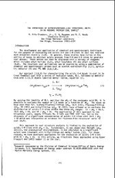
The effect <strong>of</strong> soaking temperature on <strong>liquefaction</strong> was compared at 200°C and at<br />
350°C. Illinois no. 6 coal was liquefied at 430°C for 1 h after soaking at these<br />
temperatures. The yields <strong>of</strong> TS were the same for these runs, but the yields <strong>of</strong> ToS and<br />
CyS were 5% higher for the samples soaked at 350°C than for that at 200°C. The coal was<br />
mildly refluxed in pyridine for 24 h, followed by the removal <strong>of</strong> the solvent, and liquefied<br />
at 430°C. The conversion was compared to that liquefied under the same condition but<br />
using the raw coal. The yield <strong>of</strong> CyS increased about 10% by soaking in pyridine. Other<br />
related results are available. An increase in conversion at 427°C was observed when a<br />
mal/coal liquid mixture was soaked at 277-322°C for 10 min'. Preswelling with THF and<br />
tetraammoniumhydroxide, followed by removal <strong>of</strong> solvents, enhanced hydro<strong>liquefaction</strong><br />
yields at Wde6. These results show that disintegrated <strong>coals</strong> lead to high conversions in<br />
<strong>liquefaction</strong>.<br />
Optimum temperature <strong>of</strong> the high temperature soaking was around 350°C as shown<br />
in klgue 1. However, the CyS (or oil) yield was still low (35%) at 350°C. The two-step<br />
wise soaking was further tested to increase an oil yield. Soaking at 35OoC, followed by<br />
soaking at W C, gave the 50% oil yield (Run 10 in Figure 2), but soaking at 2oo°C,<br />
followed by soaking at 400aC, was not effective and led to the yield <strong>of</strong> more than 100%<br />
482
ecause <strong>of</strong> incorporation <strong>of</strong> the coal liquid used as a solvent (Run 11).<br />
The effect <strong>of</strong> radical initiators on the high-temperature soaking and <strong>liquefaction</strong><br />
were investigated in the recent works7*'. Although it has widely been accepted that radicals<br />
cause retrograde reactions, the addition <strong>of</strong> radical initiators did not have the expected<br />
negative effect and the slightly positive effect in the high-temperature soaking (350-400"C).<br />
The addition <strong>of</strong> H,O, at the high-temperature soaking increased the 5% oil yield under low<br />
pressure hydrogen gas (Run 12)'. The addition <strong>of</strong> small amount <strong>of</strong> water alone gave the<br />
similar change in conversion in the high-temperature soaking. Therefore, a small amount<br />
<strong>of</strong> water or hydrogen peroxide solution may be added to improve the high-temperature<br />
soaking.<br />
The two-step high-temperature soaking at 350°C and 400°C gave the 50% <strong>of</strong><br />
cyclohexane solubles as shown above. This implies that slow heating is better than fast<br />
heating on coal conversion. The autoclave was heated up relatively slowly (at 8°C mid).<br />
The effect <strong>of</strong> heating rate, therefore, was investigated using the microreactor which was<br />
relatively fast heated up in the sand bath. The reactor was heated from room temperature<br />
to 430°C in 0.5 h and held at 430°C for 2 h (Run 13). For Run 14, the mixture was reacted<br />
under the same condition, but heated with a step-wise heating before reaction (at 350°C<br />
for 0.5 h and at 400°C for 0.5 h), and then held at 430°C for 1 h. The total heating-up time<br />
from room temperature to 35WC, from 350°C to 400°C and from 400°C to 430°C was 0.5<br />
h. So, the total residence time including heating-up was 2.5 h. For Run 15, the mixture<br />
was slowly heated from 130°C to 430°C and held at 430°C for 1 h. The total duration <strong>of</strong><br />
heating-up and reaction time was also controlled to 2.5 h. Although the coal was reacted<br />
at 430°C for the longest time for Run 13, coal conversion was the lowest among three<br />
Runs. The oil yield was enhanced about 10% by these programmed heatings. These<br />
results shows that the programmed heating or step-wise high-temperature soaking was<br />
important for coal conversion. Song et aL9 recently reported the effect <strong>of</strong> the temperature-<br />
programmed <strong>liquefaction</strong> <strong>of</strong> low rank <strong>coals</strong>. Montana sub<strong>bituminous</strong> coal was converted<br />
to 5-10% more (THF solubles) by slow heating compared to rapid heating.<br />
Coal f.lctionr and liquefactwn<br />
Another important factor to decrease a gas yield is suggested on the basis <strong>of</strong> the<br />
associated molecular nature <strong>of</strong> coal. Hydrocarbons with lower molecular weight generally<br />
produce more gas by thermal pyrolysis. Hydrocarbons with higher molecular weight will<br />
be decomposed under more severe conditions under which more gas will be produced from<br />
hydrocarbons with lower molecular weight. The associated structural model <strong>of</strong> coal can be<br />
regarded as material with broad molecular weight distribution. Therefore, coal with<br />
different molecular weight should be treated separately, if possible.<br />
A low molecular weight fraction may be separated after dissolution <strong>of</strong> coal, and a<br />
remaining high molecular weight fraction may selectively be liquefied. Here, pyridine<br />
solubles and insolubles were separately liquefied to compare their conversions under the<br />
same condition (Runs 16 and 17). Approximately the same oil yield was obtained from<br />
pyridine solubles and insolubles (Figure 3). Furthermore, cyclohexane insolubles from Run<br />
10 was examined. The 50% oil yield was obtained even from this fraction (Run 18).<br />
The <strong>liquefaction</strong> characteristics <strong>of</strong> @e soluble and insoluble components has recently<br />
483<br />
.
I<br />
been reviewed and studied''. The dissolution and hydrogen consumption rates <strong>of</strong> a pyridine<br />
extracted coal and a whole coal were similar for West Kentucky coal (80% carbon, daf)".<br />
Whereas, a significant decrease in <strong>liquefaction</strong> conversions was observed when a coal was<br />
extracted with pyridine for Illinois no. 6 coal". Waninski and Holder" found the<br />
retrogressive behavior in conversion for pyridine extract part <strong>of</strong> Illinois no. 6 coal.<br />
Although it is difficult to conclude the effect <strong>of</strong> the soluble and insoluble components fmm<br />
these results, it seems that the reactivity <strong>of</strong> residues or high molecular weight components<br />
is not so poor as that <strong>of</strong> low molecular weight components.<br />
The assmiutd molecular nature and liipefactwn<br />
It was shown that a large portion <strong>of</strong> coal can be dissolved by the high-temperature<br />
soaking in the coal liquid, and the programmed or step-wise heating is preferred to enhance<br />
an oil yield. The highly dissolved coal was liquefied to a larger extent. Further, it was<br />
suggested that coal with a broad molecular weight distribution should be separated into an<br />
oil fraction after dissolution, and that only residue should be liquefied at the following step.<br />
From these results, a new concept is proposed to increase an oil yield and decrease a gas<br />
yield as shown in the block diagram (Figure 4). Coal is soaked in a recycle oil at 350°C and<br />
at 400°C. Gas and oil are recovered by vacuum distillation, and the bottom fraction is fed<br />
to a <strong>liquefaction</strong> section and liquefied under low pressure hydrogen at a relatively low<br />
temperature.<br />
The proposed procedure was tested using an autoclave. The DECS-2 coal was<br />
soaked in the coal liquid under nitrogen at 350°C and at 400°C for 1 h, respectively. The<br />
oil fraction was extracted with cyclohexane, and the cyclohexane insoluble portion was<br />
liquefied under low pressure <strong>of</strong> hydrogen (2.8 MPa) at 430°C for 1 h (Run 20). For<br />
comparison, the coal was soaked in the coal liquid at 200°C for 1 h, and then the mixture<br />
was liquefied under the same condition for 2 h (Run 19). In these Runs, gas yields were<br />
analyzed. Figure 5 shows these results. It is notable that the CyS (or oil) yield increased<br />
30% and the gas yield decreased 15%.<br />
DECS-8 (sub<strong>bituminous</strong>) coal was also examined with the same procedure. As the<br />
ionic forces are relatively strong and abundant in low rank <strong>coals</strong>', it is an important step<br />
to weaken the ionic forces before the high-temperature soaking. Although it has been<br />
known that acid washing enhances the conversion <strong>of</strong> low rank the details on acid<br />
washing have not clearly been explained. Here, 2N HCl washin2 was used to weaken the<br />
ionic forces in the coal before the high-temperature soaking. The coal was soaked in the<br />
coal liquid at 35OOC and at 400°C for 1 h, respectively. Cyclohexane insolubles from the<br />
soaked coal was similarly liquefied at 430°C for 1 h (Run 22). As the acid washed coal was<br />
dried, the dried DECS-8 coal was soaked at 200°C for 1 h and then liquefied at 430°C for<br />
2 h for comparison (Run 21). Again, more than 30% increase in the oil yield and 20%<br />
decrease in the gas yield was observed by the procedure (Figure 5).<br />
CONCLUSIONS<br />
An improved coal <strong>liquefaction</strong> concept was reinvestigated for the current two-stage process<br />
on the basis <strong>of</strong> the associated molecular nature <strong>of</strong> coal. Since a significant portion <strong>of</strong> coal<br />
molecules are physically associated as pointed in our recent paper, physical dissolution<br />
484
should be considered more. The step-wise high-temperature soaking was a simple and<br />
effective method for coal dissolution. Larger dissolution made <strong>liquefaction</strong> severity lower.<br />
Broad molecular weight distribution in the associated coal was another important factor.<br />
The selective reaction <strong>of</strong> fractions with high molecular weight which were isolated after the<br />
high-temperature soaking made gas yield lower. Tests with using an autoclave by the<br />
concept shown in Figure 5 enabled to produce 30% more oil and 1520% less gas yields.<br />
It is expected that the procedure will result in great cost down in coal <strong>liquefaction</strong>.<br />
ACKNOWLEDGEMENT<br />
This work was supported by the U.S. Department <strong>of</strong> Energy under Contract DEAC22-<br />
91Pc91041.<br />
REFERENCES<br />
1<br />
2<br />
3<br />
4<br />
5<br />
6<br />
7<br />
8<br />
9<br />
10<br />
11<br />
12<br />
13<br />
14<br />
15<br />
16<br />
Nishioka, M. Fuel 1992,71,941<br />
Nishioka, M., Gebhard, L. and Silbernagel, B. G. Fuel 1991, 70, 341<br />
Gollakota, S. V., Lee, J. M. and Davies, 0. Fuel Roc. Tech. 1989, 22, 205<br />
Wham, R. M. Fuel 1987,66,283<br />
Joseph, J. T. Fuel 1991, 70, 139<br />
Joseph, J. T. Fuel 1991, 70,459<br />
Nishioka, M., Laird, W. and Bendale, P. Fuel submitted<br />
Nishioka, M. and Laird, W. Fuel submitted<br />
Song, C., Schobert, H. H. and Hatcher, P. G. Energv & Fueh 1992, 6, 328<br />
Waninski, R. P. and Holder, G. D. Fuel 1992, 71, 993<br />
Whitehurst, D. D., Farcasiu, M., Mitchell, T. 0. and Dickert, J. J. Jr. Electric Power<br />
Research Institute Report EPRI AF-480, Palo Alto, CA, 1077, pp. 74-7-10<br />
Seth, M. PhD Thesis University <strong>of</strong> California Berkeley, Berkeley, CA, 1980<br />
Schafer, H. N. S. Fuel 1970,49, 197<br />
Mochida, I., Shimohara, T., Korai, Y., Fujitsu, H. and Takeshita, K Fuel 1983, 62,<br />
659<br />
%no, M. A, Solomon, P. R., Kroo, E., Bassilakis, R., Malhotra, R. and McMillen,<br />
D. Am. Chem. Soc. Div. Fuel Chon. Repr. 1990,35(1), 61<br />
Joseph, J. T. and Rorrai, T. R. Fuel 1992, 71, 75<br />
485
c.<br />
F<br />
9<br />
rr<br />
5 Y<br />
b<br />
-<br />
B<br />
c<br />
c<br />
c<br />
X<br />
W<br />
i<br />
20<br />
40<br />
30<br />
10 0 d<br />
0 326 360 376<br />
Temperature (OC)<br />
Figure 1 The effect <strong>of</strong> soaking temperature on extractability (DECS-2 coal, 0.35 MPa Na<br />
1.5h)<br />
1 4 ~ r<br />
Run no.<br />
0 cys I ToS-CyS<br />
TS-ToS El TI<br />
Figure 2 The effect <strong>of</strong> stepwise soaking on extractability for DECS-2 caal under N2<br />
except for Run 12 (Conditions: Run 10; 350"C(lh)/430"C(lh), Run 11;<br />
WC(lh)/430"C(lh); Run 12; 350°C(lh)/4300C(lh) with H,O, (3000 ppm) and H, (1.4<br />
Ma), Run 13; 430°C(2.5h), Run 14; 350"C(O.Sh)/4(#PC(0.5h)/4WC(lh), Run 15; 130°C<br />
to 430°C at 3.5"C mid. followed by 4WC(lh))<br />
486
17 18<br />
Run no.<br />
0 cys I ToS-CyS<br />
TS-ToS TI<br />
Figure 3 Coal fractions and their conversions at 430°C for 1 h with 2.8 MPa <strong>of</strong> H, ((Run<br />
16; DEeS-2/F’S, Run 17; DECS-2/PI, Run 18; Cyclohexane insolubles from Run 10)<br />
I<br />
Flgure 4 Block diagram <strong>of</strong> the proposed coal <strong>liquefaction</strong> concept<br />
487
c1 F<br />
0<br />
z j<br />
3<br />
Y<br />
100<br />
90<br />
80<br />
70<br />
=I<br />
60<br />
I 30<br />
I I I<br />
Run no.<br />
I Gas 0 cys I ToS-CyS<br />
mm0 TS-ToS S TI<br />
Figure 5 Coal conversion by the proposed procedure for DECS-2 coal (Runs 19 and 20)<br />
and DES8 coal (Runs 21 and 22) (Run 19; 200"C(lh)/430"C(2h), Run 20, calculation<br />
from Runs IO and 18, Runs 20 and 21 under the same conditions as Runs 19 and 20, see<br />
the text in detail)<br />
488
INTRODUCTION<br />
Effects <strong>of</strong> Thermal and Solvent Pretreatments<br />
on the Elastic Properties <strong>of</strong> Coal<br />
Yongseung Yun and Eric M. Suuberg<br />
Division <strong>of</strong> Engineering, Brown University<br />
Providence, RI 02912<br />
(Keywords: Elastic property, Dynamic Mechanical Analysis, Pretreatment)<br />
It is now well established that thermal pretreatment in a range <strong>of</strong> temperatures lower than those needed<br />
for pyrolysis can significantly affect the penemability and swellability <strong>of</strong> <strong>coals</strong>. This suggests that<br />
judicious use <strong>of</strong> heat together with effective swelling solvents for coal, can affect mass transport <strong>of</strong><br />
reagents or catalysts into or out <strong>of</strong> the coal, during the early stages <strong>of</strong> <strong>liquefaction</strong>.<br />
The present study is concerned with the effects <strong>of</strong> heatholvent pretreatments on the elastic<br />
constants <strong>of</strong> the coal network structure. This, in turn, tells one about how the non-covalent<br />
interactions in coal are being broken down. Studies <strong>of</strong> the elastic properties <strong>of</strong> coal are nothing new<br />
[e.g. 1-10]. Because <strong>of</strong> the compressibility <strong>of</strong> coal, the application <strong>of</strong> mercury porosimetry to pore<br />
characterization in coal has involved careful corrections, so that the actual pore size dismbution could<br />
be calculated [ 1.1 1,121. However, the limitation caused by compressibility <strong>of</strong> bulk coal structure can<br />
be an advantage in revealing the structural changes during pretreatment processes and in establishing a<br />
suitable elastic model for macromolecular coal structure.<br />
It is known that dynamic mechanical methods are ca. 1000 times more sensitive for detecting<br />
molecular relaxations such as the glass transition temperature, Tg, than are differential scanning<br />
calorimetry (DSC)/differential thermal analysis (DTA) techniques [13]. Weller and Wert [7-101 have<br />
extensively applied the torsion pendulum technique, one <strong>of</strong> the dynamic mechanical methods, for<br />
elucidating the elastic properties <strong>of</strong> coal in the temperature range below 200 'C. They employed square<br />
rods cut from whole coal. Since the relevant temperature range for the structural relaxation by heat is<br />
generally higher than 200OC. we decided to study the thermal structural relaxation at temperatures<br />
higher than 2M°C by employing dynamic hechanical analysis (DMA). This technique involves<br />
constant amplitude oscillation <strong>of</strong> the solid to determine stress-strain properties.<br />
EXPERIMENTAL<br />
A DuPont 982 DMA was employed for mechanical analysis. A detailed description <strong>of</strong> the equipment<br />
has been given elsewhere L13.141. The sample for the DMA was prepared by pressing the as-received<br />
coal powder (-100 mesh) obtained from the Argonne Premium Sample Bank with a press normally<br />
used for making FTIR sample pellets, at 15 kpsi for 6-12 hr, which results in a sample <strong>of</strong> ca. 4 mm<br />
thickness with 12.8 mm diameter.<br />
Slippage <strong>of</strong> the samples from the clamps inside the DMA, especially during oscillation in the high<br />
temperature range (>300"C), was noted to be a main cause for irreproducibility. and special care was<br />
taken to make certain that the sample was tightly clamped. The pelletizing process used here clearly<br />
creates a solid tablet <strong>of</strong> different macroscopic mechanical properties than the original solid. The choice<br />
to work with samples prepared in this way was dictated by a desire to continue to use the Argonne<br />
Premium Coal Samples, that are generally only available in powdered form. The gross macroscopic<br />
489
mechanical properties <strong>of</strong> such pellets, e.g. tensile modulus, will clearly be different from those <strong>of</strong> a<br />
sample prepared, for example, by cutting a chunk from a virgin block <strong>of</strong> coal. In fact, any samples cut<br />
directly from coal could still be subject to naturally occurring heterogeneities in the coal, and thus<br />
mechanical properties are in that case still subject to large variations, depending upon the nature <strong>of</strong> the<br />
tests. This is not important for present purposes, because our goal is not to make use <strong>of</strong> macroscopic<br />
mechanical properties. Rather, we are here only interested in changes on the molecular level that<br />
manifest themselves as -in a particular property.<br />
For purposes <strong>of</strong> comparison, we examined the changes revealed by DMA in the context <strong>of</strong> changes<br />
earlier noted using thermal techniques, such as DSC and solvent swelling techniques. The detailed<br />
procedures for obtaining DSC and solvent swelling results have been reported earlier [15,16].<br />
RESULTS AND DISCUSSION<br />
Raw DMA results are obtained as the frequency <strong>of</strong> oscillation and the damping signal. The frequency<br />
<strong>of</strong> oscillation is directly related to an elastic modulus <strong>of</strong> the sample, whereas the energy needed to<br />
maintain constant amplitude oscillation is a measure <strong>of</strong> damping within the sample [14]. Normally, the<br />
modulus is resolved into storage and loss moduli. The storage modulus corresponds to the perfectly<br />
elastic component whereas the loss modulus represents the perfectly viscous component. The<br />
dimensionless ratio <strong>of</strong> loss/storage components is defined as the damping factor, tan 6.<br />
The tensile storage modulus, in absolute value, is comparable to what might be encountered in<br />
some polymer samples. We caution against placing too much emphasis on this absolute value,<br />
because <strong>of</strong> the issues related to pressing samples from powder. Instead, it is features that are clearly<br />
visible in the tan 6 or loss modulus spectra that are <strong>of</strong> significance. It is the changes in storage<br />
modulus E’ and loss modulus E”, and their ratio, tan 6 = WE/ that convey significant information<br />
about microscopic change in the material being tested. Both EN and tan 6, for example, are used to<br />
reveal glass transitions as maxima in the spectra. Physically, E/ represents the elastic energy storage<br />
capacity <strong>of</strong> the material, whereas E// represents the energy lost as heat due to dissipation. Many other<br />
transitions, in addition to a glass transition, can cause changes in EN. Thus this parameter is a sensitive<br />
indicator <strong>of</strong> a change in the ability <strong>of</strong> molecular segments to move, relative to one another. It is this<br />
property we choose to focus on here. It should be also be emphasized that in a transition, such as a<br />
glass transition, the storage modulus will normally show a slow continuous decline, whereas the loss<br />
modulus (and thus tan 6) will show a distinct peak. This is what makes use <strong>of</strong> this modulus preferable<br />
for detecting transition.<br />
In Figure 1, the first transition is seen near 6OoC, for different samples <strong>of</strong> wet, as-received<br />
Pittsburgh high volatile <strong>bituminous</strong> coal. This transition is normally not visible in DSC, because it is<br />
buried beneath the water evaporation peak. The position <strong>of</strong> this peak is sensitive to the presence <strong>of</strong><br />
moisture, as is seen from Figure. 2. This behavior is typical <strong>of</strong> the effects <strong>of</strong> a “plasticizing agent” in a<br />
polymer. The molecular motions <strong>of</strong> the coal chains are enhanced at low temperatures when water is<br />
present, and internal hydrogen bonding <strong>of</strong> the coal itself is suppressed by the opportunity to hydrogen<br />
bond with a solvent (in this case, water).<br />
The large peak that is revealed by tan 6 above 200OC coincides with a transition shown both by<br />
DSC analysis <strong>of</strong> this coal and by a change in tetrahydr<strong>of</strong>uran (THF) swellability (see Figure 3). This<br />
uansition involves an irreversible relaxation <strong>of</strong> the coal structure [16,17].<br />
Figure 4 illusuates the behavior <strong>of</strong> Upper Freepon medium volatile <strong>bituminous</strong> coal in DMA. The<br />
tensile storage modulus exhibits a continuous decline with temperature, except for two regions <strong>of</strong> more<br />
490
apid decline in modulus. The loss modulus, and thus tan 6, both suggest that there is a low<br />
temperature event, again probably associated with moisture in the coal, at below loO°C. The main<br />
relaxation <strong>of</strong> structure starts to occur from 24OoC, as observed in both tensile storage modulus and tan<br />
6. This observation augments the DSC and solvent swelling results (see Figure 5) for the same coal,<br />
in that Upper Freeport coal showed the characteristics <strong>of</strong> a relaxed coal structure such as increased<br />
swellability in solvents and endothermic peak. In the DSC, the coal exhibited a distinct endothermic<br />
peak centered around 350°C which was started from around 310°C. whereas solvent swellability<br />
increased significantly above 250'C. It is thus confimed by DMA that solvent swelling is a more<br />
sensitive indicator <strong>of</strong> irreversible shuctural relaxation than is DSC.<br />
CONCLUSIONS<br />
Two <strong>bituminous</strong> <strong>coals</strong> were subjected to DMA analysis and the results were compared our earlier<br />
reported DSC and solvent swelling results. Results from different techniques appear to point to the<br />
same basic conclusions with regard to transitions, although there are subtle differences between the<br />
resqlts <strong>of</strong> different techniques. The transition related to coal moisture is more visible in DMA and<br />
solvent swelling techniques than in DSC analysis. DMA confirms that solvent swellability is a more<br />
sensitive index <strong>of</strong> macromolecular changes than is DSC. The importance <strong>of</strong> observations made by<br />
several different techniques in order to discern transitions accurately has been noted. This study<br />
confirms the usefulness <strong>of</strong> applying different techniques simultaneously for this purpose.<br />
We noticed that good reproducibility in DMA depends upon the reproducibility <strong>of</strong> forming pellets,<br />
in our case. A main problem was small cracks generated while the pellet was released from the press.<br />
We are further pursuing rhese problems in order to obtain a better description <strong>of</strong> transitions and elastic<br />
properties <strong>of</strong> coal.<br />
ACKNOWLEDGEMENTS The work reported here was financially supported by the Department<br />
<strong>of</strong> Energy Conmct No. DE-AC22-91PC91027 and grant DE-FG22-90PC90308.<br />
REFERENCES<br />
1. Van Krevelen, D.W. In Coal; Elsevier, New York, 1981; Chapter XX.<br />
2. Hiorns, F.J. Fuel 1953,32, 113.<br />
3. Terry, N.B. Fuel 1958,37, 309.<br />
4. Morgans, W.T.A.; Terry, N.B. Fuel 1958,37,201.<br />
5. Hall, P.J.; Marsh, H.; Thermas, K.M., unpublished results, University <strong>of</strong> Newcastle-Upon-Tyne,<br />
1988.<br />
6. Brenner, D. Prepr. Pap.-Am. Chem. Soc., Div. Fuel Chem.1986, 31fI). 17.<br />
7. Weller, M.; Wen, C. Fuel 1984.63, 891.<br />
8. Wert, C.A.; Weller, M.; Caulfield, D. J. Appl. Phys. 1984,56(9), 2453.<br />
9. Wert, C.A.; Weller, M. J. Appl. Phys. 1982,53(10), 6505.<br />
10. Weller, M; Wert, C. Int. Con$ on Coal Science 1987,65.<br />
11. Toda, Y.; Toyoda, S. Fuel 1972,51, 199.<br />
12. Debelak, K.A.; Schrodt, J.T. Fuel 1979,58,732.<br />
13. Wetton, R.E. Polymer Testing 1984.4, 117.<br />
14. Gill, P.S.; Lear, J.D.; Leckenby, J.N. Polymer Testing 1984.4, 131.<br />
15. Yun, Y.; Suuberg, E.M. Prepr. Pap.-Am. Chem. SOC., Div. Fuel Chem . 1992,37(2 ), 856.<br />
16. Yun, Y.; Suuberg, E.M. Fuel 1993, in press.<br />
17. Yun, Y.; Suuberg, E.M. Energy & Fuels 1992.6, 328.<br />
491
0.a<br />
. .<br />
Temperamure ('C)<br />
Figure 1. Tan 6 DMA spectra obtained from 4 OUinin scans <strong>of</strong> as-received and predried (up to<br />
200OC at 4 OC/min) Pittsburgh No. 8 coal pellet samples. Pellets were. made from -100 mesh<br />
powder aftex pressed at 15 kpsi for the duration as specified in the figure.<br />
Figure 2. Effect <strong>of</strong> sample drying on tensile loss modulus obtained at 4°C/min for Pittsburgh<br />
No. 8 coal. Sample pellets were made from -100 mesh powder pressed at 15 kpsi for 10 hr.<br />
492<br />
t
-0.01-<br />
. 04<br />
5 -0.03-<br />
E<br />
6 -0.0s-<br />
c)<br />
6<br />
Y<br />
0 .- c)<br />
d<br />
.-<br />
-<br />
0)<br />
3.0 -<br />
3 1.5v1<br />
h<br />
12it<br />
Y<br />
m 9-<br />
8<br />
J 6-<br />
m<br />
2<br />
Pyridine<br />
(b) Solvent swelling<br />
1.0- ' 1 ' 8 . I , I .<br />
15<br />
3-<br />
2nd.3rd<br />
1st-2nd<br />
lstdrd<br />
0 100 200 300 400 500<br />
Temperature ("C)<br />
Figure 3. Difference DSC thermograms as well as pr<strong>of</strong>iles <strong>of</strong> solvent swelling ratio and weight<br />
loss obtained at 8 "Umh from -100 mesh Pittsburgh No. 8 coal powder (swelling time:a 5 hr.0,<br />
1 day;., 2 days;A,4 days;o,S days;m,6 days).<br />
493
soL-.--.+-.-.-< : . . . .---+..<br />
40 80 120 IBO 200 210 280 120 ltlo 400 440<br />
Temperature ("C)<br />
0.32-<br />
2 1<br />
'' 3<br />
32n.. 2. I<br />
0.20.. 22 f<br />
0.18. 21<br />
0.12. 20<br />
Figure 4. DMA scan <strong>of</strong> the Upper Freeport medium volatile <strong>bituminous</strong> coal obtained at<br />
4'C/min. Sample pellet was made from -100 mesh powder pressed at 15 kpsi for 12 hr.<br />
01<br />
4.01<br />
4.03<br />
E 4.05<br />
Zmddrd<br />
In-2nd<br />
1sb3rd<br />
1 (a) Difference DSC<br />
4.09 '<br />
1 (b) Solvent swelling<br />
'.O 1 /a<br />
Pyridim , .,I , s<br />
z 4.07<br />
c<br />
(c) Weight loss<br />
0 100 100 300 400 3<br />
Temperature ("C)<br />
494<br />
0<br />
I<br />
Figure 5. Difference DSC thermograms<br />
as well as pr<strong>of</strong>iles <strong>of</strong> solvent swelling<br />
ratio and weight loss obtained at 8'Umin<br />
from -100 mesh Upper Freeport coal<br />
powder (swelling time:0,5 k,O, 7 days).
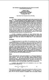
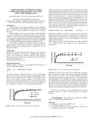
Assessment <strong>of</strong> Small Particle Iron Oxide Catalyst<br />
for coal Liquefaction<br />
Richard Anderson, Edwin N. Givens and Frank Derbyshire<br />
University <strong>of</strong> Kentucky Center for Applied Energy Research<br />
3572 Iron Works Pike, Lexington, KY 40511-8433<br />
Keywords: Coal <strong>liquefaction</strong>, iron oxide, catalysis<br />
Introduction<br />
Current efforts to lower the cost <strong>of</strong> producing coal liquids are<br />
concentrated on the use <strong>of</strong> low-rank coal feedstocks, and dispersed<br />
catalysts to promote coal dissolution in the first stage <strong>of</strong> a two-stage<br />
process. Molybdenum and iron are the most commonly investigated<br />
catalyst metals, and precursors <strong>of</strong> both can be converted to an active<br />
sulfide catalyst under <strong>liquefaction</strong> conditions.' Although iron<br />
catalysts are less active, they are preferred for reasons <strong>of</strong> economy.<br />
A great deal <strong>of</strong> research has been spent in attempting to understand the<br />
chemistry <strong>of</strong> <strong>liquefaction</strong> in the presence <strong>of</strong> iron catalysts. It has<br />
also been demonstrated that the use <strong>of</strong> powdered iron catalysts has<br />
allowed the <strong>liquefaction</strong> <strong>of</strong> sub<strong>bituminous</strong> <strong>coals</strong> which could not<br />
otherwise be processed'. Nevertheless, the activity <strong>of</strong> these catalysts<br />
is still much less than desired and means to enhance their activity are<br />
under investigation.<br />
The catalyst activity is determined principally by its composition and<br />
the extent <strong>of</strong> its dispersion with the coal or coal-solvent slurry. The<br />
catalyst dispersion is dependent upon the form and mode <strong>of</strong> addition <strong>of</strong><br />
the catalyst precursor. High activities are reportedly favored by<br />
catalysts introduced as oil-soluble organometallic precursors such as<br />
naphthenates and carbonyls. 3s4s The results <strong>of</strong> some studies, however,<br />
indicate that even with these precursors, quite large crystallites or<br />
agglomerates can be formed during <strong>liquefaction</strong> and hence the<br />
potentially high dispersion is not maintained. There is some evidence<br />
to suggest that, if introduced as fine particulates, there is less<br />
tendency for agglomeration. Iron particles <strong>of</strong> about 50 nmmean diameter<br />
synthesized by a flame pyrolysis technique appeared to have retained<br />
their particle size and shape during presulfiding and coal<br />
<strong>liquefaction</strong>.'.' Other work has shown that FeS is more active as a<br />
colloid than in powder form.' A number <strong>of</strong> studies have reported<br />
enhanced catalytic activity by using methods <strong>of</strong> preparation that<br />
introduce nanometer size iron catalysts .9*10J1,12<br />
The work presented in this paper is concerned principally with a<br />
systematic evaluation <strong>of</strong> the effect <strong>of</strong> reaction parameters on the<br />
catalytic conversion <strong>of</strong> a sub<strong>bituminous</strong> coal using a commercially<br />
produced nanometer size iron oxide catalyst. The work is part <strong>of</strong> a DOE<br />
program to evaluate process concepts that can alone, or in concert,<br />
significantly improve process economics. In order to make realistic<br />
assessments, studies have been made using process recycle oil from the<br />
Wilsonville Advanced Coal Liquefaction Research and Development<br />
Facility and Black Thunder sub<strong>bituminous</strong> coal.<br />
Materials<br />
Reasents - Reagents were purchased as follows: Practical grade dimethyl<br />
disulfide (DMDS) from Fluka AG; 99% purity W grade tetralin, high<br />
purity tetrahydr<strong>of</strong>uran (THF), and high purity pentane were Burdick &<br />
Jackson Brand from Baxter S/P; UHP 6000W hydrogen was supplied by Air<br />
Products and Chemicals, Inc. Coal, coal derived liquids and iron oxide<br />
used at the Wilsonville Advanced Coal Liquefaction Research and<br />
Development Facility were supplied by CONSOL, Inc.<br />
495
- Black Thunder sub<strong>bituminous</strong> coal was ground to -200 mesh,<br />
riffled and stored under nitrogen at 4OC in a refrigerator.<br />
Recvcle oil - A reconstituted recycle oil was used in this program that<br />
had been produced at Wilsonville in runs where the plant was in the<br />
distillate production mode with all residual materials being recycled<br />
to extinction except for the organic matter occluded in the ash<br />
reject.13 The Wilsonville recycle oil, taken from Run 262 while<br />
operating on Black Thunder Coal, contained 43.8 wt% 1050°F- distillate,<br />
36.6 wt% residual organic material, 9.2 wt% cresol insolubles and 10.4<br />
wt% ash.<br />
The fractions that were used to form the recycle oil contained<br />
significant concentrations <strong>of</strong> both molybdenum and iron which were being<br />
added as catalysts in Run 262. The ashy resid contained 3.3 wt% iron<br />
plus 300 ppm molybdenum. The distillate contained only 200 ppm <strong>of</strong> iron<br />
and 2 ppm <strong>of</strong> molybdenum. It is assumed that these metals possess some<br />
indeterminate residual catalytic activity. However, in this research,<br />
these effects are integrated into the '@thermal@@ baseline.<br />
Catalysts - Two iron oxide catalyst precursors were used in this study.<br />
One was a sample <strong>of</strong> the iron oxide used at Wilsonville in Run 262 (WIO)<br />
while the other was a sample <strong>of</strong> superfine iron oxide (SFIO) provided<br />
by MACH I, Inc., Xing <strong>of</strong> Prussia, Pennsylvania. The latter has a bulk<br />
density 1126th that <strong>of</strong> the WIO (.052 vs. 1.37 glml), and a very high<br />
surface area (318 vs. 9 m2/g for WIO).<br />
Experimental<br />
Eauioment and Procedures - In a typical experiment 3 grams <strong>of</strong> coal,<br />
5.4 grams <strong>of</strong> recycle oil, catalyst and DMDS (2.4 moles S/mole Fe added<br />
as catalyst) were added to the reactor. The reactor was sealed,<br />
pressurized with hydrogen to 1000 psig, and leak tested. Reactions<br />
were carried out in a fluidized sandbath set at the specified<br />
temperature while the reactor was continuously agitated at a rate <strong>of</strong><br />
400 cycles per minute. At the termination <strong>of</strong> the reaction period, the<br />
reactor was quenched to ambient temperature in a room temperature sand<br />
bath. The gaseous products were collected and analyzed by gas<br />
chromatography. A solvent separation technique, which is described in<br />
detail elsewhere,14 was used to separate both reactants and products.<br />
The solid-liquid products were scraped from the reactor using THF and<br />
the mixture was extracted in a Soxhlet apparatus for 18 hours. The THF<br />
insoluble material, which was comprised <strong>of</strong> IOM and ash, was dried<br />
(80°C/25 mm Hg) and weighed. The THF solubles were concentrated by<br />
removing excess THF in a rotary evaporator to which a 50:l excess<br />
volume <strong>of</strong> pentane was added to precipitate the preasphaltenes and<br />
asphaltenes (PA+A). The mixture was placed in an ultrasonic bath for<br />
3 minutes to facilitate the precipitation process before filtering <strong>of</strong>f<br />
the PA+A. The PA+A fraction was dried and weighed. This then<br />
separates the product into oils, PA+A and IOM plus ash.<br />
Material Balance and Product Yield Comoutational Methods - The<br />
calculation <strong>of</strong> the yield <strong>of</strong> products differs somewhat from those<br />
reported elsewhere, in that the feed is comprised <strong>of</strong> the multiple<br />
individual Wilsonville recycle oil fractions in addition to coal and<br />
catalyst. The product distribution was determined using this same<br />
fractionation scheme assuming complete recovery <strong>of</strong> the ash plus<br />
catalyst. In this method the iron is presumed to convert to pyrrhotite<br />
and the weight <strong>of</strong> catalyst reporting to the ash fraction is calculated<br />
as the corresponding weight <strong>of</strong> Fe,,S. By this method water produced<br />
during <strong>liquefaction</strong> is included in the oils fraction. Experimentally,<br />
complete recovery <strong>of</strong> ash and catalyst was demonstrated. Net product<br />
496
yields are calculated by subtracting the amount <strong>of</strong> material contained<br />
in the feed fractions from the corresponding amounts found in the<br />
product fractions. The total <strong>of</strong> the net products equals the amount <strong>of</strong><br />
maf coal in the feed and reflects the net make (or loss) <strong>of</strong> each <strong>of</strong> the<br />
solubility fractions while coal conversion equals 100 minus the yield<br />
<strong>of</strong> IOM.<br />
Emerimental Desiun - A major portion <strong>of</strong> the research reported here has<br />
been concerned with a detailed investigation <strong>of</strong> the influence <strong>of</strong> the<br />
reaction variables during coal <strong>liquefaction</strong> in the presence <strong>of</strong> added<br />
SFIO. An experimental approach was adopted that would maximize the<br />
amount <strong>of</strong> information gathered in a given series <strong>of</strong> experiments and<br />
provide a data set from which to draw valid comparisons. A full 2'<br />
factorial experimental design was developed following the method<br />
described by Box, Hunter, and Hunter.'' The main effects and<br />
interactions <strong>of</strong> reaction temperature, catalyst concentration, and<br />
sulfur concentration were determined separately for each <strong>of</strong> several<br />
dependent variables including THF conversion, hydrogen consumption,<br />
Co+CO,, hydrocarbon gas, oil and PA+A yields. This technique is<br />
particularly applicable to complex reaction systems, such as coal<br />
<strong>liquefaction</strong>, where the reaction mixture is comprised <strong>of</strong> recycle oil,<br />
which itself is a composite <strong>of</strong> three process materials, coal, catalyst<br />
and hydrogen.<br />
Because <strong>of</strong> the high concentration <strong>of</strong> metals in the recycle oil, iron<br />
oxide concentrations were selected which could have a clearly<br />
discernible effect on coal <strong>liquefaction</strong>, ranging'from 1 to 4 wt% Fe on<br />
as-fed coal. Added sulfur was selected to explore a wide range <strong>of</strong> S/Fe<br />
atomic ratios, with the centerpoint at 2:l. The reaction temperatures<br />
were 390 and 44OoC, centered at 415'C.<br />
Results<br />
ComDarison <strong>of</strong> Heaw Distillate and Recvcle oil - Liquefaction <strong>of</strong> Black<br />
Thunder Coal in Wilsonville heavy 1050'F distillate at 415'12 for 60<br />
minutes gave 95 wt% THF conversion and 35.8 wt% oil yield with the<br />
addition <strong>of</strong> 1.1 wt% iron as WIO and excess DMDS for its conversion to<br />
pyrrhotite (see Table 1). The added iron catalyst had a significant<br />
effect on THF conversion and the yield <strong>of</strong> pentane solubles. Based upon<br />
previous results, distillate would exhibit little reactivity under<br />
these conditions and would not complicate the analysis <strong>of</strong> coal<br />
reactivity . l6<br />
However, coal <strong>liquefaction</strong> in the Wilsonville recycle oil produced THF<br />
conversions which regularly exceeded 100%. In a thermal run, without<br />
any added iron oxide, the THF conversion was in excess <strong>of</strong> loo%, and the<br />
oil yield was in excess <strong>of</strong> the yields observed in the run with<br />
distillate alone. The difference between the two solvents was that the<br />
recycle oil contained ashy material taken from the vacuum flash unit<br />
at Wilsonville and a smaller amount <strong>of</strong> deashed resid taken from the<br />
ROSE-SR deashing unit. The unusually high level <strong>of</strong> THF conversion and<br />
high oil yield indicated that the recycle oil IOM was being converted<br />
to soluble product,<br />
Coal Conversion in Wilsonville recvcle oil - Liquefaction <strong>of</strong> Black<br />
Thunder coal in the Wilsonville recycle oil, without added catalyst,<br />
showed steadily increasing THF conversion, oil and gas make with<br />
increasing reaction time at 41592 (see Table 2). The increases<br />
parallel the changes in yield obtained with added 1.1 wt% iron as w10.<br />
The main effect <strong>of</strong> the catalyst was to produce a higher oil yield after<br />
60 minutes. The results are in agreement with experimental data from<br />
pilot plant runs at Wilsonville, in which the addition <strong>of</strong> sulfided iron<br />
491
oxide caused an appreciable increase in conversion. l7<br />
In both thermal and catalytic cases, the CO and C02 are formed at short<br />
times, and the yields increased only slightly between 15 to 60 minutes.<br />
In comparison, the hydrocarbon gas yield increased from 0.5 to 1.9 Wt%.<br />
Much <strong>of</strong> this increase in hydrocarbon gas yield comes from the<br />
conversion <strong>of</strong> recycle oil.<br />
Influence <strong>of</strong> Nanometer Size Iron Oxide ISFIO) - sulfided iron oxide<br />
particles in the size range 50-80 nm, that were prepared by high<br />
temperature thermal oxidation, have been reported to show high activity<br />
for coal <strong>liquefaction</strong>.6 The catalytic effect has been attributed to<br />
the high surface area and small particle size <strong>of</strong> the pyrrhotite formed<br />
upon sulfiding in the presence <strong>of</strong> coal where the pyrrhotite particles<br />
retain the small particle size <strong>of</strong> the oxide precursor.'8 The SFIO,<br />
whose very high surface area is consistent with nanometer size<br />
particles, may also, upon sulfiding, give rise to small particle, high<br />
surface area <strong>liquefaction</strong> catalysts.<br />
The addition <strong>of</strong> SFIO, at a loading <strong>of</strong> 2.5 wt% iron on maf coal,<br />
produced 11 wt% more oils than in the thermal case (see Table 3). In<br />
addition there were slight increases in THF conversion and yield <strong>of</strong><br />
hydrocarbon gases. These data represent the mid-point <strong>of</strong> the ranges<br />
for each <strong>of</strong> the three variables. The results <strong>of</strong> the comparison<br />
illustrate the potential advantage <strong>of</strong> processing with SFIO catalyst.<br />
1;- The R squared<br />
values for each dependent variable that was selected indicate the<br />
degree <strong>of</strong> fit by the linear model coefficients as shown in Table 4.<br />
Values for the coefficients for each <strong>of</strong> the simple linear models are<br />
summarized in Table 5. The P-value <strong>of</strong> each coefficient is shown in<br />
parentheses.<br />
Of the independent factors, temperature has the strongest overall<br />
effect, as seen by the magnitude <strong>of</strong> the coefficients for THF<br />
conversion, hydrogen consumption, and the yields <strong>of</strong> oil and PA+A; the<br />
oil yield increases and PA+A decreases with increasing temperature.<br />
Increasing the catalyst concentration produces moderate effects on THF<br />
conversion, hydrogen consumption, and enhances the PA+A yield.<br />
However, there is no apparent effect <strong>of</strong> catalyst concentration on oil<br />
yield. It must be stressed that only two levels <strong>of</strong> catalyst<br />
concentration have been examined and the zero concentration case is not<br />
included: as shown in Table 3, the addition <strong>of</strong> catalyst significantly<br />
improves the oil yield over the thermal case. The effects <strong>of</strong> added<br />
sulfur are small, producing a weak negative coefficient with respect<br />
to THF conversion, and a negative coefficient with oil yield.<br />
The average increase in oil yield obtained in the three centerpoint<br />
experiments was 11% over the thermal case. This is consistent with the<br />
increase <strong>of</strong> 10 wt% in oil yield predicted by the Z3 factorial design<br />
experiments and lends confidence to the linear model.<br />
The addition <strong>of</strong> 1.1 wt% added iron as WIO, which was the ratio used in<br />
the Wilsonville plant, gave 5% more oil than in the thermal case, which<br />
agrees closely with the results observed at Wilsonville.17 The linear<br />
model predicts that SFIO at the lower concentration level (1.1 wt% Fe)<br />
will produce 15% higher oil yield than in the thermal case, with a<br />
decrease to the observed 11% gain at the center point due to the effect<br />
<strong>of</strong> added sulfur (see Table 6). However, the experimental check <strong>of</strong> this<br />
predicted outcome gave only 8% more oil than the thermal case. The<br />
catalytic activity <strong>of</strong> the SFIO for both oil formation and coal<br />
498
conversion is greater than the corresponding activity <strong>of</strong> the WIO.<br />
The negative effect <strong>of</strong> sulfur on THF conversion and on oil ield was<br />
unexpected based upon the results <strong>of</strong>' DaS Gupta, et al.,' on the<br />
<strong>liquefaction</strong> <strong>of</strong> an iron deficient Indian coal. They found, through a<br />
non-linear parameter estimation procedure, that adding sulfur up to a<br />
SjFe atomic ratio <strong>of</strong> 8 improved conversion. In this system adding<br />
sulfur at a SfFe atomic ratio between 0.6 to 7.4 was detrimental. This<br />
effect could be related to adverse side reactions caused by the<br />
presence <strong>of</strong> excess sulfur.<br />
The negative interaction between temperature and SFIO concentration for<br />
oil yield indicates that thermal effects begin to dominate catalytic<br />
effects at the higher temperature. Also, in addition to thermal<br />
conversion <strong>of</strong> PA+A, the magnitude <strong>of</strong> the catalyst coefficient for the<br />
PA+A model (4.80 vs. 4.08 for THF conversion) suggests that catalytic<br />
IOM dissolution reports mainly to the PA+A fraction.<br />
References<br />
1. Derbyshire, F. J., Catalysis in Coal Liquefaction, IEACRf08,<br />
London, UK, IEA Coal Research, 1988, 69pp.<br />
2. Tomlinson, G. C., Gray, D., Neuworth, M. 8. and Talib, A.,<br />
Report SAND85-7238, Albuquerque, NM, USA, Sandia National<br />
Laboratories, 105pp.<br />
3. Hawk, C. O., Hiteshue, R. W., Hydrogenation <strong>of</strong> Coal in the<br />
Batch Autoclave. Bulletin 6322 Washington, DC, USA, US Department<br />
<strong>of</strong> the Interior, Bureau <strong>of</strong> Mines, 1965, 42pp.<br />
4. Watanabe, Y., Yamada, O., Fujita, K., Takegami, Y. and Suzuki<br />
T., Fuel, 1984, 63, 752-755.<br />
5. Suzuki, T., Yamada, O., Then, J. H., Ando, T. and Watanabe,<br />
Y., Proceedings - 1985 ICCS, Sydney, NSW, Australia, Pergamon<br />
Press, 1985, pp205-8.<br />
6. Andres, M., Charcosset, H., Chiche, P., Davignon, L., Djega-<br />
Mariadassou, G., Joly, J-P. and Pregermain, S., Fuel, 1983, 62,<br />
69-72.<br />
7. Andres, M., Charcosset, H., Chiche, P., Djega-Mariadassou, G.,<br />
Joly, J-P. and Pregermain, S., Preparation <strong>of</strong> catalysts I11 (Eds.<br />
G. Poncelet and P. Grange), Elsevier, 1983, pp675-682.<br />
8. Nakao, Y., Yokoyama, S., Maekawa, Y. and Kaeriyama, K., Fuel,<br />
1984, 63, 721.<br />
9. Cugini, A. V., Utz, B. R., Krastman, D. and Hickey, R. F., ACS<br />
Div. Fuel Chemistry Preprints, 1991, 36 (l), 91.<br />
10. Hager, G. T., Bi, X-X., Derbyshire, F. J., Eklund, P. C. and<br />
Stencel, J. M., ACS Div. Fuel Chemistry Preprints, 1991, 36 (4),<br />
1900.<br />
11. Pradhan, V. R., Tierney, J. W., Wender, I. and Huffman, G.<br />
P., Energy and Fuels, 1991, 5 (3), 497.<br />
12. Huffman, G. P., Ganguly, B., Taghiei, M., Huggins, F. E. and<br />
Shah, N., ACS Div. Fuel Chemistry Preprints, 1991, 36 (2), 561.<br />
13. Southern Electric International, Inc., Technical Progress<br />
Report, "Run 260 with Black Thunder Mine Sub<strong>bituminous</strong> Coal", DOE<br />
Contract No. DE-AC22-90PC90033 and EPRI Contract No. RP1234-1-2,<br />
Document No. DOEfPC90033-16, January 1992.<br />
14. Derbyshire, F., "Advance Coal Liquefaction Concepts for PETC<br />
Generic Bench-scale Unit', DOEjPCj91040-9, May 1992.<br />
15. Box, G. E. P., Hunter, W. G. and Hunter, J. S., Statistics<br />
for Experimenters, John Wiley and Sons, New York (1978).<br />
16. Anderson, R. R. and Bockrath, B. C., Fuel, 1984, 63, 329.<br />
17. Southern Electric International, Inc., Technical Progress<br />
Report, IIIntegrated Two-Stage Liquefaction <strong>of</strong> Sub<strong>bituminous</strong><br />
Coal", DOE contract No. DE-AC22-82PC50041 and EPRI RP1234-1-2,<br />
499
EPRI AP-5221, Final Report, June 1987, pp 3-7.<br />
18. Djega-Mariadassou, G., Besson, M., Brodzki, D., Charcosset,<br />
H., HUU, T. V. and Varloud, J., Fuel Processing Tech, 1986, 12,<br />
143-145.<br />
19. Das Gupta, R., Mitra, J. R., Dutta, B. K., Sharma, U. N.,<br />
Sinha, A. K. and Mukherjee, D. K., Fuel Proc Tech, 1991, 27, 35.<br />
Table 1. Liquefaction <strong>of</strong> Black Thunder Coal with Wilsonville<br />
oils'<br />
Distillateb Distillate Compositeb Composite<br />
Added Fe, wt$<br />
coal<br />
% Yield, maf<br />
coal<br />
none 1.1 none<br />
1.1<br />
Gases 7.3 7.3 6.9<br />
6.9<br />
Oils 24.9 35.8 48.5 53.8<br />
PA+A 54.5 51.9 52.2 45.3<br />
IOM 13.3 5.0 -7.6<br />
-6.0<br />
THF Conv, wt% 86.7 95.0 107.6 106.0<br />
Run No. 281-1 ' 169-2 139-1/<br />
167-1<br />
142-21<br />
189-1<br />
a. 415' C, 1 hour, 1000 psig H2 cold, 5.4 grams recyc e oil, 3.<br />
grams coal, 2.4 mole sulfur/mole iron.<br />
b. No DMDS added<br />
Table 2. Liquefaction <strong>of</strong> Black Thunder Coal in Wilsonville Recycle<br />
Oil'<br />
No Catalyst Added 1.1 wt% Fe Added<br />
15 min 30 min 60 min 15 min 30 min 60 min<br />
Yields, wt %<br />
HC Gases<br />
0.5 1.1 1.9 1.1 1.6 2.1<br />
co+coz<br />
4.5 5.0 5.0 4.4 4.8 4.8<br />
oils<br />
21.3 36.4 48.5 20.8 36.0 53.8<br />
PA+A<br />
57.6 56.2 52.2 58.1 59.3 45.3<br />
IOM<br />
16.1 1.3 -7.6 15.6 -1.7 -6.0<br />
Coal Conv, wt % 83.9 98.7 107.6 84.4 101.7 106.0<br />
Run Number<br />
148-2 167-2 139-1/ 176-1 169-1 189-1/<br />
167-1<br />
142-2<br />
a. 415O C, 1000 psig H, cold, 5.4 grams recycle oil, 3.0 grams coal,<br />
2.4 mole sulfur/mole Fe<br />
500
Table 3. Effect <strong>of</strong> Superfine Iron OxiUe on Liquefaction'<br />
Thermal SFIO A<br />
Iron, wt % coal None 2.5<br />
Yields, wt% maf coal<br />
HC Gases<br />
co+c02<br />
Oils<br />
PA+A<br />
1.9<br />
5.0<br />
48.5<br />
52.2<br />
2.8 0.9<br />
4.7 -0.3<br />
59.1 10.6<br />
43.3 -8.9<br />
IOM<br />
-7.6<br />
-9.9 -2.3<br />
THF Conversion 107.6 109.9 2.3<br />
Run Number 139-1/167-1 174-2/<br />
190-1/190-3<br />
a. 415'C, 1 hour, 1000 psig hydrogen cold, 5.4 grams recycle oil,<br />
3.0 grams coal, 2.0 mole sulfur/mole iron.<br />
Table 4. Dependent Variables EvaluateU<br />
Effect nnits<br />
THF Conv THF conversion, wt% maf coal<br />
m H, H2 consumption, mg/g maf coal<br />
HC Gas Hydrocarbon gas yield, wt% maf coal<br />
CO+C02 CO and C02 gas yield, wt% ma€ coal<br />
TGas Total gas yield, wt% maf coal<br />
Oils wt% maf coal<br />
PA+A wt% maf coal<br />
501<br />
R BcruareU<br />
0.926<br />
0.973<br />
0.969<br />
0.944<br />
0.961<br />
0.880<br />
0.922
Table 5. Summary <strong>of</strong> Estimated Coefficients'<br />
Inter- Tb Xb<br />
cept Coef f Coef f<br />
(PI<br />
+<br />
THF 107.40 4.54 4.08 -1.72<br />
-1.62<br />
Conv<br />
(. 003) (. 005) (. 097)<br />
mg H2 60.28 9.12 2.66<br />
-1.13<br />
(. 001) (. 014)<br />
( .097)<br />
HC Gas 3.50 1.86<br />
( .001)<br />
(.061)<br />
CO+C02 5.06 0.84<br />
-0.20<br />
( .001)<br />
( .046)<br />
TGas 8.57 2.71<br />
(. 001)<br />
Oils 58.61 13.87<br />
( .001)<br />
-12.03 4.80<br />
( .005) ( .085) L<br />
(. 169)<br />
a. All three way interaction coefficients (TxXxS) are small and set<br />
equal to zero. Coefficient estimates are for coded variables<br />
(-l,O,+l).<br />
b. T = temperature; X = wt% Fe in SFIO on coal; S = wt% sulfur in DMDS<br />
on coal; TxX = two-way interaction <strong>of</strong> temperature with wt% Fe in<br />
SFIO on coal; TxS = two-way interaction <strong>of</strong> temperature with wt%<br />
sulfur in DMDS on coal; XXS = two-way interaction <strong>of</strong> wt% Fe in SFIO<br />
with wt% sulfur in DMDS on coal.<br />
Table 6. Comparison <strong>of</strong> Wilsonville and Superfine Iron Oxide'<br />
Fe, wt % coal<br />
Yields, wt%<br />
maf coal<br />
HC Gases<br />
co+c02<br />
oils<br />
Thermal<br />
None<br />
1.9<br />
5.0<br />
48.5<br />
WIO Predictedb Experimental<br />
SFIO SFIO<br />
1.1 1.1 1.1<br />
2.1 2.6 1.2<br />
4.8 4.9 5.0<br />
53.8 63.7 56.9<br />
PA+A<br />
52.2<br />
45.3 35.1 45.1<br />
IOM<br />
-7.6<br />
-6.0 -6.3 -8.2<br />
THF COnV.<br />
107.6<br />
106.0 106.3 108.2<br />
Run Number 13 -11167-1 14 -21189-1 N/A 272-1<br />
a. 415'C. 1 hour, 1000 psig H2 cold, 5.4 grams Wilsonville recycle<br />
oil, 3.0 grams coal, 2.4 moles sulfurlmole iron.<br />
b. Predicted from model parameters. All curvature detected at the<br />
mid-range conditions is accounted for as resulting from<br />
temperature effects.<br />
502
EFFECT OF A CATALYST ON THE DISSOLUTION OF BLIND CANYON COAL<br />
Robert P. Warzinski<br />
U.S. Department <strong>of</strong> Energy<br />
Pittsburgh Energy Technology Center<br />
Pittsburgh, PA 15236<br />
Keywords: coal <strong>liquefaction</strong>, dispersed catalyst, molybdenum hexacarbonyl<br />
INTRODUCTION<br />
The use <strong>of</strong> catalysts to improve the dissolution and <strong>liquefaction</strong> <strong>of</strong> coal dates back to the<br />
1920s. Reviews in this area have been prepared by Weller (11, Derbyshire (21, and<br />
Anderson (3). Recently, interest has been renewed in using dispersed catalysts in the<br />
early phases <strong>of</strong> coal <strong>liquefaction</strong> to improve the quality <strong>of</strong> the products produced during<br />
the initial dissolution and <strong>liquefaction</strong> <strong>of</strong> coal. To facilitate the study <strong>of</strong> dispersed<br />
catalysts in laboratory-scale investigations, a particular sample <strong>of</strong> 'Blind Canyon coal<br />
(denoted DECS-17) that contains very low levels <strong>of</strong> pyrite (0.04 wt% on a moisture-free<br />
basis) has been made available by the Department <strong>of</strong> Energy through the Penn State Coal<br />
Sample Bank. Thus, complications due to inherent catalytic activity associated with<br />
pyrrhotites which can be formed from coal pyrite are eliminated and interferences to the<br />
characterization <strong>of</strong> the added catalysts due to native iron and sulfur are reduced.<br />
The purpose <strong>of</strong> this paper is to define the effects <strong>of</strong> a molybdenum-containing catalyst<br />
on the initial dissolution and conversion <strong>of</strong> the DECS-17 coal as a function <strong>of</strong><br />
temperature. To eliminate competing andlor complicating influences <strong>of</strong> added solvents,<br />
the <strong>liquefaction</strong> tests were performed in the absence <strong>of</strong> such materials. The catalytic<br />
effects on coal conversion and gas uptake were determined by subtraction <strong>of</strong> thermal<br />
data from the corresponding catalytic results at a given temperature. The results provide<br />
a picture <strong>of</strong> the reactivity <strong>of</strong> the DECS-17 coal and its response to a dispersed<br />
<strong>liquefaction</strong> catalyst.<br />
EXPERIMENTAL<br />
All <strong>of</strong> the experiments were performed with the DECS-17 Blind Canyon coal from the<br />
Penn State Coal Sample Bank. The coal was minus-60 mesh and was riffled prior to use.<br />
The elemental analysis (on a dry basis) provided with the coal was as follows: 76.3%<br />
carbon, 5.8% hydrogen, 1.3% nitrogen, 0.4% sulfur, 6.6% ash, and 9.7% oxygen (by<br />
difference). The moisture content <strong>of</strong> the as-received coal was 3.7%.<br />
The <strong>liquefaction</strong> tests were conducted in 31 6 stainless-steel microautoclaves. The total<br />
internal volume, including connecting tubing, <strong>of</strong> the microautoclave used in most <strong>of</strong> this<br />
work was 49.0 cm3. During the tests, the microautoclave was mounted in a horizontal<br />
position and shaken in an arc motion at approximately 360 cycles per minute in a heated,<br />
fluidized sand bath.<br />
The microautoclave was charged with 3.3 g <strong>of</strong> coal and, if used, 0.008 g <strong>of</strong> molybdenum<br />
hexacarbonyl, Mo(CO),. The Mo(CO), was used as received from Strem Chemical<br />
Company. Purity was given as 98 + YO with moisture being the only major contaminant.<br />
No special procedures were used to mix the Mo(CO), with the coal; the compound was<br />
simply added from a spatula directly to the microautoclave containing the coal sample.<br />
503
In all <strong>of</strong> the tests, an initial charge <strong>of</strong> 1030 psig (7.20 MPa) hydrogen gas containing 3%<br />
hydrogen sulfide was added to the microautoclave after it had been pressure tested and<br />
purged with nitrogen.<br />
A series <strong>of</strong> tests were performed <strong>of</strong> 60 minutes duration at 325°C. 350°C. 375"C, 4OO0C,<br />
and 425°C. A slow heat-up procedure was employed in whichxhe microautoclave was<br />
heated along with the sandbath from room temperature to the desired reaction<br />
temperature. The longest heat-up time was approximately 60 minutes to reach the<br />
highest temperature <strong>of</strong> 425°C. The temperature was monitored by a thermocouple<br />
placed inside the microautoclave. The pressure was monitored by an electronic pressure<br />
transducer connected to the microautoclave by a section <strong>of</strong> 118 inch (3.2 mm) stainless-<br />
steel tubing. Time, temperature, and pressure were recorded at ten-second intervals by<br />
a PC-based data acquisition system.<br />
At the end <strong>of</strong> the 60-minute reaction period, the microautoclave was rapidly cooled in<br />
water. The gaseous contents <strong>of</strong> the microautoclave were then measured by water<br />
displacement and a gas sample was taken. The microautoclave was then opened and the<br />
contents removed with tetrahydr<strong>of</strong>uran (THF). Sonication was used to facilitate cleaning<br />
<strong>of</strong> the microautoclave and dissolution <strong>of</strong> the products.<br />
The reaction products were extracted with THF using pressure filtration. The THF<br />
conversion was calculated by determining the difference in the weight <strong>of</strong> the starting coal<br />
and the insoluble residue. Cyclohexane conversion was similarly determined by adding<br />
the THF-soluble material to cyclohexane and performing another pressure filtration to<br />
recover the cyclohexane-insoluble residue. The THF and cyclohexane residues were dried<br />
at 11 0°C under vacuum to constant weight. The conversions are reported on a dry, ash-<br />
free basis.<br />
RESULTS AND DISCUSSION<br />
To determine the effects <strong>of</strong> a catalyst in coal <strong>liquefaction</strong>, it is useful to perform the<br />
<strong>liquefaction</strong> tests without added solvents or vehicles. Previous work has shown that<br />
fundamental catalyst investigations tend to be confounded if any solvents are present<br />
(1,2). In particular, the use <strong>of</strong> reactive liquids such as tetralin was found to exert a<br />
leveling effect on the influence <strong>of</strong> the catalyst on the initial conversion <strong>of</strong> coal (4). Using<br />
only coal and hydrogen magnifies the effect <strong>of</strong> the added catalyst.<br />
In most solvent-free <strong>liquefaction</strong> work, a benefit is noted for impregnating the catalyst<br />
precursor on the coal over adding it as a powder (1,2). This is usually evident by higher<br />
conversions for the impregnated samples. To make the <strong>liquefaction</strong> tests as simple as<br />
possible, it was desirable to utilize a catalyst precursor that required few, if any, special<br />
preparation procedures to produce an active catalyst during the <strong>liquefaction</strong> test.<br />
Compounds commonly used in coal <strong>liquefaction</strong> research such as ammonium<br />
heptamolybdate, ammonium tetrathiomolybdate, and molybdenum trisulfide only perform<br />
well when special procedures are employed either to disperse or impregnate them onto<br />
the coal or to introduce them as very small particles.<br />
Mo(COIB is not commonly used as a catalyst precursor in coal <strong>liquefaction</strong> research.<br />
While it has been shown to be an effective precursor (5.6). it is not practical for use on<br />
a larger scale. However, certain attributes <strong>of</strong> Mo(CO), make it desirable for fundamental<br />
investigations into catalytic mechanisms relative to coal <strong>liquefaction</strong>. In particular, the<br />
504
inherent volatility <strong>of</strong> Mo(CO), permits it to form an active <strong>liquefaction</strong> catalyst (MoS,) in<br />
the presence <strong>of</strong> sulfur with no special preparation, impregnation, or dispersion techniques<br />
(4,6). The reactions involved in the transformation <strong>of</strong> Mo(CO), to MoS, appear to take<br />
place in the gas phase as the carbonyl sublimes and decomposes. Conversion <strong>of</strong> Mo(CO),<br />
to MoS, has been observed to occur at temperatures as low as 100°C in the presence <strong>of</strong><br />
hydrogen sulfide (7).<br />
Figure 1 shows the effect on the conversion <strong>of</strong> the DECS-17 coal <strong>of</strong> simply adding<br />
Mo(CO), powder along with coal to the microautoclave. These tests were performed at<br />
425°C using a slow heatup to reaction temperature and an initial charge <strong>of</strong> 1030 psig<br />
(7.20 MPa) hydrogen/3% hydrogen sulfide. Duplicate tests were performed with the raw<br />
coal (indicated in Figure 1 at 10 ppml and with 100 ppm added molybdenum. Six<br />
replicate tests were performed at a level <strong>of</strong> 1000 ppm added molybdenum. The bars<br />
associated with the data points in Figure 1 indicate the range <strong>of</strong> values obtained (the<br />
results were identical for the tests with raw coal). Good conversions to both THF and<br />
cyclohexane-soluble products are noted at catalyst concentrations <strong>of</strong> 500 ppm Mo (based<br />
on daf coal) or above. These conversions are similar to those obtained with this coal<br />
when using a hydrogen-donor solvent in conjunction with more conventional catalyst<br />
precursors (8). A pronounced catalytic effect is noted even at molybdenum loadings <strong>of</strong><br />
50 to 100 ppm. There does not appear to be much additional benefit <strong>of</strong> using catalyst<br />
loadings above 1000 ppm.<br />
To determine the effect <strong>of</strong> Mo(CO), on the conversion <strong>of</strong> DECS-17 coal as a function <strong>of</strong><br />
temperature, <strong>liquefaction</strong> tests were performed at 25°C intervals from 325°C to 425°C<br />
in the presence and absence <strong>of</strong> this compound. In the catalytic tests, Mo(CO1, was used<br />
at a level <strong>of</strong> 1000 ppm Mo (based on daf coal). Table I summarizes the number <strong>of</strong><br />
replicate experiments that were performed in each case.<br />
Table 1. Number <strong>of</strong> Duplicate Tests Performed on the DECS-17 Coal.<br />
Reaction Temperature, "C<br />
Number <strong>of</strong> Tests Performed<br />
Thermal Tests Catalytic Tests<br />
325<br />
350<br />
375<br />
400<br />
425 4 6<br />
The conversion data for the thermal and catalytic tests are shown in Figures 2A and 28,<br />
respectively. The symbols represent the average conversion value and the bars<br />
associated with the symbols indicate the range <strong>of</strong> values obtained. No bars imply that<br />
the variability was less than two percentage points <strong>of</strong> conversion (the size <strong>of</strong> the<br />
symbols). The figures reveal that greater variability in conversion values was associated<br />
with specific conditions. For example, the greatest variabilities were associated with<br />
determinations <strong>of</strong> cyclohexane conversion for the catalytic tests. It was also noted that<br />
505<br />
.
the filtration <strong>of</strong> the THF solution from the catalytic test at 375°C was much more difficult<br />
than for the same product at the other temperatures, resulting in greater variability than<br />
for the same determination at the other temperatures.<br />
It is evident from the data in Figure 28 that high conversions <strong>of</strong> the DECS-17 coal are<br />
possible with Mo(CO), in the absence <strong>of</strong> any added solvents or vehicles. The THF and<br />
cyclohexane conversions at 425°C are over 90% and 6O%, respectively. Similar<br />
conversions were previously obtained using Mo(CO), with an Illinois No. 6 coal (6). Both<br />
the thermal and catalytic conversions increase with temperature; however, the influence<br />
<strong>of</strong> the catalyst becomes more apparent at higher temperature.<br />
To better illustrate the effect <strong>of</strong> the catalyst, Figure 3 contains the differences obtained<br />
by subtracting the thermal conversions from the corresponding catalytic conversions.<br />
Little or no catalytic effect is observed at 325°C. Other data, which are not presented<br />
here, show that a catalytic effect is observed at this temperature at longer reaction times.<br />
As the reaction temperature increases, there is a corresponding increase in the additional<br />
amount <strong>of</strong> THF conversion due to the effect <strong>of</strong> the catalyst. The catalytic effect levels<br />
as the maximum total conversion is approached (400°C). The greatest increment to the<br />
catalytic effect on THF conversion occurs between 350°C to 375°C.<br />
A different trend is observed for cyclohexane conversion. In this case, no activity is<br />
observed until the reaction temperature exceeds 375°C. at which point the conversion<br />
attributed to the catalyst suddenly increases. In going to 425"C, a smaller increase is<br />
noted. Figure 2A shows that the thermal conversion to cyclohexane-soluble materials<br />
increases steadily from 325°C to 425°C.<br />
Based on the above data and observations <strong>of</strong> the resulting products, it appears that the<br />
catalyst formed from Mo(CO), plays two separate roles in the <strong>liquefaction</strong> <strong>of</strong> the DECS-<br />
17 coal. First, it facilitates the dissolution <strong>of</strong> the coal to heavy products in a manner that<br />
parallels increases in reaction temperature. Second, it improves the conversion <strong>of</strong> these<br />
products to lighter, cyclohexane-soluble material. The onset <strong>of</strong> catalytic activity occurs<br />
at a higher temperature for the latter role. At present, it is not clear whether the<br />
difference in onset temperatures for the two catalytic functions is due to differences in<br />
activation energies for the catalytic reactions responsible for these two roles, or whether<br />
the catalyst itself changes in activity as the reaction temperature is increased. Further<br />
experiments would be required to differentiate between these effects. One possibility is<br />
that the two roles may be explained on the basis <strong>of</strong> two different chemical functions.<br />
That is, THF conversion is catalytically assisted by prevention <strong>of</strong> retrogressive reactions<br />
while cyclohexane conversion is assisted by catalysis <strong>of</strong> cracking or deoxygenation<br />
reactions.<br />
The conversions noted above are calculated by difference using the weights <strong>of</strong> the<br />
insoluble residues collected and thus do not differentiate between the yields <strong>of</strong> liquid and<br />
gaseous products. Figure 4 shows the average production <strong>of</strong> gaseous products for the<br />
thermal and catalytic tests at the various temperatures. It is apparent that most <strong>of</strong> the<br />
gases produced are the result <strong>of</strong> thermal chemistry. The largest increase in gas<br />
production occurs between 400°C and 425°C. Only the production <strong>of</strong> butane and, to a<br />
lesser degree, propane are influenced by the presence <strong>of</strong> the catalyst. The increased<br />
production <strong>of</strong> these species again points to increased cracking activity, possibly <strong>of</strong><br />
hydroaromatic ring structures.<br />
506
Analysis <strong>of</strong> the quantity and composition <strong>of</strong> the gas released when the microautoclave<br />
was depressurized permitted calculation <strong>of</strong> the amount <strong>of</strong> hydrogen consumed during the<br />
reactions. Figure 5 compares the increment in conversion with the increment in hydrogen<br />
uptake resulting from the addition <strong>of</strong> the catalyst. The trends are similar to those in<br />
Figure 3 and are consistent with two separate roles <strong>of</strong> the catalyst. The catalytic<br />
promotion <strong>of</strong> hydrogen uptake is associated with a regular corresponding increase in THF<br />
conversion. This is not the case for cyclohexane conversion. This indicates that<br />
catalytically promoted hydrogen uptake is insufficient in and <strong>of</strong> itself to produce lighter<br />
or less functional <strong>liquefaction</strong> products. Catalytic influence on cracking or deoxygenation<br />
reactions may require higher temperatures.<br />
The total pressure within the microautoclave was also recorded over time for each test.<br />
These data were converted to estimates <strong>of</strong> the moles <strong>of</strong> gas in the microautoclave using<br />
the ideal gas law and an experimentally derived correlation between measured pressure<br />
and reactor temperature. Figure 6 depicts the effect <strong>of</strong> the catalyst on the rate at which<br />
the amount <strong>of</strong> gas present in the microautoclave changed during the <strong>liquefaction</strong> tests<br />
at the different temperatures. The decreases noted in this figure are primarily due to the<br />
uptake <strong>of</strong> hydrogen. The results are averages <strong>of</strong> at least two sets <strong>of</strong> experiments and<br />
again are determined by subtracting the thermal data from corresponding catalytic data.<br />
The abscissa, time, includes the heat-up period and the one hour reaction time. Little<br />
influence <strong>of</strong> the catalyst on the rate <strong>of</strong> hydrogen uptake is noted at 325°C. A slightly<br />
higher rate is observed at 350°C; however, at even higher temperatures a pronounced<br />
increase in the rate <strong>of</strong> hydrogen uptake is noted. The onset <strong>of</strong> this pronounced catalytic<br />
activity occurs at about 370°C. It also appears that a limit for the catalytic influence on<br />
hydrogen uptake <strong>of</strong> about 0.016 moles is approached at 425°C. This is equivalent to<br />
0.01 1 grams <strong>of</strong> hydrogen per gram <strong>of</strong> coal.<br />
SUMMARY<br />
The preliminary work presented here with the DECS-17 Blind Canyon coal shows the<br />
importance <strong>of</strong> utilizing a catalyst in the dissolution and <strong>liquefaction</strong> <strong>of</strong> this coal. Under<br />
the conditions <strong>of</strong> the tests reported here, the catalyst appears to have dual roles in the<br />
conversion to THF- and cyclohexane-soluble products. The catalyst appears to be active<br />
at 350°C with respect to formation <strong>of</strong> the THF-soluble products; however, no activity is<br />
observed with respect to cyclohexane-soluble products until 400°C.<br />
Overall, the data show that high conversions <strong>of</strong> this coal are possible using only a<br />
dispersed catalyst (no added solvents) and hydrogen. In particular, operation at 400°C<br />
results in high conversion but with much lower gas production than at 425°C. If one is<br />
going to study the effect <strong>of</strong> a catalyst on the initial dissolution <strong>of</strong> this coal, it would be<br />
advisable to operate at temperatures below 400°C. If interest is in the production <strong>of</strong><br />
lighter products, then 400°C or higher should be used.<br />
ACKNOWLEDGMENTS<br />
The author would like to thank Richard Hlasnik and Jerry Foster for performing the<br />
microautoclave work.<br />
507
DISCLAIMER<br />
Reference in this report to any specific product, process, or service is to facilitate<br />
understanding and does not imply its endorsement or favoring by the United States<br />
Department <strong>of</strong> Energy.<br />
1<br />
2.<br />
3.<br />
4.<br />
5.<br />
6.<br />
7.<br />
8.<br />
REFERENCES<br />
Weller, S. W. Proc.. Fourth lnte r IE&I 'onal Conference on C m Uses o f<br />
w e n u m , H.F. Barry and P.C.H. Mitchell, eds., 1982, 179-186.<br />
..<br />
Derbyshire, F. J. mlvsis in Coal L iouefaction: New Directions for Resear& ; IEA<br />
Coal Research: London, 1988.<br />
Anderson, L. L. New T rends in Coal Sc ience, Y. Yijriim, ed.; Kluwer Academic<br />
Publishers: Boston, 1988.<br />
Warzinski, R. P. Proc.. U.S. DOE Direct Liouefaction Contractors' Review Meeting,<br />
September 24-26, 1990, 320-336.<br />
Suzuki, T; Yamada, H; Sears, P. L.; Watanabe, Y. m a v & Fuels 1989, 3, 707-<br />
713.<br />
Warzinski, R. P.; Lee, C.-H.; Holder, G. D. The Journal0 f Suoercritical Fluids 1992,<br />
5 60-71.<br />
Warzinski, R. P. Proc.. U.S. DOE Direct Liouefact ion Contractors' Review Meet ing,<br />
September 22-24, 1992, in press.<br />
Personal communication from Anthony V. Cugini, U.S. Dept. <strong>of</strong> Energy, Pittsburgh<br />
Energy Technology Center, Pittsburgh, Pennsylvania.<br />
0 zot-<br />
100 , , , ,,,,,, , , , , , I ,<br />
0<br />
BO -<br />
P<br />
60 0<br />
-<br />
0<br />
0 t1<br />
- -<br />
0<br />
1<br />
0-<br />
10' 102 10s 1 o4<br />
Mo Concentration, ppm<br />
Figure 1. Effect <strong>of</strong> adding MO(CO)~ on the<br />
conversion <strong>of</strong> DECS-17 coal. ( 0 THF<br />
solubility: 0 cyclohexane solubility. Data<br />
at 10 pprn are for raw coal.)<br />
508<br />
-
$ EO<br />
.- 0<br />
m<br />
L<br />
0<br />
c<br />
0<br />
0<br />
> 40<br />
300 350 400 450<br />
Temperature, 'C<br />
Figure 2A. Conversion results from thermal<br />
<strong>liquefaction</strong> tests. ( 0 THF solubility;<br />
0 cyclohexane solubility)<br />
-<br />
0<br />
0<br />
100<br />
40<br />
20<br />
0-<br />
300 350 400 450<br />
Temperature, 'C<br />
Figure 28. Conversion results from catalytic<br />
<strong>liquefaction</strong> tests. ( 0 THF solubility;<br />
0 cyclohexane solubility)<br />
509
Temperature, OC<br />
Figure 3. Catalytic-thermal conversions.<br />
( 0 THF solubility: 0 cyclohexane solubility)<br />
0.12<br />
0.06<br />
TJ<br />
2 0.04<br />
n<br />
g 0.02<br />
" 0.00<br />
4 s k<br />
~ ..<br />
. -<br />
325OC S5OoC 37J°C 4OO0C 425OC<br />
Figure 4. Average gas production for DECS-17<br />
coal for thermal (T) ond catalytic (C) tests at<br />
different temperatures (shown on abscissa).<br />
c<br />
510
0<br />
0<br />
0<br />
0<br />
0.000 0.005 0.010 0.015 0.020<br />
Catalytic-Thermal H, Uptake, g/g daf coal<br />
Figure 5. The effect <strong>of</strong> a catalyst on conversion<br />
as a function <strong>of</strong> the effect <strong>of</strong> a catalyst on<br />
hydrogen uptake. ( 0 - THF solubility; 0 -<br />
cyclohexane solubility)<br />
0.002<br />
0 - 0 0.000<br />
E. -0,002<br />
c<br />
C -0.004<br />
c<br />
C -0.006<br />
-0.000<br />
g -0,010<br />
-5 -0,012 I- \\<br />
s<br />
0<br />
-0.0141 I I<br />
0 E -0.016<br />
0 20 40 60 80 100 120<br />
Time, rnin.<br />
Figure 6. Effect <strong>of</strong> a catalyst on changes<br />
in gas content as a function <strong>of</strong> time and<br />
temperature. Trends are averages <strong>of</strong><br />
catalytic-thermal data.<br />
511
EQUILIBRIUM ADSORPTION OF MOLYBDATE BY COAL<br />
K.T. Schroeder, B.C. Bockrath, and M.L. Tate.<br />
U.S. Dept. <strong>of</strong> Energy, Pittsburgh Energy Technology Center<br />
P.O. Box 10940, Pittsburgh, PA 15236<br />
&WWX!%: Surface Charge, Catalyst, pH Effects<br />
w: To investigate the effect <strong>of</strong> solution pH on the adsorption<br />
<strong>of</strong> molybdate, two lrrgonne Premium <strong>coals</strong> were equilibrated<br />
With aqueous solutions <strong>of</strong> ammonium heptamolybdate at pH 2 and 4.<br />
The extent <strong>of</strong> molybdate adsorption by the coal was calculated<br />
from the decreased concentration <strong>of</strong> molybdate in solution as<br />
determined by atomic absorption. The time necessary to reach<br />
equilibrium was always less than 24 hours: the majority <strong>of</strong> the<br />
adsorption occurred within the first hour. The Wyodak coal<br />
adsorbed more molybdate with better reproducibility than did the<br />
Illinois No.6 coal. The amount <strong>of</strong> Mo adsorbed by both <strong>coals</strong><br />
increased with a decrease in the pH <strong>of</strong> the solution and with<br />
increased concentrations <strong>of</strong> molybdate. The increased adsorption<br />
under acidic conditions is consistent with increased positive<br />
Sites on the coal surface at the lower pH.<br />
Introduction: Electrokinetic studies <strong>of</strong> coal-water suspensions<br />
demonstrate that the surface charge <strong>of</strong> the coal particle is<br />
dependent upon the pH <strong>of</strong> the solution.' At lower pH values, the<br />
coal surface becomes positively charged due to protonation <strong>of</strong><br />
basic sites. For demineralized <strong>bituminous</strong> <strong>coals</strong>, the surface<br />
usually becomes positively charged below pH 6. Lower rank and<br />
oxidized <strong>coals</strong> have lower isoelectric points: they develop a net<br />
positive charge at lower pH levels.<br />
One would expect that the ability to disperse the negatively<br />
charged catalyst precursors, such as molybdenum anions, would be<br />
affected by the charge on the coal surface. If the coal surface<br />
has a net negative charge, the molybdate anion should tend to<br />
aggregate at the small localized positive regions. Increasing the<br />
number <strong>of</strong> the positively charged regions would be expected to<br />
provide more sites for the precursor to bind. This could lead to<br />
a more evenly dispersed catalyst with a smaller particle size.<br />
Experiments with carbon supports indicate that the mechanisms<br />
<strong>of</strong> dispersion can be related to the carbon surface chemistry.=<br />
When a number <strong>of</strong> carbons were treated with molybdate solutions<br />
at a pH above their isoelectric points, only small amounts<br />
<strong>of</strong> molybdenum were adsorbed. When the same carbons were treated<br />
in the same way at a pH lower than the carbon isoelectric point,<br />
considerably larger amounts <strong>of</strong> molybdenum were adsorbed. The<br />
higher molybdenum adsorption at lower pH was taken as evidence<br />
that the lower solution pH resulted in a more positively charged<br />
carbon particle.<br />
The effect <strong>of</strong> surface charge on the application <strong>of</strong> dispersed<br />
phase catalysts to <strong>coals</strong> has been examined only recently.= Such<br />
effects may be important to the art <strong>of</strong> catalyst impregnation. TO<br />
investigate the effect <strong>of</strong> solution pH on the adsorption <strong>of</strong><br />
molybdate, two Argonne Premium. <strong>coals</strong> were equilibrated with<br />
solutions <strong>of</strong> ammonium heptamolybdate at pH 2 and 4. The results<br />
M.Tate was a participant in the Pr<strong>of</strong>essional Internship<br />
Program administered by the Oak Ridge Associated Univer-<br />
sities, Oak Ridge, Tennessee.<br />
512
<strong>of</strong> these studies indicate that control <strong>of</strong> the pH during catalyst<br />
application may lead to more effective impregnation techniques.<br />
-: TO a 1 g sample <strong>of</strong> coal in a 50-mL pyrex centrifuge<br />
tube was added 40 mL <strong>of</strong> a buffered catalyst solution. The slurry<br />
was mixed for periods from 0.5 to 24 hours at ambient temperature,<br />
then centrifuged. Aliquots (3 mL) were removed for atomic<br />
absorption analysis (AA) and the pH was measured. Mixing was then<br />
resumed. The solution pH remained relatively constant. The<br />
measured pH values over the 3 days <strong>of</strong> equilibration were<br />
1.90&0.06 for the solution with an initial pH <strong>of</strong> 1.8 (20 determinations)<br />
and 4.14k0.05 for the solution with an initial pH <strong>of</strong> 4.1<br />
(24 determinations). The average pH <strong>of</strong> the solutions containing<br />
larger amounts <strong>of</strong> molybdate tended to be slightly higher than<br />
those containing lower concentrations, but the difference was<br />
always less than 0.1 pH unit.<br />
Coals: The Wyodak and Illinois No.6 <strong>coals</strong> were obtained from<br />
the Argonne Premium Coal sample bank'. Vials were tumbled prior<br />
to opening in accord with the Argonne instructions. The <strong>coals</strong><br />
were pre-equilibrated with the same buffers that were used to<br />
prepare the catalyst solutions. Although the purpose <strong>of</strong> the preequilibration<br />
was to adjust the pH <strong>of</strong> the coal surface, it also<br />
removed all <strong>of</strong> the alkali and alkaline earth metal cations Na, K,<br />
Mg, and Ca. However, no iron was removed. It was also noted that<br />
the Illinois 16 coal samples wetted more easily and formed fewer<br />
clumps than did the Wyodak samples.<br />
Catalyst Solutions: Ammonium heptamolybdate tetrahydrate<br />
(Fisher, Certified A.C.S.) was used as received to prepare the<br />
various concentrations <strong>of</strong> molybdate in two buffers listed in<br />
Table 1. Concentrations are expressed in ppm molybdenum. An<br />
additional solution at 6000 ppm formed a white precipitate,<br />
presumed to be MOO,, after a couple <strong>of</strong> days. Because <strong>of</strong> this<br />
instability at higher concentrations, experiments were limited to<br />
solutions containing 3000 ppm or less.<br />
Buffer Solutions: All solutions were prepared using deion-<br />
ized water which had been deaerated by purging with argon for *<br />
least 30 minutes prior to use. An acetate buffer <strong>of</strong> nominal pH 4<br />
was prepared using acetic acid and sodium acetate. This gave a<br />
solution with a measured pH <strong>of</strong> 4.1. Similarly, a sulfate buffer<br />
Of nominal pH 2 was prepared using sulfuric acid and sodium<br />
sulfate. This gave a solution with a measured pH <strong>of</strong> 1.8.<br />
Calculations: The molybdate on the coal was calculated from<br />
the loss <strong>of</strong> molybdate from solution according to the equation<br />
where Mo, is the molybdenum concentration in ppm on the coal,<br />
Mo., is the molybdenum concentration in the solution in ppm,<br />
VO+,~, is the volume <strong>of</strong> solution remaining in mL, and Ww1 is the<br />
weight <strong>of</strong> the coal in grams. It was necessary to take into<br />
account the change in volume <strong>of</strong> the solution with each successive<br />
sample i, because the aliquot size was not negligible in comparison<br />
to the solution volume. The concentration <strong>of</strong> molybdate in<br />
solution was measured by AA as described below.<br />
AA Analysis: Atomic Absorption (AA) analyses were performed<br />
using a Perkin Elmer Model 503 flame atomic absorption spectrophotometer.<br />
Ammonium chloride modifier was added to provide a<br />
final concentration <strong>of</strong> 1% in all determinations. The molybdenum<br />
513
concentration was determined by reference to a linear regression<br />
calibration curve derived from four standard solutions ranging<br />
from 0 to 10 ppm no. Samples which exceeded this range were<br />
diluted as needed to fall within the calibrated range.<br />
The agreement <strong>of</strong> the AA results with the concentrations<br />
determined from the weights <strong>of</strong> molybdate and buffer used in the<br />
Solution preparations is shown in Table 1, The last column <strong>of</strong> the<br />
Table lists the concentration determined by AA and the fifth<br />
column lists the concentration <strong>of</strong> Mo determined gravimetrically<br />
in each <strong>of</strong> the solutions used in this study. The agreement<br />
between the two determinations is very good: the gravimetric<br />
determination is always within two standard deviation units <strong>of</strong><br />
the AA result and is <strong>of</strong>ten within one unit. There may be a small<br />
bias in one <strong>of</strong> the methods since the gravimetric determination is<br />
always lower than the AA determination, but the difference is<br />
considered insignificant for the purpose <strong>of</strong> these experiments.<br />
The standard deviations and relative standard deviations<br />
were derived from a series <strong>of</strong> control samples analyzed over the<br />
several days <strong>of</strong> the experiment. The magnitudes <strong>of</strong> the deviations<br />
are similar to those found for the AA technique itself. For<br />
example, the nominal 600 ppm controls gave a standard deviation<br />
<strong>of</strong> 27 ppm at both pH levels. This compares favorably with the<br />
precision <strong>of</strong> the AA technique <strong>of</strong> 42 ppm as determined in separate<br />
quality assurance experiments. Thus, the solutions themselves<br />
were stable with time and precipitation cannot account for the<br />
loss <strong>of</strong> Mo from solution. A false positive was never obtained for<br />
blank samples which were also analyzed routinely in single blind<br />
experiments.<br />
Results: Aqueous solutions <strong>of</strong> ammonium heptamolybdate containing<br />
up to 3000 ppm molybdenum were allowed to equilibrate with<br />
samples <strong>of</strong> the Argonne Premium Wyodak and Illinois No.6 <strong>coals</strong>.<br />
The loss <strong>of</strong> molybdate from solution was monitored by AA analyses<br />
<strong>of</strong> aliquots <strong>of</strong> the supernatant solution. The results obtained<br />
using the Wyodak coal at a pH <strong>of</strong> 2 are shown in v. Molybdate<br />
was adsorbed quickly and equilibration occurred within the<br />
first 24 hours. At the lowest initial concentration, 60 ppm, the<br />
adsorption <strong>of</strong> Mo was complete: the supernatant solution contained<br />
no detectable Mo after the first hour <strong>of</strong> contact. At 600 ppm, 90%<br />
<strong>of</strong> the Mo was adsorbed resulting in about 2 g <strong>of</strong> molybdenum being<br />
adsorbed per 100 g <strong>of</strong> as-received Wyodak coal. Increasing the<br />
solution concentration by a factor <strong>of</strong> 2.5 to 1500 ppm resulted in<br />
increased adsorption by a factor <strong>of</strong> about 2. A further doubling<br />
to 3000 pprn resulted in an even smaller incremental increase in<br />
adsorption, indicating that the amount <strong>of</strong> molybdate that can be<br />
adsorbed is limited. Inspection <strong>of</strong> the graphs in suggests<br />
that under these conditions the limiting value is in the<br />
neighborhood <strong>of</strong> 5%.<br />
Buffering the solution pH to 4 resulted in less molybdate<br />
adsorption, as can be seen in fiWe 2. Although increasing the<br />
initial Mo concentration from 60 through 600 to 3000 ppm resulted<br />
in increased amounts <strong>of</strong> Mo being adsorbed, the equilibrium values<br />
are noticeably lower at this higher pH. For the case at 3000 ppm,<br />
equilibration at a pH <strong>of</strong> 4 resulted in the coal adsorbing 3.4% <strong>of</strong><br />
its weight in Mo; equilibration at a pH <strong>of</strong> 2 resulted in 4.3%<br />
adsorption by coal. Only at 60 pprn where both solutions were<br />
depleted in Mo was the amount adsorbed the same. Thus, lowering<br />
the PH <strong>of</strong> the medium effects a larger adsorption <strong>of</strong> molybdate<br />
from solution.<br />
514
Different levels <strong>of</strong> adsorption occurred when a <strong>bituminous</strong><br />
coal was used. Similar experiments using the Argonne Illinois<br />
N0.6 coal resulted in the data presented in Bigures 3 fi 4 . In<br />
contrast to the rather smooth trends discernible at all Mo<br />
concentrations for the Wyodak coal, the results for the Illinois<br />
coal contained appreciable scatter at the highest Mo concentra-<br />
tion. Despite this scatter, some comparisons between the Wyodak<br />
and Illinois <strong>coals</strong> can be made by focusing on the results ob-<br />
tained at the 60 and 600 ppm concentrations. At these lower<br />
initial molybdenum concentrations, a rapid equilibration apparent<br />
within the first 24 hours was consistent with the rapid equili-<br />
bration seen for the Wyodak coal. However, the amount <strong>of</strong> MO<br />
adsorbed was much smaller than was seen for the lower rank coal.<br />
At 60 ppm, the molybdenum adsorbed was barely above the detection<br />
limits at a pH <strong>of</strong> 2 and at the detection limits at a pH <strong>of</strong> 4. By<br />
contrast, the Wyodak coal adsorbed all <strong>of</strong> the available Mo under<br />
similar conditions. At an initial Mo concentration <strong>of</strong> 600 ppm,<br />
the amount <strong>of</strong> Mo adsorbed by the Illinois N0.6 coal is only 10%<br />
<strong>of</strong> that adsorbed by the Wyodak coal. Thus, on a weight basis, the<br />
Wyodak coal is 10 times more effective at adsorbing molybdenum<br />
anions than is the Illinois coal at a pH <strong>of</strong> 2. Substituting a pH<br />
4 buffer (-4) for the pH 2 buffer ( a w e 9) effected an<br />
even greater decrease in lo adsorption for the Illinois N0.6 coal<br />
than it did for the Wyodak coal. At the 600 ppm level, the higher<br />
pH resulted in the coal adsorbing only 0.13% <strong>of</strong> its weight in<br />
molybdate instead <strong>of</strong> the 0.51% seen at the lower pH. Thus, the<br />
Illinois No.6 coal adsorbs less MO from solution than does the<br />
Wyodak coal and the amount adsorbed is more sensitive to the pH<br />
<strong>of</strong> the aqueous solution.<br />
DISCUSSION: The results obtained for these two <strong>coals</strong> appear to be<br />
consistent with an adsorption mechanism in which molybdate in<br />
solution is in equilibrium with surface-bound molybdate. The<br />
extent <strong>of</strong> surface adsorption is expected to depend on both the<br />
concentration <strong>of</strong> molybdenum in solution and the number <strong>of</strong> adsorp-<br />
tion sites available on the coal surface. Because the coal<br />
surface develops more net positive charge at the lower pH, more<br />
anion binding sites are expected to become available. Thus, both<br />
increasing molybdate concentration and decreasing pH are expected<br />
to result in more molybdate being removed from solution.<br />
However, the nature <strong>of</strong> the molybdenum species in solution<br />
changes with changes in total concentration <strong>of</strong> molybdenum(V1) and<br />
PH.' For example, at a total Mo(V1) concentration <strong>of</strong> 50 ppm the<br />
predominate species is Mo(0H). at a pH <strong>of</strong> 2, but Moo,'- predomi-<br />
nates at a pH <strong>of</strong> 4. At a total Mo(V1) concentration <strong>of</strong> 2000 ppm<br />
the predominate species is Mo.0,:- at a pH <strong>of</strong> 2, whereas HMo70,,'-<br />
predominates at a pH <strong>of</strong> 4. This rich chemistry provides alternate<br />
explanations to the observed adsorption trends. Each <strong>of</strong> these<br />
species as well as a number <strong>of</strong> other minor species may all adsorb<br />
with different equilibrium constants. Thus, the details <strong>of</strong> the<br />
adsorption mechanism are not clear.<br />
The adsorption sites on the <strong>coals</strong> are effected by the<br />
solution pH. These sites may reside in the organic portion, the<br />
mineral portion, or both portions <strong>of</strong> the coal. Organic functional<br />
groups play an important role in the electrokinetic behavior <strong>of</strong><br />
coal-water suspensions' and the adsorption <strong>of</strong> molybdate by carbon<br />
supports can be related, in part, to the degree <strong>of</strong> surface<br />
oxidation.' Nitrogen heteroatoms, which become positively charged<br />
in acid, may also play an important role. It is interesting to<br />
note that an atomic MO to nitrogen ratio <strong>of</strong> 1 corresponds to a 5<br />
515
,<br />
weight % MO loading on the Wyodak coal. Thus, it is reasonable to<br />
suspect that the extent <strong>of</strong> molybdate adsorption and the pH<br />
dependence are related to the organic heteroatom content. Also,<br />
mineral matter may play an important role in the adsorption. The<br />
protonation <strong>of</strong> alumina hydroxyl groups is responsible for the<br />
Creation <strong>of</strong> adsorption sites for molybdate on catalyst supports.'<br />
The clays or other minerals in the coal could behave in a similar<br />
fashion.<br />
It is <strong>of</strong> interest to compare these results with those<br />
obtained for some other coal samples. Table 2 compares the<br />
results obtained by Abotsi et al.' with the results obtained<br />
here. Since some <strong>of</strong> the experimental procedures are different,<br />
and the <strong>coals</strong> are not identical, the results are not strictly<br />
comparable. The solution concentration used by Abotsi was 4800<br />
ppm whereas our highest concentration was 3000 ppm. However, the<br />
main points are readily discernable. There is a fairly large<br />
difference in the % Mo adsorbed between the <strong>bituminous</strong> and<br />
sub<strong>bituminous</strong> <strong>coals</strong>. This may be due to the higher oxygen content<br />
<strong>of</strong> the latter. However, there are also differences within rank.<br />
The Montana Rosebud sub<strong>bituminous</strong> coal (PSOC 1493) adsorbed about<br />
half as much Mo as did the Wyodak coal. Thus, the nature <strong>of</strong> the<br />
coal is also important to the adsorption mechanism.<br />
CONCLUSIONS: The extent <strong>of</strong> molybdate adsorption by coal is<br />
affected by the nature <strong>of</strong> the coal and the pH and molybdate<br />
concentration <strong>of</strong> the equilibration solution. Lower pH and higher<br />
molybdate concentrations favor molybdate adsorption. Such effects<br />
may be important to the art <strong>of</strong> catalyst impregnation.<br />
ACI-: The authors thank M s. Deborah Hreha and M s.<br />
Jodi Schuster who performed the AA analyses reported in this work<br />
and Jose Solar for many helpful discussions.<br />
DISCLAIMER: Reference in this report to any specific commercial<br />
product, process, or service is to facilitate understanding and<br />
does not necessarily imply its endorsement or favoring by the<br />
U.S. Department <strong>of</strong> Energy.<br />
BmxEKES<br />
1.<br />
- Laskowski, J.S.; Parfitt, G.D. Surfactant Sci. Ser. 1989,<br />
3.2, 279-327.<br />
2. Solar, J.M.: Leon y Leon, C.A.: Osseo-Asare, K. Radovic,<br />
L.R. Carbon 1990, =(2/3), 369-375.<br />
3. Abotsi, G.M.K.; Bota, K.B.: Saha, G. Energy Fuels 1992,<br />
6(6), 779-782.<br />
4. Vorres, K.S. Energy Fuels 1990, 4, 420-426.<br />
5. Cruywagen, J.J.: De Wet, H.F. Polyhedron 1988, 2(7), 547-<br />
556.<br />
6. Spanos, N.; Vordonis, L.; Kordulis, Ch.; Lycourghiotis, A.<br />
J. Catal. 1990, a, 301-314.<br />
516
Nominal<br />
2<br />
Table 1.<br />
Concentration <strong>of</strong> Molybdenum in Buffered Solutions<br />
COAL<br />
SUBBITUMINOUS<br />
0.0116 100.72<br />
600 0.1078 100.37<br />
3000<br />
60<br />
600<br />
I<br />
ca;-<br />
1 Concen-<br />
lated tration<br />
Concen- Measured<br />
tration i by AA<br />
(ppm no) (ppm Mol<br />
66+5<br />
I (58%)<br />
583 I 598526<br />
0.5487 100.20 2960 29685225<br />
(58%)<br />
0 - 0114 100.60 62 6 625<br />
(+8%)<br />
0.1077 101.46 576 584227<br />
1500 0.1325 50.21 1430 15 50+7 1<br />
(25%)<br />
3000 0.5484 100.22 2957 3152+175<br />
I TABLE 2.<br />
Comparison <strong>of</strong> Molybdate Adsorption for Different Coals<br />
)I I<br />
BITUMINOUS<br />
PH % Mo on Coal % MO on Coal<br />
(Ref. 3) (This Work)<br />
2 2.11 4.1<br />
I<br />
4 1.25 3.5<br />
2 0.29 - >0.5<br />
4 0.19 - >0.3<br />
517
YI I -<br />
0<br />
0 IO 10 a0<br />
TIME (Hours)<br />
40 80 80<br />
ml. Adsorption <strong>of</strong> Molybdate from Solution by Wyodak Coal at<br />
a pH <strong>of</strong> 2. 0 Initial solution concentration = 3000 ppm.<br />
v Initial solution concentration = 1500 ppm.<br />
0 Initial solution concentration = 600 ppm.<br />
A Initial solution concentration = 60 ppm.<br />
0 lo 20 30 40 60 60<br />
TIME (Hours)<br />
PIGURg. Adsorption <strong>of</strong> Molybdate from Solution by Wyodak Coal at<br />
a pH <strong>of</strong> 4. Symbols the same as on Figure 1.<br />
518
-<br />
iF<br />
m<br />
1.6<br />
1.4<br />
1.2<br />
-<br />
-<br />
- 1-<br />
0 0.8 -<br />
0 0<br />
-<br />
0 10 20 30 40 so Bo<br />
TIME (Hours)<br />
m. Adsorption <strong>of</strong> Molybdate from Solution by Illinois No.6<br />
coal at a p~ <strong>of</strong> 2. symbols the same as on Figure 1.<br />
0 10 20 so<br />
TIME (Hours)<br />
40 60 eo<br />
FIGURB.. Adsorption <strong>of</strong> Molybdate from Solution by IllinOiFJ N0.6<br />
Coal at a pH <strong>of</strong> 4. Symbols the same as on Figure 1.<br />
519<br />
0
Empirical Evaloation <strong>of</strong> Coal Amnity for Varioos Chemieals<br />
Tetsuo Aids*', Shuhsaku Suzuki', Masayuki Fujii'<br />
Masakuni Yoshihara', Teijiro Yonezawa2<br />
'Department <strong>of</strong> Industrial Chemistry, Faculty <strong>of</strong> Engineering in Kyushu<br />
Kinki University<br />
11-6 Kayanomori, lizuka, Fukuoka 820, JAPAN<br />
'Department <strong>of</strong> Applied Chemistry, Faculty <strong>of</strong> Science and Engineering<br />
Kinki University<br />
341 Kowakae. Higashi-Osaka 577. JAPAN<br />
INTRODUCTION<br />
Coal is a complicated natural product which has several functional groups in its cross-<br />
linked macromolecular structure. Because <strong>of</strong> this fact the diffusion mechanism <strong>of</strong> the<br />
penetrant molecule into the matrix <strong>of</strong> a solid coal is not so simple. It is quite important to<br />
know the affinity between the penetrant molecule and the macromolecular structure <strong>of</strong><br />
coal for the coal scientists who are challenging to develope efficient chemical<br />
transformations <strong>of</strong> coal such as liquifaclion, gasification and etc.. Neverthless the<br />
reliable methodorogy to determine the affinity has not yet been developed. One <strong>of</strong> the<br />
most practical approach to this goal will be to use the solvent swelling behaviours <strong>of</strong><br />
coal. Because as it is mostly true that better solvent makes coal better swelling, the<br />
equiliblium swelling value(Q-value) <strong>of</strong> the penetrant may reasonably reflect its affinity to<br />
the coal. However, there are some problems in this idea. One <strong>of</strong> the most critical<br />
problems will be how to determine the Q-value <strong>of</strong> solvents(chemicals) which used to be<br />
a solid(crysta1) under the measureing condition. Furthermore the steric bulkiness <strong>of</strong> the<br />
penetrant molecule also will provide an aserious error on the net Q-values(lJ.<br />
Some years ago, we revealed the steric requirement <strong>of</strong> coal toward the penetrant<br />
molecule is significantly relaxed in binary solvent system which is composed with normal<br />
solvent such as methanol or DMF and stericcally hindered molecule(ie., triethylamine or<br />
HMPA)(D. The mechanism <strong>of</strong> the relaxation <strong>of</strong> the steric requirement <strong>of</strong> coal is<br />
considered as follows; the preferential peteration <strong>of</strong> the normal solvent into solid coal<br />
makes the coal-solvent gel. Then. the significant expansion <strong>of</strong> the cross-linked network<br />
<strong>of</strong> coal is induced and thus it makes the bulky molecule easy to penetrate. These findings<br />
hinted us to use this swelling system for evaluating the affinity <strong>of</strong> various chemicals<br />
toward coal.<br />
This paper presents the results <strong>of</strong> the studies on the new methodorogy to evaluate the<br />
coal affinity <strong>of</strong> various chemicals.<br />
EXPERIMENTAL<br />
The swelling measurements were carried out as described into previous paper(3J.<br />
Coal, Illinois No.6 coal. used in these studies was from the Ames Laboratory Coal<br />
Library. Prior to use. the coal was ground. sized. dried at I IOOC overnight under<br />
vacuum, and stored under a nitrogen atmosphere. The solvents were distilled by<br />
orginary procedures before use.<br />
This work was supported by the grant from The Japanese Ministry <strong>of</strong> Education,<br />
during 1989-1992.<br />
520
RESULTS AND DISCUSSION<br />
Swelling <strong>of</strong> Illinois No. 6 Coal in Various Solvent<br />
Coal swells in the various solvent with the different manners. Figure 1 shows the<br />
relation between the equiliblium swelling value <strong>of</strong> the solvent which were determined by<br />
our instrument and its electron donor numbedDN). This type <strong>of</strong> data treatment had been<br />
reported by Manec et al.(4J, and they recognized some correletion between them.<br />
Hoever as far as the data shown in this Figure. it seems to be quite difficult to find out<br />
such correlation. As we discussed before(l), one <strong>of</strong> the problems in this figure is that<br />
the Q-values measured always involve thier steric factor, that is, the sterically hindered<br />
solvents are restricted the penetration into the macromolecular structure <strong>of</strong> coal by the<br />
steric requirement, probably due to the cross-linking density. If in this Figure we can<br />
pick up only the solvents which are not sterically bulky and also have relatively high<br />
dielectric constant(>20), the correlation becomes very clear and almost lenear as shown in<br />
Figure 2. It is quite interesting that the dielectric constant <strong>of</strong> the penetrant also seems to<br />
be one <strong>of</strong> the key parameters controlling the coal affinity. This fact may suggest that<br />
there are the significant contribution to the macromolecular cross-linking structure <strong>of</strong> coal<br />
from relatively week bonding interactions such as van der Waals, hydrogen bonding,<br />
charge transfer bonding and IC-R bonding.<br />
Introduction <strong>of</strong> Coal Affinitv Parameter<br />
Although these data shown above suggest the possibility to use the equiliblium<br />
swelling value(Qva1ue) as a convenient scale for evaluating the affinity to the coal. there<br />
seems to be at least two big problems, that is, the first <strong>of</strong> all is how to determine the Q-<br />
value <strong>of</strong> solid chemicals(crysta1) by means <strong>of</strong> the solvent swelling measurement. and the<br />
second <strong>of</strong> all is how to eliminate the steric factor from the observed Q-value.<br />
Table I summerizes the swelling behaviours <strong>of</strong> Illinois No.6 coal in the steric isomers<br />
<strong>of</strong> butylamine. It is obvious that there is a significant steric equirement on their swelling<br />
which is reflected not only on the swelling rate(V-value), but also on the Q-value. Thus,<br />
the Q-value measured in the neat solvent always involves the contribution from the steric<br />
factor. Namely, in order to use the Q-value as a tool for evaluating the coal affinity, we<br />
have to find out the methdorogy to extract the net Q-value from the observed one.<br />
Figure 3 demonstrate the swelling behaviour <strong>of</strong> Illinlois No.6 coal in the binary<br />
mixture <strong>of</strong> the butylamine and methanol. In the case <strong>of</strong> n-butylamine-methanol system,<br />
the observed Q-values have a nice lenear relationship versus the concentration.<br />
Meanwhile in the mixed system <strong>of</strong> more sterically bulkier isomers such as sec- and tert-<br />
amine a kind <strong>of</strong> the synergistic effet were observed. It is particulary interesting that the<br />
values obtained by the extraporation(ditted line on the figure) from the Q-value at the<br />
lower ocnsentration reagion seems to reasonably reflect their own values. We had<br />
revealed this phenomena as the relaxation <strong>of</strong> the steric requirement by the coa-gel<br />
fomation(D. Now. we may be able to define for the extraporated values obtained on the<br />
Figure to be their potential Q-value(Qpt) which used to be hiddn by the steric factor.<br />
If these speculation are correct, we can use this swelling sytem as a general procedure<br />
for evaluating the coal affinity. Namely, as far as the chemicals are soluble in the<br />
solvent (reference solvent). gas, liquid even sold or crystal, the potential Q-value(Qpot)<br />
must be empirically determined by this method. Farthermore, very fortunately, because<br />
<strong>of</strong> the binary solvent system the steric factor in the observed Q-value can be minimized.<br />
Based on these considerations, we propose a new empirical parameter to evaluate the<br />
affinity to the macromolecular structure <strong>of</strong> coal, as the Coal Affinity Parameter(KQ)<br />
which is calculated following equation.<br />
521
In this study we have adopted N,N'-dimethylformamide(DMD as the reference<br />
solvent. The reason is that it has a powerful ability to solve many kinds <strong>of</strong> chemicals<br />
even inorganic compounds and it is also easy to purified.<br />
Table 2 summerizes the tyipical example <strong>of</strong> Coal Affinity ParametedKQ-value)<br />
determined for various chemicals, In these data it is particulary interesting that the f3naphthol(mp<br />
122-123OC), nitrobenzene and maleic anhydride(mp 54-56OC) have higher<br />
%-values than pyridine. These compounds have long been assumed to have reasonably<br />
good affinity to coal, but their relative abilities were never compared.<br />
Figure 5 shows the relation between Coal Affinity Parameter(K value) and the<br />
electoron donor numberfDN). Surprizingly, a good correlation was %served towards<br />
wide range <strong>of</strong> organic compounds, particularly, a solid(crysta1) compound such as<br />
ethylenecarbonate(mp.350C) and a sterically hindered compound such as<br />
hexamethylphosphoramide(HMPA) in which coal used to give very small degree <strong>of</strong> 9<br />
swelling, probably because <strong>of</strong> the steric hindrance. As previously discussed there seems<br />
to be reasonable relationship between coal affinity and enectron donor numbedDN), and<br />
now we can see a similar relation between the Coal Affinity Parameter(Kpa1Ue) and<br />
DN. Although this methodorogy proposed may not be a perfect one to evaluate the<br />
affinity to coal. but as far as the results shown in this Figure and Table 2, we are very<br />
much encouraged to use the KQ-value for the study on the chemical trasformations <strong>of</strong><br />
coal.<br />
It will be also interesting to examine the dependency <strong>of</strong> %-value on the coal rank or<br />
the nature <strong>of</strong> the reference solvent , which are now underway in our laboratory.<br />
AKNOWLEDGEMENTS<br />
This research was supported by the grant from the Japanes Ministry <strong>of</strong><br />
Education(Kagaku Kenkyuhi Hojokin, Juhten Ryouiki Kenkyu) during 1989-1992.<br />
REFERENCES<br />
(1) T. Aida. K. Fuku . M. Fujii, M. Yoshihara, T. Maeshima, T. G. Squires,<br />
Energy & Fuels, 5, 79(1991)<br />
(2) T. Aida. Y. Shimoura, N. Yamawaki. M. Fujii, T.G. Squires, M. Yoshihara.<br />
T. Maeshima, Prepr. Pap.-Am. Chem. SOC., Div. Fuel Chem., 33, %8(19&3)<br />
(3) T. Aida, T.G. Squires, Prepr. Pap.-Am. Chem. Soc., Div. Fuel Chem..<br />
30,95( 1985)<br />
(4) J. Szeliga, A. Marzec, Fuel, 62, 1229(1983)<br />
522
.<br />
.<br />
% . .<br />
9<br />
'HF 0<br />
0<br />
0<br />
*. . 0<br />
.<br />
.<br />
0 10 20 30 40 50 60<br />
Elsctmn Donor NumbcdDN)<br />
Figure I Camlation between @value and Elcctmn Dom NumbedDN)<br />
(Illinois No. 6 Coal: 60100merh: at 2Bc)<br />
Table I Solvent Swelling <strong>of</strong> Illinois No. 6 Coal. in<br />
Butylamines at 20.0 f 0.5 OC<br />
amine vwb @ ?mdCP CSA'<br />
n-butylamine<br />
isobutylamine<br />
1.0<br />
11.9<br />
2.56<br />
2.57<br />
1.54 32.1<br />
32.8<br />
Yec-butylamine<br />
fert-butylamine<br />
5.4<br />
599<br />
2.41<br />
1.96,<br />
1.37<br />
1.48<br />
33.2<br />
34.1<br />
n100-200 US mesh. bV,, = Vn.h/V- V..a, = 3.1 x 10⁻¹<br />
min-'. CMeasured after 10 days' swelling. dDeterminated by<br />
means <strong>of</strong> Ubbelohde viscometer at 20.00 i 0.02 'C. 'Swelling is<br />
still continuing.<br />
* Cross-sectional Areal A' )<br />
523<br />
4:<br />
I<br />
I<br />
I<br />
e. /'<br />
I<br />
I<br />
I' 7<br />
I<br />
bi<br />
;<br />
I<br />
1.5
I ---b rc-BuNH,<br />
0 50 100<br />
MmH-concentration(vol-%)<br />
figure 3 Coal Swelling in Binary mixture<br />
(Illimir No.6C,ul.WIiXhncrh:il(?O'C)<br />
Table 2 q-values <strong>of</strong> various Chemicals<br />
(Illinois No. 6 Coal; MI(X)mesh; at 20°C)<br />
Chemicals OKQ<br />
nitromethane<br />
acetonitrile<br />
n-butyronitnle<br />
ethlenecarbonate<br />
acetone<br />
trimetylphsphate<br />
DMF<br />
nitrobenzene<br />
b-naphthol<br />
maleic anhydride<br />
benzoic acid<br />
524<br />
0.43<br />
0.41<br />
0.52<br />
0.61<br />
0.68<br />
0.88<br />
I .M)<br />
1.08<br />
1.14<br />
1.21<br />
I .62<br />
1.13<br />
1.22<br />
I .30<br />
0.80<br />
0 50 100<br />
DMF(vol%)
1.50<br />
KQ<br />
1.00<br />
0.50<br />
I / '<br />
02<br />
525<br />
I<br />
1 5<br />
I<br />
I<br />
I<br />
I<br />
/<br />
I<br />
I<br />
I<br />
80 I
PROMOTION OF DEUTERIUM INCORPORATION FROM D2 INTO<br />
COAL MODEL COMPOUNDS BY BENZYLIC RADICALS<br />
Robert D. Guthrie<br />
Buchang Shi<br />
Rustem Sharipov<br />
Department <strong>of</strong> Chemistry<br />
University <strong>of</strong> Kentucky.<br />
Lexington, KY 40506<br />
Burtron H. Davis<br />
Kentucky Center for Applied Energy Research<br />
3572 Iron Works Pike, Lexington, KY 40511<br />
Keywords: D2, hydro<strong>liquefaction</strong>, diphenylethane<br />
INTRODUCTION<br />
A large number <strong>of</strong> revealing mechanistic investigations have been<br />
carried out dealing with the thermolysis <strong>of</strong> coal and compounds which<br />
model its structure. Perhaps because <strong>of</strong> experimental difficulties,<br />
much less attention has been given to the reaction with molecular<br />
hydrogen. It seems fair to say that the detailed mechanism by which<br />
molecular hydrogen, separately or in combination with "donor solvents",<br />
is able to effect the reductive simplification <strong>of</strong> coal is not<br />
completely understood. An obvious approach to following the reaction<br />
with Hz is to substitute D The literature contains ample evidence<br />
that deuterium is incorporaxed into reaction products when thermolysis<br />
<strong>of</strong> coal and coal models is carried out under D2 gas.' It has also been<br />
shown that D-labeled substrates, such as tetralin-a,,, transfer D<br />
atoms back to dihydrogen such that HD is produced from H,.'<br />
Similarly it is clear that once incorporated into a molecule <strong>of</strong> organic<br />
substrate, transfer <strong>of</strong> D atoms between molecules is <strong>of</strong>ten fa~ile.~<br />
Several mechanisms can be involved in the scrambling process.<br />
Molecule-induced homolysis and symmetry-allowed, pericyclic mechanisms<br />
have been documented by Brower and Pajak.4 A demonstration <strong>of</strong><br />
radical-promoted exchange was provided by King and Stock' who showed<br />
that the presence <strong>of</strong> species which undergo facile homolysis increases<br />
the rate <strong>of</strong> transfer <strong>of</strong> deuterium between benzylic positions in<br />
different molecules. The mechanisms suggested seem reasonable,<br />
however, most <strong>of</strong> the proposed schemes do not address the question <strong>of</strong><br />
how the initial transfer from H2 occurs.<br />
The facility <strong>of</strong> the scrambling reactions makes the question <strong>of</strong> how the<br />
hydrogen is transferred from Hq gas into the coal structure in the<br />
first place, a particularly difficult one to answer because the initial<br />
landing site <strong>of</strong> the hydrogen atoms is rendered uncertain. Because the<br />
H-H bond is quite strong, this initial step would seem likely to be<br />
a major obstacle to the process <strong>of</strong> interest and slower than subsequent<br />
events. A scheme put forward by Vernon6 proposes hydrogen abstraction<br />
from H2 by benzyl-type radicals. This suggestion was later supported<br />
by Shin.7 Vernon's suggestion is based on the observation that the<br />
cleavage <strong>of</strong> i,Z-diphenylethane, DPE, gives an increased yield <strong>of</strong><br />
benzene when the reaction is carried out under H2. The phenomenon is<br />
more pronounced when the reactions are run in the absence <strong>of</strong> a hydrogen<br />
atom donor (tetralin or 9,lO-dihydrophenanthrene). It is suggested<br />
that benzyl radicals react with dihydrogen, producing toluene and<br />
526
hydrogen atoms. The hydrogen atoms thus generated are responsible for<br />
the hydrogenolysis <strong>of</strong> the DPE to give benzene. In the presence <strong>of</strong><br />
hydrogen donor solvents, the benzyl radicals react to give toluene and<br />
the production <strong>of</strong> H atoms is reduced. The latter part <strong>of</strong> this scheme<br />
seems quite reasonable based on the observed facility <strong>of</strong> reaction<br />
between benzyl radicals and compounds with structures similar to donor<br />
solvents.a Likewise, the reaction <strong>of</strong> hydrogen atoms with the<br />
aromatic ring <strong>of</strong> DPE seems reasonable both on energetic grounds and in<br />
consideration <strong>of</strong> the results <strong>of</strong> Price' who showed that H-atoms<br />
generated in the thermolysis <strong>of</strong> toluene above 500 'C react with toluene<br />
to produce CH and H2 with nearly equal rates. The reaction between<br />
benzyl radicals and H2 seems the most uncertain part <strong>of</strong> the scheme in<br />
that the C-H bond energy <strong>of</strong> toluene is 85 kcal/mole where as that<br />
<strong>of</strong> H-H is 104 kcal/mole." The reaction <strong>of</strong> benzyl radical with<br />
dihydrogen to form toluene and hydrogen atoms is thus likely to have<br />
an activation enthalpy <strong>of</strong> more than 20 kcal/mole. This would seem to<br />
make it an unlikely competitor with various other potential<br />
reactions <strong>of</strong> benzyl radicals which are possible in the system<br />
studied.<br />
An additional uncertainty regarding these reactions, is that most <strong>of</strong><br />
the reported exchange studies using D2 as a source <strong>of</strong> deuterium had<br />
utilized metal reactor vessels. This raised the question <strong>of</strong> whether<br />
the initial process for introduction <strong>of</strong> D atoms into the thermolysis<br />
milieu might be metal catalyzed. Either the walls <strong>of</strong> the reaction<br />
vessel or metal species contained in common reactor vessel sealants are<br />
possible stopover points for D atoms prior to their introduction at the<br />
seminal sites for the scrambling process. If these were involved, the<br />
well-precedented process <strong>of</strong> double bond reduction by metal-bound<br />
deuterium would then be a likely entry route for D atoms. In cases<br />
where <strong>liquefaction</strong> is accomplished by the deliberate addition <strong>of</strong><br />
hydrogenation catalysts, this would be the expected mechanism.'' As<br />
we wished to understand the noncatalyzed reaction and to use it as a<br />
base line for further studies <strong>of</strong> catalytic agents, we designed and<br />
employed a suitable glass reaction vessel.<br />
RESULTS AND DISCUSSION<br />
Using the glass reactor vessel described in the experimental section,<br />
we have carried out the thermolysis <strong>of</strong> 1,2-diphenylethane, DPE, under<br />
2000 psi <strong>of</strong> D gas at 450 OC. DPE disappeared following a first order<br />
rate law as &own in Figure 1. The resultant mixture showed products<br />
reported earlier by Poutsma" for this reaction in the absence <strong>of</strong> D2:<br />
toluene, benzene, ethylbenzene, stilbene, 1,l-diphenylethane,<br />
phenanthrene and diphenylmethane. We also found what appeared to be<br />
diphenylpropane and trace amounts <strong>of</strong> other materials. For comparison,<br />
we carried out the reaction at the same pressure <strong>of</strong> N, and found most<br />
<strong>of</strong> the same products except, as reported by Vernon,b greatly reduced<br />
relative amounts <strong>of</strong> stilbene, benzene and ethylbenzene. These results<br />
are shown in Table I.<br />
Representative GC\MS data on the mixture obtained from the D2 reaction<br />
are shown in Table 11. The data suggest that deuterium introduction<br />
is taking place both at aliphatic positions and in the aromatic rings<br />
(note both benzene-dl and -d are formed.) To assess the relative<br />
amounts <strong>of</strong> aromatic and alisatic substitution, the reaction mixture<br />
was subjected to gas chromatographic separation and the individual<br />
components analyzed by both 'H-NMR and 'H-NMR. Typical results are<br />
shown in Table 111.<br />
Interestingly, as seen in Table 11, the pattern is very similar for<br />
527
deuterium distribution in toluene and DPE at low conversion. Later in<br />
the reaction, the amount <strong>of</strong> deuterium in DPE is significantly greater<br />
than in toluene. surprisingly, despite the fact that hydrogen atoms<br />
must be supplied in order for DPE to be converted to toluene, the<br />
toluene formed at low conversions (in the 8 minute run, ca. 20% <strong>of</strong> the<br />
bibenzyl has been converted to products and about half <strong>of</strong> this is<br />
toluene) contains only about 20% <strong>of</strong> one atom <strong>of</strong> D by GC/MS. This can<br />
only mean that at least 80% <strong>of</strong> the benzyl radicals reacting to give<br />
toluene do so by removing H atoms, presumably from DPE, rather than D<br />
atoms from D2. Moreover, the fact that at short reaction times, there<br />
is already a substantial amount <strong>of</strong> D in the starting DPE, demands that<br />
at least some <strong>of</strong> the D-substituted toluene arises because it is formed<br />
from D-substituted DPE. This strongly Suggests that DPE molecules can<br />
pick up D atoms without first undergoing homolysis.<br />
If this reasoning is correct, it suggests that the most prominent<br />
reaction <strong>of</strong> the R- + D2 + R-D + D- type, is that in which R- = 1,2-<br />
diphenylethyl radical rather than benzyl radical. This is somewhat<br />
surprising in that more highly-substituted radicals are normally viewed<br />
as being more stable and consequently less reactive. On the other<br />
hand, in the equilibration <strong>of</strong> species present during reaction<br />
conditions, the diphenylethyl radical will achieve higher<br />
c~ncentration‘~ which will compensate for its possibly lower<br />
reactivity. Further, results to be described later for a new substrate<br />
suggest that viewing more highly-substituted radicals as less reactive,<br />
may be an oversimplification.<br />
It will be noted that the deuteration pattern for ethylbenzene as seen<br />
in Tables I and 11, is distinctly different from those <strong>of</strong> toluene and<br />
DPE. If, as is generally accepted,‘ ethylbenzene is formed by the<br />
reaction <strong>of</strong> 2-phenylethyl radical with a hydrogen source, the results<br />
suggest that, being a more reactive radical, the 2-phenylethyl radical<br />
is less selective and therefore reacts directly with D to a greater<br />
extent than do the more stable benzylic radicals presenc. Even after<br />
only 10% conversion <strong>of</strong> DPE, about 50% <strong>of</strong> the ethylbenzene molecules<br />
present contain deuterium. A similar situation exists for 1,l-<br />
diphenylethane which is believed to arise from 2,2-diphenylethyl<br />
radical, believed to be formed by rearrangement.” (See Table 11.)<br />
Unfortunately, we have not yet been able to get reliable GC\MS data for<br />
benzene at low conversion because <strong>of</strong> the problem <strong>of</strong> getting it cleanly<br />
separated from solvent on the GC. We are still working on this.<br />
It has been possible to isolate the more abundant products by<br />
preparative GC. We have then determined both ‘€I and ‘H NMR spectra<br />
using DCOpe as an internal standard for both spectra. This has<br />
allowed us to calculate the relative amounts <strong>of</strong> GC\MS-determined D<br />
atoms which are located at aliphatic vs aromatic sites. These data are<br />
shown in Table 111 for toluene, DPE and ethylbenzene. It is<br />
immediately apparent that deuterium is being incorporated at both<br />
aliphatic and aromatic sites. Moreover, the D-atom populations at the<br />
two types <strong>of</strong> location would appear to be similar in magnitude. This<br />
is consistent with a mechanism in which each aliphatic D atom<br />
introduced R + D, + R-D + DO results in D-atom incorporation in<br />
an aromatic ring. More detailed analysis <strong>of</strong> the recovered DPE suggests<br />
that the number <strong>of</strong> aromatic D atoms exceeds the number <strong>of</strong> aliphatic D<br />
atoms by a factor <strong>of</strong> between 1.2 and 1.5 (average = 1.4). This would<br />
suggest that there is some mechanism for D incorporation at aromatic<br />
sites which does not require an aliphatic radical precursor. There are<br />
a variety <strong>of</strong> possibilities, but one <strong>of</strong> the simplest is the displacement<br />
<strong>of</strong> H atoms by D atoms (probably a two Step process such as reactions<br />
4 and 9 in Figure 3). The H atoms thus generated could then react with<br />
528
D to generate more D atoms. It is reasonable to expect that if D<br />
atoms can displace alkyl radicals from the aromatic ring, the same can<br />
happen for H atoms with a five to one statistical advantage. Seeing<br />
that the amount <strong>of</strong> ethylbenzene produced is roughly 10% <strong>of</strong> the total<br />
conversion, it is perhaps reasonable to find a substantial excess Of<br />
D at aromatic sites.<br />
By computer simulation, we have tried to match the product distribution<br />
(including deuterated products) using only the first 8 reactions shown<br />
in Figure 3. These account only for the introduction <strong>of</strong> deuterium<br />
into starting DPE and the formation <strong>of</strong> toluene. We felt if we could<br />
get close to an accommodation <strong>of</strong> the data with this simple scheme, we<br />
could then approach the full set <strong>of</strong> products by elaboration and fine<br />
tuning. It will be noticed that the reaction <strong>of</strong> benzyl radicals with<br />
molecular deuterium (PhCH2- + D, 4 PhCH,D + D-) has been omitted.<br />
The assumption that only the reactions 1 through 8 are involved leads<br />
to the conclusion that the stoichiometry for formation <strong>of</strong> the major<br />
products should be between:<br />
5 PhCH2CH2Ph + 2 D2 + 2 PhCH(D)CH,Ph + D-PhCH2CHZPh + 3 PhCH3 + PhCH2D (a)<br />
and<br />
6 PhCHZCH2Ph + 2 D2 4 3 PhCH( D) CH2Ph + D-PhCH2CH2Ph + 4 PhCH,<br />
Eq (b) represents the limit in which reaction 2 (Figure 3) becomes so<br />
preferred relative to reactions 7 and 8 that all <strong>of</strong> the toluene formed<br />
arises via reaction 2 and thus would containing no D. Eq (a) results<br />
from the limit wherein reactions 5 and 6 become unimportant relative<br />
to reaction 3 thus maximizing the amount <strong>of</strong> PhCHZD produced. If<br />
reactions 5, 6, 7 and 8 all participate equally in consuming the<br />
adduct, then the intermediate stoichiometry <strong>of</strong> eq (c) should be found.<br />
11 PhCH2CH2Ph + 4 D2 -* 5 PhCH(D)CH2Ph + 2 D-PhCH2CH2Ph + 7 PhCH3 + PhCH2D<br />
(C)<br />
Clearly none <strong>of</strong> these options nor any gradation in between can explain<br />
the observed facts. The observed ratio <strong>of</strong> PhCH2D and PhCH3 is not far<br />
from the stoichiometry <strong>of</strong> eq (c) , but the experimentally observed ratio<br />
<strong>of</strong> aromatically deuterated DPE) to aliphatically deuterated DPE is<br />
found experimentally to be rather constant at a value <strong>of</strong> 1.4. The<br />
stoichiometries <strong>of</strong> eqs (a), (b), or (c) demand that the ratio be<br />
between 0.25 and 0.40. Even if a huge isotope effect were assumed<br />
favoring reaction 5 over reaction 6, the maximum possible ratio would<br />
be 1.0.<br />
Reactions 9 and 10 coupled with reaction 4, constitute a kinetic chain<br />
sequence for the introduction <strong>of</strong> aromatic D without producing<br />
aliphatically deuterated DPE. The stoichiometry <strong>of</strong> this sequence,<br />
taken in isolation from the other reactions is simply:<br />
PhCH2CH2Ph + D2 + D-PhCH2CH2Ph + HD (a)<br />
It therefore seems that it should be possible to combine reactions 1<br />
through 10 to approximately match the experimental data by selecting<br />
an appropriate set <strong>of</strong> relative rates. We are working on this<br />
proposition at the present time and preliminary results indicate that<br />
it will be possible to match the distribution <strong>of</strong> the major products.<br />
529
EXPERIMENTAL SECTION<br />
Reaction Procedure. The device shown in Figure 2 (a) consists <strong>of</strong> a<br />
thick glass reaction bulb with a long capillary neck. The reactor is<br />
inverted and several glass beads are added followed by solid reactants<br />
through the end opposite to the capillary. The reactor is sealed at<br />
the constriction Figure 2 (b). The vessel is then suspended in glass<br />
wool in the interior <strong>of</strong> a stainless steel reaction tube having a long<br />
neck to house the capillary section <strong>of</strong> the vessel. The entire<br />
apparatus is evacuated, pressured with Dz gas, closed <strong>of</strong>f and shaken<br />
at the desired temperature in a fluidized sand bath. When the reaction<br />
is complete, carbon disulfide is added and products removed for<br />
analysis using a long syringe needle. In the absence <strong>of</strong> gas generation<br />
within the tube, our observation has been that little or no material<br />
is lost from the interior <strong>of</strong> the bulb. Control experiments in which<br />
a hydrogenation catalyst was deliberately added showed complete<br />
saturation <strong>of</strong> aromatic compounds under the reaction conditions.<br />
REFERENCES<br />
1. a. Skowronski, R. P.; Ratto, I. B.; Goldberg, I. B.; Heredy, L. A.<br />
- Fuel 1984, 63, 440-448. b. Ratto, J. J. ACS Fuel Chem. PreDrints<br />
1979, a, 155. c. Goldberg, I. B.; Crowe, H. R.; Ratto, J. J.;<br />
Skowronski, P. R.; Heredy, L. A. Fuel 1980, 59, 133. d. Noor, N. S.;<br />
Gaines, A. F. Abbott, J. M. Fuel 1986, B, 67-73. e. Kershaw, J. R.;<br />
Barrass, G. Fuel 1977, s, 455.<br />
2. Cronauer, D. c.; McNeil, D. C.: Ruberto, R. G. Fuel 1982, 61,<br />
610-619.<br />
a 3. a. Franz, J. A.; Camaioni, D. M. Fuel 1984, 63, 213-229. b. Franz,<br />
J. A. Fuel 1979, 405-412. c. Aulich, T. R.; Knudson, C. L.;<br />
Hawthorne, S. B. . Chem. SOC. 1988,<br />
sa, 368-379. d. Benjamin, B. M.; Douglas, E. C.; Mesmer, S. u.<br />
1982, 27, 1-5.<br />
4. a. Pajak, J.; Brower, K. R. J. Om. Chem. 1986, 0, 2210-2216. b.<br />
Brower, KR.; Pajak, J. m., 1984, 49, 3970-3973.<br />
5. King, H. H.; Stock, L. M. Fuel 1982, 61, 257-264.<br />
6. Vernon, L. W. Fuel 1980, 59, 102.<br />
7. Shin, S.-C.; Baldwin, R. M.; Miller, R. L. Enerqv and Fuels 1989,<br />
2, 71-76.<br />
0. Bockrath, B.; Bittner, D.; McGrew, J. J. Am. Chem. SOC. 1984, 106,<br />
135-138.<br />
9. Price, S. J. 1962, 1310.<br />
lo. Benson, S. W. J. Chem. Ed. 1965, u, 502.<br />
11. a. Chien, P.-L.; Sellers, G. M.; Weller, S. W. Fuel Processin<br />
Technoloay 1983, Z, 1-9. b. Brammer, S. T.; Weller, S. W. u. 1979:<br />
2, 155-159. c. Patxer, J. F.; Farrauto, R. J.; Montagna, A. A. Ind.<br />
Fna. chem. Process Des. Dev. 1979, u, 625-630. d. Davis, K. P.;<br />
Garnett, J. L. J. Phvs. Chem. 1971, 22, 1175-1177. e. Davis, K. P.;<br />
Farnett, 3. L.; O'Xeefe, J. H. Chem. Communications 1970, 1672-1673.<br />
530
12. a. Poutsma, M. L.; Dyer, C. W. 3. Ora. Chem. 1982, 42, 4903. b.<br />
Buchanan, A. C.; Dunstan, T. S. J.; Douglas, E. C.; Poutsma, M. L. L<br />
Am. Chem. SOC. 1986, m, 7703.<br />
13. Livingston, R.; Zeldes, H. ; Conradi, M.<br />
101, 4312-4319.<br />
s. -L 1979,<br />
Table I. Product Distribution in the Thermolysis <strong>of</strong> Diphenylethane at<br />
450' C for 30 Minutes<br />
Mole %<br />
Under D,<br />
1,2-Diphenylethane 23.5<br />
Toluene 47.8<br />
1,2,3,4-Triphenylbutane 0.25<br />
Benzene 17.2<br />
Ethylbenzene 8.6<br />
1,l-Diphenylethane 1.5<br />
Stilbene 1.3<br />
Phenanthrene 0.8<br />
Triphenylpropane 0.8<br />
Diphenylpropane 0.44<br />
Diphenylmethane 0.36<br />
Wt. %<br />
Under Dz<br />
36.6<br />
37.1<br />
0.8<br />
9.3<br />
7.7<br />
2.3<br />
1.9<br />
1.2<br />
1.8<br />
0.73<br />
0.52<br />
Mole %<br />
Under N2<br />
36.1<br />
47.1<br />
3<br />
Table 111. Aliphatic vs. Aromatic Deuterium in Products from<br />
Thermolysis <strong>of</strong> 1,2-Diphenylethane under Dz at 450' C by NMR:<br />
Compound Time Aromatic D<br />
(min) /molecule<br />
1,a-Diphenyl-<br />
ethane 8 0.13<br />
30 0.91<br />
Toluene 8 0.17<br />
30 0.65<br />
Benzene 30 0.66<br />
Ethylbenzene 15 0.36<br />
30 0.50<br />
45 1.32<br />
Figure 1. Fiml.Ordw Pi01 for Convenion <strong>of</strong><br />
12-Diphenylethene Under D, a1 450. C.<br />
1.6<br />
1.4 - 0 -<br />
1.2 -<br />
1.0 -<br />
0.1 -<br />
0.11 - .<br />
0.4 -<br />
0<br />
0.2 - E<br />
@<br />
0.0<br />
0 10 20 30 40<br />
Time (min)<br />
50<br />
532<br />
Aliphatic D<br />
/molecule<br />
CH2 CH3<br />
0.09<br />
0.65<br />
0.18<br />
0.39<br />
0.18 0.54<br />
0.213 0.44<br />
0.54 0.71<br />
Figure 2. Glans Readon Vessel for<br />
Thermolysis Under D,.
Figure 3. Minimum Steps to Explin Deuterium DiotribuUon Patlorn<br />
533
COAL LIQUEFACTION USING DONOR SOLVENTS HYDROGENATED AT LOW<br />
TEMPERATURES*<br />
R.J. Kottenstette and H.P. Stephens<br />
Process Research Department 62 12<br />
Sandia National Laboratories<br />
P.O. Box 5800<br />
Albuquerque, NM 87185<br />
Keywords: Hyrogen Donor, Coal Liquefaction, Solvent Quality<br />
Introduction<br />
Direct coal <strong>liquefaction</strong> proceeds initially through a complex series <strong>of</strong> bond breaking and hydrogen<br />
transfer reactions involving coal and a donor solvent. When the recycle solvent contains high<br />
amounts <strong>of</strong> donor solvent, the requirement for high hydrogen gas pressure in the initial stage <strong>of</strong><br />
<strong>liquefaction</strong> is reduced and coal conversion is augmented. Effective tests for hydrogen donating<br />
ability <strong>of</strong> coal derived solvents <strong>of</strong>ten consist <strong>of</strong> GCMS, proton NMR, catalytic dehydrogenation, as<br />
well as microautoclave coal <strong>liquefaction</strong> testing [ 1,2,3]. Microautoclave testing is an empirical<br />
measure <strong>of</strong> solvent quality for hydrogen donation using coal, a donor solvent and an inert gas instead<br />
<strong>of</strong> hydrogen. Previous studies [4] have investigated the hydrogen transfer cycle for direct<br />
<strong>liquefaction</strong> using Illinois #6 high volatile <strong>bituminous</strong> coal and a distillate (650"F-770°F) derived from<br />
a coal <strong>liquefaction</strong> process solvent . The objective <strong>of</strong> this work is to determine the effects <strong>of</strong> donor<br />
solvent on coal conversions in microautoclave <strong>liquefaction</strong> experiments performed at 4OOOC with<br />
Wyodak coal. These tests used a heavy distillate solvent that had been hydrogenated with a synthesis<br />
gas (SO% carbon monoxide:SO% hydrogen) mixture and steam at low temperatures (3OO0C-325"C).<br />
The in situ water-gas shift (WGS) reaction provides an alternate source <strong>of</strong> hydrogen and has the<br />
potential <strong>of</strong> eliminating the need for high purity high pressure hydrogen for solvent hydrogenation.<br />
Hydrogenation at low temperatures can lead to increased donor content since larger amounts <strong>of</strong><br />
hydroaromatics are produced at equilibrium with any given hydrogen pressure. Distillate solvents<br />
were hydrogenated at various weight hourly space velocities, using two different catalysts,and used in<br />
microautoclave coal <strong>liquefaction</strong> tests to evaluate solvent pretreatment effects on coal solubility.<br />
Experimental<br />
Materials - Because solvent quality is favorably affected by increasing the aromatic nature <strong>of</strong> the<br />
solvent being fed to the catalytic hydrotreater, and solvent dewaxing has been shown to be an<br />
effective means <strong>of</strong> increasing the aromatic nature <strong>of</strong> the solvent IS], a heavy distillate and a dewaxed<br />
heavy distillate were used. Heavy distillate sample (V1074) from the Wilsonville, Alabama Advanced<br />
Integrated Two Stage Liquefaction Facility was provided by CONSOL Inc., Library PA. Dewaxed<br />
VI074 distillate was prepared by CONSOL at - 5T from the VI074 heavy distillate using an acetone<br />
dewaxing procedure. 1,2,3,6,7,8 hexahydropyrene was purchased from Aldrich Chemical Company<br />
with a 99% purity. Reagent grade tetrahydrohran (THF), pentane, and heptane were purchased from<br />
Fischer Scientific. Wyodak sub<strong>bituminous</strong> coal was used as -100 mesh from the Argonne Premium<br />
Coal Sample Bank. The NiMo catalyst, was Shell 324M and the platinum catalyst was a hydrous<br />
titanium oxide (HTO) compound synthesized in our lab. Hydrogen, carbon monoxide, and nitrogen<br />
were UHP grade.<br />
*This work was supported by the U. S. Department <strong>of</strong> Energy at Sandia National Laboratories under<br />
contract DE-AC04-76DP00789.<br />
534
Apoaratus and Procedure<br />
Micr<strong>of</strong>low Reactor Experiments - A fixed bed micr<strong>of</strong>low reactor consisting <strong>of</strong> liquid and gas feed<br />
systems and a stainless steel reactor containing the catalyst bed (0.5" O.D.) was used to hydrogenate<br />
heavy distillate and dewaxed heavy distillate. The reactor had an internal volume <strong>of</strong> 23 cm3 and<br />
typically held a 20 gram catalyst'charge. These distillate pretreatment experiments consisted <strong>of</strong> three<br />
days <strong>of</strong> testing for each catalyst and feed combination. The first two days <strong>of</strong> experiments used the in<br />
situ water-gas shift reaction to hydrotreat the distillate. Reactions on the third day used solely<br />
hydrogen to test the effect <strong>of</strong> varying the partial pressure <strong>of</strong> hydrogen gas upon solvent hydrogen<br />
uptake. The reactor tube was first packed with catalyst and then presulfided with a 9% H2S in<br />
hydrogen mixture for four hours at 39OOC for the commercial nickel molybdenum on alumina catalyst<br />
(NIMo), or prereduced in hydrogen at 2OOOC for the platinum (Pt HTO) catalyst. After catalyst<br />
pretreatment, the reactor was pressurized to 1000 psig with a 5050 mixture <strong>of</strong> carbon monoxide and<br />
hydrogen. The reactor temperature was increased to the operating value while the distillate and a<br />
1: 1:l molar mixture <strong>of</strong> CO:H2:H20 was fed the top <strong>of</strong> the reactor. Distillate was pumped into the<br />
reactor with an Eldex A-30 liquid chromatograph pump and the synthesis gas was metered into the<br />
reactor with two Brooks 5850 mass flow controllers. The liquid weight hourly space velocities were<br />
varied between 0.4 hrl and 0.8 hr-1. Water was fed to the reactor with a Beckman 114M micr<strong>of</strong>low<br />
liquid chromatography pump. All reactants flowed downward over the packed bed into a reservoir to<br />
separate the gases and liquids. Solvent and gas products were<br />
taken from the sample reservoir at the bottom <strong>of</strong> the reactor during operation. Reactor pressure was<br />
maintained with a Circle Seal BPRz7A back pressure regulator, which was located downstream from<br />
the liquid separator. Distillates and hydrotreated distillates were also analyzed by high resolution gas<br />
chromatography using a Hewlett Packard 5890 GC to qualitatively measure hydrogenation <strong>of</strong><br />
aromatic compounds.<br />
Microautoclave Experiments - Coal <strong>liquefaction</strong> tests were used to evaluate donor solvent quality.<br />
Hydrogenated solvent was tested in a microautoclave consisting <strong>of</strong> a 0.75" O.D. Swagelok tubing tee<br />
with 40 cm3 <strong>of</strong> gas volume. Pressure and temperature were measured in the micr<strong>of</strong>low and batch<br />
microautoclave reactors with Entran pressure transducers and internal reactor thermocouples. Data<br />
acqusition for both the flow and batch reactor systems was accomplished with a personal computer<br />
using Labtech Notebook s<strong>of</strong>tware.<br />
Coal and pretreated solvents representing various hydroprocessing conditions were weighed into the<br />
microautoclave reactor. The microautoclaves were sealed and pressurized with nitrogen to 100 psig<br />
cold charge to facilitate post reaction gas analysis. The pressurized microautoclaves were then<br />
fastened to a wrist-action shaker and immersed in a fluidized sand bath while being shaken at 200<br />
cycles per minute. After a rapid heat up (< 2min.) the microautoclaves were maintained at 4OOOC for<br />
30 minutes. Following reaction the microautoclaves were cooled to room temperature in water, then<br />
depressurized into gas sample bottles and dismantled to recover the reaction products. The gas<br />
samples were analyzed for hydrogen, carbon monoxide, carbon dioxide and c1-C~ hydrocarbons<br />
using a Carle series 400 Gas Chromatograph. Liquid and solids were recovered from the reactor with<br />
THF and the THF insolubles were determined by pressure filtration. The THF insolubles were dried<br />
and weighed while the THF solubles were rotoevaporated to remove most <strong>of</strong> the THF. Pentane was<br />
then added to these samples to precipitate the preasphaltendasphaltene material. These solutions<br />
were pressure filtered to remove the pentane insolubles. The pentane insolubles were then dried and<br />
weighed.<br />
535
All microautoclave tests were performed with a solvent to coal ratio <strong>of</strong> 1.5: 1 . Solvent samples<br />
&B,C and D, shown in Table 1, were produced in the micr<strong>of</strong>low reactor using various catalysts,<br />
temperatures and weight hourly space velocities (WHSV). Hydrogen donor (H6PY) was added to<br />
comprise 20 % <strong>of</strong> the solvent charge for experiments that were designed to test the effect <strong>of</strong> adding a<br />
known amount <strong>of</strong> a good hydrogen donor. Donor hydrogen was effectively increased in this<br />
"composite" solvent by 0.6 wt% (see Table 1).<br />
Model Compound Test - In a series <strong>of</strong>donor solvent tests which examined the effects <strong>of</strong>using<br />
different levels <strong>of</strong> hexahydropyrene (H6PY) alone as the solvent, heptane was used instead <strong>of</strong><br />
pentane as the precipitating solvent, as shown in Figure 5.<br />
Results and Discussion<br />
The extent <strong>of</strong> distillate hydrogenation is given in Table 1, which shows elemental analysis results for<br />
baseline distillates and hydrotreated products from the micr<strong>of</strong>low reactor. A comparison <strong>of</strong> samples<br />
A and B (from the same reactor run) shows that sample B was hydrogenated to a greater extent than<br />
sample A which had a slower space velocity. This is due in part to catalyst deactivation since sample<br />
B was obtained earlier in the run when the catalyst bed was fresher. The hydrogenated dewaxed<br />
distillates labeled samples C and D compare solvents hydrogenated with different catalysts. The<br />
maximum amount <strong>of</strong> hydrogen increase was 1.0 wt% in the dewaxed distillate (sample D); this<br />
distillate was produced at 325'C.with the Pt HTO catalyst using only hydrogen gas. This catalyst<br />
deactivated to a lesser degree than the NiMo catalyst and was more effective using hydrogen only<br />
rather than the in situ water-gas shift reaction. It is believed that the more aromatic dewaxed solvent<br />
could be hydrogenated to a greater degree, and this was true for our tests. Figures 1 and 2 show<br />
capillary gas chromatograms <strong>of</strong> the -5OC dewaxed distillate and the hydrotreated distillate. The<br />
hydrotreated sample shows a reduction in parent aromatic compounds with an emergence <strong>of</strong><br />
hydroaromatic products.<br />
Figure 3 shows the product distributions for microautoclave experiments with V1074 (feed), two<br />
hydrogenated V1074 distillates (samples A and B), and V1074 + donor solvent (H6PY) addition.<br />
Overall the coal conversion (100-%IOM ,Insoluble Organic Matter) increased from 57% to 63% with<br />
sample B. Sample B, which had an additional 0.7 wt% hydrogen (over the V1074 amount), gave an<br />
increase in pentane solubles from 14% to 25%. The experiment that contained added H6PY gave<br />
33% pentane soluble material.<br />
Figure 4 shows the product distributions for microautoclave experiments with -5OC dewaxed V1074<br />
(feed), two hydrogenated dewaxed distillates (samples C and D) and dewaxed V1074 with H6PY<br />
addition. The coal conversions increased from 64% to 69% with solvent C. Most notable, however<br />
was the increase in pentane solubles with samples C and D. These increased from 0% to 22% and<br />
23% respectively using the hydrotreated solvent.<br />
These results show that unhydrogenated<br />
dewaxed solvent produced a higher coal conversion than V1074 but little or no oil. The small oil<br />
yield for the -5OC dewaxed distillate shows that it is necessary to hydrogenate the more reactive<br />
dewaxed solvents to avoid potentially retrogressive conditions that occur when solvent hydrogen is<br />
limited. Sample D which had an increase <strong>of</strong> 1 wt% hydrogen did not perform as well as the H6PY<br />
doped solvent even though the doped solvent had only 0.6 wt% hydrogen. The increase in<br />
hydrogen, in sample D, could possibly have been in alicyclic compounds which are poorer donors<br />
than hexahydropyrene. Increasing the liquid space velocity could adjust the hydrogenation extent to<br />
enhance production <strong>of</strong> hydrogen donor species in the product when the Pt HTO catalyst is used,<br />
536
Model ComDound Test<br />
Figure 5 shows the product distributions for donor solvent tests which used only hexahydropyrene as<br />
the solvent. Coal conversion increases dramatically from 52% to 87% when the hexahydropyrene<br />
amount was increased from 0.5g to 1 .Og. These addition rates amounted to 10 and 20 mg hydrogen I<br />
g dmmf coal respectively. Further addition <strong>of</strong> H6PY (1.75g H6PY or 3Smg HI g dmmfcoal) showed<br />
little improvement in conversion or heptane solubility over the lg H6Py addition. This could possibly<br />
be due to the relatively mild <strong>liquefaction</strong> temperature. For comparison the -5T dewaxed solvent<br />
with H6PY addition (Figure 4.) had l5mg <strong>of</strong> hydrogen I g dmmfcoal from the H6PY giving 77%<br />
coal conversion.<br />
Conclusions<br />
At 400°C for 30 minutes, coal conversions and pentaneheptane soluble yields increase with<br />
increasing solvent hydrogen content during <strong>liquefaction</strong> using Wyodak coal. Dewaxed VI074 heavy<br />
distillate gives higher coal <strong>liquefaction</strong> conversions than V1074 without dewaxing, yet very little<br />
pentane soluble product compared to the VI074 heavy distillate. Hydrogenation <strong>of</strong> dewaxed heavy<br />
distillate is necessary to avoid potentially retrogressive conditions with this solvent since it is a good<br />
physical solvent yet produces very little pentane soluble material at these conditions. There is <strong>of</strong><br />
course a potential to over hydrogenate the solvent by forming alicyclic and naphtheno compounds<br />
which would add hydrogen without the benefit <strong>of</strong> increasing solvent quality. These concerns are<br />
especially valid when using low rank <strong>coals</strong> and solvents with limited hydrogen donating capacity.<br />
Acknowledgments<br />
The authors gratefully acknowledge R. A. Winschel and M. S. Lancet form CONSOL inc. for<br />
providing dewaxed solvents for the hydrotreating studies. Experimental contributions from W. K.<br />
Hollis <strong>of</strong> Sandia National Laboratories are also gratehlly acknowledged.<br />
1)<br />
2)<br />
3)<br />
4)<br />
5)<br />
References<br />
C. E. Snape, H. P. Stephens, R. J. Kottenstette and S. R. Moinelo. Proceedings <strong>of</strong> the 1989<br />
Conference <strong>of</strong> Coal Science, Vol. 2, p 739.<br />
J. Delpuech, D. Nicole, M. Le Roux, P. Chiche and S. Pregerman. Fuel, 1986, Vo1.65, p<br />
1600.<br />
R. A. Winschel, G. A. Robbins, and F. P. Burke. Fuel, 1986, Vol.65, p 526.<br />
H. P. Stephens and R. J. Kottenstette. Preprints <strong>of</strong> Papers, h er. Chem. SOC. Div.<br />
Fuel Chem. 32 (3), p 377 (1987)<br />
R. A. Winschell, G. A. Robbins and F. P. Burke. Fuel, 1987, Vo1.66, p 654.<br />
531
Table 1. Elemental analysis <strong>of</strong> VI 074 and -5°C dewaxed hydrotreated<br />
distillates<br />
Dewax+H6PY , I I I I I I<br />
538
Figure 1. High resolution gas chromatogram <strong>of</strong> -5°C dewaxed heavy<br />
distillate VI074<br />
Aromatic<br />
compounds<br />
Figure 2. High resolution gas chromatogram <strong>of</strong> Sample D<br />
I compounds<br />
Hydroaromatic<br />
539
1-<br />
oox<br />
ply<br />
-<br />
i ! W<br />
70%<br />
E m<br />
E<br />
Z m<br />
1WU<br />
oox<br />
Boy<br />
-<br />
L 0 -<br />
70%<br />
E m<br />
E<br />
- l o x<br />
ap<br />
ur*<br />
?m<br />
10%<br />
0%<br />
YK<br />
20%<br />
10%<br />
Figure 3. Product distribution for VI074 heavy<br />
distillate experiments (Wyodak, 400C, N2,30 min.)<br />
px<br />
V1074 Sample A Sample B V1074+H6PY<br />
Figure 4. Product distribution for dewaxed VI074<br />
heavy distillate (Wyodak, 400C, N2,30 min.)<br />
-5 Dewax Sample C Sample D 4 Dewax +<br />
WPY<br />
540<br />
m%gas<br />
.%CS sol<br />
.%CS Insol<br />
13XIOM<br />
E% cs so1<br />
E% CS Insol
Figure 5. Product distribution for hexahydropyrene<br />
donor solvent (Wyodak, 400C, N2,30 min.)<br />
0.5g HGPY 1.09 HGPY 1.759 HBPy<br />
541
Bimetallic RulMo Catalyst Particles for HDN <strong>of</strong> Tetrahydroquinoline<br />
Daniel B. Ryan, Thomas Hinklin, Gregory Reuss, S.-M. Koot and Richard M. Laine, Conhibution<br />
from the Departments <strong>of</strong> Materials Science and Engineering, and Chemistry, University <strong>of</strong> Michigan,<br />
Ann Arbor, MI 48109-2136, *Depart. <strong>of</strong> Chemistq and Eng., Hanyang University Seoul, Korea<br />
KEY WORDS: Unsupported RuMo Bimetallic Catalysts, Tetrahydroquinoline Hydrodenitmgenation,<br />
Heteropolyanion Catalyst Recursors<br />
ABSTRACT<br />
Ethanol solutions <strong>of</strong> the hetempolyanion H3PMo1204.xH20, (Mo-HPA) mixed with RuC13 were<br />
decomposed, at 180°C in the presence <strong>of</strong> CS2 and H2 to form small multimetallic catalyst particles.<br />
Revious efforts have demonstrated the synergistic effect <strong>of</strong> these catalyst systems for Quinoline hydro-<br />
genation to THQ and alkylation <strong>of</strong> THQ by ethanol. The current study extends these efforts to the HDN<br />
<strong>of</strong> THQ in hexadecane.<br />
,<br />
I<br />
’ NIRODUCTION<br />
We have previously shown that alumina supported RuMo and RuCoMo bi- and himetallic catalysts<br />
provide catalytic activities and product selectivities during quinoline (Q) and teaahydroquinoline (THQ<br />
hydrodenimgenation ON) that are not normally observed with alumina supported, M’Mo (M’ = Co,<br />
Ni) or single metal Mo or Ru catalysts.’-’ The RuMo combination <strong>of</strong> metals appears to <strong>of</strong>fer synergistic<br />
behavior during Q and THQ HDN. In particular, the catalysts are sulfur tolerant, even showing enhanced<br />
activities in the presence <strong>of</strong> sulfur compounds. Their activities are 5 to 10 times higher than corresponding<br />
M’Mo catalysts for similar weight loadings on identical supports. Moreover, their selectivity<br />
towards the formation <strong>of</strong> propylbenzene vs. propylcyclohexane during Q or THQ HDN is much higher<br />
(1:3 product ratios at temperatures <strong>of</strong> 350°C and H2 pressures <strong>of</strong> 400-600 psig at RT).<br />
In an effort to completely delineate this synergistic behavior, we have examined the catalytic activity<br />
<strong>of</strong> RuMo catalysts with Q and THQ under a variety <strong>of</strong> conditions. Furthermore, we have examined the<br />
feasibility <strong>of</strong> preparing these heterogeneous bimetallic catalysts directly from soluble precursors based<br />
on ethanolic solutions <strong>of</strong> molybdenum hetempolyanion, H3PMo1204 @lo-HPA) and RuC13.xH20<br />
(Ru-C1).<br />
We find that 1:9 Ru:Mo atomic ratio solutions consisting <strong>of</strong> 1.0 ml(5.7~10‘~ M, 5.7~10.~ mmol) <strong>of</strong><br />
RuC13.x~0 in EtOH with 4.0 ml <strong>of</strong> l.l~lO-~ M in Mo-HPA (4.38~10-~ mmol) in EtOH, when heated<br />
with 5.0 ml(42 mmol) Q or THQ and 591 <strong>of</strong> CS2 for 3 h at 175-uw)oC decompose uniformly to give<br />
0.3-1.5 pm dia. RuMo catalyst particles (surface areas typically <strong>of</strong> 5-9 m2/g)6s7 These bimetallic particles<br />
appear to be more catalytically active for Q hydrogenation to THQ than similar particles generated<br />
either from Mo-HPA or Ru-CI under identical conditions? Furthermore, efforts to promote HDN <strong>of</strong><br />
542
THQ at somewhat higher temperatures in EtOH solutions leads to the Nethylation <strong>of</strong> THQ rather than<br />
HDN.6 Again, the RuMo catalyst is much more effective for N-ethylation than either <strong>of</strong> the metals<br />
alone. N-ethylation was also observed when THQ HDN was attempted in acetonitrile solutions <strong>of</strong><br />
RuMo. We have now determined that it is possible to conduct THQ HDN to the exclusion <strong>of</strong> extraneous<br />
reactions through the use <strong>of</strong> hexadecane as solvent. We describe here preliminary efforts to study this<br />
reaction.<br />
EXPERIMENTAL<br />
HDN catalysis studies were conducted using hexadecane as solvent and using 1:9 RuMo catalyst<br />
particles generated under conditions identical to the Q hydmgenation reactions, at 175°C. but in the ab<br />
sence <strong>of</strong> 4.' Particle surface. areas were 5-6 m2/g. Studies were done with two 250 mg batches <strong>of</strong> catalyst<br />
which were mixed to obtain a uniform catalyst<br />
Product analyses for all the kinetic studies were performed on a temperature programmed Hewlett-<br />
Packad 5890A reporting GC equipped with FID using a 12 m x 0.53 nun x 2.65 pm capillary column<br />
packed with 100 9% dimethyl polysiloxane gum. The column heating schedule was initiated with a hold<br />
at 35'C (2 min) followed by ramping at 7'Umin to 250'C. The eluting gas mixture was %/He.<br />
GC-MS studies were performed using an HF' 5890 Series Il GC, an HP 5970 mass spectrometer,<br />
and the HP 5940 MS Chemstation. The capillary column used for product separation was a 12 m x<br />
0.12 mm x 0.33 film thickness HP-5 (crosslinked 5% phenyl methyl silicone) capillary column.<br />
The temperature for the analysis was held at 50'C for 5 min, then ramped at 4'Umin to 275'C. The<br />
eluting gas used was H2/He.<br />
THO HDN Kinetic Runs<br />
Typically, 18-20 mg <strong>of</strong> catalyst are added to a solution <strong>of</strong> 5.0 ml(42.3 mol) <strong>of</strong> THQ mixed with<br />
5.0 ml <strong>of</strong> hexadecane and 50 pl <strong>of</strong> decane as internal standard in a quartz lined, Parr General Purpose<br />
Bomb reactor with a 34 ml internal volume. The reaction solution is then pressurized to 400 psig with<br />
N2 at RT and depressurized. The process is repeated and then 400 psig with H2 at RT is added and the<br />
reaction is heated, with magnetic stimng, to the desired temperature, e.g 370°C for the studies shown<br />
below. At the appropriate times (typically 3,6,9,12 and 15 h) the reactor is cooled in flowing water,<br />
depressurized and a sample is taken for GC analysis. The reactions are run to less than 5% conversion<br />
so that the initial rates <strong>of</strong> product formation correspond essentially to zero d er in reactant concentra-<br />
tion.<br />
RESULTS AND DISCUSSION<br />
Figure 1 shows the standard reaction network for Q HDN.8 Ropylcyclohexene may arise both<br />
from hydrogenation <strong>of</strong> propylaniline and from deamination <strong>of</strong> aminopropylcyclohexane, presumed to be<br />
an intermediate in DHQ HDN. Ropylaniline and DHQ are presumed to derive directly from catalytic re-<br />
actions <strong>of</strong> THQ, and propylbenzene and propylcyclohexane are presumed to arise from the catalytic re-<br />
actions <strong>of</strong> propylaniline and DHQ respectively; although propylcyclohexane could also derive from<br />
propylbenzene.<br />
543
1. H*<br />
Figure 1. Quinoline HDN Reaction Network<br />
Figure 2 shows a plot <strong>of</strong> the major bond cleavage products observed at 37OOC during RuMo cat-<br />
alyzed HDN <strong>of</strong> THQ, as a function <strong>of</strong> time. In Figure 2, the quantities <strong>of</strong> propylaniline initially p m<br />
duced are not significantly higher than the propylbenzene. Furthemre, [propylcyclohexane] increases<br />
significantly with time whereas [propylbenzene] does not. Given that the amount <strong>of</strong> products produced<br />
during the course <strong>of</strong> the reaction all fall in the 0.1 to 0.8 mmol range and the starting amount <strong>of</strong> THQ is<br />
on the order <strong>of</strong> 42 mmol, the percent conversion <strong>of</strong> THQ is <strong>of</strong> the order <strong>of</strong> 1 %. Normally, the sequen-<br />
tial formation <strong>of</strong> products, as depicted in Figure 1, should not lead to the formation <strong>of</strong> significant<br />
amounts <strong>of</strong> secondary products such as propylbenzene or propylcyclohexane at conversions <strong>of</strong> 1%.<br />
Thus, these results are rather surprising.<br />
We <strong>of</strong>fer two explanations for these observations, the fust is that the catalyst particles are highly<br />
porous'and that much <strong>of</strong> the catalysis occurs in the particles' interiors. In this case, the actual concentration<br />
<strong>of</strong> reactants at the catalyst surface would be much higher than it is in solution and secondary products<br />
might be expected to escape from the ~ rous body at about the same rate as primary products.<br />
Hence the relative concentrations <strong>of</strong> the two types <strong>of</strong> products seen by GC would be representative <strong>of</strong><br />
the mixture ' rather than in solution.<br />
The second possibility is that once THQ is bound to the active catalytic site in these unsupported cat-<br />
alyst particles, it remains bound for sufficient periods <strong>of</strong> time to undergo more than one type <strong>of</strong> catalytic<br />
reaction. This would mean that the site would have a higher affinity for the reaction products and would<br />
be able to perform several different types <strong>of</strong> Catalytic operations.<br />
At this point, it is not possible to distinguish between the two possibilities; however, the surface<br />
544
areas <strong>of</strong> the particles and the SEM micrograph^^*^ bely the possibility <strong>of</strong> a very porous catalyst particle.<br />
But tk conversions are sufficiently low that it m y be that some <strong>of</strong> this type <strong>of</strong> pomsity exists and is re-<br />
sponsible for most <strong>of</strong> the catalytic activity. Further studies will be required to differentiate between<br />
these, or other, possible explanations.<br />
8.OE-4<br />
5.OE-4<br />
4.OE-4<br />
$ 3.OE-4<br />
3<br />
2.OE-4<br />
1 .OE-4<br />
O.OE+O 4<br />
3 0 9 12 1s<br />
Time<br />
propylcyclohexane<br />
--O- propylbenzene<br />
---C propylanlllne<br />
-k methylanlllne<br />
Finally, the appearance <strong>of</strong> significant quantities <strong>of</strong> methylaniline, a product <strong>of</strong> C-C rather than C-N<br />
bond hydmgenolysis suggests that there are Ru rich regions on the catalyst pardcles as this product is<br />
more typical <strong>of</strong> bulk Ru catalyzed HDN <strong>of</strong> THQ.5<br />
ACKNOWLEDGEMENTS<br />
We wish to thank the Department <strong>of</strong> Energy and the Pittsburgh Energy and Technology Center for<br />
generous support <strong>of</strong> this work through contract no. DE-FG22-90PC90313.<br />
REFERENCES<br />
1. Hirschon, A. S.; Wilson, Jr., R. B.; Laine, R. M.; New J. Chem., 1987,U. 543-547.<br />
2. Hirschon, A. S.; Wilson, Jt, R. B.; Laine, R. M.; in Adv. in Coal Chemistry, Theophrastus<br />
Publ, Athens 1988, p 351.<br />
3. Hirschon, A. S.; Wilson Jr., R. B.; Laine,R. M.; J. Appl. Cat., 1987,2, 311-316.<br />
4. bine. R. M.; Hirschon, A. S.; Wilson Jr., R. B.; U.S. Pat. No. 4,716,142 1987.<br />
5. Hirschon, A. S. ; Laine, R. M.; J. Energy and Fuels, 1988,z. 292-295.<br />
6. KOO, S-M.; Ryan,D. B.; andLaine, R. M.; Appl. Organornet. Chem., 1992.6, 437-448.<br />
7. Hoppe, M. L.; Koo, S-M.; Ryan, D. B.; and Laine, R. M.; submitted to Energy and Fuels.<br />
8. a.Satterfield, C.N.; and Cocchetto, J.F.; AICHE J., 1975,21, 1107-1111. b. Yang, S. H. and<br />
Satterfield, C.N., J. Catal. 1983,fi. 168-178.<br />
545
i<br />
Temperature-Programmed Liquefaction <strong>of</strong> Coals Using Bimetallic<br />
Dispersed Catalysts from Organometallic Complexes<br />
Chunshan Song*, Derrick S. Parfitt, and Harold H. Schobert<br />
Fuel Science Program, 209 Academic Rojects Building,<br />
The Pennsylvania State University, University Park, PA 16802<br />
Keywords: Bimetallic catalysts, coal, temperature-programmed liquefacion<br />
Introduction<br />
It has been recognized recently that dispersed catalysts are superior to<br />
supported catalysts for primary coal <strong>liquefaction</strong>. Most previous work involved<br />
dispersed molybdenum sulfide from a water-soluble salt [Derbyshire, 19881. Some<br />
organometallic compounds including metal carbonyls and naphthenates have also<br />
been tested as catalyst precursors [Suzuki et al.. 1987; Herrick et al.. 1990; Swanson.<br />
19921. which <strong>of</strong>ten requires the addition <strong>of</strong> sulfur compounds [Yamada et al., 19851.<br />
There are some unique advantages <strong>of</strong> organometallic compounds as catalyst<br />
precursors. First. most organometallic compounds are soluble in hydrocarbon solvents<br />
and may be used as oil-soluble precursors. Second, as has been demonstrated by<br />
Hirschon and Wilson [1991, 19921. some organometallic compounds can be easily<br />
decomposed to metal sulfides at low temperatures. The present work is concerned with<br />
organometallic precursors which can directly produce metal sulfides upon thermal<br />
decomposition.<br />
Little work on bimetallic dispersed catalyst for coal <strong>liquefaction</strong> has appeared,<br />
although previous work on multicomponent catalysts has involved the mixture <strong>of</strong> two<br />
or more inorganic salts [Garg and Givens, 1984; Song et al., 1986, 1991; Sommerfeld et<br />
al.. 19921. Related to this work is a general observation from previous investigations<br />
that there could be synergistic effects between different metals. and an<br />
organometallic precursor may be better than an inorganic one. Our interest in the<br />
heteronuclear organometallic compounds was stimulated by the recent book on metal<br />
clusters published by Mingos and Wales [19901. It seemed to us that highly active<br />
catalysts might be prepared from some clusters containing metal-metal bonds.<br />
especially the “thiocubane” clusters containing two metals such as Fe or Co and Mo in<br />
a single molecule.<br />
Two different metals bound together in a single compound should have a more<br />
systematic spatial arrangement in the resulting catalytic phase upon thermal<br />
decomposition than if two separate compounds were used to introduce the two different<br />
metals to a catalytic system. The present work is an exploratory study <strong>of</strong> bimetallic<br />
dispersed metal sulfide catalysts for coal <strong>liquefaction</strong>. involving the synthesis <strong>of</strong> the<br />
orgnometallic thiocubane clusters that contain Mo and Co as well as sulfur in a single<br />
molecule, and <strong>liquefaction</strong> <strong>of</strong> coal impregnated with the precursors under non-<br />
programmed and temperature-programmed (TPL) conditions, where the programmed<br />
heat-up serves as a step for both catalyst activation and coal pretreatment or<br />
preconversion. The advantages <strong>of</strong> temperature-programmed conditions have been<br />
demonstrated in our recent work [Song et al.. 1992; Song and Schoben. 1992; Huang et<br />
al., 19921.<br />
546
Experimental<br />
Catalyst Precursors and Coal Samples<br />
Three bimetallic thiocubanes were used as catalytic precursors:<br />
MO~CO~S~(S~CNE~~)~(CH~CN)~(CO)~<br />
[MoCo-TCI]. Mo2Co~SqCp~(C0)2 [MOCO-TC~]. and<br />
Mo2Co2Sq(Cp")2(C0)2 [MoCO-TC~]. in which Et. Cp and Cp" represent ethyl group,<br />
cyclopentadiene, and pentamethylcyclopentadiene, respectively. These thiocubanes<br />
were synthesized in our laboratory based on the procedures <strong>of</strong> Brunner and Watcher<br />
[I9821 and Halbert et al. [1985]. For comparative examination, bimetallic metal sulfide<br />
complex, cobalt bis-tetrathiomolybdate trianion was also synthesized based on the<br />
procedure <strong>of</strong> Pan et al. [1985]. The trianionic compound, (PPh4)3Co(MoSq)2. is<br />
designated as MoCo-S.<br />
The U.S. Department <strong>of</strong> Energy Coal Samples (DECS. #9 and #12) were obtained<br />
from the Penn State/DOE Coal Sample Bank. The Montana sub<strong>bituminous</strong> coal (DECS-9,<br />
PSOC-1546, < 60 mesh) has the following composition: 24.7% moisture, 4.8% ash. 33.5%<br />
volatile matter. and 37.1% fixed carbon on an as-received basis; 76.1% carbon, 5.1%<br />
hydrogen, 0.9% nitrogen, 0.3% organic sulfur, and 17.5% oxygen on a dmmf basis. The<br />
Pittsburgh #8 <strong>bituminous</strong> coal (DECS-12, PSOC-1549, < 60 mesh) has the following<br />
composition: 2.4% moisture, 10.0% ash, 35.2% volatile matter. and 52.4% fixed carbon on<br />
an as-received basis; 84.8% carbon, 5.7% hydrogen, 1.4% nitrogen. 0.7% organic<br />
sulfur, and 6.5% oxygen on a dmmf basis. The <strong>coals</strong> were dried for two hours at 100°C<br />
in a vacuum oven before use.<br />
Incipient Wetness Impregnation <strong>of</strong> Catalyst Precursors<br />
The catalytic precursors were dispersed on to the coal by the incipient wetness<br />
impregnation (IWI) method using organic solvents. IWI method was applied to coal in<br />
a previous work [Huang et al.. 19921. Because <strong>of</strong> the difference in the solubility <strong>of</strong> the<br />
organometallic precursors, several solvents including toluene, THF. CHC13 and<br />
acetonitrile were used for dissolving them. The organic solution <strong>of</strong> a precursor was<br />
intermittently added dropwise to the dried coal in a 100 mL beaker, in a fashion that<br />
the wet spots over the coal particles do not touch each other, followed by manual<br />
stirring with a glass rod until1 all signs <strong>of</strong> wetness disappeared. In order to keep the<br />
metal loading from different precursors at a constant level, we first estimated the<br />
incipient wetness volume prior to the catalyst impregnation with a given solvent,<br />
which means the total volume <strong>of</strong> the solvent needed to reach the point <strong>of</strong> incipient<br />
wetness: the point when the solution drops begin to remain on the external surface <strong>of</strong><br />
the coal. The loading for the bimetallic thiocuhanes was 0.5-0.6 wt% <strong>of</strong> molybdenum<br />
on the basis <strong>of</strong> dmmf coal. The impregnated coal sample was dried at 100°C for 2 h<br />
in a<br />
vacuum oven. IWI method is <strong>of</strong>ten used for loading inorganic salts from their aqueous<br />
solution on to a catalyst support without [Solar et al., 19911. It should be noted that the<br />
IWI method used in our work is different from conventional one in that we only use<br />
certain amount <strong>of</strong> solution defined by the estimated incipent wetness volume to<br />
achieve a constant metal loading.<br />
Liquefaction under SSL and TPL Conditions<br />
All reactions were carried out in 25 mL tubing bomb microautoclaves in a<br />
temperature-controlled fluidized sandhath. Each reaction used approximately 3 g dried<br />
coal. 1-Methylnapthalene was used as the reaction solvent (3 g) unless otherwise<br />
mentioned. In several experiments tetralin was also used as a hydrogen-donor solvent<br />
(3 g) for comparison. The initial H2 pressure was 7 MPa at room temperature for all the<br />
runs. For catalyst screening. single-stage <strong>liquefaction</strong> (SSL) was performed, where<br />
the tubing bomb was rapidly heated to the prescribed temperatures (400-425. "C) for 30<br />
minutes (plus a three minute heat-up period) followed by a rapid quench in cold water<br />
bath. Temperature-programmed <strong>liquefaction</strong> (TPL) had the tubing bomb rapidly<br />
heated up to a low temperature (275'C in all the catalytic runs, 200°C in the thermal<br />
541
uns) and soaked at that temperature for 30 minutes before the temperature was<br />
gradually increased (5-7°C/min) to a higher temperature (40OoC-42S0C) and held there<br />
for 30 minutes before rapid quenching with cold water bath. These procedures were<br />
established in our recent work [Song and Schobert, 1992; Huang et al.. 19921.<br />
The gaseous product was vented after the reaction was complete and the liquid<br />
and solid products were washed into a tared ceramic thimble with hexane. The<br />
products were separated under a N2 atmosphere by Soxhlet-extraction using hexane,<br />
toluene. and THF in succession. Solvents were removed by rotary evaporation, and the<br />
products were dried in vacuum at l0OT for 6 h except for the hexane-solubles. The<br />
asphaltene (toluene soluble, but hexane insoluble), preasphaltene (THF soluble, but<br />
toluene insoluble), and residue were weighed and the conversion and product<br />
distribution were calculated based on dmmf coal. All the runs were repeated at least<br />
once or twice to confirm the reproducibility. In most cases, the experimental errors<br />
were within f 2 wt% for conversion, and the average data are reponed here.<br />
Results and Discussion<br />
Effects <strong>of</strong> Precursor Type and Solvents for Impregnation<br />
Table I shows the results <strong>of</strong> <strong>liquefaction</strong> <strong>of</strong> the Montana sub<strong>bituminous</strong> coal at<br />
400°C for 30 min. We first prepared and tested MO~CO~S~(S~CNEI~)~(CH~CN)~(CO)~<br />
[MoCo-TCl]. which was first synthesized and used recently by Halbert et al. [I9911 in<br />
preparing MoCo hydrotreating catalyst. Using MoCo-TC1 impregnated on IO DECS-9 coal<br />
from acetonitrile, however, showed little catalytic effect for increasing conversion.<br />
Replacing CH3CN with THF for impregnating MoCo-TCI increased coal conversion<br />
relative to the thermal run by 14 wt%. but did not improve oil formation to any<br />
significant extent. It seems that the acetonitrile solution and the dithiocarbamate and<br />
acetonitrile ligands in MoCo-TCI can poison the resulting catalyst under the conditions<br />
employeed. This observation prompted us to prepare the thiocubane which contains no<br />
nitrogen in the ligands, leading to the synthesis <strong>of</strong> MoZCoZS4Cp2(C0)2 [MoCo-TCZ], and<br />
M02Co~Sq(Cp")2(C0)2 [MoCO-TC~]. The basic difference between these three<br />
thiocubanes is the type <strong>of</strong> ligands to the Mo [ Cp = C5H5. Cp" = CgMeg: all the five (ring)<br />
carbon atoms are equidistant from the metal atom].<br />
MoCo-TC2 impregnated from toulene afforded much higher conversion and oil<br />
yield; it appears to be much more active than MoCo-TCI. MoCo-TC3 exhibited slightly<br />
lower catalytic activity compared to MoCo-TC2. It was expected that MoCo-TC2 would<br />
afford greater conversion when THF was used as the impregnating solvent, since THF<br />
is a better swelling solvent and can penetrate the coal structure. which would improve<br />
the dispersion <strong>of</strong> the resulting Co-Mo bimettalic sulfide catalyst. Surprisingly, the<br />
catalytic <strong>liquefaction</strong> using MoCo-TC2 gave both higher oil yields and total conversion<br />
when toluene was used rather than THF. The structure and ligands <strong>of</strong> MoCo-TC3 and<br />
MoCo-TC2 are <strong>of</strong> the same nature, except that cyclopentadiene in MoCo-TC2 is<br />
substituted by pentamethylcyclopentadiene in MoCo-TC3. There was a small increase<br />
in the oil yield coupled with a decrease in preasphaltene yield when MoCo-TC3 was<br />
used in temperature-programmed <strong>liquefaction</strong>. Table 2 presents the results <strong>of</strong> catalytic<br />
runs <strong>of</strong> DECS-9 coal at 425OC. The order <strong>of</strong> catalytic activity at 425T is the same as that<br />
observed from runs at 400T: MoCo-TC2 > MoCo-TC3 > MoCo-TCI.<br />
In an attempt to examine the role <strong>of</strong> bonding bettween Co and Mo, we further<br />
prepared and tested heterometallic cluster <strong>of</strong> the form Co(MoS4)23- which has<br />
distinctly different structure than the above-mentioned thiocubanes. Comparing<br />
results in Table 1 and Table 2 reveal that MoCo-S is more active than MoCo-TCl at both<br />
400 and 425°C but is much less active compared to MoCo-TC2. regardless <strong>of</strong> the<br />
548
impregnating solvent.<br />
Table 3 shows the effect <strong>of</strong> using the catalytic precursors on <strong>liquefaction</strong> <strong>of</strong><br />
DECS-I2 Pittsburgh #8 <strong>bituminous</strong> coal. At 400'C. the catalytic effects appear to be<br />
enhanced coal conversion to preasphaltene and asphaltene. with little increase in oil<br />
production relative to thermal run. At 425OC. using MoCo-TC2 increased total<br />
conversion significantly compared to the thermal run; it also promoted oil production<br />
moderately. However. increasing temperature from 400°C to 425'C caused decrease in<br />
total conversion both in thermal run and catalytic runs. In both cases, MoCo-TC2 was<br />
much more active than MoCo-TCI, although the latter was used under better conditions<br />
(TPL) than the former (SSL), as we further describe below. This again points to the<br />
negative impact <strong>of</strong> the CH3CN and SzCNEt2 ligands in MoCo-TCI upon the resulting<br />
catalyst in coal <strong>liquefaction</strong>. Therefore, it appears that an active MoCo bimetallic<br />
sulfide catalyst is generated in-situ from MoCo-TC2 during <strong>liquefaction</strong>. Under<br />
comparable conditions the catalyst from MoCo-TCI is much less active, although an<br />
active catalyst could be generated also from this precursor if first decomposed at low<br />
temperature followed by venting and purging to remove poisonous compounds and<br />
followed by recharging H2 gas and heat-up.<br />
By combining Tables I, 2 and 3 it becomes very clear that MoCo-TC2 is the best<br />
precursor and MoCo-TCI is the worst precursor among the three thiocubanes which<br />
differ from each other only in the type <strong>of</strong> ligands to Mo. Bimetallic sulfide complex<br />
MoCo-S also produces a catalyst whose activity is lower than that from MoCo-TC3 at<br />
400°C and close to MoCo-TC3 at 425OC. In MoCo-S, the Co and M3 are bound through<br />
sulfur-bridge bonding, hut in MoCo-TC2 or TC3. there are direct metal-metal bonds<br />
between Co-Mo. Co-Co. and Mo-MO in addition to the sulfur-bridges. The superiority <strong>of</strong><br />
MoCo-TC2 over MoCo-S may suggest the importance <strong>of</strong> direct metal-metal bonding; the<br />
differences between the three thiocubanes clearly indicate the importance <strong>of</strong> ligand<br />
type. The solvents used for loading the precursors are also influential. Both toluene<br />
and THF were tested for impregnating MoCo-TC2 but the non-polar solvent seems to be<br />
better in terms <strong>of</strong> higher oil yield; the optimium solvent and method for loading<br />
catalyst are not known yet. In summary. the above results indicate that both the<br />
ligands to the metal species and the type <strong>of</strong> bonding between the two metals affect the<br />
activity <strong>of</strong> the resulting bimetallic MoCo sulfide catalyst significantly. For a given<br />
precursor, the solvent used for catalyst impregnalion also affects coal conversion.<br />
although the impregnating solvent was removed before reaction.<br />
Effects <strong>of</strong> Temperature-Programming<br />
The second major task in this study is to optimize the performance <strong>of</strong> promising<br />
catalysts selected from screening tests described above. As a means to increase<br />
conversion, the <strong>liquefaction</strong> <strong>of</strong> <strong>coals</strong> impregnated with the precursbrs was carried out<br />
under temperature-programmed (TPL) conditions. where the programmed heat-up<br />
serves as a step for both catalyst activation (precursor decomposition to active phase)<br />
and coal pretreatment or preconversion.<br />
Table 4 shows the effects <strong>of</strong> temperature-programming on the catalytic and<br />
thermal runs <strong>of</strong> both DECS-9 and DECS-12 <strong>coals</strong>. In the presence <strong>of</strong> either MoCo-TC2 or<br />
MoCo-TC3. TPL runs in I-MN always give higher conversions and higher oil yields<br />
than the corresponding SSL runs. At a final reaction temperature <strong>of</strong> 425°C with I-MN<br />
solvent, TPL runs <strong>of</strong> both DECS-9 and DECS-12 <strong>coals</strong> using MoCo-TC2 or TC3 gave 13-15<br />
wt% higher conversions and 5-11 wt% higher oil yields than the corresponding SSL<br />
runs. Most <strong>of</strong> the trends observed from Table 4 can be rationalized based on a general<br />
reaction model for <strong>liquefaction</strong> presented in recent papers [Song et al.. 1989. 19911.<br />
549
The first question that arises is why programmed heat-up is better than rapid<br />
heat-up? The superiority <strong>of</strong> TPL over SSL in catalytic runs with I-MN solvent could be<br />
due lo 1) more products from coal after longer residence time irrespective <strong>of</strong> catalyst,<br />
since a programmed heat-up is included in TPL but SSL only involves a very rapid<br />
heat-up in about three minutes followed by reaction at 400 or 425°C; 2) due to reactions<br />
including precursor decomposition and catalytic reactions during programmed heat-<br />
The first is not the case, as demonstrated by the fact that in the non-catalytic runs<br />
up.<br />
in I-MN, using temperature programmed heat-up had essentially no impact on the<br />
<strong>liquefaction</strong> <strong>of</strong> DECS-9. neither on total conversion nor on product distribution. as can<br />
be seen from Table 4. The desirable effects <strong>of</strong> TPL, therefore, are associated with lowtemperature<br />
catalytic hydrogenation reactions during programmed heat-up.<br />
It is interesting to note from Table 4 that under TPL conditions using I-MN<br />
solvent. increasing final temperature <strong>of</strong> all the catalytic runs from 400 to 425OC<br />
further increased coal conversions and oil yields considerably. In distinct contrast.<br />
under SSL conditions, increasing temperature <strong>of</strong> the catalytic runs (using MoCo-TC2.<br />
TC3) from 400 to 425T caused marked decrease in the total conversions, which is a<br />
remarkable sign <strong>of</strong> significant retrogressive reactions. As pointed out in Song et al.<br />
[1989]. the rate <strong>of</strong> coal thermal fragmentation is influenced by temperature and<br />
heating rate; very fast heating to high temperature would lead to extremely rapid<br />
fragmentation <strong>of</strong> <strong>coals</strong> that may exceed the capacity or rate <strong>of</strong> hydrogenation (H-<br />
donation) <strong>of</strong> the system. leading to significant retrogressive crosslinking. It is also<br />
likely that under SSL conditions (heating rates. 2 100°C/min) very fast radical<br />
formation occurs before transformation <strong>of</strong> MoCo-TC2 into active phase is complctcd,<br />
resulting in an unbalance between the rate <strong>of</strong> radical formation and the rate <strong>of</strong><br />
radical-capping by H from catalyst surface, especially at higher temperature. In TPL<br />
runs, however, the catalyst precursor decomposes to form active bimetallic sulfide and<br />
the weak linkages are broken and stabilized during programmed heat-up, so that at the<br />
time the radical formation becomes considerable at high temperature (425OC). the<br />
catalyst is already activated and can provide dissociated hydrogen atom to cap the<br />
thermally generated radicals. These mechanistic considerations account for why using<br />
MoCo-TC2 or TC3 affords further increased conversion and oil yield under TPL<br />
conditions but gives decreased conversion under SSL conditions when the final<br />
reaction temperature is increased from 400 io 425 OC.<br />
In regards to the catalytic effects associated with solvent, the increases in<br />
conversion and oil yield due to catalyst are much higher when using a non-donor 1-<br />
MN solvent as compared to the runs using a H-donor tetralin (Table 4). For example, for<br />
SSL runs <strong>of</strong> DECS-9 coal at 400°C. using MoCo-TC2 increased coal conversion from about<br />
32 to 75 wt% [(75-32)/32 = 134% increase] with I-MN , and from about 71 to 88 wt% [(88-<br />
71)/71 = 24% increase1 with tetralin. In the presence <strong>of</strong> H-donor solvent. the catalytic<br />
effects relative to thermal runs appear to be higher in SSL runs than under TPL<br />
conditions, as can be seen by comparing the thermal and catalytic runs with tetralin<br />
in Table 4.<br />
Conclusions<br />
This work provides a fundamental approach to developing novel bimetallic<br />
dispersed catalysts and optimum conditions for coal conversion. We have synthesized<br />
and tested several heterometallic complexes consisting <strong>of</strong> two transition metals [Co, Mol<br />
and sulfur as precursors <strong>of</strong> bimetallic dispersed catalysts for <strong>liquefaction</strong> <strong>of</strong> a<br />
sub<strong>bituminous</strong> and a <strong>bituminous</strong> coal. The results revealed that both the ligands to the<br />
metal species and the type <strong>of</strong> bonding between the two metals affect the activity <strong>of</strong> the<br />
resulting catalyst significantly. Among the M-M” type precursors tested, Mo-Co<br />
thiocubane cluster, MO~CO~S~(CP)Z(CO)~ [MoCO-TC~I, produced the best catalyst. Loading<br />
550
<strong>of</strong> MoCo-TC2 at the level <strong>of</strong> 0.5 wt% Mo can increase the conversion <strong>of</strong> the<br />
sub<strong>bituminous</strong> coal from 32 to as high as 80 wt%. The performance <strong>of</strong> the Mo-Co<br />
bimetallic catalyst was further enhanced by using temperature programmed heat-up<br />
(TPL) conditions. For a final temperature <strong>of</strong> 42S°C, using the programmed conditions<br />
with MoCo-TC2 significantly increased the conversions by about 12-13 wt% for both<br />
<strong>coals</strong>, as compared to the non-programmed runs. Further work is now in progress.<br />
Acknowledgements<br />
This project was supported by the US DOE Pittsburgh Energy Technology Center<br />
and the US Air Force Wright Laboratory/Aero Propulsion and Power Directorate. We<br />
are pleased to thank Mr. W. E. Harrison 111 and Dr. D. M. Storch <strong>of</strong> WL. and Dr. S. Rogers<br />
<strong>of</strong> PETC for their support. We gratefully acknowledge Mr. J. McConnie for his<br />
assistance in the non-catalytic SSL and TPL experiments. We also wish to thank Dr. A.<br />
Davis and Mr. D.C. Glick <strong>of</strong> PSU for providing the samples and data <strong>of</strong> the <strong>coals</strong> from the<br />
sample bank, and Dr. A.S. Hirschon <strong>of</strong> SRI International for providing recent<br />
literature information.<br />
References<br />
Brunner, H.; Wachter. J., I. Organomet. Chem. 1982, 240, C41-44.<br />
Derbyshire. F.J.; Catalysis in Coal Liquefaction, IEACWO8, IEA Coal Research, London,<br />
1988. 69 pp.<br />
Garg. D.; Givens. E.N.; Fuel Process. Technol.. 1984, 8, 123-134.<br />
Halben, T. R.; Cohen, S. A.; Stieffel. E. I., Organometallics 1985, 4. 1689-1690.<br />
Halben, T.R.; Ho, T. C. Stieffel. E. 1.; Chianelli. R. R., Daage. M., J. Catal. 1991, 130, 116-119.<br />
Hemck. D. E.; Tiemey, J. W.; Wender, 1.; Huffamn. G. P.; Huggins, F. E., Energy & Fuels<br />
1990, 4, 231-236.<br />
Hirschon, A.S.; Wilson, R.B.; Am. Chem. SOC. Sym. Ser., 1991. 461. 273-283.<br />
Hirschon. A.S.; Wilson, R.B.; Fuel, 1992, 71, 1025-1031.<br />
Huang, L.; Song, C.; Schoben, H. H.. Am. Chem. SOC. Div. Fuel Chem. Prepr.. 1992, 37(1),<br />
223-221.<br />
Mingos, D.M.P.; Wales, D.J.. “Introduction to Cluster Chemistry”. Prentice Hall:<br />
Englewood Cliffs, New Jersey, 1990. 318 pp.<br />
Solar, J.M.; Derbyshire. F.J.; de Beer, V.H.J.; Radovic, L.R.; J. Catal.. 1991, 129. 330-342.<br />
Sommerfeld. D.A.; Jaturapitpornsakul. I.; Anderson, L.; Eyring, E.M.; Am. Chem. SOC.<br />
Div. Fuel Chem. Prepr.. 1992, 37(2), 749-755.<br />
Song, C.; Nomura, M.; Miyake, M.; Fuel, 1986, 65, 922-926.<br />
Song, C.; Hanaoka. K.; Nomura. M.; Fuel, 1989, 68. 287-292.<br />
S0ng.C.; Nomura, M.; Ono. T.. Am. Chem. SOC. Div. Fuel. Chem. Prepr. 1991. 36(2). 586-596.<br />
Song, C.; Schoben. H. H.; Hatcher, P. G., Energy & Fuels, 1992. 6. 326-328.<br />
Song, C.; Schoben. H. H.; Am. Chem. SOC. Div. Fuel. Chem. Prepr. 1992. 37(2), 976-983.<br />
Suzuki. T.; Ando. T.; Watanabe. Y., Energy & Fuels 1987. I, 299-300.<br />
Swanson. A,; Am. Chem. SOC. Div. Fuel. Chem. Prepr. 1992, 37(1). 149-155.<br />
Yamada. 0.; Suzuki, T.; Then, 1.; Ando, T.; Watanabe. Y.; Fuel Process. Technol., 1985, 11,<br />
297-311.<br />
551
Table 1. Liquefaction <strong>of</strong> DECS-9 Montana Sub<strong>bituminous</strong> Coal ar 400T for 30 rnin<br />
Catalyst Solvent for<br />
~ C U ~ S O catalyst ~<br />
impregna<br />
Reaction<br />
solve&<br />
Reaction Oil+Gas ,Is&& PreasDh.<br />
condition dmmfwt% dmmfwt% dmmfwt% dmmfwt%<br />
None None I-MN SSL 16.0 9.4 . 6.8 32.2<br />
MOCO-TCI CH3CN I-MN SSL 22.8 4.8 5.2 32.8<br />
MOCO-TCI THF I-MN SSL 18.7 12.8 14.8 46.3<br />
MoCo-TC2 Toluene I-MN SSL 32.4 18.0 24.2 74.6<br />
MoCo-TC2 THF I-MN SSL 25.8 17.9 23.7 67.4<br />
MoCo-TC3 Toluene I-MN TPL 33.8 17.8 19.9 71.5<br />
MOCD-S CHC13 I-MN SSL 21.3 12.6 16.0 49.8<br />
a) The impregnating solvent was removed by evaporation in vacuum before reaction.<br />
b) I-MN was added as reaction solvent after the impregnating solvent was removed.<br />
Table 2. Liquefaction <strong>of</strong> DECS-9 Montana Sub<strong>bituminous</strong> Coal at 425T for 30 min<br />
Catalyst Solvent for Reaction Reaction Oil + Gas Amhalt PreaSDh. lot Cony<br />
precursor catalyst solvent condition dmmf wt% . dmmf wt% dmmf wt% dmmf wt%<br />
impregn ~<br />
None None 1-MN SSL 16.7 16.4 13.8 46.9<br />
MoCo-TCI THF 1-MN SSL 20.3 9.9 5.7 35.9<br />
MoCo-TC2 Toluene I-MN SSL 42.3 14.9 14.8 72.0<br />
MoCo-TC2 THF I-MN SSL 36.5 15.5 18.0 70.0<br />
MoCo-TC3 Toluene I-MN SSL 36.7 11.9 13.2 61.4<br />
MoCO-S CHC13 I-MN SSL 34.9 11.1 13.2 59.2<br />
Table 3. Liquefaction <strong>of</strong> Pittsburgh #8 Bituminous Coal in I-MN at 400-425OC<br />
Catalyst<br />
precursor<br />
Solvent for<br />
catalyst<br />
impregn<br />
Reaction<br />
temp'c<br />
Reaction AsDhalt. Preasoh. Tot Conv<br />
condition dmmfwt% dmmfwt% dmmfwt% dmmfw%<br />
None None 400 SSL 13.7 20.4 26.8 60.9<br />
MoCo-TCI THF 400 TPL 9.8 21.9 34.0 65.1<br />
MoCo-TC2 Toluene 400 SSL 14.5 27.8 34.3 76.6<br />
None None 425 SSL 16.2 19.1 16.1 51.4<br />
MoCO-TCI THF 425 TPL 16.9 24.6 19.4 60.8<br />
MoCO-TCZ Toluene 425 SSL 21.8 27.7 23.8 73.3<br />
552
Table 4. Effect <strong>of</strong> Temperature Programming on Coal Liquefaction Using Bimetallic<br />
Thiocubane Precursors MoCo-TC2 and MoCo-TC3* *<br />
Catalyst Solvent for Reaction Reaction QII t Gas Asohalt. Preasoh. Tot Conv<br />
precursor catalyst solvent condition dmmf wt% dmmf wt% dmmf wt% dmmf wt%<br />
DECS-9 Montana Subbit Coal<br />
None 400 I-MN<br />
None 400 1-MN<br />
MoCo-TC2<br />
MoCO-TC2<br />
None<br />
MoCo-TC2<br />
MoCO-TC~<br />
MoCO-TC3<br />
MoCO-TC3<br />
None<br />
None<br />
MoCO-TC2<br />
MoCO-TC~<br />
400<br />
400<br />
425<br />
425<br />
425<br />
425<br />
425<br />
400<br />
400<br />
400<br />
400<br />
1-MN<br />
1-MN<br />
I-MN<br />
I-MN<br />
I-MN<br />
I-MN<br />
1-MN<br />
Tetralin<br />
Tetralin<br />
Tetralin<br />
Tetralin<br />
DECS-I2 Pittsburgh #8 Bitum Coal<br />
None 400 1-MN<br />
MoCO-TC~ 400 1-MN<br />
MoCO-TC~ 400 1-MN<br />
None 425 I-MN<br />
MoCO-TC2 425 I-MN<br />
MoCo-TC2 425 I-MN<br />
SSL<br />
TPL<br />
SSL<br />
TPL<br />
SSL<br />
SSL<br />
TPL<br />
SSL<br />
TPL<br />
SSL<br />
TPL<br />
SSL<br />
TPL<br />
SSL<br />
SSL<br />
TPL<br />
SSL<br />
SSL<br />
TPL<br />
16.0<br />
18.9<br />
32.4<br />
37.0<br />
16.7<br />
42.3<br />
46.7<br />
36.7<br />
4.6.3<br />
29.4<br />
34.4<br />
44.1<br />
46.4<br />
13.7<br />
14.5<br />
15.8<br />
16.3<br />
21.8<br />
33.1<br />
9.4<br />
8.2<br />
18.0<br />
19.8<br />
16.4<br />
14.9<br />
19.5<br />
11.9<br />
17.5<br />
20.6<br />
21.1<br />
22.9<br />
25.4<br />
20.4<br />
27.8<br />
28.7<br />
17.6<br />
27.6<br />
31.5<br />
6.8<br />
7.0<br />
24.2<br />
22.0<br />
13.8<br />
14.8<br />
15.0<br />
13.2<br />
12.9<br />
21.4<br />
23.7<br />
21.0<br />
17.4<br />
26.8<br />
34.3<br />
35.4<br />
16.1<br />
23.9<br />
23.4<br />
MoCo-TC2 400 Tetralin SSL<br />
18.8 32.6 31.0<br />
MoCo-TC2 400 Tetralin TPL<br />
21.9 34.2 33.0<br />
** Impregnated from toluene solution using incipient wetness method.<br />
553<br />
32.2<br />
34.1<br />
14.6<br />
78.7<br />
46.9<br />
72.0<br />
81.1<br />
61.4<br />
76.6<br />
71.4<br />
79.2<br />
88.1<br />
89.2<br />
60.9<br />
76.6<br />
79.9<br />
51.4<br />
73.3<br />
81.9<br />
82.4<br />
89.1
t<br />
ABSTRACT<br />
MILD PRETREATMFAT METHODS FOR IMPROVING THE LOW SEVERITY<br />
REACTMTY OF ARGONNE PREMIUM COALS<br />
S. Kelkar, K. Shams, R. L. Miller, and R. M. Baldwin<br />
Chemical Engineering and Petroleum Refining Department<br />
Colorado School <strong>of</strong> Mines<br />
Golden, Colorado 80401<br />
This paper describes results from an on-going coal pretreatment study with the goal <strong>of</strong> developing<br />
simple. inexpensive treatment options to enhance low seventy coal dissolution reactivity. Data are<br />
presented for two pretreatment methods: 1) ambient treatment with methanol and hydrochloric acid, and<br />
2) aqueous carbonic acid treatment. We have found that ambient pretreatment <strong>of</strong> eight Argonne <strong>coals</strong><br />
using methanol and a trace amount <strong>of</strong> hydrochloric acid improves THF-soluble conversions by 24.5<br />
wt% (maf basis) for Wyodak sub<strong>bituminous</strong> coal and 28.4 wt% for Beulah-Zap lignite with an average<br />
inrrease <strong>of</strong> 14.9 wt% for <strong>liquefaction</strong> <strong>of</strong> the eight <strong>coals</strong> at 623 K (350OC) reaction temperature and 30<br />
min. reaction time. Pretreatment with methanol and HCI separately indicated that both reagents were<br />
necessary to achieve maximum <strong>liquefaction</strong> improvement. The extent <strong>of</strong> calcium removal correlated<br />
well with reactivity enhancement in these experiments. This effect is attributed to the role <strong>of</strong> calcium as<br />
a catalyst for retrogressive reactions during the initial stages <strong>of</strong> dissolution. Preliminary treatment<br />
results using C02/H20 suggest that the reactivity <strong>of</strong> <strong>bituminous</strong> <strong>coals</strong> such as Illinois #6 can be<br />
significantly enhanced with this method but that less improvement is Seen for low rank <strong>coals</strong> such as<br />
wyodak or Beulah-zap.<br />
INTRODUCTION<br />
Much <strong>of</strong> the recent research in direct coal <strong>liquefaction</strong> seeks to develop methods for dissolving coal at<br />
lower reaction seventy [<strong>of</strong>ten defined as temperatures below 623 K (3500C) and pressures in the range<br />
<strong>of</strong> 6.9-10.3 MPa (1000-1500 psi)]. The incentives for developing a viable low severity <strong>liquefaction</strong><br />
process ~IE numerous; they include: 1) reduced hydrocarbon gas production resulting in reduced feed<br />
gas consumption and enhanced hydrogen utilization efficiency; 2) suppressed retrogression <strong>of</strong> primary<br />
coal dissolution products resulting in enhanced distillate and residuum product quality; 3) production <strong>of</strong><br />
high boiling residuum which is less refractory and thus more amenable to catalytic upgrading in a<br />
conventional second-stage hydrocracker; 4) substitution <strong>of</strong> less expensive <strong>of</strong>f-the-shelf vessels, piping,<br />
valves, pumps, etc. in place <strong>of</strong> expensive, custom-designed units; and 5) less severe slurry handling and<br />
materials <strong>of</strong> construction problems as a result <strong>of</strong> lower operating temperatures and pressures.<br />
However, as shown schematically in Figure 1, lowering the reaction severity reduces coal conversion<br />
reaction rates and liquid product yields unless the intrinsic coal reactivity can be sufficiently enhanced<br />
using some method <strong>of</strong> physical or chemical pretreatment prior to dissolution. Possible methods for<br />
reactivity enhancement include: 1) dispersed homogeneous or heterogeneous catalysts, 2) promoters<br />
such as basic nitrogen compounds, 3) physical pretreatment <strong>of</strong> the coal structure, or 4) chemical<br />
pretreatment <strong>of</strong> the coal’s inorganic and organic fractions. Generally these methods all improve low<br />
severity coal <strong>liquefaction</strong> reactivity, but for various reasons (use <strong>of</strong> exotic, expensive, and sometimes<br />
hazardous Chemical feedstocks; long pretmitment times; and the potential for incorporating undesirable<br />
chemical constituents into the coal), none have been seriously considered as a process step in coal<br />
<strong>liquefaction</strong>. The objective <strong>of</strong> the research described in this paper has been to develop simple,<br />
inexpensive coal pretreatment methods using readily available commodity chemicals to enhance low<br />
seventy <strong>liquefaction</strong> reactivity <strong>of</strong> lignites, sub<strong>bituminous</strong>, and <strong>bituminous</strong> <strong>coals</strong>.<br />
554
In the past, chemical treatments including reductive and non-reductive alkylation (1.2). acylation (3).<br />
partial oxidation (4). alkali hydrolysis (5). and solvent swelling (6) have been used to disrupt the cod's<br />
organic structure, increase solubility in selected solvents, and improve <strong>liquefaction</strong> reactivity. Selected<br />
coal demineralization has also be studied as a method for enhancing <strong>liquefaction</strong> reactivity. Mochida<br />
(7) rep<strong>of</strong>led that hydrochloric acid can be used to destroy cationic bridges present in low rank <strong>coals</strong>.<br />
thereby reducing coordination between oxygen-containing functional groups and allowing better<br />
contacting between coal and solvent during the initial stages <strong>of</strong> dissolution. Joseph (8) used ion<br />
exchange techniques to remove various cations from Wyodak SubbituminoUS coal and Noah Dakota<br />
lignite. He found that removal <strong>of</strong> calcium, magnesium sodium, and potassium from each Low rank coal<br />
improved high severity [673 K (4oOOC). 3.5 MPa (500 psig) H2.60 min.] <strong>liquefaction</strong> conversion and<br />
product quality. This result was attributed to inhibited hydrogen transfer in the presence <strong>of</strong> alkaline and<br />
alkaline earth cations. Serio (9) also found that ion-exchanged and demineralized low rank <strong>coals</strong> were<br />
more reactive at high reaction severity. He attributed his results to reduced cross-linking <strong>of</strong> the treated<br />
<strong>coals</strong> during the initial stages <strong>of</strong> dissolution.<br />
The objective <strong>of</strong> this paper is to present experimental results from a study in which two pretreatment<br />
methods were used to improve intrinsic coal reactivity at low severity <strong>liquefaction</strong> conditions. Possible<br />
explanations for the observed reactivity enhancement will also be discussed.<br />
EXPERIMENTAL PROCEDURE<br />
The entire suite <strong>of</strong> eight <strong>coals</strong> from the Argonne Premium Coal Sample Bank was used as the source <strong>of</strong><br />
feed <strong>coals</strong> for this study. Ultimate analysis (10) and calcium content (1 1) data for each coal are listed in<br />
Table 1. Additional chemical and physical properties <strong>of</strong> the Argonne <strong>coals</strong> have been reported (12).<br />
Two methods <strong>of</strong> coal pretreatment were used in this study. The fmt method employed a Liquid phase<br />
technique we developed based on the gas phase alkylation chemistry reported by Sharma (13). Coal<br />
was pretreated by suspending 5 g <strong>of</strong> undried coal in 40 cm3 <strong>of</strong> methanol and 0-2 cm3 (0-5 ~01%) <strong>of</strong><br />
concentrated hydrochloric acid in a 100 cm3round bottom flask and continuously stining the<br />
coaVmethano1 slurry on a magnetic stirring plate for the desired pretreatment time (usually 3 hrs.). The<br />
flask was connected to a cooling water condenser to reduce solvent losses by evaporation. Treated coal<br />
samples were washed with 500 cm3 aliquots <strong>of</strong> methanol and centrifuged to remove excess acid and<br />
soluble mineral species.<br />
The second pretreatment method was based on a C02/H20 treatment technique reported by Hayashi, et<br />
al. (14). Five gram samples <strong>of</strong> coal were pre-dried at JOT in vacuum [1.3-2.6 Pa (10-20 millitom)] for<br />
1 hour and then placed in a 300 cm3 autoclave reactor. Distilled water (100 g) was added to the reactor<br />
which was then sealed, flushed with CR, and finally pressurized with C02 to 600 KPa (87 psig)<br />
pressure at ambient temperature. The codwater sluny was agitated at loo0 rpm for the desired<br />
treatment time (usually 2 hours). At the end <strong>of</strong> each pretnxtment run, the reactor was depressurized and<br />
the moist coal sample recovered from the slurry by centrifugation. Each sample was washed with 500<br />
cm3 aliquots <strong>of</strong> distilled water to remove any water-soluble species present in the treated coal.<br />
Coal samples from each pretreatment method were vacuum dried at 298 K (25oC) under 1.3-2.6 Pa<br />
(10-20 minitom) pressure for 24 hrs. Untreated coal samples were vacuum dried at the same conditions<br />
prior to use. After drying, all treated and untreated coal samples were stored at mom temperature in a<br />
vacuum desiccator at 13.3 Pa (0.1 torr)before analysis or <strong>liquefaction</strong>. Reactor runs were scheduled so<br />
that each coal sample was stored for less than 12 hours before use. Portions <strong>of</strong> each untreated coal and<br />
pretreated coal were subjected to elemental analysis and ash analysis, as well as 'H CRAMPS NMR, i3C<br />
CP/MAS NMR, FUR, Mossbauer, and XRD spectroscopy.<br />
555
t!<br />
t<br />
'<br />
Liquefaction experiments were conducted in a 20 cm3 tubing bomb reactor system attached to an<br />
agitator and immersed in a fluidized sandbath. Low seventy <strong>liquefaction</strong> conditions were set at 35OOC<br />
reaction temperature, 6.9 MPa (loo0 psig) initial cold hydrogen pressure, and 30 minutes reaction time.<br />
Dihydrophenanthrene (DHP) was used as hydrogen donor solvent (Y1 solventkoal wt. ratio) in these<br />
runs. Coal conversion was monitored using THF extraction data corrected for the intrinsic THF<br />
solubilities <strong>of</strong> treated and untreated <strong>coals</strong>. Solubility measurements were conducted at ambient<br />
conditions and consisted <strong>of</strong> three steps: 1) sonicating the liquid products from the tubing bomb reactor<br />
(or feed coal sample) in excess THF for 10 min., 2) centrifuging the $xtm at 2000 rpm for 20 min.,<br />
and 3) decanting THF-soluble products and excess THF from the THF-insoluble residuum. This<br />
procedure was repeated at least two times or until no additional THF-soluble products were recovered.<br />
Remaining THF-insolubles were dried at 373 K (IOOCC) for 24 hours to remove residual THF, weighed,<br />
and finally ashed. Coal conversion to THF-soluble products was computed on a moisture and ash-<br />
free basis correcting for the intrinsic solubility <strong>of</strong> each feed coal sample. Thus reported changes in coal<br />
conversion levels can be attributed solely to inherent differences in low severity coal <strong>liquefaction</strong><br />
reactivity and not to changes in intrinsic solubility.<br />
RESULTS AND DISCUSSION<br />
Several sets <strong>of</strong> experiments were completed to evaluate the effectiveness <strong>of</strong> our pretreatment method in<br />
enhancing low severity <strong>liquefaction</strong> reactivity. In each set <strong>of</strong> runs, individual reactor experiments were<br />
duplicated and in some cases triplicated. Results shown in this paper represent average values <strong>of</strong><br />
replicated runs; conversion differences <strong>of</strong> 2.1 wt% or greater (maf basis) represent statistically<br />
significant differences in <strong>liquefaction</strong> reactivity at the 95% confidence level.<br />
Baseline low severity <strong>liquefaction</strong> reactivity data for the untreated Argonne <strong>coals</strong> are summarized in<br />
Figures 2 and 3. At the conditions studied, three <strong>of</strong> the high volatile <strong>bituminous</strong> <strong>coals</strong> [Illinois #I6 (75.0<br />
wt%), Blind Canyon (69.9 wt%), and Pittsburgh #8 (57.0 wtb)] gave the highest THF conversions.<br />
Wyodak sub<strong>bituminous</strong> coal was the next most reactive coal (42.0 wt%), while Pocahontas low volatile<br />
<strong>bituminous</strong> coal was the least reactive sample studied (15.6 wt%). These reactivity data follow the<br />
generally accepted trends reported for thermal conversion <strong>of</strong> the Argonne <strong>coals</strong> (15).<br />
Pretreatment with methanol and 1.5 volS HCI for three hours at ambient conditions using the procedure<br />
described earlier enhanced low severity <strong>liquefaction</strong> reactivity for all eight Argonne <strong>coals</strong>. The absolute<br />
increase ranged from 24.5 wt% for Wyodak coal and 28.4 wt% for Beulah-Zap lignite to 5.2 wt% for<br />
Blind Canyon coal, and averaged 14.9 wt% for the eight <strong>coals</strong>. No simple trends in reactivity<br />
improvement with chemical or physical properties <strong>of</strong> the <strong>coals</strong> were obvious, although reactivity <strong>of</strong> the<br />
pretreated low rank <strong>coals</strong> (Wyodak and Beulah-Zap) increased much more than reactivity <strong>of</strong> the six<br />
<strong>bituminous</strong> <strong>coals</strong>.<br />
Although Sharma (13) showed that vapor phase methanoUHC1 mixtures would partially alkylate<br />
<strong>bituminous</strong> <strong>coals</strong>, elemental analyses <strong>of</strong> the treated <strong>coals</strong> indicated that little methylation (fewer than 0.1<br />
methyl groupdl00 C atom) had occurred during liquid phase methanol/HCl pretreatment; no evidence<br />
<strong>of</strong> methylation was observed from NMR and RIR measurements on untreated and treated coal samples.<br />
This result was confumed by replacing methanol with hexane during coal pretmatment; reactivity <strong>of</strong><br />
hexanekIC1 pretreated <strong>coals</strong> was also enhanced. Since hexane cannot participate in the proposed<br />
alkylation chemistry, other effects must also contribute to the observed reactivity enhancement. Several<br />
pretreatment experiments were conducted using acetone in place <strong>of</strong> methanol or hexane and similar<br />
reactivity results were obtained. Throughout this portion <strong>of</strong> the study, we found no obvious<br />
trends relating reactivity enhancement, pretreatment solvent properties, and coal properties. Our general<br />
conclusion is that any simple organic solvent may be used to conduct the liquid phase pretreatment step.<br />
556
The effect <strong>of</strong> Corn20 preaatment on low severity <strong>liquefaction</strong> <strong>of</strong> the Argonne <strong>coals</strong> is also shown in<br />
Figures 2 and 3. With the exception <strong>of</strong> Blind Canyon coal. COz/H@ pretreatment significantly<br />
enhanced low severity reactivity <strong>of</strong> each Argonne coal. Interestingly, the extent <strong>of</strong> enhancement for the<br />
two low rank <strong>coals</strong> (Wyodak and Beulah-Zap) was significantly lower than the enhancement observed<br />
using MeOH/HCI pretreatment. Conversely, C02/H20 pretreatment <strong>of</strong> each <strong>bituminous</strong> coal except<br />
Blind Canyon and Lewiston-Stockton provided greater reactivity enhancement than MeOwHCl<br />
pretmtment.<br />
At this point, we can only speculate on the contrast in reactivity behavior between the. two pretreatment<br />
methods. We have previously reported (16) that reactivity enhancement using MeOwHCl pretreatment<br />
can be correlated with the extent <strong>of</strong> calcium removal and that HCI destroys calcium dicarboxylate<br />
bridging structures. We also presented model compound evidence (16) that calcium can directly<br />
catalyzc retrogressive reactions involving coal-derived free radical intermediates during the initial<br />
stages <strong>of</strong> coal dissolution. Thus, it appears that given the reactivity enhancement data shown in Figures<br />
2 and 3, we can tentatively conclude that CO2/HzO pretreatment more efficiently removes calcium from<br />
<strong>coals</strong> such as Illinois #6 in which calcium exists predominately as part <strong>of</strong> a discrete mineral phase, while<br />
MEOwHCl prematment more efficiently removes calcium from dicarboxylate bridging structum<br />
which predominately occur in low rank <strong>coals</strong>. Further analyses <strong>of</strong> pretreated <strong>coals</strong> and additional model<br />
compound experiments are currently underway to help elucidate pretreatment effects on low severity<br />
coal <strong>liquefaction</strong> reactivity.<br />
ACKNOWLEDGMENT<br />
We wish to aclolowledge financial support from the U.S. Department <strong>of</strong> Energy under Contract Nos.<br />
DE-AC22-88PC888 12 and DBFG22-90eC90289. Jenefer R. Olds performed the intrinsic solubility<br />
analyses for untreated and treated coal samples.<br />
LITERATURE CITED<br />
1. Stemberg, H. and Delle Donne, C.L. Fuel 1974, s, 172.<br />
2. Liotta, R. Fuel 1979,& 724.<br />
3. Hcdek. W. and Kolling, G. Fuel 1973.2.220.<br />
4. Hessley, R.K. 'Co-Oxidative Depolymerization <strong>of</strong> Coal,' Final Report for Electric Power Research<br />
Institute Project No. 2383-2, June 1985.<br />
5. Mh. Z.B., Sarkar, M.K. and Sharma, D.K. Fuel Proc. Tech. 1984,2,149.<br />
6. Sanada, Y. and Honda, H. Fuel 1986, a, 295.<br />
7. Mochida, I., Shimohata, T., Korai, Y., Fujitsu, H. and Takeshita, K. Fuel 1983,62,659.<br />
8. Joseph, J.T. and Forrai, T.R. Fuel 1992,a. 75.<br />
9. Serio. M.A., Solomon, P.R., Kroo, E., Bassilakis, R., Malhotra, R., and McMillen, D. Am. Chem.<br />
Soc. Div. Fuel Chem. Prepr. 1990. m, 61.<br />
10. Vorres, K.S. Energy & Fuels 1990.4.420.<br />
11. Doughten. M.W. and Gillison, J.R. Energy & Fuels 1990.4.426.<br />
12. Vom, K.S. "Users Handbook for the Argonne Premium Coal Sample Rogram," Argonne National<br />
Laboratory, Argonne, Illinois, October 1989.<br />
13. Sharma, D.K., Sarkar, M.K., and Mh, Z.B. Fuel 1985.44,449.<br />
14. Hayashi, J., Takeuchi, K., Kusakabe, K., and Momka, S. Fuel 1990, IQ, 1181.<br />
15. Shin, S.C., Baldwin, R.M. and Miller, R.L. Energy &Fuels 1989,3,193.<br />
16. Shams, K., Miller, R.L., and Baldwin, R.M. Fuel 1992, a, 1015.<br />
557<br />
'I'
Table I<br />
Analysis <strong>of</strong> Feed Coals<br />
Ultimate Analysis Ill.* Pi-<br />
(wt% maf coal)<br />
Carbon 68.4 65.9 65.7 75.5<br />
Hydrogen<br />
Nitrogen<br />
Sulfur<br />
4.9<br />
1 .o<br />
0.6<br />
4.4<br />
1 .o<br />
0.8<br />
4.2<br />
1.2<br />
4.8<br />
4.8<br />
1.5<br />
2.2<br />
Oxygen 16.3 18.2 8.6 6.7<br />
Ash 8.8 9.7 15.5 9.3<br />
Calcium content 1.20 1.54 0.96 0.21<br />
(wt% maf coal)<br />
Coal Rank Subbit. Lignite HVB HVB<br />
Symbol WY ND IL PITr<br />
Table I (conk)<br />
Analysis <strong>of</strong> Feed Coals<br />
558
Reaction Time<br />
Figure 1 - Schematic Representation <strong>of</strong> Reactivity Enhancement Using Coal Pretreatment<br />
(LS = low reaction severity, HS =high reaction severity)<br />
559
100<br />
3 E2 Untreated IIII M~OH/HCI C O ~ O<br />
'I<br />
...................................................<br />
WY ND IL PITT<br />
Figure 2 - Effect <strong>of</strong> Pretreatment with MethanoVNydrochloric acid and Carbon Dioxidemater on<br />
Low Severity Liquefaction Reactivity <strong>of</strong> Argonne Coals<br />
1 nn<br />
v)<br />
Untreated MeOWHCl CO&O 'I - I 1<br />
80 4 ......................................................................................<br />
ad<br />
B<br />
!f 60<br />
v<br />
8<br />
40<br />
g<br />
8 20<br />
E b<br />
0<br />
....................................................................<br />
I<br />
.................<br />
UT wv UF POC<br />
Figure 3 - Effect <strong>of</strong> Pretreatment with MethanoVNydrochloric acid and C&on DioxideNater on<br />
Low Severity Liquefaction Reactivity <strong>of</strong> Argonne Coals<br />
560
DISSOLUTION OF THE ARGONNE PREMIUM<br />
COAL SAMPLES IN STRONG BASE*<br />
R. E. Wim, R. L. McBeth, and J. E. Hunt<br />
Chemistry Division. 9700 S Cass Avenue<br />
Argonne National Laboratory, Argonne, IL 60439<br />
Keywords: Solubilization, Base Hydrolysis, Premium &als<br />
INTRODUCTION<br />
The objective <strong>of</strong> this study is to solubilize the Argonne Premium Coal Samples in order to facilitate<br />
analysis by mass spectrometry, FTIR and NMR. Earlier, in a search for relatively mild methods for<br />
solubilizing coal. we discovered that treating <strong>coals</strong> with potassium hydroxide in ethylene glycol at 250°C<br />
to be quite an effective approach.' Under these conditions, secondary reactions which may obscure the<br />
distribution <strong>of</strong> the basic building blocks <strong>of</strong> the coal slructure are not expected to occur. At higher<br />
temperatures. such as those used in more traditional <strong>liquefaction</strong> processes (> 400 "0, secondary reactions<br />
such as the formation <strong>of</strong> polycyclic aromatic and heteroaromatic compounds dominate.<br />
A focus <strong>of</strong> our approach to characterization <strong>of</strong> <strong>coals</strong> is desorption-pyrolysis high resolution CI and E1 mass<br />
spectrometry and laser desorption mass spectrometry (LDMS). It has been shown by PyMS that the yields<br />
and the distribution <strong>of</strong> products is superior for coal extracts compared to the original whole <strong>coals</strong>.u<br />
There appears to be few secondary reactions occurring and many molecules. which are released in analysis<br />
<strong>of</strong> the extract, are trapped in the solid matrix <strong>of</strong> the coal and never observed. In sddition, soluble<br />
materials are more amenable to LDMS!<br />
The glycol/KOH system was chosen since in early work up to 93% <strong>of</strong> the product was soluble for lower-<br />
nnk <strong>bituminous</strong> <strong>coals</strong>.' Others have solubilized <strong>coals</strong> under basic conditions. &chi and co-workers' used<br />
ethanolic - NaOH at temperatures ranging from 260 "C to 450 "C. More recently, Stock and co-workers<br />
have discussed the use <strong>of</strong> Lochmann's base (potassium tert-butoxide, n-buty1 lithium in heptane at reflux)<br />
which is especially effective for the higher rank <strong>coals</strong>!J Also, a base hydrolysis is included in a low<br />
severity <strong>liquefaction</strong> scheme devised by Shabtai and co-workers?<br />
Table VII-I . Elemental analyses for the coal samples.<br />
%C Per 100 Carbons<br />
Sample Name (dmmf) H N S 0<br />
8 Beulah-Zap Lignite 74.1 79.5 1.35 0.36 20.9<br />
2 Wyodak-Anderson SubB 76.0 85.6 1.28 0.23 18.0<br />
3 Henin hvCB 80.7 n.2 1.51 1.15 13.0<br />
6 Blind Canyon hvBB 81.3 85.7 1.67 0.17 10.8<br />
4 F'ittsburghhvAB 85.0 76.7 1.69 0.40 7.96<br />
7 Lewiston-Stockton hvAB 85.5 76.3 1.62 0.30 8.93<br />
I Upper Freepon mvB 88.1 66.0 155 0.32 6.59<br />
5 Pocahontas IvB 91.8 58.5 1.25 0.21 2.04<br />
561<br />
"
EXPERIMENTAL<br />
The following procedure was applied to all eight <strong>of</strong> the monne Premium Coal Samples. Approximately<br />
20 g <strong>of</strong> coal was stirred in 100 ml concentrated HCl and 100 ml 48% HF under a N2 amosphere in a<br />
teflon container for at least 48 hours. After dilution to 1.5 1 with distilled water, it was filtered through<br />
acid-hardened filter paper, the residue was washed <strong>of</strong>f the paper and, subsequently, filtered through a<br />
sintered glass funnel, washed acid-free and vacuum dried at 100 "C for 16 hours. An ash determination<br />
was made on the dried product.<br />
The demineralized coal was refluxed in pyridine for 10 hours. After cooling, the residue was separated<br />
by centrifuging and decantation. The residue was stirred in 5% HCI heated to 80°C for 2 hours. filtered,<br />
washed acid-free with distilled water, then methanol and, finally, vacuum dried at 100 OC for 16 hours.<br />
The pyridine solution was roto-evaporated to dryness and the pyridine soluble material was treated in the<br />
same maimer as the insoluble: hot 5% HCI but no methanol rinse.<br />
Ten grams <strong>of</strong> the pyridine extracted residue was added to a 100 ml solution <strong>of</strong> 10 g KOH and dissolved<br />
in ethylene glycol in a 300 ml stirred Parr reactor. The reaction mixture was heated to 250 OC for 2 hours<br />
and cooled. After dilution to 1 1, the mixture was heated to 60 "C and filtered. washed alkaline-free, and<br />
the residue vacuum dried at 100 "C for 16 hours.<br />
The residue was then successively extracted by refluxing for 2 hours in hexane, 1:l benzenc-methanol,<br />
and pyridine. The filtrates were roto-evaporated to dryness and vacuum dried at 60 O C for 16 hours. The<br />
pyridine soluble and insoluble residues were washed as described above with 5% HCI and vacuum dried<br />
2 100 'C for 16 hours.<br />
RESULTS AND DISCUSSION<br />
The solubility yields from the KOH<br />
in glycol reaction are shown in<br />
Figure 1. The pyridine soluble<br />
yields are a combination <strong>of</strong> the yield<br />
<strong>of</strong> pyridine solubles prior to the<br />
reaction added to the pyridine<br />
solubles produced during the<br />
reaction <strong>of</strong> the extracted coal. This<br />
reaction produces (typically less<br />
than 1%) <strong>of</strong> very small, non-polar<br />
molecules which would be soluble<br />
in hexane. Indigenous molecules <strong>of</strong><br />
this type would have been removed<br />
prior to the reaction by the initial<br />
pyridine extraction. Apparently, the<br />
extensive bond breaking which<br />
occurs at higher temperatures such<br />
as in pyrolysis and <strong>liquefaction</strong> is<br />
not taking place under those reaction<br />
conditions. In addition, the recovery<br />
tm<br />
80<br />
80<br />
40<br />
P<br />
0 . . . . .<br />
74.1 78 80.7 81.3 06 06.5 00.4 91.8<br />
Xcsbon<br />
Figure 1. Yields from the ethylene glycol-KOH treatment <strong>of</strong><br />
the Argonne Premium Coals.<br />
weights were very close to 100%for all <strong>of</strong> the samples. Very little sample weight was lost to small<br />
molecules or gained from the addition <strong>of</strong> the solvent to the products.<br />
562
A much more def~tive trend is seen for the decrease in soluble product yields as a function <strong>of</strong> increasing<br />
rank than in the previous study.' In the original study, surprisingly, only 60% <strong>of</strong> the lignite products were<br />
soluble. However, this lignite coal was highly oxidized and had not been stored under premium<br />
conditions as is the case with the present samples. This procedure is obviously very effective for the<br />
lower rank <strong>coals</strong>. There are significant yields <strong>of</strong> bemneMeOH solubles in the three lowest rank <strong>coals</strong>.<br />
These mixtures are typically much more amenable to characterization than the pyridine extracts.<br />
There is good correlation with<br />
oxygen content as is shown in<br />
Figure 2. This is expected since it<br />
is likely that cleavage <strong>of</strong> ether<br />
linkages is one <strong>of</strong> the important<br />
mechanisms <strong>of</strong> solubilization. The<br />
Utah coal is much more reactive<br />
than expected from its oxygen<br />
content. However, this coal tends to<br />
be much more reactive than one<br />
would expect from its rank, such as<br />
in vacuum pyrolyis.' Also, this<br />
result implies that oxygen<br />
functionality is only partially<br />
responsible for the mechanisms <strong>of</strong><br />
solubilization for this reaction.<br />
* *<br />
The Lochmann's base reaction yields 0 5 10 15 20<br />
5<br />
the opposite rank trend compared to<br />
OxySens/1 OM:<br />
the KOWglycol approach. For the<br />
sub<strong>bituminous</strong> coal, which has ken Figure 1. Yields as a hction <strong>of</strong> oxygen content for the ethylene<br />
methylated, the pyridine solubility glycol-KOH reaction.<br />
increases only to 4% from 35s6,<br />
while for the high rank Pocahontas coal (AF'CS 5). pyridine solubility increases dramatically from 2.5%<br />
to 55% upon treatment with the base? These results suggest that these two different base treatments can<br />
be. used in parallel to produce a very soluble set <strong>of</strong> samples for the complete set <strong>of</strong> Argonne Premium<br />
Coal Samples. Mass spectral data from both LDMS and DCIMS, along with FTIR data are being<br />
analyzed for this complete set <strong>of</strong> samples from the KOH glycol solubdization.<br />
ACKNOWLEDGMENT<br />
This work was performed under the auspices <strong>of</strong> the Office <strong>of</strong> Basic Energy Sciences, Division <strong>of</strong> Chemical<br />
Sciences, US. Department <strong>of</strong> Energy, under contract number W-31-109-ENG-38.<br />
563
REFERENCES<br />
1. Winans, R.E.; Hayatsu, R.;McBeth. R.L.; Scott, R.G.; Moore, L.P.; Studier, M.H. In Coal<br />
Sfructure, Gorbaty and Ouchi, K. Eds.; Adv. Chem. Series 192. ACS, 1981, 161-178.<br />
2.<br />
3.<br />
4.<br />
5.<br />
6.<br />
7.<br />
winans, RE.; Melnikov, P.E.; McBeth, R.L. Preprinf. Dtv. Fuel Chem.. ACS, 1992,37(2), 693-<br />
698.<br />
Cagniant, D.; G Nk, R.; Lacordaire-Wilhem, C.; Shulten, H.-R. Energy Fuels, 1992,6,702-708.<br />
Hunt, J.E.; Lykke, K.R.; Winans, R.E. Preprint, Div. FuelChem., ACS, 1992, 36(3), 1325-1329.<br />
&Chi, K.; Hosokawq S.; Maeda, K.; Itoh. H. Fuel, 1982, 61, 627-630.<br />
chatterjee, K.; Miyake, M.; Stock, L.M. Energy Fuels, 1990. 4. 2.42-248.<br />
' chattejee, K. Ph.D. Disseltation, The University' <strong>of</strong> Chicago, 1991.<br />
8. Shabtai, J.; Saito, I. U.S. Patenr 4,728,418 (1988).<br />
564
EFFECT OF CHLOROBENZENE TREATMENT ON THE LOWSEVERITY<br />
LIOUEFACTION OF COALS<br />
Carol A. McArthur, Peter J. Hall and Colin E. Snape<br />
University <strong>of</strong> Strathclyde, Dept. <strong>of</strong> Pure & Applied Chemistry, Thomas Graham<br />
Building, 295 Cathedral Street, Glasgow G1 IXL, UK<br />
Kevwords: Conformational changes, tetralin extraction, hydrogen transfer.<br />
ABSTRACT<br />
Chlorobenzene has the advantage <strong>of</strong> extracting virtually no organic matter from <strong>coals</strong><br />
and it has been reported previously, that for the Pittsburgh No. 8 Argonne Premium<br />
Coal Sample (APCS), chlorobenzene treatment significantly improved the oil yield as<br />
measured by dichloromethane (DCM-solubles) from short contact time hydrogen-<br />
donor <strong>liquefaction</strong> with tetralin (400°C. 15 min.). Similar effects with tetralin have been<br />
found for two UK <strong>bituminous</strong> <strong>coals</strong>. Point <strong>of</strong> Ayr and Bentinck, where the yields <strong>of</strong><br />
DCM-solubles also increased. In contrast, for Wyodak sub-<strong>bituminous</strong> coal (APCS),<br />
pretreatment reduced the yield <strong>of</strong> DCM-solubles reflecting the vast differences in both<br />
<strong>liquefaction</strong> chemistry and pore structure with <strong>bituminous</strong> <strong>coals</strong>. The amounts <strong>of</strong><br />
hydrogen transferred are broadly similar for the initial and chlorobenzene treated <strong>coals</strong><br />
strongly suggesting that the improved oil yields arise from limiting char-forming<br />
retrogressive reactions rather than cleaving more bondsper se. The effect was still<br />
evident for Point <strong>of</strong> Ayr coal when the extraction time was increased from 15 to 60<br />
min., although conversions were considerably higher underlying the importance <strong>of</strong> the<br />
initial contact betwen coal and solvent. A similar improvement in the oil yield for Point<br />
<strong>of</strong> Ayr coal to that found with tetralin was achieved with hydrogenated anthracene oil<br />
which has a boiling range <strong>of</strong> cu 250450°C and, unlike tetralin, is largely in the liquid<br />
phase at 400°C.<br />
INTRODUCTION<br />
Much <strong>of</strong> the recent literature on the effects <strong>of</strong> pre-swelling and pre-extracting <strong>coals</strong> in<br />
both polar and non-polar solvents on <strong>liquefaction</strong> and pyrolysis behaviour (1-10) was<br />
briefly reviewed by the authors in an earlier article (11). In cases where improved<br />
<strong>liquefaction</strong> yields are achieved, the accessibility <strong>of</strong> solvents within the highly porous<br />
macromolecular structure <strong>of</strong> <strong>coals</strong> is undoubtedly improved, particularly during the<br />
initial stages <strong>of</strong> <strong>liquefaction</strong> where retrogressive reactions need to be avoided.<br />
However, unambiguous interpretation <strong>of</strong> these phenomena in terms <strong>of</strong> changes in the<br />
macromolecular structure <strong>of</strong> <strong>coals</strong> is complicated by the fact some organic matter is<br />
invariably removed at the same time that conformational changes may be occurring<br />
and, in the case <strong>of</strong> polar solvents and pre-treatments at elevated temperatures,<br />
hydrogen bonds are being disrupted. Chlorobenzene has the advantage <strong>of</strong> extracting<br />
virtually no organic matter from <strong>coals</strong> (12) but it is non-polar and does not significantly<br />
disrupt hydrogen bonds at relatively low temperatures (
affect mass transfer phenomena in both the Pittsburgh No.8 and Upper Freeport<br />
Argonne Premium Coal Samples (APCS) and this prompted an investigation into the<br />
effects <strong>of</strong> the treatment on tetralin extraction and dry hydrogenation (70 bar, with and<br />
without a dispersed sulphided molybdenum (Mo) catalyst) for the Pittsburgh No.8<br />
APCS (11).<br />
Tetralin was selected because, although it is clearly not representative <strong>of</strong> process-<br />
derived <strong>liquefaction</strong> solvents as it can be largely in the vapour phase at 40°C. mass<br />
transfer effects may be particularly prevalent for this very reason. Further, a relatively<br />
short contact time <strong>of</strong> IS min. was used as any conformational effects are likely to be<br />
most pronounced during the initial stages <strong>of</strong> conversion. Indeed, the chlorobenzene<br />
treatment significantly improved the oil yields as measured by dichloromethane (DCM)-<br />
solubles from both tetralin extraction and non-catalytic dry hydrogenation presumably<br />
due to improved accessibility <strong>of</strong> the tetralin and the hydrogen gas. In marked contrast,<br />
reduced yields were obtained in catalytic hydrogenation. However, this was probably<br />
due to the macromolecular conformation <strong>of</strong> the coal being further altered by the<br />
procedure used for catalyst addition which involved contacting the coal with methanol<br />
before drying at cu 100°C.<br />
The yield <strong>of</strong> pyridine-solubles from the tetralin extraction was also improved by the<br />
chlorobenzene treatment. This finding would appear to be contrary to the recent<br />
communication by Larsen and co-workers (14) who found that the chlorobenzene<br />
treatment reduced the yield <strong>of</strong> pyridine-insolubles in tetralin for the Illinois No. 6<br />
APCS. However, the extraction was conducted at 350°C where the conversions and<br />
level <strong>of</strong> hydrogen transfer are going to be considerably less than at 400°C. Further,<br />
only the yield <strong>of</strong> pyridine-solubles was determined which is less sensitive than the yield<br />
<strong>of</strong> DCM-solubles to hydrogen utilisation as high conversions to pyridine/quinoline-<br />
solubles can be achieved with non-donor polynuclear aromatic compoound, such as<br />
pyrene for some <strong>bituminous</strong> <strong>coals</strong> (4).<br />
In the continuing investigation into the effects <strong>of</strong> chlorobenzene treatment on coal<br />
conversion phenomena, <strong>liquefaction</strong> experiments have been conducted on two UK<br />
<strong>bituminous</strong> <strong>coals</strong> and the Wyodak APCS to address whether the effects <strong>of</strong> the<br />
chlorobenzene treatment found for Pittsburgh No. 8 coal (11) are general and, in cases<br />
where improved conversions are achieved with hydrogen-donor solvents, whether<br />
more hydrogen transferred Further, are similar effects likely to occur occur with other<br />
hydrogen-donor and non-donor solvents, for example, hydrogenated anthracene oil<br />
(HAO) which, unlike tetralin, is largely in the liquid phase at 4oo"c?<br />
E-<br />
The two UK<strong>coals</strong>, Point <strong>of</strong> Ayr (87% dmmf C) and Bentinck (83% dmmf C), and the<br />
Wyodak APCS were treated in cu 10 g batches with chlorobenzene under nitrogen for<br />
1 week in a Soxhlet apparatus. The treated <strong>coals</strong> were then dried in vacuo at 50°C as<br />
were the original <strong>coals</strong> prior to the <strong>liquefaction</strong> experiments. For Point <strong>of</strong> Ayr coal, the<br />
treatment was also carried out with the time reduced from 1 week to 3 hours.<br />
The tetralin extractions were conducted in duplicate on the Original and chlorobenzene<br />
treated samples. using 1 g <strong>of</strong> coal and 2 g <strong>of</strong> tetralin at 400°C for 15 min. as described<br />
previously ( It), the yields <strong>of</strong> DCM niid pyridiiie-solubles being dekriniid. In addition,<br />
estractions on Point <strong>of</strong> Ayr coal were camed out with HA0 and naphthalene using the<br />
566
same conditions and an extraction time <strong>of</strong> 60 min. with tetralin. The amounts <strong>of</strong><br />
hydrogen donated to the <strong>coals</strong> from the tetralin during the extractions were calculated<br />
from the gas chromatographic-determined mass ratios <strong>of</strong> tetralin to naphthalene in the<br />
recovered DCM solutions.<br />
RESULTS AND DISCUSSION<br />
Tetralin extractions<br />
Tables 1 and 2 list the yields <strong>of</strong> KM-solubles, pyridine-solubles/DCM-insolubles and<br />
pyridine-insolubles from the tetralin, HA0 and naphthalene experiments. For<br />
comparison, the results reported previously for Pittsburgh No. 8 coal are included in<br />
Table 1. The duplicate tetralin and naphthalene extractions indicate that the<br />
repeatability is ca k 1% dafcoal. The mean values are presented in<br />
Figure 1, together with the concentrations <strong>of</strong> hydrogen donated for the 15 min.<br />
extractions.<br />
The results indicate that chlorobenzene treatment has significantly improved the yield<br />
<strong>of</strong> DCM-solubles for the two UK <strong>bituminous</strong> <strong>coals</strong> as found previously for Pittsburgh<br />
No.8 coal ('1). Similarly, the yield <strong>of</strong> pyridine-insolubles for Bentinck coal has also been<br />
reduced (Table 1). It would appear that for the 3 <strong>bituminous</strong> <strong>coals</strong> investigated, the<br />
increase in the yield <strong>of</strong> DCM-solubles decreases with increasing rank being smallest for<br />
Point <strong>of</strong> Ayr coal (Figure 1). In contrast, the conversions to DCM and pyridine-<br />
solubles for the Wyodak APCS have been reduced considerably (Table 1 and Figure 1).<br />
This striking difference in behaviour for the one low-rank coal investigated thus far is<br />
attributed to the fact that the macromolecular structures <strong>of</strong> sub-<strong>bituminous</strong> <strong>coals</strong> and<br />
lignites are swollen to a considerable extent by the water presemnt and its removal<br />
during the chlorobenzene treatment and subsequent drying could well lead to a collapse<br />
<strong>of</strong> the pore structure giving much poorer access to hydrogen-donor solvents. Further,<br />
the <strong>liquefaction</strong> chemistry for <strong>bituminous</strong> and low-rank <strong>coals</strong> is quite different during<br />
the initial stages <strong>of</strong> conversion, particularly retrogressive reactions involving coupling <strong>of</strong><br />
dihydric phenolic moieities being more prevalent in low-rank <strong>coals</strong> (15).<br />
The concentrations <strong>of</strong> hydrogen transferred during the tetralin extractions are similar<br />
for the initial and the treated <strong>coals</strong> (Figure 1, expressed on a % dafcoal basis). This<br />
important finding strongly suggests that the improved oil yields are due to changes in<br />
the conformational StNCtUre <strong>of</strong> the <strong>bituminous</strong> <strong>coals</strong> allowing better solvent access.<br />
This limits the extent <strong>of</strong> char-forming retrogressive reactions rather than cleaving more<br />
bonds per se which would result in a grater demand for hydrogen. Indeed, the effect is<br />
still evident for Point <strong>of</strong> Ayr coal with an extraction time <strong>of</strong> 60 min. (Table 1) although<br />
the yield <strong>of</strong> DCM-solubles and the amount <strong>of</strong> hydrogen donated are considerably<br />
higher underlining the importance <strong>of</strong> the initial contact achieved between the coal and<br />
solvent<br />
Reducing the chlorobenzene treatment time from 1 week to 3 hours had liitle effect on<br />
the conversions indicating that the conformational changes in the macromolecular<br />
structure <strong>of</strong> the <strong>coals</strong> brought about by the treatment occur on a fast timescale to that<br />
<strong>of</strong> ca 3-7 days usually associated with the removal <strong>of</strong> low temperature solvent<br />
extractable material.<br />
567
1<br />
I<br />
HA0 and naohthalene extractions<br />
Table 2 indicates that the effect <strong>of</strong> the chlorobenzene treatment upon HA0 extraction<br />
<strong>of</strong> Point <strong>of</strong> Ayr coal is similar to that for tetralin with the yield <strong>of</strong> DCM-solubles<br />
increasing by cu 10% daf coal. The fact that HA0 is largely in the liquid rather than<br />
the vapour phase at 400°C suggests that mass transfer limitations on controlling the<br />
initial rate <strong>of</strong> conversion are still severe.<br />
The oil yields obtained with non-hydrogendonor aromatic compounds, such as<br />
naphthalene are obviously much lower than with effective donor solvents and this is<br />
reflected in the DCM-soluble yields in Table 2. However, as discussed earlier, aromatic<br />
compounds can give high conversions to pyridindquinoline-solubles (CU 80% daf basis)<br />
for some <strong>bituminous</strong> <strong>coals</strong> (3) probably with the aid <strong>of</strong> hydrogen shuttling or radical<br />
mediated hydrogen radical transfer in the case <strong>of</strong> a number <strong>of</strong> 4 and 5 ring systems,<br />
such as pyrene. Table 2 indicates that the chlorobenzene treatment has reduced the<br />
yield <strong>of</strong> pyridine-insolubles for Point <strong>of</strong> Ayr coal with naphthalene but has had little<br />
effect for the lower rank UK<strong>bituminous</strong> coal, Bentinck. It was reported previously (3)<br />
for a different sample <strong>of</strong> Point <strong>of</strong> Ayr coal that THF extraction lead to significant<br />
improvements in primary conversions to pyridine-solubles with both naphthalene and<br />
pyrene. In the case <strong>of</strong> Bentinck coal, it could well be that the primary conversion is<br />
limited by the lack <strong>of</strong> available hydrogen rather than by solvent accessibility.<br />
General discussion<br />
This investigation has reinforced other recent work (1-7) which has indicated that pre-<br />
treatments can greatly enhance <strong>liquefaction</strong> yields, particularly in relatively low-severity<br />
regimes. However, much <strong>of</strong> the other work was concerned with pre-swelling <strong>coals</strong> in<br />
polar solvents where the dominant effect is undoubtedly the disruption <strong>of</strong> hydrogen<br />
bonding. The increases in oil yield obtained here <strong>of</strong> 20-25% upon chlorobenzene<br />
treatment for the two <strong>bituminous</strong> <strong>coals</strong> <strong>of</strong> lowest rank (Pittsburgh No.8 and Bentinck)<br />
are somewhat greater than that <strong>of</strong> 14% reported by Joseph (3) for tetralin extraction<br />
(with a hydrogen over-pressure) <strong>of</strong> an Illinois N0.6 coal pre-treated with<br />
tetrabutlyammonium hydroxide (TBAH). Increases <strong>of</strong> only 5% were obtained for THF<br />
and methanol.but, nonetheless, pre-swelling with both these weakly-basic solvents<br />
increased the overall conversions to THF-solubles more than with TBAH. However,<br />
their boiling points are considerably lower than that <strong>of</strong> 132°C for chlorobenzene and,<br />
although some disruption df the hydrogen-bonding network in <strong>coals</strong> would<br />
undoubtedly have occurred as the coal swells to a significant extent in these polar<br />
solvents, it is uncertain whether the glass transition temperature would have been<br />
lowered sufficiently to allow the coal to adopt a lower energy configuration as with<br />
chlorobenzene. The nature <strong>of</strong> the conformational changes have yet to be fully<br />
. elucidated and are currently being investigated in our laboratory by a combination <strong>of</strong><br />
DSC, surface area measurements, broadline IH NMR and electron microscopy.<br />
However, they are clearly different to those induced by polar solvents and could well<br />
involve the disruption <strong>of</strong> non-covalent bonding between aromatic moieties.<br />
There would appear to be considerable scope for improving conversions with process-<br />
derived solvents through pretreatments. Although it is clearly impractical to consider<br />
the chlorobenzene treatment in terms <strong>of</strong> a <strong>liquefaction</strong> process, the fact that it has been<br />
shown that the conformational changes can be brought about with a relatively short<br />
treatment time (3 hours, Table 1) provides a basis for exploiting such treatments above<br />
the glass transition temperatures <strong>of</strong> <strong>bituminous</strong> <strong>coals</strong> with actual process solvents.<br />
568
ACKNOWLEDGEMENT<br />
The authors thank the British Coal Utilisation Research Association (Contract No. B18)<br />
for financial support.<br />
REFERENCES<br />
1. R.M. Wham, Fuel, 1987,66,283.<br />
2. N.R. Pollack, G.D. Holder and R.P. Waninski, Prepr. Am. Chem. Soc. Div. Fuel<br />
Chem., 1991,36(1), 15.<br />
3. J.T. Joseph, Fuel, 1991,70, 139 and 459.<br />
4. C.E. Snape, FJ. Derbyshire, H.P. Stephens, R.J. Kottenstetteand N.W. Smith,<br />
Fuel Process. Technol., 1990,24, 119.<br />
5. J.M. Rincon and S. Cruz, Fuel, 1988,67, I 162.<br />
6. N.K. Narain. H.R. Appell and B.R. Utz, Prepr. Am. Chem. Soc. Div. Fuel<br />
Chem., 1983,28(1), 161.<br />
7. L. Artok, H.H. Schobert, G.D. Mitchell and A. Davis, Prepr. Am. Chem. Soc.<br />
Div. Fuel Chem., 1991,36(1), 36.<br />
8. C. Riemer and C.E. Snape CB Patent No. 2,204,877A, 1988.<br />
9. J. W. Larsen, T.L. Sams and B.R. Rogers, Fuel, 1980,59.666.<br />
10. RJ. OBrien, J.R. Gibbons and R. Kandiyoti, Fuel Process. Technol., 1987,15,<br />
71.<br />
11. C.A. McArthur, S. Mackinnon, P.J. Hall and C.E. Snape, Prepr. Am. Chetn. Soc.<br />
Div.Fue1 Chem.. 1992,37 (San Francisco meeting).<br />
12. M. Nishioka and J.W. Larsen, Energy and Fuels. 1990,4, 100.<br />
13. PJ. Hall and J.W. Larsen, Energy and Fuels, 1991,5,228.<br />
14. J.W. Larsen, M. Azik and A. Korda, Energy & Fuels, 1992,6,109.<br />
15. D.S. Ross, B.H. Loo, D.S. Tse and A.S. Hirschon, Fuel, 1991,70,289.<br />
% daf coal<br />
1 60<br />
'0.5<br />
Initial coal<br />
Chlorobenzene treated<br />
0.6<br />
40<br />
20<br />
0<br />
1 2 3 4<br />
FIGURE 1 YIELDS OF DCM-SOLUBLES FROM<br />
TETRALIN EXTRACTIONS INDICATING %H<br />
TRANSFERRED (daf BASIS)<br />
569
I<br />
Coal<br />
fig. N0.8 @)(IS min.)<br />
Initial coal<br />
CB treated coal<br />
Benlinck (15 min.)<br />
Initial coal<br />
CB treated coal<br />
PI. <strong>of</strong> Ayr, 15 min.<br />
Initial coal<br />
CB treated coal<br />
-one week<br />
-3 hours<br />
Pt. <strong>of</strong> Ayr, 60 min.<br />
Initial coal<br />
CB-treated coal<br />
Table 1 Tetralin Extraction Results<br />
DCM-solubles* Pyr soIslDCM- Pyr. insols<br />
insols<br />
43.9 , 52.4 3.7<br />
62.8 31.0 6.2<br />
31.5 49.9 18.6<br />
28.9 46.9 24.4<br />
59.9 25.2 14.9<br />
56.6 28.9 14.5<br />
18.0 52.9 29.1<br />
20.1 48.8 31.1<br />
28.9 27.9 43.2<br />
33.6 25.1 41.3<br />
29.2 22.3 48.5<br />
37.3 36.2 26.5<br />
46.7 29.7 23.6<br />
* = 100 - %DCM-insols, includes DCM soluble liquid product + gas +water.<br />
(a) = mean <strong>of</strong> duplicate runs from ref. 11.<br />
Solventkoal(15 min.<br />
extlaction time)<br />
HAO, Pt <strong>of</strong> Ayr<br />
Initial coal<br />
CB-treated coal<br />
Naphthalene, Pt. <strong>of</strong> AyA@<br />
Initial coal<br />
CB-treated coal<br />
Naphthalene, Bentinck (8)<br />
Initial coal<br />
CB-treated coal<br />
(a) = mean <strong>of</strong> duplicate runs<br />
%&Coal<br />
CCM-solubles* Pyr sols/DCMinsols<br />
Pyr. insols<br />
18.5 31.1 50.4<br />
29.9 30.2 39.9<br />
13.6 15.9 70.5<br />
21.0 19.2 57.8<br />
21.7 24.8 53.5<br />
22.1 20.6 57.3<br />
570
THE STRUCTURAL &=RATION OF HUMINlTE BY LOW SEVERITY<br />
LIQUEFACTION<br />
Kurt A. Wenzel, Pahick G. Hatcher, George D. Cody, and<br />
Chunshan Song<br />
Fuel Science Program<br />
The Pennsylvania State University<br />
University Park, Pa 16802<br />
Keywords: low seventy <strong>liquefaction</strong>, coal suucture, huminite<br />
Hydrous pyrolysis experiments were preformed on low-rank coalified wood to<br />
investigate the chemical transformations that occur in huminite (vimnite) during low<br />
seventy <strong>liquefaction</strong>. The coal chosen for the experiments was <strong>of</strong> lignite rank. It consists<br />
<strong>of</strong> a single maceral huminite which consists predominantly <strong>of</strong> guaiacol- and catechol-like<br />
suuctrns. These structures are believed to be responsible for many <strong>of</strong> the retrogressive<br />
reactions during <strong>liquefaction</strong> (1). Tubing bomb reactions were varied with reaction times<br />
ranging from 30 minutes to 240 hours and temperatures ranging from 100°C to 350OC.<br />
Suuctural characterization <strong>of</strong> the reacted residues were quantified by solid state 13C NMR<br />
and flash pyrolysis/gas chromatography/mass spectrometry. The combined analytical<br />
techniques show there is a progressive loss <strong>of</strong> oxygen which corresponds with the loss <strong>of</strong><br />
catechols and guaiacols with increasing thermal stress. Further, dehydration <strong>of</strong> these<br />
catechol structures involves the transformation to phenol, and alkyl phenol structures that<br />
make up the macromolecular structure <strong>of</strong> the altered coalified wood. Dealkylation is also a<br />
dominant reaction pathway, as revealed by a decrease in alkyl substitutents in the residue.<br />
Detailed studies using NMR specuoscopic and pyrolysis GCMS techniques indicate<br />
that the natural evolution <strong>of</strong> humic <strong>coals</strong> proceeds through several fundamental stages<br />
(2-6). The transformation <strong>of</strong> huminite to viuinite is characterized by reactions which result<br />
in complete demethylation <strong>of</strong> methoxy phenols to catechols and a concomitant reduction in<br />
catechols (and alkylated catechols), presumably through reaction, to form phenols and<br />
cresols; the details <strong>of</strong> the catechol reaction are so far unknown. Low severity hydrous<br />
pyrolysis <strong>of</strong> lignite parallels many <strong>of</strong> the natural coalifcation reactions.<br />
Recently, Siskin et al. (7) have demonstrated that many <strong>of</strong> the reactions which<br />
typify coalification are. facilitated, if not initiated, in the presence <strong>of</strong> water. They recognized<br />
that since coalification occurs in a water saturated system, water may play an integral role<br />
in the geochemistry <strong>of</strong> coalification. From their study <strong>of</strong> an enormous number <strong>of</strong> reactions<br />
with model compounds, several mechanisms with direct bearing on the chemical structural<br />
evolution <strong>of</strong> coal during <strong>liquefaction</strong> under hydrous conditions are. clear. The demethylation<br />
reaction, for example, has been shown to be acid catalyzed yielding phenol as the<br />
predominant product (8). The mechanism by which the alkyl-aryl ether linkage (beta-0-4)<br />
<strong>of</strong> the modified lignin is rearranged to the beta-C-5 linkage may reasonably be expected to<br />
parallel the mechanism that Siskin et al.(7) demonstrated for their model compound study<br />
<strong>of</strong> the aquathermolysis <strong>of</strong> benzyl phenyl ether in which they observed significant yield <strong>of</strong> 2<br />
benzyl phenol; this product is a perfect analog for the rearrangement necessary to yield the<br />
beta-C-5 linkage.<br />
571
TO date there is no mechanism proposed for the reduction <strong>of</strong> catechols and their<br />
alkylated analogs ,through conversion, to phenol and cresols. This reaction appears to be<br />
a principal means by which the oxygen content <strong>of</strong> coal is reduced during the transformation<br />
through the sub<strong>bituminous</strong> range (2-6). Although Siskin et al. (7) have not investigated the<br />
chemisuy <strong>of</strong> catechols specifically, it appears reasonable to assume that the reactions <strong>of</strong><br />
catechols may be ionic as well as thermolytic.<br />
A crushed sample <strong>of</strong> a coalified log described previously as the Patapsco lignite (2)<br />
was heated under hydrous conditions in a 22 ml autoclave reactor. The reactor was<br />
charged with approximately 1 gram <strong>of</strong> coal and 7 milliliters <strong>of</strong> deionized, deoxygenated<br />
water following a procedure similar to that <strong>of</strong> Siskin et al. (7). The tubing bomb reactor<br />
was consecutively pressurized to 1000 psi and depressurized with nitrogen three times to<br />
ensure all the oxygen was removed from the reactor. Finally it was depressurized to<br />
atmospheric pressure before heating. The bomb was inserted into a heated fluidized sand<br />
bath for different reaction periods, ranging from 30 min. to 10 days, and at various<br />
temperatures, ranging from lOBC to 35BC. After the elapsed heating times the reactor<br />
was removed and immediately quenched in water and then allowed to cool to room<br />
temperature. The liquids and solids were collected and analyzed. Only trace amounts <strong>of</strong><br />
gases were detected. The bombs were opened and the liquid content pipetted <strong>of</strong>f. The<br />
organic matter dissolved in the water was separated by extraction with diethyl ether. The<br />
residual lignite was removed, extracted in a 5050 mixture <strong>of</strong> benzene:methanol, dried in a<br />
vacuum oven at 450 C for 24 hours, and then weighed.<br />
The original lignite and solid residue from the reactors were analyzed by flash<br />
pyrolysis and by solid state NMR. The flash pyrolysis technique used was that published<br />
by Hatcher et al. (4). Solid-state 1% NMR spectra were obtained by the method <strong>of</strong> cross<br />
polarization and magic angle spinning (CPMAS) using the conditions previously given (2).<br />
The spectrometer was a Chemagnetics Inc. M-100 spectrometer operating at 25.2 MHz<br />
carbon frequency. Cycle times <strong>of</strong> 1 sec and contact times <strong>of</strong> 1 msec were chosen as the<br />
optimal conditions for quantitative spectroscopy.<br />
. .<br />
and Dtscy~~~~tl<br />
Aquathermolysis <strong>of</strong> the Patapsco lignite was conceived as a means to trace the<br />
chemical changes that occur to the dominant maceral in low rank <strong>coals</strong> during <strong>liquefaction</strong>.<br />
Accordingly, our goal was to examine the coal before and after thermal treatment and to<br />
infer <strong>liquefaction</strong> <strong>pathways</strong>. Conversions ranged from 29 to 40 percent for the different<br />
experiments (Table I). This mass loss probably reflects low molecular weight products<br />
formed, water, and panial solubilization <strong>of</strong> lignitic shuctures originally <strong>of</strong> low molecular<br />
weight. The GC/MS analysis <strong>of</strong> the water soluble materials indicates the presence <strong>of</strong> lignin<br />
phenols and catechols, all <strong>of</strong> which are components <strong>of</strong> the lignite prior to thermolysis.<br />
Cleavage <strong>of</strong> a few bonds on the macromolecule could conceivably produce a catechol or<br />
methoxyphenol which would be soluble in water. Another water soluble product identifed<br />
was acetic acid. This product is most likely derived from thermolysis <strong>of</strong> the side-chain<br />
carbons associated with the original lignin and coalified lignin in the sample. The content<br />
<strong>of</strong> evolved gases was not measured, because the amount <strong>of</strong> gas evolved was negligible.<br />
The NMR data <strong>of</strong> the thermolysis residues (Figure 1) indicates clearly the<br />
evolutionary path during thermolysis. Comparing the NMR data for the residues with the<br />
original lignite and with gymnospermous wood coalified to higher rank (2) there appear to<br />
be several changes which describe the average chemical alteration. First, the most obvious<br />
change is the loss <strong>of</strong> aryl4 carbons having a chemical shift at 145 ppm. From previous<br />
studies (2) this peak has been assigned to aryl-0 carbons in catechol-like structures in the<br />
coalified wood, based on chemical shift assignments and pyrolysis data. These are thought<br />
572
to be originally derived from demethylation <strong>of</strong> lignin during coalification (2-6). The NMR<br />
spectrum <strong>of</strong> the aquathermolysis residue has clearly lost most <strong>of</strong> the intensity at 145 ppm<br />
but now shows a peak at 153 ppm which is related to aryl-0 carbons in monohydric<br />
phenols. These are. the primary constituents <strong>of</strong> sub<strong>bituminous</strong> and high volatile <strong>bituminous</strong><br />
coalified wood as depicted in the NMR spectra for such woods. It is obvious that the<br />
catechol-like structure.^ <strong>of</strong> the lignitic wood have been transformed to phenol-like structures<br />
somewhat similar to those in higher rank coal. Thus, the aquathermolysis has reproduced,<br />
to some degree, the coalification reactions acting on aromatic centers.<br />
The second most apparent change to occur during aquathermolysis is the loss <strong>of</strong><br />
aliphatic structures. The methoxyl groups at 56 ppm are lost from the lignitic wood as are.<br />
the other alkyl-0 carbons at 74 ppm, consistent with demethylation reactions and<br />
dehydroxylation <strong>of</strong> the three carbon side chains <strong>of</strong> lignin which occur naturally during<br />
coalification <strong>of</strong> woods. However, the loss <strong>of</strong> alkyl-C carbons (those aliphatic carbons not<br />
substituted by oxygen) is the most significant change in the aliphatic region in the<br />
aquathermolysis residue. Loss <strong>of</strong> substantial amounts <strong>of</strong> aliphatic carbon is not observed<br />
during coalification <strong>of</strong> wood from lignite to high volatile <strong>bituminous</strong> coal. In fact, in most<br />
coalified wood samples, loss <strong>of</strong> alkyl-C carbon occurs only at higher ranks, above that <strong>of</strong><br />
medium volatile <strong>bituminous</strong> coal. The lack <strong>of</strong> retention <strong>of</strong> aliphatic carbon during<br />
aquathermolysis is an indication that this treatment probably does not reproduce well the<br />
low-rank coalification reactions associated with aliphatic structures. It is important to note<br />
that the alkyl-C carbons in the aquathermolysis residues become dominated by methyl<br />
carbons with inmasing thermal stress.<br />
The pyrolysis data (Figure 2) provide confirmation for the average changes in<br />
structure observed by NMR. The loss <strong>of</strong> catechol-like structures is documented with the<br />
significant diminution <strong>of</strong> catechols in the pyrolyzate <strong>of</strong> the aquathermolysis residue<br />
compared to that <strong>of</strong> the original lignite. This loss <strong>of</strong> catechols is the singular most<br />
significant change in pyrolysis products. The pyrolyzate <strong>of</strong> the residue mimics somewhat<br />
the pyrolysis data for sub<strong>bituminous</strong> coalified wood (3). being dominated by phenol and<br />
akylphenols. Another difference between aquathermolysis residues and the original lignitic<br />
wood is in the abundance <strong>of</strong> methoxyphenols derived from lignin-like structures. The<br />
aquathermolysis has apparently reduced the relative yields significantly, consistent with the<br />
NMR data showing loss <strong>of</strong> methoxyl carbons. Some <strong>of</strong> the methoxyphenols may have<br />
been transformed to water soluble phenols and washed out <strong>of</strong> the residue in the aqueous<br />
phase; others may have undergone demethylation reactions, converted to catechols and then<br />
transformed to phenols.<br />
The pyrolysis <strong>of</strong> the residue yields mostly phenol and the cresol isomers; other<br />
alkylated phenols, the C2 and Cg phenols, are not as abundant relative to phenol and<br />
cresols as the C2 and C3 phenols are in the pyrolysis <strong>of</strong> original lignite or the<br />
-<br />
sub<strong>bituminous</strong> log. This is probably related to the fact that alkyl substituents are not as<br />
abundant in the residue and the alkyl substituents are probably mostly methyl substituents<br />
as was deduced from the NMR data. Thus, the lack <strong>of</strong> significant relative amounts <strong>of</strong> Q<br />
and C3 phenols in the thermolysis residue's pyrolyzate fiuther supports the conclusion that<br />
thermolysis does not reproduce coalification reactions with regard to the aliphatic structures<br />
in the residue. The relatively high temperatures used in this study may force proportionally<br />
more thermolytic <strong>pathways</strong> over ionic <strong>pathways</strong>. The potential for such a situation has<br />
been recognized by Siskin et al. (7).<br />
Financial support for this work was provided by the U. S. Department <strong>of</strong> Energy,<br />
Pittsburgh Energy Technology Center, under contract No. DE-AC22-91PC91042.<br />
573
I<br />
References<br />
1) Song, C.; Schobert, H. H.; Hatcher, P.G.; Am. Chem. SOC. Div. Fuel Chem. Prepr.<br />
1992.37, 638.<br />
2) Hatcher, P. G,.; Energy Fuels 1988,2,40<br />
3) Hatcher, P. G.; Lerch, H.E.; Verheyen, T. V.; Int. Jow. Coal. Geol. 1989.13.65.<br />
4) Hatcher, P. G.; Lerch, H. E.; Kotra, P.K.; Verheyen, T. V.; Fuel 1988.67, 106.<br />
5) Hatcher, P. G.; Wilson, M.A.; Vassallo, A. M.; Inr. Jow. Coal. Geol. 1989.13.99.<br />
6) Hatcher, P. G.; Lerch, H. E.; Bates, A. L.; Verheyen, T. V.; 0rg.Geochemisrry<br />
1989.1 4,145.<br />
7) Siskin, M.; Brons, G.;Vaughn, S.N.;Katxitzky, A.K.;Balasubramanian, M.;Energy &<br />
Fuels 1990,4, 488.<br />
8) Kahitzky, A. K. and Siskin, M. Energy Fuels, 1990.4.475-584.<br />
9) Katritzky, A.K.; Murugan, R.; Balasubramanian. M.; Siskin, M.; Energy Fuels<br />
1990,4, 482.<br />
10) Hatcher, P. G.; Org. Geochem. 1990.16, 959.
145 30<br />
I<br />
--/---Jh I<br />
, ,<br />
I<br />
I ,<br />
250 200 150 100 50 0 50<br />
Patapsco lignite<br />
lOdays @ 100 C<br />
2hrs @ 300 C<br />
3hrs @ 350 C<br />
Figure 1. CPMAS 13NMR <strong>of</strong> the Patapsco lignite and the thermally altered residues.<br />
575
30<br />
20<br />
10<br />
0<br />
Table I. Conversion data for hydrous pyrolysis experiments.<br />
# time temceratu converso<br />
1 240hrs loooC 29.3<br />
2 .5 hrs 3oooc 29.8<br />
3 2 hrs 3oooc 30.6<br />
4 3hrs 35w 39.1<br />
* Phenols<br />
-0- Benzenes<br />
* Guaiacols<br />
-f- Catechols<br />
-<br />
Potapsco 10 days 200 C0.5 brs 300 C 2 hrs 300 C 3hrs 350 C<br />
Increasing Thermal Alteration<br />
Figure 2. Relative Yields <strong>of</strong> Flash Pyrolysis Products<br />
from Aquathermolysis Residues<br />
576
THE EFFECTS OF MOISTURE AND CATIONS ON LIQUEFACTION<br />
OF LOW RANK COALS<br />
M.A. Serio, E. Kroo, H. Teng, and P.R. Solomon<br />
Advanced Fuel Research, Inc.<br />
87 Church Street<br />
East Hartford, CT 06108<br />
Keywords: Coal <strong>liquefaction</strong>, Cations, Low rank <strong>coals</strong><br />
INTRODUCTION<br />
The role <strong>of</strong> calcium in reducing <strong>liquefaction</strong> yields from low rank <strong>coals</strong> has been suggested in<br />
previous work by Whitehurst et al. (1) and Mochida et al. (2). It is also consistent with work<br />
which shows an effect <strong>of</strong> calcium on reducing pyrolysis tar yields (3-7). The role <strong>of</strong> calcium may<br />
be to provide a nascent crosslink site in the coal by allowing coordination <strong>of</strong> groups like carboxyl<br />
and hydroxyl which are prone to such reactions. Otherwise, these sites would be more likely to<br />
coordinate with water (through hydrogen bonding) then with each other. There have been no<br />
studies <strong>of</strong> the effects <strong>of</strong> cation type and the associated moisture on <strong>liquefaction</strong> yields.<br />
Studies were done on samples <strong>of</strong> Argonne Zap Lignite and Wyodak sub<strong>bituminous</strong> <strong>coals</strong> which<br />
have been demineralized and then exchanged with calcium, barium or potassium cations. Two<br />
sets <strong>of</strong> samples were prepared: 1) vacuum-dried; 2) exposed to water vapor until an equilibrium<br />
moisture content was reached. The samples were characterized by FT-IR transmission analysis<br />
in KBr pellets, programmed pyrolysis in aTG-FTIR system and <strong>liquefaction</strong> in donor solvent. The<br />
pyrolysis and <strong>liquefaction</strong> results are discussed in the current paper.<br />
EXPERIMENTAL<br />
In order to subject <strong>coals</strong> to a variety <strong>of</strong> modifications and avoid exposure to the ambient air, an<br />
apparatus fur continuous-flow, controlled-atmosphere demineralization and controlled pH ion-<br />
exchange <strong>of</strong> <strong>coals</strong> was designed and constructed. A closed system is used, where instead <strong>of</strong><br />
stimng the batch reactor contents, a continuous flow <strong>of</strong> solvent through the sample is used. By<br />
utilizing valves, it is possible to change solvents without opening the reactor. The different<br />
solvents are held in separate reservoirs which are all equipped with sparge valve systems to<br />
deoxygenate the solvents before use (with N, or He as needed).<br />
Demlneralization - The procedure is similar to that described in the work <strong>of</strong> Bishop and Ward<br />
(8). The coal samples used in this study are the Zap lignite and Wyodak sub<strong>bituminous</strong> <strong>coals</strong><br />
from the Argonne premium sample bank (9). The sample sizes were all -100 mesh. Before<br />
starting the acid treatment, the samples were thoroughly wetted by mixing with de-ionized water<br />
under a nitrogen environment. Demineralization involved washing the coal with a flow <strong>of</strong> 2M HCI<br />
for 45 minutes, 50% HF for 45 minutes, 2M HCI for 45 minutes, and de-ionized water for 120<br />
minutes. The process was performed at 80 'C. After demineralization, the sample was dried<br />
in vacuum for at least 20 hours at room temperature. The vacuum dried samples were kept in<br />
a nitrogen box for subsequent analysis and <strong>liquefaction</strong> experiments.<br />
Ion-Exchange <strong>of</strong> Carboxyl Groups with Metal Cations - The acidity constant (kJ <strong>of</strong> carboxylic<br />
acids is around lU5, and that <strong>of</strong> phenols is around 10"'. Theoretically, almost all carboxyl OH<br />
can be exchanged with cations at pH 8, whereas the phenolic-OH can remain in the acid form,<br />
according to the equation: [A- ] / [HA] = k, / [H'], where HA is either the carboxyl or phenolic<br />
group in acid form. At pH 8, (A]/[HA] would be a value <strong>of</strong> order lo3 for carboxyl groups, and<br />
10' for phenols. Schafer's experimental results also suggest that the carboxyl groups in coal<br />
can be completely exchanged with cations at pH around 8-8.5, along with ortho-dihydroxy<br />
groups (10). In the case <strong>of</strong> barium, a 1N barium acetate solution, which has a pH value around<br />
8.2, was used for ion-exchange with carboxyl groups. Roughly 3 g <strong>of</strong> demineralized coal was<br />
577
mixed with 300 ml <strong>of</strong> 1 N barium acetate in a cell under a nitrogen environment. After 5 minutes<br />
<strong>of</strong> mixing, the pH value <strong>of</strong> the mixture dropped to less than 7.5. The mixture was filtered through<br />
a Teflon membrane by increasing the nitrogen pressure, and the mixing cell was refilled with<br />
another 300 ml <strong>of</strong> barium acetate. The pH value <strong>of</strong> the solution dropped again after mixing. The<br />
filtration and refilling procedure was repeated, usually 15-20 times, until the pH value <strong>of</strong> the<br />
mixture in the cell reached 8.0 f 0.1 and remained constant with mixing. The drop <strong>of</strong> the pH<br />
Value was probably due to the release <strong>of</strong> H+ from carboxylic acids in the coal.<br />
The mixture was kept under continuous mixing conditions in a nitrogen environment for at least<br />
20 hours before the acetate solution was purged out, and the cell was refilled with a final 300 ml<br />
charge <strong>of</strong> 1N barium acetate. After 10 minutes <strong>of</strong> mixing, the acetate solution was purged out,<br />
and the coal sample was washed with 150-200 ml <strong>of</strong> de-ionized water. The coal sample was<br />
then removed from the cell for vacuum drying, which lasted for at least 20 hours. The sample<br />
was kept in a nitrogen box after drying. A similar procedure was used for exchanging calcium<br />
and potassium cations, starting with the metal acetate.<br />
Ion-Exchange <strong>of</strong> Phenolic and Carboxyl Groups wlth Metal Cations - In theory, both phenolic<br />
and carboxyl groups can be totally exchanged with cations at pH around 12.5. Schafer (10) also<br />
reported that the exchange <strong>of</strong> -OH groups was complete at pH 12.6. in this study, a solution,<br />
recommended by Schafer, <strong>of</strong> 0.8 N BaCI, and 0.2 N Ba(OH), having a pH <strong>of</strong> 12.7, was used for<br />
ion-exchange <strong>of</strong> barium cations. A similar procedure was used for calcium and potassium<br />
cations.<br />
Approximately 3 g <strong>of</strong> a demineralized coal sample was stirred with 300 ml <strong>of</strong> the pH 12.7 solution<br />
in a nitrogen environment. After 5 minutes <strong>of</strong> mixing, the mixture was filtered through a<br />
membrane and the cell was refilled with another 300 ml <strong>of</strong> the pH 12.7 solution. The purging<br />
and refilling procedure was repeated 3 times, and the pH value <strong>of</strong> the final mixture was around<br />
12.6. The mixture was continuously mixed under a nitrogen environment for at least 20 hours<br />
for exchange. After this long-time exchange period, the solution was purged out, and the cell<br />
was refilled with the pH 12.7 solution.<br />
After 10 minutes <strong>of</strong> mixing, the solution was purged out, and the coal sample was washed with<br />
a solution <strong>of</strong> 0.1 N BaCI, and 0.03 N NaOH, which has a pH around 12.7, to avoid hydrolysis<br />
<strong>of</strong> the exchanged coal. The coal sample was then removed from the cell for vacuum drying.<br />
After drying, the sample was kept in a nitrogen box for further study.<br />
It was noticed, in the process <strong>of</strong> ion-exchange that part <strong>of</strong> the coal structure was dissolved in the<br />
high pH value solution, since the filtrate had a yellowish color. This is most likely due to<br />
hydrolysis <strong>of</strong> the ester linkage in coal. The amount <strong>of</strong> the coal structure (so called humic acids)<br />
dissolved in the high pH value solutions during complete ion-exchange was estimated to be<br />
about 6.6 daf <strong>of</strong> the demineralized Zap and 17 wt% daf <strong>of</strong> the demineralized Wyodak.<br />
Preparation <strong>of</strong> Moisturized Coal Samples - A procedure for restoring the moisture level <strong>of</strong><br />
modified coal samples was developed. The moisturized samples were prepared by enclosing<br />
the vacuum-dried modified samples in a box with a nitrogen purge <strong>of</strong> 100% humidity. The<br />
sample exposure to moisture was performed for several days (-6 days) until no further moisture<br />
uptake was observed.<br />
RESULTS AND DISCUSSION<br />
The modified coal samples were characterized by FT-IR transmission analysis in KBr pellets,<br />
programmed pyrolysis in a TG-FTIR system and <strong>liquefaction</strong> in donor solvent. The results are<br />
discussed below.<br />
Effed <strong>of</strong> Cations on Pyrolysis Tar and Liquefaction Yields - The results <strong>of</strong> sample analysis<br />
by programmed pyrolysis in the TG-FTIR are shown in Figures 1 and 2, and summarized in Table<br />
578
1 for the Zap lignite. These results show that demineralization tends to increase the tar yield,<br />
whereas both the gas and char yields were reduced. Similar results were observed for the<br />
Wyodak coal (11). Table 1 also shows a decrease <strong>of</strong> the tar yield with the extent <strong>of</strong> ion-<br />
exchange with the metal cations, and a corresponding increase in the total amount <strong>of</strong> gas<br />
evolution. The <strong>liquefaction</strong> results for different samples are shown in Table 2. The data in Tables<br />
1 and 2 show that the yields <strong>of</strong> both the pyrolysis tar and toluene solubles from <strong>liquefaction</strong><br />
decrease with the extent <strong>of</strong> ion-exchange. i.e., in the order <strong>of</strong> (demineralized) > (ion-exchanged<br />
at pH 8) > (ion-exchanged at pH 12.5). This result indicates that having the carboxyl or phenolic<br />
groups in the salt form makes it easier to crosslink the coal structure during pyrolysis or<br />
<strong>liquefaction</strong> reactions.<br />
It is realized that this is a more difficult comparison for the samples exchanged at pH 12.5, since<br />
considerable amounts <strong>of</strong> humic acids were observed to dissolve in the high pH value solutions.<br />
The dissolution <strong>of</strong> <strong>coals</strong> in the aqueous alkaline solutions may be due to the breaking <strong>of</strong> ester<br />
bonds in coal, i.e., RCOOR' + OH'-= RCOO- + R'OH. This coal dissolution mechanism was also<br />
proposed by other workers (12). The solubility <strong>of</strong> coal in alkaline solutions varies with the cations<br />
contained in the solution. The color difference <strong>of</strong> the calcium and potassium solutions after ion-<br />
exchange at high pH is striking, in that the potassium solution has a much darker color,<br />
indicating much more coal dissolved in the monovalent cation (Kt here) solution than the<br />
bivalent cation (Cat+ here) solution. The results also show that the barium solution extracted<br />
more coal than the calcium solution, but not as much as the potassium solution. A possible<br />
reason is the fact that Cat' and Ea++ ions can act as cross-links between two acid groups <strong>of</strong><br />
different coal fragments (12), whereas Kt can only interact with one acidic site. The ability <strong>of</strong><br />
bivalent cations to act as initial crosslinks in the structure at high pH is supported by data on the<br />
pyridine volumetric swelling ratios (VSR) and pyridine extractables, shown in Table 3. The values<br />
<strong>of</strong> the VSR are lower for the bivalent cations at high pH for both the dry and moist <strong>coals</strong>. It can<br />
be seen in Table 1, for the pyrolysis <strong>of</strong> vacuum dried samples, that the tar yield was higher for<br />
the potassium-exchanged <strong>coals</strong> than the calcium and barium-exchanged samples at high pH,<br />
suggesting that bivalent cations tighten the coal structure by cross-linking coal fragments and<br />
making it more difficult for tar molecules to form (7). At pH 8; the values <strong>of</strong> the tar yield and VSR<br />
for the monovalent and bivalent cations are more similar, though lower than the values for either<br />
the raw or demineralized <strong>coals</strong>. Consequently, it appears that the monovalent cations help to<br />
hold the structure together, although this must occur through electrostatic rather than colavent<br />
interactions. It makes sense that valency would be less important in the normal state <strong>of</strong> the coal<br />
or at pH=8 since, for steric reasons, cations are unlikely to be exchanged on more than one<br />
carboxyl or ortho-dyhydroxy site.<br />
It is likely that coal solubility in aqueous alkaline solutions increases with the size <strong>of</strong> the cations<br />
<strong>of</strong> the same valence. If this is true, the dissolution <strong>of</strong> coal in sodium solution would be expected<br />
to be less than that in the potassium solution. Preliminary results show that this is the case.<br />
However, this requires further confirmation. In summary, at similar pH values (- 12.5), the amounts<br />
<strong>of</strong> Zap lignite extracted by 1 liter <strong>of</strong> the cation solutions in 20 hours increases in the order <strong>of</strong><br />
Cat' < Bat < K+.<br />
In considering the size effect <strong>of</strong> the cations on the pyrolytic tar and <strong>liquefaction</strong> yields, one<br />
should compare the data for the barium- and calcium-exchanged samples. It is interesting that<br />
the size <strong>of</strong> the cations has an opposite effect on the tar and <strong>liquefaction</strong> yields. In pyrolysis, the<br />
tar yield for the barium-exchanged samples is lower than that <strong>of</strong> the calcium-exchanged samples,<br />
while in <strong>liquefaction</strong>, the yield was higher for the barium-exchanged samples. This could be due<br />
to increased extraction <strong>of</strong> tar precursors during ion-exchange in the case <strong>of</strong> barium which<br />
subsequently makes the coal more accessible to the <strong>liquefaction</strong> solvent.<br />
Effect <strong>of</strong> Cations on Gas Yields from Pyrolysis and Liquefaction - It is <strong>of</strong> interest to note that<br />
the gas yields from <strong>liquefaction</strong> and pyrolysis do not always follow the same trend. Table 1<br />
shows that, in pyrolysis, the total yield <strong>of</strong> oxygen-containing gases (Le., CO, CO, and H,O)<br />
always increases with decreasing tar yield. Table 2 shows the expected increase <strong>of</strong> the<br />
579
<strong>liquefaction</strong> yields with tar yield. However, the gas yields in <strong>liquefaction</strong> show an irregular<br />
variation with pH and with cation type. For example, the CO, yield is high for the partially barium<br />
exchanged Zap lignite, and is significantly reduced for the completely barium exchanged sample.<br />
The Wyodak sub<strong>bituminous</strong> coal shows the opposite trend. For the ion-exchanged Zap lignite,<br />
the decrease <strong>of</strong> the CO, yield in <strong>liquefaction</strong> can be explained by the loss <strong>of</strong> some organic<br />
components, which contain COP-forming functions, during the barium exchange at high pH.<br />
Some <strong>of</strong> these variations could be due to catalysis <strong>of</strong> secondary gas-phase or gas-solid<br />
reactions.<br />
For CO evolution in pyrolysis, the demineralized samples show the major evolution at<br />
temperatures between 400 and 800 OC. CO evolution also occurs in a similar temperature range<br />
for fresh and ion-exchanged samples. However, the evolution is depressed at temperatures<br />
lower than about 750 OC, but elevated above this temperature by comparing with that <strong>of</strong> the<br />
demineralized samples. It was also noted that the fraction <strong>of</strong> CO evolving before 750 OC<br />
increases with increasing tar yield, as shown in Fig. 3a for the Zap lignite. This observation is<br />
significant. The higher CO evolution at temperatures lower than 750 OC for demineralized<br />
samples could be due to more oxygen functions evolving as CO without crosslinking. For ion-<br />
exchanged samples, the depressed CO evolution at lower temperatures is probably caused by<br />
oxygen retention through crosslinking between oxygen functions, and the CO evolved at 750 OC<br />
or above, is likely from the decomposition <strong>of</strong> the metal carboxylate groups which can produce<br />
carbonates as a decomposition product. The raw and cation exchanged samples have a sharp<br />
evolution peak in the TG-FTIR analysis, as shown in Figs. 1 and 2. This occurs in the same<br />
temperature range as the decomposition <strong>of</strong> carbonates and could be the result <strong>of</strong> catalytic<br />
gasification <strong>of</strong> the CO, produced to CO. The correlation <strong>of</strong> the total CO evolution in coal<br />
pyrolysis with pyrolytic tar and <strong>liquefaction</strong> yields was studied, as shown in Fig. 3b for the Zap<br />
lignite. The data shows that both tar and <strong>liquefaction</strong> yields increase with decreasing total<br />
(pyrolysis) CO yield. Therefore, both the relative amount <strong>of</strong> CO evolved before 750 OC and the<br />
total CO evolution are indicators <strong>of</strong> the extent <strong>of</strong> crosslinking.<br />
Figures 1 to 2 also show that CO, H,O, and low temperature CO evolve in a similar temperature<br />
range. This might imply that these products are derived from a consecutive mechanism. The<br />
CO, evolution curve does not show as much shape variation with changes in cation content.<br />
However, the yield is basically a decreasing function <strong>of</strong> tar yield. In previous work, the<br />
relationship between CO, evolution and crosslinking events has been noted (13-15). This has<br />
been explained by the mechanism that elimination <strong>of</strong> CO, would create aryl radicals to enhance<br />
crosslinking. The CH, yield also showed a trend opposite to that <strong>of</strong> the tar yield for the ion-<br />
exchanged samples. This has been generally reported in coal pyrolysis studies. By<br />
reincorporation into the solid matrix by more stable bonds, the tar precursors can yield volatiles<br />
only by cracking <strong>of</strong>f <strong>of</strong> small side groups, hence the increased CH, yields with decreasing tar<br />
yields.<br />
One aspect <strong>of</strong> the H,O evolution data revealed in Figs. 1 and 2 merits further comment. For<br />
samples which contain acidic functions in the salt form, including fresh and barium exchanged<br />
samples, there is always a water evolution peak present at around 200 OC. This 200 OC peak<br />
is obscure for demineralized samples. It is very likely that this peak is due to the evolution <strong>of</strong><br />
moisture which is ionically bonded on the salt structure. For vacuum dried samples, it can be<br />
seen that the moisture content increases with the amount <strong>of</strong> barium in the samples, as shown<br />
in Table 3. This indicates that the acidic functions in the salt forms attract polar water molecules.<br />
These attracted water molecules cannot be removed by vacuum drying, but only by raising the<br />
temperature <strong>of</strong> the sample.<br />
Analysis Of Carboxyl and Phenolic Groups by Barium Titration - In theory, all <strong>of</strong> the carboxyl<br />
groups <strong>of</strong> demineralized samples can be exchanged with barium at pH 8. Consequently, it<br />
follows that one could determine the concentration <strong>of</strong> carboxyl groups in coal by knowing the<br />
amount <strong>of</strong> barium ion exchanged at pH 8. The chemical composition <strong>of</strong> ash formed by<br />
combustion Of the barium exchanged sample is predominantly BaO. Therefore, from the ash<br />
580
content <strong>of</strong> the samples ion-exchanged at pH 8, one can estimate the concentration <strong>of</strong> carboxyl<br />
groups in the coal. Similarly, the total concentration <strong>of</strong> carboxyl and phenolic groups can be<br />
determined by the ash content <strong>of</strong> the sample ion-exchanged at pH 12.6. The concentration <strong>of</strong><br />
phenolic groups can be obtained from the difference <strong>of</strong> the above two measurements. The<br />
concentrations <strong>of</strong> carboxyl and phenolic groups determined in this manner for Zap and Wyodak<br />
are shown in Table 4. The results shown in Table 4 are similar to those determined by Schafer<br />
(10, 16) for Australian low-rank <strong>coals</strong>, using barium titration methods. However, our FT-IR results<br />
indicate that not all <strong>of</strong> these groups can be exchanged and that the cations can interact with<br />
additional sites in the coal. This will be the subject <strong>of</strong> a separate publication.<br />
Pyrolysis and Liquefaction <strong>of</strong> Moisturlzed Coal Samples - Remoisturization <strong>of</strong> vacuum dried<br />
Zap and Wyodak was done in the attempt to understand if moisture uptake for low rank <strong>coals</strong><br />
is a reversible process and to see if moisture influences the role <strong>of</strong> the cations. The remoisturized<br />
samples were analyzed by programmed pyrolysis with TG-FTIR. Preliminary results show that the<br />
moisture content can reach that <strong>of</strong> the raw samples by remoisturization for Zap, but not for<br />
Wyodak. The results for the Zap lignite are shown in Table 3. Furthermore, the chemical<br />
structure <strong>of</strong> the coal samples seems to have been changed by remoisturization, since different<br />
CO evolution behaviors were observed. A comparison <strong>of</strong> the CO, evolution behavior for raw<br />
ancfremoisturized coal samples is given in Fig. 4. The detailed <strong>liquefaction</strong> and pyrolysis results<br />
are presented in Ref. 11.<br />
In almost every case, the asphaltene yield was increased with moisturization except for the pH<br />
8 Zap, in which case the asphaltene yield was slightly reduced. Interestingly enough, the oil yield<br />
was reduced for most <strong>of</strong> the modified samples with moisturization, except for the demineralized<br />
Zap and the pH 12.6 Wyodak. The indication from the above results is that moisturization favors<br />
the formation <strong>of</strong> the larger molecular weight asphaltenes in <strong>liquefaction</strong>, while the formation <strong>of</strong><br />
the smaller molecular weight oils is less favored.<br />
It is usually shown that the trends for improved <strong>liquefaction</strong> yields parallel those for improved tar<br />
yields In pyrolysis. However, it was found in this study that the influences <strong>of</strong> moisturization on<br />
the yields <strong>of</strong> pyrolytic tars and <strong>liquefaction</strong> toluene soluble yields are different in that<br />
moisturization does not appear to have a significant effect on pyrolysis tar yields. This indicates<br />
that moisture plays different roles for the formation <strong>of</strong> tars in pyrolysis and coal liquids in<br />
<strong>liquefaction</strong>. A possible explanation for the difference is that most <strong>of</strong> the moisture is depleted<br />
early in the pyrolysis process, whereas the moisture is retained in the reactor during <strong>liquefaction</strong><br />
and can exist in a liquid phase. This aspect requires further investigation.<br />
The resuits also show that the moist samples have higher gas yields in <strong>liquefaction</strong> than the<br />
vacuum dried samples. The increase in gas yield is mainly from CO, and CO (especially CO,),<br />
whereas the yields <strong>of</strong> hydrocarbon gases decrease with moisturization. One possible explanation<br />
for this result is that moisture may react with side chain structures in coal, which are the sources<br />
for the formation <strong>of</strong> oils and hydrocarbon gases during <strong>liquefaction</strong>, to form oxygen functions.<br />
The subsequent reaction <strong>of</strong> these oxygen functions produces more CO, CO and asphaltenes<br />
in the <strong>liquefaction</strong> <strong>of</strong> moist <strong>coals</strong>.<br />
CONCLUSIONS<br />
The conclusions from this study are as follows:<br />
The tar yields and <strong>liquefaction</strong> yields are reduced for all three cations tested (K', Ca",<br />
Ba+ +) and are lower for the fully exchanged <strong>coals</strong>. The ability <strong>of</strong> cations to act as initial<br />
crosslinks is an important aspect <strong>of</strong> their role in retrogressive reactions.<br />
The previously observed correlation between pyrolysis tar and <strong>liquefaction</strong> yields for <strong>coals</strong><br />
and modified <strong>coals</strong> appears to hold for the vacuum-dried cation-exchanged <strong>coals</strong>, but not<br />
always for the re-moisturized <strong>coals</strong>.<br />
581
always for the re-moisturized <strong>coals</strong>.<br />
The total evolution <strong>of</strong> CO, and CO from pyrolysis is changed significantly by cation-<br />
exchange. However, only in the case <strong>of</strong> CO does the evolution pr<strong>of</strong>ile change<br />
significantly.<br />
After careful demineralization, a calcium form Zap or Wyodak coal can be prepared at<br />
pH= 8, which is similar to the raw coal with regard to pyrolysis and <strong>liquefaction</strong> behavior.<br />
At pH =8, cations are most likely to be coordinating multiple oxygen functionalities around<br />
themselves through electrostatic type interactions, which diminishes the importance <strong>of</strong><br />
valency.<br />
Some <strong>of</strong> the moisture in a coal is associated with the cations. The moisture content has<br />
a larger role in <strong>liquefaction</strong> than in pyrolysis because it is present for a longer period <strong>of</strong><br />
time.<br />
ACKNOWLEDGEMENTS<br />
This work was supported by the U.S. D.O.E. Pittsburgh Energy Technology Center under<br />
Contract No. DE-AC22-91 PC91026.<br />
REFERENCES<br />
1.<br />
2.<br />
3.<br />
4.<br />
5.<br />
6.<br />
7.<br />
8.<br />
9.<br />
10.<br />
11.<br />
12.<br />
13.<br />
14.<br />
15.<br />
16.<br />
Whitehurst, D.b., Mitchell, T.O., and Farcasiu, M., Coal Liauefaction. The Chemistrv and<br />
Technoloav <strong>of</strong> Thermal Processes, Academic Press, NY (1 980).<br />
Mochida, I., Shimohara, T., Korai, Y., Fujitsu, H.. and Takeshita, IC, Fuel 62,659, (1983).<br />
Tyler, R.J. and Schafer, H.N.S., Fuel, 59, 487, (1980).<br />
Morgan, M.E. and Jenkins, Fuel, 65, 757, (1986).<br />
Morgan, M.E. and Jenkins, Fuel, 65, 764, (1986).<br />
Morgan, M.E. and Jenkins, Fuel, 65, 769, (1986).<br />
Wornat, M.J., and Nelson P.F., Energy and Fuel, 6 (2) (1992).<br />
Bishop, M., and Ward, D.L., Fuel, 37, 191, (1958).<br />
Vorres, KS., Energy and Fuel, 4 (5). 420 (1990).<br />
Schafer, H., Fuel, 49, 197, (1970).<br />
Serio, M.A., Kroo, E., Teng, H., Charpenay, S., and Solomon, P.R., 'The Dual Role <strong>of</strong><br />
Oxygen Functions in Coal Pretreatment and Liquefaction: Crosslinking and Cleavage<br />
Reactions," Fifth Quarterly Report, U.S. DOE Contract No. DE-AC22-91-PC91026 (1992).<br />
van Bodegom, E., van Veen, J.A., van Kessel. G.M.M., Sinnige-Nijssen, M.W.A., and<br />
Stuiver, H.C.M, Fuel, 63, 346 (1984).<br />
Suuberg, EM., Lee, D., and Larsen, J.W., Fuel, 64, 1668, (1985).<br />
Suuberg, E.M., Unger, P.E., and Larsen, J.W., Energy & Fuels, 1, 305, (1987).<br />
Solomon, P.R., Serio, M.A., Deshpande, G.V., and Kroo, E., Energy & Fuels, 4 (I), 42,<br />
(1 990).<br />
Schafer, H., Fuel, 51, 4, (1972).<br />
582
Table 1. F'yrolysis Results <strong>of</strong> Vacuum Dried Modified Zap Samples.<br />
Coal Pyndysb Products (d.% ,d&<br />
Tars Cop CO Ha0 CH4 Char<br />
Fresh 7 8.9 14.7 14.3 2.2 57<br />
Demin. 20 4.8 10.4 8.4 2.7 fA<br />
Demin. +IC+ (pH6) 11 8.6 9.9 16.0 1.9 57<br />
Demin. + Ce* (pH8) 10 8.6 13.5 10.3 2.4 58<br />
Demin. + Be* (pH8) 6 11.7 15.8 18.6 2.6 55<br />
Demin. + K+ (pHl2.5) 5 9.9 12.4 13.5 1.6 57<br />
Demin. + Ce* (pHl2.5) 4 8.2 22.6 12.6 2.0 51<br />
Demin. + Ba* (pHl2.5) 3 10.5 24.1 15.5 2.6 52<br />
Table 2. Liquefaction Results <strong>of</strong>vacuum Dried Modified Zap Samples.<br />
Toluene Solubles GlM<br />
Total Oils Auphaltenes Cop CO CH4<br />
Fresh 26 12 14 4.3 0.24 0.25<br />
Demin. 52 26 26 1.1 0.43 0.27<br />
Demin. +I(+ (pH8) 30 11 19 7.7 0.27 0.17<br />
Demin. + Ca++ (pH81 25 13 12 2.7 0.30 0.22<br />
Demin. + Ba++ (pH81 37 25 12 7.3 0.40 0.20<br />
Demin. + IC+ (pH1z.5)<br />
Demin. + Ca++ (pHl2.5)<br />
17<br />
*<br />
5<br />
*<br />
12<br />
3<br />
5.0<br />
0.7<br />
0.24<br />
0.04<br />
0.27<br />
0.08<br />
Demin. + Ba++ (pHl2.5) 15 15 0.5 0.3 0.27 0.02<br />
Yields Calculated by Difierenca were Negative. Solvent heorparation is Sunperred.<br />
Notes V3.R = Vohmetrlc Swelling Ratio in Pyridine, Pa = pyridine Sohbles (daO<br />
Moisture was Dstermined by TG-FlYR and ls Reponed on an Abreesived Baals.<br />
NM =Not Measured.<br />
Table 4. The Carbonyl and Phenolic Contents <strong>of</strong> Zap and Wyodak Coals<br />
Determined by Barium Titration. (meq g' daf basis)<br />
Carboxyl Groups Phenolic Groups Total Acidity<br />
Zap Lignite 2.52 6.74 9.26<br />
Wyodak Sub. 2.40 5.76 8.16<br />
583
d<br />
B<br />
N
585<br />
I
I<br />
I<br />
s<br />
F<br />
B<br />
1:<br />
8<br />
a<br />
cc<br />
30 40 50 60 70 80<br />
CO evolved before 750°C<br />
(%<strong>of</strong> total CO)<br />
""L3<br />
10<br />
n -<br />
10 20 30<br />
Total CO evolution (wt% dat7<br />
Correlation <strong>of</strong> P olysis Tar<br />
%%%rand oluene Soluges from<br />
Li uefaction 2) for Zap Lpte with,<br />
a)(hyrolysis COEvoluhon efore 750 C;<br />
b) Total Pyrolysis CO Evolution.<br />
Time (minutas) h Time (minutes)<br />
Time (minutea) (minutas)<br />
Figme 4. CO Evolution Dunn Coal P olysis. a) Raw Zap; b) Remoisturized Zap;<br />
c) aw Wyodal?; d) Remoistunzef Wyodag<br />
586
EFFECT OF TEMPERATURE, SAMPLE SI2E AND GAS FLOW RATE ON<br />
DRYING OF BEULAH-ZAP LIGNITE AND WYODAK SUBBITUMINOUS COAL<br />
Karl S. Vorres<br />
Chemistry Division, Building 211<br />
Argonne National Laboratory<br />
Argonne, IL 60439<br />
Keywords: drying, <strong>liquefaction</strong>, TGA<br />
ABSTRACT<br />
Beulah-Zap lignite and Wyodak-Anderson (-100 and -20 mesh from<br />
the Argonne Premium Coal Sample Program) were dried in nitrogen<br />
under various conditions <strong>of</strong> temperature (20-80°C), gas flow rates<br />
(20-160 cc/min), and sample sizes (20-160 mg). An equation relat-<br />
ing the initial drying rate in the unimolecular mechanism was<br />
developed to relate the drying rate and these three variables<br />
over the initial 80-85% <strong>of</strong> the moisture loss for the lignite.<br />
The behavior <strong>of</strong> the Wyodak-Anderson sub<strong>bituminous</strong> coal is very<br />
similar to that <strong>of</strong> the lignite. The nitrogen BET surface area<br />
<strong>of</strong> the sub<strong>bituminous</strong> sample is much larger than the lignite.<br />
INTRODUCTION<br />
Economical production <strong>of</strong> synthetic coal liquids suitable for<br />
transportation fuels is a continuing goal <strong>of</strong> a number <strong>of</strong> coal conversion<br />
programs. The vast reserves <strong>of</strong> low rank <strong>coals</strong> in the<br />
western part <strong>of</strong> the U. S. provide a plentiful supply <strong>of</strong> input for<br />
potential processes. The low rank <strong>coals</strong> generally possess a high<br />
reactivity in many chemical reactions which also make them attractive<br />
feedstocks. One <strong>of</strong> the major detractors, however, is the<br />
high moisture content associated with many <strong>of</strong> these fuels, ranging<br />
up to 40%. An economical means <strong>of</strong> removing the moisture<br />
without sacrificing the reactivity or oil yields would be<br />
desirable.<br />
A number <strong>of</strong> studies have been carried out on the drying behavior<br />
<strong>of</strong> <strong>coals</strong> from a fundamental viewpoint (1,2,3,4,5). The drying<br />
behavior has been found (1,2,3,4) to follow a unimolecular<br />
mechanism in a flow <strong>of</strong> dry gas (nitrogen or carbon dioxide) over<br />
a range <strong>of</strong> temperatures, gas flow rates and sample sizes). The<br />
mechanism proceeds through two stages. The initial stage accounts<br />
for about 80-85% <strong>of</strong> the moisture loss, while the second<br />
accounts for all but about 1% <strong>of</strong> the rest <strong>of</strong> the loss.<br />
EXPERIMENTAL<br />
Coal drying was done with a modified Cahn model 121 thermobalance<br />
or thermo-gravimetric analyzer (TGA) attached to an IBM PC/XT<br />
microcomputer. Vendor-supplied s<strong>of</strong>tware was used to monitor the<br />
progress <strong>of</strong> individual runs, and convert data files to a form<br />
that could be further studied with Lotus 123.<br />
The data were obtained as files <strong>of</strong> time, temperature and weight<br />
at 10 second intervals. Run times varied from 7-23 hours.<br />
Sample sizes typically started at about 80 mg, but varied from<br />
587
20-165 mg. Runs were typically isothermal, with temperatures<br />
selected from 20 to 80°C. The gas velocity movin9 upward past<br />
the sample was typically 80 cc/min (but ranged from 20 to 160)<br />
in the 25 mm diameter tube. The thermobalance was modified so<br />
that all <strong>of</strong> the gas flow passed around the sample, rather than<br />
partly through the weighing mechanism. The sample was placed in<br />
a quartz flat bottom bucket about 10 mm internal diameter. The<br />
samples were the -100 mesh Argonne,Premium Coal Samples: Beulah-<br />
Zap lignite and Wyodak-Anderson sub<strong>bituminous</strong> (6).<br />
Samples were quickly transferred from ampoules which had been<br />
kept in constant humidity chambers with water at room temperature<br />
(2OoC or 293 K). In the thermobalance system a period <strong>of</strong> about 5<br />
minutes was used to stabilize the system and initiate data ac-<br />
quisition. A condenser was made to replace the usual quartz en-<br />
velope and furnace that surrounds the sample. Water was circu-<br />
lated from a constant temperature bath through the condenser to<br />
maintain constant temperature during the experiments. This was<br />
more stable than the original furnace and provided uniform tem-<br />
perature control during the experiments.<br />
The atmosphere for the nitrogen gas runs was cylinder nitrogen<br />
(99.99%) or "house" nitrogen from the evaporation <strong>of</strong> liquid<br />
nitrogen storage containers used without further purification.<br />
Data were analyzed on a separate microcomputer as reported ear-<br />
lier (1-4). Regression analysis was used to obtain the kinetic<br />
constants in terms <strong>of</strong> mg <strong>of</strong> water lost/gm sample per 10 second<br />
time interval. Lotus 123 was used for analysis <strong>of</strong> individual run<br />
data. In some runs, approximations to a first and second deriva-<br />
tive <strong>of</strong> the rate expressions were made in Lotus 123 by averaging<br />
over a number <strong>of</strong> the 10 second time intervals before and after<br />
the point <strong>of</strong> interest. These derivatives were plotted with the<br />
rate data to aid in identifying the beginning <strong>of</strong> the transitions<br />
from an.initial phase <strong>of</strong> drying to a second, slower phase. The<br />
initial drying kinetic data from a run at a temperature different<br />
from room temperature were collected over a time in which the<br />
sample was reaching the temperature <strong>of</strong> the system. These runs<br />
indicated that the initial rate increased for about 10-30 minutes<br />
until a constant value for the first phase was reached. Figure 1<br />
indicates typical weight changes over the duration <strong>of</strong> a run for<br />
the Beulah Zap lignite and the Wyodak-Anderson sub<strong>bituminous</strong><br />
samples. Note that the lignite has a higher initial moisture con-<br />
tent and therefore can lose more water.<br />
Surface area measurements were carried out to complement the<br />
drying kinetic runs. The surface area was assumed to be impor-<br />
tant in that it determines the amount <strong>of</strong> exposure to the gaseous<br />
phase. The greater the surface area the greater the overall reac-<br />
tion rate will be, assuming a similar reactivity per unit <strong>of</strong> sur-<br />
face and comparable access to exterior and interior'surface.<br />
The Quantasorb Jr. instrument was used for nitrogen BET<br />
(Brunauer-Emmett-Teller) measurements <strong>of</strong> the surface. A series<br />
<strong>of</strong> values were obtained on samples which were prepared by drying<br />
in the vacuum oven at a range <strong>of</strong> temperatures as well as a set <strong>of</strong><br />
nitrogen dried samples, prepared both in the vacuum oven' with a<br />
flow <strong>of</strong> nitrogen at atmospheric pressure, and also the products<br />
588
<strong>of</strong> some <strong>of</strong> the thermobalance runs. The typical run gives the<br />
data from the desorption cycle. Samples <strong>of</strong> nitrogen in helium<br />
(10, 20 and 30% nitrogen) were allowed to interact with the surface<br />
<strong>of</strong> the sample. Adsorption was carried out at liquid<br />
nitrogen temperatures. The amount <strong>of</strong> adsorbed nitrogen was determined<br />
by calibration <strong>of</strong> a thermal conductivity bridge.<br />
RESULTS AND DISCUSSION<br />
A typical run indicates a rapid initial moisture loss, followed<br />
by significantly reduced rates. A plot <strong>of</strong> the logarithm <strong>of</strong> the<br />
water left as a function <strong>of</strong> time gives two straight line segments<br />
followed by a downward slope for the loss <strong>of</strong> the last 1%. See<br />
Figure 2 for typical lignite and sub<strong>bituminous</strong> coal runs. The<br />
first line segment has been correlated with the loss <strong>of</strong><br />
"freezable" water, while the latter has been associated with<br />
"non-freezableIq water as identified by Mraw and co-workers (7,s).<br />
The rate constants for the initial rate loss can be correlated<br />
with an Arrhenius plot to give an activation energy for the ini-<br />
tial stage <strong>of</strong> water loss, but the second stage could not be corre-<br />
lated. A multiple regression analysis <strong>of</strong> the initial rate with<br />
the values <strong>of</strong> the absolute temperature, gas flow and sample<br />
weight was carried out with the data from 51 runs made with -100<br />
mesh material in dry nitrogen. For an equation <strong>of</strong> the form:<br />
Log Initial Rate (mg water left/gm sample/lO second interval)= c<br />
* Temperature (K) + c3 * Gas flow (cc/min) + c3 Sample Weight<br />
(ms) f c4<br />
The best fit was given for:<br />
C1 =<br />
C3 =<br />
-0248<br />
-.00528<br />
c2 =_ .00376<br />
Cq - -3.295<br />
-<br />
with an R2 value <strong>of</strong> .867. These values cover experiments<br />
range <strong>of</strong> 2O-8O0C, 20-160 cc/min gas flow and 20-169 mg<br />
weight.<br />
in the<br />
sample<br />
A smaller series <strong>of</strong> runs (6) made with the -100 mesh Wyodak sub-<br />
<strong>bituminous</strong> sample at gas flow rates <strong>of</strong> 80 cc/min were analyzed<br />
with multiple regression. The best fit over the range <strong>of</strong> 20-60°C<br />
and weight <strong>of</strong> 40-80 mg were given by:<br />
log kl (initial rate in mg water left/gm sample /10 second interval)<br />
= .0242 * Temperature (K) -.00673 * Sample weight (mg) -<br />
9.315. The R2 value = .983. There is a similarity in the coefficients<br />
for the temperature and the weight for the two <strong>coals</strong>. The<br />
similarity in the two curves in Figure 2 would also indicate<br />
this.<br />
The surface area measurement data are given in Table 1.<br />
Table 1, Surface Area Measurements<br />
Run # Drying Temp. Su face area<br />
5<br />
Method OC. m /gm<br />
ND173 Nitrogen 22 1.993<br />
589
RM-59-1 Vacuum 22 3.221<br />
RM-59-1 Vacuum 22 2.889 reproducibility check<br />
RM-68-2 Vacuum 22 2.969 repro. different sample<br />
ND175 Nitrogen 40 1.811<br />
RM-67-1 Vacuum 40 2.141<br />
ND177 Nitrogen 60 1.887<br />
ND178 Nitrogen 70 1.286 Questionable value<br />
RM-62-1 Nitrogen 110 1.819<br />
RM-63-1 Vacuum 110 1.768<br />
RM-65-1 Nitrogen 150 1.865<br />
RM-65-1 Vacuum 150 1.900<br />
RM-66-1 Vacuum 150 1.764 repeat above after<br />
heating overnight in N2 at 150OC.<br />
For comparison a run was made using Wyodak sub<strong>bituminous</strong> coal:<br />
RM-68-1 vacuum 25 10.61<br />
Clearly the sub<strong>bituminous</strong> coal has a much larger surface area,<br />
reflecting a greater order in the coal particles, and better<br />
developed pore structure.<br />
CONCLUSIONS<br />
Generalizations on Lignite Drying<br />
1. A complete understanding <strong>of</strong> the rate <strong>of</strong> lignite drying must<br />
include the effects <strong>of</strong> a number <strong>of</strong> variables. Some <strong>of</strong> these are<br />
inherent in the material itself, others depend on the processing<br />
given to the material, and still others have to do with mass<br />
transfer effects.<br />
2. The rate <strong>of</strong> drying is affected by the temperature, gas flow,<br />
sample thickness and history. For the experiments conducted in<br />
this study the rate <strong>of</strong> drying from the 10 mm diameter container<br />
can be expressed by:<br />
Log rate = .0248 * Temp. (K) + .00376 * gas flow (cc/min) -<br />
.00528 sample wt (mg) - 3.295.<br />
3. There is a unimolecular mechanism for the initial 6045% <strong>of</strong><br />
the weight loss. A transition occurs to a slower mechanism until<br />
about 1% <strong>of</strong> the water remains.<br />
4. There are at least two kinds <strong>of</strong> water present in the low rank<br />
<strong>coals</strong>. The terms llfreezable" and t'non-freezable@l have been applied<br />
to these. The kinetic data support this concept, and extend<br />
the perception to exchange between the two forms. The initial<br />
water loss corresponds to "freezable" water, while the later<br />
loss corresponds to "non-freezable" water.<br />
Generalizations on Sub<strong>bituminous</strong> Drying<br />
1. The behavior <strong>of</strong> sub<strong>bituminous</strong> coal on drying is'very similar<br />
to that <strong>of</strong> lignite.<br />
590
2. The mechanism <strong>of</strong> drying is a unimolecular process. There is<br />
a transition after about 80% <strong>of</strong> moisture loss to a slower<br />
unimolecular process.<br />
3. The rate <strong>of</strong> drying is affected by the temperature, sample<br />
thickness or weight and history. For the experiments conducted<br />
in this study the rate <strong>of</strong> drying from the 10 mm diameter con-<br />
tainer can be expressed by:<br />
Log rate = .0242 * Temp. (K) - .00673 sample w t (mg) - 9.315.<br />
4. The sub<strong>bituminous</strong> coal has a larger nitrogen BET surface<br />
area, but the rate <strong>of</strong> drying is not enhanced by this larger area.<br />
ACKNOWLEDGHENTB<br />
The author is grateful for the support <strong>of</strong> the Office <strong>of</strong> Fossil<br />
Energy, U. S. Department <strong>of</strong> Energy in this work.<br />
REFERENCES<br />
1. Vorres, K. S., R. Kolman, and T. Griswold, Am. Chem. SOC.<br />
Preprints Fuel Chem. Div. =.(2), 333 (1988).<br />
2. Vorres, K. S. and R. Kolman, Am. Chem. SOC. Preprints Fuel<br />
Div. 11 (3), 7 (1988).<br />
3. Vorres, K. S., Wertz, D. L., Malhotra, V. M., Dang. Joseph,<br />
J. T. and Fisher, R. Fuel, a (9) 1047-1053 (1992)<br />
4. Vorres, K. S. Am. Chem. SOC. Preprints Fuel Chem. Div.<br />
(Z), 928 (1992). See also Vorres, K. S., Wertz, D., Joseph, J.<br />
T., and Fisher, R., Am. Chem. SOC. Preprints Fuel Chem. Div.<br />
(3), 853 (1991) and Vorres, K. S., Molenda, D., Dang, Y., and<br />
Malhotra, V. M. .Am. Chem. SOC. Preprints Fuel Chem. Div. a (l),<br />
108 (1991).<br />
5. Abhari, R. and L. L. Isaacs, Energy & Fuels 4, 448 (1990).<br />
6. Vorres, K. S. Energy & Fuels 4 (5) 420-426 (1990)<br />
7. Mraw, S. C. and B. G. Silbernagel, Am. Inst. Physics Proceed-<br />
ings =, 332 (1981).<br />
8. Mraw, S. C. and Naas-O'Rourke, D. F., Science, 205 901 (1979)<br />
and J. Coll. Int. Sci., 89 268 (1982)<br />
591
90<br />
s5<br />
SO<br />
2 15<br />
v<br />
5 70<br />
.-<br />
$ 65<br />
-<br />
60<br />
55<br />
Fig. 1: Wyodak and Beulah-Zap Dried in N2, 40 C.<br />
WY13 & ND86, - 100 mesh, 80 cchin, SO rng, fbb<br />
50 2 1002 2002 3002 4002 5002 6002 7002 8002<br />
502 1502 2502 3502 4502 5502 6502 7502<br />
Time (10 second intervals)<br />
,WY13 ,ND86<br />
7<br />
c6<br />
2 s<br />
2 4<br />
E 3<br />
5v 2<br />
I .5'1<br />
2 0<br />
-$ -1<br />
L -2<br />
3 -3<br />
Fig. 2 Wyodak & Beulah-Zap Dried in N2,40 c.<br />
WY13 & ND86,40 C, in N2, -100 mesh, 80 cc/min, 80 mg, fbb<br />
-41l I ' ' I<br />
2 1002 2002 3002 4002 5002 6002 7002 8002<br />
502 1502 2502 3502 4502 5502 6502 7502<br />
Time (10 second intervals)<br />
,'AT13 ,NDS6<br />
592
Influence <strong>of</strong> Drying and Oxidation 01 Coal on its Catalytic and Thermal Liquefaction.<br />
1. Coal Conversion and Products Distribution.<br />
w,<br />
w e n<br />
Chunshan Song and Harold H. Schoben<br />
t <strong>of</strong> Material Science and Engineering, 209 Academic PwjecU Building. Fuel Science Program, The<br />
Pennsylvania State University. University Park, PA 16802.<br />
Keywads Dryiig, Oxidation. Coal <strong>liquefaction</strong>.<br />
INlRODUCIlON<br />
Most <strong>of</strong> the sub<strong>bituminous</strong> <strong>coals</strong> contain more then 25 wt % <strong>of</strong> moisture and it is considered an economic<br />
necessity to dry !hex, <strong>coals</strong> prior to <strong>liquefaction</strong>. The drying <strong>of</strong> coal can have significant effect on the conversion<br />
reactivity <strong>of</strong> coal. Atherton (1) reponed hat the drying <strong>of</strong> low rank sub<strong>bituminous</strong> coal in a gas atmosphere did not<br />
effect the total conversion except in air. The air-dryig gave somewhat lower conversion, which may be. a result <strong>of</strong><br />
the adverse effect <strong>of</strong> preoxidation. The best conversion was obtained by vacuum and microwave drying. The<br />
oxidation <strong>of</strong> coal has been known to have an adverse effect on the coal conversion. Neavel(2) reported a significant<br />
reduction in the yield <strong>of</strong> benzene soluble products fmm hvC <strong>bituminous</strong> coal as a result <strong>of</strong> oxidation. Cmnauer el al.<br />
(3) reponed that partial drying <strong>of</strong> sub<strong>bituminous</strong> coal in a mixture <strong>of</strong> nitrogen and oxygen or even io nimgen alone<br />
reduced the conversion as compared to that <strong>of</strong> the raw coal. On the other hand, Vorres et al. recently reponed that<br />
drying improves the oil yield in <strong>liquefaction</strong> <strong>of</strong> lignite samples (4)<br />
In the present study we repon the influence <strong>of</strong> drying Wyodak sub<strong>bituminous</strong> coal in air and vacuum on the<br />
THFconversion in thermal and catalytic <strong>liquefaction</strong>s. From our results it appears that the drying <strong>of</strong> coal in air to<br />
some extent, which has teen considered to be worse for <strong>liquefaction</strong>, may give a better conversion with dispersed Mo<br />
catalyst compared to the vacuumdried coal in the presence <strong>of</strong> a <strong>liquefaction</strong> solvent The raw coal was also subjected<br />
to <strong>liquefaction</strong>. Best conversion was obtained from the raw coal in the thermal and catalytic solvent-free run. In<br />
presence <strong>of</strong> solvents during catalytic runs the raw coal did not show any improvement over the thermal runs.<br />
EXPERIMENTAL<br />
?he coal used was Wyodak sub<strong>bituminous</strong> coal (DECS-8). This coal contains 32.4 % volatile matters,<br />
29.3% fued carbon. 9.9 % ash and 28.4 % moisture. on as-received basis; 75.8% C, 5.2% H. 1.0% N. 0.5% S and<br />
17.5% 0. on dmmf basis. The coal was dried under vacuum for 2 h at 100 "C. The drying <strong>of</strong> coal in air was done in<br />
an oven maintained at 100 and 1% OC with the door partially open. At 100 "C the coal was dried for 2.20 and 100<br />
hours and at 150 T it was dried for '20 hm. The <strong>liquefaction</strong> was carried out at 3% OC for 30 minutes under 7<br />
MPa (cold) H2 in 7.5 ml tubing bomb. Ammonium tetrathiomolybdate (Al'TM) was used as precursor for<br />
molybdenum sulfide catalyst It was loaded on to coal by incipient wemess impregnation method h m aqueous<br />
solution with 1 wt % Moon dmmf basis. The impregnated coal samples were dried in a vacuum oven at 100 OC for<br />
2 h. The experimental details about the <strong>liquefaction</strong> and the product work up is given elsewhere (5). The toul<br />
conversion (TC) <strong>of</strong> the coal into soluble products have been calculated on the basis <strong>of</strong> the THF-insoluble residues<br />
The analysis <strong>of</strong> the gases evolved during <strong>liquefaction</strong>s at 350 'C show that the major components <strong>of</strong> the gases are<br />
CO and C@. The total yield <strong>of</strong> the hydrccarbon gases produced is less than 1 wt % dmmf coal, in all the<br />
<strong>liquefaction</strong> NIIS.<br />
RESULTS AND DISCUSSION<br />
The products distribution for the solvent-free thermal <strong>liquefaction</strong>s are given in Table 1. As compared to<br />
the vacuum-drying the air-drying <strong>of</strong> coal at 100 OC for up to 100 h did not effect the tal conversion on the basis <strong>of</strong><br />
THF-insoluble residue. But the total gas yield increased with the drying time in air. This increase is mainly due to<br />
the increase in the CO and COz yields (Table 3) at the expense <strong>of</strong> other products which is undesirable. The drying in<br />
air. oxidizes the coal, increasing the carboxylic and carbonyl functionalities which upon thermolysis produce C@<br />
and CO gases. Upon excessive oxidation at 150 "C for 20 h the coal conversion slightly deneased but the gas yield<br />
increased considerably. which was accompanied by the decrease in the oil. asphaltene and preasphaltene yields. Since<br />
the main constituent <strong>of</strong> the gas is C@ which is associated with air-oxidation. it would be more appropriate to see<br />
the effect <strong>of</strong> drying on the desirable products. Figure 1 shows the dismbutions <strong>of</strong> the liquid and solid products in the<br />
593
solvent-free thermal <strong>liquefaction</strong> experiments. It is clear that compared to Ihe vacuum-dryiing. the air-drying <strong>of</strong> coal<br />
at 100 "C for up to 20 h increases tbe oil yield with no significant effect on the total convcrsion into THF-soluble<br />
products in thermal runs. But oxidative drying for the extended period <strong>of</strong> time decreases the toIal conversion as well<br />
as the oil yield because <strong>of</strong> the extensive demdation <strong>of</strong> the coal.<br />
As with the vacuum-dried coal, the presence <strong>of</strong> catalyst in the solvent-free runs <strong>of</strong> the airdried coal increases<br />
the total conversion compared to that <strong>of</strong> the thermal NIX on the basis <strong>of</strong> THF-insdluble residues (Table 2). Similar<br />
to the thermal runs, in catalytic <strong>liquefaction</strong>s the dryimg <strong>of</strong> coal in air at 100 'C for up to 100 h does not show any<br />
significant effect on the total conversion as compared to that <strong>of</strong> the vacuum-dried coal. The gas yields in the<br />
catalytic runs are lower than in the corresponding thermal runs with the most contribution from C@ and also<br />
increases with the drying time. If the conversion is calculated excluding the gas yield, the airdried coal at 100 "C for<br />
up to 20 h does not show any effect but for the drying time <strong>of</strong> 100 h and at 150 "C for 20 h there is a considerable<br />
decrease in the conversion compared to that <strong>of</strong> the vacuumdried coal (Figure 1). Over all. the increase in total<br />
conversion for the air-dried coal in catalytic runs over the thermal runs is similar to tha for the vacuum-dried coal<br />
(Table 2 and Figure 1).<br />
As-received coal (raw) was also subjected to thermal and catalytic <strong>liquefaction</strong>s. The products distribution is<br />
given in Tables 1 and 2. Surprisingly, best values for the total conversions are obtained in the solvent-free thermal<br />
(25.0 wt%) and catalytic (43.3 wt%) NIB on the basis <strong>of</strong> THF-insoluble residue compared to the vacuum- (12.5 and<br />
29.8 wt%, respxtively) and air-dried coal (14.8 and 29.2 wt%, respectively. for 2 h drying time). Significant<br />
increase in the oil yield is also observed from the raw coal compared to the dried coal. There is also a higher gas<br />
yield from the raw coal in thermal run compared to the vacuum- and air-dried coal at 100 "C for upto 20 h (Table 3).<br />
The increase in the gas yield is mainly due to the remarkable increase in the CO and C@ yields. The increase in the<br />
CO and C@ gases is due to the presence <strong>of</strong> water in the coal. It has been reported that the presence <strong>of</strong> water in the<br />
oxidized coal may enhance the removal <strong>of</strong> oxygen-containing pups (6). It appears that the presence <strong>of</strong> water during<br />
<strong>liquefaction</strong> removes the carbonyl functionalities from the coal network which makes the coal less refractory for<br />
<strong>liquefaction</strong> and hence improved conversion. The total-conversions excluding the gas yield shown in Figure 1. are<br />
the best in the case <strong>of</strong> the raw coal both in the solvent-free thermal and catalytic runs.<br />
. .<br />
p<br />
It is known that the presence <strong>of</strong> a hydrogen donor solvent during <strong>liquefaction</strong>. enhances the total conversion<br />
<strong>of</strong> a coal to THF-soluble products as compared to the solvent-free NN. In the presence <strong>of</strong> tetralin during thermal<br />
runs the increase in total conversion <strong>of</strong> the vacuum-dried and air-dried coal is quite remarkable but, relatively. air-dried<br />
coal shows more increase in conversion (Table 1 and 2). The vacuumdried coal shows an increase <strong>of</strong> 13.4 % (12.5%<br />
excluding gas yield) while the total conversion for the air-dried coal for 2 hat 100 'C increases by 20.3 % (19.9%<br />
excluding gas yield). The coal dried in air for 20 and 100 h at 100 OC also show a remarkable increase in conversion<br />
in the presence <strong>of</strong> ledin but the increase is not as much as for the coal dried for 2 h. The oil yield for the air-dried<br />
coal for 2 hat 100 OC increases from 3.3 % to 11.7% with an increase <strong>of</strong> 8.4% in presence <strong>of</strong> tetralin,<br />
correspondingly. the increase in the oil yield for the vacuum-dried coal is only 2.0%. The oil yield for the coal dried<br />
at 100 "C in air for 20 h is also better than that <strong>of</strong> the vacuum-dried coal. The innease in the asphaltene and<br />
preasphaltene yields in presence <strong>of</strong> tetralin as compared to that <strong>of</strong> the solvent-lke runs for the air-dried for 2 h and<br />
vacuum-dried coal are not significantly different. As the coal was dried in air for longer periods <strong>of</strong> time at 100 OC the<br />
increase in the oil pmduction declined. The coal dried in air for 20 h at 150 "C showed only an increase <strong>of</strong> 1.5%.<br />
These resuls show that in thermal NIIS with tetralin the air-dried coal at 100 "C for up to 20 h gives tetter<br />
conversion and oil yield compared to the vacuum-dried coal (Figure 2). This suggests that the oxidation <strong>of</strong> a coal to<br />
some extent may enhance the oil yield and the total conversion but excessive oxidation <strong>of</strong> coal may have a negative<br />
effect,<br />
The total conversion for the raw coal is 43.3% (37.5%, excluding gases) in thermal <strong>liquefaction</strong> in the<br />
presence <strong>of</strong> retralin (Table I). This conversion is undoubtedly better than the airdried or vacuum-dried coal runs.<br />
Raw coal <strong>liquefaction</strong> gives an oil yield <strong>of</strong> 15.8% with an increase <strong>of</strong> 10.4% over the solvent-free run. Increasing<br />
the oil yields in <strong>liquefaction</strong> experiments is most desirable. Compared to the air-dried or vacuum-dried coal the oil<br />
yield is better in the case <strong>of</strong> raw coal run (Figure 2).<br />
In the catalytic <strong>liquefaction</strong>s also there is a remarkable increase in the mtal conversion from that <strong>of</strong> the<br />
solvent-free runs in presence <strong>of</strong> tetralin. This increase is similar to that in the thermal runs for the air-dried coal at<br />
100 "C and vacuumdried coal (Tables 1 and 2). In the catalytic runs in presence <strong>of</strong> teualin the airdried coal at 100<br />
594
"c gives<br />
W conversion mpared to the vacuum-dried coal. on the basis <strong>of</strong> THF-insoluble or the total yields<br />
<strong>of</strong> oil, aph&ene and preasphaltene (Table 2 and Figure 2). It seems that the extent <strong>of</strong> drying at 100 'C also does<br />
not d m the total conversion. Unexpectedly. the <strong>liquefaction</strong> <strong>of</strong> the raw coal in presence <strong>of</strong> letralin does not<br />
show any significant catalytic improvement in total conversion (Figure. 2). In the catalytic <strong>liquefaction</strong> in presence<br />
<strong>of</strong> -in <strong>of</strong>the raw coal the total conversion is 42.2% (39.4% excluding gas yield) and is 43.3% (375% excluding<br />
gas yield) in the thermal runs with LeWaIin. The products distribution <strong>of</strong> the raw coal experiments are also quite<br />
similar. ,& w n before in the thermal runs the raw coal showed a remarkably higher conversion in presence <strong>of</strong><br />
tern, compared to he air-dried coal (Table 1). In the catalytic runs the raw coal and the air-dried coal showed a<br />
very similar conversions (Table 2 and Figure. 2). It seems that during <strong>liquefaction</strong> <strong>of</strong> the raw coal in presence <strong>of</strong><br />
tehalin fie catalyst is less active. The decrease in the H2consumption by the raw coal during catalytic <strong>liquefaction</strong><br />
in presence <strong>of</strong> tetralin from that in the solvent-free run is much higher then that for the dried coal (Figure 4).<br />
It has been seen before that the presence <strong>of</strong> a non-donor solvent such as 1-methylnaphthalene (I-MN) also<br />
enhances the total conversion to some extent compared to that <strong>of</strong> the solvent-free runs. In the thermal <strong>liquefaction</strong> <strong>of</strong><br />
he vacuumdried ccal the total conversion increases from 12.5% in the solvent-free run to 18.3% with I-MN (Table<br />
I). The difference is significantly high. The <strong>liquefaction</strong> <strong>of</strong> the air-dried coal in presence <strong>of</strong> I-MN also show a<br />
considerable increase as compared to that <strong>of</strong> the solvent-free runs. Total conversions for the coal dried at 100 "C for<br />
2 and 20 h in air increases from 14.8 and 15.5% to 22.4 and 24.1% respectively. in presence <strong>of</strong> 1-MN. These<br />
conversion figures are better than that <strong>of</strong> the vacuum-dried coal (Table 1). Even after excluding the gas yields, the<br />
conversion is better if the coal was dried at 100 OC for up to 20 h in air. (Figure 3). Upon drying coal for 100 h at<br />
100 T in air the total conversion decreases and it is worse for the extensively oxidized coal at 150°C for 20 h.<br />
The total conversion <strong>of</strong> the raw coal in the thermal <strong>liquefaction</strong> increases from 25.0% (17.3% excluding<br />
gas) in solvent-free run Io 39.9% (34.0%. excluding gas) with I-MN (Table 1). This increase is significantly higher<br />
lhan that <strong>of</strong> the air- or vacuum-dried coal. In the thermal runs with I-MN the raw coal gives 19.7% more THF-<br />
soluble products excluding gas yield, compared to the vacuumdried coal. which is remarkably higher than that <strong>of</strong><br />
the air-dried coal. The most imponanlly the increase in the total conversion <strong>of</strong> the raw coal is due to the significant<br />
increase in the yield <strong>of</strong> the most desirable product, oil. The oil yield increases from 1.1% in the vacuum-dried coal<br />
to 15.9% in the raw coal.<br />
The catalytic <strong>liquefaction</strong> <strong>of</strong> vacuum- or air-dried coal in presence <strong>of</strong> I-MN improves the conversion. The.<br />
best conversion is obtained in the case <strong>of</strong> air-dried coal at 100 'C. The extent <strong>of</strong> drying at this temperature does not<br />
Seem to make any considerable difference in the conversion (Table 2 and Figure 3). The catalytic <strong>liquefaction</strong> <strong>of</strong> the<br />
raw coal in presence <strong>of</strong> I-MN gives a total conversion <strong>of</strong> 35.9% on the THF-insoluble residue basis. This<br />
conversion is rather lower than that <strong>of</strong> the thermal <strong>liquefaction</strong> under similar conditions. The unusual decrease in the<br />
oil yield for the raw coal in the catalytic run compared to that in the thermal run may be an artifact which needs w be<br />
reconfirmed. As in the presence <strong>of</strong> knalin. the <strong>liquefaction</strong> <strong>of</strong> the lilw coal in the presence <strong>of</strong> 1-MN in the catalytic<br />
runs there is no improvement in the total conversion compared to the thermal runs. In the catalytic <strong>liquefaction</strong> in<br />
presence <strong>of</strong> I-MN the best conversion obtained is with the coal-dried in air at 100 'C with a significantly higher oil<br />
yields compared to he vacuum-dried coal.<br />
Consumptku<br />
Figure 4 shows the H-consumption pr<strong>of</strong>ile for the thermal and catalytic <strong>liquefaction</strong>s from H~gas and from<br />
tetralin.. There is a significant decrease in the H2-consumption during thermal <strong>liquefaction</strong> if the coal is pre-dried.<br />
In the solvent-free thermal run the Hconsumption increases with the drying time in air at 100 'C and also the<br />
consumption increases as the Coal is dried at 150 OC for 20 h. With tetralin and I-MN there is an initial decrease in<br />
he H-consumption from 2 h to 20 h drying time and than it increases with the increased oxidative drying <strong>of</strong> coal.<br />
This suggests that the oxidative drying <strong>of</strong> coal increases the H2consumption during <strong>liquefaction</strong> and the<br />
consumption is higher if no solvent is used. In !he catalytic runs the oxidative drying <strong>of</strong> coal at 100 OC for up w<br />
I00 h does not seem to have any significant effect on H2-consumption. When the coal is dried at 150 "C for 20 h a<br />
slight decrease in the Hp-consumption in the solvent-free catalytic <strong>liquefaction</strong> is observed otherwise in presence <strong>of</strong> a<br />
solvent the H2consumption is essentially the same. These results suggest that the H>consumption increases with<br />
the extent <strong>of</strong> oxidation in thermal <strong>liquefaction</strong> and in catalytic <strong>liquefaction</strong>s the oxidation does not make any<br />
considerable diffaence.<br />
595
The vacuumdried coal shows a similar H2consumption value as that <strong>of</strong> the coal dried in air for 2 h in<br />
thermal as well as catalytic runs. But during thermal <strong>liquefaction</strong> <strong>of</strong> the raw coal the HFconsumption is higher than<br />
that <strong>of</strong> the vacuum- and air-dried coal for 2 h. In the catalytic <strong>liquefaction</strong> <strong>of</strong> the raw coal in presence <strong>of</strong> solvents the<br />
H2ansumption is not much different from that <strong>of</strong> the vacuum- or air-dried coal for 2 h, but in the solvent-free<br />
catalytic run the H2-consumption is remarkably higher. These results may account for the beuer conversions in the<br />
case <strong>of</strong> lilw coal <strong>liquefaction</strong> compared to that <strong>of</strong> the vacuum- or airdried coal.<br />
Hydrogen-transfer from tetralin (Figure 4) increases (in the thermal <strong>liquefaction</strong>s) with the extent <strong>of</strong><br />
oxidation <strong>of</strong> coal. Vacuum-dried and the raw coal show a lower H-transfer compared to that <strong>of</strong> the airdried coal. In<br />
the catalytic runs the H-transfer from teualin is relatively lower than that in the corresponding thermal run and does<br />
not make any noticeable difference as the coal is dried at 100 "C in air up to 100 h. When the coal is dried ai 150 'C<br />
for 20 h the H-uansfer is slightly higher. The vacuumdried coal shows a lowest value for the H-transfer from<br />
d i n in the catalytic run.<br />
CONCLUSIONS<br />
The airdried coal at 100 OC for up to 20 h gave similar conversions as the vacuum-dried coal in the solvent-<br />
free thermal and catalytic <strong>liquefaction</strong>s. In the presence <strong>of</strong> solveno, better conversions were obtained from the coal<br />
dried in air at 100 "C for 2 h compared to the vacuumdried coal. The extensive oxidation <strong>of</strong> coal decreased the coal<br />
conversions in thermal as well as caralytic runs. These resulu suggests that air-drying <strong>of</strong> coal to some extent may<br />
be beneficial for <strong>liquefaction</strong>. The raw coal gave the best conversions in the solvent-free runs. The improved<br />
conversion Seems to be due to the prescnce <strong>of</strong> water, which enhances the removal <strong>of</strong>carbony1 functionalities during<br />
<strong>liquefaction</strong> making coal network less rehctory for <strong>liquefaction</strong>.<br />
ACKNOWLEDGEMENTS<br />
REFERENCES<br />
This work was supported by the US. DOE Pittsburgh Energy Technology Center.<br />
1. Athenon. L.F.; Pmc. 1985 Int. Conf. Coal Sci., p.553.<br />
2. Navel, R.; Fuel 1976.55.237.<br />
3. Cronauer. D.C.. Rubeno, R.G.. Silver, R.S., Jenkins, R.G., Davis, A.. and Hoover. D.S.; Fuel, 1984.<br />
63, 77.<br />
4. Vorres, K.S.. Wem. D.L., Malhoua, V., Dang. Y., Joseph, J.T., and Fisher, R.: Fuel. 1992, 71, 1047.<br />
5. Saini, A.K.. Song, C., Schoben. H.H.. and Hatcher, P.G.; ACS Fuel Chem. Div. Prepr. 1992,<br />
37(3). 1235.<br />
6. Petit. J.C.; Fuel, 1991, 70.1053.<br />
596
Table 1. Products dismbutions (dmmf wt %) for the thermal <strong>liquefaction</strong>s <strong>of</strong> the raw and<br />
dried coal at 350 OC with different solvents.<br />
Drying Conditions.<br />
blv -fra<br />
Raw-undricd 7.7 (9.5)<br />
Air-dricd.2h.100°C 5.0 (6.3)<br />
Airdricd.2Oh.1000C 5.7 (7.3)<br />
Air-dricd.IOOh.100"C 8.5 (12.0)<br />
Air-dricd.2Oh.l SOT 9.8 (I 3.2)<br />
Vac.-dricd.2h.I00"C 3.3 (5.9)<br />
bL.alin<br />
Raw-undried 5.8 (7.7)<br />
Air-dricd.2h.100°C 5.4 (6.3)<br />
Air-dried.20h.lOO"C 5.9 8.7)<br />
Air-dried, 1 OOh.l OOOC 8.7 (1 1.6)<br />
Air-dried.20h.150"C 11.8(16.6)<br />
Vac.-dricd.2h.100°C 4.2 (5.4)<br />
I-Mcthvln- c e<br />
Raw-undried 5.9 (8.4)<br />
Air-dricd.2h. 100°C 5.1 (7.6)<br />
Airdri~d.20h.100~C 6.2 (7.5)<br />
Air-dricd.IOOh.100"C 9.0 (12.7)<br />
Drying Conditions.<br />
Raw-undricd<br />
Air-dricd.2h.100°C<br />
Airdri~d.20h.100~C<br />
Air-dricd.lOOh.lOO°C<br />
Air-dricd.2Oh.lSO'C<br />
Vac.-dricd.2h.100°C<br />
Solvent Tetrak<br />
Raw-undricd<br />
Air-dricd.2h.IOO'C<br />
Air-dricd.20h.100°C<br />
Air-dried.lOOh.lOO°C<br />
Air-dricd,20h.15OoC<br />
Gas*<br />
-<br />
5.4<br />
3.3<br />
6.0<br />
1.2<br />
0.6<br />
2.1<br />
15.8<br />
11.7<br />
11.1<br />
6.1<br />
2.1<br />
4.1<br />
15.9<br />
4.2<br />
8.0<br />
1.7<br />
Oil Asphal<br />
2.2 (4.3) 16.9 9.2<br />
3.3 (6.2) 12.6 3.2<br />
4.8 (6.8) 14.6 3.1<br />
7.6 (9.3) 13.3 2.4<br />
11.2(11.2) 5.1 0.5<br />
3.0 (2.9) 10.0 5.4<br />
2.8 (4.9) 16.0 11.5<br />
3.9 (5.5) 15.7 11.1<br />
5.6 (7.4) 18.6 8.6<br />
6.7 (9.7) 16.5 10.8<br />
1 l.g(l3.2) 9.6 2.3<br />
Vac.-dricd.2h.l0OoC 3.0 (2.9) 10.2 12.9<br />
Snlvcnt 1 -m<br />
Raw-undried 3.2 (5.0) 10.4 10.4<br />
Air-dried.2h.100"C 3.0 (5.8) 10.3 8.1<br />
Air-dricd.20h.100°C 6.4(10.0) 14.1 8.7<br />
Air-dricd.100h.10O0C 5.2( 10.3) 14.4 8.7<br />
Air-dricd.20h,15O0C 12.1 (I 3.0) 5.3 2.8<br />
Vac.-dricd.2h.100°C 2.6 (3.7) 6.1 10.1<br />
,:<br />
2.2 2.5<br />
< Q I ,.-,<br />
I.. 2." ,<br />
' lh figvnr in parenthesis give the total gas yidds calculated from GC ar<br />
-<br />
Total<br />
- Conv.<br />
25.0<br />
14.8<br />
15.5<br />
12.7<br />
10.9<br />
12.5<br />
-<br />
43.3<br />
35.1<br />
32.4<br />
30.8<br />
19.9<br />
25.9<br />
-<br />
39.9<br />
22.7<br />
24.5<br />
21.1<br />
18.0<br />
18.3<br />
ris.<br />
-<br />
Table 2. Products distributions (dmmf wt 410) for the catalytic <strong>liquefaction</strong>s <strong>of</strong> the raw and<br />
dried coal at 350 OC with different solvents.<br />
597<br />
UlaIYdS.
Table 3. Gas yields (dmmf wt W) for the thermal and catalytic <strong>liquefaction</strong>s.<br />
Drying Conditions.<br />
Solvent-frcc<br />
Raw-Undried<br />
Air-dricd.Zh.100'C I 0.37<br />
0.26<br />
Air-dricd.20h.100"C<br />
Air-dricd.IOOh.100'C<br />
Airdricd.20h.150°C<br />
Vac.drisd.Zh.100T<br />
ramtin<br />
0.39<br />
0.66<br />
0.80<br />
0.24<br />
Raw-Undried<br />
Air-dricd.2h. 100°C<br />
Airdricd.2Oh.lM)'C<br />
0.11<br />
0.24<br />
0.28<br />
Air-dricd.100h.100"C<br />
Air-dricd.20h.150°C<br />
Vac.dricd2h,100°C<br />
0.46<br />
0.59<br />
0.19<br />
Raw-Undricd 0.14<br />
Air-dricd.2h.100°C 0.25<br />
Airdricd,2Oh,l00T 0.28<br />
Air-dricd.1 OOh. 100°C 0.5 0<br />
Air-dncd.20h,150°C 0.65<br />
Vac.-dri~d.Zh.l00~C 0.16<br />
I Thermal<br />
4.34 I 0.16<br />
598<br />
-<br />
Total<br />
9.52<br />
6.33<br />
7.25<br />
12.01<br />
13.21<br />
5.93<br />
1.12<br />
6.35<br />
8.74<br />
11.63<br />
16.58<br />
5.44<br />
8.45<br />
1.59<br />
7.48<br />
12.67<br />
16.47<br />
5.66<br />
'tic<br />
cic4<br />
0.35<br />
0.59<br />
0.71<br />
0.63<br />
0.54<br />
0.29<br />
0.35<br />
0.43<br />
0.36<br />
0.51<br />
0.38<br />
0.28<br />
-<br />
-<br />
0.34<br />
0.37<br />
0.51<br />
0.44<br />
0.32<br />
0.25<br />
-<br />
-<br />
Total<br />
-<br />
4.26<br />
6.15<br />
6.79<br />
9.29<br />
11.24<br />
2.88<br />
-<br />
4.94<br />
5.41<br />
7.39<br />
9.61<br />
13.20<br />
2.99<br />
4.96<br />
5.79<br />
9.95<br />
10.26<br />
13.01<br />
3.73<br />
-
-<br />
50<br />
45<br />
40<br />
E 35<br />
2 30<br />
E<br />
T) 25<br />
ap 20<br />
15<br />
10<br />
5<br />
0<br />
Drying Condltlons<br />
[7 ReatpMtcnc<br />
[7 Asphalmc<br />
oil<br />
AD Airdried<br />
VD Vacuumdried<br />
T Thermal<br />
C Catalyic<br />
Figure 1. Products distribution from solvent-free thermal and catalytic <strong>liquefaction</strong>s at 350 OC<br />
<strong>of</strong> the raw and coal dried in different conditions.<br />
Rcasphallcne<br />
45 5 0 Asphalane<br />
40 -<br />
oil<br />
E 35<br />
AD Airdried<br />
c<br />
E 30<br />
u E 25<br />
* 20<br />
15<br />
10<br />
5<br />
0 . . . . . . . .<br />
Drylng Condltlons<br />
VD Vacuumdried<br />
T Thermal<br />
C Cntalylic<br />
Figure 2. Products distribution fFom the thermal and catalytic <strong>liquefaction</strong>s in the presence <strong>of</strong><br />
tetralin at 350 "C <strong>of</strong> the raw and coal dried in different conditions.<br />
599
40<br />
I<br />
RerrpMlenc<br />
0 Asphalunc<br />
rn oil<br />
AD Airdried<br />
VD Vacuumdried<br />
T Thermal<br />
C Catalytic<br />
Drylng Condltlons<br />
Figure 3. Products distribution from the thermal and catalytic <strong>liquefaction</strong>s in the presence <strong>of</strong><br />
1-methylnaphthalene at 350 OC <strong>of</strong> the raw and coal dried in different conditions.<br />
Figure 4.<br />
and tetralin.<br />
21- 1 H,-Consumotion<br />
Drying Condltlons<br />
-<br />
Thermal Solvent-free<br />
Catalytic Solvent-free<br />
Thermal Tetralin<br />
Catalytic Tetralin<br />
Thermal I-MN<br />
Catalytic 1 -MN<br />
Thermal<br />
Catalytic<br />
Hydrogen consumption pr<strong>of</strong>iles during thermal and catalytic <strong>liquefaction</strong>s from H2<br />
600
Influence <strong>of</strong> Drying and Oxidation <strong>of</strong> Coal on Its Catalytic and Thermal Liquefaction.<br />
2. Characterization <strong>of</strong> Dried and Oxidized Coal and Residues.<br />
eiay K. Saini, Chunshan Song and Harold H. Schoben<br />
Department <strong>of</strong> Material Science and Engineering, 209 Academic Projects Building, Fuel Science hh. The<br />
Pennsylvania State University, University Park. PA 16802.<br />
Keywords: Drying, Oxidation,Swctural characterization.<br />
INTRODUCTION<br />
Because <strong>of</strong> the high moisture content <strong>of</strong> the low rank <strong>coals</strong> it is desirable to dry coal before <strong>liquefaction</strong>. It<br />
has been recognized that drying <strong>of</strong> coal could adversely affect the reactivity <strong>of</strong> sub<strong>bituminous</strong> coal for <strong>liquefaction</strong><br />
(1,2). 'Ihis study has been carried out with a view to undersmd the effect <strong>of</strong> low temperature oxidative and non-<br />
oxidative drying on coal structure and <strong>liquefaction</strong> residues. In the preceding paper the impacts <strong>of</strong> coal drying on the<br />
<strong>liquefaction</strong> have been discussed (3).<br />
Several papers have been devoted to understanding the oxidation <strong>of</strong> cod (4-10) but very little has been<br />
reponed on the effect <strong>of</strong> oxidation on the structures <strong>of</strong> <strong>liquefaction</strong> residues which could lead to an insight <strong>of</strong> the<br />
oxidative effect on <strong>liquefaction</strong>. In the present work we have analyzed the residues from thermal as well as catalytic<br />
Liquefactions <strong>of</strong> the raw and dried coal under vacuum and in air. The analysis <strong>of</strong> the residues reveal that although<br />
there is a significant decrease in the aliphatics upon oxidative drying <strong>of</strong> coal compared to the vacuum dried coal the<br />
residues from the air-dried coal are more. aliphatic rich, and as the oxidation proceeds more longerchain aliphatics ars<br />
lost during <strong>liquefaction</strong>. The raw coal shows an enhanced loss <strong>of</strong> carbonyls during <strong>liquefaction</strong>, which may be the<br />
cause <strong>of</strong> its higher conversion.<br />
EXPERlMENTAL<br />
The coal used was Wyodak sub<strong>bituminous</strong> oblained from the Penn State Sample Bank (DECS-8). The<br />
characteristics <strong>of</strong> coal are given elsewhere (1 1). For the raw coal <strong>liquefaction</strong> it was used as received. For the drying<br />
experiments the coal was dried under vacuum at 100 "C for 2 h and in air at 100 "C for 2.20 and 100 h. At 150 OC<br />
coal was dried for 20 h. The airdrying <strong>of</strong> coal was done in a preheated oven at desired temperature with the door<br />
slightly open to ensure the sufficient air supply. The thermal and catalytic <strong>liquefaction</strong>s <strong>of</strong> coal were carried out at<br />
350 "C under 6.9 Mpa (cold) H2 pressure. for 30 minutes. Ammonium tetrathiomolybdate (A?-ru) was used as<br />
catalyst. It was loaded on to coal by incipient wetness impregnation method from aqueous solution, with 1 wt %<br />
Moon dmmf coal. After the reaction, the liquid and solid products were separated by sequential extraction with<br />
hexane, toluene and THE After the extraction the THF-insoluble residues were washed first with acetone and then<br />
pentane in order to remove all the THF, followed by drying at 1 IO 'C for 6 h under vacuum. The coal and residues<br />
were analyzed by F'y-GC-MS, solid state CPMAS 13C NMR and mIR techniques discribed elsewhere (12,13).<br />
RESULTS AND DISCUSSION<br />
o m t p<br />
CPMAS '3C NMR<br />
Figure. 1 compares between lheCPMAS I3C NMR spectra <strong>of</strong> the raw coal and the vacuum and air-dried<br />
coal. The raw coal and the dried coal show similar NMR features. The region between 0-80 ppm consists <strong>of</strong><br />
aliphatic carbons which may include methoxy carbons and the second region between 90 to 170 ppm is due to the<br />
aromatic carbons including two shoulders due to catechol-like and phenolic carbons (I I). The carboxylic band<br />
appears at 170-190 ppm and carbonyl gmup between 190-230 ppm. Upon drying coal under vacuum there was no<br />
noticeable difference in the NMR spectrum as compared to that <strong>of</strong> the raw coal. When the coal was dried in air a<br />
slight difference seems to be apparent but not very significant until the coal was dried at 100 "C for 100 h or at 1%<br />
"C for 20 h. It appears that as the coal was dried under oxidative conditions there was a decrease in the intensity <strong>of</strong><br />
the catechol shoulder. The other change seems to be the broadening in the carboxyl and carbonyl bands. These<br />
changes in the coal ~trtl~ture becomes amarent when the coal was dried in air under severe conditions. After drvinp -,- 0<br />
coal at 150 'C for 20 h the CPMAS 13CNMR shows a complete disappearance <strong>of</strong> the catechol peak and the<br />
601<br />
1
carbouyl and carbonyl peaks also show significant broadening, seems to be merging into the aromatic band. The<br />
oxidation <strong>of</strong> coal significantly dec- the aliphatics from the coal. From NMR the decrease in aliphatics is not<br />
apparent when coal is dried at 100 T, but after drying at 150 OC the aliphatic band shows a significant decrease.<br />
FTIR<br />
Obvious diffme in the FIlR specwm <strong>of</strong> the dried caal compared to that <strong>of</strong> the raw coal is Ik decrease in<br />
the had water band between 3000-3600 cm-I which IS apparcnt from the direct comparison <strong>of</strong> the specua. The<br />
dyne <strong>of</strong> coal in air is known to oxidize the coal causing increase in the ketone. carboxyl and ester type<br />
functionalities and durease in the aliphatic groups. Such changes in the functionalities <strong>of</strong> the coal upon oxidation at<br />
100 T weat no( apparent from direct Comparison <strong>of</strong> the spectra. The difference FIIR technique was utilized to detect<br />
the minute specmscopic changes in the coal srmcture. Vacuumdried coal was used as a reference for the difference<br />
spccua. ThC differences in coal srmcwre arising due to oxidative drying <strong>of</strong> mal apparent from the difference FllR<br />
spectra are consislent with the licerawre (4-10). Thc difference spectra show a prominent peak a1 1720~m'~ due to<br />
carbonyl which increases in intensity with the severity <strong>of</strong> drying. There is another shoulder on the high energy side<br />
<strong>of</strong> the 1720cm-1 band near 1770 crn-l which also increases with the severity <strong>of</strong> drymg. This band could be assigned<br />
to he ester groups The band at 1640 cm-1 in the difference specba can be assigned to the highly conjugaled<br />
carbonyls formed by the Oxidation <strong>of</strong> the methylene bridges linking aromatic units (Ar-CHz-Ar) which are highly<br />
susceptible to autoxidation forming Ar-CO-Ar groups. As the oxidative drying at 100 "C pmceeds the band at 1720<br />
cm-1 due to uuboxyl carbonyls Seem to be increasing st a faster rak than 1640 cm'l band. This band may also<br />
conlain carbonyls in unconjugaled ketones. After drying coal a1 150 "C for 20 h in afr the 1720 cm-l band becomes<br />
more intense relative lo he 1640 cm-l band. A broad band between I500 and IS90 cm-l also becomes apparent in<br />
the difference spectra <strong>of</strong> the dried coal. This band is assigned to Ihe carboxylate (COO-) pups which incrcasc upon<br />
oxidative drying <strong>of</strong> coal. After drying coal at 150 "C the broad band a1 I550 cm-' in the difference spectrum due to<br />
the carboxylate carbonyls (-COO.) which is just a broad shoulder in the ca~e when coal Wac dned at 100 "C, becomes<br />
an independent peak. The increw in the intensity <strong>of</strong> he 1550 cm-l band could be relaled to the increase in the<br />
carboxylic functional groups upon ox,dation followed by exchange with cationspresent in the coal togive COO.<br />
The region betwcen the range IOOOand 1300 cm.l consists <strong>of</strong> the bands due to C-0 iype <strong>of</strong> linkages in ethers. esters<br />
and phenols. Upon oxidauve drying at 100 'C there is a slight increase in the intensity <strong>of</strong> the cthcr region.<br />
Pyroly sis-GC-MS<br />
The major aromatic components <strong>of</strong> wyodak sub<strong>bituminous</strong> coal obtained upon pyrolysis have been reponed<br />
previously (3). Low rank <strong>coals</strong> are known (0 have higher oxygen functionalities. The major oxygen compounds are<br />
phenol, methylphenol. ethylphenol. C2-phenols and catechol and these are the most abundant components in the<br />
pyrogram <strong>of</strong> the raw coal. Among the alkylbenzenes the most abundant compounds identified are toluene, xylenes<br />
and C3-benzenes. The other aromatic compounds such as naphthalene and alkyl-naphthalenes are also found but in a<br />
very low concentrations. There are many other peaks appearing over the whole pyrogram <strong>of</strong> the raw coal. These<br />
peaks have been identified as alkanes and alkenes ranging from C4C3 1. The most abundant <strong>of</strong> lhese are C4C6<br />
alkanes and alkenes which appear in the early pan <strong>of</strong> the pyrogram and are not very well resolved.<br />
Upon drying coal under vacuum or in air the pyrogram is similar to that <strong>of</strong> the raw coal from which one can<br />
fmd identical peaks. The only difference is in the relative intensities <strong>of</strong> the peaks. Table 1 shows the ratios between<br />
the total am <strong>of</strong> the major phenolic and the alkylbenzene compounds in the pyrograms <strong>of</strong> the raw and the dried coal<br />
samples. The vfcuum drying <strong>of</strong> coal did not change the phenolics to alkylbenme ratio but oxidative drying <strong>of</strong> coal<br />
seems to have a significant effect on these ratios. For fust two hours <strong>of</strong> drying coal in air at 100 OC the change is<br />
not very significanl but as the exlent <strong>of</strong> drying increases the ratio seems to be decreasing as if the phenolic structures<br />
are being consumed fmm he coal as the air-drying pmceeds. After drying coal at 150 "C for 20 h the phenolic lo<br />
alkylbenzene ratio dsreascs remarkably.<br />
Using the selective ion chromatogram (SIC) technique for the 71 mlz ion the paucrn <strong>of</strong> the abundances <strong>of</strong><br />
the alkanes and alkenes can be recognized in the ppgram <strong>of</strong> the coal. The SIC for the raw and the vacuum-dried<br />
coal using 71 mh ion show a similar pattern. The most abundant are the C4-C6 alkanes and alkenes. Upon airdrying.<br />
coal shows a decrease in the intensities <strong>of</strong> the short chain aliphatic compounds. The extent <strong>of</strong> air-drying did<br />
not change overall pa& <strong>of</strong> the aliphatics, the SIC <strong>of</strong> aliphatics for all the air-dried samples looked similar.<br />
602
FTIR<br />
. .<br />
<strong>of</strong> the L m<br />
To investigate the differences in the smcture. <strong>of</strong> the residues from the raw and airdried coal and to<br />
understand the <strong>liquefaction</strong> behavior <strong>of</strong> the coal dried under different conditions, the residua from the vacuum dried<br />
coal were used as reference for the FITR difference spectra. The vacuum dried coal residues were subb'acted from thac<br />
<strong>of</strong> the raw and the air-dried coal. The subtraction factors were calculated on the basis <strong>of</strong> the amount <strong>of</strong> organic<br />
mam left in the residues after <strong>liquefaction</strong>s and calculated by the ratio <strong>of</strong> the amount <strong>of</strong> dmmf coal per mg <strong>of</strong> the<br />
pellet keeping the diameter <strong>of</strong> the pellet constant Before dishsing the differences in coal shucture using difference<br />
techniaue. it should be. noted thar the freauencies <strong>of</strong> the bands in the difference wtra are not well defmed and also<br />
the a p k t frequencies <strong>of</strong> different bands can <strong>of</strong>ten be affected by the degree <strong>of</strong>submtion and residual band overlap<br />
(8).<br />
The difference spectra <strong>of</strong> the residues from the thermal runs show a significant dJfcrcnces in the coal<br />
smcture as a consequence <strong>of</strong>airdrying (Figure 2). The major differences are in the carbonyl region (1500-1800<br />
cm-I). The raw coal shows anegative band at 1740 cm-l which could be assigned to the ester and ketone groups.<br />
This band is negative, also in the case when tetralin or lmethylnaphthalene was used as solvent suggesting that<br />
during liquefacuon the raw cod Iosscs more <strong>of</strong> carbonyl structures compared to the vacuum-dried coal. The enhanced<br />
lose <strong>of</strong> carbonyls from the raw coal can also be accounted by the relauve increase in thc C@ and CO gas yields<br />
compared to the vacuum-dried coal. The residues from the aivdried coal also show a significantly higher loss <strong>of</strong> ester<br />
groups as indicated by the negative dip in the ester region <strong>of</strong> the difference speclra. But. there is also a positive band<br />
at 1700 cm-l which could be assigned to the carboxylic groups. The carboxylic band incream with the extent <strong>of</strong><br />
oxi&uon. The maeax in the carboxylic lunctionalities in the residues could also be noticed by the broad band<br />
centered at 1590cm-I. This band is assigned to Le carboxylate (Coo-) groups. The incrwe in these<br />
functionalrues is the consequence <strong>of</strong> increase in the carboxylic groups upon oxidation <strong>of</strong> coal. This band may also<br />
have slight contribution from the aromatic C=C stetching which appears at 1610 cm.l.<br />
In the aliphatic region between 2700-2950 cm-l the raw coal shows no significant change in the band<br />
(Figure 2). But. relative to the vacuumdried coal the residues from the airdned coal show a significantly higher<br />
aliphatic content shown by the positive aliphatic bands. This is only Uue when coal was dried in air at I00 OC but<br />
for the coal dried at 150 T for 20 h the aliphatic region shows a negauve change. The increase. in the aliphatics in<br />
the miducs from au-drying at loODC is interesung because the UIUWX~ air-dried coal show a decrease m the<br />
aliphatics because <strong>of</strong> the oxidation <strong>of</strong> some <strong>of</strong> the aliphatic groups. It appears bat during <strong>liquefaction</strong>. the air-dried<br />
coal at 100 "C has remned more <strong>of</strong> the aliphatic components <strong>of</strong> the network as compared to hat <strong>of</strong> the vacuum.dried<br />
coal. The negative aliphatic band in the cay: <strong>of</strong> the cod dried at I50 "C could be due to the extensive lose <strong>of</strong> these<br />
groups initially during an-drying. In the presence <strong>of</strong> teualin or I-MN also the airdried coal showed an increase in<br />
the aliphatics.<br />
Same criteria was adopad. as for the thermal runs. to oblain the FIIR difference spectra for the residues<br />
from the calalytic runs. Comparcd to the thermal runs, the difference spectra for the catalylic runs did not show any<br />
significant differences. Similar to the thermal runs, the residues from the airdned coal at 100 'C were found to be<br />
more aliphatic and carbonyl nch compmd to the vacuum dried coal. The residues from the tetralin and I-MN runs<br />
also showed similar diffcrence spccua except that the raw c-1 seemed to be aliphatic richer in the calalytic runs.<br />
More significant differences in the thermal and calalytic runs were observed when the difference specvd were<br />
obmned between the residues from thermal and catalytic NUN (Figure 3). The FTlR spectra <strong>of</strong> the catalytic runs<br />
were subtracted from that <strong>of</strong> the thermal runs. The negative mineral mauer bands ( I010 and 103s cm-I) in the<br />
difference spectra <strong>of</strong> the thermal and catalytic runs are the signs for more conversion <strong>of</strong> coal during catalytic runs. In<br />
the case <strong>of</strong> the raw coal the mineral matter bands are negative only in the solvent free runs may be because in the<br />
presence <strong>of</strong> solvents the raw coal did not show any significant difference in convcrsiom between thermal and alalytic<br />
runs. The negative aliphatic bands in the difference spectra <strong>of</strong> the solvent-free runs clearly showed that during<br />
thermal runs more aliphatic compounds were lost in all the cases except when coal was oxidized at 150 OC. The<br />
differences in the aliphatic COnEnts in the solvent runs were not very clear probably due to the differences in the<br />
adduction <strong>of</strong> solvents during liquefacuon. In the carbonyl region positive bands near 1700 and 1550 cm-l where<br />
ObSeNed tn Ihe solvent-free as well as solvent runs. The fust band could be due to ketone and carboxylic groups and<br />
the second band could be. assigned to the carboxylate ions. It suggesrs that the rcsldues from the thermal NUN arc<br />
603
icher in such functionalities. The ether region between 1100-1300 cm-1 also showed significantly intense positive<br />
bands which clearly suggests that more <strong>of</strong> ether type bonds are broken during catalytic <strong>liquefaction</strong> compared to that<br />
<strong>of</strong> the thermal ms. At the high oxidation level the ether region did not show any noticeable difference in the ether<br />
contents <strong>of</strong> the thermal and catalytic residues. The most significant difference was observed in the coal dried at<br />
100 OC.<br />
Pyrolysis-CC-MS<br />
Compsred to the raw coal the residues from the thermal solvent-free <strong>liquefaction</strong>s show similar pyrolysis<br />
compounds. that is one can identify the same compounds in the raw coal as well as in residues. The differences in<br />
the pyrograms appear to be in the relative abundances <strong>of</strong> the compounds. Table 1 gives the ratios between phenolic<br />
and akylbenzene compunds. For these ratios same compounds have been used as for the raw coal mentioned above.<br />
These ratios indicate the variations in the chemical composition <strong>of</strong> the aromatic compounds in the coal network as a<br />
consequence <strong>of</strong> different treatments to coal. After solvent-free thermal <strong>liquefaction</strong> <strong>of</strong> the raw coal the phenolic to<br />
akylbenzene mi0 decreaw remarhbly compand to that <strong>of</strong> the unreaced coal. Similar decrease is obseveed for the<br />
airdriedcoal at 100 T for2 h and the vacuum-dried coal. For thecoal dried at 100T for20 and 100 hand driedat<br />
150 'C there is no significant change in this ratio. From the catalytic solvent-free <strong>liquefaction</strong> the phenolic to<br />
akylbenzene ratios <strong>of</strong> the residues are slightly higher than that <strong>of</strong> the corresponding residue from the thermal run but<br />
it is still lower than that <strong>of</strong> the unreacted coal. It appears that as the oxidative drying proceeds the difference in the<br />
phenolic to alkyltenzene ratio between the umackd coal and the <strong>liquefaction</strong> residue decreases. Eventually at<br />
extensive oxidation <strong>of</strong> coal this ratio becomes Same for the unreacted coal and its <strong>liquefaction</strong> residue.<br />
Figure 4 compares <strong>of</strong> the pawn <strong>of</strong> the aliphatics present in the pyrogram <strong>of</strong> the residues from solvent-free<br />
thermal runs. Noticeable differences can be seen in the relative intensities <strong>of</strong> the aliphatics compared IO that <strong>of</strong> the<br />
corresponding u mted coal. In the residues from the raw and vacuum dried coal there is an appreciable decrease in<br />
the intensities <strong>of</strong> the shoner chain relative to the longer chain aliphatics, which has been noticed before with different<br />
<strong>coals</strong> m. For the air-dried unreacled coal, as mentioned before the pattern <strong>of</strong> the aliphatics in the pyrogram remains<br />
similar with the extent <strong>of</strong> drying, but for the residues the panern is quite different. By comparing the residues from<br />
the airdried coal at different extent <strong>of</strong> oxidation it appears that as the extent <strong>of</strong> oxidation increases more and more <strong>of</strong><br />
longer chain aliphatics are lost during thermal <strong>liquefaction</strong> (Figure 4). It seems that for the air-dried coal the shoner<br />
chain aliphatics are strongly retained upon <strong>liquefaction</strong>. This phenomena was not observed for the catalytic runs.<br />
All the pyrolysis compounds found in the ppgram <strong>of</strong> the raw coal can also be identified in the pyrogram<br />
<strong>of</strong> the residues from the <strong>liquefaction</strong>s in presence <strong>of</strong> solvents. Besides, there are several new bands which are known<br />
to have come from the the adduction <strong>of</strong> solvent used during <strong>liquefaction</strong> (1 1). Some <strong>of</strong> these compounds are in most<br />
abundances. From the <strong>liquefaction</strong> runs in presence <strong>of</strong> temlin the peaks due to the solvent are tenalin,<br />
dihydronaphtblene, naphlhalene and 1 and 2-methylnaphthalenes. CZnaphthalenes may also be due to temlii but<br />
are in a very low abundances. From the runs with 1 -methylnaphthalene IWO solvent adduction bands are observed,<br />
naphthalene and I-methylnaphthalene. In our previous work (1 1) we reponed that the adduction <strong>of</strong> solvents could be<br />
either due to the formation <strong>of</strong> chemical bond between the solvent molecules and coal network or the solvent<br />
molecules could be physically enmpped in the micropores. From Figure 5 the adduction <strong>of</strong> solvent is apparent by<br />
the presence <strong>of</strong> tenalin. dihydronaphthalene. naphthalene and 1 and 2-methylnaphthalene peaks. It is clear that the<br />
extent Of adduction <strong>of</strong> the solvents is remarkably effected by the extent <strong>of</strong> initial oxidation <strong>of</strong> the coal. Apparently.<br />
as the Oxidation proceeds the relative intensities <strong>of</strong> the adduced compounds increases. Similar mend was observed in<br />
the case when 1-MN was used as solvent. The residues from the catalytic runs also show a similar trends in the<br />
adduction <strong>of</strong> solvents with the drying <strong>of</strong> coal but during catalytic runs the adduction seems to be lower as compared<br />
to the thermal run.<br />
Not much difference is observed between the pymgrams qualitatively in Figure 5. All the ppgrams for<br />
the raw and dried coal under different conditions have the same compounds but there relative intensities are<br />
significantly different. Table 1 gives the phenolic to alkylbenzene ratios. These ratios have increased significantly<br />
for residues from the raw coal and for the coal dried in air at 100 'C for 2 h and under vacuum, compared to that <strong>of</strong><br />
the solvent-free runs. But, for the I-MN runs these ratios seems to be similar to that <strong>of</strong> the thermal runs. It seems<br />
hat during solvent-free runs or in the presence <strong>of</strong> 1-MN more phenolic type units which pmduce phenolic<br />
compounds upon pyrolysis are lost. This phenomena seems to be me for raw, vacuum-dried coal and for the coal<br />
dried in air at 100 'C for 2 h. At the higher oxidative drying <strong>of</strong> coal the change in the ratios <strong>of</strong> the phenolic to<br />
akylbenzene is not significant.<br />
604
CONCLUSIONS<br />
The characexizntion <strong>of</strong> the <strong>liquefaction</strong> residues reveal lhat the residues from the air-dried coal are more<br />
aliphatic and carbonyl rich compared to the vacuumdried coal. The increase in the carbonyls is due to the oxidation<br />
<strong>of</strong> rhc coal upon air-drying. It appears that upon oxidation <strong>of</strong> coal at I00 'C more shorter chain aliphatics are<br />
ruained in the coal nawolk as compared to the vacuum-dried coal. The enhanced conversion <strong>of</strong> the unoxidized raw<br />
coal may be. due to the enhanced loss <strong>of</strong> carbonyls upon reacting with water. The enhanced loss <strong>of</strong> carbonyls with<br />
wam can make coal Iw refnrtory for <strong>liquefaction</strong>. ?he Py-GC-MS analysis <strong>of</strong> the residues suggests that the extent<br />
<strong>of</strong> oxidation can enhance the solvent adduction during <strong>liquefaction</strong>.<br />
ACKNOWLEDGEMENTS<br />
This work has been supported by the US. Department <strong>of</strong> Energy, Pittsburgh Energy Technology Center.<br />
We wish to thank h. P. G. Hatcher, Mr. K. Wenzel and Mr. L. Hou for their insnumental support with Py-GC-MS<br />
and CPMAS I3C NMR instruments and Dr. M. Sobkowiak for her help with FTIR instrument.<br />
REFERENCES<br />
I.<br />
2.<br />
3.<br />
4.<br />
5.<br />
6.<br />
7.<br />
8.<br />
9.<br />
IO.<br />
11.<br />
12.<br />
13.<br />
Cronauer. D.C.. Rubeno, R.G.. Silver, R.S.. Jenkins, R.G., Davis, A,, and Hoover, D.S.; Fuel, 1984,<br />
63, 71-77.<br />
Athenon, L.F.; Proc. 1985 Int. Conf. Coal Sci.. p.553.<br />
Saini. A.K.. Song, C., and Schokn. H.H.; ACS Fuel Chem. Prepr.. 1993, Preceding Paper,<br />
Cronauer, D.C., Rubeno. R.G.. Jenkins, R.G., Davis, A,. Painter, P.C.. Hoover, D.S.;<br />
Starsinic. ME., and Schlyer. D.; Fuel, 1983. 62, 1124-1132..<br />
Calemma. V.. Iwanski, P.. Rausa. R.. and Girardi, E.;ACS Fuel Chem. Prepr. 1992,730.<br />
Calemma, V.. Rausa, R.. Margarit, R.. and Girardi. E.; Fuel, 1988.67,764.<br />
Clemens. A.H.. Matheson. T.W.. and Rogers, D.; Fuel, 1991.70.215.<br />
Rhoads. C.A.. Senftle, J.T.. Coleman, M.M., Davis, A,, and Painter. P.C.; Fuel, 1983. 62. 1387.<br />
Painter. P.C.. Snyder, R.W.. Pearson. D.E.. and Kwong. J.; Fuel, 1980, 59,283.<br />
Chamberlain, E.A.C., Barrass. G.. and Thirlaway. J.T.; Fuel, 1976.55.217,<br />
Saini, A.K.. Song, C., Schobert. H.H., and Hatcher, P.G.; ACS Fuel Chem. Prepr.. 1992, 37(3),<br />
1235.<br />
Sokowiak, Mand Painter, P.; Fuel, 1992, 71, 1105.<br />
Song, C., Schobert. H.H.and Hatcher. P.G.; ACS Fuel Chem. Prepr.. 1992,37(2), 638-645; Energy<br />
& Fuels, 1992.6. 326-328.<br />
Table 1. Ratios <strong>of</strong> the amounts <strong>of</strong> the phenolic compounds to the alkylbenzenes.<br />
Dryiig conditions Unreacted Coal Residues<br />
Thermal I Catalytic<br />
I I I<br />
Raw 3.8 1.9<br />
Air-dricd,u. Io0 3.5 2.0<br />
Airdried.20h.100°C 2.5 2.4<br />
Air-dried, 100h. 1WC 2.3 2.0<br />
Airdried,20h. 150T 1.1 1.2<br />
VaCUUm-driCd<br />
UdiD<br />
3.6 2.2<br />
Raw 2.5<br />
*dri42hJ00<br />
Airdried.ZOh.1WT<br />
Airdri4100h.lWC<br />
Air-dried.ZOh.l5OT<br />
VaClIUmdIiCd<br />
3.3<br />
2.8<br />
2.2<br />
1.4<br />
3.1<br />
Raw<br />
AiIdIiCd,Zh.100<br />
Airdried.Z@ I OOT<br />
Airdried. 100h.IWC<br />
2.2<br />
2.4<br />
2.4<br />
1.5<br />
Airdried,Xlh,lSPC<br />
VSCUUm-d+d<br />
1.3<br />
1.8<br />
605<br />
2.8<br />
2.8<br />
26<br />
2.2<br />
1.6<br />
2.4<br />
2.9<br />
3.7<br />
3.3<br />
2.6<br />
1.5<br />
3.1<br />
2.0<br />
2.7<br />
2.8<br />
2.3<br />
1.1<br />
2.3
I * I . I , , . , . ,<br />
A<br />
b<br />
s<br />
0<br />
r<br />
b<br />
a<br />
n<br />
C<br />
e<br />
A<br />
b<br />
S<br />
O<br />
r<br />
b<br />
a<br />
n<br />
C<br />
e<br />
2w 1W w<br />
PPM<br />
A<br />
Figure 1. CPMAS 13C NMR spectra b<br />
<strong>of</strong> the coal a) raw, b) vacuum-dried at s<br />
loO°C, dried in air at 100°C for c) 2 h, 0<br />
d) 20 h, e) 100 h, and 9 dried at 150°C I;<br />
for 20 h.<br />
a<br />
n<br />
C<br />
e<br />
t I I I I I I<br />
4000 3500 3000 2500 ,2000 1500 1000<br />
. Wavenumbers<br />
4000 3500 3000 2500 2000 1500 1000<br />
Wavenumbers<br />
4<br />
I I I I I I<br />
10 3500 3000 2500 2000 1500 1000<br />
Wavenumbers<br />
Figure 2. FlTR difference spectra for the residues from thermal<br />
<strong>liquefaction</strong>s in a) solvent-free, b) tetrah, and c) 1-methylnaphthalene<br />
runs for the rilw and air-dried (AD) coal.<br />
606
A<br />
b<br />
S<br />
0<br />
r<br />
b<br />
a<br />
n<br />
C<br />
e<br />
A<br />
b<br />
s<br />
0<br />
r<br />
b<br />
a<br />
n<br />
C<br />
e<br />
A<br />
b<br />
s<br />
0<br />
r<br />
b<br />
a<br />
n<br />
C<br />
e<br />
4000 3500 3000 2500 2000 1500 1000<br />
Wavenumbers<br />
4000 3500 3000 2500 2000 1500 1000<br />
Wavenumbers<br />
607<br />
Figure 3. FTlR difference spectra<br />
between the residues from the thermal<br />
and catalytic a) solvent-free, b) tetralin<br />
and 1-methylnaphthalene runs for<br />
the raw, vacuum-dried (VD) and<br />
air-dried (AD) coal.
100,<br />
50<br />
0.<br />
Retention Time (min.1<br />
100<br />
50<br />
Figure 4. Selective ion monitoring <strong>of</strong> paraffins 10 15 20 25<br />
at m/z 71 from Py-GC-MS pr<strong>of</strong>iles <strong>of</strong> residues from<br />
Retention Time (min.)<br />
thermal <strong>liquefaction</strong>s <strong>of</strong> the coal a) raw, b) vacuum-<br />
dried at 100°C. died in airat l00T for c) 2 h,<br />
d) 20 h, e) 100 h, and f) dned at 150°C for 20 h.<br />
Figure.5. Py-GC-MS pr<strong>of</strong>iles <strong>of</strong> the residues from the<br />
thermal <strong>liquefaction</strong>s in presence <strong>of</strong> tenalin <strong>of</strong> the coal a) raw,<br />
b) vacuum-dried at 100OC, dried in air at 100°C for c) 2 h,<br />
d) 20 h, e) 100 h, and 9 dried at 15OOC for 20 h.<br />
608
An NMR Investigation <strong>of</strong> the Effd <strong>of</strong> Different<br />
Drying Methods on Coal Structure.<br />
Francis P. Miknis, Daniel A. Netzel and Thomas F. Turner,<br />
Western Research Institute, Box 3396, Laramie, WY 82071-3396<br />
Keywords: Mimwave and chemical drying, solid-state NMR, subbituminourr coale<br />
INTRODUCTION<br />
One area for improvement in the economics <strong>of</strong> coal <strong>liquefaction</strong> is coal drying. This is<br />
particularly true for sub<strong>bituminous</strong> coal and lignites <strong>of</strong> which the US reserves are huge.<br />
These <strong>coals</strong> contain significant amounta <strong>of</strong> water so that simply drying these materials before<br />
transportation to their final destination can represent a sizable reduction in cost. There is<br />
considerable evidence to show that drying has a detrimental effect on the <strong>liquefaction</strong><br />
behavior <strong>of</strong> <strong>coals</strong> (1,2,3). As <strong>coals</strong> have both a physical and chemical structure, it is<br />
conceivable that drying affects one, the other, or both <strong>of</strong> these structurea.<br />
There do not appear to have been any systematic studies <strong>of</strong> different methods <strong>of</strong> coal drying<br />
on coal structure, and the role that water plays in enhancing, or lessening coal reactivity<br />
toward <strong>liquefaction</strong>. The overall objectives <strong>of</strong> this work are to investigate the effects <strong>of</strong><br />
different drying methods on the <strong>liquefaction</strong> behavior <strong>of</strong> coal. Different methods for coal<br />
dryingare being investigated to determine if drying can be accomplished without destroying<br />
coal reactivity toward <strong>liquefaction</strong>, thereby making coal drying a relatively economical and<br />
efficient method for coal pretreatment. Coal drying methods include conventional thermal<br />
and microwave drying at elevated temperatures, and chemical drying at low temperature.<br />
Solid-state nuclear magnetic resonance (NMR) techniques <strong>of</strong> cross polarization with magic-<br />
angle spinning (cP/MAS) are employed to measure changea in coal structure brought about<br />
by the different methods <strong>of</strong> drying and by low temperature oxidation. The initial work on the<br />
project has focused on development <strong>of</strong> standardized procedures for thermal, microwave, and<br />
chemical methods <strong>of</strong> coal drying. Results <strong>of</strong> this aspect <strong>of</strong> the project are reported in this<br />
paper.<br />
EXPERIMENTAL<br />
Coal Pmparation<br />
In order to study the effects <strong>of</strong> different methods for drying coal on moisture removal, a<br />
master batch sample (-600 g) <strong>of</strong> Eagle Butte sub<strong>bituminous</strong> coal from the Powder River<br />
Basin, Wyoming was prepared by grinding and screening to -20, t100 mesh particle size.<br />
This sample was placed in a wide mouth jar and allowed to equilibrate in an oven with a<br />
beaker <strong>of</strong> water at 40°C for 24 hra. The sample was then removed from the oven and placed<br />
in a humidifier until aliquot8 were taken for the different drying testa. The moisture values<br />
for all the coal drying testa were determined from the weight loss at 106OC for 24 hrs. The<br />
609
'<br />
moisture values for 2-gram aliquots from the master batch <strong>of</strong> Eagle Butte coal were 18-2090<br />
using this metliod.<br />
Thermal Drying<br />
Samples <strong>of</strong> the Eagle Butte sub<strong>bituminous</strong> coal were heated to different final temperatures in<br />
order to determine at what temperature, significant structural changes begin to occur that<br />
might afFect the <strong>liquefaction</strong> behavior. These heating experiments are referred to as ballistic<br />
heating experiments. The ballistic heating experiments were performed with a small,<br />
vertically aligned furnace. The furnace has a 12-centieter long heated section which accepts<br />
a 1.4-centimeter i.d. quartz liner. A stainless steel screen provides support for the coal tuid a<br />
steel wool pack heats the nitrogen sweep gas which is introduced at the bottom <strong>of</strong> the quartz<br />
liner. In a typical experiment, the furnace is preheated to about 1O'C above the desired final<br />
coal temperature. A 2-gram coal sample is then poured into the quartz liner end a<br />
thermocouple is inserted into the coal sample bed. When this thermocouple reaches the<br />
desired temperature, the quartz liner is removed from the furnace and allowed to cool.<br />
Nitrogen flow is maintained at all times. When the sample temperature is below 50'c the<br />
coal is poured into a sample vial, capped with nitrogen, and sealed. Heatup times with this<br />
system are typically from 15 to 20 minutes.<br />
Microwave Drying<br />
A number <strong>of</strong> microwave drying experiments were conducted using Eagle Butte sub<strong>bituminous</strong><br />
coal. The experiments were conducted using a CEM model MDS 81-D laboratory microwave<br />
oven that is equipped with facilities to introduce different gaseous environments, or using a<br />
commercially available microwave oven. Microwave drying tests were conducting in the<br />
following manner: - 2 grams <strong>of</strong> coal were placed in 26 mL beakers, and the beakera plarced at<br />
the center <strong>of</strong> the microwave oven. Samples were exposed to microwave radiation for different<br />
periods <strong>of</strong> time and at different power levels, after which the samples were removed from the<br />
oven and a thermocouple inserted into the coal bed to determine FSI average temperature.<br />
Chemical Drying<br />
Chemical drying experiments were conducted on the Eagle Butte sub<strong>bituminous</strong> coal, and<br />
also a Usibelli sub<strong>bituminous</strong> coal from Alaska using 2,2-dimethoxypropane as a drying<br />
agent. One-half gram <strong>of</strong> coal was weighed into a 10 mL centrifuge tube followed by 2 mL <strong>of</strong><br />
0.2 N CH,SO,H in CH,OH and 1 mL <strong>of</strong> the reference standard cycloheptane. Four mL <strong>of</strong><br />
dimethoxypropane were then added to the mixture. The total mixture was stirred, then<br />
centrifuged for 10 minutes. After 2,4,6, and 8 hours, one-half mL aliquots were removed,<br />
diluted with one-half mL CDCl,, and the 'H NMR spectrum recorded. The solution was<br />
stirred and centrifuged prior to removing the aliquots.<br />
A 'H NMR method was developed to rapidly measure the amount <strong>of</strong> water in coal. The 'I3<br />
NMR spectra <strong>of</strong> the reaction products, methanol and acetone, give single resonances for the<br />
methyl groups, which are easily identified. These resonances do not overlap the hydrogen<br />
NMR resonances <strong>of</strong> DMP. Integration <strong>of</strong> the methyl resonances from acetone is used to<br />
measure directly the moles <strong>of</strong> water reacted. The average relative error using the 'H NMR<br />
method is c 3% for standard solutions with a known amount <strong>of</strong> water. A curve-fitting routine<br />
610
for determining the area <strong>of</strong> the peaks increaRes the precision and accuracy <strong>of</strong> the NMR<br />
method by eliminating instrumental and other artifacta which contribute to the peak shape.<br />
RESULTS AND DISCUSSION<br />
Thermal Drying<br />
Samples <strong>of</strong> the Eagle Butte coal were ballistically heated to final temperatures <strong>of</strong> 100, 150,<br />
200, and 250 'C. Solid-state 13C NMR measurements were made on the heated samples, and<br />
are shown in Figure 1 for the starting coal, and coal heated to 150, and 250 OC. The spectra<br />
indicate that under this method <strong>of</strong> heating, there are no significant changes in carbon<br />
functionality up to temperatures <strong>of</strong> 260 oC, except for some deterioration in resolution <strong>of</strong><br />
branched aromatic carbons (-140 ppm), phenolic carbons (-155 ppm), and carboxyl carbons<br />
(-180 ppm).<br />
Microwave Drying<br />
Microwave drying is an alternative thermal method <strong>of</strong> drying <strong>coals</strong>. However, the mechanism<br />
<strong>of</strong> drying with microwaves is different from that <strong>of</strong> simply heating the coal. In order for a<br />
substance to absorb microwaves and become heated, it must have a permanent dipole<br />
moment. Therefore, the functional groups that are the most efficient absorbers <strong>of</strong> microwaves<br />
are those that are highly polar, such as the -OH group in water.<br />
When a substance containing water molecules is exposed to microwaves <strong>of</strong> the proper<br />
frequency (2,450 MHz) the water molecules attempt to align and realign with the alternating<br />
electric field <strong>of</strong> the microwaves. This causes friction at the molecular level, which becomes<br />
manifested as heat. Because the water in <strong>coals</strong> can be distributed on the surface, in pores, or<br />
as part <strong>of</strong> the coal structure as in a gel, depending on rank, microwaves might be used to<br />
provide some selectivity for coal drying without appreciably affecting the overall coal<br />
structure and <strong>liquefaction</strong> behavior <strong>of</strong> the coal.<br />
The objective <strong>of</strong> the microwave drying subtask is to determine whether microwave drying<br />
alters the structure and composition <strong>of</strong> the coal, and hence its behavior toward <strong>liquefaction</strong>.<br />
This work was prompted by earlier work <strong>of</strong> Silver and Frazee (1) that showed that drying coal<br />
with microwaves beyond -75% moisture removal actually had a detrimental effect on the<br />
reactivity toward <strong>liquefaction</strong>. However, there has not been a systematic study <strong>of</strong> changes in<br />
coal structure induced by microwave drying.<br />
At full power (600 watts), 75 % or greater <strong>of</strong> the moisture was removed in -2 min., and<br />
removal <strong>of</strong> the remaining moisture caused the temperatures to increase rapidly (Figure 2).<br />
Because <strong>of</strong> the rapid moisture removal at full power, different levels <strong>of</strong> microwave power were<br />
used in order to obtain a more complete drying curve. At power levels <strong>of</strong> 300 watts, 25 -75 %<br />
moisture could be removed for irradiation times <strong>of</strong> up to 15 min.<br />
The general features <strong>of</strong> the coal dryingcurves using microwave radiation are shown in Figure<br />
2. In general, there is a very rapid temperature rise after -10 % <strong>of</strong> the moisture is removed.<br />
This is followed by removal <strong>of</strong> the bulk <strong>of</strong> the moisture (1040%) at temperatures close to the<br />
611
oiling point <strong>of</strong> water, which is - 93oC at. the 7,200 R elevation in Leramie, WY. The rapid<br />
increase in temperature after >76% <strong>of</strong> the moisture is removed seems to be a general<br />
characteristic <strong>of</strong> microwave heating <strong>of</strong> sub<strong>bituminous</strong> <strong>coals</strong>. This behavior was also observed<br />
by Silver and Frazee (l), who also noted a decreased reactivity toward <strong>liquefaction</strong> for greater<br />
than 75% moisture removal. We speculate that heyond this level <strong>of</strong> moisture removal, the<br />
additional moisture that is removed is an integral part <strong>of</strong> the gel or pore structure <strong>of</strong> the coal.<br />
These wat.er molecules have a more difficult time aligning and realigning with the radiation<br />
field, and thus would cause heating to higher temperature, and possible disruption <strong>of</strong> part <strong>of</strong><br />
the coal matrix enabling some retrograde reactions to take place that diminish the reactivity<br />
toward <strong>liquefaction</strong>.<br />
It was possible to remove greater amounts <strong>of</strong> moisture than that determined by thermal<br />
drying, by microwave drying for extended periods <strong>of</strong> time (180 min) using lower power levels<br />
(300 watts). These results are shown in Figure 3. Solid-state ',C CPlMAS NMR spectra <strong>of</strong><br />
the microwave heated <strong>coals</strong> are shown in Figure 4. The spectra do not show any significant<br />
carbon structural changes as a result <strong>of</strong> moisture removal using microwaves, even though the<br />
temperatures were greater than 100 'C and greater than 100% <strong>of</strong> the moisture removable by<br />
thermal drying at 105'C was removed using microwaves. In general, there is a slight<br />
degradation in the resolution <strong>of</strong> some <strong>of</strong> the carbon functionality during heating, as evidenced<br />
by the smoothing <strong>of</strong> the resonance bands at -140,156, 180 ppm, similar to what was observed<br />
in the ballistically heated samples (Figure 1).<br />
Chemical Drying<br />
Chemical drying <strong>of</strong> <strong>coals</strong> is a relatively unexplored technique for removing water at low<br />
temperature. Thermal methods <strong>of</strong> drying can alter the physical structure <strong>of</strong> coal as well as<br />
promote undesirable chemical reactions. Low-temperature drying <strong>of</strong> coal, on the other hand,<br />
should preserve the structural integrity, reduce retrograde reactions, reduce thermal<br />
degradation, and provide information on nonbonded, chemisorbed, and physisorbed water.<br />
This method <strong>of</strong> dehydrating coal should provide a baseline for studying initial stages <strong>of</strong><br />
retrograddcondensation reactions. That is, decarboxylation and low-temperature oxidation<br />
reactions can then be studied in the presence and absence <strong>of</strong> water and gases and as a<br />
function <strong>of</strong> temperature.<br />
Pore water and surface adsorbed water on coal can be effectively removed by the use <strong>of</strong><br />
chemical dehydration agents which react with water to form volatile reaction products. We<br />
are investigating the use <strong>of</strong> a unique chemical dehydrating agent, 2,2-dimethoxypropane<br />
(DMP), for chemically drying <strong>coals</strong>. The reaction <strong>of</strong> DMP with water is as follows:<br />
OCH, 0<br />
/ II<br />
CH,-C-CH, + 30 -> ZCH,OH + CH,-C-CH,<br />
\<br />
OCH,<br />
This reaction is rapid (
<strong>of</strong> the ronl roniponcnte nnd (2) the reartinn pmd~~ctn cnn enaily be mearrured quantitatively to<br />
determine Lhe amount <strong>of</strong> water in coal.<br />
The results <strong>of</strong> the chemical drying experiments are summarized in Figure 5. As expected, the<br />
measured moisture content increased with time and reached a maximum after about 8 hrs.<br />
The data suggest that two types <strong>of</strong> water are removed sequentially. Free or surface sorbed<br />
water is rapidly removed upon contact with the drying agent, followed by removal <strong>of</strong> more<br />
tightly bound water as the reagents diffuse into the micropore structure. There appears to be<br />
an induction period <strong>of</strong> about 4 hrs for the Eagle Butte coal before the moisture content<br />
increases more rapidly due to removal <strong>of</strong> the more tightly bound water.<br />
The chemical drying experiment was repeated twice for the Usibelli sub<strong>bituminous</strong> coal. In<br />
the first experiment, aliquot8 were removed sequentially, and in the second experiment,<br />
separate coal samples were prepared and allowed to stand until the appropriate time for<br />
acquisition <strong>of</strong> the 'H NMR spectrum. The data show excellent reproducibility.<br />
Both <strong>coals</strong> were thermally dried at llO'C for 1 hour. The moisture content was determined<br />
by weight loss. Eagle Butte coal had an as determined moisture content <strong>of</strong> 16.6 wt% and the<br />
Usibelli had an as determined moisture content <strong>of</strong> 14.1 wt%. These values are close to the<br />
early time moisture contents determined by chemical drying.<br />
ACKNOWLEDGMENT<br />
This work was supported by DOE contract DE-AC22-91PC91043 and DOE grant DE-FG22-<br />
91PC91310. The solid-state NMR analyses were provided, in part, by a DOE Universit.y<br />
Research Instrumentation grant No. DE-FG05-89ER75506. Such support does not, however,<br />
constitute endorsement by DOE <strong>of</strong> the views expressed in this paper.<br />
REFERENCES<br />
1. Silver H.F., W.S. Frazee, Integrated Two-Stage Coal Liquefaction Studies, University <strong>of</strong><br />
Wyoming, Laramie, WY, August 1985, EPRI report AP-4193,460 p.<br />
2. Silver H., P.J. Hallinan, W.S. Frazee, Amerf. Chem. SOC. Div. Petrol. Chem. Preprints,<br />
1986, m ,765.<br />
3. Serio M.A., P.R. Solomon, E.Kroo, R. Bassilnkis, R Malhotra, D. McMillen, Amer. Chem.<br />
SOC. Div. Fuel Chem. Preprints, 1990.350.61.<br />
613
i<br />
614
2w<br />
180<br />
160<br />
9 140<br />
120<br />
P loo<br />
f 80<br />
P O<br />
40<br />
2o 0 3<br />
0 Eagle Butte<br />
a0 100 1 20<br />
0 20 40 60<br />
Moisture Removed, I<br />
Figure 2. Coal temperature as a function <strong>of</strong> moisture removal for microwave<br />
drying.<br />
8<br />
0<br />
30 I<br />
$ 15-<br />
9<br />
10 -<br />
5 -<br />
0’<br />
0<br />
I I I<br />
50 100 150 2<br />
Microwave Drying Time @ 300 Watts, minutes<br />
Figure 3. Moisture removal BB a function <strong>of</strong> microwave drying time at 300 watts.<br />
615<br />
IO
616
25 I<br />
20 '<br />
+<br />
0<br />
Drying lime, hours<br />
Figure 6. Moieture removal ae a function <strong>of</strong> time for chemical drying.<br />
617<br />
0<br />
D
CO PRETREATMENT AND LIQUEFACTION OF SUBBITUMINOUS COAL<br />
S. C. Lim, R. F. Rathbone, E. ti. Givens and F. J. Derbyshire,<br />
University <strong>of</strong> Kentucky Center for Applied Energy Research,<br />
3572 Iron Works Pike, Lexington, KY 40511-8433.<br />
Keywords: coal <strong>liquefaction</strong>, Pretreatment, Carbon Monoxide, Water<br />
Abstract<br />
A Wyodak sub<strong>bituminous</strong> coal was pretreated at 3OO0C at various CO partial<br />
pressures in aqueous NaOH. Up to one-third <strong>of</strong> the oxygen is removed<br />
both in the presence and absence <strong>of</strong> CO. Oxygen-rich, water soluble<br />
humic acids are formed in the absence <strong>of</strong> or at low CO pressures; at 800<br />
psig CO, water soluble product is absent. Higher CO conversions to<br />
hydrogen via the water gas shift (WGS) reaction was observed at lower<br />
pressures with higher H consumption occurring at the higher pressures.<br />
Pyridine solubility and optical microscopy <strong>of</strong> the pretreated material<br />
indicate major reconstruction <strong>of</strong> the coal structure. Liquefaction <strong>of</strong><br />
the pretreated material at 4OO0C in hydrogen/tetralin indicates that<br />
pretreated coal reacts faster giving higher conversion and lower<br />
hydrogen consumption than raw coal.<br />
INTRODUCTION<br />
Pretreating coal prior to <strong>liquefaction</strong> has been shown to result in<br />
higher yields <strong>of</strong> product through a net reduction <strong>of</strong> retrograde<br />
reactions. The methodology can vary from treatment <strong>of</strong> coal throu h<br />
demineralization,'*2 acid-washing, solvent ~welling,'.~ alI~ylation,~-~<br />
dissolution with strong acids and bases,'.' catalytic reactions," or by<br />
the presence <strong>of</strong> hydrogen." Solomon et al." identified at least two<br />
distinct cross-linking events when <strong>coals</strong> are heated; one applies<br />
primarily to low-rank <strong>coals</strong> and occurs at lower temperatures<br />
simultaneous with CO, and H,O ev~lution'~ that correlates with loss <strong>of</strong><br />
carboxyl groups and occurs prior to bridge breaking or depolymerization<br />
reactions. A second event that is exhibited by higher rank <strong>coals</strong> occurs<br />
at moderate temperatures simultaneous with methane formation subsequent<br />
to the initial bridge breaking reactions and correlates best with<br />
methane formation. For lignites, these cross-linking reactions begins<br />
at about 2OO0C while the corresponding reaction for higher rank <strong>coals</strong><br />
begin at temperatures above 40OoC. l2<br />
Aqueous treatment around the supercritical temperature <strong>of</strong> water, i.e.<br />
-372OC, is also known to cause significant changes in coal which enhance<br />
coal conversion under a variety <strong>of</strong> process conditions.l4,l5 Illinois No.<br />
6 coal, pretreated with steam at 50 atm between 320-360°C, provided a two<br />
fold increase in liquid yields and a 20% increase in total volatile<br />
yields when pyrolyzed at 740°C.16 Pretreated coal had lower oxygen<br />
content, exhibited reduced hydrogen bonding, had increased pore volume,17<br />
and had twice as many hydroxyl groups than the starting coal.18 Steam<br />
inhibited retrograde reactions <strong>of</strong> the phenolic groups that were<br />
evolved. l7*'<br />
Generally, coal conversion in aqueous systems to which CO and base are<br />
added, is higher than in straight aqueous s stems or in hydrogen/donor<br />
solvent,20 especially for lower rank In the CO/H O/base system<br />
the water-gas shift Conversion OCCUrS" (CO+H,O+H,+CO,) whick involves the<br />
intermediacy <strong>of</strong> the formate anion, HCO -.27 In the study reported here<br />
the effect <strong>of</strong> this reaction system on sub<strong>bituminous</strong> coal at temperatures<br />
around 3OO0C has been investigated. Substantial changes to the coal<br />
618
substructure have been identified and the <strong>liquefaction</strong> <strong>of</strong> the pretreated<br />
coal in hydrogen donor solvent has been evaluated.<br />
EXPERIMENTAL<br />
Materials - Reagents were purchased as follows: 99% purity W grade<br />
tetralin, high purity tetrahydr<strong>of</strong>uran (THF), and high purity pentane<br />
were Burdick & Jackson Brand from Baxter SIP; UHP 6000# hydrogen was<br />
supplied by Air Products and Chemicals, Inc. A sample <strong>of</strong> Wyodak Clovis<br />
Point coal was supplied by the Wilsonville Advanced Coal Liquefaction<br />
Research and Development Facility and had been ground to -200 mesh,<br />
riffled and stored in a tightly sealed container. Analysis <strong>of</strong> the coal<br />
is presented in Table 1.<br />
Procedures - Pretreatment experiments were conducted by adding the<br />
specified amounts <strong>of</strong> coal, distilled water, and NaOH to a 25 ml vertical<br />
reactor which was sealed and pressurized with CO. The pH <strong>of</strong> the<br />
starting solution was between 13-14. After leak testing. the reactor<br />
was submerged in a fluidized sandbath at 3OO0C and shaken at a rate <strong>of</strong><br />
400 cycles per minute. At the end <strong>of</strong> the reaction period, the reactor<br />
was rapidly quenched to room temperature. Gaseous products were vented<br />
into a collection vessel and analyzed by gas chromatography. Solid and<br />
liquid products were scrapped and washed from the reactor using water<br />
and then filtered, and 'freeze dried'. The pH <strong>of</strong> the aqueous layer was<br />
between 5 and 6. Subsequently the sample was dried at 8OoC/25 mm Hg for<br />
60 min. In several experiments the insoluble material was placed in a<br />
Soxhlet thimble, extracted with THF for 18 hours, and dried overnight at<br />
8OoC/25 mm Hg. Ashing <strong>of</strong> the water and THF insolubles indicated >95% <strong>of</strong><br />
the Na fed as NaOH reported to the aqueous layer. Soluble material was<br />
concentrated by removing excess THF to which was added a 50:l excess<br />
volume <strong>of</strong> pentane and the mixture placed in an ultrasonic bath for 3<br />
min. The insolubles were removed by filtering and the solubles<br />
recovered after evaporating the pentane. The water soluble fraction was<br />
acidified with HC1 to precipitate humic acids which were centrifuged,<br />
collected and dried. The aqueous layer was extracted with ether.<br />
Recoveries and products are reported on an maf basis calculated by<br />
subtracting the coal ash from the total THF insolubles. Na product is<br />
assumed to report completely to the aqueous phase.<br />
Liquefaction experiments were performed by placing raw or pretreated<br />
coal and tetralin (2:l tetra1in:coal) in the reactor described above and<br />
submerging the reactor in a sandbath at 4OO0C for periods from 15 to 60<br />
min in 800 psig (cold) H2. The reactor was rapidly cooled and gaseous<br />
products collected. The solid/liquid products were separated into THF<br />
insoluble (IOM plus ash), THF soluble/pentane insoluble (PA+A) and<br />
pentane soluble (oils) fractions. Conversions and product yields are<br />
reported on an maf basis by assuming complete recovery <strong>of</strong> the ash in the<br />
THF insolubles.<br />
Analyses - FTIR transmittance spectra were obtained on a Nicolet Model<br />
20SXC spectrometer using KBr pellets <strong>of</strong> the parent and demineralized<br />
<strong>coals</strong>. Carbon, hydrogen and nitrogen were determined on a Leco Model<br />
600 combustion analyzer. Total sulfur was determined according to ASTM<br />
D4239-84 with a Leco Model SC32 combustion-IR analyzer.<br />
Optical Microscopy - Samples <strong>of</strong> coal, pretreated coal, and <strong>liquefaction</strong><br />
residues were prepared for microscopical examination by mixing with<br />
epoxy resin, placing the mixture into a small cylindrical mold, and<br />
allowing the epoxy to harden. A sample surface was then ground and<br />
619
polished on a polishing wheel using a series <strong>of</strong> Sic grits and alumina<br />
polishing compounds. Microscopical observations were conducted using a<br />
Leitz MPv Compact polarizing microscope-photometer. As a qualitative<br />
measure <strong>of</strong> the acidic oxygen functional groups in the feedstock and<br />
pretreated coal, a freshly polished surface <strong>of</strong> the coal-epoxy pellet was<br />
immersed in aqueous KOH (pH = 13), rinsed, and then placed in a<br />
Safranin-0 (a cationic dye) water solution. This procedure has been<br />
used as a petrographic method for detecting weathering in <strong>coals</strong>.2a-29<br />
This provides a measure <strong>of</strong> the number <strong>of</strong> carboxyl and phenolic groups in<br />
the coal; the more intense the staining <strong>of</strong> the polished coal surface,<br />
the greater the proportion <strong>of</strong> acidic oxygen functipnal groups.<br />
RESULTS AND DISCUSSION<br />
CO Pretreatment <strong>of</strong> coal - The yields on an maf basis ranged from 75-92<br />
wt% for water insoluble products and up to 7 wt% for water soluble<br />
products as presented in Table 2. All <strong>of</strong> the unaccounted for organic<br />
matter plus water and CO+CO produced from the coal is lumped into<br />
Oil+Gas+Water . Total elemental recoveries based upon analysis <strong>of</strong> the<br />
water-insoluble material, or the subdivided PA+A and THF insoluble<br />
fractions, and humic acids indicate generally complete carbon recovery,<br />
especially at the higher CO pressures. The minor amounts <strong>of</strong> carbon<br />
associated with direct elimination <strong>of</strong> CO and CO, from the coal, which<br />
would be less than 1 wt%, plus the ether extract, which was formed only<br />
at the lower CO pressures, are not included in these values. Combined<br />
hydrogen recoveries ranged from 81% in the absence <strong>of</strong> CO to greater than<br />
100% at higher CO pressures, and parallel the higher HZ gas consumptions.<br />
Because <strong>of</strong> the small magnitude <strong>of</strong> the nitrogen and sulfur contents in<br />
the coal these numbers show greater scatter. A rather uniform 40 ? 4<br />
wt% oxygen loss was observed. Based upon ash measurements, Na, added as<br />
NaOH, reported exclusively to the water phase.<br />
The highest yield <strong>of</strong> water soluble product occurs in the complete<br />
absence <strong>of</strong> added CO with its yield steadily decreasing as co<br />
concentration increases. At 800 psig it is completely absent. On the<br />
other hand, water insoluble product, as well as the PA+A portion <strong>of</strong> that<br />
product, is higher at higher CO pressures. Significantly, in the<br />
absence <strong>of</strong> CO, the PA+A fraction is completely absent. The yield and<br />
H/C atomic ratios <strong>of</strong> water insoluble product increase simultaneously.<br />
The WGS reaction was approximately 80% complete at the lower co<br />
concentrations versus only 39-53% complete at the higher pressures.<br />
Based upon the 4 fold greater CO concentration present at the higher<br />
pressure, twice as much H, is present at this concentration at which much<br />
higher levels <strong>of</strong> H, are consumed. At the lower CO concentrations the<br />
observed lower PA+A yields, the higher water insoluble product yields,<br />
and the generally higher oil+gas+water yields may be due, in part, to<br />
pyrolysis processes which dominate the competing hydrogenation reactions<br />
in the more hydrogen deficient environment. Data from the run in the<br />
complete absence <strong>of</strong> CO, where PA+A is absent and the highest yield <strong>of</strong><br />
water soluble product was obtained, supports this view.<br />
In each <strong>of</strong> the runs sufficient water is present to maintain a liquid<br />
phase at reaction temperature. The results suggest that increasing<br />
water concentration gives higher coal conversion at both 200 and 800<br />
psig CO. The WGS reaction appears to show no sensitivity to water<br />
concentration in these runs probably because <strong>of</strong> similar water partial<br />
pressures. At this point whether water concentration affects the<br />
reaction remains unclear.<br />
620
Pyridine extraction showed that 60 wt% <strong>of</strong> pretreated coal prepared at<br />
800 psig co pressure was soluble versus only 4.5 wt% solubility <strong>of</strong> the<br />
starting coal (Table 3). Pyridine solubility was lower for water<br />
insoluble products prepared either at low CO concentrations or in the<br />
absent@ <strong>of</strong> CO. Pyridine solubility qualitatively reflects the degree <strong>of</strong><br />
cross-linking in the sample. This value plus the increased H,<br />
consumption and the absence <strong>of</strong> an significant reaction in a H,<br />
environment under these condition^,^' suggest that coal depolymerizes<br />
into smaller fragments which are stabilized by the in-situ hydrogen<br />
generated during the WGS reaction. The poorer result observed at lower<br />
co concentrations suggest rapid depletion <strong>of</strong> the CO which converts to C02<br />
and H, before any significant coal upgrading takes place. This is<br />
consistent with a reaction path in which the coal structure is<br />
stabilized and hydrogenated by the active WGS intermediate.<br />
optical microscopy showed significant morphological changes in the coal<br />
structure <strong>of</strong> the water insoluble product prepared at the higher CO<br />
pressure (Run 45). The structure was completely melted and agglomerated<br />
to form large, coherent masses as compared to the original coal (Figure<br />
1). The treated material contained abundant pores ranging from<br />
submicron to tens <strong>of</strong> microns in size, some <strong>of</strong> which were filled with<br />
solid homogeneous bitumen-type material which was fluorescent under<br />
ultraviolet illumination, suggesting a high-hydrogen content. The<br />
reflectance <strong>of</strong> the surrounding more abundant altered vitrinite (0.43%)<br />
was close to the original coal (0.39%) and showed no visible<br />
fluorescence. Staining <strong>of</strong> the samples with Safranin-0 indicates that<br />
some <strong>of</strong> the oxygen functional groups were removed during pretreatment<br />
which agrees with the elemental analysis.<br />
FTIR data indicate partial decarboxylation occurred during pretreatment.<br />
The intensity <strong>of</strong> the carbonyl absorption, which appears as a shoulder at<br />
1703 cm-’ on the relatively intense aromatic stretching vibration at 1600<br />
cm-’, is reduced in the pretreated coal.<br />
Liquefaation <strong>of</strong> Pretreated Coal - THF conversions for <strong>liquefaction</strong> <strong>of</strong><br />
pretreated coal in hydrogen and tetralin were 60.8 wt.% at 15 min and<br />
83.2 wt% at 60 min. The corresponding values for raw coal were higher:<br />
49.4 wt.% at 15 min and 74.8 wt.% at 60 min (see Table 4). The increase<br />
in THF conversion at 15 min reported mainly to the PA+A fraction while<br />
in the 60 min run the improvement in conversion reported to the oil<br />
fraction. The CO+CO, yields for pretreated coal were significantly<br />
reduced for both 15 and 60 rnin runs suggesting significant elimination<br />
<strong>of</strong> carbon oxides during pretreatment.<br />
Both gaseous H, and total hydrogen consumption, the latter which includes<br />
the sum <strong>of</strong> gaseous H, and hydrogen from tetralin, were determined.<br />
Hydrogen consumed in <strong>liquefaction</strong> <strong>of</strong> the pretreated coal over the<br />
reaction period from 15 to 60 rnin is nearly constant even though THF<br />
conversion increases by 22 wt%. By contrast, raw coal showed a larger<br />
increase in total hydrogen consumption over the period.<br />
CONCLUBIONB<br />
LOW temperature CO pretreatment <strong>of</strong> coal promotes formation <strong>of</strong> a<br />
material through hydrogenation and modification <strong>of</strong> the coal structure<br />
which is more reactive than the starting coal. Retrogressive<br />
reactions competing for hydrogen during <strong>liquefaction</strong> apparently have<br />
been quenched leading to a more effective utilization <strong>of</strong> hydrogen.<br />
621
1.<br />
2.<br />
3.<br />
4.<br />
5.<br />
6.<br />
7.<br />
8.<br />
9.<br />
10.<br />
11.<br />
12.<br />
13.<br />
14.<br />
15.<br />
16.<br />
17.<br />
18.<br />
19.<br />
20.<br />
21.<br />
22.<br />
23.<br />
24.<br />
25.<br />
26.<br />
27.<br />
28.<br />
29.<br />
30.<br />
REFERENCES<br />
Serio, M. A., P. R. Solomon, E. Kroo, R. Bassilakis, R. Malhotra<br />
and D. McMillen, Preprints, Am. Chem. Sdc. Div. <strong>of</strong> Fuel Chem.,<br />
1990, 35(1), p. 61.<br />
Deshpande, G. V., P. R. Solomon and M. A. Serio, Preprints, Am.<br />
Chem. SOC., Div. <strong>of</strong> Fuel Chem. 1988, 33(2), p. 310.<br />
Matturo, M. G., R. Liotta, and R. P. Reynolds, Energy and Fuels,<br />
1990, 4, p. 346.<br />
Warzinski, R. P., and G. D. Holder, Preprints, Am. Chem. SOC.,<br />
Div. <strong>of</strong> Fuel Chem. 1991, 36(1), p. 44.<br />
Schlosberg, R. H., R. C. Neavel, P. S. Maa and M. L. Gorbaty,<br />
Fuel, 1980, 59, p. 45.<br />
Baldwin, R. M., 0. Nguanpraesert, D. R. Kennar, and R. L. Miller,<br />
Preprints, Am. Chem. SOC. Div. <strong>of</strong> Fuel Chem. 1990, 35(1), p. 70.<br />
Solomon, P. R. and K. R. Squire, Preprints, Am. Chem. SOC. Div.<br />
<strong>of</strong> Fuel Chem. 1985, 30(4), p.346<br />
van Bodegom, B., J. A. Rob van Veen, G. M. M. van Kessel, M. W.<br />
A. Sinnige-Nipsen and H. C. M. Stuiver, Fuel, 1984, 63, p. 346.<br />
Kasehegen, L., Ind. Eng. Chem., 1937, 29, p.600<br />
Solomon, P. R., M. A. Serio, G. V. Deshpande, E. Kroo, H.<br />
Schobert, and C. Burgess, Preprints, Am. Chem. SOC. Div. <strong>of</strong> Fuel<br />
Chem. 1989, 34(3), p. 803.<br />
Bockrath, B.C., E. G. Illig and W. D. Wassell-Bridger, Energy and<br />
Fuels, 1987, 1, p.227.<br />
Solomon, P. R., M. A. Serio, G. V. Deshpande and E. Kroo, Energy<br />
and Fuels, 1990, 4, p.42.<br />
Suuberg, E.M., D. Lee, and J. W. Larson, Fuel, 1985, 64, p.1669.<br />
Towne, S. E., Y. Shah, G. D. Holder, G. V. Deshpande and D. C.<br />
Cronauer, Fuel, 1985, 64, p883.<br />
Bienkowski, P. R., R. Naragan, R. A. Greenkorn, K. C. Chao, Ind.<br />
Eng. Chem., 1987, 26, 202.<br />
Graff, R. A., s. D. Brandes, Energy and Fuels 1987, 1, p 84.<br />
Tse, D. S., A. Hirschon, R. Malhotra, D. F. McMillan and D. S.<br />
Ross, Preprints, Am. Chem. SOC., Div. <strong>of</strong> Fuel Chem., 1991, 36(1),<br />
p. 23.<br />
Khan, M. R., W, Y, Chen, and E. Suuberg, Energy and Fuels 1989,<br />
3, p. 223.<br />
Trewhella, M. J. and A. Grint, Fuel, 1988, 67, p.1135.<br />
Lim, S.C., Ph.D Thesis, Monash University, 1990.<br />
Appell, H. R. et al., Preprints, Am. Chem SOC., Div. <strong>of</strong> Fuel<br />
Chem., 1968, 12(3), p. 220.<br />
Appell, H. R. , Energy, 1976, 1(4), p.24.<br />
Jackson, W. R. et al., 1987 International Conference on Coal<br />
Science, Maastricht, Coal Science and Technology 11 (J. A.<br />
Moulijn, K.A. Nater, H.A.G. Chermin. Eds.), p.45.<br />
Oelert, H.H et al., Fuel, 1976, 55, p.39.<br />
Takemura, Y. et al., Fuel, 1983, 62, p.1133.<br />
D. C. Elliott and L. J. Sealock, Jr., Ind. Eng. Chem. Prod. Res.<br />
Dev. 1983, 22: ~~426.<br />
Ross, D. S., in Coal Science," (M.L. Gorbarty, J.W. Larsen and<br />
I. Wender, Eds. ) Academic Press, Inc., New York, NY.<br />
Gray, R. J., A. H. Rhoads and D. T. King, Trans. Society Mining<br />
Engineers, 1976, 260, p. 334.<br />
Marchioni, D. L., Int. J. Coal Geol., 1983, 2, p. 231.<br />
D. S. ROSS, J. E. Blessing, Q. C. Nguyen and G. P. Hum, Fuel,<br />
1984, 63, p 1206.<br />
622
Figure 1. Reflected white-light photomicrographs <strong>of</strong> Wyodak coal (left) and CO-pretreated coal<br />
(right), at 625X. Width <strong>of</strong> each field <strong>of</strong> view is approximately 165 microns.<br />
Table 1. Analysis <strong>of</strong> Wyodak Clovis Point Coal<br />
Composition, wt % maf<br />
Carbon 71.0<br />
Hydrogen 4.9<br />
Nitrogen 1.3<br />
Sulfur 1.1<br />
Oxygen (by difference) 21.7<br />
Ash, wt% dry coal 6.94<br />
H/C Ratio 0.83<br />
623
Table 2. Product Distribution from CO Pretreatment <strong>of</strong> Coal'<br />
CO, psig cold 200<br />
Added water, ml 2<br />
Products, wt% maf coal<br />
Water Insoluble 80.8<br />
PA+Ac 2.2<br />
THF Insoluble 78.6<br />
Water Soluble<br />
Humic Acidsd 5.1<br />
Ether Extract' 1.1<br />
Oil+Gas+Water' 13.0<br />
Elemental Recoveryg<br />
Carbon 93<br />
Hydrogen 84<br />
Nitrogen 79<br />
Sulfur 62<br />
Oxygenh 64<br />
WGS Conversion' 78<br />
H, Gas Consumedi<br />
WC Atomic Ratiok 0.75<br />
Run Number 52<br />
a 2 g dry coal, 4.4 wt% NaOH on maf coal<br />
100% Nitrogen<br />
THF soluble-pentane insoluble<br />
Precipitated from acidified aqueous phase<br />
Ether extract from acidified aqueous phase<br />
200<br />
6<br />
74.7<br />
5.5<br />
69.2<br />
5.5<br />
0.5<br />
19.3<br />
82<br />
8<br />
48<br />
400<br />
4<br />
90.0<br />
17.2<br />
72.8<br />
2.7<br />
7.3<br />
101<br />
99<br />
120<br />
60<br />
66<br />
47<br />
13<br />
0.83<br />
46<br />
800<br />
2<br />
91.7<br />
17.6<br />
74.1<br />
8.3<br />
101<br />
103<br />
99<br />
67<br />
60<br />
39<br />
22<br />
0.85<br />
49<br />
Oil+Gas+Water= lOO-[water-soluble- (maf)+water insoluble (maf)]<br />
8 Total in combined water soluble + water insoluble<br />
f Oxygen analysis by difference<br />
' WGS = H,O gas shift; % WGS Conv = [[COh-COo,J/Cqn] x 100<br />
j H, Consumed is [mg H,(from WGS)-mg H2(final)J/g maf coal<br />
Ratio for water insoluble product.<br />
624<br />
800<br />
6<br />
89.7<br />
18.0<br />
71.7<br />
10.3<br />
97<br />
107<br />
91<br />
97<br />
59<br />
53<br />
26<br />
0.92<br />
45<br />
8oob<br />
6<br />
80.0<br />
80.0<br />
7.0<br />
13.0<br />
97<br />
81<br />
115<br />
51<br />
56<br />
0.71<br />
69
Table 3. Pyridine Extraction<br />
Sample" Pyridine Soluble, wt% maf<br />
wyodak coal 4.5<br />
N2/6 ml H,O/NaOH<br />
200 psi C016 ml HzO/NaOH<br />
800 psi C0/6 ml H,O/NaOH<br />
6.4<br />
9.0<br />
60.0<br />
a. 1.0 g water insoluble product extracted with 300 ml <strong>of</strong> pyridine in Soxhlet<br />
apparatus for 18 hours.<br />
Table 4. Liquefaction <strong>of</strong> Raw and CO Pretreated Coalaeb<br />
coal Raw PEVeated Raw Pretreated<br />
Time, min 15 15 60 60<br />
THF Conv, wt% maf coal 49.4 60.8 74.8 83.2<br />
Products, wt% maf coal<br />
PAtA 34.3 47.0 42.8 41.8<br />
Oilsfwater 9.9 11.6 26.3 38.9<br />
cot co2 5.0 2.0 5.4 1.9<br />
HC Gases 0.2 0.2 0.3 0.6<br />
H, Gas Consumed' 11 19 17 18<br />
Total H, Consumedd<br />
Run Number 79 81/82 85 86<br />
a. Pretreatment: 800 psig CO cold, 6 ml water, 4.4 wt% NaOH on dry coal, 3WC, 1 hr.<br />
b.Liquefaction conditions: 400'C, 800 psig H2 cold, 2 g pretreated coal, 2 g tetralin.<br />
c. H2 Gas Consumed = IH, in - H, ,,uJ/coal (mg/g maf coal); excludes H2 consumed by<br />
tetralin.<br />
d. Includes both gaseous Hz and hydrogen consumed from tetralin.<br />
625
REACTOR SYSTEM DEVELOPMENT<br />
TO REDUCE COAL LIQUEFACTION SEVERITY<br />
H.G. Sanjay, Arthur R. Tamer<br />
Department <strong>of</strong> Chemical Engineering<br />
Auburn University, Auburn, ALA 36849<br />
Keywords: Loop Reactors, Coal Liquefaction, Hydrogenation<br />
mODUCTION<br />
The hydrogenation <strong>of</strong> aromatic hydrocarbons is <strong>of</strong> interest not only because <strong>of</strong> the<br />
commercial interest <strong>of</strong> the reaction, but also because the <strong>liquefaction</strong> <strong>of</strong> coal and the<br />
subsequent product upgrading involves the hydrogenation <strong>of</strong> aromatic rings [l]. A number<br />
<strong>of</strong> reactions <strong>of</strong> industrial importance, such as the hydrogenation <strong>of</strong> various organic<br />
compounds and the hydrodesulfurization <strong>of</strong> petroleum fractions, involve reactions between<br />
two fluids in the presence <strong>of</strong> a solid catalyst. Coal <strong>liquefaction</strong> is one such reaction in<br />
which coal slurried in a solvent reacts with hydrogen to yield liquid products. The goal in<br />
a coal <strong>liquefaction</strong> process is to convert coal into a clean liquid fuel by increasing the<br />
hydrogen content <strong>of</strong> coal derived liquids and removal <strong>of</strong> heteroatoms such as sulfur,<br />
nitrogen and oxygen.<br />
The efforts to improve yield and selectivity from coal <strong>liquefaction</strong> have focussed on the<br />
development <strong>of</strong> improved catalysts 12-41 and the use <strong>of</strong> different hydrogen donors [S-7].<br />
These attempts have met with limited success due to the autocatalytic nature <strong>of</strong> the free<br />
radical propagation. The hydrogen supply rates are not sufficient to saturate the free<br />
radicals generated at longer residence times used in conventional reactors such as tubing<br />
bomb microreactors and stirred autoclaves. The development <strong>of</strong> new and improved<br />
reactor systems with better reaction control and improved mass transfer rates will reduce<br />
some <strong>of</strong> the problems associated with coal <strong>liquefaction</strong>.<br />
REACTOR DESIGN CONCEPT<br />
Coal <strong>liquefaction</strong> reactions proceed via a free radical propagation mechanism. The free<br />
radical propagation increases exponentially and very high gas-liquid mass transfer rates are<br />
necessary to saturate the free radicals and prevent retrogressive reactions. Commercial<br />
gas-liquid contactors are not capable <strong>of</strong> providing sufficiently high gas-liquid mass transfer<br />
rates to prevent hydrogen starvation and thus retrogressive reactions from occurring. An<br />
alternative approach to increase the yield and improve the product selectivity in free<br />
radical type reactions is to control the rate <strong>of</strong> free radical propagation so that only<br />
practically achievable mass transfer rates would be required. The reactor system used in<br />
this study is based on this alternative approach.<br />
The approach used in developing the reactor system was two-fold: 1) a reactant flow<br />
pattern was developed which would allow versatility in reaction rate controllability and 2) a<br />
gas-liquid contactor design was sought that would provide the highest mass transfer rates<br />
per unit volume. The higher the mass transfer rate can be made per unit reactor volume<br />
via gas-liquid contactor design, the farther the operational range <strong>of</strong> the reactor system over<br />
which the rate <strong>of</strong> retrogressive reactions would be low.<br />
626
A bang-bang control strategy was used to regulate the reaction rate. A cyclic switching<br />
from high to low reaction temperatures was used to control the free radical propagation<br />
rate. The adjustable control parameter selected was the frequency <strong>of</strong> the cyclic switching<br />
<strong>of</strong> the reaction temperature. Physically, this was accomplished using a recycle loop type<br />
reactor in which the temperature in part <strong>of</strong> the loop was kept high (reaction zone) and<br />
that in the remainder <strong>of</strong> the loop it was lower (quenching zone). The frequency <strong>of</strong> cyclic<br />
switching <strong>of</strong> the reactant temperature could be varied simply by changing the reactant<br />
recycle flow rate. The mass transfer requirements per reaction cycle could be maintained<br />
within a range that could be satisfied by practical gas-liquid contactors, simply by<br />
optimizing the recycle flow rate. This type <strong>of</strong> reactor flow arrangement is similar to jet<br />
loop type reactors, which have been employed when reaction rates are very high and the<br />
reactions are mass transfer limited.<br />
REACTOR SYSTEM<br />
The conventional slurry reactor designs are modified in industrial reactors to achieve<br />
specific objectives such as higher heat and mass transfer capabilities, higher catalyst<br />
efficiency, better reactor performance and selectivity, etc [8]. The high heat and mass<br />
transfer rates, easy control over the degree <strong>of</strong> backmixing, and simple design have made<br />
loop reactors very attractive for both industrial and academic purposes. A jet loop type<br />
reactor was designed and used in this study.<br />
Jet loop reactors with hydrodynamic jet flow drive are suitable for gas-liquid-solid<br />
processes which require rapid and uniform mass distribution and high mass transfer rates.<br />
The reactor system developed for this study operates in a semi-batch mode with the gas<br />
being supplied continuously. The liquid and the solid constituting the slurry are recycled<br />
through the reactor system.<br />
The reactor system employs stainless steel columns measuring eight inches in length and<br />
one inch in outer diameter (O.D.) as reactors. The reactors were connected with 0.5 inch<br />
O.D. tubing and were placed in a fluidized sand bath for efficient temperature control.<br />
The reactor tubes were filled with stainless packing rings, as heat transfer in a packed<br />
column with metal rings is highly efficient due to a large surface area per unit volume <strong>of</strong><br />
liquid. The slurry was recycled through the closed loop reactor system by a pump. The<br />
slurry passes through a preheater before entering the reactor system. The slurry is heated<br />
to the desired temperature in the preheater by using ethylene glycol as the heating fluid.<br />
The glycol was heated in a cylindrical tank fitted with three electric heaters. A centrifugal<br />
pump was used to circulate the ethylene glycol between the preheater and the tank. The<br />
slurry passes through the preheater into the reactor tubes and through the reactors into a<br />
chiller. The slurry is cooled in the chiller using tap water as the coolant. A gas-liquid<br />
decoupling chamber separates the gas and the liquid coming out <strong>of</strong> the chiller. The liquid<br />
flows into the suction side <strong>of</strong> the pump to be recycled. The gas flows into a gas<br />
recirculation unit. The unit consists <strong>of</strong> three gas-liquid separators and an air driven gas<br />
compressor. The gas is drawn from the decoupling chamber into the separators in<br />
succession. The gas is fed to the compressor and pumped into the slurry along with fresh<br />
gas at the gas-liquid contactor on the discharge side <strong>of</strong> the pump. Any vapors in the gas<br />
condense in the separators and are drained after the run.<br />
627
I<br />
The reactant gas is fed into the reactor system through a gas-liquid contactor before the<br />
slurry enters the preheater. A number <strong>of</strong> gas-liquid contacting devices are available to<br />
increase the gas-liquid mass transfer rates. These include motionless mixers, column<br />
packings, high shearing mechanical agitators and different kinds <strong>of</strong> nozzles. An<br />
improvement in the gas-liquid mass transfer will result in stabilization <strong>of</strong> free radicals and<br />
could result in improved product selectivity.<br />
Different types <strong>of</strong> nozzles are being used increasingly to enhance mass transfer during gas-<br />
liquid contacting. Two phase nozzles, where both the phases come into contact inside the<br />
nozzle, were used in this study due to their high mass transfer capabilities and their ease<br />
<strong>of</strong> use in a closed system. A very efficient type <strong>of</strong> two phase nozzle employed in the<br />
present study is the slot injector introduced by Zlokarnik [9]. In a slot injector, the mixing<br />
chamber which is circular becomes slot shaped gradually keeping the cross-sectional area<br />
constant. The slot shape results in a lower pressure drop, because the shear rate increases<br />
along the convergent surface. This produces a fine gas dispersion with the free jet<br />
retaining a large portion <strong>of</strong> its kinetic energy. In addition, the free jet leaves as a flat band<br />
and mixes rapidly with the surrounding liquid, reducing bubble coalescence. The reactor<br />
system is shown in Figure 1.<br />
EXPERIMENTAL<br />
Naphthalene hydrogenation kxperiments in the reactor system were conducted using<br />
tetralin as the solvent. A predetermined quantity <strong>of</strong> naphthalene and catalyst (5% Pd on<br />
carbon) was mixed with the solvennin a beaker. The mixture was sonicated for about ten<br />
minutes to effectively disperse the catalyst. The slurry was charged into the reactor system<br />
when the desired reaction temperature was reached (130-160°C). The system pressure was<br />
then increased to 125 psig by feeding in hydrogen. The pressure was monitored and the<br />
system was charged back to 125 psig after a 10 psig drop. A sample was withdrawn for<br />
analysis approximately a minute after gas recharging. The reaction was allowed to<br />
proceed until no drop in pressure was observed. The system was then drained and the<br />
product mixture was filtered before sampling for analysis. The system was flushed with<br />
toluene or tetralin after every run.<br />
RESULTS AND DISCUSSION<br />
The model reaction used in the present study to evaluate the reactor system was the<br />
hydrogenation <strong>of</strong> naphthalene. This is a very important reaction during the <strong>liquefaction</strong> <strong>of</strong><br />
coal to regenerate the hydrogen donor solvent (tetralin). The catalyst used in the study<br />
was a commercial 5% Pd on carbon. Palladium is the most active hydrogenation catalyst,<br />
but is strongly inhibited by the presence <strong>of</strong> sulfur compounds [IO]. However, the use <strong>of</strong><br />
palladium in model compound studies (without the presence <strong>of</strong> sulfur) will facilitate<br />
evaluation <strong>of</strong> new and improved reactor systems under conditions which are not severe.<br />
This helps to reduce the "bugs" in the reactor system and, in addition, will also<br />
demonstrate improvements in conversion and selectivity.<br />
The results <strong>of</strong> naphthalene hydrogenation in the present reactor system and in tubing<br />
bomb microreactors (TBMR) are shown in Tables 1 & 2. It appears from the tubing<br />
bomb results that the catalyst is deactivated very rapidly when the temperature is<br />
628
increased from 120°C to 135”C, resulting in no conversion. The catalyst requirement in the<br />
tubing bomb was very high (35% based on naphthalene) at 120°C to obtain 93%<br />
conversion. There was no conversion in the TBMR at 165°C with 10% catalyst loading,<br />
but when the tubing bomb experiments were conducted with repeated heating and cooling<br />
every three minutes, 86% conversion was obtained in 7.5 minutes. The repeated heating<br />
and cooling is similar to the conditions in the reactor system, where the reactants are<br />
exposed to the high temperature for a very short time (6-10 seconds). The naphthalene<br />
conversion in the reactor system was nearly complete (Table 1) under similar conditions<br />
with much lower catalyst loading and less time. In the TBMR, the reactants are exposed<br />
to high temperature throughout the reaction time resulting in an exponential increase <strong>of</strong><br />
free radicals. The mass transfer rates are not adequate to saturate all the radicals and this<br />
leads to polymerization <strong>of</strong> free radicals resulting in the deactivation <strong>of</strong> the catalyst. In the<br />
reactor system however, the reactants are subjected to high temperature for a very short<br />
time per pass, reducing the probability <strong>of</strong> free radical polymerization.<br />
The effect <strong>of</strong> catalyst loading on naphthalene hydrogenation in the reactor system<br />
(Table 1) was used to determine if gas-liquid mass transfer was controlling the reaction. A<br />
plot <strong>of</strong> reciprocal reaction rate vs reciprocal catalyst loading indicated that gas-liquid<br />
. resistance is about 25% <strong>of</strong> the total resistance at the lowest catalyst loading and about<br />
50% at the highest loading, indicating that the reactor is operating in a regime where gas-<br />
liquid mass transfer is only partially controlling. The mass transfer coefficient K,<br />
determined from the experimental results was 6.0/min.<br />
A limitation <strong>of</strong> the reactor system for use with severe reaction conditions was the<br />
performance <strong>of</strong> the mechanical pump. The pump was not capable <strong>of</strong> handling slurries<br />
under these conditions and suitable custom made pumps were prohibitively expensive. To<br />
overcome this limitation, a gas driven pumping system was developed and integrated to the<br />
reactor system. The reactor system with the gas-driven pumping system has been used for<br />
naphthalene hydrogenation under elevated pressures (800-1000 psig). Attempts are being<br />
made at present to use the system for coal <strong>liquefaction</strong>.<br />
CONCLUSIONS<br />
A loop reactor system has been developed for use with reaction systems such as coal<br />
<strong>liquefaction</strong> that are gas-liquid mass transfer limited. The reactor system has the ability to<br />
process slurries and permits better control <strong>of</strong> free radical generation/reaction and provides<br />
higher mass transfer rates than conventional reactors. The reactor system was tested using<br />
naphthalene hydrogenation as a model reaction and performed much better than the<br />
conventional tubing bomb microreactors. The amount <strong>of</strong> catalyst required was<br />
considerably less than that required in the microreactors. A unique gas-driven pumping<br />
system was developed and integrated to the system because <strong>of</strong> the prohibitive cost <strong>of</strong> a<br />
suitable mechanical pump that could withstand coal <strong>liquefaction</strong> conditions. The reactor<br />
system will be used to coprocess coal with waste oil. Improvements in coal<br />
conversion/selectivity will be compared with those obtained in conventional reactors.<br />
629
1.<br />
2.<br />
3.<br />
4.<br />
5.<br />
6.<br />
7.<br />
8.<br />
9.<br />
10.<br />
REFERENCES<br />
Satterfield, C.N., Hererogeiieour Catalysis irt Indusrrial Practice, McGraw Hill, Inc,<br />
New York, 1991.<br />
Pradhan, V. R., Tierney, J. W., Irving, W., Energy & Fuels 1991, 5, 497-507.<br />
Suzuki, T., Yamada, O., Takehaski, Y., Watanabe, Y., Fuel Process. Tecltnol. 1985,<br />
10, 33-43.<br />
Zielke, C. W., Struck, R. T., Evans, J. M., Costanza, C. P., Gorin, E., I & EC<br />
Process Des. Dev. 1986, 5(2), 151, 158.<br />
Bedell, M. W., Curtis, C. W.,ACS Fuel Div. Preprints 1990, 2, 577.<br />
Curtis, C. W., Guin, J., Kwon, K., Fuel 1984, 63, 1404.<br />
Neavel, R. C., Fuel 1984,63,237.<br />
Chaudhari, R.V., et a1 Catalysis Review-Science atid Engheering 1986, 28(4)<br />
Zlokarnik, M., Chemical Engiteenng Scietice 1979, 34, 1265<br />
Boitiaux, J.P., et al., Hydrocarbon Processing 1985, 3, 51,<br />
Figure 1. Jet Loop Reactor System<br />
630
* wt% based on the amount <strong>of</strong> naphthalene used<br />
Tetralin: 750 ml<br />
Naphthalene : 129.9 gm (18% <strong>of</strong> Tetralin)<br />
Average reactor inlet Temperature: 123°C;<br />
Average reactor outlet Temperature: 153°C;<br />
Pressure: 120 psig<br />
I<br />
631
Table 2.<br />
Naphthalene Hydrogenation (Tubing bomb reactor)<br />
10% Na~hthalene'. 10% Catalvst"<br />
Temperature Pressure (psig) Time Conversion (%)<br />
1. II<br />
90<br />
105<br />
120 I<br />
150<br />
300<br />
300 I<br />
(minl<br />
30<br />
60<br />
60 I<br />
0<br />
20<br />
36<br />
*<br />
**<br />
126 300 60 0<br />
Temperature Pressure (psig)<br />
("C)<br />
90 150<br />
165 150<br />
Time Conversion (%)<br />
(min)<br />
30 0<br />
30 0<br />
165 300 30 0<br />
Temperature<br />
Pressure (psig) Time Conversion (%)<br />
(min)<br />
120 300 30 93<br />
Temperature<br />
("C)<br />
165<br />
1 65<br />
165<br />
Pressure (psig) Time Conversion (%)<br />
(min)<br />
Wt% based on the amount <strong>of</strong> tetralin used<br />
Wt% based on the amount <strong>of</strong> naphthalene used<br />
100 3.0 38.26<br />
100 6.0 73.85<br />
100 7.5 86.09<br />
632
Use <strong>of</strong> Biocatalysts for the SolubilizationlLiquefaction <strong>of</strong> Bituminous Coal in<br />
a Fluidized-Bed Bioreactor<br />
Eric N. Kaufman, Charles D. Scott, Timothy C. Scott, and Charlene A. Woodward<br />
c<br />
Chemical Technology Division<br />
Oak Ridge National Laboratoly<br />
Oak Ridge, TN 3783 1<br />
Keywords: coal <strong>liquefaction</strong>, enzymes, fluidized-bed reactor<br />
Abstract<br />
Biocatalysts allow the solubilizationi<strong>liquefaction</strong> <strong>of</strong> coal at near-ambient<br />
temperatures. This research has focused on the chemical modification <strong>of</strong> enzymes to<br />
enhance their solubility and activity in organic media and on optimal reactor design for a<br />
biocatalyst coal-<strong>liquefaction</strong> process. Modification <strong>of</strong> hydrogenase and cytochrome c<br />
using dinitr<strong>of</strong>luorobenzene has effected increased solubilities up to 20 g/L in organic<br />
solvents ranging fiom dioxane to benzene. Use <strong>of</strong> these modified enzymes in a small<br />
fluidized-bed reactor (with H2 sparge) resulted in greater than 35% conversion <strong>of</strong> coal. A<br />
new class <strong>of</strong> continuous columnar reactors will be necessary to achieve the high<br />
throughput and low inventory necessary for biocatalyst processes. The controlling<br />
mechanisms in fluidized-bed systems using very small coal particulates are being studied.<br />
This investigation has included the hydrodynamic modeljng <strong>of</strong> coal segregation in<br />
fluidized-bed reactors, with direct microscopic visualization using fluorescence<br />
miscrQscopy.<br />
Introduction<br />
Biocatalysts allow the solubilizatiodiquefaction <strong>of</strong> coal at near-ambient<br />
temperatures. In such applications, it is apparent that enzymes must retain solubility and<br />
activity in organic media. This work summarizes our previous efforts on the modification<br />
<strong>of</strong> enzymes using dinitr<strong>of</strong>luorobenzene (DNFB) to enhance enzyme solubility and activity<br />
in organic media.l The ability <strong>of</strong> DNFB-modified hydrogenase and cytochrome c to<br />
solubilize lignite and <strong>bituminous</strong> <strong>coals</strong> in a fluidized-bed bioreactor is demonstrated.<br />
Optimal reactor design and scaleup will require detailed knowledge <strong>of</strong> coal segregation in<br />
the fluidized-bed bioreactor. A fluorescence visualization method is introduced to enable<br />
direct in situ observation <strong>of</strong> coal particles in operating fluidized bed reactors.2 This<br />
information will be combined with a predictive mathematical model <strong>of</strong> coal fluidization3 to<br />
enable efficient reactor design and operation.<br />
633
Methods<br />
Techniques for Enzyme Modification<br />
Modification <strong>of</strong> hydrogenase and cytochrome c with DNFB was achieved by a<br />
significant revision <strong>of</strong> the method originally developed by Sa~~ger.~-~ Typically, the<br />
reaction solution was a mixture <strong>of</strong> water and ethyl alcohol, with the ethanol fraction<br />
varying from 28 to 65% that contained 0.1 to 3 vol% DNFB buffered to a pH <strong>of</strong><br />
approximately 8.5 with a 7 a phosphate buffer andor NaHCO3. The reaction was<br />
carried out in shake flasks at ambient temperature (25 l°C) in the presence <strong>of</strong> air for<br />
reaction times <strong>of</strong> 0.5 to 2 h. Mer the primary reaction, the pH was reduced to 7 by the<br />
addition <strong>of</strong> HCI, and the reaction mixture was dialyzed overnight against 50 times the<br />
volume <strong>of</strong> the same ethanol-water-buffer mixture (without DNFB) at a pH <strong>of</strong> 7, using a<br />
cellulose membrane. Mer dialysis, the modified enzymes were converted to the reduced<br />
state by the addition <strong>of</strong> 5 mghL sodium dithionite and then lyophilized and stored under<br />
N2 until used.<br />
Fluidized-Bed Tests<br />
Tests with coal were made with a small, tapered fluidized-bed bioreactor that was<br />
hbricated from glass. The reaction chamber was a 1 5-cm-long column in the form <strong>of</strong> an<br />
inverse cone with a diameter varying from 1.25 cm at the entrance to 2.5 cm at the exit,<br />
and the reactor was temperature-controlled at 3OoC by circulating fluid in a surrounding<br />
jacket. The 0.5- to 1.0-g samples <strong>of</strong> coal particles (North Dakota lignite and Illinois No. 6<br />
<strong>bituminous</strong> coal, -270+325 mesh fraction) were fluidized by pumping the reaction fluid<br />
containing the biocatalyst through the column at the rate <strong>of</strong> 2 to 3 mllmin. The system<br />
operated with continuous liquid recycle, and there was a H2 sparge in the upper part <strong>of</strong><br />
the column. The course <strong>of</strong> the reaction was followed by periodically measuring the<br />
spectrophotometric properties <strong>of</strong> the liquid phase. There appears to be a broad increase in<br />
light absorption in the range <strong>of</strong> 250 to 450 nm as the coal disappears, although it is usually<br />
convenient to choose a single wavelength for the presentation <strong>of</strong> results. At the end <strong>of</strong><br />
tests for coal conversion, the solid residue was removed by successive centrifugation and<br />
washing. The first wash solution was the same solvent as that used in the tests, and this<br />
was followed by acetone and, finally, water. The supernatants were removed by siphoning,<br />
and spectral measurements were made. Coal conversion was reported on a moisture and<br />
ash-free basis.<br />
634
Results<br />
Enzyme Modification with Dinitr<strong>of</strong>luorobenzene<br />
Modification <strong>of</strong> enzymes with DNFB resulted in higher solubilization in organic<br />
solvents, which increased as the hydrophobicity <strong>of</strong> the solvent decreased. The solubility <strong>of</strong><br />
the unmodified enzyme also increased as the hydrophobicity <strong>of</strong> the solvent decreased, but<br />
it varied from undetectable in benzene and toluene to barely detectable in pyridine and<br />
dioxane. Appreciable enzyme deactivation was noted in the solvent <strong>of</strong> lowest<br />
hydrophobicity, dioxane, although significant enzyme solubilization occurred in that<br />
solvent.<br />
The degree <strong>of</strong> dinitrophenylization affects the solubilization <strong>of</strong> the modified<br />
enzyme in organic solvents. For example, with a 0.5-h reaction time, as the concentration<br />
<strong>of</strong> DNFB in the reaction solution was increased from 0 to 0.67 vol YO, there was a<br />
corresponding increase in the dinitrophenyl @NP) content and solubilization in benzene<br />
that reached a maximum value <strong>of</strong> 9.2 mg/~nI.~ However, there was also a corresponding<br />
decrease in the enzyme activity, presumably due to the addition <strong>of</strong> DNP in the region <strong>of</strong><br />
the active sites. At the higher DNFE3 concentration, the activity was only 40% <strong>of</strong> the<br />
original value.7 This could be partially alleviated by the adsorption <strong>of</strong> an appropriate<br />
substrate, such as benzyl viologen, to the enzyme mixture prior to the addition <strong>of</strong> the<br />
DNFB For example, when 0.17% DNFB was used to react with hydrogenase for 30 min,<br />
the biocatalytic activity was only 86.5% that <strong>of</strong> the starting material. But, when 20 &f<br />
benzyl viologen was added to the reaction mixture, the resulting activity <strong>of</strong> the modified<br />
hydrogenase was increased to the original value. The preadsorption <strong>of</strong> the substrate<br />
apparently partially protected the active site from interaction with the phenyliing reagent.<br />
Coal LiquefactiodSolubilization Tests in Fluidized Beds<br />
Two types <strong>of</strong> tests were made in small fluidized bed reactors: one in which the<br />
initial charge was maintained throughout the test, with periodic measurements <strong>of</strong><br />
spectrophotometric changes in the organic solution, and one in which the solvent with<br />
modified enzymes was periodically replenished while the coal residue was maintained in<br />
the reactor. The latter type <strong>of</strong> test was somewhat representative <strong>of</strong> a continuous system in<br />
which some fresh biocatalyst was continuously introduced. Tests were made with pyridine<br />
as the solvent in contact with either <strong>bituminous</strong> or lignite coal,<br />
In fluidized-bed tests with a single charge <strong>of</strong> the solvent containing DNP-enzymes,<br />
an apparent rapid conversion <strong>of</strong> the coal occurred during the first few hours, followed by a<br />
more gradual process throughout the remaining 24 h. This observation could be due to an<br />
initial use <strong>of</strong> the included reducing agent @NP-cytochrome c) for the hydrogenation<br />
reaction, followed by the use <strong>of</strong> molecular H2 for the succeeding hydrogenation at a lower<br />
rate. Without treatment for removing enzyme precipitation, the liquefactiodsolubilization<br />
<strong>of</strong> the lignite was 23.9?40 and that <strong>of</strong> <strong>bituminous</strong> coal was 8.5%. The results were<br />
635
somewhat higher t h comparable shake-flask tests for both types <strong>of</strong> coal without HCI<br />
treatment.l Thus, the fluidized bed appears to be a more efficient contacting system.<br />
One test was made with <strong>bituminous</strong> coal in pyridine in which the solvent<br />
containing DNP-mixed enzymes was replaced after 4 and 8 h in order to determine<br />
whether appreciable interaction could be induced throughout the course <strong>of</strong> the 24-h run.<br />
This was apparently the case since there was a significant increase in absorbance at 376<br />
nm throughout a greater portion <strong>of</strong> the 24-h test. Apparent coal conversion without acid<br />
leaching <strong>of</strong> the residue to remove precipitated enzymes was 35.3%. This is the largest<br />
amount <strong>of</strong> biocatalyzed liquefactiodsolubilization <strong>of</strong> a higher-rank coal that has been<br />
observed; it is a threefold increase over the fluidized-bed test in which there was a single<br />
charge <strong>of</strong> the solvent mixture.<br />
Fluorescence Visualization <strong>of</strong> Coal Particles in a Fluidized Bed<br />
Effective modeling, design and implementation <strong>of</strong> fluidized-bed reactors rely upon<br />
knowledge <strong>of</strong> bed expansion and segregation tendencies with particles <strong>of</strong> varying size and<br />
density. We have recently introduced a fluorescence method for the visualization <strong>of</strong> coal<br />
particles within a fluidized bed-reactor.* In this method, the dye fluorescein is added to<br />
the liquid phase and serves as a contrast agent. A modified fluorescence microscope abuts<br />
the column and is used to image the fluorescence emission in response to epi-illumination.<br />
The resulting image (dark particles on a bright field <strong>of</strong> fluorescent liquid) may be digitized<br />
and analyzed by using edge-detection algorithms to provide particle-area fraction and size<br />
distributions. The microscope may be positioned at any height relative to the column, thus<br />
producing particle segregation and expansion statistics as a hnction <strong>of</strong> bed height. Unlike<br />
previous attempts to visualize segregation in fluidized beds which require direct sampling,<br />
use <strong>of</strong> a modified ultra-thin column, low particle volume fraction, or radiation, the<br />
proposed method is non-invasive and may be conducted in an operational reactor at<br />
standard flow rates and particle loading. Further, unlike our previous attempts to directly<br />
label a bimodal distribution <strong>of</strong> coal particles,* the current method may be applied to any<br />
distribution <strong>of</strong> particle sizes and densities, without possible alteration <strong>of</strong> particle<br />
hydrodynamics.<br />
Preliminary results have been obtained on a small (I-A) column in which a bimodal<br />
distribution (53-63 and 150-250 pm) <strong>of</strong> coal was fluidized. Digitized images clearly show<br />
that particle segregation is occurring and that both large and small particles are present<br />
throughout the column. Figure 1 demonstrates the current abilities in bed visualization.<br />
Figure la is a view near the top <strong>of</strong> the column while Figure Ib displays conditions near the<br />
bottom. In these figures, the round, darker regions are coal particles fluidized by<br />
fluoresceidwater. Even from these preliminary data, it is evident that more large particles<br />
reside at the bottom <strong>of</strong> the column. Digital filtering and edge-detection algorithms have<br />
been developed to convert such images into particle area fraction and size distribution data<br />
as a function <strong>of</strong> axial position. These data will be <strong>of</strong> use in the development <strong>of</strong> predictive<br />
mathematical models <strong>of</strong> bed expansion and segregation), and will also be usehl in<br />
assessing the accuracy <strong>of</strong> current models.<br />
636
Conclusions<br />
Reducing enzymes can be chemically modified by the addition <strong>of</strong> dinitrophenyl<br />
groups so that they will be soluble in organic solvents while still maintaining biocatalytic<br />
activity. A hydrogenase has been shown to enhance the liquefactiod solubilization <strong>of</strong><br />
<strong>bituminous</strong> and lignite <strong>coals</strong> in both pyridine and benzene at 30°C when a reducing reagent<br />
such as reduced cytochrome c and/or molecular H2 is used. A less polar organic solvent<br />
such as benzene may be more effective, and a small fluidized-bed has been shown to be an<br />
efficient contactor, especially with sequential addition <strong>of</strong> the reaction liquids. Coal<br />
conversions <strong>of</strong> up to 35.3% have been observed. A fluorescence method has been<br />
introduced to enable the visualization <strong>of</strong> coal-particle segregation and degradation in a<br />
fluidized bed-reactor. This technique will greatly enhance the ability to design and<br />
efficiently utilize this reactor scheme.<br />
Acknowledgments<br />
Research supported by the Fossil Energy Advanced Research and Technology<br />
Program, managed in part by the Pittsburgh Energy Technology Center, U.S. Department<br />
<strong>of</strong> Energy, under contract DE-AC05-840R21400 with Martin Marietta Energy Systems,<br />
Inc. “The submitted manuscript has been authored by a contractor <strong>of</strong> the U.S.<br />
Government under contract DE-AC05-840R21400. Accordingly, the U.S. Government<br />
retains a nonexclusive, royalty-free license to publish or reproduce the published form <strong>of</strong><br />
this contribution, or allow others to do so, for U.S. Government purposes.”<br />
REFERENCES<br />
Scott, C. D., Scott, T. C. and Woodward, C. A,, Fuel. In Press<br />
Kaufman, E. N. and Scott, T. C., Powder Technology. Submitted for Publication<br />
Asif, M., Petersen, J. N., Scott, T. C. and Cosgrove, J. M., Fuel. In Press.<br />
Scott, C. D., Faison, B. D., Woodward, C. A,, and Brunson, R. R. in<br />
“Proceedings: 1991 Second International Symposium on the Biological<br />
Processing <strong>of</strong>coal,” (Ed. S. Yunker), Electric Power Research Institute, Palo<br />
Alto, CA, 1991, pp. 4-29 - 4-39.<br />
Sanger, F. Biochem. J. 1945.39, 507<br />
Sanger, F. Biochem. J. 1949,45, 563<br />
Scott, C. D., Scott, T. C., and Woodward, C. A. Appl. Biochem. Biotechnol. In<br />
Press.<br />
Scott, T. C., Cosgrove, J. M., Asif, M. and Petersen, J. N., Fuel. In Press.<br />
637
~<br />
Firmre 1 : Visualization <strong>of</strong> fluidized coal particles using fluorescence microscopy,<br />
Coal particles appear dark on the otherwise bright background <strong>of</strong> fluorescent<br />
liquid. (a) Near top <strong>of</strong> column, the bed consists <strong>of</strong> only smaller particles (b) near<br />
bottom <strong>of</strong> column, the bed is a mixture <strong>of</strong> large and small coal particles. Video<br />
digitization, filtering and edge detection algorithms will be implemented to provide<br />
area fraction and particle size information from such images.<br />
638
Dynamics <strong>of</strong> the Extract Molecular-Weight Distribution<br />
in supercritical Thermolysis <strong>of</strong> Coal:<br />
continuous-Mixture Kinetics<br />
Chunjie zhang, Ming Wang,<br />
J. M. Smith, Ben J. McCoy<br />
Department <strong>of</strong> Chemical Engineering<br />
University <strong>of</strong> California<br />
Davis, CA 95616<br />
Keywords: coal, thermolysis, kinetics<br />
Introduction<br />
In this paper experimental molecular-weight distribution data<br />
for coal thermolysis at 340 OC and 360 OC in a differential flow<br />
reactor are interpreted by assuming that decomposition reaction rate<br />
expressions are continuous with molecular weight. Three groups <strong>of</strong><br />
chemical species, representing polyaromatic compounds bound in the<br />
coal network by one, two, or more chemical linkages, are extracted<br />
simultaneously during the thermolysis reaction. The three groups<br />
are gamma distributions in molecular weight (Darivakis et al.,<br />
1990). The data support the hypothesis that the first-order rate<br />
coefficient is independent <strong>of</strong> molecular weight, and that as a<br />
consequence the MWD has a similar shape during the time <strong>of</strong><br />
extraction.<br />
When the number <strong>of</strong> chemical species involved in a chemical<br />
process reaches a large number, e.g., 102-103, it is convenient to<br />
consider a property <strong>of</strong> the components to be a continuous variable.<br />
For example, the molecular weight, the number <strong>of</strong> carbon or oxygen<br />
atoms, or the boiling point <strong>of</strong> the different species can be<br />
considered a continuum <strong>of</strong> values, rather than discrete numbers. One<br />
line <strong>of</strong> inquiry is to formulate and solve the equations governing<br />
the chemical kinetics, or thermodynamics, <strong>of</strong> the continuous mixture,<br />
and to test the theory by experimentally measurinq the frequency <strong>of</strong><br />
occurrence <strong>of</strong> the continuous variable (e.g., the molecular weight<br />
distribution). Another possible program is to average the governing<br />
equations to obtain relations for lumped variables that can be<br />
measured experimentally for the bulk mixture. Both these approaches<br />
have been explored for continuous-mixture the-. The<br />
theoretical issues <strong>of</strong> continuous mixture and lumping kinetics for<br />
chemical reactions have been addressed in numerous mathematical<br />
studies, but their use to interpret experimental data has been<br />
limited. In the present work we wish to apply concepts from<br />
continuous-mixture kinetics to thermolytic coal extraction.<br />
Some essential ideas <strong>of</strong> continuous-mixture kinetics provide a<br />
framework for the theoretical analysis <strong>of</strong> the data given below. The<br />
averaging, or lumping procedure shows how the kinetics governing the<br />
MWDs can lead to overall, lumped rate expressions used in most<br />
earlier studies <strong>of</strong> coal thermolysis. The overlapping groups <strong>of</strong><br />
extractable compounds in the coal matrix present, in some cases,<br />
complications for lumping mathematics. The low temperature data (T<br />
5 360 OC) are readily explained by first-order expressions with rate<br />
coefficients that are independent ‘<strong>of</strong> molecular weight and identical<br />
for the three groups <strong>of</strong> extractable compounds. The lumping in this<br />
case provides overall first-order rate expressions with the same<br />
rate coefficient.<br />
639<br />
1
Theory<br />
In the present continuous-mixture approach the MW is considered<br />
to be a continuous variable. If x is the MW then the MWD is<br />
ci(x,t), where at time t, c.(x,t)dx is the concentration in the MW<br />
interVal (x, x+dx). The in$egral over all x is the lumped<br />
concentration, expressed in units <strong>of</strong> mass (kg) <strong>of</strong> extractables per<br />
mass (kg) <strong>of</strong> coal sample.<br />
A central question <strong>of</strong> continuous-mixture kinetics is whether<br />
the reaction order is preserved by the lumping procedure. We follow<br />
Aris (1989) in answering this question for kinetics that describe<br />
coal thermolytic extraction when secondary reactions are negligible.<br />
For the flow reactor used here the residence time is too short for<br />
further (secondary) reactions <strong>of</strong> the extract molecules to occur. We<br />
generalize the earlier development by considering that several<br />
groups <strong>of</strong> chemical species are extracted simultaneously from the<br />
coal. If the process consists <strong>of</strong> parallel reactions <strong>of</strong> nth-order at<br />
each molecular weight, x, then the governing differential equation<br />
for the differential coal batch is<br />
dci(x,t)/dt -ki(x) [ci(x,t)]" (1)<br />
with initial condition c.(x,t=O) = c. (x!. The rate coefficient is<br />
ki(x) and the subscript<br />
react. The solution is<br />
refers to #e ith group <strong>of</strong> compounds that<br />
ci(x,t) = cio(x) [l + (n-1) ~ i~(x)~-l ki(~)t]l/(~-l) (2)<br />
where in the limit as n --> 1, ci(x,t) approaches an<br />
The averaged, or lumped, concentration is given by<br />
and<br />
C(t) = Li romci(x,t)dx<br />
Co = Ci ~omcio(~,t)dx<br />
The lumped nth-order kinetics equation corresponding<br />
dC(t)/dt = -K [C(t)]"<br />
with initial condition C(t=O)=Co has the solution<br />
c(t) = co[i + (n-1) con-l ~t]l/(n-l)<br />
exponential.<br />
(3)<br />
(4)<br />
to this system,<br />
where K is the rate constant. The solutions for C(t) and the lumped<br />
expression <strong>of</strong> ci(x,t) are identical when<br />
Ci0(X)"-l ki(X) = K (7)<br />
Thus for first-order kinetics (n=1) we must have ki(x) = K,<br />
independent <strong>of</strong> molecular weight, for the lumped expression to be<br />
first-order. If the rate coefficient is not constant with x, then<br />
the resulting lumped kinetics can be other than first-order.<br />
Ho and Aris (1987) showed how lumping first-order continuousmixture<br />
kinetics can lead to any reaction order between one and two,<br />
depending on the initial condition. We apply their reasoning here<br />
to the chemical groups extracted from coal. Consider that the rate<br />
coefficient is proportional to MW, i.e., k (x) = klix, where k . is<br />
independent <strong>of</strong> x. A general initial MWD tkat covers many possihe<br />
forms for cio(x) is the gamma distribution (or Pearson Type I11<br />
distribution; see Abramowitz and Stegun, 1968),<br />
640<br />
(5)
where yi = (x-xi !/pi. The zero moment <strong>of</strong> the distribution is moi.<br />
The average osieion <strong>of</strong> the peak, x = xoi + ai@i, and its<br />
variance, oiS = aip.2, are the firseland second moments. The<br />
position <strong>of</strong> the pea& maximum is + Pi(Qe-1). The<br />
distribution is equivalent to th&iuze%y Ho an& Aris (1987) if<br />
p=l/a and moi=l. In the limit as ai--> m, cio(x) = m0i6(x-xio), so<br />
that only components having a single molecular weight are reacting,<br />
and the rate coefficient has a constant value at that MW.<br />
With the solution for c.(x,t), i.e., the case when n=l in Eq.<br />
(2) above, we can integrate $0 obtain the lumped concentration,<br />
C(t) = Zroa Cio(x)exp(-kljxt)dx = C Ci(t)<br />
with<br />
Ci = moi(l + p.k.t)-Qi 1 1<br />
The rate expression is obtained by differentiation,<br />
dC/dt = Z dC:/dt A'<br />
where<br />
dCi/dt = -moiaipikli(Ci/m 01 .) (ai+l)/ai<br />
(9)<br />
(10)<br />
In the special case that only one species group is reacting, this<br />
last equation simplifies to a power-law rate expression,<br />
dC/dt = - K& (13)<br />
where @ = (1 + a)/a. As a increases from one to infinity, the order<br />
<strong>of</strong> the lumped kinetics expression decreases from two to one. For<br />
the more general case when several groups react independently,<br />
however, no simple kinetics expression appears. One can perform the<br />
lumping operation numerically, and determine a reaction expression<br />
empirically.<br />
For our experimental procedure, the extractable component MWD<br />
and concentration <strong>of</strong> coal, c(x,t) and C(t), are not measured<br />
directly. Rather, the concentrations <strong>of</strong> solubilized extract (both<br />
MWDs and lumped concentrations) in the solvent leaving the reactor<br />
are monitored with time. The time evolution <strong>of</strong> these concentrations<br />
is described by mass balances written for the reactor. The use <strong>of</strong> a<br />
differential bed <strong>of</strong> fine coal particles allows the reactor analysis<br />
to be simplified considerably.<br />
The convective term in the mass<br />
balance can be approximated as the volumetric flow rate multiplied<br />
by the gradientless concentration in the fixed bed. For the<br />
experimental conditions the residence time in the heated zone <strong>of</strong> the<br />
reactor is much less than the characteristic reaction time<br />
(reciprocal <strong>of</strong> the rate coefficient). Thus the accumulation term<br />
can be neglected, and the mass balance becomes simply<br />
ui(x,t) = ki(X) fCci(xrt) 1/Q (14)<br />
where ui(x,t) is the MWD <strong>of</strong> extract in the solvent, Q is the<br />
volumetric flow rate <strong>of</strong> solvent, and f[ci(x,t)] represents the rate<br />
expression. The lumped extract concentration is<br />
U(t) = Z row ui(x,t)dx<br />
Various rate expressions can be hypothesized for f[] and substituted<br />
into the equation for U(t). Similar to the discussion above <strong>of</strong> the<br />
coal batch extraction, one concludes that only for special cases<br />
641<br />
1
Will simple lumped mass balance expressions be found for U(t). For<br />
example, at temperatures 360 OC and below, the rate is first-order<br />
with rate coefficients, k , independent <strong>of</strong> x and identical for the<br />
extractable groups. For this case it is straightforward to<br />
demonstrate that the lumped rate is first-order with rate<br />
coefficient equal to ko: thus,<br />
and<br />
u(x.t) = ko co(x) exp(-kot)/Q (16)<br />
u(t) = ko Co exp(-kot)/Q (17)<br />
which can be compared with the lumped reactor exit concentration.<br />
Experiments<br />
The experimental apparatus and procedure have been described<br />
previously (Zhang et al., 1992). Supercritical fluid thermolysis <strong>of</strong><br />
Illinois No. 6 coal is conducted in a fixed-bed reactor with flowing<br />
solvent. The lumped, reactor-exit concentration is measured by<br />
spectrophotometric absorbance in a flow cuvette. Thus we select t-<br />
butanol as the solvent, since it does not interfere with the uv<br />
absorbance <strong>of</strong> aromatic coal extraction products. The thermolysis<br />
process is carried out at constant pressure, 6.8 MPa, and constant<br />
flow rate, 0.17 cm3/sec. Coal particles are small enough that<br />
intraparticle diffusion resistance is not significant, and the<br />
solvent flow rate is large enough that external mass transfer<br />
resistance is negligible (Zhang et al., 1992). The coal is<br />
pretreated by supercritical extraction at 300 OC to remove<br />
physically extractable constituents. Coal extract samples <strong>of</strong> 100 ml<br />
were collected during the thermolysis process, and concentrated by<br />
evaporation <strong>of</strong> t-butanol under vacuum. The MWDs <strong>of</strong> these samples,<br />
based on polystyrene molecular-weight standards, are determined by<br />
gel permeation chromatography with the uv detector set at 254 nm<br />
(Bartle et al. 1984).<br />
Discussion <strong>of</strong> Results<br />
The time evolution <strong>of</strong> extract MWDs for the temperatures 340 and<br />
360 OC are provided in Figures 1. The two temperatures show MWDs<br />
whose shapes are similar at the different times, i.e., the ratio <strong>of</strong><br />
peak heights, the position <strong>of</strong> peaks, and the average molecular<br />
weight are invariant with time. Such behavior can be described by<br />
assuming that the rate coefficient for the MWDs is independent <strong>of</strong><br />
MW. The values <strong>of</strong> the first-order rate coefficients at the two<br />
temperatures, displayed in Table 1, give an energy <strong>of</strong> activation El<br />
= 58 kJ/mol. The gamma distribution parameters, provided in Table<br />
2, show that increasing the temperature changes only the zero<br />
moments. The concentrations for each group <strong>of</strong> extractable<br />
compounds, moi, shift due to the greater extraction at the higher <strong>of</strong><br />
the two temperatures.<br />
The comparison <strong>of</strong> the calculated and experimental MWDs is shown<br />
in Figure 2 for two samples. Only time changes during the course <strong>of</strong><br />
the evolution <strong>of</strong> the MWDs; the parameters for the initial MWD in the<br />
coal and the rate coefficients are constant. The agreement between<br />
the experimental data and the model calculations is consistently<br />
good for a samples during the course <strong>of</strong> a run.<br />
Figure 3 shows experimental data for total, lumped extract<br />
concentrations for the thermolytic extractions at two temperatures.<br />
The lumped concentrations are determined by the flow-through<br />
spectrophotometer at the reactor exit. The model calculations shown<br />
in Figure 3 are based on Eq. (17) and the same rate constant values<br />
(Table 1) determined from the time evolution <strong>of</strong> the mDs. The<br />
642
satisfactory agreement between theory and experiment, for both the<br />
lumped and MWD data, supports the validity <strong>of</strong> the explanation <strong>of</strong><br />
coal thermolytic extraction that we have proposed.<br />
conclusion<br />
A continuous-flow thrmolysis reactor, in which supercritical t-<br />
butanol contacts a differential bed <strong>of</strong> coal particles, provides<br />
sequential coal-extract samples that are analyzed by HPLC gel<br />
permeation chromatography to obtain time-dependent MWD data. The<br />
coal thermolysis experimental data support an interpretation <strong>of</strong> the<br />
results based on considering the molecular weight <strong>of</strong> extraction<br />
products as a continuous variable. This continuous-mixture theory<br />
suggests that three groups <strong>of</strong> coal components are extracted<br />
independently. At temperatures 340 OC and 360 OC the MWDs maintain<br />
a similar shape during the semibatch extraction. This indicates<br />
that first-order kinetics dominate, and that the rate coefficient is<br />
independent <strong>of</strong> molecular weight. The lumped extract concentration<br />
is monitored at the reactor exit by continuous uv-absorbance<br />
spectrophotometry. Both MWD and lumped concentration data are<br />
described by consistent expressions based on the same rate<br />
coefficient .<br />
Acknowledgements<br />
The financial support <strong>of</strong> Pittsburgh Energy Technology Center<br />
Grant No. DOE DE-FG22-90PC90288, and the University <strong>of</strong> California<br />
UERG is gratefully acknowledged.<br />
References<br />
R. Aris, I8Reactions in Continuous Mixtures," AIChE J. 35, 539<br />
(1989).<br />
Abramowitz, M. and I. A. Stegun, Handbook <strong>of</strong> Mathematical Functions,<br />
NBS, Chap. 26 (1968).<br />
Bartle, K. D., M. J. Mulligan, N. Taylor, T. G. Martin, C. E. Snape,<br />
"Molecular Mass Calibration in Size-Exclusion Chromatography <strong>of</strong> Coal<br />
Derivatives," Fuel, 63, 1556 (1984).<br />
Darivakis, G. S., W. A. Peters, J. B. Howard, "Rationalization for<br />
the Molecular Weight Distributions <strong>of</strong> Coal Pyrolysis Liquids,'* AIChE<br />
- J. 36, 1189 (1990).<br />
Ho, T. C. , R. Aris, "On Apparent Second-Order Kinetics," AIChE J.<br />
33, 1050 (1987).<br />
Zhang, C., J. M. Smith, B. J. McCoy, "Kinetics <strong>of</strong> Supercritical<br />
Fluid Extraction <strong>of</strong> Coal: Physical and Chemical Processes,*f ACS<br />
SvmDosium on SuDercritical Fluids, in press (1992).<br />
643
Figure 1. Time evolution <strong>of</strong> MWDs for thermolytic extractions <strong>of</strong> coal at<br />
340 O C (a) and 360 O C (b). Samples 1,2, and 5 were collected at the<br />
reactor effluent at times 30,56, and 145 min for runs at 340 OC and l0,30,<br />
and 70 min for runs at 360 OC.<br />
644
0.8<br />
0.6<br />
0.4<br />
0.2<br />
“E \<br />
bo<br />
Y,<br />
- 1<br />
0<br />
+<br />
X<br />
Y<br />
h .L<br />
x‘ Y<br />
0.0 0 200 4(x) 600 800 IO00 1200<br />
2<br />
X<br />
(a)<br />
0 0 200 400 600 800 IO00 1200<br />
Figure 2. Comparison <strong>of</strong> model calculations and experimental data for<br />
MWDs for Sample 2 <strong>of</strong> runs at 340 OC (a) and 360 OC (b), respectively.<br />
X<br />
(b)<br />
645
14 I I<br />
6-<br />
A T=633K,P=68MPa<br />
I I<br />
0.<br />
0 2000 4000 6ooo 8OOo loo00<br />
Time (sec.)<br />
Figure 3. The experimental data <strong>of</strong> total extract concentrations at 613 K and<br />
633 K and their exponential fit based upon kg <strong>of</strong> initial coal sample mass.<br />
Table 1. The values <strong>of</strong> the first-order rate constants from the model<br />
Temperature (K) Rate Constant, ki, sec-1 Activation Energy, kJ/mol<br />
613 0.00015 58<br />
633 0.00022<br />
Table 2. The parameter values for the gamma distributions<br />
a=2<br />
mol = 0.0033 kg/kg coal &=20 120<br />
T=613K mo2 = 0.032 kg/kg coal 82 = 62 x02 = 170<br />
md = 0.029 kg/kg coal 83 = 120 %= 275<br />
- a=2<br />
mol = 0.0080 kg/kg coal p1=20 x,1= 120<br />
T=633K m02 = 0.049 kg/kg coal 02 = 62 x02 = 170<br />
md = 0.041 kg/kg coal p3 = 120 X& = 275<br />
646<br />
--
The Use <strong>of</strong> Solid State C-13 NMR Spectroscopy to Study Pyridine Extracted and<br />
Extraction Residues in the Argonne Premium Coals<br />
&1.,' M.S. solum^ S. Bai, +<br />
T.H. Fletcher,++ S. Woods,+ and D.M. Grant**<br />
Departments <strong>of</strong> Chemical & Fuels Engineering' and Chemistry**<br />
University <strong>of</strong> Utah, SLC, UT 84112<br />
and<br />
Departments <strong>of</strong> Chemistry+ and Chemical Engineering++<br />
Brigham Young University, Provo, UT 84602<br />
IHmBKmm<br />
The relationship between coal structure and combustion behavior is a matter <strong>of</strong><br />
on-going research in our laboratories. A great deal <strong>of</strong> effort has gone into obtaining data<br />
that is used for modeling studies <strong>of</strong> devolatilization behavior.' We have also carefully<br />
studied the process <strong>of</strong> char formation.2-3 Our past work has focused on trying to<br />
understand the relationship between coal/char/tar formation2 as they relate to the<br />
devolatilization and char oxidation phenomena. The formation <strong>of</strong> metaplast during<br />
pyrolysis was studied by Fong and Howard5 in terms <strong>of</strong> extractable material obtained at<br />
different stages <strong>of</strong> the devolatilization process. We have recently turned out attention to<br />
metaplast formation in devolatilization and plan to conduct a series <strong>of</strong> experiments that<br />
will help define the formation and chemical structure <strong>of</strong> metaplast in <strong>coals</strong> <strong>of</strong> different<br />
rank.<br />
Howard and Fong used pyridine extraction methods to quantify the amount <strong>of</strong><br />
metaplast formed during pyrolysis <strong>of</strong> a Pittsburgh #8 coal. These experiments<br />
demonstrated that pyridine extractable material initially increased with pyrolysis<br />
temperature, passed through a maximum, and then decreased as retrogressive reactions<br />
became dominant at the higher temperatures. We have completed an initial study <strong>of</strong> the<br />
pyridine extraction <strong>of</strong> the Argonne Premium coal samples and the detailed study <strong>of</strong> the<br />
carbon skeletal structure <strong>of</strong> the extracts and the exrraction residues from these <strong>coals</strong>. The<br />
13C NMR data obtained from these extracts and extraction residues will be compared<br />
with the extracts and extraction residues formed at different stages <strong>of</strong> the pyrolysis<br />
process in these. <strong>coals</strong> as our pyrolysis work develops.<br />
EXPERIMENTAL<br />
It is well known that a considerable amount <strong>of</strong> material is extracted by pyridine<br />
from <strong>bituminous</strong> <strong>coals</strong>. However, a significant pan <strong>of</strong> the extract seems to form colloidal<br />
dispersions that can be disruptive to analytical techniques such as proton and carbon<br />
NMR spectroscopy. It is also known that pyridine is imbibed into the suucture <strong>of</strong> coal<br />
and is very difficult to remove. This imbibed pyridine makes it difficult to quantify the<br />
structural features <strong>of</strong> <strong>coals</strong>. We adopted the technique <strong>of</strong> Buchanan6 in an effort to<br />
minimize the formation <strong>of</strong> colloidal dispersions. Extractions were carried out at room<br />
temperature after the manner <strong>of</strong> Buchanan's procedure with the extraction process taking<br />
as much as three days to complete. It was judged that extraction was complete at the<br />
point that the pyridine recycle solvent in the Abderhalden extraction apparatus was<br />
colorless. The samples were then washed as described by Buchanan and dried at room<br />
temperature in a vacuum to remove solvents. Proton NMR spectra were then obtained on<br />
the extract to determine the level <strong>of</strong> incorporation <strong>of</strong> pyridine into the extract material. h<br />
all cases only minor traces <strong>of</strong> pyridine were observed in the proton NMR spectra.<br />
647
The carbon-13 NMR spectra <strong>of</strong> all extracts and extraction residues were obtained<br />
according to the procedure <strong>of</strong> Solum, et a1.7 High resolution NMR data was obtained on<br />
a Varian VXR-500 spectrometer using dimethyl sulfoxide as solvent. It was noted that<br />
the solubility <strong>of</strong> the extracts varied with the coal and that solubilization was not complete<br />
for any <strong>of</strong> the <strong>coals</strong>. The NMR spectra exhibited the characteristics <strong>of</strong> high resolution<br />
with line widths that would be typical <strong>of</strong> compounds with molecular weights <strong>of</strong> several<br />
hundred daltons.<br />
RESULTS<br />
The amount <strong>of</strong> extract obtained from each <strong>of</strong> the 8 Argonne Premium <strong>coals</strong> is<br />
given in Table 1. The duplicate extractions were run in parallel and the reproducibility <strong>of</strong><br />
the results appears to be quite adequate. It is noted that a mass closure <strong>of</strong> at least 94%<br />
was obtained on each sample. Figure 1 portrays the extract yield together with the<br />
fraction <strong>of</strong> total carbons that are protonated aromatic carbons in the pyridine extracts and<br />
residues. In each case this parameter is found to be higher in the extract than in the<br />
residue, indicating that the residue contains a higher fraction <strong>of</strong> substituted carbons than<br />
the extract. In Figure 2, the coordination number <strong>of</strong> the residues is higher than the<br />
extracts with the single exception <strong>of</strong> the Illinois Mi in which no distinction can be made.<br />
The number <strong>of</strong> bridges and loops in the residues and extracts are shown in Figure 3. This<br />
parameter is a measure <strong>of</strong> the cross link structure that exists between individual aromatic<br />
clusters. As one might expect, the residues exhibit a greater number <strong>of</strong> bridges than are<br />
found in the extracts. The single exception, again, is the Illinois #6 coal in which no<br />
distinction can be made between the two. In Figure 4, the average aromatic cluster size is<br />
given and in each case the size <strong>of</strong> the extract is less than that <strong>of</strong> the residue, with the<br />
single exception <strong>of</strong> Illinois #6 where no clear distinction can be made. Figure 5 pomays<br />
the number <strong>of</strong> side chains per cluster in the extracts and residues. From this data no<br />
consistent trend can be observed. Figure 6 contains the aromatic characteristics <strong>of</strong> the<br />
extracts from the Argonne <strong>coals</strong>. As expected, both the carbon and proton aromaticity <strong>of</strong><br />
the extracts increase with rank with the single exception <strong>of</strong> the Pocahontas extract. The<br />
carbon aromaticity <strong>of</strong> the residue is also plotted for comparison purposes. Using the<br />
proton structural definitions reported by Fletcher, et al.? it is possible to approximate the<br />
contributions 1,2, and 3-ring aromatic species in the coal extracts. These data are also<br />
shown in Figure 6. In Figure 7, the contributions <strong>of</strong> total a-hydrogens, a-methyls, a-<br />
CH2 groups, and y-methyls for the pyridine extracts are given. It is interesting to note<br />
that the total a-hydrogen and a-CH2 groups pass through a maximum, as a percent <strong>of</strong> the<br />
total hydrogen in the samples, in the high volatile <strong>bituminous</strong> coal. As expected, the<br />
contributions <strong>of</strong> y-methyl groups decrease from lignite through the high volatile<br />
<strong>bituminous</strong> coal range and then increase slightly in the Upper Freepon and Pocahontas<br />
extracts.<br />
CONCLUSIONS<br />
Comparing the l3C NMR data on the extracts and residues, it becomes apparent<br />
why material is extracted from the parent coal. While the C PMS spectra <strong>of</strong> both the<br />
extracts and residues are quite similar, an examination <strong>of</strong> the details <strong>of</strong> the structure<br />
provide the subtle differences in structural detail that are important in describing the<br />
extraction process. While one must recognize that we are observing the averages <strong>of</strong> all<br />
the components present in the extracts, the extracted material appears to have many <strong>of</strong> the<br />
structural features that are observed in the macromolecular structure <strong>of</strong> the coal. The<br />
648
differences lie in the fact that the number <strong>of</strong> cross links is reduced and the number <strong>of</strong><br />
substituents on the aromatic rings is lower in the extracts than in the residues. Hence,<br />
these data are consistent with the fact that this material can be extracted since it is not<br />
extensively incorporated by means <strong>of</strong> covalent bonds into the macromolecular structure.<br />
The proton NMR data shows that the amount <strong>of</strong> 2- and 3-ring components present in the<br />
extracts increases with the rank <strong>of</strong> the coal. The aliphatic region <strong>of</strong> the proton NMR data<br />
indicates that: a) the amount <strong>of</strong> a-methyl groups is essentially the same in all extracts, b)<br />
the amount <strong>of</strong> y-methyl groups decreases with rank, and c) the amount <strong>of</strong> a-hydrogen<br />
goes through a maximum at the high volatile <strong>bituminous</strong> rank range.<br />
These data on the extracts will be used to compare the pyridine extractable<br />
material that is obtained as these <strong>coals</strong> are pyrolyzed. Experiments that are now<br />
underway in our laboratories together with the results presented herein will be useful in<br />
our future work on modeling the transformation that occur during devolatilization and<br />
char formation.<br />
ACKNOWLEDGMENT'<br />
This work was supported by the National Science Foundation through the<br />
Advanced Combustion Engineering Research Center at Brigham Young University and<br />
the University <strong>of</strong> Utah.<br />
REFERENCES<br />
1.<br />
2.<br />
3.<br />
5.<br />
6.<br />
7.<br />
T.H. Fletcher, A.R. Kerstein, R.J. Pugmire, and D.M. Grant, A Chemical<br />
Percolation Model for Devolatilization: 3. Chemical Structure as a Function <strong>of</strong><br />
Coal Type, Energy & Fuels, 1992,6,414.<br />
T.H. Fletcher, M.S. Solum, D.M. Grant, S. Critchfield, and R.J. Pugmire, Solid<br />
State 13C and 1H NMR Studies <strong>of</strong> the Evolution <strong>of</strong> the Chemical Structure <strong>of</strong><br />
Coal Char and Tar During Devolatilization, 23rd Symposium (International) on<br />
Combustion, The Combustion Institute, 1990,1231.<br />
R.J. Pugmire, M.S. Solum, D.M. Grant, S. Critchfield, and T.H. Fletcher,<br />
Structural Evolution <strong>of</strong> Matched Tar/Char Pairs in Rapid Pyrolysis Experiments,<br />
Fuel, 1991,zQ. 414.<br />
W.S. Fong, W.A. Peters, and J. Howard, Fuel, 1986, a, 251.<br />
D.H. Buchanan, Am. Chem. Soc., Div. <strong>of</strong> Fuel Preprints, 32, No. 4, p. 293.<br />
M.S. Solum, R.J. Pugmire, and D.M. Grant, 13C Solid State NMR <strong>of</strong> the Argonne<br />
Premium Coals, Energy & Fuels, 1989,3, 187.<br />
649 /
,<br />
Table 1<br />
Pyridine Extraction Yields<br />
Coals Extractable Yield Residue Yield Total<br />
(%)a (%)a Recovery<br />
Stockton 13.8<br />
15.6<br />
Pittsburgh #8 26.0<br />
27.0<br />
Blind Canyon 31.1<br />
33.1<br />
Illinois #6 27.3<br />
28.5<br />
Upper Freeport 14.8<br />
15.0<br />
80.2<br />
80.5<br />
69.1<br />
70.5<br />
65.3<br />
64.6<br />
67.3<br />
65.1<br />
81.8<br />
82.7<br />
94.0<br />
96.1<br />
95.2<br />
97.5<br />
96.4<br />
97.5<br />
94.6<br />
93.6<br />
96.6<br />
97.7<br />
Wyodak 6.1 92.4 98.5<br />
6.3 91.7 98.0<br />
3.0<br />
3.2<br />
Pocahontas os<br />
os<br />
a Weight percent on a dry basis.<br />
650<br />
94.5<br />
94.7<br />
96.8<br />
97.2<br />
97.5<br />
97.9<br />
97.3<br />
97.7
I- z W<br />
0<br />
K<br />
W n<br />
PROTONATED AROMATIC CARBONS IN<br />
PYRIDINE EXTRACTS AND RESIDUES FROM<br />
ARGONNE COALS<br />
ZAP wvo uinc ILL.' Plne~ LS UT POC<br />
COAL(RANK)<br />
Figure I Exwc~ yields and fracuon <strong>of</strong> total mrnanc carbons that an pmtonatcd (f,H)<br />
in pyndmc exnacts and resldues <strong>of</strong> the AF'CS <strong>coals</strong>.<br />
0<br />
z<br />
U<br />
0 2<br />
0<br />
ZAP<br />
Figure 2.<br />
COORDINATION NUMBER IN PYRIDINE<br />
EXTRACTS AND RESIDUES IN ARGONNE COALS<br />
UTBC<br />
I<br />
110<br />
0 RESIDUE<br />
I 1 r I/<br />
Uf<br />
E UTRACT<br />
COAL(RANK) 4<br />
POC<br />
coordinadon number in pyridine cxuacts and residues <strong>of</strong> the Apcs mala.<br />
651
BRIDGES AND LOOPS IN PYRIDINE EXTRACTS<br />
AND RESIDUES FROM ARGONNE COALS<br />
'I I<br />
ZAP<br />
i WYO<br />
UTBC ILL a6 PtTT<br />
COAL (RANK) I<br />
I<br />
1<br />
LS<br />
UF POC<br />
Figure 3. Number <strong>of</strong> bridges and loops per clusicr in pyridine ~ X ~ and I S rcsiducs <strong>of</strong><br />
he APCS <strong>coals</strong>.<br />
AVERAGE AROMATIC CLUSTER SIZE IN<br />
PYRIDINE EXTRACTS AND RESIDUES<br />
FROM ARGONNE COALS<br />
I I<br />
*YO<br />
UlBC ILL11<br />
COAL(RANK) +<br />
Figure 4. Average amnaric cluster size in the cxuacfs and residues <strong>of</strong> the APCS 4 s.<br />
652<br />
POC
ZAP WIO<br />
SIDE CHAINS IN PYRIDINE EXTRACTS AND<br />
RESIDUES FROM ARGONNE COALS<br />
n<br />
i i<br />
Fi- 5. Number <strong>of</strong> ride chains pcr cluster (cwrdinaoon numbcr) in the CXWCD and<br />
residues oi the APCS <strong>coals</strong>.<br />
AROMATIC CHARACTERISTICS OF PYRIDINE<br />
EXTRACTS FROM ARGONNECOALS<br />
COAL(RANK) -<br />
.<br />
.....<br />
n..,:.,<br />
Figure 6. Aromatic channeristics in the exnac~<br />
and miduu <strong>of</strong> the APCS w.<br />
653
i<br />
ALIPHATIC PROTON STRUCTURAL PARAMATERS<br />
IN PYRIDINE EXTRACTS FROM ARGONNE COALS<br />
-<br />
Figure 7. Aliphatic proton srmctunl panmctm <strong>of</strong> the APCS <strong>coals</strong>.<br />
654
ORGAFlIC VOLATILE MATER AND ITS SULFUR-CONTAINING COMPOUNDS<br />
PRODUCED BY COAL PYROLYSIS<br />
M.4.M. Chou, C.W. Kruse, and J.M. Lytle, Illinois State Geological Survey, Champaign, IL 61820<br />
KK Ho, Illinois Clean Coal Institute, Carterville, IL 62918-0008<br />
Keywords: coal, pyrolysis, volatile matter<br />
INTRODUCTION<br />
The types and distributions <strong>of</strong> the major components in the volatile matter produced from two types <strong>of</strong> coal<br />
pyrolysis were examined. Batch pyrolysis was used to produce coal tars for fractionation and<br />
characterization. Flash pyrolysis, in combination with gas chromatography (GC) analysis, showed a broad<br />
distribution <strong>of</strong> the volatile organics, including sulfurcontaining compounds. Further characterization <strong>of</strong> these<br />
volatile sulfur compounds should provide the understanding needed <strong>of</strong> coal's behavior during thermal<br />
processing, an understanding critical for cleaning coal through flash pyrolysis or thermal pre-treatment<br />
processes.<br />
EXPERIMENTAL<br />
Tar Collection, Separation, and Characterization - Batch Pyrolysis: About 100 g <strong>of</strong> coal was pyrolyzed at<br />
450 'Cor 600 'C in a Parr reactor (1). The tar was delivered through a heated quartz tube to a collection<br />
flask containing a mixture <strong>of</strong> tetrahydr<strong>of</strong>uran and dimethoxypropane at -30 'C. After evaporation <strong>of</strong> the<br />
solvents, the tar was fractionated into acid, base, neutral-nitrogen, saturates, and aromatic fractions by ion-<br />
exchange, coordination, and adsorption chromatography (SARA) (2). The a-paraffins, separated from the<br />
saturates by a molecular sieve method (3), were analyzed by GC. Three solvents (5% benzene in pentane,<br />
15% benzene in pentane, and 20% benzene/20% ethyl ether/60% methanol) were used to separate aromatic<br />
fractions into three subfraction by column chromatography on alumina. The fractions were designated<br />
monoaromatics, diaromatics and polyaromatics, and identified as SAF-1, SAF-2, and SAF-3, respectively (4).<br />
Elemental analyses were performed on each subfraction.<br />
On-line Analysis <strong>of</strong> Volatile Matter fmm Flash Pyrolysis: A Perkin-Elmer 3920B gas chromatograph (GC)<br />
with a flame photometric detector (FPD) and a flame ionization detector (FID) and a Dexsil-300 column<br />
(programmed for 8 'Chin from 50 'C to 280 'C) was used. Coal volatile matter was produced by a<br />
Chemical Data System pyroprobe 190 pyrolyzer in the GC's injection port. Pulverized coal (5 mg to 15 mg)<br />
in a 25 mm by 2.4 mm quartz tube was heated at 75 'C/msec in the GC's helium carrier gas flowing at<br />
30mUmin. Samples were preheated at 100 'C for 30 seconds prior to the first analysis. A given sample was<br />
analyzedat 300 'C, 400 'C, 500 'C,600 'C, 700 'C, and 800 'C. The pyroprobe temperaturewas held at each<br />
temperature for 20 seconds and then it was allowed to return to the injection port temperature during the<br />
37 minutes required for the GC analysis <strong>of</strong> the volatile matter from each step using the FID. A new coal<br />
sample was analyzed at 600 'C with FPD for sulfur compounds.<br />
RESULTS AND DISCUSSION<br />
Batch Pyrolysis Pruducts: The amount <strong>of</strong> tar obtained from the pyrolysis <strong>of</strong> six <strong>coals</strong> (Table 1) varied from<br />
3 to 15 weight percent <strong>of</strong> the raw coal and the yields were approximately proportional to the H/C atomic<br />
ratio <strong>of</strong> the raw coal. Yields <strong>of</strong> fractions separated from each coal by the SARA method are also listed in<br />
Table 1. The aromatic fraction was generally the largest fraction in the tars. Elemental analysis <strong>of</strong> the<br />
SARA fractions from one coal sample (Table 2) showed most <strong>of</strong> the nitrogen to be in the base fraction.<br />
Sulfur was more evenly distributed but it too was highest in the base fraction.<br />
The C, H, N, and S contents <strong>of</strong> the three aromatic subfractions are listed in Table 3. The H/C ratio<br />
decreased as expected for a progression <strong>of</strong> increasing aromaticity from monoaromatics (SAF-I) to the<br />
polyaromatics (SAFJ). Sulfur in the aromatic fractions was detected only in the polyaromatic subfractions,<br />
and this trend was observed both at 450 'C and 600 'C. The nitrogen content within the aromatic<br />
subfractions varied in a similar fashion, especially at 600 'C. The lack <strong>of</strong> sulfur and nitrogen in the<br />
monoaromatics and diaromatics fractions may be due a higher ratio <strong>of</strong> the functional group(s) to carbon<br />
atoms in the hydrocarbon portion <strong>of</strong> the molecule, or to having both sulfur and nitrogen in the same small<br />
molecule. Either factor might result in the partitioning <strong>of</strong> these aromatics into earlier SARA fractions,<br />
655
possibly the basic fraction. Further study is needed to identify the S and N functional groups and learn more<br />
about their positions in the structure <strong>of</strong> molecules in order to understand the solvent partitioning properties<br />
seen in this study and other studies (3.5). GC/FPD chromatograms <strong>of</strong> two SAF-3 fractions show most <strong>of</strong><br />
the Sulfur-containing compounds to be in the GC retention time range starting with dibenzothiophene and<br />
beyond as expected <strong>of</strong> a polyaromatic fraction. They also indicated that the distribution <strong>of</strong> sulfur-containing<br />
compounds <strong>of</strong> the high-sulfur Illinois coal (Figure 1, €3) was much more complex than those <strong>of</strong> the low-sulfur<br />
Alabama coal (Figure 1, A).<br />
Patterns among tars for the distribution <strong>of</strong> pparaffins are indicated in Figure 2. The effect <strong>of</strong> different<br />
pyrolysis temperatures (450 and 600 'C) on n-paraffins distribution <strong>of</strong> the same coal sample was minor.<br />
Calkins et al. (6) who studied flash pyrolysis <strong>of</strong> pure p-paraffins and also low-temperature tar showed that<br />
n-paraffins in low temperature tar (
(Figure 1). They indicated that the distribution <strong>of</strong> sulfur-containing compounds <strong>of</strong> the high-sulfur Illinois<br />
coal was much more complex than that <strong>of</strong> the low-sulfur coal. Flash pyrolysis <strong>of</strong> raw coal with on-line<br />
GC/FPD analysis <strong>of</strong> sulfur volatile matter (Figure 4) showed sulfurcontaining compounds as a broad peak<br />
in the region corresponding to retention times for benzothiophene (two aromatic rings) and<br />
dibenzothiophene (three aromatic rings). The sulfur compounds in the SAF-3 fractions (Figure 1) are better<br />
resolved. The absence <strong>of</strong> sulfur in SAF-1 and SAF-2 (Table 3), despite the presence sulfur compounds in<br />
pyroprobe products corresponding to their molecular weight range (Figure I), suggests that sulfur in this<br />
molecular weight range may be in basic nitrogen molecules separated by the SARA method into another<br />
fraction.<br />
SUMMARY AND CONCLUSION<br />
With one exception, the aromatic fraction was the largest fraction isolated. The sulfur-containingcompounds<br />
were observed to concentrate in the polyaromatic subfraction <strong>of</strong> the three aromatic subfractions, and this<br />
tendency was observed for both 450°C and 600°C samples. This study indicated that the distribution <strong>of</strong><br />
sulfur-containing organic compounds in the tar produced from the high-sulfur Illinois coal was much more<br />
complex than that <strong>of</strong> the low-sulfur coal. Although there are numerous sulfur compounds in flash pyrolysis<br />
products having molecular weights up through those <strong>of</strong> benzothiophene and dibenzothiophene, sulfur<br />
compounds did not appear in the monoaromatics and diaromatics subfractions. We postulate that sulfur<br />
in the molecular weight compounds below dibenzothiophene may be in compounds having a basic nitrogen<br />
as well. Sulfur as well as nitrogen were the highest in the SARA base fractions as would be expected by this<br />
postulate. This would account for the absence <strong>of</strong> this molecular weight range <strong>of</strong> sulfur compounds in the<br />
SARA aromatic fraction. The nitrogen compounds in batch pyrolysis tars partitioned mainly into the base<br />
fraction <strong>of</strong> the tar, whereas the sulfur-containing compounds were more evenly distributed between the base,<br />
neutral-nitrogen, and aromatic fractions. This study also indicated that flash pyrolysis in a pyroprobe is a<br />
fast method to screen and compare sulfur-containing compounds produced during thermal treatment <strong>of</strong><strong>coals</strong><br />
<strong>of</strong> different rank.<br />
The observation that the distributions <strong>of</strong> n-paraffins in tars produced at 450°C or 600°C from a given coal<br />
were essentially the same supports the view that these ¶ffins are thermal extraction products, not<br />
cracking products. The variations in the distributions <strong>of</strong> the ¶ffins from <strong>coals</strong> <strong>of</strong> different rank show<br />
that the lower rank, less mature LigA contained more longer chain p-paraffins than the higher ranks. The<br />
NMR spectra <strong>of</strong> raw coal together with the batch pyrolysis a-paraffins GC analysis support the view that<br />
algae/resinsderived a-paraffinic material occurring during the relatively early stages <strong>of</strong> coalification may have<br />
been converted to branched/cyclic material and ultimately either eliminated as light hydrocarbons or<br />
converted to aromatics as coalification progressed toward anthracite. The preponderance <strong>of</strong> relatively long<br />
chain aliphatic hydrocarbons in low-rank coal was also seen in the GC spectra <strong>of</strong> flash pyrolysis products.<br />
ACKNOWLEDGMENTS<br />
Support for this research was provided by the Illinois State Geological Survey and the U.S. Environmental<br />
Protection Agency, Fuel Process Branch, Research Triangle Park, North Carolina, under Contract 68-CQ-2130<br />
to the University <strong>of</strong> Illinois: "Characterization <strong>of</strong> Coal and Coal Residues." The current publication and<br />
continued research on coal desulfurization are supported by the Illinois Clean Coal Institute (ICCI). The<br />
authors are indebted to D.R. McKay, and J.S. Frye <strong>of</strong> the Colorado State University for NMR analysis and<br />
to two members <strong>of</strong> the ISGS staff, R.H. Shiley for coal tar generation by batch pyrolysis and D.D. Dickerson<br />
for the technical assistance in coal tar fractionation.<br />
1.<br />
2.<br />
3.<br />
4.<br />
REFERENCES<br />
ahill, R.k, R.H. Shiley, and N.F. Shimp, 1982, "Forms and Volatiles <strong>of</strong> Trace and Minor Elemenu in Cosy<br />
Illinois State Geological Survey, EGN 1126.<br />
Jewek D.M., J.H. Weber, J.W. Bunger, H. Plancher, and D.R. Lalham, 1972. "Ion-Exchange, Coordination,and<br />
Adsorption Chromatographic Separation <strong>of</strong> HeayPelroleum Distillates." Anal. Chem., 441391-95.<br />
OConnor, J.G., F.H. Burow, and M.S. Norris, 1962, "Determination <strong>of</strong> normal paraffins in C, IO C;, paramnS<br />
waxes by molecular sieve chromatography," Anal. Chem., 34(1)82-85.<br />
Selucky, M.L., Y. Chu, T. Ruo, and O.P. Strausz, 1977. "Chemical Composition <strong>of</strong> Athabasca Bitumen.'&& 56<br />
369-381.<br />
657
I<br />
5. Farcasiu, M., 1977, 'Fractionation and Smctual Characterization <strong>of</strong> Coal Liquid," Fuel. 569-14.<br />
6. Qkh, W.H., and RJ. Tyler, 1984. 'Polymethylene Compounds in Low-Temperature Flash Pyrolysis Tars.' &qL<br />
631119-1124.<br />
7. Given, P.H., A Manec, W.A. Barton, U. Lynch,and B.C Gerstein. 1986, The Concept <strong>of</strong> a Mobile or Molecular<br />
Phase Within the Macromolecular Network <strong>of</strong> Coals A Debate,' Fuel. 65155-164.<br />
8. Yun, Y., H.LC Meuzelaar, N. Simleit, and H.-R Schulten, 1991, "Mobile Phase in Coal Viewed from a Mass<br />
Spectrometric Perspective,' In ACS Svmws ium Series, 461:89-110.<br />
9. Solum. M.S., R.J. Pugmire, and D.M. Grant, 1989, 'W Solid-State NMR <strong>of</strong> Argonne Preminum Coals,' EnerPr<br />
and Fueg 3(2):187-193.<br />
10. Chou, M.-I.M., D.R. Dickerson. D.R. Mckay. and J.S. Frje, 1984, "Characterization <strong>of</strong> Coal Chars from a Flash<br />
Pyrolysis Process by Cross Polarization/Magic Angle Spinning "C NMR,' Liauid Fuels Technology, 2(4):375-384.<br />
11. Colin, ES.. W.R. Landner, and K.D. Bartle, 1985, "Fate <strong>of</strong> Aliphatic Groups in Low-Rank Coals During Exvaction<br />
and Pyrolysis Pro~sses,' 64:1394-1400.<br />
12 Barker, C, 1974, 'Programmed-Temperature Pyrolysis <strong>of</strong> ViVinites <strong>of</strong> Various Rank,' Fuel. 53176-177.<br />
Table 1. Yields <strong>of</strong> pyrolysis products from six coal samples<br />
(No. 6) (No. 6) (No. 6) (No. 5) Formation<br />
1.05 0.85 0.85 0.85 0.78<br />
face channel face face channel<br />
I channel channel channel<br />
Tar Yield (wt 5%) 450'C 3.2 14.5 10.4 121 11.9 7.3<br />
600°C 3.1 14.6 15.8 12.2 13.8 8.3<br />
Tar Sample No. 4WC T-18848 T-18857 T-16501 T-18560 T-16264 T-18440<br />
Tar fraction recovered from chromatography (wt%)<br />
Acid 10.4 11.7 26.0 11.1 52.2 10.4<br />
Base<br />
Neutral-Nitrogen<br />
saturate<br />
Aromatic<br />
2.5<br />
-<br />
3.9<br />
57.1<br />
2.7<br />
2.4<br />
5.4<br />
24.9<br />
1.0<br />
2.0<br />
9.0<br />
35.0<br />
8.6<br />
10.5<br />
5.7<br />
46.9<br />
2.3<br />
-<br />
8.6<br />
27.6<br />
5.1<br />
3.4<br />
8.2<br />
29.9 -.<br />
TarSampkNo. 600°C T-18848 T-18557 T-16501 T-18560 T-16264 T-18440<br />
Tar fraction recovered from chromatography (w%)<br />
Acid 27.5 10.3<br />
Base 20 5.2<br />
Neutral-Niuogen - 5.4<br />
Saturate 3.5 5.6<br />
Aromatic 57.6 39.1<br />
- not determutea<br />
-<br />
-<br />
9.3<br />
7.4<br />
0.5<br />
6.1<br />
49.0<br />
47.9<br />
4.0<br />
7.5<br />
27.6<br />
122<br />
5.1<br />
3.9<br />
14.5<br />
46.8<br />
Table 2 Elemental analyses acid, base, and neutral-nitrogen, saturate, and aromatic fractions derived from<br />
coal sample C18440.<br />
Fraction Carbon Hydrogen Nitrogen Sulfur H/C Atom Ratio<br />
Acid 78.75 7.81 0.12 0.56 1.18<br />
Base 77.29 7.73 3.85 1.13 1.21<br />
Neutral-Nitrogen<br />
Saturate<br />
78.42<br />
79.75<br />
8.18<br />
12.22<br />
0.38<br />
__<br />
0.90 1.25<br />
1.84<br />
Aromatic<br />
-- not determined<br />
79.50 9.22 . 0.30 1.05 1.39<br />
658
Table 3. Elemental analysis <strong>of</strong> aromatic subfractions<br />
Coal (seam) Blue Creek Herrin (No.6) Springfield (No. 5)<br />
Tar Sample Number T-18848-450 'C T-16501-450 'C T-16264-450 'C<br />
Aromatic Subfraction 1<br />
monoaroma tics<br />
(eluted with 5% benzene<br />
in &pentane)<br />
Carbon<br />
Hydrogen<br />
Nitrogen<br />
Sulfur<br />
89.64<br />
9.77<br />
trace<br />
-<br />
87.06<br />
10.70<br />
0.18<br />
-<br />
84.24<br />
11.60<br />
0.21<br />
-<br />
WC Atom Ratio 1.30 1.46 1.64<br />
Aromatic Subfraction 2 Carbon 89.97 87.26 84.91<br />
diaromatics Hydrgen 8.02 8.21 9.03<br />
(eluted with 15% benzene<br />
in q-pentane)<br />
Nitrogen<br />
Sulfur<br />
0.23<br />
-<br />
0.07<br />
-<br />
0.25<br />
-<br />
H/C Atom Ratio 1.14 1.12 1.27<br />
Aromatic Subfraction 3 Carbon 85.81 82.48 84.41<br />
plyaromatics Hydrogen 7.30 7.32 7.44<br />
(eluted with mixed solvent Nitrogen 0.53 0.14 0.24<br />
20% benzene, 20% ethyl ether Sulfur 1.10 2.37 2.37<br />
and 60% methanol) WC Atom Ratio 0.97 1.06 1.05<br />
Tar Sample Number T-18848-600 'C T-16501-600 'C T-16264-600 'C<br />
Aromatic Subfraction 1<br />
monoaromatics<br />
(eluted with 5% benzene<br />
in &pentane)<br />
Carbon<br />
Hydrogen<br />
Nitrogen<br />
Sulfur<br />
87.25<br />
9.55<br />
-<br />
-<br />
87.74<br />
10.20<br />
86.71<br />
10.70<br />
-<br />
H/C Atom Ratio 1.30 1.39 1.47<br />
Aromatic Subfraction 2 Carbon 90.55 86.14 85.45<br />
diaromatics<br />
(eluted with 15% benzene<br />
in &pentane)<br />
Hydrogen<br />
Nitrogen<br />
Sulfur<br />
7.71 7.25<br />
-<br />
8.01<br />
-<br />
WC Atom Ratio 1.01 1.01 1.12<br />
Aromatic Subfraction 3 Carbon 86.88 81.90 80.92<br />
plyaromatics Hydrogen 7.04 6.90 7.81<br />
(eluted with mixed soknc Nitrogen 0.35 0.34 0.90<br />
20% benzene, 20% ethyl ether Sulfur 0.80 3.93 4.29<br />
and 60% methanol) WC Atom Ratio 0.97 1.01 1.15<br />
- not detectable<br />
659
% x 4 e<br />
retenlion Urn (minutes)<br />
Figure 1. Typical GC/FPD chromatogram <strong>of</strong> SAF-3 fraction from a<br />
low-sulfur Alabama coal (A) and a high-sulfur Illinois coal (B).<br />
f f<br />
Figure 2 Distniution <strong>of</strong> n-paraftins obtained from batch pplysh<br />
three different ranks <strong>of</strong> coal at 450'C (0) and W0C ( I ).<br />
660
1- 700'C<br />
Figure 3. GClFID chromatogram <strong>of</strong> organic compounds produced from<br />
stepwise flash pyrolysis <strong>of</strong> three different ranks <strong>of</strong> coal.<br />
2<br />
0 10 retention time 20 (minutes) 30 40<br />
(2-18440 (LigA: PYR S 0.01%; ORG S 0.43%)<br />
Bb PYR S 0.73%; ORG S 1.36%)<br />
C-18848 (mvb: PYR S 0.04%; ORG S 0.50%)<br />
Figure 4. GQFF'D chromatogram <strong>of</strong> volatile sulfur compounds produced<br />
from flash pyrolysis <strong>of</strong> three different ranks <strong>of</strong> coal at 600°C.<br />
661