
Create successful ePaper yourself
Turn your PDF publications into a flip-book with our unique Google optimized e-Paper software.
MODEL AFFECTED: 412CF<br />
ALERT SERVICE BULLETIN 412CF-13-53<br />
25 April 2013<br />
SUBJECT: INVERTER P/N 412-375-079-101, INSPECTION OF<br />
HELICOPTERS AFFECTED: Serial number 46400 through 46499.<br />
COMPLIANCE: No later than 1 June 2014<br />
DESCRIPTION:<br />
[Serial number 46500 and subsequent will have the<br />
intent of this bulletin accomplished prior to delivery.]<br />
Bell Helicopter has received reports of premature failures of static inverter P/N 412-375-<br />
079-101. In rare cases the failure of the static inverter has resulted in smoke entering<br />
the cockpit. These failures have been attributed to over tightening of the electrical<br />
system wiring connector plug on the inverter receptacle connector. Over tightening can<br />
cause rigid internal copper jumpers to be pushed against an adjacent ground plane<br />
resulting in an electrical short. This can cause various intermittent failures including loss<br />
of static inverter output.<br />
This bulletin provides instructions to inspect the inverters and modify affected inverters<br />
to prevent full engagement of the mating connector.<br />
Applicability of this bulletin to any spare part shall be determined prior to its installation<br />
on a helicopter. Inverter P/N 412-375-079-101 was the spares replacement item for<br />
inverter P/N 412-075-101-101. Inverter P/N 412-375-079-103 will replace Inverter P/N<br />
412-375-079-101 in the future.<br />
APPROVAL:<br />
The engineering design aspects of this bulletin are FAA/ODA approved.<br />
ASB 412CF-13-53<br />
Page 1 of 5<br />
ECCN EAR99
CONTACT INFO:<br />
For any questions regarding this bulletin, please contact:<br />
MANPOWER:<br />
Bell Helicopter Product Support Engineering - Medium Helicopters<br />
Tel: 450-437-6201 / 1-800-363-8028 / psemedium@bh.com<br />
Approximately 1.0 man-hour is required to complete this bulletin. This estimate is<br />
based on hands-on time, and may vary with personnel and facilities available.<br />
WARRANTY:<br />
There is no warranty credit applicable for parts or labor associated with this bulletin.<br />
MATERIAL:<br />
Required Material:<br />
The following material is required for the accomplishment of this bulletin and may be<br />
obtained through your Bell Helicopter Textron Supply Center.<br />
Part Number Nomenclature Qty<br />
1-001-2709-0431 Adapter plate 1 one per unit<br />
Consumable Material:<br />
The following material is required to accomplish this bulletin, but may not require<br />
ordering, depending on the operator’s consumable material stock levels. This material<br />
may be obtained through your Bell Helicopter Textron Supply Center.<br />
Part Number Nomenclature Qty Reference *<br />
RTV-3145 Adhesive, Silicone<br />
(MIL-A-46146 Type 1)<br />
ASB 412CF-13-53<br />
Page 2 of 5<br />
ECCN EAR99<br />
1 C-593<br />
* C-XXX numbers refer to the consumables list in BHT-ALL-SPM Standard Practices Manual<br />
SPECIAL TOOLS:<br />
None required.<br />
WEIGHT AND BALANCE:<br />
Not Affected
ELECTRICAL LOAD DATA:<br />
Not affected.<br />
REFERENCES:<br />
BHT-412CF-IPB Illustrated Parts Breakdown<br />
BHT-412CF-MM Maintenance Manual<br />
BHT-ALL-SPM Standard Practice Manual<br />
PUBLICATIONS AFFECTED:<br />
BHT-412CF-IPB Illustrated Parts Breakdown<br />
BHT-412CF-MM Maintenance Manual<br />
ACCOMPLISHMENT INSTRUCTIONS:<br />
1. Prepare helicopter for maintenance.<br />
2. Disconnect helicopter battery.<br />
3. Gain access to #1 and #2 inverters.<br />
-NOTE-<br />
The following inspection applies to inverters P/N 412-375-079-101 only.<br />
4. Examine both inverter #1 and #2 to determine if this bulletin applies.<br />
5. For inverters that are not affected by this bulletin, proceed to steps 15.<br />
6. For inverters affected by this bulletin, remove safety wire from inverter plug.<br />
7. Unscrew plug from inverter.<br />
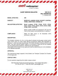
8. Refer to figure 1 and inspect inverter connector insert material as follows:<br />
a. If inverter connector insert is made of hard dielectric material, no action<br />
is required, proceed to step 13 thru 15.<br />
b. If inverter connector insert is made of soft dielectric material and the<br />
inverter plug was removed by hand and there is no signs of excessive<br />
torque being applied to the inverter connector then proceed to steps 10<br />
thru 15.<br />
ASB 412CF-13-53<br />
Page 3 of 5<br />
ECCN EAR99
c. If inverter connector insert has soft dielectric material and the inverter<br />
plug had to be removed using any tools and/or shows signs of excessive<br />
torque being applied to the inverter connector then proceed to step 9.<br />
9. Remove affected inverter and replace with inverter P/N 412-375-079-103,<br />
proceed to steps 13 thru 15.<br />
10. Install adapter plate P/N: 1-001-2709-0431.<br />
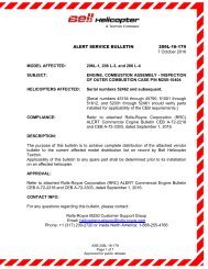
11. Apply thin coat of Adhesive, Silicone C-593 (MIL-A-46146 Type 1) or<br />
equivalent, to chamfered side of adapter plate P/N 1-001-2709-0431 and<br />
position adapter plate over inverter connector as shown in figure 2.<br />
12. Re-identify the affected inverter as, P/N 412-375-079-101(FM) using a<br />
permanent black felt pen.<br />
CAUTION<br />
Do not use any type of tool to install plug. Use moderate<br />
hand pressure only.<br />
13. Re-install plug and safety wire plug onto inverter.<br />
14. Perform inverter functional check.<br />
15. Annotate helicopter record indicating that the helicopter complies with this<br />
bulletin.<br />
ASB 412CF-13-53<br />
Page 4 of 5<br />
ECCN EAR99
Figure 1<br />
Figure 2<br />
ASB 412CF-13-53<br />
Page 5 of 5<br />
ECCN EAR99<br />
Inspect for signs of excessive<br />
torque on threads. (Such as<br />
damaged threads or deformed<br />
threads)<br />
Connector inserts.