KBR's Transport Gasifier (TRIGTM) – an Advanced Gasification ...
KBR's Transport Gasifier (TRIGTM) – an Advanced Gasification ...
KBR's Transport Gasifier (TRIGTM) – an Advanced Gasification ...

Create successful ePaper yourself
Turn your PDF publications into a flip-book with our unique Google optimized e-Paper software.
KBR’S TRANSPORT GASIFIER (TRIG) <strong>–</strong><br />
AN ADVANCED GASIFICATION TECHNOLOGY FOR<br />
SNG PRODUCTION FROM LOW-RANK COALS<br />
Authors:<br />
Siva Ariyapadi - KBR, Houston, TX<br />
Philip Shires - KBR, Houston, TX<br />
M<strong>an</strong>ish Bhargava - KBR, Houston, TX<br />
David Ebbern - KBR, Houston, TX<br />
Publication / Presented:<br />
Twenty-fifth Annual International Pittsburgh Coal Conference<br />
Pittsburgh, PA<br />
Date:<br />
September 29 <strong>–</strong> October 02, 2008
KBR’s <strong>Tr<strong>an</strong>sport</strong> <strong>Gasifier</strong> (TRIG ) <strong>–</strong> <strong>an</strong> Adv<strong>an</strong>ced <strong>Gasification</strong> Technology for SNG<br />
Production from Low-R<strong>an</strong>k Coals<br />
Introduction<br />
Siva Ariyapadi, Philip Shires, M<strong>an</strong>ish Bhargava, <strong>an</strong>d David Ebbern<br />
KBR, Houston, TX<br />
Presented at the<br />
Twenty-fifth Annual International Pittsburgh Coal Conference<br />
September 29 <strong>–</strong> October 02, 2008, Pittsburgh, PA<br />
Coal gasification coupled with CO2 m<strong>an</strong>agement offers <strong>an</strong> environmentally conscious way of<br />
providing a secure energy source. The recent surge in natural gas prices <strong>an</strong>d projected shortages<br />
in the long-term availability of LNG are making coal-derived natural gas or substitute natural gas<br />
(SNG) <strong>an</strong> attractive option to provide reliable supply of gas at a fixed price. A major adv<strong>an</strong>tage of<br />
SNG is its production c<strong>an</strong> be located near the coal reserves <strong>an</strong>d supplied to end-users by tying<br />
into existing natural gas pipeline grid system. This allows tapping the vast coal reserves in<br />
str<strong>an</strong>ded areas that would otherwise be uneconomic to develop.<br />
The KBR <strong>Tr<strong>an</strong>sport</strong> <strong>Gasifier</strong>, also known as TRIG, is <strong>an</strong> adv<strong>an</strong>ced coal gasification technology<br />
that provides cle<strong>an</strong>, particulate-free syngas for a wide variety of coal-based chemicals <strong>an</strong>d fuels<br />
applications. In this paper, the new KBR TRIG Coal-to-SNG process is described, in which the<br />
TRIG gasifier is integrated with a conventional meth<strong>an</strong>ation scheme, producing about 150 million<br />
st<strong>an</strong>dard cubic feet per day (mscfd) of SNG from two representative low-r<strong>an</strong>k coals that are<br />
abund<strong>an</strong>t in the U.S.A. <strong>an</strong>d worldwide. The paper further discusses the process scheme<br />
development, integration <strong>an</strong>d optimization elements that build on the unique attributes of the<br />
TRIG gasification system to produce <strong>an</strong> efficient <strong>an</strong>d technically robust SNG pl<strong>an</strong>t design.<br />
Overview of TRIG <strong>Gasification</strong> Technology<br />
The TRIG gasifier is <strong>an</strong> adv<strong>an</strong>ced pressurized circulating fluidized bed gasifier that operates at<br />
moderate temperatures (1,500 <strong>–</strong> 1,950 o F). The mech<strong>an</strong>ical design <strong>an</strong>d operation of the gasifier are<br />
based on KBR’s fluidized catalytic cracking (FCC) technology, which has more th<strong>an</strong> 60 years of<br />
commercial operating experience. As shown in Figure 1, the TRIG gasifier is simple in design<br />
<strong>an</strong>d has no internals, exp<strong>an</strong>sion joints, valves or other moving parts. It is designed to operate<br />
using air, pure oxygen or enriched air/oxygen mixtures as oxid<strong>an</strong>t. While the air-blown mode is<br />
ideally suited for power generation applications, the oxygen-blown mode <strong>an</strong>d enriched air-blown<br />
mode provide syngas for chemicals <strong>an</strong>d fuels synthesis.<br />
The TRIG gasifier features a dry feed injection system <strong>an</strong>d is a non-slagging gasifier. In<br />
particular, the gasifier’s continuous dry ash h<strong>an</strong>dling system eliminates the technical difficulties<br />
associated with slag h<strong>an</strong>dling <strong>an</strong>d removal faced by comparable slagging gasifiers. Slagging<br />
gasifiers generally require frequent refractory ch<strong>an</strong>ge out due to the erosive nature of the high<br />
temperature fluidic slag. This c<strong>an</strong> escalate mainten<strong>an</strong>ce costs while reducing gasifier availability.<br />
In contrast, lower operating temperatures in the TRIG gasifier allow installation of conventional,<br />
cost-effective alumina-silica type refractory that has a signific<strong>an</strong>tly longer life.<br />
KBR MS#2086 1
Low-r<strong>an</strong>k coals, which account for roughly half of the worldwide coal assets play to the strength<br />
of the TRIG gasifier. These coals typically have high ash <strong>an</strong>d/or moisture content. The moderate<br />
temperatures employed in the TRIG gasifier combined with the dry feed <strong>an</strong>d dry ash h<strong>an</strong>dling<br />
systems greatly improves the gasification cold gas efficiencies <strong>an</strong>d reduces the specific oxygen<br />
dem<strong>an</strong>d. The net impact is reduced cost <strong>an</strong>d auxiliary power consumption associated with the<br />
pl<strong>an</strong>t’s air separation unit (ASU). In addition, the operating temperature r<strong>an</strong>ge of the gasifier is<br />
sufficient to achieve high carbon conversions while mitigating formation of tars <strong>an</strong>d oils.<br />
TRIG <strong>Gasifier</strong> Operation<br />
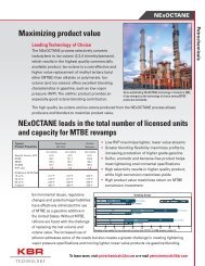
Figure 1: Schematic of the KBR <strong>Tr<strong>an</strong>sport</strong> <strong>Gasifier</strong> (TRIG)<br />
The TRIG gasifier (Figure 1) consists of a mixing zone, riser, disengager/cyclones, loop-seal,<br />
st<strong>an</strong>dpipe, <strong>an</strong>d a J-leg. Steam <strong>an</strong>d oxid<strong>an</strong>t (O2/Air) are routed separately <strong>an</strong>d mixed together in the<br />
mixing zone along with the circulating solids returning from the J-Leg. The mixing zone of the<br />
gasifier c<strong>an</strong> also be referred to as a ‘combustion zone’, where partial oxidation reactions occur<br />
between the unreacted carbon (char) in the solids returning from the J-leg <strong>an</strong>d the injected oxid<strong>an</strong>t<br />
(O2/air). Coal or other carbonaceous feedstock is fed slightly above the mixing zone in a reducing<br />
atmosphere to avoid premature combustion with the oxid<strong>an</strong>t. The endothermic coal gasification<br />
reactions take place primarily in the riser above the coal feed injection point (gasification zone)<br />
by utilizing the heat generated from char combustion in the mixing zone. The circulating solids in<br />
the system act as heat carriers that seamlessly tr<strong>an</strong>sfer heat generated from the bottom<br />
KBR MS#2086 2
(combustion) zone to the gasification zone. This staging effect is <strong>an</strong>other salient feature of the<br />
gasifier in that fresh coal is primarily utilized for gasification, while the unreacted carbon in the<br />
returning solids is sourced for heat generation.<br />
The TRIG gasifier operates at higher superficial gas velocities, riser densities <strong>an</strong>d solids<br />
circulation rates th<strong>an</strong> most conventional circulating fluidized bed reactors. These unique attributes<br />
result in higher syngas throughput, enh<strong>an</strong>ced mixing, <strong>an</strong>d high heat <strong>an</strong>d mass tr<strong>an</strong>sfer rates.<br />
Within the riser, the gas superficial velocities are appropriately maintained such that sufficient<br />
residence time is available to maximize both carbon conversion <strong>an</strong>d tar cracking. The syngas<br />
produced along with the circulating solids, move up the riser through a crossover line <strong>an</strong>d enter a<br />
primary cyclone (or disengager) for bulk separation of solids from the gas. The primary cyclone<br />
removes majority of the particles in the gas-solids mixture by gravity <strong>an</strong>d/or centrifugal forces.<br />
The gas <strong>an</strong>d the remaining finer solids then move to a secondary cyclone that captures most of the<br />
fine particulates not collected by the primary cyclone. The syngas then leaves the unit <strong>an</strong>d passes<br />
through a syngas cooler for high-grade heat recovery followed by a particulate control device.<br />
The solids collected by the primary <strong>an</strong>d secondary cyclones are recycled back to the gasifiermixing<br />
zone via <strong>an</strong> aerated loop-seal, st<strong>an</strong>dpipe, <strong>an</strong>d J-leg arr<strong>an</strong>gement. Solids inventory is<br />
maintained by withdrawing a purge of bed material (coarse ash).<br />
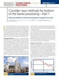
TRIG Demonstration Unit (PSDF), Wilsonville, AL<br />
The adaptation of TRIG technology for coal-based energy has been tested <strong>an</strong>d proven effective<br />
through operations at the Power Systems Development Facility (PSDF) in Wilsonville, Alabama.<br />
The TRIG gasifier at PSDF is <strong>an</strong> engineering-scale, 50 tons/day demonstration unit of the<br />
technology (see Figure 2) <strong>an</strong>d has been in operation since the mid-1990s. The PSDF was codeveloped<br />
by KBR <strong>an</strong>d Southern Comp<strong>an</strong>y, in association with the U.S. Department of Energy<br />
(DOE).<br />
Figure 2: TRIG <strong>Gasifier</strong> Demonstration Unit at the PSDF, Wilsonville, AL<br />
KBR MS#2086 3
The demonstration unit at the PSDF has been successfully operated on a wide r<strong>an</strong>ge of coals<br />
including bituminous, sub-bituminous, <strong>an</strong>d various lignites. The unit has logged thous<strong>an</strong>ds of<br />
hours in both air-blown <strong>an</strong>d oxygen-blown configurations. Table 1 provides a sample listing of<br />
the coals successfully tested at PSDF <strong>an</strong>d their characteristics. As previously mentioned, the<br />
TRIG gasifier prefers low-r<strong>an</strong>k or reactive coals such as, Powder River Basin (PRB) coal <strong>an</strong>d<br />
lignites <strong>–</strong> these coals are ideally suited for the short contact times available in the riser section of<br />
the gasifier where carbon conversions of 96 <strong>–</strong> 99% have been consistently achieved. The TRIG<br />
unit has also successfully tested a number of bituminous coals. While these coals c<strong>an</strong> be<br />
comfortably processed at the higher end of the gasifier’s operating temperature envelope, carbon<br />
conversions are generally lower (87 <strong>–</strong> 93%). When processing bituminous coals or other high<br />
r<strong>an</strong>k coals, there is usually a trade-off between the slightly lower carbon conversion vs. the<br />
benefits of lower energy consumption <strong>an</strong>d higher efficiencies offered by the TRIG gasifier.<br />
Other characteristics such as moisture <strong>an</strong>d total ash content of the coal are generally non-issues<br />
for processing in the TRIG unit but the sodium content in the ash <strong>an</strong>d the initial ash fusion<br />
temperatures are critical. The TRIG gasifier prefers low-sodium coals <strong>an</strong>d is generally operated at<br />
200 o F below the ash fusion temperature to avoid particle sintering <strong>an</strong>d agglomeration.<br />
Coal<br />
Table 1: Typical Coals tested at TRIG Demonstration Unit (PSDF, Wilsonville, AL)<br />
Moisture, wt%<br />
Carbon, wt%<br />
Hydrogen, wt%<br />
Nitrogen, wt%<br />
Oxygen, wt%<br />
Sulfur, wt%<br />
Ash, wt%<br />
Volatiles, wt%<br />
Fixed Carbon, wt%<br />
HHV, Btu/lb<br />
HHV, kcal/kg<br />
Initial Ash Fusion<br />
Temperature,<br />
(Reducing), °F<br />
PRB<br />
15.24<br />
59.28<br />
3.73<br />
0.76<br />
15.10<br />
0.26<br />
5.61<br />
35.70<br />
43.44<br />
9,887<br />
5,493<br />
2138 -<br />
2143<br />
Falkirk<br />
Lignite<br />
27.95<br />
42.53<br />
2.73<br />
0.69<br />
12.04<br />
0.76<br />
13.07<br />
29.67<br />
29.08<br />
6,973<br />
3,874<br />
2046<br />
Status of TRIG <strong>Gasification</strong> Technology<br />
Freedom<br />
Lignite<br />
21.91<br />
48.76<br />
2.97<br />
0.69<br />
15.06<br />
0.78<br />
9.83<br />
30.87<br />
37.38<br />
8,068<br />
4,482<br />
2066 - 2286<br />
Mississippi<br />
Lignite<br />
28.08<br />
39.14<br />
5.20<br />
0.77<br />
37.12<br />
0.94<br />
16.84<br />
29.38<br />
25.60<br />
6,616<br />
3,676<br />
2196 - 2292<br />
Utah<br />
Bituminous<br />
6.85<br />
66.36<br />
4.34<br />
1.08<br />
10.71<br />
0.38<br />
10.29<br />
35.61<br />
47.25<br />
11,246<br />
6,248<br />
2080<br />
Illinois<br />
Bituminous<br />
12.98<br />
62.42<br />
4.03<br />
1.41<br />
6.27<br />
0.86<br />
12.03<br />
27.52<br />
47.47<br />
10,932<br />
6,073<br />
2254 - 2354<br />
The operational experience gained at the demonstration unit at PSDF is the basis for a pl<strong>an</strong>ned<br />
full-scale, commercial implementation of TRIG technology to produce 600 MWe power in<br />
Mississippi, U.S.A. This Integrated <strong>Gasification</strong> Combined Cycle (IGCC) power project is being<br />
developed by Mississippi Power. Front-End Engineering Design (FEED) work on the project has<br />
been completed <strong>an</strong>d additional studies are currently being investigated. The project is based on<br />
gasification of Mississippi lignite <strong>an</strong>d will employ two KBR TRIG gasifiers operating in airblown<br />
mode. Through years of operating experience at PSDF <strong>an</strong>d from proprietary FCC<br />
KBR MS#2086 4
technology, optimized commercial-scale TRIG gasifier designs are available today for both airblown<br />
power applications as well as oxygen-blown chemicals <strong>an</strong>d fuels applications.<br />
SNG Production from Low-r<strong>an</strong>k Coals via TRIG Technology<br />
As previously mentioned, the KBR TRIG gasifier offers several adv<strong>an</strong>tages in processing lowr<strong>an</strong>k<br />
coals. The following sections of the paper examine the applicability of the TRIG technology<br />
to one of the rapidly emerging gasification-based applications in the U.S. market <strong>–</strong> production of<br />
SNG.<br />
KBR has performed pre-feasibility studies evaluating the technical <strong>an</strong>d economic feasibility of<br />
commercially implementing coal-to-SNG at grass roots facilities in the western U.S.A. The<br />
proposed SNG facility employs KBR’s TRIG gasification technology <strong>an</strong>d utilizes either Powder<br />
River Basin (PRB) coal from Wyoming, or low-sodium North Dakota lignite as feedstock.<br />
The technical solutions developed included <strong>an</strong> optimized syngas-processing scheme to maximize<br />
SNG production, while reducing the make-up water usage <strong>an</strong>d overall pl<strong>an</strong>t energy consumption.<br />
An integrated heat recovery scheme was selected wherein the high-pressure steam produced in<br />
the meth<strong>an</strong>ation section is superheated in the gasification section. With this scheme, high<br />
thermodynamic efficiencies in the steam <strong>an</strong>d power generation systems c<strong>an</strong> be achieved, while<br />
reducing auxiliary firing requirements <strong>an</strong>d its associated emissions. Details of these solutions <strong>an</strong>d<br />
their benefits are described in the following sections.<br />
Description of the new KBR TRIG Coal-to-SNG Process<br />
In the new KBR coal-to-SNG process, the proprietary TRIG gasification technology is integrated<br />
with a conventional meth<strong>an</strong>ation scheme to make pipeline-quality SNG from two different coals<br />
<strong>–</strong> Wyoming PRB <strong>an</strong>d North Dakota lignite. For this paper, the SNG pl<strong>an</strong>t is assumed a minemouth<br />
facility with a nominal SNG capacity of about 150 mscfd. This capacity requires syngas<br />
from three TRIG gasifiers operating in oxygen-blown mode. The size <strong>an</strong>d design of the TRIG<br />
gasifier have been kept the same as KBR’s st<strong>an</strong>dard commercial offering. For the PRB case, there<br />
is excess syngas capacity, which is used as fuel gas to achieve power bal<strong>an</strong>ce. The entire SNG<br />
facility was assumed to be air-cooled wherever practical to minimize water usage <strong>–</strong> deemed <strong>an</strong><br />
import<strong>an</strong>t requirement in the locations considered.<br />
Figure 3 depicts a simplified block flow diagram illustrating the connectivity between major<br />
process units. A cluster of three TRIG gasifiers supply the necessary syngas feed with the<br />
appropriate H2:CO ratio to the meth<strong>an</strong>ation unit. The main process units include gasification,<br />
shift, COS hydrolysis, ammonia scrubbing, mercury removal, acid gas removal, sulfur removal,<br />
CO2 compression, meth<strong>an</strong>ation, <strong>an</strong>d SNG drying <strong>an</strong>d compression.<br />
The as received composition for the two coals considered in the study are shown in Table 2. As<br />
shown in the table, the PRB coal has a relatively low heating value <strong>an</strong>d sulfur content as<br />
compared to other bituminous or <strong>an</strong>thracite coals. PRB coal is the single largest mined coal in the<br />
U.S. <strong>an</strong>d has been routinely used for baseline tests in the demonstration TRIG gasifier. The lignite<br />
assumed for this study is representative of the coal from Freedom Mine, ND. It has slightly higher<br />
moisture <strong>an</strong>d about twice the sulfur <strong>an</strong>d ash content of the PRB coal, which results in a reduced<br />
higher heating value (HHV). Both coals are ideal feedstocks that gasify well in the TRIG unit<br />
yielding high carbon conversions.<br />
KBR MS#2086 5
STEAM<br />
AIR<br />
ASU<br />
O2<br />
KBR TRANSPORT<br />
GASIFIER (TRIG)<br />
UNITS<br />
COAL<br />
PREPARATION<br />
& MILLING<br />
COAL FEED<br />
CONDENSATE<br />
N2<br />
SUPERHEATED<br />
HP STEAM<br />
(1,250 psig, 950 o F)<br />
SYNGAS<br />
COOLER<br />
BFW<br />
COARSE ASH<br />
Figure 3: Block Flow Diagram of KBR TRIG Coal-to-SNG Process<br />
ASH<br />
COOLING<br />
ASH<br />
DISPOSAL<br />
RECYCLED SYNGAS<br />
PARTICULATE<br />
CONTROL<br />
DEVICE<br />
FINE ASH<br />
WASTE HEAT<br />
RECOVERY<br />
COS<br />
HYDROLYSIS<br />
GAS<br />
COOLING /<br />
HEAT<br />
RECOVERY<br />
MAKE-<br />
UP H2O<br />
SATURATOR<br />
BLOWDOWN<br />
CONDENSATE<br />
MAKE-<br />
UP H2O<br />
SOUR<br />
GAS<br />
SHIFT<br />
(1 STAGE)<br />
AMMONIA<br />
SCRUBBER<br />
CONDENSATE<br />
FLASH GAS<br />
to GASIFIER<br />
GAS<br />
COOLING /<br />
HEAT<br />
RECOVERY<br />
TAIL GAS<br />
SNG<br />
DEHYDRATION/<br />
COMPRESSION<br />
150 mscfd SNG<br />
to PIPELINE<br />
Table 2: As Received Coal Compositions <strong>–</strong> PRB <strong>an</strong>d Lignite<br />
Coal Wyoming PRB North Dakota Lignite<br />
Component Wt% Wt%<br />
C 51.75 44.21<br />
O 11.52 12.45<br />
H 3.41 2.71<br />
N 0.71 0.68<br />
S 0.26 0.60<br />
Cl 0.011 0.005<br />
F 0.004 0.00<br />
Moisture 27.21 29.82<br />
Ash 5.13 9.53<br />
HHV, BTU/lb 8,764 7,335<br />
MERCURY<br />
REMOVAL<br />
1,250 psig<br />
SAT.<br />
STEAM<br />
BFW<br />
SULFUR<br />
CLAUS<br />
UNIT<br />
O2<br />
H2S<br />
ACID GAS<br />
REMOVAL UNIT<br />
METHANATION<br />
CO2<br />
CONDENSATE<br />
KBR MS#2086 6<br />
FUEL<br />
GAS
The main processing units in TRIG gasification to SNG scheme are as follows:<br />
Syngas Generation<br />
• Coal Preparation<br />
• Air Separation<br />
• Coal <strong>Gasification</strong><br />
• Syngas Cooler<br />
• Particulate Control<br />
• Syngas Saturation<br />
• Sour Gas Shift<br />
• COS Hydrolysis<br />
Syngas Purification<br />
• Ammonia Scrubbing<br />
• Mercury Removal<br />
• Acid Gas Removal<br />
• CO2 M<strong>an</strong>agement<br />
SNG Synthesis<br />
• Meth<strong>an</strong>ation Unit<br />
• SNG Drying & Compression<br />
Utility Section<br />
• Steam & Power Systems<br />
Each of the above steps is described in detail below:<br />
SYNGAS GENERATION<br />
Coal Preparation<br />
As received coal is crushed to the required size <strong>an</strong>d fed to a system of fluidized bed coal dryers,<br />
the dryers utilize low-grade process heat to dry coal to the desired moisture levels. Dried,<br />
pulverized coal is then tr<strong>an</strong>sferred to coal storage bins. Because the TRIG gasifier c<strong>an</strong> accept<br />
larger-sized coal particles (~ 400 microns) th<strong>an</strong> other high temperature gasifiers, required<br />
crushing energy is less. Coal is then fed to the pressurized TRIG unit through a system of lock<br />
hoppers <strong>an</strong>d pneumatically conveyed using recycled syngas. Coal is injected at a location slightly<br />
above the gasifier-mixing zone. The coal particles fluidize, mix with the circulating solids, <strong>an</strong>d<br />
heat up rapidly as they enter the gasifier.<br />
Air Separation<br />
The TRIG gasifier for the SNG application uses pure oxygen as the oxid<strong>an</strong>t to reduce inerts in the<br />
syngas. Oxygen is provided by a cryogenic air separation unit (ASU) supplied by a suitable<br />
process licensor. To maintain a reasonable size <strong>an</strong>d energy consumption of the ASU, oxygen<br />
purity of about 99.5 mol% is selected. The main impurities in the oxygen stream are argon <strong>an</strong>d<br />
nitrogen. Oxygen is supplied to the gasifier at about 600 psia <strong>an</strong>d ambient temperature. The ASU<br />
also supplies high pressure (HP) <strong>an</strong>d low pressure (LP) gaseous nitrogen for use within the<br />
gasification facility. The specific oxygen consumption for the PRB <strong>an</strong>d lignite cases are 0.75 <strong>an</strong>d<br />
0.66 tons of oxygen per ton of coal on a moisture <strong>an</strong>d ash free (MAF) basis. The difference in<br />
KBR MS#2086 7
specific oxygen consumption between PRB <strong>an</strong>d lignite cases is due to the slight variation in<br />
gasifier operating temperatures <strong>an</strong>d the difference in oxygen composition between the two coals.<br />
Coal <strong>Gasification</strong><br />
Partially dried, pulverized coal, oxygen <strong>an</strong>d steam are fed to the TRIG gasifier near the mixing<br />
zone where they contact the circulating solids. Coal gasification reactions take place in the<br />
resulting fluidized bed operating in the high velocity ‘tr<strong>an</strong>sport regime’. The flow of oxygen is<br />
carefully controlled to limit carbon combustion within the gasifier. Steam is added to the gasifier,<br />
both as a react<strong>an</strong>t <strong>an</strong>d as a moderator to control the reaction temperature. For this study, the<br />
gasifier operating temperatures selected were 1,700 o F for the PRB case <strong>an</strong>d 1,650 o F for the lignite<br />
case. These operating temperatures were chosen to maximize meth<strong>an</strong>e concentration in the<br />
syngas while ensuring the highest possible carbon conversions are attained. This is possible<br />
because, for a given coal, the maximum carbon conversion in the TRIG unit remains const<strong>an</strong>t<br />
over a r<strong>an</strong>ge of temperature <strong>an</strong>d only drops when the temperature is further reduced. Meth<strong>an</strong>e<br />
concentration at a const<strong>an</strong>t pressure, however, is inversely correlated with temperature <strong>–</strong> with a<br />
lower operating temperature producing more meth<strong>an</strong>e. Therefore, the gasifier operating<br />
temperatures selected for this study represents the lower-end of the temperature r<strong>an</strong>ge for which<br />
carbon conversions are uncompromised for both PRB <strong>an</strong>d lignite coals.<br />
The syngas produced along with the solids then move up the riser <strong>an</strong>d enter a system of primary<br />
<strong>an</strong>d secondary cyclones where most of the particles larger th<strong>an</strong> 10 microns are separated <strong>an</strong>d<br />
recycled back to the gasifier. The hot syngas exiting the top of the second stage cyclone then<br />
enters a system of primary syngas coolers at a pressure of about 522 psia. A small portion of the<br />
recycled syngas is compressed <strong>an</strong>d sent back to the gasifier for coal conveying <strong>an</strong>d as fluidizing<br />
gas within the gasifier. Typical syngas composition at the gasifier exit for the PRB <strong>an</strong>d the lignite<br />
cases are shown in Table 3.<br />
Table 3: Typical Syngas Composition at TRIG <strong>Gasifier</strong> exit for the PRB <strong>an</strong>d lignite coals<br />
Coal Wyoming PRB North Dakota Lignite<br />
Temperature 1,700 o F 1,650 o F<br />
Pressure 522 psia 522 psia<br />
Component Mol% (wet basis) Mol% ( wet basis)<br />
CO 39.7 35.6<br />
H2 28.5 25.6<br />
CO2 14.3 17.5<br />
CH4 4.3 6.1<br />
NH3 0.4 0.4<br />
H2O 12.6 14.4<br />
N2 0.09 0.09<br />
Ar 0.08 0.07<br />
H2S 750 ppmv 2,007 ppmv<br />
HCN 250 ppmv 274 ppmv<br />
COS 40 ppmv 106 ppmv<br />
HF 18 ppmv nil<br />
HCl 30 ppmv 15 ppmv<br />
KBR MS#2086 8
Syngas Cooler<br />
The main purposes of the syngas cooler are (1) to recover high-grade process heat from syngas<br />
leaving gasifiers, <strong>an</strong>d (2) to provide necessary superheat for steam generated within the syngas<br />
cooler <strong>an</strong>d steam generated from the pl<strong>an</strong>t’s meth<strong>an</strong>ation section. To accommodate the<br />
integration between the meth<strong>an</strong>ation unit <strong>an</strong>d the syngas cooler, HP steam header pressure was<br />
fixed at 1,250 psig in both process units.<br />
Hot syngas containing traces of fine particles exits the TRIG gasifier at 1,650 <strong>–</strong> 1,700°F <strong>an</strong>d is<br />
cooled to about 700°F in the syngas cooler. It consists of three exch<strong>an</strong>ger sections <strong>–</strong> Steam<br />
Generator, Superheater, <strong>an</strong>d Economizer. The first section of the syngas cooler is the Steam<br />
Generator. Here, HP steam is produced <strong>an</strong>d the syngas is cooled to approximately 1,350°F. The<br />
middle section of the syngas cooler is the Superheater. Here, HP steam from the steam drum<br />
within the syngas cooler area along with 1,250 psig saturated HP steam from the meth<strong>an</strong>ation<br />
section is superheated to 950°F. The final section of the syngas cooler is the Economizer. Here,<br />
the syngas is cooled to about 700°F. Boiler feed water enters the Economizer at 385°F at 1,250<br />
psig. Water is then heated to about 574°F <strong>an</strong>d flows to the HP steam drum.<br />
It is import<strong>an</strong>t to note the TRIG gasification scheme’s ability to superheat the entire HP steam<br />
from the meth<strong>an</strong>ation section within the syngas cooler. In particular, it presents a signific<strong>an</strong>t<br />
adv<strong>an</strong>tage over the ‘Quench’ gasification designs employing conventional meth<strong>an</strong>ation (low- or<br />
medium-temperature) schemes, where there is typically inadequate heat within the meth<strong>an</strong>ation<br />
section to provide the desired superheat levels. In such cases, additional superheat will need to be<br />
provided by auxiliary firing, which increases both fuel consumption <strong>an</strong>d pl<strong>an</strong>t emissions. In<br />
contrast, the present TRIG configuration integrated with the meth<strong>an</strong>ation unit is able to achieve<br />
the desired steam superheat levels <strong>an</strong>d efficiency with no additional emissions.<br />
Particulate Control Device (PCD)<br />
Gas exiting the syngas cooler at about 700°F flows through PCD, a proprietary filter (designed by<br />
a suitable vendor) that removes remaining particulate matter as fine ash. Removing fine<br />
particulates from syngas is <strong>an</strong> integral part of <strong>an</strong>y gasifier system as it c<strong>an</strong> foul or corrode<br />
downstream equipment, reducing perform<strong>an</strong>ce or causing equipment failure.<br />
Figure 4 shows a simplified sketch of the PCD employed in the TRIG gasification system. It uses<br />
rigid, barrier-type, filter elements to remove essentially all of the fine particulates in the syngas<br />
stream. The inlet solids concentration in the syngas to the PCD is about 20,000 ppmw <strong>an</strong>d is<br />
reduced to less th<strong>an</strong> 0.1 ppmw upon exit. A small amount of high-pressure recycled syngas is<br />
used to pulse-cle<strong>an</strong> filters as they accumulate particles from the unfiltered syngas. Downstream of<br />
each filter element, a safeguard (fail-safe) device is installed to protect downstream equipment<br />
from particulate-related damage in the event of <strong>an</strong> isolated filter element failure. The particulate<br />
stream (fine ash) is depressurized to atmospheric pressure <strong>an</strong>d removed via a proprietary<br />
continuous fine ash removal system.<br />
The PCD is a critical component of the TRIG gasifier development as it ensures the syngas<br />
produced is particulate-free, eliminating dirty water or grey water systems that are a feature of<br />
most other commercially available gasification processes. The elimination of grey water systems<br />
also implies unique heat integration <strong>an</strong>d water recovery possibilities. KBR has developed<br />
proprietary technologies around the core TRIG unit to maximize heat <strong>an</strong>d condensate recovery.<br />
These novel features are incorporated in present coal-to-SNG process scheme. Additional<br />
information on PCD <strong>an</strong>d details on filter elements used c<strong>an</strong> be found in Ref. 1.<br />
KBR MS#2086 9
Syngas Saturator<br />
Figure 4: Sketch of the Particulate Control Device (PCD)<br />
Cle<strong>an</strong> Gas Out<br />
Dirty Gas In<br />
Collected Solids<br />
Shroud<br />
Shroud<br />
Top View<br />
As shown in Figure 1, a portion of the raw syngas that needs to be shifted passes through the<br />
syngas saturator. This step is required because raw gas from the TRIG unit does not contain<br />
desired moisture (steam) levels required at the inlet of sour shift catalyst beds. The primary<br />
function of the saturator, therefore, is to raise the moisture level for the portion of raw gas that<br />
requires shifting. The fraction of total gas that requires to be shifted is set by the desired H2:CO<br />
ratio at the inlet of the meth<strong>an</strong>ation unit. The syngas saturator primarily uses recycled process<br />
condensate as the main source of water to saturate gas. A small amount of fresh demineralized<br />
make-up water is also added to maintain the water bal<strong>an</strong>ce. In the present configuration, around<br />
70-75% of total saturator heat requirement is met by the sensible heat available in the syngas,<br />
plus medium- to low-grade heat available elsewhere in the process. The remaining 25-30% of<br />
saturator reboiling heat duty is met by indirect steam reboiling using 650-psig medium pressure<br />
(MP) steam. It should be noted that there is no live steam addition to the saturator <strong>–</strong> this<br />
configuration minimizes overall water make-up <strong>an</strong>d reduces saturator blowdown. In both PRB<br />
<strong>an</strong>d lignite cases, a minimum blowdown is maintained from the saturator. This stream would<br />
contain small amounts of dissolved gases, virtually no suspended or dissolved solids, <strong>an</strong>d in some<br />
cases, traces of hydrogen halides absorbed from raw syngas. This blowdown is sent to the process<br />
condensate stripper for further treatment.<br />
As indicated before, it is import<strong>an</strong>t to note that the saturator utilized in the TRIG gasification<br />
scheme is not a particulate scrubber. A particulate scrubber is not used because syngas entering<br />
the saturator from the PCD is essentially free of <strong>an</strong>y solids. The implementation of the PCD<br />
eliminates the need for water scrubbing of solids <strong>an</strong>d greatly simplifies the design of the saturator<br />
<strong>an</strong>d its condensate recovery scheme. More details on the operation of the saturator are provided in<br />
Ref. 2.<br />
KBR MS#2086 10
Sour Gas Shift<br />
The overhead gas from the saturator is pre-heated <strong>an</strong>d passes through a system of parallel, singlestage<br />
sour gas shift catalytic beds. The steam-to-dry gas molar ratio at inlet to the catalyst beds is<br />
about 0.95. Carbon monoxide conversion is optimized by adjusting inlet temperature to the shift<br />
unit in the r<strong>an</strong>ge of 500 <strong>–</strong> 550 o F so that the appropriate H2:CO ratios in the feed gas to the<br />
meth<strong>an</strong>ation unit c<strong>an</strong> be achieved for both start of run (SOR) <strong>an</strong>d end of run (EOR) conditions.<br />
Carbonyl sulfide (COS) in the syngas is almost completely hydrolyzed to hydrogen sulfide. This<br />
eliminates the requirement for a dedicated COS hydrolysis unit for shifted gas.<br />
As part of the overall heat integration philosophy developed for this study, the heat recovery from<br />
the shift reactor effluent was maximized <strong>an</strong>d utilized for the following services:<br />
• Feed pre-heat to the sour gas shift reactors<br />
• Part of the heat duty for the upstream syngas saturator<br />
• Pre-heat for recycled condensate <strong>an</strong>d make-up water to syngas saturator<br />
• Heat duty for acid gas removal unit reboilers<br />
• Part of the heat for coal drying<br />
• Deaerator feed water pre-heating<br />
After recovering most of the heat in the shifted gas effluent, it is passed through <strong>an</strong> air cooler to<br />
reject the last, unrecoverable portion of the heat.<br />
COS Hydrolysis<br />
After recovering part of the high-grade heat in the unshifted raw syngas leaving the PCD, it<br />
passes through a number of parallel, carbonyl sulfide (COS) hydrolysis reactors to reduce the<br />
COS concentration in the unshifted syngas. The hydrolysis reaction essentially proceeds to<br />
equilibrium, reducing COS concentration in the exit gas to about 1 ppmv. There is no added<br />
steam addition at the inlet to the COS catalyst beds as the moisture present in the syngas is<br />
sufficient for the hydrolysis reaction. The heat in the unshifted syngas leaving the COS hydrolysis<br />
reactor is utilized for boiler feed water (BFW) pre-heating <strong>an</strong>d part of the low-grade heat required<br />
for coal drying. After heat recovery, unshifted gas passes on to the ammonia scrubbing section.<br />
SYNGAS PURIFICATION<br />
Ammonia Scrubbing<br />
As shown in Figure 1, a dedicated ammonia scrubber is included only in the unshifted gas line<br />
due to insufficient water in the syngas to condense the ammonia. In contrast, when the shifted gas<br />
effluent is cooled almost all of the ammonia is condensed. In the ammonia scrubber, the unshifted<br />
raw syngas is scrubbed with water recovered from coal drying at about 130°F to remove<br />
ammonia, remaining chlorides <strong>an</strong>d fluorides. Water leaving the ammonia scrubber is mixed with<br />
condensate generated from cooling the shifted gas effluent. The combined condensate stream is<br />
then pumped to about 600 psig, pre-heated <strong>an</strong>d flashed. The flash gas contains signific<strong>an</strong>t<br />
amounts of ammonia vapors along with some carbon dioxide <strong>an</strong>d hydrogen sulfide. These gases<br />
are recycled to the gasifier where bulk of the ammonia is converted into elemental nitrogen <strong>an</strong>d<br />
hydrogen. The hot condensate from the flash drum is then recycled to the syngas saturator.<br />
KBR MS#2086 11
Mercury Removal<br />
Unshifted syngas leaving the ammonia scrubber <strong>an</strong>d cooled shifted syngas are mixed upstream of<br />
the mercury removal unit. The combined gas stream is pre-heated to about 150 o F <strong>an</strong>d passes<br />
through mercury removal guard beds. It consists of activated carbon beds that adsorb <strong>an</strong>y<br />
mercury present in the syngas. Mercury-free syngas is then sent to the acid gas removal unit for<br />
sulfur <strong>an</strong>d carbon dioxide removal.<br />
Acid Gas Removal<br />
Raw syngas leaving the mercury removal unit enters the acid gas removal unit (AGRU). A<br />
physical solvent based, two-stage AGRU was selected <strong>an</strong>d the process data was supplied by a<br />
suitable process licensor. Since carbon dioxide (CO2) is also a react<strong>an</strong>t in the meth<strong>an</strong>ation unit,<br />
the treated gas CO2 specification was arbitrarily set at 0.5 mol%. The total sulfur in the treated gas<br />
was less th<strong>an</strong> 0.1 ppmv. Treated gas is sent to the meth<strong>an</strong>ation unit.<br />
Most of the captured carbon dioxide from raw syngas is recovered as a low-pressure CO2-rich<br />
stream (>95% CO2) with a hydrogen sulfide (H2S) content of less th<strong>an</strong> 20 ppmv. The CO2 stream<br />
also meets typical pipeline-specifications for hydrocarbons <strong>an</strong>d inerts. Low-pressure CO2 stream<br />
is sent to the CO2 compression unit. Sulfur removed from raw syngas is concentrated as a H2Srich<br />
stream <strong>an</strong>d sent to a conventional oxygen-fired Claus Unit for sulfur recovery. Tail gas from<br />
the Claus unit is compressed <strong>an</strong>d recycled to upstream of the acid gas removal unit to reduce<br />
emissions associated with tail gas treatment.<br />
CO2 M<strong>an</strong>agement<br />
The current KBR TRIG gasification scheme to make SNG is designed to accommodate <strong>an</strong>y future<br />
carbon capture <strong>an</strong>d storage (CCS) requirements. This is accomplished by having a design that is<br />
inclusive of <strong>an</strong> AGRU that maximizes CO2 recovery <strong>an</strong>d meets the most stringent CO2 pipeline<br />
specifications, <strong>an</strong>d by adding a CO2 compression unit. The low-pressure CO2 recovered from the<br />
acid gas removal unit is sent to a CO2 compression unit, where the CO2 is routed through one or<br />
more compression trains to provide a dense-phase fluid with a discharge pressure of about 2,200<br />
psig. The compressed CO2 at these pressures is expected to be suitable for either Enh<strong>an</strong>ced Oil<br />
Recovery (EOR) <strong>an</strong>d/or Sequestration. Based on KBR’s experience in large-scale CO2<br />
compression design, a st<strong>an</strong>dard four-stage intercooled Centrifugal Compressor configuration<br />
(with electric drives) was adopted for this study. The requirement for dehydration will be<br />
assessed in later phases as it largely depends on the acid gas removal technology selected <strong>an</strong>d<br />
ambient conditions to which the CO2 pipeline may be exposed. The total amount of compressed<br />
CO2 available for the PRB <strong>an</strong>d lignite cases is approximately, 290 <strong>an</strong>d 260 mscfd, respectively.<br />
SNG SYNTHESIS<br />
Meth<strong>an</strong>ation Scheme Development<br />
The KBR TRIG-based meth<strong>an</strong>ation scheme developed for this study assumes the equilibriumlimited<br />
meth<strong>an</strong>ation reactor concept. The scheme involves recycling sufficient qu<strong>an</strong>tity of product<br />
gas to quench heat liberated by robust exothermic meth<strong>an</strong>ation reactions. The maximum<br />
permissible temperature in the meth<strong>an</strong>ator beds was limited to about 900 o F. This temperature is<br />
within the proven r<strong>an</strong>ge of meth<strong>an</strong>ation catalysts employed in typical commercial-scale SNG<br />
pl<strong>an</strong>ts. KBR has signific<strong>an</strong>t expertise in meth<strong>an</strong>ation scheme development <strong>an</strong>d design based on<br />
previous work <strong>an</strong>d from interactions with various meth<strong>an</strong>ation catalyst providers. The<br />
meth<strong>an</strong>ation scheme adopted for the present study incorporates this experience <strong>an</strong>d represents a<br />
technically robust design.<br />
KBR MS#2086 12
Meth<strong>an</strong>ation Unit<br />
Treated gas leaving the acid gas removal section enters the meth<strong>an</strong>ation unit. Table 4 indicates<br />
the estimated syngas composition for both PRB <strong>an</strong>d lignite cases at inlet to the meth<strong>an</strong>ation unit.<br />
The hydrogen content in the feed gas represents the stoichiometric requirement for complete<br />
conversion of carbon oxides (CO <strong>an</strong>d CO2) in the feed gas to SNG.<br />
From Table 4, two import<strong>an</strong>t aspects are noted:<br />
1. The feed gas meth<strong>an</strong>e concentration is about 5.70 <strong>an</strong>d 8.71 mol% for the PRB <strong>an</strong>d lignite<br />
cases, respectively. As mentioned before, for this SNG application, the meth<strong>an</strong>e<br />
concentrations in the syngas have been maximized by adjusting the gasifier operating<br />
temperatures. The high meth<strong>an</strong>e concentration in feed gas not only represents product<br />
value but also signific<strong>an</strong>tly reduces product gas recycle requirements to quench the heat<br />
of reaction. The ability to maximize meth<strong>an</strong>e concentration in feed gas is <strong>an</strong> import<strong>an</strong>t<br />
adv<strong>an</strong>tage of the TRIG gasification system. The net impact when utilizing feed gas with<br />
higher meth<strong>an</strong>e content is reduced auxiliary power consumption <strong>an</strong>d capital costs<br />
associated with the meth<strong>an</strong>ation unit.<br />
2. The N2+Ar content of feed gas to the meth<strong>an</strong>ation unit are about 0.22 <strong>an</strong>d 0.25 mol% for<br />
both coals, which represents very low inerts content. Typically, N2+Ar content of syngas<br />
c<strong>an</strong> be traced back to the ASU oxygen purity, plus the amount of N2 present in feedstock<br />
(fuel N2). In the TRIG gasifier when processing most coals, about 80% of the fuel N2 is<br />
converted to ammonia, which is easily separable from the syngas. Thus, with the TRIG<br />
gasification system it is possible to produce a syngas stream that is low in nitrogen (<strong>an</strong>d<br />
total inerts) by removing most of the fuel nitrogen as ammonia. The low inerts content<br />
shown in Table 4 reflects this signific<strong>an</strong>t benefit, particularly for the SNG application<br />
where low-inerts gas c<strong>an</strong> boost the SNG higher heating value (HHV).<br />
Table 4: Estimated Feed Gas Composition to the Meth<strong>an</strong>ation Unit <strong>–</strong> PRB <strong>an</strong>d Lignite<br />
Coal PRB Lignite<br />
Temperature 81 o F 81 o F<br />
Pressure 400 psia 400 psia<br />
Component Mol% (dry basis) Mol% ( dry basis)<br />
CO 22.89 22.14<br />
H2 70.68 68.41<br />
CO2 0.50 0.50<br />
CH4 5.70 8.71<br />
N2 0.12 0.14<br />
Ar 0.10 0.11<br />
H2S + COS < 0.1 ppmv < 0.1 ppmv<br />
The heat in the effluent from the meth<strong>an</strong>ator beds <strong>an</strong>d from recycle compression is primarily<br />
utilized for the following services:<br />
• 1,250 psig saturated steam generation<br />
• Meth<strong>an</strong>ation feed pre-heat<br />
• Meth<strong>an</strong>ation section boiler feed water (BFW) pre-heat<br />
KBR MS#2086 13
SNG Drying & Compression<br />
The wet SNG leaving the meth<strong>an</strong>ation unit is air-cooled to about 110 o F <strong>an</strong>d the condensed water<br />
is removed. It is then dehydrated to about 7 lbs of water per mscf in a conventional tri-ethylene<br />
glycol (TEG) unit. The dry SNG leaving the TEG unit passes through <strong>an</strong> SNG compression step,<br />
followed by after-cooling. SNG product is delivered at 1,000 psig <strong>an</strong>d about 110 o F. Higher<br />
heating value (HHV) is estimated to meet or exceed <strong>an</strong> assumed pipeline specification of 970<br />
BTU/scf on a dry basis.<br />
By-products from the meth<strong>an</strong>ation unit are HP saturated steam <strong>an</strong>d process condensate. As<br />
mentioned earlier, the 1,250-psig HP saturated steam produced in the meth<strong>an</strong>ation unit is routed<br />
to the syngas cooler, where it is superheated to about 950 o F <strong>an</strong>d sent to the steam turbines for<br />
power generation. Condensate recovered from the meth<strong>an</strong>ation unit is re-used as make-up water<br />
for various process units.<br />
Overall Pl<strong>an</strong>t Consumption & Production Figures<br />
Table 5 summarizes estimated feed requirements <strong>an</strong>d by-product production figures for the two<br />
cases <strong>–</strong> PRB <strong>an</strong>d lignite, each producing about 150 mscfd SNG product with a higher heating<br />
value of at least 970 BTU/scf. The data presented in Table 5 are preliminary figures only <strong>an</strong>d<br />
based on the conceptual scheme developed. Overall pl<strong>an</strong>t inside battery limit (ISBL) <strong>an</strong>d outside<br />
battery limit (OSBL) auxiliary power load <strong>an</strong>d power generation from the steam system are<br />
discussed in the next section.<br />
As noted before, the data in Table 5 represents maximum syngas capacity of three TRIG gasifiers<br />
operating in oxygen-blown mode. Because the PRB case has some excess capacity (in addition to<br />
meeting the target 150 mscfd SNG), there is additional syngas shown as fuel gas. Conversely,<br />
additional syngas c<strong>an</strong> also be used to make more SNG. This paper does not discuss the latter<br />
option.<br />
The overall process make-up water requirements for two cases are also shown in Table 5. The net<br />
make-up water figures are obtained from a detailed water bal<strong>an</strong>ce that considers make-up<br />
required for process units <strong>an</strong>d steam system blowdowns, plus water lost in reaction (shift). The<br />
contribution from water recovered in coal drying, condensate from meth<strong>an</strong>ation, <strong>an</strong>d treated water<br />
from condensate stripper is included in determining the net make-up. For the lignite case, this net<br />
make-up requirement is much smaller compared to the PRB case due to slightly more water<br />
recovered from coal drying, less water lost in shifting (less syngas), <strong>an</strong>d a smaller blowdown<br />
from the steam system (less steam production).<br />
KBR MS#2086 14
Coal<br />
Coal feed rate,<br />
tons/day<br />
AR 1 AF 2<br />
Table 5: Summary of Feed <strong>an</strong>d By-product Figures<br />
O2,<br />
ton/ton<br />
coal 3<br />
Makeup<br />
water,<br />
GPM<br />
Fuel Gas<br />
mscfd BTU/scf<br />
(HHV)<br />
CO2 ,<br />
tons/day<br />
Sulfur,<br />
tons/day<br />
Ash,<br />
tons/day<br />
PRB 14,565 12,912 0.75 300 67 360 16,437 36 898<br />
Lignite 15,446 13,202 0.66 70 0 n/a 14,931 88 1,677<br />
Notes:<br />
1. AR = As Received. AR moisture for PRB coal = 27.21 wt%; Lignite = 29.82 wt%<br />
2. AF = As Fed. AF moisture content for PRB coal = 17.89 wt%; Lignite = 17.89 wt%<br />
3. Moisture <strong>an</strong>d Ash Free Basis<br />
UTILITY SECTION<br />
Steam & Power Systems<br />
The following section discusses the SNG facility’s auxiliary power load requirements, power<br />
generation concepts, <strong>an</strong>d options to meet the bal<strong>an</strong>ce of power dem<strong>an</strong>d.<br />
The OSBL steam <strong>an</strong>d power systems include the steam generation system <strong>an</strong>d the electric power<br />
generation system. The ISBL process units produce subst<strong>an</strong>tial amounts of steam from waste heat<br />
recovery, which is used to make signific<strong>an</strong>t electric power in the steam turbine generators<br />
(STGs). The specific configuration options depend on decisions regarding the electric power<br />
bal<strong>an</strong>ce. If sufficient electric power is reliably available at a competitive price from the local<br />
utility grid, then the design is simplified. If this is not the case, then the pl<strong>an</strong>t will effectively<br />
operate electrically in ‘isl<strong>an</strong>d mode’ <strong>an</strong>d will have to generate all power on-site. The basic design<br />
options considered include:<br />
• Base Case <strong>–</strong> Purchase the bal<strong>an</strong>ce of power requirements from the grid<br />
• Option 1 <strong>–</strong> Isl<strong>an</strong>d operation with bal<strong>an</strong>ce of power from fired boilers <strong>an</strong>d larger<br />
STGs<br />
• Option 2 <strong>–</strong> Isl<strong>an</strong>d operation with bal<strong>an</strong>ce of power primarily from gas turbine<br />
generators (GTGs), heat recovery steam generators (HRSGs), <strong>an</strong>d<br />
slightly larger STGs<br />
Tables 6 <strong>an</strong>d 7 summarize the basic perform<strong>an</strong>ce parameters for the steam <strong>an</strong>d power generation<br />
systems for the PRB <strong>an</strong>d lignite cases.<br />
PRB Case Description<br />
With the PRB coal, there is a surplus of syngas (fuel gas) produced based on the target SNG<br />
production rate of 150 mscfd. In the Base Case option, this surplus syngas is used as boiler fuel to<br />
make more electric power in the STGs, <strong>an</strong>d the bal<strong>an</strong>ce of electric power is purchased off-site. In<br />
Options 1 & 2, the bal<strong>an</strong>ce of power is generated on-site. With a fixed amount of syngas<br />
production from the gasifiers, using syngas as fuel generally reduces the net production of SNG<br />
KBR MS#2086 15
in Option 1 as indicated. In Option 2, a small surplus of syngas is available after meeting the<br />
power generation requirements (i.e., the figures show slightly more power generation th<strong>an</strong> load<br />
for Option 2). This is due to the higher efficiency of Option 2 vs. Option 1. The excess syngas c<strong>an</strong><br />
be used to increase SNG production marginally or the cogen cycle c<strong>an</strong> be de-tuned (i.e. GTG load<br />
reduced <strong>an</strong>d HRSG duct firing increased) to keep the syngas requirement in bal<strong>an</strong>ce.<br />
Table 6: Power Consumption & Generation Summary <strong>–</strong> PRB (150 mscfd SNG, plus Fuel<br />
Gas)<br />
Case Base Option 1 Option 2<br />
Power Bal<strong>an</strong>ce Description purchase power<br />
fire boiler & use<br />
larger STGs<br />
add 2x Fr. 6B<br />
GTG+HRSG<br />
cogen<br />
Electrical Load Summary MW<br />
ISBL 111.9 111.9 111.9<br />
ASU 132.6 132.6 132.6<br />
CO2 Compression 66.3 66.3 66.3<br />
OSBL Misc. 23.9 25.5 21.1<br />
Total 334.7 336.3 331.9<br />
Electrical Supply Summary MW<br />
STGs 293.1 336.3 258.8<br />
GTG n/a n/a 74.2<br />
Outside Purchase 41.6 n/a -1.1<br />
Total 334.7 336.3 331.9<br />
Fuel To Steam/Power Gen MMBTU/h HHV<br />
Package Boilers - 1536.0 -<br />
GTGs - - 886.4<br />
HRSGs - - 114.8<br />
Total Consumption MMBTU/h HHV 0.0 1,536.0 1,001.2<br />
Surplus Syngas Available MMBTU/h HHV 1,001.2 1,001.2 1,001.2<br />
Other Syngas to Fuel - 534.8 0.0<br />
Total Syngas to Fuel 1,001.2 1,536.0 1,001.2<br />
SNG Production Reduction mscfd 0.0 10.8 0.0<br />
Lignite Case Description<br />
For the lignite case, in the Base Case option, the bal<strong>an</strong>ce of electric power is purchased from offsite.<br />
In Options 1 & 2, the bal<strong>an</strong>ce of power is generated on-site. Since no additional fuel gas is<br />
available, the extra fuel requirement for Options 1 & 2 is shown as <strong>an</strong> equivalent reduction in<br />
SNG production.<br />
Comparison of Bal<strong>an</strong>ce of Power Generation Options<br />
The best configuration option for a given project will be in part dependent on the selected site. If<br />
the site has access to reliable electricity from the local utility grid at a competitive price, then the<br />
base case would likely be the best option due to its lower installed cost.<br />
In the case of a remote site, which is more likely, Options 1 & 2 generate all the required electric<br />
power on-site. Although installed costs for Options 1& 2 are similar, it is likely that Option 2 is<br />
preferred. Option 2 includes a cogen component, which is inherently more efficient <strong>an</strong>d produces<br />
KBR MS#2086 16
more net SNG for sale. In addition, in isl<strong>an</strong>d operation mode, the use of GTGs will likely enh<strong>an</strong>ce<br />
overall pl<strong>an</strong>t production by providing a more toler<strong>an</strong>t <strong>an</strong>d therefore reliable electrical generation<br />
system.<br />
Table 7: Power Consumption & Generation Summary <strong>–</strong> lignite (150 mscfd SNG)<br />
Case Base Option 1 Option 2<br />
Power Bal<strong>an</strong>ce Description purchase power<br />
fire boiler & use<br />
larger STGs<br />
add 2x Fr. 6B<br />
GTG+HRSG<br />
cogen<br />
Electrical Load Summary MW<br />
ISBL 105.3 105.3 105.3<br />
ASU 110.3 110.3 110.3<br />
CO2 Compression 60.0 60.0 60.0<br />
OSBL Misc. 17.4 23.5 18.8<br />
Total 292.9 299.1 294.4<br />
Electrical Supply Summary MW<br />
STGs 184.8 299.1 220.1<br />
GTG n/a n/a 74.2<br />
Outside Purchase 108.1 n/a n/a<br />
Total 292.9 299.1 294.4<br />
Fuel To Steam/Power Gen MMBTU/h HHV<br />
Package Boilers - 1353.9 -<br />
GTGs - - 883.6<br />
HRSGs - - unfired<br />
Total Consumption MMBTU/h HHV 0.0 1,353.9 883.6<br />
Surplus Syngas Available MMBTU/h HHV - - -<br />
Other Syngas to Fuel - 1,353.9 883.6<br />
Total Syngas to Fuel 0.0 1,353.9 883.6<br />
SNG Production Reduction mscfd 0.0 27.9 18.2<br />
Power Generation Optimization Opportunities<br />
Depending on technical configuration <strong>an</strong>d predicted capital cost, the following opportunities to<br />
improve project perform<strong>an</strong>ce will be considered in the later phases of the study:<br />
• ASU Driver Selection <strong>–</strong> Electric motor drivers are currently selected; however, steam<br />
turbine drivers on the main compressors in the ASU may offer some cost savings on a net<br />
project basis including a corresponding reduction in capacity <strong>an</strong>d cost of STGs.<br />
• Mech<strong>an</strong>ical Drivers <strong>–</strong> Particularly for Options 1 & 2, which are electrically isolated in<br />
isl<strong>an</strong>d operation. Consideration of using steam turbine drivers for m<strong>an</strong>y of the major<br />
mech<strong>an</strong>ical drivers such as BFW pumps, FD f<strong>an</strong>s, air compressors, etc. may help<br />
improve overall pl<strong>an</strong>t reliability. Using steam turbine drivers reduces capacity of the<br />
electrical system <strong>an</strong>d makes the overall system more fault-toler<strong>an</strong>t to temporary<br />
disruptions in operation.<br />
• BSG <strong>an</strong>d EPG Optimization <strong>–</strong> Based on final design parameters; capacity, number of<br />
units, <strong>an</strong>d driver type (diesel engine or gas turbine) for black-start generators (BSGs) <strong>an</strong>d<br />
essential power generators (EPGs) c<strong>an</strong> be optimized.<br />
KBR MS#2086 17
Conclusions<br />
A new KBR TRIG gasification-based coal-to-SNG process has been developed <strong>an</strong>d presented in<br />
this paper. The process shown is well suited for a wide r<strong>an</strong>ge of feedstocks, particularly low-r<strong>an</strong>k<br />
coals that are low-cost <strong>an</strong>d abund<strong>an</strong>t. The process scheme offers a technically robust <strong>an</strong>d energyefficient<br />
design, with several adv<strong>an</strong>tages over comparable gasification processes. The economics<br />
of building mine-mouth 150 mscfd coal-to-SNG facilities using KBR’s TRIG gasification<br />
technology is currently being investigated for various western U.S. locations.<br />
References<br />
1. R-A. Yongue., Gu<strong>an</strong> X., Dahlin R.S., L<strong>an</strong>dham C.E.; “Update on the Hot Gas Filtration<br />
Testing at the Power Systems Development Facility”; 32 nd International Technical<br />
Conference on Coal Utilization & Fuel Systems, Clearwater, Florida, June 10-15, 2007.<br />
2. Abughazaleh J., Salazar N., S. Ariyapadi.; “Optimizing Hydrogen <strong>an</strong>d Chemicals Production<br />
from the <strong>Tr<strong>an</strong>sport</strong> <strong>Gasifier</strong>”; 24 th International Pittsburg Coal Conference, Joh<strong>an</strong>nesburg,<br />
South Africa, Sept. 10-14, 2007.<br />
KBR MS#2086 18