Control of Volatile Organic Compounds Emissions from Manufacturing
Control of Volatile Organic Compounds Emissions from Manufacturing
Control of Volatile Organic Compounds Emissions from Manufacturing

Create successful ePaper yourself
Turn your PDF publications into a flip-book with our unique Google optimized e-Paper software.
dine Series<br />
Emission Standards and Engineering Division<br />
Office <strong>of</strong> ~ir,.~<strong>of</strong>p,<br />
and Radiation<br />
Office <strong>of</strong> Air Qualify P!anning and Standards<br />
Research Triangle Park: .North Carolina 2771 1<br />
November 1 983 I
GUIDELINE SERIES<br />
The guideline series <strong>of</strong> reports is issued by the Office <strong>of</strong> Air Quality Planning and Standards<br />
(OAQPS) to provide information to state and local air pollution control agencies; for example, to<br />
provide guidance on the acquisition and processing <strong>of</strong> air qualitydata and on the planning and<br />
analysis requisite for the maintenance <strong>of</strong> air quality. Reports published in this series will be<br />
available - as supplies permit - <strong>from</strong> the Library Services Office (MD-35), U.S. Environmental<br />
Protection Agency, Research Triangle Park, North Carolina 2771 1, orfor a nominal fee, <strong>from</strong> the<br />
National Technical Information Service, 5285 Port Royal Road, Springfield, Virginia 221 61.<br />
I
TABLE OF CONTENTS<br />
................<br />
............<br />
............<br />
.........<br />
INTRODUCTION<br />
PROCESS,AND POLLUTANT EMISSIONS .....<br />
INTRODUCTION<br />
POLYPROPYLENE<br />
2.2.1 General Industry Description .<br />
2.2.2 Model Plant<br />
HIGH-DENSITY POLYETHYLENE ......<br />
2.3 .I General Industry Description .<br />
2.3.2 Model Plant. .........<br />
POLYSTYRENE . . . . . .<br />
2.4.1 General Industry Description .<br />
2,4,2 Model Plant .......<br />
REFERENCES FOR CHAPTER 2. ....<br />
EMISSION CONTROL TECHNIQUES. .....<br />
3.1 CONTROL BY COMBUSTION TECHNIQUES.<br />
3.1.1 Flares ..........<br />
3.1.2 Thermal Incinerators ...<br />
3.1.3 Catalytic Incinerators . .<br />
3.1.4 Industrial Boilers ....<br />
3.2 CONTROL BY RECOVERY TECHNIQUES .<br />
3.2.1 Condensers ........<br />
3.2.2 Adsorbers ........<br />
3.2.3 Absorbers ........<br />
3.3 REFERENCES FOR CHAPTER 3. ....<br />
ENVIRONMENTAL ANALYSIS OF RACT ....<br />
4.1 INTRODUCTION. ..........<br />
4.2 AIR POLLUTION ..........<br />
4.3 WATER POLLUTION .........<br />
4.4 SOLID WASTE DISPOSAL. . 0.0 . .<br />
4.5 ENERGY. ....*........<br />
iii
5.0 CONTROL COST ANALYSIS OF RACT ............<br />
5.1 BASES OF COST ANALYSES .............<br />
5.1.1 Thermal Incinerator Design<br />
and Cost Basis ............<br />
5.1.2 Flare Design and Cost Basis .......<br />
5.1.3 Catalytic Incinerator Design<br />
and Cost Basis ............<br />
5.1.4 Condenser Design and Cost Basis .....<br />
5.2 EMISSION CONTROL COSTS .............<br />
5.2.1 Polypropylene (PP) ...........<br />
5.2.2 High-Density Polyethylene (HDPE) ....<br />
5.2.3 Polystyrene ( PS) ............<br />
5.3 COST EFFECTIVENESS OF RACT ...........<br />
5.4 REFERENCES FOR CHAPTER 5 ............<br />
APPENDIX A .LIST OF COMMENTERS .............<br />
APPENDIX B .COMMENTS ON MAY 1982 DRAFT CTG DOCUMENT ...<br />
APPENDIX C .MAJOR ISSUES AND RESPONSES .........<br />
C.l THE INCLUSION OF FLARES AS RACT ........<br />
C.2 ACCEPTABILITY OF CONDENSERS. CATALYTIC<br />
INCINERATORS. ABSORBERS. AND<br />
PROCESS HEATERS AS RACT ...........<br />
C.3 STRINGENCY OF RACT. ..............<br />
C.4 BASIS OF COST ANALYSIS .............<br />
C.4.1 Origin <strong>of</strong> costs (GARD vs<br />
Enviroscience .............<br />
C.4.2 Cost Effectiveness Calculations .....<br />
C.4.3 Miscellaneous ..............<br />
C.5 SCOPE OF CTG: POLYSTYRENE CONTINUOUS<br />
PROCESS ....................<br />
C.6 SCOPE OF THE CTG: HIGH DENSITY POLYETHYLENE.<br />
LIQUID PHASE SOLUTION PROCESS AND OTHER<br />
PROCESSES NOT CURRENTLY INCLUDED ........<br />
APPENDIX D .EMISSION SOURCE TEST DATA ..........<br />
D.l FLARE VOC EMISSION TEST DATA ..........<br />
D.l.l <strong>Control</strong> Device ............<br />
D.1.2 Sampling and Analytical Techniques ...<br />
0.1.3 Test Results ..............
D.2 THERMAL INCINERATOR VOC EMISSION TEST DATA. . .<br />
D.2.1 Environmental Protection Agency (EPA)<br />
Polymers Test Data . . . . . . . . . .<br />
D.2.2 Environmental Protection Agency (EPA)<br />
Air Oxidation Unit Test Data . . . . .<br />
D.2.3 Chemi cal Company Ai r Oxidation<br />
Unit Test Data . . . . . . . . . . . .<br />
D.2.4 Union Carbide Lab-Scale Test Data. . . .<br />
D.3 VAPOR RECOVERY SYSTEM VOC EMISSION TEST DATA. .<br />
D.4 DISCUSSION OF TEST RESULTS AND THE TECHNICAL<br />
BASIS OF THE POLYMERS AND RESINS VOC<br />
EMISSIONS REDUCTION REQUIREMENT . . . . . . .<br />
D.4.1 Discussion <strong>of</strong> Flare Emission Test<br />
Results. . . . . . . . . . . . . . . .<br />
D.4.2 Discussion <strong>of</strong> Thermal Incineration<br />
Test Results . . . . . , . . . . . . .<br />
D.5 REFERENCES FOR APPENDIX D . . . . . . . . . . .<br />
APPENDIX E - DETAILED DESIGN AND COST ESTIMATION<br />
PROCEDURES . . . . . . . . . . . . . . . . .<br />
E.l GENERAL............. ..... ..<br />
E.2 FLARE DESIGN AND COST ESTIMATION PROCEDURE. . .<br />
E.2.1 Flare Design Procedure . . . . . . . . .<br />
E.2.2 Flare Cost Estimation Procedure. . . . .<br />
E.3 THERMAL INCINERATOR DESIGN AND COST ESTIMATION<br />
PROCEDURE . . . . . . . . . . . . . . . . . . .<br />
E.3.1 Thermal Incinerator Design Procedure . .<br />
E.3.2 Thermal Incinerator Cost Estimation<br />
Procedure, , . . . . . . . . . .' .<br />
. .<br />
E.4 CATALYTIC INCINERATOR DESIGN AND COST<br />
ESTIMATION PROCEDURE. . . . . . . . . . . . . .<br />
E.4.1 Catalytic Incinerator Design Procedure .<br />
E.4.2 Catalytic Incinerator Cost Estimation<br />
Procedure. . . . . . , . . . . . . . .<br />
E.5 SURFACE CONDENSER DESIGN AND COST ESTIMATION<br />
PROCEDURE.... .... ...........<br />
E.5.1 Surface Condenser Design . . . . . . . .<br />
E.5.2 Surface Condenser Cost Estimation<br />
Procedure. . . . . . . . . . . . . . .
E.6 PIPING AND DUCTING DESIGN AND COST ESTIMATION<br />
PROCEDURE ....................<br />
E.6.1 Piping and Ducting Design Procedure. ..<br />
E.6.2 Piping and Ducting Cost Estimation<br />
Procedure. ..............<br />
E.7 REFERENCES FOR APPENDIX E ...........<br />
APPENDIX F - CALCULATION OF UNCONTROLLED EMISSION<br />
RATES AT SPECIFIC COST EFFECTIVENESSES ...<br />
F.l PROCEDURE FOR INCINERATION DEVICES. .......<br />
F.l.l General Procedure. ...........<br />
F.2 PROCEDURES FOR CONDENSERS ...........<br />
F -2.1 Styrene-i n-Steam Emi ssions .......<br />
F.2.2 Styrene-in-Air <strong>Emissions</strong> ........
LIST OF TABLES<br />
End Uses <strong>of</strong> Polypropylene. .............<br />
Polypropyl ene (PP) Pl ants in Ozone<br />
Nonattainment Areas. ...............<br />
Characteristics <strong>of</strong> Vent Streams <strong>from</strong> the<br />
Polypropylene Continuous Liquid Phase Sl urry<br />
Process..<br />
....................<br />
Components <strong>of</strong> Polypropylene Vent Streams ......<br />
~i~h-~ensi<br />
ty Pol yethyl ene (HDPE) Pl ants in Ozone<br />
Nonattainment Areas. ...............<br />
Characteristics <strong>of</strong> Vent Streams <strong>from</strong> the High Density<br />
Polyethylene Low-Pressure, Liquid Phase Sl urry<br />
Process. .....................<br />
Polystyrene (PS) Plants in Ozone<br />
Nonattainment Areas. ...............<br />
Characteristics <strong>of</strong> Vent Streams <strong>from</strong> the Polystyrene<br />
Continuous Process ................<br />
Flare <strong>Emissions</strong> Studies ..............<br />
Uncontrolled Emission Rates Versus Cost<br />
Effectiveness for Polypropylene Plants Based<br />
on Model Plant Parameters, by Process Section. ..<br />
Uncontroll ed Emi ssi on Rates Versus Cost<br />
Effectiveness for Hi gh-Densi ty Polyethylene<br />
Plants Based on Model Plant Parameters,<br />
by Process Section ................<br />
Uncontrolled Emission Rates versus Cost<br />
Effectiveness for Polystyrene Plants<br />
Based on Model Plant Parameters,<br />
by Process Section ................<br />
Model Pl ant Envi ronmental Ana:ysi s Based on<br />
Recommendations for RACT .............<br />
Additional Energy Requi red for <strong>Control</strong><br />
with RACT in Polypropylene Plants. ........<br />
Page
Additional Energy Requi red for <strong>Control</strong><br />
with RACT in High-Densi ty Polyethylene Plants. .<br />
Additional Energy Requi red for <strong>Control</strong><br />
with RACT in Polystyrene Plants. ........<br />
CostAdjustments ................<br />
Installation Cost Factors ............<br />
Annualized Cost Factors for Polymers<br />
and Resins CTG ............. .. ..<br />
Polypropylene Model Pl ant Parameters<br />
and Emission <strong>Control</strong> Costs ...........<br />
High-Densi ty Pol yethyl ene Model Pl ant<br />
Parameters and Emission <strong>Control</strong> Costs. .....<br />
Polystyrene Mode1 Pl ant Parameters<br />
and Emission <strong>Control</strong> Costs ...........<br />
Cost Analysis for Polypropylene Model Plant. ...<br />
Cost Analysis for Polypropyl ene Process<br />
Sections Across Process Lines. .........<br />
Cost Analysis for Polypropylene Process<br />
Sections Within a Process Line .........<br />
Cost Analysis for High-Density Polyethylene ...<br />
Cost Analysis for Hi gh-Densi ty Polyethylene<br />
Process Sections ................<br />
Cost Analysis for Polystyrene Model Plant. ....<br />
Cost Analysis for Polystyrene Process<br />
Sections Within a Process Line .........<br />
Cost Effectiveness <strong>of</strong> RACT Applied to<br />
Continuous Streams in the Polymers and<br />
Resins Industry, by Model Plant. ........<br />
Cost Effectiveness <strong>of</strong> RACT Applied to<br />
Continuous Streams in the Polymers and<br />
Resins Industry, by Process Section<br />
Across Lines ..................<br />
Cost Effectiveness <strong>of</strong> RACT Applied to<br />
Continuous Streams in the Polymers and<br />
Resins Industry, by Process Section<br />
Within a Line. .................<br />
Emission .Analyzers and Instrumentation Uti 1 i2:ed<br />
for Joint EPAICMA Flare Testing. ........<br />
Steam-Assisted Flare Testing Summary .......<br />
Summary <strong>of</strong> Thermal Inci nerator Emi ssi on Test<br />
Results .....................<br />
viii
Typical Inci nerator Parameters for ARCO Polymers<br />
Emission Testing Based on Data From<br />
August1981.. ..................<br />
ARCO Polymers Incinerator Destruct ion Efficiencies<br />
for Each Set <strong>of</strong> Conditions ............<br />
Ai r Oxidation Unit Thermal Incinerator Fie1 d Test<br />
Data.......................<br />
Destruct ion Efficiency Under Stated Conditions<br />
Based on Results <strong>of</strong> Union Carbide<br />
Laboratory Tests ......&..........<br />
Comparisons <strong>of</strong> Emi ssi on Test Results<br />
for Union Carbide Lab Incinerator and<br />
Rohm & Haas Field Incinerator ...........<br />
Procedure to Design 98 Percent Efficient Elevated<br />
Steam-Assisted Smokeless Flares. .........<br />
Flare Budget Purchase Cost Estimates Provided by<br />
National Air Oil Burner, Inc.,<br />
in October 1982 Dollars. .............<br />
Capital and Annual Operating Cost Estimation<br />
Procedures for Steam-Assisted Smokeless Flares . .<br />
Worksheet for Calculation <strong>of</strong> Waste Gas<br />
Characteri stics. .................<br />
Generalized Waste Gas Combustion Calculations. ...<br />
Procedure to Design Thermal Incinerators<br />
Combusti ng Streams with Lower Heati ng<br />
Values Greater than 60 Btu/scf ..........<br />
Capital and Annual Operating Cost Estimates for<br />
Retr<strong>of</strong> it Thermal Inci nerators Without<br />
Heat Recovery. ..................<br />
Operati ng Parameters and Fuel Requi rements<br />
<strong>of</strong> Catalytic Incinerator Systems .........<br />
Gas Parameters used for Estimating Capital and<br />
Operating Costs <strong>of</strong> Catalytic Incinerators. ....<br />
Catalytic Incinerator Vendor Cost Data .......<br />
Capital and Operating Cost Estimation for<br />
Catalytic Incinerator Systems. ..........<br />
Procedure to Calculate Heat Load <strong>of</strong> a<br />
Condensation System for Styrene in Air ......<br />
Procedure to Calculate Heat Transfer Area <strong>of</strong> an<br />
Isothermal Condenser System. ...........<br />
Procedure to Calculate Heat Transfer Area <strong>of</strong> a<br />
Condensation System <strong>of</strong> Styrene in Air. ......
Capital and Annual Operating Cost Estimates<br />
for a Retr<strong>of</strong>it 20 ft2 Condenser System for<br />
the Streams <strong>from</strong> the Continuous Polystyrene<br />
Model Plant. ...................<br />
Capital and- +Annual Operating Cost Estimation<br />
Procedure for Condensers with Refrigeration. ...<br />
Piping and Ducting Design Procedure. ........<br />
Piping Components .................<br />
Installed Piping Costs ...............<br />
Installed Ducting Cost Equations,<br />
1977 Dollars ...................<br />
Initial Emi ssion Characteristics and <strong>Control</strong> Costs<br />
for Calculation <strong>of</strong> Uncontrolled Emission Rates . .<br />
Summary <strong>of</strong> Annual Costs, $ .............<br />
Basic Minimum Costs at Various Flow Rates. .....<br />
Summary <strong>of</strong> Coefficients. ..............<br />
Summary <strong>of</strong> Cost Effective Flows and Emission Rates,<br />
Polypropylene and High-Density Polyethylene<br />
Plants ......................<br />
<strong>Control</strong> Costs for Styrene-in-Air-<strong>Emissions</strong>. .....<br />
Exponents Used for condensers within Line Analysis,<br />
$1,00O/Mg and $2,00O/Mg. .............<br />
Styrene-i n-Ai r Uncontrolled Emission Rates Equivalent<br />
to $l,OOO/Mg, $2,00O/Mg, and $3,00O/Mg ......
LIST OF FIGURES<br />
Simplified Process Block Diagram for the<br />
Polypropylene Continuous. Liquid Phase<br />
Slurry Process .................. 2-7<br />
Page<br />
Simplified Process Block Diagram for the<br />
High Density Polyethylene Liquid Phase<br />
Slurry Process .................. 2-15<br />
Simplified Process Block Diagram for the<br />
Polystyrene Continuous Process ........... 2-21<br />
Steam Assisted Elevated Flare System ......... 3-4<br />
Steam Injection Flare Tip .............. 3-5<br />
Di screte Burner Thermal Inci nerator .........<br />
Distributed Burner Thermal Incinerator ........<br />
Catalytic Incinerator ................<br />
Condensation System .................<br />
Two Stage Regenerative Adsorption System ......<br />
Packed Tower for Gas Absorption ........ ;..<br />
Flare Sampling and Analysis System .........<br />
Schematic <strong>of</strong> Incineration System at ARC0<br />
Polypropylene Facility ..............<br />
Incinerator Combustion Chamber ...........<br />
Petro-Tex 0x0 Unit Incinerator ...........<br />
Off-gas Incinerator. Monsanto Co.,<br />
Chocolate Bayou Plant ...............<br />
Thermal Incinerator Stack Sampling System ......<br />
Estimated Flare Purchase Cost for 40.ft . Height ...<br />
Approximate Fluidic Seal Costs ...........<br />
Purchase Costs for Thermal Incinerator Combustion<br />
Chambers .....................<br />
Installed Capital Costs for Inlet Ducts. Waste Gas<br />
and Combustion Air Fans. and Stack for Thermal<br />
Incinerator Systems with No Heat Recovery ......<br />
Instal led Capital Costs for Catalytic Incinerators<br />
With and Without Heat Recovery ...........<br />
Installed Capital Cost vs . Condenser Area for<br />
Various Materials <strong>of</strong> Construction for a<br />
Complete Condenser Section .............<br />
Installed Capital Costs vs . Refrigeration Capacity<br />
at Various Coolant Temperatures for a Complete .<br />
Condenser Section .................<br />
x i
1.0 '. INTRODUCTION<br />
The Clean Air Act Amendments <strong>of</strong> 1977 require each State in which<br />
there are areas in which the national ambient air qua1 i ty standards<br />
(NAAQS) are exceeded to adopt and submit revised State implementation<br />
plans (SIP's) to EPA. Revised SIP'S were required to be submitted to<br />
EPA by January 1, 1979. States which were unable to demonstrate attainment<br />
with the NAAQS for ozone by the statutory deadline <strong>of</strong> December 31, 1982,<br />
could request extensions for attainment with the standard. States<br />
granted such an extension are required to submit a further revised SIP<br />
by July 1, 1982.<br />
Section 172(a)(2) and (b)(3) <strong>of</strong> the Clean Air Act require that<br />
nonattainment area SIP's include reasonably available control technology<br />
(RACT) requirements for stationary sources. As expl ained in the "General<br />
Preamble for Proposed Rul emaki ng on Approval <strong>of</strong> State Imp1 ementation<br />
Plan Revisions for Nonattainment Areas," (44 FR 20372, April 4, 1979)<br />
for ozone SIP's, €PA permitted States to defer the adoption <strong>of</strong> RACT<br />
regulations on a category <strong>of</strong> stationary sources <strong>of</strong> volatile organic<br />
compounds (VOC) until after EPA pub1 ished a control techniques guide1 ine<br />
(CTG) for that VOC source category. See also 44 FR 53761 (September 17,<br />
1979). This delay allowed the States to make more technically sound<br />
decisions regarding the application <strong>of</strong> RACT.<br />
Although CTG documents review existing information and data concerning<br />
the technology and cost <strong>of</strong> various control techniques to reduce emissions,<br />
they are, <strong>of</strong> necessity, general in nature and do not fully account for<br />
variations within a stationary source category. Consequently, the<br />
purpose <strong>of</strong> CTG documents is to provide State and local air pollution<br />
control agencies with an initial information base for proceeding with<br />
their own assessment <strong>of</strong> RACT for specific stationary sources.
2.1 INTRODUCTION<br />
2.0 PROCESS AND POLLUTANT EMISSIONS<br />
The polymers and resins industry includes operations that convert<br />
monomer or chemical intermediate materials obtained <strong>from</strong> the basic<br />
petrochemical industry and the synthetic organic chemicals manufacturing<br />
industry into polymer products. Such products include plastic material s,<br />
synthetic resins, synthetic rubbers, and organic fibers covered by<br />
Standard Industrial Classification (SIC) codes 2821, 2822, 2823, and<br />
2824. The 1979 production <strong>of</strong> the major industry polymers was 16,052 Gg.<br />
Thi rty-six percent <strong>of</strong> this total production <strong>of</strong> the industry is <strong>from</strong><br />
the manufacture <strong>of</strong> high-densi ty polyethylene, polypropyl ene, and polystyrene.<br />
In addition, the manufacture <strong>of</strong> these three polymers is estimated to<br />
account for 56 percent <strong>of</strong> the total estimated industry process emissions<br />
<strong>of</strong> 86.2 Gg/yr <strong>of</strong> volatile organic compounds (VOC) .<br />
This chapter describes the manufacturing processes for each <strong>of</strong><br />
these three polymers under consideration and the associated process VOC<br />
emissions. In general, the manufacture <strong>of</strong> these polymers may be<br />
considered as a five step operation: (1) raw materials storage and<br />
preparation, (2) polymerization reaction, (3) materi a1 recovery, (4)<br />
product finishing, and (5) product storage. The equipment used in each<br />
process step may have associated process emissions. The relationship<br />
between process section (that is, the group <strong>of</strong> equipment used in<br />
the performance <strong>of</strong> one <strong>of</strong> the five basic process steps) and process<br />
emissions is shown in the tables identifying vent stream characteristics<br />
for each polymer type.<br />
Fabrication, bl endi ng , or format ion <strong>of</strong> resi n materi a1 s are not<br />
included in the process descriptions, nor are emissions <strong>from</strong> these<br />
operations quantified. Fugitive and storage emissions <strong>from</strong> these<br />
processes are described in other CTG documents, '<strong>Control</strong> <strong>of</strong> <strong>Volatile</strong><br />
<strong>Organic</strong> Fugitive <strong>Emissions</strong> <strong>from</strong> Synthetic <strong>Organic</strong> Chemical and Polymers
and Resins <strong>Manufacturing</strong> Equipment" and "<strong>Control</strong> <strong>of</strong> Vol at i1 e <strong>Organic</strong><br />
<strong>Emissions</strong> <strong>from</strong> <strong>Volatile</strong> <strong>Organic</strong> Liquid Storage in Floating and Fixed<br />
Ro<strong>of</strong> Tanks" and hence, they are not discussed here.<br />
The model plants in this chapter represent most <strong>of</strong> existing processes<br />
in the ozone nonattainment areas for each particular resin. The uncontroliled<br />
emission factors can be used as a basis for the verification <strong>of</strong> VOC<br />
emissions developed <strong>from</strong> emission source tests, plant site visits,<br />
permit applications, etc. These emission factors should not be applied<br />
in cases where site-specific data are available, but rather, in instances<br />
where specific plant information is lacking or highly suspect. States<br />
may choose to analyze, or EPA may subsequently analyze, other processes<br />
not represented by the model plants, such as the relatively new gas phase<br />
processes <strong>of</strong> polypropylene and polyethylene or the 1ess common 1 iquid phase<br />
solution process <strong>of</strong> high-density polyethylene production.<br />
2.2 POLYPROPYLENE<br />
2.2.1 General Industry Description<br />
Manufacture <strong>of</strong> polypropylene, on a commercial scale, started in the<br />
1950's when stereospecific catalysts were discovered. Polypropylene is<br />
a high-molecular weight thermopl astic crystal 1 ine polymer <strong>of</strong> propyl ene.<br />
The general formula for polypropylene is as follows:<br />
.. . CH2 - CH - CH2 - CH - CH2 - CH - . . .<br />
I I I<br />
CH3 CH3 CH3<br />
The polymer is 1ightwei ght , water- and chemical -resi stant, somewhat<br />
rigid, and easy to process. It exists in three different forms depending<br />
on the geometric arrangement <strong>of</strong> the methyl groups: (1) isotactic - with<br />
all methyl groups aligned on the same side <strong>of</strong> the chaiin as shown above,<br />
(2) syndiotactic - with the methyl groups alternating, and (3) atactic - '<br />
a11 other forms in which the methyl groups are randon~ly aligned on<br />
either side <strong>of</strong> the chain. Typical ly, commerci a1 polypropy1 ene consi sts<br />
I<br />
principally <strong>of</strong> crystal1 ine material (isotactic) , with only a small amount<br />
<strong>of</strong> amorphous material (atactic) .l I<br />
Consumer products <strong>from</strong> polypropylene can be formed in many ways,<br />
f nc1 uding sol id molding, extrusion, rotational moldi ng, powder watering,<br />
therm<strong>of</strong>orming, foam molding, and fiber orientation .2<br />
1<br />
I
Polypropylene resins are supplied in many grades for a variety <strong>of</strong><br />
uses. Apart <strong>from</strong> major distinctions between homopolymer, intermediate-impact<br />
co-polymer, and high-impact co-polymer, the grades may a1 so di ffer in<br />
speci fi c formulations. Different grades <strong>of</strong> polypropylene lend themselves<br />
to use in di fferent applications. Molded applications include bottles<br />
for syrups and foods, caps, auto parts, appliance parts, toys, housewares,<br />
and furniture components. Fibers and filaments are used in carpets,<br />
rugs, and cordage. Film uses include packaging for cigarettes, records,<br />
and housewares. Extrusion products include pipes, pr<strong>of</strong> i1 es, wi res and<br />
cable coatings, and corrugated packing sheetsS3<br />
Injection mol di ng accounts for 41 percent <strong>of</strong> polypropylene use;<br />
fibers and filaments account for 31 percent; and other forms account for<br />
28 percent.3 In terms <strong>of</strong> end uses, major sectors are shown in Table 2-1.<br />
Production <strong>of</strong> polypropylene has grown <strong>from</strong> 981 Gg in 1973 t o 1,743-Gg<br />
in 1979, a 10.1 percent annual growth rate. C.H. Kline projects a<br />
9.0 percent growth rate for polypropylene <strong>from</strong> 1978 t o 1983,4 and SRI<br />
International projects an 8 percent growth rate <strong>from</strong> 1977 to 1982.5<br />
Currently, 24 plants produce polypropylene in the United ~tates.~ The<br />
existing polypropylene plants known to be in the current ozone nonattainment<br />
areas are listed in Table 2-2.<br />
2.2.2 Model Plant<br />
The continuous slurry process for manufacture <strong>of</strong> polypropylene is<br />
the most widely used process commercially. Based on data <strong>from</strong> 10 existing<br />
plants 1 ocated in nonattainment areas, a model plant capacity <strong>of</strong> 141 Gg/yr<br />
was selected.<br />
The polypropylene resins, characterized by havi ng a control 1 ed<br />
content <strong>of</strong> isotactic material, are obtained through coordination polym-<br />
erization, employing a heterogeneous Ziegler-Natta type catalyst system,<br />
which typical ly is a combination <strong>of</strong> titanium tetrachloride and alumi num<br />
alkyls. More recent process technology, which uses a high-yield catalyst<br />
with improved activity, requires much less catalyst than the conventional<br />
process. With this high-yield process, the catalyst is left in the<br />
product. This techno1 ogy results in fewer processing steps and, thus,<br />
less emi ssions. This new process is incorporated in the model plant by<br />
exclusion <strong>of</strong> several processing units, and is consistent with a proportional<br />
reduction in the total emission factor.
Table 2-1. END USES OF POLYPR0PYLE:NE<br />
Weight; Percent<br />
Sector Polypropy1 ene Use<br />
Consurner/Insti tutional 19<br />
Furni ture/Furni shi ngs<br />
Packaging<br />
Transportation 12<br />
Electrical /Electronics 7<br />
Other 28<br />
I
Table 2-2. POLYPROPYLENE (PP) PLANTS IN OZONE NONATTAINMENT ARE AS^<br />
Capacity<br />
Company Location statusb (Gg/~r)<br />
ARC0 Polymers, Inc. Deer Park, TX NAR 181<br />
Amoco Chem. Corp. Chocolate Bayou, TX NANR 125<br />
Exxon Chem. Co. Baytown, TX NAR 250<br />
Gul f Oi 1 Cedar Bayou, TX NAR 181<br />
Hercul es, Inc. Baytown, TX NAR 272<br />
Lake Charles, LA NANR 376<br />
Northern Petrochem. NANR<br />
Co.<br />
USS Novamont Corp. La Porte, TX NAR<br />
Phillips Petro. Co. Pasadena, TX NAR<br />
Rexene Pol yo1 ef i ns Odessa, TX NANR .<br />
Co. Bayport, TX NAR<br />
Norco, LA NANR<br />
Woodbury, NJ NAR<br />
Soltex Polymer Corp. Deer Park, TX NA R<br />
a~hislist is illustrative only. Since the nonattainment status <strong>of</strong><br />
areas changes <strong>from</strong> time to time, this is not intended to be a definitive<br />
list <strong>of</strong> plants that will be affected by this guideline document.<br />
b~zone nonattainment area not requesting extension (NANR).<br />
Ozone nonattai nment area requesting extension (NAR) .<br />
SOURCES: SRI International, 1980 Directory <strong>of</strong> Chemical Producers,<br />
United States.<br />
I<br />
U.S. EPA study by Pullman-Kellogg Co., plant listing.<br />
The BNA Envi ronmental Reporter AQCR Li sti ng . $121 (through<br />
March 12, 1981).
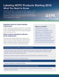
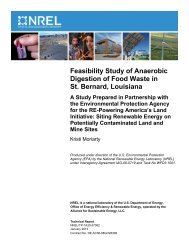
2.2.2.1 Process Description. The continuous slurry processes,<br />
conventional and hi gh-yiel d, are represented in Figure 2-1. Reactor<br />
feed materials consist mainly <strong>of</strong> monomer propylene, comonomer ethylene,<br />
monomer impurities propane and ethane, hexane, and a stereospeci fic<br />
catalyst. Hexane is used as a process diluent and acts as a heat transfhr<br />
agent and polymer suspending medium. The catalyst is usual ly manufactured<br />
on site to consistently maintain the required catalyst activity. It is<br />
mixed with necessary solvents and metered accurately into the polymerizati<br />
reactor along with other reactants. Process di luent is also used in<br />
catalyst preparation and spent diluent is sent to the diluent recovery<br />
section for reuse.<br />
The reactor is a continuously stirred jacketed vessel or a loop<br />
reactor. During reaction, a portion <strong>of</strong> the polymer/monomer/diluent<br />
mixture is continuously drawn <strong>from</strong> the reactor to a flash tank in which<br />
the unreacted propylene and propane are separated, and recovered by<br />
condensation.<br />
Slurry <strong>from</strong> the flash tank is then fed to the deactivationldecanting<br />
section for washing with an alcohol-water solution to remove most <strong>of</strong> the<br />
catalyst residues. The diluentlcrude product slurry is lighter than the<br />
alcohol-water solution and the two phases are separated by decantation.<br />
The a1 cohol-water phase is distil led to recover a1 cohol ; whereas, the<br />
diluent/crude product phase which is in the form <strong>of</strong> a slurry is stripped1<br />
to remove part <strong>of</strong> the diluent. The product slurry is then sent to a<br />
slurry vacuy fi1,ter system in which isotactic polyrr~er product solids are<br />
separated <strong>from</strong> the di luent. The atacti c polymer rerrrai ns di ssol ved in<br />
the diluent. The isotactic product goes through a product dryer, then is<br />
extruded, pelletized, and sent to product storage.<br />
In the methanol recovery section, the crude methanol streams are<br />
refined and recycled, and the bottom streams, contai ni ng catalysts<br />
metals are sent to the plant waste-water treatment f'acil ity.<br />
The atactic-diluent solution is fed to the by-plroduct (atactic) and<br />
diluent separation unit in which the diluent is purified and dried for<br />
recycle, and the atactic solids are recovered or burned in incinerators.<br />
In the high-yield slurry process, the catalyst is left in the<br />
product so deacti vati onldecanti ng and a1 cohol recovery sections are<br />
unnecessary. Along with this, one <strong>of</strong> the major emission streams is also<br />
I<br />
I
Fxlrus loll<br />
l'el lciiz ltlq<br />
Methanol-<br />
Water Solution<br />
I'rotLtc t<br />
Storage<br />
hthanol to Process<br />
Note: Process Steps 6 and 7 arc unnecessary<br />
in the high yield catalyst process.<br />
Fi yure 2-1 . Simp1 if i ed Process Block Diagram for the Polypropylene Continuous ,<br />
Liquid Phase Slurry Process
eliminated. Figure 2-1 indicates the units that should be excluded in<br />
thf s process.<br />
In addition to the use <strong>of</strong> high-yield catalysts, other process<br />
variations may occur. Mixtures <strong>of</strong> aliphatic hydrocarbons may replace<br />
hexane as the process diluent, and isopropyl alcohol may replace methanol<br />
as the catalyst deactivation agent. Also polymer dryers may vary with<br />
the facility, but a fluid bed dryer with hot nitrogen or air is the most<br />
common. Nitrogen drying has safety advantages and the nitrogen can be<br />
recycled resulting in lower costs and emissions. Other types <strong>of</strong> product<br />
dryers and different operating pressures may result in a much higher VOC<br />
em4 ssion rate. Except for high-yi el d catalyst, and the product dryer<br />
type and operating pressure, these other process variations are minor<br />
and should have little effect on the process VOC emissions.<br />
2.2.2.2 VOC Sources. The <strong>of</strong> fgas stream characteristics for polypropylene<br />
manufacturer are shown in Table 2-3. The combined process VOC emission<br />
factor for the conventional slurry process is 36.7 kg VOC/1,000 kg<br />
product. For the high-yield slurry process, Streams C and D are not<br />
present; therefore, the combined process VOC emission factor for this<br />
process is about 23.4 kg VOC/1,000 kg product. Most <strong>of</strong> the emission<br />
streams are continuous and consist mainly <strong>of</strong> propylene, ethylene, propane,<br />
and a small amount <strong>of</strong> process diluent. Properties <strong>of</strong> these compounds<br />
are summarized in Table 2-4. The temperature <strong>of</strong> the streams varies <strong>from</strong><br />
ambient to 1040C, and the pressure is about atmospheric. Each <strong>of</strong> the<br />
major VOC-containing streams are indicated on Figure 2-1 and are described<br />
be1ow:<br />
1. Stream A: Catalyst Preparation Vents - This vent continuously<br />
releases process diluent that is used in preparation <strong>of</strong> the catalyst.<br />
2. Stream B: Combined Polymerization Reactor Vents -- These emissions<br />
are <strong>from</strong> vents <strong>of</strong> reactors <strong>from</strong> all process trains. This is a continuous<br />
stream venting organic process <strong>of</strong>fgas, consisting mainly <strong>of</strong> C3 (propylene<br />
monomer and other hydrocarbons with three carbon atoms such as propane)<br />
and process diluent, which could be hexane or a mixture <strong>of</strong> aliphatic<br />
hydrocarbons with 10-12 carbon atoms.<br />
3. Streams C & D: Decanter and Neutralizer Vents - - These vents<br />
are part <strong>of</strong> the alcohol recovery section. This is usually the largest<br />
VOC source in the process and consists <strong>of</strong> methanol or isopropyl alcohol,<br />
I<br />
l<br />
I
Tab1e 2-3. CHARACTER1 STICS OF VENT STREAMS FROM THE POLYPROPYLENE CONTINUOUS<br />
LIQUID PHASE SLURRY PROCESS<br />
Emi ssion<br />
rate.<br />
Process kg VOGfNg Temperature, Pressure,<br />
~ectionb Streamc Name Nature product OC PSQ Compositiond~e<br />
RMP A Catalyst preparation Continuous 0.07 29 0 CloHC, IPA<br />
PR B Reactor vents Continuous 4.07 54 0 C3HC, CloHC<br />
MR C Decanter vents Continuous 11.49 38 0 C3HC, CloHC, IPA<br />
I MR E Slurry wacuum/f 11ter Contl nuous 7.93 32 0 CloHC. IPA<br />
system vent<br />
I HR F Oi luent separation Continuous 8.72 104 0 CloHC, IPA<br />
R) ' and recovery<br />
I<br />
u3<br />
PF G Dryer vents Continuous 0 to 0.6f 85-104 0 Air and small amount<br />
<strong>of</strong> VOC<br />
MR D Neutralizer vents Continuous 1.82 32-71 0 C3HC. CqHC. CloHC, IPA<br />
PF H Extrusion/pel letizing Continuous 2.0<br />
vent<br />
Total Emission Rate<br />
aSource <strong>of</strong> information: Industry correspondence.<br />
I<br />
~RMP=raw materials preparation; PR = polymerization reaction; MR = material recovery; PF = product finishing.<br />
cSee Figure 2-1 for stream identification.<br />
d~treams are diluted in 10 to 30 percent nitrogen.<br />
eC3HC - Propylene or any other hydrocarbon compound with three carbon atoms such as propane.<br />
I C4HC - Butylene or any other hydrocarbon compound with four carbon atoms.<br />
I CloHC - A mixture <strong>of</strong> aliphatic hydrocarbons with 10-12 carbon atoms.<br />
I IPA - lsopropyl alcohol.<br />
I<br />
f~he range reflects the fluidized bed dryer emission at different operating pressures. Other types <strong>of</strong> dryers may have<br />
even higher erni ssions.<br />
grncluding upper end to the range <strong>of</strong> emissions <strong>from</strong> dryer vents.<br />
36.79
Propyl ene (monomer) PllW = 42.06, 2186 Btu/cu ft<br />
Propane (monomer impurity) MW = 44.09, 2385 Btu/cu ft<br />
n-Hexane (di 1uent) MW = 86.17, 4412 Btu/cu ft<br />
Methanol or Isopro an01<br />
(washing alcohol !<br />
MW = 32.04 or 60.02<br />
Ethylene (cmonomer), MW = 28.05, 1513 Btu/cu ft<br />
C C Hydrocarbons (might include<br />
2k8ylene, propyl ene, and propane) MW = 50 AM^)<br />
C H.C. (A mixture <strong>of</strong> aliphatic<br />
lRydrocarbons with 10-12 carbon<br />
atoms. ) MW = 144. CI<br />
All <strong>of</strong> these compounds are usual ly diluted in qases 1 ike:<br />
Ai r ItIW = 29.0<br />
Nitrogen MW = 28.0<br />
Hydrogen MW = 2.0, 275 Btu/cu ft
in addition to C3 and process diluent. The stream is continuous and<br />
exists in most <strong>of</strong> the existing polypropylene plants. The process using<br />
a high-yield catalyst does not require these vents, and the reduction in<br />
total emi ssi on factor is significant.<br />
4. Stream E: Slurry Vacuum Filter System Vents - This stream is<br />
<strong>from</strong> the system which separates the atactic and isotactic polymer. It<br />
is one <strong>of</strong> the largest VOC emission streams venting process diluent and<br />
alcohol remaining in the polymer. It is a continuous stream at atmospheric<br />
pressure and exists in both the conventional and high-yield slurry<br />
process pl ants .<br />
5. Stream F: - This stream originates<br />
<strong>from</strong> the by-product and diluent recovery section and can be the second<br />
largest VOC emission stream in the entire process. The diluent recovery<br />
section which consists <strong>of</strong> an evaporator, an extractor and distillation<br />
units is part <strong>of</strong> all processes and emits process diluents and alcohol<br />
vapors.<br />
6. Stream G: Dryer Vents - This vent emits hydrocarbons diluted<br />
in air or nitrogen at a relatively high temperature (104OC) and atmospheric<br />
pressure. The emissions consists <strong>of</strong> vapor <strong>of</strong> hexane, methanol, and<br />
propane.<br />
7. Stream H: Extrusion/Pelletizing Vent - This vent can continuously<br />
emit significant quantities <strong>of</strong> hydrocarbon that may remain in the polypropylene<br />
powder as it exits the dryer and enters the extruder feed chute. At<br />
this point, the powder is in equilibrium with a vapor that can contain<br />
up to 25 percent hydrocarbon by weight. As a result <strong>of</strong> heating and<br />
compression in the extruder, there is some VOC loss through the extruder/<br />
pel 1 eti zi ng section and futher 1 osses <strong>from</strong> the powder/pel let transfer<br />
system downstream <strong>from</strong> the product dryer since the transfer medium acts<br />
as a stripping gas.<br />
The stream properties and VOC concentrations <strong>of</strong> Streams A to H can<br />
vary depending on process conditions. The variation generally depends<br />
on the product grade or type being manufactured and other variables such<br />
as temperature, pressure, catalyst concentration or activity, and the<br />
amount <strong>of</strong> hydrogen used for molecular weight control. The concentration<br />
and the magnitude <strong>of</strong> each stream is, <strong>of</strong> course, hightest under start-up<br />
or shutdown conditions because <strong>of</strong> process conditions away <strong>from</strong> equil ibrium.
2.2.2.3 <strong>Control</strong> Systems. No controls are routinely appl ied<br />
for<br />
j VOC control <strong>of</strong> these conti nuous sources. The polymerization reactors<br />
and the atactic separation units, however, are generally provided with<br />
emergency relief valves leading to a flare for safety purposes in the<br />
case <strong>of</strong> upsets. These emergency vents usually pass through knock-out<br />
drums to separate entrained liquid and polymer particles before the<br />
vapors are piped to the flare. Also, in the production steps, the<br />
concentrated atactic polymer stream <strong>from</strong> the slurry vacuum filter system<br />
f s piped to a vessel and its liquid content is removed by evaporation.<br />
The solid amorphous atactic polypropylene is left behind and is then<br />
either burned in incinerators or is packed and sold as a by-product for<br />
paper coating and other applications. For some producers, the atactic<br />
polymer is incinerated, liquid and gaseous waste streams <strong>from</strong> the process<br />
may also be burned in the same device.<br />
2.3 HIGH-DENSITY POLYETHYLENE<br />
2.3.1 General Industry Description<br />
High-density polyethylene (HDPE) resins are linear thermoplastic<br />
polymers <strong>of</strong> ethylene with densities higher than 0.94 g/cm3. HOPE resins<br />
are typically produced by a 1 ow-pressure process in which organic sol vbnts<br />
are used; the solid catalyst is in suspension; and the polymer forms a<br />
slurry (e.g., the processes originated by Phil lips Petroleum Company ahd<br />
Solvay and Cie, SA). Although there are various solvent processes used,<br />
the variations do not affect emissions except with respect to the solvent<br />
recovery methods used.<br />
HDPE is a highly (>90 percent) crystal line polymer containing less<br />
than one side chain per 200 carbon atoms in the main chain. The typical<br />
density range is 0.95-0.97 g/cm3.7 It is strong, water- and chemical-<br />
resistant, and can be easily processed. It is one <strong>of</strong> the largest volume<br />
plastics produced in the U.S. and in the world. It is extruded into<br />
film sheets, pipe or pr<strong>of</strong>iles, coated, injection molded, blow molded,<br />
rotationally molded, foamed, or formed in other ~ a i ~ s . ~<br />
HDPE's primary application is blow molded bottles for bleaches,<br />
liquid detergents, milk, and other fluids. Other blow molded forms for<br />
which HDPE's are used include automotive gas tanks, drums, and carboys.<br />
HDPE's also are used for injection molded forms ir~cluding material<br />
handling pallets, stadium seats, trash cans, and abut0 parts. Film is<br />
I
used in maki fig shopping bags. Forty percent <strong>of</strong> a1 1 HDPE is blow molded;<br />
another 22 percent is injection molded. Film and sheet combined account<br />
for only six percent <strong>of</strong> HDPE use. Other uses account for 32 percent.<br />
End use sectors for HDPE include packagi ng (45 percent), consumer/i nsti -<br />
tutional (11 percent), bui 1 ding and construction (9 percent), and other<br />
sectors (35 percent).3<br />
From 1973 t o 1979, production <strong>of</strong> HDPE grew <strong>from</strong> 1,196 Gg to 2,273 Gg,<br />
'a growth rate <strong>of</strong> 11.3 percent. C.H. Kline projects growth at 7.0 percent<br />
for 1978 t o 1983.4 SRI International projected growth <strong>from</strong> 1976 t o 1980<br />
at 10 percent.5<br />
2.3.2 Model Plant<br />
The Phillips particle form process serves as the basis for this<br />
model plant, but it is intended to represent all other liquid phase<br />
slurry processes.<br />
This model plan specifically includes an unreacted monomer recycling<br />
system. There are other similar liquid-phase processes that do not use<br />
such systems and have larger emissions. The plant capacity for the<br />
model HDPE plant is 214 Gg/yr. This is based on plants 1 ocated in<br />
nonattainment areas. .The existing HDPE plants known to be in the current<br />
ozone nonattainment areas are listed in Table 2-5.<br />
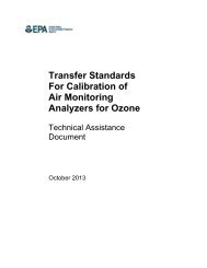
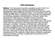
2.3.2.1 Process Description. Referring to the schematic for thi s<br />
process, Figure 2-2, the feed section includes catalyst purification and<br />
activation. The prepared catalyst is then fed to the reactor continuously<br />
by being slurried in a stream <strong>of</strong> process diluent (pentane or isobutane).<br />
Ethylene monomer and comonomer (1-butene or hexene), after purification,<br />
are also fed to the reactor where polymerization takes place in process<br />
sol vent. The reactor, for the particle-form process, is usually a<br />
closed loop pipe reactor. The product HDPE is separated <strong>from</strong> unreacted<br />
monomer and di luent by flashing <strong>from</strong> a 1 ow pressure to a vacuum and by<br />
steam stripping. The wet polymer solids are dewatered in a centrifuge<br />
and then dried in a closed-loop nitrogen or air-fluidized drying system<br />
prior to extrusion.<br />
The unreacted monomer and diluent vapors are sent through a diluent<br />
recovery unit where most <strong>of</strong> the di luent is separated and recycled back<br />
to the reactor. The rest <strong>of</strong> the stream is then sent to the ethylene
Table 2-5. HIGH-DENSITY POLYETHYLENE (VDPE) PLANTS IN OZONE<br />
NONATTAINMENT AREAS I<br />
b<br />
Capacity<br />
Company Location Status (Gg/yr<br />
Allied Chem. Corp. Baton Rouge, LA NANR<br />
ARC0 polymers', Inc . Port Arthur, TX NANR<br />
Cities Service Co. Texas City, TX NANR<br />
Dow Chemical Freeport, TX NANR<br />
Pl aquemine, LA NANR<br />
Amoco Chem. Corp. Chocolate Bayou, TX NAN R<br />
E.I. Du Pont de Orange, TX NANR<br />
Nemours & Co. Inc. Victoria, TX NANR<br />
Gulf Oil Cot-p. Orange, TX NANR<br />
Hercules, Inc . Lake Charles, LA NANR<br />
Nat'l Petrochem. La Porte, TX NAR<br />
Corp.<br />
Phillips Petro. Co. Pasadena, TX NAR<br />
So1 tex Polymer Corp. Deer Park, TX NAR<br />
UCC Port Lavaca, TX NANR<br />
a~hislist is illustrative only. Since the attainment status <strong>of</strong><br />
areas change <strong>from</strong> time to time, this is not intended to be a definitive<br />
list <strong>of</strong> plants that will be affected by this guide1 ine document.<br />
b~zone nonattai nment area not requesting extension ( NANR)<br />
Ozone nonattainment area requesting extension (NAR).<br />
, 8,<br />
SOURCES: SRI Internati ona1 , 1980 Directory <strong>of</strong> Chemical Producers,<br />
United States.<br />
U.S. EPA study by Pullman-Kellogg Co., plant listing.<br />
The BNA Environmental Reporter AQCR Listing. 5121 (through'<br />
Flarch 12, 1981).<br />
.<br />
!
I<br />
2<br />
CTC<br />
E%%<br />
PCS A<br />
wrcc 2<br />
C W P<br />
U<br />
iZdS<br />
CTPP: LL<br />
an<br />
3
ecovery unit where ethylene is recovered and sent to recycle ethylene<br />
treaters and back to the reactor.<br />
2.3,2,2 VOC Sources. All the process streams, except the feed<br />
preparation stream, in HDPE manufacture are continuous, and they consist<br />
mainly <strong>of</strong> ethylene and process solvent diluted in nitrogen or air.<br />
Most <strong>of</strong> the streams are at ambient temperature. An ethylene safety<br />
flare is always a part <strong>of</strong> each system, and some plants may use it for<br />
VOC emission control . Since thi s parti cul ar model p'l ant incorporates<br />
ethylene recycle, it has re1 atively small emissions , but plants which<br />
vent unreacted monomer and use ai r-fluidized dryers have substantial ly<br />
higher VOC emissions. The major VOC source is the flash tank where an<br />
unreacted monomer stream (about 50 percent VOC) is released. HDPE<br />
manufacturers <strong>of</strong>ten send this stream to a boiler to recover the heat<br />
content. Table 2-6 shows the vent stream.characteristics for the VOC ,<br />
sources: these sources are described be1 ow: I<br />
1. Stream A: Feed Preparation - This is an intermittent stream<br />
consisting mostly <strong>of</strong> ethylene. Assumed to vent 12 times a year, it's<br />
sources are arying, dehydrating and other feed purification operations.<br />
2. Stream B: Dryer - Dryer emissions are continuous and have low I<br />
VOC concentrations. Closed-1 oop drying systems have very 1 ow emissions<br />
<strong>of</strong> process solvent in nitrogen. Air-fluidized dryers have significantly<br />
higher emi ssi ons.<br />
3. Stream C: Continuous Mixer - This is another low VOC emission<br />
stream coming <strong>from</strong> a mixer which mixes polymer with anti-oxidants, It<br />
is continuous and releases process solvent that is still left in the<br />
polymer along with a large quantity <strong>of</strong> nitrogen. Usually this stream is<br />
emitted to the atmosphere.<br />
4. Stream 0: Recycle Treaters - This is a semi-continuous VOC<br />
emSssfon stream containing about 80 weight percent VOC. Currently this<br />
stream is usually flared. Treaters consi st <strong>of</strong> vessel s containing such<br />
materi a1 s as adsorbents , dessi cant s , and mol ecul ar sieves whi ch remove<br />
I<br />
water and other impurities in the recycle ethylene stream. <strong>Emissions</strong> ,<br />
occur when the vessels are purged during regeneration <strong>of</strong> the adsorber<br />
I<br />
beds, This stream is considered a continuous stream. The stream flows<br />
continuously for about 20 out <strong>of</strong> 24 hours.<br />
I<br />
I
Table '2-6. CHARACTERISTICS OF VENT STREAMS FROM THE HIGH DfN8ITY<br />
.<br />
POLYETHYLENE LOW-PRESSURE, LIQUID PHASE SLURRY PROCESS '<br />
Process<br />
Sectionc stread Name Nature<br />
Emission<br />
rate,<br />
kg VOC/Mg<br />
product<br />
Temperature,<br />
OC<br />
Composition.<br />
IJt.%<br />
RHP A Feed preparation Intermittente 0.2 21 100.0 Ethylene<br />
PF B Dryer nitrogen bl ouer Continuous 0.06-0.4f 21 0.3 Isobutane<br />
99.7 Nitrogen<br />
PF C Continuous mixer Continuous . 0.006 21 0.6 Isobutane<br />
99.4 Nitrogen<br />
HR D Recycle treaters Continuous 12.7 21 61.0 Ethylene<br />
18.0 Isobutane<br />
20.0 Ethane<br />
1.0 Hydrogen<br />
aSource <strong>of</strong> information : Industry correspondence.<br />
b~as stream pressure data unknown.<br />
Total Emission Rate 13.0-13.3<br />
cRMP = raw materials preparation; PF= product finishing; MR = material recovery.<br />
dSee Figure 2-2 for stream identification.<br />
eOne occurrence per month.<br />
f~ow end is for recycle nitrogen dryers; high end is for air fluidized bed dryers.
2.3.2.3 <strong>Control</strong> Systems. As noted, like the other polyolefin<br />
processes, the HDPE process generally has a flare as a part <strong>of</strong> the<br />
system for safety reasons. A complete line <strong>of</strong> safety re1 ief devices<br />
leading to the flare are commonly provided to avoid accidents as a<br />
result <strong>of</strong> equi went overpressuri zation or ma1 function.<br />
2.4 POLYSTYRENE<br />
2.4.1 General Industry Descri pti on<br />
Polystyrene <strong>of</strong>fers a combination <strong>of</strong> excellent physical properties<br />
and processi bi 1 ity at a re1 atively 1 ow price for thermoplastic material s.<br />
It i s crystal clear and has colorability, rigidity, good electrical<br />
properties, thermal stabil ity , and high-fl exural and tensi 1 e strengths.<br />
Polystyrene products are used in molded forms, extrusions, liquid solutions,<br />
adhesives, coatings, and foams. The family <strong>of</strong> polymerized co-polymers<br />
Prom styrene monomer and its modifications ranked third among all plasti'cs<br />
in consumption within the United ~tates.8<br />
Molded uses incl ude toys, autoparts , housewares, kitchen items ,<br />
appliances, wall tiles, refrigerated food containers, radio and televi si on<br />
housings, small appl iance housi ng , furniture, packages, and bui 1 di ng<br />
components such as shutters. Extruded sheets also are used in packaging,,<br />
appl iance, boats, 1 uggage, and di sposabl e pl ates. Foamed styrene is a<br />
good insul ator and is used in construction, packaging, boats, housewares,<br />
toys, and hot/cold insulated drink cups.2 Fifty percent <strong>of</strong> a1 1 styrene I<br />
is molded. Extrusion accounts for 33 percent. Other forms make up<br />
17 percent.<br />
.<br />
Of end use sectors, packaging makes up 35 percent, consumer/<br />
1nsti tutional - 22 percent, bui 1 ding and construction - 10 percent,<br />
electrical and electronic - 10 percent, and other sectors - 23 percent.3<br />
Production <strong>of</strong> styrene has grown <strong>from</strong> 1,507 Gg .in 1973 to 1,817 Gg<br />
in 1978, a 3.2 percent growth rate. C.H. Kline pro,jects a 6.0 percent<br />
growth rate for 1978-19834 while SRI ~nternational projects a 4-9 percent<br />
growth rate for 1979-1982.5<br />
Styrene polymerizes readily with the addition <strong>of</strong> either heat or<br />
catalyst like benzoyl peroxide or ditertiary butylperbenzoate. Styrene<br />
will homopolyrneri ze in the presence <strong>of</strong> inert materi a1 s and co-polymeri ze<br />
with a variety <strong>of</strong> monomers. Pure polystyrene has the following structure:<br />
I
A1 though polymers with molecular weights in the mil 1 ions can be<br />
made, those most useful for molding have molecular weights <strong>of</strong> about<br />
125,000; while those used in the surface coating industry average about<br />
35,000.<br />
2.4.2 Model Plant<br />
A continuous process for the manufacture <strong>of</strong> polystyrene was chosen<br />
for developing the model plant primarily because <strong>of</strong> its significant VOC<br />
emissions. Mass (bul k) polymerization was used as a basis for developing<br />
the flow diagram. However, the model plant represents all liquid phase<br />
continuous processes, In the case <strong>of</strong> suspension polymerization, because<br />
polymerization takes place in water, dewatering, washing, centrifuge and<br />
dryer sections are required. These sections usually are not sources <strong>of</strong><br />
VOC emissions. The model plant capacity is 73.5 Gg/yr. This capacity<br />
represents an average <strong>of</strong> capacities <strong>from</strong> polystyrene plants using batch<br />
or continuous processes in ozone nonattainment areas. The existing<br />
polystyrene plants in ozone nonattainment areas are listed in Table 2-7.<br />
The list includes both continuous and batch-type processes; when the<br />
process type is unknown the process comment is left blank. The plants<br />
with unknown process type are included for completeness <strong>of</strong> the list.<br />
Only the continuous processes are covered by RACT.<br />
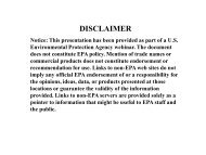
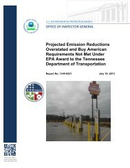
2.4.2.1 ProcessDescription. This description is for a<br />
fully continuous, thermal co-polymerization process for the manufacture<br />
<strong>of</strong> pel 1 eti zed polystyrene resi n <strong>from</strong> styrene monomer and polybutadi ene.<br />
Several grades <strong>of</strong> crystal and impact polystyrene are produced by this<br />
process. The continuous process is represented in Figure 2-3.<br />
Styrene, polybutadiene, mineral oi i , and small amounts <strong>of</strong> recycl e<br />
polystyrene, anti-oxidants and other additives are introduced into the<br />
feed dissolver tank in proportions that vary according to the grade <strong>of</strong><br />
resin being produced. Blended feed is pumped on a continuous basis to<br />
the reactor where the feed is thermally polymerized to polystyrene. The<br />
polymer melt, containing some unreacted styrene monomer and by-products
Tab1e 2-7. POLYSTYRENE (PS) PLANTS IN OZONE NONATTAINMENT ARE AS^<br />
Capacity Procesg<br />
C ~ P W Location statusb (Gg/yr) Comment<br />
A.E. Plastik Pak Co., Inc. City <strong>of</strong> Industry, CA NAR 16<br />
Fun. Hoechst Corp. Cheasapeake, VA<br />
Leominster, MA<br />
NANR<br />
NANR<br />
91<br />
54<br />
hco Chemical Corp.<br />
ARC0 Polymers, Inc.<br />
Joliet, IL<br />
Torrance, CA<br />
Willow Springs, IL<br />
Monaca, PA<br />
NANR<br />
NAR<br />
NAR<br />
NAR<br />
136<br />
16<br />
41<br />
238<br />
Continuous<br />
Batch<br />
Batch<br />
-<br />
BaSF Uyandotte Corp.<br />
Carl Gordon, Ind., Inc.<br />
Jamesburg, NJ<br />
South Brunswick, NJ<br />
Owensboro, KY<br />
Oxford, MA<br />
NAR<br />
NAR<br />
z: 1 136<br />
Cosden Oil & Chemical Co.<br />
Crest Container Corp.<br />
Worchester, MA<br />
Windsor, NJ<br />
Calumet City, IL<br />
Saginaw, TX<br />
Fort Worth, TX<br />
50<br />
68<br />
NAR<br />
NAR<br />
NAR<br />
NANR<br />
NANR<br />
Batch<br />
Batch<br />
Batch-- -<br />
Continuous<br />
Batch- Dart Ind., Inc.<br />
Dow Chmfcal Corp.<br />
Bayport, TX<br />
Allyns Pt., CT<br />
Midland, MI<br />
Torrance, CA<br />
NANR<br />
NAR<br />
NANR<br />
NAR<br />
- .<br />
..<br />
Continuous<br />
Continuous<br />
Gulf Oil Chemical Co.<br />
Mobil Chenical Co.<br />
Marietta, OH<br />
Channelview, TX<br />
Holyoke, MA<br />
Joilet, IL<br />
Santa Ana, CA<br />
1<br />
NANR<br />
NAR<br />
NAR<br />
NANR<br />
NANR<br />
Continuous<br />
-<br />
Continuous<br />
Addyston, OH<br />
Decatur, AL<br />
Long Beach, CA<br />
Springfield, MA<br />
NAR<br />
NANR<br />
NAR<br />
NAR<br />
Continuous<br />
Continuous -<br />
Continuous<br />
Polysar Resins, Inc.<br />
Richardson Canpany<br />
Copley, OH<br />
Leominster, MA<br />
Channel vi ew, TX<br />
NANR<br />
NAR<br />
NANR<br />
Continuous<br />
- Shell Chmlcal Co. Belpre, OH NANR Continuous<br />
Sterling Plastics Corp. Windsor, NJ NAR Continuous<br />
a~hislist is illustrative only. Since the attainment status <strong>of</strong> areas change<br />
frm time to time, this is not intended to be a definitive list <strong>of</strong> p'lants that will<br />
be affected by this guide1 ine document.<br />
b~tont nonattabment area not requesting extension (NANR).<br />
Ozone nonattaiment area requesting extension (NAR).<br />
'Only continuous processes are covered by RACT.<br />
SOURCES: SRI International , 1980 Directory <strong>of</strong> Chemical Producers,<br />
United States.<br />
U.S. EPA study by Pullman-Kellogg Co., plant listing.<br />
The BNA Environmental Reporter AQCR Listing. 5121 (through Harch 12,<br />
1981).<br />
-
A - . STYREL<br />
+VACUUH SYSTEM<br />
(8)<br />
(9)<br />
4<br />
STYREHE<br />
RECOVERY COLUHN HEAVIES USED<br />
AS FUEL MAKFUP<br />
REACTOR FEED ISOTHEWL MASS' (BULK) VACWH EXTRUDER AND<br />
FEED NATERIALS FEED DISSOLVER POLYHERI2AT.ION -OEVOLATILIZER PELLETIZER --+ PELLET STORAGE<br />
+ +<br />
STORAGE (HIXER) CONTINUNS REACTOR (3) (5) (6)<br />
(1) (2)<br />
- 1<br />
I
is pumped to a vacuum devolatilizer where most <strong>of</strong> the monomer and by-<br />
products are separated, condensed and sent to a styrene recovery unit.<br />
Vapors <strong>from</strong> the styrene condenser are vented through a vacuum system.<br />
Molten polystyrene <strong>from</strong> the bottom <strong>of</strong> the devolatilizer is pumped<br />
through a stranding die-plate into a cold water bath. The cooled strands<br />
are pelletized and sent to product storage.<br />
In the styrene recovery unit, crude styrene rrlonomer is separated in<br />
'<br />
a distillation column. The styrene vapor overhead frbm the tower is<br />
condensed and recycled to the feed di ssol ver tank, Noncondensi bl es are<br />
vented through a vacuum system, Heavies <strong>from</strong> the bottom <strong>of</strong> the column<br />
can be used as a fuel supplement.<br />
2.4.2.2 VOC Sources. Table 2-8 shows the vent stream characteristics<br />
for the continuous polystyrene process. All VOC emission streams <strong>from</strong><br />
the process are continuous. Industry's experience with continuous<br />
polystyrene plants indicate a wide range <strong>of</strong> emission rates <strong>from</strong> plant to<br />
plant. Steam present in Streams B and C reflects the use <strong>of</strong> a steam jet<br />
ejector in the vacuum system used; air reflects the use <strong>of</strong> vacuum<br />
pumps.<br />
1. Stream A: Feed Dissolver - This vent emits mostly styrene.<br />
The VOC emission results <strong>from</strong> washing losses. Currently, the styrene is<br />
emitted to the atmosphere.<br />
2. Stream B: Styrene Condenser Vent - Consists <strong>of</strong> unreacted<br />
styrene separated <strong>from</strong> the polystyrene in a vacuum devol ati 1 izer. The<br />
stream can be exhausted through a vacuum system ( g , steam jet ejector)<br />
to atmosphere. This is the largest VOC source. CJhen vacuum pumps are<br />
used and fol 1 owed by refrigerated bri ne condenser ,, the emi ssi ons can be<br />
lower.<br />
3. Stream C: Styrene Recovery Unit Condenser Vent - This stream<br />
contains the noncondensible components separated in the styrene recovery<br />
I<br />
tower and is vented through a steam jet ejector or vacuum pump.<br />
4. Stream D: Extruder Quench Vent - This stream consists <strong>of</strong><br />
steam and a trace <strong>of</strong> styrene vapor. The stream is usually vented through<br />
l<br />
a forced-draft hood and passed through demister-pad or electrostatic<br />
I<br />
precipitator before venting to the atmosphere.<br />
2.4.2.3 <strong>Control</strong> Systems. No routine control is applied to continuous<br />
1<br />
processes other than normal condensation operations. One unique system,<br />
,<br />
.3
Tab1e 2-8. CHARACTERISTICS OF VENT STREAMS FROM THE POLYSTYRENE CONTINUOUS PROCESS^<br />
Processb<br />
Section streamC Name Nature<br />
Emission<br />
rate,<br />
kg VOC/Mg<br />
product<br />
Temperature.<br />
OC<br />
Pressure,<br />
P S ~<br />
Cmposition,<br />
M.%<br />
Feed Dissol ver Continuous 0.009 - - 92 Styrene<br />
7.5 Polybutadiene<br />
1.5 Other<br />
Devolatil izer condenser<br />
vent Continuous 0.05-2.96 100 0 21.8 Styrene<br />
78.2 Steam<br />
Styrene recovery unit<br />
condenser vent<br />
Continuous 0.05-0.13 100 0 2.1 Styrene<br />
97.9 Steam<br />
Extruder quench vent Continuous 0.15 . 21 - 99.99 Steam<br />
Trace Styrene<br />
Total Emission Rate 0.26-3.25<br />
a~ource<strong>of</strong> Information: Industry correspondence.<br />
bfU!~ = raw material preparation; t1R = material recovery; PF = product finishing.<br />
'see Figure 2-3 for stream identification.
however, <strong>of</strong> vapor condensing/recovery is used where each process vessel<br />
is equipped with rupture discs having the respective pressure relief<br />
settings. When any <strong>of</strong> these process vessels are overpressured, the<br />
vapors re1 ieve to the vapor condensi ng/recovery system. By flashi ng<br />
I<br />
action and by condensation, most <strong>of</strong> the vapors are condensed, recovered,<br />
and reused in the process. This system a1 so results in a single emission<br />
point in the entire process. Unlike the polyolefins processes, no<br />
flares are used as control devices.<br />
I
3.0 EMISSION CONTROL TECHNIQUES<br />
<strong>Volatile</strong> organic compounds (VOC), used as solvents and key raw<br />
materials in the manufacture <strong>of</strong> polymers and resins, are emitted to the<br />
atmosphere <strong>from</strong> a variety <strong>of</strong> process equipment. Process VOC emissions<br />
can be reduced either by installing emission control devices or by<br />
reducing the VOC in the vent streams by a process modification such as<br />
recovery <strong>of</strong> monomer or sol vent. This chapter describes emission control<br />
techniques that may be used to reduce process emissions <strong>from</strong> the polymers<br />
and resins industry.<br />
Process emi ssi ons <strong>from</strong> the manufacture <strong>of</strong> polymers and resins are<br />
diverse in both composition and flow. Streams contain a wide range <strong>of</strong><br />
VOC concentrations, i.e., less than 1 percent to essentially 100 percent,<br />
but most are <strong>of</strong> high concentration. Some streams are continuous, while<br />
others are intermittent. Process emissions also differ in temperature,<br />
pressure, heating value, and miscibility. These factors are extremely<br />
important in the selection and design <strong>of</strong> VOC emission control equipment.<br />
Due to this diversity, different control techniques may be appropriate<br />
for different vent streams. The control techniques may be characterized .<br />
by two broad categories: combustion techniques and recovery techniques.<br />
Combustion techniques such as flares and incinerators are applicable to<br />
a variety <strong>of</strong> VOC streams. Recovery techniques such as condensation,<br />
, absorption, and adsorption, are effective for some select vent streams.<br />
Economic incentives may encourage the use <strong>of</strong> either type <strong>of</strong> VOC control,<br />
since certain combustion configuraticns my permit heat recovery, and<br />
recovery techniques permit the conservation and reuse <strong>of</strong> valuable materials.<br />
The selection <strong>of</strong> a control system for a particular application is based<br />
primarily on considerations <strong>of</strong> technical feasibility and process economics.<br />
The most common control techniques form the basis for this chapter.<br />
Basic design considerations for flares, thermal and catalytic incinerators,
industrial boilers, condensers, absorbers, and adsorbers, are briefly<br />
described. The conditions affecting the VOC removal efficiency <strong>of</strong> each<br />
type <strong>of</strong> device and its applicability for use in the polymers and resins<br />
industry are examined. Emphasis has been given to flares, thermal<br />
incinerators, and condensers because <strong>of</strong> their wide aplplicability to a<br />
variety <strong>of</strong> VOC streams. Combustion techniques are discussed in Section 3.1<br />
and recovery techniques in Section 3.2.<br />
3.1 CONTROL BY COMBUSTION TECHNIQUES<br />
The four major combustion devices that are or can be used to control<br />
VOC emissions <strong>from</strong> the polymers and resins industry alre: flares, thermali<br />
or catalytic incinerators, and boilers. Flares are the most widely used<br />
I<br />
control devices at polyethylene and polypropylene manufa'cturi ng plants.<br />
Incinerators and boilers are also used, to a lesser extent, to control<br />
continuous vent streams. Although these control devilces are founded<br />
i<br />
upon basic combustion principles, their operating characteristics are<br />
very different. While flares can handle both continuous and intermittent<br />
streams, neither boilers nor incinerators can effectively hand1 e 1 arge<br />
volume intermittent streams. This section discusses the general principles<br />
<strong>of</strong> combustion, and then the design and operation, VOC destruction efficiency,<br />
and applicability <strong>of</strong> these four combustion devices at polymers and<br />
I<br />
resins manufacturing plants.<br />
Combustion is a rapid oxidation process, exothermic in nature,<br />
which results in the destruction <strong>of</strong> VOC by converting it to carbon<br />
dioxide and water. Poor or incomplete combustion results in the production<br />
I<br />
<strong>of</strong> other organic compounds including carbon monoxide, The chemical<br />
reaction sequence which takes place in the destruction <strong>of</strong> VOC by combustion<br />
is a camplicated process. It involves a series <strong>of</strong> reactions that produce<br />
free radicals, partial oxidation products, and final combus tion products.<br />
I<br />
Several intermediate products may be created before the oxidation process<br />
is completed. However, most <strong>of</strong> the intermediate products have a very<br />
short life and, for engineering purposes, complete destruction <strong>of</strong> the<br />
VQC is the principal concern. 1<br />
Destruction efficiency is a function <strong>of</strong> temperature, turbul ence,<br />
and residence time. Chemicals vary in the magnitude!; <strong>of</strong> these parameters<br />
I
that they require for complete combustion. An effective combustion<br />
technique must provide:<br />
1. Intimate mixing <strong>of</strong> combustible material (VOC) and the oxidizer<br />
(air),<br />
2. Sufficient temperature to ignite the VOC/air mixture and complete<br />
its coinbustion,<br />
3. Required residence time for combustion to be completed, and<br />
4. Admission <strong>of</strong> sufficient air (more than the stoichiometric<br />
amount) to oxidize the VOC completely.<br />
3.1.1 Flares<br />
Flaring is an open combustion process in which the oxygen required<br />
for combustion is provided by the air around the flame. Good combustion<br />
in a flare is governed by flame temperature, residence time <strong>of</strong> components<br />
in the combustion zone, turbulent mixing <strong>of</strong> components to complete the<br />
oxidation reaction, and oxygen for free radical formation.<br />
There are two types <strong>of</strong> flares: ground level flares and elevated<br />
flares. Kalcevic (1980) presents a detail ed discussion <strong>of</strong> different<br />
types <strong>of</strong> flares, flare design and operating considerations, and a method<br />
for estimating capital and operating costs for flaresa3 Elevated flares<br />
are most common in the polymers and resins industry. The basic elements<br />
<strong>of</strong> an elevated flare system are shown in Figures 3-1 and 3-2. Process<br />
<strong>of</strong>fgases are sent to the flare through the collection header. The<br />
<strong>of</strong>fgases entering the header can vary widely in volumetric flowrate,<br />
moisture content, VOC concentration, and heat value. The knock-out drum<br />
removes water or hydrocarbon droplets that could create problems in the<br />
flare combustion zone. Offgases are usually passed through a water seal<br />
before going to the flare. This prevents a possible flame flashback,<br />
which can be caused when the <strong>of</strong>fgas flow to the flare is too low and the<br />
flame front moves down into the stack.<br />
Purge gas (Np, C02, or natural gas) also he1 ps to prevent flashback<br />
in the flare stack caused by low <strong>of</strong>fgas flow. The total volumetric flow<br />
to the flame must be carefully control led to prevent low flow flashback<br />
problems and to avoid a detached flame (a space between the stack and<br />
flame with incomplete combustion) caused by an excessively high flowrate.<br />
A gas barrier or a stack seal is sometimes used just below the flare<br />
head to impede the flow <strong>of</strong> air into the flare gas network.<br />
3-3
Eflisslo~l<br />
Swce<br />
Gas<br />
. +<br />
Drain<br />
, ''<br />
Steam -<br />
Nozzles<br />
Flare -<br />
Head<br />
Gas ,<br />
Barrier<br />
Flare<br />
Stack<br />
Figure 3-1. Steam Assisted Elevated Flare System
PILOT AND<br />
CENTER mAlri<br />
JET<br />
ELNATION<br />
Figure 3-2. Steam Injection Flare Tip
The VOC stream enters at the base <strong>of</strong> the flame where it is heated<br />
by already burning fuel and pilot burners at the fliire tip. Fuel flows<br />
into the combustion zone where the exterior <strong>of</strong> the rnicroscopic gas<br />
I<br />
pockets is oxidized. The rate <strong>of</strong> reaction is 1 imitcd by the mixing <strong>of</strong><br />
the fuel and oxygen <strong>from</strong> the air. If the gas pocket has sufficient<br />
oxygen and residence time in the flame zone it can be completely burned.<br />
A diffusion flame receives its combustion oxygen by diffusion <strong>of</strong> air<br />
into the flame <strong>from</strong> the surrounding atmosphere. The high volume <strong>of</strong> fuel<br />
flow in a flare requires more combustion air at a faster rate than<br />
simple gas diffusion can supply, so flare designers add steam injection<br />
nozzles to increase gas turbulence in the flame boundary zones, drawing<br />
Jn more combustion air and improving combustion efficiency. The steam<br />
injection promotes smokeless flare operation by minimizing the cracking<br />
reactions that form carbon. Significant disadvantages <strong>of</strong> steam usage<br />
are the increased noise and cost. The steam requirement depends on the<br />
composition <strong>of</strong> the gas flared, the steam velocity <strong>from</strong> the injection<br />
nozzle, and the tip diameter. Although some gases can be flared smokelessly<br />
without any steam, typically 0.15 to 0.5 kg <strong>of</strong> steam per kg <strong>of</strong> hydrocarbon<br />
in the flare gas is required.<br />
Steam injection is usual 1y control led manual ly with the operator<br />
observing the flare (either directly or on a television monitor) and<br />
adding steam as required to maintain smoke1 ess operation. Several flare<br />
manufacturers <strong>of</strong>fer devices which sense flare flame characteristics and I<br />
adjust the steam flowrate automatically to maintain smokeless operation.<br />
Some elevated flares use forced air instead <strong>of</strong> steam to provide the<br />
combustion air and mixing required for smoke1 ess operation. These<br />
flares consist <strong>of</strong> two coaxial flow channels. The combustible gases flow<br />
in the center channel and the combustion air (provided by a fan in the<br />
bottom <strong>of</strong> the flare stack) flows in the annulus. The principal advantage<br />
<strong>of</strong> air assisted flares is that expensive steam is not required. Air<br />
assist is rarely used on large flares because air flow is difficult to<br />
control when the gas flow is intermittent. About 600 J/sec (0.8 hp) <strong>of</strong><br />
blower capacity is required for each 45 kg/hr (100 1 b/hr) <strong>of</strong> gas flared<br />
(Kl ett and Gal es ki , 1976).
Ground flares are usually enclosed and have mu1 tiple burner heads<br />
that are staged to operate based on the quantity <strong>of</strong> gas released to the<br />
flare. The energy <strong>of</strong> the gas itself (because <strong>of</strong> the high nozzle pressure<br />
drop) is usually adequate to provide the mixing necessary for smokeless<br />
operation and air or steam assist is not required. The fence or other<br />
enclosure reduces noise and 1 ight <strong>from</strong> the flare and provides some wind<br />
protection.<br />
Ground flares are less numerous and have less capacity than elevated<br />
flares. Typically they are used to burn gas "continuously" while steam<br />
assisted elevated flares are used to dispose <strong>of</strong> large amounts <strong>of</strong> gas .<br />
released in emergencies (Payne, 1982) .5<br />
3.1.1.1 Flare VOC Destruction Efficiency. The flammability limits<br />
<strong>of</strong> the gases flared influence ignition stability and flame extinction<br />
(gases must be within their flammabi 1 ity 1i mits to burn). When flammabil ity<br />
limits are narrow, the interior <strong>of</strong> the flame may have insufficient air<br />
for the mixture to burn. Outside the flame, so much air may be induced<br />
that the flame is extinguished. Fuels with wide limits <strong>of</strong> flammability<br />
are therefore usually easier to burn (for instance, H2 and acetylene).<br />
However, in spite <strong>of</strong> wide flammability limits, CO is difficult to burn<br />
because it has a low heating value and slow combustion kinetics.<br />
The auto-ignition temperature <strong>of</strong> a fuel affects combustion because<br />
gas mixtures must be at high enough temperature and at the proper mixture<br />
strength to burn. A gas with a low auto-ignition temperature will<br />
ignite and burn more easily than a gas with a high auto-ignition temperature.<br />
Hydrogen and acetylene have low auto-ignition temperatures while CO has<br />
a high one.<br />
The heating value <strong>of</strong> the fuel also affects the flame stability,<br />
emissions, and structure. A lower heating value fuel produces a cooler<br />
flame which does not favor combustion kinetics and also is more easily<br />
extinguished. The lower flame temperat~x will a1 so reduce buoyant<br />
forces, which reduces mixing (especially for large flares on the verge<br />
<strong>of</strong> smoking). For these reasons, VOC emissions <strong>from</strong> flares burning gases<br />
with low heat content may be higher than those <strong>from</strong> flares which burn<br />
high heat content gases.
k<br />
Some fuels, a1 so, have chemical differences (slow combustion kinetics)<br />
suffjcient to affect the VOC emissions <strong>from</strong> flares. For instance, CO is<br />
difficul t to ignite and burn, and so flares burning fuels with large<br />
amounts <strong>of</strong> CO may have greater VOC emissions than flares burning pure<br />
VOC . The density <strong>of</strong> the gas flared also affects the structure and stability<br />
<strong>of</strong> the flame through the effect on buoyancy and mixing. The velocity in<br />
many flares is very low, and, therefore, most <strong>of</strong> the flame structure is<br />
developed through buoyant forces on the burning gas. Lighter gases thus<br />
tend to burn better, a1 1 else being equal. The density <strong>of</strong> the fuel a1 so<br />
affects the minimum purge gas required to prevent flashback and the<br />
design <strong>of</strong> the burner tip.<br />
Poor mixing at the flare tip or poor flare maintenance can cause<br />
smoking (particulate). Fuels with high carbon-to-hydrogen ratios (greater<br />
than 0.35) have a greater tendency to smoke and require better mixing if<br />
they are to be burned smokelessly.<br />
The following review <strong>of</strong> flares and operating conditions summarizes<br />
five studies <strong>of</strong> flare combustion efficiency.<br />
Palmer (1972) experimented with a 112-inch ID flare head, the tip<br />
<strong>of</strong> which was located 4 feet <strong>from</strong> the ground.6 Ethylene was flared at 15<br />
to 76 m/sec (50 to 250 ft/sec) and 0.12-0.62 x lo6 J/sec (0.4-2.1 x lo6<br />
Btu/hr) at the exit. Helium was added to the ethylene as a tracer at 1<br />
to 3 volume percent and the effect <strong>of</strong> steam injection was investigated<br />
in some experiments. Four sets <strong>of</strong> operating conditions were investigated;<br />
destruction efficiency was measured as greater than 99.9 percent for<br />
three sets and 97.8 percent for the fourth. The author questioned the<br />
validity <strong>of</strong> the 97.8 percent result due to possible sampling and analytical<br />
errors. He recommended further sampl ing and analytical techniques<br />
development before conducting further flare evaluations.<br />
I<br />
Siege1 (1980) made the first comprehensive study <strong>of</strong> a commercial<br />
flare system.7 He studied burning <strong>of</strong> refinery gas on a commercial flare<br />
head manufactured by Fl aregas Company. The flare gases used consisted<br />
primarily <strong>of</strong> hydrogen (45.4 to 69.3 percent by volume) and light paraffins<br />
(methane to butane). Traces <strong>of</strong> H2S were also present in some runs. The<br />
1
flare was operated with <strong>from</strong> 130 t o 2,900 kilograms <strong>of</strong> fuel/hr (287 to<br />
6,393 Iblhr), and the maximum heat release rate was approximately 68.9 x lo6<br />
Jlsec (235 x lo6 Btu/hr). Combustion efficiency and local burnout was<br />
determined for a total <strong>of</strong> 1,298 measurement points. Combustion efficiency<br />
was greater than 99 percent for 1,294 points and greater than 98 percent<br />
for all points except one, which had a 97 percent efficiency. The<br />
author attributed the 97 percent result to excessive steam addition.<br />
Lee and Whipple (1981) studied a bench-scale propane flare.* The<br />
flare head was 2 inches in diameter with one 13116-inch center hole<br />
surrounded by two rings <strong>of</strong> 16 1/8-inch holes, and two rings <strong>of</strong> 16 3/16-inch<br />
holes. This configuration had an open area <strong>of</strong> 57.1 percent. The velocity<br />
through the head was approximately 1 m/sec (3 ft/sec) and the heating<br />
rate was 0.09 x lo6 J/sec (0.3 x 10⁶ Btu/hr). The effects <strong>of</strong> steam and<br />
crosswind were not investigated in this study. Destruction efficiencies<br />
were greater than 99 percent for three <strong>of</strong> four tests. A 97.8 percent<br />
result was obtained in the only test where the probe was located <strong>of</strong>f the<br />
center1 ine <strong>of</strong> the flame. The author did not be1 ieve that this probe<br />
location provided a valid gas sample for analysis.<br />
Howes, et a1 . (1981) studied two commercial flare heads at John Zink's<br />
flare test fa~ility.~ The primary purpose <strong>of</strong> this test (which was<br />
sponsored by the EPA) was to develop a flare testing procedure. The<br />
commercial flare heads were an LH air assisted head and an LRGO (Linear<br />
Relief Gas Oxidizer) head manufactured by John Zink Company. The LH<br />
flare burned 1,045 kg/hr (2,300 Ib/hr) <strong>of</strong> commercial propane. The exit<br />
gas velocity based on the pipe diameter was 8.2 m/sec (27 ft/sec) and<br />
the firing rate was 12.9 x lo6 J/sec (44 x lo6 Btu/hr). The LRGO flare<br />
consisted <strong>of</strong> three burner heads 1 meter (3 feet) apart. The three-burner<br />
combination fired 1,909 kg/hr (4,200 lbs/hr) <strong>of</strong> natural gas. This<br />
corresponds to a firing rate <strong>of</strong> 24.5 x 10⁶ J/sec (83.7 x 10⁶ Btu/hr).<br />
Steam was not used for either flare, but the LH flare head was in some<br />
trials assisted by a forced draft fan. In four <strong>of</strong> five tests, combustion<br />
efficiency was determined to be greater than 99 percent when sampling<br />
height was sufficient to ensure that the combustion process was complete.<br />
One test resulted in combustion efficiency as low as 92.6 percent when<br />
the flare was operated under smoking conditions.<br />
3-9
An excel lent detailed review <strong>of</strong> the above four studi es was done by<br />
Payne, et a1 . i n January 1982,lO and a fifth study [McDaniel , et a1 .<br />
(1982)l determined the influence on flare performance <strong>of</strong> mi xi ng , heat<br />
content, and gas flow velocity.ll A summary <strong>of</strong> these studies is given<br />
in Table 3-1. Steam assisted and air assisted flares were tested at the<br />
John Zink facility using the procedures developed b,y Howes. The test<br />
was sponsored by the Chemical Manufacturers Associ ation (CMA) with the<br />
cooperation and support <strong>of</strong> EPA. All <strong>of</strong> the tests were with an 80 percent<br />
propylene, 20 percent propane mixture di 1 uted as requi red with nitrogen<br />
to give different Btulscf values. This was the first work which determined<br />
flare efficiencies at a variety <strong>of</strong> "nonideal" conditions where lower<br />
efficiencies had been predicted. All previous tests were <strong>of</strong> flares<br />
I<br />
which burned gases that were very easily combustible and did not tend to<br />
soot. This was also the first test that used the sampling and chemical<br />
analysis methods developed for the EPA by Howes.<br />
The steam assisted flare was tested with exit flow velocities up to<br />
19 rn/sec (62.5 ftlsec), with heat contents <strong>of</strong> 11 to 81 x lo6 J/scm (294 to<br />
2,183 Btuls~f) and with steam-to-gas (weight) ratios varying <strong>from</strong> zero<br />
(no steam) to 6.86:l. Flares without assist were tested down to 7.2 x 10⁶<br />
J/scm (192 Btulscf). All <strong>of</strong> these tests, except for those with very<br />
high steam-to-gas rati os, showed combustion effi cienci es <strong>of</strong> over 98 percent<br />
Flares with high steam-to-gas ratios (about 10 times more steam than<br />
required for smokeless operation) had lower efficiencies (69 to 82 percent)<br />
when combusting 81 x lo6 J/scm (2,183 Btulscf) gas.<br />
The air assisted flare was tested with flow velocities up to 66 mlsec<br />
(218 ft/sec) and with Btu contents <strong>of</strong> 3.1 to 81 x 106 J/scm (83 to 2,183 Bt<br />
Tests at 10.5 x 10⁶ Jlscm (282 Btulscf) and above gave over 98 percent<br />
efficiency. Tests at 6.3 x 10⁶ J/scm (168 Btulscf) gave 55 percent<br />
efficiency.<br />
After consideration <strong>of</strong> the results <strong>of</strong> these five tests, EPA<br />
concluded that 98 percent combustion efficiency can be achieved by<br />
steam assisted flares when these flares are operateid with combustion<br />
gas heat contents and exit flow velocities within ranges determined by<br />
the tests. Under the tests conducted, steam flares were shown to<br />
obtain 98 percent combustion efficiency combusting gases with heat<br />
contents over 11.2 x lo6 Jlscm (300 Btulscf) at velocities <strong>of</strong><br />
3-10<br />
I<br />
I
w<br />
Table 3-1 . FLARE EMISSIONS STUDIES<br />
Throughput Flare Efficiency<br />
Investigator Sponsor Flare Tip Design Flared Gas (lo6 Btu/hr) (percent) Reference<br />
Palmer (1972) E.I. du Pant 0.5" diameter Ethylene 0.4 - 2.1 97.8 6<br />
Lee & Whipple (1981) Union Carbide Discrete Holes in .2"<br />
diameter cap<br />
Siege1 (1980) Ph.0. Dissertation<br />
University <strong>of</strong> Karlsruhe<br />
Commercial Design<br />
(27.6" dia. steam)<br />
Propane 0.3<br />
50% H<br />
plus li$ht<br />
hydrocarbons<br />
49 - 178 97 - 99 7<br />
Howes et al. (1981) EPA Comnercial Design Propane 44 92.6 - 100 9<br />
(6" dia. air assist)<br />
I<br />
-4<br />
-f Commercial Design H.P.<br />
(3 tips <strong>of</strong> 4' dia.)<br />
Natural Gas 28 (per tip) 99<br />
McDaniel et a1 . CMA-EPA commercial Design Propylene 0.003 - 58 59.6 - 99.9 11<br />
(1982) (6"dia. air ass1s.t)<br />
Commercial Design<br />
(4" dia. steam assist)
m<br />
less than 18.3 mlsec (60 ftlsec). Steam flares are not normally operated<br />
at the very high steam-to-gas ratios that resulted in low efficiency in<br />
some tests because steam is expensive and operators make every effort to<br />
keep steam consumption low. Flares with high steam rates are also noisy<br />
and may be a neighborhood nuisance. Nonassisted pipe flares were shown<br />
to obtain 98 percent efficiency with heat contents aver 200 Btu/scf at<br />
velocities <strong>of</strong> less than 18.3 m/sec (60 ft/sec). Air assisted flares<br />
were shown to obtain 98 percent efficiency with heat contents over 11.2<br />
x 106 J/scm and at velocities not exceeding that determined by the<br />
following formula:<br />
v(ft/sec) = 28.75 + 0.867 HC<br />
where v = maximum gas velocity in ft/sec, standard conditions,<br />
HC = heat content <strong>of</strong> the combustecl gas in Btu/scf.<br />
The EPA has a program underway to determine more exactly the efficienc<br />
<strong>of</strong> flares used in the petroleum/SOCMI industries and a flare test facility<br />
has been constructed. The combustion efficiency <strong>of</strong> four flares (3.8 to<br />
30.5 cm dia.) will be determined and the effect on efficiency <strong>of</strong> flare<br />
operating parameters, weather factors, and heat content will be established.<br />
The efficiency <strong>of</strong> larger flares will be estimated by scaling.. A final<br />
report <strong>of</strong> this work should be available in the spring <strong>of</strong> 1984.<br />
3.1.1.2 Appl icabi1ity <strong>of</strong> Flares. A typical polymer plant produces<br />
several hundred million pounds <strong>of</strong> product per year. Because <strong>of</strong> this<br />
huge throughput, the VOC emissions that result <strong>from</strong> frequent process<br />
upsets are also large. Flares are used mainly to minimize the safety<br />
risk caused by emergency blowdowns <strong>from</strong> high pressure processes where<br />
large volumes <strong>of</strong> gases with variable composition must be released <strong>from</strong><br />
the plant almost instantaneously. Flares are ideal for this service and<br />
their reliability, as measured by absence <strong>of</strong> explosions and plant fires,<br />
has been demonstrated repeatedly. Flares a1 so effectively el imi nate the<br />
hazard <strong>of</strong> process streams which, during startup or shutdown, would<br />
otherwise vent to the atmosphere and could also create an explosion or<br />
toxic hazard. Finally, flares are also used to burn co-products or<br />
by-products <strong>of</strong> a process that has too little value to reclaim, and thus<br />
would otherwise be a continuous VOC emission during normal operation <strong>of</strong><br />
the unit. This practice, which was the standard practice for low presshe<br />
processes such as the liquid phase polypropylene and polyethylene processes,<br />
3-12<br />
I
has become less common during the past decade as the value <strong>of</strong> VOC stream<br />
components has dramatically increased,<br />
3.1.2 Thermal Incinerators<br />
The design and operation <strong>of</strong> thermal incinerators are influenced by<br />
operating temperature, residence time, desired VOC destruction efficiency,<br />
<strong>of</strong> fgas characteristics, and combustion ai r. Operating temperatures may<br />
typically be between 650°C (1,200°F) and 980°C (1,800°F) with a residence<br />
time <strong>of</strong> 0.3 to 1.0 second.12 The temperature theoretically required to<br />
achieve complete oxidation depends on the nature <strong>of</strong> the chemical involved<br />
and can be determined <strong>from</strong> kinetic rate studies.13 The design <strong>of</strong> the<br />
combustion chamber should maximize the mixing <strong>of</strong> the VOC stream, combustion<br />
air, and hot combustion products <strong>from</strong> the burner. This helps ensure<br />
that the VOC contacts sufficient oxygen while at combustion temperature, .<br />
for maximum combustion effici ency.<br />
The heating value and water content <strong>of</strong> the waste gas feed and the<br />
excess combustion air delivered to the incinerator also affect incinerator<br />
design and operation. Heating value is a measure <strong>of</strong> the heat produced<br />
by the combustion <strong>of</strong> the VOC in the waste gas. Gases with a heating<br />
value less than 1,860 kJ/scm (50 Btu/scf) will not burn and requi re<br />
auxiliary fuel to maintain combustion. Auxiliary fuel requi rements 'can<br />
be reduced and sometimes even eliminated by transferring heat <strong>from</strong> the<br />
exhaust gas to the inlet gas. Offgases with a heating value between<br />
1,860 kJ/scm (50 Btu/scf) and 3,720 kJ/scm (100 Btu/scf) can support<br />
combustion but requi re some auxi 1 iary fuel to ensure flame stabi 1 ity,<br />
i.e., avoid a flameout. Theoretically, <strong>of</strong>fgases with a heating value<br />
above 3,720 kJ/scm (100 Btu/scf) possess enough heat content to not<br />
require auxiliary fuel (although practical experience has shown that<br />
5,580 kJ/scm (150 Btu/scf) and above may be necessary)14 and these<br />
<strong>of</strong>fgases may be used as a fuel gas or bo~ier feed gas.15 A thermal<br />
incinerator handling <strong>of</strong>fgas streams with varying heating values and<br />
moisture content requi res periodic adjustment to maintain the proper<br />
chamber temperatures and operating efficiency. Increases in heat<br />
content reduce auxi 1 iary fuel requi rements, whereas increases in water<br />
content can substanti a1 l y increase fuel requi rements.<br />
Incinerators are always operated with excess air to ensure a sufficient<br />
supply <strong>of</strong> oxygen. The amount <strong>of</strong> excess air used varies with the fuel
and burner type but should be kept as low as possible. Using too much<br />
excess air wastes fuel because this air must be raised to the combustion<br />
temperature but does not contribute any heat by participating in the<br />
oxidation reaction. Large amounts <strong>of</strong> excess air also increase the flue<br />
gas volume and may cause an operator to invest in a larger system than<br />
requi red.<br />
A thermal incinerator usual ly contains a refractory-1 ined chamber<br />
(which may vary in cross-sectional size along its length) containing a<br />
burner at one end. Because <strong>of</strong> the risk to the refractory, incinerators<br />
are neither brought quickly up to nor cooled down quickly <strong>from</strong> operating<br />
temperatures. They require a fairly constant fuel input to maintain<br />
combustion temperature. A diagram <strong>of</strong> a thermal incinerator using discrete<br />
burners is shown in Figure 3-3. (Numbers in parentheses following the<br />
mention <strong>of</strong> equipment parts or streams denote the numbered items on the<br />
referenced figures.) Discrete dual fuel burners (1 )I and inlets for the<br />
<strong>of</strong>fgas (2) and combustion air (3) are arranged in a premixing chamber<br />
(4) to thoroughly mix the hot products <strong>from</strong> the burners vith the <strong>of</strong>fgas<br />
air streams. The mixture <strong>of</strong> hot reacting gases then passes into the<br />
main combustion chamber (5). This section is sized to a1 low the mixture<br />
enough time at the elevated temperature for the oxidation reaction to be<br />
completed (residence times <strong>of</strong> 0.3 to 1 second are common). Energy can<br />
then be recovered <strong>from</strong> the hot flue gases with the installation <strong>of</strong> a<br />
heat recovery section (6). Preheating <strong>of</strong> combustion air or the process<br />
waste <strong>of</strong>fgas fed to the incinerator by the incinerator exhaust gases<br />
will reduce auxi 1iary fuel usage. In some instances, the inci nerator<br />
exhaust gas may be used in a waste heat boiler to generate steam.<br />
Insurance regulations requi re that ifthe process wisste <strong>of</strong> fgas is preheated,<br />
I<br />
the VOC concentration must be maintained below 25 percent <strong>of</strong> the lower<br />
explosive limit (LEL) to minimize explosive hazards .16<br />
Thermal incinerators designed specif ical ly for VOC incineration<br />
with natural gas as the auxiliary fuel may use a grid-type (distributed)<br />
gas burner similar to that shown in Figure 3-4. The tiny gas flame jets<br />
(1) on the grid surface (2) ignite the vapors as thley pass through the<br />
grfd. The grid acts as a baffle for mixing the gasles entering the<br />
chamber (3). This arrangement ensures burning <strong>of</strong> all vapors using less<br />
fuel and a shorter burning length in the duct than conventional forward<br />
1<br />
I
Waste Gas- Stack<br />
Section<br />
Figure 3-3. Discrete Burner Thermal Incinerator<br />
Burner Plate<br />
1<br />
. Flume Jets<br />
7<br />
(natural gas)<br />
Auxiliary Fuel<br />
Recovery<br />
I Optional<br />
Figure 3-4. Distributed Burner Thermal Incinerator<br />
Stack<br />
4
flame burners. Overall, this system makes possible a shorter reaction<br />
chamber while maintaining high efficiency.17<br />
Thermal incinerators used t o burn halogenated VOC's <strong>of</strong>ten use<br />
additional equipment to remove the corrosive combustii on products. The<br />
flue gases are quenched to lower their temperature and Fouted through<br />
absorption equipment such as spray towers or liquid ;jet scrubbers to<br />
remove the corrosive gases <strong>from</strong> the exhaust.18<br />
Packaged, single unit thermal incinerators are available in many<br />
sizes to control streams with flowrates <strong>from</strong> a few hundred scfm up to<br />
about 50,000 scfm. A typical thermal incinerator built to handle a VOC<br />
waste stream <strong>of</strong> 850 scm/min (30,000 scfm) at a temperature <strong>of</strong> 870°C<br />
(1,600°F) with 0.75 second residence time would probably be a refractory-<br />
lined cylinder. With the typical ratio <strong>of</strong> flue gas do waste gas <strong>of</strong><br />
about 2.2, the chamber volume necessary to provide for 0.75 second<br />
residence time at 870°C (l,600°F) would be about 100 m3 (3,500 ft3). If<br />
the ratio <strong>of</strong> the chamber length to the diameter is 2, and if a 30.5 cm<br />
(1 ft) wall thickness is a1 lowed, the thermal inci netrator would measure<br />
8.3 m (27 ft) long by 4.6 m (15 ft) wide, exclusive <strong>of</strong> heat exchangers<br />
and exhaust equipment.<br />
3.1.2.1 Thermal Incinerator VOC Destruction Efficiency. The<br />
destruction efficiency <strong>of</strong> an incinerator can be affected by variations<br />
in chamber temperature, residence time, inl et concentration, compound<br />
type, and flow regime (mixing). Of these, chamber temperature, residence<br />
time, and flow regime are the most important.<br />
When the temperature exceeds 700°C (1,290°F), the oxidation reaction<br />
rate is much faster than the rate at which mixing can take place, so VOC I<br />
destruction becomes more dependent upon the fluid mechanics within the<br />
combustion chamber.19 Variations in in1 et concentration also affect the<br />
VOC destruction efficiency achievable; ki netics calculations describing<br />
the combustion reaction mechanisms indicate much slower reaction rates<br />
at very low compound concentrations. Therefore, at low VOC concen-<br />
tration, a greater residence time is required to achieve a high combustion<br />
effici ency .<br />
Test results show that a VOC control efficiency <strong>of</strong> 98 percent can<br />
be achi eved consistently for many VOC compounds by we1 1 -desi gned units<br />
and can be met under a variety <strong>of</strong> operating condi tions:20,21 combustion<br />
I<br />
1
chamber temperatures ranging <strong>from</strong> 700 to 1,300°C (1,300 to 2,370°F) and<br />
residence times <strong>of</strong> 0.5 to 1.5 seconds. The test results covered the<br />
following VOC compounds: C1 to C5 alkanes and olefins, aromatics (benzene,<br />
toluene, and xylene), oxygenated compounds (methyl ethyl ketone and<br />
isopropanol ), chlorinated organics (vinyl chloride), and nitrogen-containing<br />
species (acryloni trile and ethyl ami nes) . Although a combustion chamber<br />
temperature <strong>of</strong> 870°C (1600°F) and a residence time <strong>of</strong> 0.75 seconds was<br />
chosen for the cost analysis, the test results show that 98 percent<br />
destruction efficiency is sometimes avai 1 able at temperatures <strong>of</strong> 700°C<br />
(1300°F) and residence times <strong>of</strong> 0.5 to 1.5 seconds.20<br />
Based on the studies <strong>of</strong> thermal incinerator efficiency, auxiliary<br />
fuel use, and costs, EPA has concluded that 98 percent VOC destruction,<br />
or a 20 parts per million by volume (ppmv) compound exit concentration<br />
(whichever is less stringent), is the highest reasonable control level<br />
achievable by a1 1 new incinerators consideri ng current techno1 ogy.22<br />
3.1.2.2 Applicability <strong>of</strong> Thermal Incinerators. Thermal incinerators<br />
can be used to control a wide variety <strong>of</strong> continuous waste gas streams (one<br />
, has been observed in a polypropylene plant23). They can be used t o<br />
destroy VOC in streams with any concentration and type <strong>of</strong> VOC. Although<br />
they accommodate mi nor fluctuations in flow, inci nerators are not we1 1<br />
.suited to streams with intermittent flow because <strong>of</strong> the large .auxiliary<br />
fuel requirements during periods when there is no fuel contribution <strong>from</strong><br />
the waste gas, yet the chamber temperature must be maintained to protect<br />
the inci nerator 1ini ng .<br />
For extremely di 1 ute streams, a catalytic inci nerator might be a<br />
favorable choice over a thermal incinerator if supplemental fuel requi rements<br />
are <strong>of</strong> principal concern. However, most waste gas streams in this<br />
industry contain enough heating value to support a flame by itself on a<br />
properly designed flame burner. Such streams can be considered for use<br />
as fuel gas or boiler feed gas, <strong>from</strong> which the recovery <strong>of</strong> energy may<br />
more than compensate for a thermal incinerator's capital costs.<br />
3.1.3 Catalytic Incinerators<br />
The control principles and equipment used in catalytic inci neration<br />
are similar to those employed in conventional thermal incineration. The<br />
VOC-containing waste gas stream is heated to an appropriate reaction<br />
temperature and then oxidation is carried out at active sites on the
surface <strong>of</strong> a solid catalyst. The catalyst increases the rate <strong>of</strong> oxidation,<br />
allowing the reaction to occur at a lower temperature than in thermal<br />
4 nci neration. This technique may <strong>of</strong>fer advantages over thermal inci nerat ion<br />
,<br />
in auxiliary fuel savings where low VOC content makes large fuel usage<br />
necessary. Catalytic incinerators also may produce less NOx because <strong>of</strong> '<br />
lower combustion temperatures and smaller excess air requirements.<br />
Combustion catalysts are made by depositing p1 a ti num or p1 at! num<br />
alloys, copper oxide, chromium, or cobalt on an inert substrate, which<br />
is suitably shaped to fit the mechanical design <strong>of</strong> the incinerator. The ,<br />
operating temperature <strong>of</strong> the catalyst is usually <strong>from</strong> 315°C (600°F) to .<br />
65Q°C (1,200°F). Combustion may not occur below 315°C (600°F) and<br />
temperatures higher than 650°C (1,200°F) may shorten the catalyst life<br />
or even evaporate catalyst <strong>from</strong> the support substrate.24 Accumulation<br />
<strong>of</strong> particulate matter, condensed VOC's, or polymerized hydrocarbons on<br />
the catalyst can block the active sites and reduce its effectiveness.<br />
Catalysts can also be contaminated and deactivated hy compounds containing<br />
sulphur, bi smuth, phosphorous, arsenic, antimony, mercury, lead, zi nc,<br />
tin, or halogens. If the catalyst is so "poisoned,"' VOC's will pass<br />
through unreacted or only partia 1ly oxidized. Catalytic inci nerators<br />
can operate efficiently treating <strong>of</strong>fgas streams with VOC concentrations<br />
below the lower explosive limit. This is a distinct, advantage over<br />
thermal incinerators which would in this situation require auxiliary<br />
fuel .<br />
A schematic <strong>of</strong> a catalytic incinerator unit is shown in Figure 3-5.<br />
During operation, the waste gases (1) first enter the mixing chamber<br />
(also called the preheat zone) (3) where they are heated by contact with<br />
the hot combustion products <strong>of</strong> a burner (2). The m'ixing chamber temperature<br />
I<br />
may vary as a function <strong>of</strong> the composition and type <strong>of</strong> contaminants to be<br />
oxidized, but will generally operate in the range <strong>of</strong> 343°C (650°F) to<br />
593OC (1,100~~) .25 The heated mixture then passes through the catalyst<br />
bed (4) where oxygen and VOC8s diffuse to the catalyst and are adsorbed<br />
on its surface. The oxidation reaction takes place at these "active<br />
sites," Reaction products desorb <strong>from</strong> the active sites and diffuse back<br />
Into the waste gas. As with the exhaust gases <strong>from</strong> thermal incinerators,<br />
the products <strong>of</strong> combustion leaving the bed may be used in a waste heat<br />
recovery device (5) before being exhausted to the atmosphere.
=<br />
alti-
3.1.3.1 Catalytic Incinerator VOC Destruction Efficiency, The<br />
destruction efficiency <strong>of</strong> catalytic incinerators is a function <strong>of</strong> many<br />
variables, including type <strong>of</strong> catalyst, its surface area, volume, and<br />
pore size distribution, gas composition, uniformity <strong>of</strong> flow through the<br />
catalyst bed, oxygen concentration, and temperature in the unit .26,27<br />
The efficiency <strong>of</strong> a catalytic incinerator will deteriorate over<br />
time, necessitating periodic repl acement <strong>of</strong> the catalyst. The repl ace-<br />
ment time varies widely, depending on the service <strong>of</strong> the unit, <strong>from</strong> less<br />
than 1 year up to 10 years,12 with an average life between 3 and 5 years,28<br />
A 1980 study by Engelhard Industries for the EPA involved testing<br />
<strong>of</strong> both pi1 ot and full -scale catalytic incineration systems. The full -scale<br />
unit installed on a formaldehyde plant achieved control efficiencies<br />
ranging <strong>from</strong> 97.9 to 98.5 percent. These efficiencies represent overall<br />
control levels for carbon monoxide, methanol, dimethyl ether, and formaldehyde.<br />
Measurements indicated the ability <strong>of</strong> the system to control at this<br />
level consistently over a 1-year period. No trend in the data points<br />
gave indication <strong>of</strong> a maximum catalyst life.29<br />
3.1.3.2 Applicability <strong>of</strong> Catalytic Incinerator's. - A catalytic<br />
incinerator is best applied to a continuous stream that is (1) low in<br />
VOlC (higher VOC concentrations lead to higher catalyst temperatures,<br />
which can seriously damage the catalyst activity and possibly create<br />
fire hazards) and (2) free <strong>from</strong> solid particles and catalyst "poisons."<br />
A catalytic incinerator in many situations may be fitvored over a thermal<br />
-incinerator because it can destroy the VOC at a lower temperature and,<br />
therefore, use less fuel. However, since most <strong>of</strong> the streams involved<br />
in the polymers and resins industry are high enough in heating value to<br />
sel f-combust without using auxi 1 iary fuel , vi rtual ly no advantage is<br />
achieved by using a catalytic unit and thei r applicabi 1 ity in thi s<br />
industry is very limited.<br />
3.1.4 Industrial Boilers<br />
Fireboxes <strong>of</strong> boilers and fired heaters can be used, under proper<br />
conditions, to incinerate waste streams that contai n VOC1s. Combusti bl e<br />
contaminants, includi ng smoke, organic vapors, and gases can be converted<br />
essentially to carbon dioxide and water in boiler f'ireboxes. As the<br />
primary purpose <strong>of</strong> the boiler is to generate steam, a1 1 aspects <strong>of</strong><br />
operation must be thoroughly evaluated before this method <strong>of</strong> air pollution<br />
1<br />
I<br />
I
control can be used. Any breakdown in the boiler can result in expensive<br />
process downtime. Consequently, the risk <strong>of</strong> shutdown should be kept<br />
small and only streams that do not threaten boiler performance should be<br />
int roduced.<br />
For the satisfactory use <strong>of</strong> boilers as a control device, there are<br />
several prerequisites. General ly, the burner must be modifi ed, the<br />
boiler must operate continuously and concurrently with the pollution<br />
source, the contaminants must be completely combustible, and the products<br />
<strong>of</strong> combustion must not corrode the materials used to construct the<br />
boiler. Corrosive VOC compounds can be combusted in a boiler, but<br />
special attention must be given to operate above the dew point <strong>of</strong> the<br />
flue gases. If these gases are allowed to condense, severe corrosion<br />
problems will occur. Further, the volumetric flowrate <strong>of</strong> low VOC concen-<br />
tration emission streams must be taken into consideration because they<br />
can reduce thermal efficiencies in the same way as excess combustion ai r<br />
does. The pressure drop caused by additional products <strong>of</strong> combustion<br />
should not exceed the draft provided by boiler auxiliaries. Boiler -<br />
life, efficiency, and capacity can be affected by the presence <strong>of</strong> con-<br />
taminants in the VOC emission streams. Halogens, for example, would be<br />
devastating to the life <strong>of</strong> boiler tubes. Finally, a personnel safety<br />
hazard may occur if coal-fired boilers that are not pulverized coal-<br />
fired are used to destroy organic waste. Any interruption in the air<br />
supply to these types <strong>of</strong> boilers would release into the boiler house<br />
combustion vapors and any hazardous or toxic substances that may have<br />
been injectedO3O Great care, therefore, must be exercised in selecting<br />
this mode <strong>of</strong> pollution control.<br />
The large majority <strong>of</strong> industrial boilers are <strong>of</strong> water tube design.<br />
Water, circulated through the tubes, absorbs the heat <strong>of</strong> combustion.<br />
Drums store the superheated water <strong>from</strong> which steam is directed to external<br />
heat exchangers for use as process steam. Boilers typically operate at<br />
combustion chamber temperatures above 1,650°C (3,000°F) with a residence<br />
time <strong>of</strong> about 1 second.31<br />
Both forced and natural draft burners, designed to thoroughly mix<br />
the incoming fuel and combustion air, may be used. After ignition, the<br />
mixture <strong>of</strong> hot reacting gases passes through the furnace section that is<br />
sized to allow the oxidation reaction to reach completion and to minimize
abrasion on the banks <strong>of</strong> the water tubes. Energy transfer <strong>from</strong> the hot<br />
flue gases to form steam can attain greater than 85 percent efficiency.<br />
Additional energy can be recovered <strong>from</strong> the hot exhaust gases by instal-<br />
lation <strong>of</strong> a gas-gas heat exchanger to preheat combustion air.<br />
Boilers designed speci fical ly for use as a VOC control device<br />
typical ly use discrete or vortex burners, depending on the heating value 1<br />
<strong>of</strong> the vent stream. For vent streams with heating values between<br />
I<br />
1,100 kJ/scm (300 Btu/scf) and 1,850 kJ/scm (500 ~tu/scf), a discrete<br />
burner would be best suited.31 Streams with lower heating values would I<br />
probably require vortex burners to ensure the desired VOC destruction.<br />
3.1.4.1 Industrial Boiler VOC Destruction Efficiency. VOC destruction<br />
efficiency achievable by boilers depends on the same factors that affect<br />
any combustion technique. Since boiler furnaces typically operate at<br />
hlgher peak temperatures and with longer combustion residence times than<br />
thermal incinerators, the VOC destruction efficiency usual ly would be<br />
expected to match or exceed the 98 percent efficiency demonstrated in<br />
1nc'i nerato rs.<br />
3.1.4.2 Applicability <strong>of</strong> Industrial Boilers. Use <strong>of</strong> a boiler for<br />
VOC emission control in the polymers and resins industry is uncommon.<br />
Despite the potential problems, boilers are being used in at least two<br />
polypropylene plants32 and a hi gh-densi ty polyethylene plant. 33 The<br />
I<br />
polypropylene plants supplement boiler fuel with waste gas that otherwi se<br />
would be flared. The high density polyethylene plant sends the dehydrator<br />
regeneration gas (a mixture <strong>of</strong> natural gas and nitrogen) and a degassing<br />
stream <strong>from</strong> the recycle diluent step (mostly ethylene) to steam-generating<br />
boilers as a fuel .<br />
A boiler would be used as a control devi ce only if the process<br />
generated its own steam or the fuel value <strong>of</strong> the waste gas was sufficient<br />
to make the process a net exporter <strong>of</strong> steam. Whenever either condition<br />
exists, installation <strong>of</strong> a boiler is an excell ent control measure that<br />
provides greater than 98 percent VOC destruction and very efficient<br />
recovery <strong>of</strong> the heat <strong>of</strong> combustion <strong>of</strong> the waste gas,,<br />
3.2 CONTROL BY RECOVERY TECHNIQUES<br />
The three major recovery devi ces are condenser!;, adsorbers , and<br />
absorbers. These devices permit many organic materi a1 s to be recovered
and, in some cases, reused in the process. Condensers are widely used<br />
for recoveri ng organics <strong>from</strong> both conti nuous and intermittent rich<br />
by-product streams in polystyrene manufacturing processes. The VOC is<br />
mainly styrene which is easily condensed because <strong>of</strong> its relatively high<br />
condensation temperature. The ease <strong>of</strong> styrene recovery and the abi 1 ity<br />
<strong>of</strong> a condenser to handle an intermittent stream makes it a desirable<br />
control technology for all process VOC emissions in the polystyrene<br />
industry. Condensers may a1 so be used in series with other air pol lu-<br />
tion control systems. A condenser located upstream <strong>of</strong> an incinerator,<br />
adsorber, or absorber will reduce the VOC load entering the downstream<br />
control device. The downstream device will abate most <strong>of</strong> the VOC that<br />
passes through the condenser.<br />
Adsorbers are used on gas streams which contain relatively low VOC<br />
concentrations. Concentrations are usual ly we1 1 be1 ow the 1ower expl osi ve<br />
limit in order to guard against overheating <strong>of</strong> the adsorbent bed.<br />
Adsorbers are <strong>of</strong>ten neither suitable nor the most efficient means <strong>of</strong><br />
control for the higher VOC concentration streams characteristic <strong>of</strong> the<br />
polymers and resi ns industry .<br />
Absorbers, which use low volatil ity 1 iquids as absorbents, are<br />
another control option. Thei r use is general ly limited to applications<br />
in which the spent absorbent can be used directly in a process, since<br />
desorption <strong>of</strong> the VOC <strong>from</strong> the absorbent is <strong>of</strong>ten prohibitively expensive.<br />
Recovery techniques either condense the organic or contact the<br />
VOC-containing gas stream with an appropriate liquid or solid. Gases<br />
containing only one or two organic gases are easier to process by recovery<br />
techniques than multi-component mixtures. The presence <strong>of</strong> inert or<br />
immi scible components in the waste gas mixture compl icates recovery<br />
techniques.<br />
3.2.1 Condensers<br />
Condensation devices transfer Chermal energy <strong>from</strong> a hot vapor to a<br />
cooling medium, causing the vapor to condense. Condenser design thus<br />
typically requires knowledge <strong>of</strong> both heat and mass transfer processes.<br />
Heat may be transferred by any combination <strong>of</strong> three modes: conduction,<br />
convection, or radi ation.<br />
The design <strong>of</strong> a condenser is significantly affected by the number<br />
and nature <strong>of</strong> components present in the vapor stream. The entering
I gases<br />
may consist <strong>of</strong> a single condensable component or any number <strong>of</strong><br />
gaseous components which may or may not all be condensable or miscible<br />
with one another. Example gas streams found in the polystyrene industry<br />
may consist <strong>of</strong> a single condensable component (styrelne); a mixture <strong>of</strong><br />
condensable and noncondensable components (styrene and air); a mixture<br />
<strong>of</strong> condensable, but immiscible, components (styrene and steam); or a<br />
mixture <strong>of</strong> condensable, but immiscible, components with a noncondensable<br />
component (styrene, steam, and ai r).<br />
Condensers are designed and sized using the pri nciples <strong>of</strong> thermodynamics.<br />
At a fixed pressure, a pure component will condense isothermally at the<br />
saturation or equilibrium temperature, yielding a pure liquid conden-<br />
sate. A vapor mixture, however, does not have a single condensate<br />
temperature. As the temperature drops, condensation progresses, and the<br />
composition, temperature, enthalpy, and fl owrate <strong>of</strong> both the remaining<br />
vapor and the condensate will change. These change:; can be calculated<br />
<strong>from</strong> thermodynamics data, if it is assumed that the vapor and liquid<br />
condensate are in equi 1 ibrium. Variations in composition and temperature<br />
will affect most <strong>of</strong> the physical and transport properties which must be<br />
used in condenser design calculations. When these properties change,<br />
the calculations governing the heat transfer process are adjusted to<br />
accom~mdate these changes.<br />
In a two-component vapor stream with one noncondensable component,<br />
condensation occurs when the partial pressure <strong>of</strong> the condensable component<br />
is equal to the component's vapor pressure. To separate the condensate<br />
<strong>from</strong> the gas at fixed pressure, the temperature <strong>of</strong> the vapor mixture<br />
must be reduced. The liquid will begin to appear when the vapor pressure<br />
# I I<br />
<strong>of</strong> the condensable component becomes equal to its partial pressure, the<br />
Mdew point." Condensation continues as the temperature is further<br />
reduced.<br />
I<br />
The presence <strong>of</strong> a noncondensable componenl: interferes with the<br />
condensation process, because a layer <strong>of</strong> noncondensable on the condensate<br />
acts as a heat transfer barrier.<br />
Two types <strong>of</strong> condensers are employed: contact and surface, Contact,<br />
or direct, condensers cause the hot gas to mingle intimately with the<br />
cooli ng medium. Contact condensers usual ly operate by sprayi ng a cool<br />
liquid directly into the gas stream. Contact condensers also may behave<br />
as scrubbers since they sometimes collect noncondensable vapors which
are immiscible with the coolant. The direct contact between the vapor<br />
and the coolant limits the application <strong>of</strong> contact condensers slnce the<br />
spent coolant can present a secondary emission source or a wastewater<br />
treatment probl em,34 unless it is economical ly feasible to separate the<br />
two in a subsequent process.<br />
Surface, or indirect, condensers are usually common shell-and-tube<br />
heat exchangers. The coolant usually flows through the tubes and the<br />
vapor condenses on the outside <strong>of</strong> the tubes. In some cases, however, it<br />
may be preferable to condense the vapor inside the tubes. The condensate<br />
forms a film on the cool tube and drains to st0ra~e.35 The shel 1-and-tube<br />
condenser is the optimum configuration <strong>from</strong> the standpoint <strong>of</strong> mechanical<br />
integrity, range <strong>of</strong> allowable design pressures and temperatures, and<br />
versatility in type <strong>of</strong> service. She1 1 -and-tube condensers may be designed<br />
to safely handle pressures ranging <strong>from</strong> full vacuum to approximately<br />
41.5 MPa (6,000 psig), and for temperatures in the cryogenic range up to<br />
approximately 1,lOO°C (2,000~~) ,36 Surface condensers usual ly requi re<br />
more auxiliary equipment for operation (such as a cooling tower or a<br />
refrigeration system) but <strong>of</strong>fer the advantage <strong>of</strong> recovering valuable VOC<br />
without contaminating the coolant, thereby mi nimizi ng waste di sposal<br />
problems. The successively more volatile material returned <strong>from</strong> the<br />
condenser to the distil lation column is termed "reflux," or overhead<br />
product. The heavier compounds removed at the bottom are <strong>of</strong>ten called<br />
column "bottoms. "37<br />
The major pieces <strong>of</strong> equipment used in a typical refrigerated surface<br />
condenser system are shown in Figure 3-6.38 Refrigeration is <strong>of</strong>ten<br />
required to reduce the gas phase temperature sufficiently to achieve low<br />
outlet VOC concentrations. This type <strong>of</strong> system includes dehumidification<br />
equipment (1 ), a shel 1-and-tube heat exchanger (Z), a refrigeration<br />
unit (3), recovery tank (4), and operating pumps (5). Heat transfer<br />
within a shel 1 -and-tube condenser occurs through several materi a1 1 ayers,<br />
including the condensate film, combined dirt and scale, the tube wall,<br />
and the coolant film. The choice <strong>of</strong> coolant used depends on the saturation<br />
temperature <strong>of</strong> the VOC stream. Chilled water can be used to cool down<br />
to 4OC (40°F), brines to -34°C (-30°F), and chlor<strong>of</strong>luorocarbons below<br />
-34°C (-30"~).39 Temperatures as low as -62°C (-80°F) may be necessary<br />
to condense some VOC streams.34
W<br />
I<br />
N<br />
cn<br />
WGIADEW GAS<br />
COOLANT<br />
"'T f-"- -""LANT<br />
1<br />
Figure 3-6. Condensation System<br />
CLWED GAS OlUT<br />
To Prlm~ry C~n~lrol Flare.<br />
Afterbrurner, Etc.<br />
Recovered VOC<br />
70 Storage<br />
I '" tI<br />
PUMPS<br />
~-.-
3.2 .I .1 Condenser <strong>Control</strong> Efficiency. VOC removal eff ici ency <strong>of</strong><br />
a condenser is dependent upon the composition <strong>of</strong> the stream. Single<br />
component streams with a relatively high boiling point will easily<br />
condense, resulting in essential ly 100 percent control efficiency.<br />
Thus, very high efficiencies would be expected for condensers control ling<br />
such streams in the polystyrene industry. A less condensable component<br />
in the stream, however, will reduce the control efficiency because <strong>of</strong><br />
the lower temperatures required for higher percentage removal. Water-cooled<br />
condensers sometimes cannot achieve a sufficiently low temperature to<br />
ensure high control efficiency. Better control, <strong>of</strong> course, is possible<br />
by use <strong>of</strong> a chi1 led coolant or even a refrigerated condenser at an<br />
increased cost. Outlet concentrations for low boi ling organics may be<br />
above 10,000 ppmv to 20,000 ppmv.40<br />
3.2.1.2 Applicability <strong>of</strong> Condensers. Water-cooled condensers<br />
are effective in reducing potential emissions <strong>of</strong> high boi 1 ing, easily<br />
condensable organics, and find broad application in the polystyrene<br />
manufacturing segment. Surface condensers are used to recover styrene<br />
<strong>from</strong> polystyrene vents. Condensers cannot be used to condense low<br />
boiling organics such as ethylene or propylene in streams containing<br />
large quantities <strong>of</strong> inert gases such as nitrogen. Refrigerated condensers<br />
may be a viable option unless the stream contains water or heavy organics<br />
which would freeze and foul the condenser.<br />
3.2.2 Adsorbers<br />
Vapor-phase adsorption utilizes the ability <strong>of</strong> certain solids to<br />
preferentially adsorb and thereby concentrate certain components <strong>from</strong> a<br />
gaseous mixture onto their surfaces. The gas phase (adsorbate) is<br />
pumped through a packed bed <strong>of</strong> the solid phase (adsorbent) where selective<br />
components are captured on its surface by physical adsorption. The<br />
organic molecules are retained at the surface <strong>of</strong> the adsorbent by means<br />
<strong>of</strong> intermolecular or Van-der-Waals forces. The adsorbed organics can be<br />
readily removed and the adsorbent regenerated.<br />
The most common industri a1 vapor-phase adsorption systems use beds<br />
<strong>of</strong> activated carbon. Carbons made <strong>from</strong> a variety <strong>of</strong> natural materials<br />
(wood, coal, nut she1 ls, etc.) are marketed for their speci'al adsorbent<br />
properties. The multiple bed system maintains at least one bed online<br />
while another is being regenerated. Most systems di rect the vapor
stream downward through a fixed carbon bed, Granular carbon is usually<br />
favored because it is not easily entrained in the exh,aust stream.<br />
Figure 3-7 is a schematic <strong>of</strong> a typical fixed bed, regenerative<br />
carbon adsorption system. The process <strong>of</strong>fgases are filtered and cooled (1)<br />
to mi ni mize bed contami nation and maximize adsorpti or1 ef f ici ency. The<br />
<strong>of</strong>fgas is directed through the porous activated carbon bed (2) where<br />
adsorption <strong>of</strong> the organics progresses until the activated carbon bed is<br />
"saturated". When the bed is completely saturated, the organic will<br />
"breakthroughu the bed with the exhaust gas and the inlet gases must<br />
then be routed to an alternate bed. The saturated bed is then regenerated<br />
I<br />
to remove the adsorbed material.<br />
Low-pressure steam (3) is usually used to heat the carbon bed<br />
duri ng the regeneration cycl e, dri vi ng <strong>of</strong>f the adsorbed organi cs , which<br />
are usual ly recovered by condensing the vapors (4) and separating them<br />
<strong>from</strong> the steam condensate by decanting or di stil lation (5). The adsorption/<br />
I<br />
regeneration cycle can be repeated numerous times, but eventually the<br />
carbon loses its adsorption activity and must be replaced. The carbon<br />
can sometimes be reactivated by recharri ng.<br />
3.2.2.1 Adsorber <strong>Control</strong> Efficiency. The ef f ici ency <strong>of</strong> an adsorption<br />
unit depends on the properties <strong>of</strong> the carbon and the adsorbate, and on<br />
the conditions under which they contact. Lower temperatures aid the<br />
adsorption process, while higher temperatures reduce the adsorbent's<br />
~a~acity.41Removal efficiencies <strong>of</strong> 95 to 99 percent are achieved by<br />
we1 I-designed and we1 1-operated units.42<br />
3.2.2.2 Applicability <strong>of</strong> Adsorbers. Adsorbers effectively control<br />
streams with dilute concentrations <strong>of</strong> organics. In fact, to prevent<br />
excessive temperatures within the bed due to the heat <strong>of</strong> adsorption,<br />
f nlet concentrations <strong>of</strong> organics are usual ly limited to about 0.5 to<br />
1 percent.40 The maximum practical inlet concentration is about 1 percent,<br />
or 10,000 ppmv.43 Higher concentrations are frequently handled by<br />
allowing some condensate to remain <strong>from</strong> the regeneration process to<br />
remove the heat generated during adsorption, ~lso, 'the inlet stream can<br />
be diluted by use <strong>of</strong> a condenser or addition <strong>of</strong> air lor nitrogen upstream<br />
<strong>of</strong> the adsorber. If the organic is reactive or oxygen is present in the<br />
vent stream, then additional precautions may be necessary to safeguard<br />
the adsorption system.<br />
3-28<br />
I<br />
I<br />
I<br />
I
VOC -*, VENT TO<br />
VcntS~ AmOSPnERE<br />
Figure 3-7. Two Stage Regenerative Adsorption System
Adsorbers can foul and hence are not very suitcable for streams<br />
containing fine particles or polymerizeabl e monomers. Both can contami nate<br />
the beds and result in poor performance, or even introduce safety problems.<br />
Because <strong>of</strong> thei r 1 imitations in certain gas streams, carbon adsorbers<br />
are not ideally suited for most <strong>of</strong> the emission streams encountered in<br />
the polymers and resins industry.<br />
3.2.3 Absorbers<br />
Absorption is a gas-liquid mass transfer operation in which a gas<br />
mixture is contacted with a liquid (solvent) for the purpose <strong>of</strong> preferentia<br />
dl ssolvi ng one or more components (solutes) <strong>of</strong> the gas. Absorption may<br />
entail only the physical phenomenon <strong>of</strong> solution or may also involve<br />
chemical reaction <strong>of</strong> the solute with constituents <strong>of</strong> the solvent.44<br />
For any given sol vent, solute, and set <strong>of</strong> operating conditions,<br />
there exists a theoretical equilibrium ratio <strong>of</strong> solute concentration in<br />
the gas mixture to solute concentration in the solvent. The driving<br />
force for mass transfer in an operating absorption tower is related to<br />
the difference between the actual concentration ratio and this equilibrium<br />
rati0.4~ The solvents used are chosen for high solute (VOC) solubility<br />
and include liquids such as water, mineral oil, nonvolatile hydrocarbon<br />
olls, and aqueous solutions <strong>of</strong> oxidizing agents like sodium carbonate<br />
and sodi um hydroxi de.46<br />
Devices based on absorption principles include spray towers, venturi<br />
scrubbers, packed columns, and plate columns. Spray towers and venturi<br />
scrubbers are general 1y restricted to particulate removal and control <strong>of</strong><br />
high-solubility gases.47 Most VOC control by gas a.bsorption is by<br />
packed or plate columns. Packed columns are used nlostly for handling<br />
corrosive materials, 1 iquids with foaming or plugging tendencies, or<br />
where excessive pressure drops would result <strong>from</strong> the use <strong>of</strong> plate columns.<br />
They are less expensive than plate columns for smal l-scale or pilot<br />
plant operations where the column diameter is less than 0.6 m (2 ft).<br />
Plate columns are preferred for large-scale operations, where internal<br />
cooling is deslred, or where low liquid flowrates would inadequately wet<br />
the packi ng.48<br />
A schematic <strong>of</strong> a packed tower is shown in Figure 3-8, The gas is 1<br />
introduced at the bottom (1) and rises through the packing material (2).<br />
Solvent flows by gravity <strong>from</strong> the top <strong>of</strong> the column (3), countercurrent<br />
1<br />
I
ABSORBlHG UQUlD<br />
WITH VOC OUT<br />
To Disposal or VOC/Solvmt Recmry<br />
Figure 3-8. Packed Tower for Gas Absorption
to the vapors, absorbing the solute <strong>from</strong> the gas phase and carrying the<br />
dissolved solute out <strong>of</strong> the tower (4). Cleaned gas exiting at the top<br />
1s ready for release or final treatment such as incineration.<br />
The major tower design parameters, column diameter and height,<br />
pressure drop, and liquid flowrate, are based on the specific surface<br />
area <strong>of</strong> the tower packing, the solubility and concerrtration <strong>of</strong> the<br />
components, and the quantity <strong>of</strong> gases to be treated,,<br />
3.2.3.1 Absorber <strong>Control</strong> Efficiency. The VOC removal efficiency<br />
<strong>of</strong> an absorption device is very dependent on the chiwacteristics <strong>of</strong> the<br />
solvent and the design and operation <strong>of</strong> the tower. Generally, for a<br />
given solvent and solute, an increase in absorber sJze or a decrease in<br />
the operating temperature can increase the VOC control efficiency <strong>of</strong> the<br />
system.<br />
Systems that utilize organic liquids as the solvent usually include<br />
a separate item <strong>of</strong> equipment to strip the adsorbed gas so that the<br />
solvent can be recycled to the absorber. The efficiency <strong>of</strong> the absorber<br />
is affected by the efficiency <strong>of</strong> the stripper. For examole, a theoretica<br />
absorber calculated to achieve a removal efficiency <strong>of</strong> 99.9 percent with<br />
once-through so1 vent usage (equi valent to 100 percent strippi ng ef ficienc<br />
would achieve only 98.5 percent VOC removal if the solvent were recycled<br />
through a stripper whi ch was 98 percent eff ici ent. 49<br />
3.2.3.2 Applicability <strong>of</strong> Absorbers. The selelction <strong>of</strong> absorption<br />
for VOC control depends on the availability <strong>of</strong> an appropriate solvent<br />
for the specific VOC. Absorption is usually not considered when the VOC<br />
concentration is be1 ow 200-300 ppmv .5O<br />
The use <strong>of</strong> absorbers is generally limited to applications in which<br />
the stripped absorbent can be reused di rectly or with mi nimum treatment.<br />
Absorption may not be practical if the waste gas stream contains a<br />
rnSxture <strong>of</strong> organics, since all will likely not be highly soluble in the<br />
same absorbent. Absorbers have found limited use as a VOC emission<br />
control device in the polymers and resins industry.<br />
I<br />
I<br />
I
REFERENCES FOR CHAPTER 3<br />
Lee, K.C., H.J. Jahnes, and D.C. Macauley. Thermal Oxidation<br />
Kinetics <strong>of</strong> Selected <strong>Organic</strong> <strong>Compounds</strong>. Journal <strong>of</strong> the Air<br />
Pol lution <strong>Control</strong> Association. 29:749-751. July 1979. p. 750.<br />
Perry, R.H. and C.H. Chi1 ton. Chemical Engineers ' Handbook, Fifth<br />
Edition. McGraw-Hill Book Company. 1973. p. 9-18.<br />
Kalcevic, V. Emission <strong>Control</strong> Options for the Synthetic <strong>Organic</strong><br />
Chemical s rlanufacturi ng Industry, <strong>Control</strong> Device Eva1 uation, Flares<br />
and the Use <strong>of</strong> <strong>Emissions</strong> as Fuels. U. S. Environmental Protection<br />
Agency. Research Triangle Park, N.C. Publication No. EPA-450/3-80-026.<br />
December 1980.<br />
Klett, M.G. and J.B. Galeski. Flare Systems Study. Lockheed<br />
Missiles and Space Company. NTIS Report PB-251664. Pub1 ication<br />
No. 600/2-76-079. March 1976.<br />
Payne, R., D. Joseph, J. Lee, C. McKinnon, and J. Pohl . Evaluation<br />
<strong>of</strong> the Efficiency <strong>of</strong> Industrial Flares Used to Destroy Waste Gases.<br />
Phase I Interim Report - Experimental Design. EPA Contract<br />
No. 68-02-3661. Draft, January 1982. p. 2-20.<br />
Palmer, P.A. A Tracer Technique for Determining Efficiency <strong>of</strong> an<br />
El evated Fl are. E .I. duPont de Nemours and Company. Wilmington ,<br />
DE. 1972.<br />
Siege1 , K.D. Degree <strong>of</strong> Conversion <strong>of</strong> Flare Gas in Refinery High<br />
Flares. Uni versi ty <strong>of</strong> Karl sruhe, The Federal Republ ic <strong>of</strong> Germany.<br />
Ph .D. Dissertation. February 1980.<br />
Lee, K.C. and G.M. Whipple. Waste Gas Hydrocarbon Combustion in a<br />
Flare. Union Carbide Corporation. South Char1 eston, W.V. (Presented<br />
at the 74th Annual Fleeting <strong>of</strong> the Air Pollution <strong>Control</strong> Association.<br />
Philadel phia, PA. June 21-26, 1981.)<br />
Howes, J.E., T.E. Hill, R.N. Smith, G.R. Ward, and W.F. Herget.<br />
Development <strong>of</strong> Flare Emi ssion Measurement Method01 ogy. EPA Contract<br />
No. 68-02-2682. Draft, 1981.<br />
Reference 5, p. 2-44 to 2-76.<br />
McDaniel , M. Flare Efficiency Study, Volume I. Engineering-Science.<br />
Austin, Texas. Prepared for Chemical Manufacturers Association,<br />
Washington, D.C, Draft 2, January 1983.<br />
Kenson, R.E. A Guide to the <strong>Control</strong> <strong>of</strong> <strong>Volatile</strong> <strong>Organic</strong> <strong>Emissions</strong>.<br />
Systems Division, MET-PRO Corporation. Technical Page 10T-1.<br />
Harleysvil le, PA. 1981.
Reference 1, p. 749.<br />
Keller, M. Cmment on <strong>Control</strong> Techniques Guideline Document for<br />
<strong>Control</strong> <strong>of</strong> <strong>Volatile</strong> <strong>Organic</strong> <strong>Compounds</strong> <strong>Emissions</strong> <strong>from</strong> <strong>Manufacturing</strong><br />
<strong>of</strong> High-Densi ty Pol yethyl ene, Polypropylene, and Polystyrene Resins.<br />
NAPCTAC Meeting. June 1, 1981. p. 6.<br />
Blackburn, J .W. <strong>Organic</strong> Chemical <strong>Manufacturing</strong>, Vo1 ume 4:<br />
Combustion <strong>Control</strong> Devices, Report 1, Thermal Oxidation. U. S.<br />
Environmental Protection Agency. Research Triangle Park, N.C.<br />
Publication No. EPA-450/3-80-026. December 1980. p. 1-1.<br />
Basdeki s, H.S. <strong>Organic</strong> Chemical <strong>Manufacturing</strong>, Volume 4: Combustion<br />
<strong>Control</strong> Devices, Report 2, Thermal Oxidation Supplement (VOC<br />
Containing Halogens or Su1 fur). U. S. Environmental Protection<br />
Agency. Research Triangle Park, N.C. Publication No. EPA-450/3-80-026.<br />
December 1980. p. 1-2 and 1-4.<br />
North American <strong>Manufacturing</strong> Company. North American Combustion<br />
Handbook. Cl eve1 and, North American Mfg . Company. 1978. p. 264.<br />
Reference 16, p. 1-1 and 1-2.<br />
Stern, A.C., ed. Air Pollution, Third Edition, Volume IVY Engineering<br />
<strong>Control</strong> <strong>of</strong> Air Pollution. New York, Academic Press. 1977. p. 368.<br />
Mascone, D.C. Thermal Incinerator Performance for NSPS. U. S.<br />
Env4 ronmental Protection Agency. Research Tri angl e Park, N .C.<br />
Memorandum to J.R. Farmer, Chemicals and Petroleum Branch. June 11,<br />
1980.<br />
Mascone, D.C. Thermal Incinerator Performance for NSPS, Addendum.<br />
U. S. Environmental Protection Agency. Research Triangle Park,<br />
N.C. Memorandum to J.R. Farmer, Chemicals and Petroleum Branch.<br />
July 22, 1980.<br />
Reference 20, p. 1.<br />
EEA, Incorporated. Trip Report to ARC0 Polymers, Inc. EPA Contract<br />
No. 68-02-3061, Task 2. 1980.<br />
U. S. Environmental Protection Agency, Office <strong>of</strong> Air and blaste<br />
Management. <strong>Control</strong> Techniques for Vol atil e <strong>Organic</strong> <strong>Emissions</strong> <strong>from</strong><br />
Stationary Sources. Research Triangle Park, N.C. Publication<br />
No. EPA-450/2-78-022. May 1978. P. 32.<br />
U. S. Environmental Protection Agency, Office <strong>of</strong> Air and Water<br />
Programs. Air Pollution Engineering Manual. Research Triangle<br />
Park, N.C. Publication No. AP-40. May 1973. p. 180.<br />
Reference 25, p. 181.<br />
8 ,<br />
I
Reference 24, p. 34.<br />
Key, J . A. <strong>Organic</strong> Chemical <strong>Manufacturing</strong> , Vol ume 4: Combustion<br />
<strong>Control</strong> Devices, Report 3, Catalytic Oxidation. U. S. Environmental<br />
Protection Agency. Research Triangle Park, N.C. Publication No.<br />
EPA-450/3-80-026. December 1980. p. 11-9.<br />
Engelhard Industries Division, Engelhard Corporation. Catalytic<br />
Incineration <strong>of</strong> Low Concentration <strong>Organic</strong> Vapors. Prepared for<br />
U. S. Environmental Protection Agency. Washington, D.C. Contract<br />
No. 68-02-3133. January 1981.<br />
Letter <strong>from</strong> Monsanto Company to J.R. Farmer, U. S. Environmental<br />
Protection Agency. April 19, 1982. p. 17.<br />
Memo <strong>from</strong> Senyk, D., EEA, Inc., to Distillation file.<br />
She11 Chemical Company, Woodbury Plant. Appl ication for Pemi t 'to<br />
Construct, Instal 1 or A1 ter <strong>Control</strong> Apparatus or Equipment. To New<br />
Jersey State Department <strong>of</strong> Environmental Protection. March 16,<br />
1976.<br />
EEA, Incorporated. Trip Report to Phillips Chemical Company. EPA<br />
Contract No. 68-02-3061, Task 2. August 8, 1980.<br />
Erikson, D.G. <strong>Organic</strong> Chemical <strong>Manufacturing</strong>, Volume 5: Adsorption,<br />
Condensation, and Absorption Devices, Report 2, Condensation.<br />
U. S. Environmental Protection Agency. Research Triangle Park,<br />
N.C. Publication No. EPA-450/3-80-027. December 1980. p. 11-3.<br />
Reference 24, p. 84.<br />
Devore; A,, G. J . Vago , and G. J . Picozzi . Heat Exchangers : Speci fyi ng<br />
and Selecting . Chemical Engineering. 87(2O):133-148. October 1980.<br />
p. 136.<br />
Kern, D.Q. Process Heat Transfer. New York, McGraw-Hill Book<br />
Company. 1950. p. 255.<br />
Reference 34, p. 11-4.<br />
Reference 34, p. IV-1.<br />
Parmele, C.S., W.L. OIConnell, and H.S. Basdekis. Vapor-Phase<br />
Adsorption Cuts Pollution, Recovers Solvents. Chemical Engineering.<br />
86(28) :58-70. December 1979. p. 60.<br />
Basdekis, H.S. and C.S. Parmele. <strong>Organic</strong> Chemical <strong>Manufacturing</strong>,<br />
Volume 5: Adsorption, Condensation, and Absorption Devices, Report 1,<br />
Carbon Adsorption. U. S. Environmental Protection Agency. Research<br />
Triangle Park, N.C. Publication No. EPA-450/3-80-027. December 1980.<br />
p. 11-1.
42. Reference 40, p. 69.<br />
43. Reference 40, p. 62.<br />
44. Reference 2, p. 14-2.<br />
I 1 I I I 11<br />
45. Standifer, R.L. <strong>Organic</strong> Chemical <strong>Manufacturing</strong>, Volume 5: . Adsorption,<br />
Condenstation, and Absorption Devices, Report 3, Gas Absorption.<br />
U. S. Environmental Protection Agency. Research Triangle Park,<br />
N.C. Publication No. EPA-45013-80-027. December 1980.<br />
46. Reference 24, p. 76.<br />
47, Reference 45, p. 11-1.<br />
48. Reference 2, p. 14-10.<br />
49. Reference 45, p. 111-6 and 111-7.<br />
50. Reference 45, p. 1-1.<br />
I<br />
I<br />
I<br />
I<br />
I
4.1 INTRODUCTION<br />
4.0 ENVIRONME NTAL ANALYSIS OF RACT<br />
The environmental impact <strong>of</strong> the systems considered representative<br />
<strong>of</strong> reasonably available control technology (RACT) is essenti a1 l y two-fol d.<br />
Primary impacts are those attributed di rectly to the control systems,<br />
such as reduced levels <strong>of</strong> specific pollutants. Secondary impacts are<br />
indirect or induced in nature, such as aggravation <strong>of</strong> another pollutant<br />
problem through utilization <strong>of</strong> a particular control system. Both beneficial<br />
and adverse envi ronmental impacts related to each <strong>of</strong> the pollution<br />
categories, air, water, and solid waste are assessed in the following<br />
sections. Also a discussion <strong>of</strong> the additonal amount and type <strong>of</strong> energy<br />
required for control is included.<br />
The fol lowing emi ssion reductions or limitations are considered<br />
representati ve <strong>of</strong> RACT:<br />
(1) For polypropylene plants using liquid phase processes: a 98<br />
weight percent reduction or reduction to 20 ppm <strong>of</strong> continuous VOC<br />
emissions <strong>from</strong> the polymerization reaction sect ion (i .e., reactor<br />
vents), the materi a1 recovery section (i .e., decanter vents, neutralizer<br />
vents, by-product and diluent recovery operations vents), and the<br />
product finishing section (i .e., dryer vents and extrusion and pelletizing<br />
vents).<br />
(2) For high-density polyethylene plants using liquid phase slurry<br />
processes: a 98 weight percent reduction or reduction to 20 ppm <strong>of</strong><br />
continuous VOC emi ssions <strong>from</strong> the materi a1 recovery section (i .e.,<br />
ethylene recycle treater vents) and the product finishing section (i .e.,<br />
dryer vents and continuous mixer vents).<br />
(3) For polystyrene plants using continuous processes: an emission<br />
1 imi t <strong>of</strong> 0.12 kg VOC/1,000 kg product <strong>from</strong> the material recovery section<br />
(i.e., product devolatilizer system).
These RACT recommendations were made on the basis <strong>of</strong> a single<br />
control device controlling a1 1 vents <strong>of</strong> VOC emissions. Many, if not<br />
most, existing plants will have already some control that is representative<br />
<strong>of</strong> RACT. At these plants, additional emission contrlol may be obtained<br />
at the expense <strong>of</strong> installing an additional control device, which may be<br />
controlling emissions <strong>from</strong> a single process section only. The costs <strong>of</strong><br />
gaining addi tional emi ssion reduct ion, therefore, depends upon the level<br />
<strong>of</strong> control already employed at an existing plant. For existing plants<br />
that a1 ready have RACT level controls on most vents, a State may find<br />
that control <strong>of</strong> the remaining vents may be very expensive in terms <strong>of</strong><br />
dollars per Mg <strong>of</strong> VOC emission reduction and the instal lation <strong>of</strong> a<br />
separate control device to reduce these emissions, while technically<br />
feasible, may not be reasonable.<br />
Tables 4-1 through 4-3 present emission rates (and their equivalent<br />
annual emissions) associated with various levels <strong>of</strong> control cost<br />
(expressed as dollars per Mg <strong>of</strong> VOC reduction) for two potential control<br />
situations. (Appendix F detai 1s the derivation <strong>of</strong> these numbers.) The<br />
first situation is where a new single control device is needed to<br />
control the emissions <strong>from</strong> one <strong>of</strong> the process sections in a si ngle<br />
process line. The second potential control situation is where a new<br />
sf ngle control device is needed to control the emissions <strong>from</strong> one <strong>of</strong><br />
the process sections throughout the entire plant (i,,e., across process<br />
lines). Using the emission rates (or annual emission levels) at one <strong>of</strong><br />
the optional cost-effectiveness cut-<strong>of</strong>f levels as a guideline, States<br />
may exempt plants with uncontrolled emissions at or below these emission<br />
levels. However, it must be emphasized that the emlssion levels in<br />
Tables 4-1 through 4-3 were based on a general mode'! plant and used<br />
approximate cost equations. Speci f ic plants may have di fferent stream<br />
characteristics, the potential to combine streams, or uti 1 ize existing<br />
control devices that would make control <strong>of</strong> emi ssionls at levels be1 ow<br />
those presented in Tables 4-1 through 4-3 reasonable. Thus, the States<br />
are encouraged to use a case-by-case approach for exempting any uncon-<br />
trolled emission stream <strong>from</strong> the general 98 percent reduction (or to 20<br />
ppm reduct ion) requi rement.<br />
Combustion control devices such as flares, thermal and catalytic<br />
incinerators, boilers, and process heaters can achieve 98 percent VOC<br />
destruction. The following paragraphs discuss, as appropriate, the
Table 4-1. UNCONTROLLED EMISSION RATES VERSUS COST EFFECTIVENESS<br />
FOR POLYPROPYLENE PLANTS BASED ON MODEL PLANT<br />
PARAMETERS, BY PROCESS SECTION<br />
A. SINGLE PROCESS SECTION WITHIN A SINGLE LINE (47 Gg capacity)<br />
<strong>Control</strong> Uncontrolled Emission Rates<br />
Process Costs,<br />
Section kg VOC/Mg ~roductb Mg/y rc<br />
Polymerization 1,000 0.45 20.9<br />
Reaction 2,000 0.23 10.4<br />
3,000 0.15 7<br />
Materi a1 Recovery 1,000 0 .50 23.O<br />
2,000 0.25 11.5<br />
3,000 0.17 7.7<br />
Product Finishing 1,000 2.57 121<br />
2,000 1.20 56<br />
3,000 0.77 36<br />
.......................................................................<br />
Raw Materials 1,000 0.45 20.9<br />
~reparationd 2,000 0.23 10.4<br />
3,000 0.15 7<br />
B. SINGLE PROCESS SECTION ACROSS LINES (141 Gg capacity)<br />
<strong>Control</strong> Uncontrol 1ed Emission Rates<br />
process Costs ,<br />
Section $/Mga kg VOC/Mg ~roductb Mg/y rc<br />
Polymeri ration 1,000 0.16 22.3<br />
Reacti on 2.000 0.08 11.1<br />
3,000 0.06 7.4<br />
Materi a1 Recovery 1,000 0.21 28.5<br />
2,000 0.10 14.2<br />
3,000 0.07 9.5<br />
Product Finishing 1,000 0.83 116<br />
2,000 0.39 55<br />
3,000 0.26 36<br />
Raw Materials 1,000 0.16 22.3<br />
~reparationd 2,000 0.08 11.1<br />
3,000 0.06 7.4<br />
a Based on 98 percent reduction in the uncontrolled emission rate.<br />
b Emission rates have been rounded up to the nearest one-hundreth.<br />
C Equivalent uncontrolled annual emissions (Mg/yr) were calculated by<br />
mu1 tiplying the unrounded emission rate (kg VOC/Mg product) times<br />
production capacity (1 .e., 47 Gg or 141 Gg).<br />
d Typical emissions <strong>from</strong> the raw materials preparation section are<br />
relatively small so that the cost <strong>of</strong> emission reduction is considered<br />
unreasonable. Therefore, control <strong>of</strong> these emissions is not part <strong>of</strong><br />
the RACT recommendations. However, emission levels may vary <strong>from</strong><br />
plant to plant. If raw materials preparation emissions are at these<br />
levels or higher (as indicated in the table), the State may choose to<br />
requi re thei r control . Furthermore, i f raw materi a1 s preparation<br />
emissions can be combined with other uncontrolled emissions (for<br />
example, <strong>from</strong> the material recovery section), then it is reasonable to<br />
control raw materials preparation emissions at even lower emission<br />
1eve1s.<br />
4-3
C<br />
Table 4-2. UNCONTROLLED EMISSION RATES VERSUS COST EFFECTIVENESS<br />
FOR HIGH-DENSITY POLYETHYLENE PLANTS BASED ON MODEL<br />
PLANT PARAMETERS, BY PROCESS SECTION<br />
A. SINGLE PROCESS SECTION WITHIN A SINGLE LINE (71.3 Gg capacity)<br />
<strong>Control</strong> Uncontroll ed ~rni slsion Rates<br />
Process<br />
Section<br />
Costs.<br />
$/Mga - kg VOC/Mg ~roductb Mg/y rc<br />
Material Recovery 1,000<br />
2,000<br />
3,000<br />
Pro'duct Fi ni shi ng 1,000<br />
2 $000<br />
3,000<br />
B. SINGLE PROCESS SECTION ACROSS LINES (214 Gg capacity)<br />
<strong>Control</strong> Uncontroll ed Emi ssion Rates<br />
Process Costs,<br />
Sectior; $/Ma kg VOC/Mg ~roductb Mg/yrc ,<br />
Materi a1 Recovery 1,000 0.11 22.4<br />
2,000 0.06, 11.1<br />
3,000 0 .04 7.4<br />
Product Fi nishi ng 1,000<br />
2,000<br />
a Based on 98 percent reduction in the uncontrolled emission rate.<br />
b Emission rates have been rounded up to the nearest one-hundreth.<br />
Equivalent uncontrol led annual emissions (Mg/yr) cal cul ated by mu1 tiplying<br />
the unrounded emission rate (kg VOC/Mg product) times production<br />
capacity (i .e., 71.3 Gg or 214 Gg).
C<br />
Table 4-3. UNCONTROLLED EMISSION RATES VERSUS COST EFFECTIVENESS<br />
FOR POLYSTYRENE PLANTS BASED ON MODEL PLANT PARAMETERS,<br />
BY PROCESS SECTION<br />
A. SINGLE PROCESS SECTION WITHIN A SINGLE LINE (36.75 Gg)<br />
<strong>Control</strong> Uncontrol 1 ed Emission Rates<br />
Process Costs , -<br />
Section $/Ma kg VOC/Mg ~roductb M~/Yrc<br />
Material ~ecoveryd 1,000<br />
2,000<br />
3,000<br />
Materi a1 Recoverye 1,000<br />
2,000<br />
3,000<br />
5. SINGLE PROCESS SECTION ACROSS LINES (73.5 Gg)<br />
<strong>Control</strong> Uncontrol 1 ed Emi ssi on Rates<br />
Process Costs,<br />
Section $/Ma kg VOC/Mg ~roductb M~/Yrc<br />
Materi a1 ~ecoveryd 1,000<br />
2,000<br />
3,000<br />
Materi a1 Recoverye 1,000<br />
2,000<br />
3,000<br />
a Based on the emission reduction associated with going <strong>from</strong> the<br />
uncontrolled emission rate down to the RACT level <strong>of</strong> 0.12 kg VOC/Mg <strong>of</strong><br />
product.<br />
b Emission rates have been rounded up to the nearest one-hundreth.<br />
Equivalent uncontroll ed annual emi ssions (Mglyr) cal cul ated by mu1 tiplyi ng<br />
the unrounded emission rate (kg VOC/Mg product) times production<br />
capacity (i.e., 36.75 Gg or 73.5 Gg) .<br />
d Styrene in air.<br />
e Styrene in steam.
design and operating conditions that, based upon available data, ensure<br />
98 percent VOC destruction, the feasibility <strong>of</strong> emission testing, and<br />
the acceptability <strong>of</strong> existing units.<br />
A recent comprehensive fl are emi ssions testing program conducted<br />
jointly by EPA and the Chemical Manufacturers Association has demonstrated<br />
that the fol lowing conditions ensure 98 weight percent VOC destruction:<br />
smokeless operation (no visible emissions except for periods <strong>of</strong> 5 minutes<br />
or less during a 2-hour period) ; the presence <strong>of</strong> a flame; a net heating.<br />
value <strong>of</strong> 300 Btu/scf or greater if the flare is steam-assisted or air-<br />
assisted or <strong>of</strong> 200 Btu/scf or greater if the flare is non-assisted, and<br />
an exit velocity <strong>of</strong> 60 fps or less if steam-assisted or non-assisted or<br />
less than C8.706 + 0.7084 (HT)] fps, where HT is the net heating value,<br />
I I<br />
if the flare is air-assisted. Operating condition!; other than those above<br />
have not been investigated and there is no assurance that VOC destruction<br />
efficiencies <strong>of</strong> 98 percent or greater would be achaieved. The high cost<br />
makes it impractical to test a flare. Therefore, a State may accept<br />
new and existing flares as RACT provided the flares are operated smoke-<br />
lessly, with a flame, with minimum heat contents (Btu/scf) as outlined<br />
above, and with maximum exit velocities as outlined above; except that'<br />
existing flares do not need to meet the maximum exit velocity guidelines<br />
when major structural changes, such as flare tip replacement, are<br />
required to meet the maximum exit velocity recommended for the particular<br />
flare.<br />
For thermal incinerators, a control efficienqy <strong>of</strong> 98 percent VOC<br />
I<br />
destruction or reduction to 20 ppm VOC, whichever is less stringent, is<br />
I<br />
considered to be achievable by a1 1 new inci nerators considering avai 1 abl e<br />
technology, cost, and energy usage. This determination is based on<br />
considering incinerator operating conditions <strong>of</strong> 870°C (1600°F), a<br />
residence time <strong>of</strong> 0.75 seconds, and adjustment <strong>of</strong> the incinerator after<br />
start-up. As stated in Chapter 3, operating conditions other than<br />
those noted above may still result in 98 percent elmission reduction.<br />
Thus, some existing incinerators designed and operated at lower combustion<br />
temperatures and residence times may perform as well; others may not.<br />
An emission test <strong>of</strong> an incinerator is technically and economically<br />
feasible. Therefore, a State may require emission tests and, based on<br />
I
the results and an analysis <strong>of</strong> cost effectiveness, require modifications<br />
to improve efficiency or even replacement <strong>of</strong> an existing incinerator.<br />
Catalytic incinerators can be designed and operated to achieve<br />
98 percent destruction; however, general parameters to assure performance<br />
can not be specified because the required parameters vary with the<br />
characteristics <strong>of</strong> the waste stream. The performance <strong>of</strong> catalytic<br />
incinerators can be tested at reasonable cost, Therefore, as with<br />
thermal incinerators, a State may require an emission test, modification,<br />
or rep1 acement <strong>of</strong> an exi sting catalytic inci nerator.<br />
Boilers and process heaters used for VOC reduction must have the<br />
VOC vent stream introduced into the flame zone <strong>of</strong> the boiler or process<br />
heater to assure high combusti on effi ciency. Boi lers and process heaters<br />
with a design heat input capacity <strong>of</strong> 150 million Btu/hour or greater are<br />
generally operated at temperatures and residence times greater than 1095OC<br />
(2,000°F) and 1 second, respectively. Thus, the probability <strong>of</strong> very high<br />
VOC reduction efficiency (i.e., 98 percent or a VOC reduction to 20 ppm)<br />
is a near certainty, The achievement <strong>of</strong> 98 percent destruction efficiency<br />
for boilers and process heaters with design heat input capacities less<br />
than 150 m il lion Btu/hour is not so certain. Since performance tests<br />
can be conducted at reasonab1.e cost, however, a State may require testing<br />
and, based on a cost effectiveness analysis, subsequent modification or<br />
even replacement to improve combustion performance.<br />
Other control techniques, such as those utilizing condensation,<br />
absorption and adsorption, can be designed and operated to achieve a<br />
98 weight percent VOC reduction. Any techniques that achieve the same<br />
degree <strong>of</strong> control should be cons idered equivalent to and acceptable as<br />
RACT.<br />
The 0.12 kg VOC/1,000 kg <strong>of</strong> product emi ssi on 1imi t for polystyrene<br />
conti nuous processes is based on the use <strong>of</strong> condensers. This level is<br />
in agreement with the current emii ssion factors reported by the Chemical<br />
Manufacturers Association. The use <strong>of</strong> process changes or other control<br />
techniques that achieve the same degree <strong>of</strong> control should be considered<br />
equivalent to and acceptable as RACT.<br />
Although many existing plants are expected to be achieving RACT<br />
already, these control technique guidelines establish uniform, reasonably<br />
avail able state-<strong>of</strong>-the-art control for existing plants in a1 1 non-attainment
areas nationwide and provide information regardi ng VClC emi ssions and<br />
their control in polypropylene liquid phase processes,, high-density<br />
polyethylene liquid phase slurry processes, and polysltyrene continuous<br />
processes.<br />
<strong>Control</strong> techniques guidelines and RACT are not established in this<br />
document for other polymer processes, such as polypropylene gas phase<br />
processes, polyethylene gas phase processes, and high-density polyethylene<br />
liquid phase solution processes. <strong>Emissions</strong> and control <strong>of</strong> these processes<br />
were not analyzed because <strong>of</strong> the relatively small number <strong>of</strong> existing<br />
plants. EPA may subsequently analyze and establ ish control technique<br />
guidelines for any or all <strong>of</strong> such other processes. In the meantime, a<br />
State may choose to conduct its own model plant or case-by-case analysis<br />
and establish its own guidelines.<br />
4.2 AIR POLLUTION .<br />
The annual quantities <strong>of</strong> volatile organic compounds (VOC) <strong>from</strong> the<br />
model plants before and after control by RACT are presented in Table 4-4.<br />
The stream frm each model plant represents a combi nation bf continuous<br />
emission streams <strong>from</strong> process vents excluding fugitives and raw material<br />
and product storage facilities. The range <strong>of</strong> expected reductions in VOC<br />
emissions, achieved as a result <strong>of</strong> implementation <strong>of</strong> RACT for the model<br />
plants, is shown in Table 4-4.<br />
The VOC destroyed or recovered as a result <strong>of</strong> the application <strong>of</strong><br />
RACT consists mainly <strong>of</strong> ethylene, propylene, styrene, and certain<br />
organic diluents. These gases dre known to react in the atmosphere<br />
wf t h oxides <strong>of</strong> nitrogen to form oxidants, principal lay ozone. Reduction<br />
<strong>of</strong> emissions <strong>of</strong> these gases will contribute to the attainment <strong>of</strong> the<br />
national ambient ai r quality standard (NAAQS) for ozone.<br />
A flare is expected to be the major control device used as RACT for<br />
polypropylene liquid phase processes and polyethylene liquid phase<br />
slurry processes. A properly designed combustion device would lead to<br />
minimal formation and subsequent emission <strong>of</strong> carbon monoxide. The<br />
amount <strong>of</strong> NOx products formed by flaring or by incineration at 870°C<br />
(1,600 OF) is negligible. Thus, there should be minimal generation <strong>of</strong><br />
secondary air pollutants by combustion techniques.<br />
'<br />
I<br />
,<br />
1<br />
I
Tab1e 4-4. MODEL PLANT ENVIRONMENTAL ANALYSIS BASED -ON RECOMMENDATIONS FOR RACT<br />
Model Plant Model Plant<br />
Model Plant Uncontrolled Existing VOC Projected Projected <strong>Control</strong> led VOC<br />
Polymer Process . VOC Emission Rate, Mglyra Emission Rate, Mglyr a <strong>Control</strong> <strong>Control</strong> Emission Rate, Mg/yr<br />
Section All Streams RACT Streams A11 Streams RACT Streams Device(s) Efficiency A1 1 Streams RACT Streams<br />
Polypropylene RMP 10 0 10 0 Flare, 10 0<br />
PR 574 574 57.4 57.4 Incinerator, 98% 11.5 11.5<br />
MR 4.224 4.224 422.4 422.4 or Boiler 84.5 84.5<br />
P F ~ 367 367 7.3 7.3<br />
TOTAL PLANT - 857 847 In- iin-<br />
High-Density RMP 43 0 Flare, 4 0<br />
Polyethylene MR 2,718 272 Incinerator, 98% 54.4 54.4<br />
PFC 2 87 or Boiler 1.7 1.7<br />
TOTAL PLANT - 2,847 359 60 46<br />
Polystyrene md<br />
P (styrene 8.8 8.8 8.8 8.8<br />
I in air)<br />
U3<br />
MR e<br />
(styrene 227 227 227 227 Condenser 96.lf 8.8<br />
in steam)<br />
PF - 11 - 0 -11 - 0<br />
TOTAL PLANT<br />
- styrene<br />
in air<br />
- styrene<br />
in steam<br />
a Based on 90 percent assumed existing control efficiency applied to the following streams: for polypropylene, streams 6, C,<br />
0, E, and F; for high-density polyethylene, streams A and D.<br />
b Including stream 6, dryer vent, at 0.6 kg VOC/1,000 kg product.<br />
C<br />
Including stream B, dryer vent, at 0.4 kg VOC/1,000 kg product.<br />
d<br />
Including stream B, devolatilizer condenser vent, at 0.06 kg VOC/1,000 kg product and strean C, styrene recovery unit<br />
condenser vent, at 0.06 kg VOC/1,000 kg product.<br />
e<br />
Including stream B, devolatilizer condenser vent, at 2.96 kg VOC/1,000 kg product and stream C, styrene recovery unit<br />
condenser vent, at 0.13 kg VOC/1,000 kg product.<br />
f<br />
For a reduction <strong>from</strong> upper end <strong>of</strong> range <strong>of</strong> emission factors (as noted in footnote e) totaling 3.09 kg VOC/1,000 kg for RACT<br />
streams to 0.12 kg VOC/1,000 kg product.
A condenser is expected to be the major control device used as RACT<br />
for polystyrene continuous processes. There should be no generation <strong>of</strong><br />
secondary ai r pollutants by condensation.<br />
4.3 WATER POLLUTION<br />
Combustion systems do not generate an effluent water stream.<br />
(Boi lers do generate an. effluent water stream duri ng bl owdown, but<br />
cornbustion <strong>of</strong> VOC generates neither additional effluent nor changes in<br />
effluent characteri sti cs.) The condensers for each polystyrene* model<br />
plant could require as much as 38,000 gallons <strong>of</strong> make-up water (at a<br />
cost <strong>of</strong> about $12 per year). Most <strong>of</strong> the condenser water losses, however,<br />
would be expected to be by evaporation rather than by discharge.<br />
4.4 SOLID WASTE DISPOSAL<br />
Generation <strong>of</strong> solid wastes is not an expected result <strong>of</strong> control by<br />
RACT in any model plant under consideration. Relatively small amounts<br />
<strong>of</strong> used catalyst would be generated if a catalytic incinerator were used<br />
to separately control some <strong>of</strong>.the low VOC streams.<br />
4.5 ENERGY<br />
Tables 4-5, 4-6, and 4-7 present the additional amount and type <strong>of</strong><br />
energy required after control within each model plant by RACT. The contro<br />
techniques analyzed for RACT are flares, thermal incinerators, and<br />
catalytic incinerators for polypropylene and hi gh-densi ty pol yet hylene I<br />
and condensers for polystyrene. These control techniques requi re<br />
steam, natural gas, and electricity. Total estimated energy consumption<br />
is presented for each application in equivalent barrels <strong>of</strong> distil late<br />
oil and total cost.<br />
For a flare, steam is generally used to ensure smokeless combustion.<br />
Natural gas is used for pilot flames to assure ignition and subsequent<br />
combustion <strong>of</strong> the waste gas. The combined streams <strong>from</strong> the liquid-phase<br />
processes <strong>of</strong> both polypropylene and high-density polyethylene production<br />
have high enough heat contents that no supplemental fuel is required.<br />
In addition, for this same reason, no supplemental fuel is required for<br />
the control <strong>of</strong> emissions <strong>from</strong> individual process s&tions for those<br />
process sections controlled by a flare. As the flow rate <strong>of</strong> the flares<br />
I
Tab1e 4-5. ADDITIONAL ENERGY REQUIREMENTS FOR CONTROL w ITH RACT IN POLYPROPYLENE PLANTS<br />
Annual Steam Annual Natural Gas Annual Electricity Total Energy<br />
Process <strong>Control</strong> Consumption Consumption Consumpti on Consumpti on<br />
<strong>Control</strong> Scenario Sectiona Device 1,000 lb/yr S/Y~ 1,000 scf/yrD flyr kWhlyr $/yr bbl oillyrc $ / ~ r<br />
Total Plant A1 1 Thermal<br />
Incinerator - - 2.9 20 93,000 4,500 -140 4,500<br />
Flare 4,560 28,200 700 4,300 - - 1,240 32,500<br />
Process Section<br />
Within Line PR Flare 170 1,050 700 4,300 - - 160 5,400<br />
HR Flare 1,230 7,600 700 4,300 - - 420 11,900<br />
PF Thermal - - 230 1,400 1,240 105 40 1,500<br />
- Incinerator<br />
f Process Section - Across Lines<br />
--I<br />
PR Fl are 510 3,130 700 4,300 - - 240 7,400<br />
MR Flare 3,690 22,800 700 4,300 - - 1,030 27,100<br />
PF Thermal - - 690 4,200 6,330 310 120 4,500<br />
Incinerator<br />
a PR = polymerization reaction; MR = material recovery; PF = product finishing.<br />
b Standard cubic feet (scf) at 60°F.<br />
C<br />
Equivalent barrels <strong>of</strong> distil late oil required considering energy conversion efficiencies:<br />
steam: 10001b = 1.525 GJ<br />
natural gas: 106~tu = 1.0551 GJ and 1040 But(HHV)/scf at 60°F<br />
electricity: 1 kwh = 9.476 x 10⁻³ GJ<br />
oil: 1 GJ = 0.1628 bbl oil
Table 4-6. ADDITIONAL ENERGY REQUIRED FOR CONTROL WITHrRACT IN HIGH-DltiNSITY POLYETHYLENE PLANTS<br />
Annual Stem Annual Natural Gas Annual Electricity Total Energy<br />
Process <strong>Control</strong> Consua~ption Consumpti on Consumption Consuntptf on<br />
<strong>Control</strong> Scenario Sectiona Device 1,000 lblyr flyr kbthlyr fly r bbl oillyrc fly I.<br />
Total Plant A1 1 Thermal<br />
Incinerator - - - - 70,520 3.50Q ' 110 3,500<br />
Flare 3,080 19,000 700 4,300 - - 870 23,300<br />
Process Sect ion<br />
Within Line la Flare 1,010 6,200 700 4,300 - - 370 10,500<br />
PF Catalytic - . - - 4,080 200 4,080 200<br />
Incinerator<br />
Process Section<br />
Across Lines MR Flare 3,030 18,700 700 4,300 - - 870 23,000<br />
a MR = material recovery; PF = product finishing.<br />
b Standard cubic feet (scf) at 60°F.<br />
PF Catalytic - - 210 1,310 12,040 590 52 1,900<br />
Incinerator<br />
C<br />
Equivalent barrels <strong>of</strong> distil late oil required considering-energy conversion efficiencies:<br />
steam: 10001b = 1.525 GJ<br />
natural gas: 106~iu = 1..0551 GJ and 1040 But(HHV)/scf at 60°F<br />
electricitv: 1 kUh = 9.476 x GJ<br />
oi 1 : 1 GJ = 0.1628 bbl oil
--<br />
Table 4-7. ADDITIONAL ENERGY REQUIRED FOR CONTROL WITH RACT IN POLYSTYRENE PLANTS<br />
Annual Steam Annual Natural Gas Annual Electricity Total Energy .<br />
Process <strong>Control</strong> ConsumpU on Consumption ,Cons;mption*---<br />
<strong>Control</strong> Scenario Sect iona 0evi.ce m d - - 1,000 scf/yrD -$ij7 kWhlyr flyr bbl oil/yr /Y r<br />
Total Plant MR CI<br />
MRe Condenser<br />
Process Section<br />
Uithin Line ~d - 104.500 5,120 160 5.120<br />
(11.330) (555) (555)<br />
MRe Condenser - - - - 2,900 140 140<br />
Process Section<br />
Across Lines md<br />
a MR = material recovery.<br />
me<br />
b Standard cubic feet (scf) at 60°F.<br />
Condenser (same as "Total la-nt")<br />
C<br />
Equivalent barrels <strong>of</strong> distil late oil required considering energy conversion efficiencies:<br />
steam: lOOOlb = 1.525 GJ<br />
natural gas: 1068tu = 1.0551 GJ and 1040 But(HHV)/scf at 60°F<br />
electricity: 1 kwh = 9.476 x lo-3 GJ<br />
oil: 1 GJ = 0.1628 bbl oil<br />
d Styrene in air at 3.09 kg VOC/Mg <strong>of</strong> product (numbers in parantheses are at 0.2 kg VOC/Mg <strong>of</strong> product).<br />
e~tyrene in steam. Nunbers are applicable for b.oth 3.09 kg VOC/Mg <strong>of</strong> product and 0.2 kg VOC/Mg <strong>of</strong> product,
would be largely, if not entirely, continuous, no natural gas will be<br />
required as a purge.<br />
For an incinerator, no fuel is required for flame stability or<br />
combustion since the streams enco.untered in these polymer industries are<br />
rich enough to sustain stable sel f-combustion. Electricity cost projected<br />
is only for fan operation. Instrumentation is assumed to consume a<br />
negligible amount <strong>of</strong> electricity. If natural gas were used as a supplemental<br />
fuel, the possibility <strong>of</strong> fuel switching (gas to coal) is remote for an<br />
inci nerator.<br />
For a condenser, electricity is required to pump $he1 cooling liquih.<br />
Electricity may also be required to operate the refrigeration system <strong>of</strong><br />
a refrigerated condenser. A condenser has no other energy requirements.<br />
1<br />
I
5.0 CONTROL COST ANALYSIS OF RACT<br />
This chapter presents assumptions, procedures, and results <strong>of</strong> the<br />
analysis to estimate the costs <strong>of</strong> controlling volatile organic compounds<br />
(VOC) emissions <strong>from</strong> the polymers and resins industry. The results are<br />
estimates <strong>of</strong> capital costs, annualized costs, and costs <strong>of</strong> emission<br />
reductions, for a range <strong>of</strong> existing control levels. The following<br />
sections present outlines <strong>of</strong> the bases for estimating control costs for<br />
flares, thermal incinerators, catalytic incinerators, and condensers<br />
(more detailed procedures are given in Appendix E) and the results <strong>of</strong><br />
the cost analyses for each model plant.<br />
5.1 BASES OF COST ANALYSES<br />
The cost analysis consists <strong>of</strong> two steps for each control system:<br />
designing a system that will reliably maintain the desired efficiency<br />
and estimating capital and operating costs for such a system. Designing<br />
a control system for process VOC emissions requires an analysis <strong>of</strong> the<br />
waste gas characteristics <strong>of</strong> the combined stream to each control device<br />
specified for a model plant. The various streams for each model plant<br />
were assumed to have the same compositions assumed for the new source<br />
performance standard cost analysi s.1 The stream characteristics along<br />
with mass and energy balances are the basis for determining the equipment<br />
sizes, operating parameters, and operating requirements (e.g., fuel ) .<br />
Once these control system parameters have been determined, then the<br />
capital and annual costs can be calculated. The capital cost estimates<br />
for each control device and model plant combination include purchase and<br />
instal lation <strong>of</strong> the control or monitori n'g devices and piping systems<br />
necessary for proper control <strong>of</strong> continuous process VOC emissions <strong>from</strong><br />
each model plant.<br />
All process VOC control capital costs are converted to June 1980<br />
dollars using the plant cost indices published in the Chemical Engineering<br />
Economic Indicators. The installed capital costs for process controls<br />
represent the total investment, incl udi ng indi rect costs such as engineering<br />
and contractors ' fees and overhead, requi red for purchase and instal lati on<br />
<strong>of</strong> all equipment and materials for the control systems. These are
attery-limit costs and do' not include any provisions for br ingi ng<br />
utilities, services, or roads to the site, or for amy backup facilities,<br />
land, research and development required, or for any process piping and '<br />
instrumentation interconnections that may be required within the process<br />
generating the waste gas. Since RACT will affect existing plants, the<br />
control equipment instal 1 ation factors incl ude cost adjustments for<br />
retr<strong>of</strong>it instal 1 ations. Typical cost adjustments for control equipment<br />
Installations given in the GARD ~anual2 are presented in Table 5-1. The<br />
installation factors and retr<strong>of</strong>it cost adjustments assumed for the<br />
various process control devices are presented in Table 5-2. Actual<br />
direct and indirect cost factors depend upon the plant specific conditions<br />
and may vary with the size <strong>of</strong> the system. The annualized costs consist<br />
<strong>of</strong> the direct operating and maintenance costs, including labor, utilities,<br />
fuel, and materials for the control system, and indirect costs for<br />
overhead, taxes, insurance, admini stration, and the capital recovery<br />
charges. The utilities considered include natural gas and electricity.<br />
The annualized cost factors that are used to analyze all <strong>of</strong> the process<br />
VOC control systems are summarized in Table 5-3.<br />
The following sections outline the design and costing procedures<br />
developed for-flares, thermal incinerators, catalytic incinerators,<br />
and condensers. Details <strong>of</strong> these procedures are given in Appendix E.<br />
This section presents an overview <strong>of</strong> the procedures and their important<br />
features. The results <strong>of</strong> the cost analyses for the various control<br />
device and model plant combinations are also presented.<br />
5.1.1 Thermal Incinerator Design and Cost Basis<br />
I<br />
For costing purposes thermal incinerator designs were based on heat<br />
and mass balances for combustion <strong>of</strong> the waste gas and any required<br />
auxil iary fuel , considering requi rements <strong>of</strong> total combustion ai r.<br />
Associated piping, ducting, fans, and stacks werd a1 so costed.<br />
5.1.1 -1 Thermal Incineration Design. Designs <strong>of</strong> thermal incineration<br />
systems for the various combinations <strong>of</strong> waste gas streams were developed<br />
using a procedure based on heat and mass balances and the characteristics<br />
<strong>of</strong> the waste gas in conjunction with some engineering design assumptions.<br />
For the purpose <strong>of</strong> the cost analyses in this report, thermal incinerators<br />
were designed to maintain a 0.75 second residence time at 870°C (1600°F).3<br />
The design procedure is outlined in this section.<br />
5-2<br />
I
m<br />
I<br />
W<br />
1. Simple. continuous uanually operated<br />
2, lntewittent operatioc~, uodulating flwr with atissioas<br />
wnitorlng tnstmntdtion<br />
3. lbzardous operation with explosive gases and safety<br />
backups<br />
B. Freight:<br />
1. Hajor wtropolitan areas in continental U.S.<br />
2. Weprole areas in continental U.S.<br />
3. Alaska. Hawaii, and foreign<br />
C. Handling and Erection:<br />
I. Assetably included in delivered cost vilh supprts.<br />
base. skidrs Included. hall to pderate size<br />
equipent<br />
2. Equipwit supplied in dule$.. compact area site with<br />
ducts and piping less than 200 ft in length. Werate<br />
size systm<br />
3. Large systw, scattered rquipatent with long runs.<br />
Equipnrent requires fabrication at site with extensive<br />
welding a@ erection<br />
4. Retr<strong>of</strong>it <strong>of</strong> existing systm; Includes rewval <strong>of</strong><br />
existing equipnent and renovation <strong>of</strong> si to. Hnderate<br />
to larye systea<br />
0. Site Preparation:<br />
1. Uitliin battery limits <strong>of</strong> existing plant; includes nzlnilwulli<br />
effort to clear, grub. and level<br />
2. Outside battery liwi ts; extensive level ing and recuoval<br />
<strong>of</strong> existing structures; includes Ian4 survey and study<br />
3. Requires extensive excavatioa and land ballast and leveling.<br />
Hay require denatering and pi1 ings 2<br />
Tab1e 5-1 . COST ADJUSTMENTS~<br />
--<br />
-Cost Adjustment<br />
E. facilities 6 Buildins:<br />
7--<br />
0.5 to 1.0 1. Outdoor units. utilities at site<br />
2. Outdoor units with sw weather etrlusures. Requtres<br />
utilities brought to site. access roads, fencing. and<br />
minlw lighting<br />
3. Re uires building with heating and cooling, sanitation<br />
ktcllities, with shops and <strong>of</strong>fice. Hay include railroad<br />
sldings, truck depot, with parking area<br />
Engineering 6 Supervision:<br />
1. &+a11 capacity standard equiphmt. duplication <strong>of</strong> typical<br />
systea, turnkey quote<br />
2. Custoa~ equipnt, autmated controls<br />
3. New process or prototype equipent,<br />
Construct iun L&ele Expenses:<br />
1. Samll capacity systems<br />
2. Hediun! capacity systecws<br />
3. Large capacity systems<br />
Construction Fee:<br />
large systw<br />
I. Turnkey project. erection, and instailation included in<br />
equiputent cost<br />
2. Single contractor for total installation<br />
3. Nultiple contractors with ME fiw's supervision<br />
I. Contingency:<br />
1. Firin process<br />
2. Prototype or experimental process subject to change<br />
3. Guarantee <strong>of</strong> efficiencies and operating specifications<br />
requiring initial pilot tests. defenaent <strong>of</strong> paylaent<br />
until finial certification <strong>of</strong> EPA tests, penalty for<br />
failure ta met conpietion date or efficiency
cn<br />
I<br />
;P<br />
Tab1e 5-2. INSTALLATION COST FACTORS<br />
Thermal lnci n~erator Flare Catalytic Incinerator<br />
Installatio~n Retr<strong>of</strong>it Retr<strong>of</strong>it Retr<strong>of</strong>tt<br />
Cost Component Typical Multiplier~usted . Typical Multipliera Adjusted Typical Hultipliera Mjusted<br />
Major Equipment<br />
Purchase<br />
Price (P)<br />
Unspecified<br />
Equi pent<br />
Total Equipment (A)<br />
Installation<br />
Factors<br />
(Wultiples <strong>of</strong> A1<br />
Foundations<br />
Structures<br />
Equipment Erection<br />
Piping<br />
Insulation<br />
Paint<br />
Fire Protection<br />
Instrpents<br />
Electrical<br />
Sales Tax<br />
Freight<br />
Cont~actnr'sFee<br />
Engineering<br />
Contingencies<br />
Tota1<br />
aRetr<strong>of</strong>it:multipliers based on cost adjustments given in Table 5-1, taken <strong>from</strong> ~eference 2.
Tab1e 5-2, INSTALLATION COST FACTORS (Concl uded)<br />
Condenser (20ft2) Condenser (130ft2)<br />
Installation Retr<strong>of</strong>it Retr<strong>of</strong>it<br />
Cost Component Typical Elultipliera., . Adjusted Typical Hultipliera Adjusted<br />
Hajor Equipment<br />
Purchase<br />
Price (P)<br />
Wspeci fled<br />
Equipaent<br />
Total Equipment (A)<br />
Installation<br />
Factors<br />
JMultiples <strong>of</strong> A1<br />
Foupdati ons<br />
Structures<br />
Equipnt Erection<br />
Piping<br />
Insulation<br />
Paint<br />
Fire Protection<br />
lnstrlaaents<br />
Electrical<br />
Sales Tax<br />
Freight<br />
Contractor's Fee<br />
Engineering<br />
Contingencies<br />
Total<br />
aRetr<strong>of</strong>it multipliers based on cost adjustments given in Table 5-1, taken frm Reference 2.
Table 5-3. ANNUALIZED COST FACTORS FOR POLYMERS AND RESINS CTG<br />
(June 1980 Do1 lars)<br />
--.<br />
Direct Cost Factors<br />
Operating 1abor price: $18/hr (i ncl udi ng overhead)a<br />
Operati ng 1abor requi rements (i ncl udi ng. supervi sory 1 abor) :<br />
= 1200 1 abor hourslyr for thermal incinerator<br />
without heat recoveryb<br />
= 620 1abor hourslyr for fl areC<br />
= 60 1 abor hourslyr for condensed<br />
= 620 labor hourslyr for catalytic incinerator<br />
without heat recoveryc<br />
El ectrici ty price: $0.049/kwhe<br />
Natural gas price: $5.67165 ($5.98/~~~tu)f<br />
, # ,<br />
Steam price: $13.62/Mg ($6.18/1000 1 b)S<br />
Uater price: $0 .079/m3 ($0.3O/lOOO gal lh<br />
Styrene recovery credit: $0.788/kg ($0.357/l b)i<br />
Indi rect Cost Factors<br />
4<br />
Interest rates: I<br />
I<br />
10 percent (in the absence <strong>of</strong> taxes)<br />
I<br />
Equipment life, ~ : j<br />
i<br />
15 years for flare<br />
10 years for thermal incinerator, catalytic inc~inerator,<br />
condenser, pi pi ng<br />
!<br />
Capital recovery charge factor = yl<br />
= 0.131 for flare<br />
= 0.163 for thermal incinerator, catalytic irici nerator,<br />
condenser, pi pi ng<br />
I I<br />
Taxes, insurance, and administration: 0.04 x Total instal 1 ed capital cdstk<br />
I i<br />
Maintenance cost: 0.05 x Total install ed capital c:ostl<br />
I<br />
I<br />
Operating hours: 8000 hours/yr<br />
I<br />
I<br />
4<br />
I<br />
I
FOOTNOTES FOR Tab1 e 5-3<br />
a<br />
Incl udes wages pl us 40 percent for 1 abor-re1 ated admi ni stcative and<br />
overhead costs.<br />
b<br />
Bl ackburn, J .W. <strong>Control</strong> Device Eva1 uation: Thermal Oxidation, Report<br />
No. 1 in <strong>Organic</strong> Chemical <strong>Manufacturing</strong>, Vol ume 4. U.S. Environmental<br />
Protect ion Agency. Research Tri angl e Park, N.C. Publ ication No.<br />
EPA-450/3-80-026. December 1980.<br />
C 0.5 man-hourslshift x 8600 hrslyr i8 hrslshift + 15 percent <strong>of</strong> the<br />
operating 1 abor for supervisory costs.<br />
d 1 man-hourlweek x 8600 hrslyr + 8 hrslshift + 21 shiftslweek + 15 percent<br />
<strong>of</strong> operati ng 1 abor for supervi sory costs,<br />
e Memo <strong>from</strong> Chasko and Porter, EPA, September 17, 1980. Guidance for<br />
devel opi ng CTGD Cost Chapters.<br />
f Memo <strong>from</strong> -A1 Wehe, to Information Analysis Working Group for the<br />
Industri a1 Boiler Norking Group. April 23, 1981. IFCAM Modification:<br />
Projected 1985 price in 1978 dollars is $4.91 + $.60 del ivery charge<br />
per MMBtu.<br />
Projected 1990 price in 1978 dollars is $5.55 + $0.61 de1 ivery charge<br />
per MMBtu.<br />
By 1 inear interpolation between $4.91 and $5,55/MMBtu; 1988 price<br />
in 1978 dollars = $5,29/MMBtu.<br />
Using GNP implicit price deflator index: 4th quarter 1978 <strong>of</strong><br />
154.99 and 2nd quarter 1980 <strong>of</strong> 175.28; 1988 price in 1980 dollars =<br />
175.281154.99 x 5.29 = $5.98/MMBtu.<br />
Assumed higher heati ng val ue <strong>of</strong> 1040 Btulscf at 160C(60°F).<br />
w everi ill, R.B. Capital and Operating Costs <strong>of</strong> Selected Air Pollution<br />
<strong>Control</strong> Systems. U .S. Envi ronment a1 Protection Agency. Research<br />
Triangl e Park, N.C. Publ ication No. EPA-45015-80-002, December 1978.<br />
p. 3-12:<br />
$5.04/1000 1b steam, 4th quartw 1977.<br />
Using GNP implicit price deflator index: 4th quarter 1977 <strong>of</strong> 142.91<br />
and 2nd quarter 1980 <strong>of</strong> 175.28; updated steam price = 175.281142.91<br />
x $5.04 = $6.18/1000 1 b steam.<br />
h Peters, M.S. and K.D. Tirnmerhaus. Plant Design and Economics for<br />
Chemical Engineers. McGraw-Hi11 Book Co. New York, N.Y. Third Edition.<br />
1980. p. 881.<br />
i 90 percent <strong>of</strong> styrene price given in Chemical Marketing Reporter.<br />
5-7
FOOTNOTES FOR Tab1 e 5-3 (Concl uded)<br />
j<br />
Average equipment lives given by Neverill in reference cited in g.,<br />
p* 3-16.<br />
1<br />
k<br />
Fugitive Emission Sources <strong>of</strong> <strong>Organic</strong> <strong>Compounds</strong> -- rlddi tional Informati on<br />
on <strong>Emissions</strong>, Emission Reductions, and Costs. U .S. Envi ronmental<br />
Protection Agency. Research Triangl e Park, N.C.<br />
45013-82-010. April 1982. p. 5-16.<br />
1<br />
Per reference cited in footnote k:<br />
Pub1ication No. EPA-<br />
9 percent <strong>of</strong> total install ed capital costs for maintenance<br />
and miscell aneous charges - 4 percent <strong>of</strong> total instal 1 ed capital<br />
costs for taxes, insurance and administration (equivalent to<br />
mi sce11 aneous) .
In order to prevent an explosion hazard and satisfy insurance<br />
requirements, dilution ai r was added to any individual or combined waste<br />
stream with both a lower heating value between 13 and 50 Btu/scf at O°C<br />
(32°F) (about 25 and 100 percent <strong>of</strong> the lower explosive limit) and an<br />
oxygen concentration <strong>of</strong> 12 percent or greater by volume. Dilution air<br />
was added to reduce the lower heating value <strong>of</strong> the stream to below<br />
13 Btu/scf. (Adding dilution air is a more conservative assumption than<br />
the alternative <strong>of</strong> adding natural gas and Is probably more realistic as<br />
other streams <strong>of</strong>ten have enough heat content to sustain the combustion<br />
<strong>of</strong> the combined stream.)<br />
The combustion products were then calculated assuming 18 percent<br />
excess air for required combustion air, but 0 percent excess air for<br />
oxygen in the waste gas, i.e., oxygen thoroughly mixed with VOC in waste<br />
gas. The procedure includes a cal cu1 ation <strong>of</strong> auxi 1 iary fuel requirements<br />
for streams (usually with heating values less than 60 Btu/scf) unable to<br />
achieve stable combustion at 870°C (1600°F) or greater. Natural gas was<br />
assumed as the auxi 1i ary fuel as it was noted by vendors as the primary<br />
fuel now being used by industry. Natural gas requirements were calculated<br />
using a heat and mass balance assuming a 10 percent heat loss in the<br />
incinerator. Minimum auxi 1 iary fuel requirements for 1 ow heati ng value<br />
streams were set at 5 Btu/scf to ensure flame stability.4<br />
For streams able to maintain combustion at 870°C (1600°F), fuel was<br />
added for flame stability in amounts that provided as much as 13 percent<br />
<strong>of</strong> the lower heating value <strong>of</strong> the waste gas for streams with heating<br />
values <strong>of</strong> 650 Btu/scf or less. For streams containing more than 650 Btu/scf,<br />
flame stability fuel requirements were assumed to be zero since coke<br />
oven gas, which sustains a stable flame, contains only about 590 Btu/scf.<br />
In order to prevent damage to incinerator construction materials, quench<br />
air was added to reduce the combustion temperature to below the incinerator<br />
design temperature <strong>of</strong> 980°C (1800°F) for the cost curve given by IT<br />
Envi rosci en~e.~<br />
The total flue gas was then calculated by summing the products <strong>of</strong><br />
combustion <strong>of</strong> the waste gas and natural gas along with the dilution air.<br />
The required combustion chamber volume was then calculated for a residence<br />
time <strong>of</strong> 0.75 sec, conservatively oversizing by 5 percent according to<br />
standard industry pract ice.6 The design procedure assumed a minimum
cmmrci a1 1y available size <strong>of</strong> .l .Ol m3 (35.7 ft3) based on vendor informati<br />
and a maximum shop-assembled unit size <strong>of</strong> 205 m3 (7,238 ft3) .8<br />
The design procedure would allow for pretreating <strong>of</strong> combustion air,<br />
natural gas, and when permitted by insurance guidelines, waste gas using<br />
a recuperative heat exchanger in order to reduce the natural gas required<br />
to maintain a 870°C (1600°F) combustion temperature. However, a1 1<br />
streams to thermal incinerators costed for these polymers and resins<br />
had sufficient waste gas heating values to combust at 870°C (1600°F)<br />
without preheating the input streams. If a plant had a use for it,<br />
heat could be recovered. (In fact, a waste heat boiler can be used to<br />
generate steam, generally with a net cost savings.)<br />
5.1.1.2 Thermal Incinerator Costing. Thermal inci nerator purchase<br />
costs were taken directly <strong>from</strong> the IT Enviroscience graph for the calculated<br />
combust~on chamber vol ume.5 (Essenti a1 l y equi val ent purchase costs<br />
would be obtained by using data <strong>from</strong> the GARD manual .2) A retr<strong>of</strong>it<br />
Installation cost factor <strong>of</strong> 5.29 was used based on the Enviroscience<br />
document (see Table 5-2) .9<br />
The installed cost <strong>of</strong> one 150-ft. duct to the incinerator and its<br />
associated fan and stack were also taken directly <strong>from</strong> the IT Enviroscience<br />
I<br />
study.10 A minimum cost <strong>of</strong> $70,000 (December 1979 dollars) was assumed .<br />
for waste gas streams with flows below 500 scfm. The costs <strong>of</strong> piping or<br />
ducting <strong>from</strong> the process sources to the 150-ft. duct costed above were<br />
estimated for 70 feet long "source legs."ll For flow's less than 700 scfm,<br />
an economic pipe diameter was calculated based on an equation in the<br />
Chemi ca1 Engi neer ' s ~andbookl~ and simp1 ified as suggested by<br />
~hontos.13~14~15 The next larger size (inner di ameter) <strong>of</strong> schedule<br />
40 pipe was selected unless the calculated size was within 10 percent <strong>of</strong> I<br />
the size interval between the next smaller and next larger standard<br />
sizes. For flows <strong>of</strong> 700 scfm and greater, duct sizes were calculated<br />
assuming a velocity <strong>of</strong> 2,000 fpm for flows <strong>of</strong> 60,000 acfm or less and<br />
5,000 fpm for flows greater than 60,000 acfm. Duct sizes that were<br />
multiples <strong>of</strong> 3-inches were used. (See Section E.6 for detailed design<br />
and cost procedures for piping and ducting.)<br />
Piping costs were based on those given in the Richardson Engineering<br />
Services Rapid Construct ion Estimati ng Cost system16 as combi ned for<br />
70 ft. source legs and 500 ft. and 2,000 ft. pipelines for the cost<br />
4<br />
I<br />
1<br />
I
analysis <strong>of</strong> the Distil 1 ation NSPS.~~Ducti ng costs were calculated<br />
based on the installed cost equations given in the GARD Manual .I8<br />
Installed costs were put on a June 1980 basis using the following<br />
Chemical Engineering PI ant Cost Indices: the overall index for thermal<br />
incinerators; the pipes, valves, and fittings index for piping; and the<br />
fabricated equipment index for ducts, fans, and stacks. Annualized<br />
costs were calculated using the factors in Table 5-3. The electricity<br />
required was calculated assuming a 6-inch Hz0 pressure drop across the<br />
system and a blower efficiency <strong>of</strong> 60 percent.<br />
5.1.2 Flare Design and Cost Basis<br />
Elevated steam-assisted flares were costed based upon 60 fps and<br />
300 Btu/scf and standard design techniques. Associated piping and<br />
ducting <strong>from</strong> the process sources to a header and <strong>from</strong> a header to the<br />
flare were conservatively designed for costing purposes. Operating<br />
costs for utilities were based on industry practice.<br />
5.1.2.1 Flare Design. Design <strong>of</strong> flare systems for the combinations<br />
<strong>of</strong> waste streams was based on standard flare design equations for diameter<br />
and height presented by IT ~nvi roscience.lg These equations were simp1ified<br />
to functions <strong>of</strong> the following waste gas characteristics: volumetric<br />
flow rate, lower heating value, temperature, and molecular weight. A<br />
minimum commercially available diameter <strong>of</strong> 2 inches was assumed. The<br />
height correlation premise is design <strong>of</strong> a flare that will not generate a<br />
lethal radiative heat level (1500 ~tulft2 hr, including solar radi ationzo)<br />
at the base <strong>of</strong> the flare (considering the effect <strong>of</strong> wind). Heights in<br />
5-foot multiples with a minimum <strong>of</strong> 30 ft. were used.21<br />
Supplemental fuel , natural gas, is added to increase the heating<br />
value to 300 Btu/scf to help ensure 98 percent VOC destruction, For<br />
flares with diameters <strong>of</strong> 24-inches or less, this natural gas was assumed<br />
to be premixed with the waste gas and to exit out the stack. For larger<br />
flares, a gas ring at the flare tip was assumed because such separate<br />
piping is more economical than increasing the flare stack size for 1 arge<br />
diameter.<br />
Purge gas also may be required to prevent air intrusion and<br />
flashback. A purge velocity requirement <strong>of</strong> 1 fps was assumed during
periods <strong>of</strong> continuous flow for standard systems without sea1s.Z2 No<br />
purge gas is needed for either model plant under consideration.<br />
Natural gas consumption at a rate <strong>of</strong> 80 scfh per pilot flame to<br />
ensure ignition and combustion was assumed. The number <strong>of</strong> pilots was<br />
based on di ameter accordi ng to avail able commerci a1 equi pment .23<br />
Steam was added to produce smokeless combustion through a combined<br />
mixing and quenching effect. A steam ring at the flare tip was used to<br />
add steam at a rate <strong>of</strong> 0.4 lb steamllb <strong>of</strong> hydrocarbons (VOC plus methake<br />
and ethane) in the conti nuous stream.24 Avai labi 1 it y and del iverabi lity<br />
<strong>of</strong> thls quantity <strong>of</strong> steam was assumed.<br />
Piping (for flows less than 700 scfm) or ducting (for flows equal<br />
to or greater than 700 scfm) was designed <strong>from</strong> the process sources to a<br />
header coqibining the streams (via "source legs") and <strong>from</strong> the header to<br />
the base <strong>of</strong> the flare (via "pipelines"). Since it is usual industry<br />
practice, adequate pressure (approximately 3 to 4 psig) was assumed<br />
available to transport a1 1 waste gas streams withcut use <strong>of</strong> a compressor<br />
or fan. The source legs were assumed to be 70 feet in length,ll while<br />
the length <strong>of</strong> pipelines to the flare was based on the horizontal distance<br />
required to provide the safe radiation level for c:ontinuous working<br />
(440 ~tu/hr-ft2, includi ng solar radi ati on23). The sizes <strong>of</strong> pi pi ng and<br />
ducti ng were estimated as for thermal inci nerators (see Appendix E-6).<br />
5.1.2.2 Flare Costing. Flare purchase costs were based on costs'<br />
for diameters <strong>from</strong> 2 to 24 inches and heights <strong>from</strong> 20 to 200 feet prov'ided'<br />
by National AirOil Burner, Inc., (NAO) during Novcmber 1982.23 These<br />
costs are October 1982 prices <strong>of</strong> self-supporting flares without ladders<br />
and platforms for heights <strong>of</strong> 40 feet and less and <strong>of</strong> guyed flares with<br />
ladders and platforms for heights <strong>of</strong> 50 feet and greater. Flare purchase<br />
costs were estimated by either choosing the value provided for the<br />
requi red height and di ameter or usi ng two correla1;ions devel oped <strong>from</strong><br />
the NAO data for purchase cost as a function <strong>of</strong> height and diameter.<br />
(One correlation for heights <strong>of</strong> 40 feet and less and one for heights <strong>of</strong><br />
50 feet and greater). A retr<strong>of</strong>it installation factor <strong>of</strong> 2.65 (see<br />
Table 5-2) was used t o estimate installed flare costs.<br />
I<br />
I
Install ed piping and ducting costs were estimated as noted for<br />
thermal incinerators (see Appendix E.6). Instal 1 ed costs were put on a<br />
June 1980 basis using the fo11 owi ng Chemical Engi neeri ng Pl ant Cost<br />
Indices: the overall index for f1 ares; the pipes, val ves, and fittings<br />
index for piping; and the fabricated equipment index for ducting.<br />
Annualized costs were calculated using the factors presented in Table 5-3.<br />
5.1.3 Catalytic Incinerator Design and Cost Basis<br />
Catalytic incinerators are general 1 y cost effective VOC control<br />
devices for low concentration streams. The catalyst increases the<br />
chemical rate <strong>of</strong> oxidation all owing the reaction to proceed at a 1 ower<br />
energy 1eve1 (temperature) and thus requi ring a small er oxidation chamber,<br />
1 ess expensive material s, and much 1 ess auxil iary fuel (especial 1 y for<br />
1 ow concentration streams) than requi red by a thermal incinerator. The<br />
primary determinant <strong>of</strong> catalytic incinerator capital cost is vol umetric<br />
fl ow rate. Annual operating costs are dependent on emi ssion rates,<br />
mol ecul ar weights, VOC concentration, and temperature. Catalytic<br />
inci neration in conjunction with a recuperative heat exchanger can<br />
reduce overall fuel requirements.<br />
5.1 -3.1 Catalytic Incinerator Design. The basic equipment component<br />
<strong>of</strong> a catalytic incinerator incl ude a bl ower, burner, mi xi ng chamber,<br />
catalyst bed, an optional heat exchanger, stack, controls, instrumentation,<br />
and control panels. The burner is used to preheat the gas to catalyst<br />
temperature. There is essentially no fume retention requirement. The<br />
.preheat temperature is determined by the VOC content <strong>of</strong> the combined<br />
waste gas and combustion air, the VOC destruction efficiency, and the<br />
type and amount <strong>of</strong> catalyst required. A sufficient amount <strong>of</strong> air must<br />
be available in the gas or be supplied to the preheater for VOC combustion.<br />
(All the gas streams for which catalytic incinerator control system<br />
costs were developed are dilute enough in air and therefore require no<br />
additional combustion air.) The VOL components contained in the gas<br />
streams incl ude ethyl ene, n-hexane, and other easily oxidi zabl e components.<br />
These VOC components have catalytic ignition temperatures below 315°C<br />
(600°F). The catalyst bed out1 et temperature is determi ned by gas VOC-*<br />
content. Catalysts can be operated up to a temperature <strong>of</strong> 700°C (1,300°F).<br />
However, continuous use <strong>of</strong> the catalyst at this high temperature may<br />
cause accel erated thermal aging due to recrystal 1 ization.
The catalyst bed size requi red depends upon the type <strong>of</strong> catalyst used<br />
and the VOC destruction efficiency desi red. Heat exchanger requi rements<br />
are determined by gas inlet temperature and preheater temperature. A<br />
minimum practical heat exchanger efficiency is about 30 percent; a maximum<br />
<strong>of</strong> 65 percent was assumed for this analysis. Gas temperature, preheater<br />
temperature, gas dew point temperature, and gas VOC content determine the'<br />
maximum feasible heat exchanger efficiency. A stack is used to vent the '<br />
flue gas to the atmosphere.<br />
Fuel gas requi rements were cal cul ated based on the heat requi red<br />
for a preheat temperature <strong>of</strong> 315OC (600°F), plus 10 percent for auxiliary<br />
fuel. The fuel was assumed to be natural gas, although oil (No. 1 or 2)<br />
can be used. Electricity demand was based on pressurk drops <strong>of</strong> 4 inches '<br />
I<br />
water for systems without heat recovery and 10 inches witell for systems<br />
with heat recovery, a conversion rate <strong>of</strong> 0.0001575 hplin. water, 65 percen<br />
motor efficiency, and 10 percent additional electricity requi red for<br />
instrumentation, controls, and mi scel laneous. A catalyst requi rement <strong>of</strong><br />
2.25 ft3/1,000 scfm was assumed for 98 percent efficiency.25 Catalyst<br />
rep1 acement every three years was assumed.<br />
5.1.3.2 Catalytic Incinerator Costing. Cal cul ations for capital<br />
cost estimates were based on equipment purchase costs obtained <strong>from</strong><br />
vendors for all basic components and the application <strong>of</strong> direct and<br />
indi rect cost factors .25326,27 Purchase cost equations were devel oped<br />
based on vendor third quarter 1982 purchase costs <strong>of</strong> catalyst incinerator<br />
systems with and without heat exchangers for sizes <strong>from</strong> 1,000 scfm to<br />
50,000 scfm. The cost data are based on carbon steel material for<br />
incinerator systems and stainless steel for heat exchangers. Catalytic<br />
fnclnerator systems <strong>of</strong> gas volumes higher than 50,000 scfm can be<br />
estimated by considering two equal volume units in the system. A minimum<br />
available unit size <strong>of</strong> 500 scfm was assumed28~29; the instal led cost <strong>of</strong><br />
this minimum size unit, which can be used without addition <strong>of</strong> gas or<br />
air for stream flows greater than about 150 scfm29, was estimated to be<br />
$53,000 (June 1980). Heat exchangers for small size systems are costly<br />
and may not be practical. The direct and indirect cost component<br />
factors used for estimati ng capital costs <strong>of</strong> catalytic inci nerator<br />
systems with no heat exchangers and for heat exchangers were presented<br />
in Table 5-2. Installed costs <strong>of</strong> piping, ducts, fans, and stacks were<br />
I<br />
I<br />
I
estimated by the same procedure as for thermal incinerators. Installed<br />
costs were put on a June 1980 basis using the following Chemical Engineering<br />
Plant Cost indicies: the overall index for catalytic incinerators; the<br />
pipes, valves, and fittings index for piping; and the fabricated equipment<br />
index for ducts, fans, and stacks. Annualized costs were calculated<br />
using the factors in Table 5-3.<br />
5.1-4 Condenser Design and Cost Basis<br />
This section outlines the procedures used for sizing and estimating<br />
the costs <strong>of</strong> surface condenser systems applied to the gaseous streams<br />
<strong>from</strong> the continuous process polystyrene mode1 plant. Exi sting polystyrene<br />
processes may emit either styrene in steam or styrene in air, depending<br />
on the type <strong>of</strong> vacuum system used. Styrene in steam is more readily<br />
condensed than styrene in air and is thus less costly to control.<br />
Design and costing were performed for both styrene-in-steam and styrene-<br />
in-air emissions. For styrene in steam, a condensation system was<br />
designed that would reduce styrene emissions <strong>from</strong> 3.09 kg/1,000 kg<br />
product and <strong>from</strong> 0.20 kg VOC/1,000 kg <strong>of</strong> product to 0.12 kg VOC/1,000 kg<br />
<strong>of</strong> product. Although polystyrene processes that emit styrene in air<br />
are expected to have emissions already around 0.12 kg/1,000 kg <strong>of</strong> product,<br />
an analysis was performed to design a condensation system that reduced<br />
styrene emissions in air <strong>from</strong> 3.09 kg VOC/1,000 kg product and 0.20 kg<br />
VOC/1,000 kg <strong>of</strong> product to 0.12 kg/1,000 kg <strong>of</strong> product. For both<br />
design analyses, styrene emissions were assumed to be saturated in<br />
steam (or in air) at 27*C(80°F).<br />
5.1.4.1 Surface Condenser Design. The condenser system evaluated<br />
consists <strong>of</strong> a shell and tube heat exchanger with the hot fluid in the<br />
shell side and the cold fluid in the tube side. The condenser system,<br />
which condenses the vapors by isothermal condensation, is sized based on<br />
the total heat load and the overall heat transfer coefficient which is<br />
established <strong>from</strong> individual heat transfer coefficients <strong>of</strong> the gas stream<br />
and the coolant.<br />
Total heat load was calculated using the following procedure: the<br />
system condensation temperature was determined <strong>from</strong> the total pressure<br />
<strong>of</strong> the gas and vapor pressure data for styrene and steam (and styrene<br />
in air). As the vapor pressure data are not readily available, the<br />
condensation temperature was estimated by trial-and-error for styrene in
steam and by a regression analysis <strong>of</strong> available data points30 for<br />
styrene in air using the Clausius Clapeyron equation which relates the<br />
stream pressures to the temperatures. The total pressure <strong>of</strong> the stream<br />
is equal to the vapor pressures <strong>of</strong> individual components at the condensation<br />
I<br />
temperature. Once the condensation temperature was "kndwn, the total<br />
heat load <strong>of</strong> the condenser was determined <strong>from</strong> the latent heat contents<br />
<strong>of</strong> styrene and steam and, for styrene in air, <strong>from</strong> the latent heat<br />
content <strong>of</strong> the condensed styrene ,and the sensible heat changes <strong>of</strong> styrene<br />
and air. The coolant is selected based on the condlensation temperature.<br />
For styrene in steam, no detailed calculations were made to determine<br />
the individual and overall heat transfer coeffici ents. Si nce the streams<br />
under consideration contain low amounts <strong>of</strong> styrene, the overall heat<br />
transfer coefficient was estimated based on published data for steam.<br />
For styrene in air, the styrene-in-air refrigerated condenser systems<br />
were designed accordi ng to procedures for cal culating she1 1 side31 and<br />
tube side32 heat transfer coefficients and accordi ng to condenser33 and<br />
refri gerant34~35 characteristics given primarily in the Chemical Engineers'<br />
Handbook and consistent with the 8-ft. long condenser with 1-inch<br />
outslde diameter tubes assumed by ~nvi roscience36 for cost estimation<br />
purposes. Then the total heat transfer area was calculated <strong>from</strong> the<br />
known values <strong>of</strong> total heat 1 oads and overall heat transfer coef f ici ent<br />
using Fourier's genera1 equation.<br />
5.1.4.2 Surface Condenser Costing. For styrene in steam, the<br />
heat exchanger costs for each stream were obtained <strong>from</strong> vendors .37,38,39<br />
For styrene in air, condensation system costs were based on IT<br />
Enviroscience40 as well as vendor information. An installation factor <strong>of</strong><br />
1.48 (See Table 5-2) was used to estimate installed condenser costs for<br />
condensers <strong>of</strong> 20 ft2 or less and 2'.58 for condenserbs 125 ft2 or greater.<br />
No additional piping was costed for condensers with 20 ft2 or less heat<br />
transfer area because the condenser unit is so small (-1-2 ft. diameter)<br />
that it should be able to be installed adjacent to the source.<br />
5.2 EMISSION CONTROL COSTS<br />
This section presents the cost estimates <strong>of</strong> REKT emission control<br />
for each <strong>of</strong> the model plants. Tables 5-4, 5-5, and 5-6 summarize the<br />
model plant parameters used in the cost analysis and gives the emission<br />
I<br />
I I<br />
I I
.ble 5-4. POLYPROPYLENE MODEL PLANT PARAMETERS AND EMISSION CONTROL COSTS<br />
process ~ectionb<br />
Parameter Total Planta PR MR PF<br />
Production Capacity (Gg/yr) 141<br />
47c<br />
VOC Concentration, wt. %<br />
Gas Flowrate, acfm<br />
Gas Temperature, OF<br />
Flow Time, hr/yr<br />
Uncontrolled Emission<br />
Factor, kg VOC/Mg Product<br />
Total Uncontroll ed VOC<br />
<strong>Emissions</strong>, Mglyr<br />
Total Existing VOC<br />
<strong>Emissions</strong>, Mg/yre 847<br />
Projected <strong>Control</strong> ~evicef TI, F<br />
Assumed VOC Reduction<br />
Efficiency, %<br />
<strong>Control</strong> 1 ed VOC<br />
<strong>Emissions</strong>, Mg/yr 103 12 85 7<br />
Installed Capital Cost, $ 635,900 (TI)<br />
90,600 (F)<br />
Annual ized Cost, $/yr 186,700 (TI)<br />
65,70O'(F) .<br />
a Excludes emissions <strong>from</strong> raw material preparation.<br />
C<br />
27,200<br />
21,500<br />
25,000<br />
21,400<br />
(F)g<br />
(~)h<br />
(F)g<br />
(~)h<br />
64,200<br />
31,100<br />
53,800<br />
30,400<br />
(F)g<br />
(~)h<br />
(F)9<br />
(~)h<br />
414,1009<br />
377,500h<br />
130,8009<br />
118,500h<br />
b Parameters are provided on a process section across lines basis and represent initial stream<br />
conditions <strong>from</strong> the sources.<br />
Assumed plant has 3 process lines, each at 47 Gg/yr production capacity.<br />
d Including stream G, dryer vent, at 0.6 kg VOC/Mg product.<br />
e Based on assumed 90 percent control <strong>of</strong> selected streams (given in Table 4-4, footnote a).<br />
f TI thermal incinerator; F = flare; CI = catalytic incinerator.<br />
g~osts<br />
for emission control across lines (i .e., at 141 Gg capacity).<br />
h 1<br />
Costs for emission control within a single 1 ine (i .e., at 47 Gg capacity).
C<br />
Table 5-5. HIGH-DENSITY POLYETHYLENE MODE*:L PLANT<br />
PARAMETERS AND EM1SSION CONTROL COSTS<br />
Production Capacity (Gglyr) 214<br />
7l.3c<br />
Process ~ectionb<br />
Total Planta MR PF<br />
VOC concentration, wt. % 25.6 99<br />
Gas flowrate, acfm 9 12 209<br />
Gas Temperature, OF 70 70<br />
flow Tim, hr/yr 8,000 8,000<br />
Uncontrolled Emission<br />
Factor, kg VOC/Mg Product 13.1 12.7<br />
Total Uncontrol 1 ed VOC<br />
<strong>Emissions</strong>, Mglyr 2,805' 2,718<br />
Total Existing VOC<br />
E dssi ons ,Mglyr 359 272<br />
Projected <strong>Control</strong> wviced TI or F F<br />
Assuned VOC Reduction<br />
Effi cicncy , % 98 98<br />
<strong>Control</strong> 1 et VOC<br />
Eraissions, mlyr 56 54<br />
Installed Capital Cost, $ 557,400 TI) 57,300 (F);<br />
54,500 [F) 30,900 (F)<br />
Annualized Cost, $ 166,000 (TI) 47,960 (F):<br />
47,400, (F) 28,900 (F)<br />
a Excl udas emissions fran raw materi a1 preparation. , , , ,,<br />
b Parameters are provided on a process section across lines basis and represent<br />
fnitial stream conditions <strong>from</strong> the sources.<br />
Assunmi plant has 3 process lines, each at 71.3 Gglyr.<br />
d~I = themal incinerator; F = flare; CI = catalytic incinerator.<br />
e<br />
Costs for miision control across lines (i.e., at 214 Gg capacity).<br />
f~osts for mission control within a single line (i .e., at 71.J Gg capacity).
Table 5-6. POLYSTYRENE MODEL PLANT PARAMETERS AND EMISSION CONTROL COSTS<br />
Styrene in Steam Styrene in Air<br />
Total Process Sectionb Total Process sectionb<br />
Parameter PI anta MR Pl anta MR<br />
Production Capacity (Gglyr) 73.5<br />
36.75C<br />
VOC Concentration, wt. % 15.5d 15.5d<br />
Gas Fl owrate, acfm 99.5 49.8<br />
Gas Temperature, OF 210 210<br />
Flow Time, hrlyr 8,000 8,000<br />
Uncontrol 1 ed Emission<br />
Factor, kg VOC/Mg Product 3.09 3.09 0.2<br />
Total Uncontrol 1 ed VOC<br />
<strong>Emissions</strong>, Mglyr 227 114 14 .'7<br />
Total Exlsting VOC<br />
<strong>Emissions</strong>, Mglyr 227 114 14.7 7.4<br />
Projected <strong>Control</strong> Device Condenser Condenser Condenser Condenser<br />
Assumed VOC Reduction<br />
Efficiencye, % 96.1 96.1 40<br />
<strong>Control</strong> 1 ed VOC<br />
<strong>Emissions</strong>, Mglyr 8.8 4.4 8.8<br />
Installed Capital Cost, $ 28,000 28,000 32,300<br />
Annual ized ~ostf , $ -146,700 -69,200 5,660<br />
a.<br />
Excludes emissions <strong>from</strong> raw material storage (stream A) and product finishing (Stream 0).<br />
b Parameters are provided on a per process line basis and represent initial stream conditions <strong>from</strong><br />
C<br />
the sources.<br />
Assumed plant has 2 process lines, each at 36.75 Gglyr.<br />
d Weight % <strong>of</strong> total mass <strong>of</strong> stream.<br />
e From uncontrolled emission rate to 0.12 kg VOCIMg product.<br />
f Includes styrene recovery credit.
L I I 1 I<br />
reductions <strong>from</strong> uncontrolled to RACT levels and the instal led capital<br />
costs and annualized costs <strong>of</strong> achieving RACT for the three polymers.<br />
The specific assumptions and breakdowns <strong>of</strong> capital and annual costs and<br />
recovery credits, where appropriate, are given for each model plant in<br />
the following sections. ,<br />
Three cost analyses were performed for each polymer. These analyses<br />
were made in order to reflect various control costs and emission<br />
reductions associated with applyi ng RACT at plants that have di f ferent<br />
existing 1 evels <strong>of</strong> control. The actual costs and emission reductions<br />
I<br />
will depend upon the actual exi sting control level, stream characteristics<br />
potential stream combination, and potential utilization <strong>of</strong> existing<br />
control devi ces.<br />
The first cost estimate is based on combining a1 1 continuous<br />
streams that were judged to be reasonable to contro'l and delivering the8<br />
combined stream to a single control device. Since the reduced cost <strong>of</strong> '<br />
piping will generally not <strong>of</strong>fset the increased cost <strong>of</strong> multiple control1<br />
equi pment units, the use <strong>of</strong> a single control device for a plant is<br />
usually the lower cost option open to a plant.<br />
The second cost estimate is based on combining a1 1 continuous<br />
I<br />
streams <strong>from</strong> one type <strong>of</strong> process section in a plant and delivering the '<br />
combined stream to a single control device. This analysis reflects,<br />
I<br />
I<br />
for example, a potential situation in which a plant may be control ling<br />
I<br />
all other emissions except those <strong>from</strong> product finishing and in order to<br />
control product finishing emissions a new control device is required.<br />
I<br />
The third cost estimate is, in a sense, a subset <strong>of</strong> the second<br />
cost estimate where a plant may be controlling, for example, product<br />
I<br />
I<br />
finishing emissions <strong>from</strong> some <strong>of</strong> the lines. This estimate reflects a<br />
'"orst case'' scenario in which a new control device is required to<br />
control the emissions <strong>from</strong> a single process section (e.g., product<br />
finishing) in a single process line.<br />
5.2.1 Polypropylene (PP)<br />
The first cost estimate was developed for 98 percent VOC destruction<br />
by both thermal incinerators and flare control <strong>of</strong> the combined continuous<br />
emission streams <strong>from</strong> the liquid-phase polypropylene process. The cost<br />
I<br />
analysis is based on a fluidized bed dryer with emissions <strong>of</strong> 0.6 kg<br />
1<br />
VOC/1000 kg <strong>of</strong> product. (Some other dryers are potentially larger<br />
I
emitters, while other dryers, e.g., those using recycled nitrogen, are<br />
extremely small emitters.) The dryer emissions were further diluted<br />
with air to prevent a potential explosive hazard. The combined emission<br />
stream <strong>from</strong> polypropylene plants is very rich in VOC so that quench<br />
dilution air must be added in the incinerator combustion chamber to<br />
keep the combustion chamber temperature below the limit for the con-<br />
struction materials <strong>of</strong> 980°C (1800°F). (A1 ternatively, the combi ned<br />
stream is <strong>of</strong>ten diluted with nitrogen - about 10-30 volume percent <strong>of</strong><br />
the total diluted stream - to keep the lower heating value in the<br />
desired range <strong>of</strong> 1000-1100 Btulscf. This nitrogen-diluted stream has<br />
characteristics similar to those <strong>of</strong> natural gas and, thus, can be used<br />
readily in boilers as a fuel supplement.) Similarly, no auxiliary fuel<br />
is required for flaring.<br />
Table 5-7 summarizes the results <strong>of</strong> the cost analysis for the<br />
polypropylene model plant. Breakdowns <strong>of</strong> capital and operating costs<br />
are presented for both thermal incinerator and flare systems. The use<br />
<strong>of</strong> a boiler to control VOC emissions was not costed because boiler<br />
availability and operating practice are both site-specific; however,<br />
costs for this control option basically consist <strong>of</strong> piping costs which<br />
would be negligible when compared with the expected energy credit. The<br />
total instal led capital cost <strong>of</strong> RACT is $635,800 for a thermal incinerator<br />
system and $90,600 for a flare system. The annualized cost is $186,700<br />
per year for an incinerator system and $65,700 per year for a flare.<br />
The second cost estimate was developed based on controlling<br />
emissions separately <strong>from</strong> each process section across process lines in<br />
a model plant. The third cost estimate was developed based on controlling<br />
emissions separately <strong>from</strong> each process section within a process line,<br />
Tables 5-8 and 5-9 summarize the results <strong>of</strong> these two additional cost<br />
analyses.<br />
5.2.2 High-Density Polyethylene (HDPE)<br />
The f ir st cost estimate for thermal inci nerators and f 1 ares achi evi ng<br />
98 percent destruction <strong>of</strong> VOC emissions <strong>from</strong> the high-density polyethylene<br />
model plant was based on one stream combining the three continuous<br />
emission streams: ethylene recycle treaters, dryer, and continuous<br />
mixer vents. An air-fluidized dryer with emissions <strong>of</strong> 0.4 kg VOC/1000<br />
kg <strong>of</strong> product was assumed. As noted for the polypropylene model plant,
Table 5-7. COST ANALYSIS FOR POLYPROPYLENE WDlEL PLANT<br />
Thema1 Incinerator Flare<br />
It&- Com~bustion Chamber Source Legs Duct, Fan & Stacks Flare<br />
Installed Cost, $<br />
-Purchased Equipment<br />
-Instal lation<br />
Total Installed<br />
Annual ized Cost, Slyr<br />
Di rect<br />
-Ope rating Labor<br />
-Mai ntenance<br />
-Natural Gas<br />
-Electricity<br />
-Steam<br />
Subtot a1<br />
Indi rect<br />
-Capi tal Recovery<br />
-Tax, Insurance &<br />
Admi nistration<br />
Subtot a1<br />
Manifold<br />
Tot a1 152,000 14,700 20,000 49,400 16,300
Table 5-8. COST ANALYSIS FOR POLYPROPYLENE PROCESS SECTIONS<br />
ACROSS PROCESS LINES<br />
Polymerization Reaction Material Recovery Product Finishing<br />
Thermal Incinerator<br />
-Item Flare Manifolding Flare Manifolding<br />
Conbusti on<br />
Chamber Source Legs<br />
Duct, Fan,<br />
& Stacks<br />
Installed Cost, $<br />
-Purchased Equipment 6,000 7,900 54,400<br />
-Instal lation 9,800 13,100 233,600<br />
Total Instal led 15,800 11.400 21,000 43,200 288,000 48,200 77,900<br />
Annualized Cost, $/yr<br />
Direct<br />
-0pefati ng Labor<br />
-Maintenance<br />
-Natural Gas<br />
-Electricity<br />
-Steam<br />
Subtotal<br />
Indirect<br />
-Capital Recovery<br />
-Tax, Insurance L<br />
Administration<br />
Subtotal<br />
Total
Table 5-9. COST ANALYSIS FOR POLYPROPYLENE PROCESS SECTIONS<br />
WITHIN A PROCESS LIME<br />
Installed Cost, $<br />
-Purchased Eauimnt 6.000<br />
-installation' ' 9;800<br />
Total Installed xmm ?qz%<br />
Annualized Cost, $/yr<br />
Direct<br />
-Operating Labor<br />
-Maintenance<br />
-Natural Gas<br />
-Electrid ty<br />
-Steam<br />
Subtotal<br />
Indirect<br />
-Capita; i+zover.y<br />
-Tax, Insurance &<br />
Add nistration<br />
Subtotal<br />
Tot a1<br />
Polyneri zation Reaction Materi a1 decovery Product Finishing<br />
Thermal Incinerator<br />
Combust ion Duct. Fan.<br />
Flare t4ani folding Flare Manifolding. Chamber Source Legs 6-siacks'
other dryers may have higher or lower emissions. The combi ned stream<br />
characteri sti cs were cal cul ated based on the indi vidual stream character-<br />
istics and compositions given in Table 2-6 and an assumed composition<br />
<strong>of</strong> 0.7 percent isobutane in air (thus requiring no further dilution to<br />
reduce the lower heating value to below 25 percent <strong>of</strong> the lower explosive<br />
limit in order to prevent an explosion hazard). Because <strong>of</strong> the substantial<br />
VOC content <strong>of</strong> the combined waste gas stream, quench air is required to<br />
reduce the combustion temperature <strong>of</strong> the incinerator and no auxiliary<br />
natural gas is required for flaring,<br />
Table 5-10 summarizes the results <strong>of</strong> the cost analysis for the<br />
high-densi ty polyethylene model plant. Breakdowns <strong>of</strong> capital and operating<br />
costs are presented for both thermal incinerators and flare systems.<br />
The total installed capital cost estimated for RAC T is $557,400 for a<br />
thermal incinerator system and $54,500 for a flare system. The annualized<br />
RACT cost estimates are $166,000 for a thermal incinerator and $47,400<br />
for a flare system. As was done for the polypropy lene model plant,<br />
two additional cost analyses were undertaken, The results <strong>of</strong> these two<br />
analyses are summarized in Table 5-11.<br />
5.2.3 Polystyrene (PS)<br />
Costs <strong>of</strong> ach ievi ng RACT for polystyrene continuous processes were<br />
estimated based on further condensation <strong>of</strong> JOC emitted <strong>from</strong> the two<br />
vents <strong>from</strong> the system recovering unreacted styrene monomer: the styrene<br />
condenser vent and the styrene recovery unit condenser vent. The extruder<br />
quench vent, the other stream within the scope <strong>of</strong> this CTG, contains<br />
only a trace <strong>of</strong> styrene in steam and was not considered for control<br />
under RACT. The styrene emissions <strong>from</strong> the two streams were combined<br />
and cooled to reduce gaseous emissions to 0.12 kg VOC/1000 kg <strong>of</strong> product.<br />
Current industry control is in a transitional period in which vacuum<br />
pumps are replacing steam eductors to produce the required vacuum. This<br />
transition is taking place because <strong>of</strong> cost incentives to recover styrene<br />
as vacuum pumps' result in lower emissions <strong>of</strong> styrene to the atmosphere.<br />
Both an "uncontrolled" emission level <strong>of</strong> 3.09 kg VOC/1000 kg <strong>of</strong> product<br />
and an already relatively well-control led emission level <strong>of</strong> 0.20 kg<br />
VOC/1000 kg <strong>of</strong> product were examined in the cost basis, The higher level<br />
is based on one plant that is already in the process <strong>of</strong> reducing emissions to
I<br />
N<br />
Table 5-10, COST ANALYSIS FOR HIGH DENSITY POLYETHYLENE MODEL PLANT<br />
Thermal Incinerator 1 Flare<br />
-Item Combustion Chamber Source Legs Duct, Fan & Stacks Flare ' Mani fol d<br />
Installed Cost, $<br />
-Purchased Equipment 85,300 9,800<br />
-Instal lation 365,900 16,100<br />
Total Installed 451,200 21,100 85,100 28,600<br />
Annualized Cost, $/yr<br />
Cn Di rect<br />
cn<br />
-0perati ng Labor 21,600 -- -- 11,200 --<br />
-Maintenance 22,600 1,100 4,200<br />
--<br />
1,300<br />
4,300<br />
1,400<br />
--<br />
-Natural Gas -- --<br />
-Electricity 3,500 -- -- -St eam --<br />
--<br />
--<br />
--<br />
19,000<br />
--<br />
--<br />
Subtotal 47,700 1,100 4,200 35,800 1,400<br />
Ind?rect<br />
-Capital Recovery 73,400 3,400 13,900 3,400 4,700<br />
-Tax, Insurance &<br />
Admi ni stration<br />
Subtotal<br />
Tot a1 139,200 ' 5,300 21,500 40,200 7,200
Table 5-11. COST ANALYSIS FOR HIGH DENSITY POLYETHYLENE PROCESS SECTIONS<br />
Across Process Lines Within Process Lines<br />
Product Finishing Product Finishing<br />
Material Recoverx Catalytic Incinerator Material Recovery Catalytic Incinerator<br />
Flare<br />
Combust ion Duct, Fan Combustion Duct. Fan<br />
- Manifolding Chamber Source Legs ' k Stacks Flare Manifolding Chamber Source Lags h Stacks<br />
Installed Cost. 6<br />
-Purchase Eq;ipment 7,900<br />
-Installation 13.100<br />
Total Installed 21.ooO 36.300<br />
Annualized Cost, $/yr<br />
I<br />
N<br />
w -Operating Labor<br />
-Maintenance<br />
-Natural Gas<br />
-Electricitv<br />
-Steam<br />
Subtotal<br />
Indirect<br />
-Capital Recovery<br />
-Tax, Insurance 8<br />
Administration<br />
, Subtotal<br />
Total 47,950 71.600 28,900 56,200<br />
a Catalyst requi re~nent.
elow the 0.12 kg VOC/1000 kg <strong>of</strong> product level (through the use <strong>of</strong><br />
vacuum pumps) because <strong>of</strong> economic incentives. The 0.20 kg VOC/1000 kg<br />
<strong>of</strong> product VOC level is based on the plant that currently has the<br />
greatest known emissions. Both emi ssion levels were costed for styrene-<br />
in-steam emissions as we1 1 as for styrene-i n-ai r emi ssi ons.<br />
Both <strong>of</strong> the units examined for recovery <strong>of</strong> styrene in steam require<br />
only a minimum commercially available size condenser unit with 20 ft2<br />
heat transfer area. Therefore, as shown in Table 5-1.2, the only difference<br />
in the costs <strong>of</strong> the two units is the amount <strong>of</strong> the recovery credit.<br />
The total installed capital cost and annualized cost <strong>of</strong> both units are<br />
$28,000 and $8,300 per year, respectively. The net annualized costs<br />
considering recovery credit are $-147,000 per year for a reduction <strong>from</strong><br />
3.09 kg/1000 kg and $4,130 per year for a reduction <strong>from</strong> 0.20 kg/1000 kg.<br />
For the recovery <strong>of</strong> styrene in air, a minimum commercially available<br />
size condenser unit with 20 ft2 heat transfer area is requi red when the<br />
uncontrolled emission rate is 0.2 kg VOC/Mg <strong>of</strong> product. If the<br />
uncontrolled emission rate is 3.09 kg VOC/Mg <strong>of</strong> product, then a condenser<br />
with 185 ft2heat transfer area is required to remove the styrene <strong>from</strong><br />
the styrene-i n-ai r emi ssions.<br />
Only one additional cost analysis was undertaken for the polystyrene<br />
plant because the model plant consists <strong>of</strong> only two process lines and only<br />
one process section for which RACT is being recommended. The additional<br />
cost analysis looks at controlling emissions <strong>from</strong> a single process<br />
lfne. The results <strong>of</strong> this cost analysis are summarized in Table 5-13.<br />
5.3 COST EFFECTIVENESS OF RACT<br />
The annualized cost effectiveness values (net annualized cost per<br />
megagram <strong>of</strong> VOC emission reduction) are given in Tables 5-14, 5-15, and 1<br />
5-16 for the various control techniques and model plant combinations.<br />
The estimated costs <strong>of</strong> emission reduction (using the lowest cost combustion<br />
1<br />
control option <strong>of</strong> flares for PP and HDPE) are only $13 and $17 per<br />
I<br />
megagram <strong>of</strong> VOC reduced <strong>from</strong> uncontrolled levels, for polypropylene and<br />
high-density polyethylene, respectively. Even for a reduction <strong>from</strong> the<br />
assumed upper level <strong>of</strong> existing control for which acldi tional or replacement<br />
control might be required, the cost <strong>of</strong> the same control techniques<br />
would be about $88 and $160, per megagram. For the polystyrene model<br />
plant, the condenser analysis results in a range in the potential cost<br />
5-28<br />
I<br />
I<br />
I
Table 5-12. COST ANALYSIS FOR POLYSTYRENE MODEL PLANT<br />
Instal 1 ed Cost, '$<br />
-Purchased Equipment<br />
-Instal latlon<br />
Total Instal led<br />
-<br />
Annual i zed Cost, $/yr<br />
Dl rect<br />
-Operating Labor 1,080<br />
-Maintenance 1,400<br />
-Natural Gas --<br />
-El ectri ci ty 140<br />
-Steam<br />
Subtotal<br />
Indirect<br />
&pi tal Recovery<br />
-Tax, Insurance &<br />
Administration<br />
Subtotal<br />
Styrene in Steam Styrene i n Air<br />
0.2 kg VOC 3.09 kg VOC<br />
per Mg product per Mg product<br />
Recovery Credit 155 ,OOOef 4,170 155,000<br />
(4,170)<br />
Total (Direct + Indirect -<br />
Recovery Credit) -146,700e 5,660 -90,800<br />
(4,130)f<br />
a<br />
Includes only condenser and refrigeration unit costs.<br />
b<br />
Condenser only 1-2 ft in djameter so no piping, etc. beyond that in installation<br />
cost considered- necessary.<br />
L~ncl udes $29,500 for piping.<br />
d<br />
Cost is for make-up cool ant.<br />
e<br />
From uncontrolled emission rate <strong>of</strong> 3.09 kg VOC/Mg product.<br />
f Fran uncontroi'led emission rate <strong>of</strong> 0.2 kg VOC/Mg product.
Table 5-13. COST ANALYSIS FOR POLYSTYRENE PROCESS SECTIONS ,<br />
WITHIN A PROCESS LINE<br />
'<br />
1 1 1 1<br />
Materi a1 Recovery<br />
Styrene in Steam Styrene in Ai r<br />
Ej-El VOC 3.09 kg VOC<br />
Item per My product per Mg-product<br />
I<br />
Instal 1 ed Cost, S "'<br />
-Purchased Equipment<br />
-1nstallatlon<br />
Total Instal 1 ed<br />
Annual ized Cost, $/yr<br />
-Dl rect<br />
-Operating Labor<br />
-Maintenance<br />
-Natural Gas<br />
-Electric1 ty<br />
-Stearn<br />
Subtotal<br />
Indf rect<br />
-Capital Recovery<br />
-Tax, Insurance &<br />
Admlnfstration<br />
Subtotal<br />
Recovery Credit<br />
Total (Direct + Indirect -<br />
Recovery Credit)<br />
a Includes only condenser and refrigeration unit costs.<br />
b condenser only 1-2 ft in diameter so no piping, etc. beyond that in installation cost<br />
considered necessary.<br />
C Includes 514,740 for pi ping.<br />
d Cost Is for make-up cool ants.<br />
e Frm uncontrolled emission rate <strong>of</strong> 3.09 kg VOC/Mg product.<br />
fFrw uncontrolled emission rate <strong>of</strong> 0.2 kg VOC/Mg product.
Polymer<br />
Table 5-15. COST EFFECTIVENESS OF RACT APPLIED TO CO~NTIN~UO~US STREAMS IN THE<br />
- POLYMERS AND RESINS INDUSTRY, BY PROCESS SECTION ACROSS LINES<br />
Process<br />
Sect iona<br />
Projected<br />
control<br />
Device<br />
VOC Redudion, Idglyr<br />
From<br />
Frm Existing<br />
~ncontrol led <strong>Control</strong><br />
Annualized<br />
Cost. $/yr<br />
Cost Effectiveness.<br />
$I& VOC Reduced From-<br />
Frm Existlng<br />
Uncontrolled <strong>Control</strong><br />
Polypropylene PR Flare 563 46 25,000 44 545<br />
la. Flare 4 .I40 338 53,800 13 160<br />
Thermal 360 360 130.800 365 365<br />
Incinerator<br />
High-knsi ty<br />
~ol~eth~lene<br />
HR F1 are 2,663 266 47,960<br />
PF Catalytic<br />
Incinerator<br />
85 85 71,600<br />
Polystyrene (Same as in Table 5-14)
C<br />
Table 5-16. COST EFFECTIVENESS OF RACT APPLIED TO CONTINUOUS STREAMS IN THE<br />
POLYMERS AND RESINS INDUSTRY, BY PROCESS SECTION WITHIN A PROCESS LINE<br />
Cost Effectiveness,<br />
VOC Reduct Ian, Mg/yr $/Mg VOC Reduced<br />
Projected Frm ~rom<br />
Process <strong>Control</strong> Frm Existing Annualized Frm Existing<br />
Polymer Sectiona Device Uncontrolled <strong>Control</strong> Cost, $/y r Uhcontrol led <strong>Control</strong><br />
Polypropylene Flare<br />
Flare<br />
Thenal<br />
Incinerator<br />
High-Densi ty Flare<br />
Polyethylene<br />
Catalytic<br />
Incinerator<br />
Polystyrene OtR Condenser<br />
(st! 'en@ i n steam)<br />
#R Condenser<br />
(styrene in air)<br />
a PR = polymerization reaction; MR = material recovery; PF = product finishing.<br />
b From uncontrolled emission rate <strong>of</strong> 3.09 kg VOC/Mg product.<br />
Frm uncontrolled emission rate <strong>of</strong> 0.2 kg VOC/#g product.
effectiveness <strong>of</strong> polystyrene control <strong>from</strong> a credit <strong>of</strong> $-670/Mg (for I<br />
styrene in steam reduced <strong>from</strong> 3.09 kg/Mg) to a cost <strong>of</strong> $960/Mg (styrene I<br />
I<br />
-In air reduced <strong>from</strong> 0.20 kg/Mg) .<br />
I
REFERENCES FOR CHAPTER 5<br />
Polymer <strong>Manufacturing</strong> Industry - Background Information for Proposed<br />
Standards. U.S, Environmental Protection Agency, Research Triangle<br />
Park, North Carolina. Draft EIS. September 1983.<br />
,.<br />
Neverill R.B. Capital and Operating Costs <strong>of</strong> Selected Air Pollution<br />
<strong>Control</strong> Systems, U.S. Environmental Protection Agency. Research<br />
Triangle Park, N.C.<br />
p. 3-7 and 3-8.<br />
Publication No. EPA-45015-80-002. December 1978.<br />
Memo <strong>from</strong> Mascone, D.C., EPA, to Farmer, J.R., EPA. June 11, 1980.<br />
Thermal incinerator performance for NSPS.<br />
Blackburn, J .We <strong>Control</strong> Device Evaluation: Thermal Oxidation. In:<br />
Chemical <strong>Manufacturing</strong> Volume 4: Combustion <strong>Control</strong> Devices. U.S.<br />
Envi ronmental Protection Agency, Research Triangle Park, N.C.<br />
Publication No. EPA-45013-80-026, December 1980. Fig 111-2, p. 111-8.<br />
Reference 4, Fig. A-1, p. A-3<br />
Ai r Oxidation Processes in Synthetic <strong>Organic</strong> Chemical <strong>Manufacturing</strong><br />
Industry - Background Information for Proposed Standards. U.S.<br />
Envi ronmental Protect ion Agency, Research Triangle Park, N.C.<br />
Draft EIS. August 1981. p. 8-9.<br />
EEA. Distillation NSPS Thermal Incinerator Costing Computer Program<br />
(DSINCIN). May 1981. p. 4.<br />
Reference 4, p. 1-2.<br />
Reference 6, p. 6-3 and 6-4.<br />
Reference 4, Fig. V-15, curve 3, p. V-18.<br />
Memo <strong>from</strong> Senyk, David, EEA, to EBIS Files. September 17, 1981.<br />
Piping and compressor cost and annualized cost parameters used in<br />
the determi nation' <strong>of</strong> compliance costs for the EBIS industry.<br />
Perry, R.H. and C.H. Chi 1 ton, eds. Chemical Engineers' Handbook,<br />
fifth edition, Mew York, McGraw-Hill Book Company. 1973. p. 5-31.<br />
Chontos, L.W. Fi nd Economic Pip 3i meter via Improved Formula.<br />
Chemical Engi neeri ng, 87 (12) :139-142. June 16, 1980.<br />
Memo <strong>from</strong> Desai, Tarun, EEA, to EB/S Files. March 16, 1982.<br />
Procedure to estimate piping costs.<br />
Memo <strong>from</strong> Kawecki, Tom, EEA, to SOCMI Distillation File. November 13,<br />
1981. Distillation pipeline costing model documentation.<br />
Richardson Engi neeri ng Services. Process Plant Construction Cost<br />
Estimating Standards, 1980-1981. 1980.
EEA. Distil lation NSPS Pi peline Costing Con~puter Program (DMPIPE) ,<br />
1981.<br />
Reference 2, Section 4.2, p. 4-15 through 4-'28.<br />
Kalcevic, V. <strong>Control</strong> Device Evaluation: Flares and the Use <strong>of</strong><br />
<strong>Emissions</strong> as Fuels. In: <strong>Organic</strong> Chemical <strong>Manufacturing</strong> Volume 4:<br />
Combustion <strong>Control</strong> Devices. U .S. Envi ronmerrtal Protection Agency.<br />
Research Triangle Park, N.C. Publicati on No. EPA-45013-80-026.<br />
December 1980.<br />
Reference 19, p. IV-4.<br />
I<br />
Memo <strong>from</strong> Sarausa, A,. I.,Energy and Envi ronniental Analysis, Inc.<br />
(EEA), to Polymers and Resins File.<br />
program (FLACOS).<br />
May 12, 1982. Flare costing<br />
I I<br />
I<br />
Telecon. Siebert Paul, PES, with Keller, Mike, John Zink, Co.<br />
August 13, 1982. Clarification <strong>of</strong> comments on draft polymers and<br />
resins CTG document.<br />
Telecon. Siebert, Paul, PES with Fowler, Ed, NAO. November 5,<br />
1982. Purchase costs and operating requi rernents <strong>of</strong> elevated flares.<br />
Telecon. Siebert, Paul, PES with Fowler, Ed, NAO.<br />
I<br />
1<br />
November 17,<br />
1982. Purchase costs and operati ng requi rernents <strong>of</strong> elevated flares.<br />
I<br />
Telecon. Katari , Vi shnu, Pacific Envi ronmental services, Inc. with<br />
Tucker, Larry, Met-Pro Systems Division. October 19, 1982. Catalytic<br />
incinerator system cost estimates.<br />
I<br />
Telecon. Katari , Vishnu, Pacific Environmental Services, Inc., with<br />
Kroehling, John, DuPont, Torvex Catalytic Reactor Company. October 19,<br />
1982. Catalytic incinerator systsem cost estimates.<br />
Letter <strong>from</strong> Kroehling, John, DuPont, Torvex Catalytic Reactor<br />
Company, to Katari, V., PES. October 19, 182. Catalytic incinerator<br />
system cost estimates.<br />
I<br />
Key, J .A. <strong>Control</strong> Device Eva1 uation: Catalytic Oxidation. In: Chemical<br />
<strong>Manufacturing</strong> Volume 4: Combustion <strong>Control</strong> Devices. U.S. Environmental<br />
Protection Agency, Research Triangle Park, N.C. Publicati on No. EPA-<br />
450/3-80-026. December 1980.<br />
I<br />
Telecon. Siebert, Paul, Pacific Envi ronmental Services, Inc., w; th<br />
Kenson, Robert, Met-Pro Corporation, Systems Division. July 22, 1983.<br />
Miminum size catalytic incinerator units.<br />
Reference 12, p. 3-59.<br />
I<br />
I<br />
I
Reference 12, pp.<br />
Reference 12, pp.<br />
Reference 12, pp.<br />
Reference 12, pp.<br />
through 12-48.<br />
10-25 through 10-28.<br />
10-12 through 10-15.<br />
11-1 through 11-18.<br />
3-191, 3-212 through 3-214, and 12-46<br />
Weast, R.C., ed. Handbook <strong>of</strong> Chemistry and Physics,<br />
fifty-thi rd edition.<br />
1972. p. E-26.<br />
Cleveland, The Chemical Rubber Company.<br />
Erikson, DOG. <strong>Control</strong> Device Evaluation: Condensation.<br />
In: <strong>Organic</strong> Chemical Manufacturi ng Volume 5: Adsorption,<br />
Condensation, and Absorption Devices. U.S. Environmental<br />
Protection Agency, Research Triangle Park, N.C.<br />
Publication No. EPA-45013-80-027. December 1980. p. A-3.<br />
Telecon. Katari , Vishnu, Pacific Environmental Services, Inc.,<br />
with Mr. Ruck, Graham Company. September 29, 1982. Heat exchanger<br />
system cost estimates.<br />
Telecon. Katari , V i shnu, Paci fic Envi ronmental Services, Inc.,<br />
with Clower, Dove, Adams Brothers, a representative <strong>of</strong> Graham<br />
Company. September 30, 1982. Heat exchanger system cost estimates.<br />
Telecon. Katari , Vishnu, Pacific Environmental Services, Inc.,<br />
with Mahan, Randy, Brown Fintube Company. October .7, 1982. Heat<br />
exchanger system cost estimates.<br />
, Reference 36, pp. A-4 and A-5.
APPENDIX A<br />
LIST OF COMFIENJERS
APPENDIX A<br />
LIST OF COMMENTERS'<br />
Comment No. Comment Date<br />
1 June 16, 1982 Monsanto Company<br />
(W.G. Bir and C.D. Malloch)<br />
2 June 18, 1982 Texas Chemical Council<br />
(A.H. Nickolaus)<br />
3 June 21, 1982 Chemical Manufacturers<br />
Assolci ation<br />
(Geraldine V. Cox)<br />
June 21, 1982 Gulf Oil Chemicals<br />
Can pa ny<br />
(J .R. Strausser)<br />
July 19, 1982 Polysar Inc., Resins<br />
Division<br />
(F. J . Ni trano)<br />
Du Pont<br />
(G. Madden)<br />
aOnly cments on the May 1982 draft CTG document are included.<br />
I<br />
I
APPENDIX B<br />
COMMENTS OW<br />
MAY 1982 DRAFT<br />
CTG DOCUflENT
I I I<br />
Monsanto Company<br />
800 N. Lindbmrgh Boulevard mil. Zone G3WG<br />
St. Louts. miss our^ 63166<br />
Phonm: (314) 694-1000<br />
June 16, 1982<br />
Ckternicals & Petroleum Branch (MD-13)<br />
&isaion Standard & Engineering Division<br />
U.S. Environmental Protection Agency<br />
Reerearch Triangle Park, North Carolina 27711<br />
A-ON : Mr. Jack R. Farmer<br />
IN DUPLICATE<br />
: COMMENTS ON EPA'S DRAFT CTG ENTITLED CONTROL OF VOLATILE ORGANIC<br />
COHPOUND EMISSIONS FROM HANUFACTURE OF HIGH-DENSITY POLYETHYLENE,<br />
POLYPROPLENE, POLYSTYRENE RESINS, MAY 1982 ' -<br />
Dear Mt. Farmer:<br />
Monsanto has reviewed the subject draft CTG and submits the following comments<br />
on it. Monsranto is a major manufacturer <strong>of</strong> polystyrene and as such, the<br />
iaeues discussed below will only address this one product.<br />
Polystyrene VOC <strong>Emissions</strong> are Insignificant<br />
Monsanto plants experience much lower emission factors than<br />
shown on page 2-21, figure 2-3 <strong>of</strong> the draft CTG. Monsanto's<br />
sm+seion factors for its existing operations do not exceed<br />
those shown in the CMA comments on the EPA model plant emission<br />
factors for polymers/resins manufacture submitted to EPA on<br />
October 19, 1981 (see attached). A comparison <strong>of</strong> the data is:<br />
Tankage (A)<br />
S tyrene Condenser Vent (B)<br />
S tyrcne Recovery Condenser<br />
Vent (C)<br />
Extruder and Pelletizer<br />
Vent <strong>Emissions</strong> (D)<br />
TOTAL EMISSION FACTOR<br />
'<br />
Kg VOC/lOClO Kn resin<br />
1 1 1 I<br />
DRAFT CTG - CMA COMMENTS
Mr. J. R. Famet Page 2<br />
EPA<br />
June 16, 1982<br />
As noted, there is a 20-30 fold difference between the EPA and<br />
CXA numbers shown. FOP the model plant in the draft CTG <strong>of</strong><br />
73.5 Gg capacity, the CMA missions would run <strong>from</strong> approximately<br />
9-11 Mg/Yr. compared with the 246 Mg/Yr. emissions shown in the<br />
draft CTG. No references were contained in the draft CTG which<br />
allows backtracking to the EPA basis for the quoted emissions<br />
factors. Since actual experfence indicates that the CMA emission<br />
factors are appropriate, the emissions expected <strong>from</strong> existing<br />
continuous polystyrene facilities are insignificant and as such, there<br />
is no significant .nonoccupzneisaaal exposure. Monsanto contends the<br />
CTG is not necessary for this fndustry segment.<br />
e Therrsaal. llacFrneratioa is not an Appropriate <strong>Control</strong>:'.Device ,<br />
If EPA persists, and issues a CTG for VOC emissions <strong>from</strong> polystyrene<br />
units, then Monsanto disagrees with the selection <strong>of</strong> thermal incinera-<br />
tion as the emission control device to use (see draft CTG on page' 5-1,<br />
where EPA states "'Tke-1 incinerators are the only control device<br />
evaluated .'')<br />
Incinerators are not cost-effective control devices for control <strong>of</strong><br />
the insignificant V6C levels which emit <strong>from</strong> existing continuous<br />
polystyrene units. As EPA stated on page 5-14 <strong>of</strong> the draft CTG<br />
"For each model plant, the resulting combined stream was smaller than<br />
the capacity <strong>of</strong> the siaallast <strong>of</strong>f-the-shelf incinerator available."<br />
Using EPAss cost nmbers <strong>of</strong> approximately $70,000 for direct and<br />
indirect costs (see the draft CTG page 5-15, Table 5-7),and applying<br />
CreA mission levels, the cost-effectiveness would run.<strong>from</strong> about<br />
$6400 to $7800/Mg. VOC removed (as compared to EPA's number <strong>of</strong><br />
$320/~g.VOC) .<br />
The cost-effectiveness levels would be even higher than this if a detailed<br />
cost estimate were done taking into consideration factors such as:<br />
1. Due to the insignificance <strong>of</strong> the VOC stream size, and the size <strong>of</strong><br />
the incinerator, auxiliary fuel would be needed to sustain burning,<br />
hence, added operating cost.<br />
2. The technology <strong>of</strong> compressing the styrene monomer vapors and trans-<br />
. porting them for up to 1,000 ft., would promote.polymerization in<br />
the pipe and hence buildup which would need to be removed. periodically.<br />
This would also add to the operating cost.<br />
As such, incineration is not an appropriate control device to use<br />
on the insignificant VOC emissions which emit <strong>from</strong> existing continuous<br />
polystyrene units. In addition, Monsanto strongly objects to the use<br />
<strong>of</strong> its acf ylonitrile incinerator data contained in Monsan to 's submission<br />
to EPA on November 8, 1979 (see reference 5 on draft CTG page A-27)<br />
as being an equivalent technology base for styrene. The AN data was
Mr. J. R. Farmer Page 3<br />
EPA<br />
June 16, 1982<br />
I,<br />
submitted for another purpose and not to be extrapolated for<br />
polystyrene use due to the totally different chemical and<br />
physical properties <strong>of</strong> the two substances.<br />
Miscellaneous Items<br />
1. On page 5-12, first sentence in Section 5.3.4, EPA makes the<br />
statement "The continous process emits unreacted styrene<br />
monomer (VOC) because the polymerization process approaches<br />
equilibrium before reaction completion." This is an incorrect<br />
statement since the process time for a reactor system to<br />
reach equilibrium <strong>from</strong> the initial startup operation has no<br />
impact on this CTG. The continuous process emits unreacted<br />
styrene monomer (VOC) because the fresh and recycled styrene<br />
feed straarmare partially converted to polymers in the reactors<br />
(i,e,-greater than 60% styrene conversion) . The amount <strong>of</strong><br />
styrene converted is set by the polymer molecular weight, the<br />
reactor space-time-yield, and by conventional process design<br />
variables, EPA should correct the first sentence in the<br />
referenced section accordingly.<br />
I<br />
2. Table 2-7 on the draft CTG page 2-20 shows Monsanto's Long<br />
Beach, California plant on the list <strong>of</strong> polystyrene producers<br />
in nonattairrment areas. Monsanto has shut this operation down<br />
and hence requests that it be removed <strong>from</strong> the list <strong>of</strong> polystyrene<br />
producers.<br />
I<br />
As documented above, Monsanto stro&ly encourages EPA to =ease work on devhlo<br />
r CTG for existing continuous polystyrene unit, since the resulting VOC emiss<br />
frcm these units are insignificant in quantity. Monsanto would welcome the<br />
opportunity to discuss its point further with EPA if it is necessary for further<br />
cfarif ication <strong>of</strong> the points above.<br />
I<br />
I<br />
Sincerely,<br />
.a"?- .<br />
.I;,? 4, 4- c ' L *<br />
W. G. Bir<br />
Engineering Group Consultant<br />
Corporate Engineering Department<br />
l<br />
1' @J&k&:zeA<br />
C/<br />
C. D. Malloch<br />
Regulatory Management Director, Air<br />
I<br />
I<br />
I<br />
I
October 19, 1981<br />
Attachment to June 16, 1982 letter<br />
<strong>from</strong> C.D, Malloch, Monsanto to<br />
J R Farm<br />
SS~CIAYI~R*<br />
RE: CXA Cc4H18menta on EPA Model Plant Zrnissions Factoxs for<br />
Our Palymzzs/Resins Work Group kzs reviewed the draft docmerit<br />
prepared as-paxt <strong>of</strong> the Agencyqr effort to develop an NS?S for Polyme,ts/Resins<br />
Manufacture. The Croup has focused its attention primazily<br />
on %%e aceuraey <strong>of</strong> the esdo~ie~s factors and their location<br />
within in&ividualb precesses as based upen its ceLlectiva expexieace.<br />
As you may haw, CHA fs a nonpr<strong>of</strong>it trade asseciation mad9 up<br />
<strong>of</strong> approxbate2.y 184 m anies i~ United States representing<br />
mere ~~ 38 p estie production capacity<br />
for basic iaduo4dal cfideels. ~~ member capanies have a direct<br />
and czitieab interest fw enswing that E2A develops enission standards<br />
when a dem~ns~ated need is preseoted, that are sde~tifisally<br />
ar.6 techically sound, zeasenable, ~roee&uralPyworkcble , cost cffeceve,<br />
and clsaxly autficsrized by the C f e a A5,z Ac*, . <strong>of</strong> our menber<br />
companies produce Pohper a d llesia products a d may be hapacted<br />
by any regulations which may be based on the subject docwewt,<br />
while our cements provide what we believe are improvements to<br />
Lye mogiel plant dssions factors, we do believe that the high degree<br />
<strong>of</strong> vaziability betieen individual processes used to manufaskure<br />
,",ie same ptoduct de?monstrates the I Mted usefulness <strong>of</strong> the model<br />
plant concept, This point w ill be axc~olifiedin oux discussion ol<br />
Lhe indivadual dssions fae-kors fos the specific products/processes.<br />
I. Polypropylene - continuous slu,-hy, liquid phase process<br />
A, mere art two Liquid phase precesses new in comercia%<br />
we; the large particle slurry process and the solution<br />
process, Most new Ifquid phase plants enploy ox will<br />
empPey the solution process. A sizeable number: but nat<br />
all <strong>of</strong> these n@w plants are using or will use LLae high<br />
yield catalyst techolog. As a result, there are sme<br />
s<strong>of</strong>ution processes that stflL =equire catalyst de-ashiag
and removal. Most slurry process wits and low yiel',<br />
catalyst. plants employ jacketed, continuous sfirzeci-tank<br />
reactors rather than loop reactors. The loop reactor is<br />
more prevalent in the high yield catalyst plants.<br />
Some slurry processes operate at pressures as hiqh 2s<br />
300 psig which is much higner than the value cited iz<br />
the draft.<br />
The atactic generation rate <strong>of</strong> 30 percent <strong>of</strong> capacity<br />
cited in the draft would be untcono~iic. Mcst liquiZ<br />
phase processes have average atactic: generation rates<br />
In the range <strong>of</strong> 2 perceat to 4 percrmt <strong>of</strong> nameolzte<br />
wiL,L, 5 2ercent an upper baznd.<br />
The model plant did not prcvide for a VOC emissions vent<br />
<strong>from</strong> the extrusion/pelletizing sec=i,on. Sipificant<br />
auantities <strong>of</strong> hydrocarbon still remain in the polyprcjvlene<br />
powder as it exits the dryer anc? enters the extxder<br />
fee2 elute. At *is soifit, the aowder is iz<br />
=q"ilib=i-m with a vapoz tnat cai. ceatain up to 25 ?ercant<br />
liydrocarbon (wt./wt. ) . As a result, there is some<br />
hydrocarbon loss through fhe extrudec/peiletizer secrlcr.<br />
and the pwder/pellet transfer systrn downstream <strong>of</strong> the<br />
product dryer. One manufacturez has provided an estiinate<br />
<strong>of</strong> 2 kg VOC/1000 kg product for t!i.s section <strong>of</strong> tile process.<br />
Ill 1 , I<br />
PclygropyLene units =re subj tet t o ~luq+ng, esgecirlly<br />
in the polymer handling sections cf =he process. Fcr th<br />
reason, most units are provided wi* emergency relief<br />
valves, where tpplicablo, thtoughcut &he process and not<br />
just in the polymerization aad atcctic rzcovery sections<br />
1x1 *a vzst rna jority <strong>of</strong> cases, these! relief valves' aze.-*<br />
ti& to 'the flare header.<br />
PolyeLiylene - all pro&icts/processes<br />
I<br />
Ther~arc c considerable nuinbe= 3f ZDPE 2nd HDPE ?izz:s<br />
loaateZ neaz or integrated vith olefins rnanufxturins<br />
operations. Some <strong>of</strong> these ;~r.itsC= not have zecycle<br />
tzeczers since monomer reccveq ant pxification is ecconplished<br />
by recycle throuoh the'ole5i.n~ manuf acturinc unit.<br />
In these cases, overall process VOC emissions <strong>from</strong> these<br />
-its cen be expected to be 2-50 pcr.cer.5 Icwez for ci-= LZP<br />
pzocesscs and by up to 96 percent iower :or *e 95PE ?rccesses.<br />
Low Density Polyethylene - ali process<br />
A. The total model plant capacity cf 90.1 G~/yr a?pe=zs lw.<br />
Plant capacifies -2 200-300 Gg/yr s;i,=h individual ?roc===<br />
tzeins capacities <strong>of</strong> up t9 70 Gg/yr art not axccmmoz.<br />
-<br />
--
Be The mocial plant does nst incEude an emissiox factsr for<br />
the wax blowdown system. This section <strong>of</strong> the process ca3<br />
be a source af signiffeant ethylene losses. The emissions<br />
factor is highly dependent upeq the desiga ef the wax blowdawn<br />
and discharge system,<br />
C. For the liquid phase 'process, the estimzte& frequency for<br />
ePnezgensy reacterr conditions is too high. The assumption<br />
that two out <strong>of</strong> faux reactors would simultaneously experi-<br />
. eace a tdpse%is extr sly =likely. FurAfiefinore =stmated<br />
130 reactor upsets per year is atypical <strong>of</strong> indusfriai<br />
experience.<br />
- ali process<br />
A. Hazy plants use air-flui2ized rather tiiar. izert ~ 2 sCryers.<br />
In -ese plants Lhere are some VOC emissions, in the range<br />
<strong>of</strong> 0.2-0,4 kg VOC/1000 kg product. In plants witho~treqsle<br />
treatears, these are the major V ~ZI~S. Most <strong>of</strong> %ese<br />
efissions consist sf proeets 5iluent.<br />
3. Most plants use separate recycle treaters far each indivihzl<br />
hydrocarbon corngonest since they are usuclly recovered by<br />
fractional cLLstillation. Therefore, BOPS ?lank recyclinc<br />
ethylene, isobu+ane q d butene would under nost circumstanczs<br />
have three tseaters and the vent empositicn <strong>of</strong> each treater<br />
wou%d canlain 108 peteent <strong>of</strong> hydroca~bon=seated.<br />
A. The emissions frctorr cited for the inodel phnt may a~roximate<br />
+2e average for the industry but may not adequately<br />
Zescribe the missians fez the juqoses ci ze~~Lation.3zteh<br />
placts are well suited for use in :he sen~facture<strong>of</strong> a wide<br />
variety cf products. <strong>Emissions</strong> factors ftr the vents for :kc<br />
process also vaq widely wib& the higher smissions factors<br />
more likely cluing the mznuOacfure <strong>of</strong> 1cw.r ~oleculzrweic:?i,<br />
greducts . Typical emissions factors spar. the f cllowing<br />
ranges :<br />
Styrene Condenser Vent 0.25 - 3.75 k~ VOC/1000 kq rest:<br />
Reactor Heading Vawt 0.13 - 1.35 k~ VOC/1000 k~ resin<br />
It is important tc note that =be snisrizrs fzctor for Eny<br />
qivan process train will chan~ewitn procacz grade.<br />
A. Like the batch polystyrene plcnts , rnaustr; ' s<br />
. . experience with conziauous pdlystyrene plcts ix~ic+=ssa..rzce r=nGe c2 enissions<br />
"attors but for difE'eent reiso-s. -~ntivihaico~tizc<br />
ous process trains tend to ?an blockee-ir. c:: one'polper<br />
orade or family <strong>of</strong> orade wit?? relatively smell -JC,;C --'--' L L ~ S12<br />
B-7<br />
. -<br />
.
c.Jnissions factors- However, different process 'trains<br />
dedicated to widely differins polymers may have signifr-<br />
cant differences in their emissions factors.<br />
B. Recent process hprovements have included a shift to the<br />
use <strong>of</strong> vacuum pumps to generate process vacuums. These<br />
pumps consume less energy than steam eductors and also nave<br />
Lower emissions factors. Industry ' s experience with t.?.?e<br />
use <strong>of</strong> vacuum pumps arc substantially different than one<br />
would expect when reviewing &he model plant emissions fac-<br />
tors. Our experience indicates that the -following emissions<br />
factors are more typical <strong>of</strong> newer continuous polystyrene<br />
process technolow :<br />
Tankage 0.01 - 0.02 kg VOC/1000 k@ resin<br />
Styrene Recovery Unit 0.05 - 0.06 kg VOC/1000 kq resin<br />
Condenser Vent<br />
Extruder Quench Vent 0.009- 0.01 kg VOC/1000 kg resin<br />
We trust that these comxnents will be cor,hi.de&d as you revise the<br />
draft model plant emissions factors. We thank: you for givins us the<br />
cpportunity to review this materf a1 and are wi.llin5 tc meet w i ~ you !<br />
to discuss our concerns in gzeater detail. a.ch Symuleski, the Work<br />
Gxoup leader w ill contact you for follow-up in this regard.<br />
Sf ncerely,<br />
Janet So Matey<br />
Manager<br />
Air 3rosrams<br />
I<br />
I<br />
i<br />
I<br />
!<br />
I<br />
I<br />
I<br />
I<br />
, I<br />
i<br />
: '<br />
!<br />
I<br />
I
1000 BRAZOS, SUITE 200, AUSTIN, TEXAS 78701-2476, (512) 477-4485<br />
June 18, 1982<br />
Mr. Jack R. Farmex, Chief (2)<br />
Chemicals and Petroleum Branch<br />
Emission Standards and Engineering Division (MD-13)<br />
Office <strong>of</strong> Air Quality Planning and Standards<br />
U. S. Environmental Protection Agency<br />
Research Triangle Park, North Carolina 27711<br />
RE: TCC '~eviewComments on the Draft CTG for <strong>Control</strong> <strong>of</strong> VOc<br />
<strong>from</strong> Polymer/Resin Manufacture 47F~J.9580 (May 6,1982). '<br />
. .<br />
. . . . , .<br />
. ... .. . ... . .. . ,.<br />
,<br />
, . . .<br />
~ a zMr. ' ~armer:' . . .<br />
. . . .<br />
,<br />
. .. . .. . . . . . -. ..<br />
. . The Texas Chemical Council (TCC) subits +he attached '<br />
com&ts' on the subjec,t draft <strong>Control</strong> Technique Guideline for the .<br />
control <strong>of</strong>, volatile, organic compound emissions <strong>from</strong> the manxfacture<br />
<strong>of</strong> high-density polyethylene, polypropylene, and polystyrene.<br />
. . . ..<br />
Should the agency have any questions or wish to discuss<br />
any <strong>of</strong> the issues raised by our comments, you may contact me at<br />
(512)573-5111, Ext.'1277, or write our Austin <strong>of</strong>fice.<br />
.. , '.<br />
. .. .<br />
. .. Very truly yours,<br />
cc: TCC Air Policy Committee<br />
J. B . Cox - Exxon<br />
. J. S. Matey - eMA<br />
P, J- Sienknecfnt - Dow<br />
TCC Fi.les<br />
A. H. Nickolaus<br />
Chairman, CTG Subcommittee<br />
Texas Chemical Council
COMMENTS BY THE TEXAS CHEMICAL COUNCIL<br />
ON THE MY, 1982 DRAFT CONTROL TECHNIQUE GUIDELINE (CTG)<br />
FOR CONTROL OF VOLATILE ORGANIC COMPOUND (VOC) EMISSIONS<br />
FROM THE MANUFACTURE OF HIGZ-DENSITY POLYETHYLENE,<br />
POLYPROPYLENE, AND POLYSTYRENE<br />
The Texas Chemical Council (TCC) is an association <strong>of</strong><br />
85 chemical companies having more than 67,000 employees in Texas<br />
and representing approximately 40% <strong>of</strong> the chcrnical industry in<br />
the State. Many <strong>of</strong> the polyethylene and polypropylene plants<br />
covered by the CTG are in Texas and, thus, the proposed guide-<br />
lines are <strong>of</strong> concern to us.<br />
A. Review <strong>of</strong> Previous Comments<br />
I<br />
This draft CTG is very similar to the April, 1981 version<br />
reviewed at the June 2-3, 1981 National Air Pollutant<br />
<strong>Control</strong> Technique Advisory Committee meeting and we are<br />
disappointed that it does not more fully reflect the<br />
TCC comments submitted to the EPA than (Ref. 1). Most<br />
<strong>of</strong> our previous comments. are still pertinent an2 are<br />
srmuaarized below as they relate to the present CTG.<br />
I<br />
. 1. The CTG Does Not Fulfill It's Stated Purpose<br />
I<br />
The TCC continues to believe that the omission <strong>of</strong><br />
- absoxption, and other poIlutant recovery techniques,<br />
and the definition <strong>of</strong> Keasonably Available <strong>Control</strong><br />
.. Technology (RACT.) excIusively in terms <strong>of</strong> thermal<br />
. 'incineration is not very useful in helping the states<br />
'<br />
roceed with their own assessment <strong>of</strong> RACT - the<br />
$ideli.nels stated gurpose. The rezscnigg used in<br />
Secti~n3-1 to dismiss these other technologies<br />
presents no data and is largely specious.<br />
2, KA1m'Shouf d Allow Several Technolosies<br />
I I<br />
In,our May 29, 1981 comments we: set forth what we<br />
thought were excellent reasons why RACT should allow<br />
severax abatement technologies. We still think they<br />
are valid and that a 98% reduct:ion requirement is<br />
unduly stringent for RACE when compared to New Source<br />
Perf onnance Standard (NSPS) requirements and the<br />
levef <strong>of</strong> 'regulation on mobile and other sources.<br />
Restating the RACT recommendation to a 98% reduction<br />
in Section 4.1 <strong>of</strong> the present document <strong>from</strong> thermal<br />
incineration (under conditions to give a 98% reduction)<br />
in the ApriL, 1981 version does not really address<br />
our concern.<br />
I I<br />
I 1<br />
I<br />
I I<br />
I I I<br />
I i<br />
,<br />
I
our previous comments the TCC questioned whether<br />
a 98% destruction efficiency could be achieved in<br />
a11 applications. However <strong>from</strong> subsequent consultation<br />
with incineration experts we conceded (Ref. 2)<br />
that a 98% efficiency could be achieved in all new<br />
well-designed aad well-operated incinezators. The<br />
TCC continues to believe that incineator efficiencies<br />
should not be sot at achievable Levels. RAm should<br />
be based on demonstrated levels in equipment that<br />
operates pretty much as designed without elaborate<br />
post-installation modifications to fine-tune it to<br />
maximum levels. The EPA has discounted <strong>from</strong> optimum<br />
perfomace in their evaluation <strong>of</strong> flare efficiencies<br />
(Ref. 3) and we don't see why they shouldn't discount<br />
"state-<strong>of</strong>-the-art* incinelrator test results as w ell. .<br />
Thus a realistic incinerator efficiency would certainly<br />
be less than 98%; probably in the range <strong>of</strong> 90 to 95%.<br />
RACT Should Include the Use <strong>of</strong> Flares<br />
Our previous comments are still pertinent and since<br />
then the results <strong>of</strong> the EPA sponsored John Zink/<br />
Battcllc studies have become available, They show<br />
dest~uctionefficiendes greater than 99% for smoke-<br />
less operation ia two different flare systems and<br />
,average-effficiandcs <strong>of</strong> about 96% in tests <strong>of</strong> nonsamkalaoa<br />
operation on one flare. Thus available<br />
measured data show flare efficiencies comparable-to<br />
thema1 inrinaration (Ref. 4 ) . .<br />
For reasons known only to themselves, the EPA has<br />
been hostile to the use <strong>of</strong> flares and.has nitpicked<br />
and discounted test results showing high destruction<br />
efficiencies. We find the summary <strong>of</strong> flare efficiencies<br />
on page 5-17,18 <strong>of</strong> this CTG to be biased<br />
and misleading. A 1978 report, heret<strong>of</strong>ore unknown,<br />
showbg 70-981 effiefencies for natural gas (Reference<br />
10, ?. 5-11 <strong>of</strong> CTC) is quoted and relied on heavily<br />
to drscouat flare efficiencies to 90% for economic<br />
studies. This report 30~3not show up in Reference<br />
4, also publf shed by me, EPA in April, 1982. Last<br />
year the Chemical Manufacturers Assodation looked<br />
for fhrc test facilities that would be suitable to<br />
the EPA and found none except the John ZirA facilities-<br />
Thus we have +he following questions about the 70098%<br />
data <strong>from</strong> National Air Oil Burner (EPA' s Ref. 10) :<br />
* Were the data measured?<br />
c<br />
Were the results subjected to the same ceitical<br />
review as the others?<br />
-'<br />
.
If not, we think they should not lw included in the<br />
summary.<br />
This &G (p. 5-17,18) lists four flare studies;<br />
Du Pont, National Ai2 Oil Burner, Union Carbide,<br />
and Seigel. Reference 4 also lisl=s four flare<br />
studies; Du Pont, Union Carbide, Seigel, and Zink/<br />
Battelle. Why were the Zink/Battr%Lle studies which<br />
showed high destruction afficienc:ies and which were<br />
rua for thC EPA left out <strong>of</strong> this study? And why was<br />
the National Air Oil Burner repor.1: left out <strong>of</strong><br />
Reference 4?<br />
The CTG1sdiscussion <strong>of</strong> flares states that "The uncertainity<br />
associated with flare combustion contrasts<br />
starkly with our knowledge <strong>of</strong> inciinerators and boilers.<br />
Evidence to show the thoroughness <strong>of</strong> cornbustian effi-. -<br />
ciency in these devices is ponderous." One can be<br />
ignorant <strong>of</strong> anything if they refuse to study it and the<br />
data presented in Appendix A is hardly ponderous. Six<br />
plant scale test results are presemted and these show<br />
destruction efficiencies ranging <strong>from</strong> -70.3 to 99.9%.<br />
If the EPA applied the same critiaal criteria to incinerators<br />
as they do to flaxes they would have to conchdh<br />
incheratot efficiencies arc sig2ificantly lass .<br />
thsa 98%. Based on information fmm in-house experts<br />
.%.<br />
we tfrink all combrrs.tion devices w iLl give high destrue- .<br />
efELcienc3.e~if the polxutant dues not by-pass and<br />
rtctuaIly: expetrhnces the fIame, Thus even new incinerators<br />
can: &vet. poor ~esultsuch as the Ptztra-tex<br />
data lif by-passing occus,<br />
. I<br />
The TCC? does not we<br />
- -thinkit .is time the EPA judged data for flares by<br />
tfig same criteria as they use fez boilers and incherators..<br />
- We realfze flare efficiency is not readily<br />
measure&'but the test <strong>of</strong> a control technique should<br />
be its cost effectiveness and effj.ciency, not its<br />
ease <strong>of</strong> gnforcement,<br />
Fhz;slfy, as the: EPR is probably atraze, flare tests<br />
by tfia Chemical Manufacturers Association should be<br />
underway now at the John Zink pIartt, Results <strong>from</strong><br />
this study will.be available short:ly and should be<br />
inchdad -b anz.fiaal appraisal <strong>of</strong> flare destruction<br />
efficiency,
. .<br />
. . " . .<br />
5. Emission Reductions in the A pril, 1981. CTG Were<br />
Overstated I.7<br />
This comment is no longer applicable since projections<br />
<strong>of</strong> industry emissions have been removed <strong>from</strong> this<br />
draft <strong>of</strong> the CTG,<br />
B. . Processes Covered by the CTG,<br />
---. ...<br />
The. Phfllips particle form (slurry) process is used by the<br />
EPA for their highdensity polyethylene model plant. It<br />
is intended Oto represent all other liquid-phase processes<br />
with high-efficiency catalyst that do not require catalyst<br />
removal.c But DQW, Du Pont, and perhaps others use solutior<br />
liquid-phase processes that are completely different <strong>from</strong><br />
the Phillips process, the'emissions arc different, and they<br />
Come out at different places. We presume these are not<br />
cover& by this CEG since the EPA has made no evaluaGn<br />
<strong>of</strong> appropriate control tehcnology or abatement costs for<br />
them.<br />
- .<br />
We recammad Saction. 4.I be revised to make cleae that the<br />
. -'EPR R%CT xecomntndation apply to ' high-density polyethylene<br />
.: :. ' plants<br />
. . -<br />
';,<br />
using .,<br />
. . low-prcsowc, slurry. Liquid-phase processes.<br />
.: . . . . . ............ ,<br />
.<br />
..I#<br />
,., ' .<br />
. . .<br />
: -.> .... . . . .<br />
, . . . . . . . . . . ,<br />
. . . . . . . .<br />
. . . .......:... .;. ..,:; - .. .... _<br />
. I<br />
. . . .<br />
..<br />
. . . .<br />
&-<br />
. . . . .<br />
. &bmena.&- ~&.... .;. :<br />
, ,<br />
. . . ,<br />
, . . . . . .. .. . . ... .<br />
mireksorrrr' &&dy ~scussedthe believes the . 989 . . .<br />
redOeti01l': r:ecoQrnrex&ationis too stringent and that.a 90<br />
-"952 figure wu.ld..bamore realistic, more appropiate, . ,<br />
aria more -con~iotcntwith NSPS and NESHAPS reduction re- .<br />
:qrrfeements, We take it the reductions are to be calculated<br />
fram:thc moaal plant "uncontxolled' emissf& levels since<br />
most.:glaptsalrcadp . . , have.soma controt facilities..<br />
... A..' _.... ...<br />
. ., . . .<br />
. .', . .<br />
. .<br />
. : :. =r fatter fakt is'nat:rctlciicted:in the cast itanalis--<br />
. ...14Seekiox 5. . Zt should be since the guideline applies<br />
tc.dsW.n$;pmceasaa, Some data for high-density poly-<br />
; ethylene plants-., ,gatheed h 1377 7 the TCC iUwstrates<br />
, '. .,:*gr prob1~~ .
* Includes fugitive and miscell<br />
** ~la&ts<br />
% Reduction<br />
Emission Factorf From Model<br />
(Xs/lOOO Kg)- Plant<br />
I<br />
I I<br />
sions.<br />
I I I<br />
include solution processes but chis was a blind<br />
inquiry so specific process or producer was not connected<br />
to a given emission factor.<br />
I<br />
Consider the problem <strong>of</strong> plant R-1, 3, and 5. To reduce.<br />
their emissions to 0.25 Kg/l000 Kg they must now install<br />
an incinerator. For plant H-5, at model ?laat rates, this<br />
will amount to a reduction <strong>of</strong> 160 Mg./yr. a= a cost <strong>of</strong><br />
$121,000 per year (Table 5-4) or $756/Hg, a figure over<br />
an order <strong>of</strong> magnitude higher than the $46/Mg shown in<br />
the CTG cost analysis (Table 5-6).<br />
. . . I<br />
I<br />
.EPACsAttempted JustiEcation for Reguirins Incineration<br />
<strong>of</strong> Stream Now Bemg Flared<br />
I<br />
'IILSection 5-.4.2 the EPA attempt to justify requiring<br />
incirreration <strong>of</strong> streams now being flared, Their who1e<br />
case rests on the ass tion <strong>of</strong> a low efficiency (90%)for<br />
flares and a "state-o -the-art" ezficiency (98%)<br />
--i?-<br />
for incinerators . As discussed earliter (A 3 and 4) ,<br />
the TCC aoubts that these is any significant difference<br />
between the destruction efficiency o:E flares and incinerators.<br />
Without definitive data to quantify a difference<br />
between the two the EPAssproposal to require the replacement.<br />
<strong>of</strong> existing flares with incinerators is unconscionable,<br />
I<br />
. I I 1<br />
~<br />
I<br />
The Texas Chemical Council<br />
, 1000 Brazos, Suite 200<br />
Austin, Texas 78701<br />
June 18, 1982 I '<br />
I I<br />
I<br />
I<br />
I<br />
I
REFERENCES<br />
Texas Chemical Council to Don R. Goodwin, EPA, 'Comments<br />
by the Texas Chemical Council on the Draft <strong>Control</strong><br />
Technique Guideline ...,' May 29, 1981.<br />
-----( -------<br />
January 4, 1982.<br />
EPA, "Fugitive Emission Sources <strong>of</strong> <strong>Organic</strong> <strong>Compounds</strong> -<br />
Additional Information on <strong>Emissions</strong>, Emission Reduction<br />
Costs', April 1982, EPA-450/3-82-010, Page 4-68.
I<br />
1<br />
ov&state both the missions and the cost effectiveness <strong>of</strong> RACT con-<br />
& L-O1 . for thege sources. ~-1 6<br />
.<br />
Formerly ~antrfaiturin~ Chen~sts ~ssocihion-sarving t h Chemical ~ Industry Since 1872, 4 .<br />
2%; M Street. NW Washin=!on. DC 20037 Tele2hone 2021118711260 Telex 69617 (CMA \FISH) ,<br />
o The cold plant description and enissions factors for polystyrene ,<br />
nenuf+cture are not representative <strong>of</strong> current industry practice and
' Y !. Jack R. Faner<br />
o The A~ency hzs relied on obsolete irifomation in developing incinerator<br />
costs which overstatos the cost effectiveness <strong>of</strong> RkCT.<br />
Designation <strong>of</strong> PACT<br />
The.Draft CTG states t3at a 98%weight reduction <strong>of</strong> VOC emissions <strong>from</strong><br />
continuo-zs vents is re~resatative<strong>of</strong> ?.XCT for Polymers and Resins<br />
Wmufactare. This level <strong>of</strong> err.issions~reduction is more t~ical<strong>of</strong> LPZR<br />
for process emissions sources. For ex=ple, the &aft CTG is more strin-<br />
gent tha the preliminary draft NS?S for SOmI Distillation Units. It is<br />
also more stringent thzn the 97% reduction in benzene emissions specified<br />
in the Agency's proposed EESE'F3 for Benzene <strong>from</strong> Maleic Mhydride Mzmfacture.<br />
R?CT retr<strong>of</strong>it recyirmeats for existing sources shoul6 be less strinr~en than<br />
the NSPS regiremerits fsr the sane source category. The RACT requirements :<br />
should also be less stringent thin BACT, LAZR, and NESH.;LP requirements for<br />
sirnilzr types <strong>of</strong> emissions. The level <strong>of</strong> control specified by this CTG should<br />
be consistent with the levels sgecified in other CTG?~that are under develop-<br />
ment for the control or' VOC emissions.<br />
c!!A recornends that RACP be' set at a lower percentage level <strong>of</strong> VOC extissiors reZuctions<br />
that will allow iceividual states to select t3e level <strong>of</strong> emissions reductions<br />
for existing sources. Th'is permits the ogtimal selection <strong>of</strong> 3ACT used by the<br />
stztes to bring individual ozone non-attainment areas into compliance with<br />
GIe NAAQS.<br />
Flares as Egivalent RACT<br />
At the UwE.3C pu5lic hearing on the Pzeliminary Draft CTG for Polymers az~d<br />
Resins Manufacture, CFA camented extensively on this issue. OU; concerns<br />
have not been addressed 5y the Agency in the latest draft <strong>of</strong> the CTG. CIM-9<br />
maintains that the availaSle data on flare destruction efficiency demonstrate<br />
that these devices quzlify as RACT for VOC erdssions control. The Draft CTG<br />
should be changed to 2eL?nit the use <strong>of</strong> flares as RACT for pblyolefins plants.<br />
CMA and ETA are currently funding a study <strong>of</strong> flare efficiency at the John Zink<br />
Com?any Test Center. This study is designed to determine the VOC comSustion<br />
a d destruction efficiencies achieve6 by flares controlling zmall continucus<br />
streams typical <strong>of</strong> those found in polymers and resins and other chem'ical<br />
'mmufactuzing _processes. Since EPA is intinately involved in this study, (23%<br />
t&es the position that any CTG provision that would preclude the use <strong>of</strong><br />
flares is ina_o_oropriate and strongly recommends that the language in the<br />
final CTG not discourage their use.<br />
Furthermora, since flares are specified as an acceptable control techniqe<br />
for meeting the NSPS for SOGYI Distillation Units, CYA sees no reason why<br />
flares should not be acceptable as RACT for the CTG for Polymers and Resins<br />
Mnufacture.<br />
,
* W. Ja'dkR. Farmer<br />
, June 21, 1982<br />
Raga Three<br />
IZI. Model Plant Descriptions and <strong>Emissions</strong> Factors<br />
The model glant descriptions and emissions factors for polystyrene manufacture<br />
are generally not representative <strong>of</strong> current industrj.al practice. A wide<br />
range <strong>of</strong> polystyrene polymers are manufactured, ranqinq <strong>from</strong> low molecular<br />
weight anulsiona to high molecular weight crystalllie polymers. missions<br />
factors generally decrease with increasing molecular weight.<br />
I<br />
I<br />
iQkcant increases in plar,t steam costs have forced same resin mariufactcrers<br />
o-prating lants 05 capacities similar to the model slant tc provide process<br />
v a = '~sin~ ~ ~ :'3=-.~.: ~ ~ ?mps rzther thar. stez, eeactors. 1;ro-.5deZ sirnilax<br />
czzzezts t= EFA iz & letter sated Octcber 19, 19E1, fcr t5e NSPS Polymers 2nd<br />
+-.. .<br />
3enfr.a dqvale-=me.-.=a==ivit)-. In this ietter we indj.ca=ecZ that these process<br />
,-~tments have lowered typical err.issions Zactors for continuous -polystyrene<br />
trnfts to 0.15 kcj <strong>of</strong> VOC/1000 kg! <strong>of</strong> resin or less. Ibis is ap;?roximately 5%<strong>of</strong><br />
%a modal plant emissions factor <strong>of</strong> 3.09 kg <strong>of</strong> VOC/1.000 kg <strong>of</strong> resin. As a<br />
rasCt, =A hes drastically overestL?la=ed total e~issions 5rcx exiszir.g polysryrar-e<br />
facilities. Using the more czrreat emissizz fattar, tczal in&zstzy<br />
wide process missions u e 11 MG <strong>of</strong> VOC/year rather t9m.n the 227 MG <strong>of</strong> MC/<br />
yczr esti?lctat2 by -A.<br />
I<br />
1<br />
This reduction in emissions has significant *act on the cost effectiveness<br />
<strong>of</strong> the CTG. At the lower emissions rate, more typical <strong>of</strong> hdustry practice,<br />
the control costs resulting <strong>from</strong> incinerating these emissions are $6,586./MG<br />
05 VOC destroyed rather than the $320./MG <strong>of</strong> vOC daartroyed estimated by EPA.<br />
For this reason, CMA concludes that further control <strong>of</strong> these emissions as<br />
spcLfiad in the CTG is unjustified. We recammend ?hat continuous polystyrene<br />
facilities with emissions factors tmical <strong>of</strong> those described by CMA be exqt<br />
fron: the CIlG on the basis that they are already demonskrating RACT.<br />
1<br />
iV. Lkitations in the Incinerator Cost Data<br />
1.<br />
Asiz, CMk commented extensively on this issue at the NAPCTAC meeting. h<br />
pra,sarhq the Draft CTG the Agency ignored our correnemts on the limitations<br />
<strong>of</strong> t5e cost data. We wish to reemphasize - that EPk should use the more<br />
rtgrasa?ltativc cost information in the Hydroscience Cata base ir. detexining<br />
tta ccst tfftctivenass 05 tkis CTG.<br />
I<br />
I<br />
We =-rust that these comments will be considered as you grepare the f h l version<br />
05 &e CZC* Ehclosed Tor your review, are copies <strong>of</strong> 0.~2: ?zeviously submittea commexs<br />
rtr'erre8 to in this letter. I5 you have any questions or commezts, please contact<br />
5arrcc 5. Matay, Manager, Air Programs at (202; 887-1179. We thank you for navin~<br />
the owzzxnlty to comment on the Draft CTG.<br />
Sincerely yours,
NATION& AIR POLLUTION CONTROL<br />
Y COMI TVEE<br />
FOR<br />
e-t q<br />
S1FI POLYETHYLEHE,<br />
STYREME RESINS<br />
ATACHMENT TO JUNE 21, 7982 LETTER<br />
FROM G.V. COX, CMA TO J.R. FARMER,EPA.<br />
* CHEMICAL MANUFACTURERS ASSOCIATION<br />
2501 PI STREET, NW<br />
WASHI NGTON, D,c , 28037
Mv NAME IS RICHARD A. SYMULESKI , I AM THE ENVIRONMENTAL CONSERVATI<br />
COORD~NATOR FOR THE ~ O C CHEM; O CALS CORPORATI OIN SUBS1 D.1 ARY OF<br />
OIL OF INDIANA. I AM SPEAKING TO YOU TODAY ON BEHALF OF WE C~WICAL<br />
l l .<br />
~NVFACTURERS ASSOCIATION' s PROCESS EMI SSI ONS REGULATI<br />
1 ONS TASK CROUP AND I<br />
I<br />
I 1 11<br />
PRODUCTION CAPACITY OF BASIC INDUSTRIAL CHEMICALS WITHIN THIS GOUNTRYt<br />
WE ARE PLEASED TO HAVE THE OPPORTUNITY TC PRESENT OUR VIEWS AND<br />
CONCERNS TO TMI s CO~IYTEE ON THE PRELIMINARY DRAFT CONTROL TECHNIQUES<br />
4<br />
GUIDELINE FOR THE CONTROL OF VOLATILE DRGANIC COMPOUNDS FROM THE<br />
PANUFACTURE OF HIGH DENS IN POLYETHYLENE, POLYPROPYLENE AtiD POLYSTYRENE<br />
RESINS, CiW MEMBER COMPANIES HAVE A CONTINUING INTEREST IN ENSURIN<br />
l 1 I<br />
THAT EPA DEVELOPS, WHEN HEEDS WARRANTJ CONTROL TECHNIQUES GUIDELINES<br />
(CTG'S) THAT ARE TECHN1CAIJ.Y SOUND, REASONABLEJ ADMI N I STRATI VELY FEAS IBLE<br />
I<br />
DEVELOPMENT. OF THIS flG. TO DATE OUR EFFORT H,hS BEEN LIMITED qY<br />
EPP. TO TRACKING THEIR REGULATORY DEVELOPRENT EFFORTS. AS A RESULT)<br />
INITIALLY IDENTIFIED SIX MAJOR PROBLEM AREAS IN THE PRELIMINARY<br />
I<br />
INCLUDE:<br />
THAT COULD BE IMPACTED BY THE CTG,<br />
LIMITATIONS<br />
IN THE DESCRIPTIOK OF THE INDUSTRY) ITS ~<br />
EM1 SS I ONS FACTORS. AND IN THE DEF I NEII MODEL PUNTS t<br />
~ C OF K ADMINISTRATIVE FLEXIBILITY 7'0 THE STATES IN<br />
I<br />
IMPLEMENTATI ON OF REASONAELY AVA I WILE CONTROL<br />
TE~HNOLOGY (RACT) ,<br />
B- 20 1<br />
I I,<br />
I<br />
I<br />
1<br />
I<br />
I
" DEFINITION OF INCINERATION AS MCT FOR THESE SOURCE<br />
CATEeORIES AND EXCLUSIOW OF APPLICABLE AND APPROPRIATE .<br />
ALTERNATE CONVROL TECHN1QUESo<br />
-<br />
FAILURE TO RECOGNIZE FLARES AS EQUIVALENT RACL<br />
L~nr~rrro~s IN THE COST DATA USED TO* JUST!FY-RACT,<br />
BECAUSE THESE PROBLEnS ARE EQUALLY APPLICABLE TO ALL THREE<br />
POLYMERS INCLUDED IN THE Cr6, MY COMMENTS WILL PROVIDE A GENERAL OVERVIEW<br />
OF THE NATURE OF THE PROBLEMS IDEMTI FIED, f0 ILLUSTRATE SPECIFIC POINTS<br />
I WIU PRESENT EXAMPLES FOR INDIVIDUAL POLYMERS. HOW EVER^ THESE COMMENTS<br />
SHOULD NOT BE CONSTSUED AS APPLYING ONLY TO ?HE SPECIFIC POLYMERS<br />
MENTIONED SINCE TblEY 00 CROSS PRODUCT LINES.<br />
I. Funem OF P w s Syayt~ To- CTk,<br />
f H€ CT6 IDENTIFIES A TOTAL OF 17 PUNTS 1N OZONE NONATTAINMEWf<br />
FROM 7WE 1982 COMPLIANCE DEADLINE. THESE PLANTS W I UJ THEREFoREJ BE<br />
AN EXTENSION OF W E OZONE ARASNMENT DATE AND WE HAVE IDENTIFIED A<br />
NO EXTENSIONS HAVE YET BEEN. FILED, '<br />
IT<br />
rS HIGHLY UNLIKELY THAT A U THESE<br />
AREAS WILL ACHIEVE COMPLIANCE WITH THE OZONE STANDARD BY THE DEADLINE<br />
TO THIS CTG,<br />
IN ADDITION, THERE ARE SEVERAL ERRORS IN THE LIST OF PUNTS<br />
IDENTIFIED BY AS BEING SUBJECT TO W E CTG. ~ O C O HAS PUBLICLY<br />
ANNOUNCED mC;r IT WIU NOT REBUILD ITS NEW CASTLE POLYPROPYLENE PUN%
-4-<br />
ISSIBNS FROM CONTIMOOUS k8L'IS~WENE UNITS 0 IN THE BATCH BRBCE<br />
FOR THE VA<br />
WEACWR LOADING OPERATIONS CQNSVITWE A<br />
EMISSIONS ARE RELEASED OVER A SHORT PERIOD<br />
NERV 24 HOURS, Cowrr nuous ~~ocrssts,<br />
FEE3 SVSTI34S AND DO MOT HAVE AN<br />
IONS AS GREAT AS TXE BATCH PROCESSES*<br />
EACTOR FEm ~ISSIBNS FACTOR,<br />
TWMSFEW OF FE<br />
STORAGE AND FUGITf<br />
WOL UNDER A n6 FOR PROCESS<br />
THE enxssks FAGTORSFOR THE VACUUM SYSTEMVEMS FROM POLYSNRE~E<br />
RE ARE US6<br />
EDSTOCK COSTS WAVE RESULTED IN<br />
ERY RESULTING IN LOWER EMISSIONS mems<br />
TO VARY FROM ONE UCT TO ANOTHER. THE HOST n p p ~ o p ~ l ~ ~ ~<br />
IS810NS FACTORS WOULD C OF RANGES, SO THAT PR&UCT/pROCES~<br />
.
-5-<br />
IN SUWRYj THE AGENCY, BY RELYING UPON AN INNACCURATE<br />
WEPRESE)ICTATION OF WE INDUSTRYj HAS DEVELOPED QUESTIONABLE MODEL PLANT<br />
COHFfGURATIONS FROM WHICH UNCONTROLLED EMISSIONS FACTORS WERE OBTAINED*<br />
As A RESULr, THE WISSIONS FROM THE INDUSTRY HAVE BEEN OVERSTATa AND<br />
.- -<br />
WE ACTUAL MISSIONS REDUCTIONS THAT W IU BE OBTAINED BY IMPLEMENTING<br />
THE C76 wru.fiost LIKELY BE MUCH SMALLER,<br />
111, LACK OF FLEXIBILITYFOR THE STATES IN IMPLEMENTING<br />
I<br />
THE CLEAN AIR ACT REQUIRES'THATSTATE IMPLEMENTATION PLANS FOR.<br />
NOHATTAIWENT AREAS MUST INCLUDE MCr REQUI REMENTS FOR STAT1 ONARY<br />
SOURCES. EPA HAS PERMIRP) STATES TO DEFER THE 49DPIS.ION OF RACT<br />
REGULATIONS UWTL AFTER ?HE AGENCY HAS DMfO<br />
SOURCE CATEGORIES THE 06's ARE TO PROVIDE STA'TE AND LOCAL AIR<br />
POLLUTION CONTROL AGENCIES WITH q~ INFORMATION<br />
MBY DEVELOP SPECIFIC REQUIREMENTS, THE<br />
MANDATES COMBUSTION OF THE MISSIONS AT THE 98 PERCENT LEVEL AND CR<br />
THAT THERMAL INCINERATI.ON IS THE ONLY FEASIBLE AqPROACH TO EMISSIONS<br />
I<br />
CONTROL. THIS APPROACH SEVERELY CONSTRAINSTHE !STATE's ABILITY TO<br />
'SELECT THE MOST COST-EFFECTSVE CONTROL STRAtEGIE!$ FOR STATIONARY ,<br />
SOURCES UNDER THEIR JURISDIVION,<br />
IT15 m's POSIwr1ON THAT IF A c?G 3s HEEDED FOR A SPECIFIC<br />
I I<br />
SOURCE CATEGORY, IT SHOULD BE DEVELOPED COWSISTEMTWITH THE GOALS<br />
AND REQUIREMENTS 6~ THE CLEAN AIR ACT, AS SUCHr THE CTG MUST BE ABLE<br />
70 DESCRIBE FOR 'ME STATES THE APPROPRIATE<br />
UNDER A VARIEN OF SPECIFIC CIRCUMSTANCES WITHOUT DICTATING TO THE<br />
STATES HOW TO CONTROL SOURCES UNDER THE1R JURISD [ CTI OM. THE m6 SHOUU<br />
8- 24<br />
PROVIDE AN ACCURATE DESCRIPTION OF THE INDUSTRYJ ITS EMISSIONS AM<br />
I I
1<br />
BACKGiRQUNP RIE UG SHOULD DESCRIBE THE MU'SAPPROPRIATE FOR THE<br />
INTERPRET1WG HOW SOURCES MIGHT BE AFFECFEO BY THE CT6,4 BUI THE STATES<br />
PRELIM1NARY DRAFT CT6 STATES MCT FOR<br />
THESE SOURCES HAS BEEN DEFINED A PERCENT CONTROL OF PROCESS VOUT~~E<br />
ORGAN1C COMPOUND (vo6) I NCI NEWTI OM SERVI Ne AS<br />
I'HE MODEL CONTROL TECIINIOUE. THIS DEFZNEO LML OF CONTROL FOR RACT<br />
IS EQUIVALENT TO ma LeveL OF mrssraivs ewma~OR waucmoas NOR<br />
1<br />
IS NOT GENERALLY EMPLOY<br />
PROCESS voc mr ssrons n RS/RESINS INDUSTRY. FLARES$ HOWEVE.?,<br />
1MTERHIRENT EMS SSlONS HH<br />
THE SELECTION 09 %BE1 ERATI OM FOR THE R86Y STRAfECY 1S ' I NCQNSI STENB<br />
WITH THE GENERALLY ACCEPTED DEFIMITIBW OF MCT,<br />
€$A'S ARGUMENT FOR MCLUDtWG BOX LE~S AS MCT IS INCONSISTENT' WITH<br />
ITS ARGUMENT FOR SELECTING INCINERATORS, WE AGREE WITH EPA THAT BQILERS<br />
AND OTHER ENCLOSED COMBUJTION DEVICES 4 INCLUDINGINCINERATORS) ARE NOT<br />
OPERATION OF I'WESE DEVICES REQUIRES THAT THEY BE SIZED TO HANDLE CONTINUOUS<br />
8- 25 .--
STRUMS WITH RELATIVELY STABLE FLOW RATES 8 FOR EMPLEJ IMTERPII'FTENT<br />
1<br />
URGE VOLUME STRmS SUCH AS EMERGENCY RELEASES FROM REACTOR DECOnWSlTIONS<br />
IN POLYOLEFINS PUNTS SHOULD BE CONTROLLED WITH I%ARES, INSELECTING<br />
I<br />
I<br />
HOWEVER, VA JUST1 FIE3 INCINERATION BY D(CL.UOINB INTERMITI'UCT<br />
RELEASESFRW COHTROL ON THIS BASIS, EPA'S ARWMENT FOR EXCLUDI~<br />
BOILERS FROM RACTJ EVEN THOUGH THEY HAVE BEEN USED BY INDUSTRY FOR THE<br />
CONTROL OF CONTINUOUS EMISSIONSJ CANNOT BE SUPBORTEDa<br />
AND CONDENSATION MAY ALSO PROVIDE HIGH VOC<br />
I<br />
ICIEWCIES AT<br />
I I il<br />
LOWER COSTS THAN INCINERATION8 FOR THESE SOURCE!J THE DEFINITION OF<br />
Mn SHQULD BE FLEXIBLE ENOUGH TO PERMIT INDUSTRY<br />
1 1 I<br />
TQ'SELE<br />
I<br />
E MOST<br />
JUST1FI CATION TO EXCLUDE FLARES AS ACCEPTABLE an TECHNOLOGY, HE<br />
I .<br />
FURES HAVE NO ROLE IN THESE R AU RECOMMENDATIONS.* HOWEVER IN THE<br />
DESCRIPTIO n OF EM1 SS ION CONTROL TECHNIQUES THE DOCUMENT STATES "ELEVATES<br />
I<br />
FLARES .E OF ADAf'T'ING 70 mANGFS<br />
INIDUSTRY," CONTENDS THAT A PROPERLY DES IGNEP FLARE SYSTEM CAN<br />
HAWE BO+H INTERMITTENT AND SMAU CONTINUOUS STREAMS, AND PART OF THIS<br />
1
THEREARE A N ER Of ENGINEERING BRACT1 CES CURREWLY IN USE<br />
WITHIN INDUSTRYTO DEAL WITH FLARING LOW FLOWCONTINUOUS EMISSIONS. ONE<br />
SUCH SYSTEM XMVOLVES THE USE OF STAGED ELEVATED FLARE SYSTEHS WHERE A<br />
SMALL DIA)rl€TER RARE IS OPERATED IN TANDEM WITH A U RGE DIAMETER FLAREI<br />
Tnl SYSTEH IS DESIGNED su E SMALL FLARE TAKES THE CONTINUOUS<br />
LOW FLOW RELEASES AND THE tAWCER FLARE ACCEPTS WERGENCY RELEASES, A<br />
SECQND SYSTEM INVOLVES THE USE Of A SEPARATE CONVEYANCE LINE TO THE<br />
PURE f IP FOR CONTf NUQUS LOW VOLUME& LOW PRESSURE RELEASES 8 A PHIRD<br />
SYSfWs SOMETIMES US HN CONJUNt3'XON WITH EITHER OF mE OVE sys"pmso<br />
s NVOLVES USE OF CONTI NUQUS F RE GAS RECOVERY, IN T#E U ~ SYSTEM R<br />
A CDMPRESSOR IS USED TO RECOVER THE CONTINOU~LYGEWEMTD FLARE GAS<br />
"BASE LOAO a a ?HE COMPRESSOR 1S SX ZED to HANDLE THE %ASE UAO* AM) mi.<br />
EXCESS GAS IS FUWam<br />
IN THE C%6 FOR FLARE SYSTEMS IS THE --<br />
BOSSISILITY OF DUCT FIRES FROM IF OLD IN^ V&T. STREAMS. OBVIOUSLY,<br />
TECHNOLOGIES 1KLUDf NC THE PREFERRED<br />
FLARE SYSTHS HAVE BEEN RECOGNIZED TnROUGHOUT THE POLYMER INDUSTRY<br />
AS SAFEs COSToEFFECTIVE CONTROL TECHNOLOGIES WHICH CAN ACHIEVE OW<br />
APPROACH THE SAME DECREE OF WC DESTRUeZldN AS OTHER INCINERATION<br />
DEVICES, THE MOST PEFIWITWE DATA AVAILABLE ON FUR ING EFFICIENCIES<br />
ARE CONTAINED IN THE GER<br />
GERMAN FLARE STUDY REPRESENT A YEAR'S WORTH OF TEST DATA ON FLARES ~ I C H<br />
CONSISTED OF RoutnLY LJ300 TEST SAMPLES. THE TESTS WERE PIWORMED AT<br />
42 DIFFERENT MASS RATESj 23 DIFfEREWT FLARE GAS DENSITIES AND 114 STEAM/<br />
GAS RATIOS CONVERSIONEFFICIENCY ;AS FOUND TO BE INDEPENDENT Of MASS<br />
FLOW, WIND SPEm QR 08% CQMPOSITfON FOR THE REFINERY GAS STUDIED, OF<br />
B-27
1 I<br />
CoHPlTIONS OF 10 TIMES NORMAL STEAL RATE.<br />
I<br />
IN ALlL CASES THE HEASU<br />
I 11 11 1 llll~~ 1 1<br />
EFFICIENCY WAS GREATER THIN 95 PERCENT.<br />
BARE^ MEMORIAL LABORATORIES HAS co ED A STUDY FOR !PA TO<br />
DEMONSTM MEASURING TECHNIQUES FOR USE AT TOWERSa THE S T ~ Y<br />
WAS CONDUCTED OVER A THREE-~AYPERIOD USING A JOHN ZINCFACILITY FLA<br />
I<br />
PROPANE. ALTHOUGH THE TEST HAS LONG BEEN COMPLETEDJ THE BATTELLE STUDY<br />
HAS NOT BEEN WEAVAILABLE (EVEN IN DRAFT FORM) I FOR l l .PUBLIC REVIEW AND I<br />
I I I<br />
CWENTI WE HAVE LEARNED, HOWEVERj THAT ( OT A SPECIF1 C<br />
ABLE TO ACHIEVE A DESTRUCTION EFFICIENCY OF GREATER THAN 95 PERCEN'~<br />
WEH - WITH A SMOKf NG FLARE* CM CONTENDS THAT THE CTG SHOUD NOT BE<br />
I I<br />
I I<br />
ISSUED fN FINAL FORM UNTIL VHE RESULTS OF THIS CAN BE<br />
I 1 1 1 Ill1 I<br />
EVALUATEDe<br />
I<br />
IN ORDER FOR EPA TO BE CONSISTEM WITH THE.SPIRITJ IF NOT<br />
EXPRESS LANGUAGE OF THE RECENTLY ISSUED EXECUINE O~DERtb. 1229lI<br />
(FEBRUARYVJ19811, EPA IS UNDER AN AFFIRMATIVE DUTY ~b AUOW &SE<br />
CONTROL OPTIONS THAT DATA DEMONSTRATE WILL ACHIEVE THE ENVIRONMENTAL<br />
OBJECTIVES OF THE REGULATIONJ Bllf AT A LOWER COST TO INDUSTRY IN THIS<br />
I<br />
REGARD^ THE AGENCY SHOUU NOT PRECLUDE SUCH TECHNICALLY S~XJNO AND COST-<br />
EFFECTIVE CONTROL TECHNIQUESJ UNLESS THE AGENCY IESTABLISHES AN<br />
ADMINISTRATIYE RECORD THAT CLEARLY DOCUMENTS THESE COST-EFFECTIVE<br />
11 I I 1<br />
CONTROL TECHNIQUES WILL OFFSET A SIGNIFICANT ENVIROF(MENTAL BENEFIT THAT<br />
COOID OTHERWISE RESULT 8<br />
*<br />
I<br />
1
IS CONCERN IS ?HAT BWE INCINERATOR DATA USED IN SUPPORT OF<br />
?HE CTG ARE OUTDATED, INACCURATE AND INCONSISTENT WIlW THE INCINERATOR<br />
COST 1NFORMATI.ON PREPARED FOR THE AIR OXIDATION 0 6 MD Nm SOURCE<br />
PERFO~NCE( IVIPIES, THE CIT REFEREN& FORT ~ EPOLYMERS/<br />
RESINS fNCfNERAT6W COST ESTIM ES IS A REPORT PREPARED FOR EfA BY<br />
~ARD, IN^, IN DECEMBER OSfS fM 'PHIS REPORT HAVE BEEN UPDATED<br />
TO DECEMBER 1977 BY GA<br />
R~MARY SOURCES FOR BOTH DES IGN<br />
AND COST INFORWTIO EBORT DATE BACK rs 1972, f<br />
POINTS WERE USED TO DEVELOP WE COST CURVES, FROMTHE SHAPE OF THE<br />
TWO POINPS BY THE USE'<br />
MR THE AIR OXIDATION REGUUTIOIJ 1HIS iNCONS I STENCY EXISTS DESP l?E<br />
THE SIMILARSTIES IN THE APPLICATION OF INCINERATOR TECHNOLOGY FOR<br />
CQNTROL OF VOC1s FROM POLYMER~RESINSAND AIR OXIDATION UNITS. THE<br />
POLYMERS/RESINS CTG USES AS A A S I ~THERMAL II(CINERATIONAT 1500? F IN<br />
AN INCINERATOR HAVING A 0.5 SECOND RESIDENCE TIME. THE AIR OXIDATION<br />
8-29
I 1 I<br />
- gU - I<br />
I<br />
n G PROPO.SED INCINERATING GASES OF SIMILAR HEAT AND W)C CONTENT h<br />
1~30~ F IN AN ~CINERATORWITH<br />
A 0.75 TO 1.0 SECOND RESIDENCE TIME. IN<br />
GENERAL, THE MORE CONSERVATIVE CRITERIA IN THE AIR OXIDATION f lG WILL<br />
ASSWE ~P~ COMBUSTION OF ORGANICS AND WI IN A MORE<br />
t .<br />
EXPENSIVE'INCINERATORHAVING HIGHER SUPPLEMENTAL<br />
1<br />
REOUIREMENTSI<br />
PUT ANOTHER WAY3 IF ?HE SIZING AND OPERATING CRITERIA FOR THE INCINERATOR<br />
I I<br />
FOR AIR OXIDATION CHEMICALS ARE CORRECTj THEN THE DqS1 GN CR<br />
1 1<br />
COST ESTIMATES FOR INCINERATION IN THE POLYMERS/RES INS CT6<br />
PARISON OF TOTAL MHIALIZED CO& ~ T I ~ 1 T E ~<br />
THE GARD REPORT WILL PREDICT INCINERATOR COSTS THAT ARE<br />
25 PERCENT to 35 PERCENT LOWER THAN THE COSTS OF MBE PR<br />
DATA BASE. WE BELIEVE THE HYDROSCI ENCE COST<br />
REPRESENTATIVE CF INDUSTRY EXPERIENCE AND SHOUU BE USED<br />
I I<br />
FOR DETERMININO THE COST EFFE~IVEWESSOF THIS CTG.<br />
I l l<br />
IN s YJ (MA HAS IDEWIFIED SEVERA~KEY DEFICIENCIESWITH<br />
THE PRELIMINARY DRqFT m6 WHICH ABVERSELY AFFECT THE UTI<br />
I I<br />
CTG. TO THE STATESj AND INCORRECTLY ESTIMATE THE BENEFITS<br />
ACCRUE FROS3 ITS IMPLEMENTATI ON, BELf EVES THAT A MOR<br />
ASSESSMENT O f THE INDUSTRYj ITS EMISSIONS AND THE CONTRO<br />
IN PUCE CAN BE USED TO DEWLOP A- CTG WHICH WILL DEFINE co<br />
' RACT STRATEGIES THAT ARE WORKABLE FOR INDUSTRYj WHILE MEETING THE<br />
. .<br />
NEms OF WE STATES IN BRINGING NoNAnAINnENt A m s INTO cowLIA&,<br />
IS GRATEFUL FOR HAVING HAD THE OPPORTUNITY TO ADDRESS THE<br />
ITTEE TODAY. OUR WORK GROUP, WIU REMAIN AVAILABLE TO WORK WITH<br />
RESINS INDUSTRY. THISCONCLUDES M? FORMAL ST I I WILL ATTEMPT<br />
TO MSWER ANY QUESTIONS YOU MAY HAVE CONCERNING m PRESENTATION.<br />
B-30<br />
1 1 1 I I<br />
.
,<br />
P. 0.Box 3766<br />
June 21, 1982 Uoumton. TX 77001<br />
. .<br />
Mr. Jack R. Farmer, Chief<br />
Chemicals and Petroleum Branch .--. . - .-. .. . ,<br />
Emission Standards and Engineering Division (MD13) ., . .<br />
Environmental Protection Agency . .<br />
Research Triangle Park . .. ' ' . .<br />
horth Carolina 277 1 1<br />
DeBr dr.r'arwer:<br />
EPA published the "<strong>Control</strong> <strong>of</strong> volatile <strong>Organic</strong> Compound <strong>Emissions</strong> <strong>from</strong> the ', ..<br />
.h.ianufacture <strong>of</strong> iiigh-Density Polyethylene, Polypropylene, Polystyrene Resinsn and ,- : ,<br />
. . requested comments. Our comments below are. directed at the high-density ..<br />
, .<br />
' . poly,ethylene and polypropylen~ manufact~ring sections: , .<br />
.. . ,<br />
. . ...'. I<br />
. , '<br />
.:. . . . .' . . . ' .<br />
, . . . ,. . I.'-.; .:, A RACT <strong>of</strong>. 98 weight percent reduction in VOC emissions ' - ':i<br />
. _<br />
, ' . . . .. . '. '. - <strong>from</strong> continuous vent streams is based on biased data <strong>from</strong> . . ' -<br />
. .<br />
, ~<br />
.: unrelated sources. :. .<br />
. .<br />
' . , . .:i . . , .,<br />
..<br />
.. ..<br />
.<br />
'<br />
. : . '.<br />
. )<br />
... ..<br />
. . .,<br />
- ..<br />
. 3-6,. paragraph tw6 states". . .'..that 98 per'cent de'struction ' ,, '<br />
. efficiency is sometimes achievable ... .",page 4-1, paragraph four .' ', ' , '<br />
. states therm'al and catalytic incinerators or boilers and process heaters.<br />
.<br />
. . . . . ,; ..'l...can achieve 98 percent VOC destruction efficiency .. .",'and page 5- . :, . . , . . .<br />
-:' . ' . . .10 paragraph four states It. .: 98 percent efficiency for incinerator was -, . ~.<br />
. .<br />
.<br />
. ; ... assumed (for the model plant) .....'I. 'A 98 percent efficiency. can :.<br />
. . . . . '<br />
,. .<br />
,. probably be.achieved, but to maintain this efficiency on a continuocs or<br />
, -......<br />
average basis nas not boen.supported 51. dasz in this docun~eat. .<br />
. . .<br />
'<br />
, tests.<br />
. , . .<br />
. . . .<br />
.. .<br />
.. .. The supporting data. in ~ ~~endix .4 is based on incineraiion tests.<br />
.dn waste .vent streams <strong>from</strong> an oxidative buradiene uni~,, maleic<br />
: anhydride'units, .anacrylonitrile unit, acrylic acid unirs, and lab-scale .<br />
..The organic compounds and concentrations in the plant scale . ,<br />
tests are different than those found in units subject to this guideline<br />
docurnem and .as stated on page A-25 the VOC reduction efficiency<br />
--. achieved is unique for each VOC compound; Again in the ,lab-scale<br />
tesrs, real'world efficiencies are nos comparable as ssated on page '11-2~<br />
due .to excellent mixirig in laboratcry equipment resulring in hign .<br />
reported efficiencies. .- .. ,<br />
. . ' .<br />
.<br />
The achievement and mainrenance <strong>of</strong> a 9S percent destruction<br />
efficiency are further questionable zs Terro-Tex speni $2.5 miiiion on<br />
an incinerator which achieved seventy percent efficiency. Only after<br />
thousi&nas <strong>of</strong> dollars in improvemenxs, was 'a greater 'than 98 percen:<br />
efficiency achieved. The Rohm and Has rests were made only when<br />
the production unit was "operating smoothly and the combustion<br />
temperarur6 was at a steady state".<br />
, .<br />
, -<br />
'<br />
. .
The use <strong>of</strong> data <strong>from</strong> the CTG for air oxidation processes is not<br />
adequate as a basis for KACT in this guideline document, and 98<br />
percent conrrol efficiency is not achievable on ;a continuous .and<br />
average basis.<br />
11111 I<br />
2. Discussion rhroughout the document infers' only incineraE<br />
and boilers can achieve RACT.<br />
There was only one reference to the use <strong>of</strong> process heaters and<br />
one reference to the use <strong>of</strong> refrigerated condensers as possible methods<br />
ro achieve RACT. In the reference to condensers, the efficiency was<br />
quesrioned. There was no reference to the processing <strong>of</strong> vent streams<br />
by orher units operated at the site or by neighboring units, nor was<br />
inert reference rc cornbinations <strong>of</strong> control techniques such as the use<br />
<strong>of</strong> ref rigerzic~ coxensers f oliouec by flare co:rrousrion. The<br />
re:-,erh;:on cI' xerxs. Iriclcerarix. st.ggesis e speciiir coniroi ner?oc<br />
cnc :ne autiioriiy to s?eciiy controi methods is quesrionable.<br />
3. Tne documentation <strong>of</strong> flare efficiencv is not complete,<br />
disregards or simolifies efficiency d,ata, and makes<br />
irzccurax x~fe!r~es:s ;n ilare dssigr! anc oserarions.<br />
Page 4-1 srares flare efficiency ". . . canno ntifiea in<br />
absence <strong>of</strong> adequare test data . . .", yet four flare studies were<br />
reviewed with one study containing 1298 test measurements. A portion<br />
oi this data was disregarded because the flared vern gas was <strong>from</strong> a<br />
petroleum industry. A petroleum industry vent gas i!; more variable in<br />
composition which mats design more difficult and i!; mare susceptible<br />
io efficiency problems than a plastics industry f<br />
Tim description <strong>of</strong> a polymer plant flare states, "The<br />
flares are mainly used to handle emergency blowdowns which requires<br />
the control device to handle large volumes <strong>of</strong> gases with variable<br />
co~qosirionr." This is true for iign ?yessure processes. but ?or f x<br />
pressure, liquia pnase high-density polyethylene ma polypropylene<br />
mznufacture. On page 3-12 good com~usrion ae!;ign for flares is<br />
queszioned aue to lac^ <strong>of</strong> llcompletely well-aefirred" measurement<br />
methods. Agericy or society approved methods give reliability to<br />
measuremenr methods, but the lack <strong>of</strong> these methods should not detract<br />
ircm tne evzluauor, <strong>of</strong> combustion design or tne merir <strong>of</strong> the flare<br />
eiiicienc!. car&. The $rase on page 5-18 in reference ss flares srating,<br />
". . . variarions in flow and hqar content <strong>of</strong> tne waste stream coulc<br />
ext~nguishme ilarne . . ." is completely false as flares are aesigneti<br />
with csnrinuous 2ilor ilames. .4 conrinuous pilot flame is essentia! to<br />
ensure safe conaitions.<br />
l~ l l l l ~ l l l I . , I<br />
I<br />
I<br />
i l<br />
. Cost calt:!anonc for ther ma1 incineraror .?sra!f arior: heed<br />
On page 5-5 the escalation ind<br />
labor cost <strong>of</strong> $1 1.1 Gihr (including overhead) is incorrect and should be<br />
$19. :G/hr (including overhead and benefits), and the interest rate <strong>of</strong> 10<br />
percent should be tlpazred to the 18-21) percent range. The COST<br />
andiiyses drc C C ~inciuae the cost <strong>of</strong> & filter sys~en: uostream <strong>of</strong> tne<br />
B-32<br />
I I<br />
icu.
Mr. Jack R. Fanner., Chief<br />
July 19, 1982<br />
Paoe -2-<br />
polymer manufacturing process. The major components to condense are styrene<br />
and ethyl benzene. Their vapor pressures at 60°F and atmospheric pressure<br />
are 3.5mms and S.Omms respectively, and this low vapor pressure enables them<br />
to be readily condensed even at low concentrations in a vapor- stream. Condensation<br />
is believed to be an accepted mode <strong>of</strong> control in a majority <strong>of</strong> the<br />
- bulk polystyrene facilities in use in the United States. , .<br />
. . . . , . ,<br />
. .<br />
:. .<br />
. , . . . . . . . .<br />
. - Monomer Recovery<br />
. .<br />
.<br />
. . . . . .<br />
. , . . . , .<br />
. . . . .<br />
. .<br />
.<br />
. . .<br />
.:I<br />
,<br />
; To 'achieve kry'measure <strong>of</strong> pr<strong>of</strong> irabiliry in the'.polystyrene .industry, .it is, .: :.'. '.' :<br />
very important to.-maximize the' recovery <strong>of</strong> unused monomk. . Recovered monomer ' .<br />
. can normally be reused,, after purilfication,,<br />
- . ~. . . ...<br />
. . , . .<br />
.. ,<br />
, .<br />
and must be success full^ recycled. ......<br />
,<br />
, '.to achieve pr<strong>of</strong>itable results. ::,., . . . . . ...<br />
. . .<br />
....... ... ....<br />
. . . . . . . ,,. ...<br />
. . .. : . . . . . . . . . ..;....... '". :<br />
,<br />
. . . . . ....<br />
. . . . . . . . . . . . .... ,<br />
'<br />
condensing unused monoier <strong>from</strong> the vapor phase which is' i n the' , , , ,<br />
',lastphase"<strong>of</strong> the process is,. therefore,"an. absolute findncial necessity. :.. .: ,.:<br />
- . . . ......<br />
. . . . . . . . . . .. : ....<br />
. .......<br />
..'. :to,the 'qccessful;;operation.<strong>of</strong> _ ._<br />
a'polystyrene.process. .<br />
, . I :. . . ,<br />
.. . .<br />
. . . ., . ...... . .<br />
,<br />
... ' .. . . . . . . . . . . . . . . . .<br />
:. . . . . . . ...<br />
. . . . . . . . . . _ . . .. .- .<br />
I_<br />
. ...;.... - ........ .: ........-:.-... ..;:..'.:...... :rene faciliiies Zo be reduced to below the recommended<br />
RACT - (Reasonably .bailzble <strong>Control</strong> Technology) referred to in the CTG <strong>of</strong><br />
0.3 kgs per 1000 kgs or' producr.<br />
-__.._- ...... , . .<br />
The attached information was taken <strong>from</strong> reports which were ap~roved.by the State<br />
.emfronmental agency in Korceseer, Massachusetts, before the construction <strong>of</strong><br />
a new Polysar facility for p.olystyrene nanufacture. The ,technology used in. .<br />
this facility to achieve the emission control levels shown is purely based" :<br />
on the condensation t i ~ erechnol.ogy discussed in this letter, and.clearly :<br />
illustrates the ability <strong>of</strong> this technology to achieve the conirol.required.<br />
The data submitted is theoretical and will: be further substantiated. during<br />
the initial operation: <strong>of</strong> the new facility: - ,. .<br />
Based: on the information submitted wizh this letter concerning the emissions<br />
<strong>of</strong> the latest Polysar facility in Leominster, Mas..sachusetts, ,l,,believe.-"itis<br />
readily apparent %hat the trse <strong>of</strong> .an incinerator ,i,snot required' dr;e to the<br />
snail irolune .........- <strong>of</strong> emissions actually discharged.<br />
. . . .<br />
: ej-.35 Y<br />
-. .. ,<br />
a .<br />
, .
Mr. Jack R. Farmer, Chief<br />
July 19, 1982<br />
Page -3-<br />
In general, the installation and use '<strong>of</strong> an incinerat~ris -an excessive Axpense<br />
in a polystyrene facility, both for purchase and installation <strong>of</strong> the original<br />
equipment and for the operating costs <strong>of</strong> the installed equipment, and this<br />
is illustrated very clearly in the financial analysis which is part <strong>of</strong> the<br />
CTG. The operation <strong>of</strong> an incinerator for any polystyrene facility would<br />
incur a continuous purge <strong>of</strong> fuel gas to maintain the stability <strong>of</strong> the flame.<br />
This would certainly incur a substantial use <strong>of</strong> fuel gas on an annual basis<br />
and would increase the-emissions <strong>of</strong> carbon monoxideldioxide and sulphur<br />
compounds <strong>from</strong> the facility. Due to the nature <strong>of</strong> incinerators, their mode<br />
<strong>of</strong> operation and the associared. vapor colleczion systems, Polysar believes<br />
that an inadequa~ely designed<br />
be hazardous to operate and ~ o u<br />
due to the potential for collec<br />
Summary<br />
Due to the nature <strong>of</strong> the raw rn<br />
process, the use <strong>of</strong> incinerators for emissi<br />
~ondensatikis the control tei3hnology most<br />
This technology 'is used to recover un-react<br />
in the process) and to control emissions to<br />
. . .... - . . -- _...I I.<br />
7ht nekless installation and &e <strong>of</strong> an in=<br />
will increase the emissions <strong>of</strong> carbon dioxide, carbcm monoxide and s<br />
dioxide. The use <strong>of</strong> an incinerator and th<br />
system may inherently be a potential explosion.haz<br />
0 - .<br />
you hgve any queries cdnce<br />
to have further. discussions on<br />
me.<br />
.6.3M/bb<br />
Att achment<br />
PRE 503- 2.4 .<br />
I R-36<br />
Very truly yours,<br />
RESISS DIVISIOX<br />
1<br />
,
OATL4<br />
UNITED STATES ENVIRONMENTAL PROTEC'TIOM AGENCY<br />
Apri 1 13, 1983 Office <strong>of</strong> Air Qua1ity Planning and Standards<br />
Research Triangle Park, North Carol ina 27711<br />
Tele hone Conversation with Dr. rald Madden E.Z., duPont de Nemours<br />
BUltJtCf<br />
FROM:<br />
to*<br />
and &arpany. Inc. (Phone No.:(609 "i 299-1120) Rega,~ing the Use <strong>of</strong> Catalytic<br />
Incinerators for Existing - Polymers and Resins Pl ants.<br />
James Berry, Chief<br />
Chmfcal Appl ications Section, CPB, ESED<br />
Polymers & Resins CT6 File<br />
Dr. Wden wanted to assure that catalytic ir~cinerators are not<br />
preempted fraa the Polymers & Resins CTG. He feels that the capital cost<br />
<strong>of</strong> catalytic incineration is not prohibitive and welcomes an opportunity<br />
ta prove it with a cmparative study if there was a case for him ,to bid on.<br />
Dr. Wden has made several presentations to ESU) (including one on March 12,<br />
regarding tire capabil itles <strong>of</strong> the Wont Towex Cirtalytic Reactor.<br />
I said we would review the CT6 and see if we felt strongly against<br />
catalytic incineration for this a plication. If !lo, we would give him<br />
the ctpprTtUnity to disprove us. &hewise, we will change the CTG to<br />
allow catalytic incineration.<br />
I
APPENDIX C<br />
MAJOR ISSUES AND RESPONSES
APPENDIX C. MAJOR ISSUES AND RESPONSES<br />
The major issues raised in the comment letters on the May 1982<br />
draft <strong>of</strong> the CTG document are summarized in this appendix, as well as<br />
I<br />
EPA1s responses to the comments. (The comment 1 etters themselves are<br />
included as Appendix B.) The major issues which are discussed (and<br />
the corresponding section <strong>of</strong> this appendix) are: the inclusion <strong>of</strong><br />
flares as RACT ( 1 )<br />
I<br />
the acceptability <strong>of</strong>* other control devices, such<br />
as condensers, catalytic incinerators, absorbers, adsorbers, and<br />
,#, , , 8, ,<br />
8<br />
' 8 , I<br />
process heaters (C. 2) ; the stringency <strong>of</strong> RACT and 98 reduction (C.3); the basis <strong>of</strong> the cost analy<br />
I<br />
<strong>of</strong> the CTG regarding the inclusion <strong>of</strong> both polystyrel(e (C.5) and the<br />
high density polyethylene 1 iquid phase solution procesr (C. 6). Minor<br />
I<br />
corrections or updates regarding the chemical reactidn mechanisms <strong>of</strong><br />
I<br />
missions or the status <strong>of</strong> individual plants were rectified without<br />
P.. -&L-._ L L.. r n n<br />
Turzner comenr; oy trn.<br />
I<br />
I<br />
voc<br />
1 1 I<br />
C.l THE INCLUSION OF FLARES AS RACT<br />
I<br />
I<br />
Summary <strong>of</strong> Comments:<br />
Several commenters (the Texas Chemical Council - TCC, the chemical<br />
I<br />
Manufacturer's Association - CMA, and Gulf Oil chhikalk Co. - Gulf)<br />
were <strong>of</strong> the opinion that flares should be included i RACT as equivalhnt<br />
control to thermal incinerators. TCC felt that flares should be<br />
I<br />
included, especially in light <strong>of</strong> recent tests by Battelle and John<br />
I<br />
Zink, Co. for EPA (Howes et.al., Chapter 4, Ref. 9). CMA noted the<br />
1<br />
forthcoming - joint CNA/EPA flare efficiency study (using the methods<br />
developed by Battelle and John Zink, Co.) and sug~gested that any<br />
I<br />
language precluding the use <strong>of</strong> flares would be inappropriate especially<br />
since they were a1 ready acceptable for the SOCMI Di sti 11 ation NSPS.<br />
Gulf remarked that the quantified flare efficiency rksh ts ob four<br />
'<br />
'<br />
studies were disregarded. Gulf also disagreed wi~th several statements<br />
regarding flares in the draft CTG: (1) that polymer plant flares are<br />
C-2<br />
I<br />
I<br />
I , i<br />
I
generally for large volume, variable composition emergency blowdowns<br />
(p.'3-18) - which Gulf stated is true for high pressure processes, but<br />
not for low pressure liquid phase polypropylene (PP) and high density<br />
polyethy1 ene (HDPE) production; (2) that good combusti on design was<br />
questioned due to 1 ack <strong>of</strong> compl etely we1 1 -defined measurement<br />
methods (p. 3-12) - Gulf felt that lack <strong>of</strong> measurement methods should<br />
not detract <strong>from</strong> design evaluation or the merit <strong>of</strong> efficiency data;<br />
and (3) that variations in flow and heat content <strong>of</strong> the waste stream<br />
could extinquish the flame (p. 5-18) - Gulf was <strong>of</strong> the opinion that<br />
this statement was completely false since continuous pilot flames are<br />
used for safety.<br />
Response:<br />
On the basis <strong>of</strong> the now available results <strong>from</strong> the joint CMA/EPA<br />
flare testing (FrlcDaniel, et a1 ., Chapter 4, Reference ll), flares have<br />
been included as RACT capable <strong>of</strong> achieving 98 percent VOC destruction<br />
under certain conditions. This study is the first to use the sampling .<br />
and chemical analysis method developed by Battelle for EPA and is the<br />
first to test efficiency at a variety <strong>of</strong> non-ideal conditions where<br />
lower efficiencies had been predicted. (All previous tests had used<br />
easily combustible gases that do not tend to soot.) Although 98 percent<br />
VOC reduction efficiency has been demonstrated only for certain prescribed<br />
conditions <strong>of</strong> gas velocity and heat content, existing flares are<br />
considered acceptable for RACT in light <strong>of</strong> the high heat content<br />
streams (other than the product finishing streams) generally emitted<br />
by the PP and HDPE liquid phase processes.<br />
With regard to Gulf's comments on statements about flares in the<br />
CTG, it is agreed that the statement on p, 3-18 that flares are primarily<br />
used for large, emergency releases is true for the polymer industry in<br />
general, but not for low pressure, PP and HDPE liquid phase process.<br />
The statement on p. 3-12, however, is that the individual effects <strong>of</strong><br />
time, mixing, and temperature on combustion efficiency could not yet<br />
be evaluated because measurement methods were not completely well<br />
defined. This statement was not intended to infer that information<br />
regarding design or efficiency was not available,. but that its extent<br />
and value was limited. The ongoing CMA/EPA tests use a method that<br />
was developed based on the previous studies, and these ongoing tests
are improving and expanding the data base. The remark on p. 5-18<br />
stated that extinguishing the flame <strong>of</strong> a flare is "conceivableu - not<br />
likely. Although it is true that flares with cont.inuous pilots will<br />
relight momentarily, all existing flares do not necessarily have<br />
continuous pilots or automatic re1 ighting system's 'such as have come<br />
into genera1 use in recent years.<br />
ABSORBERS,<br />
"'- 1<br />
---~EssHEATERS AS RACT<br />
1<br />
Summary <strong>of</strong> Comments<br />
Various commenters were <strong>of</strong> the opinion that control devices other<br />
than thermal incinerators should be included as RACT. Monsanto, CMA,<br />
Gu1f. and Pol vsar commented thit cond&nsers were mord adproiri ate RACY<br />
I<br />
for polystyrene manufacture than thermal incinerators because no<br />
hiahl v volatile materilal is ~rksent in ~ol yst.yr&nfi mdnufacturing so<br />
that condensation is less expensive and already in use by the industry.<br />
DuPont wanted to ensure that cktalytic incin not preempted<br />
because DuPont feels the cost is competitive 1 incineration.<br />
Gulf and TCC were concerned that the repeated mention <strong>of</strong> thermal<br />
I<br />
incineration implied that only thermal incineration was accepted as<br />
RACT and that the States would, therefore, not allow alternative<br />
control methods such as conderkers, process heaters br combinations<br />
(Gulf) , or absorption or other! recovery techniqu& ((~cc). (The incl u<br />
<strong>of</strong> flares as an alternate control technique was also'suggested; this<br />
issue was discussed separately in that last section.)<br />
I<br />
Response:<br />
7 I<br />
While the May 1982 draft focused on thermal incinerators it was<br />
not intended to give the impression that other control techniques<br />
except flares, which were then disallowed, would not be capable <strong>of</strong>,<br />
and thus acceptable for, achieving 98 percent reduction. For exampl e<br />
the May 1982 draft CTG (on p. 4-1) set an emission reduction <strong>of</strong> 98 weight<br />
percent VOC for polypropylene and high-densi ty pol yethyl ene pl ants add<br />
an emission limit <strong>of</strong> 0.3 kg VOC/Mg polystyrene produced and stated<br />
that "other control techniques such as refrigerated condensation thai<br />
I<br />
can achieve the same degree <strong>of</strong> control should be considered equivalent<br />
and acceptable." The May 1982 draft a1 so stated specifically that "Combustion<br />
i<br />
I
control devices, such as thermal and catalytic incinerators or boil ers<br />
and process heaters, can achieve 98 percent VOC destruction efficiency"<br />
required for polypropylene and high density polyethylene 1 iquid-phase<br />
processes. Therefore, the current CTG has been revised so that alternate<br />
control techniques are clearly defined as acceptable RACT if they<br />
achieve the appropriate emission reductions or 1 imits.<br />
'In addition, this final CTG document has been revised so that<br />
a1 ternative control techniques are discussed, cost estimates are<br />
presented for not only thermal incinerators but also flares for PP and<br />
HDPE, and condensers for PS.<br />
C.3 STRINGENCY OF RACT<br />
Summary <strong>of</strong> Comments<br />
TCC, CMA, and Gulf questioned the ability <strong>of</strong> thermal incinerators<br />
to achieve 98 percent VOC destruction on a continuous or average basis<br />
under normal and realistic design and operating practice. Monsanto<br />
specifically questioned the extrapolation <strong>of</strong> its incinerator test data<br />
<strong>from</strong> acryloni trile to polymer production, while Gul f questioned the<br />
applicability <strong>of</strong> test data <strong>from</strong> the CTG for air oxidation processes.<br />
TCC agreed that 98 percent VOC reduction was achievable in all new,<br />
well designed and well operated incinerators, but be1 ieved RACT should<br />
be based upon "demonstrated levels in equipment that operates pretty<br />
much as designed without elaborate post installation modifications to<br />
fine-tune it to maximum (efficiency) levels." TCC also felt that<br />
thermal incinerator efficiency should be discounted to more realistic<br />
levels since flare efficiency was discounted. CMA was <strong>of</strong> the opinion<br />
that 98 percent reduction was more appropriate for LAER than RACT and<br />
was not consistent with other VOC emission limits under development.<br />
Response<br />
The questions regarding the stringency <strong>of</strong> RACT and the capability<br />
<strong>of</strong> thermal incinerators to realistically achieve 98 percent VOC destruction<br />
probably have become superfluous since flares have been accepted as<br />
capable <strong>of</strong> achieving equivalent destruction and they have lower cost<br />
so that flares are likely to be used to satisfy RACT, where needed.<br />
However, the state <strong>of</strong> the art supports that new incinerators can<br />
achieve 98 percent reduction if properly designed and operated, as TCC
has acknowledged after discussion with vendors. A1 so, Petro-tex<br />
increased the efficiency <strong>of</strong> control 1 ing emissions <strong>from</strong> its 0x0 Butadiene<br />
process <strong>from</strong> 70 percent to over 98 percent through relatively low cost<br />
(in comparison to total capital cost) modifications that improved<br />
mixing. Although the air oxidation process emission test data are <strong>of</strong><br />
value in assessing incineration capabilities in general, it is true I<br />
that they do involve other chemicals and processes, some <strong>of</strong> which,<br />
however, would be expected to be more, not less, difficult to control .)<br />
Since the May 1982 draft was published, final results became available<br />
for EPA emissions testinq at a polypropylene facility. The results <strong>of</strong><br />
this studv ~rosram showed VOC destruction efficiencies <strong>of</strong> mixtures <strong>of</strong><br />
1<br />
gaseous, 1 iquid, and sol id wastes greater than 99 .71'p$rcent' for '<br />
temperatures <strong>of</strong> 1,600°F and greater and 1.5 seconds residence time.<br />
Therefore, 98 percent should be readily attainable for 0.75 seconds<br />
I<br />
residence time since kinetic studies show that residence time is<br />
beyond 0.5 to 0.75 sec is not a determining factor <strong>of</strong> reduction efficiency<br />
I<br />
(see p. D36).<br />
In order to ensure that RACT is readily achievable at a reasonable<br />
cost, and to avoid giving a competitive disadvantage to a1 ready welli-<br />
control led facil ities (another concern <strong>of</strong> the TCC) , existing incinerators<br />
and flares will be considered to achieve RACT without the need for<br />
modification or replacement. Also, in order to prevent a potential<br />
safety hazard (<strong>from</strong> cornbusting high-oxygen content streams) and a -<br />
potentially unreasonable cost effectiveness, RACT for product finishing<br />
and product storage operations was changed <strong>from</strong> 98 percent to 0.35 kg<br />
VOC/Mg product <strong>from</strong> the extruder on in the manufacturing process<br />
(e .g ., pel1 etizing and product storage).<br />
Regarding CMA's comment that RACT is not consistent with the<br />
other VOC regulations under development: RACT is not more stringenk<br />
than the NSPS for PP liquid phase and HDPE liquid phase slurry. The<br />
only difference with the SOCrlI Distil 1 ation NSPS, besides the SOCMI<br />
Distil 1 ation NSPS's anticipation <strong>of</strong> the joint CMA/EPA flare testing<br />
results is the use <strong>of</strong> a total resource effectiveness (TRE) index. the<br />
SOCHI Air Oxidation CTG also employs a TRE index and exempted'streams<br />
a1 read-Y control 1 ed by a thermal incinerator. The Polymers and Resins<br />
CTG allows States to decide whether to require testing and subsequdnt
modification or rep1 acement, based on a case-by-case analysis <strong>of</strong> cost<br />
effectiveness.<br />
C.4 BASIS OF COST ANALYSIS<br />
C.4.1 Origin <strong>of</strong> Costs (GARD vs Enviroscience)<br />
CMA believes that the incinerator cost data used in preparing the<br />
Polymers and Resin CTG are "outdated, inaccurate, and inconsistent<br />
with the incinerator cost information prepared for the Air Oxidation<br />
CTG and New Source Performance (NSPS) activities. ' Further, they<br />
state that these Polymers and Resins CTG cost data, which were obtained<br />
<strong>from</strong> the GARD report,* have been escalated over a 9-year period (<strong>from</strong><br />
l972), that the GARD report does not indicate how many data points<br />
were used to develop the incinerator cost curves, and that the GARD<br />
incinerator design basis (1,500°F combustion temperature and 0.5 second<br />
residence time) differs <strong>from</strong> the Air Oxidation CTG basis (1,600°F and<br />
0.75 to 1.0 seconds). Also, CMA notes that the GARD report predicts<br />
annualized costs that are 25 to 35 percent lower than those prepared<br />
<strong>from</strong> the Enviroscience data. Finally, CMA believes 'I. .. the Hydroscience<br />
(now Envi ronscience) cost data** are more representative <strong>of</strong> industry<br />
experience and should be used as the basis for determining the cost<br />
effectiveness <strong>of</strong> this CTG. I'<br />
Response:<br />
Because flares, not incinerators, will likely be the control<br />
technology employed to meet the CTG emission limits, the CMA comment<br />
is effectively academic. Nonetheless, we feel it necessary to respond<br />
to certain statements CMA made concerning the quality <strong>of</strong> the GARD<br />
data.<br />
First <strong>of</strong> all, we disagree with CMA that the Hydroscience<br />
(Enviroscience) costs are "more representative" than the GARD data.<br />
In actuality, the GARD incinerator costs generally compare well with<br />
""Capital and Operating Costs <strong>of</strong> Selected Air Pollution <strong>Control</strong> Systems.''<br />
R.B. Neverill, GARD, Inc., Niles, Illinois. EPA Report 450/5-80-002.<br />
December 1978.<br />
**"<strong>Organic</strong> Chemical <strong>Manufacturing</strong> Volume 4: Combustion Devices."<br />
IT Envi ronscience, Knoxvill e, Tennessee. EPA Report-450/3-80-026.<br />
December 1980.
the Enviroscience costs. For example, based on the combus tion chamber<br />
volume, the GARD purchase cost for a thermal incinerator to control<br />
one set <strong>of</strong> vent streams in the CTG is approximately $65,000. The<br />
Enviroscience cost for an incinerator <strong>of</strong> the same size is approximately<br />
$54,000. (Both costs are in June 1980 dollars.) Thus, the GARD cost<br />
is 20 percent higher. Most <strong>of</strong> this difference is due to the fact that<br />
the GARD cost includes a low-pressure fan, while the ~nviroscience<br />
cost just includes the combustion chamber. Even so, the differences<br />
are small when compared to the nominal accuracy <strong>of</strong> the CTG and NSPS<br />
estimates ( 30 percent). From this, one can conclude that the two<br />
sets <strong>of</strong> costs are essenti a1 ly equivalent.<br />
I<br />
CMA makes additional statements regarding the accuracy <strong>of</strong> the<br />
I<br />
GARD data. Our responses to these points fo1 low:<br />
I<br />
1. Although some older references were used in preparing the<br />
text for the incinerator section <strong>of</strong> the report, the costs in<br />
GARD are not "nine years old."<br />
I<br />
In fact, most <strong>of</strong> the data<br />
were obtained <strong>from</strong> a 1976 EPA report prepared by an incinerator<br />
vendor.* Additional data were taken <strong>from</strong> q~lotations for<br />
incinerators instal led at GARD~S $ffil"'iit
epresent excellent agreement for such "study" estimates.<br />
Because these cost factors vary so widely, it is more meaningful<br />
to compare the purchased or installed capital costs than the<br />
annual ized.<br />
The differences between the Polymers and Resins and Air<br />
Oxidation CTG design parameters are re1 atively small and<br />
impact the purchase costs only about 20 percent. (See<br />
Appendix B <strong>of</strong> Air Oxidation CTG and Appendix E <strong>of</strong> this CTG.)<br />
Moreover, the Enviroscience report "<strong>Control</strong> Device Evaluation<br />
for Thermal Oxidizers" (December 1979) states that a VOC<br />
control efficiency <strong>of</strong> 98 percent or greater is achievable<br />
with a 1,500°F combustion temperature, the basis for the<br />
GARD costs. Thus, it is likely, a1 though less certain than<br />
for 1600°F, that the GARD incinerator can also meet the<br />
98 percent emission reduction alternative listed in the CTG.<br />
summarize: The GARD and Enviroscience thermal incinerator<br />
costs can both meet the costing requirements <strong>of</strong> the CTG. The differences<br />
between the two sets <strong>of</strong> costs fall within the accuracy 1 imits <strong>of</strong> the<br />
CTG estimates. Further, the GARD data are as current and as well-founded<br />
as the Enviroscience costs. Because <strong>of</strong> this, it makes little technical<br />
difference which costs are used in the document. In deference to CMA,<br />
thermal incinerator costs in this version <strong>of</strong> the CTG are based on<br />
Envi roscience.<br />
C.4.2. Cost Effectiveness Calculations<br />
TCC noted that existing control levels for eight HDPE slurry and<br />
solution process plants varied <strong>from</strong> - 696 percent (already meeting<br />
RACT) to +92 percent <strong>of</strong> the uncontrolled emission rate for the model<br />
plants. TCC, therefore, questioned the validity <strong>of</strong> the cost effectiveness<br />
analyses, especially if the 98 percent reduction were based on uncontrolled<br />
model plant levels. Similarly, Monsanto was concerned that the cost<br />
effectiveness <strong>of</strong> RACT for polystyrene would be unreasonably high for<br />
plants that were already well controlled.<br />
Response:<br />
TCC1s concern about the cost effectiveness <strong>of</strong> existing plants<br />
with varying degrees <strong>of</strong> control is unwarranted. The 98 percent reduction
would be applied to uncontrolled emission levels for a particular<br />
1<br />
plant. The cost effectiveness is assessed in gerieral by using the<br />
uncontrolled and expected existing control levels as the lower and<br />
upper bounds <strong>of</strong> the analysis. However, the streams a1 ready control 1 id<br />
by an existing flare or thermal incinerator are no longer required to<br />
I<br />
be control 1 ed further. Therefore, a1 ready well (:Ionturol 1 ed pl ants<br />
would be rewarded, even though the calculated cost effectiveness <strong>from</strong><br />
the revised cost analysis bashd on Enviroscience is leis than $550/~91<br />
for a thermal incinerator and less than $160 for a flare if the same<br />
I<br />
unit were used to reduce <strong>from</strong> 90 percent (selected arbitrarily to<br />
I<br />
approximate the upper end <strong>of</strong> the range <strong>of</strong> existing control levels for<br />
which additional control might be required) to 98 percent reduction.<br />
Monsanto's concern regarding the high cost-effectiveness <strong>of</strong><br />
control for a1 ready we1 1 -controll ed polystyrene manufacturing f acil i ti es<br />
was evidently based on the misunderstanding that incineration would be<br />
required regard1 ess <strong>of</strong> exis ti ng control 1eve1 s. On the contrary, RACT<br />
for polystyrene is defined as an emission limit that can be met by any<br />
I combination - - <strong>of</strong> exi stina- and additional ~rocesses and control s. ow ever ,<br />
1 1 I<br />
thermal incinerators were used as a worst case c!ost'an~lysis even<br />
I<br />
after - -- the - acceotance - - <strong>of</strong> the 0.3 ka/rIq ". - emission 1 imi'k that was based on<br />
the use <strong>of</strong> a condenser. If a plant a1 ready has low emissions, cost<br />
effectiveness would not incr6ase unreasonably because less control or I<br />
no control would be required to meet the emission 1 imi t.<br />
C.4.3. Mi scell aneous<br />
Gulf pointed out several suggestions about details in the cost<br />
I<br />
I<br />
I<br />
analysis: the escalation index needs updating; (2) operating labor '<br />
lincludina overhead) should be $19.10 rather than $11.10; (3) the<br />
w<br />
Interest rate <strong>of</strong> 10 percent should be updated to 18-20 percent,<br />
(4) inclusion <strong>of</strong> a filter system upstream <strong>of</strong> the incinerator to remove<br />
polymers and entrained liquids, (5) inclusion <strong>of</strong> operating labor,<br />
maintenance 1 abor , and el ectrici ty costs for th~~*reciprocating compressor<br />
and maintenance labor costs for manifolding, (6) completion <strong>of</strong> justification<br />
<strong>of</strong> the 90 percent efficiency used for existing flares in assessing I<br />
reasonabl mess <strong>of</strong> retr<strong>of</strong>it, and (7) consideration <strong>of</strong> total sys tern<br />
I<br />
cost, not only incinerator cost, for incremental cost effectiveness:<br />
C-10<br />
I I<br />
I
Response:<br />
The following responses are made with respect to Gulf's comments<br />
on details <strong>of</strong> the cost analysis: (1) the revised analysis uses a<br />
different and corrected escalation factor; (2) operating labor (including<br />
overhead) is now $18 per hour; (3) the interest rate (before taxes)<br />
remains at 10 percent because the analysis I's in real, constant dollars<br />
not considering inflation (even with inflation, 18 to 20 percent<br />
interest would be too high at the time <strong>of</strong> writing this final CTG<br />
document), (4) the cost analysis still does not include a filter<br />
sys tem because the tested polypropylene plant incinerates 1 iquids and<br />
solid atactic waste along with the gases and achieves greater than<br />
99.7 percent VOC reduction; (5) the revised cost analysis includes<br />
operating labor and electricity costs for the entire system and the<br />
incinerator combustion chamber and includes maintenance costs for<br />
manifolding (under source legs and ducts, fans and stack) and compression<br />
(fan under duct, fan, and stack) ; (6) the 90 percent existing flare<br />
efficiency, which was used to represent a range <strong>of</strong> flare efficiencies<br />
<strong>of</strong> existing units (about 70-99 percent), is still used for worst case<br />
cost effectiveness calculation purposes to approximate the greatest<br />
existing control efficiency for a device, other than a flare or thermal<br />
incinerator, that might have to be replaced or augmented. (It is not<br />
even certain that all existing flares meet the conditions known to<br />
achieve 98 percent VOC reduction according to results <strong>of</strong> the joint<br />
CMAIEPA test program even though they will be considered to satisfy<br />
RACT requirements); and (7) the incremental cost effectiveness <strong>of</strong> the<br />
revised cost analysis is correctly based on total system cost.<br />
C.5 SCOPE OF CTG: POLYSTYRENE CONTINUOUS PROCESS<br />
sum mar.^ <strong>of</strong> Comments<br />
Monsanto, CMA, and Polysar questioned the need for polystyrene<br />
production to be covered by the CTG. CMA and llonsanto noted in a<br />
October 19, 1981, submittal by CMA regarding the NSPS that current<br />
typical emission factors were 0.119 to 0.15 kg/Mg, which is about<br />
5 percent <strong>of</strong> the model plant level <strong>of</strong> 3.09 kg/Mg, because <strong>of</strong> economic<br />
incentives. Polysar was also confident that condensation could be<br />
used to meet the 0.3 lcg/Mg emission 1imit. A1 1 commenters were concerned
about the imp1 ication that thermal incinerators would be the required<br />
control techno1 ogy in spite <strong>of</strong> the re1 atively high cost effectiveness<br />
I<br />
(especial ly if calculated based on the lower miss ion factors).<br />
Response I<br />
As discussed in C.2, the May 1982 draft CTG suggests the use <strong>of</strong><br />
,<br />
condensers to control the major polystyrene vent streams. Since a<br />
I<br />
mass mission limit per production rate is used, the cost effectiveness<br />
!<br />
would not become unreasonable for a1 ready we1 1 control 1 ed pl ants,<br />
Therefore, in accordance with the industry data and the revised cost<br />
'<br />
analyses for control <strong>of</strong> polystyrene processes by condensation (which<br />
resulted in costs <strong>of</strong> emission reduction ranging <strong>from</strong> $-700/Mg to<br />
$950/Mg considering a range <strong>of</strong> current emissions <strong>of</strong> 0.20 kg/Mg to<br />
3.09 kg/Mg in steam and in air, and vendor or Enviroscience costs) the<br />
mission level for polystyrene was reduced to 0.12 kg/Mg. Although<br />
!<br />
most polystyrene plants may a1 ready be attaining the RACT emission<br />
level, and the consequent emission reduction may be small, polystyrene<br />
will be retained in the CTG to ensure uniform control in nonattainment<br />
areas across the country so that at least a minimum control level is<br />
!<br />
applied and no unfair competitive advantage results.<br />
I<br />
C.6 SCOPE OF THE CTG: HIGH D~NSITY POLYETHYLENE, LIQUID PHASE<br />
I<br />
SOLUTION PROCESS AND OTHER PROCESSES NOT CURRENTLY INCLUDED<br />
I<br />
Summary <strong>of</strong> Comnent<br />
I<br />
TCC presumed that the HDPE, liquid phase solution process was not<br />
covered by the CTG since the model plant was based on the slurry<br />
(particle form) process and recommended, therefore, that the CTG be<br />
revised to clarify that only the slurry process is covered.<br />
Response<br />
I<br />
'<br />
The HDPE, liquid phase solution process has been examined for the<br />
NSPS since the May 1982 draft CTG. The solution process was concluded<br />
to be different <strong>from</strong> the slurry process in terms <strong>of</strong> emissions and<br />
I<br />
control. Therefore, the HDPE, liquid phase solutibn process is not<br />
I I I<br />
included in the CTG.<br />
I<br />
Analyses <strong>of</strong> emissions and control have not been conducted and<br />
control techniques guidelines and RACT have not been established for<br />
high-density polyethylene liquid phase solution processes or for other<br />
1 1 Y<br />
I<br />
1
processes (e.g ., polypropylene and polyethylene gas phase processes)<br />
with a relatively small number <strong>of</strong> existing plants. However, EPA may<br />
subsequently analyze and establish control techniques for any or a1 1<br />
<strong>of</strong> such other processes. In the meantime, a State may choose to<br />
conduct its own model plant or case-by-case analysis and establish its<br />
own guide1 i nes.
APPENDIX D<br />
EMISSION SOURCE TEST DATA
I I I I<br />
The purpose <strong>of</strong> this appendix is to describe the test results <strong>of</strong>'<br />
flare and thermal incinerator vol atil e organic - compounds (VOC) emi ssions<br />
reduction capabi 1 i ties. Background data and detai 1 ed information"'<br />
I<br />
which support the emission levels and reduction capabilities are<br />
incl uded . I<br />
Section D.l <strong>of</strong> this appendix presents the VOC emissions test data<br />
including individual test descriptions for control <strong>of</strong> process source's<br />
by flaring. Sections 0.2 and 0.3 present the VOC emissions test dat'a<br />
for control <strong>of</strong> process sources by thermal incineration and vapor<br />
recovery system, respectively. Section D.4 consists <strong>of</strong> comparisons <strong>of</strong><br />
various VOC test results and a discussion exploring and evaluating the<br />
simil ari ti es and differences <strong>of</strong> these resul ts .<br />
I<br />
D.l FLARE VOC EMISSION TEST DATA<br />
The design and operating conditions and results <strong>of</strong> the five<br />
experimental studies <strong>of</strong> flare combustion efficiiency that have been<br />
conducted were summarized in Section 3.1.1.1. This section presents<br />
more detailed results <strong>of</strong> the first flare efficiency emissions test to<br />
encanpass a variety <strong>of</strong> %on ideal " conditions that can be encountered<br />
in an industrial setting. These results repres6nt1only the first<br />
phase <strong>of</strong> an extended study df which a final report should be available<br />
by mid-1983.<br />
1<br />
The aforementioned experimental study was performed during a<br />
three week period in June 1982 to determine the combustion efficienhy<br />
for both air- and steam-assisted flares under different operating<br />
I<br />
conditions, The study was sponsored by the U.S. Environmental Protection<br />
Agency and the Chemical Manufacturers Association (CMA). The test<br />
facility and flares were provided by the John Zink Company. A total
on air-assisted flares. The values <strong>of</strong> the following parameters were<br />
varied: flow rate <strong>of</strong> flare gas, heating valve <strong>of</strong> flare gas, flow rate<br />
<strong>of</strong> steam, and flow rate <strong>of</strong> air. This section describes the control<br />
device and the sampling and analytical technique used and test results<br />
for the steam-assisted flare.<br />
D. 1.1 <strong>Control</strong> Device.<br />
A John Zink standard STF-S-8 flare tip was used for the steam-assisted<br />
flare test series. This flare tip has an inside diameter <strong>of</strong> 0.22 m<br />
(8 518 in.) and is 3.7 m (12 ft. 3.5 in.) long with the upper 2.2 m<br />
(7 'ft 3 in) constructed <strong>of</strong> stainless steel and the long 1.5 m (5 ft<br />
0.5 in) constructed <strong>of</strong> carbon steel. Crude propylene was used as the<br />
flare gas. The maximum capacity <strong>of</strong> the flare tip was approximately<br />
24,200 kg/hr (53,300 1 b/hr) for crude propylene at 0.8 Mach exit<br />
velocity. Variations in heating valves <strong>of</strong> flare gas were obtained by<br />
diluting the propylene with inert nitrogen.<br />
0.1.2 Sampling and Analytical Techniques<br />
An extractive sampling system was used to collect the flare<br />
emission samples and transport these samples to two mobile analytical<br />
laboratories. Figure D-1 is a diagram <strong>of</strong> the sampling and analysis<br />
system, A specially designed 8.2 m (27 ft) long sampling probe was<br />
suspended over the flare flame by support cables <strong>from</strong> a hydraulic<br />
crane.<br />
Gaseous flare emission samples entered the sampling system via<br />
the probe tip, passed through the particulate filter, and then were<br />
carried to ground level, The sampl ing system temperature was maintained<br />
above 100°C (212OF) to prevent condensation <strong>of</strong> water vapor, The flare<br />
emission sample was divided into three possible paths. A fraction <strong>of</strong><br />
the sample was passed through an EPA Reference Method 4 sampling train<br />
to determine moisture content <strong>of</strong> the sample. A second fraction was<br />
directed through a moisture removal cold trap and thence, into a<br />
sampling manifold in one <strong>of</strong> the mobile laboratories. Sample gas in<br />
this manifold was analyzed by continuous monitors for 0 2' CO, COZY NO X<br />
and THC on a dry sample basis. A third sample was directed into a<br />
sampling manifold in the other mobile laboratory. Sample gas in this<br />
manifold was analyzed for SO2 and hydrocarbon species on a wet basis.
Data collection continued for each test for a target period <strong>of</strong><br />
20 minutes. Ambient air concentrations <strong>of</strong> the compounds <strong>of</strong> interest<br />
were measure d in the test area before and after each test or series <strong>of</strong><br />
tests.<br />
Flare emission measurements <strong>of</strong> carbon monoxide (CO) , carbon<br />
dioxide (Cop), oxygen (Cop), oxides <strong>of</strong> nitrogen (NO,), total hydrocarbons<br />
(THC) and sulfur dioxide (SO2) were measured by continuous analyzers<br />
that responded to real time changes in concentrations. Table D-1<br />
presents a summary <strong>of</strong> the instrumentation used during the tests.<br />
D.1.3 Test Results<br />
Twenty three tests were completed on the steam-assisted flare.<br />
Table D-2 summarizes the results <strong>of</strong> these tests. The results indicate<br />
that the combustion efficiencies <strong>of</strong> the flare plume are greater than<br />
98 percent under varying condition <strong>of</strong> flare gas flow rate, including<br />
velocities as high as 18.2 m/s (60 fps) flare gas, heat content over<br />
11.2 MJ/m3 (300 Btu/scf), and steam flow rate below 3.5 units <strong>of</strong> per<br />
unit <strong>of</strong> flare gas. The concentrations <strong>of</strong> NOx emissions which were<br />
also measured during the testing ranged <strong>from</strong> 0.5 to 8.16 ppm.<br />
D.2 THERMAL INCINERATOR VOC EMISSION TEST DATA<br />
The results <strong>of</strong> six emission tests and one laboratory study were<br />
reviewed to evaluate the performance <strong>of</strong> thermal incinerators under<br />
various operating conditions in reducing VOC emissions <strong>from</strong> the different<br />
process waste streams generated during the manufacture <strong>of</strong> polymers and<br />
several synthetic organic chemicals. The variable parameters under<br />
which the incinerator tests were performed include combustion temperature<br />
and residence time, type <strong>of</strong> VOC, type and quantity <strong>of</strong> supplemental<br />
fuel, and feedstocks (solid, liquid, and gaseous waste streams). The<br />
test results, which are summarized in Table D-3, in combination with a<br />
theoretical analysis indicate that high VOC reduction efficiencies (by<br />
weight) can be achieved by all new incinerators.<br />
Three sets <strong>of</strong> test data are available. These are emission tests<br />
conducted on (1) incinerators at polymers and resins plants by EPA,<br />
(2) incinerators for waste streams <strong>from</strong> air oxidation processes conducted<br />
by EPA or the chemical companies, and (3) laboratory unit data <strong>from</strong><br />
tests conducted by Union Carbide Company on incinerated streams containing<br />
various pure organic compounds. (No adequately documented data were<br />
D- 5
s<br />
0 E<br />
0<br />
.I-<br />
C, C,<br />
P e<br />
L L<br />
0 0<br />
V) V)<br />
n n<br />
fd fd<br />
w<br />
0)<br />
L<br />
fd<br />
L<br />
'i-<br />
u<br />
aJ<br />
L<br />
fd<br />
L<br />
'i-<br />
s<br />
W s<br />
n<br />
E<br />
P<br />
s<br />
0<br />
.r<br />
C,<br />
la N<br />
.F<br />
EI<br />
0<br />
.C<br />
a,<br />
5<br />
F-<br />
LL.<br />
P E<br />
0<br />
0<br />
.,<br />
l-l<br />
I<br />
0<br />
be<br />
LO<br />
I<br />
0<br />
N<br />
0<br />
U<br />
a<br />
e<br />
0<br />
0<br />
l-l<br />
I<br />
0<br />
s<br />
0<br />
n<br />
L<br />
fa<br />
U<br />
0<br />
L<br />
u<br />
h<br />
s<br />
C<br />
fd<br />
w<br />
0<br />
I-<br />
2<br />
C,<br />
0)<br />
E<br />
0<br />
C,<br />
0<br />
r<br />
P<br />
a,<br />
E<br />
fd<br />
7<br />
LL<br />
Ei<br />
a<br />
LO<br />
I<br />
0<br />
n<br />
N<br />
0<br />
v,<br />
V<br />
L<br />
a,<br />
U<br />
rd<br />
L<br />
I-<br />
0<br />
0<br />
0<br />
N<br />
OC<br />
n<br />
a<br />
Lo<br />
n<br />
-0<br />
a,<br />
.I--<br />
'i-<br />
-r<br />
-0<br />
0<br />
Z<br />
v,<br />
W<br />
V<br />
LO<br />
a3<br />
N<br />
(d<br />
n<br />
,-I<br />
4 z<br />
.C<br />
L<br />
C,<br />
0 7<br />
0<br />
x<br />
w 3<br />
U<br />
v,<br />
a,<br />
Z<br />
L<br />
a,<br />
C,<br />
a,<br />
E<br />
.I--<br />
C,<br />
s<br />
a,<br />
LC,<br />
a, 0<br />
", L<br />
0 s 0<br />
sot'<br />
U.r V)
Test .<br />
Number<br />
~104Velocity<br />
(scfm) (ftlmin)<br />
Tabl e D-2. STEAM-ASSISTED FLARE TEST1NG SUMMARY<br />
Lower<br />
Heating<br />
Value<br />
(Btulscf)<br />
FLARE GAS^<br />
Propylene Flow<br />
'(lbslhr) (scfm)<br />
Nitrogen Flow<br />
bsfhr) (1 bs/hr)<br />
Steam Steam-to-Re1 ief<br />
Flow Gas Ratio<br />
(lbslhr) (lbllb)<br />
1<br />
2<br />
3<br />
4<br />
8<br />
473<br />
464<br />
456<br />
283<br />
157<br />
2,523<br />
2,475<br />
2,432<br />
1,509<br />
83 7<br />
2,183<br />
2,183<br />
2,183<br />
2,183<br />
2,183<br />
. 3,138<br />
3,078<br />
3,027<br />
1,875<br />
1,044<br />
473<br />
464'<br />
465<br />
283<br />
157<br />
-<br />
-<br />
2,159<br />
1,564<br />
1,355<br />
-<br />
0.688<br />
0.508<br />
0.448<br />
-<br />
99.96<br />
99.82<br />
99.82<br />
98.80<br />
98.81<br />
7 154 821 2,183 1,019 154<br />
722 0.757<br />
99.84<br />
-<br />
- -<br />
Combus tion<br />
Efficiency<br />
Percent Cmnts<br />
Incipient smoking flare<br />
Smoking flare<br />
Smoking flare<br />
Incipient smoking flare<br />
5 149 795 2.183 991 149 - - 1,543 1.56 99.94<br />
67 148 789 2,183 980 148 - - 711 0.725 - Sampling probe in flame<br />
17 24.5 131 2,183 162 24.5 - - 150 0.926 99.84<br />
50 24.4 130 2,183 162 24.4 - 498 3.07 99.45<br />
56 24.5 131 2,183 163 24.5 - - 562 3.45 99.70<br />
61 25.0 133 2,183 166 25.0 - - 941 5.67 82.18 Steam-quenched flame<br />
55 24.7 132 2,183 164 24.7 - - 1,125 6.86 68.95 Steam-quenched flame<br />
57 703 3.749 294 629 94.8 2,663 608 49 7 0.150 99.90<br />
ll(a) 660 3,520 305 612 92.2 2.489 568 - - 99.93<br />
ll(b) 599 3,195 342 623 93.9 2,210 . 505 - - 99.86<br />
ll(c) 556 2,965 364 616 92.8 2,028 463 - 99.82<br />
59(a) 591 3,152 192 345 52 2,361 539 - - 98.11<br />
59(b) 496 2,645 232 350 52.7 1,942 443 - - 99.32<br />
60 334 1,781 298 212 32 1,325 302 - 98.92<br />
51<br />
16(a)<br />
325<br />
320<br />
1,733<br />
1,707<br />
309<br />
339<br />
305<br />
329<br />
46<br />
49.6<br />
1,222<br />
1,182<br />
2 79<br />
270<br />
256<br />
-<br />
0.168 98.66<br />
99.74 No smoke<br />
16(b) 252 1,344 408 313 46.2 897 205 - 99.75 No smoke<br />
I6(c) 194 1,035 519 307 46.2 650 148 - 99.74 Incipient smoking flare<br />
16(d) 159 848 634 307 46.3 496 113 - 99.78 Smoking flare<br />
a<br />
All values at standard conditions <strong>of</strong> 68°F and 29.92 in Hg.<br />
b~he flare gas flow rates ranged <strong>from</strong> 473 scfm (approximately 60 percent flare capacity) to 0.35 scfm (purge flow rate).
Canpany and Lo~catio~n<br />
Arco Polymers<br />
Deer Park, TX<br />
Table D-3. SUMRY OF THERMAL INCINERATOR EMISSION TEST RESULTS<br />
Type <strong>of</strong> Prodluct<br />
Polypropylene<br />
Waste Incinerated<br />
Waste as^<br />
Waste as^<br />
Atactic wastea<br />
Temp.<br />
(OF)<br />
1600<br />
1800<br />
1600<br />
uasiaence<br />
Time<br />
(secondg)<br />
1.5<br />
1.5<br />
1.5<br />
ttticiency,<br />
by weight<br />
(XI<br />
99.83, b<br />
99.77<br />
99.9~~<br />
EPA<br />
Sanpling<br />
Runs<br />
2<br />
2<br />
3<br />
Atactic wastea 1800 1.5 99.9~5~ 3<br />
Atactic wastea 2000 1.5 99.986 1<br />
Waste Gas + Atactic wastea 1600 1.5 99.995C 2<br />
Waste Gas + Atactic waste: 1800 1.5 99.997C 2 -<br />
Waste Gas + Atactic Waste 20100 1.5 99.996' 2<br />
Denka, Maleic Anhydride Waste as^ EPA 5<br />
Houston, TX<br />
Rohm & Haas<br />
Deer Park, TX<br />
Union Carbide Corp,,<br />
Taft, LA<br />
Petro-tex Chemical Corp.,<br />
Houston, TX<br />
Acrylic Acid &<br />
Esters<br />
Acrylic Acid 8<br />
Acrylate Esters<br />
d<br />
Waste Gasd<br />
Waste Gasd<br />
Waste Gas<br />
Waste as^<br />
Waste h as^<br />
EPA 3<br />
4<br />
Butadiene Waste c as^ Petro-tex 2 sets<br />
Wonsanto Chemical Acryloni trile Waste as^ Confidential Confidential 99 Monsanto 2 units<br />
Intermediates, Co.,<br />
Alvin, TX<br />
a~upplemented with natural gas to improve combustion.<br />
b~verage <strong>of</strong> mean test results maasured by each <strong>of</strong> four methods: proposed EPA Method 18 (on-site) for total hydrocarbons, proposed EPA Method 18 (<strong>of</strong>f-site<br />
for individual hydrocarbons, Byron Instruments Models 90 and 401 in combination for total hydrocarbons, and Byron Instruments Models 90 and 401 for<br />
total nonmethane hydrocarbons.<br />
'~vera~e<strong>of</strong> mean test results measured by each <strong>of</strong> three methods: proposed EPA Method 18 (on-site) for total hydrocarbons, Byron Instruments Models 90 and<br />
401 i n combination for total hydrocarbons, and Byron Instruments Models 90 and 401 for total nonmethane hydrocarbons.<br />
*supplemented with gas to improve combustion.<br />
e~verage efficiency for tests after completion <strong>of</strong> major modifications to improve mixing.<br />
EPA<br />
.<br />
6<br />
3
found for tests <strong>of</strong> incinerators at polymers and resins plants that<br />
were conducted by the companies. )<br />
The EPA test studies represent the most in-depth work available.<br />
These data show the combustion efficiencies for full-scale incinerators<br />
on process vents at four chemical plants. The tests measured inlet<br />
and outlet VOC, by compound, at different incineration temperatures.<br />
The reports include complete test results, process rates, and descriptions<br />
<strong>of</strong> the test method. The four plants tested by the EPA are:<br />
1. ARCO Polymers, Deer Park, Texas, polypropylene unit,<br />
2. Denka Chemicals, Houston, Texas, maleic anhydride unit,<br />
3. Rohm and Haas, Deer Park, Texas, acryl ic acid unit, and<br />
4. Union carbide, Taft, Louisiana, acrylic acid unit.<br />
The data <strong>from</strong> ARCO Polymers include test results based on three different<br />
incinerator temperatures and three different waste stream combinations.<br />
The data <strong>from</strong> Rohm and Haas also include results for three temperatures.<br />
The data <strong>from</strong> Union Carbide include test results based on two different<br />
incinerator temperatures. In all tests, bags were used for collecting<br />
integrated samples and a gas chromatagraph with f1 ame ionization<br />
detector (GC/FID) was used for obtaining an organic analysis.<br />
D. 2.1 Environmental Protection Agency (EPA) Polymers Test ~ a t a ~<br />
EPA conducted emission tests at the incinerator at the ARCO<br />
Polymers, Inc., LaPorte polypropylene plant in Deer park, Texas (1 isted<br />
as ARCO Chemical, Co., in LaPorte, Texas, in the 1982 Directory <strong>of</strong><br />
Chemical ~roducers3) to assess emission 1 eve1 s and VOC destruction<br />
efficiency.<br />
The ARCO polypropylene facility has a nameplate capacity <strong>of</strong><br />
181,000 Mg/yr (400 mil 1 ion I bslyr) .3 The facility produces polypropylene<br />
resin by a liquid phase polymerization process. The facility includes<br />
two "plants" (Monument I and Monument 11) comprised <strong>of</strong> a total <strong>of</strong> six<br />
process trains producing a variety <strong>of</strong> polypropylene resins. Both<br />
plants discharge their gaseous, liquid, and solid process wastes to<br />
the same incinerator system where they undergo thermal destruction.<br />
The wastes in the plants occur <strong>from</strong>:<br />
a) processing chemical s and dilution sol vents for the catalyst,
I I<br />
b) spent catalyst,<br />
c) waste polymeric material (by-product atactib polymer), and<br />
d) nitrogen-swept propylene <strong>from</strong> the final stages (product<br />
resin purge columns) <strong>of</strong> the process.<br />
11 1 I I<br />
The feed rates <strong>of</strong> these wastes to the incinerator vary according to<br />
which trains are running and what startups are occurring in the two<br />
plants. Feed rate variations were observed during the two weeks <strong>of</strong><br />
the incinerator test.<br />
The waste heat boiler associated with the incinerator provides a<br />
major portion <strong>of</strong> the process steam needed by the two polymer plants.<br />
Natural gas is used as an auxil iary fuel to fire tbe incinerator. If<br />
necessary, fuel oil can a1 so be used. Under full production conditions,<br />
the atactic waste provides approximately 50 percent <strong>of</strong> the energy<br />
needed to produce the steam, and natural gas use .is reduced.<br />
D.2.1.1 <strong>Control</strong> Device. The incinerator anti associated equipment<br />
were designed by John Zink, Company. The system was put into operation<br />
I<br />
on August 16, 1978. The incinerator's two main pllrposes are to destroy<br />
organic waste <strong>from</strong> the polymer processes (primary) and to provide heat<br />
to generate steam (secondary). Figure C-2 depicts a flow diagram <strong>of</strong><br />
the incinerator and associated equipment. Each inlet stream has its<br />
own nozzle inside the incinerator. Combustion air is fed into the<br />
incinerator at the burner nozzles located approximately 4 feet beyond<br />
the incinerator entrance. The combustion air flolw rate is regulated<br />
manually. The quench air enters the incinerator within 3 feet <strong>of</strong> the<br />
. burner nozzles. It is used to maintain a constant temperature and<br />
provide excess combustion air. The quench air flow rate is automati<br />
regulated by an incinerator temperature control 1 er.<br />
Dluring normal operation with all waste streams entering the<br />
incinerator, the natural gas is cut back and the atactic waste becom<br />
the major fuel source. The purge gas, which has a low fuel value because<br />
it is 95 percent nitrogen, is fed continuously to the incinerator for<br />
destruction <strong>of</strong> the VOC since there is no gas storage capacity in the<br />
system. During an upset <strong>of</strong> the incinerator this stream is sent to a<br />
I l l I I<br />
flare, ARC0 provided data to illustrate normal operating parameters<br />
<strong>of</strong> the incinerator. These are listed in Table D-4 and represent the I<br />
I<br />
T n I I I I<br />
I
7'<br />
Tab1e 0-4. TYPICAL INCINERATOR PARAMETERS FOR ARCO POLYMERS EM1 SSION TESTING BASED ON DATA<br />
FROM AUGUST '1981<br />
(Provided by ARCO Chemical Colmpany <strong>from</strong> process data) 3<br />
-<br />
Atactlc Waste<br />
Waste Liquid Waste Liquid Recirculation<br />
to Incinerator <strong>from</strong> to Incinerator <strong>from</strong> Waste Gas to Incinerator <strong>from</strong> <strong>from</strong> Monument<br />
Parameter Monument I Plant Monument I1 Plant Nonment IL I1 Plants I& I1 Plants<br />
Temperature: Range 60-68°C(140-1550F) 52-60°C(125-140°F) 107-116°C(225-2400F) 66-7l0C(150-160°F)<br />
Pressure: Average<br />
Range<br />
Maximum<br />
960-1,030<br />
-<br />
kPa(140-150 psig)<br />
.<br />
998-1,070 - kPa(145-155 psig)<br />
-<br />
-<br />
21-41 kPa(3-6 psig)<br />
-<br />
585 kPa(85 psig)<br />
860 kpailz5psig)<br />
Steam Rate: Average -<br />
- - 0 -<br />
Maximum - - -<br />
- -<br />
d Air Flow: Average - -<br />
IU Maxim - - -<br />
-<br />
Nitrogen Flow: Range<br />
<strong>Organic</strong> Sol ids: Average 41.2 glsec(327 1b/hr) 51.8 glsec(4ll 1 b/hr) -<br />
<strong>Organic</strong> Gases: Average<br />
Range
Table D-4. TYPICAL INCINERATOR PARAMETERS FOR ARCO POLYMERS EMISSION TESTING BASED ON DATA<br />
FROM AUGUST 1981 (Concluded)<br />
(Provided by ARCO Chemical Company <strong>from</strong> process data)<br />
- - -<br />
Waste Heat<br />
Atactic Waste to Combustion and Quench Natural Gasato Steam Production Boiler Outlet<br />
Parameter .Incinerator Air to Incinerator Incinerator <strong>from</strong> Vaste Heat Boiler -VOC Sampling Point-<br />
Temperature: Average 29"C(85OF) 1930C(380°F) 211°C(412"F)<br />
Range<br />
Steam Rate: Average<br />
u Maximum<br />
. t<br />
Pressure: Average 413 kPa(60 psig) - 1,240 kPa(l80 psig)<br />
Range - 34-69 kPa (5-10 psig) - 8.5-18 kpa(34-71 in.^^^)^<br />
Maximum - - - -<br />
Air Flow: Average 11.34 m3/sec 24,000 scfm<br />
Maximum 16.02 m3/sec[34,000 scfm<br />
Nitrogen Flow: Range<br />
<strong>Organic</strong> Sol ids : Average<br />
<strong>Organic</strong> Liquids: Average<br />
<strong>Organic</strong> Gases: Average<br />
Range<br />
a~umber 6 fuel oil can be substituted for natural gas.<br />
bhring test period, this pressure was 10" H20.<br />
'cut back during Atactic Waste incineration.
I I I I<br />
I l l I<br />
averages for the month <strong>of</strong> August 1981. The following are considered<br />
design parameters:<br />
I 11 llllll<br />
a)<br />
heat input =2.18 MJ/s (7.45 x lo6 Btu/hr),<br />
,,,,,,,,, 8 88 , , , ,, ,<br />
b) air supply 515.1 standaid m3/s & 'd" (33,900 scfm, at 60O'~)<br />
c) firebox temperature ~980°C average and 1,200°C maximum (1,800<br />
average and 2,200°F maximum),<br />
d) firebox residence time ~1.5 seconds, and<br />
l<br />
l<br />
e) pressure 519 kPa (78 in. H,O).<br />
D.2.1.2<br />
L.<br />
Sampl ing and ~nal ytical Techniques. A secondary purpose<br />
<strong>of</strong> the ARC0 incinerator test was to compare results <strong>of</strong> different<br />
analytical methods for to the measdrement <strong>of</strong> VOC missions. During<br />
the testing phase <strong>of</strong> this program, three differen.t1 methods were used<br />
for the col lection and analysis <strong>of</strong> hydrocarbons. These were:<br />
a) EPA Method 25, 1<br />
b) Proposed EPA ~ethod18 (both on-site and <strong>of</strong>f-site analyses<br />
performed), and<br />
I<br />
c) Byron instruments Model 90 sample collection system and<br />
Model 401 hydrocarbon analyzer sampling system and instrument<br />
combination.<br />
I<br />
To characterize the VOC destruction efficiency across the thermal<br />
Incinerator, liquid, solid, and gas phase samplirig was performed.<br />
sampl ing locations were:<br />
he<br />
a)<br />
~ncin'erator inlet - waste gas stream<br />
- natural gas stream<br />
-atactic waste stream , ,,,,, ,,<br />
,,, ,, ,, , ,<br />
' , ,, , , , ,<br />
, , , 8 ,;; , #, ,, 8 8, 8 , , , ,,<br />
I<br />
b) Waste heat boiler outlet, and<br />
c) Scrubber stack out1 et (volumetric flow rate).<br />
I<br />
The sampling system used for Method 25 consmisted <strong>of</strong> a mini-impinger<br />
moisture knockout, a condensate trap, flow control system, and a<br />
sample tank. Both pre- and post-sampling leak tests were performed lo<br />
ensure sample integrity. In the case <strong>of</strong> Method 18, samples were<br />
collected using a modification <strong>of</strong> EPA Method 110 for benzene, This<br />
modification was necessary due to the high moistlare content <strong>of</strong> the<br />
incinerator gases and the positive pressure <strong>of</strong> the emissions. To<br />
ensure that a representative, integrated sample was collected using<br />
the modified Method 18, three val idation tests for sample flow rate<br />
and sample volume into the Tedlar bag were performed.<br />
I<br />
I I I II<br />
I
The principle underlying the Byron method is the same as EPA<br />
Method 25. However, rather than using a modified standard GC, the<br />
Byron method uses a process analyzer. This instrument speciates C2<br />
<strong>from</strong> higher hydrocarbons, but gives a single value for all nonmethane<br />
hydrocarbons. After separation, a1 1 carbonaceous material is combusted<br />
to C02 which is then converted to CH4 before being measured by an FID.<br />
Thus, the variable response <strong>of</strong> the FID to different types <strong>of</strong> organics<br />
is eliminated in the Byron 401 as it is in EPA Method 25.<br />
The oxides <strong>of</strong> nitrogen (NOx) content <strong>of</strong> the flue gas was determined<br />
using the methodology specified in EPA Method 7. A detailed description<br />
<strong>of</strong> a11 these sampling and analytical techniques can be found in the<br />
ARC0 test report.<br />
The total flue gas flow rate was determined two or three times<br />
daily using procedures described in EPA Method 2. Based on this<br />
method, the volumetric gas flow rate was determined by measuring the<br />
cross-sectional area <strong>of</strong> the stack and the average velocity <strong>of</strong> the flue<br />
gas. The area <strong>of</strong> the stack was determined by direct measurements.<br />
The work performed during this program incorporated a comprehensive<br />
quality assurance/quality control (QA/QC) program as an integral part<br />
<strong>of</strong> the overall sampling and analytical effort. The major objective <strong>of</strong><br />
the QA/QC program was to provide data <strong>of</strong> known qua1 ity with respect to<br />
completeness, accuracy, precision, representativeness, and comparability.<br />
D.2.1.3 Test Results. The VOC measurements were made by at<br />
least four <strong>of</strong> five independent methods for each <strong>of</strong> eight different<br />
combinations <strong>of</strong> incinerator temperature and waste streams. Tab1 e D-5<br />
summarizes the results <strong>of</strong> measured destruction efficiencies (DE's) for<br />
each <strong>of</strong> these condi tions.<br />
The results indicate that the values for the DE's by Method 25<br />
are consistently lower and <strong>of</strong> poorer quality. The poorer quality is<br />
indicated by the imprecision reflected by the much larger standard<br />
deviations for this measurement method. The accuracy and representa-<br />
tiveness <strong>of</strong> these values obtained <strong>from</strong> Method 25 is, thus, questionable.<br />
If Method 25 results are disregarded, the DE's for all testing combinatio<br />
are found to be consistently above 99 percent.
Table D-5. ARC0 POLYMERS INCINERATOR DESTRUCTION EF<br />
OF CONDITIONS<br />
Percent Destruction ~fficiency~<br />
Calculated for Each Method<br />
Hethod 18 (on-site) Byron Byron<br />
~orwlitions~ fie THC~ NMHC~<br />
&J/fim >99.99777 i .OW08 99.994 i ,002 99.997 i .002 99.844 !C .006<br />
2,000*F<br />
>99.9979 tgg= * .OM4 99.996 i .001 99.998 i -001 99.8 i .4<br />
in/%/% >99.99721 i .00009 99.9961 i .0003 99.9957 i .0002 99.6 i .2<br />
1.6WeF<br />
@/WG 99.8 + .1 99.9 * .1 99.6 i .4 76 k 20<br />
l,tm*F<br />
?i%F<br />
I<br />
I<br />
I<br />
I Method 18 (<strong>of</strong>f-site)<br />
>99.76 i .07 99.8 i .10 99.88 i .04 66 i 10 99.88 i .04<br />
MINO 99.99674 * .00007 99.9941 i .0001 99.99796 r .00005 96.32 i .08<br />
2,000eF<br />
?G*F<br />
>99.990 .004 99.983 i ,007 99.983 i .007 98 * 3<br />
M/HG >99.9975 A .0001 99.994 i .002 99.995 i .003~ 99 t 1 99.9979 i .0001<br />
l,meF<br />
- .(g~<br />
I<br />
C in Stack as<br />
destwction loo in Atahc Waste +qgC in Waste Gas)<br />
wtisra: gC = grams <strong>of</strong> organic carbon<br />
The nunbor following the t sign is the standard deviation (statistically expecteci true value would fall between the<br />
reported value minus the standard deviation and the reported value plus the standard deviation).<br />
b~andltiow <strong>of</strong> test given are materials burned and the temperature <strong>of</strong> the incinerator. Material codes are AW = Atactic<br />
Waste. S = Hawral Gas, and WG = Waste Gas. Incinerator desi n parameters are about 2.18 MJ/s (7.45 MMBtu/hr), 15.1 sm3/s<br />
(33 900 xfm) alr supply, 980°C; 1200°C(18000F; 2200°F maxlmumq firebox temperature, 1.5 seconds residence the, and<br />
19 ha (78 in. H20 pressure).<br />
C~sumdusing prwosed EPA Method 18 (on-site) for hydrocarbons (HC) utilizing gas chromatography (GC) with a flame<br />
ionfzatlon detector (FID). The values with "greater than" signs (>) indicate that the VOC was below the detectable<br />
limit and the detection level was used to calculate the DE's.<br />
%surd using the Byron Instruments Model 90 sample collection systm and the Bryon Model 401 Hydrocarbon Analyzer<br />
s~larplinpsystm and instrument cmbfnation (utflizing reduction to methane and FID) in the total hydrocarbon (THC)<br />
we.<br />
%isured using the Byron Models 90 and 401 canbination (utilizing reduction to methane and FID) in the nonmethane<br />
hydrocarbon mode.<br />
f~asured using €PA bthod 25 for total gaseous nonethane organics (TGNMO) utilizing GC-FID. Oata not believed to<br />
represent true values.<br />
g&asure-d usfng proposed €PA Method 18 (<strong>of</strong>f-sfte) for fndfvidual hydrocarbon species utilizing GC-FID.<br />
hOlfflcultfes with analysis - Based on most probable value.<br />
D-7 6 1<br />
11 I I<br />
I<br />
I<br />
d V JUI
D.2.2 Environmental Protection Agency (EPA) Air Oxidation Unit Test<br />
-Data<br />
The EPA test study represents the most in-depth work available<br />
for full-scale incinerators on air oxidation vents at three chemical<br />
plants. Data includes inlet/outlet tests on three large incinerators.<br />
The tests measured inlet and outlet VOC concentrations by compound for<br />
different incinerator temperatures. The referenced test reports<br />
include complete test results, process rates, and test method descriptions.<br />
The three plants tested are Denka's maleic anhydride unit in Houston,<br />
Texas, Rohm and Haas's acrylic acid unit in Deer Park, Texas, and<br />
Union Carbide's acrylic acid unit in Taft, Louisiana. The data <strong>from</strong><br />
Union Carbide include test results for two different incinerator<br />
temperatures. The data <strong>from</strong> Rohm and Haas include results for three<br />
temperatures. In all tests, bags were used for collecting integrated<br />
samples and a GC/FID was used for organic analysis.<br />
D.2.2.1 Denka Test ~ata.4 The Denka maleic anhydride facility<br />
has a nameplate capacity <strong>of</strong> 23 Gg/yr (50 mill ion 1 bs/yy). Maleic<br />
anhydride is produced by vapor-phase catalytic oxidation <strong>of</strong> benzene.<br />
The liquid effluent <strong>from</strong> the absorber, after undergoing recovery<br />
operations, is about 40 weight percent aqueous solution <strong>of</strong> maleic<br />
acid. The absorber vent is directed to the incinerator. The thermal<br />
incinerator has a primary heat recovery system to generate process<br />
steam and uses natural gas as supplemental fuel. The plant was operating<br />
at about 70 percent <strong>of</strong> capacity when the sampling was conducted. The<br />
plant personnel did not think that the lowered production rate would<br />
seriously affect the validity or representativeness <strong>of</strong> the results.<br />
1. <strong>Control</strong> Device. The size <strong>of</strong> the incinerator combustion<br />
chamber is 204 m2 (2,195 ft2). There are three thermocouples used to<br />
sense the flame temperature, and these are averaged to give the temperature<br />
recorded in the control room.<br />
is provided in Figure D-3.<br />
A rough sketch <strong>of</strong> the combustion chamber<br />
2. Sampling and Analytical Techniques. Gas samples <strong>of</strong> total<br />
hydrocarbons (THC), benzene, methane, and ethane were obtai ned according<br />
to the September 27, 1977, EPA draft benzene method. Seventy-liter<br />
a1 uminized MylarR bags were used to collect samples over periods <strong>of</strong>
Thempies Spaced Evenly Across the Top <strong>of</strong> the Firebox.<br />
Firebox is 6ft -6in.<br />
gure D-3. Incl nerator Combusti on Chamber<br />
I<br />
(Outlet )<br />
I
two to three hours for each sample. The insulated sample box and bag<br />
were heated to approximately 66°C (150°F) using an electric drum<br />
heater. During Run 1-Inlet, the rheostat used to control the temperature<br />
malfunctioned so the box was not heated for this run. A stainless<br />
steel probe was inserted into the single port at the inlet and connected<br />
to the gas bag through a "tee." The other leg <strong>of</strong> the "tee" went to<br />
the total organic acid (TOA) train. A ~eflonR line connected the bag<br />
and the "tee." A stainless steel probe was connected directly to the<br />
bag at the outlet. The lines were kept as short as possible and not<br />
heated. The boxes were transported to the field lab immediately upon<br />
completion <strong>of</strong> sampling. They were heated until the GC analyses were<br />
completed.<br />
A Varian model 2440 gas chromatograph with a Carle gas sampling<br />
valve, equipped with matched 2 cm3 loops, was used for the integrated<br />
bag analysis. The SP-1200/Bentone 34 GC column was operated at 80°C<br />
(176°F). The instrument has a switching circuit which allows a bypass<br />
around the column through a capillary tube for THC response. The<br />
response curve was measured daily for benzene (5, 10, and 50 ppm<br />
standards) with the column and in the bypass (THC) mode. The THC mode<br />
was also calibrated daily with propane (20, 100, and 2000 ppm standards).<br />
The cal i bration pl ots showed moderate nonl i nearity . For sampl e readi ngs<br />
that fell within the range <strong>of</strong> the cal i bration standards, an interpolated<br />
response factor was used <strong>from</strong> a smooth curve drawn through the calibration<br />
points. For samples above or below the standards, the response factor<br />
<strong>of</strong> the nearest standard was assumed. THC readings used peak height<br />
and column readings used area integration measured with an electronic<br />
"disc" integrator.<br />
Analysis for carbon monoxide was done on samples drawn <strong>from</strong> the<br />
same integrated gas sample bag used for the THC, benzene, methane, and<br />
ethane analyses. Carbon monoxide analysis was done following the GC<br />
analyses using EPA Reference Method 10 (Federal Register, Vol. 39,<br />
No. 47, March 8, 1974). A Beckman Model 21 5 NDIR analyzer was used to<br />
analyze both the inlet and outlet samples.<br />
Duct temperature and pressure values were obtained <strong>from</strong> the<br />
existing inlet port. A thermocouple was inserted into the gas sample
probe for the temperature while a water manometer was used for the<br />
pressure readings. These values were obtained at the conclusion <strong>of</strong><br />
the sarnpl ing peri od .<br />
Temperature, pressure, and vel oci ty val ues were obtained for the<br />
outlet stack. Temperature values were obtained by a thermocouple<br />
during the gas sampl ing . Pressure and velocity measurements were<br />
taken according to EPA Reference Method 2 (Federal- Register, Vo1 . 42,<br />
No. 160, August 18, 1977). These values also were obtained at the<br />
conclusion <strong>of</strong> the sampl ing period.<br />
3. Test Results - The Denka incinerator achieved greater than<br />
98 percent reduction at 760°C (1400°F) and 0.6 second residence time.<br />
These results suggest that 98 percent control is achievable by properly<br />
maintained and operated incinerators under operating conditions less<br />
stringent than 870°C (1600°F) and 0.75 second. Table 0-6 provides a<br />
summary <strong>of</strong> these test results.<br />
D.2.2.2 Rohm and Haas Test ~ata5. The Rohm and Haas plant in<br />
Deer Park, Texas, produces acrylic acid and ester. The capacity <strong>of</strong><br />
this facility has been listed at 181 Gg/yr (400 million lbs/yr) <strong>of</strong><br />
acryl ic monomers. Acrylic esters are produced using propylene, air,<br />
and alcohols, with acrylic acid produced as an intermediate. Acrylic<br />
acid is produced directly <strong>from</strong> propylene by a vaplor-phase catalytic<br />
air oxidation process. The reaction product is purified in subsequent<br />
ref inina o~erations. Excess a1 coho1 is recovered and heavy end bv-orbducts<br />
are incinerated. This waste incinerator is designed to burn <strong>of</strong>fgas<br />
<strong>from</strong> the two absorbers. In addition, all process vents (<strong>from</strong> extractbrs,<br />
vent condensers, and tanks) that might be a potential source <strong>of</strong> gaseous<br />
emissions are collected in a suction vent system and normally sent to<br />
the incinerator. An organic liquid stream genbr'\ked in the proc'ess ils<br />
also burned, thereby providing part <strong>of</strong> the fuel requirement. The<br />
remainder is provided by natural gas. I<br />
1. <strong>Control</strong> Device - Combustion air is added to the incinerator<br />
in an amount to produce six percent oxygen in the effluent. Waste<br />
I<br />
gases are f 1 ared during maintenance shutdowns anid severe process<br />
upsets. The incinerator unit operates at relatively shorter residence<br />
times (0.75-1.0 seconds) and higher combustion temperatures (650" -<br />
850°C) r1200°-1560°F1 than most exi stinq incinerators.<br />
I<br />
I<br />
I<br />
I<br />
I<br />
I
Table D-6. AIR OXIDATION UNIT THERMAL INCINERATOR FIELD TEST DATA<br />
..-.-<br />
VOC<br />
Sup lemental VOC Destruction<br />
Waste Gas Set Number ~ue! and Residence Concentration Efficiency,<br />
Type <strong>of</strong> Flow ate^ (Number Amount Used Time Tpp.<br />
Company & Location Process (scfm) <strong>of</strong> Tests) Test Date (scfm) (seconds) F<br />
Natural<br />
Gas<br />
Denka, Maleic Anhydride 1060 (gas) 0.6<br />
Houston, TX 1060 0.6<br />
1060 0.6<br />
Rohm & Haas, Acrylic Acid 900 (gas) 1.0<br />
Deer Park, TX & Esters<br />
Union Carbide Corp.<br />
Taft, LA<br />
Acrylic Acid 8<br />
Acrylate Esters<br />
Petro-Tex Chemical Butadiene 7,250~ Set 1<br />
Corp.,<br />
Houston, TX<br />
15,617~<br />
20,750~<br />
15,867~<br />
12,500~<br />
Set 2<br />
Set 3<br />
Set 4<br />
Set 5<br />
20,600 Set 1<br />
(6)<br />
Natural<br />
Gas<br />
2-3<br />
Set 2<br />
(3)<br />
2- 3<br />
Monsanto Chemical Acryloni trile 75, OO<strong>of</strong> Unit 1 Natural NA~ Confiden- Confiden- 25 99<br />
Intermediates Co., Gas dential dential<br />
Alvin, TX Unit 2 N A ~ 47 99<br />
a~t production capacity.<br />
- - -- - - - - - - --<br />
b~t 70 percent rather than 100 percent <strong>of</strong> total capacity.<br />
'fatal waste gas flow rate <strong>of</strong> 52,500 scfm comprised <strong>of</strong> 12,500 scfm <strong>from</strong> tank farm vent (TVF) and 40,000 scfm <strong>from</strong> oxidizer vent (OXV).<br />
d~verage combustion air was 49,333 scfm.<br />
e~otavailable.<br />
f~verage.
The total installed capital cost <strong>of</strong> the incinerator was $4.7 mil lion.<br />
The estimated operating cost due to supplemental natural gas use is<br />
$0.9 million per year.<br />
2. Sampling and Analytical Techniques - Sarr~ples were taken<br />
simultaneously at a time when propylene oxidations,, separations, and<br />
esterifications were operating smoothly and the combus ti on temperature<br />
~<br />
was at a steady state. Adequate time was allowed between the tests<br />
conducted at different temperatures for the incinerator to achieve<br />
steady state. Bags were used to co1le"ct integrated samples and a<br />
I<br />
GC/FID was used for organic analysis.<br />
3. Test Results - VOC destruction efficiency was determined at<br />
three - different - - tem~eratures and a residence time <strong>of</strong> 1.0 second at<br />
I<br />
I<br />
each temperature. The test results are summarized in Table C-6.<br />
Efficiency is found to increase with temperature and, except for 774°C<br />
(l42S0F), is above 98 percent, Theoretical calculations show that<br />
greater efficiency would be achieved at 870°C (1600°F) and 0.75 second<br />
than at the longer - residence times but lower temperatures represented'<br />
in these tests.<br />
0.2.2.3 Union Carbide Corporation (UCC) Test ~ata~. The total<br />
capacity for the UCC acrylatesl facilities is about 90 Gglyr (200<br />
million lbs/yr) <strong>of</strong> acrolein, acrylic acid, and esters. Acrylic acid<br />
comprises 60 Gg/yr (130 million Ibs/yr) <strong>of</strong> this total. Ethyl acrylate<br />
capacity is 40 Gg/yr (90 mil lion lbs/yr). Total heavy ester capacities<br />
(such as 2-ethyl-hexyl acrylate) are 50 Gg/yr (110 mil 1 ion 1 bslyr).<br />
I<br />
UCC considers butyl acrylate a heavy ester.<br />
The facility was originally built in 1969 and utilized British<br />
Petroleum technology for acrylic acid production,, In 1976 the plant '<br />
I<br />
was converted to a technology obtained under license <strong>from</strong> Sohio.<br />
1. <strong>Control</strong> Device - The thermal incinerator is one <strong>of</strong> the two<br />
major control devices used in acrylic acid and acrylate ester manufacture.<br />
The UCC incinerator was installed in 1975 to destroy acrylic acid and<br />
I<br />
acrolein vapors. This unit was constructed by John Zink Company for<br />
an installed cost <strong>of</strong> $3 mi1 lion and incorporates a heat recovery unit<br />
to produce process steam at 4.1 MPa (600 psig). The unit operates at<br />
a relatively constant feed input and supplements the varying flow and<br />
!
fuel value <strong>of</strong> the streams fed to it with inversely varying amounts <strong>of</strong><br />
fuel gas. Energy consumption averages 15.5 MJ/s (52.8 mi 11 ion Btulhr)<br />
instead <strong>of</strong> the designed level <strong>of</strong> 10.5 to 14.9 MJ/s (36 to 51 million<br />
Btu/hr). The operating cost in 1976, excluding capi ta1 depreciation,<br />
was $287,000. The unit is run with nine percent excess oxygen instead<br />
<strong>of</strong> the designed three to five percent excess oxygen. The combustor is<br />
designed to handle a maximum <strong>of</strong> four percent propane in the oxidation<br />
feed . The materials <strong>of</strong> construction <strong>of</strong> a nonreturn block valve in the<br />
4.1 MPa (600 psig) steam line <strong>from</strong> the boiler section require that the<br />
incinerator be operated at 650°C (1200°F) instead <strong>of</strong> the designed<br />
980°C (1800°F). The residence time is three to four seconds.<br />
2. Sampling and Analytical Techniques - The integrated gas<br />
samples were obtained according to the September 27, 1977, EPA draft<br />
benzene method.<br />
Each integrated gas sample was analyzed on a Varian Model 2400<br />
gas chromatograph with FID, and a heated Carle gas sampl'ing valve with<br />
matched 2-cm3 sample loops. A valved capillary bypass is used for<br />
total hydrocarbon (THC) analyses and a 2 m long, 3.2 mm (118-in.)<br />
outer diameter nickel column with PORAPAKR P-S, 80-100 mesh packing is<br />
used for component analyses.<br />
Peak area measurements were used for the individual component<br />
analyses. A Tandy TRS-80, 48K floppy disc computer interfaced via the<br />
integrator pulse output <strong>of</strong> a Linear Instruments Model 252A recorder<br />
acquired, stored, and analyzed the chromatograms.<br />
The integrated gas samples were analyzed for oxygen and carbon<br />
dioxide by duplicate Fyrite readings. Carbon monoxide concentrations<br />
were obtained using a Beckman Model 21 5A nondispersive infrared (IR)<br />
analyzer using the integrated samples. A three-point calibration<br />
(1000, 3000, and 10,000 ppm CO standards) was used with a linear-log<br />
curve fit,<br />
Stack traverses for outlet flowrate were made using EPA Methods 1<br />
through 4 (midget impingers) and NOx Was sampled at the outlet using<br />
EPA Method 7.
3. Test Results - VOC destruction efficienc,~ was determined at<br />
two different temperatures. Table D-6 provides a summary <strong>of</strong> these<br />
test results. Efficiency was found to increase with temperature. At<br />
(800°C) 1475"F, the efficiency was well above 99 percent. These tests<br />
were, again, for residence times greater than 0.75 second. However,<br />
theoretical calculations show that even greater ef'f iciency would be<br />
achieved at 870°C (1600°F) and 0.75 second than at the longer residence<br />
times but lower temperatures represented in these tests.<br />
A1 1 actual measurements were made as parts<br />
propane with the other units reported derived fr<br />
values. The values were measured by digital integration.<br />
The incinerator combustion temperature for the first six runs was<br />
about 630°C (1160°F). Runs 7 through 9 were made at an incinerator<br />
temperature <strong>of</strong> about 800°C (1475°F). Only during Run 3 was the acrolein<br />
process operating. The higher temperature caused most <strong>of</strong> the compounds<br />
heavier than propane to drop below the detection limit due to the wide<br />
range <strong>of</strong> attenuations used, nearby obscuring peaks, and base1 ine noise<br />
variations. The detection 1 imit ranges <strong>from</strong> about 10 parts per bill i ~ n<br />
(ppb) to 10 ppm, generally increasing during the chromatogram, and<br />
I<br />
especially near 1 arge peaks. Several <strong>of</strong> the mi nor peaks were di ff icul t<br />
to measure. However, the compounds <strong>of</strong> interest, methane, ethane,<br />
ethylene, propane, propylene, acetal dehyde, acetone, acrol ein, and<br />
acrylic a&d, dominate the chromatograms.<br />
I<br />
detected Sn any sample.<br />
Only &tic"acid bas never<br />
I I<br />
The probable reason for negative destruction efficiencies for<br />
several light components is generation by pyr om other com~on~ents<br />
For instance, the primary pyrolysis products <strong>of</strong> acrolein are carbon<br />
monoxide and ethylene. Except for methane and, to a much lesser<br />
extent, ethane and propane, the fuel gas cannot contribute hydrocarbons<br />
- *<br />
to the outlet samples.<br />
I<br />
A sample taken <strong>from</strong> the inlet line knockout trap showed 6 mg/g <strong>of</strong><br />
acetaldehyde, 25 mg/g <strong>of</strong> butenes, and 100 mg/g <strong>of</strong> acetone when analyzed<br />
I<br />
by gas chromatography/flame ionization detection (GC/FID) .<br />
0.2.3 Chemical Company Air Oxidation Unit Test D i 3<br />
These data are <strong>from</strong> tests performed by chemical companies on<br />
incinerators at two air oxidation units: the Petro-Tex oxidative<br />
- B ><br />
I I<br />
I<br />
I
utadiene unit at Houston, Texas, and the Monsanto acrylonitrile unit<br />
at Alvin, Texas. Tests at a third air oxidation unit, the Koppers<br />
ma1 eic anhydride unit at Bridgevil le, pennsy1vania,7 were disregarded<br />
as not accurate because <strong>of</strong> poor sampling technique.8<br />
D.2.3.1 Petro-Tex Test ~atag. The Petro-Tex Chemical Corporation<br />
conducted emission testing at its butadiene production facility in<br />
Houston, Texas, during 1977 and 1978. This facility was the "0x0" air<br />
oxidation butadiene process. The emission tests were conducted during<br />
a period when Petro-Tex was modifying the incinerator to improve<br />
mixing and, thus, VOC destruction efficiency.<br />
1. <strong>Control</strong> Device - The Petro-Tex incinerator for the '0x0'<br />
butadiene process is designed to treat 48,000 scfm waste gas containing<br />
about 4000 ppm hydrocarbon and 7000 ppm carbon dioxide. The use <strong>of</strong><br />
the term hydrocarbon in this discussion indicates that besides VOC, it<br />
may include nonVOC such as methane. The waste gas treated in this<br />
system results <strong>from</strong> air used to oxidize butene to butadiene. After<br />
butadiene has been recovered <strong>from</strong> air oxidation waste gas in an oil<br />
absorption system, the remaining gas is combined with other process<br />
waste gas and fed to the incinerator. The combined waste gas stream<br />
enters the incinerator between seven vertical Coen duct burner assemblies.<br />
The incinerator design incorporates flue gas recirculation and a waste<br />
heat boiler. The benefit achieved by recirculating flue gas is to<br />
incorporate the ability to generate a constant 100,000 lbs/hr <strong>of</strong><br />
750 psi steam with variable waste gas flow.10 The waste gas flow can<br />
range <strong>from</strong> 10 percent to 100 percent <strong>of</strong> the<br />
The incinerator measures 72 feet by 20<br />
average firebox cross-sectional area <strong>of</strong> 111<br />
design production rate.<br />
feet by 8 feet, with an<br />
square feet. The instal led<br />
capftal cost was $2.5 million.<br />
The waste gas stream contains essentia Ily no oxygen; therefore,<br />
significant combustion air must be supplied. This incinerator is<br />
fired with natural gas which supplies 84 percent <strong>of</strong> the firing energy.<br />
The additional required energy is supplied by the hydrocarbon content<br />
<strong>of</strong> the waste gas stream. Figure D-4 gives a rough sketch <strong>of</strong> this<br />
unit.
Figure D-4. Petro-Tex 0x0 unit incinerator.
2. Sampling and Analytical Techniques. Integrated waste gas<br />
samples were collected in bags. The analysis was done on a Carle<br />
analytical gas chromatograph having the fol lowing col umns :<br />
1. 6-ft OPN/PORASILR (80/100).<br />
2. 40-ft 20 percent SEBACONITRILER on gas chrom. RA 42/60.<br />
3. 4-ft PORAPAKR N 8o/ioo.<br />
4. 6-ft molecular sieve bx 80/100.<br />
Stack gas samples were collected in 30 to 50 cc syringes via a<br />
tee on a long stainless steel probe, which can be inserted into the<br />
stack, at nine different locations, They were then transferred to a<br />
smaller 1 cm3 syringe via a small glass coup1 ing device sealed at both<br />
ends with a rubber grommet. The 1-cm3 samples were injected into a<br />
Varian 1700 chromatograph for hydrocarbon analysis. The chromatograph<br />
has a 1/8-in. x 6-ft column packed with 5A molecular sieves and a<br />
1/4-in. x 4-ft column packed with glass beads connected in series with<br />
a bypass before and after the molecular sieve column, control 1 ed by a<br />
need1.e valve to split the sample. The data are reported as ppm total<br />
HC, ppm methane, and ppm non-methane hydrocarbons (NMHC). The CO<br />
content in the stack was determined by using a Ki tagawa sampl ing<br />
probe.<br />
The o2 content in the stack was determined via a Teledyne<br />
02/combustible analyzer.<br />
3. Test Results. Petro-Tex has been involved in a modification<br />
plan for its '0x0' incinerator unit after startup. The facility was<br />
tested by the company after each major modification to determine the<br />
impact <strong>of</strong> these changes on the VOC destruction efficiency. The incinerator<br />
showed improved performance after each modification and the destruction<br />
efficiency increased <strong>from</strong> about 70 percent to above 99 percent, Table<br />
D-4 provides a summary <strong>of</strong> these test results. The modifications made<br />
in the incinerator are described below.<br />
November 1977<br />
Test data prior to these changes showed the incinerator was not<br />
destroying hydrocarbons as we1 1 as it should (VOC destruction efficiency<br />
as low as 70 percent), so the following changes were made:<br />
front;<br />
1. Moved the duct burner baffles <strong>from</strong> back <strong>of</strong> the burner to the
air to reduce the air flow through the burner pods;<br />
3. Installed plates upstream <strong>of</strong> the burners so that ductwork<br />
matches burner dimensions;<br />
I<br />
4. Cut slots in recycle duct to reduce exit velocities and<br />
improve mixing with 0x0 waste gas;<br />
Ill I I I<br />
5. Instal led balancing dampers in augmenting (supplemental ) air<br />
I 1 1 I<br />
plenums, top and bottom;<br />
6. Installed balancing ddmpers in three <strong>of</strong> thekive sections <strong>of</strong><br />
the recycle duct transition; and<br />
I<br />
7. Cut opening in the recirculation duct to reduce the outlet<br />
velocities.<br />
I<br />
March 1978<br />
After the November changes were made, a field test was made in<br />
December 1977, which revealed that the incinerator VOC destruction<br />
I4<br />
efficiency increased <strong>from</strong> 70.3 percent to 94.1 percent.<br />
I<br />
However, it<br />
still needed improvement. After much discussion and study the fol lowing<br />
changes were made in March 1978:<br />
I<br />
1. Took the recirculation fan out <strong>of</strong> service and diverted the<br />
I I1 I 1<br />
excess forced draft air into the recircul ct;<br />
2. Sealed <strong>of</strong>f the 14-cm (5-112-in.) wide slots adjacent to the '<br />
burner pods and removed the 1.3 cm (112-in.) s were i nstai 1 ed<br />
O h 1 I I<br />
in November 1977;<br />
3. Instal led vertical baffles between the bottdm ;ow <strong>of</strong> burner I<br />
111 I I 1<br />
pads to improve mixing;<br />
I I<br />
4. Instal led oerforated ~l ;tes between the 'five *rkcirculation<br />
ducts for better waste gas distribution in the incinerator; and<br />
I<br />
5. Cut seven 3-in. wide slots in the recyci'e duct for bettkr<br />
I<br />
secondary air distribution.<br />
1<br />
I<br />
I<br />
July 1978<br />
After the March 1978 changes, a survey in April 1978, showed the'<br />
1<br />
0x0 incinerator to be performing very well (VOC dlestruction efficiency<br />
<strong>of</strong> 99.6 percent) but with a high superheat temperature <strong>of</strong> 450°C (8500~).<br />
So, in July 1978, some stainless steel shields were installed over the<br />
I<br />
superheater el ements to he1 p lower the superheat temperature. A<br />
I<br />
I
subsequent survey in September 1978, showed the incinerator to be<br />
still destroying 99.6 percent <strong>of</strong> the VOC and with a lower superheat<br />
temperature <strong>of</strong> 400°C (7506~).<br />
This study pointed out that mixing is a critical factor in efficiency<br />
and that incinerator adjustment after startup is the most feasible and<br />
efficient means <strong>of</strong> improving mixing and, thus, the destruction efficiency.<br />
0.2.3.2 Monsanto Test ~ata.11 Acryloni trile is produced by<br />
feeding propylene, ammonia, and excess air through a fluidized, catalytic<br />
bed reactor. In the air oxidation process, acrylonitrile, acetonitrile,<br />
hydrogen cyanide, carbon dioxide, carbon monoxide, water, and other<br />
miscellaneous organic compounds are produced in the reactor. The<br />
columns in the recovery section separate water and crude acetoni tril e<br />
as liquids. Propane, unreacted propylene, unreacted air components,<br />
some unabsorbed organic products, and water are emitted as a vapor<br />
<strong>from</strong> the absorber column overhead. The crude acrylonitrile product is<br />
further refined in the purification section to remove hydrogen cyanide<br />
and the remaining hydrocarbon impurities.<br />
The organic waste streams <strong>from</strong> this process are incinerated in<br />
the absorber vent thermal oxidizer at a temperature and residence time<br />
sufficient to reduce stack emissions below the required levels. The<br />
incinerated streams include (1) the absorber vent vapor (propane,<br />
propylene, CO, unreacted air components, unabsorbed hydrocarbons), (2)<br />
1 iquid waste acetoni trile (acetoni trile, hydrogen cyanide, acryloni tril e) ,<br />
(3) liquid waste hydrogen cyanide, and (4) product column bottoms<br />
purge (acryloni trile, some organic heavies). The two separate acrylonitrile<br />
p1 ants at Chocolate Bayou, Texas, employ identical thermal oxidizers.<br />
1. <strong>Control</strong> Device - The Monsanto incinerator burns both liquid<br />
and gaseous wastes <strong>from</strong> the acryloni trile unit and is termed the<br />
absorber vent thermal oxidizer. Two identical oxidizers are empl oyed.<br />
The primary purpose <strong>of</strong> the absorber vent thermal oxidizers is hydrocarbon<br />
emission abatement.<br />
Each thermal oxidizer is a horizontal, cylindrical, saddle-supported,<br />
end-fired unit consisting <strong>of</strong> a primary burner vestibule attached to<br />
the main incinerator shell. Each oxidizer measures 18 feet in diameter<br />
by 36 feet in length.
HEAT<br />
EXCHANGE1<br />
NOTE: From Exchanger Rocess Outlet, AM Lines are Vacuum Tublng.<br />
-+WT<br />
Cooling Water<br />
4- IRI<br />
Cooling Waler<br />
TEMPERATURE<br />
WDICATOR<br />
TWO 2SML BUBBLERS<br />
With 165UL Distilled Wale1 in Each.<br />
Buckat Contains Wet Ice gush<br />
250YL 2MI<br />
SAMPLE BWB SAMPLE BOMB<br />
/ Uns~ubbed Sample ) ( Scrubbed Sample ]<br />
FbJre 0-6. Thermal incinerator stack sampl ing sys tern.<br />
PORTABLE<br />
VE# T TO<br />
A WOSPOtERE<br />
10 Feet Above Glade
.<br />
The thermal oxidizer is provided with special burners and burner<br />
guns. Each burner is a combination fuel-waste liquid unit. The<br />
absorber vent stream is introduced separately into the top <strong>of</strong> the<br />
burner vestibule. The flows <strong>of</strong> all waste streams are metered and<br />
1 1 I<br />
sufficient air is added for complete combustion. Supplemental natural<br />
I<br />
' I<br />
I 1<br />
gas is used to maintain the operating temperature required to combust<br />
the organics - and to maintain a stable flame on the burners during<br />
minimum gas usage. Figure D-5 gives a plan view <strong>of</strong> the incinerator,<br />
2, Sampling and Analytical Techniques. The vabor feed streams '<br />
(absorber vent) to the thermal oxidizer and the effluent gas stream<br />
were sampl id and analyzed using a modified anal ytiical re'ac tor recovery'<br />
run method. The primary recovery run methods are Sohio Analytical<br />
Laboratory procedures.<br />
The mdified method involved passing a measured amount <strong>of</strong> sample<br />
gas through three scrubber flasks containing water and catching the<br />
scrubbed gas in a gas sampling bomb. The samples were then analyzed<br />
with a gas chromatograph and the weight percent 08 the components was<br />
I I<br />
determined .<br />
Figure 0-6 shows the apparatus and configuradiorl used tb sample<br />
I<br />
the stack gas. It consisted <strong>of</strong> a sampling line <strong>from</strong> the sample valve1<br />
to the small water-cooled heat exchanger. The exchanger was then<br />
I<br />
connected to a 250 ml sample bbmb used to collect thd unscrubbed<br />
I<br />
sample.<br />
IB<br />
The bomb was then connected to .a pair <strong>of</strong> 250 ml bubblers,<br />
1<br />
each with 165 ml <strong>of</strong> water in it. The scrubbers, in turn, were connected<br />
to another 250 m1 sample bomb used to collect the scrubbed gas sample<br />
1<br />
which is connected to a portable compressor. The compressor discharge<br />
then was connected to a wet test meter that vents to the atmosphere.<br />
After assembling the apparatus, the compressor was turned on<br />
I<br />
drawing the gas <strong>from</strong> the stack and through the system at a rate <strong>of</strong><br />
I<br />
about 90 cm3/s ( 0.2 ft3/min). Sample gas was drawn until at least<br />
0.28 rn<br />
'<br />
3 (10 ft<br />
3 ) passed through the scrubbers. After the 0.28 m 3<br />
(10 ft3) was scrubbed, the compressor was shutdown and the unscrubbedl<br />
I<br />
bomb was analyzed for CH4, C2's, C tl and C3H8, the scrubbed bomb was<br />
3 6'<br />
I<br />
analyzed for N2, air, 02, Cop, and CO, and the bubbler 1 iquid was<br />
analyzed for acryloni tril e, acetoni tril e, hydrogen cyanide, and total<br />
1 1<br />
I<br />
I
'<br />
organic carbon.<br />
chromatography.<br />
The gaseous samples were analyzed by gas<br />
3. Test Results. The Monsanto Chemical Intermediate Company<br />
conducted emissions testing at its A1 vin (Chocolate Bayou), Texas,<br />
acryloni trile production facil i ty during December 1977. The VOC<br />
destination efficiency reported was 99 percent. (Residence time<br />
information was not available and the temperature <strong>of</strong> the incinerator<br />
is considered confidential i nformation by Monsanto. )<br />
D.2.4 Union Carbide Lab-Scale Test ~atal2<br />
Union Carbide test data show the combustion efficiencies achieved<br />
on 15 organic compounds in a lab-scale incinerator operating between<br />
430" and 830°C (800" and 1500°F) and 0.1 to 2 seconds residence time.<br />
The incinerator consisted <strong>of</strong> a 130 cm, thin bore tube, in a bench-size<br />
tube furnace. Outlet analyzers were done by direct routing <strong>of</strong> the<br />
incinerator outlet to a FID and GC.<br />
1000 ppmv.<br />
A1 1 inlet gases were set at<br />
In order to study the impact <strong>of</strong> incinerator variables on efficiency,<br />
mixing must first be separated <strong>from</strong> the other parameters. Mixing<br />
cannot be measured and, thus, its impact on efficiency cannot be<br />
readily separated when studying the impact <strong>of</strong> other variables. The<br />
Union Carbide lab work was chosen since its small size and careful<br />
design best assured consistent and proper mixing.<br />
The results <strong>of</strong> this study are shown in Table D-7. These results<br />
show moderate increases in efficiency with temperature, residence<br />
time, and type <strong>of</strong> compound.<br />
regime on efficiency,<br />
The results also show the impact <strong>of</strong> flow<br />
Flow regime is important in interpreting the Union Carbide lab<br />
unit results, These results are significant since the lab unit was<br />
designed for optimum mixing and, thus, the results represent the upper<br />
limit <strong>of</strong> incinerator efficiency. As seen in Table D-7, the Union<br />
Carbide results vary by flow reg3ime. Though some large-scale incinerators<br />
may achieve good mixing and plug flow, the worst cases will 1 ikely<br />
require flow patterns similar to complete backmixing. Thus, the<br />
results <strong>of</strong> complete backmixing would be relatively more comparable to<br />
those obtained <strong>from</strong> large-scale units.
he results <strong>of</strong> the Union Carbide work are presented as a series <strong>of</strong> equations. These<br />
equations relate destruction efficiency to temperature, residence time, and flow<br />
regime for each <strong>of</strong> 15 compounds. The efficiencies in this table were calculated<br />
<strong>from</strong> these equations.<br />
b~hreeflow regimes are presented: two-stage backmixing , complete backmixi ncj, and<br />
plug flow. Two-stage backmixing is considered a reasonable approximation <strong>of</strong> actual<br />
field units, with complete backmixing and plug flow representing the extremes.<br />
D-34<br />
I I<br />
I
D.3 VAPOR RECOVERY SYSTEM VOC EMISSION TEST DATA^^<br />
On July 14, 1980, Mobil Company collected samples <strong>of</strong> hydrocarbon<br />
emi ssions <strong>from</strong> the exhaust vent <strong>of</strong> the Vapor Recovery/Knockdown System<br />
at its Santa Ana, California polystyrene plant. The samples were<br />
taken using a MDA-808 ~ccuhaler~ pump while velocity was determined<br />
using a ~ u r Model z ~ 441 ai r ve1 oci ty meter. Samples were taken while<br />
the plant was in normal operation. One set <strong>of</strong> samples was taken while<br />
a vacuum was drawn on dissolver tanks. Another set <strong>of</strong> samples was<br />
taken while a vacuum was drawn on the flash tank. Both sets <strong>of</strong> samples<br />
were analyzed for styrene and ethylbenzene by an independnet laboratory.<br />
Computations for emission rates were made based on velocity, sample<br />
volume and sample time. The test results, submitted by the company,<br />
indicate that 0.942 kglday <strong>of</strong> ethylbenzene and 10.018 kg/day <strong>of</strong> styrene<br />
are emitted <strong>from</strong> the exhaust vent <strong>of</strong> the vapor recovery/knockdown<br />
system. No more information was provided regarding the sampling and<br />
analysis procedure used by Mobil or the laboratory. It is assumed<br />
that standard industri a1 practices were used, thus generati ng valid<br />
estimates <strong>of</strong> emissions. However, the data should not be used as a<br />
significant basis for emission limitation.<br />
D.4 DISCUSSION OF TEST RESULTS AND THE TECHNICAL BASIS OF THE POLYMERS<br />
AND RESINS VOC EMISSIONS REDUCTION REQUIREMENT<br />
This section discusses test results as well as available theoretical<br />
data and findings on flare and incinerator efficiencies, and presents<br />
the logic and the technical basis behind the choice <strong>of</strong> the selected<br />
control 1 eve1 .<br />
D.4.1 Discussion <strong>of</strong> Flare Emission Test Results<br />
The results <strong>of</strong> the five flare efficiency studies summarized in<br />
Section 3.1.1.1 showed a 98 percent VOC destruction efficiency<br />
except in a few tests with excessive stream, smoking, or sampling<br />
problems. The results <strong>of</strong> the Joint CMA-EPA study, summarized in<br />
Tab1 e D-2,. confirmed that 98 percent VOC destruction ef fici ency was<br />
achievable for a1 1 tests (i ncludi ng when smoking occurred) except when<br />
steam quenching occurred within the range <strong>of</strong> flare gas velocities and<br />
heating values tested. Flare gas velocities for the tests reported<br />
to date go up to a high <strong>of</strong> 18.2 m/s (60 fps) and lower heating values<br />
go as low as 11.2 ~ ~ / m (300 3 Btu/scf). Additional testing is currently
eing undertaken to determine the effect <strong>of</strong> higher velocities, in<br />
particular, on destruction efficien;ies.<br />
0.4.2 Discussion <strong>of</strong> Thermal Incineration ~est Results<br />
Both the theoretical and experimental data concerning combustion<br />
efficiency <strong>of</strong> thermal incinerators are discussed in this section. A<br />
theoretical consideration <strong>of</strong> VOC combustion kinetics leads to the<br />
conclusion that at 870°C (1600°F) and 0.75 second residence time,<br />
mixing is the crucial design parameter.14 Pub1 ished 1 iterature indicates<br />
that any VOC can be oxidized to carbon dioxide and water if held at<br />
sufficiently high temperatures in the presence <strong>of</strong> oxygen for a sufficient<br />
time. However, the temperature at which a given level <strong>of</strong> voc reduction<br />
I<br />
is achieved is unique for each VOC compound. Kinetic studies indicate<br />
that there are two rate-determining (i.e., ow) steps in I<br />
I<br />
I<br />
the oxfdation <strong>of</strong> a compound. he first slo overall<br />
oxidation reaction is the initial reaction in which the original<br />
compound disappears. The initial reaction <strong>of</strong> methane (CH4) has been<br />
determined to be slower than that <strong>of</strong> any other ncmhalogenated organic<br />
compound. Kinetic calculations show that, at 870°C (1600°F), 98<br />
percent <strong>of</strong> the original methane will react in 0.3 seconds. Therefore,<br />
any nonhalogenated VOC will undergo an initial reaction step within<br />
this time. After the initial step, extremely rapid free radical<br />
reactions occur until each carbon atom exists as carbon monoxide (co)'<br />
immediately before oxidation is complete. The oxidation <strong>of</strong> CO is the<br />
second slow step. ~a1colatio"s show that, at 870°C (1600"~), 98<br />
percent <strong>of</strong> an original concentration <strong>of</strong> CO will react in 0.05 second.<br />
Therefore, 98 percent <strong>of</strong> any VOC' would be expected to undergo the<br />
initial and final slow reaction steps at 870°C (1600°F) in about 0.35<br />
second. It i s very unlikely that the intermediate free radical reactions<br />
would take nearly as long as 0.4 seconds to convert 98 percent <strong>of</strong> the<br />
organic molecules to CO. Therefore, <strong>from</strong> a theoretical viewpoint, any<br />
VOC should undergo complete combustion at 870°C (1600°F) in 0.75<br />
second. The cal cul ati ons on $hi ch thi s conC1;si d; 'is basedr ha"e taken<br />
Ill I I I 1 1 1<br />
into account the low mole fractions <strong>of</strong> VOC and oxygen which would be<br />
found in the actual system. They have also provided for the great<br />
decrease in concentration per unit volume due ta the elevated temperature.<br />
I<br />
I<br />
I<br />
I<br />
I<br />
1
However, the calculations assume perfect mixing <strong>of</strong> the <strong>of</strong>fgas and<br />
c~mbustion air. Mixing has been identified as the crucial design<br />
parameter <strong>from</strong> a theoretical viewpoint.<br />
The test results both indicate an achievable control level <strong>of</strong><br />
98 percent at or below 870°C (1600°F) and illustrate the importance <strong>of</strong><br />
mixing. Union Carbide results on lab-scale incinerators indicated a<br />
minimum <strong>of</strong> 98.6 percent efficiency at 760°C (1400°F). Since lab-sca1 e<br />
incinerators primarily differ <strong>from</strong> field units in their excel lent<br />
mixing, these results verify the theoretical ca1 culations and suggest<br />
that a full-size field unit can maintain similar efficiencies if<br />
designed to provide good mixing. The tests cited in Table D-6 are<br />
documented as being conducted on full -scale incinerators control 1 ing<br />
<strong>of</strong>fgas <strong>from</strong> air oxidation process vents <strong>of</strong> a variety <strong>of</strong> types <strong>of</strong><br />
plants. To focus on mixing, industrial units were selected where all<br />
variables except mixing were held constant or accounted for in other<br />
ways. It was then assumed any changes in efficiency would be due to<br />
changes in mixing.<br />
The case most directly showing the effect <strong>of</strong> mixing is that <strong>of</strong><br />
Petro-Tex incinerator. The Petro-Tex data show the efficiency changes<br />
due to modifications on the incinerator at two times after startup.<br />
These modifications (see Section 0.2.3.1, 3. Test Results) increased<br />
efficiency <strong>from</strong> 70 percent to over 99 percent, with no significant<br />
change in temperature.<br />
A comparison <strong>of</strong> the Rohm and Haas test versus the Union Carbide<br />
lab test, as presented in Table D-8, indirectly shows the effect <strong>of</strong><br />
mixing. The UCC lab unit clearly outperforms the R&H unit. The data<br />
<strong>from</strong> both units are based on the same temperature, residence time, and<br />
inlet stream conditions. The more complete mixing <strong>of</strong> the lab unit is<br />
judged the cause <strong>of</strong> the differing efficiencies.<br />
The six tests <strong>of</strong> in-place incinerators do not, <strong>of</strong> course, cover<br />
every feedstock. However, the theoretical discussion given above<br />
indicates that any VOC compound should be sufficiently destroyed at<br />
870°C (1600°F). More critical than the type <strong>of</strong> VOC is the VOC<br />
concentration in the <strong>of</strong>fgas. This is true because the kinetics <strong>of</strong><br />
combustion are not first-order at low VOC concentrations. The Petro-Tex
esuIts are for a butadiene plant, and butadiene <strong>of</strong>fgas tends to be<br />
1 ean in VOC. Therefore, the test results support the achievability <strong>of</strong><br />
98 percent VOC destruction efficiency by a fie1 d incinerator designed<br />
to provide good mixing, even for streams with low VOC concentrations.<br />
. The EPA tests at Union Carbide and Rohm and Haas were for residence<br />
times greater than 0.75 second. However, theoretical calculations<br />
show that greater efficiency would be achieved at 870°C (1600°F) and<br />
0.75 second than at the longer residence times but lower temperatures<br />
represented in these two tests. The data on which the achieveability<br />
<strong>of</strong> the 98 percent VOC destruction efficiency is based is test data for<br />
similar control systems: thermal incineration at various residence<br />
times and temperatures. If 98 percent VOC reduction can be achieved<br />
at a lower temperature, then according to kinetic theory it can certainly<br />
be achieved at 870°C (1600°F), other conditions being equal.<br />
A control efficiency <strong>of</strong> 98 percent VOC reduction, or 20 pprn by<br />
compound, whichever is less stringent, has been considered to be the<br />
acheivable control level for a1 1 new inci nerators, considering available<br />
technology, cost and energy use.14 This is based on incinerator operation<br />
at 870°C (1600°F) and on adjustment <strong>of</strong> the incinerator after start-up.<br />
The 20 pprn (by compound) level was chosen after three different incinerator<br />
outlet VOC concentrations, 10 ppm, 20 ppm, and 30 ppm, were analyzed.<br />
In addition to the incinerator tests cited earlier in this Appendix,<br />
data <strong>from</strong> over 200 tests by Los Angeles County (L.A.) on various waste<br />
gas incinerators were considered in choosing the 20 pprn level. However,<br />
the usefulness <strong>of</strong> the L.A. data was limited by three factors: (1) the<br />
incinerators tested are small units designed over a decade ago; (2) the<br />
units were designed, primarily, for use on coating operations; and<br />
(3) the units were designed to meet a regulation requiring only 90 percent<br />
VOC reduct ion.<br />
The 10 ppmv level was judged to be too stringent. Two <strong>of</strong> the six<br />
non L.A. tests and 65 percent <strong>of</strong> the L.A. tests fail this criteria.<br />
consideration was given to the fact that many <strong>of</strong> the units tested were<br />
below 870°C (1600°F) and did not have good mixing. However, due to<br />
the large percent that failed, it is judged that even with higher<br />
temperatures and moderate adjustment, a large number <strong>of</strong> units would<br />
still not meet the 10 ppmv level.<br />
D-39
The 20 pprn level was judged to be attainable. All <strong>of</strong> the non L.A. I I<br />
and the majority <strong>of</strong> the LA. units met this criteria. There was<br />
concern over the. large number <strong>of</strong> L.A. tests that failid, i .e. 43 percent.<br />
However, two factors outweighed this concern.<br />
First, all <strong>of</strong> the non L.A. units met the criteria. This is<br />
significant since, though the L.A. units represent many tests, they<br />
represent the same basic design. They all are small units designed<br />
over a decade ago to meet a ruie for 90 percent reduction. They are<br />
*<br />
I # ?<br />
I did so due to common factors and do not represent a widespread inability I<br />
Second, the difference between 65 percent failing 10 ppmv and<br />
, 43 percent failing 20 ppm is larger than a direct comparison <strong>of</strong> the<br />
'<br />
percentages would reveal. At 20 ppm, not only did fewer units fail,<br />
but those that did miss the criteria did so by a smaller margin and<br />
would require less adjustment. Dropping the criteria <strong>from</strong> 10 pprn to '<br />
20 pprn drops the failure rate by 20 percent, but is judged to drop the<br />
overall time and cost for adjustment by over 50 percent.<br />
I<br />
adjustment effort for the worst case is considered. The crucial point<br />
is how close a 10 pprn level pushes actual field unit efficiencies to<br />
those <strong>of</strong> the lab unit. Lab unit results for complete backmixing<br />
indicate that a 10 pprn level would force field units to almost match<br />
lab unit mixing. A less stringent 20 pprn level i~ncreasesthe margin<br />
allowed for nonideal incinerator operation, especially for the worst<br />
improve mixing enough for field units to approach lab unit efficiencies,<br />
a drop <strong>from</strong> 10 pprn to 20 pprn hay decrease costs .to improve mixing in<br />
the worst case by an order <strong>of</strong> magnitude.<br />
I<br />
The 30 pprn level was judged too lenient. The only data indicating<br />
such a low efficiencv was <strong>from</strong> L.A. All other data shbwed 20 Dpm.<br />
showed that moderate adjustment can increase efficiency. In addition, I<br />
the L.A. units were judged to have poor mixing. The mixing deficienkies<br />
I<br />
I
weve large enough to mask the effect <strong>of</strong> increasing temperature. Thus,<br />
it is judged that 20 ppm could be reached with moderate adjustment and<br />
that a 30 ppm level would represent a criteria not based on the best<br />
available control techno1 ogy cost, energy, and environmental impact.
REFERENCES FOR APPENDIX D<br />
McDaniel, M. Flare Efficiency Study, Volume I. Engineering-Science.<br />
Austin, Texas. Prepared for Chemical Manufacturers Association,<br />
Washington, D.C. Draft 2, January 1983.<br />
Lee, K.W. et a1 ., Polymers and Resins <strong>Volatile</strong> <strong>Organic</strong> Compound<br />
<strong>Emissions</strong> <strong>from</strong> Incineration: Emission Test Report, ARC0 Chemical<br />
Company, LaPorte Plant, Deer Park, Texas, Volume I Summary <strong>of</strong><br />
Results. U.S. Environmental Protection Agency, Research Triangle<br />
Park, North Carolina. EMB Report No. 81-PMR-1, March 1982.<br />
SRI International , 1982 Directory <strong>of</strong> Chemical Producers.<br />
I<br />
Maxwell, W. and G. Scheil. Stationary Source Testing <strong>of</strong> a Maleic<br />
Anhydride Plant at the Denka Chemical Corporation, Houston,<br />
Texas, U.S. Envi ronmental Protection Agency,, Research Triangle<br />
Park, North Carol i na. Contract No. 68-02-3281 4, March 1978.<br />
I<br />
Blackburn, J. Emission <strong>Control</strong> Options for the Synthetic organic<br />
Chemical s <strong>Manufacturing</strong> Industry, Trip Report. IJ. S. Environmental<br />
Protection Agency, Research Triangle Park, North Carolina. EPA<br />
Contract No.<br />
68-02-2577, November 1977.<br />
Scheil , G. Emission <strong>Control</strong> Options for the Synthetic <strong>Organic</strong><br />
Chemicals <strong>Manufacturing</strong> Industry, Trip Report. U.S. Environmental<br />
Protection Agency, Research Triangle Park, North Carolina.<br />
Contract No.<br />
68-02-2577, November 1977.<br />
I<br />
Letter <strong>from</strong> Lawrence, A., Koppers Company, Inc., to Goodwin, D.,<br />
EPA. January 17, 1979.<br />
Air Oxidation Processes in Synthetic <strong>Organic</strong> Chemical ~anufacturhng<br />
lndustry-Background Information for Proposed Standard Preliminary<br />
Draft EIS. U.S. Environmental Protection Agency. Research<br />
Triangle Park, North Carolina. August 1981. p. C-7 and C-8.<br />
Letter <strong>from</strong> Towe, R., Petro-Tex Chemical Corporation, to ~armer, J.,<br />
€PA. August 15, 1979.<br />
Broz, L.D. and R.D. Pruessner. Hydrocarbon Emission Reduction<br />
Systems Util ized by Petro-Tex. Presented at 83rd National Meeting<br />
<strong>of</strong> AIChE, 9th Petrochemical and Refining Exposition, Houston,<br />
Texas, March 1977.)<br />
Letter <strong>from</strong> Weishaar, M., Monsanto Chemical Intermediates Co., to<br />
Farmer, J., EPA, November 8, 1979.<br />
Lee, K., J. Hansen and D, Macauley. Thermal Oxidation Kinetics<br />
<strong>of</strong> Selected <strong>Organic</strong> <strong>Compounds</strong>. (Presented at the 71st Annual<br />
Meeting <strong>of</strong> the APCA, Houston, Texas, June 1978.)<br />
D-42<br />
I<br />
I<br />
1<br />
I<br />
I
13. Letter and attachments f~om Bowman, V.A. Jr., Mobil Chemical<br />
Company, to Farmer, J.R., EPA. September 9, 1980. p. 13-16.<br />
Response to Section 114 1etter on polystyrene manufacturing<br />
plants.<br />
14. Memorandum <strong>from</strong> Mascone, D.C., EPA. June 11, 1980. Incinerator<br />
efficiency.
APPENDIX E: DETAILED DESIGN AND COST ESTIMATION PROCEDURES
APPENDIX E: DETAILED DESIGN AND COS<br />
E.I GENERAL<br />
This appendix consists <strong>of</strong> a more detailed presentation <strong>of</strong> the<br />
bases, assumptions, and procedlres used to estimate &quipment designs<br />
and correspondi ng capita1 and operating costs for f1 ares, thermal<br />
incinerators, catalytic incinerators, she11-and-tube condensers, and<br />
piping and ducting. The basis <strong>of</strong> design and cost estimates are presented<br />
in the foll owi ng sections: E.2, flares; E.3, thermal incinerators;<br />
E.4, catalytic incinerators; E .5 she1 1-and-tube condensers; and E.6,<br />
piping and ducting. The instal lation cost factors used in each analysis<br />
and the annualized cost factors used in all <strong>of</strong> the cost analysis are<br />
given in Tables 5-2 and 5-3, respectively.<br />
E.2 FLARE DESIGN AND COST ESTIMATION PROCEDURE<br />
Flares are open combustion devices that can be used to effectively<br />
I<br />
I
characteristics: volumetric flow rate, lower heating value, temperature,<br />
and molecular weight. The diameter expression is based on the equation<br />
<strong>of</strong> f1 ow rate with velocity times cross-sectional area. A minimum<br />
commercially available diameter <strong>of</strong> 2 inches was assumed. The height<br />
correlation premise is design <strong>of</strong> a flare that will not generate a<br />
1 ethal radi at ive heat level (1500 ~tulft2 hr, incl udi ng solar radi ationz)<br />
at the base <strong>of</strong> the flare (considering the effect <strong>of</strong> wind). Heights in<br />
5-foot multiples with a minimum <strong>of</strong> 30 ft. were used.3 Natural gas to<br />
increase the heating value to 115 Btulscf is considered necessary by<br />
vendors to ensure combustion <strong>of</strong> streams containing no sulfur or toxic<br />
materials.4 A minimum lower heating value <strong>of</strong> 300 Btu/scf has been<br />
shown to help ensure a 98 percent efficiency for steam-assisted flares.<br />
For flares with diameters <strong>of</strong> 24-inches or less, this natural gas was<br />
assumed to be premixed with the waste gas and to exit out the stack.<br />
For larger flares, a gas ring was assumed if large amounts <strong>of</strong> gas were<br />
required because separate piping to a ring injecting natural gas into<br />
the existing waste gas is more economical than increasing the flare<br />
stack size for large diameters. The flare height and diameter selection<br />
procedure is detailed in Table E-1.<br />
Natural gas was assumed at a rate <strong>of</strong> 80 scfh per pilot flame<br />
to ensure ignition and combustion. The number <strong>of</strong> pilots was based on<br />
di ameter accordi ng to avail able commerci a1 equipment .5 Purge gas a1 so<br />
may be required to prevent air intrusion and flashback, A purge velocity<br />
requirement <strong>of</strong> 1 fps was assumed during periods <strong>of</strong> continuous flow for<br />
'standard systems without seals.6<br />
Steam was added to produce smokeless combustion through a combined<br />
mixing and quenching effect. A steam ring at the flare tip was used<br />
to add steam at a rate <strong>of</strong> 0.4 lb steamllb <strong>of</strong> hydrocarbons (VOC plus<br />
methane and ethane) in the conti nuous st ream. Avai 1 abi 1 it y and<br />
deliverability <strong>of</strong> this quantity <strong>of</strong> steam was assumed.<br />
Piping (for flows less than 700 scfm) or ducting (for flows equal<br />
to or greater than 700 scfm) was designed <strong>from</strong> the process sources to<br />
a header combining the streams and <strong>from</strong> the header to the base <strong>of</strong> the<br />
flare. Since it is usual industry practice, adequate pressure (approximately<br />
3 to 4 psig) was assumed available to transport all waste gas streams<br />
without use <strong>of</strong> a compressor or fan. The source legs <strong>from</strong> the various
Table E-I. PROCEDURE TO DESIGN 98 PERCENT EFFICIE'NT (60 ips, 300 Btulscf)<br />
ELEVATED STEAM-ASSISTED SMOKELESS FLARES<br />
Item<br />
I. Waste gas flw rate, Qwg (scfmIa<br />
2,<br />
lower heating value <strong>of</strong> waste gas, LHVwg (~tu/scf)<br />
3. Tmperature <strong>of</strong> waste gas, Twg (OF)<br />
4. Nolecular wight <strong>of</strong> waste gas, HWwg<br />
(1 b/l b-rnol e)<br />
5. Weight percent <strong>of</strong> hydrocarbons, wt. % HC<br />
6. Auxiliary natural gas flow rate, Qg (~cfrn)~<br />
7. Total flare gas flow rate, QflSg (scfm)<br />
8. Lmr heating value <strong>of</strong> flare gas, LHVfl.g (~tu/scf)<br />
9. Temperature <strong>of</strong> flare gas, Tfl-g (OF)'<br />
10. blccelar weight <strong>of</strong> flare gas. MWfl .g (lb/lb-mole)<br />
11. Calculated flar~ diameter, D talc. {in.)<br />
12. Selected flare diameter, 0(in.Ie<br />
f<br />
13. Flare tip pressure drop,Ap (in. HZO)<br />
14. ktual aft velocity, Ve (fpslg<br />
15. Ram angle, 0 h<br />
16. Calculated flare height, Hcalc. (ft)j<br />
17. Salected flare height. H (ft)<br />
d<br />
Value<br />
<strong>from</strong> Chapter 5<br />
fran Chapter 5<br />
<strong>from</strong> Chapter 5<br />
<strong>from</strong> Chapter 5<br />
<strong>from</strong> Chapter 5<br />
Qwg + Qng<br />
,,,, , ,<br />
(Qwg x ~4wg + (17.4 x Qng)<br />
+ owg Qng<br />
[Q~~<br />
, if qng>0<br />
(2.283 x<br />
- .g hwf1 .g (Ttl .g + 4604%<br />
Select standard size for which cost data availlable:<br />
2, 3, 4, 6, 8, 10, 12, 14, 16, 10, 20, 24, or.60.
Footnotes for Table E-1<br />
astandad conditions for flare design and cost calculations: 70°F and 1 atm.<br />
b~uxiliary natural gas requirement assumes 300 Btulscf minimum lower heating<br />
value necessary to assure 98 percent destruction in accord with<br />
the results <strong>of</strong> the Joint CMAIEPA flare testing program, and lower heating value<br />
<strong>of</strong> natural gas <strong>of</strong> 930 Btulscf at 70°F (1000 Btulscf at 32OF). From an energy<br />
balance<br />
Q (scfm) = 300 - LHVwg (Btulscf)<br />
I<br />
"9<br />
LHVng (BtuIscf) - 300<br />
x Qwg (scfm)<br />
C~emperature<strong>of</strong> mixture approximated by assuming unifotm specific heats<br />
per unit mass.<br />
I"<br />
d~rom Envi roscience (Reference 1, Appendix A)<br />
[ (2.72 x loe3) x QflSg (lb/hr) x<br />
i n =<br />
(Twg (OF) + 460)/nWfl.g<br />
,lap (in. H20)<br />
Fran the Envi ronscience equation for flame angle,<br />
Ap (in. H20) = 55 [Ye (fpr)/~60]2 = (1.818 x ye2<br />
In accord with the results <strong>of</strong> the Joint CMA/EPA flare testing<br />
program:<br />
Ve = 60 fps<br />
Substituting,<br />
D (in.)=<br />
(2.72 x x Qflag (scflmin) x HYfl .g (lbllb mole)x(60 minlhr) (Twg + 460)/Rf1.g1 li<br />
(387 scf at 70°Fllb-mole) x J(1.818 x (60)~ 1<br />
Which simplifies to the relationship given.<br />
e~elect next larger standard size than calculated diameter unless calculated diameter is<br />
within 10% <strong>of</strong> interval between next smaller and next larger size, if so, select next<br />
smal ler standard size.<br />
f~ran Enviroscience eauation for D qiven in footnote d above.<br />
I<br />
t<br />
t (2.72 x lo-') x Qflmg (scfhint) x HWfl.g (lbllb-mole) x (60 minlhr) J(T*,~ + 460)/NWfl.g<br />
ap (in. H20) =<br />
(387 scf at 70°F/l b-mole) x 0'<br />
I'
FOlOTNOTES FOR TABLE E-1 (continued)<br />
gFmonp (In. H20) = 55 [V, (fps)/55012 = (1.818 x 10-~)y:, (as in footnote d.)<br />
'From Enviroreience (Reference 1, Appendix A) ass~lcing ~ind velocity,<br />
V.,, <strong>of</strong> 60 rnph<br />
i~rom Enviroscience (Reference 1, Appendix A), assuming flamf) emissivity,<br />
o, <strong>of</strong> 0.12, flame radiation intensity, I, <strong>of</strong> 1200 Btulhr ft<br />
j~afe<br />
pipe length is the pipe length necessary to reach the horizontal distance<br />
frm the flare where the flame radiation jntensity, I, is reduced to 440 ~tulhr-ft2<br />
including solar radiation (-300 Btulhr-ft ) , a safe working level, (Reference 7):.<br />
7
sources to the flare header were assumed to be 70 feet in length,8<br />
while the length <strong>of</strong> pipelines to the flare was' based on the horizontal<br />
distance required to provide a tolerable and safe radiation level for<br />
conti nuous worki ng (440 ~tulhr-ft2, incl udi ng solar radi ation) .5<br />
Piping and ducting were selected and costed as outlined in Section E.6.<br />
E.2.2 Flare Cost Estimation Procedure. Flare purchase costs<br />
were based on costs for diameters <strong>from</strong> 2 to 24 inches and heights <strong>from</strong><br />
20 to 200 feet provided by National Air Oil Burner, Inc., (NAO) during<br />
November 1982 and presented in Table E-2.5 A cost was also provided<br />
for one additional case <strong>of</strong> 60 inch diameter and 40 feet height.7<br />
These costs are October 1982 prices <strong>of</strong> self-supporting flares without<br />
ladders and platforms for heights <strong>of</strong> 40 feet and less and <strong>of</strong> guyed<br />
flares with ladders and platforms for heights <strong>of</strong> 50 feet and greater.<br />
Flare purchase costs were estimated for the various regulatory alternatives<br />
by either choosing the value provided for the required height and<br />
diameter or using two correlations developed <strong>from</strong> the NAO data for<br />
purchase cost as a function <strong>of</strong> height and diameter. (One correlation<br />
for heights <strong>of</strong> 40 feet and less, i.e., self-supporting flares and one<br />
for heights <strong>of</strong> 50 feet and greater, i.e., guyed flares.) Purchase<br />
costs <strong>of</strong> large diameter, 40-ft. high flares were approximated using a<br />
curve developed <strong>from</strong> the NAO data (see Figure E-1). Purchase costs for<br />
fluidic seals were approximated using a curve based on data provided by NAO~<br />
(see Figure E-2).<br />
A retr<strong>of</strong>it installation factor <strong>of</strong> 2.65 (see Table 5-2) was used to<br />
estimate installed flare costs. Instal led costs were put on a June<br />
1980 basis using the following Chemical Engineering Plant Cost Indices:<br />
the overall index for flares; the pipes, valves, and fittings index for<br />
pi ping; and the fabricated equipment index for duct ing. Annualized<br />
costs were calculated using the factors presented in Table 5-3. The<br />
flare cost estimation procedure is presented in Table E-3.<br />
E.3 THERMAL INCINERATOR DESIGN AND COST ESTIMATION PROCEDURE<br />
Thermal incinerator designs for costing purposes were based on<br />
heat and mass balances for combustion <strong>of</strong> the waste gas and any requi red
-- -<br />
-<br />
--- - ---<br />
Table E-2. FLARE BUDGET PURCHASE COST ESTIRATES PROVIDED BY<br />
NATIONAL AIR OIL BURNER, INC., IN OCTOBER 1982 DOLLARS<br />
flare HeEeight (ft) Purchase Price<br />
Tip<br />
Diameter<br />
flow<br />
Rate (lb/hrl 1000 Btu/scf 1500 Btu/scf 2000 Btu/scf 1000 Btu/scf 1500 Btujscf 2000 Btu/scf<br />
-- - a~ricefor heights <strong>of</strong> 40 feet or less are for self-supporting flares without ladders or platforms. Prices for<br />
heights <strong>of</strong> 50 feet and greater are for guyed flares with ladders and platforms.<br />
-<br />
-<br />
- -<br />
-<br />
-<br />
-
Flare Tip Diameter (in.)<br />
Figure E-1. Estimated Flare Purchase Cost for 40 ft Height
auxi 1i ary fuel, considering requi rements <strong>of</strong> total combustion air.<br />
Costs <strong>of</strong> associated piping, ducting, fans, and stacks were also estimated.<br />
E .3.l Thermal Incinerator Design Procedure<br />
Designs <strong>of</strong> thermal incineration systems for the vari ous combinations<br />
<strong>of</strong> waste gas streams were developed using a procedure based on heat<br />
and mass balances and the characteristics <strong>of</strong> the waste gas in conjunction<br />
with some engineering design assumptions. In order to ensure a 98 percent<br />
VOC destruction efficiency, thermal incinerators were designed to<br />
maintain a 0.75 second residence time at 870°C (1600°~).9 The design<br />
procedure is outlined in this section.<br />
Streams with low heat contents, which require auxiliary fuel to<br />
ensure combustion and sometimes require air dilution or fuel enrichment<br />
to prevent an explosive hazard, are <strong>of</strong>ten able to utilize recovered<br />
waste heat by preheati ng inlet ai r, fuel , and perhaps, waste gas. The<br />
* ,.I<br />
design considerations for such streams are noted in the following<br />
discussion, but the combustion calculations, etc. are not detai 1ed<br />
because a1 1 combined streams to thermal incinerators for polymers and<br />
resins regulatory alternatives had sufficient waste gas heating values<br />
to combust at 870°C (1600°F) without preheating the input streams.<br />
Therefore, only the design procedure for high heat content streams,<br />
independently able to sustain combustion at 870°C (1600°F), is detailed<br />
in this section.<br />
The first step in the design procedure was to calculate the<br />
physical and chemical characteristics affecti ng combusti on <strong>of</strong> the<br />
waste gas stream <strong>from</strong> the model plant characteristics given in Chapter 2,<br />
using Table E-4. In order to prevent an explosion hazard and satisfy<br />
insurance requirements, dilution air was added to any individual or<br />
combined waste stream with both a lower heating value between 13 and<br />
50 Btulscf at O°C (32OF) (about 25 and 100 percent <strong>of</strong> the lower explosive<br />
limit) and an oxygen concentration <strong>of</strong> 12 percent or greater by volume.<br />
Dilution air was added to reduce the lower heating value <strong>of</strong> the stream<br />
to below 13 Btulscf. (Adding dilution air is a more conservative<br />
assumption than the alternative <strong>of</strong> adding natural gas and is probably<br />
more realistic as other streams <strong>of</strong>ten have enough heat content to<br />
sustain the combustion <strong>of</strong> the combined stream for the regulatory<br />
a1t ernative.)
Table E-3. CAPITAL AND ANNUAL OPERATING COST ESTIMATION PROCEDURE FOR'<br />
STEAM-ASSISTED SMOKELESS FLARES<br />
- - Y 1 l I _ l - r - - - - - P m - - - - - - - - - --=,,----~.--=d?lr;a---=<br />
I<br />
1<br />
Item Val ue<br />
1<br />
I<br />
Capital Costs<br />
Flare- ourchase cost. C1 ' ~1 Select <strong>from</strong> Table E-2 if val ue given'<br />
r-- - I I<br />
(Oct. 1982 $)<br />
or use equations:<br />
(3905.7) + (35#.054) H x D + (900.36) D.<br />
- (126.08)~2, fair 20 ( H 5 40 ft and D < 8 in.<br />
(6275.6) + (2214.10) H -i-(12.782) H x D<br />
+ (24.856)~2, for 50 5 H 5 200 ft.<br />
or <strong>from</strong> Figure E:-2 if H = 40 ft and D > 8 in.<br />
I<br />
I I<br />
I<br />
Fluidic seal purchase cost, C1 'fl.s. See footnote a.<br />
(Oct. 1982 $)<br />
Flare system purchase cost, C1'fl C"lf1 + C1"fl ,,s.<br />
Flare installed cost, ~ . ' . ~ 1 - C1 ' fl x 2.65<br />
(Oct. 1982 $1<br />
Total installed piping costs, C', Method <strong>of</strong> Appendix E .6<br />
(Aug. 1978 $)-<br />
Total instal 1 ed ducting costs, C1d Method <strong>of</strong> Appendix E .6 - *<br />
(Dec. 1977 $)<br />
I 1 1<br />
June 1980 Installed costs<br />
. .-<br />
Total flare system cost, (Cp + cd + cfl)<br />
Csvs<br />
~Ill<br />
I<br />
I<br />
I<br />
I<br />
I
Table E-3. CAPITAL AND ANNUAL OPERATING COST ESTIMATION PROCEDURE FOR<br />
STEAM- ASS ISTED SMOKELESS FLARES (Concl uded )<br />
_C/- -.--vlEC==------=--_.- -n=
Footnotes for Table E-3<br />
aFluidic seal is costed only if cost <strong>of</strong> purge gas without seal is grea'ter<br />
than the annualized cost <strong>of</strong> the seal plus any purge gas required with<br />
the seal. i.e., taking the October 1982 purchase cost <strong>of</strong> a seal, Cf1 .sa<br />
<strong>from</strong> ~igure E-2 for D, if<br />
or, simp1ifyi ng,<br />
0.818 JU~. '80$ 2.1 installed<br />
Oct. '80$ purchase Cfl.s.l<br />
then C1"fl .so = Cfl .s.<br />
- 3154 Qscfm > (0,3805 x C.pl ,s,) .<br />
Note: This condition will be in error tb the degree that'<br />
'""'I[O -45 02 - (~scfm)<br />
I < O<br />
f1.s. cont.<br />
Otherwi se, C'" = 0<br />
f1.s.<br />
b~orinstal 1 ati on cost factor breakdown, see Tab1 e 5-2.<br />
,,, , , , , , ,<br />
I<br />
cupdated usi ng Chemical Engi neeri ng Pl ant Cost pi pes , val ves and fittings<br />
index <strong>from</strong> August 1978 (273.1) to June 1980 (329.3).<br />
dupdated using Chemical Engineering Pl ant Cost fabri cated equipment index<br />
<strong>from</strong> December 1977 (226.2) to June 1980 (291.3),<br />
eAdjusted using Chemical Engineering Plant Cost :[idex <strong>from</strong> October 1982<br />
(317 estimated) to June 1980 (259.2).<br />
I<br />
f~or annualized cost factors, see Table 5-3.<br />
9Based on vendor information for pilots without energy conservation<br />
(Reference 5 ) .<br />
h~nsures continuous flow <strong>of</strong> at least 1 fps for flare with any contindous<br />
flow not using fluidic seal :<br />
x<br />
E i(~(in.))~ ft2 x (1 fps) x (60 sec/min)<br />
4 144 in
I<br />
Foot notes for Tab 1e E-3 (Concluded)<br />
Ensures sufficient conti nuous flow per vendor i nformation for flare<br />
with any continuous flow using a fluidic seal :<br />
0.45 SCfh x con in.)]^<br />
2<br />
in<br />
i\~~Qn.g(scfm) x 60 mi n/hr x (f operating hours per year<br />
i at stream combination i)<br />
520°R scf at 60°F 1,040 Btu (HHV) $5.98<br />
530°F scf at 70°R scf at 60°F (100 Btu (HHV)<br />
x (lo6 6 Btu)<br />
10 BTU<br />
j~ssumes steam at 0.4 1 b/l b <strong>of</strong> hydrocarbon at maximum continuous flaring<br />
rate for 8600 hrlyr:<br />
Qcont. (scfm) X<br />
x 8600 hrlyr .x 60 mi n/hr<br />
cont .<br />
x (1 b-mole1387 scf at 70°F) x (0.4 1b steamllb HC) x (1000 lb steam)<br />
1000 (1b steam)<br />
x $6.18/(1000 1 b steam)<br />
or simplifying,<br />
C<br />
(scfm) x MW x w~*%HC
Tab1e E-4. WtORKSHEET FOR CALCULATION OF WASTE GAS CHARACTERISTICS (molecular wet ght,<br />
rolecular formula, lower heating value in Btu/scf)<br />
..' mission factor: m,f. = kg VW/YFg products nod.el plant capacity: CAP = WYr<br />
lb-moles/ lb-mlesC/ lb-noluH/ lb-m1esW<br />
1 10 lbHSg, 100 lb If30 lb 100 lb<br />
ecular (lb/ (I A 1.9- (I8 1.9. (I c X-9-<br />
I~IIOO ik. cmpound aearlcaa Weight 100 lb lb-moles/ lb-moles/ Ib-m~les/<br />
(= wt. X x %o) * -Fomla ( * 0 b g ) 100 1bWaq.) 100 lbw . . )<br />
l ~ l e s 0 / Lower<br />
100 lb Heatlng<br />
(- D #.gs Value<br />
lbroles/ (LHV)<br />
LOO lb* . .) in 8tu/lbb<br />
Bt~/lb,,.~.<br />
(8 lb/lW lbUag ) x<br />
(100 lb<br />
UN x mlb".q.j n.9.<br />
-<br />
hydrogen H2 2.016<br />
methane CH4 16.011<br />
nitrogen N2 28.01<br />
ethylene<br />
(ethene)<br />
C2H4 28.05<br />
air (0.79~~,0.21 07) 29.0 Air:<br />
ethane C2H6<br />
methyl<br />
alcohol<br />
(methanol )<br />
CH30H<br />
'2-'5 (C2.5H5)<br />
hydrocarbons<br />
'2-'5 (C2.7H6.4)<br />
hydrocarbons<br />
propylene C3H6<br />
(propenel<br />
propane C3Hg<br />
'2-'5 (C3.5Ha)<br />
hydrocarbons<br />
n-butene C4H8)<br />
n-butane C4H10<br />
isobutane C4H10<br />
(2-~thylpropane)<br />
isopropyl C3H70H<br />
alcohol (2propanol<br />
J<br />
C -C<br />
3 8 (c5H12)<br />
hydrocarbons
01<br />
0 - 0<br />
r m o<br />
D,??<br />
92%
excess air for oxygen in the waste gas, i.e., oxygen thoroughly mixed1<br />
I<br />
with VOC in waste gas. The procedure would include a calculation <strong>of</strong><br />
auxil iary fuel requi rements for streams (usual ly with heati ng values<br />
less than 60 Btulscf) unable to achieve stable combustion at 870°C<br />
I<br />
(1600°F) or greater. Natural gas was assumed as the auxiliary fuel as<br />
it was noted by vendors as the primary fuel now being used by industry.<br />
Natural gas requirements would be calculated using a heat and mass<br />
balance assuming a 10 percent heat loss in the incinerator. Minimum<br />
auxiliary fuel requirements for low heating content streams would be<br />
set at 5 Btulscf to ensure flame stability.10<br />
The design procedure for streams able to mailkal!n combustion at<br />
- .<br />
870°C (1600°F) is presented ii Table E-6. ~hdlwhs Added for flame<br />
stability in amounts that prodided as much as 13 berCent <strong>of</strong> the lower'<br />
heating value <strong>of</strong> the waste gas for streams' w ith t(6ating values <strong>of</strong><br />
650 Btulscf or less. For strAams containing nor(; then 650 Btu/scf,<br />
'<br />
'
Tab1e E-5. GENERALIZED WASTE GAS COMBUSTION CALCULATIONS<br />
Basis: per 100 l b waste gas (w.g.) Stream 1.0.:<br />
Assumptions: (1) 18 percent excess air (1 02:3.76 N 2 by volume or by mole);<br />
Reaction (in dry air):<br />
(2) known waste gas composition <strong>of</strong> C, H, N, 0, (in lb-moles <strong>of</strong> atom per 100 lb w.g.);<br />
(3) known amount <strong>of</strong> AIR (in lb-moles/100 lb w.g.) in waste gas stream (also included in N & 0 compositions);<br />
(4) oxygen in waste gas (in air or hydrocarbons) thoroughly mixed with VOC so only stoichiometric requirement.<br />
Cc Hh Nn Oo + (1.18) (C+ t - 3 (02 + 3.76 N2) c(co2) + 8 (H20) + # + (C t # - $)(1.18)(3.76) X(N2) + (0.18) (C + - $) (02)<br />
Products <strong>of</strong> Combustion in lb1100 Ib w.g. (wet):<br />
44.01 lb<br />
Ib-mol e<br />
Ib-mole C02<br />
(<br />
100 lb w.g.<br />
= (44.01) =<br />
H20: if air required 18.02 lb H<br />
Ib<br />
H 6 lb-mole (2+ [AIR + (C + 9- (4.76) (1.18)] (0.013)<br />
a (29 i:ixeair)<br />
i s( C ) 7 Ib dry air<br />
= (2.118) C * (9.539) H - (1.059) 0 + (0.377) AIR =<br />
If (B) + (AIR) (0.013)<br />
H 0 '<br />
i.e., (C 7 lb-mole 2<br />
(29 -)<br />
lb<br />
lb a (9.01) H + (0.377) AIR =<br />
dry air<br />
=<br />
ifno air required<br />
0 : Ib-mole 28.02 lb (N) 2<br />
= (14.01)<br />
i,e., (c*$ 7<br />
02: if air required 32.00 lb<br />
6 lb-mole (0.18)<br />
i.e., (C+$<br />
(C + q - $!) = (5.760) C + (1.44) H - (2.88) 0 =<br />
if no air required* 32.00 lb<br />
i.e., lb-mole 2 - (C +<br />
'!)I<br />
2<br />
Total: prod. = lb products (wet) = lb(C02 + H20 + N2 to2) =<br />
w.g. 100 lb w.g. 100 lb w.g.<br />
= (-32.00)C - (8.00) H + (16.00) 0 =<br />
a~ounds <strong>of</strong> water per pound <strong>of</strong> dry air at 80°~.and 60% relative humidity.
Table E-6. PROCEDURE TO DESIGN<br />
THERMAL INCINERATORS COMBUSTING STREAMS<br />
WITH LOWER HEATING VALUES (LHV) GREATER THAN 60 ~tu/scf~<br />
Iten Value<br />
b<br />
(1) Assign auxiliary fuel (gatural gas) For LHV(Btu/scf 1 (m)<br />
for flame stability (%aux)<br />
(2) Calculate dilution air to 1-imit combustion<br />
temperature to 1800°F (basis <strong>of</strong> cost<br />
LHV S 75<br />
75 < LHV s 1010 0.32(LHV)-19<br />
100 c LHV < 200 16-0.03(LHV)<br />
200 < LHV s, 375 10<br />
375 < LHV 5 600 18.2-0.022(LHV)<br />
6010 < LHV 5 650 65-0.1 (LHV)<br />
650 < LHV oc<br />
.,<br />
t(5.92 x IO-~)N~ + (5.35 x 10'~02)]<br />
+(1.65 x 10-~)(%aux) x LHV (Btu/lb)<br />
(3) Calculate total flue gas volume:<br />
(a) waste gas products <strong>of</strong> combustion: R.9. prod.<br />
(lb-moles/100 lb w.g.) =<br />
C02<br />
+<br />
H20<br />
12 O2<br />
+m+mm<br />
5<br />
7, ,*prod.<br />
(lb-moles/100 lb w.g.) = (1.66 x lo-' llaauxjiiHY w.g.:<br />
'n.9.<br />
lb air<br />
qdil. ail (lb-moles/ioO lb w.g.) = wair<br />
~b w.g. )<br />
i-29.1 b air11 b-mole air<br />
(d) total flue gas:f 'tag.(scfm) = (5'98 ('w.9. prod. 'Qn.g. prod. + Qdil. air) qw.9.<br />
(4) Calculate combustion chamber vo1ume:g vcC(ft3) = (6.029 x Qfmg (~cfm)~
Footnotes for Table E-6<br />
a Haste gas streams with lower heating values (LHV) <strong>of</strong> about 60 Btulscf or greater can attain 1600°F combustion temperatures without<br />
additional fuel. Standard conditions for thermal incinerator design procedure are 32°F and 1 atm.<br />
b(j: aux) = percentage <strong>of</strong> LHV per standard cubic foot <strong>of</strong> waste gas (<strong>from</strong> Table E-4) to be supplied by auxiliary fuel. Amounts<br />
assigned based on a conservative approximation <strong>of</strong> curve in Figure 111-2 <strong>of</strong> Reference 10.<br />
'NO additional fuel requirement for flare stability assumed for LHV >650 Btu/scf since 10% higher than LHV <strong>of</strong> coke oven gas,<br />
which is about 590 Btu/scf.<br />
d Tw.g. = inlet temperature <strong>of</strong> waste gas (frm Ch. 2 and Table E-4); C02, H20, N2, 9 = lb. <strong>of</strong> waste gas combustion products per<br />
100 lb <strong>of</strong> waste gas <strong>from</strong> Table E-5. Relationship based on following assumptions: (1) no preheat so inlet temperature <strong>of</strong> natural<br />
gas & dilution air assumed to be 60°F; (2) adequate unrequired oxygen in waste gas and in dilution air to combust small amounts<br />
<strong>of</strong> auxilliary natural gas for flame stability at 18 percent excess air; (3) mean specific heats(^ ) in Btu/lb OF between 60°F and<br />
P<br />
1800°F <strong>of</strong> 0.270 for C02, 0.517 for H20, 0.269 for N2, 0.243 for 02, and 0.261 for air; (4) natural gas composition (vol.%)<br />
<strong>of</strong> 92% CH4, 4% C2H6, 2% C3H8,and 2 percent N2 (NW = 17.40; LHV = 20,660 Btu/lb = 1000 Btu/scf). Therefore, for combustion <strong>of</strong> 1 malo<br />
<strong>of</strong> natural gas on a mole basis:<br />
m or simplifying and putting on a weight basis:<br />
I<br />
N<br />
--1<br />
(2.68 lb C02 + 2.11 1b H20 + 0.03 lb N2 + 0.68 lb 02)/lb natural gas;<br />
(5) 4.51 1 b O2 in waste gas and dilution air used for combustion <strong>of</strong> 1 l b <strong>of</strong> natural gas; (6) energy balance:<br />
-<br />
90 LHVWeg. [I+(% aux/100)] I(wicpi) waste gas products (1800-TW.,.) + (1800-60){C( Hi c ~ ~ x ) (Xaux ? ~ LHVwSg,) LHVnag t<br />
[Wkp)air - 4.51(~~)~ I), where TWsg, = inlet temperature <strong>of</strong> waste gas, W = weight c = mean spec~fic heats at constant pre;sure<br />
P<br />
(assuming same for temperature change <strong>of</strong> TWsg. to 1800°F as for 60°F to 1800°F since Tw.g generally about 60°F-100°F, and LHV<br />
w.g.<br />
and LHV<br />
n.g.<br />
= lower heating values <strong>of</strong> the waste gas and natural gas, respectively.<br />
e[(1.06 + 2.04 + 0.02 + 0.37) lb-mole natural gas] x [(% aux)LHV w.g. ] Btu natural gas required1100 lb waste gas + (20,660 Btu n.g.1<br />
lb n.g. x 17.4 lb n.g./lb-nole n.g.)<br />
f (Qwag, prod, t Qnmg.prod. + Qdil air) lb-molesl(l00 lb w.g.) x (100 lb w.g.)/100 lb w.g. x Qweg. (lblhr) x (hrl60 min) x<br />
359 scf at 32"F)Ilb-mole.<br />
gQf.g.(scfm) x (0.75 sec) x (min/60 sec) x (1800 t. 460) "R/492"R x (1.05) design safety factor (Reference 12).<br />
hIfVcc c. 35.7 ft3 (minimum comercially available sire13), must add air and redesign.<br />
IfV > 7238 ft3(maximum shop-assembled unit14), larger units would require field fabrication; therefore, assume multiple<br />
unittc<strong>of</strong> equal sizes.
I I<br />
a plant had a use for it, heat could be recovered. (In fact, a waste<br />
I<br />
heat boiler can be used t o generate steam, generally with a net cost<br />
savi ngs .)<br />
E.3.2 Thermal Incinerator Cost Estimation Procedure<br />
- I<br />
Thermal incinerator purchase costs for the calculated combustion<br />
I<br />
chamber volume were taken directly <strong>from</strong> Figure E-3, (Figure A-1 in the<br />
1<br />
IT Envi roscience document, Reference 11). A retr<strong>of</strong>it instal lation<br />
cost factor <strong>of</strong> 5.29 (see Table 5-2) was used based on the Enviroscieke<br />
document.lfi The instal led cost <strong>of</strong> one 150-ft. duct to the incinerator<br />
1<br />
and its associated fan and stack were also taken directly <strong>from</strong> Figure<br />
E-4 (Figure I'd-15, curve 3 in the IT Enviroscience study16). A minimum<br />
I I I<br />
cost <strong>of</strong> $70,000 (in December 1979) was assumed for waste gas streams I<br />
with flows below 500 scfm. he costs <strong>of</strong> pi ping b'r ducting <strong>from</strong> the<br />
process sources to the 150-ft! duct costed above were estimated as fbr<br />
flares. Installed costs were put . on . a June 1980 basis using the<br />
1<br />
following Chemical Engineering Plant Cost Indices: the overall index<br />
for thermal incinerators; the pipes, valves, and fittings index for<br />
piping; and the fabricated equipment index for ducts, fans, and stacks.<br />
1<br />
Annualized costs were calculated using the factors in Table 5-3. The<br />
I<br />
electricity required was calculated assuming a 6-inch Hz0 pressure<br />
drop across the system and a blower efficiency <strong>of</strong> 60 percent. The<br />
cost calculation procedure is given in Table E-7.<br />
E.4 CATALYTIC INCINERATOR DESIGN AND COST ESTIMATION PROCEDURE<br />
I 1<br />
Catalytic inci nerators are general ly cost effective VOC control<br />
devices for low concentration streams. The catalyst increases the<br />
chemical rate <strong>of</strong> oxidation allowing the reaction t o proceed at a lowkr<br />
energy 1 eve1 (temperature) and thus requi ring a sma'l ler oxidation<br />
chamber, I ess expensive materi a1 s , and much 1 ess auxi 1 iary fuel<br />
(especially for low concentration streams) than required by a thermal<br />
incinerator. The primary determinant <strong>of</strong> catalytic incinerator capital<br />
cost is volumetric flow rate. Annual operating costs are dependent on<br />
I<br />
emission rates, molecular weights, VOC concentration, and temperature.<br />
Catalytic incineration in conjunction with a recuperative heat exchanger<br />
-- - - I I I I<br />
can reduce overall fuel requi rements.<br />
I<br />
I<br />
I<br />
I
TABLE E-7. CAPITAL AND ANNUAL OPERATING COST ESTIMATES FOR<br />
RETROFIT THERMAL INCINERATORS WITHOUT HEAT RECOVERY<br />
-= -<br />
Capital Costs<br />
ITEM VALUE<br />
Combustion Chamber<br />
Purchase cost<br />
Instal 1 ed cost<br />
Installed cost, June 1980a<br />
Piping & Ducting (<strong>from</strong> sources<br />
to main incinerator duct)<br />
Instal led cost<br />
Installed cost, June 1980b<br />
Ducts, Fans & Stacks (<strong>from</strong><br />
main duct to inci nerator<br />
and <strong>from</strong> incinerator to<br />
atmosphere)<br />
Installed costC<br />
Instal led cost, June 1980d<br />
Total Installed Cost, June 1980<br />
Annual ized Costse<br />
Operati ng 1 abor<br />
Mai ntenance materi a1 & 1 abor<br />
Utilities<br />
natural gas f<br />
electricityg<br />
Capital recoveryh<br />
Taxes, admi ni strati on & insurance<br />
Tot a1 Annual ized Cost<br />
<strong>from</strong> Figure E-3 for Vc,<br />
purchase cost x 5.29<br />
installed cost x 1.047<br />
see Section E.6 for Qweg. (scfm)<br />
instal led cost x 1.206 for piping<br />
instal led cost x 1.288 for ducting<br />
<strong>from</strong> F igure E-4 for Qweg.;<br />
use $70,000 minimum<br />
instal led cost x 1.O64<br />
sum <strong>of</strong> combustion chamber,<br />
pi ping & ducti ng, and ducts,<br />
fans, & stacks<br />
1200 hr/yr x $18/hr = $21,600<br />
0.05 x total installed cost<br />
(5.245 x (% aux) x LHVWeg<br />
Qw.~. (Whr)<br />
(0.4610) x Qfogo (scfm)<br />
0.1627 x total installed cost<br />
0.04 x total installed cost<br />
operati ng 1 abor + mai ntenance<br />
+ utilities + capital recovery<br />
+ taxes, administration &<br />
-- insurance<br />
--
Footnotes for Table E-7<br />
Wpdated using Chemical Engineering Plant Cost Index <strong>from</strong> December 1979'<br />
(247.6) to June 1980 (259.2).<br />
l<br />
bpipi ng updated using Chemical Engineering Plant Cost pipes, valves,<br />
and fittings index <strong>from</strong> August 1978 (273.1) to June 1980 (329.3).<br />
Ducti ng updated using Chemical Engineering Plant Cost fabricated<br />
equipment index <strong>from</strong> December 1977 (226.2) to June 1980 (291.3).<br />
CFrom F i gure E-4 for no heat recovery <strong>from</strong> Envi rosci ence (Reference 16)',<br />
which assumed 150-ft <strong>of</strong> round steel inlet ductwork with four ells,<br />
one expansion joint, and one damper with actuator;, and costed according<br />
to the GARD Manual (Reference 17). Fans were assumed for both waste<br />
gas and combustion air using the ratios developed for a "typical<br />
hydrocarbon" and various estimated pressure drops and were costed<br />
using the Richardson Rapid System (Reference 18). Stack costs were<br />
estimated by Enviroscience based on cost data received <strong>from</strong> one<br />
thermal oxidizer vendor.<br />
I<br />
I<br />
Although these Envi rosci ence estimates were developed for lower<br />
heati ng value waste gases usi ng a "typical hydrocarbon" and no di 1 ut ion<br />
to limit combustion temperature, the costs were u!jed directly because<br />
Enviroscience found variations in duct, etc., design to cause only<br />
small variations in total system cost. Also, since the duct, fan,<br />
and stack costs are based on different flow rates (waste gas, combustion<br />
air and waste gas, and flue gas, respectively) the costs can not be<br />
separated to be adjusted individually.<br />
I<br />
dupdated using Chemical Engineering Plant Cost fa ed equipment<br />
index <strong>from</strong> December 1979 (273.7) to June 1980 (29l.3).<br />
@Cost factors resented in Table 5-3.<br />
(379 scf at 60°F/lb-mole) x (1040 Btu(HHV)/scf at 60°F) x $5.98110~<br />
1 1 1 1 I<br />
Btu (HHV) x (106 ~tu)/106 (Btu).<br />
g~lectricit~(6 = in. H20 pressure drop) x Qfeg (scfm) x (8000 hrs/yr)<br />
x (0.7457 kW/hp) x (5.204 1b/ft2/in. H20) r [(60 seclmin) x (550 ft-lb,<br />
secfhp) x (0.6 kW blower11 kW electric) x $0.049/kwh].<br />
h10 percent interest (before taxes) and 10 yr. life.<br />
I<br />
I
E.4.1 Catalytic Incinerator Design Procedure<br />
The basic equipment components <strong>of</strong> a catalytic incinerator include<br />
a blower, burner, mi xi ng chamber, catalyst bed, an optional heat<br />
exchanger, stack, control s, instrumentation, and control panel s. The<br />
burner is used to preheat the gas to catalyst temperature. There is<br />
essentially no fume retention requirement. The preheat temperature is<br />
determined by the VOC content <strong>of</strong> gas, the VOC destruction efficiency,<br />
and the type and amount <strong>of</strong> catalyst required. A sufficient amount <strong>of</strong><br />
air must be available in the gas or be supplied to the preheater for<br />
VOC combustion. (All the gas streams for which catalytic incinerator<br />
control system costs were developed are dilute enough in air and<br />
therefore require no additional combustion air.) The VOC components<br />
contained in the gas streams include ethylene, n-hexane, and other<br />
easily oxidizable components. These VOC components have catalytic<br />
ignition temperatures below 315OC (600°F). The catalyst bed outlet<br />
temperature is determined by gas VOC content. Catalysts can be operated<br />
up to a temperature <strong>of</strong> 700°C (1,300°F). However, continuous use <strong>of</strong><br />
the catalyst at this high temperature may cause accelerated thermal<br />
agi ng due to recrystal lization.<br />
The catalyst bed size required depends upon the type <strong>of</strong> catalyst<br />
used and the VOC destruction efficiency desired. About 1.5 ft3 <strong>of</strong><br />
catalyst for 1,000 scfm is required for 90 percent control efficiency<br />
and 2.25 ft3 is required for 98 percent control efficiency.19 As<br />
di scussed earlier many factors influence the catalyst 1 ife. Typical ly<br />
the catalyst may loose its effectiveness gradual ly over a period <strong>of</strong><br />
2 to 10 years. In this report the catalyst is assumed to be replaced<br />
every 3 years.<br />
Heat exchanger requi rements are determi ned by gas inlet temperature<br />
and preheater temperature. A minimum practical heat exchanger efficiency<br />
is about 30 percent. Gas temperature, preheater temperature, gas dew<br />
point temperature and gas VOC content determine the maximum feasible<br />
heat exchanger efficiency. A maximum heat exchanger efficiency <strong>of</strong><br />
65 percent was assumed for this analysis. The procedure used to calculate<br />
fuel requi rements is presented in Table E-8. Estimated fuel ' requi rements .<br />
and costs are based on using natural gas, although either oil (No. 1<br />
or 2) or gas can be used. Fuel requirements are drastically reduced
Table E-8. OPERATING PARAMETERS AND FUEL REQUIREMENTS<br />
OF CATALYTIC INCINERATOR SYSTEMS<br />
-
Itefia<br />
- -<br />
I I I<br />
Tahl~F-R, OPERATING PARAAETERS AND FUEL REOllIREMENTS<br />
Source <strong>of</strong> information or calculation !<br />
(13) Waste gas temperature at 0.65 [Item (9) - Item (6)] + Item (6)<br />
PHR out1et, OF<br />
(14) Amount <strong>of</strong> heat required by Item (5) x [Item (7) - Item (13)] x<br />
preheater at additional 10% [Gas s ecific heatg, Btu/scf; OF] x<br />
for auxiliary, Btu/mi n (110%)R<br />
(15) \ --, Amount .....- -.. - <strong>of</strong> - heat reaui red rItem (14) x 60 winhtes/hour] x (10%)~<br />
for oreheater and 'auxi 1iarv<br />
(16) h u n t <strong>of</strong>. - ..- natural - - - aas "<br />
requi re4i per year, lo3 cfm x 10-3 '+ (1,040-6tu/cfm) -<br />
a0n volume basis (scfm/scfm): 11.45 for methane, 20.02 for ethane, 28.58 for<br />
propane, 54.31 for hexane, 17.15 for ethylene, and 45.73 for pentane.<br />
Values taken <strong>from</strong> p. 6-2 in Steam (Reference 24) for 100% total air and<br />
multiolied by - 1.2 for 120% t m a i r or 20% excess air.<br />
b~rimar~ heat recovery unit.<br />
=Heat exchanger should be designed for at least 50°F above the gas dew<br />
d~heheat exchanger will be designed for 25OF lower than the preheater<br />
temperature so as to not cause changes in catalyst bed outlet temperature.<br />
eThough the heat recovery to the tehperature level <strong>of</strong> inlet gas is the<br />
maximum heat efficiency possible, in some cases this may not be possible<br />
due to gas dew point condition.<br />
f~ostestimates are based on cal culked maximum possible h'eat recovery<br />
up to an upper limit <strong>of</strong> 65 percent heat recovery.<br />
%as soecific heat varies with compbsition and. tempdra.hid. Used 0.019 Bt?/f<br />
based' on averaqe specific heat <strong>of</strong>-air for calculation purpose.<br />
h~uxiliar~ fuel requirement is assumed to be 10 <strong>of</strong> total.<br />
1<br />
I<br />
I<br />
1<br />
I<br />
I<br />
I<br />
, ,# , ,,<br />
I
TABLE E-9. GAS PARAMETERS USED FOR ESTIMATING CAPITAL AND<br />
OPERATING COSTS OF CATALYTIC INCINERATORSa<br />
- -<br />
ITEM VALUE<br />
Stream identi f icati on Identify the vent and the polymer<br />
industry <strong>from</strong> Chapters 2 and 5<br />
Stream conditions<br />
Temperature,OF<br />
Pressure, psig<br />
VOC content:<br />
Emi ssion factor, kg/Mg<br />
<strong>of</strong> product<br />
Weight % <strong>of</strong> total gas (W1)<br />
Mass flow rate, kg/h (Emission factor, E, kg/Mg) x 1000 Mg/Gg<br />
(Plant production rate, P, Gglyr) i<br />
(8,000 h/yr)<br />
(kg/h) x (2.205 lb/kg)<br />
.<strong>Organic</strong> constituents, wt %<br />
Average mol. wt. (MI), lbs<br />
Volume flow (Q1), scfm (VOC mass rate, 1 b/h) i (60 min./h) +<br />
(Molecular weight (Mi), lbs/lb mole) x<br />
385 scfllb-mole at 68OF) = 1.768 (EP/Mi)<br />
Heat content (Hi),<br />
Btu/scf<br />
Total gas:<br />
Constituents VOC, air and others<br />
Mass flow rate, 1 b/h (VOC rate, 1b/h) + (wt% <strong>of</strong> VOC in<br />
gas, W1/100%)<br />
Molecular weight (M2)<br />
Volume flow (42) , scfm Gas mass rate, I b/h) i (60 min/h) i<br />
(Gas mole ular weight (Me), 1b/lb mole)<br />
x (385 ft5 /Ib mole) = 1.768 (EP/M2W1)<br />
Air volume flow rate, scfm (Total gas flow (Q2), scfm) - (VOC volume<br />
flow (Q1), scfm)<br />
VOC concentration (A), % (100) [(Volume flow <strong>of</strong> VOC, scfm) I<br />
<strong>of</strong> LEL (Volume flow <strong>of</strong> ai r, scfml + LEL~<br />
Heat content (HZ),<br />
Btu/total scf From Chapter 5e
Catalytic Incinerator Equipment Purchase<br />
Flow --Without heat recovery With 65 % heat recovery<br />
(scf~n) Vendor A Vendor B Geometric Flean Vendor A Vendor B Geometric Mean<br />
a~osts in third quarter 1982 dollars.
~<br />
1<br />
1<br />
I I l 1 I<br />
I<br />
represent June 1980 by using acost index multiplying factor <strong>of</strong><br />
I<br />
82.3 percent (based on chemical Engineering plant cost indices <strong>of</strong><br />
Y<br />
259.2 for June 1980 and 315.1 for August 1982). The 'direct and<br />
f ndirect capital cost factors were applied to th<br />
costs and the resultant estimates <strong>of</strong> catalvtic i<br />
- - - -- - .- - "<br />
capital co$ts as <strong>of</strong> June 1980 ire presented in Figure E-5.<br />
Installed costs <strong>of</strong> piping1, ducts, fans, and stacks were estimated<br />
bv the same orocedure as for thermal incinerators. Installed costs<br />
-4 ----- r- - -- -<br />
were put on a June 1980 basis using the following Chemical Engineel<br />
Plant Cnqt indices: the overall index for catalvtic incinerators: the<br />
pipes, valves, and fittings index for piping; and the fabricated<br />
equipment index for ducts, fans, and stacks.<br />
Table 5-3 presents cost bases used for annualized cost estimates.<br />
The operating labor requirement value is based o ations with I<br />
vendors. The capital recovery factor is based on capital recovery<br />
period <strong>of</strong> 10 years and an intirest rate (before t, 10 percent.1<br />
(Actual ly the current tax regulations a1 1 ow the control system owners'<br />
to depreci ate the total capital expenditure in the fi rst 5 years .)<br />
Fuel cost is the major di rect cost item.<br />
The total annual operating costs are calculated using the cost<br />
I<br />
bases shown in Table 5-3 and the fuel requi rements calculated in<br />
I<br />
Table E-8. Table E-11 presents a procedure for calculating total<br />
1<br />
annualized cost estimates <strong>of</strong> catalytic inci nerators .<br />
The amount <strong>of</strong> catalyst required usually depends upon the <strong>Control</strong><br />
efficiency. Accordi ng to a vendorYz1 typical catalyst costs are about<br />
$3,000 per ft3. Indirect additional costs involved in replacing the1<br />
catalyst every 3 years are assumed to be 20 percent. Therefore, for1<br />
98 percent efficient systems, the annual catalyst replacement costs<br />
I 11 I I I<br />
L- ,+c, -,A,--,=amounc<br />
co g~ .I u/ scrrn.<br />
Electricity cost calculations are based on<br />
4 in. water for systems with '110 heat recovery a<br />
I<br />
systems with heat recovery, and at 10 percent additional electrici<br />
seaui red for instrumentation, cbntrol s, and mi scel laneous. heref fore,<br />
at the conversion rate <strong>of</strong> 0.d001575 hp per inch <strong>of</strong> water pressure<br />
. .<br />
drop per cubic foot per minute, 65 percent motor efficiency, and $0.049/kWh<br />
electricithy unit cost, the total annual electri c:i ty costs amount to<br />
-<br />
I<br />
I<br />
I<br />
I<br />
I
,000<br />
-<br />
Key :<br />
10 $ 3<br />
0.5 1 10 100<br />
I<br />
Gas Flow Rate (1000 scfm)<br />
Figure E-5. Instal led Capital Costs for Catalytic Incinerators<br />
With and Without Heat Recovery
Tabl e -11 CAPITAL AND . IERATIONG COST ESTIMATION FOR<br />
CATALYTIC INCINERATOR SYSTEMS<br />
L-rUICIL1CP<br />
I I<br />
I<br />
Item<br />
Capital Costs<br />
Inci neration s.ystem<br />
Installed cost, June 1980<br />
Instal1ed retr<strong>of</strong>it cost, June 1980<br />
Piping & ducti ng (<strong>from</strong> sources<br />
to main incinerator duct)<br />
Instal led cost<br />
Installed cost, June 1980a<br />
Ducts, fans & stacks (<strong>from</strong> main duct<br />
to i nci nerator and <strong>from</strong> inci nerator<br />
to atmosphere)<br />
Installed costb<br />
Installed cost, June 1980C<br />
Total Instal led Cost, June 1980<br />
Annual ized Costs<br />
Di rect costs<br />
Operating labor<br />
Maintenance materi a1 and<br />
labor<br />
Catalyst requi rement<br />
Utilities:<br />
Fuel (natural gas)<br />
From Figure E-5<br />
Installed cost x 1.18, <strong>from</strong> Ta ble 5-2<br />
See Section E-6 for source flow<br />
rates, scl'm.<br />
I<br />
Installed cost x 1.206 for piping<br />
Instal led cost x 1.288 for ducting<br />
I<br />
I<br />
From Figure E-4 for waste gas f<br />
(Qz), scfm; use $70,000 mi nimum<br />
Instal 1 ed cost x 1.O64<br />
Sum <strong>of</strong> i<br />
piping & ducti ng, and ducts,<br />
fans, & stacks<br />
I d . I<br />
$11,200 for systems with no heat<br />
recovery; and $16,700 for systems<br />
wi th heat recovery I<br />
(0.05) x (Total installed capktal<br />
cost, $ <strong>from</strong> Figure E-5)<br />
I<br />
$2.7 x (Total gas volume flOW'(Q~)~<br />
scfm, item 5 <strong>from</strong> Table E-8) =<br />
($2.7 x CI4)<br />
($6.22/103ft3) x (Amount <strong>of</strong> natural<br />
gas requi red, 103ft3, Item 16 <strong>of</strong><br />
Tabl e E-B)e<br />
1
-___P___P_5-==-=-<br />
Table E-11. CAPITAL AND OPERATIONG COST ESTIMATION FOR<br />
CATALYTIC INCINERATOR SYSTEMS (Concluded)<br />
P - - - - P - - r - - - - = - = 7 - ---<br />
Item Value<br />
Electricity ($0.312/scfm) x (Total gas volume<br />
flow rate (Q4), scfm, Item 5 <strong>from</strong><br />
Table E-8) for units with no heat<br />
recovery; and ($0.78/scfm) x (Total<br />
gas volume flow rate (Q4), scfm,<br />
Item 5 <strong>from</strong> Table E-8) for units with<br />
heat recovery<br />
Indi rect Costs<br />
Capital recovery (0.1627) x (Total instal led capital<br />
cost, $ <strong>from</strong> Figure E-5)<br />
Taxes, insurance and (0.04) x (Total instal led capital<br />
administrative charges cost, administrative charges<br />
$ <strong>from</strong> Figure E-5)<br />
Total Annualized Costs Sum <strong>of</strong> total direct costs and<br />
total indi rect costs<br />
aUpdated using Chemical Engineering Plant Cost Index <strong>from</strong> December 1979<br />
(247.6) to June 1980 (259.2).<br />
bpiping updated using Chemical Engineering Plant Cost pipes, val ves, and<br />
fittings index <strong>from</strong> August 1978 (273.1) to June 1980 (329.3). Ducting<br />
updated using Chemical Engineering Plant Cost fabricated equipment index<br />
<strong>from</strong> December 1977 (226.2) to June 1980 (291.3).<br />
%ee footnote c, Table E-7 for discussion on application <strong>of</strong> these costs<br />
developed by Envi rosci ence (Reference 25).<br />
d~pdated usi ng Chemical Engineering Plant Cost fabricated equipment index<br />
<strong>from</strong> December 1979 (273,7) to June 1980 (291.3).<br />
eTotal gas flow including waste gas and additional combustion air.
$0.335/scfm for units with no heat recovery (i e., fhr 4 in. Hz0 presLure<br />
drop) and $0.838/scfm for units with heat recovery ( e . for 10 in. k20<br />
pressure drop).<br />
E.5 SURFACE CONDENSER DESIGN AND COST ESTIMATION PROCEDURE<br />
This section presents the details <strong>of</strong> the procedire used for<br />
I I I<br />
sizing and estimating the costs <strong>of</strong> condenser sysths applied to the<br />
gaseo'us streams <strong>from</strong> the continuous process polystyrene model plant.<br />
Two types <strong>of</strong> condensers are in use in the industry: surface condensers<br />
I<br />
in which the coolant does not contact the gas or condensate; and<br />
contact condensers in which coolant, gas, and condensate are intimatdly<br />
mixed. 1<br />
Surface condensers were evaluated for the fol loki Ag two streams ' I<br />
<strong>from</strong> the polystyrene model plant: the styrene condens& vent and the<br />
styrene recovery unit condenser vent. These streams consist <strong>of</strong> styrene<br />
and steam, which are immiscible, or <strong>of</strong> styrene in air, a non-condensable.<br />
The nature <strong>of</strong> components present in the gas stream determines the<br />
method <strong>of</strong> condensation: isothermal or non-isothermal. The condensation<br />
method for streams containing either a pure component or a mixture <strong>of</strong><br />
two immiscible components is isothermal. In the isothermal condensation<br />
<strong>of</strong> two immiscible components,such as styrene and steah, the componetks<br />
I 1 J 1<br />
condense at the saturation temperature and yieid "two immi scible 1 iqu~d<br />
I<br />
condensates. The saturation temperature is reached when the vapor<br />
pressure <strong>of</strong> the components equals the total pressure <strong>of</strong> the system.<br />
The entire amount <strong>of</strong> vapors can be condensed by isothermal condensation.<br />
I<br />
Once the condensation temperature is determined, the total heat load' is<br />
calculated and the corresponding heat exchanger system size is estimated.<br />
The condensation <strong>of</strong> styrene mixed with a non-condensable, such as air, -<br />
can be considered isothermal if the temperature <strong>of</strong> one fluid is nearjy<br />
I<br />
constant. The analysis shows that the condenser coolant tempearturel is<br />
nearly constant for the combined material recovery vent stream <strong>from</strong> the<br />
continuous polystyrene model plant. The condensation <strong>of</strong> styrene in '<br />
I<br />
air, nevertheless, is accompl ished less readily, and thus more expensively,<br />
than the condensation <strong>of</strong> styrene in steam.<br />
The following procedures and assumptions were used in evaluating<br />
I<br />
the isothermal condensation systems for the two streams containing<br />
I<br />
I<br />
I<br />
I<br />
I<br />
I
(1) styrene in steam and .(2) sytrene in air <strong>from</strong> the continuous polystyrene<br />
model plant.<br />
E.5.1 Surface Condenser Design<br />
The condenser system evaluated consists <strong>of</strong> a shell and tube heat<br />
exchanger with the hot fluid in the shell side and the cold fluid'in<br />
the tube side. The system condensation temperature is determined <strong>from</strong><br />
. the total pressure <strong>of</strong> the gas and vapor pressure data for styrene and<br />
steam and sytrene in air. As the vapor pressure data are not readily<br />
available, the condensation temperature is estimated for styrene in<br />
steam by trial-and-error, and for styrene in air by a regression equation<br />
.<br />
<strong>of</strong> available data points26 using the Clausius Clapeyron equation which<br />
relates the stream pressures to the temperatures. The total pressure<br />
<strong>of</strong> the stream is equal to the vapor pressures <strong>of</strong> individual components<br />
at the condensation temperature, Once the condensation temperature is<br />
known, the total heat load <strong>of</strong> the condenser is determined <strong>from</strong> the<br />
latent heat contents <strong>of</strong> styrene and steam and, for styrene in air, <strong>from</strong><br />
the latent heat content <strong>of</strong> the condensed sytrene and the sensible heat<br />
changes <strong>of</strong> styrene and air. Table E-12 shows the procedure for calculating<br />
. the heat load <strong>of</strong> a condensation system for styrene in ai r. The design<br />
requirements <strong>of</strong> the condensation system are then determined based on<br />
the heat load and stream characteristics. The coolant is selected<br />
based on the condensation temperature, The condenser system is sized<br />
based on the total heat load and the overall heat transfer coefficient<br />
which is established <strong>from</strong> individual heat transfer coefficients <strong>of</strong> the<br />
gas stream and the coolant. An accurate estimate <strong>of</strong> individual coefficients<br />
can be made using such data as viscosity and thermal conductivity <strong>of</strong><br />
the gas and coolant and the standard sizes <strong>of</strong> shell and tube systems to<br />
be used.<br />
For styrene in steam, no detailed calculations were made to determine<br />
the individual and overall heat transfer coefficients. Since the<br />
streams under consideration contain 1 ow amounts <strong>of</strong> styrene, the overall<br />
heat transfer coefficient is est imated based on pub1ished data for<br />
steam.<br />
For styrene-i n-ai r, refrigerated condenser systems were designed<br />
according to procedures for calculating she1 1 side28 and tube side29<br />
heat transfer coefficients and according to condenser30 and refri gerant31.32
Table E-12. PROCEDURE TO CALCULATE HEAT LOAD<br />
OF A CONDENSATION SYSTEM FOR STYRENE -- IN AIR<br />
A-<br />
- - .<br />
-- -<br />
Item Value<br />
Heat exchanger type<br />
Source identificati on<br />
Source production capacity<br />
(CAP) ,WYr<br />
Source emission factor (E) ,<br />
kg VOC/Mg product<br />
Desi red emi ssi on reduction,<br />
(%Red'n), %<br />
Gas stream condition<br />
Parti a1 pressure <strong>of</strong> styrene<br />
at inlet (Pin)<br />
Composition <strong>of</strong> gas stream<br />
at inlet;<br />
Styrene mass flowrate<br />
(Ws), lb/hrd;<br />
Gas stream vol umetri c<br />
fl owrate (V) , acfme<br />
Gas stream mass flowrate<br />
(W), lb/hrf<br />
Partial pressure <strong>of</strong> styrene<br />
at outlet (Pout), mm Hg<br />
Temperature required for reduction<br />
(T1out)3 KS<br />
Temperature required for reduction<br />
(Tout), OF<br />
Latent heat change <strong>of</strong> styrene (Qsty),<br />
~tu/hrh<br />
I<br />
I<br />
1<br />
She11 and tube heat exchanger<br />
with hot fluid in the shell<br />
side and the cold fluid in the<br />
tube side<br />
Identify the polymer indusiry and<br />
the vent <strong>from</strong> Chapters I 2 and 5<br />
I From model plant in Chapter 2<br />
From model plant in Chapter 2<br />
96.1% at 3.09 kg VOC/Mg <strong>of</strong> product<br />
40% at 0.2 kg VOC/Mg <strong>of</strong> product<br />
I I 1 l<br />
Assumed skturat&d styrene in<br />
air at 80°F. latm.<br />
0.2756 x CAP x E<br />
I<br />
166.:36 x W x (% Red'n)<br />
1<br />
I<br />
I<br />
1<br />
I<br />
I
Table E-12. PROCEDURE TO CALCULATE HEAT LOAD<br />
OF A CONDENSATION SYSTEM FOR STYRENE IN AIR (Concludedl<br />
Item Value<br />
Average (bul k) gas temperature (Tb) ,OF (80 + Tout) + 2<br />
3i<br />
Density <strong>of</strong> air (pair), 1 b/ft ,j<br />
1 i C(0.002517 x Tb) + 1.1571<br />
Specific heat <strong>of</strong> air((cp)air),<br />
Btu/l b-OF From API Report 44k<br />
Sensible heat change <strong>of</strong> air (Qa V x pair x (cp) x (80-Tout)<br />
Btu/hr<br />
air<br />
60 min/hr<br />
Specific heat <strong>of</strong> styrene ((cp) 1,<br />
Btu/l b-OF StY From API Report 441<br />
Sensible heat change <strong>of</strong> styrene (Q'sty),<br />
Btu/hr WS x ( c ~ X )(80-Tout) ~ ~ ~<br />
Total design heat load (Qtot), ~tu/hr~ 1-2 (Qsty + Qair + Qtsty)<br />
aCal culated <strong>from</strong> Clausius Clapeyron curve fit<br />
(In p = m 1+ b) <strong>of</strong> styrene vapor pressure versus<br />
T, OK<br />
temperature data given on p. 3-59 <strong>of</strong> the Chemical Engineers' Handbook<br />
(Reference 26) for 80°F (see temperature required for reduction).<br />
b~olume fraction <strong>of</strong> styrene = 7.952 mm Hg = 0.01046 ft3 styrene/ft3 gas.<br />
760 mm Hg<br />
CAssumi ng ideal gas:<br />
styrene content (lb/ft3 gas) =<br />
0.01046-ft3 styrene 1b-mole 104.14 1 b styrene<br />
ft3 gas 394.13 ft4 1 b-mol e<br />
x
Footnotes for Table E-12 (Concluded)<br />
d ~ ~ product/yr ~ , ~ g x 1000 Mg/Gg x E kg VOC/Mg procw<br />
8000 hr/yr x 0.4536 kg/lb<br />
f~,acfm @ 80°F x w29 lb/lb-mole x 60 rnin/hr<br />
394.13 acf/lb-mole B 80°F<br />
gSolving Clausius Clapeyron curve fit <strong>of</strong> styrene vapor pressure data '<br />
(r2 = 0.99995) referred to in footnote a for temperature.<br />
h~lope, rn, <strong>of</strong> Clausius Clapeyron curve fit = - X/R<br />
latent heat <strong>of</strong> styrene, X = -m x R =<br />
Btu-1 b-rnol e<br />
4847.95 (OK) x 1.9853 cal/g-mole-OK<br />
104.14 1 b/l b-mole<br />
x 1.8 cal/g-mole<br />
j ~ o ran ideal gas (pV = ~RT/MW),pl = rnl/~<br />
= T? ; pair = 0.08081b/ft<br />
m ,fl;7;<br />
at O°C (ChE Hndbk, p. 3-72)<br />
0.796 (c ) + 0.231 ( c ~ ) ~ where ~ , (c ) and (c ) are<br />
P N2 P N2 p 02<br />
specific heats <strong>of</strong> nitrogen and ai r, respectively, available by<br />
interpolation <strong>from</strong> API Report 44, p. 652 (Reference 27).<br />
'(cp) sty<br />
vs T,OF, values are available for interpolation on p. 682<br />
<strong>of</strong> API Report 44 (Reference 27).<br />
mInc1 udi ng 20% safety margin.<br />
I I<br />
I<br />
1<br />
I 11 I
characteristics given primarily in the Chemical Engineers ' Handbook and<br />
consistent with the 8-ft. long condenser with 1-inch outside diameter tubes<br />
assumed by ~nviroscience33 for cost estimation purposes. Then the total<br />
heat transfer area is calculated <strong>from</strong> the known values <strong>of</strong> total heat<br />
loads and overall heat transfer coefficient using Fourier's general<br />
equation. A tabular procedure for calculating heat exchanger size is<br />
presented in Table E-13 for styrene in steam and in Table E-14 for<br />
styrene in air.<br />
E.5.2 Surface Condenser Cost Estimation Procedure<br />
For styrene in steam, the heat exchanger costs for each stream were<br />
obtained <strong>from</strong> vendors.36~37~38 For styrene in air, condensation system costs<br />
were based on IT Envi ronscience39 as well as vendor information.<br />
A retr<strong>of</strong>it installation factor <strong>of</strong> 1.48 (See Table 5-2) was used to<br />
estimate instal led condenser costs for condensers <strong>of</strong> 20 ft2 or less and<br />
2.58 for condensers 125 ft2 or greater. No additional piping was costed<br />
for condensers with less than 20 ft2 <strong>of</strong> heat transfer area because<br />
the condenser unit is so small ,( 1-2 ft. diameter) that it should<br />
be able to be installed adjacent to the source. For condensers with<br />
heat transfer areas <strong>of</strong> 125 ft2 or greater, piping was costed using the<br />
procedures described in Section E-6. Table E-15 presents the estimated<br />
total capital and annual operating costs for the condenser system <strong>of</strong> 20<br />
ft2 heat transfer area for styrene in steam. Table E-16 presents the<br />
procedure for estimating capital and annual operating costs for condensation<br />
systems for styrene in air.<br />
E.6 PIPING AND DUCTENG DESIGN AND COST ESTIMATION PROCEDURE<br />
<strong>Control</strong> costs for flare and incinerator systems included costs <strong>of</strong><br />
piping or ducting to convey the waste gases (vent streams) <strong>from</strong> the<br />
source to a pipeline via a source leg and through a pipeline to the<br />
control device. A1 1 vent streams were assumed to have sufficient<br />
pressure to reach the control device, (A fan is included on the duct,<br />
fan, and stack system <strong>of</strong> the incinerators.)<br />
E.6.1 Piping and Ducting Design Procedure<br />
The pipe or duct diameter for each waste gas stream (i ndi vidual<br />
or combined) was determined by the procedure given in Tab l e E-17. For<br />
flows less than 700 scfm, an economic pipe diameter was calculated
i<br />
m-<br />
Table E-13. PROCEDURE TO CALCULATE HEAT TRANSFER AREA OF AN<br />
ISOTHERMAL CONDENSER SYSTEM<br />
Iten Value<br />
Heat exchanger type Cocurrent she1 1 and tulle heat<br />
exchanger with the hot fluid<br />
in the shel 1 side and the cold<br />
fluid in the tube side<br />
Gas stream condition<br />
including temperature<br />
T )OF pressure (P 1,<br />
psjg , and compositfon)<br />
Condensation temperature<br />
(T2) sOF<br />
Total heat load (H), Btulh b<br />
-<br />
Obtain <strong>from</strong> Chapters 2 and 5<br />
Coolant usedC water at 85OF, 25 gpm<br />
Temperature. rise <strong>of</strong><br />
coolant, (AT), OF<br />
Cool ant out1 e t temperature 85OF + AT<br />
(T3) 9 OF<br />
Log man temperature<br />
dlfference (LMTD) ,OF<br />
a I<br />
H Btu/h + [(25 gpm x !SO0 Ib/h/gpm)<br />
(1 Btull b°F)]<br />
Heat transfer coefficient d (U) 240 Btu/h f t 2 ~ ~<br />
Heat transfer area (A), ft 2<br />
(H)/U(LMTD)<br />
[(TI-T3) - (T2 - 85)l + In [(TI-T3)/(T2-8511<br />
aktemine fran vapor pressures <strong>of</strong> styrene and steam anti the total<br />
qas pressure. Calculate the styrene vapor pressure using Clausius<br />
?3apeyron equation:<br />
In P/Po = (h/R) (l/To - 1/T)<br />
where P and P are stream pr$ssures, mm Hg; and T and T are<br />
correspondingOtemperatures, K; h is latent heat, cal /gOmol e;<br />
and R is universal gas constant = 1.99 callg mole0K.<br />
The same equation can be rearranged to eliminate A and R:<br />
ln(P/P) (l/To-11T)<br />
~iiD$$T = (ilro- UT~T<br />
Using tuo known values <strong>of</strong> pressure and temperature, calculate<br />
the pressure for an assumed temperature. Proceed by tri a1 -and-error<br />
until the temperature which gives a total value <strong>of</strong> styrene pressure<br />
and steam pressure equals to the toal gas pressure.<br />
b~otal <strong>of</strong> latent heat <strong>of</strong> styrene and steam in stream per unit time<br />
(Btulhr): Calculate the latent heat <strong>of</strong> styrene frem Cl ausius-Clapeyron<br />
equation using pressure and temperature values <strong>of</strong> gas and condensation<br />
condition, multiply by lb/hr styrene in stream and add to product <strong>of</strong> A<br />
(970.3 Btu/lb steam) and lb/hr steam in stream.<br />
'~ixed amount <strong>of</strong> 25 gpm is used in order to maintain turbulent flow.<br />
*obtained usi9g a clean overall heat transfer coefficient (U ) <strong>of</strong><br />
866 Btu/h ft OF and-a dirt factor (D.F.) <strong>of</strong> 0.003. The cfegn overall<br />
heat transfer coefficient is obtained using weighted averages (86%<br />
stem and 16% ftyrene) <strong>of</strong> pure fluid heat tzansfer coefficients,<br />
1,000 Btu/h ft OF for steam and 35 Btu/h ft OF for styrene and the<br />
following relationship:<br />
1-- -L = 0.F.<br />
'd 'c I<br />
E-44<br />
1<br />
I<br />
-<br />
x<br />
I 1<br />
I<br />
1<br />
I<br />
I<br />
I<br />
I -<br />
I r<br />
I<br />
I
Table E-14. PROCEDURES TO CALCULATE HEAT TRANSFER<br />
AREA OF A CONDENSATION SYSTEM OF STYRENE IN AIR<br />
-. . . . -<br />
Heat exchanger configuration Try 8" shell with 17 1-inch o.d.,<br />
16 gage, 8-feet long brass tubes<br />
on 1-1/4" square pitcha<br />
Source Identification Identify the polymer industry and<br />
the vent <strong>from</strong> Chapters 2 and 5<br />
Coolant temperature, TCS0F Tout-10, rounded to next lower<br />
multiple <strong>of</strong> 5.<br />
She11-side heat transfer Cal culate usi ng procedure in<br />
Coefficient (ho), Bsu Chemical Engi neers ' Handbook,<br />
hr-ft' - OF pp. 10-25 thru 10-28<br />
(Reference 28)<br />
Coolant Select chi1 led water at Tc 2 35OF;<br />
for Tout 2 45°F; ethylene glycol-<br />
water brine solutions at Tc >_ -40°F,<br />
for Tout 2 -30°F; and Freon-12 or<br />
or other di rect expansion coolants<br />
Tube-si de Reynol d ' s Number (NRe) d (12 x r,, x p) i p<br />
at Tc 5-40°F, for Tout - 3 0 0 ~ ~ ~<br />
Tube-side heat transfer<br />
Coefficient (h,), Bzu Calculate using appropriate equations<br />
hr-ftc - "t. for forced connection in pipes.e<br />
Coolant flow ( ) 1b/hrf 757.9 x p<br />
Temperature change <strong>of</strong> coolant<br />
(AT,), OF<br />
Coolant flow (V,), gpmg 94.5<br />
Clean overall heat transf 5 r<br />
coefficient (Uc), Btu/ft -hr-"~~<br />
-
I<br />
- I - 1 A nnnrrn~~nrc rn rnl PIII A r c ucnr ToAhlCCCD<br />
IdD It: C-I+. ~KULCVUKC~IU bnLbuLnlc ncnl lnnlral rn<br />
AREA OF A CONDENSATION SYSTEM OF STYRENE IN AIR (Conti nued)<br />
I 1 1 I<br />
I Dfrty overall heat trans er<br />
coefficient (Ud), Btu/ft d-hr-OF [(I t Uc) + 0:00l]~l<br />
I<br />
Log mean temperature di fference (LMTD) , OF [AT1 - LIT2) + In (AT~/AT~)<br />
Requlred heat transfer area (A), ft2<br />
Total tube length required (Lt), ftj I<br />
Required heat exchanger length (LHaE. ), ftK Lt s 17<br />
I<br />
9p0k +, (UD x LMTD);<br />
> 43.8 ft2, try<br />
heat exchanger'<br />
Required refrigeration capacity (RC') , tons1 Qtot + 12,000<br />
Selected refri geration capaci ty (RC) , tons RC' or minimum <strong>of</strong> 1<br />
Wondenser and tube characteristics <strong>from</strong> pp. 11-1 thru 11-18 <strong>of</strong> the<br />
Chemical Engineers ' Handbook (Reference 30) :<br />
Tube: outer diameter, Do = 1.00 in.; inner diameter, Di := 0.870 in. ;<br />
thickness Xw = 0.065 in.; specific external surface area =<br />
0.2618 ft?/ft;<br />
cross-sectional area = 0 .OO4l28 ft2/tube<br />
, ,<br />
Condenser: shell inside area, Ai = 0.3553 f$*;<br />
total tube area, A = 0.09272 ft ;<br />
net area = 0.2626 b.2, wetted perimeter = 6.54 ft;<br />
hydraulic radius, rH = 0.04001 ft.?<br />
length, L = 8 ft, total cross-sectional area inside <strong>of</strong><br />
tubes = 0.004128 ft2/tube x 17 tubes = 0.07018 ft2.<br />
, , , ,, ,,,<br />
b~ssuming baffle cuts, 1, = 0.25 (shell diameter, DS); shell outer tube<br />
limit, D ti x7.634 in. (7/16" clearance for fixed tube sheet for<br />
DS -< 241'7; baffle spacing, bS = DS s 8 in.<br />
CCoolant characteristics can be interpolated or extrapolated for the<br />
coolant temperature, Tc, <strong>from</strong> The Chemical Engineers ' Handbook:<br />
pp, 3-71, 206, 213, & 214 (Refeece 34) for water; pp. 12-46 thru 12-48<br />
(Reference 31) for ethylene glycol water solutions; and pp. 3-191 and<br />
3-212 thru 3-214 (Reference 31, plus p. E-26 (Reference 32) <strong>of</strong> The Hand-<br />
book <strong>of</strong> Chemistry and Physics for Freon-12 (di chlorodi fluoromethane).<br />
Characteristics requi red are dynamic viscosity ( p ) , der1sit.y (p),<br />
specific heat (c ), thermal conductivity (k), and specific gravity (y)<br />
= P/62,42, 1b/ft 9.<br />
d~orcoolant velocity, V = 3 fps (3-10 fps recommended by Kern in Process<br />
Heat Transfer (Reference 35).<br />
I<br />
I<br />
1<br />
l<br />
a large<br />
I<br />
I
FOOTNOTES FOR Table E-14 (concluded)<br />
eFrom The Chemical Engineers' Handbook, pp. 10-12 thru 10-15 (Reference 29).<br />
(I) For turbulent flow (NR, 2 10,000) (<strong>from</strong> Eq. 10-51):<br />
-* 0.023 x V, ftlhr x plb/ft3 x C, Btu-lb-OF<br />
ho - r<br />
0.2<br />
( ~ p t - 1 ~ ~ ~<br />
if 0.7 < Npr < 700 & LID > 60; ~ 1 if , properties<br />
at average <strong>of</strong> bulk (b) & wall (w) temperature.<br />
(2) For transition flow (2000 < NR, < 10,000) (<strong>from</strong> Eq. 10-49):<br />
(3) For laminar flow (NRe < 2100) (<strong>from</strong> Eq. 10-40):<br />
f~or coolant velocity <strong>of</strong> 3 fps and total tube cross-sectional area <strong>of</strong><br />
0.07018 ft2: 0.07018 ft2x 180 ftlmin. x p , 1 blft3 x 60 mi nlhr.<br />
SFor coolant velocity <strong>of</strong> 3 fps, 0.07018 ft2 x 180 ftlmin. x 7.48 gal/ft3.<br />
h~o/~i = 1.000 in. i 0.870 in. = 1.149;<br />
D, Xw = 0.0542 ft x 1.000 in.<br />
KtDL 69.2 Btulft-hr-OF x 0.9335 in.<br />
where: Kt = thermal conductivity <strong>of</strong> brass tube<br />
(pp. 23-49 ChE Hndbk) (Reference 26)<br />
DL =<br />
isee heat exchanger configurations for 1-in. o.d., 1-114-i n. square pitch,<br />
T.E.M.A. P or S on p. 1 1-15 <strong>of</strong> The Chemical Engineers ' and book (~eference 30)<br />
for 8-ft heat exchangers assumed by Enviroscience for cost basis: 17 tube<br />
minimum unit, A = 35;6 ft2; for 30- tube next larger unit, A = 62.8 ft2;<br />
assume need larger than minimum size for design (Enviroscience costing<br />
curve is continuous for all areas) when A = 35.6 + (0.2 heat load design safety<br />
-<br />
margin + 0.1 allowable undersizing) x (62.8 - 35.6) = 43.8 ft2.<br />
j~,f't2 + 0.2618 ft2 <strong>of</strong> tube external surface arealft <strong>of</strong> tube.<br />
k ~ ,ft t <strong>of</strong> tubes i 17 tubes.<br />
112,000 Btulhr per ton <strong>of</strong> refrigeration capacity.<br />
E-47
Table E-15. CAPITAL AND ANNUAL OPERATING COST E1STIMATES<br />
FOR A RETROFIT 20 ft2 CONDENSER SYSTEM FOR THE<br />
STREAMS FROM THE CONTINUOUS POLYSTYRENE IYODEL PLANT<br />
-<br />
Item Value<br />
<strong>Control</strong> system Heat exchanger wi2h a maximum<br />
capacity <strong>of</strong> 20 ft heat transfer<br />
area<br />
Capital Cost:<br />
Purchase cost<br />
Instal 1 ed capital costa<br />
Annual ized cost:<br />
Operating laborb<br />
Utili t ip<br />
Water<br />
Taxes, insurancef and<br />
administration<br />
Capital recoveryg<br />
Total ann'ual ized cost<br />
without recovery credit<br />
I I I I<br />
Total amount <strong>of</strong> styrene<br />
recovered <strong>from</strong> W lb/hr (W lb/hr x 8,000 hr/yr x X heat exchanger<br />
<strong>of</strong> styrene<br />
efficiency x 90% recovery efficiency<br />
<strong>from</strong> the separator)<br />
+ 2,000 1 blton = Y tonsjyear<br />
Annual styrene recovery credit<br />
at $O.3575/1 b<br />
.Total annualized cost after credit ($1,980 - $Z)<br />
Y tons x 2,000 lb/ton x $0.3575/1b = $Z<br />
Cost effectiveness <strong>of</strong> emission ($1,980 - $Z)/[W lb/hr x 8,000 hr/yr<br />
reduction ($/Mg)<br />
x X heat exchanger (VOC reduction)<br />
efficiency/2,205 1 b/Mg]<br />
,, ,<br />
a~urchase cost times retr<strong>of</strong>it installation cost factbr <strong>of</strong> 1.48 (see Table 5-2).<br />
b~peratinglabor cost = 1 hr/wk k 52 wk/yr x 1.15 (with supervision1<br />
without supervision) x $18/hr (including overtime).<br />
'~aintenance cost = 0.05 x (installed capital cost).<br />
d~atercost = 25 gpm x 60 min/hr x 8,600 hr/yr x 0.001 make-up/total<br />
x $0.30/(1,000 gal) x (1,000 ga1)/1,000 gal.<br />
e~lectrici ty consumption (equations <strong>from</strong> Reference 40) and cost:<br />
hydraulic horsepower = 50 ft x (1.0 specific gravity) x i!5 gpm/3960 0.3157 hp<br />
brake horsepower = 0.3157 hp x 745.7 W/hp x 8,000 hr/yr<br />
, , , , , , , ,<br />
x kW/1,000W + 0.65 pump efficiency = 2,900 kWh1yr<br />
Cost = 2.900 kWh/yr x $O.O49/kWh<br />
f~axes insurance, and adminjstration cost = 0.04 x (instal led capital<br />
cost).<br />
I I* I<br />
g~apital<br />
recovery factor = 0.1627, for 10 percent interest (before taxes)<br />
and 10 year 1 ife.
Table E-16. CAPITAL AND ANNUAL OPERATING COST ESTIMATION<br />
PROCEDURE FOR CONDENSERS WITH REFRIGERATION<br />
Item<br />
Ca ital Costs<br />
-+KEm<br />
Installed cost, Dec. 1979<br />
Inst a1 1 ed cost , June 1980a<br />
Instal led retr<strong>of</strong>it cost, June 1980<br />
Refrigeration<br />
Installed cost, Dec. 1979<br />
Installed cost, June 1980a<br />
Total Instal led Cost, June 1980<br />
Annual ized cosIkC<br />
Operating 1 abord<br />
Mai ntenance materi a1 s & 1 abor<br />
r .<br />
Utilities<br />
Electricity, pumping<br />
Electricity, refrigeration<br />
Coolant, make-up<br />
Capital recoveryh<br />
Taxes, administration<br />
& insurance<br />
Tot a1 annual ized cost<br />
without recovery credit<br />
Styrene recovery credit<br />
Net Annual ized Cost<br />
after recovery credit<br />
Value<br />
From Figure E-6 for A<br />
Instal led cost, Dec. 1979 x 1.O47<br />
Installed cost, June 1980 x 1.065,<br />
<strong>from</strong> Table 5-2<br />
From Fig. E-7 for RC & T~~<br />
Installed cost, Dec. 1979 x 1.047<br />
Sum <strong>of</strong> condenser and refrigeration<br />
$1,080<br />
0.05 x total installed cost<br />
See footnote e<br />
See footnote f<br />
See footnote g<br />
0.1627 x total installed cost<br />
0.04 x total installed cost<br />
Operating labor & maintenance<br />
+ utilities + capital recovery<br />
+ taxes, admi ni st ration &<br />
insurance<br />
2767 x Ws x (%Red'n. + 100)<br />
Total annualized cost - styrene<br />
recovery credit
aUpdated using Chemical ~<br />
I<br />
nneiri ~ ng i Plant ~ &t index f rok December 1979<br />
(247.6) to June 1980 (259.2).<br />
I '1rl l l<br />
for the 1 ton minimum refrigeration capacity can be appprximate!d<br />
by exp (expL(0.60784 x In (hp/ton)) + 0.311691) .<br />
~ C O S ~ S<br />
CCost factors presented in Table 5-3.<br />
doperating labor cost = 1 hr/wk x 52 wk/yr x 1.15 (with supervision/without<br />
supervi sion) x $18/hr (i nc1 udi ng overtime).<br />
-, - ... ...- -..-. . .. - -.. -. . d ~- -<br />
-.,-.,.-. - - ~<br />
--. .-a--I---- -.- -<br />
(Reference 40) for V = 3 f ~ (for s condensers wi tk a heat transfer area<br />
<strong>of</strong> 20 ft2 .- or . less .--- and 125 ft2) or 10 fps (for condensers with a heat<br />
trans -.-..,fer area <strong>of</strong> 185 ft2), assuming a pumping . . - he.ight <strong>of</strong> 50 ft. and a pump<br />
efficiency <strong>of</strong> 65%:<br />
ellci no Fnmtinn 6-7- D,- 6-3- in The Chemical Enaineers' Handbook<br />
50 ft x Y x V, ,0.7457 kW x 8000 h r/y r<br />
I 3960 gpm ft/hp hP 0.65 pump efficiency<br />
11 I I<br />
where -. - Y= s~ecific aravitv <strong>of</strong> coolant = P ;. 62.42 lb/ft3<br />
-r-- d .I<br />
I<br />
I (the density <strong>of</strong> water<br />
I<br />
l l I<br />
V, = volumetric flow <strong>of</strong> coolant; equaib 94.5 gpm for<br />
condensers -- - - - - with heat transfer area <strong>of</strong> 20 ft2 or<br />
I<br />
less: .--- eauals 472 aDm for condensers with heat<br />
7 - , - -<br />
transfer area <strong>of</strong> ii5 ft2; and equals 1,575 g m for<br />
condensers with heat transfer area <strong>of</strong> 185 ft k. O 2%-compressor efficiency x 0.85 motor efficiency<br />
x 0.7457 KM x 8000 hr/yr x $0.049/kwh<br />
hp<br />
where (hp/ton <strong>of</strong> refrigeration) for a particular coolant temperature<br />
is aiven on Fia E-7 for multi~les <strong>of</strong> 20°F between -60 and + 40°F<br />
d - - -<br />
6; can be cal c;l ated <strong>from</strong> the' curve fit:<br />
(hp/tonj = exD . r-0.1777 - + 0.01503 (45-1'11 ,-<br />
!%or chilled water, assume 99.9% recycle:<br />
@ 94.5 cmm -. x 60 min/hr x 8000 hrlyr x 0.001 make-up<br />
x $0.30/1000 gal = $14/yr, .<br />
I use $20/yr;<br />
I<br />
I<br />
I<br />
I<br />
I<br />
I
Footnotes for Table E-16 (Concluded)<br />
For ethylene glycol-water brine solutions and Freon-12, assume one<br />
replacement per year <strong>of</strong> coolant in condenser and refrigeration system<br />
and coolant volume in condenser and refrigeration twice that <strong>of</strong> condenser<br />
a1 one.<br />
Coolant volume, gal = A x 0.004128 ft2 x-sect./tube<br />
x 7-48 gal/ft3 x (2 x inside<br />
tube volume in condenser) i<br />
0.2618 ft.2 surfacelft tube<br />
= 0.2359 x A -<br />
For ethylene glycol-water brine solutions:<br />
cost <strong>of</strong> coolant = XM ($0.3011000 gal) + XEG ($0.27/1b x PEG lb/ft3<br />
where: XW = volume fraction <strong>of</strong> water in brine solution,<br />
XEG = volume fraction <strong>of</strong> ethylene glyco 1 in brine solution<br />
For Freon-12 solutions:<br />
cost <strong>of</strong> coolant = $8.70/liter x 3.785 literlgal based on 20 liter<br />
1ot price <strong>of</strong> trichl orotri fluoroethane reagent price <strong>of</strong> $8.7311 iter<br />
<strong>from</strong> Fisher Scientific Co, 1979.<br />
h10 percent interest (before taxes) and 10 yr, life.<br />
i~s, lb styrene emittedlhr x 8000 hr/yr x (%Red'n in condenser i 100)<br />
x 0.90, fraction <strong>of</strong> reduction recovered x $O.3575/1 b styrene.
Condenser ~y2<br />
!<br />
;tern Area (ftL)<br />
Figure E-6. Installed Capita Cost vs. Condenser Area for Various<br />
Materials <strong>of</strong> Construction for a Complete Condenser Section<br />
I<br />
I
-<br />
10 I00 1,OOC<br />
Refrigeration Capacity - Tons (1 2,000 Btu/ hr)<br />
gure E-7. Installed Capital Costs vs. Refrigeration<br />
Capacity at Various Coolant Temperatures for a<br />
Complete Refrigeration Section<br />
E-53<br />
7<br />
6
ased on an equation in the Chemical Engi neer's -~andbbok41 and simpli fied<br />
as suggested by Chontos.42,43~44 The next larger size (inner diameter')<br />
<strong>of</strong> schedule 40 pipe was selected unless the calculated size was within<br />
1<br />
10 percent <strong>of</strong> the difference between the next smaller and next larger<br />
standard size. For flows <strong>of</strong> 700 scfm and greater, duct sizes were<br />
calculated assuming a velocity o f 2,000 fpm for flows <strong>of</strong> 60,000 acfm<br />
or less and 5,000 fpm for flows greater than 60,000 acfm. Duct sizes<br />
that were multiples <strong>of</strong> 3-inches were used.<br />
1<br />
E.6.2 Piping and Ducting Cost Estimation Procedure -<br />
Pipi ng costs were based on those given in the Richardson Engineering<br />
Services Rapid Construction Estimating Cost systed8 as combined for<br />
70 ft. source legs and 500 ft. and 2,000 ft. pipelines for the cost<br />
analysis <strong>of</strong> the Distil lation NSPS.~~(see Tables E-18 and E-19)<br />
Ducting costs were calculated based on the instal led cost equations 1<br />
,<br />
given in the GARD Manual -46 (See Tab1 e E-20 .)<br />
Costs <strong>of</strong> source legs were taken or calculated directly <strong>from</strong> the<br />
tables. Costs <strong>of</strong> pipelines for flares were intei-poldteb for 'the safe'<br />
I<br />
pipeline lengths differing by Lore than 10 pkrcen* <strong>from</strong> the itandard<br />
lengths <strong>of</strong> 70, 500, and 2,000 ft. Installed were updated<br />
to June 1980 using the Chemicil Engineering p and fittings<br />
index for pi ping and the fabricated equipment index for ducti ng.<br />
-<br />
1<br />
I<br />
I<br />
I<br />
*
Table E-17.: PIPING AND DUCTING DESIGN PROCEDURE<br />
Item Value<br />
(1) Pipe diameter, D<br />
(a) pipinga ' For source legs:<br />
D (in.) = 0.042 x Q (scfm) + 0.472, for Q
m<br />
Equi p ent<br />
Type<br />
Check Valves<br />
Gate Valves<br />
<strong>Control</strong> Valves<br />
Strainers<br />
El bows<br />
I<br />
~n Tees<br />
~ Flanges<br />
Drip Leg Valves<br />
Expansion Fittings<br />
Bolt and Gasket Sets<br />
Hangers<br />
Field Welds<br />
n:-- C-L--I A n I=+\<br />
r I ye, xrieulr .1 1i3 ru [I b1<br />
a~rom Reference 44.<br />
Table E-18. PIPING CO~MPOW!ENTS~<br />
Number <strong>of</strong> Equipment Type in Pipe Leg Type<br />
Source compressor Pipe1 ine (500) Pipe1 ine (2,000)
Table E-19. INSTALLED PIPING COSTS~<br />
Cost in August 1978 Dollars for Pipe Leg Type<br />
Pipe Diameter (ft) (TO') Source Leg (20' ) Compressor Leg 500' Pipeline 2,000' Pipeline<br />
0.0411 2,200 1,050 2,275 4,360<br />
0.0518 2,262 1,085 2,555 4,955<br />
0.0647 2,330 1,120 2,660 5,255<br />
0.0874 2,470 1,170 2,870 5,800<br />
0.1342 2,725 1,375 3,485 7,235<br />
0.1722 3,340 1,490 3,990 8,190<br />
0.2057 5,644 2,725 5,765 10,690<br />
6,045 2,900 6,640 12,500<br />
7,428 3,465 7,925 14,825<br />
7.786 3,830 9,000 16,870<br />
a~rom SOCMI-Di still ation NSPS Computer Program "DM Pipe" (Reference 45 ) based on component costs<br />
<strong>from</strong> Reference 18.
-<br />
1/8<br />
- -<br />
Table E-20. INSTALLED DUCTING COST EQUATIONS, DECEMBER 1977 DOLLARS~<br />
Pipe Wall Pipe Leq Type as a Function <strong>of</strong> Diameter, D, (in.) Permissable<br />
Thickness (in) Source Leq Compressor Leq 500 ft. Pipeline 2,000 ft. Pipeline Diameters (in. 1<br />
2198 t 285.8 D t 1.76 D2 1121 t 146.7 D t 1.174 D~ 420 t 673.9 D t 1.232 D~ -1770 t 2309 D t 1.232 D' 12 I D s 81<br />
a~romequations for carbon steel pipe components (straight duct, elbows, tees, and transistions) given in the GARD Manual (Reference 46) combined<br />
for piping components in each pipe leg type as shown in Table E-18.<br />
b~fterexamining dependence <strong>of</strong> wall thickness, t, upon pressure, (psi) and diameter, D (in.):<br />
t (in.) =<br />
PXD + 0.16<br />
[2[18,200 x 0.501 + (0.4 x p)]<br />
for cases where pressure was known.<br />
assumed = 114" for p > 74.7 psia or D 2 11.5 ft.<br />
= 3/16" for Q 2 30,000 acfm, (0-10 psig)<br />
= 1/8"for Q < 30,000 acfm
REFERENCES FOR APPENDIX E<br />
Kalcevic, V. <strong>Control</strong> Device Evaluation: Flares and the Use <strong>of</strong><br />
<strong>Emissions</strong> as Fuels. In: <strong>Organic</strong> Chemical <strong>Manufacturing</strong> Volume 4:<br />
Combustion <strong>Control</strong> Devices. U.S. Envi ronmental Protection Agency.<br />
Research Triangle Park, N.C. Publication No. EPA-45013-80-026.<br />
December 1980.<br />
Reference 1, p. IV-4.<br />
Memo <strong>from</strong> Sarausa, A. I.,Energy and Envi ronmental Analysis, Inc.<br />
(EEA), to Polymers and Resins File. May 12, 1982. Flare costing<br />
program (FLACOS) .<br />
Telecon. Siebert, Paul, PES with Straitz, John 111, National Air<br />
Oi 1 Burner Company, Inc. (NAO). November 1982. Design, operati ng<br />
requirements, and costs <strong>of</strong> elevated flares.<br />
Telecon. Siebert, Paul, PES with Fowler, Ed, NAO. November 5,<br />
1982. Purchase costs and ope rat ing requi rements <strong>of</strong> elevated<br />
flares.<br />
Telecon. Siebert, Paul, PES, with Keller, Mike, John Zink Co.<br />
August 13, 1982. Clarification <strong>of</strong> comments on draft polymers and<br />
resins CTG document.<br />
Telecon. Siebert, Paul, PES with Fowler, Ed, NAO. November 17,<br />
1982. Purchase costs and operati ng requirements <strong>of</strong> elevated<br />
flares.<br />
Memo <strong>from</strong> Senyk, David, EEA, to EBIS Files. September 17, 1981.<br />
Pi ping and compressor cost and annual ized cost parameters used in<br />
the determination <strong>of</strong> compliance costs for the EB/S industry.<br />
Memo <strong>from</strong> Mascone, D.C., EPA, to Farmer, J .R., EPA. June 11,<br />
1980. Thermal inci nerator performance for NSPS.<br />
Blackburn, J.W. <strong>Control</strong> Device Evaluation: Thermal Oxidation.<br />
In: Chemical <strong>Manufacturing</strong> Volume 4: Combustion <strong>Control</strong> Devices.<br />
U .S. Envi ronmental Protection Agency, Research Triangle Park,<br />
N.C. Publication No. EPA-45013-80-026, December 1980.<br />
Fig. 111-2, p. 111-8.<br />
Reference 10, Fig. A-1, p. A-3.<br />
Air Oxidation Processes in Synthetic <strong>Organic</strong> Chemical <strong>Manufacturing</strong><br />
Industry - Background Information for Proposed Standards. U.S.<br />
Environmental Protection Agency, Research Triangle Park, N.C.<br />
Draft EIS. August 1981. p. 8-9.<br />
EEA. Distil lation NSPS Thermal Incinerator Costi ng Computer<br />
Program (DSINCIN). May 1981. p. 4.<br />
Reference 10, p. 1-2.
Reference 12, p. 6-3 and 6-4.<br />
Reference 10, Fig. V-15, curve 3, p. V-18.<br />
I<br />
Neverill, R.B. Capital and Operating Costs <strong>of</strong> Selected Air<br />
Po1 lution <strong>Control</strong> Systems. U.S. Envi ronmental Protection Agency,<br />
Research Triangle Park, N.C. Publication No. EPA-45015-80-002.<br />
December 1978.<br />
I<br />
Richardson Engineering Services. Process Plant Construction Cos<br />
Estimating Standards, 1980-1981. 1980.<br />
Tel econ. Katari , Vi shnu, Pacif ic Envi ronmental Services, Inc.<br />
with Tucker, Larry, Met-Pro Systems Division. October 19, 1982.<br />
Catalytic incinerator system cost estimates.<br />
Telecon. Katari , Vishnu, Pacific Environmental Services, Inc.,<br />
with Kroehling, John, DuPont, Torvex Catalytic Reactor Company.<br />
October 19, 1982. Catalytic incinerator system cost estimates.<br />
Key, J.A. <strong>Control</strong> Device Evaluation: Catalytic Oxidation. In:<br />
Chemical Manufacturi ng Volume 4: Combustior\ <strong>Control</strong> Devices.<br />
U.S. Envi ronmental Protect ion Agency. Research Tri angle Park,<br />
N.C. Pub1ication No. EPA-45013-80-026. December 1980.<br />
Telecon. Siebert, Paul, Pacific Environmen1;al Services, ~nc.,<br />
Steam: Its Generation and Use. New York,<br />
1975. p. 6-10. - h<br />
Reference 10, Fig. V-15, curve 3, p. V-18.<br />
Perry, R.H. and C.H. Chilton, eds. Chemical Engineers' Handbook,<br />
fifth edition. New York, McGraw-Hill Book Company. 1973. p. 3-59<br />
Rossini, F.D. et al. Selected Values <strong>of</strong> Physical and ~hermod~nahic<br />
Properties <strong>of</strong> Hydrocarbons and Re1 ated <strong>Compounds</strong>, Compri sing the<br />
Tables <strong>of</strong> API Research Project 44. Pittsburg, Carnegie Press,<br />
1953. pp. 652 and 682.<br />
Reference 26, pp. 10-25 through 10-28.<br />
Reference 26, pp. 10-12 through 10-15.<br />
Reference 26, pp. 11-1 through 11-18.<br />
I<br />
I<br />
I I<br />
I 1 I<br />
I I<br />
I E-60<br />
I l l I I<br />
I
Reference 26, pp. 3-191, 3-212 through 3-214, and 12-46 through<br />
12-48.<br />
Weast, R.C., ed. Handbook <strong>of</strong> Chemistry and Physics, fifty-thi rd<br />
edition. Cleveland, The Chemical Rubber Company. 1972. p. E-26.<br />
Erikson, D.G. <strong>Control</strong> Device Evaluation: Condensation. In:<br />
<strong>Organic</strong> Chemical Manufacturi ng Volume 5: Adsorpi ton, Condensation and<br />
Absorption Devices. US. Envi ronmental Protect ion Agency, Research<br />
Triangle Park, N.C. Publication No. EPA-450/3-80-027. December 1980.<br />
p. A-3.<br />
Reference 26, pp. 3-71, 3-206, 3-213, and 3-214.<br />
Kern, D.Q. Process Heat Transfer. New York, McGraw-Hill Book<br />
Company, 1950. p. 306.<br />
Tel econ. Katari , Vi shnu, Paci fic Envi ronmental Services, Inc.,<br />
with Mr. Ruck, Graham Company. September 29, 1982. Heat exchanger<br />
system cost estimates.<br />
Telecon. Katari , V i shnu, Pacific Envi ronmental Services, Inc.,<br />
with Clower, Dove, Adams Brothers, a representative <strong>of</strong> Graham<br />
Company. September 30, 1982. Heat exchanger system cost estimates.<br />
Telecon. Katari , Vishnu, Pacific Environmental Services, Inc.,<br />
with Mahan, Randy, Brown Fi ntube Company. October 7, 1982. Heat<br />
exchanger system cost estimates.<br />
Reference 33, pp. A-4 and A-5.<br />
Reference 26, p. 6-3.<br />
Reference 26, p. 5-31.<br />
Chontos, L.W. Find Economic Pipe Diameter via Improvec d Formula.<br />
Chemical Engineering. -87(12) :139-142. June 16, 1980.<br />
Memo <strong>from</strong> Desai, Tarun, EEA, to EB/S Files. March 16,' 1982.<br />
Procedure to estimate piping costs.<br />
Memo <strong>from</strong> Kawecki , Tom, EEA, to SOCMI Distil lation File. November; 13,<br />
1981. Distil lation pipeline costi ng model documentation.<br />
EEA. SOCMI Distil lation NSPS Pipe1 ine Costing Computer Program<br />
(DMPIPE) , 1981.<br />
Reference 17, Section 4.2, p. 4-15 through 4-28.
APPENDIX F<br />
CALCULATION OF UNCONTROLLED EMISSION RATES<br />
AT SPECIFIC COST EFFECTIVENESSES
APPENDIX F. CALCULATION OF UNCONTROLLED EMISSION RATES<br />
I 1 I1 I I I I1 lllll<br />
AT SPECIFIC COST EFFECTIVEMESSES<br />
I 1 1 I<br />
This appendix details the procedures used to c:alculate the uncontrblled<br />
I<br />
emission rates equivalent to $1,000 per Mg, $2,000 per Mg, and $3,000 per Mg<br />
I<br />
when RACT is applied. Section F.l describes the procedures for flares, I<br />
thermal incinerators, and catalytic incinerators. Sect ion F.2 describes the<br />
I<br />
procedures for condensers.<br />
I<br />
F.1. PROCEDURE FOR INCINERATION DEVICES<br />
For the polypropylene and high-density polyethylene model process<br />
sections, the question asked was what uncontrolled VOC emission rates {hen<br />
re'duced 98 ~ercent (i .e. . RACT 1 eve1 1 corresoonded to cost effect ivenesses <strong>of</strong><br />
I<br />
$1,000 per Mg, $2,000 per ~ g , abd $5,000 per ~ g .<br />
.he following sections<br />
describe the nrocedures used t o cal culate these uncont'roll ed ehi ssion dates.<br />
F-1.1 General Procedure<br />
i<br />
- 'I1<br />
The general procedure used is as follows:<br />
First. For each process section identified in Tables 4-1 and 4-2;<br />
the emission characteristics identified in Chapter 2 <strong>of</strong> the CTG and chApter 6<br />
<strong>of</strong> the background information document for the polymer manufacturi ng iAdustry<br />
and the control costs identified in Chapter 5 <strong>of</strong> the CTG were used as khe<br />
I<br />
starti ng point. Table F-1 summarizes the pertinent information.<br />
Second. Uncontrol led erni ssions were adjusted proportional ly by c/langi ng<br />
volumetric flow proportional to the ini tia1 flow. Concentration <strong>of</strong> the<br />
emi ssions was assumed to remain constant. Uncontrol led emi ssi ons needbd to<br />
be adjusted downward or upward depending upon the in iti a1 cost effectiveness.<br />
For example, if the initial cost effectiveness was $1,50O/Mg, the uncohtrol led<br />
emissions would be higher than the initial uncontrolled emissions in order to<br />
corresoond to $1,00O/Mq - and lower than the initial uncontrolled missibns in<br />
order to correspond to $2,00O/Mg and $3,00O/Mg.<br />
Third. Annual costs were adjusted to take<br />
conditions, which affect control device costs.<br />
into three components: (1) those related to capit<br />
related to operating costs (Cp), and (3) minimum<br />
I<br />
1<br />
I
Table F-1 . INITIAL EMISSION CHARACTERISTICS AND CONTROL COSTS FOR<br />
CALCULATION OF UNCONTROLLED EMISSION RATES<br />
Total Annual Cost-<br />
Costs, Effectivene~s,~<br />
Emission <strong>Emissions</strong>,Mg/yr FIOW, scfmb $/Yr $/Mg<br />
Rate,<br />
Process kgVoc/Mg withi across within across within across within across<br />
Pdlymer Sectiona product . Line Lines iine Lines Line Lines Line Lines<br />
Po1 y propy 1 ene RMP 0 .07 3 10 0.0627 0.188 20,418 21,793 6,945 2,224<br />
PR<br />
MR<br />
4.07<br />
30<br />
191<br />
1,410<br />
574<br />
4,230<br />
7.175<br />
43.46<br />
21.526<br />
130.4<br />
21,409<br />
30,403<br />
24,961<br />
53,824<br />
114<br />
22<br />
44<br />
13<br />
P F 2.6 122 367 8~6.3~ 2,658.~~ 118,510 130,770 991 364<br />
Hi gh-Dens ity MR 12.7 906 2,718 69.63 208.9 28,904 47,954 - 33 18<br />
Polyethylene PF - , 0.406;. 29 87 251.5~ 754.6d 56,140 71,600 1,975 840<br />
a RMP = raw material preparation; PR = polymerization reaction; MR = material recovery; PF = product finishing.<br />
b Flow proportioned directly to ratio <strong>of</strong> medel plant capacities in the CTG and the background information document for the<br />
' polymers and resins NSPS.<br />
C<br />
Based on 98 percent reduction <strong>of</strong> uncontrolled annual emissions.<br />
d Flows include combustion air. .. . . ...<br />
., ..
Table F-2 summarizes these costs for each <strong>of</strong> the two polymers. ThL annual<br />
costs were adjusted as follows:<br />
o Capital-related costs, C1,<br />
I<br />
l<br />
were adjusted using the equation<br />
I<br />
(~^)0*~<br />
where: VI = total initial volnme <strong>of</strong> flow <strong>from</strong> model process<br />
section and<br />
V, = adjusted flow rate.<br />
o Operating-related costs, Cp, were adjusted using the equa!tion<br />
Capital-related costs included capital recovery, maintenance,'<br />
taxes, insurance and administration charges. operati ng-related cdsts<br />
included utilities (e.g., natural gas, steam, electricity). operating<br />
labor was assumed to be constant.<br />
~<br />
I<br />
I<br />
I1 I 1 I<br />
Fourth. As flow rates vary, the size <strong>of</strong> the control device rdqui red<br />
will also vary. No matter how small the flow, however, there are' 1<br />
certain minimum size control devices avail able; thus, control device<br />
I<br />
costs do not approach zero as flows become very small. In addition,<br />
1<br />
some utility requirements, such as natural gas purge rates, may be<br />
constant, or even increase as flow rates become increasi ngly smal ier.<br />
Finally, a different control device design may be more cost effective<br />
as flow rates change. For example, as flow rates approach 1.46 sCfm<br />
(70°F), a change in flare design was assumed to occur where a flahe<br />
with a fluidic seal was used for flows less than 1.46 scfm. ~ablkF-3<br />
summarizes the basic minimum costs associated with the various cothrol<br />
I<br />
devices at flow rates that affect design criteria.<br />
Fifth. Using the above information and procedures, the following<br />
basic equation was solved for Vx for each process section:<br />
whe<br />
\ 11 and $3,000/~g<br />
re: C; = the difference between the capital-related costs <strong>of</strong><br />
the control device control ling V1 and the capital -related<br />
costs <strong>of</strong> the control device controlling V2.<br />
I
Table F12. SUMMARY OF ANNUAL COSTS, $<br />
ANNUAL COSTS<br />
Process Capi tal-Related Operating-Related Constant<br />
Polymer sect iona (C1) . (C2 (C3) ~ oa1 t<br />
. .<br />
Polypropylene - RMP<br />
Hi gh-Densi ty<br />
Polyethylene<br />
PF<br />
13,820 22,974 11,160 47,954<br />
37,890 1,550 16,700 56,140<br />
a RMP = raw materials preparation; PR = polymerization reaction; MR = material recovery; PF = product<br />
finishing.
C<br />
Table F-3. BASIC MINIMUM COSTS AT VARIO<br />
<strong>Control</strong> Fl ow,<br />
Device scfm Capital -Re1 ated<br />
Flare, within<br />
line 1.49 4,8~7~<br />
1.46 4,964d<br />
0.81 4,964d<br />
0 .03 4,964d<br />
Flare, across<br />
lfnes<br />
1.49 6,208~<br />
1.46 6,304~<br />
0.81 6,304~<br />
0 .03 6,304~<br />
Thermal<br />
Incf nerator<br />
- WE thi n<br />
1ine<br />
- across<br />
32.19 75,240<br />
lines 96.58 78,000<br />
Catalytfc<br />
Incinerator<br />
- within 754.6 42,260<br />
1ine<br />
150 37,260<br />
- across 500 45,480<br />
1f nes<br />
150 43,060<br />
I<br />
I<br />
I I l l I *<br />
a the minimum costs for flares are based on a single emission stream (i.e., one source leg) per<br />
process sectfon. If more than one emission stream emanates <strong>from</strong> a process section, then minimum<br />
capital costs will be higher than those reported in the table. The increase in capital-related<br />
costs fs about $690 per additional source leg at 1.49 scfm and about $670 per additional source<br />
leg at lower flows. The minimum incinerator costs are specific to the process sections +or<br />
I<br />
which they were costed.<br />
bFlare wtthout a fluidic seal.<br />
Add steam costs at 1.49, 1.46, 0.81, and 0.03 scfm. Actual cost is dependent on molecular weight<br />
<strong>of</strong> gas stream and weight percent <strong>of</strong> VOC.<br />
lare re with flu~dic seal.<br />
I<br />
I<br />
F-6<br />
I I
= the difference between the operating-related costs for<br />
C' the control device controlling V1 and the operating-<br />
related costs <strong>of</strong> the control device controlling V2.<br />
C' = the minimum costs associated with controlling V2.<br />
3<br />
ck<br />
= the di fference in emission reduction associated with<br />
control ling emissions at V1 and emissions at V2.<br />
C' = the emission reduction at V2.<br />
5<br />
V = the initial, or higher, flow rate.<br />
1<br />
V = the flow rate at the lower end <strong>of</strong> the design range.<br />
2<br />
Vx = Flow rate to be solved for.<br />
Table F-4 summarizes the coefficients used in the calculations.<br />
Sixth. Once the flow rates were found, the uncontrolled emission<br />
rates were calculated by the following equation:<br />
where: V, = flow rate at $1,00O/Mg ($2,00O/Mg, $3,00O/Mg)<br />
VI = initial flow rate <strong>from</strong> process section<br />
ER = initial uncontrolled emission rate.<br />
Table F-5 summarizes these results.<br />
F.2. PROCEDURES FOR CONDENSERS<br />
In calculating the uncontrolled emi ssion rates for polystyrene,<br />
the general question that was asked was: What uncontrolled emission rate,<br />
when controlled to 0.12 kg VOC per Mg <strong>of</strong> product (i.e., to the RACT level),<br />
yields a cost effectiveness <strong>of</strong> $1,000 per Mg ($2,000 per Mg, and $3,000<br />
per Mg)? This is slightly di fferent <strong>from</strong> incineration where, regardless<br />
<strong>of</strong> the uncontrolled emission rate, 98 percent VOC reduction was assumed.<br />
For polystyrene, the effective percent emission reduction varies as the<br />
uncontrolled emission varies. The foll owing paragraphs detail the<br />
procedures used to cal cul ate the uncont roll ed emi ssion rates associ ated<br />
with the three cost effectivenesses.
Polymer<br />
Table F-5. SUMMARY OF COST EFFECTIVE FLOWS AND EMISSION RATES,<br />
POLYPROPYLENE AND HIGH-DENSITY POLYETHYLENE PLANTS<br />
Process<br />
Section<br />
Cost<br />
Effectiveness V, + VI x ER =<br />
Polypropylene 1.000 0.3989<br />
AMP 2,000 0.1989 0.0627<br />
- within line 3,000 0.1325<br />
- across lines 1.000 0.4249 0.1582<br />
RMP 2,000 0.2119 0.188 0.07 0.0789<br />
3,000 0.1411 0.0525<br />
Hi gh-Densi ty<br />
Polyethylene<br />
- within line 1,000 1.6095<br />
MR 2,000 0 .a033 69.63 12.7<br />
3,000 0.535<br />
- across lines 1.000 1.7245 0.1048<br />
MR 2,000 0.856 208.9 12.7 0 .052<br />
3,000 0.5701 0.0347<br />
Annual<br />
Uncontrolled<br />
Emission<br />
Rate<br />
<strong>Emissions</strong><br />
(x relevant<br />
capaci ty)
I 8<br />
- a<br />
F.Z. 1 Sty rene-i n-Steam mi ssi ons<br />
For ~ol.<br />
I<br />
1<br />
81, ,I, ;I ''18<br />
1 ' 1, 8<br />
1 ' 8 , I , ,I! 1 1<br />
The basic equation for cal'blati ng<br />
8 ,<br />
(1) 'CE = AC - (0.9 E R x~ RC)<br />
ERed I 1 1<br />
where: CE = cost effectiveness, $/Mg<br />
AC<br />
I1 1 1<br />
..- = annual ized ' cost' <strong>of</strong> condenser to 'reduce uncontrol 1 $d<br />
~ --<br />
emissions to 0.12 kg VOC/Mg product, $/yr<br />
RC = recovery credit, $/Mg, = $0.7{38/kg <strong>of</strong> styrene<br />
0.9 = efficiency <strong>of</strong> actually recovering the styrene<br />
<strong>from</strong> the condenser<br />
€Red = annual emission reduction <strong>from</strong> uncontrol led<br />
~<br />
to 0.12 kg I VOC/Mg S product, MgJyr<br />
11 "' '<br />
. yst.yrene, we are a1 ready deel i<br />
- - 1<br />
and operati ng requi rements (which were assumed coktdnt) when the<br />
uncontrolled emission rate is at 3.09 kg VOC/Mg t. In order to<br />
I 1 I I<br />
get a cost effectiveness <strong>of</strong> $11,000 per Mg, a stnall'er uncontrolled<br />
emlssion rate is needed. ~hul, annual ized costs assbci ated with<br />
polystyrene are a constant - equal to $8,300.<br />
Emission reduction, in general, can be calculated with the<br />
following equation:<br />
(2) ERed = (Emission Rate x Capacity) - (0.12 x Capacity)<br />
Capacity is given: 36.75 Gg for a process line and 73.5 Gg<br />
for the plant. Thus the above equation reduces to:<br />
For single process line:<br />
(3) ERed = (ER x 36.75) - (0.12 x 36.75)<br />
For two process lines:<br />
- -- - -- i<br />
= 36.75 ER - 4.41<br />
(4) ERed = (ER x 73.5) - (0.12 x 73.5)<br />
! F-10<br />
!<br />
' , , ' ,<br />
I<br />
I<br />
I<br />
I<br />
I<br />
I<br />
I<br />
I<br />
I<br />
, , , ,
I<br />
~ Inserting the above information into the general cost-effective equation<br />
(I), the foll owing equation is derived:<br />
For a si ngl e process 1 ine :<br />
(5) CE = $8,300 - C36.75 ER - 4.411 (0.9) [$788/kg]<br />
, .<br />
For two process lines:<br />
(36.75 ER - 4.41)<br />
(6) CE = $8,300 - C73.5 ER - 8.821 (0.9) [$788/kg]<br />
(73.5 ER - 8.82)<br />
As we know CE (i .e., $1,00O/Mg; $2,00O/Mg; or $3,00O/Mg), we can<br />
solve directly for ER. Simplifying the above equations (5 and 6), we<br />
get :<br />
I<br />
For a single process 1 ine:<br />
(7) ER = 11,428 + 4.41 CE<br />
26,063 + 36.75 CE<br />
For two process 1 ines (i ,e., the model plant) :<br />
(8)<br />
ER = 14,555 + 8-82 CE<br />
52,126 + 73.5 CE<br />
Substituting $1,00O/Mg, $2,00O/Mg, and $3,00O/Mg into the 1 ast two<br />
equations (7 and 8) , yields the following results:<br />
Emission Rate, kg VOC/M~ Product<br />
Single Line Two Line<br />
$1,00o/Mg 0.2521 0.1861<br />
$2,00O/Mg 0.2034 0.1617<br />
$3,00O/Mg 0.1809 0.1504<br />
F.2.2 Styrene-in-Air <strong>Emissions</strong><br />
As with styrene-in-steam emissions, the basic equation for calculating<br />
cost effectiveness is as follows:<br />
F- 11
(9 CE = AC - (0.9 ~<br />
CDnA<br />
~ x eRC) d<br />
I,<br />
AC = annualized costs, $/yr<br />
,,,,, ,<br />
0.9 = efficiency <strong>of</strong> col lecti ng recovered styrene<br />
ERed = annual emission reduction, Mg/yr<br />
RC = recovery credit, $/Mg <strong>of</strong> styrene recovered<br />
I<br />
In cal culati ng the cost effectiveness numbers and the uncontroll ed<br />
emission rates for the "across line" analysis,. costs were initi a1 l y I<br />
developed for two uncontrolled emission rates: 0.2 kg VOC/Mg product<br />
and 0.15 kg VOC/Mg product. The resulting costs are summarized in<br />
I I<br />
I I<br />
Table F-6. I I<br />
As seen in Table F-6, the uncontrolled emission rates associated<br />
with $1,00O/Mg, $2,00O/Mg, and $3,00O/Mg lie between 0.2 and 0.15 kg<br />
VOC/Mg product. Using the general equation (9) ablove and assuming that<br />
refrf geration electricity and recovery credit vary proportional ly with Iemission<br />
rate, the following equation is developed:<br />
where: AC' = Constant costs associated with an uncontrolled emi siion<br />
rate <strong>of</strong> 0.15 kg VOC/Mg product<br />
RElec = Refrigeration electricity associated with an uncontrol led<br />
emission rate <strong>of</strong> 0.2 kg VOC/Mg product<br />
RElec' = Refrigeration electricity associated with an uncont/ol led<br />
emission rate <strong>of</strong> 0.15 kg VOC/Mg product<br />
RC<br />
= Recovery credit, $/yr, associated with an uncontrol ied<br />
emission rate <strong>of</strong> 0.2 kg VOC/Mg product<br />
RC' = Recovery credit, y , associated with an uncontrol led<br />
I<br />
ERed = Annual emission reduction associated with an uncont{ol led<br />
emission rate <strong>of</strong> 0.2 kg VOC/Mg product<br />
ERed' = Annual emission reduction a with an uncontrol 1 ed<br />
ER<br />
emission rate <strong>of</strong> 0.15 kg VO<br />
= Emission rate to be solved<br />
uct<br />
I<br />
I<br />
I<br />
I<br />
I<br />
I<br />
I<br />
I<br />
I
I<br />
A<br />
W<br />
Tab1 e F-6. CONTROL COSTS FOR STYRENE-IN-AIR EMISSIONS<br />
Uncontrolled<br />
Emission<br />
CONTROL Rate, Annualized Costs, $<br />
kg/Mg<br />
Pumping Refriger- Annual Cost<br />
Across<br />
Lines<br />
0.15<br />
0.2<br />
Mainte- Electric- ation Elec- Emission Effec-<br />
Labor nance ity trici ty Make-up<br />
Coolant<br />
1,080<br />
1,080<br />
1,620<br />
1,620<br />
540<br />
540<br />
20<br />
30<br />
15<br />
15<br />
TIA CRF Recovery<br />
Credit<br />
1,290<br />
1,290<br />
5,260<br />
5,260<br />
-1,560<br />
-4,170<br />
Total Red~ction,~ tiveness,<br />
WYr $/My<br />
Within 0.15 1,080 1,620 540 10 15 1,290 5,260 -780 9,035 1.1025 8,190<br />
Lines 0.2 1,080 1,620 540 15 15 1,290 5,260 -2,085 7,735 2.94 2,630<br />
3 .09 15,770 4,720 2,810 2,310 65 3,780 15,370 -77,485 -32,660 109.15 -300<br />
a To 0.12 kg VOCIMg product.<br />
8,265<br />
5,665<br />
2.205<br />
5.88<br />
3,750<br />
960
Substituting the values <strong>from</strong> Table F-6 into elquation 10 and then<br />
simplifying, yields the following equations:<br />
For across lines:<br />
For within line ($3,00O/Mg only) :<br />
Solving for ER, equations 11 and 12 become:<br />
For across 1ines:<br />
(13)<br />
ER = 16,065 + 8.82 CE<br />
52,000 + 73.5 CE<br />
For within 1 ine ($3,00O/Mg only) :<br />
I I I<br />
For cithin line uncontrol led emission rates equivalent to $1,00O/Mg<br />
and $2,00O/Mg, the calculations are complicated by the changing size bf<br />
the condenser. (A1l previous condenser cal cul ati ons assumed the use <strong>of</strong><br />
a minimum size condenser). A cost-effectiveness equation was devel opkd<br />
I<br />
to cal culate the particular uncontrol 1 ed emission rates, whi ch are<br />
known to lie between 3.09 kg VOC/Mg product and 0.2 kg VOC/Mg (see la'st<br />
column in Table F-6).<br />
To start developing this equation, we know that at minimum the<br />
costs and emission reduction are equivalent to those when the emission<br />
rate is 0.2 kg VOC/Mg product. ~hese'numbers provide a base, or mini'mum,<br />
<strong>from</strong> which to start. In addition, we know that at most costs and<br />
emission reduction are equivalent to those when the emi ssion rate is ,<br />
3.09 kg VOC/Mg product. The primary calculation is to determine how<br />
costs vary <strong>from</strong> the minimum (i.e., at 0.2 kg/Mg) to the maximum (i.e.,<br />
at 3.09 kg/Mg). We know that emission reduction, and, thus, recovery<br />
credit, is proportional to the emission factors; that is, there is ai<br />
linear relationship between emission factor, emission reduction, and<br />
recovery credit. However, the annual ized costs associated with increasi n<br />
I<br />
I<br />
1<br />
I<br />
I<br />
1<br />
1<br />
I<br />
I
condenser sizes are not necessarily linear. Therefore, we assumed that<br />
the costs varied exponentially with the ratio <strong>of</strong> the emission factors<br />
between the costs at 3.09 kg/Mg and 0.2 kg/Mg. The exponents were<br />
calculated using the following equation:<br />
(15) exp =<br />
where: AC1 = the relevant annualized costs associated with ER1<br />
AC2 = the relevant annualized costs associated with ER2<br />
ER1 = 3.09 kg VOC/Mg product<br />
ERE = 0.2 kg VOC/Mg product<br />
The annualized costs were grouped as follows: (a) capital related<br />
(maintenance, taxes, insurance, administration, and capital recovery<br />
charge, (b) labor, (c) pumping electricity and make-up coolant, and (d)<br />
refrigeration coolant. Table F-7 summarizes the costs and resulting<br />
exponents.<br />
Using the exponents <strong>from</strong> Table F-7 and the costs <strong>from</strong> Table F-6,<br />
the following cost-effectiveness equation was developed:<br />
where: (23,870 - 8,170) 0.3 = Incremental maintenance,<br />
taxes, insurance, etc.<br />
costs associated with an<br />
uncontrol led emi ssion<br />
rate (ER) higher than<br />
0.2 kg VOC/Mg product, $
Table 7. EXPONENTS USED FOR CONDENSER WITHIN<br />
LINE ANALYSIS, $1,00O/Mg and $2,00O/Mg<br />
Emi ssio~ Annual ized<br />
Rate Cost Exponent<br />
hintenance<br />
L raxes, -..-- Insurance, z<br />
Adrni ni strati on, -;nd<br />
Capital Recovery<br />
3 .09<br />
I<br />
23,870<br />
l l<br />
0.297 = 0.3<br />
I<br />
'<br />
I I l l 1<br />
I<br />
3.09 15,770<br />
Labor 0.742 = 0.75'<br />
Purnpi ng Electricity<br />
and Make-uo Coolant<br />
Refrigeration<br />
Electricity<br />
Recovery<br />
Credit<br />
1
(15,770 - 1,080) ER<br />
(3.09<br />
'<br />
(2,875 - 555) ER<br />
(3.09<br />
8,170 = Minimum maintenance, taxes,<br />
etc. costs at 0.2 kg VOC/Mg<br />
product, $<br />
- 0.2 0.75 = Incremental labor costs, $<br />
- 0.J<br />
1,080 ' = Minimum labor costs, $<br />
- 0.2<br />
- 0.2)<br />
0.46 = Incremental pumpi ng<br />
electricity and make-up<br />
coolant costs, $<br />
555 = Minimum pumping electricity<br />
and make-up coolant costs, $<br />
- 0.2 1-4 = Incremental refrigeration<br />
i)(3s:9 - 0.2) costs, $<br />
15 = Minimum refrigeration costs, $<br />
(77,485 - 2,085) ER - 0.2 = Incremental recovery credit, $<br />
(3.09 - 0.2)<br />
2,090 = Minimum recovery credit, $<br />
= Incremental emission<br />
reduction, Mg<br />
2.94 = Minimum emission<br />
reduction, Mg<br />
ER = Uncontrolled emission<br />
rate, kg/Mg<br />
Uncontrol 1 ed emi ssi on rates equi val ent to $1,00O/Mg and $2,00O/Mg<br />
were determined by trial and error, substituting different emission<br />
rates into the above equation (16) until a cost effectiveness <strong>of</strong> $1,00O/Mg<br />
(or $2,00O/Mg) was obtai ned. Tab1e F-8 summarizes the uncontrol led<br />
emissions rates for a1 1 styrene-i n-ai r emi ssion cal cul ati ons.
Within Line<br />
Table F-8. STYRENE'-IN-AIR UNCONTROLLED EMISSION<br />
RATES EQUIVALENT TO $1,00O/Mg,<br />
$2,00O/Mg,<br />
,<br />
and $3,00O/Mg<br />
Uncontrolled Emi ssion Rates, kg/Mg<br />
_I<br />
Across Line 0.1983 0.165)4 0.1561<br />
I I<br />
I<br />
,<br />
I<br />
I<br />
1
TECHNJCAL REPORT DATA<br />
{Please read lnstruct~ons on the reverse before completing)<br />
.REPORT NO. 2. 3. RECIPIENT'S ACCESSION NO.<br />
EPA-450/3-83-008<br />
.TITLE AND SUBTlTLE 5. REPORT DATE<br />
<strong>Control</strong> <strong>of</strong> <strong>Volatile</strong> <strong>Organic</strong> Compound <strong>Emissions</strong> <strong>from</strong> November, 1983 ..<br />
Manufacture <strong>of</strong> High-Densi ty Polyethylene, Polypropylene 6, ORGANIZATloN CODE<br />
and Polystyrene Resins<br />
.AUTHOR(S) 8. PERFORMING ORGANIZATION REPORT NO.<br />
1<br />
.PERFORMING ORGANIZATION NAME AND ADDRESS (10. PROGRAM ELEMENT NO.<br />
Pacific Environmental Services, Inc.<br />
1905 Chapel Hi1 1 Road<br />
Durham,, NC 27707<br />
I<br />
2. SPONSORING AGENCY NAME AND ADDRESS 113.TYPE OF REPORT AND PERIOD COVERED<br />
U. S. Environmental Protection Agency Fin-1<br />
14. SP'O~'$U~~INGAGENCY CODE<br />
Office <strong>of</strong> Air Qua1 ity Pl anning and Standards<br />
Research Triangle Park, North Carolina 27711<br />
5. SUPPLEMENTARY NOTES<br />
6. ABSTRACT<br />
<strong>Control</strong> techniques guide1 ines (CTG) are issued for the control <strong>of</strong> volatile<br />
organic compounds (VOC) <strong>from</strong> certain pol'ymer manufacturing plants to inform<br />
Regional , State, and local air pollution control agencies <strong>of</strong> reasonably available<br />
control technology (RACT) for development <strong>of</strong> regulations necessary to attain the<br />
national ambient air quality standards for ozone. This document contains information<br />
on VOC emissions and the costs and environmental impacts <strong>of</strong> RACT in polypropylene<br />
liquid-phase process plants, high-density polyethylene slurry process plants and<br />
polystyrene continuous process plants.<br />
7. KEY WORDS AND DOCUMENT ANALYSIS<br />
DESCRIPTORS DEN DEN TI FIERS/OPEN ENDED TERMS Ic. COSATI FieId/Group<br />
Air Pollution<br />
<strong>Volatile</strong> <strong>Organic</strong> <strong>Compounds</strong><br />
Polymers<br />
Resins<br />
Polyethylene<br />
Pol ypropyl ene<br />
Polystyrene 1<br />
18. DISTRIBUTION STATEMENT 19. SECURITY CLASS (ThisReporf) 121. NO. OF PAGES<br />
. Unclassified 302<br />
20. SECURITY CLASS (This page) 22. PRICE<br />
Unl imi ted Unclassified<br />
EPA Form (Rev. 4-77) PREVIOUS EDITION IS OBSOLETE<br />
I