10. Appendix

Create successful ePaper yourself
Turn your PDF publications into a flip-book with our unique Google optimized e-Paper software.
<strong>Appendix</strong> A:<br />
Pioneers of Semiconductor Physics Remember...<br />
Semiconductor physics has a long and distinguished history. The early developments<br />
culminated in the invention of the transistor by Bardeen, Shockley,<br />
and Brattain in 1948. More recent work led to the discovery of the laser diode<br />
by three groups independently in 1962. Many prominent physicists have contributed<br />
to this fertile and exciting field. In the following short contributions<br />
some of the pioneers have recaptured the historic moments that have helped<br />
to shape semiconductor physics as we know it today. They are (in alphabetical<br />
order):<br />
Elias Burstein<br />
Emeritus Mary Amanda Wood Professor of Physics,<br />
University of Pennsylvania, Philadelphia, PA, USA.<br />
Editor-in-chief of Solid State Communications 1969–1992;<br />
John Price Wetherill Medal, Franklin Institute 1979;<br />
Frank Isakson Prize, American Physical Society, 1986.<br />
Marvin Cohen<br />
Professor of Physics, University of California, Berkeley, CA, USA.<br />
Oliver Buckley Prize, American Physical Society, 1979;<br />
Julius Edgar Lilienfeld Prize, American Physical Society, 1994.<br />
Leo Esaki<br />
President, Tsukuba University, Tsukuba, Japan.<br />
Nobel Prize in Physics, 1973.<br />
Eugene Haller<br />
Professor of Materials Science and Mineral Engineering,<br />
University of California, Berkeley, CA, USA.<br />
Alexander von Humboldt Senior Scientist Award, 1986.<br />
Max Planck Research Award, 1994.<br />
Conyers Herring<br />
Professor of Applied Physics, Stanford University, Stanford, CA, USA.<br />
Oliver Buckley Prize, American Physical Society, 1959;<br />
Wolf Prize in Physics, 1985.<br />
P.Y. Yu, M. Cardona, Fundamentals of Semiconductors, Graduate Texts in Physics, 4th ed.,<br />
DOI <strong>10.</strong>1007/978-3-642-00710-1, © Springer-Verlag Berlin Heidelberg 2010
554 <strong>Appendix</strong> A<br />
Charles Kittel<br />
Emeritus Professor of Physics, University of California, Berkeley, CA, USA.<br />
Oliver Buckley Prize, American Physical Society, 1957;<br />
Oersted Medal, American Association of Physics Teachers, 1978.<br />
Neville Smith<br />
Scientific Program Head, Advanced Light Source,<br />
Lawrence Berkeley Laboratory, Berkeley, CA, USA.<br />
C.J. Davisson and L.H. Germer Prize, American Physical Society, 1991.<br />
Jan Tauc<br />
Emeritus Professor of Physics and Engineering, Brown University,<br />
Providence, RI, USA.<br />
Alexander von Humboldt Senior Scientist Award, 1981;<br />
Frank Isakson Prize, American Physical Society, 1982.<br />
Klaus von Klitzing<br />
Director, Max-Planck-Institut für Festkörperforschung, Stuttgart, Germany.<br />
Nobel Prize in Physics, 1985.
Ultra-Pure Germanium 555<br />
Ultra-Pure Germanium:<br />
From Applied to Basic Research or<br />
an Old Semiconductor Offering New Opportunities<br />
Eugene E. Haller<br />
University of California, Berkeley, USA<br />
Imagine arriving one morning at the laboratory and somebody comes to ask<br />
you if single crystals of germanium with a doping impurity concentration in<br />
the 10 10 –10 11 cm 3 range can be grown! You quickly compare this concentration<br />
with the number of Ge atoms per cm 3 , which is close to 4 × 10 22 . Well,<br />
you pause and wonder how anybody can ask if a 99.999999999% pure substance<br />
can be made. The purest chemicals available are typically 6 or 7 nines<br />
pure. Robert N. Hall of the General Electric Company proposed in 1968 [1]<br />
that such crystals could be grown and that they would be most useful in fabricating<br />
very large volume (up to 400 cm 3 ) p-i-n junctions working as gammaray<br />
detectors [2].<br />
When I arrived at Berkeley as a postdoc I joined the group of F.S. (Fred)<br />
Goulding, who headed one of the leading groups of semiconductor detector<br />
and electronics experts at the Lawrence Berkeley Laboratory (LBL), then<br />
called the Radiation Laboratory. There I met W.L. (Bill) Hansen, who had<br />
started the race towards the ultra-pure Ge single-crystal goal believed to be attainable<br />
by Hall. Bill was extremely knowledgeable in chemistry, physics, and<br />
general laboratory techniques. In addition, he was the fastest-working experimentalist<br />
I had ever encountered. Somewhat overwhelmed, I started to work<br />
with Bill and Fred on these Ge crystals. When Bill tried out various Czochralski<br />
crystal growth configurations [3], he rigorously pursued ultra-purity by using<br />
the simplest crystal growth design, the purest synthetic silica (SiO2) container<br />
for the Ge melt, and hydrogen gas purified in a Pd diffusion system. I,<br />
on the other hand, tried to build up an arsenal of characterization techniques<br />
which would allow us to find out within hours the purity and crystalline perfection<br />
we had achieved. The IEEE meetings on nuclear science, which were<br />
held every fall, provided the forum where we “crossed swords” with Hall [4–<br />
7]. It was a close race. Hall had the advantage of enormous experience, which<br />
started way back when Ge was first purified and single crystals were grown<br />
for transistors. We had the advantage of blissful ignorance but also excellent<br />
and helpful colleagues. Furthermore, nobody could match Bill’s agility in trying<br />
out new purification and crystal growth methods. One major development<br />
for us was learning, through Hall, about a super-sensitive photoconductivity<br />
technique which was capable of identifying extremely small numbers of impurities<br />
in Ge single crystals. The technique had been discovered by Russian<br />
scientists at the Institute of Radio-engineering and Electronics in Moscow [8,<br />
6.85]; see Figs. 6.39 and 6.40. They found that a two-step ionization process of
556 <strong>Appendix</strong> A<br />
shallow hydrogenic donors or acceptors in a very cold crystal would lead to<br />
photoconductivity peaks which were very sharp and unique for each dopant<br />
species. Paul Richards, of the Physics Department at the University of California<br />
at Berkeley, had a home-built Fourier-transform far-infrared spectrometer<br />
and the necessary liquid helium temperature dewar. By the end of the first day<br />
of experimenting we had a spectrum of a p-type high-purity Ge crystal with<br />
only 10 10 cm 3 net amount of acceptors and we knew also that phosphorus<br />
and aluminum were the major residual impurities.<br />
In parallel with a number of novel and interesting physics studies we fabricated<br />
gamma-ray detectors at LBL. We broke records in the resolution of the<br />
gamma-ray photopeaks with our ultra-pure crystals [2]. Soon the commercial<br />
detector manufacturers became interested and started their own ultra-pure Ge<br />
crystal-pulling programs. In a few years several companies in the US and in<br />
Europe succeeded in developing large-diameter ( 8 cm) single crystals with<br />
incredibly good yield, excellent purity ( 2 × 10 10 cm 3 ) and very small concentrations<br />
(10 8 cm 3 ) of deep-level defects which would detrimentally affect<br />
the charge collection in large-size coaxial p-i-n diodes. In order to achieve the<br />
best spectral resolution, electrons and holes had to have mean-free-paths of<br />
up to several meters. Most semiconductor physicists simply shook their heads<br />
and could not comprehend these numbers.<br />
How pure is ultra-pure Ge? The person who cares only about electrically<br />
active impurities would say that crystals with a few 10 10 cm 3 of impurities<br />
are routinely grown. But are there other inactive impurities? Yes, of course<br />
there are. Hydrogen, oxygen, silicon and carbon are usually present at concentrations<br />
of up to 10 14 cm 3 , depending on the crystal growth conditions.<br />
These impurities do not interfere with Ge’s operation as radiation detectors<br />
provided certain rules are followed: no heating to temperatures above 350C<br />
and no rapid temperature changes. Can we reduce the concentration of these<br />
four electrically inactive impurities? Yes, we can, but we pay a price. Eliminating<br />
hydrogen by growing in vacuum leads to the introduction of impurities<br />
which can no longer be “flushed” out of the crystal puller. Furthermore, hydrogen<br />
will passivate the very small concentrations of deep-level defects and<br />
impurities which are always present. Free oxygen and silicon are generated<br />
by the reduction of the ultra-pure silica crucible by the liquid Ge. We do not<br />
know of any substance which can replace silica with, perhaps, the exception of<br />
graphite. Numerous attempts to grow ultra-pure Ge in graphite crucibles have<br />
failed so far because the resultant crystals contain too many Al acceptors.<br />
Most recently, the interest in Ge has sharply increased because isotopically<br />
pure Ge can be obtained from Russia. Isotopically pure Ge bulk crystals [9–<br />
12] and isotope superlattices [13] have been grown. New phonon physics and<br />
electronic transport studies are currently being pursued by several groups with<br />
these isotopically controlled crystals and multilayers.<br />
Have we arrived at the ultimately ideal material: isotopically and chemically<br />
pure and crystallographically perfect Ge single crystals? Perhaps the answer<br />
is no, but I certainly do not know of another parameter that can be controlled.
References<br />
Ultra-Pure Germanium 557<br />
1 R.N. Hall: in Proc. of the 12th Int. Conf. on Physics of Semiconductors, ed. by M.H.<br />
Pilkuhn (Teubner, Stuttgart 1974), p. 363<br />
2 E.E. Haller, F.S. Goulding: Handbook on Semiconductors, Vol. 4, ed. by C. Hilsum<br />
(Elsevier, New York 1993), Chap. 11, p. 937–963<br />
3 W.L. Hansen, E.E. Haller: Mater. Res. Soc. Proc. 16, 1 (1983)<br />
4 R.N. Hall, T.J. Soltys: IEEE Trans. Nucl. Sci. NS-18, 160 (1971)<br />
5 E.E. Haller, W.L. Hansen, F.S. Goulding: IEEE Trans. Nucl. Sci. NS-20, 481 (1973)<br />
6 E.E. Haller, W.L. Hansen, G.S. Hubbard, F.S. Goulding: IEEE Trans. Nucl. Sci. NS-<br />
23, 81 (1976)<br />
7 E.E. Haller, W.L. Hansen, F.S. Goulding: Adv. Phys. 30, 93 (1981)<br />
8 E.E. Haller: Physics 146B, 201 (1987)<br />
9 E.E. Haller: Semicond. Sci. Technol. 5, 319 (1990)<br />
10 E.E. Haller: Solid State Phenom. 32–33, 11 (1993)<br />
11 G. Davies, J. Hartung, V. Ozhogin, K. Itoh, W.L. Hansen, E.E. Haller: Semicond. Sci.<br />
Technol. 8, 127 (1993)<br />
12 H.D. Fuchs, P. Etchegoin, M. Cardona, K. Itoh, E.E. Haller: Phys. Rev. Lett. 70, 1715<br />
(1993)<br />
13 J. Spitzer, T. Ruf, M. Cardona, W. Dondl, R. Schorer, G. Abstreiter, E.E. Haller:<br />
Phys. Rev. Lett. 72, 1565 (1994)
558 <strong>Appendix</strong> A<br />
Two Pseudopotential Methods:<br />
Empirical and Ab Initio<br />
Marvin L. Cohen<br />
University of California, Berkeley, USA<br />
It took a relatively long time to develop methods capable of determining the<br />
detailed electronic structure of solids. In contrast, for gases, unraveling the<br />
mysteries of atomic energy levels went hand in hand with the development of<br />
quantum theory. Atomic optical spectra yielded sharp lines that could be interpreted<br />
in terms of excitations of electrons from occupied to empty states.<br />
These studies provided important tests of the theory. However, compared to<br />
atomic spectra, solid-state spectra are broad, since the interactions between<br />
the atoms spread the allowed occupied and empty energy levels into energy<br />
bands. This made interpretation of spectra in terms of electronic transitions<br />
very difficult. Trustable precise electronic energy band structures were needed<br />
to interpret solid-state spectra, but these were difficult to obtain.<br />
In principle, the Schrödinger equation can describe the behavior of electrons<br />
in solids; but without approximations, solutions for the electronic energy<br />
levels and wavefunctions are extremely difficult to calculate. Despite considerable<br />
effort, the situation around 1960 was still unsatisfactory. Creative models<br />
of solids had been introduced to explain many physical phenomena such as<br />
electronic heat capacities and superconductivity with spectacular success. However,<br />
calculations capable of yielding band structures and other properties for<br />
specific materials were not available.<br />
An important intermediate step was the introduction of the empirical<br />
pseudopotential model (EPM). Pseudopotentials had been around since 1934,<br />
when Fermi introduced the concept to examine the energy levels of alkali<br />
atoms. Since he was interested in highly excited atoms, he ignored the oscillations<br />
of the valence electron wavefunctions in the regions near the nucleus.<br />
By assuming a smooth wavefunction responding to a weak potential or pseudopotential,<br />
Fermi could easily solve for the outer electron energy levels.<br />
Since most solid-state effects, such as bonding, are principally influenced<br />
by the changes in the outermost electrons, this picture is appropriate. For the<br />
EPM it is assumed that the solid is composed of a periodic array of positive<br />
cores. Each core has a nucleus and core electrons. Each of the outer valence<br />
electrons moves in the electrostatic potential or pseudopotential produced by<br />
the cores and by the other valence electrons. In this one-electron model, each<br />
electron is assumed to respond to this average periodic crystalline pseudopotential.<br />
The periodicity allows Fourier decomposition of the potential and the<br />
EPM fits data to obtain Fourier coefficients. Usually only three coefficients per<br />
atom are needed.
Two Pseudopotential Methods: Empirical and Ab Initio 559<br />
The EPM stimulated interactions between theorists and experimentalists<br />
and the result was one of the most active collaborations in physics. Not only<br />
were optical and photoemission spectra of solids deciphered, the activities resulted<br />
in new experimental techniques and a much deeper understanding of<br />
the behavior of electrons in solids. The meeting ground between experiment<br />
and theory is usually response functions such as dielectric functions or reflectivity.<br />
In the early phases of this work the actual energy band structures, which<br />
are plots of energy versus wavevector, were the domain of theorists. However,<br />
the introduction of angular resolved photoemission spectroscopy (ARPES)<br />
gave energy bands directly and provided further tests of the EPM.<br />
The EPM band structures obtained in the 1960s and 1970s are still used today.<br />
In addition, the EPM produced the first plots of electronic charge density<br />
for crystals. These plots displayed covalent and ionic bonds and hence gave<br />
considerable structural information. Optical constants, densities of states, and<br />
many other crystal properties were obtained with great precision using EPMderived<br />
energy levels and wavefunctions.<br />
Despite the success of the EPM, there was still considerable motivation to<br />
move to a first-principles or ab initio model. The approach chosen was similar<br />
to Fermi’s. Instead of an EPM potential, the interaction of the valence<br />
electron with the core was described using an ab initio pseudopotential constructed<br />
from a knowledge of atomic wavefunctions. The valence electron–<br />
electron interactions were modeled using a density functional theory which,<br />
with approximations, allows the development of an electron–electron potential<br />
using the electronic charge density. However, the latter approach is appropriate<br />
only for calculating ground-state properties. Excited states such as those<br />
needed to interpret atomic spectra require adjustments to this theory. These<br />
adjustments are complex and require significant computer time compared to<br />
the EPM, but they are successful in reproducing the experimental data and<br />
the approach is completely ab initio.<br />
One of the most important applications of the ab initio pseudopotential<br />
model was the determination of structural properties. It became possible to<br />
explain pressure-induced solid–solid structural transitions and even to predict<br />
new structural phases of solids at high pressure using only atomic numbers<br />
and atomic masses. Bulk moduli, electron–phonon coupling constants, phonon<br />
spectra, and a host of solid-state properties were calculated. The results allowed<br />
microscopic explanations of properties and predictions. An example was<br />
the successful prediction that semiconducting silicon would become a superconducting<br />
hexagonal metal at high pressure.<br />
The two types of pseudopotential approaches, empirical and ab initio, have<br />
played a central role in our conceptual picture of many materials. Often the<br />
resulting model is referred to as the “standard model” of solids. Unlike the<br />
standard model of particle physics, which is sometimes called a theory of everything,<br />
the standard model of solids is most appropriate for those solids with<br />
reasonably itinerant electrons. Despite this restriction, the model is extremely<br />
useful and a triumph of quantum theory.
560 <strong>Appendix</strong> A<br />
The Early Stages of Band-Structures Physics<br />
and Its Struggles for a Place in the Sun<br />
Conyers Herring<br />
Stanford University, Stanford, USA<br />
It is universally recognized today that among the components necessary for<br />
a theoretical understanding of the properties of semiconductors, their specific<br />
electronic band structures have an extremely fundamental place. Textbooks<br />
on semiconductors typically have, among their earliest chapters, one on band<br />
structure, which contains diagrams of energy versus wavevector for important<br />
semiconductors, usually obtained from first-principles numerical calculations.<br />
But obviously these calculations would not be so conspicuously featured if<br />
they did not agree with a great body of experimental information. What the<br />
present-day student may not realize is that, despite the spurt of activity in<br />
the early post-transistor years – roughly 1948–1953 – the workers of this period<br />
had almost no knowledge of band structures, and had to muddle through<br />
as best they could without it. The evolution of this aspect of semiconductor<br />
physics provides a thought-provoking perspective on how science moves toward<br />
truth by erratic diffusional steps, rather than with military precision.<br />
The possible range of band structures had, of course, long been known in<br />
principle. The standard generalities about Bloch waves and their energy spectra<br />
had been known for a couple of decades; symmetry-induced degeneracies<br />
had been classified; early band-structure calculations, though not quantitatively<br />
reliable, had suggested that degenerate and multi-valley band edges might often<br />
occur. The trouble lay elsewhere. When so many possibilities for exciting<br />
work were opening up, people tended to avoid projects that would be tedious<br />
and time-consuming. Band-structure theorists, equipped only with mechanical<br />
calculators, often opted to use incomplete boundary conditions or limited basis<br />
sets. Experimentalists, despite rapid improvements in purity and perfection of<br />
materials, continued to focus mostly on properties whose interpretation did not<br />
depend critically on anisotropies and other special features of the energy bands.<br />
Much of the blame for this neglect must be cast on the theorists, not only for<br />
their failure to agree on calculated band structures, but also because, for too long,<br />
they shied away from the tedium of making detailed calculations of properties<br />
such as magnetoresistance for various kinds of nonsimple band structures.<br />
My own experience provides a typical example. In December 1953 I delivered<br />
an invited paper at an APS meeting with the title “Correlation of Electronic<br />
Band Structures with Properties of Silicon and Germanium”. In it I<br />
tried to reason as logically as possible from the existing experimental and theoretical<br />
literature, to draw plausible conclusions about the possible band-edge<br />
symmetries for these elements. While I got a few things right, it was distress-
The Early Stages of Band-Structures Physics and Struggles 561<br />
ing to learn over the next year or so that most of my inferences were wrong.<br />
How did I go astray?<br />
My first step, safe enough, was to classify the possible types of band-edge<br />
points: those at wavevector k 0, and those at k 0 (multi-valley); for each<br />
of these the states could be degenerate (two or more states of the same energy<br />
and k) or nondegenerate. In surveying the experimental and theoretical<br />
evidence bearing on the choices among these numerous alternatives, I began<br />
by trying to limit the possible choices to those that could occur for band structures<br />
qualitatively similar to that newly calculated by Herman [1] for diamond,<br />
which seemed more reliable than any others that had been made for any material<br />
with this crystal structure. Using the “k · p method” for qualitative estimations<br />
of the energy-band curvatures on moving away from k 0, this<br />
meant that I neglected perturbations of the p-like k 0 states °25 ′, °15 by the<br />
anti-bonding s-like level °2 ′, which is quite high in diamond but, contrary to<br />
my assumption, much lower in silicon and germanium. This neglect turned out<br />
to make me omit the possibility of conduction-band edges on the [111] axes in<br />
k-space for n-germanium, and to retain the possibility of valence-band edges<br />
on the [100] axes for p-silicon.<br />
From this flawed start I tried to narrow the possibilities further by appealing<br />
to experimental evidence, and especially to magnetoresistance. The nearvanishing<br />
of longitudinal magnetoresistance in [100]-type directions was obviously<br />
consistent with multi-valley band-edge regions centered on the [100]type<br />
axes in k-space, and this proved to be the correct identification for n-type<br />
silicon. But, lacking explicit calculations, I assumed that the energy surfaces of<br />
a degenerate hole band at k 0 would be so strongly warped as to preclude<br />
the near-zero [100] longitudinal magnetoresistance observed for p-silicon. So<br />
my predictions were all wrong here. Finally, I had the tedious task of calculating<br />
the complete anisotropy of magnetoresistance for multi-valley models,<br />
which a few months later were shown to give strong evidence for [111]-type<br />
valleys for n-germanium.<br />
What all this illustrates is that to achieve an acceptable understanding of<br />
band structures, each of three types of information sources had to reach a<br />
certain minimum level of sophistication. Band calculations from first principles<br />
had to be made with accuracy and self-consistency in an adequately large<br />
function space. Experimental measurements of properties sensitive to band<br />
structure had to be made under well-controlled conditions. And theoretical<br />
predictions of these properties for different band structure models had to be<br />
available. There were gaps in all three of these sources up to the end of 1953;<br />
it is thus not surprising that Shockley, in writing what was intended as a basic<br />
text for the coming semiconductor age [2], stated, in spite of his awareness of<br />
the diversity of possible band structures, that the theoretical reasoning in the<br />
book would all be based on the simple model with an isotropic effective mass.<br />
Remarkably, in a year or so starting in 1954, each of the three sources filled<br />
itself in sufficiently so that they could pull together (e. g., better theoretical<br />
bands [3], cyclotron resonance [4], magnetoresistance theory [5]) and bandstructure<br />
physics became a solid and accepted component of basic knowledge.
562 <strong>Appendix</strong> A<br />
References<br />
1 F. Herman: Phys. Rev. 88, 1210 (1952)<br />
2 W. Shockley: Electrons and Holes in Semiconductors (Van Nostrand, New York<br />
1950), esp. p. 174<br />
3 For an early review of progress 1953–1955, see, for example, F. Herman: Proc. IRE<br />
43, 1703 (1955)<br />
4 See the following contribution by C. Kittel<br />
5 B. Abeles, S. Meiboom: Phys. Rev. 95, 31 (1954); M. Shibuya, Phys. Rev. 95, 1385<br />
(1954)
Cyclotron Resonance and Structure of Conduction and Valence Band Edges 563<br />
Cyclotron Resonance and Structure of Conduction<br />
and Valence Band Edges in Silicon and Germanium<br />
Charles Kittel<br />
University of California, Berkeley, USA<br />
A prime objective of the Berkeley solid-state physics group (consisting of<br />
Arthur Kip and myself) from 1951 to 1953 was to observe and understand cyclotron<br />
resonance in semiconductors. The practical problems were to gain reliable<br />
access to liquid helium, and to obtain an adequate magnet and sufficiently<br />
pure crystals of Ge and Si. The liquid helium was obtained from the Shell Laboratories<br />
and later from the Giauque laboratory on campus. The magnet was<br />
part of a very early cyclotron (from what one may call the Ernest O. Lawrence<br />
collection), and the dc current for the magnet came from recycled US Navy<br />
submarine batteries. The semiconductor crystals were supplied by the Sylvania<br />
and Westinghouse Research Laboratories, and later by the Bell Telephone<br />
Laboratories. I think the microwave gear came from war surplus at MIT Radiation<br />
Laboratory. Evidently, very little of the equipment was purchased.<br />
The original experiments were on Ge [1], both n-type and p-type. There<br />
were too few carriers from thermal ionization at 4 K to give detectable signals,<br />
but the carriers that were present were accelerated by the microwave electric<br />
field in the cavity up to energies sufficient to produce an avalanche of carriers<br />
by impact ionization. This was true cyclotron resonance! A good question is,<br />
why not work at liquid hydrogen temperature, where the thermal ionization<br />
would be adequate? Hydrogen was then, and perhaps is still now, considered<br />
to be too hazardous (explosive) to handle in a building occupied by students.<br />
A better question is, why not work at liquid nitrogen temperature, where<br />
there are lots of carriers and the carrier mobilities are known to be much<br />
higher than at the lower temperatures? Cyclotron resonance at liquid nitrogen<br />
temperature had been tried at several other laboratories without success. The<br />
reason for the failures is that the plasma frequencies, being mixed with the<br />
cyclotron frequencies to produce a magnetoplasma frequency, are too high at<br />
the higher carrier concentrations – you are not measuring a cyclotron resonance<br />
but instead a magnetoplasma resonance [2]. Indeed, one can follow the<br />
plasma displacement of the original cyclotron lines when the cavity is allowed<br />
to warm up. In radio wave propagation in the ionosphere this effect is called<br />
magneto-ionic reflection, a subject I had learnt from the lectures of E.V. Appleton<br />
at Cambridge.<br />
A better way to produce carriers at 4 K was suggested by the MIT group.<br />
They irradiated the crystal with weak light sufficient to excite both electrons<br />
and holes. With this method both electrons and holes could be excited in the<br />
same crystal. Alternatively, one can excite a known carrier type by infrared
564 <strong>Appendix</strong> A<br />
irradiation of n- or p-type material. By modulating the optical excitation the<br />
detection of the absorption signal was made highly sensitive [3]. In addition,<br />
if there is any doubt about the sign of the carriers, circularly polarized microwaves<br />
can be (and were) used to distinguish the sense of rotation of the<br />
carriers in the magnetic field.<br />
The most surprising result of the original experiments was the observation<br />
of two effective masses (m ∗ ) for the Ge holes: m ∗ /m0 0.04 and 0.3, both approximately<br />
isotropic. Frank Herman and Joseph Callaway had calculated that<br />
the top of the valence band in Ge occurs at the center of thr Brillouin zone<br />
and is threefold degenerate (sixfold with spin), corresponding to p bonding orbitals<br />
on the Ge atoms. This would have given rise to three hole masses. We<br />
suggested [4,5] that the spin–orbit (s.o.) interaction splits the p orbitals into<br />
fourfold degenerate (related to p3/2 orbitals) and twofold degenerate (related<br />
to p1/2 orbitals) bands at the zone-center. We found that the most general form<br />
of the energy of the upper valence bands in the diamond structure to second<br />
order in wavevector k is (2.62)<br />
E(k) Ak 2 ± [B 2 k 4 C 2 (k 2 x k2 y k2 y k2 z k2 z k2 x )]1/2 .<br />
This was perhaps the first application of the spin–orbit interaction in semiconductors.<br />
The “s.o. split-off” or lower band in Ge is 0.30 eV below the top of the<br />
valence band edge. This s.o. splitting and the lower band itself are explored<br />
best by optical absorption. The analysis by Kahn [6] of the available experiments<br />
was an important confirmation of our model developed from cyclotron<br />
resonance.<br />
One of the early applications of the results of cyclotron resonance experiments<br />
in Si and Ge was to the theory of the ionization energies of the shallow<br />
donor and acceptor states in these materials. The approximate ionization energies<br />
are 0.04 eV for electrons and 0.05 eV for holes in Si, and 0.01 eV for<br />
both electrons and holes in Ge. The near equality of the ionization energies<br />
for both electrons and holes was astonishing, at the time, because their band<br />
edge structures were known to be completely different (thanks to cyclotron<br />
resonance). The problem was discussed in the summer of 1954 with visitors<br />
to Berkeley, notably Freeman Dyson and Joaquin Luttinger. The near equality<br />
turns out to be merely a matter of coincidence after the electron and hole<br />
ionization energies are calculated separately.<br />
The donor ionization energy was calculated first at Berkeley [7]. We used<br />
the hamiltonian for an ellipsoidal energy surface at any of the degenerate<br />
band edges for electrons and the dielectric constant of the bulk crystal. The<br />
calculated energies are in good agreement with experiment, at least for donors<br />
with atomic numbers close to that of the host crystal. For heavier donors, central<br />
cell corrections must be made. The acceptor problem is more difficult because<br />
of the fourfold degeneracy of the valence band edges at the zone center,<br />
and is reviewed by Walter Kohn [8], with satisfying results.
References<br />
Cyclotron Resonance and Structure of Conduction and Valence Band Edges 565<br />
1 G. Dresselhaus, A.F. Kip, C. Kittel: Phys. Rev. 92, 827 (1953)<br />
2 G. Dresselhaus, A.F. Kip, C. Kittel: Phys. Rev. 100, 618 (1955)<br />
3 G. Dresselhaus, A.F. Kip, C. Kittel: Phys. Rev. 98, 368 (1955)<br />
4 G. Dresselhaus, A.F. Kip, C. Kittel: Phys. Rev. 95, 568 (1954)<br />
5 R.J. Elliot: Phys. Rev. 96, 266 (1954)<br />
6 A.H. Kahn: Phys. Rev. 97, 1647 (1955)<br />
7 C. Kittel, A.H. Mitchell: Phys. Rev. 96, 1488 (1954)<br />
8 W. Kohn, in Advances in Solid State Physics, Vol. 5, ed. by F. Seitz, D. Turnbull (Academic,<br />
New York 1957), p. 257–320
566 <strong>Appendix</strong> A<br />
Optical Properties of Amorphous Semiconductors<br />
and Solar Cells<br />
Jan Tauc<br />
Brown University, Providence, USA<br />
In the early 1960s the foundations for an understanding of the optical properties<br />
of crystalline semiconductors were established. They were based on the<br />
existence of long-range order and k-vector conservation, which led to sharp<br />
structures in the spectra associated with the Van Hove singularities. My group,<br />
working in the Institute of Solid State Physics of the Czechoslovak Academy<br />
of Sciences in Prague, was making contributions to this ongoing effort which<br />
flourished throughout the 1960s. While on leave at Harvard in 1961–1962, I<br />
started thinking about what the optical properties should be like when longrange<br />
order is absent, and I began working on this problem after my return to<br />
Prague.<br />
There is a huge group of materials, called glasses, that lack long-range order;<br />
they are produced by quenching the melt, which of course does not have<br />
long-range order. In these materials the liquid has the same short-range order as<br />
the solid phase. This is not the case for semiconductors with tetrahedral bonding.<br />
The efficiency of this bond in lowering energy depends on the geometrical<br />
rigidity of the structure; once it is loosened at high temperature, the energetically<br />
favorable phase is a metallic one (some kind of close packing). So even if it<br />
were possible to quench, say, liquid Ge (which it is not), the short-range order of<br />
this “glass” would be completely different from crystalline Ge, and therefore a<br />
comparison of the optical properties would be meaningless. There are, however,<br />
ways to prepare amorphous Ge (a-Ge) (and other tetrahedral semiconductors)<br />
with the same short-range order as crystalline Ge (c-Ge) as a thin film, for example<br />
by condensing evaporated Ge on a cold substrate.<br />
In Prague, we first worked on the optical properties of some liquids, which<br />
clearly demonstrated the fact that the main optical properties depend on the<br />
short-range order. A breakthrough came when we learned that Radu Grigorovici<br />
had prepared thin films of a-Ge at the Institute of Physics of the Romanian<br />
Academy of Sciences. A close, fruitful and friendly collaboration soon<br />
developed, and for some years Radu regularly visited Prague. We spent long<br />
hours and days discussing amorphous semiconductors with tetrahedral bonding.<br />
At that time, we did not know of anyone else who would be interested<br />
in amorphous semiconductors of this kind (there was an important group in<br />
Leningrad which had been studying amorphous chalcogenide semiconductors<br />
since the 1950s, but these are real glasses and very different from tetrahedral<br />
semiconductors). Radu was interested in the preparation, structure and electronic<br />
transport, while we in Prague worked on the optical properties.
Optical Properties of Amorphous Semiconductors and Solar Cells 567<br />
From the reflection spectra, using Kramers-Kronig analysis, we determined<br />
the optical constants of a-Ge in the spectral range up to 12 eV and confirmed<br />
the expectation that there should be no sharp structures [1]. Instead<br />
of the three prominent peaks in the fundamental absorption band observed<br />
in c-Ge, there is just one band, which has the remarkable feature of having<br />
much larger absorption in the low energy region (a “red shift”). From the<br />
transmission spectra we determined the dependence of the absorption coefficient<br />
· on photon energy in the absorption edge region. The data gave a<br />
straight line when √ ˆ· was plotted as a function of photon energy ˆ[ √ ˆ· <br />
const. × (ˆ Eg)]. This plot defines an energy Eg, which it is natural to call<br />
the optical gap. Of course, it was the most obvious plot to try: if the k-vector<br />
is not conserved, if the density of electron states close to the valence and conduction<br />
band extrema is proportional to the square root of energy as in the<br />
crystal, and if the matrix element is a constant then · ∝ (ˆ Eg) 2 /ˆ, asis<br />
the case for phonon-assisted indirect transitions in crystalline semiconductors.<br />
In fact, in amorphous semiconductors there was no rigorous theoretical justification<br />
for this law at that time (and there is no generally accepted one today),<br />
so it must be considered as empirical. It is, however, most amazing that this<br />
plot works in many amorphous semiconductors. In the literature, this kind of<br />
edge is sometimes referred to as a “Tauc edge” and used as a definition of the<br />
“optical” gap, which is usually somewhat different from the gap determined<br />
from electrical conductivity measurements (“electrical gap”).<br />
The “red shift” mentioned above is observed also in a-Si and is the basis<br />
for the usefulness of this material for solar cell. Although Radu and I, during<br />
our walks in Prague (which was run down at that time but still beautiful), considered<br />
various possible applications of these materials, the truth is that they<br />
are useless as electronic materials because they are full of defects which act as<br />
traps, preventing n- and p-type doping. A prominent defect is a Si atom with<br />
only three neighbors, i. e., with an unpaired electron (a “dangling bond”). Our<br />
walks ended in 1968 after the tragic political events which put an end to what<br />
has since become known as the “Prague Spring”.<br />
In the 1970s the oil crisis hit the world, and thinking about renewable<br />
energy sources became popular. Among these, solar cells appeared very attractive.<br />
Cells made of c-Si are very good but too expensive for large scale<br />
deployment. The reason is that c-Si is an indirect-gap semiconductor and the<br />
absorption coefficient is small in the spectral region of the solar flux. To absorb<br />
it, the cell must be relatively thick (∼ 100 Ìm), which requires a large<br />
amount of a rather expensive material, in addition to the expensive technology<br />
(crystal growing, wafer cutting, polishing, etc.). Because of the red shift,<br />
a-Si absorbs solar light much more efficiently: the cells can be made much<br />
thinner, and thin film technology is much cheaper.<br />
A discovery dramatically improved the electronic properties of a-Si. It<br />
started with the work of Chittick and coworkers at Standard Telecommunications<br />
Laboratories in England in the late 1960s. A standard procedure for<br />
the crystal growth of a silicon layer on a Si substrate is the decomposition of<br />
SiH4 gas by the high temperature of the substrate. Instead, Chittick et al. [2]
568 <strong>Appendix</strong> A<br />
studied the decomposition of SiH4 by radio frequency glow discharge, which<br />
enabled them to deposit silicon on a cool noncrystalline substrate. They produced<br />
thin amorphous Si films whose electronic properties were radically improved<br />
through a reduced defect state density in the gap. They showed that<br />
the resistivity of these films could be lowered by two orders of magnitude by<br />
adding PH3 gas to SiH4 – the first demonstration of doping of an amorphous<br />
semiconductor. Their company did not let them continue the work. What is<br />
quite amazing is that Chittick told many of us about this work in 1969 and<br />
no one grasped the enormous significance of his result except Spear and Le<br />
Comber at the University of Dundee. They reported in 1975 [3] n- and pdoping<br />
and in 1976 production of p-n junctions. It was first believed that the<br />
good properties were due to an exceptionally gentle deposition technique, but<br />
the work of W. Paul and others showed that they were due to the presence of<br />
hydrogen in the films. Hydrogen in a-Si:H reduces the defect state density by<br />
compensating the dangling bonds.<br />
The gap of a-Si:H (about 1.8 eV) is larger than that of a-Si (1.4 eV) but<br />
the spectrum is also red-shifted with respect to c-Si, and therefore the films<br />
can be quite thin (1 Ìm) and still absorb a substantial part of the solar spectrum.<br />
One would think that with all these clues in hand someone would go<br />
ahead and design an a-Si:H solar cell. It did happen, but not in this way. Carlson<br />
and Wronski [4] discovered such cells independently at RCA in thin-film<br />
solar cells made of polycrystalline Si. They observed that when the substrate<br />
was cold enough the cells had a better efficiency and found that these better<br />
cells were amorphous rather than polycrystalline; only then did they realize<br />
the connection of their discovery to the current research on a-Si:H. These<br />
cells are today produced for small-scale applications and still remain a primary<br />
candidate for large-scale photovoltaic energy conversion plants which may be<br />
needed someday.<br />
References<br />
1 J. Tauc, A. Abraham, L. Pajasova, R. Grigorovici,A. Vancu: Non-Crystalline Solids<br />
(North-Holland, Amsterdam 1965), p. 606<br />
2 R.C. Chittick, J.H. Alexander, H.F. Sterlin: J. Electrochem. Soc. 116, 77 (1969)<br />
3 W.E. Spear, P.G. Le Comber: Solid State Commun. 17, 1193 (1975)<br />
4 D.E. Carlson, C.R. Wronski: Appl. Phys. Lett. 28, 671 (1976)
Optical Spectroscopy of Shallow Impurity Centers 569<br />
Optical Spectroscopy of Shallow Impurity Centers<br />
Elias Burstein<br />
University of Pennsylvania, Philadelphia, USA<br />
In the fall of 1948, Frank Isakson, head of the Physics Section of the Office<br />
of Naval Research, was a frequent visitor at the Naval Research Laboratory,<br />
where I was a member of the Crystal Branch. During one of our frequent discussions<br />
of projects of mutual interest, he informed me about the Navy’s interest<br />
in developing an infrared (IR) photoconductor with a response beyond<br />
7 Ìm, the long wavelength limit of PbS films, an intrinsic photoconductor developed<br />
in Germany during World War II. The properties of the III–V semiconductors<br />
were still unknown at that time. In the summer of 1949 I had the<br />
good fortune of being able to attend the annual Modern Physics Symposium<br />
at the University of Michigan, one of a series of symposia that started in 1928.<br />
The lecturers that summer were Luis Alvarez (High Energy Physics), Richard<br />
Feynman (Path Integral Method), Frederick Seitz (Solid State Physics) and<br />
Gordon B.B. Sutherland (Infrared Spectroscopy of Solids).<br />
In his lectures on semiconductors, Seitz discussed the nature of the impurity<br />
levels in Si and Ge and summarized the thermal ionization energies of<br />
group III acceptors and group V donors that had been obtained by Pearson<br />
and Bardeen at Bell Telephone Laboratories [1] from data on the temperature<br />
dependence of the carrier densities derived from resistivity and Hall measurements.<br />
He also discussed their conclusions that the ionization energies of the<br />
group III acceptors (0.048 eV) and group V donors (0.045 eV) were in reasonable<br />
agreement with a simple effective-mass hydrogen model. It was at that<br />
point in the lecture that the idea came to me to make use of the photoionization<br />
of un-ionized hydrogenic impurity centers in Si and Ge as the basis for<br />
IR detectors.<br />
Shortly after returning to Washington, DC, I went to see John Bardeen,<br />
who provided me with several Si samples. Together with John J. Oberly, James<br />
W. Davisson and Bertha Henvis, I started measurements of the low temperature<br />
IR absorption spectra of the Si samples. I wanted to study the absorption<br />
spectra associated with photoionization of un-ionized impurity centers before<br />
making an effort to observe the photoconductive response. Our first measurements,<br />
using a Perkin-Elmer model 12C spectrometer with interchangeable<br />
NaCl, KBr, KSR-5(TlBr+I) prisms and mirror optics, were carried out at 77 K,<br />
since a simple calculation based on the thermal ionization energy of impurities<br />
indicated that over 90% of the impurity centers would remain un-ionized<br />
at this temperature.
570 <strong>Appendix</strong> A<br />
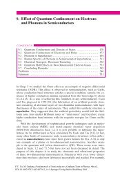
The observed spectrum for a boron-doped Si sample was quite striking,<br />
since it exhibited peaks corresponding to transitions from the ground state to<br />
excited states of the acceptor centers, as well as the onset of a photoionization<br />
continuum [2,3] (Fig. 1). Moreover, the positions of the excitation peaks corresponded<br />
closely to the 1s–2p, 1s–3p and 1s–4p transitions of a hydrogenlike<br />
center and yielded an ionization energy of 0.046 eV, in good agreement with<br />
the thermal ionization data [4]. However, the oscillator strengths of the absorption<br />
peaks are markedly different from those for a hydrogenic center. In<br />
particular, the oscillator strength of the 1s–2p peaks is an order of magnitude<br />
smaller than that for a hydrogenic center. The widths of the excitation peaks<br />
decrease on cooling to liquid helium temperature, but there is no appreciable<br />
shift in the peak positions, indicating that Franck–Condon effects are small.<br />
Our data showed no obvious evidence of transitions from the ground state of<br />
Absorption cross section [10 –16 cm 2 ]<br />
40<br />
30<br />
20<br />
10<br />
20<br />
15<br />
10<br />
5<br />
3.0<br />
2.0<br />
1.0<br />
Boron-doped Silicon<br />
0 0.05 0.1 0.15<br />
Aluminum-doped Silicon<br />
0 0.1 0.2 0.3<br />
15<br />
Gallium-doped Silicon<br />
10<br />
5<br />
0 0.1 0.2 0.3<br />
Lattice<br />
Absorption<br />
Band<br />
><br />
Indium-doped Silicon<br />
0 0.1 0.2 0.3 0.4 0.5 0.6 0.7<br />
Photon energy [eV]<br />
Fig. 1. Photoexcitation and photoionization<br />
absorption spectra of group III acceptors<br />
in Si at liquid helium temperature<br />
[6]. For boron-doped Si, the dashed<br />
line is the theoretical photoionization<br />
absorption spectrum of the corresponding<br />
hydrogenic model
Optical Spectroscopy of Shallow Impurity Centers 571<br />
the split-off valence band, which is not unexpected since the spin–orbit interaction<br />
is small in Si and the optical spectra are broadened appreciably.<br />
Efforts to detect photoconductivity in n- and p-type Si at 77 K were unsuccessful,<br />
due to the presence of large numbers of thermally excited carriers.<br />
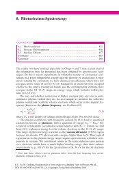
However, a photoconductive response was observed at liquid helium temperature.<br />
The spectral response of relatively pure n-Si is shown in Fig. 2 [5]. The<br />
dips in the photoconductive response between 8 and 24 Ìm correspond to lattice<br />
vibration absorption peaks. The data yielded a donor optical ionization<br />
energy of 0.04 eV. Photoconductivity studies were later carried out at liquid<br />
helium temperature on Ge doped with group III and V impurities. The photoconductive<br />
response was found to extend out to 38 Ìm, the limit of measurement<br />
at that time [6].<br />
Fairly complete optical studies were carried out for the group III acceptors<br />
(B, Al, Ga and In) and for the group V donors [7,8]. Absorption spectra<br />
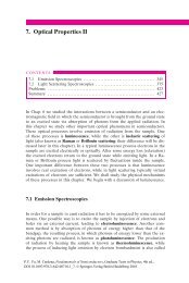
for the group III centers are shown in Fig. 1. The variations in the ionization<br />
energy (Fig. 3) are accompanied by changes in the character of the excitation<br />
and photoionization absorption spectra. The positions of the excitation bands<br />
for Al, Ga and In centers, unlike B, do not correspond to a hydrogenic model,<br />
their oscillator strengths also differ appreciably from those of a hydrogenic<br />
model (Fig. 3). These deviations, which become more pronounced on going<br />
from B to In, are due to central cell corrections. The states with s character<br />
have their energies and wavefunctions rather strongly modified, since their<br />
wavefunctions are relatively large at the impurity atoms. The states with p<br />
characters, whose wavefunctions are small at the center of the impurity atom,<br />
are affected to a lesser degree. The agreement between the experimental ionization<br />
energy for B and the predictions of the hydrogenic model is probably<br />
due to a cancellation of different effects.<br />
Relative photoconductivity<br />
per incident photon<br />
10<br />
5<br />
1<br />
0.5<br />
0.1<br />
0.05<br />
0.01<br />
0.6 1.0 5.0 10 20 30 40<br />
Wavelength [µm]<br />
10<br />
α [cm –1 ]<br />
Fig. 2. The relative photoconductive response per incident photon of a relatively pure<br />
n-Si sample [4]. The dips in the photoconductive response between 8 and 24 Ìm correspond<br />
to the peaks in the optical absorption due to lattice vibrations
572 <strong>Appendix</strong> A<br />
Energy [eV]<br />
0.15<br />
0.10<br />
In<br />
Ga<br />
Al<br />
0.05 B H<br />
0<br />
Valence band<br />
1s<br />
2p<br />
3p<br />
4p<br />
Fig. 3. Suggested term scheme for group<br />
III acceptors in Si showing the levels<br />
whose energies are derived from the<br />
low temperature absorption spectra [6]<br />
The optical ionization energies for donors in Si were found to be 10%<br />
larger than the thermal ionization energies, due in part to the presence of<br />
low-lying excited states that were not taken into account in the calculation<br />
of the activation energies. The positions of the ground state relative to the<br />
conduction band are appreciably different for the three donors P, As and Sb,<br />
again due to central cell effects. However, their excited p-states are observed<br />
at about the same positions relative to the conduction band (see Fig. 3 and<br />
[7]). Moreover, they are in good agreement with the results of the effective<br />
mass formulation of the donor p levels by Kohn and Luttinger [9], which takes<br />
into account the fact that the conduction band of Si has six nondegenerate<br />
minima along the [100] and equivalent directions.<br />
The data obtained in these early investigations were limited by the relatively<br />
low quality of the Si Samples, the poor resolution of the spectrometers<br />
and by the electronics. There has been major progress in the IR spectroscopy<br />
of shallow impurity levels in semiconductors since then, made possible by<br />
significant improvements in crystal quality, spectrometers and detectors, by<br />
the development of photothermal conductance spectroscopy, which has much<br />
higher sensitivity than IR detectors, and by the availability of tunable IR lasers<br />
[10].<br />
References<br />
1 J. Bardeen, G.L. Pearson: Phys. Rev. 75, 865 (1949)<br />
2 E. Burstein, J.J. Oberly, J.W. Davisson, B.W. Henvis: Phys. Rev. 82, 764 (1951)<br />
3 E. Burstein, E.E. Bell, J.W. Davisson, M. Lax: J. Phys. Chem. 57, 849 (1953)
Optical Spectroscopy of Shallow Impurity Centers 573<br />
4 F.J. Morin, J.P. Maita, R.G. Schulman, N.B. Hannay: Phys. Rev. 97, 833 (1954)<br />
5 E. Burstein, J.J. Oberly, J.W. Davisson, Phys. Rev. 89, 331 (1953)<br />
6 E. Burstein, J.W. Davisson, E.E. Bell, W.J. Turner, H.G. Lipson: Phys. Rev. 93, 65<br />
(1954)<br />
7 E. Burstein, G. Picus, B.W. Henvis, R.F. Wallis: J. Phys. Chem. Solids 1, 65 (1956)<br />
8 G. Picus, E. Burstein, B.W. Henvis: J. Phys. Chem. Solids 1, 75 (1956)<br />
9 W. Kohn, J.M. Luttinger: Phys. Rev. 97, 883 (1954); ibid. 98, 915 (1955)<br />
10 See the review by A.K. Ramdas, S. Rodriguez: Rep. Prog. Phys. 44, 1297 (1981)
574 <strong>Appendix</strong> A<br />
On the Prehistory<br />
of Angular Resolved Photoemission<br />
Neville V. Smith<br />
Lawrence Berkeley Laboratory, Berkeley, USA<br />
Band mapping using angle-resolved photoemission started in the early 1970s.<br />
Interest in the angular dependence of the photoelectric effect, however, goes<br />
back much further. Figure 1 shows an apparatus used in the 1920s by Herbert<br />
Ives and coworkers [1] at the Bell Telephone Laboratories. These workers<br />
were definitely not concerned with band structures. Wave mechanics was a<br />
newfangled concept, and solid-state physics had yet to be invented. They were<br />
concerned rather with optimizing the efficiency of photocathodes for use in<br />
television and eventually videotelephony.<br />
The sample (C) sits at the center of a spherical collector (B). Application<br />
of retarding potentials to the collector permits measurement of the photoelectron<br />
energy spectra. A finger (F) moving around a slot in the collector permits<br />
measurements as a function of angle of emission. We recognize here a resemblance<br />
to modern experimental methods. More striking is the resemblance to<br />
the apparatus used by Clinton Davisson and Lester Germer in establishing the<br />
wave nature of the electron [2]. This is not surprising. These scientists were all<br />
working at the same time in the same building in Manhattan.<br />
It is diverting to speculate on the interactions between Ives and Davisson.<br />
It seems likely, on the artistic evidence, that they were using the services of<br />
the same glass blower! But what did they talk about? Would they have been<br />
pleased to know that their separate lines of research would converge half a<br />
century later into the indispensable technique of band mapping?<br />
Evan Kane proposed in a prescient paper published in 1964 that bands<br />
could in principle be mapped using the angular dependence of photoemission<br />
spectra [3]. A decade elapsed, however, before bands were actually mapped<br />
[4]. Mort Traum and I approached this problem in the early 1970s but with<br />
some hesitance. There were persuasive proponents of the view that photoelectrons<br />
would be so thoroughly scattered before emerging from the sample that<br />
all memory of angular information would be lost. We were so intimidated by<br />
this that we built only a minimal apparatus, essentially the same as that of<br />
Ives but with a channel electron multiplier in place of the finger F. To circumvent<br />
the indeterminacy of k⊥, we looked at two-dimensional materials,<br />
the layer compounds TaS2 and TaSe2. Frank DiSalvo was manufacturing single<br />
crystals of these compounds in his laboratory a few doors down the corridor.<br />
Len Mattheiss was calculating their band structures just a few further<br />
doors down the corridor, and we found beautiful agreement with his predictions<br />
[5].
On the Prehistory of Angular Resolved Photoemission 575<br />
Fig. 1. Apparatus used by Ives et al. [1]<br />
With these shortcuts and fine collaborators we were able to perform the first<br />
demonstration of band mapping [4]. In hindsight, it is embarrassing to contemplate<br />
our hesitance and timidity. It is all now so obvious and commonplace.<br />
References<br />
1 H.E. Ives, A.R. Olpin, A.L. Johnsrud: Phys. Rev. 32, 57 (1928)<br />
2 C.J. Davisson, L.H. Germer: Phys. Rev. 30, 705 (1927)<br />
3 E.O. Kane: Phys. Rev. Lett. 12, 97 (1964)<br />
4 N.V. Smith, M.M. Traum, F.J. DiSalvo: Solid State Commun. 15, 211 (1974)<br />
5 L.F. Mattheiss: Phys. Rev. B 8, 3719 (1973)
576 <strong>Appendix</strong> A<br />
The Discovery and Very Basics<br />
of the Quantum Hall Effect<br />
Klaus von Klitzing<br />
Max-Planck-Institut für Festkörperforschung, Stuttgart, Germany<br />
The discovery of the quantum Hall effect (QHE) was the result of basic research<br />
on silicon field effect transistors – the most important device in microelectronics.<br />
Unlike in other conductors, the electron concentration in these<br />
devices can be varied in a wide range just by changing the gate voltage. Therefore<br />
this system is ideal for an investigation of the Hall effect at different carrier<br />
densities by analyzing the Hall voltage as a function of the gate voltage.<br />
The experimental curves together with the notes of February 4, 1980, which<br />
characterize the birthday of the quantum Hall effect, are shown in Fig. 9.39.<br />
As expected qualitatively from the classical Hall effect, the Hall voltage UH<br />
varies (at a fixed magnetic field B 18 T) inversely proportional to the number<br />
N of free electrons (or gate voltage Vg). However, plateaus are visible<br />
if the ratio of the number N of electrons to the number Nº of flux quanta<br />
within the area of the device is an integer. For one electron per flux quantum<br />
(this corresponds to a fully occupied lowest Landau level with the filling<br />
factor 1) the Hall voltage divided by the current has the fundamental<br />
value RK h/e 2 (25812.807 ± 0.005) ø. This Hall plateau is barely visible<br />
in the upper left corner of Fig. 9.39 and distorted by the large device resistance<br />
due to localization phenomena at this relatively small electron density.<br />
The plateaus at 2 or 4 times larger electron concentration are much better<br />
resolved. Today, electronic systems with higher quality are available so that<br />
measurements at much smaller electron densities with filling factors smaller<br />
than one are possible. This is the region where the fractional quantum Hall<br />
effect is observed [9.70].<br />
A special situation seems to be present if two flux quanta are available<br />
for one electron (filling factor 1/2): Quasiparticles (composite fermions) are<br />
formed which behave like electrons moving in an effective magnetic field<br />
B ∗ 0. The Shubnikov–de Haas oscillations of these composite fermions are<br />
equivalent to the structures of the fractional quantum Hall effect.<br />
Already the first publication on the QHE [1] with the original title “Realization<br />
of a Resistance Standard Based on Fundamental Constants” indicated<br />
that an application similar to the Josephson effect may be possible. Today,<br />
it is known that different materials (silicon field effect transistors, GaAs/<br />
AlGaAs heterostructures) show the same value for the quantized Hall resistance<br />
within the experimental uncertainty of 3.5 × 10 10 , and since 1990 all<br />
calibrations of resistances are based on the quantum Hall effect with a fixed<br />
value RK1990 25812.807 ø for the von Klitzing constant RK.
The Discovery and Very Basics of the Quantum Hall Effect 577<br />
Different approaches can be used to deduce a quantized value for the Hall<br />
resistance. The calculation shown in Fig. 9.39, which led to the discovery of the<br />
QHE, is simply based on the classical expression for the Hall effect. A quantized<br />
Hall resistance h/e 2 is obtained for a carrier density corresponding to the<br />
filling factor one. It is surprising that this simple calculation leads to the correct<br />
result. Laughlin was the first to try to deduce the result of the QHE in<br />
a more general way from gauge invariance principles [2]. However, his device<br />
geometry is rather removed from the real Hall effect devices with metallic<br />
contacts for the injection of the current and for the measurement of the electrochemical<br />
potential.<br />
The Landauer–Büttiker formalism, which discusses the resistance on the<br />
basis of transmission and reflection coefficients, is much more suitable for analyzing<br />
the quantum Hall effect [3]. This formalism was very successful in explaining<br />
the quantized resistance of ballistic point contacts [4] and, in a similar<br />
way, the quantized Hall resistance is the result of an ideal one-dimensional<br />
electronic transport. In a classical picture this corresponds to jumping orbits of<br />
electrons at the boundary of the device. In the future, the textbook explanation<br />
of the QHE will probably be based on this one-dimensional edge channel<br />
transport (see Fig. 9.40).<br />
References<br />
1 K. v. Klitzing, G. Dorda, M. Pepper: Phys. Rev. Lett. 45, 494 (1980)<br />
2 R.B. Laughlin: Phys. Rev. B 23, 5632 (1981)<br />
3 M. Büttiker: Phys. Rev. Lett. 57, 1761 (1986)<br />
4 B.J. von Wees, H. van Houten, S.W.J. Beenakker, J.G. Williamson, L.P. Kouwenhoven,<br />
D. van der Marel, C.T. Foxon: Phys. Rev. Lett. 60, 848 (1988);<br />
D.A. Wharam, T.J. Thornton, R. Newbury, M. Pepper, H. Ahmed, J.E.F. Frost, D.G.<br />
Hasko, D.C. Peacock, D.A. Ritchie, G.A.C. Jones: J. Phys. C 21, L 209 (1988)
578 <strong>Appendix</strong> A<br />
The Birth of the Semiconductor Superlattice<br />
Leo Esaki<br />
University of Tsukuba, Tsukuba, Japan<br />
In 1969, research on artificially structured materials was initiated when Tsu<br />
and I [1,2] proposed an engineered semiconductor superlattice with a onedimensional<br />
periodic potential. In anticipation of advances in controlled epitaxy<br />
of ultrathin layers, two types of superlattices were envisioned: doping and<br />
compositional, as shown in Fig. 1.<br />
Before arriving at the superlattice concept, we had been examining the<br />
feasibility of structural formation of potential barriers and wells that were thin<br />
enough to exhibit resonant tunneling [3]. A resonant tunnel diode [4,5] appeared<br />
to have more spectacular characteristics than the Esaki tunnel diode<br />
[6], the first quantum electron device consisting of only a single tunnel barrier.<br />
It was thought that advanced technologies with semiconductors might be<br />
Electron energy<br />
Electron energy<br />
(a)<br />
(b)<br />
+ + + + + + +<br />
+<br />
Energy gap Eg – – –<br />
– – –<br />
Valence band<br />
compositional superlattice<br />
conduction band<br />
Energy gap E g1 E g2<br />
Valence band<br />
– – –<br />
0<br />
l<br />
2<br />
l<br />
3l<br />
2<br />
Distance<br />
2l<br />
5l<br />
2<br />
3l<br />
Fig. 1a,b. Spatial variations of<br />
the conduction and valence<br />
band edges in two types of<br />
superlattices: (a) doping, (b)<br />
compositional
The Birth of the Semiconductor Superlattice 579<br />
ready for demonstration of the de Broglie electron waves. Resonant tunneling<br />
(see Sect. 9.5) can be compared to the transmission of an electromagnetic<br />
wave through a Fabry–Perot resonator. The equivalent of a Fabry–Perot resonant<br />
cavity is formed by the semiconductor potential well sandwiched between<br />
the two potential barriers.<br />
The idea of the superlattice occurred to us as a natural extension of<br />
double-, triple- and multiple-barrier structures: the superlattice consists of a<br />
series of potential wells coupled by resonant tunneling. An important parameter<br />
for the observation of quantum effects in the structure is the phasecoherence<br />
length, which approximates the electron mean free path. This depends<br />
on the bulk quality as well as the interface quality of crystals, and also<br />
on the temperatures and values of the effective mass. As schematically illustrated<br />
in Fig. 2, if characteristic dimensions such as superlattice periods or well<br />
widths are reduced to less than the phase-coherent length, the entire electron<br />
system will enter a mesoscopic quantum regime of low dimensionality, on a<br />
scale between the macroscopic and the microscopic. Our proposal was to explore<br />
quantum effects in the mesoscopic regime.<br />
The introduction of the one-dimensional superlattice potential perturbs the<br />
band structure of the host materials, yielding a series of narrow subbands and<br />
forbidden gaps which arise from the subdivision of the Brillouin zone into<br />
a series of minizones. Thus, the superlattice was expected to exhibit unprecedented<br />
electronic properties. At the inception of the superlattice idea, it was<br />
recognized that the long, tailormade lattice period provided a unique opportunity<br />
to exploit electric-field-induced effects. The electron dynamics in the super-<br />
1 Ìm<br />
100 nm<br />
10 nm<br />
1 nm<br />
0.1 nm<br />
Superlattice<br />
or<br />
quantum wells<br />
Macroscopic regime<br />
Phase–coherent distance<br />
(electron mean free path)<br />
Interatomic spacing<br />
microscopic regime<br />
“Mesoscopic” quantum<br />
regime<br />
Crystal quality<br />
(decreasing temperature)<br />
Fig. 2. Schematic illustration<br />
of a “mesoscopic” quantum<br />
regime (shaded) with a superlattice<br />
of quantum wells (inset)
580 <strong>Appendix</strong> A<br />
lattice direction was analyzed for conduction electrons in a narrow subband of<br />
a highly perturbed energy–wavevector relationship. The result led to the prediction<br />
of a negative differential resistance at a modestly high electric field,<br />
which could be a precursor of Bloch oscillations. The superlattice allows us to<br />
enter the regime of electric-field-induced quantization: the formation of Stark<br />
ladders [7,8], for example, can be proved in a (one-dimensional) superlattice<br />
[9], whereas in natural (three-dimensional) crystals the existence and nature of<br />
these localized states in a high electric field have been controversial [10,11].<br />
This was, perhaps, the first proposal which advocated using advanced thinfilm<br />
growth techniques to engineer a new semiconductor material designed<br />
by applying the principles of quantum theory. The proposal was made to the<br />
US Army Research Office (ARO), a funding agency, in 1969, daringly stating,<br />
with little confidence in a successful outcome at the time, “the study of superlattices<br />
and observations of quantum mechanical effects on a new physical<br />
scale may provide a valuable area of investigation in the field of semiconductors”.<br />
Although this proposal was favorably received by ARO, the original version<br />
of the paper [1] was rejected for publication by Physical Review on the<br />
referee’s unimaginative assertion that it was “too speculative” and involved<br />
“no new physics”. The shortened version published in IBM Journal of Research<br />
and Development [2] was selected as a Citation Classic by the Institute<br />
for Scientific Information (ISI) in July 1987. Our 1969 proposal was cited as<br />
one of the most innovative ideas at the ARO 40th Anniversary Symposium in<br />
Durham, North Carolina, 1991.<br />
At any rate, with the proposal we launched a program to make a “Gedankenexperiment”<br />
a reality. In some circles, the proposal was criticized as close to<br />
impossible. One of the objections was that a man-made structure with compositional<br />
variations on the order of several nanometers could not be thermodynamically<br />
stable because of interdiffusion effects. Fortunately, however,<br />
it turned out that interdiffusion was negligible at the temperatures involved.<br />
In 1970, Chang, Tsu and I [12] studied a GaAs–GaAs0.5P0.5 superlattice<br />
with a period of 20 nm synthesized by CVD (chemical vapor deposition) by<br />
Blakeslee and Aliotta [13]. Although transport measurements failed to reveal<br />
any predicted effect, the specimen probably constituted the first strainedlayer<br />
superlattice having a relatively large lattice mismatch. Early efforts in<br />
our group to obtain epitaxial growth of Ge1xSix and Cd1xHgxTe superlattices<br />
were soon abandoned because of rather serious technical problems at<br />
that time. Instead, we focused our research effort on compositional GaAs–<br />
Ga1xAlxAs superlattices grown by MBE (molecular beam epitaxy). In 1972,<br />
we found a negative resistance in such superlattices [14], which was interpreted<br />
in terms of the superlattice effect.<br />
Following the derivation of the voltage dependence of resonant tunnel currents<br />
[5], Chang, Tsu and I observed current–voltage characteristics with a<br />
negative resistance [15]. Subsequently, Chang and I measured quantum transport<br />
properties in a superlattice with a narrow bandwidth, which exhibited an<br />
oscillatory behavior [16]. Tsu et al. performed photocurrent measurements on
Number of papers<br />
500<br />
200<br />
100<br />
50<br />
20<br />
10<br />
5<br />
2<br />
1<br />
1970<br />
The growth of papers on<br />
quantum heterostructures<br />
presented at the int. conf.<br />
on phys. of semiconductors<br />
72 74 76 78 80 82 84 86 88 90 92 1994 1<br />
Warsaw<br />
Stuttgart<br />
Rome<br />
Edinburgh<br />
Kyoto<br />
Montpellier<br />
San Francisco<br />
Stockholm<br />
The Birth of the Semiconductor Superlattice 581<br />
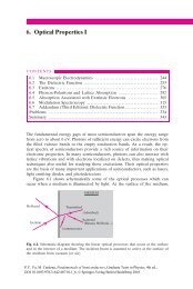
Fig. 3. Growth in relevant papers at the biennial International Conference on the Physics<br />
of Semiconductors<br />
superlattices subjected to an electric field perpendicular to the plane layers<br />
with the use of a semitransparent Schottky contact, which revealed their miniband<br />
configurations [17].<br />
Heteroepitaxy is of great interest for the growth of compositional superlattices.<br />
Innovations and improvements in epitaxial techniques such as MBE and<br />
MOCVD (metal-organic chemical vapor deposition) have made it possible to<br />
prepare high-quality heterostructures with predesigned potential profiles and<br />
impurity distributions having dimensional control close to interatomic spacing.<br />
This great precision has cleared access to the mesoscopic quantum regime<br />
[18,19].<br />
Since a one-dimensional potential can be introduced along with the growth<br />
direction, famous examples in the history of one-dimensional mathematical<br />
physics, including the above-mentioned resonant tunneling [3], Kronig–Penney<br />
bands [20], Tamm surface states [21], Zener band-to-band tunneling [22], and<br />
Stark ladders including Bloch oscillations [7–9], all of which had remained<br />
textbook exercises, could, for the first time, be practiced in a laboratory. Thus,<br />
do-it-yourself quantum mechanics is now possible, since its principles dictate<br />
the details of semiconductor structures [23].<br />
Warsaw<br />
Thessaloniki<br />
Beijing<br />
100<br />
50<br />
20<br />
10<br />
5<br />
2<br />
Percentage of total papers
582 <strong>Appendix</strong> A<br />
Our original proposal [1] and pioneering experiments have triggered a<br />
wide spectrum of experimental and theoretical investigations on superlattices<br />
and quantum wells over the last two decades. A variety of engineered structures<br />
now exhibit extraordinary transport and optical properties which do not<br />
exist in any natural crystal. This new degree of freedom offered in semiconductor<br />
research through advanced materials engineering has inspired many ingenious<br />
experiments, resulting in observations of not only predicted effects but<br />
also totally unknown phenomena. As a measure of the growth of the field, Fig.<br />
3 shows the number of papers related to the subject and the percentage of<br />
the total presented at the biennial International Conference on the Physics of<br />
Semiconductors. Following 1972, when the first paper [14] was presented, the<br />
field went through a short period of incubation before experiencing a phenomenal<br />
expansion in the 1980s. It appears that nearly half of all semiconductor<br />
physicists in the world are working in this area. Activity at this new frontier<br />
of semiconductor physics has in turn given immeasurable stimulus to device<br />
physics, provoking new ideas for applications. Thus, a new class of transport<br />
and opto-electronic devices has emerged.<br />
References<br />
1 L. Esaki, R. Tsu: IBM Res. Note RC-2418 (1969)<br />
2 L. Esaki, R. Tsu: IBM J. Res. Devel. 14, 61 (1970)<br />
3 D. Bohm: Quantum Theory (Prentice Hall, Englewood Cliffs, NJ 1951), p. 283<br />
4 L.V. Iogansen, Zh. Eksp. Teor. Fiz. 45, 207 (1963) [Sov. Phys. – JETP 18, 146 (1964)]<br />
5 R. Tsu, L. Esaki: Appl. Phys. Lett. 22, 562 (1973)<br />
6 L. Esaki: Phys. Rev. 109, 603 (1958)<br />
7 H.M. James: Phys. Rev. 76, 1611 (1949)<br />
8 G.H. Wannier: Elements of Solid State Theory (Cambridge University Press, Cambridge<br />
1959), p. 190; Phys. Rev. 117, 432 (1960)<br />
9 W. Shockley: Phys. Rev. Lett. 28, 349 (1972)<br />
10 J. Zak: Phys. Rev. Lett. 20, 1477 (1968); Phys. Rev. B 43, 4519 (1991)<br />
11 A. Rabinovitch, J. Zak: Phys. Rev. B 4, 2358 (1971)<br />
12 L. Esaki, L.L. Chang, R. Tsu: Proc. 12th Int. Conf. Low Temp. Phys., Kyoto, Japan<br />
1970, p. 551<br />
13 A.E. Blakeslee, C.F. Aliotta: IBM J. Res. Devel. 14, 686 (1970)<br />
14 L. Esaki, L.L. Chang, W.E. Howard, V.L. Rideout: Proc. 11th Int. Conf. Phys. Semiconductors,<br />
Warsaw, Poland 1972, p. 431<br />
15 L.L. Chang, L. Esaki, R. Tsu: Appl. Phys. Lett. 24, 593 (1974)<br />
16 L. Esaki, L.L. Chang: Phys. Rev. Lett. 33, 495 (1974)<br />
17 R. Tsu, L.L. Chang, G.A. Sai-Halasz, L. Esaki: Phys. Rev. Lett. 34, 1509 (1975)<br />
18 L. Esaki: IEEE J. Quantum Electron. QE-22, 1611 (1986)<br />
19 L. Esaki: in Highlights in Condensed Matter Physics and Future Prospects, ed. by L.<br />
Esaki (Plenum, New York 1991), p. 55<br />
20 R. de L. Kronig, W.G. Penney: Proc. R. Soc. London A 130, 499 (1931)<br />
21 I. Tamm: Phys. Z. Sowjetunion 1, 733 (1932)<br />
22 C. Zener: Proc. R. Soc. London 145, 523 (1934)<br />
23 L. Esaki, Phys. Scr. T42, 102 (1992)
<strong>Appendix</strong> B:<br />
Solutions to Some of the Problems<br />
Solution to Problem 2.2<br />
There are many ways to “verify” a character table. One way to do this is to calculate<br />
the character table starting with the given basis functions. This is what we<br />
shall do here. This approach can be used to solve both parts (a) and (b).<br />
We note that the character of a class can be obtained by applying one of<br />
the symmetry operations in the class listed in Chapter 2 to the basis function<br />
(or functions), thus finding the transformation matrices and then summing up<br />
their diagonal elements. To do this for all the classes it is convenient to create<br />
first a table listing the effect of the symmetry operations on the spatial coordinates<br />
x, y and z.<br />
For the Td group we obtain immediately the following list:<br />
{E}: identity; xyz → xyz<br />
{C2}: 2-fold rotation about the x-axis; xyz → x, y, z<br />
{C3}: 3-fold clockwise rotation about the [111]-axis; xyz → yzx<br />
{S4}: 4-fold clockwise rotation about the x-axis followed by a reflection onto<br />
the yz-plane; xyz → x, z, y<br />
{Û}: reflection onto the [110]-plane; xyz → yxz<br />
The effects of these operations on the different basis functions are summarized<br />
below:<br />
A1 Irreducible Representation with basis function: xyz<br />
Since all the symmetry operations either do not change the signs or change<br />
the signs in pairs it is clear that all of them leave the function xyz unchanged<br />
and therefore all the characters are equal to unity as expected for the identity<br />
representation. Combining these results we obtain the characters for A1 as:<br />
Classes {E} {C2} {S4} {s} {C3}<br />
Characters of A1 1 1 1 1 1<br />
A2 Irreducible Representation with basis function:<br />
x4 (y2 z2 ) y4 (z2 x2 ) z4 (x2 y2 )<br />
If a symmetry operation simply changes the cyclic permutation of |x|, |y| and<br />
|z| then it will not change the above basis function and the corresponding<br />
character should be unity. This is the case for the operation {E} and the two
584 <strong>Appendix</strong> B<br />
proper rotations: {C2} and {C3}. In the case of the other two improper rotations<br />
{S4} and {Û}, the cyclic order of |x|, |y| and |z| is reversed. This changes<br />
the sign of the basis function and therefore the characters are both 1. Combining<br />
these results we obtain the characters for A2 as:<br />
Classes {E} {C2} {S4} {Û} {C3}<br />
Characters of A2 1 1 1 1 1<br />
E Irreducible Representation with basis functions: f1 (x2 y2 )<br />
and f2 z2 1<br />
2 (x2 y2 )<br />
The operation {C2} changes only the signs of y and z and therefore leaves<br />
both f1 and f2 unchanged i.e. its character is 2. The operation {C3} changes<br />
the orders of x, y and z. It changes f1 into (y2 z2 ) ( 1<br />
2 )(f1 2f2) and f2<br />
into x2 1<br />
2 (y2z2 ) ( 1<br />
2 )f1(f2/2). The two diagonal elements are both 1<br />
2 and<br />
the character is 1. The operation {S4} interchanges y 2 and z 2 . It changes f1<br />
into (x2 z2 ) ( 1<br />
2 )(f1 2f2) and f2 into y2 1<br />
2 (x2 z2 ) ( 3<br />
4 )f1 (f2/2). Thus,<br />
the two diagonal elements are 1 1<br />
2 and 2 , respectively and the character is 0.<br />
The operation {Û} interchanges x2 and y2 . It changes f1 into (y2 x2 ) f1<br />
and f2 into z2 1<br />
2 (x2 y2 ) f2. The two diagonal elements are 1 and 1,<br />
respectively and the character is 0. Combining the above results we obtain the<br />
characters for E as:<br />
Classes {E} {C2} {S4} {Û} {C3}<br />
Characters 2 2 0 0 1<br />
The derivation of the characters for the remaining two irreducible representations<br />
are left as exercise.<br />
Solution to Problem 2.4<br />
In this problem we demonstrate that the symmetrized wave functions in Table<br />
2.9 indeed transform according to the irreducible representations given in that<br />
table. The readers should try to verify the symmetry of the wave functions<br />
in Table 2.<strong>10.</strong> To do this we note that the three functions: {sin x, sin y, sin z}<br />
transform like x, y, z under all the symmetry operations of the Td group. On<br />
the other hand, the functions {cos x, cos y, cos z} are “even” under C2 rotations<br />
so they have the same transformation properties as {x2 , y2 , z2 }. Based on these<br />
observations we see immediately that:<br />
(a) The function sin(2applex/a) sin(2appley/a) sin(2applez/a) transforms like xyz and therefore<br />
from Table 2.3 it belongs to the °1 representation.<br />
(b) Similarly, the function cos(2applex/a) cos(2appley/a) cos(2applez/a) transforms like<br />
(xyz) 2 or (°1) 2 and, therefore, belongs to the °1 representation also.<br />
(c) By the same argument, the three functions: {sin(2applex/a) sin(2appley/a)<br />
cos(2applez/a), sin(2applex/a) cos(2appley/a) sin(2applez/a), cos(2applex/a) sin(2appley/a) sin(2applez/a)}
Solution to Problem 2.6 585<br />
transform like {xyz 2 , xy 2 z, x 2 yz} xyz{z, y, x}. Since {xyz} transforms like<br />
°1 and {x, y, z} transform like °4 these three functions transform like °4.<br />
(d) The derivation of the symmetry of the three functions {sin(2applex/a)<br />
cos(2appley/a) cos(2applez/a), cos(2applex/a) sin(2appley/a) cos(2applez/a), cos(2applex/a) cos(2appley/a)<br />
sin(2applez/a)} is left as an exercise.<br />
Solution to Problem 2.6<br />
In this solution we demonstrate how to derive the compatibility relation between<br />
° and ¢. The reader should repeat the calculation for the remaining<br />
compatibility relations in this problem. First, we need to find the symmetry<br />
operations of the group of ° which are also symmetry operations of ¢. From<br />
Table 2.13 we find the following correspondence between the symmetry operations<br />
in those two groups.<br />
Operation in ° Corresponding Operation in ¢<br />
{E} {E}<br />
{C2} {C2 4 }<br />
{Û} {md}<br />
{Û ′ } {m ′ d }<br />
According to the definition on page 45, two representations are compatible<br />
if they have the same characters for the corresponding classes in the above<br />
table. Based on this definition °1 is compatible with ¢1 while °2 is compatible<br />
with ¢2.<br />
For °3 the characters of the above 4 classes are:<br />
{E} {C2} {Û} {Û ′ }<br />
°3 2 2 0 0<br />
From Table 2.14 we see that the characters of ¢1 ¢2 are exactly the same<br />
for the corresponding classes of °:<br />
{E} {C 2 4 } {md} {m ′ d }<br />
¢1 ¢2 2 2 0 0<br />
Hence °3 is compatible with ¢1 ¢2.
586 <strong>Appendix</strong> B<br />
Solution to Problem 2.8<br />
(a) Before we symmetrize the wavefunctions at the X point, it is important<br />
to note that the pseudopotential form factors in Table 2.21 have been defined<br />
with (1) the origin chosen at the mid-point between the two atoms in the zincblende<br />
structure, (2) the cation has been chosen to be the atom a located at<br />
the point (a/8)(111), and (3) the anti-symmetric form factor is proportional to<br />
Va Vb. The symmetry operations of the group of X have to be defined to<br />
conform to this particular choice of coordinate system (denoted by O and its<br />
axes by x, y, and z in Fig. 1). It should be noted that the symmetry operations<br />
listed on p. 47 and the corresponding character table (Table 2.15) on the same<br />
page have been defined with respect to the coordinate system in which one of<br />
the two atoms in the unit cell has been chosen to be the origin (denoted by O ′<br />
and its axes by x ′ , y ′ , and z ′ in Fig. 1).<br />
y'<br />
y<br />
Cation (Atom a)<br />
(1/8)(1,1,1)<br />
Anion O<br />
(Atom b) (0,0,0)<br />
O'<br />
x'<br />
(–1/8)(1,1,1)<br />
x<br />
Prob.2.8-Fig. 1 The relation between the coordinate<br />
systems O and O ′<br />
Some of the symmetry operations are identical in the two coordinate systems.<br />
for example the identity operation {E} is independent of the choice of<br />
coordinate system. Unfortunately most of the other operations are affected by<br />
the change in coordinate system. To see the relations between symmetry op-<br />
erations in O and O ′ , we shall consider the operation C 2 4<br />
as an example. In O′<br />
this operation is a 2-fold rotation, say about the y ′ -axis. The same operation in<br />
O will involve:<br />
(i) a translation T to move the origin from that of O to O ′ ,<br />
(ii) a 2-fold rotation with respect to the axis y ′ and then<br />
(iii)another translation T 1 to move the origin back to O.<br />
In general any symmetry operation P in O ′ will become P ′ T 1 PT in O. We<br />
shall now symmetrize the X point wave functions in O ′ by first forming the<br />
following six linear combinations out of the two |100〉 and four |011〉 wave-<br />
functions:<br />
⎧ ⎫<br />
2apple<br />
⎪⎨ cos x ⎪⎬<br />
a<br />
<br />
⎪⎩<br />
2apple<br />
i sin x<br />
⎪⎭<br />
a<br />
1<br />
2<br />
<br />
|100〉 |100〉<br />
|100〉 |100〉<br />
(2.8.1)
⎧ ⎫<br />
2apple<br />
⎪⎨ cos (y z) ⎪⎬<br />
a<br />
<br />
⎪⎩<br />
2apple<br />
i sin (y z)<br />
⎪⎭<br />
a<br />
1<br />
2<br />
<br />
|011〉 |011〉<br />
|011〉 |011〉<br />
Partial solution to Problem 2.8 587<br />
(2.8.2)<br />
⎧ ⎫<br />
2apple<br />
⎪⎨ cos (y z) ⎪⎬<br />
a<br />
<br />
⎪⎩<br />
2apple<br />
i sin (y z)<br />
⎪⎭<br />
a<br />
1<br />
<br />
|011〉 |011〉<br />
(2.8.1)<br />
2 |011〉 |011〉<br />
We shall denote these six symmetrized wave functions as:<br />
<br />
2apple<br />
æ1 ∼ cos (y z)<br />
a<br />
<br />
2apple<br />
æ2 ∼ sin (y z)<br />
a<br />
<br />
<br />
2apple<br />
2apple<br />
æ3 ∼ sin (y z) cos (y z)<br />
a<br />
a<br />
<br />
<br />
(2.8.4)<br />
2apple<br />
2apple<br />
æ4 ∼ sin (y z) cos (y z)<br />
a<br />
a<br />
<br />
2apple<br />
2apple<br />
æ5 ∼ cos x sin x<br />
a<br />
a<br />
<br />
2apple<br />
2apple<br />
æ6 ∼ cos x sin x<br />
a<br />
a<br />
To determine their irreducible representations we shall test their symmetry<br />
by applying the 2-fold rotation C2 4 (y′ ) to all these 6 wave functions. First we<br />
have to find out the effect of this operation on the point (x, y, z) inO. When<br />
refered to O ′ this point has the coordinate: x ′ x (a/8); y ′ y (a/8) and<br />
z ′ z (a/8). We may also say that the operation T transforms (x, y, z) to<br />
(x ′ , y ′ , z ′ ). The 2-fold rotation then transforms (x ′ , y ′ , z ′ ) into (x ′ , y ′ , z ′ ).<br />
Finaly T1 transforms this point into x ′ a<br />
8 , y′ a<br />
8 , z′ a<br />
<br />
a<br />
8 x 4 ,<br />
y, z a<br />
<br />
2<br />
4 . Thus the net effect of the operation C4 (y ′ ) on the crystal can be<br />
represented by the change:<br />
<br />
(x, y, z) → x a a<br />
<br />
, y, z . (2.8.5)<br />
4 4<br />
The effect of this operation on the six wavefunctions æ1 to æ6 can now be<br />
shown to be:<br />
æ1 ∼ cos(2apple/a)(y z) → cos(2apple/a)(y z a/4)<br />
sin(2apple/a)(y z) æ2<br />
æ2 ∼ sin(2apple/a)(y z) → sin(2apple/a)(y z a/4)<br />
cos(2apple/a)(y z) æ1<br />
(2.8.6a)<br />
(2.8.6b)
588 <strong>Appendix</strong> B<br />
æ3 ∼ sin(2apple/a)(y z) cos(2apple/a)(y z)<br />
→ sin[(2apple/a)(y z) apple/2] cos[(2apple/a)(y z) apple/2]<br />
cos(2apple/a)(y z) sin(2apple/a)(y z) æ3<br />
æ4 ∼ sin(2apple/a)(y z) cos(2apple/a)(y z)<br />
→ sin[(2apple/a)(y z) apple/2] cos[(2apple/a)(y z) apple/2]<br />
cos(2apple/a)(y z) sin(2apple/a)(y z) æ4<br />
æ5 ∼ cos(2apple/a)x sin(2apple/a)x<br />
→ cos(2apple/a)(x a/4) sin(2apple/a)(x a/4)<br />
(2.8.6c)<br />
(2.8.6d)<br />
(2.8.6e)<br />
sin(2apple/a)x cos(2apple/a)x æ5<br />
and æ6 → æ6. (2.8.6f)<br />
Therefore the characters of these 6 wavefunctions under the operation of C2 4<br />
are: ¯(æ1) ¯(æ2) 0; ¯(æ3) 1; ¯(æ4) 1; ¯(æ5) 1; and ¯(æ6) 1.<br />
if we compare these characters with those in Table 2.15 we conclude that:<br />
(1) æ1 and æ2 form a 2D representation X5;<br />
(2) æ3 and æ6 belong to either the X3 or X4 representation; and<br />
(3) æ4 and æ5 belong to either the X1 or X2 representation.<br />
To narrow down the choice of irreducible representations for wave functions<br />
æ3, æ4, æ5 and æ6 we need to apply another symmetry operation to them.<br />
Let us choose the operation S4. In particular we consider an opeation involving<br />
a 4-fold rotation about the x ′ -axis. Using the same procedures as for the<br />
operation C2 4 (y′ ), we can show that the effect of this operation on (x, y, z) is<br />
given by:<br />
<br />
(x, y, z) → x a a<br />
<br />
, z, y . (2.8.7)<br />
4 4<br />
The effect of the operation S4 on the six wave functions is summarized below:<br />
æ1 ∼ cos(2apple/a)(y z) → cos(2apple/a)(z y a/4)<br />
(2.8.8a)<br />
sin(2apple/a)(z y) æ2<br />
æ2 ∼ sin(2apple/a)(y z) → sin(2apple/a)(y z a/4)<br />
(2.8.8b)<br />
cos(2apple/a)(y z) æ1<br />
æ3 ∼ sin(2apple/a)(y z) cos(2apple/a)(y z)<br />
→ sin[(2apple/a)(z y) apple/2] cos[(2apple/a)(y z) apple/2] (2.8.8c)<br />
cos(2apple/a)(y z) sin(2apple/a)(y z) æ3<br />
æ4 ∼ sin(2apple/a)(y z) cos(2apple/a)(y z)<br />
→ sin[(2apple/a)(z y) apple/2] cos[(2apple/a)(y z) apple/2] (2.8.8d)<br />
cos(2apple/a)(z y) sin(2apple/a)(y z) æ3<br />
(2.8.8e)<br />
æ5 → æ6<br />
æ6 → æ6<br />
(2.8.8f)
Partial solution to Problem 2.8 589<br />
The characters of these 6 wave functions under the operation S4 are, therefore,<br />
¯(æ1) 0 ¯(æ2); ¯(æ3) 1; ¯(æ4) 1; ¯(æ5) 1; and ¯(æ6) 1.<br />
We note that the characters of æ1 and æ2 are consistent with those of the<br />
irreducible representation X5 we obtained for these two wave functions based<br />
on the operation C2 4 (y′ ). The additional characters now allow us to determine<br />
uniquely the irreducible representation of æ3 and æ6 as X3 and those of æ4<br />
and æ5 as X1. The reader should try to determine the characters for the remaining<br />
symmetries of the group of X so as to complete the character table<br />
for these 6 wave functions.<br />
(b) To calculate the matrix elements of the above six wave functions we shall<br />
first derive the following results. First we notice that with the conventions in<br />
Section 2.5 the pseudopotential form factor Vg is defined for GaAs by (2.33)<br />
as:<br />
Vg V s g cos(g · s) iVa g sin(g · s)<br />
where s (a/8)(1, 1, 1) and g is a reciprocal lattice vector. If g <br />
(2apple/a)(g1, g2, g3) then g · s (apple/4)(g1 g2 g3). Limiting ourselves to: g <br />
(2apple/a)(2, 0, 0); (2apple/a)(2, 2, 0); (2apple/a)(1, 1, 1) we obtain<br />
V (220) V a (220) cos apple Vs (220) sin apple Vs (220) vs g V (220) vs g (2.8.9a)<br />
V (220) V (220) V (220) ... V (022) v s g<br />
(2.8.9b)<br />
V (200) iV a (200) iva4 and its cyclic permutations (2.8.9c)<br />
V (200) iv a 4 V (200)<br />
V (111) 1 √ 2<br />
(2.8.9d)<br />
s<br />
1<br />
v iVa √2 (v (111) (111)<br />
s 3 iva3 ) (2.8.9e)<br />
V (111) 1 √ (v<br />
2 s 3 iva3 ) (2.8.9f)<br />
V (111) 1 √ (V<br />
2 s 3 iva3 ) (2.8.9g)<br />
v (111) 1 √ (v<br />
2 s 3 iva3 ) (2.8.9h)<br />
We shall now demonstrate the calculation of a few selected matrix elements<br />
of the pseudopotential V : 〈æi|V|æj〉 where i and j 1, ..., 6. In principle there<br />
are 36 matrix elements. The number of inependent elements is roughly halved<br />
by noting that 〈æi|V|æj〉 〈æj|V|æi〉 ∗ .<br />
〈æ1|V|æ1〉 1<br />
〈011 011|V|011 011〉<br />
1<br />
2<br />
2<br />
<br />
〈011|V|011〉 〈011|V|011〉 〈011|V|011〉 〈011|V|011〉<br />
(2.8.10)
590 <strong>Appendix</strong> B<br />
Noting that according to (2.25) 〈abc|V|a ′ b ′ c ′ 〉 V (aa ′ ,bb ′ ,cc ′ ) we find:<br />
〈æ1|V|„1〉 1<br />
2 (V (000) V (220) V (220) V (000))<br />
1<br />
2 (V (220) V (220) ) v s (2.8.11a)<br />
8<br />
In obtaining (2.8.11a) we have set V (000) 0. In a similar manner we can<br />
obtain:<br />
〈æ1|V|æ3〉 1<br />
2 √ <br />
〈011|V|011〉〈011|V|011〉〈011|V|011〉〈011|V|011〉<br />
2<br />
〈011|V|011〉 〈011|V|011〉 〈011|V|011〉 〈011|V|011〉 0<br />
〈æ3|V|æ3〉 v s 8 2va 4<br />
(2.8.11b)<br />
(2.8.11c)<br />
〈æ4|V|æ5〉 √ 2i(v s 3 va3 ) (2.8.11d)<br />
The readers are urged to calculate the rest of the matrix elements in the determinant<br />
on p. 94.<br />
(c) Once the 6 × 6 determinant on p. 94 is constructed, it is clear that the<br />
wave functions æ1 and æ2 are coupled. Similarly æ3 and æ6 are coupled and<br />
the same is true for æ4 and æ5. Hence the 6 × 6 determinant can be broken<br />
up into three 2 × 2 determinants. As an example the 2 × 2 determinant for the<br />
æ4 and æ5 wave functions is given by:<br />
<br />
<br />
<br />
4<br />
<br />
<br />
<br />
<br />
2apple2 ma2 E vs8 2va4 i √ 2(va 3 vs 3 )<br />
i √ 2(va 3 vs 3 )<br />
22apple2 ma2 E va <br />
<br />
<br />
<br />
0 (2.8.12)<br />
<br />
4 <br />
(2.8.12) can be expanded into the following quadratic equation:<br />
<br />
E 2 E<br />
<br />
<br />
6 2 apple 2<br />
ma 2 vs 8 3va 4<br />
<br />
8 2 apple 2<br />
ma 2 22 apple 2<br />
ma 2 (vs 8 4va 4 ) 2(vs 3 va 3 )2 v a 4 (vs 8 2va 4 )<br />
<br />
0<br />
(2.8.13)<br />
Solving (2.8.13) we obtain the energies E(X1) given on p. 94. The energies<br />
E(X3) and E(X5) can be obtained similarly.<br />
(d) The energy splittings in Fig. 2.28 are obtained by substituting the following<br />
values into the equations for E(X1), E(X3) and E(X5) on p. 94:<br />
a 5.642 ˚A and the pseudopotential form factors for GaAs from Table 2.21:<br />
vs 3 0.252 Ry, vs 8 0Ry, va 3 0.068 Ry and va 4 0.066 Ry. Since the split-<br />
ting of 0.74 eV between the X3 and X1 levels is the result of subtracting two<br />
large numbers, it is important to keep at least four significant figures in your<br />
calculations.
Partial solution to Problem 2.10 591<br />
(e) The next higher energy plane wave states at the X point are obtained by<br />
adding the reciprocal vectors [0, ±2, 0] and [0, 0, ±2] to the vector [±1, 0, 0].<br />
This gives rise to eight additional plane wave states:<br />
|120〉, |120〉, |120〉, |120〉, |102〉, |102〉, |102〉 and |102〉<br />
while the additional form factors are: v11, v12, v16 and v18. These four form factors<br />
correspond to: g11 (1, 3, 1) etc; g12 (2, 2, 2) etc; g16 (0, 4, 0) etc; and<br />
g18 (2, 4, 0) etc (using the notation on p. 58). For the face-centered cubic<br />
lattice all form factors with reciprocal lattice vector (h, k, l) where the components<br />
are a mixture of even and odd integers vanish. As a result we only need<br />
to include g11, g12, g16 and g18.<br />
Solution to Problem 2.10<br />
Let us denote the operator exp[i£Û · n/2] by O(ı). The operators Ûx, Ûy and<br />
Ûz are the Pauli matrices given in 2.6.2. The coordinate axes are assumed to<br />
be chosen with the z-axis parallel to the spin axis. In other words, the spin<br />
functions (to be denoted by · and ‚) are eigenfunctions of the operator Ûz<br />
with eigenvalues 1 and 1, respectively.<br />
(a) For a 2apple rotation about the z axis, we obtain the following results:<br />
O(2apple)· exp[i2appleÛz/2]· ·.<br />
O(2apple)‚ exp[i2appleÛz/2]‚ ‚.<br />
This gives a character of 2 for this symmetry operation.<br />
(b) For the Td group we will demonstrate how to obtain the character for the<br />
operations: {C2x}: 2-fold rotation about the x-axis; and {C2z}: 2-fold rotation<br />
about the z-axis. Normally we expect these two operations to belong to the<br />
same class and, therefore, should have the same character. In this case, because<br />
of the rather unusual nature of the rotation operators when applied to<br />
spin functions (which can change sign upon a 2apple rotation), we shall derive the<br />
results for both operators just to be absolutely sure. For {C2z} the axis of rotation<br />
is along the z-direction so n · Û Ûz. As the spin wave functions are<br />
eigenfunctions of Ûz, we find that:<br />
O(apple)· exp[iappleÛz/2]· i·.<br />
O(apple)‚ exp[iappleÛz/2]‚ i‚.<br />
Thus the character of {C2z} is (i i) 0.<br />
For {C2x} the axis of rotation is along the x-direction so n · Û Ûx. We<br />
note that: Ûx· ‚ and Ûx‚ · while (Ûx) 2 · Ûx‚ · and similarly<br />
(Ûx) 2 ‚ Ûx· ‚. From these results we can conclude that all even functions<br />
of (Ûx) will leave · and ‚ unchanged while all odd functions of (Ûx) will<br />
interchange · and ‚.<br />
The rotation operator corresponding to {C2x} is: exp[iappleÛx/2] <br />
cos[appleÛx/2] i sin[appleÛx/2]. From the above results we can deduce that the spin<br />
wave functions · and ‚ are eigenfunctions of the operator cos(appleÛx/2) with
592 <strong>Appendix</strong> B<br />
eigenvalues cos(apple/2) 0 since an expansion of the cosine function will contain<br />
only even functions of Ûx. On the other hand, the operator sin(appleÛx/2) contain<br />
only odd functions of Ûx and, therefore, will interchange the spin wave functions:<br />
sin[appleÛx/2]· ‚ and sin[appleÛx/2]‚ ·.<br />
Hence the character of the rotation matrix corresponding to {C2x} is again<br />
0 in agreement with the character of the rotation matrix corresponding to<br />
{C2z}.<br />
In principle, the characters for the other operators can be obtained similarly.<br />
In practice, the improper rotations deserve special attention. An improper<br />
rotation can usually be expressed as the product of a proper rotation<br />
and the inversion operator I. For example, a reflection onto the xy-plane (or<br />
md) can be thought of as a 2-fold rotation about the z-axis followed by I.<br />
Similarly, the S4 operation can be decomposed into a 4-fold rotation followed<br />
by I. In quantum mechanics the inversion operator is also referred to as the<br />
parity operator. Its eigenvalue is the parity of its eigenfunction. Except in processes<br />
where particles are created or annihilated, the parity of a vector (like<br />
the spatial coordinate r and the momentum p) are 1. On the other hand, the<br />
parity of the angular momentum l rxp is 1. Since spin is similar to l we expect<br />
its parity is also 1. It turns out that there is a subtle difference between<br />
ordinary angular momentum and spin. Angular momentum involves rotation<br />
about a fixed axis. Under a reflection onto a plane containing the axis of rotation<br />
the sense of rotation will change. For example, the adjacent figure shows<br />
how under reflection a clockwise rotation is changed into a counterclockwise<br />
rotation. The axis of rotation serves also as the axis for quantization of the zcomponents<br />
of the angular momentum vector(spatial quantization). However,<br />
spin is an intrinsic property of elementary particles and cannot be visualized<br />
in terms of a classical rotation. There is no such thing as “an axis of rotation”<br />
associated with spin. The axis of spatial quantization in the case of spin can be<br />
chosen arbitrarily. The effect of an inversion operation I on the spin functions<br />
· or ‚ can be expressed as: I(· or ‚) A(· or ‚) where the constant A can<br />
be 1, 1, i or –i.<br />
Reflection Plane<br />
Prob 2.10-Fig. 1 Effect of a reflection on a rotation when the reflection<br />
plane is parallel to the axis of rotation.<br />
This arbitrariness in the constant A does not pose a problem in quantum<br />
mechanics because the effect of I on any matrix element involving the spin<br />
functions will be proportional to |A| 2 1. For simplicity, we shall choose<br />
A 1. In other words, the spin wavefunctions are eigenfunctions of the inver-
Partial solution to Problem 2.12 593<br />
sion operator with eignenvalues: 1. Hence, the double group character of the<br />
improper rotations such as S4 can be obtained by first calculating the character<br />
for the corresponding proper rotation. In the book it was pointed out in 2.6.2<br />
that for some symmetry operations Ci both Ci and ÊCi belong to the same<br />
class. It can be shown [see H. Jones: The Theory of Brillouin Zones and Electronic<br />
States in Crystals, p. 251] that this is not true if the trace of the spin operator<br />
corresponding to Ci (i.e. Tr[O(Ci)]) is non-zero. In case Tr[O(Ci)] 0<br />
then Ci and ÊCi will belong to the same class if Ci contains a 2-fold rotation<br />
about an axis perpendicular to the axis n.<br />
Some references on the effect of symmetry operations on spin wave functions:<br />
E. Merzbacher: Quantum Mechanics. (John Wiley & Sons, Inc. New York, 1961).<br />
M. Tinkham: Group Theory and Quantum Mechanics. (McGraw-Hill, New York, 1964).<br />
V. Heine: Group Theory in Quantum Mechanics. (Dover, New York, 1993).<br />
Solution to Problem 2.12<br />
(a) The operator p has three components px, py and pz which transform under<br />
the symmetry operations of Td like the components of a vector x, y, and<br />
z. Similarly the °4 conduction and valence bands of the zincblende-type semiconductor<br />
are three-dimensional whose basis functions transform under the<br />
symmetry operations of Td like the components of a vector x, y, and z. We<br />
shall denote the valence band basis functions as |X〉, |Y〉 and |Z〉 respectively.<br />
The corresponding conduction band basis functions will be denoted by °4c(x),<br />
°4c(y) and °4c(z), respectively. Under a C2 or 180◦ rotation around say the<br />
x-axis the coordinate transformation can be represented as: xyz ⇒ xyz. Thus,<br />
under the C2 operation about the x-axis, any terms of the form xxy, xxz and<br />
yyy etc., which contain only an odd number of y or z will change sign and<br />
therefore vanish. The same will be true for terms of the form xyy, xxx etc<br />
which contain an odd number of x. Similarly all matrix elements of the form<br />
〈X|px|°4c(x)〉, 〈Y|px|°4c(x)〉 etc., can be shown to vanish under appropriate C2<br />
rotations.<br />
(b) In the case of matrix elements of the form 〈X|py|°4c(z)〉 which do not<br />
vanish since they do not transform like the matrix elements considered in (a),<br />
we can show that they transform into each other under the three-fold rotations<br />
C3. For example, a 120◦ rotation about the [111] axis will result in the<br />
following coordinate transformation: xyz ⇒ yzx and its effect on the matrix<br />
element 〈X|py|°4c(z)〉 would be to transform it into 〈Y|pz|°4c(x)〉. Since the<br />
crystal is invariant under this C3 rotation we conclude that: 〈X|py|°4c(z)〉 <br />
〈Y|pz|°4c(x)〉. The other cyclic permutations of 〈X|py|°4c(z)〉 can also be<br />
shown to be equal by using C3 rotations about the other equivalent [111] axes.<br />
(c) This remaining problem is left as an exercise.
594 <strong>Appendix</strong> B<br />
Partial solution to Problem 2.14<br />
In the book the matrix element H ′ 11 of the k · p Hamiltonian was worked out<br />
for the wave function º1. Here we will work out the matrix element: H ′ 12 .<br />
By definition (2.52):<br />
H ′ 12 H12 2<br />
m2 〈º1|k · p|°1c〉〈°1c|k · p|º2〉<br />
E0<br />
2<br />
m2E ′ 〈º1|k · p|°4c〉〈°4c|k · p|º2〉<br />
0<br />
Substituting into the first matrix elements the wave functions º1 and º2 we<br />
get:<br />
and<br />
〈º|k · p|°1c〉〈°1c|k · p|º2〉 〈3/2,3/2|k · p|°1c〉〈°1c|k · p|3/2,1/2〉<br />
<br />
1 <br />
√ 〈X iY|k · p|°1c〉〈°1c|k · p|Z〉<br />
<br />
3<br />
P2<br />
<br />
√ (ikx ky)(ikz)<br />
3<br />
<br />
P2<br />
<br />
√ (kxkz ikykz)<br />
3<br />
〈º1|k · p|°4c〉〈°4c|k · p|º2〉 〈3/2,3/2|k · p|°4c〉〈°4c|k · p|3/2,1/2〉<br />
<br />
1 <br />
√ 〈X iY|k · p|°4c〉〈°4c|k · p|Z〉<br />
<br />
3<br />
1 <br />
√ 〈X iY|kzpz|°4c(x)〉〈°4c(x)|kypy|Z〉<br />
<br />
3<br />
1 <br />
√ 〈X iY|kzpz|°4c(y)〉〈°4c(y)|kxpx|Z〉<br />
<br />
3<br />
Q2<br />
<br />
(kz)(iky) √ (ikz)(ikx)<br />
3<br />
<br />
<br />
Q2<br />
<br />
√ (kxkz ikykz)<br />
3<br />
H12 ∼〈3/2,3/2|k · p|3/2,1/2〉 <br />
<br />
<br />
X iY<br />
√ 2<br />
<br />
<br />
<br />
k · p<br />
2<br />
3 Z<br />
<br />
0<br />
Hence H ′ 12 <br />
<br />
1 <br />
<br />
√ (M L)(kxkz ikykz) <br />
3<br />
N <br />
√ (kxkz ikykz). The<br />
3<br />
remaining matrix elements can be obtained in a similar manner.
Solution to Problem 2.16<br />
Solution to Problem 2.16 595<br />
(a) The matrix elements of the tight-binding Hamiltonian are given by (2.78).<br />
Examples of the calculation of these matrix elements, such as Hs2,s2, are given<br />
in the book for the diamond structure. The results for the zincblende structure<br />
differ only slightly from that of the diamond structure in that the two atoms<br />
in the unit cell are different. Since the nearest neighbor tetrahedral arrangement<br />
is the same in the two structures, one would expect that the definition<br />
of the vectors d1, ..., d4 would be the same. The main difference would be the<br />
matrix elements 〈S1|int|S1〉 and 〈S2|int|S2〉 which are no longer equal. Similarly<br />
〈X1|int|X1〉 would not be equal to 〈X2|int|X2〉 etc. This means that<br />
in Table 2.25 it would be necessary to introduce an energy ES1 for the matrix<br />
element 〈S1|int|S1〉 and a different energy ES2 for the matrix element<br />
〈S2|int|S2〉. Similarly, one can introduce energies Ep1 and Ep2.<br />
(b) At k 0, g0(k) 1 and g1(k) g2(k) g3(k) 0. Hence, the s-band<br />
determinant derived from the modified Table 2.25 for the zincblende crystal is<br />
given by:<br />
<br />
<br />
<br />
Es1 Es(0) Vss<br />
V∗ ss<br />
<br />
<br />
<br />
Es2 Es(0) 0<br />
Evaluating this determinant one obtains a quadratic equation in Es(0):<br />
[Es(0)] 2 Es(0)(Es1 Es2) (Es1Es2) |Vss| 2 0<br />
The solutions for the s-band energies at k 0 are therefore:<br />
Es(0) [(Es1 Es2)]/2] ± (1/2)[(Es1 Es2) 2 4|Vss| 2 ] 1/2<br />
The solutions for the p-band energies at k 0 can be obtained similarly.<br />
Solution to Problem 2.18<br />
In this case the overlap parameter Vxx can be evaluated in the same way as<br />
〈px|H|px〉 in Fig. 2.23 of the book and the result is the same, except for replacing<br />
the angle £ by £x.<br />
The overlap parameter Vxy can be evaluated, in principle, by drawing the<br />
following diagram and decomposing the figure into a sum of two figures as<br />
shown in Prob. 2.18-Fig. 1.<br />
The first figure on the right is rather simple and easy to calculate since<br />
both orbitals are projected along the vector d. The projections of px and py<br />
along d are simply px cos £x and py cos £y, respectively. The resulting overlap<br />
integral is VppÛ cos £x cos £y.<br />
The second overlap integral is more difficult to evaluate from the second<br />
figure on the right, since the components of px and py perpendicular to d are<br />
not parallel to each other. Instead, we will decompose the unit vector along
596 <strong>Appendix</strong> B<br />
+<br />
z<br />
-<br />
d +<br />
- y<br />
y<br />
-<br />
z<br />
d +<br />
-<br />
+ y<br />
x<br />
x x<br />
x x x<br />
Prob. 2.18-Fig. 1 Decomposition of the overlap integral Vxy into two in which the two p<br />
orbitals are either parallel or perpendicular to the vector d joining the two atoms.<br />
the x-axis into two components: ˆx x || x⊥, where x || is parallel to d and x⊥<br />
is perpendicular to d. x⊥ is given by:<br />
x⊥ ˆx (ˆx · ˆd) ˆd<br />
where ˆd is a unit vector along d. Defining y || and y⊥ in similar ways we obtain:<br />
x⊥y⊥ ˆx (ˆx · ˆd) ˆd ˆy (ˆy · ˆd) ˆd (ˆx · ˆd)(ˆy · ˆd) cos £x cos £y<br />
Using these results it can be shown that the overlap integral from the second<br />
figure is given by: Vppapple cos £x cos £y. Hence Vxy (VppÛ Vppapple)<br />
cos £x cos £y.<br />
Solution to Problem 2.20<br />
(a) In the nearly-free electron model the lowest energy bands at the L-point<br />
are those with k (apple/a)(1, 1, 1) and (apple/a)(1, 1, 1) (see Fig. 2.9). According<br />
to group theory, the plane wave states: „1 exp[ik · x] and „2 <br />
exp[ik · x] can be symmetrized into one even parity state with L1 symmetry<br />
and one odd parity state with L2 ′ symmetry. The proper symmetrization depends<br />
on the choice of origin. In order to use (2.22), we have to choose the<br />
origin at the mid-point of the two atoms in the unit cell. The inversion operation<br />
we have to apply to „1,2 is then the standard inversion operation I,<br />
without any translation. However, this operation is the equivalent of the special<br />
operation I ′ when the origin is chosen at one of the atoms. For simplicity,<br />
we will neglect the coupling of these two plane waves with the higher energy<br />
states with wave vectors (apple/a)(3, 1, 1) etc.. As we will show later, the separation<br />
between the L2 ′ valence band and the L1 conduction band under the<br />
present approximation is given by the matrix element of the pseudopotential:<br />
(2) 1/2 |Vs 3 |. In the case of Si the magnitude of this term is only ∼4 eV which is<br />
much smaller than the value of ∼12 eV obtained by the full pseudopotential<br />
calculation including the other pseudopotential form factors and also coupling<br />
y<br />
+<br />
z<br />
-<br />
-<br />
d<br />
+<br />
y
Solution to Problem 2.20 597<br />
to the higher energy plane wave states. However, for the purpose of demonstrating<br />
the symmetry of the L wave functions the present approximation is<br />
adequate.<br />
Based on the above assumption, the only pseudopotential form factor<br />
which couples „1 and „2 is: Vg V s 3<br />
cos(g · s) from (2.33) where the vec-<br />
tors g (2apple/a)(1, 1, 1) and s (a/8)(1, 1, 1). Notice that in arriving at (2.33)<br />
we have chosen the origin to be at the mid-point between the two atoms in the<br />
diamond lattice. We note also that the symmetric pseudopotential form factor<br />
Vs 3 is negative for all diamond and zincblende-type semiconductors (see Table<br />
2.21) because of the attractive nature of the potential seen by the electrons.<br />
Thus Vg Vs 3 cos(g · s) Vs 3 cos(3apple/4) (1/√2)Vs 3 is 0.<br />
To calculate the eigenvalues and eigenfunctions we will set up the usual<br />
determinant:<br />
<br />
<br />
<br />
<br />
<br />
<br />
<br />
<br />
2k2 E Vg<br />
2m<br />
V∗ <br />
g<br />
2k2 <br />
<br />
<br />
<br />
and diagonalize it.<br />
<br />
E <br />
2m<br />
The resultant energies are: E± [2k2 /2m] ±|Vg| where [2k2 /2m] ± Vg.<br />
The corresponding wave functions are given by: (1/2) 1/2 [„1 „2].<br />
For the valence band we have to take the lower energy solution: „v <br />
C1„1 C2„2. Substituting back EV E into the linear equation for C1 and<br />
C2 we get:<br />
{[2k2 /2m] E}C1 VgC2 0orVgC1 VgC2 0.<br />
Since Vg is 0, we obtain: C1 C2. Thus „V (1/2) 1/2 [„1 „2] or the valence<br />
band has odd parity under inversion operation I and hence its symmetry<br />
is L2 ′.<br />
(b) To calculate the bonding and anti-bonding s-orbitals within the tightbinding<br />
approximation we will further simplify the results contained in 2.7.2.<br />
First, we neglect the overlap between the s- and p-orbitals. This has the effect<br />
of reducing the 8 × 8 matrix in Table 2.25 into a 2 × 2 matrix for the s-orbitals<br />
and a 6×6 matrix for the p-orbitals. The effect of this simplification will affect<br />
the accuracy of the bonding and anti-bonding orbital energies but should not<br />
change their parity. Within this approximation there are only 2 orbitals: |S1〉<br />
and |S2〉 corresponding to the s-orbitals of the two atoms inside the primitive<br />
unit cell. The secular equations for their eigenvalues (as obtained from Table<br />
2.25) are now:<br />
<br />
<br />
<br />
Es<br />
<br />
Ek Vssg1<br />
<br />
<br />
0<br />
Vssg ∗ 1<br />
Es Ek<br />
According to (2.82a) the factor<br />
g1 (1/4) exp[i(d1 · k)] exp[i(d2 · k)]<br />
exp[i(d3 · k)] exp[i(d4 · k)] <br />
cos(k1apple/2) cos(k2apple/2) cos(k3apple/2) i sin(k1apple/2) sin(k2apple/2) sin(k3apple/2) ,
598 <strong>Appendix</strong> B<br />
where k (2apple/a)(k1, k2, k3). For the L point of interest to us here: k1 k2 <br />
k3 1/2. Thus g1 cos 3 (apple/4) i sin 3 (apple/4) (1/2 √ 2)(1 i). We can also write<br />
g1 as (1/2) exp(iapple/4).<br />
Note that:<br />
(1) (2.82a) was obtained by assuming that the origin is located at one of the<br />
atoms (atom 1) in the unit cell and the second atom is located at (a/4)(1,1,1).<br />
(2) Vss is negative for all the diamond-type semiconductors according to Table<br />
2.26.<br />
The eigenvalues of the secular equations given above are: Ek Es ±<br />
|Vss||g1|. The lower energy level: E Es |Vss||g1| is identified as the<br />
bonding state. The corresponding wave function will be denoted by: „B <br />
A1|S1〉 A2|S2〉. As in part (a) we substitute Ek E into the above determinant<br />
and obtain the following linear equation for A1 and A2:<br />
A1|Vss||g1| A2Vssg1 0.<br />
Solving the above equation for A2/A1 |g1|/g1 exp(iapple/4) we obtain:<br />
„B (1/ √ 2)[|S1〉 exp(iapple/4)|S2〉].<br />
In principle, the tight-binding wave functions should be expressed in the form<br />
given by (2.74), with the index j running over all the nearest neighbors. To<br />
achieve this we simply note that when k (apple/a)(1, 1, 1) we get: ºsk(1) |S1〉<br />
for atom 1 located at the origin. For atom 2 we get:<br />
ºsk(2) |S2〉[exp(ik · d1) exp(ik · fkd2) exp(ik · d3) exp(ik · d4)]/4<br />
|S2〉[exp(i3apple/4) 3 exp(iapple/4)]/4<br />
exp(iapple/4)|S2〉.<br />
Thus the properly symmetrized tight-binding s-wave function corresponding to<br />
the valence band at the L-point is:<br />
„B (1/ √ 2)[ºsk(1) ºsk(2)] (1/ √ 2)[|S1〉 exp(iapple/4)|S2〉].<br />
By writing the wave function in this way the antisymmetric nature of the wave<br />
function is not obvious. To determine the parity of this wave function we have<br />
to apply the operation I ′ to „B. The effects of I ′ on |S1〉 are: (1) inversion and<br />
(2) translation by the vector T (a/4)(1, 1, 1). As a result of the translation<br />
|S1〉 becomes |S2〉 multiplied by the phase factor exp[ik · T] exp(3applei/4). This<br />
can be written as:<br />
|S1〉<br />
I ′<br />
→ e 3applei/4 |S2〉<br />
On the other hand, the effect of I ′ on |S2〉 is to bring the atom 2 to the origin<br />
or the original position of atom 1 via a translation of (a/4)(1, 1, 1). This<br />
can be represented as:<br />
|S2〉<br />
I ′<br />
→ e 3applei/4 |S2〉
Therefore the result of I ′ on „B is to change it to:<br />
(1/ √ 2)[exp(i3apple/4))|S2〉 exp(iapple/4) exp(i3apple/4)|S1〉]<br />
(1/ √ 2)[ exp(iapple/4))|S2〉 exp(apple)|S1〉]<br />
(1/ √ 2)[exp(iapple/4))|S2〉 |S1〉]<br />
Solution to Problem 2.20 599<br />
„B.<br />
Thus we find the lower energy bonding s-orbital to have odd parity under I ′ .<br />
Again the energy separating the bonding and anti-bonding s-orbitals in Si is<br />
only 2|Vss| 8.13 eV only. But the agreement with the full scale pseudopotential<br />
calculation is better than the result in (a).<br />
(c) One may ask then: what will the electron density look like for the odd<br />
parity (bonding) orbital when k is at the L point? Will this electron density<br />
have a maximum between the two atoms as we would expect for the bonding<br />
state? The answer is yes. To understand why the bonding electronic wave<br />
function has odd parity while the anti-bonding electronic wave function has<br />
even parity we will examine the parity of the zone-center acoustic and optical<br />
phonons in the diamond lattice. In Fig. 2.7 we have shown schematically<br />
the displacement vectors for both phonon modes. We notice that the displacement<br />
vectors point in the same direction for both atoms within the unit cell<br />
in the case of the acoustic phonon. Clearly, if we extrapolate the atomic displacement<br />
to the midpoint between the two atoms it will not be zero. In a<br />
sense the acoustic phonon is the analogue of a bonding electronic state and<br />
yet the acoustic phonon has odd parity under the operation I ′ . On the other<br />
hand, the displacement vectors for the optical phonon point in opposite directions<br />
at the two atoms inside the unit cell. When extrapolated to the midpoint<br />
of the two atoms in the unit cell we expect the phonon wave function should<br />
vanish as in an anti-bonding state but its parity is even under the operation<br />
I ′ . The reason why the parity of these phonon modes seems to be opposite to<br />
what one may expect intuitively lies in the translation by T of the lattice under<br />
the operation I ′ . This translation causes the parity of the phonon modes<br />
to change sign. Without this translation the acoustic phonon parity would indeed<br />
be even while the parity of the optical phonon would be odd. The same<br />
is true for the electron wave functions when k is at the L point. The translation<br />
operation T introduces a phase factor: exp[ik · T] to the electronic wave<br />
functions. When k (apple/a)(1, 1, 1) at the L point, this phase vector is equal to<br />
exp(i3apple/4) and causes the parity of the electron wave function to reverse sign<br />
as shown in (b). Thus the operation T causes both the phonon wave functions<br />
at k 0 and the electronic wave functions for k (apple/a)(1, 1, 1) to reverse<br />
the sign of their parity. This phase factor does not cause a problem when one<br />
consider the “compatibility” between the zone-center and L point electronic<br />
wave functions since this phase factor is zero when k (0, 0, 0). If we start at<br />
k 0 we find that the parity of the bonding state (where the electron density<br />
is non-zero at the mid-point between the two atoms in the unit cell) is even.<br />
The parity of the electronic wave function changes sign as k approaches the L<br />
point but the state remains a bonding state.
600 <strong>Appendix</strong> B<br />
Solution to Problem 3.1<br />
We will first choose the oxygen atom to be at the center of the unit cube as<br />
the origin and then label the six atoms in the primitive unit cell as:<br />
Atom [1] = oxygen atom at (0, 0, 0);<br />
Atom [2] = oxygen atom at (a/2)(1, 1, 1), where a is the size of the unit cube;<br />
Atom [3] = copper atom at (a/4)(1, 1, 1);<br />
Atom [4] = copper atom at (a/4)(1, 1, 1);<br />
Atom [5] = copper atom at (a/4)(1, 1, 1); and<br />
Atom [6] = copper atom at (a/4)(1, 1, 1).<br />
(a) To determine the characters for representations of the zone center (°)<br />
phonon modes we apply first the symmetry elements of the Td group to the<br />
six atoms and in each case count the number of atoms which are unchanged<br />
by the operation. For example, the symmetry operation C2(z) (a 2-fold rotation<br />
about the z-axis) will change atom [2] to the position (a/2)(1, 1, 1)<br />
which differs from its original position by a lattice vector. Because of the periodicity<br />
of the lattice, the atom [2] is considered unchanged. On the other<br />
hand, atoms [3] and [4] obviously will interchange their positions and similarly<br />
for atoms [5] and [6]. Thus, the total number of atoms unchanged by C2(z) is<br />
2 and hence the character of C2(z) is2.<br />
Similarly, the 3-fold rotation (C3) about the [111] axis will leave the oxygen<br />
atoms unchanged while permuting the position of all the copper atoms,<br />
except atom [3]. Thus its character is 3. The reflection md onto the [110] plane<br />
will leave atoms [1], [2], [3] and [4] unchanged while interchanging atoms [5]<br />
and [6] making its character equal to 4. Using similar method the readers can<br />
show easily that the character of the class {S4} is 2.<br />
Next, we consider the symmetry operation I ′ involving inversion followed<br />
by the translation of (a/2)(1, 1, 1). Under this operation the two oxygen atoms<br />
interchange their positions while atom [3] is unchanged. Under I ′ the position<br />
of atom [4] is changed to (a/4)(3, 3, 1). Applying the lattice translation<br />
(a/4)(4, 4, 0) atom [4] is returned to its original position. Similarly the other<br />
copper atoms are unchanged by I ′ so its character is 4.<br />
In summary, the characters of ° for the operations of the Td group and I ′<br />
are given by:<br />
{E} {C2} {S4} {md} {C3} {I ′ }<br />
6 2 2 4 3 4<br />
(b) Based on these characters and Table 2.16 we can determine that ° can be<br />
reduced to the following representations:<br />
2° ∗ 1 ⊕ ° 2 ⊕ ° 5 .<br />
(c) Again using Table 2.16 we can show that:<br />
(2° 1 ⊕ ° 2 ⊕ ° 5 ) ⊗ ° 4 ° 2 ⊕ ° 3 ⊕ 3° 4 ⊕ ° 5 ⊕ ° 5 .<br />
Reference<br />
K. Huang: The long wave modes of the Cu2O lattice. Zeitschrift für Physik, 171, 213–225<br />
(1963)
Solution to Problem 3.2(c)<br />
Solution to Problem 3.2(c) 601<br />
Let us assume that a pair of equal and opposite forces, F and F, are applied<br />
along the [111] direction: F (F/ √ 3)(1, 1, 1). These forces are applied to a<br />
pair of surfaces of area A whose normals are also oriented along the [111]<br />
directions. It is convenient to use a vector parallel to the normal of a surface<br />
to represent both its area and direction. In the case of the surface of a solid<br />
the convention we shall adopt is: a normal pointing away from the solid is<br />
positive. For example, the surface to which the above force F is applied can be<br />
represented by the vector: A (A/ √ 3)(1, 1, 1). Similarly, the force F would<br />
now be applied to a surface, represented by the vector A, on the opposite<br />
side of the solid. The combined effect of F and F would be to stretch the<br />
solid. Since the forces F and F lie along the same axis, the solid is said to be<br />
under a tensile uniaxial stress. The magnitude of the uniaxial stress X is equal<br />
to F/A. However, the stress on a solid cannot be represented, in general, by a<br />
scalar or a vector. Instead, we have to define a second rank tensor Xij, known<br />
as a stress tensor, such that when Xij is contracted with the vector A we obtain<br />
the force F. For the present case of F applied along the [111] direction to the<br />
area represented by A, the component of F along the direction x is Fx <br />
(F/ √ 3). We can decompose A into three mutually perpendicular components:<br />
Ax, Ay and Az. The tensor elements X11, X12 and X13 are defined by: Fx/Ax,<br />
Fx/Ay and Fx/Az, respectively. Since Ax Ay Az for the area A we have<br />
defined above, we expect that X11 X12 X13. Similarly, we find that X21 <br />
X22 X23 and X31 X32 X33. Finally, since Fx Fy Fz we find all the<br />
elements of the stress tensor Xij to be equal: X11 X22 X33 ... etc.. Thus,<br />
the second rank tensor Xij is given by:<br />
⎛ ⎞<br />
1 1 1<br />
C ⎝ 1 1 1⎠<br />
1 1 1<br />
where C is a constant to be determined. To obtain C we note that a contraction<br />
between the stress tensor Xij and the vector A would yield the force F<br />
or XijAj Fi. This implies 3C(A/ √ 3) F/ √ 3orC X/3. Thus, the stress<br />
tensor corresponding to a tensile stress applied along the [111] direction is:<br />
<br />
X<br />
3<br />
⎛ ⎞<br />
1 1 1<br />
⎝ 1 1 1⎠<br />
1 1 1<br />
Notice that our sign convention for the area vector A leads to the following<br />
sign convention for the stress: a tensile stress is positive.<br />
Solution to Problem 3.3<br />
To determine the non-zero and linearly independent components of the compliance<br />
tensor Sijkl we apply symmetry operations of the zincblende structure<br />
to Sijkl.
602 <strong>Appendix</strong> B<br />
As an example, consider a C3 rotation about the [111] axis. The change<br />
in the coordinate axes can be represented as: xyz ⇒ zxy. This operation is<br />
basically a cyclic permutation of the coordinates x, y and z. The fact that<br />
the crystal remains unchanged under this symmetry operation implies that:<br />
Sxxxx Syyyy Szzzz; similarly Sxxyy Szzxx Syyzz and Sxyxy Szxzx Syzyz<br />
and so on.<br />
By applying a reflection onto the (110) plane the coordinate axes are<br />
changed as: xyz ⇒ yxz. This operation essentially interchanges x and y so<br />
that: Sxxyy Syyxx etc and Sxyxy Syxyx, and so on.<br />
The remaining components which contain three identical indices, such as:<br />
Sxxxz, can be shown to be zero by applying the C2 rotation: xyz ⇒ x, y, z.<br />
This operation will change the sign of Sxxxz. The invariance of the crystal under<br />
this operation implies that: Sxxxz Sxxxz 0. The other components,<br />
like Sxxzx, Sxzxx etc., can also be shown to vanish by applying this C2 operation.<br />
Similarly, the remaining components Sxxxy etc., can be shown to vanish<br />
by applying other C2 operations.<br />
Solution to Problem 3.5<br />
By applying the symmetry operations of the zincblende structure to the 4 th<br />
rank stiffness tensor Cijkl as in Problem 3.3, we can show also that:<br />
Cxxxx Cyyyy Czzzz<br />
Cxyxy Cxzxz Cyzyz Cyxyx Czxzx Czyzy<br />
Cxxyy Cyyzz Czzxx Cyyxx Czzyy Cxxzz<br />
Using the same convention as for the compliance tensor in Problem 3.3, the<br />
stiffness tensor can be contracted into a 6 × 6 matrix:<br />
⎛<br />
⎞<br />
C11 C12 C12<br />
⎜ C12 C11 C12<br />
⎟<br />
⎜<br />
⎟<br />
⎜ C12 C12 C11<br />
⎟<br />
⎜<br />
⎟<br />
⎜<br />
C44<br />
⎟<br />
⎝<br />
⎠<br />
C44<br />
C44<br />
The easiest way to obtain the relations between the stiffness and compliance<br />
tensor components would be to assume that a stress belonging to an irreducible<br />
representation of the stress tensor is applied to the crystal. To demonstrate<br />
this procedure, we will consider the stress tensor Xij of a zincblende<br />
crystal. There are 6 linearly independent components in this tensor. Since the<br />
dimension of the irreducible representations of the zincblende crystal is at<br />
most three, this tensor is reducible. In 3.3.1 it has been shown that the second<br />
rank strain tensor eij of the zincblende crystal is reducible to these three<br />
irreducible representations:<br />
eij(°1) e11 e22 e33; eij(°3) e11 e22, e33 (e22 e11)/2 and eij(°4) e12,<br />
e23, e31.
Solution to Problem 3.5 603<br />
Similarly, we expect the stress tensor of the zincblende crystal to be reducible<br />
to three irreducible representations:<br />
Xij(°1) X11 X22 X33; Xij(°3) X11 X22, X33 (X22 X11)/2 and<br />
Xij(°4) X12, X23, X31.<br />
It is easily seen that the °1 component of the stress tensor is a hydrostatic<br />
stress. The two remaining °3 and °4 representations can be shown to correspond<br />
to shear stresses applied along the [100] and [111] axes, respectively.<br />
If we apply stresses represented by these irreducible representations to a<br />
zincblende crystal, the resulting strain tensors will also be irreducible and belong<br />
to the same irreducible representations as the stress tensors. In other<br />
words, the stress and strain tensors of the same irreducible representation<br />
will be related by a scalar. As an example, we apply a hydrostatic stress to<br />
a zincblende crystal. From Problem 3.2 this stress has the form:<br />
⎛<br />
P<br />
X ⎝ 0<br />
0<br />
0<br />
P<br />
0<br />
⎛ ⎞<br />
P<br />
⎞ ⎜ P ⎟<br />
0 ⎜ ⎟<br />
0 ⎠ ⎜ P ⎟<br />
⎜ ⎟<br />
⎜ 0 ⎟<br />
P ⎝<br />
0<br />
⎠<br />
0<br />
where P is the pressure. The resultant strain tensor is given by:<br />
⎛ ⎞ ⎛<br />
P S11 S12 S12<br />
⎜ P ⎟ ⎜ S12<br />
⎜ ⎟ ⎜<br />
⎜ P ⎟ ⎜ S12<br />
e ⎜ ⎟ ⎜<br />
⎜ 0 ⎟ ⎜<br />
⎝<br />
0<br />
⎠ ⎝<br />
S11<br />
S12<br />
S12<br />
S11<br />
S44<br />
0<br />
⎛ ⎞<br />
1<br />
⎜ 1 ⎟<br />
⎜ ⎟<br />
⎜ 1 ⎟<br />
(P)(S11 2S12) ⎜ ⎟<br />
⎜ 0 ⎟<br />
⎝<br />
0<br />
⎠<br />
0<br />
⎛<br />
1<br />
(P)(S11 2S12) ⎝ 0<br />
0<br />
1<br />
⎞<br />
0<br />
0⎠<br />
0 0 1<br />
which belongs to the °1 irreducible representation, as we expect. Thus, the<br />
strain tensor is identical in form to the stress tensor, except for the difference<br />
of a factor of (S11 2S12). If we had started with a strain tensor of the above<br />
form we would have ended with the stress tensor:<br />
S44<br />
S44<br />
⎞<br />
⎟<br />
⎠
604 <strong>Appendix</strong> B<br />
⎛ ⎞ ⎛<br />
1 C11 S12 C12<br />
⎞<br />
⎜ 1 ⎟ ⎜ S12<br />
⎜ ⎟ ⎜<br />
⎜ 1 ⎟ ⎜ C12<br />
X (P)(S11 2S12) ⎜ ⎟ ⎜<br />
⎜ 0 ⎟ ⎜<br />
⎝<br />
0<br />
⎠ ⎝<br />
C11<br />
C12<br />
C12<br />
C11<br />
C44<br />
C44<br />
⎟<br />
⎠<br />
0<br />
⎛ ⎞<br />
1<br />
C44<br />
⎜ 1 ⎟<br />
⎜ ⎟<br />
⎜ 1 ⎟<br />
(P)(S11 2S12)(C11 2C12) ⎜ ⎟<br />
⎜ 0 ⎟<br />
⎝<br />
0<br />
⎠<br />
0<br />
⎛<br />
1<br />
(P)(S11 2S12)(C11 2C12) ⎝ 0<br />
0<br />
1<br />
⎞<br />
0<br />
0⎠<br />
0 0 1<br />
This stress tensor must equal to the one we started with, so we must have<br />
(S11 2S12)(C11 2C12) 1or(C11 2C12) (S11 2S12) 1 .<br />
We need to apply uniaxial shear stress along the two symmetry directions:<br />
[100] and [111] to obtain the two remaining relations between Cij and Sij. Using<br />
again the results of Problem 3.2, we obtain the results that S44C44 1 for<br />
the [111] stress, while for the [100] stress we obtain (S11 S12)(C11 C12) 1.<br />
Solution to Problem 3.6 (a, b and c)<br />
(a) We shall adopt the convention: subscripts 1,2,3 correspond to x, y and z.<br />
Newton’s equation of motion for a small volume ¢x¢y¢z of the<br />
zincblende crystal along the x-axis can be written as:<br />
ρ(¢x)(¢y)(¢z) 2u1 net Force along the x-axis on a<br />
t2 unit volume (¢x)(¢y)(¢z)<br />
<br />
(¢y)(¢z) X11 X11<br />
x ¢x<br />
<br />
X11<br />
<br />
(¢x)(¢z) X12 X12<br />
y ¢y<br />
<br />
X12<br />
<br />
(¢x)(¢y) X13 X13<br />
z ¢z<br />
<br />
X13<br />
where ρ is the density, u (u1, u2, u3) is the displacement vector, t is the time<br />
and Xij is the stress tensor. There are two similar equations for u2 and u3. The<br />
above equation can be reduced to:<br />
ρ 2u1 X11<br />
<br />
t2 x1<br />
X12<br />
<br />
x2<br />
X13<br />
x3<br />
These three equations for u can be simplified as: ρ(2u/t2 ) ∇·X.
Solution to Problem 3.7 (b and c) 605<br />
The stress tensor can be expressed in terms of the strain tensor eij (or ei in<br />
the contracted notation) and the stiffness tensor Cijkl (or Ckl in the contracted<br />
notation). By using the results of Problem 3.5, the stress tensor in zincblende-<br />
type crystals can be expressed as:<br />
⎛<br />
⎞<br />
C11e1 C12e2 C12e3<br />
⎜ C12e1 C11e2 C12e3 ⎟<br />
⎜<br />
⎟<br />
⎜ C12e1 C12e2 C11e3 ⎟<br />
Xij ⎜<br />
⎟<br />
⎜ C44e4 ⎟<br />
⎝<br />
⎠<br />
C44e5<br />
C44e6<br />
Substituting these stress tensor elements into the above equation of motion<br />
for u1 we obtain the following equation:<br />
ρ 2u1 <br />
C11<br />
t2 2u1 x2 <br />
<br />
C44<br />
1<br />
2u1 x2 <br />
2<br />
2u1 x2 <br />
<br />
<br />
(C12 C44)<br />
3<br />
2u2 <br />
x1x2<br />
2 <br />
u3<br />
x1x3<br />
Two similar equations for u2 and u3 can be obtained from the equation of<br />
motions for u2 and u3.<br />
(b) To simulate the LA wave propagating along the [100] direction as a solution,<br />
we assume that u1 u0 exp[i(kx1 ˆt)], u2 0 and u3 0. By substituting<br />
this solution into the above equation for u1 we obtain: ρ(ˆ 2 )u0 <br />
C11(k 2 )u0. Therefore, the LA sound velocity along the [100] axis is given by:<br />
vl (ˆ/k) [C11/ρ] 1/2 .<br />
To obtain a solution representing a TA wave (polarized along the [010]<br />
direction) propagating along the [100] direction we assume that u2 <br />
u0 exp[i(kx1 ˆt)], u1 0 and u3 0. Substituting this solution into the<br />
equation of motion for u2 we obtain: ρ(ˆ 2 )u0 C44(k 2 )u0. Therefore, the<br />
corresponding TA sound velocity is: vt (ˆ/k) [C44/ρ] 1/2 .<br />
(c) To simulate a LA wave traveling along the [111] direction one has to assume<br />
solutions of the form: u1 u2 u3 u0 exp{i[(k/ √ 3)(u1u2u3)ˆt]}.<br />
Again by substituting this solution into the equation of motion for u1 one can<br />
obtain the LA sound velocity. The remaining cases are left as exercises.<br />
Solution to Problem 3.7 (b and c)<br />
(b) To determine the linearly independent and non-zero elements of the stress<br />
tensor in the wurtzite crystal we shall start by examining the stress tensor for<br />
a zincblende crystal and ask: what is the difference in symmetry between the<br />
two structures? We notice that if we choose the c-axis of a wurtzite crystal<br />
to be the z-axis then the properties along the z-axis are different from those<br />
along the x- and y-axes while the properties along the x, y and z directions<br />
are the same in the zincblende crystal. This leads us to conclude that in the<br />
wurtzite crystal the coefficients C11 and C22 are equal but they are not equal<br />
to C33. Similarly, C13 C23 but they are not equal to C12. While C1313
606 <strong>Appendix</strong> B<br />
C2323 C44 but they not necessarily equal to C1212 C66. To obtain the<br />
relation between C1212 and C1111 C2222 we have to consider some symmetry<br />
operations that transform x into y, such as a 3-fold rotation. If we rotate the<br />
coordinate axes by 120 ◦ in the counter-clockwise direction about the z-axis we<br />
will transform the axis (x, y, z) into (x ′ , y ′ , z ′ ) with the transformation matrix:<br />
⎛<br />
⎝ x′<br />
y ′<br />
z ′<br />
⎞ ⎛<br />
<br />
⎠ ⎝<br />
1<br />
√2 3<br />
2<br />
√<br />
3<br />
2<br />
1<br />
2<br />
⎞ ⎛<br />
0<br />
0 ⎠ ⎝ x<br />
⎞<br />
y ⎠<br />
z<br />
0 0 1<br />
or x ′ i aijxj.<br />
The effect of this operation on C1212 is given (as corresponds to a fourth<br />
rank tensor) by: C ′ 1212 a1ka2la1ma2nCklmn, with summation over repeated indices<br />
implied. In principle, the summation has to be performed over all values<br />
of k, l, m and n. This operation is greatly simplified by the observation that<br />
Cklmn is zero for many combination of k, l, m and n. The non-zero summands<br />
are: C1212, C2222, C2121, C1111, C1122, C2211, C1221, C2112, and C1212. In terms of<br />
the contracted notation we obtain:<br />
C ′ 66 C66(a 2 11a222 a212a221 2a11a22a12a21)<br />
C11(a 2 12a222 a211a221 ) C12(2a11a22a12a21)<br />
Substituting in the transformation coefficients aij, etc. we find:<br />
C ′ 66 C66[(1/4)(1/4) (3/4)(3/4) 2(1/4)(3/4)]<br />
C11[(3/4)(1/4) (1/4)(3/4)] C12[(1/4)(3/4) (1/4)(3/4)]<br />
C66(4/16) C11(6/16) C12(6/16).<br />
Since the crystal is invariant under this operation, we expect C ′ 66 C66. By<br />
substituting this result back into the above equation for C ′ 66 we obtain: C66 <br />
(1/2)(C11 C12).<br />
(c) We shall again adopt a coordinate system in which the z-axis is parallel to<br />
the c-axis of the wurtzite crystal. The subscripts 1, 2, 3 will correspond to x, y<br />
and z.<br />
Newton’s Equation of motion for a small volume xyz of the wurtzite crystal<br />
along the x-axis can be written as:<br />
ρ(¢x)(¢y)(¢z) 2u1 net Force along the x-axis on a<br />
t2 unit volume (¢x)(¢y)(¢z)<br />
<br />
(¢y)(¢z) X11 X11<br />
x ¢x<br />
<br />
X11<br />
<br />
(¢x)(¢z) X12 X11<br />
y ¢y<br />
<br />
X12<br />
<br />
(¢x)(¢y) X13 X13<br />
z ¢z<br />
<br />
X13<br />
where ρ is the density, u (u1, u2, u3) is the displacement vector, t is the time<br />
and Xij is the stress tensor. There are two other similar equations for u2 and
u3. The above equation can be reduced to:<br />
Solution to Problem 3.8 (a, c and d) 607<br />
ρ 2u1 X11<br />
<br />
t2 x1<br />
X12<br />
<br />
x2<br />
X13<br />
x3<br />
Using the results of part (b) the stress tensor can be expressed in terms of the<br />
strain tensor eij (or ei in the contracted notation) and the stiffness tensor Cijkl<br />
(or as Ckl in the contracted notation) as:<br />
⎛<br />
⎞<br />
C11e1 C12e2 C13e3<br />
⎜ C12e1 C11e2 C13e3 ⎟<br />
⎜<br />
⎟<br />
⎜ C13e1 C13e2 C33e3 ⎟<br />
Xij ⎜<br />
⎟<br />
⎜ C44e4 ⎟<br />
⎝<br />
⎠<br />
C44e5<br />
C11C12<br />
2<br />
e6<br />
Substituting these stress tensor elements into the equation of motion we obtain<br />
the following equation:<br />
ρ 2u1 <br />
C11<br />
t2 2u1 x2 <br />
1<br />
C11 C12 <br />
2<br />
2u1 x2 <br />
C44<br />
2<br />
2u1 x2 <br />
3<br />
C11 C12<br />
2<br />
(C13 C44) 2 u3<br />
x1x3<br />
with two similar differential equations for u2 and u3.<br />
Solution to Problem 3.8 (a, c and d)<br />
2 u2<br />
x1x2<br />
(a) In Prob. 3.4 (b) it was shown that a tensile uniaxial stress X applied along<br />
the [100] axis of a zincblende crystal will induce a strain tensor of the form:<br />
⎛<br />
˜e ⎝ S11X<br />
⎞<br />
0 0<br />
0 S12X 0 ⎠ .<br />
0 0 S12X<br />
This matrix can be decomposed into its irreducible components consisting of<br />
two matrices:<br />
a diagonal matrix (belonging to the °1 irreducible representation) of the form:<br />
⎛ ⎞<br />
1 0 0<br />
˜ehydrostatic ⎝ 0 1 0⎠<br />
(S11 2S12)(X/3)<br />
0 0 1<br />
which represents a hydrostatic strain; and the traceless matrix (belonging to<br />
the °3 irreducible representation):<br />
⎛<br />
⎞<br />
2 0 0<br />
˜eShear ⎝ 0 1 0 ⎠ (S11 S12)(X/3) .<br />
0 0 1<br />
This decomposition allows us to simplify the evaluation of the strain Hamltonian<br />
HPB in (3.23). [note that there is a difference of a factor of 3 in the second
608 <strong>Appendix</strong> B<br />
and third terms containing the deformation potentials b and d in (3.23) in the<br />
first and second editions, depending on definition].<br />
Since the first term in (3.23) contains the trace of the strain tensor,<br />
the traceless shear strain tensor ˜eshear does not contribute to this term and<br />
we obtain from the hydrostatic strain tensor ˜ehydrostatic a term of the form:<br />
a(S11 2S12)X. Similarly, the hydrostatic strain tensor will not contribute to<br />
the shear part of the Hamiltonian HPB. On the other hand, the contribution<br />
of the shear strain tensor to HPB is simply:<br />
(b)(S11 S12)(X/3)[(J 2 x J2 /3)2 (J 2 y J2 /3) (J 2 z J2 /3)]<br />
(b/3)(S11 S12)X[2J 2 x J2 y J2 z ]<br />
b(S11 S12)X[J 2 x (J2 /3)]<br />
Combining the above results we find that the form of the strain Hamiltonian<br />
for uniaxial stress along the [100] direction is:<br />
HPB(X) a(S11 2S12)X b(S11 S12)X[J 2 x (J2 /3)] .<br />
(c) To calculate the splitting in the J 3/2 states due to the uniaxial stress<br />
X along the [100] direction we note that the hydrostatic component of the<br />
stress Hamiltonian: a(S11 2S12)X will shift all the J 3/2 states by the same<br />
amount so we can neglect this term in calculating the splitting. From the form<br />
of the shear component of the stress Hamiltonian: b(S11 S12)X[J 2 x (J2 /3)]<br />
it is clear that the two mJ ±3/2 states will remain degenerate while the<br />
two mJ ±1/2 states also will not be split by the stress. Thus, we need only<br />
calculate the eigenvalues of b(S11 S12)X[J 2 x (J2 /3)] for the mJ 3/2 and 1/2<br />
states. Noting that:<br />
while<br />
〈3/2, 3/2|J 2 x|3/2, 3/2〉 (3/2) 2 9/4 and 〈3/2, 1/2|J 2 x|3/2, 1/2〉 (1/2) 2 1/4<br />
〈3/2, 3/2|J 2 |3/2, 3/2〉 (3/2)(5/2) 15/4 〈3/2, 1/2|J 2 |3/2, 1/2〉<br />
we obtain the following results:<br />
〈3/2, 3/2|b(S11 S12)X[J 2 x (J2 /3)]|3/2, 3/2〉<br />
b(S11 S12)X〈3/2, 3/2|J 2 x (J2 /3)|3/2, 3/2〉<br />
b(S11 S12)X[(9/4) (5/4)]<br />
b(S11 S12)X<br />
and similarly<br />
b(S11 S12)X〈3/2, 1/2|J 2 x (J2 /3)|3/2, 1/2〉<br />
b(S11 S12)X[(1/4) (5/4)] b(S11 S12)X .<br />
Thus the splitting between the mJ ±3/2 states and mJ ±1/2 states induced<br />
by the [100] uniaxial stress is: 2b(S11 S12)X.<br />
The results for the [111] uniaxial stress can be obtained similarly.
Solution to Problem 3.8 (a, c and d) 609<br />
(d) In case the spin orbit-coupling is zero, the Pikus-Bir Hamiltonian can be<br />
written as:<br />
<br />
L 2 L2<br />
x <br />
HPB a(exx eyy ezz) 3b ∗<br />
exx c.p.<br />
3<br />
6d∗<br />
<br />
1<br />
√<br />
3 2 (LxLy<br />
<br />
Lylx)exy c.p. .<br />
By repeating the calculation in (a) we obtain for [100] stress:<br />
HPB(X) a(S11 2S12)X 3b ∗ (S11 S12)X[L 2 x (L2 /3)] .<br />
The matrix elements corresponding to those in part (c) are:<br />
while<br />
〈1, 1|L 2 x|1, 1〉 〈1, 1|L 2 x|1, 1〉 1 and 〈1, 0|L 2 x|1, 0〉 0<br />
〈1, 1|L 2 |1, 1〉 〈1, 1|L 2 |1, 1〉 〈1, 0|L 2 |1, 0〉 2.<br />
Clearly, the mL ±1 states remain degenerate while these two states are split<br />
from the mL 0 state by the uniaxial stress. Calculating the matrix elements<br />
for the Pikus-Bir Hamiltonian we obtain:<br />
〈1, 1|3b ∗ (S11 S12)X[L 2 x (L2 /3)]|1, 1〉 3b ∗ (S11 S12)X[1 (2/3)]<br />
b ∗ (S11 S12)X<br />
and<br />
〈1, 0|3b ∗ (S11 S12)X[L 2 x (L2 /3)]|1, 0〉 3b ∗ (S11 S12)X[0 (2/3)]<br />
2b ∗ (S11 S12)X .<br />
Thus the three L 1 states split into a doublet (mL ±1 states) and a singlet<br />
(mL 0) with the energy of the splitting equal to 3b∗ (S11 S12)X.<br />
The reason why the stress induced splitting depends on the angular momentum<br />
can be traced to the degeneracy of the initial states. In case of semiconductors<br />
with a large spin-orbit coupling we can assume that the spin-orbit<br />
splitting ¢ will be much larger than the stress-induced splitting. Thus the initial<br />
state J 3/2 before stress is applied is 4-fold degenerate. [100] uniaxial stress<br />
splits these states into two doublets with a splitting equal to 2b(S11S12)X. On<br />
the other hand, if we neglect spin-orbit coupling then the initial state L 1is<br />
six-fold degenerate (including spin). [100] uniaxial stress splits them into two<br />
pairs of degenerate states (one is a spin doublet while the other is a fourfold<br />
degenerate state when spin degeneracy is included) with total splitting<br />
3b∗ (S11 S12)X. Thus, the splitting is larger than that for the J 3/2 states by<br />
a factor of (3/2) which is equal to the ratio of the degeneracy of their initial<br />
states.<br />
We have assumed in this book the general case where b and b∗ , d and d∗ may be different. Usually we can assume that the spin-orbit coupling is not dependent<br />
on strain. In this case, within this approximation b b∗ and d d∗ .<br />
It is with this approximation in mind that the strain Hamiltonians with and<br />
without the spin-orbit coupling are defined with a difference of a factor of 3<br />
in the shear terms.
610 <strong>Appendix</strong> B<br />
Note that in real situations one often has to diagonalize the Pikus-Bir<br />
Hamiltonian by assuming that the unperturbed states include both the J 3/2<br />
and J 1/2 states. In this case one can use the large spin-orbit coupling approximation<br />
only for low stress to obtain the linear stress-induced splitting<br />
2b(S11 S12)X. For high uniaxial stress the mJ ±1/2 states of both the<br />
J 3/2 and J 1/2 states will be coupled by the stress Hamiltonian and one<br />
obtains a nonlinear stress dependence of their energies. Students are urged to<br />
derive the 6×6 matrices for the two cases of a [100] and a [111] uniaxial stress<br />
and then diagonalize these matrices to obtain the stress dependent energies of<br />
the J 3/2 and 1/2 states.<br />
Solution to Problem 3.9<br />
From (2.84a) and (2.94b) we can express the zone-center conduction and valence<br />
band energies Ec and Ev as:<br />
Ec Es Es |Vss| and Ev Ep Ep |Vxx| .<br />
If we assume that both |Vss| and |Vxx| depend on the nearest neighbor distance<br />
d as d 2 and d is related to the lattice constant a by d (a/4) √ 3 then<br />
¢Vss<br />
Vss<br />
¢Vxx<br />
Vxx<br />
2 ¢a<br />
a 2<br />
3<br />
¢V<br />
V<br />
where ¢V<br />
V<br />
is the volume dilation.<br />
It can be expressed in terms of the trace of the strain tensor e : ¢V/V <br />
Trace(e). We can express the above results as:<br />
¢Ec <br />
2<br />
3<br />
<br />
|Vss|Trace(e); and ¢Ev <br />
2<br />
3<br />
<br />
|Vxx|Trace(e).<br />
The relative deformation potential (ac av) is then given by: ¢Ec ¢Ev <br />
(ac av)Trace(e) (2/3)[|Vss| |Vxx|]Trace(e). Hence the relative deformation<br />
potential (ac av) is given by: (2/3)[|Vss| |Vxx|].<br />
In the following table we compare the values of (ac av) inC,SiandGe<br />
obtained from the tight binding parameters in Table 2.26 and compare them<br />
with experimental values (all energies in units of eV).<br />
|Vss| |Vxx| (ac av)theoretical (ac av)experimental<br />
C 15.2 3.0 12.1<br />
Si 8.13 3.17 7.53 10<br />
Ge 6.78 2.62 6.07 12<br />
While this approach gives the right order of magnitude and sign for the deformation<br />
potentials, it is not accurate enough. As seen in the cases of Si and Ge<br />
the values obtained from the model are smaller than the experimental values<br />
by about a factor of two.
Solution to Problem 3.11(a,b and c)<br />
Solution to Problem 3.11(a,b and c) 611<br />
(a) By definition, a strain tensor e will induce a change in the vector r inside a<br />
crystal by an amount ¢r given by: ¢r r · e. Suppose a pure [111] shear strain<br />
is defined by the strain tensor:<br />
⎛ ⎞<br />
0 1 1<br />
e ‰ ⎝ 1 0 1⎠<br />
1 1 0<br />
For the vector d1 (a/4)(1, 1, 1) the change ¢d1 induced by e is equal to:<br />
<br />
a‰<br />
¢d1 <br />
4<br />
⎛ ⎞ ⎛<br />
0 1 1<br />
⎝ 1 0 1⎠⎝<br />
1 1 0<br />
1<br />
⎞<br />
<br />
1 ⎠<br />
a‰<br />
a‰<br />
(2, 2, 2) (1, 1, 1) .<br />
4<br />
2<br />
1<br />
For the vector d2 (a/4)(1, 1, 1) the change ¢d2 induced by e is equal to:<br />
<br />
a‰<br />
¢d2 <br />
4<br />
⎛ ⎞ ⎛<br />
0 1 1<br />
⎝ 1 0 1⎠⎝<br />
1 1 0<br />
1<br />
⎞<br />
<br />
<br />
1 ⎠<br />
a‰<br />
a‰<br />
(2, 0, 0) (1, 0, 0) .<br />
4<br />
2<br />
1<br />
Thus, an atom located at d1 in the unstrained solid will be displaced, in the<br />
strained solid, to d ′ 1 d1 ¢d1 (a/4)(1, 1, 1) (a‰/2)(1, 1, 1) (a/4)(1 <br />
2‰)(1, 1, 1) while another atom at d2 will be displaced to d ′ 2 d2 ¢d2 <br />
(a/4)(1, 1, 1) (a‰/2)(1, 0, 0) (a/4)(1 2‰, 1, 1).<br />
The displaced vectors d ′ 3 and d′ 4 can be calculated in a similar manner.<br />
Note that if we define a bond by connecting an atom located at the origin to<br />
the atom at d1 this bond will be stretched by the positive strain. On the other<br />
hand, the bonds to the other 3 atoms will be bent.<br />
(b) From the results in (a) it is clear that the ratio ¢d1/d1 (2‰) where<br />
¢d2 |d ′ 2| 2 |d2| 2 <br />
a<br />
√ <br />
a<br />
√ <br />
a<br />
<br />
√<br />
3 4‰ 3 ≈ 3 1<br />
4<br />
4 4<br />
2‰<br />
<br />
a<br />
√<br />
3.<br />
3 4<br />
or ¢d2/d2 (2‰/3). Furthermore, the direction of d ′ 2 is no longer parallel to<br />
d2.<br />
(c) To calculate the matrix elements in the strained crystal we will consider<br />
first the matrix element V ′ xx . For atom 1 located at d1 we can express the<br />
matrix element V ′ xx (1) as:<br />
V ′ xx (1) cos 2ı′ 1x V′ ppÛ sin 2ı′ 1x V′ ppapple<br />
where ı ′ 1x is the angle between the x-axis and the vector d′ 1 ; V′ ppÛ and V′ ppapple are<br />
the overlap parameters in the strained crystal. In the case of atom 1 the angle<br />
ı ′ 1x is the same as in the unstrained crystal so that cos 2ı′ 1x cos 2ı1x 1/3.<br />
Assuming that the overlap integral scales with atomic separation d as 1/d 2 ,<br />
both V ′ ppÛ and V′ ppapple are related to the overlap parameters VppÛ and Vppapple in<br />
the unstrained crystal by the factor [1 2(¢dl/d1)] [1 4‰]. Thus, we obtain:<br />
V ′ xx (1) (1/3)[VppÛ 2Vppapple][1 4‰]
612 <strong>Appendix</strong> B<br />
The calculation for V ′ xx (2) is essentially similar except that the angle ı′ 2x<br />
equal to ı2x. Instead<br />
cos ı ′ 2x<br />
1 2‰<br />
√ 3 4‰ .<br />
is not<br />
If we expand cos ı ′ 2x to the lowest order in ‰ we get: cos 2ı′ 2x ∼ (1/3)[1 <br />
(8‰/3)]. Using this result we can show that:<br />
V ′ <br />
xx (2) 1 2¢d2<br />
<br />
VppÛ<br />
1 <br />
d2 3<br />
8‰<br />
<br />
<br />
3<br />
2Vppapple<br />
<br />
1 <br />
3<br />
4‰<br />
<br />
3<br />
≈ VppÛ<br />
<br />
1 <br />
3<br />
4‰<br />
<br />
<br />
3<br />
2Vppapple<br />
<br />
1 <br />
3<br />
8‰<br />
<br />
3<br />
Similarly V ′ xx (3) V′ xx (4) can be shown to be given by:<br />
V ′ <br />
VppÛ<br />
xx (3) ≈ 1 <br />
3<br />
8‰<br />
<br />
<br />
3<br />
2Vppapple<br />
<br />
1 <br />
3<br />
2‰<br />
<br />
.<br />
3<br />
Finally<br />
V ′ xx <br />
4<br />
i1<br />
V ′ VppÛ 8Vppapple<br />
xx (i) <br />
3 3 O(‰2 ) ≈ Vxx .<br />
This proves that the deformation changes V ′ xx only by amounts that are of<br />
second order in ‰. This is not true for V ′ xy . To calculate the corresponding<br />
results for V ′ xy we can first show that: V′ xy (1) cos ı′ 1x cos ı′ 1y (V′ ppÛ V′ ppapple )<br />
where cos ı ′ 1x cos ı′ 1y 1/3. Thus we can show that V′ 1y (l) ∼ (l 4‰)(VppÛ <br />
Vppapple)/3 to the lowest order in ‰. The other matrix elements V ′ xy (2), V′ xy (3) and<br />
(4) can be calculated similarly. In particular the reader should show that:<br />
V ′ xy<br />
cos ı ′ 2y <br />
1<br />
√<br />
3 4‰<br />
so that cos ı ′ 2x cos ı′ 2y (1/3)[1 (2‰/3)] cos ı′ 3x cos ı′ 3y and<br />
cos ı ′ 4x cos ı′ 4y<br />
(1/3)[1 (4‰/3)] all to the lowest order in ‰. Combining these<br />
results one obtains<br />
V ′ xy ≈ 8‰<br />
9 (VppÛ Vppapple).<br />
In this way one can obtain the 6 × 6 determinant on p. 152. The solutions to<br />
the rest of this problem can be obtained by following the directions given in<br />
the problem.<br />
Solution to Problem 3.15<br />
We note first that the third rank electromechanical tensor (em)ijk is symmetric<br />
with respect to interchange of the indices i and j.<br />
(a) By applying the symmetry operations of the zincblende crystal to this third<br />
rank tensor as in Problem 3.5 we can show that:
Solution to Problem 3.16 613<br />
(1) All the components containing two identical indices, such as (em)xxy and<br />
(em)yyy, must be zero by applying the C2 rotations.<br />
(2) This leaves as the only non-zero elements to be those where all the three<br />
indices are different, such as (em)xyz (or (em)14 in the contracted notation).<br />
By applying C3 operations then all the non-zero elements can be shown to<br />
be identical.<br />
The form of the electromechanical tensor in the zincblende crystal can be expressed<br />
as a 3 × 6 matrix of the form:<br />
⎛<br />
⎝ 0 0 0 (em)14 0 0<br />
0 0 0 0 (em)14 0<br />
0 0 0 0 0 (em)14<br />
⎞<br />
⎠<br />
(b) Repeating the calculation by applying the symmetry operations of the<br />
wurtzite structure (assuming that the c-axis of wurtzite is chosen as the z-axis)<br />
we can show that the components (em)ijk containing x and y as indices satisfy<br />
the same constraint as in the zincblende crystal. This means: (em)xxx and<br />
(em)yyy are both zero but not (em)zzz ( (em)33). Similarly (em)xxy and (em)yyx<br />
are both zero but not (em)xxz and (em)yyz (these two components are both<br />
equal to (em)15) while (em)zxx and (em)zyy are also not zero (both equal to<br />
(em)31). However, there is now a new symmetry operation involving reflection<br />
onto the zy plane. This symmetry operation will change the sign of x while<br />
leaving those of y and z unchanged. As a result of this symmetry operation,<br />
the components (em)xyz etc., are now all zero. Thus (em) in wurtzite crystals<br />
can be expressed as:<br />
⎛<br />
⎝ 0 0 0 0 (em)15<br />
⎞<br />
0<br />
0 0 0 (em)15 0 0⎠<br />
(em)31 (em)31 (em)33 0 0 0<br />
Solution to Problem 3.16<br />
Using the result of Prob. 3.15 we will assume that the non-zero and linearly<br />
independent elements of the electromechanical tensor em in wurtzite crystals<br />
have the contracted form:<br />
⎛<br />
⎞<br />
em <br />
⎝ 0 0 0 0 e15 0<br />
⎠<br />
0 0 0 e15 0 0<br />
e31 e31 e33 0 0 0<br />
In the contracted notation the strain tensor e corresponding to a phonon with<br />
displacement vector u and wavevector q is given by:
614 <strong>Appendix</strong> B<br />
⎛ ux<br />
⎞<br />
⎜ x ⎟<br />
⎜ uy<br />
⎟<br />
⎜ ⎟<br />
⎜ y ⎟<br />
⎜ ⎟<br />
⎜ uz ⎟<br />
⎜ ⎟<br />
⎜ z ⎟<br />
e ⎜ ⎟<br />
⎜ uy uz ⎟<br />
⎜ ⎟<br />
⎜<br />
z x ⎟<br />
⎜ ux uz ⎟<br />
⎜<br />
⎟<br />
⎜ z x ⎟<br />
⎝ ux uy ⎠<br />
<br />
y x<br />
Once the strain tensor and the electromechanical tensor are known the polarization<br />
P induced by the strain can be calculated from the definition:<br />
Pi (e)ijej while the electric field E is related to P by: E ( 4appleP<br />
 ),  being<br />
the dielectric constant.<br />
To simply the notation we can assume that the z-axis is parallel to the<br />
c-axis of the wurtzite structure and the y-axis lies in the z-q plane so that<br />
q (0, q sin ı, q cos ı). With this notation we obtain the strain tensor as:<br />
⎛<br />
⎞<br />
0<br />
⎜ iuyq sin ı ⎟<br />
⎜<br />
⎟<br />
⎜ iuzq cos ı ⎟<br />
e ⎜<br />
⎟<br />
⎜ iq(uz sin ı uy cos ı) ⎟<br />
⎝<br />
iuxq cos ı<br />
⎠<br />
iuxq sin ı<br />
From this strain tensor we obtain the polarization:<br />
P e15iqux cos ı, e15iq(uz sin ı uy cos ı), iq(e31uy sin ı e33uz cos ı) <br />
and hence the electric field.<br />
In particular we are interested in the longitudinal component of this piezoelectric<br />
field since this will couple most strongly to an electron. The longitudinal<br />
electric field El is given by the projection of E along q:<br />
E · q<br />
El <br />
q<br />
4appleiq<br />
e15 sin ı(uz sin ı uy cos ı) e31uy cos ı sin ı e33uz cos<br />
Â<br />
2 ı <br />
From this longitudinal field we can define a scalar potential V such that<br />
Hpiezoelectric |e|V<br />
4apple|e| <br />
e15 sin ı(uz sin ı uy cos ı) e31uy cos ı sin ı e33uz cos<br />
Â<br />
2 ı <br />
Note that a factor of 4apple may be missing in some earlier editions of the book.
Solution to Problem 3.17<br />
Solution to Problem 3.17 615<br />
In real crystals the ionic interaction Hamiltonian (Hion in Eq. (3.1)) is a complicated<br />
function of the ion positions Rj. If one expands this Hamiltonian<br />
about the equilibrium positions Rj0 the expansion will contain terms of higher<br />
order than the second order term (‰Rj0) 2 . These higher order terms are known<br />
as anharmonic terms. When these anharmonic terms are present, the phonon<br />
modes calculated without them are no longer true normal modes of the crystal.<br />
One consequence of the lattice anharmonicity is that the phonons will decay<br />
via phonon-phonon interaction. For example, the third-order anharmonic<br />
term: (‰Rj0) 3 will allow a phonon to decay into two phonon modes. The anharmonic<br />
terms are important in determining the mean-free path of phonons<br />
and hence the thermal conductivity of a crystal (see, for example, Chapter 5<br />
of C. Kittel, Introduction to Solid State Physics, Wiley & Sons, New York).<br />
Another important effect of the lattice anharmonicity is to cause thermal expansion<br />
of the lattice. This effect will be discussed in part (b) of this problem.<br />
One not so obvious effect of the anharmonic terms is to effect a change of<br />
the phonon frequency with the equilibrium lattice volume. To understand this<br />
result we will consider the simple case of a one-dimensional anharmonic oscillator.<br />
The energy of this oscillator can be expanded around any point x0 as a<br />
Taylor series:<br />
E(x) E(x0) <br />
<br />
dV<br />
(x x0) <br />
dx x0<br />
<br />
1<br />
2<br />
<br />
d2V dx2 <br />
x0<br />
(x x0) 2 ... (3.17.1)<br />
In this expression V is the potential energy of the oscillator. If x0 is the equilibrium<br />
position of theoscillator, the linear term will vanish for x x0 and<br />
d<br />
the second derivative:<br />
2V dx2 <br />
becomes the spring constant (to be denoted<br />
x0<br />
by k). Often it is assumed that k is independent of x0. Suppose k is a function<br />
of x0. Since the frequency ˆ of the oscillator is related to k and the reduced<br />
mass m by ˆ (k/m) 1/2 , the fact that k changes with x0 implies that the frequency<br />
of oscillation also changes with x0.<br />
Next we continue the expansion of E(x) to the third order term: a(xx0) 3 ,<br />
which represents the anharmonic component of the potential. We assume that<br />
the constant a is small so that for small displacements (x x0) the potential is<br />
almost harmonic. This is known as the quasi-harmonic approximation. What it<br />
means is that: in the vicinity of x0 the potential is dominated by the quadratic<br />
term: (x x0) 2 and is, therefore, almost harmonic. Suppose we now change<br />
(say via a small pressure) the equilibrium position of the oscillator from x0 to<br />
x0 ‰. For weak anharmonicity we can assume that the constants k and a of<br />
the potential are not changed by ‰.The energy of the oscillator is now given<br />
by:<br />
E ′′ (x) E(x0 ‰) (k/2)(x x0) (1/3!)a(x x0) 3 . (3.17.2)
616 <strong>Appendix</strong> B<br />
(a) The mode Grüneisen parameter Áˆ of a phonon mode is defined as:<br />
Áˆ d(ln ˆ)/d(ln v) where v is the volume of the crystal. In the following<br />
table we list the mode Grüneisen parameter for various phonon modes in<br />
semiconductors.<br />
Table 1 of Problem 3.17. Mode Grüneisen parameter of phonons in selected diamondand<br />
zincblende-type semiconductors (TO transverse optical phonon, LO longitudinal<br />
optical phonon, TA transverse acoustic phonon and LA longitudinal acoustic<br />
phonon).<br />
Semiconductors Zone Center<br />
Phonons<br />
Zone Edge Phonons<br />
TO LO L X<br />
Si 0.98 0.9(LA) 1.3(TA) 0.9(LA) 1.4(TA)<br />
Ge 1.12 1.53(TA)<br />
GaAs 1.39 1.23 1.5(TO) 1.7(TA) 1.73(TO) 1.62(TA)<br />
GaP 1.09 0.9 1.5(TO) 0.81(TA) 1.0(LA) 0.72(TA)<br />
InP 1.44 1.24 1.4(TO) 2.0(TA) 1.4(TO) 2.1(TA)<br />
ZnS 0.95 1.0(TO) 1.5(TA) 1.0(TO) 1.2(TA)<br />
ZnTe 1.7 1.2 1.7(LO) 1.0(TA) 1.8(LO) 1.55(TA)<br />
The experimental values contained in this table are obtained from:<br />
B.A. Weinstein and R. Zallen: Pressure-Raman Effects in Covalent and Molecular Solids<br />
in Light Scattering in Solids IV, edited by Cardona and G. Güntherodt (Springer-Verlag,<br />
Berlin, 1984) p. 463–527. Citations to the original publications for these values can be<br />
found in this article’s references.<br />
This table shows that for most diamond- and zincblende-type semiconductors<br />
the value of Áˆ for the optical phonons is around 1, although it can be as large<br />
as 1.7 in ZnTe. However, the value of Áˆ is usually negative for the zoneedge<br />
TA phonons. This is related to the fact that the diamond and zincblende<br />
lattices are unstable against shear distortion except for the restoring forces due<br />
to the bond charges (see Section 3.2.4).<br />
(b) The linear thermal expansion coefficient · of a solid is defined usually as:<br />
· 1<br />
<br />
L<br />
where L is the length of the solid, T the temperature and P<br />
L T P<br />
the pressure. It is related to the volume thermal coefficient of expansion ‚ by<br />
the expression:<br />
‚ 1<br />
<br />
v<br />
3·<br />
v T P<br />
where v is the volume of the solid. To relate ‚ to the mode Grüneisen parameter<br />
of the solid we start with the thermodynamic relation between the<br />
pressure P and the Helmholtz free energy F:<br />
<br />
F<br />
P .<br />
v T<br />
For a semiconductor, where there are no free electrons, the free energy contains<br />
mainly two contributions: one, which we shall denote as º, is due to the
Solution to Problem 3.17 617<br />
forces holding the atoms together, and a second one stems from the vibration<br />
of the atoms. Since phonons are bosons (like photons), the calculation of<br />
the free energy term due to phonons is the same as that for photons and can<br />
be found in many standard textbooks on statistical mechanics (see, for example,<br />
C. Kittel and H. Kroemer: Thermal Physics, second edition. Freeman, San<br />
Francisco, 1980. p. 112). The contribution Fvib to the total free energy from<br />
the phonons can be calculated from the partition function Zvib of phonons:<br />
Fvib kBT ln Zvib where kB is the Boltzmann’s constant and<br />
Zvib <br />
1 (n<br />
e 2)<br />
i,n<br />
ˆi <br />
kBT e<br />
i<br />
ˆi 1<br />
2kBT 1 e ˆ <br />
i<br />
kBT 1<br />
(3.17.3)<br />
ˆi<br />
i 2 sinh<br />
2kBT<br />
with the summation i over all the phonon modes.<br />
From this partition function we obtain:<br />
Fvib kBT <br />
<br />
ˆi<br />
ln 2 sinh<br />
(3.17.4)<br />
2kBT<br />
i<br />
The energy º is assumed now to be a function of v only. Using (3.17.4) for<br />
Fvib we obtain an expression for P:<br />
<br />
dº<br />
P kBT<br />
dv<br />
<br />
<br />
ˆi dˆi<br />
coth<br />
(3.17.5)<br />
2kBT 2kBT dv<br />
i<br />
To simplify this expression we assume that the mode Grüneisen parameters<br />
for all the phonon modes are roughly the same and can be approximated by<br />
an average Grüneisen parameter 〈Á〉 ∼d(ln ˆi)/d(ln v) for all phonon modes.<br />
Within this approximation the expression for P simplifies to:<br />
<br />
dº 〈Á〉 <br />
<br />
ˆi ˆi<br />
P ≈ <br />
coth<br />
(3.17.6)<br />
dv v<br />
2kBT 2<br />
i<br />
i<br />
The average energy (like the average energy for photons) of a phonon mode<br />
with frequency ˆ is given by:<br />
U(ˆ) {n(1/2)}(ˆ) where n is the phonon occupancy or Bose-Einstein<br />
distribution function (see p. 126), given by: n [exp(ˆ/kBT)1] 1 . Using the<br />
result that {n (1/2)} (1/2) coth[(ˆ/2kBT)] we obtain:<br />
<br />
<br />
ˆi ˆi<br />
coth<br />
U (3.17.7)<br />
2kBT 2<br />
where U represents the internal energy of the crystal due to vibrational modes<br />
only. Hence we arrive at:<br />
P (dº/dv) 〈Á〉U/v (3.17.8)<br />
We can regard this relation between P and v as an equation-of-state of the<br />
crystal.<br />
Using this equation we can obtain the relation between the coefficient of<br />
thermal expansion ‚ and 〈Á〉 under a quasi-harmonic approximation. In this
618 <strong>Appendix</strong> B<br />
approximation we can expand the term º(v) as a function of v about the equilibrium<br />
volume v0 and keep only terms up to the quadratic term:<br />
º(v) ∼ º(v0) (dº/dv)v0 (v v0) (1/2)(d 2 º/dv 2 2<br />
)V0 (v v0)<br />
(3.17.9)<br />
By definition, the linear term (dº/dv)V0 vanishes at the equilibrium volume so<br />
we can take the derivative of º(v) with respect to v and obtain:<br />
(dº/dv) ∼ (d 2 º/dv 2 )v0 (v v0) . (3.17.10)<br />
On the other hand, if we have started from (3.17.8) and take the derivative<br />
with respect to v at equilibrium volume then we would obtain:<br />
(dP/dv)V0 ∼ (d2 º/dv 2 )v0 (3.17.11)<br />
by noting that U is proportional to v. (3.17.11) can be simplified by introducing<br />
the isothermal compressibility Î0 (1/v0)(dv/dP)T. The bulk modulus B<br />
defined on Page 139 is related to Î by: B 1/Î. With this simplification we<br />
arrived at:<br />
(dP/dv)T 1/Î0v0 . (3.17.12)<br />
Combining (3.17.10) – (3.17.12) we obtain:<br />
(dº/dv) (dP/dv)V0 (v v0) (v v0)/Î0v0<br />
(3.17.13)<br />
On substituting (3.17.13) back into (3.17.8) we obtain the equation-of-state<br />
within the quasi-harmonic approximation:<br />
P (v v0)/Î0v0 〈Á〉U/v . (3.17.14)<br />
This equation was first derived by Mie and later by Grüneisen.<br />
To obtain the coefficient of thermal expansion ‚ (1/v)(v/T)P we take<br />
the partial derivative of (3.17.14) with respect to T while keeping P constant:<br />
0 ‚v<br />
<br />
〈Á〉 <br />
Î0v0<br />
‚U<br />
<br />
U<br />
‚ <br />
v v T<br />
1<br />
<br />
U<br />
. (3.17.15)<br />
v T v<br />
The quantities inside the braces can be expressed in terms of measurable<br />
quantities, such as the heat capacity. For example, the constant volume heat<br />
capacity Cv is equal to (U/T)V. By differentiating the equation (3.17.7) for<br />
U with respect to v, we can show that:<br />
(U/v)T (〈Á〉CvT/v) (〈Á〉U/v) . (3.17.16)<br />
Actually this calculation is very similar to the one used to derive (3.17.5) by<br />
taking the derivative of Fvib in (3.17.4) with respect to v. Substituting back<br />
(3.17.16) into (3.17.15) we obtain:<br />
‚V<br />
<br />
Î0v0<br />
〈Á〉‚U<br />
<br />
CVT U<br />
‚〈Á〉2 <br />
v v v<br />
〈Á〉Cv<br />
(3.17.17)<br />
v<br />
Since we have assumed a weak anharmonic term we expect that terms<br />
quadratic in 〈Á〉 can be neglected. This means that at P 0 (when v v0)
Solution to Problem 4.1 619<br />
the above equation can be simplified to:<br />
‚ 〈Á〉CV<br />
<br />
v<br />
<br />
V Î0v0<br />
〈Á〉U<br />
1 ∼<br />
v<br />
〈Á〉Cv<br />
<br />
1<br />
<br />
v0 Î0<br />
〈Á〉U<br />
1 <br />
v0<br />
〈Á〉CvÎ0<br />
(3.17.18)<br />
v0<br />
This result shows that: the volume coefficient of thermal expansion is directly<br />
proportional to the average mode Grüneisen parameter and hence is a measure<br />
of the anharmonicity of the lattice, provided this anharmonicity is weak.<br />
References<br />
G.P. Srivastava: The Physics of Phonons. (Adamm Hilger, Bristol, 1990) p. 115.<br />
Ryogo Kubo, H. Ichimura, T. Usui, and N. Hashizume: Statistical Mechanics. (North-<br />
Holland Publishing Co., Amsterdam, 1965) p. 163.<br />
Solution to Problem 4.1<br />
(a) We have to first establish the characters of the six wave functions:<br />
X, Y, Z, X, Y and Z with respect to the symmetry operations of the point<br />
group Td. To do this we have to apply to them the symmetry operations belonging<br />
to the 5 classes of Td. As an example, we will apply the two-fold rotation<br />
C2(z) about the z-axis. This operation will leave only the functions Z<br />
and Z unchanged. Thus the character ¯ for C2 is 2. On the other hand, a S4(z)<br />
operation will interchange Z and Z so that the character ¯(S4) 0. The reflection<br />
operation onto a [110] plane will not change Z and Z so its character<br />
¯(Ûd) 2. Finally, a C3 rotation will permute all 6 wave functions so its character<br />
¯(C3) 0.<br />
In summary, the characters for the 6 conduction band minima wave functions<br />
in Si with respect to the symmetry operations of Td are given by:<br />
{E} {C2} {S4} {Ûd} {C3}<br />
6 2 0 2 0<br />
(b) By inspection one sees that the characters in the above table can be obtained<br />
by taking the following direct sum of the irreducible representations of<br />
Td listed in Table 2.3:<br />
A1 ⊕ E ⊕ T2 .<br />
(c) To obtain the proper linear combinations of the 6 Si conduction band wave<br />
functions that transform according to the above irreducible representations,<br />
we note first that a sum of all 6 functions must be invariant under all the<br />
symmetry operations of Td and therefore belongs to the A1 irreducible representation.<br />
The irreducible representation T2 is three dimensional and the three<br />
basis functions should transform into each other like the coordinate axes x, y<br />
and z. A possible choice for these three functions (with proper normalization)<br />
is clearly: [X X]/ √ 2; [Y Y]/ √ 2 and [Z Z]/ √ 2. Notice that under C2(x)<br />
rotation both y and z will change sign. This is also the case for [Y Y] √ 2 and<br />
[Z Z] √ 2. Finally, according to Table 2.3 the E irreducible representation is
620 <strong>Appendix</strong> B<br />
two-dimensional and a possible set of basis function has the form: x 2 y 2 and<br />
z 2 [x 2 y 2 ]/2. In this case y 2 and z 2 will not change sign under C2(x) rotation.<br />
To achieve the result with the Si wave functions we find that [Y Y] and<br />
[ZZ] will not change sign under the C2(x) rotation. Thus the normalized linear<br />
combination for the E irreducible representations are: {[XX][YY]}/2<br />
and {[2Z 2Z] [X X] [Y Y]}/ √ 12.<br />
Solution to Problem 4.5<br />
Assume that the imaginary part of an analytic function F(E) is given by:<br />
Im[F(E)] [(E E ′ ) 2 ° 2 ] 1 . (4.5a)<br />
Applying the Kramers-Kronig relation (4.56), we find that the real part of<br />
F(E) is given by:<br />
Re[f (E)] 1<br />
apple P<br />
1<br />
apple P<br />
∞<br />
∞ ∞<br />
∞<br />
Im[F(z)]<br />
z E dz<br />
(1)<br />
(z E)[(z E ′ ) 2 ° 2 ] dz<br />
(4.5b)<br />
One way to calculate this definite integral is to rewrite the integrand as a sum:<br />
1/(z E)[(z E ′ ) 2 ° 2 ] [A/(z E)] [B/(z E ′ i°)]<br />
[C/(z E ′ i°)]<br />
(4.5c)<br />
where i2 (1), A 1/[(E E ′ )2 ° 2 ], B (i/2°)[1/(E E ′ i°)]<br />
and C (i/2°)[1/(E E ′ i°)]. For each term in (4.5c) the corresponding<br />
integration in (4.5b) can be performed with the help of a contour integral. As<br />
an example, let us consider:<br />
∞<br />
dz<br />
P<br />
∞ z (E ′ (4.5d)<br />
i°)<br />
First, we will simplify the integral with a change in variable: x z E ′ so that<br />
(4.5d) becomes:<br />
∞<br />
dx<br />
P<br />
(4.5e)<br />
∞ x i°<br />
The integrand in (4.5e) has a pole at x i°. To obtain its principal value we<br />
consider an integral over a closed contour C in the complex z ′ -plane where<br />
z ′ x iy:
C<br />
dz ′<br />
z ′ i°<br />
Solution to Problem 4.5 621<br />
(4.5f)<br />
In order to avoid the pole at z ′ i°, we construct the contour C with the<br />
half-circle shown in the following figure:<br />
<br />
C<br />
y<br />
-R R<br />
R<br />
C<br />
dz ′<br />
z ′ i° <br />
R<br />
dx<br />
R x i° <br />
apple<br />
0<br />
x<br />
C consists of two parts: (1) a straight<br />
line along the x-axis connecting (R,0)<br />
and (R,0) and (2) a semi-circle in the<br />
lower half of the y-plane with radius R<br />
and centered at the origin. Since C does<br />
not enclose any pole we obtain from the<br />
Residue Theorem<br />
<br />
C<br />
dz ′<br />
z ′ i°<br />
0 (4.5g)<br />
We now explicitly decompose the integration<br />
over C into one integral over the horizontal<br />
axis and one over the semi-circle:<br />
Rieiı dı<br />
Re iı i°<br />
(4.5h)<br />
Next we take the limit R ⇒ ∞. The first integral of (4.5h) becomes<br />
∞<br />
dx<br />
P<br />
which is just what we want to calculate.<br />
∞ x i°<br />
In the limit RÊ ≫ °, the second integral becomes<br />
apple<br />
0<br />
Rieiı dı<br />
Re iı i° ⇒<br />
apple<br />
0<br />
Rie iı dı<br />
i(apple) (4.5i)<br />
iı<br />
Re<br />
Substituting these results back into (4.5g) we get:<br />
∞<br />
dx<br />
P<br />
iapple (4.5j)<br />
∞ x i°<br />
Similarly we can obtain:<br />
∞<br />
dx<br />
P<br />
iapple (4.5k)<br />
∞ x i°<br />
Finally, to evaluate the integral:<br />
∞<br />
P<br />
∞<br />
1<br />
x ′ E dx′ ∞<br />
P<br />
∞<br />
1<br />
dx (4.5l)<br />
x<br />
we have to use a different contour C as shown in the following figure.
622 <strong>Appendix</strong> B<br />
y<br />
-R R<br />
R<br />
C<br />
x<br />
In this case the pole occurs at the origin<br />
so we have to exclude the origin from C<br />
by adding another semicircle with radius<br />
‰. By applying the Residue Theorem we<br />
find that:<br />
<br />
C<br />
1<br />
dz 0 (4.5m)<br />
z<br />
To obtain the integral in (4.5l) we have<br />
to take the limits: R ⇒ ∞ and ‰ ⇒ 0.<br />
We note that the integrals over the two semicircles of radius R and ‰ cancel<br />
each other since the integration over the angle ı is from 0 to apple for the larger<br />
semicircle and from apple to 0 for the smaller semicircle.<br />
Thus<br />
∞<br />
1<br />
P<br />
∞ x ′ E dx′ 0 (4.5n)<br />
Putting all these integration results back into (4.5b) we obtain:<br />
Re[f (E)] 1<br />
<br />
i (iapple)<br />
apple 2° (E E ′ i iapple<br />
<br />
) i° 2° (E E ′ <br />
) i°<br />
1<br />
<br />
1<br />
2° (E E ′ ) i° <br />
1<br />
(E E ′ <br />
) i°<br />
<br />
1 (E E<br />
<br />
°<br />
′ )<br />
(E E ′ ) 2 ° 2<br />
(4.5o)<br />
For readers who are familiar with complex analysis and contour integrals,<br />
there is a faster way to obtain the same result. The first step is to make a<br />
transformation: z ′ z E ′ so that the integral in (4.5b) becomes:<br />
Re[f (E)] 1<br />
apple P<br />
∞<br />
(1)<br />
∞ (z ′ E ′ E)[(z ′ ) 2 ° 2 ] dz′<br />
(4.5p)<br />
The integrand now has three poles at E E ′ , i° and i°. To calculate the<br />
principal value of the integral one constructs two contours A and B as shown<br />
in the following figures.
R<br />
-R<br />
A<br />
y<br />
E’-E<br />
y<br />
E’-E<br />
R<br />
x<br />
Solution to Problem 5.1 623<br />
Let us first consider the contour integral:<br />
<br />
A<br />
dz ′<br />
(z ′ E ′ E)(z ′ i°)(z ′ i°)<br />
In the limits of R ⇒∞and ‰ ⇒ 0 the<br />
part of the contour integral over the xaxis<br />
will give us the principal value of:<br />
∞<br />
∞<br />
dz ′<br />
(z ′ E ′ E)(z ′ i°)(z ′ i°)<br />
-R<br />
R<br />
R<br />
x<br />
Similarly, when we perform the contour<br />
integral over B in the limits of R ⇒∞<br />
B<br />
and ‰ ⇒ 0, the part of the contour integral<br />
over the x-axis will give us again the<br />
same principal value of the above integral.<br />
On the other hand, the parts of the two contour integrals over the semicircles<br />
(whether of radius R or ‰) will exactly cancel each other since the directions<br />
of the integrations in A and B are opposite. Thus, the principal value<br />
of the integral becomes:<br />
∞<br />
dz<br />
∞<br />
′<br />
(z ′ E ′ E)(z ′ i°)(z ′ i°)<br />
1<br />
<br />
dz<br />
2 A<br />
′<br />
(z ′ E ′ E)(z ′ i°)(z ′ i°)<br />
<br />
dz<br />
<br />
B<br />
′<br />
(z ′ E ′ E)(z ′ i°)(z ′ (4.5q)<br />
<br />
i°)<br />
The value of the two contour integrals in (4.5q) can now be obtained by<br />
the Residue Theorem. For example, the contour integral over A is given by<br />
2applei times the residue of the integrand at the only pole: i°, and is equal to<br />
(2applei)(1/2apple°)[i° E ′ E] 1 . Similarly the contour integral over B is given by<br />
the residue at the pole: i° and is equal to (2applei)(1/2i°)[i° E ′ E] 1 .<br />
Substituting these results into (4.5q) one can obtain the same expression as in<br />
(4.5o).<br />
Solution to Problem 5.1<br />
[Note: (5.19) in the first, second and third editions has an error in the sign of<br />
gk. This error has led to errors in the sign of the term qÙkvk · F in Problem 5.1<br />
in those older editions].<br />
In Sect. 5.2.1 it is shown that, when a small enough electric field F is applied<br />
to a charge distribution with a distribution function f 0 k in the absence of
624 <strong>Appendix</strong> B<br />
F, the change in the distribution function gk is given by (5.19) as:<br />
<br />
gk <br />
f 0 k<br />
Ek<br />
qÙkvk · F<br />
within the relaxation time approximation. The new distribution function fk is<br />
given by (5.16): fk f 0 k gk. Thus<br />
<br />
fk f 0 k gk f 0 k (Ek) <br />
f 0 k<br />
Ek<br />
(qÙkvk · F) ≈ f 0 k (Ek qÙkvk · F)<br />
The physical meaning of this result is that: under the influence of the field, the<br />
functional form of the final distribution function fk is the same as the initial<br />
distribution function f 0 k (Ek). However, the energy E ′ k of each electron is now<br />
equal to its energy in the presence of the field, ie E ′ k Ek qÙkvk · F. Asa<br />
result we can write<br />
fk(E ′ k ) f 0 k (Ek) f 0 k (E′ k qÙkvk · F)<br />
If we consider the distribution function of the electron as a function of its<br />
velocity vk rather than its energy, then initially f 0 k is symmetric with respect<br />
to vk 0 in the absence of F. In the presence of F the entire distribution<br />
function would be displaced (without change in shape) along the vk axis by<br />
an amount: qÙkF/m (where m is the electron mass). The entire distribution<br />
appears to have acquired a drift velocity qÙkF/m. Hence f 0 k (Ek qÙkvk · F) is<br />
known as a drifted distribution.<br />
Solution to Problem 5.2(a)<br />
(a) As an example of the application of the results in Problem 5.1 we will<br />
consider the special case where f 0 k is the Boltzmann distribution function in<br />
the absence of F: f 0 k A exp[Ek/kBT]. In addition, we will assume that<br />
the electrons occupy a spherical band with the dispersion: Ek (1/2)m∗v2 k<br />
where m∗ is the electron effective mass. The resultant distribution is known<br />
as a Maxwell-Boltzmann distribution. Under the effect of the field F the perturbed<br />
distribution function fk is given by:<br />
fk ≈ f 0 k (Ek qÙkvk · F)<br />
<br />
m∗v2 k<br />
f 0 k<br />
<br />
≈ f 0 k<br />
2 qÙkvk · F<br />
<br />
m ∗ (vk vd) 2<br />
2<br />
<br />
f 0 k<br />
<br />
m ∗ (vk vd) 2<br />
2<br />
m∗ v 2 d<br />
2<br />
using the result of Prob. 5.1. This result can also be expressed as: fk <br />
A exp[m ∗ (vk vd) 2 /2kBT] where vd qÙkF/m ∗ is the drift velocity. This<br />
distribution function is known as a drifted Maxwell-Boltzmann distribu-
Solution to Problem 5.3(a) 625<br />
tion. The following figure shows schematically the “undrifted” (solid curve)<br />
and drifted (broken curve) Maxwell-Boltzmann distribution. Note that the<br />
Maxwell-Boltzmann distribution is a Gaussian function of vk.<br />
o<br />
fk 0<br />
Solution to Problem 5.3(a)<br />
v d<br />
f k<br />
v k<br />
(a) The interaction Hamiltonian between the electron and the longitudinal<br />
acoustic (LA) phonon is given by (3.21):<br />
HeLA ac(q · ‰R)<br />
(where ac is the conduction band deformation potential while q is the phonon<br />
wave vector). Substituting in the phonon displacement vector ‰R from (3.22)<br />
one obtains:<br />
<br />
HeLA ac<br />
q ′<br />
1/2 <br />
(q · eq<br />
2NVρˆ<br />
′)<br />
<br />
· C q ′ exp[i(q′ · r ˆt)] Cq ′ exp[i(q′ <br />
· r ˆt)]<br />
In the above expression ρ, N and V are, respectively, the density, the number<br />
of unit cells, and the volume of the crystal. eq is the phonon displacement vector<br />
and C and C are, respectively, the creation and annihilation operators<br />
for the phonon. In the case of the LA phonon propagating along high symmetry<br />
directions, such as along the [100] and [111] axes of the zincblende-type<br />
crystals, eq is parallel to q. Using the Fermi Golden Rule (6.43a) we can calculate<br />
the probability for an electron to scatter from state k to k ′ via emission<br />
or absorption of a LA phonon:<br />
P(k, k ′ ) (2apple/) 〈k, Nq|HeLA|k ′ , Nq ± 1〉 2 ρf<br />
where Nq is the occupation number of a LA phonon with wave vector q, Eq<br />
is its energy and ρf is the density of final electronic states. The and signs<br />
in the above equation represent, respectively, emission and absorption of a<br />
phonon by the electron during the scattering.
626 <strong>Appendix</strong> B<br />
As an example, we will calculate the probability for the scattering process<br />
in which the electron absorbs a phonon. In this case the electron-phonon matrix<br />
element is given by (under the simplifying assumption that eq is parallel<br />
to q):<br />
<br />
〈k, Nq|HeLA|k ′ , Nq 1〉 2 <br />
<br />
2 <br />
(ac) (q · eq) 2<br />
<br />
<br />
〈k, Nq|C q exp[i(q · r ˆt)]k′ <br />
<br />
, Nq 1〉<br />
(ac)<br />
q<br />
<br />
2<br />
q<br />
2NVρˆ<br />
<br />
2NVρˆ<br />
<br />
(q) 2 Nq‰(Ek Ek ′ Eq)‰(k k ′ q)<br />
In obtaining the above expression we have used the result that the probability<br />
of absorbing a phonon is proportional to Nq. Substituting this matrix element<br />
into the Fermi Golden Rule we obtain the total scattering rate of the electron<br />
out of the state k via absorption of phonon:<br />
<br />
2apple <br />
2<br />
P(k) (ac)<br />
<br />
k ′ <br />
<br />
2NVρˆ<br />
,q<br />
<br />
2apple<br />
(ac)<br />
<br />
2<br />
<br />
<br />
2NVρ<br />
q<br />
<br />
(q) 2 Nq‰(Ek Ek ′ Eq)‰(k k ′ q)<br />
<br />
q<br />
2 Nq‰(Ek Ekq Eq)<br />
ˆ<br />
It should be noted that the LA phonon frequency ˆ vsq where vs is the<br />
LA phonon velocity and therefore cannot be taken outside the summation<br />
over q in the above expression. Notice that P(k) is essentially the same as<br />
(5.41). In the high temperature limit, where kBT ≫ ˆ and Nq ≫ 1, we can<br />
approximate Nq ∼ kBT/(vsq) so that the q 2 term inside the summation sign<br />
is cancelled by the Nq/ˆ term. The final result can be reduced to:<br />
P(k) ∼ ‰(Ek Ekq Eq)<br />
except for a constant of proportionality which depends on material properties,<br />
such as the density, sound velocity, and the deformation potential. The<br />
way to calculate the allowed values of q is shown geometrically in Fig. 5.1(a).<br />
The summation over q can be converted into an integral over q as shown in<br />
(5.42a). The resultant expression is:<br />
P(k) <br />
<br />
a 2 c kBT<br />
8apple 2 ρv 2 s<br />
<br />
2appleq 2 dq d cos £‰<br />
<br />
2 q<br />
2m ∗<br />
<br />
(q 2k cos £) v2q<br />
After integration over cos £ and q the final expression becomes:<br />
<br />
a<br />
P(k) <br />
2 <br />
∗<br />
ckBTm q2 <br />
max<br />
2k<br />
4appleρ 3 v 2 s<br />
where qmax represents the maximum value of the wave vector of the phonon<br />
absorbed. We will now make the approximation that qmax ∼ 2k as in 5.2.4.<br />
With this simplification the probability of absorbing a phonon is given by:<br />
<br />
a<br />
P(k) <br />
2 √<br />
∗<br />
2<br />
ckBTm 2ackBT(m k <br />
∗ ) 3/2<br />
<br />
E 1/2<br />
2appleρ 3 v 2 s<br />
2appleρ 4 v 2 s<br />
2
Solution to Problem 5.5 627<br />
To obtain the total scattering rate of the electron by the LA acoustic phonon<br />
we have to add the rate of phonon emission (which is proportional to Nq 1)<br />
to the above rate of phonon absorption. For kBT ≫ ˆ, Nq ≫ 1soNq <br />
1 ∼ Nq. In other words: the rate of phonon emission is the same as the rate<br />
of phonon absorption. Thus the rate of scattering of electron by LA phonon<br />
(1/Ùac) is:<br />
1<br />
Ùac<br />
<br />
√ 2a 2 c (m ∗ ) 3/2 kBT<br />
apple 4 ρv 2 s<br />
Solution to Problem 5.5<br />
<br />
E 1/2<br />
(a) Let Ek, E ′ k and ELO be, respectively, the initial and final electron energies,<br />
and the LO phonon energy. In the case of emission of a LO phonon, energy<br />
and wave vector conservation requires that: Ek E ′ k ELO ˆLO and k <br />
k ′ q where ˆLO and q are, respectively, the LO phonon frequency and wave<br />
vector. For a parabolic band with mass m ∗ and a dispersionless LO phonon<br />
these two equations can be combined to yield:<br />
( 2 /2m ∗ )[k 2 (k q)] 2 ] ˆLO<br />
Let £ be the angle between k and q. Then the above equation can be rewritten<br />
as:<br />
( 2 /2m ∗ )[2kq cos £ q 2 ] ˆLO or q 2 2kq cos £ (2m ∗ /)ˆLO 0<br />
The roots of this quadratic equation are:<br />
<br />
2k cos £ ± (2k cos £)<br />
q <br />
2 <br />
8m∗ <br />
<br />
⎛<br />
2<br />
<br />
k ⎝cos £ ± cos2 £ ˆLO<br />
⎞<br />
⎠<br />
Ek<br />
ˆLO<br />
The maximum and minimum values of q (to be denoted as q2max and q2min)<br />
are obtained when cos £ 1. They correspond, respectively, to the and
628 <strong>Appendix</strong> B<br />
signs in the above solutions: q2max k[1 f (Ek)] and q2min k[1 f (Ek)]<br />
where f (Ek) [1 (ˆLO/Ek)] 1/2 .<br />
Note that the above derivation is valid as long as k (and hence Ek) is<br />
not zero. When k 0 one cannot define the angle £ between k and q. For<br />
LO phonon emission, the minimum value for Ek is ELO so Ek has to be 0<br />
always. When Ek ELO, f 0 and q2max q2min k. This can be easily seen<br />
in the following figure.<br />
q 1max<br />
E<br />
2min<br />
0<br />
q<br />
q 1min<br />
k<br />
LO phonon absorption<br />
q<br />
LO phonon emission<br />
k<br />
(b) The above results can be applied to the calculation for the absorption of a<br />
LO phonon by an electron by simply changing q to q and ELO to ELO in<br />
the appropriate places. For example, the quadratic equation for q is now:<br />
q 2 2kq cos £ (2m ∗ /)ˆLO 0<br />
and the solutions to this quadratic equation become:<br />
⎛ <br />
q k ⎝ cos £ ± cos2 £ ˆLO<br />
⎞<br />
⎠<br />
Ek<br />
while the maximum and minimum values of q (to be denoted by q1max and<br />
q1min) are given by: q1max k[1 f ′ (Ek)] and q1min k[f ′ (Ek) 1] where<br />
f ′ (E ′ k) [1 (ˆLO/Ek)] 1/2 .<br />
Again, the results are valid as long as Ek 0. For phonon absorption the<br />
minimum value of Ek is 0. k becomes 0 also when this happens. In this special<br />
case one has to go back to the equation: (2 /2m∗ )[k2 (k q)] 2 ] ˆLO and<br />
substitute in k 0. The only solution for q is then:<br />
q [2m ∗ ˆLO/] 1/2<br />
and therefore both q1max and q1min are equal to [2m ∗ ˆLO/] 1/2 .<br />
Also note that in the above figure both q1min and q2min decrease to 0 when<br />
Ek ⇒∞.<br />
(c) In the relaxation time approximation, the momentum relaxation rate<br />
(1/Ùm) is given by:<br />
(1/Ùm) [(k ′ k)/k]P(k, k ′ )
Ùm<br />
∞<br />
NLOq<br />
0<br />
2 apple<br />
dq<br />
0<br />
∞<br />
Solution to Problem 5.5 629<br />
where P(k, k ′ ) is the probability per unit time for the electron to be scattered<br />
from the initial state k to the final state k ′ . The summation over k ′ can be<br />
converted into an integration over q by invoking wave vector conservation. In<br />
the case of scattering by LO phonons the expression for PLO is then given by<br />
(5.48). The corresponding expression for (k/Ùm) then becomes:<br />
<br />
k<br />
q<br />
∝<br />
d cos £<br />
2<br />
(q2 q2 0 )<br />
<br />
q cos £‰(Ek ′ (Ek ELO))<br />
<br />
·<br />
0<br />
apple<br />
0<br />
(NLO 1)q 2 dq<br />
<br />
q<br />
d cos £<br />
2<br />
(q2 q2 0 )<br />
<br />
(q cos £)‰(Ek ′ (Ek ELO))<br />
To eliminate the integration over cos £ one notes that the ‰-functions can be<br />
written as:<br />
and<br />
‰[Ek ′ (Ek ELO)] (2m ∗ / 2 )‰[(2kq cos £ q 2 ) (2m ∗ / 2 )ELO]<br />
‰[Ek ′ (Ek ELO)] (2m ∗ / 2 )‰[(2kq cos £ q 2 ) (2m ∗ / 2 )ELO]<br />
After integration over cos £, one eliminates the delta functions and obtains:<br />
k<br />
Ùm<br />
∝<br />
q1max<br />
q1min<br />
<br />
NLO dq q 2m∗ELO 2 <br />
<br />
q<br />
q2max<br />
q2min<br />
<br />
(NLO 1) dq q 2m∗ELO 2 <br />
q<br />
Using the results from (a) and (b) for the limits of integration, we can perform<br />
the integration over q. The above results have been obtained under the<br />
assumption that the screening wave vector q0 can be set to zero. This assumption<br />
is valid when q1min and q2min are both larger than q0 or if the concentration<br />
of electrons is low. [Note that in case of scattering by acoustic phonons<br />
via the piezoelectric interaction it is impossible to neglect q0 since the minimum<br />
value of q is zero]. For LO phonons we have shown that both q1min and<br />
q2min can never be zero (except in the limit Ek ⇒∞) so this problem will<br />
not arise. To obtain (5.51) we have to perform the integration and put in the<br />
appropriate limits in the above expression. The result is:<br />
1<br />
∝ NLO<br />
Ùm<br />
<br />
q 2 1max q2 1min<br />
(NLO 1)<br />
k 2<br />
ELO<br />
Ek<br />
ln<br />
q1max<br />
<br />
q1min<br />
<br />
q2 2max q2 2min<br />
k2 ELO<br />
<br />
q2max<br />
ln<br />
Ek q2min
630 <strong>Appendix</strong> B<br />
The final step involves substituting in the expressions for q1min, q1max, q2min<br />
and q2max from parts (a) and (b) and replacing k2 by (2m∗ /2 )Ek to obtain:<br />
Ek 1/2 1<br />
ELO<br />
sinh 1<br />
<br />
1/2<br />
Ek<br />
∝ NLO<br />
Ùm<br />
(NLO 1)<br />
<br />
Ek<br />
ELO<br />
Ek<br />
Ek 1/2 ELO<br />
Ek<br />
ELO<br />
Ek<br />
ELO<br />
sinh 1<br />
Ek ELO<br />
ELO<br />
1/2 <br />
(d) Readers are urged to substitute the parameters for GaAs into the above<br />
expression to calculate Ùm.<br />
Solution to Problem 5.6<br />
(a) Starting with (5.72) we can write the drift velocity vd of charges q in an<br />
applied electric field F and an applied magnetic field B as:<br />
(m ∗ /Ù)vd q[F vd × B/c] (5.6a)<br />
where m ∗ is the carrier effective mass and Ù is its scattering time. Let Ì <br />
(qÙ/m ∗ ) represent the mobility of the charges. Then (5.6a) can be written as:<br />
vd Ì[F vd × B/c] (5.6b)<br />
Let N be the charge density, then the current density J is given by<br />
J Nqvd qÌ[F vdxB/c] q [F (J × B/Nqc)] (5.6c)<br />
For a magnetic field B applied along the z-direction (5.6c) can be written as:<br />
Jx NqÌ[Fx (JyBz/Nqc)] (5.6d)<br />
Jy NqÌ[Fy (JxBz/Nqc)] and (5.6e)<br />
Jz NqÌFz<br />
(5.6f)<br />
The two equations (5.6d) and (5.6e) can be solved for the two unknowns:<br />
Jx and Jy to give:<br />
Jx NqÌ[Fx (ÌFyBz/c)]/[1 (ÌBz/c) 2 ] and (5.6g)<br />
Jy NqÌ[Fy (ÌFxBz/c)]/[1 (ÌBz/c) 2 ] (5.6h)<br />
To simplify the notation we introduce · NqÌ and ‚ ·Ì/c so that<br />
(5.6g) and (5.6h) are rewritten as:<br />
Jx [·Fx ‚FyBz)]/[1 (ÌBz/c) 2 ] and (5.6i)<br />
Jy [·Fy ‚FyBz)]/[1 (ÌBz/c) 2 ] (5.6j)
plus<br />
Jz ·Fz<br />
Solution to Problem 5.7 631<br />
(5.6k)<br />
If there are both electrons and holes we have to add their contributions to J.<br />
Notice that · depends on the charge as q2 so ·n and ·p will both be positive.<br />
Similarly (5.6i) to (5.6k) are valid for both electrons and holes. Finally, if we<br />
assume that Bz is small then the B2 z terms can be neglected and the answer<br />
for J is:<br />
and<br />
Jx (·n ·p)Fx (‚n ‚p)FyBz<br />
Jy (·n ·p)Fy (‚n ‚p)FxBz<br />
Jz (·n ·p)Fz<br />
(b) In the Hall configuration Jy 0 in (5.6j) so that<br />
Fy Fx[(‚n ‚p)Bz/(·n ·p)] and<br />
Jx Fx[(·n ·p) 2 (‚n ‚p) 2 B 2 z ]/(·n ·p)<br />
The Hall Coefficient is RH Fy/JxBz (‚n ‚p)/[(·n ·p) 2 (‚n ‚p) 2B2 z ].<br />
Again, at low magnetic field, we can neglect the B2 z term so that<br />
RH (‚n ‚p)/(·n ·p) 2 .<br />
In terms of Nn and Np etc., the Hall Coefficient is equal to:<br />
RH (1/qc)[Np (Ìn/Ìp) 2 Nn]/[(Ìn/Ìp)Nn Np] 2<br />
Solution to Problem 5.7<br />
For samples where the electron distribution is given by f (E) the ensemble<br />
average of the current density is given by (5.88a) to(5.88c):<br />
and<br />
〈jx〉 ·Fx ÁBzFy<br />
〈jy〉 ·Fy ÁBzFx<br />
〈jz〉 〈Û0〉Fx<br />
where F and B are the electric and magnetic fields, respectively; · and Á are<br />
defined in (5.89a) and (5.89b). To obtain the Hall Coefficient RH we set 〈jy〉 <br />
0 so that Fy (Á/·)BzFx. Substituting back into RH Fy/〈Jx〉Bz we obtain:<br />
RH (Á/· 2 )Fx/[·Fx ÁBzFy] (Á/· 2 )/[1 (ÁBz/·) 2 ].
632 <strong>Appendix</strong> B<br />
Solution to Problem 6.6<br />
Van Hove singularities in the density-of-states (DOS) occur at energies E0 at<br />
which the gradient of E with respect to the electron wave vector k vanishes<br />
or |∇kE| 0. This means that E0 is either an extremum (a maximum or minimum)<br />
or a saddle point as a function of k. In general one can expand E as<br />
a Taylor series of k in the vicinity of E0. Without loss of generality, we can<br />
assume that E0 occurs at k 0. Since ∇kE vanishes at E0, the expansion has<br />
the form: E E0 ·k2 ... in 1D; E E0 ·k2 1 ‚k2 2 ... in 2D and E <br />
E0 ·k2 ‚k2 2 Ák2 3 ... in 3D.<br />
In the 1D case, the result is the simplest, since there is only one coefficient<br />
· whose sign will determine whether E0 is a maximum (corresponding to<br />
· 0) or a minimum (corresponding to · 0). If E0 is a minimum, there are<br />
no states with E E0 so the DOS must be zero when E E0. ForE E0<br />
the derivative |∇kE| is simply 2·|k|. To calculate the DOS we need to evaluate<br />
the integral in (6.52) over the constant energy surface Sk. In 1D a constant energy<br />
“surface” Sk defined by the energy E consists of two points only! These<br />
2 values of k are given by: k ±(1/·)[E E0] 1/2 . Thus an integral over Sk<br />
reduces to a summation over these two points of the integrand: 1/(2·|k|). If<br />
we convert k back to a function of E we find that the DOS is a function of<br />
1/[E E0] 1/2 . A similar divergence of the DOS at E0 of the form: 1/[E0 E] 1/2<br />
is obtained when E0 is a maximum. Thus the DOS of a 1D system diverges at<br />
the van Hove singularities. This result has a significant effect on the electronic<br />
and optical properties of quasi-1D materials such as semiconductor nanowires,<br />
and carbon nanotubes etc.<br />
In a 2D system there are two non-zero coefficients · and ‚. As a result, there<br />
are 3 possibilities:<br />
(a) both · and ‚ 0 so that E0 is a minimum.<br />
(b) both · and ‚ 0 so that E0 is a maximum.<br />
(c) ·‚ 0 so that E0 is a saddle point (in this case E increase in one direction<br />
but decreases in the other).<br />
Let us consider the case (a) where E0 is a minimum. As in the 1D case, there<br />
are no states with E E0 so the DOS must be zero for E E0. ForEE0 one can scale k1 and k2 so that · ‚ and the derivative |∇kE| is simply 2·|k|<br />
again. The constant energy “surface” (or, more appropriately, a curve) Sk in<br />
2D is a circle with radius k (1/·)[E E0] 1/2 . The result of an integration of<br />
1/|∇kE| over this circle is simply: 2apple(k/|∇kE|) apple/·. Therefore, the DOS in<br />
2D is a constant independent of k for E E0.<br />
If E0 corresponds to a maximum, the DOS is again a constant for E E0.<br />
The case of the saddle point (c) is rather interesting since the constant<br />
energy “surface” is a hyperbola. A hyperbola extends to ±∞ in k-space so,<br />
in principle, the integration of 1/|∇kE| over this hyperbola may diverge. In<br />
reality, the integration over the k-space for a real crystal must be limited to<br />
k kB (the size of the Brillouin zone). To illustrate this point, let us assume<br />
that the E(k) E0 k2 1 k2 2 after a proper transformation of the coordinate
Solution to Problem 6.7 633<br />
axes. For E E0 the constant energy curve is shown schematically in the<br />
following figure.<br />
k 2<br />
2 2 1/2<br />
2 k 1 2<br />
1<br />
k 1<br />
2 2<br />
E=E o+k 1– k 2<br />
The DOS is proportional to:<br />
<br />
dSk<br />
|∇kE| <br />
<br />
kB (dk1)<br />
0<br />
2 (dk2) 2<br />
<br />
k2 1 k2 2<br />
Using the result that:<br />
<br />
dx<br />
√<br />
x2 a2 log <br />
e x √ x2 a2 <br />
<br />
k2 B (E E0)<br />
<br />
kB<br />
0<br />
dk2<br />
|k1| <br />
kB<br />
0<br />
dk2<br />
<br />
k2 2 (E E0)<br />
We obtain the DOS as proportional to:<br />
<br />
<br />
<br />
loge kB <br />
loge E E0 ∼ C loge E E0<br />
The dependence on E of the first term in the above expression can be neglected<br />
since k 2 B ≫ (EE0). As a result, it can be approximated by a constant<br />
C. The dependence of the DOS is, therefore, determined by the second term<br />
which diverges logarithmically at E E0.<br />
The results we have obtained in this problem show that the energy dependence<br />
of the DOS is strongly dependent on the functional relation between<br />
the energy E and the wave vector k which, in turn, depends strongly on the<br />
dimensionality of the k-space and real space under consideration.<br />
Solution to Problem 6.7<br />
(c) A good starting point to solve this problem would be [6.44], the classic paper<br />
by R.J. Elliott, on the intensity of optical absorption by excitons. For direct<br />
excitons the transition probability per unit time (P) for an incident radiation
634 <strong>Appendix</strong> B<br />
of energy density ρ(˘) and frequency ˘ is given by:<br />
P (1/˘ 2 ) 〈i|HXR|f 〉 2 ‰(Ei Ef ˘)ρ(˘)<br />
HXR represents the exciton-photon interaction, |i〉 the initial state with the<br />
exciton in the ground state and |f 〉 the final state of the exciton. Ei and Ef<br />
are, respectively, the exciton initial state and final state energies. For absorption<br />
to the continuum state of the exciton, the exciton wave functions |f 〉 are<br />
expressed in terms of the hypergeometric functions within the hydrogenic approximation.<br />
These continuum wave functions can be decomposed into the<br />
product of a radial wave function R(r) and the spherical harmonic. R(r) is<br />
indexed by the exciton kinetic energy E and wave vector K and has the form:<br />
R(r) exp(apple·/2)/V 1/2 (2l 1)! |°(l 1 i·)|(2Kr) l<br />
· exp(iKr)F(i· l 1; 2l 2; 2iKr)<br />
In this expression l is the usual angular momentum quantum number of the<br />
exciton. · is a dimensionless quantity related to the exciton kinetic energy<br />
E(K) (K) 2 /2M (M is the exciton mass) and the R∗ exciton Rydberg constant<br />
(defined in (6.81)) by<br />
· (R ∗ /E) 1/2 .<br />
° is the Gamma function and F is the confluent hypergeometric function.<br />
Some references in physics textbooks on the hypergeometric functions are:<br />
L.D. Landau and E.M. Lifshitz, Quantum Mechanics, Nonrelativistic Theory<br />
(Addison-Wesley, Reading, MA 1958), Mathematical Appendices.<br />
N.F. Mott and H.S.W. Massey, Theory of Atomic Collisions (Clarendon Press,<br />
Oxford, 1949), second edition, p. 52.<br />
They are defined by an infinite series of the form:<br />
F(a; b; z) 1 a z a(a 1) z<br />
<br />
b 1! b(b 1)<br />
2<br />
...<br />
2!<br />
From this definition it is clear that b cannot be 0 or a negative integer. For<br />
b 0 the series will converge for all finite z provided both a and b are real.<br />
We are, however, only interested in direct and allowed excitonic optical transitions.<br />
As shown in (6.86) the transition matrix element depends on the magnitude<br />
of the final exciton wave function |f 〉 at r 0. For direct and allowed<br />
transitions l 0. The radial wave function of |f 〉 simplifies to:<br />
R(0) exp(apple·/2)/V 1/2 |°(1 i·)|F(i· 1; 2; 0)<br />
exp(apple·/2)/V 1/2 |°(1 i·)|<br />
The magnitude of this radial function is therefore:<br />
|R(0)| 2 [exp(apple·)/V] |°(1 i·)| 2<br />
Our problem now is to calculate the magnitude of the Gamma function with a<br />
complex argument. First, we will recall the properties of the Gamma function
which can be found in standard textbooks on mathematical analysis:<br />
°(1 n) n°(n);<br />
°(n)°(1 n) apple/ sin(napple) provided 0 n 1;<br />
and the Weierstrass definition of °(n):<br />
∞<br />
1<br />
<br />
zeÁz 1 <br />
°(z) z<br />
<br />
z <br />
e m .<br />
m<br />
m1<br />
Solution to Problem 6.11 635<br />
In this definition Á is the Euler constant, equal to 0.5772157...<br />
Next, we use analytic continuation to extend these results to complex arguments.<br />
From the above results one can show that:<br />
°(1 i·) (i·)°(i·)<br />
and hence:<br />
°(i·)°(i·) <br />
apple<br />
(i·) sin(i·apple)<br />
From the Weierstrass definition we can show that the complex conjugate of<br />
1/°(i·) is1/°(i·). Combining these results together we find the magnitude<br />
of the Gamma function with an imaginary argument:<br />
|°(1 i·)| 2 |·| 2 |°(i·)| 2 ·apple/ sinh(·apple).<br />
Substituting this result back into the relation between °(i·) and °(1 i·)<br />
we obtain:<br />
|°(1 i·)| 2 |·| 2 |°(i·)| 2 ·apple/ sinh(·apple).<br />
Finally, when we substitute this expression for |°(1 i·)| 2 into |R(0)| 2 we<br />
obtain:<br />
|R(0)| 2 ·apple exp(apple·)/[V sinh(·apple)]<br />
For a given photon energy ˆ bigger than the energy gap Eg, energy conservation<br />
leads to the relation: E ˆEg and · [R ∗ /(ˆEg)] 1/2 . We obtain<br />
(6.153) when we replace ·apple by Ù and use the atomic units for which 1.<br />
Solution to Problem 6.11<br />
(a) Let us start with the wave equation for the electric field: ∇ 2 E <br />
(Â/c 2 )( 2 E/t 2 ) 0 in a medium with dielectric constant Â. Without loss of<br />
generality we can assume that the interface corresponds to z 0 and the vacuum<br />
is given by z 0 and the solid fills z 0. The wave equation applies to
636 <strong>Appendix</strong> B<br />
both media with the appropriate value for  (keeping in mind that the dielectric<br />
constant for a solid is a function of the frequency of the electromagnetic<br />
wave ˆ). As trial we assume a plane wave solution:<br />
E(x, y, z) E0 exp[i(kxx kyy kzz ˆt)].<br />
Since both media are isotropic we can choose, without loss of generality, the<br />
direction of propagation of the wave to be in the yz-plane. Substituting this<br />
plane wave solution into the wave equation we obtain the dispersion relation:<br />
k 2 yn k2 zn (ˆ/c)2 Ân where n A ⇔ vacuum and n B ⇔ solid.<br />
For the special case where ÂB is 0 and ÂA is 0, k 2 zB (ˆ/c)2 ÂB k 2 yB<br />
is also<br />
0 and kzB is purely imaginary. We will define kzB ±i· such that · is 0.<br />
If we choose kzB i· we obtain a solution whose dependence on z varies<br />
as exp(·z). This solution represents a surface wave since its amplitude decays<br />
exponentially to 0 as z decreases from 0 to ∞. However, the condition that<br />
ÂB 0 is necessary but not sufficient for a surface wave to exist.<br />
To obtain the necessary and sufficient condition we will try to obtain the<br />
relation between the wave vector of the wave ky and its frequency ˆ (ie the<br />
dispersion relation). In the absence of any sources of charge and current at<br />
the interface, Maxwell’s Equations for a nonmagnetic medium can be written<br />
as:<br />
div D 0; div H 0; curl E (1/c)H/t; and curl H (1/c)D/t,<br />
where E and H are the electric and magnetic field vectors, respectively. In addition,<br />
we have to include the constitutive equation D ÂBE for the solid.<br />
The boundary conditions imposed on E, D and H by the Maxwell Equations<br />
become:<br />
zx(EAEB)0; zx(HAHB)0; z · (DADB)0 and z · (HAHB)0.<br />
The subscripts A and B now denote the electric and magnetic fields at the<br />
interface, lying within the vacuum and the solid, respectively. For example, EA<br />
represents the electric field at z 0 ‰ with ‰ 0 in the limit ‰ ⇒ 0.<br />
Again we assume plane wave solutions of the form:<br />
E and H ∼ exp[i(kyy ˆt)] exp[ikzz]<br />
for waves in both media but with the understanding that kzB i·, so that<br />
these solutions represent surface waves. To determine the amplitudes of the<br />
waves in the two media we apply the above boundary conditions. As an example,<br />
we take the simple case of a transverse magnetic solution (a transverse<br />
electric solution will give similar results):<br />
Hy Hz 0 and<br />
HxA CA exp[i(kyAy ˆt)] exp[ikzAz];<br />
HxB CB exp[i(kyBy ˆt)] exp[ikzBz].
Solution to Problem 6.11 637<br />
The continuity of the tangential component of H at z 0 implied by the<br />
equation: zx(HA HB) 0 means that kyA kyB (which we will now denote<br />
as k ||) and CA CB.<br />
The corresponding solution for E can be obtained from the equation:<br />
curl H (1/c)D/t. Substituting the solution of Ey F exp[i(k ||y <br />
ˆt)] exp[ikzz] and Ez G exp[i(k ||y ˆt)] exp[ikzz] for both media A and<br />
B into the boundary conditions we obtain the following relations:<br />
kzCn (ˆÂn/c)Fn and k ||Cn (ˆÂn/c)Gn, where n A or B.<br />
The continuity of Ey at z 0 implies that<br />
FA FB or kzA/ÂA kzB/ÂB,<br />
while the continuity of Ez at the interface is trivially satisfied and generates<br />
no additional nontrivial equation.<br />
When this result is substituted back into the two expressions: k 2 || k2 zA <br />
(ˆ/c) 2 ÂA and k 2 || k2 zB (ˆ/c)2 ÂB to eliminate kzA and kzB one obtains an<br />
expression containing k || only:<br />
<br />
ˆ<br />
2 ÂAÂB k<br />
c<br />
2 || (ÂA ÂB)<br />
By taking the square root of both sides of this equation we obtain the dispersion<br />
of the surface wave:<br />
<br />
ˆ<br />
<br />
ÂAÂB<br />
k || <br />
c (ÂA ÂB)<br />
Since we have assumed ÂB 0 and ÂA 0, ÂAÂB is 0. In order that k ||<br />
be real we find that another condition, ÂA ÂB 0, has to be satisfied. If<br />
A is vacuum, then ÂA 1 and we find that the medium B must satisfy the<br />
condition that ÂB 1.<br />
For metals the dielectric function corresponding to the free electrons can<br />
be written as (see Problem 6.3):<br />
 1 4appleNe2<br />
mˆ2 1 ˆ2 p<br />
ˆ2 where ˆp is the bulk plasmon frequency of the metal. In analogy to the bulk<br />
plasmon oscillation, the frequency ˆsp at which a long wave length plasma oscillation<br />
can exist on the surface of the metal is known as the surface plasmon<br />
frequency. This frequency is given by:<br />
ˆsp <br />
4appleNe 2<br />
2m<br />
ˆp<br />
√2<br />
We can obtain the surface plasmon dispersion by replacing ÂA with 1 and<br />
ÂB with the expression for the dielectric function of the metal in the surface<br />
electromagnetic wave dispersion. Notice that in the special case of k || ∞,<br />
ÂB 1 and the frequency of the surface electromagnetic wave is equal<br />
to ˆsp. In this limit the photon (or electromagnetic wave in free space) and
638 <strong>Appendix</strong> B<br />
the surface plasmon are completely decoupled since the photon frequency<br />
approaches infinity when the wave vector becomes infinite while the surface<br />
plasmon frequency remains finite. Hence, retardation of the surface plasmon<br />
is completely negligible. When k || is finite there is coupling between the surface<br />
plasmon and the photon and therefore the surface plasmon is known as<br />
a surface-polariton in analogy to the phonon-polariton discussed in 6.4.1.<br />
(c) The dispersion of the surface phonon-polariton can be obtained simply by<br />
substituting ÂA by 1 and ÂB by the expression for the dielectric function of<br />
the optical phonon (6.110b). To obtain the surface phonon frequency without<br />
retardation we again set ÂB 1. Since ÂB approaches ∞ for ˆ slightly<br />
larger than ˆT and ÂB 0asˆ approaches ˆL, ÂB must be equal to 1 at<br />
some ˆ lying between ˆT and ˆL.<br />
Solution to Problem 6.13<br />
(a) In Figure 3.1 we found that the symmetry of the zone center optical<br />
phonon of Si is °25 ′ (this is true for any material with the diamond crystal<br />
structure, including Ge and gray tin). From the character table for the ° point<br />
in the diamond structure (Table 2.16) we find that the wave function of the<br />
°25 ′ optical phonon is triply degenerate. The crystal symmetry is lowered when<br />
the crystal is subjected to a uniaxial strain causing the triply degenerate optical<br />
phonon to split.<br />
For a [100] applied strain the crystal symmetry is lowered from cubic to<br />
tetragonal. Before the crystal is strained the optical phonons whose vibrations<br />
are polarized along the [100], [010] and [001] directions are degenerate. After<br />
the crystal is strained, the vibrations polarized along the [100] axis are expected<br />
to have a different frequency than those polarized perpendicular to the<br />
strain axis. Since the crystal remains invariant under S4 symmetry, operations<br />
of the strained crystal (provided the four-fold axis of rotation is parallel to<br />
the [100] axis) we expect the optical phonons polarized along the [010] and<br />
[001] axes to remain degenerate. Thus we conclude that the optical phonon<br />
in Ge will split into a doublet (polarized perpendicular to the strain axis) and<br />
a singlet (with polarization parallel to the strain axis). The effect of an [100]<br />
uniaxial strain on the symmetry of the q 0 optical phonons is similar “in a<br />
sense” to making the phonon wave vector q non-zero and directed along the<br />
[100] axis. In both cases the triple degeneracy of the phonon is split. As shown<br />
in Fig. 3.1, when the optical phonons propagate along the ¢ direction their<br />
frequencies split into two, corresponding to symmetries ¢2 ′ and ¢5. The character<br />
table of the group of ¢ (Table 2.20) shows that ¢2 ′ is a singlet while ¢5<br />
is a doublet. Using similar arguments we can show that a tensile stress along<br />
the [111] direction will split the optical phonon in Ge into a doublet (§3) and<br />
a singlet (§1). Whether the singlet or triplet phonon state will have a lower<br />
frequency cannot be determined by symmetry alone. This and also the magnitude<br />
of the splitting between the singlet and triplet states can be determined
Solution to Problem 6.19(a) 639<br />
if the phonon deformation potentials are known. See Problem 6.23 (new for<br />
the 4 th edition) for a discussion of the strain Hamiltonian for optical phonons.<br />
(b) Along high symmetry directions in a zincblende-type crystal, such as<br />
GaAs, the “nearly zone-center” optical phonons are split by the Coulomb interaction<br />
between the transverse effective charges e∗ of the ions into TO and<br />
LO phonons. The polarization of the LO phonon is along the direction of<br />
propagation of the phonon while the TO phonon is polarized perpendicular to<br />
the direction of propagation. When the crystal is subjected to a uniaxial strain,<br />
it is necessary to specify the direction of the uniaxial strain relative to that of<br />
the phonon propagation direction. Since, in many experiments, the strain direction<br />
is perpendicular to that of the phonon propagation (the exceptional<br />
case being a forward scattering experiment), let us consider the case of an<br />
uniaxial strain along the [100] direction while the phonon wave vector q is<br />
along the [010] direction. Without strain the TO phonon polarized along the<br />
[100] and [001] directions are degenerate. After the application of the strain<br />
along the [100] direction this degeneracy is removed. The LO phonon which<br />
is polarized along [010] is non-degenerate and, therefore, cannot exhibit any<br />
strain-induced splitting. The spring constant of the LO phonon involves two<br />
contributions: a “short-range mechanical” restoring force which is equal to<br />
that of the TO phonon and a long range Coulomb force which depends on e∗ .<br />
If the uniaxial strain does not affect the Coulomb force we expect the straininduced<br />
shift to be similar to that of the TO phonon along the [001] axis. In<br />
case the strain changes also e∗ then we will find the strain-induced shift of the<br />
LO phonon to be different from that of the [001] polarized TO phonon. Thus<br />
the difference between the stressed-induced shifts of the LO phonon and TO<br />
phonons in zincblende-type semiconductors can be used to study the effect of<br />
strain on e∗ . See the following references for further details:<br />
(1) F. Cerdeira, C.J. Buchenauer, F.H. Pollak and M. Cardona: Stress-induced<br />
Shifts of First-Order Raman Frequencies of diamond- and Zinc-Blende-Type<br />
Semiconductors. Phys. Rev. B5, 580 (1972).<br />
(2) E. Anastassakis and M. Cardona in Semiconductors and Semimetals Vol.<br />
55 (1998).<br />
One should note that it is possible to separate the optical phonons into TO<br />
and LO modes only for q along high symmetry directions. For the zincblendetype<br />
semiconductors the only other direction (in addition to the [100] and<br />
[111] directions) for which this is possible is the [110] direction. How a uniaxial<br />
strain along the [110] direction will affect the optical phonons is left as<br />
an exercise.<br />
Solution to Problem 6.19(a)<br />
Figure 6.44 shows the temperature (T) dependence of the direct band gap<br />
(Eg) ofGefrom0Kto600K.Thiscurve is representative of the temperature<br />
dependence of the fundamental band gap of most direct gap semiconductors
640 <strong>Appendix</strong> B<br />
with the diamond- and zincblende-type crystal structure. The main features of<br />
this curve are that: Eg is almost independent of T for T 100 K and then decreases<br />
linearly with T at higher temperatures. There are a few notable exceptions<br />
to this behavior. For example, the direct band gap of IV–VI chalcogenide<br />
semiconductors like PbS, PbSe and PbTe increases with T (see Fig. 6.14(b)).<br />
The band gaps of the chalcopyrite semiconductors AgGaS2 and AgGaSe2 exhibit<br />
a small blue-shift with increase in T at T 100 K before decreasing with<br />
T (see, for example, P.W. Yu, W.J. Anderson and Y.S. Park: Anomalous temperature<br />
dependence of the energy gap of AgGaS2, Solid State Commun. 13,<br />
1883 (1973)). Finally, the exciton energy (whose temperature dependence is<br />
similar to the band gap at low T) in cuprous iodide shows a shallow minimum<br />
as a function of T at low temperatures (see: J. Serrano, Ch. Schweitzer, C.T.<br />
Lin, K. Reimann, M. Cardona, and D. Fröhlich: Electron-phonon renormalization<br />
of the absorption edge of the cuprous halides. Phys Rev B65125110<br />
(2002)).<br />
Because the temperature dependence of Eg shown in Fig. 6.44 is highly<br />
nonlinear, especially around the “knee” at 100 K, it is not possible to derive<br />
(6.161) by simply expanding Eg(T) as a Taylor series in T. Instead, one has<br />
to consider what are the effects of T on Eg. In general, T can change Eg via<br />
one of these two effects. The first effect is associated with thermal expansion,<br />
an effect that results from the anharmonicity of the lattice. In other words, it<br />
involves phonon-phonon interaction (see, for example, C. Kittel: Introduction<br />
to Solid State Physics (Wiley, New York, 1995)). Typically, at T ∼ 300 K this<br />
effect is small since the coefficient of linear expansion is ∼ 5 × 10⁶ K1 .For<br />
a semiconductor with these typical parameters: bulk modulus ∼100 GPa and<br />
pressure coefficient dEg/dP ∼ 100 meV/GPa (see Table of Physical Parameters<br />
of Tetrahedral Semiconductors in the inside cover), the contribution of<br />
this effect to the temperature coefficient is ∼0.15 meV/K. This is about a factor<br />
of 3 smaller than the typically observed value of dEg/dT ∼ 0.5 meV/K. The<br />
second effect is present even if the size of the unit cell does not change with T<br />
and arises directly from the electron-phonon interaction (whose Hamiltonian<br />
Hep is discussed in Chapter 3). Of the two effects, usually the second effect<br />
has a larger magnitude although they may have different sign. This happens in<br />
the case of the indirect band gap of Si where the gap increases with thermal<br />
expansion. One approach to estimate the electron-phonon effect is to assume<br />
that Hep is weak enough for the change in Eg to be calculated by second-order<br />
perturbation theory (see, for example, Eq. (2.38)). Using perturbation theory<br />
one obtains:<br />
Eg(T) Eg(0) <br />
<br />
〈g,0|Hep|i, ∓q〉〈i, ∓q|Hep|g,0〉<br />
n(ˆk,q) 1<br />
<br />
1<br />
±<br />
2 2<br />
i,k,q<br />
Eiq Eg ± ˆk,q<br />
In this expression |g,0〉 represent the electronic initial state of the system<br />
where an electron is in the conduction band and a hole is in the valence<br />
band at zone-center. |i, q〉 represents an intermediate electronic state where<br />
the electron-hole pair has been scattered to the state i by either emitting ()<br />
or absorbing () a phonon with wave vector q and belonging to the branch
Solution to Problem 6.19(a) 641<br />
k. ˆk,q and n(ˆk,q) are, respectively, the energy and occupancy of the this<br />
phonon mode. The summation in the above expression is over all the intermediate<br />
electron states and phonon branches. Notice that energy does not have<br />
to be conserved in the transition to the intermediate state (this is called a virtual<br />
transition) while the wave vector has to be conserved: this has already<br />
been taken into account in the summation. We have purposely put a minus<br />
sign in front of the second term on the right hand side of the above equation<br />
to emphasize that this term is always positive. The reason is that Eg is<br />
the lowest possible energy state of an electron-hole pair in the semiconductor<br />
(when excitonic effects are neglected). Most of the possible intermediate<br />
states will have higher energies than Eg so the energy denominator will usually<br />
be positive (one exception is when the electron or hole scatters back into<br />
the same initial state via the emission of a zone-energy optical phonon). The<br />
above equation can be simplified by considering only electron-hole pair states<br />
near the band gap since the energy denominator will make contributions from<br />
the high energy states negligible. In addition, one can limit the summation to<br />
only intraband scattering processes (ie |i〉 involves the same bands as those<br />
forming the gap). This approach is sometimes referred to as the Fan mechanism<br />
after H.Y. Fan (H.Y. Fan: Temperature Dependence of the Energy Gap<br />
in Semiconductors. Phys. Rev. 82, 900 (1951)). Another simplification is to assume<br />
that one phonon branch dominates the scattering. For example, the longitudinal<br />
optical phonon in zincblende-type semiconductors tends to have the<br />
strongest interaction with the electron-hole pairs near the band gap via the<br />
Fröhlich interaction. Using this approximation, one can limit the summation<br />
over phonon modes to essentially over one “average phonon mode” with energy<br />
ˆ. The net result of all the above simplifications is that:<br />
Eg(T) Eg(0) A[n(ˆ) 1] An(ˆ) Eg(0) A[2n(ˆ) 1]<br />
where the phonon occupancy n(ˆ) is given by:<br />
1<br />
n(ˆ) <br />
exp(ˆ/kBT) 1<br />
kB being the Boltzmann constant and A is a negative parameter. The term<br />
[2n(ˆ) 1] results from the probabilities for phonon emission (proportional<br />
to n 1) and absorption (proportional to n). Usually this expression gives a<br />
fairly good fit to the experimental result provided ˆ is adjustable.<br />
One should note that in some special cases the interband scattering contributions<br />
to the electron-phonon scattering may become as important as the<br />
intraband scattering. When this happens it becomes difficult to estimate even<br />
just the sign of the electron-phonon effect because the interband scattering<br />
terms can be either positive or negative. In principle, scattering to the lower<br />
energy band tends to increase the gap while scattering to the higher energy<br />
bands will decrease the gap. Which process will win out may depend on the<br />
detailed band structure and the electron-phonon interaction. In other words, it<br />
is difficult to calculate the temperature dependence of the band gap from first<br />
principles.
642 <strong>Appendix</strong> B<br />
How to explain a Positive Eg/T?<br />
We note that the above approach based on a second-order perturbation treatment<br />
of electron-phonon interaction tends to predict a decrease in Eg with<br />
increase in T. Clearly a different approach is necessary to explain the increase<br />
in Eg with T observed experimentally in the lead chalcogenides (even after<br />
deduction of the effect of thermal expansion) . This approach has been proposed<br />
by Antončik [E. Antončik, Czech. J. Phys. 5, 449 (1955)]. The main idea<br />
of this approach is that one starts with the pseudopotential method for calculating<br />
the energy gap Eg at T 0 (to be more precise, with the atoms at rest,<br />
so as to avoid quantum-mechanical zero-point vibrations) and then calculates<br />
Eg(T) from the temperature dependent pseudopotential form factors Vg. Let<br />
us assume that we define the T 0 pseudopotential form factors by (2.25):<br />
Vg(0) 1<br />
<br />
V(r) exp[ig · r]dr<br />
ø ø<br />
At T 0 we would expect that both V(r) and the unit cell volume ø would<br />
change with T. Again, we neglect the effect of thermal expansion on the lattice<br />
constant so ø remains unchanged. Under this assumption the effect of T<br />
is simply to cause the atoms to vibrate with amplitude ¢R(t) about the T 0<br />
equilibrium position R0. In principle, this vibration will cause V to be a function<br />
of time t and hence Vg also becomes time dependent. Since the period<br />
of atomic vibration is typically much shorter than the time of measurement<br />
of Eg in an experiment, Eg can be assumed to depend on the time-averaged<br />
pseudopotential 〈V〉 only. It is not easy to calculate this average 〈V〉 since we<br />
do not know how V will change as a result of the atomic vibration. Even if<br />
we can assume that the ion cores vibrate as a rigid body there is no reason to<br />
assume that the charge distribution of the valence electrons will rigidly follow<br />
the ion cores. One way to understand this is to think of what happens when<br />
we shake an egg. The egg yolk will not necessarily follow the shell rigidly.<br />
For simplicity, one can assume that the whole atom, including all the valence<br />
electrons, will vibrate as a rigid body. This means that when the atom moves<br />
from R0 to R0 ¢R(t) the pseudopotential changes from V to V ′ where V ′<br />
is related to V simply by a displacement of the coordinate system by ¢R(t).<br />
If we define a new coordinate system so that the origin is displaced by ¢R(t)<br />
and a point r in the old system becomes: r ′ r ¢R in the new system then<br />
V ′ (r ′ ) V(r). The new pseudopotential form factor Vg(T) is given by:<br />
Vg(T) 1<br />
<br />
V<br />
ø ø<br />
′ (r) exp[ig · r]dr<br />
1<br />
<br />
V(r<br />
ø ø<br />
′ ) exp[ig · (r ′ ¢R)dr ′<br />
<br />
[exp ig · ¢R]<br />
V(r<br />
ø<br />
′ ) exp[ig · r ′ ]dr ′<br />
ø
Solution to Problem 6.19(a) 643<br />
The terms inside the integral are now time-independent and so the time average<br />
of Vg(T) is given by:<br />
〈Vg(T)〉〈exp(ig · ¢R)〉Vg(0)〈1 (ig · ¢R) (1/2)(ig · ¢R) 2 ...〉Vg(0).<br />
Since g ∼ 1/lattice constant and ¢R ≪ lattice constant, g · ¢R ≪ 1. The above<br />
expansion can be terminated at the first non-zero term beyond 1. The time<br />
average of the first order term involving ¢R is zero for sinusoidal oscillations.<br />
Thus the first non-trivial and non-zero term is the second order term: 〈(g ·<br />
¢R) 2 〉. It is convenient to write 〈Vg(T)〉 as:<br />
〈Vg(T)〉 ∼[1 (1/2)〈(g · ¢R) 2 〉]Vg(0)<br />
∼ exp[〈(g · ¢R) 2 〉/2]Vg(0)<br />
exp[g 2 ¢R 2 /6]Vg(0).<br />
We note that the exponential factor exp[g2 ¢R2 /3] is known as the Debye-<br />
Waller Factor (see, for example, C. Kittel: Introduction to Solid State Physics<br />
(Wiley, New York, 1995), <strong>Appendix</strong> A). In studying the effect of temperature<br />
on the x-ray diffraction pattern, it was found that the sharpness of the x-ray<br />
peaks is not changed by the thermal vibration of the atoms. Instead, only the<br />
intensities of the peaks decrease while a constant background increases. The<br />
explanation for this result is that the thermal vibration does not change the<br />
time-averaged lattice constant and hence leaves the sharpness of the diffraction<br />
peaks unchanged. However, the thermal vibration decreases the magnitude<br />
of the structure factors causing the intensity to decrease by a Debye-<br />
Waller Factor. For the same reason, the magnitude of the pseudopotential<br />
form factors always decreases when the temperature increases. This decrease<br />
can lead to either a decrease or an increase in energy gaps which are formed<br />
when the pseudopotentials are turned on. It is easy to see how this decrease<br />
in pseudopotential form factors with T can cause the band gap Eg to decrease.<br />
What is not so clear is how it may lead to an increase in Eg under some special<br />
circumstances. In the case of PbTe and PbSe the positive Eg/T has been<br />
explained, at least partially, by this “Debye-Waller” mechanism.<br />
Additional References:<br />
Y.W. Tsang and M.L. Cohen: Calculation of the temperature dependence of the energy<br />
gaps in PbTe and SnTe. Phys. Rev. B3, 1254 (1971).<br />
M. Schlüter, G. Martinez and M.L. Cohen: Pressure and temperature dependence of electronic<br />
energy levels in PbSe and PbTe. Phys. Rev. B12, 650 (1975).<br />
P.B. Allen and M. Cardona: Temperature dependence of the direct gap of Si and Ge.<br />
Phys. Rev. B27, 4760 (1988). This paper includes both the Fan and “Debye-Waller”<br />
mechanisms.<br />
M. Cardona and M.L.Thewalt: Isotope effects on the optical spectra of semiconductors.<br />
Rev Mod Phys. 77, 1173 (2005).<br />
Ibrahim et al.: Temperature dependence of the optiocal response: Applications to GaAs<br />
using first-principles molecular dynamics. Phys Rev. B77, 125218 (2008)<br />
A. Marini: Ab initio finite temperature excitons, Phys. Rev. Letters 101, 106405 (2008).
644 <strong>Appendix</strong> B<br />
Solution to Problem 6.21<br />
The ratio ¢0/¢1 in Table 6.2 is not close to 3/2 for the two compounds GaN<br />
and InP. To understand why the ratio of the spin-orbit (S-O) splittings deviates<br />
from 3/2 for these compounds we have to find the reason why this ratio should<br />
be equal to 3/2 in the first place. Quantum mechanics teaches us that the S-O<br />
coupling is a relativistic effect described by the Hamiltonian: (see (2.45a)):<br />
HSO [/4c 2 m 2 ][(∇Vxp) · Û]<br />
Where V is the potential seen by the electron, p and Û are, respectively, the<br />
electron momentum operators and the Pauli spin matrices. In atoms the nuclear<br />
potential has spherical symmetry so one can express the S-O coupling in<br />
terms of the electron orbital angular momentum operator L and spin operator<br />
S as:<br />
HSO ÏL · S<br />
where Ï is known as the S-O coupling constant. In cubic semiconductors with<br />
the zincblende and diamond structure we find that the top valence band wave<br />
functions at k 0 are “p-like”. As a result we can “treat” these wave functions<br />
as if they were eigenfunction of L with eigenvalue L 1. Within this<br />
model, we can define a total angular momentum operator J L S. Following<br />
the results of atomic physics we symmetrize the k 0 valence band<br />
wave functions to correspond to J 3/2 and J 1/2. Using the relation that<br />
L · S (1/2)[J 2 L 2 S 2 ] we can show that:<br />
〈J 3/2|HSO|J 3/2〉 Ï/2 while 〉J 1/2|HSO|J 1/2〉 Ï.<br />
The S-O splitting ¢0 given by the separation between the J 3/2 and 1/2<br />
states is, therefore, 3Ï/2. In atoms the parameter Ï depends on the atomic orbitals<br />
involved. In crystals, we have pointed out on p. 59 that the conduction<br />
and valence band wave functions contain two parts: a smooth plane-wave like<br />
part which is called the pseudo-wave function and an oscillatory part which<br />
is localized mainly in the core region. Since HSO depends on ∇V most of<br />
the contribution to Ï comes from the oscillatory part of the wave function.<br />
Hence we expect that HSO in a semiconductor will depend on the S-O coupling<br />
of the core states (p and d states only since s states do not have S-O<br />
coupling) of its constituent atoms. In the cases of atoms with several p and<br />
d core states, the outermost occupied states are expected to make the biggest<br />
contribution to Ï of the conduction and valence bands. This is because the<br />
deeper core states tend to be screened more and hence contribute less to<br />
the valence and conduction electrons. For example, in Ge atoms the deep 2p,<br />
3d and 3p cores states all have larger S-O constants than the outermost 4p<br />
state. However, most of the S-O interaction in the valence band of Ge crystal<br />
at k 0 comes from the 4p atomic state. For the diamond-type semiconductors,<br />
such as Si and Ge, one may expect that S-O coupling in the crystal<br />
is related to the S-O coupling of the outermost occupied atomic p states
Solution to Problem 6.21 645<br />
by a simple constant Í. The valence electron wave functions in an atom are<br />
normalized to the total number of valence electrons/atom over the entire<br />
space. However, the valence band wave functions in a crystal are normalized<br />
over a unit cell by the total number of valence electrons/unit cell. Thus,<br />
the probability of finding a valence electron near the atomic nuclei will be<br />
enhanced in the crystal leading to a stronger S-O coupling. In other words:<br />
¢crystal Í¢atom with Í 1. As an example, ¢atom 0.219 eV for the 4p<br />
electrons in Ge (see, for example, the Atomic Spectra Database at the NIST<br />
website: http://physics.nist.gov/PhysRefData/ASD/index.html). The corresponding<br />
¢0 for the p-like top valence band at k 0 in Ge crystal is 0.296 eV. Thus,<br />
the enhancement factor Í is about 1.4, which is quite substantial.<br />
For a binary compound semiconductor, like GaAs, we expect that that<br />
S-O coupling for the valence electrons will depend on the S-O coupling of<br />
the outermost filled core electrons in both the cation and the anion. A simple<br />
approach would be to assume that ¢crystal Í1¢atom1 Í2¢atom2. If the electron<br />
spends equal time around the cation and the anion one would expect the<br />
ratio Í1/Í2 1. In ionic compounds this is usually not the case. For example,<br />
in GaAs the valence electrons spend more time around the As atoms so one<br />
expects that ÍAs/ÍGa 1. Indeed a ratio of ÍV/ÍIII 1.86 has been suggested<br />
for III-V compounds. An even larger ratio is expected for the II-VI semiconductors.<br />
So far we have been considering the effect of HS-O on the degenerate plike<br />
valence band states at the zone center. When the electron wave vector k<br />
increases from the zone center along a general direction, one would not expect<br />
the above model based on a spherical potential to be valid. Hence one<br />
may not be able to predict the contribution of HS-O to the band splitting. Using<br />
the k · p approach, the orbital part of the Hamiltonian of the electron as<br />
given by (2.35) is:<br />
H H0 [(k) 2 /2m] (/m)k · p<br />
Where H0 is the Hamiltonian for k 0. The k · p term now appears as an<br />
additional contribution to the crystal potential term and as a result HSO becomes<br />
k dependent. Instead of changing the crystal potential in response to<br />
the non-zero value of k we can interpret this effect as the electron now moving<br />
with velocity v k/m. We will choose a moving coordinate system O ′<br />
which is traveling with the electron (the electron rest frame). In this moving<br />
frame O ′ the spin-orbit Hamiltonian is again given by: HSO(v 0) <br />
[(/4c2m2 ][(∇V × p) · Û]. However, the electron momentum p ′ in the stationary<br />
(or laboratory frame) O is now given by p ′ p k. Thus the spin-orbit<br />
Hamiltonian in the frame O is:<br />
HSO(k) [h/4c 2 m 2 ][(∇V × p ′ ) · Û]<br />
[/4c 2 m 2 ][(∇V × p) · Û (∇V × k) · Û]<br />
In this Hamiltonian V and p both refer to the electron rest frame and, therefore,<br />
are calculated just as for the zone center electrons. In general, the second<br />
term is much smaller than the first one. The reasoning is like this: when the
646 <strong>Appendix</strong> B<br />
electron is close to the core where V is large the electron wave function ˇ<br />
will be varying rapidly over a distance which is of the order of the Bohr radius.<br />
On the other hand, (1/k) is of the order of the lattice constant which is<br />
much larger than the Bohr radius. Therefore 〈ˇ|p|ˇ〉 ∼〈ˇ|∇|ˇ〉 tends to be<br />
much larger than k (see, for example, E.O. Kane: Energy band structure in<br />
p-type germanium and silicon. J. Phys. Chem. Solids 1, 83 (1956)). When the<br />
second term is neglected we obtain again (2.45a) for the S-O coupling. However,<br />
for a general point k in the Brillouin Zone one finds the k · p term to be<br />
the dominant interaction which mixes the k 0 electron states so the effect<br />
of HSO on the electrons is no longer discernible. There are two exceptional<br />
cases though. They are when k is along the [111] or [100] directions.<br />
In Sections 2.4.1 and 2.4.2 we learn that the group of § in both the<br />
zincblende and diamond structure has three-fold rotational symmetry about<br />
the [111] axis. This symmetry is high enough that in the diamond-type semiconductor<br />
the triply degenerate p-like wave functions at k 0 splits into a<br />
doublet with symmetry §3 and a singlet with symmetry §1. See Fig. 2.10 for<br />
the band structure in Si neglecting S-O splitting and Table 2.12 for the character<br />
table (same for diamond and zincblende crystals along the [111] direction<br />
as long as k is inside the Brillouin zone). This degeneracy of the §3 state can<br />
be split by the S-O coupling.<br />
In fact, we can model the valence band electron in this case as a “p-like”<br />
electron in a cylindrical potential. In case of the L 1 state we expect the<br />
three degenerate states to be split into a doublet with Lz ±1 and a singlet<br />
with Lz 0 We will assume that the axis of quantization of the angular<br />
momentum vector L to be the [111] axis which will be labeled as the z-axis<br />
to simplify the notation. We can identify the doubly degenerate §3 states as<br />
corresponding to the Lz ±1 states. The wave functions for the §3 state can<br />
then be represented as [|X〉 i|Y〉]/ √ 2 and [|X〉 i|Y〉]/ √ 2 to correspond to<br />
the Lz ±1 states. Again |X〉 and |Y〉 are shorthand notations for the two §3<br />
wave functions which transform into each under the symmetry operations of<br />
the group of § like the spatial coordinates x and y. In this coordinate system<br />
the S-O interaction is given by: HSO Ï ′ L · S Ï ′ LzSz. We will assume at<br />
first that the spin-orbit coupling constant Ï ′ is not the same as Ï. We can show<br />
that:<br />
〈Lz 1, Sz 1/2|HSO|Lz 1, Sz 1/2〉 Ï ′ /2 while<br />
〈Lz 1, Sz 1/2|HSO|Lz 1, Sz 1/2〉 Ï ′ /2.<br />
Similarly 〈Lz 1, Sz 1/2|HSO|Lz 1, Sz 1/2〉 Ï ′ /2 while<br />
〈Lz 1, Sz 1/2|HSO|Lz 1, Sz 1/2〉 Ï ′ /2.<br />
In other words, along the [111] direction the Jz ±3/2 states are split<br />
from the Jz ±1/2 states by the spin-orbit coupling. The magnitude of the<br />
S-O coupling ¢1 is equal to Ï ′ .IfÏ Ï ′ then we obtain the “two-thirds rule”:<br />
¢1/¢0 2/3.<br />
The reason why one may expect Ï to differ from Ï ′ is that the k · p perturbation<br />
term mixes the k 0 wave functions. For example, the k · p term<br />
will mix the anti-bonding °15 conduction band wave function with the bonding
Solution to Problem 6.21 647<br />
°25 ′ valence band wave function. The anti-bonding and bonding states sample<br />
different amount of the core potential and hence contribute slightly different<br />
amounts to the S-O coupling. This mixing of the k 0 wave functions by the<br />
k·p term explains the small deviations from the “two-thirds rule” in Si and Ge.<br />
In case of III-V semiconductors the situation is complicated by the fact that<br />
there are two kinds of atoms which sometimes have quite different atomic S-<br />
O coupling strengths. In a simple-minded approach one can assume that the<br />
coefficients Í1 and Í2 are now k dependent so that we can write:<br />
¢1 (2/3)[Í1(k)¢atom1 Í2(k)¢atom2] with ¢0 Í1(0)¢atom1 Í2(0)¢atom2.<br />
Assuming that the admixture of anti-bonding states to the §3 wave functions<br />
is small we can expand Í1(k) ∼ Í1(0) ¢Í1 and similarly Í2(k) ∼ Í2(0) ¢Í2.<br />
¢Í1 (or ¢Í2) represents the change in Í1 (or Í2) as a result of the variation<br />
in the probability of finding the electron near the atom1 (or atom 2) as k<br />
increases along the [111] direction. To first order, we expect that a decrease in<br />
Í1 will be compensated by an increase in Í2. Thus we conclude that:<br />
¢1/¢0 (2/3)[1 ¢Í1(¢atom1 ¢atom2)/¢0].<br />
This argument shows that when the atomic S-O couplings for the two atoms in<br />
the unit cell are quite different one would expect a larger deviation from the<br />
“two-thirds rule”. Since the size of the atomic S-O coupling depends mainly<br />
on the atomic number Z, we expect the “two-thirds rule” not to be valid when<br />
the cation and anion have significantly different Z. This explains why ¢0/¢1<br />
for GaN and InP are not ∼ 1.5. In both compounds the cation has much larger<br />
Z than the anion. For the same reason one would expect the “two-thirds rule”<br />
not to be valid for BAs where Z for the anion is much larger than that of the<br />
cation. Although there is no experimental determination of the S-O couplings<br />
in BAs, there are reliable theoretical calculations of the band structure of BAs.<br />
See, for example, Gus L.W. Hart and Alex Zunger: Electronic structure of<br />
BAs and boride III-V alloys. Phys. Rev. B62, 13522 (2000). The theoretical<br />
values of ¢0 and ¢1 are, respectively, 0.22 and 0.1 eV with a ratio of ¢0/¢1 ∼<br />
2.2.<br />
Based on the above analysis, one may expect the same arguments to apply to<br />
the S-O coupling for k ||[100]. Along the [100] direction the triply degenerate<br />
p-like wave functions are split into a doublet with symmetry ¢5 and a sin-<br />
glet with symmetry ¢2 ′ as shown in Fig. 2.<strong>10.</strong> However, the “two-thirds rule”<br />
does not apply along the [100] direction even in the diamond-type semiconductors.<br />
The reason is: the group of X in the diamond structure contains the<br />
non-symorphic operation TÛz. As a result, all the states at the X point are<br />
doubly degenerate (not including the spin degeneracy) as shown on p. 56-57.<br />
This means that the effect of S-O coupling has to vanish at the zone boundary<br />
along the [100] direction. Similarly the ¢5 state has to become doubly degenerate<br />
as k ⇒ 0. As a result, the splitting of the ¢5 state induced by the S-O<br />
interaction becomes smaller than (2/3)¢0 and dependent on k. This large qualitative<br />
difference in the effect of HS-O on the valence bands along § and ¢ is<br />
clearly shown in the band structure of Ge in Fig. 2.13.
648 <strong>Appendix</strong> B<br />
References<br />
L. Liu: Effects of spin-orbit coupling in Si and Ge. Phys. Rev. 126, 1317 (1962).<br />
M.Cardona: Modulation Spectrosocopy, Solid State Physics, Suppl. 11 (Academic, New<br />
York, 1969) p. 66-73.<br />
Solution to Problem 7.1<br />
For simplicity, we assume that the two levels n and m (with energies En and<br />
Em) are both non-degenerate, although it is rather straightforward to generalize<br />
the result to the degenerate case. Let Nn and Nm be, respectively, the<br />
occupancies of these two levels. First, for the sake of argument, let us assume<br />
that there is no stimulated emission. If the rate of spontaneous emission from<br />
level n to level m is Anm then the rate of depopulation of the level n via emission<br />
is: NnAnm since Nn of the level n states are occupied. Similarly, if the<br />
rate of absorption from level m to level n induced by a radiation field of frequency<br />
Ó and energy density u(Ó) isuBmn then the rate of depopulation of<br />
level m due to absorption is: uBmnNm. At thermal equilibrium the principle of<br />
detailed balance (see p. 208) requires that the two rates be equal. This means:<br />
NnAnm uBmnNm or Nn/Nm uBmn/Anm<br />
At thermal equilibrium the ratio of the occupancies: Nn/Nm has to be equal to<br />
exp[(En Em)/kBT] at temperature T according to the Boltzmann’s distribution<br />
law (kB is Boltzmann’s constant). Equating these expressions for Nn/Nm<br />
one obtains:<br />
uBmn/Anm exp[(En Em)/kBT]<br />
Combining these results one obtains:<br />
u(Ó) [Anm/Bmn] exp[(En Em)/kBT]<br />
which, after equating hÓ to (En Em), disagrees with Planck’s Radiation Law:<br />
u(Ó) <br />
8applehÓ 3 n 3 r<br />
c 3 {exp[hÓ/(kBT)] 1}<br />
except for kBT ≪ hÓ.<br />
The way Einstein removed this disagreement between the classical result<br />
and Planck’s Radiation Law is to postulate that, in addition to the spontaneous<br />
emission processes between level n and m, there are stimulated emission<br />
processes induced by u(Ó). If we denote the rate of stimulated emission as Bnm<br />
then the only change we have to make to include the stimulated emission processes<br />
is to replace the rate of depopulation of level n by: Nn(Anm uBnm).<br />
Applying the principle of detailed balance again we obtain:<br />
Nn/Nm uBmn/(Anm uBnm).
Equating the two expressions for Nn/Nm one obtains now:<br />
u(Ó) Anm/{Bmn exp[(En Em)/kBT] Bnm}.<br />
Solution to Problem 7.5 649<br />
This expression becomes equal to Planck’s Radiation Law when one assumes<br />
that:<br />
Bmn Bnm and Anm<br />
Bnm<br />
Solution to Problem 7.5<br />
8applehÓ3 n 3 r<br />
c 3<br />
According to Problem 3.7 the wurtzite crystal structure possesses 4 atoms<br />
per primitive unit cell (double the number in the zincblende structure). As<br />
a result, there are 9 zone-center optical phonon modes with symmetries:<br />
°1 ⊕2°3 ⊕°5 ⊕2°6 (or A1 ⊕2B1 ⊕E1 ⊕2E2 using the C6v point group notation).<br />
One should note that the E modes are doubly degenerate and not all of these<br />
optical phonons are Raman-active.<br />
To determine the symmetry of the Raman-active phonon modes we note<br />
that, unlike absorption, Raman scattering involves two electromagnetic (EM)<br />
waves: one incident and one scattered wave. If we want to annihilate a photon<br />
and generate a phonon, as in optical absorption, then the phonon must<br />
have the same symmetry as the photon (which belongs to the same representation<br />
as a vector). We have already obtained this result as one of the many<br />
applications of group theory (see Section 2.3.4). In Raman scattering we annihilate<br />
the incident photon and create a scattered photon with the generation<br />
or annihilation of a phonon. The symmetry of the phonons involved is going<br />
to be the same as in the case where two photons are annihilated to generate<br />
one phonon (i.e. a two-photon absorption process). The reason is that the matrix<br />
elements describing the photon creation and annihilation processes are the<br />
same except for a term involving the photon occupancy factor Np (see Section<br />
7.1). Thus the representation of the phonon (or phonons) involved in Raman<br />
scattering must be contained within the direct product of the representations of<br />
two vectors.<br />
For example, a vector in zincblende-type crystals belongs to the °4 irreducible<br />
representation. Thus the representation of the Raman-active phonons<br />
must belong to the direct product:<br />
°4 ⊗ °4 °1 ⊕ °2 ⊕ °4.<br />
Although the zone-center optical phonons in zincblende-type crystals have °4<br />
symmetry, Raman scattering from phonon modes with the °1 and °2 symmetry<br />
can also be observed in the two-phonon spectra of zincblende-type crystals.<br />
See, for example, Fig. 7.22 for the various symmetry components of the twophonon<br />
Raman spectra of Si.
650 <strong>Appendix</strong> B<br />
To determine the symmetry of the Raman-active phonons in wurtzite crystals,<br />
we need to determine the irreducible representations of a vector in the<br />
wurtzite structure. From Problem 3.7 we find that the character table for the<br />
wurtzite structure becomes identical to that of point group C6v in the limit<br />
when the phonon wave vector approaches zero. Assuming that one chooses<br />
the z-axis to be parallel to the C6 axis of this point group or the c-axis of the<br />
wurtzite structure (this axis will also be labeled as 3 in subsequent tensor subscripts,<br />
while the x and y axes will be labeled as 1 and 2, respectively). Since<br />
the largest dimension of irreducible representations in C6v is 2, the representation<br />
of a vector in 3D (with components x, y and z) has to be reducible. One<br />
way this representation can be reduced is to separate {z} from {x, y}. {z}<br />
must belong to the A1 irreducible representation since it is invariant under all<br />
the symmetry operations of C6v. The remaining components {x} and {y} form<br />
a 2D irreducible representation. Whether this irreducible representation is of<br />
symmetry E1 or E2 can be decided by applying to {x, y} the C2 operation (a<br />
rotation by 180 ◦ about the z-axis): xy → xy. The character for this operation<br />
is 2. Hence {x, y} belongs to the E1 irreducible representation. The above<br />
result can be summarized as: the irreducible representations to which a vector<br />
in the group C6v belongs are A1 and E1.<br />
Based on this result we can predict that the zone-center phonons of symmetry<br />
°1 and °5 in the wurtzite crystal (corresponding to A1 and E1 representations,<br />
respectively, in C6v) are infrared-active. To obtain the symmetry of the<br />
corresponding Raman active phonons we have to calculate the direct product:<br />
(A1 ⊕ E1) ⊗ (A1 ⊕ E1). By inspection of the character table of C6v in Problem<br />
3.7 it can be shown that: E1 ⊗ E1 A1 ⊕ A2 ⊕ E2. Thus one obtains the result:<br />
(A1 ⊕ E1) ⊗ (A1 ⊕ E1) 2A1 ⊕ A2 ⊕ 2E1 ⊕ E2.<br />
In summary, in systems with C6v point group symmetry the Raman-active<br />
phonon modes must belong to the A1, A2, E1 or E2 irreducible representations.<br />
Similarly, the Raman-active zone-center optical phonons in the wurtzite<br />
crystal structure must belong to the °1, °2, °5, or°6 irreducible representations.<br />
Thus, of all the 9 zone-center optical phonons in the wurtzite structure the<br />
ones with °1 and °5 symmetries are both infrared and Raman active; the two<br />
phonons with °6 symmetry are only Raman-active while the two phonons with<br />
°3 symmetry are neither infrared nor Raman active (such modes are said to<br />
be silent).<br />
To obtain the Raman tensor for the Raman-active phonons we have to<br />
derive, in principle, the form of the phonon displacement vector Qk and the<br />
electric susceptibility tensor ¯ and then apply Eq. (7.37) to obtain the Raman<br />
tensor Rij. In reality, we can choose any basis function in lieu of the phonon<br />
displacement vectors, provided they belong to the same irreducible representation.<br />
As, an example, let us consider the °1 optical phonon. As shown in Problem<br />
3.15 the third order electromechanical tensor (em) in the wurtzite crystal<br />
has only three linearly-independent and non-zero elements: (em)15, (em)31,<br />
and (em)33. Since the third rank tensor (¯/Q) has the same symmetry prop-
Solution to Problem 7.5 651<br />
erties as (em) we expect that its linearly-independent and non-zero elements<br />
are: c (¯/Q)15, a (¯/Q)31, and b (¯/Q)33. The number of non-zero<br />
elements for the °1 optical phonon will be further reduced since we can put<br />
Q1 Q2 0 and Q3 z. Thus the second rank Raman tensor is obtained by<br />
the contraction of (¯/Q) with (0, 0, z):<br />
⎛ ⎞<br />
az<br />
⎛<br />
⎞ ⎜ az ⎟ ⎛ ⎞<br />
0 0 0 0 c 0 ⎜ ⎟ a 0 0<br />
(0 0 z) ⎝ 0 0 0 c 0 0⎠<br />
⎜ bz ⎟<br />
⎜ ⎟ ⇔ ⎝ 0 a 0 ⎠ z<br />
⎜ 0 ⎟<br />
a a b 0 0 0 ⎝<br />
0<br />
⎠ 0 0 b<br />
0<br />
The final form of the Raman tensor for the °1 mode, after dividing by the<br />
phonon amplitude z, is therefore:<br />
⎛ ⎞<br />
a 0 0<br />
Rij(°1) ⎝ 0 a 0 ⎠<br />
0 0 b<br />
The Raman tensor for the 2D °5 modes can be obtained similarly by assuming<br />
that Q (x, 0, 0) for one of the two modes and (0, y, 0) for the remaining<br />
mode. The second rank Raman tensor obtained by the contraction of (¯/Q)<br />
with (x, 0, 0) is:<br />
⎛ ⎞<br />
0<br />
⎛<br />
⎞ ⎜ 0 ⎟ ⎛ ⎞<br />
0 0 0 0 c 0 ⎜ ⎟ 0 0 c<br />
(x 00) ⎝ 0 0 0 c 0 0⎠<br />
⎜ 0 ⎟<br />
⎜ ⎟ ⇔ ⎝ 0 0 0⎠x<br />
.<br />
⎜ 0 ⎟<br />
a a b 0 0 0 ⎝<br />
cx<br />
⎠ c 0 0<br />
0<br />
The final form of the Raman tensor for the °5(x) mode, after dividing by the<br />
phonon amplitude x, is therefore:<br />
⎛ ⎞<br />
0 0 c<br />
Rij(°5(x)) ⎝ 0 0 0⎠<br />
.<br />
c 0 0<br />
Similarly, the Raman tensor for the °5(y) mode is:<br />
⎛ ⎞<br />
0 0 0<br />
Rij(°5(y)) ⎝ 0 0 c ⎠ .<br />
0 c 0<br />
Finally, the °6 mode is also doubly degenerate. However, there is an important<br />
difference between this mode and the °5 mode. While the °5 mode is<br />
infrared-active and can be represented by the components of a vector, the °6<br />
mode is not infrared-active and it cannot be represented by a vector (it can<br />
be represented instead by a pseudovector). As a result, we cannot deduce the<br />
symmetry of the Raman tensor for the °6 mode by taking advantage of the<br />
known symmetry of the third rank tensor in the wurtzite structure. Instead,<br />
we have to derive the symmetry of the Raman tensor by first finding some<br />
basis functions to represent the °6 modes. It is easier to do this for the C6v
652 <strong>Appendix</strong> B<br />
point group. We notice that one important difference between the E1 and E2<br />
irreducible representation is that under a C2 operation the character of the<br />
E1 mode is 2 while the corresponding character for the E2 mode is 2. This<br />
suggests that both basis functions of the E2 mode remain invariant under a<br />
C2 operation, On the other hand, the character for the E2 mode under a C6<br />
operation is 1 while that of the E1 mode is 1.<br />
Functions of x and y that remain invariant under a rotation by 180◦ about<br />
the z-axis (C2 symmetry operation) are: {xy and x2 y2 }. Thus, their character<br />
is 2 for a C2 operation. To verify that these two functions indeed form an<br />
irreducible 2D representation of E2 symmetry, we consider a 6-fold rotation<br />
about the z-axis. Under this symmetry operation x and y transform according<br />
to: x ⇒ (x/2) ( √ 3y/2) while y ⇒ ( √ 3x/2) (y/2).<br />
From these two transformation equations we find the character of the 2D<br />
representation {x, y} to be: ( 1 1<br />
2 ) ( 2 ) 1 consistent with the fact that the<br />
symmetry of this representation is E1. Under the same symmetry operation<br />
{xy, x 2 y 2 } transform according to the following equations:<br />
xy ⇒ [(x/2) ( 3y/2)][( √ 3x/2) (y/2)] <br />
<br />
1<br />
2<br />
<br />
xy ( √ 3/4)(x 2 y 2 )<br />
while<br />
x 2 y 2 ⇒[(x/2)( 3y/2)] 2 [( √ 3x/2)(y/2)] 2 <br />
3xy 1<br />
<br />
(x<br />
2<br />
2 y 2 ).<br />
These results show that {xy, x2 y2 } forms a 2D representation whose character<br />
is 1 under a C6 symmetry operation. It is easy to show that the characters<br />
of {xy, x2 y2 } under the other symmetry operations of the C6v point group<br />
are all consistent with the E2 irreducible representation. Thus {xy, x2 y2 }<br />
form a set of basis functions for the E2 mode.<br />
Next we have to deduce the non-zero and linearly independent elements<br />
of the Raman tensor of a phonon belonging to the E2 irreducible representation.<br />
We will illustrate this process by showing that the Raman tensor component<br />
R13 has to vanish. For simplicity, we will define f1 xy and f2 x2 y2 .<br />
By definition<br />
R13 ∼ (¯13/f1)f1 (¯13/f2)f2<br />
Consider the effect of a symmetry operation Ûd (reflection in the plane containing<br />
the y and z axes): xyz → xyz. Under this operation f1 ⇒ f1 while<br />
f2 ⇒ f2. The second rank tensor component (¯13) ⇒ (¯13). Thus R13 ⇒ R13<br />
under this symmetry operation and hence R13 0. By similar symmetry arguments<br />
one can conclude that R23 0 also.<br />
Next, we consider the diagonal term: R33 ∼ (¯33/f1)f1 (¯33/f2)f2<br />
Under the same operation Ûd, ¯33 is invariant while f1 changes sign. Thus<br />
(¯33/f1) changes sign and hence is zero. By considering another reflection<br />
operation in which f2 changes sign we can show similarly that (¯33/f2) 0<br />
and hence R33 0.<br />
The derivation of the remaining non-zero components of the Raman tensor<br />
for the E2 or °6 mode is left as an exercise.
A Short Cut to the Calculation of the Raman tensor for the °6 mode<br />
Solution to Problem 7.5 653<br />
For readers who have worked out Problem 3.7(b) to derive the symmetry<br />
properties of the stiffness tensor for the wurtzite crystal, the above derivation<br />
should look very familiar. The reason is that the stiffness component Cijkl<br />
can be defined as:<br />
Cijkl Xij/ekl where Xij and ekl are, respectively, the second rank, symmetric<br />
stress and strain tensors.<br />
The two functions f1 xy and f2 x2 y2 happen to be related to the<br />
components of the second rank tensor:<br />
⎛<br />
⎞<br />
xx xy xz<br />
⎝ yx yy yz ⎠<br />
zx zy zz<br />
We should note that the above second rank tensor is not symmetric. However,<br />
as we have seen in the case of the strain tensor, we can always symmetrize<br />
(xy yx)/2. As long as we consider<br />
this tensor by defining a new function f ′ 1<br />
symmetry operations within the C6 point group f1 and f ′ 1<br />
will have the same<br />
symmetry properties. This observation allows us to map f ′ 1 into exy or e6 and<br />
f2 into exx eyy or e1 e2. Now we apply this mapping to the Raman tensor<br />
components. For example, for the mode f1 the Raman tensor should be given<br />
by:<br />
⎛ ¯11 ¯12 ¯13<br />
⎞<br />
⎜ f1<br />
⎜ ¯21<br />
Rij(f1) ⎜ f1<br />
⎝<br />
f1<br />
¯22<br />
f1<br />
f1 ⎟<br />
¯23 ⎟<br />
f1 ⎟<br />
⎠<br />
¯31<br />
¯32<br />
¯33<br />
f1 f1 f1<br />
Next we can apply the mapping: ¯ij/f1 ⇔ ¯ij/f ′ 1 ⇔ Xij/e6 Ci6 where i <br />
1...6. From the results of Problem 3.7 we see that the only non-zero element<br />
of the form Ci6 is C66. Thus, based on the results of Problem 3.7 we conclude<br />
that the Raman tensor for the f1 mode has the form:<br />
⎛ ⎞<br />
0 d 0<br />
Rij(°6(xy)) ⎝ d 0 0⎠<br />
0 0 0<br />
To obtain the Raman tensor for the f2 mode we map ¯ij/f2 into (Xij/exx <br />
Xij/eyy) (Xij/e1 Xij/e2). Again using the results of Problem 3.7 we<br />
conclude that all the off-diagonal elements of the Raman tensor vanish. The<br />
only non-vanishing elements are of the form: (X11/e1 X11/e2) C11 C12<br />
and (X22/e1 X22/e2) C21 C22 (C11 C12). Thus, the Raman tensor<br />
for the f2 mode is of the form:<br />
Rij(°6(x 2 y 2 ⎛ ⎞<br />
e 0 0<br />
)) ⎝ 0 e 0 ⎠<br />
0 0 0<br />
In Problem 3.7 the stiffness tensor components C66 (C11 C12)/2. Similarly,<br />
one can show that d e.
654 <strong>Appendix</strong> B<br />
Solution to Problem 7.6<br />
Figure 7.26(b) shows the scattering geometry used by Henry and Hopfield in<br />
determining the polariton dispersion of GaP.<br />
(a) From this figure it is clear that the minimum value of the polariton wave<br />
vector q for a given value of kL and the scattering angle ı is: qmin kL sin ı.<br />
(b) From Pythagoras Theorem one obtains that q2 a2 q2 min .ora [q2 <br />
q2 min ]1/2 . Since ks a kL cos ı one obtains the result: ks kL cos ı a <br />
kL cos ı [q2 q2 min ]1/2 .<br />
(c) Using the result in (b) we can write:<br />
kL ks kL (kL cos ı [q 2 q 2 min ]1/2 )<br />
kL(1 cos ı) q[1 (qmin/q) 2 ] 1/2<br />
Since ˆL hckL and ˆS hckS (where c is the speed of light inside the<br />
crystal) the Raman frequency ˆL ˆS hc(kL ks) ˆL(1 cos ı) <br />
hcq[1 (qmin/q) 2 ] 1/2 .Forq ≫ qmin one obtains the dependence of ˆL ˆS on<br />
q as hcq. This is the reason why the series of broken curves in Fig. 7.26(a) are<br />
“nearly” parallel straight lines for different values of ı. Forq near qmin these<br />
lines are not really straight lines since ˆL ˆS depends on q as [q 2 q 2 min ]1/2 .<br />
Solution to Problem 7.8<br />
(a) The solution to this part of the problem can already be found in Fig.<br />
7.28. The results of translating the various Feynman diagrams into perturbation<br />
terms can be found in (7.50). The correspondence between the diagrams<br />
and the terms in (7.50) is simply: (a) ⇔ term 1; (b) ⇔ term 2; (c) ⇔ term 3<br />
etc. Students are urged to work through each diagram to learn the “art” of<br />
translating Feynman diagrams into perturbation theory expressions. In addition,<br />
notice how some of the terms are related by permutation of the timeorder<br />
of the vertices. This is a very convenient way to generate all the diagrams<br />
by first starting with a few diagrams and then use them to generate<br />
all the remaining diagrams via permutation of the order in which the vertices<br />
occur in time.<br />
(b) To write down all the Feynman diagram contributing to a phonon-assisted<br />
optical transition in an indirect bandgap semiconductor, let us start with the<br />
schematic diagram in Fig. 6.16. The Feynman diagram corresponding to the<br />
process labeled as (1) in Fig. 6.16 is:
The diagram for the process labeled (2) is:<br />
Solution to Problem 7.8 655<br />
These diagrams translate into perturbation terms similar to that in (6.61).<br />
In both of the above diagrams the vertex for the electron-photon interaction<br />
occurs first. We can generate other diagrams in which the electron(hole)phonon<br />
interaction occurs first. For example, the following is a diagram in<br />
which the electron-phonon interaction excites an electron from an intermediate<br />
valence band (°v ′) to the conduction band (¢c) and then the photon<br />
excites another electron from the final valence band state (°v) to fill the hole<br />
in °v ′.<br />
This diagram can also be translated into an expression similar to (6.61). However,<br />
since the electron-hole pair has to be created via emission of a phonon<br />
the energy denominator in this case has the form: Ecv ′ ˆphonon and this term<br />
is highly non-resonant.<br />
(c) The Feynman diagrams for two-phonon Raman scattering processes can be<br />
divided into three types. These are labeled (a) to (c) in the following figure.
656 <strong>Appendix</strong> B<br />
All the diagrams have corresponding diagrams in which the holes are scattered<br />
by phonons rather than electrons.<br />
Solution to Problem 7.10<br />
This problem is another illustration of the power of group theory. The yellow<br />
exciton in Cu2O is electric-dipole forbidden. However, optical excitation via<br />
an electric quadrupole transition of representation ° 5 (or ° 25 ) is allowed. This<br />
opens up the possibility of a resonant Raman process in which the incident<br />
photon excites the yellow exciton via an electric quadrupole transition, the<br />
exciton is scattered via the creation or annihilation of a phonon and finally a<br />
scattered photon is emitted via an electric dipole transition of representation<br />
° 4 (or ° 15 ). According to the Matrix Element Theorem the phonon in this<br />
case should have the same representation as the direct product of ° 5 and<br />
° 4 (see also the solution to Problem 7.5). The character table for the space<br />
group of Cu2O (O4 h ) is nonsymmorphic (see Problem 3.1) but its factor group<br />
isomorphic to the factor group of the space group of diamond (O7 h ). Thus we<br />
can use the characters for the space group of diamond in Table 2.16 to obtain<br />
the characters of ° 5 ⊗ ° 4 :<br />
{E} {C2} {S4} {Ûd} {C3} {i ′ } {i ′ C2} {i ′ S4} {i ′ Ûd} {i ′ C3}<br />
° 5 3 1 1 1 0 3 1 1 1 0<br />
° 4 3 1 1 1 0 3 1 1 1 0<br />
° 5 ⊗ ° 4 9 1 1 1 0 9 1 1 1 0<br />
By inspection we can show that the direct product: ° 5 ⊗° 4 is reducible to the<br />
direct sum: ° 1 ⊕ ° 3 ⊕ ° 4 ⊕ ° 5 . When combined with the results of Problem<br />
3.1 we find that all the odd-parity phonons in Cu2O should become Ramanactive<br />
via this quadrupole-dipole transition mechanism whenever the incident
Solution to Problem 7.12 657<br />
or scattered photon is resonant with the electric-quadrupole allowed yellow<br />
exciton. An example of the application of this resonant Raman process involving<br />
the odd-parity ° 3 (or ° 12 ) phonon mode to map out the yellow excitonic<br />
series in Cu2O is shown in Fig. 7.34.<br />
Solution to Problem 7.12<br />
For a [100] uniaxial stress of magnitude X the strain tensor is given by (as<br />
shown in Problem 3.4):<br />
⎛<br />
eij ⎝ S11<br />
⎞<br />
0 0<br />
0 S12 0 ⎠ X<br />
0 0 S12<br />
In a diamond-type semiconductor the zone-center optical phonons are threefold<br />
degenerate at X 0. Under the [100] uniaxial stress the crystal symmetry<br />
is lowered to tetragonal so we expect the phonon to be split into a singlet and<br />
doublet as discussed also in Problem 6.13. To obtain the magnitude of the<br />
stress-induced shift in the phonon frequencies we will first substitute the elements<br />
of the above strain tensor into the determinant of the secular equation<br />
given in Problem 6.23. We obtain:<br />
<br />
<br />
<br />
(pS112qS12)X Ï 0 0 <br />
<br />
<br />
0 [pS12q(S11S12)]X Ï 0 <br />
<br />
0 0 [ ( pS12<br />
... S12)]X <br />
The three solutions of the corresponding secular equations consist of a nondegenerate<br />
(singlet) solution:<br />
Ï1 ˆ 2 1 ˆ2 0 X(pS11 2qS12)<br />
and a doubly degenerate (doublet) solution:<br />
Ï2 ˆ 2 2 ˆ2 0 X[pS12 q(S11 S12)].<br />
Under the small strain (and therefore low stress) condition we have assumed,<br />
we can approximate Ï ˆ 2 ˆ 2 0 by (ˆ ˆ0)(ˆ ˆ0) ∼ 2ˆ0(ˆ ˆ0). The<br />
shifts of the singlet and doublet optical phonons are thus given, respectively,<br />
by:<br />
¢ˆs X<br />
[pS11 2qS12]<br />
2ˆ0<br />
and<br />
¢ˆd X<br />
[pS12 q(S11 S12)]<br />
2ˆ0<br />
The average of the three phonon modes: ¢ˆH (ˆs 2ˆd)/3 shifts with stress<br />
as: ¢ˆH (X/6ˆ0)(p 2q)(S11 2S12) while the splitting between the two
658 <strong>Appendix</strong> B<br />
modes ¢ˆ ˆsˆd is given by ¢ˆ (X/2ˆ0)(pq)(S11S12). The stress dependence<br />
of the singlet and doublet phonon modes can be expressed in terms<br />
of ¢ˆH and ¢ˆ as:<br />
¢ˆs ¢ˆH (2/3)¢ˆ and ¢ˆd ¢ˆH (1/3)¢ˆ.<br />
Another way of obtaining the above results is to first decompose the strain<br />
tensor into a hydrostatic component plus a traceless shear component as discussed<br />
in Problem 3.4:<br />
⎛<br />
eij ⎝ S11<br />
0<br />
0<br />
S12<br />
0<br />
0<br />
⎞<br />
⎠ X<br />
0 0 S12<br />
⎛<br />
1<br />
[(S11 2S12)X/3] ⎝ 0<br />
0<br />
1<br />
⎞<br />
⎛<br />
0<br />
2<br />
0⎠<br />
[(S11 S12)X/3] ⎝ 0<br />
0<br />
1<br />
0<br />
0<br />
⎞<br />
⎠<br />
0 0 1<br />
0 0 1<br />
It is then straightforward to show that the hydrostatic strain produces the average<br />
shift ¢ˆH while the shear strain splits the degenerate optical phonons<br />
into a singlet and a doublet separated by ¢ˆ. Using the same approach and<br />
the results of Problem 3.4 the splitting of the optical phonons induced by a<br />
[111] oriented stress can be calculated easily.<br />
Note: The Raman tensors of a diamond-type crystal are, in principle, altered<br />
by the application of a uniaxial stress. For low stress one can, however, neglect<br />
the effect of the stress on the magnitude of the Raman tensor. This is particularly<br />
true for a scattering geometry where the Raman tensor is non-zero at<br />
zero stress and is most likely much larger than the strain-induced change.<br />
As an example of the effect of uniaxial strain on Raman modes, we will consider<br />
the case of backscattering from a [100] surface of a diamond-type crystal<br />
under a uniaxial stress along the [001] direction. Based on the above discussions<br />
we would expect that the optical phonon polarized along the [001] direction<br />
to be the singlet mode while the ones polarized along the [100] and [010]<br />
axes to be the doublet mode. For the singlet mode the non-zero Raman tensor<br />
component are: Rxy and Ryx. For the backscattering geometry from the [100]<br />
surface the light polarization cannot lie along the x-axis or [100] direction so<br />
the singlet mode is always forbidden. For the doublet mode the non-zero Raman<br />
tensor components are: Rxz, Rzx, Ryz and Rzy. Thus the doublet mode is<br />
allowed for the scattering geometries: (||, ⊥) and (⊥, ||) where || and ⊥ refers<br />
to the [001] stress axis. The reader should work out the Raman selection rules<br />
for backscattering from a surface under [111] stress. The results can be found<br />
also in:<br />
F. Cerdeira, C.J. Buchenauer, F.H. Pollak and M. Cardona: Stress-induced<br />
shifts of first-order Raman frequencies of diamond- and zinc-blende-type semiconductors.<br />
Phys. Rev. B5, 580 (1972).
Solution to Problem 8.1<br />
Solution to Problem 8.1 659<br />
There are several units of pressure in use nowadays. When we try to inflate<br />
our tires we find that the unit for pressure most commonly used in the US is<br />
pounds per square inch (PSI). When the meteorologists report their weather<br />
forecast they quote the atmospheric pressure in terms of inches of mercury<br />
(Hg). The SI unit for pressure is the Pascal (Pa). However, when one is dealing<br />
with vacuum systems and pumps the most common unit for pressure is the<br />
torr. The conversion from torr to Pa and the cgs units (which we use here)<br />
can be found in the inside back cover table.<br />
Let us recall that a torr is the pressure exerted by a column of Hg 1 mm<br />
high. Since the density of Hg 13.6 g/cm 3 , and the acceleration due to gravity<br />
is 981 cm/sec 2 , 1 torr 1.33 × 10 3 dyn/cm 2 in cgs units. Thus, a pressure of<br />
10 6 torr corresponds to 1.33 × 10 3 dyn/cm 2 .<br />
Next we determine the density of oxygen molecules at this pressure and a<br />
temperature of 300 K using the equation of state of ideal gases:<br />
p NkBT,<br />
where p is the pressure (in dyn/cm 2 ), N is the number of molecules per cm 3 ,<br />
kB is the Boltzmann’s constant (1.38×10 16 erg/K, from the inside back cover)<br />
and T the temperature in Kelvin. From this equation we obtain N 3.22 ×<br />
10 10 molecules/cm 3 for the pressure and temperature under consideration.<br />
Using the kinetic theory of gases (see e.g., F.J. Blatt, Principles of Physics,<br />
(Allyn and Bacon, 1983), p. 262) we find that the pressure p is related to the<br />
average velocity v of one molecule by the equation:<br />
v 2 3p/NM,<br />
where M is the mass of the molecule (we take M to be the oxygen molecule<br />
mass: 2 × 16 × 1.67 × 10 24 gm 5.34 × 10 23 gm). Hence the average<br />
oxygen molecule velocity v 4.82 × 10 4 cm/sec. The number of molecules<br />
impinging on a surface area of 1 cm 2 per second is obtained by multiplying v<br />
by N. However, one must take into account that the velocity can point along<br />
six different directions: x, y, z, x, y, z. If the surface is perpendicular to say<br />
the z-direction, then only the molecules with velocities along the z direction<br />
will contribute to collisions with the surface. Hence, we have to divide N by 6<br />
in order to obtain the total number of molecules colliding with 1 cm 2 of the<br />
surface per second. The result is:<br />
(1/6)v.N 2.62 × 10 14 /cm 2 sec.<br />
Let us now consider the (001) silicon surface. Since there are two atoms per<br />
unit lattice square on this surface, the surface density of Si atoms is: 2/a 2 0 ,<br />
where a0, the lattice constant, is equal to 0.543 nm. The surface density of<br />
atoms is, therefore, 6.78×10 14 atoms/cm 2 . Assuming that the oxygen molecules<br />
split into two oxygen atoms upon collision with the surface, then after 1 Langmuir<br />
(L) of exposure the Si surface should be 77.3% covered if the sticking
660 <strong>Appendix</strong> B<br />
coefficient of oxygen atoms to Si atoms is one. Typically an exposure of ∼1 L<br />
is needed to cover a surface with a monolayer of adatoms.<br />
Students are urged to repeat the calculation for a (111) and a (110) Si<br />
surface.<br />
Solution to Problem 8.2<br />
We refer for notation to Fig. 8.9.<br />
The average radius of the analyzer is Ra. The applied voltage is Va, the<br />
kinetic energy of the electrons under consideration is Ee. The electron band<br />
pass energy, being non-relativistic, is obtained by equating the electron centripetal<br />
force mv 2 /Ra to the force eVa/2¢Ra exerted by the electric field on<br />
the electron (of charge e and mass m):<br />
mv 2<br />
Ra<br />
eVa<br />
2¢Ra<br />
i.e., Ee eVa<br />
4<br />
Ra<br />
¢Ra<br />
For some typical values: Va 1V,Ra 10 cm and ¢Ra 0.5 cm we find that<br />
Ee 5eV.<br />
The resolution of the hemispherical analyzer is defined by the change in<br />
the band pass energy ¢Ee induced by a small change ‰Ra in Ra: From the<br />
above result ¢Ee/‰Ra (eVa/4¢Ra). In case of the typical hemispherical analyzer<br />
values given above the resolution is 0.05 eV/mm.<br />
Solution to Problem 8.5<br />
A model of the zincblende crystal structure would be helpful in visualizing this<br />
problem<br />
Let us first consider a (100) surface. It involves atoms of only one of the<br />
two sublattices discussed in Chap. 2 as constituting diamond or zincblende<br />
crystals. Hence no operations transforming an atom in one of the sublattices<br />
into one in the other can exist and a single flat surface layer must have a symmorphic<br />
space group. One may at first sight think that C4, a fourfold rotation<br />
about the [100] axis, is a symmetry operation. This is not the case: the atoms<br />
have tetrahedral, not fourfold symmetry because of the sp 3 bonding. The only<br />
symmetry operations of the diamond (Table 2.5) or the zincblende (Table 2.3)<br />
point groups that survive when we consider the (100) surface are: a C2 rotation<br />
around the [100] axis and two reflections across the (011) and (01-1)<br />
planes. The point group is C2v whose characters are shown in Table 2.14.<br />
Similar considerations concerning a (111) surface lead to the point group<br />
C3v. Note, however, that there are two possible non-equivalent flat (111) surfaces.<br />
One of them has “dangling bonds” sticking out of the crystal perpendicular<br />
to (111). In the other, each atom has three “dangling bonds” at an angle
Solution to Problem 8.9 661<br />
of 19.5 ◦ with the surface. Show that the former is energetically favorable when<br />
cleaving a crystal parallel to one of the equivalent (111) surfaces.<br />
The primitive translation vectors of a (100) surface are (a/2)(011) and<br />
(a/2)(01-1).<br />
The two corresponding reciprocal lattice vectors can be obtained from<br />
(2.9) by defining a3 a(001). Using these two vectors it is easy to draw the<br />
corresponding Brillouin zone.<br />
The groups of the k-vector at the center of the Brillouin.zone. are also C2v<br />
and C3v.<br />
Solution to Problem 8.9<br />
Let us start with the simplest case, that of a zincblende crystal (point group at<br />
°: Td).<br />
We will discuss the hexagonal faces first and then the tetragonal faces.<br />
The point in a tetragonal face with the highest symmetry is the X-point:<br />
(2°/a0)(100). The corresponding group of the k-vector is D2d (Table 2.15). The<br />
slope of a given band perpendicular to this face is proportional to the expectation<br />
value of px according to (2.35). It is easy to check with Table 2.15 that<br />
px has X3 symmetry. All bands are non-degenerate (we are neglecting spin at<br />
this point) at the X point except those of X5 symmetry which are twofold degenerate<br />
(see Fig. 2.14. In this figure the X5 bands are split into X6 and X7<br />
by spin-orbit interaction. In the absence of spin-orbit interaction these bands<br />
remain doubly degenerate along the ¢ direction because of time reversal invariance).<br />
Any nondegenerate bands will approach the X-point along ¢ with<br />
zero slope because the product of two nondegenerate representations is the<br />
identity representation, X1 in our case. Since px belongs to X3, its expectation<br />
value for a nondegenerate representation must vanish. Since the X5 degeneracy<br />
does not split along ¢, both bands belonging to it act as a single band<br />
which also end at the X point with zero slope. The only other high symmetry<br />
point on the (100) face is the W-point, (1, 0, 1<br />
2 ). Its point group is S4 [2.4]. It is<br />
easy to see that the matrix elements of px do not vanish by symmetry at this<br />
point and thus no one-dimensional van Hove singularities occur there.<br />
Let us consider now a face perpendicular to the [111] axis. The highest<br />
symmetry point of k-space on this surface is L. The corresponding group is<br />
C3v (see Table 2.12). The component of p along the [111] direction is invariant<br />
under all operations of C3v and, therefore, we cannot use an argument<br />
similar to that used for the (100) face to prove that the bands have zero slope<br />
perpendicular to the (111) face. An examination of Figs. 2.14 and 2.15, however,<br />
suggests that this is still the case. In order to prove it, we use the following<br />
arguments. Let us move along the § axis, perpendicular to the (111)<br />
face, by an infinitesimally small amount ‰. The resulting point we label as<br />
(apple/a0)(1 ‰)(111). Using time reversal symmetry we can show that the energy<br />
of a given band at this point is equal to that at (apple/a0)(1 ‰)(111). Adding to
662 <strong>Appendix</strong> B<br />
the latter k the reciprocal lattice vector (2apple/a0)(111) we find that the energy at<br />
the point (apple/a0)(1 ‰)(111) should be the same as that of (apple/a0)(1 ‰)(111).<br />
Hence the slope of the energy vs. ‰ vanishes. There are no other symmetry<br />
points (U, W, orK) for which the slope perpendicular to the (111) faces vanishes.<br />
In the case of germanium the group of the k vector at L is isomorphic to<br />
D3d (see p. 55). This group has even higher symmetry than C3v. Hence, the<br />
slope under consideration also vanishes. In the case of the X-point matters<br />
are more complicated because of the non-symmorphic nature of the groups<br />
as discussed in 2.4.2. The relevant k-vector representations are all two-fold<br />
degenerate (X1, X2, X3, X4 in Table 2.19). With the exception of X4 these representations<br />
split along ¢ becoming non-degenerate. The representations that<br />
split have equal and opposite slopes along ¢ (so that the average slope remains<br />
zero). Hence for them no van Hove singularities are obtained. All the<br />
others reach the X point with zero slope.<br />
Solution to Problem 8.10<br />
Let us first consider the case of the d orbital states (l 2) under a tetrahedral<br />
field (point group symmetry Td, which is equivalent to the ° point of a<br />
zincblende crystal). The splitting pattern is the same for a cubic field of point<br />
group symmetry Oh (similar to the ° point of the diamond crystal) although<br />
the corresponding representations may be labeled differently, according to Tables<br />
2.3 (Td) or2.5 (Oh). The d-functions are even upon inversion, hence reflections<br />
and C2 rotations must have the same characters, given by (8.24) when<br />
considering the full rotation group. These characters are, for the five operations<br />
relevant to the Td group:<br />
E C2 S4 Û C3<br />
5 1 1 1 1<br />
(8.25)<br />
In order to decompose the fivefold degenerate orbital d states into those belonging<br />
to irreducible representations of the Td point group we use the orthogonality<br />
relations (2.11) and the Table 2.3 of characters of the Td group.<br />
Performing the appropriate multiplications and sums, the right hand side<br />
of (2.11) becomes: h (the number of Td group operations 24) for the °3(E)<br />
and °4(T2) representations and zero for all others. Hence, the fivefold d orbital<br />
states split into a triplet °4(T2) and a doublet °3(E) in a field of either<br />
tetrahedral or cubic symmetry. In the case of electronic band structures this<br />
will happen for the d states at k 0.<br />
Let us consider d-orbital states with a spin of 1<br />
2<br />
attached to them (one-<br />
electron states). Multiplication of angular momentum l 2 (orbit) with<br />
s 1/2 (spin) gives rise to two sets of states, a sextuplet with J 5/2 and<br />
a quadruplet with J 3/2. In order to investigate the effect of a field of either<br />
Td (the case we are considering here) or Oh symmetry we must use the
Solution to Problem 8.10 663<br />
corresponding double groups. These have, besides the operations mentioned<br />
above, rotations by 2apple which reverse the sign of the spin (because s 1<br />
2 ). The<br />
representations of the double group fall into two classes, those with the same<br />
character for E and E (a rotation by 2apple) and those for which ¯(E) ¯(E).<br />
The latter operations introduce a set of so-called additional representations.<br />
The counterpart of (8.25) for the double group of the J 5/2 functions is (use<br />
(8.24)):<br />
E E C2 C2 S4 S4 Û Û C3 C3<br />
J (5/2) 6 6 0 0 √ 2 √ (8.26)<br />
2 0 0 0 0<br />
In order to find out the effect of a Td symmetry field on the (5/2) wave functions.<br />
We use the characters of the additional representations of the Td group<br />
given in Ref. 2.4:<br />
°6<br />
°7<br />
E<br />
2<br />
2<br />
E<br />
2<br />
2<br />
3C2<br />
0<br />
0<br />
3C2<br />
0<br />
0<br />
6S4 √<br />
2<br />
<br />
6S4 √<br />
2<br />
6Û<br />
0<br />
6Û<br />
0<br />
8C3<br />
1<br />
8C3<br />
1<br />
√ 2 √ 2 0 0 1 1<br />
°8 4 4 0 0 0 0 0 0 1 1<br />
(8.27)<br />
The numbers on the first row indicate the number of corresponding operations,<br />
which have to be used in the evaluation of (2.11). This evaluation gives<br />
for the product of the J (3/2) representation and the additional ones of Td:<br />
(5/2) × °6 0<br />
(5/2) × °7 48<br />
(5/2) × °8 48<br />
(48 is the total number of operations of the Td double group)<br />
This implies that the J 5/2 sextuplet splits into a quadruplet (°8) and a<br />
doublet (°7).<br />
Multiplying the characters of the J 3/2 representation by those in Table<br />
(8.27) and contracting them as required by (2.11) we obtain:<br />
(3/2) × °6 0<br />
(3/2) × °7 0<br />
(3/2) × °8 48,<br />
Hence the J 3/2 quadruplet does not split under the action of a field of either<br />
Td or Oh symmetry.<br />
Another interesting exercise consists of introducing spin, and applying<br />
spin-orbit interaction (2.45a), to the °4 and °3 functions into which J 5/2<br />
splits. We assume that the orbital splitting is much larger than the spin-orbit<br />
splitting so that no coupling between °4 and °3 takes place. The effect of spin<br />
is obtained by multiplying the orbital representations by °6, the double group<br />
representation which corresponds to J 1/2. By applying the orthogonality<br />
relation (2.11) one will find that the sextuplet consisting of °4 with either up<br />
or down spin split into a quadruplet (°8) and a doublet (°7). The °3 orbital<br />
doublet becomes a °8 quadruplet and does not split.<br />
An interesting observation is that, in the absence of a Td or Oh field but<br />
in the presence of spin-orbit interaction, the sextuplet (J 5/2) state is usually
664 <strong>Appendix</strong> B<br />
higher in energy than the J 3/2 quadruplet. However, if one includes spin in<br />
the split °4 state, it splits further into °8 and °7, the former being below the<br />
latter.<br />
Readers may want to consult:<br />
K. Shindo, A. Morita and H. Kamimura: Spin-orbit coupling in ionic crystals with zincblende<br />
and wurtzite structures. Proc. Phys Soc Japan 20, 2054 (1965), and errata in<br />
Proc. Phys Soc Japan 21, 2748 (1966)<br />
For further discussions.<br />
Another exercise will be to show that the spin-orbit interaction does not split the °3<br />
orbital doublet which becomes a °8 quadruplet when spin is included.<br />
Solution to Problem 8.11<br />
The problem is of interest in connection with the calculation of core level<br />
shifts discussed in pages 453 and 454.<br />
We consider a uniformly charged spherical shell with outer radius rm and<br />
inner radius °rm with 0 ° 1. We impose the boundary condition on the<br />
potential V → 0 for r (the distance from the center of the shell) →∞.We<br />
use Gauss’s theorem: the electric field E is directed towards (or away from)<br />
the center of the shell and has, at the distance r from that center and outside<br />
of the shell (r rm) the magnitude E q/r 2 where q is the total charge in<br />
the shell, taken to be negative for an electron (note that cgs units are used in<br />
this problem). For r rm the magnitude of the field is q ∗ /r 2 , where q ∗ is the<br />
charge within a sphere of radius r∗ rm.<br />
q ∗ q[r 3 (°rm) 3 ]/[r 3 m (°rm) 3 ].<br />
In order to calculate V(r) we integrate the field E(r) from infinity to rm and<br />
add to the resulting V(rm) q/rm, the integral of E(r) between rm and °rm.<br />
The result is:<br />
V(0) q<br />
rm<br />
<br />
q<br />
[r3 m (°rm) 3 <br />
°rm<br />
r <br />
] rm<br />
q q<br />
<br />
rm [r3 m (°rm) 3 ]<br />
<br />
<br />
(°rm) 2<br />
2<br />
3 (°rm)<br />
r2 <br />
dr<br />
(°rm) 2 r2 m<br />
2 r2 m °3<br />
It is of interest to check the value of V(0) for the two extreme cases, ° 0<br />
(uniformly charged sphere) and ° 1 (infinitesimal thickness of the shell.<br />
In the former case we find V(0) q/rm. In the latter case we find V(0) <br />
(3/2)q/rm.
Solution to Problem 9.2<br />
Solution to Problem 9.2 665<br />
This 1D periodic potential (known as the Kronig-Penney Potential) is so wellknown<br />
that the solutions can be found in textbooks on Solid State Physics<br />
(see, for example, Ref. [7.14]) or Quantum Mechanics (see, for example,<br />
Ref. [9.19]).<br />
First, to simplify the problem we will assume that the solutions are Bloch<br />
waves of the form: Ê exp(ikx)u(x) where u(x) is a periodic function.<br />
Next we assume that the origin x 0 is chosen to be the beginning of one<br />
well. In this coordinate system the potential V(x) 0 for 0 x a (the well)<br />
and V(x) V for a x b. The period of the potential a b is defined as<br />
d.<br />
The boundary conditions imposed by the periodicity of the potential on<br />
u(x) are: u(0) u(d) and u ′ (0) u′ (d).<br />
We have defined u(0) u(‰) and u(d) u(d ‰) where, in both cases,<br />
‰ is 0 and in the limit ‰ ⇒ 0. When the particle is inside the well we expect<br />
its wave function to satisfy the Schrödinger Equation for a free particle (since<br />
V(x) 0):<br />
Ê(x) A exp(ik1x) B exp(ik1x) (9.2a)<br />
where E (k1) 2 /2m is the particle energy. We will now assume that E V<br />
so that classically the particle will be confined inside the well. In this case the<br />
particle cannot penetrate into the barrier under the laws of classical physics.<br />
Thus, its wave function has to decay exponentially with distance into the barrier.<br />
Let us assume solutions of the form:<br />
Ê(x) C exp(Îx) D exp(Îx) (9.2b)<br />
where V E (Î) 2 /2m.<br />
By writing u(x) exp(ikx)Ê(x) and imposing the boundary conditions<br />
on u(x) and u ′ (x) atx 0 and at x a we can obtain four linear equations<br />
relating A, B, C and D:<br />
A B exp(ikd))[C exp(Îd) D exp(Îd)] (9.2c)<br />
ik1(A B) Î exp(ikd)[C exp(Îd) D exp(Îd)] (9.2d)<br />
A exp(ik1a) B exp(ik1a) C exp(Îa) D exp(Îa) (9.2e)<br />
ik1[A exp(ik1a) B exp(ik1a)] Î[C exp(Îa) D exp(Îa)] (9.2f)<br />
These 4 homogenous equations have non-trivial solutions when their determinant<br />
vanishes:<br />
<br />
<br />
1<br />
<br />
<br />
<br />
<br />
<br />
1 ed(Îik) ed(Îik) k1 k1 Î<br />
i<br />
ed(Îik)<br />
Î<br />
i ed(Îik)<br />
eik1a eik1a eÎa eÎa <br />
<br />
<br />
<br />
<br />
0<br />
<br />
<br />
(9.2g)<br />
k1e ik1a k1e ik1a Î<br />
i eÎa<br />
Î<br />
i eÎa
666 <strong>Appendix</strong> B<br />
After a bit of algebra we obtain from (9.2g) the secular equation:<br />
(cos k1a)(cosh Îb) [(k 2 1 Î2 )/2k1Î](sin k1a)(sinh Îb) cos kd. (9.2h)<br />
This equation contains the unknown k as a function of k1 and Î. Both<br />
k1 and Î are functions of E and are related by: k 2 1 Î2 2mV/ 2 . By<br />
combining k1 and Î in a way so that the above equation (9.2h) contains<br />
only E and k we can obtain the dispersion relation i.e. E as a function<br />
of k. The results in the following figure and table are obtained by using<br />
the program Mathcad. The program codes are shown in a separate file labeled<br />
as Problem9.2 Codes.mcd which can be downloaded from the website:<br />
http://pauline.berkeley.edu/book/SolutionsNew.html.<br />
Figure 9.2.1 was obtained for a b 5 nm and for an effective mass<br />
m 0.1 times the free electron mass m0.<br />
The Left Hand Side of Eq. (9.2h)<br />
Electron Energy (eV)<br />
Figure 9.2.1 The relation between E and k can be determined by setting the y-axis (equal<br />
to L(E) Left Hand Side expression of Eq. 9.2h)) to cos(kd) and reading off the value<br />
of E from the x-axis. This process can be greatly simplified if we notice that the curves<br />
in the above figure can be approximated by straight lines. Let E0 be the minimum energy<br />
when L(E) 1 and W be the band width of the lower energy branch. If we assume that<br />
the curve is a straight line then it can be written as: E [E0 (W/2)] (W/2)L(E) or:<br />
E [E0 (W/2)] (W/2) cos(kd)<br />
In the Table 9.2.1 we show the values of E for some simple values of L(E) and the corresponding<br />
E0 and W.
Solution to Problem 9.4 667<br />
Table 9.2.1 The eigenvalues E of the Kronig-Penney Model for two different sets of values<br />
of the well (a) and barrier width (b) assuming that the effective mass of the electron<br />
in the well and barrier is 0.1m0 (free electron mass). When there are two bands they are<br />
shown in separate columns under the same values of a and b.<br />
cos[k(a b)] E(a b 3 nm) in eV E(a b 5 nm) in eV<br />
1 0.13176 0.07563 0.291<br />
0 0.14465 0.07637 0.28154<br />
1 0.16068 0.07713 0.27352<br />
E0 (eV) 0.13176 0.07563 0.27352<br />
W (meV) 29 1.5 16<br />
Additional eigenvalues for other values of a and b can be calculated similarly.<br />
Solution to Problem 9.4<br />
For the case of k 0, the equations in (9.22) reduce to:<br />
mAˆ 2 v f [x 2v u];<br />
mBˆ 2 x f [y 2x v];<br />
mBˆ 2 y f [x 2y u]; and<br />
mAˆ 2 u f [v 2u y].<br />
One can solve this system of four linear and homogeneous equations by setting<br />
its determinant:<br />
<br />
<br />
mAˆ<br />
<br />
<br />
<br />
<br />
<br />
2 2f f 0 f<br />
f mAˆ2 2f f 0<br />
0 f mBˆ2 2f f<br />
f 0 f mBˆ2 <br />
<br />
<br />
<br />
<br />
<br />
<br />
2f <br />
equal to zero. A simpler and more elegant way to solve this problem would<br />
be to note that this linear chain of atoms has reflection symmetry with respect<br />
to a plane passing through the center between any two atoms (such as the<br />
midpoint between two B atoms). As a result, the k 0 phonons must have<br />
definite parity under this reflection operation. The displacement pattern of the<br />
atoms would either remain unchanged or change sign upon reflection. To symmetrize<br />
the displacement patterns we define new displacement vectors: U, V,<br />
X and Y in terms of the displacements u, v, x and y shown in Fig. 9.14:<br />
U (u v), V (u v); X (x y) and Y (x y).<br />
With these new definitions the equations of motion become:<br />
mAˆ 2 V f [Y 3V];<br />
mBˆ 2 X f [U X];<br />
mBˆ 2 Y f [V 3Y]; and<br />
mAˆ 2 U f [X U].
668 <strong>Appendix</strong> B<br />
Now V and Y form two linear homogeneous equations while U and X form<br />
another set of two linear homogeneous equations. The fact that the modes<br />
represented by U and X are decoupled from those represented by V and<br />
Y means that the atoms of both kinds are moving either in phase or out of<br />
phase.<br />
For<br />
<br />
the X and U modes we obtain the determinant:<br />
<br />
<br />
mBˆ2 f f<br />
f mAˆ2 <br />
<br />
<br />
f <br />
By setting this determinant to be zero we can obtain the equation:<br />
ˆ 4 ˆ 2<br />
<br />
1<br />
<br />
mA<br />
1<br />
<br />
f 0.<br />
mB<br />
By solving this equation we obtain the eigenvalues:<br />
ˆ 0 and ˆ 2 f [(1/mA) (1/mB)]. (see(9.23))<br />
By calculating the eigenvectors one can show that: for the ˆ 0 acoustic<br />
mode X U i.e. the displacement of the A and B layers are in the same direction<br />
as one may expect for an acoustic mode. Furthermore, this displacement<br />
pattern is odd under reflection. Similarly, one can show that the eigenvector<br />
for the other mode is given by: mAU mBX or mA(u v) mB(x y) 0.<br />
In this mode the A and B layers vibrate against each other but their center of<br />
gravity remains constant. Their displacement patterns are shown in Fig. 9.14 as<br />
that of the 348 cm 1 mode. Again, one can show that this mode is odd under<br />
reflection (since only modes of same parity can be coupled with each other in<br />
the equations of motion).<br />
The determinant of the remaining (even parity) Y and V modes is given<br />
by: mBˆ 2 f f<br />
f mAˆ 2 f<br />
<br />
<br />
<br />
<br />
The eigenvalues are obtained by the solving the following equation:<br />
ˆ 4 ˆ 2<br />
<br />
1<br />
<br />
mA<br />
1<br />
<br />
2 8f<br />
f 0<br />
mB mAmB<br />
or<br />
ˆ 2 f 3(mA mB) ± 9(mA mB) 2 4mAmB<br />
2mAmB<br />
as given in (9.24). The corresponding eigenvectors will give the displacement<br />
patterns of the remaining two modes in Fig. 9.14.<br />
When k apple/d, the phase factors exp[±ikd] exp[±iapple] (1).<br />
Thus, the equations of motion become:<br />
mAˆ 2 v f [x 2v u];<br />
mBˆ 2 x f [y 2x v];<br />
mBˆ 2 y f [x 2y u]; and<br />
mAˆ 2 u f [v 2u y].
Solution to Problem 9.14 669<br />
Again by symmetrizing u, v, x and y as in the case of k 0 one can simplify<br />
the 4 × 4 determinant into two 2 × 2 determinants from which the eigenvalues<br />
and eigenvectors can be calculated. The parity of the modes can be deduced<br />
from the eigenvectors afterwards. This is left as an exercise for the readers.<br />
Solution to Problem 9.14<br />
The double barrier structure relevant to Fig. 9.34 is shown schematically below:<br />
V d1<br />
d2<br />
d2<br />
The height of the barrier V 1.2 eV. The widths of the barrier (d2) and of<br />
the well (d1) are equal to 2.6 and 5 nm, respectively. The zero bias transmission<br />
coefficient T(E) can be calculated with the transmission matrix method<br />
described in section 9.5.1.<br />
To apply the transfer matrix technique we will divide the potential into 5<br />
regions to be labeled as 1, ..., 5 from left to right. To define these 5 regions we<br />
will label the horizontal axis as the x-axis and define the five regions by:<br />
x [∞, d2 (d1/2)], [d2 (d1/2), (d1/2)], [(d1/2), (d1/2)],<br />
[(d1/2), d2 (d1/2)], [d2 (d1/2), ∞].<br />
We will choose the origin for the potential such that the potential Vi is equal<br />
to 0 inside the regions i 1, 3 and 5 and equal to V in the regions 2 and 4.<br />
The incident wave is assumed to arrive in region 1 from the left while the<br />
transmitted wave emerges into region 5. Let Ai and Bi be the amplitudes of<br />
the incident and reflected wave in region i. In region i 1, 3 and 5 we can<br />
define the generalized wave vector k1 by:<br />
2 k 2 1 /2m1 E (9.14a)<br />
where E is the energy of the incident electron and is assumed to be less than<br />
V in this problem. In regions i 2 and 4 we will define k2 by:<br />
2 k 2 2 /2m2 E V (9.14b)<br />
m1 and m2 are, respectively, the electron masses in the well and in the barrier.<br />
The wave vector k2 in Eq. (9.14b) is imaginary since E is smaller than the<br />
barrier V. The wave amplitudes An1 and Bn1 in the final region is related
670 <strong>Appendix</strong> B<br />
to the waves A1 and B1 via a product of transfer matrices M1, M2, ..., Mn1:<br />
<br />
<br />
A1<br />
An1<br />
M1M2...Mn<br />
B1<br />
Bn1<br />
Each transfer matrix Mi isa2× 2 matrix of the form:<br />
Mi <br />
<br />
Mi(1, 1)<br />
<br />
Mi(1, 2)<br />
Mi(2, 1) Mi(2, 2)<br />
whose elements are given in Eqs. (9.59a) to (9.59d):<br />
M1(1, 1) <br />
M1(1, 2) <br />
M1(2, 1) <br />
M1(2, 2) <br />
<br />
1 m1k2<br />
exp i(k2 k1) d2 <br />
2 2m2k1<br />
d1<br />
<br />
2<br />
<br />
<br />
1 m1k2<br />
exp i(k2 k1) d2 <br />
2 2m2k1<br />
d1<br />
<br />
2<br />
<br />
1 m1k2<br />
exp i(k2 k1) d2 <br />
2 2m2k1<br />
d1<br />
<br />
2<br />
<br />
<br />
1 m1k2<br />
exp i(k2 k1) d2 <br />
2 2m2k1<br />
d1<br />
<br />
2<br />
(9.14c)<br />
(9.14d)<br />
(9.14e)<br />
(9.14f)<br />
(9.14g)<br />
(9.14h)<br />
The transfer matrices M2, M3, and M4 can be obtained similarly. The product<br />
(Mij) of the four matrices M1, ..., M4 can be calculated with a computer<br />
program, such as Mathematica, Mathcad etc. T(0) can obtained by assuming<br />
that there will be no reflected wave in region 5 so B5 0 and A1 M11A5:<br />
T(0) |A5/A1| 2 |1/M11| 2 .<br />
The following plot of T(0) vs E has been obtained by using the program<br />
Mathcad. The program codes are shown in a separate file labeled<br />
as Problem9.14 Codes.mcd which can be downloaded from the website:<br />
http://pauline.berkeley.edu/book/SolutionsNew.html.
Solution to Problem 9.14 671<br />
Note that in obtaining this plot we have assumed that the electron effective<br />
masses in the well (m1) and in the barrier (m2) are equal, respectively, to<br />
0.037 and 0.0023 times the free electron mass.<br />
Electron Energy (eV)<br />
Transmission curve obtained for m1=0.037mo and m2=0.0023mo.<br />
To calculate the transmission coefficient under applied bias one has to tilt the<br />
barrier and the well and approximate the tilted potential with piece-wise constant<br />
potentials. With slight variation in the computer program this computation<br />
can be done easily and is left as an exercise for the students. The students<br />
are also urged to vary the effective masses and other parameters to see their<br />
effects on the transmission curve.
<strong>Appendix</strong> C:<br />
Recent Development<br />
A4.1 A Prototypical Deep Center in N-Type<br />
Zincblende-Type Semiconductors: The DX Center<br />
A4.1.1 Introduction<br />
So far the hydrogenic impurities have been very attractive from the viewpoint<br />
of understanding their properties. By applying the effective mass theory we<br />
have been able to explain the properties of a large family of impurities using<br />
only the physical properties of the host lattice, without regard to the chemical<br />
nature of the impurities. The relevant physical properties of the host are<br />
its dielectric constant and the effective mass parameters of the nearest band<br />
extrema. We have defined deep centers as defects whose properties cannot be<br />
understood within the effective mass theory. We expect, therefore, their properties<br />
to be sensitive to their chemical and physical nature, such as their ionic<br />
radii and/or electronegativities. It has been relatively difficult to explain the<br />
properties of deep centers in terms of those of the host lattice alone. The vacancy<br />
without lattice relaxation and the isovalent impurities discussed in 4.3.2<br />
and 4.3.3 are two exceptions we have encountered so far. The utility of the<br />
vacancy model is unfortunately reduced by its neglect of lattice relaxation. In<br />
this addition we shall present a class of deep centers known as the DX centers<br />
which was first mentioned in 4.2.2. This family of defects is technologically<br />
important because it has strong effects on the electrical properties of the<br />
host crystal. It has interesting features found in other deep centers, such as<br />
large lattice relaxation, strong electron-phonon coupling, and the existence of<br />
metastable excited states. It is also an interesting example of a many-body effect<br />
known as negative-U, already mentioned in 4.3.<br />
The outline of this addition is as follows. We shall start with some historical<br />
background on how the DX centers were discovered and in so doing<br />
summarize also their important features. This is followed by a simple qualitative<br />
description of the theoretical model of the DX center first proposed by<br />
Chadi and Chang. This model has successfully explained many of the characteristics<br />
of the DX centers. It has also made predictions about properties<br />
which were subsequently verified experimentally. One important prediction of<br />
the Chadi and Chang model (to be abbreviated as the CCM) is that the DX<br />
centers have a negative correlation energy U. We conclude by discussing the<br />
experimental results which have confirmed this prediction.
674 <strong>Appendix</strong> C<br />
A4.1.2 Historical Background<br />
The DX center was discovered in 1979 by Lang and coworkers [Lang79a] in<br />
the ternary alloys n-AlxGa1xAs with Al concentration x 0.22. As shown in<br />
4.2.2, Group IV dopants like Te substituting atoms on the Group VI sublattice<br />
of III-V semiconductors like GaAs form hydrogenic donors. Lang et al. found<br />
that the substitutional Te atoms suddenly behave more like deep centers in<br />
AlxGa1xAs when x is 0.22. For example, the energy required to thermally<br />
ionize the Te impurities (known as the thermal ionization energy) increases<br />
from the hydrogenic donor binding energy of ∼5 meV by more than one order<br />
of magnitude to ∼0.1 eV. The center exhibits a higher-energy, metastable<br />
(or long-lived) and conducting state which can be excited optically. As a result,<br />
samples containing these centers exhibit persistent photoconductivity at low<br />
temperatures (such as T 100 K), i.e. their conductivity is greatly increased<br />
by light irradiation but, unlike ordinary photoconductivity, the sample remains<br />
in this conducting state for a very long time even after the light is turned<br />
off. These unusual properties of the Te donors in AlGaAs have been demonstrated<br />
by Lang et al. with two different kinds of capacitance transient techniques.<br />
These techniques are known as Deep Level Transient Spectroscopy<br />
(or DLTS) and Thermally Stimulated Capacitance (TSCAP). Their results are<br />
shown in Fig. A4.1.<br />
DLTS Signal (arb. units)<br />
TOTAL DIODE CAPACITANCE (pF)<br />
+<br />
0<br />
-<br />
80<br />
60<br />
40<br />
20<br />
0<br />
iii<br />
h<br />
i<br />
ii<br />
(a) DLTS<br />
Al xGa 1-xAs(Te)<br />
x=0.36<br />
(b) TSCAP<br />
0 100 200 300<br />
TEMPERATURE (K)<br />
Fig. A4.1 The DLTS(a) and thermally<br />
stimulated capacitance (TSCAP) results<br />
(b) in AlGaAs:Te obtained<br />
by Lang et al. Reproduced from<br />
[Lang79a].
A4.1 A Prototypical Deep Center in N-Type Zincblende-Type Semiconductors 675<br />
A detailed description of these techniques is beyond the scope of this book.<br />
Interested readers are referred to many reviews found in the literature<br />
[Lang74, Sah75, Lang84, Li94]. The basic idea behind these two techniques<br />
involves the use of a semiconductor containing deep centers as the insulating<br />
layer between two conductors to form a parallel-plate capacitor. For example,<br />
a reverse-biased pn-junction forms such a capacitor [see, for example,<br />
Wang89a]. The highly doped p-type and n-type regions form the conductors<br />
while the depletion layer between them forms the insulator. Unlike a standard<br />
insulator whose thickness is fixed, the thickness of the semiconductor<br />
space-charge layer can be varied by applying an electric field to populate or<br />
depopulate the deep centers. This change in the thickness of the space-charge<br />
layer can be monitored accurately by measuring the corresponding change in<br />
capacitance. A Schottky Barrier formed at a metal/semiconductor junction as<br />
a result of Fermi Level pinning (see 8.3.3) is another example of a variablecapacitance<br />
condenser [see, for example, Wang89b]. In both cases the charge<br />
state of the deep centers in study (assumed to be the only kind in the sample)<br />
affects the junction capacitance. For example, the deep centers can be filled<br />
by applying an appropriate electrical pulse (sometimes referred to as a filling<br />
pulse). Suppose this deep level is normally above the Fermi Level in the depletion<br />
layer. A filling pulse will change the band bending so as to lower the<br />
deep level towards the Fermi level. Whenever a deep level is below the Fermi<br />
level it becomes filled with electrons. Since these electrons have to come from<br />
the filled shallow donors in the n-type region, the depletion layer expands.<br />
As a result, the junction width increases and the capacitance decreases. When<br />
the applied field is removed the deep centers return to their equilibrium occupancy<br />
by emission of carriers and, correspondingly, the junction capacitance<br />
increases. However, in many deep centers the rate of this emission is usually<br />
thermally activated and strongly dependent on temperature. The emission<br />
process can be monitored by measuring the junction capacitance either as a<br />
function of time at fixed temperature or for a fixed time interval as a function<br />
of temperatures.<br />
In the case of DLTS experiments one fixes the time interval (known as the<br />
time window) defined by two times t1 and t2 and then measures the difference<br />
in capacitance C given by ¢C C(t2) C(t1) while sweeping the temperature.<br />
The resulting ¢C (labeled as the DLTS signal in Fig. A4.1) versus temperature<br />
curves are known as the DLTS spectra. As seen in Fig. A4.1 dips and peaks<br />
can appear in these spectra. A dip in capacitance indicates a sudden decrease<br />
in the capacitance which results when the emission rate of carriers from the<br />
deep centers falls within the time window. Typically by selecting several time<br />
windows appropriately and measuring the corresponding temperature of the<br />
dip in the DLTS spectra one can construct an Arrhenius plot (see 7.1.2 for<br />
definition) for the emission rate of carriers from the deep centers. A variation<br />
of the DLTS technique can be used to measure the capture rate of carriers by<br />
deep centers. Figure A4.2 shows Arrhenius plots for the emission and capture<br />
rates of the deep centers in AlGaAs:Te obtained by Lang et al.. The corresponding<br />
activation energies for emission and capture of electrons determined
676 <strong>Appendix</strong> C<br />
from the slopes of these plots are 0.33 eV and 0.26 eV, respectively. Notice<br />
that the emission activation energy Eem is not the same as the capture activation<br />
energy Ecap. Their difference Eem Ecap is equal to the thermal ionization<br />
energy which is defined as the energy required to thermally ionize carriers out<br />
of the deep center. The relation between the three energies will become clear<br />
when we discuss the large lattice relaxation model.<br />
ELECTRON EMISSION OR CAPTURE RATE (sec -1)<br />
10 7<br />
10<br />
10<br />
10<br />
10<br />
10<br />
5<br />
3<br />
10<br />
-1<br />
-3<br />
-5<br />
0.33 eV<br />
0.26 eV<br />
Al Ga As(Te)<br />
0.36 0.64<br />
ELECTRON EMISSION<br />
RATE<br />
ELECTRON CAPTURE<br />
RATE<br />
THERMAL<br />
QUENCHING OF<br />
PHOTOCONDUCTIVITY<br />
0.18 eV<br />
5 7 9 11 13 15 17<br />
1000/T (1/K)<br />
Fig. A4.2 The Arrhenius plots<br />
for the emission and capture<br />
rates of the deep centers in Al-<br />
GaAs:Te obtained by Lang et al.<br />
Reproduced from [Lang79a].<br />
In the TSCAP measurement shown in Fig. A4.1(b) the total capacitance (as<br />
distinct from the capacitance difference measured in DLTS) is measured as a<br />
function of temperature. An increase in capacitance indicates that a smaller<br />
number of electrons are trapped at the deep centers. The curve labeled as (1)<br />
is the steady-state state zero-bias capacitance curve. This curve is reversible for<br />
increasing and decreasing temperatures. Curves labeled as (2) and (3) are irreversible<br />
with respect to temperature cycling. Curve (2) is obtained by first<br />
cooling the sample in the dark from about 200 K to 50 K with a bias of<br />
1 V. This positive bias causes electrons to be trapped on the deep centers<br />
thus returning them to the neutral charged state. At the lowest temperature<br />
the bias voltage is set to zero so that the electrons want to escape from the<br />
deep centers. However, the emission rate at low temperature is very slow and,<br />
therefore, the deep centers remain in a non-equilibrium state. As the sample<br />
is warmed above 100 K the emission process is thermally activated and be-
A4.1 A Prototypical Deep Center in N-Type Zincblende-Type Semiconductors 677<br />
comes much faster than at low temperatures. The result is a sudden rise in<br />
the capacitance. If the sample is now cooled back to 50 K under zero bias,<br />
the capacitance will follow curve (1) rather than retrace curve (2). The reason<br />
why electrons are not re-captured into the deep centers under zero bias<br />
is because the electrons have to overcome a barrier of 0.2 eV in order to<br />
be re-captured by the deep centers. Thus, at temperatures below 100 K the<br />
capture rate is too small for a significant number of electrons to return to the<br />
deep centers. Curve (3) is obtained by illuminating the sample with a broadband<br />
light source after it has been cooled to low temperature in the dark and<br />
under zero bias. The rise in capacitance indicated by the arrow (labeled hÓ)<br />
in Fig. A4.1(b) suggests that the deep centers are photo-ionized. However,<br />
the capacitance remains high even when the light is turned off. This indicates<br />
that carriers have been photo-excited into a metastable state. If the sample is<br />
now warmed up in the dark, the capacitance will follow curve (3). The sudden<br />
decrease in the capacitance at less than 100 K can be explained by the thermal<br />
activation of the capture of electrons from the metastable state back onto<br />
the deep centers. At still higher temperatures the emission process becomes<br />
thermally activated and results in the rise of the capacitance. Thus, the results<br />
obtained by Lang et al. for the behavior of Te in AlGaAs are completely different<br />
from those expected from shallow donors.<br />
Lang et al. named this newly discovered deep defect the DX center because<br />
they thought that it involved a complex consisting of a donor atom D<br />
and an unknown constituent X. Since this center was first observed in alloys<br />
of AlGaAs only, it was believed that X is an intrinsic defect, such as a vacancy<br />
or an interstitial, which are abundant in alloys. Another characteristic of the<br />
DX centers which distinguishes them from the shallow impurities is that their<br />
optical ionization energy (i.e. the minimum photon energy necessary to ionize<br />
the defect, usually denoted by Eop) is much larger than the thermal ionization<br />
energy. For shallow impurities, these two energies are identical and we have,<br />
therefore, not made a distinction between them. In case of the DX centers Eop<br />
is ∼1 eV as shown in Fig. A4.3.<br />
Lang et al. explained qualitatively many of the unusual properties of the<br />
DX centers with a large lattice relaxation model. We shall discuss this model<br />
in greater detail in A4.1.4. The results of Lang et al. in AlGaAs:Te were soon<br />
confirmed by other authors using different donors. For example, Chand et al.<br />
[Chand84] studied the DX centers in AlGaAs:Si using temperature-dependent<br />
Hall-effect measurements. They determined the thermal activation energy of<br />
the Si DX centers as a function of alloy concentration. They found that the<br />
DX center energy level does not follow the lowest conduction band minima<br />
as a function of Al mole fraction. Instead, it appears to follow the conduction<br />
band minima at the L point of the Brillouin Zone as shown in Fig. A4.4. The<br />
fact that the DX center does not follow the nearest conduction band minimum<br />
suggests that it is not a shallow impurity. Lifshitz et al. [Lifshitz80] made<br />
the interesting observation that pressure has the same effect in converting
678 <strong>Appendix</strong> C<br />
Fig. A4.3 The electron photo-ionization cross-section of the DX center in AlGaAs:Te<br />
obtained by Lang and Logan. Reproduced from [Lang79b].<br />
shallow Sn donors in Al0.15Ga0.85As into DX centers as increasing the Al<br />
fraction. 1<br />
A.4.1.3 Identification of DX Centers as Substitutional Deep Donors<br />
An important experiment which eventually led to the correct identification of<br />
the DX centers was performed by Mizuta et al. in 1985[Mizuta85]. Unlike Lifshitz<br />
et al. [Lifshitz80], who started with n-type AlGaAs, these authors applied<br />
hydrostatic pressure to a Si-doped GaAs sample. They found that they could<br />
convert the Si shallow donors into DX centers by applying pressure larger<br />
than 2.4 GPa. Their results are shown in Fig.A4.5. Subsequently many exper-<br />
1 It is interesting to note that William Paul has reported anomalies in the pressure dependence<br />
of resistivity in both n-type GaAs and n-GaSb as early as 1961 [Paul61]. In those<br />
early days of semiconductor research, these anomalies (involving a sudden increase by<br />
more than one order of magnitude at the pressure of around 2.5 GPa in case of GaAs)<br />
were explained in terms of the pressure effect on the conduction band minima. Now,<br />
in hindsight, one can attribute these resistivity anomalies to the conversion of shallow<br />
donors to deep DX centers under pressure.
A4.1 A Prototypical Deep Center in N-Type Zincblende-Type Semiconductors 679<br />
iments have firmly established that the deep centers induced by pressure in<br />
GaAs have the same properties as the DX center found in AlGaAs and, furthermore,<br />
this conversion of shallow donors to DX centers occurred also for<br />
other group IV donors, such as Ge and Sn, and group VI donors like S, Se<br />
and Te. In fact, it has been shown that the effect of a hydrostatic pressure of<br />
0.1 GPa on the DX in GaAs is almost equivalent to adding 1% of Al [Wei89].<br />
It has been known that both pressure and alloying with Al have the similar<br />
effect of lowering the conduction band minima at the X point of the Brillouin<br />
zone in GaAs relative to the zone-center conduction band valley. With<br />
sufficient pressure or Al concentration GaAs can be converted from a direct<br />
band gap semiconductor into an indirect one. At ambient pressure the DX<br />
level associated with donor atoms in GaAs is actually a resonant state above<br />
the conduction band. As a result of the change in the conduction band structure<br />
caused by alloying or by pressure, the DX level emerges from the conduction<br />
band into the band gap and becomes the stable ground state of the<br />
donor. Thus, one can conclude that the DX center is the result of a so-called<br />
“shallow-to-deep transformation” of substitutional donors in GaAs induced by<br />
changes in the conduction band structure. In this transformation the chemical<br />
nature of the impurity plays only a secondary role.<br />
E (eV)<br />
2.5<br />
2.0<br />
1.5<br />
Al Ga As<br />
x 1-x<br />
1.4<br />
0 0.2 0.4 0.6 0.8 1.0<br />
GaAs AlAs Mole Fraction x AlAs<br />
Γ<br />
L<br />
X<br />
E(eV)=0.54x+1.57<br />
Fig. A4.4 The DX center energy<br />
level (open squares) determined by<br />
Chand et al. from temperature-dependent<br />
Hall effect measurement on<br />
Si doped AlGaAs as a function of<br />
the AlAs mole fraction. For comparison<br />
the solid curves labeled as °,<br />
L and X show, respectively, the corresponding<br />
dependence of the direct<br />
band gap energy at the zone center,<br />
the indirect band gap energies between<br />
the conduction valleys at the<br />
L and X points and the zone-center<br />
valence band maximum. Reproduced<br />
from Chand et al. [Chand84].
680 <strong>Appendix</strong> C<br />
Fig. A4.5 (a)–(d)The Deep Level Transient Spectroscopy (DLTS) results in GaAs:Si measured<br />
at different pressures. From the temperature of the dip in the spectra and experimental<br />
conditions it is possible to deduce the thermal ionization energy (EI) of the deep<br />
center. The absence of a dip in the spectra (a)–(c) indicates the absence of any center<br />
with EI larger than 0.2 eV. Spectrum (e) was obtained from a AlGaAs:Si sample under<br />
similar experimental conditions except that no high pressure was applied to that sample.<br />
From the size of the dip in the spectrum (d) an approximate concentration of the deep<br />
center more than 10 17 cm 3 could be deduced. The inset shows the appearance of a persistent<br />
effect in the photoconductivity in GaAs:Si under pressure exceeding 2.5 GPa. The<br />
solid curves were measured with the sample in the dark before any light illumination<br />
while the broken curves were measured after the sample was illuminated momentarily by<br />
light. Reproduced from Mizuta et al. [Mizuta85].<br />
A.4.1.4 Theoretical Models of the DX Centers<br />
Many theoretical models of the DX centers have been proposed. At one time<br />
there were controversies surrounding the atomic and electronic configurations<br />
of the DX center. One such controversy involves the question of whether<br />
there are large [Lang79a, Chadi88, Khachaturyan89] or small lattice relaxations<br />
[Hjalmarson86, Henning87, Bourgoin89, Yamaguchi90] associated with<br />
the formation of the DX center. Another issue is whether the DX center has
A4.1 A Prototypical Deep Center in N-Type Zincblende-Type Semiconductors 681<br />
a negative on-site Coulomb interaction U (abbreviated as -U) between two<br />
electrons localized on the same impurity (as a result of a large lattice relaxation).<br />
It is now generally accepted that the model proposed by Chadi and<br />
Chang in 1988 [Chadi88] is the correct one. One modification to this original<br />
model, referred to as the Chadi-Chang model (or CCM), is the idea proposed<br />
by Yamaguchi et al. [Yamaguchi90] that, in addition to the ground state with<br />
large relaxation, the DX center has also a metastable resonant state with small<br />
lattice relaxation and symmetry A1. The existence of this state which is neutral<br />
rather than negatively charged has now been confirmed by several theoretical<br />
calculations [Dabrowski92] and experiments [Suski94].<br />
The CCM which used the approach based on a super-cell self-consistent pseudopotential<br />
calculation has two important features:<br />
1. When the DX center becomes the stable ground state of the substitutional<br />
donor impurity in GaAs or AlGaAs (as a result of either high pressure or<br />
alloying), the DX center is formed by one neutral donor capturing an electron<br />
from another neutral donor atom. This process can be represented by the<br />
“reaction”:<br />
2d 0 → d DX <br />
where d 0 and d represent, respectively, a fourfold-coordinated substitutional<br />
donors in the neutral and ionized state. The resultant DX center is negatively<br />
charged and contains two electrons localized on the same donor atom. Normally<br />
two electrons will repel each other via the Coulomb interaction U (see<br />
4.3, p. 182). In special cases, such as encountered in the DX center, two electrons<br />
can attract each other as a result of electron-lattice interaction. Such<br />
defect centers exhibiting attractive Coulomb interaction between electrons are<br />
referred to as negative-U centers [Baraff80].<br />
2. The DX defect formation involves a large bond-rupturing displacement of<br />
either the defect atom or the host lattice atoms. For donors on cation sites,<br />
such as SiGa, the donor atom is displaced as shown in Figs. A4.6(a) and (b).<br />
In the case of donors located on anion sites, such as SAs, one of its nearestneighbor<br />
Ga (or Al) atoms along a bond axes, is displaced. This is illustrated<br />
in Figs. A4.6(c) and (d). Thus the local symmetry of a donor is charge dependent.<br />
When the electron occupancy of the donor is 0 or 1, corresponding to<br />
the positively charged d or neutrally charged d 0 states, the local symmetry of<br />
the donor in the vicinity of the donor atom is tetrahedral (i.e., the point group<br />
symmetry is Td) and there is no lattice relaxation. When the electron occupancy<br />
is increased to 2, corresponding to the negatively charged DX state,<br />
the defect symmetry is lowered to trigonal (the point group symmetry is C3v)<br />
as a result of a bond-breaking lattice relaxation.<br />
The reason why a deep and localized state becomes favorable in GaAs<br />
under pressure or alloying with Al is the near degeneracy between the three<br />
conduction minima at °, L and X. The contribution of all these conduction<br />
minima to the deep DX state manifests itself in its alloy and pressure dependence.<br />
Instead of following either the °, L or X conduction valleys as a func-
682 <strong>Appendix</strong> C<br />
tion of alloying (see Fig. A4.4) or pressure, the deep DX state roughly follows<br />
an average (weighted by the degeneracy of each kind of valley) of the dependence<br />
of all the valleys. Because of this degeneracy in reciprocal space, itis<br />
energetically favorable for the electron wave function to become delocalized<br />
in reciprocal space while becoming localized in real space. This localization is<br />
achieved via a large lattice distortion. In other words, the defect electron can<br />
lower its energy by “trading-off” lattice energy with electronic energy. In order<br />
to maximize the gain in electronic energy the DX center attracts an extra<br />
electron when it undergoes lattice relaxation so that the total gain in electronic<br />
energy is doubled while the lattice energy spent remains the same. The idea<br />
that the DX center may be a negative-U center was proposed independently<br />
by Khachaturyan et al. [Khachaturyan89].<br />
Fig. A4.6 The displacement of the donor atoms or<br />
the surrounding host atoms in forming the DX center.<br />
In (a) and (c) the substitutional atoms are in<br />
their neutral states and located in tetrahedral sites.<br />
In (b) the substitutional Si atom is shown displaced<br />
along one of the Si-As bonds into a site where it is<br />
surrounded by only three As atoms. In (d) the substitutional<br />
S atom is not displaced but, instead, one<br />
of its three Ga neighbors is relaxed in a pattern<br />
similar to the Si donor in (b). Reproduced from<br />
[Chadi88].<br />
A4.1.5 Experimental Evidence in Support of the Chadi-Chang Model<br />
The CCM was not immediately accepted because initial attempts to measure<br />
the large lattice relaxation associated with the DX center turned out<br />
to be quite difficult. On one hand, it was possible to introduce only around<br />
10 18 cm 3 of such centers. Techniques for measuring lattice displacements such<br />
as x-ray diffraction and extended x-ray absorption fine structures (or EXAFS)<br />
are not sensitive enough for low atomic number atoms like Si. Heavier atoms,<br />
like Sn, induce smaller lattice displacements. On the other hand, measurement<br />
of the -U properties of the DX centers was easier and the correctness of the<br />
CCM became accepted based on its correct prediction of the properties of the<br />
DX centers including their -U nature.<br />
The -U nature of the DX centers has now been established by several experiments.<br />
Perhaps the most convincing ones are those based on the concept<br />
of co-doping. As we noted earlier, most DX centers exhibit similar properties,
A4.1 A Prototypical Deep Center in N-Type Zincblende-Type Semiconductors 683<br />
independent of their chemical nature. However, there is a “chemical shift” in<br />
their activation energies. For example, Si DX centers have larger activation<br />
energies than Sn. Similarly, S DX centers have larger activation energies than<br />
Te. This chemical shift makes it possible to convert one donor specie into the<br />
deep DX center while a different donor specie remains shallow. When this<br />
shallow-to-deep conversion occurs for one donor specie it can capture free<br />
electrons from the specie which remains shallow. Such a co-doping experiment<br />
was performed by Baj et al. [Baj93]. These authors co-doped a GaAs sample<br />
with both Te and Ge. A hydrostatic pressure of over 1.0 GPa converts Ge into<br />
a DX center while Te remains as a shallow donor level in the gap. Normally<br />
these Ge donors contribute free carriers to the conduction band and the free<br />
electron concentration can be measured accurately by Hall effect (see 5.5.2).<br />
When the Ge donors transform to DX centers there is a drop in the free electron<br />
concentration. This drop should be exactly equal to the Ge concentration<br />
if the deep state captures only one electron per Ge atom. On the other hand,<br />
if the deep state has a negative U then each Ge atom will capture two electrons<br />
with the extra electron coming from the Te donors which remain shallow<br />
at 1 GPa. As a result, the total free carrier concentration will decrease by twice<br />
the total number of Ge donors. Such a co-doping experiment can, therefore,<br />
probe not only the negatively charged DX state but also the neutral A1 state<br />
with small lattice relaxation.<br />
To realize the above idea Baj et al. utilized a combination of light irradiation<br />
and temperature to control the number of electrons trapped on the DX<br />
centers. The Hall effect is used to measure the free carrier concentration as<br />
a function of pressure at 77 K and 100 K, respectively. Light illumination was<br />
used to excite carriers into the persistent photo-conducting states. Their results<br />
are shown in Figure A4.7. Both curves exhibit a step at a pressure between<br />
0.5 GPa and 1.0 GPa. The step in the 77 K curve is smaller and has a magnitude<br />
of ∼ 1 × 10 17 cm 3 . This step is explained by the trapping of electrons<br />
from the conduction band into the shallower A1 level of Ge. Thus, the concentration<br />
of Ge impurities is determined accurately to be 1 × 10 17 cm 3 since<br />
each A1 state captures only one electron. The deeper -U DX level associated<br />
with the Ge impurities does not capture electrons at 77 K because of its large<br />
capture barrier height. However, at 100 K the capture rate of Ge DX center<br />
becomes much larger. If the DX center were really a -U center, then one<br />
would expect to see a bigger drop in the carrier concentration due to trapping<br />
into the DX state. Indeed Baj et al. found that the step in the 100 K curve<br />
in Fig. A4.7 is ∼ 2 × 10 17 cm 3 or exactly twice the Ge impurity concentration.<br />
This experiment unambiguously demonstrates that each DX level of the<br />
Ge impurity in GaAs captures two electrons. The beauty of this experiment<br />
is that the result is independent of the existence of any compensating acceptors.<br />
Also, no prior information on doping concentrations is needed. The only<br />
requirement is that the concentration of the Te shallow donor which provides<br />
the electrons for the Ge DX centers be higher than that of the Ge donors so<br />
that Te can provide enough electrons to fill the -U DX ground states.
684 <strong>Appendix</strong> C<br />
17 -3<br />
Hall Concentration (10 cm )<br />
3<br />
2<br />
1<br />
T=100K<br />
T=70K<br />
0<br />
0 0.5 1.0 1.5<br />
Pressure (GPa)<br />
Fig. A4.7 Plots of the Hall carrier concentration<br />
in GaAs co-doped with Ge and Te<br />
measured as a function of hydrostatic pressure<br />
at T 77 and 100 K. The open<br />
symbols are the experimental points. The<br />
solid lines are theoretical fits based on a -U<br />
model. Reproduced from Baj et al. [Baj93].<br />
Many other experiments [Mooney88,90; Calleja90, Wolk92, Zeman95] have<br />
helped to firmly establish the properties of the DX center to the point that<br />
it is one of the best understood deep centers in semiconductors.<br />
References for A4.1<br />
[Baraff80] G. A. Baraff, E. O. Kane and M. Schlüter: Theory of the silicon vacancy: an<br />
Anderson negative-U system. Phys. Rev. B21, 5662–5686 (1980).<br />
[Baj93] M. Baj, L. H. Dmowski and T. Stupinski: Direct Proof of two-electron occupation<br />
of Ge-DX centers in GaAs codoped with Ge and Te. Phys. Rev. Lett., 71, 3529–3532<br />
(1993).<br />
[Bourgoin89] J. C. Bourgoin, Solid State Phenomena, 10, 253 (1989).<br />
[Calleja90] E. Calleja, F. Garcia, A. Gomez, E. Munoz, P. M. Mooney, T. N. Morgan and<br />
S. L. Wright: Effects of the local environment on the properties of DX centers in Sidoped<br />
GaAs and dilute AlxGa1xAs alloys. Appl. Phys. Lett., 56, 934–936 (1990).<br />
[Chadi89] D. J. Chadi, and K. J. Chang: Theory of the atomic and electronic structure of<br />
DX centers in GaAs and AlxGa1xAs alloys. Phys. Rev. Lett. 61, 873–876 (1988); and<br />
Energetics of DX-center formation in GaAs and AlxGa1xAs alloys. Phys. Rev. B39,<br />
10063–10074 (1989).<br />
[Chand84] N. Chand, T. Henderson, J. Klem, W. T. Masselink, R. Fischer, Y.-C. Chang and<br />
H. Morkoç: Comprenhensive analysis of Si-doped AlxGa1xAs (x 0 to 1): Theory and<br />
Experiment. Phys. Rev. B30, 4481 (1984).<br />
[Dabrowski92] For a discussion on the theory of the do state see, for example, J.<br />
Dabrowski and M. Scheffler, in Defects in Semiconductors 16, Materials Science Forum,<br />
83–87 (Trans Tech Publ., Switzerland, 1992) p. 735.<br />
[Henning87] J. C. M. Henning and J. P. M. Ansems: A new model of deep donor centres<br />
in AlxGa1xAs. Semicond. Sci. Tech. 2, 1–13 (1987).<br />
[Hjalmarson86] H. P. Hjalmarson and T. J. Drummond: Deep donor model for the persistent<br />
photoconductivity effect. Appl. Phys. Lett. 48, 656–658 (1986).<br />
[Khachaturyan89] K. Khachaturyan, E. R. Weber and M. Kaminska: Two electron D-state<br />
of DX-centers. Defects in Semiconductors, 15 (Trans. Tech., Switzerland, 1989), p. 1067–<br />
1071.
A4.1 A Prototypical Deep Center in N-Type Zincblende-Type Semiconductors 685<br />
[Lang74] D. V. Lang: Deep-level transient spectroscopy: a new method to characterize<br />
traps in semiconductors. J. Appl. Phys., 45, 3023–3032 (1974).<br />
[Lang79a] D. V. Lang, R. A. Logan and M. Jaros: Trapping characteristics and a donorcomplex<br />
(DX) model for the persistent-photoconductivity trapping center in Te-doped<br />
AlxGa1xAs. Phys. Rev. B19, 1015 (1979).<br />
[Lang79b] D. V. Lang, and R. A. Logan: Chemical shifts of DX centers in AlxGa1xAs.<br />
Physics of Semiconductors 1978 (Inst. Phys. Conf. Ser. No. 43, 1979) p. 433–436.<br />
[Lang85] D. V. Lang: DX centers in III-V alloys, in Deep Centers in Semiconductors, ed.<br />
by S. T. Pantelides (Gordon and Breach, New York, 1985) p. 489–539.<br />
[Li87] M. F. Li, P. Y. Yu, E. R. Weber and W. L. Hansen: Photocapacitance Study of<br />
Pressure-induced deep donors in GaAs:Si. Phys. Rev. B36, 4531 (1987).<br />
[Li94] M. F. Li: Modern Semiconductor Quantum Physics, (World Scientific, Singapore,<br />
1994 ), p.280-286.<br />
[Lifshitz80] N. Lifshitz, A. Jayaraman and R. A. Logan, and H. C. Card. Pressure and<br />
compositional dependences of the Hall coefficient in AlxGa1xAs and their significance.<br />
Phys. Rev. B21, 670–678 (1980).<br />
[Mizuta85] M. Mizuta, M. Tachikawa, H. Kukimoto and S. Minomura: Direct evidence<br />
for the DX center being a substitutional donor in AlGaAs alloy system. Jpn. J. Appl.<br />
Phys. 24, L143–L146 (1985).<br />
[Mooney88] P. M. Mooney, T. N. Theis and S. L. Wright: Effect of local alloy disorder on<br />
emission kinetics of deep donors (DX centers) in AlxGa1xAs of low Al content. Appl.<br />
Phys. Lett., 53, 2546–2548 (1988).<br />
[Mooney90] P. M. Mooney: Deep donor levels (DX centers) in III-V semiconductors, J.<br />
Appl. Phys. 67, R1 (1990).<br />
[Paul61] W. Paul. Band Structure of the Intermetallic Semiconductors from Pressure Experiments.<br />
J. Appl. Phys. Suppl. 32, 2082 (1961).<br />
[Sah75] C. T. Sah: Bulk and interface imperfections in semiconductors. Solid State Electronics,<br />
19, 975–990 (1976).<br />
[Shan89] W. Shan, P. Y. Yu, M. F. Li, W. L. Hansen and E. Bauser: Pressure Dependence<br />
of the DX Center in Ga1xAlxAs:Te. Phys. Rev. B40, 7831 (1989).<br />
[Suski94] For discussions on experimental results see, for example, T. Suski: Hydrostatic<br />
pressure investigations of metastable defect states. Defects in Semiconductors 17, Materials<br />
Science Forum, 143–147 (Trans Tech Pub., Switzerland, 1994) p. 975–982.<br />
[Wang89a] Shyh Wang: Fundamentals of Semiconductor Theory and Device Physics<br />
(Prentice Hall, New Jersey, 89] Chapter 8.<br />
[Wang89b] Shyh Wang: Fundamentals of Semiconductor Theory and Device Physics<br />
(Prentice Hall, New Jersey, 89] Section 9.7.<br />
[Wolk92] See, for example, J. A. Wolk, W. Walukiewicz, M. L. Thewalt and E. E. Haller:<br />
Formation of a DX center in InP under hydrostatic pressure. Phys. Rev. Lett. 68, 3619–<br />
3622 (1992) for a description of the infrared vibrational study.<br />
[Yamaguchi90] E. Yamaguchi, K. Shiraishi and T. Ohno: First principle calculation of the<br />
DX-center ground-states in GaAs, AlxGa1xAs alloys and AlAs/GaAs superlattices. J.<br />
Phys. Soc. Japan, 60, 3093–3107 (1991).<br />
[Zeman95] See J. Zeman, M. Zigone and G. Martinez: Optical investigation of the DX<br />
centers in GaAs under hydrostatic pressure. Phys. Rev. B51, 17551–17560 (1995) for a<br />
review of the Raman investigation of the DX center under pressure inside the DAC.
<strong>Appendix</strong> D:<br />
Recent Developments and References<br />
Chapter 1<br />
Many new techniques for growing semiconductors have been developed recently<br />
in response to interests in nanostructures of semiconductors and their<br />
alloys. The following list contains some of these techniques and appropriate<br />
references.<br />
The Vapor-Liquid-Solid (VLS) Method<br />
This is a very popular method for growing one-dimensional structures known<br />
as nanorods or nanowires. It is one of a few techniques that can grow a large<br />
array of nanorods and also nanorods which contain a core different from an<br />
outer shell (core-shell nanowires). This technique usually requires a liquified<br />
metal, such as Au, as a “catalyst”. However, it has also been found that, without<br />
a “catalyst”, tapered nanocrystals known as nanoneedles can be grown.<br />
R. S. Wagner and W. C. Ellis: Vapor-Liquid-Solid Mechanism Of Single Crystal<br />
Growth. Appl. Phys. Lett. 4, 89–91 (1964).<br />
L. J. Lauhon, M. S. Gudiksen, D. Wang and C. M. Lieber: Epitaxial core-shell<br />
and core-multishell nanowire heterostructures. Nature, 420, 57–61 (2002).<br />
C. W. Blackledge, J. M. Szarko, A. Dupont, G. H. Chan, E. L. Read, S. R.<br />
Leone: Zinc oxide nanorod growth on gold islands prepared by microsphere<br />
lithography on silicon and quartz. J. of Nanoscience and Nanotechnology, 7,<br />
3336–3339 (2007).<br />
M. J. Tambe, S. K. Lim, M. J. Smith, L. F. Allard and S. Gradecak: Realization<br />
of defect-free epitaxial core-shell GaAs/AlGaAs nanowire heterostructures.<br />
Appl. Phys. Lett., 93, 151917–151919, (2008).<br />
K. Tateno, G. Zhang and H. Nakano: InP nanostructures formed in GaPbased<br />
nanowires grown on Si(111) substrates. J. Crystal Growth, 310, 2966–9<br />
(2008).<br />
M. Moewe, L. C. Chuang, S. Crankshaw, C. Chase, and C. Chang-Hasnain:<br />
Atomically sharp catalyst-free wurtzite GaAs/AlGaAs nanoneedles grown<br />
on silicon. Appl. Phys. Lett. 93, 023116–023118 (2008).
688 <strong>Appendix</strong> D<br />
The “TOPO” and related Method of Growing Nanocrystals<br />
This technique starts with solutions in tri-n-octyl-phosphine oxide (TOPO)<br />
of the desired chemical species for forming the semiconductor, such as Cd<br />
and Se compounds (or precursors) to produce CdSe. After reacting to form<br />
CdSe the size of the resultant nanocrystals is limited due to capping by TOPO<br />
molecules. The size of the almost spherical nanocrystals can be controlled to<br />
certain extent by selecting the temperature of the reagents and by performing<br />
further size sorting afterwards. This method can produce large quantities<br />
of nanocrystals with size spread of 5% for industrial application. Core-shell<br />
nanocrystals have also been successfully grown. The discovery of many other<br />
chemical agents to replace TOPO has greatly broadened the choice of nanostructured<br />
semiconductor which can be grown by this technique.<br />
C. B. Murray, D. J. Norris and M. G. Bawendi: Synthesis and Characterization<br />
of Nearly Monodisperse CdE (E=S, Se, Te) Semiconductor Nanocrystallites.<br />
J. Am. Chem. Soc. 115, 8706–8715 (1993).<br />
J. E. B. Katari, V. L. Colvin and A. P. Alivisatos: X-ray Photoelectron spectroscopy<br />
of CdSe nanocrystals with applications to studies of the nanocrystal<br />
surface. J. Phys. Chem. 98, 4109–4117 (1994).<br />
K. Hashizume, M. Matsubayashi, M. Vacha1 and T. Tani: Individual mesoscopic<br />
structures studied with sub-micrometer optical detection techniques:<br />
CdSe nanocrystals capped with TOPO and ZnS-overcoated system. J. of Luminescence,<br />
98, 49–56 (2002).<br />
J.-Yu Zhang and W. W. Yu: Formation of CdTe nanostructures with dot, rod,<br />
and tetrapod shapes. Appl. Phys. Lett. 89, 123108 (2006).<br />
P. Dagtepe, V. Chikan, J. Jasinski and V. J. Leppert: Quantized growth of<br />
CdTe quantum dots; observation of magic-sized CdTe quantum dots. J. Phys.<br />
Chem. C, 111, 14977–83 (2007).<br />
N. O. V. Plank, H. J. Snaith, C. Ducati, J. S. Bendall, L. Schmidt-Mende and<br />
M. E. Welland: A simple low temperature synthesis route for ZnO-MgO<br />
core-shell nanowires. Nanotechnology, 19, 465603–465610 (2008).<br />
Growth Of Nanocrystals In Glass<br />
In the middle ages stained glass was fabricated by dissolving metals in molten<br />
glass following by quenching and annealing to form metallic nanocrystals. Today<br />
this method can be used to produce nanocrystals of semiconductors embedded<br />
in a glass matrix. First the semiconductor is dissolved in the molten<br />
glass which is then quenched to room temperature. By annealing, the dispersed<br />
semiconductor molecules or atoms coalesce into nanocrystals which are<br />
approximately spherical. This method is inexpensive and can produce industrial<br />
size glass containing semiconductor nanocrystals for optical applications<br />
(neutral density filters, color filters in photography are some examples). A<br />
variation of this method involves implanting ions into the glass and then heat-
Chapter 1 689<br />
ing up the glass to allow the ions to react to form the semiconductor nanocrystals.<br />
L. C. Liu and S. H. Risbud: Quantum-dot size-distribution analysis and precipitation<br />
stages in semiconductor doped glasses. J. Appl. Phys. 68, 28–32 (1990).<br />
S. A. Gurevich, A. I. Ekimov, I. A. Kudryavtsev, O. G. Lyublinskaya, A. V.<br />
Osinskii, A. S. Usikov, N. N. Faleev: Growth of CdS nanocrystals in silicate<br />
glasses and in thin SiO2 films in the initial stages of the phase separation of<br />
a solid solution. Semiconductors, 28, 486–93 (1994).<br />
S. Guha, M. Wall and L. L. Chase: Growth and Characterization of Ge<br />
nanocrystals. Nuclear Instru. Meth. in Phys. Research B (Beam Interactions<br />
with Materials and Atoms) 147, 367–372 (1999).<br />
H. Bernas and R. E. de Lamaestre: Ion beam-induced quantum dot synthesis<br />
in glass. Nuclear Instru. Meth. in Phys. Research B (Beam Interactions with<br />
Materials and Atoms) 257, 1–5 (2007).<br />
Pulsed Laser Deposition<br />
This technique is similar to evaporation except it uses a uv laser producing<br />
high power nanosecond long pulses to ablate a source into a plume. The short<br />
duration of the pulse will not dissociate the semiconductor unlike evaporation<br />
by an oven. Contamination by the crucible is avoided since only the source is<br />
heated. By depositing nanometer metal catalyst particles on the substrate it is<br />
possible to grow an array of nanowires just as the LVS technique.<br />
N. Wang, Y. F. Zhang, Y. H. Tang, C. S. Lee and S. T. Lee: SiO2-enhanced synthesis<br />
of Si nanowires by laser ablation. Appl. Phys. Lett. 73, 3902–4 (1998).<br />
Y. Y. Wu, Rong Fan and P. D. Yang: Block-by-block growth of single-crystalline<br />
Si/SiGe superlattice nanowires. Nano Letters, 2, 83-6 (2002).<br />
S. Neretina, R. A. Hughes, N. V. Sochinski, M. Weber, K. G. Lynn, J. Wojcik,<br />
G. N. Pearson, J. S. Preston, and P. Mascher: Growth of CdTe/Si(100) thin<br />
films by pulsed laser deposition for photonic applications. J. Vac. Sci. Technol.<br />
A24, 606–611 (2006).<br />
C. V. Cojocaru, A. Bernardi, J. S. Reparaz, M. I. Alonso, J. M. MacLeod, C.<br />
Harnagea, and F. Rosei: Site-controlled growth of Ge nanostructures on<br />
Si(100) via pulsed laser deposition nanostenciling. Appl. Phys. Lett. 91,<br />
113112–113114 (2007).<br />
A. Rahm, M. Lokenz, T. Nobis, G. Zimmirmann, M. Grundmann, B. Fuhrmann<br />
and F. Syrowatka: Pulsed-laser deposition and characterization of<br />
ZnO nanowires with regular lateral arrangement. Applied Physics A88,<br />
31–4 (2007).<br />
X. W. Zhao, A. J. Hauser, T. R. Lemberger and F. Y. Yang. Growth control of<br />
GaAs nanowires using pulsed laser deposition with arsenic over-pressure.<br />
Nanotechnology, 18, 485608-1-6 (2007).
690 <strong>Appendix</strong> D<br />
Review articles<br />
L. Brus: Chemical Approaches to Semiconductor Nanocrystals. J. Phys. Chem.<br />
Solids, 59, 459–465 (1998).<br />
Y. N. Xia, P. D. Yang, Y. G. Sun, Y. Y. Wu, B. Mayers, B. Gates, Y. D. Yin, F.<br />
Kim and H. Q. Yan: One-dimensional Nanostructures: Synthesis, Characterization,<br />
and Applications. Adv. Materials 15, 353–389 (2003).<br />
N. Wang, Y. Cai and R. Q. Zhang: Growth of nanowires. Materials Science &<br />
Engineering R: 60, 1–51 (2008).<br />
Carbon Nanotubes and Graphene<br />
In earlier editions of this book carbon nanotubes, semiconducting as well as<br />
(semi)-metallic, had already been mentioned (1.1.5) and some references<br />
given. The field has reached an enormous development since the beginning<br />
of the present century: according to the Web of Science nearly 35 000 articles<br />
have appeared to date in source journals mentioning carbon nanotubes<br />
either in the title or in the abstract. Single wall nanotubes can now be grown<br />
readily and are available commercially. However, the control over chirality<br />
of the tube, which determines the size of the bandgap, is lacking. A related<br />
development which started around 2004 concerns single graphene sheets. For<br />
symmetry reasons they are semimetallic, with Dirac-type massless electrons at<br />
the Fermi energy. Nearly 3500 articles, cited to date (Dec. 2008) about 63000<br />
times, have been published on graphene. While single graphene sheets can be<br />
obtained by simple techniques, such as pealing, a well-controlled and reproducible<br />
growth technique is still lacking. We give next a few recent references<br />
on carbon nanotubes and graphene with the understanding that these are still<br />
fast developing fields:<br />
X. Fan, R. Buczko, A. A. Puretzky, D. B. Geohegan, J. Y. Howe, S. T. Pantelides,<br />
S. J. Pennycock: Nucleation of Single Walled Carbon Nanotubes.<br />
Phys. Rev. Letters 90, 145501 (2003).<br />
M. Monthioux, Who should be given credit for Nanotubes? Carbon 44, 1621<br />
(2006).<br />
M. J. Height, J. B. Howard, J. W. Tester, J. B. V. Sande: Flame Synthesis of Carbon<br />
Nanotubes. Carbon 42, 2295 (2004).<br />
K. S. Novoselov, A. K. Geim, S. V. Morozov, D. Jiang, Y. Zhang, S. V. Dubonos,<br />
I. V. Grigoreva and A. A. Firsov: Carbon Wonderland, Scientific American<br />
298, 90 (2008).<br />
K. S. Novoselov, A. K. Geim, S. V. Morozov, D. Jiang, M. I. Katsnelsov, S. V.<br />
Dubonos, I. V. Grigoreva, S. V. Dubonos, and A. A. Firsov: Two–Dimensional<br />
Gas of Massless Dirac Fermions in Graphene, Nature 438, 197 (2005).<br />
General Reading<br />
Jorio, A., Dresselhaus, M. S., Dresselhaus, G. (ed.): Carbon Nanotubes: advanced<br />
topics in synthesis, structure, properties, and applications, Topics in<br />
Applied Physics, Vol. 111 (Springer, New York, 2008).
Chapter 2 691<br />
Popov, V. N., Lambin, P. (ed): Carbon Nanotubes: from basic research to technology,<br />
(Kluwer Acad. Pub., Doordrecht, 2006).<br />
Thomsen, C., Reich, S.: Raman Scattering in Carbon Nanotubes, in Springer<br />
Topics in Applied Physics, ed. by M. Cardona and R. Merlin (Springer, Heidelberg,<br />
2007).<br />
Chapter 2<br />
During the past two decades so-called ab initio techniques have become increasingly<br />
important as already mentioned in p. 333. This fact is due partly<br />
to the enhanced power of available computers and partly to the increasing<br />
sophistication of the computer codes available for the calculation of electronic<br />
structures. The latter now include free and commercial ones. Most of<br />
these computer codes are based on the so-called density functional theories<br />
which allow the conversion of the intractable many electron interactions into<br />
tractable one electron potentials. Among these functionals, the most commonly<br />
used ones are the local density approximation (LDA) and, more recently,<br />
the generalized gradient approximation (GGD). Some of these approaches<br />
start with one-electron ionic potentials which are reduced to ab initio<br />
pseudopotentials derived from the corresponding atomic wavefunctions. Plane<br />
waves or augmented plane waves (APW) are used as trial functions for solving<br />
the appropriate Schrödinger equation. In semiconductors containing partially<br />
filled d and f shells, the strong Coulomb repulsion between these highly<br />
localized electrons cannot be represented by pseudopotentials alone. One approach<br />
is to add an additional Coulomb repulsion term (U) for these localized<br />
electrons leading to approximations known as LDAU or GGAU. Most<br />
of these approaches are now implemented via a plethora of computer codes<br />
available through the web (on the basis of free access or for an annual fee)<br />
under acronyms such as:<br />
ABINIT (www.abinit.org),<br />
QUANTUM-EXPRESSO (www.quantum-espresso.org),<br />
SIESTA which stands for Spanish Initiative for Electronic Simulations with<br />
Thousands of Atoms (www.uam.es/departamentos/ciencias/fismateria),<br />
VASP which stands for Vienna Ab-initio Simulation Package<br />
(cms.mpi.univie.ac.at/vasp/),<br />
WIEN 2K (www.wien2k.at)<br />
and others.<br />
These methods have proven to be rather accurate for determining ground<br />
state energies and properties but have limited success when dealing with excited<br />
states properties, like the band gaps, and exciton energies in the dielectric<br />
response spectra (see p. 333). A number of highly sophisticated correction<br />
schemes have been developed to overcome these difficulties. They include<br />
the GW approximation to the electron self-energy and the time dependent
692 <strong>Appendix</strong> D<br />
density functionals, as well as direct solutions of the Bethe-Salpeter equation<br />
which take into account the Coulomb (excitonic) interaction between an excited<br />
electron and the hole left behind (see Fig. 6.55). Unfortunately, most<br />
of these calculations are quite computation intensive and require the use of<br />
super-computers. Even then, most of these calculations do not include the effect<br />
of electron-phonon interaction, which can be non-negligible in many cases<br />
even at zero temperature (because of the zero-point vibrations, see Fig. 6.44).<br />
We give below a list of articles and books related to the theory and practice of<br />
ab initio electronic band structure calculations including their recent updates.<br />
The acronyms of some of the codes used are given in red.<br />
P. Hohenberg and W. Kohn: Inhomogeneous electron gas. Phys. Rev. 136,<br />
B864–B871 (1964).<br />
W. Kohn and L. J. Sham: Self-consistent equations including exchange and correlation<br />
effects. Phy. Rev. 140, A1133–A1138 (1965). (Walter Kohn shared<br />
the 1998 Nobel Prize in Chemistry for his development of the densityfunctional<br />
theory.)<br />
M. S. Hybertson and S. G. Louie: Electron correlation in semiconductors and<br />
insulators: band gaps and quasiparticle energies. Phy. Rev. B34, 5390–5413<br />
(1986).<br />
A. Rubio, J. L. Corkill, M. L. Cohen, E. L. Shirley, and S. G. Louie: Quasiparticle<br />
Band Structure of AlN and GaN. Phys. Rev. B48, 11810–11816 (1993).<br />
B. Wenzien, P. Kackell, F. Bechstedt, G. Capellini: Quasiparticle Band Structure<br />
of Silicon Carbide Polytypes. Phys. Rev. B52, 10897–10905 (1995).<br />
D. Vogl, P. Krüger, J. Pollmann: Self-Interaction and Relaxation-Corrected<br />
Pseudopotentials for II-VI Semiconductors. Phys. Rev. B54, 5495–5511<br />
(1996).<br />
F. Bechstedt, P. Kackell, A. Zywietz, K. Karch, B. Adolph, K. Tenelsen, J.<br />
Furthmüller: Polytypism and Properties of Silicon Carbide. Phys. Stat. Solidi<br />
B 202, 35–62 (1997) (VASP).<br />
S. Albrecht, L. Reining, R. del Sole and G. Onida: Ab Initio Calculations of<br />
Excitonic Effects in the Optical Spectra of Semiconductors. Phys. Rev. Lett.<br />
80, 4510–4513 (1998).<br />
C. Stampfl and C. G. Van de Walle: Density-Functional Calculation of III–V<br />
Nitrides Using Local-Density Approximation and the Generalized Gradient<br />
Approximation. Phys. Rev. B59, 5521–5535 ( 1999).<br />
D. Sánchez-Portal, E. Artacho, J. M. Soler, A. Rubio, P. Ordejón: Ab Initio<br />
Structural, Elastic and Vibrational Properties of Carbon Nanotubes. Phys.<br />
Rev. B59, 12678–12688 (1999).<br />
K. Labniczak-Jablonska, T. Suski, I. Gorczyca, N. E. Christensen, K. E. Attenkofer,<br />
R. C. C. Perera, E. M. Gullikson, J. H. Underwood, D. L. Ederer,<br />
and Z. Liliental Weber: Electronic States in Valence and Conduction Bands<br />
of Group III Nitrides: Experiment and Theory. Phys. Rev. B61, 16623–16632<br />
(2000).<br />
L. E. Ramos, L. K. Teles, L. M. R. Scolfaro, J. L. P. Castineira, A. L. Rosa,<br />
J. R. Leite: Structural, Electronic, and Effective-Mass Properties of Silicon
Chapter 2 693<br />
and zinc-blende group III Nitride Semiconductors. Phys. Rev. B63, 165210–<br />
165219 (2001).<br />
F. Bechstedt and J. Furthmüller: Do We Know the Fundamental Gap of InN?<br />
J. Cryst. Growth 246, 315–319 (2002) (VASP).<br />
D. Sánchez-Portal, P.Ordejón, E. Canadell: Computing the Properties of Materials<br />
from First Principles with SIESTA. Structure and Bonding 113, 103–170<br />
(2004).<br />
M. Cardona: Electron-Phonon Interaction in Tetrahedral Semiconductors.<br />
Solid State Commun. 133, 3–18 (2005).<br />
M. Cardona and M. L. W. Thewalt: Isotope Effects on Optical Spectra of Semiconductors.<br />
Rev. Mod. Phys. 77, 1173–1224 (2005).<br />
A. Sucivara, B. R. Sahu, L. Kleinman: Density Functional Study of the Effect<br />
of Pressure on Ferroelectric GeTe. Phys. Rev. B73, 214105–214110 (2006)<br />
(VASP).<br />
R. Laskovski and N. E. Christensen: Ab Initio Calculation of Excitons in ZnO.<br />
Phys. Rev. B73, 045201 (2006).<br />
A. N. Chantis, M. Cardona, N. E. Christensen, D. L. Smith, M. van Schilfgaarde,<br />
T. Kotami, A. Svane, and R.C. Albers: Strain-Induced Conduction-<br />
Band Splitting in GaAs from First Principles Calculations. Phys. Rev. B78,<br />
075208–075214 (2008).<br />
A. Marini: Ab initio Finite-Temperature Excitons, Phys. Rev. Lett. 101,<br />
106405–106408 (2008) (YAMBO).<br />
Z. A. Ibrahim, A. I. Shkrebtii, M. J. G. Lee, K. Vynck, T. Teatro, W. Richter,<br />
T. Trepk, and T. Zettler: Temperature Dependence of the Optical Response:<br />
Application to bulk GaAs Using First-Principles Molecular Dynamics Simulations.<br />
Phys. Rev. B77, 125218–125222 (2008) (QUANTUM-EXPRESSO).<br />
M. Verstraete: First-Principles Computation of the Electronic and Dynamical<br />
Properties of Solids and Nanostructures with ABINIT. J. Phys.: Cond. Matter<br />
20, 064212 (2008).<br />
General Reading<br />
Dresselhaus M. S., Dresselhaus G., Jorio A.: Group Theory: Application to the<br />
Physics of Condensed Matter (Springer; Heidelberg, Berlin, 2008).<br />
Evarestov R. A.: Quantum Chemistry of Solids: The LCAO First Principles<br />
Treatment of Crystals (Springer, Berlin, Heidelberg, New York, 2007). In<br />
page 526 there is a list of computer codes for periodic systems that use a<br />
localized orbital basis.<br />
Fiolhais C., Nogueira F., and Marques M. A. L. (eds.): A Primer in Density<br />
Functional Theory (Lecture Notes in Physics) (v.620) (Springer, Heidelberg,<br />
Berlin, 2003).<br />
Marques M. A. L., Ullrich C. A., Nogueira F., Rubio A., Burke K., Gross<br />
E. K. U. (eds.): Time-Dependent Density Functional Theory (Springer, Heidelberg,<br />
Berlin, 2006).<br />
Martin R. M.: Electronic Structure: Basic Theory and Practical Methods (Cambridge<br />
University Press, Cambridge, 2004).
694 <strong>Appendix</strong> D<br />
Chapter 3<br />
Ab initio phonon calculations<br />
The discussion of phonon dispersion relations in Chap. 3 was based on semiempirical<br />
models of the force constants. In Fig. 3.3, however, an example of<br />
ab initio calculations was shown for the dispersion relations of GaN. These<br />
results are based on the total energy calculations obtained from an ab initio<br />
electronic band structure. The atomic positions are then perturbed and<br />
the corresponding changes in the total energy are used to obtain restoring<br />
forces. This can be done either by using static atomic displacements (i.e.<br />
time independent phonon eigenvectors), which correspond to frozen phonons,<br />
or by energy functional perturbation theory. During the past decade several<br />
of the ab initio computer codes mentioned in the update to the references<br />
of Chap. 2, (e.g. ABINIT, CASTEP, VASP) and others (MedeA is the<br />
name of a software platform which works with VASP for the computation<br />
of materials properties including phonons. Further details can be found at<br />
the URL:www.materialsdesign.com/), have been expanded so as to allow the<br />
calculation of phonon dispersion relations. In the references that follow, the<br />
reader will find examples of ab initio calculations of the lattice dynamics of<br />
semiconductors. Whenever standard codes were used in these calculations, the<br />
corresponding acronyms are given in red.<br />
S. Baroni, S. de Gironcoli, A. del Corso, P. Giannozzi: Phonons and Related<br />
Crystal Properties from Density-Functional Perturbation Theory. Rev. Mod.<br />
Phys 73, 515–562 (2001).<br />
M. D. Segall, P. J. D. Lindan, M. J. Probert, C. J. Pickard, P. J. Hasnip, S. J.<br />
Clark and M. C. Payne: First-principles simulation: ideas, illustrations and the<br />
CASTEP code. J. Phys.: Condens. Matter 14, 2717–2744 (2002).<br />
X. C. Gonze: A Brief Introduction to the ABINIT software package. Z. für<br />
Kristallographie, 220, 558–562 (2005).<br />
S. J. Clark, M. D. Segall, C. J. Pickard, P. J. Hasnip, M. I. J. Probert, K. Refson<br />
and M. C. Payne: First Principles Methods Using CASTEP. Z. für Kristallographie<br />
220, 567–570 (2005).<br />
K. Parlinski: First-Principle Lattice dynamics and Thermodynamics of Crystals.<br />
J. Physics: Conference Series 92, 012009-012013 (2007). (VASP) (In this article<br />
references to calculations for a number of semiconductors such as BN, GaN,<br />
HgSe, ZnTe, AgGaS2 etc. can be found.)<br />
A. H. Romero, M. Cardona, R. K. Kremer, R. Lauck, G. Siegle, J. Serrano,<br />
X. C. Gonze: Lattice Properties of PbX (X=S, Se, Te): Experimental studies<br />
and ab initio calculations including spin-orbit effects. Phys. Rev. B78,<br />
224302–224310 (2008). (ABINIT) (In this work, evidence for the influence<br />
of electronic spin-orbit coupling on the lattice dynamics and related properties<br />
is presented.)
Chapter 3 695<br />
Inelastic x-ray Scattering (IXS)<br />
As discussed in Chap. 7, laser Raman scattering yields very precise information<br />
about the frequencies and line widths of phonons at or near the center of<br />
the Brillouin zone. However, it cannot access phonons throughout the whole<br />
Brillouin zone because the laser wavelength is much larger than the typical lattice<br />
constants. The measured dispersion relations shown in this chapter were<br />
obtained by inelastic neutron scattering (INS), taking advantage of the fact<br />
that the wavelength of thermal neutrons is close to the lattice constants. This<br />
technique, however, is slow, cumbersome, requires large samples and has poor<br />
energy resolution. Within the past decade, these problems have been circumvented<br />
(except for the poor resolution) by using IXS, with monochromatized<br />
x-rays from a synchrotron radiation source. An example of these measurements<br />
is given in Fig. 3.3. IXS allows the use of small samples ( 1mmin<br />
size) and is thus suitable for measurements under pressure in diamond anvil<br />
cells (DAC). A discussion can be found in the following articles:<br />
M. Krisch: Status of Phonon Studies at High Pressure by inelastic X-ray scattering.<br />
J. Raman Spectr. 34, 628–632 (2003).<br />
M. Krisch and F. Sette: Inelastic X-ray Scattering from Phonons, in Light Scattering<br />
in Solids IX, edited by M.Cardona and R. Merlin (Springer, Heidelberg,<br />
2007) p. 317–369.<br />
Effects of Hydrostatic Pressure on Phonons<br />
The large samples required by INS limits the highest hydrostatic pressure that<br />
can be reached to about 1 GPa. With IXS much smaller samples can be used<br />
and, with the help of DACs pressures as high as a few hundred GPa can be<br />
reached at the expense of the resolution. The pressure effects of main interest<br />
are the shift in phonon frequencies (related to the mode Grüneisen parameters<br />
discussed in Problem 3.17) and changes in phonon line widths. These “anharmonic”<br />
effects are amenable to ab initio calculations. The phase transitions<br />
which take place at high pressures are also evinced in the phonon spectra.<br />
Recent advances in the field can be found in the following publications:<br />
A. Debernardi: Anharmonic Èffects in the Phonons of III-V Semiconductors:<br />
First Principles Calculations. Solid State Commun. 113, 1–10 (1999).<br />
J. Camacho, K. Parlinski, A. Cantarero, and K. Syassen: Vibrational Properties<br />
of the high pressure Cmcm phase of ZnTe. Phys. Rev. B70, 033205–033208<br />
(2004).<br />
J. Kulda, A. Debernardi, M. Cardona, F. de Geuser, and E. E. Haller: Self-<br />
Energy of Zone- Boundary Phonons in Germanium: Ab initio Calculations<br />
versus Neutron Spin-Echo Measurements. Phy. Rev. B69, 045209–045213<br />
(2004).<br />
J. Serrano, A. H. Romero, F. J. Manjon, R. Lauck, M. Cardona and A. Rubio:<br />
Pressure Dependence of the Lattice Dynamics of ZnO, an ab initio approach.<br />
Phys. Rev. B69, 094306–094319 (2004). (ABINIT)
696 <strong>Appendix</strong> D<br />
Effects of Isotopic Substitution on Phonons<br />
During the pass 15 years isotopically pure constituents of many semiconductors<br />
have become available at affordable prices. With them it has become possible<br />
to grow semiconductor crystals with tailor-made isotopic compositions.<br />
A number of interesting experiments have thus become possible. In p. 117<br />
(footnote) it has already been mentioned that elimination of strongly neutron<br />
absorbing isotopes (e.g. 113Cd) allows INS measurements on cadmium compounds<br />
such as CdS. Isotopic substitution also yields information about anharmonic<br />
effects, among others the dependence of the lattice parameters on<br />
isotopic mass. The interested reader should consult:<br />
N. Vast and S. Baroni: Effects of Isotopic Disorder on the Raman Spectra of<br />
Crystals: Theory and ab initio Calculations for Diamond and Germanium.<br />
Phys. Rev. B61, 9387–9392 (2000).<br />
M. Cardona and M. L. W. Thewalt: Isotope Effects on Optical Spectra of Semiconductors.<br />
Rev. Mod. Phys 77, 1173–1224 (2005).<br />
Electron Phonon Interactions<br />
In Sect. 3.3 we have discussed the effects of phonons on the electronic states<br />
on the basis of semi-empirical models of the electronic band structures and the<br />
lattice dynamics. As expected, these effects can also be calculated using the ab<br />
initio approach from both the electronic band structures and lattice dynamics.<br />
Such calculations are the simplest for long wavelength acoustic phonons; they<br />
correspond to the effects of uniform (either uniaxial or hydrostatic) strains on<br />
the electronic band structure. More general electron-phonon interaction effects,<br />
including intervalley scattering, have since been calculated also by ab<br />
initio techniques. We mention two recently articles on this subject.<br />
S. Sjakste, V. Tyuterev and N. Vast: Ab initio Study of °-X intervalley scattering<br />
in GaAs under pressure. Phys. Rev. B74, 235216–235222 (2006).<br />
S. Sjakste, N. Vast, V. Tyuterev: Ab initio Method for Calculating Electron-<br />
Phonon Scattering Times in Semiconductors: Application to GaAs and GaP.<br />
Phys. Rev. Lett. 99, 236405–236408 (2007).<br />
Chapter 4<br />
The study of defects in semiconductors is one of the most important fields<br />
in semiconductor physics and new developments appear constantly. For example,<br />
it has been found that large band gap semiconductors tend to be n-type.<br />
It was thought that there might be fundamental reasons preventing the incorporation<br />
of acceptors in them. By now it has been demonstrated via the<br />
p-doping of GaN and related alloys that no insurmountable barriers exist to<br />
prevent the p-doping of the large band gap semiconductors. This breakthrough
Chapter 4 697<br />
results from a better understanding and control of intrinsic defects which often<br />
compensate the acceptors. Another interesting development involves the discovery<br />
that alloying GaAs with high concentration of N (as shown in Section<br />
4.3.3 low concentration of nitrogen isoelectronic impurities produce resonant<br />
states inside the conduction band of GaAs) can lower the band gap of GaAs<br />
rather than increasing it as one may expect from the much larger band gap of<br />
GaN than that of GaAs. A related development is the incorporation of high<br />
concentration of magnetic ions, such as Mn, into a III-V host to produce ferromagnets<br />
with Curie temperature above room temperature. Much of these recent<br />
advances would not have been possible without the development of new<br />
“non-equilibrium” growth techniques (see updates in references of Chapter 1).<br />
Equally important for the study of deep centers in semiconductors has been<br />
the application of ab initio approaches to calculate the electronic properties of<br />
defects. A good case in point is the deep center known as the DX center (see<br />
Section 4.3). This deep center has been studied extensively, both experimentally<br />
and theoretically, so that its nature can be said to be completely understood.<br />
An appendix has been devoted in this book to this important deep center.<br />
The following is a list of references on the above topics except for the DX<br />
center. References to work on the DX center can be found in the <strong>Appendix</strong>.<br />
A few words of caution are in order though. There are still confusions and<br />
controversies in the study of dilute magnetic III-V semiconductors because<br />
many of the samples are inhomogeneous and poorly characterized. Nevertheless,<br />
our understanding of the properties of magnetic ions in semiconductors<br />
has greatly improved recently.<br />
Intrinsic and Deep Centers in Large Gap Semiconductors<br />
G. Y. Zhang, Y. Z. Tong, Z. J. Yang, S. X. Jin, J. Li and Z. Z. Gan: Relationship<br />
of background carrier concentration and defects in GaN grown by metalorganic<br />
vapor phase epitaxy. Appl. Phys. Lett., 71, 3376–3378 (1997).<br />
K. H. Chow. G. D. Watkins, A. Usui and M. Mizuta: Detection of interstitial<br />
Ga in GaN. Phys. Rev. Lett., 85, 2761–2764 (2000).<br />
C. H. Park, S. B. Zhang and S.-H. Wei: Origin of p-type doping difficulty in<br />
ZnO: The impurity perspective. Phys. Rev. B66, 073202/1–3 (2002).<br />
C. G. Van de Walle and J. Neugebauer: First-principles calculations for defects<br />
and impurities: applications to III-nitrides. J. Appl. Phys., 95, 3851–79 (2004).<br />
K. H. Chow, L. S. Vlasenko, P. Johannesen, C. Bozdog, G. D. Watkins, A. Usui,<br />
H. Sunakawa, C. Sasaoka and M. Mizuta: Intrinsic defects in GaN. I. Ga<br />
sublattice defects observed by optical detection of electron paramagnetic<br />
resonance. Phys. Rev. B69, 045207/1–5 (2004).<br />
P. Johannesen, A. Zakrzewski, L. S. Vlasenko, G. D. Watkins, A. Usui, H.<br />
Sunakawa and M. Mizuta: Intrinsic defects in GaN. II. Electronically enhanced<br />
migration of interstitial Ga observed by optical detection of electron<br />
paramagnetic resonance, Phys. Rev. B69, 045208/1–9 (2004).
698 <strong>Appendix</strong> D<br />
A. Janotti and C. G. Van de Walle: Oxygen vacancies in ZnO. Appl. Phys.<br />
Lett., 87, 122102/1–3 (2005)<br />
P. Dev, Y. Xue, and P. H. Zhang: Defect-induced intrinsic magnetism in widegap<br />
III-nitrides. Phys. Rev. Lett. 100, 117204–117206 (2008).<br />
Electronic Structure of GaAsN and related alloys<br />
W. Shan, K. M. Yu, W. Walukiewicz, J. W. Ager III, E. E. Haller, M. C. Ridgway:<br />
Reduction of band-gap energy in GaNAs and AlGaNAs synthesized by<br />
N implantation. Appl. Phys. Lett., 75, 1410–12 (1999).<br />
S. B. Zhang and S.-H. Wei: Nitrogen solubility and induced defect complexes<br />
in epitaxial GaAs: N. Phys. Rev. Lett., 86, 1789–92 (2001).<br />
P. R. C. Kent and A. Zunger: Evolution of III-V nitride alloy electronic structure:<br />
the localized to delocalized transition. Phys. Rev. Lett., 86, 2613–16<br />
(2001); Theory of electronic structure evolution in GaAsN and GaPN alloys.<br />
Phys. Rev. B64, 115208/1–23 (2001).<br />
L.-W. Wang: Large-scale local-density-approximation band gap-corrected<br />
GaAsN calculations. Appl. Phys. Lett., 78, 1565–7 (2001).<br />
Magnetic impurities in semiconductors and III-V dilute magnetic<br />
semiconductors<br />
H. Ohno: Making nonmagnetic semiconductors ferromagnetic. Science, 281,<br />
951–614 (1998).<br />
T. Dietl and H. Ohno:Ferromagnetism in III-V and II-VI semiconductor structures,<br />
Physica E.9, 185–93 (2001).<br />
M. A. Scarpulla, B. L. Cardozo, R. Farshchi, W. M. Oo, M. D. McCluskey, K. M.<br />
Yu, and O. D. Dubon: Ferromagnetism in Ga1xMnxP: Evidence for Inter-<br />
Mn Exchange Mediated by Localized Holes within a Detached Impurity<br />
Band. Phys. Rev. Lett. 95, 207204 (2005).<br />
E. Malguth, A. Hoffmann, W. Gehlhoff, O. Gelhausen, M. R. Phillips and X.<br />
Xu: Structural and electronic properties of Fe 3 and Fe 2 centers in GaN<br />
from optical and EPR experiments. Phys. Rev. B74, 165202/1–12 (2006).<br />
T. Jungwirth, J. Sinova, A. H. MacDonald, B. L. Gallagher, V. Novak, K. W.<br />
Edmonds, A. W. Rushforth, R. P. Campion, C. T. Foxon, L. Eaves, E. Olejnik,<br />
J. Masek, S.-R. E. Yang, J. Wunderlich, C. Gould, L. W. Molenkamp,<br />
T. Dietl and H. Ohno: Character of states near the Fermi level in<br />
(Ga,Mn)As: Impurity to valence band crossover. Phy. Rev. B76, 125206/1–9<br />
(2007).<br />
L. Liu, P. Y. Yu, Z. X. Ma, and S. S. Mao: Ferromagnetism in GaN:Gd: A Density<br />
Functional Theory Study. Phys. Rev. Lett. 100, 127203–127206 (2008).<br />
A. Ney, T. Kammermeier, V. Ney, S. Ye, K. Ollefs, E. Manuel, S. Dhar, K. H.<br />
Ploog, E. Arenholz, F. Wilhelm and A. Rogalev: Element specific magnetic<br />
properties of Gd-doped GaN: Very small polarization of Ga and paramagnetism<br />
of Gd. Phy. Rev. B77, 233308/1–4 (2008).
Chapter 5 699<br />
K. Alberi, K. M. Yu, P. R. Stone, O. D. Dubon, W. Walukiewicz, T. Wojtowicz,<br />
X. Liu, and J. K. Furdyna: Formation of Mn-derived impurity band in<br />
III-Mn-V alloys by valence band anticrossing Phys. Rev. B78, 075201/1–7<br />
(2008).<br />
General Reading<br />
Dietl T., Awschalom D. D., Kaminska M., Ohno H. (ed.): Spintronics, Volume<br />
82 (Semiconductors and Semimetals), (Academic Press; New York, 2008).<br />
Drabold D. A., Estreicher S. (ed.): Theory of Defects in Semiconductors (Topics<br />
in Applied Physics, Vol. 104), (Springer, Heidelberg, Berlin, 2006).<br />
Norbert H. N., Terukov E. (ed.): Zinc Oxide – A Material for Micro- and Optoelectronic<br />
Applications (NATO Science Series II: Mathematics, Physics and<br />
Chemistry) (Springer; Heidelberg, Berlin, 2005).<br />
Tilley R. J. D.: Defects in Solids (Special Topics in Inorganic Chemistry) (Wiley-<br />
Interscience, New York, 2008).<br />
Chapter 5<br />
In Chapter 5 we have studied the transport of electrons under an applied electric<br />
field based on the assumption that the mean-free-paths of the electrons<br />
are much smaller than the dimensions of the sample. This assumption allows<br />
us to treat the motion of the electron classically, similar to the diffusion of particles<br />
in the presence of an external perturbation. In reality, electrons behave<br />
as Bloch waves in a crystal. Although predictions of the effect of the wave<br />
nature of electrons on their transport can be traced back to F. Bloch, they<br />
were not realized until advances in the fabrication of nanometer size samples<br />
(see updated references for Chapter 1) make their observation possible. When<br />
the mean-free-paths of the carriers are much longer than the dimension of the<br />
sample, the motion of the carriers is said to be ballistic (as compared to diffusive).<br />
In this regime, the transport of carriers through a sample has to be<br />
described in terms of the transmission of quantum mechanical waves. This approach<br />
has already been applied in Section 9.5 to describe resonant tunneling.<br />
With the recent interest in low-dimensional structures, quantum transport has<br />
become a topic of great interest for both its basic science and electronic device<br />
applications. Some of the important phenomena discovered include: the<br />
observation of quantized conductance (the reciprocal of a quantum of conductance:<br />
the “quantum of resistance” has been defined on p. 541 in relation<br />
to the Quantum Hall Effect which is clearly an example of quantum transport).<br />
Another phenomenon is Coulomb Blockade which influences quantum<br />
transport through a double-barrier quantum well or quantum dot. This effect<br />
plays an important role in the operation of single electron transistors (or<br />
SET). One interesting consequence of the long mean-free-path of the electron
700 <strong>Appendix</strong> D<br />
is that electrons can be reflected many times within a superlattice sample just<br />
like light inside a Fabry-Perot interferometer. The resultant interference of the<br />
electron wave under a dc applied field can give rise to high frequency oscillations<br />
known as Bloch oscillations.<br />
The following list contains references to some of the theoretical and experimental<br />
papers related to quantum transport of charged carriers in semiconductors<br />
and metals. Additional references on more recent work including carbon<br />
nanotubes and graphene can be found in the updated references for Chapter 9.<br />
Theory<br />
M. Büttiker, Y. Imry, R. Landauer, S. Pinhas: Generalized many-channel Conductance<br />
Formula with Application to small Rings. Phys. Rev. B31, 6207–<br />
6215 (1985).<br />
S. Horiguchi, Y. Nakajima, Y. Takahashi, M. Tabe: Energy eigenvalues and<br />
quantized conductance values of electrons in Si quantum wires on {100}<br />
plane. Japan. J. of Appl. Phys., (Part 1) 34, 5489–5498 (1995).<br />
J.-L. Mozos, C. C. Wan, G. Taraschi, J. Wang, H. Guo: Quantized conductance<br />
of Si atomic wires. Phys. Rev. B56, R4351–4354 (1997).<br />
S. K. Lyo: Magnetic-field-induced V-shaped quantized conductance staircase in<br />
a double-layer quantum point contact. Phys. Rev. B60, 7732–7735 (1999).<br />
Y. Imry, R. Landauer: Conductance viewed as transmission. Rev. Mod. Phys.<br />
71, S306–312 (1999).<br />
W. Magnus, W. Schoenmaker: Quantized conductance, circuit topology, and<br />
flux quantization. Phys. Rev. B61, 10883–10889 (2000).<br />
B. Dwir, D. Kaufman. E. Kapon, A. Palevski: Quantized conductance and<br />
inter-subband scattering in serially connected quantum wires. Europhys.<br />
Lett., 55, 80–85 (2001).<br />
Quantized Conductance Experiments<br />
M. A. Kastner: Mesoscopic physics and artificial atoms. AIP Conference Proceedings,<br />
no. 275, 573–851 (993).<br />
E. B. Foxman, P. L. McEuen, U. Meirav, N. S. Wingreen, Y. Meir, P. A. Belk,<br />
N. R. Belk, M. A. Kastner, S. J. Wind: Effects of quantum levels on transport<br />
through a Coulomb island. Phys. Rev. B 47, 10020–10023 (1993).<br />
D. Dixon, L. P. Kouwenhoven, P. L. McEuen, Y. Nagamune, J. Motohisa, H.<br />
Sakaki: Linear and non-linear transport through coupled quantum dots. Surf.<br />
Sci., 361–362, 636–9 (1996).<br />
S. J. Koester, B. Brar, C. R. Bolognesi, E. J. Caine, A. Patlach, E. L. Hu, H.<br />
Kroemer, M. J. Rooks: Length dependence of quantized conductance in ballistic<br />
constrictions fabricated on InAs/AlSb quantum wells. Phys, Rev, B53,<br />
13063–13073 (1996).
Chapter 5 701<br />
P. Ramvall, N. Carlsson, I. Maximov, P. Omling, L. Samuelson, W. Seifert, Q.<br />
Wang, S. Lourdudoss: Quantized conductance in a heterostructurally defined<br />
Ga0.25In0.75As/InP quantum wire. Appl. Phys. Lett., 71, 918–920 (1997).<br />
B. E. Kane, G. R. Facer, A. S. Dzurak, N. E. Lumpkin, R. G. Clark, L. N.<br />
Pfeiffer, K. W. West: Quantized conductance in quantum wires with gatecontrolled<br />
width and electron density. Appl. Phys. Lett., 72, 3506–3508<br />
(1998).<br />
L. Worschech, F. Beuscher, A. Forchel,: Quantized conductance in up to 20 Ìm<br />
long shallow etched GaAs/AlGaAs quantum wires. Appl. Phys. Lett., 75,<br />
578–580 (1999).<br />
O. Klochan, W. R. Clarke, R. Danneau, A. P. Micolich, L. H. Ho, A. R. Hamilton,<br />
K. Muraki, Y. Hirayama: Ballistic transport in induced one-dimensional<br />
hole systems. Appl. Phys. Lett., 89, 92105/1–3 (2006).<br />
P. J. Simmonds, F. Sfigakis, H. E. Beere, D. A. Ritchie, M. Pepper, D. Anderson,<br />
G. A. C. Jones: Quantum transport in In0.75Ga0.25As quantum wires. Appl.<br />
Phys. Lett., 92, 152108/1–3 (2008).<br />
Coulomb Blockade and SET<br />
H. Matsuoka, S. Kimura: Transport properties of a silicon single-electron transistor<br />
at 4.2 K. Appl. Phys. Lett., 66, 613–615 (1995).<br />
K. Murase, Y. Takahashi, Y. Nakajima, H. Namatsu, M. Nagase, K. Kurihara,<br />
K. Iwadate, S. Horiguchi, M. Tabe, K. Izumi: Transport properties of silicon<br />
nanostructures fabricated on SIMOX substrates. Microelect. Eng., 28, 399–<br />
405 (1995).<br />
H. Ishikuro, T. Hiramoto: Quantum mechanical effects in the silicon quantum<br />
dot in a single-electron transistor. Appl. Phys. Lett., 71, 3691–3693 (1997).<br />
D. Goldhaber-Gordon, H. Shtrikman, D. Mahalu, D. Abusch-Magder, U.<br />
Meirav, M. A. Kastner: Kondo effect in a single-electron transistor. Nature<br />
391, 156–159 (1998).<br />
J. W. Park. K. S. Park, B. T. Lee, C. H. Lee, S. D. Lee, J. B. Choi, K.-H. Yoo,<br />
J. Kim, S. C. Oh, S. I. Park, K. T. Kim, J. J. Kim: Enhancement of Coulomb<br />
blockade and tunability by multidot coupling in a silicon-on-insulator-based<br />
single-electron transistor. Appl. Phys. Lett., 75, 566–568 (1999).<br />
L. P. Rokhinson, L. J. Guo, S. Y. Chou, D. C. Tsui: Kondo-like zero-bias<br />
anomaly in electronic transport through an ultrasmall Si quantum dot. Phys.<br />
Rev. B60, R16319–16321 (1999).<br />
L. Geppert: Quantum transistors: toward nanoelectronics. IEEE Spectrum, 37,<br />
46–51 ( 2000).<br />
T. W. Kim, D. C. Choo, J. H. Shim, S. O.Kang: Single-electron transistors operating<br />
at room temperature, fabricated utilizing nanocrystals created by<br />
focused-ion beam. Appl. Phys. Lett., 80, 2168–2170 (2002).<br />
C. Thelander, T. Mårtensson, M. T. Björk, B. J. Ohlsson, M. W. Larsson, L. R.<br />
Wallenberg, L. Samuelson: Single-electron transistors in heterostructure<br />
nanowires. Appl. Phys. Lett., 83, 2052–2054 (2003).
702 <strong>Appendix</strong> D<br />
S. M. Goodnick, J. Bird: Quantum-effect and single-electron devices. IEEE<br />
Transactions on Nanotechnology, 2, 368–385 (2003).<br />
L. J. Klein, K. A. Slinker, J. L. Truitt, S. Goswami, K. L. M. Lewis, S. N. Coppersmith,<br />
D. W. van der Weide, M. Friesen, R. H. Blick, D. E. Savage, M. G. Lagally,<br />
C. Tahan, R. Joynt, M. A. Eriksson, J. O. Chu, J. A. Ott, P. M. Mooney:<br />
Coulomb blockade in a silicon/silicon-germanium two-dimensional electron<br />
gas quantum dot. Appl. Phys. Lett., 84, 4047–4049 (2004).<br />
L. Y. Gorelik, S. I. Kulinich, R. I. Shekhter, M. Jonson, V. M. Vinokur:<br />
Coulomb promotion of spin-dependent tunneling. Phys. Rev. Lett., 95,<br />
116806/1–4 (2005).<br />
T. Nakaoka, S. Kako, Y. Arakawa, S. Tarucha: Coulomb blockade in a selfassembled<br />
GaN quantum dot. Appl. Phys. Lett., 90, 162109/1–3 (2007).<br />
Bloch Oscillations<br />
J. Rotvig, A.-P. Jauho, H. Smith: Bloch oscillations, Zener tunneling, and<br />
Wannier-Stark ladders in the time domain. Phys. Rev. Lett., 74, 1831–1834<br />
(1995).<br />
A. M. Bouchard, M. Luban: Bloch oscillations and other dynamical phenomena<br />
of electrons in semiconductor superlattices. Phys. Rev. B52, 5105–5123<br />
(1995).<br />
M. M. Dignam: Excitonic Bloch oscillations in a terahertz field. Phys. Rev.<br />
B59, 5770–5783 (1999).<br />
Y. Shimada, K. Hirakawa, S. W. Lee: Time-resolved Terahertz Emission Spectroscopy<br />
of Wide Miniband GaAs/AlGaAs Superlattices, Appl. Phys. Lett.,<br />
81, 1642–1644 (2002).<br />
S. K. Lyo: Bloch oscillations and nonlinear transport in a one-dimensional<br />
semiconductor superlattice. Phys. Rev. B77, 195306/1–8 (2008).<br />
General Reading<br />
J. H. Davis: The Physics of Low Dimensional Semiconductors (Cambridge University<br />
Press, Cambridge, 1998).<br />
T. Ihn: Electronic Quantum Transport in Mesoscopic Semiconductor Structures<br />
(Springer Tracts in Modern Physics) (Springer, Berlin, Heidelberg, 2004).<br />
S. Datta: Quantum Transport: Atom to Transistor (Cambridge University Press,<br />
Cambridge, 2005).<br />
R. Tsu: Superlattice to Nanoelectronics (Elsevier Science, 2005).<br />
A. Glatz, V. I. Kozub, and V. M. Vinokur (Editors): Theory of Quantum Transport<br />
in Metallic and Hybrid Nanostructures (NATO Science Series II: Mathematics,<br />
Physics and Chemistry), (Springer, Berlin, Heidelberg, 2006).
Chapter 6<br />
Ab initio calculations of the bulk dielectric response of semiconductors<br />
Chapter 6 703<br />
In the additional references to Chap. 2 we have already mentioned the possibility<br />
of calculating fully ab initio the dielectric response (Â1 and Â2 vs. ˆ).<br />
There was already in the 3rd edition (Fig. 6.55) an example of such calculations<br />
for GaN, compared with experimental results. During the past decade<br />
this topic has received considerable attention. Some examples have been listed<br />
among the additional references to Chap. 2, such as the book: Time Dependent<br />
Density Functional Theory, ed. by M. A. L. Marques et al.. Most extant<br />
calculations, however, do not include spin-orbit interaction nor the effect of<br />
electron-phonon interaction (i.e., the dependence on temperature and on isotopic<br />
masses). Since much of the information on these two effects has been<br />
obtained from optical measurements, we have added references to pertinent<br />
recent articles in this chapter. We also take advantage of this update to include<br />
references to ab initio calculations of the second-harmonic generation<br />
at surfaces, and on the Burstein-Moss shift of the band gap with increasing<br />
doping.<br />
K. Nakamura, Y. Yoshimoto, R. Arita, S. Tsuneyuki, M. Imada: Optical Absorption<br />
Study by ab initio downfolding approach: Application to GaAs,<br />
Phys. Rev. B77, 195126/1–13 (2008).<br />
L. E. Ramos, J. Paier, G. Kresse, F. Bechstedt: Optical Spectra of Si Nanocrystallites:<br />
Bethe-Salpeter Approach Versus Time-Dependent Density Functional<br />
Theory. Phys. Rev. B78, 195423/1–9 (2008).<br />
A. Walsh, J. L. F. Da Silva, S. H. Wei: Origins of Band Gap Renormalization in<br />
Degenerate Doped Semiconductors, Phys. Rev. B78, 075211/1–5 (2008)<br />
M. Shishkin and G. Kresse: Self-Consistent GW Calculation for Semiconductors<br />
and Insulators. Phys. Rev. B75, 235102/1–9 (2007).<br />
O. Onida, L. Reining and A. Rubio: Electronic Excitations: Density-Functional<br />
vs. Many-Body Green’s-function Approaches. Rev. Mod. Phys. 74, 601–659<br />
(2002).<br />
V. Olevano and L. Reining: Excitonic Effects on the Silicon Plasmon Resonance.<br />
Phys. Rev. Lett. 86, 5962–5965 (2001).<br />
B. S. Mendoza, M.Palummo, G. Onida, R. del Sole: Ab Initio Calculation of<br />
Second Harmonic Generation at the silicon [100] surface. Phys. Rev. B63,<br />
205406/1–6 (2001).<br />
Dependence of bandgaps on Temperature and Isotopic Masses:<br />
Electron-Phonon Interaction<br />
Most calculations of Â(ˆ) available in the literature imply that they apply to<br />
T 0. This is, however not correct: even at T=0 the electron-phonon interaction,<br />
not included in the calculation, can significantly alter the corresponding<br />
electronic states. This fact has already been mention in Problem 6.19, in con-
704 <strong>Appendix</strong> D<br />
nection with Fig. 6.44. The effects of the zero –point vibrations (i.e. at T 0)<br />
can be found for many semiconductors in TABLE III of the article by Thewalt<br />
and Cardona mentioned in the additional references of Chap. 2.<br />
Note that with increasing temperature energy gaps usually (but not always:<br />
see PbS) decrease. Some additional references were already given for Chap. 2.<br />
We add a few more:<br />
R. Ramírez, C. P. Herrero: Path Integral Molecular Dynamics Simulation of<br />
Diamond. Phys. Rev. B73, 245202/1–8 (2006).<br />
H. J. Liang, A. Yang, M. L. W. Thewalt, R. Lauck and M. Cardona: Effect<br />
of Sulfur Isotopic Composition on the Band Gap of PbS. Phys. Rev. B73,<br />
233202/1–4 (2006).<br />
S. Tsoi, H. Alawadhi, X. Lu, J. W. Ager III, C. Y. Liao, H. Riemann, E. E.<br />
Haller, S. Rodríguez and A. K. Ramdas: Electron-Phonon Renormalization<br />
of the Electronic Band Gap of Semiconductors: Isotopically Enriched Silicon:<br />
Phys. Rev. B70, 193201/1–4 (2004); erratum: Phys. Rev. B72, 249905<br />
(2005).<br />
M. Cardona, T. A. Meyer, and M. L. W. Thewalt: Temperature Dependence of<br />
the Energy Gap of Semiconductors in the Low-Temperature Limit. Phys.<br />
Rev. Letters 92, 196403–196406 (2004).<br />
D. Olguín, M. Cardona and A. Cantarero: Electron-Phonon Effects on the<br />
Direct Band Gap of Semiconductors: LCAO calculation. Sol. State Comm.<br />
122, 575–589 (2002)<br />
Optical Properties of Semiconductor Mixed Crystals<br />
Mixed Crystals or alloys have been mentioned in connection with Fig. 4.8.<br />
Their energy gaps vary usually continuously from one end to the other of the<br />
composition range. They are used by technologists for bandgap engineering<br />
(see Fig. 9.2). The literature in the field has an old and distinguished history<br />
(see Chap. 9). Recent work involves ab initio calculations of the so-called<br />
“bowing” in the dependence of bandgaps on composition. A few recent references<br />
are:<br />
C. Mitra and W. R. L. Lambrecht: Band-Gap Bowing in AgGa(Se1xTex)2 and<br />
its effect on second–order response coefficients and refractive indices. Phys.<br />
Rev. B76, 205206/1–5 (2007).<br />
V. R. D’Costa, C. S. Cook, J. Menéndez, J. Tolle, J. Kouvetakis and S. Zollner:<br />
Transferability of bowing optical parameters between binary and ternary<br />
group-IV alloys. Solid State Commun. 138, 309 (2006)<br />
Z. H. Sun, W. S. Yan, H. Oyanagi, Z. Y. Pan, S. H. Wei: Local Lattice Distortion<br />
of Ge-Dilute Ge-Si alloy: Multiple-Scattering EXAFS Study. Phys. Rev.<br />
B74, 092101/1–4 (2006).
Chapter 6 705<br />
Strain-induced birefringence and intrinsic birefringence of cubic<br />
semiconductors<br />
Equation (6.158) describes the effect of an electric field on the dielectric function.<br />
A similar tensor equation can be used to describe the effect of a tensorial<br />
strain. Whereas a cubic crystal is usually assumed to be optically isotropic, a<br />
finite wavevector q breaks this isotropy (p. 246 and Refs. [6.7, 8]). This effect<br />
has recently received attention as determining the resolution of lenses used<br />
for uv lithography. In the past few years ab initio calculations of strain induced<br />
and q induced birefringence have been performed:<br />
G. Bester, X. Wu, D. Vanderbilt and A. Zunger: Importance of Second order<br />
Piezoelectric Effects in Zinc-Blende Semiconductors. Phys. Rev. Lett. 96,<br />
187602–187605 (2006)<br />
J. H. Burnett, Z. H Levine and E. L. Shirley: Photoelastic and Elastic Properties<br />
of the Fluorite Structure Materials, LiF and Si. Phys. Rev. B68,<br />
155120/1–12 (2003); erratum: Phys. Rev. B70, 239904 (2004).<br />
J. H. Burnett, Z. H. Levine and E. L. Shirley: Intrinsic Birefringence in calcium<br />
fluoride and barium fluoride. Phys. Rev. B64, 241102/1–4 (2001).<br />
Optical Response of Semiconductor Surfaces<br />
During the past decade many studies have concentrated on the optical response<br />
of surfaces. This is due to advances in ab initio computational techniques<br />
as well as development of highly sensitive experimental methods based<br />
on ellipsometry and reflectometry. The results have proven to be useful for<br />
the in situ characterization of epitaxial layers during growth.<br />
The calculations are often performed on fictitious samples obtained by repetition<br />
of thin layers so as to generate in the computer a three-dimensional<br />
crystal. Many experiments are of the reflectance difference variety, which take<br />
advantage of the fact that even on cubic crystals some surfaces (e.g. (110)) are<br />
anisotropic. Recent theoretical and experimental references are as follows:<br />
O. Pulci, O. Onida, R. del Sole and L. Reining: Ab Initio Calculation of Selfenergy<br />
Effects on Optical Properties of GaAs(110). Phys. Rev. Lett. 81,<br />
5374–5377 (1998).<br />
P. Chiaradia, and R. del Sole: Difference-Reflectance Spectroscopy and<br />
Reflectance-Anisotropy Spectroscopy on Semiconductor Surfaces. Surface<br />
Review and Letters 6, 517–528 (1999).<br />
W. G. Schmidt, F. Bechstedt, and J. Bernholc: Understanding Reflectance<br />
Anisotropy: Surface-State Signatures and Bulk Related Features. J. Vac. Sci.<br />
Technol. B18, 2215–2223 (2000).<br />
W. G. Schmidt, N. Esser, A. M. Frisch, P. Vogl, J. Bernholc, F. Bechstedt, M.<br />
Zorn, Th. Hannappel, S. Visbeck, F. Willig, and W. Richter: Understanding<br />
Reflectance Anisotropy: Surface-State Signatures and Bulk-Related Features<br />
in the Optical Spectrum of InP(001)(2×4). Phys. Rev. B61, R16335–8 (2000).
706 <strong>Appendix</strong> D<br />
J. Pollmann, P. Kruger, A. Mazur, and M. Rohlfing: Electron, Phonon and Excitons<br />
at Semiconductor Surfaces in Advances in Solid State Physics, Volume<br />
42 (Springer, Berlin, Heidelbery, 2002) 189–206.<br />
W. G. Schmidt, K. Seino, P. H. Hahn, F. Bechstedt, W. Lu, S. Wang, and J.<br />
Bernholc: Calculation of Surface Optical Properties: from Qualitative Understanding<br />
to Quantitative Predictions. Thin Solid Films, 455–456, 764–771<br />
(2004).<br />
P. Weightman, D. S. Martin, R. J. Cole, and T. Farrell: Reflection Anisotropy<br />
Spectroscopy. Rep. Prog. Phys. 68, 1251–1341 (2005).<br />
L. F. Lastras-Martínez, J. M. Flores-Camacho, A. Lastras-Martínez, R. E.<br />
Balderas-Navarro and M.Cardona: Measurement of the Surface Strain Induced<br />
by Reconstructed Surfaces of GaAs(001) using Photoreflectance and<br />
Reflectance-Difference Spectroscopies. Phys. Rev. Letters 96, 047402–047405<br />
(2006).<br />
M. Marsili, O. Pulci, F. Fuchs, F. Bechstedt, and R. del Sole: Many Body Effects<br />
in the Electronic and Optical Properties of the (111) Surface of Diamond.<br />
Surface Science 601, 4097–4101 (2007).<br />
K. F. Mak, M. Y. Sfeir, Y. Wu, C. H. Lui, J. A. Misewich, and T. F. Heinz: Measurement<br />
of the Optical Conductivity of Graphene. Phys. Rev. Lett. 101,<br />
196405–196408 (2008).<br />
Dielectric Response due to Vibrational Excitations:<br />
Born Effective Charges<br />
The first order infrared absorption related to the excitation of phonons in polar<br />
materials is discussed in Sect. 6.4. Its strength is related to the Born effective<br />
charge e ∗ shown in Eq. (6.119). This effective charge has been calculated<br />
for many semiconductors during the past 15 years using ab initio techniques.<br />
e ∗ and other polarization related properties have been described by several<br />
authors using the so-called Berry’s phase. Ab initio methods also allow the<br />
calculation of the dependence of e ∗ on strain. Although a non-zero e ∗ is characteristic<br />
of polar crystals and thus vanishes for crystalline Si, in amorphous<br />
Si deviations from the regular lattice positions induce dynamic charges and,<br />
consequently, ir absorption. Several references are listed as follows.<br />
R. Resta: Macroscopic Polarization in Crystalline Dielectrics: the Geometric<br />
Phase Approach. Rev. Mod. Physics 66, 899–915 (1994).<br />
A. Debernardi, M. Bernasconi, M. Cardona, and M. Parrinello: Infrared Absorption<br />
in Amorphous Silicon from ab initio Molecular Dynamics. Appl.<br />
Phys. Lett. 71, 2692–2694 (1997).<br />
X. Gonze and C. Y. Lee: Dynamical Matrices, Born Effective Charges, Dielectric<br />
Permittivity Tensors, and Interatomic Force Constants from Density<br />
Functional Theory. Phys. Rev. B55, 10355–10368 (1997).<br />
F. Bernardini, V. Fiorentini, and D. Vanderbilt: Accurate Calculation of Polarization<br />
Related Quantities in Semiconductors. Phys. Rev. B63, 193201/1–4<br />
(2001).
Chapter 7 707<br />
S. Baroni, S. de Gironcoli, A. dal Corso, and P Giannozzi: Phonons and Related<br />
Properties from Density-Functional Perturbation Theory. Rev. Mod.<br />
Physics 73, 515–562 (2001).<br />
G. Y. Guo, S. Ishibashi, T. Tamura, and K. Terakura: Static Dielectric Response<br />
and Born Effective Charge of BN Nanotubes from ab initio Finite Electric<br />
Field Calculations. Phys. Rev. B75, 245403/1–7 (2007).<br />
H. Y. Wang, H. Xu, N. D. Zhang, and P. H. Zhang: The Dielectric and Dynamical<br />
Properties of Zinc-blende BN, AlN, and GaN from First-principle<br />
Calculation. Science in China Series G: Physics, Mechanics, Astronomy 51,<br />
1037–1045 (2008).<br />
General Reading<br />
V. G. Plekhanov: Applications of the Isotopic Effect in Solids (Springer Series<br />
in Materials Science) (Springer, Heidelberg, 2004).<br />
Chapter 7<br />
Emission Spectroscopies<br />
During the past decade photoluminescence spectroscopies have continued to<br />
play an important role in the characterization and in basic investigations of<br />
semiconductors. Luminescence has also found an increasing role in applications<br />
such as light emitting diodes, lasers and high efficiency solid state lighting.<br />
Considerable effort has been spent in the investigation of large band gap<br />
II-VI compounds, such as ZnO, and the group III nitrides. Isotopically pure<br />
semiconductors have been used to decrease the width of emission lines and<br />
thus the resolution of emission spectroscopies. A few relevant references are<br />
listed in the following:<br />
U. Kaufman, M. Kunzer, H. Obloh, M. Maier, Ch. Manz, A. Ramakrishnan,<br />
and B. Santic: Origin of Defect-Related Photoluminescence Bands in Doped<br />
and Nominally Undoped GaN. Phys. Rev. B59, 5561–5567 (1999).<br />
F. Rossi, and T. Kuhn: Theory of Ultrafast Phenomena in Photoexcited Semiconductors.<br />
Rev. Mod. Physics 74, 895–950 (2002).<br />
Q. X. Yu, B. Xu, Q. H. Wu, Y. Liao, G. Z. Wang, R. C. Fang, H. Y. Lee, and<br />
C. T. Lee: Optical Properties of ZnO/GaN heterostructure and its nearultraviolet<br />
Light-Emitting Diodes. Appl. Phys. Lett. 83, 4713–4715 (2003).<br />
D. Pelka and K. Patel: An Overview of LED Applications for General Illumination.<br />
Proceed. of SPIE Conference on Design of Efficient Illumination<br />
Systems 5186, 15–26 (2003).<br />
J. Y. Tsao: Solid State Lighting: Lamps, Chips and Materials for Tomorrow.<br />
IEEE Circuits and Dvices Magazine, 20, 28–37 (2004).
708 <strong>Appendix</strong> D<br />
B. K. Meyer, H. Alves, D. M. Hofmann, W. Kriegseis, D. Forster, F. Bertram, J.<br />
Christen, A. Hoffmann, M. Strassburg, M. Dworzak, U. Haboeck, and A. V.<br />
Rodina: Bound Exciton and donor-acceptor Pair Recombination in ZnO.<br />
Phys. Stat. Solidi (b) 241, 231–260 (2004).<br />
M. S. Jin, C. D. Kim, and W. T. Kim: Optical Properties of GaS: Ho 3 and<br />
GaS:Tm 3 Single Crystals. J. Korean Phys. Soc. 44, 920–924 (2004).<br />
F. J. Manjón, M. Mollar, B. Marí, N. Garro, A. Cantarero, R. Lauck, and M.<br />
Cardona: Effect of Isotopic Mass on Photoluminescence Spectra of – ‚-Zinc<br />
Sulfide. Solid State Commun. 133, 253–258 (2005).<br />
A. Yang, M. Steger, K. Karaiskaj, M. L. W. Thewalt, M. Cardona, K. M. Itoh,<br />
H. Reimann, N. V. Abrosimov, M. F. Churbanov, A. V. Gusev, A. D. Bulanov,<br />
A. K. Kaliteevskii, O. N. Godisov, P. Becker, H. J. Pohl, J. W. Ager III, and<br />
E. E. Haller: Optical Detection and Ionization of Donors in Specific Electronic<br />
and Nuclear Spin States. Phys. Rev. Lett. 97, 227401/1–4 (2006).<br />
M. L. Thewalt, A. Yang, M. Steger, D. Karaiskaj, M. Cardona, H. Riemann,<br />
and N. V. Abrosimov: Direct Observation of the Donor Nuclear Spin in a<br />
Near-Gap Bound Exciton Transition: 31 P in Highly Enriched 28 Si. J. Appl.<br />
Phys. 101, 081724/1–5 (2007).<br />
A. Yang, M. Steger, H. J. Lian, M. L. W. Thewalt, M. Uemura, A. Sagara, K. M.<br />
Itoh, E. E. Haller, J. W. Ager III, S. A. Lyon, M. Konuma, and M. Cardona,<br />
High-Resolution Photoluminescence Measurement of Isotopic-Mass<br />
Dependence of the Lattice Parameter of Silicon. Phys. Rev. B77, 113203/1–4<br />
(2008).<br />
Raman Spectroscopy<br />
Some of the recently developed important Raman techniques not covered in<br />
previous editions are: inelastic x-ray scattering (using monochromatized synchrotron<br />
radiation), time-dependent reflectivity induced by coherent phonons<br />
excited by femtosecond pulses (Raman scattering in the time domain), and<br />
spatially resolved Raman scattering using enhanced near-field in the vicinity<br />
of nanometer size scanning tips (known as Tip-enhanced Raman scattering or<br />
TERS). To measure the sample topology and size in TERS the scanning tips<br />
are typically controlled by an Atomic Force Microscopes (AFM). In terms of<br />
materials, carbon nanotubes and graphene, as well as semiconductor nanostructures<br />
and microcavities, have attracted considerable attention. TERS has<br />
become a very powerful technique for studying these nanostructures. The discovery<br />
of superconductivity in B-doped diamond, silicon, and SiC has again<br />
drawn attention to the Fano interference effect in the Raman spectra induced<br />
by the interaction between optical phonons and the continuum background<br />
of hole excitations. The book series Light Scattering in Solids, mentioned in<br />
the previous edition (vols. I-VI) has been continued with three new volumes<br />
(VII-IX, see references below). Last but not the least, ab initio calculations of<br />
Raman tensors have been performed. Appropriate references are given below:
Chapter 7 709<br />
W. Windl, K. Karch, P. Pavone, O. Schütt and D. Strauch: Full ab initio Calculations<br />
of second-order Raman spectra of Semiconductors. Int. J. of Quantum<br />
Chem. 56, 787–790 (1995).<br />
L. G. Quagliano, B. Jusserand and F. R. Ladan: The use of surface enhanced<br />
Raman scattering to investigate the surface of semiconductors. Proceedings<br />
of 22nd International Conference on the Physics of Semiconductors. Edited<br />
by D. J. Lockwood (World Scientific, Singapore, 1995) Vol. 1, pp. 505–508.<br />
G. Deinzer, and D. Strauch: Raman Tensor Calculated from the 2n+1 Theorem<br />
in Density Functional Theory. Phys. Rev. B66, 100301/1–3 (2002).<br />
D. Richards, R. G. Milner, F. Huang and F. Festy: Tip-enhanced Raman microscopy:<br />
practicalities and limitations. J. Raman Spect. 34, 663–667 (2003).<br />
D. S. Bulgarevich and M. Futamata: Apertureless tip-enhanced Raman microscopy<br />
with confocal epi-illumination/collection optics. Appl. Spect. 58,<br />
757–761 (2004).<br />
S. Piscanec, F. Mauri, A. C. Ferrari, M. Lazzeri, and J. Robertson: Ab Initio<br />
Resonant Raman Spectra of Diamond-like Carbons. Diamond & Related<br />
Materials 14, 1078–1083 (2005).<br />
M. Cardona and M. L. W. Thewalt: Isotope Effects on the Optical Spectra of<br />
Semiconductors. Rev. Mod. Phys. 77, 1173–1224 (2005).<br />
C. Aku-Leh, J. Zhao, R. Merlin, J. Menéndez, and M. Cardona: Long-Lived<br />
Optical Phonons in ZnO Studied with Impulsive Stimulated Raman Scattering.<br />
Phys. Rev. B71, 205211/1–4 (2005).<br />
P. Verma, T.-A. Yano, Y. Inouye and S. Kawata: Tip-enhanced near-field Raman<br />
scattering and imaging of carbon nanostructures. Proceed. of SPIE Conference,<br />
6324, 63240K/1–9 (2006).<br />
M. Becker, V. Sivakov, G. Andra, R Geiger, J. Schreiber, S. Hoffmann, J. Michler,<br />
A. P. Milenin, P. Werner and S.H. Christiansent: The SERS and TERS<br />
effects obtained by gold droplets on top of Si nanowires. Nano Letters, 7, 6<br />
(2006).<br />
O. Pagès, A. Chafi, D. Fristot, and A. V. Postnikov: (Ga, In)P: A Standard<br />
Alloy in the Classification of Phonon Mode Behavior. Phys. Rev. B73,<br />
165206/1–10 (2006).<br />
N. Garro, A. Cros, J. M. Llorens, A. García-Cristóbal, A. Cantarero, N.<br />
Gogneau, E. Sarigiannidou, E. Monroy, and B. Daudin: Resonant Raman<br />
Scattering in Self-Assembled GaN/AlN Quantum Dots. Phys. Rev B74,<br />
075305/1–8 (2006).<br />
M. Mohr, M. Machón, J. Maultzsch, C. Thomsen: Double-Resonant Raman<br />
Processes in Germanium: Group Theory and ab initio Calculations. Phys.<br />
Rev. B73, 035217 (2006)<br />
V. N. Popov, and P. Lambin: Resonant Raman Intensity of the Totally Symmetric<br />
Phonons of Single-Walled Carbon Nanotubes. Phys. Rev. B73, 165425/1–<br />
11 (2006).<br />
K. K. Kohli, G. Davies, N. Q. Vinh, D. West, S. K. Estreicher, T. Gregorkiewicz,<br />
I. Izedin, and K. M. Itoh: Isotope Dependence of the Lifetime of the<br />
1136 cm 1 Vibration of Oxygen in Silicon. Phys. Rev. Lett. 96, 225503/1–4<br />
(2006).
710 <strong>Appendix</strong> D<br />
K. G. Lee, D. S. Kim, K. J. Yee and H. S. Lee: Control of Coherent Optical<br />
Excitations in GaN Using Femtosecond Pulse Shaping. Phys. Rev. B74,<br />
113201/1–3 (2006).<br />
J.-R. Huntzinger, A. Mlaya, V. Paillard, A. Wellner, N. Combe, and C.<br />
Bonafos: Electron-Acoustic-Phonon Interaction and Resonant Raman Scattering<br />
in Ge Quantum Dots: Matrix and Quantum Confinement Effects.<br />
Phys. Rev. B74, 115308/1–12 (2006).<br />
A. Cros, N. Garro, A. Cantarero, J. Coraux, H. Renevier, and B. Daudin: Raman<br />
Scattering as a Tool for the Evaluation of Strain in GaN/AlN Quantum<br />
Dots: The Effect of Capping. Phys. Rev. B76, 165403/1–6 (2007).<br />
S. Nakashima, T. Mitani, T. Tomita, T. Kato. S. Nishizawa, H. Okumura, and<br />
H. Harima: Observation of Surface Polarity Dependent Phonons in SiC by<br />
Deep Ultraviolet Spectroscopy. Phys. Rev. B75, 115321/1–5 (2007).<br />
M. Mohr, J. Maultzsch, E. Dobardˇzić, S. Reich, I Milosević, M. Damnjanović,<br />
A. Bosak, M. Krisch, and C. Thomsen: Phonon Dispersion of Graphite by<br />
Inelastic x-Ray Scattering. Phys. Rev. B76, 035439/1–7 (2007).<br />
Y. Ezzahri, S. Grauby, J. M. Rampnoux, H. Michel, G. Pernot, W. Claeys, S.<br />
Dilhaire, C. Rossignol, G. Zeng, and A. Shakouri: Coherent Phonons in<br />
Si/SiGe Superlattices. Phys. Rev. B75, 195309/1–12 (2007)<br />
D. Graf, F. Molitor, K. Ensslin, C. Stampfer, A. Jungen, C. Hierold, and<br />
L. Wirtz: Raman Imaging of Graphene. Solid State Commun. 143, 44–46<br />
(2007).<br />
J. W. Pomeroy, M. Kuball, C. H. Swartz, T. H. Myers, H. Lu, and W. J. Schaff:<br />
Evidence for Phonon-Plasmon Interaction in InN by Raman Spectroscopy.<br />
Phys. Rev. B75, 035205/1–6 (2007).<br />
M. F. Pascual Winter, G. Rozas, A. Fainstein, B. Jusserand, B. Perrin, A.<br />
Huynh, P. O. Vaccaro, and S. Saravanan: Selective Optical Generation of Coherent<br />
Acoustic Nanocavity Modes. Phys. Rev. Lett. 98, 265501/1–4 (2007).<br />
V. R. D’Costa, J. Tolle, C. D. Poweleit, J. Kouvetakis, and J. Menéndez: Compositional<br />
Dependence of Raman Frequencies in Ternary Ge1xySixSny Alloys.<br />
Phys. Rev. B76, 035211/1–9 (2007).<br />
R. Matsui, P. Verma, T. Ichimura, Y. Inouye and S. Kawata: Nanoanalysis<br />
of crystalline properties of GaN thin film using tip-enhanced Raman spectroscopy.<br />
Appl. Phys. Lett. 90, 61906/1–3 (2007).<br />
C. Georgi, M. Hecker and E. Zschech: Raman intensity enhancement in<br />
silicon-on-insulator substrates by laser deflection at atomic force microscopy<br />
tips and particles. Appl. Phys. Lett. 90, 171102/1–3 (2007).<br />
X. L. Wu, S. J. Jiong, Y. M. Yang, J. F. Gong, H. T. Chen, J. Zhu, J. C. Shen,<br />
and P. K, Chu: Nanocrystal-Induced Line Narrowing of Surface Acoustic<br />
Phonons in the Raman Spectra of Embedded GexSi1x Alloy Nanocrystals.<br />
Phys. Rev. B78, 165319/1–5 (2008).<br />
R. Narula, and S. Reich: Double Resonant Raman Spectra in Graphene and<br />
Graphite: A Two-Dimensional Explanation of the Raman Amplitude. Phys.<br />
Rev. B78 165422/1–6 (2008).<br />
F. Pezzoli, E. Bonera, E. Grilli, M. Guzzi, S. Sanguinetti, D. Chrastina, G.<br />
Isella, H. von Känel, E. Wintersberger, J. Stangl, and G. Bauer: Phonon
Chapter 8 711<br />
Strain Shift Coefficients in Si1xGex Alloys. J. Appl. Phys. 103, 093521/1–4<br />
(2008).<br />
General Reading<br />
M. Cardona and G. Güntherodt (Eds.), Light Scattering in Solids VII: Crystal<br />
Field and Magnetic Excitations, (Springer, Heidelberg, 2000).<br />
M. Cardona and G. Güntherodt (Eds.), Light Scattering in Solids VIII:<br />
Fullerenes, Semiconductor Surfaces, Coherent Phonons, (Springer, Heidelberg,<br />
2000).<br />
M. Cardona and R. Merlin (Eds.), Light Scattering in Solids IX: Novel Materials<br />
and Techniques, (Springer, Heidelberg, 2007).<br />
V.G. Plekhanov, Applications of the Isotopic Effect in Solids (Springer, Heidelberg,<br />
2004).<br />
Chapter 8<br />
Photoelectron spectroscopy<br />
During the past two decades the number of electron synchrotrons and storage<br />
rings dedicated exclusively to applications of synchrotron radiation has<br />
proliferated. Most of these applications involve condensed matter physics, especially<br />
semiconductors. Most developed and a few developing countries (e.g.<br />
Brazil) have either domestic synchrotrons or easy access to one in a neighboring<br />
country. Their light and x-rays emission, once monochromatized, is particularly<br />
suitable for photoelectron spectroscopy. Although Chapter 8 discusses<br />
mostly bulk photoemission spectroscopy, a few pages are already devoted to<br />
surface effects. During the past decade emphasis has shifted from bulk to surface<br />
phenomena, a field in which ab initio electronic and vibronic calculations<br />
have been very helpful. The availability of synchrotrons has also made possible<br />
the development of a bulk-type spectroscopy in which electrons are resonantly<br />
excited from a core level to a conduction band. X-rays of a lower<br />
energy are then emitted through recombination of valence electrons with the<br />
hole left behind in the core. The efficiency of this Raman-like spectroscopy<br />
(called resonant x-ray emission spectroscopy) is rather limited and so is the<br />
corresponding resolution. Nevertheless, it allows one to map out the full band<br />
structures and even obtain information about their atomic and orbital compositions.<br />
As already mention in the past editions of this book, scanning tunneling<br />
microscopies and spectroscopies are useful techniques to elucidate surface<br />
properties. Some recent references are listed below.<br />
A. M. Frisch, W. G. Schmidt, J. Bernholc, M. Privstovsek, N. Esser, W. Richter:<br />
(2×4) GaP(001) Surfaces: Atomic Structure and Optical Anisotropy. Phys.<br />
Rev. B60, 2488–2494 (1999).
712 <strong>Appendix</strong> D<br />
J. Ristein, F. Maier, M. Riedel, J. B. Cui, L. Ley: Surface Electronic Properties<br />
of Diamond. Phys. Stat. Solidi A 181, 65–76 (2000).<br />
B. Voigtländer: Fundamental Processes in Si/Si and Ge/Si Epitaxy Studied by<br />
Scanning Tunneling Microscopy during Growth. Surf. Sci. Reports 43, 127–<br />
254 (2001).<br />
I. Mahboob, T. D. Veal, L. F. J. Piper, C. F. McConville, H. Lu, W. J. Schaff, J.<br />
Furthmüller, F. Bechstedt: Origin of Electron Accumulation at wurtzite InN<br />
surfaces. Phys. Rev. B69, 201307/1–4 (2004).<br />
I. Mahboob, T. D. Veal, C. F. McConville, H. Lu, and W. J. Schaff: Intrinsic<br />
Electron Accumulation at Clean InN Surfaces. Phys. Rev. Lett. 92, 036804/1–<br />
4 (2004).<br />
P. Rinke, A. Qteish, J. Neugebauer, C. Freysoldt, M. Scheffler: Combining<br />
GW Calculations with Exact-Exchange Density-Functional Theory: an Analysis<br />
of Valence Band Photoemission for Compound Semiconductors. New J.<br />
Phys. 7, 126/1–35 (2005).<br />
J. N. Crain, F. J. Himpsel: Low Dimensional Electronic States at Silicon Surfaces.<br />
Appl. Phys. A: Mat. Science and Processing 82, 431–438 (2006).<br />
L. Weinhardt, O. Fuchs, E. Umbach, C. Heske, A. Fleszar, W. Hanke, J. D.<br />
Denlinger: Resonant Inelastic Soft x-Ray Scattering, x-Ray Absorprion<br />
Spectroscopy and Density Functional theory Calculations of the Electronic<br />
Bulk Band Structure of CdS. Phys. Rev. B75, 165207/1–8 (2007).<br />
A. R. H. Preston, B. J. Ruck, L. F. J. Piper, A. DeMasi, K. E. Smith, A. Schleife,<br />
F. Fuchs, F. Bechstedt, J. Chai, S. M. Durbin: Band Structure of ZnO from<br />
Resonant x-Ray Emission Spectroscopy. Phys. Rev. B78, 155114/1–4 (2008).<br />
Core Levels and Core Level Shifts<br />
Electron emission from core levels is usually excited with far uv or x-ray radiation.<br />
Although investigations are sometimes still performed with conventional<br />
sources, most work is done now with monochromatized synchrotron radiation.<br />
Strong monochromaticity allows the determination of the natural line widths<br />
(not broadened by spectral resolution). Sometimes these widths are so narrow<br />
that the resolution of the contributions of the first few surface layers becomes<br />
possible (especially at low temperatures). Ab initio calculations of core level<br />
energies and shifts are also being performed. A few recent references follow:<br />
H. W. Yeom, Y. C. Chao, S. Terada, S. Hara, S. Yoshida, R. I. G. Uhrberg: Surface<br />
Core Levels of the 3C SiC(001)3×2 Surface: Atomic Origins and Surface<br />
Reconstruction. Phys Rev. B56, R15525–R15528 (1997).<br />
R. I. G. Uhrberg, T. Kaurila, Y. C. Chao: Low-Temperature Photoemission<br />
Study of the Surface Electronic Structure of Si(111)7×7. Phys. Rev. 58,<br />
R1730–R1733 (1998).<br />
P. De Padova, R. Larciprete, C. Quaresima, C. Ottaviani, B. Ressel, P. Perfetti:<br />
Identification of Si 2p Surface Core Level Shifts on the Sb/Si(001)-(2×1)<br />
interface. Phys. Rev. Letters 81, 2320–2323 (1998).
Chapter 9 713<br />
Z. J. Zhao, F. Liu, L. M. Qiu, L. Z. Zhao, S. K. Yan: Core Level Binding Energy<br />
Shifts Caused by Size Effect in Nanoparticles. Acta Physico-Chimica Sinica<br />
24, 1685–1688 (2008).<br />
Graphite and Graphene<br />
Recently it has been shown that by sticking adhesive tape on a graphite surface,it<br />
is possible to peel off isolated single hexagonal layers of carbon, the socalled<br />
graphene sheets. These are ideal two-dimensional samples. Their symmetry<br />
(with two atoms per two-dimensional primitive cell), demands degeneracy<br />
at the Fermi energy at the K-points of the two-dimensional Brillouin<br />
zone. The perfect single graphene layer can be called a semi-metal or a zerogap<br />
semiconductor. This fact has received considerable attention in the past<br />
5 years. A k · p expansion of the valence and conduction bands around this<br />
point results in Dirac-like particles of zero effective mass (see Problem 2.19).<br />
The interested reader should consult the following references in addition to<br />
those in Chapt. 1&9:<br />
K. S. Novoselov, A. K. Geim, S. V. Morozov, D. Jiang, M. I. Katsnelson, I. V.<br />
Grigorieva, S. V. Dubonos, A. A. Firsov: Two-Dimensional Gas of Massless<br />
Dirac Fermions in Graphene. Nature 438, 197–200 (2005).<br />
A. K. Geim and K. S. Novoselov: The Rise of Graphene. Nature Materials. 6,<br />
183–191 (2007).<br />
Chapter 9<br />
This chapter deals with the effect of confinement of electrons and phonons in<br />
semiconductors. At the time of first publication of this book the best way of<br />
demonstrating these confinement effects was to fabricate a nanometer thick<br />
layer of semiconductor, making a so called quantum well. Since then the<br />
field of creating nanometer scale semiconductor structures has “exploded”<br />
concomitantly with world-wide interest in nano-science and -technology. New<br />
terms like nanowires, quantum wires and quantum dots have appeared. We<br />
have tried to cover some of these new developments in subsequent editions. In<br />
the present edition we try to add new references to recent work in the area of<br />
nanostructured semiconductors relevant to the topics covered in various chapters.<br />
Due to the large number of publications which have appeared we find it<br />
necessary to limit ourselves to only a small number of selected papers.<br />
Confinement of electrons and holes in Quantum Wires and Quantum Dots<br />
Al. L. Efros, A. L. Efros: Interband absorption of light in a semiconductor<br />
sphere. Sov. Phys. Semicond. 16, 772–776 (1982).<br />
K. I. Kang, B. P. McGinnis, Sandalphon, Y. Z. Hu, S. W. Koch, N. Peyghambarian,<br />
A. Mysyrowicz, L. C. Liu, S. H. Risbud: Confinement-induced valenceband<br />
mixing in CdS quantum dots observed by two-photon spectroscopy.<br />
Phys. Rev. B45, 3465–3468 (1992).
714 <strong>Appendix</strong> D<br />
D. J. Norris, A. Sacra, C. B. Murray, M. G. Bawendi: Measurement of the Size<br />
Dependent Hole Spectrum in CdSe Quantum Dots. Phys. Rev. Lett. 72,<br />
2612–2615 (1994).<br />
A. I. Ekimov: Optical properties of oxide glasses doped by semiconductor<br />
nanocrystals. Radiation Effects and Defects in Solids, 134, 11–22 (1995).<br />
D. J. Norris, and M. G. Bawendi: Measurement and assignment of the sizedependent<br />
optical spectrum in CdSe quantum dots. Phys. Rev. B53, 16338–<br />
16346 (1996).<br />
M. H. Huang, S. Mao, H. Feick, H. Q. Yan, Y. Y. Wu, H. Kind, E. Weber, R.<br />
Russo, P. D. Yang: Room-temperature ultraviolet nanowire nanolasers. Science,<br />
292, 1897–1899 (2001).<br />
P. D. Yang: From nanowire lasers to quantum wire lasers. Proceedings of<br />
the SPIE – The International Society for Optical Engineering, 5349, 18–23<br />
(2004).<br />
Phonon modes and Electron-Phonon Interaction in Quantum Wires and<br />
Quantum Dots<br />
M. C. Klein, F. Hache, D. Ricard, C. Flytzanis: Size dependence of electronphonon<br />
coupling in semiconductor nanospheres: The case of CdSe. Phys.<br />
Rev. B42, 11123–11132 (1990).<br />
S. Nomura, K. Takayoshi: Exciton–LO-phonon couplings in spherical semiconductor<br />
microcrystallites. Phys. Rev. B45, 1305–1316 (1992).<br />
T. Takagahara: Electron-phonon interactions and excitonic dephasing in semiconductor<br />
nanocrystals. Phys. Rev. Lett. 71, 3577–3580 (1993).<br />
P. A. Knipp, T. L. Reinecke: Effects of boundary conditions on confined optical<br />
phonons in semiconductor nanostructures. Phys. Rev. B48, 18037–18042<br />
(1993).<br />
M. A. Stroscio, K. W. Kim, S. G. Yu, A. Ballato: Quantized acoustic phonon<br />
modes in quantum wires and quantum dots. J. Appl. Phys. 76, 4670–4675<br />
(1994).<br />
E. Roca, C. Trallero-Giner, M. Cardona: Polar optical vibrational modes in<br />
quantum dots. Phys. Rev. B49, 13704–13711 (1994).<br />
Al. L. Efros, V. A. Kharchenko, M. Rosen: Breaking the Phonon bottleneck<br />
in nanometer Quantum Dots: Role of Auger-like Processes. Sol. State Commun.<br />
93, 281–284 (1995).<br />
G. Tamulaitis, P. A. M. Rodrigues, P. Y. Yu: Screening of Longitudinal Optical<br />
Phonons by Carriers in Quantum Dots. Sol. State Commun. 95, 227–231<br />
(1995).<br />
T. Itoh, M. Nishijima, A. I. Ekimov, C. Gourdon, Al. L. Efros, M. Rosen: Polaron<br />
and Exciton-Phonon Complexes in CuCl Nanocrystals. Phys. Rev. Lett.<br />
74, 1645–1648 (1995).<br />
W. Cheng, S. F. Ren, P. Y. Yu: A Theoretical Investigation of the Surface Vibrational<br />
Modes in Germanium Nanocrystals. Phys. Rev. B68, 193309/1–4<br />
(2003).
Chapter 9 715<br />
S. F. Ren, W. Cheng, P. Y. Yu: Microscopic investigation of phonon modes in<br />
SiGe alloy nanocrystals. Phys. Rev. B69, 235327/1–8 (2004).<br />
Properties of Confined Excitons<br />
Y. Z. Hu, S. W. Koch, M. Lindberg, N. Peyghambarian: Theoretical and Experimental<br />
Results on Coulomb Effects in Semiconductor Quantum Dots. Phys.<br />
Stat. Sol. B 159, 249–257 (1990).<br />
M. G. Bawendi, W. L. Wilson, L. Rothberg, P. J. Carroll, T. M. Jedju, M. L.<br />
Steigerwald, L. E. Brus: Electronic structure and photoexcited-carrier dynamics<br />
in nanometer-size CdSe clusters. Phys. Rev. Lett. 65, 1623–1626<br />
(1990).<br />
K. Shum, W. B. Wang, R. R. Alfano, K. M. Jones. Observation of the 1P excitonic<br />
states in Cd(S,Se)-glass quantum dots. Phys. Rev. Lett. 68, 3904–3907<br />
(1992).<br />
J.-Y. Marzin, J.-M. Gérard, A. Izraël, and D. Barrier, G. Bastard: Photoluminescence<br />
of Single InAs Quantum Dots Obtained by Self-Organized Growth<br />
on GaAs. Phys. Rev. Lett. 73, 716–719 (1994).<br />
R. Rinaldi, R. Cingolani, M. Lepore, M. Ferrara, I. M. Catalano, F. Rossi,<br />
L. Rota, E. Molinari, P. Lugli, U. Marti, D. Martin, F. Morier-Gemoud, P.<br />
Ruterana, F. K. Reinhart: Exciton Binding Energy in GaAs V-Shaped Quantum<br />
Wires. Phys. Rev. Lett. 73, 2899–2902 (1994).<br />
C. R. M. de Oliveira, A. M. de Paula, F. O. Plentz Filho, J. A. Medeiros Neto,<br />
L. C. Barbosa, O. L. Alves, E. A. Menezes, J. M. M. Rios, H. L. Fragnito,<br />
C. H. Brito Cruz, C. L. Cesar: Probing of the quantum dot size distribution<br />
in CdTe-doped glasses by photoluminescence excitation spectroscopy. Appl.<br />
Phys. Lett. 66, 439–441 (1995).<br />
P. A. M. Rodrigues, G. Tamulaitis, P. Y. Yu, S. H. Risbud: Size selective Photoluminescence<br />
Excitation Spectroscopy in CdSe Nanocrystals. Sol. State Commun.<br />
94, 583–587 (1995).<br />
M. Bayer, O. Stern, A. Kuther, A. Forchel: Spectroscopic study of dark<br />
excitons in InxGa1xAs self-assembled quantum dots by a magnetic-fieldinduced<br />
symmetry breaking. Phys. Rev. B61, 7273–7276 (2000).<br />
K. L. Teo, S. H. Kwok, P. Y. Yu, S. Guha: Quantum Confinement of the Quasi-<br />
Two-Dimensional E1 Excitons in Ge Nanocrystals Studied by Resonant Raman<br />
Scattering. Phys. Rev. B62, 1584–1587 (2000).<br />
Raman Scattering in Quantum Wires and Quantum Dots<br />
A. Tanaka, S. Onari, and T. Arai: Raman scattering from CdSe microcrystals<br />
embedded in a germanate glass matrix. Phys. Rev. B45, 6587–6592 (1992).<br />
J. J. Shiang, I. M. Craig, A. P. Alivisatos: Resonance Raman Depolarization in<br />
CdSe nanocrystals. Z. Phys. D26, 358–360 (1993).<br />
L. Saviot, B. Champagnon, E. Duval, A. I. Ekimov: Size-selective resonant Raman<br />
scattering in CdS doped glasses. Phys. Rev. B57, 341–346 (1998).
716 <strong>Appendix</strong> D<br />
L. Saviot, B. Champagnon, E. Duval, A. I. Ekimov: Resonant low-frequency<br />
Raman scattering in CdS-doped glasses. J. Crystal Growth, 184–185, 370–373<br />
(1998).<br />
S. H. Kwok, P. Y. Yu, C. H. Tung, Y. H. Zhang, M. F. Li, C. S. Peng, J. M. Zhou:<br />
Confinement and Electron-Phonon Interactions of the E1 Exciton in Selforganized<br />
Ge Quantum Dots. Phys. Rev. B59, 4980–4984 (1999).<br />
W. Cheng, S. F. Ren, P. Y. Yu: A Microscopic Theory of the Low Frequency<br />
Raman Modes in Germanium Nanocrystals Phys. Rev. B71, 174305/1–10<br />
(2005); erratum: Phys. Rev. B72, 059901 (2005).<br />
S. P. Hepplestone, G. P. Srivastava: Lattice dynamics of ultrasmall silicon<br />
nanostructures. Appl. Phys. Lett., 87, 231906/1–3 (2005).<br />
J. Frechette, C. Carraro: Diameter-dependent modulation and polarization<br />
anisotropy in Raman scattering from individual nanowires. Phys. Rev. B74,<br />
161404/1–4 (2006).<br />
Y. Q. Chen, B. Peng, B. Wang: Raman spectra and temperature-dependent Raman<br />
scattering of silicon nanowires. J. Phys. Chem. C, 111, 5855–5858 (2007).<br />
M. J. Konstantinovic: Interplay between phonon confinement effect and anharmonicity<br />
in silicon nanowires. Physica E, 38, 109–111 (2007).<br />
Qi. J. Lu, K. W. Adu, H. R. Gutierrez, G. G. Chen, K.-K. Lew, P. Nimmatoori,<br />
X. Zhang, E. C. Dickey, J. M. Redwing, P. C. Eklund: Raman scattering from<br />
Si1xGex alloy nanowires. J. Phys. Chem. C, 112, 3209–15 (2008).<br />
Resonant Tunneling in Low Dimensional Devices<br />
S. Krishnamurthy, A.-B. Chen, A. Sher: I-V characteristics of resonant tunneling<br />
devices: Difference equation method. J. Appl. Phys. 84, 5037–5045<br />
(1998).<br />
A. G. Petukhov, D. O. Demchenko, A. N. Chantis: Electron spin polarization in<br />
resonant interband tunneling devices. Phys. Rev. B68, 125332/1–5 (2003).<br />
K. S. Chan: Rate enhancement in phonon-assisted resonant tunneling in quantum<br />
dots. J. Appl. Phys. 97, 16104/1–3 (2005).<br />
O. A. Tretiakov, K. A. Matveev: Decay of metastable current states in onedimensional<br />
resonant tunneling devices. Phys. Rev. B73, 115302/1–11 (2006).<br />
Quantum Transport in Carbon Nanotubes and Graphene<br />
D. H. Cobden, M. Bockrath, N. G. Chopra, A. Zettl, P. L. McEuen, A. Rinzler,<br />
A. Thess, R. E. Smalley: Transport spectroscopy of single-walled carbon<br />
nanotubes. Physica B 249–251, 132–135 (1998).<br />
J. Park, P. L. McEuen: Formation of a p-type quantum dot at the end of an<br />
n-type carbon nanotube. Appl. Phys. Lett. 79, 1363–1365 (2001).<br />
M. T. Woodside, P. L. McEuen: Scanned probe imaging of single-electron<br />
charge states in nanotube quantum dots. Science 296, 1098–1101 (2002).<br />
C. L. Kane, E. J. Mele: Quantum spin Hall effect in graphene. Phys. Rev. Lett.,<br />
95, 226801/1–4 (2005).
Chapter 9 717<br />
V. P. Gusynin, S. G. Sharapov: Unconventional integer quantum Hall effect in<br />
graphene. Phys. Rev. Lett., 95, 146801/1–4 (2005).<br />
Y. Zhang, Y. W. Tan, H. L. Stormer, P. Kim: Experimental observation of the<br />
quantum Hall effect and Berry’s phase in graphene. Nature, 438, 201–204<br />
(2005).<br />
Y. Zhang, Z. Jiang, J. P. Small, M. S. Purewal, Y.-W. Tan, M. Fazlollahi, J. D.<br />
Chudow, J. A. Jaszczak, H. L. Stormer, P. Kim: Landau-level splitting in<br />
graphene in high magnetic fields. Phys. Rev. Lett., 96, 136806/1–4 (2006).<br />
S. Y. Zhou, G.-H. Gweon, J. Graf, A. V. Federov, C. D. Spataru, R. D. Diehl,<br />
Y. Kopelevich, D.-H. Lee, S. G. Louie, A.Lanzara: First direct observation of<br />
Dirac fermions in graphite. Nature Physics, 2, 595–599 (2006).<br />
A. J. M. Giesbers, U. Zeitler, M. I. Katsnelson, L. A. Ponomarenko, T. M. G.<br />
Mohiuddin, J. C. Maan: Temperature dependence of the quantum Hall effect<br />
in graphene. Physica E, 40, 1089–1091 (2008).<br />
General Reading<br />
Barenham K., D. Vvedensky (ed): Low-Dimensional Semiconductor Structures<br />
(Cambridge University Press, 2001).<br />
Davies J. H.: The Physics of Low-Dimensional Semiconductors (Cambridge<br />
University Press, 1998).<br />
Yoffe A. D.: Semiconductor Quantum Dots And Related Systems: Electronic,<br />
Optical, Luminescence And Related Properties Of Low Dimensional Systems.<br />
Adv. Phys. 50, 1- 208 (2001).<br />
M. Di Ventra, S. Evoy, J. R. Heflin Jr., (Eds.): Introduction to Nanoscale<br />
Science and Technology Series: Nanostructure Science and Technology.<br />
(Springer, Heidelberg, 2004).<br />
R. Tsu: Superlattice to Nanoelectronics (Elsevier Science, 2005).
References 1<br />
Chapter 1<br />
1.1 J. I. Pankove, T. D. Moustakas (eds.): Gallium Nitride I, Semiconductors and<br />
Semimetals, Vol. 50 (Academic Press, San Diego 1998)<br />
S. Nakamura, G. Fasol: The Blue Laser Diode. GaN Based Light Emitters and<br />
Lasers (Springer, Berlin, Heidelberg 1997)<br />
1.2 L. Gao, Y. Y. Xue, F. Chen, Q. Xiong, R. L. Meng, D. Ramirez, C. W. Chu, J. H.<br />
Eggert, H. K. Mao: Superconductuvity up to 164 in HgBa2Ca m1CumO 2m2‰<br />
(m 1, 2, 3), under pressure. Phys. Rev. B50, 4260–4263 (1994)<br />
1.3 R. Saito, G. Dresselhaus and M. S. Dresselhaus: Physical Properties of Carbon<br />
Nanotubes (Imperial College Press, London 1998)<br />
1.4 J. Shinan, Z. Vardeny and Z. Kapati (ed.): Optical and Electronic Properties of<br />
Fullerenes and Fullerene-Band Materials (Marcel Dekker, New York, 1999)<br />
1.5 C. N. R. Rao and B. Raveau (ed.): Colossal Magnetoresistance, Charge Ordering<br />
and Related Properties of Manganese Oxides (World Scientific, Singapore,<br />
1998)<br />
1.6 T. Ruf, R. W. Henn, M. Asen-Palmer, E. Gmelin, M. Cardona, H.-J. Pohl, G. G.<br />
Devyatych, P.G. Sennikov: Thermal conductivity of isotopically enriched silicon.<br />
Solid State Commun. 115, 243 (2000)<br />
1.7 J. Czochralski: A new method for measuring the crystallization velocity of metals<br />
(in German). Z. Phys. Chem. 92, 219–221 (1918)<br />
1.8 O. Madelung, M. Schulz, H. Weiss (eds.): Landolt-Börnstein, Series III, Vol. 17c<br />
(Semiconductors) (Springer, Berlin, Heidelberg 1984) p. 29. This series contains<br />
comprehensive references on the growth techniques and properties of individual<br />
semiconductors up to 1984<br />
1.9 W. C. Dash: Growth of silicon crystals free of dislocations. J. Appl. Phys. 30,<br />
459 (1959)<br />
1.10 C. T. Foxon, B. A. Joyce: Growth of thin films and heterostructures of III–V compounds<br />
by molecular beam epitaxy, in Growth and Characterization of Semiconductors<br />
ed. by R. A. Stradling, P. C. Klipstein (Hilger, Bristol 1990) p. 35<br />
1.11 S. Nakamura and G. Fasol: The Blue Laser Diode: GaN Based Light Emitters<br />
and Lasers (Springer-Verlag, Berlin, 1997) p. 36–37<br />
1.12 I. N. Stranski and L. Krastanow: Sitzungsberichte d. Akad. d. Wissenschaften<br />
in Wien, Abt. 11B, Band 146, 797 (1937)<br />
1.13 D. W. Pashley: The Basics of Epitaxy, in Growth and Characterization of Semiconductors<br />
ed. by R. A. Stradling, P. C. Klipstein (Hilger, Bristol 1990) p. 1<br />
1.14 F. C. Frank and J. H. van der Merwe: One-dimensional dislocations I. Static<br />
theory, Proc. Royal Society A198, 205–216 (1949); One-dimensional disloca-<br />
1 In case several references are listed under one number, it is tacitly assumed that the<br />
first reference is a, the second one b, etc. The reference numbers highlighted in red correspond<br />
to proceedings of International Conferences on the Physics of Semiconductors<br />
(ICPS). See Preface to the Second Edition.
720 References<br />
tions II. Misfitting monolayers and oriented overgrowth, Proc. Royal Society<br />
A198, 216–225 (1949); One-dimensional dislocations III. Influence of the second<br />
harmonic term in the potential representation on the properties of the<br />
model, Proc. Royal Society A200, 125–134 (1949)<br />
1.15 See, for example, D. Bimberg, M. Grundmann, and N. N. Lebentsov: Growth,<br />
Spectroscopy, and Laser Application of Self-ordered III-V Quantum Dots.<br />
Bulletin of the Materials Research Society, 23, 31 (1998)<br />
1.16 J. Bohm, A. Lüdge, W. Schröder: Crystal Growth by Floating Zone Melting,<br />
in Handbook of Crystal Growth, Vol. 2 ed. by D. T. H. Hurle (North-Holland,<br />
Amsterdam, 1994) p. 213–258<br />
General Reading<br />
Bernard, J.C., M. Sugawara (ed.): Self-Assembled in GaAs/GaAs Quantum Dots. Volume<br />
60 of Semiconductors and Semimetals (Academic Press, New York, 1999)<br />
Bimberg, D., M. Grundmann and N. Ledentsov: Quantum Dot Heterostructures<br />
(John Wiley & Son, New York, 1999)<br />
Chernov A. A.: Modern Crystallography III – Crystal Growth, Springer Ser. Solid-<br />
State Sci., Vol. 36 (Springer, Berlin, Heidelberg 1984)<br />
Gilman J. J. (ed.): The Art and Science of Growing Crystals (Wiley, New York 1963)<br />
Hermann M. A., H. Sitter: Molecular Beam Epitaxy, 2nd edn., Springer Ser. Mater.<br />
Sci., Vol. 7 (Springer, Berlin, Heidelberg 1996)<br />
Kittel C.: Introduction to Solid State Physics, 7th edn. (Wiley, New York 1995)<br />
Laudies R. A.: The Growth of Single Crystals (Prentice-Hall, New York 1970)<br />
Matthews J. W. (ed.): Epitaxial Growth, Pts. a & b (Academic, New York 1975)<br />
Panish M. B., H. Temkin: Gas Source Molecular Beam Epitaxy, Springer Ser. Mater.<br />
Sci., Vol. 26 (Springer, Berlin, Heidelberg 1993)<br />
Williams, J. O.: Metal Organic Chemical Vapour Deposition (MOCVD) for the preparation<br />
of semiconductor materials and devices, in Growth and Characterization of<br />
Semiconductors, ed. by R. A. Stradling, P. C. Klipstein (Hilger, Bristol 1990) p. 17<br />
Chapter 2<br />
2.1 Quantum Theory of Real Materials (eds. Chelikowsky, J.R., Louie, S.G.)<br />
(Kluwer, Dordrecht, 1996)<br />
2.2 C. Kittel: Introduction to Solid State Physics, 7th edn. (Wiley, New York 1995)<br />
p. 37<br />
2.3 L. M. Falicov: Group Theory and its Physical Applications (Univ. Chicago<br />
Press, Chicago 1966)<br />
2.4 G. F. Koster: Space groups and their representations, in Solid State Physics 5,<br />
173–256 (Academic, New York 1957)<br />
2.5 G. Lucovsky, A comparison of the long wavelength optical phonons in trigonal<br />
Se and Te, Phys. Stat. Sol. (b) 49, 633 (1972)<br />
2.6 D. M. Greenaway, G. Harbeke: Optical Properties and Band Structure of Semiconductors<br />
(Pergamon, New York 1968) p. 44<br />
2.7 H. Jones: The Theory of Brillouin Zones and Electronic States in Crystals, 2nd<br />
edn. (North-Holland, Amsterdam 1975)<br />
2.8 M. L. Cohen, J. Chelikowsky: Electronic Structure and Optical Properties of<br />
Semiconductors, 2nd edn., Springer Ser. Solid-State Sci., Vol. 75 (Springer,<br />
Berlin, Heidelberg 1989)
References 721<br />
2.9 J. R. Chelikowsky, D. J. Chadi, M. L. Cohen: Calculated valence band densities<br />
of states and photoemission spectra of diamond and zinc-blende semiconductors.<br />
Phys. Rev. B 8, 2786–2794 (1973)<br />
2.10 C. Varea de Alvarez, J. P. Walter, R. W. Boyd, M. L. Cohen: Calculated band<br />
structures, optical constants and electronic charge densities for InAs and InSb.<br />
J. Chem. Phys. Solids 34, 337–345 (1973)<br />
2.11 P. Hohenberg, W. Kohn: Inhomogeneous electron gas. Phys. Rev. B 863, 136<br />
(1964)<br />
2.12 W. Kohn, L. Sham: Self-consistent equations including exchange and correlation<br />
effects. Phys. Rev. A 113, 140 (1965)<br />
2.13 M. S. Hybertsen, S. G. Louie: Electron correlation in semiconductors and insulators.<br />
Phys. Rev. B 34, 5390–5413 (1986)<br />
2.14 N. Trouillier, J. L. Martins: Efficient pseudopotentials for plane wave calculations.<br />
Phys. Rev. B 43, 1993–2006 (1991)<br />
2.15 E. O. Kane: Band structure of indium antimonide. J. Phys. Chem. Solids 1,<br />
249–261 (1957)<br />
2.16 M. Cardona, F. H. Pollak: Energy-band structure of germanium and silicon.<br />
Phys. Rev. 142, 530–543 (1966); see also Vol. 41B<br />
2.17 M. Cardona: Band parameters of semiconductors with zincblende, wurtzite,<br />
and germanium structure. J. Phys. Chem. Solids 24, 1543–1555 (1963); erratum:<br />
ibid. 26, 1351E (1965)<br />
2.18 O. Madelung, M. Schulz, H. Weiss (eds.): Landolt-Börnstein, Series III,<br />
Vol. 17a–h (Semiconductors) (Springer, Berlin, Heidelberg 1987)<br />
2.19 E. O. Kane: The k · p method. Semiconductors and Semimetals 1, 75–100 (Academic,<br />
New York 1966)<br />
2.20 M. Cardona, N. E. Christensen, G. Fasol: Relativistic band structure and<br />
spin-orbit splitting of zincblende-type semiconductors. Phys. Rev. B 38,<br />
1806–1827 (1988)<br />
2.21 G. Dresselhaus, A. F. Kip, C. Kittel: Cyclotron resonance of electrons and holes<br />
in silicon and germanium crystals. Phys. Rev. 98, 368–384 (1955)<br />
2.22 M. Willatzen, M. Cardona, N. E. Christensen: LMTO and k·p calculation of effective<br />
masses and band structure of semiconducting diamond. Phys. Rev. B50,<br />
18054 (1994)<br />
2.23 J. M. Luttinger: Quantum theory of cyclotron resonance in semiconductors:<br />
General theory. Phys. Rev. 102, 1030–1041 (1956)<br />
2.24 W. A. Harrison: Electronic Structure and the Properties of Solids: The Physics<br />
of the Chemical Bond (Dover, New York 1989)<br />
2.25 D. J. Chadi, M. L. Cohen: Tight-binding calculations of the valence bands of diamond<br />
and zincblende crystals. Phys. Stat. Solidi B 68, 405–419 (1975)<br />
2.26 W. A. Harrison: The physics of solid state chemistry, in Festkörperprobleme 17,<br />
135–155 (Vieweg, Braunschweig, FRG 1977)<br />
2.27 F. Herman: Recent progress in energy band theory, in Proc. Int’l Conf. on<br />
Physics of Semiconductors (Dunod, Paris 1964) pp. 3–22<br />
2.28 T. Dietl, W. Dobrowolski, J. Kosut, B. J. Kowalski, W. Szuskiewicz, Z. Wilamoski,<br />
A. M. Witowski: HgSe: Metal or Semiconductor? Phys. Rev. Lett. 81,<br />
1535 (1998);<br />
D. Eich, D. Hübner, R. Fink, E. Umbach, K. Ortner, C. R. Becker, G. Landwehr,<br />
A. Flezsar: Electronic structure of HgSe investigated by direct and inverse<br />
photoemission. Phys. Rev. B61, 12666–12669 (2000)<br />
2.29 T. N. Morgan: Symmetry of electron states in GaP. Phys. Rev. Lett. 21, 819–823<br />
(1968)
722 References<br />
2.30 R. M. Wentzcovitch, M. Cardona, M. L. Cohen, N. E. Christensen: X 1 and X3<br />
states of electrons and phonons in zincblende-type semiconductors. Solid State<br />
Commun. 67, 927–930 (1988)<br />
2.31 S. H. Wei, A. Zunger: Band gaps and spin-orbit splitting of ordered and disordered<br />
AlxGa 1xAs and GaAsxSb 1x alloys. Phys. Rev. B 39, 3279–3304 (1989)<br />
General Reading<br />
Group Theory and Applications<br />
Burns G.: Introduction to Group Theory and Applications (Academic, New York<br />
1977)<br />
Evarestov R. A., V. P. Smirnov: Site Symmetry in Crystals, Springer Ser. Solid-State<br />
Sci., Vol. 108 (Springer, Berlin, Heidelberg 1993)<br />
Falicov L. M.: Group Theory and Its Physical Applications (Univ. Chicago Press,<br />
Chicago 1966)<br />
Heine V.: Group Theory in Quantum Mechanics (Pergamon, New York 1960)<br />
Inui T., Y. Tanabe, Y. Onodera: Group Theory and Its Applications in Physics, 2nd<br />
edn. Springer Ser. Solid-State Sci., Vol. 78 (Springer, Berlin, Heidelberg 1996)<br />
Jones H.: Groups, Representations, and Physics (Hilger, Bristol 1990)<br />
Koster G. F.: Space groups and their representations. Solid State Physics 5, 173–256<br />
(Academic, New York 1957)<br />
Lax M.: Symmetry Principles in Solid State and Molecular Physics (Wiley, New York<br />
1974)<br />
Ludwig W., C. Falter: Symmetries in Physics, 2nd edn., Springer Ser. Solid-State Sci.,<br />
Vol. 64 (Springer, Berlin, Heidelberg 1996)<br />
Tinkham M.: Group Theory and Quantum Mechanics (McGraw-Hill, New York<br />
1964)<br />
Vainshtein B. K.: Fundamentals of Crystals, 2nd edn., Modern Crystallography, Vol. 1<br />
(Springer, Berlin, Heidelberg 1994)<br />
Electronic Band Structures<br />
Cohen M. L., Chelikowsky, J.: Electronic Structure and Optical Properties of Semiconductors,<br />
2nd edn., Springer Ser. Solid-State Sci., Vol. 75 (Springer, Berlin, Heidelberg<br />
1989)<br />
Greenaway D. L., Harbeke, G.: Optical Properties and Band Structure of Semiconductors<br />
(Pergamon, New York 1968)<br />
Harrison W. A.: Electronic Structure and the Properties of Solids: The Physics of the<br />
Chemical Bond (Dover, New York 1989)<br />
Jones H.: The Theory of Brillouin Zones and Electronic States in Crystals (North-<br />
Holland, Amsterdam 1962)<br />
Phillips J. C.: Covalent Bonding in Crystals, Molecules, and Polymers (Univ. Chicago<br />
Press, Chicago 1969)<br />
Chapter 3<br />
3.1 D. N. Talwar, M. Vandevyver, K. Kunc, M. Zigone: Lattice dynamics of zinc<br />
chalcogenides under compression: Phonon dispersion, mode Grüneisen, and<br />
thermal expansion. Phys. Rev. B 24, 741–753 (1981)
References 723<br />
A. Debernardi, M. Cardona: Isotope effects on the lattice constant by perturbation<br />
theory: an ab initio calculation, Phys. Rev. B 54, 11305–11310 (1996)<br />
3.2 H. Goldstein: Classical Mechanics (Addison-Wesley, Reading 1950) p. 329<br />
3.3 A. Debernardi: Phonon Linewidth in III–V semiconductors from density functional<br />
perturbation theory. Phys. Rev. B 57, 12847–12858 (1998)<br />
3.4 G. Nilsson, G. Nelin: Study of the homology between silicon and germanium<br />
by thermal-neutron spectroscopy. Phys. Rev. B 6, 3777–3786 (1972)<br />
3.5 W. Weber: Adiabatic bond charge model for the phonons in diamond, Si, Ge,<br />
and ·-Sn. Phys. Rev. B 15, 4789–4803 (1977)<br />
3.6 D. Strauch, B. Dorner: Phonon dispersion in GaAs. J. Phys.: Condens. Matter<br />
2, 1457–1474 (1990)<br />
3.7 T. Ruf, J. Serrano, M. Cardona, P. Pavone, M. Pabst, M. Krisch, M. D’Astuto,<br />
T. Suski, I. Grzegory and M. Leszczynski: Phonon Dispersion curves in<br />
wurtzite-structure GaN determined by inelastic x-ray scattering. Phys. Rev.<br />
Lett. 86, 906–909 (2001)<br />
3.8 R. Zallen, R. M. Martin, V. Natoli: Infrared Activity in Elemental Crystals.<br />
Phys. Rev. B49, 7032 (1994)<br />
3.9 M. Born, K. Huang: Dynamical Theory of Crystal Lattices (Oxford Univ. Press,<br />
Oxford 1988, reprint of the original 1954 edition)<br />
3.10 M. Born: The space lattice theory of diamond. Ann. Physik 44, 605–642 (1914)<br />
in German<br />
3.11 Y. C. Hsieh: The vibrational spectrum and the specific heat of germanium and<br />
silicon. J. Chem. Phys. 22, 306–311 (1954)<br />
3.12 F. Herman: Lattice vibrational spectrum of germanium. J. Phys. Chem. Solids<br />
8, 405–418 (1959)<br />
3.13 W. Cochran: Theory of the lattice vibrations of germanium. Proc. R. Soc. (London)<br />
Ser.A 253, 260–276 (1959)<br />
3.14 G. Dolling, R. A. Cowley: The thermodynamics and optical properties of germanium,<br />
silicon, diamond, and gallium arsenide, Proc. Phys. Soc. 88, 463–494<br />
(1966)<br />
3.15 J. C. Phillips: Covalent bonds in crystals. I. Elements of a structural theory.<br />
Phys. Rev. 166, 832–838 (1968); II. Partially ionic bonding. ibid. 168, 905–911<br />
(1968)<br />
3.16 M. J. P. Musgrave, J. A. Pople: A general valence force field for diamond. Proc.<br />
R. Soc. (London) Ser.A 268, 474–484 (1962)<br />
3.17 M. A. Nusimovici, J. L. Birman: Lattice dynamics of Wurtzite: CdS. Phys. Rev.<br />
156, 925–938 (1967)<br />
3.18 A. Debernardi, N. M. Pyka, A. Göbel, T. Ruf, R. Lauck, S. Kramp, M. Cardona:<br />
Lattice Dynamics of Wurtzite CdS, Solid State Commun. 103, 297–301 (1997)<br />
3.19 J. M. Rowe, R. M. Nicklow, D. L. Price, K. Zanio: Lattice dynamics of cadmium<br />
telluride. Phys. Rev. B 10, 671–675 (1974)<br />
3.20 F. Widulle, S. Kramp, N. M. Pyka, A. Göbel, T. Ruf, A. Debernardi, R. Lauck,<br />
M. Cardona: The phonon dispersion of wurtzite CdSe. Physica B263–264, 448–<br />
451 (1999)<br />
3.21 G. Lang, K. Karch, M. Schmitt, P. Pavone, A. P. Mayer, R. K. Wehner, D.<br />
Strauch: Anharmonic lineshift and linewidth of the Raman mode in Ge and<br />
Si. Phys. Rev. B59, 6182 (1999);<br />
S. Shobhana, D. Vanderbilt: Anharmonic self-energies of phonons in silicon.<br />
Phys. Rev. B43, 4541 (1991)<br />
3.22 P. N. Keating: Effect of invariance requirements on the elastic strain energy of<br />
crystals with application to the diamond structure. Phys. Rev. 145, 637–645 (1966)
724 References<br />
3.23 R. M. Martin: Elastic properties of ZnS structure semiconductors. Phys. Rev.<br />
B 1, 4005–4011 (1970)<br />
R. M. Martin: Dielectric screening model for lattice vibrations of diamondstructure<br />
crystals. Phys. Rev. 186, 871 (1969)<br />
3.24 J. Noolandi: Theory of crystal distortions in A II B IV C2 V and A 1 B III C2 VI chalcopyrite<br />
semiconductors. Phys. Rev. B 10, 2490–2494 (1974)<br />
3.25 S. Göttlicher, E. Wolfel: X-ray determination of the electron distribution in<br />
crystals (in German). Z. Elektrochem. 63, 891–901 (1959)<br />
3.26 L. W. Yang, P. Coppens: On the experimental electron distribution in silicon.<br />
Solid State Commun. 15, 1555–1559 (1974)<br />
3.27 J. Chelikowsky, M. L. Cohen: Nonlocal pseudopotential calculations for the<br />
electronic structure of eleven diamond and zincblende semiconductors. Phys.<br />
Rev. B 14, 556-582 (1976)<br />
3.28 P. Pavone, K. Karch, O. Schütt, W. Windl, D. Strauch, P. Gianozzi, S. Baroni:<br />
Ab initio lattice dynamics of diamond. Phys. Rev. B 48, 3156–3163 (1993)<br />
M. Schwoerer-Bohning, A. T. Macrauder, D. A. Arms: Phonon Dispersion<br />
in Diamond measured by inelastic X-ray scattering. Phys. Rev. Lett. 80,<br />
5572–5575 (1998)<br />
3.29 G. P. Srivastava: The Physics of Phonons (Hilger, Bristol 1990)<br />
3.30 A. Blacha, H. Presting, M. Cardona: Deformation potentials of k=0 states of<br />
tetrahedral semiconductors. Phys. Stat. Solidi b 126, 11–36 (1984)<br />
3.31 D. D. Nolte, W. Walukiewicz, E. E. Haller: Critical criterion for axial modes of<br />
defects in as-grown n-type GaAs. Phys. Rev. B 36, 9374–9377 (1987)<br />
3.32 M. Cardona, N. E. Christensen: Acoustic deformation potentials and heterostructure<br />
band offsets in semiconductors. Phys. Rev. B 35, 6182–6194 (1987)<br />
3.33 E. O. Kane: Strain effects on optical critical-point structure in diamond-type<br />
crystals. Phys. Rev. 178, 1368–1398 (1969)<br />
3.34 G. E. Pikus, G. L. Bir: Effect of deformation on the hole energy spectrum of<br />
germanium and silicon. Sov. Phys. – Solid State 1, 1502–1517 (1960)<br />
3.35 G. E. Pikus, G. L. Bir: Symmetry and Strain Induced Effects in Semiconductors<br />
(Wiley, New York 1974)<br />
3.36 E. L. Ivchenko and G. E. Pikus: Superlattices and other Heterostructures,<br />
(Springer, Heidelberg, 1997), p. 71<br />
3.37 C. Herring, E. Vogt: Transport and deformation-potential theory for manyvalley<br />
semiconductors with anisotropic scattering. Phys. Rev. 101, 944–961<br />
(1956)<br />
3.38 H. Brooks: Theory of the electrical properties of germanium and silicon. Advances<br />
in Electronics and Electron Physics 7, 85–182 (Academic, New York<br />
1955)<br />
3.39 J. F. Nye: Physical Properties of Crystals (Oxford Univ. Press, Oxford 1969)<br />
3.40 G. D. Mahan, J. J. Hopfield: Piezoelectric polaron effects in CdS. Phys. Rev.<br />
Lett. 12, 241–243 (1964)<br />
3.41 K. Hübner: Piezoelectricity in zincblende- and wurtzite-type crystals. Phys.<br />
Stat. Solidi B 57, 627–634 (1973)<br />
3.42 W. A. Harrison: Electronic Structure and the Properties of Solids: The Physics<br />
of the Chemical Bond (Dover, New York 1989) p. 224<br />
3.43 O. Madelung, M. Schulz, H. Weiss (eds.): Landolt-Börnstein, Series III, Vol. 22<br />
(Semiconductors), Subvolume a. Intrinsic Properties of Group IV Elements,<br />
III-V, II-VI and I-VII Compounds (Springer, Berlin, Heidelberg 1987)<br />
3.44 S. Adachi: GaAs, AlAs, and AlxGa 1xAs: Materials parameters for use in research<br />
and device applications. J. Appl. Phys. 58, R1–29 (1985)
References 725<br />
3.45 L. Kleinmann: Deformation potentials in Si: I. Uniaxial strain. Phys. Rev. 128,<br />
2614–2621 (1962)<br />
3.46 E. Anastassakis, M. Cardona: Internal strains and Raman-active optical<br />
phonons. Phys. Stat. Solidi B 104, 589–600 (1981)<br />
3.47 W. Plötz, P. Vogl: Theory of optical-phonon deformation potentials in tetrahedral<br />
semiconductors. Phys. Rev. B 24, 2025–2037 (1981)<br />
3.48 M. Cardona, M. Grimsditch, D. Olego: Theoretical and experimental determinations<br />
of Raman scattering cross sections in simple solids, in Light Scattering<br />
in Solids, ed. by J. L. Birman, H. Z. Cummins, K. K. Rebane (Plenum, New<br />
York 1979) pp. 249–256<br />
3.49 S. Zollner, S. Gopalan, M. Cardona: Intervalley deformation potentials and scattering<br />
rates in zincblende semiconductors. Appl. Phys. Lett. 54, 614–616 (1989)<br />
3.50 C. Carabatos, B. Prevot: Rigid ion model lattice dynamics of cuprite (Cu2O).<br />
Phys. Status Solid B 44, 701–712 (1971)<br />
3.51 P. Molinàs-Mata, M. Cardona: Planar force-constant models and internal strain<br />
parameter of Ge and Si. Phys. Rev. B 43, 9799–9809 (1991)<br />
3.52 P. Molinàs-Mata, A. J. Shields, M. Cardona: Phonons and internal stresses in<br />
IV-VI and III-V semiconductors: The planar bond-charge model. Phys. Rev.<br />
B 47, 1866–1875 (1993)<br />
3.53 C. H. Xu, C. Z. Wang, C. T. Chan, K. M. Ho: Theory of the thermal expansion<br />
of Si and Diamond. Phys. Rev. B43, 5024–5027 (1991)<br />
3.54 A. Debernardi and M. Cardona: Isotopic effects on the lattice constant in compound<br />
semiconductors by perturbation theory: an ab initio calculation. Phys.<br />
Rev. B54, 11305–11310 (1996)<br />
General Reading<br />
Lattice Dynamics<br />
Bilz, H., W. Kress: Phonon Dispersion Relations in Insulators, Springer Ser. Solid-<br />
State Sci., Vol. 10 (Springer, Berlin, Heidelberg 1979). This is touted as a “phonon<br />
atlas” by its authors. It presents a collection of phonon dispersion curves and densities<br />
of states for more than a hundred insulators, including all the well-known<br />
semiconductors.<br />
Born, M., K. Huang: Dynamical Theory of Crystal Lattices (Oxford Univ. Press,<br />
Oxford 1988), reprint of the original 1954 edition<br />
Horton G. K., Maradudin, A. A. (eds.): Dynamical Properties of Solids, Vols. 1–5<br />
(North-Holland, Amsterdam 1974)<br />
Sinha S. K.: Phonons in semiconductors. CRC Critical Reviews in Solid State Sciences<br />
3, 273–334 (1973)<br />
Srivastava G. P.: The Physics of Phonons (Hilger, Bristol 1990)<br />
Properties Related to Phonons<br />
Harrison W. A.: Electronic Structure and the Properties of Solids: The Physical of the<br />
Chemical Bond (Dover, New York, 1989)<br />
Kittel C.: Introduction to Solid State Physics, 7th edn. (Wiley, New York 1995) Chap. 4<br />
Madelung O.: Introduction to Solid-State Theory, Springer Ser. Solid-State Sci., Vol. 2<br />
(Springer, Berlin, Heidelberg 1978)<br />
Madelung O., Schulz, M., Weiss, H. (eds.): Landolt-Börnstein, Series III, Vol. 22<br />
(Semiconductors), Subvolume a) Intrinsic Properties of Group IV Elements, III-V,<br />
II-VI and I-VII Compounds (Springer, Berlin, Heidelberg 1987)
726 References<br />
Nye J. F.: Physical Properties of Crystals (Oxford Univ. Press, Oxford 1969)<br />
Pikus G. E., Bir, G. L.: Symmetry and Strain Induced Effects in Semiconductors<br />
(Wiley, New York 1974)<br />
Chapter 4<br />
4.1 G. Wannier: Elements of Solid State Theory (Cambridge Univ. Press, Cambridge<br />
1959), for discussions of Wannier functions<br />
4.2 W. Kohn: Shallow impurity states in silicon and germanium. Solid State Physics<br />
5, 257–320 (Academic, New York 1957)<br />
4.3 J. M. Ziman: Principles of the Theory of Solids, 2nd edn (Cambridge Univ.<br />
Press, Cambridge 1972), for discussion of the effective-mass approximation,<br />
see Chap. 6, pp. 147–176<br />
4.4 R. K. Watts: Point Defects in Crystals (Wiley-Interscience, New York 1977)<br />
4.5 N. Chand, T. Henderson, J. Klem, W. T. Masselink, R. Fischer, Y.-C. Chang,<br />
H. Morkoç: Comprehensive analysis of Si-doped AlxGa 1xAs (x=0 to 1):<br />
Theory and experiment. Phys. Rev. B 30, 4481–4492 (1984)<br />
4.6 M. Mizuta, M. Tachikawa, H. Kukimoto, S. Minomura: Direct evidence for the<br />
DX center being a substitutional donor in AlGaAs alloy system. Jpn. J. Appl.<br />
Phys. 24, L143–146 (1985)<br />
4.7 D. J. Chadi, K. J. Chang: Energetics of DX-center formation in GaAs and<br />
AlxGa 1xAs alloys. Phys. Rev. 39, 10063–10074 (1989)<br />
4.8 J. Dabrowski, M. Scheffler: Defect metastability in III-V compounds. Mater.<br />
Sci. Forum 83–87, 735–750 (1992)<br />
4.9 W. Kohn, J. M. Luttinger: Theory of donor levels in silicon. Phys. Rev. 97, 1721<br />
(1955); Theory of donor states in silicon. ibid. 98, 915–922 (1955)<br />
4.10 R. A. Faulkner: Higher donor excited states for prolate-spheroid conduction<br />
bands: A re-evaluation of silicon and germanium. Phys. Rev. 184, 713–721<br />
(1969)<br />
4.11 S. Pantelides, C. T. Sah: Theory of localized states in semiconductors. I. New<br />
results using an old method. Phys. Rev. B 10, 621–637 (1974) and II. The<br />
pseudo impurity theory applications to shallow and deep donors in silicon.<br />
ibid. 638–658 (1974)<br />
4.12 N. Lipari, A. Baldereschi: Interpretation of Acceptor Spectra in Semiconductors.<br />
Solid State Commun. 25, 665–668 (1978)<br />
4.13 W. Kohn. D. Schechter: Theory of acceptor levels in germanium. Phys. Rev. 99,<br />
1903–1904 (1955)<br />
4.14 A. Baldereschi, N. O. Lipari: Spherical model of shallow acceptor states in<br />
semiconductors. Phys. Rev. B 8, 2697–2709 (1973)<br />
4.15 A. Baldereschi, N. O. Lipari: Cubic contributions to the spherical model of<br />
shallow acceptor states. Phys. Rev. B 9, 1525–1539 (1974)<br />
4.16 N.O. Lipari, A. Baldereschi: Interpretation of acceptor spectra in semiconductors,<br />
Solid State Commun. 25, 665, 668 (1978)<br />
4.17 M. Willatzen, M. Cardona, N. E. Christensen: Spin-orbit coupling parameters and<br />
g-factors of II–VI zincblende materials. Phys. Rev. B 51, 17992–17994 (1995)<br />
4.18 M. A. Hasse, J. Qiu, J. M. DePuydt, H. Cheng: Blue-green laser diode. Appl.<br />
Phys. Lett. 59, 1272–1274 (1991)<br />
4.19 H. Jeon, J. Ding, W. Patterson, A. V. Nurmikko, W. Xie, D. C. Grillo,<br />
M. Kobayashi, R. L. Gunshor: Blue-green injection laser diodes in (Zn,Cd)Se/<br />
ZnSe quantum wells. Appl. Phys. Lett. 59, 3619–3621 (1991)
References 727<br />
4.20 J. Serrano, M. Cardona, T. Ruf: Spin-orbit splitting of acceptor-related states,<br />
Solid State Commun. 113, 411–414 (2000)<br />
4.21 J. Serrano, A. Wysmolek, T. Ruf, M. Cardona: Spin-orbit splitting of acceptors<br />
in Si and C, Physica B273–274, 640–644 (1999)<br />
4.22 S. Pantelides: The electronic structure of impurity and defect states in semiconductors.<br />
Rev. Mod. Phys. 50, 797–858 (1978)<br />
4.23 P. M. Mooney: Deep donor levels (DX centers) in III–V semiconductors.<br />
J. Appl. Phys. 67, R1–26 (1990)<br />
4.24 N. F. Mott: Metal-Insulator Transition (Taylor and Francis, London 1990) p. 76<br />
4.25 D. J. Chadi: Doping in ZnSe, ZnTe, MgSe, and MgTe wide-band-gap semiconductors.<br />
Phys. Rev. Lett. 72, 534–537 (1994)<br />
4.26 E. N. Economou: Green’s Functions in Quantum Physics, 2nd edn., Springer<br />
Ser. Solid-State Sci., Vol. 7 (Springer, Berlin, Heidelberg 1983) pp. 97–125<br />
4.27 M. Lannoo, J. Bourgoin: Point Defects in Semiconductors I, Theoretical Aspects,<br />
Springer Ser. Solid-State Sci., Vol. 22 (Springer, Berlin, Heidelberg<br />
(1981) pp. 68–152<br />
4.28 P. A. M. Dirac: The Principles of Quantum Mechanics (Oxford Univ. Press,<br />
Oxford 1967) pp. 58–61<br />
4.29 H. P. Hjalmarson, P. Vogl, D. J. Wolford, J. D. Dow: Theory of substitutional<br />
deep traps in covalent semiconductors. Phys. Rev. Lett. 44, 810–813 (1980)<br />
4.30 J. C. Phillips: Covalent Bonding in Crystals, Molecules, and Polymers (Univ.<br />
Chicago Press, Chicago 1969) p. 232, Table E. 1<br />
4.31 R. A. Faulkner: Toward a theory of isoelectronic impurities in semiconductors.<br />
Phys. Rev. 175, 991–1009 (1968)<br />
4.32 D. G. Thomas, J. J. Hopfield: Isoelectronic traps due to nitrogen in GaP. Phys.<br />
Rev. 150, 680–703 (1966)<br />
4.33 D. J. Wolford, J. A. Bradley, K. Fry, J. Thompson: The nitrogen isoelectronic<br />
trap in GaAs, in Physics of Semiconductors 1984, ed. by J. D. Chadi, W. A. Harrison<br />
(Springer, New York 1984) pp. 627–630<br />
4.34 E. Cohen, M. D. Sturge: Excited states of excitons bound to nitrogen pairs in<br />
GaP. Phys. Rev. B 15, 1039–1051 (1977)<br />
4.35 W. Y. Hsu, J. D. Dow, D. J. Wolford, B. G. Streetman: Nitrogen isoelectronic<br />
trap in GaAs 1xPx. II. Model calculation of the electronic states N ° and NX<br />
at low temperature. Phys. Rev. B 16, 1597–1615 (1977)<br />
4.36 S. Pantelides (ed.): Deep Centers in Semiconductors, A State of the Art Approach<br />
(Gordon and Breach, New York 1986) Chaps. 1 and 7<br />
4.37 A. Messiah: Quantum Mechanics (North-Holland, Amsterdam 1961), pp. 1054–<br />
1060<br />
General Reading<br />
Economou E. N.: Green’s Functions in Quantum Physics, 2nd edn., Springer Ser.<br />
Solid-State Sci., Vol. 7 (Springer, Berlin, Heidelberg 1983)<br />
Lannoo M., J. Bourgoin: Point Defects in Semiconductors I, Theoretical Aspects,<br />
Springer Ser. Solid-State Sci., Vol. 22 (Springer, Berlin, Heidelberg 1981)<br />
Pantelides S.: The Electronic Structure of Impurity and Defect States in Semiconductors.<br />
Rev. Mod., Phys. 50, 797–858 (1978)<br />
Pantelides S. (ed.): Deep Centers in Semiconductors, A State of the Art Approach<br />
(Gordon and Breach, New York 1986)
728 References<br />
Schubert E. F.: Doping in III–V Semiconductors (Cambridge Univ. Press, Cambridge<br />
1993)<br />
Wannier G.: Elements of Solid State Theory (Cambridge Univ. Press, Cambridge<br />
1959), for discussions of Wannier functions<br />
Watts R. K.: Point Defects in Crystals (Wiley-Interscience, New York 1977)<br />
Ziman J. M.: Principles of the Theory of Solids, 2nd edn. (Cambridge Univ. Press,<br />
Cambridge 1972), for discussions of the effective-mass approximation<br />
Chapter 5<br />
5.1 J. M. Ziman: Principles of Theory of Solids, 2nd edn. (Cambridge Univ. Press,<br />
Cambridge 1972) pp. 129–178<br />
5.2 B. K. Ridley: Quantum Processes in Semiconductors, 2nd edn. (Clarendon,<br />
Oxford 1988)<br />
5.3 H. S. Robertson: Statistical Thermophysics (Prentice Hall, Englewood Cliffs, NJ<br />
1993) pp. 445–449<br />
5.4 C. Jacoboni, P. Lugli: The Monte Carlo Method for Semiconductor Device Simulation<br />
(Springer, Wien 1989) pp. 104–160<br />
5.5 D. K. Ferry: Semiconductors (Macmillan, New York 1991)<br />
5.6 S. S. Devlin: Transport properties, in Physics and Chemistry of II–VI Compounds,<br />
ed. by M. Aven, J. S. Prener (North-Holland, Amsterdam 1967)<br />
5.7 C. Kittel: Introduction to Solid State Physics, 7th edn. (Wiley, New York 1995)<br />
5.8 E. M. Conwell, M. O. Vassel: High-field distribution function in GaAs. IEEE<br />
Trans. ED-13, 22–27 (1966)<br />
5.9 C. L. Collins, P. Y. Yu: Nonequilibrium phonon spectroscopy: A new technique<br />
for studying intervalley scattering in semiconductors. Phys. Rev. B 27,<br />
2602–2604 (1983)<br />
5.10 D. L. Rode: Low field electron transport. Semiconductors and Semimetals 10,<br />
1–89 (Academic, New York 1982)<br />
5.11 D. Long: Scattering of conduction electrons by lattice vibrations in silicon.<br />
Phys. Rev. 120, 2024–2032 (1960)<br />
5.12 J. L. Birman, M. Lax, R. Loudon: Intervalley-scattering selection rules in III–V<br />
semiconductors. Phys. Rev. 145, 620–622 (1966)<br />
5.13 D. K. Ferry: First-order optical and intervalley scattering in semiconductors.<br />
Phys. Rev. B 14, 1605–1609 (1976)<br />
5.14 H. Brooks: Scattering by ionized impurities in semiconductors. Phys. Rev. 83,<br />
879 (1951)<br />
5.15 E. M. Conwell, V. Weisskopf: Theory of impurity scattering in semiconductors.<br />
Phys. Rev. 77, 388–390 (1950)<br />
5.16 R. L. Liboff: Quantum Mechanics (Addison-Wesley, Reading, MA 1980) p. 625<br />
5.17 S. M. Sze: Semiconductor Devices (Wiley, New York 1985) p. 33<br />
5.18 G. E. Stillman, C. M. Wolfe, J. O. Dimmock: Hall coefficient factor for polar<br />
mode scattering in n-type GaAs. J. Phys. Chem. Solids 31, 1199–1204 (1970)<br />
5.19 K. Fletcher, P. N. Butcher: An exact solution of the linearized Boltzmann equation<br />
with applications to the Hall mobility and Hall factor of n-GaAs. J. Phys.<br />
C 5, 212–224 (1972)<br />
5.20 H. L. Störmer, R. Dingle, A. C. Gossard, W. Wiegmann, R. A. Logan: Electronic<br />
properties of modulation-doped GaAs-AlxGa 1xAs Superlattices, in<br />
Physics of Semiconductors 1978, ed. by B. L. H. Wilson (Inst. Phys., Bristol<br />
1979) pp. 557–560
References 729<br />
5.21 W. Walukiewicz, H. E. Ruda, J. Lagowski, H. C. Gatos: Electron mobility in<br />
modulation-doped heterostructures. Phys. Rev. B 30, 4571–4582 (1984)<br />
5.22 S. Wang: Fundamentals of Semiconductor Theory and Device Physics (Prentice<br />
Hall, Englewood Cliffs, NJ 1989)<br />
5.23 E. M. Conwell: High Field Transport in Semiconductors. Solid State Physics,<br />
Suppl. 9 (Academic, New York 1967)<br />
5.24 E. J. Yoffa: Dynamics of dense laser-induced plasmas. Phys. Rev. B 21,<br />
2415–2425 (1980)<br />
5.25 W. H. Knox, C. Hirlimann, D. A. B. Miller, J. Shah, D. S. Chemla, C. V. Shank:<br />
Femtosecond excitation of nonthermal carrier populations in GaAs Quantum<br />
Wells. Phys. Rev. Lett. 56, 1191–1193 (1986)<br />
5.26 K. Seeger: Semiconductor Physics, 5th edn., Springer Ser. Solid-State Sci.,<br />
Vol. 40 (Springer, Berlin, Heidelberg 1991)<br />
5.27 B. Carnez, A. Cappy, A. Kaszynski, E. Constant, G. Salmer: Modeling of a<br />
submicrometer gate field-effect transistor including effects of nonstationary<br />
electron dynamics. J. Appl. Phys. 51, 784–790 (1980)<br />
5.28 J. Singh: Physics of Semiconductors and Their Heterostructures (McGraw-Hill,<br />
New York 1993) pp. 524–531<br />
5.29 J. S. Blakemore: Semiconducting and other major properties of gallium arsenide.<br />
J. Appl. Phys. 53, R123–181 (1982)<br />
5.30 J. Shah, B. Deveaud, T. C. Damen, W. T. Tsang, A. C. Gossard, P. Lugli: Determination<br />
of intervalley scattering rates in GaAs by subpicosecond luminescence<br />
spectroscopy. Phys. Rev. Lett. 59, 2222–2225 (1987)<br />
5.31 D. S. Kim, P. Y. Yu: Hot-electron relaxation and hot phonons in GaAs studied<br />
by subpicosecond Raman scattering. Phys. Rev. B 43, 4158–4169 (1991)<br />
5.32 P. J. Vinson, C. Pickering, A. R. Adams, W. Fawcett, G. D. Pitt: The band structure<br />
of GaAs from transferred electron effects at high pressure, in: Physics<br />
of Semiconductors 1976, ed. by. F. G. Fumi (Tipografia Marves, Rome 1976)<br />
pp. 1243–1246<br />
5.33 J. B. Gunn: Microwave oscillations of current in III–V semiconductors. Solid<br />
State Commun. 1, 88–91 (1963)<br />
5.34 J. B. Gunn: Microwave oscillations of current in III–V semiconductors. IBM<br />
J. Res. Dev. 8, 141–159 (1964)<br />
5.35 R. Dalven: Introduction to Applied Solid State Physics, 2nd edn. (Plenum, New<br />
York 1990) pp. 158–165<br />
5.36 K. Seeger: Semiconductor Physics, 5th edn., Springer Ser. Solid-State Sci.,<br />
Vol. 40 (Springer, Berlin, Heidelberg 1991) pp. 217–272<br />
5.37 C. Herring, E. Vogt: Transport and deformation potential theory for manyvalley<br />
semiconductors with anisotropic scattering. Phys. Rev. 101, 944–961<br />
(1956); erratum 105, 1933 (1956)<br />
5.38 E. H. Hall: On a new action of the magnet on electric current. Am. J. Math. 2,<br />
287–292 (1879)<br />
5.39 L. van der Pauw: A method of measuring specific resistivity and Hall effect of<br />
discs of arbitrary shape. Philips Res. Rep. 13, 1–9 (1958)<br />
General Reading<br />
Transport Properties<br />
Dalven R.: Introduction to Applied Solid State Physics 2nd edn. (Plenum, New York<br />
1990)
730 References<br />
Ferry D. K.: Semiconductors (Macmillan, New York 1991)<br />
Rode D. L.: Low field electron transport. Semiconductors and Semimetals 10, 1–89<br />
(Academic, New York 1982)<br />
Kittel C.: Introduction to Solid State Physics 7th edn. (Wiley, New York 1995)<br />
Nag B. R.: Electron Transport in Compound Semiconductors, Springer Ser. Solid-<br />
State Sci., Vol. 11 (Springer, Berlin, Heidelberg 1980)<br />
Ridley B. K.: Quantum Processes in Semiconductors, 2nd edn. (Clarendon, Oxford<br />
1988)<br />
Seeger K.: Semiconductor Physics, 5th edn., Springer Ser. Solid-State Sci., Vol. 40<br />
(Springer, Berlin, Heidelberg 1991);<br />
J. Shah: Ultrafast Spectroscopy of Semiconductors and Semiconductor Nanostructures,<br />
2nd edn., Springer Ser. Solid-State Sci., Vol. 115 (Springer, Heidelberg, 1999)<br />
Wiley J. D.: Mobility of holes in III–V compounds. Semiconductors and Semimetals<br />
10, 91–174 (Academic, New York 1982)<br />
Ziman J. M.: Principles of the Theory of Solids, 2nd edn. (Cambridge Univ. Press,<br />
Cambridge 1972)<br />
Hot Carriers<br />
Conwell E. M.: High Field Transport in Semiconductors, Solid State Physics, Suppl. 9<br />
(Academic, New York 1967)<br />
Conwell E. M.: In Handbook of Semiconductors (North-Holland, Amsterdam 1982)<br />
Vol. 1, pp. 513–561<br />
Jacoboni C., P. Lugli: The Monte Carlo Method for Semiconductor Device Simulation<br />
(Springer, New York 1989)<br />
Devices<br />
Singh J.: Physics of Semiconductors and Their Heterostructures (McGraw-Hill, New<br />
York 1993)<br />
Sze S. M.: Semiconductor Devices (Wiley, New York 1985)<br />
Wang, S.: Fundamentals of Semiconductor Theory and Device Physics (Prentice Hall<br />
Englewood Cliffs, NJ 1989)<br />
Chapter 6<br />
6.1 L. Brillouin: Scattering of light and X-rays by a transparent homogeneous<br />
body: Influence of the thermal agitation (in French). Ann. Pysique 17, 88–122<br />
(1922)<br />
L. I. Mandelstam: On light scattering by an inhomogeneous medium (in Russian).<br />
Zh. Russko Fiz. Khim. Obshch. (J. Russian Physico-Chemical Soc.) 58, 381 (1926)<br />
6.2 Y. R. Shen: The Principles of Nonlinear Optics (Wiley, New York 1989)<br />
D. L. Mills: Nonlinear Optics (Springer, Berlin, Heidelberg 1991)<br />
6.3 H. Haug, S. W. Koch: Quantum Theory of Optical and Electronic Properties of<br />
Semiconductors (World Scientific, Singapore 1990)<br />
6.4 F. Henneberger, S. Schmidt-Rink, E. O. Göbel (eds.): Optics of Semiconductor<br />
Nanostructures (Akademie, Berlin 1993);<br />
J. Shah: Ultrafast Spectroscopy of Semiconductors and Semiconductor Nanostructures,<br />
(Springer, Heidelberg, 1999)<br />
6.5 J.D. Joannopoulos, R.D. Meade, J.N. Winn: Photonic Crystals (Princeton University<br />
Press, 1995)
References 731<br />
6.6 L. D. Landau, I. M. Lifshitz: Statistical Physics, 3rd edn. (Addison-Wesley,<br />
Reading, MA 1980)<br />
6.7 P. Y. Yu, M. Cardona: Spatial dispersion in the dielectric constant of GaAs.<br />
Solid State Commun. 9, 1421–1424 (1971)<br />
6.8 P. Etchegoin, M. Cardona: Stress induced optical activity in zincblende-type<br />
semiconductors. Solid State Commun. 82, 655–661 (1992)<br />
6.9 V. M. Agranovich, V. Ginzburg: Crystal Optics with Spatial Dispersion,<br />
Springer Ser. Solid-State Sci., Vol. 42 (Springer, Berlin, Heidelberg 1984)<br />
6.10 J. D. Jackson: Classical Electrodynamics, 2nd edn. (Wiley, New York 1975)<br />
6.11 M. Cardona: Modulation Spectroscopy, Solid State Physics, Suppl.11 (Academic,<br />
New York 1969) pp. 55–65<br />
6.12 D. E. Aspnes, A. A. Studna: Dielectric functions and optical parameters of Si,<br />
Ge, GaP, GaAs, GaSb, InP, InAs, and InSb from 1.5 to 6.0 eV. Phys. Rev. B 27,<br />
985–1009 (1983)<br />
6.13 P. S. Hauge: Recent developments in instrumentation in ellipsometry. Surf. Sci.<br />
96, 108–140 (1980)<br />
6.14 H. R. Philipp, H. Ehrenreich: Ultraviolet optical properties – optical properties<br />
of III–V compounds. Semiconductors and Semimetals 3, 93–124 (Academic,<br />
New York 1967)<br />
6.15 C. Kunz: Synchrotron Radiation, Techniques and Applications, Topics Curr.<br />
Phys., Vol. 10 (Springer, Berlin, Heidelberg 1979)<br />
6.16 E. E. Koch: Handbook of Synchrotron Radiation (North-Holland, Amsterdam<br />
1983)<br />
6.17 W. Heitler: The Quantum Theory of Radiation, 3rd edn. (Oxford Univ. Press,<br />
Oxford 1954) pp. 56–64<br />
6.18 M. Cardona, F. H. Pollak: Energy-band structure of germanium and silicon:<br />
The k · p method. Phys. Rev. 142, 530–543 (1966)<br />
6.19 M. Cardona, N. E. Christensen, G. Fasol: Relativistic band structure and<br />
spinorbit splitting of zincblende-type semiconductors. Phys. Rev. B 38,<br />
1806–1827 (1988)<br />
6.20 L. Van Hove: The occurence of singularities in the elastic frequency distribution<br />
of a crystal. Phys. Rev. 89, 1189–1193 (1953)<br />
6.21 M. L. Cohen, J. R. Chelikowsky: Electronic Structure and Optical Properties<br />
of Semiconductors, 2nd edn., Springer Ser. Solid-State Sci., Vol. 75 (Springer,<br />
Berlin, Heidelberg 1989)<br />
6.22 L. X. Benedict, E. L. Shirley, R. B. Bohn: Theory of optical absorption in diamond,<br />
Si, Ge, and GaAs. Phys. Rev. B 57, R9385–9387 (1998)<br />
6.23 S. Albrecht, L. Reining, R. Del Sole, G. Onida: Ab initio calculation of excitonic<br />
effects in the optical spectra of semiconductors. Phys. Rev. Lett. 80,<br />
4510–4153 (1998)<br />
Note that the peak calculated to appear in Si at 3.8 eV is not observed experimentally<br />
and must be due to a shortcoming in the calculation;<br />
6.24 M. Cardona, L.F. Lastras-Martínez, D.E. Aspues: Comment on “Ab initio calculations<br />
of excitonic effects in the optical spectra of semiconductors”, Phys.<br />
Rev. Lett. 83, 3970 (1999)<br />
6.25 C. W. Higginbotham: Band structure and optical properties of semiconductors,<br />
PhD Thesis, Brown University, Providence, RI (1970)<br />
6.26 M. Cardona, NE. Christensen: Spin-Orbit Splittings in AlN, GaN, and InN,<br />
Solid State Commun. 116, 421–425 (2000)<br />
6.27 G. Ramírez-Flores, H. Navarro-Contreras, A. Lastras-Martínez, R.C. Powell,<br />
J.E. Greene: Temperature dependence of the optical band gap of the<br />
metastable zincblende structure ‚-GaN, Phys. Rev. B50, 8433–8438 (1994)
732 References<br />
6.28 S. Logothetidis, J. Petalas, M. Cardona, T.D. Moustakas: Optical properties and<br />
temperature dependence of the interband transitions of cubic and hexagonal<br />
GaN, Phys. Rev. B50, 18017, 18029 (1994)<br />
6.29 O. Madelung, M. Schulz, H. Weiss (eds.): Landolt-Börnstein, Ser.III, Vol. 22<br />
(Semiconductors), Subvol. a: Intrinsic properties of group-IV elements, III–V,<br />
II–VI and I–VII compounds (Springer, Berlin, Heidelberg 1987)<br />
6.30 R. B. Schoolar, J. R. Dixon: Optical constant of lead sulfide in the fundamental<br />
absorption edge region. Phys. Rev. 137, A667–670 (1965)<br />
6.31 G. W. Gobeli, H. Y. Fan: Semiconductor Research, Second Quartertly Rept.,<br />
Purdue University, Lafayette, IN (1956), as reproduced in [6.25]<br />
6.32 E. J. Johnson: Absorption near the fundamental edge, optical properties of<br />
III–V compounds. Semiconductor and Semimetals 3, 153–258 (Academic, New<br />
York 1967)<br />
6.33 G. G. MacFarlane, V. Roberts: Infrared absorption of germanium near the lattice<br />
edge. Phys. Rev. 97, 1714–1716 (1955); Infrared absorption of silicon near<br />
the lattice edge. ibid. 98, 1865–1866 (1955)<br />
6.34 G. G. MacFarlane, T. P. McLean, J. E. Quarrington, V. Roberts: Fine structure<br />
in the absorption-edge spectrum of Ge. Phys. Rev. 108, 1377–1383 (1957)<br />
6.35 M. Gershenzon, D. G. Thomas, R. E. Dietz: Radiative transitions near the band<br />
edge of GaP, in Proc. Int’l Conf. on the Physics of Semiconductors, ed. by A. C.<br />
Stickland (IOP, London 1962) p. 752–759<br />
6.36 S. Nikitine: Excitons, in Optical Properties of Solids, ed. by S. Nudelman, S. S.<br />
Mitra (Plenum, New York 1969) pp. 197–237<br />
6.37 G. H. Wannier: The structure and electronic excitation levels in insulating crystals.<br />
Phys. Rev. 52, 191–197 (1937)<br />
6.38 N. F. Mott: Conduction in polar crystals: II. The conduction band and ultra-violet<br />
absorption of alkali-halide crystals. Trans. Faraday Soc. 34, 500–506 (1938)<br />
6.39 R. S. Knox: Theory of Excitons, Solid State Physics, Suppl.5, ed. by F. Seitz, D.<br />
Turnbull (Academic, New York 1963)<br />
6.40 D. L. Dexter, R. S. Knox: Excitons (Wiley, New York 1965)<br />
6.41 K. Cho (ed.): Excitons, Topics Curr. Phys., Vol. 14 (Springer, Berlin, Heidelberg<br />
1974)<br />
6.42 J. J. Hopfield: Theory of contribution of excitons to the complex dielectric constant<br />
of crystals. Phys. Rev. 112, 1555–1567 (1958)<br />
6.43 Y. Toyozawa: On the dynamical behavior of an exciton. Suppl. Prog. Theor.<br />
Phys. 12, 111–140 (1959)<br />
6.44 R. J. Elliott: Intensity of optical absorption by excitons. Phys. Rev. 108,<br />
1384–1389 (1957)<br />
6.45 M. Steube, K. Reimann, D. Fröhlich and S.J. Clarke: Free excitons with n 2<br />
in bulk GaN. Appl. Phys. Lett. 71, 948–949 (1997)<br />
B. Monemar: Optical Properties of GaN, in Semiconductors and Semimetals,<br />
Vol. 50 (Academic, N.Y., 1998) p. 305–363<br />
6.46 A. Baldereschi, N. O. Lipari: Energy levels of direct excitons in semiconductors<br />
with degenerate bands. Phys. Rev. B 3, 439–450 (1971)<br />
6.47 A. Baldereschi, N. O. Lipari: Spherical model of shallow acceptor states in<br />
semiconductors. Phys. Rev. B 8, 2697–2709 (1973)<br />
6.48 S. Adachi: Physical Properties of III–V Semiconductor Compounds (Wiley,<br />
New York 1992)
References 733<br />
6.49 B. Segall, D. T. F. Marple: Intrinsic exciton absorption, in Physics and Chemistry<br />
of II–VI Compounds, ed. by M. Aven, J. S. Prener (North-Holland, Amsterdam<br />
1967) pp. 319–378<br />
6.50 M. Altarelli, N. O. Lipari: Exciton dispersion in semiconductors with degenerate<br />
bands. Phys. Rev. B 15, 4898–4906 (1977)<br />
6.51 P. Y. Yu: Resonant Brillouin scattering of exciton polaritons. Comments Solid<br />
State Phys. 9, 37–48 (1979)<br />
6.52 J. J. Hopfield: Aspects of polaritons. J. Phys. Soc. Jpn., Suppl. 21, 77–88 (1966)<br />
6.53 L. D. Landau, I. M. Lifshitz: Quantum Mechanics, Nonrelativistic Theory, 3rd<br />
edn. (Addison-Wesley, Reading, MA 1965) pp. 116–125 and 600–610<br />
6.54 M. D. Sturge: Optical Absorption of gallium arsenide between 0.6 and 2.75 eV.<br />
Phys. Rev. 127, 768–773 (1962)<br />
6.55 P. W. Baumeister: Optical absorption of cuprous oxide. Phys. Rev. 121, 359–362<br />
(1961)<br />
6.56 Y. Petroff, P. Y. Yu, Y. R. Shen: Study of photoluminescence in Cu2O. Phys.<br />
Rev. B 12, 2488–2495 (1975)<br />
6.57 Y. Petroff, M. Balkanski: Coulomb effects at saddle-type critical points in<br />
CdTe, ZnTe, ZnSe, and HgTe. Phys. Rev. B 3, 3299–3301 (1971)<br />
6.58 J. P. Walter, M. L. Cohen, Y. Petroff, M. Balkanski: Calculated and measured<br />
reflectivity of ZnTe and ZnSe. Phys. Rev. B 1, 2661–2667 (1970)<br />
6.59 E. O. Kane: Coulomb effects at saddle-type critical points. Phys. Rev. 180,<br />
852–858 (1969)<br />
6.60 S. Antoci, G. F. Nardelli: Evidence for a high sensitivity of §2-§ 1 resonant absorption<br />
structures on energy-band behavior for CdTe and ZnTe. Phys. Rev.<br />
B 6, 1311–1314 (1972)<br />
6.61 S. Flügge, H. Marschall: Rechenmethoden der Quantentheorie (Springer, Berlin,<br />
Heidelberg 1952) p. 80<br />
6.62 J. C. Phillips: Excitons, in The Optical Properties of Solids, ed. by J. Tauc (Academic,<br />
New York 1966) pp. 155–184<br />
6.63 U. Fano: Effects of configuration interaction on intensities and phase shifts.<br />
Phys. Rev. 124, 1866–1878 (1961)<br />
6.64 W. Hanke, L. J. Sham: Many-particle effects in the optical spectrum of a semiconductor.<br />
Phys. Rev. B 21, 4656–4673 (1980)<br />
6.65 N. Meskini, H. J. Mattausch, W. Hanke: Many-body effects in the absorption<br />
spectrum of a heteropolar crystal. Solid State Commun. 48, 807–809 (1983)<br />
6.66 B. Velick´y, J. Sak: Excitonic effects in the interband absorption of semiconductors.<br />
Phys. Status Solidi 16, 147–157 (1966)<br />
6.67 F. A. Jenkins, H. E. White: Fundamentals of Optics, 3rd edn. (McGraw-Hill,<br />
New York 1957) p. 472<br />
6.68 M. Born, K. Huang: Dynamical Theory of Crystal Lattices (Oxford Univ. Press,<br />
Oxford 1988, reprint of the original 1954 edition) pp. 228–238<br />
6.69 M. Hass: Lattice reflections, in Optical Properties of III–V Compounds, Semiconductors<br />
and Semimetals, Vol. 3 (Academic, New York 1967) pp. 3–16<br />
6.70 A. Debernardi: Phonon linewidth in III-V semiconductors from density functional<br />
perturbation theory. Phys. Rev B57, 12847–12858 (1998)<br />
6.71 A. Debernardi: Anharmonic effects in the phonons of III-V semiconductors:<br />
first principles calculations. Solid State Commun. 113, 1–10 (2000)<br />
6.72 H. Siegle, L. Eckey, A. Hoffmann, C. Thomsen, B. K. Meyer, D. Schikora, M.<br />
Hankeln, K. Lischka: Quantitative determination of hexagonal minority phase<br />
in GaN using Raman spectroscopy, Solid State Commun. 96, 943–949 (1995)
734 References<br />
6.73 H. D. Fuchs, C. H. Grein, R. I. Devlin, J. Kuhl, M. Cardona: Anharmonic decay<br />
time, isotopic scattering time, and inhomogeneous line broadening of optical<br />
phonons in 70 Ge, 76 Ge and natural Ge crystals. Phys. Rev. B 44, 8633–8642 (1991)<br />
6.74 R. J. Collins, H. Y. Fan: Infrared lattice absorption bands in germanium, silicon<br />
and diamond. Phys. Rev. 93, 674–678 (1954)<br />
6.75 F. A. Johnson: Lattice absorption bands in silicon. Proc. Phys. Soc. (London)<br />
73, 265–272 (1959)<br />
6.76 M. Lax, E. Burstein: Infrared lattice absorption in ionic and homopolar crystals.<br />
Phys. Rev. 97, 39–52 (1955)<br />
6.77 J. L. Birman: Space group selection rules: Diamond and zinc blende. Phys. Rev.<br />
127, 1093–1106 (1962)<br />
6.78 W. G. Spitzer: Multiphonon lattice absorption, in Optical Properties of III–V Compounds.<br />
Semiconductors and Semimetals 3, 17–69 (Academic, New York 1967)<br />
6.79 H. Bilz, R. Geik, K. F. Renk: Lattice vibrations and infrared absorption of germanium,<br />
silicon, and diamond, in Proc. Int’l Conf. on Lattice Dynamics, ed. by<br />
R. F. Wallis (Pergamon, Oxford 1963) p. 355–368<br />
6.80 A. Debernardi, M. Bernasconi, M. Cardona, M. Parrinello: Infrared absorption<br />
in ·-Si from ab initio molecular dynamics. Appl. Phys. Lett. 71, 2692–2694 (1997)<br />
6.81 J. C. Phillips: Covalent Bonding in Crystals, Molecules, and Polymers (Univ.<br />
Chicago Press, Chicago 1969)<br />
6.82 W. A. Harrison: Electronic Structure and the Properties of Solids: The Physics<br />
of the Chemical Bond (Dover, New York 1989)<br />
6.83 S. K. Sinha: Phonons in semiconductors. CRC Crit. Rev. Solid State Sci. 3,<br />
273–334 (1973)<br />
6.84 S. de Gironcoli, S. Baroni, R. Resta: Piezoelectric properties of III–V semiconductors<br />
from first-principles linear-response theory. Phys. Rev. Lett. 62,<br />
2853–2856 (1989)<br />
6.85 J. A. Sanjurjo, E. López-Cruz, P. Vogl, M. Cardona: Dependence on volume of<br />
the phonon frequencies and their IR effective charges of several III–V semicondutors.<br />
Phys. Rev. B 28, 4579–4584 (1983)<br />
6.86 P. Vogl: In Physics of Nonlinear Transport in Semiconductors, ed. by D. K.<br />
Ferry, J. R. Barker, C. Jacoboni (Plenum, New York 1980) pp. 75–116<br />
6.87 R. D. King-Smith, D. Vanderbilt: Theory of polarization of crystalline solids.<br />
Phys. Rev. B 47, 1651–1654 (1993)<br />
6.88 E. Anastassakis, M. Cardona: Phonons, strains, and pressure in semiconductors,<br />
in High Pressure in Semiconductor Physics II ed. by T. Suski and W. Paul<br />
(Academic, San Diego 1998) p. 196<br />
6.89 H. Ibach, H. Lüth: Solid-State Physics, 2nd edn. (Springer, Berlin, Heidelberg<br />
1995) Chap. 9<br />
6.90 C. Kittel: Introduction to Solid State Physics, 7th edn. (Wiley, New York 1995)<br />
6.91 H. Y. Fan: Effects of free carries on the optical properties, in Optical Properties<br />
on III–V Compounds. Semiconductors and Semimetals 3, 405–419 (Academic,<br />
New York 1967)<br />
6.92 J. R. Dixon: Optical absorption mechanism in InAs, in Proc. Int’l on the<br />
Physics of Semiconductors (Czech. Acad. Sci., Prague; and Academic, New<br />
York 1961) pp. 366–368<br />
6.93 R. Braunstein, E. O. Kane: The valence band structure of the III–V compounds.<br />
J. Phys. Chem. Solids 23, 1423–1429 (1962)<br />
6.94 W. G. Spitzer, H. Y. Fan: Determination of optical constants and carrier effective<br />
mass of semicondutors. Phys. Rev. 106, 882–890 (1957)
References 735<br />
6.95 G. Herzberg: Atomic Spectra and Atomic Structure (Dover, New York 1944)<br />
6.96 C. Jagannath, Z. W. Grabowski, A. K. Ramdas: Linewidth of the electronic<br />
excitation spectra of donors in silicon. Phys. Rev. B 23, 2023–2098 (1981)<br />
6.97 R. L. Aggarwal, A. K. Ramdas: Optical determination of the symmetry of the<br />
ground states of group-V donors in silicon. Phys. Rev. 140, A1246–1253 (1965)<br />
6.98 T. M. Lifshits, F. Ya. Nad’: Photoconductivity in germanium doped with group-<br />
V impurities at photon energies below the impurity ionization energy. Sov.<br />
Phys. – Dokl. 10, 532–533 (1965)<br />
6.99 K. Seeger: Semiconductor Physics, 5th edn., Springer Ser. Solid-State Sci.,<br />
Vol. 40 (Springer, Berlin, Heidelberg 1991) pp. 6-70<br />
6.100 E. E. Haller, W. L. Hansen: High resolution Fourier transform spectroscopy of<br />
shallow acceptors in ultra-pure germanium. Solid State Commun. 15, 687–692<br />
(1974)<br />
6.101 A. K. Ramdas, S. Rodriguez: Spectroscopy of the solid state analogues of the<br />
hydrogen atom: Donors and acceptors in semiconductors. Rep. Prog. Phys. 44,<br />
1297–1387 (1981)<br />
6.102 O. J. Glembocki, B. V. Shanabrook, N. Bottka, W. T. Beard, J. Comas: Photoreflectance<br />
characterization of interband transitions in GaAs/AlAs multiple<br />
quantum wells and modulation doped heterojunctions. Appl. Phys. Lett. 46,<br />
970–972 (1985)<br />
6.103 A. Frova, P. Handler: Electric field shift of the absorption edge in the space<br />
charge region of a Ge p-n junction, in Physics of Semiconductors, ed. by M.<br />
Hulin (Dunod, Paris 1964) p. 157–164<br />
6.104 B. O. Seraphin. R. B. Hess: Franz-Keldysh effect above the fundamental edge<br />
in germanium. Phys. Rev. Lett. 14, 138–140 (1965)<br />
6.105 D. E. Aspnes: Modulation spectroscopy/electric field effects on the dielectric<br />
function of semiconductors, in Handbook of Semiconductors, ed. by<br />
M. Balkanski (North-Holland, Amsterdam 1980) Vol. 2, pp. 109–154<br />
6.106 F. H. Pollak, H. Shen: Modulation spectroscopy of semiconductors: Bulk/thin<br />
films, microstructures, surfaces/interfaces and devices. Mater. Sci. Eng. R 10,<br />
275–374 (1993)<br />
6.107 D. D. Sell. E. E. Stokowski: Modulated piezoreflectance and reflectance studies<br />
of GaAs, in Proc. 10th Int’l Conf. on the Physics of Semiconductors, ed. by S. P.<br />
Keller, C. Hensel, F. Stern (Nat’l Bureau of Standards, Springfield, VA 1970)<br />
pp. 417–422<br />
6.108 R. R. L. Zucca, Y. R. Shen: Wavelength-modulation spectra of some semiconductors.<br />
Phys. Rev. B 1, 2668–2676 (1970)<br />
6.109 B. O. Seraphin, N. Bottka: Band structure analysis from electroreflectance studies.<br />
Phys. Rev. 145, 628–636 (1966)<br />
6.110 S. Gopalan, P. Lautenschlager, M. Cardona: Temperature dependence of the shifts<br />
and broadenings of the critical points in GaAs. Phys. Rev. B 35, 5577–5584 (1987)<br />
6.111 P. B. Allen, M. Cardona: Temperature dependence of the direct gap of Si and<br />
Ge. Phys. Rev. B 27, 4760–4769 (1983)<br />
6.112 E. Matatagui, A. Thomson, M. Cardona: Thermoreflectance in semiconductors.<br />
Phys. Rev. 176, 954–960 (1968)<br />
6.113 A. Gavini, M. Cardona: Modulated piezoreflectance in semiconductors. Phys.<br />
Rev. B 1, 672–682 (1970)<br />
6.114 M. Abramowitz, I. A. Stegun: Handbook of Mathematical Functions, NBS<br />
Math. Ser. No. 44 (US GPO, Washington, DC 1970) Sect. 10<br />
6.115 K. Thamarlingham: Optical absorption in the presence of uniform electric<br />
field. Phys. Rev. 130, 2204–2206 (1963)
736 References<br />
6.116 D. E. Aspnes: Electric field effects on the dielectric constant of solids. Phys.<br />
Rev. 153, 972–982 (1967)<br />
6.117 W. Franz: Influence of an electric field on an optical absorption edge (in German).<br />
Z. Naturforsch. 13a, 484–489 (1958)<br />
6.118 L. V. Keldysh: Effect of a strong electric field on the optical properties of insulating<br />
crystals. Sov. Phys. – JETP 34, 788–790 (1958)<br />
6.119 J. P. Estrera, W. M. Duncan, R. Glosser: Complex Airy analysis of photoreflectance<br />
spectra for III–V semiconductors. Phys. Rev. B 49, 7281–7294 (1994)<br />
6.120 D. E. Aspnes, A. A. Studna: Schottky barrier electroreflectance: Application to<br />
GaAs. Phys. Rev. B 7, 4605–4625 (1973)<br />
6.121 D. E. Aspnes. Schottky barrier electroreflectance of Ge: Non-degenerate and<br />
optically degenerate critical points. Phys. Rev. B 12, 2297–2310 (1975)<br />
6.122 M. Kuball: Effects of hydrogen exposure, doping, and electric fields on the<br />
properties of GaAs surfaces. Dissertation, University of Stuttgart (1995)<br />
6.123 E. Gharhamani, D. J. Moss, J. E. Sipe: Linear and nonlinear optical properties<br />
of (GaAs)m/(AlAs)n superlattices. Phys. Rev. B 43, 9269–9272 (1991)<br />
6.124 D. F. Blossey: Wannier excitons in an electric field: II. Electroabsorption in<br />
direct-band-gap solids. Phys. Rev. 3, 1382–1391 (1971)<br />
6.125 J. S. Kline, F. H. Pollak, M. Cardona: Electroreflectance in the Ge-Si alloys.<br />
Helv. Phys. Acta 41, 968–976 (1968)<br />
6.126 M. Cardona, K. L. Shaklee, F. H. Pollak: Electroreflectance at a semiconductorelectrolyte<br />
interface. Phys. Rev. 154, 696–720 (1967)<br />
6.127 J. G. Gay: Screening of excitons in semiconductors. Phys. Rev. B 4, 2567–2575<br />
(1971)<br />
6.128 C. Parks, A. K. Ramdas, S. Rodriguez, K. M. Itoh, E. E. Haller: Electronic<br />
band structure of isotopically pure Ge: Modulated transmission and reflectivity<br />
study. Phys. Rev. B 49, 14244–14250 (1994)<br />
6.129 S. Zollner, M. Cardona, S. Gopalan: Isotope and temperature shifts of direct<br />
and indirect band gaps in diamond-type semiconductors. Phys. Rev. B 45,<br />
3376–3385 (1992)<br />
6.130 X. Yin, X. Guo, F. H. Pollak, Y. Chan, P. A. Mantau, P. D. Kirchner, G. D. Petit,<br />
J. M. Woodal: Photoreflectance study of the surface Fermi level at a (001) nand<br />
p-type GaAs surface. J. Vac. Sci. Technol. A 10, 131–136 (1992)<br />
6.131 I. Kamiya, D. E. Aspnes, L. T. Florez, J. P. Harbison: Reflectance difference<br />
spectroscopy on (001) GaAs surfaces in ultrahigh vacuum. Phys. Rev. B 46,<br />
15894–15904 (1992)<br />
6.132 W. Richter: Optical in-situ control during MOVPE and MBE growth. Philos.<br />
Trans. R. Soc. (London) A 344, 453–467 (1993)<br />
6.133 M. Cardona, F. H. Pollak, K. L. Shaklee: Electroreflectance in semiconductors.<br />
J. Phys. Soc. Jpn. Suppl. 21, 89–94 (1966)<br />
6.134 D. E. Aspnes. A. A. Studna: Anisotropies in the above-band-gap optical spectra<br />
of cubic semiconductors. Phys. Rev. Lett. 54, 1956–1959 (1985)<br />
6.135 W. L. Mochan, R. G. Barrera: Local field on the surface conductivity of adsorbed<br />
overlayers. Phys. Rev. Lett. 56, 2221–2224 (1986)<br />
6.136 Y. Chang. D. E. Aspnes: Theory of the dielectric function anisotropy of (001)<br />
GaAs (2×1) surface. Phys. Rev. B 41, 12002–12012 (1990)<br />
6.137 D. E. Aspnes: Observation and analysis of epitaxial growth with reflectancedifference<br />
spectroscopy. J. Electron. Mater. B 30, 109–119 (1995)<br />
6.138 L. X. Benedict, T. Wethkamp, K. Wilmers, C. Cobet, N. Esser, E L. Shirley, W.<br />
Richter and M. Cardona: Dielectric function of wurtzite GaN and AlN thin<br />
films. Sol. Stat. Commun. 102, 129 (1999)
References 737<br />
6.139 C. Cobet, N. Esser, J. T. Zettler, W. Richter, P. Waltereit, O. Brandt, K. H.<br />
Ploog, N. V. Edwards, O. P. A. Lindquist and M. Cardona: Optical properties of<br />
wurtzite AlxGa 1xN (x 0.1) parallel and perpendicular to the c axis. Phys.<br />
Rev. B 64, 16503-16508 (2001).<br />
6.140 D. R. Penn: Wavenumber-dependent dielectric function of semiconductors.<br />
Phys. Rev. 128, 2093–2097 (1962)<br />
6.141 M. Cardona: Infrared dielectric constants and ultraviolet optical properties of<br />
solids with diamond, zincblende, wurtzite and rocksalt structures. J. Appl. Phys.<br />
36, 2181–2186 (1965)<br />
6.142 P. Y. Yu, M. Cardona: Temperature coefficient of the refractive index of zincblende<br />
and diamond-type semiconductors. Phys. Rev. B 2, 3193–3197 (1970)<br />
6.143 M. Cardona: Fresnel reflection and surface plasmons. Am. J. Phys. 39, 1277 (1971)<br />
6.144 M. Cardona: Electronic optical properties of solids, in Solid State Physics, Nuclear<br />
Physics and Particle Physics, ed. by I. Saavedra (Benjamin, New York<br />
1968) pp. 737–816<br />
6.145 P. Wickbold, E. Anastassakis, R. Sauer, M. Cardona: Raman phonon piezospectroscopy<br />
in GaAs: Infrared measurements. Phys. Rev. B 35, 1362–1368 (1987)<br />
6.146 J. F. Nye: Physical Properties of Crystals (Oxford Univ. Press, Oxford 1969)<br />
L. A. Shuvalov (ed.): Modern Crystallography IV, Springer Ser. Solid-State<br />
Sci., Vol. 37 (Springer, Berlin, Heidelberg 1988)<br />
6.147 P. Lautenschlager, P. B. Allen, M. Cardona: Temperature dependence of band<br />
gaps in Si and Ge. Phys. Rev. B 31, 2163–2171 (1985)<br />
6.148 Y. R. Shen: The Principles of Nonlinear Optics (Wiley, New York 1984) pp. 86–93<br />
6.149 J. A. Van Vechten, M. Cardona, D. E. Aspnes, R. M. Martin: Theory of the 3rdorder<br />
susceptibility, in Proc. 10th Int’l Conf. on the Physics of Semiconductors,<br />
ed. by S. P. Keller, C. Hensel, F. Stern (Nat’l Bureau of Standards, Springfield,<br />
VA 1970) pp. 82–86<br />
General Reading<br />
Azzam R. M. A., N. M. Bashara: Ellipsometry and Polarized Light (North-Holland,<br />
Amsterdam 1977)<br />
Bassani F.: Electronic States and Optical Transitions in Solids (Pergamon, London<br />
1975)<br />
Burstein E.: Atomic Structure and Properties of Solids (Academic, New York 1972)<br />
Greenaway D., G. Harbeke: Optical Properties and Band Structure of Semiconductors<br />
(Pergamon, London 1968)<br />
Ill’inskii Yu.A., L. V. Keldysh: Electromagnetic Response of Material Media (Plenum,<br />
New York 1994)<br />
Kalt H.: Optical Properties of III–V Semiconductors, Springer Ser. Solid-State Sci.,<br />
Vol. 120 (Springer, Berlin, Heidelberg 1996)<br />
Landau L., I. M. Lifshitz: The Classical Theory of Fields (Addison-Wesley, Reading,<br />
MA 1958)<br />
Pollak F. H., H. Shen: Modulation Spectroscopy of Semiconductors, Bulk, Thin Film,<br />
Microstructures, Surfaces/Interfaces and Devices. Mater. Sci. Eng. R 10, 275–374<br />
(1993)<br />
Palik E. A.: Handbook of Optical Constants (Academic, Orlando, FL 1985)<br />
Pankove J.: Optical Processes in Semiconductors (Dover, New York 1971)<br />
Tauc J.: The Optical Properties of Solids (Academic, New York 1966)<br />
Willardson R. K., A. C. Beer (eds.): Optical Properties of III–V Compounds, Semiconductors<br />
and Semimetals, Vol. 3 (Academic, New York 1967)
738 References<br />
Chapter 7<br />
7.1 W. Heitler: The Quantum Theory of Radiation (Oxford Univ. Press, Oxford<br />
1954)<br />
7.2 A. Einstein: Emission and absorption of radiation in the quantum theory (in<br />
German). Verh. Dtsch. Phys. Ges. 18, 318–323 (1916)<br />
7.3 A. Einstein: The quantum theory of radiation (in German). Phys. Z. 18,<br />
121–128 (1917)<br />
7.4 W. van Roosbroeck, W. Schockley: Photon-radiative recombination of electrons<br />
and holes in germanium. Phys. Rev. 94, 1558–1560 (1954)<br />
J. Pankove: Optical Processes in Semiconductors (Dover, New York 1971)<br />
p. 110<br />
7.5 E. Burstein: Anomalous optical absorption limit in InSb. Phys. Rev. 93,<br />
632–633 (1954)<br />
7.6 T. S. Moss: The interpretation of the properties of indium antimonide. Proc.<br />
Phys. Soc. (London) B 67, 775–782 (1954)<br />
7.7 S. Wang: Fundamentals of Semiconductor Theory and Device Physics (Prentice<br />
Hall, Englewood Cliffs, NJ 1989) pp. 760–766<br />
7.8 N. Caswell, J. S. Weiner, P. Y. Yu: A study of non-thermalized luminescence<br />
spectra: The case of Cu2O. Solid State Commun. 40, 843–846 (1981)<br />
7.9 P. Y. Yu, Y. R. Shen: Resonance Raman studies in cuprous oxide. II. The yellow<br />
and green excitonic series. Phys. Rev. B 17, 4017–4030 (1978)<br />
7.10 L. T. Canham: Silicon quantum wire array fabrication by electrochemical and<br />
chemical dissolution of wafers. Appl. Phys. Lett. 57, 1046–1048 (1990)<br />
7.11 L. T. Canham, W. Y. Leong, T. I. Cox, M. I. Beale, K. J. Nash, P. Calcott,<br />
D. Brumhead, L. L. Taylor, K. J. Marsh: Efficient visible photoluminescence<br />
and electroluminescence from highly porous silicon, in The Physics of Semiconductors,<br />
ed. by P. Jiang, H.-Z. Zheng (World Scientific, Singapore 1992)<br />
Vol. 2, pp. 1423–1430<br />
7.12 K. H. Jung, S. Shih, D. L. Kwong: Developments in luminescent porous Si.<br />
J. Electrochem. Soc. 140, 3046–3064 (1993)<br />
7.13 J. Zeman, M. Zigone, G. L. J. A. Rikken, G. Martinez: Hydrostatic pressure effects<br />
on the porous silicon luminescence. J. Phys. Chem. Solids 56, 655–661<br />
(1995)<br />
For reviews on the luminescence of porous silicon see: L. Brus: Luminescence<br />
of silicon materials: Chains, sheets, nanocrystals, microcrystals, and porous silicon.<br />
J. Phys. Chem. 98, 3575–3581 (1994)<br />
7.14 C. Kittel: Introduction to Solid State Physics, 7th edn. (Wiley, New York 1995)<br />
7.15 J. Pankove. Optical Processes in Semiconductors (Dover, New York 1971)<br />
7.16 P. Y. Yu, B. Welber: High pressure photoluminescence and resonance Raman<br />
studies of GaAs. Solid State Commun. 25, 209–211 (1978)<br />
7.17 H. Y. Fan: Temperature dependence of the energy gap in semiconductors. Phys.<br />
Rev. 82, 900–905 (1951)<br />
7.18 J. C. Inkson: The effect of electron interaction on the band gap of extrinsic<br />
semiconductors. J. Phys. C 9, 1177–1183 (1976)<br />
7.19 W. P. Dumke: Optical transitions involving impurities in semiconductors. Phys.<br />
Rev. 132, 1998–2002 (1963)<br />
7.20 F. E. Williams: Theory of the energy levels of donor-acceptor pairs. J. Phys.<br />
Chem. Solids 12, 265–275 (1960)<br />
7.21 P. J. Dean: Inter-impurity recombinations in semiconductors. Progress in Solid<br />
State Chemistry 8, 1–216 (Pergamon, Oxford 1973)
References 739<br />
7.22 D. G. Thomas, M. Gershenzon, F. A. Trumbore: Pair spectra and “edge” emission<br />
in gallium phosphide. Phys. Rev. 133, A269–279 (1964)<br />
7.23 P. J. Dean, E. G. Schönherr, R. B. Zetterstrom: Pair spectra involving the shallow<br />
acceptor Mg in GaP. J. Appl. Phys. 41, 3474–3479 (1970)<br />
7.24 D. G. Thomas, J. J. Hopfield, W. N. Augustyniak: Kinetics of radiative recombination<br />
of randomly distributed donors and acceptors. Phys. Rev. 140, A202–220<br />
(1965)<br />
7.25 D. D. Sell, S. E. Stokowski, R. Dingle, J. V. DiLorenzo: Polariton reflectance<br />
and photoluminescence in high-purity GaAs. Phys. Rev. B 7, 4568–4586<br />
(1973)<br />
7.26 F. Askary, P. Y. Yu: Polariton luminescence and additional boundary conditions:<br />
Comparison between theory and experiment. Solid State Commun. 47,<br />
241–244 (1983)<br />
7.27 Y. Toyozawa: On the dynamical behavior of an exciton. Prog. Theor. Phys.<br />
Suppl. 12, 111–140 (1959)<br />
7.28 J. J. Hopfield: Theory of the contribution of excitons to the complex dielectric<br />
constant of crystals. Phys. Rev. 112, 1555–1567 (1958)<br />
7.29 J. D. Jackson: Classical Electrodynamics, 2nd edn. (Wiley, New York 1975)<br />
pp. 17–22; p. 396<br />
7.30 S. I. Pekar: The theory of electromagnetic waves in a crystal in which excitons<br />
are produced. Sov. Phys. – JETP 6, 785–796 (1958); ibid. 7, 813–822<br />
(1958)<br />
7.31 C. S. Ting, M. J. Frankel, J. L. Birman: Electrodynamics of bounded spatially<br />
dispersive media: The additional boundary conditions. Solid State Commun.<br />
17, 1285–1289 (1975)<br />
7.32 K. Cho (ed.): Excitons, Topics Curr. Phys. Vol. 14 (Springer, Berlin, Heidelberg<br />
1979)<br />
7.33 A. Stahl, I. Balslev: Electrodynamics of the Semiconductor Band Edge,<br />
Springer Tracts Mod. Phys., Vol. 110 (Springer, Berlin, Heidelberg 1987)<br />
7.34 J. Tignon, T. Hasche, D. Chaula, H. C. Schneider, F. Jahnke, S. W. Koch: Unified<br />
Picture of Polariton Propagation in Bulk GaAs Semiconductors. Phys.<br />
Rev. Lett. 84, 3382 (2000)<br />
7.35 T. Steiner, M. L. Thewalt, E. S. Koteles, J. P. Salerno: Effect of neutral donor<br />
scattering on the time-dependent exciton-polariton photoluminescence line<br />
shape in GaAs. Phys. Rev. B 34, 1006–1013 (1986)<br />
7.36 D. G. Thomas, J. J. Hopfield: Optical properties of bound exciton complexes in<br />
cadmium sulfide. Phys. Rev. 128, 2135–2148 (1962)<br />
7.37 R. McWeeny: Coulson’s Valence, 3rd edn. (Oxford Univ. Press, Oxford 1979)<br />
p. 90<br />
7.38 J. J. Hopfield: The quantum chemistry of bound exciton complexes, in Proc. 7th<br />
Int’l Conf. on the Physics of Semiconductors, ed. by M. Hulin (Dunod, Paris<br />
1964) pp. 725–735<br />
7.39 L. Pauling, E. B. Wilson: Introduction to Quantum Mechanics (McGraw-Hill,<br />
New York 1935) p. 225<br />
7.40 D. D. Thornton, A. Honig: Shallow-donor negative ions and spin-polarized<br />
electron transport in silicon. Phys. Rev. Lett. 30, 909–912 (1973)<br />
7.41 S. Huant, S. P. Najda, B. Etienne: Two-dimensional D centers. Phys. Rev. Lett.<br />
65, 1486–1489 (1980)<br />
7.42 M. L. Lambert: Mobile and Immobile Effective-Mass-Particle Complexes in<br />
Nonmetallic Solids. Phys. Rev. Lett. 1, 450–453 (1958)
740 References<br />
7.43 G. Finkelstein, H. Shtrikmann and I. Bar-Joseph: Optical spectroscopy of a<br />
two-dimensional electron gas near the metal-insulator transition. Phys. Rev.<br />
Lett. 74, 976 (1993)<br />
7.44 R. T. Cox, V. Huard, K. Kheng, S. Lovisa, R. B. Miller, K. Saminadayar, A.<br />
Arnoult, J. Cibert, S. Tatarenko and M. Potemski: Exciton Trions in II-VI Heterostructures.<br />
Acta Physica Polonica A, 94, 99 (1998)<br />
7.45 M. Stuke (ed.): Dye Lasers: 25 Years, Topics Appl. Phys., Vol. 70 (Springer,<br />
Berlin, Heidelberg 1992)<br />
7.46 W. Gellermann: Color center lasers. J. Phys. Chem. Solids 52, 249–279 (1991)<br />
7.47 Y. A. Carts: Titanium sapphire’s star rises. Laser Focus World 25, 73–88<br />
(September 1989)<br />
7.48 A. Sanchez, R. E. Fahey, A. J. Strauss, R. L. Aggarwal: Room temperature CW<br />
operation of the Ti:Al2O3 laser, in Tunable Solid State Lasers II, ed. by A. B.<br />
Budgor, L. Esterowitz, G. DeShazer, Springer, Ser. Opt. Sci., Vol. 52 (Springer,<br />
Berlin, Heidelberg 1986) p. 202<br />
7.49 R. Dingle: Optical properties of semiconductors superlattices, in Proc. 13th<br />
Int’l Conf. on the Physics of Semiconductors, ed. by F. Fumi (Tipografia<br />
Marves, Rome 1976) pp. 965–974<br />
7.50 H. W. Liu, R. Ferreira, G. Bastard, C. Delalande, J. F. Palmier, B. Etienne: Optical<br />
evidence of assisted tunneling in a biased double quantum well structure.<br />
Appl. Phys. Lett. 54, 2082–2084 (1989)<br />
7.51 P. S. Kop’ev, N. N. Ledentsov, B. Ya. Meltser, I. N. Uraltsev, A. L. Efros, D. R.<br />
Yakovlev: Exciton luminescence probe of interface quality in multi-quantum<br />
well structures, in The Physics of Semiconductors, ed. by O. Engström (World<br />
Scientific, Singapore 1986) pp. 219–222<br />
7.52 H. Tews, H. Venghaus, P. J. Dean: Excited states of shallow acceptors in ZnSe.<br />
Phys. Rev. B 19, 5178–5184 (1979)<br />
7.53 L. Brillouin: Scattering of light and X-rays by a transparent homogeneous body:<br />
Influence of the thermal agitation (in French). Ann. Physique 17, 88–122 (1922)<br />
7.54 L. I. Mandelstam: On light scattering by an inhomogeneous medium (in Russian).<br />
Zh. Russko Fiz. Khim. Obshch. (J. Russian Physico-Chemical Soc.) 58,<br />
381 (1926)<br />
7.55 C. V. Raman: A new class of spectra due to secondary radiation. Ind. J. Phys.<br />
2, 387–400 (1928)<br />
C. V. Raman: A change of wavelength in light scattering. Nature 121, 619–620<br />
(1928)<br />
7.56 A. K. Ramdas, S. Rodriguez: Raman Scattering in Diluted Semiconductor in<br />
Light Scattering in Solids VI, ed. by M. Cardona and G. Güntherodt (Springer,<br />
Heidelberg 1991) pp. 137–206; see also Light scattering in Solids VII, ed. by M.<br />
Cardona and G. Güntherodt (Springer, Heidelberg, 1999)<br />
7.57 R. Loudon: Theory of the first-order Raman effect in crystals. Proc. Roy. Soc.<br />
(London) A 275, 218–232 (1963)<br />
7.58 R. Loudon: Raman effect in crystals. Adv. Phys. 13, 423–482 (1964); erratum<br />
ibid. 14, 621 (1965)<br />
7.59 E. Burstein, A. Pinczuk: Light scattering by collective excitation in dielectrics<br />
and semiconductors, in The Physics of Opto-electronic Materials, ed. by W. A.<br />
Albers Jr (Plenum, New York 1971) pp. 33–79<br />
7.60 Z. P. Su, T. Ruf, K. R. Wald and P. Y. Yu: Resonant Generation of Nonequilibrium<br />
Phonons in GaAs/AlAs Quantum Wells via Intersubband Scattering.<br />
Proc. of 22nd Int. Conf. on The Physics of Semicond., et. by D. J. Lockwood,<br />
(World Scientific, Singapore, 1995) p. 963–966
References 741<br />
7.61 Y. R. Shen: The Principles on Nonlinear Optics (Wiley, New York 1984)<br />
pp. 141–186<br />
7.62 M. R. Zatzick: How to make every photon count. Electro-Opt. Syst. Design<br />
20–23, 26–27 (1972)<br />
7.63 R. K. Chang, M. B. Long: Optical multichannel detection, in Light Scattering<br />
in Solids II, ed. by M. Cardona, G. Güntherodt, Topics Appl. Phys., Vol. 49<br />
(Springer, Berlin, Heidelberg 1983) Chap. 3, pp. 179–205<br />
7.64 J. C. Tsang: Multichannel detection and Raman sprectroscopy of surface layers<br />
and interfaces, in Light Scattering in Solids V, ed. by M. Cardona, G.<br />
Güntherodt, Topics Appl. Phys., Vol. 66 (Springer, Berlin, Heidelberg 1989)<br />
Chap. 6, pp. 233–284<br />
7.65 C. Firmani, E. Ruiz, C. W. Carlson, M. Lampton, F. Paresce: High-resolution<br />
imaging with a two-dimensional resistive anode photon counter. Rev. Sci. Instrum.<br />
53, 570–574 (1982)<br />
7.66 C. Firmani, L. Gutierrez, E. Ruiz, G. F. Bisiacchi, L. Salas, F. E. Paresce, C. W.<br />
Carlson, M. Lampton: High dispersion spectrophotometry with the mepsicron<br />
photon counter. Astron. Astrophys. 134, 251–257 (1984)<br />
7.67 A. Mooradian, G. B. Wright: First order Raman effect in III–V compounds.<br />
Solid State Commun. 4, 431–434 (1966)<br />
7.68 P. A. Temple, C. E. Hathaway: Multiphonon Raman spectrum of silicon. Phys.<br />
Rev. B 7, 3685–3697 (1973)<br />
7.69 J. L. Birmann: Space group selection rules: Diamond and zinc blende. Phys.<br />
Rev. 127, 1093–1106 (1965)<br />
7.70 L. Kleinman: Polarization effects in two-phonon Raman scattering in cubic<br />
crystals. Solid State Commun. 3, 47–53 (1965)<br />
7.71 B. A. Weinstein, M. Cardona: Second-order Raman spectrum of germanium.<br />
Phys. Rev. B 7, 2545–2551 (1973)<br />
7.72 G. Nelin, G. Nilsson: Phonon density of states in germanium at 80 K measured<br />
by neutron spectrometry. Phys. Rev. B 5, 3151–3160 (1972)<br />
7.73 C. H. Henry, J. J. Hopfield: Raman scattering by polaritons. Phys. Rev. Lett. 15,<br />
964–966 (1965)<br />
7.74 L. B. Humphreys, A. A. Maradudin: Ionic Raman effect. III. First and secondorder<br />
ionic Raman effect. Phys. Rev. B 6, 3886–3897 (1972)<br />
7.75 V. B. Berestetskii, E. M. Lifshitz, L. P. Pitaevskii: Quantum Electrodynamics<br />
(Pergamon, Oxford 1980)<br />
7.76 W. E. Parry: The Many-Body Problem (Clarendon, Oxford 1973)<br />
7.77 V. I. Belitsky, A. Cantarero, M. Cardona, I. G. Lang, S. T. Pavlov: Spatial correlation<br />
of electrons and hole in multiphonon resonant Raman scattering in a<br />
high magnetic field. Phys. Rev. B 46 15767–15788 (1992)<br />
7.78 R. M. Martin, L. M. Falicov: Resonance Raman scattering, in Light Scattering<br />
in Solids I, ed. by M. Cardona, 2nd edn., Topics Appl. Phys., Vol. 8 (Springer,<br />
Berlin, Heidelberg 1983) Chap. 3, pp. 70–145<br />
7.79 A. Pine: Brillouin scattering in semiconductors, in Light Scattering in Solids I,<br />
ed. by M. Cardona, 2nd edn., Topics Appl. Phys., Vol. 8 (Springer, Berlin, Heidelberg<br />
1983) Chap. 6, pp. 253–273<br />
7.80 A. Dervisch, R. Loudon: Theory of Brillouin scattering lineshape in an opaque<br />
material. J. Phys. C 9, L669–673 (1976)<br />
7.81 A. S. Pine, G. Dresselhaus: Lineshape asymmetries in light scattering from<br />
opaque materials, in Light Scattering in Solids, ed. by M. Balkanski, R. C. C.<br />
Leite, S. P. S. Porto (Flammarion, Paris 1976) p. 138
742 References<br />
7.82 J. R. Sandercock: Brillouin scattering measurements on silicon and germanium.<br />
Phys. Rev. Lett. 8, 237–240 (1972)<br />
7.83 J. R. Sandercock: Light scattering from surface acoustic phonons in metals and<br />
semiconductors. Solid State Commun. 26, 547–551 (1978)<br />
7.84 J. R. Sandercock: The design and use of a stabilized multipassed interferometer<br />
of high contrast ratio, in 2nd Int’l Conf. on Light Scattering in Solids, ed. by<br />
M. Balkanski (Flammarion, Paris 1971) pp. 9–12<br />
7.85 J. M. Ralston, R. L. Wadsack, R. K. Chang: Resonant cancellation of Raman<br />
scattering from CdS and Si. Phys. Rev. Lett. 25, 814–818 (1970)<br />
7.86 J. Menéndez, M. Cardona: Interference between allowed and forbidden<br />
Raman scattering by longitudinal-optical phonons in GaAs. Phys. Rev. Lett.<br />
51, 1297–1299 (1983)<br />
7.87 R. Zeyher, H. Bilz, M. Cardona: On the ˆ 4 law in microscopic theories of inelastic<br />
light scattering. Solid State Commun. 19, 57 (1976)<br />
R. M. Martin: Resonance Raman scattering near critical points. Phys. Rev.<br />
B 10, 2620 (1974)<br />
7.88 B. A. Weinstein, M. Cardona: Resonant first- and second-order Raman scattering<br />
in GaP. Phys. Rev. B 8, 2795–2809 (1973)<br />
7.89 A. Cantarero, C. Trallero-Giner, M. Cardona: Excitons in one-phonon resonant<br />
Raman scattering. Solid State Commun. 69, 1183–1186 (1989)<br />
7.90 A. K. Ganguly, J. L. Birman: Theory of lattice Raman scattering in insulators.<br />
Phys. Rev. 162, 806–816 (1967)<br />
7.91 B. Bendow, J. L. Birman: Polariton theory of Raman scattering in insulating<br />
crystals. Phys. Rev. B 4, 1678–1686 (1971)<br />
7.92 P. Y. Yu: Study of excitons and exciton-phonon interactions by resonant Raman<br />
and Brillouin spectroscopies, in Excitons, ed. by K. Cho, Topics Curr.<br />
Phys., Vol. 14 (Springer, Berlin, Heidelberg) 1979) p. 211<br />
7.93 C. Weisbuch, R. G. Ulbricht: Resonant light scattering mediated by excitonic<br />
polaritons in semiconductors, in Light Scattering in Solids III, ed. by M. Cardona,<br />
G. Güntherodt, Topics Appl. Phys., Vol. 51 (Springer, Berlin, Heidelberg<br />
1982) Chap. 7<br />
7.94 J. Reydellet, P. Y. Yu, J. M. Besson, M. Balkanski: Cascade resonant Raman<br />
processes in GaSe, in Physics of Semiconductors 1978, ed. by B. L. H. Wilson<br />
(Inst. of Phys., Bristol, UK 1979) pp. 1271–1274<br />
7.95 E. I. Rashba, G. Gurgenishvili: Edge absorption theory in semiconductors. Sov.<br />
Phys. – Solid State 4, 759–760 (1962)<br />
7.96 A. S. Barker Jr., A. J. Sievers: Optical studies of the vibrational properties of<br />
disordered solids. Rev. Mod. Phys. 47, S1–178 (1975)<br />
P. Y. Yu, M. H. Pilkhun, F. Evangelisti: Resonant Raman scattering of Cl in<br />
CdS. Solid State Commun. 25, 371–373 (1978)<br />
7.97 M. A. Washington, A. Z. Genack, H. Z. Cummins, R. H. Bruce, A. Compaan,<br />
R. A. Forman: Spectroscopy of excited yellow exciton states in Cu2O by forbidden<br />
resonant Raman scattering. Phys. Rev. B 15, 2145–2153 (1977)<br />
7.98 J. S. Weiner, N. Caswell, P. Y. Yu, A. Mysyrowicz: Ortho- to para-exciton conversion<br />
in Cu2O: A subnanosecond time-resolved photoluminescence study.<br />
Solid State Commun. 46, 105–108 (1983)<br />
7.99 M. Cardona, M. Grimsditch, D. Olego: Theoretical and experimental determination<br />
of Raman scattering cross sections in simple solids, in Light Scattering<br />
in Solids, ed. by J. L. Birman, H. Z. Cummins, K. K. Rebane (Plenum, New<br />
York 1979) pp. 249–256
References 743<br />
7.100 A. Cantarero, C. Trallero-Giner, M. Cardona: Excitons in one-phonon resonant<br />
Raman scattering: Deformation potential interaction. Phys. Rev. B 39,<br />
8388–8397 (1989)<br />
7.101 A. Cantarero, C. Trallero-Giner, M. Cardona: Excitons in one-phonon resonant<br />
Raman scattering: Fröhlich and interference effects. Phys. Rev. B 40,<br />
12290–12295 (1989)<br />
7.102 M. Cardona: Resonance phenomena, in Light Scattering in Solids II, ed. by M.<br />
Cardona, G. Güntherodt, Topics Appl. Phys., Vol. 50 (Springer, Berlin, Heidelberg<br />
1982) Chap. 2, pp. 19–176<br />
7.103 R. M. Martin: Theory of the one-phonon resonance Raman effect. Phys. Rev.<br />
B 4, 3676–3684 (1971)<br />
7.104 R. M. Martin, T. C. Damen: Breakdown of selection rules in resonance Raman<br />
scattering. Phys. Rev. Lett. 26, 86–89 (1971)<br />
7.105 P. J. Colwell, M. V. Klein: Wave vector dependence and numerical value of the<br />
scattering efficiency for the resonant Raman effect in CdS. Solid State Commun.<br />
8, 2095–2100 (1970)<br />
7.106 S. Permogorov, A. Reznitzky: Wave vector conservation in the first order resonant<br />
Raman scattering. Solid State Commun. 18, 781–784 (1976)<br />
7.107 E. F. Gross, S. A. Permogorov, V. V. Travnikov, A. V. Sel’kin: Inelastic scattering<br />
of polaritons in CdS crystals, in Light Scattering in Solids, ed. by M. Balkanski<br />
(Flammarion, Paris 1971) pp. 238–243<br />
7.108 R. C. C. Leite, J. C. Scott, T. C. Damen: Multiple-phonon resonant Raman scattering<br />
in CdS. Phys. Rev. Lett. 22, 780–782 (1969)<br />
7.109 M. V. Klein, S. P. S. Porto: Multiple-phonon-resonance Raman effect in CdS.<br />
Phys. Rev. Lett. 22, 782–784 (1969)<br />
7.110 R. M. Martin, C. M. Varma: Cascade theory of inelastic scattering of light.<br />
Phys. Rev. Lett. 26, 1241–1244 (1971)<br />
7.111 R. Zeyher: Theory of multiphonon Raman spectra above the energy gap in<br />
semiconductor. Solid State Commun. 16, 49–52 (1975)<br />
7.112 J. Menéndez, M. Cardona: Interference effects: A key to unterstanding forbidden<br />
Raman scattering by LO phonons in GaAs. Phys. Rev. B 31, 3696–3706 (1985)<br />
7.113 M. V. Klein: The equivalence of resonance Raman scattering in solids with absorption<br />
followed by luminescence. Phys. Rev. B 8, 919–921 (1973)<br />
7.114 Y. R. Shen: Distinction between resonance Raman scattering and hot luminescence.<br />
Phys. Rev. B 9, 622–626 (1974)<br />
7.115 A. García-Cristóbal, A. Cantarero, C. Trallero-Giner, M. Cardona: Excitonic<br />
model for second-order resonance Raman scattering. Phys. Rev. B 49, 13430–<br />
13445 (1994)<br />
7.116 D. Olego, M. Cardona: Raman scattering by two LO-phonons near ° in GaAs.<br />
Solid State Commun. 39, 1071–1075 (1981)<br />
7.117 K. Huang: The long wave modes of the Cu2O lattice. Z. Physik 171, 213–225<br />
(1963)<br />
7.118 C. Carabatos, B. Prevot: Rigid ion model lattice dynamics of cuprite (Cu2O).<br />
Phys. Status Solidi (b) 44, 701–712 (1971)<br />
7.119 E. Burstein, D. L. Mills, A. Pinczuk, S. Ushioda: Exciton-enhanced Raman<br />
scattering by optical phonons. Phys. Rev. Lett. 22, 348–352 (1969)<br />
7.120 J. J. Hopfield: Resonant scattering of polaritons as composite particles. Phys.<br />
Rev. 182, 945–952 (1969)<br />
7.121 B. Bendow, J. L. Birman: Polariton theory of resonant Raman scattering in insulating<br />
crystals. Phys. Rev. B 1, 1678–1686 (1970)
744 References<br />
7.122 D. C. Reynolds, R. N. Euwema, T. C. Collins: Evidence for spatial dispersion in<br />
emission from CdS platelets, in Proc. Int’l Conf. on the Physics of Semiconductors,<br />
ed. by S. M. Ryvkin (Nauka, Moscow 1968) pp. 210–216<br />
7.123 V. A. Kiselev, B. S. Razbirin, I. N. Uraltsev: Additional waves and Fabry-Perot<br />
interference of photoexcitation (polaritons) in thin II–VI crystals. Phys. Status<br />
Solidi B 72, 161–172 (1975)<br />
7.124 W. Brenig, R. Zeyher, J. L. Birman: Spatial dispersion effects in resonant polariton<br />
scattering. II. Resonant Brillouin scattering. Phys. Rev. B 6, 4617–4622<br />
(1972)<br />
7.125 R. G. Ulbrich, C. Weisbuch: Resonant Brillouin scattering of excitonic polaritons<br />
in gallium arsenide. Phys. Rev. Lett. 38, 865–868 (1977)<br />
7.126 R. G. Ulbrich: Resonant Brillouin scattering in semiconductors. Festkörperprobleme<br />
(Adv. Solid State Phys.) 18, 217–240 (Vieweg, Braunschweig 1978)<br />
7.127 E. S. Koteles: Investigation of exciton-polariton dispersion using laser techniques,<br />
in Excitons, ed. by E. I. Rashba, M. D. Sturge (North-Holland, Amsterdam<br />
1982) pp. 85–140<br />
7.128 P. Wickboldt, E. Anastassakis, R. Sauer, M. Cardona: Raman phonon piezospectroscopy<br />
in GaAs: Infrared measurements. Phys. Rev. B 35, 1362–1368<br />
(1987)<br />
General Reading<br />
Agrawal, G. P.: Semiconductor Lasers: post, present, and future. (AIP Press, Woodburry,<br />
New York, 1995)<br />
Balkanski M. (ed.): Light Scattering in Solids (Flammarion, Paris 1971)<br />
Bebb H. B., E. W. Williams: Photoluminescence: I. Theory, II. Gallium arsenide.<br />
Semiconductors and Semimetals 8, 182–329 (Academic, New York 1972)<br />
Cardona M., G. Güntherodt (eds.): Light Scattering in Solids I–VI, Topics Appl.<br />
Phys., Vols. 8, 50, 51, 54, 66, 68 (Springer, Berlin, Heidelberg 1975–91)<br />
Chapter 8<br />
8.1 M. Cardona. L. Ley (eds.): Photoemission in Solids I, Topics App. Phys.,<br />
Vol. 26 (Springer, Berlin, Heidelberg 1978)<br />
8.2 L. Ley, M. Cardona (eds.): Photoemission in Solids II, Topics Appl. Phys.,<br />
Vol. 27 (Springer, Berlin, Heidelberg 1979)<br />
8.3 K. Siegbahn, C. Nordling, A. Fahlman, R. Nordberg, K. Hamrin, J. Hedman,<br />
G. Johansson, T. Bergman, S.-E. Karlsson, I. Lindgren, B. Lindberg: ESCA –<br />
Atomic, Molecular and Solid State Structure (Almqvist and Wiksels, Uppsala<br />
1967)<br />
8.4 L. E. Davis, N. C. MacDonald, P. W. Palmberg, G. E. Riach, R. E. Weber: Handbook<br />
of Auger Electron Spectroscopy (Physical Electronics Industries, Eden<br />
Prairie, MN 1979)<br />
8.5 C. Kunz (eds.): Synchrotron Radiation Techniques and Applications, Topics<br />
Curr. Phys., Vol. 10 (Springer, Berlin, Heidelberg 1979)<br />
8.6 E. E. Koch: Handbook of Synchrotron Radiation (North-Holland, Amsterdam<br />
1983)
References 745<br />
8.7 M. Cardona, W. Gudat, B. Sonntag, P. Y. Yu: Optical absorption of semiconductors<br />
from 12 to 200 eV, in: Proc. 10th Int’l Conf. on the Physics of Semiconductors,<br />
Cambridge MA (National Bureau of Standards, Washington, DC<br />
1971) pp. 209–212<br />
8.8 J. Daniels, C. v. Festenberg, H. Raether, K. Zeppenfeld: Optical constants<br />
of solids by electron spectroscopy. Springer Tracts Mod. Phys. 54, 77–135<br />
(Springer, Berlin, Heidelberg 1970)<br />
8.9 C. v. Festenberg: Z. Phys. 227, 453 (1969)<br />
8.10 D. A. Shirley: In Photoemission in Solids I, ed. by M. Cardona. L. Ley, Topics<br />
Appl. Phys., Vol. 26 (Springer, Berlin, Heidelberg 1978) Chap. 4<br />
8.11 W. Mönch: Semiconductor Surfaces and Interfaces, 2nd edn., Springer Ser. Surf.<br />
Sci., Vol. 26 (Springer, Berlin, Heidelberg 1995)<br />
8.12 H. Lüth: Surfaces and Interfaces of Solids, 3rd edn. (Springer, Berlin, Heidelberg<br />
1995)<br />
8.13 H. Hertz: The effect of ultraviolet light on an electrical discharge. Ann. Phys.<br />
(Leipzig) 31, 983–1000 (1887) in German<br />
J. J. Thompson: Cathode rays. Phil. Mag. 44, 293 (1897)<br />
8.14 A. Einstein: The production and transformation of light: A heuristic point of<br />
view. Ann. Phys. (Leipzig) 17, 132 (1905) in German<br />
8.15 A. L. Hughes, L. A. DuBridge: Photoelectric Phenomena (McGraw-Hill, New<br />
York 1932) p. 16, Fig. 2–7<br />
8.16 R. I. Bell: Negative Electron Affinity Devices (Clarendon, Oxford 1973)<br />
8.17 C. Sebenne, D. Bolmont, G. Guichar, M. Balkanski: Surface states from photoemission<br />
threshold measurements on a clean, cleaved Si (111) surface. Phys.<br />
Rev. B 12, 3280–3285 (1983)<br />
8.18 E. O. Kane: Theory of photoelectric emission from semiconductors. Phys. Rev.<br />
127, 131–141 (1962)<br />
8.19 K. Winer, I. Hirabayashi, L. Ley: Distribution of occupied near-surface<br />
bandgap states. Phys. Rev. B 38, 7680–7693 (1988)<br />
8.20 J. Kirschner: Polarized Electrons at Surfaces, Springer Tracts Mod. Phys.,<br />
Vol. 106 (Springer, Berlin, Heidelberg 1985)<br />
J. Kessler: Polarized Electrons, 2nd edn., Springer Ser. Atoms Plasmas, Vol. 1<br />
(Springer, Berlin, Heidelberg 1985)<br />
8.21 H. Riechert, S. F. Alvarado, A. N. Titkov, V. I. Safarev: Precession of the spin<br />
polarization of photoexcited electrons in the band bending region of GaAs<br />
(110). Phys. Rev. Lett. 52, 2297–2300 (1984)<br />
8.22 F. J. Himpsel: Measurements of the photoemission in the study of solids. Adv.<br />
Phys. 32, 1–51 (1983)<br />
8.23 T. Valla, A. V. Fedorov, P. D. Johnson, B. O. Wells, S. L. Hulbert, Q. Li, G. D.<br />
Gu, N. Koshizuka: Evidence for Quantum critical behavior in optimally doped<br />
Bi2Sr2CaCu2O 8‰. Science 285, 2110–2113 (1999). Here a commercial hemispherical<br />
analyzer with a resolution of 10 meV was used<br />
8.24 H. Feldner-Feldegg, U. Gelius, B. Wannberg, A. G. Nilsson, E. Basilier, K. Siegbahn:<br />
New developments in ESCA instrumentation. J. Electron Sprectrosc. 5,<br />
643–689 (1974)<br />
8.25 W. L. Schaich: Theory of photoemission: Independent praticle model, in Photoemission<br />
in Solids I, ed. by M. Cardona, L. Ley, Topics Appl. Phys., Vol. 26<br />
(Springer, Berlin, Heidelberg 1978) Chap. 2<br />
8.26 C. N. Berglund, W. E. Spicer: Photoemission studies of Cu and Ag: Theory.<br />
Phys. Rev. A 136, 1030–1044 (1964)
746 References<br />
8.27 A. Goldmann, J. Tejeda, N. J. Shevchik, M. Cardona: Density of valence states<br />
of CuCl, CuBr, CuI, and AgI. Phys. Rev. B 10, 4388–4402 (1974)<br />
8.28 W. V. Nemoshkalenko, V. G. Aleshin, Yu. N. Kucherenko: Theoretical study of<br />
X-ray photoelectron spectrum of germanium valence electrons. Solid State<br />
Commun. 20, 1155–1157 (1976)<br />
8.29 S. P. Kowalczyk, L. Ley, F. R. McFeeley, D. A. Shirley: An ionicity scale based<br />
on X-ray photoemission valence band spectra of A N B 8N and A N B 10N type<br />
crystals. J. Chem. Phys. 61, 2850–2856 (1974)<br />
8.30 N. V. Smith: Angular dependent photoemission. In Photoemission in Solids I,<br />
ed. by. M. Cardona, L. Ley, Topics Appl. Phys., Vol. 26 (Springer, Berlin, Heidelberg<br />
1978) Chap. 6<br />
8.31 R. Leckey, J. D. Riley, A. Stampfl: Angle resolved photoemission using a<br />
toroidal energy analyser. J. Electron Spectrosc. 52, 855–866 (1990)<br />
8.32 G.D. Mahan: Theory of Photoemission in Simple Metals. Phys. Rev. B2, 4334–<br />
4350 (1970)<br />
8.33 P. M. Williams: Direct evalution of electronic band structures of layered solids<br />
using angle resolved photoemission. Nuovo Cimento B 38, 216–225 (1977)<br />
8.34 I. T. McGovern, W. Eberhardt, E. W. Plummer, J. E. Fischer: The band structures<br />
of graphite and graphite intercalation compounds as determined by angle<br />
resolved photoemission using synchrotron radiation. Physica B 99, 415–419<br />
(1980)<br />
8.35 L. F. Ley: Angular resolved photoemission and the band structure of solids. J.<br />
Electron Spectrosc. 15, 329–347 (1979)<br />
8.36 M. C. Schabel, C. H. Park, A. Matsuura, Z. X. Shen, D. A. Bonn, R. Liang,<br />
W. N. Hardy: Angle Resolved Photoemission on untwinned YBa2Cu3O 6.95.<br />
Phys. Rev. B 57, 6107–6115 (1998)<br />
8.37 F. J. Himpsel: Electronic structure of solids: photoemission spectra and related<br />
data. Landolt-Börnstein, Vol. 23 (Springer, Berlin, Heidelberg 1989)<br />
8.38 G. Williams, F. Cerrina, G. J. Lapeyre, J. R. Anderson, R. J. Smith, J. Hermanson:<br />
Experimental study of the band structure of GaP, GaAs, GaSb, InP, InAs,<br />
InSb. Phys. Rev. B 34, 5548–5557 (1986)<br />
8.39 H. U. Middleman, L. Sorba, U. Kinkel, K. Horn: Valence-band-structure determination<br />
of InSb by angle resolved photoemission. Phys. Rev. B 34, 957–962<br />
(1986)<br />
8.40 H. X. Chen, W. Ranke, E. Schröder-Bergen: Complete band structure of germanium<br />
determined by photoemission. Phys. Rev. B 42, 7429–7433 (1990)<br />
8.41 J. R. Chelikowsky and M. L. Cohen: Nonlocal pseudopotential calculations for<br />
the electronic structure of eleven diamond and zinc-blende semiconductors.<br />
Phys. Rev. B 14, 556–582 (1976)<br />
8.42 T. Grandke, L. Ley, M. Cardona: Angular resolved UV photoemission<br />
and electronic band structure of the lead chalcogenides. Phys. Rev. B. 18,<br />
3847–3871 (1978)<br />
8.43 N. J. Shevchik, J. Tejeda, M. Cardona, D. W. Langer: Photoemission and density<br />
of valence states of II–VI compounds. Phys. Stat. Solidi B 59, 87–100 (1973)<br />
8.44 K. O. Magnusson, G. Neuhold, K. Horn, D. A. Evans: Electronic band structure<br />
of cubic CdSe by angle resolved photoemission: Cd 4d and valence states.<br />
Phys. Rev. B 57, 8945–8950 (1998)<br />
8.45 W. A. Harrison: Electronic Structure and the Properties of Solids: The Physics<br />
of the Chemical Bond (Dover, New York 1989)<br />
8.46 J. N. Anderson, U. O. Karlsson: Surface core level shifts of InAs (110). Phys.<br />
Rev. B 41, 3844–3846 (1990)
References 747<br />
8.47 T. C. Chiang: Core level photoemission of surfaces, interfaces, and overlayers.<br />
Crit. Rev. Solid State Mater. Sci. 14, 275–317 (1988)<br />
8.48 S. P. Kolwalczyk, E. A. Kraut, J. R. Waldrop, R. W. Grant: Measurement of<br />
ZnSe/GaAs and ZnSe/Ge heterojunctions band discontinuities by X-ray photoelectron<br />
spectroscopy. J. Vac. Sci. Technol. 21, 482–485 (1982)<br />
8.49 J. E. Ortega, F. J. Himpsel: Inverse-photoemission study of Ge (110), Si (100),<br />
and GaAs (110): Bulk bands and surface states. Phys. Rev. B 47, 2130–2137<br />
(1993)<br />
8.50 P. Molinàs i Mata: Atomic structure and electronic properties of pure and Gacovered<br />
Ge(111) surfaces as seen with STM (in German). Dr. Sci. Dissertation,<br />
University of Stuttgart (1993)<br />
8.51 N. Takeuchi, A. Selloni, E. Tosatti: Do we know the true structure of Ge(111)c(2×8)?<br />
Phys. Rev. Lett. 69, 648–651 (1992)<br />
8.52 M. A. Olmstead, N. Amer: Direct measurement of the polarization dependence<br />
of Si (111) 2×1 surface-state absorption by use of photothermal displacement<br />
spectroscopy. Phys. Rev. Lett. 52, 1148 (1984)<br />
8.53 W. Eberhardt, G. Kalkoffen, C. Kunz, D. Aspnes, M. Cardona: Surface band<br />
bending, EDC and Yield spectroscopy from 2p core levels in heavily doped<br />
silicon. Phys. Stat. Solidi B 88, 135–143 (1978)<br />
General Reading<br />
Electron Spectrocopies<br />
Cardona M., L. Ley: Photoemission in Solids I, Topics Appl. Phys., Vol. 26 (Springer,<br />
Berlin, Heidelberg 1978)<br />
Daniels J., C. v. Festenberg, H. Raether, K. Zeppenfeld: Optical constants of solids<br />
by electron spectroscopy. Springer Tracts Mod. Phys. 54, 77–135 (Springer, Berlin,<br />
Heidelberg 1970)<br />
Davis E., N. C. MacDonald, P. W. Palmberg, G. E. Riach, R. E. Weber: Handbook<br />
of Auger Electron Spectroscopy (Physical Electronics Industries, Eden Prairie, MN<br />
1976)<br />
Himpsel F. J.: Electronic structure of solids: Photoemission spectra and related data,<br />
in Landolt-Börnstein, Vol. 23 (Springer, Berlin, Heidelberg 1989)<br />
Hüfner S.: Photoelectron Spectroscopy, 2nd edn., Springer Ser. Solid-State Sci.,<br />
Vol. 82 (Springer, Berlin, Heidelberg 1996)<br />
Ley L., M. Cardona: Photoemission in Solids II, Springer Ser. Solid-State Sci., Vol. 35<br />
(Springer, Berlin, Heidelberg 1979)<br />
Siegbahn K., C. Nordling, A. Fahlman, R. Nordberg, K. Hamrin, J. Hedman, G.<br />
Johansson, T. Bergman, S.-E. Karlsson, I. Lindgren, B. Lindberg: ESCA-Atomic,<br />
Molecular and Solid State Structure (Almqvist and Wiksels, Uppsala 1967)<br />
Thompson M., M. D. Barker, A. Christio, J. F. Tysan: Auger Electron Spectroscopy<br />
(Wiley, New York 1985)<br />
Synchrotron Radiation<br />
Eberhardt W. (ed.): Applications of Synchrotron Radiation, Springer Ser. Surf. Sci.,<br />
Vol. 35 (Springer, Berlin, Heidelberg 1995)<br />
Koch E. E.: Handbook of Synchrotron Radiation (North-Holland, Amsterdam 1983)<br />
Kunz C.: Synchrotron Radiation, Topics Curr. Phys., Vol. 10 (Springer, Berlin, Heidelberg<br />
1979)
748 References<br />
Electronic and Surface Structure<br />
Bai C.-L.: Scanning Tunneling Microscopy and Related Techniques, Springer Ser.<br />
Surf. Sci., Vol. 32 (Springer, Berlin, Heidelberg 1995)<br />
Bell R. I.: Negative Electron Affinity Devices (Clarendon, Oxford 1973)<br />
Güntherodt H.-J., R. Wiesendanger (eds.): Scanning Tunneling Microscopy I, 2nd<br />
edn., Springer Ser. Surf. Sci., Vol. 20 (Springer, Berlin, Heidelberg 1994)<br />
Harrison W. A.: Electronic Structure and the Properties of Solids: The Physics of the<br />
Chemical Bond (Dover, New York 1989)<br />
Lannoo M., P. Friedel: Atomic and Electronic Structure of Surfaces, Springer Ser.<br />
Surf. Sci., Vol. 16 (Springer, Berlin, Heidelberg 1991)<br />
Lüth H.: Surfaces and Interfaces of Solids 3rd edn. (Springer, Berlin, Heidelberg<br />
1995)<br />
Mönch W.: Semiconductor Surfaces and Interfaces, 3rd ed., Springer Ser. Surf. Sci.,<br />
Vol. 26 (Springer, Berlin, Heidelberg 2001)<br />
Wiesendanger R., H.-J. Güntherodt (eds.): Scanning Tunneling Microscopy II and III,<br />
2nd edn., Springer Ser. Surf. Sci., Vols. 28 and 29 (Springer, Berlin, Heidelberg<br />
1995 and 1996)<br />
Chapter 9<br />
9.1 L. Esaki, R. Tsu: Superlattice and negative differential conductivity in semiconductors.<br />
IBM J. Res. Devel. 14, 61–65 (1970)<br />
9.2 K. K. Tiong, P. M. Amirtharaj, F. H. Pollak, D. E. Aspnes: Effects of As ion<br />
implantation on the Raman spectra of GaAs: “Spatial correlation” interpretation.<br />
Appl. Phys. Lett. 44, 122–124 (1984)<br />
N. Tomassini, A. d’Andrea, R. del Sole, H. Tuffigo-Ulmer, R. T. Cox: Center of<br />
mass quantization of excitons in CdTe/Cd 1xZnxTe quantum wells. Phys. Rev.<br />
B. 51, 5005–5012 (1995)<br />
9.3 M. Asada, Y. Migamoto, Y. Suematsu: Gain and the threshold of three dimensional<br />
quantum-box lasers. IEEE J. QE–22, 1915–1921 (1986)<br />
9.4 C. Weisbuch, B. Vinter: Quantum Semiconductor Structures, Fundamentals and<br />
Applications (Academic, San Diego, CA 1991)<br />
9.5 J. Singh: Physics of Semiconductors and their Heterostructures (McGraw-Hill,<br />
New York 1993) p. 524<br />
9.6 R. Dingle, W. Wiegmann, C. H. Henry: Quantum states of confined carriers in<br />
very thin AlxGa 1xAs–GaAs–AlxGa 1xAs heterostructures. Phys. Rev. Lett.<br />
33, 827–830 (1974)<br />
9.7 M. H. Meynadier, C. Delalande, G. Bastard, M. Voss. F. Alexandre, J. L. Lievin:<br />
Size quantization and band-offset determination in GaAs–GaAlAs separate<br />
confinement heterostructure. Phys. Rev. B 31, 5539–5542 (1985)<br />
9.8 M. S. Skolnick, P. R. Tapster, S. J. Bass, A. D. Pitt, N. Apsley, S. P. Aldredy:<br />
Investigation of InGaAs–InP quantum wells by optical spectroscopy. Semicond.<br />
Sci. Technol. 1, 29–40 (1986)<br />
9.9 F. Capasso: Band-gap engineering: From physics and materials to new semiconductor<br />
devices. Science 235, 172–176 (1987)<br />
9.10 H. Kroemer: Theory of a wide gap emitter for transistors. Proc. IRE 45, 1535<br />
(1957); A proposed class of heterojunction injection lasers. Proc. IEEE 51,<br />
1782 (1963); a general review on heterojunctions: Problems in the theory of<br />
heterojunction discontinuities Crit. Rev. SSC 5, 555 (1975).
References 749<br />
9.11 Zh. I. Alferov and D. Z. Gabruzov: Recombination radiation spectrum of<br />
GaAs with current excitation via p-n heterojunctions of GaP-GaAs. [English<br />
translation] Sov. Phys. Solid State 7, 1919–1921 (1966).<br />
9.12 Zh. Alferov, V. M. Andreev, V. I. Korol’kov, E. L. Portnoi, D. N. Tret’yakov:<br />
Coherent Radiation of Epitaxial Heterojunction Structures in the AlAs-GaAs<br />
system. [English translation] Sov.Phys. Semiconductors 2, 1289 (1969).<br />
9.13 T. P. Pearsall (ed.): Strain-Layer Superlattices: Physics, Semiconductors and<br />
Semimetals, Vol. 32 (Academic, New York, NY 1990)<br />
9.14 L. Esaki: Semiconductor superlattices and quantum wells, in Proc. 17th Int’l<br />
Conf. on The Physics of Semiconductors, ed. by J. Chadi, W. A. Harrison<br />
(Springer, New York, Berlin 1984) pp. 473–483<br />
9.15 K. Ploog, G. H. Döhler: Compositional and doping superlattices in III–V semiconductors.<br />
Adv. Phys. 32, 285–359 (1983)<br />
9.16 J. Spitzer, T. Ruf, W. Dondl, R. Schorer, G. Abstreiter, E. E. Haller: Optical<br />
Phonons in Isotopic 70 Ge 74 Ge Superlattices. Phys. Rev. Lett. 72, 1565–1568<br />
(1994)<br />
9.17 J. Ihm: Effect of the layer thickness on the electronic character in GaAs–AlAs<br />
superlattices. Appl. Phys. Lett. 50, 1068–1070 (1987)<br />
9.18 S. Gopalan, N. E. Christensen, M. Cardona: Band edge states in short period<br />
(GaAs)m(AlAs)m superlattices. Phys. Rev. B 39, 5165–5174 (1989)<br />
9.19 L. I. Schiff: Quantum Mechanics (McGraw-Hill, New York 1955)<br />
9.20 G. Bastard: Superlattice band structure in the envelope-function approximation.<br />
Phys. Rev. 24, 5693–5697 (1981)<br />
G. Bastard, J. A. Brum, R. Ferreira: Electronic states in semiconductor heterostructures.<br />
Solid State Physics 4, 229–415 (Academic, San Diego, CA 1991)<br />
9.21 E. L. Ivchenko, G. Pikus: Superlattices and Other Heterostructures: Symmetry<br />
and Optical Phenomena, Springer Ser. Solid-State Sci., Vol. 110 (Springer,<br />
Berlin, Heidelberg 1995)<br />
9.22 G. Bastard, J. A. Brum: Electronic states in semiconductor heterostructures.<br />
IEEE J. QE–22, 1625–1644 (1986)<br />
9.23 J. C. Hensel, G. Feher: Cyclotron resonance experiment in uniaxially stressed<br />
silicon: Valence band inverse mass parameters and deformation potentials.<br />
Phys. Rev. 129, 1041–1062 (1963)<br />
9.24 L. Liboff: Introductory Quantum Mechanics (Addison-Wesley, Reading, MA<br />
1980) pp. 267–279<br />
9.25 L. Esaki: A perspective in superlattice development, in Symp. on Recent Topics<br />
in Semiconductor Physics (Prof. Y. Uemura’s Festschrift) (World Scientific,<br />
Singapore 1983) pp. 1–71<br />
9.26 Y. C. Chang, J. N. Schulman: Interband optical transitions in GaAs–Ga 1xAlxAs<br />
and InAs–GaSb superlattices. Phys. Rev. B 31, 2069–2079 (1985)<br />
9.27 R. Dingle: Optical properties of semiconductor superlattices, in Proc. 13th Int’l<br />
Conf. on the Physics of Semiconductors, ed. by F. G. Fumi (Tipografia Marves,<br />
Rome 1976) pp. 965–974<br />
9.28 M. Cardona, N. E. Christensen: Heterostructure band offsets in semiconductors.<br />
Phys. Rev. B 35, 6182–6194 (1987)<br />
9.29 J. A. Kash, M. Zachau, M. A. Tischler: Anisotropic valence bands in quantum<br />
wells: Quantitative comparison of theory and experiment. Phys. Rev. Lett. 69,<br />
2260–2263 (1992)<br />
9.30 G. Fasol, W. Hackenberg, H. P. Hughes, K. Ploog, E. Bauser, H. Kano:<br />
Continous-wave spectroscopy of femtosecond carrier scattering in GaAs. Phys.<br />
Rev. B 41, 1461–1478 (1990)
750 References<br />
9.31 A. Pinczuk, G. Abstreiter: Spectroscopy of free carrier excitations in semiconductor<br />
quantum wells, in Light Scattering in Solids V, ed. by M. Cardona,<br />
G. Güntherodt, Topics Appl. Phys., Vol. 66 (Springer, Berlin, Heidelberg 1989)<br />
pp. 153–211<br />
9.32 P. Giannozzi, S. R. Gironcoli, P. Pavone, S. Baroni: Ab initio calculation<br />
of phonon dispersions in semiconductors. Phys. Rev. B 43, 7231–7242<br />
(1991)<br />
9.33 S. M. Rytov: Acoustic properties of a thinly laminated medium. Sov. Phys. –<br />
Acoust. 2, 68–80 (1956)<br />
9.34 B. Jusserand, M. Cardona: Raman spectroscopy of vibrations in superlattices,<br />
in Light Scattering in Solids V, ed. by M. Cardona, G. Güntherodt, Topics<br />
Appl. Phys., Vol. 66 (Springer, Berlin, Heidelberg 1989) Chap. 3<br />
9.35 J. Menéndez: Phonons in GaAs–AlxGa 1xAs superlattices. J. Luminesc. 44,<br />
285–314 (1989)<br />
9.36 P. Molinàs-Mata, M. Cardona: Planar force-constant models and internal strain<br />
parameter of Ge and Si. Phys. Rev. B 43, 9959–9961 (1991)<br />
9.37 R. A. Ghanbari, J. D. White, G. Fasol, C. J. Gibbings, C. G. Tuppen: Phonon<br />
frequencies for Si–Ge strained-layer superlattices calculated in a threedimensional<br />
model. Phys. Rev. B 42, 7033–7041 (1990)<br />
9.38 W. Richter, D. Strauch: Lattice dynamics of GaAs/AlAs superlattices. Solid-<br />
State Commun. 64, 867–872 (1987)<br />
9.39 E. Molinari, A. Fasolino, K. Kunc: Superlattice effects on confined phonons.<br />
Phys. Rev. Lett. 56, 1751 (1986)<br />
9.40 R. Fuchs, K. L. Kliewer: Optical modes of vibration in an ionic crystal slab.<br />
Phys. Rev. A 140, 2076–2088 (1965)<br />
9.41 M. Nakayama, M. Ishida, N. Sano: Raman scattering by interface-phonon<br />
polaritons in GaAs–AlAs heterostructures. Phys. Rev. B 38, 6348–6351<br />
(1988)<br />
9.42 R. Merlin, C. Colvard, M. V. Klein, H. Morkoc, A. Y. Cho, A. C. Gossard: Raman<br />
scattering in superlattices: Anisotropy of polar phonons. Appl. Phys. Lett.<br />
36, 43–45 (1980)<br />
9.43 C. Trallero-Giner, F. García-Moliner, V. R. Velasco, M. Cardona: Analysis<br />
of the phenomenological models for long-wavelength polar optical modes in<br />
semiconductor layered systems. Phys. Rev. B 45, 11944–11948 (1992)<br />
9.44 Z. V. Popović, M. Cardona, E. Richter, D. Strauch, L. Tapfer, K. Ploog:<br />
Phonons in GaAs/AlAs superlattices grown along the (111) direction. Phys.<br />
Rev. B 41, 5904–5913 (1990)<br />
9.45 M. P. Chamberlain, M. Cardona, B. K. Ridley: Optical modes in GaAs/AlAs<br />
superlattices. Phys. Rev. B 48, 14356–14364 (1993)<br />
9.46 M. Zunke, R. Schorer, G. Abstreiter, W. Klein, G. Weimann, M. P. Chamberlain:<br />
Angular dispersion of confined optical phonons in GaAs/AlAs superlatices<br />
studied by micro-Raman spectroscopy. Solid State Commun. 93, 847–851<br />
(1995)<br />
9.47 G. Scarmarcio, L. Tapfer, W. König, A. Fischer, K. Ploog, E. Molinari, S. Baroni,<br />
P. Giannozzi, S. de Gironcoli: Infrared reflectivity by transverse-optical<br />
phonons in (GaAs)m/(AlAs)n ultrathin-layer superlattices. Phys. Rev. B 43,<br />
14754–14757 (1991)<br />
9.48 E. Jahne, A. Röseler, K. Ploog: Infrared reflectance and ellipsometric studies<br />
of GaAs/AlAs superlattices. Superlattices Microstruct. 9, 219–222 (1991)<br />
9.49 Yu. Pusep, A. Milekhin, A. Poropov: FTIR spectroscopy of (GaAs)n/(AlAs)m<br />
superlattices. Superlattices Microstruct. 13, 115–123 (1992)
References 751<br />
9.50 M. Krieger, H. Sigg: Zone-edge gap in the folded acoustic phonon dispersion<br />
of an AlAs–GaAs semiconductor superlattice, in The Physics of Semiconductors,<br />
ed. by J. Lockwood (World Scientific, Singapore 1995) pp. 959–<br />
962<br />
9.51 C. Colvard, T. A. Gant, M. V. Klein, R. Merlin, R. Fischer, H. Morkoc, A. C.<br />
Gossard: Folded acoustic phonons and quantized optic phonons in (GaAl)As<br />
superlattices. Phys. Rev. B 31, 2080–2091 (1985)<br />
9.52 J. He, B. Djafari Rouhani, J. Sapriel: Theory of light scattering by longitudinalacoustic<br />
phonons in superlattices. Phys. Rev. B 37, 4086–4098 (1988)<br />
9.53 J. He, J. Sapriel, H. Brugger: Semiconductor photoelastic constants measured<br />
by light scattering in superlattices. Phys. Rev. B 39, 5919–5923 (1989)<br />
9.54 J. Spitzer, Z. V. Popovic, T. Ruf, M. Cardona, R. Nötzel, K. Ploog: Folded<br />
acoustic phonons in GaAs/AlAs superlattices grown on non-(100)-oriented<br />
surface. Solid State Electron. 37, 753–756 (1994)<br />
9.55 T. Ruf, J. Spitzer, V. F. Sapega, V. I. Belitsky, M. Cardona, K. Ploog: Interface<br />
roughness and homogeneous linewidths in quantum wells and superlattices<br />
studies by resonant acoustic-phonon Raman scattering. Phys. Rev. B 50,<br />
1792–1806 (1994)<br />
9.56 J. E. Zucker, A. Pinczuk, D. S. Chemla, A. C. Gossard, W. Wiegmann: Optical<br />
vibrational modes and electron-phonon interaction in GaAs quantum wells.<br />
Phys. Rev. Lett. 53, 1280–1283 (1984)<br />
9.57 A. Fainstein, P. Etchegoin, M. P. Chamberlain, M. Cardona, K. Tötemeyer,<br />
K. Eberl: Selection rules and dispersion of GaAs/AlAs multiple quantum<br />
well optical phonons studied by Raman scattering in right angle, forward<br />
and backscattering in-plane geometries. Phys. Rev. B 51, 14448–14458<br />
(1995)<br />
9.58 A. J. Shields, M. P. Chamberlain, M. Cardona, K. Eberl: Raman scattering due<br />
to interface optical phonons in GaAs/AlAs multiple quantum wells. Phys. Rev.<br />
B 51, 17728–17739 (1995)<br />
9.59 A. K. Sood, J. Menéndez, M. Cardona, K. Ploog: Interface vibrational modes<br />
in GaAs–AlAs superlattices. Phys. Rev. Lett. 54, 2115–2118 (1985)<br />
9.60 K. Huang, B. Zhu: Dielectric continuum models and Fröhlich interaction in superlattices.<br />
Phys. Rev. B 38, 13377–13386 (1988)<br />
9.61 H. Rücker, E. Molinari, P. Lugli: Microscopic calculation of the electronphonon<br />
interaction in quantum wells. Phys. Rev. B 45, 6747–6756 (1992)<br />
9.62 S. Rudin, T. Reinecke: Electron-LO-phonon scattering rates in semiconductor<br />
quantum wells. Phys. Rev. B 41, 7713–7717 (1991)<br />
9.63 K. T. Tsen, K. R. Wald, T. Ruf, P. Y. Yu, H. Morkoc: Electron-optical phonon<br />
interactions in ultrathin multiple quantum wells. Phys. Rev. Lett. 67, 2557–2560<br />
(1991)<br />
9.64 L. Esaki: New phenomenon in narrow germanium p-n junctions. Phys. Rev.<br />
109, 603–604 (1958)<br />
9.65 R. Tsu, L. Esaki: Tunneling in a finite superlattice. Appl. Phys. Lett. 22,<br />
562–564 (1973); erratum 43, 9288 (1991)<br />
9.66 T. C. L. G. Sollner, W. D. Goodhue, P. E. Tannenwald, C. D. Parker, D. D. Peck:<br />
Resonant tunneling through quantum well at frequencies up to 2.5 THz. Appl.<br />
Phys. Lett. 43, 588–590 (1983)<br />
9.67 A. Silbille, J. F. Palmier, H. Wang, F. Mollot: Observation of Esaki-Tsu negative<br />
differential velocity in GaAs/AlAs superlattices. Phys. Rev. Lett. 64, 52–55<br />
(1990)
752 References<br />
9.68 J. P. Palmier: Miniband transport and resonant tunneling in superlattices, in<br />
Resonant Tunneling in Semiconductors, ed. by. L. L. Chang (Plenum, New York<br />
1991) pp. 361–375<br />
E. E. Mendez, W. I. Wang, B. Ricco, L. Esaki: Resonant tunneling of holes in<br />
GaAs–GaAlAs superlattices. Appl. Phys. Lett. 47, 415–417 (1985). For this and<br />
related work Mendez was awarded the Prince of Asturias Prize, 1998<br />
9.69 E. Merzbacher: Quantum Mechanics (Wiley, New York 1961) pp. 94–97<br />
9.70 D. Z.-Y. Ting, S. K. Kirby, T. C. McGill: Interface roughness effects in resonant<br />
tunneling structures. Appl. Phys. Lett. 64, 2004–2006 (1994)<br />
9.71 T. P. E. Broekaert, W. Lee, C. G. Fonstad: Pseudomorphic In 0.53Ga0.47As/AlAs/<br />
InAs resonant tunneling diodes with peak-to-valley current ratios of 30 at<br />
room temperature. Appl. Phys. Lett. 53, 1545–1547 (1988)<br />
9.72 K. von Klitzing, G. Dorda, M. Pepper: New method for high-accuracy determination<br />
of the fine-structure constant based on quantum Hall resistance. Phys.<br />
Rev. Lett. 45, 494–497 (1980)<br />
9.73 D. C. Tsui, H. L. Störmer, A. C. Gossard: Two dimensional magnetotransport in<br />
the extreme quantum limit. Phys. Rev. Lett. 45, 1559–1562 (1982)<br />
9.74 L. D. Landau: Diamagnestism of metals (in German). Z. Physik. 64, 629–637<br />
(1930)<br />
9.75 L. D. Landau, E. N. Lifshitz: Quantum Mechanics, 3rd edn. (Pergamon, Oxford<br />
1977)<br />
9.76 J. M. Ziman: Principles of the Theory of Solids, 2nd edn. (Cambridge Univ.<br />
Press, Cambridge 1972) pp. 313–326<br />
9.77 M. Brodsky (ed.): Amorphous Semiconductors, 2nd edn., Topics Appl. Phys,<br />
Vol. 36 (Springer, Berlin, Heidelberg 1985)<br />
9.78 J. Tauc: Amorphous and Liquid Semiconductors (Plenum, New York 1974)<br />
9.79 H. Störmer: Fractional Quantum Hall effect today, Solid State Commun. 107,<br />
617–622 (1998)<br />
9.80 S. M. Girvin: Exotic quantum order in two-dimensional systems, Solid State<br />
Commun. 107, 623–628 (1998)<br />
9.81 D. C. Tsui, H. Störmer, A. C. Gossard: Two-dimensional magnetotransport in<br />
the extreme quantum limit. Phys. Rev. Lett. 48, 1559–1562 (1982).<br />
9.82 R. B. Laughlin: Anomalous QHE: An incompressible fluid with fractionally<br />
charged excitations. Phys. Rev. Lett. 50, 1395–1398 (1983)<br />
9.83 R. Loudon: Raman effect in crystals. Adv. Phys. 13, 423–482 (1964); erratum<br />
ibid. 14, 621 (1965)<br />
General Reading<br />
Growth of Quantum Wells and Superlattices<br />
Hermann M. A., H. Sitter: Molecular Beam Epitaxy, 2nd. edn., Springer Ser. Mater.<br />
Sci., Vol. 7 (Springer, Berlin, Heidelberg 1996)<br />
Milnes A. G., D. L. Feucht: Heterojunctions and Metal-Semiconductor Junctions (Academic,<br />
NY, 1972)<br />
Panish M. B., H. Temkin: Gas Source Molecular Beam Epitaxy, Springer Ser. Mater.<br />
Sci., Vol. 26 (Springer, Berlin, Heidelberg 1993)<br />
Ploog K.: Formation of semiconductor interfaces during molecular beam epitaxy, in<br />
Semiconductor Interfaces: Formation and Properties, ed. by G. LeLay, J. Denien,<br />
N. Boccara (Springer, Berlin, Heidelberg 1987)
References 753<br />
Stradling R. A., P. C. Klipstein (eds.): Growth and Characterization of Semiconductors<br />
(Hilger, Bristol, UK 1990)<br />
Wang S.: Fundamentals of Semiconductor Theory and Device Physics, (Prentice Hall,<br />
Englewood Cliffs, New Jersey, 1989)<br />
Properties of Quantum Wells and Superlattices<br />
Ando T., Y. Arakawa, K. Furuya, S. Komiyama, H. Nakashima (eds.): Mesoscopic<br />
Physics and Electronics, NanoScience and Technology (Springer, Berlin, Heidelberg<br />
1998)<br />
Dekker A. J.: Solid State Physics (Prentice Hall, Englewood Cliffs, NJ 1957) p. 244<br />
Ehrenreich H., D. Turnbull (eds.): Semiconductor Heterostructures and Nanostructures<br />
Adv. Res. Appl., Vol. 44 (Academic, San Diego, CA 1991)<br />
Ivchenko E. L., G. Pikus: Superlattices and Other Heterostructures: Symmetry and<br />
Other Optical Phenomena, Springer Ser. Solid-State Sci., Vol. 110 (Springer, Berlin,<br />
Heidelberg 1995)<br />
Jaros M.: Superlattices of Semiconductor Microstructures (Clarendon, Oxford 1985)<br />
Jusserand B., M. Cardona: Raman spectroscopy of vibrations in superlattices, in<br />
Light Scattering in Solids V, ed. by M. Cardona, G. Güntherodt, Topics Appl.<br />
Phys., Vol. 66 (Springer, Berlin, Heidelberg 1989) pp. 49–152<br />
Kroemer H.: Theory of heterojunction: A critical review, in Molecular Beam Epitaxy<br />
and Heterostructures, ed. by L. L. Chang, K. Ploog (Nijhoff, Dordrecht 1985)<br />
pp. 331–379<br />
Menéndez J.: Phonons in GaAs–AlxGa1xAs superlattices. J. Luminesc. 44,<br />
285–314 (1989)<br />
Pearsall, T. P. (ed.): Strain-Layer Superlattices: Physics, Semiconductors and Semimetals,<br />
Vol. 32 (Academic, Orlando, FL 1990)<br />
Pinczuk A., G. Abstreiter: Spectroscopy of free carriers excitations in semiconductor<br />
quantum wells, in Light Scattering in Solids V, ed. by M. Cardona, G. Güntherod,<br />
Topics Appl. Phys., Vol. 66 (Springer, Berlin, Heidelberg 1989) Chap. 4,<br />
pp. 153–211<br />
Sapriel J., B. Djafari Rouani: Vibrations in superlattices. Surf. Sci. Rept. 10, 189–275<br />
(1989)<br />
Singh J.: Physics of Semiconductors and their Heterostructures (McGraw-Hill, New<br />
York 1993)<br />
Wang S.: Fundamentals of Semiconductor Theory and Device Physics (Prentice Hall,<br />
Englewood Cliffs, NJ 1989)<br />
Weisbuch C., B. Vinter: Quantum Semiconductor Structures, Fundamentals and Applications<br />
(Academic, San Diego, CA 1991)<br />
Quantum Hall Effect<br />
Chakraborty T., P. Pietiläinen: The Quantum Hall Effects – Fractional and Integral,<br />
2nd edn., Springer Ser. Solid-State Sci., Vol. 85 (Springer, Berlin, Heidelberg 1995)<br />
Jain, J. K.: The composite fermion: a quantum particle and its quantum fluids, Physics<br />
today, April 2000, pp. 39–45<br />
Janssen M., O. Viehweger, U. Fastenrath, J. Hajdu: Introduction to the Theory of the<br />
Integer Quantum Hall Effect (VCH, Weinheim 1994)<br />
McDonald A. H. (ed.): Quantum Hall Effect: A Perspective (Kluwer, Boston 1989)<br />
Prange R. E., S. M. Girvin (eds.): The Quantum Hall Effect (Springer, New York,<br />
Berlin 1990)
Subject Index<br />
A<br />
·-Sn (gray tin) 95<br />
– phonon dispersion 120<br />
ab initio calculation 333<br />
ABCs (additional boundary conditions) 364<br />
Abelian groups 26<br />
Absorption 244<br />
– above the fundamental edge 315<br />
– by bound carriers 311<br />
– by free carriers 307<br />
– coefficient 246<br />
– in GaAs/AlGaAs quantum wells (QW) 371<br />
Absorption edge<br />
– direct 265, 273<br />
– indirect 265, 268–269<br />
– Tauc 567<br />
Absorption spectra<br />
– excitons 283, 286, 287<br />
– P in Si 311, 312<br />
Ac amplifier 228<br />
Acceptors 160<br />
– double 160<br />
Acceptor level<br />
– binding energies 180<br />
– diamond- and zincblende-type<br />
semiconductors 174<br />
– energy levels calculated with Baldereschi-<br />
Lipari Hamiltonian 181<br />
– one spherical band approximation 176<br />
Acoustic impedances 500<br />
Acoustic phonon 43, 110, 370<br />
– electron acoustic-phonon scattering 227<br />
– in Cu 2O 137<br />
– in layered structures 495<br />
– Raman scattering 426<br />
Adatoms 458<br />
Additional boundary conditions 364<br />
Adiabatic approximation 19, 107, 291<br />
– for impurity levels 172<br />
Adiabatic bond charge model 119, 120<br />
– phonon dispersion curves 111<br />
AES (Auger electron spectroscopy) 9<br />
AgGaS 2 4<br />
Airy function 323<br />
AlGaAs<br />
– direct bandgap 223<br />
Al K · line excitation for XPS 436<br />
AlAs phonon dispersion 495<br />
AlSb Raman spectra 389<br />
Amorphous semiconductors 226, 253<br />
– absorption spectra 567<br />
– amorphous Ge 566, 568<br />
– amorphous Si 303, 568<br />
– – doping effect of hydrogen 568<br />
– – preparation 568<br />
– defect density in gap 568<br />
– optical properties 566<br />
– short range order 566<br />
– wave vector nonconservation 259<br />
Angle-integrated photoemission 435<br />
Angle-resolved photoelectron spectroscopy<br />
(ARPES) 435<br />
Angular resolved photoemission<br />
– photoelectron spectra 43<br />
– prehistory 574<br />
Angular frequency 247<br />
Angular momentum 166<br />
Angular resolution in photoemission 443<br />
Anharmonic interactions in two-phonon<br />
absorption 303<br />
Anharmonicity 157<br />
Anti-Stokes Raman shift 377<br />
Anti-crossing 298, 338, 513<br />
Anti-Stokes Raman scattering 377, 384<br />
Antibonding orbital 84<br />
Antibonding states 70<br />
Antiferromagnetism 4<br />
Antisite defect 160<br />
Appearance potential spectroscopy (APS) 428<br />
ARPES (Angle-resolved photoemission<br />
spectroscopy) 443, 445, 559<br />
– normal emission 447<br />
Arrhenius plots 355<br />
Arsine 7<br />
As 2Se 3 5<br />
Associated Laguerre polynomials 281<br />
Asymmetric QW 480<br />
Atomic units 285, 286, 291, 336<br />
– effective 176
756 Subject Index<br />
Atomically clean surface 248<br />
Auger electron spectroscopy 9, 430<br />
– schematic diagram 431<br />
Auto-ionizing state<br />
– atomic spectra 291<br />
Average gap 336<br />
Average scattering time 206<br />
B<br />
Baldereschi-Lipari Hamiltonian 175<br />
– cubic term 179<br />
Band bending 478<br />
– at interfaces 223<br />
– determination by UPS in Si 465<br />
– effect on UPS core level spectra of Si 464<br />
Band dispersion 68<br />
Band dispersion near a degenerate extremum 71<br />
Band index 21<br />
Band nonparabolicity effect on plasma<br />
frequency 339<br />
Band offsets 223, 473<br />
Band structure<br />
– calculation by k · p method 68<br />
– calculation by pseudopotential methods 58, 66,<br />
98, 558<br />
– calculation by tight-binding method 83<br />
– determination by photoemission 445, 448<br />
– – in Ge 457<br />
– – in graphite 447<br />
– GaAs 65<br />
– Ge 65<br />
– – showing optical transitions 268<br />
– historical development 560<br />
– nearly-free electrons in zincblende 48<br />
– nearly-free electrons in diamond 52, 53<br />
– Si 53<br />
– valence bands in diamond- and zincblende-type<br />
semiconductors 71, 563<br />
– ZnSe 65<br />
Band-to-band emission lineshape 422<br />
Band-to-band transitions in photoluminescence<br />
351<br />
Bandgap 1<br />
Bandgap engineering 475<br />
Bandgaps vs lattice constant 475<br />
Bare exciton in CdS 284<br />
Basis functions 33<br />
Basis set 21<br />
Bastard boundary condition 481<br />
Biaxial crystals 246<br />
Binding energies<br />
– of acceptors in Ge 314<br />
– of an exciton to pairs of nitrogen atoms 197<br />
– of core electrons 429<br />
– of exciton to ionized donors and acceptors 368<br />
Birefringence 246<br />
BIS (Bremsstrahlung Isochromat Spectra) 428,<br />
456<br />
Bloch functions 20, 162, 279<br />
Bloch oscillations 580, 581<br />
Body-centered cubic lattice 23<br />
Bohr magneton 536<br />
Bohr radius<br />
– effective 176<br />
– exciton 281, 282<br />
Boltzmann constant 247<br />
Boltzmann distribution 207<br />
Boltzmann equation 206<br />
Bond bending force 115<br />
bond charge model 117<br />
– adiabatic (ABCM) 119<br />
Bond charges 118<br />
Bond stretching force 116<br />
Bonding orbital 83, 84<br />
Bonding states 69<br />
Bonds 84<br />
Born approximation 217<br />
Born effective charge 303<br />
Born-Oppenheimer approximation 19, 107, 121<br />
Born-von-Kármán boundary conditions 27<br />
Born-von Kármán model 114<br />
Bose-Einstein distribution function 126<br />
Bosons 346<br />
Bound electrons 203<br />
Bound exciton 194, 362, 407<br />
– emission spectra 366<br />
– recombination spectra of CdS 366<br />
– in GaAsP 197<br />
Bound holes 203<br />
Boundary condition 481<br />
Bragg reflection 61<br />
Bremsstrahlung isochromat spectra 429, 456<br />
Bridgman Method 6<br />
Brillouin frequency 399<br />
Brillouin scattering 244, 345, 375, 398–400<br />
– resonant 401<br />
– selection rules 424<br />
– spectra of Ge, Si, GaAs 401, 402<br />
Brillouin tensor 405<br />
Brillouin zone 21<br />
– of the fcc lattice 96<br />
de Broglic electron waves 579<br />
Broken bonds 180<br />
Brooks–Herring approach 217, 219–220<br />
Bulk modulus 139<br />
Burstein-Moss shift 348
C<br />
c(2 × 8)(111) surface of Ge<br />
– direct photoemission 459<br />
– energy bands 459<br />
c(8 × 2) reconstruction of (111) Ge surface 458<br />
Callan charge 303<br />
Carrier distribution function<br />
– degenerate 355<br />
– drifted 237<br />
Carrier lifetime 226<br />
Carrier mobility nondegenerate electron gas 206<br />
Carrier-carrier interactions 226<br />
Carrier-phonon interactions 226<br />
Cartesian tensors 174<br />
Cascade model 414, 416<br />
Cathodoluminescence 346<br />
Cauchy principal value 184, 252<br />
Causality 252<br />
CCD (charge-coupled device) 250, 387<br />
Cd 1-xMn xTe 1, 4<br />
CdS 69, 143, 368<br />
– A exciton dispersion 283<br />
– phonons 117<br />
– polariton emission 364<br />
CdSe 69<br />
CdTe 289<br />
– effective charges 305<br />
– Piezoreflectance 322<br />
Center-of-mass (CM) motion of exciton 278, 323<br />
Center-of mass coordinate 323<br />
– of exciton 281<br />
Central cell correction 170, 571<br />
– acceptors 315<br />
Central cell effects in excitons 289<br />
Centrosymmetric crystals 48<br />
Channeltron 387, 437<br />
Character tables 34<br />
– D 2d 548<br />
– T d 37, 38<br />
– O h 39, 40<br />
– diamond structure,<br />
– – ° point 54<br />
– – ¢ point 58<br />
– – X point 57<br />
– zincblende structure,<br />
– – ° point 73<br />
– – § point 50<br />
– – ¢ point 51<br />
– – X point 52<br />
Characteristic energy loss 428<br />
Characters of representations 34<br />
Charge density of the valence electrons 67<br />
Charge distribution 118<br />
Subject Index 757<br />
– X-ray determination 118<br />
Charge-coupled devices 250, 387<br />
Charged harmonic oscillators dielectric function<br />
335<br />
Chemical potential 206<br />
Chemical shifts 173<br />
Chemical Vapor Deposition 6, 7<br />
Chirality 342<br />
Class in group theory 34<br />
– in a double group 72<br />
Classical equation of motion of free carriers 204<br />
Cohesive energies 67<br />
Collossal magneto-resistance (CMR) 4<br />
Collector in resonant tunneling devices 524<br />
Color Center Laser 386<br />
Combination scattering 377<br />
Compatibility relations 49, 98<br />
Compensated semiconductors 356<br />
Compensator 249, 250<br />
Complex in group theory 28<br />
Complex dielectric constant for lattice vibration<br />
299<br />
Complex reflectivity 252<br />
Compliance tensor 128, 138<br />
Compton scattering 428<br />
Conduction band 70<br />
Conduction band extrema 126<br />
– along ¢ in Si 128<br />
– in AlAs 480<br />
Conductivity tensor 205<br />
Confined acoustic phonons Raman scattering 516<br />
Confined optic phonon modes 498, 500<br />
– electron-phonon interactions<br />
– – deformation potential interaction 516<br />
– – Fröhlich interaction 517<br />
– – Huang-Zhu model 523<br />
– in QW’s 494<br />
– in SL’s 494<br />
Confinement energy levels 471<br />
Confinement of electrons in quantum wells 472<br />
Confluent hypergeometric functions 286<br />
Conjugate bonds 4<br />
Constant energy surfaces<br />
– holes 80<br />
– J = 3/2(° 8) bands in diamond- and zincblendetype<br />
semiconductors 81<br />
Convolution theorem 245<br />
Conwell-Weisskopf approach 217, 218<br />
Copper halides p-d hybridization 451<br />
Core electrons 18, 58<br />
– d 429<br />
– p 429<br />
Core levels<br />
– binding energy 451
758 Subject Index<br />
Core levels (continued)<br />
– photoemission 451<br />
– shifts 453<br />
Core shells 59<br />
Correlated electron-hole pairs 277<br />
Cosets 30<br />
Coulomb gauge 255, 534<br />
Coulomb interaction 112, 131<br />
Coulomb potential screened 162<br />
Coupled plasmon-LO phonon modes 338<br />
Critical field for Gunn diodes 229<br />
Critical layer thickness 12, 477<br />
Critical points in density-of-states 262<br />
– M 0, M 1, M 2, and M 3 types in 3D 262<br />
Critical points in photoemission 450<br />
Crystal growth (see Growth) 5<br />
Crystal structure<br />
– cuprite (Cu 2O) 137<br />
– diamond 22<br />
– fluorite (CaF 2)32<br />
– selenium, tellurium 157<br />
– wurtzite 143<br />
– zincblende 22<br />
Crystallographic point groups 28<br />
Crystallographic until cell 23<br />
Cu 2O (cuprite) 1, 3, 275<br />
– crystal structure 137<br />
– exciton effective mass 419<br />
– forbidden absorption edge 275<br />
– green exciton series 350<br />
– luminescence 349<br />
– phonons 113, 137, 409<br />
– Raman scattering 349, 416, 417<br />
– – by odd parity phonons 409, 410<br />
CuCl 2, 363, 451<br />
– 3d-electrons 440<br />
– polariton emission 364<br />
– spin-orbit splitting at ° 74, 451<br />
CuO 3<br />
Cuprite (see Cu 2O)<br />
Current density operator 204<br />
CVD (Chemical vapor deposition) 7<br />
Cyclotron frequency 233<br />
Cyclotron resonance 561<br />
– study of valence band edges 563<br />
Czochralski Method 6<br />
– growth of Ge 555<br />
D<br />
D – (electron bound to neutral donor) 368<br />
D – in low dimensions 368<br />
Damping constant 298, 403<br />
Dangling bonds 182, 457<br />
Dark counts 387<br />
Dash technique 6<br />
Debye screening 212, 217<br />
Deep center 161<br />
Deep impurity level 159, 161, 170, 180, 197<br />
– A 1 symmetry 191, 193<br />
– bound state 185<br />
– energy moments 196<br />
– Green’s function method 183<br />
– LCAO method 187<br />
– resonant states 186<br />
Defect complexes 160<br />
Defects 159<br />
– classification 160<br />
– extrinsic 160<br />
Deformation potentials 122, 126, 130, 132, 153<br />
– at L valley in Ge 128<br />
– deformation potential interaction 211<br />
– electron-optical phonon 132<br />
– intervalley 130<br />
– volume 125<br />
Density of conduction states 456<br />
Density of excitations 427<br />
Density of final states 472<br />
Density-of-states 183, 472<br />
– local 186<br />
– partial 190<br />
– peaks in photoemission 450<br />
– projected 190<br />
– two dimensional 324<br />
Dependence of energy gaps on isotopic mass 330<br />
Derivative of dielectric function 315, 319<br />
Detailed balance 208, 346<br />
Detector in Raman spectroscopy 386<br />
Diad screw axis 29<br />
Diamond<br />
– character tables of group of ° 54<br />
– crystal structures 22, 30<br />
– factor group 32<br />
– irreducible representation and characters of<br />
¢-point 58<br />
– irreducible representation of X-point 57<br />
– phonon dispersion curves 121<br />
– stiffness constants 141<br />
– symmetry of L-point 55<br />
– symmetry of X-point 57<br />
– tight-binding interaction parameters 91<br />
– zone-center phonons 44<br />
Diatomic molecule 85<br />
Dielectric constant 337<br />
– high frequency 134, 293<br />
– low frequency 134, 295<br />
– static 162
Dielectric function 117, 246, 253, 261, 315, 333<br />
– including phonons and free carriers 338<br />
– microscopic theory 254<br />
– of GaAs 248, 253<br />
– – theory vs experiment 265<br />
– of Ge 253, 255<br />
– – theory vs experiment 266<br />
– of Si 254<br />
– of wurtzite GaN 334<br />
– – theory vs experiment 264<br />
Dielectric tensor 245<br />
Difference modes 377<br />
Differential scattering cross section 383<br />
Diffusion of carriers 206<br />
Dilation 124<br />
Dilute magnetic semiconductors 4<br />
Dimension of a representation 35<br />
Dirac delta-function 183<br />
Direct absorption edges 268<br />
– forbidden 273<br />
– of Ge 349<br />
Direct bandgap semiconductor 136, 215<br />
Direct forbidden transitions<br />
– dependence of  i on ˆ 277<br />
– in Cu 2O 287<br />
Direct lattice 23<br />
Direct product of representations 41<br />
Direct sum of representations 40<br />
Direct transition 259, 449<br />
Dislocation 5, 12, 160<br />
Disorder 539<br />
Dispersion<br />
– of J z = 3/2 and J z = 1/2 hole bands in QW’s<br />
484<br />
– of J z = 3/2 and J z = 1/2 hole bands under<br />
uniaxial stress 484<br />
– of the Ge(111)-c(2 × 8) surface bands 460<br />
– Dispersion relations 185, 250<br />
Displacement patterns of phonons in<br />
AlAs/GaAlAs SL’s 501<br />
Displacement vectors 42<br />
Distribution function 206<br />
– Boltzmann 207<br />
– Bose-Einstein 126<br />
– Fermi-Dirac 206<br />
Domain in Gunn diodes 232<br />
Donor acceptor pairs (DAP)<br />
– Coulomb attraction 356<br />
– distribution 423<br />
– luminescence spectra 373<br />
– – in GaP 357, 358<br />
– – lineshapes 357<br />
– – selectively excited in ZnSe 374<br />
– – time resolved 361<br />
– – Type I 357<br />
– – Type II 357<br />
Donor electron 161<br />
– Bohr radius 167<br />
– energy levels in Si 172–173<br />
Donors 160<br />
– associated with anisotropic conduction bands<br />
171<br />
– binding energy in zinc-blende-type<br />
semiconductors 169<br />
– double 160<br />
– hydrogenic 166<br />
– in Si photoconductive response 571<br />
– shallow 166<br />
– tight-binding method 194<br />
Doping superlattices 477<br />
– schematic diagram 578<br />
Doppler broadening 372<br />
Double barrier QW structure 526<br />
Double barrier tunneling devices<br />
I–V characteristics 527<br />
Double groups 72<br />
– representation 98<br />
– notations 64<br />
Double monochromator 386<br />
Drift velocity 205, 226<br />
– dependence on electric field 226<br />
– – in GaAs 231<br />
Drude edge 310<br />
Drude model 306, 310<br />
DX center 170, 182, 197<br />
Dye laser 386<br />
Dynamic effective charges 304<br />
Dynamic range 387<br />
Dynamical matrix 110<br />
Dyson equation 187<br />
E<br />
E 0 critical points 268, 316<br />
E 0 gap 70, 77, 266<br />
E 0 + ¢ 0 critical points 316<br />
E 0 + ¢ 0 gap 266<br />
E 0' transition 267<br />
E 1<br />
– critical points 268, 290, 316<br />
– excitons 290<br />
– transitions 266<br />
E 1 + ¢ 1 critical points 268, 290, 316<br />
E 1' transitions 267<br />
E 2<br />
– critical points 268, 316<br />
– peak 267<br />
Subject Index 759
760 Subject Index<br />
Edge-electrons 540<br />
EELS (Electron Energy Loss Spectroscopy)<br />
428, 430<br />
Effective charge<br />
– dependence on strain 339<br />
– dynamic 304<br />
– LCAO method 304<br />
– pseudopotential method 304<br />
– static 304<br />
Effective ionic charge 297<br />
Effective mass 69<br />
– k · p method 69<br />
– negative 70<br />
– of electrons in L valleys of GaAs 228<br />
– of electrons in group IV, III–V and II–VI<br />
semiconductors 71<br />
– of holes in group IV and III-V semiconductors<br />
75, 200<br />
Effective mass approximation 166, 204<br />
Effective medium 505<br />
Effusion cell 9<br />
Eigenvalues<br />
– continuous 166<br />
– discrete 166<br />
Eigenvectors of phonons in Si 2Ge 2 SL’s 497<br />
Einstein’s A and B coefficients 346, 422<br />
Einstein’s photoemission law 432<br />
– test 433<br />
EL2 197<br />
Elastic compliance tensor 138<br />
Elastic moduli<br />
– bulk 110<br />
– shear 110<br />
Elastic scattering 374<br />
Elastic stiffness tensor 140<br />
Elastic waves in zincblende-type crystals<br />
141<br />
Elasto-optic coefficients 513<br />
Elasto-optic constants 405<br />
Electric dipole 259<br />
– approximation 257, 259<br />
– moment (second order) 302<br />
– operator 46<br />
– transition probability 260<br />
Electric quadrupole 260, 409<br />
Electric susceptibilty 244<br />
Electric-field-induced quantization 580<br />
Electrical transport in MQW’s 525<br />
Electroluminescence 345, 346, 354<br />
Electromechanical tensor 130, 132<br />
– table 132<br />
– Zinc-Blende-and Wurtzite-Type semiconductors<br />
156<br />
Electron affinity 438<br />
Electron acoustic-phonon interaction 19<br />
– at degenerate bands 129<br />
– piezoelectric 130<br />
Electron analyzer<br />
– cylindrical mirror 437<br />
– retarding grid 437<br />
Electron confinement energies vs well width in an<br />
AlInAs/InP QW 484<br />
Electron-electron interaction 276<br />
Electron energy loss spectroscopy (EELS) 430<br />
Electron escape depth 450<br />
– universal curve 432<br />
Electron-hole pairs,<br />
uncorrelated vs exciton description 278<br />
Electron LO-phonon interaction in quantum wells<br />
– dielectric models 522<br />
– Huang-Zhu model 523<br />
– macroscopic models 521<br />
– mechanical models 522<br />
Electron multiplier 437<br />
Electron optical-phonon interaction 132<br />
Electron-phonon Hamiltonian piezoelectric 131<br />
Electron-phonon interactions 19, 107, 121<br />
– degenerate heavy and light hole bands at °<br />
127<br />
– effect on bandgaps 341<br />
– Hamiltonian 394<br />
– intervalley 135<br />
– in Si and GaAs 135<br />
Electron-radiation interaction Hamiltonian<br />
257, 394<br />
Electron spin 71<br />
Electron storage ring 435<br />
Electron volts 247<br />
Electronegativity 181<br />
Electronic band structure (see Band structure) 21<br />
Electronic potential, adiabatic 107<br />
Electrons and holes in superlattices 487<br />
– experimental results 489<br />
Electrons in a magnetic field<br />
– classical treatment 232<br />
– quantum treatment 534<br />
Electrooptic functions 325<br />
Electrooptic tensors 339<br />
Electrooptical energy 323<br />
Electroreflectance 315, 322<br />
– contactless 330<br />
– low field 327<br />
– of GaAs at E 0 326<br />
– third derivative 327<br />
Electrotransmission 315<br />
Ellipsometry 249, 334<br />
Elliptically polarized light 250<br />
Emission of photons 258
Emission rate vs frequency in Ge 348<br />
Emitter in resonant tunnel device double barriers<br />
524<br />
Empty lattice 48<br />
Energy band mapping 574<br />
Energy distribution from photoemission in<br />
graphite 446<br />
Energy gap 1, 61<br />
Energy levels in QW 489<br />
Energy loss function<br />
– of Ge 255<br />
– of Si 254<br />
Energy relaxation time 227<br />
Envelope function 164, 166, 169<br />
Envelope function approximation 478<br />
Envelope wave functions 164<br />
E 0 transition 266<br />
Epilayer 477<br />
 r(∞) table 331<br />
Esaki tunnel diode 228, 525, 578<br />
Escape depth of electrons 431<br />
EuS 4<br />
Evanescent waves 480<br />
Exchange and correlation 67<br />
Exciton 194, 276, 336<br />
– at indirect edge 273<br />
– at M 0 critical points 279<br />
– at M 1 critical points 288<br />
– at M 3 critical points 291<br />
– binding energy and Bohr radius in zincblende<br />
and wurtzite semiconductors 282<br />
– bound to neutral donors in CdS<br />
– – emission spectra 368<br />
– – quenching by IR radiation 368<br />
– center-of-mass dispersion 278<br />
– continuum states 336<br />
– envelope wavefunction 279<br />
– in CdS 284, 366<br />
– recombination 367<br />
– translational mass 278<br />
Exciton absorption<br />
– continuum 287<br />
– discrete spectra 286<br />
Exciton absorption spectra<br />
– in Cu 2O 288<br />
– in GaAs 287<br />
Exciton binding energy to neutral donor 367<br />
Exciton confinement 472<br />
Exciton dispersion from Resonant Raman<br />
Scattering 416<br />
Exciton relaxation rate 426<br />
Exciton Rydberg 281<br />
Exciton-LO phonon interaction wave vector<br />
dependence 411<br />
Exciton-polaritons 279, 383, 419<br />
– dispersion 337<br />
– – CdS 283<br />
– – emission 363–365<br />
– – GaAs 421<br />
Extended states 163<br />
Extended zone scheme 21<br />
External modulation spectra 318<br />
Extinction coefficient 246<br />
Extrinsic defects 160<br />
Extrinsic electrons optical response 305<br />
F<br />
f-process 216<br />
Fabry-Perot interferometers 400<br />
Fabry-Perot resonator 579<br />
Face-centered cubic (fcc) lattice 23<br />
– Brillouin zone template 97<br />
Factor group 29, 30<br />
Fano interference 290<br />
Faraday cage 435, 437<br />
Faraday rotations 4<br />
Femtoseconds 226<br />
Fermi Golden Rule 257, 260, 285, 472<br />
Fermi level 61, 438<br />
– at surface 463<br />
– in 2D electron 537<br />
– pinning 460<br />
Fermi-Dirac distribution function 206<br />
Ferroelectrics 1, 4, 302<br />
Ferromagnetism 4<br />
Feynman diagrams 271, 395<br />
– exercises 423<br />
– for one-phonon Stokes Raman scattering<br />
396<br />
– symbols 395<br />
Field effect transistors 225, 576<br />
Filling factor of Landau levels 536<br />
Final state interaction 356<br />
First Brillouin Zone 21<br />
Fluorite (CaF 2) crystal structure 32<br />
Flux quantum 536<br />
Folded acoustic phonon modes 494, 499<br />
– scattering efficiency 513<br />
Folded optic phonons 498<br />
Forbidden excitons spectrum of Cu 2O 289<br />
Forbidden Raman scattering in CdS 412<br />
Force constants (interatomic) 108<br />
Fourier transforms 245<br />
Fractals 545<br />
Fractional quantum Hall effect 538, 541<br />
Franck-Condon effect 570<br />
Subject Index 761
762 Subject Index<br />
Franz-Keldysh effect 322, 325<br />
– low field 327<br />
Free carrier absorption<br />
– energy and wave vector conservations 307<br />
– in doped semiconductors 306<br />
– in n-type InAs 308<br />
– interband 309<br />
Free carriers 203<br />
Free exciton emission 363<br />
Free-to-bound transitions luminescene 354<br />
Frenkel defect pair 160<br />
Frenkel excitons 276<br />
Frequency modulated reflectance 319<br />
– spectra in GaAs 316<br />
Frequency modulation 377<br />
Fresnel equations 248<br />
Fröhlich electron-phonon interaction 132–134,<br />
214<br />
Fröhlich interaction 132, 134<br />
Frozen phonon approximation 117<br />
Full rotation group 175, 198<br />
Full zone k · p method 267<br />
Fundamental absorption edge 265<br />
G<br />
g-factors 538, 549, 550<br />
Ga 0.47In 0.53As-Al 0.42In 0.52As quantum well 481<br />
GaAlAs alloys 170<br />
GaAs 363<br />
– acceptor level energies 178<br />
– band structure 65<br />
– band energies at X point 98<br />
– Brillouin spectrum 402<br />
– conduction band effective mass 70<br />
– core level absorption spectrum 429<br />
– deformation potential for valence bands 126<br />
– dielectric function 248, 256, 265, 328<br />
– – derivatives 328<br />
– donor binding energy 169<br />
– drift velocity 226<br />
– – velocity overshoot 226<br />
– – velocity saturation 226<br />
– effective charges 305<br />
– electromechanical tensor component 132<br />
– electron-phonon interactions 135<br />
– electroreflectance 326<br />
– exciton<br />
– – absorption spectra 287<br />
– – binding energy and Bohr radius 282<br />
– – emission 364<br />
– – polariton dispersion 421<br />
– free electron to bound hole luminescence 355<br />
– growth<br />
– – chemical vapor deposition 7<br />
– – liquid phase epitaxy 13<br />
– – molecular beam epitaxy 9<br />
– Gunn effect 230<br />
– heterojunction 223<br />
– infrared absorption in p-type samples 309<br />
– intervalley deformation potentials 136<br />
– lattice reflection spectrum 300<br />
– Luttinger parameters 82, 175, 484<br />
– mobility<br />
– – in n-type samples 222<br />
– – in 2D electron gas 224<br />
– nitrogen impurities 195<br />
– optical phonon (zone center) energies and damping<br />
300<br />
– Penn gap 337<br />
– phonon dispersion 111, 495<br />
– photocathode 387<br />
– photoluminescence 362<br />
– – at 29.4 Kbar 353<br />
– photoreflectance 331<br />
– quantum wells 478<br />
– – confined LO phonons 522<br />
– – confined TO phonons 511<br />
– – folded acoustic phonon 511<br />
– – folded LA phonon 514<br />
– – hole subband dispersion 492<br />
– – homogeneous and inhomogeneous<br />
broadening 514<br />
– – interface modes 505, 509<br />
– – intersubband scattering rates 523<br />
– – negative resistance 580<br />
– – photoluminescence excitation spectra 369<br />
– – Raman spectrum 514–516<br />
– – resonant tunneling 525, 529<br />
– – TEM picture 474<br />
– radiative lifetime 352<br />
– Raman spectra 388<br />
– reflectance 256, 316<br />
– – energies of prominent structures 268<br />
– – frequency modulated 316<br />
– relaxation time of electrons 213<br />
– resonant Brillouin scattering 420<br />
– scattering rate of conduction electrons 213<br />
– spin-orbit splitting 267<br />
– stiffness constants 140<br />
– thermoreflectance 320<br />
– transmission spectra 491<br />
– valence band parameters 75<br />
– XPS spectrum 442<br />
GaAsP alloys<br />
– deep centers with A 1 symmetry 193<br />
– N impurities 193
Galena (PbS) 1<br />
Gamma-ray detectors 556<br />
Gap problem 61, 64, 457<br />
Gallium phosphide (GaP)<br />
– absorption edge 275<br />
– effective charges 305<br />
– nitrogen 192<br />
– optical phonon frequencies 300<br />
– phonon-polariton 393<br />
– type I and II donor-acceptor pair (DAP) recombination<br />
spectra 359, 368<br />
Gas discharge lamps<br />
– photoemission sources 452<br />
Gas phase epitaxy 7<br />
GaSb spin-orbit splitting 74<br />
GaSe 3<br />
– two dimensional excitons 291<br />
Gauge<br />
– Coulomb 255<br />
– invariance 255<br />
– Landau 534<br />
Ge<br />
– (111)-c(2 × 8) surface<br />
– – band structure 460<br />
– – dangling bond surface bands 461<br />
– – imaged by scanning tunneling microscope<br />
459<br />
– absorption coefficients 274<br />
– absorption from core levels 429<br />
– acceptor energy levels 178, 180, 181<br />
– – binding energies of B,Al,Ga,In,Tl 314<br />
– bandgap, temperature dependence 320<br />
– band structure 58, 268<br />
– Brillouin spectrum 402<br />
– conduction band<br />
– – dispersion determined by inverse<br />
photoemission 457<br />
– – effective mass 69<br />
– cyclotron resonance 563<br />
– density of valence states 441<br />
– deformation potentials 125<br />
– dielectric function 253<br />
– – energies of prominent structures 268<br />
– – imaginary part 265<br />
– electronic band structure 64<br />
– – comparison between tight-binding method,<br />
pseudopotential method and nearly-free<br />
electron model 93<br />
– emission rate 347<br />
– internal strain parameter ˙ 150<br />
– isotopically pure 555<br />
– Luttinger parameters 175<br />
– minority carrier radiative lifetime 352<br />
– Penn gap 338<br />
– photomodulated reflectivity 331<br />
– photothermal ionization spectrum 314<br />
– pseudopotential from factors 61<br />
– Raman spectra<br />
– – monolayers 391–392<br />
– – two-phonon 390<br />
– reflectance 255<br />
– Seraphin coefficients 317<br />
– spin-orbit splitting 267<br />
– stiffness constants 141<br />
– tight-binding interaction parameters 91<br />
– ultra-pure 555<br />
– UPS spectrum 441<br />
– valence band 441<br />
– – dispersion determined by angle-resolved<br />
UPS 449, 457<br />
– – parameters 75<br />
– XPS spectrum 450<br />
Ge-Si alloys<br />
– interband critical points vs concentration 330<br />
– Raman spectrum 391<br />
Ge nSi m superlattices 498<br />
GeS, GeSe 445<br />
GeTe 1<br />
Glass 2, 566<br />
Glassy semiconductors 2, 5<br />
Glide planes 28, 29<br />
– diamond structure 52<br />
Gray tin 2<br />
– phonon dispersion relation 120<br />
Green’s function, real part 190<br />
Green’s function method 188<br />
Group 25<br />
Group of the wavevector k 42<br />
Group theory 17, 25<br />
Guiding center of cyclotron orbits 537, 542<br />
Gunn effect 127, 225<br />
Gunn oscillators 225, 240<br />
H<br />
Subject Index 763<br />
H – 368<br />
Hall coefficient 232, 539, 543<br />
– electrons 240<br />
– holes 240<br />
– thin film 236<br />
Hall effect<br />
– classical 232, 234<br />
– for a distribution of electron energies 237<br />
– quantum 539, 576<br />
Hall factor 237<br />
– limit of strong and weak magnetic fields 240<br />
Hall measurements 235
764 Subject Index<br />
Hall mobility 237<br />
Hall plateaus<br />
– explanation 541<br />
Hamiltonian<br />
– Baldereschi-Lipari 175<br />
– for an electron in a magnetic field 534<br />
– for nuclear motions 107<br />
– Herring and Vogt 129<br />
– Luttinger 82<br />
– piezoelectric electron-phonon 130<br />
– Pikus-Bir 127, 147<br />
Harmonic approximation 108<br />
Harmonic oscillators 293<br />
– dielectric function 261<br />
– response to radiation 293<br />
He-Ne laser 385<br />
Heavily doped sc 354<br />
Heavy hole 80, 490<br />
Heavy hole mass 75<br />
Hemispherical analyzer 435<br />
Hertz 247<br />
Hetero-epitaxy 7<br />
Heterojunction 223, 476<br />
– modulation-doped 223<br />
Heteropolar molecule 85<br />
HgBaCa 2Cu 3O 8 3<br />
HgSe 95<br />
HeTe 2, 95<br />
High field transport 225<br />
High frequency oscillators 230<br />
High T c superconductors 3<br />
Hilbert transform 185<br />
Hole 3<br />
– band 80<br />
– definition 80<br />
– droplets in QHE 542<br />
– subband in GaAs/GaAlAs QW’s 484,<br />
485<br />
Holographic gratings 250<br />
Homo-epitaxy 7<br />
Homogeneous broadening 515<br />
Homogeneous linewidth 372<br />
Homomorphism 30, 33<br />
Homojunction 475<br />
Homopolar molecule 84<br />
Hot carrier 225<br />
Hot electrons 203, 225<br />
– transport 215<br />
Hot luminescence 349, 415<br />
Hubbard model 182<br />
Hybridized sp 3 orbitals 59<br />
Hydrogen atom 280<br />
– electronic states 166<br />
– elliptically-deformed 171<br />
Hydrogen molecule binding energy 366<br />
Hydrogenic impurity center 570<br />
Hydrostatic pressure 138<br />
Hyperbolic excitons 288–291<br />
I<br />
Identity operation 25, 26<br />
Identity representation 36<br />
Image-intensifier 250, 387<br />
Imaging photomultiplier tubes 387<br />
Impact ionization 230<br />
Impact parameter 218<br />
Improper rotations 26<br />
Impurities<br />
– hydrogenic 161<br />
– shallow 161<br />
– deep 181<br />
Impurity band 354<br />
Impurity core 170<br />
Impurity ionization energies, Ge, Si 564<br />
Incoming and outgoing Raman resonance 403<br />
– GaSe 407<br />
Indirect absorption edge 269<br />
– GaP 276<br />
– Ge 275, 349<br />
– Si 275<br />
Indirect bandgap semiconductors 135, 136, 194,<br />
215<br />
Indirect excitons 287<br />
Indirect gap in Si 271<br />
Indirect transitions 265<br />
– dependence on ˆ 273<br />
– Feynman diagrams 424<br />
– model 449<br />
– phonon absorption and emission 273<br />
– phonon-assisted 567<br />
Inelastic neutron scattering 110<br />
Inelastic scattering 345<br />
– of light 375<br />
Infrared absorption spectra<br />
– p-type GaAs 309<br />
– shallow impurities 311<br />
Infrared detectors 569<br />
Infrared-active transitions 47<br />
Inhomogeneous broadening 512, 513<br />
Inhomogeneous linewidth 372<br />
Initial state interaction 356<br />
InP Raman spectra 389<br />
InS, InSe 445<br />
InSb<br />
– fundamental absorption edge 270<br />
– spin-orbit splitting 75
Insulators 1<br />
Integral quantum Hall effect 541, 551<br />
Interband scattering<br />
– f-processes 216<br />
– g-process 216<br />
inter-valence-band excitations<br />
– spin-orbit splitting 310<br />
Intercalation 3<br />
Interface modes 500, 501<br />
– angular dispersion 507, 508<br />
– double heterojunction 502<br />
– GaAs/AlAs QW’s 503<br />
– single heterojunction 5ß2<br />
– single QW 501<br />
– SL’s 505<br />
Interface plasmons 501<br />
Interface states 478<br />
Internal strain 133, 155<br />
Internal strain parameter 150, 155<br />
– and optical phonon 157, 158<br />
Interstitial defect 160<br />
Intervalley deformation potential 136<br />
Intervalley scattering 135, 215<br />
– by LA phonons 239<br />
– electrons in Si 215–217<br />
– time 229<br />
Intraband scattering 210<br />
– by acoustic phonons 210<br />
– by polar optical phonons 214<br />
Intrinsic defect 160<br />
Invariant subgroup 29<br />
Inverse photoemission 428, 429, 456, 457<br />
Inversion operator 26<br />
Inversion symmetry of energy band 82<br />
Ion cores 18<br />
Ion lasers 385<br />
Ionic bonding 113<br />
Ionicity 2, 304<br />
Ionization energies 432<br />
– group III acceptors in Si 569<br />
– group V donors in Si 569<br />
Ionized impurities scattering 208<br />
Infrared absorption parity selection rule 379<br />
Irreducible 34<br />
Irreducible representations<br />
– of group of § 50<br />
– of the double group of ° in zincblende 73<br />
Isoelectronic acceptor 193<br />
Isoelectronic donor 193<br />
Isoelectronic impurity 160<br />
Isomorphism 30, 33<br />
Isotopic shift of bandgaps 340<br />
Isotopically pure Ge 5, 556<br />
Isovalent impurity 160<br />
I–V characteristic of resonant tunnel devices<br />
double barriers 527<br />
J<br />
Joint-density-of-states 261<br />
K<br />
k · p method 68, 257, 266, 338, 561<br />
– band structure of GaAs 78<br />
– dielectric function calculation 263<br />
– spin-orbit interactions 71, 76<br />
k nonconserving photoemission 450<br />
k-conservation in QW’s 481<br />
Keating model 117<br />
Kerr effect 339<br />
Knudsen cell 9<br />
Kohn-Luttinger parameters 78, 82, 175, 484<br />
Kramers degeneracy 147<br />
Kramers-Kronig analysis 567<br />
Kramers-Kronig relations (KKR) 185, 201, 250,<br />
334<br />
Kronig-Penny model 486<br />
Kronig-Penny bands 581<br />
L<br />
La 2CuO 4 1, 3<br />
Landau gauge 534<br />
Landau levels 535<br />
– area quantization 537<br />
– degeneracy 537<br />
– filling factor 576<br />
Landau theory of diamagnetism 534<br />
Langmuir(L) 433<br />
Laser annealing 225<br />
Laser diodes 225, 347<br />
(La 1-xSr x) 2CuO 4 1<br />
Lattice absorption 292, 298<br />
Lattice dynamical models 116<br />
Lattice mismatch 11, 478<br />
Lattice relaxation in deep centers 181<br />
Lattice relaxation energy 181<br />
Lattice vector operator 163<br />
Layered semiconductors 3<br />
Lead chalcogenides 450<br />
Level anticrossing 298, 338, 510<br />
Lifetime broadening<br />
– critical points 318<br />
– modulation spectra 318<br />
Subject Index 765
766 Subject Index<br />
Light emission spectroscopies 345<br />
Light emitting diodes 351<br />
Light hole 80, 487<br />
– mass 75, 80<br />
Light scattering as a modulation spectroscopy<br />
404<br />
Light scattering spectroscopies 375<br />
Line defects 160<br />
Linear combination of atomic orbitals (LCAO)<br />
83<br />
Linear electro-optic effect 329<br />
Linear k term in the band dispersion 77<br />
Liquid Phase Epitaxy (LPE) 13<br />
Liquid-encapsulated Czochralski (LEC) method 6<br />
Local density approximation (LDA) 67<br />
Local density-of-states 186<br />
– associated with defect 187<br />
Local dielectric reponse 245<br />
Local field corrections 244<br />
Local pseudopotential 53<br />
Local vibrational modes 408<br />
Localized states 163, 539<br />
Lock-in amplifiers 315<br />
Long wavelength vibrations (in zincblende and<br />
diamond crystals) 41<br />
Long-range order 566<br />
Longitudinal charge 304<br />
– in zincblende-type semiconductor 305<br />
Longitudinal excitations 430<br />
Longitudinal exciton frequency 337<br />
Longitudinal frequency 294<br />
Longitudinal optical (LO) phonon 111, 294, 295<br />
– LO-TO splitting 112<br />
– – and interface modes 509<br />
Longitudinal resistivity 538<br />
Lorentz equation 232<br />
Loss function 430<br />
Low Energy Electron Diffraction (LEED)<br />
9, 444<br />
Low frequency dielectric constant 295<br />
Löwdin orbitals 87, 163, 187<br />
Löwdin’s perturbation method 75<br />
Luminescence 285, 345<br />
– excitation, thermalization and<br />
recombination 349<br />
– from excitons and bound excitions in GaAs<br />
362<br />
– from hot electrons to acceptors 492<br />
– from N in GaP 351<br />
Luminescence excitation spectroscopy 369<br />
Luttinger 82<br />
– Hamiltonian 82, 174, 200, 484<br />
– parameters 82, 175, 484<br />
Lyddane-Sachs-Teller (LST) relation 295, 335<br />
M<br />
Macroscopic electrodynamics 244<br />
Macroscopic longitudinal field 380<br />
Madelung constant 454<br />
Madelung energy contribution to core level<br />
binding energy 454<br />
Magnetic dipole transitions 260, 408<br />
Magnetic induction 296<br />
Magnetic quantum numbers 73<br />
Magnetic semiconductors 4<br />
Magneto-conductivity tensor 233, 537<br />
Magneto-resistivity tensor 537<br />
Magneto-transport 232<br />
Magnetoplasma resonance 563<br />
Magnetoresistance 234<br />
– multi-valley models 561<br />
Magneto-resistivity tensor 535<br />
Mahan cone 444<br />
– inverse 456<br />
Mass reversal<br />
– in QW 485<br />
– under uniaxial stress 485<br />
Mass spectrometry 9<br />
Matrix element theorem 46, 70, 276, 424<br />
Matrix product 41<br />
Maxwell’s equations 296<br />
Maxwell-Boltzmann distribution, drifted 238<br />
Mean free path 471<br />
Mean-field approximation 19<br />
Mechanical boundary conditions in QW 500<br />
Mepsicron 387<br />
Mesoscopic quantum regime 579, 581<br />
Metal-oxide-semiconductor field effect<br />
transistor(MOSFET) 536<br />
Metal-oxide-semiconductor structure 533<br />
Metalorganic chemical vapor deposition<br />
(MOCVD) 8<br />
Methane molecule 26, 35<br />
Method of invariants 127<br />
Mg 2Ge, Mg 2Si, Mg 2Sn 32<br />
Microwave generators 232<br />
Microwave oscillator 526<br />
Miller Indices 27<br />
Minibands 486, 581<br />
Minority carrier radiative lifetime 351<br />
Misfit dislocations 12, 477<br />
Mobility 205<br />
– due to ionized impurity scattering 220<br />
– modulation doped GaAs vs temperature<br />
224<br />
– n-GaAs vs temperature 222<br />
– n-Si 222<br />
– – ionized impurity scattering 222
– – vs T 222<br />
– temperature dependence 221<br />
Mobility edge<br />
– in amorphous semiconductors 539<br />
– in QHE 539<br />
MODFET 225<br />
Modified Airy function 325<br />
Modulation doping 223<br />
Modulation of critical points 340<br />
Modulation spectroscopy 315, 316<br />
Molecular beam epitaxy (MBE) 9, 469<br />
Molecular orbitals 83<br />
Momentum relaxation time 209, 228<br />
Monochromators 250<br />
Monte Carlo simulation 209, 221<br />
MoS 2 3<br />
Mott transition 355<br />
Multiple quantum well (MQW, see also quantum<br />
wells) 473<br />
– classification 478<br />
Multichannel detectors 250, 386<br />
Multiphonon lattice absorption 299<br />
Multiphonon Raman scattering<br />
– cascade model 413<br />
– in CdS 414<br />
– multiplication of representations 25<br />
N<br />
Nanocrystals 351<br />
Nanostructures 469<br />
Native defect 160<br />
Nd:YAG laser 385<br />
Nearly-free-electron model 48<br />
Nearly-free-electron wavefunctions in zincblende<br />
crystals 43<br />
Negative differential resistance (NDR) 227, 228,<br />
526, 580<br />
Negative U 182<br />
Nipi structure 477<br />
Nitrogen in GaAs, GaAsP 192–197<br />
Nobel laureates 3, 67, 110, 228, 375, 432, 433,<br />
458, 470, 477, 545<br />
Non-symmorphic groups 28, 31<br />
Nonequilibrium carriers 225<br />
Nonlinear optical processes 244<br />
Nonlocal dielectric response 245<br />
Nonlocal pseudopotential 53<br />
Nonparabolic bands 339<br />
Nonparabolicity constant 340<br />
Nonradiative recombination rate 352<br />
Nonradiative traps 349<br />
Normal modes (phonons) 109<br />
Normal scattering process 216<br />
Notch filter 386<br />
O<br />
O h point group 38<br />
– basis function 39<br />
– character table 38<br />
One-phonon Raman spectra in GaAs, InP, AlSb,<br />
Si 389<br />
One-step photoemission model 439<br />
Onsager relations 245<br />
Optical absorption at indirect bandgaps 136,<br />
271<br />
Optical axis 246<br />
Optical deformation potential d 0 calculated with<br />
the tight-binding model 153<br />
Optical mass 339<br />
Optical modulators 4<br />
Optical penetration depth 247<br />
Optical phonon 43, 110<br />
– deformation potential 132<br />
– dependence on strain 339<br />
– scattering 227<br />
Optical spectra of semiconductors 243<br />
– energy of prominent structures 268<br />
Orbital angular momentum 71<br />
Order of a group 33<br />
Organic semiconductors 4<br />
Orthogonality relation for characters 35, 45<br />
Oscillator strength 261<br />
– giant 407<br />
Outgoing Raman resonance 403<br />
– in GaSe 406<br />
Overlap parameter 83–84, 151<br />
– dependence on nearest-neighbor distances<br />
94<br />
– tight binding 95<br />
– universal 94<br />
Overtone scattering 377<br />
P<br />
Parametric process 377<br />
Parity 38<br />
– forbidden transitions 276<br />
– selection rule 70<br />
– – for phonons in Ge, Si 302<br />
Partial density-of-states 189<br />
Particle confined in a one-dimensional square<br />
well 481<br />
Pauli spin matrices 72<br />
Subject Index 767
768 Subject Index<br />
Pauli’s exclusion principle 20, 59<br />
PbI 2 3<br />
PbS 3, 569<br />
– dispersion of  r near edge 270<br />
– fundamental absorption edge 269–270<br />
PbTe 3<br />
Peak-to-valley current ratio in resonant tunneling<br />
devices 529<br />
Peierls transition 458<br />
Pekar additional boundary condition (ABC) 365<br />
Penn gap 336<br />
– table 337<br />
Percolation 544<br />
Periodic boundary conditions 27<br />
Perturbation theory<br />
– degenerate 68<br />
– nondegenerate 68<br />
Phase transition in QHE 543<br />
Phonon 109, 208<br />
– acoustic 110<br />
– creation and annihilation operators 125<br />
– dispersion curves 109, 110, 113<br />
– – AlAs 495<br />
– – ·-Sn 120<br />
– – CdS 117<br />
– – diamond 121<br />
– – GaAs 111, 495<br />
– – Si 111<br />
– dispersion relation in Si 2Ge 2 496<br />
– in polar SL’s 502<br />
– in tunneling devices 532<br />
– longitudinal 110<br />
– occupation number 126, 211, 382<br />
– optical 110, 300<br />
– quantization 109, 110<br />
– Raman spectra in semiconductors 388<br />
– Raman spectra in superlattices 519<br />
– sidebands in emission spectra 366<br />
– springs and balls models 109<br />
– transverse 110, 142<br />
– under uniaxial stress 426<br />
– velocity 210<br />
Phonon-polariton 292, 295–298<br />
Phosphine 6<br />
Phosphorus 2<br />
Photocathodes<br />
– efficiency 574<br />
– GaAs 432<br />
Photoconductive responce in semiconductor<br />
569<br />
Photoconductivity<br />
– extrinsic 312<br />
– intrinsic 312<br />
– phonon-assisted 311<br />
Photoelectron spectra 66<br />
– angle-integrated 440<br />
Photoelectron spectrometer (diagram) 435<br />
Photoelectron spectroscopy 427, 428, 429<br />
– angle-integrated 435<br />
– angle-resolved (ARPES) 435<br />
– diagram 434<br />
– origin of energy 437<br />
Photoemission 429, 431<br />
– direct-transitions scheme 449<br />
– indirect-transitions model 449<br />
– one-step model 439<br />
– surface preparation 437<br />
– three-step model 440, 446<br />
– threshold spectra of Si 434<br />
photoemission spectroscopy<br />
– UV 434<br />
– X-ray 434<br />
Photoexcitation spectra of group III acceptors in<br />
Si 570<br />
Photoluminescence 244, 345<br />
– determination of carrier temperature 354<br />
– from GaAs 353<br />
Photoluminescence excitation spectroscopy (PLE)<br />
369<br />
– correspondence with absorption spectra 370<br />
Photon counting electronics 387<br />
Photon energies 247<br />
Photon energy density 347<br />
Photon-assisted tunneling 325<br />
Photon-assisted photoconductivity 311<br />
Photon-exciton interaction 279<br />
Photon occupation number 346, 347<br />
Photon to polariton conversion 285<br />
Photons, zero-point motion 346<br />
Photoreflectance 329<br />
– of GaAs near E 0 331<br />
– of Ge with different isotopic masses 331<br />
Photothermal ionization spectroscopy (PTIS) 311<br />
– of ultrapure Ge 314<br />
– spectrum of P in Si 313<br />
Photothreshold energy 432, 438<br />
Piezoelectric effect 130<br />
Piezoelectric electron-phonon interaction 131, 213<br />
– in wurtzite semiconductors 156<br />
Piezoelectric field 131<br />
Piezoreflectance 321, 340<br />
– experimental setup 321<br />
– spectra of CdTe 322<br />
Pikus and Bir strain Hamiltonian 127, 147<br />
Planck distribution 422<br />
Planck’s radiation law 422<br />
Plasma 335<br />
– edge 310
– frequency 253, 306, 335<br />
– – of valence electrons 422<br />
– – screened 306<br />
– oscillations 335<br />
– wave 335<br />
Plasmon-LO phonon coupled modes 338<br />
Plasmons 335, 422<br />
Pockels effect 339<br />
Point defects 160<br />
Point group 27<br />
– C 2d 52<br />
– C 3v 50<br />
– C 2v 51<br />
– O h 38<br />
– T d 35<br />
Poisson’s equation 462<br />
Polariton<br />
– bottleneck 363<br />
– Brillouin scattering in GaAs 420<br />
– dispersion in GaP 393<br />
– dispersion curves 419<br />
– emission 363<br />
– emission spectra in CdS, CdSe, CuCl, GaAs<br />
364<br />
– group velocity 363<br />
– lower and upper branches 364, 393<br />
– transmission coefficients 363<br />
– scattering 284<br />
Polarity 304<br />
– Harrison 304<br />
Polyacetylene 1, 4<br />
Polydiacetylene 4<br />
Porous Si 351<br />
Porto notation in Raman scattering 380<br />
Position-sensitive photomultiplier tubes 387<br />
Positronium 277<br />
Primitive cell 30<br />
Primitive lattice vectors 22<br />
Primitive reciprocal lattice vectors 23<br />
Principle of detailed balance 208, 347, 422<br />
Projection operators 45<br />
Propagators 395<br />
Pseudo-angular momentum of acceptor levels<br />
177<br />
Pseudo-scalar 38<br />
Pseudo-vector 39<br />
Pseudo-wave equation 60<br />
Pseudo-wavefunction 59<br />
Pseudodielectric functions 248<br />
Pseudomorphic growth 474<br />
Pseudopotential 59<br />
– atomic 61<br />
– hard core 59<br />
– local 53<br />
– nonlocal 53<br />
– soft core 50<br />
– ultrasoft 67<br />
Pseudopotential band structure calculation by<br />
hand 98–101<br />
Pseudopotential form factor 61–63, 66<br />
– antisymmetric 62<br />
– for group IV and zincblende semiconductors<br />
63<br />
– symmetric 62<br />
Pseudopotential in superlattice 488<br />
Pseudopotential method 316<br />
– ab initio 66, 558<br />
– band structure calculation 58<br />
– empirical 66, 558<br />
– self-consistent 66<br />
Q<br />
Subject Index 769<br />
Quantized Hall resistance 577<br />
Quantum confinement 470, 471<br />
– of electrons and holes 475<br />
Quantum dots 12, 470<br />
Quantum Hall droplet 540<br />
Quantum Hall Effect (QHE) 470, 533<br />
– discovery 576<br />
– effect of disorder 541<br />
– experiment of von Klitzing, Pepper and Dorda<br />
538, 539<br />
– fractional 470, 534<br />
– gauge invariance 577<br />
– integral 534<br />
– resistance standard 541, 576<br />
– transverse and longitudinal resistivity 540<br />
Quantum of resistance 541<br />
Quantum number, principal 166<br />
Quantum wells (QW’s) 473<br />
– absorption spectra 554<br />
– based on GaAs and III–V semiconductors 370<br />
– classification 478<br />
– confinement of electrons 480, 484<br />
– confinement of holes 483, 485<br />
– excitonic effect 290<br />
– growth 5, 11<br />
– hot luminescence 494<br />
– mass reversal 487<br />
– phonons (see also superlattices) 495<br />
– photoluminescence excitation (PLE) spectra<br />
369<br />
– Raman spectra (see also superlattices) 513<br />
– subbands 484, 494<br />
– transmission electron micrograph (TEM) 474<br />
– transmission spectrum 491
770 Subject Index<br />
Quantum wires 470<br />
Quasi-thermal equilibrium 225<br />
Quasiparticle approach 67<br />
R<br />
Radiative lifetime minority carrier 351<br />
Radiative recombination 194, 346<br />
– centers 349<br />
– time 351<br />
Raman<br />
– frequencies 350, 377<br />
– modes of acoustic phonons in Cu 2O 416<br />
– resonance at forbidden exciton in Cu 2O 408<br />
– shift 377<br />
– spectrometers 385<br />
Raman excitation spectroscopies 386<br />
Raman scattering 244, 345, 428<br />
– and Fröhlich interaction in superlattices 515<br />
– as a form of modulation spectroscopy 319<br />
– breakdown of q-conservation 413<br />
– by LA modes in GaAs/AlAs superlattice 514<br />
– confined optical phonons 516<br />
– interface modes 518<br />
– interference in scattering amplitudes 413<br />
– microscopic theory 394<br />
– odd parity phonon in Cu 2O 409, 424<br />
– polaritons 423<br />
– selection rules 423<br />
– – parity 379<br />
– – zincblende-type crystals 381<br />
– spontaneous 394<br />
– stimulated 385, 395<br />
– Stokes and Anti-Stokes scattering 377<br />
– three phonons in Cu 2O 417, 418<br />
– two phonons 377<br />
– via deformation potential 426<br />
– via Fröhlich interaction 426<br />
– zone-center phonons 377<br />
Raman spectra<br />
– (GaAs) 16(AlAs) 16 SL 519<br />
– Ge monolayers 392<br />
– interface mode in GaAs/AlAs 520<br />
– phonon-polaritons 392<br />
Raman spectroscopy<br />
– detector 387<br />
– light source 385<br />
– spectrometer 386<br />
Raman tensor 378<br />
– antisymmetric components 379<br />
– symmetry properties 383, 424<br />
– wurtzite crystal 423<br />
– zincblende crystal 380<br />
Raman-active transitions 47<br />
Random alloy 192<br />
Rayleigh scattering 375, 382<br />
Reciprocal lattice 23<br />
Recombination 226<br />
Reduced ionic mass 297<br />
Reduced mass of exciton 280<br />
Reduced zone scheme 21, 109<br />
Reflectance difference spectroscopy (RDS)<br />
332<br />
Reflectance 246<br />
– GaAs 256, 316<br />
– modulation 315<br />
– normal incidence 250<br />
– spectra 567<br />
Reflection coefficient 246<br />
Reflection High Energy Electron Diffraction<br />
(RHEED) 9, 10, 11<br />
Reflection of light by lattice vibrations 298<br />
– spectra of InAs, GaAs, InSb, GaSb, AlSb, InP<br />
300<br />
Reflection symmetry 20<br />
Reflectivity<br />
– complex 249<br />
– Reststrahlen region 299<br />
– spectra 66<br />
Reflectometer 251<br />
Refractive index 246<br />
Relaxation time 208<br />
– approximation 206, 238<br />
– momentun 209<br />
Renormalization of bandgap at T = 0 341<br />
Representations 33<br />
– characters 34<br />
– compatibility 49<br />
– dimension 34<br />
– equivalent 34, 36<br />
– identity 36<br />
– irreducible 34<br />
– reducible 34<br />
Resolvent operator 183<br />
Resolving power of Raman spectrometers 386<br />
Resonance Brillouin scattering 375, 403, 419<br />
– in GaAs 421<br />
Resonance Raman scattering 375, 399, 403<br />
– allowed and forbidden 412<br />
– at band continua 404<br />
– at bound exciton 407<br />
– at free excitons 406<br />
– confined and IF modes in GaAs/AlAs MQW’s<br />
510<br />
– in CdS 407, 412<br />
– in GaP 405<br />
– multiphonon 410
Resonant Raman profile 403<br />
Resonant state 291<br />
– in deep centers 181<br />
Resonant tunneling 526, 529, 581<br />
– devices 527<br />
– diode 228<br />
– in double-barrier quantum well 524<br />
– – GaAs/GaAlAs/GaAs 527<br />
– – InGaAs/AlAs/InAs 533<br />
Reststrahlen frequency 298, 429<br />
Retardation 295, 338, 560<br />
Rigid-ion model for lattice dynamics calculation<br />
111<br />
Rocksalt structure 3<br />
Roosbroeck-Shockley relation 348<br />
Rotational symmetries 20, 26<br />
Rotoreflectance 332<br />
Rutherford scattering 217, 218<br />
Rydberg constant 167<br />
– effective 176<br />
– exciton 280–281<br />
Rydberg Series 167<br />
S<br />
Saddle points 262<br />
Sampling depth 431<br />
Saturation velocities 228<br />
SbSI 1, 4<br />
Scanning tunneling microscopy 458<br />
Scattering<br />
– cross section 382, 383<br />
– differential 383<br />
– efficiency 382<br />
– length 382<br />
– of electromagnetic wave by inhomogeneities<br />
244<br />
– processes<br />
– – normal 216<br />
– – umklapp 216<br />
– rate of carriers by phonons 239<br />
– time 206, 208, 471<br />
– – in free carrier absorption 308<br />
Scattering of carriers 206, 213<br />
– by acoustic phonons 239, 308<br />
– by impurities 217, 308<br />
– by optical phonons 239, 308, 370<br />
– in GaAs 213<br />
Schönflies notation 26<br />
Schrödinger equation<br />
– for hydrogenic impurities 166<br />
– defect electron 185<br />
Screened Coulomb potential 162, 217<br />
Subject Index 771<br />
Screening 117<br />
Screening of ionic charges 117<br />
Screening wave vector 212<br />
Screw axis 28<br />
Secondary electron emitter 437<br />
Seismic waves 496<br />
Selection rules 25, 46<br />
– in Raman scattering 379<br />
Selective excitation of photoluminescence<br />
372<br />
Selenium 1, 2, 157<br />
Self-compensation in II–VI compounds 182<br />
Self-organization 12<br />
Sellmeier’s equation 293<br />
Semi-insulating GaAs 1<br />
Semiconducting diamond 1<br />
Semimetals 1, 2<br />
Seraphin coefficients 317, 340<br />
Shallow donors<br />
– bound states 167<br />
– electron wave function 169<br />
Shallow impurities 159, 161, 170<br />
– optical spectroscopy 569<br />
Shallow-to-deep instability 170<br />
Shear 124<br />
– deformation potentials<br />
– – b * 148<br />
– – d * 150<br />
– – d' 153<br />
– – d 0 153<br />
Shell models 114<br />
Short-range order 566<br />
Si<br />
– absorption spectrum 274<br />
– – due to P donors 312<br />
– acceptor levels<br />
– – energies 178, 180, 181, 572<br />
– – B, Al, Sb and In 570<br />
– band bending in n- and p-doped Si from UPS<br />
465<br />
– band structure 53, 58<br />
– Brillouin spectrum 402<br />
– conduction band minima 128<br />
– deep impurity energies 191<br />
– deformation potentials<br />
– – conduction bands 130<br />
– – valence bands 126, 153<br />
– dielectric function 254, 264<br />
– donor binding energy 172<br />
– drift velocity 226<br />
– electronic configuration 58<br />
– electron-phonon interactions 135<br />
– growth<br />
– – chemical vapor deposition 7
772 Subject Index<br />
– – Czochralski 5<br />
– internal strain parameter ˙ 150, 155<br />
– intervalley scattering 215<br />
– – g- and f-processes 215–216<br />
– lattice absorption 301<br />
– Luttinger parameters 175<br />
– mobility in n-type samples 221–222<br />
– MOSFET 538<br />
– Penn gap 337<br />
– phonon dispersion 111<br />
– photoconductive response 571<br />
– photocurrent yield from clean and contaminated<br />
(111) surfaces 434<br />
– photothermal ionization spectrum (PTIS)<br />
of P donors 313<br />
– porous Si 351<br />
– pseudopotential form factors 61, 63<br />
– QHE 539, 576<br />
– radiative lifetime 352<br />
– Raman spectra 389, 390<br />
– reflectance 254<br />
– – energies of prominent structures 268<br />
– reflectance difference spectra 332<br />
– spin-orbit splitting 75, 267<br />
– scattering rate of conduction electrons 213<br />
– stiffness constants 141<br />
– tight-binding parameters 91<br />
– UPS from near-intrinsic and heavily doped<br />
sample 464<br />
– valence band parameters 75<br />
– valence band structure and density of states 92<br />
– valence charge distribution 108<br />
– XPS spectrum 442<br />
– zone edge phonon energies 303<br />
Silent phonon modes 138<br />
Similarity transformations 34<br />
Slater-Koster interaction 194<br />
SnS 3, 445<br />
SnSe 445<br />
Solar cells 566<br />
– based on amorphous and crystalline Si 567<br />
– based on polycrystalline Si 568<br />
Space charge layers 460<br />
Space charge penetration in band bending 463<br />
Space groups 28<br />
Spatial dispersion 245, 337<br />
Spectral resolving power 386<br />
Spectroscopic ellipsometry 250<br />
Spherical approximation in calculating acceptor<br />
level energies 177<br />
Spherical harmonics 73, 175, 280<br />
Spherical tensors 174<br />
Spin 71, 166<br />
Spin dynamics of electrons 520<br />
Spin-orbit coupling 64, 71, 266, 564, 571<br />
– in atomic physics 71<br />
Spin-orbit interaction 71, 147<br />
Spin-orbit split-off hole band<br />
– effective mass 75<br />
– IR absorption 564<br />
Spin-orbit splitting 74<br />
– along (111) direction ¢ 1 267<br />
– atomic 74<br />
– at zone center ¢ 0 267<br />
Spin-polarized photoelectron spectra in GaAs<br />
435<br />
Spontaneous emission 346, 422<br />
Square well 473<br />
SrTiO 3 1<br />
Stacking of atomic layers in zincblende- and<br />
wurtzite-type crystals 142<br />
Stark ladders 580, 581<br />
Static effective charge 304<br />
Sticking coefficient at surfaces 465<br />
Stiffness constants of diamond- and zincblendetype<br />
semiconductors 141<br />
Stiffness tensor 140<br />
Stimulated emission 258, 260, 346, 422<br />
Stimulated Raman scattering 385<br />
Stokes Raman scattering 377, 384<br />
Strain 7<br />
Strain tensor 123<br />
– irreducible components 123<br />
– volume dilation 124<br />
Stranski-Krastanow growth 11<br />
Stray light rejection of Raman spectrometers 386<br />
Stress 138<br />
Stress tensor 128, 138<br />
Structure factor 61<br />
Subbands 483<br />
Subgroups 28<br />
Substitutional defects 160<br />
Sulfur 2<br />
Sum rules 335<br />
Superconductors 1, 3<br />
Supperlattices (SL’s) 5, 469, 578<br />
– birth 578<br />
– Bloch oscillations 581<br />
– electrons and holes 487–489<br />
– – tight-binding (LCAO) calculation 490<br />
– minibands 488<br />
– negative differential resistance 580<br />
– phonons 494–511<br />
– – in polar SL’s 502<br />
– – interface modes 502–511<br />
– – Si-Ge 496–498, 501<br />
– Raman spectra 511<br />
– – interface modes 518
– – LA phonons 512<br />
– – LO phonons 517, 519<br />
– resonant tunneling 581<br />
– schematic diagram 578<br />
– short-period 486<br />
– Stark ladder 580, 581<br />
– strained-layer 470<br />
– Tamm surface states 581<br />
Surface core level<br />
– InAs 455<br />
– oxygen effects 455<br />
Surface depletion layer 462<br />
Surface effects in photoemission 457<br />
Surface energy bands 455, 458<br />
– Ge(111)-(2 × 1) surface 461<br />
Surface enrichment layer 462<br />
Surface gap of Si and Ge 460<br />
Surface phonon 338<br />
Surface plasmon 338<br />
Surface plasmon frequency 338<br />
Surface reconstruction 458<br />
Surface resonance 458<br />
Surface states 160, 445, 457<br />
Surface waves 338<br />
Surfaces and interfaces 208<br />
Symmetrization 41<br />
– of long wavelength vibrations 41<br />
– of basis functions 41<br />
Symmetrized wavefunctions 24<br />
– at X 98<br />
Symmetry operations 24<br />
– equivalent 24, 36<br />
– of diamond and zincblende structures 30<br />
– of methane molecule 26<br />
– of wurtzite crystals 143<br />
Symmorphic groups 28<br />
Synchrotron radiation 250, 428, 448<br />
– absorption spectra of Ge, GaAs, GaP 428<br />
– tunable 463<br />
T<br />
Tamm surface states 581<br />
TaS 2 574<br />
TaSe 2 574<br />
T d point group<br />
– basis function 37<br />
– character table 35<br />
– irreducible representations 36<br />
Tellurium 2, 157<br />
Temperature dependence of bandgaps 340<br />
– E 0 gap in Ge 320<br />
Temporal evolution of DAP transition 359<br />
Subject Index 773<br />
Tetrahedral bonding 2, 566<br />
– in amorphous semiconductors 566<br />
Thermal expansion 108<br />
– effect on gaps 341<br />
– low temperature anomalies 108<br />
Thermal ionization energy of impurity levels 181<br />
Thermalization time 225<br />
Thermoluminescene 319, 345<br />
Thermoreflectance spectra of GaAs 320<br />
Third derivative spectroscopy 327<br />
Third monochromator 386<br />
Third-order nonlinear susceptibility in Ge 341<br />
Thomas-Fermi screening 217<br />
Three-dimensional critical points (see also van<br />
Hove singularities) 267<br />
Three-step photoemission model 440, 446<br />
Threshold function in photoemission 433<br />
Ti doped sapphire laser 386<br />
Tight binding<br />
– Hamiltonian 89<br />
– model 83, 89<br />
– – comparison with EPM in Si 92<br />
– – interaction parameters for C, Si, Ge 91<br />
– – optical deformation potential d 0 153<br />
– – superlattice 474<br />
Time-reversal symmetry 82, 383<br />
Tin, phonon dispersion 120<br />
Transverse optical (TO) phonon 111, 297<br />
Total angular momentum 73<br />
Total decay rate 352<br />
Total energy 108<br />
Total recombination time 352<br />
Transfer matrices 528<br />
Transferability of pseudopotential 67<br />
Transformation matrix 33<br />
Translation operator 20<br />
Translational symmetry 20<br />
Transmission coefficient of electrons through a<br />
double barriers 529<br />
Transport of carriers<br />
– in parabolic bands 207<br />
– quasi-classical approach 203<br />
Transverse acoustic (TA) phonons 110<br />
– fast 142<br />
– slow 142<br />
Transverse charge 303<br />
– in zincblende-type semiconductors 305<br />
Transverse exciton energy 337, 363<br />
Transverse resistivity 538<br />
Transverse resonance frequency 294<br />
Transverse vibrations 294<br />
Triad screw axis 29<br />
Trimethyl gallium 7<br />
Trions 369
774 Subject Index<br />
Triple spectrometers 386<br />
Tunable cw lasers 372<br />
– dye laser 420<br />
– IR laser 572<br />
Tunnel diode 525<br />
Tunneling 473, 525, 567<br />
Two-dimensional crystals 445, 574<br />
Two-dimensional critical points (see also van<br />
Hove singularities) 266<br />
Two-dimensional exciton 291<br />
Two-phonon absorption 302<br />
– spectra of Si and Ge 301<br />
Two-phonon Raman scattering 377<br />
– Ge 390, 391<br />
– Si 390<br />
Two-thirds rule for spin-orbit splitting 266<br />
Type I and type II MQW’s 478<br />
– type IIA 478<br />
– type IIB 478<br />
Type I and type II superlattice 478<br />
– type IIA 478<br />
– type IIB 478<br />
Type III MQW’s and superlattices 478, 479<br />
U<br />
Ultrahigh vacuum 8, 248, 433<br />
Ultra-pure germanium 555<br />
Ultraviolet photoemission spectroscopy (UPS)<br />
9, 428, 436<br />
– effect of band bending 463<br />
– spectrum of III–V compounds 443<br />
Umklapp process 216<br />
Uncertainty principle 161<br />
Uniaxial crystals 246<br />
Uniaxial stress 138<br />
Unit element 25<br />
Units (see inside covers)<br />
– frequency of electromagnetic waves 247<br />
– pressure 434<br />
V<br />
Vacancies 160, 182<br />
– binding energy 192<br />
– in diamond- or zincblende-type 183<br />
Vacuum level 438<br />
Vacuum ultraviolet 422<br />
Valence band<br />
– dispersion in GaAs/AlGaAs QW's as determined<br />
by hot luminescence 493<br />
– extrema 126<br />
– Ge determined by UPS 449<br />
– parameters A, B, C 81<br />
– parameters of diamond and zincblende semiconductor<br />
75<br />
Valence electrons 18, 59<br />
Valence force field method 116<br />
– force constants 115<br />
Valence plasmons 430<br />
– in GaP 430<br />
Valley-orbit coupling 171, 311<br />
Valley-orbit splitting of donor levels 173<br />
Van der Pauw method 234–236<br />
Van der Waals interaction 3, 356, 445<br />
Van Hove singularities 261, 262, 267, 325, 336,<br />
566<br />
– in  i 262<br />
– in one, two, and three dimensions 263<br />
Van Roosbroek-Shockley relation 348<br />
Vapor-phase epitaxial growth 332<br />
Variational technique for impurity levels 172<br />
Velocity overshoot 226<br />
Velocity saturation 226–228<br />
Vertex in Feynman diagrams 395<br />
Vertical transition 259<br />
Vibrational properties of semiconductors 107<br />
Videotelephony 574<br />
Virtual crystal approximation 193<br />
Virtual crystal potential 192<br />
Virtual transitions 271, 327<br />
Volmer-Weber growth 11<br />
Volume deformation potential 125, 238<br />
– tight-binding model 148<br />
Volume dilation 124<br />
Von Klitzing constant 576<br />
W<br />
Wannier excitons 276, 281<br />
– absorption spectrum 336<br />
Wannier functions 162, 279<br />
Wannier-Mott excitons 277<br />
Warm carriers 227<br />
Wave nature of electron 574<br />
Wave vectors 21<br />
Wavenumber 247<br />
Wetting layer 11<br />
Work function 438<br />
Wurtzite crystal<br />
– acoustic phonons 147<br />
– electromechanical tensor elements 132<br />
– piezoelectric electron-phonon interactions 156<br />
– phonons 145<br />
– stiffness tensor 144
– structure 142<br />
– symmetry operations 145<br />
X<br />
X-rays 9<br />
X-ray fluorescence 428<br />
X 1–X 3 splitting in zincblende materials 443<br />
XES (X-rays fluorescence emission spectroscopy)<br />
431<br />
X-rays photoemission spectroscopy (XPS) 9,<br />
428, 436<br />
– effect of band bending 463<br />
– spectrum of III–V compounds 443<br />
Z<br />
Zener band-to-band tunneling 581<br />
Zero bandgap semiconductor 2, 95<br />
Zero-point motion 346<br />
– phonons 378<br />
– photons 346<br />
Zincblende (ZnS) 1, 423<br />
– crystal structure 22<br />
– elastic waves 141<br />
– group of ¢ and representation 51<br />
– group of X and representation 52<br />
– nearly-free-electron band structure 48<br />
– symmetry operations 30<br />
– zone center TO and LO phonons 111, 112<br />
ZnO 3<br />
ZnS (see also zincblende) 143<br />
ZnSe<br />
– band structure 65<br />
– effective charges 305<br />
– selective excitation spectra of excitons<br />
bound to Na and Li donors 373<br />
– self-compensation 182<br />
ZnTe<br />
– effective charges 305<br />
– imagingary part of dielectric function 289<br />
– self-compensation 182<br />
ZnSiP 2 4<br />
Zone folding and splittings of phonons 497<br />
Subject Index 775