Mag Vader - Licht-Technik Vertriebs GmbH
Mag Vader - Licht-Technik Vertriebs GmbH
Mag Vader - Licht-Technik Vertriebs GmbH

You also want an ePaper? Increase the reach of your titles
YUMPU automatically turns print PDFs into web optimized ePapers that Google loves.
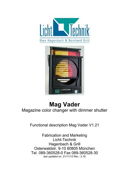
<strong>Mag</strong> <strong>Vader</strong><br />
<strong>Mag</strong>azine color changer with dimmer shutter<br />
Functional description <strong>Mag</strong> <strong>Vader</strong> V1.21<br />
Fabrication and Marketing<br />
<strong>Licht</strong>-<strong>Technik</strong><br />
Hagenbach & Grill<br />
Osterwaldstr. 9-10 80805 München<br />
Tel. 089-360528-0 Fax 089-360528-30<br />
last updated on: 21/11/12 Rev.: 2.18<br />
<strong>Mag</strong> <strong>Vader</strong> V1.21 Rev.: 2.18 1
Caution! Operate the device only after having read and understood<br />
operating instructions!<br />
2 <strong>Mag</strong> <strong>Vader</strong> V1.21 Rev.: 2.18
The <strong>Mag</strong> <strong>Vader</strong><br />
With the <strong>Mag</strong> <strong>Vader</strong> we can offer a combination of a color changer and a dimmer shutter<br />
in one device. The great advantage is the low weight and the low profile construction.<br />
Therefore the light angle, especially of the fresnel lamps, can be kept.<br />
The color cartridge can be exchanged within a few seconds. The breakes for changing<br />
and setting up for the next show can be shortended considerably.<br />
The cartridges are compatible to the color changers <strong>Mag</strong> Max. For example a cartridge<br />
with color code „red“ fits to the devices <strong>Mag</strong> Max Mk2 250 and <strong>Mag</strong> <strong>Vader</strong> 200.<br />
After putting in the color cartridge, the color changer will automatically scan the string<br />
and memorise the individual positions of the color tape. There is no more need for any<br />
further programming of the positions. The individual positions of the colors are detected by<br />
the aluminium markers on the string which move through a light sensor. Special (longer)<br />
markers are at the first and the last frame to recognize the begin and the end.<br />
The controlling is done by DMX512 (USITT). The position of the color changer, the speed<br />
of the color changer, the fan intensity (noise reduction), the position of the shutter and the<br />
speed of the shutter can be triggered by DMX.<br />
The string can be moved in linear and frame-by-frame mode. In linear mode every<br />
position on the foil can be reached. In frame-by-frame mode only the full color frames are<br />
resonsive. A dark color mode is possible for especially sensitive colors. A dark color<br />
frame has the double length of a normal frame and will be moved in slowmotion from the<br />
beginning of the frame to its end. The advantage is a better heat distribution on the foil, so<br />
that the gel has a longer lifetime.<br />
Speed can be programmed as a speed or time function at the color changer as well as at<br />
the shutter. Speed control defines the speed with which the color tape should move. Time<br />
control determines a time in which the next move is to be done.<br />
This time can be programmed from 1s (color changer) or 0.2s (shutter) up to 120min. via<br />
DMX. This allows very slow movement to make sunrise effects for example but also very<br />
quick color changes (20 colors in 3.5 seconds for MM200) can be realized. With the<br />
shutter thunderstorm effects are possible as well as very slow fades.<br />
The fan intensity can be determined from 5% to 100% to avoid noise if necessary.<br />
The built in 32-Bit Processor provides a high throughput of the computer, quick<br />
positioning and uncomplicated handling. Even when triggering several color changers the<br />
precise control system provides an absolute synchronous movement. For example horizon<br />
crossfadings can also be realised with several <strong>Mag</strong> <strong>Vader</strong>s on a large width.<br />
Because of the absolute value device, the color changer doesn´t need to make any<br />
initialisation runs after power up. The shutter makes a short initialisation move after<br />
switching on.<br />
<strong>Mag</strong> <strong>Vader</strong> V1.21 Rev.: 2.18 3
The lighted LCD display (the light can be switched off) leads the user in plain text<br />
instructions through the various programming steps. The instrucions are available either in<br />
english or german language.<br />
We would like to express our special thanks to Max Keller, Gundram von Löffelholz and<br />
Tobias Löffler, whose ideas, creativity and criticism represented a valuable contribution in<br />
the development of the MAGMAX and the MAGMAX MkII.<br />
4 <strong>Mag</strong> <strong>Vader</strong> V1.21 Rev.: 2.18
Table of content<br />
The <strong>Mag</strong> <strong>Vader</strong>..................................................................................................................... 3<br />
Safety and operating instructions......................................................................................... 6<br />
Dimensions of color tape...................................................................................................... 8<br />
Positioning of the aluminium markers.................................................................................. 9<br />
Dimensions of strings of <strong>Licht</strong>-<strong>Technik</strong> color changers...................................................... 11<br />
Inserting the foil strip into the cartridge.............................................................................. 12<br />
Cabling............................................................................................................................... 13<br />
Getting started.................................................................................................................... 14<br />
User interface..................................................................................................................... 15<br />
Display lighting ON/OFF..................................................................................................... 15<br />
Checking basic parameter.................................................................................................. 16<br />
Setting to default values .................................................................................................... 16<br />
The different modes........................................................................................................... 17<br />
P01 DMX-Adress position (color changer)......................................................................... 20<br />
P02 DMX address speed (color changer).......................................................................... 21<br />
P03 DMX address fan intensity.......................................................................................... 22<br />
P04 DMX address shutter.................................................................................................. 23<br />
P05 DMX adress speed (shutter)....................................................................................... 24<br />
P08 DMX addresses together or separately...................................................................... 25<br />
P09 Dark color mode speed............................................................................................... 26<br />
P10 Setting, Resetting and controlling of the dark colors................................................... 27<br />
P11 Move mode color changer.......................................................................................... 28<br />
P12 Speed mode color changer ........................................................................................ 29<br />
Time conversation table time drive mode (color changer)................................................. 30<br />
P13 Maximum moving time for time drive mode................................................................ 31<br />
P15 Speed mode shutter................................................................................................... 32<br />
Conversation table time drive mode shutter (mode 2)....................................................... 33<br />
P16 Maximum moving time for time drive mode (shutter).................................................. 34<br />
P18 Middle position compensation..................................................................................... 35<br />
P20 Internal Speed of color changer.................................................................................. 36<br />
P21 Internal speed shutter................................................................................................. 37<br />
P22 Internal fan intensity.................................................................................................... 38<br />
P30 Displaying the DMX value........................................................................................... 39<br />
P32 Selecting the user language....................................................................................... 40<br />
P34 Reverse DMX time drive............................................................................................. 41<br />
P35 Unit number (Netspider only)...................................................................................... 42<br />
Technical data.................................................................................................................... 43<br />
Factory presettings............................................................................................................. 44<br />
Error Messages / Malfunctions........................................................................................... 45<br />
Warranty............................................................................................................................. 46<br />
Further information............................................................................................................. 46<br />
Declaration of conformity.................................................................................................... 47<br />
<strong>Mag</strong> <strong>Vader</strong> V1.21 Rev.: 2.18 5
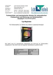
Safety and operating instructions<br />
The MAG <strong>Vader</strong> must only be operated in the operating position provided for this<br />
purpose. Operating position is vertical (LCD display is in bottom position) with max. +/- 60<br />
degree.<br />
Admissible ambient temperature: 0..55 degree Celsius.<br />
The device is getting very hot during operation because of the heat of the lamp. Let it cool<br />
for at least 1 hour before touching.<br />
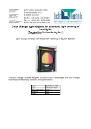
The lamp must not shine direct onto the color changer. This means the diameter of the<br />
color changer must not be smaller than the diameter of the head. For example it is not<br />
allowed to use a MAGMAX 200 in front of a lamp with a diameter of 300mm.<br />
Never seize inside the device, because the fan may run.<br />
The top and bottom vents must not be blocked or covered.<br />
The equipment is designed to be used in dry and clean rooms.<br />
The Unit must be kept dry. In case of condensation of water a waiting period of up to 2<br />
hours is necessary until the colour changer acclimatisation is reached.<br />
„PAR“ spotlights without dispersing lens are not suitable for being used with color<br />
changers.<br />
Make sure that the maximum load of the fastening spigots will not be exceeded by the<br />
additional weight of the unit.<br />
Check fixing of the <strong>Mag</strong> <strong>Vader</strong> at the lamp,<br />
Always use a safety belt for the device itself and the cartridge.<br />
Check the fixing of the cassette.<br />
Power supply of <strong>Licht</strong>-<strong>Technik</strong> <strong>Mag</strong> <strong>Vader</strong>s via the datapower input must only be realized<br />
via power supplies authorized by us (safe electriacal seperation from the mains).<br />
When it has to be assumed that a safe operation is no longer possible, the equipment<br />
must be switched off immediately and be secured against unintended operation.<br />
6 <strong>Mag</strong> <strong>Vader</strong> V1.21 Rev.: 2.18
This is the case when<br />
· the equipment shows visible damages;<br />
· the equipment is no longer functional;<br />
· parts of the equipment are loose or slackened;<br />
· connecting lines show visible damages.<br />
Prior to starting the equipment the user must check the usefulness of the device for its<br />
intended use. In particular, <strong>Licht</strong>-<strong>Technik</strong> shall decline any liability for damages of the<br />
equipment as well as for consequential damages resulting of the device being used<br />
inappropriately, of inexpert installation, incorrect starting and use, and of noncompliance<br />
with the valid safety regulations.<br />
<strong>Mag</strong> <strong>Vader</strong> V1.21 Rev.: 2.18 7
Dimensions of color tape<br />
We recommend filters of Rosco type Supergel©<br />
Please cut your gels to fit on the rolls in the same way like the gels is on original gel roll.<br />
Your can avoid disturbing movement noise and a excessive wear of the foil.<br />
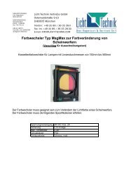
At standard length of each frame you can put in the amount written in the table. The<br />
maximum number of colors depends on the size of the device. The <strong>Mag</strong> Max can<br />
memorise the individual positions for a maximum of 47 aluminium markers (if you like to<br />
realize special effects like sunrise or rainbow). At standard length of the individual foil<br />
strips the following foil composition is resulting thereof. However, at any time it is possible<br />
to insert a lesser amount of foil strips. Minimum is 2 (the begin and the end marker).<br />
A<br />
Tail<br />
leader<br />
Endmarker<br />
C C<br />
Color<br />
n<br />
C<br />
Color Color<br />
n-1<br />
2<br />
(dark)<br />
D<br />
2 x C C<br />
Leader<br />
MV 200 Red 276 370 8140 20<br />
MV 250 Black 320 440 9680 20<br />
MV 300 Yellow 370 490 9800 18<br />
MV 350 Blue 450 550 9900 16<br />
MV 430 Grey 530 630 10080 14<br />
All dimensions in mm!<br />
To use a color in dark color mode it is necessary to double the length C. The total number<br />
of colors is reduced accordingly.<br />
White Diffusion proved itself extremely efficient as leader and tail-leader, since this type of<br />
material is fitting very closely and can thus compensate any inaccuracies resulting from<br />
the tape-in procedure. We recommend to use a transparent adhesive tape with high<br />
temperature stability for this purpose.<br />
The positioning of the aluminium markers are described as follows.<br />
8 <strong>Mag</strong> <strong>Vader</strong> V1.21 Rev.: 2.18<br />
Color<br />
1<br />
C<br />
Beginmarker<br />
Darkcolormarker<br />
Colormaker<br />
X<br />
Put marker on the bottom<br />
concisely with the frame!<br />
Type Color code cartridge Height A Color length C Total length D Max colors
Positioning of the aluminium markers<br />
The color changer can recognize the individual color positions by means of the attached<br />
aluminium markers. Thus the frames can be exactly positioned or even be corrected<br />
should the foil strips expand because of the heat.<br />
The minimum number of markers is 2 (Begin and endmarker).<br />
The markers must consist of an opaque material (aluminium). They can also be ordered<br />
from our company.<br />
Positions of the markers on the gel:<br />
Type Dimension x in mm<br />
(Dark-) Colormarker Beginmarker Endmarker<br />
MV 200 65 80 35<br />
MV 250 65 80 35<br />
MV 300 80 95 40<br />
MV 350 80 95 40<br />
MV 430 80 95 40<br />
The marker has to be consicely with the bottom end of the foil!<br />
Dimensions of the marker:<br />
Begin- and endmarker: 25 mm x 25 mm<br />
Colormarker: 6,5 mm x 25 mm vertical<br />
Dark color marker: 13 mm x 25 mm vertical<br />
Beginmarker: It has to be attached to the beginning of the first color so that the beginning<br />
of the marker (right side) is in the light sensor when the first color is centered in the<br />
cartridge.<br />
end first begin<br />
frame<br />
Begin marker<br />
Endmarker: It has to be attached to the beginning of the last color so that the end of the<br />
marker (left side) is in the light sensor when the first color is centered in the cartridge.<br />
Endmarker<br />
end last<br />
begin<br />
Color<br />
<strong>Mag</strong> <strong>Vader</strong> V1.21 Rev.: 2.18 9<br />
x
Colormarker: The Colormarker has to be taped in vertical position at the beginning of<br />
each frame. It must be positioned precisely in the sensor when the respective color is<br />
centered in the cartridge window.<br />
end<br />
last<br />
color<br />
Colormarker<br />
first<br />
color<br />
Dark color marker: The dark color marker has to be taped in vertical position at the<br />
beginning of a dark color frame. It must be positioned precisely in the sensor when the<br />
respective color is centered in the cartridge window. The first and the last color of the<br />
string can not be taped with a dark color marker because these frames have the begin<br />
and end marker.<br />
The markers can also be taped to the front or rear side after the color tape has been<br />
inserted into the cartridge.<br />
10 <strong>Mag</strong> <strong>Vader</strong> V1.21 Rev.: 2.18<br />
Begin<br />
end last<br />
Dark color first begin<br />
color<br />
color<br />
Dark color marker
Dimensions of strings of <strong>Licht</strong>-<strong>Technik</strong> color changers<br />
(All dimensions in mm! )<br />
Sizes of markers: Begin- and Endmarker: 25 x 25mm<br />
Colormarker: 6,5 x 25mm vertical<br />
Darkcolormarker: 13 x 25mm vertical<br />
At the bottom end, the marker has to be placed concisely with the bottom end of the<br />
gel!<br />
A<br />
Tail<br />
leader<br />
Endmarker<br />
<strong>Mag</strong>Max<br />
C C<br />
Color<br />
n<br />
C<br />
Color Color<br />
n-1<br />
2<br />
(dark)<br />
D<br />
2 x C C<br />
Leader<br />
The revolutions for tensioning should be a reference point valid for new gels<br />
and the maximum of color frames!<br />
<strong>Mag</strong> <strong>Vader</strong> V1.21 Rev.: 2.18 11<br />
Color<br />
Type Color-code Height A Color String Max.<br />
Cartridge Length C Length D Colors<br />
1<br />
C<br />
Beginmarker<br />
Darkcolormarker<br />
Colormaker<br />
Position x<br />
MM200 216 280 6160 20 50 80 15<br />
MM250 275 380 7980 19 70 75 45<br />
MM300 318 450 9000 18 70 75 45<br />
MM350 358 480 8640 16 65 75 45<br />
MM430 450 530 8480 14 60 75 20<br />
MM500 520 640 8960 12 65 80 30<br />
MM500XL 700 640 8960 12 65 80 30<br />
MM8-Lite 700 530 8480 14 60 75 20<br />
X<br />
Put marker on the bottom<br />
concisely with the frame!<br />
<strong>Mag</strong>Max Mk2 <strong>Mag</strong><strong>Vader</strong><br />
Type Color-code Height A Color String Max. Color<br />
Position x<br />
Begin End<br />
Cartridge Length C Length D Colors marker marker marker<br />
MV175 Event 206 280 7560 25 50 50 50 5-6<br />
MM200 Mk2 Green 225 305 6710 20 65 80 35 5-6<br />
MM200 MK2-25 Green 225 305 8235 25 65 80 35 6-7<br />
MM250 Mk2 MV200 Red 276 370 8140 20 65 80 35 5-6<br />
MM300 Mk2 MV250 Black 320 440 9680 20 65 80 35 10-11<br />
MM300 Mk2-25 Black 320 440 11880 25 65 80 35 12-14<br />
MM350 Mk2 MV300 Yellow 370 490 9800 18 80 95 40 10-11<br />
MM430 Mk2 MV350 Blue 450 550 9900 16 80 95 40 12-14<br />
MM500 Mk2 MV430 Grey 530 630 10080 14 80 95 40 20-22<br />
CC-Serie SH-CC Use dark color markers only with Version 2.1 (CC) respectively 1.1 (SH-CC) or higher<br />
Position x<br />
Type Height A Color String Max. Color Begin End<br />
Length C Length D Colors marker marker marker<br />
CC150 174 215 6880 30 40 30 30<br />
CC175 192 240 7680 30 40 30 35<br />
CC200 SH-CC185 225 305 9760 30 50 50 50<br />
CC250 276 370 9990 25 65 50 50<br />
CC270 SH-CC270 276 370 9990 25 65 50 50<br />
CC350 SH-CC325 370 465 9300 18 75 60 50<br />
SH-CC460 498 580 10440 16 75 60 50<br />
<strong>Mag</strong>Max Cyclo Series<br />
See Cyclo Series manual<br />
Use dark color markers only with Version 2.1 or higher<br />
Color<br />
marker<br />
Begin<br />
marker<br />
End<br />
marker<br />
Revolutions for foil<br />
tensioning
Inserting the foil strip into the cartridge<br />
left hand foil drum right hand foil drum<br />
adhesive tape<br />
left knob<br />
wound up<br />
string roll<br />
right knob<br />
Wind up the foil strip in a way that the open end shows the leader. Insert the colour tape,<br />
as indicated, into the cartridge and, by means off left-hand knob, wind the complete color<br />
tape onto the right-hand foil drum. Now center and tape the tail-leader on the left-hand foil<br />
drum. Tense the foil strip by retaining the right-hand stop button and turning the left-hand<br />
knob against the clockwise direction.<br />
At the older model <strong>Mag</strong>Max (angular design) it is just the way around:<br />
Start putting in the foil with the tail leader onto the left drum. The left button is the stop<br />
button and the right button must be turned in clockwise direction to tense the foil.<br />
Observe the number of revolutions for tensioning in the table on page 11! For counting the<br />
revolutions the screw at the knob can be a help. The revolutions should be a reference<br />
point valid for new gels and the maximum of color frames!<br />
Note: Too much tension is the reason for failure and broken springs.<br />
Important: Check whether all of the individual aluminium markers are moving through the<br />
sensor.<br />
12 <strong>Mag</strong> <strong>Vader</strong> V1.21 Rev.: 2.18
Cabling<br />
The standardized DMX-Signal is based on industrie´s RS485 Interface. It is designed for<br />
maximum lengths up to 1200m. This length is under condition in theatre or studio normally<br />
not possible. As a result of internal tests we recommend a maximum length of 200m (only<br />
DMX, 5PIN).<br />
The maximum length of a Output (Data Power, 4PIN) must not exceed 80m because of<br />
the voltage drop.<br />
Splitbox/Netzteil PS104 or PS204<br />
OUT<br />
1-4<br />
Data Power<br />
cable XLR<br />
4pin<br />
<strong>Mag</strong><strong>Vader</strong><br />
IN<br />
DMX-OUT connector for further Splitbox<br />
230V Netzanschluss<br />
OUT<br />
DMX-cable XLR 5pin<br />
DMX-Light mixer panel<br />
IN<br />
Out Connector<br />
for further<br />
<strong>Mag</strong> <strong>Vader</strong><br />
Operating position top!<br />
Connect the light mixer panel and the Splitbox PS104/PS204 with a 5PIN XLR-DMXcable.<br />
The splitbox is provided with a DMX out jack for connecting additional splitboxes. At<br />
each of the four DATA Power outputs for the devices a maximum of 4 color changers can<br />
be connected. However, the total number of Color Changers per splitbox must not exceed<br />
16 color changer (PS204) or 8 Color Changer (PS104) respectively.<br />
The last device of a serie should be connected with a terminating impedance (470 Ohm).<br />
It is plugged into the OUT connector of the last device of a row.<br />
<strong>Mag</strong> <strong>Vader</strong> V1.21 Rev.: 2.18 13<br />
IN
Getting started<br />
Important! Never change the colour cartridges when the equipment is switched off! Doing<br />
so may result in malfunctions or torn foil strips.<br />
– Cable the <strong>Mag</strong> <strong>Vader</strong> according to its wiring diagram. Refer to page 13<br />
– Compose the foil strip and insert it into the cartridge (see page 12).<br />
– Switch the unit on - without the colour cartridge inserted - and wait until the message<br />
INSERT CARTRIDGE is displayed.<br />
– Set the color tape of the cartridge to its centre color frame, insert the cartridge and<br />
close it. Wait until the colour changer has finished memorizing the individual colors and<br />
scanning the complete cartridge. During the memorizing process of the colours the first<br />
line will display the color number and the second line the value of the internal absolute<br />
value device.<br />
– When the color tape is too long, ERROR 41 will be displayed. If necessary, shorten the<br />
color tape down to its maximum length and reinsert the cartridge. This message also<br />
occurs if the tape was not centered when putting in.<br />
– The second line of the display will show the adjusted DMX address and the DMX value<br />
transmitted by the light adjusting panel. (You will see values from 0..255 the full DMX<br />
8bit value)<br />
– The only thing left to do is to adjust the DMX address (menu P01, position of color tape,<br />
refer to page 20) after that then you can position the color changer via your light<br />
adjusting panel.<br />
– For further programming possibilities, please refer to the following pages.<br />
14 <strong>Mag</strong> <strong>Vader</strong> V1.21 Rev.: 2.18
User interface<br />
Display lighting ON/OFF<br />
In normal operation the LCD backlight is switched off to avoid a disturbing light. Only if an<br />
error occurs or during programming the light will be switched on automaticly. The user can<br />
also switch it on manually to see what is indicated.<br />
Condition: Color changer is on working level (default state)<br />
Operation:<br />
Moving text with type of device, software version and service telephone number<br />
1. DMX-address Value of 1. DMX-Address<br />
Button UP<br />
Button<br />
DOWN<br />
Button<br />
Menü<br />
depress. Display light ON<br />
depress. Display light OFF<br />
Button OK<br />
<strong>Mag</strong> <strong>Vader</strong> V1.21 Rev.: 2.18 15
Checking basic parameter<br />
With this function you can quick check some basic parameters. Here you can get an quick<br />
overview of what is programmed.<br />
Condition: Color changer is on working level.<br />
Operation:<br />
depress. check number of stored color frames. You can see the<br />
number in second line of the display e.g.:<br />
FRAME:11<br />
depress again. check parameters P01..P03. e.g.<br />
P01: 001<br />
023 002<br />
depress again. check marked dark-colors. Displayed are only dark<br />
colors.<br />
dark: 01 03 08 16 17<br />
depress again. Address and DMX-value is displayed again e.g.<br />
A001:023<br />
You are back at working level.<br />
Setting to default values<br />
With the following handles the equipment can be put back to factory presettings (refer to<br />
page 44). This is an interesting feature for rental houses which can reset the device after a<br />
order.<br />
Operation:<br />
Ok<br />
Power off <strong>Mag</strong> <strong>Vader</strong> first<br />
depress and hold.<br />
Power on <strong>Mag</strong> <strong>Vader</strong>.<br />
release. Display shows ok for presets<br />
if you like to store default values<br />
any other key for doing nothing<br />
16 <strong>Mag</strong> <strong>Vader</strong> V1.21 Rev.: 2.18
The different modes<br />
The color changers are well prepared for customers desires regarding the control.<br />
The string consists of different color frames glued together by the user. To improve<br />
position accuracy a marker should be put on every frame. With the help of the aluminum<br />
marker the positions of the frames can also be corrected when waving (heat!). This<br />
correction is only possible in frame-by-frame mode. In this mode only full frames can be<br />
positioned. If you like to do intermediate positions you should switch to linear mode in<br />
menu P11 (page 28).<br />
When triggering in linear mode the length of the string is divided in 256 steps (8-Bit, one<br />
DMX-channel). For example: The smallest step on a tape with 10m length is 10m divided<br />
by 256. The length of one step is 39mm. This is about 4cm! A crossfade with a smooth,<br />
jerking free movement which lasts several minutes is normally not possible because the<br />
string will move in steps of 39mm!<br />
Because of this reason we developed with our customers different modes to solve this<br />
problem.<br />
First, lets have a look on the calculation of the DMX value for full frame positioning when<br />
the device is in linear mode. For example for colour 3:<br />
Under the condition that all frames have the same length.<br />
Please note: It depends on the programmed mode, if some menu points are reachable.<br />
For example if one channel mode is programmed the speed menu is unreachable!<br />
The same behavior, if P08 (DMX adresses seperated or together) is programmed in<br />
together mode. In this case only P01 is reachable, P02 is not.<br />
<strong>Mag</strong> <strong>Vader</strong> V1.21 Rev.: 2.18 17
Modes color changer:<br />
The speed mode:<br />
2 DMX-channels.<br />
In this mode one DMX-channel is for position information, the second one is a speed<br />
information. Here it is possible to determine how fast the color changer must move. The<br />
light mixining can store fast or slow fades. This mode is often used in TV studios. Quiet<br />
scenes require a quiet movement. Fast color changing can also be done by setting the<br />
speed to maximum.<br />
Settings: P12: 00<br />
The time-drive mode:<br />
2 DMX-channels.<br />
Here the first channel represents the position information, the second one represents a<br />
time in which a move should be done. Here you can determine how long (in min. or sec.)<br />
a new positioning should last.<br />
Settings: P12: 01<br />
The one-channel mode:<br />
1 DMX-channel.<br />
One channel for positioning. The speed is calculated from the changing of the value of the<br />
position channel.<br />
Settings:: P12: 02<br />
A detailed description of the move modes and further programming possibilities are<br />
described in the following pages.<br />
18 <strong>Mag</strong> <strong>Vader</strong> V1.21 Rev.: 2.18
Modes Shutter:<br />
The speed mode:<br />
2 DMX channels.<br />
In this mode one DMX channel is for positioning of the blades, the other one is the speed<br />
information (how fast the positioning should happen). Use it if you like to move the blades<br />
fast and slow. It is also possible to set the second channel to a fixed speed (internal<br />
speed).<br />
Settings: P15: 00<br />
P01: DMX adress for position of the blades<br />
P02: DMX adress for speed control<br />
(select DMX value for speed at your lightcontrol:<br />
0% means no speed; 100% means full speed)<br />
The time drive mode:<br />
2 DMX channels.<br />
First channel is for position of the blades. The second channel is the time (not speed!) in<br />
which the positions should be reached. You have the possibility to open/close the shutter<br />
in certain time (selected with 2 nd DMX-channel) Often used in theatre houses where you<br />
need to control the time for opening and closing the blades. There is no flickering of the<br />
light, because the Shutter moves without any visible steps.<br />
Settings: P15: 01<br />
P16: e.g. 10 ( = maximum fade time in minutes (here 10)).<br />
P01: DMX adress for position of the blades<br />
P02: DMX adress for the fade time<br />
(select DMX value for time in time conversion table (page 33),<br />
here you find the corresponding DMX-value.).<br />
The 16-Bit Mode:<br />
2 DMX channels.<br />
Both channels are used for positioning of the blades. The second channel is fine<br />
positioning. This mode is only supported by modern light consoles.<br />
Settings: P15: 02<br />
P01: DMX adress shutter<br />
(the following channel will be automatically used for fine positioning)<br />
The 1 channel mode:<br />
1 DMX channel<br />
One channel for blade positioning. The moving speed is internally calculated from the<br />
position channel.<br />
Settings: P15: 03<br />
P01: DMX adress shutters<br />
A detailed description of the operating modes and further programming possibilities,<br />
please refer to the following pages.<br />
<strong>Mag</strong> <strong>Vader</strong> V1.21 Rev.: 2.18 19
P01 DMX-Adress position (color changer)<br />
At this point the DMX address of the color changer (position) can be adapted to the<br />
address of the light mixer panel<br />
Range of values: Adress 1..512<br />
Operation:<br />
Menü<br />
Menü<br />
Ok<br />
Ok<br />
depress Now you are at the menu level. The last adjusted menu<br />
point is displayed, e.g.:<br />
menu p02: DMX-Address speed color<br />
changer<br />
depress ... until Menu P01 is displayed.<br />
depress The second line displays the currently adjusted value.<br />
depress Adjust the desired DMX address.<br />
depress You are back at the menu level.<br />
depress The equipment is ready for operation.<br />
20 <strong>Mag</strong> <strong>Vader</strong> V1.21 Rev.: 2.18
P02 DMX address speed (color changer)<br />
At this point the DMX address for the speed control of the colour changer can be adapted<br />
to the address of the light mixer panel.<br />
If the value is set to 0, the internal adjusted speed of P20 (refer to page 36) will be used.<br />
In this case it is possible to operate the color changer without a seperate speed channel.<br />
Range of values: 0 no DMX channel for speed (internal speed is used)<br />
1..512 address channel for speed<br />
Operation:<br />
Menü<br />
Menü<br />
Ok<br />
Ok<br />
depress Now you are at the menu level. The last adjusted menu<br />
point is displayed, e.g.:<br />
menu p01: DMX-Address color changer<br />
depress ... until Menu P02 is displayed.<br />
depress The second line displays the currently adjusted value.<br />
depress Adjust the desired DMX address.<br />
depress You are back at the menu level.<br />
depress The equipment is ready for operation.<br />
<strong>Mag</strong> <strong>Vader</strong> V1.21 Rev.: 2.18 21
P03 DMX address fan intensity<br />
At this point the DMX address for the fan intensity control of the colour changer can be<br />
adapted to the address of the light mixer panel.<br />
If the value is set to 0, the internal adjusted intensity of P22 (refer to page 38) will be used.<br />
In this case it is possible to operate the color changer without a separate speed channel.<br />
Range of values: 0 no DMX channel for fan intensity (internal intensity is used)<br />
1..512 address channel for fan intensity<br />
Operation:<br />
Menü<br />
Menü<br />
Ok<br />
Ok<br />
depress Now you are at the menu level. The last adjusted menu<br />
point is displayed, e.g.:<br />
menu p01: DMX-Address color changer<br />
depress ... until Menu P03 is displayed.<br />
depress The second line displays the currently adjusted value.<br />
depress Adjust the desired DMX address.<br />
depress You are back at the menu level.<br />
depress The equipment is ready for operation.<br />
22 <strong>Mag</strong> <strong>Vader</strong> V1.21 Rev.: 2.18
P04 DMX address shutter<br />
At this point the DMX address of the shutter can be adapted to the address of the light<br />
mixer panel.<br />
Range of values: Address 1..512<br />
Operation:<br />
Menü<br />
Menü<br />
Ok<br />
Ok<br />
depress Now you are at the menu level. The last adjusted menu point<br />
is displayed, e.g.:<br />
menu p01: DMX-Address color changer<br />
depress ... until menu p04 is displayed.<br />
depress The second line indicates the currently adjusted value.<br />
depress Adjust the desired address.<br />
depress You are back at the menu level.<br />
depress The equipment is ready for operation.<br />
<strong>Mag</strong> <strong>Vader</strong> V1.21 Rev.: 2.18 23
P05 DMX adress speed (shutter)<br />
Only available in operation mode 0 and 1 (set the operation mode in P15).<br />
At this point the DMX address for speed control of the shutter can be adapted to the<br />
address of the light mixer panel.<br />
When value 0 is entered there will be no speed control via the DMX light mixer panel. The<br />
shutter moves with the speed indicated in P21. In this case the shutter moves with fixed<br />
speed, programmend in P21 (You need one channel less).<br />
Range of values: Adress 0 no DMX channel for speed (internal speed is used)<br />
1..512 DMX address for speed<br />
Operation:<br />
Menü<br />
Menü<br />
Ok<br />
Ok<br />
depress Now you are at the menu level. The last adjusted menu point<br />
is displayed, e.g.:<br />
menu p01: DMX-Adress shutter<br />
depress ... until menu p02 is displayed.<br />
depress The second line indicates the currently adjusted value.<br />
depress Adjust the desired address.<br />
depress You are back at the menu level.<br />
depress The equipment is ready for operation.<br />
24 <strong>Mag</strong> <strong>Vader</strong> V1.21 Rev.: 2.18
P08 DMX addresses together or separately<br />
To reduce the time for programming it is possible to set only the first address (for position)<br />
the others will follow. This means you program only the address for position. For example,<br />
if this menu point set to 1 and the position address is set to 139, the speed address is 140<br />
and the fan address is 141. If this menu point is set to 0 you have to program all 3<br />
addresses seperately.<br />
Range of values: 0 adjust all addresses individually<br />
1 adjust only the first address, the others will follow<br />
The menus P02 to P05 are not reachable!<br />
Operation:<br />
Menü<br />
Menü<br />
Ok<br />
Ok<br />
depress Now you are at the menu level. The last adjusted menu<br />
point is displayed, e.g.:<br />
menu p01: DMX-Address color changer<br />
depress ... until Menu P08 is displayed.<br />
depress The second line displays the currently adjusted value.<br />
depress Adjust the desired value<br />
depress You are back at the menu level.<br />
depress The equipment is ready for operation.<br />
<strong>Mag</strong> <strong>Vader</strong> V1.21 Rev.: 2.18 25
P09 Dark color mode speed<br />
Dark colors (like dark blue tones) bleech and shrink very fast with heat. For this colors the<br />
dark color mode is available. This means the frame will be moved slowly back and forward<br />
for a better heat distribution on the foil. The life time will be enormous increased.<br />
It´s up to the user to determine which color should be a dark color. If a color is shrinking<br />
and bleeching very fast it is advisable to set this color to a dark color. Note that per dark<br />
color the maximum number of colors is decreased by one.<br />
Operation:<br />
1. The concering color must be twice as long like a normal color (refer to page 8)<br />
2. Set a dark color marker on the concerning color (refer to page 9)<br />
3. P11 (frame by frame or linear Modus) must be set to 1 (refer to page 28)<br />
4. P12 (speed mode) must not be 2 (no 1 channel mode, page 29)<br />
When scanning and memorizing the tape, the device can recognize a dark color because<br />
of the longer marker.<br />
At this point you set how fast a selected the dark color frame is to be moved.<br />
Range of values: 3..80<br />
(Note: 5 is default value, suitable for fresnel lenses to be used for<br />
quiet theatre and opera use.<br />
40 should be minimum for PAR Lamps)<br />
Operation:<br />
Menü<br />
Menü<br />
Ok<br />
Ok<br />
depress Now you are at the menu level. The last adjusted menu<br />
point is displayed, e.g.:<br />
menu p01: DMX-Address color changer<br />
depress ... until Menu P09 is displayed.<br />
depress The second line displays the currently adjusted value.<br />
depress Adjust the desired value<br />
depress You are back at the menu level.<br />
depress The equipment is ready for operation.<br />
26 <strong>Mag</strong> <strong>Vader</strong> V1.21 Rev.: 2.18
P10 Setting, Resetting and controlling of the dark colors<br />
A dark color is twice as long as a normal color (refer to page 8). If a dark color is<br />
selected, the frame is permanently moved in slow motion from the beginning to the end of<br />
the frame. This prevents a burn in of the foil and extends the life time of the foil.<br />
The dark color moving speed is set in P09, page 26.<br />
When scanning and memorizing the tape, the device can recognize a dark color because<br />
of the longer marker (refer to the marker chapter, page 9).<br />
In function P10 a frame can be set or reset to dark color. These manual changings will be<br />
overritten if a string is new scanned after putting in a cartridge.<br />
All colors except the last can be set to dark color.<br />
Range of value: First to next to last frame.<br />
Operation:<br />
Menü<br />
Menü<br />
Menü<br />
Ok<br />
Ok<br />
depress Now you are at the menu level. The last adjusted menu<br />
point is displayed, e.g.:<br />
menu p01: DMX-Address color changer<br />
depress ... until Menu P10 is displayed.<br />
depress The second line indicates:<br />
f01 ---- frame 1 is no dark color<br />
f01 Dark frame 1 is a dark color<br />
depress Choose the desired color.<br />
depress Switch between normal color / dark color.<br />
depress You are back at the menu level.<br />
depress The equipment is ready for operation.<br />
<strong>Mag</strong> <strong>Vader</strong> V1.21 Rev.: 2.18 27
P11 Move mode color changer<br />
At this point you can determine the move mode of the color changer. You can select<br />
between linear and frame-by-frame mode. Linear mode means every position on the<br />
tape is reachable. So it is possible to have 2 different colors in the light. Frame-by-frame<br />
mode means, only full frames are responsive.<br />
Tip: Even in linear mode the colour changer corrects the frame positions by means of the<br />
attached aluminium markers, should the string be expanded.<br />
Range of values: 0 linear mode<br />
1 frame by frame mode<br />
Operation:<br />
Menü<br />
Menü<br />
Ok<br />
Ok<br />
depress Now you are at the menu level. The last adjusted menu<br />
point is displayed, e.g.:<br />
menu p01: DMX-Address color changer<br />
depress ... until Menu P11 is displayed.<br />
depress The second line displays the currently adjusted value.<br />
depress Adjust the desired move mode.<br />
depress You are back at the menu level.<br />
depress The equipment is ready for operation.<br />
28 <strong>Mag</strong> <strong>Vader</strong> V1.21 Rev.: 2.18
P12 Speed mode color changer<br />
At this point you can switch over between the functions of speed control, time control<br />
and one channel mode of the color changer.<br />
In speed mode you define via the light mixer panel, how many mm/sec the color tape is<br />
moving.<br />
In time mode you define how much time the process of positioning of the desired position<br />
shall require. Time can be adjusted from 0 sec (maximum speed), up to the maximum<br />
time defined under P13. A time table is shown on the following page.<br />
In single channel Mode the speed of color changer is calculated from DMX-signal direct.<br />
You need only one channel, but is only practicable with linear mode (P11=0, page 28).<br />
For the time drive mode the following equation applies:<br />
DMX in %<br />
P13 in minutes<br />
moving time in seconds<br />
If you like to calculate from a given moving time the corresponding DMX value you can<br />
use the time conversation table on the next page or the following equation:<br />
Range of values: 0 speed mode<br />
1 time drive mode<br />
2 1 channel mode<br />
Operation:<br />
Menü<br />
Menü<br />
Ok<br />
Ok<br />
DMX in %<br />
P13 in minutes<br />
moving time in seconds<br />
depress Now you are at the menu level. The last adjusted menu<br />
point is displayed, e.g.:<br />
menu p01: DMX-Address color changer<br />
depress ... until Menu P12 is displayed.<br />
depress The second line displays the currently adjusted value.<br />
depress Adjust the desired mode.<br />
depress You are back at the menu level.<br />
depress The equipment is ready for operation.<br />
<strong>Mag</strong> <strong>Vader</strong> V1.21 Rev.: 2.18 29
Time conversation table time drive mode (color changer)<br />
Conversion from moving time into DMX (in%) and reverse.<br />
First determine what maximum moving time you need. For example the fades don´t take<br />
longer than 10 minutes. So set this time in menu P13, page 31. Choose the corresponding<br />
column (10min., 20min. etc.). Choose the desired time for positioning. In the first column<br />
you will find the corresponding DMX value.<br />
P13 max time in min. P13 max time in min.<br />
DMX in % 10 20 30 DMX in % 10 20 30<br />
0 0 0 0 50 02:30 05:00 07:30<br />
1 00:00 00:00 00:00 51 02:36 05:12 07:48<br />
2 00:00 00:00 00:01 52 02:42 05:24 08:07<br />
3 00:01 00:01 00:02 53 02:49 05:37 08:26<br />
4 00:01 00:02 00:03 54 02:55 05:50 08:45<br />
5 00:02 00:03 00:05 55 03:02 06:03 09:05<br />
6 00:02 00:04 00:06 56 03:08 06:16 09:24<br />
7 00:03 00:06 00:09 57 03:15 06:30 09:45<br />
8 00:04 00:08 00:12 58 03:22 06:44 10:06<br />
9 00:05 00:10 00:15 59 03:29 06:58 10:27<br />
10 00:06 00:12 00:18 60 03:36 07:12 10:48<br />
11 00:07 00:15 00:22 61 03:43 07:27 11:10<br />
12 00:09 00:17 00:26 62 03:51 07:41 11:32<br />
13 00:10 00:20 00:30 63 03:58 07:56 11:54<br />
14 00:12 00:24 00:35 64 04:06 08:12 12:17<br />
15 00:14 00:27 00:41 65 04:14 08:27 12:41<br />
16 00:15 00:31 00:46 66 04:21 08:43 13:04<br />
17 00:17 00:35 00:52 67 04:29 08:59 13:28<br />
18 00:19 00:39 00:58 68 04:37 09:15 13:52<br />
19 00:22 00:43 01:05 69 04:46 09:31 14:17<br />
20 00:24 00:48 01:12 70 04:54 09:48 14:42<br />
21 00:26 00:53 01:19 71 05:02 10:05 15:07<br />
22 00:29 00:58 01:27 72 05:11 10:22 15:33<br />
23 00:32 01:03 01:35 73 05:20 10:39 15:59<br />
24 00:35 01:09 01:44 74 05:29 10:57 16:26<br />
25 00:38 01:15 01:53 75 05:38 11:15 16:53<br />
26 00:41 01:21 02:02 76 05:47 11:33 17:20<br />
27 00:44 01:27 02:11 77 05:56 11:51 17:47<br />
28 00:47 01:34 02:21 78 06:05 12:10 18:15<br />
29 00:50 01:41 02:31 79 06:14 12:29 18:43<br />
30 00:54 01:48 02:42 80 06:24 12:48 19:12<br />
31 00:58 01:55 02:53 81 06:34 13:07 19:41<br />
32 01:01 02:03 03:04 82 06:43 13:27 20:10<br />
33 01:05 02:11 03:16 83 06:53 13:47 20:40<br />
34 01:09 02:19 03:28 84 07:03 14:07 21:10<br />
35 01:14 02:27 03:41 85 07:14 14:27 21:41<br />
36 01:18 02:36 03:53 86 07:24 14:48 22:11<br />
37 01:22 02:44 04:06 87 07:34 15:08 22:42<br />
38 01:27 02:53 04:20 88 07:45 15:29 23:14<br />
39 01:31 03:03 04:34 89 07:55 15:51 23:46<br />
40 01:36 03:12 04:48 90 08:06 16:12 24:18<br />
41 01:41 03:22 05:03 91 08:17 16:34 24:51<br />
42 01:46 03:32 05:18 92 08:28 16:56 25:24<br />
43 01:51 03:42 05:33 93 08:39 17:18 25:57<br />
44 01:56 03:52 05:48 94 08:50 17:40 26:30<br />
45 02:02 04:03 06:05 95 09:02 18:03 27:05<br />
46 02:07 04:14 06:21 96 09:13 18:26 27:39<br />
47 02:13 04:25 06:38 97 09:25 18:49 28:14<br />
48 02:18 04:36 06:55 98 09:36 19:12 28:49<br />
49 02:24 04:48 07:12 99 09:48 19:36 29:24<br />
100 stopped stopped stopped<br />
Caution: The color changer doesn´t move at DMX value 100% to have the possibility to<br />
stop<br />
a fade.<br />
30 <strong>Mag</strong> <strong>Vader</strong> V1.21 Rev.: 2.18
P13 Maximum moving time for time drive mode<br />
If you choosed time drive mode (P12 to 1, page 29) you can program here the maximum<br />
moving time for positioning.<br />
Range of values: 0..120 minutes<br />
Operation:<br />
Menü<br />
Menü<br />
Ok<br />
Ok<br />
depress Now you are at the menu level. The last adjusted menu<br />
point is displayed, e.g.:<br />
menu p01: DMX-Address color changer<br />
depress ... until Menu P13 is displayed.<br />
depress The second line displays the currently adjusted value.<br />
depress Adjust the desired time.<br />
depress You are back at the menu level.<br />
depress The equipment is ready for operation.<br />
<strong>Mag</strong> <strong>Vader</strong> V1.21 Rev.: 2.18 31
P15 Speed mode shutter<br />
At this point you switch to the different operation modes of the shutter.<br />
Mode 0:<br />
Speed mode, 2 Channels. One channel for position, an other channel for speed from<br />
0 .. 100% to move to the given position.<br />
Mode 1:<br />
Time drive mode, 2 channels. One channel for position, an other channel represents<br />
the time to move on the given position. (refer to next page for time table).<br />
DMX in %<br />
P16 in minutes<br />
Moving time in seconds<br />
If you like to calculate a DMX value from a given moving time, you can use the time<br />
conversion table on the next page, or you can use this formula:<br />
DMX in %<br />
P13 in minutes<br />
Moving time in seconds<br />
Mode 2:<br />
16 Bit mode, 2 channels Kanäle. Both channels for position of the blades. The 2 nd<br />
channel is fine position.<br />
Mode 3:<br />
One channel mode. One channel for position. The speed is calculated by the<br />
shutter.<br />
Range of values: 0 = Speed mode<br />
1 = Time drive mode<br />
2 = 16-Bit mode<br />
3 = One channel mode<br />
Operation:<br />
Menü<br />
Menü<br />
Ok<br />
Ok<br />
Moving time= DMX 2 ⋅P16⋅60<br />
10000<br />
DMX = moving time⋅10000<br />
P16⋅60<br />
depress Now you are at the menu level. The last adjusted menu point<br />
is displayed, e.g.:<br />
menu p01: DMX-Adress shutter<br />
depress ... until menu p15 is displayed.<br />
depress The second line indicates the currently adjusted value.<br />
depress Adjust the desired value.<br />
depress You are back at the menu level.<br />
depress The equipment is ready for operation.<br />
32 <strong>Mag</strong> <strong>Vader</strong> V1.21 Rev.: 2.18
Conversation table time drive mode shutter (mode 2)<br />
Umrechnung DMX-Wert(%) in Verfahrzeit (sec)<br />
Legen Sie zuerst fest welche max. Verfahrzeit Sie benötigen. (z.B. Ihre Überblendungen<br />
dauern nie länger als 10 min., legen Sie diese max. Zeit unter P16 fest). In der<br />
entsprechenden Spalte 10min, 20min usw. suchen Sie die Zeit die Sie einstellen möchten<br />
und können dann in der ersten Spalte den ensprechenden DMX-Wert ablesen.<br />
Innerhalb der Tabelle finden Sie die Verfahrzeit, in der ersten Spalte steht der<br />
dazugehörige DMX-Wert in Prozent.<br />
Important !!!<br />
DMX value Time control: Set maximum moving time in P16<br />
in % 10 min. 20 min. 30 min. 60 min. 120 min.<br />
0 0 0 0 0 0<br />
1 0 0 0 0 1<br />
2 0 0 1 1 3<br />
3 1 1 2 3 6<br />
4 1 2 3 6 12<br />
5 2 3 5 9 18<br />
6 2 4 6 13 26<br />
7 3 6 9 18 35<br />
8 4 8 12 23 46<br />
9 5 10 15 29 58<br />
10 6 12 18 36 72<br />
15 14 27 41 81 162<br />
20 24 48 72 144 288<br />
25 38 75 112 225 450<br />
30 54 108 162 324 648<br />
35 74 147 221 441 882<br />
40 96 192 288 576 1.152<br />
45 121 243 364 729 1.458<br />
50 150 300 450 900 1.800<br />
55 182 363 545 1.089 2.178<br />
60 216 432 648 1.296 2.592<br />
65 254 507 761 1.521 3.042<br />
70 294 588 882 1.764 3.528<br />
75 338 675 1.013 2.025 4.050<br />
80 384 768 1.152 2.304 4.608<br />
85 433 867 1.300 2.601 3.901<br />
90 486 972 1.458 2.916 4.374<br />
95 541 1.083 1.624 3.249 6.498<br />
100 No move No move No move No move No move<br />
If the time is set to 100% (DMX value 255), the shutter doesn´t move to allow stops during<br />
a fade over!<br />
<strong>Mag</strong> <strong>Vader</strong> V1.21 Rev.: 2.18 33
P16 Maximum moving time for time drive mode (shutter)<br />
When time control mode is selected (P15 set to value 1) you can enter the maximum<br />
moving time for a positioning process.<br />
Condition: P15 set to 1<br />
Range of values: 1..120 minutes<br />
Operation:<br />
Menü<br />
Menü<br />
Ok<br />
Ok<br />
depress Now you are at the menu level. The last adjusted menu point<br />
is displayed, e.g.:<br />
menu p01: DMX-Adress shutter<br />
depress ... until menu p16 is displayed.<br />
depress The second line indicates the currently adjusted value.<br />
depress Adjust the desired value.<br />
depress You are back at the menu level.<br />
depress The equipment is ready for operation.<br />
34 <strong>Mag</strong> <strong>Vader</strong> V1.21 Rev.: 2.18
P18 Middle position compensation<br />
With this function it possible to adjust the opening position of the blades.<br />
Range of values: -999 .. +999 Steps<br />
Operation:<br />
Menü<br />
Menü<br />
Ok<br />
Ok<br />
depress Now you are at the menu level. The last adjusted menu point<br />
is displayed, e.g.:<br />
menu p01: DMX-Adress shutter<br />
depress ... until menu p18 is displayed.<br />
depress The second line indicates the currently adjusted value.<br />
depress Adjust the desired value.<br />
depress You are back at the menu level.<br />
depress The equipment is ready for operation.<br />
<strong>Mag</strong> <strong>Vader</strong> V1.21 Rev.: 2.18 35
P20 Internal Speed of color changer<br />
At this point you can define at which speed the color changer should carry positioning, if<br />
no DMX channel for speed control is programmed (P02, page 21).<br />
Caution! This speed is only used if P02 is set to 0!<br />
Range of values: 0..255 real DMX value<br />
Operation:<br />
Menü<br />
Menü<br />
Ok<br />
Ok<br />
depress Now you are at the menu level. The last adjusted menu<br />
point is displayed, e.g.:<br />
menu p01: DMX-Address color changer<br />
depress ... until Menu P20 is displayed.<br />
depress The second line displays the currently adjusted value.<br />
depress Adjust the desired value.<br />
depress You are back at the menu level.<br />
depress The equipment is ready for operation.<br />
36 <strong>Mag</strong> <strong>Vader</strong> V1.21 Rev.: 2.18
P21 Internal speed shutter<br />
At this point you define at which speed the shutter shall carry out positioning processes<br />
when no DMX channel for speed control was programmed (P02 set to value 0).<br />
Remember that this value is related to the speed mode and the time drive mode. When<br />
time control was selected (P15 set to 1) this value is a time parameter. When speed mode<br />
was selected (P15 set to 0) this value indicates a speed.<br />
Condition: P15 set to 0 or 1 (16 bit mode and one channel mode don´t need any<br />
speed<br />
information<br />
Mit der internen Geschwindigkeit wird nur dann verfahren, wenn P02 auf 0 ist.<br />
Range of values: 0..255<br />
Operation:<br />
Menü<br />
Menü<br />
Ok<br />
Ok<br />
depress Now you are at the menu level. The last adjusted menu point<br />
is displayed, e.g.:<br />
menu p01: DMX-Adress shutter<br />
depress ... until menu p21 is displayed.<br />
depress The second line indicates the currently adjusted value.<br />
depress Adjust the desired speed/time.<br />
depress You are back at the menu level.<br />
depress The equipment is ready for operation.<br />
<strong>Mag</strong> <strong>Vader</strong> V1.21 Rev.: 2.18 37
P22 Internal fan intensity<br />
At this point you can define the fan intensity if no DMX channel for fan control is<br />
programmed (P02, page 22).<br />
Caution! This intensity is only used if P03 is set to 0!<br />
Range of values: 0..255 real DMX value<br />
Operation:<br />
Menü<br />
Menü<br />
Ok<br />
Ok<br />
depress Now you are at the menu level. The last adjusted menu<br />
point is displayed, e.g.:<br />
menu p01: DMX-Address color changer<br />
depress ... until Menu P22 is displayed.<br />
depress The second line displays the currently adjusted value.<br />
depress Adjust the desired value.<br />
depress You are back at the menu level.<br />
depress The equipment is ready for operation.<br />
38 <strong>Mag</strong> <strong>Vader</strong> V1.21 Rev.: 2.18
P30 Displaying the DMX value<br />
This function assists you in checking the values transmitted by the light mixer panel. At<br />
this point you can quickly detect whether the colour changer is triggered with the correct<br />
values. It is possible to check all 512 DMX channels. Note that the value of the address<br />
programmed in this menu will be indicated in normal operation. After power up the<br />
programmed address in menu P01 (page 20) will be displayed.<br />
Range of values: Adress 1..512<br />
Operation:<br />
Menü<br />
Menü<br />
Ok<br />
Ok<br />
depress Now you are at the menu level. The last adjusted menu<br />
point is displayed, e.g.:<br />
menu p01: DMX-Address color changer<br />
depress ... until Menu P30 is displayed.<br />
depress The second line displays the currently adjusted value.<br />
depress Adjust the desired address.<br />
depress You are back at the menu level.<br />
depress The equipment is ready for operation.<br />
<strong>Mag</strong> <strong>Vader</strong> V1.21 Rev.: 2.18 39
P32 Selecting the user language<br />
At this point you can choose in which language you want the texts and messages to be<br />
displayed.<br />
Range of values: 0 = German<br />
1 = English<br />
2 = Russian<br />
Operation:<br />
Menü<br />
Menü<br />
Ok<br />
Ok<br />
depress Now you are at the menu level. The last adjusted menu<br />
point is displayed, e.g.:<br />
menu p01: DMX-Address color changer<br />
depress ... until Menu P32 is displayed.<br />
depress The second line displays the currently adjusted value.<br />
depress Adjust the desired language.<br />
depress You are back at the menu level.<br />
depress The equipment is ready for operation.<br />
40 <strong>Mag</strong> <strong>Vader</strong> V1.21 Rev.: 2.18
P34 Reverse DMX time drive<br />
If the time drive mode is selected (P12 = 1, page 29), you can decide either if DMX value<br />
100% is the maximum time or DMX value 0% is the maximum time.<br />
Range of values: 0 100% DMX is maximum time (standart)<br />
(slow move at 100%)<br />
1 0% DMX is maximum time<br />
(fast move at 0%)<br />
Operation:<br />
Menü<br />
Menü<br />
Ok<br />
Ok<br />
depress Now you are at the menu level. The last adjusted menu<br />
point is displayed, e.g.:<br />
menu p01: DMX-Address color changer<br />
depress ... until Menu P34 is displayed.<br />
depress The second line displays the currently adjusted value.<br />
depress Adjust the desired value.<br />
depress You are back at the menu level.<br />
depress The equipment is ready for operation.<br />
<strong>Mag</strong> <strong>Vader</strong> V1.21 Rev.: 2.18 41
P35 Unit number (Netspider only)<br />
With this function you can set the unit number for Netspider systems.<br />
Range of values: 0..9999<br />
Operation:<br />
Menü<br />
Menü<br />
Ok<br />
Ok<br />
depress Now you are at the menu level. The last adjusted menu<br />
point is displayed, e.g.:<br />
menu p01: DMX-Address color changer<br />
depress ... until Menu P34 is displayed.<br />
depress The second line displays the currently adjusted value.<br />
depress Adjust the desired unit number.<br />
depress You are back at the menu level.<br />
depress The equipment is ready for operation.<br />
42 <strong>Mag</strong> <strong>Vader</strong> V1.21 Rev.: 2.18
Technical data<br />
Dimensions and Weight (without lampholders):<br />
Connected loads: 24V DC, max. 2,5 A<br />
Fuse: 6,3 A slow blow<br />
Type Weight Height Length Depth<br />
MV 200 7,7 kg 485 mm 405 mm 125 mm<br />
MV 250 10,0 kg 510 mm 530 mm 130 mm<br />
MV 300 10,5 kg 585 mm 535 mm 140 mm<br />
MV 350 13,3 kg 636 mm 630 mm 170 mm<br />
MV 430 16,0 kg 720 mm 720 mm 140 mm<br />
Pin assignment:<br />
Data-Power-cable: 4pin XLR min.<br />
Housing: shield<br />
PIN 1: 0 V cross section 0,75mm²<br />
PIN 2: Data – cross section 0,25mm²<br />
PIN 3: Data + cross section 0,25mm²<br />
PIN 4: +24 V DC cross section 0,75mm²<br />
DMX-data cable: 5pin XLR<br />
PIN 1: shield cross section 0,25mm²<br />
PIN 2: Data – cross section 0,25mm²<br />
PIN 3: Data + cross section 0,25mm²<br />
PIN 4: not connected cross section 0,25mm²<br />
PIN 5: not connected cross section 0,25mm²<br />
Caution: To comply EMV rules our equipment has to be connected with shielded cables.<br />
This also for reliability of our equipment.<br />
The DMX wires must be twisted pair and shielded seperately.<br />
<strong>Mag</strong> <strong>Vader</strong> V1.21 Rev.: 2.18 43
Factory presettings<br />
Menu Description Value Remark<br />
P01 DMX Adress color changer position 1 0%: Color 1<br />
100%: last color<br />
P02 DMX Adress speed color changer 2 0%: no speed<br />
100%: full speed<br />
P03 DMX Adress fan intensity 3 0%: 5% speed<br />
100%: full speed<br />
P04 DMX Adress shutter position 4 0%: closed<br />
100%: open<br />
P05 DMX Adress shutter speed 5 0%: no speed<br />
100%: full speed<br />
P08 DMX Single adress mode on/off 1 On<br />
P09 Dark color mode speed 5 3..80<br />
P10 Manual setting of dark colors individual<br />
P11 Move mode color changer 1 Frame by frame<br />
P12 Speed mode color changer 0 Time drive mode<br />
P13 Maximum time for time drive mode color changer 10 minutes<br />
P15 Speed mode shutter 3 1-Channel mode<br />
P16 Maximum time for time drive mode shutter 10 minutes<br />
P18 Middle position compensation shutter individual<br />
P20 Internal speed color changer 128<br />
P21 Internal speed shutter 255<br />
P22 Internal fan intensity 255<br />
P30 DMX tester 1<br />
P32 Language 0 German<br />
P34 Reverse DMX time drive 0 No Reverse<br />
P35 Unit number Netspider 0<br />
44 <strong>Mag</strong> <strong>Vader</strong> V1.21 Rev.: 2.18
Error Messages / Malfunctions<br />
- No display after power up.<br />
The equipment houses a slow-blow fuse for feeble currents of 6,3 A protecting the<br />
equipment of wrong polarities on the supply line. When the fuse is blown, cable and<br />
polarity have absolutely to be checked (pin1 = 0 V, pin 4 = +24V).<br />
- E20<br />
The DMX control signal does not arrive at the device.<br />
– Check the DMX signal supply to the power supply unit. LED „DMX okay“ must<br />
light.<br />
– The data lines (Pin2 and/or Pin3) in the cable leading to the color changer is<br />
defective.<br />
– The controlling unit is not yet operative.<br />
- E21 The polarity of the DMX signal is interchanged<br />
– Check at the supply cables if pins 2 and 3 are interchanged.<br />
- E23 DMX noise<br />
– This malfunction may come up in case of major line length or in case of bad<br />
signal quality. Check cables and connections.<br />
– Check out if a terminating resistor (470 Ohm) can help.<br />
- E28 Eprom Error<br />
– After power up the program memory is checked. If any error is detected, the<br />
above message will be displayed. Notify company <strong>Licht</strong>-<strong>Technik</strong> in this case.<br />
- E29 RAM-Error<br />
– After power up the RAM memory is checked. If any error is detected, the above<br />
message will be displayed. Notify company <strong>Licht</strong>-<strong>Technik</strong> in this case.<br />
- E30 Motor blocked<br />
– Check if any foreign object is in the device.<br />
– Make sure that the drum drive is running smoothly.<br />
– Connections of motor or potentiometer were possibly interchanged when motor<br />
or potentiometer was replaced.<br />
- E40 Cartridge is not memorized<br />
– The inserted cartridge is not memorized. It is possible that the cartridge was<br />
changed when the color changer was switched off.<br />
<strong>Mag</strong> <strong>Vader</strong> V1.21 Rev.: 2.18 45
- E41 Memorization of cartridge is not possible<br />
– Remove the cartridge, position the color tape of the cartridge to its middle<br />
position (the center color). Insert the cartridge again and lock it. Should the error<br />
occur again proceed as follows:<br />
– The color tape is too long. Make sure the tape does not exeed the maximum<br />
length. (Refer to page 8, dimensions of color tape).<br />
– There may be foreign particles in the sensor detecting the aluminium markers.<br />
Remove these particles and insert the cartridge again.<br />
Note: Never write down anything (e.g. color numbers) onto the bottom of the tape,<br />
because the writing will move through the sensor and may be detected as markers!<br />
Warranty<br />
The warranty for our products is 2 years. It comprises any repair of failures – free of<br />
charge – which can be proved to result from defects of fabrication.<br />
Warranty expires when:<br />
- the device was modified or attempted to be repaired<br />
- damages were caused by the intervention of foreign persons<br />
- damages are due to noncompliance with the operating instructions<br />
- the device was connected to an incorrect voltage or incorrect type of current<br />
- the device was incorrectly operated or when damages were caused by negligent<br />
handling or misusage<br />
All maintenance and servicing works related to the product must be carried out by the<br />
company <strong>Licht</strong>-<strong>Technik</strong>. <strong>Licht</strong>-<strong>Technik</strong> shall not assume any liability for losses or damages<br />
of any kind being the results of inexpert servicing.<br />
Further information<br />
This document and the information contained therein are subject to copyright and neither<br />
the whole nor any part of it may, and this is also valid for the described product, be<br />
reproduced, copied or recorded in any form without the prior written authorization of <strong>Licht</strong>-<br />
<strong>Technik</strong> <strong>Vertriebs</strong> <strong>GmbH</strong>.<br />
The products of <strong>Licht</strong>-<strong>Technik</strong> <strong>GmbH</strong> are subject to constant development. Therefore<br />
<strong>Licht</strong>-<strong>Technik</strong> reserves the right to modify components, motors and also technical<br />
specifications any time and without prior notice.<br />
46 <strong>Mag</strong> <strong>Vader</strong> V1.21 Rev.: 2.18
Declaration of conformity<br />
Manufacturer: <strong>Licht</strong>-<strong>Technik</strong> <strong>Vertriebs</strong> <strong>GmbH</strong><br />
Address: Osterwaldstraße 9-10<br />
80805 München<br />
declares that the product:<br />
Name of product: <strong>Mag</strong><strong>Vader</strong> (Color changer / dimmer shutter combination)<br />
Type of product: MV200/MV250/MV300/MV350/MV430<br />
corresponds to the following specifications under strict observance of the installation instructions and<br />
technical specifications:<br />
Standard 2004/108/EG of the European Parliament and the council from<br />
15. December 2004<br />
for law provision adaptation of the memeber states concerning the electronical<br />
compatibility and for<br />
abrogation of standard 89/336/EWG.<br />
The device passed the test. A testreport is available at company <strong>Licht</strong>-<strong>Technik</strong> Vetriebs <strong>GmbH</strong>.<br />
Munich 19.9.2005<br />
-------------------------------------------------------<br />
Uwe Hagenbach / Bernhard Grill<br />
Managing directors<br />
<strong>Mag</strong> <strong>Vader</strong> V1.21 Rev.: 2.18 47