LNG Carrier Propulsion by ME-GI Engines and/or Reliquefaction
LNG Carrier Propulsion by ME-GI Engines and/or Reliquefaction
LNG Carrier Propulsion by ME-GI Engines and/or Reliquefaction

You also want an ePaper? Increase the reach of your titles
YUMPU automatically turns print PDFs into web optimized ePapers that Google loves.
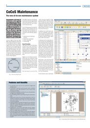
Fig. 22: N 2 compress<strong>or</strong>/exp<strong>and</strong>er<br />
Nitrogen cycle<br />
The cryogenic temperature inside the<br />
cold box is produced <strong>by</strong> means of a<br />
nitrogen compression-expansion cycle,<br />
shown in<br />
Fig. 22. Nitrogen gas at a pressure of<br />
13.5 bar is compressed to 57 bar in a<br />
3-stage centrifugal compress<strong>or</strong>. The gas<br />
is cooled <strong>by</strong> water (seawater <strong>or</strong> indirect)<br />
after each stage. After the last cooler,<br />
the gas is led to the “warm” part of the<br />
cryogenic heat ex-changer where it is<br />
pre-cooled to about -110°C <strong>and</strong> then<br />
exp<strong>and</strong>ed to a pressure of 14.5 bar<br />
in the exp<strong>and</strong>er. The gas leaves the<br />
exp<strong>and</strong>er at about -163°C <strong>and</strong> is then<br />
introduced into the “cold” part of the<br />
cryogenic heat exchanger where it<br />
cools <strong>and</strong> reliquefies the boil-off gas to<br />
<strong>LNG</strong>.<br />
The nitrogen then continues through<br />
the “warm” part of the cryogenic heat<br />
SUCTION THROTTLE<br />
2 3<br />
1 E<br />
exchanger bef<strong>or</strong>e it is returned to the<br />
suction side of the 3-stage compress<strong>or</strong>.<br />
The N 2 -compress<strong>or</strong>/exp<strong>and</strong>er unit is a<br />
three-stage integrated gear centrifugal<br />
compress<strong>or</strong> with one exp<strong>and</strong>er stage.<br />
The unit has a gear with 4 pinions<br />
where each of the 4 wheels is coupled<br />
to a separate pinion. The result is that<br />
the exp<strong>and</strong>er w<strong>or</strong>k goes directly into<br />
the gearbox <strong>and</strong> relieves the electric<br />
mot<strong>or</strong>.<br />
The advantages of this solution are:<br />
• M<strong>or</strong>e compact design<br />
• Reduced cost<br />
• Improved control of the refrigeration<br />
• Reduced power consumption.<br />
Control systems<br />
Generally, the temperature in the nitrogen<br />
loop decides the quantity of N 2 in<br />
the coolant circuit.<br />
Increasing <strong>or</strong> decreasing the amount of<br />
nitrogen in the loop changes the cooling<br />
capacity. The amount is changed <strong>by</strong> injecting<br />
<strong>or</strong> withdrawing nitrogen from the<br />
receiver. If the cooling capacity is too<br />
high, the inlet exp<strong>and</strong>er temperature will<br />
decrease. The control valve to the receiver<br />
at the compress<strong>or</strong>s discharge<br />
will open to withdraw the nitrogen from<br />
the main loop. C<strong>or</strong>respondingly, if the<br />
cooling capacity is too low, the inlet exp<strong>and</strong>er<br />
temperature will increase. The<br />
control valve from the receiver to the<br />
compress<strong>or</strong> suction side will open to<br />
inject nitrogen into the main loop.<br />
The relationship between cooling capacity<br />
<strong>and</strong> pressure changes is based on<br />
the fact that a turbo compress<strong>or</strong> is a<br />
constant volume flow machine. When<br />
the suction pressure is changing, the<br />
mass flow is changing <strong>and</strong>, c<strong>or</strong>respondingly,<br />
the cooling capacity. The pressure<br />
ratio f<strong>or</strong> the compress<strong>or</strong> is constant <strong>and</strong><br />
independent of the suction pressure.<br />
Even if the cooling capacity is reduced,<br />
the outlet exp<strong>and</strong>er temperature will be<br />
nearly the same.<br />
The BOG cycle is an independent loop.<br />
The cargo tank pressure is kept approximately<br />
constant <strong>by</strong> varying the mass<br />
flow through the compress<strong>or</strong>. The boil-off<br />
compress<strong>or</strong> will be a two-stage centrifugal<br />
compress<strong>or</strong> with diffuser guide vanes<br />
(DGV) f<strong>or</strong> controlling the capacity. There<br />
is DGV on both stages, <strong>and</strong> they w<strong>or</strong>k<br />
in parallel, controlled <strong>by</strong> the same signal.<br />
15