

ICOM JTG SYSTEM GENERAL SCHEME
ICOM JTG SYSTEM GENERAL SCHEME
ICOM JTG SYSTEM GENERAL SCHEME

Create successful ePaper yourself
Turn your PDF publications into a flip-book with our unique Google optimized e-Paper software.
icom S.p.A.<br />
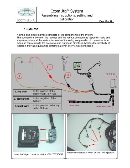
5. HARNESS<br />
Icom Jtg ® System<br />
Assembling instructions, setting and<br />
calibration<br />
Page 12 of 27<br />
A single and simple harness connects all the components of the system.<br />
The connections between the harness and the various components happen in rapid and<br />
simple way since all the various terminals of the wiring are provided of connectors type<br />
auto and conforming to the normative and European directives, besides the simplicity of<br />
insertion, they also guarantee extreme safety in every single connection.<br />
2<br />
1. red wire<br />
2. brawn wire<br />
3. black wire<br />
1<br />
to the positive of the<br />
battery with 7.5A fuse<br />
to the negative of the<br />
battery<br />
to the positive under key<br />
with 15A fuse<br />
Schema generale del cablaggio / Wiring harness general drawing / Schéma général du câblage<br />
Insert the 36 pin connector on the ICU <strong>JTG</strong> ® <strong>ICOM</strong><br />
3<br />
TO THE TANK<br />
TO THE ICU<br />
TO THE INJECTORS<br />
Green connectors to insert on the LPG injectors