8154001 Version 1.00 - Massoth
8154001 Version 1.00 - Massoth
8154001 Version 1.00 - Massoth

You also want an ePaper? Increase the reach of your titles
YUMPU automatically turns print PDFs into web optimized ePapers that Google loves.
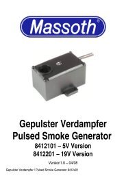
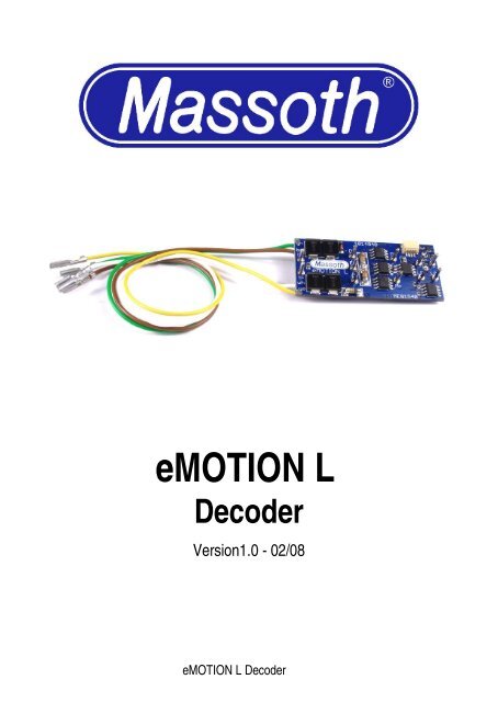
eMOTION L<br />
Decoder<br />
<strong>Version</strong>1.0 - 02/08<br />
eMOTION L Decoder
Summary Page<br />
1. General and Safety Details 2<br />
2. Important Information for Operation 3<br />
2.1. Properties of the eMOTION L Decoder 3<br />
2.2. General Hook-Up 4<br />
2.2.1. Hook-Up of the eMOTION L to a LGB ® gearbox 5<br />
2.3. Pin Connectors on the Upper Surface 5<br />
2.4. Basic Settings 7<br />
2.5. Installation 8<br />
3. Advanced Settings 8<br />
3.1. Soldering Pads on the Lower Surface 8<br />
3.2. MASSOTH Bus Connectors 8<br />
3.3. Function Outputs 9<br />
3.3.1. Serial Pulse String for LGB ® Interface<br />
9<br />
3.3.2. RC Servo Hook-Up 9<br />
3.3.3. Hook-Up of a Power Buffer 10<br />
3.4. Motor Output 11<br />
3.4.1. Special Driving Functions 15<br />
3.5. Analog Operation 16<br />
4. CV-List 17<br />
4.1. Attachments to the CV-List 19<br />
Attachment 1: NMRA Configuration Register 19<br />
Attachment 2: MASSOTH Configuration Register 19<br />
Attachment 3: Command Allocation 19<br />
Attachment 4: Dimming Function 20<br />
Attachment 5: Special Functions F1 + F2 + F3 + F4 + F5 20<br />
Attachment 5a: Expanded Special Functions F2 + F4 + F5 + F6 20<br />
Attachment 6: Reset Program 21<br />
4.2. Reset Function 21<br />
1 eMOTION L Decoder
Attachment 7: Basic Settings of the freely programm. Driving Curve 21<br />
4.3. Address Programming 21<br />
5. Programming Methods 22<br />
5.1. CV Programming 23<br />
5.2. CV Reading 23<br />
5.3. CV Programming bit-by-bit 23<br />
5.4. Register Programming 24<br />
5.5. Indirect Programming 24<br />
5.6. PoM: Program on Main 24<br />
6. Properties of the eMOTION L 24<br />
6.1. General Information Regarding DCC Systems 25<br />
6.2. Operation with LGB ® MTS-I, MTS-II and MTS III<br />
26<br />
7. Technical Specifications 29<br />
8. Warranty 30<br />
8.1. Warranty Claims 30<br />
8.2. Support 31<br />
1. General and Safety Details<br />
Congratulations on your purchase of an eMOTION L Decoder. The<br />
eMOTION L Decoder is an exceptional, high-performance Digital Decoder<br />
designed for G-Scale by <strong>Massoth</strong> Elektronik GmbH, Germany. We highly<br />
recommend reading this manual and the documentation carefully and<br />
thoroughly before operating your eMOTION L Decoder.<br />
<strong>Massoth</strong> Elektronik GmbH used the latest in technology in designing and<br />
manufacturing the eMOTION L Decoder. Excellent operation at all times<br />
is assured by the high safety standard in data processing and by<br />
delivering an exceptional power output and performance. Future<br />
alterations of the DCC standards are easily implemented into the<br />
eMOTION L Decoder by updating. The latest Flash-Technology is utilized<br />
eMOTION L Decoder 2
in the eMOTION L Decoder to provide a safe and consumer-friendly<br />
operation during updating.<br />
2. Important Information for Operation<br />
Install your decoder in compliance with the connecting diagram in this<br />
manual. The decoder is protected against shorts and excessive loads.<br />
However, in case of a connection error e.g. a short between a light and<br />
the motor, this safety feature cannot work and the decoder will be<br />
destroyed subsequently.<br />
The decoder is originally programmed on address #3 with 14 speed steps.<br />
In case you want to use a high address, you have to program CV17,<br />
CV18, and CV29 accordingly. If you want to use 28 speed steps you need<br />
to set CV29-Bit1 to ”2”. Otherwise the lights might not work or may flicker.<br />
2.1. Properties of the eMOTION L Decoder<br />
Decoder functions:<br />
• Loco decoder for digital and analog Operation<br />
• Motor output max. 1,8 Amps (1 motor)<br />
• 2 Light outputs with max. 500mAmps each (front, rear)<br />
• 6 Function outputs (2 with 500mAmps each (F1-2), 4 with 50mAmps<br />
each (F3-6))<br />
• Overload and temperature protection for motor and functions<br />
• Hook-up by cable, mini-connectors and soldering pads<br />
Digital and Analog Features:<br />
• 10239 loco addresses available<br />
• 14, 28, 128 speed steps<br />
• programmable driving curve<br />
• Start-, mid-, and maximum speed adjustable<br />
• Acceleration- and deceleration settings adjustable<br />
• Motor frequency adjustable<br />
• Back-EMF in digital and analog operation<br />
3 eMOTION L Decoder
• 16 selectable functions according to NMRA<br />
• Switching speed and delay time selectable with function key<br />
• Parallel and serial control of all light and function outputs<br />
• Control of parallel updated modules (LGB ® )<br />
• Easy function mapping with direction assignment<br />
• Programmable flashing light function and short term function<br />
• Dimmable light and function outputs, activatable in analog<br />
• Output for a RC-Servo<br />
• Many settings may be used analog too<br />
• Reset function for all CV-values<br />
• Bus interface for MASSOTH and LGB ® modules<br />
2.2. General Hook-Up<br />
Please note the colour code of the cables and the pin assignment in the<br />
illustration below:<br />
Illustration 1: eMOTION L Decoder hook-up<br />
The colour coded cables connect as follows:<br />
YELLOW= Motor +<br />
WHITE = Track + (lh track in driving direction)<br />
BROWN = Track - (rh track in driving direction)<br />
GREEN = Motor -<br />
eMOTION L Decoder 4
Illustration 2: eMOTION L hook-up to a LGB ® gear box<br />
2.2.1. Hook-Up to a LGB ® gear box (Illustration 2)<br />
All current LGB ® gear boxes feature 4 contact pins on the upper side. To<br />
utilize these gear boxes for digital operation the pins must be connected<br />
to the eMOTION XLS Sound Decoder according to the schematic below.<br />
Older versions of LGB ® gear boxes have only 3 contact pins. These gear<br />
boxes need to be changed for digital operation. One pin is connected to<br />
the motor and the track. This connection needs to be disconnected as the<br />
motor and the track must be isolated for digital operation.<br />
2.3. Pin Connectors on the Upper Surface<br />
The eMOTION L decoder conforms to the pin arrangement of the LGB ®<br />
55021 decoder. Therefor the eMOTION L decoder may be installed in<br />
LGB ® locomotives that are equipped with a direct-decoder interface. The<br />
cable 55026 may be utilized with older interfaces as well (Illustration 4).<br />
The decoder features two light outputs for front light and rear light which<br />
are activated according to the driving direction. Please observe the<br />
maximum current for each output: 500mAmps/output. Light bulbs and<br />
other consumer loads (e.g. smoke generator) are connected to Dec+ and<br />
the respective output (LF, LR or F1, see illustration 5). Light bulbs and<br />
smoke generators used must be suited for 24 Volts. In case 5Volt bulbs<br />
and smoke generators are used, please see in “Advanced<br />
Functions“ (Chapter 3.3) for the correct output setting.<br />
5 eMOTION L Decoder
Illustration 3: Pin Assignment Upper Surface<br />
Illustration 4: Hook-Up to a LGB ® - Interface<br />
eMOTION L Decoder 6
2.4. Basic Factory Settings:<br />
Illustration 5: Hook-Up of Light Bulbs<br />
and Smoke Generator<br />
• CV1 = 3 (loco address)<br />
• Light outputs adjusted to full track voltage (for 19/24 Volt bulbs)<br />
• Switching Speed on/off by F8 (half speed)<br />
• Functions Outputs F1 to F6 mapped to Function Keys F1 to F6<br />
• CV29 = 4 (to comply with 14 speed steps for MTS) For 28 speed<br />
steps, CV29 must be set to “6“.<br />
Note: The light function depends on the selected speed step setting. In<br />
case the setting in CV29 is not identical to the setting of the digital<br />
control system, the lights may flicker or may not work at all. (Irrelevant<br />
when using 128 speed steps).<br />
7 eMOTION L Decoder
2.5. Installation<br />
The decoder MUST NOT touch any metallic constructional elements. This<br />
may lead to short circuits and to the destruction of the decoder<br />
subsequently. Attach the decoder with double-sided tape to the<br />
locomotive body or utilize the MASSOTH decoder bracket #8104010.<br />
3. Advanced Settings<br />
The eMOTION L decoder delivers a plentitude of functions when<br />
compared to the LGB ® 55021 decoder : 5 additional function outputs, 1<br />
output for the control of a RC servo, 1 bus interface and a great number of<br />
additional programming options.<br />
3.1. Soldering Pads on the Lower Surface (Illustr. 6)<br />
The lower surface of the eMOTION L decoder is fitted with 6 additional<br />
soldering pads for the function outputs F2, F3, F3S, F4, F5, and F6.<br />
Please observe that the outputs F2, F3, F3S, F4, F5, and F6 are<br />
restricted to 50mAmps each.<br />
F3S is reserved for RC servo control only. No other kind of consumer load<br />
must be connected to this output!<br />
Illustration 6: Soldering Pads on the Lower Surface<br />
3.2. MASSOTH Bus Interface<br />
The MASSOTH bus interface connects to components with special digital<br />
control functions, e.g. the MASSOTH Pulse Smoke Generator.<br />
eMOTION L Decoder 8
3.3. Function Outputs<br />
The eMOTION L Decoder is fitted with 1 function output on the upper<br />
surface (pin) and 5 additional soldering pads on the lower surface. All light<br />
outputs are set to 24Volts as default. This means, at 24Volts track voltage<br />
the function outputs 1 to 6 deliver 24Volts, if activated.<br />
The outputs 3 to 6 are restricted to max. 50mAmps. The output voltage as<br />
well as the function of the light and function outputs may be set by<br />
programming (function key allocation, direction sensitivity, flashing<br />
function and short-term function). See the CV list for further details. The<br />
outputs may be controlled by NMRA-DCC commands as well as with<br />
serial LGB ® pulse chain commands. The light outputs and the function<br />
outputs F1 to F4 are dimmable.<br />
3.3.1. Serial Pulse Chain for LGB ® - Interface<br />
The factory default setting of the eMOTION L decoder provides serial and<br />
parallel data processing. Therefor the decoder may be utilized with all<br />
NMRA digital systems. The serial data processing mode may be<br />
deactivated, thus eliminating the brief waiting period of 0.5 secs with F1<br />
(utilizing the mixed operation serial/parallel). The F1 function will be<br />
triggered instantly.<br />
Special settings for serial pulse chain or parallel function data processing:<br />
CV49 = 2 : Parallel function triggering only<br />
CV49 = 3 : Serial and parallel function triggering<br />
CV49 = 11 : Serial pulse chain on F1 for 6pole LGB ® - Interface with sound<br />
module (Illustr. 4)<br />
CV49 = 11 : Valid, too, for special P-Updates of LGB ® - sound modules.<br />
3.3.2. RC Servo Hook-Up (Illustr. 7)<br />
The eMOTION L decoder is fitted with a special F3S output which is only<br />
usable for RC servo operation. This output is activated if F3 is<br />
programmed for RC operation. In this case the F3 output cannot be<br />
utilized as a regular output.<br />
9 eMOTION L Decoder
RC servos are especially suited for point-to-point movements (e.g. decoupler,<br />
pantograph) or circular motions. The RC servo needs a 5Volt<br />
regulator additionally and the control commands of the decoder.<br />
The end-positions are defined in CVs. In case the function is switched<br />
“ON“, the servo is positioned in one of the end-positions, in case the<br />
function is “OFF“, the servo will travel to the opposite end-position.<br />
In addition the travel speed may be adjusted.<br />
Illustration 7: Hook-Up of a RC Servo<br />
3.3.3. Hook-Up of a Power Buffer<br />
A power buffer may be installed to improve the operational reliability. The<br />
buffer connects to “Dec+“ and “Dec-“. The charging current must not<br />
exceed 500 mAmps.<br />
Analog operation must be disabled with a power buffer connected to the<br />
eMOTION L Decoder otherwise the decoder recognizes the power buffer<br />
as an analog power supply (CV29 bit2).<br />
The power buffer must be switched off during programming.<br />
The MASSOTH Power Buffers (#8151001 or #8151501) are switched off<br />
automatically during programming if you connect the white control line to<br />
“F5“ with the power buffer control function activated in CV118 = 31. Then<br />
the F5 output cannot be used for other purposes.<br />
eMOTION L Decoder 10
3.4. Motor Output<br />
Depending on which digital system utilized different speed steps may be<br />
used. The more steps are used the smoother the locomotive responds to<br />
the throttle. In Garden G-Scale 14 speed steps are used and 28 speed<br />
steps are recommended if supported by the digital system.<br />
• The direction of driving (including the direction related functions) can<br />
be reversed by setting CV29 - bit0 accordingly.<br />
• Three settings of speed control are available:<br />
14 speed steps (CV29 – bit1 = Off)<br />
28 speed steps (CV29 – bit1 = On)<br />
128 speed steps (is detected automatically)<br />
Using the eMOTION L with LGB ® MTS I or II requires a 14 speed step<br />
setting. This is the factory default setting of the decoder.<br />
Several CV settings in the eMOTION L Decoder influence the<br />
acceleration and deceleration characteristics of the locomotive. The<br />
acceleration/deceleration characteristic is defined by 2 CVs:<br />
• Acceleration delay (CV3)<br />
• Deceleration delay (CV4)<br />
The time lag between speed 0 and the maximum speed (or reverse) is<br />
0.5 sec if the setting is “1”, maximum possible is 128 sec (setting<br />
“255”). Simply divide your desired time delay by “2” to acquire the<br />
respective CV setting.<br />
11 eMOTION L Decoder
Driving Curve<br />
The speed characteristic of the locomotive is defined by the driving curve<br />
which is programmed by 3 CVs. The standard driving curve is linear.<br />
llustration 8: Internal Driving Curve of the eMOTION XLS Sound Decoder,<br />
Adjustable with CV2 (Starting Voltage), CV5 (Maximum Speed), CV6 (Mid<br />
Speed)<br />
Recent decoders like the eMOTION L Decoder feature 3 CVs to define<br />
the speed parameters. The basic setting of the eMOTION L Decoder is<br />
shown in the illustration above.<br />
• The start voltage (CV2) defines the driving voltage of speed step1. The<br />
smaller the voltage the slower the locomotive drives. If the PI-Load<br />
Control is “off” and the locomotive does not move in speed step 1, the<br />
start voltage should be increased.<br />
• The maximum speed (CV5) may be reduced by inserting smaller<br />
values.<br />
• The mid-speed (CV6) defines how many speed steps are available. In<br />
eMOTION L Decoder 12
case CV6 is half of the value of CV5, all speed steps are distributed<br />
equally. In case CV6 is smaller than half the value of CV5 the<br />
locomotive will drive slower at mid-speed; the slow speed range will be<br />
stretched.<br />
As an alternative you may program the driving curve individually in 28<br />
speed steps (CV67 - CV94). This driving curve is activated by CV29- bit4.<br />
In this case the CVs 2, 5, and 6 are deactivated!<br />
Motor Control Frequency<br />
Basically the motor runs quieter and smoother when the control frequency<br />
is increased. The motor control frequency is defined in 4 steps by CV9. At<br />
24 kHz the motor is operated at its optimum and runs very quiet. A few<br />
types of motors may require a lower setting if they do not run smoothly or<br />
get hot. The integrated load control works only with 24 kHz. The<br />
eMOTION L Decoder is usable with all kinds of DC motors.<br />
Load Control<br />
The eMOTION L Decoder monitors the driving performance of the<br />
locomotive and regulates the driving voltage. The load control governs the<br />
speed of the locomotive regardless of up or down grades or the length of<br />
the train. This means the decoder delivers more voltage to the motor(s) if<br />
the locomotive is running uphill in order to keep the speed constant. The<br />
eMOTION L Decoder is equipped with a state-of-art integrated PI-Load<br />
Control (proportional-integral) that can be programmed efficiently by 3<br />
CVs. These 3 CVs define the characteristics of the PI-Load Control by the<br />
following parameters: maximum re-adjustment factor (allowed<br />
readjustment per adjustment interval), re-adjustment retardation<br />
(frequency of the adjustment intervals), and maximum re-adjustment<br />
strength (maximum re-adjustment to the speed setpoint).<br />
13 eMOTION L Decoder
Illustration 9: Operating Modes of the PI-Load Control<br />
Maximum Re-Adjustment Factor (CV60)<br />
The maximum re-adjustment factor sets the range of change per readjustment<br />
interval for the motor voltage (see CV61), input range is 0 …<br />
255. The larger the value the more aggressive the decoder will react to<br />
load changes. In the most extreme cases the locomotive will overcontrol<br />
and tend to drive jerky during load changes.<br />
Re-Adjustment Retardation (CV61)<br />
The re-adjustment retardation defines how often the eMOTION L Decoder<br />
is allowed to re-adjust per second. Increasing the value means an<br />
increase of re-adjustments per second. The eMOTION L Decoder is able<br />
to perform up to 4000 adjustments per second. The basic setting is “60”.<br />
This results in a leisurely and realistic control characteristic. Formula:<br />
4000/(CV-value) = Number of adjustments per second.<br />
eMOTION L Decoder 14
Re-Adjustment Strength (CV62)<br />
An example will explain this matter best: The motor voltage is insufficient<br />
to keep the speed as the load increases. The PI-load control kicks in and<br />
regulates (increases) the motor voltage accordingly to make sure the<br />
locomotive continues with the same speed. The re-adjustment strength is<br />
the maximum allowable voltage to achieve the required speed. The<br />
selectable value range is 0…255. The basic setting is “255”, the maximum<br />
strength. This means the eMOTION L Decoder is allowed to increase the<br />
motor voltage up to the track voltage if so required. Lowering this value<br />
sets a ceiling for the motor voltage which cannot be exceeded. This might<br />
meet reality closely as the power reserve of real locomotives is not<br />
unlimited. Entering a track segment with an upgrade the locomotive will<br />
be only partially able to cope with the new power demand and will<br />
decrease the speed at some point. With the setting at “128” the<br />
readjustment is limited to 50%. In case the locomotive reaches this limit, a<br />
speed decrease will occur under an increased load.<br />
The basic setting of the PI-load control is set to “fast”. This enables fast<br />
speed changes but may result in over-regulating and thus to bucking.<br />
The PI-load control may be switched off in CV49.<br />
3.4.1. Special Driving Functions<br />
Shunting Speed<br />
The maximum speed is reduced by half to facilitate a more effective<br />
driving characteristic during shunting. This feature may be set on any<br />
programmable function key. With CV59 = 0 the function is “off”. Values<br />
between 1…16 define the number of the function key. The standard F-key<br />
setting is “8”.<br />
Dis-Engageable Acceleration/Deceleration Times<br />
Disabling acceleration value and braking value: the programmed values of<br />
CV3 and CV4 may be reduced to a minimum by a single keystroke. With<br />
CV64 = 0 the function is “off”. Values between 1…16 define the number of<br />
the function key. The standard F-key setting is “7”.<br />
15 eMOTION L Decoder
Automatic Braking (V1.3 and up)<br />
There are two methods to stop a train automatically in front of a stop<br />
signal. The first method uses DCC brake signals produced by a booster<br />
with a braking module (Broadcast), the second method utilizes a DC<br />
signal (Brake-On-DC). For both methods a track portion in front of the<br />
signal must be totally isolated and powered by the respective signal.<br />
For Brake-On-DC the option for analog operation must be blocked<br />
(CV 29, Bit2). Please check your DCC system manual for further<br />
information.<br />
Pausing Time during Shuttle Operation<br />
You may program a pausing time in a simple shuttle operation in analog<br />
and digital mode. Values between 1 and 255 define a waiting time in 1 to<br />
255 seconds, with CV58=0 this function is deactivated. The activated<br />
pausing time is executed only if the driving direction is reversed during<br />
operation, e.g. by an analog electronic shuttle control. In case the<br />
locomotive is stopped and started in the same direction, the pausing time<br />
will not be executed.<br />
3.5. Analog Operation<br />
In analog mode the eMOTION L Decoder is fully functional with as little as<br />
5Volts of track voltage. The operation in analog mode may be deactivated<br />
with CV29–Bit2. The eMOTION L Decoder features an internal<br />
motor characteristic curve which enables a smooth operation by<br />
measuring the track voltage. An analog load control (pat.pend.) may be<br />
activated (CV49-Bit2). The 3 light outputs are always activated according<br />
to the driving direction. The 6 function outputs (CV13) may be activated in<br />
analog mode also, including the dimming and flashing features.<br />
eMOTION L Decoder 16
4. CV - Table<br />
This table shows the default settings of the eMOTION L Decoder.<br />
An = Analog<br />
CV Description Default An Value Note<br />
1 Loco Address (Standard Short) 3 1 - 127<br />
2 Starting Voltage 2 1 - 255 CV2 x (1/255 track voltage)<br />
3 Acceleration Time 3 √ 1 - 255 CV3 x 2ms x (1/255 track<br />
voltage)<br />
4 Braking Time 3 √ 1 - 255 CV4 x 2ms x (1/255 track<br />
voltage)<br />
5 Top Speed 255 √ 1 - 255 CV5 x (1/255 track voltage)<br />
6 Mid Speed 64 1 - 255 CV6 x (1/255 track voltage)<br />
5+6 Programming in Register Mode:<br />
Register 6 = CV No.<br />
Register 5 = Value<br />
--- --- CV5 and CV6 are not affected<br />
7 Software <strong>Version</strong> 1.2 --- read only<br />
7 Decoder Reset Functions<br />
(3 Ranges available)<br />
--- 55<br />
66<br />
77<br />
8 Manufacturer ID 123 --- read only<br />
reset basic setting<br />
reset motor setting<br />
reset lights and functions<br />
9 Motor Frequency 0 √ 0 ... 3 0=16 kHz, 1=2 kHz,<br />
2=250 Hz, 3= 60 Hz<br />
13 Function Outputs in Analog Mode<br />
(on if Value Set)<br />
17 Long Loco Address (high byte)<br />
18 Long Loco Address (low byte)<br />
3 √ 0 ... 255 F1 = 1, F2 = 2; F3 = 4, F4 = 8;<br />
F5 = 16, F6 = 32; F7 = 64,<br />
F8 = 128<br />
add the values of the desired<br />
functions!<br />
128 128 ...<br />
10239<br />
high loco address active,<br />
if CV29-Bit5 = 1<br />
29 Configuration Table NMRA 4 √ see attachment 1<br />
49 Configuration Table MASSOTH 3 √ see attachment 2<br />
50 Light: Dimming Value (PMW) 32 √ 1 ... 32 32 = full track voltage<br />
51 Front Light: Command Allocation 128 see attachment 3<br />
52 Rear Light: Command Allocation 64 see attachment 3<br />
53 F1 + F2 Dimming Value 0 √ see attachment 4<br />
54 F1: Command Allocation 1 see attachment 3<br />
55 F1: Special Function 0 √ see attachment 5<br />
17 eMOTION L Decoder
CV Description Default An Value Note<br />
56 F2: Command Allocation 2 see attachment 3<br />
57 F2: Special Function 0 √ see attachment 5 + 5a<br />
58 Pause Time for Stop with Reversing 0 √ 0 ... 255 0.5 sec per value<br />
59 Shunting Speed (Half Speed) Command<br />
Allocation<br />
60 PI-Load Control: Maximum<br />
Readjustment Factor<br />
61 PI-Load Control: Readjustment<br />
Retardation<br />
8 0 ... 16 0 = Off, 1…16 = F-key<br />
2 √ 1 ... 255 large value = strong<br />
readjustment<br />
60 √ 1 ... 255 large value = slow readjustment<br />
62 PI-Load Control: Readjustment Strength 255 √ 1 ... 255 1 = fast limitation<br />
254 = slow limitation<br />
255 = no limitation<br />
64 PI-Load Control On/Off: Command<br />
Allocation<br />
67<br />
...<br />
94<br />
Freely Programmable Driving Curves in<br />
28 Steps<br />
7 0 ... 16 0=Off, 1…16: No. of function<br />
key<br />
1 ... 255 1 ... 255 see attachment 6<br />
(if CV29-bit4=16)<br />
112 F3+F4 Dimming Value 0 √ see attachment 4<br />
113 F3: Command Allocation 3 see attachment 3<br />
114 F3: Special Function 0 √ see attachment 5<br />
115 F4: Command Allocation 4 see attachment 3<br />
116 F4: Special Function 0 √ see attachment 5 + 5a<br />
117 F5: Command Allocation 5 see attachment 3<br />
118 F5: Special Function 0 √ see attachment 5 + 5a<br />
119 F6: Command Allocation 6 see attachment 3<br />
120 F6: Special Function 0 see attachment 5 + 5a<br />
121 RC Servo Configuration 0 0,1 0=F3 standard output function<br />
1=F3 RC servo operation<br />
122 Lower End Position 16 5...50 Adjust to RC servo<br />
123 Upper End Position 32 5...50 Adjust to RC servo<br />
127 RC Servo Time Base 1 1...16 1 Unit = 10 msec<br />
eMOTION L Decoder 18
4.1. Attachments to the CV-Table<br />
Attachment 1: (CV29) - NMRA-Configuration<br />
Bit Off (Value=0) Application On Value Note<br />
0 Standard Driving Direction Reverse Driving Direction 1<br />
1 14 Speed Steps 28 Speed Steps 2 automatic recognition of 128<br />
speed steps<br />
2 Digital Operation Only Digital + Analog Operation 4<br />
3 Not Used<br />
4 Internal Driving Curve Programmable Driving<br />
Curve<br />
5 Short Address (CV1) Long Address (stored in<br />
CV17+18)<br />
6 not used<br />
7 not used<br />
16 CV 67 - 94<br />
Attachment 2: (CV49) - <strong>Massoth</strong>-Configuration<br />
Bit Off (Value=0) Application On Value Note<br />
0 Parallel Data Transfer Only Seriell + Parallel Data<br />
Transfer<br />
1 Digital Load Control = Off Digital Load Control = On 2<br />
2 Analog Load Control = Off Analog Load Control = On 4<br />
3 F1-Output Standard Function Fast Pulse String (P-Update)<br />
on F1<br />
4 Not Used<br />
5 Not Used<br />
6 Not Used<br />
7 Not Used<br />
Attachment 3: Switching Output Commands<br />
(CV51, 52, 54, 56, 113, 115, 117, 119)<br />
Value Application Note<br />
0 ... 16 0 = Switch Function with Light Key, 1...16 = Switch<br />
Function with F-Key No. 1-16<br />
32<br />
1 automatic detection of seriell/<br />
parallel<br />
8 Bit3 "on" only with Bit0 "on"<br />
+ 64 Switching Output "on" in Reverse Only additional value must be added<br />
+ 128 Switching Output "on" in Standard Driving Direction<br />
Only<br />
19 eMOTION L Decoder<br />
additional value must be added
Attachment 4: Dimming Values (CV53, 112)<br />
Value Application Note<br />
1 ... 32 Voltage in Percent of Track Voltage on Output 1 Unit = approx. 3% of track voltage<br />
1 = 3% of track voltage (0.75V)<br />
32 = 100% track voltage (24V)<br />
+ 64 F1 resp. F3 Is Dimmed Only F1 = value in CV53<br />
F3 = value in CV112*<br />
+ 128 F2 resp. F4 Is Dimmed Only F2 = value in CV53<br />
F4 = value in CV112*<br />
+ 192 Both Outputs are Dimmed *<br />
* = Command Allocation Value must be added to Voltage Value<br />
Attachment 5: Special Function F1 + F2 + F3 + F4 + F5<br />
(CV55, 57, 114, 116, 118)<br />
Value Application Note<br />
0 0 = Steady "On" (Standard Operation)<br />
1 ... 15 Flashing symmetrical (Time Base 0.25 sec/value) symmetric flashing<br />
(1 ... 15)<br />
+ 64<br />
(1 ... 15)<br />
+ 128<br />
(1 ... 15)<br />
+ 192<br />
Short Term Function (Monoflop) (Time Base 0.25<br />
sec/value)<br />
output switches off after time out<br />
Asymmetric Flashing (1/3 on, 2/3 off) short "on", long "off"<br />
additional value must be added<br />
Asymmetric Flashing (2/3 on, 1/3 off) long "on", short "off"<br />
additional value must be added<br />
Attachment 5a: Expanded Special Functions F2 + F4 + F5 + F6<br />
(CV57, 116, 118, 120)<br />
Value Application Note<br />
16 Inverse Coupling with Output F1, resp. F3 or F5<br />
Alternating Flashing<br />
31 Charging Control of Voltage Buffer in Programming<br />
Mode (only F5)<br />
CV57 (F2 with F1)<br />
CV116 (F4 with F3)<br />
CV120 (F6 with F5)<br />
only in CV118: buffer controlled by F5<br />
eMOTION L Decoder 20
Attachment 6: Basic Values of Freely Programmable Driving<br />
Curve (CV67…CV94)<br />
The programmable driving curve is set to the setting below as basic<br />
setting. This setting is not subject to the reset functions.<br />
Basic values of freely programmable driving curve (CV + Value)<br />
67=6, 68=8, 69=10, 70=13, 71=16, 72=19, 73=22, 74=26, 75=31, 76=36, 77=42, 78=48, 79=54, 80=60,<br />
81=68, 82=76, 83=84, 84=92, 85=102, 86=112, 87=124, 88=136, 89=152, 90=168, 91=188, 92=208,<br />
93=228, 94=232<br />
4.2. Reset Functions<br />
In case the settings of your eMOTION L Decoder are messed up or<br />
obscure, you may reset the decoder to the manufacturer’s settings by<br />
using specific CV values. A distinctive feature of the eMOTION L Decoder<br />
is that you can reset a specific part of the decoder without changing the<br />
remaining parts. The CVs are combined to function groups and reset as a<br />
group. You may reset the basic settings (address, switching speed and<br />
driving characteristics) or the light functions (F-key assignment and<br />
brightness) separately. Please find detailed information about the reset<br />
functions of the eMOTION L Decoder in the CV-table.<br />
Attachment 7: CV 7 Default Settings at Resets<br />
Write the desired reset value into CV7 (software version of the decoder)<br />
to reset the decoder settings to the basic factory settings.<br />
RESET CV-Values on Reset Programing<br />
55 1=3, 17=0, 18=128, 29=4, 49=2, 58=0, 59=8<br />
66 2=2, 3=3, 4=3, 5=255, 6=64, 9=0, 60=4, 61=60, 62=255, 64=9<br />
77 13=0, 50=32, 51=128, 52=64, 53=32, 54=1, 55=0, 56=2, 57=0, 112=32, 113=3, 114=0, 115=4,<br />
116=0, 117=5, 118=0, 119=6, 120=0, 121=0<br />
4.3. Address Programming<br />
Each locomotive operated by the NMRA/DCC standard needs a digital<br />
address to receive its specific command.<br />
21 eMOTION L Decoder
• The NMRA standard provides two kinds of addresses:<br />
- Low (short) addresses (1…127)<br />
- High (long) addresses (128…10239)<br />
• The address must be stored in the decoder to enable the decoder to<br />
recognize the commands that are meant for it.<br />
• The low address is stored in CV 1. The maximum value is “127”. In<br />
addition bit5 in CV 29 must be “off” (value 0).<br />
• The high address is divided into two values and is stored in CV17 and<br />
CV18. In addition bit5 in CV29 must be set to “on”.<br />
The long address must be calculated as follows:<br />
CV17 = address / 256 (store only the whole-numbered value)<br />
CV18 = address – (CV17 x 256)<br />
In case you want to calculate the locomotive address “3005”, please<br />
proceed as follows:<br />
Step 1: 3005 / 256 = 11.74 , so CV17 will be “11”<br />
Step 2: 3005 – (11 x 256) = 3005 – 2816 = “189”<br />
Consequently you have to program CV17 with “11” and CV18 with “189”.<br />
Current digital systems (e.g. the DiMAX-System) offer a comfortable<br />
programming method of the addresses. All CVs including CV29 are<br />
being calculated automatically and programmed at the same time<br />
when using the function “Loco Address Programming”. The<br />
original address setting of the eMOTION L Decoder is “3”. In case of a<br />
decoder reset the address will be reset to this value.<br />
5 Programming Methods<br />
The eMOTION L Decoder supports all programming methods in<br />
accordance with the latest NMRA/DCC standards. Please note that not all<br />
of the DCC systems currently available can be programmed according to<br />
this standard. The manufacturer of your DCC system should give you indepth<br />
information. Choose the programming method applicable to your<br />
eMOTION L Decoder 22
digital system. The eMOTION L Decoder confirms every successful<br />
programming cycle with a short bucking of the engine. This ensures the<br />
correct reception and accomplishment of the programming command.<br />
5.1 Reading Configuration Variables (Cvs)<br />
The readout of CV parameters shall not be mistaken for a programming<br />
procedure. However, it is essential for checking the programmed settings.<br />
The eMOTION L Decoder provides this function and the readout can be<br />
easily accomplished with a hand held controller. After inserting the<br />
desired CV No. the controller will display the value of the respective<br />
variable.<br />
5.2 Writing Configuration Variables (CVs)<br />
Programming (writing) the CV values is the easiest way of programming<br />
the decoder. This method is utilized by most of the DCC systems. Using<br />
your hand held controller, the central station, or the PC - you select the<br />
desired CV parameter and insert your desired value. Programming is<br />
done on a separate programming track or a piece of track that is used as<br />
programming track, depending on the digital system. Please check the<br />
manual of your central station.<br />
5.3 Writing the Configuration Variables (CVs) bit by bit<br />
Some of the CV (e.g. CV29, CV49) parameters consist of multiple binary<br />
values. This means that several values are combined in one value. Each<br />
function has a bit and a value. Programming a CV of this kind requires<br />
that all values of all functions controlled by this CV need to be summed<br />
up. A deactivated function always is “0”, an active function must be<br />
programmed with the respective value according to the CV-table. The<br />
sum represents the value of the CV and must be written into the CV<br />
parameter. All known programming methods may be used.<br />
23 eMOTION L Decoder
Let’s look at the NMRA configuration register for example (CV 29). You<br />
intend to program “normal driving direction, 28 speed steps, digital and<br />
analog operation, internal driving curve, and a short locomotive<br />
address”. This sums up to 2+4=6 according to the attachment list #1. So<br />
CV should be programmed with “6”.<br />
5.4 Register Programming / Writing CVs Indirectly<br />
Register programming was the first method of CV programming. The<br />
eMOTION XLS Sound Decoder supports this programming method. The<br />
CV value is to be entered into an intermediate variable. The decoder<br />
thereafter does the real programming. The input into register 5 and 6 is<br />
accomplished with the hand held controller. The CVs 1 to 4 are entered<br />
directly; all other CVs with higher numbers are programmed indirectly.<br />
Let’s assume you want to set the light output voltage (CV 50) to “10”.<br />
The first step is to go into the register programming mode, insert “6”<br />
thereafter “50”. If this was successful, program register “5” with “10”.<br />
Now your light output is set to “10”.<br />
5.5 PoM Programming on Main (main track)<br />
The PoM method is the only procedure to accomplish programming on<br />
the main track. All of the CV programming can be done except CV1,<br />
17+18 (address) with the eMOTION XLS Sound Decoder. PoM<br />
programming should only be performed when the locomotive is not<br />
in motion.<br />
6. Properties of the eMOTION L<br />
The eMOTION L Decoder is a compact and small-sized driving and<br />
function decoder designed for the G-Scale garden railroad operation. The<br />
decoder features an output for one electric motor and 8 programmable<br />
function outputs.<br />
The eMOTION L Decoder has exceptional driving characteristics in both<br />
digital and analog operation. The performance in analog is outstanding<br />
eMOTION L Decoder 24
and delivers steady operation from 7 to 8 Volts and up. Optional an<br />
additional power buffer may be used which eliminates power interruptions<br />
on contaminated tracks in digital and analog operation.<br />
On which type of layout is the L Decoder to be used?<br />
The eMOTION L Decoder supports the operation on all digitally controlled<br />
layouts according to the NMRA standards, irrespective of the<br />
manufacturer. The use of the internationally accepted standard of the<br />
National Model Railroad Association (NMRA) ensures that the eMOTION<br />
L Decoder works with all NMRA/DCC compatible digital central stations.<br />
The eMOTION L Decoder may be utilized according to NMRA/DCC as<br />
well as with regular analog DC.<br />
6.1. General Information Regarding DCC Systems<br />
In analog operation the speed of the locomotive is controlled by the level<br />
of the track voltage. All locomotives connected to the throttle will drive<br />
with the same speed and direction. Multiple train operation can only be<br />
accomplished by separated track sections with separate power supplies.<br />
A digitally controlled layout, however, is powered by a steady track<br />
voltage. This track voltage is supplied by an overlay of digital signals<br />
which carry digital commands for speed and switch commands. All<br />
locomotives and switches have a decoder with a programmed address,<br />
comparable to a phone number. Thus multiple locomotives may be<br />
controlled independently to each other although they a located on the<br />
same track. In addition light and other functions may be operated<br />
comfortably. The most popular digital systems are NMRA/DCC and<br />
Motorola. These systems are not compatible because they use different<br />
commands.<br />
This means, a locomotive with a Motorola decoder may not be used on a<br />
NMRA/DCC layout and vice versa. In G-Scale generally the NMRA/DCC<br />
system is used (e.g. LGB ® MTS). In addition there are some niche<br />
products as Selectrix (Trix) or FMZ (Fleischmann). Basically decoders by<br />
25 eMOTION L Decoder
different manufacturers utilizing the same DCC system may be operated<br />
jointly. All functions like driving, light or switch commands are identical.<br />
Many systems however may feature functions additional to the DCC<br />
standard which may only be used with decoders of the same<br />
manufacturer.<br />
To ensure the proper operation of the decoders, the decoders need to be<br />
individually programmed according to the CV-table. CV stands for<br />
configuration variables and the table holds the individual data for the<br />
properties of a decoder. CV1 holds the address of the decoder; others<br />
define the maximum speed, the brightness of a light bulb or the braking<br />
characteristics of the locomotive.<br />
Please find the explicit list of all CVs at the end of this manual.<br />
6.2. Operation with LGB ® MTS-I, MTS-II and MTS-III<br />
The LGB ® MTS digital systems I and II basically work with 14 speed<br />
steps. The third generation of LGB ® MTS supports 28 speed steps,<br />
however only in connection with the DiMAX Navigator. The eMOTION L<br />
Decoder's factory default setting is 14 speed steps to ensure flawless<br />
operation with LGB ® MTS and other digital systems. In case you use a<br />
LGB ® MTS III central station in connection with a DiMAX Navigator or in<br />
case a digital system is used which supports 28 speed steps, the<br />
eMOTION L Decoder may be set to 28 speed steps by changing CV29<br />
accordingly.<br />
In addition you may have to change the decoder settings for serial or<br />
parallel function data processing (see chapter 3.3.1)<br />
LGB ® Programming Modules may be limited in the programming range of<br />
CVs. Utilizing the register programming method (see chapter 5.5) may<br />
solve this problem. With this method you may change all CV settings.<br />
eMOTION L Decoder 26
27 eMOTION L Decoder
eMOTION L Decoder 28
7. Technical Specifications<br />
Power Supply: 0-24 Volts DC/DCC (in peaks max. 27Volts)<br />
Current: 30-2000 mAmps (Motor + Functions)<br />
Maximum Motor Current: 1,8 Amps<br />
Maximum Function Outlet Current: 1 Amp (max. 500 mAmps/output)<br />
Temperature Range: -4°F to +113°F<br />
Measurements: 55 x 25 x 14 mm (L x W x H)<br />
Note: If you intend to utilize this decoder below freezing temperatures,<br />
make sure it was stored before in a heated environment before operation<br />
to prevent the generation of condensed water. The heat generated during<br />
operation is sufficient to prevent condensed water.<br />
RoHS<br />
This Decoder conforms to the CE Standards<br />
This Decoder is manufactured according to the latest EG<br />
Standards for lead free manufacturing conforming to<br />
RoHS Standard.<br />
Please dispose of according to your State regulations.<br />
Do not dispose of in open fire.<br />
29 eMOTION L Decoder
8. Warranty<br />
MASSOTH ELECTRONICS USA warrants this product for 1 year from the<br />
original date of purchase. This product is warranted against defects in<br />
materials and workmanship. Peripheral component damage is not<br />
covered by this warranty. Normal wear and tear, consumer modifications<br />
as well as improper use or installation are not covered. Errors and<br />
changes excepted.<br />
8.1. Warranty Claims:<br />
Valid Warranty Claims will be serviced without charge within the warranty<br />
period. To initiate a warranty claim, please contact your dealer or<br />
MASSOTH ELECTRONICS USA for an RMA (Return Merchandise<br />
Authorization). MASSOTH ELECTRONICS USA cannot be responsible<br />
for return shipping charges to our repair facility. Please include your Proof<br />
of Purchase with the returned goods.<br />
eMOTION L Decoder 30
8.2. Support:<br />
For support and technical questions contact: sales@massoth.com<br />
Manufacturer:<br />
<strong>Massoth</strong> Elektronik GmbH<br />
Frankensteiner Str. 28<br />
D-64342 Seeheim-Malchen<br />
GERMANY<br />
For technical support contact:<br />
<strong>Massoth</strong> Electronics USA<br />
6585 Remington Dr. Suite 200<br />
Cumming, GA 30040<br />
Hotline hours USA: 9:00 a.m. to 4:00 p.m. EST Mo through Fr<br />
Ph. 770-886-6670<br />
Fax 770-889-6837<br />
Email sales@massoth.com<br />
Stand: 02/08 ST<br />
Copyrights:<br />
<strong>Massoth</strong> ® and DiMAX ® are registered trademarks by <strong>Massoth</strong> Elektronik GmbH, Seeheim, Germany. LGB ® is a registered<br />
trademark and property of its respective owner. All other trademarks printed are registered trademarks as well. No parts of<br />
this work may be reproduced or transmitted in any form or by any means, electronic or mechanical, including photocopying<br />
and recording, or by any information storage or retrieval system without the prior written permission by <strong>Massoth</strong> Elektronik<br />
GmbH unless such copying is expressly permitted by federal copyright law.<br />
31 eMOTION L Decoder