LATS – Multi V - Klimatizace TSC
LATS – Multi V - Klimatizace TSC
LATS – Multi V - Klimatizace TSC

You also want an ePaper? Increase the reach of your titles
YUMPU automatically turns print PDFs into web optimized ePapers that Google loves.
© 2007 Air-conditioning Academy All rights reserved<br />
<strong>LATS</strong> <strong>–</strong> <strong>Multi</strong> V<br />
LG Air-conditioning Air conditioning Academy<br />
1
Contents<br />
1. <strong>Multi</strong>-V Plus model selection by product data book method (Manual Calculation)<br />
1) Model Selection Process<br />
2) Indoor Units Selection<br />
3) Outdoor Units Selection<br />
4) Calculate Performance Data<br />
5) System Check<br />
2. <strong>Multi</strong> V Plus model selection by <strong>LATS</strong> <strong>Multi</strong> V software (Without CAD)<br />
1) Program Installation guide<br />
2) User guide<br />
3. <strong>Multi</strong> V Plus model selection by <strong>LATS</strong> <strong>Multi</strong> V software (With CAD)<br />
1) User guide<br />
© 2007 Air-conditioning Academy All rights reserved<br />
2
Model selection process<br />
Basic raw data for<br />
model selection<br />
•Total Load<br />
(sensible & latent load)<br />
•Air volume (CFM)<br />
© 2007 Air-conditioning Academy All rights reserved<br />
System selection<br />
•Indoor units<br />
•Outdoor units<br />
•Capacity coefficient factor<br />
Electrical wiring<br />
•Field wiring<br />
•characteristics<br />
3<br />
Branch selection<br />
•Y-branch<br />
•Header branch<br />
Control wiring<br />
selection<br />
•Method<br />
•Devices
Load calculation data (cooling and heating)<br />
Design<br />
Conditions<br />
© 2007 Air-conditioning Academy All rights reserved<br />
Cooling<br />
Indoor 26℃DB/18℃WB<br />
Outdoor 35℃/24℃WB<br />
Load conditions<br />
Room No.<br />
Room 1<br />
Room 2<br />
Room 3<br />
Room 4<br />
Room 5<br />
Room 6<br />
Room 7<br />
Heating<br />
Indoor 20℃ DB /15 ℃WB<br />
Outdoor 7℃DB/6℃WB<br />
4<br />
Load (kW)<br />
4.9<br />
3.6<br />
1.9<br />
2.4<br />
6.2<br />
7.5<br />
1.9<br />
Calculate room load<br />
with the help of <strong>LATS</strong><br />
load calculation<br />
software or manually<br />
Value assumed for<br />
showing mathematical<br />
calculation involved in<br />
manual method<br />
•Refrigerant piping<br />
•Outdoor unit is above indoor
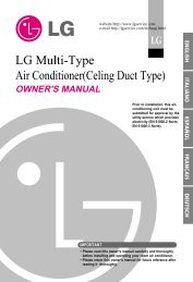
Proposed system diagram (assumed data)<br />
Maximum elevation between<br />
O/D and I/D 1, 2 and 3 = 20m<br />
O/D and I/D 4, 5, 6 and 7 = 30m<br />
Total piping length = 145m<br />
Farthest piping length = 70m<br />
© 2007 Air-conditioning Academy All rights reserved<br />
40m<br />
10m 10m 7m<br />
5m<br />
7m<br />
10m<br />
Room 7<br />
Room 1<br />
10m<br />
18m<br />
5<br />
7m<br />
Room 2<br />
7m<br />
7m<br />
7m<br />
Room 5<br />
Room 6<br />
Room 4<br />
Room 3
Indoor unit selection<br />
•Design parameters values<br />
•Total capacity value<br />
•Outdoor capacity index<br />
•Outdoor performance data<br />
•Interpolation & calculation<br />
© 2007 Air-conditioning Academy All rights reserved<br />
Indoor unit selection<br />
Outdoor unit selection<br />
Combination ratio<br />
Actual capacity of O/D<br />
at combination ratio<br />
Corrected capacities<br />
calculations (O/D & I/D)<br />
Elevation & total piping<br />
length correction factor<br />
Defrosting factor<br />
For heating mode<br />
NO Yes<br />
Matching of Capacities<br />
(indoor/outdoor)<br />
6<br />
•Design parameters values<br />
•Total and sensible capacities<br />
•Indoor capacity index<br />
• Indoor unit type<br />
•Total indoor capacities index<br />
•Standard outdoor capacity index (at 100%)<br />
•Calculation at 100%<br />
•Refer Product Data<br />
book defrost charts<br />
•Correction factor charts<br />
•Total piping length & elevation<br />
•Individual piping length & elevation<br />
Heating calculations
Indoor unit selection<br />
Consider indoor unit having higher rated capacity<br />
(at specified condition) than cooling/heating<br />
capacity required for the corresponding room<br />
• Refer product data book indoor unit specifications<br />
(as shown on the next page).<br />
• Design condition : Indoor 26℃DB/18℃WB &<br />
Outdoor 35℃DB/27℃WB<br />
© 2007 Air-conditioning Academy All rights reserved<br />
Cooling load requirement from manual<br />
calculation or <strong>LATS</strong>-load software<br />
Location<br />
Cooling Load<br />
Total (kW) Sensible (kW)<br />
Unit Cooling<br />
Total(kW) Sensible (kW)<br />
SH Factor<br />
Capacity index<br />
(Qidu_index)<br />
Room 1 4.9 2.94 5 3.8 76.00% 18<br />
Room 2 3.6 2.16 5 3.8 76.00% 18<br />
Room 3 1.9 1.14 2 1.5 75.00% 7<br />
Room 4 2.4 1.44 2.4 1.8 75.00% 9<br />
Room 5 6.2 3.72 6.6 5 75.76% 24<br />
Room 6 7.5 4.5 7.7 6 77.92% 28<br />
Room 7 1.9 1.14 2 1.5 75.00% 7<br />
Total 28.4 17.04 30.7 23.4 111<br />
7<br />
•Refer to the same capacity<br />
table for checking the capacity<br />
index at that conditions.<br />
Total capacity<br />
index = 111<br />
(∑Q idu_index )
Indoor unit selection<br />
Capacity index<br />
Q idu_index = 12<br />
Capacity index<br />
Q idu_index = 18<br />
© 2007 Air-conditioning Academy All rights reserved<br />
• At Indoor 26℃DB/18℃WB &Outdoor 35℃<br />
• Product data book page no. 270 (R-22)<br />
8<br />
Capacity index, total cooling (TC) &<br />
Sensible heat cooling (SHC) can be<br />
checked for each model from PD book<br />
like mentioned<br />
TC=3.3<br />
SHC=2.5<br />
TC=5.0<br />
SHC=3.8
Outdoor unit selection<br />
•Design parameters values<br />
•Total capacity value<br />
•Outdoor capacity index<br />
•Outdoor performance data<br />
•Interpolation & calculation<br />
© 2007 Air-conditioning Academy All rights reserved<br />
Indoor unit selection<br />
Outdoor unit selection<br />
Combination ratio<br />
Actual capacity of O/D<br />
at combination ratio<br />
Corrected capacities<br />
calculations (O/D & I/D)<br />
Elevation & total piping<br />
length correction factor<br />
Defrosting factor<br />
For heating mode<br />
NO Yes<br />
Matching of Capacities<br />
(indoor/outdoor)<br />
9<br />
•Design parameters values<br />
•Total and sensible capacities<br />
•Indoor capacity index<br />
• Indoor unit type<br />
•Total indoor capacities index<br />
•Standard outdoor capacity index (at 100%)<br />
•Calculation at 100%<br />
•Refer Product Data<br />
book defrost charts<br />
•Correction factor charts<br />
•Total piping length & elevation<br />
•Individual piping length & elevation<br />
Heating calculations
Outdoor unit selection<br />
We have already checked that the sum of total I/D unit capacity index is (∑Qidu_index) =111. So the selected<br />
outdoor unit should be such that ∑Qidu_index lie in between it 100% to 130% capacity index. Start matching<br />
capacity index with lower capacity O/D unit first. The values in the table are {Qodu_index}.<br />
© 2007 Air-conditioning Academy All rights reserved<br />
111 lies between 110% and<br />
120% combination capacity of<br />
10 hp outdoor unit.<br />
If this outdoor unit capacity does not satisfy the final total corrected capacities<br />
of indoor unit then we can choose the next higher capacity outdoor unit.<br />
We have already checked that the sum of total I/D unit capacity index is<br />
(∑Qidu_index) =111. So the selected outdoor unit should be such that<br />
∑Qidu_index lie in between it 100% to 130% capacity index. Start matching<br />
capacity index with lower capacity O/D unit first. The values in the table are<br />
{Qodu_index}.<br />
If this outdoor unit capacity does not satisfy the final total corrected capacities of<br />
indoor unit then we can choose the next higher capacity outdoor unit.<br />
10
Combination ratio<br />
•Design parameters values<br />
•Total capacity value<br />
•Outdoor capacity index<br />
•Outdoor performance data<br />
•Interpolation & calculation<br />
© 2007 Air-conditioning Academy All rights reserved<br />
Indoor unit selection<br />
Outdoor unit selection<br />
Combination ratio<br />
Actual capacity of O/D<br />
at combination ratio<br />
Corrected capacities<br />
calculations (O/D & I/D<br />
Elevation & total piping<br />
length correction factor<br />
Defrosting factor<br />
For heating mode<br />
NO Matching of Capacities<br />
(indoor/outdoor)<br />
Yes<br />
11<br />
•Design parameters values<br />
•Total and sensible capacities<br />
•Indoor capacity index<br />
• Indoor unit type<br />
•Total indoor capacities index<br />
•Standard outdoor capacity index (at 100%)<br />
•Calculation at 100%<br />
•Refer Product Data<br />
book defrost charts<br />
•Correction factor charts<br />
•Total piping length & elevation<br />
•Individual piping length & elevation<br />
Heating calculations
Combination ratio<br />
Model<br />
s<br />
10hp<br />
Maximum No.<br />
of<br />
connectable<br />
indoor units<br />
16<br />
© 2007 Air-conditioning Academy All rights reserved<br />
Capacity index range (Qodu_index )<br />
Minimum index (at Index at standard rating Maximum index (at<br />
50% connected (at 100% connected 130% connected<br />
capacity)<br />
capacity)<br />
capacity)<br />
48<br />
96<br />
125<br />
• Actual number of connected indoor units are 7 (less than maximum number 16).<br />
• The values in the above table at 100% capacity will be used to calculate<br />
combination ratio.<br />
• R combi = ∑Q idu_index / Q odu_index {Calculated at 100% outdoor unit capacity index}<br />
Models<br />
10hp<br />
Total indoor units<br />
capacity index<br />
∑Q idu_index<br />
111<br />
Index at standard<br />
rating (100%)<br />
(Q odu_index )<br />
96<br />
12<br />
Combination ratio<br />
R combi = ∑Q idu_index / Q odu_index<br />
111/96 = 115.625%<br />
Combination ratio helps in calculating actual capacities of outdoor/indoor units.
Actual capacity of O/D at combination ratio<br />
•Design parameters values<br />
•Total capacity value<br />
•Outdoor capacity index<br />
•Outdoor performance data<br />
•Interpolation & calculation<br />
© 2007 Air-conditioning Academy All rights reserved<br />
Indoor unit selection<br />
Outdoor unit selection<br />
Combination ratio<br />
Actual capacity of O/D<br />
at combination ratio<br />
Corrected capacities<br />
calculations (O/D & I/D)<br />
Elevation & total piping<br />
length correction factor<br />
Defrosting factor<br />
For heating mode<br />
NO Matching of Capacities<br />
(indoor/outdoor)<br />
Yes<br />
13<br />
•Design parameters values<br />
•Total and sensible capacities<br />
•Indoor capacity index<br />
• Indoor unit type<br />
•Total indoor capacities index<br />
•Standard outdoor capacity index (at 100%)<br />
•Calculation at 100%<br />
•Refer Product Data<br />
book defrost charts<br />
•Correction factor charts<br />
•Total piping length & elevation<br />
•Individual piping length & elevation<br />
Heating calculations
Actual capacity of O/D at combination ratio<br />
Capacity index<br />
Q odu_index = 115(at 120%)<br />
Capacity index<br />
Q odu_index = 106(at 110%)<br />
© 2007 Air-conditioning Academy All rights reserved<br />
The table below tell about the actual capacities and power<br />
input by the outdoor unit at specific indoor unit<br />
combination. (10hp)<br />
14<br />
TC=29.8<br />
PI=9.54<br />
TC=28.9<br />
PI=9.30
Actual capacity of O/D at combination ratio<br />
• Now using interpolation method the actual capacity of outdoor unit at the<br />
combination ratios can be calculated.<br />
• Q odu(Ti,To, Rcombi) is a function of indoor, outdoor temperature and combination ratio.<br />
Model<br />
10hp<br />
Q odu_ind<br />
ex<br />
(a)<br />
115<br />
106<br />
Important note : (e) & (f) are calculated on interpolation method such as<br />
For ex. Index at combination ratio (10hp) = 106 + [(115.625-110)*(115-106)]/(120-110) = 111.06<br />
Actual capacity (10hp) = 28.9 + [(115.625-110)*(29.8-28.9)] / (120-110) = 29.4 (at 115.625%)<br />
© 2007 Air-conditioning Academy All rights reserved<br />
Indoor<br />
Combinatio<br />
n (%)<br />
(b)<br />
120<br />
110<br />
Total<br />
cooling<br />
(c)<br />
29.8<br />
28.9<br />
Combination<br />
ratio<br />
R combi =<br />
∑Q idu_index /<br />
Q odu_index<br />
(d)<br />
115.625%<br />
15<br />
Outdoor Index<br />
at combination<br />
ratio<br />
(e)<br />
111.06<br />
Actual capacity<br />
Q odu(Ti,To,Rcombi)<br />
(kW)<br />
(f)<br />
29.4(115.625%)
Corrected capacities calculations (O/D & I/D)<br />
•Design parameters values<br />
•Total capacity value<br />
•Outdoor capacity index<br />
•Outdoor performance data<br />
•Interpolation & calculation<br />
© 2007 Air-conditioning Academy All rights reserved<br />
Indoor unit selection<br />
Outdoor unit selection<br />
Combination ratio<br />
Actual capacity of O/D<br />
at combination ratio<br />
Corrected capacities<br />
calculations (O/D & I/D)<br />
Elevation & total piping<br />
length correction factor<br />
Defrosting factor<br />
For heating mode<br />
NO Matching of Capacities<br />
(indoor/outdoor)<br />
Yes<br />
16<br />
•Design parameters values<br />
•Total and sensible capacities<br />
•Indoor capacity index<br />
• Indoor unit type<br />
•Total indoor capacities index<br />
•Standard outdoor capacity index (at 100%)<br />
•Calculation at 100%<br />
•Refer Product Data<br />
book defrost charts<br />
•Correction factor charts<br />
•Total piping length & elevation<br />
•Individual piping length & elevation<br />
Heating calculations
Corrected capacities calculations (I/D)<br />
• Till here<br />
• ∑Q idu_index = 111<br />
• Q odu_index = 96 (100%)<br />
• R combi = ∑Q idu_index / Q odu_index = 115.625<br />
• Q odu(Ti,To,Rcombi) = 29.4kW<br />
•Indoor unit Corrected capacity is calculated individually.<br />
• Q idu_corrected = [Q idu_index / ∑Q idu_index ] × Q odu(Ti,To,Rcombi)<br />
Corrected outdoor unit capacity = 29.4kW I/D unit 1 actual = ( 18 / 111 ) × 29.4 =<br />
4.77<br />
Room No.<br />
Room 1<br />
Room 2<br />
Room 3<br />
Room 4<br />
Room 5<br />
Room 6<br />
Room 7<br />
© 2007 Air-conditioning Academy All rights reserved<br />
Actual Sensible<br />
capacity (kW) heat (kW)<br />
5.00 3.80<br />
5.00 3.80<br />
2.00 9.00<br />
2.40 1.80<br />
6.60 5.00<br />
7.70 6.00<br />
2.00 1.50<br />
30.70 30.90<br />
Capacity<br />
Index<br />
18 4.77<br />
18 4.77<br />
7 1.85<br />
9 2.38<br />
24 6.36<br />
28 7.42<br />
7 1.85<br />
111 29.40<br />
17<br />
Correted<br />
capacity(kW)<br />
Corrected<br />
sensible heat (kW)<br />
3.62<br />
3.62<br />
1.39<br />
1.79<br />
4.83<br />
5.86<br />
1.39<br />
22.51
Elevation & total piping length correction factor<br />
•Design parameters values<br />
•Total capacity value<br />
•Outdoor capacity index<br />
•Outdoor performance data<br />
•Interpolation & calculation<br />
© 2007 Air-conditioning Academy All rights reserved<br />
Indoor unit selection<br />
Outdoor unit selection<br />
Combination ratio<br />
Actual capacity of O/D<br />
at combination ratio<br />
Corrected capacities<br />
calculations (O/D & I/D<br />
Elevation & total piping<br />
length correction factor<br />
Defrosting factor<br />
For heating mode<br />
NO Matching of Capacities<br />
(indoor/outdoor)<br />
Yes<br />
18<br />
•Design parameters values<br />
•Total and sensible capacities<br />
•Indoor capacity index<br />
• Indoor unit type<br />
•Total indoor capacities index<br />
•Standard outdoor capacity index (at 100%)<br />
•Calculation at 100%<br />
•Refer Product Data<br />
book defrost charts<br />
•Correction factor charts<br />
•Total piping length & elevation<br />
•Individual piping length & elevation<br />
Heating calculations
Elevation & total piping length correction factor<br />
© 2007 Air-conditioning Academy All rights reserved<br />
1<br />
2 and 3<br />
19<br />
For the indoor unit 1, 2 and 3<br />
Level difference = 20m.<br />
Equivalent lengths are 57m, 67m and<br />
67m correspondingly<br />
Outdoor unit is above indoor units<br />
From the above chart the elevation & total piping length<br />
correction factor {f (length, elevation) } for for indoor unit 1, 2 and 3 are<br />
0.935, 0.922 and 0.922 correspondingly
Elevation & total piping length correction factor<br />
© 2007 Air-conditioning Academy All rights reserved<br />
4, 5 and 7 6<br />
20<br />
For the indoor unit 4, 5, 6 and 7<br />
Level difference = 30m.<br />
Equivalent lengths are 62m, 62m, 70m<br />
and 62m correspondingly<br />
Outdoor unit is above indoor units<br />
From the above chart the elevation & total piping length correction factor {f (length, elevation) }<br />
for for indoor units 4, 5, 6 and 7 are 0.925, 0.925, 0.918 and 0.925 correspondingly
Final capacities (indoor unit)<br />
•Final indoor unit capacity is calculated by the given formula.<br />
• Q odu_final = Q idu_corrected ×f (length, elevation)<br />
Correted<br />
capacity(kW)<br />
© 2007 Air-conditioning Academy All rights reserved<br />
Corrected sensible heat<br />
(kW)<br />
4.77 3.62<br />
4.77 3.62<br />
1.85 1.39<br />
2.38 1.79<br />
6.36 4.83<br />
7.42 5.78<br />
1.85 1.39<br />
29.40 22.43<br />
Length and elevation<br />
correction factor<br />
0.935<br />
0.922<br />
0.922<br />
0.925<br />
0.925<br />
0.918<br />
0.925<br />
21<br />
Final indoor unit<br />
capacity (kW)<br />
4.46<br />
4.40<br />
1.71<br />
2.21<br />
5.88<br />
6.81<br />
1.72<br />
27.17<br />
Final sensible<br />
heat (kW)<br />
3.39<br />
3.34<br />
1.28<br />
1.65<br />
4.47<br />
5.31<br />
1.29<br />
20.73
Matching capacities (indoor & outdoor unit)<br />
•Design parameters values<br />
•Total capacity value<br />
•Outdoor capacity index<br />
•Outdoor performance data<br />
•Interpolation & calculation<br />
© 2007 Air-conditioning Academy All rights reserved<br />
Indoor unit selection<br />
Outdoor unit selection<br />
Combination ratio<br />
Actual capacity of O/D<br />
at combination ratio<br />
Corrected capacities<br />
calculations (O/D & I/D<br />
Elevation & total piping<br />
length correction factor<br />
Defrosting factor<br />
For heating mode<br />
NO Matching of Capacities<br />
(indoor/outdoor)<br />
Yes<br />
22<br />
•Design parameters values<br />
•Total and sensible capacities<br />
•Indoor capacity index<br />
• Indoor unit type<br />
•Total indoor capacities index<br />
•Standard outdoor capacity index (at 100%)<br />
•Calculation at 100%<br />
•Refer Product Data<br />
book defrost charts<br />
•Correction factor charts<br />
•Total piping length & elevation<br />
•Individual piping length & elevation<br />
Heating calculations
Matching capacities (indoor & outdoor unit)<br />
• Now each indoor unit capacity both actual and sensible is compared with the required parameters.<br />
• Also total overall load requirements are compared with the requirement.<br />
• If it is satisfactory then selection of units are ok but if any one indoor or outdoor unit fails in requirement we<br />
have to go for higher capacity models.<br />
Location<br />
Cooling load<br />
Total (kW) Sensible (kW)<br />
Room 1 4.90 2.94<br />
Room 2 3.60 2.16<br />
Room 3 1.90 1.14<br />
Room 4 2.40 1.44<br />
Room 5 6.20 3.72<br />
Room 6 7.50 4.50<br />
Room 7 1.90 1.14<br />
Total 28.40 17.04<br />
© 2007 Air-conditioning Academy All rights reserved<br />
Final cooling capacity<br />
Capacity index<br />
Total (kW) Sensible (kW)<br />
18<br />
18<br />
7<br />
9<br />
24<br />
28<br />
7<br />
111<br />
23<br />
4.46 3.39<br />
4.40 3.34<br />
1.71 1.28<br />
2.21 1.65<br />
5.88 4.47<br />
6.81 5.31<br />
1.72 1.29<br />
27.17 20.73<br />
The values with arrow should be equal or more than the cooling load. but in this<br />
case they are lower. So we will upgrade indoor units one by one and follow the<br />
whole process again. Till we get optimal solution.
Iteration Conclusion<br />
• So finally after iterations optimal solution is set as above<br />
• Outdoor unit changed to 12 hp unit from 10hp unit.<br />
© 2007 Air-conditioning Academy All rights reserved<br />
Cooling load<br />
Location<br />
Total (kW) Sensible (kW)<br />
Room 1<br />
Room 2<br />
Room 3<br />
Room 4<br />
Room 5<br />
Room 6<br />
Room 7<br />
Total<br />
Location<br />
Room 1<br />
Room 3<br />
Room 4<br />
Indoor unit<br />
24K<br />
Room 2 18K<br />
4.90 2.94<br />
3.60 2.16<br />
1.90 1.14<br />
2.40 1.44<br />
6.20 3.72<br />
7.50 4.50<br />
1.90 1.14<br />
28.40 17.04<br />
9K<br />
12K<br />
Comments<br />
Ok<br />
Ok<br />
Ok<br />
Ok<br />
Capacity Final cooling capacity<br />
Index Total (kW) Sensible (kW)<br />
24 5.85 4.39<br />
18 4.33 3.25<br />
9 2.16 1.60<br />
12 2.95 2.19<br />
28 6.89 5.18<br />
36 8.78 6.59<br />
9 2.21 1.64<br />
136 33.17 24.84<br />
Location<br />
24<br />
Room 5<br />
Room 6<br />
Room 7<br />
O/D unit<br />
Indoor unit<br />
28k<br />
36K<br />
9k<br />
12hp<br />
Comments<br />
Ok<br />
Ok<br />
Ok<br />
Ok
2. <strong>Multi</strong> V Plus model selection<br />
by <strong>LATS</strong> <strong>Multi</strong> V software (Without CAD)<br />
© 2007 Air-conditioning Academy All rights reserved<br />
25
Program Installation guide<br />
For downloading <strong>LATS</strong> model selection software<br />
Log on to LG global website : www.lgeaircon.com<br />
For access to website contact to sales manager of your area<br />
Note: Access to this site is permitted to LG employees only<br />
© 2007 Air-conditioning Academy All rights reserved<br />
26
Program Installation guide<br />
1. Click to Partner Support and new window will open<br />
2. Click Technical Data<br />
3. Then click Software and Software download window will open<br />
© 2007 Air-conditioning Academy All rights reserved<br />
27
Program Installation guide<br />
Select latest version of <strong>LATS</strong>-<strong>Multi</strong> V: <strong>Multi</strong> V Model Selection<br />
© 2007 Air-conditioning Academy All rights reserved<br />
28
Program Installation guide<br />
Then click to hyperlink “Download <strong>LATS</strong>-<strong>Multi</strong> V” and select folder for<br />
downloading in your PC.<br />
© 2007 Air-conditioning Academy All rights reserved<br />
29
Program Installation guide<br />
1. For start setup <strong>LATS</strong> <strong>Multi</strong> V click install icon<br />
2. Click next to continue process<br />
© 2007 Air-conditioning Academy All rights reserved<br />
30<br />
1. Click on install icon<br />
2. Click Next (No Special Option)<br />
3. Click Yes for accepting downloading agreement<br />
3. Read agreement and click “Yes” (if you don’t accept it then you can’t install<br />
<strong>LATS</strong>)
Program Installation guide<br />
6. Start copying files and Finish Installation.<br />
© 2007 Air-conditioning Academy All rights reserved<br />
31<br />
4. Input<br />
User Name<br />
Company Name.<br />
Input Installation Password “latsmultiv”<br />
5. Click Next Button .<br />
4. Fill User Name and Company name. Input password “latsmultiv”<br />
5. Click Next to continue install<br />
6. Start copying files and Finish Installation
User Guide<br />
© 2007 Air-conditioning Academy All rights reserved<br />
After successful installation of software the given below window will open<br />
<strong>LATS</strong>-<strong>Multi</strong> V Initial Window.<br />
32
User Guide<br />
© 2007 Air-conditioning Academy All rights reserved<br />
1. Project Information Menu<br />
2. Click on Create Project 3. Create Project Window will open<br />
Be sure to disable<br />
CAD option if you<br />
are not using CAD<br />
drawing for model<br />
selection<br />
1. Project Information Menu<br />
33<br />
4. Input Project Name<br />
5. Select Unit system<br />
6. Select Cooling or Heating Mode<br />
7. Select ODU Type<br />
8. Give any special comment (optional)<br />
9. Click Next<br />
2. Click on Create Project<br />
3. Create Project Window will open<br />
4. Input Project Name<br />
5. Select Unit system<br />
6. Select Cooling or Heating Mode<br />
7. Select ODU Type<br />
8. Give any special comment (optional)<br />
9. Click Next<br />
Be sure to disable CAD option if you are not using CAD drawing for model<br />
selection
User Guide<br />
10. Select Country and City<br />
11. Input Design condition.<br />
12. Click Next<br />
© 2007 Air-conditioning Academy All rights reserved<br />
34<br />
12. Click Next<br />
10. Select Country and City<br />
11. Input Design condition.<br />
Change design condition if<br />
given values not satisfied<br />
your requirement<br />
If you change one of the<br />
following air property<br />
(DBT,WBT,RH),<br />
psychometric process will<br />
execute and find other<br />
related value. So it’s easy to<br />
define air property.<br />
Change design condition if given values not satisfied your requirement<br />
If you change one of the following air property (DBT,WBT,RH), psychometric<br />
process will execute and find other related value. So it’s easy to define air<br />
property.
User Guide<br />
© 2007 Air-conditioning Academy All rights reserved<br />
13. This window will open.<br />
14. When selecting Open Load, You can load the result calculated by <strong>LATS</strong>-LOAD<br />
13. This window will open.<br />
35<br />
15. Click Next<br />
16. If <strong>LATS</strong> LOAD values are<br />
not available manual load<br />
entry can also be done simply<br />
by adding values in columns<br />
15. Add floor or Add space as required. For adding and<br />
removing Floor or Space first click on the row and then<br />
click Add or Remove<br />
14. When selecting Open Load, You can load the result calculated by<br />
<strong>LATS</strong>-LOAD<br />
15. Add floor or Add space as required. For adding and removing Floor or<br />
Space first click on the row and then click Add or Remove<br />
16. If <strong>LATS</strong> LOAD values are not available manual load entry can also be<br />
done simply by adding values in columns
User Guide<br />
© 2007 Air-conditioning Academy All rights reserved<br />
36<br />
17. Input Customer &<br />
contractor Information it<br />
will be printed out while<br />
making report.<br />
18. After filling all data click Finish<br />
17. Input Customer & contractor Information it will be printed out while<br />
making report.<br />
18. After filling all data click Finish
User Guide<br />
System Panel<br />
19. This window will appear<br />
© 2007 Air-conditioning Academy All rights reserved<br />
System Property Window<br />
19. This window will appear<br />
37<br />
Indoor Unit Toolbar<br />
20. From here we will start selecting outdoor units, indoor<br />
units, branch pipes and header pipes according to design<br />
21. Double click on outdoor unit icon<br />
for selecting outdoor unit<br />
20. From here we will start selecting outdoor units, indoor units, branch pipes and<br />
header pipes according to design<br />
21. Double click on outdoor unit icon for selecting outdoor unit
User Guide <strong>–</strong> Main tool bar<br />
New system<br />
System setting<br />
Save project<br />
© 2007 Air-conditioning Academy All rights reserved<br />
Auto piping<br />
Delete system<br />
Copy system<br />
System check<br />
38<br />
View control wire<br />
System panel<br />
Toggle navigator<br />
Toggle description<br />
View reports<br />
Space load summary<br />
System pre-view (tree only)<br />
System validation property<br />
View pipe line<br />
distribution<br />
View power line
User Guide <strong>–</strong> Other tool bar<br />
Arrow<br />
New Outdoor<br />
New Indoor<br />
New Room<br />
New Pipe<br />
New Equipment<br />
Rotate Angle<br />
Create Net<br />
© 2007 Air-conditioning Academy All rights reserved<br />
New Climb<br />
Delete Unit<br />
Rotate Unit<br />
Fit window<br />
Pan<br />
Grid on/off<br />
Ortho on/off<br />
Import DWG file<br />
39<br />
Undo<br />
Redo<br />
Zoom in<br />
Zoom out<br />
Zoom window<br />
Export DXF file
User Guide<br />
Other optional<br />
accessory can also be<br />
choose by clicking<br />
this button<br />
22. This window will appear<br />
23. Select proper unit as per load requirement<br />
24. In heating case select defrost factor<br />
© 2007 Air-conditioning Academy All rights reserved<br />
40<br />
22. This window will appear<br />
Or you can use Auto<br />
Selection for seeing possible<br />
connectable O/D unit<br />
23. Select proper unit as per<br />
load requirement<br />
24. In heating case select<br />
defrost factor<br />
25. These specifications will<br />
change according to the product<br />
automatically<br />
26. After selecting above value click OK<br />
25. These specifications will change according to the product automatically<br />
26. After selecting above value click OK<br />
Other optional accessory can also be choose by clicking this button<br />
Or you can use Auto Selection for seeing possible connectable O/D unit
User Guide<br />
27. The new outdoor unit will appear.<br />
28. Double click on Stand by<br />
© 2007 Air-conditioning Academy All rights reserved<br />
41<br />
27. The new outdoor unit will appear.<br />
28. Double click on Stand by<br />
No. of connected I/D units //<br />
Maximum No. of connectable I/D<br />
units<br />
I/D unit capacity index // O/D unit<br />
capacity index (combination ratio)<br />
Total connected piping length //<br />
Maximum total piping length<br />
No. of connected I/D units // Maximum No. of connectable I/D units<br />
I/D unit capacity index // O/D unit capacity index (combination ratio)<br />
Total connected piping length // Maximum total piping length
User Guide<br />
29. This window will appear<br />
30. Choose one of them<br />
© 2007 Air-conditioning Academy All rights reserved<br />
42<br />
29. This window will appear<br />
30. Choose one of<br />
them<br />
Choose Y branch for connecting 2<br />
indoor unit or more branching<br />
Select Header branch for connecting<br />
more than 2 indoor unit at one<br />
branching point<br />
Or you can select indoor unit<br />
Choose Y branch for connecting 2 indoor unit or more branching<br />
Select Header branch for connecting more than 2 indoor unit at one branching<br />
point or you can select indoor unit
User Guide - Selecting Indoor unit<br />
© 2007 Air-conditioning Academy All rights reserved<br />
31. Choose indoor<br />
unit (if required)<br />
38. Click Accessory (if any required)<br />
39. This window will appear<br />
41. Click OK<br />
31. Choose indoor unit (if required)<br />
32. This window will appear<br />
33. Choose indoor unit type<br />
34. Choose indoor unit model<br />
40. Select the type of accessory<br />
35. Position of indoor unit or outdoor unit<br />
36. Select elevation from O/D<br />
32. This window will appear<br />
43<br />
33. Choose indoor unit type<br />
34. Choose indoor unit model<br />
35. Position of I/D w.r.t<br />
outdoor unit<br />
36. Select elevation from O/D<br />
37. IDU capacities & design load will<br />
appear automatically (Fixed)<br />
42. Finally Click OK<br />
37. IDU capacities & design load will appear automatically (Fixed)<br />
38. Click Accessory (if any required)<br />
39. This window will appear<br />
40. Select the type of accessory<br />
41. Click OK<br />
42. Finally Click OK
User Guide - If selecting Y-branch or Header branch<br />
43. Double click on Stand by icon<br />
© 2007 Air-conditioning Academy All rights reserved<br />
47. If Y branch is selected then<br />
stand-by box will change<br />
into y branch with 2 more<br />
connected stand-by boxes.<br />
43. Double click on Stand by icon<br />
44. This window will appear<br />
45. If at stand by box Y branch is required select Y branch<br />
46. And if header branch is required select header<br />
44<br />
44. This window will appear<br />
45. If at stand by box Y branch is<br />
required select Y branch<br />
46. And if header branch is<br />
required select header<br />
48. And If header branch is<br />
selected then stand-by box<br />
will change into multi branch.<br />
47. If Y branch is selected then stand-by box will change into y branch with 2<br />
more connected stand-by boxes.<br />
48. And If header branch is selected then stand-by box will change into multi<br />
branch.
User Guide - After selecting Y-branch<br />
<strong>Multi</strong> V plus 10hp outdoor unit is selected<br />
© 2007 Air-conditioning Academy All rights reserved<br />
<strong>Multi</strong> V plus 10hp outdoor unit is selected<br />
49. As per the design select different Y-branches<br />
(if needed header can also be used)<br />
45<br />
49. As per the design select different<br />
Y-branches<br />
(if needed header can also be used)
User Guide<br />
© 2007 Air-conditioning Academy All rights reserved<br />
46<br />
50.Double click on Stand by for<br />
selecting indoor unit or you can<br />
select indoor unit by dragging<br />
requisite indoor icon from icon<br />
plate<br />
51. Choose indoor unit type<br />
52. Choose indoor unit model<br />
54.Select elevation from<br />
outdoor unit<br />
55. IDU capacities & design<br />
load will appear<br />
automatically (Fixed value<br />
depend on I/D)<br />
50.Double click on Stand by for selecting indoor unit or you can select indoor unit<br />
by dragging requisite indoor icon from icon plate<br />
51. Choose indoor unit type<br />
52. Choose indoor unit model<br />
54.Select elevation from outdoor unit<br />
55.IDU capacities & design load will appear automatically<br />
(Fixed value depend on I/D)
User Guide<br />
55. Selected indoor unit<br />
This space will show required load<br />
© 2007 Air-conditioning Academy All rights reserved<br />
55. Selected indoor unit<br />
47<br />
This space will show required load
User Guide<br />
Selected indoor type and<br />
capacities will be seen on tree<br />
section like this<br />
© 2007 Air-conditioning Academy All rights reserved<br />
After selecting indoor units at stand-by locations<br />
Room icons (space) will appear next to each indoor<br />
unit. Here we can select loads which are feed<br />
manually or software calculated load.<br />
After selecting indoor units at stand-by locations Room icons (space) will appear<br />
next to each indoor unit. Here we can select loads which are feed manually or<br />
software calculated load.<br />
Selected indoor type and capacities will be seen on tree section like this<br />
48
User Guide<br />
57. Select the load for each space one<br />
by one. After double clicking on<br />
space click value on pop-up<br />
window which we have to assign at<br />
that space and click OK<br />
56. Double click on each space will show this window<br />
© 2007 Air-conditioning Academy All rights reserved<br />
49<br />
56. Double click on each space will<br />
show this window<br />
57. Select the load for each space one by one. After double clicking on space<br />
click value on pop-up window which we have to assign at that space and click OK
User Guide<br />
Load will be shown for each case like this<br />
© 2007 Air-conditioning Academy All rights reserved<br />
50<br />
Load will be shown for each case like this
User Guide<br />
© 2007 Air-conditioning Academy All rights reserved<br />
51<br />
58. Reselect indoor unit according to the<br />
required load (appearing under space).<br />
Chosen indoor unit should be such that<br />
their capacity is slightly higher than<br />
required load<br />
58. Reselect indoor unit according to the required load<br />
(appearing under space).<br />
Chosen indoor unit should be such that their capacity is slightly higher than<br />
required load
User Guide<br />
© 2007 Air-conditioning Academy All rights reserved<br />
59. Double click on pipe lengths for<br />
selecting various piping lengths<br />
between outdoor unit, Y branch and<br />
indoor units<br />
52<br />
60. At double clicking piping length this<br />
window will appear. Filled required<br />
length and then click OK<br />
59. Double click on pipe lengths for selecting various piping lengths between<br />
outdoor unit, Y branch and indoor units<br />
60. At double clicking piping length this window will appear. Filled required length<br />
and then click OK
Check :<br />
User Guide<br />
© 2007 Air-conditioning Academy All rights reserved<br />
2<br />
3<br />
4<br />
1. Percentage of indoor unit capacity to required load should be more than 100%.<br />
2. Number of connectable indoor unit should be less than maximum connected<br />
unit<br />
3. Combination ratio of Indoor to outdoor should be between 100% to 130%<br />
4. Total piping length should be less than maximum allowed piping length<br />
53<br />
1
User Guide<br />
© 2007 Air-conditioning Academy All rights reserved<br />
61. Click auto piping button<br />
This pop up message will appear which mean<br />
piping is done successfully<br />
If not warning message will appear<br />
54<br />
You can choose Y-branch manually or they<br />
will be automatically selected while<br />
executing Auto Piping.For choosing Ybranch<br />
double click on Y-branch icon<br />
61. Click auto piping button<br />
You can choose Y-branch manually or they will be automatically selected while<br />
executing Auto Piping.For choosing Y-branch double click on Y-branch icon<br />
This pop up message will appear which mean piping is done successfully<br />
If not warning message will appear
User Guide<br />
If the system is not properly<br />
balanced then a warning message<br />
will pop-up<br />
© 2007 Air-conditioning Academy All rights reserved<br />
62. Click system check button for final system<br />
balance check.<br />
55<br />
This pop-up message will appear that<br />
system check was successfully<br />
executed<br />
62. Click system check button for final system balance check.<br />
If the system is not properly balanced then a warning message will pop-up<br />
This pop-up message will appear that system check was successfully executed
User Guide<br />
Outdoor unit is still within the<br />
limits of 130% capacity<br />
© 2007 Air-conditioning Academy All rights reserved<br />
1<br />
6<br />
3<br />
So indoor unit 1,3,6,7 are short in the cooling capacity (less than 100%) as<br />
per required loads (as shown by circles).This require increasing of indoor<br />
unit capacity 7<br />
56<br />
Ratio of indoor unit capacity to required<br />
load should be more than 100%<br />
Ratio of indoor unit capacity to required load should be more than 100%<br />
Outdoor unit is still within the limits of 130% capacity<br />
So indoor unit 1,3,6,7 are short in the cooling capacity (less than 100%) as per<br />
required loads (as shown by circles).<br />
This require increasing of indoor unit capacity
User Guide<br />
© 2007 Air-conditioning Academy All rights reserved<br />
63. After upgrading the unit by 1 or 2 steps towards<br />
higher capacity and then repeat the following.<br />
Click “auto piping” button and then “system check”<br />
57<br />
Warning message “indoor unit capacity<br />
exceeds the outdoor unit capacity connection<br />
combination”<br />
64. Click OK on the message and change the outdoor unit to higher capacity<br />
63. After upgrading the unit by 1 or 2 steps towards higher capacity and then<br />
repeat the following.<br />
Click “auto piping” button and then “system check”<br />
64. Click OK on the message and change the outdoor unit to higher capacity<br />
Warning message “indoor unit capacity exceeds the outdoor unit capacity<br />
connection combination”
User Guide<br />
© 2007 Air-conditioning Academy All rights reserved<br />
65. After upgrading outdoor unit<br />
Click “auto piping” button and<br />
then “system check”<br />
66. Check for the optimal solution by again setting of indoor units till reach close to the required load<br />
(percentage ratio close to 100% but above 100%).<br />
65. After upgrading outdoor unit Click “auto piping” button and then “system<br />
check”<br />
66. Check for the optimal solution by again setting of indoor units till reach close<br />
to the required load<br />
(percentage ratio close to 100% but above 100%).<br />
58
User Guide<br />
Outdoor unit is within<br />
limit of 130% capacity<br />
Outdoor unit is within limit of 130% capacity<br />
Final solution is successful.<br />
© 2007 Air-conditioning Academy All rights reserved<br />
59<br />
Example<br />
Final solution is successful.
User Guide<br />
© 2007 Air-conditioning Academy All rights reserved<br />
67. Next click on Schematic diagram<br />
icon for seeing schematic view of<br />
this drawing<br />
67. Next click on Schematic diagram icon for seeing schematic view of this<br />
drawing<br />
60
User Guide<br />
68. Next click on Generate Report for<br />
making excel sheet of this<br />
selection<br />
© 2007 Air-conditioning Academy All rights reserved<br />
Click either of these icon for seeing<br />
control wire, power line and pipe<br />
line<br />
61<br />
clicking Schematic diagram<br />
icon will give schematic line<br />
view of<br />
1. Control wire<br />
2. Power line<br />
3. Pipe line<br />
68. Next click on Generate Report for making excel sheet of this selection<br />
clicking Schematic diagram icon will give schematic line view of<br />
Control wire<br />
Power line<br />
Pipe line
User Guide<br />
69. This menu will popup.<br />
© 2007 Air-conditioning Academy All rights reserved<br />
62<br />
69. This menu will popup.<br />
Clicking each menu will<br />
generate the report<br />
corresponding to that issue.<br />
70. Finally press ok for viewing the<br />
above choose report on excel sheet<br />
Note: You need MS Excel program<br />
installed on your computer for<br />
executing this command<br />
Clicking each menu will generate the report corresponding to that issue.<br />
70. Finally press ok for viewing the above choose report on excel sheet<br />
Note: You need MS Excel program installed on your computer for executing this<br />
command
User Guide <strong>–</strong> Final Report<br />
© 2007 Air-conditioning Academy All rights reserved<br />
1. Proposal Sheet 2. Contact Detail Sheet 3. Table of Contents Sheet<br />
1. Proposal Sheet<br />
2. Contact Detail Sheet<br />
3. Table of Contents Sheet<br />
63
User Guide - Final Report<br />
4. Building-Load Output Sheet 5. Model Selection Summary Sheet 6. Outdoor Model Selection Sheet<br />
4. Building-Load Output Sheet<br />
5. Model Selection Summary Sheet<br />
6. Outdoor Model Selection Sheet<br />
© 2007 Air-conditioning Academy All rights reserved<br />
64
User Guide <strong>–</strong> Final Report<br />
© 2007 Air-conditioning Academy All rights reserved<br />
7. Indoor Model Selection Sheet 8. Model Selection Tree<br />
7. Indoor Model Selection Sheet<br />
8. Model Selection Tree<br />
65
User Guide <strong>–</strong> Final Report<br />
9. Model Selection Diagram<br />
9. Model Selection Diagram<br />
10. Model Selection Analysis Sheet<br />
© 2007 Air-conditioning Academy All rights reserved<br />
66<br />
10. Model Selection Analysis Sheet
3. <strong>Multi</strong> V model selection<br />
by <strong>LATS</strong> <strong>Multi</strong> V software (with CAD)<br />
© 2007 Air-conditioning Academy All rights reserved<br />
67
User Guide <strong>–</strong> Main contents<br />
© 2007 Air-conditioning Academy All rights reserved<br />
1. Project Information Menu<br />
2. Click on Create Project 3. Create Project Window will open<br />
9. Be sure to<br />
active CAD<br />
option if you are<br />
using CAD<br />
drawing for<br />
model selection<br />
68<br />
4. Input Project Name<br />
5. Select Unit system<br />
6. Select Cooling or Heating Mode<br />
7. Select ODU Type<br />
8. Give any special comment (optional)<br />
10. Click Next<br />
1. Project Information Menu<br />
2. Click on Create Project<br />
3. Create Project Window will open<br />
4. Input Project Name<br />
5. Select Unit system<br />
6. Select Cooling or Heating Mode<br />
7. Select ODU Type<br />
8. Give any special comment (optional)<br />
9. Be sure to active CAD option if you are using CAD drawing for model selection<br />
10. Click Next
User Guide<br />
11. Select Country and City<br />
12. Input Design condition.<br />
© 2007 Air-conditioning Academy All rights reserved<br />
14. Click Next<br />
69<br />
11. Select Country and City<br />
12. Input Design condition.<br />
13. Change design condition if<br />
given values not satisfied your<br />
requirement<br />
If you change one of the<br />
following air property<br />
(DBT,WBT,RH), psychometric<br />
process will execute and find<br />
other related value. So it’s easy<br />
to define air property.<br />
13. Change design condition if given values not satisfied your requirement<br />
If you change one of the following air property (DBT,WBT,RH), psychometric<br />
process will execute and find other related value. So it’s easy to define air<br />
property.<br />
14. Click Next
User Guide<br />
16. When selecting Open Load,<br />
You can load the result<br />
calculated by <strong>LATS</strong>-LOAD<br />
© 2007 Air-conditioning Academy All rights reserved<br />
15. This window will open.<br />
70<br />
17. Add floor or Add space as required. For<br />
adding and removing Floor or Space first click<br />
on the row and then click Add or Remove<br />
19. Click Next<br />
18. If <strong>LATS</strong> LOAD values are<br />
not available manual load<br />
entry can also be done<br />
simply by adding values<br />
in columns<br />
15. This window will open.<br />
16. When selecting Open Load, You can load the result calculated by <strong>LATS</strong>-<br />
LOAD<br />
17. Add floor or Add space as required. For adding and removing Floor or Space<br />
first click on the row and then click Add or Remove<br />
18. If <strong>LATS</strong> LOAD values are not available manual load entry can also be done<br />
simply by adding values in columns<br />
19. Click Next
User Guide<br />
© 2007 Air-conditioning Academy All rights reserved<br />
71<br />
20. Input Customer &<br />
contractor Information it<br />
will be printed out while<br />
making report.<br />
21. After filling all data click Finish<br />
20. Input Customer & contractor Information it will be printed out while making<br />
report.<br />
21. After filling all data click Finish
User Guide <strong>–</strong> Import Auto CAD drawing<br />
© 2007 Air-conditioning Academy All rights reserved<br />
72<br />
22. This window will appear<br />
23. Click this Icon for importing Auto CAD drawing<br />
22. This window will appear<br />
23. Click this Icon for importing Auto CAD drawing
User Guide<br />
Save Project<br />
System Setting<br />
New System<br />
Copy System<br />
Delete System<br />
Auto piping<br />
System Check<br />
System Validation property<br />
Toggle description<br />
System load summary<br />
View reports<br />
System preview (Tree only)<br />
© 2007 Air-conditioning Academy All rights reserved<br />
Toggle Navigator<br />
System Panel<br />
Control Line<br />
Power Cable<br />
Pipe Line<br />
73<br />
Arrow<br />
New Outdoor<br />
New Indoor<br />
New Room<br />
New Pipe<br />
New Equipment<br />
New Climb<br />
Delete Unit<br />
Rotate Unit<br />
Rotate Angle<br />
Create Net<br />
Undo<br />
Redo<br />
Zoom in<br />
Zoom out<br />
Zoom window<br />
Fit window<br />
Pan<br />
Grid on/off<br />
Ortho on/off<br />
Import DWG file<br />
Export DXF file
User Guide<br />
© 2007 Air-conditioning Academy All rights reserved<br />
24. Select CAD drawing and then click Open icon<br />
25. This will open CAD drawing with message<br />
“CAD file is successfully open” . Click OK<br />
on this pop-up window<br />
24. Select CAD drawing and then click Open icon<br />
25. This will open CAD drawing with message “CAD file is successfully open” .<br />
Click OK on this pop-up window<br />
74
User Guide<br />
© 2007 Air-conditioning Academy All rights reserved<br />
26. Choose proper scale for opening CAD<br />
drawing and then click OK<br />
26. Choose proper scale for opening CAD drawing and then click OK<br />
75
User Guide<br />
© 2007 Air-conditioning Academy All rights reserved<br />
27. You can see imported CAD drawing like<br />
this. If it is out of screen area click Fit<br />
Window icon for resizing it<br />
27. You can see imported CAD drawing like this. If it is out of screen area click Fit<br />
Window icon for resizing it<br />
76
User Guide<br />
© 2007 Air-conditioning Academy All rights reserved<br />
28. Click on the New Room icon for specifying<br />
load to different location<br />
29. This window will open.<br />
30. When selecting Open Load, You can load the result calculated by <strong>LATS</strong>-LOAD<br />
77<br />
32. If <strong>LATS</strong> LOAD values are<br />
not available manual load<br />
entry can also be done<br />
simply by adding values in<br />
columns<br />
33. Click on any one row for<br />
locating that row load in<br />
drawing and then click OK<br />
31. Add floor or Add space as required. For adding and<br />
removing Floor or Space first click on the row and then<br />
click Add or Remove<br />
28. Click on the New Room icon for specifying load to different location<br />
29. This window will open.<br />
30. When selecting Open Load, You can load the result calculated by <strong>LATS</strong>-<br />
LOAD<br />
31. Add floor or Add space as required. For adding and removing Floor or Space<br />
first click on the row and then click Add or Remove<br />
32. If <strong>LATS</strong> LOAD values are not available manual load entry can also be done<br />
simply by adding values in columns<br />
33. Click on any one row for locating that row load in drawing and then click OK
User Guide<br />
© 2007 Air-conditioning Academy All rights reserved<br />
78<br />
34. Click your cursor on<br />
specific location (in CAD<br />
drawing) where you want<br />
to locate this load.<br />
35. Similarly choose other<br />
location by repeating steps<br />
from 28 to 34<br />
34. Click your cursor on specific location (in CAD drawing) where you want to<br />
locate this load.<br />
35. Similarly choose other location by repeating steps from 28 to 34
User Guide<br />
© 2007 Air-conditioning Academy All rights reserved<br />
38. Click Accessory (if any required)<br />
39. Accessory window will appear<br />
40. Click OK<br />
36. Click Indoor unit<br />
icon<br />
79<br />
37. This window will<br />
open<br />
41. Choose indoor unit type<br />
42. Choose indoor unit<br />
model<br />
43. Choose indoor unit<br />
elevation w.r.t the<br />
floor<br />
44. Product specific default<br />
values<br />
45. Software will automatically<br />
take feed load value after<br />
“Create “Network” command<br />
execution.<br />
46. Finally Click OK<br />
36. Click Indoor unit icon<br />
37. This window will open<br />
38. Click Accessory (if any required)<br />
39. Accessory window will appear<br />
40. Click OK<br />
41. Choose indoor unit type<br />
42. Choose indoor unit model<br />
43. Choose indoor unit elevation w.r.t the floor<br />
44. Product specific default values<br />
45. Software will automatically take feed load value after “Create “Network”<br />
command execution.<br />
46. Finally Click OK
User Guide<br />
© 2007 Air-conditioning Academy All rights reserved<br />
80<br />
47. Then click your cursor at<br />
specific location where you<br />
want to locate your indoor unit<br />
48. You can see indoor unit icon<br />
like this<br />
49. Repeat the same steps from 36 th to<br />
48 th for locating other indoor unit.<br />
You can also use copy paste<br />
command for locating other indoor<br />
units.<br />
47. Then click your cursor at specific location where you want to locate your<br />
indoor unit<br />
48. You can see indoor unit icon like this<br />
49. Repeat the same steps from 36th to 48th for locating other indoor unit.<br />
You can also use copy paste command for locating other indoor units.
User Guide<br />
© 2007 Air-conditioning Academy All rights reserved<br />
50. Join all indoor unit center to<br />
their corresponding room center<br />
by using “New Pipe” command<br />
Note: Failure to this will not<br />
allocate design load to the<br />
rooms while making Tree<br />
System.<br />
50. Join all indoor unit center to their corresponding room center by using “New<br />
Pipe” command<br />
Note: Failure to this will not allocate design load to the rooms while making Tree<br />
System.<br />
81
User Guide<br />
© 2007 Air-conditioning Academy All rights reserved<br />
82<br />
51. Adjust indoor unit direction by<br />
clicking Indoor Unit and then<br />
Rotate Angle icon (As per the<br />
piping direction required)<br />
52. This window will<br />
appear<br />
53. Fill the required rotation<br />
angle and then click OK<br />
Note: All rotation will take<br />
place by considering initial<br />
position as reference<br />
54. You can see pipe<br />
connecting point ( dash)<br />
at this location of indoor<br />
unit<br />
51. Adjust indoor unit direction by clicking Indoor Unit and then Rotate Angle icon<br />
(As per the piping direction required)<br />
52. This window will appear<br />
53. Fill the required rotation angle and then click OK<br />
Note: All rotation will take place by considering initial position as reference<br />
54. You can see pipe connecting point ( dash) at this location of indoor unit
User Guide<br />
57. Select optional<br />
accessory if required .<br />
© 2007 Air-conditioning Academy All rights reserved<br />
55. Click Outdoor Unit icon<br />
56. This window will appear<br />
83<br />
58. Auto Selection is only<br />
possible after successful<br />
connection of indoor<br />
units through “Network<br />
Create” command<br />
59. Select proper unit as per<br />
indoor load requirements<br />
60. Select defrost factor<br />
(Heat Pump model )<br />
61. Product specific default values<br />
62. After selecting above value click OK<br />
55. Click Outdoor Unit icon<br />
56. This window will appear<br />
57. Select optional accessory if required .<br />
58. Auto Selection is only possible after successful connection of indoor units<br />
through “Network Create” command<br />
59. Select proper unit as per indoor load requirements<br />
60. Select defrost factor<br />
(Heat Pump model )<br />
61. Product specific default values<br />
62. After selecting above value click OK
User Guide<br />
© 2007 Air-conditioning Academy All rights reserved<br />
63. Then click your cursor at<br />
specific location where you<br />
want to locate your outdoor unit<br />
64. You can see outdoor unit icon<br />
like this<br />
63. Then click your cursor at specific location where you want to locate your<br />
outdoor unit<br />
64. You can see outdoor unit icon like this<br />
84
User Guide<br />
65. Click “New Equipment” icon<br />
66. This window will appear<br />
© 2007 Air-conditioning Academy All rights reserved<br />
65. Click “New Equipment”<br />
icon<br />
66. This window will<br />
appear<br />
67. Select Y-branch or Header when required .<br />
85<br />
67. Select Y-branch or Header<br />
when required .
User Guide<br />
© 2007 Air-conditioning Academy All rights reserved<br />
68. Click your cursor at specific<br />
location where you want to<br />
locate your Y branch<br />
86<br />
69. You can see Y branch icon like this<br />
70. You can further adjust Y-branch<br />
direction by clicking Y-branch<br />
and then Rotate Angle icon<br />
71. This window will appear<br />
72. Fill required rotation angle<br />
and then click OK<br />
Note: All rotation will take<br />
place by considering initial<br />
position as reference<br />
68. Click your cursor at specific location where you want to locate your Y branch<br />
69. You can see Y branch icon like this<br />
70. You can further adjust Y-branch direction by clicking Y-branch and then<br />
Rotate Angle icon<br />
71. This window will appear<br />
72. Fill required rotation angle and then click OK<br />
Note: All rotation will take place by considering initial position as reference
User Guide<br />
© 2007 Air-conditioning Academy All rights reserved<br />
87<br />
73. Finally your drawing will looks<br />
like this having icons of room<br />
load, indoor units, outdoor unit<br />
and Y branch/header<br />
73. Finally your drawing will looks like this having icons of room load, indoor<br />
units, outdoor unit and Y branch/header
User Guide<br />
© 2007 Air-conditioning Academy All rights reserved<br />
74. Click “New Pipe”<br />
icon<br />
88<br />
Ortho<br />
On/Off<br />
75. Then click & drag with left<br />
button of your mouse on the<br />
drawing and finally release this<br />
button at indoor/ Y-branch<br />
connecting point<br />
76. You can see refrigerant pipes<br />
drawn between outdoor and Ybranch<br />
or Y-branch and I/D units .<br />
77. Complete the piping circuit at<br />
various points like outdoor unit, Ybranch/<br />
header and indoor units.<br />
78. Note : Use Ortho On/Off option for drawing<br />
orthogonal pipe. After drawing pipes click<br />
mouse right button on the pipe (on white color<br />
identifier at the middle of pipe) and drag it<br />
slightly by pressing “Shift Key” for placing<br />
your pipe orthogonally.<br />
74. Click “New Pipe” icon<br />
75. Then click & drag with left button of your mouse on the drawing and finally<br />
release this button at indoor/ Y-branch connecting point<br />
76. You can see refrigerant pipes drawn between outdoor and Y-branch or Ybranch<br />
and I/D units .<br />
77. Complete the piping circuit at various points like outdoor unit, Y-branch/<br />
header and indoor units.<br />
78. Note : Use Ortho On/Off option for drawing orthogonal pipe. After drawing<br />
pipes click mouse right button on the pipe (on white color identifier at the middle<br />
of pipe) and drag it slightly by pressing “Shift Key” for placing your pipe<br />
orthogonally.
User Guide<br />
© 2007 Air-conditioning Academy All rights reserved<br />
82. This window will appear<br />
79. In the Floor Viewer, You can add new floor<br />
80. Right click on Floor icon for adding,<br />
deleting and editing floors.<br />
89<br />
81. After adding floor right click on<br />
the same floor (Floor2 icon) and<br />
click Edit icon.<br />
83. Fill the floor height (Height<br />
from the linked floor) and<br />
then click Ok.<br />
84. For adding CAD drawing on<br />
the newly added floor<br />
perform steps from 23 to 27.<br />
79. In the Floor Viewer, You can add new floor<br />
80. Right click on Floor icon for adding, deleting and editing floors.<br />
81. After adding floor right click on the same floor (Floor2 icon) and click Edit<br />
icon.<br />
82. This window will appear<br />
83. Fill the floor height (Height from the linked floor) and then click Ok.<br />
84. For adding CAD drawing on the newly added floor perform steps from 23 to<br />
27.
User Guide<br />
© 2007 Air-conditioning Academy All rights reserved<br />
90<br />
85. Click “New Climb” icon for<br />
connecting added floor (Floor2)<br />
to the previous floor (Floor0).<br />
86. This window will appear<br />
87. Select the floor to be<br />
linked with the present<br />
drafting floor and click<br />
Ok.<br />
85. Click “New Climb” icon for connecting added floor (Floor2) to the previous<br />
floor (Floor0).<br />
86. This window will appear<br />
87. Select the floor to be linked with the present drafting floor and click Ok.
User Guide<br />
© 2007 Air-conditioning Academy All rights reserved<br />
91<br />
88. Click the cursor at the desired<br />
point to locate the “climb<br />
piping”.<br />
89. You can see this Icon and<br />
message showing connected<br />
floor<br />
88. Click the cursor at the desired point to locate the “climb piping”.<br />
89. You can see this Icon and message showing connected floor
User Guide<br />
© 2007 Air-conditioning Academy All rights reserved<br />
92<br />
90. After adding the new floor repeat<br />
operation from 28 to 78 for adding<br />
Room, Indoor Units, Y-branch/Header<br />
and Pipes on the new floor.<br />
90. After adding the new floor repeat operation from 28 to 78 for adding Room,<br />
Indoor Units, Y-branch/Header and Pipes on the new floor.
User Guide<br />
© 2007 Air-conditioning Academy All rights reserved<br />
Error message in the System Log<br />
Viewer<br />
93<br />
91. Click “Create Network” icon for<br />
checking the connected network.<br />
92. Error message is displayed on<br />
the error log whenever the<br />
connection between pipe and I/D<br />
unit, Y-branch or O/D unit is not<br />
proper with Error Icon located on<br />
wrong connection<br />
93. Remove the error before<br />
proceeding further.<br />
91. Click “Create Network” icon for checking the connected network.<br />
92. Error message is displayed on the error log whenever the connection<br />
between pipe and I/D unit, Y-branch or O/D unit is not proper with Error Icon<br />
located on wrong connection<br />
93. Remove the error before proceeding further.<br />
Error message in the System Log Viewer
User Guide<br />
© 2007 Air-conditioning Academy All rights reserved<br />
95. If there is no error then “Network<br />
Completion” message will appear<br />
in<br />
System Log Viewer<br />
94<br />
94. After removing the error , again<br />
click Create Network icon.<br />
94. After removing the error , again click Create Network icon.<br />
95. If there is no error then “Network Completion” message will appear in<br />
System Log Viewer
User Guide<br />
© 2007 Air-conditioning Academy All rights reserved<br />
96. Click Auto Piping icon<br />
97. Auto Piping command<br />
automatically selects Ybranch/Header<br />
branch name,<br />
pipe diameter and pipe length<br />
96. Click Auto Piping icon<br />
97. Auto Piping command automatically selects Y-branch/Header branch name,<br />
pipe diameter and pipe length<br />
95
User Guide<br />
© 2007 Air-conditioning Academy All rights reserved<br />
98. Click System Check icon<br />
99. On the successful execution of this<br />
command this window will pop-up<br />
100. If there is an error message.<br />
Fix the error and perform<br />
1. Create Network<br />
2. Auto piping<br />
3. System Check<br />
again<br />
98. Click System Check icon<br />
99. On the successful execution of this command this window will pop-up<br />
100. If there is an error message. Fix the error and perform<br />
1. Create Network<br />
2. Auto piping<br />
3. System Check again<br />
96
User Guide<br />
© 2007 Air-conditioning Academy All rights reserved<br />
101. Click Tree icon to view<br />
line diagram of this system<br />
101. Click Tree icon to view line diagram of this system<br />
97
User Guide<br />
© 2007 Air-conditioning Academy All rights reserved<br />
103. Click either of these icon for<br />
seeing control wire, power line<br />
and pipe line<br />
102. Click Schematic Diagram icon<br />
for seeing schematic diagram<br />
of the system<br />
98<br />
104. Click Drawing Export icon<br />
105. This window will appear<br />
106. Input name of exporting<br />
file and click Save<br />
102. Click Schematic Diagram icon for seeing schematic diagram of the system<br />
103. Click either of these icon for seeing control wire, power line and pipe line<br />
104. Click Drawing Export icon<br />
105. This window will appear<br />
106. Input name of exporting file and click Save
User Guide<br />
© 2007 Air-conditioning Academy All rights reserved<br />
107. Click Generate Report<br />
icon<br />
107. Click Generate Report icon<br />
108. This Window will pop up.<br />
99<br />
108. This Window will pop up.<br />
Clicking each menu will generate the<br />
corresponding report<br />
109. Finally press ok for viewing the above<br />
selected report on excel sheet<br />
Note: You need MS Excel program installed<br />
on your computer for executing this<br />
command<br />
Clicking each menu will generate the corresponding report<br />
109. Finally press ok for viewing the above selected report on excel sheet<br />
Note: You need MS Excel program installed on your computer for executing this<br />
command
User Guide<br />
© 2007 Air-conditioning Academy All rights reserved<br />
1. Proposal Sheet 2. Contact Detail Sheet 3. Table of Contents Sheet<br />
1. Proposal Sheet<br />
2. Contact Detail Sheet<br />
3. Table of Contents Sheet<br />
100
User Guide <strong>–</strong> Final Report<br />
4. Building-Load<br />
Output Sheet<br />
4. Building-Load Output Sheet<br />
5. Model Selection Summary Sheet<br />
6. Outdoor Model Selection Sheet<br />
© 2007 Air-conditioning Academy All rights reserved<br />
5. Model Selection<br />
Summary Sheet<br />
101<br />
6. Outdoor Model<br />
Selection Sheet
User Guide <strong>–</strong> Final Report<br />
7. Indoor Model Selection Sheet<br />
8. Model Selection Tree<br />
© 2007 Air-conditioning Academy All rights reserved<br />
7. Indoor Model Selection Sheet 8. Model Selection Tree<br />
102
User Guide <strong>–</strong> Final Report<br />
© 2007 Air-conditioning Academy All rights reserved<br />
9. Model Selection Diagram 10. Model Selection Analysis Sheet<br />
9. Model Selection Diagram<br />
10. Model Selection Analysis Sheet<br />
103
User Guide - Tips<br />
1. When outdoor unit is below the indoor units<br />
© 2007 Air-conditioning Academy All rights reserved<br />
This software always consider<br />
outdoor unit on topmost floor of<br />
the Floor Viewer.<br />
It is a height between<br />
chosen floor and linked<br />
floor (can’t be negative)<br />
Height of the indoor unit from<br />
the floor on which it is located<br />
All the distance in Floor Viewer are<br />
defined from ground level<br />
104
User Guide<br />
2. When outdoor is above indoor unit<br />
© 2007 Air-conditioning Academy All rights reserved<br />
1. Outdoor unit is place on the topmost floor of the Floor Viewer<br />
(Floor0)<br />
2. Floor1 is linked with Floor0 and Floor2 is linked with Floor1<br />
which implies height between floor 0 and 1 is 5m (15 - 10) and<br />
height between floor 2 and 1 is 10m (10 <strong>–</strong> 0)<br />
3. The below most row in this column (Floor2) is the floor placed<br />
at ground level.<br />
3. When indoor units are placed above and below the outdoor unit<br />
All the distance in Floor Viewer are<br />
defined from ground level<br />
1. Outdoor unit is place on the topmost floor of the Floor Viewer<br />
(Floor0)<br />
2. Floor1 is linked with Floor0, Floor2 is linked with Floor0 and<br />
floor3 is linked with floor2 which implies height between floor 0<br />
and 1 is 5m (15 - 10), height between floor 2 and 0 is 5m (10 <strong>–</strong><br />
5) and height between floor 3 and 2 is 5m (5-0)<br />
3. The below most row in this column (Floor3) is the floor placed<br />
at ground level.<br />
105