Data sheet, Type 9317B - Helmar
Data sheet, Type 9317B - Helmar
Data sheet, Type 9317B - Helmar

You also want an ePaper? Increase the reach of your titles
YUMPU automatically turns print PDFs into web optimized ePapers that Google loves.
<strong>9317B</strong>_000-464e-12.04<br />
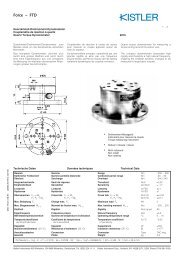
Force – FMP<br />
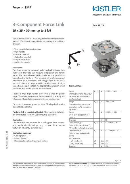
3-Component Force Link<br />
25 x 25 x 30 mm up to 2 kN<br />
Miniature force link for measuring the three orthogonal components<br />
of a dynamic or quasistatic force acting in an arbitrary<br />
direction.<br />
•Very extended measuring range<br />
• High rigidity<br />
• Minimal cross talk<br />
• Calibrated force link<br />
• Simple installation<br />
• Multipol connector<br />
Description<br />
The force sensor is mounted under preload between two<br />
plates and, therefore can measure compression and tensile<br />
forces. The piezo element yields an electric charge which is<br />
proportional to the force. This is picked off by electrodes and<br />
transferred via a connector. The charge signal is fed via a<br />
screened cable to a charge amplifier, which converts it into a<br />
proportional output voltage. An appropriate evaluation circuit<br />
can record and further process the measurand.<br />
Thanks to their high rigidity they cover a wide frequency<br />
range. The elastic behaviour of the test object is practically not<br />
influenced. Quasistatic measurements, are possible, too.<br />
The sensor is mounted ground-isolated. This largely eliminates<br />
ground loop problems.<br />
The force link is supplied calibrated. After correct installation,<br />
it is immediately ready for use without re-calibration.<br />
Application<br />
The force links can measure the 3 orthogonal force components<br />
easily, directly and precisely, because these sensors<br />
feature an inherently low cross talk.<br />
Application examples<br />
• Cutting forces<br />
• Impact forces<br />
• Determination of coefficients of friction<br />
This information corresponds to the current state of knowledge. Kistler reserves<br />
the right to make technical changes. Liability for consequential damage resulting<br />
from the use of Kistler products is excluded.<br />
Fz<br />
Fy<br />
Technical <strong>Data</strong><br />
Fx<br />
<strong>Type</strong> <strong>9317B</strong><br />
Range<br />
(Without moments if e.g. four<br />
force links are mounted into<br />
one force plate)<br />
Fx, Fy N –1000 ... 1 000<br />
Range<br />
(Example with point of force<br />
application Fx,y 12 mm above<br />
top plate)<br />
Fx, Fy N –200 … 200<br />
Range<br />
(Point of force application Fz centric)<br />
Fz N –2000 … 2 000<br />
Overload % 10<br />
Calibrated range<br />
(Point of force application Fx,y 7,5 mm below top plate surface)<br />
Fx, Fy N 0 … 600; 0 … 60<br />
Calibrated range<br />
(Point of force application Fz centric)<br />
Max. moments<br />
Fz N 0 … 2000; 0 … 200<br />
(Mz = 0; Fz = 0) Mx,y N·m –5/5<br />
(Mx,y = 0; Fz = 0) Mz N·m –4/4<br />
Threshold N
<strong>9317B</strong>_000-464e-12.04<br />
3-Component Force Link – 25 x 25 x 30 mm up to 2 kN, <strong>Type</strong> <strong>9317B</strong><br />
Sensitivity F x, F y pC/N ≈–26<br />
F z pC/N ≈–11<br />
Linearity, each axis % FSO ≤±0,5<br />
Hysteresis, each axis % FSO ≤0,5<br />
Cross talk Fz → Fx,Fy % ≤±1<br />
(Cross talk Fx,Fy –> Fz is Fx ↔ Fy % ≤±3<br />
≤±3% if e.g. four force links<br />
are mounted in to one force<br />
plate)<br />
Fx, Fy → Fz % ≤±4<br />
Natural frequency fn (x) kHz ≈5<br />
fn (y) kHz ≈5<br />
f n (z) kHz ≈21<br />
Operating temperature range °C –50 … 80<br />
Insulation resistance Ω ≥10 13<br />
Ground insulation Ω >10 8<br />
Capacitance, each channel pF ≈39<br />
Connector 3 pole<br />
M8 x 0,75<br />
Weight g 85<br />
Fig. 2: Dimensions <strong>Type</strong> <strong>9317B</strong><br />
This information corresponds to the current state of knowledge. Kistler reserves<br />
the right to make technical changes. Liability for consequential damage resulting<br />
from the use of Kistler products is excluded.<br />
Multicomponent Force Plate with 4 Force Links<br />
Four force links can be mounted together with a common top<br />
plate. Such we gain a multicomponent force plate.<br />
Fig. 1: Force plate with 4 force links <strong>Type</strong> <strong>9317B</strong><br />
Page 2/3<br />
©2004, Kistler Instrumente AG, PO Box, Eulachstr. 22, CH-8408 Winterthur<br />
Tel +41 52 224 11 11, Fax 224 14 14, info@kistler.com, www.kistler.com
<strong>9317B</strong>_000-464e-12.04<br />
3-Component Force Link – 25 x 25 x 30 mm up to 2 kN, <strong>Type</strong> <strong>9317B</strong><br />
Mounting<br />
The contact surfaces that transfer the forces onto the force link<br />
must be flat, rigid and clean.<br />
When four force links are used to construct a force plate, they<br />
must be machined to the same level.<br />
The force links can be fastened either from outside with four<br />
screws M4 in each case or from the center again in each case<br />
with four screws M3.<br />
The screws must be tightened sufficiently so that even with<br />
maximum force exerted, no gap occurs between the contact<br />
surfaces.<br />
This information corresponds to the current state of knowledge. Kistler reserves<br />
the right to make technical changes. Liability for consequential damage resulting<br />
from the use of Kistler products is excluded.<br />
Force Introduction<br />
When only a single force link is used, then as far as possible,<br />
the center of pressure should be within the cover plate.<br />
Eccentric force introduction produces a moment of force on<br />
the sensor element and is permitted only up to specified<br />
values. If such a moment prevails, then the areas of force must<br />
be reduced accordingly.<br />
A rigidly constructed force plate with four force links largely<br />
prevents moment stresses on the sensor element.<br />
Fig. 3: Mounting example: Force limited vibration testing Fig. 4: Mounting example: Drop test measurement<br />
Parallel Switching<br />
Several force links of identical sensitivities can be paralleled<br />
directly. The charge amplifier connected then gives an output<br />
voltage which corresponds to the sum of all forces acting.<br />
This is a great advantage when building force plates with<br />
which only the 3 components of the resulting force must be<br />
measured.<br />
Electronics<br />
Besides the force sensors, a 3-component force measuring<br />
system also requires 3 charge amplifiers, which convert the electrical<br />
charge signals of the sensor into voltages exactly proportional<br />
to the three components F x, F y and F z of the acting force.<br />
In order to construct multicomponent force plates for measuring<br />
three forces and three moments, special multichannel<br />
charge amplifiers are available.<br />
Systems for Multicomponent Measurements<br />
Information concerning cable concept see data <strong>sheet</strong> for Multicomponent<br />
Measurements of <strong>Type</strong>s 9017A, 9047B, 9067B and<br />
9077B.<br />
Optional Accessories <strong>Type</strong><br />
• Connecting cable 1693A…<br />
• Connecting cable 1694A…<br />
Ordering Key <strong>Type</strong><br />
• 3-Component Force Link <strong>9317B</strong><br />
Page 3/3<br />
©2004, Kistler Instrumente AG, PO Box, Eulachstr. 22, CH-8408 Winterthur<br />
Tel +41 52 224 11 11, Fax 224 14 14, info@kistler.com, www.kistler.com