LRS2151 EN.cdr - Nothnagel
LRS2151 EN.cdr - Nothnagel
LRS2151 EN.cdr - Nothnagel

Create successful ePaper yourself
Turn your PDF publications into a flip-book with our unique Google optimized e-Paper software.
ELECTRONIC PANEL LRX 2151<br />
Mono-phase electronic exchange, for the automation of gates<br />
with incorporated receiver.<br />
- Mod. LG 2151: Without radio Receiver<br />
- Mod. ( LRQ 2151 ) : 30,875<br />
MHz<br />
- Mod. ( LR 2151 ) : 306 MHz<br />
- Mod. ( LR 2151/330 ) : 330 MHz<br />
- Mod. ( LR 2151/418 ) : 418 MHz<br />
- Mod. LRS 2151: 433,92 MHz<br />
- Mod. LRS 2151 SET : Narrow band 433,92 MHz<br />
( ) This product is destined only for countries in which this use<br />
is allowed.<br />
TECHNICAL DATA<br />
- Power supply: 230VAC 50-60Hz 8W Max<br />
- Flashing light output: 230VAC 500W Max<br />
- Motor output: 230VAC 500W Max<br />
- Aux. power output: 24VAC 5W Max<br />
- Radio receiver: refer to type<br />
- Op. transmitters: 12-18 Bit or Rolling Code<br />
- TX max. codes in memory 63 different codes<br />
- Working temperature: -20÷85°C<br />
- Dimension of panel: 110x150x75mm<br />
- Degree of panel protection: ( ABS V-0 ) IP 55<br />
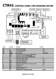
TERMINAL BOARD CONNECTION CN1<br />
1: 230VAC input.<br />
2: 230VAC input.<br />
3: 230VAC flash input.<br />
4: 230VAC flash input.<br />
5: Opening 1 motor output.<br />
6: Common 1 motor output.<br />
7: Closing 1 motor output.<br />
8: Opening 2 motor output.<br />
9: Common 2 motor output.<br />
10: Closing 2 motor output.<br />
TERMINAL BOARD CONNECTION CN2<br />
1: 24VAC 5W service feed output.<br />
2: 24VAC 5W service feed output.<br />
3: Open-close push button input (NA).<br />
4: Common GND input.<br />
5: Safety device input (NC).<br />
6: Aerial earth input.<br />
7: Aerial hot pole.<br />
OPERATING CHARACTERISTICS<br />
Selection of Automatic operation or Step by step<br />
operation :<br />
The centre in its default setting shows the automatic working<br />
function set. To set the step by step function: press the MODE<br />
button continuously for 5 seconds, when all the signalling Leds<br />
are flashing, the programming is stored. If on the other hand,<br />
the memorized function is to be removed, follow the same<br />
programming procedure or follow the RESET procedure.<br />
Automatic operation:<br />
By using either the radio control (led CODE on) or the low<br />
tension button panel (PUL) to operate the gates, commands will<br />
have the following effect: the first command impulse activates<br />
the opening mechanism until time expiry of the timing motor or<br />
until the gate is fully opened, the second command impulse<br />
closes the gate, if a command impulse is received before the<br />
activation of the limit switch, the direction of movement of the<br />
mechanism will be reversed whether engaged in opening or<br />
closing operations.<br />
Step by step operation:<br />
GB<br />
By using either the radio control (led CODE on) or the low<br />
tension button panel (PUL) to operate the gates, commands will<br />
have the following effect: the first command impulse activates<br />
the opening mechanism until time expiry of the timing motor or<br />
until the gate is fully opened, the second command impulse<br />
closes the gate, if a command impulse is received before the<br />
activation of the limit switch, the direction of movement of the<br />
mechanism will be halted whether engaged in opening or<br />
closing operations.<br />
Automatic closing<br />
The control board may be set up automatically to close the<br />
gates.<br />
The set-up procedure is described under the instruction for<br />
setting the delay period.<br />
Safety device<br />
The control board allows for the connection and control of<br />
Photocells, Tyre sensors (NC).<br />
Command from these devices are ignored during opening whilst<br />
the gate is closing they will reverse the direction of movement.<br />
If not used the terminals must be jumped.<br />
Electronic clutch<br />
The control is equipped with an adjustable electronic clutch,<br />
using Trimmer VR1. To adjust, move Trimmer VR1 until the<br />
device moves, but can still be blocked by an obstacle (for<br />
example, the test can be carried out by blocking the device with<br />
the hands).<br />
Functioning of the Flasher<br />
The panel board is powered by an output for the use of a<br />
flasher 230VAC. Its function is conditioned by the movement of<br />
the motor and the automatic closure that when inserted enables<br />
the flash even during a pause.<br />
PROGRAMMING<br />
SEL button: selects the type of function to be memorised, the<br />
selection is indicated by a flashing Led.<br />
By repeatedly pressing the button it is possible to choose the<br />
desired function. The selection will remain active for 10 seconds<br />
indicated by a flashing Led, if no other operations are executed<br />
during this period, the control board will return to its previous<br />
state.<br />
SET button: programmes the information relative the type of<br />
function previously selected with the SEL button.<br />
Led Reference Led off Led on<br />
1) CODE No code Code activated<br />
2) T. MOT. Unlimited timing Programmed delay<br />
3) T. PAUSE No automatic close With automatic close<br />
4) RIT. ANTE AP No wing delay Programmed delay<br />
5) RIT. ANTE CH No wing delay Programmed delay<br />
1) CODE: (Radio control code)<br />
The board allows the memorisation up to 63 radio commands<br />
having different codes, which are either fixed or rolling code.<br />
Programming: The transmission code is programmed in<br />
the following manner: press the SEL button until the CODE led<br />
flashes, immediately transmit the pre-selected code with the<br />
desired remote control, in the moment in which the led CODE<br />
remains accessible, the programming, will be complete. In the<br />
case that all 63 codes have been memorised repeating the<br />
operation of programming, all the 5 Led will begin to flash very<br />
quickly signalling that no further memorisation is possible.<br />
Programming through Radio command:<br />
This procedure, consents to enable the programming, without<br />
direct intervention of the SEL task on the panel, but executing<br />
the operation at a distance, allows the programming of
transmission codes without the having to use the SEL button on<br />
the central direct.<br />
The ability of programming is executed in the following manner:<br />
send in a continuous manner for max. 10 seconds the codes of<br />
the radio command previously memorised, at the same time the<br />
panel will enter into programming mode as explained above.<br />
Ability of programming through Radio command:<br />
The panel is furnished by the builder with the radio command<br />
disabled, if you wish to enable the function, proceed in the<br />
following manner: the panel board is powered by an output of<br />
230VAC, keeping the SELL task pressed, at the same time you<br />
will obtain a brief flashing of all the Leeds and the programming<br />
will be complete.<br />
If you wish to disable the function previously enabled, repeat<br />
the operation or follow the RESET procedure.<br />
Cancellation: All the transmission codes are cancelled in<br />
the following manner: press the SEL button until the CODE led<br />
flashes, then press the SET button and the CODE Led will be<br />
turned off and the cancellation will be completed.<br />
2) T. MOT.: (Programming. the motor operating time max. 4<br />
minutes)<br />
The control unit is factory supplied with a working time motor<br />
predefined equal to 30 sec.<br />
If a reprogramming of the motor operating time is needed, it<br />
must be effected through the closed frame in the following<br />
manner: set the SEL button on the T. MOT. flashing led, then<br />
continuously press the SET button, the rolling shutter will start<br />
the opening; when you have reached the required height,<br />
release the SET button key and at the same time the motor<br />
time storage will be completed and the T. MOT. Led will remain<br />
lit and fixed. If you want an infinite motor time, using the SEL<br />
task when the Led T. MOT. is flashing press for less than 1<br />
second the SET button, at the same time the Led will shut off<br />
and the operation will be completed.<br />
3) T. PAUSE: (Maximum programmed automatic wing closing 4<br />
minutes)<br />
The manufacturer furnishes the board with an automatic closure<br />
(pause time equal to 15 sec.). If a reprogramming of the<br />
automatic closing time is needed, it must be effected in closed<br />
frame in the following manner: press the SELL button until the<br />
T. PAUSE led flashes, then press and hold down the SET<br />
button for a period equal to the desired pause interval between<br />
closing and opening operations, at the expiry of the desired<br />
time leave the SET button, at the same time the memorisation<br />
of automatic closing time will be determined and the Led T.<br />
PAUSE will be lit.<br />
If decided not to have the automatic closing, take position on<br />
the flash of the Led T. PAUSE after press the SET task for less<br />
than a second, at the same time the Led will shut off and the<br />
operation will be concluded.<br />
4) DELAY IN WING OP<strong>EN</strong>ING: (programmed wing delay 15<br />
sec. max.)<br />
The manufacturer furnishes the panel if chosen the automation<br />
of 2 motors with a delay in wing opening equal to 3 seconds<br />
(del. MOTOR 2).<br />
If a reprogramming of the delay is needed in relation to its<br />
opening, it must be effected during close frame in the following<br />
manner: take position on the SEL, task when the led WING<br />
DELAY OP. is flashing, then press in continuous manner the<br />
SET task for as long as the time desired, release the SET task,<br />
at the same time the memorisation of the delay will be<br />
determined and the Led DELAY WING OP. will be fixed. If<br />
desired not to have a delay in wing opening, take position on<br />
the Led DELAY WING OP. then press SET task for less than a<br />
second, at the same time the Led will shut off and the operation<br />
will conclude.<br />
5) DELAY IN WING CLOSING: (programmed wing delay 15<br />
sec. max.)<br />
The manufacturer furnishes the panel if chosen the automation<br />
of 2 motors with a delay in wing closing equal to 3 seconds (del.<br />
MOTOR 1).<br />
If a reprogramming of the delay is needed in relation to its<br />
closing, it must be effected during close frame in the following<br />
manner: take position on the SEL, task when the led WING<br />
DELAY CL. is flashing, then press in continuous manner the<br />
SET task for as long as the time desired, release the SET task,<br />
at the same time the memorisation of the delay will be<br />
determined and the Led DELAY WING CL. will be fixed. If<br />
desired not to have a delay in wing closing, take position on the<br />
Led DELAY WING CL. then press SET task for less than a<br />
second, at the same time the Led will shut off and the operation<br />
will conclude.<br />
RESET<br />
If it necessary to reset the program board to its default values,<br />
that is with no memorised data, press both SEL and SET<br />
buttons continuously, all the RED LEDs will flash at once.<br />
IMPORTANT NOTICE FOR THE INSTALLER<br />
In order for the receiving part of the radio to function<br />
correctly, in cases where two or more centres are used, it is<br />
advisd to install them at a distance of at least 3 metres from<br />
each other.<br />
The centre must not have any type of sectioning mechanism<br />
from the electrical line 230 Vac; it is therefore the<br />
responsibility of the installer to see the installation of a<br />
sectioning device within the plant.<br />
The fixing of the electricity supply cables and their<br />
connection, must be guaranteed by means of the assembly of<br />
the cable presses which are provided as “optional”.<br />
The input, which is labelled as normally closed (NC), must<br />
be jumped if not used!!<br />
The products<br />
Electronic exchange<br />
LG2151- LRS 2151 – LRS 2151 SET<br />
comply with the requirements of Directives R&TTE 99/5/EC,<br />
EMC 2004/108/EC, LVD 2006/95/EC