CASSINI MANEUVER EXPERIENCE: FINISHING INNER CRUISE
CASSINI MANEUVER EXPERIENCE: FINISHING INNER CRUISE
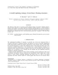
CASSINI MANEUVER EXPERIENCE: FINISHING INNER CRUISE

Create successful ePaper yourself
Turn your PDF publications into a flip-book with our unique Google optimized e-Paper software.
<strong>CASSINI</strong> <strong>MANEUVER</strong> <strong>EXPERIENCE</strong>:<br />
<strong>FINISHING</strong> <strong>INNER</strong> <strong>CRUISE</strong><br />
Troy D. Goodson, Donald L. Gray, Yungsun Hahn, and Fernando Peralta<br />
Jet Propulsion Laboratory and California Institute of Technology<br />
ABSTRACT<br />
The Cassini-Huygens spacecraft was launched in<br />
1997. It is an international effort to study the Saturnian<br />
system. Cassini’s interplanetary cruise, which will deliver<br />
the spacecraft to Saturn in 2004, is making use of multiple<br />
propulsive maneuvers, both statistical and deterministic.<br />
The inner cruise maneuvers have been completed. The<br />
system has performed better than pre-launch expectations<br />
and requirements. Improvements to the system have been<br />
made and more accurate maneuver execution error models<br />
have been determined, based on this in-flight data. This<br />
new model will provide more realism to predictions of the<br />
fuel required to navigate the tour of Saturn’s system.<br />
INTRODUCTION<br />
The Cassini-Huygens program is an international<br />
effort to study the planet Saturn and its moons with an<br />
orbital tour. The European Space Agency’s (ESA)<br />
VENUS SWINGBY<br />
26 APR 1998<br />
VENUS SWINGBY<br />
24 JUN 1999<br />
Huygens probe will be delivered to Saturn’s moon Titan<br />
by the Cassini spacecraft. This is the first mission to visit<br />
Saturn since the flybys made by the two historic Voyager<br />
spacecraft in 1980 and 1981. Cassini will arrive at Saturn<br />
in 2004, the climax of a long journey. Previous papers<br />
[1,2] reported prelaunch plans and experience during early<br />
cruise. Now that the inner-solar-system phase of cruise<br />
has finished, further operational experience of the Cassini<br />
mission is reported, with a focus on the deep space<br />
maneuver and subsequent trajectory correction maneuvers<br />
(TCMs). A second focus is the analysis of Cassini’s<br />
maneuver execution error statistics. Armed with more<br />
accurate statistics, the navigation team can make more<br />
accurate predictions of future AV usage.<br />
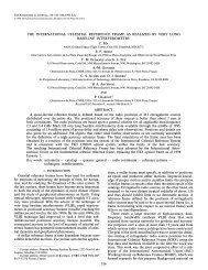
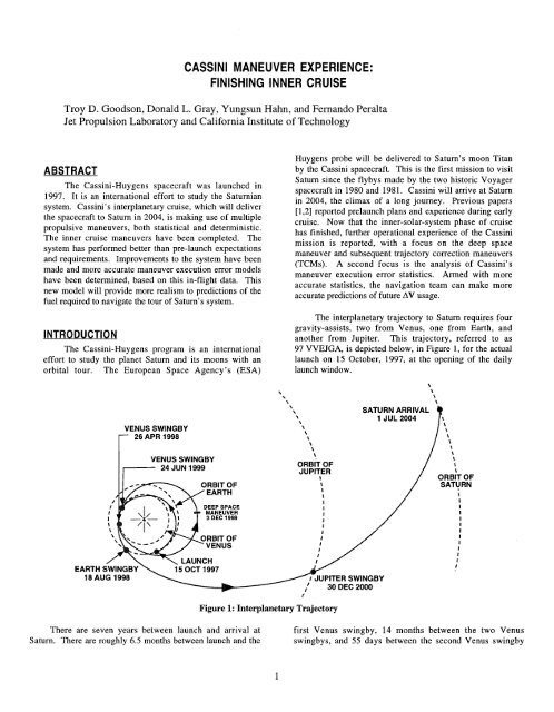
The interplanetary trajectory to Saturn requires four<br />
gravity-assists, two from Venus, one from Earth, and<br />
another from Jupiter. This trajectory, referred to as<br />
97 VVEJGA, is depicted below, in Figure 1, for the actual<br />
launch on 15 October, 1997, at the opening of the daily<br />
launch window.<br />
SATURN ARRIVAL<br />
1 JUL 2004<br />
\ s 1 \<br />
1<br />
t<br />
\<br />
\<br />
i<br />
1<br />
1<br />
ORBIT OF<br />
SATURN<br />
I<br />
EARTH SWINGBY<br />
18 AUG 1998 UPITER SWINGBY<br />
Figure 1: Interplanetary Trajectory<br />
There are seven years between launch and arrival at first Venus swingby, 14 months between the two Venus<br />
Saturn. There are roughly 6.5 months between launch and the swingbys, and 55 days between the second Venus swingby<br />
I
and the Earth swingby. The Jupiter swingby is about one-third maneuvers.[3] . The final sequence of bias-removal aimpoints<br />
of way into the subsequent 5 years. There are many activities for the Earth swingby are depicted graphically in Figure 2 and<br />
to be accomplished within this time, including the execution listed in Table 111.<br />
of up to 21 TCMs.<br />
The previous paper [2] concluded with mention of a<br />
trajectory redesign. That redesign obviated two maneuvers by<br />
accepting the current trajectory best estimate as the start of a<br />
new reference trajectory and redesigning the downstream<br />
events and maneuver targets to accommodate it. [3] After the<br />
large Deep Space Maneuver (DSM), detailed below, another<br />
trajectory redesign was performed. [4] Again, the current best<br />
estimate became the reference and all downstream events and<br />
maneuver targets changed. Only the results of this most recent<br />
redesign are reported.<br />
The previous paper also reported on the emerging design<br />
of TCM-St, a test maneuver. The purpose of TCM-St was to<br />
characterize the propulsion system by simulating conditions<br />
that would be seen later in cruise. However, after some<br />
further study these conditions proved to be more difficult to<br />
attain that expected. One particular complication was in the<br />
strategy for heating the spacecraft’s propulsion system to<br />
reflect conditions somewhat closer to the sun; in fact, a<br />
suitable strategy for this heating was not found. The so-called<br />
test maneuver was cancelled.<br />
A total of twenty-one maneuvers enter into the<br />
navigation strategy for 97 VVEJGA. The first two of these<br />
maneuvers were reported in the previous paper along with the<br />
cancellation of the third and fourth maneuvers. Several of the<br />
remaining TCMs during cruise and the final approach to<br />
Saturn are deterministic, viz. have a non-zero mean AV. For<br />
the most part, these deterministic components were designed<br />
in support of the Earth Swingby Plan [5]; they remove, in<br />
piecemeal, a built-in trajectory bias of the Earth swingby<br />
aimpoint. The trajectory bias was implemented by specifying<br />
targets in Earth’s B-plane for the maneuver sequence from the<br />
TCM-9 to TCM-12<br />
In addition to biasing in the B-plane, the time-of-arrival<br />
for the Earth swingby was altered with each maneuver. The<br />
time-of-arrival targets were specified to reduce the AV cost of<br />
the. strategy. If a given bias-removal maneuver was not<br />
executed, both the B-plane aimpoint and the time-of-arrival<br />
would have been in error.<br />
The post-Venus-1 redesign turned the current best<br />
estimate of the trajectory into the reference trajectory. A study<br />
of how this redesign would affect the Venus-2 delivery<br />
dispersions prompted a reconsideration of the post-DSM/pre-<br />
Venus-2 trajectory segment for the Earth Swingby analysis.<br />
As a result, a bias was introduced into the Deep Space<br />
Maneuver (DSM) design which would be removed by TCM-7.<br />
TCM-6 and TCM-8 would remain unbiased clean-up<br />
2<br />
h<br />
E<br />
25<br />
Q)<br />
0<br />
C<br />
tlJ<br />
c<br />
v)<br />
.-<br />
n<br />
I<br />
i<br />
-2 1 O4 ...............,............... TCM-12<br />
Aimpoint<br />
7 A / !<br />
Aimpoint /<br />
-4 lo4 0 4 lo4 8 lo4<br />
BeT - Distance (km)<br />
Figure 2: Aimpoint Biasing Strategy for Earth (Earth<br />
B-Plane)<br />
The post-DSM redesign maintained the pre-Venus bias.<br />
However, this time the bias removal was split between TCM-6<br />
and TCM-7 in such a way that TCM-6 maintained the same<br />
Earth B-plane target as the DSM but the Earth TCA target<br />
changed, as listed in Table V. In this way, TCM-7 was small<br />
enough to be performed with the monopropellant system.<br />
TCM-8 remained an unbiased clean-up maneuver.[4]<br />
Maneuver Execution<br />
The Cassini’s Propulsion Module Subsystem (PMS)<br />
consists of a bipropellant element, the main engine, for large<br />
trajectory corrections and a monopropellant element, the<br />
Reaction Control Subsystem (RCS), for small trajectory<br />
corrections, attitude control functions,<br />
desaturation. [6]<br />
and reaction wheel<br />
The RCS is used for small maneuvers, viz. less than 1<br />
ds. The RCS consists of 4 hydrazine thruster clusters - a<br />
total of 8 primary and 8 backup thrusters. These small,<br />
monopropellant thrusters supply about 0.98 Newtons each<br />
when fully pressurized and an I,, of about 195 seconds. They<br />
are labeled in Figure 4. The thrusters may be grouped into<br />
two sets. The first set faces the *YsIc spacecraft directions; it<br />
is used to make balanced turns about the Z,, axis (roll turns).<br />
The other set faces the -Z,,, axis and is used to make
unbalanced turns about the X,,c axis (pitch turns) and/or Y,,,<br />
axis (yaw turns).<br />
Table I: Interplanetary -V estimates, m/s<br />
DSM 1 449.97 I 450.02 I 1.52 I 452.56<br />
TCM-6 I I 11.67 1 0.04 I 11.74<br />
TCM-7 1 0.24 I 0.54 I 0.27 I 1.08 I<br />
- I<br />
deviation, "95%" indicates that 95% of the time, the<br />
maneuver will be less than listed<br />
Large maneuvers are executed with the main engine,<br />
which has two redundant nozzles (MEA, MEB). The two<br />
nozzles are mounted side by side along the Y-axis, which can<br />
be seen in Figure 3. Since either of these must thrust toward<br />
the spacecraft center of gravity, the resulting thrust direction<br />
has a small offset from the -Z-axis direction (approx. 7.2" or<br />
0.13 rad). When fully pressurized, this system has a thrust of<br />
445 Newtons and an I,, of about 304 seconds.<br />
Maneuvers, by and large, are be executed in the blow-<br />
down, non-pressure-regulated, configuration. Only large<br />
maneuvers, such as the DSM and SOI, were to be executed<br />
with the regulator active. TCM-1 was to be the only<br />
exception; however, TCM-1 was executed blow-down due to<br />
concern over a regulator leak. A fuel-side-only<br />
repressurization of the system in-between maneuvers was<br />
enacted after TCM-9.<br />
3<br />
High Gain<br />
Antenna<br />
Low Gain<br />
Antenna 1<br />
/<br />
Figure 3: Cassini Spacecraft Diagram<br />
Maneuvers are executed in a turn-and-burn manner.<br />
Prior to all main engine maneuvers, the attitude-control<br />
deadband is reduced from 20 mrad to 2 mrad (0.1").[7] The<br />
spacecraft then performs the so-called wind turns, a roll turn<br />
about the Z,,, axis followed by a yaw turn about the Y,,, axis.<br />
These turns are designed to place the main engine (bodyfixed)<br />
thrust vector along the desired burn AV. After the burn<br />
is complete, the roll and yaw sequence is performed<br />
reverse: these are called the unwind turns.<br />
in<br />
In addition to the roll and yaw turns, some maneuvers<br />
include a third turn that is referred to herein as the pointingbias-fix<br />
turn*. It is included in both the wind and unwind sets.<br />
This turn is described in more detail, below. Also, the attitude<br />
control system has been observed contributing some extra<br />
RCS firings for a very small AV, less than 1 d s , after each<br />
maneuver.<br />
The RCS +Z,,,-facing thrusters do not have -Z,,-facing<br />
counterparts, they are unbalanced. As a result, each maneuver<br />
has several AVs associated with it, including deadband<br />
tightening, roll and yaw turns, pointing bias fix turns, the burn,<br />
and the post-maneuver RCS firings. Strictly speaking, the<br />
total AV is the sum of all these; however, herein total AV<br />
refers to all but the post-maneuver firing. The burn & turns<br />
AV is the sum of the burn AV and the roll and wind turn AV.<br />
* The flight team often refers to this maneuver as the<br />
70FFSET turn, after the flight software command used to<br />
execute it. However, a 7OFFSET command is more general<br />
and is used for other purposes, so it is referred to here as the<br />
pointing bias fix.
The total AV is useful for discussing the whole execution error<br />
while the burn & turns AV is useful in comparing with the<br />
AACS results. See Figure 4.<br />
Errors in all of these events contribute to the total<br />
maneuver execution error. Execution performance is<br />
primarily dependent upon performance of the on-board<br />
accelerometer and the attitude control system performance.<br />
The latter is very dependent upon pre-aiming the main engine.<br />
If the pre-aim is incorrect, the main engine is pointed such that<br />
its thrust produces a torque upon the spacecraft. The attitude<br />
control system works to remove this torque and to orient the<br />
spacecraft so that the main engine thrust vector matches the<br />
desired burn direction.<br />
Total<br />
AV<br />
Burn &<br />
AV<br />
roll wind turn<br />
yaw wind turn<br />
yaw unwind turn<br />
pointing bias fix (wind turn)<br />
pointing bias fix (unwind turn)<br />
"""""""".<br />
"""""""".<br />
deadband tightening<br />
post-maneuver firing<br />
. """"~"""""""<br />
Figure 4: Definitions<br />
' AV<br />
Turns<br />
Execution errors are modeled using the Gates model.[8]<br />
The Gates model accounts for four independent error sources,<br />
two each for magnitude errors and pointing errors. These are<br />
either fixed errors or proportional. Each parameter represents<br />
the standard deviation for that error source and each error<br />
source is assumed to have zero mean.<br />
Maneuvers are forecast and, once executed, judged<br />
according to the levied execution error requirements. The pre-<br />
launch requirements are listed in Table 11.<br />
One may compute execution errors by simply<br />
subtracting the expected from the actual AV, but most of the<br />
insight into the source of the error comes after judiciously<br />
choosing a coordinate system to represent it with. Each<br />
maneuver AV is in a different inertial direction, but is<br />
controlled by spacecraft on-board systems, the accelerometer<br />
and attitude control system. It makes sense, then, to use a<br />
body-fixed coordinate system instead of an inertial system<br />
when analyzing the errors. A coordinate system definition,<br />
referred to as spacecraft coordinates X, Y, and Z,,, already<br />
exists for Cassini and is denoted in Figure 3. The Z, axis<br />
points from the high-gain antenna to the main engine, the Y,<br />
axis points away from the probe, and the X, axis completes<br />
the right-handed system.<br />
4<br />
Table 11: TCM Error Requirements (3-0)<br />
However, a coordinate system with an axis parallel to the<br />
expected AV is preferred. The compromise is a coordinate<br />
system with Z parallel to the expected AV, X parallel to the<br />
projection of X,,, into the plane perpendicular to Z, and Y<br />
completes the right-handed system. The plane perpendicular<br />
to Z is referred to herein as the pointing plane.<br />
<strong>MANEUVER</strong> <strong>EXPERIENCE</strong><br />
After TCM-2, two flight software corrections were<br />
made, both relating to the accelerometer. The accelerometer<br />
scale factor was in error by 1%, biasing the ,system to<br />
overburn by that amount. The other correction was one made<br />
to the algorithm which compensates for the misalignment<br />
between the accelerometer mounting and the thrust vector.<br />
This potentially reduced burn magnitude error by as much as<br />
0.8%. These two corrections are credited with the excellent<br />
magnitude errors discussed below.<br />
DSM<br />
The Deep Space Maneuver (DSM) was the largest that<br />
this spacecraft will execute prior to the Saturn Orbit Insertion<br />
(SOI) in 2004. The DSM was also the only maneuver for<br />
which the propulsion system was fully pressure-regulated and<br />
no other maneuver will be fully pressure-regulated until the<br />
s 01.<br />
'Given in mm/s<br />
+Uncalibrated (TCM-1, TCM-2, and SOI)<br />
Calibrated<br />
' For long burns, such as the DSM and SOI, this requirement<br />
is relaxed to 30mrad. However, high quality gyros were<br />
procured and the star sensor remains in use during the burn,<br />
making the relaxation unnecessary.
Design characteristics for the DSM, and the following<br />
maneuvers, are listed in Table V. The cut-off date for the last<br />
radiometric data, the size of the AV desired, the roll, and the<br />
yaw turn angles are all listed. Additionally, the Earth-look<br />
angle is provided. The look angle is the angle between the<br />
total AV vector and a vector from the spacecraft to Earth. The<br />
Earth-look angle provides insight into the observability of<br />
maneuver. If the angle is zero, the vectors are aligned and the<br />
magnitude of the maneuver will be well-estimated. If the<br />
angle is close to 90", then one component of the pointing error<br />
will be well-estimated.<br />
As noted in Table V, the data cut-off for the DSM was<br />
well before execution. Being such a large maneuver, its<br />
design was not very sensitive to further orbit information. The<br />
additional time allowed for an extensive review and some<br />
double-checking of this important maneuver.<br />
The execution of the DSM revealed a total AV pointing<br />
error of 0.89" and a burn-only AV pointing error of 0.94" -<br />
somewhat larger than the 0.61" previously reported for<br />
TCM-1.[2] Curiously, the AACS on-board estimate of the<br />
Table 111: Trajectory Events, Including Maneuvers and Targets<br />
I Taroets<br />
'Equivalent to Venus; 24-Jun-1999 215252 UTC, B*R 3269 km, and B-T-9775 km.<br />
+Equivalent to Venus; 24-Jun-1999 20:30:14 UTC, B*R 3255 km, and BOT -9759 km.<br />
* TCM-8 was cancelled.<br />
5<br />
pointing error was only 0.29". On the other hand,<br />
Navigation's estimate of the magnitude error was only about<br />
0.05%, a considerable improvement over the 1.67% for TCM-<br />
1.[2] The execution errors are summarized in Table VI and<br />
the resulting delivery errors are summarized in Table V.<br />
The large pointing error for the DSM led to speculation<br />
as to whether the spacecraft had a pointing bias. This<br />
suspicion prompted an examination of the difference between<br />
NAV's and AACS' pointing estimates. AACS's data<br />
represents the S/C system's own estimates while NAV's data<br />
represents what was actually observed from Earth; therefore,<br />
the best place to look for a bias is not in either of these data<br />
alone, but in their difference, NAV-AACS.<br />
The pointing error was computed for both maneuvers.<br />
The components of AV error along the X and Y pointing plane<br />
axes were divided by the magnitude of the maneuver, giving<br />
angular error along these axes in radians. The results may be<br />
seen in Figure 6. The ellipse around the TCM-1 estimate is<br />
the 1-0 (one sigma) uncertainty in that estimate. The same
was included for the DSM estimate, however the ellipse is too<br />
small to see given the scale of the plot.<br />
That analysis revealed that the two maneuvers had<br />
similar NAV-AACS pointing errors. Also, these NAV-AACS<br />
errors were in the same quadrant of the pointing plane. This<br />
conclusion was supported by a pre-launch analysis which had<br />
indicated such a bias might exist. [9]*<br />
Table V: Summary of of Maneuver Design<br />
Characteristics<br />
DSM. Pointing Errors, as Angles, for TCM-1 and I<br />
the DSM<br />
Curiously, the NAV-AACS pointing error for TCM-2<br />
was similar to that for TCM-1 and the DSM, but TCM-2 used<br />
the monopropellant system and had been the only maneuver to<br />
do SKI up to that time. There was no pre-launch analysis<br />
supporting an RCS pointing bias and it was decided to wait for<br />
more RCS results before taking any action.<br />
TCM-6 was originally planned as a purely statistical<br />
6<br />
7<br />
9<br />
10<br />
11<br />
12<br />
1/27<br />
5/7<br />
6/27<br />
7/13<br />
7/27<br />
8/7<br />
14:50<br />
9153<br />
18112<br />
17:40<br />
17140<br />
09155<br />
11.55<br />
0.2386<br />
5.133<br />
36.31<br />
maneuver, a clean-up, and in the unlikely event that the DSM<br />
-10.71" -18.97" 33.66"<br />
had small enough execution errors, it could be cancelled. The<br />
-163.6"<br />
46.00" -110.1" trajectory redesign changed those plans and, therefore, the<br />
-79.33" 43.54 81.33" -115.3" procedure for designing this maneuver. The best-estimate the<br />
90.03" -93.29" -80.74" post-DSM orbit was used by the CAT0 optimization software<br />
-171.7' -64.86O 92.01" to devise new Venus-2, Earth, and Jupiter swingby and time-<br />
-84.76" 12.26 -88.37" 92.58" of-closest-approach targets while holding constant the Earth-<br />
13 8/24 17139 6.710 8.63"<br />
93.11' -83.19" bias-removal strategy. The B-plane targets for TCM-6 were<br />
Times are UTC, dates are month/day, and AV is ds part of the Earth-bias-removal strategy and, therefore, not<br />
changed. The target for time of closest approach with Earth<br />
To correct the bias a new rotation of the spacecraft was for TCM-6 was changed. The final target parameters for<br />
introduced into the maneuver sequence. This new turn would TCM-6 are listed in Table 111.<br />
occur just after the yaw-wind turn and it would be undone just<br />
before the yaw-unwind turn. However, the AV due to this turn,<br />
The roughly 7 m/s error from the DSM would require<br />
about 7.6 mds, was ignored in the maneuver design.<br />
about 12.6 m/s to fully correct with TCM-6. However, by<br />
optimizing TCA targets, this was reduced to about 11.6 m/s.<br />
L; I<br />
Is,<br />
S<br />
0<br />
3 8<br />
L<br />
2<br />
ti<br />
0 4 8 12 16<br />
pointing error along X (mrad)<br />
Figure 6: Indication of Maneuver Pointing Bias in<br />
Pointing Error Measurements of TCM-1 and<br />
* The bias had been ignored because it was smaller than the 3-<br />
CJ requirement listed in Table 11.<br />
+ The look angle listed is the angle between the total AV vector<br />
and a vector from the spacecraft to Earth.<br />
6<br />
TCM-6<br />
The direction of the DSM AV error helped TCM-6 have<br />
a very favorable viewing geometry. Each AV event that made<br />
up TCM-6 was observable with radiometric Doppler data.<br />
Even though the only well-determined component of each AV<br />
was along the vector between the spacecraft and Earth (the<br />
line-of-sight), this information was very valuable.<br />
Table V: Maneuver B-Plane Delivery Errors<br />
#<br />
DSM<br />
B-R B-T TCA SMAA SMIA 8 or,<br />
6 -460e3 15e3 7830 60e3 6e3 34" 2060<br />
Errors are (estimate-design); BmR, BOT, SMAA, and<br />
SMIA are in krn; and TCA and dTF are in seconds.<br />
TCM-13 is Jupiter B-plane, others are Earth.<br />
* The hyperbolic excess speed for the Venus-2 swingby was<br />
about 9.4 Ms. (4*3600 s + 50*60 s)*9.4 km/s = 163,000 km.
The navigation team was able to estimate how the<br />
individual AV errors contributed to the total B-plane delivery<br />
error. The breakdown for the Venus-2 B-plane is shown in<br />
Figure 7. In that figure, it is clear that OD error and maneuver<br />
execution error played almost equal roles in determining the<br />
delivery error. One can also see that the sum ""bf the<br />
contributions of the dead-band tightening AV and the<br />
pointing-bias-fix turn AV are greater than the burn error.<br />
Assuming that the errors in TCM-6 are typical, then there is<br />
considerable improvement to be had by modeling the dead-<br />
band tightening AV and the pointing-bias-fix turn AV.<br />
Reducing OD errors is more challenging. The OD drift<br />
in Figure 7 is broken down into pre- and post-maneuver.<br />
However, together they represent the convergence of the OD<br />
solution from the pre-maneuver estimate to the post-maneuver<br />
reconstruction. The point labeled A represents the best<br />
estimate available when the maneuver was designed on<br />
January 27'h. Not counting the weekend, five working days<br />
were used to write, test, and upload the maneuver sequence to<br />
the spacecraft. The point at the other end of the line segment<br />
B represents the best estimate available when the maneuver<br />
was executed on February 4'h. The point labeled J is the best<br />
estimate available 21 days later. If the maneuver had been<br />
designed and executed on February 4'h, then there would have<br />
been no pre-maneuver OD error and line segment B would<br />
disappear from the diagram. Therefore, those five workdays<br />
for developing the sequence had a real cost in delivery<br />
accuracy. Furthermore, if the whole process had been shifted<br />
later, then the best-estimate used for the design would have<br />
been better, reducing all OD errors. On the other hand, this<br />
pre-maneuver drift is also attributable to an underestimation of<br />
the uncertainty in maintenance activity AV's that occurred<br />
between the DSM and TCM-6. This maintenance activity was<br />
called the Instrument Check Out and further discussion of the<br />
OD issues surrounding it may be found in Ref. 10.<br />
7<br />
-~~ h Y a: E<br />
3360<br />
3400<br />
3440<br />
-9800<br />
B<br />
A<br />
A) TCM-6 aimpoint<br />
B) pre-MVR OD drift<br />
C) deadband tightening<br />
D) pre-burn roll & yaw turns<br />
E) pre-burn pointing bias fix<br />
F) post-burn pointing bias fix<br />
G) post-burn roll & yaw turns<br />
H) burn error<br />
I) post-burn OD drift<br />
J) best estimate of delivery<br />
-9750 -9700 -9650<br />
T (km)<br />
Figure 7: Various contributions to TCM-6's Venus-2<br />
B-plane delivery error<br />
TCM-7<br />
Like TCM-6, TCM-7 had originally been planed as a<br />
clean-up maneuver; however, it took on a small deterministic<br />
component for the trajectory redesign. Since its deterministic<br />
component was limited to 0.25 d s, the chances that it could<br />
be executed with the RCS instead of the main engine were<br />
kept high.<br />
The final orbit estimate held the line so that TCM-7 did<br />
not require the main engine. TCM-7 is the second RCS<br />
maneuver the spacecraft performed. However, it owes its<br />
small size to the accurate execution of TCM-6. It, too, had<br />
favorable look-angles during the burn and is the only RCS<br />
maneuver to date where the radiometric data was collected<br />
during the burn, allowing separate estimates of burn and turn<br />
AV.<br />
The pointing error estimates from TCM-7 are plotted in<br />
Figure 8. Navigation's and AACS' estimates are shown with<br />
their 1-0 uncertainty ellipses, alongside the 1-0 requirement.<br />
Navigation's estimate lies just outside the requirement, though<br />
not far from it, and is clearly inside 2-0 of the requirement.<br />
Also, this pointing error is quite unlike TCM-2's pointing<br />
error, both in size and direction. Even the difference NAV-<br />
AACS is quite unlike that seen for TCM-2. Hence, there is<br />
still little evidence for any pointing bias for RCS maneuvers.
TCM-8<br />
The cancellation of TCM-8 was anticipated; that much is<br />
clear from Table I. When the scheduled time for TCM-8<br />
arrived, the required B-plane shift was only 2 km and the TCA<br />
correction needed was only 2 seconds. In fact, this translated<br />
into a 4 d s savings for TCM-9; in other words, some of the<br />
TCM-9 bias removal was already taken care of. Seeing that<br />
this difference was within the navigation delivery statistics for<br />
TCM-8, the flight team decided that the delivery could not be<br />
improved much considering the expected execution errors<br />
from TCM-8 and so the maneuver was cancelled.<br />
Venus-2<br />
The Venus-2 swingby occurred on June 24, 1999 at<br />
approximately 20:29:55 UTC. It was the only non-targeted<br />
swingby during interplanetary cruise. That isn’t to say that the<br />
swingby wasn’t necessary, but that the maneuver sequence<br />
leading up to Venus-2 aimed at points in Earth’s B-plane, not<br />
Venus’.<br />
TCM-9<br />
The first of the post-Venus, four Earth-bias-removal<br />
maneuvers and doubling as the Venus-2 swingby clean-up,<br />
TCM-9 was scheduled for 45 days before the swingby with<br />
Earth.<br />
TCM-9 was the first maneuver to include the 3 rnds<br />
deadband-tightening AV in its design, reducing the total AV<br />
error by that amount.<br />
Unfortunately, the geometry of bias to be removed was<br />
not favorable for radiometric tracking. As can be seen in<br />
Table V, the look angle for this maneuver was near 90”.<br />
Individual AV events could not be discerned and so the only<br />
estimates are for TCM-9 total AV. Furthermore, TCM-9 had a<br />
large B-R component to its bias removal, as seen in Figure 2,<br />
so that there was a large out-of-plane component to its AV,<br />
making the estimation of TCM-9 that much more difficult.<br />
8<br />
-27 -1 8 -9 0<br />
pointing error along X (mrad)<br />
Figure 8: TCM-7 Pointing Errors in Pointing Plane<br />
After TCM-9, the system was regulated, fuel-side only.<br />
This ensured that the bipropellant system would have<br />
acceptable operating conditions for the rest of the cruise<br />
trajectory.<br />
TCM-10<br />
The unfavorable geometry was a little worse for TCM-<br />
10, whose AV was mostly perpendicular to the trajectory plane<br />
making the orbit estimation more difficult, but entirely within<br />
mission requirements.[lO] In hindsight, had more resources<br />
been available pre-launch,<br />
improved.<br />
this geometry might have been<br />
TCM-10 was the first maneuver to include both the<br />
3 mds deadband-tightening AV and the 7.6 rnds pointingbias-fix<br />
AV in its design. The net effect was to reduce the<br />
magnitude error by 7.6 mm/s and to reduce the pointing error<br />
by about 3 d s . All later maneuvers incorporated these AVs<br />
into their designs.<br />
TCM-11<br />
There was some consideration given to pre-designing, or<br />
canning-in, the design for TCM-11; the idea being that the<br />
design could be made months in advance, lightening the work<br />
load during these three months between Venus-2 and Earth.<br />
The AV cost would be small. On the other hand, all the<br />
ground system procedures would be different for this one<br />
maneuver. Rather than risk the confusion, TCM-11 was not<br />
canned-in; it took advantage of the same design process used<br />
for the other maneuvers.<br />
I
TCM-12<br />
Although it was not given a special moniker like the<br />
DSM or SOI, TCM-12 was one of the most important<br />
maneuvers of the whole interplanetary cruise. The trajectory<br />
bias left over by TCM-11 (as planned) would forestall the<br />
mission. The spacecraft would pass Earth at such great<br />
distance that the gravity assist would be far too weak to reach<br />
Jupiter. Furthermore, this maneuver was, by requirement,<br />
placed only six-and-a-half days before the Earth swingby.<br />
The TCM-12 design was slightly complicated by the<br />
desire to avoid any Earth-orbiting debris. It had been decided<br />
before launch that the flight team would take account of the<br />
risk of collision with Earth-orbiting objects during the<br />
swingby. Beginning in 1998 and with more frequency in July<br />
and August of 1999, data was exchanged with the U.S. Air<br />
Force Space Command to determine if any debris hazards<br />
warranted concern.[ 111 Predictions showed one debris object<br />
with a closest approach distance to the spacecraft of 4 km<br />
occurring 138 seconds after the spacecraft’s perigee.<br />
Although the probability of collision was low, the time of<br />
perigee was delayed 14 seconds. That delay increased the<br />
closest approach distance with the object from 4 km to about<br />
90 km. Earth TCA listed in Table I11 includes the 14 second<br />
TCA shift that was implemented.<br />
One can see in Table V, that the data cut-off for TCM-12<br />
was much closer to the maneuver than for the prior<br />
maneuvers. This turn-around time was reduced for TCM-12<br />
so that as much radiometric data as possible could be<br />
processed before the maneuver design, ensuring an accurate<br />
swingby.<br />
Earth<br />
The additional data used for TCM-12 clearly paid off, as<br />
evidenced by the small TCM-12 delivery errors listed in Table<br />
V. Further evidence is provided by the small size of TCM-13,<br />
discussed below. The statistical predictions in Table I show a<br />
mean AV of about 30 d s for TCM-13, yet it only needed<br />
about 7 ds. Just before the swingby, Cassini’s magnetometer boom<br />
was deployed. The boom is shown in Figure 4 extending<br />
towards the lower right-hand corner of the drawing.<br />
TCM-13<br />
Hand-in-hand with the power of the gravitational assist<br />
from Earth comes sensitivity in the swingby conditions. Even<br />
the small error incurred must be corrected as early as possible.<br />
This is clearly shown in the a priori expectation of 30 d s for<br />
TCM-13.<br />
9<br />
TCM-13 also benefited from its geometry. Like TCM-6,<br />
the individual AV events were observable, allowing the burn<br />
to be characterized.<br />
The pointing error in this maneuver, though only about<br />
one-third that of the DSM, is still much larger than the<br />
maneuvers immediately preceding it. That error is mostly due<br />
to an incorrect setting for the main engine pre-aim, discussed<br />
earlier. The setting failed to account for the center-of-mass<br />
shift due to the magnetometer boom*.<br />
Table VI: Maneuver Burn Execution Errors<br />
Magnitude 1-0 uncertainties are in-mds, numbers for<br />
TCMs 9 through 12 are for total AV<br />
Post Maneuver AV<br />
After each of these maneuvers, Navigation noticed<br />
additional RCS thruster firings. In every case so far, these<br />
firings have been estimated separately. Strictly speaking these<br />
are execution errors, although not treated as such here, esp. as<br />
they are so small. For reference,<br />
such event is listed in Table VII.<br />
the estimated AV from each<br />
Table VII: Post-Maneuver AVs<br />
1 DSM I Not observed 1<br />
TCM-6 0.32 mmis<br />
TCM-11 0.17 mm/s<br />
NEW EXECUTION ERROR MODEL<br />
After observing such marvelous maneuver performance,<br />
the flight team realized that this mission might be flown with a<br />
significant savings of AV. The way to judge what savings is<br />
available is to use an updated maneuver execution error model<br />
* That the magnetometer boom shifted the center-of-mass was<br />
well understood, including the magnitude of that shift. This<br />
error was a case of neglect, not miscalculation.
in forecasting and planning the rest of the mission; in other<br />
words, updating Table I. With this is mind, the Navigation<br />
team has analyzed the execution errors to date.<br />
The maneuvers during early cruise [2], TCM-1 and<br />
TCM-2, are not included in this execution error analysis.<br />
TCM-2 is excluded because it was performed with the RCS,<br />
not the main engine. The first maneuver, TCM-1, was<br />
executed with a different accelerometer scale factor and an<br />
error in the algorithm for estimating maneuver magnitude.<br />
The focus of this analysis is on the maneuvers during<br />
inner cruise, that is, the maneuvers performed inside the<br />
asteroid belt. This includes the Deep Space Maneuver (DSM)<br />
and TCMs six through thirteen, and barring TCM-7, all of<br />
these employed the main engine.<br />
The spectacular maneuver performance discussed above<br />
has motivated the estimation of new Gates model parameters<br />
for maneuver execution error. With this new model in hand,<br />
more realistic AV estimates for the remainder of cruise and,<br />
more importantly, the tour may be made.<br />
In the above discussion of maneuver results, execution<br />
errors were discussed in the context of what was designed<br />
versus what was actually executed. However, those designs<br />
did not necessarily take advantage of all available models. For<br />
example, the design of TCM-6 did not account for the AV due<br />
to deadband-tightening. The design of TCM-9 did not account<br />
for the AV due to the pointing-bias-fix turn. These models<br />
are, however, a part of the best-available estimates used in the<br />
a posteriori analysis execution error analysis, below.<br />
The software set used for maneuver design does not<br />
model the AV due to the pointing-bias-fix turn, nor was the<br />
deadband-tightening AV included in every maneuver design.<br />
Therefore, the errors quoted in Table VI do not make use of<br />
the best available estimate for that maneuver. This analysis<br />
required that best available estimates be calculated for each<br />
maneuver. The best available estimate is made using current<br />
knowledge of the AVs associated with maneuvers. For<br />
example, it is only with experience that 3 m ds has become<br />
the best estimate for the deadband tightening AV. No pre-<br />
launch prediction of that AV was made.<br />
The DSM represents a special case because it is the only<br />
maneuver in the data set considered that was executed before<br />
the pointing bias fix. Therefore, the commanded burn AV<br />
must be rotated to coincide with the current best estimate of<br />
the main engine pointing direction.<br />
The magnitude errors are listed in Table VIII. The<br />
pointing errors are listed in Table X These errors are listed in<br />
units of speed, mds, as these are more natural units for<br />
estimating the Gates model parameters.<br />
10<br />
While the magnitude errors are one-dimensional and,<br />
given the small number of measurements, fairly easy to<br />
understand in a table, the pointing errors are two-dimensional<br />
and are best presented in a figure using angular units, viz.<br />
Figure 10.<br />
Table VIII: Best Estimate Magnitude Errors<br />
11.5615<br />
43.5504 -58.856<br />
5.1403<br />
I1 36.3182 -21.264 2.80<br />
12 12.2642 -10.669 3.44<br />
6 7185 8-04<br />
In perusing these data, several peculiarities are noticed.<br />
First and foremost, the DSM is the only overburn of the set<br />
and is still not understood. Also, if there were no mean fixed<br />
or proportional error, then one would expect half the samples<br />
to be underburns and half to be overburns. However, there<br />
does seem to be such a bias: a 0.1% underburn. If the DSM<br />
error were simply of the other sign, this would be a very<br />
comfortable conclusion. On the other hand, the DSM is<br />
unique enough (largest, pressure-regulated) to suspect it is<br />
truly an exception.<br />
-<br />
m<br />
.-<br />
.2<br />
Lo<br />
0.02,<br />
I<br />
0.01 -<br />
0"<br />
Q<br />
2 -0.01 -<br />
m<br />
Lo<br />
-0.02 -<br />
e<br />
-0.03 -<br />
. Lo<br />
-0.04 -<br />
L<br />
e<br />
-0.05 -<br />
v<br />
c 'E -0.06 -<br />
0,<br />
' -0.07 -<br />
TCM-6<br />
TCM-10 I<br />
TCM-13<br />
..~..~.....<br />
x<br />
TCM-11<br />
TCM-9<br />
-0.08 I<br />
0 5 10 15 20 25 30 35 40<br />
Maneuver Magnitude (m/s)<br />
Figure 8: Magnitude errors (I&) versus maneuver<br />
magnitude (ds).'<br />
~~<br />
* Overburns are positive, error bars indicate 1-0 uncertainties.<br />
DSM error is off scale (not shown).<br />
c<br />
4 5
The pointing error data is just as rich. First, the TCM-13<br />
pointing error must be thrown out of the analysis because we<br />
know that the modeling did not properly reflect the<br />
magnetometer boom deployment, but it is too difficult to<br />
compute a belt-estimate of the expected AV given that error.<br />
Second, like the magnitude data there appears to be a bias: 1.7<br />
milliradian (0.1') along the +Y axis in the pointing plane. On<br />
the other hand, the TCM-6 pointing error is in a different<br />
quadrant. This is still not understood; however , the prevailing<br />
assumption is that the main engine pre-aim for TCM-6 was<br />
not as good as the pre-aims for the DSM, TCM-9, TCM-10,<br />
TCM- 1 1, and TCM- 12.<br />
Recalling that the pointing bias correction now in use<br />
was computed based on the DSM execution errors, one might<br />
expect the best-estimate DSM pointing error to be zero. Put<br />
another way: why isn't the point labeled DSM in Figure 10 at<br />
the origin? The pointing-bias correction was based on the<br />
difference between Navigation's estimates and AACS' (NAV-<br />
AACS). Since Figure 10 is based only on Navigation's<br />
estimates, the pointing error seen for the DSM is AACS'<br />
pointing error estimate.<br />
Table X: Best-Estimates of Pointing errors<br />
1-0 uncertainty numbers are 1-0 ellipse dimensions<br />
with angle relative to X axis.<br />
The four Gates model parameters mentioned earlier<br />
represent the standard deviations of four independent<br />
distributions. However, the data available is only the<br />
magnitude and pointing errors. Given that the fixed-error<br />
standard deviations are expected to be small relative to the<br />
large TCMs, they are not likely to be well-estimated using the<br />
data in hand. Therefore, no recommendations for the fixed-<br />
error parameters will be made.<br />
Maximum Likelihood Estimation<br />
It is not difficult to set-up a maximum likelihood<br />
estimation problem for this task. First, the probability density<br />
function @dB for the magnitude error is<br />
where x is the error, y is the magnitude of the maneuver, 0,<br />
and 0, are the fixed and proportional Gates model parameters<br />
for magnitude, and exp is the exponential function. Then, the<br />
likelihood function is defined as the product of evaluations of<br />
f&) for each measurement,<br />
A corresponding likelihood function L,(o,, 0, may be<br />
defined for the pointing error, a two-dimensional vector,<br />
whose pdf is<br />
Error! Objects cannot be created from editing field codes.<br />
where x is the length of the pointing error vector in units of<br />
speed, y is the magnitude of the maneuver, 0, and 0, are the<br />
fixed and proportional Gates model parameters for pointing,<br />
and exp is the exponential function.<br />
A weighted maximum likelihood approach may be<br />
constructed by raising each term in the likelihood function to a<br />
power. For the magnitude errors, the exponent is the inverse<br />
of the 1-0 uncertainty. For pointing errors, the uncertainty is<br />
two-dimensional and and the semimajor axis of the 1-0<br />
uncertainty ellipse was used.<br />
x 3-<br />
m<br />
- 0<br />
m<br />
L<br />
g 2-<br />
w<br />
0<br />
._ c<br />
._<br />
0 1 -<br />
a<br />
I TCM-6'$,<br />
-1 I \\ ,<br />
-2 -1 0 1 2<br />
Pointing Error along X (mrad)<br />
Figure 10: Best-estimates of pointing errors, shown in<br />
the pointing plane.<br />
The Gates model parameters for magnitude errors are<br />
found by maximizing L,; likewise for pointing errors. Based<br />
on the form of these equations, one expects that only two<br />
measurements are required to determine the parameters.<br />
Obviously, the more measurements<br />
estimates of the parameters will be.<br />
taken, the better these
Results<br />
The primary result of this analysis is a recommendation<br />
for Gates model parameters that more accurately represent<br />
maneuver execution errors using current maneuver modeling.<br />
These Gates model parameters will be used to update statistics<br />
for future maneuvers and for studying navigation strategies<br />
during the tour.<br />
The secondary result is an estimate of how much<br />
improvement can be gained in execution errors by refining<br />
maneuver modeling. Obviously, this requires either some<br />
conjecture. These speculative assumptions include the<br />
following:<br />
the DSM magnitude error does not represent typical<br />
performance,<br />
the TCM-6 pointing error does not represent typical<br />
performance,<br />
the magnitude errors contain a -0.095% bias, and<br />
the pointing errors contain a 1.7 mrad bias along the<br />
+Y pointing-plane axis.<br />
The first two assumptions must be accepted in order to<br />
consider the latter two. However, all four speculations lead to<br />
considerable analysis before they can be resolved. No model<br />
has been found that might explain why the DSM was the only<br />
overburn to date. On the other, given that the DSM execution<br />
error is atypical, the -0.095% bias merely represents an error<br />
in the scale factor for the on-board accelerometer.<br />
The TCM-6 pointing error is very suspiciously<br />
correlated with the main engine pre-aim setting. Figure 10<br />
shows the history of main engine pre-aim settings. The<br />
feature of interest here is the TCM-6 setting, which is quite<br />
different from the other settings. It does not take a great leap<br />
of imagination to propose models of how the main engine preaim<br />
setting affects pointing errors in such a way to explain<br />
away the TCM-6 pointing error. On the other hand, no<br />
analysis has been performed to support any such model and so<br />
the relationship between the TCM-6 pre-aim setting and the<br />
pointing error remains speculation.<br />
A pointing error bias along the +Y pointing-plane axis,<br />
which is nearly parallel to the Y, axis in Figure 3, is even<br />
more difficult to explain. Although not shown here, the<br />
AACS estimates also indicate such a bias. One is then lead to<br />
speculate that this 1.7 mrad bias is related to the attitude<br />
control system.<br />
this, either.<br />
No analysis has been performed to support<br />
If one accepts the above speculations, which are not<br />
unreasonable, then the way is clear to estimate the execution<br />
12<br />
error capability of the spacecraft. By simply subtracting out<br />
the -0.095% magnitude bias and the 1.7 mrad pointing bias,<br />
the remaining errors show no clear pattern and appear quite<br />
random.<br />
c<br />
C<br />
a,<br />
-0.13<br />
-0.1305<br />
-0.131<br />
-0.1315<br />
0 -0.132<br />
?<br />
8<br />
> -0.1325<br />
-0.133<br />
-0.1335<br />
t<br />
TCM-6<br />
4%.<br />
I '<br />
TCM-9/1 lu<br />
-0.134<br />
-0.0275 -0.027 -0.0265 -0.026 -0.0255 -0.025 -0.0245<br />
X component<br />
Figure 10: History of main engine pre-aim<br />
settings.<br />
This is an ideal data-set for applying the weighted<br />
maximum likelihood estimator described above. Using<br />
FMINS from the MatlabTM analysis software, gives the<br />
following 1-0 results: (magnitude) o,=1.8 mds, 0,=0.03%,<br />
(pointing) 0, =2~10-~ d s , 04=0.55 mrad (0.032').<br />
Recommended Model<br />
Finally, throwing all this speculation aside, there remains<br />
the question of what Gates model parameters best represent<br />
the errors seen in Table VI11 and Table IX. Application of the<br />
maximum likelihood approach to this data-set is bound to be<br />
misleading because the data have an apparent bias. The most<br />
suitable choice, then, is to pick 1-0 numbers that encompass<br />
all of the results. A 1-0 proportional magnitude (0,) of 0.2%<br />
and proportional pointing (04) of 2 mrad (0.1 1 ') covers all the<br />
errors. Navigation recommended changing the official model<br />
in Table I1 to these numbers so that they may be used for<br />
planning the remainder of the mission.
CLOSING<br />
Early cruise for Cassini-Huygens program has been very<br />
successful. Delivery accuracy has been very good for each<br />
swingby and three maneuvers have been cancelled so far, with<br />
minimal AV cost. In fact, there has been an overall AV<br />
savings compared to pre-launch estimates. Analysis of the<br />
benefits from using the smaller execution error model is in<br />
progress. The AV savings is expected to continue.<br />
Experience with the Cassini Spacecraft has been very<br />
successful and should lead to exciting science investigations<br />
of the Saturnian planetary system. Maneuver performance<br />
thus far has been nominal, and the team fully expects mission<br />
success to follow.<br />
ACKNOWLEDGEMENT<br />
The work described in this paper was carried out by the<br />
Jet Propulsion Laboratory, California Institute of Technology,<br />
under a contract with the National Aeronautics and Space<br />
Administration.<br />
APPENDIX: THE B-PLANE<br />
Planet or satellite approach trajectories are typically<br />
described in aiming plane coordinates referred to as “B-plane”<br />
coordinates (see Figure 11). The B-plane is a plane passing<br />
through the target body’s center and perpendicular to the<br />
asymptote of the incoming trajectory (assuming two-body<br />
conic motion). The vector B is a vector in that plane, from the<br />
target body’s center to the piercing-point of the trajectory<br />
asymptote. The vector B specifies where the point of closest<br />
approach would be if the target body had no mass and did not<br />
deflect the flight path. Coordinates are defined by three<br />
orthogonal unit vectors, S, T, and R with the system origin at<br />
the center of the target body. The S vector is parallel to the<br />
incoming V, vector (approximately the velocity vector at the<br />
time of entry into the gravitational sphere of influence). T is<br />
arbitrary, but is typically specified to lie in the ecliptic plane<br />
(the mean plane of the Earth’s orbit), or in a body equatorial<br />
plane. Finally, R completes the orthogonal triad with S and T.<br />
13<br />
B-Plane<br />
Uncertainty Ellipse<br />
Figure 11: B-plane Coordinate System<br />
Trajectory errors in the B-plane are characterized by a<br />
one-sigma (1-0) dispersion ellipse, shown in Figure 11.<br />
SMAA and SMIA denote the semi-major and semi-minor<br />
axes of the ellipse; 8 is the angle measured clockwise from T<br />
to SMAA. The dispersion normal to the B-plane is typically<br />
given as a one-sigma tirne-ofTfight error, where time-of-flight<br />
specifies what the time to encounter would be from some<br />
given epoch if the magnitude of B were zero. Alternatively,<br />
this dispersion is sometimes given as a one-sigma distance<br />
error along S, numerically equal<br />
multiplied by V,.<br />
to the time-of-flight error<br />
1 Gray, D. L., and Hahn, Y., “Maneuver Analysis of the<br />
Cassini Mission,” AIAA Paper 95-3275, presented at the<br />
AIAAIAAS Guidance, Navigation & Control Conference,<br />
Baltimore, Md., August 7-9, 1995.<br />
2 Goodson, T. D., Gray, D. L., and Hahn, Y., “Cassini<br />
Maneuver Experience: Launch And Early Cruise,” AIAA<br />
Paper 98-4224, presented at the AIAA Guidance,<br />
Navigation, & Control Conference, Boston, MA, August<br />
10-12, 1998.<br />
3 Ionasescu, R., “Navigation Plan Update for October 15,<br />
1997 Prime Mission”, JPL Internal Memo 312.AIO24-98,<br />
October 2, 1998<br />
4 Guman, M. D., “Navigation Plan Update for October 15,<br />
1997 Prime Mission”, JPL Internal Memo 312.N003-99,<br />
February 12,1999<br />
5 “Cassini Program Environmental Impact Statement<br />
Supporting Study. Volume 3: Cassini Earth Swingby Plan,”<br />
Internal Document 699-70-3, November 18, 1993.<br />
6 Leeds, M. W., Eberhardt, R. N., and Berry, R. L.,<br />
“Development of the Cassini Spacecraft Propulsion<br />
Subsystem,” AIAA Paper 96-2864, presented at the 32”d<br />
Joint Propulsion Conference, Lake Buena Vista, FL, July 1-<br />
3,1996
7 Wong, E. C., and Breckenridge, W. G., “An Attitude<br />
Control Design for the Cassini Spacecraft,” AIAA Paper 95-<br />
0713, presented at AIAA GNC 1995, Baltimore MD.<br />
8 Gates, C.R., “A Simplified Model of Midcourse Maneuver<br />
Execution Errors,” JPL Technical Report 32-504, JPL,<br />
Pasadena, CA, October 15, 1963.<br />
9 Kopf, E. H., “EGA/EGE Performance during Cassini REA<br />
burns,” JPL Internal Memo 344-99-002, December 21,1998.<br />
IO Guman, M. D., Roth, D. C., Ionasescu, R., et. al., “Cassini<br />
Orbit Determination From First Venus Flyby to Earth<br />
Flyby,” AIAA Paper 00-168, presented at the AAS<br />
Spaceflight Mechanics Meeting, Clearwater, FL, January<br />
23-26,2000.<br />
11 Lewis, G. D., “Earth Orbiting Debris Collision Avoidance<br />
During a Hyperbolic Flyby: The Cassini Experience,” JPL<br />
Internal Memo 312.N034-99, September 13, 1999.<br />
14