Concrete Inserts - Cooper Industries
Concrete Inserts - Cooper Industries
Concrete Inserts - Cooper Industries

You also want an ePaper? Increase the reach of your titles
YUMPU automatically turns print PDFs into web optimized ePapers that Google loves.
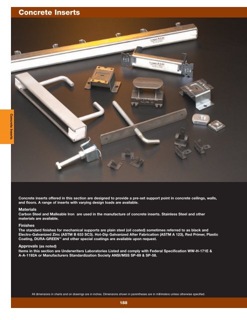
<strong>Concrete</strong> <strong>Inserts</strong><br />
<strong>Concrete</strong> <strong>Inserts</strong><br />
<strong>Concrete</strong> inserts offered in this section are designed to provide a pre-set support point in concrete ceilings, walls,<br />
and floors. A range of inserts with varying design loads are available.<br />
Materials<br />
Carbon Steel and Malleable Iron are used in the manufacture of concrete inserts. Stainless Steel and other<br />
materials are available.<br />
Finishes<br />
The standard finishes for mechanical supports are plain steel (oil coated) sometimes referred to as black and<br />
Electro-Galvanized Zinc (ASTM B 633 SC3). Hot-Dip Galvanized After Fabrication (ASTM A 123), Red Primer, Plastic<br />
Coating, DURA-GREEN and other special coatings are available upon request.<br />
Approvals (as noted)<br />
Items in this section are Underwriters Laboratories Listed and comply with Federal Specification WW-H-171E &<br />
A-A-1192A or Manufacturers Standardization Society ANSI/MSS SP-69 & SP-58.<br />
All dimensions in charts and on drawings are in inches. Dimensions shown in parentheses are in millimeters unless otherwise specified.<br />
188
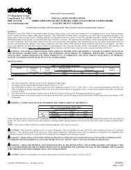
Fig. 109A - <strong>Concrete</strong> Deck Insert<br />
Size Range: 3 /8"-16 thru 7 /8"-9 rod<br />
Material: Steel<br />
Function: For use in metal deck formed concrete to attach hanger<br />
rods. Allows for pre-positioning of hanger rods in poured concrete<br />
decks.<br />
Approvals: 3 /8" - 5 /8" rod size is Underwriters Laboratories listed in<br />
the USA (UL) and Canada (cUL). Included in our Seismic Restraints<br />
Catalog approved by the State of California Office of Statewide Health<br />
Planning and Development (OSHPD). For additional load, spacing and<br />
placement information relating to OSHPD projects, please refer to the<br />
<strong>Cooper</strong> B-Line/TOLCO Seismic Restraints Systems Guidelines.<br />
Hangers certified by a<br />
registered professional engineer to conform to Section 6-1.1 of NFPA<br />
#13 (1999) and Section 9.1.1.2 of NFPA 13 (2002).<br />
Finish: Plate: Plain Steel. Rod: Electro-Galvanized. Contact <strong>Cooper</strong><br />
B-Line for alternative finishes and materials.<br />
Order By: Figure number, rod size and finish. Contact <strong>Cooper</strong> B-Line<br />
for custom rod lengths.<br />
Edge of <strong>Concrete</strong><br />
12” (305mm)<br />
Minimum<br />
Fig. 109A<br />
1” (25.4mm)<br />
Minimum<br />
2 1 /4”<br />
(57.1mm)<br />
Rod Max. Max. Hanger Max. Recommended Approx.<br />
Size Pipe Size Spacing Loads Wt./100<br />
Part No. in. (mm) in. (m) lbs. (kN) lbs. (kg)<br />
109A-3 /8 3 /8"-16 4" (101.6) 15’-0” (4.57) 1144 (3.25) 67.0 (30.4)<br />
109A- 1 /2 1 /2"-13 8" (203.2) 15’-0” (4.57) 1158 (6.00) 69.0 (31.3)<br />
109A- 5 /8 5 /8"-11 Contact <strong>Cooper</strong> B-Line 1430 (9.61) 71.0 (32.2)<br />
109A- 3 /4 3 /4"-10 Contact <strong>Cooper</strong> B-Line 2000 (14.37) 213.0 (96.6)<br />
109A- 7 /8 7 /8"-9 Contact <strong>Cooper</strong> B-Line 2000 (14.37) 217.0 (98.4)<br />
Max. Recommended Loads shown include safety factor of 5.<br />
Weight is based on the standard bolt length.<br />
Edge of <strong>Concrete</strong><br />
12” (305mm)<br />
Minimum<br />
Fig. 109A<br />
<strong>Concrete</strong> <strong>Inserts</strong><br />
NOTES:<br />
1. Mounting holes are standard. If the<br />
plate is not mechanically secured to<br />
the deck ribs, a jam nut is required to<br />
prevent the anchor bolt from laying<br />
over when concrete is poured.<br />
2. Minimum spacing between inserts<br />
shall be not less than 41 ⁄2" (114.3mm)<br />
for 3 ⁄8" and 6" (1152.4mm) for 1 ⁄2"<br />
All dimensions in charts and on drawings are in inches. Dimensions shown in parentheses are in millimeters unless otherwise specified.<br />
189<br />
<br />
1” (25.4mm)<br />
Minimum<br />
2 1 /4”<br />
(57.1mm)<br />
Component of State of<br />
California OSHPD Approved<br />
Seismic Restraints System<br />
Standard Bolt Length<br />
8” (203.2mm)<br />
Edge of <strong>Concrete</strong><br />
12” (305mm)<br />
Minimum<br />
1” (25.4mm)<br />
Minimum<br />
1” (25.4mm)<br />
Minimum<br />
2 1 /4”<br />
(57.1mm)<br />
Fig. 109A<br />
<strong>Concrete</strong> <strong>Inserts</strong>
<strong>Concrete</strong> <strong>Inserts</strong><br />
<strong>Concrete</strong> <strong>Inserts</strong><br />
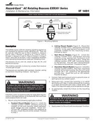
Fig. B3019 - Adjustable Metal Deck Ceiling Bolt<br />
Size Range: 3 /8"-16 thru 3 /4"-10 rod<br />
Material: Steel<br />
Function: For use in metal deck formed concrete to attach<br />
hanger rods. Allows for pre-positioning of hanger rods in poured<br />
concrete decks.<br />
Finish: Plate: Plain Steel. Rod: Electro-Galvanized. Contact<br />
<strong>Cooper</strong> B-Line for alternative finishes and materials.<br />
Order By: Figure number and finish. Contact <strong>Cooper</strong> B-Line for<br />
custom rod lengths.<br />
For maximum load rating, install plate on top of deck ribs.<br />
Steel Size<br />
B<br />
'D'<br />
D<br />
Underside of anchor bolt to<br />
bottom of plate<br />
Thread Size 'A' with Thread<br />
Length 'C'<br />
Thread Thread Design Approx.<br />
A B Length C D Steel Size Design Load Wt./100<br />
Part No. in. (mm) in. (mm) in. (mm) in. (mm) Lbs (kN) Lbs. (kg)<br />
B3019-3 /8 3 /8"-16 21 /2" (63.5) 63 /8" (161.9) 11 /4" (31.7) 7 Ga. x 11 /4"x10" (4.5 x 31.7 x 254.0) 730 (3.25) 80 (36.3)<br />
B3019-1 /2 1 /2"-13 21 /2" (63.5) 61 /2" (165.1) 11 /4" (31.7) 7 Ga. x 11 /4"x10" (4.5 x 31.7 x 254.0) 1350 (6.00) 99 (44.9)<br />
B3019-5 /8 5 /8"-11 21 /2" (63.5) 63 /4" (171.4) 11 /4" (31.7) 7 Ga. x 11 /4"x10" (4.5 x 31.7 x 254.0) 2160 (9.61) 129 (58.5)<br />
B3019-3 /4 3 /4"-10 21 /2" (63.5) 63 /16" (157.2) 21 /4" (57.1) 1 /4" x 3" x 10" (6.3 x 76.2 x 254.0) 3230 (14.37) 238 (107.9)<br />
All dimensions in charts and on drawings are in inches. Dimensions shown in parentheses are in millimeters unless otherwise specified.<br />
190
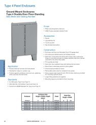
Fig. 109AF - <strong>Concrete</strong> Insert (<strong>Cooper</strong> B-Line B2501)<br />
Size Range: 3 /8"-16 thru 7 /8"-9 rod<br />
Material: Steel<br />
Function: Designed to be embedded in concrete to provide a point<br />
of support.<br />
Approvals: Underwriters Laboratories listed in the USA (UL) and<br />
Canada (cUL) for 3 /8" and 1 /2". Included in our Seismic Restraints<br />
Catalog approved by the State of California Office of Statewide Health<br />
Planning and Development (OSHPD). For additional load, spacing and<br />
placement information relating to OSHPD projects, please refer to the<br />
<strong>Cooper</strong> B-Line/TOLCO Seismic Restraint Systems Guidelines.<br />
Finish: Plain anchor bolt with Electro-Galvanized hardware and plate.<br />
Order By: Figure number, rod size and finish.<br />
Note: The hex or jam nut has NO value in determining the loads.<br />
Their function is to assist in locking the coupling snug to the bottom of<br />
the deck form preventing the concrete from leaking into the coupling<br />
threads. Any other suitable locking device may be substituted if<br />
desired.<br />
Edge of <strong>Concrete</strong><br />
E<br />
Design Load 45°<br />
DE Min.<br />
Design Load-Vertical<br />
Rod Design Load Vertical Design Load Shear Design Load 45° Embedment DE<br />
Size Hard Rock Light Wt. Hard Rock Light Wt. Hard Rock Light Wt. Depth E Min.<br />
Part No. lbs. (kN) lbs. (kN) lbs. (kN) lbs. (kN) lbs. (kN) lbs. (kN) in. (mm) in. (mm)<br />
109AF- 3 /8 3 /8"-16 1255 (55.82) 735 (3.28) 978 (4.35) 733 (3.26) 777 (3.45) 525 (2.33) 3 1 /2” (88.9) 2” (50.8)<br />
109AF- 1 /2 1 /2"-13 2321 (10.32) 1392 (6.19) 978 (4.35) 733 (3.26) 980 (4.36) 679 (3.02) 3 1 /2” (88.9) 2” (50.8)<br />
109AF- 5 /8 5 /8"-11 780 (3.47) 468 (2.08) 1278 (5.68) 958 (4.26) 688 (3.06) 445 (1,98) 4” (101.6) 2” (50.8)<br />
109AF- 3 /4 3 /4"-10 1346 (5.99) 806 (3.58) 1278 (5.68) 958 (4.26) 927 (4.12) 619 (2,75) 4” (101.6) 2 1 /2” (63.6)<br />
109AF- 7 /8 7 /8"-9 2321 (10.32) 1391 (6.19) 1278 (5.68) 958 (4.26) 1166 (5.18) 803 (3,57) 4” (101.6) 6” (152.4)<br />
Max. Recommended Loads shown include safety factor of 5.<br />
Design Load-Shear<br />
Anchor Bolt<br />
ASTM A307<br />
Rod Coupling<br />
Mounting Hole for<br />
Securing to Form<br />
<strong>Concrete</strong> <strong>Inserts</strong><br />
Component of State of<br />
California OSHPD Approved<br />
Seismic Restraints System<br />
All dimensions in charts and on drawings are in inches. Dimensions shown in parentheses are in millimeters unless otherwise specified.<br />
191<br />
<br />
Approx.<br />
Wt./100<br />
Part No. lbs. (kg)<br />
109AF- 3 /8 38.1 (17.3)<br />
109AF- 1 /2 54.7 (24.8)<br />
109AF- 5 /8 82.2 (37.3)<br />
109AF- 3 /4 113.8 (51.6)<br />
109AF- 7 /8 130.6 (59.2)<br />
<strong>Concrete</strong> <strong>Inserts</strong>
<strong>Concrete</strong> <strong>Inserts</strong><br />
<strong>Concrete</strong> <strong>Inserts</strong><br />
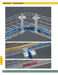
Fig. B2499 - <strong>Concrete</strong> Insert (TOLCO Fig. 107F)<br />
Size Range: 5 /8"-11 thru 11 /2"-6 rod<br />
Material: Steel<br />
Function: Designed to be embedded in concrete to provide<br />
a point of support for 5 /8"-11 thru 11 /2"-6 rod or bolt sizes .<br />
Finish: Plain anchor bolt with Electro-Galvanized coupling. Contact<br />
<strong>Cooper</strong> B-Line for alternative finishes and materials.<br />
Note: For rod sizes 3 /8"-16 and 1 /2"-13, refer to Fig. 109AF.<br />
Order By: Figure number and rod size.<br />
For 11 /8"-7, 11 /4"-6, and 11 /2"-6 consult factory.<br />
Rod Min. Embedment<br />
Max. Recommended Loads<br />
(In 3000 lb. (13.34kN) Approx. Wt./100<br />
Size A B Hard Rock <strong>Concrete</strong>)<br />
Part No. in. (mm) in. (m) lbs. (kN) lbs. (kg)<br />
B2499-5 /8 5 /8"-11 3" (76.2) 31 /2" (88.9) 1810 (8.05) 118.0 (53.5)<br />
B2499- 3 /4 3 /4"-10 3" (76.2) 3 1 /2" (88.9) 2710 (12.05) 154.0 (69.8)<br />
B2499-7 /8 7 /8"-9 3" (76.2) 4" (101.6) 3770 (16.77) 210.0 (95.3)<br />
B2499-1 1"-8 3" (76.2) 4" (101.6) 4960 (22.06) 276.0 (125.2)<br />
Consult factory for specifications on rod sizes 1 1 /8"-7, 1 1 /4"-6, and 1 1 /2"-6<br />
A<br />
A<br />
3/16" Dia.<br />
(4.8)<br />
All dimensions in charts and on drawings are in inches. Dimensions shown in parentheses are in millimeters unless otherwise specified.<br />
192<br />
<br />
B
Fig. B2500 - Light Duty Spot Insert (TOLCO Fig. 310)<br />
Material: Steel<br />
Function: Designed to be embedded in concrete to attach 1 /4"-20 to<br />
7 /8"-9 hanger rods.<br />
How to Install: Attach concrete insert to forms and install reinforcing<br />
rods as required. After forms are dismantled, the knockout can be<br />
removed from the insert. The N2500 insert nut can be installed and<br />
the rod fastened to the nut. The rod should touch the inside top of the<br />
insert but should not be forced further to avoid damaging the insert.<br />
Approvals: Underwriters Laboratories Listed for maximum pipe<br />
size 6" (150). Conforms to Federal Specification WW-H-171E &<br />
A-A-1192A, Type 19 and Manufacturers Standardization Society<br />
ANSI/MSS SP-69 & SP-58, Type 18.<br />
Weight: Approx. Wt./100 - 46 Lbs. (20.8kg)<br />
Finish: Electro-Galvanized.<br />
Order By: Figure number and finish.<br />
(Order N2500 nuts separately).<br />
Design Load: Loading based on a straight pull of 600 Lbs. (2.67kN).<br />
Note: Before installation ensure that concrete is sufficient to carry<br />
the load.<br />
Fig. N2500 - Steel Insert Nut (TOLCO Fig. 310N)<br />
Size Range: 1 /4"-20 through 7 /8"-9.<br />
Material: Steel<br />
Function: Designed for use with B2500 spot insert.<br />
Finish: Plain or Electro-Galvanized.<br />
Order By: Figure number and size.<br />
Tap Size Approx. Wt./100<br />
Part No. A Lbs. (kg)<br />
N2500- 1 /4 1 /4"-20 14 (6.3)<br />
N2500- 3 /8 3 /8"-16 13 (5.9)<br />
N2500- 1 /2 1 /2"-13 12 (5.4)<br />
N2500- 5 /8 5 /8"-11 11 (5.0)<br />
N2500- 3 /4 3 /4"-10 11 (5.0)<br />
N2500- 7 /8 7 /8"-9 10 (4.5)<br />
1 1/4"<br />
(31.7)<br />
2"<br />
(50.8)<br />
<strong>Concrete</strong> <strong>Inserts</strong><br />
1 1/2"<br />
(38.1)<br />
Material Thickness<br />
12 Gauge (2.6)<br />
1 1/4"<br />
(31.7)<br />
A<br />
3 1/4"<br />
(82.5)<br />
Hanger Rod and Nut<br />
Not Included<br />
All dimensions in charts and on drawings are in inches. Dimensions shown in parentheses are in millimeters unless otherwise specified.<br />
193<br />
1 9/16"<br />
(39.7)<br />
5/16"<br />
(7.9)<br />
<strong>Concrete</strong> <strong>Inserts</strong>
<strong>Concrete</strong> <strong>Inserts</strong><br />
<strong>Concrete</strong> <strong>Inserts</strong><br />
Fig. B3014 - Malleable Iron Insert (TOLCO Fig. 309)<br />
Material: Malleable Iron<br />
Function: Designed to be embedded in concrete to attach 3 /8"-16 to<br />
7 /8"-9 hanger rods.<br />
How to Install: Attach concrete insert to forms and install reinforcing<br />
rods as required. After forms are dismantled, the B3014N nut can be<br />
installed and the rod fastened to the nut. The rod should touch the<br />
inside top of the insert.<br />
Approvals: Underwriters Laboratories Listed when used with<br />
B3014N Insert Nut. Conforms to Federal Specification WW-H-171E &<br />
A-A-1192A, Type 18 and Manufacturers Standardization Society<br />
ANSI/MSS SP-69 & SP-58, Type 18.<br />
Weight: Approx. Wt./100 - 166 Lbs. (75.3kg)<br />
Finish: Plain or Electro-Galvanized.<br />
Order By: Figure number and finish.<br />
(Order B3014N nuts separately).<br />
Design Load: Design Loads based on B3014N malleable iron insert<br />
nut below.<br />
Note: Before installation ensure that concrete is sufficient to carry<br />
the load.<br />
Fig. B3014N - Malleable Iron Insert Nut (TOLCO Fig. 309N)<br />
Size Range: 3 /8"-20 through 7 /8"-9.<br />
Material: Malleable Iron<br />
Standard Finish: Plain or Electro-Galvanized<br />
Service: Designed for use with the B3014 malleable<br />
iron insert shown above.<br />
Ordering: Figure number and finish.<br />
1 7/8"<br />
(47.6)<br />
1 1/4"<br />
(31.7)<br />
2 1/4"<br />
(57.1)<br />
Tap Size UL Max. Design Load* Approx. Wt./100<br />
Part No. 'A' Pipe Size Lbs. (kN) Lbs. (kg)<br />
B3014N-3 /8 3 /8"-16 4” 730 (3.25) 22 (10.0)<br />
B3014N-1 /2 1 /2"-13 8” 1350 (6.00) 22 (10.0)<br />
B3014N- 5 /8 5 /8"-11 10” 1400 (6.23) 20 (9.1)<br />
B3014N- 3 /4 3 /4"-10 10” 1400 (6.23) 29 (13.1)<br />
B3014N- 7 /8 7 /8"-9 10” 1400 (6.23) 29 (13.1)<br />
* When used with B3014 Malleable Iron Insert.<br />
194<br />
13/16"<br />
(20.6)<br />
2"<br />
(50.8)<br />
3 3/8"<br />
(85.7)<br />
Horizontal Adjustment:<br />
For 3/8"-16, 1/2"-13, 5/8"-11 rods - Adjustment is 13/4" (44.4)<br />
For 3/4"-10, 7/8"-9 rods - Adjustment is 13/16" (30.2)<br />
1/2"<br />
(12.7)<br />
For 3/8"-16 thru<br />
5/8"-11 Tap Sizes 'A'<br />
1 5/8"<br />
(41.3)<br />
1 7/8"<br />
(47.6)<br />
3 1/4"<br />
(82.5)<br />
1/2"<br />
(12.7)<br />
For 3/4"-10 &<br />
7/8"-9 Tap Size 'A'<br />
All dimensions in charts and on drawings are in inches. Dimensions shown in parentheses are in millimeters unless otherwise specified.
Fig. B2505 thru B2508 - Spot Insert<br />
Material: Steel (Stainless steel available on B2505 only)<br />
Standard Finish: Plain or Pre-Galvanized<br />
Function: Designed to be embedded in concrete to attach 1 /4"-20 to<br />
7 /8"-9 hanger rods.<br />
How to Install: Attach concrete insert to forms and install reinforcing<br />
rods as required. After forms are dismantled, the channel nut can be<br />
installed and the rod fastened to the nut. The rod should touch the<br />
inside top of the insert.<br />
Approvals: Underwriters Laboratories Listed. Conforms to Federal<br />
Specification WW-H-171E & A-A-1192A, Type 18 and Manufacturers<br />
Standardization Society ANSI/MSS SP-69 & SP-58, Type 18.<br />
Order By: Figure number and finish. When supporting<br />
10" (254mm) pipe, order B2505 Insert with 5 /8"-11 channel nuts.<br />
Note: For appropriate channel nut selection, see page 16. Before<br />
installation ensure that concrete is sufficient to carry the load.<br />
2 5/8"<br />
(66.7)<br />
End Caps<br />
Channel<br />
Size<br />
Channel End Cap Design Load Max. Pipe Size Approx. Wt./100<br />
Part No. Size Part No. Lbs. (kN) in. (mm) Lbs. (kg)<br />
B2505 B22 B3322 1200 (5.34) 10" (250) 96 (43.5)<br />
B2506 B32 B3332 1000 (4.45) 8" (200) 88 (39.9)<br />
B2507 B42 B3342 1000 (4.45) 8" (200) 77 (34.9)<br />
B2508 B52 B3352 1000 (4.45) 8" (200) 69 (31.3)<br />
<strong>Concrete</strong> <strong>Inserts</strong><br />
5 1/16"<br />
(128.6)<br />
Styrofoam Filled<br />
All dimensions in charts and on drawings are in inches. Dimensions shown in parentheses are in millimeters unless otherwise specified.<br />
195<br />
<strong>Concrete</strong> <strong>Inserts</strong>
<strong>Concrete</strong> <strong>Inserts</strong><br />
<strong>Concrete</strong> <strong>Inserts</strong><br />
Fig. B2503 - Heavy Duty Spot Insert<br />
Material: Steel<br />
Standard Finish: Electro-Galvanized<br />
Function: Designed to be embedded in concrete where heavy loads<br />
are required in curtain wall applications. Styrofoam end caps prevent<br />
concrete seepage into the channel.<br />
How to Install: Attach concrete insert to forms and install reinforcing<br />
rods as required. After forms are dismantled, the channel nut can be<br />
installed and the rod fastened to the nut. The rod should touch the<br />
inside top of the insert.<br />
Approvals: Conforms to Federal Specification WW-H-171E &<br />
A-A-1192A, Type 18 and Manufacturers Standardization Society<br />
ANSI/MSS SP-69 & SP-58, Type 18.<br />
Design Load: 5000 Lbs. (22.2kN).<br />
Loading based on two N225 channel nuts spaced 3” (76.2mm) on<br />
center and a minimum of 2” (50.8mm) from the end of the insert.<br />
Weight: Approx. Wt./100 - 42 Lbs. (19.0kg)<br />
Order By: Figure number and finish. Channel nuts are sold<br />
separately, see page 16 for appropriate selection.<br />
5/32" (4.0)<br />
Dia. Nail Holes<br />
2"<br />
(50.8)<br />
12"<br />
(304.8)<br />
8"<br />
(203.2)<br />
Styrofoam<br />
End Caps<br />
5 1/2”<br />
(139.7)<br />
All dimensions in charts and on drawings are in inches. Dimensions shown in parentheses are in millimeters unless otherwise specified.<br />
196<br />
1 5/8”<br />
(41.3)<br />
1 5/8”<br />
(41.3)
Fig. B22I - Continuous <strong>Concrete</strong> Insert<br />
Material: Steel<br />
Standard Finish: Plain, Pre-Galvanized, or Hot-Dip Galvanized<br />
Function: <strong>Concrete</strong> insert should be secured to forms on<br />
16” (406.4mm) to 24” (609.6mm) intervals.<br />
How to Install: Attach concrete insert to forms and install<br />
reinforcing rods as required. After forms are dismantled, the<br />
channel nut can be installed and the rod fastened to the nut.<br />
The rod should touch the inside top of the insert.<br />
Approvals: Conforms to Federal Specification WW-H-171E &<br />
A-A-1192A, Type 18 and Manufacturers Standardization Society<br />
ANSI/MSS SP-69 & SP-58, Type 18.<br />
Design Load: 2000 Lbs. (8.89kN) per foot for B22-I-12 thru<br />
B22-I-240 in 3000 psi concrete. Loads concentrated within the<br />
last 2” (50.8mm) of inserts 8” (203.2mm) and longer should not<br />
exceed 1000 Lbs. (4.45kN).<br />
Order By: Figure number and finish. Channel nuts are sold<br />
separately, see page 16 for appropriate selection.<br />
To order inserts without styrofoam and end caps add insert only<br />
to the part number.<br />
Length Approx. Wt./100 Design Load<br />
Part No. in. (mm) Lbs. (kg) Lbs. (kN)<br />
B22-I-3 3” (76) 72 (32.6) 500 (2.22)<br />
B22-I-4 4” (101) 88 (39.9) 800 (3.56)<br />
B22-I-6 6” (152) 120 (54.4) 1000 (4.45)<br />
B22-I-8 8” (203) 152 (68.9) 1200 (5.34)<br />
3 1/8”<br />
(79.4)<br />
1 5/8”<br />
(41.3)<br />
Length Approx. Wt./100<br />
Part No. in. (mm) Lbs. (kg)<br />
B22-I-12 12” (305) 224 (101.6)<br />
B22-I-16 16” (406) 289 (131.1)<br />
B22-I-20 20” (508) 353 (160.1)<br />
B22-I-24 24” (609) 420 (190.5)<br />
B22-I-32 32” (813) 553 (250.8)<br />
B22-I-36 36” (914) 620 (281.2)<br />
B22-I-40 40” (1016) 686 (311.1)<br />
B22-I-48 48” (1219) 820 (371.9)<br />
B22-I-60 60” (1524) 1018 (461.7)<br />
B22-I-72 72” (1829) 1218 (552.5)<br />
B22-I-84 84” (2133) 1417 (642.7)<br />
B22-I-96 96” (2438) 1616 (733.0)<br />
B22-I-108 108” (2743) 1816 (823.7)<br />
B22-I-120 120” (3048) 2016 (914.4)<br />
B22-I-144 144” (3657) 2416 (1095.9)<br />
B22-I-168 168” (4267) 2816 (1277.3)<br />
B22-I-192 192” (4877) 3216 (1458.7)<br />
B22-I-216 216” (5486) 3616 (1640.2)<br />
B22-I-240 240” (6096) 4016 (1821.6)<br />
B3322<br />
End Cap<br />
1 1/2”<br />
(38.1)<br />
11/16”<br />
(17.4)<br />
<strong>Concrete</strong> <strong>Inserts</strong><br />
4”<br />
(101.6)<br />
2 5/8”<br />
(66.7)<br />
Styrofoam<br />
Filler<br />
1 5/8”<br />
(41.3)<br />
1 5/8”<br />
(41.3)<br />
B22-I-3 thru B22-I-8<br />
3/4”<br />
(19.0)<br />
.188” (4.8) Knockouts<br />
for Nailing <strong>Inserts</strong><br />
To Forms<br />
B22-I-12 thru B22-I-240<br />
Styrofoam<br />
Filler<br />
Material:<br />
12 Gauge (2.6)<br />
B205<br />
End Cap<br />
All dimensions in charts and on drawings are in inches. Dimensions shown in parentheses are in millimeters unless otherwise specified.<br />
197<br />
1 5/8”<br />
(41.3)<br />
<strong>Concrete</strong> <strong>Inserts</strong>
<strong>Concrete</strong> <strong>Inserts</strong><br />
<strong>Concrete</strong> <strong>Inserts</strong><br />
Fig. B32I - Continuous <strong>Concrete</strong> Insert<br />
Material: Steel<br />
Standard Finish: Plain, Pre-Galvanized, or Hot-Dip Galvanized<br />
Function: <strong>Concrete</strong> insert should be secured to forms on<br />
16” (406.4mm) to 24” (609.6mm) intervals.<br />
How to Install: Attach concrete insert to forms and install<br />
reinforcing rods as required. After forms are dismantled, the<br />
channel nut can be installed and the rod fastened to the nut.<br />
The rod should touch the inside top of the insert.<br />
Approvals: Conforms to Federal Specification WW-H-171E &<br />
A-A-1192A, Type 18 and Manufacturers Standardization Society<br />
ANSI/MSS SP-69 & SP-58, Type 18.<br />
Design Load: 2000 Lbs. (8.89kN) per foot for B32-I-12 thru<br />
B32-I-240 in 3000 psi concrete. Loads concentrated within the<br />
last 2” (50.8mm) of inserts 8” (203.2mm) and longer should not<br />
exceed 1000 Lbs. (4.45kN).<br />
Order By: Figure number and finish. Channel nuts are sold<br />
separately, see page 16 for appropriate selection.<br />
To order inserts without styrofoam and end caps add insert only<br />
to the part number.<br />
2 7/8”<br />
(73.0)<br />
1 3/8”<br />
(34.9)<br />
1 1/2”<br />
(38.1)<br />
11/16”<br />
(17.4)<br />
B3332<br />
End Cap<br />
4”<br />
(101.6)<br />
2 5/8”<br />
(66.7)<br />
Styrofoam<br />
Filler<br />
1 5/8”<br />
(41.3)<br />
1 3/8”<br />
(34.9)<br />
B32-I-3 thru B32-I-8<br />
3/4”<br />
(19.0)<br />
.188” (4.8) Knockouts<br />
for Nailing <strong>Inserts</strong><br />
To Forms<br />
Length Approx. Wt./100 Design Load<br />
Part No. in. (mm) Lbs. (kg) Lbs. (kN)<br />
B32-I-3 3” (76) 65 (29.5) 500 (2.22)<br />
B32-I-4 4” (101) 80 (36.3) 800 (3.56)<br />
B32-I-6 6” (152) 108 (49.0) 1000 (4.45)<br />
B32-I-8 8” (203) 137 (62.1) 1200 (5.34)<br />
Length Approx. Wt./100<br />
Part No. in. (mm) Lbs. (kg)<br />
B32-I-12 12” (305) 202 (91.6)<br />
B32-I-16 16” (406) 262 (118.8)<br />
B32-I-20 20” (508) 316 (143.3)<br />
B32-I-24 24” (609) 376 (170.5)<br />
B32-I-32 32” (813) 496 (225.0)<br />
B32-I-36 36” (914) 556 (252.2)<br />
B32-I-40 40” (1016) 616 (279.4)<br />
B32-I-48 48” (1219) 736 (333.8)<br />
B32-I-60 60” (1524) 915 (415.0)<br />
B32-I-72 72” (1829) 1095 (496.7)<br />
B32-I-84 84” (2133) 1274 (577.9)<br />
B32-I-96 96” (2438) 1453 (659.0)<br />
B32-I-108 108” (2743) 1633 (740.7)<br />
B32-I-120 120” (3048) 1813 (822.3)<br />
B32-I-144 144” (3657) 2173 (985.6)<br />
B32-I-168 168” (4267) 2533 (1148.9)<br />
B32-I-192 192” (4877) 2893 (1312.2)<br />
B32-I-216 216” (5486) 3253 (1475.5)<br />
B32-I-240 240” (6096) 3613 (1638.8)<br />
Material:<br />
12 Gauge (2.6)<br />
B206<br />
End Cap<br />
B32-I-12 thru B32-I-240<br />
Styrofoam<br />
Filler<br />
All dimensions in charts and on drawings are in inches. Dimensions shown in parentheses are in millimeters unless otherwise specified.<br />
198<br />
1 5/8”<br />
(41.3)
Fig. B52I - Continuous <strong>Concrete</strong> Insert<br />
Material: Steel<br />
Standard Finish: Plain, Pre-Galvanized, or Hot-Dip Galvanized<br />
Function: <strong>Concrete</strong> insert should be secured to forms on<br />
16” (406.4mm) to 24” (609.6mm) intervals.<br />
How to Install: Attach concrete insert to forms and install<br />
reinforcing rods as required. After forms are dismantled, the<br />
channel nut can be installed and the rod fastened to the nut.<br />
The rod should touch the inside top of the insert.<br />
Approvals: Conforms to Federal Specification WW-H-171E &<br />
A-A-1192A, Type 18 and Manufacturers Standardization Society<br />
ANSI/MSS SP-69 & SP-58, Type 18.<br />
Design Load: 1500 Lbs. (6.67kN) per foot for B52-I-12 thru<br />
B52-I-240 in 3000 psi concrete. Loads concentrated within the<br />
last 2” (50.8mm) of inserts 8” (203.2mm) and longer should not<br />
exceed 750 Lbs. (3.33kN).<br />
Order By: Figure number and finish. Channel nuts are sold<br />
separately, see page 16 for appropriate selection.<br />
To order inserts without styrofoam and end caps add insert only<br />
to the part number.<br />
2 5/16”<br />
(58.7)<br />
13/16”<br />
(20.6)<br />
1 1/2”<br />
(38.1)<br />
B3352<br />
End Cap<br />
4”<br />
(101.6)<br />
11/16”<br />
(17.4)<br />
2 9/16”<br />
(65.1)<br />
Styrofoam<br />
Filler<br />
1 5/8”<br />
(41.3)<br />
13/16”<br />
(20.6)<br />
B52-I-3 thru B52-I-8<br />
3/4”<br />
(19.0)<br />
.188” (4.8) Knockouts<br />
for Nailing <strong>Inserts</strong><br />
To Forms<br />
B52-I-12 thru B52-I-240<br />
Length Approx. Wt./100 Design Load<br />
Part No. in. (mm) Lbs. (kg) Lbs. (kN)<br />
B52-I-3 3” (76) 53 (24.0) 400 (1.78)<br />
B52-I-4 4” (101) 63 (28.6) 500 (2.22)<br />
B52-I-6 6” (152) 85 (38.5) 750 (3.33)<br />
B52-I-8 8” (203) 106 (48.1) 1000 (4.45)<br />
Length Approx. Wt./100<br />
Part No. in. (mm) Lbs. (kg)<br />
B52-I-12 12” (305) 157 (71.2)<br />
B52-I-16 16” (406) 202 (91.6)<br />
B52-I-20 20” (508) 237 (107.5)<br />
B52-I-24 24” (609) 282 (127.9)<br />
B52-I-32 32” (813) 373 (169.2)<br />
B52-I-36 36” (914) 419 (190.0)<br />
B52-I-40 40” (1016) 464 (210.4)<br />
B52-I-48 48” (1219) 556 (252.2)<br />
B52-I-60 60” (1524) 692 (313.9)<br />
B52-I-72 72” (1829) 829 (376.0)<br />
B52-I-84 84” (2133) 965 (437.7)<br />
B52-I-96 96” (2438) 1107 (502.1)<br />
B52-I-108 108” (2743) 1237 (561.1)<br />
B52-I-120 120” (3048) 1374 (623.2)<br />
B52-I-144 144” (3657) 1648 (747.5)<br />
B52-I-168 168” (4267) 1922 (871.8)<br />
B52-I-192 192” (4877) 2196 (996.1)<br />
B52-I-216 216” (5486) 2470 (1120.4)<br />
B52-I-240 240” (6096) 2744 (1244.6)<br />
<strong>Concrete</strong> <strong>Inserts</strong><br />
Styrofoam<br />
Filler<br />
Material:<br />
12 Gauge (2.6)<br />
B220<br />
End Cap<br />
All dimensions in charts and on drawings are in inches. Dimensions shown in parentheses are in millimeters unless otherwise specified.<br />
199<br />
1 5/8”<br />
(41.3)<br />
<strong>Concrete</strong> <strong>Inserts</strong>
<strong>Concrete</strong> <strong>Inserts</strong><br />
<strong>Concrete</strong> <strong>Inserts</strong><br />
Fig. BD40 - Pipe Sleeve Fastener<br />
Material: Steel<br />
Function: Designed to attach pipe sleeves to wall or<br />
floor forms before concrete pours.<br />
Standard Finish: Zinc Phosphate<br />
Order By: Figure number and finish.<br />
Approx. Wt./100<br />
Part No. Sleeve Diameter Wall Thickness Lbs. (kg)<br />
BD40<br />
All Diameters<br />
2" (50.8mm) to 6" (152.4mm)<br />
5 /16" (7.9mm) and under<br />
Schedule 40 Pipe<br />
1.5 (.68)<br />
Fig. BE-5-8 and BE-9-12 - Pipe Sleeve Fastener<br />
Material: Steel<br />
Function: Designed to attach pipe sleeves to wall or<br />
floor forms before concrete pours.<br />
Standard Finish: Zinc Phosphate<br />
Order By: Figure number and finish.<br />
Sleeve Diameter Wall Thickness Approx. Wt./100<br />
Part No. in. (mm) Lbs. (kg)<br />
BE-5-8<br />
6" (152.4) Schedule 80 Pipe<br />
8" to 10" (203.2 to 254.0) Schedule 40 Pipe<br />
3.5 (1.6)<br />
BE-9-12 9" to 14" (228.6 to 355.6) Schedule 80 Pipe 4.0 (1.8)<br />
All dimensions in charts and on drawings are in inches. Dimensions shown in parentheses are in millimeters unless otherwise specified.<br />
200
<strong>Concrete</strong> <strong>Inserts</strong><br />
All dimensions in charts and on drawings are in inches. Dimensions shown in parentheses are in millimeters unless otherwise specified.<br />
201<br />
<strong>Concrete</strong> <strong>Inserts</strong>