Cleanliness Enhancement of the Bath Surface within a ... - Pyrotek
Cleanliness Enhancement of the Bath Surface within a ... - Pyrotek
Cleanliness Enhancement of the Bath Surface within a ... - Pyrotek

You also want an ePaper? Increase the reach of your titles
YUMPU automatically turns print PDFs into web optimized ePapers that Google loves.
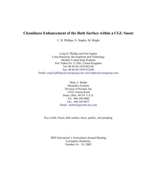
<strong>Cleanliness</strong> <strong>Enhancement</strong> <strong>of</strong> <strong>the</strong> <strong>Bath</strong> <strong>Surface</strong> <strong>within</strong> a CGL Snout<br />
C. H. Phillips, N. Staples, M. Bright<br />
Craig H. Phillips and Neil Staples<br />
Corus Research, Development and Technology<br />
Metallic Coated Strip Products<br />
Port Talbot SA 13 2NG, United Kingdom<br />
Tel: 00 44 (0) 1639 603146<br />
Fax: 00 44 (0) 1639 872308<br />
Email: craig.h.phillips@corusgroup.com, neil.staples@corusgroup.com<br />
Mark A. Bright<br />
Metaullics Systems<br />
Division <strong>of</strong> <strong>Pyrotek</strong>, Inc<br />
31935 Aurora Road<br />
Solon, Ohio 44139 U.S.A.<br />
Tel: 440-349-8800<br />
Fax: 440-349-8877<br />
Email: marbri@pyrotek-inc.com<br />
Key words: Snout, bath surface, dross, quality, zinc pumping<br />
2005 Galvanizer’s Association Annual Meeting<br />
Lexington, Kentucky<br />
October 16 – 19, 2005
2<br />
<strong>Cleanliness</strong> <strong>Enhancement</strong> <strong>of</strong> <strong>the</strong> <strong>Bath</strong> <strong>Surface</strong> <strong>within</strong> a CGL Snout<br />
C.H.Phillips, N.Staples, M. Bright<br />
Abstract<br />
Many metallic coating defects can be attributed to poor quality <strong>of</strong> <strong>the</strong> galvanising bath surface<br />
<strong>within</strong> <strong>the</strong> snout area. As <strong>the</strong> strip enters <strong>the</strong> bath any material that is less dense than zinc will<br />
float on <strong>the</strong> bath surface (i.e. dross and zinc oxides) and due to <strong>the</strong> momentum <strong>of</strong> <strong>the</strong> strip can be<br />
dragged onto <strong>the</strong> surface and cause subsequent defects.<br />
Corus Research, Development & Technology, Port Talbot, Wales, has been working with<br />
manufacturing teams at Corus' continuous strip galvanizing lines in order to identify ways and<br />
means <strong>of</strong> reducing <strong>the</strong> afore mentioned defects.<br />
The use <strong>of</strong> pumps <strong>within</strong> <strong>the</strong> snout area has been investigated and is reported. Water modelling<br />
<strong>of</strong> <strong>the</strong> zinc bath in a test tank, in conjunction with Metaullics Systems Division, was used to<br />
evaluate various pump inlet / outlet designs, <strong>the</strong> optimum position and flow <strong>of</strong> <strong>the</strong> pump<br />
outlet/inlet, as well as evaluating different scenarios <strong>of</strong> using pumps to pull, push and various<br />
combinations <strong>of</strong> <strong>the</strong> two.<br />
New pumps have been commissioned on Corus' ZODIAC galvanising line and have helped to<br />
dramatically reduce <strong>the</strong> volume and severity <strong>of</strong> snout bath surface related defects.
3<br />
<strong>Cleanliness</strong> <strong>Enhancement</strong> <strong>of</strong> <strong>the</strong> <strong>Bath</strong> <strong>Surface</strong> <strong>within</strong> a CGL Snout<br />
C.H.Phillips, N.Staples, M. Bright<br />
Introduction<br />
With <strong>the</strong> ever increasing quality demands <strong>of</strong> automotive manufacturers, producing defect-free<br />
galvanised steel sheet is becoming more and more critical. The various types <strong>of</strong> sheet defects<br />
have been well documented [Refs. 1-3] and investigations [Refs. 2, 4-8] have indicated that a<br />
critical area where many defects are initiated is <strong>within</strong> <strong>the</strong> snout region <strong>of</strong> a continuous<br />
galvanising line, at <strong>the</strong> point <strong>of</strong> initial insertion <strong>of</strong> <strong>the</strong> steel into <strong>the</strong> molten zinc. Specifically,<br />
Chen and Patil [Ref. 2] have indicated that, if contaminants <strong>within</strong> <strong>the</strong> snout are not pumped out,<br />
<strong>the</strong>y may cause defects on <strong>the</strong> coating.<br />
In 2004 <strong>the</strong>re was an increase <strong>of</strong> a defect called “micro dross”/dross spots was reported on<br />
galvanised strip produced at <strong>the</strong> Corus Zodiac line in Llanwern, South Wales and <strong>the</strong> surface <strong>of</strong><br />
<strong>the</strong> zinc bath was identified as a potential cause <strong>of</strong> this quality concern. Hence, <strong>the</strong> zinc bath<br />
surface <strong>within</strong> <strong>the</strong> snout area was investigated to determine whe<strong>the</strong>r <strong>the</strong> overall cleanliness could<br />
be improved and so reduce this type <strong>of</strong> defect (as well as o<strong>the</strong>rs) caused by bath surface<br />
cleanliness as <strong>the</strong> strip enters <strong>the</strong> bath from <strong>the</strong> annealing furnace. Addressing <strong>the</strong>se issues was<br />
vital to producing a high quality full finish product for use in <strong>the</strong> automotive market.<br />
Previous industry research has extensively reviewed fluid flow patterns in <strong>the</strong> overall galvanising<br />
pot [Refs. 7-12] and to a lesser extent <strong>the</strong> fluid dynamics <strong>of</strong> <strong>the</strong> snout area in <strong>the</strong> vertical crosssection<br />
parallel to direction <strong>of</strong> sheet motion [Refs. 7, 8, 11, 12]. This study focused on <strong>the</strong><br />
physical modeling <strong>of</strong> fluid motion on <strong>the</strong> surface <strong>of</strong> <strong>the</strong> zinc bath along <strong>the</strong> width <strong>of</strong> <strong>the</strong> sheet<br />
<strong>within</strong> <strong>the</strong> snout.<br />
As part <strong>of</strong> this investigation, it was necessary to look at <strong>the</strong> current configuration <strong>of</strong> existing<br />
snout dross pumping equipment and evaluate <strong>the</strong> benefits <strong>of</strong> adding a push pump. Consideration<br />
needs <strong>within</strong> this critical area were: nozzle position, pump angle, bath level and potential flow<br />
patterns as a result <strong>of</strong> using a push pump. The physical modelling work was best undertaken via<br />
a water model, supplied by Metaullics Systems (Solon, OH).<br />
The main aims to this physical modelling work were to investigate <strong>the</strong> following activities:<br />
• The influence <strong>of</strong> <strong>the</strong> bath height on pump outlet and inlet<br />
• The surface turbulence created by <strong>the</strong> push pump across <strong>the</strong> strip periphery<br />
• Pull pump inlet, tundish design, orientation and position<br />
• Push pump, position, orientation and tundish design
4<br />
Water Model Configuration<br />
Water modeling work was undertaken in close conjunction with Metaullics Systems at <strong>the</strong>ir<br />
facility in Cleveland, U.S.A. Figure 1 outlines <strong>the</strong> water model and equipment used. At <strong>the</strong> start<br />
<strong>of</strong> <strong>the</strong> trials, <strong>the</strong> pumps were in a central position as in Figure 1.<br />
315mm<br />
Push pump inlet<br />
95mm<br />
210mm<br />
Snout<br />
1195mm<br />
Strip<br />
Pull pump outlet<br />
Fig. 1: - Basic plan outline <strong>of</strong> water model tank set up <strong>of</strong> <strong>the</strong> snout area<br />
90mm<br />
157.5mm<br />
The model strip width was 30” [762mm] and was located in a stationary position <strong>within</strong> <strong>the</strong><br />
snout area. Snout dimensions were 47” x 12.5” x 5.5” [1195 x 315 x 140mm] (L x W x snout<br />
depth into water) and <strong>the</strong> water tank dimensions were 70”x 47” x 31” [1778 x 1195 x 787mm] (L<br />
x W x water depth). (See Figures 2 and 3 for additional details.)<br />
The push pump arrangement for this investigation utilised a Metaullics D-13SD centrifugal<br />
pump, constructed <strong>of</strong> MSA2000 (a Metaullics zinc-resistant superalloy). The pull pump was a<br />
MetJet nitrogen propulsion gas-lift pump supplied again by Metaullics [Ref. 13]. The MetJet<br />
works via a venturi effect, drawing zinc from one part <strong>of</strong> <strong>the</strong> bath to ano<strong>the</strong>r without any moving<br />
mechanical components.<br />
The MetJet pull pump piping dimensions were 3.5” [90mm] diameter for <strong>the</strong> suction inlet with<br />
an 8.5” [216mm] diameter discharge (external to <strong>the</strong> snout area). The push pump discharge that<br />
was employed for <strong>the</strong>se tests was configured with a 3.75” [95mm] fixed, oval outlet. Metaullics<br />
recommended that <strong>the</strong> pull pump inlet be 1 to 4 inches deep and similarly, a 2 inch depth was<br />
specified for <strong>the</strong> outlet <strong>of</strong> <strong>the</strong> push pump (i.e. 1/2 submerged).<br />
The flow <strong>of</strong> <strong>the</strong> top surface <strong>of</strong> <strong>the</strong> bath was monitored indirectly by placing floating, perforated,<br />
polyethylene discs (2.5cm diameter) to display movement <strong>of</strong> <strong>the</strong> surface. These could pass<br />
through <strong>the</strong> MetJet without hindrance and be expelled into <strong>the</strong> bath freely.
140mm<br />
60°<br />
157.5mm<br />
315mm<br />
5<br />
Pull pump inlet<br />
Fig. 2 : - Side view <strong>of</strong> <strong>the</strong> water model bath<br />
Strip<br />
Fig.3 : Push system (left) and pull system (right)<br />
Snout<br />
Water model
6<br />
Deduction from water model<br />
It was found that <strong>the</strong> push flow must be tightly controlled to cause <strong>the</strong> flow <strong>of</strong> particles away<br />
from <strong>the</strong> strip area but not too high as to cause a ‘wash’ effect at <strong>the</strong> snout walls where zinc dust<br />
would be dislodged. Zinc may also solidify building up on <strong>the</strong> wall and increasing <strong>the</strong> surface<br />
area hence more zinc oxide entrapment that would be harder to remove by mechanical means.<br />
Too high a push flow causes major turbulence at <strong>the</strong> surface <strong>of</strong> <strong>the</strong> bath and is clearly visible<br />
along <strong>the</strong> strip width.<br />
The push pump is <strong>the</strong> dominant feature <strong>within</strong> <strong>the</strong> water model. The push flow has a greater<br />
effect <strong>of</strong> particle tracking than that <strong>of</strong> <strong>the</strong> pull system. Therefore it was suggested that <strong>the</strong> pull<br />
system be run continuously and at higher rate than <strong>the</strong> push system.<br />
It must be ascertained <strong>the</strong> bath level that is most effective at removing surface oxides for both<br />
push and pull systems. This is necessary as <strong>the</strong> surface tension and density <strong>of</strong> water to zinc is<br />
vastly different but <strong>the</strong> knowledge gained from this exercise gives us an optimal starting point<br />
for fur<strong>the</strong>r modification on-line.<br />
It was concluded from this work that <strong>the</strong> optimum shape <strong>of</strong> <strong>the</strong> pull system inlet was a weir<br />
design as <strong>the</strong> zinc cascades over <strong>the</strong> weir and is removed efficiently from <strong>the</strong> snout area. This<br />
would allow for <strong>the</strong> best arrangement so that <strong>the</strong> pull system should pull more than <strong>the</strong> push<br />
system pushes. In this configuration <strong>the</strong> amount <strong>of</strong> dross that comes into contact with <strong>the</strong> strip is<br />
minimised. More importantly this means that <strong>the</strong>re is less chance <strong>of</strong> <strong>the</strong> surface tension being<br />
broken and hence a loss in pull flow.<br />
Care must be taken when considering any new designs for pull inlets, as any loss <strong>of</strong> surface<br />
tension allowing <strong>the</strong> atmosphere can be pulled into <strong>the</strong> Metjet giving a loss <strong>of</strong> suction. The<br />
width <strong>of</strong> <strong>the</strong> outlet must be less than any tracking that <strong>the</strong> strip may cover in <strong>the</strong> snout to prevent<br />
contact with <strong>the</strong> strip.<br />
<strong>Bath</strong> level effects<br />
The level <strong>of</strong> <strong>the</strong> pot was crucial when <strong>the</strong> pumps were installed. The level <strong>of</strong> <strong>the</strong> pot needs to be<br />
controlled tightly as <strong>the</strong> outlet <strong>of</strong> <strong>the</strong> push and <strong>the</strong> inlet <strong>of</strong> pull pump is highly sensitive to level<br />
fluctuations. If <strong>the</strong> pot level is too high <strong>the</strong> pull outlet is below <strong>the</strong> surface <strong>of</strong> <strong>the</strong> bath and so <strong>the</strong><br />
flow <strong>of</strong> zinc that is supposed to push across <strong>the</strong> surface to help move surface contaminants to <strong>the</strong><br />
pull pump does not occur. Similarly at higher level <strong>the</strong> inlet to <strong>the</strong> pull pump is below <strong>the</strong> surface<br />
and will <strong>the</strong>n take sub-surface material and again <strong>the</strong> debris on top <strong>of</strong> <strong>the</strong> bath will remain.<br />
Conversely, If <strong>the</strong> pot level is too low <strong>the</strong> push outlet will cascade out <strong>of</strong> <strong>the</strong> pump outlet and fall<br />
into <strong>the</strong> bath. This increased flow <strong>of</strong> zinc appears on <strong>the</strong> surface <strong>of</strong> <strong>the</strong> strip as 'wash marks' and<br />
hence is undesirable. Conversely <strong>the</strong> pull inlet is above <strong>the</strong> surface <strong>of</strong> <strong>the</strong> bath and hence cannot<br />
collect any surface debris.
7<br />
Plant installations<br />
Based on <strong>the</strong> evidence <strong>of</strong> <strong>the</strong> water modeling experiments it was decided to try a push / pull<br />
pump set-up, it was decide to centrally mount <strong>the</strong> collection tundish and <strong>the</strong> push (slot) <strong>within</strong><br />
<strong>the</strong> snout area (Fig. 4). A Metaullics D13 pump for <strong>the</strong> push and use <strong>the</strong> conventional<br />
Metaullics M12 pump as <strong>the</strong> “puller”. Also <strong>the</strong> pull pump utilised <strong>the</strong> collection tundish.<br />
However this required very precise positioning on <strong>the</strong> tundish in relation to <strong>the</strong> bath surface and<br />
requiring a tight control <strong>of</strong> <strong>the</strong> bath height.<br />
Fig. 4 : Collection tundish and push slot trialed <strong>within</strong> Zodiac snout<br />
Additionally <strong>the</strong> position <strong>of</strong> <strong>the</strong> push slot is also critical to obtain <strong>the</strong> maximum benefit.<br />
Defect reductions<br />
Following on from <strong>the</strong> optimisation <strong>of</strong> <strong>the</strong> pump design and configuration a study was carried<br />
out to identify <strong>the</strong> effect that this enhancement has had on snout related defects. The volume and<br />
frequency <strong>of</strong> <strong>the</strong> three main defects that are attributed to <strong>the</strong> snout area are dramatically reduced<br />
post <strong>the</strong> installation <strong>of</strong> <strong>the</strong> pumps. As can be seen in Figure 5 below.
Frequency rate<br />
60<br />
50<br />
40<br />
30<br />
20<br />
10<br />
0<br />
XMAS<br />
TREE<br />
2004<br />
DROSS<br />
SPOTS<br />
2004<br />
Defects attributed to <strong>the</strong> snout area<br />
DIGS<br />
2004<br />
2004 2005<br />
Defect<br />
8<br />
XMAS<br />
TREE<br />
2005<br />
DROSS<br />
SPOTS<br />
2005<br />
DIGS<br />
2005<br />
Frequency<br />
Fig. 5 : Graph to illustrate <strong>the</strong> differences in <strong>the</strong> strip defects witnessed at ZODIAC in <strong>the</strong> first 5<br />
months <strong>of</strong> 2004 compared to <strong>the</strong> same period in 2005.<br />
The condition <strong>of</strong> <strong>the</strong> snout itself as seen from <strong>the</strong> camera system is clear to even <strong>the</strong> untrained eye. The<br />
surface <strong>of</strong> <strong>the</strong> bath shows clear on <strong>the</strong> images shown below for both <strong>the</strong> outlet <strong>of</strong> <strong>the</strong> push pump (on <strong>the</strong><br />
left) and <strong>the</strong> inlet <strong>of</strong> <strong>the</strong> pull (shown on <strong>the</strong> right).<br />
Fig. 6 : Improved surface with push and pull pumps installed<br />
This much-improved surface as shown in figure 6 has lead to a dramatic reduction in surface<br />
defects attributed to <strong>the</strong> snout bath surface.
9<br />
Conclusions<br />
The pictures from <strong>the</strong> snout clearly show that when <strong>the</strong> bath level control is maintained at <strong>the</strong><br />
agreed level <strong>the</strong>n <strong>the</strong>re is clearly a continuous flow <strong>of</strong> zinc into <strong>the</strong> tundish.<br />
Similarly <strong>the</strong> collection tundish has performed exceptionally well at removing debris from <strong>within</strong><br />
<strong>the</strong> snout area. With poor bath level control surface scum built up but over a period <strong>of</strong> time when<br />
bath height was controlled, <strong>the</strong> scum was captured along with subsurface zinc.<br />
The installation <strong>of</strong> <strong>the</strong> pumping system <strong>within</strong> <strong>the</strong> snout has dramatically reduced defects, which<br />
are attributed to <strong>the</strong> snout bath surface.
10<br />
Acknowledgments<br />
The authors would like to acknowledge Corus Strip Products UK and Metaullics Systems for<br />
<strong>the</strong>ir willingness to promote <strong>the</strong> enclosed research.<br />
References<br />
1. Dunbar, F.C., “Defects <strong>of</strong> <strong>the</strong> 80’s – A Closer Look at <strong>the</strong> Critical Requirements <strong>of</strong><br />
Today’s Hot-Dip Galvanized”, 1988 Galvanizer’s Association Meeting, W. Middlesex,<br />
Pennsylvania<br />
2. Chen, F., Patil, R., “An In-Depth Analysis <strong>of</strong> Various Subtle Coating Defects <strong>of</strong> <strong>the</strong><br />
2000’s”, Galvatech 2004, Chicago, 2004, 1055-1066<br />
3. Tang, N-Y., Coady, F., “Coating Defects: Origins and Remedies”, 2001 Galvanizer’s<br />
Association Meeting, Portland, Oregon<br />
4. Mallens, R., Treadgold, C., Vlot, M., Meijers, S., “Prevention <strong>of</strong> Dross Contamination in<br />
<strong>the</strong> Corus Ijmuiden Hot Dip Galvanizing Line”, Galvatech 2001, Brussels, Belgium,<br />
2001, 255-261<br />
5. Komatsu, A., Andoh, A., Uchida, Y., “Initial Stages <strong>of</strong> Formation <strong>of</strong> Interfacial Alloy<br />
Layers in Hot Dip Galvanizing”, Galvatech 2001, Brussels, Belgium, 2001, 337-344<br />
6. Zermout, Z., Drillet, P., Houziel, J., “Reaction Mechanisms during Immersion <strong>of</strong> Low-<br />
Carbon Steel in Zn-5wt.%Al <strong>Bath</strong>”, Galvatech 2001, Brussels, Belgium, 2001, 345-351<br />
7. Pare, A., Binet, C., Ajersch, F., “Numerical Simulation <strong>of</strong> 3-Dimensional Flow in a<br />
Continuous Strip Galvanizing <strong>Bath</strong>”, Galvatech 1995, Chicago, 1995, 695-706<br />
8. Kato, C., Koumura, H., Mochizuki, K., Morito, N., “Dross Formation and Flow<br />
Phenomena in a Molten Zinc <strong>Bath</strong>, Galvatech 1995, Chicago, 1995, 801-806<br />
9. Evans, K., Treadgold, C., “Modelling and Measurement <strong>of</strong> Transient Conditions in <strong>the</strong><br />
Galvanising Pot”, 1999 Galvanizer’s Association Meeting, Jackson, Mississippi<br />
10. Goodwin, F., “An Integrated View <strong>of</strong> Galvanizing <strong>Bath</strong> Flow and Dross Management”,<br />
2001 Galvanizer’s Association Meeting, Portland, Oregon<br />
11. Baril, E., DuBois, M., Gagne, M., “Investigation <strong>of</strong> Fluid Flow in <strong>the</strong> Snout <strong>of</strong> a<br />
Continuous Galvanising <strong>Bath</strong> using Numerical Modelling”, Galvatech 2001, Brussels,<br />
Belgium, 2001, 435-442<br />
12. Ajersch, F., Ilinca, F., Perrault, M., Malo, A., Hetu, J-F., “Numerical Analysis <strong>of</strong> <strong>the</strong><br />
Effect <strong>of</strong> Operating Parameters on Flow in a Continuous Galvanizing <strong>Bath</strong>”, Galvatech<br />
2001, Brussels, Belgium, 2001, 511-518<br />
13. Becherer, G., “Utilizing Pumps to Continuously Remove Dross from Inside <strong>the</strong> Inlet<br />
Snout”, 2001 Galvanizer’s Association Meeting, Portland, Oregon