
You also want an ePaper? Increase the reach of your titles
YUMPU automatically turns print PDFs into web optimized ePapers that Google loves.
<strong>Wind</strong> <strong>Power</strong><br />
<strong>Wind</strong> <strong>Power</strong><br />
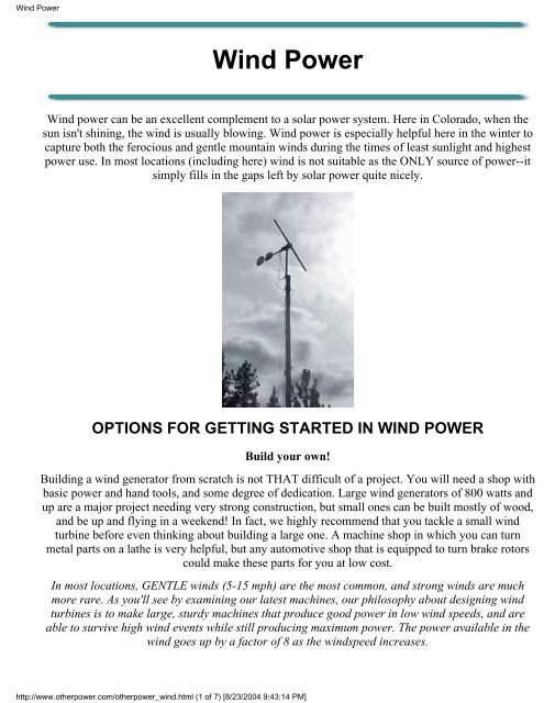
<strong>Wind</strong> power can be an excellent complement to a solar power system. Here in Colorado, when the<br />
sun isn't shining, the wind is usually blowing. <strong>Wind</strong> power is especially helpful here in the winter to<br />
capture both the ferocious and gentle mountain winds during the times of least sunlight and highest<br />
power use. In most locations (including here) wind is not suitable as the ONLY source of power--it<br />
simply fills in the gaps left by solar power quite nicely.<br />
OPTIONS FOR GETTING STARTED IN WIND POWER<br />
Build your own!<br />
Building a wind generator from scratch is not THAT difficult of a project. You will need a shop with<br />
basic power and hand tools, and some degree of dedication. Large wind generators of 800 watts and<br />
up are a major project needing very strong construction, but small ones can be built mostly of wood,<br />
and be up and flying in a weekend! In fact, we highly recommend that you tackle a small wind<br />
turbine before even thinking about building a large one. A machine shop in which you can turn<br />
metal parts on a lathe is very helpful, but any automotive shop that is equipped to turn brake rotors<br />
could make these parts for you at low cost.<br />
In most locations, GENTLE winds (5-15 mph) are the most common, and strong winds are much<br />
more rare. As you'll see by examining our latest machines, our philosophy about designing wind<br />
turbines is to make large, sturdy machines that produce good power in low wind speeds, and are<br />
able to survive high wind events while still producing maximum power. The power available in the<br />
wind goes up by a factor of 8 as the windspeed increases.<br />
http://www.otherpower.com/otherpower_wind.html (1 of 7) [8/23/2004 9:43:14 PM]
<strong>Wind</strong> <strong>Power</strong><br />
Other critical factors are rotor size and tower height. The power a wind turbine can harvest goes up<br />
by almost a factor of 4 as you increase the rotor size. And making a tower higher gets you above<br />
turbulence for better performance and substially increased power output. Putting a wind turbine on<br />
a short tower is like mounting solar panels in the shade!<br />
Before you jump into building your own wind turbine, do your homework! There are certain<br />
things that work and certain things that don't, and you can save hours and dollars by learning<br />
from other people's successes and mistakes. Some recommended reading:<br />
● Homebrew wind power articles here on Otherpower.com:<br />
❍ Tips on designing, building and flying wind generators.<br />
❍ Choosing alternators/generators for wind power.<br />
❍ Designing and building towers for wind turbines.<br />
❍ Glossary of wind power terms.<br />
● <strong>Wind</strong> power information from homebrew wind power guru Hugh Piggott's website. We've<br />
learned a BUNCH from Hugh.<br />
● Hugh Piggott's book <strong>Wind</strong>power Workshop is an indispensable reference for anyone that's<br />
thinking about building a wind turbine. His Axial Flux Alternator <strong>Wind</strong>mill Plans are very<br />
detailed and highly recommended.<br />
● Homebrew wind power infomation from Ed Lenz's <strong>Wind</strong>stuffnow.com, a highly informative<br />
website.<br />
● Read the Renewable energy FAQs on the Otherpower discussion board, and Search the<br />
Otherpower.com discussion board. It's highly active and populated by windpower experts and<br />
hobbyists worldwide. If you still can't find and answer, by all means please join the board and<br />
ask your question there!<br />
● Join the AWEA mailing list for more discussion with wind power experts worldwide.<br />
● Explore other wind power websites from worldwide on our Links page.<br />
Here's a roundup of all of Otherpower.com's homebrew wind turbines. The individual web<br />
pages give construction and performance details. We've changed many things in our designs<br />
over the past few years, so if you are reading an older page, be sure to check out what we've<br />
been doing recently before you start the project. Enjoy!<br />
6-21-2004 -- 16 foot dia. rotor made from scratch.<br />
Really, really from scratch this time! We started with cutting up the logs, loading them on the 1951<br />
Dodge <strong>Power</strong> Wagon, hauling them to the sawmill, milling them into billets, then using the sawmill<br />
to do the rough shaping. THEN it was time to carve.<br />
http://www.otherpower.com/otherpower_wind.html (2 of 7) [8/23/2004 9:43:14 PM]
<strong>Wind</strong> <strong>Power</strong><br />
5-10-2004 -- The <strong>Wind</strong> Farm -- some 10-foot<br />
diameter homebrew wind turbines.<br />
Our whole community is off-grid, and we've<br />
been assisting neighbors in the design and<br />
construction of our brake disc axial turbines.<br />
Somehow the project became the '<strong>Wind</strong> Farm'<br />
and there are now turbines flying in the area<br />
sporting a whale, a rooster, and a pig for tail<br />
vanes. We get valuable testing information out<br />
of the deal, and our neighbors get power.<br />
Homebrew dynomometer testing rig for<br />
wind turbine alternator<br />
We've tested alternators before by spinning<br />
them in the lathe, but it wasn't powerful<br />
enough to get much power out. Out at Hugh<br />
Piggott's 2004 <strong>Wind</strong> Turbine seminar, we all<br />
tested Hugh's new 12-foot design by spinning<br />
it with an engine. Details are here for how we<br />
did it with two of our alternator designs, and<br />
the data we got. The scale is in there so we<br />
could derive foot-pounds of torque and<br />
calculate efficiency. A great idea from Hugh<br />
Piggott!<br />
http://www.otherpower.com/otherpower_wind.html (3 of 7) [8/23/2004 9:43:14 PM]<br />
05/10/2004 -- Building and testing some BIG<br />
wind turbines.<br />
This one has a 14-foot dia. rotor. 2 More similar<br />
to it are under construction.Larger rotors mean a<br />
turbine can capture power out of lower wind<br />
speeds. This one starts making power at 6 mph,<br />
hits 200 watts at 10 mph, and makes over 1000<br />
watts at 22 mph, when it starts furling to protect<br />
itself.<br />
10/10/2003 -- The Triplets -- 3 new 10-foot<br />
diameter dual-rotor brake disc wind turbines!<br />
These 3 nearly identical machines are built with<br />
the same design as the mill at the Caboose<br />
(5/20/03, below) but we streamlined the<br />
construction process significantly and built 3<br />
machines at the same time -- Curly, Moe and<br />
Larry. These are the latest of our designs, and<br />
they perform great in low winds. Detailed<br />
DanCAD drawings and dimensions on this page.
<strong>Wind</strong> <strong>Power</strong><br />
5/10/2003 -- New Brake Disc Mill<br />
9-foot dia prop, furling tail, 3-phase, separate<br />
laminate assembly with excellent specs. Many<br />
improvements over our previous designs!<br />
Spins up and makes power freely in low winds,<br />
and governs itself in high winds.<br />
The Wood 103<br />
A 100-watt windmill built entirely from wood!<br />
More of a demonstration than anything, but a<br />
quick weekend project that will teach you<br />
about windmill construction.<br />
DanF's Wood A-X<br />
DanF's version of the Wood A-X is very<br />
similar to the original, but with slightly sturdier<br />
contruction. The props are interchangable<br />
between the two. Some problems to be fixed<br />
here, but in progress. .<br />
http://www.otherpower.com/otherpower_wind.html (4 of 7) [8/23/2004 9:43:14 PM]<br />
5/20/2003 -- Dual Rotor Brake Disc Mill<br />
Up and flying at the Caboose. Excellent low wind<br />
performance with 10 foot prop, great furling<br />
system.<br />
The Wood A-X<br />
A quick-and-easy 200 watt windmill, built mostly<br />
from wood! Perfect for a remote cabin or RV,<br />
this one is quick and easy, and we are working on<br />
an updated version too.<br />
Ward's Prop Gallery<br />
Ward and his collection of broken props, tails and<br />
stators. This is what happens when you let DanB<br />
and DanF use you for a wind guinea pig! But<br />
Ward's tower has the best height and wind<br />
exposure in the area, so it's where we try and<br />
make windmills blow up to further our research.<br />
And he's a good sport!
<strong>Wind</strong> <strong>Power</strong><br />
400-watt Volvo <strong>Wind</strong>mill<br />
One of our older designs with no furling<br />
system. But it has been up and flying for a year<br />
and half now.......with no furling system.<br />
Building Towers for <strong>Wind</strong> Turbines<br />
Details, diagrams and photos of many different<br />
ways to construct tilt-up towers -- ranging from<br />
the extremely solid and sturdy to the quick and<br />
dirty, field-expedient versions!<br />
Induction Motor Conversion Mill<br />
Built using an AC induction motor converted<br />
to a permanent-magnet alternator. We've since<br />
found that from-scratch PMAs are more<br />
efficient than conversions.<br />
400-watt Volvo <strong>Wind</strong>mill<br />
Again based on a Volvo brake disc, this one has a<br />
3-bladed prop that is slightly smaller than Ward's<br />
mill. It's an ongoing experiment too...a new stator<br />
is in the works. One of our older deisgns with no<br />
furling system.<br />
Designing, Building and Flying a <strong>Wind</strong><br />
Turbine<br />
Just our collection of information on all phases of<br />
the process! If you are new at wind power, it<br />
might help explain some confusing aspects of this<br />
'black art.'<br />
Small Science Fair <strong>Wind</strong>mill<br />
With a small computer fan blade as a rotor, this<br />
little mill makes a great science fair project. The<br />
frame is made of PVC pipe, and nothing is to big<br />
or fast to be very dangerous. It will light a small<br />
bulb using a box fan for power.<br />
A high-tech test rig for our high-tech wind generators! Otherpower.com's trusty<br />
Model A Ford windmill tester.<br />
http://www.otherpower.com/otherpower_wind.html (5 of 7) [8/23/2004 9:43:14 PM]
<strong>Wind</strong> <strong>Power</strong><br />
Click on the image to see a 15-second MPEG video of the Model A wind test experiment<br />
Find an antique<br />
If you find an old windmill for sale, first make sure it's intended for generating electricity instead of<br />
just pumping water. One common old windmill that's often found for sale used is the Wincharger.<br />
The other popular wind generator of the era was the Jacobs. These were of higher quality than<br />
Winchargers--but many of both are still flying today. Several people around the U.S. restore, service<br />
and stock parts for old windmills. And the Jacobs is still being made today! The current production<br />
models are very large and expensive, with over 10 kW output--they are magnificently designed and<br />
built. Check out the Manufacturer's Website for more information and cool pictures.<br />
Electricity producing wind generators were very popular in the 1920s and 1930s all over rural<br />
America. They were available in many different sizes and voltages, and can often be found for sale<br />
in rural farm communities. Most models are quite suitable for a modern remote power system no<br />
matter what voltage they are. If you are able to locate an old wind generator, some basic<br />
maintenance (rust removal, lubrication, and testing) could put it back in working order quickly. They<br />
were built to last--before Rural Electricifation, they were the ONLY source of power for many rural<br />
farms and ranches. Backwoods Home Magazine published an excellent article in 2001 about finding<br />
and restoring old wind generators.<br />
Otherpower.com is always interested in purchasing used wind generators, including these!<br />
Buy a commercial wind generator<br />
Suitable only if you have more money available than time. Prices range from $500 to $5000 for<br />
small-scale wind turbines ranging from 300w up to 5 Kw. Your wind generator retailer should<br />
provide you with LOTS of information regarding many issues if you choose to purchase a wind<br />
generator! Since you will be spending lots of money, it might be wise to survey your site with a<br />
http://www.otherpower.com/otherpower_wind.html (6 of 7) [8/23/2004 9:43:14 PM]
<strong>Wind</strong> <strong>Power</strong><br />
logging anemometer before making a commitment. The AWEA mailing list is a good place to ask<br />
questions about commercial wind generators, and Mike Klemen's <strong>Wind</strong> Generator Page has lots of<br />
performance data on a variety of commercial wind turbines that he has flying. Or contact the wind<br />
turbine manufacturer directly and have them point you toward a retailer nearby.<br />
<strong>Wind</strong> Generator Manufacturers<br />
| Bergey <strong>Wind</strong>power Company (USA) | | Southwest <strong>Wind</strong> <strong>Power</strong> (USA) | | Jacobs (WTIC) (USA) |<br />
| <strong>Wind</strong>Mission of Denmark (DK) | | Marlec (UK) | | Proven (UK) | | Flowtrack (AUS) | African <strong>Wind</strong><br />
<strong>Power</strong> |<br />
Curious about the <strong>Wind</strong>Tree® turbine? Read this article before you spend money!<br />
HOME PRODUCTS DISCUSSION BOARD DAILY NEWS<br />
CONSERVATION BATTERIES SUN WIND<br />
HYDRO FOSSIL FUELS EXPERIMENTS ORDER NOW!<br />
WATER PUMPING POWER SYSTEMS EFFICIENT LIGHTING LINKS<br />
Questions or comments? Click here to send us an email!<br />
©2003 by FORCEFIELD<br />
This page last updated 5/10/2004<br />
http://www.otherpower.com/otherpower_wind.html (7 of 7) [8/23/2004 9:43:14 PM]
Tips for Designing and Building a <strong>Wind</strong> Generator<br />
Tips for Designing, Building, and Flying<br />
<strong>Wind</strong> Generators<br />
Raising a wind machine and watching it produce power is an<br />
exhilharating experience. And if it does fly apart during a gale, the<br />
show is often worth the price of admission--plus you've obtained<br />
more knowledge for the next try!<br />
| Site | Tower | Anemometers | Generators & Alternators | Cut-In Speed | Alternator<br />
Design |<br />
| Rotor Design & Carving | Furling & Shutdown | Regulation | Slip Rings |<br />
Where do you start???<br />
First, do your homework! Why re-invent the wheel when you can learn from others' successes and<br />
failures? There are many useful books, websites and plans available. Check our recommended<br />
reading list HERE.<br />
First, figure out how big a wind generator you are willing to tackle, either commercial or<br />
home-brewed. There is really only one important measure of windmill size...the swept area. That's how<br />
many square feet (or meters, if you are into that sort of thing) of area the windmill's blades cover during<br />
a rotation. The formula for swept area is Pi r^2, where Pi is 3.1415 and r is the radius of your prop. The<br />
available power from the wind increases dramatically with the swept area...but so do the stresses on<br />
your blades, tower, bearings, tail. More stress means stronger engineering and materials are required,<br />
and a much larger, more complicated and expensive project. <strong>Wind</strong>mills with props of 4 feet diameter<br />
and under are fairly easy to design, build and handle. Once you get into the 7-8 foot range, everything<br />
must be very strong and rock-solid. At 10 feet and above, your materials and engineering need to be<br />
top-notch! We have learned this from the experience of watching windmills blow up, and we highly<br />
recommend building a smaller windmill like our 4 foot diameter Wood A-X or the 4-foot model in<br />
Hugh Piggott's Axial Flux Alternator <strong>Wind</strong>mill Plans before trying a large windmill.<br />
Here's some of our advice and ramblings about various aspects of designing, flying, building and<br />
destroying wind generators.<br />
●<br />
Site<br />
Location--First, figure out the direction from which the prevailing winds in your area usually<br />
come. You can determine this by observation during wind storms, and by looking at the trees near<br />
your site. Trees that are all leaning the same direction and that have branches mostly on one side<br />
http://www.otherpower.com/otherpower_wind_tips.html (1 of 13) [8/23/2004 9:43:17 PM]
Tips for Designing and Building a <strong>Wind</strong> Generator<br />
●<br />
●<br />
of the trunk are a good indication of prevailing wind speed and direction. Local airports and<br />
weather stations can sometimes provide you with this information. The National Renewable<br />
Energy Laboratory in Golden, CO publishes an excellent <strong>Wind</strong> Energy Resource Atlas of the<br />
United States on the internet, for free. A Logging anemometer that also records wind direction<br />
can be useful here too, though expensive.<br />
Height: Flying a wind generator close to the ground is like mounting solar panels in the shade!<br />
Your wind generator should be located at least 30 feet above any obstruction within 400 feet -many<br />
sources recommend even more. Of course, this may be impractical, so just keep in mind<br />
that turbulance caused by obstructions will rob you of huge amounts of potential power, and<br />
cause extra stress on all components of your wind machine. A higher tower is usually MUCH<br />
easier on your machine! At least make sure there are no obstructions between your windmill and<br />
the direction from which the wind usually blows. Remember that even an obstacle that's behind or<br />
to the side of your turbine in the prevailing wind will cause turbulance, rob you of power, and<br />
beat up your machine.<br />
Distance: The distance between your wind generator and your batteries can also be a<br />
problem--the closer the better, to avoid losses in long wires and to keep the wire size required<br />
down to a reasonable thickness and cost. 12 volt systems are the worst for power transmission<br />
losses--you end up needing very thick wire. A 24v or 48v battery bank can save you big money<br />
on wire! Transformers can be used to keep the voltage high for long distances, but they cause<br />
added complexity and losses.<br />
Tower<br />
Check out our TOWERS page for some home-brewed solutions that are cheap and easy to<br />
fabricate, plus lots of details and pictures. There's also lots of tower information, discussion and<br />
pictures available by Searching the Otherpower discussion board for 'towers'.<br />
● Your tower must be extremely sturdy, well-anchored, and tall enough to get above obstructions.<br />
We've seen 1.5 inch steel pipe bend like a pipe cleaner in 50 mph winds, underneath a wind<br />
machine with only an 8-foot prop. Some wind energy guidelines tell you to plan on spending at<br />
LEAST as much on your tower and power wiring as on the wind generator itself!<br />
● Do you like to climb? The two basic kinds of tower are the Tilt-Up and Stationary. A stationary<br />
tower is the most sturdy and trouble-free, but you have to climb it to install, maintain or remove<br />
the wind machine. A crane is often used for installation, an expensive proposition--though you<br />
can do it yourself by climbing the tower and moving a gin pole up it as you add each new section.<br />
If climbing towers disagrees with you, go for a tilt-up. Then all maintenence can be performed<br />
while standing safely on solid ground.<br />
● Roof mount? We strongly recommend against mounting a wind generator on your roof. Though<br />
the manufacturer of the AIR 403 says it works, we have observed first-hand the vibration and<br />
noise during a windstorm in two different roof installations...it is VERY noticable and irritating.<br />
And keep in mind that the AIR 403 is a very small unit (only a 1.3 meter prop) that makes very<br />
little power...a larger mill would be unbearable, and possibly dangerous to your house itself. Most<br />
commercial and homemade wind generators don't make much physical noise, but some vibration<br />
is unavoidable due to the nature of permanent magnet alternators. Listen to the vibration of<br />
Ward's 7 foot diameter windmill (12 second .WAV file, 140K) and hear why we don't<br />
recommend roof mounts! Ward's mill is actually very quiet; this audio clip was taken with the<br />
http://www.otherpower.com/otherpower_wind_tips.html (2 of 13) [8/23/2004 9:43:17 PM]
Tips for Designing and Building a <strong>Wind</strong> Generator<br />
●<br />
●<br />
●<br />
●<br />
●<br />
●<br />
●<br />
microphone pressed against the steel mast to give an idea of the vibration that would be<br />
transmitted into your house with a roof mount. The buzzing sound is the vibration of magnets<br />
spinning past coils; the clanking is from the sectional tower itself. The windmill rotor itself makes<br />
very little noise.<br />
Anemometers<br />
It is essential to know the real windspeed in any wind generator installation, commercial or<br />
homemade. This allows you to see if the machine is performing correctly, and extremely high<br />
windspeeds might be a clue that you should shut the mill down for the duration of the storm. If<br />
you plan on investing significant money in wind power, a logging anemometer might help you<br />
decide if your local wind resource is worth the investment. Commercial anemometers and<br />
weather stations are very expensive, but can be found with a quick Google search...you can also<br />
try one of the homebrew options below.<br />
Build your own anemometer: We built an accurate anemometer for under $10 using plastic<br />
Easter eggs. See it here! It counts frequency with a simple circuit, and can be adapted to use with<br />
computer data acquisition equipment. Another option uses a pre-fabricated cup assembly and a<br />
bicycle speedometer, you can see our page about it HERE.<br />
Logging anemometer kit: This ingenious kit is from Australia and costs less than $100 US,<br />
including shipping. It tracks wind speed and direction, and logs data to its own memory, including<br />
average and peak readings. And, it interfaces directly to a PC...your wind data can import live<br />
right into a spreadsheet! See it here.<br />
Generators and Alternators<br />
Terms--On our site, we try to use the term Generator to describe a machine that produces Direct<br />
Current (DC), and use the term Alternator to describe a machine that produces Alternating<br />
Current (AC). However, the term Generator is also used generically to describe any machine that<br />
produces electricity when the shaft is spun.<br />
Options--The alternator or generator is the heart of your wind machine, and it must be both<br />
properly sized to match your swept area, and produce the right type and voltage of power to<br />
match your application. Options include commercial and homemade permanent magnet (PM)<br />
alternators, PM converted induction motors, DC generators, DC brushless PM motors, vehicle<br />
alternators, and induction motors.<br />
We cover the different types extensively on our Alternator and Generator Comparison<br />
page.<br />
Application--<strong>Wind</strong>-generated electricity can be used for battery charging, heating, and for<br />
connection with the power grid. All of our designs and information are about battery charging, as<br />
we heat with wood and the nearest power line is 12 miles away from Otherpower.com<br />
headquarters.<br />
Single Phase vs. Three Phase--3 phase offers some advantages over single phase in most<br />
alternators. Most small commercial wind turbines use 3 phase alternators, and then rectify the<br />
output to DC (direct current) for charging batteries. When building an alternator from scratch,<br />
single phase seems attractive because it is simple and easy to understand. 3 phase is not really any<br />
http://www.otherpower.com/otherpower_wind_tips.html (3 of 13) [8/23/2004 9:43:17 PM]
Tips for Designing and Building a <strong>Wind</strong> Generator<br />
●<br />
●<br />
●<br />
●<br />
●<br />
●<br />
●<br />
more difficult. For some details, look at some of our later wind turbine experiments vs some of<br />
the earlier ones. Going 3 phase allows for squeezing more power from a smaller alternator. It<br />
significantly reduces line loss, and it runs with less vibration. Older single phase alternators we<br />
made vibrate much more (and make more noise) than 3 phase machines.<br />
Speed--The shaft speed is a very crucial factor in all types of alternator and generator. The unit<br />
needs to make higher voltages at lower rpms, otherwise it is not suited for wind power use. This<br />
goes for all power units...even motors used as generators and alternators should be rated for low<br />
rpms. This is also why vehicle alternators are not suited for wind power use, see our Alternator<br />
and Generator Comparison page for more details.<br />
Start-Up Speed--This is the windspeed at which the rotor starts turning. It should spin smoothly<br />
and easily when you turn it by hand, and keep spinning for a few seconds. Designs that 'cog' from<br />
magnetic force or that use gears or pulleys to increase shaft speed will be poor at start up. A good<br />
design can start spinning in 5 mph winds and cut in at 7 mph.<br />
Cut-In Speed--A wind generator does not start pushing power into the battery bank until the<br />
generator or alternator voltage gets higher than the battery bank voltage. Higher shaft speed<br />
means higher voltage in all generators and alternators, and you want to try and get the highest<br />
shaft speed possible in low winds--without sacrificing high-wind performance. Most commercial<br />
wind generators cut in at 8-12 mph. The generator's low-speed voltage performance, the design of<br />
the rotor (the blades and hub), and the wind behavior all factor into where cut-in will occur.<br />
Voltage Regulation--With battery-charging windmills, voltage control is not generally<br />
needed--until the batteries fill up. Even if your alternator is producing an open-circuit voltage of<br />
90 volts, the battery bank will hold the system voltage down to its own level. Once the betteries<br />
are full, you'll need to send the windmill's output to a 'dump load' such as a heating element. This<br />
regulation can be done manually by simple turning on an electric heater, stereo, or lights.<br />
Automatic systems can be built or purchased too.<br />
Battery Bank Voltage--In addition to having less line loss, 24v and 48v power systems give<br />
other significant advantages in wind alternator systems. An alternator that cuts in at 300 rpm into<br />
a 12v battery bank will not cut in until 600 rpm into a 24v battery bank. However, the same<br />
machine may produce half again as much power at higher speeds into a 24v battery than into a<br />
12v one. This is because of...<br />
Inefficiency--Every generator has a certain speed at which it runs most efficiently. But since the<br />
wind is not constant, we must try to design to a happy medium. As the wind speed rises, the raw<br />
power coming into the generator from the wind becomes more than the generator can effectively<br />
use, and it gets more and more inefficient. This power is wasted as heat in the stator coils.<br />
Alternators with wound fields can adjust the magnetic flux inside to run most efficiently, but PM<br />
alternators cannot. An alternator that uses many windings of thin wire will have better low-speed<br />
performance than one that uses fewer windings of thicker wire, but higher internal resistance.<br />
This means it will become inefficient more quickly when producing higher amperage as wind<br />
speeds and power output rise. The formula used to calculate power wasted from inefficiency is<br />
AMPS^2 * RESISTANCE = <strong>Power</strong> wasted as heat in the alternator windings (in watts).<br />
What does this mean in practice? Compare the performance of our Volvo Disk Brake<br />
Alternator to that of our Induction Motor PM Conversion Alternator. The Volvo alternator<br />
internal resistance is 1/4 ohm, while the converted motor's resistance is 4 ohms. The conversion<br />
alternator reaches 12 volts at very low rpms for cut-in, but look what happens at 10 amps of<br />
output: 400 watts being used as heat while charging the batteries at 130 watts. With the Volvo<br />
alternator at 10 amps, only 25 watts are used up as heat, and at 50 amps it is wasting 625 watts<br />
http://www.otherpower.com/otherpower_wind_tips.html (4 of 13) [8/23/2004 9:43:17 PM]
Tips for Designing and Building a <strong>Wind</strong> Generator<br />
●<br />
●<br />
●<br />
●<br />
●<br />
●<br />
while charging at 600 watts...and therefore is starting to become inefficient.<br />
Alternator Design<br />
Factors--Making PM alternators from scratch is sort of a "black art"--there are many factors that<br />
enter in to it, we try to discuss some of them below. And then, you must add in another important<br />
factor, the design of the blades. We discuss that below also. We didn't start building windmills<br />
and alternators by doing a bunch of math...we just jumped right in, made lots of mistakes, and<br />
eventually wound up with a satisfactory design by observing performance and changing one<br />
variable at a time!<br />
Bearings--The operative word here is STRONG. Besides having to withstand vibration and high<br />
rotation speed, there is a significant amount of thrust back on the bearings from the wind, and it<br />
increases geometrically as the prop size increases. That's why we've moved to using automobile<br />
wheel bearings in our designs, they are tapered and designed to take the thrust loads. The front<br />
bearings in our converted AC induction motors have so far held up well, but they are not designed<br />
for that kind of load. DC tape drive motors are especially vulnerable--the front bearing will<br />
eventually fail dramatically in high winds if extra bearings are not added.<br />
Air Gap--This is the distance between the magnets and the laminates in a single magnet rotor<br />
design, or between two magnets in a dual magnet rotor design. The smaller the distance, the better<br />
the alternator performs. This means it's important to keep the coils as flat as possible, and to make<br />
the armature fit very precisely near the stator...if it is not perfectly square, the air gap will be<br />
larger on one side of the alternator than the other, and performance will be compromised. Halving<br />
the airgap gives 4 times as much magnetic flux.<br />
Number of Poles--A 'pole' is either the North or South pole of a magnet. Generally when<br />
building an alternator we need a seperate magnet for each pole. The faster that alternating north<br />
and south magnets poles pass the coils, the more voltage and current are produced. But surface<br />
area is important as well. If we have a very narrow magnet (required for using many poles), the<br />
field strength would be much weaker over a distance than a wider magnet. So like all things with<br />
making wind turbines, there is a compromise to be made. We choose a number of poles that<br />
allows for reasonably sized coils and a good strong magnetic field through whatever airgap we<br />
wind up with. It must always be an even number. If it's to be a single phase machine, we can have<br />
either the same number, or twice the number of poles as we do coils. If it's a 3 phase machine we<br />
like 4 poles for every 3 coils, although there are certainly other very feasable options. In most<br />
cases, for a 3 phase machine we'd have somewhere between 8 and 16 poles (magnets) unless<br />
perhaps the machine were to be very large.<br />
Series or Parallel? Star or Delta?When coils are connected in series, the voltage increases and<br />
so does resistance. When connected in parallel, voltage stays the same but amperage increases<br />
and resistance decreases. Also, parallel connections in an alternator can cause current to flow<br />
where you don't want it to, called 'parasitic losses.' The correct configuration for your project<br />
depends on many factors. <strong>Wind</strong>stuff now's 3-Phase Basics Page has some great diagrams that<br />
explain 3-phase, star and delta.<br />
Magnets--The stronger, the better. The larger and stronger your magnets are, the more power you<br />
can produce in a smaller alternator. Neodymium-Iron-Boron ("rare earth", NdFeB) are by far the<br />
strongest permanent magnets known to man, and are ideal for building permanent magnet<br />
alterantors. Many older designs call for strong ceramic magnets, this was mainly because of price.<br />
We do sell large, high-grade ceramic magnets that are suitable for alternator use, but in practice<br />
http://www.otherpower.com/otherpower_wind_tips.html (5 of 13) [8/23/2004 9:43:17 PM]
Tips for Designing and Building a <strong>Wind</strong> Generator<br />
●<br />
●<br />
NdFeB magnets will give over 4 times as much power in the same space than ceramics. Plus,<br />
prices on large NdFeB magnets have dropped dramatically since they were first invented in the<br />
1980s. We have a big selection of them on our web Shopping Cart, including quantity discounts<br />
on sets of large magnets for building alternators. WARNING! Large NdFeB magnets are<br />
EXTREMELY powerful, and can cause serious injury. Read our Magnet Safety Warnings<br />
before handling large magnets.<br />
Wire--Enamelled magnet wire is always used for winding the stator, because the insulation is<br />
very thin and heat-resistant. This allows for more turns of wire per coil. It is very difficult to strip,<br />
use a razor knife or sandpaper, and be sure to strip each lead thoroughly! Choosing the gauge of<br />
wire is yet another trade off--thinner gauge wire allows for more turns per coil and thus better<br />
voltage for low-speed cut-in, but using longer, thinner wire gives higher resistance and therefore<br />
the unit becomes inefficient faster at high speeds. Our larger alternators use 10-16 gauge wire, the<br />
smaller ones 18-22 gauge.<br />
Magnetic Circuit--Picture a magnet to be almost like a battery. The lines of force from a magnet<br />
are said to originate at one pole and return to the other, just like a battery. Air is a poor conductor,<br />
both for electricy and for magnetic lines of force. In order to make best use of a magnet (and our<br />
copper wire) in an alternator, we need to have the strongest possible magnetic field. Just like<br />
copper is a good conductor of electricity, steel is a good conductor of magnetic fields. A good<br />
magnetic circuit involves steel between the poles with a gap (the airgap) where we need to utilize<br />
the field. In an alternator, our wires should occupy the airgap, it should be no wider than<br />
necessary, and every other part of the magnetic circuit should be of steel. We can either use steel<br />
laminates (laminated steel reduces eddy currents) or we can have magnets on each side of the<br />
coil(s) moving together with steel behind them. Again, look at our various wind turbine<br />
experiments to see. It should be said that some of them, like the wooden alternator and the all<br />
wooden windmill have very poor magnetic circuits.<br />
Rotor<br />
● A wind generator gets its power from slowing down the wind. The blades slow it down, and the<br />
alternator collects the power. BOTH must be correctly designed to work together and do this efficiently.<br />
We are not experts at blade design...we sort of started in the middle with a functioning design, and made<br />
changes from there. Really, you could make a simple set of blades with a straight 5 degree pitch down<br />
the entire length and they would work JUST FINE! But to really tune in the performance of your wind<br />
generator, it's important to pay attention to a few factors. ALSO--please forgive us when we slip up and<br />
refer to the rotor as a "prop" or "propellor"--it doesn't propel anything! Rotor is the proper term, not to<br />
be confused with the rotor of an armature. But we slip up sometimes...<br />
● Some REALLY GOOD rotor design information can be found in Hugh Piggott's free<br />
downloadable PDF Blade Design Notes. His notes and diagrams of the blade layout and carving process<br />
are located HERE. Another excellent resource is <strong>Wind</strong>StuffNow.com, with good information and low<br />
cost blade design software.<br />
● Blade Material--Wood is really an ideal material for blades. It is very strong for its weight, easy to<br />
carve, inexpensive, and is resistant to fatigue cracking. Choose the best, straightest, most knot-free<br />
lumber you can find; pine and spruce are excellent. Hardwoods are generally too heavy. Steel and<br />
aluminum blades are much too heavy and prone to fatigue cracking; sheet metal would be a poor choice,<br />
and extremely dangerous...check out the photo of fatigue cracks on a sheet metal windmill TAIL in<br />
Ward's Prop Gallery and imagine what the vibration would do to sheet metal blades! Cast reinforced<br />
http://www.otherpower.com/otherpower_wind_tips.html (6 of 13) [8/23/2004 9:43:17 PM]
Tips for Designing and Building a <strong>Wind</strong> Generator<br />
Fiberglas® blades are very strong, and are common on commercial windmills--but the moldmaking<br />
process would take longer than carving a complete set of blades from wood, and there would be little or<br />
no gain in strength.<br />
● Diameter--Blades that are too short attached to a large alternator will not be able to get it moving fast<br />
enough to make good power. Blades that are too large for a small alternator will overpower and burn it<br />
up, or overspeed to the point of destruction in high winds--there's not enough of an alternator available<br />
to collect the energy coming in from the wind.<br />
● Number of Blades--The ideal wind generator has an infinite number of infinitely thin blades. In the<br />
real world, more blades give more torque, but slower speed, and most alternators need fairly good speed<br />
to cut in. 2 bladed designs are very fast (and therefore perform very well) and easy to build, but can<br />
suffer from a chattering phenomenon while yawing due to imbalanced forces on the blades. 3 bladed<br />
designs are very common and are usually a very good choice, but are harder to build than 2-bladed<br />
designs. Going to more than 3 blades results in many complications, such as material strength problems<br />
with very thin blades. Even one-bladed designs with a counterweight are possible.<br />
● Tip Speed Ratio (TSR)--This number defines how much faster than the windspeed the tips of your<br />
blades are designed to travel. Your blades will perform best at this speed, but will actually work well<br />
over a range of speeds. The ideal tip speed ratio depends on rotor diameter, blade width, blade pitch,<br />
RPM needed by the alternator, and wind speed. Higher TSRs are better for alternators and generators<br />
that require high rpms--but the windspeed characteristics at your particular site will make a big<br />
difference also. If in doubt, start in the middle and change your blade design depending on measured<br />
performance.<br />
● Taper--Generally, wind generator blades are wider at the base and narrower at the tips, since the area<br />
swept by the inner portion of blades is relatively small. The taper also adds strength to the blade root<br />
where stress is highest, gives an added boost in startup from the wider root, and is slightly more<br />
efficient. The ideal taper can be calculated, and it varies depending on the number of blades and the tip<br />
speed ratio desired. Hugh Piggott's <strong>Wind</strong>power Workshop book and his free Blade Design Notes contain<br />
the relevant formulas, and <strong>Wind</strong>StuffNow.com's blade design software will help you with this too.<br />
Honestly, though...if you simply take a look at a picture of a functioning small-scale wind generator's<br />
blades and estimate the taper by the eyeball method, you will come very close to meeting the criteria<br />
and have a very functional blade. The calculation is done by balancing the thrust from lift with the<br />
energy needed for Betz's momentum change and Newton's Laws (whew).<br />
● Pitch and Twist--As we've said before, a simple wind generator blade with a straight 5 degree pitch<br />
down the whole length would give adequate performance. There are advantages to having a twist,<br />
though--like with taper, having more pitch at the blade root improves startup and efficiency, and less<br />
pitch at the tips improves high-speed performance. The wind hits different parts of the moving blade 's<br />
leading edge at different angles, hence designing in some twist. One of our common blade designs that's<br />
right in the middle for design parameters is to build an even twist of 10 degrees at the root and 5 degrees<br />
at the tip--but the ideal solution will also depend on your alternator cut-in speed, efficiency and local<br />
wind patterns.<br />
● Carving--Our layout and carving process is very simple...after marking the cut depth at the trailing<br />
edge at both the root and tip, the two depths are connected with a pencil line. DanF likes to use a hand<br />
saw to make layout cuts into the blade every couple inches along the length before firing up the electric<br />
planer...when the saw kerfs disappear, the pitch is correct. DanB prefers to hack into it with a planer<br />
right from the start. In case you are fuzzy about how this all goes together, the drawings below might<br />
help.<br />
http://www.otherpower.com/otherpower_wind_tips.html (7 of 13) [8/23/2004 9:43:17 PM]
Tips for Designing and Building a <strong>Wind</strong> Generator<br />
http://www.otherpower.com/otherpower_wind_tips.html (8 of 13) [8/23/2004 9:43:17 PM]
Tips for Designing and Building a <strong>Wind</strong> Generator<br />
● Airfoil--There are great lengths that you can go to for designing an airfoil...NASA has some great<br />
information and calculations out there on the net. But all an airfoil needs to do is maximize lift and<br />
minimize drag. You will do fine if you do like we did--find a likely looking airfoil cross section from a<br />
working wind generator blade, and copy it. A power planer makes quick work of carving it, and a<br />
drawknife is great for carving too, especially with the deep cuts near the blade root.<br />
● Balancing--The blades must be very well balanced to prevent vibration. This is more easily<br />
accomplished with a 2-blade rotor than a 3 bladed one. But generally, we simply use a homemade spring<br />
scale to make sure that each blade weighs exactly the same, and that each has the same center of<br />
balance. A simple balancing jig for any rotor configuration can be made with an upright spike that sticks<br />
into a dimple punched at the exact center of the hub. Excess material from the heavy areas can be<br />
removed quickly with a power planer. You'll also need to balance the blade in place on the alternator.<br />
It's weight distribution can be adjusted by attaching lead strips to the blade root.<br />
●<br />
Furling and Shutdown Systems<br />
Furling Systems--We use the term "furling system" to describe a mechanism that turns the wind<br />
generator rotor at an angle out of the wind, either horizontally or vertically, to protect the machine<br />
from damage during high winds. Ideally it will keep power output levels near the maximum even<br />
when fully furled. Our early wind turbine designs didn't use furling systems, and we feel fortunate<br />
http://www.otherpower.com/otherpower_wind_tips.html (9 of 13) [8/23/2004 9:43:17 PM]
Tips for Designing and Building a <strong>Wind</strong> Generator<br />
●<br />
that some of them are still flying. A wind turbine that furls is also much more gentle on your<br />
tower and guy wires--the force on an overspeeding wind turbine increases as the wind gets<br />
stringer..<br />
There are a variety of furling system designs:<br />
❍ Variable Pitch-- An ideal but extremely complicated solution is to use blades which<br />
change pitch depending on the wind speed....these also have the advantage of keeping<br />
power output at the most efficient point for the current windspeed. During low winds, the<br />
blades are pitched for best startup. In higher winds, they rotate and adjust shaft speed to the<br />
ideal RPMs for the generator. In extreme winds, they turn the blades even further to protect<br />
the unit from damage. The problem is the complexity of making a system work<br />
reliably...but it can be done! Large commercial wind generators use this system<br />
exclusively, as do antique and modern Jacobs turbines, and some old WinChargers.<br />
❍ Tilt-Back--In these designs, the generator body is hinged just behind the nacelle. When<br />
wind speed gets too high, the entire nacelle, hub and blade assembly tilts back out of the<br />
wind to nearly vertical. As the wind slows down, it returns to normal horizontal operating<br />
position by either springs, wind action on a tilted tail, or a counterweight. Commerical<br />
wind generators that use this method are the old Whisper models (from before the buyout),<br />
the <strong>Wind</strong>stream, and many homemade designs.<br />
❍ Furling Tail--The generator is mounted off-center horizontallly from the yaw bearing. The<br />
tail is also angled in this axis. The tail is also angled in the vertical axis, and hinged. When<br />
the wind force back on the rotor is strong enough to overcome the off-axis generator<br />
making it want to yaw and the angled tail trying to keep it from yawing, the tail folds up<br />
and turns the alternator away from the wind direction, forcing the wind turbine to yaw out<br />
of the wind. When wind speeds drops, the tail is returned to normal operating position by<br />
gravity, or springs. Many commercial and homemade designs (including ours) use this<br />
system, and it has proven to be very reliable.<br />
❍ Folding Vane--Similar to the furling tail, but the tail boom is fixed, with a hinged vane<br />
underneath. Used on some older Winchargers and homemade designs, the disadvantage is<br />
that tail and vane are more highly stressed from wind force during furling, as they still are<br />
sticking out there in the gale.<br />
❍ Flexible Blades--The theory is that the blades flex both back toward the tower and around<br />
their main axis, and therefore protect themselves from overspeeding. It does work if the<br />
materials and details are correct...for example, the blades must not flex back far enough to<br />
hit the pole, and they must withstand flexing during cold weather too. The popular Air 403<br />
and new Air X from SouthWest <strong>Wind</strong>power use this system for furling. One problem is<br />
that it is noisy....in fact the Air 403 is noisy even in gentle 15 mph winds, BEFORE it starts<br />
producing power. The Air X has some fancy electronic circuitry to reduce noise.<br />
❍ Air Brakes--Noisy and full of vibration, but they do work. Older WinChargers used this<br />
system. Metal cups extend from the hub from centripetal force during high winds, and<br />
noisily slow the machine down; they retract back into the hub when the wind slows.<br />
Shutdown Systems--This is a manual control that completely shuts the wind generator down. It<br />
is not allowed to spin at all, and should be able to survive extremely violent winds in this<br />
condition. It can be electrical or mechanical.<br />
❍ Electrical Shutdown--With permanent magnet alternator machines, simply shorting the<br />
main AC power output leads together should effectively shut down the wind turbine. The<br />
problem is that when the machine is spinning at high RPMs during a windstorm, the<br />
http://www.otherpower.com/otherpower_wind_tips.html (10 of 13) [8/23/2004 9:43:17 PM]
Tips for Designing and Building a <strong>Wind</strong> Generator<br />
●<br />
●<br />
●<br />
●<br />
●<br />
❍<br />
shutdown may be either impossible electrically (the turbine is performing too inefficiently<br />
for shorting the output to have any effect), or too damaging to the alternator (the heat<br />
produced in the stator coils by shutdown at high speeds turns the coils into molten slag.)<br />
Our normal method is to simply wait for a space between high wind gusts to short the mill<br />
with a switch. We have successfully shut down Ward's turbine while it was putting 30<br />
amps into 12vdc...numerous shutdowns at 10-20 amps of output have caused no vibration<br />
or problems. You can use a manual switch, or simply a shorting plug to do this. Our<br />
homebrew deisgns have never had problems with refusing to stop in high winds when<br />
shorted.<br />
Mechanical Shutdown--These systems physically brake the wind generator, or force it out<br />
of the wind by turning the tail parallel to the blades. Even the mighty Bergey Excel 10kW<br />
wind turbine has a mechanical crank for emergency shutdown. Generally, a cable is<br />
attached to a hinged tail, with a small hand winch located at the bottom of the tower for the<br />
operator.<br />
Regulation<br />
With battery-charging wind generators, regulation of the incoming voltage is accomplished by the<br />
battery bank itself, until it is fully charged. Though a PM alternator or DC generator's open-circuit<br />
voltage might be 100 volts, the battery bank keeps the wind generator circuit voltage at its own<br />
level. Once the battery bank fills, system voltage will rise rapidly and something must be done<br />
with the uneeded incoming power. Simply disconnecting the windmill is not an option--a<br />
windmill allowed to 'freewheel' will quickly blow itself up from overspeed. The power must be<br />
diverted into some sort of load.<br />
Turn on Some Lights! --This is the oldest, simplest and most reliable method of regulation.<br />
Problem is, you have to be there to do it. But by turning on house lights, heaters, etc. that more or<br />
less equal the extra power coming in, you prevent the batteries from overcharging, keep a load on<br />
the windmill and keep your system voltage in the normal range.<br />
Shunt Regulation--These systems simply sense the battery voltage and divert all or part of the<br />
incoming wind power into heating elements (known as a 'dump load'), thus keeping a load on the<br />
windmill while ceasing to charge the batteries. The very simplest solution is a manually thrown<br />
switch that disconnects the incoming power from the batteries and connects it to some heating<br />
elements...just keep in mind the voltage requirements of the heaters must be a good match to the<br />
alternator for braking to occur. Simple systems that divert all the incoming power at once can be<br />
built using Trace C-series charge controllers or relays and voltage sensors. More complicated<br />
systems use power transistors or pulse width modulation to divert only part of the incoming<br />
power, or the entire amount, as charging needs require. Both Home <strong>Power</strong> Magazine and Hugh<br />
Piggott's Website have plans and schematics for building shunt regulators. Some commercial<br />
solar charge controllers can be set to function as dump load controllers, like the Trace C40. A<br />
controller intended only for solar power will NOT function with a wind turbine, nor will an<br />
automotive voltage regulator.<br />
Diodes--A permanent magnet DC generator (such as a surplus tape drive motor) does need a<br />
diode in the line--otherwise, the battery bank will simply spin it as a motor. The diode should be<br />
rated for higher amperage than the maximum output of the motor, and must be well heat-sinked.<br />
Bridge Rectifiers--Since alternators make AC power and batteries need to charge with DC<br />
power, conversion is needed. This is accomplished with bridge rectifiers, which are simply an<br />
http://www.otherpower.com/otherpower_wind_tips.html (11 of 13) [8/23/2004 9:43:17 PM]
Tips for Designing and Building a <strong>Wind</strong> Generator<br />
array of diodes. For single-phase alternators, standard bridges with 4 diodes are used. The biggest<br />
bridge that's commonly available at a reasonable cost is 35 amps--for larger wind generators<br />
multiple 35 amp bridges can be hooked in parallel to give greater power handling capacity. The<br />
bridges must be well heat-sinked to a large piece of finned aluminum or steel. Three-phase<br />
alternators need rectifiers that use 6 diodes in an array...these can be scavenged from old car<br />
alternators, or built using 6 large barrel diodes. We sell both on our web Shopping Cart.<br />
Slip Rings<br />
The power produced by the generator must be transferred down the tower to your power system. Since<br />
the actual wind generator must yaw to keep pointed into the wind, the main power wires must be able to<br />
handle this. There are 2 options...<br />
● Pendant Cable--Our personal experience up here in Colorado is that it is much easier to simply<br />
use a length of flexible cable and a steel safety cable instead of slip rings. Use the highest quality<br />
stranded, flexible cable you can find and attach it in a loose loop from the wind generator power<br />
terminals to where your feed wire comes up the pole. Use a length of wire that allows about 3 or 4<br />
wraps around the pole. Or, run the wire down the center of the tower pipe and let it twist inside.<br />
Our experience is that while the cord can eventually wind itself around the pole, it will also<br />
eventually unwind itself. Some of our models have flown for years with this kind of system and<br />
required no maintenance. With a properly designed wind turbine and furling system, you should<br />
hardly ever see the mill make a 360 degree yaw. We simple use a power plug and socket at the<br />
bottom of the tower and unplug it once or twice a year to untwist the wire. We've seen<br />
commercial turbines on 120 foot towers that successfully use the pendant cable system.<br />
● Make or Convert Slip Rings--Slip rings can be salvaged from old car alternators and converted<br />
to wind generator use, or built from scratch using copper pipe, PVC pipe and graphite brushes.<br />
Home <strong>Power</strong> Magazine has had articles in the past about both methods. We have never felt the<br />
need to use them and they make for another potential failure point, so we have not experimented<br />
with it.<br />
Recommended reading list for your 'homework':<br />
●<br />
●<br />
●<br />
●<br />
Homebrew wind power articles here on Otherpower.com:<br />
❍ Tips on designing, building and flying wind generators.<br />
❍ Choosing alternators/generators for wind power.<br />
❍ Designing and building towers for wind turbines.<br />
❍ Glossary of wind power terms.<br />
<strong>Wind</strong> power information from homebrew wind power guru Hugh Piggott's website. We've<br />
learned a BUNCH from Hugh.<br />
Hugh Piggott's book <strong>Wind</strong>power Workshop is an indispensable reference for anyone that's<br />
thinking about building a wind turbine. His Axial Flux Alternator <strong>Wind</strong>mill Plans are very<br />
detailed and highly recommended.<br />
Homebrew wind power infomation from Ed Lenz's <strong>Wind</strong>stuffnow.com, a highly informative<br />
website.<br />
http://www.otherpower.com/otherpower_wind_tips.html (12 of 13) [8/23/2004 9:43:17 PM]
Tips for Designing and Building a <strong>Wind</strong> Generator<br />
●<br />
●<br />
●<br />
Read the Renewable energy FAQs on the Otherpower discussion board, and Search the<br />
Otherpower.com discussion board. It's highly active and populated by windpower experts and<br />
hobbyists worldwide. If you still can't find and answer, by all means please join the board and ask<br />
your question there!<br />
Join the AWEA mailing list for more discussion with wind power experts worldwide.<br />
Explore other wind power websites from worldwide on our Links page.<br />
HOME PRODUCTS DISCUSSION BOARD DAILY NEWS<br />
CONSERVATION BATTERIES SUN WIND<br />
HYDRO FOSSIL FUELS EXPERIMENTS ORDER NOW!<br />
WATER PUMPING POWER SYSTEMS EFFICIENT LIGHTING LINKS<br />
Questions or comments? Click here to send us an email at our new email address.!<br />
©2000-2004 by FORCEFIELD<br />
This page last modified 1/5/2004<br />
http://www.otherpower.com/otherpower_wind_tips.html (13 of 13) [8/23/2004 9:43:17 PM]
Alternator and Generator Comparison for <strong>Wind</strong> <strong>Power</strong><br />
Alternator and Generator Comparison<br />
for <strong>Wind</strong> <strong>Power</strong><br />
| Vehicle Alternators | Homemade PM Alternators | PM Converted Induction Motors |<br />
DC Generators | DC Brushless PM Motors | Induction Motors |<br />
Para Español, traducción de Julio Andrade.<br />
Vehicle Alternators<br />
● Advantages: cheap, easy to find, pre-assembled.<br />
● Disadvantages: high rpms required, gears or pulleys needed, low power output, slip rings<br />
need maintenance.<br />
● Suitability for <strong>Wind</strong> <strong>Power</strong>: POOR<br />
The biggest problem with using car alternators for wind power is that they are designed to rotate at<br />
too high a speed to be practical in wind power applications without significant modifications. Even a<br />
small, seemingly fast windmill might do most of its work at 600 rpm, not nearly fast enough for a<br />
car or truck alternator. This means that gearing up with pulleys or other methods is needed, so lots of<br />
power is lost to friction--a big problem with wind or water power, but not a problem with a gasoline<br />
engine. Check out how useful car alternators can be for building a small gas-powered charger<br />
HERE.<br />
A standard car or truck alternator is electromagnetic-- meaning that some of the electricity produced<br />
by the unit must be used internally and sent to the armature through brushes and slip rings to make<br />
the magnetic field. Alternators that use electricity to generate the field current are less efficient and<br />
more complicated. They are quite easy to regulate, however, since the magnetic flux inside can be<br />
changed by adjusting the field power.<br />
Also, the brushes and slip rings wear out, requiring more maintenance. Car and truck alternators can<br />
also be rewound to produce power at lower speeds. This is done by replacing the existing stator<br />
windings with more turns of smaller gauge wire. This project is not for the faint of heart, but check<br />
our PRODUCTS page for the inexpensive booklet Alternator Secrets by Thomas Lindsay if you are<br />
interested. The booklet is invaluable for any alternator experimentor! Also, some alternator/electric<br />
motor shops may have the knowledge to do this for you.<br />
http://www.otherpower.com/otherpower_wind_alternators.html (1 of 6) [8/23/2004 9:43:19 PM]
Alternator and Generator Comparison for <strong>Wind</strong> <strong>Power</strong><br />
Homemade Permanent Magnet Alternators<br />
●<br />
●<br />
Advantages: Low cost per watt of output, very efficient, huge power output possible,<br />
extremely sturdy construction<br />
Disadvantages: A time-consuming, somewhat complicated project, machining needed.<br />
● Suitability for <strong>Wind</strong> <strong>Power</strong>: GOOD<br />
Homemade Volvo Brake Disc PM alternator, 800 watts, $150!<br />
Hugh Piggott in Scotland was the pioneer in building permanent magnet alternators from scratch.<br />
Much of our inspiration came from his designs. Thanks Hugh!<br />
Our experiments have consistantly shown that homemade PM alternators are the most powerful and<br />
cost-effective solution for building a wind generator. Their low-rpm performance is excellent, and at<br />
high speeds they can really crank out the amps thanks to their efficiency. Our more recent PM<br />
alternators have been based on Volvo disc brake assemblies, which are very sturdy and have thrust<br />
bearings built into the unit. Our larger units are "Disc" or "Axial" designs...a flat plate of magnets<br />
rotating next to a flat plate of coils. Our smaller PM alternators are "Radial" designs, where the<br />
magnets are fastened to the outside radius of the armature. Since all alternators produce AC, the<br />
output must be converted to DC with bridge rectifiers for battery charging.<br />
Our designs to date have been single phase for ease of construction. Three-phase alternators have<br />
some advantages (they are somewhat more efficient, and make better use of available space), but<br />
http://www.otherpower.com/otherpower_wind_alternators.html (2 of 6) [8/23/2004 9:43:19 PM]
Alternator and Generator Comparison for <strong>Wind</strong> <strong>Power</strong><br />
they are somewhat more difficult to build.<br />
With a 7 ft diameter prop, our Volvo brake designs can put more than 60 amps into a 12 volt battery<br />
in a 30-mph breeze--that's about 700 watts. We've seen the Volvo design peak at over 100 amps<br />
during high winds! This gives these homebrew designs a big advantage over similar-sized converted<br />
induction motors, which become inefficent quickly and top out at 20-25 amps output with a 7 ft.<br />
diameter prop.<br />
●<br />
Check out all of our PM alternator projects on our EXPERIMENTS page!<br />
Induction Motor Conversion Alternators<br />
Advantages: cheap, easy to find, fairly easy to convert, good low-rpm performance.<br />
Disadvantages: power output limited by internal resistance, inefficient at higher speeds,<br />
machining needed.<br />
● Suitability for <strong>Wind</strong> <strong>Power</strong>: OK<br />
●<br />
Armature converted with permanent magnets<br />
A normal AC induction motor can be converted into a permanent magnet alternator at very low cost.<br />
Our experiments have shown that these conversions produce significant power at very low speeds,<br />
but become inefficient quickly at higher power levels.<br />
An induction motor has a center core with no wires in it, just alternating plates of aluminum and<br />
steel (it will look smooth from the outside). If you rout a groove in this center core to accept<br />
permanent magnets, the unit becomes a permanent magnet alternator! We sell super-powerful<br />
neodymium magnets that are shaped and polarized perfectly for this application--check our products<br />
page.<br />
In practice, our wind generators made with these do quite well until they reach 10-20 amps of<br />
output. At this point, they become inefficient quickly--it takes a large increase in windspeed to make<br />
only slightly more power, and the rest is wasted as heat inside the unit. The induction motors are<br />
wound with wire that's simply too thin for generating large amounts of power. In our tests, DanB's<br />
PM induction motor conversion windmill peaks at around 25 amps in 30 mph winds, with a 7-foot<br />
http://www.otherpower.com/otherpower_wind_alternators.html (3 of 6) [8/23/2004 9:43:19 PM]
Alternator and Generator Comparison for <strong>Wind</strong> <strong>Power</strong><br />
diameter prop. By comparison, a 7-foot prop on an efficient PM alternator made from scratch gives<br />
peaks of 50-60 amps in similar winds! Converted motors also have the tendancy to "cog" when<br />
starting...you can feel the resistance when you turn the shaft. This affects low-speed startup<br />
somewhat.<br />
If the lesser output in high winds is acceptable to you, these units can make for a pretty easy wind<br />
generator project. Look for AC induction motors of the lowest rpm rating possible. 3-phase motors<br />
will perform better than single phase. Since alternators produce alternating current (AC), the power<br />
must be converted to DC with bridge rectifiers.<br />
Tips and photos--converting an AC induction motor into a permanent magnet alternator.<br />
DC Generators<br />
● Advantages: Simple and pre-assembled, some are good at low rpm.<br />
● Disadvantages: High maintenance, most are not good at low rpm, large sizes very hard to<br />
find, small ones have limited power output.<br />
● Suitability for <strong>Wind</strong> <strong>Power</strong>: POOR to OK<br />
Generators make DC current, and batteries need DC for charging. Generators were used in<br />
automobiles until around 1970, when alternators became more practical (due to the availability of<br />
cheap, small diodes). Even old car generators must spin too fast to be practical for wind power, but<br />
there have been many good plans for modifying them. Check out our PRODUCTS page for the<br />
LeJay Manual , which contains many useful, though involved, plans for doing this. Generators are<br />
fairly complex compared to alternators. They must have brushes, and complex commutators.<br />
Brushes require maintenance, and commutators can wear out. For most purposes, alternators are<br />
more practical today, although generators do have certain advantages at times. Certain low rpm DC<br />
motors can be purchased as surplus and work very well as 12 volt low rpm generators. These are<br />
from old mainframe computer tape drives, and are sometimes available in local and mail-order<br />
electronics stores, and on Ebay. Check out Our tape drive motor page HERE. They don't make a<br />
whole lot of power...you can expect only 100-200 watts of output...but these motors are almost a<br />
science project in a box! Slap on a frame and a 3-4 ft prop, and you have a small working wind<br />
generator.<br />
http://www.otherpower.com/otherpower_wind_alternators.html (4 of 6) [8/23/2004 9:43:19 PM]
Alternator and Generator Comparison for <strong>Wind</strong> <strong>Power</strong><br />
Surplus tape drive motors can make a quick and easy generator for small windmills<br />
Brushless DC PM Servo Motors<br />
A brushless DC permanent magnet motor is really just a permanent magnet alternator! A special<br />
driver circuit provides AC power that is in phase with the rotation. If you are able to find a large one<br />
of these surplus, it's possible you might have an excellent start for a wind power project. They are<br />
used in robotics and precision control applications, and some use Nd-Fe-B magnets for high torque<br />
in a small space. As with surplus tape drive motors, we would not trust the bearings to stand up in a<br />
wind power application...add more bearings so you don't ruin the motor's original front bearing.<br />
We have not yet been able to locate any of these surplus for experimentation. If you have tried this,<br />
or have more information on sources, please Email us! However, we do have a small version...our<br />
Homemade anemometer uses a small surplus brushless DC PM motor, which is available for cheap<br />
on our Products pages.<br />
The inside layout of our tiny Brushless PM DC Motor looks just like the Wood 103's alternator!<br />
Induction Motors as Alternators<br />
It's possible to make a 3-phase induction motor produce electricity, either 3-phase or single phase.<br />
This requires a controller and capacitor. The generator must run at a fairly constant speed. For this<br />
reason, this type of generator is more suitable for constant-speed hydro power installations than for<br />
wind, where speed varies--though it can be done. We have not experimented with this technique yet,<br />
since we don't have a suitable hydropower source. For more information, check out the book Motors<br />
as Generators for Micro-Hydro <strong>Power</strong> by Nigel Smith.<br />
HOME PRODUCTS DISCUSSION BOARD DAILY NEWS<br />
CONSERVATION BATTERIES SUN WIND<br />
HYDRO FOSSIL FUELS EXPERIMENTS ORDER NOW!<br />
http://www.otherpower.com/otherpower_wind_alternators.html (5 of 6) [8/23/2004 9:43:19 PM]
Alternator and Generator Comparison for <strong>Wind</strong> <strong>Power</strong><br />
WATER PUMPING POWER SYSTEMS EFFICIENT LIGHTING LINKS<br />
Questions or comments? Click here to send us an email at our new email address.!<br />
©2002 by FORCEFIELD<br />
This page last updated 2/19/2002<br />
http://www.otherpower.com/otherpower_wind_alternators.html (6 of 6) [8/23/2004 9:43:19 PM]
<strong>Wind</strong> Generator Towers<br />
<strong>Wind</strong> Generator Towers<br />
Para Español, traducción de Julio Andrade.<br />
A strong tower is essential for any wind generator, otherwise it will come crashing to the ground.<br />
Plan on spending at least as much on your tower as you did on your wind generator, if not more.<br />
Since a tall tower is a rather immobile structure, make sure your location is good! Your wind<br />
generator should fly at least 30 feet above any obstructions within 300 feet. If you can't do this, keep<br />
in mind that turbulence caused by nearby object will rob you of power, and cause much more stress<br />
on the mill...turbulent winds make the machine yaw violently, which put a huge amount of strain on<br />
the fast-spinning blades. If you are low on funds for your tower, you can still homebrew an<br />
inexpensive version-- we've done it many times. Check out our field-expedient tower at the bottom<br />
of this page, made from a fresh-cut stump and a lodgepole pine.<br />
Tilt-Up Towers<br />
We are very fond of tilt-up towers around Otherpower.com headquarters. One of our Dans is deathly<br />
afraid of heights, and the other Dan feels that climbing a 60 foot tower is neither fun nor conducive to a<br />
long and healthy life. Therefore, this page will concentrate entirely on the tilt-up variety. This way, all<br />
work with tools and heavy wind generators can be done while safely standing on solid ground. Tilt-up<br />
towers can be made from wooden utility poles, steel lattice radio towers, or 21-foot sections of steel pipe<br />
coupled together.<br />
The key features of these towers are 4 guy wires, a hinged base and a gin pole for leverage. To raise a<br />
tower, the 2 side guy wires are attached and tightened while the tower is laying on the ground to prevent<br />
lateral movement during the process, and the guy wire opposite the winch side is cut to the correct length<br />
and attached to the earth anchor to prevent the tower from falling over if it passes plumb. A winch or<br />
vehicle is attached to the remaining free side over a gin pole for leverage, and the tower is slowly pulled<br />
up. When it is plumbed with the turnbuckles, all guy wires are tightened. To lower it, simply reverse the<br />
process. This whole procedure is rather exciting, but not as exciting (terrifying) as climbing 60 feet in the<br />
air!<br />
The diagrams below show some simple plans for a basic tilt-up tower design.<br />
http://www.otherpower.com/otherpower_wind_towers.html (1 of 9) [8/23/2004 9:43:23 PM]
<strong>Wind</strong> Generator Towers<br />
http://www.otherpower.com/otherpower_wind_towers.html (2 of 9) [8/23/2004 9:43:23 PM]
<strong>Wind</strong> Generator Towers<br />
●<br />
Tower Materials<br />
Wood--Wooden poles can be very effective and economical. Some of our neighbors have simply<br />
used a tall tree from the forest, bored a 1 inch hole near the bottom for the hinge, built a metal collar<br />
http://www.otherpower.com/otherpower_wind_towers.html (3 of 9) [8/23/2004 9:43:23 PM]
<strong>Wind</strong> Generator Towers<br />
●<br />
●<br />
on which to mount the wind machine, and gone right ahead with the project. None of these towers<br />
has yet failed, but the heights average only 20-30 feet. I would be leery of this method with a higher<br />
tower! A straight, treated utility pole would make for a much more permanent tower. These are<br />
fairly easy to find in 20-30 foot lengths, and can be found (with difficulty) in more useful 50-60 foot<br />
sizes too. Topping, limbing and guying a tree has been suggested to us, but we don't recommend<br />
that either--trees will eventually rot, they are hard to climb, and sway too much in the wind.<br />
Metal Pipe--This is my personal favorite. I've had great success using 2 inch galvanized steel water<br />
pipe for towers. The maximum recommended height for a 2 inch water pipe tower is 42 feet, which<br />
is 2 pieces of pipe. Attach another set of guy wires at the coupling between the two pipes. Also, it<br />
would be wise to make couplers between each section that extend into the pipe on both sides for<br />
added strength.<br />
Steel Lattice--These towers are very strong and lightweight, but expensive if purchased new. Used<br />
lattice towers can sometimes be found in rural areas, or through ham radio enthusiasts. Though<br />
generally not designed for tilt-up use, the base can be modified to be hinged. Contact Lake<br />
Michigan <strong>Wind</strong> and Sun to learn more about this conversion, and for prices and availability of used<br />
and new towers. You'll be pleasantly surprised at how little lattice towers weigh--a typical 10 foot<br />
section weighs less than 80 pounds!<br />
Foundations<br />
A wind generator foundation must be very strong, especially the hinge. If your tilt-up tower, foundation, or<br />
hinge is not strong enough, you will probably find out during the erection process when the entire mess<br />
comes crashing to the ground! That is the only time when there is a great deal of sideways stress on the<br />
base--during raising and lowering. Pouring a concrete foundation that extends down below frost line is<br />
highly recommended. I have successfully used 1/4 inch steel hinge brackets embedded directly in the<br />
concrete. 1/2 inch steel plate would be better. See the diagram below for details.<br />
http://www.otherpower.com/otherpower_wind_towers.html (4 of 9) [8/23/2004 9:43:23 PM]
<strong>Wind</strong> Generator Towers<br />
Earth Anchors<br />
Your earth anchors for the guy wires must also be very strong--they have to resist the lateral thrust that is<br />
put on the windmill. As your propellor rpm increases, the blades act more and more like a solid sheet of<br />
plywood sitting up in the wind. There are a number of different earth anchors that can be used; a rugged<br />
mountain installation in the rocks might require a couple of different kinds. Generally, anchors are<br />
designed to utilize the weight and shear strength of the surrounding soil to help hold them in place.<br />
The radius of your guy wires should be between 50 and 75 percent of the tower height. It is very important<br />
to lay out your 4 anchor foundations perfectly perpendicular to each other around the tower<br />
foundation--otherwise, the 2 side guys will not stay tight while raising and lowering the tower. Leveling is<br />
a an issue too. If the guy wire pads are at different elevations, you will run into the same problems with<br />
loose and tight guy wires.<br />
Use the highest quality turnbuckles that you can find. Try to find turnbuckles that have removable bolts at<br />
each end to hold the guy wire in. Use the thimbles that come with your cable clamps to avoid fraying the<br />
cable. Avoid turnbuckles that have hook ends--if you can't find them with bolts or solid loops, be SURE to<br />
using baling wire on each hook so nothing pulls loose during raising or lowering.<br />
We recently learned a good lesson about guy wires--fortunately it was not a hard lesson! When fastening<br />
your guy wires with Crosby U-shaped cable clamps (see photo), make sure to use enough clamps on each<br />
connection (3 is recommended), orient them correctly, and tighten them VERY hard! The clamps should<br />
all be oriented the same way, with the forged saddle on the live end of the cable. Remember the<br />
saying..."Never saddle a dead horse..." don't ever put the saddle of the clamp on the dead end of the cable!<br />
Fortunately we learned this lesson while building a washtub bass for our bluegrass band, and NOT while<br />
erecting the windmill! Had we not learned this from building the bass, we would not have oriented the<br />
clamps correctly or tightened them enough. We used a length of 3/32 inch aircraft cable for the string, and<br />
fastened it at the peghead and at the washtub with cable clamps. But every time we tightened the string<br />
enough to play in the key of G, the cable clamps slipped. After about 4 tightenings and the addition of<br />
more cable clamps, success was achieved. But it was sure better to find out about these clamps on a bass<br />
instead of a windmill! Click HERE for more information about our washtub bass...it's a great instrument<br />
that's easy to play with no musical knowledge--all you need is a good ear and strong arms and legs. It's<br />
also a bit of an aerobic workout to play, as you raise and lower the pitch of the single string by pull and<br />
pushing on the neck while bracing the tub with your foot. And sorry for the diversion....back to the topic<br />
now!<br />
http://www.otherpower.com/otherpower_wind_towers.html (5 of 9) [8/23/2004 9:43:23 PM]
<strong>Wind</strong> Generator Towers<br />
●<br />
●<br />
●<br />
●<br />
Concrete--This is the all-around strongest solution. The hole for the concrete should be bell-shaped,<br />
so it is wider at the bottom than at the top--this allows the soil over the anchor to help hold it in<br />
place (see diagram below). A metal loop for the guy wire can be embedded directly in the concrete,<br />
preferably at close to a 90° angle from the attachment point near the tower top. Your footing should<br />
extend down below frost line. If you set an auger with a plate into concrete, the end should point<br />
toward the tower...In other words it should be parallel to the guy wire.<br />
Augers--If your soil has good shear strength (i.e. it is not loose, dry and crumbly) you can purchase<br />
earth augers to anchor your guy wires. These metal rods have an angled plate at the end that allows<br />
you to screw it into the ground. Again, they should be angled into the ground so that they are<br />
parallel with the guy wire.<br />
Rock Anchors--We have successfully (so far!) anchored guy wires directly into large rock<br />
outcroppings using a homemade 'piton' made of rebar. Drill a 3/4 inch hole in the rock with a<br />
hammer drill, again angled away from the windmill. Pound in a #6 rebar and weld a loop for the<br />
guy wire on the end. Epoxy in the hole might also help. Our first version used #4 rebar and seems<br />
very strong, but a larger diameter would be better.<br />
Fence Posts--Metal T posts can make fast and easy earth anchors for 20 to 30 foot towers if you can<br />
pound them in deep enough. If not, we have successfuly dug out around the post and poured in<br />
concrete for a very strong anchor on a 30 foot metal pipe tower. With fence posts, they should be<br />
angled into the ground at 90 degrees to the guy wire.<br />
Vibration<br />
<strong>Wind</strong>mill towers are subject to all sorts of vibration. The propellor, changing wind direction, generator<br />
http://www.otherpower.com/otherpower_wind_towers.html (6 of 9) [8/23/2004 9:43:23 PM]
<strong>Wind</strong> Generator Towers<br />
noise, and effects of the wind directly on the tower can cause all sorts of harmonic vibration, some audible<br />
and some not. Be sure to Loc-tite® all bolts on the tower. If harmonics are causing problems (such as a<br />
swaying metal pipe tower), the problem can sometimes be fixed by changing where the guy wires attach to<br />
the tower, or by adding extra guy wires farther down the tower.<br />
Field Expedient <strong>Wind</strong>mill Tower<br />
One of our Dans was running into some serious power problems...his batteries (inherited from the<br />
previous owner of the house) were trashed, and the new Starband satellite uplink through which we run<br />
our website draws about 300 watts. He needed more power, and fast! He didn't have time to build a proper<br />
tower, and the ground was frozen solid, eliminating any possibility of digging or pouring concrete for a<br />
foundation or guy anchors. Pictured is the result--Dan cut down a live tree, and carved the stump into a<br />
hinged base. The tower is a lodgepole pine that was standing dead, and the hinge pin is one inch pipe with<br />
another smaller pipe inside it. Two of the guy wires are anchored into rock with pitons made of 1/2 inch<br />
rebar, the others are guyed directly to the bases of live trees (he tried metal fence posts, but the ground was<br />
too rocky and frozen to pound them in). This tower is intended as a temporary measure; the windmill<br />
involved is one of our homebuilt models made with minimal monetary investment, so it's not a great loss<br />
if the tower fails--we'll chalk it up to a learning experience!<br />
Hinged base made from tree stump<br />
http://www.otherpower.com/otherpower_wind_towers.html (7 of 9) [8/23/2004 9:43:23 PM]
<strong>Wind</strong> Generator Towers<br />
Improvised guy anchor piton<br />
We would like to include more home made tower designs on this page. If you have built a windmill<br />
tower from scratch and are willing to share your experiences and photos, please email us!<br />
HOME PRODUCTS DISCUSSION BOARD DAILY NEWS<br />
CONSERVATION BATTERIES SUN WIND<br />
HYDRO FOSSIL FUELS EXPERIMENTS ORDER NOW!<br />
http://www.otherpower.com/otherpower_wind_towers.html (8 of 9) [8/23/2004 9:43:23 PM]
<strong>Wind</strong> Generator Towers<br />
WATER PUMPING POWER SYSTEMS EFFICIENT LIGHTING LINKS<br />
Questions or comments? Click here to send us an email at our new email address.!<br />
©2000 by FORCEFIELD<br />
http://www.otherpower.com/otherpower_wind_towers.html (9 of 9) [8/23/2004 9:43:23 PM]
<strong>Wind</strong> <strong>Power</strong> Terms Glossary<br />
●<br />
●<br />
●<br />
●<br />
●<br />
●<br />
●<br />
●<br />
●<br />
●<br />
●<br />
●<br />
●<br />
●<br />
●<br />
●<br />
●<br />
●<br />
●<br />
●<br />
●<br />
<strong>Wind</strong> <strong>Power</strong> Terms Glossary<br />
AC--See Alternating Current<br />
Airfoil--The cross section profile of the leeward side of a wind generator blade. Designed to<br />
give low drag and good lift. Also found on an airplane wing.<br />
Air Gap--In a permanent magnet alternator, the distance between the magnets and the<br />
laminates.<br />
Alternating Current--Electricity that changes direction periodically. The period is measured<br />
in Cycles per Second (Hertz, Hz).<br />
Alternator--A device that produces Alternating Current from the rotation of a shaft.<br />
Amperage--A unit of electrical current, equal to Coulombs per second. This is the flow rate<br />
of electrons moving through a circuit, very roughly analogous to gallons per minute flowing<br />
from a faucet.<br />
Ampere-Hour--A measure of energy quantity, equal to amperes times hours. Also used to<br />
measure battery capacity.<br />
Anemometer--A device that measures wind speed.<br />
Angle of Attack--The angle of relative air flow to the blade chord.<br />
Annealing--A heat treatment process that makes Cold-rolled steel more suitable for forming<br />
and bending.<br />
Area of a Circle--Pi multiplied by the Radius squared.<br />
Armature--The moving part of an alternator, generator or motor. In many PM alternator<br />
designs, it carries the magnets and is attached to the blades and hub. Also called a Rotor.<br />
Axial Alternator--An alternator design where a flat disc carrying magnets on the face (the<br />
Armature) rotates near a flat disc carrying coils (the Stator).<br />
Axis--The centerline of a rotating object's movement.<br />
Balancing--With wind turbine blades, adjusting their weight and weight distribution through<br />
2 axes so that all blades are the same. Unbalanced blades create damaging vibration.<br />
Battery--An electrochemical device for storing energy.<br />
Battery Bank--An array of Batteries connected in series, parallel, or both.<br />
Bearing--A device that transfers a force to structural supports. In a wind generator, bearings<br />
allow the Shaft to rotate freely, and allow the machine to Yaw into and out of the wind.<br />
Belt--A device for transferring power from a rotating shaft to a generator. Allows the use of<br />
Pulleys to change the ratio of shaft speed to and from the generator.<br />
Betz Coefficient--59.3 percent. This is the theoretical maximum efficiency at which a wind<br />
generator can operate, by slowing the wind down. If the wind generator slows the wind down<br />
too much, air piles up in front of the blades and is not used for extracting energy.<br />
Blade--The part of a wind generator rotor that catches the wind.<br />
http://www.otherpower.com/glossary.html (1 of 10) [8/23/2004 9:43:24 PM]
<strong>Wind</strong> <strong>Power</strong> Terms Glossary<br />
●<br />
●<br />
●<br />
●<br />
●<br />
●<br />
●<br />
●<br />
●<br />
●<br />
●<br />
●<br />
●<br />
●<br />
●<br />
●<br />
●<br />
●<br />
●<br />
●<br />
●<br />
●<br />
●<br />
●<br />
●<br />
●<br />
Brakedrum <strong>Wind</strong>mill--A home-built wind generator design by Hugh Piggott of Scotland.<br />
Braking System--A device to slow a wind turbine's shaft speed down to safe levels<br />
electrically or mechanically.<br />
Bridge Rectifier--An array of diodes used to convert Alternating Current to Direct Current.<br />
Single-phase bridge rectifiers use 4 diodes, 3-phase bridge rectifiers use 6 diodes.<br />
Brushes--Devices for transferring power to or from a rotating object. Usually made of<br />
carbon-graphite.<br />
Ceramic Magnets--See Ferrite Magnets.<br />
Chord--The width of a wind turbine blade at a given location along the length.<br />
Coercivity--The amount of power needed to magnetize or demagnetize a permanent magnet.<br />
Measured in MegaGauss Oersted (mGO)<br />
Cogging--The cyclic physical resistance felt in some alternator designs from magnets passing<br />
the coils and gaps in the laminates. Detrimental to Start-up.<br />
Coil--A length of wire wound around a form in multiple turns.<br />
Cold-Rolled Steel--Steel processed by working at room temperatures. More expensive than<br />
hot-rolled steel.<br />
Commutator--The rotating part of a DC generator.<br />
Concave--A surface curved like the interior of a circle or sphere.<br />
Convex--A surface curved like the exterior of a circle or sphere.<br />
Cowling--See Nacelle.<br />
Current--See Amperage.<br />
Cut-In--The rotational speed at which an alternator or generator starts pushing electricity hard<br />
enough (has a high enough voltage) to make electricity flow in a circuit.<br />
Cyanoacrylate--A fast-setting, hard and brittle adhesive. See Superglue®.<br />
Cycles per Second--Measured in Hertz. In electricity, it is the number of times an AC circuit<br />
reaches both minimum and maximum values in one second.<br />
Darrieus--A Vertical Axis <strong>Wind</strong> Turbine design from the 1920s and 1930s by F.M. Darrieus,<br />
a French wind turbine designer.<br />
DC--See Direct Current<br />
Delta--A 3-phase alternator wiring configuration in which all phases are connected in Series.<br />
Diameter--A straight line passing through the center of a circle, and ending on both edges.<br />
Equal to 2 times the Radius.<br />
Diode--A solid-state device that allows electricity to flow in only one direction.<br />
Downwind--Refers to a Horizontal Axis <strong>Wind</strong> Turbine in which the hub and blades point<br />
away from the wind direction, the opposite of an Upwind turbine.<br />
Drag--In a wind generator, the force exerted on an object by moving air. Also refers to a type<br />
of wind generator or anemometer design that uses cups instead of a blades with airfoils.<br />
Dump Load--A device to which wind generator power flows when the system batteries are<br />
too full to accept more power, usually an electric heating element. This diversion is performed<br />
by a Shunt Regulator, and allows a Load to be kept on the Alternator or Generator.<br />
http://www.otherpower.com/glossary.html (2 of 10) [8/23/2004 9:43:24 PM]
<strong>Wind</strong> <strong>Power</strong> Terms Glossary<br />
●<br />
●<br />
●<br />
●<br />
●<br />
●<br />
●<br />
●<br />
●<br />
●<br />
●<br />
●<br />
●<br />
●<br />
●<br />
●<br />
●<br />
●<br />
●<br />
●<br />
●<br />
●<br />
●<br />
●<br />
Duty Cycle--In a circuit, the ratio of off time to on time.<br />
Dynamo--A device that produces Direct Current from a rotating shaft. See Generator.<br />
Eddy Currents--Currents that flow in a substance from variations in magnetic induction. See<br />
also Lenz Effect. Laminates are used to prevent eddy currents, which cause physical and<br />
electrical resistance in an alternator or transformer, therefore wasting power.<br />
Efficiency--The ratio of energy output to energy input in a device.<br />
Electromagnet--A device made of wire coils that produces a magnetic field when electricity<br />
flows through the coils.<br />
Epoxy--A 2-part adhesive system consisting of resin and hardener. It does not start to harden<br />
until the elements are mixed together. NOT compatible with Fiberglas® Resin.<br />
Excitation--Using an electric current to create a magnetic field. See Electromagnet.<br />
Fatigue--Stress that causes material failure from repeated, cyclic vibration or stress.<br />
Ferrite Magnets--Also called Ceramic Magnets. Made of Strontium Ferrite. High Coercivity<br />
and Curie Temperature, low cost, but brittle and 4-5 times weaker than NdFeB magnets.<br />
Fiberglas® Resin--Another 2-part adhesive system, NOT compatible with Epoxy. Often used<br />
for making castings, since it is much cheaper than Epoxy.<br />
Field--See Magnetic Field<br />
Flux--See Magnetic Field<br />
Freewheeling--a wind generator that is NOT connected to a Load is freewheeling, and in<br />
danger of self-destruction from overspeeding.<br />
Frequency--See Cycles per Second.<br />
Furling--The act of a wind generator Yawing out of the wind either horizontally or vertically<br />
to protect itself from high wind speeds.<br />
Furling Tail--A wind generator protection mechanism where the rotor shaft axis is offset<br />
horizontally from the yaw axis, and the tail boom is both offset horizontally and hinged<br />
diagonally, thus allowing the tail to fold up and in during high winds. This causes the blades<br />
to turn out of the wind, protecting the machine.<br />
Gauss--A unit of magnetic induction, equal to 1 Maxwell per square centimeter. Higher<br />
Gauss measurements mean more power can be induced to flow in an alternator. Gauss<br />
readings can be increased by putting steel behind magnets, stacking magnets, or using larger<br />
or higher-grade magnets.<br />
Gearing--Using a mechanical system of gears or belts and pulleys to increase or decrease<br />
shaft speed. <strong>Power</strong> losses from friction are inherent in any gearing system.<br />
Generator--A device that produces Direct Current from a rotating shaft.<br />
Governor--A device that regulates the speed of a rotating shaft, either electrically or<br />
mechanically.<br />
Guy Anchor--Attaches tower guy wires securely to the earth.<br />
Guy Radius--The distance between a wind turbine tower and the guy anchors.<br />
Guy Wire--Attaches a tower to a Guy Anchor and the ground.<br />
H-Rotor--A Vertical Axis <strong>Wind</strong> Turbine design.<br />
http://www.otherpower.com/glossary.html (3 of 10) [8/23/2004 9:43:24 PM]
<strong>Wind</strong> <strong>Power</strong> Terms Glossary<br />
●<br />
●<br />
●<br />
●<br />
●<br />
●<br />
●<br />
●<br />
●<br />
●<br />
●<br />
●<br />
●<br />
●<br />
●<br />
●<br />
●<br />
●<br />
●<br />
●<br />
●<br />
HAWT--See Horizontal Axis <strong>Wind</strong> Turbine.<br />
Hertz--Frequency measurement. See Cycles per Second<br />
Horizontal Axis <strong>Wind</strong> Turbine--A "normal" wind turbine design, in which the shaft is<br />
parallel to the ground, and the blades are perpendicular to the ground.<br />
Hub--The center of a wind generator rotor, which holds the blades in place and attaches to the<br />
shaft.<br />
Impedance--See Resistance.<br />
Induction--The production of a magnetic field by the proximity of a electric charge or the<br />
production of a magnetic field by proximity of an electric charge.<br />
Induction Motor--An AC motor in which the rotating armature has no electrical connections<br />
to it (ie no slip rings), and consists of alternating plates of aluminum and steel.<br />
Kerf--The width of a cut made by a saw.<br />
Kilowatt--1000 Watts (see Watt)<br />
kW--See Kilowatt.<br />
Laminations--Electrical circuit core parts, found in motors, generators, alternators and<br />
transformers. When core parts are subjected to alternating electrical or magnetic fields, the<br />
buildup of Eddy Currents causes physical and electrical power loss. Laminations are made of<br />
thin strips of materials that make good temporary magnets and poor permanent magnets, and<br />
each strip is insulated electrically from the next.<br />
Leading Edge--The edge of a blade that faces toward the direction of rotation.<br />
Leeward--Away from the direction from which the wind blows.<br />
Lenz Effect--See also Eddy Currents. From H.F.E Lenz in 1833. Electromotive force is<br />
induced with variations in magnetic flux. It can be demonstrated physically in many different<br />
ways--for example dragging a strong magnet over an aluminum or copper plate, or shorting<br />
the terminals of a PM alternator and rotating the shaft by hand. Laminates are used to reduce<br />
power losses from this effect.<br />
Lift--The force exerted by moving air on asymmetrically-shaped wind generator blades at<br />
right angles to the direction of relative movement. Ideally, wind generator blades should<br />
produce high Lift and low Drag.<br />
Live--A circuit that is carrying electricity. When live, it can shock you.<br />
Load--Something physical or electrical that absorbs energy. A wind generator that is<br />
connected to a battery bank is loaded. A disconnected wind generator is NOT loaded, so the<br />
blades are free to spin at very high speed without absorbing any energy from the wind, and it<br />
is in danger of destruction from overspeeding.<br />
Losses--<strong>Power</strong> that is harvested by a wind generator but is not transferred to a usable form.<br />
Losses can be from friction, electrical resistance, or other causes.<br />
Magnet--A body that attracts ferromagnetic materials. Can be a Permanent magnet,<br />
Temporary Magnet, or Electromagnet.<br />
Magnetite--A common Iron-containing mineral with ferromagnetic properties.<br />
Magnet Wire--The kind of wire always used in making electromagnets, alternators,<br />
generators and motors. Uses very thin enamel insulation to minimize thickness and maximize<br />
http://www.otherpower.com/glossary.html (4 of 10) [8/23/2004 9:43:24 PM]
<strong>Wind</strong> <strong>Power</strong> Terms Glossary<br />
●<br />
●<br />
●<br />
●<br />
●<br />
●<br />
●<br />
●<br />
●<br />
●<br />
●<br />
●<br />
●<br />
●<br />
●<br />
●<br />
●<br />
resistance to heat.<br />
Magnetic Circuit--The path in which magnetic flux flows from one magnet pole to the other.<br />
Magnetic Field--Magnetic fields are historically described in terms of their effect on electric<br />
charges. A moving electric charge, such as an electron, will accelerate in the presence of a<br />
magnetic field, causing it to change velocity and its direction of travel. An electrically charged<br />
particle moving in a magnetic field will experience a force (known as the Lorentz force)<br />
pushing it in a direction perpendicular to the magnetic field and the direction of motion. Also<br />
called magnetic flux.<br />
Maximum Energy Product--Determines how good a magnet that different materials can<br />
make. Technically, the amount of energy that a material can supply to an external magnetic<br />
circuit when operating within its demagnetization curve.<br />
MegaGauss Oersted--Magnetic force measurement, see Maximum Energy Product.<br />
MGOe--See MegaGauss Oersted.<br />
Moment--A force attempting to produce motion around an axis.<br />
NdFeB--See Neodymium-Iron-Boron Magnet.<br />
Nacelle--The protective covering over a generator or motor.<br />
Neodymium-Iron-Boron Magnet--The composition of the most powerful Permanent<br />
Magnets known to man. The materials are mined, processed, and sintered into shape. Then,<br />
they are subjected to an extremely strong magnetic field and become Permanent Magnets.<br />
Ohm's Law--The basic math needed for nearly all electrical calculations. Please see a<br />
dictionary or Pocket Ref for all of the variations on Ohm's Law! E=I*R<br />
(voltage(E)=amperage(I)*resistance(R)), and all of the algebraic variations of this (I=E/R,<br />
R=E/I). Also, for DC circuits, Watts=Volts*Amps. For AC circuits, Watts=Amps * Volts *<br />
Cosine of phase angle theta.<br />
Open-Circuit Voltage--The voltage that a alternator or generator produces when it is NOT<br />
connected to a Load.<br />
Parallel--In DC electrical circuits such as a battery bank or solar panel array, this is a<br />
connection where all negative terminals are connected to each other, and all positive terminals<br />
are connected to each other. Voltage stays the same, but amperage is increased. In AC circuits<br />
such as a wind generator alternator, each parallel coil is connected to common supply wires,<br />
again increasing amperage but leaving voltage the same. Opposite of Series. See also Star.<br />
Permanent Magnet--A material that retains its magnetic properties after an external magnetic<br />
field is removed.<br />
Permanent Magnet Alternator--An Alternator that uses moving permanent magnets instead<br />
of Electromagnets to induce current in coils of wire.<br />
PM--See Permanent Magnet.<br />
PMA--See Permanent Magnet Alternator.<br />
Phase--The timing of AC current cycles in different wires. 3-phase alternators produce<br />
current that is cyclically timed between 3 different wires and a common wire, while single<br />
phase produces it in only 1 wire and a common. In a 3-phase alternator, wire #1 receives a<br />
voltage peak, then wire #2 receives a peak, then wire #3, and so on. A diagram is an easier<br />
way to explain phase, check out <strong>Wind</strong>stuffnow.com's 3-Phase and 1-Phase Basics page for<br />
http://www.otherpower.com/glossary.html (5 of 10) [8/23/2004 9:43:24 PM]
<strong>Wind</strong> <strong>Power</strong> Terms Glossary<br />
●<br />
●<br />
●<br />
●<br />
●<br />
●<br />
●<br />
●<br />
●<br />
●<br />
●<br />
●<br />
●<br />
●<br />
●<br />
●<br />
●<br />
●<br />
detailed diagrams.<br />
Pillow Blocks--Bearings that support a horizontal shaft.<br />
Pitch--See Setting Angle.<br />
Poles--A way of picturing magnetic phenomena. All magnets are considered to be "dipoles",<br />
having both a North pole (which would point North if used in a compass) and a South pole<br />
(which would point South if used in a compass. In an alternator, generator, or motor the<br />
number of Poles is a measure of how many coils, permanent magnets or electromagnets are in<br />
the armature or stator.<br />
Prop--Slang term for Propeller.<br />
Propeller--The spinning thing that makes an airplane move forward. Often incorrectly used<br />
(by Otherpower.com also!) to describe a wind turbine Rotor.<br />
Pulley--A device for transferring power when using Belts as Gearing. Changing to smaller or<br />
larger Pulleys changes the gear ratio, and can be used to make a shaft turn faster or slower<br />
than the shaft that is providing its power.<br />
Pulse Width Modulation--(abbrev. PWM) A regulation method based on Duty Cycle. At full<br />
power, a pulse-width-modulated circuit provides electricity 100 percent of the time. At half<br />
power, the PWM is on half the time and off half the time. The speed of this alternation is<br />
generally very fast. Used in both solar wind regulators to efficiently provide regulation.<br />
PWM--See Pulse Width Modulation.<br />
Radius--The distance between the center of a circle and the outside.<br />
Rare-Earth Magnets--See Neodymium-Iron-Boron magnets.<br />
Rated <strong>Power</strong> Output--Used by wind generator manufacturers to provide a baseline for<br />
measuring performance. Rated output may vary by manufacturer. For example, one<br />
manufacturer's 1500 watt turbine may produce that amount of power at a 30 mph windspeed,<br />
while another brand of 1500 watt turbine may not make 1500 Watts until it gets a 40 mph<br />
windspeed! So read manufacturer's ratings statements very carefully.<br />
Rectifier--See Diode.<br />
Radial--An alternator design in which the armature magnets are attached to the outside<br />
circumference of a disc, with the stator coils mounted around the outside.<br />
Regulator--A device to adjust incoming power so as to avoid overcharging a battery bank. In<br />
solar power, the regulator generally just turns the solar array off when the batteries are full.<br />
With a wind generator, the regulator generally diverts all or part of the incoming power to a<br />
Dump Load when the batteries fill, thus keeping a Load on the wind generator so it will not<br />
Freewheel.<br />
Relay--An electromechanical switch that uses a small amount of incoming electricity to<br />
charge an electromagnet, which physically pulls down a connecting switch to complete a<br />
circuit. This allows a low-power circuit to divert the electricity in a high-power circuit.<br />
Resistance--The voltage per amp needed to make electricity flow through a wire. See Ohm's<br />
Law.<br />
Root--The area of a blade nearest to the hub. Generally the thickest and widest part of the<br />
blade.<br />
Rotor--1) The blade and hub assembly of a wind generator. 2) The disc part of a vehicle disc<br />
http://www.otherpower.com/glossary.html (6 of 10) [8/23/2004 9:43:24 PM]
<strong>Wind</strong> <strong>Power</strong> Terms Glossary<br />
●<br />
●<br />
●<br />
●<br />
●<br />
●<br />
●<br />
●<br />
●<br />
●<br />
●<br />
●<br />
●<br />
●<br />
●<br />
brake. 3) The armature of a permanent magnet alternator, which spins and contains permanent<br />
magnets.<br />
RPM--Revolutions Per Minute. The number of times a shaft completes a full revolution in<br />
one minute.<br />
Savonius--A vertical-axis wind turbine design by S.J. Savonius of Finland from the 1920s<br />
and 30s. Shaped like a barrel split from end to end and offset along the cut. They are drag<br />
machines, and thus give very low rpm but lots of torque.<br />
Series--In DC electrical circuits such as a battery bank or solar panel array, this is a<br />
connection where all the negative terminals are connected to the neighboring positive<br />
terminals. Voltage increases, but amperage stays the same. In AC circuits such as a wind<br />
generator alternator, each coil is connected to the one next to it, and so on, again increasing<br />
voltage but leaving amperage the same. Opposite of Parallel. See also Delta.<br />
Servo Motor--A motor used for motion control in robots, hard disc drives, etc. Generally<br />
designed more like an alternator than a standard motor, most Servos need special control<br />
circuitry to make them rotate electrically. Some can be used in reverse to generate alternating<br />
current.<br />
Setting Angle--The angle between the blade Chord and the plane of the blade's rotation. Also<br />
called Pitch or blade angle. A blade carved with a Twist has a different setting angle at the Tip<br />
than at the Root.<br />
Shaft--The rotating part in the center of a wind generator or motor that transfers power.<br />
Short Circuit--1) Parts of a circuit connected together with only the impedance of the leads<br />
between them. 2) In wind generators, connecting the output leads directly together so as to<br />
heavily load a generator in high winds. This creates a "short" circuit path back to the<br />
generator, bypassing all other loads.<br />
Shunt--An electrical bypass circuit that proportionally divides current flow between the shunt<br />
and the shunted equipment. It also allows high current measurements with low-current<br />
equipment.<br />
Shunt Regulator--A bypass device for power not needed for charging batteries. When<br />
batteries are full, the regulator shunts all or part of the excess power to a Dump Load to<br />
protect the batteries from overcharging damage.<br />
Slip Ring--Devices used to transfer electricity to or from rotating parts. Used in wound-field<br />
alternators, motors, and in some wind generator yaw assemblies.<br />
Star--A coil connection scheme for 3 phase alternators and generators in which all 3 coil<br />
phases are connected in parallel--they all share a common connection.<br />
Start-Up--The windspeed at which a wind turbine rotor starts to rotate. It does not necessarily<br />
produce any power until it reaches cut-in speed.<br />
Stationary--With wind generator towers, a tower that does not tilt up and down. The tower<br />
must be climbed or accessed with a crane to install or service equipment at the top.<br />
Stator--The part of a motor, generator or alternator that does not rotate. In permanent magnet<br />
alternators it holds the coils and laminates.<br />
SuperGlue®--Cyanoacrylate adhesive. Fast bonding glue, easy to find in different viscosities.<br />
Sets on its own, and sets instantly when sprayed with an accelerator chemical. Hard, but<br />
somewhat brittle. Does not react adversely with Fiberglas® resin or epoxy.<br />
http://www.otherpower.com/glossary.html (7 of 10) [8/23/2004 9:43:24 PM]
<strong>Wind</strong> <strong>Power</strong> Terms Glossary<br />
●<br />
●<br />
●<br />
●<br />
●<br />
●<br />
●<br />
●<br />
●<br />
●<br />
●<br />
●<br />
●<br />
●<br />
●<br />
●<br />
●<br />
●<br />
●<br />
●<br />
●<br />
●<br />
●<br />
●<br />
Tail--See Vane. The proper term is actually Vane, but Tail is commonly used.<br />
Tail Boom--A strut that holds the tail (Vane) to the wind generator frame.<br />
Tape Drive Motor--A type of permanent magnet DC motor often used as a generator in small<br />
wind generator systems.<br />
Taper--The change in wind turbine blade width (chord) along the length.<br />
Temporary Magnet--A material that shows magnetic properties only while exposed to an<br />
external magnetic field.<br />
Thrust--In a wind generator, wind forces pushing back against the rotor. <strong>Wind</strong> generator<br />
bearings must be designed to handle thrust or else they will fail.<br />
Thrust Bearing--A bearing that is designed to handle axial forces along the centerline of the<br />
shaft--in a wind generator, this is the force of the wind pushing back against the blades.<br />
Tilt-Up--A tower that is hinged at the base and tilted up into position using a gin pole and<br />
winch or vehicle. <strong>Wind</strong> turbines on tilt-up towers can be serviced on the ground, with no<br />
climbing required.<br />
Tip--The end of a wind generator blade farthest from the hub.<br />
Tip Speed Ratio--The ratio of how much faster than the windspeed that the blade tips are<br />
moving. Abbreviation TSR.<br />
Torque--Turning force, equal to force times radius. See also Moment.<br />
Tower--A structure that supports a wind generator, usually high in the air.<br />
Trailing Edge--The edge of a blade that faces away from the direction of rotation.<br />
Transformer--Multiple individual coils of wire wound on a laminate core. Transfers power<br />
from one circuit to another using magnetic induction. Usually used to step voltage up or<br />
down. Works only with AC current.<br />
TSR--See Tip Speed Ratio.<br />
Turn--In winding stator coils, this is one loop of wire around a form. A coil will often be<br />
referred to by how many turns of a certain gauge wire are in each coil.<br />
Twist--In a wind generator blade, the difference in Pitch between the blade root and the blade<br />
tip. Generally, the twist allows more Pitch at the blade root for easier Startup, and less Pitch at<br />
the tip for better high-speed performance.<br />
Upwind--<br />
Vane--A large, flat piece of material used to align a wind turbine rotor correctly into the wind.<br />
Usually mounted vertically on the tail boom. Sometimes called a Tail.<br />
Variable Pitch--A type of wind turbine rotor where the attack angle of the blades can be<br />
adjusted either automatically or manually.<br />
VAWT--See Vertical Axis <strong>Wind</strong> Turbine.<br />
Vertical Axis <strong>Wind</strong> Turbine--A wind generator design where the rotating shaft is<br />
perpendicular to the ground, and the cups or blades rotate parallel to the ground.<br />
Voltage--A measure of electrical potential difference. One volt is the potential difference<br />
needed in a circuit to make one Ampere flow, dissipating one Watt of heat.<br />
Volt-Amp--In an AC circuit, this is Volts * Amps, without factoring in the power factor,<br />
http://www.otherpower.com/glossary.html (8 of 10) [8/23/2004 9:43:24 PM]
<strong>Wind</strong> <strong>Power</strong> Terms Glossary<br />
●<br />
●<br />
●<br />
●<br />
●<br />
●<br />
●<br />
●<br />
derived from the phase angle. See also Watt.<br />
Watt--One Joule of electrical energy per second. In DC circuits, Watts=Volts * Amps. In AC<br />
circuits, Watts=Volts * Amps * the cosine of the phase angle. See also Volt-Amp.<br />
Wild AC--Alternating Current that varies in Frequency.<br />
<strong>Wind</strong> Generator--A device that captures the force of the wind to provide rotational motion to<br />
produce power with an alternator or generator.<br />
<strong>Wind</strong>mill--A device that uses wind power to mill grain into flour. But informally used as a<br />
synonym for wind generator or wind turbine, and to describe machines that pump water with<br />
wind power.<br />
<strong>Wind</strong> Turbine--A machine that captures the force of the wind. Called a <strong>Wind</strong> Generator<br />
when used to produce electricity. Called a <strong>Wind</strong>mill when used to crush grain or pump water.<br />
<strong>Wind</strong>ward--Toward the direction from which the wind blows.<br />
Yaw--Rotation parallel to the ground. A wind generator Yaws to face winds coming from<br />
different directions.<br />
Yaw Axis--Vertical axis through the center of gravity.<br />
More Homebrew <strong>Wind</strong> <strong>Power</strong> Information on Our<br />
Site:<br />
Tips on Designing and Building a<br />
<strong>Wind</strong> Generator at Home<br />
Choosing Alternators/Generators for <strong>Wind</strong> <strong>Power</strong><br />
<strong>Wind</strong> <strong>Power</strong> Glassary (you are here) Building a Tower<br />
HOME PRODUCTS DISCUSSION BOARD DAILY NEWS<br />
CONSERVATION BATTERIES SUN WIND<br />
HYDRO FOSSIL FUELS EXPERIMENTS ORDER NOW!<br />
WATER PUMPING POWER SYSTEMS EFFICIENT LIGHTING LINKS<br />
Questions or comments? Click here to send us an email at our new email address.!<br />
http://www.otherpower.com/glossary.html (9 of 10) [8/23/2004 9:43:24 PM]<br />
©2002 by FORCEFIELD<br />
This page last updated 3/27/2002
<strong>Wind</strong> <strong>Power</strong> Terms Glossary<br />
http://www.otherpower.com/glossary.html (10 of 10) [8/23/2004 9:43:24 PM]
Links<br />
Renewable Energy Links<br />
ADD YOUR LINK to OTHERPOWER.COM<br />
| <strong>Wind</strong> | | Electronics and Data Acquisition | | Hydro | Solar | Fossil Fuels | Hard to Categorize |<br />
Magazines | Government |<br />
| Survival/Homesteading | Steam | BioFuels | Hydrogen | | Used/Surplus Equipment | New<br />
Equipment |<br />
<strong>Wind</strong> <strong>Power</strong> Links<br />
Scoraig <strong>Wind</strong> Electric<br />
Hugh Piggott's homebuilt wind power homepage. Great information about small-scale wind power--one of the<br />
best websites out there. Lots of interesting pages and links. Blade design and construction techniques, Tip<br />
Speed Ratio explained in plain english, Rotor design info and other downloads, and pictures and information<br />
about Hugh's Brakedrum <strong>Wind</strong>mill. The newest pages of his site describe in detail the axial flux designs that<br />
Hugh is building at his seminars now, both an 8-foot dia. and 4-foot dia. model. You can order the plans for<br />
these new machines from his site.<br />
<strong>Wind</strong>StuffNow.com<br />
Ed Lenz's excellent homebuilt wind power site. Lots of projects! Alternators from scratch, converting<br />
induction motors to permanent-magnet alternators, useful formulas, blade building, 3-phase explained in plain<br />
English, inexpensive blade design software, and more. Really cool site, with lots of informative pictures too.<br />
Building a <strong>Wind</strong> Generator from Scratch<br />
Chuck Morrison's highly informative homebuilt windmill site. A 7 ft. rotor with lots of pictures and templates<br />
of rotor construction. <strong>Power</strong>ed by a fan motor re-wound into an alternator. Great project!<br />
Andy Little's Homemade <strong>Wind</strong> Generator<br />
Uses a homebrew PM alternator based on Hugh Piggott's design. In use for pumping water electrically. Lots of<br />
photos and information about how it was built, very informative site if you want to build an axial-flux machine<br />
from scratch!<br />
Otherpower.com's Homebrew <strong>Wind</strong> Generators<br />
A collection of all of our experiments with wind power, including our Volvo brake disc wind generator<br />
designs. A great resource for the homebrew wind experimentor, with lots of informative photos.<br />
Mike Klemen's <strong>Wind</strong> Generator Page<br />
Lots of information, photos, maintenence logs, reliability reports, windmill sound clips and data aquisition<br />
plots from a variety of working wind installations. A really nice site!<br />
AWEA <strong>Wind</strong> Discussion Board<br />
A very active, moderated discussion board about wind power and other alternative energy topics. Populated by<br />
a bunch of very knowledageble people, including many professionals in the wind power field!<br />
http://www.otherpower.com/otherpower_links.html (1 of 11) [8/23/2004 9:43:26 PM]
Links<br />
The Otherpower.com Discussion Board<br />
Our own discussion board, populated by hundreds of folks who like to build wind turbines, hydro plants and<br />
other power-generating equipment from scratch! A great place to go for help with your projects and renewable<br />
energy questions.<br />
Paul Gipe's Website<br />
Lots of small- and large-scale wind power articles and information from an expert in the field. Paul Gipe is<br />
also an active participant in the AWEA wind Discussion Board, and has written excellent books on the subject.<br />
Airheads -- the GarboGen wind generator<br />
The GarboGen is a wind generator designed by Jerry and built by him and many others worldwide -- made<br />
from a surplus garbage disposal motor converted into a permanent magnet alternator, and plastic blades on a<br />
metal hub to drive it. Many detailed pictures on the site, and the blades and hubs are available for purchase<br />
inexpensively.<br />
TomW's Renewable Links (and Garbogen info)<br />
Lots of excellent pages and links. Detailed GarboGen information, pictures and schematics. Troubleshooting<br />
for Dummies, shunts, styrofoam wind generator blades and more.<br />
Savonious Rotor<br />
Savonious Rotor windmill sketches and information from Australia. This windmill design is built from 55<br />
gallon oil drums.<br />
American <strong>Wind</strong> Energy Association<br />
A non-profit organization dedicated to wind power. Large archives full of articles and free information.<br />
<strong>Wind</strong>mission of Denmark<br />
Danish windmill manufacturer's site with many pages about windmill and propellor design and construction.<br />
TopGreen.co.uk<br />
Homebuilt brake disc wind turbine information and pictures from the hamlet of Top Green, Sibthorpe,<br />
Nottinghamshire. An excellent array of pictures of every step of the construction process.<br />
Jemmett Engineering<br />
Free windpower information, inexpensive plans for wind, hydro and bicycle generators, books for sale,<br />
including Al Forbes' ¨Homebuilt Dynamo¨ book. Cool site!<br />
The North American Brakedrum <strong>Wind</strong>mill<br />
The Canadian interpretation of Hugh Piggott's design. Brakedrum windmill books, plans, and instructional<br />
videos. Lots of information. These folks have been flying brakedrum windmills for years now, and know their<br />
stuff!<br />
Integrated Energies<br />
Lots of informative material about aerodynamics and blade design, plus lots of renewable energy technology<br />
links.<br />
The Illustrated History of <strong>Wind</strong> <strong>Power</strong><br />
An excellent site that traces the complete history of windpower. Great information, and BEAUTIFUL wind<br />
power pictures!<br />
http://www.otherpower.com/otherpower_links.html (2 of 11) [8/23/2004 9:43:26 PM]
Links<br />
Picoturbine.com<br />
Includes a unique educational windmill kit, wind power books, and Savonius rotor simulator software, as well<br />
as many links.<br />
Doug Selsam's Multirotor <strong>Wind</strong> Turbine<br />
Information, details and pictures of this unique design!<br />
New Belgium Brewing Company<br />
The world's first wind-powered brewery! They don't have their own wind turbine...but they participate in our<br />
local program with Excel energy, where power consumers can voluntarily pay higher rates for their<br />
electricity...and the extra goes to subsidize building more wind turbines for Colorado. Otherpower.com's<br />
shipping office in town also participates in the program. Plus, without their absolutely SUPERB ales and<br />
lagers, most of the experiments at Otherpower.com HQ would never be completed!<br />
Van alles wat<br />
A really cool site, with wind power and solar power projects. Really cool wooden wind generator designs!<br />
Now includes a version translated to English. Well worth a visit.<br />
Dragonfly <strong>Power</strong><br />
Home of the Dragonfly <strong>Wind</strong> Generator, a very interesting design that uses an automotive alternator and<br />
gearing. Neat furling and field control system.<br />
<strong>Wind</strong>power.org<br />
Big Danish wind power information site in 5 languages. Many FAQs, power calculator programs, and<br />
formulas. Excellent technical explanations and formulas on Betz, turblance, available power and many more<br />
topics! Focused on wind energy in general and primarily commercial products, the information and math are<br />
excellent for anyone.<br />
Bryant <strong>Wind</strong> Electric<br />
(Email)<br />
Bryant <strong>Wind</strong> Electric has been providing parts and service for Pre REA 32 and 110 volt Winchargers for over<br />
30 years. They have the tooling to provide many of the impossible to find parts for the large Pre REA<br />
machines. They can provide new slip ring brushes, new turntable shafting, new galvanized tail assemblies, new<br />
field coils, new generator brushes, new Wincharger manuals and more. They buy, sell, trade, and repair<br />
exclusively Wincharger. Good used parts always wanted.<br />
Lake Michigan <strong>Wind</strong> and Sun<br />
They provide parts for small wind turbines and still support the old pre REA Jacobs and Wincharger lines as<br />
well as most currently USA produced wind turbines. Parts they can provide include props, brushes, bearings,<br />
towers and tower tops. Excellent wind power resource.<br />
<strong>Wind</strong>stream <strong>Power</strong> Systems<br />
Manufacturer of reliable and simple wind, water and human-powered generators. Their <strong>Wind</strong>stream wind<br />
turbine has been built for over 2 decades -- it tilts back to furl out of the wind when speeds get too high.<br />
<strong>Wind</strong>stroom.tk<br />
<strong>Wind</strong> power information from the Netherlands, written in Dutch. We can't understand it, but it looks good!<br />
Woodworker's Workshop<br />
Big online resource for woodworking information, plans, tools, and more. An excellent resource for folks who<br />
want to learn woodworking for carving their own props.<br />
http://www.otherpower.com/otherpower_links.html (3 of 11) [8/23/2004 9:43:26 PM]
Links<br />
Renewable Energy Electronics and Data Acquisition Links<br />
Circuits Maximus<br />
Micro wind generators built from stepper motors, converting motors to permanent magnet alternators, and<br />
more. Inexpensive wind power dump load controller available for purchase as a kit or just the circuit board.<br />
Plus lots of other interesting information...including an incredibly sensitive homebrewed magnetomer.<br />
Design Specialties<br />
Home of the Tach-Plus digital tachometer, an essential tool for any wind generator or alternator builder -- free<br />
information, and available for purchase inexpensively as a kit or circuit board. As featured in Poptronics<br />
magazine, Sept. 2002. Also Rob's high-power star/delta switch for 3-phase low rpm alternators.<br />
Low-Cost DIY Logging Anemometer Kit<br />
A brilliant microprocessor-controlled logging anemometer kit from Australia. It senses wind direction without<br />
a separate vane! Total cost less than $100 US. Interfaces directly to a PC, and includes <strong>Wind</strong>ows software.<br />
Vortex Anemometer from Inspeed<br />
A slick, low-cost, ready-to-fly anemometer, only US$65. Check it out!<br />
Make Your Own <strong>Wind</strong>meter<br />
Free details on building a solar-powered logging anemometer with data retrievable by laptop computer.<br />
Detailed construction photos, parts lists, and instructions.<br />
MTM Scientific<br />
Really neat online alternator rewinding tutorial, alternator modification booklet and kits, long range AM radio<br />
antenna kits and info for remote areas, and more. Even info and kits for aerial photography from kites!<br />
Red Rock Energy<br />
Tons of electronics projects for alternative energy--charge controllers, the LED solar tracker, shunt regulators,<br />
heliostats... Free schematics and information; kits, parts and assembled products available. Tons of links; very<br />
informative site.<br />
Draker Solar Design<br />
Specialists in the design and implementation of renewable energy data acquisition systems....you can see a<br />
very impressive system on their website. Also, full service professional system design, sales and installation.<br />
Burlington, Vermont area.<br />
Hydro <strong>Power</strong> Links<br />
Water Wheel Factory<br />
The coolest hydro site around, with pictures of some amazing waterwheels! Plus energy calculations,<br />
waterwheel history, a pictorial guide to waterwheel and water turbine types and their advantages and<br />
disadvantages, hydro power links, and more. We are fond of waterwheels here at Otherpower.com, since we<br />
don't have the water resources for high-head turbines!<br />
MicroHydro<strong>Power</strong>.net<br />
Wim Klunne's Micro Hydro power portal. Lots of free information, extensive hydro power links directory,<br />
downloads, web ring...lots of information!<br />
http://www.otherpower.com/otherpower_links.html (4 of 11) [8/23/2004 9:43:26 PM]
Links<br />
Joe Cole's Microhydro Site<br />
Excellent information! Formulas, flow measurement, pipe tables, turbine types explained, and homebrew<br />
designs. Includes the best information we've seen yet on using AC induction motors as asynchronous<br />
generators. Great site!<br />
Yahoo Microhydro E-group and Discussion Board<br />
Another valuable resource! Lots of microhydro experts frequent this group, it's a great place to get your hydro<br />
questions answered.<br />
WaterTurbine.com<br />
Excellent site...these folks make high-quality microhydro plants that run in low-head situations where a normal<br />
Pelton or Turgo runner won't work!<br />
Canyon Industries<br />
Manufacturer of high-quality hydro turbines, ranging from residential-sized to utility sized!<br />
<strong>Wind</strong>Stream <strong>Power</strong> Systems<br />
In addition to wind- and human-powered generators, <strong>Wind</strong>Stream also makes hydro generators from 150W to<br />
10kW. They even have a floating waterwheel version available as a kit! They also supply permanent magnet<br />
generators and alternators to home builders.<br />
Solar <strong>Power</strong> Links<br />
SustainableHost.com<br />
Internet Web hosting powered completely by solar and wind power! A great place to get your RE website<br />
hosted.<br />
Alternative Energy Resources<br />
Offers an ebook titled "Understanding and Installing Your Own Solar Electric System". The ebook includes<br />
lots of info, charts, worksheets, a glossary and a large online alternative energy resource section. Written for<br />
the beginning to intermediate alternative energy enthusiast. No techie jargon!<br />
Bill Darden's BATTERY FAQs<br />
A definitive resource for deep cycle and car battery information, with a huge battery link directory. Excellent!<br />
Green-Trust.org<br />
Steve Spence's monster link directory for many Renewable Energy topics! Formerly WebConx.com.<br />
Solar Hot Water Heater - home construction - in French<br />
All-French language page with details about building a solar water heating system from scratch. Deatiled<br />
photos and instructions. We translated it using BabelFish and could understand it just fine. Great project!<br />
Independent <strong>Power</strong> Providers (IPP)<br />
A non-profit organization dedicated to small-scale energy producers. State and Federal law info, net metering,<br />
list of qualified installers, links, and more.<br />
Arizona Solar Center<br />
Non-profit organization with information and links.<br />
http://www.otherpower.com/otherpower_links.html (5 of 11) [8/23/2004 9:43:26 PM]
Links<br />
Solar Energy International<br />
Non-profit renewable energy education organization. They hold classes about all aspects of solar, wind and<br />
water power.<br />
Dankoff Solar Products<br />
Wholesale distributor of RE products, makes highly efficient water pumps designed for solar pumping. Free<br />
water pumping and solar power information, calculations, and formulas. Great site even if you are not a<br />
retailer!<br />
Renewable Energy Information in Portuguese<br />
We can't read it, but if you speak Portugese this looks like a good site!<br />
Fossil Fuel Energy Links<br />
Go <strong>Power</strong><br />
BIG generator site! Gas, diesel, propane, natural gas, from tiny to huge--3 kW to 2000 kW. Controls, transfer<br />
switches, light towers, transfer swtiches, trailers, enclosures, soundsproofing, and more. All major brands, new<br />
and refurbished.<br />
GeneratorJoe.net<br />
An incredible variety of generators for sale new, used, for rent, for lease....plus transfer switches, enclosures,<br />
battery chargers and more. Lots of free information pages to help you select the right equipment. Factory<br />
authorized reps for numerous brands. Gasoline, diesel, PTO and propane/natural gas gensets in single phase,<br />
3-phase, marine models...ranging from 1000 watt portables for $700 up to containerized 2000 kW behemoths<br />
for $300,000 and up! Very informative website.<br />
Antique Lightplants<br />
Information about old gasoline powered battery chargers. Great pictures of great old engines.<br />
Generator Gus Old Engines<br />
A great gallery of old engines, with neat pictures.<br />
Homemade Electricity<br />
Old gasoline powered battery chargers. Cool pictures!<br />
DanB's Old Engine Page<br />
Boss DanB's early page about his extensive collection of antique engines. The pages on this little sub-site were<br />
the inspiration for Otherpower.com! Includes a wood gasifier engine that runs on sawdust.<br />
RustyIron Workshop<br />
A whole bunch of old engine and generator photos. Great stuff!<br />
Tom's Generator Tips<br />
Information page for owners of modern 3600-rpm generators with lots of useful information. Tips for not<br />
blowing it up, build your own rodent guards, plug comparison, wire sizing, wall feed-thrus and more. Don't<br />
miss the sound file of a generator blowing up! If the site is too busy to get access, you can get in by going to<br />
his MIRROR SITE.<br />
Animated Engines<br />
Animated GIFs that show how a huge variety of different engines move and work. Internal combustion, steam,<br />
Stirling, etc...Great page!<br />
http://www.otherpower.com/otherpower_links.html (6 of 11) [8/23/2004 9:43:26 PM]
Links<br />
Oilcrash.com<br />
A collection of essays, links, quotes and articles about our modern, worldwide oil-based energy systems. How<br />
government and oil company math vs. population growth and energy consumption math might add up to a<br />
future energy disaster. This site will make you think!<br />
Hard to Categorize -- Science, fun, experiments, other resources<br />
The Science Hobbyist<br />
Bill Beatty's experimental science website is simply THE BEST out there! You can get lost for days exploring<br />
his projects and links--this happens to the Otherpower.com staff frequently. Highly recommended, and FAR<br />
more interesting than television!<br />
Dragon's Den<br />
Permanent magnet alternator conversions, wind generators, windmill blades at home with a duplicator. Lots of<br />
cool experiments!<br />
Convergance Tech -- Electric Bicycles and Pedal-powered Generators<br />
Plans, kits, parts, and completed projects for bicycle conversion. Make power while getting a workout, or let<br />
the sun and wind charge your battery for easy travelling. And check out his Bat and Rat detector too! Cool site.<br />
FORCEFIELD<br />
New, used and surplus Neodymium and Ceramic magnets, magnet wire for building your own alternators, and<br />
other items. Lots of useful information, magnet science demonstrations, links. The best source for strong<br />
magnets on the internet!!! Our sister site.<br />
AlienObserver.com<br />
Monster links directory! Alternative energy links, plus UFOs, SETI, paranormal, free energy, conspiracies,<br />
skeptics, alchemy...you could easily spend days here...<br />
Matchrockets.com<br />
Another Otherpower.com sister site, this brand new one full of weird science experiments. You'll also find<br />
many of our Otherpower and Wondermagnet experiments mirrored here.<br />
Glow, Inc.<br />
Incredible glow-in-the-dark paints and powders. This is new technology -- much brighter than any glow paint<br />
you've ever seen. Anyone want to try painting a wind turbine with this stuff? It would look amazing!<br />
Atle's Generator Site<br />
Interesting generator designs, tips and plans, and how to light a fluorescent bulb without wires! Cool site.<br />
Steve Redmond's site<br />
Extremely detailed information on building a Tesla Disc Turbine. His test model did 10,200rpm on 75psi of<br />
compressed air. Detailed pictures and information. Also lots of info on casting your own metal and using the<br />
castings to build your own machine tools. The turbine was built with home-made machine tools!<br />
OKDPM.com<br />
Big variety of interesting and esoteric books on metal working, machining, welding, engines, knifemaking,<br />
gunsmithing, and much more!<br />
http://www.otherpower.com/otherpower_links.html (7 of 11) [8/23/2004 9:43:26 PM]
Links<br />
Magazines<br />
Home <strong>Power</strong> Magazine<br />
A great magazine for anyone interested in renewable energy. Lots of links and good information. Download<br />
free articles, plans and power system software. Current issue always available for free downloading.<br />
Alternative energy, homesteading, farming, building, survival, and more!<br />
Back Home Magazine<br />
Renewable energy, homesteading, organic gardening, and remote living.<br />
Government Agencies<br />
National Renewable Energy Laboratory<br />
In Golden, Colorado. This site has lots of free wind and solar information. Your tax dollars at work! Includes<br />
average wind speed map of the USA--a useful tool.<br />
Sandia National Laboratory<br />
Department of Defense laboratory involved in solar and wind research, located in New Mexico.<br />
U.S. Department of Energy Solar <strong>Power</strong> Page<br />
A site with plenty of useful information concerning solar power.<br />
Rural Living, Survival and Homesteading<br />
TheWorkshop.ca<br />
Plans and projects for renewable energy and self-sufficiency. Electric bike, meat smoker, solar fish finder,<br />
rural survival skills, maple syrup, and more!<br />
Off-the-Grid Living<br />
Large collection of links to equipment suppliers, information sources, and practicing off-the-grid<br />
homesteaders.<br />
BagelHole.org<br />
An excellent rural living, renewable energy and survival site! Big links directory.<br />
SurvivalistBooks.com<br />
A HUGE selection of books, and a big link directory. You can get the famous Foxfire books here.<br />
Homeschooling, videos, and more!<br />
http://www.otherpower.com/otherpower_links.html (8 of 11) [8/23/2004 9:43:26 PM]
Links<br />
Steam <strong>Power</strong><br />
Tiny<strong>Power</strong> Steam Engine Kits<br />
A whole bunch of slick little steam engine kits for sale, and a cool website too. If you have a machine shop and<br />
are interested in steam power, this is great resource.<br />
Pearl Engine Company<br />
Steam engines, both in kit form and already completed. From small models to engines large enough to produce<br />
substantial electricity!<br />
Bio-Fuels<br />
Veggie<strong>Power</strong>.org<br />
Great information about biodiesel fuel! How to make it at home from vegetable oil, and how to convert<br />
engines and vehicles to run on fuel from vegetables. Lots of links and free information.<br />
National BioDiesel Board<br />
News articles, information, and links about biodiesel fuel. See cars, buses, and airplanes that run on vegetables.<br />
Green-Trust.org<br />
An awesome collection of wood gasification and biodiesel information and links. Run your truck on waste<br />
wood or used french fry oil! Lots of links and free information here, and pages about biodiesel, methane,<br />
methanol, etc. also. There's a working wood gas generator near Otherpower.com headquarters, we just haven't<br />
written a page about it yet.<br />
Ethanol India<br />
A detailed and informative site from India with information, links and resources about ethanol fuel worldwide.<br />
Detailed articles about new ethanol production technology and specific info about ethanol production and use<br />
in India.<br />
Hydrogen<br />
American Hydrogen Association<br />
Information and links about all aspects of Hydrogen fuel, including fuel cells. News articles and links to<br />
manufacturers of Hydrogen power equipment.<br />
National Hydrogen Association<br />
Information and links, and hydrogen-powered cars.<br />
US Dept. of Energy Hydrogen Page<br />
Our government actually does have an interest in clean Hydrogen fuel...this is the DOE's Hydrogen Network<br />
homepage.<br />
Hydrogen Energy Center<br />
Information and links. Lots of current news articles!<br />
Used/Surplus<br />
Energy Matters<br />
A great resource for used and surplus power equipment. Hundreds of categories, and you can place free ads.<br />
http://www.otherpower.com/otherpower_links.html (9 of 11) [8/23/2004 9:43:26 PM]
Links<br />
New Equipment<br />
Colorado Solar Electric<br />
Full-service, full-line renewable energy equipment supplier located in Silt, Colorado. Free, detailed system<br />
design manual online, with grid-tie information.<br />
Affordable Solar<br />
Online supplier of a full line of renewable energy equipment, at a discount. Many free technical articles<br />
available on their website.<br />
LA Sunpower<br />
Photovoltaic (PV) Solar System Design and Installation in the Los Angeles area. Lots of online information<br />
regarding the economics of switching a grid-powered house to solar, and environmental benefits.<br />
Northwest <strong>Power</strong> Co.<br />
Supplier of a full variety of solar panels, wind generators, inverters, and all related equipment. Great online<br />
power calculation tools for system planning and sizing! Located in northern Colorado.<br />
Planetary Systems<br />
Full selection of alternative energy equipment and free information. Nice site!<br />
RMS Locksmiths -- RV info<br />
The owners specialize in RV security...and the site has a wealth of information and links for RV enthusiasts.<br />
Solardyne.com<br />
New equipment, free information, and links. Lots of efficient appliances for sale!<br />
Pine Ridge Products<br />
Dealers for high-quality wind turbines from Bergey, Aeromax, and Turbex. Excellent wind generators,<br />
friendly, knowledgable folks!<br />
www.4lots.com<br />
A large selection of new renewable energy equipment. Large variety of inverters, solar panels, and more!<br />
Pine Ridge Products<br />
Dealers for high-quality wind turbines from Bergey, Aeromax, and Turbex. Excellent wind generators,<br />
friendly, knowledgable folks!<br />
GridTieInverters.com<br />
These folks specialize in small, affordable ($250!) grid tie inverters that connect solar panels directly to the<br />
power grid. Solar panels and other items available too. This kind of system is becoming very popular for folks<br />
who want to run their electric meter backwards, but don't want to invest in batteries, controllers, and other<br />
complicated system equipment.<br />
HOME PRODUCTS DISCUSSION BOARD DAILY NEWS<br />
CONSERVATION BATTERIES SUN WIND<br />
HYDRO FOSSIL FUELS EXPERIMENTS ORDER NOW!<br />
WATER PUMPING POWER SYSTEMS EFFICIENT LIGHTING LINKS<br />
http://www.otherpower.com/otherpower_links.html (10 of 11) [8/23/2004 9:43:26 PM]
Links<br />
Questions or comments? Click here to send us an email at our new email address.!<br />
©2003 by FORCEFIELD<br />
This page last updated 11/19/2003<br />
http://www.otherpower.com/otherpower_links.html (11 of 11) [8/23/2004 9:43:26 PM]
14' Homebrew <strong>Wind</strong> turbines<br />
Homebrew <strong>Wind</strong>turbine Blades<br />
15' <strong>Wind</strong> Turbine blades from scratch<br />
This page is a diary about making the blades for the wind turbine shown above. The goal here is a<br />
15' diameter wind turbine. Click Here to visit the page about the construction of this, and other<br />
similar machines.<br />
http://www.otherpower.com/mattsblades.html (1 of 18) [8/23/2004 9:43:39 PM]
14' Homebrew <strong>Wind</strong> turbines<br />
We decided to work build these from scratch, partially because large boards are expensive, and<br />
partly because we thought it would be fun. Pictured above is a large (by our standards) Douglas Fir<br />
tree that I've had my eye on for a couple years now. It's about 50 yards off the road, down in a creek<br />
bed. I believe it blew down about 4 years ago.<br />
http://www.otherpower.com/mattsblades.html (2 of 18) [8/23/2004 9:43:39 PM]
14' Homebrew <strong>Wind</strong> turbines<br />
The first step was to cut it into 10' long sections. Although we didn't see many knots at this point, I<br />
figured there might be some. I could also see some rot just under the bark, so I figured we'd do well<br />
to have them a little longer so we could pick the best part of the boards.<br />
http://www.otherpower.com/mattsblades.html (3 of 18) [8/23/2004 9:43:39 PM]
14' Homebrew <strong>Wind</strong> turbines<br />
We used Matts old <strong>Power</strong> Wagon to drag the trees up to the road. Lots of old stuff around up here<br />
that just barely works! Her name is 'Dode', it'll go anywhere if your patient enough! (I barely was)<br />
Click Here to see how she goes right into the creek!<br />
http://www.otherpower.com/mattsblades.html (4 of 18) [8/23/2004 9:43:39 PM]
14' Homebrew <strong>Wind</strong> turbines<br />
The tree was about 1 mile from our old Sawmill, which sits right under Ward's <strong>Wind</strong> turbine, which<br />
is still up and running! The Sawmill is the remains of an old Bellsaw which has been working up<br />
here since the 1930's. It's been simplified and rebuilt to a large degree, the only origional parts are<br />
parts of the carriage, the track, and the blade. The feed is by hand, we turn a crank which pulls the<br />
carriage past the blade. The power is an old tractor which is now stationary.. it's been rolled twice. It<br />
runs well though, and the blade is powered off the PTO.<br />
http://www.otherpower.com/mattsblades.html (5 of 18) [8/23/2004 9:43:39 PM]
14' Homebrew <strong>Wind</strong> turbines<br />
Above is pictured the mill running, making the first cut for Matt's windmill blades.<br />
http://www.otherpower.com/mattsblades.html (6 of 18) [8/23/2004 9:43:39 PM]
14' Homebrew <strong>Wind</strong> turbines<br />
The boards came out nicely, they were 11.5" wide, 3.25" thick and 10' long. Quite heavy - there will<br />
be lots of wood chips on the floor before we have windmill blades!<br />
http://www.otherpower.com/mattsblades.html (7 of 18) [8/23/2004 9:43:39 PM]
14' Homebrew <strong>Wind</strong> turbines<br />
We took the boards back to my shop, and layed out the blades on all 4. Then we selected the best 3,<br />
and brought them back to the sawmill to remove whatever material we could. We cut the taper for<br />
the proper chord width, and then took a wedge off the back so that we were about 1.25" thick at the<br />
tips and full board thickness at the root. Kind of tricky clamping these in the mill at an angle, but<br />
once we got it figured out it did a beautiful job! Normally I do this on a bandsaw, but my bandsaw is<br />
nowhere near big enough for these. The blades are 6" wide at the tip, and 11.25" wide at the root. In<br />
the end, at the thickest point of the airfoil, they'll be 1/8" as thick as they are wide although we<br />
increase that ratio a little bit towards the root for the sake of keeping them a bit stronger.<br />
http://www.otherpower.com/mattsblades.html (8 of 18) [8/23/2004 9:43:39 PM]
14' Homebrew <strong>Wind</strong> turbines<br />
Pictured above Matt's curfing the blades with a sawzall. This goes very quickly - we only do it near<br />
the root. Once a lot of slots get cut, we knock out the chips with a chizel.<br />
http://www.otherpower.com/mattsblades.html (9 of 18) [8/23/2004 9:43:39 PM]
14' Homebrew <strong>Wind</strong> turbines<br />
I think it's called a 'lancelot'... a wicked tool, possibly the most dangerous power tool I've ever used.<br />
Once used to it though, it does a nice job of removing wood quickly and precisely. It's useful down<br />
at the root of the blade.<br />
http://www.otherpower.com/mattsblades.html (10 of 18) [8/23/2004 9:43:39 PM]
14' Homebrew <strong>Wind</strong> turbines<br />
We did a lot with the power planer. I think we made over 50 pounds of chips this way! It works<br />
nicely especially on knotty wood. These boards have quite a few small knots especially towards the<br />
trailing edge. I tried to lay them out so that there would be no knots at the thickest part of the blade.<br />
http://www.otherpower.com/mattsblades.html (11 of 18) [8/23/2004 9:43:39 PM]
14' Homebrew <strong>Wind</strong> turbines<br />
We used a finishing sander to smooth things out. This orbital sander does a nice fast job.<br />
http://www.otherpower.com/mattsblades.html (12 of 18) [8/23/2004 9:43:39 PM]
14' Homebrew <strong>Wind</strong> turbines<br />
Here's one way to stress test the blades! They all seem very strong, if not a bit heavy... we'll see what<br />
happens!<br />
http://www.otherpower.com/mattsblades.html (13 of 18) [8/23/2004 9:43:39 PM]
14' Homebrew <strong>Wind</strong> turbines<br />
Here are all 3 blades finished up! They came out pretty nicely.. at least, in appearance! Time will tell<br />
how they actually work.<br />
http://www.otherpower.com/mattsblades.html (14 of 18) [8/23/2004 9:43:39 PM]
14' Homebrew <strong>Wind</strong> turbines<br />
A 15' blade set is much too large to assemble in my small shop. We had to layout each side of the<br />
hub seperately, and drill those out. Once the hub parts (basicly disks of 3/4" plywood) were drilled<br />
out, we marked where the holes would be in the blades, and drilled out each blade individually.<br />
http://www.otherpower.com/mattsblades.html (15 of 18) [8/23/2004 9:43:39 PM]
14' Homebrew <strong>Wind</strong> turbines<br />
All the holes came out nice and square and on location. In this picture we have the front hub<br />
screwed down and were preparing to put the back hub on. It all fit quite well. We painted the hub<br />
disks, and finished the blades in linseed oil before assembly.<br />
http://www.otherpower.com/mattsblades.html (16 of 18) [8/23/2004 9:43:39 PM]
14' Homebrew <strong>Wind</strong> turbines<br />
And there we have it! All finished up. It seems rather large compared to the ten foot blades behind<br />
it! It was about 3 days from log to finished blade set. The whole set, assembled weighs about 50<br />
pounds, a bit heavy... it makes me wonder if the bearing in the alternator is up to it! Time will tell I<br />
suppose. On my 14' machine which I built about 6 months ago, I used normal 2X10 lumber, the<br />
blades weighed about 30 pounds. It works fine and has no startup problems, so I suspect perhaps<br />
we're a bit heavier than we need to be.<br />
HOME PRODUCTS DISCUSSION BOARD DAILY NEWS<br />
CONSERVATION BATTERIES SUN WIND<br />
HYDRO FOSSIL FUELS EXPERIMENTS ORDER NOW!<br />
WATER PUMPING POWER SYSTEMS EFFICIENT LIGHTING LINKS<br />
Questions or comments? Click here to send us an email at our new email address.!<br />
©2003 by FORCEFIELD<br />
This page last updated 9/29/2003<br />
http://www.otherpower.com/mattsblades.html (17 of 18) [8/23/2004 9:43:39 PM]
14' Homebrew <strong>Wind</strong> turbines<br />
http://www.otherpower.com/mattsblades.html (18 of 18) [8/23/2004 9:43:39 PM]
<strong>Wind</strong>farm of 10' diameter wind turbines<br />
<strong>Wind</strong>Farm Page one, the Rooster and<br />
the Whale<br />
10' <strong>Wind</strong> Turbines with Furling Tails<br />
This page is somewhat of a diary about the construction of wind turbines we built throughout the<br />
winter of 2004. These machines are nearly identical to 10' wind turbines we built last summer, so<br />
most of the construction details are the same. So, this page will not go into much detail, Click here<br />
for the more detailed information on how these are made. In building these however, there were<br />
http://www.otherpower.com/windfarm1.html (1 of 13) [8/23/2004 9:43:47 PM]
<strong>Wind</strong>farm of 10' diameter wind turbines<br />
some improvements made and lots of fun had. This diary will document most of that! All of these<br />
wind turbines are 10' machines, we call it the '<strong>Wind</strong> Farm'... because all these machines had animal<br />
tails! Again, it's a diary of upgrades and fun times had, there is no specific order of events, just lots<br />
of fun pictures and captions.<br />
There are a few favorite ways to make blades, and in my opinion how we do it has a lot to do with<br />
the nature of the wood. I prefer to rough them out with a drawknif and finish with a power planer<br />
and sander. In this case, we have very nice knotless, tight grained fir. The drawknife seemed very<br />
tedious near the root of the blade. Usually when this is the case we'd cut slots with a handsaw and<br />
remove the wood with a hammer and chizel. Here we found a nice shortcut using a sawzall! This is<br />
our good freind Adam who attendended Hugh Piggott's <strong>Wind</strong> Turbine Seminar up on Guemes Island<br />
in 2003 with us.<br />
http://www.otherpower.com/windfarm1.html (2 of 13) [8/23/2004 9:43:47 PM]
<strong>Wind</strong>farm of 10' diameter wind turbines<br />
Our freind and neighbor Scott came up to build a machine, he decided to go with the rooster for a<br />
tail.<br />
http://www.otherpower.com/windfarm1.html (3 of 13) [8/23/2004 9:43:47 PM]
<strong>Wind</strong>farm of 10' diameter wind turbines<br />
A small improvement to the stator mould. Here we have Scott's stator setting up. For the lid of the<br />
mould we used a 14" diameter steel disk and bolted it down tightly with a 1/2" bolt/nut. This made<br />
the stator come out very nice and thin - it was much nicer than using clamps or screws like we have<br />
before.<br />
http://www.otherpower.com/windfarm1.html (4 of 13) [8/23/2004 9:43:47 PM]
<strong>Wind</strong>farm of 10' diameter wind turbines<br />
Above is pictured Scott's blade set. We carved these from standard 2X10 lumber from a lumber<br />
yard... about $25 worth of wood. Lots cheaper than the fir, we had to settle for a few small knots but<br />
nothing too bad.<br />
http://www.otherpower.com/windfarm1.html (5 of 13) [8/23/2004 9:43:47 PM]
<strong>Wind</strong>farm of 10' diameter wind turbines<br />
Here Scott is assembling the plywood hub that holds the blades together with 1.5" long wood<br />
screws.<br />
http://www.otherpower.com/windfarm1.html (6 of 13) [8/23/2004 9:43:47 PM]
<strong>Wind</strong>farm of 10' diameter wind turbines<br />
Here the alternator is almost finished. Like all the others, we started with the strut tower from a<br />
Volvo 240 sedan. The brake rotors were used as magnet rotors in the alternators. These brake rotors<br />
are 11.25" diameter and are from a later model Volvo 850. There is one big change in these<br />
machines we've made to the stator. The earlier versions had the stator wired in Delta, and if I recall<br />
we had something like 65 windings of #14 gage in each coil. This one is wound from #11 wire, (or<br />
two strands of #14 tied together which is equivelant) and we have 35 windings per coil. This raises<br />
the cutin speed slightly, although after watching these machines and finding that we need to open the<br />
airgap on almost all of them a bit, I think next time Ill lower it to 30 windings or perhaps try running<br />
them with a slightly larger prop.<br />
http://www.otherpower.com/windfarm1.html (7 of 13) [8/23/2004 9:43:47 PM]
<strong>Wind</strong>farm of 10' diameter wind turbines<br />
Here we have the tail up on the site where we raised the machine. Beneath it is the tail for his<br />
antique <strong>Wind</strong>charger Giant, which was origionally a 32 volt machine with an 11' prop. His was<br />
always missing some parts and he was running a belt off the blades to a PM DC motor which<br />
worked out OK, but it had some problems and we replaced it.<br />
http://www.otherpower.com/windfarm1.html (8 of 13) [8/23/2004 9:43:47 PM]
<strong>Wind</strong>farm of 10' diameter wind turbines<br />
Here we are assembling the machine on the tower top.<br />
http://www.otherpower.com/windfarm1.html (9 of 13) [8/23/2004 9:43:47 PM]
<strong>Wind</strong>farm of 10' diameter wind turbines<br />
And there it sits! We had about 4 days into building this machine. It sits on a tower slightly over 30',<br />
and not really on the best of sites. It's on a hillside in a very turbulant area... but it works allright.<br />
When we first put the machine up it had a problem stalling the blades. We were cutting in just above<br />
120 rpm, and at 180 rpm (which we'd expect in perhaps a 10mph wind) we were seeing about 20<br />
amps output. Since there is nowhere near the power in a 10mph wind to produce 20 amps from a 10'<br />
diameter prop, the blades were stalling rather badly. Opening the airgap by about 1/16" helped this,<br />
although I think we could go a bit further with it.<br />
http://www.otherpower.com/windfarm1.html (10 of 13) [8/23/2004 9:43:47 PM]
<strong>Wind</strong>farm of 10' diameter wind turbines<br />
Here is another machine our neighbor Adam has built. He's fortunate enough to have a 48 volt<br />
system. The coils in this stator are wound from 120 windings of #16 wire. His cutin speed is more<br />
reasonable, around 140 rpm, I think he may have fewer problems with stall but time will tell since<br />
we have yet to raise this one.<br />
http://www.otherpower.com/windfarm1.html (11 of 13) [8/23/2004 9:43:47 PM]
<strong>Wind</strong>farm of 10' diameter wind turbines<br />
Adams tail is in primer... but it will be a white whale.<br />
Click Here for page 2 all about the pigmill!<br />
HOME PRODUCTS DISCUSSION BOARD DAILY NEWS<br />
CONSERVATION BATTERIES SUN WIND<br />
HYDRO FOSSIL FUELS EXPERIMENTS ORDER NOW!<br />
WATER PUMPING POWER SYSTEMS EFFICIENT LIGHTING LINKS<br />
Questions or comments? Click here to send us an email at our new email address.!<br />
©2003 by FORCEFIELD<br />
This page last updated 9/29/2003<br />
http://www.otherpower.com/windfarm1.html (12 of 13) [8/23/2004 9:43:47 PM]
<strong>Wind</strong>farm of 10' diameter wind turbines<br />
http://www.otherpower.com/windfarm1.html (13 of 13) [8/23/2004 9:43:47 PM]
14' Homebrew <strong>Wind</strong> turbines<br />
Homebrew <strong>Wind</strong>turbines<br />
14' <strong>Wind</strong> Turbines with Furling Tails<br />
This page is a diary about the construction of my 14' wind turbine, and some very similar machines<br />
currently under construction during the spring of 2004. Click Here to see a more detailed page about<br />
the construction of some very similar 10' diameter machines we built during the summer of 2003. As<br />
with all the wind turbines we've made, these are pretty experimental. I had my 14' turbine up and<br />
down several times before I got it working well, and at the time of writing this it's been up and<br />
working well for about 4 months! Could be it'll explode after 5...! To do it over again, I'd make<br />
http://www.otherpower.com/bigmills1.html (1 of 17) [8/23/2004 9:44:00 PM]
14' Homebrew <strong>Wind</strong> turbines<br />
certain parts stronger.<br />
Again, I started with the strut tower from an old Volvo 240 sedan. Here, the main part we're using is<br />
the wheel spindle, the hub and bearings, and a bit of the tubing.<br />
http://www.otherpower.com/bigmills1.html (2 of 17) [8/23/2004 9:44:00 PM]
14' Homebrew <strong>Wind</strong> turbines<br />
Pictured above is the wheel spindle with about 7" of the strut towers tubing attached. Instead of<br />
using the strut tower's tubing for the yaw bearing like we did on past machines, this time we'll weld<br />
the spindle to a stronger piece of 2.5" diameter pipe.<br />
http://www.otherpower.com/bigmills1.html (3 of 17) [8/23/2004 9:44:00 PM]
14' Homebrew <strong>Wind</strong> turbines<br />
Most of the metal parts are shown above. There is the piece of 2.5" tubing which serves as the yaw<br />
bearing. I used 1" dia pipe for the tail pivot, and there is the 20 deg wedge to set the angle for the tail<br />
pivot. This is one thing I'd change now... the strength of the tail pivot worries me a bit after<br />
discussing it with Hugh Piggott... but it's done and painted now so time will tell! The magnet rotors<br />
for the alternator are 14" diameter and cut from 3/8" thick steel. I had these plasma cut down in<br />
town... they cost about $20 ea.<br />
http://www.otherpower.com/bigmills1.html (4 of 17) [8/23/2004 9:44:00 PM]
14' Homebrew <strong>Wind</strong> turbines<br />
Here we have the yaw bearing, the alternator spindle, and the tail pivot all welded together. The top<br />
piece on the yaw bearing is actually the center of one of the magnet rotors which was cutout with a<br />
hole saw, it made a nice heavy washer to hold her on top of the tower. The spindle on which the<br />
alternator will turn is tipped up a couple deg to help keep the blade tips out of the tower. It adds a bit<br />
of insurance and I think it looks kind of sporty that way!<br />
http://www.otherpower.com/bigmills1.html (5 of 17) [8/23/2004 9:44:00 PM]
14' Homebrew <strong>Wind</strong> turbines<br />
I layed out the positions for the magnets, and the holes through which the studs must fit on a paper<br />
disk 14" in diameter. I could then use a center punch to locate the holes I had to machine, and the<br />
positions for the magnets.<br />
http://www.otherpower.com/bigmills1.html (6 of 17) [8/23/2004 9:44:00 PM]
14' Homebrew <strong>Wind</strong> turbines<br />
After it's layed out, I piled up both disks and drilled them at the same time. The center is easy to<br />
cutout with a holesaw, the diamter is such that the hub fits through the the hole, I believe it was<br />
2.75".<br />
http://www.otherpower.com/bigmills1.html (7 of 17) [8/23/2004 9:44:00 PM]
14' Homebrew <strong>Wind</strong> turbines<br />
Above we have the machined rotors and the wheel hub they'll fit onto. There is the large hole in the<br />
middle, 5 1/2" dia holes that fit the studs, and then 3 holes (smaller) which are tapped for 1/2" - 13<br />
bolts. These last 3 holes are used for jacking screws which we need to safely put the magnetic rotors<br />
together and take them apart. The attraction of these two disks is VERY powerful, wthout jacking<br />
screws it would be impossible.<br />
http://www.otherpower.com/bigmills1.html (8 of 17) [8/23/2004 9:44:00 PM]
14' Homebrew <strong>Wind</strong> turbines<br />
These magnets are rather massive. They are such, that 16 will fit together tightly to form a ring 14"<br />
outer diameter and 8" inner diameter. So they are 3" long, about 2.5" wide at the top, and 1/2" thick.<br />
I've mounted 12 on each rotor. We might do better here to use a larger disk so that there is some<br />
additional space between each magnet, I suspect were having some significant leakage from pole to<br />
pole which basicly means were not making best use of the magnets here. With a larger rotor, we<br />
could probably build just as powerful an alternator with slightly smaller magnets.<br />
One has to be very careful placing magnets this large! I had already center punched their location, so<br />
I was very careful to put each one down, and tap it into place with a copper hammer. One each<br />
magnet is placed properly, I superglue them down.<br />
http://www.otherpower.com/bigmills1.html (9 of 17) [8/23/2004 9:44:00 PM]
14' Homebrew <strong>Wind</strong> turbines<br />
Once the magnets are placed, I wrap duct tape around the outside diameter of the rotors. On the<br />
inside I put a greased plywood disk 6" in diameter. The disk, and the tape form a sort of mould so<br />
that I can pour polyester resin mixed with a little talcom powder into the rotor up to the thickness of<br />
the magnets. I pour it this deep mainly because it looks neat and perhaps makes things a bit stronger,<br />
but I think there may be some argument for pouring it perhaps half the thickness of the magnets so<br />
that the magnets can serve as little fan blades to help move air around the stator.. that may help with<br />
cooling somewhat, I'm not really sure.<br />
It should be stressed... these are VERY powerful magnetic assemblies! Notice how I have them<br />
seperated, this is as close as I could safely put these two rotors for a picture! Once done, I handle<br />
only one at a time, and hang them somewhere in a safe place. If these two rotors came together I<br />
suspect we might never seperate them. If they came together with someones hand in between, I<br />
suspect it would break every bone. It's like high explosives if they come together, they need to be<br />
treated with similar caution.<br />
http://www.otherpower.com/bigmills1.html (10 of 17) [8/23/2004 9:44:00 PM]
14' Homebrew <strong>Wind</strong> turbines<br />
Pictured above the back magnet rotor is mounted to the wheel hub. I like to keep the back rotor<br />
towards the rear as much as possible, this will keep the hardware that mounts the stator shorter so<br />
that it's stronger and more compact. The rotors are held to the hub with 1/2 - 13 allthread and nuts.<br />
http://www.otherpower.com/bigmills1.html (11 of 17) [8/23/2004 9:44:00 PM]
14' Homebrew <strong>Wind</strong> turbines<br />
I worked out the size of the coils exactly, so that 9 coil would exactly fit around in a circle with no<br />
room to spare. The hole in the middle of the coils is just under 3" long. They are somewhat wedge<br />
shaped. Here I wound one coil to the proper size from thin wire (Cannot recall, probably #18) and<br />
simply counted the number of windings. By poking this coil in the airgap between the two magnet<br />
rotors, and knowing the rpm, I could figure out about how many windings per coil would be<br />
required to have a proper cutin speed. Once I knew that, I picked the heaviest gage of wire that I<br />
could so that the proper number of windings would yeild a coil of the proper size.<br />
http://www.otherpower.com/bigmills1.html (12 of 17) [8/23/2004 9:44:00 PM]
14' Homebrew <strong>Wind</strong> turbines<br />
There's a picture of a single coil on the coil winder. My 14' machine is for my 12 volt system, so I<br />
have 24 windings per coil. It would've worked out to about #9 wire, which is pretty heavy and stiff<br />
to wind tightly. So I wound the coils with a bundle of 4 strands of #14 wire, which is close. We're<br />
currently building some 24 volt machines, and there we've gone with 48 winding of 2 strands of #14.<br />
Im thinking now... that perhaps slightly fewer windings might workout better, so the next stator I<br />
make will probably have about 45 windings per coil... things will fit better this way and the cutin<br />
speed will be slightly higher. These 24 volt machines will have 15' diameter props.<br />
http://www.otherpower.com/bigmills1.html (13 of 17) [8/23/2004 9:44:00 PM]
14' Homebrew <strong>Wind</strong> turbines<br />
In the past I've always brought all the wires from each coil to the outside of the stator and done the<br />
wiring after the stator was cast. It easy that way, and perhaps it cools a bit better, but I think it looks<br />
a little sloppy. So this time we're making all the connections before we cast the stator. To keep the<br />
wire a bit shorter (and resistance down slightly) I've made the connections on the inside diameter of<br />
the stator. Pictured above I've got 1 phase wired up inside the mould. I do all this in the mould so I<br />
know it'll fit!<br />
http://www.otherpower.com/bigmills1.html (14 of 17) [8/23/2004 9:44:00 PM]
14' Homebrew <strong>Wind</strong> turbines<br />
And here all 3 phases are connected. In an attempt to make it strong enough to move in and out of<br />
the mould before it's cast, I superglued little bits of fibrglass mat to the tops of the coils to hold it all<br />
together. Again, all the connections are on the inside diameter of the stator, except for the starts, and<br />
ends of each phase. Im bringing all those out (6 leads) so that I have the option of either a Star, or<br />
Delta connection, although it is my intention to wire it in star and leave it that way.<br />
http://www.otherpower.com/bigmills1.html (15 of 17) [8/23/2004 9:44:00 PM]
14' Homebrew <strong>Wind</strong> turbines<br />
Once the coils are all wired up, we put them in the mould and cast them in polyester resin with<br />
fiberglass mat to strengthen it. Here we have a nice 24 volt stator fresh out of the mould.<br />
Well, thats probably enough pictures to seem rather tedious with a dial up connection, so we'll break<br />
this diary into two pages.<br />
Click Here for page 2 all about these wind turbines!<br />
HOME PRODUCTS DISCUSSION BOARD DAILY NEWS<br />
CONSERVATION BATTERIES SUN WIND<br />
HYDRO FOSSIL FUELS EXPERIMENTS ORDER NOW!<br />
WATER PUMPING POWER SYSTEMS EFFICIENT LIGHTING LINKS<br />
Questions or comments? Click here to send us an email at our new email address.!<br />
http://www.otherpower.com/bigmills1.html (16 of 17) [8/23/2004 9:44:00 PM]<br />
©2003 by FORCEFIELD<br />
This page last updated 9/29/2003
14' Homebrew <strong>Wind</strong> turbines<br />
http://www.otherpower.com/bigmills1.html (17 of 17) [8/23/2004 9:44:00 PM]
Testing Homebrew alternators with gas engines<br />
testing homebrew windturbine<br />
alternators<br />
Testing Homebrew Alternators with Gas Engines<br />
It seems a bit tricky for me to build alternators for wind turbines and get everything right the first<br />
time around. Calculating the number of windings to get a good cutin speed is not too hard, but<br />
getting the power curve the alternator close to that of the blades is always tricky, and it seems I<br />
usually build the alternator such that they are producing a bit too much power at too low an rpm so<br />
that the blades stall, and we have to take the machine down and adjust the airgap, or add some<br />
resistance to the line between the wind turbine and the batteries. It seems a good idea to do some<br />
testing on the ground so perhaps I can get things a bit better matched up before we actually put it up<br />
on a tower.<br />
Pictured above is my first attempt. It's an old Fairbanks Morse 'Z' engine, rated 6hp at 400 rpm. You<br />
can see the flange I welded to the crank shaft. It fits the 'Volvo' bolt pattern.<br />
http://www.otherpower.com/dynotest.html (1 of 8) [8/23/2004 9:44:05 PM]
Testing Homebrew alternators with gas engines<br />
Above Im trying to get some data on one of the brake disk alternators which are intended to run with<br />
a 10' diameter prop. Click Here to see a page about identical wind turbines with identical alternators<br />
and their construction.<br />
I knew this engine wouldn't be ideal - the rpm varies quite a bit, it's not very smooth because it's a 1<br />
cylender machine. So, in practice all the readings I got varied quite a bit with each revolution of the<br />
engine. I had a scale there and a long lever to it so I could estimate foot pounds and try to come up<br />
with some HP figure, but the readings were not smooth enough to get much idea or really use the<br />
data. But here is the rough data I got...<br />
At 200 rpm system voltage was at 17, current was 15 amps, and I had about 4 pounds on the scale.<br />
At 225 rpm, voltage was at 17.3, current was 22 amps, I had roughly 5 pounds on the scale.<br />
At 250 rpm, voltage was 17.7, we had 30 amps, and about 6 pounds on the scale.<br />
At 275 rpm we had 18 volts, 45 amps, and about 7 pounds it seemed...<br />
And that was the limit for the engine, I was at full throttle. This alternator is identical to the last few<br />
we've made up here, it seems quite a bit too powerful for a 10' prop I think (12 2" X 1/2" disk<br />
magnets on each rotor, 9 coils of #12 wire - 35 windings per coil and all the coils wired in star).<br />
Although none of this is very scientific and I've not worked out any numbers yet, it's producing<br />
more power than a 10' prop could hope for at any given rpm. This is why we've been having to add<br />
resistance to the line, or open the airgap on most machines - especially those that have short lines.<br />
Had I tested it on the engine with even bigger/better batteries... the problem would seem even<br />
http://www.otherpower.com/dynotest.html (2 of 8) [8/23/2004 9:44:05 PM]
Testing Homebrew alternators with gas engines<br />
worse...<br />
At 175 rpm, with a 10' prop, I think we might see 8 - 10 amps @ 13 volts in a 10mph wind. This<br />
alternator is doing at least 12 amps... and the higher the windspeed goes the more the power curve is<br />
seperating from that of the prop.<br />
It gave some interesting information though, and it's always fun to have an excuse to put such a<br />
wonderful old engine to use! Click Here to see a short movie of all the fun!<br />
So, I decided I needed a smoother and more powerful engine. Rosy the Truck, a '30 Ford with a 40<br />
HP 200 cubic inch flathead 4 cylender should do nicely.<br />
http://www.otherpower.com/dynotest.html (3 of 8) [8/23/2004 9:44:05 PM]
Testing Homebrew alternators with gas engines<br />
George was up and he helped me do some cutting and welding on an old warped/cracked wheel I<br />
had around.<br />
http://www.otherpower.com/dynotest.html (4 of 8) [8/23/2004 9:44:05 PM]
Testing Homebrew alternators with gas engines<br />
Flash is at the helm, we've got the Model A wheel with the flange that fits the Volvo bolt pattern<br />
mounted. It runs pretty well, a little wobble, but not much.<br />
http://www.otherpower.com/dynotest.html (5 of 8) [8/23/2004 9:44:05 PM]
Testing Homebrew alternators with gas engines<br />
This time I'm testing a larger alternator which is intended for a 15' diameter wind turbine. Click Here<br />
to see a page about the these larger machines which are lots of fun! In the picture above we have the<br />
alternator bolted to the wheel, and it's hooked to rectifiers and wired to a 24 volt battery bank. (This<br />
machine is intended for a 24 volt system). I've got an optical Tachometer, a DC ammeter, an AC<br />
voltmeter, and the alternator is held from spinning by a foot which rests on a scale so that I can read<br />
Foot Pounds fairly well. It does wobble a bit so at lower rpm I'm unable to get very accurate<br />
readings on the scale. Perhaps some sort of shock absorber would help even things out. I also had<br />
trouble getting the engine to run slow enough to get much info below about 120 rpm<br />
Lots of fun though! Click Here to see a brief movie of this setup!<br />
http://www.otherpower.com/dynotest.html (6 of 8) [8/23/2004 9:44:05 PM]
Testing Homebrew alternators with gas engines<br />
So here's the data I got off it. It's a bit inconsistant, some things don't quite make sense - but that's<br />
the real world, this setup still has lots of room for improvement. My scale only goes to 80 pounds, so<br />
at higher rpm I couldn't get information regarding foot pounds or efficiency. My guess is that<br />
efficiency probably starts dropping off quickly above 2KW. It's intersting though - and probably all<br />
the information I need. I think if we had a very short and thick line from the machine to a large<br />
battery bank I'd have problems with the blade stalling, but this machine will be quite a ways from<br />
the batteries and I have a feeling the alternator will come out close for a 15' prop in this application.<br />
Time will tell...<br />
It's intersting to see how hot the stator gets at different current levels. I think I would run this all day<br />
at about 20 amps, it warms up a bit, but seems to stabilize. At 40 amps it gets rather hot fairly<br />
quickly. Of course, down here on the ground there is no wind going by, and I suspect in the air<br />
things might cool down much faster. Again, time will tell... it'll either work fine, or it'll melt!<br />
HOME PRODUCTS DISCUSSION BOARD DAILY NEWS<br />
CONSERVATION BATTERIES SUN WIND<br />
HYDRO FOSSIL FUELS EXPERIMENTS ORDER NOW!<br />
WATER PUMPING POWER SYSTEMS EFFICIENT LIGHTING LINKS<br />
http://www.otherpower.com/dynotest.html (7 of 8) [8/23/2004 9:44:05 PM]
Testing Homebrew alternators with gas engines<br />
Questions or comments? Click here to send us an email at our new email address.!<br />
http://www.otherpower.com/dynotest.html (8 of 8) [8/23/2004 9:44:05 PM]<br />
©2003 by FORCEFIELD<br />
This page last updated 9/29/2003
Construction of a 10' diameter wind turbine<br />
Construction of a 10' diameter <strong>Wind</strong> Turbine<br />
With Furling Tail<br />
PAGE 1 PAGE 2 PAGE 3<br />
Para Español, traducción de Julio Andrade.<br />
These pages are HUGE with lots of photos to download, so please be patient...it may take some<br />
time. All of the diagrams drawn with DanCAD are scanned larger than they appear on these<br />
pages. Sometimes they don't show very clearly, depending on your screen size. If you have<br />
trouble reading a diagram -- first try Right Click --> View Image to enlarge it. You can also do<br />
Right Click --> Save Image or Right Click --> Print Image to get the hi-res version.<br />
http://www.otherpower.com/trips1.html (1 of 21) [8/23/2004 9:44:25 PM]
Construction of a 10' diameter wind turbine<br />
This is a sort of diary about how we built the last 5 windturbines, all of which are pretty much identical. The<br />
windmills use axial field, dual rotor alternators, with a furling tail system and a 10 foot diameter 3 blade prop. It's<br />
very much inspired and along the lines of Hugh Piggott's latest design. Click Here to visit his site for lots of useful<br />
information.<br />
The windturbine I'm describing here turns very freely and should start generating power at, or below 7mph. Click<br />
here to see a less detailed page about a nearly identical machine I helped a neighbor build earlier in the summer.<br />
They spin easily, they start charging in low winds, and seem to work pretty well. They are quiet, slow.. and seem<br />
safe and strong. Time will tell, this is an experiment!<br />
Here is a fairly complete list of the materials we used, not including the tower.<br />
80" of 1/2 - 13 allthread<br />
10" of 1/4 - 20 allthread<br />
44 1/2 - 13 nuts<br />
2 1/4 - 20 nuts<br />
1 washer 2" outer dia and 1/2" inner dia<br />
6' of 3/4" steel pipe<br />
6.5" of 1" steel pipe<br />
2' of 2" X 3/16" steel bar stock<br />
3 or 4' of 1" X 1/8" steel bar stock<br />
A half of 1/2" plywood<br />
about 6 square feet of 3/8" plywood<br />
18" square piece of 3/4" plywood<br />
A little bit of 1/4" masonite and misc lumber scraps for the coil winder<br />
A quart of polyester resin and some fiberglass fabric<br />
A bottle of baby (talcum) powder<br />
thin viscosity superglue and accellerator for hardening coils<br />
5 pounds of AWG 14 magnet wire<br />
24 NdFeB magnets 2" diameter X 1/2" thick<br />
strut tube/wheel spindle assembly from a volvo 240<br />
2 11" diameter brake rotors from a volvo 740 or 850<br />
3 boards, 5' long and at least 1.5" thick and 7.5" wide<br />
lots of 1.5" long wood screws, at least 60<br />
And for tools, I used common hand tools and power tools. A metal lathe is nice for this - there are a couple quick<br />
simple things that can't be done easily without it. The lathe work is easy and any machine shop could do it quickly<br />
http://www.otherpower.com/trips1.html (2 of 21) [8/23/2004 9:44:25 PM]
Construction of a 10' diameter wind turbine<br />
and cheaply for you. A bit of redesigning and one could live without it. I had a welder, a drill press, belt sander,<br />
power planer.. the usual! A draw knife is a MUST HAVE for carving the prop. I'd not try this project without a<br />
reasonable workspace and plenty of tools. For me, it takes about 30 hours to build one - I don't fret too much about<br />
little details or getting things just perfect.<br />
The most expensive part of the project is the magnets, they cost around $250. The rest of the cost depends on what<br />
gets purchased new, what gets salvaged, and resources on hand. I like to use salvaged, or recycled materials<br />
whenever possible. I'd figure the cost of the whole system not including batteries or a tower to be around<br />
$300-$400. In the end we get a machine which performs quite well, especially in low windspeeds. I think one<br />
would be lucky to get similar performance from a commercial machine costing less than $1500. I think it's a great<br />
way to go so long as the recources are on hand and so long as it's fun! In the end there is a wind turbine which the<br />
builder understands, and feels comfortable maintaining, modifying, and repairing.<br />
This page will often have pictures of different machines in progress. When we built these, I had 2 neighbors come<br />
by and we worked together on 3 machines at one time to make things a bit more efficient and fun!<br />
Pictured above are the Volvo 240 strut assemblies we start with. Volvo made the 240 for almost 20 years! They<br />
should be easy to find. We have to remove any extra parts that come with the strut assembly.<br />
We'll need to remove the strut inside (shock absorber), any brake parts, and the spring. One should probably either<br />
pay a shop to remove the spring, or get a spring compressor. These springs are under quite a bit of tension in this<br />
assembly. Simply loosening the large nut which holds all this together will result in the spring popping off with<br />
quite a lot of force! I've seen them fly over 20', if you are not very careful this could be quite dangerous. We'll take<br />
the wheel hub off, remove the bearings - clean and re-grease them. The Volvos are nice, they have very nice large<br />
wheel bearings which may never wear out in this application. Compared to banging your Volvo up and down the<br />
road, these bearings don't see much stress in a wind turbine application.<br />
http://www.otherpower.com/trips1.html (3 of 21) [8/23/2004 9:44:25 PM]
Construction of a 10' diameter wind turbine<br />
The Volvo 240 comes with 10" diameter brake rotors. I prefer a bit more diameter for a machine this large, so I<br />
found larger rotors on some of the newer Volvos - and they fit the same bolt pattern. Brake rotors on modern cars<br />
get thrown away frequently. Our local Volvo shop always has a dumpster full of them! Each machine requires 2<br />
11" diameter brake rotors, these will be the "armature" for the alternator. Each rotor will have 12 magnets fixed to<br />
it.<br />
http://www.otherpower.com/trips1.html (4 of 21) [8/23/2004 9:44:25 PM]
Construction of a 10' diameter wind turbine<br />
I like to turn down the inside of the brake rotors just a bit. This leaves a rougher, yet flat surface for gluing the<br />
magnets down. We also leave a very thin lip on the very outer edge of the rotor to help with placing the magnets in<br />
a concentric circle - and to help hold the magents in against the centrifugal force they'll see when the alternator is<br />
turning quickly. This is an easy operation- if I didn't have a lathe I think any automotive machine shop could do it<br />
quickly.<br />
The other important operation with the lathe, is to bore the hole in the middle of 1 brake rotor a bit larger so that it<br />
can fit over the back side of the wheel hub. The picture below will hopefully show that.<br />
The picture above shows how 5 long studs, made from the 1/2" - 13 allthread will hold all this together. The coils<br />
will exist between the two brake rotors, in between the magnets. These brake rotors were designed to fit over the<br />
front of the wheel hub, and the hole in the middle is not quite large enough to fit over the backside of it, so this is<br />
why we need to turn it out just a bit with the lathe. I suppose this could be done with a grinder or something...<br />
http://www.otherpower.com/trips1.html (5 of 21) [8/23/2004 9:44:25 PM]
Construction of a 10' diameter wind turbine<br />
Above is shown the brake rotors after being turned. You can see that the hole in the ones on the left is slightly<br />
larger than those on the right. After machining them, we clean them carefully with paint thinner or gasoline so that<br />
we can glue the magnets on later.<br />
Tom is cutting pieces on the saw. It's nice to get a list of all the parts you need to cut and get it over with in one<br />
shot. Here Tom is cutting a 5' piece of 3/4" pipe, 5 pieces of 1/2"-13 allthread 10" long, 3 pieces of<br />
http://www.otherpower.com/trips1.html (6 of 21) [8/23/2004 9:44:25 PM]
Construction of a 10' diameter wind turbine<br />
1/2"-13allthread 6" long, 1 piece of 3/4" pipe about 6" long, and 1 piece of 1" pipe about 6.5" long. We also need<br />
3 pieces of 2" barstock cut at 7" long, with a 120 deg angle on one end. These are for the bracket which will hold<br />
the stator in place. A picture of that is below. It's important to be careful and try to leave nice edges when cutting<br />
allthread, either with a bandsaw or a hacksaw! It saves time... cleaning all these ends up with a grinder so the nuts<br />
will thread on is tedious and completely unnecessary if you make careful and clean cuts.<br />
http://www.otherpower.com/trips1.html (7 of 21) [8/23/2004 9:44:25 PM]<br />
Pictured above are some of those pieces I described above.
Construction of a 10' diameter wind turbine<br />
Above we can see the strut assembly mostly stripped of it's extra parts. The picture below will show how we need<br />
to cut this up and weld it back together to make the furling system work.<br />
http://www.otherpower.com/trips1.html (8 of 21) [8/23/2004 9:44:25 PM]
Construction of a 10' diameter wind turbine<br />
In the older and simpler wind turbines I made there was no system by which the machine could turn away from<br />
high winds. In this one there is, and part of that simple system requires that the alternator be offset to the side of<br />
the tower a bit. So we need to cut up the strut tube! I used a bandsaw, it could be done with a torch, grinder, or<br />
hacksaw. The picture above describes (hopefully) how we cut it and weld it together. The angle is not critical, and<br />
things should work fine so long as the center of the wheel spindle is about 4"-5" to the side of the main tube which<br />
fits over the tower (yaw bearing).<br />
http://www.otherpower.com/trips1.html (9 of 21) [8/23/2004 9:44:25 PM]
Construction of a 10' diameter wind turbine<br />
The picture above shows how we weld the tail pivot to the strut assembly. The 2" tall 20 degree wedge is<br />
important for this. Looking at the picture, you can see also how the tail fits over the 3/4" pipe we welded on and<br />
pivots. The tail is welded to the 1" pipe, which should allow it to pivot over the 3/4" pipe. I've noticed that some<br />
1" pipe fits nicely over 3/4" pipe, and some does not. It's probably wise to check when buying the pipe! I wound<br />
up having to grind ours down a bit to make things fit.<br />
At some point we'll grind (or cut) a notch in the 1" pipe to which the tail is welded. This notch will serve as the<br />
stop to determine where the tail rests in normal operation and where it stops in high winds when it's completely<br />
furled away from the wind.<br />
http://www.otherpower.com/trips1.html (10 of 21) [8/23/2004 9:44:25 PM]
Construction of a 10' diameter wind turbine<br />
Above you can see the assembly described in the last picture. Again, there are 3 because we were building 3<br />
machines at one time.<br />
http://www.otherpower.com/trips1.html (11 of 21) [8/23/2004 9:44:25 PM]
Construction of a 10' diameter wind turbine<br />
The drawing above shows the stator bracket I mentioned earlier, and how it will be welded to the assembly we've<br />
been making.<br />
http://www.otherpower.com/trips1.html (12 of 21) [8/23/2004 9:44:25 PM]
Construction of a 10' diameter wind turbine<br />
Here we see the basic frame for the windturbine with the stator brackets welded on. Now we can start really<br />
building the alternator!<br />
http://www.otherpower.com/trips1.html (13 of 21) [8/23/2004 9:44:25 PM]
Construction of a 10' diameter wind turbine<br />
Above I've drawn some details about the coil winder I used. We need to make this because we need 9 nice tight<br />
identical coils. Each coil will be 65 windings of AWG 14 enameled magnet wire. Basicly the coil winder is made<br />
up of two disks 4" diameter. I drill them 1/4" in the middle so they fit over 1/4" allthread tightly. The shaft and<br />
crank are of one piece of 1/4 - 20 allthread with a crank bent on the end. The back disk in the winder is thick wood<br />
(1/4") and it fits tightly over the allthread and it glued on there. The center part of the spool is of 3/8" material -<br />
this is the part we'll wind the wire over. I like to sand it very smooth, and give it a slight taper (so the front is<br />
slightly narrower and shorter than the back) so that the finished coils slide off easily. The front of the coil winder<br />
has a slot so we can drop the wire in there and tie it off to the shaft when we start winding a new coil. Before using<br />
it, I wax it carefully. (well be putting glue on the coils and this keeps the coil from getting glued down!) We bolt<br />
the front on it, drop the end of the wire in the slot (leaving about 10" sticking out) - and wrap the end around the<br />
shaft to secure it. I hold the wire with tension in one hand while winding with the other, taking care to keep the<br />
wire reasonably tight, and the windings pretty neat. It goes very quickly. The drawing shows about the size the<br />
coils should come out. Once the coil is done, before removing it I put a bit of thin viscosity super glue on it. It<br />
soaks into the coil tightly gluing all the windings together and making the coil quite hard and tough. I then spritz<br />
the coil with accelerator and the glue dries instantly. It's a neat sort of glue, very handy! Click here to find that on<br />
our shopping cart. Once the glue is hard the coil should be easy to remove. Sometimes they are a bit tight and<br />
gentle prying with a butter knife or something helps.<br />
http://www.otherpower.com/trips1.html (14 of 21) [8/23/2004 9:44:25 PM]
Construction of a 10' diameter wind turbine<br />
Pictured above is the glue, the coil winder with the lid off showing a coil... and a few coils I wound. Once all 9<br />
coils are wound we're almost ready to build the stator! First we have to make a mold.<br />
The mold we made is very simple, the picture above leaves little to be explained. It's all screwed together. It's<br />
important to sand it well, and leave the insides slightly tapered so that the casting will slip out easily. In the bottom<br />
of the mold I take a heavy black marker and draw lines at 40 deg to each other so that we have exact spaces to put<br />
http://www.otherpower.com/trips1.html (15 of 21) [8/23/2004 9:44:25 PM]
Construction of a 10' diameter wind turbine<br />
our 9 coils. The lines should be heavy so we can see them through 1 layer of fiberglass material and some resin.<br />
Pictured above is the finished mold. The dark purple spots are caulk we used to fill gaps and cracks between<br />
wood... this just helps the casting come out more easily. Before using the mold, we need to put some kind of<br />
release agent in there. Auto polish wax works great... we didn't have any so we used axle grease! Lard, butter... I'm<br />
sure lots of things would work fine!<br />
http://www.otherpower.com/trips1.html (16 of 21) [8/23/2004 9:44:25 PM]
Construction of a 10' diameter wind turbine<br />
We need some fiberglass in the stator for strength. Pictured above DanF is cutting out 2 rings of fiberglass fabric<br />
exactly the size of the stator, 14" diameter with a 5" hole in the middle. We'll have one of these on each side of the<br />
coils for reinforcement.<br />
Pictured above we are wiping axle grease all over the mold to assure things will come out easily in the end.<br />
http://www.otherpower.com/trips1.html (17 of 21) [8/23/2004 9:44:25 PM]
Construction of a 10' diameter wind turbine<br />
We mix up a little polyester resin and put it in the bottom of the mold. Then we lay the fiberglass fabric over that,<br />
and pour a little more resin over the top. We work it in with gloves so the fiberglas is completely soaked in resin.<br />
At that point it becomes somewhat transparent so we can see the lines we drew in the bottom of the mold and we<br />
can tell exactly where the coils should be placed. Something to note about polyester resin: It smells bad! Some<br />
folks will get headaches... it's the sort of horrible smell that can stick with you for hours! A respirator is probably<br />
wise. You don't want it in your eyes, so safety goggles would be apprpriate. It's sticky - messy, so wear latex<br />
gloves or something to keep it off your skin and hands.<br />
http://www.otherpower.com/trips1.html (18 of 21) [8/23/2004 9:44:25 PM]
Construction of a 10' diameter wind turbine<br />
Pictured above we've layed the coils in the mold, as you can see they fit pretty tightly! This picture is actually<br />
from an earlier machine so it's not quite right. Since then I've shortened the coils a bit and made the hole in the<br />
center of the mold a bit smaller so that the coils have less wire in them, lower resistance - and don't come quite so<br />
close to the outer edge of the mold. It's important to push the coils in towards the center of the mold as much as<br />
possible so they are existing directly beneath the magnet rotors. The leads from the coils should stick out the sides<br />
in an organized fashion. Each coil has a "start" - the inside lead, and an "end"- the outside lead - I like to keep<br />
them organized so that wiring them up is easy later on. At this point we mix up more resin and add some talcum<br />
powder - mix it up real well. By volume, a half and half mix is reasonable though it could be thinner. The talcum<br />
powder adds some strength and lets the resin go a bit further. We pour that into the mold till the coils are covered,<br />
and then lay on top the other fiberglass fabric ring. We can then mix up a little more resin (without talc) and pour<br />
it over the top making sure the fabric is completely soaked and transparent.<br />
http://www.otherpower.com/trips1.html (19 of 21) [8/23/2004 9:44:25 PM]
Construction of a 10' diameter wind turbine<br />
Once the resin is poured we put the lid on the mold and put lots of weight on it to keep things clamped down and<br />
flat. Best is to leave it like this overnight.... I get impatient and usually wait about 2 hours!<br />
And here we have an almost finished stator! All we have now to make a functional alternator is to bolt it on, wire<br />
it up, and add a couple of magnet rotors. Lots of pictures in this page and LOTS more to go!<br />
http://www.otherpower.com/trips1.html (20 of 21) [8/23/2004 9:44:25 PM]
Construction of a 10' diameter wind turbine<br />
PAGE 1 PAGE 2 PAGE 3<br />
HOME PRODUCTS DISCUSSION BOARD DAILY NEWS<br />
CONSERVATION BATTERIES SUN WIND<br />
HYDRO FOSSIL FUELS EXPERIMENTS ORDER NOW!<br />
WATER PUMPING POWER SYSTEMS EFFICIENT LIGHTING LINKS<br />
Questions or comments? Click here to send us an email at our new email address.!<br />
http://www.otherpower.com/trips1.html (21 of 21) [8/23/2004 9:44:25 PM]<br />
©2003 by FORCEFIELD<br />
This page last updated 9/29/2003
9' Diameter Brake Disk <strong>Wind</strong>mill<br />
9' Diameter Brake Disk <strong>Wind</strong>mill<br />
With Furling Tail<br />
This page is a diary about my latest wind turbine experiment from May of 2003.<br />
Although a bit more complex, it features some significant improvements over the brake<br />
disk turbines I've made in the past.<br />
http://www.otherpower.com/bdwm53.html (1 of 35) [8/23/2004 9:44:49 PM]<br />
Para Español, traducción de Julio Andrade.
9' Diameter Brake Disk <strong>Wind</strong>mill<br />
This is what I started with. It's the front strut, brake and wheel assembly from a Volvo<br />
240. The Volvo parts are good, and since they are rear wheel drive this front assembly is<br />
simple and inexpensive from junk yards. They also built these cars for about 20 years,<br />
so the parts are easy to come by. Volvos are somewhat heavy cars, so the bearings are<br />
large and the brake disks are larger in diameter than most.<br />
http://www.otherpower.com/bdwm53.html (2 of 35) [8/23/2004 9:44:49 PM]
9' Diameter Brake Disk <strong>Wind</strong>mill<br />
Above are pictured the important parts. The spindle and strut tube will make up the<br />
main frame of the wind turbine. The blade will bolt down to the front of the brake disk,<br />
where the rim used to fit on the car. That stator shown below will replace the backing<br />
plate that used to cover the back of the brake rotor. Of course the machine will use the<br />
wheel hub, and the strong wheel bearings from the car. I take some care to inspect the<br />
used bearing, clean it and grease it again. Normally in the past I've used the same brake<br />
disk that came with the assembly. In this case, I noticed that the front brake rotors from<br />
the Volvo 740 (a heavier car) were a whole inch larger in diameter (11 inches), and they<br />
fit over the same wheel hub, so I aquired the larger brake disk off the 740 for this<br />
project. It's important to consider when disassembling these struts that the spring is<br />
under some tension! One should compress and clamp the spring.<br />
http://www.otherpower.com/bdwm53.html (3 of 35) [8/23/2004 9:44:49 PM]
9' Diameter Brake Disk <strong>Wind</strong>mill<br />
This wind turbine has a furling system so that in high winds the alternator and blades<br />
will turn sideways out of the wind and protect itself from overspeeding. To do so, the<br />
tail must raise. The weight of the tail ultimately determines when the machine can furl.<br />
This seems to be the most popular furling system on small home brew machines, and<br />
the idea has been perfected by Hugh Piggott from Scoraig <strong>Wind</strong> Electric. Go to his site,<br />
or www.windstuffnow.com for details about how this system works. In this case, the<br />
center of the alternator sits about 4 inches off to the side from the center of the mast. I<br />
did this by cutting the strut tube off at about 4 inches from the wheel spindle and<br />
welding it onto the side of the remaining tube at somewhat of an angle. The tail will<br />
pivot over a 1 inch diameter pipe which is welded to the assembly at an angle of about<br />
20 deg from the mast.<br />
http://www.otherpower.com/bdwm53.html (4 of 35) [8/23/2004 9:44:49 PM]
9' Diameter Brake Disk <strong>Wind</strong>mill<br />
http://www.otherpower.com/bdwm53.html (5 of 35) [8/23/2004 9:44:49 PM]<br />
Above is another picture of the same assembly.
9' Diameter Brake Disk <strong>Wind</strong>mill<br />
The tail is shown above. Actually - when I got 'round to testing this the tail came up too<br />
small and too light weight. I wound up making it slightly larger in the end. The end<br />
which attaches to the wind turbine is a short segment of pipe slightly larger than the 1<br />
inch diameter pivot, which is welded to the main frame of the windmill.<br />
http://www.otherpower.com/bdwm53.html (6 of 35) [8/23/2004 9:44:49 PM]
9' Diameter Brake Disk <strong>Wind</strong>mill<br />
Above is pictured the main frame, with the tail mounted. I painted the metal frame with<br />
green epoxy enamel to prevent rust and keep things looking as nice as possible.<br />
http://www.otherpower.com/bdwm53.html (7 of 35) [8/23/2004 9:44:49 PM]
9' Diameter Brake Disk <strong>Wind</strong>mill<br />
Although probably not necessary, I like to cut a bit off the back of the brake disk from<br />
the inner diameter, almost all the way out to the outer edge, but not quite. This leaves an<br />
edge, about 1/16 inch high, which catches the magnets to help hold them in. It also<br />
leaves a nice clean flat surface. Since the magnets will also be glued and held in with<br />
some polyester resin, it's important after cutting this to clean it and make sure it's oil and<br />
iron filing free so the resin sticks well.<br />
http://www.otherpower.com/bdwm53.html (8 of 35) [8/23/2004 9:44:49 PM]
9' Diameter Brake Disk <strong>Wind</strong>mill<br />
Pictured above are the magnets I used. This machine has 12 magnets, each one is 1.8<br />
inch diameter and 1 inch thick. They are available on our web Shopping Cart.<br />
http://www.otherpower.com/bdwm53.html (9 of 35) [8/23/2004 9:44:49 PM]
9' Diameter Brake Disk <strong>Wind</strong>mill<br />
The magnets lay down on the brake disk such that each one has the opposite pole facing<br />
up as the one next to it. Alternating North and South poles all around the disk. I push the<br />
magnets all the way out to the lip I cut and space them approximately by eye. Then I use<br />
shims (playing cards) and go 'round the circle so they are perfectly spaced. The space<br />
between the magnets here is about 1/2 inch (or exactly the thickness of 49 playing<br />
cards).<br />
I think the leakage (magnetic field which is going from magnet to magnet before it has a<br />
chance to go through the coils) between these 1 inch thick magnets is significant. More<br />
space between them would reduce that, it is also possible that thinner magnets (like 1/2<br />
inch) might even work as well, or better. One the magnets are spaced evenly, I wrapped<br />
some tape (duct tape) around both the inside and outside of the brake rotor so the edge<br />
stuck up about half an inch, creating a dam, or cavity in which I could pour polyester<br />
resin to glue the magnets down and keep the space between them. I wish I'd caught a<br />
picture of that.<br />
http://www.otherpower.com/bdwm53.html (10 of 35) [8/23/2004 9:44:49 PM]
9' Diameter Brake Disk <strong>Wind</strong>mill<br />
http://www.otherpower.com/bdwm53.html (11 of 35) [8/23/2004 9:44:49 PM]<br />
I made a simple hand cranked coil winder.
9' Diameter Brake Disk <strong>Wind</strong>mill<br />
I tested lots of coil shapes and sizes. Lots of things worked, but through lots of testing<br />
and some good advice I wound up deciding on this wedge shaped coil. The coils are<br />
wound from AWG 14 wire, and each coil has 60 turns. They are 3/8 inch thick, and the<br />
width (I never measured it) is such that exactly 3 coils fit over 4 magnets. Unlike the<br />
past machines I made which were single phase, this one is 3 phase. This setup seems to<br />
squeeze a bit more power from the same magnet rotor and also offers some benifits in<br />
reducing line loss. The alternator will also run more smoothly as 3 phase, meaning<br />
basicly less vibration. Since there are 12 magnets, I need 9 of these coils and 3 coils will<br />
be wired in series to make up each phase.<br />
The inside of the coil winder is waxed (I used crayons) so that glue wont stick to it.<br />
After the coil is wound, and the top removed from the coil winder, I put thin viscosity<br />
cyanoacrylate 'super glue' in the coil and spritz it with accellerator which hardens the<br />
glue instantly. This makes for very hard, strong coils that don't come apart easily.<br />
http://www.otherpower.com/bdwm53.html (12 of 35) [8/23/2004 9:44:49 PM]
9' Diameter Brake Disk <strong>Wind</strong>mill<br />
Pictured above are the coils, and the magnet rotor (the magnets are not glued down yet,<br />
actually I never did that till the very end and never got a picture of it finished).<br />
http://www.otherpower.com/bdwm53.html (13 of 35) [8/23/2004 9:44:49 PM]
9' Diameter Brake Disk <strong>Wind</strong>mill<br />
I made a mold out of partical board. The circle is 14 inches in diameter and I divided it<br />
into nine parts and drew lines so that I know where to place the coils. The top of the<br />
mold is the cutout from the bottom. The mold is 1/2 inch thick. I waxed the mold so that<br />
the resin would not stick to it. Once I place the coils and pour the resin, the top will get<br />
clamped in, and the wires from each coil will poke out the edge so all the wiring will be<br />
done later.<br />
http://www.otherpower.com/bdwm53.html (14 of 35) [8/23/2004 9:44:49 PM]
9' Diameter Brake Disk <strong>Wind</strong>mill<br />
I cut two disks of fiberglass fabric about 14 inches in diameter. I put one down in the<br />
bottom of the mold before placing the coils. Then I put down a thin layer of polyester<br />
resin. I then put each coil in its place. I took care to make sure each coil is placed the<br />
same way. In other words... when the coil comes out of the winder, it has a top, and<br />
bottom side. I made sure they are all the same way so that the inside wire of the coil (the<br />
start) and the outside wire (the end) come out the same for each coil. Although not<br />
absolutely necessary it makes for much easier wiring later on. Once all the coils were<br />
placed, I filled up the mold with polyester resin mixed with talcum (baby) powder. The<br />
powder makes the resin go further and makes things a bit stronger. Once the mold was<br />
filled I put another fiberglass fabric disk over the top, and poured over some straight (no<br />
talcom powder) resin. I thin clamped the top on the mold with the wires poking out.<br />
The reason for the red, and green coils is simply that I ran out of magnet wire! The<br />
green stuff is extra high temperature wire rated for about 400 deg F, and the red is less -<br />
but it will work fine.<br />
http://www.otherpower.com/bdwm53.html (15 of 35) [8/23/2004 9:44:49 PM]
9' Diameter Brake Disk <strong>Wind</strong>mill<br />
After a couple hours I opened the mold and the stator is pictured above.<br />
http://www.otherpower.com/bdwm53.html (16 of 35) [8/23/2004 9:44:49 PM]
9' Diameter Brake Disk <strong>Wind</strong>mill<br />
You can see in the picture above how the center of the stator is drilled out the same as<br />
the backing plate. The center hole has to be a bit larger (2.5 inches) so that the bottom of<br />
the wheel hub will fit inside it. The mold could have been modified to leave this hole in<br />
the stator and it would've saved some resin, but it was easy to use a hole saw and resin is<br />
cheap. On past machines I've made, the back of the stator was plywood, and steel<br />
laminates (which help to conduct the magnetic field through the coils) were glued into<br />
the plywood. The coils were glued over the top of the laminates, and the plywood bolted<br />
to the windturbine frame. A problem I had was that the laminates were getting yanked<br />
out of the plywood by the very strong magnets. In this machine, the laminates will be a<br />
seperate part which simply lay (stuck there by the force of magnets alone) behind the<br />
stator. Or, with a smaller and faster prop it would probably run just fine without<br />
laminates at all.<br />
http://www.otherpower.com/bdwm53.html (17 of 35) [8/23/2004 9:44:49 PM]
9' Diameter Brake Disk <strong>Wind</strong>mill<br />
Pictured above is the stator bolted onto the machine. I've also got the wheel hub on here.<br />
You can see how the studs (where the lugnuts used to go) have been replaced by longer<br />
(7 inch long) pieces of 1/2 inch allthread. The studs were pressed in, and are easily<br />
knocked out with a hammer. The allthread is held on with nuts on each side, and then<br />
another nut is used on each one to hold the magnet rotor out the proper distance so that<br />
the magnets run very near (about 1/8 inch) the stator.<br />
http://www.otherpower.com/bdwm53.html (18 of 35) [8/23/2004 9:44:49 PM]
9' Diameter Brake Disk <strong>Wind</strong>mill<br />
Above the whole machine starts coming together so that I can wire, and test the<br />
alternator. I used 6 brass bolts for binding posts to hook up the 3 phases. My intention<br />
with this alternator was to wire it in Delta.<br />
http://www.otherpower.com/bdwm53.html (19 of 35) [8/23/2004 9:44:49 PM]
9' Diameter Brake Disk <strong>Wind</strong>mill<br />
Here you can see how the laminates simply "stick" to the stator when the magnetic rotor<br />
is on. This is convenient, because it is easy to remove the laminates before removing the<br />
magnet rotor! It can otherwise be difficult to pull the magnet rotor loose when the<br />
laminates are built into the stator. Of course, this design with the fairly thick coils and<br />
removable laminates means I have a pretty thick airgap (distance from magnets to<br />
laminates). Past machines I've made could have much thinner coils and probably make<br />
slightly better use of the magnets.<br />
The laminates I used here are actually a coil of very nice Silicon steel which I got from<br />
Ed at <strong>Wind</strong>stuffnow.com. Also go there for lots of good information on all aspects of<br />
building and designing small wind turbines.<br />
http://www.otherpower.com/bdwm53.html (20 of 35) [8/23/2004 9:44:49 PM]
9' Diameter Brake Disk <strong>Wind</strong>mill<br />
Probably not necessary, but I glued the steel laminates into a plywood ring to make<br />
them easier to handle and prevent corrosion.<br />
http://www.otherpower.com/bdwm53.html (21 of 35) [8/23/2004 9:44:49 PM]
9' Diameter Brake Disk <strong>Wind</strong>mill<br />
Here the machine is pretty finished up except for the prop. At this point I've got about<br />
20 hours into the project if I don't count the mess I have to clean up later.<br />
http://www.otherpower.com/bdwm53.html (22 of 35) [8/23/2004 9:44:49 PM]
9' Diameter Brake Disk <strong>Wind</strong>mill<br />
I made the blades from wood about 8 inches wide and 1.5 inches thick. Each blade<br />
started out 5 feet long, for a 10 foot prop. Here you can see I cut out the shape for one<br />
prop. Then I used it as a template and cut the others to match.<br />
http://www.otherpower.com/bdwm53.html (23 of 35) [8/23/2004 9:44:49 PM]
9' Diameter Brake Disk <strong>Wind</strong>mill<br />
These are simple blades (as usual with me...). The tips are pitched about 4 deg, and the<br />
middle of the blade about 6 deg. From there it pitches steeper and steeper until the angle<br />
takes up the board thickness near the root of the prop. The airfoil is designed to do little<br />
more than 'look like an airfoil' and the thickest part of the airfoil is about 1/3 of the way<br />
back from the leading edge towards the trailing edge.<br />
It'd probably work better if I designed it 'properly'. Hugh Piggot has some good<br />
information on this on his website here and Ed from windstuffnow.com offers some<br />
nifty software which figures it all out for you!<br />
I've seen several commercial machines which have very simple non-tapered, non<br />
twisted (straight pitch) blades which work fine, so it inspires to me to keep things<br />
simple.<br />
http://www.otherpower.com/bdwm53.html (24 of 35) [8/23/2004 9:44:49 PM]
9' Diameter Brake Disk <strong>Wind</strong>mill<br />
Before doing any carving, I cut one slot with a cross cut saw at the point where the<br />
angle of the blade is steepest. This is insurance that I won't ruin the hub area of the<br />
blade with the drawknife should I make a mistake or have the wood split.<br />
http://www.otherpower.com/bdwm53.html (25 of 35) [8/23/2004 9:44:49 PM]
9' Diameter Brake Disk <strong>Wind</strong>mill<br />
After attending Hugh's seminar this spring... the drawknife has moved to the top of my<br />
list as the favorite tool to use. Very fast, and very accurate. No need for a chisel and the<br />
only power tools were used for finishing. I roughed out the whole prop with this quickly<br />
and then finished it up with a power planer and a belt sander.<br />
http://www.otherpower.com/bdwm53.html (26 of 35) [8/23/2004 9:44:49 PM]
9' Diameter Brake Disk <strong>Wind</strong>mill<br />
http://www.otherpower.com/bdwm53.html (27 of 35) [8/23/2004 9:44:49 PM]<br />
Pictured above the top of one blade is finished.
9' Diameter Brake Disk <strong>Wind</strong>mill<br />
http://www.otherpower.com/bdwm53.html (28 of 35) [8/23/2004 9:44:49 PM]<br />
Here you can see the airfoil, and the back of the prop.
9' Diameter Brake Disk <strong>Wind</strong>mill<br />
I rounded the tips to look nice, although later in testing I wound up cutting them off as<br />
the prop was too large and a bit slow.<br />
http://www.otherpower.com/bdwm53.html (29 of 35) [8/23/2004 9:44:49 PM]
9' Diameter Brake Disk <strong>Wind</strong>mill<br />
The blades are sandwiched between two plywood disks and held together with a ton of<br />
screws. In the past I've used glue here, but I opted not to this time thinking that the<br />
screws, along with the tight squeezing that happens when the prop is bolted on would be<br />
good enough. This way if I ever need to replace one blade it will be easy.<br />
http://www.otherpower.com/bdwm53.html (30 of 35) [8/23/2004 9:44:49 PM]
9' Diameter Brake Disk <strong>Wind</strong>mill<br />
Pictured above she's pretty much finished up on the nose of my truck for testing. When I<br />
do this I have a battery in the truck on the floor, some rectifiers, and meters so I can get<br />
a rough idea of how much it charges at certain speeds. This also allowed me to test the<br />
furling setup. In the first test it was clear the tail wasn't quite big enough or heavy, as it<br />
wouldnt run square with the wind and started furling at about 15 mph. The next morning<br />
I increased the tail size some and made it from thicker wood. As it is now - the tail is<br />
back about 36 inches from the machine, and its about 4 square feet in area. It works<br />
reasonably well, although a bit larger might be better. I'm keeping it as it is because my<br />
tower is not so strong and I want it to furl early.<br />
This is a big improvement from past machines, mainly in that it turns in practically no<br />
wind at all and the slightest breeze spins it up to charging speed quickly and quietly.<br />
Past machines I've made wouldn't start till they saw a 10mph wind, and then it took<br />
them some time to spin up--so they were not nearly as responsive. The reasons for this<br />
improvement: the good laminate material I got from Ed, the 3 bladed prop, and the poor<br />
(wide) airgap (these laminates are not seeing near the magnetic field intensity as others<br />
I've made). It's always spinning even on a still day - and it seems to be making an amp<br />
or two at 7mph. At 10 mph it charges 12 volts at 8-10 amps. 15 mph I see about 15, and<br />
at 20 mph it's doing 30 amps and just starting to furl. At 25 mph it's furled out of the<br />
wind almost half way and doing about 35 amps and at 30 mph its more than half way<br />
turned out of the wind and charging about 45 amps. I believe the power I'll get from this<br />
in very light winds will add up significantly and prove it to be a much better producer<br />
than others I've made, some off which actually had more powerful alternators.<br />
http://www.otherpower.com/bdwm53.html (31 of 35) [8/23/2004 9:44:49 PM]
9' Diameter Brake Disk <strong>Wind</strong>mill<br />
In one test I added some weight to the tail. Although it was still somewhat turned out of<br />
the wind, it was producing about 60 amps at 30mph. So, if I add weight to the tail it will<br />
produce much more, but as it is it's less stress on my tower. I also think that the majority<br />
of the power I see from it will be in winds below 20mph so this is the area I'm<br />
concerned about.<br />
Above is a good picture of how we test them on the truck. Click Here to see a brief<br />
movie of the truck test!<br />
http://www.otherpower.com/bdwm53.html (32 of 35) [8/23/2004 9:44:49 PM]
9' Diameter Brake Disk <strong>Wind</strong>mill<br />
In this picture I'm tying it up so we can more easily navigate the trees on our driveway<br />
for the ride home. This picture does give a good idea of how the furling system works,<br />
as the wind puts force back on the blades it makes the machine want to fold up like this<br />
- but in order to do so the tail must be raised! So the furling system is a balancing act<br />
between the force back on the blades, and the weight of the tail.<br />
http://www.otherpower.com/bdwm53.html (33 of 35) [8/23/2004 9:44:49 PM]
9' Diameter Brake Disk <strong>Wind</strong>mill<br />
This is how it looks now up on my tower with the blades cut down to 9 foot diameter<br />
and the larger tail. It's been doing well now for a few days, starting to turn below 5mph<br />
and definitely making power. It's definitely an improvement over past machines. I<br />
notice significantly less line loss due to the 3 phase power, and it generates in much<br />
lower windspeed because it turns much easier. To do it over again, changes I'd make<br />
would be a still larger tail, and/or... cut down the prop size maybe a bit more. I'm<br />
pleased with it though and will probably leave it as is. Can't wait to make the next one!<br />
HOME PRODUCTS DISCUSSION BOARD DAILY NEWS<br />
CONSERVATION BATTERIES SUN WIND<br />
HYDRO FOSSIL FUELS EXPERIMENTS ORDER NOW!<br />
WATER PUMPING POWER SYSTEMS EFFICIENT LIGHTING LINKS<br />
http://www.otherpower.com/bdwm53.html (34 of 35) [8/23/2004 9:44:49 PM]
9' Diameter Brake Disk <strong>Wind</strong>mill<br />
Questions or comments? Click here to send us an email at our new email address.!<br />
http://www.otherpower.com/bdwm53.html (35 of 35) [8/23/2004 9:44:49 PM]<br />
©2003 by FORCEFIELD<br />
This page last updated 6/11/2003
10' Diameter Dual Rotor Brake Disk <strong>Wind</strong>mill<br />
10' Diameter Brake Disk <strong>Wind</strong>mill<br />
With Furling Tail<br />
This page is a diary about my latest wind turbine experiment from June of 2003.<br />
Although a bit more complex, it features some significant improvements over the brake<br />
disk turbines I've made in the past. All the machines I've made in the last two years<br />
featured a single magnet rotor with steel laminates, and coils in between. This one is<br />
using two magnet rotors turning together with the coils in between. It has some<br />
advantages in that there is no loading on the bearings, and no losses in the laminates so<br />
it turns very freely. Be patient, there are a LOT of pictures detailing the construction<br />
here.<br />
http://www.otherpower.com/davesmill.html (1 of 48) [8/23/2004 9:45:17 PM]
10' Diameter Dual Rotor Brake Disk <strong>Wind</strong>mill<br />
Yesterday my freind and neighbor Dave came up to start building a wind turbine for his<br />
small power system. Currently he's got 2 105 watt solar panels setup which do OK, but<br />
his site is not excellent for sun. He does have a pretty good wind site up the hill from his<br />
caboose. His system is 12 volts, so were building the machine for that.<br />
http://www.otherpower.com/davesmill.html (2 of 48) [8/23/2004 9:45:17 PM]
10' Diameter Dual Rotor Brake Disk <strong>Wind</strong>mill<br />
As usual, we started with some Volvo parts (just have too many around....). Were using<br />
the front strut asssembly off a Volvo 240, and two 11" diameter brake disks which fit<br />
the wheel hub. This machine will be very much like the last one I made. Click here for<br />
more details about that. The main change were making here, is that this will be a dual<br />
rotor machine. The tail will also be slightly larger and longer. It should be slightly more<br />
powerful at lower rpm than mine was, were using slightly more magnet and exactly the<br />
same 3 phase stator design as I did last time.<br />
http://www.otherpower.com/davesmill.html (3 of 48) [8/23/2004 9:45:17 PM]
10' Diameter Dual Rotor Brake Disk <strong>Wind</strong>mill<br />
To make the furling tail assembly, I cut the strut about 6" from the wheel spindle. We<br />
want the spindle (and therefor the alternator and the prop) to be offset from the tower<br />
about 5" to the side.<br />
http://www.otherpower.com/davesmill.html (4 of 48) [8/23/2004 9:45:17 PM]
10' Diameter Dual Rotor Brake Disk <strong>Wind</strong>mill<br />
I ground it out so its a good fit for welding. It will be welded on at an angle to provide<br />
more contact between the two pieces making the joint stronger. I also like to weld it on<br />
so that the spindle (and therefor the alternator and the prop) is pointed up about 2 deg to<br />
help keep the tips of the blade away from the tower.<br />
http://www.otherpower.com/davesmill.html (5 of 48) [8/23/2004 9:45:17 PM]
10' Diameter Dual Rotor Brake Disk <strong>Wind</strong>mill<br />
Pictured above you can see what I described a bit better. You can also see the wedge I<br />
was setting up on the back side to hold the tail pivot out at about 20 deg.<br />
http://www.otherpower.com/davesmill.html (6 of 48) [8/23/2004 9:45:17 PM]
10' Diameter Dual Rotor Brake Disk <strong>Wind</strong>mill<br />
I like to cut the brake rotors down so that there is a slight lip (about 1/16 inch) to hold<br />
the magnets in. This helps a bunch too in spacing the magnets out evenly later. Pictured<br />
above Dave is doing this on the lathe.<br />
http://www.otherpower.com/davesmill.html (7 of 48) [8/23/2004 9:45:17 PM]
10' Diameter Dual Rotor Brake Disk <strong>Wind</strong>mill<br />
Here Dave is learning to run the lathe and his friend Fred is cutting up various metal<br />
pieces which we'll need.<br />
http://www.otherpower.com/davesmill.html (8 of 48) [8/23/2004 9:45:17 PM]
10' Diameter Dual Rotor Brake Disk <strong>Wind</strong>mill<br />
This is how the brake rotors look after cutting them down to make a lip on the outside<br />
which holds things together. I don't think this step is necessary - but it's easy and<br />
provides some insurance against magnets flying loose. It also makes a nice clean flat<br />
surface to put the magnets down onto.<br />
You'll notice that the rotor on the right side has a larger hole in the middle than the one<br />
on the left. We turned it out a bit so that this rotor could actually fit on the back side of<br />
the wheel hub! (where I put the stator on past machines...). This way the back rotor sits<br />
behind the wheel hub with its magnets pointing foward towards the stator.<br />
http://www.otherpower.com/davesmill.html (9 of 48) [8/23/2004 9:45:17 PM]
10' Diameter Dual Rotor Brake Disk <strong>Wind</strong>mill<br />
Here Dave is struggling with strong magnets trying to lay them down with about a<br />
quarter inch between each one. They kept sliding together - he was getting a bit<br />
frustrated! These magnets are 2" diameter X 1/2" thick. They go down with alternating<br />
poles up. Were using 12 of these on each rotor. Once they get placed down and<br />
approximately evenly spaced, we used playing cards as shims to make sure the space<br />
between each magnet was exactly the same. Its kind of trial and error, but it goes very<br />
quickly. Once they are right - a few spots of super glue on each magnet holds them in<br />
place untill we pour polyester resin around them.<br />
http://www.otherpower.com/davesmill.html (10 of 48) [8/23/2004 9:45:17 PM]
10' Diameter Dual Rotor Brake Disk <strong>Wind</strong>mill<br />
Since this is a dual rotor machine, the stator will not be able to bolt on in place of the<br />
backing plate like I've done in the past. The stator will have to be in between two rotors,<br />
and held on by a bracket which ties into the outside of the stator. These are the pieces I<br />
made up for this bracket. The bracket will actually bolt on in place of the backing plate<br />
(to the strut assy behind the wheel spindle). These 3 pieces are cut from 3/16" thick X<br />
3" wide steel, and they are 7" long.<br />
http://www.otherpower.com/davesmill.html (11 of 48) [8/23/2004 9:45:17 PM]
10' Diameter Dual Rotor Brake Disk <strong>Wind</strong>mill<br />
Above you can see how those go together. After this we drilled holes in the center to<br />
bolt it down, and a large 1.75" dia hole in the center for the wheel spindle to pass<br />
through. We also need to drill holes out at the ends to accept allthread so we can mount<br />
the stator to it.<br />
http://www.otherpower.com/davesmill.html (12 of 48) [8/23/2004 9:45:17 PM]
10' Diameter Dual Rotor Brake Disk <strong>Wind</strong>mill<br />
Pictured above Dave is winding up some coils. Just like my last one, each coil occupies<br />
the space of about 1 and 1/3 magnets (so 3 coils take up space occupied by 4 magnets,<br />
so there are 9 coils in the stator). Its 3 phase, so each phase consists of 3 coils in series.<br />
The coils are made up of 65 windings of AWG 14 wire.<br />
http://www.otherpower.com/davesmill.html (13 of 48) [8/23/2004 9:45:17 PM]
10' Diameter Dual Rotor Brake Disk <strong>Wind</strong>mill<br />
Here Dave is putting duct tape around the inner and outer diameters of the magnet rotor.<br />
This simply serves as a "quck and dirty" sort of mold, so that we can pour the resin<br />
around the magnets and it hopefully wont run out the sides!<br />
http://www.otherpower.com/davesmill.html (14 of 48) [8/23/2004 9:45:17 PM]
10' Diameter Dual Rotor Brake Disk <strong>Wind</strong>mill<br />
Pictured above is the mold we made for the stator, and we're putting some fiberglass<br />
fabric in the bottom to strengthen it.<br />
http://www.otherpower.com/davesmill.html (15 of 48) [8/23/2004 9:45:17 PM]
10' Diameter Dual Rotor Brake Disk <strong>Wind</strong>mill<br />
We first poured a bit of resin in the bottom of the mold (got the fabric saturated) and<br />
then placed the 9 coils in. Then we cover the coils with more fabric, and pour resin over<br />
those and put the lid on the mold.<br />
http://www.otherpower.com/davesmill.html (16 of 48) [8/23/2004 9:45:17 PM]
10' Diameter Dual Rotor Brake Disk <strong>Wind</strong>mill<br />
Here we are pouring resin (mixed with talcom powder) into the magnet rotor. Well have<br />
to make 2 magnet rotors, but for now we're just doing one. It is possible the alternator<br />
will work OK with only one magnet rotor and the other rotor simply serving to conduct<br />
the field of these magnets (like laminates except itll be rotating) - so were not doing the<br />
2nd rotor untill we test the alternator. We may even decide to use different magnets on<br />
the 2nd one.<br />
http://www.otherpower.com/davesmill.html (17 of 48) [8/23/2004 9:45:17 PM]
10' Diameter Dual Rotor Brake Disk <strong>Wind</strong>mill<br />
Pictured above the main chassis of the wind turbine is pretty much together. You can<br />
see now how the stator bracket bolts on. The tail boom is 5' long.<br />
http://www.otherpower.com/davesmill.html (18 of 48) [8/23/2004 9:45:17 PM]
10' Diameter Dual Rotor Brake Disk <strong>Wind</strong>mill<br />
Here you can see the magnet rotor, and the stator mold while the resin sets up. The<br />
battery serves as a weight to hold the top of the mold down tightly.<br />
http://www.otherpower.com/davesmill.html (19 of 48) [8/23/2004 9:45:17 PM]
10' Diameter Dual Rotor Brake Disk <strong>Wind</strong>mill<br />
After about 2 hours we opened the mold and took the stator out.<br />
http://www.otherpower.com/davesmill.html (20 of 48) [8/23/2004 9:45:17 PM]
10' Diameter Dual Rotor Brake Disk <strong>Wind</strong>mill<br />
Above you can see how we replaced the studs in the wheel hub with long (10 inches)<br />
pieces of allthread. The allthread will serve to hold the magnet rotors, and the prop<br />
securely to the wheel hub.<br />
http://www.otherpower.com/davesmill.html (21 of 48) [8/23/2004 9:45:17 PM]
10' Diameter Dual Rotor Brake Disk <strong>Wind</strong>mill<br />
That's where were at after 1 day (About 8 hours of work). You can see things starting to<br />
come together! It should be said, this machine is very similiar to the one we built at the<br />
SEI <strong>Wind</strong> turbine workshop on Guemes Island in April. It's very much along the lines of<br />
Hugh's Axial Flux <strong>Wind</strong>mill Plans. If I really wanted a guarenteed good machine, I'd<br />
probably follow them to the letter, but I like to play with junk I have on hand and<br />
experiment a bit. I should also say - again, we have about 8 hours into this so far, and I<br />
believe we'll have it completely finished in about 20 hours. But it might come out a bit<br />
cleaner, prettier - and possibly a lot better if we took a little more time on certain steps.<br />
Time will tell! It's fun though, and since I have limited time to put towards this sort of<br />
thing, and Dave only has a few free days available, we're trying to move things along<br />
quickly.<br />
http://www.otherpower.com/davesmill.html (22 of 48) [8/23/2004 9:45:17 PM]
10' Diameter Dual Rotor Brake Disk <strong>Wind</strong>mill<br />
Here were putting allthread and nuts into the stator bracket to hold the stator on. The<br />
allthread is 1/2" diameter with 13 threads per inch.<br />
http://www.otherpower.com/davesmill.html (23 of 48) [8/23/2004 9:45:17 PM]
10' Diameter Dual Rotor Brake Disk <strong>Wind</strong>mill<br />
Pictured above you can see the notch in the tail hinge which determines the angle of the<br />
blade during normal operation and when it's furling in higher winds. We reinforced the<br />
pipe around the notch to make things stronger, my guess is it might crack eventually if<br />
we didn't.<br />
http://www.otherpower.com/davesmill.html (24 of 48) [8/23/2004 9:45:17 PM]
10' Diameter Dual Rotor Brake Disk <strong>Wind</strong>mill<br />
Here Dave is putting the stator on over the first magnet rotor. It's interesting to note<br />
here... with one magnet rotor on the machine, and the 3 long pieces of steel allthread<br />
which hold the stator on, that the magnets are somewhat attracted to the allthread and at<br />
this point the machine cogs a bit. When we attended Hugh Piggot's seminar in Guemes<br />
Island in April, we used stainless bolts for this, so the magnets would not be attracted to<br />
it. I kind of wondered if this cogging would get worse with the 2nd magnet rotor on<br />
(since there'd be twice the magnets and the top rotor might be getting attracted to the<br />
nuts on the front of the stator)... or better, since the magnetic circuit would be completed<br />
and the lines of flux would be concentrated between the magnets. As it turned out, when<br />
we did put the 2nd magnet rotor on the front of the stator this cogging disappeared<br />
completely. I was planning to replace this steel allthread with stainless, but as it turns<br />
out I think it is not necessary.<br />
http://www.otherpower.com/davesmill.html (25 of 48) [8/23/2004 9:45:17 PM]
10' Diameter Dual Rotor Brake Disk <strong>Wind</strong>mill<br />
Here we're gluing magnets on the 2nd rotor. It is very important that the 2nd rotor line<br />
up perfectly with the 1st one. In other words, wherever we have a North pole facing out<br />
on the 1st rotor, we must have a South pole facing it on the 2nd rotor. Keeping in mind<br />
that there are 5 studs which hold the 2nd rotor on, we have to take care to position the<br />
magnets exactly. What we did, is put the 2nd rotor on without any magnets, and made<br />
some marks around it noting the position and polarity of the magnets on the 1st rotor.<br />
We then positioned the magnets on the 2nd rotor accordingly. This worked out well.<br />
http://www.otherpower.com/davesmill.html (26 of 48) [8/23/2004 9:45:17 PM]
10' Diameter Dual Rotor Brake Disk <strong>Wind</strong>mill<br />
Here we basicly have the whole alternator together. At this point we could spin the<br />
alternator by hand. Were getting about twice the voltage at any given rpm now with two<br />
rotors than we were with only one before. We didn't have a tach, or even a clock with a<br />
second hand.... so no real numbers yet. But it seems to be hitting cut in voltage (12<br />
Volts) perhaps a bit below 100 rpm.<br />
http://www.otherpower.com/davesmill.html (27 of 48) [8/23/2004 9:45:17 PM]
10' Diameter Dual Rotor Brake Disk <strong>Wind</strong>mill<br />
We soldered all the connections on the stator and made 6 lugs (2 for each phase) from<br />
brass screws and brass nuts. It can get tedious stripping all the ends of the magnet wire,<br />
a good way is to burn the insulation off with a propane torch, and then sand it lightly.<br />
http://www.otherpower.com/davesmill.html (28 of 48) [8/23/2004 9:45:17 PM]
10' Diameter Dual Rotor Brake Disk <strong>Wind</strong>mill<br />
Here the alternator is pretty much done, and the tail is finished! The tail occupies<br />
between 5 and 6 feet of area. (If you look real close at the ammeter on the wall, you can<br />
see that my last wind turbine is putting out about 40 amps. It was a breezy day!)<br />
http://www.otherpower.com/davesmill.html (29 of 48) [8/23/2004 9:45:17 PM]
10' Diameter Dual Rotor Brake Disk <strong>Wind</strong>mill<br />
I drew up and cut out the profile for one blade, and Dave is tracing it onto blank boards<br />
in preparation for making the other two. The wood here is 6/4 (an inch and a half thick)<br />
Eastern White pine, and it's 7.5 inches wide. It's pretty lightweight, but fairly dense and<br />
strong. We have a couple knots to work around here, but not too bad.<br />
http://www.otherpower.com/davesmill.html (30 of 48) [8/23/2004 9:45:17 PM]
10' Diameter Dual Rotor Brake Disk <strong>Wind</strong>mill<br />
Here Dave is cutting out the blades on the bandsaw.<br />
http://www.otherpower.com/davesmill.html (31 of 48) [8/23/2004 9:45:17 PM]
10' Diameter Dual Rotor Brake Disk <strong>Wind</strong>mill<br />
Since the blades get very thin (in this case about 3/8") at the tips, it saves time to<br />
remove some of the thickness of the board with the bandsaw.<br />
http://www.otherpower.com/davesmill.html (32 of 48) [8/23/2004 9:45:17 PM]
10' Diameter Dual Rotor Brake Disk <strong>Wind</strong>mill<br />
Pictured above we are roughing out the front of the blades with the draw knife.<br />
http://www.otherpower.com/davesmill.html (33 of 48) [8/23/2004 9:45:17 PM]
10' Diameter Dual Rotor Brake Disk <strong>Wind</strong>mill<br />
At the end of the 2nd day we had the front side of the blades roughed out. Each blade is<br />
5 feet long, for a total diameter of 10'. The pitch at the tips is 5 deg, and it gets steeper to<br />
about 6 deg in the middle of the blade, at which point it gets steeper quickly towards the<br />
root (near the hub) untill we pretty much take up the whole thickness of the board. No<br />
real scientific blade design here, just going with what feels good and what's worked<br />
fairly well in the past! I've since been advised, and will do this next time - to reduce the<br />
pitch at the tips of the blades to something like 2 deg. This would make it a bit faster<br />
and a bit quieter.<br />
http://www.otherpower.com/davesmill.html (34 of 48) [8/23/2004 9:45:17 PM]
10' Diameter Dual Rotor Brake Disk <strong>Wind</strong>mill<br />
Here we are finishing up the front of the blades with a power planer. We did most of the<br />
work with the draw knife, but the power planer does nicely to finish things up quickly.<br />
http://www.otherpower.com/davesmill.html (35 of 48) [8/23/2004 9:45:17 PM]
10' Diameter Dual Rotor Brake Disk <strong>Wind</strong>mill<br />
While Dave was planing on the blades I made up a cable with lugs on it and wired the<br />
alternator in Delta. For more details on Star, or Delta wiring and 3 phase alternators,<br />
checkout Ed's 3 phase basics here.<br />
http://www.otherpower.com/davesmill.html (36 of 48) [8/23/2004 9:45:17 PM]
10' Diameter Dual Rotor Brake Disk <strong>Wind</strong>mill<br />
Here we are roughing out the back side of the blade (making an airfoil) with the draw<br />
knife.<br />
http://www.otherpower.com/davesmill.html (37 of 48) [8/23/2004 9:45:17 PM]
10' Diameter Dual Rotor Brake Disk <strong>Wind</strong>mill<br />
Same as above, working over the back side of the blades with a draw knife, but here you<br />
can really see things coming together! This blade is nearly done.<br />
http://www.otherpower.com/davesmill.html (38 of 48) [8/23/2004 9:45:17 PM]
10' Diameter Dual Rotor Brake Disk <strong>Wind</strong>mill<br />
Once the blades were carved and sanded fairly smooth, we put them together -<br />
measuring from tip to tip to make sure the distance between tips is equal. Then we used<br />
10 inch diameter plywood disks, one half inch thick, and screwed one on each side of<br />
the blades with a ton of wood screws to hold them together.<br />
http://www.otherpower.com/davesmill.html (39 of 48) [8/23/2004 9:45:17 PM]
10' Diameter Dual Rotor Brake Disk <strong>Wind</strong>mill<br />
This is a simple tool I made to go with the machine. Notice my beautiful welds... (I have<br />
one of those cheap 120 AC mig welders which barely work on good power. Up here I<br />
have to run it off my generator which stalls quickly when I start welding. Welding here<br />
is very frustrating...)<br />
Once you get two magnet rotors like these made up, and close to each other, it become<br />
impossible to pull one off without a tool. This makes the job easy. It should also be<br />
said... one of these rotors is a very powerful and dangerous thing! Two is twice as bad...<br />
anything that gets between them gets smashed. This tool does a nice job of removing the<br />
front rotor, but it's not so useful for putting it on gracefully! On this machine we've<br />
simply been lining it up and letting it snap into place which works fine as long as you<br />
keep your fingers clear! (I did get my thumb in there and my thumbnail was the only<br />
casualty. I think I got lucky...) Better would be for me to weld a nut right in the center<br />
of the front rotor and then we could use this same setup for smoothly lowering the front<br />
magnet rotor onto the alternator.<br />
http://www.otherpower.com/davesmill.html (40 of 48) [8/23/2004 9:45:17 PM]
10' Diameter Dual Rotor Brake Disk <strong>Wind</strong>mill<br />
Here is a picture of the wheel puller in action. It doesn't pull it quite straight, but it does<br />
a good enough job to make it very easy to pull the rotor off by hand once it's a few<br />
inches back.<br />
http://www.otherpower.com/davesmill.html (41 of 48) [8/23/2004 9:45:17 PM]
10' Diameter Dual Rotor Brake Disk <strong>Wind</strong>mill<br />
We pulled the whole thing apart in preparation for painting. Here you can see all the<br />
alternator parts on my workbench.<br />
http://www.otherpower.com/davesmill.html (42 of 48) [8/23/2004 9:45:17 PM]
10' Diameter Dual Rotor Brake Disk <strong>Wind</strong>mill<br />
Here Dave is putting primer on the machine. First we ground off some of the uglier<br />
welds and then cleaned it carefully with gasoline to remove any oil.<br />
http://www.otherpower.com/davesmill.html (43 of 48) [8/23/2004 9:45:17 PM]
10' Diameter Dual Rotor Brake Disk <strong>Wind</strong>mill<br />
Thats pretty much where we wound up at the end of day 3! We used wood stain on the<br />
hub and tips of the prop, and on the tail. The rest is good old Avacado green epoxy<br />
appliance enamel just like on my last machine. At this point we need to make<br />
adjustments in the airgap, get some wobble out of the magnet rotor on the front, balance<br />
the blades and test it!<br />
http://www.otherpower.com/davesmill.html (44 of 48) [8/23/2004 9:45:17 PM]
10' Diameter Dual Rotor Brake Disk <strong>Wind</strong>mill<br />
Here Dave is soldering up 6 bridge rectifiers we'll need in order to convert the 3 phase<br />
AC current into DC current useful for charging batteries.<br />
http://www.otherpower.com/davesmill.html (45 of 48) [8/23/2004 9:45:17 PM]
10' Diameter Dual Rotor Brake Disk <strong>Wind</strong>mill<br />
We made a short tower that fits the front of my truck. In the end, this short tower will go<br />
on top of Daves (probably wooden) tower down at the caboose. The machine weighs<br />
too much to lift it up this high, so we had to disassemble it, and reassemble it on the<br />
truck for testing.<br />
http://www.otherpower.com/davesmill.html (46 of 48) [8/23/2004 9:45:17 PM]
10' Diameter Dual Rotor Brake Disk <strong>Wind</strong>mill<br />
It was a pretty good calm day for this sort of testing today, although the more I do it the<br />
more I'm starting to take this sort of data with a "grain of salt". We get pretty consistant<br />
readings at higher speeds, but lower speeds (like 10mph) come in all over the place.<br />
When testing like this, I have a 12 volt battery on the floor of the truck, a volt meter, a<br />
frequency meter, and a DC ammeter. The frequency meter always gives numbers that<br />
bounce around and I don't trust it fully, but the numbers did seem to make some sense<br />
this time, so I'll write down the rpm as we got it and it may.... or may not be right! This<br />
battery was about half charged - and we ran the power to it with about 20' of AWG 14<br />
extension cord (I figured this kind of simulates a longer line from the windmill to the<br />
battery made of better wire, plus... it was handy). When we do this, we always run one<br />
way down the road at a certain speed, turn around and go the other way at the same<br />
speed - so that we can kind of average the numbers out. Even the lightest breeze will<br />
cause it to do much better one way than the other.<br />
So here's what we come up with roughly in the truck test...<br />
Our neighbor Tom is in the Volvo pacing us (his speedometer works... mine doesn't)<br />
with his flashers on to warn oncoming traffic.<br />
It starts charging at around 110-120 rpm and the frequency meter in the truck was in<br />
agreement with the tachometer I used on my workbench.<br />
At 10mph we were getting readings ranging between 5 - 20 amps, 10 amps seemed a<br />
pretty good average, so a little over 100 watts. At 10 mph the frequency meter didn't<br />
http://www.otherpower.com/davesmill.html (47 of 48) [8/23/2004 9:45:17 PM]
10' Diameter Dual Rotor Brake Disk <strong>Wind</strong>mill<br />
seem to be working so we got no rpm readings. (we later found it a wire had come<br />
loose)<br />
At 15 mph it was producing about 15 - 20 amps consistantly both directions. At 20 mph<br />
25-30 amps, and it was just starting to furl. At 20 amps output it seems to be running<br />
right around 400 rpm. At 30 amps output it's running right at 500 rpm.<br />
At 25 mph we seemed to be getting around 30 - 35 amps and it was furled out some all<br />
the time.<br />
At 30 mph we got consistant readings of 37-40 amps and it was quite furled out by this<br />
time (I'd say it was at about 45 deg to the wind). At 37 amps output we recorded around<br />
550 rpm.<br />
I've certainly seen higher numbers from past machines which did not furl before - but I<br />
don't think I've ever done so well at very low windspeeds, which is what's important.<br />
Output could be increased I think by adding weight to the tail (so it furls a bit later) and<br />
making a better stator. I think it's fine as is though. It runs square with the wind - the tail<br />
seems of fairly reasonable size and overall it runs pretty well. I like the double rotor<br />
design, it's a bit more work than others I've made, but it has 0 load on the bearings, and<br />
0 losses in the laminates. I can give this alternator a good spin by hand, and then walk<br />
across my shop and give one of my old laminate alternators a good spin. The old ones<br />
will rotate once or twice and then stop... this one will keep turning for 10 or 20 seconds.<br />
Time will tell how it holds up! Sure was fun though. We've got 4 days into it now since<br />
we started with the front strut assembly off a Volvo and all that's left to do is get it into<br />
the air down at the caboose.<br />
HOME PRODUCTS DISCUSSION BOARD DAILY NEWS<br />
CONSERVATION BATTERIES SUN WIND<br />
HYDRO FOSSIL FUELS EXPERIMENTS ORDER NOW!<br />
WATER PUMPING POWER SYSTEMS EFFICIENT LIGHTING LINKS<br />
Questions or comments? Click here to send us an email at our new email address.!<br />
©2003 by FORCEFIELD<br />
This page last updated 6/11/2003<br />
http://www.otherpower.com/davesmill.html (48 of 48) [8/23/2004 9:45:17 PM]
Wooden wind generator<br />
The Wood 103<br />
All-Wooden <strong>Wind</strong> Generator<br />
Built in a day<br />
Our article about this silly Wooden<br />
<strong>Wind</strong>mill was published in issue #88<br />
(April/May 2002) of Home <strong>Power</strong><br />
Magazine! You can Download the entire<br />
Wood 103 article HERE in .PDF format.<br />
You'll need Acrobat Reader to view it. The<br />
http://www.otherpower.com/woodmill.html (1 of 13) [8/23/2004 9:45:23 PM]
Wooden wind generator<br />
article goes into much more detail than<br />
the text below...Please refer to it first!<br />
UPDATE (05/22/2003): We are now completely SOLD<br />
OUT of Item#7, the magnets we used to build this<br />
project.<br />
They were surplus, and we can't get any more. We do<br />
have other magnets that could be used with a little<br />
adaptation of the design....check out NdFeB magnets on<br />
our Web Shopping Cart.<br />
This page is all about a rather silly, quick project where in about 1 day I built a small<br />
wind generator using the following items, and nothing else....<br />
(1) Wood<br />
(2) Copper wire<br />
(3) Surplus Neodymium magnets<br />
(4) Dirt<br />
(5) 10" piece of 3/8" steel shaft<br />
(6) Two bolts, but these are optional.<br />
...and that's all, unless we count glue, and linseed oil which I used for finishing.<br />
Initially the project started out to simply be an alternator experiment. Once I had the<br />
armature finished and a couple of the coils wound on the stator, I realized it was<br />
definitely going to be a successful one, so I decided to build it into a small wind<br />
generator. Mostly simple tools were used, although a band saw, wood lathe, and drill<br />
press came in pretty handy.<br />
http://www.otherpower.com/woodmill.html (2 of 13) [8/23/2004 9:45:23 PM]
Wooden wind generator<br />
Pictured above is one of the magnets I used. These are surplus magnets from<br />
computer hard drives, one of my favorites for alternator experiments. They are about<br />
1.75" long, 1.4" wide, and a quarter of an inch thick. 8 of them will fit together to<br />
make a ring. We no longer have these magnets in stock. They were surplus, they<br />
are sold out, and we can't get any more. But this design could easily be adapted<br />
to use different size or shape NdFeB magnets.<br />
http://www.otherpower.com/woodmill.html (3 of 13) [8/23/2004 9:45:23 PM]
Wooden wind generator<br />
Above you can see the armature for the alternator. I simply laminated wood until I felt<br />
it was thick enough to hold the magnets securely. After they were glued together, I<br />
lathed the armature down to match the diameter of a ring of 8 magnets, I cut a slot so<br />
the magnets could be pressed/glued in. Epoxy is probably the best glue for this. In the<br />
center I drilled a hole and glued/pressed in the 3/8" diameter shaft. Keep in mind, this<br />
alternator has 8 poles, and the magnets must have alternating poles facing out.<br />
http://www.otherpower.com/woodmill.html (4 of 13) [8/23/2004 9:45:23 PM]
Wooden wind generator<br />
Pictured above you see the wooden pillow block bearings. I simply drilled a hole,<br />
slightly under 3/8" diameter, and then using a gas stove, heated the shaft to almost red<br />
hot, and forced it through the holes. This makes for a good tight fit, and it serves to<br />
harden the wood, and the inside of the holes has a layer of carbon, which makes for a<br />
better bearing. These bearings are from pine, certainly a harder wood would work<br />
much better! In the top of the pillow blocks I drilled a small hole so that the bearings<br />
could be oiled/greased. Once the alternator was assembled, there was no play in the<br />
shaft at all, and it turned freely. Even after several hours of hard running, the bearings<br />
are holding up well. It's interesting information, although I would certainly encourage<br />
anybody building a windmill to use steel ball bearings. I just did wooden ones for the<br />
sake of fun, and simplicity. Odds are, on a slow running machine, like a slow water<br />
wheel, wooden bearings, properly made could last for years. This is actually a high<br />
speed windmill and I should think these would wear out quickly.<br />
http://www.otherpower.com/woodmill.html (5 of 13) [8/23/2004 9:45:23 PM]
Wooden wind generator<br />
The stator, on which the coils are wound was cut from two pieces of 2" X 4" lumber.<br />
The inner diameter is 1/2" larger than that of the armature, and to the sides are thin<br />
plywood pieces with holes drilled for winding the coils. Inner diameter of the<br />
plywood pieces is only slightly larger than the diameter of the armature. This allowed<br />
for "hollow coils" into which I would have a "dirt" core to attract the magnetic field<br />
through the coils. These coils are wound with #22 AWG enameled copper wire, each<br />
coil is 100 turns. The coils are wound in opposite directions.<br />
http://www.otherpower.com/woodmill.html (6 of 13) [8/23/2004 9:45:23 PM]
Wooden wind generator<br />
I dragged a magnet around in the dirt of my driveway, so that it would attract the<br />
magnetite sand. Pictured above you can see the pile I used, with a stack of magnets<br />
demonstrating its magnetic properties.<br />
http://www.otherpower.com/woodmill.html (7 of 13) [8/23/2004 9:45:23 PM]
Wooden wind generator<br />
The dirt was mixed with epoxy, so that I had a thick paste. I simply spooned it inside<br />
the hollow space in the stator. This makes for a reasonable core, and although it does<br />
not work nearly as well as steel laminates, it's much easier. Making steel laminates is<br />
a nearly impossible task without significant time and tooling. The magnetite paste<br />
does a good job of attracting the magnetic field, and is non-conductive so eddy<br />
currents are not a problem.<br />
http://www.otherpower.com/woodmill.html (8 of 13) [8/23/2004 9:45:23 PM]
Wooden wind generator<br />
The completed alternator! I was real surprised by the performance. I could easily spin<br />
it up with my fingers to produce over 12 volts. Attaching a cordless drill to the shaft,<br />
it would light up a 25 watt 12 volt light bulb easily! Although this may not seem<br />
breath taking, I thought it was, considering the simplicity of the project! It was at this<br />
point I decided it deserved a windmill for testing!<br />
http://www.otherpower.com/woodmill.html (9 of 13) [8/23/2004 9:45:23 PM]
Wooden wind generator<br />
To stay with the "style" of the project I decided to build the whole windmill out of<br />
wood, it's a fairly simple design and should be self explanatory. It's glued and pinned,<br />
with wooden dowels, no bolts are used except to bolt the alternator on it. I cheated<br />
there.<br />
http://www.otherpower.com/woodmill.html (10 of 13) [8/23/2004 9:45:23 PM]
Wooden wind generator<br />
The prop is wooden, made from 1" X 4" lumber. Each blade is 3.5" wide at the base,<br />
2.5" at the tip, and 2' long, for a total diameter of 4 feet. The pitch of the blade is 10<br />
degrees at the hub, and 6 degrees at the tip. The hub is simply made from 2" thick<br />
wood, and glued to the shaft with epoxy. The blades are held on by one small nut at<br />
the end of the shaft, and several wooden pins. So far its held up well! Hope I never<br />
feel like taking it apart, because it would be nearly impossible...<br />
http://www.otherpower.com/woodmill.html (11 of 13) [8/23/2004 9:45:23 PM]
Wooden wind generator<br />
So there it is, all finished up! I took it for a test drive in the model A Ford. I didn't<br />
want to break it, so I never took it over 25 miles per hour, but it seems to perform<br />
well (considering). In a 25 mph wind it produces about 60 watts (5 amps into a 12<br />
volt battery), so I think I can give it an optimistic rating of 100 watts...not bad for a 1<br />
day project made entirely of wood. Obviously, it's not made to hold up over the long<br />
term, it was merely a fun little test, but I think the alternator provides some interesting<br />
data. I feel pretty sure now that with little work one could definitely build a very<br />
useful alternator completely from scratch. By simply increasing the diameter some<br />
one could get a LOT more output from a very similar machine. Of course, using<br />
better bearings would be wise, but I like the use of wood, because it is a material<br />
which is widely available, and easily worked with the simplest of tools. Thanks for<br />
dropping in and letting me show off this silly windmill!<br />
HOME PRODUCTS DISCUSSION BOARD DAILY NEWS<br />
CONSERVATION BATTERIES SUN WIND<br />
HYDRO FOSSIL FUELS EXPERIMENTS ORDER NOW!<br />
WATER PUMPING POWER SYSTEMS EFFICIENT LIGHTING LINKS<br />
http://www.otherpower.com/woodmill.html (12 of 13) [8/23/2004 9:45:23 PM]
Wooden wind generator<br />
Questions or comments? Click here to send us an email at our new email address.!<br />
http://www.otherpower.com/woodmill.html (13 of 13) [8/23/2004 9:45:23 PM]<br />
©2003 by FORCEFIELD<br />
This page last updated 5/22/2003
Wood - AX, another wooden wind generator.<br />
THE WOOD-AX<br />
We've had lots of response in regard to the wooden windmill I built last spring. It was<br />
built almost completely from wood, and was actually capable of around 100 watts of<br />
output. It was good for fun, and demonstration - but only barely produced usable<br />
power and due to the wooden bearings and small shaft, it was not really suitable for<br />
permanant installation. This page is about a recent windmill I made, mostly from<br />
wood, and capable of about 3 times the output. Although mostly wooden, the ball<br />
bearings and thicker shaft should allow it to stand up to the elements for some time to<br />
come! The alternator is of an axial design. It's a smaller version of the VOLVO DISK<br />
BRAKE ALTERNATOR I built in the fall of 2001. It produces 200 watts in a 30mph<br />
wind - maybe not the most efficient wind generator in the world, but nice, simple and<br />
reasonably effective!<br />
http://www.otherpower.com/woodax.html (1 of 15) [8/23/2004 9:45:30 PM]<br />
Para Español, traducción de Julio Andrade.
Wood - AX, another wooden wind generator.<br />
http://www.otherpower.com/woodax.html (2 of 15) [8/23/2004 9:45:30 PM]<br />
Stuff I used<br />
12" long 3/4" shaft<br />
5 1/2" diameter steel gear for the armature<br />
2 3/4" ball bearings on pillow blocks<br />
AWG 18 magnet wire - about 2 pounds<br />
12 NdFeB magnets, 1" diameter X 3/8" thick<br />
Some plywood and other lumber<br />
lots of epoxy, wood screws and linseed oil
Wood - AX, another wooden wind generator.<br />
I cut a slot in the gear 1" wide, and about 1/8" deep to hold the magnets in. The<br />
magnets must be evenly spaced around the circle, and once they were, I glued them in<br />
with epoxy. This is very similiar to the Volvo disk brake alternator I made - so check<br />
that page out for more detail. The polarity of the magnets around the circle alternates,<br />
so each magnet has the opposite pole up as its neighbor.<br />
http://www.otherpower.com/woodax.html (3 of 15) [8/23/2004 9:45:30 PM]
Wood - AX, another wooden wind generator.<br />
The stator (part that contains the coils and does NOT move) is made up from plywood<br />
laminates. It includes 2 disks, each 6" diameter with a 1" hole through the center (to<br />
allow the shaft to pass through). There are also semicircular pieces which sit on the<br />
top to provide a cavity for the steel laminates to be glued in. The cavity for the<br />
laminates has a rough inner diameter of 4.5" and outer diameter of 5.375" - basicly, it<br />
is immediately behind of the ring of magnets on the armature and a hair less than 1"<br />
wide.<br />
http://www.otherpower.com/woodax.html (4 of 15) [8/23/2004 9:45:30 PM]
Wood - AX, another wooden wind generator.<br />
Show above is the plywood stator, glued, and screwed together. You can clearly see<br />
the cavity into which the laminates will be glued in. The laminates are made up of<br />
1/2" wide strips of 20 gage cold rolled steel sheet metal. The strips I used are 4' long,<br />
and before installing them, I covered 1 side of each strip with tape so that each piece<br />
would be insulated from the one beside it! This is very important to reduce eddy<br />
currents.<br />
http://www.otherpower.com/woodax.html (5 of 15) [8/23/2004 9:45:30 PM]
Wood - AX, another wooden wind generator.<br />
Pictured above you can see the stator, with the laminates glued in. I glued the strips in<br />
with epoxy, and when I could no longer fit 4' long coils in the slot, I started cutting<br />
shorter segments and tapping them in with a hammer. Unfortunately, gluing these in<br />
with epoxy is a nasty, sticky messy job, and I wish I could find a "nice" way to do it -<br />
all I can say, wear some rubber gloves and don't try gluing these in untill you have a<br />
lot of patience! After the laminates are glued down, it is important to cover the whole<br />
surface of the laminates with a coat of epoxy. This provides some insulation between<br />
the laminates and the coils and makes it less likely that the coils should short out to<br />
the laminates! If 2 coils shorted out to the laminates - in the process of<br />
gluing/clamping them down - it would ruin the alternator.<br />
http://www.otherpower.com/woodax.html (6 of 15) [8/23/2004 9:45:30 PM]
Wood - AX, another wooden wind generator.<br />
The coils are glued (with epoxy) on top of the stator - right over the top of the steel<br />
laminates. Before making the coils I made a very simple winding form - simply a<br />
handle, with a small plexiglass form on top (where the coils would be formed), and a<br />
cap, which is held on with a nut. I could hold it in one hand, wind the coils with the<br />
other, and when the coil is done the top is removed so the coil can slide off.<br />
http://www.otherpower.com/woodax.html (7 of 15) [8/23/2004 9:45:30 PM]
Wood - AX, another wooden wind generator.<br />
Above is shown the same coil winder with a finished coil on it. Each coil is made up<br />
of 40 turns of AWG 18 magnet wire. Once the coils are finished, I twisted the ends<br />
tightly together before removing them from the winder.<br />
http://www.otherpower.com/woodax.html (8 of 15) [8/23/2004 9:45:30 PM]
Wood - AX, another wooden wind generator.<br />
The coils are layed out in their places on top of the stator. It's very important that they<br />
be in exactly the right spot. One could lay out with a pencil exactly where they go, but<br />
I simply put a coat of epoxy down, lay out the coils as shown above, and then put the<br />
armature over them and carefully line up each coil with the magnet above it. This is<br />
not the most precision way of doing things - but it's quick, simple - and I've had fine<br />
luck with it so far. Once the coils are tacked in place, they are generously coated with<br />
epoxy. I cover the whole stator with wax paper, and clamp the coils down very hard -<br />
the point being to make them as thin as possible, as the gap between magnets, and the<br />
steel laminates behind the coils must be kept to a minimum! In the case of this<br />
alternator, the coils were smashed to about 1/4" thick. The thicker they are, the less<br />
effective the alternator will be, and a little difference in coil thickness will result in a<br />
big change in alternator performance.<br />
http://www.otherpower.com/woodax.html (9 of 15) [8/23/2004 9:45:30 PM]
Wood - AX, another wooden wind generator.<br />
Once the coils are glued down nice and flat and thin - the alternator is pretty much<br />
finished except for the base. In this case, the windmill is made from solid walnut,<br />
about 2.5" thick and 6" wide. The pillow blocks are bolted down to it, and the stator is<br />
glued, and screwed to the front of it. The shaft passes through the stator, and the<br />
armature is set on the end. It's important to keep in mind that the armature is full of<br />
very powerful magnets, and it's attraction to the steel laminates behind the coils (or<br />
anything else made of iron or steel) is very strong! So - the shaft must first be<br />
tightened down at the ball bearings. Then, a spacer (I used a compact disk) should be<br />
placed over the coils so that the armature can never touch them. Then, the armature is<br />
placed on the shaft, up against the spacer and the set screws tightened. Once<br />
everything is tight, then the spacer can be removed. Again - I used a compact disk, so<br />
the gap between the magnets and the coils just over 1/16". The gap must be kept as<br />
small as possible. Once all this is together and tight - it should be possible to test the<br />
alternator! One should easily be able to spin it up to around 6 volts by hand. Although<br />
the alternator is functional - it's not quite ready for the abuse a prop would put on it.<br />
Some further insurance should be added to make sure nothing can move - set screws<br />
are not enough! In my case, I welded a small tab on the shaft just in front of the rear<br />
bearing so the shaft could not be moved back, and I welded the armature (The gear) to<br />
the front of the shaft. These were light, "tack" welds. A better job would be to use key<br />
slots and keys, and make spacers - although welding is quick, easy - and it still allows<br />
for complete disasssembly of the machine. Should the shaft need to be seperated from<br />
the armature, the welds are such they could easily be ground off.<br />
http://www.otherpower.com/woodax.html (10 of 15) [8/23/2004 9:45:30 PM]
Wood - AX, another wooden wind generator.<br />
The prop is a simple "two blader", 4' long and pitched 5 degrees at the tip with a<br />
likely looking airfoil on the back side. Again - I'm no expert at prop design, seems<br />
like everything I put up works reasonably well though. Two blad props are quick, and<br />
easy. This one is made from a board 1" thick and 6" long, made from lodgepole pine.<br />
The blades are 2" wide at the tips, 4" where they meet the hub, and the part in the<br />
middle that bolts to the hub is 6" wide. The picture above hopefully explains this.<br />
http://www.otherpower.com/woodax.html (11 of 15) [8/23/2004 9:45:30 PM]
Wood - AX, another wooden wind generator.<br />
Check out some of our other wind generator pages for a little more info on prop<br />
making! Or...for a lot more info - find our links page and check out Hugh Piggots<br />
website! Again, this prop is pitched 5 degrees at the tip, and as steep at the hub as a 1"<br />
thick X 4" wide piece of wood will allow! (the wood I started with is 6" wide, but<br />
only at the hub, as soon as the "blade" starts - I cut it down to 4". Most of the blades<br />
are quickly knocked out with a power planer - or a hand planer, but near the hub it is<br />
necessary to chisel as a planer will not fit in there! I make lots of relief cuts with a<br />
handsaw, down to the depth which I must chisel, and the material comes off quickly<br />
and easily.<br />
I drilled and tapped the armature to accept two bolts, with which the prop would be<br />
bolted down. The prop should be balanced well to avoid vibration, which would result<br />
in power loss and stress to the whole machine. A small 2 blade prop is easily balanced<br />
by simply hanging it from it's center. It will be obvious if one side is heavier than the<br />
other, and material should be removed untill both sides weigh the same. Once<br />
balanced, the prop, and the rest of the wind generator are coated generously with<br />
linseed oil. It may not be the best finish, but I have lots on hand...<br />
http://www.otherpower.com/woodax.html (12 of 15) [8/23/2004 9:45:30 PM]
Wood - AX, another wooden wind generator.<br />
To test it we simply put it on the mast which I keep mounted to the nose of my '70<br />
F250 and go driving on a still day! We had wonderful results when we tested this, all<br />
of our test results came out very consistant - they all fall exactly on a nice curve<br />
which we plotted on graph paper. In the truck, we carry a 12 volt battery, a volt meter,<br />
and an ammeter. We watch the speedometer, vs system voltage (between 12-15 volts<br />
volts when charging) and the ammeter. Here is the bottom line...<br />
It takes about 15mph to get it running, but then once spinning - we could slow down<br />
and it would continue to spin and produce power all the way down to a 10 mph wind.<br />
http://www.otherpower.com/woodax.html (13 of 15) [8/23/2004 9:45:30 PM]
Wood - AX, another wooden wind generator.<br />
It's a fun little windmill! Nice, simple and small - and actually somewhat useful!<br />
Were installing this machine at my parents weekend airstream trailer to keep the<br />
batteries topped off. It's a good size for a small, remote power system that mostly gets<br />
used only on weekends.<br />
HOME PRODUCTS DISCUSSION BOARD DAILY NEWS<br />
CONSERVATION BATTERIES SUN WIND<br />
HYDRO FOSSIL FUELS EXPERIMENTS ORDER NOW!<br />
WATER PUMPING POWER SYSTEMS EFFICIENT LIGHTING LINKS<br />
Questions or comments? Click here to send us an email at our new email address.!<br />
http://www.otherpower.com/woodax.html (14 of 15) [8/23/2004 9:45:30 PM]<br />
©2000 by FORCEFIELD
Wood - AX, another wooden wind generator.<br />
http://www.otherpower.com/woodax.html (15 of 15) [8/23/2004 9:45:30 PM]
DanF's Wood A-X<br />
DanF's Wood A-X<br />
DanF's Wood A-X right before the test flight<br />
DanF's wind generator is still under construction, and so is this<br />
page! More Soon!<br />
Project Status:<br />
While connecting the coils in series, we found that 2 of them had shorted out to the laminates. Drat!<br />
So, we simply took one of them out of the circuit, leaving 11 coils and 12 magnets. The other<br />
shorted coil was not a problem, since there was no where for the 'leaking' power to go. We don't<br />
even know which one it is yet... We tested the mill with both a plastic blade set and the wooden<br />
blade from the original Wood A-X. The plastic blades performed very well at low speed, spinning<br />
up with a very weak breeze. The wood blades were very hard to start, but gave much better<br />
performance at high speeds--peaks of 22 amps. We are not including numbers here yet since truck<br />
testing was done on a very breezy day, so any speed readings would be meaningless. More to come!<br />
NEWS FLASH!!! DanF was a complete space cadet before the truck testing, and left the bad coil<br />
leads shorted! He intended to disconnect them but forgot! The result is shown below....<br />
http://www.otherpower.com/danfwoodax.html (1 of 3) [8/23/2004 9:45:32 PM]
DanF's Wood A-X<br />
●<br />
●<br />
Can you see which coil was shorted? Yep, it was burnt to a crisp!<br />
Removing the bad coil was much like doing dentistry with a hacksaw and chisel...OUCH!<br />
Project To-Do List:<br />
Replace the bad coil<br />
Find and replace the OTHER bad coil<br />
http://www.otherpower.com/danfwoodax.html (2 of 3) [8/23/2004 9:45:32 PM]
DanF's Wood A-X<br />
●<br />
Carve an ideal prop...it will be wider at the base with an aggressive pitch there for better<br />
low-wind startup. And thinner and less pitch at the tips. I'll keep the same size, 4 ft diameter.<br />
Again, it will be a 2-blader, since this alternator needs some speed to put out good power.<br />
IN PROGRESS -- Updates to come soon!<br />
More Homebrew <strong>Wind</strong> <strong>Power</strong> Information on Our<br />
Site:<br />
Tips on Designing and Building a<br />
<strong>Wind</strong> Generator at Home<br />
Choosing Alternators/Generators for <strong>Wind</strong> <strong>Power</strong><br />
Glossary of <strong>Wind</strong> <strong>Power</strong> Terms Building a Tower<br />
HOME PRODUCTS DISCUSSION BOARD DAILY NEWS<br />
CONSERVATION BATTERIES SUN WIND<br />
HYDRO FOSSIL FUELS EXPERIMENTS ORDER NOW!<br />
WATER PUMPING POWER SYSTEMS EFFICIENT LIGHTING LINKS<br />
Questions or comments? Click here to send us an email!<br />
©2002 by FORCEFIELD<br />
This page last updated 2/15/2002<br />
http://www.otherpower.com/danfwoodax.html (3 of 3) [8/23/2004 9:45:32 PM]
Ward's Prop Gallery<br />
Ward's Prop Gallery<br />
Ward is a really good sport! In fact he is DanB and DanFs favorite wind power guinea pig,<br />
since he has the tallest tower around, with the best wind exposure too. It's a tilt-up pipe tower<br />
40 feet high, made from 3 inch and 2.5 inch steel pipe. We have raising and lowering the tower<br />
down to an art -- really only about a 10 minute proposition. This is a good thing--it took us a<br />
few tries to come up with optimum tower, alternator and prop designs. The failures all<br />
resulted in broken blades...which Ward mounted on his ceiling for decoration, hence Ward's<br />
Prop Gallery!<br />
Ward is now flying the most powerful windmill up here--it does over 700 watts in 30 mph winds,<br />
and we've seen peaks of 1600 watts in high winds! The homebrew alterantor is made from an old<br />
Volvo disc brake assembly, and has a single phase stator and 36 large rare-earth magnets in the<br />
armature. It's powered by an 8-foot diameter 2-bladed wooden prop that has survived some very<br />
extreme winds and is making great power...our most sucessful mill yet. It can be shut down<br />
electrically during high wind events...but that spoils all the fun!<br />
Ward and some of his broken props. He's grinning because the latest version of the windmill is<br />
working great. The beer helps too...<br />
http://www.otherpower.com/propgarden.html (1 of 4) [8/23/2004 9:45:34 PM]
Ward's Prop Gallery<br />
And some more...<br />
The best one...Douglas Fir with no knots...and an expensive cyanoacrylate finish!<br />
http://www.otherpower.com/propgarden.html (2 of 4) [8/23/2004 9:45:34 PM]
Ward's Prop Gallery<br />
Stress fractures from vibration in a sheet metal tail. We don't use sheet metal any more because of<br />
this...can you see why we think sheet metal blades are dangerous?!?!<br />
More Homebrew <strong>Wind</strong> <strong>Power</strong> Information on Our<br />
Site:<br />
Tips on Designing and Building a<br />
<strong>Wind</strong> Generator at Home<br />
Choosing Alternators/Generators for <strong>Wind</strong> <strong>Power</strong><br />
Carving a Propeller Building a Tower<br />
HOME PRODUCTS DISCUSSION BOARD DAILY NEWS<br />
CONSERVATION BATTERIES SUN WIND<br />
HYDRO FOSSIL FUELS EXPERIMENTS ORDER NOW!<br />
WATER PUMPING POWER SYSTEMS EFFICIENT LIGHTING LINKS<br />
Questions or comments? Click here to send us an email at our new email address.!<br />
©2002 by FORCEFIELD<br />
This page last updated 2/19/2002<br />
http://www.otherpower.com/propgarden.html (3 of 4) [8/23/2004 9:45:34 PM]
Ward's Prop Gallery<br />
http://www.otherpower.com/propgarden.html (4 of 4) [8/23/2004 9:45:34 PM]
Homebrew 700 watt windmill<br />
Homebrew 700 Watt <strong>Wind</strong> turbine<br />
http://www.otherpower.com/wardmil.html (1 of 15) [8/23/2004 9:45:41 PM]
Homebrew 700 watt windmill<br />
We made a deal with our good freind Ward. Going into Dec, with only one solar panel, it seemed<br />
maybe he could use a bit more power! We agreed, that if he'd foot the cost of the tower, and wire,<br />
and help in the construction, we'd offer the shop space, parts, and some help to build a new wind<br />
turbine from scratch. It's an experimental design, and the alternator is designed around the front<br />
wheel assembly of an old Volvo 122s. Click Here to read about details and the construction of the<br />
alternator! Although it's not terribly efficient, we see about 60 amps into a 12 volt battery in a<br />
40mph wind - so it makes significant power.<br />
Para Español, traducción de Julio Andrade.<br />
Please be patient, this page has a lot of pictures!<br />
The Alternator<br />
It's a radial alternator, designed around a volvo disc brake, wheel hub, bearings, and spindle. The<br />
Volvo wheel bearings make for a very tough unit, which should hopefully stand up to severe abuse!<br />
The studs which used to hold the wheel on were replaced with much longer bolts, so that the prop<br />
could bolt on the disc brake in place of the wheel. Again, please see the page about the alternator for<br />
further details about building it, and testing it - and some discussion about problems it has!<br />
http://www.otherpower.com/wardmil.html (2 of 15) [8/23/2004 9:45:41 PM]<br />
The Propeller
Homebrew 700 watt windmill<br />
We actually had to make two props for this, since we accidently dropped the machine in our first<br />
attempt to raise it! Click here to read about that failure! The first prop we made out of the very best,<br />
vertical grain knot free fur. The second prop we made out of some fairly clean Lodgepole pine we<br />
had on hand. Both worked well, the 2nd prop actually runs somewhat quieter due to reduced<br />
thickness. Otherwise, they are about the same and this page will document only the creation of the<br />
1st one!<br />
http://www.otherpower.com/wardmil.html (3 of 15) [8/23/2004 9:45:41 PM]
Homebrew 700 watt windmill<br />
The prop is a 3 blader, 8 feet in diameter. The pitch at the tip is 4 degrees, at the hub it's about 8<br />
degrees. At the hub, each blade is 7" wide, and at the tip they are 3.5" wide. The blades are 7/8"<br />
thick at the hub, and 5/8" thick at the tip. The airfoil is of an "intuitive" design, and the thickest part<br />
of the prop (the high point of the airfoil) is about 35% of the blades width, from the leading edge.<br />
Near the hub, we made relief cuts with a crosscut saw, and chiseled down to the line. After the first<br />
6" away from the hub are chiseled out, it was an easy matter to finish the rest of the prop with a<br />
power planer.<br />
http://www.otherpower.com/wardmil.html (4 of 15) [8/23/2004 9:45:41 PM]
Homebrew 700 watt windmill<br />
Once the blades were roughed out we had to balance them. The system I usually use (and<br />
please...any experts with a better idea let us know!) involves two things. I first find the blades center<br />
of gravity (the point at which the blade balances) and then weigh the blade, at that point. We didn't<br />
have a scale on hand which was sensitive enough, so we made a simple scale from some bandsaw<br />
blade! (show in picture above) I'm not in the habit of adding weights to blades (though I probably<br />
should be), but instead we plane material off the blades, untill they all weigh the same and all have<br />
the center of gravity located at the same location. It usually goes fairly quickly and I've always had<br />
good results with this system. It is true, that when finished some blades might be slightly thicker<br />
than others, but if each one is made from fairly similiar wood, which has similiar density, then the<br />
blades all turn out very close.<br />
http://www.otherpower.com/wardmil.html (5 of 15) [8/23/2004 9:45:41 PM]
Homebrew 700 watt windmill<br />
The hub for the prop consists of 2 10" diameter 1/2" thick plywood discs. One of them is routed out,<br />
into a ring (6" inner diameter)- so that into it we could inlay a 1/2" thick Aluminium disc, which was<br />
drilled out to accept the "studs" by which the prop would be bolted to the alternator. Once all the<br />
blades were finished, we coated both plywood discs with epoxy (on the inside) and laminated the<br />
discs together with the blades on the inside. The whole sandwitch was tightly screwed together with<br />
a bunch of 1.5" wood screws.<br />
http://www.otherpower.com/wardmil.html (6 of 15) [8/23/2004 9:45:41 PM]
Homebrew 700 watt windmill<br />
Once the epoxy dried, we finished the prop with "Super Glue" - from a spray bottle. Neat way to put<br />
a tough finish on wood, but horribly toxic and very expensive! (about $50!). As it turned out, we<br />
smashed this prop and the next prop we simply finished with a thick coat of Linseed oil.<br />
The chassis<br />
It's very simple. About 5' of steel sign post make up the machine. The alternator is welded to the<br />
front of it. Even though it is welded on, all the important parts can still be removed, everything<br />
except for the wheel spindle, which should never wear out. The alternator's armature (brake disc) is<br />
removed easily with one cotter pin and 1 bolt. The stator can be removed by removing 4 bolts/nuts.<br />
http://www.otherpower.com/wardmil.html (7 of 15) [8/23/2004 9:45:41 PM]
Homebrew 700 watt windmill<br />
The tail I cut from thin sheet metal, which is bent, and folded over on the back side. Since I have no<br />
tin snips, we cut the tail out with an angle grinder. The tail is bolted to the signpost, and 1 heavt steel<br />
bracket is bolted to the top of the tail for reinforcement. As it turns out - this is inadequate. I've seen<br />
this machine running now for a couple weeks, the tail is NOT longed for the world. It should have<br />
been much stronger. We'll take it down soon and fix it.<br />
*** update - since writton, the tail has been replaced twice! 1st one too thin, 2nd one too heavy and<br />
large, the new one is smaller and made of plywood which is bolted to the frame ***<br />
A 2.5" diameter pipe, about 20" long serves to mount the machine to the mast....it slips over a 2"<br />
pipe. A couple reinforcements are welded between the sign post, the pivot, and the alternator. It's<br />
very simple. I has no system of "overspeed" protection. We've made some good windmills up here<br />
without it, and many have held up for the long term. I'll be honest, I've seen this machine run in 80+<br />
miles per hour now. Although it held up well, I would be a little more comfortable with some system<br />
of high wind protection, not only for the sake of the turbine itself, but also for the tower. I'll<br />
definitely look into some system of governing the next time I make a prop 8' or larger. This wind<br />
generator also has no slip rings(the commutator/brush assembly which allows power to flow from<br />
the wind generator(which pivots) to the mast). I've never made one with slip rings and it's never<br />
been a problem! Although slip rings are nice, they add some work to the project and they are not<br />
necessary. This machine has a piece of aircraft cable, which is tightly tied to the wind generator<br />
frame, and the mast, and allows for the machine to turn about 4 revolutions either way, before the<br />
cable gets tight. The power line, is even slightly more slack than this aircraft cable, so the power line<br />
can never get pulled tight. I, and my neighbors have built several machines this way. It has never<br />
failed, and you'll rarely if ever see the cable tight such that the machine cannot yaw in the wind. It's<br />
http://www.otherpower.com/wardmil.html (8 of 15) [8/23/2004 9:45:41 PM]
Homebrew 700 watt windmill<br />
a lot simpler, and probably less likely to fail that slip rings.<br />
The Test!<br />
I bolted a piece of the same sign post we used to make the windmill onto the front of my '70 F250,<br />
and made some U clamps so that a 2" diameter pipe mast could be fitted. See in the picture above, I<br />
am wiring the alternator up for testing. This serves as an excellent test rig. On the passenger floor of<br />
the truck is a 12 volt battery, and enough meters on the seat to record whats going on! By watching<br />
the meters and my speedometer, and a still day, one can record good information about how the<br />
machine performs.<br />
http://www.otherpower.com/wardmil.html (9 of 15) [8/23/2004 9:45:41 PM]
Homebrew 700 watt windmill<br />
This windmill is a bit hard to start, it takes about 12 miles per hour for a couple seconds to really get<br />
it spinning good. When I made the alternator, I soldered the coils together in series in two sets of 9.<br />
The two "halves" of the stator could either be hooked in series (for the highest possible voltage) or<br />
parallel (for half the voltage and twice the current). When all 18 coils were hooked in series it had<br />
difficulty ever charging over 30-35 amps. I realized that there was very little lost (if any) at low<br />
windspeeds, and much gained at high windspeeds, to hookup the alternator with the 2 sets of 9 coils<br />
hooked in parallel. Again, it didn't start really spinning well untill it saw 12mph for a couple<br />
seconds. After that the wind could slow and it would produce around 5 amps @ 10mph, about<br />
20amps @ 20mph, about 35amps @ 30mph, and about 60amps @ 40 mph. At 40 miles per hour,<br />
there were wires melting into the seat of my truck and the cab smelt of burning diodes. I've never<br />
seen better than 60 out of it, and my guess is that is close to the limit unless some changes were<br />
made to the alternator.<br />
The Tower<br />
As stated above, we failed in our first attempt to raise this, which resulted in a broken base, broken<br />
prop and a bent mast. In retrospect, it's a good thing we did forget to tighten guy wires, because had<br />
we put the mast up in it's origional form, it would have surely failed.<br />
http://www.otherpower.com/wardmil.html (10 of 15) [8/23/2004 9:45:41 PM]
Homebrew 700 watt windmill<br />
Ward opted for a tower made from steel pipe. It's made up of sections of pipe, which fit tightly<br />
together. The bottom 15' is 3" diameter steel pipe, into which another 15' of 2.5" section is slid<br />
(About 1' overlap) and into that an 8' section is slid. It fits very tightly and all the joits were welded.<br />
At two points on the tower (15' from the base and 30') we welded links of chain around the mast so<br />
that the guy wires could be attached. The base was a "Simpson Strong Tie" bracket, which Ward had<br />
laid into a fairly large concrete base. At the bottom of the mast, I welded a small pipe, so that the<br />
mast was loosely hinged to the base on a 1/2" dia blot. At the bottom of the mast was welded a 2"<br />
pipe, 8' long to serve as a jin pole. The jin pole is reinforced with one steel brace at the bottom and a<br />
cable which runs up the jin pole 6' and up the mast 15'. Upon raising the mast (1st time) the jin pole<br />
immediately started to bend. We got it up a bit, and it stopped bending. We got it allmost all the way<br />
up, and it fell to the side, because we had forgotten to tighten the guy wires on one side. The<br />
Simpson "strong tie" bracket was torn to pieces, and the top 8' of the mast was bent, and the prop<br />
was destroyed.<br />
http://www.otherpower.com/wardmil.html (11 of 15) [8/23/2004 9:45:41 PM]
Homebrew 700 watt windmill<br />
Otherwise, the alternator and everything looked fine. We stayed up late, made a much stronger<br />
bracket, and a new prop. Next morning we ground the old bracket out of the concrete, and bolted the<br />
new one on using 1/2" bolts and a rock drill so it would be set well in the concrete. It was obvious at<br />
that time, that the 2' pipe on the top 8' of the mast was NOT strong enough, it was easy for us to<br />
bend it back straigtht - by hand. We cut a piece of 2.5" pipe, 6' long, and slipped it over the existing<br />
2" pipe - making the top section of the tower much stronger, and leaving only enough 2" pipe<br />
sticking out for the wind generator to fit on. The jin pole was straighted out and we reinforced it by<br />
welding 2 fence posts (which we had on hand) to it. Next time we raised it, we made sure to tighten<br />
the guy wire clamps, and things went smoothly with no problems.<br />
http://www.otherpower.com/wardmil.html (12 of 15) [8/23/2004 9:45:41 PM]
Homebrew 700 watt windmill<br />
Inside the house!<br />
Pictured above is the "inside" part of Wards "utility" sytem. The wood stove heats his whole cabin<br />
with no problems. The windmill runs through a couple of bridge rectifiers mounted to a heat sink on<br />
the wall. The antique ammeter shows any power coming in from the windmill. When the windmill<br />
has the batteries topped off (which doesn't take long), the power is diverted into the antique<br />
parabolic space heater, which is bolted to the wall to the right of the heating stove. Although this<br />
doesn't make much heat, it does make some on windy nights, and it keeps the windmill from running<br />
too fast (at least, that's the idea...).<br />
In Conclusion<br />
The total cost of this installation came in around $500, most of that was for the pipe tower, and the<br />
expensive extension cord Ward purchased to bring the power into his house from it. The<br />
windgenerator itself cost around $200, including Volvo parts, magnets, glue....everything. Had we<br />
used a wooden tower (which I think would've been stronger) and less expensive wire the whole<br />
project could've come in around $250-$300. It's a pretty powerful windmill for that price! It does<br />
have some problems which I'm sure time will sort out. It would start easier if I'd picked better metal<br />
for the laminates, I used bandsaw blade material, and it's hystoreses makes the machine a bit hard to<br />
start in low winds. It surely also creates inefficiencies. If this were not the problem that it is, I would<br />
be able to decrease the airgap between the armature and the stator greatly, and it's output would be<br />
significantly increased. Read more about that in the alternator page. The tail came apart, so a<br />
stronger tail than described above is necessary. I've watched it in super high winds and it seems to<br />
http://www.otherpower.com/wardmil.html (13 of 15) [8/23/2004 9:45:41 PM]
Homebrew 700 watt windmill<br />
hold up well otherwise. The tower looks a little rickity in high winds - I'd surely do no less next<br />
time, in fact...I'm tempted to further reinforce this tower! Although I believe an 8 foot prop, with no<br />
overspeed protection is risky, it's very strong and I believe no overspeed protection is needed. The<br />
bearings are more than strong enough and in watching the machine I believe it'll hold up! Only time<br />
will tell. If it were any larger, it would need some overspeed protection for sure. Otherwise, I have<br />
no complaints. The prop is very quiet, you cannot hear it at all till the machine is producing over 30<br />
amps! I've seen it make 700 watts at 12 volts in high winds. I believe if the alternator were<br />
improved, with a better core material and a much smaller air gap, it would be capable of at least<br />
1000 watts at 12 volts, probably much more at 24v. So, soon...I'll try to make one like this with<br />
some of these improvements in mind.<br />
Be sure to check out Hugh Piggot's site! He's a pro at making homebrew windmills.... all of the<br />
problems I'm having are ones he's solved and his plans are excellent. You'll find some excellent<br />
alternator ideas, a good overspeed protection system, lots of info on blade design, and fun reading!<br />
Also be sure to check the many resources available on our Links page and feel free to email, or use<br />
our discussion board if you have any questions or comments about this stuff!<br />
Update! Jan 2002<br />
This wind turbine has been up and down a couple times now. 1st failure - as you may have seen, we<br />
forgot to tighten the guy wires on one side and it fell over breaking the prop. 2nd failure, the tail<br />
cracked and blew off! We replaced it with a large (About 25" diameter) old circle saw blade, from<br />
an old shingle mill. It ran for a few weeks very nicely, and then in one night of ferocious winds, we<br />
woke up to a broken prop, a bent mast, and a missing tail! Not sure exactly what led to what, but -<br />
I'm starting to think we should seriously consider some way to shut it down in high winds! Again -<br />
the alternator held up fine though. We made a new 8' 6" two bladed prop for it - it's of very strong<br />
wood and somewhat thicker near the hub. We also built a new stator for the alternator, replacing the<br />
bandsaw blade material with 1/2" wide strips of 22 gage cold rolled sheet metal (which is a LOT<br />
better than bandsaw blade!). I rewound the stator with 18 coils of AWG 14 magnet wire, and I<br />
doubled up the magnets. (so the magnets are now 1.5" diameter X 3/8" thick). We've yet to raise it -<br />
still have to straighten the mast, but we have tested it's performance on the nose of my truck. It does<br />
somewhat better, and the prop seems to run a little slower (which is good). Kicks in around 10mph<br />
doing 5 amps and quickly rises to around 70 amps at 35 mph! I figure the odds be 50/50 that it will<br />
blow up in a high wind once we raise it!<br />
HOME PRODUCTS DISCUSSION BOARD DAILY NEWS<br />
CONSERVATION BATTERIES SUN WIND<br />
HYDRO FOSSIL FUELS EXPERIMENTS ORDER NOW!<br />
WATER PUMPING POWER SYSTEMS EFFICIENT LIGHTING LINKS<br />
Questions or comments? Click here to send us an email at our new email address.!<br />
http://www.otherpower.com/wardmil.html (14 of 15) [8/23/2004 9:45:41 PM]
Homebrew 700 watt windmill<br />
http://www.otherpower.com/wardmil.html (15 of 15) [8/23/2004 9:45:41 PM]<br />
©2001 by FORCEFIELD<br />
This page last updated 11/25/2001
Volvo 240 windmill<br />
Another homebrew windmill from<br />
Volvo parts!<br />
This page is about another homebrew windmill I built using the front strut, hub, bearings, and<br />
disk brake assembly from a Volvo 240. The Volvo 240 was built, and sold in large numbers<br />
worldwide from 1975 to 1993! There should be lots of cheap parts out there. Surely this design<br />
could be adapted to many front strut assemblies. The alternator is very similiar to others and if<br />
you look at our other experiments, you'll see many similarities. There are a few points of<br />
construction which are not addressed in detail on this page, as many elements of it are redundant.<br />
Should anybody want further detail, they should read our other pages about the volvo disk brake<br />
alternator, and other alternators we've made.<br />
http://www.otherpower.com/bartmil.html (1 of 13) [8/23/2004 9:45:47 PM]<br />
Para Español, traducción de Julio Andrade.
Volvo 240 windmill<br />
Pictured above is the front strut assembly. The only part not shown in this picture is the brake<br />
disk itself, which is necessary to make the armature for the alternator. The strut assembly, in the<br />
car, contains the strut (a shock absorber), front wheel bearing, hub, and brake rotor. It serves for<br />
the basic frame of a compact, and reasonably powerful wind generator. Once the strut is removed,<br />
it leaves a steel tube, which fits over pipe at the top of the tower. The wheel spindle is not at a<br />
perfect right angle to the tube in which the strut fit, so the prop will be canted back a few degrees<br />
from the mast. This may not be ideal in a windmill... Im not sure really - but I doubt it hurts<br />
much, and I suspect that more wind comes "down from the sky" than "up from the ground"! So it<br />
may be a good thing. It does allow for the blade to be very close to the pivot at the mast, yet well<br />
out of the way from the tower. It's actually such, that with a 7' 6" prop, part of it at the very top<br />
runs downwind from the mast! Considering that, and how close the prop is to the mast, the tail<br />
can be mounted much closer to the alternator than normal - which allows for a short, and stubby<br />
windmill! It's also good that the alternator can be based upon the very strong tapered wheel<br />
bearings. I feel confident, that if this assembly is strong enough to support the front wheel of a<br />
Volvo, it's more than strong enough for a windmill of this size.<br />
http://www.otherpower.com/bartmil.html (2 of 13) [8/23/2004 9:45:47 PM]
Volvo 240 windmill<br />
The existing studs are knocked out of the wheel hub with a hammer, and replaced by bolts long<br />
enough to accomodate the armature, and the prop. A spacer (not shown) has to be made to hold<br />
the brake rotor out. The stator will replace the backing plate, and it is much thicker. The magnets<br />
in the rotor will also add thickness, and there will have to be somewhat of an airgap between the<br />
stator, and the armature (the brake rotor). The spacer will have to be thick enough to make room<br />
for all these things.<br />
http://www.otherpower.com/bartmil.html (3 of 13) [8/23/2004 9:45:47 PM]
Volvo 240 windmill<br />
The stator is made up from a disk of 3/4" plywood 11.5" in diameter. In the center of it I cut a<br />
hole (3" dia) with a holesaw. This hole will allow room for the wheel hub. The steel laminates lay<br />
into a slot which is cut into the plywood 1/4" deep. The slot is a ring, inner diameter is 9.25" and<br />
outer diameter is 10.25". The laminates are made up of strips of cold rolled steel sheet metal, they<br />
are 1/2" wide, so they stickout of the stator by 1/4". The steel strips are first coated on 1 side with<br />
a coat of insulation - I used plastic tape, and then packed tightly into the slotted plywood disk and<br />
epoxied tightly. After they are glued in, I apply another coat of epoxy over the top - and<br />
especially around the sides. This insures that the coils will not short out to the steel laminates and<br />
they will be clamped on very tightly.<br />
http://www.otherpower.com/bartmil.html (4 of 13) [8/23/2004 9:45:47 PM]
Volvo 240 windmill<br />
Pictured above is the plywood stator bolted on to the strut assembly. It bolts on exactly in place of<br />
the backing plate (the sheetmetal plate on cars which covers the backside of the brake rotor), in<br />
fact - I left the backing plate in place and put the wooden stator on top of it, because it fit<br />
perfectly inside and I figure the backing plate may provide some protection to the wood against<br />
weathering. The bolts that used to hold the backing plate on are too short to go through the<br />
plywood stator, but I found that the bolts which hold the ball joint to the strut assembly are<br />
exactly the right length! So.. if anybody tries this - save those bolts and try to find a strut<br />
assembly with the ball joint attached!<br />
http://www.otherpower.com/bartmil.html (5 of 13) [8/23/2004 9:45:47 PM]
Volvo 240 windmill<br />
Above you can see the brake rotor with magnets installed. There are 20 magnets in this one, each<br />
one is 1.25" diameter X 0.5" thick. Its important that they be perfectly spaced. I cut a shallow slot<br />
(about 1/8" thick) in the brake rotor, with inner diameter of exactly 9.25" and outer 10.5" which<br />
holds the magnets in place. I spaced the magnets out perfectly, and epoxied them in place. This<br />
finished assembly is the "armature".<br />
http://www.otherpower.com/bartmil.html (6 of 13) [8/23/2004 9:45:47 PM]
Volvo 240 windmill<br />
I made a simple coil winder to make the job easy and the coils consistant in size/shape. It was a<br />
quick job to windup 20 coils. Each coil in this alternator has 20 windings of AWG 14 magnet<br />
wire. At this point, it should be pointed out that this is a "Single Phase" machine. It could<br />
probably be more powerful and offer some advantages if it were wound as 3 phase or even 2<br />
phase - but this gets more complicated and it becomes difficult for me to maintain a thin enough<br />
airgap. So far I've had good luck with single phase, and I believe that this alternator will do an<br />
adequate job of getting a reasonably amount of power out of the 7'6" diameter prop.<br />
http://www.otherpower.com/bartmil.html (7 of 13) [8/23/2004 9:45:47 PM]
Volvo 240 windmill<br />
Once all the coils are made, they are laid out over the laminated steel ring on the plywood stator.<br />
They must be perfectly spaced around the circle. Once I was sure all 20 coils fit properly, I took<br />
them all off and laid a thin coat of epoxy over the steel laminates. I then put the coils back on -<br />
and exactly in place, and cover all the coils with a generous coat of epoxy. The assembly then<br />
gets covered with wax paper, and I used another disk brake rotor to lay over the wax paper -<br />
although anything which is flat, large enough - and none-flexible should work. I put C clamps<br />
around and clamped the steel rotor down over the coils. Once all the clamps are reasonably tight,<br />
the thickness of the "sandwich" is measured and the clamps adjusted untill the stator is the same<br />
thickness all around. This will insure an even airgap when the alternator is complete.<br />
http://www.otherpower.com/bartmil.html (8 of 13) [8/23/2004 9:45:47 PM]
Volvo 240 windmill<br />
Except for hooking up the coils, the stator is finished in the picture above. The only other thing I<br />
did later was coat the entire surface of the wood with epoxy to help the plywood standup against<br />
the weather. This is a good time to carefully strip all the wire ends on the coils. As with other<br />
machines I've made, it turns out best to divide the stator in half, and hookup 10 coils in series on<br />
each half - then, those halves are hooked in parallel. This allows the alternator to reach cut in<br />
voltage (12 volts) at around 250 rpm. It would probably be better to use a heavier wire (like AWG<br />
12 maybe) and make each coil only 10 windings, and hook all 20 in parallel, but this works fine.<br />
http://www.otherpower.com/bartmil.html (9 of 13) [8/23/2004 9:45:47 PM]
Volvo 240 windmill<br />
The prop is 7' 6" in diameter, and for simplicity and lack of patience I made it a "2 blader". As it<br />
turns out - I've had a few problems getting it balanced well and it does vibrate some when it yaws.<br />
I'd have probably saved time in the end to make it a "3 blader". The prop is made from normal -<br />
mostly knot free 2" X 10" lumber (1.5" X 9"). At the tips, it's 1/2" thick at the thickest part of the<br />
airfoil, and the pitch is 5 degrees. At the hub, its the full 9" wide and the pitch is... as steep as the<br />
board will allow! Most of the other props Ive made were made from 1" thick or 3/4" thick lumber<br />
and worked reasonably well, however - this is the best one yet, it starts up real easily in the<br />
lightest breeze and I believe the extra work involved working the 2" thick boards pays off.<br />
Pictured above is the process of chizeling out the board. I first cutout the basic shape of the prop,<br />
and then draw lines so I know exactly which material to remove. I can cut down to the lines and<br />
the wood chizels out easily and quickly. It took about 4 hours to make this prop and it works<br />
great.<br />
http://www.otherpower.com/bartmil.html (10 of 13) [8/23/2004 9:45:47 PM]
Volvo 240 windmill<br />
As stated above, using this assembly, with the prop canted back away from the mast - allows for a<br />
very short tail! On this the tail is supported by 2 bolts on a small frame I welded up from rhee-bar.<br />
It's very strong. The tail is cutout from 1/2" thick plywood.<br />
http://www.otherpower.com/bartmil.html (11 of 13) [8/23/2004 9:45:47 PM]
Volvo 240 windmill<br />
All finished up. The performance of this alternator is very similiar to the other Volvo disk brake<br />
alternator shown on this page. In 30mph winds I see about 50 amps, and I have seen over 100<br />
amps in high winds. I like this one best as it was much quicker and simpler to build - the strut<br />
assembly provides a good start!. The finished project is an unusually short - and somewhat "cute"<br />
windmill! I built this for installation at my own house, and at the time of writing this page it's<br />
been up for about 3 weeks. I'm impressed with its performance, and I've seen it survive some<br />
incredibly strong windstorms. We live in a gusty... mountain environment - we rarely see<br />
sustained, constant strong winds. I've had no problems with needing a furling - or other system of<br />
protection to keep these from blowing up in high winds. It seems they can be built strong enough<br />
to hold up - and if they dont, they are usually an easy fix. However - in areas which do have high,<br />
sustained and constant winds, a furling system of some kind may be needed simply to keep the<br />
alternator from overheating! I'm not sure... one day I'll have to stick one of these down on the<br />
plains somewhere and see how it holds up!<br />
HOME PRODUCTS DISCUSSION BOARD DAILY NEWS<br />
CONSERVATION BATTERIES SUN WIND<br />
HYDRO FOSSIL FUELS EXPERIMENTS ORDER NOW!<br />
WATER PUMPING POWER SYSTEMS EFFICIENT LIGHTING LINKS<br />
http://www.otherpower.com/bartmil.html (12 of 13) [8/23/2004 9:45:47 PM]
Volvo 240 windmill<br />
Questions or comments? Click here to send us an email at our new email address.!<br />
http://www.otherpower.com/bartmil.html (13 of 13) [8/23/2004 9:45:47 PM]<br />
©2001 by FORCEFIELD<br />
This page last updated 12/3/2001
Homebrew wind generator<br />
HOMEBREW WIND GENERATOR<br />
This page is about a windmill experiment. The windmill was built for under $100, and<br />
although there is certainly much room for design improvement, it works fairly well<br />
and should provide some data to other folks who'd like to build their own from<br />
scratch! If time is money, and one has more money than time, it might be wise to buy<br />
a commercial machine, there are many good ones starting from about $500 on up,<br />
however to build one at home is fun, and it can save a lot of money! It's my hope that<br />
"experts" (folks more knowledgeable than myself on this topic) will review this page<br />
and offer suggested improvements on our discussion board! This page will break<br />
down the components of the machine and in the end I'll discuss what I know about its<br />
performance!<br />
The Propeller<br />
The propeller for this machine is a 3 bladed design. Although a 2 blade prop is<br />
simpler to build, they have the disadvantage of being harder to start. The other<br />
drawback is that when the wind changes direction, a 2 blade prop tends to vibrate<br />
http://www.otherpower.com/danb_windmill.html (1 of 9) [8/23/2004 9:45:52 PM]
Homebrew wind generator<br />
quite a bit while turning. This is hard on the prop, and the generator bearings. I made<br />
my prop out of spruce 1" X 4" boards. I tried to pick 3 boards which were knot free,<br />
had good vertical grain and seemed to have similar density. (they weighed about the<br />
same). Of course other types of wood could be used, this is what I had available. I've<br />
made very good props from redwood, ponderosa and lodgepole pine with no<br />
problems. I used 1" X4" (actually - it was planed down to about 3/4" X 3 1/2")<br />
because I wanted the prop to be light weight, I think this helps them start faster and<br />
preserves the bearings on the generator. It seems consistent with props I've seen on<br />
small commercial windmills. I carved my prop real fast, took about 2 hours.<br />
Undoubtedly, had I spent more time I 'd probably have a better prop, but...I have seen<br />
folks spend a week on this stage and I feel it can be a fairly quick and simple project.<br />
I used "intuition" on both the pitch of the prop, and the airfoil shape. I simply marked<br />
1/4" down on the thickness of the prop, so that over the 3 1/2" width the low end<br />
would be 1/4" below the high end. There is a LOT of information on prop carving,<br />
airfoil details etc on the Internet. The Lee-Jay manual, published in the 1930's also<br />
has good simple instructions for both propeller carving and building a windmill from<br />
scratch. See the picture below....<br />
Once roughed out, I weighed each prop and planed them down so they were the same.<br />
I then bolted them together, two at a time, and further planed them down so they were<br />
reasonably balanced. Once all three blades were the same weight, I painted them, and<br />
bolted them to a hub (an old gear about 8" diameter). Once on the hub, I could put the<br />
whole assembly on a shaft, and spin it. I would observe the place in which the prop<br />
stopped, if it had tendency to stop in 1 place more often than others, I would plane<br />
down the heavy side(s) until it seemed perfectly balanced. (of course I had to paint<br />
those spots again!). The whole process of building this prop, and balancing it took<br />
less than 4 hours. It should be noted that all 3 blades, after being balanced, were NOT<br />
of the same thickness. At the tip, they varied from in thickness by over 1/8"! This<br />
could have been prevented by finding better wood, and taking more time in the initial<br />
carving of the prop. The main tool I used for carving this prop was a power planer. It<br />
should also be noted, this prop has NO twist, the pitch remains the same from the hub,<br />
http://www.otherpower.com/danb_windmill.html (2 of 9) [8/23/2004 9:45:52 PM]
Homebrew wind generator<br />
to the tip. Although unsure, I do not think this hurts, especially in a small machine.<br />
Total prop diameter is approx. 6 1/2'...although, to be honest, I never measured it!<br />
This is the same propeller I tested on my model A ford. Click here to check out that<br />
page! . It worked so well on the Ford test, that I figured it would hold up on a<br />
windmill. The only modifications I made since that test was to cut about 8" off the<br />
diameter and further balance it.<br />
The Alternator<br />
The alternator used in this windmill is a 2hp induction motor which I took off a<br />
Taiwanese milling machine. I took it apart, and cut a slot into the armature with a<br />
metal lathe so that I could insert 8 Neodymium rare earth magnets, thus turning the<br />
induction motor into a permanent magnet low rpm alternator. The magnets are<br />
rectangular in shape, and curved such that they seem to be a good fit in the armatures<br />
of most induction motors 1/2hp on up. I cut a slot in the armature so that when<br />
pressed all the way down, the highest point on the magnets is flush with the outer<br />
diameter of the armature. The slot is cut so the magnets are a tight fit, and the<br />
magnets are glued in with epoxy. This is a 4 pole motor, so it requires 4 alternating<br />
poles in the alternator. To accommodate 8 magnets, I had to insert them in pairs, with<br />
two magnets of identical polarity beside each other. These particular magnets are<br />
surplus from computer hard drives and are available with both North, and South on<br />
the convex surface. See a picture of 8 of these magnets in a ring below. You'll find<br />
these same magnets for sale on our products page.<br />
http://www.otherpower.com/danb_windmill.html (3 of 9) [8/23/2004 9:45:52 PM]
Homebrew wind generator<br />
The alternator is wired so that it hits 12 volts at approx. 160rpm. Had I wired the<br />
motor differently it could have hit charging voltage at 80 rpm, but I was afraid this<br />
would limit the current too much. Of course, the output here is alternating current and<br />
it must be rectified before charging batteries. I used a 40 amp bridge rectifier to reach<br />
this end. We also offer large bridge rectifiers on our products page. It is very<br />
important that when using a diode, or a bridge rectifier in this application that it be<br />
attached to a suitable heat sink, or else it will got too hot and burn up! Click here to<br />
see our experiments page about converting induction motors into low rpm alternators.<br />
The Tower<br />
The tower is probably the MOST important part of any wind machine, and is often the<br />
most neglected....this is probably the case here! I put this up in the middle of Feb, it<br />
was very cold, the ground was very frozen and I didn't have the ability to pour a<br />
proper concrete pad which I think would make for a nice tower base. I also have the<br />
disadvantage of being in a forest, with no level ground. Although this works OK, I<br />
feel a much higher tower would be appropriate. My windmill currently sits 36' feet<br />
above the ground. I removed one large pine tree, as I thought that would be the best<br />
place for the tower. I cut the stump off about 3' high, and notched it with a chain saw.<br />
The mast is made from a lodgepole pine. The base of it was drilled through so that it<br />
could pivot in the stump. The top of it has a steel assembly made from pipe, to allow<br />
support and pivoting of the windmill. I while assembling the windmill the tower was<br />
http://www.otherpower.com/danb_windmill.html (4 of 9) [8/23/2004 9:45:52 PM]
Homebrew wind generator<br />
supported off the ground by a small tripod made from lodgepole pine. A larger tripod<br />
was used for raising it. The tower is supported by 4 guy wires of 1/8" diameter<br />
aircraft cable with turn buckles on the ground for adjustment.<br />
I simply used a truck, a long cable, and the large tripod to raise the mast, it went<br />
smoothly!<br />
http://www.otherpower.com/danb_windmill.html (5 of 9) [8/23/2004 9:45:52 PM]
Homebrew wind generator<br />
The windmill chassis and tail<br />
The windmill is really very simple. I started with a 3/8" thick piece of steel to which<br />
the alternator could be bolted. To that I welded a pipe, which fits over a smaller pipe<br />
on the top of the tower - this is what the windmill pivots on. There are no slip rings in<br />
this machine, I simply ran enough aircraft cable so that the machine could pivot<br />
several times before it gets tight. The power line from the alternator is slightly longer<br />
than this cable, the idea being that the aircraft cable will get tight just before the<br />
power cord. The tail sits back about 4' from the pivot, and is bolted into angle iron.<br />
Two 1/2" diameter steel rods serve to further support the tail. In home built windmills<br />
I've seen...tails breaking off seems a common problem. This part needs to be strong,<br />
and a well balanced prop will also help prevent metal fatigue. I offset the tail, and the<br />
alternator slightly from the pivot, in hopes that it would turn out of the wind should it<br />
get too fast. This was done intuitively, I have no specific data on how to do this right,<br />
but it was my intention to move in the direction of several home-built windmill I've<br />
seen before. See Hugh Piggots design!<br />
Performance<br />
So far, so good. The alternator has a slight cogging affect, which keeps this machine<br />
from starting easily at low wind speeds (below about 10mph). This could be solved<br />
by a bigger prop, wider blades, or...more blades! I think should I try to improve this I<br />
http://www.otherpower.com/danb_windmill.html (6 of 9) [8/23/2004 9:45:52 PM]
Homebrew wind generator<br />
will use wider blades. Once started it keeps spinning well at very low speeds. We<br />
have very gusty winds, the direction changes frequently so it is difficult for me to<br />
offer specifics on output vs wind speed. Best output I've seen in high winds is approx.<br />
25 amps, though typically it puts out 5-15amps (into my 12 volt batteries) in low, to<br />
medium wind speeds. It is possible that a regulator could be made with a matching<br />
transformer or possibly a linear current booster that would better match the load to the<br />
alternator and provide significantly more output, I've not tried this yet. This machine<br />
does perform much better than smaller ones I've made using surplus DC tape drive<br />
motors, and so far it has held up well to extremely high winds. It does seem to turn<br />
out of the wind somewhat in extreme conditions, although I doubt it needs to.<br />
Again, building these at home is fun, and rewarding. Lots more fun, in my opinion<br />
than buying an expensive new machine! I hope that folks provide input about their<br />
own machines, and their comments about this one! This machine, although fairly<br />
quick and easy to build, is a culmination of several experiments....the prop, the<br />
alternator, the tower. Please check out our products page for a few of the items I used<br />
to build this machine and some interesting books!<br />
April 8 update<br />
After about 8 weeks up, there was a breakdown! On the radio they were predicting<br />
80+mph winds. I took care to go out, make sure all the guy wires were good and tight<br />
and did what I could to help insure its survival. At about 4pm I woke up to a most<br />
unpleasant sound. Although still running, and pegging the 20 amp meter it definitely<br />
had a problem. Turns out she threw a blade in extremely high winds. Considering the<br />
lack of time I put into them, it really came as on surprise and I was grateful for the<br />
data.<br />
I found the piece of broken blade only 20' from the base of the mast. Turns out, the<br />
http://www.otherpower.com/danb_windmill.html (7 of 9) [8/23/2004 9:45:52 PM]
Homebrew wind generator<br />
blade definitely had a crack in it, before I even raised the windmill, I could tell by the<br />
paint which had seeped into the wood. The other two blades were still in fine shape,<br />
suggesting that the design would have been good, had I taken more care to use better<br />
wood in making the prop. This was especially surprising considering how long the<br />
machine ran in extremely high winds, with only two blades!<br />
Rather than replacing the one broken blade, I decided to make a new prop all<br />
together. It's slightly larger, the diameter being just over 7 feet. These new blades are<br />
4" wide at the hub, and 3" wide at the tip. The wood is much stronger. The pitch is<br />
similar, although this new blade has a little twist to it. Although it's been up for less<br />
than 24 hours, I can already tell it starts much easier. It's still real quiet even at high<br />
speeds. It should make for an interesting test, the tips of this new blade are only 3/8"<br />
thick. The blades are of good vertical grain pine, each one weighs exactly 11 oz.<br />
Other good information from this breakdown...the tower. It came down and went back<br />
up very easily with no problems at all. I simply used an A frame built from lodge<br />
poles, my truck, and a cable. Total down time, 4 hours, thats how long it took to lower<br />
it, build a new prop, finish it and get her back in the air again!<br />
In conclusion, I believe, judging from the improvements on the new props that this<br />
machine will probably hold up well over time. In watching it for a few weeks now it<br />
seems to do a find job producing up to 400 watts. In "normal" winds it produces<br />
between 100 and 200 watts. It seems to outperform some small commercial<br />
windmills, which I have also had opportunity to watch. It's very quiet even in high<br />
http://www.otherpower.com/danb_windmill.html (8 of 9) [8/23/2004 9:45:52 PM]
Homebrew wind generator<br />
winds. Overall I would say this experiment has been a good one! Please email us with<br />
comments, questions, or suggestions.<br />
HOME PRODUCTS DISCUSSION BOARD DAILY NEWS<br />
CONSERVATION BATTERIES SUN WIND<br />
HYDRO FOSSIL FUELS EXPERIMENTS ORDER NOW!<br />
WATER PUMPING POWER SYSTEMS EFFICIENT LIGHTING LINKS<br />
Questions or comments? Click here to send us an email at our new email address.!<br />
©2000 by FORCEFIELD<br />
http://www.otherpower.com/danb_windmill.html (9 of 9) [8/23/2004 9:45:52 PM]
Science Fair <strong>Wind</strong> Generators<br />
Science Fair <strong>Wind</strong> Generators<br />
The frame is made of PVC pipe, the tail from a video game CD, and the rotor from a computer fan.<br />
The generator is a small DC hobby motor. It will light a small bulb using an electric window fan for<br />
power.<br />
How to build some very simple demonstrations of wind-generated<br />
electricity<br />
UPDATE 12/2003 -- we have received all kinds of email about this project! Some folks have<br />
been successful (CLICK HERE to see pictures and graphs....) and others have had trouble. In<br />
almost all cases the problem is finding a suitable little motor.....if the motor needs very high<br />
rpms to generate power, it won't work for this experiment. Testing the motors you have<br />
available by spinning them by hand into a voltmeter will give you a good idea of if it will work<br />
or not. You want good voltage at low rpms.<br />
You might also want to check out our Hamster-powered alternator. Since Skippy the Hamster<br />
could only produce low rpms on his wheel, we custom-built this little alternator to work in the<br />
40-60 rpm range. This makes it very suitable for wind or hydro experiments.<br />
The intention of this project was a quick, small and easy windmill that would be buildable by a kid<br />
with very little adult supervision. It seems to be science fair season all year 'round up here at<br />
Otherpower.com headquarters. We get many requests for information about science fair projects,<br />
http://www.otherpower.com/toymill.html (1 of 9) [8/23/2004 9:45:55 PM]
Science Fair <strong>Wind</strong> Generators<br />
and hope this page will help kids and adults alike...at heart, all the Otherpower.com staff are kids!<br />
As a result of the experiments, we've come up with a variety of different ideas for science fair<br />
projects. The current projects on this page are very simple thanks to the use of small DC hobby<br />
motors as generators. The only test equipment you'll need is a cheap DC multimeter, available for<br />
$5-$15 at Radioshack. These projects are suitable for even a 3rd-grade science project (with adult<br />
supervision, of course). We hope to add some more complicated wind projects in the near future,<br />
involving more advanced students building their own alternator by winding coils, attaching magnets,<br />
etc. For more detailed research information regarding wind power (you'll need lots of background<br />
information for a science fair project!) we suggest searching GOOGLE for 'wind power,' and<br />
checking out some of the web pages listed in our <strong>Wind</strong> Links.<br />
The Basic Parts of a <strong>Wind</strong> Generator<br />
Even in a giant commercial wind generator that puts out thousands of watts of electricity, the basic<br />
parts are still pretty much the same as in a toy wind generator!<br />
● Rotor--The blades and hub (the part that holds the blades on), which begin to spin when the<br />
wind gets above a certain speed. This is called "start-up" speed. The blades get their energy<br />
from slowing down the wind, extracting energy from it. Most commercial wind generators<br />
have 2 or 3 blades. Some only have 1 blade, and a counterweight for balance! More blades<br />
make a wind generator start up more easily in low winds, and give higher torque but with a<br />
lower rotation speed. Fewer blades mean harder start-up, but better performance at high wind<br />
speeds and faster rotational speeds. The backs of the blades have an 'airfoil' on them, shaped<br />
just like the top of an airplane wing or the front of an airplane propellor. This airfoil provides<br />
lift, which allows the blade tips to spin at a speed that is FASTER than the actual wind speed.<br />
● Generator--The component that makes electricity when it is spun by the rotor. Some wind<br />
generators produce alteranting current (AC), in this case the component is an 'alternator.'<br />
<strong>Wind</strong> machines that produce direct current use a 'generator.' In both cases, however, the<br />
electricity is produced by magnets moving quickly past coils of wire--or coils of wire moving<br />
quickly past magnets. The hardest part of selecting a generator for a commercial OR toy wind<br />
generator is the rotation speed required to put out the amount of electricity you need, at a<br />
certain windspeed. More on this later!<br />
● Tail and Yaw Bearing--To effectively slow down the wind and harvest power, the wind<br />
generator must always face directly into the wind. The tail (properly called a 'vane') lets the<br />
wind itself point the machine correctly, and the yaw bearing is simply the assembly that lets it<br />
rotate.<br />
Fan <strong>Power</strong> versus <strong>Wind</strong> <strong>Power</strong><br />
The first consideration is, what do you want to DO with the wind generator? For our simple projects<br />
here, the objective is to make just enough power to light up a small flashlight bulb using wind<br />
provided with a multi-speed electric window fan...since for a science demonstration you'll probably<br />
be in a classroom or gymnasium. And of course remember the well-known 'wind anchor'<br />
phenomenon--as soon as you erect any size of wind generator, all natural wind will immediately<br />
stop for at least a few days!<br />
If your project allows you to use outdoor air flow such as an actual windy day or a vehicle, it will be<br />
much easier -- and all of the designs presented here will work. Even strange, unique, and silly<br />
designs will still start up and function with enough wind!<br />
http://www.otherpower.com/toymill.html (2 of 9) [8/23/2004 9:45:55 PM]
Science Fair <strong>Wind</strong> Generators<br />
If your project must work indoors with a fan for power, you must design the unit to start up in very<br />
low winds. The air flow provided by a fan is VERY turbulent--it is difficult to make a toy windmill<br />
spin fast enough to make enough power. A combination of a many-bladed rotor and a free-spinning<br />
generator are needed to get enough rpms to light a bulb.<br />
Choosing a Rotor<br />
We recommend having 3 or 4 rotors of different kinds and diameters available for testing. This will<br />
prevent multiple trips to the hobby store during your deisgn and testing!<br />
● Model Airplane Propellors--One of the simplest options is to buy an inexpensive ($3 to<br />
$6US) plastic or wooden 2-bladed model airplane propeller, and mount it backwards. It will<br />
style your machine like a commercial wind generator. Good sizes range from 8 to 12 inches in<br />
diameter. In a wind generator, the flat sides of the blades face into the wind, and the airfoil<br />
sides face away from the wind, the OPPOSITE of an airplane propellor. However, a quick<br />
experiment shows the problem with reversing the propellor...suspend the propellor on a<br />
straightened paper clip, and blow on the flat sides. The airfoil is pointed the wrong<br />
direction...it's opposite the direction of rotation! However, upon close inspection of the<br />
propellor, you'll also see that the airfoil carved into it is very minimal...just barely an airfoil at<br />
all. Because of this factor we've found that model airplane props still work just fine for this<br />
experiment. However, they are hard to get started with an electric fan because of having only<br />
2 blades. You should be able to get one started at around 15-20 mph in a vehicle or in the<br />
wind, depending on the generator and prop size.<br />
<strong>Wind</strong>mill built with 2-blade model airplane prop mounted backwards. Though this unit works<br />
while testing in the wind or from a vehicle, it will NOT start up in the wind from a box fan...for<br />
that you need to use a computer fan blade prop.<br />
http://www.otherpower.com/toymill.html (3 of 9) [8/23/2004 9:45:55 PM]
Science Fair <strong>Wind</strong> Generators<br />
●<br />
● Computer Fan Blades--These multi-bladed units are an excellent and cheap option. The<br />
multi-bladed design allows them to start up very easily, at mere walking speed or in front of<br />
an electric box fan. Old computer fans are easy to scrounge up for free, and are also available<br />
at electronics stores. A diameter of 4 to 6 inches will work well. The hardest part is removing<br />
the blade from the fan assembly...since the assembly has to turn into the wind, you can't really<br />
use the bracket that contains the fan. Adult supervision is required for removing the fan blade,<br />
it may take some cutting and prying. But it's well worth it!<br />
Portable Fan Blades--Removed from cheap desktop electric fans, these usually have 4 or 6<br />
wide blades, and also work very well. A diameter of 4 to 6 inches is just right. Again,<br />
supervision is needed for removal!<br />
Choosing a Generator<br />
By far the simplest and easiest choice for a generator is to use small DC hobby motors, available at<br />
any local or mail-order electronics store, including Radio Shack. Once again, we recommend having<br />
a variety on hand for experimentation. They work as motors when you apply electricity to them, but<br />
they ALSO work as generators when you spin the shaft! Get a variety of different voltages and<br />
speeds if possible. Lower-voltage versions (such as 3 volts) start up the easiest, but their output will<br />
be limited to 3 volts at high speeds. 12-volt versions will make the most power, but may be harder to<br />
start up. Anything in between works just fine too! The key thing with selecting a hobby motor is<br />
to buy the ones that have a toothed sprocket already attached to the tip of the shaft. This will<br />
make securely mounting the rotor MUCH, MUCH easier for you. See picture below.<br />
Be sure to get hobby motors with a sprocket like this already attached -- it makes things MUCH<br />
easier!<br />
Initial Assembly and Testing<br />
Better to make sure things will work right for you before assembling the whole thing with glue!<br />
Carefully drill a hole in the EXACT CENTER of the fan blade hub, slightly smaller than the<br />
diameter of the sprocket. You want the teeth of the sprocket to catch the plastic or wood of the blade<br />
hub. Gently heating the plastic of the hub with a match will soften it and make this operation<br />
simpler, and allow you to test it before gluing it in place.<br />
Now, connect the wires from the hobby motor to your DC voltmeter. Set up your fan, turn it to low<br />
speed, and hold the motor and blades up to the fan. Wear gloves and eye protection for this<br />
http://www.otherpower.com/toymill.html (4 of 9) [8/23/2004 9:45:55 PM]
Science Fair <strong>Wind</strong> Generators<br />
operation! Once the blade comes up to speed, record the voltage you get. Turn the fan up to high<br />
speed, and again record the voltage you get. This information will allow you select your lightbulb<br />
for the demonstration.<br />
Radio Shack has a huge variety of flashlight bulbs in different voltages. LEDs can also be used, but<br />
must be hooked up with the correct polarity. LEDs also light up with much less electrical current<br />
than incandescent flashlight bulbs. The polarity doesn't matter with flashlight bulbs however. Either<br />
one will burn out if you apply too much current from your wind generator! Pick a bulb that has a<br />
rated voltage very close to the MAXIMUM voltage reading you got, with the fan at highest speed.<br />
Attach the bulb to the circuit in place of the voltmeter, and try the test again. If all goes well, the<br />
bulb should glow brightly at the fan's top speed, and glow dimly at lower speeds. This will let you<br />
show differing power output with different wind speeds. At this point, you are ready to assemble the<br />
final version of the wind generator.<br />
Final Assembly<br />
Details of frame construction are visible here, including the yaw bearing<br />
Our frames were built using PVC pipe and fittings. Since hobby motors come in different sizes,<br />
you'll need to pick a pipe diameter that allows you to slide the motor into a pipe end or fitting. In our<br />
designs, the motor fits into a PVC elbow fitting, and is held in place with epoxy putty. Once you<br />
find which pipe diameters you need, purchase a variety of components -- 2 or 3 feet of pipe, and a<br />
http://www.otherpower.com/toymill.html (5 of 9) [8/23/2004 9:45:55 PM]
Science Fair <strong>Wind</strong> Generators<br />
few elbows, caps and reducers. Generally, the pipe and fittings fit together tightly without the use of<br />
glue, but you might wish to use PVC cement on your machine after it is together and working.<br />
The yaw bearing can be built a number of different ways. Be sure it allows the machine to turn<br />
freely or it won't yaw into the wind correctly. Our design was very simple -- we ran a 4" long bolt<br />
down through the top, fastened underneath the yaw bearing to a pipe cap. There are undoubtably<br />
many easy ways to improve this -- we simply used what fittings we had available to make things<br />
quick and easy.<br />
Top view showing yaw bearing bolt<br />
The tail should be made of thin plastic, and can be of a variety of shapes and sizes. Look at pictures<br />
of commercial wind generators for good ideas on proportions and lengths. The dimensions and shapr<br />
not critical--we found that a Playstation 2 CD made a fine tail, and it expresses DanF's opinions<br />
about kids, videogames, books and science experiments quite ironically!<br />
To mount the tail, use a hand saw to carefully cut a vertical groove in the back of the right-angle<br />
pipe fitting into which your motor will mount. The groove should be wide enough for your tail<br />
material to slide into.<br />
Securely connect your power wires to the connectors on the hobby motor. Depending on the kind of<br />
connector, it might be best to solder them on. Adult supervision needed for this please! Then, run the<br />
wires down through the 90-degree pipe fitting, and out a small hole you've drilled in the side of it.<br />
Securely fit the motor into the fitting. You'll have to choose the size of pipe you use depending on<br />
the diameter of the motor you selected; that's why we don't give specific diameters of pipe here. Use<br />
a thin 'rope' of epoxy putty to secure the motor in place. This is the kind of epoxy that comes in a<br />
stick, and feels like modelling clay. You simply knead the 2 parts together until they blend, lay it in<br />
the gap between the motor and the fitting, and wait for it to set.<br />
The easiest solution for how to run the wires is to mount the lightbulb directly to the upper frame or<br />
tail of the wind generator. If you want to have the lightbulb separate from the wind generator or<br />
want to use a voltmeter for your demonstration, just make a loose loop of wire near the yaw bearing,<br />
and use tape or a cable tie to keep it from hitting the rotor as it spins. This loose loop can wind itself<br />
http://www.otherpower.com/toymill.html (6 of 9) [8/23/2004 9:45:55 PM]
Science Fair <strong>Wind</strong> Generators<br />
up around the pipe mount, but will also unwind itself when the wind (fan) changes direction.<br />
Experimental Ideas<br />
There are a variety of different experiments that can be performed once your wind generator is<br />
operational. You can change the fan speed to show the increase in power using your voltmeter or by<br />
how brigth your bulb or LED lights up. You can change the facing of the fan to show how the tail<br />
makes the unit yaw into the wind. If you want to charge small batteries with your unit, you'll need a<br />
small diode, available for under a dollar at Radioshack. Get a diode rated at around 1 amp. The<br />
diode acts as a one-way valve for electricity--without it, your batteries will simply spin the motor<br />
and prop. You want the power to flow into the battery, but not out.<br />
A great way to test a small windmill is with a vehicle -- that way you don't have to buy or make an<br />
anemometer to measure windspeed. If you do test in a vehicle, either build a mount in the back of a<br />
pickup truck, or have someone hold the unit carefully out the car window. This could be somewhat<br />
dangerous! The person holding the unit should wear thick leather gloves and eye protection incase<br />
the prop flies off! If the unit starts to become unstable, have the driver slow down immediately. It<br />
helps immensely to have a thrid person in the vehicle to write down the speed of the truck as the<br />
driver calls it out, and write down the voltage reading at each speed.<br />
We urge you to have fun with your project and hope our ideas<br />
have helped. However, PLEASE be safe in your experiments and<br />
wear eye protection and gloves when you are near spinning<br />
props! And remember, adult supervision is required.<br />
About the project that was previously pictured on this page<br />
In that project, we attempted to use a small Brushless DC motor as an AC alternator to power a<br />
small bulb. However, the motor was incapable of producing enough current after rectification to DC<br />
with a diode bridge. That's why we switched to using DC hobby motors. We are also working on<br />
some more complicated science fair wind generator projects, with homemade alternators and carved<br />
wooden props....an example of which is shown below.<br />
http://www.otherpower.com/toymill.html (7 of 9) [8/23/2004 9:45:55 PM]
Science Fair <strong>Wind</strong> Generators<br />
Not much more than a handsaw, chisel, and sandpaper is needed to carve a 16 inch prop!<br />
More Homebrew <strong>Wind</strong> <strong>Power</strong> Information on Our<br />
Site:<br />
Tips on Designing and Building a<br />
<strong>Wind</strong> Generator at Home<br />
Choosing Alternators/Generators for <strong>Wind</strong> <strong>Power</strong><br />
Glossary of <strong>Wind</strong> <strong>Power</strong> Terms Building a Tower<br />
HOME PRODUCTS DISCUSSION BOARD DAILY NEWS<br />
CONSERVATION BATTERIES SUN WIND<br />
HYDRO FOSSIL FUELS EXPERIMENTS ORDER NOW!<br />
WATER PUMPING POWER SYSTEMS EFFICIENT LIGHTING LINKS<br />
http://www.otherpower.com/toymill.html (8 of 9) [8/23/2004 9:45:55 PM]<br />
Questions or comments? Click here to send us an email!<br />
©2002 by FORCEFIELD<br />
This page last updated 12/1/2003
Science Fair <strong>Wind</strong> Generators<br />
http://www.otherpower.com/toymill.html (9 of 9) [8/23/2004 9:45:55 PM]
Model A <strong>Wind</strong> Test<br />
<strong>Wind</strong> Generator Testing<br />
There is some advantage it seems to being able to test windmills, close to the ground, and find out<br />
exactly their output, and durability. We built a simple bracket of wood, and tied it onto our '30<br />
tudor. This way we could monitor exact windspeed, and take down information. So far we used it<br />
to test only a 7' diameter 3 bladed prop, attached to a alternator built from an induction motor. The<br />
results were definitely<br />
interesting, and the ride<br />
exciting. I didn't feel safe<br />
much over 20 mph, at which<br />
point the output was about<br />
12 amps into a 12 volt<br />
battery. I doubt this prop, or<br />
the hub to which it was<br />
attached would have held<br />
together much past 20. At<br />
any rate, it's fun, exciting,<br />
and an excellent way to get<br />
information about a systems<br />
performance. It helps to<br />
have a co-pilot to monitor<br />
speed, voltage and amperage,<br />
and to jot down<br />
measurements.<br />
Do this only on a deserted country road. It would NOT be wise to let anyone pass<br />
you, either! Don't be surprised at the strange looks you receive, too!<br />
Click here to download a 15 second video of this test.<br />
HOME PRODUCTS DISCUSSION BOARD DAILY NEWS<br />
CONSERVATION BATTERIES SUN WIND<br />
HYDRO FOSSIL FUELS EXPERIMENTS ORDER NOW!<br />
WATER PUMPING POWER SYSTEMS EFFICIENT LIGHTING LINKS<br />
http://www.otherpower.com/otherpower_wind_modelAtest.html (1 of 2) [8/23/2004 9:45:56 PM]
Model A <strong>Wind</strong> Test<br />
Questions or comments? Click here to send us an email at our new email address.!<br />
©2000 by FORCEFIELD<br />
http://www.otherpower.com/otherpower_wind_modelAtest.html (2 of 2) [8/23/2004 9:45:56 PM]
Sell your Stuff!<br />
SELL YOUR STUFF!<br />
We are interested in buying most anything related to alternative energy, including solar panels, wind<br />
generators, antique light plants, meters etc. We are also interested in re-selling certain books or<br />
plans. Please simply send us an email if you have something!<br />
We also encourage folks to offer goods for sale on our discussion board (individuals, not<br />
businesses!). If your business in selling remote power goods/information, let us know via email and<br />
we'd consider trading links or advertising.<br />
Contact us via email!<br />
HOME PRODUCTS DISCUSSION BOARD DAILY NEWS<br />
CONSERVATION BATTERIES SUN WIND<br />
HYDRO FOSSIL FUELS EXPERIMENTS ORDER NOW!<br />
WATER PUMPING POWER SYSTEMS EFFICIENT LIGHTING LINKS<br />
Questions or comments? Click here to send us an email at our new email address.!<br />
©2000 by FORCEFIELD<br />
http://www.otherpower.com/otherpower_sellstuff.html [8/23/2004 9:45:56 PM]
What is the <strong>Wind</strong>Tree® Turbine?<br />
What is the <strong>Wind</strong>Tree® Turbine?<br />
We receive many questions about EcoQuest's <strong>Wind</strong>Tree® turbine. The<br />
company and the product have been the subject of heated discussion<br />
among wind power experts, enthusiasts, engineers, and dealers. Our goal<br />
here is not to slam anyone, but to present some basic facts about wind<br />
power, evaluate EcoQuest's advertisment claims about the <strong>Wind</strong>Tree®, and<br />
provide links to commentary on the topic from wind industry experts.<br />
We don't want to get into trouble for copyright infringement on illustrations. So, CLICK HERE for an<br />
illustration of the <strong>Wind</strong>Tree® from Ecoquest.<br />
Advertising Claims About the <strong>Wind</strong>Tree®<br />
Ecoquest is a multi-level marketing company that sells many products other than the <strong>Wind</strong>Tree®, primarily<br />
air and water purification systems. People purchase dealerships for EcoQuest products, and sell both the<br />
products and dealerships to other potential dealers. So, the advertising claims about the turbine vary from<br />
dealer to dealer. Here are some samples we have collected from the Internet and in person from local<br />
EcoQuest dealers.<br />
1.<br />
2.<br />
One of the primary complaints about <strong>Wind</strong>Tree® advertising claims from wind power experts has been<br />
'potential' power output claims that defy the laws of Physics. We have noticed that during the summer<br />
of 2003, these controversial power vs. size numbers have disappeared from Ecoquest's websites. They<br />
are still in place in many dealer's websites, though. And the handout we received from a local dealer at<br />
the 2003 Fort Collins Sustainable Living Fair still contained these 'potential' power output<br />
figures.--Source -- handout from local N Front Range, Colo. dealer. We have the handout on file if you want a<br />
copy, please Email Us.<br />
CLICK HERE for picture of 30-foot tall Vertical Axis, Ducted Savonious <strong>Wind</strong> Turbine in handout we<br />
received--<br />
"This large-scale production model harnesses the power of wind to provide vast amounts of<br />
energy. A unit roughly one-third this size (The unit potentially weighs less than two hundred<br />
pounds, and should be less than 6 feet) is being developed for personal home use to provide<br />
enough energy for the entire home with 3kw at 12 to 14mile per hour winds."<br />
EcoQuest's <strong>Wind</strong>Tree® - The answer to the world's energy crisis coming in 2004!--from a local dealer's<br />
handout and EcoQuest's webpage: Source: http://www.ecoquestintl.com/eqwindtreepop.htm --<br />
"Sounds like a pipe dream; Free, pollution-free energy, renewable and abundant. With Alpine<br />
Technologies new <strong>Wind</strong>Tree rooftop energy system, it may soon be a reality. <strong>Wind</strong>Tree, a<br />
product under development by Alpine Technologies?, harnesses the power of very small to large<br />
amounts of wind into usable energy for the consumer. Small in size, the <strong>Wind</strong>Tree is a practical<br />
solution to rising energy costs and environmental concerns. <strong>Wind</strong>Tree is in the development<br />
stages, which doesn't allow room for specific details, but needless to say this is a multi-billion<br />
dollar opportunity. However we are not ready for <strong>Wind</strong>Tree even if Alpine Technologies<br />
finalizes the project early. We need more leaders at the Distributor, Manager, and upper levels of<br />
Leadership. We will continue to lay the foundation for this dramatic rollout. <strong>Wind</strong>Tree requires<br />
many more trainers, recruiters, and problemsolvers. These leaders will have the most rewarding<br />
http://www.otherpower.com/windtree.html (1 of 4) [8/23/2004 9:45:57 PM]
What is the <strong>Wind</strong>Tree® Turbine?<br />
3.<br />
opportunity of our times, but the next year will be crucial."<br />
"I can tell you from first hand experience, that EcoQuest allows you to advance faster and make more<br />
money, more quickly, than any of the many network marketing opportunities I've been involved with<br />
over the years."--from this EcoQuest dealer's<br />
webpage--http://www.ecoquestintl.com/cnsmrProducts_Opportunities-Template3.asp?Usr=3circlescommunity<br />
"Since you are here because you are interested in a business opportunity that works, that helps<br />
provide a great income and more time, I have one question to ask: *If you were presented with a<br />
ground floor opportunity to get in on a new technology today, one that was as revolutionary and<br />
enriching as the telephone and the computer, would you be interested in hearing more? * I can bet<br />
that 99% of you said, "YES". Well, I'm here to tell you that such a technology has been<br />
developed and is in the testing phase right now. It's called "<strong>Wind</strong>Tree" and EcoQuest<br />
International holds exclusive world wide rights on this roof-top energy generation system that<br />
uses the FREE power of the wind to provide enough electricity to run your home. That is why I'm<br />
in this business, to have a network of people in place when "<strong>Wind</strong>Tree" is released to the public.<br />
Because when it is, there are going to be a lot more millionaires... do you want to be one of<br />
them?"<br />
Information and Rebuttals regarding the above advertising claims<br />
1.<br />
Regarding the <strong>Wind</strong>Tree's <strong>Power</strong> Output vs. Size Claims. As we noted previously, these claims are rapidly<br />
disappearing from the internet, but were present in the handout we received locally.<br />
❍ <strong>Wind</strong>Tree® power output claims in advertisements defy the laws of physics. The wind has been<br />
harnessed for energy for 3000 years. It is not in any way a mystery, and the physics and math involved<br />
have been well understood, quantified and tested for over 100 years.<br />
■ At sea level, a cubic meter of air weighs about 1.2 kilograms. A variety of solar and atmospheric<br />
factors cause the air to move, which is the phenomenon we call <strong>Wind</strong>.<br />
■ Energy can be extracted from this movement of air, very much like it's done with the movement<br />
of water, which also weighs a certain amount per cubic meter and travels at a measurable speed.<br />
The energy is extracted by slowing down the air or water with a turbine.<br />
■ The amount of energy in the wind is completely quantifiable, since air weighs a certain amount<br />
and moves at a measurable speed. The power available in the wind increases with the cube of<br />
wind velocity, so as the wind speed increases, available power increases by 8 times. The other<br />
important factor is swept area -- this is how much wind the turbine sees, and is simply the area of<br />
the circle or square that the rotor harvests energy from. Increasing the swept area increases<br />
available power by a factor of 4.<br />
■ The flyer we received from a local EcoQuest dealer claims the <strong>Wind</strong>Tree® can produce<br />
3000 watts in a 12-14mph wind, with a swept area of 6 feet x 6 feet. That translates (in metric)<br />
to a swept area of 6 ft. x 6 ft = 1.83m x 1.83m = 3.35 m^2 (square meters) of rotor area. We'll use<br />
a middle windspeed figure from EcoQuest, 13 mph = 5.81 m/s (meters per second).<br />
■ The formula for maximum kinetic energy available in the wind is expressed as: in the 6' x 6' area<br />
= 1/2 x 1.225 kg/m3 x (5.81 m/s)^3 x 3.35 m^2 = 402 Watts (Source--VanNostrand's Scientific<br />
Encyclopedia--calculated for sea level), vs. EcoQuest's claim of 3000 watts in a 13 mph wind<br />
with a 6 ft. by 6ft. swept area. Therefore EcoQuest is claiming that their turbine produces 7.5<br />
times the energy than is even available for that size rotor and wind speed.<br />
■ A gentleman named Betz discovered around 1926 that there is a limit to how much power can<br />
extracted from the wind by slowing it down. This limit is 59.3% of the total available energy. If<br />
you try to extract more power than that, air piles up in front of the turbine and prevents more air<br />
from reaching it. After hundreds of years of research and testing, no wind turbine has ever beaten<br />
the Betz coefficient. Applying Betz to the <strong>Wind</strong>Tree (402 Watts x 0.593) = 238 Watts. EcoQuest<br />
http://www.otherpower.com/windtree.html (2 of 4) [8/23/2004 9:45:57 PM]
What is the <strong>Wind</strong>Tree® Turbine?<br />
2.<br />
❍<br />
❍<br />
❍<br />
❍<br />
❍<br />
❍<br />
❍<br />
is claiming that their turbine produces 12.6 times more power at the rotor than the Betz<br />
condition allows for.<br />
■ There are other losses in power generation systems as well. Even the best generators and<br />
alternators can rarely achieve 85% efficiency, the best-designed blades and rotors achieve only<br />
30% efficiency, and power conversion saps another 10%. This gives a probable <strong>Wind</strong>Tree®<br />
output figure of about 55 watts in a 13mph wind with a 6ft x 6ft rotor. EcuQuest is claiming<br />
their unit can produce 54 times more electricity than any modern wind turbine can<br />
produce.<br />
There are other issues involved, such as the efficiency disadvantages and reliability problems inherent<br />
in the sort of turbine pictured in EcoQuest's advertising. It's called a Ducted Savonious Turbine, a<br />
variety of Vertical Axis <strong>Wind</strong> Turbine (VAWT), and has been around for over 100 years. For the<br />
purposes of simplifying this discussion, we will not treat VAWTS differently than HAWTs (Horizontal<br />
Axis <strong>Wind</strong> Turbines), which are the current state of the art in both small-scale and utility-scale wind<br />
power installations -- even though the disadvantages of VAWTs are well-known in the industry.<br />
The math formulas presented above were taken from Van Nostrand's Scientific Encyclopedia, checked<br />
against Mike Klemen's posting on the American <strong>Wind</strong> Energy Association's (AWEA) email list, and<br />
re-calculated by us to the increased windspeed figures (3kW at 13 mph) that we received in a local<br />
EcoQuest dealer's handout. Mr. Klemen is a recognized expert on wind turbines, and flys a large variety<br />
of them for testing and data acquisition purposes. You can click to visit his website<br />
(http://www.ndsu.nodak.edu/ndsu/klemen/index.htm) HERE.<br />
Here are some more comments about EcoQuest's claimed output figures from leading industry<br />
wind experts:<br />
More from Mike Kleman.<br />
From Paul Gipe, leading wind power industry expert and author.<br />
From Andy Kruse, an official at Southwest <strong>Wind</strong>power, a respectable wind turbine manufacturer with<br />
tens of thousands of wind turbines sold and in service.<br />
The American <strong>Wind</strong> Energy Association (AWEA) was forced to serve EqoQuest Intl. with a<br />
cease-and-desist order for false and misleading advertising which claimed that the AWEA endorsed the<br />
<strong>Wind</strong>Tree®. You can see the AWEA's official statement on their webpage HERE, and a copy of the<br />
cease-and-desist letter HERE.<br />
'<strong>Wind</strong>Tree® is in the development stages...' So, here they are telling you that there actually is NO product<br />
yet for anyone to see, evaluate, or test. The only test model is a 30-foot tall version shown in a picture HERE.<br />
❍ If you pay your money, you don't get a wind turbine, you get a 'dealership' for a product that does not<br />
exist yet. Many experts with wind turbine test sites have requested a product to test, but no product has<br />
appeared yet. Originally, dealers were told the <strong>Wind</strong>Tree® would be available for delivery during the<br />
summer of 2002. None have been delivered yet.<br />
❍ You'll also note that none of EcoQuest's literature talks about exactly how this turbine connects to the<br />
electrical feed for a house. It does imply that the unit is grid-tied. But do you just plug it into your dryer<br />
outlet or what? Grid-tied renewable energy systems are quite complicated. They must have safety<br />
systems to ensure a power company lineman won't be electrocuted while working on a supposedly<br />
'dead' line, metering systems so your power production and use can be accurately calculated, and<br />
permits from both the building inspector and the power company must be obtained and paid for.<br />
❍ There's much more missing information, too. <strong>Wind</strong> speed and available power are affected greatly by<br />
nearby obstacles and the air turbulance that they cause. And, turbulance is the leading cause of failure<br />
and mechanical breakage in all varieties of wind turbine. The recommended height for mounting<br />
ANY wind turbine is to place it at least 30 feet above any obstacle within 300 feet in any<br />
direction.How many residential rooftops are 30 feet above anything within 300 feet? Very, very few!<br />
And almost all local government regulations limit tower height without a special-use permit. And<br />
http://www.otherpower.com/windtree.html (3 of 4) [8/23/2004 9:45:57 PM]
What is the <strong>Wind</strong>Tree® Turbine?<br />
almost all regulations require that if the tower falls, all of it must land on your own property. That's a<br />
big limitation on building a tower on a tiny residential lot in the city.<br />
3. Number 3 here is typical multi-level marketing hype. You MUST get in on the ground floor or else you won't<br />
make any money. Etc. So far, we have not talked or emailed with a single EcoQuest dealer who knew<br />
anything about wind power at all. We have not met or heard from ANY <strong>Wind</strong>Tree® dealer who has even<br />
flown a wind turbine of any kind!<br />
4. A Federal Judge ordered Alipine Industries, the Research and Development division of EqoQuest Intl., to stop<br />
making claims that their air purifiers and ozone generators can help cure a wide variety of health ailments, and<br />
that their products are proven to remove a variety of contaminants from the air, stating that the company failed<br />
to provide 'competent and reliable scientific evidence' that the product worked as claimed. You can see a copy<br />
of the Federal Trade Commission ruling HERE. More details about Alpine and EquQuest's legal troubles are<br />
available on the MLMwatch website HERE. Alpine was assessed a $1.49 million fine for these infractions.<br />
Our point here is that <strong>Wind</strong>Tree® dealers are not necessarily con men -- the dealers are just trying to make a<br />
living selling EcoQuest's products, and really don't understand the laws of physics.<br />
● We send out our sincere sympathy to any EcoQuest dealer who has invested money into the <strong>Wind</strong>Tree® scam.<br />
Please consider doing some serious wind turbine research right away! In the future you could be subject to massive<br />
lawsuits from irate consumers and dealers. Read as many books as you can find about wind power and wind<br />
turbines, and do some research online. You will quickly see that EcoQuest's power output and turbine size claims<br />
violate the laws of physics.<br />
Our recommendations in short:<br />
Do your homework before spending your money! Learn all you can about<br />
wind energy.<br />
TANSTAAFL! -- There Ain't No Such Thing As A Free Lunch.<br />
If it sounds too good to be true, it probably isn't.<br />
Keep your hands firmly gaurding your wallet.<br />
HOME PRODUCTS DISCUSSION BOARD DAILY NEWS<br />
CONSERVATION BATTERIES SUN WIND<br />
HYDRO FOSSIL FUELS EXPERIMENTS ORDER NOW!<br />
WATER PUMPING POWER SYSTEMS EFFICIENT LIGHTING LINKS<br />
Questions or comments? Click here to send us an email at our new email address.!<br />
http://www.otherpower.com/windtree.html (4 of 4) [8/23/2004 9:45:57 PM]<br />
©2003 by FORCEFIELD
Welcome to OTHERPOWER.COM<br />
Scotty's new homebrew hydro plant, using a Banki Turbine design built from scratch. The generator is a homebuilt<br />
permanent magnet alternator, very similar to our Brake disc alternators. In a Banki design, the water hits the vanes twice,<br />
once upon entrance and then again upon exit. There is only about 3 feet of head available at the site, and the system is<br />
producing about 2 amps at 12VDC, fed by a 4 inch pipe. Check out the page about it HERE.<br />
Thank you for dropping by!<br />
We are a group of alternative energy enthusiasts who want to spread the message that<br />
It's EASY to make your own power FROM SCRATCH! Otherpower.com's headquarters is<br />
located in a remote part of the Northern Colorado mountains, 15 miles past the nearest<br />
power pole or phone line. All of our houses and shops run on only solar, wind, water and<br />
generator power...not because we are trying to make some sort of political or<br />
environmental statement, but because these are the only options available. And we<br />
refuse to move to town.<br />
http://www.otherpower.com/otherpowerfront.shtml (1 of 4) [8/23/2004 9:46:00 PM]
Welcome to OTHERPOWER.COM<br />
We could never have made it to our current level of electrification up<br />
here without the help of friends, neighbors--and folks we've never<br />
met, thanks to the internet. Our goal is to share our information<br />
about experimental successes and failures alike, free of charge, with<br />
anyone who is interested. We also offer a wide selection of books<br />
and hard-to-find alternative energy parts and components on our<br />
web Shopping Cart. We hope you find our pages informative, useful<br />
and enjoyable!<br />
For all questions about orders, inventory, tracking, shipping, etc. please E-Mail our<br />
Shipping Office<br />
or call us at: 877-944-6247 (toll-free in USA) or (970) 484-7257. Our mailing address is: Forcefield<br />
2606 West Vine<br />
Fort Collins, CO 80521<br />
Also, you can visit our Retail Store at 614 South Mason St., Fort Collins, CO<br />
You can send DanB and DanF an E-mail HERE. However, PLEASE be aware that we receive many more<br />
Email requests for free information and advice than we can possibly respond to and still run our<br />
business...they come in twice as fast as we can reply. For quicker advice and opinions alternative<br />
energy questions from experimenters worldwide, try posting your question to the Otherpower<br />
Discussion Board. Please research your question by searching our discussion board and Google<br />
before posting or emailing us. If you do Email us, make sure your email has a good subject line -- if the<br />
subject is 'blank', says 'hello' or 'how are you' it will never be read - many viruses and spam contain<br />
these headers. Please keep your questions specific regarding topics we've written about. If you ask<br />
'how do I build a windmill?' or 'how big a system do I need to run my house?' you probably won't get a<br />
reply...please do your homework first. If you ask us 'on your Gerbil-powered generator page, how many<br />
turns are in each coil and what direction are they wound' we will almost certainly reply promptly. If we<br />
dont, please email again and remind us. THANKS for being considerate!<br />
http://www.otherpower.com/otherpowerfront.shtml (2 of 4) [8/23/2004 9:46:00 PM]
Welcome to OTHERPOWER.COM<br />
OUR NEWEST PAGE<br />
Making a BIG set of wind<br />
turbine blades--from scratch<br />
We did it completely from scratch<br />
this time--cutting the tree, hauling it<br />
to the sawmill, milling it, and<br />
carving the blades! The blades are<br />
for a 16 foot dia turbine that's going<br />
in at MattB's house. Click the photo<br />
to check out the web page about the<br />
project.<br />
OUR NEWEST<br />
PRODUCT<br />
Axial Flux Alternator<br />
<strong>Wind</strong>mill Plans by Hugh<br />
Piggott<br />
The latest of Hugh Piggott's<br />
axial-flux wind turbine plans.<br />
Detailed CAD drawings,<br />
dimensions, photos, instructions, and<br />
theory. Build for 12, 24 or 48 vdc,<br />
both an 8-foot and a 4-foot diameter<br />
version. All the information you<br />
need to build a wind turbine from<br />
scratch!<br />
SAFETY NOTE: Some of the experiments described on our pages may present various hazards. Please<br />
be cautious. We are not responsible for injury resulting from neglecting safety precautions when<br />
performing experiments.<br />
WWW || Otherpower.com || Otherpower Discussion Board ||<br />
Wondermagnet.com || Forcefield Shopping Cart<br />
ABOUT FORCEFIELD PRODUCTS DISCUSSION BOARD DAILY NEWS<br />
CONSERVATION BATTERIES SUN WIND<br />
HYDRO FOSSIL FUELS EXPERIMENTS ORDER NOW!<br />
WATER PUMPING POWER SYSTEMS EFFICIENT LIGHTING LINKS<br />
©2004 by FORCEFIELD<br />
http://www.otherpower.com/otherpowerfront.shtml (3 of 4) [8/23/2004 9:46:00 PM]
Welcome to OTHERPOWER.COM<br />
This page last updated 6/21/2004<br />
http://www.otherpower.com/otherpowerfront.shtml (4 of 4) [8/23/2004 9:46:00 PM]
FORCEFIELD<br />
HOME | Return to store front | Login | Setup Account | View Cart | Checkout<br />
The World's Strongest Magnets!<br />
NOW through 8/31/04 -- you'll receive a FREE $5 magnet grab bag with any order over $20!<br />
Browse the categories below, or Search our Database for Products<br />
Books Electricity Magnets_and_Magnetism Needful_Things<br />
We stock a large<br />
and unique variety<br />
of books, focusing<br />
on magnetism,<br />
electricity,<br />
experimental<br />
science and<br />
renewable energy.<br />
Our specialty is<br />
reprints of antique<br />
science books, and<br />
you can sometimes<br />
find original<br />
editions of the same<br />
books for sale here<br />
too.<br />
Feature Item:<br />
Axial Flux<br />
Alternator<br />
<strong>Wind</strong>mill Plans<br />
by Hugh Piggott<br />
Here you'll find<br />
everything related to<br />
making your own<br />
electricity from<br />
scratch, including<br />
solar panels, large<br />
magnets, books,<br />
hard-to-find<br />
components, and<br />
magnet wire. All the<br />
stuff you'll need for<br />
solar, wind, hydro,<br />
gasoline, human or<br />
dog-powered<br />
electricity.<br />
Feature Item:<br />
Anemometer Cup<br />
and Hub<br />
Assembly<br />
Magnets started our business, and rare earth<br />
Neodymium-Iron-Boron (NdFeB) 'super'<br />
magnets are our specialty. They are<br />
high-tech, the strongest formulation currently<br />
available. We stock a gigantic selection in<br />
many shapes, sizes, and formulations. They<br />
range in size from nearly microscopic to very<br />
large and dangerous. You'll also find<br />
magnets of other formulations, books about<br />
magnet science and magnetism, magnet wire,<br />
and more.<br />
Feature Item:<br />
NdFeB Super Magnets: Grab Bag!<br />
We just can't get along<br />
without them! Hard-to-find<br />
tools and supplies for your<br />
projects, meters and<br />
measuring devices, kits for<br />
building amazing science<br />
experiments at home, and<br />
everything else that we<br />
couldn't decide where to<br />
catagorize!<br />
Feature Item:<br />
Magnetic Viewing Film<br />
3" x 3"<br />
NOTE: Some of the items we sell can be potentially hazardous. Click for important<br />
safety information.<br />
http://www.wondermagnets.com/cgi-bin/edatcat/WMSstore.pl (1 of 2) [8/23/2004 9:46:03 PM]
FORCEFIELD<br />
HOME | Return to store front | Login | Setup Account | View Cart | Checkout<br />
© 2003 ForceField<br />
Email us<br />
toll free (877)944-6247 or (970)484-7257<br />
Also, you can visit us at our retail store in Fort Collins, Colorado, USA at 614 South Mason Street!<br />
http://www.wondermagnets.com/cgi-bin/edatcat/WMSstore.pl (2 of 2) [8/23/2004 9:46:03 PM]
the Otherpower.com Discussion Board || Make your electricity from scratch!<br />
Front Page - Homebrewed Electricity-- (wind) (solar) (hydro) (controls) - Remote Living - Classifieds<br />
Magnets & Magnetism - Weird Science - Rants & Opinion - Site News - Our Products<br />
Latest postings from all Sections Menu<br />
New! Ohms law observation<br />
By windstuffnow, Section Homebrewed Electricity<br />
Posted on Mon Aug 23rd, 2004 at 06:16:11 PM MST<br />
questioning ohms law as it pertains to an alternator... (3<br />
Comments, 187 words in story) FULL STORY<br />
Comments by: RobC(1) , commanda(1) , tecker(1)<br />
New! Pole Lathe<br />
By Man With A Gauntlet, Section Remote Living<br />
Posted on Mon Aug 23rd, 2004 at 04:59:57 PM MST<br />
Would Anybody have plans for a Pole Lathe (6<br />
Comments, 33 words in story) FULL STORY<br />
Comments by: Norm(1) , TomW(1) , wdyasq(2) , Man With A<br />
Gauntlet(1) , tecker(1)<br />
New! REVERSING ROTATION OF MOTOR<br />
By johnjach, Section Homebrewed Electricity<br />
Posted on Mon Aug 23rd, 2004 at 03:35:06 PM MST<br />
How can I reverse rotation of electric motor? (3<br />
Comments, 91 words in story) FULL STORY<br />
Comments by: Opera House(1) , hiker(1) , tecker(1)<br />
New! Sheilding EM feilds...<br />
By JoeOh, Section Magnets & Magnetism<br />
Posted on Mon Aug 23rd, 2004 at 02:58:49 PM MST<br />
can it be done? (1 Comment, 67 words in story) FULL<br />
STORY<br />
Comments by: Chagrin(1)<br />
New! Static Battery Charger - Sailboat<br />
By Gronzhay, Section Homebrewed Electricity<br />
Posted on Mon Aug 23rd, 2004 at 02:13:32 PM MST<br />
Advise on an overload swich (3 Comments, 633 words in<br />
story) FULL STORY<br />
Comments by: Opera House(1) , laskey(1) , tecker(1)<br />
New! CERAMIC MAGNETS<br />
By Breezee, Section Magnets & Magnetism<br />
Posted on Mon Aug 23rd, 2004 at 12:37:26 PM MST<br />
QUESTION (5 Comments, 65 words in story) FULL<br />
STORY<br />
Comments by: RobC(2) , hiker(2) , juiced(1)<br />
New! How do I check Specific Gravity?<br />
By karen, Section Homebrewed Electricity<br />
Posted on Mon Aug 23rd, 2004 at 11:48:30 AM MST<br />
specific gravity (2 Comments, 324 words in story) FULL<br />
STORY<br />
Comments by: DanB(1) , TomW(1)<br />
http://www.fieldlines.com/ (1 of 3) [8/23/2004 9:46:07 PM]<br />
· create account<br />
· How to use the board<br />
· FAQs<br />
· search<br />
· Old Otherpower Board<br />
Login<br />
Make a new account<br />
Username:<br />
Password:<br />
Recent Diaries<br />
LM2917 tacho circuit<br />
by commanda - August 22<br />
2 comments<br />
Tower going up.<br />
by Jerry - August 21<br />
4 comments<br />
for LHanawalt<br />
by zubbly - August 19<br />
3 comments<br />
Tower Rebuild Update #3<br />
by TomW - August 18<br />
2 comments<br />
More Diaries...<br />
Poll<br />
What energy storage<br />
system for vehicles<br />
holds the most<br />
promise?<br />
Hydrogen Fuel Cell<br />
Hydrogen burned in<br />
normal engine<br />
Storage Batteries<br />
Diesel<br />
Bio-Diesel<br />
Compressed Air<br />
Gasoline<br />
Alcohol<br />
Other
the Otherpower.com Discussion Board || Make your electricity from scratch!<br />
New! New Generator Thought<br />
By wayne, Section <strong>Wind</strong><br />
Posted on Mon Aug 23rd, 2004 at 08:22:38 AM MST<br />
New Generator Thought (1 Comment, 26 words in story)<br />
FULL STORY<br />
Comments by: Norm(1)<br />
New! Moving Battery Bank<br />
By hohenwald48, Section Solar<br />
Posted on Mon Aug 23rd, 2004 at 07:47:07 AM MST<br />
Should I reorder them? (2 Comments, 50 words in story)<br />
FULL STORY<br />
Comments by: wpowokal(1) , tecker(1)<br />
New! CFL's or Lite Strips?<br />
By Norm, Section Rants & Opinion<br />
Posted on Mon Aug 23rd, 2004 at 07:11:19 AM MST<br />
Back to square 1 (6 Comments, 138 words in story)<br />
FULL STORY<br />
Comments by: Norm(2) , ghurd(1) , baggo(1) , RobD(1) , Gary D(1)<br />
New! Controls for motors used as generators<br />
By deb, Section Controls<br />
Posted on Mon Aug 23rd, 2004 at 03:46:22 AM MST<br />
control systems to avoid too high and too low rpm's. (3<br />
Comments, 71 words in story) FULL STORY<br />
Comments by: DanB(1) , Norm(1) , TomW(1)<br />
New! Load sensing circuit for inverters<br />
By baggo, Section Controls<br />
Posted on Mon Aug 23rd, 2004 at 01:42:07 AM MST<br />
Any ideas on designing circuit to control my inverters (5<br />
Comments, 134 words in story) FULL STORY<br />
Comments by: baggo(1) , Opera House(1) , RobD(1) , thunderhead(1)<br />
, RobT(1)<br />
New! Mobius coil winding technique - any<br />
better/worth the trouble<br />
By Matrix1000, Section Magnets & Magnetism<br />
Posted on Mon Aug 23rd, 2004 at 01:08:53 AM MST<br />
Mobius Coil <strong>Wind</strong>ing reduces coil capacitance (2<br />
Comments, 174 words in story) FULL STORY<br />
Comments by: Norm(1) " coil winding technique -", Flux(1)<br />
New! Winglets on turbine blades - worth the<br />
trouble?<br />
By Matrix1000, Section <strong>Wind</strong><br />
Posted on Sun Aug 22nd, 2004 at 10:54:24 PM MST<br />
Heres a picture of a cool winglet that may be easy to<br />
replicate (2 Comments, 63 words in story) FULL STORY<br />
Comments by: Oso(1) , RatOmeter(1)<br />
New! Converting delco CS144 to PMA ....Help<br />
By jare, Section Magnets & Magnetism<br />
Posted on Sun Aug 22nd, 2004 at 10:33:40 PM MST<br />
Converting delco CS144 to PMA ....Help (4 Comments, 83<br />
words in story) FULL STORY<br />
Comments by: jare(2) , Flux(2)<br />
http://www.fieldlines.com/ (2 of 3) [8/23/2004 9:46:07 PM]<br />
Votes: 7 | Comments: 0<br />
Results | Other Polls<br />
Who's Online? (24)<br />
· wpowokal<br />
· chinsettawong<br />
· Jerry<br />
· Tommy L<br />
· woodyone<br />
· MichelL<br />
· Anonymous Users: 18<br />
5 minute interval.<br />
Note: You may cloak yourself from<br />
appearing here in your Display<br />
Preferences.
the Otherpower.com Discussion Board || Make your electricity from scratch!<br />
New! Are these "stators" or electro-mag?<br />
By juiced, Section Magnets & Magnetism<br />
Posted on Sun Aug 22nd, 2004 at 08:13:03 PM MST<br />
first scaning experiance great res.! :D (6 Comments, 140<br />
words in story) FULL STORY<br />
Comments by: Junkie(1) , commanda(1) , veewee77(1) , juiced(3)<br />
New! Best energy storage system for<br />
vehicles...<br />
By bill541, Section Rants & Opinion<br />
Posted on Sun Aug 22nd, 2004 at 08:10:59 PM MST<br />
Hydrogen, Air, Battery... Some thoughts on the subject.<br />
(5 Comments, 1094 words in story) FULL STORY<br />
Comments by: DanB(2) , Wolfie1(2) , thunderhead(1)<br />
New! Building Solenoids<br />
By Voltaic, Section Magnets & Magnetism<br />
Posted on Sun Aug 22nd, 2004 at 06:41:01 PM MST<br />
I plan to construct a solenoid for an experiment but I am<br />
not sure how or what works best... (5 Comments, 128<br />
words in story) FULL STORY<br />
Comments by: Voltaic(2) , Matrix1000(1) , Flux(2)<br />
New! Electromagnet Release<br />
By Kemper73, Section Magnets & Magnetism<br />
Posted on Sun Aug 22nd, 2004 at 05:13:42 PM MST<br />
I'm looking for suggestions on wire size and number of<br />
coils (1 Comment, 156 words in story) FULL STORY<br />
Comments by: Flux(1)<br />
New! Solar PV Vertically Mounted - Help<br />
Needed<br />
By elektronix, Section Solar<br />
Posted on Sun Aug 22nd, 2004 at 04:42:45 PM MST<br />
electronix (3 Comments, 229 words in story) FULL<br />
STORY<br />
Comments by: Opera House(1) , Ungrounded Lightning Rod(2)<br />
Next 20 >><br />
You must be a registered user to post here. It's easy and free, and the link is on the upper right side of your page.<br />
All trademarks and copyrights on this page are owned by their respective companies. Postings are owned by the poster, but may be deleted or moved at the ADMIN's sole<br />
discretion. The Rest © 2003 Forcefield.<br />
You can Email the board ADMIN here. PLEASE include the username you signed up with!<br />
http://www.fieldlines.com/ (3 of 3) [8/23/2004 9:46:07 PM]
Otherpower.com<br />
© 2003 by ForceField<br />
OTHERPOWER.COM SITE NEWS<br />
http://www.otherpower.com/motd.html [8/23/2004 9:46:07 PM]<br />
Please stand by....<br />
Redirecting you to the Site News section of our message board.
the Otherpower.com Discussion Board || Site News<br />
Front Page - Homebrewed Electricity-- (wind) (solar) (hydro) (controls) - Remote Living - Classifieds<br />
Magnets & Magnetism - Weird Science - Rants & Opinion - Site News - Our Products<br />
Home/Site News Menu<br />
New! Otherpower Board Email address<br />
changed<br />
By ADMIN, Section Site News<br />
Posted on Fri Jul 23rd, 2004 at 10:19:38 AM MST<br />
Due to overwhelming SPAM (3 Comments, 75 words in<br />
story) FULL STORY<br />
Comments by: iFred(1) , inode buddha(1) , dconn(1)<br />
New! Board changes -- Making the board look<br />
like YOU want it to.....<br />
By ADMIN, Section Site News<br />
Posted on Sun Jun 20th, 2004 at 10:31:55 AM MST<br />
A preview of what's going to be happening.... (3<br />
Comments, 522 words in story) FULL STORY<br />
Comments by: wooferhound(1) , JW(1) , stop4stuff(1)<br />
New! Board changes<br />
By ADMIN, Section Site News<br />
Posted on Mon Jun 14th, 2004 at 12:55:06 PM MST<br />
Homebrew electricity split into subsections, topics<br />
eliminated (19 Comments, 262 words in story) FULL<br />
STORY<br />
Comments by: Demetri(1) , ADMIN(3) , elvin1949(1) , iFred(1) ,<br />
kurt(1) , wooferhound(3) , hvirtane(1) , monte350c(1) , TomW(1) ,<br />
bob g(1) , John(1) "All new posts together.", Gary D(1) , Electric Ed(1)<br />
, KHB1(2)<br />
New! Low-RPM Hamster-<strong>Power</strong>ed Alternator<br />
By ADMIN, Section Site News<br />
Posted on Fri Nov 21st, 2003 at 11:36:48 AM MST<br />
Why should pet rodents get a free ride? Make them pull<br />
their share of the power generation tasks! (14<br />
Comments, 194 words in story) FULL STORY<br />
Comments by: Demetri(1) , Luke Dogwalker(1) , drdongle(1) ,<br />
ADMIN(2) , Bach On(1) , Reno(1) , camp185(1) , wooferhound(1) ,<br />
whiskey(1) , ThomasK(2) , BrianK(1) , Old F(1)<br />
New! New Section -- Renewable Energy FAQs<br />
By ADMIN, Section Site News<br />
Posted on Tue Nov 4th, 2003 at 02:52:01 PM MST<br />
We plan to build this section into a large RE FAQ<br />
reference! (4 Comments, 124 words in story) FULL<br />
STORY<br />
Comments by: RobC(2) , ADMIN(1) , Sponge(1)<br />
New! Mini posting Primer This is the title [first<br />
text entry area]<br />
By TomW, Section Site News<br />
Posted on Mon Oct 27th, 2003 at 06:31:28 AM MST<br />
http://www.fieldlines.com/section/news/ (1 of 4) [8/23/2004 9:46:11 PM]<br />
· create account<br />
· How to use the board<br />
· FAQs<br />
· search<br />
· Old Otherpower Board<br />
Login<br />
Make a new account<br />
Username:<br />
Password:<br />
Recent Diaries<br />
LM2917 tacho circuit<br />
by commanda - August 22<br />
2 comments<br />
Tower going up.<br />
by Jerry - August 21<br />
4 comments<br />
for LHanawalt<br />
by zubbly - August 19<br />
3 comments<br />
Tower Rebuild Update #3<br />
by TomW - August 18<br />
2 comments<br />
More Diaries...<br />
Poll<br />
What energy storage<br />
system for vehicles<br />
holds the most<br />
promise?<br />
Hydrogen Fuel Cell<br />
Hydrogen burned in<br />
normal engine<br />
Storage Batteries<br />
Diesel<br />
Bio-Diesel<br />
Compressed Air<br />
Gasoline<br />
Alcohol<br />
Other
the Otherpower.com Discussion Board || Site News<br />
This is the SHORT Intro Copy [second text entry area] 30<br />
words or less (298 words in story) FULL STORY<br />
Comments by: None yet<br />
New! Added new topic: Solar Thermal<br />
By ADMIN, Section Site News<br />
Posted on Fri Oct 24th, 2003 at 01:16:10 PM MST<br />
As per user request last week! Cheers ADMIN (3<br />
Comments) Comments >><br />
Comments by: desertratjack(1) , windracer(1) , wdyasq(1) "heating is<br />
the largest user of energy?"<br />
New! WWW in URL bug fixed<br />
By ADMIN, Section Site News<br />
Posted on Wed Oct 8th, 2003 at 01:53:56 PM MST<br />
It was Apache weirdness after our last software update.<br />
Now it doesn't matter if you have WWW in the URL or not.<br />
(1 Comment, 45 words in story) FULL STORY<br />
Comments by: tummyscott(1)<br />
New! Added Topic -- Reviews<br />
By ADMIN, Section Site News<br />
Posted on Wed Oct 8th, 2003 at 01:50:29 PM MST<br />
For reviewing equipment, parts, components, anything<br />
related to this board. (11 Comments, 44 words in story)<br />
FULL STORY<br />
Comments by: Wolfie1(1) , zubbly(1) , wooferhound(2) , kurt(1) ,<br />
JW(3) , TomW(1) , desertratjack(1) , John(1)<br />
New! Fort Collins Sustainable Living Fair 2003<br />
web page is up<br />
By ADMIN, Section Site News<br />
Posted on Fri Sep 19th, 2003 at 07:55:00 PM MST<br />
The Dans had a BLAST at the Fair -- here's our page about<br />
the whole deal. (2 Comments, 17 words in story) FULL<br />
STORY<br />
Comments by: RobC(1) , Old F(1)<br />
New! Wondermagnet.com -- major site<br />
update!<br />
By ADMIN, Section Site News<br />
Posted on Wed Sep 10th, 2003 at 11:05:54 AM MST<br />
Should make navigation easier for everyone, plus some<br />
new pages. Enjoy! (12 words in story) FULL STORY<br />
Comments by: None yet<br />
New! Hugh Piggott's Axial Flux Alternator<br />
<strong>Wind</strong>mills Plans in stock<br />
By ADMIN, Section Site News<br />
Posted on Fri Aug 29th, 2003 at 03:04:29 PM MST<br />
The latest version of the wind turbines Hugh is building in<br />
his seminars.... (87 words in story) FULL STORY<br />
Comments by: None yet<br />
New! <strong>Wind</strong>power Workshop by Hugh Piggott<br />
now in stock<br />
By ADMIN, Section Site News<br />
Posted on Thu Aug 28th, 2003 at 10:28:13 AM MST<br />
http://www.fieldlines.com/section/news/ (2 of 4) [8/23/2004 9:46:11 PM]<br />
Votes: 7 | Comments: 0<br />
Results | Other Polls<br />
Who's Online? (24)<br />
· wpowokal<br />
· woodyone<br />
· chinsettawong<br />
· MichelL<br />
· Jerry<br />
· Tommy L<br />
· Anonymous Users: 18<br />
5 minute interval.<br />
Note: You may cloak yourself from<br />
appearing here in your Display<br />
Preferences.
the Otherpower.com Discussion Board || Site News<br />
This is an ESSENTIAL book for your wind turbine library!<br />
(28 words in story) FULL STORY<br />
Comments by: None yet<br />
New! Sizing of large images<br />
By ADMIN, Section Site News<br />
Posted on Sat Aug 23rd, 2003 at 10:59:31 AM MST<br />
This should be implemented and working now! (13<br />
Comments, 119 words in story) FULL STORY<br />
Comments by: Demetri(1) , LowTechWreck(5) "Skippy Resized 4x6",<br />
TomW(1) , Junkie(1) , JB(1) , John(1) , ADMIN(3)<br />
New! 50 word limit problem<br />
By TomW, Section Site News<br />
Posted on Tue Jul 29th, 2003 at 05:25:37 AM MST<br />
Its simply that Scoop does NOT like quotes in the subject<br />
of replies (5 Comments, 37 words in story) FULL STORY<br />
Comments by: Wolfie1(1) , TomW(2) , JB(2)<br />
New! Unable to select SECTION from pulldown<br />
menu<br />
By ADMIN, Section Site News<br />
Posted on Sun Jul 27th, 2003 at 11:10:17 AM MST<br />
It's an easy fix, be sure to include WWW in the URL (184<br />
words in story) FULL STORY<br />
Comments by: None yet<br />
New! New Product -- Anemometer Cup and<br />
Hub Assembly<br />
By ADMIN, Section Site News<br />
Posted on Wed Jul 16th, 2003 at 09:10:54 AM MST<br />
Takes care of the tedious part of anemometer building -fabricating<br />
and balancing the cups and hub! (5<br />
Comments, 271 words in story) FULL STORY<br />
Comments by: energymiser(1) , troy(1) , Demetri(1) , gameman(1) ,<br />
ADMIN(1) "Anemometer humor"<br />
New! FAQ change - Board Newbies -- use Auto<br />
Format<br />
By ADMIN, Section Site News<br />
Posted on Fri Jul 11th, 2003 at 04:49:54 PM MST<br />
It picks up your links and makes them clickable, and<br />
more..... (108 words in story) FULL STORY<br />
Comments by: None yet<br />
New! Sorry about the board outage!<br />
By ADMIN, Section Site News<br />
Posted on Tue Jul 8th, 2003 at 11:28:53 AM MST<br />
And thanks to all who emailed to let us know it went<br />
down! (1 Comment) Comments >><br />
Comments by: Norm(1)<br />
New! Anonymous postings<br />
By DanB, Section Site News<br />
Posted on Tue Jul 8th, 2003 at 11:07:06 AM MST<br />
http://www.fieldlines.com/section/news/ (3 of 4) [8/23/2004 9:46:11 PM]
the Otherpower.com Discussion Board || Site News<br />
All users will have to sign up an account. (15 Comments,<br />
391 words in story) FULL STORY<br />
Comments by: wpowokal(1) , Brian(1) , troy(1) , RobD(1) , Andrew(1)<br />
, elvin1949(1) , hvirtane(4) , TomW(2) "Please explain", WetinOR(1) ,<br />
xeroid(1) , electronbaby(1)<br />
Next 20 >><br />
You must be a registered user to post here. It's easy and free, and the link is on the upper right side of your page.<br />
All trademarks and copyrights on this page are owned by their respective companies. Postings are owned by the poster, but may be deleted or moved at the ADMIN's sole<br />
discretion. The Rest © 2003 Forcefield.<br />
You can Email the board ADMIN here. PLEASE include the username you signed up with!<br />
http://www.fieldlines.com/section/news/ (4 of 4) [8/23/2004 9:46:11 PM]
Conservation<br />
Electricity<br />
Wasters<br />
Remote Controlled<br />
appliances--TVs, VCRs,<br />
stereos and such that turn<br />
on when you push a button<br />
on the remote. We've<br />
measured some TVs that<br />
use 6 watts (half an amp<br />
out of a 12-volt battery)<br />
just sitting there waiting<br />
for you to push "ON" on<br />
the remote!<br />
Refrigerators--normal,<br />
mass-market refrigerators<br />
waste huge amounts of<br />
power with both inefficient<br />
compressor motors and<br />
lack of insulation. A<br />
frost-free cycle adds a<br />
huge electric heating<br />
element every couple days<br />
to waste even more power.<br />
Wall Warts--Those<br />
ubiquitous black cubes that<br />
plug into your sockets.<br />
These force you to make<br />
12 volt DC power to<br />
charge your batteries,<br />
convert it to 110 volt AC<br />
with an inverter (and with<br />
Energy Conservation<br />
Conservation<br />
Solutions<br />
Plug these appliances into<br />
switched power strips and<br />
turn them on only when<br />
needed. Yes, this means you<br />
must get off your butt to turn<br />
the TV on and off, and your<br />
VCR will never show the<br />
correct time. But you'll save<br />
lots of power.<br />
Use either a propane<br />
refrigerator or a special<br />
energy-efficient refrigerator<br />
designed for remote power<br />
systems, such as the SunFrost<br />
or VestFrost.<br />
Chest freezers are also<br />
available in both propane and<br />
efficient electric. The initial<br />
cost increase will pay for itself<br />
quickly if you use batteries for<br />
energy storage.<br />
If possible, buy or make 12<br />
volt DC converters for these<br />
items (try Radio Shack's<br />
multi-voltage universal<br />
cigarette lighter adaptor)--then<br />
you'll be converting 12 volt DC<br />
directly into whatever DC<br />
voltage you need with very<br />
little loss. Also, you can at<br />
least plug all these warts into<br />
a power strip so you don't use<br />
power when your item is<br />
turned off.<br />
http://www.otherpower.com/otherpower_conservation.html (1 of 4) [8/23/2004 9:46:12 PM]<br />
Example of the perfect<br />
energy-efficient, multi-use<br />
appliance--Kodiak the Dog<br />
Kodiak is a truly multipurpose<br />
appliance--she saves hot water by<br />
prewashing dishes, firewood by helping<br />
warm the bed, and electricity by<br />
vacuuming food scraps off the floor.
Conservation<br />
power loss), then they<br />
convert it back down to<br />
around 12 volts DC (again<br />
at a loss). Plus they use<br />
power when your printer,<br />
charger, laptop computer,<br />
etc. is not even on!<br />
Incandescent Light<br />
Bulbs--These dinosaurs<br />
produce 90% heat and only<br />
10% light. Halogen lights<br />
are only slightly better, but<br />
last much longer.<br />
Electric heat in<br />
general--Despite what the<br />
power company says in<br />
their advertisements,<br />
electricity is a very poor,<br />
inefficient way to make<br />
heat if your home is not on<br />
the grid. This goes for<br />
electric stoves, heaters,<br />
coffee makers, air<br />
conditioners, water heaters,<br />
crock pots, deep fryers,<br />
etc. None of these should<br />
be included in an<br />
alternatively-powered<br />
home. It does -not- apply<br />
to microwave ovens, since<br />
they only operate for a few<br />
minutes per day, though at<br />
high power draw.<br />
Use LED, flourescent and<br />
compact flourescent bulbs in<br />
most of your lights, AC and<br />
DC. 120 volt AC versions are<br />
available at any hardware store.<br />
Use 12 volt DC halogen bulbs<br />
instead of 12 VDC<br />
incandescants. Flourescent and<br />
compact flourescent bulbs are<br />
available in12 volt DC versions<br />
for a higher cost, since they are<br />
not common items at the local<br />
hardware store. Try the new<br />
LED bulbs. Click here to<br />
check out our efficient<br />
lighting page. See our<br />
products page to order do it<br />
yourself kits for LED<br />
lights--they use far less power<br />
and last 10 times as long as<br />
even compact flourescents!<br />
(click here for home built LED<br />
lamp information)<br />
Click here to see a<br />
solar-powered outhouse way<br />
up in the mountains!<br />
http://www.otherpower.com/otherpower_conservation.html (2 of 4) [8/23/2004 9:46:12 PM]<br />
Wall Wart<br />
Early to Bed, Early to<br />
Rise<br />
makes a man healthy, wealthy and<br />
wise<br />
(and saves lots of power in the<br />
winter)<br />
We're not kidding! Around 40 degrees<br />
lattitude where we are, you can expect<br />
only half as many full-sun hours in<br />
December as in June. Add to this<br />
increased use of lights during long winter<br />
nights, and you'll find that Ben Franklin's<br />
adage will also save lots of electricity.
Conservation<br />
Phantom Loads--Any<br />
appliance that draws power<br />
even when turned off.<br />
Includes the TVs and<br />
VCRs with remotes<br />
mentioned above, anything<br />
that has a clock<br />
(microwave, clock radio),<br />
and anything where you<br />
touch a button to turn on<br />
the power instead of just<br />
flipping an old-fashioned<br />
switch, even such<br />
innoccous items as<br />
washing machines.<br />
City Slicker Habits--<br />
We're not joking here<br />
either. People who move to<br />
a remote area and expect to<br />
run their solar-powered<br />
house the same way they<br />
did in town are in for a<br />
rude surprise (ruined<br />
batteries). Those of you<br />
who have spent a year or<br />
more reading by kerosene<br />
lamp or candle, hauling<br />
water in 5-gallon buckets,<br />
and using a stereo powered<br />
by AA batteries will<br />
marvel at how wonderful<br />
even a single solar panel<br />
and battery are--and will<br />
conserve power to keep the<br />
system working for as long<br />
as possible!<br />
Again, use a power strip or<br />
wire a switch to the outlet<br />
where such things are plugged<br />
in. Phantom loads also wreak<br />
havoc on inverters. If the<br />
inverter is designed to shut<br />
down at night to save power,<br />
they will keep it on. Buy a<br />
clock that runs on AA batteries<br />
instead of AC power.<br />
Be aware of your power use<br />
at all times. Turn off the light<br />
every time you leave the<br />
room. Early to bed, early to<br />
rise for the whole family, at<br />
least in winter. In the<br />
bathroom, if it's yellow, let it<br />
mellow; if it's brown flush it<br />
down. Do all your<br />
power-intensive chores<br />
(vacuuming, washing machine,<br />
power tools, water pumping)<br />
when the generator is running.<br />
Make your spouse and kids pay<br />
attention too, even to the point<br />
that they call you "the <strong>Power</strong><br />
Ogre." Make your family<br />
generate their own power on a<br />
treadmill or bicycle generator<br />
to watch TV or movies...at<br />
least until divorce is<br />
threatened!<br />
The Lawrence Berkeley National<br />
Laboratory calculated that<br />
phantom loads waste the<br />
equivalant of the output of 5<br />
power plants each year!<br />
Liz generating electricity to power the<br />
TV and VCR. The kids complain and call<br />
me the <strong>Power</strong> Ogre; we compromised and<br />
made their mother exempt from this<br />
requirement for watching movies. Click<br />
here for plans on making this bicycle.<br />
Regular electric grid customers in our area can voluntarily pay more<br />
for their electricity in order to subsidize wind power plants in<br />
Northern Colorado. The concept has caught on quickly.<br />
HOME PRODUCTS DISCUSSION BOARD DAILY NEWS<br />
http://www.otherpower.com/otherpower_conservation.html (3 of 4) [8/23/2004 9:46:12 PM]
Conservation<br />
CONSERVATION BATTERIES SUN WIND<br />
HYDRO FOSSIL FUELS EXPERIMENTS ORDER NOW!<br />
WATER PUMPING POWER SYSTEMS EFFICIENT LIGHTING LINKS<br />
Questions or comments? Click here to send us an email at our new email address.!<br />
©2000 by FORCEFIELD<br />
http://www.otherpower.com/otherpower_conservation.html (4 of 4) [8/23/2004 9:46:12 PM]
Batteries<br />
"FEW<br />
BATTERIES DIE<br />
A NATURAL<br />
DEATH...MOST<br />
ARE<br />
MURDERED"<br />
----Unknown Industry<br />
Representative (please<br />
take credit for this quote if<br />
you originated it!) Source:<br />
Sunelco Planning Guide<br />
BATTERIES ARE<br />
YOUR MOST<br />
IMPORTANT COMPONENT<br />
STORAGE BATTERIES<br />
Your battery bank is THE MOST important part of your remote power system. If you have to cut<br />
corners to afford the system you need, skimp somewhere else. The rest of your system is only as<br />
good as the battery bank!<br />
BATTERIES ARE ANTIQUE TECHNOLOGY<br />
Well, OK, not quite! But the most common and cost-effective banks of large batteries for remote<br />
power storage are the flooded lead-acid type, and a battery reference book from 1910 will give you<br />
all the information you need about charging and maintenence. And like the antiques, modern<br />
batteries for remote power use are still heavy and cumbersome to move.<br />
"DEEP-CYCLE" BATTERIES ARE NOT<br />
Unfortunately, there's not a battery out there that thrives on abuse. "Deep-cycle" batteries are<br />
designed to resist damage from repeated deep discharges (50% to 80% of capacity used up)...but<br />
will still last significantly longer if discharged by only 20%.<br />
http://www.otherpower.com/otherpower_battery.html (1 of 2) [8/23/2004 9:46:14 PM]
Batteries<br />
CHECK OUT THIS CHEAP AND INFORMATIVE BATTERY BOOK!<br />
Secrets of Lead-Acid Batteries by Thomas Lindsay is one of the best reference books on the subject<br />
that we've ever seen. Plus, it's cheap, since he doesn't waste any paper talking about irrelevancies.<br />
Available on our Products Page for only $4.95!<br />
Battery Type Comparison Battery Bank Wiring Battery Bank Care<br />
Battery Safety Battery Metering Battery Chargers<br />
Small Rechargeable Batteries Deep Cycle Battery FAQs Battery References and Links<br />
BATTERY MYTH:<br />
"Never leave batteries on the ground or a concrete floor...all the power will leak out."<br />
This one is a "rural legend"--batteries don't care what they sit on. It probably orginated from when<br />
batteries came in porous wooden cases. There are some truths behind this myth, though! All<br />
batteries do self-discharge over time when they are not being charged. If dust and dirt build up on<br />
the battery tops, sulfuric acid will carbonize the grime into an electrical conductor, acting like a<br />
short circuit across the terminals and quickly draining the power. Cold temperatures also reduce<br />
available power from a battery. And thermal gradiants can reduce the life of large battery...this can<br />
occur when the air temperature around a battery is much warmer than the surface it is sitting on.<br />
HOME PRODUCTS DISCUSSION BOARD DAILY NEWS<br />
CONSERVATION BATTERIES SUN WIND<br />
HYDRO FOSSIL FUELS EXPERIMENTS ORDER NOW!<br />
WATER PUMPING POWER SYSTEMS EFFICIENT LIGHTING LINKS<br />
Questions or comments? Click here to send us an email at our new email address.!<br />
©2001 by FORCEFIELD<br />
This page last updated 12/12/2001<br />
http://www.otherpower.com/otherpower_battery.html (2 of 2) [8/23/2004 9:46:14 PM]
Solar <strong>Power</strong><br />
Solar <strong>Power</strong><br />
Solar power is the basis for all life on earth! Solar heating has been used for thousands of years to<br />
warm dwellings. But solar electricity (photovoltaics) is a very new industry. We will be expanding<br />
this website to cover solar space and water heating soon--please email us with suggestions and your<br />
own experiences. For now, we are concentrating on solar electricity.<br />
A ZERO-MAINTENANCE GENERATOR<br />
Solar panels have no moving parts. You just sit them out in the sun, hook up the wires, and collect<br />
power, without adding fuel or replacing worn-out parts. It's amazing that nobody knows for sure<br />
how long a solar panel will last. That's because many of the very first photovoltaic panels are still<br />
producing power today.<br />
USED SOLAR PANELS<br />
If you are going to buy solar panels, compare them by Dollars per Watt. Used solar<br />
panels are a bargain in every way. The old ARCO panel shown here has been in the<br />
sun for around 20 years, and produces only 10% less power than when it was new!<br />
http://www.otherpower.com/otherpower_solar.html (1 of 3) [8/23/2004 9:46:15 PM]
Solar <strong>Power</strong><br />
otherpower.com buys and sells used solar panels in any quantity! Click here for<br />
more information.<br />
Northern Colorado, where we are located, has LOTS of people living in remote mountainous areas<br />
with no grid power. Over the last 2 years, we have tried to obtain used solar panels from various<br />
sources, and have had NO LUCK at all. In many cases, used panels are selling here for the same<br />
price as brand new ones. We'll keep trying, but we most likely will not be able to sell used solar<br />
panels.<br />
DOLLARS PER WATT versus SPACE<br />
Used solar panels produce less power per square foot (or square meter...convert these units at<br />
metricsucks.com) than do new panels. A modern solar panel might produce twice as much power as<br />
an old one of the same size--but will cost more than twice as much. That's why you should compare<br />
dollars per watt! The best current deal on new 50 watt solar panels is about $4.25 a watt--$212 for a<br />
50 watt panel, in quantity. Other new panels of about the same size can produce 120 watts, but cost<br />
$700--$5.83 per watt. The only difference is size--unless you have limited mounting space (rarely a<br />
problem), panels that cost the least dollars per watt are the best deal. You just put up more of<br />
them!<br />
Used Solar Panels<br />
See a Solar-<strong>Power</strong>ed<br />
Outhouse<br />
Repairing Dead<br />
Solar Panels<br />
Solar <strong>Power</strong><br />
Systems<br />
New Solar Panels<br />
Solar Water<br />
Pumping<br />
HOME PRODUCTS DISCUSSION BOARD DAILY NEWS<br />
CONSERVATION BATTERIES SUN WIND<br />
HYDRO FOSSIL FUELS EXPERIMENTS ORDER NOW!<br />
WATER PUMPING POWER SYSTEMS EFFICIENT LIGHTING LINKS<br />
Questions or comments? Click here to send us an email at our new email address.!<br />
©2003 by FORCEFIELD<br />
This page last updated 06/27/2003<br />
http://www.otherpower.com/otherpower_solar.html (2 of 3) [8/23/2004 9:46:15 PM]
Solar <strong>Power</strong><br />
http://www.otherpower.com/otherpower_solar.html (3 of 3) [8/23/2004 9:46:15 PM]
Water <strong>Power</strong><br />
Water <strong>Power</strong><br />
Large scale hydroelectric power has been used worldwide for a long time to generate huge<br />
amounts of power from water stored behind massive dams. Small scale hydropower has been used<br />
for hundreds of years for manufacturing, including milling grain, sawing logs and manufacturing<br />
cloth. However, it can also be used without a dam to generate electricity for home scale remote<br />
power systems. These so-called micro-hydro installations can be a very good complement to a solar<br />
power system, as they produce electricity 24 hours a day.<br />
Waterwheels--It's important to differentiate between water wheels and water turbines. A water<br />
wheel is more akin the antique version we are all familiar with--a massive wooden wheel that slowly<br />
turns as the creek pours down over it. Water wheels spin slowly, but with lots of torque. They are<br />
also surprisingly efficient! One very good place to go for waterwheel information, kits and photos is<br />
The Waterwheel Factory.<br />
NEW 6/21/2004 ---<br />
Scotty's new homebrew hydro plant, using a Banki Turbine design built from scratch. The generator<br />
is a homebuilt permanent magnet alternator, very similar to our Brake disc alternators. In a Banki<br />
design, the water hits the vanes twice, once upon entrance and then again upon exit. There is only<br />
http://www.otherpower.com/otherpower_hydro.html (1 of 3) [8/23/2004 9:46:16 PM]
Water <strong>Power</strong><br />
about 3 feet of head available at the site, and the system is producing about 2 amps at 12VDC, fed<br />
by a 4 inch pipe. Check out the page about it HERE.<br />
A while back, one of our neighbors constructed a water wheel generator using a squirrel cage fan,<br />
belt, pulley and surplus tape drive motor that produced a steady 1-2 amps of power, 24 hours a day.<br />
He used a natural dam (a log that fell across the creek years ago) to get the fall and to mount the<br />
generator on. Click here for more information on this clever water wheel.<br />
Some General Micro Hydro <strong>Power</strong> Information<br />
NOTE -- as you can see from the photos and web pages linked to above, we don't have much of<br />
a hydro power resource here. The crick is very small, often dries up in the summer, and freezes<br />
nearly solid in the winter. So we are not the best place to direct your hydro power questions to, we<br />
have hardly any hydro experience. There are some great sites listed in our Hydro <strong>Power</strong> Links<br />
section.<br />
Turbines--All of the commercial micro hydro generators available today use a small turbine<br />
connected to an electrical generator or alternator. Water is collected in an intake pipe upstream,<br />
travels down to the turbine in plastic pipe, and is forced through one or more nozzles by its own<br />
gravity pressure. No dam is needed; systems without a dam are called "run of river" systems.<br />
<strong>Power</strong> is generated by a generator or alternator directly connected to the turbine wheel (no gears or<br />
pulleys needed). All of the factors below must be calculated correctly for your micro-hydro<br />
equipment to make power most efficiently. All commercial micro-hydro setups are custom-made by<br />
the manufacturer for your specific application. For proper operation, you must supply the<br />
manufacturer with specific data about your site, most importantly the vertical drop in feet (called<br />
"head"), the amount of water flow available during different seasons in gallons per minute, and the<br />
length of pipeline required to get a sufficient head.<br />
● In general, for a water turbine you need at least 3 feet of fall and at least 20 gallons per minute<br />
of flow. If you have more fall (head), less water is required. You can calculate potential head<br />
with a water level, a contractor's level and stadia rod, or with just a string level attached to a<br />
measuring stick. The more fall and flow that you have, the more potential power you can<br />
http://www.otherpower.com/otherpower_hydro.html (2 of 3) [8/23/2004 9:46:16 PM]
Water <strong>Power</strong><br />
generate. You can measure flow by building a weir in the creek and measuring how fast it<br />
will fill up a 5 gallon bucket.<br />
● Your pipeline must be of a big enough diameter to minimize friction loss in the pipe. Your<br />
micro-hydro supplier can give you specific information regarding this.<br />
● Nozzle size and turbine wheel type are all interrelated to your total head and flow. Again,<br />
your hydro supplier will customize these for your specific application. Often, different size<br />
nozzles are designed to be switched in and out as stream conditions change throughout the<br />
year.<br />
● There are two main types of turbines, impulse and reaction. With impulse turbines, a jet of<br />
water is created by the nozzle and squirted onto the wheel. Reaction turbines are more akin to<br />
propellor that spins INSIDE the pipe, generating power.<br />
The 3 primary impulse turbine wheel types are Pelton, Turgo, and Cross-flow. Pelton wheels<br />
are used in low flow, high head conditions, and Cross-flow wheels are for high flow, low head<br />
installations. Turgo wheels are somewhere in the middle. Francis and propellor turbines are<br />
the most common reaction type; the Francis design is very similar to the innards of a<br />
centrifugal pump. A Kaplan turbine is also similar to this design.<br />
● Home built reaction turbines have been built using centrifugal pumps running in reverse<br />
(generating power with moving water instead of using power to move the water). We hope to<br />
have more information about experimenting with this soon. You can buy a book about from<br />
ITDG books, they also have a book about using induction motors as generators for micro<br />
hydro power.<br />
●<br />
HOME PRODUCTS DISCUSSION BOARD DAILY NEWS<br />
CONSERVATION BATTERIES SUN WIND<br />
HYDRO FOSSIL FUELS EXPERIMENTS ORDER NOW!<br />
WATER PUMPING POWER SYSTEMS EFFICIENT LIGHTING LINKS<br />
Questions or comments? Click here to send us an email at our new email address.!<br />
©2000-2004 by FORCEFIELD<br />
This page last updated 6/21/2004<br />
http://www.otherpower.com/otherpower_hydro.html (3 of 3) [8/23/2004 9:46:16 PM]
gas<br />
INTERNAL COMBUSTION<br />
Alternative energy can be expensive. The system that meets your needs 90% of the year could cost<br />
a fraction as much as the system that will always provide more energy than you need. Even with an<br />
excellent solar array and wind power supplement, there will be times when the sun doesn't shine for<br />
weeks, and the wind won't blow. In order to keep your batteries from cycling too much, a gasoline<br />
backup is usually wise. On this page we'll show some systems at work.<br />
A good gas backup should be quiet, reliable, and efficient. Unfortunately...this sort of machine is<br />
very difficult to find these days. Only in the last couple of years has anyone put effort into building a<br />
commercial generator designed specifically for charging batteries. This is surprising considering<br />
how much research and development has gone into solar panels, windmills, etc. Most generators<br />
today are designed to run 120VAC appliances; most of them are loud, and all the affordable ones are<br />
lightweight, cheap, and not designed for the long haul. Using a normal 120VAC generator to charge<br />
batteries is terribly expensive, requires frequent maintenance, is generally loud, and not very<br />
efficient.<br />
There are a couple of alternatives....<br />
Find an antique!<br />
Click here to check out our antique Maytag battery charger!<br />
My favorite option, and it should not be difficult for most folks with some mechanical inclination to<br />
find an old lightplant, restore it to usable condition, and make good use of it for many years. Keep<br />
in mind, most of these antique lightplants were built for daily use. Properly maintained, they could<br />
run a lifetime with very little trouble. Check out my 1930's Delco below...<br />
<br />
Delco made lots of these in the 20's and<br />
30's. When I got mine, it was seized. The<br />
cylinder and valves looked like they came<br />
from the bottom of a lake! I spent one<br />
afternoon beating the piston loose, lapping<br />
the valves, and making other small<br />
modifications. It runs well now - although<br />
it could certainly use a good valve job.<br />
Although this machine was designed for 32<br />
volts, it starts and runs well on 12 or 24<br />
http://www.otherpower.com/otherpower_gas.html (1 of 3) [8/23/2004 9:46:18 PM]
gas<br />
volts. Mine runs well on gasoline, but<br />
seems to prefer kerosene, or diesel. Its good<br />
for about 25 amps at 12 volts, and consumes<br />
a little over 1 pint of fuel per hour( a little<br />
less with kerosene, a little more with<br />
gasoline). Surprisingly, it seems to run best<br />
of all on citronella tiki lamp oil, which is<br />
probably mostly kerosene. And we've had<br />
no mosquitos around for months now! Electric start makes it convenient. It runs slow, under 1000<br />
rpm, so with a good tailpipe and muffler, it's very peaceful to have running. It weighs in somewhere<br />
around 300-400 pounds, and the size of the castings/bearings/brushes etc. almost guarantee that it<br />
should run, and stay put, forever.<br />
Build your own!<br />
Something as simple as a small lawnmower engine belted to a car alternator can do a wonderful job<br />
of charging batteries very efficiently. Most lawnmower engines have crummy mufflers...this is real<br />
important, noise pollution is intolerable. It is best to use an oversized engine...run it slow and gear<br />
up the alternator. It will run quieter, and last longer. 5-10 horsepower is a good match for a 30-50<br />
amp alternator. Watch for more information about this here soon. Home <strong>Power</strong> Magazine has had<br />
some excellent articles about building one of these.<br />
Buy a New Dedicated Gas Battery Charger<br />
These chargers are a commercial version of the home built model we discussed above. We have not<br />
tested any of these chargers, but are VERY relieved that other people are as frustrated as us with the<br />
maintenance, noise and ineffciency of charging 12 volt DC battery banks with a 120 VAC generator.<br />
We know of 3 companies that manufacture dedicated gas battery chargers. Check out<br />
wildernessenergy.com, and epowerchargerboosters.com. We congratulate these companies for their<br />
foresight, and urge you to check out their products! We will be testing them out soon.<br />
Buy a normal generator<br />
The least desirable option in our opinion, but may be your only choice if you have a 220 volt AC<br />
well pump or do not have time to work on an antique or build your own. Click below for more<br />
information about regular 120/220 volt AC generators.<br />
Click here to read about regular gas<br />
generators (AC)<br />
http://www.otherpower.com/otherpower_gas.html (2 of 3) [8/23/2004 9:46:18 PM]<br />
Click here to read about AC battery chargers
gas<br />
Click to read about our homebuilt AC<br />
battery charger<br />
Click to read about electric alternators and<br />
generators<br />
HOME PRODUCTS DISCUSSION BOARD DAILY NEWS<br />
CONSERVATION BATTERIES SUN WIND<br />
HYDRO FOSSIL FUELS EXPERIMENTS ORDER NOW!<br />
WATER PUMPING POWER SYSTEMS EFFICIENT LIGHTING LINKS<br />
Questions or comments? Click here to send us an email!<br />
©2000 by FORCEFIELD<br />
http://www.otherpower.com/otherpower_gas.html (3 of 3) [8/23/2004 9:46:18 PM]
Experiments<br />
EXPERIMENTS<br />
We at Otherpower.com have always been in a quandary...we have more time on our hands than<br />
money, and remote power equipment is expensive! That's why we started making our power from<br />
scratch! The experiments presented here are not to be interpreted as "plans" or "kits"--they simply<br />
show what we did, and how it worked. Some of these experiments worked well, some were partially<br />
successful, and others were complete failures! But we hope that our experiences will provide a good<br />
starting point for your own experimentation. If you have any experiments that you would like to<br />
share, please contact us by Email or post on our Discussion Board.<br />
WARNING!! These experiments are things we and other people have done. We are serving only to<br />
share free information and take no liability for the dangers imposed should somebody attempt<br />
these experiments at home. Most of these could be dangerous! If you are unsure of the dangers<br />
involved, DO NOT try any of these experiments! Always wear eye protection and gloves. FAILURE<br />
TO INITIATE AND FOLLOW YOUR OWN SAFETY PROCEDURES MAY RESULT IN BODILY INJURY<br />
OR DEATH! Possible hazards include high and low voltage electrocution, large items spinning very<br />
fast that could remove your head, high towers, power lines, battery acid, explosion danger from<br />
hydrogen or propane gas, and faulty wiring causing fires. IF YOU ARE NOT SURE, DON'T EVEN<br />
START!!!!!!<br />
10/10/2003 -- The Triplets -- 3 new<br />
10-foot diameter dual-rotor brake disc<br />
wind turbines!<br />
These 3 nearly identical machines are<br />
built with the same design as the mill at<br />
the Caboose (5/20/03, below) but we<br />
streamlined the construction process<br />
significantly and built 3 machines at the<br />
same time -- Curly, Moe and Larry.<br />
These are the latest of our designs, and<br />
they perform great in low winds.<br />
Detailed DanCAD drawings and<br />
dimensions on this page.<br />
http://www.otherpower.com/otherpower_experiments.html (1 of 5) [8/23/2004 9:46:21 PM]<br />
Hamster-<strong>Power</strong>ed Alternator<br />
Skippy the Hamster is Forcefield's newest<br />
employee! We custom-built a low-rpm<br />
permanent magnet alternator onto his<br />
exercise wheel, and he lights a night light<br />
at DanF's house. We installed a data<br />
acquisition computer on his wheel too!<br />
And of course this simple alternator,<br />
buildable by kids, would work for wind or<br />
hydro power experiments and science fair<br />
projects too.
Experiments<br />
5/10/2003 -- New Brake Disc Mill<br />
9-foot dia prop, furling tail, 3-phase,<br />
separate laminate assembly with<br />
excellent specs. Many improvements<br />
over our previous designs! Spins up and<br />
makes power freely in low winds, and<br />
governs itself in high winds.<br />
DanB's Homebrew Volvo 240 400-watt<br />
<strong>Wind</strong>mill<br />
One of our older designs, but still<br />
functional. No furling system.<br />
Ward's Homebrew Volvo 400-watt<br />
<strong>Wind</strong>mill<br />
One of our older designs. 7-foot prop, no<br />
furling system.<br />
The Wood 103<br />
The infamous "Wood 103," a 100-watt<br />
windmill made entirely from wood--and<br />
from scratch! You can also download our<br />
entire Home <strong>Power</strong> Magazine article<br />
here.<br />
<strong>Wind</strong>mill Testing with Model AOur<br />
windmill testing rig--a 1930 Model A<br />
Ford! Cool video.<br />
http://www.otherpower.com/otherpower_experiments.html (2 of 5) [8/23/2004 9:46:21 PM]<br />
5/20/2003 -- Dual Rotor Brake Disc Mill<br />
Up and flying at the Caboose. Excellent<br />
low wind performance with 10 foot prop,<br />
great furling system.<br />
Choosing Alternators and Generators<br />
for <strong>Wind</strong> <strong>Power</strong><br />
A guide to help you figure out where to<br />
start for your application...<br />
Volvo 140 Disc Brake Alternator<br />
One of our earlier designs.<br />
Regulator for PM Alternators<br />
Uses the Lenz effect to change alternator<br />
wiring from series to parallel and back. Not<br />
a very practical design, but a great<br />
demonstration.<br />
Converting Motors Into AlternatorsHow<br />
we have converted AC induction motors<br />
into permanent-magnet alternators
Experiments<br />
The Wood A-X<br />
Sequel to our infamous Wood 103, this<br />
all-wooden 200-watt wind genny uses<br />
sturdy ball bearings One of our older<br />
designs, but we are working on a new<br />
version.<br />
Homebrew Easter Egg AnemometerA<br />
very quick and easy project for<br />
accurately measuring wind speed. Good<br />
science project for kids, too!<br />
Homebrew <strong>Wind</strong> Generator<br />
Uses an AC induction motor converted to<br />
a permanent magnet alternator<br />
Science Fair <strong>Wind</strong> Generator<br />
A bunch of ideas for building tiny wind<br />
generators for science projects.<br />
http://www.otherpower.com/otherpower_experiments.html (3 of 5) [8/23/2004 9:46:21 PM]<br />
Surplus Tape Drive Motors<br />
How to use surplus tape drive motors for<br />
wind and hydro power<br />
OOPS! Always Tighten Your Cable<br />
ClampsHow a very small oversight caused<br />
a major disaster while raising a windmill<br />
on a 40 foot mast! No humans, dogs or<br />
pickup trucks were hurt.<br />
Homebrew Wooden Alternator<br />
A very powerful permanent magnet<br />
alternator built from wood, and from<br />
scratch! We use it as a demonstration unit<br />
at our retail magnet store!<br />
Anemometer made from Bicycle<br />
Speedometer<br />
Very simple and easy to build! Uses a<br />
standard, inexpensive bike computer to<br />
calculate wind speed and acquire data,<br />
including maximum gust, wind miles,<br />
average speed, and hours of wind. Built<br />
using our pre-made anemometer cup<br />
assemblies so it goes together fast.
Experiments<br />
Homemade Waterwheel<br />
Built from a surplus squirrel-cage blower<br />
and a surplus tape drive motor<br />
Automatic Solar Water Pumping<br />
Cheap! DanF's solar pumping system<br />
with one solar panel and a small Shurflo<br />
pump<br />
Homebrew Float Switch<br />
When DanF's commercial float switches<br />
failed, he built this reliable homebrew<br />
magnetic version<br />
Bicycle <strong>Power</strong>ed Generator<br />
Make your spouse and children pedal if<br />
they want to watch TV! Or use it to<br />
charge batteries, pump water, etc. in<br />
remote areas.<br />
Simple Homebrew Ammeter<br />
Build a big, beautiful, accurate ammeter<br />
from cheap surplus materials. Digital is<br />
cool, but analog can be a work of art!<br />
Convert Flashlights to Use LEDs<br />
Get longer battery and bulb life with<br />
these easy white LED conversions. DanF<br />
uses them extensively for the local Fire<br />
Department<br />
Maytag Engine Battery Charger<br />
A slick little homebrew battery charger<br />
using a car alternator and old Maytag<br />
engine<br />
Antique Witte Engine Charger<br />
A beautiful old engine hooked to a modern<br />
car alternator for battery charging<br />
Charger Built From Dead Inverter<br />
This dead 1000 watt Heart inverter found a<br />
second life as a powerful homebrew AC<br />
battery charger<br />
Homebrew Lightning Detector<br />
Watch the charge potential rise as a<br />
thunderstorm moves in...predict if it'll hit<br />
you or not!<br />
Convert Gas Generators to Propane<br />
Propane generators are easy to start and<br />
reliable...and they are perfect for cold<br />
climates. But DON'T TRY this...you could<br />
blow yourself up!<br />
SYSTEMS<br />
Disk Drive Magnet Alternators<br />
Our earliest alternator projects using<br />
dirt-cheap, readily-available hard disk<br />
drive magnets. Be sure to follow through<br />
the update pages too!<br />
Ward's Cheap Solar <strong>Power</strong> System Page<br />
How Ward put together a complete cabin power system for under $700!<br />
http://www.otherpower.com/otherpower_experiments.html (4 of 5) [8/23/2004 9:46:21 PM]
Experiments<br />
Solar <strong>Power</strong>ed Captive Caboose<br />
How Dave put together an inexpensive solar power system for his new captive caboose.<br />
HOME PRODUCTS DISCUSSION BOARD DAILY NEWS<br />
CONSERVATION BATTERIES SUN WIND<br />
HYDRO FOSSIL FUELS EXPERIMENTS ORDER NOW!<br />
WATER PUMPING POWER SYSTEMS EFFICIENT LIGHTING LINKS<br />
Questions or comments? Click here to send us an email at our new email address.!<br />
©2003 by FORCEFIELD<br />
This page last updated 12/05/2003<br />
http://www.otherpower.com/otherpower_experiments.html (5 of 5) [8/23/2004 9:46:21 PM]
Water Pumping<br />
Water Pumping<br />
Water pumping is a wonderful use for alternative power technology. Even if your ranch house is<br />
powered by conventional power from the grid, what about getting water to your cattle on the back<br />
40? <strong>Wind</strong>mills have been used for over 100 years for this purpose, but other alternative power<br />
methods are effective too. Really, ANYTHING is better than pumping water by hand, but gas<br />
powered generators are the worst of the bunch.<br />
First, a word about your well pump. The standard well pump your well drilling company will<br />
install is usually a 220 volt AC model. If they tell you, "don't worry, your solar system will run this<br />
just fine if you add a 220 volt transformer," DON'T believe them! This has been a big problem with<br />
a certain well pump company in our area. Standard 220 well pumps are very inefficient, and the<br />
required 220 transformer wastes lots of power. A huge Trace 2500 watt inverter can only sometimes<br />
power one of these behemoths--even if the pump IS able to start, all your lights may dim every time<br />
the well pump kicks on, resulting in premature inverter failure. We recommend you avoid this sort<br />
of system if at all possible. The only solution if you have this sort of well pump is to run a generator<br />
to fill your cistern, or replace the pump with a variety suited to remote power. And if you have a<br />
remote power system, why be dependent on a gas powered generator for all your water? It will<br />
eventually leave you stranded without water, and usually at midnight when its 20 below zero<br />
outside. Spend an extra 1000 bucks on a 12 volt deep well pump or a super efficient 120 volt<br />
AC model. You can pump with your regular remote<br />
power system, your generator will last longer, and if<br />
it won't start when its 20 below zero, you still have<br />
water.<br />
The single 75 watt solar panel shown here pumps<br />
water to my house from a shallow spring. It moves<br />
the water at 75 gallons per hour in full sun. The total<br />
lift to the house from the spring is 35 feet, the total<br />
horizontal distance is 480 feet. The pump is an<br />
inexpensive Shurflo pressure pump, controlled by a<br />
Photocomm controller and Linear Current Booster<br />
(LCB). There are float switches at the spring and at<br />
the cistern underneath the house. No batteries are<br />
used, but I installed jumper cable lugs at the pump so<br />
that I can hook up my truck battery to the pump for<br />
times of no sun (our cistern is only 150 gallons).<br />
This system has run for over a year now without any<br />
maintenance.<br />
In any remote water pumping situation, avoid<br />
using batteries if AT ALL possible! Your water<br />
storage tank should be your battery--that is, your<br />
http://www.otherpower.com/otherpower_waterpumping.html (1 of 3) [8/23/2004 9:46:23 PM]
Water Pumping<br />
system should pump water fast enough and your cistern should be big enough that you can last<br />
through as many days of no sun or wind as necessary. Batteries are a waste of money and resources<br />
in a remote water pumping system, unless you are planning some sort of specialized application.<br />
Home water pressure pumps--For pressurizing your tap water, the best choice is a 12 volt DC<br />
pressure pump. These are inexpensive, efficient and reliable, and the pressure settings for turning on<br />
and off are built-in. They cost from $40 to $200. 120 volt AC versions are very inefficient, using<br />
far more power than necessary.<br />
Click here for information on our solar water system. It uses one solar panel to pump spring water<br />
480 feet horizontally and 45 feet vertically to our cistern under the house.<br />
<strong>Power</strong> for Water Pumping<br />
● Solar--Solar technology is very well suited to pumping water, even more so than the<br />
traditional windmill. A typical system includes one or more solar panels, an efficient 12 volt<br />
DC pump, a controller (with float switches), and a "linear current booster" (more about this<br />
later). As long as it's daytime and the float switches show that the water source is not empty<br />
and the cistern in the house is not overflowing, the pump will run. The linear current booster<br />
allows the pump to run even if it's cloudy out.<br />
● <strong>Wind</strong>--The traditional windmill is still useful technology. The pump is directly coupled to<br />
the wind generator. The only problem comes if there is no wind for a few days at a time, and<br />
with maintenance. The leather seals on this sort of pump wear out and require replacement.<br />
The Bowjon windmill system uses pressurized air to pump water, and requires very little<br />
maintenance. It can also be used to generate power. Other systems have been built using an<br />
electric wind generator, linear current booster, and pump, as described in the Solar section<br />
above.<br />
● Water--Yes, water can be used to pump water. The device involved is called a "water ram."<br />
It uses your local stream's water pressure to move a fraction of the total stream flow uphill--as<br />
much as 30 times the total fall. Water rams can be purchased, or built at home with PVC pipe<br />
and valves. Look for more information on this here in the future.<br />
● Gasoline-- A waste of resources. Avoid it if possible.<br />
● Hand Pumps--Better than not having water, if you have no resources available. Or if you can<br />
get your kids to do it. Different hand pumps are available commercially (my grandma had<br />
one), or pumps can be constructed than run on foot power instead of hand.<br />
Linear Current Booster (LCB)--This device trades voltage for extra current to start a pump.<br />
Electric pumps take more power to start up than they take to run, and the LCB takes care of this<br />
problem. It will allow your pump to start and run even on cloudy days.<br />
Click here for more information on Dan F's waterpump system<br />
HOME PRODUCTS DISCUSSION BOARD DAILY NEWS<br />
CONSERVATION BATTERIES SUN WIND<br />
HYDRO FOSSIL FUELS EXPERIMENTS ORDER NOW!<br />
http://www.otherpower.com/otherpower_waterpumping.html (2 of 3) [8/23/2004 9:46:23 PM]
Water Pumping<br />
WATER PUMPING POWER SYSTEMS EFFICIENT LIGHTING LINKS<br />
Questions or comments? Click here to send us an email at our new email address.!<br />
©2000 by FORCEFIELD<br />
http://www.otherpower.com/otherpower_waterpumping.html (3 of 3) [8/23/2004 9:46:23 PM]
<strong>Power</strong> Systems<br />
<strong>Power</strong> Systems<br />
How Cheaply Can You Get Started in Alternative <strong>Power</strong>?<br />
We get asked that question a bunch. The cheapest, most basic system possible consists of simply an<br />
old solar panel and a truck battery, plus some Romex! That's how everyone up here at Otherpower<br />
got started in solar power, too. But for a higher comfort and convenience level, check out Ward's<br />
Cheap Solar Page--We wanted to see how cheaply it could be done, and his really nice little<br />
AC/DC system came in at under $800.<br />
Here's a basic rundown on how a remote power system functions, and a diagram of a typical system.<br />
Click on any highlighted keyword to jump to a page about that subject.<br />
First, your electricity is produced by solar panels, wind generators, hydro generators, and/or a<br />
gasoline generator. This electricity is usually in the form of 12 volt direct current (12 VDC).<br />
Some gasoline generators produce 120 volt alternating current (120 VAC), and require a battery<br />
charger to convert this to 12 VDC.<br />
Your electricity then flows to your batteries through a charge controller, with a meter in the line<br />
to tell you what's happening with the system. The charge controller shuts off the charging current<br />
when your batteries are full.<br />
When you run 12 VDC lights or appliances, the current flows from your batteries, through a meter<br />
and fuse box to your appliance. Devices that run off of 120 VAC take their power from an inverter,<br />
which converts the 12 VDC to 120 VAC. Inverters are availble that can power your whole house<br />
through regular AC wall outlets, or in small versions that can run only one device at time.<br />
Below is a diagram of a sample power system:<br />
http://www.otherpower.com/otherpower_systems.html (1 of 3) [8/23/2004 9:46:25 PM]
<strong>Power</strong> Systems<br />
This page is still in progress...we have LOTS of information to add!<br />
HOME PRODUCTS DISCUSSION BOARD DAILY NEWS<br />
CONSERVATION BATTERIES SUN WIND<br />
HYDRO FOSSIL FUELS EXPERIMENTS ORDER NOW!<br />
WATER PUMPING POWER SYSTEMS EFFICIENT LIGHTING LINKS<br />
Questions or comments? Click here to send us an email at our new email address.!<br />
©2001 by FORCEFIELD<br />
http://www.otherpower.com/otherpower_systems.html (2 of 3) [8/23/2004 9:46:25 PM]
<strong>Power</strong> Systems<br />
This page last updated 12/3/2001<br />
http://www.otherpower.com/otherpower_systems.html (3 of 3) [8/23/2004 9:46:25 PM]
Efficient Lighting<br />
Efficient Lighting<br />
Incandescent lights are basically electric space heaters that give<br />
off light as a byproduct. They are VERY inefficient, wasting most<br />
of the power they consume as heat.<br />
Since lights are one of the biggest power uses in a remote home,<br />
pay close attention to what kind you use. If you replace all of your<br />
lights with efficient versions, you may be able to get by with fewer<br />
expensive batteries and solar panels!<br />
You may have noticed that we've made major changes to this page. This is because of new<br />
information given to us by some lighting experts regarding lighting efficiency. Our thanks to Don<br />
Klipstein and Victor Roberts for the engineering lessons...<br />
Otherpower.com's lighting recommendations in a nutshell: For best efficiency, use fluorescents<br />
of any type. Install standard fluorescents in workspaces where you can stand the blue-tinged light,<br />
hum and flicker. Use compact flourescents in living spaces for a more 'friendly' ambiance. Use<br />
halogen lighting for outdoor applications where temperature causes problems with fluorescents. Use<br />
white LED lighting for applications that normally use dismally-efficient small incandescents...task<br />
lights, nightlights, pathway lighting, exit signs, and flashlights. Don't use incandescent lighting at all<br />
if you can afford to avoid it.<br />
Lighting Efficiency Ratings<br />
A standard way of rating lighting efficiency is in lumens per watt--this figure accounts for all of the<br />
light produced by a bulb. This rating does not necessarily reflect how much usable light is is thrown<br />
on your work area. The reflector and fixture will have a large effect on this. So be sure to read our<br />
guidelines for each type of lighting discussed below--lights that show a lower efficiency may still<br />
save you energy depending on the application.<br />
● 32 watt T8 fluorescent--85 to 95 lumens/watt<br />
● standard F40T12 cool white fluorescent--60-65 lumens/watt<br />
● compact fluorescents--low 30's to low 60's lumens per watt, usually 48-60<br />
● T3 tubular halogen--20 lumens/watt<br />
● white LED--15-19 lumens/watt<br />
● standard 100 watt incandescent--17 lumens/watt<br />
● incandescent night light bulb (7w)--6 lumens/watt<br />
● incandescent flashlight bulbs--dismal, less than 6 lumens/watt<br />
http://www.otherpower.com/otherpower_lighting.html (1 of 6) [8/23/2004 9:46:27 PM]
Efficient Lighting<br />
But wait! What about all the white LED high-efficiency claims that are all over...including the<br />
claims that used to be on this site? Unfortunately, much of this information is incorrect.<br />
Comparing the efficiency of a white LED light with a compact fluorescent by measuring the<br />
intensity of a tiny spot within the beam does NOT give proper efficiency results. We got much of<br />
our data for efficiency claims from an article in Home <strong>Power</strong> Magazine (click here to see this testing<br />
article) and in literature from LED distributors. The problem? All of the light from our LEDs is<br />
concentrated in a 20 degree beam, while the incandescent and compact fluorescent lights were tested<br />
without fixtures...and most of the light they produced was never measured in the test, since it sensed<br />
only light falling on the sensor. It's OK to compare different lights by how brightly they illuminate a<br />
certain size area...but put a reflector behind the compact fluorescent and incandescent bulbs in the<br />
test rig and the data would change significantly. Therefore, while the LED lights in this test may<br />
illuminate a small area as brightly as other lights, they are NOT significantly more efficient. LEDs<br />
can still be a good choice for illuminating your workbench, for example, as long as the light<br />
cast onto your small work area is as bright as you need--in this case your LED light could be a<br />
good investment for saving power, especially if your old incandescent fixture is also lighting<br />
the rest of the room where you don't need the light (like in the Home <strong>Power</strong> experiment link<br />
above). If you try and light an entire living room with an LED fixture, though, you are not saving<br />
much--in that case you want a wide dispersal of light, and a fluorescent fixture would be the<br />
hands-down winner for efficiency, cost and practicality.<br />
Another thing to keep in mind--notice that with current commercial lighting products, the<br />
smaller the incandescent bulb, the less efficient it is. For small-sized and lower-light-intensity<br />
applications such as task and reading lights, pathway lighting, exit signs, and flashlights, LED<br />
lights will be much more efficient than the equivilant small incandescent. This is because<br />
fluorescent light products in these small sizes are not available commercially. We are currently<br />
researching remote power applications for small cold-cathode fluorescents, which are commonly<br />
used to backlight LCD screens. We hope to have more information about these lights soon, though<br />
they are still significantly larger than LED products...too big to use in anything smaller than a very<br />
large flashlight.<br />
LED lighting<br />
Despite our new information regarding white LED efficiency claims, they are still VERY useful in<br />
certain applications. They are an excellent, efficient replacement for the terribly inefficient SMALL<br />
incandescent bulbs found in task lights, nightlights, pathway lighting, exit signs, and ESPECIALLY<br />
flashlights. As the amount of light needed gets larger (lighting an entire room, for instance) LEDs<br />
are only marginally more efficient than a 100 watt incandescent--but a nightlight made with white<br />
LEDs is almost three times as efficient as the incandescent it replaces. Also, if run at recommended<br />
current levels, LED lights should last tens of thousands of hours, a huge improvement over other<br />
lighting technologies. They are also very shock and cold resistant, perfect for portable and outdoor<br />
applications.<br />
Groups of 3-9 white LEDs are effective as<br />
reading lamps. 3 of our white LEDs running<br />
together use only 0.22 watts! Single white<br />
http://www.otherpower.com/otherpower_lighting.html (2 of 6) [8/23/2004 9:46:27 PM]
Efficient Lighting<br />
LEDs make great pathway lights, and can be<br />
left on all the time. Flashlights can be easily<br />
converted to use LED bulbs...this is probably<br />
the best application for them. Converted LED<br />
flashlights have become my favorite lights for<br />
fire/rescue and wildland firefighting, since the<br />
batteries last 6 times longer, I've never<br />
replaced an LED bulb, and light output is more<br />
even, though slightly dimmer than the original.<br />
Click Here for information about home<br />
built LED room lighting<br />
Click here for information on converting<br />
flashlights to LED bulbs<br />
otherpower.com offers state of the art white LEDs in bulk for experimentors to make their<br />
own LED reading and path lights, and flashlight conversions. Visit our products page for<br />
ordering information.<br />
Compact Fluorescent<br />
These lights were a huge advance in energy efficient lighting--very efficient, with 10 times longer<br />
life than an incandescent bulb. Plus, the light quality (color temperature) is much warmer than<br />
normal fluorescents, they fit in most normal light fixtures, and flicker is hardly noticable. Models<br />
are available for any application, including spotlights with reflectors.<br />
http://www.otherpower.com/otherpower_lighting.html (3 of 6) [8/23/2004 9:46:27 PM]<br />
We highly recommend these lights in both 120 volts AC and 12<br />
volts DC models. The AC versions are available at any hardware<br />
store and are very inexpensive for efficient lights ($8 to $15 each).<br />
DC compact fluorescants are more expensive because of limited<br />
demand for 12 volt ballasts, but only the ballast is different for AC<br />
and DC compact fluorescents--the bulbs are the same! We may<br />
soon offer interchangable compact fluorescent bulbs and ballasts<br />
for both 12 volt DC and 120 volt AC systems. Currently,<br />
interchangable parts are available from Jade Mountain.<br />
The only drawbacks to keep in mind for compact fluorescents are<br />
1) they are not very bright at cold temperatures, and 2) the quality<br />
of light is still not as good as halogen or incandescent bulbs. I<br />
personally use 12 volt DC halogen bulbs for reading lights, while<br />
lighting whole rooms with compact fluorescents.
Efficient Lighting<br />
Standard AC Fluorescent Lights<br />
These really are a very good, energy efficient method of area lighting, and are widely available.<br />
They are the most efficient room light available. Problem is, the quality of light is very irritating to<br />
some people. It's too blue, and the flicker is extremely annoying to me. Perhaps this is a reaction to<br />
my lifelong aversion to large office buildings with windows that don't open! But fluorescents make<br />
great energy efficient lights for shops, garages, etc. where you don't have to spend too much time in<br />
the winter. I also use them for under-cabinet countertop lights in the kitchen.<br />
Quartz-Halogen Lights<br />
These bulbs are only about 15% more efficient than standard incandescents, but are available in 12<br />
volt DC versions. They were a lifesaver for our house--the inverter doesn't have to run to use them,<br />
they are more efficient, and the quality of light is excellent for reading or any other use. They fit in<br />
ALL standard light sockets, so the monetary investment is low. AC versions are available<br />
anywhere, and are still more efficient than standard bulbs. They give out lots of light even in an<br />
outdoor situation where its 25 degrees below zero, and last almost 3 times longer than<br />
incandescants. We hope to offer 12 volt DC Halogen bulbs for sale on our products page soon, as<br />
they are difficult to find--even most RV shops don't carry them, only the innefficient 12 volt<br />
incandescents.<br />
http://www.otherpower.com/otherpower_lighting.html (4 of 6) [8/23/2004 9:46:27 PM]
Efficient Lighting<br />
Standard Incandescent Bulbs<br />
They give out more heat than light. Only 40 cents each, or lots more in 12 volt versions. Popular<br />
electricity wasters, seen in almost every grid-connected house. Edison's invention changed the<br />
world, but much more efficient lights are available now. Besides, EDISON HAD GRID POWER!<br />
Gas Lights<br />
A real technological innovation a hundred years ago, these lights are still effective today if you have<br />
no electricity and some propane or gasline to burn. Humphrey has been making these lamps for 92<br />
years, they are available from Jade Mountain, Lehmans, and certain Amish catalogs. They make<br />
some noise, but not too much.<br />
Coleman lanterns are another familiar gas light--they use white gas that is vaporized in a heated<br />
generator tube. These are VERY noisy! Also, the mantles in these lights (and in kerosene mantle<br />
lamps) are treated with radioactive thorium--it doesn't pose much of a hazard, but don't carry<br />
mantles in your pocket! The thorium from lantern mantles can be used to contruct a home built<br />
lightning detector for fun or experiments--see our plans on this website.<br />
Click here to read about making a home built lightning detector!<br />
Kerosene Lamps<br />
The Aladdin mantle version of these (with the tall glass chimney) produces lots of light and heat,<br />
more than enough to read by. Regular kerosene lamps produce enough to read by, barely, but are<br />
much brighter than a candle. But most of us up here spent at least a year with ONLY kerosene for<br />
lighting, and it sure beats a candle or nothing! Be careful of the fire hazard--don't burn these lights<br />
unattended.<br />
Amory Lovins of the Rocky Mountain Institute calculated that replacing a 75 watt incandescent<br />
lightbulb with an 18 watt compact flourescent (that gives the same amount of light) would, over the<br />
lifespan of the new bulb, prevent the emission of about 1 ton of carbon dioxide and 8 kilograms of<br />
sulpher dioxide into the atmosphere, plus a huge savings on electricity cost. And, the compact<br />
flourescent will last over 10 times as long.<br />
http://www.otherpower.com/otherpower_lighting.html (5 of 6) [8/23/2004 9:46:27 PM]
Efficient Lighting<br />
HOME PRODUCTS DISCUSSION BOARD DAILY NEWS<br />
CONSERVATION BATTERIES SUN WIND<br />
HYDRO FOSSIL FUELS EXPERIMENTS ORDER NOW!<br />
WATER PUMPING POWER SYSTEMS EFFICIENT LIGHTING LINKS<br />
Questions or comments? Click here to send us an email at our new email address.!<br />
©2000 by FORCEFIELD<br />
http://www.otherpower.com/otherpower_lighting.html (6 of 6) [8/23/2004 9:46:27 PM]
Contact Otherpower.com<br />
Contact Otherpower.com<br />
We've changed our contact email address, because we were<br />
receiving over 2000 SPAM emails a day here, and had trouble<br />
separating the wheat from the chaff. Important emails from<br />
customers, comments and questions about our site, and<br />
legitimate renewable energy questions were getting lost in the<br />
SPAM.<br />
There are 2 easy ways to contact us now that won't allow SPAM harvester robots to<br />
steal our email address:<br />
●<br />
●<br />
●<br />
If your browser can run Javascript (almost all of them can, unless they are really old), just<br />
click the link below:<br />
Send an email to<br />
Or, here's a photo of our email address. Type it into your mail program and mail away.<br />
We apologize for any inconvenience to our customers and visitors. Hopefully this change will<br />
allow us to find and respond to your important email more promptly!<br />
HOME PRODUCTS DISCUSSION BOARD DAILY NEWS<br />
CONSERVATION BATTERIES SUN WIND<br />
HYDRO FOSSIL FUELS EXPERIMENTS ORDER NOW!<br />
WATER PUMPING POWER SYSTEMS EFFICIENT LIGHTING LINKS<br />
http://www.otherpower.com/contact_op.html (1 of 2) [8/23/2004 9:46:27 PM]<br />
©2004 by FORCEFIELD<br />
This page last updated 7/21/2004
Contact Otherpower.com<br />
http://www.otherpower.com/contact_op.html (2 of 2) [8/23/2004 9:46:27 PM]
About Us<br />
About Us<br />
Otherpower.com is owned by ForceField--a small business, run completely out of our homes. Our<br />
inventory and shipping office is in Fort Collins, Colorado, USA. It is usually staffed Monday thru<br />
Friday, 9-4 Mountain Time, and is a very busy place! Some of our staff live and work in a very<br />
remote area west of town, high up in the mountains. They are connected to the office thru the<br />
miracle of Starband 2-way satellite internet service. Since there are no telephone or power lines up<br />
there, please be aware that when you call our toll-free number, the person you wish to talk to may<br />
not be in the office--though we can certainly relay a message! However, everyone in our company is<br />
available via Email. You can call us during business hours at (toll free) (877)944-6247 or<br />
(970)484-7257. Our shipping office address is 2606 W Vine Dr, Fort Collins, CO 80521.<br />
Forcefield's Websites:<br />
Otherpower.com<br />
A huge FREE resource for alternative energy enthusiasts and experimentors. Build your own<br />
low-rpm permanent-magnet alternators, battery chargers, anemometers, windmills, hydro turbines<br />
and more. Free information on building remote power systems for cheap. Very active discussion<br />
board...get your solar/wind/hydro power questions answered fast! Many DIY projects and<br />
experiments. Unusual and hard-to-find components and books!<br />
Wondermagnet.com<br />
The world's most powerful magnets in dozens of shapes and sizes. Magnet and magnetism FAQs,<br />
safety information, science experiments with magnets, amazing demonstration images, very active<br />
magnet science discussion board! Diamagnetic levitation, superconductors, magnetic water<br />
treatment, unusual uses for strong magnets. Links to other magnet science resources. Great selection<br />
of unusual experimental science and magnet books!<br />
Matchrockets.com<br />
Experimental Science for Everyone! This site is still under construction, but there's lots of neat stuff<br />
there already. You'll find all of our science experiments from Otherpower and Wondermagnet<br />
collected here in one place, and lots of other new experiments too!<br />
We sell our products mostly on the Internet, and also at our retail store in Fort Collins, Colorado.<br />
The Forcefield store is located at 614 S. Mason St., just north of the CSU campus. We do have a<br />
http://www.otherpower.com/otherpower_aboutus.html (1 of 5) [8/23/2004 9:46:28 PM]
About Us<br />
mail-order catalog available. If you would like a copy, please call, write or email us! Customers may<br />
place orders online with the order form and pay via check, money order, paypal, or through our<br />
secure credit card processing form. After payment is received, we ship products on the same or next<br />
business day via UPS or Priority Mail. If you need faster shipping, call us -- we can ship by FedEx<br />
or UPS 2- or 1- day air also.<br />
We also sell certain products on Ebay, including magnets and one-of-a-kind experimental science<br />
and alternative energy components. Our Ebay user ID is pie, and we have many thousands of<br />
positive feedbacks.<br />
FORCEFIELD was created in 1998. One day DanB purchased a computer and browsed the web for<br />
the first time. He gave eBay a try. Dan immediately became hooked as he experimented selling a<br />
variety of odd products, and qucikly discovered that surplus magnets had tremendous appeal.<br />
The next step was the creation of the web site. Initially it was a scanned image of a hand-written<br />
sign, declaring "FORCE-FIELD" with a phone number.<br />
Since then, we have been gradually growing, selling larger numbers of a greater variety of products.<br />
Otherpower.com was our next big project, a natural thanks to the remote rural environment where<br />
much of our staff lives. Our web sites are continually growing as new products, experiments,<br />
information, and functionality are integrated into the pages. The project has grown considerably and<br />
has developed into full-time work for many of us. We're not on the NASDAQ yet, but we plan to be,<br />
someday.<br />
Our goal is to share our information free of charge with anyone who is interested. Information is a<br />
very powerful tool, and we hope our experiments with magnets, alternative energy and experimental<br />
science are helpful to you. However, if you need magnets, books or science supplies please consider<br />
ordering them from us! We hope you find our pages informative, useful and enjoyable.<br />
THE PEOPLE<br />
We all take up slack when it's necessary. We try our hardest to be<br />
friendly, honest, and FAST! It is our goal to provide complete<br />
satisfaction for each and every one of our customers--please let<br />
us know if you are having a problem, and we'll try our best to<br />
help. We currently have 5 full-time and 3 part-time employees,<br />
some of whom work at the office, some at home.<br />
DanB is the founder and CEO of ForceField. He is President of Mad Scientist Activities and<br />
Vintage Electrical Equipment, which means he is involved in every aspect of the company! He lives<br />
high up in the mountains west of town with wife Michelle and daughter Maya. Like his brother<br />
Matt, he has unusual tastes in cars. DanB plays nearly every stringed musical instrument ever made<br />
(guitar, mandolin, fiddle, banjo, and (his favorite) washtub bass) and builds his own instruments too.<br />
http://www.otherpower.com/otherpower_aboutus.html (2 of 5) [8/23/2004 9:46:28 PM]
About Us<br />
Maya is our President of Research, Development and Theoretical Physics. She facilitates progress in<br />
our cutting-edge quantum electromagnetism, wind power design, and perpetual motion research<br />
laboratory. (Maya, at age 6, has a PhD in Theoretical Physics from Cambridge University.)<br />
Michelle is our President of Support and Retail Services. She runs the retail store and our Ebay sales<br />
with Liza, and she helps all Forcefield employees in keeping their sanity. She also provides technical<br />
and maternal assistance to Dr. Maya.<br />
Matt is our President of Business Operations, Extreme Golf and Old Dodge <strong>Power</strong>wagons. He is<br />
often found at our shipping office in town answering the phone, taking orders, solving shipping and<br />
inventory problems, and answering Email until the wee hours of the morning. He also has a cabin<br />
way up on the mountain, and spends the rest of his time up there playing Extreme Golf, working on<br />
his vintage 1948 Jaguar, and pulling his 1951 Dodge <strong>Power</strong>wagon out of the crick.<br />
Kristy is our President of Shipping and Customer Relations, and Supreme Ruler of the Office. She<br />
keeps everything running smoothly, makes our customers happy, and generally makes order out of<br />
chaos at our office. Everyone down there does exactly what Kristy tells them to do! She plays a<br />
mean fiddle and will someday surpass Alison Krauss in legend.<br />
Hank is our President of Bluegrass music and Landscaping. He spends all day at the office with<br />
Mommy Kristy, and is an expert at being good (and excavating the yard) while we pack orders. He<br />
loves bluegrass music (he's listened to it since before he was born!), and will probably surpass both<br />
Brad (below) and Hank Williams in musical prowess by the time he turns 12....that's only 9 years<br />
away!<br />
Buck, Hank's little brother, is our President of Morale, Cuteness, Sweetness and Light. He also<br />
spends all day at the office with Mommy Kristy, and is an expert at entertaining the Forcefield staff<br />
while being cute. In a few years, we predict that brothers Hank and Buck will hit the bluegrass and<br />
country music charts in a big way!<br />
Rich is our President of Packing and Magnetic Flux Analysis. He is an expert in cancelling magnetic<br />
fields so we can safely ship your magnet orders, and tests each package before it goes out using a<br />
scientifically-designed electron-beam-deflection system. He plays a mean upright bass with the<br />
Pearl Button Ramblers, and also when we get together and jam up on the mountain.<br />
Liza is our President of Ebay Sales and runs our retail store with Michelle. If you email or call about<br />
an Ebay purchase, you'll probably be talking with Liza. No matter how complicated your transaction<br />
is, she'll fix you up right!<br />
http://www.otherpower.com/otherpower_aboutus.html (3 of 5) [8/23/2004 9:46:28 PM]
About Us<br />
DanF is our President of Vices, Web Pages and Firefighting. He produces most of our magnet,<br />
experimental science and alternative power web pages, administers the message boards, and writes<br />
articles and copy for us. He also lives way up on the mountain, and is on call 24/7 to respond next<br />
door to DanB's house when giant balls of flame, huge sparks, and loud noises emit from the<br />
Wondermagnet/Otherpower Research Laboratory Facilities Trailer. He is a State-Certified<br />
firefighter for the local Volunteer Fire Dept., and has decided that the only safe way to live next<br />
door to DanB is to have a Fire Truck parked in your yard. So he does -- it's a 1967 Jeep 5/4, type 6x<br />
wildland engine. DanF plays the banjo, dobro, washtub bass, and trumpet (not at the same time), and<br />
built his own banjo.<br />
Brad is our President of Custodial Engineering, Disassembly Services and Organizational Services.<br />
He takes apart magnet assemblies so we can ship you your surplus magnets, and keeps the office<br />
clean and organized so Kristy doesn't quit. This is his secret life...in his real life, he's the lead singer,<br />
guitarist and songwriter for the Open Road Bluegrass Band. They just recorded their third album<br />
with Rounder Records, and are an absolutely top-notch traditional bluegrass band! Their live shows<br />
are incredible, try to catch them if you visit Northern Colorado. Just don't tell Brad's fans that he<br />
walks around the Forcefield office with a pink feather duster in his back pocket!<br />
Thank you for visiting! Please Email us if you have any questions or comments.<br />
Sincerely,<br />
FORCEFIELD<br />
HOME PRODUCTS DISCUSSION BOARD DAILY NEWS<br />
CONSERVATION BATTERIES SUN WIND<br />
HYDRO FOSSIL FUELS EXPERIMENTS ORDER NOW!<br />
WATER PUMPING POWER SYSTEMS EFFICIENT LIGHTING LINKS<br />
Questions or comments? Click here to send us an email!<br />
©2003 by FORCEFIELD<br />
This page last updated 7/8/2004<br />
http://www.otherpower.com/otherpower_aboutus.html (4 of 5) [8/23/2004 9:46:28 PM]
About Us<br />
http://www.otherpower.com/otherpower_aboutus.html (5 of 5) [8/23/2004 9:46:28 PM]
FORCEFIELD<br />
HOME | Return to store front | Login | Setup Account | View Cart | Checkout<br />
The World's Strongest Magnets!<br />
NOW through 8/31/04 -- you'll receive a FREE $5 magnet grab bag with any order over $20!<br />
>Books<br />
Axial Flux Alternator <strong>Wind</strong>mill Plans by<br />
Hugh Piggott<br />
Item#: 1502<br />
How to Build a <strong>Wind</strong> Turbine<br />
Axial Flux Alternator <strong>Wind</strong>mill<br />
Plans<br />
by Hugh Piggott<br />
52 pp<br />
8.5" x 11"<br />
Wire coil bound, photocopied,<br />
clear covers<br />
These plans represent the latest<br />
of Hugh Piggott's wind turbine<br />
designs. This is the new<br />
successor to Hugh's venerable<br />
Brake Drum <strong>Wind</strong>mill, using<br />
modern Neodymium-Iron-Boron<br />
(NdFeB) magnets instead of<br />
ferrite blocks, and with an axial<br />
configuration instead of radial for<br />
simple and lighter-weight<br />
construction. It's a dual-magnet-rotor alternator, so no tedious and complicated salvaging of<br />
motor laminates is needed -- using 2 magnets rotors eliminates the need for laminates and<br />
improves performance too.<br />
This is the same machine that the Dans built at Hugh's wind power seminar on Guemes<br />
Island, WA, April 2003. It also includes plans for the 4 foot design that we built out there.<br />
Hugh's new plans are meticulously presented, with detailed and dimensioned CAD drawings,<br />
charts and tables, and photos. There are short, detailed theory discussions at the beginning of<br />
each section. Both USA and Metric designs and dimensions are included. Some layout<br />
templates are provided. The plans also show how to build this windmill for 12, 24 and 48 volt<br />
power systems. This is a great companion to Hugh's <strong>Wind</strong>power Workshop book, also<br />
available from Forcefield.<br />
Sections in the plans cover safety, rotor and blade theory, blade carving, alternator theory,<br />
fabricating the alternator, electrical theory, coil winding and connections, mould building,<br />
http://www.wondermagnets.com/cgi-bin/edatcat/WMSstore.pl?user_action=detail&catalogno=1502 (1 of 3) [8/23/2004 9:50:09 PM]
FORCEFIELD<br />
casting a stator, fabricating and casting the magnet rotors, furling system theory, frame<br />
fabrication, assembly, blade balancing and alternator testing, connecting to your power<br />
system, shunt regulator circuits, wire sizing, guyed tower basics...plus a detailed 6-page<br />
supplement about building a 4-foot version of this machine.<br />
$20.00<br />
Quantity In Stock = 26<br />
http://www.wondermagnets.com/cgi-bin/edatcat/WMSstore.pl?user_action=detail&catalogno=1502 (2 of 3) [8/23/2004 9:50:09 PM]
FORCEFIELD<br />
Quantity to order:<br />
Back to Books list...<br />
You might be interested in these related items too:<br />
<strong>Wind</strong>power<br />
Workshop<br />
by Hugh<br />
Piggott<br />
($15.95)<br />
HOME | Return to store front | Login | Setup Account | View Cart | Checkout<br />
© 2003 ForceField<br />
Email us<br />
toll free (877)944-6247 or (970)484-7257<br />
Also, you can visit us at our retail store in Fort Collins, Colorado, USA at 614 South Mason Street!<br />
http://www.wondermagnets.com/cgi-bin/edatcat/WMSstore.pl?user_action=detail&catalogno=1502 (3 of 3) [8/23/2004 9:50:09 PM]
<strong>Wind</strong> Energy Resource Atlas of the United States<br />
<strong>Wind</strong> Energy Resource Atlas of the<br />
United States<br />
Table of Contents<br />
●<br />
●<br />
●<br />
●<br />
●<br />
●<br />
Title Page<br />
Notice<br />
Acknowledgments<br />
Chapter 1 Introduction<br />
❍ Background<br />
❍ Updating the Assessment<br />
❍ Map Descriptions<br />
Chapter 2 The National <strong>Wind</strong> Resource<br />
❍ Annual Average <strong>Wind</strong> Resource<br />
❍ Seasonal Variations of the <strong>Wind</strong> Resource<br />
❍ Certainty of the Resource Estimates<br />
❍ Areal Distribution of the <strong>Wind</strong> Resource<br />
Chapter 3 Regional Summaries<br />
❍ The Northwest Region<br />
❍ The North Central Region<br />
❍ The Great Lakes Region<br />
❍ The Northeast Region<br />
❍ The East Central Region<br />
http://rredc.nrel.gov/wind/pubs/atlas/ (1 of 3) [8/23/2004 9:50:10 PM]
<strong>Wind</strong> Energy Resource Atlas of the United States<br />
●<br />
●<br />
●<br />
●<br />
●<br />
❍<br />
❍<br />
❍<br />
❍<br />
❍<br />
❍<br />
❍<br />
The Southeast Region<br />
The South Central Region<br />
The Southern Rocky Mountain Region<br />
The Southwest Region<br />
Alaska<br />
Hawaii and the Pacific Islands<br />
Puerto Rico and the Virgin Islands<br />
Chapter 4 References<br />
Appendix A Synthesis of Regional Assessments - Data Analysis and Assessment<br />
Methodologies<br />
❍<br />
❍<br />
❍<br />
❍<br />
❍<br />
❍<br />
❍<br />
❍<br />
❍<br />
❍<br />
❍<br />
❍<br />
❍<br />
Indentification of <strong>Wind</strong> Data Sources<br />
<strong>Wind</strong> Data Screening<br />
Time Scales Used in the Analysis<br />
Calculation of <strong>Wind</strong> <strong>Power</strong> Density<br />
Vertical Adjustment<br />
<strong>Wind</strong> <strong>Power</strong> Estimates for Mountainous Areas<br />
Qualitative Indicators of the <strong>Wind</strong> Resource<br />
Analysis of the <strong>Wind</strong> Resource<br />
<strong>Wind</strong> <strong>Power</strong> Classes<br />
Classes of Land Surface Form<br />
Certainty Rating<br />
Areal Distribution of the <strong>Wind</strong> Resource<br />
References<br />
Appendix B <strong>Wind</strong> Energy Resource Information System (WERIS)<br />
❍<br />
❍<br />
❍<br />
❍<br />
Microfiche Tables<br />
Digital File<br />
Summary<br />
References<br />
Appendix C Annual and Seasonal Mean <strong>Wind</strong> Speed and <strong>Power</strong> Summaries for Selected<br />
Station in the United States and its Territories<br />
❍<br />
References<br />
Appendix D Evaluation of New Site Data for Verifying or Updating the <strong>Wind</strong> Resource<br />
Estimates<br />
❍<br />
Sources of New <strong>Wind</strong> Data<br />
http://rredc.nrel.gov/wind/pubs/atlas/ (2 of 3) [8/23/2004 9:50:10 PM]
<strong>Wind</strong> Energy Resource Atlas of the United States<br />
●<br />
●<br />
●<br />
❍<br />
❍<br />
❍<br />
❍<br />
❍<br />
Data Screening and Analysis<br />
Comparisons of Estimated and Measured Resource<br />
Comparison of Rayleigh and Actual <strong>Wind</strong> <strong>Power</strong><br />
Comparison of Actual and Extrapolated <strong>Power</strong> at 50 m (164 ft)<br />
References<br />
Appendix E Annual and Seasonal Mean <strong>Wind</strong> Speed and <strong>Power</strong> Summaries for 35<br />
Candidate <strong>Wind</strong> Turbine Sites<br />
❍<br />
References<br />
List of Maps<br />
List of Tables<br />
Product of Pacific Northwest Laboratory (now Pacific Northwest National Laboratory)<br />
Return to RReDC Homepage ( http://rredc.nrel.gov )<br />
http://rredc.nrel.gov/wind/pubs/atlas/ (3 of 3) [8/23/2004 9:50:10 PM]
the Otherpower.com Discussion Board || Search Stories<br />
Front Page - Homebrewed Electricity-- (wind) (solar) (hydro) (controls) - Remote Living - Classifieds<br />
Magnets & Magnetism - Weird Science - Rants & Opinion - Site News - Our Products<br />
story search results<br />
Find: In:<br />
Containing:<br />
Results: View story summaries<br />
Found more than 30 results.<br />
1. Ohms law observation (Homebrewed Electricity, All<br />
Topics)<br />
posted by windstuffnow on 08/23/2004 06:16:11 PM MST<br />
3 comments<br />
2. Pole Lathe (Remote Living, All Topics)<br />
posted by Man With A Gauntlet on 08/23/2004 04:59:57<br />
PM MST<br />
6 comments<br />
3. REVERSING ROTATION OF MOTOR (Homebrewed<br />
Electricity, All Topics)<br />
posted by johnjach on 08/23/2004 03:35:06 PM MST<br />
3 comments<br />
4. Sheilding EM feilds... (Magnets & Magnetism, All<br />
Topics)<br />
posted by JoeOh on 08/23/2004 02:58:49 PM MST<br />
1 comment<br />
5. Static Battery Charger - Sailboat (Homebrewed<br />
Electricity, All Topics)<br />
posted by Gronzhay on 08/23/2004 02:13:32 PM MST<br />
3 comments<br />
6. CERAMIC MAGNETS (Magnets & Magnetism, All<br />
Topics)<br />
posted by Breezee on 08/23/2004 12:37:26 PM MST<br />
5 comments<br />
7. How do I check Specific Gravity? (Homebrewed<br />
Electricity, All Topics)<br />
posted by karen on 08/23/2004 11:48:30 AM MST<br />
2 comments<br />
8. Oreck XL, Is it the brushes? (Rants & Opinion, All<br />
Topics)<br />
posted by Wolfie1 on 08/23/2004 09:59:47 AM MST<br />
0 comments<br />
9. New Generator Thought (<strong>Wind</strong>, All Topics)<br />
posted by wayne on 08/23/2004 08:22:38 AM MST<br />
1 comment<br />
10. Moving Battery Bank (Solar, All Topics)<br />
posted by hohenwald48 on 08/23/2004 07:47:07 AM MST<br />
2 comments<br />
11. CFL's or Lite Strips? (Rants & Opinion, All Topics)<br />
http://www.fieldlines.com/search (1 of 3) [8/23/2004 9:50:15 PM]<br />
Menu<br />
· create account<br />
· How to use the board<br />
· FAQs<br />
· search<br />
· Old Otherpower Board<br />
Login<br />
Make a new account<br />
Username:<br />
Password:<br />
Who's Online? (23)<br />
· wpowokal<br />
· woodyone<br />
· chinsettawong<br />
· MichelL<br />
· Jerry<br />
· Tommy L<br />
· DngrDave<br />
· Anonymous Users: 16<br />
5 minute interval.<br />
Note: You may cloak yourself from<br />
appearing here in your Display<br />
Preferences.
the Otherpower.com Discussion Board || Search Stories<br />
posted by Norm on 08/23/2004 07:11:19 AM MST<br />
6 comments<br />
12. Controls for motors used as generators (Controls,<br />
All Topics)<br />
posted by deb on 08/23/2004 03:46:22 AM MST<br />
3 comments<br />
13. Load sensing circuit for inverters (Controls, All<br />
Topics)<br />
posted by baggo on 08/23/2004 01:42:07 AM MST<br />
5 comments<br />
14. Mobius coil winding technique - any better/worth<br />
the trouble (Magnets & Magnetism, All Topics)<br />
posted by Matrix1000 on 08/23/2004 01:08:53 AM MST<br />
2 comments<br />
15. Winglets on turbine blades - worth the trouble?<br />
(<strong>Wind</strong>, All Topics)<br />
posted by Matrix1000 on 08/22/2004 10:54:24 PM MST<br />
2 comments<br />
16. Converting delco CS144 to PMA ....Help (Magnets<br />
& Magnetism, All Topics)<br />
posted by jare on 08/22/2004 10:33:40 PM MST<br />
4 comments<br />
17. Are these "stators" or electro-mag? (Magnets &<br />
Magnetism, All Topics)<br />
posted by juiced on 08/22/2004 08:13:03 PM MST<br />
6 comments<br />
18. Best energy storage system for vehicles... (Rants<br />
& Opinion, All Topics)<br />
posted by bill541 on 08/22/2004 08:10:59 PM MST<br />
5 comments<br />
19. Building Solenoids (Magnets & Magnetism, All<br />
Topics)<br />
posted by Voltaic on 08/22/2004 06:41:01 PM MST<br />
5 comments<br />
20. Electromagnet Release (Magnets & Magnetism, All<br />
Topics)<br />
posted by Kemper73 on 08/22/2004 05:13:42 PM MST<br />
1 comment<br />
21. Solar PV Vertically Mounted - Help Needed (Solar,<br />
All Topics)<br />
posted by elektronix on 08/22/2004 04:42:45 PM MST<br />
3 comments<br />
22. Magnetised work area & PC's (Magnets &<br />
Magnetism, All Topics)<br />
posted by juiced on 08/22/2004 04:31:29 PM MST<br />
3 comments<br />
23. Where are these giant blades going? (<strong>Wind</strong>, All<br />
Topics)<br />
posted by whatsnext on 08/22/2004 11:54:51 AM MST<br />
4 comments<br />
24. electronics ? (Homebrewed Electricity, All Topics)<br />
posted by deerslayer660 on 08/22/2004 08:09:07 AM MST<br />
8 comments<br />
25. Setting output voltage on 240 v 5.5kva<br />
http://www.fieldlines.com/search (2 of 3) [8/23/2004 9:50:15 PM]
the Otherpower.com Discussion Board || Search Stories<br />
generetor (Homebrewed Electricity, All Topics)<br />
posted by paulpic on 08/22/2004 03:09:45 AM MST<br />
7 comments<br />
26. DIY PV Panels (Solar, All Topics)<br />
posted by juiced on 08/22/2004 12:14:48 AM MST<br />
2 comments<br />
27. Resin and Glue Questions (Magnets & Magnetism,<br />
All Topics)<br />
posted by Matrix1000 on 08/21/2004 10:20:21 PM MST<br />
3 comments<br />
28. Don't Laugh ...but what am I missing :P (<strong>Wind</strong>, All<br />
Topics)<br />
posted by Matrix1000 on 08/21/2004 06:48:31 PM MST<br />
9 comments<br />
29. Prop to pole clearance (<strong>Wind</strong>, All Topics)<br />
posted by windstuffnow on 08/21/2004 06:08:26 PM MST<br />
5 comments<br />
30. converting water into hydrogen (Homebrewed<br />
Electricity, All Topics)<br />
posted by devoncloud on 08/21/2004 12:08:58 AM MST<br />
33 comments<br />
You must be a registered user to post here. It's easy and free, and the link is on the upper right side of your page.<br />
All trademarks and copyrights on this page are owned by their respective companies. Postings are owned by the poster, but may be deleted or moved at the ADMIN's sole<br />
discretion. The Rest © 2003 Forcefield.<br />
You can Email the board ADMIN here. PLEASE include the username you signed up with!<br />
http://www.fieldlines.com/search (3 of 3) [8/23/2004 9:50:15 PM]
Homemade Easter Egg Anemometer<br />
Homemade Easter Egg Anemometer<br />
UPDATE 12/05/2003 -- We've been building and flying Bicycle Speedometer Anemometers<br />
recently. The project is more expensive than this one, but it's simpler and easier to build. We<br />
used our Anemometer Cup and Hub Assembly to save time, and an inexpensive digital<br />
bicycle speedometer to calculate speed and acquire data. Another cool project, check it out!<br />
And you can use the pre-built cup assembly on this Easter egg anemometer project, too, to<br />
save time.<br />
In any wind generator installation, it's critical to be able to measure wind speed. That gives you a<br />
baseline against which to measure your machine's performance, and anemometers respond much<br />
more quickly to changes in windspeed than do wind generators. Commercial anemometers are<br />
very expensive and the operational concept is pretty simple, so we decided it would be cheaper<br />
(and MUCH more fun) to build our own! Plastic Easter Egg halves made ideal (and very colorful)<br />
cups.<br />
Our homemade anemometer...a fun project!<br />
We chose a really neat little brushless DC permanent magnet motor as the basis for our DIY<br />
anemometer. The reason for this choice was simple...these motors contain a superb little ball<br />
bearing that would cost far more new than the entire motor cost surplus! In addition, the internal<br />
windings of the motor provide enough circuitry to calibrate the anemometer by both frequency and<br />
voltage output.<br />
http://www.otherpower.com/anemometer.html (1 of 10) [8/23/2004 9:50:22 PM]
Homemade Easter Egg Anemometer<br />
Brushless DC motor--note the really nice ball bearing!<br />
In the past, we've built anemometers based on small DC hobby motors. While these units did<br />
work, there were problems to overcome. Most hobby motors use cheap bushings instead of<br />
bearings. The bushings tend to fail rather quickly, since they are not designed to withstand the<br />
forces put on them in an anemometer. Their voltage output is not linear with the windspeed, but<br />
instead tapers off as speeds get higher. And there is quite a bit of physical resistance in the motors,<br />
resulting in high startup speeds.<br />
The internal circuitry of our brushless DC motor consists of 12 coils, and a permanent magnet ring<br />
that spins around them. These motors are NOT like a normal DC motor...they require a special<br />
driver circuit to make them spin. If you apply plain DC current to the motor, it will simply seek a<br />
point aligned with the coils, stop, and burn out. The motors have 3 leads...a common in the center<br />
and 2 outputs (well, actually inputs!). For connection to measuring equipment, you need only<br />
connect to the center common lead and one of the side ones. The output of the motor when spun as<br />
an anemometer can be measured with a multimeter set for AC volts, or by counting pulses with a<br />
frequency meter or BASIC stamp. We had the best results using a Fluke 87 multimeter set for<br />
measuring Hz (cycles per second). There are 12 internal coils in the motor, but we only measured<br />
the output of half the coils (since we connected to only one power lead). Therefore, a meter<br />
reading of 6 Hz equals one revolution per second (60 rpm). Both frequency and voltage readings<br />
from the motor are quite linear, making for easy calibration. The other advantage of counting<br />
frequency over measuring voltage is that the length of the data cable would affect voltage<br />
readings; when counting frequency it can be any length and the calibration will stay the same.<br />
http://www.otherpower.com/anemometer.html (2 of 10) [8/23/2004 9:50:22 PM]
Homemade Easter Egg Anemometer<br />
●<br />
Internal coil layout of the brushless DC PM motor<br />
Materials and Tools Needed:<br />
brushless DC PM Motor (check our products page, we do have these available surplus from<br />
time to time)<br />
● 4 plastic Easter eggs, 2.2" dia. (use the hemispherical half)<br />
● 3 short pieces of steel rod (we cut them from an old oven rack)<br />
● 3 nuts to fit the steel rod<br />
● 3 small self-tapping screws to mount the motor<br />
● 1 piece of solid plastic for the hub, 1/4" thick, about 3" dia. (ours was Lexan®)<br />
● 1 PVC 1 1/2" to 2" reducer<br />
● 1 length of 1 1/2" PVC for the mast (2 ft or longer)<br />
● 2-conductor wire for the data cable...telephone wire works great<br />
● epoxy<br />
Construction<br />
To build the mount, first solder and insulate the data cable wires to the center and one of the<br />
outside terminals of the motor. Using a hacksaw, cut the wide 2" end of the PVC reducer off to<br />
leave a flat plate (about 0.4" wider than the 1 1/2" side of the reducer). Thread the wires through<br />
the reducer, and screw the DC motor mounting lugs onto this flat plate, pressing the motor into the<br />
1 1/2" hole. It's a tight fit...we also used epoxy in addition to screws in mounting the motor, and<br />
had to bend the leads out straight to fit them in.<br />
To construct the hub, first cut the 1/4" plastic sheet into a 3" dia. circle. We used a lathe. A hole<br />
saw would be the next best choice. If you don't have a lathe or hole saw available, remember that<br />
plastic is pretty easy to cut! You can cut it out roughly with a hand saw, chuck it to a mandrel, and<br />
spin it with a hand drill against a piece of sandpaper to make it circular. This piece does need to be<br />
perfectly circular so the anemometer will be balanced, but the exact diameter is not critical. The<br />
center hole in the hub should press fit tightly on the motor--the diameter needed is about 0.83".<br />
Since we didn't have a hole saw or bit in this size, we again used the lathe. With no lathe, it would<br />
be easiest to drill a centered hole slightly under this diameter and ream it out to a tight fit using a<br />
http://www.otherpower.com/anemometer.html (3 of 10) [8/23/2004 9:50:22 PM]
Homemade Easter Egg Anemometer<br />
file or a small sanding drum on an electric hand drill. Again, the hole must be perfectly centered so<br />
the machine will be balanced. Lastly, lay out the 3 holes for the cup spokes at exactly 120 degree<br />
angles. Drill into the outside diameter of the hub with a bit sized for the steel rod you have<br />
chosen--it should again be a very tight fit. Be sure to drill all 3 holes to the same depth so hub<br />
balance is maintained.<br />
To build the cups and spider, first carefully drill 2 holes into the rim of each Easter egg half, about<br />
1/4" to 3/8" in from the edge. Be sure the holes are aligned so the egg will hang straight on the rod.<br />
Cut the 3 rods to exactly the same length, so the weight will be equal. Weld or solder a nut to the<br />
end of each rod. Slide an egg half onto each rod, align them to vertical carefully, and glue them<br />
down with epoxy on both sides. After the epoxy cures, weigh the rods on a sensitive scales and file<br />
off the solder or weld material until the weights match exactly. Rough up rod ends with sandpaper,<br />
cover with epoxy, and insert the rod/cup assemblies into the hub. Be sure they are all inserted to<br />
the same depth to maintain hub balance. I also glued the edges of the cups to the hub directly with<br />
epoxy for added strength; with longer spider arms this would not be possible.<br />
Cover the inside hole of the hub with epoxy, and press fit it tightly onto the motor. Epoxy the 4th<br />
egg half onto the top of the hub to cover the bearing as a weather shield. We turned a groove into<br />
the hub tob to accept the egg, but it should hold with just epoxy. Thread the data cable down<br />
through the piece of pipe you've cut for the mounting mast. That's it for construction! There are<br />
many variations to this design that could work equally well, if not better...in particular, the hub<br />
could be designed in many different ways depending on the materials and machine tools you have<br />
available.<br />
I chose the anemometer diameter of 7.4" completely arbitrarily. As is, it starts spinning at about 8<br />
mph, which is slightly below where our wind generators start spinning. It would be nice to have it<br />
respond in lower wind speeds; for the next one I'll probably extend the spider arms an inch or so to<br />
solve this. Lighter cups and hub would also help, but I wanted this unit to be very sturdy...we get<br />
winds in excess of 100 mph up here!<br />
Calibration<br />
This is the fun part! You may wish to build a vehicle mount for the anemometer, though it can be<br />
http://www.otherpower.com/anemometer.html (4 of 10) [8/23/2004 9:50:22 PM]
Homemade Easter Egg Anemometer<br />
calibrated just fine by someone other than the driver holding it out the car window, away from the<br />
car's slipstream. If you choose to calibrate it without a mount, the holder should wear thick<br />
welding gloves and eye protection in case it comes apart. DanF's anemometer calibration rig is<br />
shown below...the unit rides a good 6 ft above the truck cab, out of the truck's slipsteam and<br />
turbulance. SAFETY NOTE: THERE ARE NO POWER LINES UP HERE WHERE THE<br />
CALIBRATION WAS DONE!!!! IF THERE ARE POWER LINES IN YOUR AREA, DO<br />
YOUR CALIBRATION SOMEWHERE ELSE, or use a lower mast!!!<br />
It's essential to pick an absolutely calm day for calibrating the anemometer. Any wind will throw<br />
off your readings significantly. First, we checked my truck speedometer using a GPS receiver. It<br />
turned out to be right on, so it wasn't neccessary to use the GPS any further. We connected the<br />
data cable leads to a Fluke 87 multimeter set to measure Hertz. Radio Shack and Harbor Freight<br />
also sell some inexpensive nultimeters that count frequency, you shouldn't need to spend too much<br />
money on one. Then it's simply a matter of the driver trying to maintain constant speeds and<br />
calling out the vehicle speed to the passenger, who writes down the speed and frequency readings.<br />
We later repeated the procedure while measuring AC volts and made a chart for them too. Since<br />
there was the occasional breeze during our calibration, we took readings travelling both up and<br />
down the road, and averaged them.<br />
http://www.otherpower.com/anemometer.html (5 of 10) [8/23/2004 9:50:22 PM]
Homemade Easter Egg Anemometer<br />
Reading <strong>Wind</strong> Speed Directly<br />
The simple solution for reading wind speed directly as mph was a quick paper template overlaid<br />
on the meter's "bar graph" display. While the numerals on the meter must be translated to get<br />
actual windspeed, the bar graph can be read directly against the calibrated paper template.<br />
However, DanF has quite a silly fondness for large old analog meters--he wanted to watch<br />
windspeed on an excellent old 8"x10" analog microammeter (salvaged from a pH meter). The<br />
meter reads 0-500 microamps on a scale of 0-14 pH. The LM2917 frequency to voltage converter<br />
chip proved to be a perfect choice for this application...it can even drive much more powerful<br />
analog meters with no problems and minimal external circuitry. The chip costs under $3 at most<br />
electronics stores, and only 3 capacitors and 3 resistors are needed to get it working.<br />
The LM2917 provides an output voltage proportional to the input frequency. It differs from the<br />
LM2907 in that it has an internal Zener diode voltage reference--the supply voltage can change<br />
without affecting the output. It can be used in many applications and configurations...in this case,<br />
it provides a 0-500 microamp current proportional to a frequency of about 0-90 Hz. With the<br />
anemometer design above, that means full scale (500 microamps) equals about 60 mph.<br />
DISCLAIMER: DanF is NOT an electronics expert. He still believes in 'magic smoke' inside<br />
electronics components...if you mess up and let the smoke out, it's very hard to put it back in the<br />
http://www.otherpower.com/anemometer.html (6 of 10) [8/23/2004 9:50:22 PM]
Homemade Easter Egg Anemometer<br />
right places. He used extensive trial and error (plus some help from a member of the<br />
Otherpower.com message board) to get the resistor and capacitor values right...so there's no<br />
guarantee we will be able to help you if want to use this circuit in a different configuration! END<br />
DISCLAIMER. The manufacturer's data sheets for building circuits with this chip are located<br />
HERE, and have many useful charts, calculations, and schematics for possible circuits. The circuit<br />
was taken right from the 'application notes' pages. There is also an 8-pin version of the LM2917<br />
available; the two are very similar, and the datasheet will tell you how to convert between them.<br />
All parts were purchased at Radio Shack, with the exception of the LM2917 chip--I had to go to an<br />
electronics store for it.<br />
The 470 ohm resistor from pin 9 simply drops the supply voltage a bit. The circuit will work as-is<br />
from a 12-14v supply also. The meter can be any 0-500 microamp meter. The resistor from pins 10<br />
and 5 sets the full-scale amperage for the meter...12K ohm gives you approximately full scale at<br />
500 microamps; a trimmer pot could be added here if you want high precision. The 0.1 microfarad<br />
capacitor across the frequency input terminals is simply to filter out spurious signals...the chip is<br />
very sensitive, and will read frequencies seemly from nothing if not filtered. The other 2 capacitors<br />
and 100K ohm resistor were calculated right from the chip's datasheet....there's a chart and a<br />
formula for selecting them. All resistors are 1/4 watt.<br />
http://www.otherpower.com/anemometer.html (7 of 10) [8/23/2004 9:50:22 PM]
Homemade Easter Egg Anemometer<br />
I first built the circuit on a solderless breadboard. I highly recommend this...unless you build the<br />
exact same circuit shown here and use the exact same motor for the anemometer, you'll need to<br />
adjust some or all of the component values. The breadboard makes this easy to do. Once<br />
everything is calibrated and working properly, switch the circuit over to a soldered version; PC<br />
boards are available at Radio Shack that match the connections inside the solderless breadboard.<br />
Buy a 50 cent IC socket for the chip, and solder that into the board instead of the chip itself! It<br />
could save you much grief...<br />
From your calibration procedure with the anemometer, you should have a listing of what<br />
frequency equals how many miles per hour. If your calibration was done on a windless day, it will<br />
be easy to figure out how many Hz equals how many miles per hour. In my case, it ended up that a<br />
6 Hz frequency increase equalled a 4 mph windspeed increase. I did a final calibration check by<br />
spinning the anemometer at a constant speed, noting how many Hz were produced, and marking<br />
where on the meter this speed fell. In my case, 34 Hz = 25 mph = 4.6 pH (this WAS a pH meter to<br />
start with!). I drew a new scale on white paper, matching the meter's, but with new tick marks for<br />
every 5 mph. I carefully glued this new scale on the meter face (being careful not to damage the<br />
needle), with the 34 Hz/25 mph/4.6 pH mark lined up as a calibration reference.<br />
http://www.otherpower.com/anemometer.html (8 of 10) [8/23/2004 9:50:22 PM]
Homemade Easter Egg Anemometer<br />
Since I wanted the unit to be portable, it is designed to run from a 9V battery. It's been running for<br />
over a week now (in fairly windy conditions) on this battery--power use is very low! Thanks to the<br />
chip's internal voltage reference, accuracy will not degrade as the battery is discharged...it will run<br />
until power is too low, and then stop completely. Meter deflection is very crisp and defined...when<br />
a gust hits the unit, the needle jumps up quickly. The scale is completely linear, unlike DC hobby<br />
motor anemometers in which the upper part of the scale is compressed. I am VERY pleased with<br />
how this project turned out! And so far, I have not let any of the magic smoke out of any<br />
components. ;~)<br />
http://www.otherpower.com/anemometer.html (9 of 10) [8/23/2004 9:50:22 PM]
Homemade Easter Egg Anemometer<br />
HOME PRODUCTS DISCUSSION BOARD DAILY NEWS<br />
CONSERVATION BATTERIES SUN WIND<br />
HYDRO FOSSIL FUELS EXPERIMENTS ORDER NOW!<br />
WATER PUMPING POWER SYSTEMS EFFICIENT LIGHTING LINKS<br />
Questions or comments? Click here to send us an email at our new email address.!<br />
©2001 by FORCEFIELD<br />
This page last updated 11/25/2001<br />
http://www.otherpower.com/anemometer.html (10 of 10) [8/23/2004 9:50:22 PM]
DIY Rotorvane Anemometer<br />
REALTIME CONTROL<br />
DIY Rotorvane Anemometer<br />
* LED dials display wind speed, wind direction and maximum gust<br />
* Serial port allows direct connection to a computer or modem<br />
* Integrated data logger stores wind speed and direction distributions<br />
* <strong>Wind</strong>ows TM software supports realtime display and logged data retrieval<br />
* Rotorvane TM sensor provides accurate data from simple, reliable hardware<br />
* Low cost Kit contains the critical electronic and mechanical parts<br />
These pages describe how to build an elegantly simple vector anemometer. It is an accurate and<br />
reliable standalone instrument for general use and has features which simplify its use in more<br />
complex applications.<br />
The LED dials display wind speed to within a knot or so and wind direction within a few degrees.<br />
Pressing the pushbutton displays maximum gust speed and direction. Holding the pushbutton<br />
down resets these.<br />
Web-based weather servers and other computers can read the wind data directly from its serial<br />
port. Its serial port can be connected to a modem, allowing remote wind monitoring via a dialup<br />
line.<br />
The built-in data logger records speed and direction distributions and so stand alone it collects and<br />
stores the data for wind power site assessment.<br />
One sensor measures both speed and direction and the downlead is general purpose twinlead. This<br />
reduces cost and improves reliability.<br />
http://www.alphalink.com.au/~derekw/ane/anemain.htm (1 of 3) [8/23/2004 9:50:25 PM]
DIY Rotorvane Anemometer<br />
We supply a Kit containing two bare printed circuit boards, the less common electronic parts and<br />
the specialised mechanical parts. You provide the other items required, and build and calibrate the<br />
instrument. Total cost is typically around US$95.<br />
Electronic construction is fairly straightforward, and likely to be uneventful for those who have<br />
previously successfully built electronic kits. Mechanical construction requires only a drill and a<br />
few other hand tools.<br />
Our Rotorvane for <strong>Wind</strong>ows package allows you to read and save current and logged data from a<br />
DIY Rotorvane Anemometer, and to plot wind speed and direction in real time. The anemometer<br />
can be either directly connected to the computer serial port or connected via modem. This package<br />
(and the VB source code) can be downloaded free of charge from our site.<br />
Rotorvane TM technology is the intellectual property of Realtime Control. The design is copyright.<br />
Permission is granted to copy the hardware design provided it is used with a microcontroller<br />
supplied by REALTIME CONTROL.<br />
●<br />
●<br />
●<br />
●<br />
●<br />
Specifications<br />
Parts list<br />
Sensor<br />
❍ Housing<br />
❍ Shaft and bearings<br />
❍ Cups and spider<br />
❍ Sensor board<br />
❍ Bearing shield<br />
❍ Assembly<br />
Display<br />
❍ Speed units and scale<br />
❍ Front panel<br />
❍ Printed circuit board<br />
Calibration<br />
http://www.alphalink.com.au/~derekw/ane/anemain.htm (2 of 3) [8/23/2004 9:50:25 PM]
DIY Rotorvane Anemometer<br />
●<br />
●<br />
●<br />
●<br />
●<br />
●<br />
●<br />
●<br />
Operation<br />
❍<br />
Serial port<br />
<strong>Wind</strong> power site assessment<br />
<strong>Wind</strong>ows software<br />
Kits and Prices<br />
FAQ<br />
Fault finding<br />
Links<br />
REALTIME CONTROL Home<br />
http://www.alphalink.com.au/~derekw/ane/anemain.htm (3 of 3) [8/23/2004 9:50:25 PM]
Low RPM Disk Alternator<br />
Low-RPM Disk Alternator<br />
The completed unit. It's already been attached to a homebrew wind generator with an<br />
8-foot diameter, 3-bladed rotor--and is up and flying! See it HERE! We've already seen<br />
peaks of over 60 amps into a 12 volt battery bank, and it survived 60-mph winds last<br />
week. Steady output of 30 amps in 28 mph winds, and reaches charging voltage at<br />
around 12 mph.<br />
After building a couple of reasonably successful alternators out of wood, I thought it<br />
would be fun to make one utilizing steel behind the magnets, and some sort of steel<br />
laminates. The most recent wooden alternator I built works great, but the lack of iron<br />
behind the magnets and coils severely limits its maximum output and may cause<br />
inefficiencies, especially at higher output levels. Iron behind the magnets nearly doubles<br />
the magnetic field density through the coils. Putting steel laminates behind the coils has<br />
the same effect, again nearly doubling the field density through the coils. The wooden<br />
pillow blocks and ball bearings in the wooden alternator also limit its strength and<br />
durability. This alternator uses a rock-solid Volvo wheel bearing, which is built to take<br />
thrust forces and abuse, and will hold up well to weather.<br />
http://otherpower.com/wardalt.html (1 of 19) [8/23/2004 9:50:35 PM]
Low RPM Disk Alternator<br />
Parts/supplies required to build this alternator<br />
Front wheel assembly from Volvo 122s, incuding wheel spindle, wheel hub, bearings,<br />
and brake disc.<br />
3 square feet of 1/2" thick plywood<br />
5 pounds AWG 16 Magnet wire<br />
18 NdFeB disc magnets, 1.5" diameter X 3/16" thick<br />
1.5" drywall screws<br />
Epoxy (lots of it!)<br />
A bunch of steel banding material for the laminates (I used bandsaw blades!)<br />
This alternator is built around the front wheel/disk brake assembly from an old Volvo<br />
122s. I chose the Volvo parts simply because I had them on hand; this concept could<br />
easily be adapted to any front disk brake assembly. Odds are, another type might even<br />
work out better. The main advantages to using the front wheel hub and brake disk disc<br />
from a vehicle are: 1) Very strong bearings - the front wheel bearings are tapered<br />
bearings, they hold up well to thrust. 2) A nice steel disc to put the magnets on! 3) Cost,<br />
and time saved. Building this from scratch would be fairly expensive and involve a fair<br />
amount of machine work. Here, in one cheap package from almost any junkyard many<br />
http://otherpower.com/wardalt.html (2 of 19) [8/23/2004 9:50:35 PM]
Low RPM Disk Alternator<br />
of the problems are solved.<br />
This is the only machine work involved, very easily done by any automotive machine<br />
shop, or anybody with a metal lathe. I cut a slot 1.5" wide in the back of the brake disk<br />
very near the outer edge. (I left about 1/16" steel on the outer edge) This slot serves to<br />
hold the magnets in. It might not be needed, but at high rpm there is risk of the magnets<br />
flying off. This slot should hold them in tightly.<br />
http://otherpower.com/wardalt.html (3 of 19) [8/23/2004 9:50:35 PM]
Low RPM Disk Alternator<br />
The magnets are N40 grade NdFeB rare earth magnets (available from our shopping<br />
cart). In this alternator, I installed 18 magnets. I put them all together side by side, and<br />
measured the gap. I then divided the gap and it turned out that there should be exactly<br />
0.08" gap between each magnet. Wooden kitchen matches fit the bill, so I spaced the<br />
magnets evenly using kitchen matches! At a later time, after the magnets and brake disk<br />
are cleaned carefully, the magnets are epoxied down in the slot, and the kitchen matches<br />
removed. One safety note: At this point we have 18 VERY powerful magnets stuck<br />
down to a perfectly flat surface, making for one heck of a strong magnetic<br />
assembly! Should this get stuck to another flat, steel surface, it could be<br />
IMPOSSIBLE to remove! If your fingers get stuck between the armature and<br />
another metal surface it would probably SQUEEZE them right off - so be careful if<br />
you try to build this, and keep it in a safe place!<br />
http://otherpower.com/wardalt.html (4 of 19) [8/23/2004 9:50:35 PM]
Low RPM Disk Alternator<br />
Pictured above is the beginning of the plywood stator. It is made out of laminated<br />
plywood discs. The total thickness is 1.5". The top layer, which is 1/2" thick, has a slot<br />
1" wide at about 10" diameter so that steel laminates can be epoxied in. Over that will<br />
be the coils. (you'll see this later in the page!)<br />
http://otherpower.com/wardalt.html (5 of 19) [8/23/2004 9:50:35 PM]
Low RPM Disk Alternator<br />
I made the "steel laminates" from old rusty 1/2" bandsaw blade. The reason for thin<br />
pieces of steel (laminates) is to prevent the low voltage, high amperage eddy currents<br />
which would be very problematic with a solid steel core. I annealed the bandsaw blade<br />
in a wood stove, hoping to make it more flexible and a better magnetic conductor. My<br />
thought was that coiling it up and sticking it into the stator (in the slot described above)<br />
would serve as a good magnetic conductor so the field density through the stator coils<br />
would be maximized. In retrospect, bandsaw blade is NOT the best choice. Although<br />
the alternator works well, the bandsaw blade I used is a reletively high carbon steel, and<br />
makes for a pretty good permanant magnet! So - although eddy currents are not a<br />
problem, the Neodymium magnets in the armature actually magnetize the metal,<br />
creating a noticable drag on the machine. It's call "hysteresis," and it's definitely<br />
something to avoid in the steel laminates of an alternator. Anyhow...in tests, even after I<br />
built a complete windmill from this alternator, it still starts up reasonably well and<br />
produces plenty of power, so this setup, although not ideal, still works fine. In the<br />
future, I will find better metal to use than bandsaw blade. The main point here is that<br />
coiling up thin strips of metal behind the coils makes for a simple solution to the<br />
problem of having steel laminates behind the stator coils.<br />
http://otherpower.com/wardalt.html (6 of 19) [8/23/2004 9:50:35 PM]
Low RPM Disk Alternator<br />
Pictured above you can see the plywood stator, with the steel "laminates" (strips of<br />
bandsaw blade) glued into the slot. Each layer of metal should be insulated from the<br />
ones next to it in order to preven eddy currents. Eddy currents in a steel core are very<br />
low voltage, high current in nature. With that in mind, I assumed that simply the<br />
corrosion on the bandsaw blade and the epoxy resin which I used to glue them in would<br />
provide good enough insulation. I believe it did - however, it would be "safer" to<br />
actually put a thin paper insulating material such as masking tape between each layer of<br />
metal banding to ensure that significant eddy currents do not develop.<br />
http://otherpower.com/wardalt.html (7 of 19) [8/23/2004 9:50:35 PM]
Low RPM Disk Alternator<br />
Above is pictured Ward (my neighbor who we are building this machine for) winding<br />
coils on the same coil winder I made for the wooden alternator. Each coil in this<br />
machine is 30 windings of AWG 16 magnet wire. The coil winder we used probably<br />
wound the coils a little taller than needed, so the unit could be improved by making the<br />
coils a little smaller. (In other words, these coils came out about 1.5" wide, and 2.5" tall<br />
- there would be less resistance in the stator if the coils were only 2" tall and some wire<br />
could have been saved) After each coil is wound, it is carefully set aside to be glued and<br />
clamped over the top of the stator at a later time.<br />
http://otherpower.com/wardalt.html (8 of 19) [8/23/2004 9:50:35 PM]
Low RPM Disk Alternator<br />
Ward works well with his hands, but....the coil winder I made was quickly built, for a<br />
different machine and really only meant to be used once. He got a bit impatient with<br />
constantly gluing it back together, and its rather crude performance. After winding the<br />
last coil he threw it in the stove, so - our next alternator is bound to turn out a little<br />
better and we should get through the coil winding phase with hopefully a little more<br />
patience left over!<br />
http://otherpower.com/wardalt.html (9 of 19) [8/23/2004 9:50:35 PM]
Low RPM Disk Alternator<br />
As I stated above, the coils come off the winder in rather delicate condition, and rough<br />
in appearance. The next step is to line them up around the stator and put them in exactly<br />
the right place. Since there are 18 coils, each one must occupy a 20 degree arc around<br />
the stator. This is actually easily estimated by first perfectly aligning the magnets<br />
around the armature (the brake disk), placing all the coils down around the stator<br />
(pictured above), and then placing the brake disc down over the stator, making sure that<br />
there is 1 coil located exactly under each magnet. Sometimes it was necessary to<br />
squeeze the coils by hand so that they would fit in the space provided. Once everything<br />
is lined up properly, I "tacked" the coils down with super glue so they would stay in<br />
their places.<br />
http://otherpower.com/wardalt.html (10 of 19) [8/23/2004 9:50:35 PM]
Low RPM Disk Alternator<br />
Once the coils are tacked in place, I generously covered them with epoxy and layed wax<br />
paper over the top. I took a 12" diameter disc of plywood, and layed that over the wax<br />
paper. Then I took the brake disk (which is 11" diameter), centered over the stator, and<br />
clamped the whole thing together tightly. It is very important! When clamped, the<br />
thickness of all the coils around the stator should be the same. Otherwise, when<br />
completed the gap between magnets and coil will be wider in one part of the alternator<br />
than another. So, when one side had thicker coils than another, I would simply adjust<br />
the clamps until it was about even all around. As it turned out, I somehow missed and<br />
one side of this alternator does have coils about 1/8" thicker than another side...but it<br />
works fine anyhow!<br />
http://otherpower.com/wardalt.html (11 of 19) [8/23/2004 9:50:35 PM]
Low RPM Disk Alternator<br />
While I had the glue out, I glued the magnets into the brake disk at the same time. Once<br />
the glue set up partially, I removed the matchstick spacers.<br />
http://otherpower.com/wardalt.html (12 of 19) [8/23/2004 9:50:35 PM]
Low RPM Disk Alternator<br />
Above is pictured the stator, mostly complete, with the coils smashed down tightly and<br />
glued well. At this point, I coated the assembly (plywood front and back) with epoxy to<br />
weather proof it as best I could. I divided the coils in half, hooking 2 sets of 9 coils<br />
together in series and figured I would decide later whether to hook the two halves in<br />
series or parallel - this was not decided untill a prop was made and I actually got to test<br />
it in known windspeeds.<br />
http://otherpower.com/wardalt.html (13 of 19) [8/23/2004 9:50:35 PM]
Low RPM Disk Alternator<br />
When originally used on the car the wheel hub was in direct contact with the brake disk,<br />
which allowed for the brake disk to fit well with the brake caliper and the backing plate.<br />
In this application, the backing plate is replaced by the stator, which is about 2" thick<br />
when you account for the thickness of the wood plus the coils! So I had to make a<br />
spacer which would allow for the brake disk to sit about 2 1/2" out away from the wheel<br />
hub in order to allow space for the wooden stator. Pictured above is that spacer, which I<br />
made out of some kind of white plastic that I had on hand (maybe Nylon but I'm not<br />
sure). In a bind, it could probably be made from wood - a hard wood like Maple or Oak<br />
would probably be fine. A machinist with lots of goodies on hand and a lathe could<br />
make it real nicely from Aluminium. If that is not available, it could be made from<br />
wood with a bandsaw and a drill press.<br />
http://otherpower.com/wardalt.html (14 of 19) [8/23/2004 9:50:35 PM]
Low RPM Disk Alternator<br />
Pictured above, all the parts are assembled except for the armature. Note the long bolts<br />
sticking through the hub and spacer. These will hold the rotor on, and the armature will<br />
not be held down tightly until the rotor is tightened. Although other systems might<br />
work, in this case I decided to lightly tack weld the bolt heads to the wheel hub on the<br />
bottom, since it would be impossible to hold them with a wrench once the brake disk<br />
(armature) was installed.<br />
http://otherpower.com/wardalt.html (15 of 19) [8/23/2004 9:50:35 PM]
Low RPM Disk Alternator<br />
So thats it, all finished up! At this point it becomes obvious that it will be an effective<br />
low rpm alternator. There is slight drag from the hysteresis problem of magnetizing the<br />
steel bandsaw blade as described above, but it isn't too bad. It spins fairly freely, and<br />
when the leads of the stator are shorted out it locks up and becomes very difficult to<br />
turn. When the stator is hooked up with all 18 coils in series, it is easy to spin it up to<br />
about 15 volts by hand. Next step is to chuck it in my lathe and get some real test<br />
results.<br />
http://otherpower.com/wardalt.html (16 of 19) [8/23/2004 9:50:35 PM]
Low RPM Disk Alternator<br />
Pictured above is the "test rig." It's somewhat limited by the motor on my lathe - the<br />
max speed I could test it at was 500 rpm, and even at that speed it loads up the motor<br />
and slows it down. The problem is that my lathe only has a 1/2 hp motor on it. The<br />
reason for this is that I run my whole shop off my batteries and a "cheap Chinese"<br />
inverter! Someday I'll upgrade to a 1 hp motor, which my inverter should barely<br />
run...but for now my tests are limited.<br />
I have an accurate tachometer (a DC generator hooked to a well-calibrated meter), a<br />
voltmeter, an ammeter, and a 12 volt battery for performing reasonably accurate tests.<br />
http://otherpower.com/wardalt.html (17 of 19) [8/23/2004 9:50:35 PM]
Low RPM Disk Alternator<br />
Above are pictured the results. For this test, all 18 coils in the stator are hooked into<br />
series. It appears that the numbers (amps into the battery) are climbing quickly above<br />
300 rpm, but unfortunately I could not make tests above 500. As shown in the picture,<br />
open circuit voltage is about 1 volt per 12 rpm. Shortly after making these tests, we built<br />
the windmill and put it on a "test mast" which was bolted to the front of my truck. In<br />
testing it became clear that the unit (with all coils hooked in series) became inefficient<br />
above about 30 amps (into a 12 volt battery), so we divided the stator into two sets of 9<br />
coils in series, and wired the two sets of 9 in parallel. In this configuration, we lost very<br />
little at low windspeeds (it still put out power at 10 mph!) but saw 60 amps (about 700<br />
watts) into the 12 volt battery at 40 mph. More information about these tests will soon<br />
be available on the follow-up webpage about the windmill we made from it!<br />
In conclusion, I think this is a great way to make an alternator. Keep in mind that I put<br />
this together as I went, without a plan! Several improvements could be made. As tested,<br />
the average gap between coils and magnets in around 1/4"! With better core material<br />
and careful attention payed to the thickness of the coils, this gap could be reduced for<br />
improved output. Overall it's dirt simple, super strong and the output seems reasonable.<br />
The bearings in the Volvo wheel hub are huge, and should last practically forever. The<br />
cost? The magnets would run about $100, the wire about $40, the glue about $15, and<br />
hopefully a wheel assembly could be had for next to nothing. It's not a bad price for an<br />
effective alternator probably capable of 1000 watts. Again, in the future I would NOT<br />
use bandsaw blade. The best bet would be to find the very same metal used in motor<br />
laminates, although I have a feeling that hot rolled sheet metal is not a bad way to go.<br />
http://otherpower.com/wardalt.html (18 of 19) [8/23/2004 9:50:35 PM]
Low RPM Disk Alternator<br />
There's a good chance that the steel strapping material used to hold stuff down to pallets<br />
would also work fine. Overall, it's a good way to build a tough, useful alternator with<br />
minimal tools and highly available materials.<br />
I owe some thanks here for the ideas involved!<br />
Be sure to check out Hugh Piggot's site. His brake drum windmill inspired me to<br />
consider making use of available auto parts. His design is well proven, and probably the<br />
most popular "home brew" windmill plan available at this time. Hundreds have been<br />
built. He has recently been building a different sort of "radial" alternator - visit his page<br />
to check that out!<br />
Dragon's<strong>Wind</strong> Stuff Now page has a very similiar 3 phase radial alternator, with details<br />
about the construction. His page is full of useful formulas, products and information,<br />
and his correspondance with me has been helpful and inspiring! Be sure to check it out!<br />
HOME PRODUCTS DISCUSSION BOARD DAILY NEWS<br />
CONSERVATION BATTERIES SUN WIND<br />
HYDRO FOSSIL FUELS EXPERIMENTS ORDER NOW!<br />
WATER PUMPING POWER SYSTEMS EFFICIENT LIGHTING LINKS<br />
Questions or comments? Click here to send us an email at our new email address.!<br />
http://otherpower.com/wardalt.html (19 of 19) [8/23/2004 9:50:35 PM]<br />
©2001 by FORCEFIELD<br />
This page last updated 12/3/2001
3 Phase Basics<br />
Understanding 3 phase alternators....<br />
Three phase is nothing more than single phase with 2 extra coils slightly out of phase<br />
with first. Basically "Phase" relates to the timing of the magnets passing over the<br />
coils at different times. With single phase the magnets and coils all line up with each<br />
other and are said to be in "phase". The diagram below shows single phase wiring....<br />
In a single phase unit the coils are wound opposite of the first. That is to say one is<br />
wound clockwise and the next is counter clockwise. If your unit has 8 magnets then it<br />
would also have 8 coils. With 3 phase you would have 3 coils for each pair of<br />
magnets. A pair meaning one north and one south magnet. There are many<br />
combinations for any one set up. For instance you could use 8 magnets and only<br />
have 6 coils without overlapping them... or 3 set of 4 coils in series. For now we<br />
won't worry about the combinations and stick with the basics. Below shows a<br />
diagram of 4 magnets with the placement of each of the coil sets...<br />
http://www.windstuffnow.com/main/3_phase_basics.htm (1 of 5) [8/23/2004 9:50:42 PM]
3 Phase Basics<br />
As you can see the first phase covers only the north pole magnets and are wound all<br />
in the same direction. The other of the two are identical to the first with the exception<br />
they are offset equally. The next diagram shows all the sets in place for a 4 pole<br />
alternator. You end up with 3 start wires labeled A,B,C and 3 end wires labeled<br />
D,E,F. The output wires to this arrangement would be A, C and E. The reason E is<br />
an output or ends up being a "start" wire is because when the magnet passes over<br />
the 2nd phase its out of phase between the 1 and 3 so the ends are reversed instead<br />
of winding them in the opposite order.<br />
http://www.windstuffnow.com/main/3_phase_basics.htm (2 of 5) [8/23/2004 9:50:42 PM]
3 Phase Basics<br />
Now to connect the ends and change the AC to DC for battery charging... Below<br />
shows the star and delta symbols and 2 different types of rectifiers. Either rectifier<br />
can be used for star or delta. You can use diodes and make your own rectifier set up<br />
or you can purchase the standard rectifiers. Notice on the standard rectifiers one AC<br />
lead isn't used. Similar to the diodes, a rectifier that is already made up for such use<br />
and my personal preference is a unit from a GM alternator. They seem to give the<br />
best rectified output out of all of them. I'm not sure why but they do. They are<br />
expensive to buy new but usually you can get them from the junk yard fairly cheap.<br />
Sometimes get the whole alternator for around 15 bucks. They also make a nice<br />
clean set-up.<br />
There are basically two ways to wire a 3 phase alternator, star ( or Wye) and Delta.<br />
With Delta you get lower voltage but more amps. In star you get higher voltage but<br />
less amps. You can calculate these by using the square root of 3 ( or 1.732 ). Each<br />
coil set is a "phase" of the alternator so when you measure voltage,ohms or current to<br />
test one phase of the alternator you would measure the "phase". Once you know<br />
what the output will be from one phase you can calculate the "line" output of either<br />
delta or star. The line voltage would be measured from any 2 of the 3 outputs. If one<br />
phase measured 22 volts in your test and 10 amps then the star configuration would<br />
produce 38 volts and 10 amps ( 22 x 1.732 ). The amps remain the same as the<br />
phase measurement because the star is basically series'd to another phase. In Delta<br />
you would get 22 volts at 17.32 amps (10 amps x 1.73 ). If you calculate this out 22<br />
volts x 17.32 = 381 watts and 38 x 10 = 380 watts... so what is the advantage?<br />
Typically the resistance in Delta is 1/3 the resistance of star. If the resistance of star<br />
was 1.5 ohms we could calculate the output ( see formula section ). Lets assume the<br />
http://www.windstuffnow.com/main/3_phase_basics.htm (3 of 5) [8/23/2004 9:50:42 PM]
3 Phase Basics<br />
test was at 600 rpm, we achieved 38 volts in star ( about 16 rpm per volt ) so at 1000<br />
rpm we would get 62.5 volts less battery voltage of 12.6 = 49.9 volts / 1.5 ohms =<br />
33.26 amps * 12.6 = 419 watts... not to bad. Now in delta we had 22 volts at the<br />
same rpm ( about 27 rpm per volt ). So at the same 1000 rpm we get 37 volts - 12.6<br />
battery = 24.4 volts / .5 ohms = 48.8 amps * 12.6 = 614 watts. Almost a 200 watt gain<br />
!!! The advantage of star is the higher voltage at lower rpm which means our unit<br />
would have to make 201 rpm to start charging at 12.6V where the Delta would require<br />
340 rpm to start charging.<br />
Some Basic factoids about 3 phase.... Most of the electric power in the world is 3<br />
phase. The concept was originally conceived by Nikola Tesla and was proven that 3<br />
phase was far superior to single phase power. 3 phase power is typically 150% more<br />
efficient than single phase in the same power range. In a single phase unit the power<br />
falls to zero three times during each cycle, in 3 phase it never drops to zero. The<br />
power delivered to the load is the same at any instant. Also, in 3 phase the<br />
conductors need only be 75% the size of conductors for single phase for the same<br />
power output.<br />
And there you have it ! Not really much more difficult than single phase but much<br />
http://www.windstuffnow.com/main/3_phase_basics.htm (4 of 5) [8/23/2004 9:50:42 PM]
3 Phase Basics<br />
more efficient !!!<br />
http://www.windstuffnow.com/main/3_phase_basics.htm (5 of 5) [8/23/2004 9:50:42 PM]
FORCEFIELD<br />
HOME | Return to store front | Login | Setup Account | View Cart | Checkout | Search the product<br />
list<br />
FORCEFIELD will NOT be responsible<br />
for personal injury or property<br />
damage resulting from the use or<br />
misuse of our products! Please use<br />
caution and common sense, and<br />
please read and understand our safety<br />
warnings below!<br />
Magnet Safety Warnings<br />
Keep out of reach of children<br />
Although magnets can be wonderful toys and highly educational, these are<br />
'adult' toys, and not for children. Small children should not be allowed to<br />
handle any of our magnets at all! Older children should handle them only<br />
under adult supervision, and wearing proper safety equipment (depending on<br />
the size and power of the magnets being used). Small magnets pose very little<br />
hazard, but large magnets should be handled with extreme caution.<br />
Pacemakers and Defibrillators<br />
Pacemakers and defibrillators can be sensitive to strong magnetic fields. If<br />
you or someone in your household has a pacemaker or defibrillator, or has<br />
health issues which require that you wear electronics of any sort, avoid<br />
magnets completely until you consult your doctor!<br />
Pinch and Eye Hazard<br />
Strong magnets can pose a serious pinch hazard due to their attractive force on<br />
each other and to any metal object containing iron. Usually surprise is an<br />
issue--they can jump out of your hands and snap together from a surprising<br />
http://www.wondermagnets.com/disclaimer.html (1 of 4) [8/23/2004 9:50:43 PM]
FORCEFIELD<br />
distance before you realize what is happening. Though small magnets are<br />
quite safe, larger sizes are strong enough that they can pinch you like a pair of<br />
pliers, and be very difficult to remove from your fingers without help. They<br />
are strong enough that they can fly into each other or to a piece of iron or steel<br />
with such velocity that they can break and send sharp 'shrapnel' flying about!<br />
Plus, your expensive magnets are then permanently broken.<br />
ALWAYS use a strong grip and zen-like concentration when handling large<br />
magnets, and wear safety goggles. Some people wear gloves when handling<br />
them, this is at your option. Glove may help prevent accidental blood blisters<br />
if the magnets snap together, but they may also compromise you firm grip.<br />
Large magnets with sharp corners pinch and shatter the worst, rounded ones<br />
are safer. Small magnets are generally very safe.<br />
Damage to magnetic storage media<br />
Magnetic fields can cause damage to magnetic storage media. These include:<br />
cassette tapes, floppy disks, credit cards, video tapes, and computer hard<br />
drives. Keep all magnets at least 24 inches away from all types of magnetic<br />
media.<br />
Damage to Electronics<br />
Certain electronic devices are sensitive to magnetic fields and may be<br />
damaged permanently or temporarily disabled if exposed to a magnetic field<br />
that is too strong. Any video screen or television will become distorted and/or<br />
discolored if exposed to a strong magnetic field. While damaged screens can<br />
usually be demagnetized, it's often tricky and may require qualified service<br />
technicians to do so. Other electronic devices like cellphones and pagers can<br />
also be damaged. Store your magnets in a safe place away from electronics of<br />
any kind.<br />
Pregnant Women<br />
Although there are no known health risks involving the handling of permanent<br />
magnets of the sizes we sell, just to be on the safe side we would advise<br />
pregnant women to avoid any exposure to strong magnetic fields.<br />
Drilling and Machining<br />
Neodymium magnets are by nature very hard and brittle. Although they can<br />
be cut, drilled and machined, it should ONLY be done by folks who are<br />
experienced with ceramics. If the magnets get over about 300 deg F, they will<br />
lose their magnetism permanently. They are flammable, and it is not difficult<br />
while grinding or machining to get them (or the chips and dusts from cutting)<br />
so hot hot they ignite. If they do ignite, the fumes are toxic and the material<br />
burns very fast and hot, like Magnesium! In our experience any machining of<br />
http://www.wondermagnets.com/disclaimer.html (2 of 4) [8/23/2004 9:50:43 PM]
FORCEFIELD<br />
these magnets should be done with diamond tools under lots of coolant with<br />
good ventilation and the risk of fire in mind.<br />
Shipping Magnets Safely<br />
We take great care when shipping to see that any magnetic fields are well<br />
contained within the box we send them in. We pack very carefully so the<br />
external magnetic fields cancel out, and we use steel box liners as needed to<br />
insure that every box is safe and non-magnetic to comply with national and<br />
international postal regulations.<br />
Electrical System Safety<br />
While small electrical experiments and projects using small batteries are<br />
generally very safe, a large homemade alternator for a wind generator can<br />
make a lethal amount of electricity--as can a normal wall outlet in your house.<br />
A typical car battery can easily start a fire if shorted accidentally with a<br />
wrench. If you are unsure of the dangers involved with your particular project,<br />
consult with someone who is experienced. Always wear eye protection and<br />
gloves. FAILURE TO INITIATE AND FOLLOW YOUR OWN SAFETY<br />
PROCEDURES MAY RESULT IN BODILY INJURY OR DEATH! Possible<br />
hazards include high and low voltage electrocution, large items spinning very<br />
fast that could remove your head, high towers, power lines, battery acid,<br />
explosion danger from hydrogen or propane gas, and faulty wiring causing<br />
fires. IF YOU ARE NOT SURE, CONSULT WITH SOMEONE<br />
EXPERIENCED BEFORE STARTING!!!!!!<br />
Science Experiment Safety<br />
We offer several books that were originally published many years ago and<br />
have been reprinted. Some have CRAZY ideas in them, and no regard at all<br />
for what we would now consider prudent safety precautions. We offer these<br />
books because they explain in detail some wonderful projects and experiments<br />
which are difficult to find anywhere else. Some of them are downright<br />
dangerous! Although we have books which explain in detail how to build an<br />
X-ray machine, or a hang glider, we don't encourage it. These are fun books,<br />
full of excellent information - but please use common sense before taking on a<br />
project you found in a book which was originally published before the turn of<br />
the last century!<br />
Some of these old books have excellent ideas for science fair and school<br />
projects that you rarely see anymore. Just be sure that an adult does some<br />
independant research, is supervising and does a safety check before allowing<br />
kids ot work on old science experiment ideas.<br />
http://www.wondermagnets.com/disclaimer.html (3 of 4) [8/23/2004 9:50:43 PM]
FORCEFIELD<br />
If you have concerns or questions about any of our<br />
products, please call or Email us before ordering.<br />
Common sense and good judgment should prevent<br />
any problems.<br />
HOME | Return to store front | Login | Setup Account | View Cart | Checkout<br />
© 2003 ForceField<br />
toll free in USA (877)944-6247 or (970)484-7257<br />
http://www.wondermagnets.com/disclaimer.html (4 of 4) [8/23/2004 9:50:43 PM]
ladeDesign.pdf download page<br />
Notes based on a session during the Centre for Alternative Technology <strong>Wind</strong>power Course<br />
Notes written and taught by Hugh Piggott with input from Claus Nybroe.<br />
The first time I did this talk at CAT they threw me in with no preparation, "Just come as you are!"<br />
and I had to wave my arms about a lot. Since then I have done it countless times, but I still get<br />
more than a few blank looks. It's probably the most obscure bit of the course. Finally after about<br />
ten years, I have produced a full set of notes. Sorry I did not explain Betz's theorem, or 'tip speed<br />
ratio'. Buy my book '<strong>Wind</strong>power Workshop' and read the whole story :-)<br />
The notes were originally a series of graphics file documents (GIFs) written in a logical order.<br />
To see them in GIF format go to Ian's site where I put them before I had<br />
my own page.<br />
PDF download>>>>>>>>>><br />
thanks to "F. Marc de Piolenc" for the pdf document<br />
To download the free 200k document<br />
use the mouse buttons on the link BladeDesign.pdf-<br />
Just clck...<br />
or if that does not work, try "Save link as"<br />
<strong>Wind</strong>ows: Click the right mouse button on the link.<br />
Mac: Hold down the mouse button until menu appears.<br />
You need the Acrobat Reader to read the document.<br />
A free copy can be obtained by clicking http://www.adobe.com/prodindex/acrobat/readstep.html<br />
http://homepages.enterprise.net/hugh0piggott/wpNotes/index.htm [8/23/2004 9:50:43 PM]
Carving Wooden Blades<br />
Carving Wooden Blades<br />
The following instructions will help you to produce a 3-bladed wind turbine rotor, which you can use<br />
to drive a low speed permanent magnet alternator or other arrangement to produce electricity.<br />
Diameter is 2.3 metres (90 inches) and the tip speed ratio is about 5.5. There is a color picture at the<br />
bottom of the page (so maybe it will have loaded by the time you get there). For more info see my<br />
self build books page.<br />
Tools<br />
You will need some or all of the following tools:<br />
saw (+jigsaw+bandsaw..)<br />
chisel (+mallet)<br />
plane<br />
spokeshave<br />
draw knife (recommended)<br />
callipers, compasses<br />
square<br />
tape measure<br />
ruler<br />
pencil<br />
spirit level<br />
drills size 4,8 and 25 mm<br />
Keep your tools very sharp, and always work with the grain of the wood, to prevent it splintering.<br />
Grip the workpiece firmly to a bench with a G clamp. If a tool judders or sticks, try sliding it<br />
sideways as you cut. A sawing motion like this gives more control.<br />
Materials you need:<br />
3 pieces of wood, 150mm by 50mm, by1150mm long (6" x 2" x 3'9"). Lightweight softwood is the<br />
most suitable. Select pieces which are free from knots or sapwood, with a straight, close grain, and<br />
well seasoned (dry). Imported Oregon Pine is ideal, but expensive.<br />
2 plywood discs, 12mm (1/2")thick, 300mm (1') in diameter, exterior or marine plywood.<br />
4 off M8x90mm (5/16ths by 3.5") bolts.<br />
48 woodscrews, size10x1.5".<br />
Start by marking out the pieces of wood. Measurements are made at the 'stations' of which there are<br />
five along the length of each blade, equally spaced at intervals of 230mm.<br />
http://homepages.enterprise.net/hugh0piggott/selfblade/index.htm (1 of 8) [8/23/2004 9:50:50 PM]
Carving Wooden Blades<br />
ï Mark the position of each station, and draw a line right around the piece, using a square.<br />
The left hand end is the root of the blade, and the fifth station is the tip, at the right hand end of the<br />
piece.<br />
The first shaping operation is to taper the blade, so that the tip is narrower than the root. The width<br />
of the first four stations are 145, 131, 117, and 104mm. The width of the tip is 90mm.<br />
ï Measure these widths from the top edge which is nearest to you.<br />
If there are any knots in the piece, try to arrange it so that they are in the triangular piece at the back<br />
which you will remove.<br />
You can use a bandsaw for this, or cut the waste out in sections using a saw and chisel.<br />
ï Plane the newly cut surface smooth, straight and square.<br />
The blade is beginning to take shape now. The tip moves clockwise, viewed from upwind, so the<br />
leading edge is the one nearest to you. The front (or windward) face should be perfectly flat at this<br />
stage. If not, then<br />
ï Plane it flat, checking with a spirit level across the piece, to remove any twist which may have<br />
arisen through warping.<br />
The next stage of the operation is to create a deliberate twist in the blade. First you must turn the<br />
piece around, so that the leading edge is at the back.<br />
ï At each station, draw a line on the newly cut face, square to the front face.<br />
ï Mark a point on each line, a certain distance down from the front face (the 'drop').<br />
http://homepages.enterprise.net/hugh0piggott/selfblade/index.htm (2 of 8) [8/23/2004 9:50:50 PM]
Carving Wooden Blades<br />
The drawing shows newly cut face, with the thickness of the wood exaggerated, for clarity.<br />
ï join the dots to draw the line of the trailing edge of the blade.<br />
At the root, the line rises to the front face at a steep angle. The root is left as 150 x 50mm timber for<br />
assembly into the hub.<br />
The next carving operation is to put the twist into the blade, using the line you have drawn.<br />
ï Lay the piece down with the front face uppermost, and carve away all the wood above the trailing<br />
edge (pencil line), so that you can lay a ruler between the leading and trailing edges.<br />
When you get near the hub, the wood returns to full thickness in a triangular ramp, as in this front<br />
view:<br />
You should now have a piece of wood tapered slightly, with a twisted face hollowed out of the<br />
'front'. This will be the windward side of the blade.<br />
http://homepages.enterprise.net/hugh0piggott/selfblade/index.htm (3 of 8) [8/23/2004 9:50:50 PM]
Carving Wooden Blades<br />
The next step is to reduce the thickness of the piece, so that it is the correct thickness at each<br />
station. The thicknesses are 25,20,18,15, and 11mm at the tip.<br />
ï Lay the piece of wood with leading edge uppermost, and make a mark at the correct distance from<br />
the leading edge, at each station.<br />
ï Join the dots with a line.<br />
ï Do the same relative to the trailing edge,<br />
Now there are two lines, which will guide you as you cut off the waste wood.<br />
ï turn the piece so that the front face is underneath, and cut away the waste until you get close to the<br />
lines you have drawn:<br />
As you work the piece down to the right thickness, it is more accurate to use callipers to check the<br />
actual thickness at each station. Measure how many more millimetres need to be removed, then<br />
write it in pencil on the workpiece, at each station.<br />
ï Resume shaving off the wood.<br />
At the root, be sure to leave the hub disks area untouched, same as you did with the front face.<br />
You should now have a tapered, twisted blade, with the correct thickness, but the cross section is still<br />
a crude parallelogram shape, which is not sufficiently aerodynamic. The final stage of carving your<br />
blade is to give it an airfoil 'section'.<br />
http://homepages.enterprise.net/hugh0piggott/selfblade/index.htm (4 of 8) [8/23/2004 9:50:50 PM]
Carving Wooden Blades<br />
ï Start by feathering off the trailing edge. Plane off wood from the back until you have a sharp edge,<br />
less than a millimetres wide, bevelled at the angle shown.<br />
Try to make the light shine on the edge, so you can easily see how much is left to go.<br />
Finally the section needs rounding off into a smooth 'wing shape'. Take care not to reduce the<br />
overall thickness. The thickest part should be about 25% back from the leading edge.<br />
ï Draw a line along the back of the blade, 25% back from the leading edge, and avoid cutting the<br />
line.<br />
Keep removing the corners, running your fingers over the surface of the back of the blade or<br />
watching the way the light casts shadows as it rakes across the wood. Use sandpaper if you must,<br />
but a really sharp spokeshave, set very fine, is lovely to use.<br />
Assembling the rotor blades<br />
Each blade must be cut to a point at the root, so that they will fit snugly at the hub.<br />
ï Measure the exact centre of the blade root, and draw lines out to the edges, at an angle of 60degrees<br />
to each edge. Do this front and back, then cut along the lines<br />
:<br />
The blades can now be laid out with all three roots fitting together. They are supported in this<br />
position by the two plywood disks, one on each side.<br />
ï Make pencil marks on the blades, 152mm from each root (front and back), to help you to centre the<br />
plywood disks.<br />
The disks will need pre-drilled, countersunk holes for the screws.<br />
http://homepages.enterprise.net/hugh0piggott/selfblade/index.htm (5 of 8) [8/23/2004 9:50:50 PM]
Carving Wooden Blades<br />
ï Lay out and drill the screw holes.<br />
I suggest 8 screws on each side of each blade, in the pattern shown. They must clear the bolt holes,<br />
which will be at 38mm radius. The easiest way to lay out the screw holes neatly is to scribe circles<br />
on the plywood, with compasses, and then walk the compasses around the circle, marking six equal<br />
60degree angles. Take every second mark as the centre of a blade, and measure from there.<br />
ï Clamp the hub together securely, and check that the blades are equally spaced.<br />
Measuring from tip to tip and adjusting them is the easiest.<br />
ï Check that the tips are all the same height above the bench on which the plywood sits.<br />
This will ensure that they 'track' properly (follow each other through space).<br />
ï Screw the hub together tightly.<br />
ï Drill out four 8mm holes for the mounting bolts, equally spaced around a circle of 76mm diameter.<br />
Drilling the bolt holes is best done with a drill press if possible. In any case take care to drill the<br />
holes square to the plywood.<br />
ï Drill the centre of the hub out with a 25mm bit (or similar) to allow cooling air to reach the<br />
alternator.<br />
ï Screw small blocks of plywood to the back of the hub, to permit air flow across the front of the<br />
alternator.<br />
While dismantling the hub for painting, take care to mark each blade with a number of shallow<br />
holes, and mark the disks to match.<br />
Painting the blades<br />
It may be easiest to unscrew the blades, to paint them and the disks.<br />
The leading edges need special treament, either with epoxy resin or 'leading edge tape'. If you are<br />
using epoxy resin, it is best to plane off about 3mm from the leading edges and rebuild it with a paste<br />
mixed with epoxy and aluminium powder.<br />
ï After applying resin if any, prime the wood carefully ,and apply plenty of coats of gloss paint.<br />
Sand it well before the final coat.<br />
http://homepages.enterprise.net/hugh0piggott/selfblade/index.htm (6 of 8) [8/23/2004 9:50:50 PM]
Carving Wooden Blades<br />
I do not recommend the use of epoxy coatings unless you are sure that the coating will never be<br />
damaged. Water within an epoxy coating cannot escape, whereas other paints will breathe.<br />
I do not recommend varnish, since it degrades much faster than paint in ultra-violet light.<br />
Balancing the assembled rotor.<br />
It is essential to balance the blades carefully. The aim is to ensure that the centre of gravity of the<br />
assembled rotor is exactly at the centre of rotation, i.e. the centre of the mounting.<br />
ï Make a jig like this, from a piece of plywood. Drill a tiny hole at the centre and four 8mm holes,<br />
correctly spaced to suit the mounting bolts. Thread a piece of fine cord (eg fishing line) through the<br />
centre hole, and lock it with a tiny screw in the hole.<br />
ï Bolt the jig onto the rotor assembly, and hang it from the cord. It should hang level. If not, then<br />
make it hang level, by adding small weights to it.<br />
Pieces of lead flashing are ideal, but old nuts and washers are adequate. Before you screw the<br />
balancing weight on for good, check your jig for accuracy:<br />
ï Remove, rotate and replace the jig in a different position.<br />
The rotor should still hang level.<br />
These instructions were used for a project (the 'windkit') which I entered into with Proven <strong>Wind</strong><br />
Turbines, based on an alternator which they were able to supply at the time. For more detailed plans<br />
and instructions see my other books.<br />
Here is what it looks like now (August 1999), after 4 years in action:<br />
http://homepages.enterprise.net/hugh0piggott/selfblade/index.htm (7 of 8) [8/23/2004 9:50:50 PM]
Carving Wooden Blades<br />
It looks as if I forgot to put epoxy resin on the blade edges! Otherwise it works fine. The grey patch<br />
on the topmost blade is a piece of lead flashing (used in roofing) screwed on as a balance weight.<br />
Normally a smaller weight will do!<br />
Hugh Piggott - back to my home page..<br />
http://homepages.enterprise.net/hugh0piggott/selfblade/index.htm (8 of 8) [8/23/2004 9:50:50 PM]
Index<br />
http://www.windstuffnow.com/ [8/23/2004 9:50:50 PM]<br />
<strong>Wind</strong>StuffNow.com<br />
Click here to enter
<strong>Wind</strong>stream <strong>Power</strong> Systems<br />
<strong>Wind</strong>stream <strong>Power</strong> Systems<br />
Supplying independent power products and systems throughout the world for 30 years.<br />
Select Topic:<br />
<strong>Wind</strong>stream <strong>Power</strong> Systems offers reliable, economical, environmentally benign renewable<br />
energy sources. We are versed in wind, solar, microhydro, and human-powered energy<br />
solutions and can help you harness the energy that surrounds you. The type of renewable<br />
energy system you choose depends on your location and your power needs. A combination<br />
of power sources may work best for you. On a hot, windless July afternoon, you may have<br />
plenty of solar energy, while on a cold winter night, you would rely entirely on wind<br />
energy. You may also have access to other renewable energy sources, such as water<br />
power. We will work with you to create a cost-effective, reliable, and efficient renewable<br />
energy power system matched to your needs.<br />
WIND MICROHYDRO HUMAN POWER SOLAR GENERATORS EDUCATIONAL<br />
RESEARCH & DEVELOPMENT LINKS PRICELIST<br />
<strong>Wind</strong>stream <strong>Power</strong> Systems Incorporated<br />
PO Box 1604 Burlington VT 05402-1604 USA Tel 802 658 0075 Fax 802 658 1098<br />
email: info@windstreampower.com<br />
Last updated 2 July 2004<br />
......................................................................................©2004 <strong>Wind</strong>stream <strong>Power</strong><br />
Systems<br />
http://www.windstreampower.com/ [8/23/2004 9:50:52 PM]
Home <strong>Power</strong> Magazine - Your Small Scale Renewable Energy (RE) Source<br />
August 23, 2004<br />
Home | Your Account | View Cart | Contact Us<br />
You are at: Home Site Search:<br />
H P M a g a z i n e<br />
Issue #102 Contents<br />
Download Current Issue #102<br />
P o l l<br />
My electrical know-how has<br />
enabled me to confidently<br />
Wire a PV array or<br />
equivalent system<br />
Run a new branch circuit<br />
from my breaker panel<br />
Install wall receptacles and<br />
switches<br />
Repair a table lamp<br />
Change my own light<br />
bulbs<br />
View Results: 3393 votes<br />
(Click here for our complete<br />
reader survey or to post other<br />
comments.)<br />
W e l c o m e t o H o m e P o w e r . c o m !<br />
Home <strong>Power</strong> magazine, the hands-on journal of home-made<br />
power, grew out of our passion for renewable energy (RE).<br />
We're concerned about a world that is increasingly polluted.<br />
We're concerned about the high energy use and waste of<br />
"developed" cultures. And we're concerned that people are<br />
dependent and unable to care for themselves when it comes<br />
to energy. Renewable energy gives people control over their<br />
energy future by using energy that is provided daily by<br />
nature. New to Home <strong>Power</strong>... click here to learn about us!<br />
F e a t u r e A r t i c l e s<br />
http://www.homepower.com/ (1 of 2) [8/23/2004 9:50:56 PM]<br />
Solar Cheese<br />
The Vella Cheese factory has been soaking up the abundant<br />
California sun—and solar energy rebates and tax credits.<br />
This familyowned and operated small business saves money<br />
on its monthly electricity bills with a 30 KW grid-intertied,<br />
solarelectric system. The factory combines Old World<br />
values and modern technology to produce its fine cheeses at<br />
one of Sonoma, Californiaâ€s, oldest and most historic<br />
businesses.<br />
Ignazio Vella understands that his success in making<br />
award-winning cheese lies in his attention to each dayâ€s<br />
production and the quality.... more<br />
Hybrid Vehicle<br />
A redesigned mid-sized envirocar is on the block—the<br />
2004 Toyota Prius. The Prius has become very popular with<br />
people concerned with the environment. This is due in some<br />
part to the environmental impact of emissions, increasing<br />
fuel prices, potential gas shortages, and our dependence on<br />
foreign sources of fuel. The engineering crowd likes it for<br />
its design and technical excellence, and the wealthy and<br />
famous have embraced the Toyota Prius as well.... more<br />
Advertising Info<br />
R E D i r e c t o r y<br />
Need HELP? Locate an RE<br />
business in your area:<br />
R E T i p s<br />
To increase your PV array's<br />
seasonal output, you can<br />
adjust its tilt angle several<br />
times a year.<br />
T h i n k A b o u t I t …<br />
"The sun, with all those<br />
planets revolving around it<br />
and dependent on it, can still<br />
ripen a bunch of grapes as if it<br />
had nothing else in the<br />
universe to do."<br />
Galileo Galilei
Home <strong>Power</strong> Magazine - Your Small Scale Renewable Energy (RE) Source<br />
2,130,112 hits since 8/5/02.<br />
2353 hits today (08/23/04).<br />
Magazine | HP Archive | Resources | Education | Events | Advertise in HP | Links | Store<br />
Your Account | Subscribe/Renew | Reader Feedback | Contact Us | Terms Of Use | Privacy Policy<br />
Copyright © 1987-2004 Home <strong>Power</strong>, Inc. All rights reserved.<br />
NOTE: You must have the FREE Adobe Acrobat Reader version 4 or above<br />
installed to view our PDF files. Have questions or problems with our PDF files?<br />
http://www.homepower.com/ (2 of 2) [8/23/2004 9:50:56 PM]
Hugh Piggott - Scoraig <strong>Wind</strong> Electric<br />
<strong>Wind</strong>mill building<br />
workshop courses page<br />
Hugh Piggott's Homepage<br />
updated August 2004<br />
Pages on this site are updated regularly<br />
hugh@scoraigwind.co.uk<br />
'Axial flux<br />
alternator windmill<br />
plans'<br />
(May 2004 Edition is now out!)<br />
Here are my other books.<br />
<strong>Wind</strong> turbine construction course in Ghana<br />
July 2004<br />
Pictures of the April 2004<br />
workshop in Washington state<br />
http://homepages.enterprise.net/hugh0piggott/ (1 of 5) [8/23/2004 9:51:07 PM]<br />
Email me at:<br />
hugh@scoraigwind.co.uk<br />
Or (if you must) send<br />
snail mail to:<br />
Scoraig <strong>Wind</strong> Electric,<br />
Dundonnell, Ross shire,<br />
IV23 2RE, Scotland,<br />
UK,<br />
UK phone 01854 633<br />
286,<br />
fax 01854 633 233.<br />
international phone +44<br />
1854 633 286, fax +44<br />
1854 633 233.<br />
Mobile 077 1315 7600<br />
I respond much quicker<br />
to e-mail than to letters!<br />
I do reply to all<br />
reasonable e-mail<br />
questions.<br />
Letters often get no<br />
reply.<br />
Pictures of the Scoraig course<br />
May 2004
Hugh Piggott - Scoraig <strong>Wind</strong> Electric<br />
Matt Bartmann's photo diary<br />
Dan Fink's analysis<br />
The 'Blue Energy' photo diary<br />
Quick links<br />
to stuff on<br />
this site<br />
Free downloadable pdf<br />
files for blade<br />
manufacture and other<br />
aspects of small<br />
wind/battery systems<br />
Homebuilt<br />
windpower - general<br />
information<br />
Permanent magnet alternator<br />
construction manual - free<br />
download in acrobat pdf<br />
Blade theory<br />
http://homepages.enterprise.net/hugh0piggott/ (2 of 5) [8/23/2004 9:51:07 PM]<br />
Beautiful pictures of axial flux<br />
windmill construction at Blue<br />
Energy<br />
Using a servomotor as a pm<br />
generator<br />
Blade<br />
carving -<br />
diagrams<br />
Notes for<br />
brakedrum<br />
builders - extra<br />
information to<br />
supplement my<br />
plans<br />
Blade<br />
carving<br />
-colour<br />
pics<br />
Differences<br />
between the<br />
'European'<br />
and the<br />
'North<br />
American'<br />
versions of<br />
the<br />
brakedrum<br />
design<br />
<strong>Power</strong><br />
performance<br />
testing of<br />
small wind<br />
turbines<br />
Magnet<br />
suppliers
Hugh Piggott - Scoraig <strong>Wind</strong> Electric<br />
Technical stuff about<br />
load control circuits<br />
<strong>Wind</strong>mill<br />
building<br />
workshop<br />
courses<br />
My books<br />
Scoraig <strong>Wind</strong><br />
Electric<br />
renewable<br />
energy<br />
installation<br />
service - new<br />
grants available in<br />
the UK<br />
Current in 3-phase cables<br />
Pictures of the 2004<br />
course in April USA<br />
New 'Axial flux<br />
alternator<br />
windmill plans' for<br />
sale<br />
Renewable energy<br />
options for electricity<br />
supply on the Isle of<br />
Eigg<br />
A report on the potential for small<br />
hydro, wind and photovoltaic<br />
systems on the island<br />
Information about African<br />
<strong>Wind</strong>power and the AWP36<br />
wind turbine,some picsand its<br />
history<br />
SUPPLIERS OF MATERIALS<br />
FOR HOMEBREW MACHINES<br />
http://homepages.enterprise.net/hugh0piggott/ (3 of 5) [8/23/2004 9:51:07 PM]<br />
Performance and noise<br />
curves for the AirX<br />
turbine from Paul Gipe's<br />
personal research program<br />
are now available here.<br />
Pictures of the 2003<br />
course at CAT in<br />
Wales<br />
Scoraig where I live :<br />
Our house<br />
<strong>Power</strong><br />
performance<br />
testing of small<br />
wind turbines<br />
Scoraig 2003<br />
course<br />
Blade design<br />
spreadsheet<br />
Tour of the<br />
More<br />
Scoraig wind<br />
information<br />
turbines in about Hugh<br />
year 2000<br />
pmg<br />
construction<br />
manual is<br />
now<br />
available<br />
for free<br />
download<br />
IN DANISH<br />
(på Dansk)<br />
Free<br />
downloadable<br />
pdf files for<br />
blade<br />
manufacture<br />
and other<br />
aspects of<br />
small<br />
wind/battery<br />
systems.
Hugh Piggott - Scoraig <strong>Wind</strong> Electric<br />
Magnet plates in the UK from Andy Taylor<br />
Price of 8mm thick disc is £14.00 each<br />
The 6mm discs for the free download pmg at £6.00 each.<br />
Unfortunately the 8mm discs cost a lot more to be cut out.<br />
18 Tilleycombe Road,<br />
Portland<br />
Dorset<br />
DT5 1LG<br />
Telephone number 01305 861001<br />
Mobile number 07818656345<br />
E-Mail Taywind@aol.com.<br />
Magnet suppliers worldwide - based in Colorado - great discussion board.<br />
2" x 1" x .5" magnets blocks for $6.50 each in quantity<br />
Abundant RE sell the AWP36 turbine in the USA<br />
Claus Nybroe at windmission, the small-wind guru of Denmark, with exciting alternators for self-build<br />
Ampair wind and water turbines are about as near to 'fit and forget' as you can get!<br />
http://homepages.enterprise.net/hugh0piggott/ (4 of 5) [8/23/2004 9:51:07 PM]<br />
Magnet suppliers in the UK<br />
Sell neodymium magnets suitable for use in the axial plans for<br />
£3.95 each.
Hugh Piggott - Scoraig <strong>Wind</strong> Electric<br />
A site with both windmills and woolly bits!<br />
Clive (DCW) Wilkinson<br />
<strong>Power</strong>Sense<br />
Dunnose Head Farm<br />
Falkland Islands<br />
Proven make really substantial wind machines, for rough weather and the long haul.<br />
<strong>Wind</strong> and Sun are a UK company that specialise sin grid connected solar, and other applications which use inverters.<br />
Home <strong>Power</strong> magazine is the Hands-on Journal of Home-Made <strong>Power</strong>.<br />
A shop window of small scale renewable energy in the USA, with some 'homebrew' stuff too.<br />
Picoturbine .<br />
"We provide plans, books, videos, and kits for renewable<br />
energy education and homebrew projects. Projects are<br />
available for fifth grade through adult at this time."<br />
www.electrichorse.co.uk is George Glaister's site for electric-powered mopeds.<br />
E-mail me at: hugh@scoraigwind.co.uk<br />
http://homepages.enterprise.net/hugh0piggott/ (5 of 5) [8/23/2004 9:51:07 PM]
FORCEFIELD<br />
HOME | Return to store front | Login | Setup Account | View Cart | Checkout<br />
The World's Strongest Magnets!<br />
NOW through 8/31/04 -- you'll receive a FREE $5 magnet grab bag with any order over $20!<br />
>Books<br />
<strong>Wind</strong>power Workshop by Hugh Piggott<br />
Item#: 1501<br />
<strong>Wind</strong>power Workshop by Hugh<br />
Piggott<br />
159 pp.<br />
8.5 inches x 5.5 inches<br />
Soft cover<br />
publisher TCAT, 1997, 2000<br />
This is the best book ever<br />
printed about building wind<br />
turbines from scratch, in a<br />
home workshop! It's an<br />
essential in any wind power<br />
enthusiast's reference library. It's<br />
not intended to serve as detailed<br />
"plans" for building your turbine -for<br />
that check out Hugh's Axial<br />
Flux Alternator <strong>Wind</strong>mill Plans,<br />
also for sale by Forcefield. This<br />
volume is intended to serve as a starting point for designing your own wind turbine project.<br />
Hugh covers multiple different blade, alternator, and furling system designs here, and lists the<br />
pros and cons of each. He's designed, built and flown hundreds of wind turbines worldwide<br />
over the last 20 years, and his emphasis is on sturdy, reliable systems that won't fail under the<br />
harshest conditions. The book is loaded with detailed diagrams, charts, and photos.<br />
Chapters include The <strong>Wind</strong> - A Wild Resource, Safety, Rotor Design, Blade Making,<br />
Generators, Mechanical Controls, Electrical Controls, Towers, a Glossary, and <strong>Wind</strong>power<br />
Equations with worked examples. He thoroughly covers all turbine configurations, including<br />
Upwind, downwind, and vertical-axis designs. You'll learn how to design and carve a blade to<br />
a specific Tip Speed Ratio, and how to choose the right number of blades. The Generators<br />
section covers many possible choices, ranging from home-built Permanent Magnet<br />
Alternators, modified vehicle alternators, DC motors, axial vs. radial designs, multi-phase vs.<br />
single phase (and how and why they are wired and used). The Mechanical Controls section<br />
covers numerous different furling systems that protect the turbine from high wind speeds, with<br />
details and formulas on designing a gravity-operated furling tail. He discusses electrical<br />
controls in details, including star-delta switching and shunt regulation into a dump load. The<br />
Towers section contains detailed information on how to design and build a SAFE tilt-up tower,<br />
and how to fabricate the tower base, guy wire anchors and gin pole.<br />
http://www.wondermagnets.com/cgi-bin/edatcat/WMSstore.pl?user_action=detail&catalogno=1501 (1 of 3) [8/23/2004 9:51:11 PM]
FORCEFIELD<br />
http://www.wondermagnets.com/cgi-bin/edatcat/WMSstore.pl?user_action=detail&catalogno=1501 (2 of 3) [8/23/2004 9:51:11 PM]
FORCEFIELD<br />
$15.95<br />
Quantity In Stock = 31<br />
Quantity to order:<br />
Back to Books list...<br />
You might be interested in these related items too:<br />
Axial Flux<br />
Alternator<br />
<strong>Wind</strong>mill<br />
Plans by<br />
Hugh<br />
Piggott<br />
($20.00)<br />
HOME | Return to store front | Login | Setup Account | View Cart | Checkout<br />
© 2003 ForceField<br />
Email us<br />
toll free (877)944-6247 or (970)484-7257<br />
Also, you can visit us at our retail store in Fort Collins, Colorado, USA at 614 South Mason Street!<br />
http://www.wondermagnets.com/cgi-bin/edatcat/WMSstore.pl?user_action=detail&catalogno=1501 (3 of 3) [8/23/2004 9:51:11 PM]
the Otherpower.com Discussion Board || Make your electricity from scratch!<br />
Front Page - Homebrewed Electricity-- (wind) (solar) (hydro) (controls) - Remote Living - Classifieds<br />
Magnets & Magnetism - Weird Science - Rants & Opinion - Site News - Our Products<br />
FAQ: Homebrewed Electricity FAQ<br />
● Batteries -- Can I use car batteries in my solar/wind RE<br />
system?<br />
● Batteries -- What voltage should my SLA battery read<br />
when fully charged?<br />
● Can I charge a 12v battery with a 9v power source<br />
● coils coils coils<br />
● everything you wanted to know about magnetism but<br />
were to repulsed to ask<br />
● Systems -- Fuses and Circuit Breakers -- where do I put<br />
them in a system?<br />
● what happens when I hook a 30v power source to a 12v<br />
battery<br />
● <strong>Wind</strong> -- Can I use a car alternator to build a wind<br />
generator?<br />
● <strong>Wind</strong> -- Can I use a car voltage regulator to regulate<br />
my wind generator?<br />
● <strong>Wind</strong> -- How do I regulate voltage from my windmill to<br />
my battery bank?<br />
● <strong>Wind</strong> -- How do you get the windmill power down the<br />
tower, since the mill yaws into the wind?<br />
Batteries -- Can I use car batteries in my solar/wind<br />
RE system?<br />
car batteries are not a good choice for this type of an<br />
application.<br />
DETAILS >> (0 Comments) [Top]<br />
Batteries -- What voltage should my SLA battery<br />
read when fully charged?<br />
This question gets asked allot along with a few other SLA<br />
(Sealed Lead Acid) related questions.<br />
DETAILS >> (0 Comments) [Top]<br />
Can I charge a 12v battery with a 9v power source<br />
no current will flow into the battery until the voltage from<br />
the charger exceeds the voltage of the battery<br />
DETAILS >> (0 Comments) [Top]<br />
coils coils coils<br />
for your coil questions look here<br />
DETAILS >> (0 Comments) [Top]<br />
http://www.fieldlines.com/faq/re_faq (1 of 2) [8/23/2004 9:51:13 PM]<br />
Menu<br />
· create account<br />
· How to use the board<br />
· FAQs<br />
· search<br />
· Old Otherpower Board<br />
Login<br />
Make a new account<br />
Username:<br />
Password:<br />
Who's Online? (22)<br />
· chinsettawong<br />
· Jerry<br />
· Tommy L<br />
· DngrDave<br />
· Anonymous Users: 18<br />
5 minute interval.<br />
Note: You may cloak yourself from<br />
appearing here in your Display<br />
Preferences.
the Otherpower.com Discussion Board || Make your electricity from scratch!<br />
everything you wanted to know about magnetism<br />
but were to repulsed to ask<br />
for all those magnetics questions look here<br />
DETAILS >> (0 Comments) [Top]<br />
Systems -- Fuses and Circuit Breakers -- where do I<br />
put them in a system?<br />
For safety's sake, there are different places to put them,<br />
with different types of fuses and breakers required.<br />
DETAILS >> (0 Comments) [Top]<br />
what happens when I hook a 30v power source to a<br />
12v battery<br />
the battery pulls the source voltege down to its level<br />
DETAILS >> (0 Comments) [Top]<br />
<strong>Wind</strong> -- Can I use a car alternator to build a wind<br />
generator?<br />
You could...but they are poorly-suited for the task,<br />
requiring high rpms to make power, and have other<br />
problems.<br />
DETAILS >> (0 Comments) [Top]<br />
<strong>Wind</strong> -- Can I use a car voltage regulator to regulate<br />
my wind generator?<br />
No, vehicle voltage regulators are built to perform a<br />
completely different function.<br />
DETAILS >> (0 Comments) [Top]<br />
<strong>Wind</strong> -- How do I regulate voltage from my windmill<br />
to my battery bank?<br />
The batteries actually regulate themselves, UNTIL they<br />
get full. At that point you must start diverting power to a<br />
Dump Load.<br />
DETAILS >> (0 Comments) [Top]<br />
<strong>Wind</strong> -- How do you get the windmill power down<br />
the tower, since the mill yaws into the wind?<br />
Commercial slip rings are expensive...you can build your<br />
own, or go with a simple "pendant cable." Read on....<br />
DETAILS >> (0 Comments) [Top]<br />
You must be a registered user to post here. It's easy and free, and the link is on the upper right side of your page.<br />
All trademarks and copyrights on this page are owned by their respective companies. Postings are owned by the poster, but may be deleted or moved at the ADMIN's sole<br />
discretion. The Rest © 2003 Forcefield.<br />
You can Email the board ADMIN here. PLEASE include the username you signed up with!<br />
http://www.fieldlines.com/faq/re_faq (2 of 2) [8/23/2004 9:51:13 PM]
WONDERMAGNET.COM - NdFeB Magnets, Magnet Wire, Books, Weird Science, Needful Things<br />
FF Main | Products | Discussion Board | Magnet FAQ | Experiments | Uses+Demos |<br />
Links | About Us | Email<br />
"IT IS WISE TO INVEST IN STRONG MAGNETS"<br />
Click REFRESH on your browser to load another cool magnet image!<br />
http://www.wondermagnet.com/main.shtml (1 of 3) [8/23/2004 9:51:15 PM]
WONDERMAGNET.COM - NdFeB Magnets, Magnet Wire, Books, Weird Science, Needful Things<br />
OUR NEWEST PAGE<br />
Diamagnetic Levitation<br />
3 different version of the classic<br />
diamagnetic levitation experiment -levitating<br />
magnets over<br />
carbon-graphite and bismuth, and<br />
levitating carbon-graphite over<br />
magnets! Great science experiment<br />
idea.<br />
OUR NEWEST<br />
PRODUCT<br />
Ferrofluid<br />
One of the coolest science<br />
experiments ever! Ferrofluid takes<br />
on the shape of a magnetic field<br />
applied to it, and lets you visualize<br />
moving magnetic fields in 3<br />
dimensions! Other amazing<br />
properties too.<br />
FUN STUFF to do here:<br />
Magnet Science Experiments<br />
Check out a variety of very cool science experiments using<br />
magnets! Levitation, superconductors, ferrofluid, diamagnetism,<br />
Halbach arrays, how to view a magnetic field, and much more!<br />
Magnet Science FAQs<br />
What exactly IS that force you feel with a magnet, anyway?<br />
Concise explanations of magnetic fields and field lines, how<br />
magnets are made, magnet formulations and their properties, how<br />
to measure them, and more!<br />
Magnet Uses and Demo Images<br />
See the incredible variety of uses that our customers have put our<br />
magnets to, and submit your own magnet usage ideas! And check<br />
out a whole bunch of cool demonstration images showing magnets<br />
in many configurations.<br />
http://www.wondermagnet.com/main.shtml (2 of 3) [8/23/2004 9:51:15 PM]
WONDERMAGNET.COM - NdFeB Magnets, Magnet Wire, Books, Weird Science, Needful Things<br />
Browse our Products<br />
We carry hundreds of magnets in many sizes and shapes, great<br />
deals on magnet wire, plus a variety of new and antique<br />
experimental science books, magnet science tools, supplies, and<br />
test equipment, and hard-to-find components for the Renewable<br />
Energy enthusiast.<br />
Join our Discussion Board<br />
Extremely active discussion board used by magnet, weird science<br />
and renewable energy enthusiasts worldwide! A great place to ask<br />
questions, and always entertaining reading. Be sure to check out<br />
the incredible wind turbines being built using our magnets and<br />
wire! No charge to join.<br />
Otherpower.com - our Renewable Energy<br />
Sister Site<br />
Free information, photos, and details about how to make your own<br />
electricity from junk and from scratch! Solar, wind, hydro, fossil<br />
fuel, bio-fuel, human, and animal power ideas. Disconnect from the<br />
grid -- we are! The cutting edge of low technology.<br />
FF Main | Products | Discussion Board | Magnet FAQ | Experiments | Uses+Demos |<br />
Links | About Us | Email<br />
© 2003 by ForceField<br />
(877) 944-6247 (toll free in U.S.) or (970) 484-7257<br />
2606 West Vine Dr.<br />
Fort Collins, CO 80521<br />
Visit our retail store at 614 South Mason St. in Fort Collins, just North of the CSU campus!<br />
http://www.wondermagnet.com/main.shtml (3 of 3) [8/23/2004 9:51:15 PM]
SELECCIÓN COMPARATIVA DE VARIOS TIPOS DE<br />
GENERADORES.<br />
El material de este capítulo es una traducción autorizada del original titulado<br />
“Selectting Alternators and Generators”, preparado por la gente de<br />
Otherpower.com.<br />
1. Un generador es un aparato que “fabrica” electricidad. Los hay de dos tipos:<br />
Alternadores y Dínamos.<br />
2. Alternadores de Vehículos.<br />
• Ventajas: Baratos, se consiguen fácilmente, generalmente se<br />
presentan armados.<br />
• Desventajas: Requieren altas rotaciones (RPM), poleas o<br />
engranajes, son de poca potencia, requieren escobillas de<br />
recolección y exigen mantenimiento relativamente frecuente.<br />
• Utilidad como generadores de viento: BAJA<br />
El problema más grave con los alternadores de vehículos es que se<br />
han diseñado para rotar a altas velocidades que son imposibles de<br />
lograr con corrientes de viento. Aún un molino rápido difícilmente<br />
supera 600 RPM. Esto es excesivamente lento para un alternador. El<br />
uso de multiplicadores causa una gran pérdida de potencia por causa<br />
de la fricción.<br />
Un alternador es una unidad electromagnética. Esto quiere decir que<br />
parte de la electricidad generada por la unidad debe ser utilizada<br />
internamente y desviada al inducido por medio de escobillas para<br />
iniciar los campos magnéticos. Esto los hace ineficientes y<br />
complicados. Son fáciles de regular ya que la intensidad magnética<br />
puede ser cambiada modificando la potencia de los campos.<br />
Los alternadores pueden ser modificados para generar electricidad a<br />
menores velocidades de rotación rebobinando las bobinas con más<br />
vueltas y un alambre más delgado. Estos proyectos no son<br />
aconsejables para los novatos.<br />
Si usted habla inglés le recomendamos leer Alternator Secrets de<br />
Thomas Lindsay. Lo puede localizar por Internet.
2. Alternadores fabricados en casa con imanes permanentes (IP).<br />
• Ventajas: Baratos, eficientes, tienen una enorme capacidad de<br />
producción y su construcción puede ser muy robusta.<br />
• Desventajas: Su construcción puede ser complicada. Requieren<br />
cierto maquinado.<br />
• Utilidad como generadores de viento: BUENA.<br />
Mucha de la experiencia en la construcción de generadores de viento<br />
proviene del Dr. Hugh Pigott, de Irlanda. Casi todos los diseños que<br />
actualmente se siguen provienen de su inspiración.<br />
Uno de los diseños que presentamos es un generador axial de más de<br />
600 vatios fabricado empleando una punta eje delantera de un vehículo<br />
de frenos de disco. Estas piezas se pueden conseguir casi<br />
abandonadas en los cementerios de vehículos, ya que lo único que<br />
debe estar en buen estado es la punta de eje. El disco puede estar<br />
rayado e inservible como tal para frenar un vehículo, pero no para<br />
fabricar este generador.
Todos los experimentos que se han hecho con este tipo de<br />
generadores demuestran que los generadores de imanes permanentes<br />
(IP) son los más potentes a todas sus velocidades, tanto bajas como<br />
altas.<br />
Los generadores grandes axiales se llaman así porque consisten en<br />
una plancha redonda de imanes permanentes que giran sobre otra<br />
plancha plana de bobinas.<br />
Los generadores radiales se fabrican haciendo que los imanes estén<br />
en el radio de las bobinas, que entonces se asemejan a un iducido de<br />
motor.<br />
Como todos los alternadores generan corriente alterna (AC), ésta debe<br />
ser convertida a corriente directa (DC) a través de rectificadores<br />
insertados entre el alternador y la batería de almacenamiento de<br />
electricidad.<br />
El diseño que ofrecemos es de una sola fase a fin de facilitar su<br />
construcción. Existen alternadores de tres fases. Estos tienen la<br />
ventaja de ser más eficientes y aprovechan mejor el espacio<br />
disponible, pero también son algo más difíciles de construir.<br />
Nuestro diseño, empleando una hélice de tres aspas de dos metros de<br />
diámetro puede generar m{as de 60 amperios a 12 voltios en brisas de<br />
50 KPH. Esto es algo más de 700 vatios. En fuertes ventiscas este<br />
diseño ha generado 100 amperios (1.2 KW).<br />
4. Conversión de motores de inducción al alternadores.
• Ventajas: Baratos, fáciles de encontrar, relativamente sencillos de<br />
convertir, buena eficiencia a baja velocidad.<br />
• Desventajas: La capacidad de generación la limita la resistencia<br />
interna, son ineficientes a altas velocidades, requieren cierto<br />
maquinado.<br />
• Utilidad como generadores de viento: BUENA.<br />
Campos modificados cambiándolos por imanes permanentes.<br />
Un motor normal de AC puede ser convertido a un alternador de IP a<br />
un costo bajo. Los experimentos que con ellos se han hecho indican<br />
que generan cantidades apreciable de electricidad a bajas velocidades,<br />
pero al altas dejan de ser eficientes muy rápidamente.<br />
Un motor de inducción tiene un inducido sin cables, pues está<br />
fabricado de láminas alternadas de acero y aluminio que le dan un<br />
aspecto liso a su superficie. Si este inducido fuese cavado para fijar IP<br />
en los huecos se transforma en un alternador de IP. En el comercio se<br />
consiguen unos modernos imanes de neodimio de un tamaño y forma<br />
perfectos para este uso.<br />
En la práctica estos generadores trabajan bastante bien hasta generar<br />
electricidad en el rango de 10 a 20 amperios. A partir de allí se genera<br />
calor y se desperdicia la corriente de viento. La bobinas de un motor<br />
de inducción están hechas de un alambre demasiado delgado para<br />
generar grandes cantidades de electricidad. Los motores convertidos<br />
tienen una tendencia a “atascarse”, lo que afecta su arranque.<br />
5. Generadores de corriente directa.<br />
• Ventajas: Son sencillos y vienen armados. Algunos son buenos a bajas<br />
RPM.
• Desventajas: Requieren mucho mantenimiento, la gran mayoría no son<br />
útiles a bajas RPM, los tamaños mayores son muy difíciles de ubicar, los<br />
pequeños no son muy útiles.<br />
• Utilidad como generadores de viento : DEFICIENTE A BUENA..<br />
Esta unidades generan corriente DC, que es lo que hace que las baterías<br />
acumulen energía. Los vehículos de antes de 1970 usaban este tipio de<br />
generador, cuando fueron reemplazados por alternadores que emplean<br />
diodos pequeños y baratos. Estos generadores deben girar muy<br />
rápidamente para ser utilizados como máquinas de viento. Hay muchos<br />
planos para modificarlos. Ver el Lejaí Manual , que contiene muchos planos<br />
e ideas para convertir estos generadores. Estas unidades son bastante<br />
complejas y requieren el uso de conmutadores y escobillas. Ambas piezas<br />
se dañan.
Witte charger<br />
Witte engine battery charger<br />
This is a brief page about a very effective battery charger I built from an old Witte log<br />
saw engine. This type of engine is often referred to as a "stationary" gas engine, most<br />
of them were built between 1900 and 1940. Unfortunately most of them were melted<br />
down for their cast iron during World War 2. Although I am unsure, I believe this to<br />
be a 1.5 horsepower engine, and it is a good match for a Delco alternator with a 14"<br />
pulley! This motor runs full throttle at about 300 rpm. The alternator is what folks call<br />
a 1 wire alternator. It only has 1 wire to worry about! The regulator is built in and its<br />
real simple to hook up. These are often sold as retrofits for tractors, old cars, etc and<br />
should be available at most parts stores for around $50. It's rated 55 amps, and with<br />
this setup I get between 40 and 50 amps output!<br />
http://www.otherpower.com/witte.html (1 of 4) [8/23/2004 9:53:03 PM]
Witte charger<br />
Witte built this engine in the mid 1920's, specifically for use in a log saw. (see picture<br />
above!) This application explains the angled top on the water hopper. These type of<br />
motors, although very heavy have the advantage of developing reasonable<br />
horsepower at very low rpm (around 300 rpm). They also require a little more<br />
attention than the normal small engine. One must be careful to see they always have<br />
water in the hopper, oil in the oiler, and grease in the grease cups. Past that, they are<br />
reliable, quiet(with a good muffler) and lots of fun to watch. Although they are<br />
collectible, and might seem expensive, the price is reasonable when you compare<br />
them to a new engine this well built. Surprisingly, parts and support for engines of<br />
this type are real easy to find. Check out some of the links off our links page! To<br />
make a nice, slow running generator like this with a modern engine, one should look<br />
in the 8 - 10 horsepower range.<br />
http://www.otherpower.com/witte.html (2 of 4) [8/23/2004 9:53:03 PM]
Witte charger<br />
Since building this generator, I have not used my 120VAC generator. This is capable<br />
of putting 600 watts, into my batteries, which is adequate to make up quickly for large<br />
loads off my inverter. I'll admit, it's a little work in the morning to start it, but once<br />
started it can run for many hours with no maintenance short of adding water. It seems<br />
to use about a gallon of fuel every 4 hours, not bad in my opinion...a LOT better than<br />
my old Honda generator (which quit after two years) which pounded itself to death<br />
charging batteries with a battery charger. Although antique engines may not be<br />
everybody's preference, a good slow running charger like this should be an important<br />
part of any "off the grid" battery powered system. Something like this, a good battery<br />
bank, and a strong inverter can go a long ways!<br />
HOME PRODUCTS DISCUSSION BOARD DAILY NEWS<br />
CONSERVATION BATTERIES SUN WIND<br />
HYDRO FOSSIL FUELS EXPERIMENTS ORDER NOW!<br />
WATER PUMPING POWER SYSTEMS EFFICIENT LIGHTING LINKS<br />
Questions or comments? Click here to send us an email at our new email address.!<br />
http://www.otherpower.com/witte.html (3 of 4) [8/23/2004 9:53:03 PM]
Witte charger<br />
http://www.otherpower.com/witte.html (4 of 4) [8/23/2004 9:53:03 PM]<br />
©2000 by FORCEFIELD
Motor Alternator<br />
Converting common induction motors to low rpm<br />
alternators<br />
Induction motors are commonplace, you'll find them on tools, furnaces,<br />
blowers...etc. It is possible to convert them into effective brushless low rpm<br />
alternators by installing permanent magnets in the armature. We have performed<br />
experiments installing surplus computer hard drive magnets into the armatures.<br />
Undoubtedly, a "surplus" magnet is probably not optimized for the application, but<br />
the results have still been promising and we think it might be a cheap, quick, and<br />
practical approach to building a low rpm alternator. Unless extremely creative, one<br />
would probably need to have, or find somebody who does have, a metal lathe...that<br />
makes it a half hour project.<br />
Para Español, traducción de Julio Andrade.<br />
NOTE 06/25/2003 -- We've stopped experimenting with these<br />
conversions. They work, but the windings of the motors are just<br />
not made for producing lots of power. The resistance is way too<br />
high, which makes them VERY inefficient once they reach higher<br />
speeds. They also cog, which causes slow startup. We've found<br />
http://www.otherpower.com/otherpower_experiments_motor_convert.html (1 of 5) [8/23/2004 9:53:05 PM]
Motor Alternator<br />
that it's the same amount of work to build an efficient alternator<br />
from scratch as it is to convert an induction motor, and the<br />
home-made alternators perform MUCH better. You can see some<br />
of our latest, most powerful, and most efficient from-scratch PM<br />
alternators on our HERE.<br />
Magnets<br />
Pictured above are the magnets we've used, though undoubtedly any small magnets<br />
could be arranged to work reasonably well. The magnets we used are rectangular,<br />
and arched such that 8 of them fit to form a ring approx. 3 3/4" diameter(pictured<br />
above), which seems to be a fairly good match for induction motors from 1/2 hp to 2<br />
hp. The magnets come out of a computer hard drive, ours are surplus, and are<br />
available from our products page. The come magnetized with either the North or<br />
South pole on the concave surface. These are NdFeB(Neodymium Iron Boron)<br />
magnets, of extremely high grade - much stronger than normal ceramic or AlNiCo<br />
magnets.<br />
UPDATE 6/25/2003 -- These magnets were surplus, and they have<br />
SOLD OUT. We cannot get any more. We do have some<br />
rectangular block magnets that should do the trick, and still fit<br />
inside the armature....you'll just have to turn out the slot<br />
differently. You can check out of magnet selection HERE.<br />
http://www.otherpower.com/otherpower_experiments_motor_convert.html (2 of 5) [8/23/2004 9:53:05 PM]
Motor Alternator<br />
The Armature<br />
The armature will need to have a slot cut, to accept the magnets. We think they<br />
should press in fairly tightly, and then glued applied(epoxy is probably best). Odds<br />
are the curvature of the magnets won't match up perfectly with the diameter of the<br />
armature, so the slot needs to be deep enough so that the highest point of the<br />
magnets is flush with the surface of the amateur. In the armature above, there are 6<br />
magnets used. We used feeler guages to even up the gap between the magnets.<br />
Undoubtedly one could drill out the armature to accept disc magnets, but disc<br />
magnets are not ideal, and some performance would be compromised. Of course,<br />
the number of magnets used depends upon the number of poles in the motor. A<br />
3600 rpm motor would have 2 poles, 1800 rpm 4 poles, and 1200 6 poles. Voltage is<br />
dependent upon the speed at which the magnetic field changes, so...the more poles,<br />
the better candidate the motor would be for a low rpm alternator. The lower the<br />
rated speed of the motor, the better it will work at low rpm. In our tests, we always<br />
used the same number of magnets as poles, except in a 2 horsepower motor, which<br />
had 4 poles. In that motor we installed 8 magnets, but in sets of two such that there<br />
were 2 North and two South poles on the armature.<br />
Results...<br />
The first motor we tested was a 1/2 hp furnace blower motor, rated at 7 amps and<br />
1050 rpm. It had 6 poles and we installed 6 magnets in the armature, equally<br />
spaced. It cogs(when the magnetic field locks in with the slots in the motor stator)<br />
enough such that it is difficult to turn the shaft of the motor. It hits charging<br />
voltage(12 volts) at approx. 80 rpm! At 400 rpm, it will charge 12 volt batteries at<br />
http://www.otherpower.com/otherpower_experiments_motor_convert.html (3 of 5) [8/23/2004 9:53:05 PM]
Motor Alternator<br />
over 10 amps. We tested this with a wind generator propellor - click here to see<br />
more on that! Basically, it worked fairly well, but he wind speed had to hit about 10<br />
mph before the propellor would start turning. Once it started turning...it kept<br />
spinning and generated well. We also hooked this one up to a bike- it would easily<br />
put 10 amps into the battery with pedal power. I suspect this one would probably<br />
peak at 15-20 amps, but it becomes inefficient after about 10. This could be changed<br />
if one could make a regulator which would take the coils in the motor(alternator) out<br />
of series and put them in parallel at a certain rpm. Another drawback of this<br />
motor...it was a fairly cheap furnace blower motor, with bronze bushings, it might<br />
last longer with higher quality bearings.<br />
The second motor was a 2 hp single phase 1800 rpm, rated at 15 amps. In this motor<br />
we installed 8 magnets. Oddly, these computer hard drive magnets just happen to<br />
be a perfect fit, there are no gaps, and no overlap - the diameter of the ring is exactly<br />
that of the armature. The magnets on this motor are in sets of 2, so...we put 2<br />
magnets with North up, then 2 magnets with South up...etc, so that there are 4<br />
magnetic poles on the armature. This alternator doesn't cog nearly as bad as the<br />
first one, and would certainly work well on most windmills. It doesn't reach charging<br />
voltage until about 150 rpm, but...at 400 rpm it charges my batteries at over 15 amps,<br />
and would probably be efficient up to 20-30 amps.<br />
Both of these test alternators become very difficult to turn by hand if the wires are<br />
shorted...even a couple of rpm by hand will produce a very noticeable spark at the<br />
leads. This might be an excellent alternative, considering the difficulty and labor<br />
required in making an alternator from scratch. Considering just how slow these<br />
alternators are charging, they may have the most potentual of any low rpm alternator<br />
we have yet to run across. We'd like to know what other folks have done in this area,<br />
so please send us an email if you have any ideas/experience.<br />
Check out our homebrew windmill page!<br />
HOME PRODUCTS DISCUSSION BOARD DAILY NEWS<br />
CONSERVATION BATTERIES SUN WIND<br />
HYDRO FOSSIL FUELS EXPERIMENTS ORDER NOW!<br />
WATER PUMPING POWER SYSTEMS EFFICIENT LIGHTING LINKS<br />
Questions or comments? Click here to send us an email at our new email address.!<br />
©2003 by FORCEFIELD<br />
http://www.otherpower.com/otherpower_experiments_motor_convert.html (4 of 5) [8/23/2004 9:53:05 PM]
Motor Alternator<br />
http://www.otherpower.com/otherpower_experiments_motor_convert.html (5 of 5) [8/23/2004 9:53:05 PM]
Tape Drive Motors<br />
Computer tape drive motors<br />
These may well be the best, most inexpensive, ready to go low rpm DC generator out there. They are<br />
not ideal for wind and hydro power, but they are very convenient! Check out our Choosing an<br />
Alternator or Generator page for more details on their advantages and disadvantages. Expect a<br />
maximum of 200 watts from the larger versions (about 4 inches diameter by 8 inches long) and 100<br />
watts from the smaller ones. They are surplus, from large mainframe computer tape drives. The<br />
supply seems to be getting scarce--we had a few in stock at one time--but they sold out quickly and<br />
we have not been able to obtain any more. They seem to come in many sizes, the larger ones usually<br />
having higher output. We've built and seen many very successful wind generators made from these,<br />
usually capable of 150 watts at best. They seem to be well built, have robust bearings and can hold<br />
up for years. The bearings are not really designed for a thrust load, so adding another bearing and<br />
shaft might be wise. They are DC motors, so they do have brushes which do wear out. Some of these<br />
will generate 12 volts at less than 300 rpm! Even simply shorting out the leads makes them difficult<br />
to turn by hand (a good sign for a low rpm generator). These generators have 4 ceramic grade<br />
permanant magnets in them. Maximum current before demagnetization occurs is 24 amps. Weight,<br />
10 lbs. +/-.<br />
Current Best Bets for obtaining these motors:<br />
Ebay -- around $50, lots available<br />
C&H Sales -- around $60, available<br />
http://www.otherpower.com/otherpower_experiments_tapedrivemotors.html (1 of 3) [8/23/2004 9:53:05 PM]
Tape Drive Motors<br />
Surplus Sales of Nebraska (no website)<br />
Local electronics stores -- many small mom and pop electronics stores have a couple of these<br />
around.<br />
Our experience....a windmill with one of these might need taken down once every two years to<br />
replace the ball bearings and brushes. One of our neighbors built a very simple hydro system, out of<br />
a squirrel cage fan and one of these. They are also well-suited for direct connection to a small pelton<br />
or turgo wheel for hydro power, a bicycle for human power, a circular wire cage for dog or cat<br />
power...<br />
In a battery-charging application, you will need a heat-sinked diode in the circuit, otherwise<br />
the battery will simply spin the motor. We sell 35-amp diodes on our products page.<br />
Our test results from these motors appear below. Please note that these tests were approximate--the<br />
lathe we used for testing them started to bog down at about 9 amps. In our experience using these for<br />
windmills, they can produce much more current than this. The voltages given are OPEN CIRCUIT,<br />
the amperages were measured while connected to a battery bank. As with any generator or alternator<br />
for battery charging, the battery bank will hold the generator's voltage down to its own level during<br />
charging, until the batteries fill. At that point, you need some sort of regulation that does not allow a<br />
wind generator or hydro plant to overspeed and 'freewheel' -- in other words, a load of some sort<br />
must be kept on the motor after the batteries fill. These motors are ideal for charging 12 volt battery<br />
banks!<br />
RPM Large Motor Volts Large Motor Amps Small Motor Volts Small Motor Amps<br />
80 3.0 -- 3.0 --<br />
130 5.1 -- 5.0 --<br />
200 8.0 -- 8.0 --<br />
340 13.5 2.0 13.4 --<br />
440 18.2 4.0 18.5 6.2<br />
780 31.0 8.5 31.5 8.0<br />
1260 48.3 12.0 50.5 9.0<br />
HOME PRODUCTS DISCUSSION BOARD DAILY NEWS<br />
CONSERVATION BATTERIES SUN WIND<br />
HYDRO FOSSIL FUELS EXPERIMENTS ORDER NOW!<br />
WATER PUMPING POWER SYSTEMS EFFICIENT LIGHTING LINKS<br />
Questions or comments? Click here to send us an email at our new email address.!<br />
©2002 by FORCEFIELD<br />
http://www.otherpower.com/otherpower_experiments_tapedrivemotors.html (2 of 3) [8/23/2004 9:53:05 PM]
Tape Drive Motors<br />
This page last updated 3/6/2002<br />
http://www.otherpower.com/otherpower_experiments_tapedrivemotors.html (3 of 3) [8/23/2004 9:53:05 PM]
TORRES ERIGIBLES PARA GENERADORES DE VIENTO<br />
El material de este artículo es una traducción autorizada del original “<strong>Wind</strong><br />
Generator Towers” preparado por la gente de<br />
Otherpower.com .<br />
Disponer de una torre robusta es muy importante para colocar un generador<br />
de viento. De no ser así se corre el riesgo de verla caer al suelo. Piense en<br />
gastar lo mismo o más en la torre que lo que gastó construyendo el<br />
generador. Como una torre es una estructura fija, búsquele un buen sitio. Su<br />
generador debe estar a una altura ideal no menor de 10 metros por encima<br />
de cualquier obstrucción en un radio de 30 metros. Si eso no es posible,<br />
tome en cuenta que la turbulencia del aire le quitarán parte de la fuerza<br />
disponible del viento y le inducirán esfuerzos adicionales al molino. La<br />
turbulencia ocasiona giros violentos al equipo que le imponen esfuerzos<br />
inmensos a aspas que giran a alta velocidad.<br />
TORRES ERIGIBLES<br />
Una de las razones que nos mueven a emplear este tipo de torre es la de proveer<br />
diseños a personas que no tienen mayor interés en ascender a las alturas por<br />
mucha razones, todas ellas válidas. Este artículo lo vamos a dedicar a la variedad<br />
a las torres que cuya erección tiene lugar desde el suelo. Estas torres se pueden<br />
fabricar de postes desechados, torres de radio y torres de tubos empalmados.<br />
La característica de estar torres viene dada por cuatro vientos, una base oscilante<br />
y una carrucha para impulsarla hacia arriba. Para elevar la torre, dos vientos<br />
opuestos son ajustados a sus anclajes mientras la torre está en el suelo. Así se<br />
evitan desplazamientos laterales. Uno de los vientos libres, después de cortado a<br />
su longitud, es ajustado para impedir que la torre caiga una vez que llegue a la<br />
vertical y el último es acoplado a un medio que la hale hacia arriba (Vehículo, grúa<br />
liviana o personas). Una vez que la torres está vertical todo se reduce a apretar los<br />
tirantes de los vientos. Para bajarla basta con invertir el procedimiento. Los<br />
diagramas que siguen muestran brevemente el proceso.
Materiales de la torre<br />
Madera. Los postes de madera son efectivos y económicos. En oportunidades<br />
pueden usarse árboles altos perforando un agujero de una pulgada cerca de la<br />
base de la bisagra y colocando un collar de metal alrededor de la base del árbol<br />
para fijar a la torre. El problema de este tipo de instalación es que los árboles se<br />
mecen con la brisa.<br />
Tubos metálicos. Estos son nuestros favoritos. Empleamos tubos galvanizado de<br />
dos pulgadas. El alto máximo recomendado es el de dos tramos de tubo<br />
(Aproximadamente 10 – 11 metros). Es importante fijarle vientos al sitio de unión<br />
de los dos tubos y reforzarla con un extensor dentro del anillo de unión de manera<br />
que se proyecte dentro de los dos tubos unidos.<br />
Tejidos de Metal. Estas torres son las que usan mucho los radio aficionados. Son<br />
livianas (Aluminio) pero muy caras. Estas torres no están diseñadas para ser<br />
izadas pero sus bases pueden ser modificadas para que lo sean.<br />
Las Bases<br />
La base de un generador de viento debe ser muy robusta y muy en especial su<br />
bisagra. Estas unidades son sobre las que se apoya la torre en el proceso de<br />
erección y su debilidad ocasionará la caída de todo el conjunto que se va a izar.<br />
Es sólo en esos momento cuando existe el mayor esfuerzo sobre la base y la<br />
bisagra. Vea los detalles de su construcción más abajo.
Anclajes a la Tierra<br />
Los vientos deber ser también muy robustos, pues habrán de soportar los<br />
impulsos laterales que el molino le imprimirá a la torre. A medida que las aspas<br />
aumentan de velocidad casi se transforman en una pared frente al viento. Los<br />
anclajes de los vientos se valen de la fuerza del suelo que los rodea para proveer<br />
sustentación.<br />
El radio de los vientos debe ser entre 50 y 75 por ciento del alto de la torre. Deben<br />
quedar perfectamente perpendiculares entre sí. Emplee tensores de buena calidad<br />
y emplee los protectores que hay para evitar presionar directamente sobre el<br />
alambre de los vientos. No use tensores de ganchos sino de argollas enterizas.<br />
Coloque la brida del tensor en el lado donde está la tensión, no en el lado opuesto.<br />
Apriete bien las tuercas de sus tensores.<br />
Los anclajes de concreto son los mejores. Para asegurarse que se fijan a su sitio<br />
deben ser acampanados. Dentro del concreto puede fijarse una argolla de cabilla<br />
que servirá para pasar los vientos. Esta argolla debe quedar paralela a la torre.<br />
A veces una roca grande puede servir de anclaje. Hay que hacerle un agujero<br />
relativamente profundo en un ángulo contra la torre para insertar en ella la argolla<br />
de cabilla. Posteriormente este agujero se tapará bien sea con cemento o con<br />
resina epóxica.
Vibración<br />
Las torres de los molinos de viento encaran vibraciones todo el tiempo. El rotor,<br />
los cambios constantes en la dirección y velocidad del viento ocasionan<br />
vibraciones harmónicas que pueden o no ser escuchadas. Asegure todas las<br />
tuercas de la torre. Si las vibraciones son muy intensas añada cuatro vientos más<br />
a la torre.
Large 14' diameter wind turbines<br />
Large 14' Homebrew <strong>Wind</strong> Turbines<br />
14' <strong>Wind</strong> Turbines with Furling Tails<br />
So on Page one we had finished most of the metal cutting and welding, cast the magnet rotors, and<br />
finished the stator. Lately I've become fond of the idea of cleaning, priming and painting each part<br />
(and greasing the bearing) before it ever goes together in the optimistic hope that it may never have<br />
to come apart again for a long time.<br />
http://www.otherpower.com/bigmills2.html (1 of 11) [8/23/2004 10:07:10 PM]
Large 14' diameter wind turbines<br />
In this picture that alternator is finished, and we've fabricated the tail boom.<br />
http://www.otherpower.com/bigmills2.html (2 of 11) [8/23/2004 10:07:10 PM]
Large 14' diameter wind turbines<br />
Here is a picture of the same thing from behind... it's coming out nicely. Again though... were I to do<br />
it over again I'd seriously consider a stronger tail pivot! Matt (my brother and the fellow who's going<br />
to wind up with this machine) has a standing bet that the tail *won't* be the first 'bits' to fall off this<br />
machine, so he's against the idea of strengthening it now. ;-)<br />
http://www.otherpower.com/bigmills2.html (3 of 11) [8/23/2004 10:07:10 PM]
Large 14' diameter wind turbines<br />
Here are my 14' blades on the floor of my shop. They are made from nearly perfect and expensive<br />
vertical grain fir, not a knot to be found. The blades are much too large to assemble and get out my<br />
door, so I had to assemble them on the floor, mark things out, drill the holes for the studs in one<br />
blade at a time, and then assemble them outside.<br />
http://www.otherpower.com/bigmills2.html (4 of 11) [8/23/2004 10:07:10 PM]
Large 14' diameter wind turbines<br />
Here mine is before paint, assembled on a 9' high stand outside.<br />
http://www.otherpower.com/bigmills2.html (5 of 11) [8/23/2004 10:07:10 PM]
Large 14' diameter wind turbines<br />
A bit of stress testing on the blades! It was on the 9' stand and a high wind came through and blew it<br />
over! Fortunately no damage was done.<br />
http://www.otherpower.com/bigmills2.html (6 of 11) [8/23/2004 10:07:10 PM]
Large 14' diameter wind turbines<br />
So the next fun part is the tower! I built this tower from pipe, it's 60' tall. Before putting the machine<br />
on it we raised it so that we could get all the guy wires adjusted and make sure everything looked<br />
solid.<br />
http://www.otherpower.com/bigmills2.html (7 of 11) [8/23/2004 10:07:10 PM]
Large 14' diameter wind turbines<br />
Were assembling the machine on top of the tower. It was a cold snowy day in early Jan! These<br />
things seem quite simple when you think about doing them, but when it finally comes time there are<br />
many details and it can take all day.<br />
http://www.otherpower.com/bigmills2.html (8 of 11) [8/23/2004 10:07:10 PM]
Large 14' diameter wind turbines<br />
Here it goes up! This tower has a 20' jin pole, and I raise it with a truck. It was a bit tedious... we had<br />
6" of snow and my truck had difficulty with traction once we got it half way up. After about an hour<br />
of shoveling snow and throwing dirt under the tires it went up fine.<br />
http://www.otherpower.com/bigmills2.html (9 of 11) [8/23/2004 10:07:10 PM]
Large 14' diameter wind turbines<br />
And here's how it looks today. It took a few tries to get it right, I wound up making two stators and a<br />
couple adjustments to the airgap before I was happy with it's performance. At first, it stalled the<br />
blades rather badly. This is one reason were going to try slightly larger blades on the next one. After<br />
jacking the airgap open to almost an inch... it does very well. It turns in almost no breeze at all, and<br />
is cutting in at around 6mph. It does around 200 watts @ 10mph and starts furling at around 22 mph.<br />
At 25 mph it's good for about 130 amps into my 12 volt system, so about 1.5KW. It continues to<br />
produce good output in higher winds while furling, but it does drop off some. At 40 mph I see about<br />
60 amps and it's very much folded up. It's a lot of current to handle at 12 volts, It inspires me to<br />
change over our system to a higher voltage and build a new stator for it. If its very breezy at all, it<br />
often produces more power than we can use. I regulate it with the aux relays in my Trace SW 2512<br />
inverter, when battery voltage goes too high it simply turns on a 1200 watt heater and leaves it on<br />
for a while to pull them down a bit. So far it's been good... time will tell. If nothing else, it's LOTS<br />
OF FUN!!<br />
Click Here for page 1 all about these projects<br />
http://www.otherpower.com/bigmills2.html (10 of 11) [8/23/2004 10:07:10 PM]
Large 14' diameter wind turbines<br />
Click Here to see the next page about the completion, and raising of an even larger 15' diameter<br />
machine<br />
HOME PRODUCTS DISCUSSION BOARD DAILY NEWS<br />
CONSERVATION BATTERIES SUN WIND<br />
HYDRO FOSSIL FUELS EXPERIMENTS ORDER NOW!<br />
WATER PUMPING POWER SYSTEMS EFFICIENT LIGHTING LINKS<br />
Questions or comments? Click here to send us an email at our new email address.!<br />
©2003 by FORCEFIELD<br />
This page last updated 9/29/2003<br />
http://www.otherpower.com/bigmills2.html (11 of 11) [8/23/2004 10:07:10 PM]
Oops...1951 Dodge <strong>Power</strong> Wagon in the Crick!<br />
Oops!<br />
The owner and driver shall remain unnamed. Some of you may, however, recognize him<br />
from this nifty 1951 Dodge <strong>Power</strong> Wagon he put into the crick. Nobody was hurt, and the<br />
Dodge was nearly undamaged. A lesser vehicle (such as a typical SUV) would have been<br />
totalled.<br />
The owner claims the crash was a result of an icy road, his snowy boot slipping of the<br />
slippery clutch pedal, the driver's side door flying open in mid-turn, lack of brakes, and<br />
being unable to find the hand brake in the dark. We are inclined to believe him! A large<br />
wrecker with dual winches and boom was required to extract him, along with a large wad of<br />
cash.<br />
http://buckville.com/dodgecrick.html (1 of 3) [8/23/2004 10:07:15 PM]
Oops...1951 Dodge <strong>Power</strong> Wagon in the Crick!<br />
http://buckville.com/dodgecrick.html (2 of 3) [8/23/2004 10:07:15 PM]
Oops...1951 Dodge <strong>Power</strong> Wagon in the Crick!<br />
http://buckville.com/dodgecrick.html (3 of 3) [8/23/2004 10:07:15 PM]<br />
Make your power from scratch!
SEI Homebrew windpower 2003<br />
SEI Homebuilt wind generators workshop<br />
Guemes Island April 2003<br />
Main picture page<br />
hugh@scoraigwind.co.uk<br />
"The most fun you can have with your pants on!"<br />
(Dan Bartmann of wondermagnet.com)<br />
Thanks to Ian Woofenden for providing many of the pictures on these pages.<br />
These pages may be slow to load because I have gone for high resolution images in this case.<br />
If you have a slow connection, why not go off and get a breath of air<br />
or make a cup of coffee and come back soon.<br />
More courses<br />
Solar Energy International<br />
Axial windmill plans for sale<br />
Links to other picture pages of the workshop course (click on a<br />
pic)<br />
http://homepages.enterprise.net/hugh0piggott/sei2003/index.htm (1 of 19) [8/23/2004 10:07:45 PM]
SEI Homebrew windpower 2003<br />
sorry about the smell, Rani :-)<br />
http://homepages.enterprise.net/hugh0piggott/sei2003/index.htm (2 of 19) [8/23/2004 10:07:45 PM]<br />
--
SEI Homebrew windpower 2003<br />
Miscellaneous pictures.........<br />
Why does the sun never come out for the group photo?<br />
http://homepages.enterprise.net/hugh0piggott/sei2003/index.htm (3 of 19) [8/23/2004 10:07:45 PM]
SEI Homebrew windpower 2003<br />
This is the bigger of the two machines we finished during the course. Rotor diameter is 8 feet (2.4 metres).<br />
Guemes Island Resort, where we stayed. Chris Freitas of Ouback stops by with his wireless winch.<br />
http://homepages.enterprise.net/hugh0piggott/sei2003/index.htm (4 of 19) [8/23/2004 10:07:45 PM]
SEI Homebrew windpower 2003<br />
Robert Preus came to talk to us. Robert is the distributor for African <strong>Wind</strong>power in the USA. There was one<br />
AWP machine in the classroom, and another on a 150 foot tall tower across the road. The one on the tower looks<br />
pretty small.<br />
Later, Robert gave us a talk about how wind turbines fail. In the picture below he has a hub from a Jacobs<br />
machine.<br />
http://homepages.enterprise.net/hugh0piggott/sei2003/index.htm (5 of 19) [8/23/2004 10:07:45 PM]
SEI Homebrew windpower 2003<br />
Andy Gladish was in charge of metalworking but he can also do stick welding.<br />
http://homepages.enterprise.net/hugh0piggott/sei2003/index.htm (6 of 19) [8/23/2004 10:07:45 PM]
SEI Homebrew windpower 2003<br />
Here are Dan Fink and Dan Bartmann. They supplied the magnets, the wire and some music.<br />
They also worked hard on the smaller of the two machines. Here Dan Bartmann applies some subtle persuasion.<br />
http://homepages.enterprise.net/hugh0piggott/sei2003/index.htm (7 of 19) [8/23/2004 10:07:45 PM]
SEI Homebrew windpower 2003<br />
An evening session on 'magnets at work and play'<br />
http://homepages.enterprise.net/hugh0piggott/sei2003/index.htm (8 of 19) [8/23/2004 10:07:45 PM]
SEI Homebrew windpower 2003<br />
Course staff from top left : Ian Woofenden (SEI and Home <strong>Power</strong>), Brain Faley (Shoreline <strong>Power</strong>), Andy Gladish<br />
and BJ Daniels of Guemes<br />
Hugh Piggott, and Win Anderson and Michael McGuinnes of Guemes<br />
We were using Win's shop for the week. BJ and Win helped with tbe woodworking.<br />
Dan Whitney came back and brought the machine he built last time using a Ford truck brakedrum.<br />
http://homepages.enterprise.net/hugh0piggott/sei2003/index.htm (9 of 19) [8/23/2004 10:07:45 PM]
SEI Homebrew windpower 2003<br />
http://homepages.enterprise.net/hugh0piggott/sei2003/index.htm (10 of 19) [8/23/2004 10:07:45 PM]
SEI Homebrew windpower 2003<br />
Putting the larger machine onto the tower for erection. The tail is a map of the island.<br />
http://homepages.enterprise.net/hugh0piggott/sei2003/index.htm (11 of 19) [8/23/2004 10:07:45 PM]
SEI Homebrew windpower 2003<br />
The big machine is on the tall tower (twenty feet up but still not nearly tall enough)<br />
and the little 4' diameter machine is on a short stand in the foreground.<br />
http://homepages.enterprise.net/hugh0piggott/sei2003/index.htm (12 of 19) [8/23/2004 10:07:45 PM]
SEI Homebrew windpower 2003<br />
Of course we had no wind to speak of and the best I saw was a 7 watt ouput.<br />
http://homepages.enterprise.net/hugh0piggott/sei2003/index.htm (13 of 19) [8/23/2004 10:07:45 PM]
SEI Homebrew windpower 2003<br />
Later we did truck testing of the small machine. I recorded 30 amps output at 16 volts.<br />
But to get that output I had to hold down the furling tail and we had to hit about 45 mph.<br />
Not very scientific, but lots of fun!<br />
At 30 mph we got about 10 amps at 15 volts and the tail was starting to furl.<br />
In October 2003, the SEI workshop lead by Mick Sagrillo<br />
erected Win's machine at the Guemes Island store for<br />
grid intertie with some pv.<br />
http://homepages.enterprise.net/hugh0piggott/sei2003/index.htm (14 of 19) [8/23/2004 10:07:45 PM]
SEI Homebrew windpower 2003<br />
http://homepages.enterprise.net/hugh0piggott/sei2003/index.htm (15 of 19) [8/23/2004 10:07:45 PM]
SEI Homebrew windpower 2003<br />
Here is the power room with the SW inverter that manages the intertie.<br />
http://homepages.enterprise.net/hugh0piggott/sei2003/index.htm (16 of 19) [8/23/2004 10:07:45 PM]
SEI Homebrew windpower 2003<br />
"What a warm, sweet feeling on a dark, ugly day to look<br />
up and see that mill makin' watts!"<br />
Win<br />
Links to other picture pages of the workshop course (click on a<br />
pic)<br />
http://homepages.enterprise.net/hugh0piggott/sei2003/index.htm (17 of 19) [8/23/2004 10:07:45 PM]
SEI Homebrew windpower 2003<br />
sorry about the smell, Rani :-)<br />
http://homepages.enterprise.net/hugh0piggott/sei2003/index.htm (18 of 19) [8/23/2004 10:07:45 PM]<br />
--
SEI Homebrew windpower 2003<br />
http://homepages.enterprise.net/hugh0piggott/sei2003/index.htm (19 of 19) [8/23/2004 10:07:45 PM]
<strong>Wind</strong>farm of 10' diameter wind turbines<br />
<strong>Wind</strong>Farm Page two, the PIG<br />
Our freind and neighbor George came up to build another 10' diameter wind turbine.<br />
http://www.otherpower.com/windfarm2.html (1 of 16) [8/23/2004 10:08:00 PM]
<strong>Wind</strong>farm of 10' diameter wind turbines<br />
George's wife collects anything to do with pigs. Pictures, cups, statues, wind turbines....<br />
The wind turbine is starting to look nice here with glossy black paint and a pink tail.<br />
http://www.otherpower.com/windfarm2.html (2 of 16) [8/23/2004 10:08:00 PM]
<strong>Wind</strong>farm of 10' diameter wind turbines<br />
Just another alternator made using the volvo 240 strut tower, and brake disks. Again, we've put 12 2"<br />
diameter X 1/2" thick magnets on each rotor. Georges coils are wound with 35 windings of #12<br />
wire, and the stator is wired in Star. This is somewhat of an improvement over the earlier machines<br />
which we had wired in Delta.<br />
http://www.otherpower.com/windfarm2.html (3 of 16) [8/23/2004 10:08:00 PM]
<strong>Wind</strong>farm of 10' diameter wind turbines<br />
Here's a fun shot of Georges blades. These were made from nearly perfect (and expensive) knotless<br />
vertical grain fir.<br />
http://www.otherpower.com/windfarm2.html (4 of 16) [8/23/2004 10:08:00 PM]
<strong>Wind</strong>farm of 10' diameter wind turbines<br />
The stator came out pretty well. We cast these with polyester resin, the sort you buy at an autoparts<br />
store for fiberglass layup. There is a layer of fiberglass to reinforce the stator on each side of the<br />
coils.<br />
http://www.otherpower.com/windfarm2.html (5 of 16) [8/23/2004 10:08:00 PM]
<strong>Wind</strong>farm of 10' diameter wind turbines<br />
Here it is all finished up ready for a tower! George was motivated throughout, this one took a little<br />
over 3 days to build start to finish. It came out pretty nice overall.. probably the nicest of them all so<br />
far. Shortly after finishing this, George built his tower from pipe so that he could bring it to his cabin<br />
in pieces, and he welded up a nice pivot for the base. Before we brought the machine up, he'd poured<br />
nice concrete guy wire mounts and a base for the tower.<br />
http://www.otherpower.com/windfarm2.html (6 of 16) [8/23/2004 10:08:00 PM]
<strong>Wind</strong>farm of 10' diameter wind turbines<br />
Above is pictured the hinge for Georges tower. The tower is 41' tall. When we made the hinge, we<br />
welded pipes to the hinge so that the gin pole and the tower itself could simply slip over these pipes,<br />
and we could hopefully assemble it on site with no welding.<br />
http://www.otherpower.com/windfarm2.html (7 of 16) [8/23/2004 10:08:00 PM]
<strong>Wind</strong>farm of 10' diameter wind turbines<br />
Georges guy wire mounts looked pretty nice! He did 3 like this, and one we were able to drill into<br />
solid rock.<br />
http://www.otherpower.com/windfarm2.html (8 of 16) [8/23/2004 10:08:00 PM]
<strong>Wind</strong>farm of 10' diameter wind turbines<br />
Above is pictured Georges tower just before we test raised it. This is a great wind site, he's up on a<br />
knob and 40' puts him well above any obstructions for... perhaps 10,000 miles to the east and a mile<br />
to the west. This is probably the best site we have up here.<br />
http://www.otherpower.com/windfarm2.html (9 of 16) [8/23/2004 10:08:00 PM]
<strong>Wind</strong>farm of 10' diameter wind turbines<br />
Here the machine is being assembled on the tower top. It was a pretty nice day, but threatening to<br />
rain or snow.. and we could hear distant thunder. We're hoping at this point that well be all finished<br />
up in about half an hour. We'd allready test raised the tower, so everything should be OK!<br />
http://www.otherpower.com/windfarm2.html (10 of 16) [8/23/2004 10:08:00 PM]
<strong>Wind</strong>farm of 10' diameter wind turbines<br />
We went to raise her with a truck. Got the windturbine about 10' off the ground when the jin pole<br />
snapped off! Normally we'd put a gusset in to strengthen things, but we figured it'd be strong<br />
enough.. and this simplified the on site assembly (so we thought). It probably cracked when we test<br />
raised the tower, and it came past center to rest on the jin pole before we had the guy wires adjusted<br />
properly. Basicly.. it simply wasn't strong enough. Lesson learned!<br />
http://www.otherpower.com/windfarm2.html (11 of 16) [8/23/2004 10:08:00 PM]
<strong>Wind</strong>farm of 10' diameter wind turbines<br />
Of course the wind turbine came crashing down. We got quite lucky, nothing was damaged! One of<br />
the neighbors came by, saw it fall, and offered to go up and get his welder so we could fix it right<br />
away! At this point its thundering and starting to rain. We went up, turned out his welder was a 1500<br />
pound Lincoln diesel, which we loaded into his truck with a tractor. We brought it down and starting<br />
bringing that up to the site.<br />
http://www.otherpower.com/windfarm2.html (12 of 16) [8/23/2004 10:08:00 PM]
<strong>Wind</strong>farm of 10' diameter wind turbines<br />
Should've strapped that in I guess! This would be the 2nd generator we dropped in one day...<br />
http://www.otherpower.com/windfarm2.html (13 of 16) [8/23/2004 10:08:00 PM]
<strong>Wind</strong>farm of 10' diameter wind turbines<br />
So we drove back and our very kind and patient neighbor got his tractor so we could load the welder<br />
back up. At this point there's close lightning, rain and snow and were feeling very driven to get<br />
things done quickly.<br />
http://www.otherpower.com/windfarm2.html (14 of 16) [8/23/2004 10:08:00 PM]
<strong>Wind</strong>farm of 10' diameter wind turbines<br />
After fixing the tower it went up with no problem, unfolded, and started turning immediately. I've<br />
not had a great deal of time to watch this yet, but it seemed to be doing pretty well - perhaps it's got<br />
a minor stall problem, but it seemed pretty responsive and was producing over 100 watts in very<br />
light winds. George also has an Air 403 at this site, very nearby. We were producing 8 amps (about<br />
100 watts) before the Air was even turning. When the little Air 403 wind turbine finally did start<br />
turning and making a good bit of noise (but less than 1 amp) we were producing around 200 watts. It<br />
was not a windy day. And.. like all of these machines, it's very quiet.<br />
Click Here for the first page all about the rooster and the whale!<br />
Click Here to visit Hugh Piggott's page, his plans, books, seminars.. and advice have been very<br />
helful and inspiring.<br />
Click Here to visit the page we made last summer with further details about the construction of<br />
machines like these.<br />
http://www.otherpower.com/windfarm2.html (15 of 16) [8/23/2004 10:08:00 PM]
<strong>Wind</strong>farm of 10' diameter wind turbines<br />
HOME PRODUCTS DISCUSSION BOARD DAILY NEWS<br />
CONSERVATION BATTERIES SUN WIND<br />
HYDRO FOSSIL FUELS EXPERIMENTS ORDER NOW!<br />
WATER PUMPING POWER SYSTEMS EFFICIENT LIGHTING LINKS<br />
Questions or comments? Click here to send us an email at our new email address.!<br />
©2003 by FORCEFIELD<br />
This page last updated 9/29/2003<br />
http://www.otherpower.com/windfarm2.html (16 of 16) [8/23/2004 10:08:00 PM]
Construction of a 10' diameter wind turbine<br />
Construction of a 10' diameter <strong>Wind</strong> Turbine,<br />
page 2<br />
PAGE 1 PAGE 2 PAGE 3<br />
Para Español, traducción de Julio Andrade.<br />
When we left off on page one we had the stator out of the mold. In this picture we have stators for 3 machines. At<br />
this point I like to chip the extra resin off the inside and outside of the stator.<br />
http://www.otherpower.com/trips2.html (1 of 19) [8/23/2004 10:08:34 PM]
Construction of a 10' diameter wind turbine<br />
Pictured above we've welded the stator brackets to the main chassis of the wind turbine. This is a good time to<br />
prepare the stator for mounting.<br />
We line the stator up so it's perfectly centered around the wheel spindle. Since the stator is exactly 14" diameter,<br />
and each leg of the stator bracket is 7" long, the edges of the stator should line up perfectly with the edges of the<br />
stator bracket. We've drilled 1/2" holes in the stator bracket for mounting. We need to position the stator so that<br />
http://www.otherpower.com/trips2.html (2 of 19) [8/23/2004 10:08:34 PM]
Construction of a 10' diameter wind turbine<br />
we can clamp it down, and then drill into it so that the 3 holes in the stator line up with 3 holes in the stator<br />
bracket. It's very important to position the stator so that we are not drilling through any coils! This is pretty easy to<br />
see, although sometimes it's helpful to shine a flashlight through the holes in the bracket so that you can make sure<br />
there is not a coil in the way. If we make a mistake and drill into a coil, odds are the stator will be scrapped and<br />
we'd have to start over again. Once the holes are drilled, the stator is finished except for wiring. The only thing left<br />
to do before wiring and being able to test for some output is to place, and glue magnets on the brake rotors.<br />
Pictured above DanF is placing the magnets on one rotor. I usually do them one at a time. We'll actually be able to<br />
wire, and test the stator with only one rotor finished. On the first rotor, we need not pay careful attention to getting<br />
the magnets in any certain spot. The only important thing is that each magnet have the opposite pole facing out as<br />
its neighbors! So, They must go 'round the circle North, South, North, South.. etc. It get's a bit tricky... these<br />
magnets are very strong and a bit dangerous. You have to use very careful attention when handling them and be<br />
very careful that you handle only one magnet at a time, and keep the rest of the magnets away in a safe location. If<br />
two come together on a finger it hurts... it could possibly even break a finger!<br />
So we put one magnet down at a time. The face of the magnet which is pointing out should always attract the<br />
out-pointing face of the neighboring magnet. I use playing cards as shims to keep some space between the<br />
magnets. Once all the magnets are placed down, we can use cards to measure the space between them, sliding<br />
them around and adding/subracting cards untill the gap between all the magnets are equal. In practice, for all these<br />
machines it seems like a gap as thick as 27 or 28 cards is about right, but this depends on the exact diameter of the<br />
rotor and the thickness of the playing cards. We call this "Hoyle's Law." Its about a 3/8" gap between the magnets.<br />
Once all the magnets are down, and the gaps are even, I like to put a bit of superglue around them to hold them<br />
there before removing the cards.<br />
So now we have a steel disk, with 12 VERY powerful magnets around it! This is something to be very careful of.<br />
Keep it away from dirt, tools, metal filings, etc. -- it must stay clean and it must not be allowed to stick down to<br />
anything big and flat and made of steel or you may NEVER break it loose! It has enough magnetic force to<br />
squeeze a finger off should your fingers get between it, and that which it is attracted to. One must be very<br />
careful! We can't emphasize this enough! The attraction between a magnet rotor and a loose crescent<br />
wrench is enough to be extremely painful, or break fingers!<br />
http://www.otherpower.com/trips2.html (3 of 19) [8/23/2004 10:08:34 PM]
Construction of a 10' diameter wind turbine<br />
Once the magnets are stuck down to the rotor, we simply wrapped duct tape around the outer diameter, and made a<br />
cardboard insert for the center. (the cardboard insert is from a 6" cardboard tube which we modified to tightly fit<br />
the inside of the brake rotor). This creates a sort of dam, so that we can pour resin around the magnets and it<br />
doesn't leak out. Once that's done we mix up some polyester resin, add some talcum powder, and pour it in around<br />
the magnets. To tops of the magnets should be flat and free of resin, so we take care to clean them after pouring.<br />
After a couple hours the resin should be hard and we have one magnet rotor done. I mentioned it earlier, but it is<br />
important to be sure the rotor is free of oil or grease before pouring in the resin! It must be clean.<br />
http://www.otherpower.com/trips2.html (4 of 19) [8/23/2004 10:08:34 PM]
Construction of a 10' diameter wind turbine<br />
The wheel hub still has the original studs which used to hold the tire on the car. These are simply a press fit, and<br />
they are quickly knocked out with a hammer.<br />
This was shown in an earlier drawing on page one. Once the studs have been knocked out with a hammer, we<br />
replace them with 10" long pieces of 1/2"-13 allthread. The new 10" studs are held to the wheel hub with a nut on<br />
each side. We need to leave about 1" of thread sticking out past the nut on the back side so there will be room for<br />
http://www.otherpower.com/trips2.html (5 of 19) [8/23/2004 10:08:34 PM]
Construction of a 10' diameter wind turbine<br />
the brake rotor and one more nut on the back. When tightening these studs to the wheel hub, I like to get them<br />
really tight and use plenty of locktight (super glue works well I think). These may never be removed again, so we<br />
don't want any chance of them coming loose!<br />
In the picture above we are placing the back rotor on. One has to be a bit careful, as the magnets will attract the<br />
hub. Sometimes it's easier if one person holds the hub securely while the another lowers the rotor down over the<br />
studs. It should fit on nicely, and well centered. The wheel hub itself is only very slightly smaller than the inner<br />
diameter of the brake rotor, this helps keep things nicely centered. Once it's on there, we again use locktight, and<br />
tighten it down with 5 nuts. There is no real reason the back rotor should ever have to come off again.<br />
http://www.otherpower.com/trips2.html (6 of 19) [8/23/2004 10:08:34 PM]
Construction of a 10' diameter wind turbine<br />
This shows how the back rotor fits over the wheel hub. Had we not turned out the center hole on a bit larger, the<br />
hub could not have fit through like this as the rotor was never designed to fit on in this way. Now we only need to<br />
tighten 5 nuts over these studs and locktight them.<br />
In this picture we've put the wheel hub, and bearings, and back rotor onto the rest of the wind turbine chassis. At<br />
that point we can rotate it and make sure all is flat and centered. Then we use the 3 6" long pieces of 1/2"-13<br />
http://www.otherpower.com/trips2.html (7 of 19) [8/23/2004 10:08:34 PM]
Construction of a 10' diameter wind turbine<br />
allthread, with 4 nuts on each piece to fasten the stator to the stator brackets. The stator will be adjustable in and<br />
out with nuts. It should be set so that it run pretty close to the magnet rotor and so the gap between them is the<br />
same all around.<br />
Once we have 1 magnet rotor, and the stator mounted, we have everything we need in place to wire, and test the<br />
stator. Output won't be quite up to par with only one rotor on, but once wired we will be able to test each phase<br />
and know that the alternator will work. First step is to strip the ends of each wire on the stator. I find the easiest<br />
way to do this is with a propane torch. Heat the ends of the wires till the enamel burns off, and then rub off the<br />
ashes with sandpaper untill you are left with nice clean copper.<br />
http://www.otherpower.com/trips2.html (8 of 19) [8/23/2004 10:08:34 PM]
Construction of a 10' diameter wind turbine<br />
There are 9 coils, and this is a 3 phase alternator, so each phase consists of 3 coils in series. Hooking 3 coils in<br />
series per phase is the first step, and the drawing above should explain this. Each coil has a start lead, and an end<br />
lead. Each phase has 3 coils which are 120 deg apart around the circle. Usually I'd pick one, keep the start lead<br />
free (this will be the output from that phase) and then hook the end of the 1st coil to the start of the next, and the<br />
end of that coil to the start of the next, and the end of the last coil will be the output. Once those connnections are<br />
made you can test that phase with an AC voltmeter. It should be easy to see at least 10 volts with a good spin by<br />
hand, even with only one magnet rotor on. In the picture above, you'll see that we have 6 leads coming out, labeled<br />
A, B, C, and X, Y, Z. I've always made this for 12 volts, and we have always wired it into Delta. For 12 volt<br />
operation, we'd hook X to A, C to Y, and B to Z -- and these connection points would be our 3 output leads for the<br />
3 phase output. At that point we can bring those connections out to some kind of terminal... I use 3 long brass bolts<br />
with copper washers and nuts. This makes for easy connection to the line. We should now be able to give it a spin,<br />
and use our AC voltmeter to measure between any 2 of the 3 terminals and see good output. (just like before, a<br />
good spin of the hand should show 10 or more volts AC).<br />
There will be a drawing further down which explains how to make use of this 3 phase output for battery charging.<br />
I suspect (though I've not tried it), that this would make a fine 24 volt machine if we wired it into the Star<br />
connection. In that case we'd just tie ABC together and the output would be X,Y, and Z. This gives us about 1.7 X<br />
the voltage at any given rpm, and I believe it would be fairly appropriate for a 24 volt system. It is hard to say if it<br />
would be better to go that way, or simply use finer wire (AWG 17 perhaps), twice the number of windings in the<br />
coils - and stick with the Delta connection. I think either approach would work if the goal were to charge 24 volt<br />
batteries.<br />
http://www.otherpower.com/trips2.html (9 of 19) [8/23/2004 10:08:34 PM]
Construction of a 10' diameter wind turbine<br />
At this point we have the stator wired, soldered, and you can see the 3 brass screws we used for terminals. I like to<br />
take some epoxy at this point (once all the connections are tested) and glue the wires down around the edge of the<br />
stator to protect them, and keep them from vibrating. DanF is building a cowling around his stator to keep the<br />
wind from vibrating the solder connections.<br />
http://www.otherpower.com/trips2.html (10 of 19) [8/23/2004 10:08:34 PM]
Construction of a 10' diameter wind turbine<br />
Now we need to prepare for the 2nd magnet rotor. We have no magnets on the rotor yet, so it's somewhat safer to<br />
handle. I take the rotor, holding it backwards (so the magnetic force of the back rotor doesn't grab it too hard), and<br />
see if the 5 holes in it line up nicely with the half in studs. Usually it doesn't, because the studs bend around a bit<br />
when we tighen them to the wheel hub! But this test gives us an idea how far off they are.<br />
Carefully measuring from one point on the stator, we try to get the studs as straight and in place as possible. I use<br />
a long piece of 3/4" pipe to bend them around as needed. During the bending process we can re-check alignment<br />
with the other brake rotor. In the end, we want the other rotor to fit on there easily, and on center. Again, it's<br />
important to hold it backwards right now, because there are no nuts yet on the studs to keep it from being pulled<br />
into the stator by the force of the magnets on the back rotor.<br />
http://www.otherpower.com/trips2.html (11 of 19) [8/23/2004 10:08:34 PM]
Construction of a 10' diameter wind turbine<br />
Once the studs are straight, we can carefully measure exactly where to put nuts that will hold the front rotor out<br />
just barely away from the stator. The nuts are about 1/2" thick, and our magnets will also be 1/2" thick. In the end<br />
(as per the drawing on page 1) we'll double nut here, but for now a single nut will do. We have to put single nuts<br />
on each stud, and they need to be placed carefully so that the rotor will sit flat on all 5 without wobbling. I<br />
measure all this very carefully! When we're sure we have it right, we hold the front rotor very carefully in such a<br />
way that it would be impossible for our fingers to get caught between it, and the stator! - Because -- The force of<br />
the magnets on the back rotor will grab this front rotor and pull it down with some force! This will be much more<br />
dangerous once the magnets are installed on the front rotor, but even now it goes on with a bang! If the nuts are<br />
adjusted properly, then there is a small gap between the front rotor and the stator. It should turn freely and there<br />
should be minimal wobble. This part will be off again, so we can make adjustments later if necessary.<br />
Now we carefully make marks so that we know exactly where to place the magnets on the front rotor. This is<br />
fairly important and has to be done carefully. Wherever we have a North pole on the back rotor, we must have a<br />
South pole on the front rotor! (so they attract each other). I usually make two marks just to be sure... marking the<br />
location of 2 magnets 180 degrees around the circle. I mark the back rotor, and the front rotor, and then it's very<br />
important to mark 1 stud, and one hole on the front rotor. After this, the front rotor must always go on the same<br />
way, so that the same stud always goes through the same hole. It doesn't hurt to use a file to make some of these<br />
marks, as we'll be painting it in the end and it's easy to lose marks made with a pen.<br />
http://www.otherpower.com/trips2.html (12 of 19) [8/23/2004 10:08:34 PM]
Construction of a 10' diameter wind turbine<br />
The drawing above shows how the magnets must be aligned. Again, once we mark the front rotor, and place the<br />
magnets we must be sure it always goes back together this way. Since there are 5 studs, and 5 holes in the front<br />
rotor... it would be easy to reassemble the alternator improperly if we don't make good marks and line things up<br />
whenever the alternator is assembled.<br />
http://www.otherpower.com/trips2.html (13 of 19) [8/23/2004 10:08:34 PM]
Construction of a 10' diameter wind turbine<br />
So now we can remove the front rotor again. It should pull off easily by hand at this point, although levers could<br />
be used if the magnetic force is too strong. Down the page a bit we'll be making a wheel puller so we can remove<br />
this once all the magnets are on... perhaps we should have made the puller earlier! Once the front rotor is off, and<br />
we have made marks laying out where North and South poles need to be, we can place down 12 magnets on the<br />
front rotor and cast them in there just like we did on the back rotor. This time the magnets must align with the<br />
marks perfectly!<br />
Once that resin sets up, we need to prepare the alternator to mount the front rotor. First we need to double nut the<br />
studs. If the gap between the blank rotor and the stator was good before, it should be good again by adding 1 more<br />
nut (which adds extra thickness and compensates nicely for the thickness of the magnets). We should measure<br />
very carefully again and double check! A little wobble in the front rotor is OK so long as the gap between it and<br />
the stator stays almost exactly the same all the time. A bit hard to explain, but we will be balancing things, so as<br />
long as the wobble only puts things out of balance at this point were OK, but if it results in the gap between the<br />
magnets and the stator changing, then the nuts must be re-adjusted. The nuts should be adjusted perfectly... We<br />
can have the propellor wobbling up and down a tiny bit - as we can balance that out with weights, but we can not<br />
have it wobbling back and fourth very much. A small error at the center of the alternator could result in a large<br />
wobble at the tips of the prop which could be bad. So we measure the nuts very carefully, and double and triple<br />
check before putting this front magnet rotor on.<br />
http://www.otherpower.com/trips2.html (14 of 19) [8/23/2004 10:08:34 PM]
Construction of a 10' diameter wind turbine<br />
In the picture above we've put the front rotor on, and basicly the alternator is done. Putting the front rotor on is not<br />
necessarily easy or safe the way I do it! Perhaps better would be to weld a bracket and a nut onto the inside of the<br />
front rotor so we could safely lower it down. The force between these two magnet rotors is fantastic! What I do, is<br />
carefully hold the front rotor up, and line up the marked hole with the marked stud so I know its close to the right<br />
position. Then, quickly, I place the rotor on there so that it's resting on top of the studs! This is a bit tricky,<br />
because the magents are attracted to the studs and unless things are fairly well centered the rotor will be pulled<br />
into the studs and I have to pull it off and try again. This could be resolved if we used stainless steel allthread<br />
studs, but I'm not sure the extra cost and difficulty cutting stainless warrants it.<br />
Once the rotor is sitting on top of the studs slightly skewed, I can then rotate it a bit so that it lines up with the<br />
studs. It's very important to hold the rotor in such a way that there is NO POSSIBILITY that fingers could<br />
get caught between the rotor and the stator! I then start lowering the rotor down over the studs, and very<br />
quickly the magnetic force will yank it from my hands and it will be sucked down onto the nuts which hold it into<br />
place! Again - a jacking screw in the center of the rotor would improve this operation a good bit, I think it's well<br />
worth the time to do so and will next time! As it is, this bangs on with gobs of force and sounds a bit like a gun<br />
going off when it comes into place. Without a jacking screw or a wheel puller, it will be impossible to remove! At<br />
this point, we can rotate the alternator. The gap between the front rotor should remain the same as it rotates (none<br />
of that sort of wobble is tolerable). Again, a bit of up and down/side to side wobble could be balanced out... it<br />
means we didn't get the studs quite straight probably. But wobble that changes the distance between the stator and<br />
rotor must be fixed with the adjusting nuts.<br />
I've really not had much problem with either though, the worst being less than 1/16". If all looks good, then we<br />
know it's well adjusted and don't have to make any changes. We'll take it apart 1 more time for painting. If all<br />
doesn't look good, we keep disassembling it/putting it back together until it does! In either case, at this point we<br />
can turn the alternator and check output. At 60 rpm (1 revolution per second) we should see about 6 volts AC<br />
between any of the two terminals on the stator.<br />
http://www.otherpower.com/trips2.html (15 of 19) [8/23/2004 10:08:34 PM]
Construction of a 10' diameter wind turbine<br />
Above is a drawing of the wheel puller as we made it. This doesn't do much to help peaceful lowering of the<br />
magnet rotor I don't think, it's not stable enough, but it does pull the rotor back nicely so that we can get it back far<br />
enough from the back rotor to safely remove it by hand. It might be better to weld the 3.5" steel part of the puller<br />
to the inside of the front rotor, this way it might be easier to use and it might serve well to lower the rotor back on<br />
easily. If I were going to do that, I think I would upgrade to thicker steel and larger allthread just to be sure<br />
nothing could bend.<br />
http://www.otherpower.com/trips2.html (16 of 19) [8/23/2004 10:08:34 PM]
Construction of a 10' diameter wind turbine<br />
In the picture above we are hand turning the alternator and testing for output.<br />
I didn't get many good pictures of this, but above is shown the notch in the tail pivot which sets the stops for the<br />
furling system. We like to weld a bead around it to strengthen it here and hopefully prevent cracking. The drawing<br />
on page one shows this to some degree. The notch must allow the tail to pivot around so that it's almost<br />
perpendicular to the wheel spindle on which the alternator rotates during furling (in high winds) and it must stop it<br />
http://www.otherpower.com/trips2.html (17 of 19) [8/23/2004 10:08:34 PM]
Construction of a 10' diameter wind turbine<br />
just a few degrees PAST being parallel with the same wheel spindle. Check out the drawing on page one, as it<br />
shows this somewhat.<br />
To determine the location and size of this notch, we first weld the short 1" pipe to the tail boom, and place it over<br />
the pivot on the windmill chassis. We simply move the tail boom into the normal running condition, and mark it -<br />
then into the full furled position and mark it. We can then cut the notch out. In practice... we may not get it quite<br />
right the first time. Some adjustment may be required and we'll know after we raise the wind turbine and observe<br />
if it's running square with the wind or not. Sometimes it's easier to adjust the size of the tail than it is to adjust this<br />
notch, but... with a welder, and a grinder, we can add and subract metal here as needed. Initially we want to get it<br />
as close as possible.<br />
Pictured above we have 3 machines very nearly finished except for tails, paint, and props. The tails we'll put on<br />
here by welding brackets of 1" wide, 1/8" thick steel bar stock near the end of the tail boom. Again, the tail boom<br />
is 3/4" pipe, 5' long. The tail itself will be made of 3/8" plywood, and will be about 5 square feet in area.<br />
http://www.otherpower.com/trips2.html (18 of 19) [8/23/2004 10:08:34 PM]
Construction of a 10' diameter wind turbine<br />
Here we have the tail brackets, and the tail on.. all finished up except for paint and a prop! We'll get to that on the<br />
NEXT PAGE.<br />
PAGE 1 PAGE 2 PAGE 3<br />
HOME PRODUCTS DISCUSSION BOARD DAILY NEWS<br />
CONSERVATION BATTERIES SUN WIND<br />
HYDRO FOSSIL FUELS EXPERIMENTS ORDER NOW!<br />
WATER PUMPING POWER SYSTEMS EFFICIENT LIGHTING LINKS<br />
Questions or comments? Click here to send us an email at our new email address.!<br />
http://www.otherpower.com/trips2.html (19 of 19) [8/23/2004 10:08:34 PM]<br />
©2003 by FORCEFIELD<br />
This page last updated 9/29/2003
Construction of a 10' diameter wind turbine<br />
Construction of a 10' diameter <strong>Wind</strong> Turbine<br />
Part 3<br />
PAGE 1 PAGE 2 PAGE 3<br />
Para Español, traducción de Julio Andrade.<br />
At the end of page 2 we had the machine pretty much finished except for final adjustments, painting and making<br />
the prop.<br />
http://www.otherpower.com/trips3.html (1 of 16) [8/23/2004 10:08:52 PM]
Construction of a 10' diameter wind turbine<br />
This is our last chance to grind any ugly welds down. After that we'll need to completely disassemble the machine<br />
and clean it carefully with gasoline or laquer thinner. We can then spray primer on it and paint all the metal. I<br />
prefer to leave the stator unpainted (I just think it looks neat when you can see the coils!) but we could surely paint<br />
it.<br />
http://www.otherpower.com/trips3.html (2 of 16) [8/23/2004 10:08:52 PM]<br />
Then we can paint it up! Nothing left except the prop.
Construction of a 10' diameter wind turbine<br />
The drawing above shows roughly how I layed the prop out. It's not very scientific at all... though it certainly<br />
could be! It could also be quite a bit simpler... they could probably run with a straight 5 deg. pitch from root to tip<br />
and they'd work fine. The could also be tapered straight and not curved like I did these. I think you could even use<br />
fairly straight boards (no taper at all), put a 5 deg pitch on the front and an airfoil on the back and it would work<br />
OK. A *big* part of why my props look the way they do is for fun... the attempt to make them look nice! They<br />
could be much more angular and even simpler in design. I'm not getting into any science behind why they work...<br />
or how to design them. I'd suggest, for more information visit Hugh Piggott's website or take a look at Ed's page<br />
on blade design . The blades I made here work quite well, especially in low winds.. we are getting about as much<br />
power in low winds as we could hope for from a 10' diameter prop. The nature of the alternator is such that the 10'<br />
prop actually seems a bit underpowered in higher winds (like above 20mph). This results in lower output than<br />
you'd think in higher winds, but the good side of that is very safe, slow and silent operation. I like it that way!<br />
Most of our power is in winds between 7 and 15 mph and if we focus on that and forget about the rest of I think<br />
we do well.<br />
http://www.otherpower.com/trips3.html (3 of 16) [8/23/2004 10:08:52 PM]
Construction of a 10' diameter wind turbine<br />
We start with boards which are 5' long, about 7.5" wide and nearly 2" thick. I layout the shape of one blade, and<br />
cut that out. Then we have a template to trace around.<br />
http://www.otherpower.com/trips3.html (4 of 16) [8/23/2004 10:08:52 PM]<br />
Pictured above, all the blades are cut out.
Construction of a 10' diameter wind turbine<br />
As per the drawing above, the tips of the blades are only 3/8" thick, and the root is full thickness. So quite a bit of<br />
material needs to be removed. Pictured above we are cutting off this extra wood on the bandsaw. We leave a bit of<br />
extra, just in case we make a mistake with the saw, it gets tricky ripping through the thickest part of a board this<br />
way, it's best to leave some room for error.<br />
I used to think the saw, hammer, chisesl and power planer was the way to make a blade! After spending a bit of<br />
http://www.otherpower.com/trips3.html (5 of 16) [8/23/2004 10:08:52 PM]
Construction of a 10' diameter wind turbine<br />
time in Hugh Piggott's seminar, I'm convinced the drawknife is the only way to go. At this point we have drawn<br />
lines so we know how far down to carve in order to get the proper pitch on the blade. With the draw knive we can<br />
hog wood off quickly and smoothly! About 15 min is required to rough out the front side of one blade. After that<br />
we clean it up a bit (though not much is necessary) with a power planer or a belt sander.<br />
In the picture above I'm carving down to the line. This goes really quickly with a sharp draw knife.<br />
http://www.otherpower.com/trips3.html (6 of 16) [8/23/2004 10:08:52 PM]
Construction of a 10' diameter wind turbine<br />
To rough out the airfoil, First we plane (I use a power planer) the back side of the prop down so it's to the right<br />
thickness. (3/8" at the tips tapered to full board thickness at the root) Then I draw a line, 1/3 of the way back from<br />
the front (leading edge) of the prop, and use the draw knife (and power planer) to basicly carve it into a triangle.<br />
From here it's quick to use the drawknife and the power planer to make a nice looking airfoil.<br />
http://www.otherpower.com/trips3.html (7 of 16) [8/23/2004 10:08:52 PM]<br />
The picture above shows the airfoil almost finished up.
Construction of a 10' diameter wind turbine<br />
I don't get too carried away with perfection on the blades... perhaps I should. It takes about a full day (8 hours) to<br />
get 3 blades cut out and carved. It could take lots longer if I wanted to remove every scratch and divot. When<br />
carving I try to do one operation on each blade, and move to the next one thinking this will help them all come out<br />
about the same. I use calipers to measure thicknesses on them and make an effort to get them pretty close to each<br />
other.<br />
So once they are done, we need to put them together. The hub is made from two 1/2" thick plywood disks. On<br />
ours, the front disk is only 8" diameter and the back one is 10" diameter... more a matter of appearance than<br />
anything. I wouldn't go much less than 8". The larger the disks the stronger it will be. We lay the blades out on a<br />
flat surface, and measure from tip to tip ensuring that they are pretty much equally spaced. Hopefully they fit well<br />
together at the center! Then we center one plywood disk on them, and screw it down with lots of screws! At least<br />
10 per blade per side I think. So once the first disk is screwed on the front, then we turn it over and put the 2nd one<br />
on. Once the blades are screwed together we can paint, or finish them. They must be water proof. For appearance,<br />
I stained the middle part of the blades. Once that dried I covered the whole blade generously (and repeatedly over<br />
a couple of days) with boiled linseed oil. I like the linseed oil.. it's easy, it doesn't chip off - and it's easy to wipe<br />
them down once a year if necessary.<br />
http://www.otherpower.com/trips3.html (8 of 16) [8/23/2004 10:08:52 PM]
Construction of a 10' diameter wind turbine<br />
So, there it is all finished up! The only thing left to do is balance the prop, hook up the wires, and stick it up on a<br />
tower! To balance the prop we simply turn it by hand. If it seems heavy on one side, we add weights to the other<br />
side (in or near the hub). It goes quickly. For weights we used lead pipe hammered flat and held it on with wood<br />
screws. If its a slight imbalance, sometimes adding washers to the studs can get it there.<br />
This machine is going up at a neighbors house. (one of the fellows who helped to build it) We'll be building a 30'<br />
http://www.otherpower.com/trips3.html (9 of 16) [8/23/2004 10:08:52 PM]
Construction of a 10' diameter wind turbine<br />
tilt up tower from scraps we found around. 30' doesn't seem very high, it'd be nice to go higher! - but, we're<br />
working with the resources available here. He's also quite clear for hundreds of feet all around except for a couple<br />
trees which should only be a problem on occasion. Pictured above is where we decided to put the base of the<br />
tower. It's a big piece of granite coming up from the ground. We drilled several 1/2" holes into it with a hammer<br />
drill. The brown piece of steel I-Beam will serve as a mount for the pivot which we'll be making from pipe. We<br />
liked this location, because we are able to find large granite rocks also to use for guy wire mounts! We do those<br />
the same way, drilling into the rock with a hammer drill, and pounding in rebar with epoxy to use as a guy wire<br />
mount.<br />
We pounded pieces of rebar into the rock, with epoxy, and welded the I beam to them so that the I beam is<br />
perfectly level. This makes for a strong base. Normally with a tilt up tower, one would choose to have level<br />
ground. In reality - especially in the mountains, that's wishful thinking! If we did have level ground, we could<br />
count on the side guy wires to hold this tower rigidly while it was being raised and lowered. In this case, we may<br />
be able to count on one wire to help - but the base needs to be strong enough to be nearly free-standing in raising<br />
and lowering.<br />
http://www.otherpower.com/trips3.html (10 of 16) [8/23/2004 10:08:52 PM]
Construction of a 10' diameter wind turbine<br />
For the tower we have found 36' of very heavy duty handrail from something or other! One side is made from 2"<br />
pipe, and it's welded to another side which is 1.5" pipe. We'll use one section for the tower base, and the other for<br />
the jin pole. Pictured above Tom is cutting pieces off square and we're preparing to weld the tower together.<br />
In this picture you can see the tower as we're starting to assemble it to the base.<br />
http://www.otherpower.com/trips3.html (11 of 16) [8/23/2004 10:08:52 PM]
Construction of a 10' diameter wind turbine<br />
We welded more pipe to the top of the tower to get a full 30'. This picture shows roughly how it all goes together.<br />
http://www.otherpower.com/trips3.html (12 of 16) [8/23/2004 10:08:52 PM]
Construction of a 10' diameter wind turbine<br />
Here is another shot of how the tower looks before we raised it. At this point, we can assemble the wind turbine on<br />
the tower. A 10 gauge extension cord is hooked up to the 3 terminals on the alternator, and it runs down through<br />
the washer on the top of the yaw bearing (the part that slips over the tower) and down the tower pipe. At the<br />
bottom we have a locking 3 prong plug so that it can be unplugged, and the wire untwisted should that be<br />
necessary. From there we bring the line into the batteries. This particular installation is nice, because Tom's<br />
battery bank is in his little power house which is only 8' away from the tower base! So we'll have very little line<br />
loss.<br />
http://www.otherpower.com/trips3.html (13 of 16) [8/23/2004 10:08:52 PM]
Construction of a 10' diameter wind turbine<br />
So we have 3 wires, with 3 phase AC coming into the battery house. The diagram above shows us how to either<br />
use individual diodes, or bridge rectifiers to turn this 3 phase AC current into DC current useful for charging<br />
batteries. From there we may go straight to the batteries, or incorporate a shunt regulator in the system.<br />
http://www.otherpower.com/trips3.html (14 of 16) [8/23/2004 10:08:52 PM]
Construction of a 10' diameter wind turbine<br />
We pulled the tower up with a truck and a chain. It went smoothly! At the time of writing this page, the machine<br />
has been up for about a month. It turns in the lightest of winds and seems to make 10 amps in practically the<br />
lightest breeze. In higher winds it speeds up some and makes reasonable power, although again, I think the blade<br />
could be a bit larger if we wanted more power from the machine, especially in higher winds. As it is, you can<br />
never hear any noise from the blades and it's making good power when we need it most! (7-15mph winds) It<br />
seems were getting a good 100 watts around 10mph, which is quite reasonable for a 10' prop. We probably see<br />
about 500 watts or so at 25 mph and maybe 700 at 30 when it starts furling out of the wind. 500 watts in 25 mph is<br />
a bit less than we'd hope for from the 10' prop, and I believe it's because the alternator is a bit too powerful for it.<br />
A larger prop could still cut in nicely at 7mph and have the power to bring the alternator up to speed in higher<br />
winds. As it is, our alternator produces 12 volts DC at 110 rpm. If our 10' prop runs at a tip speed ratio of 7, we<br />
could actually be hitting that speed in about a 5.5mph wind! So it seems reasonable, that if we wanted more power<br />
from the machine, an 11 foot prop would be appropriate... although it would work the machine harder and heat up<br />
the alternator more.<br />
So, we could run a bigger prop I think, but for safety, quiet, and peace of mind I'm quite pleased the way it is. Tom<br />
used to conserve power, he only had 200 watts worth of solar. I believe hes got well over twice the power he had,<br />
especially in winter. Since we installed this he's usually turning the machine off early in the day as he cannot seem<br />
to use enough electricity! It's been lots of fun.<br />
I've tried to cover most of the details about building this. I'd strongly suggest that anybody considering such a<br />
project first do a bit of homework!<br />
http://www.otherpower.com/trips3.html (15 of 16) [8/23/2004 10:08:52 PM]
Construction of a 10' diameter wind turbine<br />
Check out these pages....<br />
Hugh Piggott's website! This machine is very much along the lines of his design and his plans are the main<br />
inspiration.<br />
<strong>Wind</strong>stuffnow for lots of useful formulas, 3 phase alternator education, ideas projects and plans.<br />
Our Discussion board, because this sort of thing is mostly what we talk about!<br />
<strong>Wind</strong>power Workshop, you'd be silly to set out on such a project without reading this first!<br />
Hugh Piggott's Axial Field <strong>Wind</strong> turbine plans are excellent! Similar to the machine described in these pages, yet<br />
lots more detail and well proven!<br />
The Caboose <strong>Wind</strong>mill page is an almost identical machine we built earlier in the year. There's less detail, but it<br />
might be useful!<br />
PAGE 1 PAGE 2 PAGE 3<br />
HOME PRODUCTS DISCUSSION BOARD DAILY NEWS<br />
CONSERVATION BATTERIES SUN WIND<br />
HYDRO FOSSIL FUELS EXPERIMENTS ORDER NOW!<br />
WATER PUMPING POWER SYSTEMS EFFICIENT LIGHTING LINKS<br />
Questions or comments? Click here to send us an email at our new email address.!<br />
http://www.otherpower.com/trips3.html (16 of 16) [8/23/2004 10:08:52 PM]<br />
©2003 by FORCEFIELD<br />
This page last updated 9/29/2003
CONSTRUCCION DE UNA TURBINA DE 10 PIES DE<br />
DIÁMETRO<br />
Con Veleta Oscilante<br />
PAGINA<br />
1<br />
PAGINA<br />
2<br />
PAGINA<br />
3<br />
El que sigue es un diario de cómo construimos nuestras últimas cinco turbinas de<br />
viento que son casi idénticas. El molino consiste en un alternador de dos rotores<br />
de campos axiales, con veleta oscilante y una hélice de tres aspas de 10 pies de<br />
diámetro. Se inspira en el último diseño de Hugh Pigott. Haga clic aquí para visitar<br />
ese sitio y obtener amplia información en inglés.
Antes de empezar es bueno que sepa que obtendrá unos 700 vatios con vientos<br />
de aproximadamente 50 KPH y unos 500 vatios con vientos de aproximadamente<br />
40 KPH.<br />
Como el mantenimiento de este generador es prácticamente nulo, compare cuánto<br />
le puede costar un generador usado de una capacidad parecida al nuestro tanto<br />
en combustible como en mantenimiento en un plazo de dos o tres años y entonces<br />
decida lo que va a hacer. Más abajo le indicamos el costo aproximado de éste<br />
proyecto.<br />
La turbina que describimos rota suavemente y debe comenzar a generar<br />
electricidad con vientos de 10 KPH. Tenemos otros artículos que aunque en<br />
menos detalle, ilustran la construcción de otras turbinas que ayudamos a fabricarle<br />
a un vecino. Todas las turbinas giran libremente, cargan a bajas velocidades de<br />
viento y parecen ser seguras y robustas. Es sólo cuestión de que pase tiempo<br />
para averiguar su durabilidad, aunque sus rodamientos, que son sus únicas piezas<br />
críticas, están fabricados para esfuerzos muchísimo mayores de los que<br />
anticipamos que estas turbinas tolerarán.<br />
A seguidas la lista de materiales que necesitamos:<br />
80 pulgadas de barra roscada de ½” –13<br />
10 pulgadas de barra riscada de ¼” – 20<br />
44 tuercas de 1/2” – 13<br />
2 tuercas de 1/4” - 20<br />
1 arandela de 2” x ½” de diámetro<br />
6 pies de tubo de ¾”<br />
6,5 pies de tubo de 1”<br />
2 pies de barra de acero de 2” x 3/16”<br />
3 ó 4 pies de barra de acero de 1” x 1/8”<br />
Una lámina de madera de 6 pies de largo por uno de ancho de 3/8”<br />
Tres láminas de madera de 6 pies de largo por uno de ancho de ¾”<br />
Un pedazo de madera de ¼” y otras sobras de madera para construir el formador<br />
de bobinas.<br />
Un litro de resina, catalizador y alguna fibra de vidrio<br />
Un envase de talco<br />
Dos tubos de goma de cementación rápida para endurecer las bobinas<br />
2 ½ Kg. de alambre de bobinar No. 14 AWG<br />
24 Imanes de NdFeB (Neodimio) de 2” de diámetro por ½” de espesor<br />
El tren de freno delantero (Incluyendo el tubo de base) de un automóvil europeo<br />
de tamaño mediano. (Visite un cementerio de automóviles. No busque piezas para<br />
reparar un vehículo, pues si los discos de freno están en buen estado le puede<br />
resultar excesivamente costoso y usted no necesita discos de freno nuevos).<br />
2 Discos de freno en mal estado de 11” de diámetro que calcen en la punta de eje<br />
que compró.<br />
3 tablas de 5 pies de largo, de 1 ½” de espesor y 7.5” de ancho para fabricar las<br />
aspas del molino.<br />
Por lo menos 60 tornillos de madera de 1 ½” de largo.
Como herramientas recomendamos las manuales y eléctricas para carpintería y<br />
soldadura. Hay un par de cosas muy sencillas y baratas de hacer con un torno de<br />
metales. Con un poco de imaginación no se requiere torno. Sí es MUY<br />
NECESARIO un buen desbastador de madera ( Aunque una escofina grande es<br />
un buen reemplazo) para fabricar las aspas. Debe disponer de buen espacio para<br />
trabajar y estar dispuesto a dedicarle por lo menos tres días a este proyecto. No<br />
trate de que todo le quede perfecto, sino razonablemente bueno.<br />
Lo más caro del proyecto son los imanes (Alrededor de US$ 250). El resto<br />
depende de lo que se tenga a mano. Trate de reciclar la mayor cantidad de<br />
material que pueda. Si lo hace así no debe gastar más de US$ 300 ó 400 sin<br />
incluir la torre, que puede ser desde un tubo hasta de ángulos y por tanto su costo<br />
puede ser desde muy económico hasta bastante costoso. Un molino comercial<br />
parecido al nuestro debe costar alrededor de US$ 1500 con la ventaja de que el<br />
suyo usted mismo lo puede reparar por nada.<br />
Si durante la construcción de su proyecto descubre fotografías de varios<br />
generadores, no se preocupe. Nosotros fabricamos tres simultáneamente y por<br />
tanto las fotografías se tomaron de cualquiera de ellos indiferentemente.<br />
La fotografía muestra el tren delantero del freno que utilizamos (Aunque parecen<br />
Toyota y Mercedes son de Volvo 240). Hay que eliminar varias piezas.<br />
Primeramente se irán los amortiguadores y piezas de freno y resorte. Para<br />
eliminar el resorte, consiga un compresor de resortes o lleve el tren a un taller.
¡Soltar la tuerca grande que retiene todo puede hacer que el resorte salte hasta a<br />
una distancia de seis metros, lo que puede ser peligroso!.<br />
Luego desarme la punta de eje, límpiela y verifique el estado del rodamiento.. De<br />
ser necesario, cámbielo. Es casi seguro que jamás tendrá que reponerla ya que el<br />
trabajo que hará en el futuro jamás se comparará con el que tenía que hacer<br />
mientras estaba montada a un vehículo.<br />
Estos son los discos de freno que emplearemos en nuestro proyecto. La razón de<br />
su diámetro es para disponer de más espacio para nuestros imanes, ya que<br />
usaremos doce. Lo importante de los discos es que se sus tornillos se ajusten a la<br />
base de la rueda..
Aquí mostramos uno de los sencillos trabajos de torno. Se trata de pulir una canal<br />
de algo más del diámetro de nuestros imanes en la cara del disco, dejando un<br />
delgado labio (No más de ¼”) en su perímetro. Este labio nos ayuda a colocar los<br />
imanes exactamente concéntricos e impide que la fuerza centrífuga los expulse de<br />
su sitio cuando el alternador gire a alta velocidad.. Cualquier taller automotriz<br />
puede hacer este trabajo.<br />
La segunda operación del torno es ampliar el agujero central del disco de manera<br />
de facilitar su colocación POR DETRÁS de la punta de eje. La siguiente fotografía<br />
muestra lo que deseamos.
En este dibujo parecen tres de las cinco barras roscadas de ½” x 13 que unen el<br />
conjunto. Las bobinas van insertadas en el centro de los dos rotores a modo de<br />
sándwich. Como los discos se fabricaron para ser ubicados al frente de la base de<br />
la rueda su agujero central puede no ser la suficientemente grande para hacerla<br />
pasar y de allí la necesidad de agrandarlo en el torno. Imaginamos que un esmeril<br />
puede servir.
La fotografía anterior muestra los discos de freno a los que les hemos fresado la<br />
cana en la que colocaremos los imanes. Observe que el agujero central de uno de<br />
ellos ha sido ligeramente agrandado tal como hemos explicado. Luego de limpiar<br />
cuiodadosamente los discos pegaremos los imanes sobre ellos.<br />
Aquí estamos haciendo un corte sobre el metal. Se trata de un pedazo de tubo de<br />
¾” a una longitud de 5 pies, cinco pedazos de barra de ½” - 13 de 10 pulgadas de<br />
largo, tres pedazos de barra de ½” –13 de 6 pulgadas de largo, un pedazo de tubo<br />
de ¾” de 6 pulgadas de largo y un pedazo de tubo de 1” de 6.5” de largo.<br />
Necesitamos además tres pedazos de pletina de 7” de largo con un ángulo de 120<br />
grados en un extremo. Con estas pletinas fabricaremos el soporte del estator. Hay<br />
que ser cuidadosos con las roscas de la barra al cortarla con segueta o sierra. Se<br />
ahorra tiempo. Es conveniente esmerilar sus extremos para no tener dificultad en<br />
pasar una tuerca por ellas.
Esta fotografía muestra las piezas que hemos cortado. Las tres pletinas están<br />
colocadas unidas al centro, que es como finalmente irán al ser soldadas. Observe<br />
el ángulo de 120 grados en el sitio de unión.
En la fotografía de arriba se puede ver lo que nos ha quedado del tren delantero.<br />
Más abajo vemos cómo vamos a cortarlo y soldarlo para fabricar el mecanismo<br />
oscilante de la veleta.
En algunas turbinas anteriores y más sencillas no hicimos un sistema que<br />
permitiera que la máquina se apartara de ráfagas de viento de velocidad excesiva.<br />
Esta turbina sí lo tiene. Parte de ese sistema requiere que el alternador quede<br />
ligeramente excéntrico de su torre. Por lo tanto hay que cortar el tubo de apoyo.<br />
Esto se puede hacer con soplete esmeril o segueta. El dibujo anterior muestra el<br />
corte y empate. El ángulo no es crítico y todo debe funcionar bien si la punta de<br />
eje finalmente queda a 4 ó 5 pulgadas a un costado del tupo principal de apoyo<br />
sobre el que se coloca la veleta..
El dibujo de arriba nos muestra cómo soldar el pivote de la veleta al chasis. La<br />
cuña de 2” de alto y 20° de ángulo es importante en este paso. Observe que la<br />
cola de la veleta se ajusta sobre el tubo de ¾” y pivota lateralmente sobre él.<br />
Verifique antes de comprar los tubos que el de ¾” se desliza dentro del de 1”.<br />
Hemos observado que esto a veces no ocurre. Más adelante abriremos un tajo en<br />
el tubo de 1” para permitir el pivote lateral del que hemos venido hablando..
En la foto de arriba se pueden apreciar los tres chassis que hemos venido<br />
describiendo. Se trata de tres generadores.
El dibujo anterior muestra la base del estator y cómo debe soldarse su armazón.<br />
Este es el marco básico. Ya estamos listos para actuar en la turbina.
El dibujo anterior detalla la construcción del fabricador de bobinas. Hay que<br />
fabricarlo para obtener nueve bobinas iguales e idénticas. Cada una tiene 65<br />
vueltas de alambre 14 AWG. La construcción del fabricador consiste en dos tapas<br />
de madera de 4” de diámetro. Nosotros le perforamos un agujero en el centro de<br />
¼” de manera que la barra de ¼” quedará bien apretada. La Manuivela y el eje<br />
son hechos de una misma pieza de barra de ¼ - 20. Al insertar la barra en el<br />
disco de madera se engoma para impedir que el disco continúa girando. La piza<br />
central es de madera de 3/8” y sobre ella se arrollará el alambre tomando esa<br />
forma. Es conveniente biselarla ligeramente en la dirección en que las bobinas<br />
salen del fabricador para que resbalen fácilmente. La tapa frontal tiene una ranura<br />
que sirve de estaje al alambre cuando se inicia el proceso de enrollado. Es bueno<br />
encerar la pieza para facilitar el resbalamiento y liberación de la bobina terminada.<br />
Al enrollar el alambre, manténgalo en tensión. Fabricar una bobina es bastante<br />
rápido. Al terminar, póngale unas gotas de pegamento de secado rápido a la<br />
bobina para que no se deforme y más bien endurezca. Para retirarlas, si es que se<br />
hace algo difícil, use un cuchillo sin filo de manera de no raspar innecesariamente<br />
el alambre.
La fotografía de arriba nos muestra una bobina y los frascos de cemento y su<br />
catalizador instantáneo. Al terminar las nueve bobinas estamos listos para armar<br />
el estator, al que hay que fabricarle un molde.
El molde es bastante sencillo. El dibujo anterior casi dice todo. Hay que atornillar<br />
el molde a su base y es conveniente lijarlo. Sus costaos deben ser biselados hacia<br />
afuera de manera que el estator una vez vaciado salga con facilidad. En la tabla<br />
de base hay que trazar líneas gruesas a 40 grados para ubicar la posición de cada<br />
bobina. Las líneas gruesas deben poder verse a través de una capa de fibra de<br />
vidrio y resina. La fibra se vuelve casi transparente al ser humedecida por la<br />
resina, que también es transparente.<br />
La fotografía anterior nos muestra el molde terminado. Las zonas de color morado<br />
oscuro son de mastique que empleamos para rellenar los espacios libres en la<br />
madera. Antes de vaciar el molde es conveniente colocar un lubricante que<br />
permita que el estator se desprenda del molde. Nosotros usamos grasa. Manteca<br />
o mantequilla también servirán.
La fibra de vidrio le da resistencia a la resina. Aquí le estamos colocando un anillo<br />
de fibra de vidrio de la dimensión del molde a su fondo. Se trata de un anillo de 14”<br />
de diámetro con un agujero de 5” en el centro.
En la fotografía anterior estamos engrasando los moldes.
Nosotros primero mezclamos algo de resina y la vaciamos en el fondo del molde.<br />
Luego colocamos la fibra y añadimos más resina. Este trabajo es mejor hacerlo<br />
con guantes. La resina huele mal y es ingrata de manejar. Su olor puede causar<br />
mareos y dolores de cabeza, pero no es venenosa. En todo caso, si tiene un<br />
respirador úselo.
En la fotografía anterior pueden verse las bobinas dentro del molde. Debe<br />
cuidarse que las bobinas queden posicionadas frente a los imanes. Los extremos<br />
de alambre de las bobinas deben proyectarse ordenadamente. Cada bobina tiene<br />
un extremo de inicio, el interno y otro de salida, el externo. El mantenerlos<br />
ordenados facilitará hacer los circuitos finales en los juegos de bobinas. Colocadas<br />
las bobinas se añade más resina con talco bien mezclado. Una mezcla de mitad y<br />
mitad es suficiente. Al final este vaciado de resina colocamos otro anillo de fibra<br />
sobre las bobinas y añadimos más resina.<br />
Una vez hecho esto le colocamos la tapa al molde y lo prensamos por no menos<br />
de dos horas.
Este es nuestro estator casi terminado. Hay que rematar los filos por donde se<br />
fugó algo de la resina.<br />
PAGINA<br />
1<br />
PAGINA<br />
2<br />
PAGINA<br />
3<br />
PRINCIPAL PRODUCTOS FORO NOTICIAS<br />
CONSERVACION BATERIAS SOL VIENTO<br />
HIDRO<br />
BOMBEO DE<br />
AGUA<br />
COMBUSTIBLES<br />
FOSILES<br />
SISTEMAS DE<br />
POTENCIA<br />
EXPERIMENTOS<br />
ILUMINACION<br />
EFICIENTE<br />
Correos a:info@otherpower.com<br />
©2003 by FORCEFIELD<br />
Esta página fue actualizada el 29/9/2003<br />
ORDENEN<br />
AHORA!<br />
LAZOS A<br />
SITIOS
FORCEFIELD<br />
HOME | Return to store front | Login | Setup Account | View Cart | Checkout<br />
The World's Strongest Magnets!<br />
NOW through 8/31/04 -- you'll receive a FREE $5 magnet grab bag with any order over $20!<br />
>Needful_Things<br />
Cyanoacrylate Glue Kit - "super glue"<br />
Item#: 5505<br />
Often known as "super glue" -<br />
the cyanoacrylate glues are<br />
excellent for many applications.<br />
Here we offer a "kit" containing<br />
all three available viscosities in<br />
nice large 2 oz bottles, and a 2<br />
oz bottle of accellerator at a<br />
discounted price. Get this for the<br />
home and the shop, you'll be<br />
glad you did! These glues work<br />
well on wood, plastic, and in<br />
some cases metal. The 3<br />
viscosities in this kit, along with<br />
the accelerator which harden<br />
them instantly, make this<br />
possibly the most useful and<br />
versatile adhesive system in<br />
history.<br />
$20.00<br />
Quantity In Stock = 2<br />
Quantity to order:<br />
Back to Needful_Things list...<br />
http://www.wondermagnets.com/cgi-bin/edatcat/WMSstore.pl?user_action=detail&catalogno=5505 (1 of 2) [8/23/2004 10:09:09 PM]
FORCEFIELD<br />
HOME | Return to store front | Login | Setup Account | View Cart | Checkout<br />
© 2003 ForceField<br />
Email us<br />
toll free (877)944-6247 or (970)484-7257<br />
Also, you can visit us at our retail store in Fort Collins, Colorado, USA at 614 South Mason Street!<br />
http://www.wondermagnets.com/cgi-bin/edatcat/WMSstore.pl?user_action=detail&catalogno=5505 (2 of 2) [8/23/2004 10:09:09 PM]
TURBINA DE 9 PIES DE DIÁMETRO CON VELETA<br />
OSCILANTE<br />
Este artículo es la traducción con permiso del original “9’ Diameter Brake<br />
Disc <strong>Wind</strong>mill with Furling Tail” de la gente de Otherpower<br />
A seguidas describimos nuestro último proyecto: Una<br />
turbina fabricada durante el mes de Mayo de este año..<br />
Aunque algo más compleja que las anteriores incluye<br />
mejoras que no han sido incluidas en ninguno de<br />
nuestros proyectos asociados a turbinas fabricadas<br />
sobre discos de freno del pasado.
Con ésta pieza es la que generalmente comenzamos.<br />
Se trata de la armazón de la punta de eje delantera de<br />
un automóvil Volvo 240. Las piezas de Volvo son muy<br />
buenas. Por tratarse de automóviles de tracción trasera<br />
su tren delantero se consigue a un precio relativamente<br />
económico en los cementerios de automóviles. Los<br />
Volvo son automóviles relativamente pesados, de<br />
manera que sus rodamientos son grandes y sus discos<br />
de freno suelen ser más grandes que los de la mayoría<br />
de vehículos.
En la fotografía anterior mostramos las piezas<br />
importantes. La punta de eje y el tubo de apoyo<br />
constituyen la parte principal del chasis de la turbina.<br />
Las aspas se atornillarán al frente del disco del freno en<br />
lugar de la rueda del vehículo. El estator que se<br />
muestra más abajo reemplazará la plancha que cubría<br />
el disco del freno. Antes de proceder siempre revisamos<br />
el estado de los rodamientos, las limpiamos y<br />
reengrasamos. En ésta oportunidad observamos que el<br />
Volvo 740 tiene unos discos que son una pulgada más<br />
grandes (11 pulgadas) que se ajustaban a nuestra<br />
punta de eje, de manera que hicimos ese cambio.
Esta Turbina posee una veleta oscilante que hace que<br />
cuando ocurran vientos de muy alta velocidad tanto el<br />
alternador y sus aspas giren lateralmente evitando<br />
excesos de velocidad en la máquina. Para ello la veleta<br />
debe elevarse, de manera que su peso es el que<br />
determina cuándo debe oscilar. Vale decir que éste es<br />
el método de oscilación más popularmente empleado<br />
en las máquinas hechas en casa. La idea ha sido<br />
perfeccionada por el Sr. Hugh Pigott, de Scoraig <strong>Wind</strong><br />
Electric. Visite su sitio de Internet o<br />
http://windstuffnow.com para obtener mayores detalles<br />
sobre cómo opera éste sistema.<br />
En este caso el centro del alternador se fija con una<br />
excentricidad aproximada de cuatro pulgadas respecto<br />
del centro del mástil de apoyo. Esto lo hicimos cortando<br />
el tubo de forro del chasis a una distancia desde la<br />
punta de eje de cuatro pulgadas y soldándolo al resto<br />
del tubo a un ángulo. La veleta pivotará sobre un tubo<br />
de una pulgada soldado al chasis a un ángulo de<br />
aproximadamente 20 grados del mástil.
La fotografía anterior muestra el chasis en más detalle.<br />
La fotografía anterior muestra la veleta. En la práctica<br />
ésta veleta resultó pequeña y muy liviana. El extremo<br />
que se fija a la turbina es un pequeño segmento de tubo<br />
algo mayor de una pulgada, que es el diámetro del<br />
pivote soldado al chasis del molino.
La foto anterior muestra el chasis con su veleta. La<br />
pintura empleada se basa en resina epóxica para evitar<br />
la oxidación de los elementos.<br />
Aunque no es imprescindible, nosotros preferimos tallar<br />
una canal en la cara del disco de freno. Este canal debe<br />
ser de una profundidad de 1/16 de pulgada e impide<br />
que los imanes escapen de su sitio por causa de la<br />
fuerza centrífuga que se desarrolla en ellos al girar a
alta velocidad, además de proveernos de una superficie<br />
limpia y plana. Al momento de colocar los imanes es<br />
importante que esta superficie no contenga grasa ni<br />
esquirlas metálicas.<br />
En la fotografía anterior se observan los imanes<br />
empleados. Los puede conseguir en nuestra tienda .
Los imanes se colocan sobre el disco del freno<br />
alternado sus polos. Primeramente los colocamos<br />
distanciados a ojo. Luego usamos cuñas delgadas<br />
(Barajas) hasta que queden perfectamente espaciados.<br />
En nuestro caso la distancia entre los imanes resultó<br />
ser ½ pulgada (O exactamente 49 barajas).<br />
La fuga de magnetismo (El magnetismo que va de imán<br />
a imán antes de pasar a través de las bobinas) debe ser<br />
considerable en estos imanes de una pulgada de<br />
espesor. Dejar más espacio entre ellos o incluso<br />
emplear imanes de menor espesor (1/2 pulgada, por<br />
ejemplo) debe reducir esa fuga.<br />
Al quedar colocados los imanes pegamos cinta<br />
adhesiva de empalmar conductos alrededor de los<br />
diámetros interno y externo del disco de manera de<br />
crear una cavidad dentro de la cual vaciamos resina de<br />
poliéster para pegar y mantener la distancia entre los<br />
imanes. No tenemos una fotografía de éste paso.<br />
La fotografía anterior muestra nuestra máquina de<br />
fabricar bobinas.
Nosotros probamos una multitud de formas y tamaños<br />
de bobinas. Después de las pruebas y por consejos<br />
recibidos nos decidimos por bobinas con forma de<br />
cuña. Las fabricamos de alambre 14 AWG. Cada<br />
bobina tiene 60 vueltas. Tienen 3/8 de pulgada de<br />
espesor y su tamaño, aunque no lo medimos, es tal que<br />
tres imanes cubren el espacio de 4 imanes. A diferencia<br />
de nuestras máquinas anteriores que son de una fase,<br />
esta tiene tres. Este arreglo nos permite extraer mayor<br />
potencia del rotor y reduce la pérdida en las líneas de<br />
trasmisión. El alternador tendrá una operación más<br />
estable pues vibrará menos. El circuito en tres fases<br />
exige nueve bobinas, tres de ellas unidas en serie que<br />
constituirán a su vez una fase.<br />
La parte interna del fabricador ha sido encerada con<br />
creyones para que el sellador no se pegue a él. Al<br />
concluir el bobinado de cada bobina y quitar la tapa del<br />
fabricador le pusimos una cantidad de adherente a<br />
partir de cianocrilato el cual endurecimos con un<br />
acelerador. Esto hace que las bobinas no se nos<br />
desarmen al retirarlas del fabricador.
La fotografía anterior muestra el rotor y las bobinas.<br />
La fotografía anterior muestra un molde que fabricamos<br />
de madera marina. El círculo tiene un perímetro de 14<br />
pulgadas y fue dividido en nueve partes de manera de<br />
poder colocar las bobinas en sus sitios exactos. La tapa<br />
del molde es su corte interno. Tiene un espesor de<br />
media pulgada. Nosotros enceramos el molde a fin de
impedir que la resina se pegara a él. Una vez que<br />
hayamos colocado las bobinas y hayamos vaciado<br />
resina sobre ellas, taparemos y prensaremos el molde<br />
permitiendo que los extremos de las bobinas<br />
sobresalgan para permitir su cableado.<br />
Nosotros cortamos dos discos de tela de fibra de vidrio<br />
de 12 pulgadas de diámetro y colocamos una en el<br />
fondo del molde. Luego añadimos una delgada capa de<br />
resina y luego cada bobina en su lugar predeterminado<br />
y de la forma correcta. Dicho de otro modo: cuando la<br />
bobina es retirada del formador tiene dos lados:<br />
superior e inferior. Es cuestión de colocarlas de manera<br />
que sus puntas de entrada y salida estén colocadas<br />
iguales en todas para todas las bobinas. Aunque esta<br />
previsión no es absolutamente necesaria, facilita hacer<br />
los circuitos de cada serie de bobinas. Luego de<br />
colocadas las bobinas llenamos el molde con más<br />
resina a la que añadimos talco. El talco hace que la<br />
resina rinda más y la hace algo más robusta. Luego de<br />
llenar el molde colocamos el segundo trozo de tela de<br />
vidrio con algo más de resina sin talco.<br />
La razón por la que se aprecian bobinas rojas y verdes<br />
es que se me terminó el alambre de uno de los colores.<br />
La pintura verde tolera temperaturas de hasta 400
grados Fahrenheit mientras que la roja tolera<br />
temperaturas algo menores. Pero ambas sirven.<br />
Luego de dos horas de fraguado aquí tenemos nuestro<br />
estator.<br />
En la fotografía anterior se puede ver que el estator<br />
tiene los mismos agujeros que la placa trasera de la<br />
punta de eje. El agujero central es algo más grande de
manera de asegurarnos que la punta de eje cabrá. El<br />
molde pudo modificarse con su agujero central de<br />
antemano, pero la cantidad de resina desperdiciada es<br />
pequeña y el material no es difícil de cortar con una<br />
sierra. En nuestras otras máquinas se recordará que el<br />
estator está construido con las laminillas dentro de él. El<br />
problema de este arreglo es que las laminillas son<br />
arrancada de su sitio por los imanes. Si usamos<br />
laminillas en ésta oportunidad bastará con colocarlas<br />
sobre el estator y los imanes las atraerán y fijarán a su<br />
lugar. Pero es posible que no las usemos.<br />
En esta fotografía el estator está montado a la máquina.<br />
También hemos montado el soporte de la rueda. Los<br />
pernos ahora son más largos y de barra roscada. Los<br />
pernos originales se retiran fácilmente con un martillo.<br />
La barra se fija con tuerca y contratuerca. Con otra<br />
tuerca se ajusta la distancia a que queremos que nos<br />
quede el rotor del estator. (Aproximadamente 1/8 de<br />
pulgada.
En ésta fotografía puede apreciarse que toda la<br />
máquina comienza a tomar forma. Ya podremos<br />
cablearla y probarla. Como terminales de los cables han<br />
empleados seis tornillos de cobre Nos proponemos<br />
cablear el alternador en delta.<br />
Aquí podemos ver las laminillas “pegadas” en su sitio al<br />
estator aprovechando la atracción de los imanes. Esto<br />
nos permitirá retirar el estator sin problemas más
adelante. Por supuesto que la distancia de los imanes a<br />
las laminillas es grande, pero los imanes son lo<br />
suficientemente fuertes para alcanzarlos. Si las<br />
laminillas estuvieran vaciadas al estator esa distancia<br />
sería menor pero retirar el estator sería muy difícil y<br />
probablemente se rompería.<br />
Las laminillas sin de acero de silicio y las conseguimos<br />
con Ed en windstuffnow.com. En su sitio web hay<br />
bastante material de ayuda en la construcción de<br />
turbinas de viento.<br />
Es posible que este paso no sea necesario. Nosotros<br />
pegamos las laminillas a un disco de madera para<br />
hacer su manejo más sencillo y evitar la corrosión.
Nuestra máquina casi lista. Sólo de faltan las aspas.<br />
Hemos invertido 20 horas de trabajo en ella excepto por<br />
el tiempo que tardaremos en limpiar todo nuevamente.<br />
Las aspas están hechas de madera de 20 centímetros<br />
de ancho por 37 mm de espesor. Cada una mide 1 ½<br />
metros de largo. Observe que hicimos una plantilla con<br />
la primera para cortar las demás.
Estas son aspas sencillas. En sus puntas tiene una<br />
caída de aproximadamente 4 grados y 6 grados al<br />
centro. A partir de allí el ángulo de hace mayor hasta<br />
tomar el espesor de la madera. El perfil sólo luce como<br />
una ala y su mayor espesor está a aproximadamente a<br />
1/3 de la distancia total entre el filo de ataque y el de<br />
seguimiento. Es posible que un aspa bien diseñada<br />
funcione mejor. Hugh Pigott tiene explicaciones en su<br />
sitio, presione aquí. Ed, en windstuffnow.com, tiene<br />
hasta un programa de computador para calcular un<br />
aspa en todo detalle.<br />
Nosotros hemos visto máquinas de viento con aspas<br />
sencillas que operan muy bien. Esta es la razón por la<br />
que no me procuro complicaciones adicionales.
Lo primero que hacemos es hacer un corte vertical en el<br />
sitio donde el ángulo es mayor. Así no corremos el<br />
riesgo de dañar la superficie del aspa en ningún sitio ni<br />
especialmente en el área de la base del aspa.<br />
Después de asistir al seminario de Hugh esta<br />
primavera, la cuchilla se ha transformado en nuestra<br />
herramienta favorita. Es rápida, segura y no
necesitamos formones. El acabado lo logramos con una<br />
lijadora de correa.<br />
En la fotografía anterior aparece la parte superior del<br />
aspa terminada.<br />
Esta fotografía muestra la forma de ala del extremo del<br />
aspa.
En ésta fotografía podemos ver las puntas del aspa ya<br />
redondeadas. Hubimos de recortarlas, pues el aspa era<br />
algo lenta por su longitud.<br />
Las aspas se fijan a su sitio entre dos discos de madera<br />
y una buena cantidad de tornillos. Normalmente hemos<br />
usado además pegamento. Esta vez preferimos no
usarlo para anticipar el cambio o reparación de una<br />
aspa.<br />
La fotografía de arriba nos muestra el alternador listo<br />
para probarlo montado en el parachoques delantero de<br />
nuestra camioneta. Para hacer las pruebas usamos una<br />
batería, algunos rectificadores y medidores. Las<br />
pruebas nos ayudan a verificar la oscilación de la<br />
veleta. Al principio la veleta resultó ser muy liviana, ya<br />
que se ponía al viento y oscilaba a aproximadamente<br />
25 KPH. A la mañana siguiente hicimos otra de más<br />
longitud y mayor peso. Ahora tiene aproximadamente<br />
12 pies de largo y tiene cuatro pies cuadrados de área.<br />
Trabaja bastante bien, aunque podría ser más grande.<br />
Nosotros la dejaremos así ya que nuestra torre no es<br />
muy robusta y queremos que la veleta oscile con<br />
ráfagas de viento reducidas.<br />
Esta máquina representa una gran mejora sobre<br />
nuestras anteriores. Gira con muy poco viento y la<br />
menor brisa la hace girar a la velocidad de carga rápida<br />
y silenciosamente. Nuestras otras máquinas<br />
comenzaban a girar con vientos de 18 KPH. Las<br />
razones de las mejoras son las laminillas, la rueda de<br />
tres aspas y el salto de aire. (Las laminillas no están a<br />
corta distancia de los imanes). Está girando<br />
constantemente y produce uno o dos amperios con<br />
brisas de 10 KPH. A 18 KPH carga 12 voltios a 8 – 10
amperios. A 27 KPH genera 15 amperios y a 36 KPH<br />
genera 30 y comienza a oscilar. A 36 KPH ya está a<br />
mitad del recorrido de oscilación y genera alrededor de<br />
45 amperios. Pensamos que éste generador será mejor<br />
que otros que hemos fabricado con alternadores más<br />
potentes.<br />
En una prueba que hicimos añadiéndole pesas a la<br />
veleta, aunque oscilaba ligeramente escapando al<br />
viento generaba 60 amperios a 54 KPH. Hacer la veleta<br />
más pesada hará que genere más, pero le añadirá<br />
tensión a la torre. Por otra parte, pensamos que las<br />
ráfagas de viento en nuestra localidad no pasarán de 36<br />
KPH y es de esas ráfagas de donde tomaremos la<br />
electricidad que requerimos.<br />
La fotografía anterior muestra el generador durante las<br />
pruebas.
La fotografía anterior muestra como amarramos el<br />
generador para regresar a casa al final de las pruebas.<br />
Observe que la cola se eleva al oscilar, creando una<br />
especie de acto de balanceo entre su peso y las<br />
ráfagas de viento para apartar todo el sistema de las<br />
ráfagas violentas.
Así es como nuestro nuevo generador luce colocado en<br />
su torre. Comienza a generar corriente con vientos de 7<br />
KPH y por tratarse de una unidad de tres fases<br />
observamos menores pérdidas en las líneas de<br />
trasmisión. De fabricar uno nuevo haríamos la veleta<br />
algo más grande y las aspas algo menores, aunque a<br />
éste lo dejaremos como está. Pronto fabricaremos otro.
Home Page<br />
Products<br />
Formulas<br />
Links<br />
Projects<br />
Blade design<br />
Basic <strong>Wind</strong> System<br />
3 Phase Basics<br />
=> special : $96.00 set of 16 large neodymium click here
Home Page<br />
More Neodymium magnets for those on a budget. They make nice alternators as shown in the<br />
section "Alt from scratch"<br />
These are the new magnets I've been working with. They have proved to<br />
be quite impressive for building the axial flux type alternators and for<br />
building motors for electric vehicles. I have a few extras for those<br />
interested in them. Click on the picture to go to the builders corner page.<br />
original 6 ft turbine with a car alternator and chain drive. It was changed to the axial Flux type<br />
alternator and ended up being much more efficient and powerful. The chain drive was quite<br />
noisey because of the cogging in the modified alternator. It was in service for about 2 years and<br />
is now down for maintenance. Actually it will be refitted with a new alternator using the new<br />
magnets and the blades refurbished.<br />
http://www.windstuffnow.com/main/ (2 of 3) [8/23/2004 10:09:32 PM]<br />
The
Home Page<br />
http://www.windstuffnow.com/main/ (3 of 3) [8/23/2004 10:09:32 PM]<br />
The downwind turbine, a very small but quite efficient little<br />
unit. This one was a bit more complicated to build but it<br />
features the star/delta controller ( check the link on<br />
downwind turbine for more detail)<br />
One of<br />
the<br />
original<br />
alternator<br />
modifications.<br />
This one<br />
had a<br />
rewound<br />
stator<br />
and the<br />
modified<br />
rotor<br />
using<br />
Neo'<br />
magnets.
Axial flux windmill plans for sale<br />
Introduction<br />
Axial flux windmill plans<br />
or "How to build a wind turbine"<br />
hugh@scoraigwind.co.uk<br />
The term 'axial flux' refers to a type of alternator where the magnets are mounted on disks and the flux between<br />
them is parallel to the axis of the shaft. This is unlike conventional alternators whose flux is radial across the air<br />
gap. The brakedrum alternator is a radial flux type.<br />
Lately I have been developing construction techniques for axial flux alternators. In 2001, I made a construction<br />
manual available for free down load from this site. Since then I have taught a lot of courses and my ideas have<br />
moved forward. I have made the process simpler and I have made the alternator much more powerful by using<br />
neodymium magnets. I have standardised on an eight foot diameter (2.4 metre) machine with about 500 watt<br />
output.<br />
You can see pictures of the construction process in action during my workshop courses by going to the pages for<br />
the courses.<br />
There are two slightly different versions of the design - one using inches and one using metric measurements.<br />
Both are described in full in the plans. At the end of the document there are also plans for a smaller alternator for<br />
use with a 4 foot diameter rotor (blades).<br />
There is a very nice new page at blue energy in August 2004 with pretty pictures of the US version being built.<br />
There is a lot of exciting new stuff going on at the Otherpower discussion board where Dan Bartmann is<br />
extending the design and using old Volvo parts.<br />
Dan has made a great page about his latest machines. Here's another one!<br />
Dan Fink at Otherpower has also done a thoughtful page about the nitty gritty of the process, warts and all.<br />
For my other books click here<br />
The May edition of the plans is currently being shipped regardless<br />
of what the paypal site may tell you about February.<br />
http://homepages.enterprise.net/hugh0piggott/axialplans/index.htm (1 of 12) [8/23/2004 10:10:12 PM]
Axial flux windmill plans for sale<br />
now with 3D CAD images<br />
How to buy these 'axial flux windmill plans'<br />
Prices including shipping:<br />
UK £11<br />
Europe € 17<br />
World US$ 21<br />
If you write to me, please send cash and not checks or money orders from overseas. UK cheques in pounds are<br />
OK<br />
If you send foreign currency money orders the bank will steal half of it.<br />
This also applies to Paypal unless you use the link provided below.<br />
http://homepages.enterprise.net/hugh0piggott/axialplans/index.htm (2 of 12) [8/23/2004 10:10:12 PM]
Axial flux windmill plans for sale<br />
If you send cash it will get here safely.<br />
Here is my address<br />
Hugh Piggott<br />
Scoraig, Dundonnell<br />
Ross shire<br />
IV23 2RE<br />
Scotland, UK<br />
Or you can pay by credit card at paypal with the button below<br />
click here for a series of snapshots of the document, or read on for full details....<br />
Dear Hugh,<br />
I just finished your latest book. Damn, it's<br />
good. Great information and written very<br />
clearly. If you are ever near Denver Colorado<br />
and want to get a beer let me know.<br />
Sincerely.<br />
John Steele<br />
I have bought a copy of your axial flux design<br />
handbook and its a very interesting and<br />
educational book to read on how to build a<br />
wind power. I read it for a hundred times<br />
already learning on how the system works<br />
especially the mechanical side of the furling<br />
system and up to the electrical. Wow, its so nice<br />
of you to write something that detailed more<br />
especially on the construction of the blades.<br />
Going on the work from the construction of the<br />
blade I was really impressed on how the blade<br />
look like after I've finish one. The<br />
aerodynamic design was so fantastic.<br />
Best Regards,<br />
Gene Antiquena<br />
also now available from<br />
Hello Hugh,<br />
Received the Feb 2004 version of your<br />
windmill plans. I have not been able<br />
to let it get to far away from me since<br />
receiving it !!!! My wife thinks I<br />
may have finally cracked.<br />
Oh well what can I say !!!!!!!!!!<br />
Jeff Reitz<br />
"I like the plans and the info, I really feel<br />
like I<br />
understand everything in it....<br />
What I really liked was the way the<br />
"Little Pancake" machine was thrown in<br />
at the end. With just a couple of pages we<br />
have a complete constuction plan, once<br />
we know the principals. Reminds me of<br />
house plans, all you need is some<br />
drawings, notes, a good material list and<br />
someone to ask questions when you get<br />
stuck. "<br />
Ron Dinishak<br />
This document has now superceded the brakedrum plans although the latter will still be of interest to some<br />
readers.<br />
The new plan easier to build and involves less hunting around for parts. The brakedrum idea has a lot going for<br />
it, but it's not the way I would do it now (ten years on).<br />
http://homepages.enterprise.net/hugh0piggott/axialplans/index.htm (3 of 12) [8/23/2004 10:10:12 PM]
Axial flux windmill plans for sale<br />
The plans describe how to build two machines. Both have axial flux alternators and 3-bladed wind rotors.<br />
The large one has an eight foot diameter rotor and 500 watt output.<br />
The smaller one (below) is half the diameter and one quarter of the output.<br />
We only use a single magnet disk on the smaller machine.<br />
http://homepages.enterprise.net/hugh0piggott/axialplans/index.htm (4 of 12) [8/23/2004 10:10:12 PM]
Axial flux windmill plans for sale<br />
CONTENTS (52 pages including cover)<br />
Introduction 2<br />
Blades 2<br />
Alternator 2<br />
Furling system 2<br />
Units 2<br />
Tolerances 2<br />
Glossary 4<br />
Notes on workshop safety 7<br />
GENERAL 7<br />
SPECIFIC HAZARDS 7<br />
METALWORK 7<br />
WOODWORKING 7<br />
RESINS AND GLUES 7<br />
MAGNETS 7<br />
ELECTRICAL 7<br />
BLADE THEORY 8<br />
Blade power 8<br />
Blade speed 8<br />
http://homepages.enterprise.net/hugh0piggott/axialplans/index.htm (5 of 12) [8/23/2004 10:10:12 PM]
Axial flux windmill plans for sale<br />
Blade number 8<br />
Blade shape 8<br />
Carving the blades 9<br />
STEP ONE is to create the tapered shape. 9<br />
STEP TWO carving the twisted windward face 9<br />
Checking the drop 10<br />
STEP THREE carving the thickness 10<br />
STEP FOUR Carve the curved shape on the back of the blade 11<br />
STEP FIVE Assembling the rotor hub. 12<br />
Cutting the roots to 120 degrees 12<br />
Marking and drilling the plywood disks 12<br />
Clamping the blades together 12<br />
Drilling holes for the mounting bolts 13<br />
STEP SIX Cutting out and gluing on the wedges 13<br />
ALTERNATOR THEORY 14<br />
The stator 14<br />
Preparing the bearing hub 15<br />
Drilling out the 1/2' [12 mm] holes in the flange 15<br />
Fabricating the alternator mounts 16<br />
Drilling the magnet rotor plates 18<br />
Making the coil winder 19<br />
Making the stator mould 20<br />
Mark out the shape of the stator. 20<br />
Cut out the stator shape in plywood. 21<br />
Wiring exit holes 21<br />
Screw the mould to its base 21<br />
ELECTRICAL THEORY 22<br />
<strong>Wind</strong>ing the coils 22<br />
Connecting the coils 23<br />
Hints for soldering 23<br />
Soldering the coil tails 23<br />
The ring neutral 24<br />
The output wiring 24<br />
Casting the stator 25<br />
Dry run 25<br />
Putting it together 25<br />
Removing the casting from the mould 26<br />
The magnet-positioning jig 26<br />
Making the two rotor moulds 28<br />
Index hole 28<br />
Parts of the moulds 28<br />
Casting the rotors 29<br />
Preparation 29<br />
Handling the magnets 29<br />
Dry run 29<br />
Checking for magnet polarity 29<br />
Putting it together 29<br />
FURLING SYSTEM THEORY 30<br />
Why furl? 30<br />
How the furling tail works 30<br />
Controlling the thrust force 31<br />
Fabricating the tail hinge 32<br />
http://homepages.enterprise.net/hugh0piggott/axialplans/index.htm (6 of 12) [8/23/2004 10:10:12 PM]
Axial flux windmill plans for sale<br />
The tail itself 33<br />
Cutting out the tail vane 34<br />
Mounting the heatsink 35<br />
Assembling the alternator 36<br />
Preparation 36<br />
Hub and shaft 36<br />
Stator mounting holes 36<br />
Back magnet rotor 36<br />
The stator 37<br />
Front magnet rotor 37<br />
Testing the alternator 38<br />
Short circuit tests 38<br />
AC voltage tests 38<br />
DC voltage tests 38<br />
Connecting the rectifier 39<br />
Connecting the battery 39<br />
Fuses or circuit breakers 39<br />
Connections 39<br />
Brake switch 39<br />
Choosing suitable wire sizes 40<br />
Wire type 40<br />
Fitting and balancing the blades 41<br />
Checking the tracking 41<br />
Balancing the rotor 41<br />
Fine tuning 41<br />
Guyed tower ideas 43<br />
Controlling the battery charge rate 44<br />
Shunt regulator circuit 44<br />
Using polyester resin 45<br />
Mould preparation 45<br />
Small machine supplement 46<br />
Blades 46<br />
Bearing hub 46<br />
The shaft 47<br />
Rotor moulding 47<br />
Stator mould 49<br />
Assembly of the stator 49<br />
The yaw bearing 50<br />
The tail bearing and tail 50<br />
Wiring up the battery 51<br />
Workshop tools 52<br />
Some snapshots.<br />
The cover changes as I bring out new editions.... the latest is May 2004,.<br />
This shows an older edition. The changes are not major.<br />
http://homepages.enterprise.net/hugh0piggott/axialplans/index.htm (7 of 12) [8/23/2004 10:10:12 PM]
Axial flux windmill plans for sale<br />
http://homepages.enterprise.net/hugh0piggott/axialplans/index.htm (8 of 12) [8/23/2004 10:10:12 PM]
Axial flux windmill plans for sale<br />
http://homepages.enterprise.net/hugh0piggott/axialplans/index.htm (9 of 12) [8/23/2004 10:10:12 PM]
Axial flux windmill plans for sale<br />
http://homepages.enterprise.net/hugh0piggott/axialplans/index.htm (10 of 12) [8/23/2004 10:10:12 PM]
Axial flux windmill plans for sale<br />
http://homepages.enterprise.net/hugh0piggott/axialplans/index.htm (11 of 12) [8/23/2004 10:10:12 PM]
Axial flux windmill plans for sale<br />
http://homepages.enterprise.net/hugh0piggott/axialplans/index.htm (12 of 12) [8/23/2004 10:10:12 PM]
he initial goal of our project was to<br />
build a functional, permanent magnet<br />
alternator from scratch, primarily out<br />
of wood. When the alternator was<br />
together and working, it became clear<br />
that wind was the logical energy source<br />
for it. This unit (we call it the “Wood<br />
103”) is not intended to be a permanent<br />
addition to a remote home energy<br />
system, but a demonstration of how<br />
simple it really is to produce energy<br />
from scratch—and to be a bit silly!<br />
Many homemade wind generator designs require a fully<br />
equipped machine shop to build. Our wooden version,<br />
built in a day, can be made with mostly local materials<br />
and simple hand tools in any remote corner of the<br />
world. The alternator design is well suited to<br />
hydroelectric, human, or animal power. We plan to use it<br />
for a series of magnet and electricity demonstrations at<br />
22 Home <strong>Power</strong> #88 • April / May 2002<br />
Dan Bartmann<br />
& Dan Fink<br />
©2002 Forcefield<br />
The Wood 103 was built mostly of wood in just a few hours, with very little number crunching.<br />
Producing 100 watts in a 30+ mph wind ain’t bad for a weekend project!<br />
local schools, and for future experiments with different<br />
energy sources, windings, cores, poles, and rotors. This<br />
project will cost you only US$50–75, depending on what<br />
you pay for magnets and wire.<br />
Alternator Basics<br />
Electricity is simply the flow of electrons through a<br />
circuit. When a magnet moves past a wire (or a wire<br />
past a magnet), electrons within the wire want to move.<br />
When the wire is wound into a coil, the magnet passes<br />
by more loops of wire. It pushes the electrons harder,<br />
and can therefore make more electricity for us to<br />
harvest.<br />
The magnetic field can be supplied by either permanent<br />
magnets or electromagnets. All of our designs use<br />
permanent magnets. In a permanent magnet alternator<br />
(PMA), the magnets are mounted on the armature (also<br />
sometimes called the “rotor”), which is the part that<br />
spins. It is connected directly to the wind generator rotor<br />
(the blades and hub). There are no electrical<br />
connections to the armature; it simply moves the<br />
magnets. Each magnet has two poles, north (N) and<br />
south (S). The magnets are oriented in the armature so<br />
that the poles alternate N-S-N-S.
The other half of a PMA is the stator,<br />
which does not move. It consists of<br />
an array of wire coils connected<br />
together. The coils in our stator<br />
alternate in the direction they are<br />
wound, clockwise (CW) and counterclockwise<br />
(CCW). The coils and<br />
magnets are spaced evenly with<br />
each other. So when the north pole<br />
of a magnet is passing a clockwise<br />
coil, the south pole of the next<br />
magnet is passing the counterclockwise<br />
coil next door, and so on.<br />
The coil cores are located inside or<br />
behind the coils, and help<br />
concentrate the magnetic field into<br />
the coils, increasing output. The<br />
cores must be of magnetic material,<br />
but also must be electrically<br />
nonconductive to avoid powerwasting<br />
eddy currents. The air gap is<br />
the distance between the spinning<br />
magnets and the stationary coils<br />
(between the armature and the<br />
stator), and must be kept as small as possible. But the<br />
spinning magnets must not be allowed to touch the<br />
coils, or physical damage to them will occur.<br />
Permanent Magnet Alternator<br />
CW<br />
CCW<br />
CCW<br />
N<br />
S<br />
S<br />
Shaft<br />
CW<br />
N<br />
N<br />
S<br />
Armature:<br />
Holds magnets,<br />
rotates<br />
N<br />
S<br />
S<br />
Magnets:<br />
Polarity alternates<br />
N<br />
N<br />
N<br />
S<br />
S<br />
S<br />
N<br />
Stator:<br />
Holds coils,<br />
stationary<br />
CW<br />
CCW<br />
CCW<br />
CW<br />
Coils:<br />
<strong>Wind</strong>ing direction alternates<br />
<strong>Wind</strong> <strong>Power</strong><br />
The Wood 103 has three, 2 foot, hand-carved blades,<br />
creating a swept area of 12.5 square feet.<br />
The more loops of wire that each magnet passes, the<br />
higher the voltage produced. Voltage is important, since<br />
until the alternator voltage exceeds the battery bank<br />
voltage, no electrons can flow. The sooner the alternator<br />
voltage reaches battery voltage or above in low winds,<br />
the sooner the batteries will start to charge.<br />
Increasing the number of turns of wire in each coil<br />
allows higher voltage at any given speed. But thinner<br />
wire can carry fewer electrons. Using thicker wire allows<br />
more electrons to flow, but physical size limits the<br />
number of turns per coil. This also explains why<br />
enameled magnet wire is always used in coils. The<br />
enamel insulation is very thin, and allows for more turns<br />
per coil than does thick plastic insulation. Any alternator<br />
design is a compromise between the number of turns<br />
per coil, the wire size, and the shaft rpm.<br />
The electricity produced by an alternator is called “wild”<br />
alternating current (AC). Instead of changing direction at<br />
a steady 60 times per second like standard AC house<br />
current, its frequency varies with the speed of the<br />
alternator.<br />
Since we want to charge batteries, the wild AC is fed to<br />
them through a bridge rectifier, which converts AC to<br />
DC (direct current) for battery charging. The alternator<br />
may produce much higher voltages than the battery<br />
bank does, but the batteries will hold the system voltage<br />
from the wind generator down to their normal level when<br />
charging.<br />
Home <strong>Power</strong> #88 • April / May 2002<br />
23
<strong>Wind</strong> <strong>Power</strong><br />
Design<br />
We had successfully converted AC induction motors<br />
into PMA wind generators before. But starting from<br />
scratch was truly a first-time experiment. Our design<br />
choices for wire size, number of windings, number of<br />
poles, blade pitch, and other factors were intuitive rather<br />
than calculated.<br />
Every wind generator, waterwheel, and alternator we’ve<br />
built has produced usable energy, no matter how<br />
strange the design. The trick is matching the generator,<br />
rotor, and energy source. You can do a lot of study and<br />
calculation to get there. But if the design is quick, cheap,<br />
and easy to build, why not just make adjustments by<br />
observing the unit’s performance?<br />
If you try this project and change the wire size, magnet<br />
type, rotor design, and stator cores, you’d still be<br />
making usable energy and have a great starting point<br />
for further research. Just change one thing at a time<br />
until the unit performs to your satisfaction. We’re aware<br />
that many design improvements could be made to the<br />
Wood 103—and we hope that others will experiment<br />
with variations.<br />
Wooden Alternator<br />
The biggest problem with building most wind generator<br />
designs at home is the need for machine tools—usually<br />
Wood 103 PM Alternator: End View<br />
Series Connections:<br />
Increase voltage<br />
Counterclockwise<br />
Clockwise<br />
South<br />
North<br />
<strong>Wind</strong>ings:<br />
#22 enameled copper wired,<br />
wound in alternating directions<br />
Clockwise<br />
North<br />
Shaft:<br />
3 /8 in.<br />
South<br />
Counterclockwise<br />
Armature:<br />
3 7 /8 in.<br />
South<br />
Magnets:<br />
Rare earth,<br />
poles alternate<br />
Counterclockwise<br />
24 Home <strong>Power</strong> #88 • April / May 2002<br />
North<br />
Rotation<br />
Clockwise<br />
North<br />
South<br />
To Parallel Connections:<br />
Increase amperage<br />
at least a metal lathe is required. Headquarters for our<br />
business, Otherpower.com, is high on a mountain, 11<br />
miles (18 km) past the nearest utility line. We are lucky<br />
enough to have basic tools up here, but many folks<br />
around the world don’t. That’s the main reason we used<br />
so much wood in this design.<br />
It’s possible to build human-powered<br />
woodworking tools in almost any location. With<br />
some patience, only simple hand tools are<br />
required for this project. If you want to<br />
build it in a day, though, a lathe, drill<br />
press, band saw, and power planer can<br />
be very helpful!<br />
Counterclockwise<br />
Clockwise<br />
Stator:<br />
Stationary<br />
Materials Used<br />
The materials we used are not hard to find:<br />
• Wood, the harder the better. We used pine since<br />
it was locally available.<br />
• Copper magnet wire, about 100 feet (30 m),<br />
enameled #22 (0.64 mm diameter).<br />
• Eight surplus neodymium-iron-boron magnets,<br />
four with the south pole on the convex face, and<br />
four with the north pole on the convex face.<br />
• Dirt (magnetite sand).<br />
• A 10 inch (25 cm) piece of 3 /8 inch (9.5 mm) steel<br />
shaft with a nut on the end to hold the hub on.<br />
• Two, 3 /8 inch by 2 inch (9.5 mm x 5 cm) bolts, but<br />
these are optional.<br />
• Bridge rectifier, rated for least 15 amps, 100 volts.<br />
• Other supplies—glue and linseed oil.<br />
Building the Armature<br />
The key to the Wood 103’s armature<br />
is the neodymium-iron-boron<br />
(NdFeB) magnets. They are the<br />
strongest permanent magnets<br />
available. Ours are surplus from<br />
computer hard drives. They are<br />
curved, and measure about 13 /4 by<br />
13 /8 by 1 /4 inch thick (44 x 35 x 6<br />
mm). Eight fit together in a 37 /8 inch<br />
(9.8 cm) diameter ring. That’s why<br />
we chose this particular diameter for<br />
the armature.<br />
The magnets are available with<br />
either the north or south pole on the
The wooden armature holds eight NdFeB<br />
(neodymium-iron-boron) magnets arranged<br />
in alternating polarity around its perimeter.<br />
convex face. For this project, you will need four of each<br />
configuration. Don’t start tearing your computer apart to<br />
get these, though! They are from very large hard drives,<br />
and you won’t find any inside your computer. Check the<br />
Access section at the end of this article for suppliers.<br />
To construct the armature, we laminated plywood circles<br />
together with glue. The 37 /8 inch (9.8 cm) diameter<br />
wooden cylinder is 33 /4 inches (9.5 cm) long, with a 13 /4<br />
inch (4.4 cm) wide slot cut into it 1 /4 inch (6 mm) deep to<br />
tightly accept the magnets. To assure that the magnets<br />
would be flush with the armature surface, we cut the<br />
plywood disks a bit oversized, and turned them down on<br />
the lathe to the proper diameter. The same procedure<br />
was used to cut the magnet slot to exactly the right<br />
depth.<br />
Using a firm grip, we carefully press-fit and epoxied the<br />
magnets into place. Remember that these magnets<br />
come in two different configurations—north pole on the<br />
convex face and south pole on the convex face. The<br />
magnets must have alternating poles facing out, and<br />
this is how they naturally want to align themselves.<br />
Next, we drilled the shaft hole through the center of the<br />
armature using a lathe, though it could certainly be<br />
done with a hand drill if you are careful to align it<br />
perfectly. We roughed up the surface of the shaft with a<br />
file before epoxying it into the hole. It should be a very<br />
tight fit—we had to gently tap it through with a hammer.<br />
This may not be strong enough, and it might be wise to<br />
actually pin the armature to the shaft. Time will tell!<br />
Construction without a Lathe<br />
We did cheat by using a lathe to shape the armature,<br />
but a coping saw and sandpaper would work just fine. If<br />
a lathe is not available, our suggestion is to first cut out<br />
the disks, making sure that some of them (enough to<br />
<strong>Wind</strong> <strong>Power</strong><br />
Safety Warning!<br />
The large NdFeB magnets in this project are<br />
extremely powerful, and can be dangerous. They<br />
are brittle, and if allowed to snap together from a<br />
distance, they can break and might send sharp<br />
shrapnel flying. They are powerful enough to cause<br />
painful damage to your fingers if you allow them to<br />
pinch you, and can cause malfunctions in cardiac<br />
pacemakers if brought too close.<br />
Use safety glasses, gloves, a firm grip, and Zen-like<br />
concentration when handling these magnets. Do<br />
not get them anywhere near televisions, computer<br />
monitors, floppy discs, videotapes, credit cards, etc.<br />
They are not toys, and should be kept out of reach<br />
of children!<br />
stack up to 13 /4 inches; 4.4 cm) are 1 /4 inch (6 mm)<br />
smaller in diameter than the rest. Once assembled, the<br />
armature will then have a recessed slot for the magnets.<br />
Otherwise some means of “lathing” the slot will have to<br />
be devised. It could be done on the alternator’s pillow<br />
blocks with a sanding block mounted below, or in a drill<br />
press. It would also be wise to first drill a shaft hole into<br />
each plywood disk, and then assemble, glue, and clamp<br />
all the plywood disks together on the shaft before<br />
turning.<br />
Building the Pillow Blocks<br />
The pillow block bearings were made from pine, since<br />
that’s the hardest wood we have available up here on<br />
the mountain. Certainly hardwood would be much<br />
better. First we drilled a hole slightly under 3 /8 inch (9.5<br />
mm) diameter in each pillow block. Using a gas stove<br />
burner, we heated the shaft to almost red hot, and<br />
Pillow blocks support the armature. Charred wood<br />
creates “carbon” bearings for the shaft to spin on.<br />
Home <strong>Power</strong> #88 • April / May 2002<br />
25
<strong>Wind</strong> <strong>Power</strong><br />
forced it through the holes. This gave a good tight fit,<br />
hardened the wood, and made a layer of carbon on the<br />
inside for better lubrication. We drilled a small hole in<br />
the top of each pillow block, down into the shaft hole, so<br />
the bearings can be greased.<br />
After pressing the hot shaft through the pillow blocks,<br />
we were very pleased with how freely the armature<br />
turned and how little play there was. In a slow<br />
waterwheel design, wood/carbon bearings would<br />
probably last for years. This wind generator is a actually<br />
a fairly high-speed unit, and real ball bearings would be<br />
a big improvement. Such bearings could be easily<br />
scavenged from an old electric motor of any kind.<br />
Wooden bearings were certainly simple, fast, and fun<br />
though!<br />
Building the Stator<br />
The stator, on which the coils are wound, is made up of<br />
two identical halves. Each half is made from 2 by 4 inch<br />
lumber, 6 inches long (5 x 10 x 15 cm). A semi-circular<br />
cutout with a 5 inch diameter (12.7 cm) was made on<br />
each half. The tolerances are pretty tight, but this allows<br />
more than a 1 /2 inch (13 mm) to fit the coils and core<br />
material inside.<br />
On the sides of the 2 by 4s, right over the cutout, we<br />
glued thin ( 1 /8 inch; 3 mm) U-shaped plywood “half<br />
disks,” which have an inner diameter of 4 inches (10 cm)<br />
and an outer diameter of 6 inches (15 cm). They have<br />
slots cut large enough to accept the coils. These were<br />
made with a hand saw, 3 /8 inch (9.5 mm) drill bit, and a<br />
rat tail file. The coils are wound in these slots, and the<br />
space inside and behind the coils is filled with the<br />
magnetite core material. There are four coils on each<br />
half of the stator, and they must be evenly spaced.<br />
Our twin stator halves are wound with #22 (0.64 mm<br />
diameter) enameled copper magnet wire. Magnet wire<br />
The two stator halves—one wound with 100 turns<br />
per coil, and one ready to be wound.<br />
26 Home <strong>Power</strong> #88 • April / May 2002<br />
Stator Construction<br />
6 in.<br />
1 1 /2 in.<br />
2 1 /2 in.<br />
2 in.<br />
3 1 /2 in.<br />
of this type is often available from electronics stores or<br />
electric motor repair shops. Each stator half contains<br />
four coils. Each coil is 100 turns, and every coil is wound<br />
in the opposite direction as its neighbor. It’s important to<br />
wind the coils neatly and tightly, using a wooden dowel<br />
to carefully press each winding loop into place.<br />
Most common alternators use thin steel laminates as<br />
cores, to help concentrate the magnetic field through<br />
the coils. Magnetism in motion pushes the electrons<br />
around in the steel too. The laminates are insulated from<br />
each other to block these eddy currents, which would<br />
otherwise waste energy.<br />
These laminates are difficult to make in a home shop,<br />
so we chose dirt as our stator core—actually magnetite<br />
sand mixed with epoxy. It is not as effective as real<br />
laminates, but was very easy to use, and available for<br />
free by separating it from the dirt in our road. We mixed<br />
the magnetite with epoxy and simply spooned it into the<br />
open cores. If the cores were left empty (an “air core”)<br />
the alternator would still work, but with much less power.<br />
Magnetite is a common mineral, a type of iron oxide. It is<br />
a byproduct of some gold mining operations, and can<br />
sometimes be purchased. As an alternative, we simply<br />
dragged a large neodymium magnet (just like the ones<br />
we used for the armature) around on our local dirt road<br />
on a string for a while, attracting all the ferrous sand,<br />
which stuck to the magnet.<br />
3 in.<br />
2 by 4:<br />
6 inches<br />
Plywood:<br />
1 /8 inch
The stator<br />
cores are filled<br />
with a mixture<br />
of epoxy and<br />
magnetite sand.<br />
Magnetite sand<br />
collected from<br />
Dan’s driveway<br />
by dragging a<br />
magnet around<br />
on a string.<br />
We separated this somewhat magnetic sand into a pile,<br />
sifted it through a window screen, and sorted that with<br />
the magnet one more time. The remaining black sand<br />
sticking to the magnet was nearly pure magnetite. A<br />
quick test of any local dirt pile with a neodymium<br />
magnet should reveal whether your sand contains<br />
magnetite. If not, try dragging the magnet along the<br />
sandy bottom of a local river. Any deposits of black sand<br />
on the river bottom are most likely nearly pure<br />
magnetite.<br />
The clearance between the stator coils and the<br />
armature surface is very important. It must be extremely<br />
close (within 1 /16 inch; 1.5 mm) without allowing the<br />
magnets in the armature to touch the stator. Our model<br />
is actually a bit sloppy—the clearances are more like an<br />
1<br />
/8 inch (3 mm). Tighter tolerances would produce more<br />
power.<br />
Wiring Configuration<br />
The completed stator consists of two identical sets of<br />
four coils. For our wind generator, we connected the<br />
stator halves in parallel for more current (amperage).<br />
Connecting them in series would double the voltage<br />
produced, but halve the amperage. For low wind<br />
speeds, a series connection would be the best—the<br />
alternator would reach charging voltage at slower<br />
speeds. At higher speeds, a parallel connection is<br />
optimum for producing the most amperage.<br />
An ideal system would contain a regulator that switched<br />
the stator connections from series to parallel when the<br />
unit began to spin fast enough. As is the case with many<br />
<strong>Wind</strong> <strong>Power</strong><br />
An exploded view shows the armature, stator, and pillow<br />
blocks ready to assemble into an alternator.<br />
homebrew and commercial wind turbines, we eliminated<br />
this entirely, sacrificing a small amount of efficiency for<br />
much greater simplicity and reliability. Many people have<br />
experimented with such regulators, both solid state and<br />
mechanical.<br />
Alternator Performance<br />
We were really surprised by this alternator’s<br />
performance. We could easily spin it with our fingers<br />
and get 12 volts or higher. A cordless drill attached to<br />
the shaft would light up a 25 watt, 12 VDC light bulb<br />
easily. This might not seem breathtaking, but<br />
considering the simplicity of the project and one-day<br />
construction time, we were quite impressed.<br />
Our 100 watt rating for the Wood 103 is probably right<br />
on, considering the performance we got during testing,<br />
The finished alternator, ready for a power source.<br />
Home <strong>Power</strong> #88 • April / May 2002<br />
27
<strong>Wind</strong> <strong>Power</strong><br />
Almost ready—the wooden frame and tail are attached.<br />
and the way commercial wind generator manufacturers<br />
rate their products. Our data acquisition system was<br />
pretty simple—multimeters and people with pencils and<br />
paper to watch them and record measurements.<br />
With a series connection between the stator halves, the<br />
unit reached charging voltage for 12 volt batteries at<br />
around 300 rpm. With the stator in parallel, it took<br />
around 600 rpm to start charging. When installed on our<br />
wind machine, the parallel connection gave us 4.8 amps<br />
output in a 25 mph (11 m/s) wind.<br />
Building the Frame<br />
To stay with the style of this project, we chose to build<br />
the rest of the wind generator out of wood too. It’s a very<br />
simple design and should be self-explanatory. It’s all<br />
glued and pinned with dowels. No bolts are used except<br />
to connect the alternator to the frame. We admit that we<br />
cheated here!<br />
We did not make any provision for overspeed control,<br />
since this was intended to be a demonstration unit for all<br />
energy sources, not just wind. A canted tail and spring<br />
assembly could be added to control speed during high<br />
winds. And of course, making the frame out of surplus<br />
steel or aluminum angle would give great improvements<br />
in durability.<br />
We also did not include slip rings for power transmission<br />
as the wind generator yaws. Instead, we used flexible<br />
wire for the first few feet, letting it hang in a loose loop. A<br />
piece of aircraft cable cut slightly shorter than the power<br />
cable was attached, so if the power wire gets wrapped<br />
around the pole too tightly, the connections won’t pull<br />
loose.<br />
Our normal winds are usually from one direction, and<br />
designs without slip rings seem to work fine up here.<br />
Wrapping the power wire around the pole is only rarely<br />
a problem, and this strain relief cable prevents any<br />
damage. Our experience is that if the power cable does<br />
wind up all the way, it will eventually unwind itself.<br />
28 Home <strong>Power</strong> #88 • April / May 2002<br />
Designing the Rotor<br />
The “rotor” here refers to the blades and hub of the wind<br />
generator. We don’t profess to be experts in blade<br />
design. Once again, we chose our starting point<br />
intuitively rather than trying to calculate the proper<br />
blades to match our alternator’s power curve. Since the<br />
blade carving process took us less than an hour for the<br />
whole set of three, we figured that any design changes<br />
would be quick and easy to make. However, because<br />
we glued the blades to the hub, a new hub will be<br />
necessary for any blade changes.<br />
There’s a great deal of information out there about<br />
building blades. Hugh Piggott’s Web site and his<br />
Brakedrum <strong>Wind</strong> Generator plans are some of the best<br />
sources around.<br />
The rotor was built from 3 /4 inch by 4 inch (19 mm x 10<br />
cm) pine lumber. Each blade is 31 /2 inches wide at the<br />
base and 21 /2 inches wide at the tip (9 x 6.4 cm). The<br />
three blades are 2 feet long (0.6 m), for a total diameter<br />
of 4 feet (1.2 m). The pitch of the blades is 10 degrees at<br />
the hub, and 6 degrees at the tip.<br />
The hub is made from 2 inch thick (5 cm) wood, press-fit<br />
and glued to the roughed-up shaft with epoxy. The<br />
blades are held onto the hub by one small nut at the end<br />
of the shaft, and several wooden pins with glue.<br />
Carving the Blades<br />
To prepare the blades for carving, we simply drew a few<br />
lines so that we knew what material to remove. Each<br />
blade starts out life as a 2 foot (0.6 m) long, 1 by 4 (2.5 x<br />
10 cm). Starting from the leading edge of the blade at<br />
the hub, we simply used a protractor to lay out how far<br />
into the wood 10 degrees of pitch would take us at the<br />
trailing edge—about 5 /8 inch (16 mm).<br />
At the tip, the pitch is about 6 degrees, so we removed<br />
about 3 /8 inch (9.5 mm) of material on the trailing edge.<br />
We made both marks, and connected the two with a<br />
line. We then simply took a power planer, and followed<br />
the cut depth line all the way up the blade.<br />
Blade Cross Section<br />
3 /4 in.<br />
10°<br />
6°<br />
<strong>Wind</strong><br />
3 1 /2 in.<br />
Rotation<br />
Hub<br />
2 1 /2 in.<br />
Tip
Blade Dimensions<br />
2 1 /2 in.<br />
Rotation<br />
Tip Leading Edge: No cut on this edge<br />
Hub<br />
Shallowest cut<br />
2 feet<br />
For better accuracy (or if you don’t have a power<br />
planer), you can use a hand saw to make cuts across<br />
the blade every inch or so, down to the cut depth line on<br />
the trailing edge and not cutting at all on the leading<br />
edge. Using a hammer and chisel, it’s easy to break out<br />
the chunks of wood to the proper depth. Then smooth<br />
the blade down to the proper angle with a hand plane.<br />
When the saw kerfs disappear, the blade pitch is<br />
correct.<br />
The blade width taper occurs on the trailing edge. We<br />
simply used a saw to cut the first taper, and used that<br />
first blade as a template for cutting the others. No<br />
calculations were made for the airfoil shape on the other<br />
side of the blades. We picked a likely looking profile and<br />
started cutting with the power planer. A hand planer is<br />
fine for this process, too. After everything looked good<br />
and even, we sanded the blades and treated them with<br />
linseed oil.<br />
Balancing the Blades<br />
To avoid vibration problems and enable easy starting,<br />
we made some effort to balance the blades. We<br />
considered them reasonably balanced when each blade<br />
weighed the same (about 8 ounces; 227 g) and had the<br />
same center of gravity. Adjustments can be made<br />
quickly with a planer.<br />
Once this is done, and all three blades are assembled<br />
on the hub, balance can be double-checked by spinning<br />
the rotor and making sure it has no tendency to stop in<br />
any one place. This is a quick process, and we certainly<br />
were not concerned about great precision here. As it<br />
turned out, a small effort in balancing the blades yielded<br />
good results, and the machine seems well balanced<br />
and vibration free.<br />
Truly, one could write an entire book on blade design,<br />
and it can get complicated. Don’t worry, though. It is<br />
possible to make a very basic blade that will work quite<br />
effectively. Often a simple blade with a constant 5<br />
degree pitch from hub to tip and a reasonable airfoil on<br />
the backside will work very nicely. If you are interested,<br />
explore the books and Web sites listed at the end of this<br />
article for more information on blade design.<br />
Testing<br />
For testing, we strapped the Wood 103 to our trusty<br />
Model A Ford. The Model A serves as a reliable daily<br />
driver, and with the bracket we made, it makes an<br />
<strong>Wind</strong> <strong>Power</strong><br />
excellent testing facility for wind<br />
turbines. It has a perfectly accurate<br />
speedometer, which has been<br />
120°<br />
carefully checked by the Fort Collins,<br />
Colorado Police Department’s radar<br />
machines!<br />
We carry a 12 volt battery, a voltmeter, an ammeter, and<br />
pencil and paper in the test vehicle. On a still day, we<br />
can observe the speedometer and take accurate<br />
windspeed versus output measurements on any wind<br />
turbine. We’ve used this rig with props over 8 feet (2.4<br />
m) in diameter. The cost of a good Model A (about<br />
US$4,000 if you don’t mind a jalopy) is not included in<br />
the price of this project!<br />
<strong>Wind</strong> generators should be installed high above human<br />
activity. For testing purposes, we've run our generator<br />
on low towers within reach of people, and on our Model<br />
A. <strong>Wind</strong> generators have parts that spin very fast! The<br />
blades could probably take your head off in a high wind<br />
if you were silly enough to walk into them. Make all<br />
installations well out of reach of curious organisms. You<br />
should treat any wind generator with a great deal of<br />
respect. This is not a joking matter, though we always<br />
shout “Clear prop!” before we fire up the test vehicle...<br />
Deepest cut<br />
3 1 /2 in.<br />
Model A Ford—a high tech test vehicle<br />
for a high tech wind machine.<br />
Home <strong>Power</strong> #88 • April / May 2002<br />
29
<strong>Wind</strong> <strong>Power</strong><br />
The next generation—the WoodAx is for permanent<br />
installation, and produces upwards of 300 watts<br />
in 30 mph winds.<br />
Improvements<br />
Many improvements could be made to this design. But<br />
the intention was to use mostly wood and hand tools,<br />
and keep it fast and simple. The wooden alternator is<br />
easy and quick to build, but for longest life, it would need<br />
to be protected from rain and snow. Maybe a small<br />
shingled roof over it?<br />
Using real ball bearings would help friction loss and<br />
longevity a bunch. A metal frame and tail would improve<br />
high-wind survivability significantly. A furling system to<br />
keep the Wood 103 from destroying itself during a gale<br />
would be a great addition too. We plan to experiment<br />
with many improvements, and we hope this project<br />
piques the interest of others too.<br />
Trade-Offs<br />
Designing and building a permanent magnet alternator<br />
involves a long series of trade-offs. For example, thicker<br />
wire in the windings would give more possible current,<br />
but less room for windings and hence lower voltage at<br />
the same rpm. Ceramic magnets might be cheaper, but<br />
would give far less power than neodymium magnets.<br />
Series wiring on the stator would allow lower rpm at<br />
charging voltage, but parallel gives better charging<br />
current—and a regulator to switch between the two<br />
would be complicated. Using steel laminates instead of<br />
air or dirt stator cores would produce more power, but<br />
laminate production is extremely difficult.<br />
The trade-offs involved in designing a complete wind<br />
generator (or water turbine, or bicycle generator) are<br />
even more lengthy and complicated. <strong>Wind</strong> speed, rotor<br />
diameter, number of blades, blade pitch, width and twist,<br />
optimum rpm for your winding configuration, generator<br />
diameter, and number of poles all factor into a perfect<br />
final design.<br />
30 Home <strong>Power</strong> #88 • April / May 2002<br />
Improvise, But Do it!<br />
We’ve tried to demonstrate how easy it is to produce<br />
electricity from scratch. Don’t let yourself get hung up on<br />
complicated formulas, calculations, and machine tools.<br />
Even if you make many changes to this simple design,<br />
you’ll still almost certainly have a unit that makes usable<br />
energy for charging batteries.<br />
Then, you can make small improvements until it<br />
performs exactly right for your application. And it could<br />
be powered by wind, falling water, a human on a<br />
bicycle, a dog on a treadmill, or a yak in a yoke!<br />
Access<br />
Dan Bartmann and Dan Fink, Forcefield, 2606 West<br />
Vine Dr., Fort Collins, CO 80521 • 877-944-6247 or<br />
970-484-7257 • danb@otherpower.com<br />
danf@otherpower.com • www.otherpower.com<br />
Magnets, magnet wire, bridge rectifiers, free<br />
information, and a very active discussion board<br />
All Electronics, PO Box 567, Van Nuys, CA 91408<br />
888-826-5432 or 818-904-0524 • Fax: 818-781-2653<br />
allcorp@allcorp.com • www.allelectronics.com<br />
Magnets, rectifiers, and lots of electronics parts at great<br />
prices<br />
American Science and Surplus, 3605 Howard St.,<br />
Skokie, IL 60076 • 847-982-0870 • Fax: 800-934-0722<br />
or 847-982-0881 • info@sciplus.com • www.sciplus.com<br />
Magnets, magnet wire, surplus electronics, bearings,<br />
and other neat stuff<br />
Marlin P. Jones and Assoc., PO Box 530400, Lake<br />
Park, FL 33403 • 800-652-6733 or 561-848-8236<br />
Fax: 800-432-9937 or 561-844-8764 • mpja@mpja.com<br />
www.mpja.com • Magnet wire, rectifiers, electronics,<br />
tools, test equipment<br />
Hugh Piggott, Scoraig <strong>Wind</strong> Electric, Scoraig,<br />
Dundonnell, Ross Shire, IV23 2RE, UK • +44 1854 633<br />
286 • Fax: +44 1854 633 233<br />
hugh.piggott@enterprise.net • www.scoraigwind.co.uk<br />
<strong>Wind</strong> generator and alternator designs, lots of free<br />
information about blade design and carving<br />
<strong>Wind</strong>StuffNow, Edwin Lenz, 10253 S. 34th St.,<br />
Vicksburg, MI 49097 • 616-626-8029<br />
elenz@windstuffnow.com • www.windstuffnow.com<br />
Alternator designs, parts, useful formulas, free<br />
information, and blade design software<br />
American <strong>Wind</strong> Energy Association (AWEA) discussion<br />
board • http://groups.yahoo.com/group/awea-windhome<br />
• Join the list by sending a blank e-mail to:<br />
awea-wind-home-subscribe@yahoogroups.com<br />
www.awea.org
Adobe Reader - Download<br />
Skip navigation<br />
●<br />
●<br />
●<br />
●<br />
Search<br />
Contact Us<br />
Products<br />
●<br />
●<br />
●<br />
●<br />
●<br />
●<br />
●<br />
All<br />
Acrobat family<br />
Document Services<br />
Digital imaging<br />
Digital video<br />
Web publishing<br />
Print publishing<br />
Solutions<br />
●<br />
●<br />
●<br />
●<br />
●<br />
●<br />
Enterprise<br />
Government<br />
Adobe Studio<br />
Digital imaging<br />
Education<br />
Partners<br />
Support<br />
●<br />
●<br />
●<br />
●<br />
●<br />
Support main<br />
Downloads<br />
Training<br />
Forums<br />
Announcements<br />
Purchase<br />
●<br />
●<br />
●<br />
●<br />
●<br />
Adobe Store<br />
Your account<br />
Volume licensing<br />
Other ways to buy<br />
Customer service<br />
http://www.adobe.com/products/acrobat/readstep2.html (1 of 3) [8/23/2004 10:10:22 PM]
Adobe Reader - Download<br />
Company<br />
●<br />
●<br />
●<br />
●<br />
●<br />
●<br />
●<br />
About Adobe<br />
Press<br />
Jobs<br />
Investors<br />
Adobe Ventures<br />
Community<br />
Contact Adobe<br />
Download Adobe Reader<br />
Thank you for your interest in Adobe® Reader® — free software for viewing and printing<br />
Adobe Portable Document Format (PDF) files. Created from applications like Adobe<br />
Acrobat® 6.0, Adobe Photoshop® Album photo software, and more, Adobe PDF files can be<br />
viewed on most major operating systems. Adobe Reader 6.0 is the newest version of the<br />
familiar Adobe Acrobat Reader software. It also replaces Adobe Acrobat eBook Reader,<br />
software for viewing high-fidelity eBooks on your notebook or desktop computer.<br />
IMPORTANT: Review the system requirements before downloading and installing Adobe<br />
Reader 6.0.<br />
To distribute Adobe Reader software or place an "Includes Adobe Reader" logo on your<br />
printed material, see details.<br />
Step 1 of 2<br />
Choose your language and platform. Your selection will determine the version of<br />
software that you will download.<br />
Language Platform<br />
Step 2 of 2<br />
The platform and language combination specified will determine the version of Adobe<br />
Reader that you will receive.<br />
Full version: You will receive the full-featured version of Adobe Reader software.<br />
Recommended for broadband users.<br />
Basic version: You will receive a compact version of Adobe Reader software without<br />
all available options. This version will transfer more quickly over dial-up connections.<br />
By downloading software from the Adobe Web site, you agree to the terms of our license<br />
agreements. Please read the following license agreements before downloading:<br />
Adobe Reader license agreement.<br />
http://www.adobe.com/products/acrobat/readstep2.html (2 of 3) [8/23/2004 10:10:22 PM]
Adobe Reader - Download<br />
Copyright © 2004 Adobe Systems Incorporated. All rights reserved.<br />
● Terms of Use<br />
●<br />
●<br />
●<br />
●<br />
●<br />
Privacy Policy<br />
Accessibility<br />
Avoid software piracy<br />
Permissions and trademarks<br />
Product License Agreements<br />
An accessible, text-only Adobe Reader download page is available if you are using a screen<br />
reader. An Adobe Reader archive page enables you to find and download an earlier version of<br />
Adobe Reader.<br />
http://www.adobe.com/products/acrobat/readstep2.html (3 of 3) [8/23/2004 10:10:22 PM]
GENERADOR DE VIENTO HECHO DE MADERA.<br />
EL A-X<br />
Esta es una traducción autorizada del artículo “DanF’s Wood A-X”, escrito<br />
por la gente de Otherpower.<br />
Hemos recibido muchos mensajes con motivo de un generador que fabricamos el<br />
año pasado prácticamente construido de madera y que generaba alrededor de 100<br />
vatios. Este proyecto fue más que todo para demostrar la posibilidad de fabricar un<br />
generador de madera y sus posibilidades de generación. En esta oportunidad<br />
presentamos uno que genera el triple. También es casi todo hecho de madera<br />
excepto por el rotor, las municioneras y el eje.<br />
El alternador consiste en un diseño axial y viene a constituir una versión menor<br />
que el alternador Volvo que presentamos en otro artículo. Genera 200 vatios en<br />
vientos de 45 KPH que no lo hace el más potente del mundo pero por su costo es<br />
fácil de fabricar y efectivo.
MATERIALES USADOS:<br />
• Un eje de 12” x ¾” (Trate de conseguirlo de acero inoxidable)<br />
• Un disco (De engranaje) o plancha de acero de 5 ½” de diámetro<br />
• Dos municioneras de ¾” montadas en sus chumaceras (Trate de que sean<br />
de rodamientos cónicos para soportar esfuerzos laterales).<br />
• Aproximadamente 1 kilo de alambre de bobinar 18 AWG<br />
• 12 imanes NdFeB (Neodimio, hierro, boro) de 1” de diámetro y 3/8” de<br />
espesor<br />
• Maderas varias<br />
• Resina epóxica o resina de trabajar fibra de vidrio<br />
• Tornillos varios y aceite de linaza.<br />
Primeramente tallamos una canal de 1” por aproximadamente 1/8” de profundidad<br />
en el engranaje. La conveniencia de esta canal el múltiple: evita que los imanes<br />
escapen de su sitio a altas velocidades de rotación del rotor y nos suministra un<br />
lugar equidistante del centro del mismo. En todo caso, estos imanes deben<br />
espaciarse con su centro a treinta grados el uno del otro y con sus polos Norte y<br />
Sur alternados. Lugo de correctamente ubicados los pegamos con resina epóxica<br />
de lata resistencia.
El estator (La pieza sobre la que se colocan las bobinas y que NO se mueve) está<br />
hecha de madera con dos láminas de madera de 6” con un agujero de 1” en el<br />
centro para permitir el paso del eje.<br />
El estator tiene también una canal para colocar laminillas de metal. Esta canal<br />
tiene un diámetro interno de 4 ½” y uno externo de 5 3/8” y es de ½” de<br />
profundidad.
Las laminillas son tiras de láminas de espesor No. 20 de ½” de ancho y 4” de<br />
largo. Cada laminilla debe quedar aislada de la vecina con cinta adhesiva. Su<br />
objeto es aumentar el magnetismo de los imanes frente a ellas eliminando la<br />
aparición de corrientes parasíticas.
Trate de hacer muy compacto el campo de laminillas. Cuando las de 4” no quepan<br />
más, corte medidas menores e insértelas con un martillo pequeño. Tenga mucha<br />
paciencia, pues este trabajo es laborioso por tratarse de manejar laminillas<br />
asiladas sobre resina blanda que se pega por todas partes.<br />
Una vez que esté satisfecho con su trabajo, añada una buena cantidad de resina<br />
sobre las laminillas y el estator mismo de manera de protegerlo contra los<br />
elementos y evitar circuitos entre las laminillas y las bobinas. Un circuito como<br />
éste de dos bobinas con las laminillas le dañará el alternador.<br />
Necesitamos 12 bobinas que se fijan encima de las laminillas en un arco de 30<br />
grados cada una.<br />
El bobinador consiste de una manija con una plantilla (Sobre el que se enrollarán<br />
las bobinas) y una tapa que se fija con una tuerca. La manija de sostiene con una<br />
mano y con la otra se enrolla la bobina. Finalmente se quita la tapa para deslizar la<br />
bobina hacia fuera de la plantilla.
La fotografía que sigue muestra el bobinador con una bobina terminada. Cada<br />
bobina tiene 40 vueltas de alambre N0. 18 AWG. Observe en el centro del<br />
bobinador la plantilla de plástico, aunque puede ser de madera. Antes de retirar<br />
cada bobina, en vuélvalas con cinta adhesiva para que no se aflojen y entorche<br />
sus terminales ligeramente.
Para colocar las bobinas en su sitio, marque el arco que deben ocupar en el<br />
estator. Puede también colocar el rotor cuidadosamente sobre el estator con las<br />
bobinas y llevar cada una de ellas debajo de un imán. Este es un trabajo que<br />
requiere cuidado y precisión. Evite crear circuitos.
Una vez que haya fijado sus bobinas al estator, cúbralas con una capa generosa<br />
de resina. Cubra el estator con papel encerado y cubriendo las bobinas con una<br />
lámina de material plano (Madera, por ejemplo) haga una fuerte presión contra las<br />
bobinas de manera de hacerlas tan delgadas como sea posible. En nuestro<br />
alternador las llevamos a ¼” de espesor. Estamos tratando de que la distancia<br />
entre los imanes y las laminillas sea el mínimo posible. A medida que esa<br />
distancia aumenta, menos eficiente es el alternador.<br />
Una vez que las bobinas están fijadas a su lugar casi hemos terminado con el<br />
alternador, ya que solamente nos falta su base.<br />
La nuestra es de 2 ½” de espesor y 6” de ancho. Las chumaceras se han<br />
atornillado a esta base, a la que también le fijamos una base para el estator.<br />
El rotor se ha fijado a un extremo del eje, que atravesando el estator se apoya en<br />
la chumacera en el otro extremo del mismo.
Debemos recordar que el inducido está constituido de imanes muy potentes y que<br />
son atraídos por las laminillas. Esto obliga a usar un espaciador muy delgado<br />
entre los imanes y las bobinas (Nosotros utilizamos un CD viejo) mientras fijamos<br />
las chumaceras e impedimos que el estator se nos mueva del sitio que finalmente<br />
le asignaremos. Al terminar de apretar el conjunto el espaciador puede ser<br />
retirado. Haga estajes de llaves en el eje para impedir que ni el inducido se<br />
mueva, así como tampoco el eje mismo en las chumaceras. Esto último se<br />
conseguirá con anillos de seguridad.<br />
La razón de usar un CD fue por su espesor ideal para proveernos de un espacio<br />
de aire vacío reducido y preciso.<br />
CABLEADO DEL ALTERNADOR<br />
Debido a lo pequeño de su inducido, las bobinas de este alternador están<br />
conectadas en serie a fin de lograr una velocidad de corte menor. Pero su<br />
colocación continúa siendo alternadamente siguiendo las manecillas del reloj una<br />
y la siguiente al revés. Los imanes van N, S, N, S, etc..<br />
EL ROTOR<br />
Nuestro rotor es de dos aspas, de 48” de largo y con una caída de 5 grados en su<br />
extremos. La tabla es de 1” de espesor y 6” de ancho.
Tienen además un ancho de 2” en sus puntas y 4” en el núcleo, que se ensancha<br />
en el centro hasta llegar a 6”. La caída en el núcleo serán tanta como un trozo de<br />
madera de 1” x 4” permitirá.<br />
Casi todas las paspas pueden hacerse con un alijadora mecánica o con un cepillo<br />
de carpintería. Solamente en el núcleo es necesario usar formón.
Haga algunos cortes con serrucho en la madera a algo menos de la profundidad<br />
que se requiere y empleando un formón la madera se separará fácilmente. Para<br />
terminar el trabajo bastarán una escofina y papel de lija. Con dos agujeros en el<br />
centro fijaremos este rotor a su sitio.<br />
El balanceo del rotor es bastante sencillo: Fíjelo por el centro a un eje horizontal y<br />
observe la tendencia que tenga a detenerse en el mismo sitio. Con pequeños<br />
trozos de plomo lo irá balanceando hasta que al girar no se detenga en ningún<br />
sitio en particular. También puede retirar madera del lado más pesado.<br />
En las pruebas de generación arrancó a vientos de 20 KPH, pero luego se mantuvi<br />
girando hasta que la velocidad del viento bajó a 15 KPH.<br />
Las curvas de generación aparecen en el gráfico que sigue:
WTIC - manufacturer of the Jacobs wind systems since 1986.<br />
Clean Energy for<br />
the World<br />
Site Map<br />
Best Viewed With:<br />
Last revised: May<br />
19, 2004<br />
[ Company Info. ] [ News ] [ Products ] [ Service ] [ Contact ] [ Links ] [ Search ]<br />
The Jacobs ® <strong>Wind</strong> Energy Systems have over 70 years of history providing<br />
clean, quality, reliable and efficient power in the USA and around the<br />
world.<br />
The Jacobs ® wind turbines are considered by many to be the "Cadillac" of the wind turbine<br />
industry. Founded in the mid 1920s, the Jacobs ® name is the oldest and best established<br />
company in the field of wind energy.<br />
In 1986 <strong>Wind</strong> Turbine Industries Corporation acquired from Earth Energy Systems, Inc., ("EESI"<br />
formerly Jacobs <strong>Wind</strong> Electric) a subsidiary of Control Data, Inc., the exclusive rights to the<br />
Jacobs ® name, as well as the assets of Jacobs ® <strong>Wind</strong> Energy Systems. <strong>Wind</strong> Turbine Industries<br />
also acquired from EESI the exclusive right to develop, market and sell the 10 kilowatt hybrid<br />
system. (See History)<br />
In the energy conscious person of today we see a desire to reduce electrical usage or cut the<br />
cost paid for time energy consumption. A Jacobs ® <strong>Wind</strong> Energy System can provide you a<br />
means of offsetting the ever-rising costs of you electrical energy.<br />
What are your energy needs?<br />
http://www.windturbine.net/ [8/23/2004 10:10:48 PM]<br />
A Jacobs ® <strong>Wind</strong> Energy System can provide power for the following needs:<br />
1. Reducing your power bills.<br />
2. Providing power for sites with none.<br />
Please contact us if you have special energy needs.<br />
Copyright 2002 <strong>Wind</strong> Turbine Industries Corporation. All Rights Reserved Worldwide.<br />
webmaster@windturbine.net
Self reliance, self sufficiency, country living, how-to, independence, independent & alternative energy and much more<br />
Remembering<br />
Sept. 11, 2001<br />
Enter A Keyword<br />
Features<br />
Home Page<br />
Current Issue<br />
Article Index<br />
Previous Issues<br />
Newsletter<br />
Letters<br />
Humor<br />
Free Stuff<br />
Feedback<br />
Recipes<br />
Tell-A-Friend<br />
Home Energy Info<br />
Quick Links<br />
Massad Ayoob<br />
Ask Jackie Clay<br />
Dave Duffy<br />
John Silveira<br />
Claire Wolfe<br />
Forum / Chat<br />
Forum/Chat Info<br />
Enter Forum<br />
Member Chat<br />
Lost Password<br />
General Store<br />
Ordering Info<br />
Subscriptions<br />
Anthologies<br />
Books<br />
Back Issues<br />
Help Yourself<br />
All Specials<br />
Classified Ad<br />
Trading Post Ad<br />
Advertising<br />
Swap Meet<br />
Print Classifieds<br />
Trading Post<br />
Web Site Ads<br />
Magazine Ads<br />
Read online from the current issue:<br />
Tasty uses for garden and wild edibles<br />
By Alice Brantley Yeager<br />
The old saying “Waste not, want not” could<br />
be applied to almost anyone’s producing<br />
garden. From fruit to vegetables, there is always<br />
the possibility of waste when it comes to<br />
discarding produce that doesn’t pass the<br />
picture-perfect test.<br />
For instance, not all tomatoes are perfect in<br />
appearance. Some may not have the exact<br />
shape and color as photos shown in the seed<br />
catalogs, but is that a good reason not to use<br />
them?<br />
Fake lawsuits, stacked juries, and LAWYERS!<br />
By John Silveira<br />
Dave had been listening to our conversation.<br />
He has an older brother, Hugh, who was a very<br />
powerful lawyer working for the U.S. Congress<br />
before his retirement a number of years earlier.<br />
“What’s the problem with lawyers, Mac?” he<br />
said.<br />
“No offense to your brother, Dave,” Mac<br />
said. “He’s a good man, and an honest, hard<br />
working lawyer. The country could use a few<br />
more like him. But the problem is with lawyers<br />
as a group. As a group, they are hijacking the<br />
way we govern ourselves.<br />
http://www.backwoodshome.com/ (1 of 6) [8/23/2004 10:11:02 PM]<br />
Read more articles from the Current Issue or<br />
read features in Adobe PDF format Get 3 FREE gifts,<br />
including a 384 page anthology,<br />
with any regular subscription<br />
Click Here
Self reliance, self sufficiency, country living, how-to, independence, independent & alternative energy and much more<br />
More Features<br />
Links<br />
Country Moments<br />
Radio Show<br />
Meet The Staff<br />
Contact Us/<br />
Address Change<br />
Write For BHM<br />
Privacy Policy<br />
News/Politics<br />
Dave Duffy<br />
John Silveira<br />
Columnists<br />
Available Now In<br />
The General Store<br />
Win a FREE CD!<br />
Our Latest Tell-A-Friend Winner:<br />
Andrea Elvin of Pickerington, Ohio<br />
We've had 93 winners so far. You could be the<br />
next to win a CD anthology. Here's How!<br />
Get <strong>Power</strong>ed Up!<br />
Certified energy manager Jeff Yago<br />
answers your questions on our new<br />
Home Energy Information<br />
page. You'll also find quick links<br />
to online articles and more.<br />
BHM Web Site Exclusive<br />
Click here<br />
Feedback<br />
BHM welcomes your letters. We are<br />
especially interested in your non-political<br />
letters that talk about how you live your<br />
self-reliant life.<br />
Updated August 16<br />
Click Here To Read Or Write Letters<br />
Stop back often.<br />
You'll find something new on our<br />
home page every few days.<br />
Stairs: the next level<br />
by Skip Thomsen<br />
A staircase can be so visually inviting that it beckons one to try it out—to see where it leads. A properly<br />
done staircase is comfortable to walk and visually interesting. A staircase can be designed to have a landing<br />
that affords a unique view of a room below or out of a special window. But too often, staircases are basically<br />
boring, many are uncomfortable or tiring to walk, some are even downright dangerous. Many perfectly legal<br />
and structurally correct staircases are intimidating by being too steep, dark, or narrow. Maybe even all of the<br />
above.<br />
So what are the ingredients of the perfect staircase design? The basic components are safety, comfort,<br />
eye-appeal, and visual and functional integration into the design of the room or building. Often, these<br />
elements are simple to put into practice. Sometimes they take some careful thought and even a bit of<br />
creativity.<br />
Hardyville, USA<br />
SKScapades<br />
by Claire Wolfe<br />
"Comon. Admit it. You know you did."<br />
Carty shook his head, as one of the other idlers at the Hog Trough Grill and Feed gave him a poke.<br />
"Wouldn't be very smart to blab about it if I had, now would it?"<br />
"Did what? Tell what?" I asked, dragging over a chair.<br />
"Buried an SKS," Marty Harbibi answered. "We all did it back then."<br />
Previous Column - Hardyville in Space<br />
http://www.backwoodshome.com/ (2 of 6) [8/23/2004 10:11:02 PM]
Self reliance, self sufficiency, country living, how-to, independence, independent & alternative energy and much more<br />
Duffy's View<br />
Solfest this weekend<br />
by Dave Duffy<br />
This will be an interesting show from two perspectives: energy and politics.<br />
First, there will be lots of how-to energy displays, plus many classes and workshops so you can learn<br />
about any aspect of energy you're interested in. This is why I am at the show. Backwoods Home talks about<br />
energy in every issue as we think it's an important aspect of the self-reliant life.<br />
Second, there will be lots of far-left politics at the show...<br />
Road Trip<br />
MEET THE DUFFYS<br />
September 24-26: Fredricksburg, Texas<br />
Renewable Energy Roundup and Green Living Fair<br />
512-326-3391<br />
www.theroundup.org<br />
Stop by the BHM booth to say hello and chat or just to<br />
take advantage of some spectacular deals we'll be offering.<br />
The Wisconsin energy show and other places<br />
by Dave Duffy<br />
My family and I just returned to Oregon from Wisconsin after exhibiting the magazine at the 2004<br />
Midwest Renewable Energy Association (MREA) annual energy show. The show was a resounding success<br />
for Backwoods Home Magazine...<br />
The Affordable<br />
Whole Sheebang!<br />
Includes 2 new Books<br />
& our 4-year Anthology CD<br />
You'll get<br />
11 Print Anthologies<br />
12 CD Anthologies<br />
PLUS<br />
A FREE 2-Year subscription to<br />
Backwoods Home Magazine<br />
Only 3 payments of $69<br />
Save $196.35!<br />
Click here for details<br />
http://www.backwoodshome.com/ (3 of 6) [8/23/2004 10:11:02 PM]<br />
Lifetime<br />
Subscription<br />
Special<br />
Save $355.85<br />
Order a Lifetime subscription to<br />
BHM and we'll send you The Whole<br />
Sheebang, advertised to the left,<br />
absolutely FREE!<br />
Plus you’ll get all our future<br />
anthologies sent to you FREE<br />
Only $500<br />
Click here for details
Self reliance, self sufficiency, country living, how-to, independence, independent & alternative energy and much more<br />
BHM Web Site Exclusive<br />
Brood X by Rev. J.D. Hooker<br />
Though I was still in my early thirties at the time, I clearly remember fishing during the last big 17-year<br />
hatch. At that time I'd simply gather up a large quantity of already dead locusts from where they'd fallen<br />
around the tree trunks and, after threading a locust on to a relatively large #1-size hook attached to a tapered<br />
leader, I'd flip-cast the bug into a shaded area right up near the bank. If I didn't get a strike within the first few<br />
seconds, I'd give my rod a little twitch causing the bug to move only a couple of inches. This nearly always<br />
triggered an actual attack by a frenziedly feeding fish.<br />
BHM Web Site Exclusive<br />
Getting Logs by Dorothy Ainsworth<br />
Attention: Would-be loggers. There have been changes in policy at the United States Forest Service and<br />
the Bureau of Land Management. I have just found out that the procedure to obtain logs through the USFS or<br />
BLM has changed drastically because of the NEPA (National Environmental Protection Agency). You can no<br />
longer go into a ranger station like I did and simply get a permit to cut your own logs in a given area. Now you<br />
have to go through a "process".<br />
BHM Web Site Exclusive<br />
Ayoob on Firearms<br />
Firearms handling refresher Part III: Rifles by Massad Ayoob<br />
Always remember that training is a good investment in anything serious. Your local fish and wildlife<br />
department, or your local gun shop, can probably steer you to certified instructors. So can the National Rifle<br />
Association, at their toll-free number 1-877-NRA-2000. Jeff Cooper’s Gunsite has an excellent course they<br />
call “General Rifle,” and Clint Smith’s Thunder Ranch still offers the course that made “Urban Rifle” a byword<br />
in training. Another good source is the Firearms Academy of Seattle where the pictures that accompany this<br />
article were taken. I particularly recommend the rifle classes FAS offers taught by Georges Rahbani. The<br />
graduates rave about the program.<br />
Previously: Part I: Handguns, Part II: Shotguns<br />
Recipe of the Week<br />
from Backwoods Home Cooking<br />
Old-fashioned applesauce cake<br />
http://www.backwoodshome.com/ (4 of 6) [8/23/2004 10:11:02 PM]
Self reliance, self sufficiency, country living, how-to, independence, independent & alternative energy and much more<br />
From Our Seventh Year Anthology<br />
Here are some cucumber pickles to make at home By Olivia Miller<br />
Preserving produce by “pickling” is one of the oldest and most delightful ways to save your summer<br />
harvst for your winter table. The word “pickle” applies to any food preserved in brine and/ or vinegar, with or<br />
without bacterial fermentation, and with or without the addition of spices and sugar.<br />
Read this article<br />
From Our Eleventh Year Anthology CD<br />
Build this sturdy large-capacity food dehydrator By Charles Sanders<br />
Drying of food as a means of preservation has been around for a long time. Populations in suitably dry<br />
climates all around the globe have dried meat, fish, fruit, and vegetables in times of plenty as a way to<br />
provide for the leaner months of the year. My grandmother used to tell us of when she was a child, helping to<br />
spread apple slices on the top of a tin-shed roof for drying. An aunt once described stringing fresh young<br />
bean pods on a long heavy thread and hanging them to dry, coming up with what they called leather-britches<br />
beans. Obviously, these were simple and imperfect food drying systems, but they do show ways in which<br />
food can be dried at home.<br />
Read this article<br />
Super Special Anthology Sales<br />
Get a FREE 1 year subscription to<br />
Backwoods Home Magazine<br />
when you buy our Eight Anthology<br />
Special or our CD Anthology Special<br />
Featured Writer<br />
Click Here for more info<br />
FREE Toolbar for Internet Explorer<br />
Great features. Customizable. Get yours now!<br />
Click for details.<br />
Determined woman builds distinctive vertical log studio<br />
By Dorothy Ainsworth<br />
For a novice, there's no thrill like the tactile kinetic experience of driving a<br />
16-penny nail home in three blows, then burying its head with two extra whacks for<br />
no reason. There was evidence of beginner's overkill everywhere. Electrical cord<br />
repairs looked like snakes that had swallowed gophers. A job wasn't finished until<br />
all the nails were gone. There were no gimmicks or shortcuts in the learning<br />
process. I sweated and strained and scarred. But the satisfaction of sawing a<br />
clean square cut with a hand saw rivaled sewing a fine seam or baking a perfect<br />
loaf of bread, and eventually the results became just as predictable.<br />
More by Dorothy Ainsworth:<br />
Never underestimate a woman<br />
Dorothy Ainsworth update: Out of the ashes<br />
Dorothy Ainsworth makes her valiant comeback<br />
Build a log crib<br />
This coop is for the birds<br />
http://www.backwoodshome.com/ (5 of 6) [8/23/2004 10:11:02 PM]<br />
Start a post-construction cleaning business<br />
Make a quilt out of Levis<br />
A river rock shower<br />
Dorothy Ainsworth responds to critics<br />
The “Curious Guy” and the “Offended Woman”
Self reliance, self sufficiency, country living, how-to, independence, independent & alternative energy and much more<br />
Newly Revised!<br />
Now 296 pages!!<br />
BHM's<br />
Emergency Preparedness<br />
and Survival Guide<br />
Choose the 296 page book,<br />
the expanded CD-ROM, or both!<br />
Click Here for more information.<br />
In The BHM Book Store<br />
Fences for Pasture & Garden<br />
Brewing the World's Great Beers<br />
Making Rag Rugs<br />
How To Live Without Electricity And Like It<br />
GunProof Your Children<br />
Storey's Guide to Raising Chickens<br />
Herbal Tea Gardens<br />
365 ways to RELAX mind, body & soul<br />
The Self Reliant Homestead<br />
Sex and Sins in the Cemetery<br />
http://www.backwoodshome.com/ (6 of 6) [8/23/2004 10:11:02 PM]<br />
Back Issue Special<br />
12 15 selected issues for only $29.95.<br />
Save $45.05!<br />
Click here for details<br />
From Past Issues<br />
Used bookstores can be sucessful in the<br />
hinterlands<br />
By Jennifer Stein Barker<br />
A Native American feast<br />
By Jackie Clay<br />
Tools and hardware for the backwoods home<br />
By James Ballou<br />
Finding the best dog for the country life<br />
By Anita Evangelista<br />
Five building tricks for super strong framing<br />
By Don Fallick<br />
Southern cooking that doesn't just whistle Dixie<br />
By Richard Blunt<br />
Everybody talks about lightning — and yes, there<br />
are things you can do about it<br />
By Albert H. Carlson<br />
America's earliest First Ladies were fascinating<br />
By John Silveira<br />
Backwoods Home Magazine strives for accuracy in its articles and honesty<br />
in its advertisements, but the publisher and editors assume no responsibility for<br />
injuries or loss incurred by anyone utilizing the information in the articles,<br />
responding to the ads or following any of the links posted on this website.<br />
Please click here to read our privacy policy.<br />
www.backwoodshome.com designed and maintained by Oliver Del Signore<br />
© Copyright 1998 - 2004 Backwoods Home Magazine
Yahoo! Groups : awea-wind-home<br />
Yahoo! My Yahoo! Mail<br />
Welcome,<br />
mikelob2003<br />
[Sign Out, My<br />
Account]<br />
mikelob2003 · mikelob@gte.net Start a Group - My Groups<br />
awea-wind-home · Home Energy Systems<br />
Discussion<br />
Home<br />
Messages<br />
Post<br />
Chat<br />
Files<br />
Photos<br />
Links<br />
Database<br />
Polls<br />
Calendar<br />
Promote<br />
= Owner<br />
= Moderator<br />
= Online<br />
Description<br />
Group Member [ Edit My Membership ]<br />
Category: Energy<br />
The Home Energy Systems Discussion list is intended for those with questions<br />
about household energy systems that include wind as a component. Questions<br />
about wind turbines, batteries, inverters, towers and other relevant equipment are<br />
welcome, and will be answered by persons with hands-on experience.<br />
This list is moderated to keep messages on-topic.<br />
To unsubscribe from this list at any time, send a blank message to<br />
awea-wind-home-unsubscribe@yahoogroups.com<br />
What's New<br />
New within the last seven days:<br />
Recent Messages<br />
Messages: 63<br />
View all Messages (14052)<br />
Get messages in RSS | Add to My Yahoo!<br />
Aug 23 Re: Betz limit and # of blades - wattsworth<br />
Most wind turbines with 2-3 blades have a nearly constant tip speed<br />
regardless<br />
Aug 23<br />
Re: Betz limit and # of blades -- Modeling assumption? -<br />
fleslie_fit_edu<br />
I assert that the infinite number of blades curve results from<br />
assumptions in t<br />
Aug 23 Re: Bergey too noosy? - med Barnell<br />
Is it not the eddy current causing it? or a reactance caused by the coils?<br />
Is i<br />
Aug 23 Re: Betz limit and # of blades - med Barnell<br />
I am just trying to disect that thought. Low RPM high torque, can lift<br />
water ok<br />
Aug 23 Re: Betz limit and # of blades - scoraigwind<br />
... Just to be clear I will reaffirm the fact that power is torque<br />
multiplied b<br />
Message History<br />
http://groups.yahoo.com/group/awea-wind-home/ (1 of 2) [8/23/2004 10:11:04 PM]<br />
Groups Home - Help<br />
Membership<br />
You are a member of<br />
this group<br />
[ Edit My Membership ]<br />
[ Leave Group ]<br />
Group Info<br />
Members: 2035<br />
Founded: Feb 17, 1999<br />
Language: English<br />
Group Settings<br />
· Listed in directory<br />
· Open membership<br />
· All messages require<br />
approval<br />
· All members may<br />
post<br />
· Public archives<br />
· Email attachments are<br />
not permitted
Yahoo! Groups : awea-wind-home<br />
Jan Feb Mar Apr May Jun Jul Aug Sep Oct Nov Dec<br />
2004 388 221 181 208 114 271 245 240<br />
2003 301 246 229 237 164 243 229 249 178 227 227 160<br />
2002 287 225 334 302 271 146 426 152 167 192 141 286<br />
2001 170 210 291 189 337 372 258 193 179 198 198 240<br />
2000 353 285 270 60 93 93 150 261 130 111 131 62<br />
1999 81 303 150 188 208 119 234 160 76 60 151<br />
Group Email Addresses<br />
Post message: awea-wind-home@yahoogroups.com<br />
Subscribe: awea-wind-home-subscribe@yahoogroups.com<br />
Unsubscribe: awea-wind-home-unsubscribe@yahoogroups.com<br />
List owner: awea-wind-home-owner@yahoogroups.com<br />
Yahoo! Sponsored Links<br />
<strong>Wind</strong> Turbine Fire Protection: Protect wind energy turbine equipment from fire<br />
with a reliable, effective fire suppression system.<br />
www.firetrace.com<br />
<strong>Wind</strong> Turbine at Shopping.com: Find, compare and buy vacuums and other large<br />
appliances products from top brands, including Hoover. Read product reviews<br />
and compare prices from thousands of online stores.<br />
www.shopping.com<br />
<strong>Wind</strong> Turbine: Compare Prices: Compare prices from over 30,000 stores. At<br />
BizRate.com, find deals, consumer reviews, and store ratings to save money.<br />
lite.bizrate.com<br />
Copyright © 2004 Yahoo! Inc. All rights reserved.<br />
Privacy Policy - Copyright Policy - Terms of Service - Guidelines - Help<br />
http://groups.yahoo.com/group/awea-wind-home/ (2 of 2) [8/23/2004 10:11:04 PM]
Small <strong>Wind</strong> Systems Site: Table of Contents<br />
[ About_Me | <strong>Wind</strong> Turbines Home | Home ]<br />
Here are the links on this site. Wherever you see "Home" indicates that there are subordinate<br />
pages with more detail you can get to from the parent page. I am not listing them here in the Table<br />
of Contents to make it easier to see each of the machines.<br />
●<br />
●<br />
About Me<br />
●<br />
Editorial Comments<br />
<strong>Wind</strong> Turbines Home<br />
●<br />
●<br />
●<br />
●<br />
Whisper 4500 #2<br />
●<br />
●<br />
●<br />
●<br />
Installation Information<br />
Service History Home<br />
●<br />
Annual Summaries<br />
Failure & Maintenance Pictures Home<br />
Monthly Data Home<br />
Whisper H40<br />
●<br />
●<br />
●<br />
●<br />
Installation Information<br />
Service History Home<br />
●<br />
Whisper 80<br />
●<br />
●<br />
●<br />
●<br />
Annual Summaries<br />
Monthly Data Summary<br />
Whisper H40 reports<br />
Installation Information<br />
Service History Home<br />
●<br />
Annual Summaries<br />
Monthly Data Summary<br />
Whisper 80 reports<br />
Proven WT2500<br />
●<br />
Monthly Data Summary<br />
http://www.ndsu.nodak.edu/ndsu/klemen/Site_TOC.htm (1 of 4) [8/23/2004 10:11:05 PM]
Small <strong>Wind</strong> Systems Site: Table of Contents<br />
●<br />
●<br />
●<br />
●<br />
●<br />
●<br />
●<br />
●<br />
Service History Home<br />
PV Tracker<br />
●<br />
Pictures Home<br />
Monthly Data Summary<br />
Whisper 175<br />
●<br />
●<br />
●<br />
●<br />
Air-X<br />
●<br />
●<br />
●<br />
●<br />
AWP 3.6<br />
●<br />
●<br />
●<br />
●<br />
●<br />
Installation Information<br />
Monthly Data Summary<br />
Service History Home<br />
Pictures Home<br />
Installation Information<br />
Monthly Data Summary<br />
Service History Home<br />
Pictures Home<br />
Installation Information<br />
Monthly Data Summary<br />
Service History Home<br />
Adjusted <strong>Power</strong> Curve<br />
Pictures Home<br />
Bergey XL.1<br />
●<br />
●<br />
●<br />
Installation Information<br />
Monthly Data Summary<br />
Adjusted <strong>Power</strong> Curve<br />
Energy Data<br />
●<br />
Comparing Data<br />
http://www.ndsu.nodak.edu/ndsu/klemen/Site_TOC.htm (2 of 4) [8/23/2004 10:11:05 PM]
Small <strong>Wind</strong> Systems Site: Table of Contents<br />
●<br />
●<br />
●<br />
Retired Turbines<br />
●<br />
●<br />
<strong>Wind</strong> Baron Neo Plus<br />
Whisper 4500 #1<br />
●<br />
●<br />
●<br />
Installation Information<br />
Service History Home<br />
Failure Pictures<br />
AWEA-<strong>Wind</strong>-Home FAQ (Frequently Asked Questions)<br />
●<br />
●<br />
●<br />
●<br />
Quick Start<br />
General Information<br />
●<br />
●<br />
●<br />
●<br />
●<br />
How do I learn more?<br />
Common Terminology<br />
Other Resources<br />
Useful Calculations<br />
Example Introductions<br />
<strong>Wind</strong> Systems Information<br />
●<br />
●<br />
●<br />
●<br />
●<br />
●<br />
Basic Installation Information<br />
More Turbine Information<br />
Manufacturers and Customer Testimonials<br />
Net Billing Q&A<br />
Build Your Own Turbine<br />
Perfect Turbine<br />
AWEA-<strong>Wind</strong>-Home FAQ Table of Contents<br />
(This is the end of the AWH FAQ)<br />
Data Acquisition Tidbits<br />
●<br />
●<br />
●<br />
●<br />
Battery Voltage <strong>Power</strong> Curve (battery voltage does affect turbine output)<br />
5 seconds of output from the Whisper H40 with the dump load turning on<br />
Whisper 80 graphs<br />
Whisper H40 graphs<br />
http://www.ndsu.nodak.edu/ndsu/klemen/Site_TOC.htm (3 of 4) [8/23/2004 10:11:05 PM]
Small <strong>Wind</strong> Systems Site: Table of Contents<br />
●<br />
●<br />
●<br />
42 and 84 foot tower comparisons (effect of height on wind speed, and hence, energy)<br />
High wind data (73 mph) in graphical format<br />
Audio and Video Clips<br />
Copyright © 2004 Michael A. Klemen Site Table of Contents<br />
http://www.ndsu.nodak.edu/ndsu/klemen/Site_TOC.htm (4 of 4) [8/23/2004 10:11:05 PM]
Bergey <strong>Wind</strong>power Co., the world's leading supplier of small wind turbines<br />
Site Directory<br />
Start Here<br />
Latest News<br />
Products & Prices<br />
Price Lists<br />
Value Packages<br />
Dealer Lists<br />
90 Sec. Expert<br />
<strong>Wind</strong> School<br />
Example Projects<br />
Technical Stuff<br />
<strong>Wind</strong> Maps<br />
Buying Options<br />
How to Install<br />
Site Search<br />
Library & Links<br />
Customer Feedback<br />
About Bergey<br />
Opportunities<br />
Contact Us<br />
Best Viewed With:<br />
10 kW BWC Excel<br />
America's most popular<br />
residential & small<br />
business wind turbine<br />
What's New:<br />
Help Lobby Congress<br />
Government Noise Test<br />
Results<br />
AWEA Small <strong>Wind</strong><br />
Permitting Guide<br />
Mike Bergey named<br />
<strong>Wind</strong> Pioneer<br />
Updated XL.1 Owners<br />
Manual (PDF, 735 KB)<br />
XL.1 Comparison with<br />
Competitors<br />
Home <strong>Power</strong> magazine<br />
article on installing 10 kW<br />
(PDF, 331 KB)<br />
10 kW SSV Tower<br />
Install Manual (PDF, 730 KB)<br />
http://www.bergey.com/ (1 of 2) [8/23/2004 10:11:12 PM]<br />
Huge Rebates<br />
Available!<br />
California<br />
New Jersey<br />
New York<br />
Bergey <strong>Wind</strong>power is the world’s leading supplier of small wind turbines. With<br />
installations in all 50 U.S. States and more than 90 countries, and an<br />
international network of ~800 dealers, we have the products and experience to<br />
put the wind to work for you.<br />
At Bergey <strong>Wind</strong>power, we take pride in offering advanced-technology products<br />
that let homeowners and businesses generate their own clean power and even<br />
spin their utility meter backwards. Our turbines are also used for off-grid homes,<br />
for rural electrification, and to boost the performance of solar electric systems.<br />
Solution Channels<br />
Click on the icon or text to follow the Solution Channel.<br />
By following it, you can fully evaluate how wind could<br />
work for you.<br />
(No engineering degree required)<br />
You have Grid <strong>Power</strong> There's No Grid <strong>Power</strong><br />
California, New Jersey,<br />
New York Rebates<br />
<strong>Power</strong>ing a remote home<br />
or facility
Bergey <strong>Wind</strong>power Co., the world's leading supplier of small wind turbines<br />
Rural <strong>Power</strong> in<br />
Afghanistan<br />
Seeking New Dealers<br />
Pre- Packaged<br />
Systems<br />
1 kW XL.1 Product<br />
Information<br />
Pending Product:<br />
50 kW XL.50<br />
Improved Downloadable<br />
Spreadsheet for Cash Flow<br />
http://www.bergey.com/ (2 of 2) [8/23/2004 10:11:12 PM]<br />
Reduce your electricity<br />
bills<br />
"We get long power<br />
outages"<br />
"I want to help the<br />
environment"<br />
"I want more choices"<br />
<strong>Power</strong>ing a Village<br />
<strong>Power</strong>ing a Telecom site<br />
"I need to pump<br />
water"<br />
"Teach me about wind<br />
power"
Southwest <strong>Wind</strong>power - Renewable Energy Made Simple<br />
INTERESTED IN<br />
BECOMING A<br />
DEALER?<br />
Come to see us at<br />
Products<br />
AIR- X Series<br />
AIR 403 Series<br />
Whisper H40<br />
Whisper H80<br />
Whisper 175<br />
<strong>Wind</strong>seeker -<br />
Discontinued<br />
Towers, Accessories<br />
Applications<br />
Industrial, Marine<br />
Recreational, Tower Kits<br />
Water Pumping<br />
Rural Development<br />
Residential Grid Tie<br />
Support<br />
FAQs<br />
Tech support<br />
Manuals<br />
Downloads<br />
Useful Information<br />
Links<br />
Press Releases<br />
California <strong>Wind</strong> Map<br />
Energy Star<br />
8 July, 2004<br />
Southwest <strong>Wind</strong>power is searching for new dealers and updating our records<br />
for existing dealers.<br />
We want to be sure all our existing dealers have all the information they need to<br />
include small wind in any renewable system they sell. We're also looking for new<br />
dealers who might not know about or have a good understanding about how wind<br />
can be an effective, reliable and low-cost renewable energy alternative. Fill out our<br />
online form to find out more!<br />
AOC's Utility Scale <strong>Wind</strong> Turbine<br />
http://www.windenergy.com/ (1 of 2) [8/23/2004 10:11:16 PM]<br />
1 October, 2003<br />
Southwest <strong>Wind</strong>power is highlighting AOC's 15/50 Utility Scale <strong>Wind</strong> Turbine.<br />
27 June, 2002<br />
Grundfos introduces revolutionary water pumping system.<br />
Grundfos, the world's largest manufacturer of water pumps, has created water<br />
pumping systems utilizing the popular Whisper H80. Grundfos's SQ-Flex<br />
submersible pump system breaks new ground in low cost and highly efficient pumps.<br />
24 June, 2002<br />
New Brochure and Energy Star<br />
Southwest <strong>Wind</strong>power introduces a new brochure directed at consumers with easy to<br />
follow information about basic wind systems and benefits. To support the brochure,<br />
Southwest <strong>Wind</strong>power has included the brochure's performance charts and a more<br />
detailed description of the Energy Star appliance ratings used to compile the<br />
performance charts. Download an Adobe Acrobat version of the brochure.<br />
2 May, 2002<br />
"FLAGSTAFF, ARIZONA RENEWABLE ENERGY COMPANY IS EX-IM BANK<br />
SMALL BUSINESS EXPORTER OF THE YEAR!<br />
Southwest <strong>Wind</strong>power, a producer of small battery-charging wind generators, has<br />
been chosen to receive the 2002 Small Business Exporter of the Year award from the<br />
Export-Import Bank of the United States..." to read the entire press release issued by<br />
Ex-Im Bank, click here. (pdf document-13KB)<br />
14 February, 2002<br />
Introducing the next generation AIR!<br />
Southwest <strong>Wind</strong>power is pleased to introduce the latest evolution in small wind
Southwest <strong>Wind</strong>power - Renewable Energy Made Simple<br />
http://www.windenergy.com/ (2 of 2) [8/23/2004 10:11:16 PM]<br />
turbines, the NEW AIR-X. The AIR-X builds upon what has made AIR the world's<br />
number one selling small wind turbine with new technology previously found only in<br />
today's state-of-the-art mega-watt-class wind turbines. The AIR-X is our most<br />
expensive venture to date. Thousands of hours of research and testing have gone<br />
into the design. Read some testimonials from AIR-X marine owners who rave about<br />
the new quieter design and improved performance.<br />
9 November, 2001<br />
Southwest <strong>Wind</strong>power introduces new online troubleshooting guide for AIR<br />
line of products.<br />
To better serve our customers who have access to the internet, Southwest<br />
<strong>Wind</strong>power has created an online troubleshooting guide. Find solutions to problems<br />
before contacting customer support, saving valuable down-time.<br />
21 August, 2001<br />
Be your own Electric Company!<br />
Get informed about our new Home <strong>Wind</strong> Electric <strong>Power</strong> Station and the California<br />
Energy Commission (CEC) Buy-Down Program Rebate. View a state-by-state list of<br />
Rebate Programs, Tax Incentives and Net Metering Rules.<br />
19 September, 2000<br />
Southwest <strong>Wind</strong>power receives UL Approval<br />
Effective 9/15 Southwest <strong>Wind</strong>power became the first company to receive<br />
ULapproval on a wind turbine. Its best selling AIR Industrial, AIR Land and AIR<br />
marine all received approval by Underwriters Laboratory. The turbines were certified<br />
in accordance with IEC 61400-2 under control number 81GF. This certification clears<br />
the way to allow wind turbines to be used in industrial and commerical applications<br />
where they have in the past been restricted due to local zoning laws and insurance<br />
requirements.<br />
Home - Contact Us<br />
Products - Applications - Support - Mission - Press Releases<br />
© 2003 Southwest <strong>Wind</strong>power, Inc. All Rights Reserved.<br />
AIR X, AIR wind module, AIR marine, Whisper and <strong>Wind</strong>seeker<br />
are trademarks of Southwest <strong>Wind</strong>power, Inc.
Products main page<br />
To sum it up:<br />
● We keep it simple so it's<br />
reliable.<br />
● We use durable materials<br />
so it lasts.<br />
● We innovate to deliver the<br />
best efficiency possible.<br />
Rutland <strong>Wind</strong>chargers other energy products<br />
Rutland 913 Rutland wind pump kit<br />
Rutland 503<br />
BP Solar<br />
Photo Volaic Panels<br />
Rutland Furlmatic 1803 Amazon Aquacharger<br />
Rutland Furlmatic 910-3 Leisurelights<br />
The Green Column<br />
http://www.marlec.co.uk/products/products.htm [8/23/2004 10:11:20 PM]<br />
Green <strong>Power</strong> Ed<br />
Educational Kits<br />
HOME APPLICATIONS COMPANY CONTACTS
Home<br />
[ Contact us ]<br />
[ Price Lists ]<br />
[ <strong>Wind</strong> Products ]<br />
[ Solar PV Products ]<br />
[ Hydro Products ]<br />
[ Services ]<br />
[ Systems ]<br />
[ Applications ]<br />
[ Factsheets ]<br />
[ Literature ]<br />
[ Funding & Grants ]<br />
[ Dealers ] [ News ]<br />
[ Gallery ] [ People ]<br />
[ Links ] [ Contents ]<br />
[ Jobs ]<br />
Accreditation No 2118497-<br />
Proven are accredited installers under the<br />
Clear Skies (England & Wales) and<br />
SCHRI (Scotland) grant schemes. Learn<br />
more on our funding page. Proven<br />
WT600, WT2500, WT6000 and WT15000<br />
wind turbines are also accredited<br />
equipment.<br />
Find your way<br />
around - browse via links<br />
on the left or visit our table<br />
of contents page<br />
Our Mission - To provide affordable<br />
and reliable small scale renewable energy<br />
systems for any location in the world.<br />
There is power everywhere you look!<br />
Big News....<br />
LATEST PRESS<br />
RELEASE...<br />
2004 Price List Released!<br />
New 6kW video clip added<br />
New grid connect factsheet<br />
WT15000 literature ready...<br />
New 15kW turbine<br />
launched!...<br />
We have moved!...<br />
New grants available in<br />
UK....<br />
more....<br />
http://www.almac.co.uk/proven/ (1 of 2) [8/23/2004 10:11:23 PM]<br />
Electric Citroen Berlingo and Proven WT6000 turbine<br />
Company Profile - Proven<br />
Engineering Products Ltd is a family<br />
owned business based in Stewarton in<br />
south-west Scotland which manufactures<br />
and installs wind, hydro and solar<br />
photovoltaic (electric) panels.<br />
Established in 1980 with expertise in<br />
mechanical, electrical and control<br />
engineering, Proven has been<br />
manufacturing renewable energy<br />
machinery since 1991.<br />
Proven manufacture a range of small wind<br />
turbines up to 15kW and and hydro<br />
turbines up to 25kW. We also provide<br />
consultancy, design, resource and site<br />
assessment services for small renewable
Home<br />
Contact Information<br />
- Drop in and see us at our<br />
factory near Glasgow or find<br />
how to contact us....<br />
systems.<br />
Meet the people at Proven.<br />
Members of the British <strong>Wind</strong> Energy<br />
Association. and the Scottish Renewables<br />
Forum<br />
Send mail to web@provenenergy.com with questions or comments about this web site.<br />
Copyright © Proven Engineering Products Ltd<br />
Last modified: June 08, 2004<br />
http://www.almac.co.uk/proven/ (2 of 2) [8/23/2004 10:11:23 PM]
African <strong>Wind</strong> <strong>Power</strong> 3.6 data<br />
African <strong>Wind</strong> <strong>Power</strong> 3.6m<br />
diameter<br />
wind<br />
turbine<br />
Here is some further<br />
information about the 3.6.<br />
See also the Temaruru page.<br />
The wind turbine is available<br />
in battery charging format for<br />
12, 24, 48 or other voltages as<br />
required. A high voltage<br />
version with transformers is<br />
being tested. Pumping<br />
versions are planned.<br />
"Nothing tells you<br />
more about a wind<br />
turbine's potential<br />
than rotor diameter."<br />
- Paul Gipe<br />
-<strong>Wind</strong> Energy basics, Chelsea<br />
Green 1999<br />
<strong>Power</strong> curve<br />
http://homepages.enterprise.net/hugh0piggott/african36/ (1 of 7) [8/23/2004 10:11:29 PM]
African <strong>Wind</strong> <strong>Power</strong> 3.6 data<br />
Here is the nominal<br />
power curve for the<br />
3.6 machine. <strong>Power</strong><br />
curves vary between<br />
different voltages,<br />
and there have not<br />
been sufficient<br />
funds to produce a<br />
complete set of<br />
data, but we are<br />
working on it.<br />
Notice that the<br />
diameter of the<br />
machine is large<br />
compared to it's<br />
maximum power<br />
output, and this<br />
gives it the torque to<br />
deliver good power<br />
in lower<br />
windspeeds, when<br />
other machines are<br />
unable to catch as<br />
much wind. We<br />
believe it is more<br />
important to have a steady, day to day supply of amphours into the battery, than to have a high<br />
peak-power rating.<br />
http://homepages.enterprise.net/hugh0piggott/african36/ (2 of 7) [8/23/2004 10:11:29 PM]
African <strong>Wind</strong> <strong>Power</strong> 3.6 data<br />
http://homepages.enterprise.net/hugh0piggott/african36/ (3 of 7) [8/23/2004 10:11:29 PM]
African <strong>Wind</strong> <strong>Power</strong> 3.6 data<br />
This is a<br />
'heavy<br />
metal'<br />
wind<br />
turbine,<br />
built for<br />
low speed<br />
and long<br />
life. In<br />
this picture<br />
you can<br />
see the<br />
alternator<br />
(black)<br />
and the 3<br />
blades<br />
(white).<br />
The tail<br />
had not yet<br />
been<br />
attached to<br />
this unit.<br />
Assembly<br />
usually<br />
takes place<br />
at ground<br />
level, and<br />
then the<br />
tower is erected using a simple hand hoist (Tirfor). The tower is supported by steel wire guy ropes.<br />
Evolution<br />
First built for Zimbabwe Energy Research Organisation (ZERO) by<br />
Manx <strong>Wind</strong> Energy Services (consultants) in 1996, the wind turbine design was<br />
commercialised by African <strong>Wind</strong>power of Harare and badged the pt3600. Detailed design has been<br />
http://homepages.enterprise.net/hugh0piggott/african36/ (4 of 7) [8/23/2004 10:11:29 PM]
African <strong>Wind</strong> <strong>Power</strong> 3.6 data<br />
by Scoraig <strong>Wind</strong> Electric throughout.<br />
The wooden blades of the original were replaced by fibreglass, and the tail was simplified.<br />
On the left is a 1999 production unit from <strong>Power</strong>tronics. Tens of<br />
machines have been produced for local customers in Zimbabwe and the export market. With the new<br />
African <strong>Wind</strong>power factory, production will be stepped up. A 5.5 m diameter machine is actively<br />
under development. Smaller machines around 2 m diameter, will be available later.<br />
http://homepages.enterprise.net/hugh0piggott/african36/ (5 of 7) [8/23/2004 10:11:29 PM]<br />
(click to see larger image)
African <strong>Wind</strong> <strong>Power</strong> 3.6 data<br />
Here are parts of the alternator. The magnet rotor (top<br />
left) is cast from iron. It runs on the main shaft. The<br />
blades are bolted to the face this rotor. Inside the rotor<br />
are ferrite permanent magnets. The magnets move past<br />
the laminated core of the stator which contains<br />
stationary coils of copper wire. On the right you can<br />
see the stator being wound.<br />
The alternator is heavy because it has many magnets and coils in it. Lighter alternators generally run<br />
at higher speed. These lighter wind turbines are noisier and wear themselves out sooner.<br />
Click to see an enlarged picture. The wind turbine is protected against<br />
high winds by a simple, passive system which has been tested in winds<br />
exceeding 100mph, without incident.<br />
As wind grows stronger, and maximum power is reached, the turbine is<br />
'yawed' sideways from the wind. This prevents the blades from<br />
overspeeding. There a minimum of moving parts involved.. no<br />
springs.. no highly stressed components.(click)<br />
http://homepages.enterprise.net/hugh0piggott/african36/ (6 of 7) [8/23/2004 10:11:29 PM]
African <strong>Wind</strong> <strong>Power</strong> 3.6 data<br />
Mick Sagrillo writes about the AWP 3.6:<br />
This is a very simple machine that does what it is supposed to do. It is quite heavy duty and<br />
build to last a long time. The turbine is easy to install, with simple tools. I am most impressed<br />
with the turbineís slow speed and quiet operation. It is refreshing to see that a modern wind<br />
generator can be manufactures that is absolutely quiet in its operation.<br />
This is a very nice machine. I only wish someone in the US<br />
could build something as good as the AWP. We could use the competition, to<br />
say the least. And the low speed reliability. This is heavy metal, which<br />
is right in line with my ideas on wind turbine design. Nice job!!!<br />
for information about availability in the USA contact "Robert W. Preus" <br />
http://homepages.enterprise.net/hugh0piggott/african36/ (7 of 7) [8/23/2004 10:11:29 PM]
Lake Michigan <strong>Wind</strong> and Sun, Ltd.<br />
1015 County U<br />
Sturgeon Bay WI 54235-8353, USA<br />
Phone: 920.743.0456<br />
FAX: 920.743.0466<br />
info@windandsun.com<br />
http://www.windandsun.com/ [8/23/2004 10:11:50 PM]<br />
©2000 DesignWise<br />
Website Designed, Maintained & Hosted by DesignWise.net<br />
●<br />
●<br />
●<br />
●<br />
●<br />
●<br />
●<br />
●<br />
●<br />
●<br />
ABOUT LMW&S<br />
RENEWABLE ENERGY<br />
SYSTEMS<br />
RV and MARINE SYSTEMS<br />
SERVICE and<br />
INSTALLATION<br />
USED EQUIPMENT<br />
SYSTEM DESIGN and<br />
CONSULTING<br />
SITE ANALYSIS<br />
WIND MONITORING<br />
SEMINARS<br />
PHOTOVOLTAIC & WIND<br />
COMPARISON
Washtub Bass<br />
Washtub Bass<br />
Our bluegrass and folk band was desperately in need of a string bass and a reliable bass player.<br />
However, both are hard to find! 'Reliable' and 'Bass player' are two words not normally used in the<br />
same sentence (no offense to any bass players out there, but I've had much experience in this...) And<br />
it's rare to find a bass player who owns an acoustic upright bass instead of an electric.<br />
So we improvised, and built the washtub bass pictured here. It cost more than we would have liked<br />
(total cost of about $1.75), but it was an easy 1 hour project. Everyone in all of our families can play<br />
it, kids included, and we often harass listeners to grab the bass and join in. Anyone can learn to play<br />
it in one minute or less, and no musical knowledge or complicated fingerings are required.<br />
Materials<br />
● Washtub--We got better sound quality with a new washtub than with the old rusted one we<br />
first tried, though we sure liked the appearance of the rusty one better.<br />
● Aircraft cable for the string--In doing a net search about washtub basses, the complaint we<br />
most often saw was breaking strings when using normal bass strings. Hence, the aircraft cable.<br />
http://www.otherpower.com/washtub_bass.html (1 of 5) [8/23/2004 10:11:51 PM]
Washtub Bass<br />
●<br />
●<br />
●<br />
●<br />
After trying a couple different diameters of aircraft cable, we found that the thinner cable gave<br />
a better tone. Our current model uses a 3/32 inch cable; one size smaller would probably be<br />
about right. The cable is kind of rough on the fingers, so leather gloves or a stick to hit the<br />
strings with are highly recommended.<br />
4 cable clamps--make sure they are right size for the cable you use, and clamp them down<br />
VERY tight or the string will slip. We used 2 cable clamps on each end of the string.<br />
A Stick--We used a 1 1/4 inch diameter dead aspen stick from the forest since it was already<br />
smooth.<br />
Soup can lid--This is for a washer underneath where the string connects to the washtub, so it<br />
won't pull through the tub bottom.<br />
Hose clamp--This serves as a 'capo' for the bass. You can slide it up and down the neck to<br />
change what scale note the 'sweet spot' of the bass is at for playing in different keys. After<br />
using the bass for a few weeks, we found a good spot for the keys we play in and left the<br />
clamp there.<br />
Construction<br />
Drill a hole for the string in one end of the stick, a couple inches from the end. Pass the string<br />
through the hole, double over, and clamp tightly with 2 hose clamps. Put the hose clamp around the<br />
neck and string about 6 inches below the hole. Drill a hole in the center of the washtub bottom and<br />
through the soup can lid. Pass the string though both tub and lid, and double clamp the end. Cut<br />
about a 1/2 inch deep notch in the bottom face of the neck so it fits tightly on the bottom rim of the<br />
washtub (see the photo at the top of this page for proper configuration and playing posture).<br />
We settled upon the length of the neck (66 inches) and string entirely at random. We fiddled around<br />
a bit with the hose clamp capo and settled on a string length (from hole to hole) of 53 inches as a<br />
good happy medium for the keys we usually play in (G, D, C).<br />
Detail of neck at peg head<br />
Detail of inside the washtub<br />
http://www.otherpower.com/washtub_bass.html (2 of 5) [8/23/2004 10:11:51 PM]
Washtub Bass<br />
Playing the Washtub Bass<br />
This instrument may have the shortest learning curve of anything other than a kazoo. All you need is<br />
a good ear and a little bit of stamina--you may work up a sweat while playing, as the higher the note<br />
you want to hit, the harder you have to pull back on the neck and push down with your leg. If you're<br />
getting tired, though, you can always go down instead to get that bass note for the 5 chord in a song.<br />
We seem to get about an octave and half of useful range with our model. We don't mess with the<br />
capo now that we found a good length to set it at. There's not all that much more to say about<br />
playing techniques...all kinds of slaps and plucks give unique and interesting sounds. The best way<br />
to learn is to pick it up and start playing along!<br />
Washtub Bass Resources<br />
This is the best jug band and washtub bass resource we've found on the web! They have great<br />
pictures of a variety of washtub, bucket and gas tank (!) basses, along with wealth of jug band and<br />
washtub bass information--different bass designs, picking what to use for strings, how to mike a<br />
washtub bass for onstage use(!), and more--highly recommended! Tubotonia<br />
And more washtub bass links: jugmusic.com<br />
jugband.org<br />
Dick Atlee's 'non-traditional' washtub bass<br />
s-w-b-a.com<br />
Washtub Bass Recordings<br />
Listed by ALBUM TITLE - ARTIST - PUBLIISHER. If there's no publisher listed, the album is<br />
probably published by the band itself.<br />
If you are just getting into jug band music, you really MUST check out Jim Kweskin and The Jug<br />
Band. They are talented, entertaining and prolific, and their music was recorded on a major label!<br />
Jim Kweskin and the Jug Band<br />
1963 - Unblushing Brassiness - Vanguard<br />
http://www.otherpower.com/washtub_bass.html (3 of 5) [8/23/2004 10:11:51 PM]
Washtub Bass<br />
1965 - Jug Band Music - Vanguard<br />
1966 - Relax Your Mind - (with Mel Lyman and Fritz Richmond) - Vanguard<br />
1967 - See Reverse Side for Title - Vanguard<br />
1967 - Garden of Joy - Reprise<br />
1978 - Jim Kweskin Lives Again - Mountain Railroad<br />
1980 - Swing On A Star - (Jim Kweskin and the Kids) - Mountain Railroad<br />
1987 - Jug Band Blues - (with Sippie Wallace and Otis Spann) - Mountain Railroad (on CD, Drive)<br />
1998 - Acoustic Swing and Jug - Vanguard<br />
Beat It, Blow It, Strum It, Hum It - The Sunshine Skiffle Band - Flying Fish<br />
Blues Songs and Ballads - Tom Rush with Fritz Richmond - Fantasy<br />
Chasin' Gus' Ghost - John Sebastian and the J-Band - Hollywood Records<br />
Christmas Jug Band - Xmas Novelty Songs - Relix<br />
Down Home - The Roan Mountain Hilltoppers<br />
Endangered Species - Dirdy Birdies Jugband<br />
Full Boar - Marty Jones and The Pork Boilin' Poor Boys<br />
Goodtime Washboard Three - Dixieland/20's music - Fantasy<br />
Headin' Down to Henry's - The Wags<br />
Into the Purple Valley - Ry Cooder - Reprise<br />
I Want My Roots - John Sebastian and the J-Band - Music Masters<br />
Mountain Man Blues - Miss Amy with White Lightnin' - MissAmy.net<br />
No Problem - Happy Hits String Band<br />
Panama Limited Jug Band - Panama Limited Jug Band - Harvest<br />
Peter and The Wolf - (by Prokofiev, arranged for jugband by Dave Van Ronk) - Alacazam<br />
Productions<br />
Roadkill Stew - Tortolita Gut Pluckers<br />
Second Slam - Twang - Lagado Productions<br />
Shake That Thing - Last Chance Jug Band - Inside Memphis Records<br />
Sonny Terry's Washboard Band - Folk Blues - Folkways<br />
Spreading Rhythm Around - The Lost And Wandering Blues and Jazz Band<br />
The Ribtips - The Ribtips<br />
Washtub Jerry: Mardi Gras Party Music - The Cajun Cowboys<br />
Please let us know about any albums not listed here that have a washtub bass on them!<br />
Bands that currently use a Washtub Bass<br />
I can't do any better than the good folks at tubotonia. Please go and check out their jug band website<br />
directory for the latest info!<br />
BUT, since she's really cool and sent us a couple albums when she saw our washtub bass page here,<br />
I've got to put in another plug for Miss Amy and her album 'Mountain Man Blues' with White<br />
Lightnin'. Check out<br />
HOME PRODUCTS DISCUSSION BOARD DAILY NEWS<br />
CONSERVATION BATTERIES SUN WIND<br />
HYDRO FOSSIL FUELS EXPERIMENTS ORDER NOW!<br />
http://www.otherpower.com/washtub_bass.html (4 of 5) [8/23/2004 10:11:51 PM]
Washtub Bass<br />
WATER PUMPING POWER SYSTEMS EFFICIENT LIGHTING LINKS<br />
Questions or comments? Click here to send us an email at our new email address.!<br />
©2002 by FORCEFIELD<br />
This page last updated 10/8/2002<br />
http://www.otherpower.com/washtub_bass.html (5 of 5) [8/23/2004 10:11:51 PM]
TURBINA DE VIENTO DE 700 VATIOS<br />
El material de este capítulo es una traducción autorizada del original<br />
publicado bajo el titulo “Homebrew 700 Watt <strong>Wind</strong> Turbine” publicado por la<br />
gente de Otherpower.<br />
Podemos decir que esta turbina es de un diseño experimental, pero no por ello<br />
poco confiable. Nosotros utilizamos el conjunto de piezas de una rueda delantera<br />
de un vehículo Volvo. A pesar de sus ineficiencias hemos visto cerca de 60<br />
amperios a 12 voltios generados por esta turbina. Por supuesto, ese amperaje es<br />
obtenible en vientos de bastante alta velocidad (Aproximadamente 60 KPH), pero<br />
estamos hablando de 720 vatios.<br />
El Alternador<br />
Es una unidad radial diseñada empleando el disco del freno, el soporte de la<br />
rueda, municioneras y la punta de eje de un vehículo Volvo . Las municioneras<br />
hacen esta unidad sumamente robusta.<br />
Los pernos originales sobre los que se montaba la rueda fueron reemplazados por<br />
otros más largos de modo de colocar el rotor sobre ellos.<br />
El rotor<br />
Es de tres aspas y de 96” de diámetro. La caída en la punta es de<br />
aproximadamente 4 grados. En el eje aproximadamente 8. En el eje cada aspa es<br />
de 7” de ancho y en la punta de 3 ½”. Además tienen un espesor de 7/8” en el eje<br />
y de 5/8 en la punta. En su lugar más ancho el espesor es aproximadamente 35%<br />
de la longitud del plano.
Cerca del eje trazamos la forma del aspa e hicimos cortes de guía que trabajamos<br />
con formón. A partir de allí el resto fue relativamente fácil empleando una lijadora<br />
eléctrica.<br />
Una vez que fabricamos las aspas las balanceamos. El sistema que empleamos<br />
fue localizar el centro de gravedad del aspa (El sitio en que queda en equilibrio) y<br />
luego la pesamos. Para hacer que las tres aspas pesen lo mismo tomamos la más<br />
liviana de patrón y quitamos material de las demás para que no solamente pesen<br />
lo mismo que la primera, sino que tengan su centro de gravedad en el mismo sitio.<br />
Es natural que alguna de las aspas quede ligeramente más delgada o gruesa que<br />
las demás, pero ello se debe a la densidad de la madera y no a errores de<br />
construcción.<br />
Este procedimiento es bastante rápido y sus resultados no nos han fallado.<br />
El eje del rotor consiste de dos discos de madera de 10” de diámetro y de 1/2” de<br />
espesor. En uno de ellos hemos tallado un círculo de ½” de profundidad por 6” de<br />
diámetro para insertar una plancha de aluminio que con todos sus agujeros sirve<br />
para atornillas el rotor a sus pernos.
Al terminar las aspas usamos resina epóxica y laminamos una especie de<br />
sándwich, el cual finalmente apretamos con varios tornillos de madera de 1 ½”.<br />
Cuando esta resina secó usamos un “super pegamento” que se consigue como<br />
spray.<br />
El chasis del conjunto<br />
Es bastante sencillo. Se trata de un trozo de tubo de 60”. El alternador se suelda<br />
en su frente. Aunque el alternador está soldado, sus parte importantes pueden ser<br />
retiradas sin dificultad excepto la funda del eje, que pensamos que jamás habrá<br />
que retirar por desgaste.<br />
El inducido del alternador (El disco del freno) puede ser retirado quitando una<br />
cupilla y una tuerca.<br />
La veleta la cortamos de metal delgado reforzado con dos costillas cruzadas en el<br />
centro y alrededor del marco. En la sección de Veletas de este folleto encontrará<br />
planos adecuados. Observe que el chasis tiene dos pies de amigos para apoyar
tanto el rotor como la veleta. Procure no hacer las cosas excesivamente robustas<br />
por su peso.<br />
El mástil del chasis es un tubo de 2 ½” que se inserta a otro de 2” que le sirve a su<br />
vez de mástil del generador, si es que se propone izarlo sobre tubos apoyados en<br />
vientos de alambre. En la sección de Torres de éste folleto discutimos una<br />
instalación de ese tipo en detalle.<br />
El conjunto no tiene protección para exceso de velocidad por causa de ráfagas<br />
viento violentas. Tampoco tiene escobillas de recolección y transmisión para<br />
impedir que el cable transmisor se enrolle en el mástil. Entre otras razones no lo<br />
consideramos necesario porque es raro encontrar vientos que hagan girar<br />
constantemente 360° el generador. Esto lo resolvimos de la misma manera que lo<br />
hicimos en la descripción del chasis del generador anterior. Consiga un trozo de<br />
guaya y fíjelo al chasis y el mástil de manera de permitir unas cuatro vueltas de<br />
360° a su generador. Una vez allí no girará más y por tanto el cable transmisor no<br />
se reventará si es holgadamente más largo que la guaya entorchada alrededor del<br />
chasis.<br />
Si Ud. Le coloca una cuerda a la parte trasera de la veleta y la deja colgar hasta<br />
una altura a la que Ud. llega y la sostiene con un peso para que no aletee por<br />
causa del viento podrá deshacer los giros excesivos de su equipo manualmente<br />
cada vez que ello sea necesario. Este mecanismo es bastante más sencillo que<br />
fabricar escobillas de recolección de electricidad. En este folleto discutimos y<br />
presentamos unas escobillas, si es que insiste en fabricarlas.<br />
Las pruebas<br />
Este generador está funcionando. A seguidas le mostramos cómo hicimos las<br />
pruebas con el prototipo:
Como se ve, está montado en la parte delantera de nuestra camioneta, donde<br />
tenemos nuestros instrumentos. Era sólo cuestión de esperar un día tranquilo y<br />
observar qué ocurría.<br />
El arranque es algo “duro”. Pero lo hará con vientos de aproximadamente 18<br />
KPH. Ya arrancado y conectado en serie puede generar 10 amperios en vientos<br />
de 15 KPH, 20 amperios a 30 KPH, 35 amperios a 50KPH y alrededor de 60<br />
amperios a 60 KPH. Se pueden conectar las dos mitades de bobinas series de 9<br />
bobinas cada una. La conexión en serie le proporciona el máximo voltaje. En<br />
paralelo se obtiene la mitad del voltaje, pero doble amperaje.<br />
Hay varias maneras de aumentar la potencia de este alternador:<br />
Mayores bobinas,
Mayores imanes,<br />
Menor salto vacío de aire entre los imanes y las bobinas,<br />
Un juego de aspas más eficiente.<br />
Lo único costoso de este generador son sus imanes. Se trata de un tipo de imán<br />
de neodimio que es sumamente poderoso para su tamaño. Entendemos que uno<br />
de estos imanes puede ser hasta 10 veces más poderoso que otro de su mismo<br />
tamaño.<br />
.<br />
La fotografía muestra la unidad terminada y funcionando<br />
Construcción del alternador
Partes y piezas que se requiere:<br />
La armazón de una rueda frontal de un vehículo mediano que incluya la punta de<br />
eje, el soporte de la rueda, municioneras y disco de freno. Este último, que puede<br />
resultar lo más caro, no tiene que estar pulido para ser usado en otro vehículo.<br />
36 pulgadas cuadradas de madera de ½”<br />
5 libras de alambre de bobinar AWG 16<br />
18 imanes de NdFeB en discos de 1 ½” de diámetro por 3/16” de espesor<br />
Tornillos de madera de 1 ½”<br />
Resina epóxica<br />
Tiras de metal de ½” calibre 22.
La ventaja del sistema frontal de un vehículo son:<br />
• Municioneras muy robustas. Su diseño biselado les permite tolerar<br />
enormes impulsos laterales<br />
• Un excelente soporte para colocar los imanes<br />
• Costos<br />
• Tiempo ahorrado.
El único trabajo de taller que este alternadores se requiere es tallar una canal de<br />
1 ½” en la superficie del disco de freno dejando un borde exterior de 1/16”. En<br />
ésta canal se insertarán los imanes impidiendo que escapen de su sitio cuando el<br />
rotor gire a altas velocidades. No confíe en los “pegamentos de acero”.<br />
Coloque los imanes en la canal mencionada y mida el espacio sobrante. Divida<br />
esa distancia por el número de imanes (18 en nuestro caso) y el resultado es la<br />
distancia que debe haber entre imán e imán. Nosotros fuimos afortunados, pues<br />
esa distancia era la del grueso de un palo de fósforo (0.08”).<br />
Posteriormente limpiaremos la canal cuidadosamente y pegaremos los imanes.
No queremos anticipar este paso. 18 imanes como los que necesitamos<br />
pegados a una superficie plana crean una armazón magnética muy<br />
poderosa. Si esta armazón llega a pegarse a otra armazón plana podría ser<br />
imposible despegarlas. Si sus dedos llegaran a ser aprisionados entre estas<br />
armazones corre el riesgo de perderlos. Cuando construya la armazón,<br />
colóquela sobre madera en un sitio seguro<br />
En la siguiente fotografía se observa el inicio del estator de madera. Está hecho de<br />
madera de 1 ½” de espesor. Se le ha cavado una canal de ½” de profundidad y 1”<br />
de ancho para colocar en ellas una laminillas de láminas de metal. Estas láminas<br />
deben quedar aisladas entre sí (La cinta eléctrica adhesiva sirve).<br />
Esta láminas amplían el campo magnético de los imanes y su aislamiento evita la<br />
difusión de corrientes parasíticas entre ellas. No use metal magnetizable (De alto<br />
contenido de carbono) en sus láminas. Su magnetización ocasiona un fenómeno<br />
llamado histéresis por el que se desarrollan fuerzas para compensar la acción de<br />
los imanes. (Corrientes de bajo voltaje y alto amperaje que se presentan en<br />
núcleos de estatores de acero sólido). Use resina epóxica (En bastante cantidad)<br />
para fijarlas.<br />
La siguiente fotografía muestra el estator con sus láminas metálicas en sitio.
Las bobinas deben ser de 1 ½” de ancho por 2” de largo. La herramienta para<br />
fabricarla ya la hemos comentado dos veces.<br />
En la siguiente fotografía se pueden ver las bobinas colocadas sobre el estator.<br />
Mientras eso ocurre colóquelas a un lado cuidadosamente numeradas y<br />
ordenando y marcando sus terminales adecuadamente.<br />
Como hay 18 bobinas, cada una de ellas ocupará un arco de 20 grados en el<br />
estator. Le recomendamos que lo marque así: tome su disco con los imanes y<br />
marque la posición de cada uno de ellos en el estator. No creemos que sea<br />
necesario si sus bobinas están bien hechas, pero puede darles mejor forma con<br />
los dedos para acomodarlas perfectamente.<br />
Una vez que haya colocado las bobinas fíjelas con resina de secado rápido para<br />
que no se muevan de su sitio.<br />
Al terminar este paso, rocíeles bastante resina, colóquele un papel encerado<br />
encima, tome otro disco de madera y colóquelo sobre el papel. Finalmente tome el<br />
disco de freno y centrándolo, colóquelo encima de la madera y prense el conjunto.<br />
Mida bien la distancia entre el disco de madera de apoyo inferior de las bobinas y<br />
el que está colocado encima del papel de manera que la distancia no cambie en<br />
ningún sitio de su circunferencia. No deseamos tener una distancia irregular entre<br />
las bobinas y los imanes.
Ahora es el momento de pegar los imanes al disco de freno.<br />
Cuando la resina sobre las bobinas haya fraguado, deshaga el conjunto y cubra<br />
toda la pieza con resina para protegerla de los elementos. Trate de hacer un buen<br />
trabajo, pues no queremos bajar este estator para cambiarlo por otro porque el<br />
agua de lluvia lo pudrió.
Al concluir estos trabajos dividimos nuestras bobinas en dos juegos de nueve<br />
bobinas conectadas en serie. Posteriormente decidiríamos si definitivamente<br />
conectábamos estas dos mitades en serie o paralelo.<br />
El diseño original de la punta de eje hace que el soporte de la rueda esté en<br />
contacto con el disco de freno. En nuestro alternador la placa trasera es<br />
reemplazada por el estator que tiene aproximadamente 2” de espesor con las<br />
bobinas montadas. Tenemos que fabricar un espaciador de manera que el disco<br />
de freno quede a más o menos 2 ½” del núcleo de la rueda para hacerle espacio<br />
al estator.<br />
La fotografía que sigue muestra el que hicimos de plástico, aunque se puede<br />
hacer de madera con una sierra y un taladro.<br />
En la fotografía que sigue se observa el conjunto ensamblado sin el rotor. Observe<br />
los pernos largos que se proyectan a través del espaciador. Sobre ellos se<br />
colocará el rotor. Solamente lo apretaremos cuando haya sido finalmente colocado<br />
en su sitio.<br />
Puede ser conveniente que suelde las cabezas de los tornillos a la base de la<br />
rueda, pues puede resultar muy difícil insertar una llave en el espacio que nos<br />
queda una vez que el rotor quede colocado en su sitio.
Aquí tenemos el alternador listo. Temporalmente todas las bobinas están en serie<br />
y nos proporciona 15 voltios a un simple giro por mano. El próximo paso el fijarlo a<br />
un taladro cuyas velocidades sean conocidas, como en el caso del generador<br />
anterior y por medio de instrumentos determinar su velocidad y generación más<br />
eficiente (En serie o paralelo).
Los resultados de esas pruebas con las bobinas en serie aparecen en la siguiente<br />
tabla:<br />
RPM<br />
VOLTIOS AC<br />
CORRIENTE DC A LA<br />
BATERIA<br />
125 11 0<br />
200 18 4<br />
300 26 6<br />
350 30 8<br />
500 44 18<br />
A partir de 300 RPM la carga a la batería aumenta rápidamente.<br />
Al conectar las dos mitades del estator en paralelo la generación llegó a ser 60<br />
amperios a 60 KPH.<br />
Un alternador como este, construido con cuidado y prestándole atención a los<br />
detalles, especialmente las tiras metálicas (Que si las consigue del inducido de un<br />
motor quemado son las mejores) y el salto vacío de aire entre el estator y el<br />
inducido puede llegar a producir bastante más que el nuestro. Nuestra atención a<br />
esos detalles fue algo reducida, pero los resultados nos parecen bastante<br />
satisfactorios.
OOOPS - Always remember to tighten your cable clamps!<br />
OOOPS!<br />
Always remember to tighten your cable<br />
clamps!<br />
The windmill ready to be raised...everything looks A-OK. The mast is 35 feet high with<br />
3" steel pipe at the base, and a 1 1/2" pipe jin pole with a brace welded to the bottom.<br />
The windmill has an 8 foot 3-bladed rotor, powering our homemade permanent magnet<br />
alternator (in tests, 60 amps in 40 mph winds!).<br />
http://www.otherpower.com/oops.html (1 of 4) [8/23/2004 10:12:35 PM]
OOOPS - Always remember to tighten your cable clamps!<br />
We just about got it up! Note that the end of the jin pole bent from the stress, but held<br />
on past its point of maximum stress, enough to get things vertical. Everything appears<br />
to be going good, BUT SOMBODY FORGOT TO TIGHTEN THE CABLE CLAMPS ON<br />
ONE THE SIDE GUY WIRES. Everything tilted hard to the side opposite the unfastened<br />
guy wire, and the mill came crashing to the ground. No injuries to humans, dogs or<br />
trucks.<br />
http://www.otherpower.com/oops.html (2 of 4) [8/23/2004 10:12:35 PM]
OOOPS - Always remember to tighten your cable clamps!<br />
Fortunately, there was no damage to the alternator itself. The cowling, made from a<br />
plastic bucket and wooden spacers, saved the alternator's stator coils! Ward's nice<br />
rotor, lovingly crafted with flawless, knotless and very expensive Douglas Fir and<br />
finished with about $40 worth of cyanoacrylate, is toast. Though one blade did survive!<br />
The moral of the story? Double check ALL your guy wires, anchors and cable clamps<br />
before starting to erect a windmill! And don't drink beer during or immediately prior to<br />
the erection. We plan to sue the breweries involved. ;-)<br />
We are starting into another set of blades tonight. We plan to fix the hinged base (it was<br />
ruined also) tomorrow by drilling into the concrete and pinning in a new baseplate. So<br />
maybe in the next couple days we'll be able to try again!<br />
UPDATE! We got it raised and flying. See the pictures HERE! The problem now is<br />
that the wind has quit entirely, despite forecasts of 60 mph winds. Maybe if we<br />
loosened the bolts that hold down our solar panels, the wind would come up again!<br />
HOME PRODUCTS DISCUSSION BOARD DAILY NEWS<br />
CONSERVATION BATTERIES SUN WIND<br />
http://www.otherpower.com/oops.html (3 of 4) [8/23/2004 10:12:35 PM]
OOOPS - Always remember to tighten your cable clamps!<br />
HYDRO FOSSIL FUELS EXPERIMENTS ORDER NOW!<br />
WATER PUMPING POWER SYSTEMS EFFICIENT LIGHTING LINKS<br />
Questions or comments? Click here to send us an email at our new email address.!<br />
http://www.otherpower.com/oops.html (4 of 4) [8/23/2004 10:12:35 PM]<br />
©2001 by FORCEFIELD<br />
This page last updated 11/25/2001
OTRO ALTERNADOR CONSTRUIDO CON PARTES DE<br />
VOLVO TOMADAS DE UN CEMENTERIO DE AUTOVILES.<br />
El material de este artículo es la traducción autorizada del original “Another<br />
Homebrew Mill From Volvo Parts”, preparado por la gente de Otherpower<br />
A seguidas describimos otro generador hecho en casa. En este usamos el puente<br />
delantero, base de la rueda, municioneras y disco del freno de un Volvo 240. Este<br />
diseño es adaptable a muchas otras unidades.<br />
El alternador es parecido a todos los que existen y la gran diferencia que se puede<br />
observar en nuestro caso, si es que así desea llamarla, es el rotor (De dos aspas<br />
solamente).<br />
Más abajo se observan las piezas que compramos en el cementerio de vehículos.<br />
Como puede ver, las adaptaciones son muchas.
Lo que no mostramos es el disco del freno, con el cual fabricamos el inducido.<br />
La armazón contiene el puente (Un amortiguador) y las piezas de una rueda<br />
delantera. Al quitar este amortiguador tenemos un tubo de acero que se ajusta a<br />
otro tubo en la torre del generador. La punta de eje no está a 90 grados del eje de<br />
La máquinba, lo que hará que el generador a pesar de estar en la vertical, se<br />
incline unos grados. Aunque esto no es lo ideal no creemos que nos cause<br />
problemas en el giro de las aspas del rotor.<br />
La distancia entre el mástil y el rotor hace que éstas estén muy cerca del mismo,<br />
pero a una distancia tal que se puede colocar un rotor de 90 pulgadas. Estas corta<br />
distancia nos permite colocar la veleta también más cerca del alternador lo que<br />
hace un conjunto compacto y corto.<br />
La municionera con rodillos cónicos proporciona una altísima resistencia lateral,<br />
que nos permite soportar ráfagas de viento de muy alta velocidad sin daño alguno.<br />
No creemos que otro alternador del mismo tamaño sea tan resistente.<br />
Los tornillos que trae “de agencia” deben ser retirados y reemplazados por otros<br />
más largos para fijar el inducido a través del estator y su correspondiente<br />
espaciador. Este último mantendrá alejados el inducido y el estator lo suficiente<br />
para que no se toquen. Asimismo apoyarán el rotor.
El estator está hecho de una lámina de madera de ¾” de espesor y 11 ½” de<br />
diámetro. En su centro hicimos un agujero de 3” para que pase el soporte de la<br />
rueda. Asimismo le hicimos una canal de ¼” de profundidad con diámetro interno<br />
de 9 ¼” y externo de 10 ¼” (O sea, tiene dos pulgadas de ancho).<br />
En esa canal colocaremos laminillas de material ferroso no magnetizable aisladas<br />
entre sí para evitar corrientes parasíticas. Las laminillas serán fijadas a su sitio con<br />
resina de la empleada en trabajos de fibra de vidrio. Estas laminillas tienen un<br />
ancho de ½”, de manera que sobresalen ¼” de la canal hecha en el estator. Hay<br />
que recubrirlas bien con resina de manera que las bobinas no entren en contacto<br />
con el metal de las laminillas y nos causen un corto circuito.<br />
La fotografía que sigue muestra la base del estator con su laminillas en su sitio y<br />
debidamente pegadas y aisladas. No termine sin recubrir generosamente el<br />
estator con resina para protegerlos del viento, la lluvia y el sol.
La fotografía que sigue nos muestra el estator colocado en su sitio en la armazón<br />
de la rueda delantera. Observe que está fijado de manera que no puede moverse.
Hemos dejado la placa trasera del conjunto para proveer protección adicional a<br />
nuestro estator, pero le adelantamos que la puede eliminar. Los tornillos que<br />
empleamos para fijar el estator son los que vienen con la unión articulada en el<br />
vehículo. Si consigue su unidad completa, no bote esos tornillos.<br />
En la fotografía que sigue se puede observar el disco del freno con los imanes.<br />
Hay 20 imanes de 1 ¼” de diámetro y ½” de espesor. Cada uno debe ocupar el<br />
centro de un segmento de 18 grados en el disco. Haga marcas en él y asegúrese<br />
de este aspecto del trabajo, que es crítico.<br />
Para evitar que los imanes puedan salir disparados de su sitio hay dos opciones:<br />
• Suelde una tira metálica (pletina) de 1/8” alrededor del disco. Esta pletina<br />
debe quedar muy bien ajustada en la circunferencia del disco de manera<br />
que no presente irregularidades.<br />
• Talle una canal de aproximadamente 1/8” de profundidad con un radio<br />
interno de 9 ¼” y externo de 10 ½” (O sea, de 1 ¼” que es el diámetro de<br />
nuestros imanes).<br />
A seguidas se puede ver el rotor con sus imanes debidamente espaciados y<br />
fijados en su sitio con resina epóxica de alta resistencia.<br />
Esta pieza es nuestro inducido.
Para fabricar las bobinas, cuya fotografía aparece más abajo, fabricamos un<br />
bobinador. Con él fue fácil fabricar 20 bobinas de 20 vueltas de alambre 14 AWG.<br />
Nuestro alternador es de una sola fase. Si tuviera dos o hasta una tercera sería<br />
mucho más potente, pero la distancia desde los imanes hasta las bobinas<br />
aumenta con cada capa de bobinas que se coloca. En otro artículo discutimos la<br />
colocación de tres fases en un estator., por si se anima a fabricar uno de ese<br />
modo.<br />
Nuestra opinión es que tal como está concebido este generador obtendremos una<br />
cantidad de electricidad razonable de corriente de él tal como está.<br />
Tome sus veinte bobinas y acomódelas exactamente como hizo con los imanes –<br />
en un arco de veinte grados cada una – y fíjelas con algo de resina epóxica. Luego<br />
de asegurarse que están en su sitio, rocíeles una buena cantidad de resina,<br />
cúbralas con papel encerado y colóqueles encima el disco del freno. Cualquier<br />
superficie plana y rígida servirá.<br />
Apriete el conjunto con prensas asegurándose que el espesor es el mismo en todo<br />
el perímetro del estator y el disco. Esto asegurará un salto vacío de aire uniforme<br />
entre el estator y el rotor.
La fotografía que sigue nos muestra el conjunto terminado excepto que los<br />
terminales de las bobinas no se han soldado.
Limpie bien los terminales de las bobinas, pues llegó la oportunidad de<br />
conectarlos.<br />
Lo que solemos hacer es dividir el estator en dos mitades de bobinas conectadas<br />
en serie y luego las dos mitades las conectamos en paralelo. Así nuestro<br />
alternador alcanza el voltaje de corte (12 Voltios) cuando gira a 250 RPM. Es<br />
posible hacer las bobinas de solamente diez vueltas y de alambre 12 AWG y<br />
conectarlas todas en paralelo. Tendrás mayor potencia.<br />
El rotor es de 90” y por razones de apuro lo hicimos de dos aspas. Este rotor es<br />
algo difícil de balancear y vibra cuando el rotor gira. Si puede, haga uno de tres<br />
aspas.<br />
Está fabricado de madera de 2” x 10”. En las puntas su espesor es de ½” y el<br />
ataque es de 5 grados. En el eje tiene 9” de ancho y el ataque tanto como la<br />
madera permitirá.<br />
Primeramente debe cortarse la silueta de las aspas y luego se dibujan líneas que<br />
indicarán cuánta madera retirar con una escofina. Nosotros tardamos cuatro<br />
horas en fabricarlo.<br />
Como ya dijimos, la inclinación del rotor permite fabricar una veleta más pequeña.<br />
La que hicimos es de madera de ½”.
En general este alternador rinde tanto como otro que ya hemos descrito. Le hemos<br />
visto 50 amperios con vientos de 50KPH.<br />
Si los vientos hacen girar su generador más de 360 grados considere usar el<br />
mecanismo para impedir que reviente el cable conductor que hemos descrito en<br />
páginas anteriores.
the Otherpower.com Discussion Board || Science Fair <strong>Wind</strong> Generator<br />
Front Page - Homebrewed Electricity-- (wind) (solar) (hydro) (controls) - Remote Living - Classifieds<br />
Magnets & Magnetism - Weird Science - Rants & Opinion - Site News - Our Products<br />
Science Fair <strong>Wind</strong> Generator<br />
By MikeR, Section Homebrewed Electricity<br />
Posted on Fri Nov 21st, 2003 at 05:41:23 PM MST<br />
I am a fifth grade girl who built this.......<br />
Hi,my name is Kathryn. I saw the small wind mill on your<br />
experiments page and decided to build a wind generator<br />
for my science fair project. My project was to find if<br />
different rotors make a difference and if so which rotors<br />
worked best. I used airplane propellers mounted<br />
backwards. I compared several pitches of two blade props,<br />
one three blade prop, and one blade from a desk fan. I<br />
used a hobby motor from Radio Shack for the generator.<br />
We tested it by mounting it out in front of my dad's car. It<br />
didn't make much power, but the purpose was to compare<br />
rotors. Here is a picture of my wind generator flying above<br />
my treehouse.<br />
Here is a summary of the data results.<br />
This was a really cool project and a lot of fun. Oh, by the<br />
way, I got 100! Now I want to build a bigger one.<br />
Thanks for the great website.<br />
Science Fair <strong>Wind</strong> Generator | 11 comments (11 topical, 0 editorial)<br />
Re: Science Fair <strong>Wind</strong> Generator (none / 0) (#1)<br />
by zubbly on Fri Nov 21st, 2003 at 06:24:25 PM MST<br />
(User Info)<br />
http://www.fieldlines.com/story/2003/11/21/174123/16 (1 of 5) [8/23/2004 10:13:14 PM]<br />
Menu<br />
· create account<br />
· How to use the board<br />
· FAQs<br />
· search<br />
· Old Otherpower Board<br />
Login<br />
Make a new account<br />
Username:<br />
Password:<br />
Total Views<br />
98 Scoop users have<br />
viewed this posting.<br />
Related Links<br />
· Also by MikeR
the Otherpower.com Discussion Board || Science Fair <strong>Wind</strong> Generator<br />
hello Kathryn!<br />
i must say and i think that all will agree that your little<br />
genny is quite impressive. it is not so much the output that<br />
counts, but the experience of building it and bringing your<br />
ideas to a useful purpose. oh, and those few watts that you<br />
did get, well it may not charge a very big battery, but it<br />
was plenty to brighten my life a little.<br />
keep having a great time! zubbly<br />
Re: Science Fair <strong>Wind</strong> Generator (none / 0) (#2)<br />
by DanB on Fri Nov 21st, 2003 at 07:01:08 PM MST<br />
(User Info)<br />
Thats super...<br />
so am I to understand that the 2 blade prop with the<br />
flattest pitch wins here?<br />
Pretty neat... as neat as the windmill is the good data you<br />
got on different prop configurations. Congratulations!!!!<br />
Re: Science Fair <strong>Wind</strong> Generator (none / 0) (#7)<br />
by MikeR on Sat Nov 22nd, 2003 at 07:23:23 PM<br />
MST<br />
(User Info)<br />
Dan,<br />
Yes, the two blade prop with three inch pitch<br />
produced the most power. Maybe one with a lower<br />
pitch would be better, but I didn't have one to test.<br />
Also I learned that the airfoil on the back of the prop<br />
is backwards with the sharp edge leading.<br />
Both of the three blade props started the soonest.<br />
The fan blade starts spinning with very little wind but<br />
is so inefficient the speed levels out very quickly,<br />
limiting the power output.<br />
Kathryn<br />
[ Parent ]<br />
Re: Science Fair <strong>Wind</strong> Generator (3.00 / 0)<br />
(#11)<br />
by marquin (michael@kidwind.org) on Mon<br />
Jun 21st, 2004 at 09:37:09 AM MST<br />
(User Info) http://www.kidwind.org<br />
http://www.fieldlines.com/story/2003/11/21/174123/16 (2 of 5) [8/23/2004 10:13:14 PM]
the Otherpower.com Discussion Board || Science Fair <strong>Wind</strong> Generator<br />
Mike R....<br />
Very neat small project turbine...<br />
I run a small educational non profit called<br />
kidwind (http://www.kidwind.org) that is trying<br />
to put more wind energy science into<br />
classrooms...<br />
I was wondering what you did with your<br />
daughters project after it was completed...if<br />
you are looking for a place where it can live on<br />
to education many others might I be so bold as<br />
to take it off your hands...<br />
I could pay you for materials and shipping if<br />
that is needed...I just thought it was really<br />
neat and want to share with other teachers at<br />
my workshops....<br />
I totally understand if you do not want to part<br />
with it....but I thought I would give it a shot...<br />
Michael Arquin<br />
[ Parent ]<br />
Re: Science Fair <strong>Wind</strong> Generator (none / 0) (#3)<br />
by kww on Fri Nov 21st, 2003 at 08:29:57 PM MST<br />
(User Info)<br />
Great wind turbine Kathryn, I can tell you give most<br />
teachers a hard time. :-) Keep it up, it's those things YOU<br />
have an interrest in that will lead you to your greatest<br />
potential.<br />
Kevin<br />
Re: Science Fair <strong>Wind</strong> Generator (none / 0) (#4)<br />
by windstuffnow (elenz@windstuffnow.com) on Fri Nov<br />
21st, 2003 at 08:38:04 PM MST<br />
(User Info) http://www.windstuffnow.com/main<br />
I must say Kathryn, thats far nicer than the ones I built<br />
when I started out!!! That's a fine piece of work... !!!<br />
Keep up the great work! Most of all Have fun!<br />
Ed<br />
Re: Science Fair <strong>Wind</strong> Generator (none / 0) (#5)<br />
by cevonk (cevonk(atsignhere)aol.com) on Fri Nov 21st,<br />
2003 at 11:15:56 PM MST<br />
(User Info)<br />
http://www.fieldlines.com/story/2003/11/21/174123/16 (3 of 5) [8/23/2004 10:13:14 PM]
the Otherpower.com Discussion Board || Science Fair <strong>Wind</strong> Generator<br />
That is a very nice machine! The graph is very interesting<br />
to study, too. Now I see why fan blades are used on fans<br />
instead of propellers. I always wondered about that.<br />
Thanks for teaching me something.<br />
Keep at it!<br />
Eric<br />
Re: Science Fair <strong>Wind</strong> Generator (none / 0) (#6)<br />
by RobD on Sat Nov 22nd, 2003 at 03:39:36 AM MST<br />
(User Info) http://www.dsgnspec.com<br />
Cool!<br />
RobD<br />
Re: Science Fair <strong>Wind</strong> Generator (none / 0) (#8)<br />
by charged on Sun Nov 23rd, 2003 at 04:23:28 AM MST<br />
(User Info)<br />
Nice work. It looks better then my first "wind machine".<br />
I was 9 years old and trying to bring a thin sheet of<br />
plywood panelling into the garage from the pickup bed.<br />
Suffice to say that it was a very windy day and I got<br />
thrown about 15 feet sideways off the tailgate! I marvelled<br />
at the power in that one gust.<br />
Thus was born my fascination with tapping into nature's<br />
fury.<br />
You might want to try making a savonius turbine for one of<br />
your experiments. The simplest way is to cut a 5 gallon<br />
plastic drum (kerosene containers from Walmart) right<br />
down the middle. For these small ones you can use some<br />
wood, bolts and thin steel rod without too much worry of it<br />
coming apart.<br />
Stay on the path.<br />
Re: Science Fair <strong>Wind</strong> Generator (none / 0) (#9)<br />
by ADMIN (admin@otherpower.com) on Sun Nov 23rd,<br />
2003 at 10:37:04 AM MST<br />
(User Info)<br />
I agree -- congratulations on your project. And even more<br />
congratulations on your data acquisition and graphing!<br />
Looks very professional. I'd go for a 4 footer next!<br />
ADMIN<br />
http://www.fieldlines.com/story/2003/11/21/174123/16 (4 of 5) [8/23/2004 10:13:14 PM]
the Otherpower.com Discussion Board || Science Fair <strong>Wind</strong> Generator<br />
Re: Science Fair <strong>Wind</strong> Generator (none / 0) (#10)<br />
by crazyrob on Tue May 18th, 2004 at 01:14:36 PM MST<br />
(User Info)<br />
What type of hobby motor did you use?<br />
Science Fair <strong>Wind</strong> Generator | 11 comments (11 topical, 0 editorial)<br />
Display: Sort:<br />
You must be a registered user to post here. It's easy and free, and the link is on the upper right side of your page.<br />
All trademarks and copyrights on this page are owned by their respective companies. Postings are owned by the poster, but may be deleted or moved at the ADMIN's sole<br />
discretion. The Rest © 2003 Forcefield.<br />
You can Email the board ADMIN here. PLEASE include the username you signed up with!<br />
http://www.fieldlines.com/story/2003/11/21/174123/16 (5 of 5) [8/23/2004 10:13:14 PM]
Hamster-<strong>Power</strong>ed Night Light<br />
Hamster-<strong>Power</strong>ed Night Light<br />
With Custom Low-RPM Alternator<br />
Though Skippy the Hamster powers this night light by running on his<br />
excercise wheel, the same concepts and low-rpm alternator design could<br />
be applied to a school science project using different energy sources! A<br />
small wind or hydro turbine could easily power this alternator.<br />
The Otherpower.com staff thought of building a hamster-powered nightlight a couple years ago at a rather, uh,<br />
soused company Christmas party. Then recently Analise, an 8th grader from Albuquerque, NM, contacted DanF<br />
through the AllExperts.com Science For Kids forum, asking 'Can a rodent generate enough electricity to power a<br />
light by running on it's wheel?' That was enough inspiration for us to start the project, and we soon added Skippy<br />
the Hamster to the Otherpower.com payroll. He's a Syrian Hamster, and we chose that breed since they are<br />
nocturnal and like to run on the exercise wheel. Analise will be using a mouse named Ghost for her science fair<br />
project.<br />
Skippy the Hamster<br />
The first criteria we needed to design the alternator was an estimate of the Revolutions Per Minute (RPM) a<br />
rodent can generate on the wheel. The lower the RPMs, the more difficult it is to design a good alternator for it.<br />
Analise took a stopwatch to the local pet store and recorded how many times the wheel went around in 10-second<br />
intervals, then multiplied these figures by 6 to get RPMs. She found that most rodents can make between 40 and<br />
60 rpm on the exercise wheel. That gave us a starting point for the alternator design.<br />
Our first thought was to use a DC hobby motor to generate the electricity, so we could charge up some NiCad<br />
batteries to run a light. However, we immediately ran into the same problems as when we built toy wind turbines<br />
using hobby motors -- at the required low RPMs, most hobby motors cannot get the voltage high enough to start<br />
http://www.otherpower.com/hamster.html (1 of 11) [8/23/2004 10:13:24 PM]
Hamster-<strong>Power</strong>ed Night Light<br />
charging batteries. And you often can't tell what a hobby motor is rated at, there is not usually a specs plate on it.<br />
So you might have a 500 RPM motor, or a 10,000 RPM motor! The rated RPMs of the motor determine at what<br />
RPM it can make a certain voltage. None of the DC hobby motors we had available could make even 1.2 volts<br />
(the voltage of a single AA NiCad) at 40-60 rpm. So we scrapped the idea of using a DC motor as a generator.<br />
Plus, the required diode (to keep the battery from just spinning the motor) would drop the voltage by at least<br />
another 0.7 volts. It would be possible, but complicated (and bad practice) to use gearing or a belt and pulley<br />
system to raise the RPMs -- the friction losses in the gearing system would be major, and design would be<br />
complicated. Rodents like to chew, and a rubber belt would be fair game. Plus it's much more fun to build your<br />
own alternator than to use a pre-made hobby motor!<br />
Frame and Bearing Construction<br />
So, we chose to scratch-build a tiny low-RPM alternator for the hamster wheel. The first issue we noticed is that<br />
the wheel that came with the cage was noisy when Skippy ran on it. VERY noisy! That meant that some of<br />
Skippy's energy was being converted to sound by mechanical vibration--and we want all of his energy to go into<br />
power production! So the first thing we did was modify the wheel with a new ball bearing. We simply used one<br />
of our inexpensive, surplus DC brushless motors. Although the design of the motor itself is exactly like a<br />
permanent magnet (PM) alternator, these motors can't produce enough power to even light an LED at low RPMs.<br />
We used it simply because it was a cheap source for a really nice little ball bearing, and was easy to mount the<br />
wheel to. You could use any free-spinning bearing that's available--off an old skateboard, rollerskate, anything<br />
that spins freely and you can mount the wheel to.<br />
Surplus brushless DC motor used for the ball bearing inside and easy mounting<br />
To mount the wheel to the motor, we simply centered it on the wheel and marked 3 holes from the top of the hub<br />
for drilling. The motor hub has 6 holes--3 are tapped to a weird little SAE 2/56 thread, the other 3 are blank. We<br />
used a simple 4/40 tap to thread these smooth holes to fit 4/40 machine screws, and mounted the wheel to the<br />
motor hub with these. The motor was then mounted to a thin piece of wood. The entire wheel is free-standing on<br />
this wooden bracket -- it does not have to mount to the side of the rodent cage.<br />
http://www.otherpower.com/hamster.html (2 of 11) [8/23/2004 10:13:24 PM]
Hamster-<strong>Power</strong>ed Night Light<br />
Wooden frame showing motor mounting, from back side<br />
Permanent Magnet Alternator Construction<br />
The next step was building an alternator onto the wheel. A big advantage of using a Permanent Magnet (PM)<br />
alternator for any kind of power generation is that no brushes are required for electrical contact to the spinning<br />
part (the armature, also called a rotor)--the magnets spin, and are not connected to the coils in any way. So we<br />
simply fitted a steel ring with magnets evenly spaced on it to the flat side (the axis) of the wheel. This makes it an<br />
'axial-flux' alternator....if you fitted the magnets to the curved surface of the wheel around the circumference it<br />
would be called a radial-flux alternator.<br />
http://www.otherpower.com/hamster.html (3 of 11) [8/23/2004 10:13:24 PM]
Hamster-<strong>Power</strong>ed Night Light<br />
alternator mounted to back side of wheel<br />
We cut out a ring of approx. 16 gauge steel to fit the wheel. You could easily use 2 coffee can lids stacked and cut<br />
out for this-- you could use a drill and tin snips for this. We used a hole saw for the inner circle and a bandsaw for<br />
the outer. Be careful, when the steel is first cut the edges will be very sharp! Grind them down with a wheel or<br />
file so they are safe for both you and your rodent. This steel ring behind the magnets forms a more complete<br />
magnetic circuit so there's more flux passing through the stator coils. It also makes it much easier to mount and<br />
evenly space the magnets, since they stick to it.<br />
Magnets mounted on steel ring<br />
We chose the magnet size with the limited amount of power a hamster can produce in mind. They are our Item<br />
#30, 3/4 inch diameter by 1/8 inch thick Grade N-35 Neodymium-Iron-Boron magnets. Very powerful, but not<br />
http://www.otherpower.com/hamster.html (4 of 11) [8/23/2004 10:13:24 PM]
Hamster-<strong>Power</strong>ed Night Light<br />
too heavy. You can make up for lots of design and mechanical tolerance problems by using very strong magnets<br />
in a homemade alternator! If you use weaker magnets, your power output will be significantly reduced. We used<br />
14 magnets because it was the largest EVEN number of magnets we could space around the ring, so this may vary<br />
depending on the size of your rodent's wheel. You must use an even number of magnets. We spaced them evenly<br />
using playing cards...by trial and error we found the right number of cards to use as a shim between each magnet.<br />
It's important to get them spaced evenly. The magnets also must be placed with the North and South poles<br />
alternating on each magnet. And the edges of the magnets should be aligned in a perfect circle, too. Read on for<br />
magnet mounting details.<br />
Compared to the giant, finger-breaking magnets we used in our 10 foot wind turbines, these little magnets are<br />
pretty safe and easy to work with. They are, however, powerful enough to pinch skin and give you a blood blister,<br />
so handle them carefully and keep out of reach of young children. Parental guidance is needed for older kids too.<br />
Please read our Magnet Safety Warnings before starting the project!<br />
First, place one magnet on the steel ring and center it between the inner and outer edges of the ring. Tack it down<br />
with a drop of cyanoacrylate glue (Superglue®) applied around the edges--be sure to use thin viscosity glue, so it<br />
will wick underneath the magnets and set up. It also helps to have glue accelerator around--one spritz of this and<br />
the glue sets up instantly (keep your fingers out of the way!). Now each magnet must be placed with the opposite<br />
polarity of it's neighbors facing out. To get this right, carefully take each new magnet off of the stack, and<br />
carefully hold it up to the next magnet mounted on the ring. If it repels, hold the magnet exactly as it is oriented<br />
and gently snap it to the ring. Use this test for placing each magnet, and check it when you are done....the magnets<br />
should alternately repel and attract the magnet in your hand as you go around the ring testing. Remember, you<br />
must always use an even number of magnets. After they are all placed, use playing cards to space them so they<br />
are aligned evenly around the circle. And make sure they are aligned in a perfect circle radially too -- check the<br />
inner and outer diameters of the circle of magnets and slide them around to get perfect alignment both ways.<br />
When everything is good and you've checked to be sure the magnets alternate in polarity, tack all of them down<br />
with drops of thin superglue appied around the edges of the magnets.<br />
To make things simple, we simply centered the magnet disc on the back of the plastic hamster wheel, and held it<br />
in place with 4 more strong magnets stuck to the inside of the wheel! This makes it easy to remove, but still holds<br />
it tightly on there. You could also use glue if needed. Remember also in designing your mount -- the magnetic<br />
field from the magnet disc should be away from metal cage bars or other metal parts.....it will be attracted to these<br />
metal parts and will be slowed down significantly.....you'll be wasting lots of hamster power. And use caution<br />
handling the disc -- it will be powerfully attracted to ferrous metal or other magnets.<br />
The next step is winding the coils. We wound one, tested it, and found we needed more voltage, so we ended up<br />
using 2 coils. Each coil is 400 turns of #30AWG enameled magnet wire. We used a simple hand-held coil winder,<br />
and made up a new center insert to get the coils the right size. The inner hole of the coil should be about the same<br />
size as each magnet you are using. You could also wind the coils around a tube that's the right size, but the<br />
elliptical coil shape we got by using a winder performs a little better, and the tapered form in the middle makes it<br />
easier to get the finished coil off of the winder. The important thing is to pack the wire in there as evenly and<br />
tightly as possible.....the finished coils should be about 1/4 inch thick, with each leg of the coil about 1/4 inch<br />
wide and the center hole matching the magnet size. Here's a detail of how we built the winder:<br />
http://www.otherpower.com/hamster.html (5 of 11) [8/23/2004 10:13:24 PM]
Hamster-<strong>Power</strong>ed Night Light<br />
Here's DanB winding a coil. Notice how the spool of magnet wire is on a pin in the vise to permit easy feeding.<br />
We also wax the winder form with crayons so superglue won't stick to it...makes it easier to remove the finished<br />
coil. Leave a big tail on both ends of the magnet wire.<br />
Once you get 400 turns on the coil, twist the leads together so the coil won't unwind, and drip superglue into the<br />
coils. We then hit it with accelerator to speed the drying time. Then disassemble the winder and carefully remove<br />
the coil. Hit it with more superglue if it wants to come apart on you. At this point you can even spin the wheel<br />
and hold the coil up near it by hand. In our first test we showed about 1.2 volts AC when doing this. That told us<br />
we needed another coil, which will double the voltage when hooked in series and in phase with the first coil.<br />
You'll need to strip the wire ends with sandpaper, razor blade, or knife before connecting.<br />
http://www.otherpower.com/hamster.html (6 of 11) [8/23/2004 10:13:24 PM]
Hamster-<strong>Power</strong>ed Night Light<br />
At this point you can mount the first coil. We simple glued it to a small block of wood and glued this to the<br />
frame. Get the coil as close to the rotating magnet ring as possible without it touching. We ended up with a big<br />
airgap here due to the wobbly motion of the wheel....about 1/8 inch. But the big magnets make up for this<br />
tolerance flaw. You should get an AC voltage reading now from the mounted coil when you spin the wheel. We<br />
could get more power out of the coil by mounting laminates or another magnet rotor behind them, like we do<br />
when building wind turbine alternators. But we decided that Skippy probably wouldn't care either way, and one<br />
side of the magnetic circuit open made for much easier construction.<br />
Closeup of mounted coil.<br />
Next we wound the second coil, identical to the first one. Here, however, it's very important to orient and mount<br />
the second coil correctly! It should be placed exactly the same way as the first. The easiest way to figure this is to<br />
use a voltmeter. Connect one lead of the first coil to one lead of the second coil and set your meter for AC volts<br />
(remember to strip the insulation off first). Hold the second coil away from the alternator and spin the wheel.<br />
You'll see the voltage from the first coil. Hold the second coil up to the alternator and spin it again. If you see<br />
approximately double the voltage, it is placed right. If you see no voltage, it's backwards. Flip it 180 degrees, so<br />
the other face points towards the magnets. When you know you have the coil oriented right, glue it to your mount<br />
(like with the first coil, we used a small block of wood that can then be glued right to the wooden alternator<br />
frame).<br />
You also must place the second coil in phase with the first. The easiest way to do this: Have a helper hold the<br />
wheel so that the coil is exactly centered on one magnet. While your helper keeps the wheel from moving, place<br />
the second coil so that it is also exactly centered on a magnet and glue in place. We placed ours opposite each<br />
other, but you could place the second coil anywhere -- right next to the first, or whatever you want, as long both<br />
coils are centered on a magnet when you place them.<br />
Now you can test the alternator. You should again see about twice the voltage you saw with one coil. If not -- first<br />
make sure all the wires are thoroughly stripped! It's trickier than you'd think. It's also possible you got a coil<br />
reversed. Try flipping one coil over and see if that works. And also check to see that a magnet is aligned exactly<br />
over both coils at once, so it's in phase.<br />
http://www.otherpower.com/hamster.html (7 of 11) [8/23/2004 10:13:24 PM]<br />
Data Acquisition
Hamster-<strong>Power</strong>ed Night Light<br />
Bicycle computer for data acquisition.<br />
Next, we want to install the data acquisition computer for the system. We used an inexpensive bicycle computer,<br />
available at any bike store. The trigger is simply a cylidrical NdFeB magnet, and comes included with the bike<br />
computer. We disassembled the sensor and trigger to show how they are constructed. You don't have to do this<br />
unless you want to. The sensor is simply a reed switch connected to the computer -- I had already used the sensor<br />
from this computer for another project, so I just got another reed switch and made a new sensor, shown below.<br />
Again, you don't need to do this unless you want to.<br />
http://www.otherpower.com/hamster.html (8 of 11) [8/23/2004 10:13:24 PM]<br />
magnet trigger glued to outside radius of wheel
Hamster-<strong>Power</strong>ed Night Light<br />
Reed switch trigger<br />
We simply taped the reed switch sensor to a small piece of wood and glued it to the frame. The magnet must pass<br />
within 1/8 to 1/4 inch of the sensor to trigger it. Now you need to tell the computer the circumference of your<br />
rodent's wheel, in millimeters. There will be a special button for setting the wheel size, consult the owner's<br />
manual of the bike computer. Skippy's wheel turned out to be 540 millimeters in circumference. After the<br />
computer is set, spinning the wheel should show you a miles per hour reading! Skippy does from 2-3 mph at<br />
normal speed, and slightly faster when DanF's cats are leering at him through the cage walls. The computer will<br />
also keep track of maximum speed, average speed, time spent on the wheel, and total miles run for you. We just<br />
got Skippy's system up and running, so we don't have any data yet for average hamster-miles per night yet.<br />
Lights<br />
As we mentioned before, we were not able to get enough voltage with this simple 2-coil design and low rpms to<br />
charge a battery. The losses from rectifying the AC output of this alternator into DC would be very large...over<br />
half the voltage made. We could double the number of coils or number of turns of wire -- but then the resistance<br />
in the coils is getting very high, and the machine runs inefficiently with more than half it's output going to make<br />
heat instead of light. These are the exact same sort of trade-offs we must make when designing alternators for<br />
home wind turbines too! However, the opportunity for experimentation is excellent. Adding more coils would be<br />
one way to do this. With enough voltage to overcome the drop from rectifiers, a self-contained system could be<br />
built. An LED nightlight that turns on automatically when it gets dark, run off a rechargable battery, charged by<br />
http://www.otherpower.com/hamster.html (9 of 11) [8/23/2004 10:13:24 PM]
Hamster-<strong>Power</strong>ed Night Light<br />
the hamster alternator. Please drop us an email if you experiment more with this project!<br />
So, we decided to run 2 super-bright red LEDs off the alternator directly. We chose red because they need the<br />
least voltage of any color to light up.....about 2 volts to get real bright. Other colors will work too, but they need<br />
higher voltage and therefore won't be as bright at any given speed. LEDs only pass current in one direction, so we<br />
connected the 2 backwards from each other....when one is lit, the other is off. The frequency of the flicker<br />
changes as the hamster changes speed. The light is bright enough in DanF's living room to find the bathroom at<br />
night when Skippy is running. Run Skippy, run!<br />
Experimentation and Rodent Psychology<br />
Another interesting fact -- though it's hard for the hamster to make higher voltages with his low-rpm wheel, he<br />
has torque to spare. 2 LEDs are barely taxing him......we are drawing only about 30 milliamps into the LEDs at<br />
Skippy's top speed. If we add more electrical load to the circuit, he could make more power, with a resulting<br />
increase in physical resistance on the wheel---like running uphill. We have yet to try small incandescent flashlight<br />
bulbs in the circuit--something that draws more power and makes more physical resistance against the wheel<br />
spinning. We did try more LEDs -- he had no trouble lighting up 6 of them. Next we plan to try an array of<br />
low-voltage incandescent flashlight bulbs to get optimum power output without tiring Skippy out too much. DanF<br />
is guessing that Skippy is good for 200 milliamps without tiring, and we'll post our data as it comes in.<br />
You can observe this alternator loading effect by disconnecting the alternator's leads from the LEDs. Spin it by<br />
hand -- it should spin freely for quite a long time before stopping. Now spin it, and short the alternator leads<br />
together -- it stops very quickly. Now try it with the LEDs hooked in -- it stops more quickly then having nothing<br />
at all connected, but spins longer than when shorted out. Skippy can run against the shorted wheel fairly well, but<br />
gets tired and doesn't run as many hours per night. So the goal is to find out, by experimental data, just how many<br />
lights (how much current) Skippy can push.<br />
This illustrates another principle of designing alternators for wind turbines -- the relationship between the power<br />
available from the source (the wind or the hamster), the RPMs possible, the electrical load that's connected, and<br />
how much energy the alternator can take out of the system and turn to electricity. All of these factors involve<br />
design trade-offs. Again, the opportunities for experimentation here are endless! How much power can the rodent<br />
make without getting irritated with how much load is on the wheel and refusing to run? Does using<br />
high-performance food for working hamsters help? How about weighing the hamster's food and figuring how<br />
efficient he is at converting kibbles to electricity? Tracking watt-hours per hamster-mile (wH / hM)?<br />
The bicycle computer gives you an incredible amount of data for your project! It always shows you the speed of<br />
the hamster in miles or kilometers per hour. It remembers maximum speed, and keeps track of the total miles run<br />
by your rodent, with a resettable trip odometer too. The resettable timer shows you how many Hamster-Miles<br />
(hM) were run each night, and it will also compute the average speed maintained when the wheel is turning.<br />
We bet that Analise will be working on some of these challenges for her project, and keeping careful records. We<br />
just helped her with the alternator design -- I don't think they teach it in school these days. And we hope others<br />
will try this experiment, and refine it for their own needs too! As for us -- the silliness level here at work has<br />
reached an all time high--even more so by finding out that the project actually works! Skippy is happily employed<br />
by Forcefield and keeps DanF from stumbling during those late-night trips to the bathroom. We'll keep feeding<br />
him hamster chow (Skippy, that is) and see how many watt hours he makes yearly!<br />
http://www.otherpower.com/hamster.html (10 of 11) [8/23/2004 10:13:24 PM]
Hamster-<strong>Power</strong>ed Night Light<br />
A WORKIN' Hamster!<br />
Rodent exercise wheels vary in size, and there are many ways to make mounts and bearings. So we are not<br />
including a complete parts list --hopefully your experiment will vary! If it does, please send us a photo of it. You<br />
may not have some of the tools we used available. Hopefully we've provided enough information so you can<br />
design a custom alternator for your own Chinchilla Challenge, Rat Race, or Hamster Hill Climb. One absolutely<br />
essential tool for this project is a multimeter--mandatory for any kind of electricity experiment. You can get one<br />
at Radioshack or Home Depot for only $10-15, and a student will have uses for it until graduation and beyond.<br />
And while we probably could have built this project without Superglue, it sure made it go together fast.<br />
HOME PRODUCTS DISCUSSION BOARD DAILY NEWS<br />
CONSERVATION BATTERIES SUN WIND<br />
HYDRO FOSSIL FUELS EXPERIMENTS ORDER NOW!<br />
WATER PUMPING POWER SYSTEMS EFFICIENT LIGHTING LINKS<br />
Questions or comments? Click here to send us an email at our new email address.!<br />
©2003 by FORCEFIELD<br />
http://www.otherpower.com/hamster.html (11 of 11) [8/23/2004 10:13:24 PM]
Google<br />
http://www.google.com/ [8/23/2004 10:13:25 PM]<br />
Web Images Groups News Froogle more »<br />
Advertising Programs - Business Solutions - About Google<br />
©2004 Google - Searching 4,285,199,774 web pages<br />
Advanced Search<br />
Preferences<br />
Language Tools
http://www.ecoquestintl.com/images/<strong>Wind</strong>TreePgPx.gif<br />
http://www.ecoquestintl.com/images/<strong>Wind</strong>TreePgPx.gif [8/23/2004 10:13:45 PM]
http://www.ecoquestintl.com/images/windtree.jpg<br />
http://www.ecoquestintl.com/images/windtree.jpg [8/23/2004 10:13:45 PM]
<strong>Wind</strong>Tree Update<br />
EcoQuest's <strong>Wind</strong>Tree<br />
The Answer To The World's Energy Crisis<br />
Greeneville, TN - What is <strong>Wind</strong> Tree?<br />
http://www.ecoquestintl.com/eqwindtreepop.htm [8/23/2004 10:13:47 PM]<br />
Sounds like a pipe dream; Free, pollution-free energy, renewable and abundant. With<br />
Alpine Technologies new <strong>Wind</strong>Tree rooftop energy system, it may soon be a reality.<br />
<strong>Wind</strong>Tree, a product under development by Alpine Technologies, harnesses the power of<br />
very small to large amounts of wind into usable energy for the consumer. Small in size, the<br />
<strong>Wind</strong>Tree is a practical solution to rising energy costs and environmental concerns.<br />
<strong>Wind</strong>Tree is in the development stages, which doesn’t allow room for specific details, but<br />
needless to say this is a multi-billion dollar opportunity. However we are not ready for<br />
<strong>Wind</strong>Tree even if Alpine Technologies finalizes the project early. We need more leaders at<br />
the Distributor, Manager, and upper levels of Leadership. We will continue to lay the<br />
foundation for this dramatic rollout. <strong>Wind</strong>Tree requires many more trainers, recruiters, and<br />
problemsolvers. These leaders will have the most rewarding opportunity of our times, but<br />
the next year will be crucial.<br />
Currently EcoQuest carries products that have revolutionized the field of Air, Water, and<br />
Body purification. With the addition of this piece of the puzzle, our future is limited only by<br />
our ability to present our full-range of Healthy Living Systems to the world.
EcoQuest International Products and Opportunities<br />
Home Products Opportunities<br />
Microsoft OLE DB Provider for ODBC Drivers error '80040e37'<br />
[Microsoft][ODBC SQL Server Driver][SQL Server]Invalid object name 'tblByteObjMain'.<br />
/cnsmrProducts_Opportunities-Template3.asp, line 109<br />
http://www.ecoquestintl.com/cnsmrProducts_Opportunities-Template3.asp?Usr=3circlescommunity [8/23/2004 10:13:54 PM]
Yahoo! Groups : awea-wind-home Messages : Message 10111 of 14052<br />
Yahoo! My Yahoo! Mail<br />
Welcome,<br />
mikelob2003<br />
[Sign Out, My<br />
Account]<br />
mikelob2003 · mikelob@gte.net Start a Group - My Groups<br />
awea-wind-home · Home Energy Systems<br />
Discussion<br />
Home<br />
Messages<br />
Post<br />
Chat<br />
Files<br />
Photos<br />
Links<br />
Database<br />
Polls<br />
Calendar<br />
Promote<br />
= Owner<br />
= Moderator<br />
= Online<br />
Messages<br />
Reply | Forward | View Source | Unwrap Lines<br />
Group Member [ Edit My Membership ]<br />
Groups Home - Help<br />
Message 10111 of 14052 | Previous | Next [ Up Thread ] Message Index Msg #<br />
From: Mike Bergey <br />
Date: Mon Mar 17, 2003 6:03 pm<br />
Subject: Re: [a-w-h] Oh Boy Another Squirrel-Cage Rotor<br />
James,<br />
I understand your hope for<br />
a breakthrough in<br />
residential wind power<br />
economics. It sounds so<br />
good.<br />
ADVERTISEMENT<br />
Messages Help<br />
But, let's take a quick<br />
look at what <strong>Wind</strong>Tree is<br />
saying in craftily<br />
constructed statements that<br />
give them "plausible<br />
deniability". I have<br />
pasted in, at the end of<br />
this post, their talking<br />
points newsletter from<br />
about September 2002. EcoQuest/<strong>Wind</strong>Tree's statements are<br />
carefully written<br />
to imply specifications and metrics while maintaining their<br />
ability to deny<br />
the very metrics that have their M-L-M network energized. Read<br />
it. It's<br />
very slippery language.<br />
Here's what they imply:<br />
A 6 ft. x 6 ft. wind turbine weighing less than 225 lbs that will<br />
produce 2<br />
kW in a 10-12 mph wind if placed on your roof.<br />
http://groups.yahoo.com/group/awea-wind-home/message/10111 (1 of 9) [8/23/2004 10:13:55 PM]
Yahoo! Groups : awea-wind-home Messages : Message 10111 of 14052<br />
Now here's the physics:<br />
6 ft. x 6 ft = 1.83m x 1.83m = 3.35 m2 (square meters) of rotor<br />
area<br />
For 10-12 mph, use 11 mph = 4.92 m/s (meters/second)<br />
Total Kinetic Energy in the 6' x 6' area = 1/2 x 1.225 kg/m3 x<br />
(4.92 m/s)^3<br />
x 3.35 m2 = 244 Watts<br />
Maximum Possible <strong>Power</strong> Available at the Rotor (Betz Limit) = 244<br />
W x 0.593<br />
= 145 Watts<br />
Realistic Net <strong>Power</strong> Output = 244 W x 30% rotor efficiency x 85%<br />
generator<br />
efficiency x 90% inverter efficiency = 56 Watts<br />
Therefore, the 2,000 Watts at ~ 11 mph implied is 36 times the<br />
realistic<br />
net power output, 14 times the maximum possible rotor power, and<br />
8 times<br />
the total kinetic energy in the wind.<br />
It just isn't physically possible. It's not even close. The math<br />
says it<br />
would take thirty-six 6' x 6' <strong>Wind</strong>Tree's on your roof to produce<br />
the<br />
performance they target. At the estimated cost of $8,000 each,<br />
that's<br />
$288,000 worth.<br />
After several years of development I believe that EcoQuest<br />
International,<br />
Alpine Technologies, and Bill Converse have had plenty of time to<br />
do the<br />
math or run a good test. But, the story hasn't changed, has it?<br />
110 units produced in February. That's great news. The bubble is<br />
that<br />
much closer to bursting.<br />
My prediction is that <strong>Wind</strong>Tree will fairly soon join the<br />
following fine,<br />
vastly hyped, products in the dustbin of wind power history:<br />
<strong>Wind</strong>mule<br />
<strong>Wind</strong> Jennie<br />
<strong>Wind</strong>mill Electric<br />
American Wholesale <strong>Wind</strong>mills<br />
Air Track<br />
<strong>Wind</strong> Flow<br />
American Energy Savers<br />
Herrmann Rotor<br />
http://groups.yahoo.com/group/awea-wind-home/message/10111 (2 of 9) [8/23/2004 10:13:55 PM]
Yahoo! Groups : awea-wind-home Messages : Message 10111 of 14052<br />
It's kind of sad, actually.<br />
Mike Bergey<br />
From EcoQuest:<br />
"<strong>Wind</strong>Tree is not yet a product. <strong>Wind</strong>Tree is a product under<br />
development.<br />
<strong>Wind</strong>Tree is a concept. But what a magnificent concept!<br />
Specific <strong>Wind</strong>Tree Information<br />
When a product isn't in its final form yet there are no exact<br />
specifications. There are goals, estimates, projections, and<br />
suppositions.<br />
1. We are developing a unit that will weigh less than 225 pounds<br />
that can<br />
be installed on a residential roof.<br />
2. The current prototype has a profile of about six by six feet.<br />
The final<br />
dimensions may NOT be six by six but it's the best we can say for<br />
now.<br />
3. It must withstand gale force winds and all normal weather<br />
conditions.<br />
4. A national installation service is envisioned. The cost of<br />
installation<br />
may be built into the retail price. Or maybe we will require each<br />
customer<br />
to pay this himself. We just don't know yet.<br />
5. Our plan is to build units that will tie easily into the<br />
public energy<br />
network-referred to as "the grid". Customers may have a second<br />
meter<br />
installed: one for buying electricity, the second for selling<br />
electricity<br />
back to the power company when your <strong>Wind</strong>Tree produces more than<br />
your home<br />
needs.<br />
6. We do not envision the need for batteries. But batteries may<br />
be offered<br />
as an option for rural customers who are not connected to the<br />
grid.<br />
7. <strong>Wind</strong>Tree differs from traditional windmills in that it is a<br />
"turbine"<br />
system rather than a propeller system. <strong>Wind</strong>Tree will rotate on a<br />
http://groups.yahoo.com/group/awea-wind-home/message/10111 (3 of 9) [8/23/2004 10:13:55 PM]
Yahoo! Groups : awea-wind-home Messages : Message 10111 of 14052<br />
vertical<br />
axis-similar to the turbines we use to vent hot air from our<br />
southern attics.<br />
8. If you know about electrical systems your guess as to how many<br />
phases we<br />
will have will be correct. The intent is to serve the 110 volt<br />
and 220 volt<br />
needs of a typical American home.<br />
9. How much power? The goal is to get at least 2 kilowatts per<br />
hour in a 10<br />
to 12 mile per hour wind environment. That level of productivity<br />
will make<br />
<strong>Wind</strong>Tree viable in about half of the United States and in all of<br />
Canada.<br />
10. A lot has been said about how <strong>Wind</strong>Tree will begin harvesting<br />
energy at<br />
low wind speeds (propeller systems usually require 7 to 10 miles<br />
per hour).<br />
Understand, however, that only a tiny amount of power can be<br />
harvested at<br />
under 5 or 6 miles per hour. But if 100,000 Trees collect "just a<br />
little,"<br />
that's still significant in the overall scheme of things. And if<br />
the wind<br />
is quiet in one area, it's sure to be blowing somewhere else.<br />
11. How much will it cost? Our first estimates were pegged at<br />
$10,000. One<br />
advantage of our rooftop system is that the customer does not<br />
need to build<br />
a support tower. Later estimates have been as low as $5,000. For<br />
planning<br />
purposes, we are saying that a finished Tree (with installation<br />
included)<br />
may be $8,000.<br />
12. If I have a <strong>Wind</strong>Tree and a storm knocks out the power in my<br />
area, will<br />
my house have power while the rest of the block is blacked out?<br />
Maybe yes,<br />
maybe no. If your Tree is tied into the grid your circuit will be<br />
interrupted. But if you have a manual disconnect switch, maybe<br />
you can go<br />
out to the garage and convert to self-sufficiency. But there may<br />
be reasons<br />
(brownout effect) why this will not be good for some appliances.<br />
In other<br />
words, we don't have that answer yet.<br />
13. When will more answers be available? We have <strong>Wind</strong>Tree update<br />
calls<br />
every month on the first Thursday. Check with the person who gave<br />
http://groups.yahoo.com/group/awea-wind-home/message/10111 (4 of 9) [8/23/2004 10:13:55 PM]
Yahoo! Groups : awea-wind-home Messages : Message 10111 of 14052<br />
you this<br />
newsletter for the conference number and code. You will never be<br />
more than<br />
30 days behind in learning the latest developments.<br />
14. The chief design engineer Bill Converse says we will probably<br />
have only<br />
one size-a home size-for about two years. Then we may offer<br />
larger<br />
commercial units and smaller special case units.<br />
15. Can I put a <strong>Wind</strong>Tree on the roof of my car and make enough<br />
energy to<br />
power my car? If you are thinking that the wind the car makes by<br />
its<br />
movement would make free energy, you are wrong. You'd spend more<br />
on<br />
gasoline to "push" your Tree through the wind than you could<br />
make. You are<br />
asking if a "perpetual energy system" is possible and it<br />
definitely is not<br />
possible.<br />
16. Mr. Converse expects the collection vanes to be made of<br />
carbon fiber<br />
material. But it's still too early to be certain. The goal of<br />
staying at or<br />
near 200 pounds dictates that a lightweight material would be<br />
used.<br />
17. This writer expects to paint leaves on his <strong>Wind</strong>Tree to<br />
attract<br />
attention and improve the look of his installation .<br />
18. The actual generator will not be built by our company. Many<br />
good<br />
generators are available. Our manufacturing concern is the<br />
turbine itself,<br />
the wind collection vanes, and the controlling electronics. And,<br />
of course,<br />
we own the marketing rights.<br />
19. How long will a <strong>Wind</strong>Tree last? We can't know this answer when<br />
our unit<br />
isn't even built yet. But generators tend to be long-lasting<br />
devices. A<br />
<strong>Wind</strong>Tree could conceivably operate for 20 years with only minor<br />
maintenance.<br />
20. How much money will I save? That will depend on how efficient<br />
our<br />
finished product turns out to be. When we know that answer we<br />
will be<br />
shouting it from the rooftops. Savings will also depend on your<br />
area. What<br />
http://groups.yahoo.com/group/awea-wind-home/message/10111 (5 of 9) [8/23/2004 10:13:55 PM]
Yahoo! Groups : awea-wind-home Messages : Message 10111 of 14052<br />
is your average wind speed? How much do you pay per kilowatt<br />
hour? Do trees<br />
shelter your home? Is your roof shaped in such a way that it<br />
might increase<br />
the wind speed?<br />
21. Where are these answers coming from? Well, much of what is<br />
written here<br />
is based on the project's goals. But a lot is also just common<br />
sense. At<br />
best, these are all estimates.<br />
22. Will financing be available? EcoQuest already has financing<br />
for<br />
business kits and for retail customers. I assume <strong>Wind</strong>Tree<br />
financing will be<br />
similar. Some buyers will get home improvement loans, refinancing<br />
deals, or<br />
signature loans from their local lender. Some power companies are<br />
likely to<br />
finance <strong>Wind</strong>Trees as well. The need for inexpensive,<br />
environmentally-friendly energy is known; consequently, the power<br />
industry<br />
and the lenders are totally friendly toward this idea -so there<br />
are lots of<br />
possibilities.<br />
23. What about subdivision restrictions? Well, we won't sell<br />
<strong>Wind</strong>Trees in<br />
areas where they are prohibited. It's that simple. There are over<br />
100<br />
million private homes in the US. Let's start with the ones that<br />
have no<br />
restrictions.<br />
24. What if my home is sheltered with trees or what if we have<br />
rooftop<br />
restrictions? Can I set up a <strong>Wind</strong>Tree out by my lake? Yes, you<br />
can use a<br />
different location. But the cost of your tower may be<br />
prohibitive. Some<br />
homeowners will simply not have the right windflow patterns. We<br />
probably<br />
will not sell those people.<br />
25. Will we become so focused on <strong>Wind</strong>Tree that our air and water<br />
purification sales will suffer? Absolutely not. By attracting<br />
more<br />
attention to our company, <strong>Wind</strong>Tree will serve to increase our<br />
business in<br />
other areas. Additionally, some people live in areas where the<br />
wind speeds<br />
are low. They may keep their focus on our other product lines.<br />
There is<br />
also the likelihood that we will sell package deals to buyers as<br />
http://groups.yahoo.com/group/awea-wind-home/message/10111 (6 of 9) [8/23/2004 10:13:55 PM]
Yahoo! Groups : awea-wind-home Messages : Message 10111 of 14052<br />
they<br />
arrange to finance their <strong>Wind</strong>Tree. "For just a little more," Mr.<br />
Jones, "we<br />
can include two Classic air purifiers and a Spring House whole<br />
home water<br />
system. Your monthly payments will only go up by $45 if we add<br />
those other<br />
products. What do you think?"<br />
26. What will the commission be on a <strong>Wind</strong>Tree? This writer has<br />
looked into<br />
his crystal ball and come up with this guess: "I think a new<br />
Dealer will<br />
make about $1,500 on a <strong>Wind</strong>Tree system. And for planning purposes<br />
I am<br />
estimating that the PV (the "Point Value" on which bonuses are<br />
computed)<br />
will be 2,000 per sale. Those numbers sound plenty exciting to<br />
me."<br />
27. Can I make a deposit now and get on a waiting list? A plan<br />
exists for<br />
doing this but the time is not right yet. We may-and I emphasize<br />
the word<br />
may-eventually allow customers to make deposits to secure their<br />
<strong>Wind</strong>Tree<br />
priority number. Pick a number. It could be $500... with the<br />
balance due 30<br />
days in advance of your <strong>Wind</strong>Tree ship date.<br />
28. What if unforeseen problems come up? Is there a chance that<br />
we'll never<br />
see a <strong>Wind</strong>Tree? Mr. Converse has said, "We may miss some of our<br />
targets and<br />
we may be slower than I would like, but we will definitely have a<br />
Tree...<br />
and as it stands now I don't see anyone else racing with us to<br />
the finish<br />
line."<br />
29. What about local regulations? How will I know about such<br />
things? When<br />
the product is further along the company will begin tracking<br />
local, state,<br />
and national regulations that would govern the use and sale of<br />
this<br />
product. For now we are in pre-marketing and those kinds of<br />
things are<br />
unimportant.<br />
30. What if I run into a potential customer or Dealer who wants<br />
to know<br />
more? Give him this newsletter. This is everything as of March<br />
2002. Anyone<br />
who pushes for more will probably be a pest a year from now, too.<br />
http://groups.yahoo.com/group/awea-wind-home/message/10111 (7 of 9) [8/23/2004 10:13:55 PM]
Yahoo! Groups : awea-wind-home Messages : Message 10111 of 14052<br />
The high<br />
tech guys can probably make even better guesses than the author<br />
of this<br />
newsletter has made. When the product is ready, the specs will be<br />
published.<br />
31. What is the potential for this product? Well, it's probably<br />
not as<br />
great as the automobile or the telephone or the digital<br />
computer... but it<br />
is VERY GREAT. If we sell 100,000 Trees in the first year it will<br />
amount to<br />
$800 million in sales (plus whatever we do in our other product<br />
lines).<br />
32. What is the potential for an individual Dealer? Anyone can do<br />
the math.<br />
If you sell two per week and make $1,500 per sale it would amount<br />
to<br />
$12,000 per month. The potential becomes greater as you move up<br />
in rank. A<br />
Manager who moves 50 Trees a month through his Dealer network<br />
will be doing<br />
$400,000 in raw sales and 100,000 PV. He would get a $25,000<br />
bonus check,<br />
car qualification, and perhaps a bunch of Travel Dollars. The BMW<br />
bonuses<br />
(an extra monthly and annual bonus that is based on recruiting)<br />
will go up<br />
because they are based on 2% of the national PV (the "Point<br />
Value" on which<br />
bonuses are computed).<br />
33. Will Mike Jackson and Bill Converse get their photos on the<br />
cover of<br />
Time magazine? I think they will.<br />
34. Did this newsletter quench your hunger for more details or<br />
did it<br />
increase your appetite? I sure hope you will "stay cool" at this<br />
point...<br />
because for now there are no more details!<br />
This is the time for dreaming and recruiting, not for detailing.<br />
For the<br />
next 10 months we want ambitious entrepreneurs, not curious<br />
engineers, not<br />
installers, not governmental regulation specialists."<br />
[Non-text portions of this message have been removed]<br />
http://groups.yahoo.com/group/awea-wind-home/message/10111 (8 of 9) [8/23/2004 10:13:55 PM]
Yahoo! Groups : awea-wind-home Messages : Message 10111 of 14052<br />
Message 10111 of 14052 | Previous | Next [ Up Thread ] Message Index Msg #<br />
Reply | Forward | View Source | Unwrap Lines<br />
Copyright © 2004 Yahoo! Inc. All rights reserved.<br />
Privacy Policy - Copyright Policy - Terms of Service - Guidelines - Help<br />
http://groups.yahoo.com/group/awea-wind-home/message/10111 (9 of 9) [8/23/2004 10:13:55 PM]
Small <strong>Wind</strong> Energy Systems Home Page<br />
[ About_Me | <strong>Wind</strong> Turbines Home | AWEA-<strong>Wind</strong>-Home FAQ | Data_Acquisition_Tidbits |<br />
Audio_and_Video | Site_TOC ]<br />
This site is all about small alternative energy (AE) systems, primarily wind energy installations. It is<br />
designed for the casual or home user so you can find out more about things to watch out for and things that<br />
are good. What is included in these pages is my full AE experience.<br />
I am doing this for you, so if you have any comments whatever, please let me know. Contact me.<br />
To proceed to browse my wind energy<br />
experience with small turbines,<br />
click on <strong>Wind</strong> Turbines Home here or in the<br />
menu.<br />
I am a member of the AWEA-<strong>Wind</strong>-Home<br />
discussion group on<br />
YahooGroups. I maintain the FAQ as listed<br />
above. For more<br />
details including how to join, go to:<br />
http://groups.yahoo.com/group/awea-wind-home<br />
The site Table of Contents (TOC) has a link to<br />
every major page on<br />
this site. The link is in the footer of every page.<br />
All 4 turbines on my site, Air-X, H40, Click on Perfect Turbine to see how a perfect<br />
turbine might perform!<br />
WT2500, AWP3.6<br />
FastCounter by LinkExchange<br />
Copyright © 2001, Michael A. Klemen Site Table of Contents<br />
http://www.ndsu.nodak.edu/ndsu/klemen/index.htm [8/23/2004 10:13:56 PM]
Yahoo! Groups : awea-wind-home Messages : Message 8807 of 14052<br />
Yahoo! My Yahoo! Mail<br />
Welcome,<br />
mikelob2003<br />
[Sign Out, My<br />
Account]<br />
mikelob2003 · mikelob@gte.net Start a Group - My Groups<br />
awea-wind-home · Home Energy Systems<br />
Discussion<br />
Home<br />
Messages<br />
Post<br />
Chat<br />
Files<br />
Photos<br />
Links<br />
Database<br />
Polls<br />
Calendar<br />
Promote<br />
= Owner<br />
= Moderator<br />
= Online<br />
Messages<br />
Reply | Forward | View Source | Unwrap Lines<br />
Group Member [ Edit My Membership ]<br />
Message 8807 of 14052 | Previous | Next [ Up Thread ] Message Index<br />
From: Michael Klemen <br />
Date: Tue Sep 17, 2002 5:39 pm<br />
Subject: Re: [a-w-h] Is Us <strong>Wind</strong> Turbine the new name for <strong>Wind</strong>tree?<br />
John,<br />
I appreciate your desire not to<br />
be so quick to write off<br />
this turbine. Please see the<br />
archives for a full discussion<br />
of their technical problems. They<br />
claim to do what is<br />
impossible. They claim that with<br />
their swept area, that<br />
they can produce the energy for<br />
an average home, which<br />
is impossible. The physics do not<br />
allow it. Their testing<br />
rationale is completely backwards<br />
to any rational testing<br />
methodology (it doesn't make<br />
sense). Other than that, it<br />
may be fine.<br />
Groups Home - Help<br />
ADVERTISEMENT<br />
I wouldn't invest a penny until I actually saw one that<br />
worked, and produced what they claim (in real life, not<br />
a wind tunnel, with a verified wind speed measuring device<br />
and verified output measuring device). Since it'll never<br />
do that, I wouldn't worry about whether or not it survives<br />
for a year on a good wind site.<br />
Since they are so close to production, they should have a<br />
prototype that someone could see, but nobody has seen one<br />
in real life (it has been requested).<br />
Sincerely,<br />
Mike Klemen<br />
---- Original message ----<br />
http://groups.yahoo.com/group/awea-wind-home/message/8807 (1 of 4) [8/23/2004 10:13:58 PM]<br />
Messages Help<br />
Msg #
Yahoo! Groups : awea-wind-home Messages : Message 8807 of 14052<br />
>Date: Wed, 18 Sep 2002 07:15:50 +1000<br />
>From: <br />
>Subject: Re: [a-w-h] Is Us <strong>Wind</strong> Turbine the new name for <strong>Wind</strong>tree?<br />
>To: "Ian Woofenden" ,<br />
<br />
><br />
>Hi<br />
><br />
>I don't know anything about the company at all involved in this scheme,<br />
and<br />
>they could well be sharks as suggested by some: but I'm not so quick to<br />
>write off their design and concept, as I think it possible it has some<br />
>merits.<br />
><br />
>My personal background is in engineering: and I have worked at and<br />
examined<br />
>a number of places where rooftop-mounted savonius turbines have been<br />
used to<br />
>drive ventilation systems. I personally have examined turbines that are<br />
at<br />
>least 50-60 years old, have never had a second's maintenance in their<br />
>life -- no grease in bearings etc -- and have worked continuously 24/7<br />
for<br />
>at least half a century. I'm not disputing the inefficiency of savonius<br />
>turbine design: but there is little difference -- in my own opinion --<br />
>between a turbine driving a very small pm generator -- 50-100 w -- or<br />
>driving an exhaust/ventilation system, as the load on bearings, shafts<br />
etc<br />
>would be remarkably similar. And there are many factories I've seen<br />
where it<br />
>would be quite possible to have 200-500 of such small units mounted on<br />
the<br />
>rooftops, without really requiring any roof strengthening and<br />
contributing a<br />
>percentage -- at least -- of the overall energy input for the building.<br />
><br />
>I personally don't discount the idea of multiple small units, as I<br />
think it<br />
>has some merits.<br />
><br />
>John<br />
><br />
><br />
>----- Original Message -----<br />
>From: Ian Woofenden <br />
>To: Ken Bosley ; Awea-<strong>Wind</strong>-Home@Yah<br />
>; Awea-Commentary<br />
><br />
>Sent: Wednesday, 18 September, 2002 1:30 AM<br />
>Subject: Re: [a-w-h] Is Us <strong>Wind</strong> Turbine the new name for <strong>Wind</strong>tree?<br />
><br />
><br />
>><br />
>> Two comments to those seriously asking about <strong>Wind</strong>tree:<br />
>><br />
>> 1) See the archives of this list for discussion of the technical and<br />
>> other problems of this scheme. In my book, it is not yet "new<br />
>> technology" until we have a machine to test. It is just talk, which<br />
http://groups.yahoo.com/group/awea-wind-home/message/8807 (2 of 4) [8/23/2004 10:13:58 PM]
Yahoo! Groups : awea-wind-home Messages : Message 8807 of 14052<br />
>> is cheap and abundant, unlike high quality wind-electric systems.<br />
>><br />
>> 2) I have yet to speak to a <strong>Wind</strong>tree dealer who knows the first thing<br />
>> about wind energy. Caveat emptor, and wait until there is a real<br />
>> product to empt before giving this a second thought.<br />
>><br />
>> Regards,<br />
>><br />
>> Ian<br />
>><br />
>><br />
>><br />
>> --<br />
>> Ian Woofenden , Fax: 360-293-7034<br />
>> Senior Editor, Home <strong>Power</strong> magazine, The Hands-On Journal Of Home-Made<br />
><strong>Power</strong><br />
>> Editors are Professional Idiots - We misunderstand text so our<br />
readers<br />
>won't.<br />
>><br />
>> HP subscriptions: $22.50 per year, PO Box 520, Ashland, OR 97520 USA<br />
>> 800-707-6585 (US), 541-512-0220, or download current issue at<br />
>> <br />
>><br />
>><br />
>> ==========================================================<br />
>> THANK YOU FOR PARTICIPATING IN THE HOME ENERGY LIST.<br />
>> ----------------------------------------------------------<br />
>> . Please feel free to send your input to:<br />
>> awea-wind-home@yahoogroups.com<br />
>> . Join the list by sending a blank e-mail to:<br />
>> awea-wind-home-subscribe@yahoogroups.com<br />
>> . To unsubscribe from this group, send an email to:<br />
>> awea-wind-home-unsubscribe@yahoogroups.com<br />
>> . To view previous messages from the list,<br />
>> subscribe to a daily digest of the list,<br />
>> or stop receiving the list by e-mail<br />
>> (and read it on the Web), go to<br />
>> http://www.yahoogroups.com/list/awea-wind-home .<br />
>> . An FAQ on small wind systems is located at<br />
>> http://www.ndsu.nodak.edu/ndsu/klemen .<br />
>> . This e-mail discussion list is managed by<br />
>> the American <strong>Wind</strong> Energy Association (AWEA):<br />
>> http://www.awea.org . AWEA maintains the Home<br />
>> Energy list as an "open discussion space" for<br />
>> those wishing to learn more about home energy<br />
>> systems, and takes no responsibility for the<br />
>> opinions or technical advice provided on the<br />
>> list.<br />
>> ----------------------------------------------------------<br />
>><br />
>><br />
>> Your use of Yahoo! Groups is subject to<br />
http://docs.yahoo.com/info/terms/<br />
>><br />
>><br />
><br />
><br />
http://groups.yahoo.com/group/awea-wind-home/message/8807 (3 of 4) [8/23/2004 10:13:58 PM]
Yahoo! Groups : awea-wind-home Messages : Message 8807 of 14052<br />
>------------------------ Yahoo! Groups Sponsor<br />
---------------------~--><br />
>4 DVDs Free +s&p Join Now<br />
>http://us.click.yahoo.com/pt6YBB/NXiEAA/MVfIAA/FGYolB/TM<br />
>---------------------------------------------------------------------~-<br />
><br />
><br />
>==========================================================<br />
>THANK YOU FOR PARTICIPATING IN THE HOME ENERGY LIST.<br />
>----------------------------------------------------------<br />
>. Please feel free to send your input to:<br />
> awea-wind-home@yahoogroups.com<br />
>. Join the list by sending a blank e-mail to:<br />
> awea-wind-home-subscribe@yahoogroups.com<br />
>. To unsubscribe from this group, send an email to:<br />
> awea-wind-home-unsubscribe@yahoogroups.com<br />
>. To view previous messages from the list,<br />
> subscribe to a daily digest of the list,<br />
> or stop receiving the list by e-mail<br />
> (and read it on the Web), go to<br />
> http://www.yahoogroups.com/list/awea-wind-home .<br />
>. An FAQ on small wind systems is located at<br />
> http://www.ndsu.nodak.edu/ndsu/klemen .<br />
>. This e-mail discussion list is managed by<br />
> the American <strong>Wind</strong> Energy Association (AWEA):<br />
> http://www.awea.org . AWEA maintains the Home<br />
> Energy list as an "open discussion space" for<br />
> those wishing to learn more about home energy<br />
> systems, and takes no responsibility for the<br />
> opinions or technical advice provided on the<br />
> list.<br />
>----------------------------------------------------------<br />
><br />
><br />
>Your use of Yahoo! Groups is subject to<br />
http://docs.yahoo.com/info/terms/<br />
><br />
><br />
Replies Name/Email Yahoo! ID Date<br />
Re: Is Us <strong>Wind</strong> Turbine the<br />
8808<br />
new name for <strong>Wind</strong>tree?<br />
Ian Woofenden ianwoofenden Tue 9/17/2002<br />
Message 8807 of 14052 | Previous | Next [ Up Thread ] Message Index<br />
Reply | Forward | View Source | Unwrap Lines<br />
Copyright © 2004 Yahoo! Inc. All rights reserved.<br />
Privacy Policy - Copyright Policy - Terms of Service - Guidelines - Help<br />
http://groups.yahoo.com/group/awea-wind-home/message/8807 (4 of 4) [8/23/2004 10:13:58 PM]<br />
Msg #
Yahoo! Groups : awea-wind-home Messages : Message 5989 of 14052<br />
Yahoo! My Yahoo! Mail<br />
Welcome,<br />
mikelob2003<br />
[Sign Out, My<br />
Account]<br />
mikelob2003 · mikelob@gte.net Start a Group - My Groups<br />
awea-wind-home · Home Energy Systems<br />
Discussion<br />
Home<br />
Messages<br />
Post<br />
Chat<br />
Files<br />
Photos<br />
Links<br />
Database<br />
Polls<br />
Calendar<br />
Promote<br />
= Owner<br />
= Moderator<br />
= Online<br />
Messages<br />
Reply | Forward | View Source | Unwrap Lines<br />
Group Member [ Edit My Membership ]<br />
Groups Home - Help<br />
Message 5989 of 14052 | Previous | Next [ Up Thread ] Message Index Msg #<br />
From: Paul Gipe <br />
Date: Sat Oct 6, 2001 6:34 am<br />
Subject: Alpine Air's upcoming "<strong>Wind</strong>tree" ????<br />
Pete,<br />
As I've said in the past<br />
it helps if you identify<br />
yourself. We have no idea<br />
where in the world you are<br />
or if you're a shill for<br />
the windtree people.<br />
You can forget the<br />
windtree. This idea<br />
bubbles up from time to<br />
time then,<br />
thankly, disappears again.<br />
Don't waste your time<br />
investigating it. It's<br />
bogus. One tip off is the<br />
hype. If it's too good to<br />
be true--it usually is.<br />
Paul Gipe<br />
ADVERTISEMENT<br />
Messages Help<br />
I'm a:<br />
Seeking a:<br />
Age:<br />
to<br />
City or Zip:<br />
Paul Gipe<br />
208 S. Green St., #5; Tehachapi CA 93561-1741 USA; ph: +661 822<br />
9150; fax:<br />
+661 822 8452; pgipe@i.... <strong>Wind</strong> <strong>Power</strong> for Home & Business, <strong>Wind</strong><br />
Energy<br />
Comes of Age, <strong>Wind</strong> Energy Basics, and Energía Eólica Práctica.<br />
<strong>Wind</strong> Energy: http://www.chelseagreen.com/<strong>Wind</strong>/PaulGipe.htm<br />
<strong>Wind</strong> Energy: http://rotor.fb12.tu-berlin.de/personen/paul.html<br />
http://groups.yahoo.com/group/awea-wind-home/message/5989 (1 of 2) [8/23/2004 10:13:59 PM]
Yahoo! Groups : awea-wind-home Messages : Message 5989 of 14052<br />
Electricity Feed Laws:<br />
http://invisibleuniverse.com/Juice/<strong>Wind</strong>/feedlaw.htm<br />
Message 5989 of 14052 | Previous | Next [ Up Thread ] Message Index Msg #<br />
Reply | Forward | View Source | Unwrap Lines<br />
Copyright © 2004 Yahoo! Inc. All rights reserved.<br />
Privacy Policy - Copyright Policy - Terms of Service - Guidelines - Help<br />
http://groups.yahoo.com/group/awea-wind-home/message/5989 (2 of 2) [8/23/2004 10:13:59 PM]
Yahoo! Groups : awea-wind-home Messages : Message 10135 of 14052<br />
Yahoo! My Yahoo! Mail<br />
Welcome,<br />
mikelob2003<br />
[Sign Out, My<br />
Account]<br />
mikelob2003 · mikelob@gte.net Start a Group - My Groups<br />
awea-wind-home · Home Energy Systems<br />
Discussion<br />
Home<br />
Messages<br />
Post<br />
Chat<br />
Files<br />
Photos<br />
Links<br />
Database<br />
Polls<br />
Calendar<br />
Promote<br />
= Owner<br />
= Moderator<br />
= Online<br />
Messages<br />
Reply | Forward | View Source | Unwrap Lines<br />
Group Member [ Edit My Membership ]<br />
Message 10135 of 14052 | Previous | Next [ Up Thread ] Message Index<br />
From: "Andy Kruse" <br />
Date: Tue Mar 18, 2003 8:54 pm<br />
Subject: RE: [a-w-h] Oh Boy Another Squirrel-Cage Rotor<br />
James,<br />
I am a bit confused. You say you<br />
have nothing to do with this<br />
company<br />
yet you apparently know so much.<br />
Groups Home - Help<br />
Messages Help<br />
Msg #<br />
I'm a:<br />
You said: "For your information<br />
Seeking a:<br />
Dr. Converse is both a scientist<br />
and<br />
engineer with many patents to his<br />
Age:<br />
credit. His company invents,<br />
manufactures<br />
to<br />
and markets all of their own high<br />
City or ZIP:<br />
quality life enhancing products.<br />
His<br />
16<br />
year old, privately owned, debt<br />
free company has invested in<br />
excess of<br />
$20<br />
million into R&D on this technology. Their first 110 units are now being<br />
field tested prior to mass production and final roll out sometime this<br />
summer."<br />
Help me out here, I did some basic research on Dr. William Converse and<br />
Michael Jackson. Here is what I found:<br />
http://www.ftc.gov/os/caselist/c3614.htm This link will take you to the<br />
Federal Trade Commission website. Check out the $1m+ judgment for false<br />
claims against their product.<br />
http://www.mlmwatch.org/04C/Alpine/memo2001.html%20copy Text of the same<br />
judgment. This came from the Multi-level Marketing Association's<br />
http://groups.yahoo.com/group/awea-wind-home/message/10135 (1 of 7) [8/23/2004 10:14:00 PM]
Yahoo! Groups : awea-wind-home Messages : Message 10135 of 14052<br />
website. They too think the guy is a scam.<br />
http://www.mlm-beobachter.de/alpine/alpine.htm Anyone read German? I<br />
guess Germany took it seriously enough to make sure the warnings were in<br />
their language.<br />
http://www.alpinindustries.com This will take you to their old website.<br />
I find it a bit interesting. I read another report that stated Alpine<br />
Industries was one of the largest employers in Tennessee with 250<br />
people. However the website says: "Due to the volume of e-mail received,<br />
Customer Service and Technical Support questions cannot be answered<br />
here. All non-service related Dealer inquiries will be answered by Mr.<br />
Converse in the most timely manner possible. Thank you." - The copyright<br />
date ends in 2001. That tells me that the site most likely has not been<br />
updated for a couple of years. Why would a company with 250 employees<br />
have such a lousy website?<br />
I also did a search on Dr. Converse at the patent office. According to<br />
their records the Only Dr. Converse was a guy out of Fountain Hills who<br />
helped develop a Novel way to assemble space crafts. My search was from<br />
1790 to present. Perhaps he used another name?<br />
I am sure I could go on for a few more pages but I think our audience<br />
gets the picture.<br />
Andy<br />
A deeply devoted Christian? Something seriously twisted about this guy.<br />
-----Original Message-----<br />
From: James Hanlon [mailto:jhsolar@m...]<br />
Sent: Tuesday, March 18, 2003 6:23 PM<br />
To: andy@w...; windy@b...;<br />
awea-wind-home@yahoogroups.com<br />
Subject: RE: [a-w-h] Oh Boy Another Squirrel-Cage Rotor<br />
Andy: I'm not involved with the company therefore selection of any test<br />
sites or anything else pertaining to their technology are beyond me.<br />
They<br />
have already completed their wind tunnel tests and are presently field<br />
testing 110 units in various locations. We'll all just have to wait<br />
until<br />
they are ready to release their results. They ran tests a year or two<br />
ago in<br />
Germany on a larger version which will probably be for commercial<br />
http://groups.yahoo.com/group/awea-wind-home/message/10135 (2 of 7) [8/23/2004 10:14:00 PM]
Yahoo! Groups : awea-wind-home Messages : Message 10135 of 14052<br />
application later on. They also ran some tests on the residential model<br />
in<br />
Germany until they discovered that the company they were paying to run<br />
the<br />
tests were faking the tests and the results, not really running the<br />
tests,<br />
just taking their money. They shipped the technology back to the U.S.,<br />
built<br />
their own wind tunnel and began their own testing. This set their<br />
schedule<br />
back a bit.<br />
Who's upset? I'm only responding to closed minded negatism. I have<br />
nothing<br />
to gain or lose either way as I ceased being a dealer months ago. It<br />
takes a<br />
couple years of very hard work and a lot of time to build a down line<br />
with<br />
M.L.M. marketing. I have a going business that I do well enough with and<br />
have no desire for 70 hour+ work weeks. Their established distributors<br />
who've made them successful earned the right to get first dibs on<br />
production<br />
as they should and I doubt if there will be much "trickle down". Their<br />
casual dealers will have to be satisfied with marketing their other<br />
quality<br />
life enhancing products.<br />
Now, about the wager. You're willing to give me 10 to 1 odds for $500??<br />
Who<br />
shall we select to hold the stake? May I sugest Anthony Chessick in<br />
Tehatchapi. I have never met the man but read some of his postings and<br />
he<br />
seems to be a knowledgible person. I beleive that he's an engineer so<br />
probably capable of verifing test results.<br />
Looking forward to doing business with you.<br />
Regards,<br />
Jim Hanlon<br />
>From: "Andy Kruse" <br />
>To: "'James Hanlon'" , ,<br />
><br />
>Subject: RE: [a-w-h] Oh Boy Another Squirrel-Cage Rotor<br />
>Date: Tue, 18 Mar 2003 14:34:56 -0700<br />
><br />
><br />
>Jim,<br />
><br />
>I sent you a message last night with an offer. What did you say $500 at<br />
>10 to one odds? I will take that bet. The one condition I have is that<br />
>the test is done by a credible institution. My suggestion is NREL. You<br />
http://groups.yahoo.com/group/awea-wind-home/message/10135 (3 of 7) [8/23/2004 10:14:00 PM]
Yahoo! Groups : awea-wind-home Messages : Message 10135 of 14052<br />
>are welcome to make a suggestion; I must have the right to approve of<br />
>the testing facility. It also must be tested in accordance to the IEC<br />
>standards for small wind.<br />
><br />
>There is no need to be upset about this. This group is not about<br />
busting<br />
>up every idea that comes along. It is to help people understand the<br />
>benefits and limitations of small wind.<br />
><br />
>Mike Bergey presented a wonderful explanation of the potential energy<br />
>production of this device. If you don't believe him or anyone within<br />
>this group then print off what he said, take it to your nearest<br />
>university, go to the physics department and ask a professor. It is<br />
that<br />
>simple.<br />
><br />
>Jim, we are not here to bash you. We are here to simply state the facts<br />
>the way we see them and respond to people with questions. My comments<br />
>regarding finding a way to stop these people is because I am convinced<br />
>that what they claim is not true. In fact, in my opinion, it is so<br />
>untrue that I consider it a scam. I don't care how many people they<br />
have<br />
>working on this device or how much money they are spending, not even<br />
the<br />
>Pope and his blessing can make this thing work in accordance to their<br />
>claims.<br />
><br />
>I can assure you that if this technology was possible all of us here<br />
>would embrace it as revolutionary. However, we are realists. Call us<br />
>idiots but until you can offer a single test site that is backed by a<br />
>"credible" institution or organization verifying the company's claims,<br />
I<br />
>stand by what physics dictates.<br />
><br />
>Andy<br />
><br />
><br />
><br />
><br />
><br />
><br />
><br />
>-----Original Message-----<br />
>From: James Hanlon [mailto:jhsolar@m...]<br />
>Sent: Tuesday, March 18, 2003 1:29 PM<br />
>To: andy@w...; windy@b...;<br />
>awea-wind-home@yahoogroups.com<br />
>Subject: RE: [a-w-h] Oh Boy Another Squirrel-Cage Rotor<br />
><br />
>AH, so this technology will interfere with what you are trying to<br />
>develop. I<br />
>guess your fear has merit. Do you know for a fact that they are "con<br />
>artists"??<br />
>I don't believe you know a damned thing about the company, the people<br />
>involved or their concepts. Your like Ken Bosley who likes the shut<br />
>people<br />
>up. You and him ought to get togehter. He likes to sue people. Maybe if<br />
>you<br />
http://groups.yahoo.com/group/awea-wind-home/message/10135 (4 of 7) [8/23/2004 10:14:00 PM]
Yahoo! Groups : awea-wind-home Messages : Message 10135 of 14052<br />
>start right away you can head off the catastrify. The same thing might<br />
>happen to you that happened to the horse and buggy. How about the<br />
>companies<br />
>that made horse whips. Wow!! What dire consequences lie in wait!!!<br />
><br />
>By the way, you haven't offered me any odds yet. You said that you<br />
>wanted a<br />
>piece of the action. No confidence?? That's alright, you would probably<br />
>reniege anyway.<br />
><br />
>Regards,<br />
><br />
>Jim Hanlon<br />
><br />
><br />
><br />
><br />
><br />
> >From: "Andy Kruse" <br />
> >To: "'Michael Klemen'" ,<br />
><br />
> >Subject: RE: [a-w-h] Oh Boy Another Squirrel-Cage Rotor<br />
> >Date: Tue, 18 Mar 2003 12:27:47 -0700<br />
> ><br />
> >I feel this is a serious problem for the entire small wind turbine<br />
> >industry. Particularly Mike and me who are both developing small wind<br />
> >systems that connect directly to the grid for the purposes of<br />
reducing<br />
>a<br />
> >persons electrical bill.<br />
> ><br />
> >If the word about these con-artists got out to 60-Minutes or some<br />
other<br />
> >nationally syndicated group and it was aired all across America, the<br />
> >entire industry will be gravely harmed even though we would provide<br />
all<br />
> >the documentation in the world to say our products are for real.<br />
There<br />
> >must be a way, legally, to snub these people out.<br />
> ><br />
> >I spent many years in the medical industry and watched the same thing<br />
> >happen. That company spent millions developing a product that worked<br />
>but<br />
> >had to cancel it because of the reputation of other company's<br />
products<br />
> >that failed.<br />
> ><br />
> >Any ideas?<br />
> ><br />
> >Andy<br />
> ><br />
> ><br />
> >Southwest <strong>Wind</strong>power, Inc.<br />
> >2131 N. First Street<br />
> >Flagstaff, Arizona 86004<br />
> ><br />
> >Phone: 928-779-9463<br />
> >Fax: 928-779-1485<br />
> >Web: www.windenergy.com<br />
http://groups.yahoo.com/group/awea-wind-home/message/10135 (5 of 7) [8/23/2004 10:14:00 PM]
Yahoo! Groups : awea-wind-home Messages : Message 10135 of 14052<br />
> ><br />
> ><br />
> ><br />
> ><br />
> >[Non-text portions of this message have been removed]<br />
> ><br />
> ><br />
> >------------------------ Yahoo! Groups Sponsor<br />
>---------------------~--><br />
> >Your own Online Store Selling our Overstock.<br />
> >http://us.click.yahoo.com/rZll0B/4ftFAA/46VHAA/FGYolB/TM<br />
><br />
>---------------------------------------------------------------------~-<br />
> ><br />
> ><br />
> >==========================================================<br />
> >THANK YOU FOR PARTICIPATING IN THE HOME ENERGY LIST.<br />
> >----------------------------------------------------------<br />
> >. Please feel free to send your input to:<br />
> > awea-wind-home@yahoogroups.com<br />
> >. Join the list by sending a blank e-mail to:<br />
> > awea-wind-home-subscribe@yahoogroups.com<br />
> >. To unsubscribe from this group, send an email to:<br />
> > awea-wind-home-unsubscribe@yahoogroups.com<br />
> >. To view previous messages from the list,<br />
> > subscribe to a daily digest of the list,<br />
> > or stop receiving the list by e-mail<br />
> > (and read it on the Web), go to<br />
> > http://www.yahoogroups.com/list/awea-wind-home .<br />
> >. An FAQ on small wind systems is located at<br />
> > http://www.ndsu.nodak.edu/ndsu/klemen .<br />
> >. This e-mail discussion list is managed by<br />
> > the American <strong>Wind</strong> Energy Association (AWEA):<br />
> > http://www.awea.org . AWEA maintains the Home<br />
> > Energy list as an "open discussion space" for<br />
> > those wishing to learn more about home energy<br />
> > systems, and takes no responsibility for the<br />
> > opinions or technical advice provided on the<br />
> > list.<br />
> >----------------------------------------------------------<br />
> ><br />
> ><br />
> >Your use of Yahoo! Groups is subject to<br />
>http://docs.yahoo.com/info/terms/<br />
><br />
><br />
>_________________________________________________________________<br />
>Tired of spam? Get advanced junk mail protection with MSN 8.<br />
>http://join.msn.com/?page=features/junkmail<br />
_________________________________________________________________<br />
The new MSN 8: smart spam protection and 2 months FREE*<br />
http://join.msn.com/?page=features/junkmail<br />
http://groups.yahoo.com/group/awea-wind-home/message/10135 (6 of 7) [8/23/2004 10:14:00 PM]
Yahoo! Groups : awea-wind-home Messages : Message 10135 of 14052<br />
Message 10135 of 14052 | Previous | Next [ Up Thread ] Message Index<br />
Reply | Forward | View Source | Unwrap Lines<br />
Copyright © 2004 Yahoo! Inc. All rights reserved.<br />
Privacy Policy - Copyright Policy - Terms of Service - Guidelines - Help<br />
http://groups.yahoo.com/group/awea-wind-home/message/10135 (7 of 7) [8/23/2004 10:14:00 PM]<br />
Msg #
Questions about <strong>Wind</strong>Tree<br />
Questions about <strong>Wind</strong>Tree?<br />
The American <strong>Wind</strong> Energy Association (AWEA) has recently received<br />
inquiries regarding the so-called "<strong>Wind</strong>Tree" rooftop energy system, which<br />
EcoQuest International and Alpine Industries claim to be developing and<br />
marketing.<br />
Please be advised that AWEA has not and does not in any way endorse,<br />
support or approve of the <strong>Wind</strong>Tree system, nor has AWEA ever published<br />
any articles or other written materials of any kind regarding the <strong>Wind</strong>Tree<br />
system. In fact, AWEA has never expressed any favorable or positive<br />
statement or opinion regarding <strong>Wind</strong>Tree.<br />
Please be further advised that any claims or assertions contrary to the<br />
foregoing are false, deceptive and misleading.<br />
http://www.awea.org/notice_wt.html [8/23/2004 10:14:01 PM]<br />
Copyright Notice | Non-Endorsement Policy<br />
AWEA Home Page
Yahoo! Groups : awea-wind-home Messages : Message 6854 of 14052<br />
Yahoo! My Yahoo! Mail<br />
Welcome,<br />
mikelob2003<br />
[Sign Out, My<br />
Account]<br />
mikelob2003 · mikelob@gte.net Start a Group - My Groups<br />
awea-wind-home · Home Energy Systems<br />
Discussion<br />
Home<br />
Messages<br />
Post<br />
Chat<br />
Files<br />
Photos<br />
Links<br />
Database<br />
Polls<br />
Calendar<br />
Promote<br />
= Owner<br />
= Moderator<br />
= Online<br />
Messages<br />
Reply | Forward | View Source | Unwrap Lines<br />
Group Member [ Edit My Membership ]<br />
Message 6854 of 14052 | Previous | Next [ Up Thread ] Message Index<br />
From: Paul Gipe <br />
Date: Wed Jan 30, 2002 1:37 pm<br />
Subject: AWEA Fires Shot across <strong>Wind</strong> Tree Bow<br />
January ___, 2002<br />
VIA CERTIFIED MAIL<br />
RETURN RECEIPT REQUESTED<br />
William J. Converse<br />
President & CEO<br />
Alpine Industries<br />
310 T. Elmer Cox Drive<br />
Greeneville, TN 37743<br />
Michael Jackson<br />
President<br />
EcoQuest International<br />
310 T. Elmer Cox Drive<br />
Greeneville, TN 37743<br />
Re: False, Misleading and Deceptive<br />
Claims Regarding AWEA’s Purported<br />
Endorsement of <strong>Wind</strong>Tree Energy<br />
Generator<br />
Dear Messrs. Converse and Jackson:<br />
Groups Home - Help<br />
Messages Help<br />
Msg #<br />
I'm a:<br />
Seeking a:<br />
Age:<br />
to<br />
City or ZIP:<br />
This firm represents the American <strong>Wind</strong> Energy Association (AWEA). It has<br />
come to our attention that Alpine Industries (Alpine) and EcoQuest<br />
International (EcoQuest) are making false and deceptive claims that are or<br />
may be misleading consumers into concluding that AWEA endorses your<br />
companies’ <strong>Wind</strong>Tree product. We request that you immediately cease and<br />
desist from continuing to make any such claims. We further request that<br />
you immediately remove such claims from all your advertisements, including<br />
Web site pages.<br />
AWEA is a national trade association based in Washington, D.C. Since 1974,<br />
AWEA has represented wind power plant developers, wind turbine<br />
manufacturers, utilities, consultants, insurers, financiers, researchers,<br />
and others involved in the wind energy industry. AWEA is widely recognized<br />
http://groups.yahoo.com/group/awea-wind-home/message/6854 (1 of 4) [8/23/2004 10:14:03 PM]
Yahoo! Groups : awea-wind-home Messages : Message 6854 of 14052<br />
as the best source for wind energy information, and has a well-deserved<br />
reputation for providing up-to-date, accurate and unbiased facts,<br />
statistics and other information about the domestic and international wind<br />
energy industry. This reputation has been harmed, and will continue to be<br />
harmed, by any and all false and deceptive claims that AWEA supports or<br />
endorses a particular product and service.<br />
As you know, advertising and promotional materials disseminated by Alpine<br />
and EcoQuest concerning <strong>Wind</strong>Tree have explicitly used AWEA’s name and<br />
written materials in an attempt to portray AWEA as having endorsed<br />
<strong>Wind</strong>Tree<br />
as a legitimate and effective wind energy product. As you also know, such<br />
endorsement-related claims are blatantly false, deceptive and misleading,<br />
given that AWEA does not and never has endorsed <strong>Wind</strong>Tree for any purpose<br />
whatsoever and has never given permission to any individual or entity to<br />
use the AWEA name in connection with <strong>Wind</strong>Tree.<br />
Examples abound of your companies’ attempt to lend credibility to <strong>Wind</strong>Tree<br />
through the use of false and deceptive claims regarding AWEA. For<br />
instance, EcoQuest’s Web site at<br />
http://www.101windpowerenergyresources.com<br />
provides an active link to a “28 minute National call.” At about 15<br />
minutes into the audio clip, the speaker claims to be referring to and<br />
quoting from an article supposedly written by AWEA entitled, “Pulling<br />
Energy From Thin Air What Is <strong>Wind</strong>Tree.” However, no one at AWEA has<br />
written any such article. The speaker then purports to quote from the<br />
article as follows:<br />
Now let me tell you what the <strong>Wind</strong> Energy Association said about <strong>Wind</strong>Tree.<br />
They caught wind of this new product of ours, the <strong>Wind</strong>Tree, and I’m going<br />
to quote to you what they said about our product there, uh, uhm reporters<br />
went out and did their homework and I'm going to quote the name of their<br />
article that they put out in their newspaper was, uh, in their magazine<br />
was<br />
Pulling Energy From Thin Air - What Is <strong>Wind</strong> Tree is what they called<br />
it. “Sounds like a pipe dream? Free, pollution free energy renewable and<br />
abundant with Alpine Technologies new <strong>Wind</strong>Tree Rooftop Energy System it<br />
may<br />
soon be a reality . . . harnesses the power of a very small to large<br />
amounts of wind . . . but needless to say,” they said now, “needless to<br />
say, this is a multi-billion dollar opportunity.” Now this is the wind,<br />
American <strong>Wind</strong> Energy Association said that.<br />
The foregoing quote is a complete fabrication and utterly false. No one at<br />
AWEA has ever made any such statement, and no such statement appears in<br />
any<br />
AWEA publication or other document. As another example, further into<br />
the same EcoQuest Web site, at<br />
http://www.101windpowerenergyresources.com/californiaenergypowerrates.htm,<br />
an active link to an AWEA press release is juxtaposed to a claim regarding<br />
<strong>Wind</strong>Tree as follows:<br />
Sales of the <strong>Wind</strong>Tree residential wind system will absolutely explode in<br />
California as homeowners seek alternatives to utility power. See the Feb.<br />
13 Press Release from the American <strong>Wind</strong> Energy Association, click here.<br />
The linked AWEA press release, however, contains no reference to <strong>Wind</strong>Tree,<br />
nor for that matter any product or service offered by EcoQuest or Alpine.<br />
In addition, EcoQuest has been disseminating emails to the public<br />
concerning <strong>Wind</strong>Tree. In one such email, an active link to AWEA’s Web site<br />
is placed directly adjacent to the words “Pulling Energy From Thin Air,”<br />
http://groups.yahoo.com/group/awea-wind-home/message/6854 (2 of 4) [8/23/2004 10:14:03 PM]
Yahoo! Groups : awea-wind-home Messages : Message 6854 of 14052<br />
the bogus <strong>Wind</strong>Tree article discussed above. Of course, embedding links to<br />
AWEA’s Web site into emails discussing <strong>Wind</strong>Tree deliberately misleads<br />
consumers into believing that AWEA supports or endorses that product.<br />
As yet another example, EcoQuest has been emailing <strong>Wind</strong>letter, AWEA’s<br />
monthly newsletter, in response to inquiries about <strong>Wind</strong>Tree. As you are<br />
fully aware, AWEA’s newsletters contain no references to or articles about<br />
<strong>Wind</strong>Tree. It is clear that EcoQuest disseminates this newsletter as part<br />
of an intentional strategy to create the false impression that <strong>Wind</strong>Tree is<br />
affiliated with AWEA and that AWEA endorses <strong>Wind</strong>Tree.<br />
The unauthorized use of AWEA’s name and materials to state or imply that<br />
AWEA endorses, supports, recommends or otherwise takes any position with<br />
respect to the legitimacy, quality, efficacy or any other aspect of<br />
<strong>Wind</strong>Tree is patently false, misleading and deceptive. Such unauthorized<br />
use and claims are clearly in violation of federal and state false<br />
advertising, unfair competition and unfair trade practices law. In<br />
particular, Section 43 of the Federal Lanham Act, 15 U.S.C. §1125,<br />
establishes civil liability against any person who makes any false or<br />
misleading statement that “is likely to cause confusion, or to cause<br />
mistake, or to deceive as to the affiliation, connection, or association<br />
of<br />
such person with another person, or as to the origin, sponsorship, or<br />
approval of his or her goods, services, or commercial activities by<br />
another<br />
person.”<br />
In addition, Section 5 of the Federal Trade Commission Act, 15 U.S.C. §45,<br />
declares unlawful and prohibits any “unfair or deceptive acts or practices<br />
in or affecting commerce,” and empowers the FTC to take appropriate action<br />
against such acts. You are also in violation of the FTC’s “Guide<br />
Concerning Use of Endorsements and Testimonials in Advertising,” which<br />
prohibits the making of false claims regarding third-party endorsements of<br />
a product or service.<br />
Not only is your use of AWEA’s newsletter and other materials in violation<br />
of federal and state false advertising, unfair competition and unfair<br />
trade<br />
practices law, it also clearly constitutes copyright infringement. AWEA is<br />
the exclusive owner of the copyright in and to <strong>Wind</strong>letter as well as all<br />
materials contained therein and all AWEA materials posted on its Web<br />
site. Therefore, no portion of AWEA’s newsletters or Web site content<br />
materials may be reproduced, in whole or in part, for commercial purposes,<br />
including but not limited to promoting any third-party product or service,<br />
without AWEA's prior written consent.<br />
Further, AWEA distributes its newsletter solely to its dues-paying<br />
members. Neither EcoQuest nor Alpine is an AWEA member, and thus your<br />
possession or use of AWEA’s newsletter, whether in electronic or paper<br />
form, is unauthorized and illegal.<br />
In light of the foregoing, we request that you immediately cease and<br />
desist<br />
from continuing to make any false, deceptive or misleading claims,<br />
statements, assertions or representations -- whether explicit or implicit<br />
-- regarding AWEA or regarding AWEA’s purported endorsement,<br />
recommendation, support or approval of <strong>Wind</strong>Tree or any other product or<br />
service. We further request that you immediately remove all such claims<br />
from all your promotional materials, whether in written, electronic,<br />
verbal, visual or audio form, including, but not limited to,<br />
http://groups.yahoo.com/group/awea-wind-home/message/6854 (3 of 4) [8/23/2004 10:14:03 PM]
Yahoo! Groups : awea-wind-home Messages : Message 6854 of 14052<br />
advertisements, emails, Web site materials, press releases, announcements<br />
and correspondence.<br />
If you fail to take this requested action within 5 business days, AWEA<br />
will<br />
have no choice but to pursue all available legal remedies against you,<br />
EcoQuest and Alpine.<br />
Sincerely,<br />
Eli D. Eilbott<br />
cc: Elena Paoli, Esq., FTC Bureau of Consumer Protection<br />
Elizabeth Stein, Esq., U.S. Department of Justice<br />
_____, Tennessee Attorney General’s Office<br />
_____, Tennessee Better Business Bureau<br />
_____, U.S. Department of Energy<br />
Paul Gipe<br />
208 S. Green St., #5; Tehachapi CA 93561-1741 USA; +661 822 9150; fax:<br />
+661<br />
822 8452; pgipe@i.... <strong>Wind</strong> <strong>Power</strong> for Home & Business, <strong>Wind</strong> Energy Comes<br />
of Age, <strong>Wind</strong> Energy Basics, Energía Eólica Práctica, and <strong>Wind</strong> <strong>Power</strong> in<br />
View: Energy Landscapes in a Crowded World. <strong>Wind</strong> Energy:<br />
http://www.chelseagreen.com/<strong>Wind</strong>/PaulGipe.htm or<br />
http://rotor.fb12.tu-berlin.de/personen/paul.html. Electricity Feed Laws:<br />
http://invisibleuniverse.com/Juice/<strong>Wind</strong>/feedlaw.htm.<br />
[Non-text portions of this message have been removed]<br />
Message 6854 of 14052 | Previous | Next [ Up Thread ] Message Index<br />
Reply | Forward | View Source | Unwrap Lines<br />
Copyright © 2004 Yahoo! Inc. All rights reserved.<br />
Privacy Policy - Copyright Policy - Terms of Service - Guidelines - Help<br />
http://groups.yahoo.com/group/awea-wind-home/message/6854 (4 of 4) [8/23/2004 10:14:03 PM]<br />
Msg #
Alpine Industries, Inc.<br />
For Release: January 18, 2000<br />
Judge Orders Alpine Industries to Stop Making Unsupported Claims for<br />
Ozone Generating Air Cleaner<br />
A federal judge has ordered Alpine Industries, Inc., a Greenville, Tennessee, manufacturer of ozone<br />
generating air treatment machines, and its president, William J. Converse, to stop claiming that their<br />
machines provide relief from any medical condition or remove a wide variety of indoor air pollutants. The<br />
interim injunction follows a November 1, 1999, verdict where a Federal jury found unanimously that<br />
Alpine Industries and Converse violated a 1995 Federal Trade Commission order by failing to have<br />
"competent and reliable scientific evidence" to support hundreds of claims for their products. Alpine was<br />
also found to make unsupported claims that its products control indoor ozone levels.<br />
The injunction orders Alpine and Converse to notify their thousands of dealers that they cannot make any<br />
of these claims.<br />
"What's particularly unconscionable is that the company used unsupported health-benefit claims to tout an<br />
expensive product to consumers in clear violation of an FTC order," said Jodie Bernstein, Director of the<br />
FTC's Bureau of Consumer Protection. "This case violates the basic laws of advertising. If a business<br />
makes a claim about a product or service, it had better have evidence to support the claim." Bernstein<br />
expressed her appreciation to the Department of Justice's Office of Consumer Litigation and the United<br />
States Attorney's Office for the Eastern District of Tennessee for litigating this action at the Commission's<br />
request.<br />
The jury returned a verdict after a 13-day trial and six days of deliberations. It determined that Alpine and<br />
Converse claimed that Alpine products would prevent or provide relief from various health or medical<br />
conditions, including allergies, asthma, sinus and breathing problems, emphysema, lupus, migraine<br />
headaches and an unspecified incurable eye disease. The jury determined that these claims lacked<br />
competent and reliable scientific support.<br />
The jury decided that the defendants made claims in their marketing materials that Alpine products<br />
removed or reduced various pollutants from indoor air, including mold, mildew, dust, viruses, insect parts,<br />
insect eggs, dead human skin, human hair, chemical gases, formaldehyde and other contaminants. The jury<br />
also decided that Alpine and Converse claimed that Alpine products reduced or removed from the air a<br />
variety of bacteria and viruses, including streptococcus, staphylococcus, e. coli bacteria, Aspergillus<br />
fungus, candida yeast, salmonella, legionella, and tuberculosis bacillus. The jury found that these air<br />
cleaning claims (with the exception of claims relating to cigarette smoke, tobacco smoke and smoke<br />
removal) were not supported by competent and reliable scientific evidence.<br />
The jury further decided that the defendants' claims that Alpine machines could control the ambient level<br />
of indoor ozone using a sensor installed in the machine were not supported by competent and reliable<br />
scientific evidence.<br />
The interim injunction is the first step in the ongoing "remedies" phase of the case. The court will decide<br />
later the amount of the penalty, whether to order restitution to consumers and the specific terms of a<br />
http://www.ftc.gov/opa/2000/01/alpine2.htm (1 of 2) [8/23/2004 10:14:04 PM]
Alpine Industries, Inc.<br />
permanent injunction.<br />
Alpine Industries is a privately held, multi-level marketing plan that claims to have between 75,000 and<br />
100,000 active dealers nationwide. Its main facilities are in Greene County, Tennessee. William J.<br />
Converse is the company's president and chief executive officer. Michael Jackson is vice-president and<br />
heads the company's marketing activities. The flagship product of Alpine Industries is the XL-15, which<br />
sells for approximately $600 per unit.<br />
The United States was represented in this litigation by Elizabeth Stein, of the Department of Justice's<br />
Office of Consumer Litigation, Helen Smith, of the U. S. Attorneys Office and Elena Paoli, of the Federal<br />
Trade Commission.<br />
Copies of the news release and legal documents related to this matter are available from the FTC's web site at<br />
http://www.ftc.gov and also from the FTC's Consumer Response Center, Room 130, 600 Pennsylvania Avenue, N.W.,<br />
Washington, D.C. 20580; 877-FTC-HELP (877-382-4357); TDD for the hearing impaired 1-866-653-4261. To find out the<br />
latest news as it is announced, call the FTC NewsPhone recording at 202-326-2710.<br />
MEDIA CONTACT:<br />
Brenda A. Mack<br />
Office of Public Affairs<br />
202-326-2182<br />
STAFF CONTACTS:<br />
Bureau of Consumer Protection<br />
Lawrence Hodapp, 202-326-3105<br />
Elena Paoli, 202-326-2974<br />
(FTC Matter No. C-3614, X980005)<br />
(Civil Action No. 2:97-CV-509)<br />
(alpine2)<br />
http://www.ftc.gov/opa/2000/01/alpine2.htm (2 of 2) [8/23/2004 10:14:04 PM]
Alpine Industries Ordered to Stop Unsubstantiated Claims<br />
MLM Watch Home Page<br />
Alpine Industries Ordered to<br />
Stop Unsubstantiated Claims for Ozone<br />
Generators<br />
Alpine Industries, of Greeneville Tennessee, manufactures various consumer and commercial<br />
products and markets them through independent distributors. Its best known products are<br />
air-purification devices -- ozone generators that circulate room air through an electrically charged<br />
plate. The plate converts the oxygen into ozone that is recirculated into the room by a fan in the<br />
unit [1]. The company states that its distributors have sold more than three million of its<br />
air-purification systems since 1987 [2].<br />
In January 2000, a federal court ordered the company to stop making health claims for its ozone<br />
generators [3,4]. In April 2001, the judge assessed a civil penalty of $1.49 million plus costs and<br />
interest against Alpine Industries and its president William J. Converse. The court also entered an<br />
injunction barring Alpine and Converse from making any claims that the "air purifiers" sold by the<br />
company remove any indoor air pollutant, except for "visible" tobacco smoke and some odors. It<br />
also cautioned the defendants that they cannot represent that these claims mean that the devices<br />
actually remove chemicals, particles, or microorganisms from indoor air. Finally, the court barred<br />
the defendants from claiming that their products prevent, or provide relief from, medical<br />
conditions of any kind or that sensors in the machines control the ozone levels in indoor spaces<br />
[5-7].<br />
Background History<br />
The U.S. Occupational Safety and Health Administration (OSHA) limits ozone exposure in<br />
industrial settings to 100 parts per billion (ppb) over an eight-hour day, six days per week. The<br />
FDA has set a limit of 50 ppb for the ozone from electronic air cleaners used as medical devices<br />
[1]. This standard would apply whenever such a device is marketed in interstate commerce with<br />
claims that it is effective in preventing, curing, mitigating, or treating any disease. The U.S.<br />
Environmental Protection Agency has concluded:<br />
Available scientific evidence shows that, at concentrations that do not exceed public<br />
health standards, ozone is generally ineffective in controlling indoor air pollution. The<br />
concentration of ozone would have to greatly exceed health standards to be effective<br />
in removing most indoor air contaminants [8].<br />
In 1990, Alpine issued a recall under which 13,000 units of its Air Electronic Air Purifier, Model<br />
150, were fitted with smaller ozone-generating plates to reduce their ozone output. The FDA stated<br />
that this was done because the device could generate ozone in excess of the 50 ppb limit<br />
established in 21 CFR 80.1415 for devices that generate ozone by design or as a by-product [9].<br />
In 1992, when Alpine and a sister company named Living Air Corporation were located in<br />
Minnesota, Consumer Reports rated their ozone generators "not acceptable" because they<br />
http://www.mlmwatch.org/04C/Alpine/alpine.html (1 of 6) [8/23/2004 10:14:06 PM]
Alpine Industries Ordered to Stop Unsubstantiated Claims<br />
generated unsafe levels of ozone. The report also noted that in 1991, in a civil action, a Minnesota<br />
state court had found Alpine Air Products and its president had improperly claimed that ozone (a)<br />
was safe and necessary indoors, (b) had positive health benefits, and (c) had posed no risk to<br />
people with respiratory problems, and (d) that Alpine air cleaners emitted only low and harmless<br />
levels of ozone [1].<br />
Consumers Union tested an Alpine 150 unit purchased before the Minnesota court ruling and a<br />
Living Air XL15 after the ruling. The test found that the Alpine 150 produced 90 to 180 ppb with<br />
its regular plate and 625 ppb with its power plate. The Living Air XL15 was tested for three sizes<br />
of rooms that were either sealed or had one air exchange per hour. The levels dropped below 50<br />
ppb only for the smallest room that underwent one air exchange per hour. Consumer Reports<br />
concluded:<br />
Ozone generators have limited value in unoccupied spaces. But we don't think they<br />
belong where people breathe [1].<br />
You may be able to improve the air quality inside your house without spending<br />
hundreds of dollars on an air cleaner. Just opening a few windows or using the<br />
kitchen exhaust fan may do the job. In addition, you should do what you can to<br />
minimize or eliminate sources of air pollution [10].<br />
For those who feel they must have an air cleaner, the magazine recommended choosing an<br />
electrostatic or high-efficiency-arresting (HEPA) model designed to clean a whole room. The<br />
models tested by Consumer Reports are no longer marketed. According to the company's attorney<br />
William A. Erhart, the product was redeveloped with a better type of ionizer and a hepa-like filter<br />
[11,12]. Attorney Erhart also contends that Consumer Reports got an artificially high reading by<br />
testing the device at its maximum output rather than by following the instructions for normal use<br />
[12].<br />
Federal Enforcement Actions<br />
In 1995, the FTC charged that Alpine and Living Air were making unsubstantiated representations.<br />
The case was settled with a consent agreement in which the companies and their president,<br />
William J. Converse, agreed not to make unsubstantiated claims that:<br />
● Their products eliminate or clear specified chemicals, gasses, mold, mildew, bacteria and<br />
viruses, or dust from the environment.<br />
● The use of ozone is more effective than air cleaners using filters in cleaning or purifying<br />
indoor air.<br />
● The products do not create harmful by-products.<br />
● The products prevent or provide relief from allergies, asthma, and other specified conditions<br />
[13].<br />
Violations of FTC consent agreements can trigger penalties of up to $11,000 per day per violation.<br />
(In 1995, it was $10,000 per day.) In December 1997, at the FTC's request, the U.S. Department of<br />
Justice filed a federal court suit charging that Alpine had continued to make claims for which it<br />
lacked competent scientific evidence [14]. A product brochure, for example, had stated:<br />
http://www.mlmwatch.org/04C/Alpine/alpine.html (2 of 6) [8/23/2004 10:14:06 PM]
Alpine Industries Ordered to Stop Unsubstantiated Claims<br />
ARE YOU LIVING IN A SICK HOUSE? And is it making you sick too? Many<br />
otherwise unexplained physical ailments can probably be traced to dust, various<br />
chemicals, bacteria and a host of other airborne pollutants trapped inside with you -inside<br />
where you spend 90% of your time. . . .<br />
Revitalize your indoor air at home with the power of a Living Air Model 880. The<br />
880 replicates nature by emitting ozone and negative ions into the air. This effect, the<br />
same one created by a thunderstorm or waterfall, freshens otherwise stale indoor air<br />
by oxidizing airborne pollutants and knocking down floating particulate [15].<br />
The case was tried in October 1999, after which the jury issued a verdict that generally favored the<br />
FTC but supported claims that Alpine's generators could eliminate or reduce odors. The jury also<br />
concluded that the devices could remove visible tobacco smoke but not the airborne particles or<br />
gasses in the smoke. On January 10, 1999, a federal judge issued an injunction barring Alpine<br />
from making any claim or representation that:<br />
● Any Alpine product can eliminate, remove, clear, or clean from indoor air any quantity of<br />
any pollutant, contaminant, microorganism (including bacteria, viruses, molds, and mildew),<br />
chemical or particulate, with the exception of "tobacco smoke"<br />
● Alpine's products prevent or provide relief from any health or medical condition of any kind<br />
● The sensor installed on any of its air cleaning machines is capable of controlling the ambient<br />
level of ozone in indoor air.<br />
The injunction also ordered the company to notify its distributors of the ruling [4].<br />
Shortly this order was issued, Alpine sold its marketing operations to EcoQuest International, a<br />
new corporation. Michael Jackson, who had been Alpine's vice president in charge of marketing,<br />
was the purchaser. It also issued a statement that:<br />
The jury was not judging the effectiveness of Alpine's products only the depth of<br />
Alpine's scientific evidence. This is an important distinction. A more accurate<br />
accounting of the verdict is that the jury agreed with the government's contention that<br />
Alpine did not have sufficient, reliable scientific evidence to support these claims.<br />
Once the new research is complete, we hope to have substantiation on additional<br />
product benefits. Until then, we encourage our customers to use the three-day product<br />
trial period to determine what personal benefits they might receive [16].<br />
Alpine's reference to the three-day trial period is interesting. In January 1999, Convergys<br />
Marketing Research and Database Consulting Services interviewed 800 purchasers whose names<br />
were selected from a random sample of warranty cards that had been sent to Alpine during the<br />
previous two years. The survey found: (a) 94% of the purchasers bought the product after taking<br />
advantage of the free in-home trial; (b) based on the trial -- 98% had concluded that the product<br />
was extremely effective in reducing odors, reducing dust, pollen, and other particles, and reducing<br />
molds, mildews, and bacteria; and (c) 97.2% were satisfied with the product at the end of the<br />
three-day trial [17]. Attorney Erhart included this report with a letter to me in which he stated that<br />
"97% of the people who purchase the product are satisfied." [11] The obvious question is why the<br />
survey didn't ask how the customers felt later. To measure customer satisfaction, the proper<br />
approach would be to ask how the purchasers felt about the device after at least a year rather than<br />
http://www.mlmwatch.org/04C/Alpine/alpine.html (3 of 6) [8/23/2004 10:14:06 PM]
Alpine Industries Ordered to Stop Unsubstantiated Claims<br />
three days. The Convergys survey was guaranteed to find a high satisfaction level among new<br />
purchasers, because dissatisfied users would have been unlikely to buy the device. Moreover,<br />
short-term satisfaction is not a reliable indicator of effectiveness against the symptoms of allergy,<br />
which can vary considerably from day to day and season to season.<br />
On April 11, 2000, the FTC and U.S. Department of Justice filed a motion asking the court hold<br />
Alpine, Converse, Jackson, and EcoQuest in civil contempt. The government's motion alleged that<br />
Alpine and Converse had violated the January order by making prohibited claims about their<br />
ozone generators and that Jackson and EcoQuest, although not specifically named in the order, are<br />
bound by its terms [18]. The judge agreed [7,19]. His $1.49 million penalty represents $1,000 per<br />
day for 1,490 days of "continuing failure to obey" the 1995 order against making unsubstantiated<br />
claims [5].<br />
Alpine now describes the judge's verdict as a "victory" for the company because the judge<br />
established a method for presenting the FTC with evidence supporting its air-purification<br />
equipment [20]. However, the judge merely said that (a) the FTC would have to respond in timely<br />
fashion; and (b) if the agency rejects the evidence, Alpine can appeal to the court [7]. The standard<br />
necessary for modifying injunction is still "competent and reliable scientific evidence."<br />
Meanwhile, EcoQuest has been marketing soaps, hair products, and other consumables, two of<br />
which are advertised with questionable claims:<br />
● Aloe Cleanse is said to provide "a gentle cleansing for the colon and to be "an effective aid<br />
to detoxification." This description is questionable because aloe vera is a relatively harsh<br />
laxative and laxatives do not "detoxify" the body.<br />
● Pain Relief Therapy is promoted with the statement: "You no longer have to suffer the pain<br />
of inflammation associated with such conditions as arthritis, bursitis, sciatica, leg cramps or<br />
carpal tunnel syndrome. A uniquely formulated cream with 11 approved homeopathic<br />
medicines which will help to provide relief so you can continue your busy lifestyle." This<br />
claim is dubious because the FDA has never "approved" a homeopathic medicine for any<br />
type of pain relief. The Homeopathic Pharmacopeia lists ingredients that can be used in<br />
homeopathic products but says nothing about what they are for [21]. Moreover, even<br />
powerful drugs cannot ensure that the user will "never again" suffer from pain caused by<br />
inflammation.<br />
For Additional Information on Ozone Generators<br />
●<br />
●<br />
U.S. Environmental Protection Agency Statement<br />
Questions and answers. Air cleaners designed to intentionally generate ozone (ozone<br />
generators)<br />
References<br />
1. Ozone Generators: Two not judged acceptable. Consumer Reports 57:661, 1992.<br />
2. Alpine Industries. Jury in FTC/Alpine industries case sets appropriate guidelines for product<br />
claims. Company founder and president calls verdict "anti-climatic" since majority of claims<br />
http://www.mlmwatch.org/04C/Alpine/alpine.html (4 of 6) [8/23/2004 10:14:06 PM]
Alpine Industries Ordered to Stop Unsubstantiated Claims<br />
3.<br />
4.<br />
5.<br />
6.<br />
7.<br />
8.<br />
9.<br />
10.<br />
11.<br />
12.<br />
13.<br />
14.<br />
15.<br />
16.<br />
17.<br />
18.<br />
19.<br />
20.<br />
21.<br />
exist in discontinued literature. News release, Nov 1, 1999.<br />
Judge orders Alpine Industries to stop making unsupported claims for ozone generating air<br />
cleaner. FTC News release, Jan 18, 2000.<br />
Inman DH. Order. United States of America v. Alpine Industries, Inc., and William J.<br />
Converse. United States District Court Eastern District of Tennessee at Greeneville. No<br />
2:97-CV.509, Jan 10, 1999. [Download PDF]<br />
Court-entered penalty judgment. FTC news release, April 17, 2001.<br />
Inman DH. Judgment. United States of America v. Alpine Industries, Inc., and William J.<br />
Converse. United States District Court Eastern District of Tennessee at Greeneville. No<br />
2:97-CV.509, Filed April 5, 2001. [Download PDF]<br />
Inman DH. Memorandum opinion. United States of America v. Alpine Industries, Inc., and<br />
William J. Converse. United States District Court Eastern District of Tennessee at<br />
Greeneville. No 2:97-CV.509, Filed April 5, 2001. [Download PDF]<br />
Ozone generators that are sold as air cleaners: An assessment of effectiveness and health<br />
consequences. U.S. Environmental Protection Agency Web site. Accessed Dec 26, 1999.<br />
FDA Enforcement Report, April 16, 1991.<br />
Household air cleaners: Our tests show that these machines can reduce dust and smoke, but<br />
they can't get rid of odors. Consumer Reports 57:657-662, 1992.<br />
Erhart WA. Letter to Dr. Stephen Barrett, Oct 5, 2000.<br />
Erhart WA. Letter to Dr. Stephen Barrett, Jan 5, 2001.<br />
Marketers of ozone-generator air cleaners agree to settle FTC charges. FTC news release,<br />
June 4, 1995.<br />
FTC seeks civil penalties against ozone-generator firm over air cleaning claims in violation<br />
of prior order. FTC News release, Jan 5, 1998.<br />
United States of America vs Alpine Industries and William J. Converse. United States<br />
District Court for the Eastern District of Tennessee, Northeastern Division.<br />
Alpine Industries.Alpine Industries responds to January 18 FTC injunction. New policies<br />
and corrective steps were already in place; company remains focused on its core business of<br />
removing smoke, odor from indoor air. News release, Jan 19, 2000.<br />
Good RT. Expert report of Richard T. Good, March 26, 1999.<br />
Government seeks civil contempt against Alpine Industries. FTC news release, April 18,<br />
2000.<br />
Inman DH. Order. United States of America v. Alpine Industries, Inc., and William J.<br />
Converse. United States District Court Eastern District of Tennessee at Greeneville. No<br />
2:97-CV. 509, Sept 6, 2000.<br />
Alpine industries. Judge rules in favor of Alpine's request: Court orders review protocol.<br />
News release, April 9, 2001.<br />
Barrett S. Homeopathy: The ultimate fake. Quackwatch, revised May 26, 2001.<br />
http://www.mlmwatch.org/04C/Alpine/alpine.html (5 of 6) [8/23/2004 10:14:06 PM]
Alpine Industries Ordered to Stop Unsubstantiated Claims<br />
MLM Watch Home Page<br />
This article was revised on March 13, 2002.<br />
http://www.mlmwatch.org/04C/Alpine/alpine.html (6 of 6) [8/23/2004 10:14:06 PM]
Hydro Electric Experiment<br />
Homebrew Hydro Electric<br />
Hydro Electric experiment with direct drive PM Alternator<br />
Pictured above is our neighbor Scott's Dam. He's got a 4" diameter PVC pipe out of it, running down<br />
the creek about 15'. The total head here is about 3'. Our goal is to build a small hydro electric plant.<br />
In the past he had a machine he'd built from a squirrel cage blower, with a belt, to a PM DC motor. It<br />
produced about 1 amp, give or take a bit and he ran it year round for 2 years. It provided most of his<br />
power during that time, more than enough for a couple lights and a radio. Scott came up this spring<br />
and helped build a wind turbine for his place, Click Here to see that! We figured, if we built a<br />
similar alternator for the hydro plant, that we did for his wind turbine, and perhaps improved the<br />
wheel a bit, we could capture a bit more power from this dam!<br />
http://www.otherpower.com/scotthydro1.html (1 of 18) [8/23/2004 10:14:27 PM]
Hydro Electric Experiment<br />
We started with scraps of sheet metal and angle iron. The disks for the runner were made from the<br />
base of a dead Onan Generator. The alternator was built from two 11" diameter brake rotors (we<br />
think they are off a Dodge but not sure), and the spindle/wheel hub also... probably from a Dodge,<br />
but were not sure because it was salvaged off other homemade equipment.<br />
http://www.otherpower.com/scotthydro1.html (2 of 18) [8/23/2004 10:14:27 PM]
Hydro Electric Experiment<br />
The Vanes in the runner are made from quartered 4" diameter steel conduit.<br />
http://www.otherpower.com/scotthydro1.html (3 of 18) [8/23/2004 10:14:27 PM]
Hydro Electric Experiment<br />
The sides of the runner are 12" diameter. We made a template which helped lay out the holes to fit<br />
the runner to the wheel hub (5 lugs) and layout the exact position, and angle of the vanes. The idea<br />
behind this was to make something along the lines of a "Banki" turbine, which looks a lot like a<br />
squirrel cage blower. In the Banki turbine, if one was looking at the side, the water should enter<br />
below the top (perhaps around 10 O'clock), pass through the middle of the wheel, and exit near the<br />
bottom (around 5 O'clock), so the water actually hits the vanes twice. We looked at lots of pictures<br />
and took our best guess regarding the width, and angle of the vanes. Pictured above were punching<br />
all the locations for the edges of the vanes, and the holes which will mount the runner to the<br />
alternator. The runner has 16 vanes.<br />
http://www.otherpower.com/scotthydro1.html (4 of 18) [8/23/2004 10:14:27 PM]
Hydro Electric Experiment<br />
The template is glued to one of the disks which make up the sides of the runner, and we have both<br />
disks clamped together. Pictured above we're drilling small holes which will help us know exactly<br />
where to postion the vanes.<br />
http://www.otherpower.com/scotthydro1.html (5 of 18) [8/23/2004 10:14:27 PM]
Hydro Electric Experiment<br />
We put 10" between the two sides of the runner using allthread, and squared it up as best we could<br />
before installing the vanes. You can see some of the holes we drilled to help with postioning the<br />
vanes.<br />
http://www.otherpower.com/scotthydro1.html (6 of 18) [8/23/2004 10:14:27 PM]
Hydro Electric Experiment<br />
Here the runner is getting welded up. It's important to note... the vanes are made of galvanized steel<br />
conduit. We had to grind all the galvanization (Zinc) off the edges before welding this... welding<br />
galvanized metal produces toxic gas, so we try to be careful about this.<br />
http://www.otherpower.com/scotthydro1.html (7 of 18) [8/23/2004 10:14:27 PM]
Hydro Electric Experiment<br />
Pictured above the runner is pretty well tacked together. We'll add a bit more welding later. It's not<br />
been shown yet (but later will be), one side of the runner (the side opposite the alternator) has a 4"<br />
diameter hole in in the middle, so that we could more easily bolt it to the alternator, and get our<br />
hands in there to remove sticks and such that might get stuck in it.<br />
http://www.otherpower.com/scotthydro1.html (8 of 18) [8/23/2004 10:14:27 PM]
Hydro Electric Experiment<br />
The nozzel will be the same width (10") as the runner, and it's about 1" wide where the water exits.<br />
This gives about the same area at the end of the nozzel as the 4" pipe that feeds it... slightly less.<br />
Pictured above we're bending the sheet metal which makes it up.<br />
http://www.otherpower.com/scotthydro1.html (9 of 18) [8/23/2004 10:14:27 PM]
Hydro Electric Experiment<br />
Pictured above it's starting to take shape. We've mounted the runner to the hub, and basicly<br />
assembled everyting except for the alternator. Everything on this is adjustable. We can move the<br />
nozzel forward, back, up, and down. The runner (and the alternator) can be moved back, and fourth.<br />
http://www.otherpower.com/scotthydro1.html (10 of 18) [8/23/2004 10:14:27 PM]
Hydro Electric Experiment<br />
We made the connections on the stator and it's ready for casting. Each coil has 125 windings of #17<br />
wire. Each phase has 3 coils in series, and we'll be bringing out 6 leads, so that we can choose<br />
between the Star, or Delta configuration.<br />
http://www.otherpower.com/scotthydro1.html (11 of 18) [8/23/2004 10:14:27 PM]
Hydro Electric Experiment<br />
Pictured above is how the stator looked after casting. It's 14" diameter, and 1/2" thick... it came out<br />
nicely.<br />
http://www.otherpower.com/scotthydro1.html (12 of 18) [8/23/2004 10:14:27 PM]
Hydro Electric Experiment<br />
I made a template from plywood to make positioning the magnets on the brake rotors easy. Pictured<br />
above is the template, and one brake rotor.<br />
http://www.otherpower.com/scotthydro1.html (13 of 18) [8/23/2004 10:14:27 PM]
Hydro Electric Experiment<br />
Pictured above we have the magnets positioned, and the template in place. The magnets are 1" X 2"<br />
X 1/2" thick, there are 12 on each rotor. This part of the machine is almost identical to the alternator<br />
in Hugh Piggott's Axial Flux <strong>Wind</strong> Turbine plans. The magnets are available HERE.<br />
http://www.otherpower.com/scotthydro1.html (14 of 18) [8/23/2004 10:14:27 PM]
Hydro Electric Experiment<br />
We used Polyester fiberglass resin for casting both the stator, and the magnet rotors. Here the resin<br />
is setting up, once hard the magnet rotors will be finished.<br />
http://www.otherpower.com/scotthydro1.html (15 of 18) [8/23/2004 10:14:27 PM]
Hydro Electric Experiment<br />
Pictured above the machine is about finished up, the alternator is assembled.<br />
http://www.otherpower.com/scotthydro1.html (16 of 18) [8/23/2004 10:14:27 PM]
Hydro Electric Experiment<br />
Here is a picture of the other side. There are two bridge rectifiers behind the Aluminum cover to<br />
rectify the 3 phase AC in Direct Current. The meter has a 6 amp scale. At this point, with the airgap<br />
between the magnet rotors taken up as tightly as possible, it produces 12.5 Volts DC at 38 rpm. The<br />
back magnet rotor has 3 jacking screws so that we can adjust the airgap, and allow the alternator to<br />
run faster if we need to, in hopes of matching the speed of the alternator to the optimal speed of the<br />
runner. Lots of adjustments on this machine!<br />
Well, thats probably enough pictures to seem rather tedious with a dial up connection, so we'll break<br />
this up into two pages.<br />
Click Here for page 2!<br />
HOME PRODUCTS DISCUSSION BOARD DAILY NEWS<br />
CONSERVATION BATTERIES SUN WIND<br />
HYDRO FOSSIL FUELS EXPERIMENTS ORDER NOW!<br />
WATER PUMPING POWER SYSTEMS EFFICIENT LIGHTING LINKS<br />
Questions or comments? Click here to send us an email at our new email address.!<br />
http://www.otherpower.com/scotthydro1.html (17 of 18) [8/23/2004 10:14:27 PM]
Hydro Electric Experiment<br />
©2003 by FORCEFIELD<br />
This page last updated 9/29/2003<br />
http://www.otherpower.com/scotthydro1.html (18 of 18) [8/23/2004 10:14:27 PM]
Google Search:<br />
http://www.google.com/search [8/23/2004 10:14:27 PM]<br />
Web Images Groups News Froogle more »<br />
Google Home - Advertising Programs - Business Solutions - About Google<br />
©2004 Google<br />
Advanced Search<br />
Preferences
Battery Comparisons<br />
BATTERY COMPARISONS<br />
for<br />
Remote <strong>Power</strong> Systems<br />
CHECK OUT THIS GREAT, INEXPENSIVE BATTERY REFERENCE BOOK!<br />
Secrets of Lead-Acid Batteries by Thomas Lindsay is one of the best reference books on the<br />
subject that we've ever seen. Plus, it's cheap, since he doesn't waste any paper talking about<br />
irrelevancies. Available on our products page for only $4.95!<br />
Lead-Acid Batteries<br />
listed in order of suitability to remote power use, in our humble opinion<br />
●<br />
●<br />
●<br />
●<br />
Industrial forklift batteries. These are truly top-of-the-line for a remote home, if you can<br />
afford them. Highly recommended for their longevity and resistance to abuse. Available in<br />
single 2-volt cells or trays of 3 cells (6 volts). 15-25+ year life expectancy. Advantages:<br />
longest life, most resistant to deep-discharge abuse, durable metal case, interconnect wires<br />
built-in, available in many capacities. Best value for the dollar when factored over service<br />
life. Disadvantages: Very high initial cost, extremely heavy.<br />
Deep-cycle solar batteries (L-16s). The most common choice for remote power systems.<br />
Originally designed for industrial floor sweepers, but very well-suited to remote power use.<br />
6-volt batteries. 5-6 year life expectancy. Advantages: good service life, fairly resistant to<br />
occasional abuse, reasonable cost. Disadvantages: not as resistant to abuse as industrial<br />
cells.<br />
Golf cart batteries. Often used in small systems or as "training batteries" for flatlanders who<br />
move to the mountains. But don't expect more than 2 or 3 years from them if your system<br />
gets frequent or heavy use. 6-volt batteries. 2-3 year life expectancy. Advantages: very low<br />
cost, available at many discount stores, lightweight. Disadvantages: short service life,<br />
vulnerable to deep-discharge abuse.<br />
Solar gel cells. Expensive, but good for certain specialized applications such as on boats,<br />
RVs, and computer backup power supplies. 6-volt batteries. 2-3 year life expectancy.<br />
Advantages: maintenance-free, no hydrogen emmisions, low self-discharge rate,<br />
shock-resistant, spill-proof, cold and heat resistant. Disadvantages: expensive, requires<br />
special charger and regulator, vulnerable to abuse, life expectancy very short for the price.<br />
http://www.otherpower.com/otherpower_battery_compare.html (1 of 3) [8/23/2004 10:14:42 PM]
Battery Comparisons<br />
●<br />
●<br />
●<br />
Telephone cells. Manufactured with lead-calcium instead of the lead-antimony compound of<br />
normal batteries. Not really designed for remote power use, but often available at<br />
surplus/salvage for very low cost. Can give extremely long service if pampered and not<br />
abused. Keep careful track of your battery bank's state of charge with an amp-hour meter and<br />
only shallow-cycle the batteries or they will expire quickly. 2-volt cells. Advantages:<br />
extremely low cost (sometimes even free), very low maintenance, can take very heavy use if<br />
not deep cycled. Disadvantages: cannot be deep-cycled without damage, very heavy,<br />
usually only available used, so condition is unknown, lower voltage than lead-antimony cells<br />
for charging, equalization, and metering, battery bank must have more capacity to avoid<br />
deep-cycling.<br />
RV/marine batteries. Very low cost with a very short life, but better than a car battery.<br />
12-volt battery. 6 month to 1 year life expectancy. Advantages: very low cost, lightweight,<br />
available at any hardware store. Disadvantages: short life, will not tolerate abuse.<br />
Car batteries. Better than reading by kerosene or candle light, but will last a few months at<br />
best.<br />
Nickel-Cadmium Batteries<br />
(if you are looking for information about small NiCad batteries (AA, C, D, etc.) click HERE)<br />
These batteries are super-expensive and hard to find unless you come across a surplus deal.<br />
They are very sensitive to damage from deep discharging, though a myth has circulated for years<br />
that NiCads should be deep-cycled. It's not true, even for AA-size batteries! They do, however,<br />
have some unique properties that are worth mentioning, since surplus NiCads do become available<br />
on occasion.<br />
Industrial NiCad cells do not exhibit a "memory effect" like their smaller AA, C and D brethren.<br />
Both appear to "die quickly," but this is really just a function of their power curve--NiCads release<br />
power at a constant voltage until they are almost empty, then quickly taper off into nothing.<br />
Therefore, voltage readings are useless in determining state of charge. They can freeze without<br />
damage, and require different regulator and charger settings than lead-acid batteries. NiCad<br />
batteries of different ages and capacities can be mixed, which does not work with lead-acid cells.<br />
Advantages: very long life if not deep-cycled, can freeze without damage, different sizes and ages<br />
of battery can be mixed.<br />
Disadvantages: Expensive, voltmeter cannot be used for measuring state of charge, cannot mix<br />
with lead-acid batteries, special charger and regulator required.<br />
Surplus Submarine Batteries<br />
If anyone has used these puppies or knows where to get them, please let us know!<br />
http://www.otherpower.com/otherpower_battery_compare.html (2 of 3) [8/23/2004 10:14:42 PM]
Battery Comparisons<br />
Surplus Klingon D7 Heavy Cruiser Starship<br />
Batteries<br />
Thanks to a warp in the space-time continuum and improved Klingon-Federation of Planets<br />
relations, these batteries may soon be available. Dilithium-Deuterium construction. Each cell is<br />
approximately the size of a Volkswagon beetle and weighs 12,000 kilograms (convert this unit to<br />
normal peoples units at metricsucks.com). 872,000 Amp/Hour capacity, 2 volt cells. Check our<br />
products page for availability.<br />
Battery Type Comparison Battery Bank Wiring Battery Bank Care<br />
Battery Safety<br />
Small Rechargeable Batteries<br />
Battery Metering Battery Chargers<br />
HOME PRODUCTS DISCUSSION BOARD DAILY NEWS<br />
CONSERVATION BATTERIES SUN WIND<br />
HYDRO FOSSIL FUELS EXPERIMENTS ORDER NOW!<br />
WATER PUMPING POWER SYSTEMS EFFICIENT LIGHTING LINKS<br />
Questions or comments? Click here to send us an email at our new email address.!<br />
©2000 by FORCEFIELD<br />
http://www.otherpower.com/otherpower_battery_compare.html (3 of 3) [8/23/2004 10:14:42 PM]
Battery Wiring<br />
Battery Bank Wiring<br />
12 volts versus 24 volts<br />
Most remote power systems are wired for 12 volts. Some larger systems are<br />
wired for 24 volts. It's a delicate call to make this decision in most cases.<br />
Even larger voltages are used in some huge systems. The main advantage of<br />
24 volt systems over 12 volts is that wire size is cut in half throughout the<br />
system. Besides affecting battery bank wires, this includes solar panel, wind<br />
generator and hydro plant wiring, too--if you have hundreds of feet of wire,<br />
this cost can add up quickly. The disadvantages of using 24 volts are that 1)<br />
you'll need an expensive, power-wasting transformer to run 12 volt lights and<br />
appliances, and 2) if you want to buy a cheap, Chinese inverter, they are only<br />
available in 12 volt versions. More expensive inverters are available in<br />
different voltages.<br />
Series and Parallel Battery Wiring<br />
Lead-acid batteries always have 2 volt cells wired in series to give the desired<br />
voltage. Some batteries have 3 2 volt cells in the case, already wired together<br />
for 6 volts. Most battery banks use a combination of series and parallel<br />
wiring.<br />
Series wiring increases voltage but NOT amp/hour capacity.<br />
Parallel wiring increases capacity but NOT voltage.<br />
Series Wiring Example<br />
http://www.otherpower.com/otherpower_battery_wiring.html (1 of 5) [8/23/2004 10:14:44 PM]
Battery Wiring<br />
Parallel Wiring Example<br />
Typical remote power battery bank using 2 volt batteries<br />
(series + parallel)<br />
http://www.otherpower.com/otherpower_battery_wiring.html (2 of 5) [8/23/2004 10:14:44 PM]
Battery Wiring<br />
Typical remote power battery bank using 6 volt batteries<br />
(series+parallel)<br />
Battery Bank Wire Sizing<br />
Batteries can put out a huge amount of power in a short time. It is important to use big enough wire<br />
for your series and parallel connections between the battery terminals (the interconnect wires) and to<br />
the inverter.<br />
Note: We do not guarantee the accuracy of any of our information regarding whether it meets<br />
NEC code or not!<br />
For BATTERY INTERCONNECT wires, use #4 gauge if you have a 500 watt or smaller<br />
inverter. Use #2 gauge for an 800 watt inverter, and go with #2/0 for larger inverters. If you<br />
can afford using #2/0 welding cable or can find a surplus deal on it (we did), we highly<br />
recommend it for battery interconnects no matter what size inverter you have since it is so<br />
flexible. Keep in mind that welding cable may not meet NEC code, even though it is clearly<br />
the best and safest choice (because of welding cables' flexibility, it puts little strain on the<br />
connection points) for battery and inverter wiring. Go figure!<br />
Buss Bars<br />
It often saves a lot of trouble later to install + and - buss bars directly off of your battery bank,<br />
connected with wire thicker than what you need for your inverter (click here to jump to the inverters<br />
page for the inverter wire sizing chart). These buss bars give you extra room to hook up new<br />
windmills, solar panels, meters, loads, etc. Use rectangles of at least 1/4" thick copper, drilled with<br />
extra holes. It's easy to tap threads into copper, too--this will speed your hookup time (no nuts<br />
http://www.otherpower.com/otherpower_battery_wiring.html (3 of 5) [8/23/2004 10:14:44 PM]
Battery Wiring<br />
necessary on the back side of the buss bar). If you have an amp/hour meter, it's shunt should go<br />
between the - (negative) buss bar and the battery bank so that all power collected and used is<br />
measured.<br />
My buss bars and main power switch<br />
Battery Type Comparison Battery Bank Wiring Battery Bank Care<br />
Battery Safety Battery Metering Battery Chargers<br />
Small Rechargeable Batteries<br />
HOME PRODUCTS DISCUSSION BOARD DAILY NEWS<br />
CONSERVATION BATTERIES SUN WIND<br />
HYDRO FOSSIL FUELS EXPERIMENTS ORDER NOW!<br />
WATER PUMPING POWER SYSTEMS EFFICIENT LIGHTING LINKS<br />
Questions or comments? Click here to send us an email at our new email address.!<br />
©2000 by FORCEFIELD<br />
http://www.otherpower.com/otherpower_battery_wiring.html (4 of 5) [8/23/2004 10:14:44 PM]
Battery Wiring<br />
http://www.otherpower.com/otherpower_battery_wiring.html (5 of 5) [8/23/2004 10:14:44 PM]
Battery Care<br />
Battery Bank Care<br />
Most battery banks need maintenance only 4 times a year or so. But after you first install your<br />
system, check the batteries every month for a while just to make sure. If the electrolyte level gets<br />
below the plates, your batteries WILL be damaged. I remind myself to do this by performing<br />
maintenance on the solstices and equinoxes--quite appropriate for a solar energy system!<br />
CHECK OUT THIS GREAT, INEXPENSIVE BATTERY REFERENCE BOOK!<br />
Secrets of Lead-Acid Batteries by Thomas Lindsay is one of the best reference books on the<br />
subject that we've ever seen. Plus, it's cheap, since he doesn't waste any paper talking about<br />
irrelevancies. Available on our products page for only $4.95!<br />
Equalize your battery bank about 6 times a year. Don't do this with gel cells, only with regular<br />
"flooded" lead-acid batteries. Equalization is basically a controled overcharge that extends your<br />
battery life by knocking deposits off the plates. It's usually easiest to do this with a generator.<br />
Charge the batteries at your normal rate, but don't stop when your meter shows full charge. Keep<br />
charging for 2 or 3 hours longer. If you care to monitor the process, you can take specific gravity<br />
readings 30 minutes apart and continue the process until the readings stop increasing.<br />
4 times a year you should turn off the main power switch and::<br />
● Check the electrolyte level. Do this when the batteries are -not- discharged, and wait a couple<br />
hours after charging for the hydrogen bubbles to disperse. The batteries should have full and<br />
low marks--sometimes the full mark is an inner plastic "shelf" with a hole in it to see the<br />
electrolyte level.<br />
❍ Wear safety goggles and rubber gloves<br />
❍ Fill ONLY with distilled water to the "full" mark<br />
■ DO NOT add acid!<br />
● Clean the battery tops with rags dipped in a baking soda and water solution. DO NOT let this<br />
cleaning solution get into the batteries--be careful of the vent holes in the caps on each cell, as<br />
cleaning solution can enter the battery here.<br />
● Check for corrosion on all the battery terminals<br />
❍ If any terminals are encrustedin green "stuff" you should<br />
■ Make SURE your main power switch is off. If you don't have a main switch,<br />
turn off the inverter, all load circuits, and all charging circuits.<br />
■ Carefully disconnect wires from the dirty terminal and clean off the gunk with a<br />
wire brush. Don't breath in the dust! Wear a mask if neccessary<br />
■ Apply anti-corrosion paste to the terminal (available at any hardware store in the<br />
electrical departemnt)<br />
■ Reconnect the wires<br />
● Relax and smile. Enjoy the fact that you don't have to read by candlelight anymore, or that<br />
http://www.otherpower.com/otherpower_battery_care.html (1 of 2) [8/23/2004 10:14:45 PM]
Battery Care<br />
you no longer pay bills to the power company! Your maintainence is done for the next 3<br />
months.<br />
Battery Type Comparison Battery Bank Wiring Battery Bank Care<br />
Battery Safety<br />
Small Rechargeable Batteries<br />
Battery Metering Battery Chargers<br />
HOME PRODUCTS DISCUSSION BOARD DAILY NEWS<br />
CONSERVATION BATTERIES SUN WIND<br />
HYDRO FOSSIL FUELS EXPERIMENTS ORDER NOW!<br />
WATER PUMPING POWER SYSTEMS EFFICIENT LIGHTING LINKS<br />
Questions or comments? Click here to send us an email at our new email address.!<br />
©2000 by FORCEFIELD<br />
http://www.otherpower.com/otherpower_battery_care.html (2 of 2) [8/23/2004 10:14:45 PM]
otherpower-battery-safety<br />
Battery Safety<br />
Batteries demand lots of caution when you work around them or move them. They are very heavy,<br />
store enough energy to start a fire, are full of dangerous sulfuric acid, and emit explosive hydrogen<br />
gas. Fun stuff, eh? Here are some safety tips for working with your batteries. Note: These safety<br />
precautions are for standard lead-acid batteries, since nickel-cadmium batteries use a<br />
base--potassium hydroxide--instead of sulfuric acid for an electrolyte. Follow the manufacturers<br />
instructions instead of these with your NiCad batteries.<br />
● Install your batteries in a vented battery box, they emit hydrogen gas when charging<br />
● Never install electrical equipment in the same compartment as batteries due to explosive<br />
hydrogen gas<br />
● No smoking around batteries for the same reason<br />
● Wrap wrench handles in electrical tape to avoid shorting between battery terminals. A 6-volt<br />
golf cart battery can turn a wrench red hot in seconds<br />
● Wear goggles and rubber gloves to protect yourself from sulfuric acid when moving or<br />
working on batteries<br />
● Keep a box of baking soda and a jug of water around to neutralize any spilled battery acid<br />
● If you get acid on your skin, flush with lots of water<br />
● In case of acid in your eyes, flush with water for 15 minutes and call a doctor<br />
● Make sure someone else is around when you work on or move batteries<br />
Battery Type Comparison Battery Bank Wiring Battery Bank Care<br />
Battery Safety<br />
Small Rechargeable Batteries<br />
Battery Metering Battery Chargers<br />
HOME PRODUCTS DISCUSSION BOARD DAILY NEWS<br />
CONSERVATION BATTERIES SUN WIND<br />
HYDRO FOSSIL FUELS EXPERIMENTS ORDER NOW!<br />
WATER PUMPING POWER SYSTEMS EFFICIENT LIGHTING LINKS<br />
Questions or comments? Click here to send us an email at our new email address.!<br />
©2000 by FORCEFIELD<br />
http://www.otherpower.com/otherpower_battery_safety.html (1 of 2) [8/23/2004 10:14:46 PM]
otherpower-battery-safety<br />
http://www.otherpower.com/otherpower_battery_safety.html (2 of 2) [8/23/2004 10:14:46 PM]
Battery Metering<br />
Battery Metering<br />
With proper care, quality batteries that are sized correctly for your application will last for years.<br />
If abused, an expensive battery bank may last only months. Taking out too much power without<br />
recharging is what kills most batteries. Also, batteries that are low will freeze easily, while a<br />
fully-charged battery is good to at least 30 below zero.<br />
Battery capacity is measured in ampere-hours (amp-hours). In rough terms, a 100 amp-hour<br />
battery can give out 1 amp for 100 hours, or 100 amps for one hour, or 20 amps for 5 hours.<br />
However, see the first item below--you would actually never want to use the entire capacity before<br />
recharging.<br />
Meters can be as simple as a voltmeter to measure battery bank voltage and an ammeter to show<br />
net gain or loss of power, or as complicated as a digital amp/hour meter. We sometimes stock<br />
older, unique analog meters (the kind with a needle), check our products page for availability.<br />
Click HERE for information on building analog meters at home!<br />
For maximum battery life:<br />
● If possible, never use more than 20% of your battery bank's capacity. If your capacity is<br />
1000 amp-hours, start your back-up generator when the meter shows -200 amp-hours (80% of<br />
capacity remaining).<br />
● Never use more than half your battery capacity without recharging.<br />
● If you use 75 to 80% of your capacity without recharging, your batteries WILL be damaged,<br />
even if they are "deep-cycle" batteries.<br />
To measure battery state-of-charge, there are 3 possible methods.<br />
● By Voltage: This method is the least accurate, but requires only a cheap digital voltmeter. It<br />
will not work for NiCads or Telephone cells. Analog meters (with a needle) are generally not<br />
http://www.otherpower.com/otherpower_battery_metering.html (1 of 4) [8/23/2004 10:14:47 PM]
Battery Metering<br />
accurate enough for this.<br />
❍ Wait 2 hours after any charging or discharging to take your measurement (use your<br />
disconnect switches to stop all charging or discharging if neccessary)<br />
❍ Measure DC voltage across the main positive and negative<br />
terminals (where the inverter and/or solar panels are connected to<br />
the batteries).<br />
❍ Compare to this chart<br />
■ As batteries age, this voltage reading will gradually get lower (or<br />
quickly, if they are abused)<br />
■ Measuring voltage across each cell can help diagnose failed<br />
cells. Divide the 12 volt reading from this chart by 2 for 6 volt<br />
batteries, and by 6 for individual 2 volt cells to figure state of<br />
charge (or amount of damage) for the cell. Example: An<br />
individual cell would show 2.12 volts at 100% charge when new.<br />
percentage of charge 12 volt battery voltage 24 volt battery voltage specific gravity<br />
100 12.70 25.40 1.265<br />
95 12.64 25.25 1.257<br />
90 12.58 25.16 1.249<br />
85 12.52 25.04 1.241<br />
80 12.46 24.92 1.233<br />
75 12.40 24.80 1.225<br />
70 12.36 24.72 1.218<br />
65 12.32 24.64 1.211<br />
60 12.28 24.56 1.204<br />
55 12.24 24.48 1.197<br />
50 12.20 24.40 1.190<br />
40 12.12 24.24 1.176<br />
30 12.04 24.08 1.162<br />
20 11.98 23.96 1.148<br />
10 11.94 23.88 1.134<br />
Chart from the Trojan Battery company for Trojan L-16 batteries<br />
●<br />
By Specific Gravity. This is the most accurate method, but the most messy. You do not<br />
have to wait 2 hours to take this reading. It will not work with gel cells or NiCads. You'll<br />
need a good battery hydrometer--it will look like a footlong glass turkey baster with a glass<br />
float and thermometer inside. It's available from us, or at some auto parts stores.<br />
❍ Wear goggles and rubber gloves! Keep baking soda and water handy in case you spill!<br />
❍ Open up one cell on each battery and suck out enough acid to float the float (or measure<br />
every cell if you are ambitious enough)<br />
http://www.otherpower.com/otherpower_battery_metering.html (2 of 4) [8/23/2004 10:14:47 PM]
Battery Metering<br />
●<br />
❍ write down the reading<br />
❍ average all these readings and compare to the chart<br />
By Ampere-Hours. This is best method to measure state of charge, both in accuracy and<br />
ease of use. The only drawback is price--plan on spending $175 to $200 for an amp-hour<br />
meter. But compared to the cost of replacing a quality battery bank, this cost is trivial. This<br />
also makes it easy for people not familiar with your system to avoid abusing the batteries.<br />
Our system uses 12 telephone cells with a capacity of 1080 amp-hours. These batteries<br />
should never be discharged below 80%, so even my kids know to turn off the TV when the<br />
meter shows -216, and yell for Dad to go start the generator..<br />
❍ Amp-hour meters keep track of all power moving in or out of your batteries by time.<br />
The efficiency of your battery back is calculated by the meter while the system<br />
operates, and is automatically corrected.<br />
❍ Amp-hour meters can sense when the batteries reach full charge, an automatically reset<br />
themselves to zero (full) when that point is reached.<br />
❍ Any positive reading of amp-hours refers to power that was generated but not stored by<br />
the batteries because they were full. This power is in effect wasted, but switching<br />
systems can be built to divert the extra power to run water pumps, etc.<br />
■ An amp-hour meter measures power running both ways in the main negative<br />
power cable through a "shunt". Any circuit or equipment that is on the wrong<br />
side of the shunt (the battery side) will not be metered--this will make your<br />
reading innaccurate. Connect all load and charging circuits to the side of the<br />
shunt away from the battery bank.<br />
■ The shunt must be big enough to handle -all- power the system can produce,<br />
including the inverter. A standard 500-amp shunt is big enough for most<br />
systems. A 100-amp shunt can usually be used in a small sysem with no inverter.<br />
Battery Type Comparison Battery Bank Wiring Battery Bank Care<br />
Battery Safety<br />
Small Rechargeable Batteries<br />
Battery Metering Battery Chargers<br />
HOME PRODUCTS DISCUSSION BOARD DAILY NEWS<br />
CONSERVATION BATTERIES SUN WIND<br />
HYDRO FOSSIL FUELS EXPERIMENTS ORDER NOW!<br />
WATER PUMPING POWER SYSTEMS EFFICIENT LIGHTING LINKS<br />
Questions or comments? Click here to send us an email at our new email address.!<br />
©2000 by FORCEFIELD<br />
http://www.otherpower.com/otherpower_battery_metering.html (3 of 4) [8/23/2004 10:14:47 PM]
Battery Metering<br />
http://www.otherpower.com/otherpower_battery_metering.html (4 of 4) [8/23/2004 10:14:47 PM]
Battery Chargers<br />
AC Battery Chargers<br />
This discussion centers on battery chargers that convert 120 volt AC power to 12 or 24 volt DC.<br />
There are a few different varieties available. In our opinion this is the least desirable option for<br />
charging batteries in a remote power application, but is often the only option if you are not willing to<br />
tinker with antique or home built equipment. Check out our previous pages about 12 volt<br />
chargers--gasoline engines that produce 12 volt power directly. Every time you convert power to or<br />
from 12 volt DC and 120 volt AC, there are electrical losses involved. The less conversion, the<br />
better!<br />
Options for AC Battery Chargers:<br />
Build Your Own!<br />
We converted a dead Heart Interface inverter into a super powerful battery charger by extracting the<br />
transformer and connecting it through a large bridge rectifier.<br />
Click here to see plans for our home built charger, made from a dead inverter<br />
Hardware Store Chargers<br />
(auto parts store, too)<br />
These chargers function quite well, but are not very efficient compared to the new solid-state<br />
variety. They are very easy to find, any hardware store or auto parts store will sell you one. And<br />
they work fine, BUT--the ratings are generally inflated by quite a bit. This is a problem with the new<br />
low-cost inverters available from Taiwan, too. It might SAY 1000 watts on the case, but that's not<br />
what you are getting. Shame on them! Usually what you really have is a 30-amp charger in a big<br />
case that's mostly empty space.<br />
Let WEIGHT be your guide as to the true amp rating of this sort of charger--big ones should be<br />
extremely heavy because of the transformer inside. Also, this transformer tapers the charging<br />
http://www.otherpower.com/otherpower_battery_chargers.html (1 of 3) [8/23/2004 10:14:48 PM]
Battery Chargers<br />
current into your batteries. When the batteries are nearly empty, the charger will put out nearly its<br />
full current, which will gradually get lower and lower as the batteries fill.<br />
Surplus Industrial Chargers<br />
Made for charging forklift batteries, these machines are brutally expensive when new, and a great<br />
bargain if you can find them used. Some are set up for 24 volts. This can be a problem with both<br />
efficiency and heat buildup if used to charge 12 volt batteries.<br />
Inverters with chargers built in<br />
This sort of charger is very convenient--when your generator gets up to speed, the inverter<br />
automatically switches your house over from battery to generator power, and uses the excess<br />
capacity from the generator to charge your batteries. While not as efficient as a solid-state charger,<br />
these are usually quality components. If the inverter's charger is rated at 50 amps, you can bet that it<br />
produces that rating when the batteries are empty. We've never seen one of these chargers that<br />
suffers from "ratings inflation" like the hardware-store variety above. Since it's transformer based, it<br />
will automatically taper off the charging current as the batteries fill.<br />
Solid-state chargers<br />
The latest thing in battery charging, these chargers are lightweight (no transformer) and very<br />
efficient, but expensive. The only 2 brands currently available are from Todd and Statpower. And<br />
if they say "50 amp," you'll get 50 amp into empty batteries.. Charging current is controlled<br />
electronically for best efficiency. One note--with Todd chargers (the brand we use here), be careful<br />
to unplug the charger from the generator when starting or stopping it, otherwise the charger can be<br />
damaged over time.<br />
Battery Type Comparison Battery Bank Wiring Battery Bank Care<br />
Battery Safety Battery Metering Battery Chargers<br />
Small Rechargeable Batteries<br />
HOME PRODUCTS DISCUSSION BOARD DAILY NEWS<br />
CONSERVATION BATTERIES SUN WIND<br />
HYDRO FOSSIL FUELS EXPERIMENTS ORDER NOW!<br />
WATER PUMPING POWER SYSTEMS EFFICIENT LIGHTING LINKS<br />
Questions or comments? Click here to send us an email at our new email address.!<br />
©2000 by FORCEFIELD<br />
http://www.otherpower.com/otherpower_battery_chargers.html (2 of 3) [8/23/2004 10:14:48 PM]
Battery Chargers<br />
http://www.otherpower.com/otherpower_battery_chargers.html (3 of 3) [8/23/2004 10:14:48 PM]
otherpower-battery-small<br />
Small Rechargeable Batteries<br />
(AA, C, D, etc.)<br />
Buying rechargeable AA, C and D cells for your Walkman (TM), flashlight, GPS, toys, etc. can be a<br />
very good investment. If you factor the cost of disposable alkaline batteries over the service life of<br />
rechargeables, the cost for disposables is almost 1000 times higher! Add to this the factor of<br />
pollution in landfills from disposables, and the choice of using rechargeables is a very good one.<br />
However, rechargeable NiCad and NiMH cells are not suited for every application. Hopefully, our<br />
advice will be helpful for your choices.<br />
●<br />
●<br />
Disposable Alkaline Cells--These are very powerful batteries and will work for all<br />
applications. However, they are incredibly expensive to just use and throw away. Don't even<br />
bother with chargers that say they will recharge disposable cells...the batteries are not<br />
designed for this, and you will be wasting your money if you have to depend on the batteries<br />
like we do up in the mountains. Advantages--long storage life without use, very powerful,<br />
available everywhere, just use and throw away. Disadvantages--Very expensive since they<br />
can only be used once, heavy, pollution concerns in landfills, poor power output in cold<br />
temperatures.<br />
❍ Use disposable alkalines when your electronic equipment must sit for months without<br />
use. An example would be the flashlight in your drawer or truck that hardly ever gets<br />
used. Our radios in the local volunteer fire department have all been converted over to<br />
use disposable alkaline cells for this reason (at a cost of $50 per radio--they were<br />
designed for NiCads). Rechargeables self discharge very fast compared to disposables,<br />
and our radios must be ultra-reliable, since hazards to life and limb are involved. A few<br />
incidents where NiCad powered radios were dead after sitting for 3 months in the fire<br />
truck was all that it took to convince us. The alkaline cells perform admirably in these<br />
conditions, and we haven't had a problem since the conversion. Of course, the cost of<br />
these disposable cells comes out of the fire department budget and not our pockets.<br />
NiCad (Nickel Cadmium) Rechargeable Cells--These can be found almost everywhere,<br />
from laptop computers to cordless phones to electric shavers. However, they are being<br />
quickly phased out in favor of NiMH (Nickel Metal Hydride) cells because Cadmium is a<br />
VERY toxic metal that lasts forever in landfills and pollutes groundwater...even rechargeables<br />
eventually end up in landfills. Don't be guilty of this! Most battery dealers will accept dead<br />
NiCad cells for recycling! Though the initial cost is high for the batteries and charger, they<br />
save a substantial amount of money in the long run. These cells self-discharge quickly, and<br />
should not be used in applications where the device they power has to sit unused for months at<br />
a time. Advantages--can be recharged many times, good power compared to weight,<br />
constant voltage output until cell is discharged (flashlights don't gradually get dimmer and<br />
dimmer...they stay at the same brightness until they suddenly go out). Disadvantages--Toxic<br />
waste in landfills, fast self-discharge when sitting unused, regular chargers may actually<br />
damage batteries and reduce life, lower voltage (1.2 volts instead of 1.5 with disposables)<br />
http://www.otherpower.com/otherpower_battery_small.html (1 of 3) [8/23/2004 10:14:49 PM]
otherpower-battery-small<br />
●<br />
●<br />
means special adaptors are required in some equipment (though equipment designed for<br />
rechargeables may need an adaptor to use disposable batteries), very sensitive to overcharging<br />
or deep discharging.<br />
❍ The so-called "memory effect" in NiCads gets lots of press, and lots of special chargers<br />
designed to "fix" it. This is mostly a myth! NiCad cells can exhibit this effect in<br />
appliances like a "dustbuster" vacuum cleaner, where the appliance is used for only a<br />
couple minutes at a time and then put back on the charger. After a few months of this,<br />
the batteries will only charge up to the level they were discharged to over and over. In<br />
most applications, the memory effect is not even an issue, though special equipment is<br />
available that fully discharges ("conditions") the batteries before recharging. This is<br />
another myth! These batteries are ruined by being run down until they are empty, too,<br />
just like expensive remote power batteries. To avoid the dreaded "memory effect,"<br />
every couple of months simply run your dustbuster or cordless drill longer than you<br />
need, until the motor -just- starts to slow down. Recharge it. Problem solved.<br />
■ For best NiCad life, use your video camera or laptop until the batteries are<br />
ALMOST dead, but not completely. Avoid any product that claims to<br />
"condition" your batteries.<br />
■ Recharge the batteries until they are full (use the time estimate that came with the<br />
equipment manual), then immediately remove them from the charger. NiCads are<br />
VERY sensitive to overcharging, and will be ruined in a few months if you let<br />
them sit in the charger.<br />
■ If you are really anal-retentive about your batteries (a good thing--you'll save lots<br />
of money in replacements!), find a charger that charges first at a high rate (1 amp<br />
or so) with PWM (pulse-width modulation), then switches to a trickle charge to<br />
finish, then completely shuts off. We don't know of one that does this so far,<br />
please let us know if you have one. Plans are available in a back issue of Home<br />
<strong>Power</strong> magazine--we are currently experimenting with them.<br />
NiMH (Nickel Metal Hydride) cells--These are the new high-tech replacement for NiCads.<br />
Most new laptop computers and cordless phones come equipped with these cells now. The<br />
biggest advantage is that dead batteries don't contain nearly as much toxic waste as NiCads, a<br />
good reason for switching in itself. Otherwise, their performance is similar to NiCads with a<br />
few real advantages besides. Advantages--Higher power density than NiCads (more power<br />
by size and weight), no toxic waste in the landfill, can be recharged many more times than<br />
NiCads, no "memory effect" (see above). Disadvantages--Even more sensitive to<br />
overcharging and complete discharging than NiCads, self discharge rate very high, so don't<br />
leave them sitting for even a couple weeks.<br />
❍ Within a few years, these cells will completely replace NiCads just by virtue of the<br />
toxic waste issue. Just keep in mind that if you leave NiMH cells sitting in the charger<br />
cradle for too long, you WILL ruin them.<br />
Lithium Ion Cells--While not rechargeable, these batteries have some special properties that<br />
make them very useful in certain applications. They have an incredible storage life--years and<br />
years without self-discharging. They pack more power than a standard alkaline cell, but<br />
weigh very little, and function perfectly in cold weather where alkalines would give up<br />
quickly. Use these very expensive, non-rechargeable for special applications. I use them for<br />
my firefighting equipment--flashlights, GPS, emergency strobes--where the equipment may<br />
http://www.otherpower.com/otherpower_battery_small.html (2 of 3) [8/23/2004 10:14:49 PM]
otherpower-battery-small<br />
sit for 2-3 months between uses.<br />
Battery Type Comparison Battery Bank Wiring Battery Bank Care<br />
Battery Safety Battery Metering Battery Chargers<br />
Small Rechargeable Batteries<br />
HOME PRODUCTS DISCUSSION BOARD DAILY NEWS<br />
CONSERVATION BATTERIES SUN WIND<br />
HYDRO FOSSIL FUELS EXPERIMENTS ORDER NOW!<br />
WATER PUMPING POWER SYSTEMS EFFICIENT LIGHTING LINKS<br />
Questions or comments? Click here to send us an email at our new email address.!<br />
©2000 by FORCEFIELD<br />
http://www.otherpower.com/otherpower_battery_small.html (3 of 3) [8/23/2004 10:14:49 PM]
Deep Cycle Battery Frequently Asked Questions (FAQ)<br />
The Deep Cycle Battery Frequently Asked<br />
Questions (FAQ) has been integrated into the<br />
Car and Deep Cycle Battery Frequently Asked<br />
Questions (FAQ)<br />
It is now located at<br />
http://www.batteryfaq.org/<br />
Just click the above Web address to get there,<br />
or wait a few seconds to go there automatically<br />
and thanks for visiting!<br />
Please do not forget to change your bookmarks or favorites!<br />
http://www.uuhome.de/william.darden/dcfaq.htm [8/23/2004 10:14:50 PM]
Car and Deep Cycle Battery FAQ, Battery Manufacturers and Brand Names List, and Battery References and Information Links List<br />
CAR AND DEEP CYCLE BATTERY FAQ<br />
Car and Deep Cycle battery answers to Frequently Asked Questions (FAQs), tips,<br />
information, references and hyperlinks are contained on this free consumer oriented Web<br />
site about car, motorcycle, power sports, truck, boat, marine, RV (recreational vehicle), and<br />
other starting and deep cycle applications.<br />
Car Battery Construction (Source: Eurobat)<br />
Car and Deep Cycle Battery Frequently Asked Questions (FAQ) 5.1<br />
This consumer oriented FAQ contains answers about lead-acid batteries used to start car,<br />
motorcycle, truck, boat, RV, power sports, motor home, tractor and other engines. It also answers<br />
questions about golf cart, EV, traction, motive, solar, standby, stationary, UPS, network, industrial<br />
and other lead-acid batteries used in deep cycle applications. It covers testing, jump starting,<br />
buying, installing, overnight draining, charging, removing sulfation, storing and other topics about<br />
Car and Deep Cycle batteries. Last updated on August 23, 2004.<br />
Battery Manufacturers and Brand Names List<br />
This frequently updated list contains hyperlinks to lead-acid battery manufacturer's sites, battery<br />
brand names, and private labeling information. Last updated on August 20, 2004.<br />
http://www.uuhome.de/william.darden/index.htm (1 of 2) [8/23/2004 10:14:52 PM]
Car and Deep Cycle Battery FAQ, Battery Manufacturers and Brand Names List, and Battery References and Information Links List<br />
Battery Information Links List<br />
This frequently updated list contains hyperlinks to product information and dealers associated with<br />
lead-acid batteries, for example, charging systems, regulators, isolators, inverters, desulfators,<br />
cables, test and monitoring systems, solar, etc. Last updated on August 23, 2004.<br />
Battery References Link List<br />
This frequently updated list contains hyperlinks to resources about lead-acid batteries, for<br />
example, 42-volt, associations, faqs, glossaries, business directories, books, magazines, magazine<br />
articles, history, etc. Last updated on August 23, 2004.<br />
Battery.Zip<br />
A zipped version of all the current battery related documents on this Web site can be easily down<br />
loaded to your computer. The file size is approximately 741 KBytes. Last updated on August 23,<br />
2004.<br />
I will be happy to try and answer your lead-acid battery and charging questions. However,<br />
over 80% of the questions I receive have already been answered in the information posted on<br />
this Web site, so please check first. Some of the e-mails I receive do not have a valid return<br />
address, so please inclose a valid "reply to" e-mail address in your message and subject that<br />
will not be blocked by your spam filter or firewall. For comments, suggestions or questions,<br />
please email Bill Darden at info@batteryfaq.org.<br />
I highly recommend that you hyperlink to http://www.batteryfaq.org rather than republishing this<br />
document because this information will be revised periodically to keep up with the advancements<br />
in batteries and the changing resources. Revisions will be indicated with a more recent date or<br />
higher version number. These documents are in the public domain and can be freely reproduced or<br />
distributed without permission.<br />
http://www.uuhome.de/william.darden/index.htm (2 of 2) [8/23/2004 10:14:52 PM]
Car Battery and Deep Cycle Battery Information Links List<br />
BATTERY INFORMATION LINKS LIST<br />
Bill Darden<br />
Last Updated on August 23, 2004<br />
Web addresses (URLs) will often change, so you can use an Internet search tool like http://www.google.com/ or<br />
http://www.yahoo.com/ to locate the new addresses. Answers to Frequently Asked Questions (FAQs) and additional<br />
information on car, motorcycle, truck, marine, and recreational vehicle starting and deep cycle lead-acid batteries can be<br />
found at http://www.batteryfaq.org.<br />
Tip: Use Ctrl-F to find a name.<br />
For errors or omissions, please e-mail Bill Darden at info@batteryfaq.org.<br />
Index:<br />
Alternators<br />
Cable and Wiring Products<br />
Chargers<br />
Converters (AC to DC) and DC <strong>Power</strong> Supplies<br />
Converters (DC to DC)<br />
Dealers<br />
Desulfators and Pulse Chargers<br />
Float Chargers and Battery Maintainers<br />
Generators and Gensets<br />
Inverters and Inverter-Chargers<br />
Isolators, Combiners and Seperators<br />
Jump Starters and Jumper (or Booster) Cables<br />
Low Voltage Disconnects<br />
Miscellaneous Battery Information<br />
Regulators and Charge Controllers<br />
Solar and Photovoltaic (PV)<br />
"Smart" Chargers<br />
Switches<br />
Test and Monitor Equipment<br />
Alternators:<br />
http://www.uuhome.de/william.darden/batlinks.htm (1 of 33) [8/23/2004 10:14:57 PM]
Car Battery and Deep Cycle Battery Information Links List<br />
AC Delco, (US) http://www.acdelco.com/<br />
Adverc [Deltec], (UK) +44-1902-380494 or http://www.adverc.co.uk/<br />
Alternators, Robert Bosch GmbH, ISBN 0-8376-0479-6<br />
Alternator Overview, http://www.vtr.org/maintain/alternator-overview.html<br />
Ample <strong>Power</strong>, (US) +206-789-0827 http://www.amplepower.com/<br />
AmpTech, (US) 1-800-364-9966<br />
Arco Marine, (US) +1-850-455-5476, 1-800-722-2720 or http://www.arcomarine.com/<br />
AVK, please see Newage AVK SEG<br />
Balmar, (US) +1-369-435-6100 or http://www.balmar.net/<br />
Battery Shack, (US) http://www.see-my-site.com/batteryshack/<br />
Bosch, (Germany) http://www.bosch.de/ or (US) http://www.boschusa.com/<br />
C.E. Niehoff, (US) +1-847-866-6030, 1-800-NIEHOFF or http://www.ceniehoff.com/<br />
Charging System, http://www.autosite.com/garage/encyclop/tocdoc11.asp<br />
Charles, (US) +1-847-806-6300 or http://www.charlesindustries.com/<br />
Continental Temic, (Germany) +49-911-9526-0 or<br />
http://www.conti-online.com/generator/www/com/en/contitemic/contitemic/general/home/index_en.html<br />
Continental ISAD Electronic Systems GmbH, (Germany) +49-8191-9157-114<br />
Delco Remy, (US) 1-800-372-0222 or http://www.delcoremy.com/<br />
Denso [Nippondenso], (Japan) http://www.globaldenso.com/, (US) +1-248-350-7500 or http://www.densocorp-na.com/<br />
Delphi, (US) http://www.delphi.com/<br />
ElecTroDyne, (US) +1-207-883-4121, 1-800-341-0242 or http://www.electrodyne.com/<br />
Ferris, (US) +1-508-881-4602 or http://www.charternet.com/greatgear/hamiltonferris/index.html<br />
Fischer Panda, (Germany) http://www.fischerpanda.de/ or (US) http://www.fischerpanda.com/<br />
Hewitt, Bob, "Alternators-what are they, how do they work, and what breaks?" http://www.misterfixit.com/alterntr.htm<br />
Hitachi, (Japan) +81-3-5259-5575, http://global.hitachi.com or (US and Canada) 1-800-448-2244<br />
Hehr <strong>Power</strong> Systems, [<strong>Power</strong>line], (US) +1-817-535-0284 http://www.hehrpowersystems.com/<br />
H.O. Alternators, [HO], (US) +1-866-446-8878 http://www.h-o-alternators.com/<br />
Iskra, (Solvenia) http://www.iskra-ae.com/<br />
Jack Rabbit, (US) +1-203-961-8133 or http://www.jackrabbitmarine.com/<br />
Leece-Neville, please see Prestolite<br />
Lesteck, (US) 1-800-433-7628<br />
Lucas, (UK) please see TRW Lucas<br />
http://www.uuhome.de/william.darden/batlinks.htm (2 of 33) [8/23/2004 10:14:57 PM]
Car Battery and Deep Cycle Battery Information Links List<br />
Mase Generators, (Italy) http://www.masegenerators.com/<br />
Magneti Marelli, (Italy) http://www.magnetimarelli.net/<br />
Markon, please see Newage AVK SEG<br />
Masters, Dan, Understanding Alternators: an Overview, http://www.vtr.org/maintain/alternator-overview.html<br />
Mastervolt Intl., (Netherlands) +31-20-342-2100 or http://www.mastervolt.com/<br />
Mitsubishi, (US) +1-513-398-2220 or http://www.meaa-mea.com/<br />
Motorcraft [Ford], (US) 1-800-392-3673 or http://www.motorcraft.com/<br />
Motorola, (US) please see Prestolite<br />
Newage AVK SEG, (Germany) http://www.newage-avkseg.com/<br />
Nikko, (Japan) +81-3-37399111<br />
Nippondenso, (Japan) please see Denso<br />
Northern Lights, (US) http://www.northern-lights.com/<br />
PennTex, (US) 1-877-590-7366 or http://www.penntexusa.com/<br />
Polar <strong>Power</strong>, (US) http://www.polarpowerinc.com/<br />
<strong>Power</strong>line, (US) please see Huhr <strong>Power</strong> Systems<br />
<strong>Power</strong>Maxx, (US) +1-770-981-5940 or http://www.powermaxx.com/<br />
<strong>Power</strong>tech, (US) www.weenterprises.com/utilities/utilities.htm<br />
Prestolite, (UK) +44-1772-455515 or http://www.prestolite.com/<br />
RV <strong>Power</strong> Products, (US) http://www.rvpowerproducts.com/<br />
SALT, (US) +1-305-289-1150 or http://www.salt-systems.com/<br />
Samford, please see Newage AVK SEG<br />
SEG, please see Newage AVK SEG<br />
S.E.V. Marchell, (US) +1-509-453-8275 or http://www.smithae.com/<br />
Sullivan, Kevin R., UNDERSTANDING THE ALTERNATOR,<br />
http://www.autoshop101.com/trainmodules/alternator/alt101.html<br />
Transpo, (US) http://www.transpo-usa.com/<br />
TRW Lucas, (Germany) +49-2631-912-0, http://www.trwauto.de or (UK) http://www.lucas.co.uk/<br />
Valeo, (France) +33-1-40-55-20-20 or http://www.valeo.com/<br />
Vital, (US) http://www.vitalalternator.com/<br />
Wagner Products, (US) +1-314-966-4444 or http://www.wagnerproducts.com/<br />
Westerbeke, (US) http://www.westerbeke.com/<br />
Wilson, (Canada) +1-204-667-5535 or http://www.wilsonautoelectric.com/<br />
http://www.uuhome.de/william.darden/batlinks.htm (3 of 33) [8/23/2004 10:14:57 PM]
Car Battery and Deep Cycle Battery Information Links List<br />
Xantrex [formally Heart Interface, Trace Engineering and Statpower], (Canada) +1-604-422-2777, 1-800-670-0707,<br />
1-800-446-6180 or http://www.xantrex.com/<br />
Zeftronics [Aircraft], (US) +1-903-758-1604 or http://www.zeftronics.com<br />
Zena, (US) +1-615-897-2011 or http://www.zena.net/htdocs/alternators/alt_inf.shtml<br />
[back to Index]<br />
Cable and Wiring Products:<br />
Anderson <strong>Power</strong> Products, (US) +1-978-422-3600 or http://www.andersonpower.com/<br />
Blue Sea Systems, (US) +1-360-738-8230 or http://www.bluesea.com/<br />
Cole Hersee, (US) +1-617-268-2100 or http://www.colehersee.com/<br />
Coleman Cable, (US) +1-847-672-2300, 1-800-323-9355 or http://www.colemancable.com/<br />
Colorado Solar Electric, (US) +1-970-876-0862, 1-800-766-7644 or http://www.cosolar.com/<br />
darvex.com, (US) http://www.darvex.com/<br />
Deltec, (US) +1-562-926-2304 or http://www.deltecco.com/<br />
Guest Industrial, (US) +1-203-235-4421 or http://www.guestindustrial.com/<br />
Matson-USA, (US) 1-800-328-7730 or http://www.matson-usa.com/<br />
McMaster-Carr Supply Company, (US) +1-630-833-0300 or http://www.mcmaster.com/<br />
Monster Cable Products, (US) +1-415-840-2000 or http://www.monstercable.com/<br />
Phillips Industries, (US) +1-562-781-2100, 1-800-423-4512 or http://www.phillipsind.com/<br />
Prestolite Wire Corp., (US) 1-877-947-3738 or http://enginewires.com/<br />
Quick Cable Corp., (US) 1-800-558-8667 or http://www.quickcable.com/<br />
Redneck Trailer Supplies, (US) +1-417-864-5856 or http://www.redneck-trailer.com/<br />
Standard Motor Products, (US) +1-718-729-HELP or http://www.smpcorp.com/<br />
[back to Index]<br />
Chargers:<br />
2003-01-3417: Ensuring Lead-Acid Battery Performance with Pulse Technology, Society of Automotive Engineers<br />
[SAE], (US) http://www.sae.org<br />
Absaar, (Germany) +49-6836-809-0 or http://www.absaar.com/<br />
AccuMate [OptiMate], (UK) +44-1604-890995 or http://www.accumate.co.uk/<br />
Aker Wade <strong>Power</strong> Technologies [Fork Lift], (US) +1-434-975-6001, 1-866-FAST-MAX or http://www.akerwade.com/<br />
TwinMax<br />
http://www.uuhome.de/william.darden/batlinks.htm (4 of 33) [8/23/2004 10:14:57 PM]
Car Battery and Deep Cycle Battery Information Links List<br />
uniMAX<br />
AM Solar SunRunner, (US) +1-541-284-2426 or http://www.amsolar.com/<br />
Analytic Systems, (Canada) 1-800-668-3884, +1-604-543-7378 or http://www.analyticsystems.com/<br />
Applied Magnetic and <strong>Power</strong> Converters, (AMPCON), (US) +1-615-799-1100, 1-877-267-2608 or<br />
http://www.duracharge.com/<br />
DuraCharge<br />
Arlec, (Australia) http://www.arlec.com.au/ or, (UK) +44-1582-544520<br />
Associated Equipment, (US) +1-314-385-5178, 1-800-949-1472 or http://www.associatedequip.com/<br />
Astron Corp., (US) +1-949-458-7277 or http://www.astroncorp.com/<br />
AutoCraft, (UK) http://www.autocraftequipment.co.uk/<br />
Auto Meter, (US) +1-435-283-4142 or http://www.autometer.com/<br />
Adverc [Deltec], (UK) +44-1902-380494 or http://www.adverc.co.uk/<br />
BA-<strong>Power</strong> Electronic, (Taiwan) +886-2-2695-7268 or http://www.ba-power.com<br />
Banner GmbH, (Austria) +732-3888-0 or http://www.bannerbatterie.com/<br />
Bass Pro Shops [XPS], (US) +1-417-863-2499, 1-800-227-7776 or http://ww2.basspro.com/<br />
Battery Doctors [Pro Charge], (US) 1-800-357-4003 or http://www.batterydoctors.com/<br />
Battery Tender, please see Deltran<br />
BatteryMINDer, please see VDC Electronics<br />
BatterySAVER, please see ICP Global Technology<br />
Beacon <strong>Power</strong> [formally Advanced Energy], (US) +1-978-694-9121 or www.beaconpower.com<br />
Bulldog Battery, (US) 1-800-443-3492 or http://www.bulldog-battery.com/<br />
C&D Technologies, (US) http://www.cdtechno.com/<br />
Cadex, (Canada) +1-604-231-7777 or http://www.cadex.com/<br />
Canadus <strong>Power</strong> Systems [Can-PULSE], (US) formally Solartech, +1-216-831-6600 or http://www.canadus.com/<br />
Car Battery Charger Schmatic, http://www.aaroncake.net/circuits/charger1.htm<br />
CEAc, (Belgium) +32-2-581-02-05 or http://ceac.tripod.com/<br />
Cell-Con, (US) +1-610-280-7630, 1-800-771-7139 http://www.cell-con.com/<br />
Chargers (Business Directory), http://energy.sourceguides.com/businesses/byP/batP/batC/byN/byName.shtml<br />
Chargers (Business Directory), http://dmoz.org/Business/Electronics_and_Electrical/Batteries/Chargers/<br />
Chargers (Business Directory), http://energy.sourceguides.com/businesses/byP/batP/batC/byN/byName.shtml<br />
Chargers (Business Directory), (US)<br />
http://electronic-components.globalspec.com/LearnMore/Electrical_Electronic_Components/Batteries/Battery_Chargers<br />
Chargers (Business Directory),<br />
http://www.uuhome.de/william.darden/batlinks.htm (5 of 33) [8/23/2004 10:14:57 PM]
Car Battery and Deep Cycle Battery Information Links List<br />
http://directory.google.com/Top/Business/Electronics_and_Electrical/Batteries/Chargers/<br />
Charger (Business Directory), http://www.powersupplies-ez.com/powersupplies/0044673_all_1.html<br />
ChargeTek, (US) +1-805-278-4925 or http://www.chargetek.com/<br />
CT<br />
ChargeKeeper, (CK)<br />
RTIC<br />
TPRO<br />
Charles Industries [C-Charger], (US) +1-847-806-6300 or http://www.charlesindustries.com/<br />
Charging Systems International [Dual Pro], (US) 1-800-742-2740 or http://www.dualpro.com/<br />
Chloride Motive <strong>Power</strong> [CMP Batteries Ltd.], (UK) +44-1204-64111 or http://www.cmpbatteries.co.uk/<br />
Christie Automotive [PDQ], (US) +1-949-553-1003, 1-800-365-1003 or http://www.christieautomotive.com/<br />
Christie Electric [ReFLEX], (US) +1-254-776-0650 or http://www.christiecorp.com/<br />
Cliplight Manufacturing, (US) +1-416-736-9036, 800-526-7096 or http://www.cliplight.com/<br />
Cotek Electronic Ind. Co., (Taiwan) +886-3-366-1581 or http://www.cotek.com.tw<br />
CRB Electronics, (US) http://www.angelfire.com/fl3/crbelectronics<br />
CTEK Sweden AB, (Sweden) +46-225-35180 or http://www.ctek.se<br />
DC AC <strong>Power</strong> Inverters, (US) +1-212-685-4065 or http://www.dcacpowerinverters.com/<br />
Deltran [Battery Tender], (US) +1-386-736-7900 or http://www.batterytender.com/<br />
Matson-USA, (US) 1-800-328-7730 or http://www.matson-usa.com/<br />
<strong>Power</strong> Tender<br />
Deta, (UK) +44-1773-604231 or http://www.detabatteries.co.uk/<br />
Diversified <strong>Power</strong> International, (DPI) [Accu-Charge], (US) +1-423-538-9002 or http://dpichargers.com/<br />
Dkine Enterprise, (TW) +886-2-2642-1215 or dkine@ms3.hinet.net<br />
Douglas Battery, (US) 1-800-368-4527 or http://www.douglasbattery.com/<br />
Dual Pro, please see Charging Systems International<br />
DuraCharge, please Applied Magnetics and <strong>Power</strong> Converters<br />
Durst Industries, (Australia) +61-2-9660-1755 or http://www.durst.com.au/<br />
Eagle-Picher Technologies, (US) +1-417-623-8000 or http://www.epcorp.com/<br />
Energy Storage Instruments [ESI], (Canada) +1-905-333-9483 or http://www.esi-technology.com/<br />
Exegon, (US) http://www.exegon.com/<br />
Exeltech, (US) +1-817-595-4969 or http://www.exeltech.com/<br />
Exide, please see Midtronics<br />
http://www.uuhome.de/william.darden/batlinks.htm (6 of 33) [8/23/2004 10:14:57 PM]
Car Battery and Deep Cycle Battery Information Links List<br />
ferro magnetics corporation, (US) +1-314-739-1414, 1-800-993-3776 or http://www.ferromc.com/<br />
Fischer Panda, (Germany) http://www.fischerpanda.de/ or, (US) http://www.fischerpanda.com/<br />
Fronius, (Austria) http://www.fronius.com/<br />
Gill Aircraft Teledyne Battery, (US) +1-909-793-3131, 1-800-456-0070 or http://www.gillbatteries.com/<br />
Go <strong>Power</strong> Electric, (Canada) 1-866-247-6527 or http://www.gpelectric.com/<br />
Goodall Mfg. LLC, (US) +1-952-941-6666, 1-800-328-7730 or http://www.goodallmfg.com/<br />
GSL Electronics Pty Ltd, (Australia) +61-2-9620-9988 or http://www.gsl.com.au/<br />
Guest Industrial, (US) +1-203-235-4421 or http://www.guestindustrial.com/<br />
Gunson Ltd., (UK) +44-31-5792813 or http://www.gunson.co.uk/<br />
Hawkins, (Sourh Africa) +27-31-5792813 or http://www.hawkins.co.za/<br />
Heart Interface, please see Xantrex<br />
Hindle<strong>Power</strong> Inc. [formally HITRAN], (US) +1-610-330-9000 or http://www.hindlepowerinc.com/<br />
Ibex Manufacturing, (US) +1-603-547-9400 or http://www.ibexmfg.com/<br />
ICP Global Technology [BatterySAVER], (Canada) +1-514-270-5770 or http://www.icpglobal.com/<br />
Innovative Energy Systems [IES], (US) http://www.innovativeenergy.com/<br />
Interacter Inc. [Lineage], (US) +1-203-630-0199 or http://www.interacter.com/<br />
Interstate, (US) http://www.ibsa.com/<br />
Iota Engineering [DLS], (US) +1-520-294-3292 or http://www.iotaengineering.com/<br />
JAS Technologies Ltd, (UK) +44-870-6040-342 or http://www.jastechnologies.co.uk/<br />
JFM Engineering, (US) +1-305-592-2272 or http://www.jfmeng.com/<br />
K&K [Top Dog], (US) +1-816-891-7779 or http://www.jumpstarter.com/<br />
Kussmaul Electronics Co., (US) +1-631-567-0314, 1-800-346-0857 http://www.kussmaul.com/<br />
La Marche, (US) +1-847-299-1188 or http://www.lamarche-power.com/<br />
Landau, (UK) +44-1489-881-588 or http://www.landauuk.com/<br />
Lawtronics, (UK) +44-1732-865191 or http://www.lawtronics.co.uk/<br />
Leclanche, (Switzerland) +41-24-447-22-72 or http://www.leclanche.ch/<br />
Lester Electrical [Lestronic], (US) +1-402-477-8988 or http://www.lesterelectrical.com/<br />
LVS Sales [Golf Cart], (US) +1-305-882-6767 or http://www.lvssales.com/<br />
Japlar/Schauer, (US) +1-513-791-3030, 1-800-486-VOLT or http://www.battery-chargers.com/<br />
Lyng Elektronikk, (Norway) +47-7485-5510 or http://www.lyng.com/elektronikk/index2.asp<br />
Magnum Energy, (US) +1-425-353-8833 or http://www.magnumenergy.com/<br />
RD series<br />
http://www.uuhome.de/william.darden/batlinks.htm (7 of 33) [8/23/2004 10:14:57 PM]
Car Battery and Deep Cycle Battery Information Links List<br />
MD series<br />
Mastervolt Intl., (Netherlands) +31-20-342-2100 or http://www.mastervolt.com/<br />
Midac S.p.A., (Italy) +39-045-6132132 or http://www.midacbatteries.com/<br />
Merchant Marine Inc., (US) +1-803-932-4103 or http://www.merchantmarineinc.com/<br />
MidTronics [formally Exide], (US) +1-630-323-2800, 1-800-776-1995 or http://www.midtronics.com/<br />
Minn Kota, (US) 1-800-227-6433, (Canada) 1-800-263-6390 or http://www.minnkotamotors.com/<br />
Motor Appliance Corporation, (MAC), (US) 1-800-622-3406 http://www.macmc.com/<br />
Motorguide, (US) +1-920-929-5040 or http://www.motorguide.com/<br />
Max-Pro<br />
Maxi<br />
Nauticharger, (Italy) +39-0431-687013, (Fax) or http://www.nauticharger.com/<br />
New Castle, (US) +1-724-658-5501 or http://www.turbostart.com/<br />
New Electronics AB, (Finland) +358-6-364-5248 or http://www.new-electronics.com/<br />
Newmar Mfg., (US) +1-714-751-0488 or http://www.newmarpower.com/<br />
ABC<br />
HDM<br />
Newmark Products, Inc., (US) +1-818-558-7772 or http://www.newmarkproducts.com/<br />
Norm Energy Sys. Ltd., (Turkey) +90-212-2314779 or http://www.normenerji.com.tr<br />
Ogborn, (US) http://www.ogborn.com/<br />
Pacer Engineering Systems, (US) http://www.exergizer.com/<br />
Pluskota Electric Manufacturing Co., (US) +1-708-597-0200<br />
Progressive Dymanics, (US) +1-269-781-4241 http://www.progressivedyn.com/<br />
Polar <strong>Power</strong>, (US) +1-310-830-9153 http://www.polarpowerinc.com/<br />
<strong>Power</strong> Master Technology Co., (Taiwan) +886-226-877-840, http://www.powermaster.com.tw, (UK)<br />
+44-1954-205-743 or http://www.powermastersystems.com<br />
<strong>Power</strong>Designers [<strong>Power</strong>Charge], (US) +1-608-231-0450 or http://www.powerdesigners.com/<br />
<strong>Power</strong>plus Electric Company, (India) +91-80-6747231 or http://www.powerpluselect.com<br />
<strong>Power</strong>Stream Technology, (US) +1-801-764-9060 or http://www.powerstream.com/<br />
Professional Mariner [ProMariner], (US) +1-603-433-4440 or http://www.pmariner.com/<br />
All Tech<br />
Bat Sav'r<br />
Pro Tech<br />
http://www.uuhome.de/william.darden/batlinks.htm (8 of 33) [8/23/2004 10:14:57 PM]
Car Battery and Deep Cycle Battery Information Links List<br />
Pro Tournament<br />
Pulse Charge Systems, (US) 1-800-824-1003<br />
PulseTech Products, (US) +1-817-329-6099, 1-800-580-7554 or http://www.pulsetech.com/<br />
RediPulse<br />
Solargizer<br />
PV Sun Energy, (Greece) +30-210-931-3089 or http://www.pvsunenergy.gr/<br />
Quick Charge, (US) +1-405-634-2120, 1-800-658-2141 or http://www.quickcharge.com/<br />
Redarc Electronics, (Australia) +61-8-8186-5633 or http://www.redarc.com.au/<br />
Reya, (France) +33-493-904-700 or http://www.reya.com/<br />
RN, (US) www.automotive-battery-chargers.com/<br />
RV <strong>Power</strong> Products [Solar Boost], (US) +1-760-597-1642, 1-800-493-RVPP or http://www.rvpowerproducts.com/<br />
Samlex, (Netherlands) http://www.samlex.com/, (Canada) 1-800-561-5885 or http://www.samlexamerica.com/<br />
Schumacher, (US) +1-847-385-1600 or http://www.batterychargers.com/<br />
some Canadian Tire [Eliminator], (Canada) contact local Canadian Tire store or http://www.canadiantire.ca/<br />
Motomaster<br />
Nautilus<br />
Charge 'N Ride<br />
some Sears [DieHard], (US) contact local Sears store or http://www.sears.com/<br />
Ship 'N Shore<br />
some Wal*Mart [EverStart], (US) contact local Wal*Mart store or http://www.walmart.com/<br />
Shaefer, (US) +1-508-881-7330 or http://www.schaeferpower.com/<br />
SIP Group, (UK) +44-1509-500-300 or http://www.sip-group.com/<br />
MVP<br />
Startmaster<br />
Sintech Advanced <strong>Power</strong> Products [Enduro], (South Africa) +27-11-787-0178 or http://www.sinetech.co.za/<br />
Smart <strong>Power</strong> Systems, (US) +1-410-391-9881 or http://www.smartpowerusa.com/<br />
Snap-on, (US) +1-303-405-0480, 800-516-8993 or http://www.snapondiag.com/snapon-battery-charger.asp<br />
Solardyne, (US) +1-503-830-8739 or http://www.solardyne.com/<br />
SolarTech, please see Canadus <strong>Power</strong> Systems<br />
Solidstate Controls, (US) +1-614-846-7500, 1-800-635-7300 or http://www.solidstatecontrolsinc.com/<br />
Soneil, (Canada) +1-905-565-0360 or http://soneil.com/<br />
Speciality Concepts Inc., (US) +1-818-998-5238 or http://www.specialityconcepts.com/<br />
http://www.uuhome.de/william.darden/batlinks.htm (9 of 33) [8/23/2004 10:14:57 PM]
Car Battery and Deep Cycle Battery Information Links List<br />
Statpower, please see Xantrex<br />
Sterling <strong>Power</strong> Products, (UK) +44-1905-26166 or http://www.sterling-power.com/html/<br />
Steca, (Germany) +49-8331-8558-0 or http://www.stecasolar.com/ or http://www.steca.de/<br />
Stored Energy Systems, (US) http://www.h-ertel.com/battcharge.html<br />
SunWize, (US) 1-800-817-6527 or http://www.sunwize.com/<br />
Taylor Made Environmental, Inc. [Sentry], (US) http://www.cruisair.com/cruisair/sentry.html<br />
Tiawan Battery Charger Business Directory, (Tiawan) http://business.com.tw/prod/P11704199545/e1.htm<br />
Textron [<strong>Power</strong>Wise], (US) +1-706-798-4311, 1-800-241-0388 or http://www.ezgo.textron.com/<br />
Thermodymanics Reactor, (US) +1-910-895-7717 or http://www.racingbatteries.com/<br />
Todd Engineering Sales, (US) http://www.toddengineering.com/conversi.htm<br />
Trace Engineering, please see Xantrex<br />
Traction Charger, (UK) http://www.tractioncharger.co.uk/<br />
Vanner <strong>Power</strong> Group, (US) +1-614-771-2718, 1-800-227-6937 or http://www.vanner.com/<br />
VDC Electronics, (US) +1-631-423-8029, 1-800-379-5579 or http://www.vdcelectronics.com/<br />
Battery MINDer<br />
SureCharge<br />
Vector Manufacturing, (US) 1-866-584-5504 or http://www.vectormfg.com/<br />
Victron Energy V.B., (Netherlands) +31-36-535-9700 or www.victronenergy.com/<br />
Blue power<br />
Pallas Skylla<br />
Phoenix<br />
Virtual Technologies, (US) 1-509-244-3252 or http://www.virtualtechnologiesltd.com/<br />
Yuasa, http://www.yuasabatteries.com/<br />
HotShot<br />
SmartShot<br />
Xantrex [formally Heart Interface, Trace Engineering and Statpower], (Canada) +1-604-422-2777, 1-800-670-0707,<br />
1-800-446-6180 or http://www.xantrex.com/<br />
Truecharge<br />
Xenotronix, (US) +1-407-331-4793 or http://www.xenotronix.com/<br />
[back to Index]<br />
Converters, (AC to DC) and DC <strong>Power</strong> Supplies:<br />
http://www.uuhome.de/william.darden/batlinks.htm (10 of 33) [8/23/2004 10:14:57 PM]
Car Battery and Deep Cycle Battery Information Links List<br />
1st<strong>Power</strong>.com, a division of Energy Technologies, Inc., (US) +1-419-522-4444 or http://www.1stpower.com/<br />
Acopian Technical, (US) +1-610-258-5441 or http://www.acopian.com/<br />
Astron Corp., (US) +1-949-458-7277 or http://www.astroncorp.com/<br />
Charles Industries [C-<strong>Power</strong>], (US) +1-847-806-6300 or http://www.charlesindustries.com/<br />
Converter (Business Directory), http://www.powersupplies-ez.com/powersupplies/0044673_all_1.html<br />
Duracomm [Meanwell], (US) +1-816-472-5544, 1-800-467-6741 or http://www.duracomm.com/<br />
Guest Industrial, (US) +1-203-235-4421 or http://www.guestindustrial.com/<br />
Iota [DLS], (US) +1-520-294-3292 or http://www.iotaengineering.com/<br />
Kussmaul Electronics Co., (US) +1-631-567-0314, 1-800-346-0857 or http://www.kussmaul.com/<br />
Lambda, (US) 1-800-LAMBDA-4, 1-800-346-0857 or http://www.lambdapower.com/<br />
Magnetek, (US) +1-310-689-1620 or http://www.magnetekpower.com/ also please see Parallax <strong>Power</strong> Componets<br />
Newmar Mfg., (US) +1-714-751-0488 or http://www.newmarpower.com/<br />
Newmark Products, Inc., (US) +1-818-558-7772 or http://www.newmarkproducts.com/<br />
Parallax <strong>Power</strong> Componets [acquired Magnetek RV converters], (US) +1-219-297-2361, 1-800-443-4859 or<br />
http://www.parallaxpower.com/<br />
<strong>Power</strong> Supplies (Business Directory), http://www.powersupplies-ez.com/powersupplies/0044673_all_1.html<br />
Progressive Dynamics, (US) +1-269-781-4241 or http://www.progressivedyn.com/<br />
Redarc Electronics, (Australia) +61-8-8186-5633 or http://www.redarc.com.au/<br />
Sintech Advanced <strong>Power</strong> Products [Enduro], (South Africa) +27-11-787-0178 or http://www.sinetech.co.za/<br />
Soneil International Ltd., (Canada) +1-905-565-0360 or http://www.soneil.com/<br />
Sterling <strong>Power</strong> Products, (UK) +44-1905-26166 or http://www.sterling-power.com/html/<br />
Tripp Lite, (US) +1-773-869-1111 or http://www.tripplite.com/<br />
Xantrex [formally Heart Interface, Trace Engineering and Statpower], (Canada) +1-604-422-2777, 1-800-670-0707,<br />
1-800-446-6180 or http://www.xantrex.com/<br />
[back to Index]<br />
Converters, (DC to DC):<br />
1st<strong>Power</strong>.com, a division of Energy Technologies, Inc., (US) +1-419-522-4444 or http://www.1stpower.com/<br />
Acopian, (US) +1-610-258-5441 or http://www.acopian.com/<br />
Astron Corp., (US) +1-949-458-7277 or http://www.astroncorp.com/<br />
GSL Electronics Pty Ltd, (Australia) +61-2-9620-9988 or http://www.gsl.com.au/<br />
Magnetek, (US) +1-310-689-1620 or http://www.magnetekpower.com/<br />
http://www.uuhome.de/william.darden/batlinks.htm (11 of 33) [8/23/2004 10:14:57 PM]
Car Battery and Deep Cycle Battery Information Links List<br />
Nauticharger, (Italy) +39-0431-687013, (Fax) or http://www.nauticharger.com/<br />
<strong>Power</strong>Stream Technology, (US) +1-801-764-9060 or http://www.powerstream.com/<br />
Redarc Electronics, (Australia) +61-8-8186-5633 or http://www.redarc.com.au/<br />
Samlex, (Netherlands) http://www.samlex.com/, (Canada) 1-800-561-5885 or http://www.samlexamerica.com/<br />
Sintech Advanced <strong>Power</strong> Products [Enduro], (South Africa) +27-11-787-0178 or http://www.sinetech.co.za/<br />
Smart <strong>Power</strong> Systems, (US) +1-410-391-9881 or http://www.smartpowerusa.com/<br />
Sure <strong>Power</strong> Industries, (US) +1-503-692-5360, 800-845-6269 or http://www.surepower.com/<br />
Vanner <strong>Power</strong> Group, (US) +1-614-771-2718, 1-800-227-6937 or http://www.vanner.com/<br />
Victron Energy V.B. [Orion], (Netherlands) +31-36-535-9700 or www.victronenergy.com/<br />
Virtual Technologies, (US) 1-509-244-3252 or http://www.virtualtechnologiesltd.com/<br />
Wilmore Electronics, (US) +1-919-732-9351 or http://www.wilmoreelectronics.com/<br />
Youtility, (US) +1-603-883-8102 or http://www.youtility.com/<br />
Zahn Electronics, (US) 1-800-959-0596 or http://www.zahninc.com/<br />
[back to Index]<br />
Dealers:<br />
4Unique.com, (US) please see Battery Stuff.com<br />
Bat Man UK, (UK) http://www.batmanuk.com/<br />
Batteries Glore, (US) http://www.batteriesgalore.com/<br />
Batteries4Everything.com, (US) 1-800-321-0714 https://www.batteries4everything.com/<br />
BATTERIESareUS, (US) +1-402-224-4444 or http://www.BATTERIESareUS.com<br />
Battery Alliance, (US) +1-091-843-7479 or http://www.batteryalliance.com/<br />
Battery Mart, (US) 1-800-405-2121 http://www.batterymart.com/<br />
Battery Plus, (US) 1-800-MR-START or http://www.batteriesplus.com/<br />
BatteryManitenance.com, please see Battery Stuff.com<br />
BatteryStuff.com, (US) +1-541-582-4521, 1-800-362-5397 or http://www.batterystuff.com/<br />
4Unique.com<br />
BatteryMaintenance.com<br />
Batteryweb.com, (US) +1-954-746-8868, 1-877-746-2288 or http://www.exidebatteries.com/<br />
Car-Go Battery, (US) +1-303-296-8763, 1-800-727-4100 or http://www.car-gobattery.com/<br />
DC Battery Specialists, (US) +1-305-758-5041, http://www.dcbattery.com/ or http://www.marinebatteries.com/<br />
http://www.uuhome.de/william.darden/batlinks.htm (12 of 33) [8/23/2004 10:14:57 PM]
Car Battery and Deep Cycle Battery Information Links List<br />
Discount Motorcycle Batteries, (US) 1-800-654-0565 or http://www.discountmotorcyclebattery.com/<br />
Dixon Batteries, (Canada) 1-888-896-1717 or http://www.batteriesdixon.com/<br />
ETA Engineering, (US) http://www.etaengineering.com/<br />
Motorcycle Batteries USA, (US) 1-866-654-0962 or http://www.motorcyclebatteriesusa.com/<br />
Pacific <strong>Power</strong> Batteries, (US) 1-800-326-7406 or http://www.pacificpowerbatteries.com/<br />
Polar Battery Vancouver, (Canada) +1-604-294-1891, 1-800-363-3550 or http://www.polarbattery.com/<br />
<strong>Power</strong> Quality Inc. [UPS, Wheelchair and Alarm SLA], (US) 1-800-877-7844 or http://www.powerqualityinc.com/<br />
Radio Shack, (US) http://www.radioshack.com/<br />
Service Battery Corp, (US) +1-630-595-4244 or http://www.batteryservice.com/<br />
Smith Auto Electric, (US) +1-509-453-8275 or http://www.smithae.com/<br />
West Marine, (US) 1-800-538-0775 or http://www.westmarine.com/<br />
WestCo Battery Systems, (US) +1-714-937-1033, 1-800-372-9253 or http://www.westcobattery.com/<br />
Wrangler NW <strong>Power</strong> Products, (US) 1-800-962-2616 or http://www.wranglernw.com/<br />
Yacht Outfitting, (US) +1-619-223-3640 or http://www.yachtoutfitting.com/<br />
[back to Index]<br />
Desulfators and Pulse Chargers:<br />
Battery Enhancement Systems [BES], 1-877-303-3331 or http://www.batterybes.com/<br />
Battery MINDer, (US) please see VDC Electronics<br />
Canadus <strong>Power</strong> Systems [Can-PULSE], (US) formally Solartech, +1-216-831-6600 or http://www.canadus.com/<br />
Innovative Energy Systems [IES], (US) +1-410-686-3120 or http://www.innovativeenergy.com/<br />
Lead Acid Battery Desulfation Pulse Generator, http://www.shaka.com/~kalepa/desulf.htm<br />
Mega Pulse, (Australia) +61-7-3325-4199, 1-800-800-846 or http://www.megapulse.net/<br />
Magna Labs [Bataeropac], (US) +1-941-486-1960 or http://www.magnalabs.com/<br />
PulseTech Products, (US) +1-817-329-6099, 1-800-580-7554 or http://www.pulsetech.com/<br />
RediPulse<br />
Solargizer<br />
TNI Ltd. [EuroPLUSE], (Norway) +47-370-54-100 or http://www.europulse.com/<br />
VDC Electronics [Battery MINDer], (US) +1-631-423-8029, 1-800-379-5579 or http://www.vdcelectronics.com/<br />
[back to Index]<br />
http://www.uuhome.de/william.darden/batlinks.htm (13 of 33) [8/23/2004 10:14:57 PM]
Car Battery and Deep Cycle Battery Information Links List<br />
Float Chargers and Battery Maintainers:<br />
AccuMate [Optimate], (UK) +44-1604-890995 or http://www.accumate.co.uk/<br />
Battery Doctors [Pro Charge], (US) 1-800-357-4003 or http://www.batterydoctors.com/<br />
Battery Tender, please see Deltran<br />
BatteryMINDer, please see VDC Electronics<br />
BatterySAVER, please see ICP Global Technology<br />
ChargeTek [Charger Keeper], (US) +1-805-278-4925 or http://www.chargetek.com/<br />
Deltran [Battery Tender], (US) +1-386-736-7900 or http://www.batterytender.com/<br />
Matson-USA, (US) 1-800-328-7730 or http://www.matson-usa.com/<br />
EZ Red, (US) +1-607-467-2866, 1-800-522-7947 or http://www.ezred.com<br />
ICP Global Technology [BatterSAVER], (Canada) +1-514-270-5770 or http://www.icpglobal.com/<br />
JC Whitney, (US) +1-312-431-6102 or http://www.jcwhitney.com<br />
K&K [Top Dog], (US) +1-816-891-7779 or http://www.jumpstarter.com/<br />
Lambert Enterprises [Keep-It-Up], (US) +1-919-402-0900 or http://lambertenterprises.8k.com/<br />
Northern Tool & Equipment, (US) 1-800-533-5545 or http://www.nothern-online.com/<br />
<strong>Power</strong>Stream Technology, (US) +1-801-764-9060 or http://www.powerstream.com/<br />
PulseTech Products, (US) +1-817-329-6099, 1-800-580-7554 or http://www.pulsetech.com/<br />
Solargizer<br />
Schumacher, (US) +1-847-385-1600 or http://www.batterychargers.com/<br />
some Canadian Tire [Eliminator], (Canada) contact local Canadian Tire store or http://www.canadiantire.ca/<br />
Motomaster<br />
Nautilus<br />
Charge 'N Ride<br />
some Sears [DieHard], (US) contact local Sears store or http://www.sears.com/<br />
Ship 'N Shore<br />
some Wal*Mart [EverStart], (US) contact local Wal*Mart store or http://www.walmart.com/<br />
VDC Electronics, (US) +1-631) 423-8029, 1-800-379-5579 or http://www.vdcelectronics.com/<br />
Battery MINDer<br />
SureCharge<br />
[back to Index]<br />
Generators and Gensets:<br />
http://www.uuhome.de/william.darden/batlinks.htm (14 of 33) [8/23/2004 10:14:58 PM]
Car Battery and Deep Cycle Battery Information Links List<br />
A B Gensets, (Canada) +1-519-699-5712 or http://www.abgensets.com/<br />
Americas Generators, (US) +1-305-592-6800 or http://www.americasgenerators.com/<br />
AmpTech, (US) 1-800-364-9966<br />
Atalanta, (UK) +44-1277-653-281 or http://www.butylproducts.co.uk/<br />
Atlas Copco, (Belgium) +32-3-450-6110 or http://www.atlascopco.com/<br />
AutoGen, (Ireland) +44-028-8774-7500 or http://www.autogen-generators.com/<br />
AVK, please see Newage AVK SEG<br />
Baldor Electric Co., (US) +1-479-646-4711 or http://www.baldor.com/<br />
Balmar [<strong>Power</strong> Charge], (US) +1-369-435-6100 or http://www.balmar.net/<br />
Caterpillar, (US) +1-309-675-1000 or http://www.caterpillar.com/<br />
Cengiz Topel Cad. [Ugur], (Turkey) +90-26-2335-3744 or http://www.cetiner-co.com/productions_others.htm<br />
Coleman [<strong>Power</strong>mate], (US) 1-800-454-1805 or http://www.colemanpowermate.com/<br />
Colorado Standby, (US) +1-719-264-0020 or http://www.coloradostandby.com/<br />
Cummings, (US) +1-763-574-5000, 1-800-888-6626 or http://www.cummins.com/<br />
Onan, (US) +1-763-574-5000, 1-800-888-6626 or http://www.onanindiana.com/<br />
Detroit Diesel, (US) +1-313-592-5708 or http://www.detroitdiesel.com/<br />
Deutz, (US) +1-770-564-7100 or http://deutzusa.com/<br />
Dewalt, (US) 1-800-4-DEWALT or http://www.dewalt.com/<br />
Effeti S.r.l., (Italy) +39-5190-1616 or http://www.effeti.it/<br />
Electrovent [<strong>Wind</strong> and Hydro Generators], (Canada) +1-418-654-1759 or http://www.electrovent.com/<br />
Ferris, (US) +1-508-881-4602 or http://www.charternet.com/greatgear/hamiltonferris/index.html<br />
FG Wilson, (UK) +44-28-2826-1000 or http://www.fgwilson.com/<br />
Finning, (UK) +44-1753-497-309 or http://www.finning.co.uk/<br />
Fischer Panda, (Germany) +49-5254-92020, http://www.fischerpanda.de/, (US) +1-954-462-2800, 1-800-508-6494 or<br />
http://www.fischerpanda.com/<br />
Forcefield [<strong>Wind</strong> Generators], (US) +1-970-484-7257, 1-877-944-6247 or http://www.otherpower.com/<br />
Generac, (US) 1-888-GENERAC or http://www.generac.com/<br />
Generators (Business Directory),<br />
http://dmoz.org/Business/Industrial_Goods_and_Services/Industrial_Supply/Generators/<br />
Generators (Business Directory),<br />
http://directory.google.com/Top/Business/Industrial_Goods_and_Services/Industrial_Supply/Generators/<br />
Guardian, (US) 1-888-GENERAC or http://www.guardiangenerators.com/<br />
http://www.uuhome.de/william.darden/batlinks.htm (15 of 33) [8/23/2004 10:14:58 PM]
Car Battery and Deep Cycle Battery Information Links List<br />
Goodall Mfg. LLC, (US) +1-952-941-6666, 1-800-328-7730 or http://www.goodallmfg.com/<br />
Hitachi, (Japan) +81-3-5259-5575, http://global.hitachi.com or (US and Canada) 1-800-448-2244<br />
Honda, (US) +1-678-339-2600 or +1-770-497-6400 or http://www.hondapowerequipment.com/<br />
Honeywell, (US) +1-973-455-2000, +1-602-365-3099, 1-800-601-3099 or http://www.honeywell.com/<br />
Indamex, (US) +44-17807-52-323 or http://www.indamexltd.com/<br />
Integrated <strong>Power</strong> System International, (IPSI), (US) +1-585-334-5803, 1-800-959-4724 or http://www.ipsi.net/<br />
Jack Rabbit [<strong>Wind</strong> and Hydro Generators], (US) +1-203-961-8133 or http://www.jackrabbitmarine.com/<br />
John Deere, (US) +1-309-765-8000 or http://www.deere.com/<br />
Kawasaki, (US) +1-949-460-5688 or http://www.kawasaki.com/<br />
Kirloskar, (India) +91-20-581-0341 or http://www.kirloskar.com/<br />
Kohler, (US) 1-800-544-2444 or http://www.kohlerpowersystems.com/<br />
Kubota, (US) +1-310-370-3370 or http://www.kubota.com/<br />
Lister-Petter [X-Series], (UK) +44-1453-544-141 or http://www.lister-petter.co.uk/<br />
Mase Generators, (Italy) +39-0547-354311 or http://www.masegenerators.com/<br />
Markon, please see Newage AVK SEG<br />
Mastervolt Intl., (Netherlands) +31-20-342-2100 or http://www.mastervolt.com/<br />
Maesco [POW-R-GARD], (US) +1-856-829-7798, 1-800-257-8133 or http://www.maesco.com/<br />
Miller Electric, (US) +1-920-734-9821 http://www.millerwelds.com/<br />
Mitsubishi, (US) +1-714-220-2500 http://www.mitsubishielectric.com/<br />
MultiQuip, (US) +1-310-537-3700, 1-800-421-1244 http://www.multiquip.com/<br />
Newage AVK SEG, (UK) +44-17-8048-4000 or http://www.newage-avkseg.com/<br />
Nikko, (Japan) +81-3-37399111<br />
Northern Lights, (US) +1-206-789-3880 http://www.northern-lights.com/<br />
Onan, please see Cummings<br />
Perkins, (UK) +44-1733-58-3000 or http://www.perkins.com/<br />
Polar <strong>Power</strong>, (US) +1-310-830-9153 or http://www.polarpowerinc.com/<br />
Porter Cable, (US) 1-800-321-9443 or http://www.porter-cable.com/<br />
<strong>Power</strong>Co Systems, (UK) +44-1723-376133 or http://www.generatorsets.co.uk/<br />
<strong>Power</strong>tech, (Canada) +1-905-629-1424 or www.weenterprises.com/utilities/utilities.htm<br />
Powsys Technology Inc., (Canada) +1-604-951-8118 or http://powsys.com/<br />
Robin Subaru, (US) +1-630-350-8200 or http://www.robinamerica.com/<br />
SALT, (US) +1-305-289-1150 or http://www.salt-systems.com/<br />
http://www.uuhome.de/william.darden/batlinks.htm (16 of 33) [8/23/2004 10:14:58 PM]
Car Battery and Deep Cycle Battery Information Links List<br />
Samford, please see Newage AVK SEG<br />
SDMO Industries, (France) +33-82-500-4002 or http://www.sdmo.com/<br />
SEG, please see Newage AVK SEG<br />
Sintech Advanced <strong>Power</strong> Products, (S. Africa) +27-11-787-0178 or http://www.sinetech.co.za/<br />
SIP Group, (UK) +44-1509-500-300 or http://www.sip-group.com/<br />
Toplank Mobile <strong>Power</strong>, (Austria) +43-22-39-50-58 or http://www.toplak.com/<br />
Uljanik TESU, (Croatia) +385-52-373-562 or http://www.tesu.uljanik.hr/<br />
Universal Motors, (formally Medalist Industries) please see Westerbeke<br />
Victron Energy V.B. [WhisperGen], (Netherlands) +31-36-535-9700 or www.victronenergy.com/<br />
Visa S.p.A, (Italy) +39-04-22-50-91 or http://www.onis-visa.com/<br />
Volvo Penta, (Sweden) +46-31-235-460 or http://www2.volvo.com/volvopenta/<br />
Waukesha Engine, (US) +1-262-547-3311 or http://www.waukeshaengine.com/<br />
Westerbeke, (US) +1-508-823-7677 or http://www.westerbeke.com/<br />
Yamaha Motor Corp., (US) 1-800-88-YAMAHA or http://www.yamaha-motor.com/<br />
Youtility, (US) +1-603-883-8102 or http://www.youtility.com/<br />
[back to Index]<br />
Inverters and Inverter-Chargers:<br />
1st<strong>Power</strong>.com, a division of Energy Technologies, Inc., (US) +1-419-522-4444 or http://www.1stpower.com/<br />
Advanced Energy Inc. [AEI], (US) +1-603-654-9322 or http://www.advancedenergy.com/<br />
Aixcon Elektrotechnik GmbH, (Germany) +49-2402-1221-0 or http://www.aixcon.de/<br />
ASP, (Switzerland) +41-55-246-4114 or http://www.asp-ag.com<br />
Astron Corp., (US) +1-949-458-7277 or http://www.astroncorp.com/<br />
Balmar, (US) +1-369-435-6100 or http://www.balmar.net/<br />
Battery Doctors, (US) 1-800-357-4003 or http://www.batterydoctors.com/<br />
Big Beam, (US) +1-815-459-6143 or http://www.bigbeam.com/<br />
Cengiz Topel Cad. [Ugur], (Turkey) +90-26-2335-3744 or http://www.cetiner-co.com/productions_others.htm<br />
Charles Industries, (US) +1-847-806-6300 or http://www.charlesindustries.com/<br />
Cobra Electronics Corp. [Highgear], (US) +1-773-622-2269 or http://www.cobra.com/<br />
Coleman [<strong>Power</strong>mate], (US) 1-800-454-1805 or http://www.colemanpowermate.com/<br />
Convertitori Statici Srl, (Italy) +39-059-909-058 or http://www.convertitori-statici.com/<br />
http://www.uuhome.de/william.darden/batlinks.htm (17 of 33) [8/23/2004 10:14:58 PM]
Car Battery and Deep Cycle Battery Information Links List<br />
Cotek Electronic Ind. Co., (Taiwan) +886-3-366-1581 or http://www.cotek.com.tw<br />
Century Manufacturing, (US) +1-612-884-3211, 1-800-328-2921 or http://www.cloreautomotive.com/<br />
DC AC <strong>Power</strong> Inverters, (US) +1-212-685-4065, 1-877-745-9994 or http://www.dcacpowerinverters.com/<br />
De Stroomwinkel [Top Dog], (Netherlands) +31-172-650-737 or http://www.stroomwinkel.nl/<br />
Dimension, (US) 1-800-533-6418 or http://www.dimensionsunlimited.com/<br />
DR Tecnologie Srl, (Italy) +39-02-926-6191 or http://www.drtec.com/<br />
Durite, (UK) +44-1255-555200 or http://www.durite.co.uk<br />
Dymamote, (US) +1-206-282-1000 or http://pagecoinc.com/<br />
Dytek, please see Charles Industries<br />
Exeltech, (US) +1-817-595-4969, 1-800-886-4683 or http://www.exeltech.com/<br />
Fischer Panda, (Germany) +49-5254-92020, http://www.fischerpanda.de/, (US) +1-954-462-2800, 1-800-508-6494 or<br />
http://www.fischerpanda.com/<br />
Fronius International GmbH, (Austria) +43-7242-241-254 or http://www.fronius.com/<br />
Frontline Systems & Services Ltd., (India) +91-44-2834-0055 or http://www.frontlineups.com/<br />
Galaxy Products cc, (S. Africa) +27-11-477-0400<br />
Go <strong>Power</strong> Electric, (Canada) 1-866-247-6527 or http://www.gpelectric.com/<br />
GSL Electronics Pty Ltd, (Australia) +61-2-9620-9988 or http://www.gsl.com.au/<br />
Heart Interface, please see Xantrex<br />
Helios Technology Srl, (Italy) +39-049-943-0288 or http://www.heliostechnology.com/<br />
H.O. Alternators, [HO], (US) +1-866-446-8878 http://www.h-o-alternators.com/<br />
Icemaster GmbH, please see Fischer Panda<br />
Inverters (Business Directory), http://energy.sourceguides.com/businesses/byP/invert/byB/mfg/byN/byName.shtml<br />
Inverters (Business Directory), http://www.powersupplies-ez.com/powersupplies/0044673_all_1.html<br />
JAS Technologies Ltd, (UK) +44-870-6040-342 or http://www.jastechnologies.co.uk/<br />
Jensen, (US) http://www.jensen.com/<br />
Landau, (UK) +44-1489-881-588 or http://www.landauuk.com/<br />
La Marche Mfg., (US) +1-847-299-1188 or http://www.lamarche-power.com/<br />
Magnetek, (US) +1-310-689-1620 or http://www.magnetekpower.com/<br />
Magnum Energy, (US) +1-425-353-8833 or http://www.magnumenergy.com/<br />
RD series<br />
MD series<br />
Mahe Welding Technology, (UK) +44-1909-517011 or http://www.maheuk.com/<br />
http://www.uuhome.de/william.darden/batlinks.htm (18 of 33) [8/23/2004 10:14:58 PM]
Car Battery and Deep Cycle Battery Information Links List<br />
Mekatronics Products, (India) +91-11-2737-2131 or http://www.mekatronics.org/<br />
Mastervolt, (Netherlands) +31-20-342-2100 or http://www.mastervolt.com/<br />
MHI, (US) +1-514-369-4919 or http://www.majorpower.com/<br />
MLT Drives, (S. Africa) +27-21-683-331 or http://www.mltdrives.com/<br />
Outback, (Australia) +61-7-3217-9720<br />
Nauticharger, (Italy) +39-0431-687013, (Fax) or http://www.nauticharger.com/<br />
Newmark Products, Inc., (US) +1-818-558-7772 or http://www.newmarkproducts.com/<br />
NKF Electronics, (Netherlands) +31-182-592-333 or http://www.nkfelectronics.com/<br />
Outback <strong>Power</strong> Systems, (US) +1-360-435-6030 or http://www.outbackpower.com/<br />
Pacific Solar, (Australia) +61-2-9316-6811 or http://www.pacificsolar.com.au/<br />
Pivotal <strong>Power</strong>, (US) +1-902-835-7268 or http://www.pivotalpower.com/<br />
<strong>Power</strong> Master Technology Co., (Taiwan) +886-226-877-840, http://www.powermaster.com.tw, (UK)<br />
+44-1954-205-743 or http://www.powermastersystems.com<br />
<strong>Power</strong> Services, (India) +91-2236-0575 or http://www.indiapowerhouse.com/<br />
<strong>Power</strong> Solutions Australia, (Australia) +61-3-9762-0757 or http://powersolution.com.au/<br />
<strong>Power</strong>Bright, (US) +1-514-421-6775, 1-866-295-6775 or http://www.powerbright.com/<br />
<strong>Power</strong>Stream, (US) +1-801-764-9060 or http://www.powerstream.com/<br />
Powsys Technology Inc., (US) +1-604-951-8118 or http://powsys.com/<br />
Proven Engineering Products, (UK) +44-1563-543-020 or http://www.provenenergy.com/<br />
Rich Electric Co., (Taiwan) +886-6-254-1000 or http://www.rich-electric.com/site/<br />
Samlex, (Netherlands) http://www.samlex.com/, (Canada) 1-800-561-5885 or http://www.samlexamerica.com/<br />
Selectronic, (Australia) http://www.selectronic.com.au/<br />
Shaefer, (US) +1-508-881-7330 or http://www.schaeferpower.com/<br />
Sima Products Corp., (US) +1-412-828-3700, 1-800-345-7462 or http://www.simacorp.com/<br />
Sinergex Technologies LLC [PureWatts], (US) +1-801-523-3866 or http://www.sinergex.com/<br />
Sintech Advanced <strong>Power</strong> Products [<strong>Power</strong>source], (S. Africa) +27-11-787-0178 or http://www.sinetech.co.za/<br />
SMA Regelsysteme GmbH [Sunny Boy], (Germany) +49-561-9522-0, http://www.sma.de/, (US) +1-530-273-4895 or<br />
http://www.sma-america.com/<br />
Smart <strong>Power</strong> Systems, (US) +1-410-391-9881 or http://www.smartpowerusa.com/<br />
Solidstate Controls, (US) +1-614-846-7500, 1-800-635-7300 or http://www.solidstatecontrolsinc.com/<br />
Statpower, please see Xantrex<br />
Sterling <strong>Power</strong> Products, (UK) +44-1905-26166 or http://www.sterling-power.com/html/<br />
http://www.uuhome.de/william.darden/batlinks.htm (19 of 33) [8/23/2004 10:14:58 PM]
Car Battery and Deep Cycle Battery Information Links List<br />
Steca, (Germany) +49-8331-8558-0 or http://www.stecasolar.com/<br />
Studer Innotec, (Switzerland) +41-27-205-6080 or http://www.studer-inno.com/<br />
Tinseth, Phred, Inverters, http://www.phrannie.org/invert.html<br />
Topaz <strong>Power</strong>, (Malaysia) +60-7-241-2313-511-3030 or http://www.topazpower.com/<br />
Trace Engineering, please see Xantrex<br />
Tripp Lite, (US) +1-773-869-1111 or http://www.tripplite.com<br />
Vanner, (US) +1-614-771-2718, 1-800-227-6937 or http://www.vanner.com/<br />
Vector Manufacturing [MAXX], (US) 1-866-584-5504 or http://www.vectormfg.com/<br />
Virtual Technologies, (US) +1-509-244-3252 or http://www.virtualtechnologiesltd.com/<br />
Victron Energy V.B. [Phoenix], (Netherlands) +31-36-535-9700 or www.victronenergy.com/<br />
Wagan Corp., (US) +1-510-490-9221 1-800-231-5806 or http://www.wagan.com/<br />
Whistler Group, (US) 1-800-531-0004 or http://www.whistlergroup.com/<br />
Wilmore Electronics, (US) +1-919-732-9351 or http://www.wilmoreelectronics.com/<br />
Youtility, (US) +1-603-883-8102 or http://www.youtility.com<br />
Xantrex [formally Statpower, Trace Engineering and Heart Interface], (Canada) +1-604-422-2777, 1-800-670-0707,<br />
1-800-446-6180 or http://www.xantrex.com/<br />
Fleet <strong>Power</strong><br />
Freedom<br />
Portawattz<br />
Prosine<br />
Prowatt<br />
SunTie<br />
Truck<strong>Power</strong><br />
[back to Index]<br />
Isolators, Combiners and Seperators:<br />
Ample <strong>Power</strong>, (US) +206-789-0827 http://www.amplepower.com/<br />
Arco Marine, (US) +1-850-455-5476. 1-800-722-2720 or http://www.arcomarine.com/<br />
Balmar, (US) +1-369-435-6100 or http://www.balmar.net/<br />
Charles Industries [C-<strong>Power</strong>], (US) +1-847-806-6300 or http://www.charlesindustries.com/<br />
Cole Hersee, (US) +1-617-268-2100 or http://www.colehersee.com/<br />
GSL Electronics, (Australia) +61-2-9620-9988 or http://www.gsl.com.au/<br />
http://www.uuhome.de/william.darden/batlinks.htm (20 of 33) [8/23/2004 10:14:58 PM]
Car Battery and Deep Cycle Battery Information Links List<br />
Guest Company, (US) +1-203-235-4421 or http://www.guestco.com/<br />
Heart Interface, please see Xantrex<br />
Hellroaring Technologies, (US) +1-406-883-3801 or http://www.hellroaring.com/<br />
Lambert Enterprises [Keep-It-Up], (US) +1-919-402-0900 or http://lambertenterprises.8k.com/<br />
Mastervolt, (Netherlands) +31-20-342-2100 or http://www.mastervolt.com/<br />
Hehr <strong>Power</strong> Systems [<strong>Power</strong>line], (US) +1-817-535-0284 or http://www.hehrpowersystems.com/<br />
Lightning Audio Storm, (US) +1-480-966-0393, 1-888-881-8186 or http://www.lightningaudio.com/<br />
Mastervolt Intl. [Battery Mate], (Netherlands) +31-20-342-2100 or http://www.mastervolt.com/<br />
Nauticharger, (Italy) +39-0431-687013, (Fax) or http://www.nauticharger.com/<br />
Newmar Mfg., (US) +1-714-751-0488 or http://www.newmarpower.com/<br />
Piranha Offroad, (Australia) +61-03-9762-1200 or http://www.piranhaoffroad.com.au<br />
Redarc Electronics, (Australia) +61-8-8186-5633 or http://www.redarc.com.au/<br />
Sterling <strong>Power</strong> Products, (UK) +44-1905-26166 or http://www.sterling-power.com/html/<br />
Sure <strong>Power</strong> Industries, (US) +1-503-692-5360, 800-845-6269 or http://www.surepower.com/<br />
Transpro, (US) +1-407-298-4563, 1-800-327-7792 or http://www.transpo-usa.com/<br />
Vanner <strong>Power</strong> Goup, (US) +1-614-771-2718, 800-AC-POWER or http://www.vanner.com/<br />
Victron Energy V.B., (Netherlands) +31-36-535-9700 or www.victronenergy.com/<br />
Argo, (Isolator)<br />
Cytrix, (Combiner)<br />
Wagner Products, (US) +1-314-966-4444 or http://www.wagnerproducts.com/<br />
Wells Marine Technology, (US) 1-877-228-6299 or http://www.wellsmarinetech.com/<br />
Bass Maxx, (Combiner)<br />
Batt Maxx, (Isolator)<br />
West Marine, (US) 1-800-538-0775 or http://www.westmarine.com/<br />
Xantrex [Pathways], (Canada) +1-604-422-2777, 1-800-670-0707, 1-800-446-6180 or http://www.xantrex.com/<br />
[back to Index]<br />
Jump Starters and Jumper (or Booster) Cables:<br />
Associated [Kwikstart], (US) +1-314-385-5178 or http://www.associatedequip.com/<br />
Bolder Technologies [SecureStart], (US) +1-877-215-7278<br />
Buffalo Tools [Jump Start], (US) +1-636-532-8988, 1-800-56-TOOLS or http://www.buffalotool.com/<br />
Deltran [Battery Tender Jump 'N' Start], (US) +1-386-736-7900 or http://batterytender.com/<br />
http://www.uuhome.de/william.darden/batlinks.htm (21 of 33) [8/23/2004 10:14:58 PM]
Car Battery and Deep Cycle Battery Information Links List<br />
Durst Industries, (Australia) ++61-2-9660-1755 or http://www.durst.com.au/<br />
Goodall Mfg. [Start-All], (US) +1-952-941-6666, 1-800-328-7730 or http://www.goodallmfg.com/<br />
jtm jumpstarters, (Ireland) +353-404-66998 or http://www.jtmjumpstarters.ie/<br />
JumpStartCar.com, (US) +353-404-66998 or http://cooncat.com/jsc/<br />
K&K [Jump-N-Carry], (US) +1-816-891-7779 or http://www.jumpstarter.com/<br />
MAC Tools, (US) 1-800-MAC-TOOLS or http://www.mactools.com/<br />
Preston [Jump It]<br />
Nikota [Super <strong>Power</strong>], (US) +1-626-336-1128 or http://www.nikotausa.com/<br />
Schumacher, (US) +1-847-385-1600 or http://www.batterychargers.com/<br />
Instant <strong>Power</strong><br />
Mity Mite<br />
Solar, (US) +1-952-884-3211, 1-800-328-2921 or http://www.solaronline.com/<br />
Vector Manufacturing, (US) 1-866-584-5504 or http://www.vectormfg.com/<br />
Easy-Start<br />
Start-It<br />
Xantrex [x<strong>Power</strong>], (Canada) +1-604-422-2777, 1-800-670-0707, 1-800-446-6180 or http://www.xantrex.com/<br />
[back to Index]<br />
Low Voltage Disconnects, (LVD):<br />
BLI International [Priority Start], (US) 1-800-780-8276 or http://www.prioritystart.com/<br />
Duracomm [Meanwell], (US) +1-816-472-5544, 1-800-467-6741 or http://www.duracomm.com/<br />
Mastervolt Intl. [Battery Watch], (Netherlands) +31-20-342-2100 or http://www.mastervolt.com/<br />
Newmar Mfg., (US) +1-714-751-0488 or http://www.newmarpower.com/<br />
Outback <strong>Power</strong> Systems, (US) +1-360-435-6030 or http://www.outbackpower.com/<br />
Purisys Inc. [Battery Brain], (US) +1-973-340-6000 or http://www.batterybrain.com/<br />
Redarc Electronics, (Australia) +61-8-8186-5633 or http://www.redarc.com.au/<br />
Speciality Concepts, (US) +1-818-998-5238 or http://www.specialityconcepts.com/<br />
Surepower, (US) +1-503-692-5360, 1-800-992-7873 or http://www.surepower.com/<br />
Victron Energy V.B. [BatteryProtect], (Netherlands) +31-36-535-9700 or www.victronenergy.com/<br />
Xenotronix, (US) +1-407-331-4793 or http://www.xenotronix.com/<br />
[back to Index]<br />
http://www.uuhome.de/william.darden/batlinks.htm (22 of 33) [8/23/2004 10:14:58 PM]
Car Battery and Deep Cycle Battery Information Links List<br />
Miscellaneous Battery Information:<br />
AutosSquare.com, (US) http://www.AutosSquare.com<br />
Battery Mat, (US) http://www.batterymat.com/<br />
BCI [Battery] Group Number Specifications, http://www.rtpnet.org/~teaa/bcigroup.html or<br />
http://www.exidebatteries.com/bci.cfm<br />
Bierrie, John, AGM batteries, used to be, (advice on batteries?), http://www.bitwrangler.com/wt/lv-ab-agm.html<br />
Bowling, Bruce and Grippo, Al, Battery Cold-Cranking Amp Estimation Calculator, http://www.bgsoflex.com/cca.html<br />
Car Battery Forum, Best Message Board, (US) http://carbattery.bestmessageboard.com/<br />
CarFlea Market.com, (US) http://www.CarFleaMarket.com<br />
Computer Memory Saver, (Item No 25035), (US) +1-610-323-2200, 1-800-345-1178 or http://www.eastwoodco.com/<br />
Eidell,David, IMPORTANT NOTE ABOUT THE SUITABILITY OF ABSORPTIVE GLASS MAT, (AGM) AND GELLED<br />
ELECTROLYTE BATTERIES IN RV'S, http://www.rversonline.org/ArtAGM.html<br />
Exide [Exide Battery Care], http://www.exide.com/products/trans/na/battery_care/battery_care.html<br />
Flow-Rite [Watering System], http://www.flow-rite.com/<br />
Hydro Caps [Battery Filler Caps], (US) +1-305-696-2504<br />
JBI Corp. [Testing Labs], (US) +1-419-855-3389 or http://www.jbicorp.com/<br />
Matt's Battery Site, http://www.cs.ucf.edu/~matt/index.html<br />
Motor Zoo [Automotive Classified and Hyperlinks], (US) http://www.motorzoo.com<br />
Online Battery Simulators, http://mtrl1.me.psu.edu/Simulation/Description.htm<br />
Pinney, Tor, THE INTEGRATED ENERGY SYSTEM, The Optimum Electrical <strong>Power</strong> System for the Cruising Sailboat,<br />
http://www.anchoryachts.com/articles/energy.htm<br />
Philadelphia Scientific [Watering Systems], http://www.philadelphiascientific.com/<br />
Underwriters Laboratories [Product Testing Labs], (US) 1-877-854-3577 or http://www.ul.com/<br />
Used-Cars-Prices.Net, (US) http://www.used-cars-prices.net/<br />
von Wentzel, Constantin, Comparing Marine Battery Technologies, http://www.vonwentzel.net/Battery/index.html<br />
Watermaster [Watering Systems], (US) +1-212-452-0802, 1-800-272-6244 or http://www.watermasterusa.com/<br />
Wire Sizing Software, http://www.midcoast.com/~aft/index2.html<br />
[back to Index]<br />
Regulators and Charge Controllers:<br />
AC Delco, (US) http://www.acdelco.com/<br />
Adverc [Deltec], (UK) +44-1902-380494 or http://www.adverc.co.uk/<br />
http://www.uuhome.de/william.darden/batlinks.htm (23 of 33) [8/23/2004 10:14:58 PM]
Car Battery and Deep Cycle Battery Information Links List<br />
Ample <strong>Power</strong>, (US) +1-206-789-0827 http://www.amplepower.com/<br />
AmpTech, (US) 1-800-364-9966<br />
Arco Marine, (US) +1-850-455-5476, 1-800-722-2720 or http://www.arcomarine.com/<br />
Auto-Trol, (US) +1-503-709-1513 or http://www.autotrolltd.com/<br />
Balmar, (US) +1-369-435-6100 or http://www.balmar.net/<br />
Centerfielder<br />
Max Charge<br />
Benning, (Germany) http://www.benning.de/<br />
Bosch, (Germany) +49-711-811-0, http://www.bosch.de/, (US) 1-888-715-3616 or http://www.boschusa.com/<br />
C.E. Niehoff, (US) +1-847-866-6030, 1-800-NIEHOFF or http://www.ceniehoff.com/<br />
Charles, (US) +1-847-806-6300 or http://www.charlesindustries.com/<br />
CruzPro, (New Zealand) +64-9-838-3331 or http://www.cruzpro.com/<br />
Delco Remy, (US) 1-800-372-0222 or http://www.delcoremy.com/<br />
Denso [Nippondenso], (Japan) http://www.globaldenso.com/, (US) +1-248-350-7500 or http://www.densocorp-na.com/<br />
Delphi, (US) http://www.delphi.com/<br />
ElecTroDyne, (US) +1-207-883-4121, 1-800-341-0242 or http://www.electrodyne.com/<br />
Energy Source Guide for Solar Charge Controllers,<br />
http://energy.sourceguides.com/businesses/byGeo/US/byP/solctl/byB/mfg/mfg.shtml<br />
ETA Engineering, (US) +1-480-966-1380, 1-877-964-4188 or http://www.etaengineering.com/<br />
Heliotrope General, (US) +1-619-460-3930 or 1-800-552-8838<br />
Hehr <strong>Power</strong> Systems [<strong>Power</strong>line], (US) +1-817-535-0284 or http://www.hehrpowersystems.com/<br />
Hitachi, (Japan) +81-3-5259-5575, http://global.hitachi.com or (US and Canada) 1-800-448-2244<br />
Iskra, (Solvenia) +386-5-33-93-000 or http://www.iskra-ae.com/<br />
Kato Engineering, (US) +1-507-625-4011 or http://www.kato-eng.com/voltreg.html<br />
Leece-Neville, please see Prestolite<br />
Lesteck, (US) 1-800-433-7628<br />
Lucas, (UK) please see TRW Lucas<br />
Magneti Marelli, (Italy) +39-02-972-7211 or http://www.magnetimarelli.net/<br />
Mastervolt Intl., (Netherlands) +31-20-342-2100 or http://www.mastervolt.com/<br />
Mitsubishi, (US) +1-513-398-2220 or http://www.meaa-mea.com/<br />
Motorcraft [Ford], (US) 1-800-392-3673 or http://www.motorcraft.com/<br />
Motorola, (US) please see Prestolite<br />
http://www.uuhome.de/william.darden/batlinks.htm (24 of 33) [8/23/2004 10:14:58 PM]
Car Battery and Deep Cycle Battery Information Links List<br />
Morningstar [Solar], (US) +1-215-321-4457 or http://www.morningstarcorp.com/<br />
Nikko, (Japan) +81-3-37399111<br />
Nippondenso, (Japan) please see Denso<br />
Outback Marine, (Australia) +61-7-5563-9088 or http://www.outbackmarine.com.au/<br />
PennTex, (US) 1-877-590-7366 or http://www.penntexusa.com/<br />
<strong>Power</strong>line, please see Hehr <strong>Power</strong> Systems<br />
<strong>Power</strong>Maxx, (US) +1-770-981-5940 or http://www.powermaxx.com/<br />
<strong>Power</strong>tech, (Canada) 1-905-629-1424 or http://www.weenterprises.com/utilities/utilities.htm<br />
Prestolite, (UK) +44-1772-455515 or http://www.prestolite.com/<br />
RV <strong>Power</strong> Products [Solar Boost], (US) +1-760-597-1642, 1-800-493-RVPP or http://www.rvpowerproducts.com/<br />
Samlex, (Netherlands) http://www.samlex.com/, (Canada) 1-800-561-5885 or http://www.samlexamerica.com/<br />
S.E.V. Marchell, (US) +1-509-453-8275 or http://www.smithae.com/<br />
Specialty Concepts, (US) +1-818-998-5238 or http://www.specialtyconcepts.com/<br />
Sterling <strong>Power</strong> Products, (UK) +44-1905-26166 or http://www.sterling-power.com/html/<br />
SunWize, (US) 1-800-817-6527 or http://www.sunwize.com/<br />
Transpo, (US) +1-407-298-4563, 1-800-327-7792 or http://www.transpo-usa.com/<br />
TRW Lucas, (Germany) +49-2631-912-0, http://www.trwauto.de or (UK) http://www.lucas.co.uk/<br />
Tympanium, (US) +1-781-324-8752 or http://www.tympanium.com/<br />
Valeo, (France) +33-1-40-55-20-20 or http://www.valeo.com/<br />
Vital, (US) http://www.vitalalternator.com/<br />
Wilson, (Canada) +1-204-667-5535 or http://www.wilsonautoelectric.com/<br />
<strong>Wind</strong> Generators, (US) +1-970-484-7257, 1-877-944-6247 or http://www.otherpower.com/<br />
Xantrex [formally Trace Engineering], (Canada) +1-604-422-2777, 1-800-670-0707, 1-800-446-6180 or<br />
http://www.xantrex.com/<br />
C-Series<br />
Zeftronics [Aircraft], (US) +1-903-758-1604 or http://www.zeftronics.com<br />
Zena, (US) +1-615-897-2011 or http://www.zena.net/htdocs/alternators/alt_inf.shtml<br />
[back to Index]<br />
"Smart" Chargers:<br />
2003-01-3417: Ensuring Lead-Acid Battery Performance with Pulse Technology, Society of Automotive Engineers<br />
[SAE], (US) http://www.sae.org<br />
http://www.uuhome.de/william.darden/batlinks.htm (25 of 33) [8/23/2004 10:14:58 PM]
Car Battery and Deep Cycle Battery Information Links List<br />
AccuMate [OptiMate], (UK) +44-1604-890995 or http://www.accumate.co.uk/<br />
ACI Chargers [SuperCharger], (Canada) +1-905-565-2856 or http://www.acichargers.com/<br />
AM Solar SunRunner, (US) +1-541-284-2426 or http://www.amsolar.com/<br />
Analytic Systems, (Canada) 1-800-668-3884, +1-604-543-7378 or http://www.analyticsystems.com/<br />
Applied Magnetic and <strong>Power</strong> Converters (AMPCON), (US) +1-615-799-1100, 1-877-267-2608 or<br />
http://www.duracharge.com/<br />
DuraCharge<br />
Arlec, (Australia) http://www.arlec.com.au/ or (UK) +44-1582-544520<br />
Astron Corp., (US) +1-949-458-7277 or http://www.astroncorp.com/<br />
Adverc [Deltec], (UK) +44-1902-380494 or http://www.adverc.co.uk/<br />
Battery Doctors [Pro Charge], (US) 1-800-357-4003 or http://www.batterydoctors.com/<br />
Battery Tender, please see Deltran<br />
BatteryMINDer, please see VDC Electronics<br />
BatterySAVER, please see ICP Global Technology<br />
Beacon <strong>Power</strong> [formally Advanced Energy], (US) +1-978-694-9121 or www.beaconpower.com<br />
Cadex, (Canada) +1-604-231-7777 or http://www.cadex.com/<br />
Canadus <strong>Power</strong> Systems [Can-PULSE], (US) formally Solartech, +1-216-831-6600 or http://www.canadus.com/<br />
Cell-Con, (US) +1-610-280-7630, 1-800-771-7139 http://www.cell-con.com/<br />
ChargeTek, (US) +1-805-278-4925 or http://www.chargetek.com/<br />
CT<br />
ChargeKeeper, (CK)<br />
RTIC<br />
TPRO<br />
Charles Industries [C-Charger], (US) +1-847-806-6300 or http://www.charlesindustries.com/<br />
Christie Automotive [PDQ], (US) +1-949-553-1003, 1-800-365-1003 or http://www.christieautomotive.com/<br />
Cotek Electronic Ind. Co., (Taiwan) +886-3-366-1581 or http://www.cotek.com.tw<br />
CTEK Sweden AB, (Sweden) +46-225-35180 or http://www.ctek.se<br />
Delta-Q Technologies, (Canada) +1-604-327-8244 or http://www.delta-q.com/<br />
Deltran [Battery Tender], (US) +1-386-736-7900 or http://www.batterytender.com/<br />
Matson-USA, (US) 1-800-328-7730 or http://www.matson-usa.com/<br />
<strong>Power</strong> Tender<br />
Diversified <strong>Power</strong> International, (DPI) [Accu-Charge], (US) +1-423-538-9002 or http://dpichargers.com/<br />
http://www.uuhome.de/william.darden/batlinks.htm (26 of 33) [8/23/2004 10:14:58 PM]
Car Battery and Deep Cycle Battery Information Links List<br />
Exegon, (US) http://www.exegon.com/<br />
Exeltech, (US) +1-817-595-4969 or http://www.exeltech.com/<br />
Go <strong>Power</strong> Electric, (Canada) 1-866-247-6527 or http://www.gpelectric.com/<br />
Guest Industrial, (US) +1-203-235-4421 or http://www.guestindustrial.com/<br />
Heart Interface, please see Xantrex<br />
Interacter Inc. [Lineage], (US) +1-203-630-0199 or http://www.interacter.com/<br />
Iota Engineering [DLS], (US) +1-520-294-3292 or http://www.iotaengineering.com/<br />
IVS Sales [Golf Cart], (US) +1-305-882-6767 or http://www.lvssales.com/<br />
Japlar/Schauer, (US) +1-513-791-3030, 1-800-486-VOLT or http://www.battery-chargers.com/<br />
Landau, (UK) +44-1489-881-588 or http://www.landauuk.com/<br />
Leclanche, (Switzerland) +41-24-447-22-72 or http://www.leclanche.ch/<br />
Mastervolt Intl., (Netherlands) +31-20-342-2100 or http://www.mastervolt.com/<br />
Merchant Marine Inc., (US) +1-803-932-4103 or http://www.merchantmarineinc.com/<br />
Minn Kota, (US) 1-800-227-6433, (Canada) 1-800-263-6390 or http://www.minnkotamotors.com/<br />
Nauticharger, (Italy) +39-0431-687013, (Fax) or http://www.nauticharger.com/<br />
New Electronics AB, (Finland) +358-6-364-5248 or http://www.new-electronics.com/<br />
Newmar Mfg., (US) +1-714-751-0488 or http://www.newmarpower.com/<br />
ABC<br />
HDM<br />
Progressive Dymanics, (US) +1-269-781-4241 or http://www.progressivedyn.com/<br />
<strong>Power</strong> Master Technology Co., (Taiwan) +886-226-877-840, http://www.powermaster.com.tw, (UK)<br />
+44-1954-205-743 or http://www.powermastersystems.com<br />
<strong>Power</strong>Designers [<strong>Power</strong>Charge], (US) +1-608-231-0450 or http://www.powerdesigners.com/<br />
<strong>Power</strong>Stream Technology, (US) +1-801-764-9060 or http://www.powerstream.com/<br />
Professional Mariner [ProMariner], (US) +1-603-433-4440 or http://www.pmariner.com/<br />
All Tech<br />
Bat Sav'r<br />
Pro Tech<br />
Pro Tournament<br />
Pulse Charge Systems, (US) 1-800-824-1003<br />
PulseTech Products, (US) +1-817-329-6099, 1-800-580-7554 or http://www.pulsetech.com/<br />
RediPulse<br />
http://www.uuhome.de/william.darden/batlinks.htm (27 of 33) [8/23/2004 10:14:58 PM]
Car Battery and Deep Cycle Battery Information Links List<br />
Solargizer<br />
PV Sun Energy, (Greece) +30-210-931-3089 or http://www.pvsunenergy.gr/<br />
Redarc Electronics, (Australia) +61-8-8186-5633 or http://www.redarc.com.au/<br />
Reya, (France) +33-493-904-700 or http://www.reya.com/<br />
RV <strong>Power</strong> Products [Solar Boost], (US) +1-760-597-1642, 1-800-493-RVPP or http://www.rvpowerproducts.com/<br />
Samlex, (Netherlands) http://www.samlex.com/, (Canada) 1-800-561-5885 or http://www.samlexamerica.com/<br />
Schumacher, (US) +1-847-385-1600 or http://www.batterychargers.com/<br />
some Canadian Tire [Eliminator], (Canada) contact local Canadian Tire store or http://www.canadiantire.ca/<br />
Motomaster<br />
Nautilus<br />
Charge 'N Ride<br />
some Sears [DieHard], (US) contact local Sears store or http://www.sears.com/<br />
Ship 'N Shore<br />
some Wal*Mart [EverStart], (US) contact local Wal*Mart store or http://www.walmart.com/<br />
Sintech Advanced <strong>Power</strong> Products [Enduro], (South Africa) +27-11-787-0178 or http://www.sinetech.co.za/<br />
Smart <strong>Power</strong> Systems, (US) +1-410-391-9881 or http://www.smartpowerusa.com/<br />
Solardyne, (US) +1-503-830-8739 or http://www.solardyne.com/<br />
SolarTech, please see Canadus <strong>Power</strong> Systems<br />
Soneil, (Canada) +1-905-565-0360 or http://soneil.com/<br />
Statpower, please see Xantrex<br />
Steca, (Germany) +49-8331-8558-0 or http://www.stecasolar.com/ or http://www.steca.de/<br />
SunWize, (US) 1-800-817-6527 or http://www.sunwize.com/<br />
Trace Engineering, please see Xantrex<br />
Vanner <strong>Power</strong> Group, (US) +1-614-771-2718, 1-800-227-6937 or http://www.vanner.com/<br />
VDC Electronics, (US) +1-631) 423-8029, 1-800-379-5579 or http://www.vdcelectronics.com/<br />
Battery MINDer<br />
SureCharge<br />
Vector Manufacturing, (US) 1-866-584-5504 or http://www.vectormfg.com/<br />
Victron Energy V.B., (Netherlands) +31-36-535-9700 or http://www.victronenergy.com/<br />
Blue power<br />
Pallas Skylla<br />
Phoenix<br />
http://www.uuhome.de/william.darden/batlinks.htm (28 of 33) [8/23/2004 10:14:58 PM]
Car Battery and Deep Cycle Battery Information Links List<br />
Xantrex [formally Heart Interface, Trace Engineering and Statpower], (Canada) +1-604-422-2777, 1-800-670-0707,<br />
1-800-446-6180 or http://www.xantrex.com/<br />
Truecharge<br />
[back to Index]<br />
Solar and Photovoltaic (PV)<br />
Advanced Energy Systems [AES], (Australia) +61-8-9470-6433 or http://www.aesltd.com.au/<br />
AM Solar, Inc., (US) +1-541-284-2426 or http://www.amsolar.com/tableofcontents.html<br />
Arizonia Solar Center [AZAC], (US) +1-623-587-8180 or http://www.azsolarcenter.com/<br />
Backwoods Solar Electric Systems, (US) +1-208-263-4290 or http://www.backwoodssolar.com//<br />
Charge Controllers (Business Directory),<br />
http://energy.sourceguides.com/businesses/byGeo/US/byP/solctl/byB/mfg/mfg.shtml<br />
Clifford, Paul, A Manual Of Home Solar Management, and Why, (Australia)<br />
http://www.nofrillsinfo.bigpondhosting.com<br />
Colorado Solar Electric, (US) +1-970-876-0862, 1-800-766-7644 or http://www.cosolar.com/<br />
Elliot, Thomas W., An Upgrade to our Battery System and Lessons Learned, (US)<br />
http://www.wagonmaker.com/newbatt.html<br />
ETA Engineering, (US) +1-480-966-1380, 1-877-964-4188 or http://www.etaengineering.com/<br />
Exide Management and Technology Company, Handbook of Secondary Storage Batteries and Charge Regulators in<br />
Photovoltaic Systems - Final Report, (US) http://www.azsolarcenter.com/technology/technical/batteries.html<br />
National Renewal Energy Laboratory [NREL], (US) http://www.nrel.gov/<br />
Northern Arizona <strong>Wind</strong> & Sun, (US) 1-800-383-0195, http://www.windsun.com/ or www.solar-electric.com<br />
Other<strong>Power</strong>.com, (US) +1-970-484-7257, 1-877-944-6247 or http://www.otherpower.com/<br />
Ribic's <strong>Wind</strong> and Solar, (US) +1-509-456-8397 or http://www.windandsolar.com/<br />
RV Solar Electric, (US) 1-800-999-8520 or http://www.rvsolarelectric.com<br />
SAND80-7022, Handbook for Battery Energy Storage in Photovoltaic <strong>Power</strong> Systems Final Report, November 1979,<br />
Bechtel National Inc., San Francisco, California.<br />
SAND81-7135, August 1981, Handbook of Secondary Storage Batteries and Charge Regulators in Photovoltaic<br />
Systems Final Report, Exide Management and Technology Company, Yardley, Pennsylvania.<br />
Solar Panel and Battery Sizing Links:<br />
Arizona Solar Center (AZSC), (US) http://www.azsolarcenter.com/technology/tech-6.html<br />
bp solar, (US) http://www.bpsolar.com/ContentDetails.cfm?page=61<br />
U.S. Department of Energy, (US) http://www.eere.energy.gov/consumerinfo/reading_resources/v101.html<br />
Green-Trust.Org, (US) http://ww2.green-trust.org:8383/2003/pvsizing/default.htm<br />
http://www.uuhome.de/william.darden/batlinks.htm (29 of 33) [8/23/2004 10:14:58 PM]
Car Battery and Deep Cycle Battery Information Links List<br />
Home <strong>Power</strong> Magazine, (US) http://www.homepower.com/resources/energy_master.cfm<br />
National Renewal Energy Laboratory [NREL], (US) http://www.nrel.gov/homer/<br />
Natural Resouces Canada [NRC], (Canada) http://www.retscreen.net/ang/t.php<br />
North Carolina Solar Center (NCSU), (US) http://www.ncsc.ncsu.edu/information_resources/factsheets/PVElecSun.pdf<br />
Penobscot Solar Design, (US) http://www.penobscotsolar.com/swdesignguide.pdf<br />
Sustainable Energy Industry Association (SEIA), (Australia) http://www.seia.com.au/Products/SystemSizing/Index.htm<br />
Southwest Photovoltaic, (PV) Systems, (US) 1-888-826-0939 or http://www.thesolar.biz/<br />
The Solar BiZ, (US) 1-800-899-7978 or http://www.southwestpv.com/<br />
Tinseth, Phred, "ELECTRICITY FROM THE SUN -- Is It For You?," http://www.phrannie.org/solar.html<br />
<strong>Wind</strong> & Sun, (US) please see Northern Arizona <strong>Wind</strong> & Sun<br />
[back to Index]<br />
Switches:<br />
Blue Sea Systems, (US) +1-360-738-8230 or http://www.bluesea.com/<br />
Charles Industries, (US) +1-847-806-6300 or http://www.charlesindustries.com/<br />
Cole Hersee, (US) +1-617-268-2100 or http://www.colehersee.com/<br />
Guest Industrial, (US) +1-203-235-4421 or http://www.guestindustrial.com/<br />
Hella KG Hueck, (Germany) +49-29-4138-0 or http://www.hella.com/<br />
Perko, (US) +1-305-621-7525 or http://www.perko.com/<br />
Seachoice, (US) +1-954-581-1188 or http://www.seachoice.com/<br />
Sterling <strong>Power</strong> Products, (UK) +44-1905-26166 or http://www.sterling-power.com/html/<br />
Tempo Products, (US) 1-800-321-6301 or http://www.tempoproducts.com/<br />
Vetus Den Ouden, (US) +1-410-712-0740 or http://www.vetus.com/<br />
Victron Energy V.B., (Netherlands) +31-36-535-9700 or www.victronenergy.com/<br />
[back to Index]<br />
Test, Monitor and Analysis Equipment:<br />
1999-01-1084: Hot Application Cycle Life Test for Automotive Storage Batteries, Society of Automotive Engineers<br />
[SAE], (US) http://www.sae.org<br />
12 Volt Lead-acid Battery Meter, http://ourworld.compuserve.com/homepages/Bill_Bowden/page11.htm#meter.gif<br />
12 Volt Lead-acid LED Battery Monitor Schmatic, http://www.reconnsworld.com/power_lm3914battmon.html<br />
ACT Meters, (UK) +44-1744-886660 or http://www.batterytester.co.uk/<br />
http://www.uuhome.de/william.darden/batlinks.htm (30 of 33) [8/23/2004 10:14:58 PM]
Car Battery and Deep Cycle Battery Information Links List<br />
Arbin Instruments, (US) +1-979-690-2751, or http://www.arbin.com/<br />
Associated Equipment, (US) 1-800-949-1472, +1-314-385-5178 or http://www.associatedequip.com/<br />
Auto Meter, (US) +1-435-283-7744 or http://www.autometertest.com/<br />
AutoCap, (US) http://www.autocap.com/<br />
Autotest Electric Analyzers, (US) +1-210-661-8661 or http://www.autotest.com/<br />
Avo [Megger], (US) 1-800-723-2861 or http://www.avointl.com/<br />
Balmar, (US) +1-369-435-6100 or http://www.balmar.net/<br />
BaSyTec GmbH, (Germany) +49-7345-238-500 or http://www.basytec.de/<br />
Battery Doctors, (US) 1-800-357-4003 or http://www.batterydoctors.com/<br />
Battery Test, (US) +1-610-252-9808, 1-800-765-5300 or http://www.batterytestinc.com/<br />
Bitrode Corp., (US) +1-636-343-6112 or http://www.bitrode.com/<br />
Bogart Engineering [TriMetric], (US) +1-831-338-0616 or http://www.bogartengineering.com/<br />
BTECH, (US) +1-973-683-9950 or http://www.btechinc.com<br />
Cadex Electronics, (Canada) +1-604-231-7777, 1-800-565-5228 or http://www.cadex.com/<br />
Christie Automotive [PDQ], (US) +1-949-553-1003, 1-800-365-1003 or http://www.christieautomotive.com/<br />
Crusing Equipment [E-Meter], please see Xantrex<br />
CruzPro, (New Zealand) +64-9-838-3331 or http://www.cruzpro.com/<br />
Darden, William, Using A Battery Hydrometer, http://www.batteryfaq.org/carfaq4.htm#hydrometer<br />
Deltec, (US) +1-562-926-2304 or http://www.deltecco.com/<br />
Durst Industries, (Australia) +61-2-9660-1755 or http://www.durst.com.au/<br />
ETA Engineering, (US) 1-877-964-4188 or http://www.etaengineering.com/<br />
Battery Capacity Meter [BCM]<br />
Exide, (US) +1-905-871-5600 or http://www.gnb.com/<br />
E-Z Red, (US) 1-800-522-7947 or http://www.ezred.com/<br />
Fluke [Digital Voltmeters], (US) +1-425-347-6100, 1-800-44-FLUKE or http://www.fluke.com/<br />
Freas [Hydrometer], (US) +1-610-828-0430 or http://www.freasglass.com/battery.htm<br />
Guest, (US) +1-203-235-4421 or http://www.guestindustrial.com/<br />
Gunson Ltd., (UK) +44-31-5792813 or http://www.gunson.co.uk/<br />
Heart Interface, please see Xantrex<br />
Hoyt Electrical Instrument Works, (US) +1-603-753-6321, 1-800-258-3652 or http://www.hoytmeter.com/<br />
ITW Delpro [Magic Eye Cell Hydrometer], (US) +1-708-720-0300 or http://www.itwdelpro.com/<br />
http://www.uuhome.de/william.darden/batlinks.htm (31 of 33) [8/23/2004 10:14:58 PM]
Car Battery and Deep Cycle Battery Information Links List<br />
Jameco [Digital Voltmeters], (US) +1-650-592-8097, 1-800-831-4242 or http://www.jameco.com/<br />
Kal Equipment, (US) 1-800-ACTRON-7 or http://www.kalequip.com/<br />
La Marche, (US) +1-847-299-1188 or http://www.lamarche-power.com/<br />
MidTronics [Conductance Meters], (US) +1-630-323-2800, 1-800-776-1995 or http://www.midtronics.com/<br />
Minn Kota, (US) 1-800-227-6433, (Canada) 1-800-263-6390 or http://www.minnkotamotors.com/<br />
BM-1 Battery Meter<br />
MISCO, (US) +1-216-831-1000, 1-800-358-1100 or http://www.misco.com/<br />
Multitel, (Canada) +1-418-847-2255, 1-888-685-8483 or http://www.multitel.com/<br />
Neware Technology Limted, (China) +86-755-3117143<br />
Paar [Hydrometer], (UK) +44-1992-514-730 or http://www.paar-scientific.com/<br />
Palico Instrument Labs, (US) +1-651-786-2740<br />
PennTex, (US) 1-877-590-7366 or http://www.penntexusa.com/<br />
Pluskota Electric Manufacturing Co., (US) +1-708-597-0200<br />
Polytronics Engineering Ltd., (Canada) +1-905-305-8204 or http://www.polytronicseng.com/<br />
PulseTech Products Corp., (US) +1-817-329-6099, 1-800-580-7554 or http://www.pulsetech.com/<br />
Trace Engineering [by Bogart Engineering], please see Xantrex<br />
SALT [Sea Air Land Technologies], (US) +1-305-289-1150 or http://salt-systems.com/<br />
Sarel Electronics, (US) +1-416-410-4445 or http://www.sarelelectronics.com/<br />
Serveron, (US) +1-503-924-3200, 1-800-880-2552 or http://www.serveron.com/<br />
Snap-on, (US) +1-303-405-0480, 800-516-8993 or http://buy.snapon.com/catalog/catalog.asp?tool=shop<br />
Solartron Analytical, (UK) +44-1252 556 800 or http://www.solartronanalytical.com/<br />
Specialty Concepts, (US) +1-818-998-5238 or http://www.specialtyconcepts.com/<br />
SPX OTC Tools, (US) +1-507-455-7000, 1-800-533-6127 or http://www.otctools.com/<br />
Sterling <strong>Power</strong> Products, (UK) +44-1905-26166 or http://www.sterling-power.com/html/<br />
Sun Electric Corp., please see Snap-on.<br />
SunWize, (US) 1-800-817-6527 or http://www.sunwize.com/<br />
Vanner <strong>Power</strong> Group, (US) +1-614-771-2718, 1-800-227-6937 or http://www.vanner.com/<br />
Victron Energy V.B. [BMV], (Netherlands) +31-36-535-9700 or www.victronenergy.com/<br />
Wells Marine Technology [Batt Traxx], (US) 1-877-228-6299 or http://www.wellsmarinetech.com/<br />
Xantrex [Link formally Heart Interface, Trace Engineering and Statpower], (Canada) +1-604-422-2777,<br />
1-800-670-0707, 1-800-446-6180 or http://www.xantrex.com/<br />
[back to Index]<br />
http://www.uuhome.de/william.darden/batlinks.htm (32 of 33) [8/23/2004 10:14:58 PM]
Car Battery and Deep Cycle Battery Information Links List<br />
I recommend that you hyperlink to http://www.batteryfaq.org rather than republishing this document because this<br />
information will be revised periodically to keep up with the advancements in batteries and the changing resources.<br />
Revisions will be indicated with a newer date or version number. These documents are in the public domain and can be<br />
freely reproduced or distributed without permission.<br />
[Home] [Next>>>]<br />
http://www.uuhome.de/william.darden/batlinks.htm (33 of 33) [8/23/2004 10:14:58 PM]
Used Solar Panels<br />
Used Solar Panels<br />
Used solar panels are usually a great bargain. Unless there is obvious major damage, you are most likely making<br />
a very safe and thrifty purchase--and if you can test the panels with a multimeter in full sunlight before purchase,<br />
you are almost guaranteed a functional panel. Nobody really knows what the lifespan of a solar panel is, since<br />
many of the very first panels are still in operation. I have three very old Arcos on my house, and they are still<br />
performing well.<br />
●<br />
●<br />
●<br />
●<br />
●<br />
Things to watch for when purchasing used solar panels<br />
Newer panels pack more wattage into less space. If you don't have to worry about space, older used panels<br />
will almost always be your best deal for "dollars per watt."<br />
Avoid panels with obvious damage, unless you are willing to dig in there and fix them. Cracked glass,<br />
condensation under the glass, and broken connections are common problems, but can sometimes be fixed.<br />
In our experience, solar panels that are new from the factory usually put out up to 10 percent more than<br />
the rated output printed on their backsides. As they age, power output will decrease slightly during the<br />
panel's lifespan (but only if it has been in the sun the whole time... stored panels do not degrade!) The old<br />
Arco panel shown above was rated at 22 watts when brand new in 1980. It now produces about 19 watts.<br />
Not bad for 21 years in the sun!<br />
Older panels were made with a plastic substrate that turned brown after many years in the sun. Mirror<br />
concentrators made this problem very serious. Compare the difference in browning between the old Arco<br />
shown above (no concentrator) and the Carrizo quads below (mirror concentrators). But don't discount<br />
panels that have turned brown! Measure the actual power output, and make your decision based on that.<br />
Panels that have browned will not degrade any more rapidly than ones that are still clear.<br />
Another common problem with used panels is burned-out bypass diodes. These can be easily fixed, and<br />
might get you a great deal on "worthless" fried-out solar panels. Check out <strong>Wind</strong>y Dankoff's article on<br />
diagnosing and repairing broken solar panels for more information.<br />
http://www.otherpower.com/otherpower_solar_used.html (1 of 3) [8/23/2004 10:15:04 PM]
Used Solar Panels<br />
●<br />
●<br />
●<br />
Loose connections between the actual solar cells in a panel can be a problem. This was the main problem<br />
with the "broken" solar panels that were previously for sale on our site (we are out of stock on these now.)<br />
Broken connections can be fixed by soldering...you must use electronics solder that contains at least 2<br />
percent silver. Customers have told us that conductive epoxy works great for this, with much less hassle<br />
than solder. See our Solar Panel Repair page for more information. I think it's available from Radio Shack<br />
now too!<br />
To test a used solar panel, set your voltmeter to DC volts, and measure across the + and - terminals of the<br />
panel. This is called the "open-circuit voltage." A 12 volt panel should show about 21 volts in full sun.<br />
Panels designed to be connected in sets of 4 (4 panels in series) will show 4 to 5 volts. If your meter can<br />
measure DC amperes, set it for this (on a high enough range so your meter won't go up in smoke) and<br />
connect it between the + and - terminals in full sun. This measurement is called the short circuit current,<br />
and is how much current you can expect from the panels. For a 12 volt panel, multiply your current by 17<br />
volts to get watts. (17 volts is the rated voltage of most 12 volt panels.)<br />
Used panels that are visibly brown in color (see photo below) are probably surplus from the Carrizo solar<br />
power plant in California. These were a hot item a few years ago, and the price was very low. Most were<br />
made to work only in sets of 4 ("quadlams") for charging 12V batteries. Others were made to run in sets of<br />
3 ("trilams"). The surplus panels were graded by actual power output, from "gold" to "silver" down to<br />
"mud." Some of the better modules were mounted in aluminum frames by the salvage/resale company,<br />
others were sold without frames. The browning on these panels was caused by the use of mirrored<br />
concentrators, which increased power output dramatically, but caused browning of the plastic substrate<br />
and substantially reduced power output. However, they still make power! Don't be afraid of old Carrizo<br />
panels...just make sure you test them for power output before buying, especially if they were mounted in<br />
DIY frames by the original buyer. I mounted my pair of Carrizo "mud-quality" quads (in the photo below)<br />
in homemade wooden frames. The substantial browning of the "mud" modules reduced power output to<br />
only 75 watts for the whole quad...but they were sure cheap, and I figure every 75 watts helps, especially<br />
considering the very cheap price!<br />
Used Solar Panels<br />
See a Solar-<strong>Power</strong>ed<br />
Outhouse<br />
Repairing Dead<br />
Solar Panels<br />
Solar <strong>Power</strong><br />
Systems<br />
http://www.otherpower.com/otherpower_solar_used.html (2 of 3) [8/23/2004 10:15:04 PM]<br />
New Solar Panels<br />
Solar Water<br />
Pumping
Used Solar Panels<br />
HOME PRODUCTS DISCUSSION BOARD DAILY NEWS<br />
CONSERVATION BATTERIES SUN WIND<br />
HYDRO FOSSIL FUELS EXPERIMENTS ORDER NOW!<br />
WATER PUMPING POWER SYSTEMS EFFICIENT LIGHTING LINKS<br />
Questions or comments? Click here to send us an email at our new email address.!<br />
©2000 by FORCEFIELD<br />
http://www.otherpower.com/otherpower_solar_used.html (3 of 3) [8/23/2004 10:15:04 PM]
Repairing Broken Solar Panels<br />
Repairing Broken Solar Panels<br />
This project is in our 'pending' box. It should be possible to repair almost any solar panel with<br />
solder, some wire and a still-unknown amount of time to spend.<br />
If you have ever repaired a solar panel, successfully or not, please let us know.<br />
Here's what we've learned so far about repairing broken panels:<br />
The are many possible ways to damage a solar panel. The most common seems to be broken glass,<br />
from rocks, bullets, a fall (loose bolts on the mount!) or large hail. If you are able to remove all the<br />
broken glass, it might be possible to replace it with a new piece -- but the hard part will keeping<br />
water from condensing inside and fogging the new glass. It's also possible the panel will still work<br />
even with the broken glass in place, though with reduced output from the 'shade' from the broken<br />
glass edges. So don't just just throw the broken panel away -- at least check it for output first!<br />
Another common problem is loose solder connections--some connections are intermittent and cut in<br />
and out as the panels heat and cool. You may notice cells cutting in and out if you sharply rap the<br />
panels with your hand. It may be necessary to cut through the soft silicone in which the cells are<br />
embedded to access the backs of the cells for repair. <strong>Wind</strong>y Dankoff's report, reprinted below, shows<br />
how to diagnose which cells have bad connections that must be resoldered.<br />
Individual solar cells are somewhat difficult to solder to. Self-adhesive metal stained-glass tape<br />
makes for the easiest soldering job--the tape holds itself in place while you solder. Use electronics<br />
solder that contains 2% silver. One side of the cell is (+), the other (-). Cells are connected in various<br />
combinations of series and parallel, depending on the intended use--our broken panels are made to<br />
be connected with 3 or 4 panels in series to charge 12 volt batteries.<br />
Another product that may be useful is conductive epoxy. It's expensive (about $20 for a small tube)<br />
but may do the trick for connecting to the back side of solar cells in a broken panel. It's available<br />
from Digikey Electronics. We will be experimenting with this product soon and will post the results<br />
on our site. An update -- one of the members of discussion board says conductive epoxy does NOT<br />
work --<br />
Posted By: Opa<br />
Date: Tuesday, 4 March 2003, at 12:16 p.m.<br />
Otherpower.com mentioned using conductive epoxy on their page about solar panel repair. I tried<br />
two different (expensive)tubes and they just don't conduct when the expoxy is dry, defeating the<br />
purpose of the product. Secondly, after it hardened it is very hard to remove. What DOES work is<br />
so-called 'SilverPrint'. That worked right away. Conductive epoxy may have a purpose somewhere<br />
but surely not repairing solar panels.<br />
Here's some advice from an expert, reprinted with his permission:<br />
http://www.otherpower.com/otherpower_solar_repair.html (1 of 4) [8/23/2004 10:15:05 PM]
Repairing Broken Solar Panels<br />
Troubleshooting a PV Array<br />
Copyright © 1999-2001 by Dankoff Solar Products<br />
Photovoltaic modules are so reliable that we forget that things can go wrong! The real world<br />
imposes temperature extremes, lightning and static electricity, moisture and wind stresses, as well as<br />
imperfect manufacturing. Here are some suggestions for testing and troubleshooting.<br />
Selective shading test - If the array is in a parallel or series-parallel configuration, this trick will help<br />
you locate a fault without disconnecting any wiring. Find an object that is large enough to shade at<br />
least 4 cells. (A cowboy hat will do.) Shading just a few cells will drop the module's output to less<br />
than half. With the array connected and working, monitor the current (or in the case of a nearby<br />
solar pump, just listen to it). Now, shade a portion of one module. You should see the current should<br />
drop noticeably (or the pump should slow down). If the current does NOT drop, then the module that<br />
you are shading is out of the circuit. Look for a fault in the wiring of that module, or of another<br />
module that is wired in series with it.<br />
Fading in the heat<br />
Occasionally somebody complains of reduced array output when the sun is hottest. Heat fade shows<br />
up most severely in battery systems. If the difference between the array voltage and the battery<br />
voltage approaches zero, then current flow can drop nearly to zero. This can also cause a solar pump<br />
to produce less than it should.<br />
The voltage of a PV module normally decreases with temperature rise. PV manufacturers document<br />
this by showing several lines on the IV curve (the graph of amps vs. volts), or by stating it in volts<br />
per degree of deviation from 25°C (77°F). Nominal "12 volt" PV modules are designed to sustain<br />
good current flow all the way to 17 or 18V at 25°C. This allows for voltage drop at higher<br />
temperatures. If heat fade is severe, it MAY be caused by weak PV modules or by any other weak<br />
links in the power chain, including undersized wiring, poor connections and controller losses. Here<br />
are some tests to isolate these factors.<br />
First, you can confirm heat fading by cooling the array with water while the system is operating.<br />
Monitor the current. Does it rise to normal? If so, you need to determine where the voltage drop is<br />
severe. Connect a voltmeter directly to the PV array (or it's combiner box). Disconnect the array<br />
from the controller, in order to read the open circuit voltage. If it is less than 18V (relative to a 12V<br />
configuration), then part or all of the PV array may be defective. The selective shading test (above)<br />
can help you locate weaker modules in an array.<br />
Next, reconnect the array to the system. Under good sunlight, test for voltage drop in the wiring by<br />
measuring the voltage at the array, and then again at the controller input. Note that voltage drop in<br />
wiring will increase in proportion to the current flow. Next, test for drop in the controller by<br />
measuring the voltage at its PV input, and then at its battery terminals. Remember, if the battery is<br />
fully charged, the controller SHOULD drop the voltage. If that is the case, you can bring down the<br />
battery voltage by turning loads on. When the battery is at less than 13.5V (relative to a 12V<br />
system), the controller should allow full current to flow.<br />
If voltage drop occurs at a single point (at a connector or within the controller) then concentrated<br />
heat will result. You may feel it, or see signs of heat damage. If voltage drop is evident at the loads<br />
(dimming lights, low voltage disconnection when batteries are not low) then check for corroded<br />
http://www.otherpower.com/otherpower_solar_repair.html (2 of 4) [8/23/2004 10:15:05 PM]
Repairing Broken Solar Panels<br />
battery connections (see "Batteries: How to Keep Them Alive" in SunPaper 1, or at our website).<br />
Burnt terminals<br />
Years of temperature cycling will occasionally cause a screw to loosen, or metal to distort. This can<br />
be caused by poor workmanship and/or inferior materials. Add a touch of oxidation and corrosion,<br />
and you get electrical resistance. Now, keep the current flowing and you get even more heat. When<br />
you repair overheated connections, replace all metal parts that have been severely oxidized. In worst<br />
cases, an electric arc will jump a gap, melting metal and burning insulation to a char. Charred<br />
terminals on PV modules can be bypassed by soldering a wire directly to the metal strip that leads to<br />
the PV cells.<br />
Diode failures<br />
Most PV modules have bypass diodes in the junction boxes, to protect cells from overheating if<br />
there is a sustained partial shade on them. On rare occasions a diode will fail, usually as a result of<br />
lightning. Most often, it will short out and reduce the module's voltage drastically. (A shorted diode<br />
will read near-zero ohms in both directions.) If the module is in a 12V array, there is no need for the<br />
bypass diode so you can remove it. In a 24V array that is unlikely to experience sustained partial<br />
shading, you can remove it. In any other case, replace it with a silicon diode with an amps rating at<br />
or above the module's maximum current, and with a voltage rating of 400V or more.<br />
This article on diagnosing broken solar panels was used by Otherpower.com with permission<br />
from:<br />
<strong>Wind</strong>y Dankoff<br />
Dankoff Solar Products, Inc<br />
Solar Pump Manufacturing Since 1983<br />
2810 Industrial Road<br />
Santa Fe, NM 87505-3120 USA<br />
(505) 473-3800<br />
Toll Free (888) 396-6611 (USA)<br />
email: pumps@dankoffsolar.com<br />
web: www.dankoffsolar.com<br />
HOME PRODUCTS DISCUSSION BOARD DAILY NEWS<br />
CONSERVATION BATTERIES SUN WIND<br />
HYDRO FOSSIL FUELS EXPERIMENTS ORDER NOW!<br />
WATER PUMPING POWER SYSTEMS EFFICIENT LIGHTING LINKS<br />
Questions or comments? Click here to send us an email at our new email address.!<br />
http://www.otherpower.com/otherpower_solar_repair.html (3 of 4) [8/23/2004 10:15:05 PM]
Repairing Broken Solar Panels<br />
©2000 by FORCEFIELD<br />
http://www.otherpower.com/otherpower_solar_repair.html (4 of 4) [8/23/2004 10:15:05 PM]
Solar <strong>Power</strong><br />
New Solar Panels<br />
Advances in solar photovoltaic panels are happening at a fast and furious rate. Plus, the newest<br />
panels should have an even longer life expectancy than the older models--older panels have started<br />
to turn brown in the clear substrate the solar cells are mounted in, reducing their power output. This<br />
problem has been solved by using new plastics in the manufacturing process. The biggest advances<br />
in new solar panel<br />
technology recently have<br />
been in power density--the<br />
newest panels are the same<br />
size as older models, but<br />
put out more power per<br />
square foot.<br />
A SOLAR<br />
POWER<br />
MYTH<br />
We've often heard the<br />
myth that "it takes more<br />
electricity to manufacture<br />
a solar panel than it will<br />
ever put out." This is<br />
simply not true...this myth<br />
may have started during the Ronald Reagan era. This is of course a very difficult statistic to<br />
calculate, but according to the National Renewable Energy Laboratory in Golden, CO, a study has<br />
been done to answer the question. The study found that single-crystal panels reach the energy<br />
payback point in 5-10 years, polycrystalline panels in 3-5 years, and amorphous silicon panels in<br />
0.5-2 years. Be advised that because the question is so vague, there is a large margin of error for<br />
these figures! We just discovered a recent, very detailed study about solar panel energy payback<br />
time in the January 2001 issue of Home <strong>Power</strong> magazine. This study, by Karl Knapp, PhD, and<br />
Teresa Jester, finds payback time for a standard module to be about 3.3 years, and 1.8 years on a<br />
thin-film panel. The study factors in energy costs for ALL parts of the panel and manufacturing<br />
process.<br />
http://www.otherpower.com/otherpower_solar_new.html (1 of 3) [8/23/2004 10:15:07 PM]
Solar <strong>Power</strong><br />
●<br />
●<br />
●<br />
NEW SOLAR PANEL DEVELOPMENTS OF<br />
INTEREST<br />
Solar panel roof shingles<br />
Grid-Synchronous Panels--have internal inverters to connect directly to power grid<br />
Panels with concentrators<br />
TRACKING<br />
THE SUN<br />
Many different varieties of<br />
tracking solar panel mounts are<br />
available. One-axis trackers<br />
stay at the same vertical angle,<br />
but rotate around the post to<br />
follow the sun from sunrise to<br />
sunset. The vertical angle is set<br />
manually to match the angle of<br />
the sun for the current<br />
season--closer to flat for<br />
summertime, and at a steep<br />
angle for winter, with the exact<br />
angle dependant on your<br />
lattitude. The rule of thumb is<br />
to set the panels at your latitude minus 15 in summer, and latitude plus 15 in the winter. Dual axis<br />
trackers also adjust the vertical angle automatically..<br />
● The problem with trackers in a remote power application is that they give you the biggest<br />
boost of power during the summer, when you don't need it. <strong>Power</strong> gains during winter are<br />
minimal. At my house, our batteries are full by 10 am on summer mornings, even though we<br />
need to run the generator a couple hours per night in the winter. Trackers would be an<br />
extravagance in this application..<br />
❍ This is because during summer, the sun travels a wider arc in its daily traverse across<br />
the sky, and is at a higher angle. If you live near the equator, of course, this doesn't<br />
apply to you. Trackers are much more effective near the equator.<br />
● If you are pumping water, however, your goal is to move as much liquid every day as you<br />
can, especially during summer. Tracking solar panel mounts would be a wise investment<br />
for this application.<br />
● Trackers are required for panels with concentrators<br />
OUR PROBLEM with tracking mounts is that they add mechanical components to a perfectly<br />
simple, very elegant system that uses no moving parts. Why make it more complex and add moving<br />
parts that can break down? At our latitude (40 degrees North) the big power gains would be in<br />
http://www.otherpower.com/otherpower_solar_new.html (2 of 3) [8/23/2004 10:15:07 PM]
Solar <strong>Power</strong><br />
summer when we don't need the extra. You can buy at least 2 new solar panels for the price of a<br />
tracking mount--just do that instead, crack open a beer, gaze at your stationary solar panels, and say<br />
to yourself "these will still be making power when I give them to my grand kids!" With zero<br />
maintenance, too!<br />
Used Solar Panels<br />
See a Solar-<strong>Power</strong>ed<br />
Outhouse<br />
Repairing Dead<br />
Solar Panels<br />
Solar <strong>Power</strong><br />
Systems<br />
New Solar Panels<br />
Solar Water<br />
Pumping<br />
HOME PRODUCTS DISCUSSION BOARD DAILY NEWS<br />
CONSERVATION BATTERIES SUN WIND<br />
HYDRO FOSSIL FUELS EXPERIMENTS ORDER NOW!<br />
WATER PUMPING POWER SYSTEMS EFFICIENT LIGHTING LINKS<br />
Questions or comments? Click here to send us an email at our new email address.!<br />
©2000 by FORCEFIELD<br />
http://www.otherpower.com/otherpower_solar_new.html (3 of 3) [8/23/2004 10:15:07 PM]
SOLAR POWERED OUTHOUSE<br />
Solar-<strong>Power</strong>ed Outhouse<br />
Here stands the brand new outhouse, a lovely thing indeed<br />
Though it wasn't built for pretty, and it wasn't built for speed<br />
It was built for just one purpose, there's no need to<br />
explain<br />
There's just one place to sit upon, the meaning should be<br />
plain<br />
I built the thing with surplus stuff, it all just lay about<br />
I cut some vents way up on top, so the flies could all get<br />
out<br />
I put a window in the north to look at West White<br />
Pine<br />
Real early in the morning when the sun begins to shine<br />
There's a mirror on the wall inside, so all the pretty<br />
girls<br />
Can fuss about or fix their face or curl their pretty curls<br />
Posted here and there are jokes to lighten matters up<br />
And right at hand, a little place to hold your coffee cup<br />
There's lots of books and magazines to help you pass<br />
the time<br />
And a paper pad and pencil if you feel the need to rhyme<br />
If you ever have the urge to defecate at night<br />
A little tug upon the string will provide you with some light<br />
'Cause we all know that crapping in the dark is never fun<br />
For in the dark it's hard to tell when the paperwork is done<br />
So welcome to my outhouse, come in and have a sit<br />
http://www.otherpower.com/otherpower_outhouse.html (1 of 2) [8/23/2004 10:15:08 PM]
SOLAR POWERED OUTHOUSE<br />
It's a real good place to spend some time if you need to take a shit!<br />
Thomas H.<br />
Here are the details of the solar power system in Tom's outhouse:<br />
HOME PRODUCTS DISCUSSION BOARD DAILY NEWS<br />
CONSERVATION BATTERIES SUN WIND<br />
HYDRO FOSSIL FUELS EXPERIMENTS ORDER NOW!<br />
WATER PUMPING POWER SYSTEMS EFFICIENT LIGHTING LINKS<br />
Questions or comments? Click here to send us an email at our new email address.!<br />
©2000 by FORCEFIELD<br />
http://www.otherpower.com/otherpower_outhouse.html (2 of 2) [8/23/2004 10:15:08 PM]
Waterwheel Factory world's largest manufacturer of metal waterwheels<br />
Your Waterwheel Solution<br />
The world's largest manufacturer of metal waterwheels and waterwheel<br />
kits<br />
We, at the Waterwheel Factory would like to share our knowledge about waterwheels and present<br />
the beauty of waterwheels. Explore with us our many pages dealing with; water wheels in history,<br />
waterwheel reference calculations, and the many ways you can enjoy having your own waterwheel<br />
for decoration, gristmill waterwheel restoration and water wheels for energy. So sit back, relax, and<br />
enjoy.<br />
Heritage Park, MI<br />
14' by 48"<br />
** Why Metal over Wooden Waterwheels **<br />
Waterwheel Fabrication Waterwheel Renovation Backyard Waterwheels Landscape Waterwheels<br />
Notable Projects<br />
Dollywood, TN<br />
12" by 46"<br />
http://www.waterwheelfactory.com/ (1 of 4) [8/23/2004 10:15:31 PM]<br />
Bellagio Hotel, Las Vegas<br />
16' by 38"
Waterwheel Factory world's largest manufacturer of metal waterwheels<br />
Proulx <strong>Power</strong> Plant, Quebec<br />
15.5' by 46"<br />
Dungan Mill, VA<br />
13' by 36"<br />
SharpTop Cove Camp, GA<br />
20' by 24"<br />
The residential community on the grounds of the<br />
World Famous Greenbrier hotel and resort.<br />
16 Ft by 48 inch wide Waterwheel<br />
Howard's Creek Mill<br />
White Sulphur Springs, West Virginia<br />
http://www.waterwheelfactory.com/ (2 of 4) [8/23/2004 10:15:31 PM]<br />
Please note:<br />
Skennah Mill, GA<br />
10' by 60"<br />
Special Hub Design<br />
1/2 Inch Wide Rivet<br />
Design<br />
(Side Panel Picture)<br />
Stone Mill Village, VA<br />
12' by 60"
Waterwheel Factory world's largest manufacturer of metal waterwheels<br />
I will be out of the country doing an installation till Friday 08/27/04. I will try to keep up<br />
with email if possible. Feel free to call the office and my office will take a message. If I do<br />
not get back to you quickly please excuse the delay. Bob Vitale<br />
Contact Us<br />
Phone (828) 369-5928<br />
Waterwheel<br />
History<br />
Pictures<br />
About Hubbs &<br />
Vitale<br />
Testimonials Turbine Types Reference Landscape<br />
For Landscape Architect<br />
New Products & Prices<br />
2ft *4ft *6ft Backyard Waterwheel Kit<br />
Other Waterwheel Projects<br />
Can I use a waterwheel to power my home?<br />
Some Interesting Mill / Waterpower Links<br />
To Email for: Information or Questions<br />
Phone (828) 369-5928<br />
Click here to add this page to your Favorites!<br />
SPOOM<br />
Member Of<br />
Society for the<br />
Preservation of Old Mills<br />
You Are Visitor<br />
International<br />
Association of<br />
Amusement<br />
Parks and<br />
Attractions.<br />
Last Modified on 6/15/2004<br />
All water wheel designs, pictures and text are the Property of Hydro Techno, Inc. d.b.a. Waterwheel Factory<br />
http://www.waterwheelfactory.com/ (3 of 4) [8/23/2004 10:15:31 PM]<br />
All rights reserved, not to be reproduced whole or in part without expressed written consent .<br />
LEGAL NOTICE OF USE OF WEBSITE MATERIAL AND CONTENT
Waterwheel Factory world's largest manufacturer of metal waterwheels<br />
http://www.waterwheelfactory.com/ (4 of 4) [8/23/2004 10:15:31 PM]<br />
Waterwheel Links<br />
Spoom (Society for the Preservation of Old Mills)<br />
Uncle Joe's Place<br />
Pond Lily Mill<br />
Hydro Research Foundation<br />
Other <strong>Power</strong>.com<br />
Transform the Earth Foundation<br />
Re-Energy.ca Teacher Turbine Project<br />
Mike Munro's 'Homepage'<br />
EcoIQ Link Center<br />
ELA ENERGY & POWER<br />
Alternative Fuels<br />
Fidler's Mill<br />
Microhydropower.net<br />
University of Arizona Eng Project<br />
Appalachian State University Solar Energy Society
Joe's Water Wheel<br />
Simple Home Built Waterwheel<br />
This machine was built by a neighbor of ours in about 2 hours, 6 years ago. It's been in constant<br />
operation since, except when the creek is frozen. He chose a natural dam, which was created when a<br />
tree blew across the creek. The tree is approx. 20" diameter. A slot was cut in the tree to channel the<br />
water into the turbine. The turbine was<br />
made from a junk squirrel cage fan. The<br />
fan housing was bolted to the tree, so that<br />
the water poured into the "output" of the<br />
fan, and came out a hole which was cut in<br />
the bottom of the fan housing, making for<br />
an "undershot" waterwheel. He used the<br />
pulley which was already on the fan, and<br />
belted it to a surplus computer tape drive<br />
motor (the kind they used to use in large<br />
computer tape drives, check our Products<br />
page for availability). The gear ratio is<br />
1:3-- the generator turning 3 times faster<br />
than the water wheel. They make excellent<br />
low rpm generators. This system charges 2<br />
amps into a 12 volt battery, 24 hours per day! His only power needs were 2 lights, and a small car<br />
stereo, the water wheel provided more than enough. It doesn't work after the creek freezes(4-5<br />
months of the year), and he simply lets it freeze over each year, without any apparent damage.<br />
It's easy power, cost next to nothing to build, and is low maintenance. The front bearing has failed<br />
twice (once every 3 years), but no effort was made to keep water out of the bearing--doing so might<br />
fix this problem. 2 amps may not seem like much, but consider the cost of solar panels required to<br />
produce 576 watt hours per day! Simple improvements could certainly be made to make a machine<br />
like this much more efficient. It uses a normal V belt, which introduces a lot of friction and loss. I<br />
don't know for sure, by my guess is the V belt may suck more than half the available power here.<br />
Gears, or a smaller belt would be interesting. I don't believe he ever took the time to try different<br />
pulley combinations either, it's possible there is room for improvement. Since we have been<br />
experimenting with them, it seems like a homebuilt wooden alternator or induction motor converted<br />
to an alternator (see our experiments page for more information) would work more efficiently by<br />
charging at lower rpm. Considering all the room for improvements, it's reasonable to think a unit<br />
like this could provide twice or three times the power. 50 watts, 24 hours per day would be an<br />
incredible amount of power considering the cost, low maintenance, and only about 20" of head on a<br />
small creek.<br />
Other simple undershot waterwheels have been made using 55 gallon metal or plastic drums with<br />
attached vanes, suspended above a river. Please let us know about your experiences with home built<br />
hydro power!<br />
http://www.otherpower.com/otherpower_experiments_waterwheel.html (1 of 2) [8/23/2004 10:15:31 PM]
Joe's Water Wheel<br />
HOME PRODUCTS DISCUSSION BOARD DAILY NEWS<br />
CONSERVATION BATTERIES SUN WIND<br />
HYDRO FOSSIL FUELS EXPERIMENTS ORDER NOW!<br />
WATER PUMPING POWER SYSTEMS EFFICIENT LIGHTING LINKS<br />
Questions or comments? Click here to send us an email at our new email address.!<br />
©2000 by FORCEFIELD<br />
http://www.otherpower.com/otherpower_experiments_waterwheel.html (2 of 2) [8/23/2004 10:15:31 PM]
Homebrew gas battery charger<br />
Maytag battery charger<br />
This page features a small battery charger we built from an old "antique" Maytag gas<br />
engine, and a computer tape drive motor. We only spent about an afternoon on this<br />
one, so lots of room for improvement probably exists.<br />
These motors were popular back in the 1930's, and were built by Maytag, mostly for<br />
use in washing machines, although other accessories were available to be used with<br />
them, including a small battery charger, similar to this. I found this motor at a local<br />
"flea market", and they can be easily found. If interested, a good one can usually be<br />
had from Ebay for less than $200! These are 2 stroke motors, with an interesting<br />
governor. When the engine comes up to speed, a centrifugal governor breaks a<br />
contact in the ignition, preventing the engine from firing. When idling, the engine will<br />
hit about once per second, about once per every 6-8 strokes. When under load, the<br />
engine will fire however often is required to maintain speed. Neat looking, and<br />
sounding engines, they are also very reliable and easy to start. All these Maytag<br />
engines have kick starters.<br />
http://www.otherpower.com/maytag.html (1 of 4) [8/23/2004 10:15:46 PM]
Homebrew gas battery charger<br />
The base is made from treated posts and 2X4's held together with lag bolts. The<br />
generator is one of those old computer tape drive motors which make excellent low<br />
rpm generators. We try to always offer these on our products page, but if none are<br />
available, they can usually be found on Ebay. Although not yet tried, good chance this<br />
whole charger would work better with an alternator or an old car generator for reasons<br />
which I will explain later. The generator has a 5" pulley on it, the gas engine has a 4"<br />
pulley, stock for the Maytag engine. This setup works reasonably well for charging 24<br />
volts, but when hooked to 12 it bogs down the engine too much and it dies. To fix<br />
this, a higher rpm generator could be used, or a larger pulley would do, probably 6-8"<br />
diameter on the generator.<br />
http://www.otherpower.com/maytag.html (2 of 4) [8/23/2004 10:15:46 PM]
Homebrew gas battery charger<br />
In conclusion, with a well tuned engine and the right pulley combination this unit<br />
should do a fine job of charging at about 150 watts. There are certain drawbacks to<br />
both this type of engine, and the generator we are using. The engine is a two stroke,<br />
they tend to be noisy and inefficient, but..they sure are cute, and fun to watch. Maytag<br />
engines are an excellent value where antique engines are concerned. They are still<br />
easy to get parts and support for. The tape drive motor we are using makes a fairly<br />
good generator, with the right sized pulley. The drawback, they don't cool very well,<br />
and if run for extended periods at full output (about 15 amps) they will get hot! An<br />
improvement might be to use an old car generator or an unregulated alternator and use<br />
an appropriate field resistor to properly match the load to the engine. Although not<br />
"ideal" a charger like this could easily be used to recharge small systems or car<br />
batteries. A more efficient design would probably be a modern 4 stroke engine (like a<br />
briggs from a lawnmower) and an alternator. That sort of setup could easily provide<br />
500 watts or more, and might even use less fuel! Let us know if you have any<br />
comments or questions about this project! We are always experimenting with odd<br />
ways of making electricity and love to hear input on that matter!<br />
http://www.otherpower.com/maytag.html (3 of 4) [8/23/2004 10:15:46 PM]
Homebrew gas battery charger<br />
What in the world could all those magnets be doing stuck to that big flywheel? This<br />
could be our next inefficient gas charger!<br />
HOME PRODUCTS DISCUSSION BOARD DAILY NEWS<br />
CONSERVATION BATTERIES SUN WIND<br />
HYDRO FOSSIL FUELS EXPERIMENTS ORDER NOW!<br />
WATER PUMPING POWER SYSTEMS EFFICIENT LIGHTING LINKS<br />
Questions or comments? Click here to send us an email at our new email address.!<br />
http://www.otherpower.com/maytag.html (4 of 4) [8/23/2004 10:15:46 PM]<br />
©2000 by FORCEFIELD
Wilderness Energy Systems- Electric Vehicles, Electric Bike and Electric Bicycle Conversion Kits<br />
Home | Contact Us | Retail Locations |<br />
Policies | FAQ | Testimonials and Reviews |<br />
Dealer Info<br />
Bike Electrified Conversion Kits<br />
BFP-24 - Brushed 400 Watt Hub Motor, & B-36 -<br />
Brushless 400 watt Hub Motor<br />
© 2002 Wilderness Energy<br />
http://wildernessenergy.com/ [8/23/2004 10:15:49 PM]<br />
866-856-2092<br />
(Toll-Free)<br />
Electrified Quadricycle<br />
Double Seater, Electrified or Pedal-Only<br />
Electric Vehicles<br />
Bike Electrified-Conversion Kit<br />
Electric Folding Bike<br />
Electric Beach Cruiser<br />
Electric Quadricycle<br />
Bike Electrified Accessories<br />
Batteries<br />
Chargers<br />
Controllers<br />
Battery Container/Transport<br />
Replacement Motor<br />
Used - Scratch & Dent - Bargain<br />
Corner - Hot Deals! Blowouts
EPOWER<br />
USA made<br />
EPOWER<br />
Charger/boosters<br />
http://www.epowerchargerboosters.com/ (1 of 2) [8/23/2004 10:15:51 PM]<br />
The best way to charge and boost batteries.<br />
EPOWER offers a line of truly portable, compact,<br />
gas powered, battery charger/booster systems<br />
which can be carried with one hand and are totally<br />
self-contained. EPOWER is far more efficient and<br />
eliminates the need for extension cords and 120V<br />
outlets or buying a bulky, expensive AC generator<br />
plus a charger/booster. EPOWER models fit the<br />
need for alternative energy systems, automotive,<br />
aviation, heavy equipment, RVs, trucks, and boats.<br />
Anywhere there is a battery, there is a need for an<br />
EPOWER. You can carry the security of an<br />
EPOWER charger/booster, knowing that no matter<br />
what the weather conditions, you have at your<br />
fingertips, the POWER to get you on your way.<br />
Safety is important to everyone. At EPOWER, it's a<br />
priority. EPOWER's charger/boosters have a safety<br />
on/of switch, that disables the output for safe<br />
connect and disconnect, eliminating the hazard of<br />
sparks. Regulated output that eliminates the<br />
potential for damage to the sophisticated<br />
electronics used today in vehicles, boats, and<br />
equipment. EPOWER have a diverse product line<br />
with models to fit your application and needs.
EPOWER<br />
http://www.epowerchargerboosters.com/ (2 of 2) [8/23/2004 10:15:51 PM]<br />
EPOWER®<br />
125 Towee Falls Rd.<br />
Tellico Plains, TN 37385
Regular Generators<br />
Regular Generators<br />
There are many choices available for fossil-fuel-powered backup generators. We've made our first<br />
choices clear on the previous page...a home built, antique or dedicated charger is really a more<br />
efficient, quieter, simpler energy saving choice than the regular generators we discuss below.<br />
However, we realize some folks have more money available than time. So here's some information<br />
to help you make an informed choice. Please post to our discussion board if you have any<br />
information to share regarding your experiences with battery charging using fossil fuels!<br />
Fuels<br />
● Gasoline--The most common choice,but not necessarily the best in all climates. Advantages:<br />
Easily available at the gas station, can be carried home in cans, has the most power compared<br />
to it's weight, works in most common generators, inexpensive (well, relatively so!).<br />
Disadvantages: condensation problems in cold weather, more frequent maintenance required<br />
than with propane, smelly to transport unless you have a pickup truck.<br />
● Propane--An -excellent- choice for remote power backup, if the propane trucks have decent<br />
access to your location. Advantages--No cold weather starting or condensation problems,<br />
maintenance infrequent because of little carbon buildup on cylinder heads, gasoline generators<br />
can usually be converted to propane easily at home. (more on this here later)<br />
Disadvantages-- 10% less power than gasoline, must be transported in pressurized bottles,<br />
more expensive than gasoline.<br />
● Diesel--Another good choice for remote power. Advantages--efficient engine uses less fuel<br />
per watt, very low maintenance, can be purchased at most gas stations, can be carried in cans.<br />
Disadvantages--Noisy generators, fuel more expensive, more smoke and smell, harder to start<br />
in cold weather.<br />
Altitude<br />
All generators give less performance at higher altitudes. Reduce the power rating on the label<br />
of the generator by 1% for every 1000 feet you are above sea level, and subtract another 10% if you<br />
converted it to propane.<br />
Generator Types<br />
● Standard hardware store generators-- Examples: Coleman, McCullough, Homelite. These<br />
are available almost everywhere. Since the Y2K scare, they often can be found at very low<br />
cost in the classifieds. Better grades ("contractor grade") available, but are more expensive<br />
and have only slightly better maintenance records (Generac, Dayton, Honda). These<br />
generators run at 3600 rpm, resulting in very high maintenance costs. Maintenance must be<br />
performed every 20 hours of run time or so, or the generator will die quickly and<br />
prematurely. Advantages--lowest cost, available almost everywhere. Disadvantages--Not<br />
very reliable in a remote backup situation, extremely high maintenance, noisy, most power is<br />
wasted when just charging batteries, short service life.<br />
● Slow run "industrial" generators-- Examples: Onan, Kohler. These run at only 1800 rpm,<br />
http://www.otherpower.com/otherpower_gasbattery_gensets.html (1 of 2) [8/23/2004 10:15:52 PM]
Regular Generators<br />
making for a much more reliable generator. Highly recommended, but very expensive.<br />
Advantages--very reliable due to slow rpm run speed, most can run on propane with simple<br />
conversion kit, very quiet, low maintenance, very long service life. Disadvantages--very<br />
expensive, hard to find.<br />
● Diesel generators--new Chinese models are available at very low cost compared to traditional<br />
choices. Slow running and reliable, but have other problems for a remote power application.<br />
Advantages--low rpm run speed, very low maintenance, long service life, very reliable.<br />
Disadvantages--Hard to start in cold weather, fuel different than most cars and trucks (needs<br />
different containers, etc.), noisy.<br />
Remote power folks, please send us information about your experiences with these different types of<br />
generators! Our goal is to share as much information as possible with off-the-grid dwellers<br />
worldwide.<br />
Click here to read about converting a gasoline generator to run on propane!<br />
Click here to read about regular gas<br />
generators (AC)<br />
Click to read about our homebuilt AC<br />
battery charger<br />
Click here to read about AC battery chargers<br />
Click to read about electric alternators and<br />
generators<br />
HOME PRODUCTS DISCUSSION BOARD DAILY NEWS<br />
CONSERVATION BATTERIES SUN WIND<br />
HYDRO FOSSIL FUELS EXPERIMENTS ORDER NOW!<br />
WATER PUMPING POWER SYSTEMS EFFICIENT LIGHTING LINKS<br />
Questions or comments? Click here to send us an email at our new email address.!<br />
©2000 by FORCEFIELD<br />
http://www.otherpower.com/otherpower_gasbattery_gensets.html (2 of 2) [8/23/2004 10:15:52 PM]
Homebuilt charger<br />
Home Built Battery Charger<br />
(made from a dead inverter)<br />
The battery charger pictured here is a real beast. It will dump 60 amps into a 12 volt<br />
battery bank that is low, and will taper down to about 10 amps charging current as the<br />
batteries fill. Total cost, $20!<br />
The basis of this charger is dead 1000 watt inverter from Heart. A lightning strike fried<br />
the electronics in this unit, but the transformer was intact. The owner elected to<br />
replace it with a new model, and we picked it up for $20. The inverter case made a<br />
handy case for the charger, too, because of the handles. The whole unit weighs over<br />
50 pounds.<br />
At the time, we did not have a large enough bridge rectifier available, so we built one<br />
out of 9 car alternator doides connected in parallel to a heat sink. The bridge gets hot<br />
in use, but the diode bus bar is a peice of unistrut that's massive enough to dissipate<br />
the heat produced.<br />
http://www.otherpower.com/otherpower_experiments_charger.html (1 of 3) [8/23/2004 10:15:55 PM]
Homebuilt charger<br />
Close up of home built diode bridge<br />
home built diode bridge--note the insulated standoffs so the diodes don't ground to<br />
the case.<br />
Here is the wiring diagram for the charger. Buying a bridge rectifier big enough to<br />
handle 70 amps would simplify construction...the home built diode bridge was the<br />
most complicated part of the project. Check our products page, we sometimes have<br />
large bridge rectifiers for sale.<br />
Here is the circuit schematic for the charger conversion:<br />
http://www.otherpower.com/otherpower_experiments_charger.html (2 of 3) [8/23/2004 10:15:55 PM]
Homebuilt charger<br />
HOME PRODUCTS DISCUSSION BOARD DAILY NEWS<br />
CONSERVATION BATTERIES SUN WIND<br />
HYDRO FOSSIL FUELS EXPERIMENTS ORDER NOW!<br />
WATER PUMPING POWER SYSTEMS EFFICIENT LIGHTING LINKS<br />
Questions or comments? Click here to send us an email at our new email address.!<br />
©2000 by FORCEFIELD<br />
http://www.otherpower.com/otherpower_experiments_charger.html (3 of 3) [8/23/2004 10:15:55 PM]
Permanent Magnet Alternator Regulator<br />
Regulator for Permanant Magnet<br />
Alternators<br />
Click the Photo<br />
to check out a 15-second MPEG movie (343K) which shows the regulator in<br />
operation. Watch close, and you'll see the sudden change on the voltmeter as the<br />
regulator changes the wiring of the stator from series to parallel. This is clearly visible<br />
both on acceleration of the alternator and deceleration.<br />
This page results from an effort I made to regulate the voltage from permanent<br />
magnet alternators. In making wind generators it is important to start with a good<br />
low-rpm generator/alternator. Generally, good low-rpm generators require permanant<br />
magnets to supply the field. The main reason for this, of course, is if the field of a<br />
generator is supplied by electromagnets, they require electricity (inefficient) and<br />
simply the space required by copper wire can make it impractical. By using<br />
permanent magnets, it is possible to have many strong magnetic poles, packed into a<br />
http://www.otherpower.com/pmgreg.html (1 of 7) [8/23/2004 10:16:07 PM]
Permanent Magnet Alternator Regulator<br />
small space so that fairly low rpm can offer a fairly high output voltage.<br />
The disadvantage of permanant magnet generators is that they are difficult to regulate<br />
over a range of rpm. In a normal generator or alternator, the voltage is regulated<br />
easily, by adjusting it to the field windings. In a permanent magnet machine, the<br />
strength of the field is predetermined and fixed simply by the strength of the<br />
permanent magnets used. When charging batteries, as in the case of most wind<br />
generators, the machine might be very efficient at a certain speed, but at high speeds<br />
most of the work done by the propellor is wasted by simply heating up the windings<br />
in the generator! For example, in this alternator which I used in this experiment, if all<br />
the coils are hooked into series, at 120 rpm it hits 12 volts, open voltage. At 1200<br />
rpm, it's around 120 volts! When charging batteries (12 volts) it runs fairly efficiently<br />
at 200 rpm charging aroun 5-6 amps into the batteries. At higher speeds, it charges<br />
only a little more, and most of the work into the shaft of the alternator serves only to<br />
heat up the windings in the alternator.<br />
If the alternator could be wired differently at higher speeds only, then it could serve<br />
efficiently at a wider range of rpm. This voltage regulator works in the following way.<br />
The alternator stator is divided into two halves. Depending upon the speed of the<br />
alternator, the two halves will be hooked either in series (at low speeds) or in parallel<br />
(at high speeds). Such a regulator on any permanant magnet alternator could increase<br />
the usable output significantly at both low and high speeds. There is certainly<br />
argument that "simpler is better" and it may well be worth the lack of trouble to leave<br />
certain machines completely unregulated in the spirit of simplicity and reliability, but<br />
- I've thought about this problem for a while since making windmills and this is one<br />
possible alternative.<br />
The regulator is really very simple. It consists of a set of contacts which in one<br />
position wire the stator in series, and in the other wire the stator in parallel. The whole<br />
thing is controlled by some magnets, in close proximity to an Aluminium (Copper<br />
would work even better) disc which is mounted to the alternator shaft. Of course,<br />
magnets are NOT attracted to Aluminium (or Copper), but...both are very good<br />
conductors. Spinning the disc in close proximity to magnets generates current, which<br />
is shorted out and has no place to go. This is called the "Lenz Effect." The magnets<br />
are pulled (and repelled) by the disc. It is the "pulling" force which is used here. Once<br />
the alternator is going a certain speed, the magnets and the electrical contacts they are<br />
attached to are physically pulled up to connect to the contacts above - thus re-wiring<br />
the two halves of the alternator stator into parallel, halving the voltage and doubling<br />
the current. This works exactly like a mechanical Relay, except it is triggered to<br />
switch by the Lenz Effect instead of an electromagnetic coil.<br />
http://www.otherpower.com/pmgreg.html (2 of 7) [8/23/2004 10:16:07 PM]
Permanent Magnet Alternator Regulator<br />
Above are pictured the contacts involved. They are carbon graphite, the same stuff<br />
they make motor brushes out of. I cut out the pieces on a saw, and they are arranged<br />
to hook two seperate lines (the halves of the stator) into either series (for low rpm) or<br />
parallel(for high rpm). The piece with the brass contacts is the moving part and hooks<br />
directly to the stator. All the parts are made from plywood. The carbon graphite<br />
pieces are super-glued on. I drilled holes in the brass contact and pressed brass rod<br />
through them. All were sanded flat with the belt sander. It's very important that they<br />
be flat! This would've worked a lot better had I made the brass contacts somehow<br />
spring loaded, or flexible, so they could always be assured of making good contact<br />
with the carbon. As it is, I'm surprised that it works at all...it actually so far, works<br />
very reliably.<br />
http://www.otherpower.com/pmgreg.html (3 of 7) [8/23/2004 10:16:07 PM]
Permanent Magnet Alternator Regulator<br />
Again, a picture of the moving contacts. Notice the magnet in the center of the block.<br />
The rod (1/8" steel) that serves to move the block up and down, is attached ONLY by<br />
the force of this magnet. This allows for some flexibility between the block and the<br />
rod, to aid in making good contacts between the brass and the carbon. For my first try,<br />
I drilled out the block and the rod fit tightly into the brass contact block. I had real<br />
troubles getting it to work, and this "flexible magnetic coupling" solved the problem.<br />
http://www.otherpower.com/pmgreg.html (4 of 7) [8/23/2004 10:16:07 PM]
Permanent Magnet Alternator Regulator<br />
Above are pictured all the parts of the regulator, it's really very simple!<br />
http://www.otherpower.com/pmgreg.html (5 of 7) [8/23/2004 10:16:07 PM]
Permanent Magnet Alternator Regulator<br />
The photo above shows the regulator mounted to the back of the alternator. The<br />
Aluminium disc fits just perfectly between the back of the regulator and the magnets.<br />
The regulator works pretty well, though lots of little things could be done to adjust it.<br />
Changes which would affect performance include: More or less weight on the moving<br />
parts, a thicker(or thinner) Aluminium disc, more or less magnets near the disc, and<br />
distance between the disc and the magnets. Another thing I did to it (not shown in any<br />
pictures) is include a small magnet and a washer which it was attracted to, which<br />
serves to pull down on the moving contacts. It helped to insure a tight contact at low<br />
rpm, and also a much faster switching action! It actually makes a fast clicking sound,<br />
and it never floats between the contacts. As it is adjusted now, when the altnerator<br />
comes up from 0 rpm the stator is hooked in series, until it hits around 300 rpm (about<br />
30 volts. It then changes to parallel, and the voltage drops to around 15 and available<br />
current doubles. The curve is different on the way down, due mostly to the magnet<br />
which holds the bottom contact tightly together. It stays hooked in parallel down to<br />
about 10 volts, and then switches back to series and the voltage jumps back up to<br />
around 20.<br />
Again, there are a bunch of adjustments that could be made. Simple improvements<br />
should definitely include some spring loaded contacts - or some sort of flexibility<br />
there. Although my contacts worked in testing, slight wear could render the contacts I<br />
made useless. I believe that for currents over 10 amps they should be larger. I was<br />
surprised at how hot the carbon graphite got when charging my batteries at 15 amps!<br />
Overall though, I think if scaled up some and well made, this sort of regulator could<br />
http://www.otherpower.com/pmgreg.html (6 of 7) [8/23/2004 10:16:07 PM]
Permanent Magnet Alternator Regulator<br />
squeeze a good bit of extra power out of an otherwise unregulated alternator, giving<br />
better startup performance (starts charging at a lower rpm) and better high-speed<br />
performance (halving voltage to double current).<br />
I know there are some alternative, solid-state approaches to solving this problem--but<br />
they involve high-power semiconductors, which I can't fabricate in my shop! As we<br />
learn more about other approaches we will certainly post information and links.<br />
Please let us know via email or our discussion board if you have any ideas or<br />
experience with regulating permanant magnet alternators.<br />
HOME PRODUCTS DISCUSSION BOARD DAILY NEWS<br />
CONSERVATION BATTERIES SUN WIND<br />
HYDRO FOSSIL FUELS EXPERIMENTS ORDER NOW!<br />
WATER PUMPING POWER SYSTEMS EFFICIENT LIGHTING LINKS<br />
Questions or comments? Click here to send us an email at our new email address.!<br />
http://www.otherpower.com/pmgreg.html (7 of 7) [8/23/2004 10:16:07 PM]<br />
©2000 by FORCEFIELD
Wooden Low-RPM Alternator<br />
Wooden Low-RPM Alternator<br />
After building the all wooden windmill I felt inspired to make a larger and sturdier<br />
version. The following page offers a brief description of building the alternator and<br />
testing it. I designed this alternator WHILE I was building it, using mostly intuition<br />
and working around supplies available. Undoubtedly many improvements could be<br />
made. If you have any ideas or thoughts about this, please share with us via email or<br />
our discussion board!<br />
Para Español, traducción de Julio Andrade.<br />
Initial test results--wired in series, reaches 12 volts for charging at 120 rpm, with<br />
6 amps charging current at 300 rpm. Wired in parallel, reaches 12 volts at 240<br />
rpm, with 12 amps charging current at 350 rpm. At 500 rpm it produces about<br />
500 watts. Unfortunately this is the limit of our current testing rig--we need to<br />
build a bigger one. More tests and a chart to come!<br />
http://www.otherpower.com/pmg2.html (1 of 19) [8/23/2004 10:16:23 PM]
Wooden Low-RPM Alternator<br />
Parts and supplies used<br />
To build the alternator I used the following:<br />
10" long piece of shaft, 1/2" diameter.<br />
2 1/2" inner diameter ball bearings<br />
18 surplus NdFeB rare earth magnets<br />
3/4" plywood<br />
5 Pounds 18 AWG magnet wire<br />
1 1/2" drywall screws<br />
3" deck screws<br />
Epoxy<br />
Super Glue<br />
Fiberglass resin for final finishing<br />
I cut out 5 plywood disks on a bandsaw, 9" diameter. In the center of each disc I<br />
drilled a 1/2" hole. These disks are laminated on the shaft to build up the armature. In<br />
order to hold the armature securely to the shaft, I drilled a hole about 4" from one end<br />
http://www.otherpower.com/pmg2.html (2 of 19) [8/23/2004 10:16:23 PM]
Wooden Low-RPM Alternator<br />
1/8" diameter, and inserted the a pin, 4" long. On one disk I routed a slot, 4" long and<br />
3/16" wide, 3/16" deep, to accept this pin so that it would be locked to the shaft. I<br />
generously coated the plywood discs with wood glue and clamped them together on<br />
the shaft, then screwed them together with 3" wood screws.<br />
On the metal lathe (a wood lathe would work fine) I evened up the armature so that<br />
the diameter is approx 8.75". In the center of the armature I cut a slot 3/16" deep<br />
exactly wide enough to accept the magnets (1.74"). The magnets are laid in with<br />
alternating poles facing up. This particular magnet is available with either North or<br />
South on the outside. This alternator requires 9 of each variety. The diameter is such<br />
that the magnets stick out from the wooden surface of the armature, so the total<br />
diameter, magnets included of the armature is just short of 9.25". These magnets have<br />
an arc much more acute than that of the armature, so it looks kind of "lumpy"! I don't<br />
think this is a problem. Custom magnets simply cost too much, it often pays to work<br />
with that which is available. In order for 18 magnets to fit around the armature, there<br />
is a small space between each magnet (approx 0.10"). For spacers, I used 1" drywall<br />
screws, which were removed after the glue dried. Since they are tapered at the top,<br />
simply screwing them in deeper provides for a larger gap between the magnets,<br />
so...with a little patience, it is easy to adjust the screws and get the magnets evenly<br />
spaced around the armature.<br />
http://www.otherpower.com/pmg2.html (3 of 19) [8/23/2004 10:16:23 PM]
Wooden Low-RPM Alternator<br />
Once all the magnets were pressed in place, properly spaced with screws, I glued<br />
them in with epoxy. As a clamp, I simply tied a rope around the magnets and<br />
tightened it with a stick through the knot. When the glue started to set up hard, I<br />
removed the screws and applied a new coat of glue over the entire surface of the<br />
alternator. This not only aids in holding down the magnets, but it will protect the<br />
alternator from moisture.<br />
http://www.otherpower.com/pmg2.html (4 of 19) [8/23/2004 10:16:23 PM]
Wooden Low-RPM Alternator<br />
http://www.otherpower.com/pmg2.html (5 of 19) [8/23/2004 10:16:23 PM]
Wooden Low-RPM Alternator<br />
The stator (that part which will eventually hold the coils of wire) is built up of 3/4"<br />
plywood. The inner circle has radius of 5", which leaves room for coils between it,<br />
and the armature. The magnets protrude from the wooden alternator approx 1/8", so<br />
this allows for coils to be approx 3/8" thick and have close clearance with the<br />
magnets. A very small gap between coils and magnets is important, especially if the<br />
coils do not have a ferrous core. I cut pieces to build up the stator from the plywood<br />
and glued them together, clamped them tight and screwed them together with 1 1/2"<br />
drywall screws. Each piece is made up of 3 laminates, for a total thickness of 2 1/4".<br />
The shaft is supported by pillow blocks, also built up from 3/4" plywood pieces. I cut<br />
holes with a 1 1/2" hole saw to accept the bearings. Of course, the bearings have 1/2"<br />
inner diameter to accept the shaft. The outer diameter of the bearings is roughly 1.6"<br />
inches - a very tight press fit into the holes in the plywood. I coated the outside of the<br />
bearings with epoxy and pressed them in with an arbor press(a vice, or hammer<br />
should work fine too), as deep as possible so that I could still tighten the set screws. I<br />
was pleased with how well they fit the holes, and how straight they pressed in. I<br />
believe I got a little lucky here!<br />
http://www.otherpower.com/pmg2.html (6 of 19) [8/23/2004 10:16:23 PM]
Wooden Low-RPM Alternator<br />
I built a simple coil winding device to speed production. It has a crank on one side,<br />
and a spool on the other. I used a long bolt as a shaft, and the end of the spool is held<br />
on with a nut. Each coil is wound on the form, then the nut is removed...so that the<br />
end of the spool comes off and the coil can be removed. It went very quickly! Since<br />
the alternator has 18 magnets, I wound up 18 coils. The coils are of AWG 18<br />
enameled magnet wire, each coil has 50 wraps. The coils are approx 2.75" X 1.5" on<br />
the outside, and the hole in the middle is approx .5" X 1.5"....as per the size of the<br />
spool on the winding machine. I thought this was an appropriate size, considering the<br />
size of the magnets. Really - it's somewhat of an intuitive guess...<br />
When the coils come off the winding machine, they are fairly loose, and delicate. I<br />
handled them carefully before gluing them into the stator laminates.<br />
http://www.otherpower.com/pmg2.html (7 of 19) [8/23/2004 10:16:23 PM]
Wooden Low-RPM Alternator<br />
In the above image you can see all the parts of the alternator ready for finishing and<br />
assembly.<br />
http://www.otherpower.com/pmg2.html (8 of 19) [8/23/2004 10:16:23 PM]
Wooden Low-RPM Alternator<br />
For the first step in attaching the coils (not shown in any pictures) I measured out<br />
their proper location (they must be spaced evenly) and lightly tacked them in with<br />
super glue. Then I generously coated them with super glue (epoxy would also work<br />
fine...it would just take longer), covered them with wax paper, and clamped them in<br />
using a form I cut from wood. This form forces them into exactly the right diameter to<br />
fit around the armature. Once the glue was dry, I removed the clamp, the wooden<br />
form and the wax paper, and was pleased to find they fit very well! In the future, I<br />
may fill the center of these coils with a mixture of magnetite sand and epoxy - this<br />
would help conduct the magnetic field through the coils, and increase the current<br />
output of the finished alternator. For now, I'm very curious to find out how it perfoms<br />
with nothing but air between the coils. There is also an advantage to "air cores" inside<br />
the coils--the alternator will not cog at all until under a load, which eliminates much<br />
vibration and will help the alternator start spinning in some applications. Cogging is a<br />
problem in permanant magnet alternators, especially for wind generators.<br />
http://www.otherpower.com/pmg2.html (9 of 19) [8/23/2004 10:16:23 PM]
Wooden Low-RPM Alternator<br />
After the coils are glued in, all that remains is sanding and finishing. Thankfully I had<br />
some help from our head of research, development, and particle physics....Maya!<br />
http://www.otherpower.com/pmg2.html (10 of 19) [8/23/2004 10:16:23 PM]
Wooden Low-RPM Alternator<br />
All the parts were generously coated with fiberglass resin - kind of like epoxy, it<br />
makes a thick, plastic coat and should make the alternator practically waterproof for<br />
years to come. The only drawback...it stinks real bad! You can get this stuff at any<br />
hardware or auto parts store. Difficult to see in this picture, but...the base of the<br />
alternator has wooden dowels in it, so that all the parts can be exactly located in their<br />
proper position whenever the unit is assembled. This allows for easy assembly and<br />
disassembly. When making the base, I put the parts together so that it spun easily--the<br />
coils were as close as possible to the magnets, and nothing rubbed. Then, I tacked the<br />
whole alternator together lightly with super glue and drilled 1/4" holes up from the<br />
bottom of the base into the pillow blocks, and both stator halves. I then glued into the<br />
base 1/4" dowel pins which assure that whenever assembled, all the parts will fit<br />
exactly into the right places.<br />
http://www.otherpower.com/pmg2.html (11 of 19) [8/23/2004 10:16:23 PM]
Wooden Low-RPM Alternator<br />
After the fiberglass resin set up, I assembled everything on the base. Everything fit<br />
well--the clearance between coils and magnets was excellent. Once all looked good, I<br />
screwed it together from the bottom with 3" deck screws. It seems very<br />
sturdy--nothing moves, rubs or vibrates that's not supposed to! At this point I wired<br />
all the coils on each stator half into series. The coils must alternate in the direction<br />
they are wound. It can seem confusing! Trial and error isn't the worst way to be sure<br />
it's properly wired. Simply spin it slowly by hand, and start measuring voltage,<br />
starting with one coil, and being certain that the voltage increases with each additional<br />
coil which is wired in series.<br />
http://www.otherpower.com/pmg2.html (12 of 19) [8/23/2004 10:16:23 PM]
Wooden Low-RPM Alternator<br />
All the coils on each half of the stator are wired together in series. At that point, each<br />
half can be hooked in either series or parallel to most appropriately match the load<br />
with the alternator. Above is pictured the good old Taste Test, a sure fire way to test<br />
any battery, or generator, as long as it stays below about 10 volts! (otherwise it<br />
hurts--don't try this at home!)<br />
http://www.otherpower.com/pmg2.html (13 of 19) [8/23/2004 10:16:23 PM]
Wooden Low-RPM Alternator<br />
I don't have proper equipment to fully test this alternator. The best tool I have, since it<br />
will not fit on my lathe, is a hand drill with a 1/2" chuck. With a meter which reads<br />
frequency, I am able to accurately tell rpm. When both halves of the stator are hooked<br />
in series, the alternator will reach 12 volts at approximately 120 rpm. At approx 300<br />
rpm, it charges approx 6 amps into my batteries (this is the limit of my hand drill!).<br />
When I hook both halves of the stator in parallel, it hits 12 volts at approx 240 rpm,<br />
and at approx 350 rpm it's charging slightly over 10 amps into my 12 volt batteries. In<br />
the picture above you can see the frequency meter, and the large wooden ammeter on<br />
the wall. Clearly the limiting factor here is the power of the hand drill. I'll post a chart<br />
when I build a good alternator test machine and get some better results! All things<br />
considered here, I'm very pleased with the results.<br />
http://www.otherpower.com/pmg2.html (14 of 19) [8/23/2004 10:16:23 PM]
Wooden Low-RPM Alternator<br />
I was curious what the output would look like on the scope, considering the close<br />
proximity to one another of the magnets, and the "lumpy" armature. Keep in mind,<br />
what is shown above on the scope, is Alternating Current, directly out of the<br />
alternator. In order to be useful in batterycharging, it must be rectified into Direct<br />
Current. To do this a "bridge rectifier" (a simple arrangment of 6 diodes) must be<br />
used.<br />
http://www.otherpower.com/pmg2.html (15 of 19) [8/23/2004 10:16:23 PM]
Wooden Low-RPM Alternator<br />
Shown above is the "rectified" output of the alternator. This is useful for battery<br />
charging, but - you'll notice how "lumpy" the Direct Current looks on the scope.<br />
Although this rarely causes problems, occasionally this sort of Direct Current will<br />
cause problems with radio and television reception (you'll hear a whine). To help<br />
smooth out the Direct Current available here, a capacitor can be used.<br />
http://www.otherpower.com/pmg2.html (16 of 19) [8/23/2004 10:16:23 PM]
Wooden Low-RPM Alternator<br />
See above the nice, flat DC output after a capacitor is hooked up between Pos and<br />
Neg outputs.<br />
http://www.otherpower.com/pmg2.html (17 of 19) [8/23/2004 10:16:23 PM]
Wooden Low-RPM Alternator<br />
Just for fun...I hooked it up to my stereo! This is a CD player, hooked to a '50's Fisher<br />
vacuum tube preamp, hooked to a Dynaco Stereo 70 vacuum tube power amp. If you<br />
add up the numbers on the back of these...it totals over 300 watts. To my amazement,<br />
this wooden alternator lit up the tubes and the CD player...played music and sounded<br />
just fine, when powered by the electric hand drill! The hand drill is rated to draw<br />
maximum current of about 3.5 amps...so this is a reasonably efficient transfer of<br />
power!<br />
In conclusion... This whole thing took about two full days time, about $100 in<br />
magnets and $30 in magnet wire. (The shaft and bearings I had on hand) Not a bad<br />
price for an effective low rpm alternator. It was also fun, and the information obtained<br />
is useful. Using premade pillow block bearings would probably be wise, especially if<br />
one intended to really use the alternator! There are certainly easier ways to build<br />
alternators which would be just as, or even more effective. To build this really<br />
requires a lathe, bandsaw, drill press...etc. If one built a similiar machine using a disk<br />
type armature instead of a cylinder, it would be much simpler. I stuck with this design<br />
only because it seemed fun, looked neat - and was based upon my earlier wooden<br />
windmill. Keep your eyes peeled for our next alternator..it'll be even easier to build<br />
and much more effective. Overall though, I'm surprised with the performance fo this<br />
unit, considering it contains nothing but air between the coils and wood all around.<br />
Wood is a lousy conductor of magnetic fields! Just goes to show...it doesn't have to<br />
be optimal, it just has to work!<br />
It seems that there may be some argument for not worrying too much about steel<br />
http://www.otherpower.com/pmg2.html (18 of 19) [8/23/2004 10:16:23 PM]
Wooden Low-RPM Alternator<br />
laminates, or ferrite cores in the coils, and simply adding a few more magnets and<br />
wires and settling for a somewhat larger machine. One immediate benifit of having<br />
"air coils" is obviously the complete lack of cogging, which, if used in a windmill<br />
should result in a machine that starts very easily. I have no idea at this point what the<br />
maximum output of this alternator might be, but preliminary tests are impressive in<br />
my opinion! One could build a fine wind or hydro plant with such a machine. As with<br />
all our other alternator "experiments"...it is truly the magnets which make it possible!<br />
Without these super high quality magnets, this alternator would not be nearly as<br />
effective. With normal ceramic or AlNiCo magnets, one would have to go to much<br />
greater lengths to build a alternator which efficiently produces this kind power at such<br />
low rpm.<br />
HOME PRODUCTS DISCUSSION BOARD DAILY NEWS<br />
CONSERVATION BATTERIES SUN WIND<br />
HYDRO FOSSIL FUELS EXPERIMENTS ORDER NOW!<br />
WATER PUMPING POWER SYSTEMS EFFICIENT LIGHTING LINKS<br />
Questions or comments? Click here to send us an email at our new email address.!<br />
http://www.otherpower.com/pmg2.html (19 of 19) [8/23/2004 10:16:23 PM]<br />
©2000 by FORCEFIELD
Bicycle Speedometer Anemometer<br />
An Easier Homemade Anemometer<br />
Built using a digital bicycle speedometer<br />
The completed anemometer cup and sensor assembly.<br />
http://www.otherpower.com/anemom2.html (1 of 10) [8/23/2004 10:16:28 PM]
Bicycle Speedometer Anemometer<br />
Sigma Sport Targa digital bicycle speedometer -- about US$25 at any bike shop.<br />
DanF's Easter Egg Anemometer has been up and flying beautifully for 2 years now. This new<br />
design is much easier and quicker to build, but costs a little bit more initially. We learned how<br />
to build it during our trip to Guemes Island, WA for Hugh Piggott's homebuilt wind power<br />
seminar for SEI. It uses a digital bicycle speedometer to count pulses from a magnet and reed<br />
switch on the anemometer cup assembly, and the speedometer translates this automatically to<br />
mph or kph. It also keeps track of your maximum gust, average windspeed, and total wind<br />
miles -- so it works as a wind odometer too! Very useful for doing wind power site evaluations.<br />
Parts List<br />
● Digital Bicycle Speedometer -- We used a Sigma Sport Targa because of the peak speed,<br />
average, and odometer features. It's available at almost any bicycle shop for about US$25.<br />
● Anemometer Cup and Hub Assembly -- We used a pre-built Polycarbonate (Lexan®) cup<br />
and hub assembly. It's available on our web Shopping Cart. You could use any commercial or<br />
homebuilt cup assembly for this. Check out our Easter Egg Anemometer page for details on<br />
how to build your own.<br />
NdFeB Magnet -- The magnet that comes with the speedometer is a rod shape, and we found<br />
it easier to fit a 3/8 inch diameter by 1/16 inch thick disc magnet to the cup assembly rather<br />
than the rod. It's Item #75 on our Shopping Cart, and costs only US$0.20.<br />
● Bearing Assembly -- Many different designs of bearing assembly will work. You want it to<br />
spin as freely as possible, so you can get better response and also measure very low wind<br />
speeds. For this project, we used the same ball bearing DC brushless PM motor as in our<br />
Easter Egg Anemometer, and we removed the coils to make it spin more freely....we just need<br />
●<br />
http://www.otherpower.com/anemom2.html (2 of 10) [8/23/2004 10:16:28 PM]
Bicycle Speedometer Anemometer<br />
●<br />
the bearing for this project. The motor costs only US$2.50. It's Item#2105 on our shopping<br />
cart. You could use any sort of bearing assembly you can devise from scratch, just make sure<br />
it spins VERY freely.<br />
● PVC reducer fitting -- 2 inch to 1.5 inch white PVC reducer coupling.<br />
● 3 Machine screws -- #4-40 , 1/4 inch long.<br />
● Glue -- epoxy, PVC cement, and thread lock compound are needed.<br />
● Tap -- a #4-40 tap, available at hardware stores.<br />
Mounting supplies -- 1.5 inch diameter PVC pipe for mast; telephone or other thin wire to<br />
extend sensor wire.<br />
Assembly<br />
Cut the PVC pipe reducer off with a hacksaw right at the flange, on the big 2 inch side. This gives a<br />
wide, tapered rim surface to mount the bearing assembly to. See photos below. Using a file, cut a<br />
notch in the flange just big enough to fit the sensor from your bike speedometer. Cut it deep enough<br />
so that the sensor can ride flush with the pipe.<br />
Place the bearing assembly upside down in a vise so it's suspended by the flange. DON'T tighten the<br />
vise. Gently tap the center bearing loose from the back using a Phillips screwdriver and small<br />
hammer. Or press it out on your drill press. Gently pry the coils out using a flathead screwdriver.<br />
Gently press the motor back together -- if you go all the way back in now, the motor will bind and<br />
not spin freely!<br />
Optionally, you can skip that entire step. However, there will be a bit more resistance in the<br />
bearings from cogging, and it will take a couple more mph of wind to set your anemometer spinning.<br />
By prying the motor open, you also risk bending and ruining it. So you might want to have an extra<br />
http://www.otherpower.com/anemom2.html (3 of 10) [8/23/2004 10:16:28 PM]
Bicycle Speedometer Anemometer<br />
available if you try this. The performance difference is very small with the coils left in. Our success<br />
has been mixed with removing the coils from these motors -- it's hard to get them back together so<br />
they are tight but still spin freely.<br />
Disassembled Motor<br />
Coils removed from Motor<br />
http://www.otherpower.com/anemom2.html (4 of 10) [8/23/2004 10:16:28 PM]
Bicycle Speedometer Anemometer<br />
Drill out the center of the hub with a 1/4 inch hole. The exact center is already drilled with a tiny<br />
hole, so it's easy to get it perfect.<br />
To mark the anemometer hub for drilling the mounting holes, we cut off 3 small nails with<br />
wirecutters, and dropped them point-up into 3 of the small holes in the motor. We then centered the<br />
hub around the motor shaft (si it does not touch the shaft) and pressed down to mark the holes. See<br />
photo below. Then drill your 3 holes.<br />
Nails in motor for marking hub holes.<br />
http://www.otherpower.com/anemom2.html (5 of 10) [8/23/2004 10:16:28 PM]
Bicycle Speedometer Anemometer<br />
Completed anemometer hub assembly<br />
Now, tap your 3 mounting holes in the motor. Don't push any deeper than the holes already are, or<br />
you will distort the metal and sieze up the bearing -- it'll be ruined. Assemble the anemometer cups<br />
onto the hub -- they press in, but you have to press hard! Put thread lock compound on the #4-40<br />
machine screws, and attach the cup and hub assembly to the motor. Try it, and it should spin freely<br />
by just blowing on the cups. This is essential -- it should spin in the slightest breeze. And it should<br />
be nearly perfectly centered on the bearing. To seal the top (acutally the bottom, after mounting the<br />
thing upside down) we just epoxied a poker chip on there to cover it -- perfect size!<br />
http://www.otherpower.com/anemom2.html (6 of 10) [8/23/2004 10:16:28 PM]
Bicycle Speedometer Anemometer<br />
Completed anemometer hub assembly, mounted in PVC reducer, with sensor attached.<br />
Next you'll need to install the trigger magnet and rpm sensor switch, then mount the cup, hub, and<br />
bearing assembly into the sawed-off reducer. Mount a small NdFeB magnet to the inner shoulder of<br />
the cup assembly with epoxy. Use a file to notch the PVC reducer mount to accept the sensor that<br />
came with the bike speedometer. We simply used epoxy to glue the sensor tightly in the notch. Be<br />
sure to test the sensor before glueing it into place! The range at which it will trigger depends on the<br />
location and strength of the magnet. Ours triggered best at about 1/8" clearance between the magnet<br />
and sensor. We found the sensor triggered best by pointing the small end of it right at the magnet<br />
(see picture above). The sensor wire with the speedometer is only a couple feet long, so we snipped<br />
it and used telephone wire to extend it to 20 feet long, so it could run right into the house for<br />
mounting the speedometer disply inside. We used small machine screws and epoxy for mounting the<br />
bearing assembly.<br />
http://www.otherpower.com/anemom2.html (7 of 10) [8/23/2004 10:16:28 PM]
Bicycle Speedometer Anemometer<br />
Finished unit, ready for pole mounting.<br />
Because of how our bearing assembly is built, there's a big chance that water could get down inside<br />
the bearing assembly and ruin it. So we opted for mounting these anemometers upside down, with<br />
the mounting pipe pointed down. The mount can be any design you come up with with 1.5 inch PVC<br />
pipe, using Tees, 90 deg bends, anything that fits your mounting area.<br />
Testing and Calibration<br />
For testing the new anemometer, I once again used my truck testing rig. It's simply a pipe mounted<br />
in the bed of my pickup that sticks up 6 feet over the top of the cab. Just be careful about overhead<br />
power lines and branches while you are testing! The only problem with truck testing anemometers -is<br />
that even the slightest breeze will completely destroy your test results. You'll need to find an<br />
absolutely breezeless day for calibration. If you already have another anemometer that's calibrated<br />
(or rent one from the local renewable energy store for a day), you can just mount your new one near<br />
the old one and compare the readings.<br />
The bike speedometer uses the measured circumference of a bicycle tire to calculate the bike's<br />
speed, using the number of tire revoluitions per minute as tallied by the sensor mounted ot the bike<br />
and the magnet mounted to the wheel. But with anemometer cups, there's a bunch of 'slip' involved<br />
-- the cups to not catch all the wind that goes by. So you can't just enter the anemometer's<br />
circumference into the speedometer. That's why calibration by some method is required. With our 2<br />
http://www.otherpower.com/anemom2.html (8 of 10) [8/23/2004 10:16:28 PM]
Bicycle Speedometer Anemometer<br />
anemometers, the offset number entered into the speedometer was 1320 (mm). If your unit is<br />
showing a higher speed than the truck or test anemometer, you increase the diameter that you enter<br />
into the computer. If your anemometer reads low, you decrease the diameter. A change of 5-10 mm<br />
makes a big difference! But after fiddling with it for a while, you should be able to get very close. If<br />
you get widely varying readings -- there is probably too much breeze for testing.<br />
Fun Features of the Bike Speedometer<br />
The speedometer computer has some fairly sophisticated data acquisition features, available by<br />
pushing buttons. You can have it track the maximum speed recorded, at reset it at your leisure.<br />
Using the odometer on the Targa unit, you can also track total wind miles -- a feature found only on<br />
expensive commercial scientific anemometers! It will also track your average windspeed -- but keep<br />
in mind this is a different figure than 'average windspeed' as rated for a potential wind power site.<br />
The bike speedometer ONLY averages the wind when the wind is blowing. True 'average site wind<br />
speed' readings take into account all the hours that the wind is not blowing at all. But the information<br />
can still be useful when designing or selecting a wind turbine.<br />
We hope you enjoy building this project as much as we did. It's a<br />
very quick and simple way to build a very accurate anemometer.<br />
Thanks to Ed Kennel of the University of Washington for showing<br />
us this system out on Guemes Island!<br />
More Homebrew <strong>Wind</strong> <strong>Power</strong> Information on Our<br />
Site:<br />
Tips on Designing and Building a<br />
<strong>Wind</strong> Generator at Home<br />
Choosing Alternators/Generators for <strong>Wind</strong> <strong>Power</strong><br />
Glossary of <strong>Wind</strong> <strong>Power</strong> Terms Building a Tower<br />
HOME PRODUCTS DISCUSSION BOARD DAILY NEWS<br />
CONSERVATION BATTERIES SUN WIND<br />
HYDRO FOSSIL FUELS EXPERIMENTS ORDER NOW!<br />
WATER PUMPING POWER SYSTEMS EFFICIENT LIGHTING LINKS<br />
Questions or comments? Click here to send us an email!<br />
©2003 by FORCEFIELD<br />
http://www.otherpower.com/anemom2.html (9 of 10) [8/23/2004 10:16:28 PM]
Bicycle Speedometer Anemometer<br />
This page last updated 8/14/2003<br />
http://www.otherpower.com/anemom2.html (10 of 10) [8/23/2004 10:16:28 PM]
solar water pumping example<br />
Dan F's Solar Water Pumping System<br />
Para Español, traducción de Julio Andrade.<br />
This solar water pumping system has been in service for over a year with zero<br />
maintenance. It supplies water from a shallow spring to our house, and is sufficient<br />
for a family of 4, plus dogs, cats and plants. Many principles of good system design<br />
were incorporated--the system has been a real time saver for our family.<br />
Previously, we filled our cistern with garden hose and a gasoline-powered pump!<br />
●<br />
System Specifications:<br />
● Total Vertical Lift: 45 feet<br />
● Total Horizontal Distance: 480 feet<br />
● No batteries used!<br />
● <strong>Power</strong> Source: one 75 watt solar panel<br />
● Pump: 12 volt DC Shurflo pressure pump<br />
Controller: Photowatt with limit switches and LCB<br />
http://www.otherpower.com/danf_waterpump.html (1 of 3) [8/23/2004 10:16:30 PM]
solar water pumping example<br />
●<br />
●<br />
●<br />
Float switches were installed at both the spring and the house cistern. This way, if<br />
the spring runs dry or the cistern is full, the controller will shut off the pump.<br />
The controller's built-in Linear Current Booster (LCB) allows the pump to start up<br />
even on cloudy days. Without an LCB (solar panel hooked directly to pump) it<br />
would take full sun to start.<br />
● All pipe is buried 4 feet deep. We added 2 extra runs of pipe so we can switch<br />
over if one run freezes.<br />
● The pump is always under forward pressure, since it is in a valley below the<br />
spring. If the pump ever runs dry (due to feed pipe rupture or float switch failure<br />
at the spring), an air bleed valve was installed at the output side of the pump.<br />
Otherwise, air bubbles will make the pump cavitate and not work. This process<br />
was required upon initial pump installation, too.<br />
We added + and - lugs at the top of the "manhole" where the pump and controller<br />
are located. This way, if we are without sun for a few days, I can drive my truck<br />
down there and hook up jumper cables from the truck battery to fill the cistern.<br />
UPDATE! Both float switches failed during February 2001. That's only 1 1/2 years<br />
of life, and the switches cost $40 each! This caused me considerable<br />
consternation--the root cellar was flooded when the cistern switch failed. The other<br />
switch up at the spring works only part of the time.<br />
NEW UPDATE 12/03/2003 -- The manufacturer of the float switches, SJE<br />
Rhombus, found these pages on the internet, and contacted us out of the blue<br />
recently. They informed us that we are using the wrong model of float switch--the<br />
controller only switches a tiny amount of current in the float switches, but the<br />
model we got is made only for high-power loads that arc across the contacts. The<br />
retailer who recommended this model to us and who we purchased them from has<br />
been bought out by another company. SJE Rhombus is sending us 2 new float<br />
switches of the proper kind, free of charge. We thank them for GREAT customer<br />
service!<br />
CLICK HERE to see the details of why they failed, the reason the manufacturer<br />
does not recommend this model for this application, our cheap, home-built<br />
replacements, why THEY failed, and information and specs on the new switches<br />
that SJE Rhombus sent us that ARE made for this application!<br />
System Diagram<br />
http://www.otherpower.com/danf_waterpump.html (2 of 3) [8/23/2004 10:16:30 PM]
solar water pumping example<br />
HOME PRODUCTS DISCUSSION BOARD DAILY NEWS<br />
CONSERVATION BATTERIES SUN WIND<br />
HYDRO FOSSIL FUELS EXPERIMENTS ORDER NOW!<br />
WATER PUMPING POWER SYSTEMS EFFICIENT LIGHTING LINKS<br />
Questions or comments? Click here to send us an email!<br />
©2000-2003 by FORCEFIELD<br />
This page last updated 12/03/2003<br />
http://www.otherpower.com/danf_waterpump.html (3 of 3) [8/23/2004 10:16:30 PM]
Home-Built Float Switches<br />
Failed Float Switches and Home-Built<br />
Replacements<br />
Para Español, traducción de Julio Andrade.<br />
These things cost $40 each and failed after only 1 1/2 years! The<br />
reason why? The retailer sold us the wrong switch for our<br />
application....read on! The maufacturer, SJE Rhombus, has sent<br />
us 2 replacement float switches of the right kind, free of charge.<br />
Thanks for the great customer service, SJE Rhombus!<br />
I was quite distressed in February 2001 when these expensive<br />
commercial float switches failed. They are the standard variety found<br />
at farm supply stores; They were recommended and sold to us by a<br />
retailer who obviously did not know what they were talking about, and<br />
have now been bought out by another company.<br />
The one on my cistern failed completely, letting the solar pump<br />
overfill the tank and flood my root cellar. The one at the spring<br />
continued to correctly and turn off the pump when the water level got<br />
low (whew...otherwise, if the pump sucked air from the spring instead<br />
of water, I'd have to remove all the fiberglass insulation layers, climb<br />
down in, and bleed the air from the line). But the switch also started<br />
failing to reset itself...so I'd have to hike up the hill to the spring<br />
through 3 feet of snow, open the spring house and manually shake the<br />
switch to make it reset. What a drag.<br />
http://www.otherpower.com/float_switch.html (1 of 5) [8/23/2004 10:16:32 PM]
Home-Built Float Switches<br />
We cut open a switch to see why it failed<br />
Why they failed (we think)<br />
Everything appears fine with the inner mechanism of the switch. No<br />
corrosion was noticed on the contacts. These switches were originally<br />
designed to be used for the direct switching of 120 volt AC pump<br />
loads. In my application, they are only switching a miniscule amount<br />
of power from the pump controller box instead of the whole load. We<br />
are guessing that the switch design depends on a tiny 120VAC arc to<br />
jump between the contacts every time the switch triggers.<br />
UPDATE 12/03/2003 --why they failed, from the manufacturer-the<br />
float switch manufacturer, SJE Rhombus, has sent us 2 new<br />
replacement float switches, free of charge. They found this page on the<br />
internet and contacted us out of the blue. Our guess was correct -- the<br />
model of float switch we used (the PumpMaster) REQUIRES a 120vac<br />
load to arc across the contacts -- that's what keeps the contacts clean.<br />
With the controller system I am using, only a tiny amount of DC<br />
current is used for the float switches to control the controller/LCB box.<br />
This tiny amount of current does not arc, and that caused the switches<br />
to malfunction. The replacement switches they are sending us free of<br />
charge are called the MicroMaster, and are rated for this application.<br />
Thanks again to SJE Rhombus for great customer service.<br />
Our Do-It-Yourself Float Switch<br />
We decided to try a simple, homebrew version. My home-built version<br />
uses a well made of 1 1/2 inch PVC pipe with a cap on one end. Holes<br />
http://www.otherpower.com/float_switch.html (2 of 5) [8/23/2004 10:16:32 PM]
Home-Built Float Switches<br />
are drilled in the end to allow water in, but not let the float drop. The<br />
float is just a pill bottle super glued shut with a strong magnet glued to<br />
the top. The switch is a glass-encased magnetic reed switch that<br />
triggers when it is about 1 inch from the magnet. It is sealed inside a<br />
plastic soda straw and inserted through holes drilled in the PVC above<br />
the top of the tank (so the switch never touches water). I drilled a<br />
series of holes to allow easy calibration of where the switch turns on<br />
and back off by moving the reed switch up and down.<br />
The finished float switch<br />
http://www.otherpower.com/float_switch.html (3 of 5) [8/23/2004 10:16:32 PM]
Home-Built Float Switches<br />
Magnetic reed switch<br />
Float with magnet glued on top<br />
So far the new switch has been very reliable. It took a bit of adjustment<br />
to get the magnet to trigger the reed switch without sticking to it and<br />
holding the float up when the water level dropped. All in all this was<br />
about a 2 hour project, including epoxy drying time. Total cost was<br />
ZERO for me, since all the parts were from my junk bin. New, the reed<br />
switch would cost less than a dollar, same for the magnet.<br />
Update 12/03/2003 --- well, after 2.5 years of service the home-built<br />
float switch finally failed. We actually received a couple emails<br />
from experts predicting that they would fail, and why. They were<br />
right! The reason -- after all those cycles, the big neo magnet in the<br />
float magnetized the tines of the reed switch. Eventually, after<br />
many cycles, the magnet now has to be much closer to the switch to<br />
make it trigger at all and shut off the pump. The fix was easy -- I<br />
just replaced the reed switch at a cost of about 30 cents! These<br />
homemade switches are still a good, cheap way to go -- just be sure<br />
to monitor your system and make sure everything is working right<br />
so you don't flood your water cistern room!<br />
HOME PRODUCTS DISCUSSION BOARD DAILY NEWS<br />
CONSERVATION BATTERIES SUN WIND<br />
HYDRO FOSSIL FUELS EXPERIMENTS ORDER NOW!<br />
WATER PUMPING POWER SYSTEMS EFFICIENT LIGHTING LINKS<br />
Questions or comments? Click here to send us an email!<br />
http://www.otherpower.com/float_switch.html (4 of 5) [8/23/2004 10:16:32 PM]
Home-Built Float Switches<br />
©2000-2003 by FORCEFIELD<br />
This page last updated 12/03/2003<br />
http://www.otherpower.com/float_switch.html (5 of 5) [8/23/2004 10:16:32 PM]
Bicycle experiment<br />
A quick, ugly "pedal generator" made from an old<br />
3 speed bicycle.<br />
This is a brief page about a simple pedal bike we made from<br />
a 3 speed bicycle. Although none of us really cares to<br />
"pedal" for power, we thought it would be interesting to see<br />
just how much power could be generated this way. It also<br />
served to test a low rpm alternator we built from a single<br />
phase 1/2hp induction motor. Although most folks who live<br />
off the power grid probably get plenty of exercise doing<br />
other things, this could provide significant power if used<br />
daily. We built this in about 1 hour, if a person actually had<br />
a need, it would be well worth taking a little more time, and<br />
making certain improvements to the design. The two things<br />
are necessary to build one, a bike, and a low rpm<br />
generator/alternator. We used an old 3 speed, although the gears on a 10 speed<br />
might be more appropriate. We removed the back wheel, and took the sprocket off<br />
it.<br />
http://www.otherpower.com/otherpower_experiments_bicycle.html (1 of 4) [8/23/2004 10:16:34 PM]
Bicycle experiment<br />
The sprocket was<br />
welded to a hub which<br />
fit the shaft of the<br />
generator. A design<br />
improvement would<br />
probably be to have a<br />
flywheel on the same<br />
shaft as the generator.<br />
The generator fit into a<br />
bracket which we<br />
welded near the back of<br />
the bike(approx where<br />
the rear wheel was). We<br />
welded "feet" together<br />
out of some re-bar left<br />
over from a concrete<br />
project. Another design<br />
improvement would be<br />
more rigid feet. The feet<br />
were welded to the back of the bike so that it was level, and high enough off the<br />
ground to operate. I'll have to admit...it's kind of wobbly and a little bit scary when<br />
pedaled at full speed. Better feet, and a flywheel at the generator would help a<br />
bunch. Another improvement would be a higher gear ratio. The gears from a 10<br />
speed would be excellent, at least with the alternator we used. The generator, is<br />
actually an alternator we built from a 1/2hp furnace blower motor. The lower the rpm<br />
for this type of motor, the more poles, so that it generates at lower rpm.<br />
This was a 1200 rpm 6 pole motor. We removed the armature and cut a slot into<br />
which we inserted 6 surplus computer hard drive magnets, with alternating poles<br />
facing outwards. Although the magnets were not a perfect fit for arc, and diameter,<br />
they were more than close enough. The gaps between the magnets were evened up<br />
http://www.otherpower.com/otherpower_experiments_bicycle.html (2 of 4) [8/23/2004 10:16:34 PM]
Bicycle experiment<br />
by sliding the magnets, fitting<br />
feeler gauges between them,<br />
and then using "super glue" to<br />
hold them in place. The<br />
magnets are a light press fit into<br />
the slot cut. We then put the<br />
armature back into the motor,<br />
and it becomes an effective low<br />
rpm alternator. Alternating<br />
Current(AC) is rectified into<br />
Direct Current(DC) using a<br />
bridge rectifier (4 diodes).<br />
Although I have not tested this<br />
alternator for exact speed vs<br />
output information, it seems to<br />
start charging 12 volts at<br />
approx 80 rpm. When coupled<br />
to the bike, I was able to generate 5 amps(60 watts) in a leisurely way, and if I<br />
pedaled as fast as I could, I'd get about 10 amps(120 watts). This seems to be in line<br />
with claims we've seen for other peoples plans, although it seems clear that with a<br />
higher gear ratio, one could generate significantly more with this alternator.<br />
In summary, again...none of us really feels the need, or want to pedal for electricity,<br />
which is why we didn't invest a great deal of time here. Seems like, with a few<br />
improvements to the bike, and a 1 hour workout daily, one could produce easily 100<br />
watt hours per day, which is significant, and might actually be practical for some<br />
folks who have small power systems. Especially when one considers the efficiency<br />
of new light bulbs and LED's, a daily 1 hour workout could easily provide lights, and<br />
radio for a small, simple power system. With the use of a welder and a hack saw, it<br />
took about 1 hour to make our bike. The generator took another hour, of course, it<br />
required use of a metal lathe.<br />
HOME PRODUCTS DISCUSSION BOARD DAILY NEWS<br />
CONSERVATION BATTERIES SUN WIND<br />
HYDRO FOSSIL FUELS EXPERIMENTS ORDER NOW!<br />
WATER PUMPING POWER SYSTEMS EFFICIENT LIGHTING LINKS<br />
Questions or comments? Click here to send us an email at our new email address.!<br />
©2000 by FORCEFIELD<br />
http://www.otherpower.com/otherpower_experiments_bicycle.html (3 of 4) [8/23/2004 10:16:34 PM]
Bicycle experiment<br />
http://www.otherpower.com/otherpower_experiments_bicycle.html (4 of 4) [8/23/2004 10:16:34 PM]
Homebrew Lightning Detector<br />
Homebrew Lightning Detector<br />
This lightning detector experiment uses slightly radioactive<br />
Thorium from lantern mantles to help ionize the air around the edge<br />
of a razor blade, which is connected to an earth ground. Static<br />
electricity from a thunderstorm will flow from the ground, up<br />
through a milliammeter, and is dissipated into the storm through the<br />
razor blade. We were recently informed by a kind reader that<br />
Coleman® no longer uses Thorium in their mantles! So try mantles<br />
by other companies...Alladin® mantles still use Thorium and work<br />
great for this experiment. Another suggestion we received was to<br />
use the Americium-231 sample from an ionization-type smoke<br />
detector as the radioactive source, with a steel needle pointed right<br />
towards it with a very small air gap. PLEASE NOTE that there<br />
are many more dangers involved with the Americium-231<br />
method than when using lantern mantles, which are fairly safe!<br />
Americium is a bone-seeker, and could permanently poison you.<br />
Check out the Americium lightning detector thread on our<br />
discussion board. Be sure you are a sane, sober adult before<br />
attempting to take a part a smoke detector.<br />
As static builds up before a lightning strike, the milliamp reading<br />
will increase until the lightning flashes and equalizes the electrical<br />
potential between earth and sky. At this time, the meter reading will<br />
drop to zero or negative, and then build up again until the next<br />
strike.<br />
It is possible to predict how close to you lightning will strike by<br />
observing current readings and counting the seconds between the<br />
lightning and thunder.<br />
The lightning detector actually helps prevent a lightning strike near<br />
it by dissipating static electricity, the same principle used in static<br />
discharge arrays that protect tall structures like antennas and<br />
windmill towers.<br />
This project should still work without the Thorium from the lantern<br />
mantles--sharp metal edges and points will cause a current flow on<br />
their own, but the Thorium should increase the response and current<br />
flow. If you try this experiment with a plain razor blade, please let<br />
us know your results! Another factor that will influence your current<br />
readings is the quality of grounding.<br />
http://www.otherpower.com/otherpower_detector.html (1 of 3) [8/23/2004 10:16:35 PM]
Homebrew Lightning Detector<br />
You Will Need:<br />
● Razor blade<br />
● Multimeter that reads milli- or micro- amps<br />
● Ground rod (use existing house or telephone ground rod, or<br />
use a 3-4 foot length of 1/2 inch iron or copper pipe<br />
● Small hose clamp<br />
● 15-20 feet of wire (we used telephone wire)<br />
● 5-minute epoxy<br />
● 1 or 2 Alladin® lantern mantles<br />
● 2 small alligator clips<br />
1. First, hold the two lantern mantles over a plate with pliers,<br />
and carefully light them on fire. Collect the ash on the plate<br />
(and don't breathe any in). Mix up a small amount of<br />
5-minute epoxy, and mix in the ashes thoroughly. Apply this<br />
paste all around the sharp edge of the razor blade about 1/16<br />
inch thick.<br />
2. While the epoxy is drying, Use the hose clamp to connect<br />
your wire from the ground rod to the multimeter.<br />
❍ Your existing ground rod (located underneath the<br />
telephone or electric service entrance box) is the easiest<br />
way to do this.<br />
❍ If you cannot find your ground rod, make one by<br />
pounding a 1/2" piece of iron or copper pipe into<br />
ground. Use wet ground if possible for a better ground<br />
connection. The dripline around your house works very<br />
well, but be careful of underground utilities when you<br />
drive in the rod.<br />
3. When the epoxy is dry, mount the razor blade in a high place.<br />
We mounted ours a foot above the eaves on a wooden stick.<br />
4. Fasten a wire to the razor blade with an alligator clip, and<br />
connect the other end to the multimeter.<br />
5. Set the multimeter to measure micro- or milli- amps. Try<br />
microamps first--if your reading during a storm exceeds your<br />
meter's range, switch to milliamps.<br />
Wait for a thunderstorm<br />
and have fun!<br />
http://www.otherpower.com/otherpower_detector.html (2 of 3) [8/23/2004 10:16:35 PM]
Homebrew Lightning Detector<br />
HOME PRODUCTS DISCUSSION BOARD DAILY NEWS<br />
CONSERVATION BATTERIES SUN WIND<br />
HYDRO FOSSIL FUELS EXPERIMENTS ORDER NOW!<br />
WATER PUMPING POWER SYSTEMS EFFICIENT LIGHTING LINKS<br />
Questions or comments? Click here to send us an email at our new email address.!<br />
©2000 by FORCEFIELD<br />
http://www.otherpower.com/otherpower_detector.html (3 of 3) [8/23/2004 10:16:35 PM]
Ammeter<br />
A SIMPLE AMMETER<br />
Here is a simple way to make a reliable, safe ammeter for ... ? I use mine to monitor<br />
power coming into/out of my batteries. Undoubtably one could make many<br />
modifications; it would not be too dificult to convert this to a full function<br />
multi-meter. Mine shows DC amps, plus or minus 15. This meter is simple, and<br />
reliable enough to serve many applications. With just a little work, it could be a fine<br />
addition to any shop, or living room.<br />
The meter consists of a wooden back, a long wooden needle(14" long), which pivots<br />
on a nail. To the bottom of the long wooden needle is a surplus computer hard<br />
drive magnet glued on with super-glue. You can get the magnet out of most<br />
computer hard drives, or...we sell them, between $1 and $12, depending upon the<br />
scale of meter you have in mind. (it would be great to make a BIG one)<br />
http://www.otherpower.com/otherpower_experiments_ammeter.html (1 of 4) [8/23/2004 10:16:36 PM]
Ammeter<br />
Pictured above is the surplus computer hard drive magnet. This is a NdFeB<br />
(Neodymium Iron Boron) rare earth magnet, the strongest permanant magnets<br />
currently developed. These are many times stronger than AlNiCo or ceramic<br />
magnets that we are all acustumed to, they make possible many new things!<br />
Without this magnet, this meter would not work nearly as well. The shape, strength,<br />
and polarization of these magnets make them perfect for a 0 centered ammeter. The<br />
steel back serves as a nice counterweight. Again, magnets similiar to these can be<br />
found inside almost any computer hard drive, or...if you like, go to our products<br />
page and you'll find several sizes available.<br />
Behind the hard drive magnet (attached to the wooden back) is a wooden peg,<br />
around which is a coil (3 windings) of 12 gauge romex (normal copper wire for wiring<br />
houses). In the picture below, I swung the meter such that you can see detail of the<br />
magnet, the pivot, the bottom of the needle, and the coil of wire that drives it.<br />
http://www.otherpower.com/otherpower_experiments_ammeter.html (2 of 4) [8/23/2004 10:16:36 PM]
Ammeter<br />
There isn't much resistance, the meter works well because of the extremely strong<br />
rare earth magnet. More windings on the coil could make the meter more sensitive,<br />
less windings would make it less so. It can also be calibrated/centered with a small<br />
weight on the back of the magnet or the needle. I have mine set up to read +/-15<br />
amps, this is appropriate for my power consumption/generation. The meter shown<br />
in the picture is somewhat inaccurate, as the scale should compress, especially near<br />
the ends of the scale. Mine is accurate between 0 and 10 amps, after that it becomes<br />
conservative. Simple thing, I think it can make for a more attractive meter for<br />
monitoring power systems than most available...at very little cost, if one has a<br />
couple hours to spend on it! As somebody who enjoys making/using my electricity,<br />
I also enjoy watching it come and go. This meter is sensitive, and moves freely<br />
enough that it responds very noticably to a small 12 volt car stereo, you can easily<br />
see it respond to music played at a reasonable level!<br />
HOME PRODUCTS DISCUSSION BOARD DAILY NEWS<br />
CONSERVATION BATTERIES SUN WIND<br />
HYDRO FOSSIL FUELS EXPERIMENTS ORDER NOW!<br />
WATER PUMPING POWER SYSTEMS EFFICIENT LIGHTING LINKS<br />
Questions or comments? Click here to send us an email at our new email address.!<br />
©2000 by FORCEFIELD<br />
http://www.otherpower.com/otherpower_experiments_ammeter.html (3 of 4) [8/23/2004 10:16:36 PM]
Ammeter<br />
http://www.otherpower.com/otherpower_experiments_ammeter.html (4 of 4) [8/23/2004 10:16:36 PM]
Converting Gasoline Generators to Propane<br />
Converting Gasoline Generators to<br />
Propane<br />
This conversion is NOT a difficult process. Unfortunately, our next-door<br />
neighbor who successfully converted his expensive 1800 rpm 6.5 Kw Onan<br />
genset to propane is gone to Florida for the winter. We are NOT very<br />
sympathetic about this! But it does mean that detailed pictures and<br />
instructions for this conversion will not be available until Spring on our site,<br />
unless anyone out there has done this conversion and is willing to share.<br />
Please contact us!<br />
6/20/2001 UPDATE!...he's back from Florida, and we can complete<br />
this page! The conversion is more complicated than we initially<br />
reported, but still easy for a do-it-yourselfer. Please read the new<br />
information below CAREFULLY so you don't blow yourself up!<br />
The generator's carbuerator still functions in the normal way with this<br />
conversion, mixing air and fuel into the combustion chamber. You will need<br />
some special propane regulation and safety equipment, available from any<br />
generator shop that sells and services large propane generators (Onan, Kohler,<br />
Winco, etc.).<br />
We guarantee that this procedure will void your<br />
generator's warranty!<br />
http://www.otherpower.com/otherpower_propane_convert.html (1 of 4) [8/23/2004 10:16:39 PM]
Converting Gasoline Generators to Propane<br />
We ARE NOT RESPONSIBLE for any property<br />
damage or personal injury resulting from this<br />
procedure...we are simply relaying information to<br />
you about how OTHERS have succussfully<br />
converted their generators. If you are stubborn and<br />
foolish enough to try the conversion described<br />
here on your expensive generator, you are on your<br />
own. Others have done it, and it does work! But if<br />
you don't have the basic knowledge to work with<br />
pressurized propane, DON'T EVEN START THIS<br />
PROJECT! Are we clear on this?????<br />
Examine the above photo carefully, and identify the new parts for the<br />
conversion!<br />
● First, obtain a Garretson propane regulator (see photo above) for<br />
propane generators from your local generator shop. This regulator will<br />
adjust propane flow depending on the load requirements from the<br />
http://www.otherpower.com/otherpower_propane_convert.html (2 of 4) [8/23/2004 10:16:39 PM]
Converting Gasoline Generators to Propane<br />
●<br />
●<br />
●<br />
●<br />
genset, via a vacuum sensor (that is built-in). The Garretson goes<br />
between your normal propane regulator and the genset. You can make<br />
this thing run without the Garretson, but only at constant load...if your<br />
load were to change (such as batteries filling up, a piece of power<br />
equipment turning on, etc.) you would have to immediately adjust your<br />
needle valve (as with our previous, rough conversion instructions) or<br />
the generator would stall. This would be very difficult to do, and the<br />
Garretson takes care of the problem automatically.<br />
Next, for safety reasons buy a solenoid propane cutoff valve (see photo<br />
above) and install it between the normal propane regulator and the<br />
Garretson. Wire it to the generator's ignition, so that if the ignition<br />
switch is OFF, so is the propane.<br />
Install an adjustment valve (see photo above) between the Garretson<br />
and the carbuerator to make lean/rich adjustments while the genset is<br />
running.<br />
Buy a diffuser end to stick into the carb venturi...or build your own (see<br />
photo below). The homemade version is simply a piece of copper<br />
tubing, crimped off at the end, with holes drilled into it to diffuse the<br />
propane into the venturi. It works, and costs nothing.<br />
Homemade Propane Diffuser<br />
Many parts can now be removed from your generator. Save them in<br />
case the whole deal doesn't work out for you! The carbuerator float can<br />
come out, as it will just rattle around and get in the way. Ditto with the<br />
choke (or just leave it in and keep it all the way open)...the Garretson<br />
regulator has a button you can push that provides full gas pressure<br />
during starting, though this is normally needed only during cold<br />
http://www.otherpower.com/otherpower_propane_convert.html (3 of 4) [8/23/2004 10:16:39 PM]
Converting Gasoline Generators to Propane<br />
●<br />
weather starts. Adjustments for starting can also be made with the new<br />
gas control valve you installed.<br />
That's pretty much it...our neighbor has had great success with his<br />
converted Onan. If you have any more information or advice that<br />
we could add to this page, please let us know! Propane is an<br />
excellent generator fuel, especially during cold weather...it does not<br />
suffer from condensation and thickening problems like gasoline<br />
and diesel.<br />
HOME PRODUCTS DISCUSSION BOARD DAILY NEWS<br />
CONSERVATION BATTERIES SUN WIND<br />
HYDRO FOSSIL FUELS EXPERIMENTS ORDER NOW!<br />
WATER PUMPING POWER SYSTEMS EFFICIENT LIGHTING LINKS<br />
Questions or comments? Click here to send us an email!<br />
©2000 by FORCEFIELD<br />
http://www.otherpower.com/otherpower_propane_convert.html (4 of 4) [8/23/2004 10:16:39 PM]
White LED Flashlight Conversions<br />
White LED Flashlight Conversions<br />
Many flashlights can be easily converted to use white LEDs instead of regular incandescent bulbs. The<br />
flashlight can quickly be returned to its original bulb and battery configuration later if you wish. Of<br />
course this procedure will void the warranty on your flashlight, but the only permanent modification<br />
made is increasing the size of the hole in the reflector assembly.<br />
Since I live in a remote area with no streetlights and am a volunteer firefighter, flashlights are very<br />
important and are used daily by everyone in the family. I normally use Maglite® flashlights in different<br />
sizes for reliability reasons, but have been frustrated with short battery and bulb life. I normally get only 5<br />
hours on 2xAA batteries, and have to change bulbs every 2 sets of batteries or so. Converted white LED<br />
MiniMaglites® have become my favorite flashlights! Though the LED conversions are not as bright as<br />
normal bulbs, the batteries last over 6 times as long, and I have not replaced an LED bulb yet despite<br />
running them at over their maximum current.<br />
Otherpower.com sells super-bright white LEDs that are perfect for<br />
flashlight conversions, plus LED clusters that fit normal automotive<br />
taillight bulb sockets, available at any auto parts store. We made<br />
various attempts at figuring out how to mass-produce the spacer<br />
with resistor -- and we've decided not to offer them for sale because<br />
we can't manufacture them cheaply. Much better to make your own<br />
anyway!<br />
You can check out our line of efficient lighting products in the<br />
Renewable Energy section of our web shopping cart.<br />
MiniMaglite® LED Conversions<br />
Alkaline N-Cell Flashlights<br />
Alkaline batteries are often the best choice for flashlights, since they retain more power when sitting<br />
unused for long periods of time. And you can expect over 6 times longer battery life when using a white<br />
LED bulb! This is important when a flashlight must sit in your truck for weeks or months without use. In<br />
http://www.otherpower.com/otherpower_lighting_flashlites.html (1 of 7) [8/23/2004 10:16:45 PM]
White LED Flashlight Conversions<br />
this situation, NiCad or NiMh rechargables would most likely have little power left in them after sitting<br />
for months. Alkaline N-cells are inexpensive and usually locally available--try Radio Shack or K-Mart.<br />
To convert a MiniMaglite®:<br />
● Take off the flashlight head and remove the incandescent bulb. Save the bulb for future use if you<br />
ever decide to return your flashlight to its original condition.<br />
● Trim the tabs off of the LED leads using nippers. A flat needle file or sandpaper can help smooth<br />
the lead.<br />
● Trim the LED leads off to 1/4 inch in length.<br />
● Insert the LED into the bulb socket. If does not light up, reverse the LED and it will. If not, check<br />
your batteries, and also make sure the LED leads are not touching each other.<br />
● Remove the reflector, and using a 1/4 inch drill bit carefully widen the hole for the bulb to 1/4 inch.<br />
Our LED bulbs do not need reflectors since they emit light at a set 20° angle, but the reflector<br />
assembly is needed in a MiniMaglite® for the switch to function properly.<br />
Now try your flashlight with the original AA batteries. It should light up, but somewhat dimmly. If you<br />
run it like this, the batteries will last for weeks of continous on-time. It's not very bright, but it is enough<br />
light to find the keyhole or make your way to the bathroom. To run the LED at full brightness you'll need<br />
to use 3 N cells.<br />
Next,<br />
● Install the 3 N-cell batteries.<br />
● Install a spacer (containing an internal current-limiting resistor)<br />
You'll need to build a spacer to hold the resistor and make the whole battery<br />
pack come out to the right length. Our prototype used a 3/8 inch length of 1/2<br />
inch diameter wooden dowel (see photos below). We drilled short holes at the<br />
ends of the dowel for battery contacts made of small machine screws. We then<br />
drilled an off-center hole all the way through the spacer for the resistor, and wrapped each resistor lead<br />
around the contacts.<br />
http://www.otherpower.com/otherpower_lighting_flashlites.html (2 of 7) [8/23/2004 10:16:45 PM]
White LED Flashlight Conversions<br />
Since white LEDs require 3.6 volts and the 3 N-cells in series provide 4.5 volts, a current limiting resistor<br />
is required. A 15 Ohm resistor limits the current draw to about 30 milliamps when the batteries are new,<br />
tapering off as the batteries drain. In my personal flashlite, I used a 10 Ohm resistor which gives about 50<br />
milliamps with new batteries, and noticably brighter light. This is over the current rating for the LED, but<br />
I have got over 200 hours out of the LED. There are so vany varibles in LED life when running at<br />
overcurrent, that I cancelled my testing of this. But you can expect 100 hours, and might get 500 -- I did<br />
once, but 200 is the average. At rated current, the LED could last 100,000 hours -- but the light is not very<br />
bright.<br />
Rechargable NiCad Flashlights<br />
For a flashlight that gets used daily, rechargable batteries can be a good investment. I use a MiniMaglite®<br />
converted with a white LED and NiCads as my every-night flashlight. The batteries are 3 x 400<br />
milliamp-hour units that are the same length as N-cells. Since NiCads give 1.2 volts versus the 1.5 volts<br />
of alkalines, a 5 to 10 Ohm resistor would keep the LED current to around 30 milliamps with fresh<br />
batteries. However, LED current was about 60 milliamps (tapering to 17 milliamps when discharged)<br />
with no resistor, so I elected to use a solid aluminum spacer. Once again, the LED has lasted over 100<br />
hours even in this overcurrent condition, produces much brighter light, and still far surpasses the lifespan<br />
of standard incandescent bulbs. Brass would be better than aluminum -- it doesn't corrode as fast, and is<br />
available in 1/2 dia rods.<br />
The spacer is made from 1/2 inch diameter aluminum rod, and is covered in heat-shrink tubing to prevent<br />
rattling (see photo below). It must be inserted after the last battery or else it could short to the flashlight<br />
case and interrupt the circuit. A different (slightly longer) spacer is also needed to charge the NiCads in a<br />
normal battery charger--they are shorter than regular AA cells.<br />
http://www.otherpower.com/otherpower_lighting_flashlites.html (3 of 7) [8/23/2004 10:16:45 PM]
White LED Flashlight Conversions<br />
Another NiCad Conversion<br />
Here's another flashlight converted with NiCads. In this one, the batteries are very short, allowing the use<br />
of a spacer made from a dead AA cell with the center post soldered to the case.<br />
1 AAA Cell Flashlight Conversion<br />
This single-AAA cell flashlite was converted using 3 tiny button cells and a dummy battery spacer made<br />
from tinfoil and a piece of wooden dowel. The button cells give 4.5 volts in series, and are simply held<br />
together with electrical tape. The voltage drops off quickly and the LED runs at near normal current after<br />
a couple minutes of on time.<br />
Exploded View<br />
http://www.otherpower.com/otherpower_lighting_flashlites.html (4 of 7) [8/23/2004 10:16:45 PM]
White LED Flashlight Conversions<br />
Close up of battery pack and dummy spacer<br />
Big 6-LED Makita® 12 Volt Conversion<br />
This conversion was a quick, easy project. The LED version of this flashlight gives over 100 hours of<br />
bright, broad light from a full 12 volt NiMH battery pack. We started with a 6-LED circuit using 2<br />
parallel strings of 3 white LEDs, each string with its own 50 Ohm resistor. I simply used a voltmeter to<br />
determine which lamp terminals were positive and negative, and soldered the leads from the LED circuit<br />
board to the normal lamp terminals. The LED assembly is held in place on the concave surface of the<br />
reflector with dabs of epoxy (see photo below).<br />
http://www.otherpower.com/otherpower_lighting_flashlites.html (5 of 7) [8/23/2004 10:16:45 PM]
White LED Flashlight Conversions<br />
Converting Large 3 and 4 Cell Flashlights<br />
Larger flashlights can also be converted. We are currently experimenting with some different versions of<br />
this project. These conversions also need a current-limiting resistor in the circuit. Our experiments have<br />
shown that a 15 ohm 1/4 watt resistor is about right for this...it gives an LED current of around 30<br />
milliamps when the batteries are fresh. Because of the extra power available from these larger batteries, it<br />
is possible to mount 2 or 3 white LEDs at once, increasing light output. We are currently experimenting<br />
with this by breaking the glass of a burnt-out bulb and soldering in 3 LEDs. The easiest way to install the<br />
resistor is to use a 4-cell flashlite with only 3 cells, plus a dummy spacer that contains the resistor. More<br />
on this project soon!<br />
Field-Expedient Flashlight<br />
It was a dark and stormy night. We couldn't find a flashlight anywhere in the house, the kids probably lost<br />
all of them in their rooms...and something was on the roof! It sounded big, possibly a mountain lion or a<br />
bear. So I dug up an old NiCad computer battery, gave it a 5-minute quick charge at 1000 milliamps, took<br />
a spring clamp and clipped 3 LEDs directly to the battery. Let there be light! It was only a packrat, and of<br />
course this story is mostly fabrication, but the resulting flashlight was pretty neat (see photo below).<br />
http://www.otherpower.com/otherpower_lighting_flashlites.html (6 of 7) [8/23/2004 10:16:45 PM]
White LED Flashlight Conversions<br />
HOME PRODUCTS DISCUSSION BOARD DAILY NEWS<br />
CONSERVATION BATTERIES SUN WIND<br />
HYDRO FOSSIL FUELS EXPERIMENTS ORDER NOW!<br />
WATER PUMPING POWER SYSTEMS EFFICIENT LIGHTING LINKS<br />
Questions or comments? Click here to send us an email at our new email address.!<br />
©2003 by FORCEFIELD<br />
This page last updated 06/27/2003<br />
http://www.otherpower.com/otherpower_lighting_flashlites.html (7 of 7) [8/23/2004 10:16:45 PM]
NIB magnet alternator test<br />
Low RPM alternator tests with surplus hard drive magnets<br />
9-13-99<br />
In the effort to build my own low RPM alternator for small wind/water power<br />
applications, these are some of the tests I've performed and their results. First step is the<br />
magnets. I used surplus hard drive magnets which I salvaged from scrap computer hard<br />
drives. These magnets 1.4" long, .80" high, and .090" thick. They are nickel plated<br />
Neodymium Iron Boron magnets of impressive strength. I sell surplus magnets on my<br />
web site. In this test used some of my smaller ones, due to their seemingly unlimited<br />
supply.<br />
Item #2 on my magnet web site<br />
Next wound a coil from 23 gauge magnet wire. The coil is slightly under 2" long, and<br />
consists of 700 windings, with taps at 100, 200, 400, and 700 windings. The core for the<br />
coil is made from 20 2" long segments of enameled coat hanger wire, super glued<br />
together. This should reduce inefficiencies due to eddy currents through the core. I<br />
believe annealing the wire segments would probably improve performance, but I<br />
skipped that step here. The spool on which the wire is wound are made from paper,<br />
poster board, and super glue. There are certainly better materials to use here, although<br />
paper and cardboard worked just fine. The alternator Im currently building will have<br />
spools made of phenolic sheet.<br />
http://wondermagnet.com/other/gentest.html (1 of 7) [8/23/2004 10:16:53 PM]
NIB magnet alternator test<br />
Next I took a gear, 5.5" diameter and placed two rings of surplus computer hard drive<br />
magnets on it. Each magnet has 2 poles on each face. 7 of these ones fit tightly together<br />
in a ring, having 14 poles. I placed two rings of magnets on the face of the gear, one<br />
ring containing 7 magnets(which fit together nicely), and the other ring containing 12<br />
magnets(which don't fit as well). The inner ring of 7 magnets is a little over 3.5"<br />
diameter. The outer ring is a little over 5.5" diameter. I then placed the gear in a small<br />
metal lathe on which I performed tests at 3 different speeds.. I tapped the coil to a<br />
boring bar, so that I could adjust its position in relation to the two rings of magnets.<br />
http://wondermagnet.com/other/gentest.html (2 of 7) [8/23/2004 10:16:53 PM]
NIB magnet alternator test<br />
Next step was to turn it on, and test the different taps on the coil, at 3 different speeds. I<br />
used a 12 Volt, 5 watt light bulb as a load, and tested the voltage of each tap on the coil,<br />
at each speed, with, and without the load. The tests were done at 200, 400, and 600<br />
RPM.<br />
http://wondermagnet.com/other/gentest.html (3 of 7) [8/23/2004 10:16:53 PM]
NIB magnet alternator test<br />
INNER RING(7 MAGNETS-14 POLES)<br />
200 <strong>Wind</strong>ings<br />
200rpm 400rpm 600rpm<br />
Light off 2.3 Volts 3.4 Volts 5.5 Volts<br />
Light on 2.1 Volts 3.2 Volts 4.8 Volts<br />
INNER RING, 400 <strong>Wind</strong>ings<br />
200rpm 400rpm 600rpm<br />
Light off 4.4 Volts 7.3 Volts 11.3 Volts<br />
Light on 3.8 Volts 6.1 Volts 9.1 Volts<br />
INNER RING, 700 <strong>Wind</strong>ings<br />
200rpm 400rpm 600rpm<br />
Light off 6.5 Volts 11.1 Volts 18.6 Volts<br />
Light on 4.3 Volts 7.0 Volts 10.5 Volts<br />
http://wondermagnet.com/other/gentest.html (4 of 7) [8/23/2004 10:16:53 PM]
NIB magnet alternator test<br />
OUTER RING(12 magnets, 24 poles)<br />
200 <strong>Wind</strong>ings<br />
200rpm 400rpm 600rpm<br />
light off 3.2 Volts 5.5 Volts 9.5Volts<br />
light on 3.1 Volts 5.1 Volts 9.1 Volts<br />
OUTER RING, 400 <strong>Wind</strong>ings<br />
200rpm 400rpm 600rpm<br />
light off 7.8 Volts 11.8 Volts 18.6 Volts<br />
light on 6.5 Volts 9.9 Volts 14.6 Volts<br />
OUTER RING, 700 <strong>Wind</strong>ings<br />
200rpm 400rpm 600rpm<br />
light off 13.9 Volts 19.2 Volts 30.9 Volts<br />
light on 9.3 Volts 10.8Volts 14.6 Volts<br />
Considering this data, Its my guess that 400 windings is closest to ideal for charging 12<br />
volt batteries. It surprised me, that in every test performed, the lightbulb did<br />
light-though it was rather dim on some. 1 problem with the test, is that the coil was<br />
tapped to a boring bar, attached to the compound rest of a rather cheap, old, and worn<br />
out lathe. As the machine ran, the coil would creep towards the magnets. Although I<br />
tried to keep the gap between magnets and coil consistent, I know this varied some<br />
throughout the testing. A slight change in gap has a causes a significant change in<br />
voltage. In another test, at 600 RPM with the light on and 700 windings used, output<br />
was at 18 volts. It was interesting, to be able to move the coil front/back, and side to<br />
side while observing the output voltage.<br />
IMPROVEMENTS?<br />
There must be many improvements. I have no doubt a better iron core could be used.<br />
The length of the coil, I chose 2" off the top of my head, I doubt its perfect, but I'm<br />
using that because I am building an alternator that will employ two discs, each with a<br />
ring of magnets, on opposite sides of the coil. 2" seemed like a good distance. 23 guage<br />
http://wondermagnet.com/other/gentest.html (5 of 7) [8/23/2004 10:16:53 PM]
NIB magnet alternator test<br />
wire was convenient, and seemed like a good starting point, though I have a feeling that<br />
fewer coils of thicker wire might work better. Stacking magnets? I didn't double up the<br />
magnets for fear of the lathe launching them like bullets off the gear. I'm sure that this<br />
would have a good effect though-but-it would add to the cost of an alternator. More<br />
coils-the coil is exactly big enough such that 7 of them could fit nicely in an alternator<br />
using the small ring of 7 magnets. At this point, seems to me like an alternator built<br />
with 7 coils hooked either in series or parrallel-(or a combination) would perform<br />
reasonably well at low rpm. I have no idea yet what the effect of adding a second<br />
spinning ring of magnets to the back side of the coil will be, but I'm sure it will be<br />
significant. Although already somewhat obsolete, (because of the base/bearing<br />
arrangement) you can see my current alternator project in the picture below. I intend to<br />
finish this one, and test the output. The next one will have a much improved bearing<br />
arrangement, larger discs, and more coils.<br />
Click here for updates!<br />
SOME INTERESTING LINKS!<br />
http://wondermagnet.com/other/gentest.html (6 of 7) [8/23/2004 10:16:53 PM]
NIB magnet alternator test<br />
Surplus agnets for sale on my Forcefield website<br />
Homebrew Electricity this is a site currently under construction about homebuilt, dirt<br />
simple-or antique power systems that may, or may not work!<br />
Matt's magnetic levitation page shows a quick simple way to demonstrate magnetic<br />
levitation with a spinning aluminium disc.<br />
Pico-Turbine - a great site offering books, plans-and valuable information on<br />
home-built alternators.<br />
Home made lightplants and generators - another interesting site about homebuilt<br />
alternators.<br />
EMAIL ME<br />
http://wondermagnet.com/other/gentest.html (7 of 7) [8/23/2004 10:16:53 PM]
Ward's Cheap Solar <strong>Power</strong> System<br />
Ward's Cheap Solar <strong>Power</strong> System<br />
We've been asked the same question over and over, ever since Otherpower.com was created:<br />
'How cheaply can I build a solar power system?' The answer, of course, is 'it depends on what<br />
you want to run!' If you want to run a normal house in town off of solar, you're in for a<br />
investment of tens of thousands of dollars, thanks to a house that's almost certainly full of<br />
power-wasting, inefficient lights and appliances. But if you can start from scratch...that's a<br />
different story! The awesome little 7-sided log cabin Ward bought has never had an electrical<br />
system...in fact it was built back the 1960s using NO POWER TOOLS of any kind. The<br />
builder didn't believe in power tools...It's located only a mile from Otherpower.com<br />
headquarters.<br />
Total cost of Ward's cabin solar power system :<br />
Less than 700 Bucks!<br />
Ward thought carefully about what electrical appliances he needs to run at his new home. It's<br />
important to do this before planning and purchasing your power system! He's a bachelor, but still<br />
http://www.otherpower.com/wardsolar.html (1 of 6) [8/23/2004 10:16:57 PM]
Ward's Cheap Solar <strong>Power</strong> System<br />
wanted enough 'stuff' for a comfortable lifestyle. Here's what he came up with for essential items:<br />
●<br />
●<br />
●<br />
●<br />
●<br />
Lighting--all lights to be high-efficiency. 120 VAC compact fluorescent (CF) lighting was<br />
chosen because bulb cost is so cheap compared to 12VDC CFs ($50/ea for 12VDC, $9/ea for<br />
120VAC)<br />
❍ 120 VAC CF room light, 9 watt<br />
❍ 120 VAC CF light over kitchen counter area, 6 watt<br />
❍ 12 VDC halogen light in bedroom, 20 watt (this way he can turn off the inverter before<br />
bed to save power, and still have light to get back to the bedroom). Plus, halogen lights<br />
are better for reading<br />
❍ 120 VAC Halogen outdoor spotlight, 50 watt....there's bears, cougars, and rogue moose<br />
up here all the time. Better to see them first when you have to visit the outhouse at 3<br />
AM!<br />
TV/VCR--We have about zero TV reception up here...so it's hard to waste much power on<br />
television. So Ward bought a little 13 inch color TV, rated 54 watts (though in normal use it<br />
draws only about 25 watts), and brought up his VCR from town. Winter nights up here are<br />
long and dark, and movies can save you from serious depression!<br />
Boom Box--Get the CHEAPEST one available. Why? Because Fancy stereo/TV equipment<br />
that lets you turn it on and off with the remote will draw power even when it's turned off!!!<br />
The inexpensive model he bought has a hard-wired on/off switch, and wastes no power (called<br />
a 'phantom load') when off.<br />
Future Needs--always remember to factor these in when designing a system! Eventually he<br />
might put in pressurized water (with a 12VDC pressure pump), more lights, etc.<br />
Non-Electric Appliances--these can save you lots of money on solar panels and batteries.<br />
The 'downtown' versions suck up electricity fast, but these simple alternatives are far more<br />
efficient.<br />
❍ Refrigerator--Propane, RV size. Less than $200 used from an RV dealer, uses very<br />
little propane so it can be run off of 40 lb. portable tanks. Ward's road is too rough for<br />
propane trucks.<br />
❍ Heating--Woodstove, from Harbor Freight.<br />
❍ Cooking--Propane cooktop, used from an RV dealer.<br />
❍ Water Heating--A big pot of water on the woodstove!<br />
❍ Plumbing--Maybe a pressurized water system in the future, but just a sink with an<br />
outside drain and 5-gallon buckets for now.<br />
❍ Outhouse--The outhouse works just fine, is not subject to mechanical breakdown, and<br />
uses no electricity. TIP: During winter when it's 20 below zero outside, keep the toilet<br />
seat in your house near the stove, and bring it with you when you have to visit the<br />
outhouse!<br />
http://www.otherpower.com/wardsolar.html (2 of 6) [8/23/2004 10:16:57 PM]
Ward's Cheap Solar <strong>Power</strong> System<br />
South Side of Cabin Showing Solar Panel. Shading is from trees...Ward's planning on some<br />
chainsaw work, both for solar exposure and wildfire protection! That's DanF's dogs, Kodiak and<br />
Tarmac, in the picture.<br />
●<br />
●<br />
●<br />
●<br />
●<br />
System Components<br />
Battery Bank--4 golf cart batteries. 6 VDC, 220 amp/hours, only $45.99 each from Sam's<br />
Club. Wired in series and parallel, these give 440 amp/hours of storage. That's more than<br />
enough for the minimal loads in the cabin, especially when you consider that the owner is<br />
away from home at work during the day, giving the system time to charge back up.<br />
Solar Panel--BP 75 watt, from an internet distributor. $310 new, plus $20 for shipping. Wired<br />
to contoller and battery bank with #10 Romex.<br />
Solar Panel Mount--Home built from 1 inch aluminum angle, adjustable for summer and<br />
winter positions. About $20 total for aluminum stock, nuts, and bolts.<br />
Charge Controller--An industrial model from Jade Mountain, rated for 16 amps (to provide<br />
room for adding more solar panels later), and cost only $62. Ward had to buy 2 fuse holders<br />
and 20 amp fuses, mount this controller on a home-made aluminum heat sink and build a<br />
cover himself....but for the price he'll be able to add 2 or 3 more solar panels without a new<br />
controller.<br />
Inverter--A 350-watt Wagan from Harbor Freight, only $40. Includes fuse on main power<br />
http://www.otherpower.com/wardsolar.html (3 of 6) [8/23/2004 10:16:57 PM]
Ward's Cheap Solar <strong>Power</strong> System<br />
●<br />
cable and overload shutdown. DanB has used one of these for a year, heaping abuse and<br />
neglect on it, and it's performed like a champ. The only drawback of this model is that the fan<br />
is on all the time, and produces a little noise. Ward plans to to turn the inverter off at night,<br />
and during the day while he's at work.<br />
Metering--Cheap digital multimeter, only $10. Not real accurate, but enough to determine<br />
general battery state of charge. Plus, the controller has an LED to indicate full charged<br />
condition.<br />
TOTAL SYSTEM COST: Less than 700 bucks!<br />
http://www.otherpower.com/wardsolar.html (4 of 6) [8/23/2004 10:16:57 PM]<br />
Battery Bank -- 4 Golf Cart Batteries<br />
<strong>Power</strong> Panel with Inverter and Charge Controller
Ward's Cheap Solar <strong>Power</strong> System<br />
BP 75 Watt Panel<br />
It would be impossible to power a home down in town with a system of this size...but this<br />
design goes to show that if you are conservative with your power use, realistic with your<br />
expectations, and thrifty with your equipment purchases, you can power up a home for under<br />
a grand. Just don't try to plug in that damn air conditioner!<br />
http://www.otherpower.com/wardsolar.html (5 of 6) [8/23/2004 10:16:57 PM]
Ward's Cheap Solar <strong>Power</strong> System<br />
HOME PRODUCTS DISCUSSION BOARD DAILY NEWS<br />
CONSERVATION BATTERIES SUN WIND<br />
HYDRO FOSSIL FUELS EXPERIMENTS ORDER NOW!<br />
WATER PUMPING POWER SYSTEMS EFFICIENT LIGHTING LINKS<br />
Questions or comments? Click here to send us an email at our new email address.!<br />
http://www.otherpower.com/wardsolar.html (6 of 6) [8/23/2004 10:16:57 PM]<br />
©2000 by FORCEFIELD
Solar <strong>Power</strong>ed Caboose<br />
Solar <strong>Power</strong>ed Caboose<br />
Dave M.'s new captive caboose--you can just barely see the solar panel on top--it's<br />
tilted back into summer position.<br />
Our friend Dave M. just bought this caboose near Otherpower HQ, and the beautiful<br />
acres surrounding it! He set up a quick and inexpensive solar power system to get<br />
electrified quickly, since he's living it full-time. Everything's working great--and we<br />
believe this is the first time there's been electricity in this caboose since it was built in<br />
1913! It was one of the last wooden cabooses in service when it was retired in 1962 by<br />
the Denver and Rio Grande Western Railroad. It was moved up to the mountains as a<br />
vacation cabin sometime in the 60s. It appears that all previous owners have used<br />
kerosene or gas lamps--there was no wiring at all.<br />
The new power system consists of:<br />
● 1 x 10⁵ Watt PhotoWatt PW-1000 solar panel from Otherpower.com, see it here.<br />
● 4 x Golf Cart batteries, 6 volt, connected in series/parallel for a 12 volt system.<br />
● 1 x 350 watt Chinese inverter.<br />
That's it! But it works great, and serves his needs. Wiring for 120 volts AC from the<br />
inverter is in progress. Presently he runs lights, a stereo and a full-size computer from<br />
the system. There's no charge controller--the power input and use are very well balanced<br />
http://www.otherpower.com/caboose.html (1 of 5) [8/23/2004 10:17:01 PM]
Solar <strong>Power</strong>ed Caboose<br />
at this time, and 100 Watts of input all day into a fully-charged battery bank this size<br />
would cause no damage, as long as the batteries are watered regularly.<br />
Dave cleaning dust from the dirt road off of the panel...<br />
The battery bank, with 4 golf cart batteries. Can anyone spot the safety hazard here?<br />
(sorry Dave, couldn't resist...) It has to do with the awl and the jumper cable clamps<br />
that connect to the inverter! He's fixed it by now I bet.<br />
http://www.otherpower.com/caboose.html (2 of 5) [8/23/2004 10:17:01 PM]
Solar <strong>Power</strong>ed Caboose<br />
View looking up into the cupola from below. The batteries are located in the<br />
compartment underneath the cupola seats, just below the unpainted plywood panel.<br />
Note the original cabinetry, and metal step bracket!<br />
It still has the original D+RGW coal stove! It looks like previous owners have tried to<br />
remove the stove, but it is bolted to a concrete base, bolted to the car floor. Dave is<br />
http://www.otherpower.com/caboose.html (3 of 5) [8/23/2004 10:17:01 PM]
Solar <strong>Power</strong>ed Caboose<br />
glad they left it--it's a gorgeous vintage stove. Also note how it would be hard to burn<br />
wood in this stove--the only openings for loading are the 2 discs on top. Fortunately,<br />
coal is cheap and available in Colorado, and it works great. The wood piled by the<br />
stove is NOT a safety hazard--it's been hot and dry for weeks up here, and nobody has<br />
fired up a woodstove since spring!<br />
Denver and Rio Grande Western logo on the stove top!<br />
We hope that Dave M.'s dirt simple and dirt cheap power<br />
system shows that you don't have to spend thousands of<br />
bucks or hire an electrical contractor to get into<br />
alternative energy! Good thing too, as the nearest power<br />
lines to this caboose are 6 miles away.<br />
HOME PRODUCTS DISCUSSION BOARD DAILY NEWS<br />
CONSERVATION BATTERIES SUN WIND<br />
HYDRO FOSSIL FUELS EXPERIMENTS ORDER NOW!<br />
WATER PUMPING POWER SYSTEMS EFFICIENT LIGHTING LINKS<br />
Questions or comments? Click here to send us an email at our new email address.!<br />
http://www.otherpower.com/caboose.html (4 of 5) [8/23/2004 10:17:01 PM]<br />
©2002 by FORCEFIELD
Solar <strong>Power</strong>ed Caboose<br />
http://www.otherpower.com/caboose.html (5 of 5) [8/23/2004 10:17:01 PM]<br />
This page last updated 8/21/02
Light Emitting Diodes<br />
Home Built LED Lighting<br />
Light Emitting Diodes (LEDs) have been around for years in red, yellow and green. New<br />
technological advances have given us incredibly bright blue and white versions--the white LEDs on<br />
our products page are state-of-the-art in brightness. The rated brightness varies by how wide the<br />
beam angle is. LEDs with a super-high brightness rating also have a very narrow beam angle.<br />
Wider-angle LEDs have a lower brightness rating, but may put out just as much light. It's important<br />
to choose the beam angle to suit your needs.<br />
● LEDs can last tens of thousands of hours if used at rated current<br />
● No annoying flicker like from fluorescents<br />
● LEDs are impervious to heat, cold, shock and vibration<br />
● No breakable glass is used, and LED lights can be waterproofed for marine use<br />
White LEDs are perfect for replacing small, inefficient incandescent bulbs in night lights,<br />
flashlights, path lights, task lights and exit signs. Try 6-9 white LEDs for reading and task lights, and<br />
1-3 LEDs for flashlights and path lights.<br />
http://www.otherpower.com/otherpower_lighting_leds.html (1 of 6) [8/23/2004 10:17:33 PM]
Light Emitting Diodes<br />
Designing LED lighting<br />
LED ratings are specified by current, not voltage. For longest life, we recommend you run them at<br />
20-25 milliamps (ma). HOWEVER, in our LED flashlight conversions (and many commercial LED<br />
flashlights), the LEDs are run at 50-60ma, twice the rated current. One of our test LEDs ran at 98ma<br />
for over 200 hours without damage or appreciable light loss. So go ahead and experiment with<br />
running them at over rated current if you are willing to take the risk of a shorter life. In my opinion,<br />
a flashlight bulb that lasts 100 hours is a huge improvement and cost saver over the incandescent<br />
alternative which gives only 15-20 hours before it dies.<br />
You must use some method of limiting current to your strings of LEDs. The easiest is simply using<br />
the right number of LEDs for your supply voltage. Each white LED gives a voltage drop of 3.6<br />
volts. So, for a 115 volt DC light, you could use 32 white LEDs in series (115 / 3.6 = 32 +/-) with<br />
NO current limiting (they will limit themselves by their inherent voltage drop). Reverse polarity<br />
will not damage an LED unless the voltage is very high--it simply will not work, and will not pass<br />
current through. The diagram below shows how the LED package is marked for polarity.<br />
The next easiest is a simple resistor. The resistor does consume<br />
power, though, but is usually needed since an 'ideal' 3.6 volt<br />
source is rarely available. Use Ohms law<br />
(Resistance(R)=Voltage(E)/Current(I)) to calculate the value<br />
and wattage needed: (R=E/I)<br />
Each white LED gives a voltage drop of 3.6 volts. As an example, for a 12 volt<br />
light, you can run a maximum of 3 white LEDs in series at full power (3.6 x 3 =<br />
10.8 volts drop). Subtract this from your supply voltage of 12 volts to get the<br />
additional voltage that must be dropped (in this case, 12 - 10.8 = 1.2 volts of additional drop<br />
needed). In this case, 1.2 volts of additional drop / .025 amps (25 ma) = 48 ohms. Use the next<br />
highest value of resistor available, 50 ohms. You must also be sure the resistor can handle enough<br />
current. Volts x Amps = Watts; resistors are rated in watts. So in this case, 12 volts x .025 amps =<br />
0.3 watts. A 1/4 watt resistor would work fine, but if you run a second string of 3 LEDs in parallel,<br />
each string would need its own 50 ohm, 1/4 watt resistor. It's important that each string has its own<br />
resistor....putting them in parallel with a single resistor is bad practice. We didn't know this when<br />
this article was first written....thanks to all the folks that pointed this out!.<br />
http://www.otherpower.com/otherpower_lighting_leds.html (2 of 6) [8/23/2004 10:17:33 PM]
Light Emitting Diodes<br />
This method is cheap and works great, but there's one problem--voltages in a remote power system<br />
(or car, for that matter) tend to vary. In our home system, voltages range from about 12 volts when<br />
the batteries are low up to 14 volts when equalizing the battery bank. An LED lamp string designed<br />
to run at 25 milliamps at 12 volts would be pushing 64 ma at 14 volts, which would be very bright<br />
and PROBABLY last at least a few hundred hours...but then then when your batteries are low, the<br />
LEDs will pull only 10ma or so, making them very dim. If you are looking for maximum lifespan<br />
(which could be over 10 years of run time) and brightness that doesn't vary with your battery<br />
condition, try a voltage regulator circuit (below).<br />
Therefore, we highly recommend a simple voltage regulator chip for the safety of your LEDs.<br />
White LEDs are expensive, and it would be a shame to blow them out. Parts for a current-limiting<br />
circuit are very cheap--less than $2. Regulator chips are available for various voltages. Use the<br />
Ohm's law calculations above to select the resistor for the voltage you choose. Or, use the regulator<br />
in a current-limiting configuration to run the LEDs. You can also use an LM317 adjustable voltage<br />
regulator set to the exact voltage needed by your strings of LEDs. See the circuit diagrams below.<br />
2 possible regulator circuits using the 7812<br />
regulator chip<br />
http://www.otherpower.com/otherpower_lighting_leds.html (3 of 6) [8/23/2004 10:17:33 PM]
Light Emitting Diodes<br />
With this voltage regulator circuit, choose your current-limiting resistors as described above. Output<br />
will be 12 volts DC no matter how high your input voltage goes...up to 37 VDC. This protects your<br />
LEDs from fluctuating system voltages.<br />
If you use the 7812 in this current-limiting configuration, make sure resistor R1 has a big enough<br />
wattage rating to handle ALL the current. Just choose R1 for 25 ma if you are running one string of<br />
LEDs, 50 ma for 2 parallel strings, etc.<br />
http://www.otherpower.com/otherpower_lighting_leds.html (4 of 6) [8/23/2004 10:17:33 PM]
Light Emitting Diodes<br />
Large AC LED lights<br />
You may have noticed that we deleted the circuit diagram for a 'monster' 32 LED room light.<br />
The simple circuit presented here earlier had some serious design problems in terms of peak<br />
voltage and efficiency. Thanks to the many people who pointed out the problems to us! We<br />
were also concerned about safety considerations; 120 VAC current is not to be trifled with by<br />
people not experienced with it. If you have little or no electrical knowledge and want to try a<br />
120 VAC LED room light, purchase a commercial version. If you DO have 120 VAC electrical<br />
experience, keep reading...<br />
First, note that 120 VAC house current varies in different parts of the country. You will probably<br />
have to adjust the component values in your circuit to match the exact voltage at your location. The<br />
most efficient way to run LEDs from 120 VAC is to use no series resistor at all, but instead a<br />
non-polarized series capacitor before the rectifier. We also highly recommend a fuse in the circuit<br />
before the capacitor and rectifier. The capacitor must be rated at least 200 volts. A good foil<br />
capacitor is expensive ($5 or so) but also gives very low losses and will not get warm. Such<br />
capacitors may be found in certain older fluorescent lamp ballasts. The true beauty of the<br />
capacitor-recitifier-LED light is the flexibility in the number of LEDs. If you use fewer LEDs, your<br />
series capacitor for 25 mA would get smaller and cheaper, while a series resistor would waste more<br />
power and would have to get bigger and more expensive.<br />
Here's some examples of 120vac LED circuits -- from someone who knows more about electronics<br />
than we do.<br />
http://ourworld.compuserve.com/homepages/Bill_Bowden/page10.htm#lineled.gif<br />
We also highly recommend using a multimeter ($10) and solderless breadboard ($5) for designing<br />
your home built LED fixtures. Both are available at Radio Shack. With the multimeter, you can<br />
check your polarity, voltages, resistors, and current draw before assembling the final version of your<br />
light by soldering. The breadboard allows you to make changes to the circuit without soldering, and<br />
makes it easy to transfer the working circuit to a soldered version--solder-in PC boards are available<br />
that exactly match the connections of your solderless breadboard. (see photo below).<br />
http://www.otherpower.com/otherpower_lighting_leds.html (5 of 6) [8/23/2004 10:17:33 PM]
Light Emitting Diodes<br />
Other LED design and handling concerns<br />
● If your LED mounting does not allow any air circulation, we recommend running them at<br />
18-20ma instead of 25ma to avoid any heat buildup, which will shorten their life.<br />
● LED lights generally do not need reflectors, as the angles at which they emit light are set<br />
internally. Our white LEDs emit in a 20 degree arc. Very little light is wasted from shining in<br />
the wrong direction.<br />
● Although our LEDs are not powerful enough to require eye protection labelling, DO NOT<br />
look directly into the beam from a close distance, just like with a halogen lamp.<br />
Solder your connections quickly and efficiently, using a small (less than 30 watt) soldering<br />
iron. LEDs can be ruined if the internal temperature gets too high from soldering.<br />
Do not place too much strain on the LED leads when bending them. Bend the leads ONLY<br />
below the sqaure tab on each lead.<br />
LEDs are sensitive to static. The manufacturer recommends a grounding wrist strap, but we<br />
have had no problems without one during our research. Just be careful not to drag your feet<br />
across the carpet and grab a handful of LEDs...or simply touch a grounded metal chassis<br />
before handling LEDs.<br />
●<br />
●<br />
●<br />
HOME PRODUCTS DISCUSSION BOARD DAILY NEWS<br />
CONSERVATION BATTERIES SUN WIND<br />
HYDRO FOSSIL FUELS EXPERIMENTS ORDER NOW!<br />
WATER PUMPING POWER SYSTEMS EFFICIENT LIGHTING LINKS<br />
Questions or comments? Click here to send us an email at our new email address.!<br />
©2003 by FORCEFIELD<br />
This page last updated 06/27/2003<br />
http://www.otherpower.com/otherpower_lighting_leds.html (6 of 6) [8/23/2004 10:17:33 PM]
FORCEFIELD<br />
HOME | Return to store front | Login | Setup Account | View Cart | Checkout<br />
The World's Strongest Magnets!<br />
NOW through 8/31/04 -- you'll receive a FREE $5 magnet grab bag with any order over $20!<br />
>Electricity>>Renewable_Energy<br />
Anemometer Cup and Hub Assembly<br />
Item#: 4201<br />
A quick and easy way to build<br />
your own anemometer! A<br />
windspeed meter is essential<br />
both for evaluating a site for wind<br />
power potential, and for<br />
measuring the performance of<br />
your wind turbine. The most<br />
tedious part of building our<br />
Easter Egg Anemometer was<br />
fabricating and balancing the cup<br />
assembly. This product makes<br />
that easy! You can use it for any<br />
design, including bicycle<br />
speedometer versions.<br />
The 3 cups and the hub are<br />
made from extremely durable<br />
black polycarbonate plastic<br />
(Lexan®). They ship<br />
unassembled, and the cups simply press fit very firmly into the hub -- no glue is needed. In<br />
both of the anemometers we built with these cups, no balancing was needed. There is a 3/32<br />
inch diameter reinforced hole in the exact center of the hub to make fitting your own shaft,<br />
bearing, or surplus gadget to the hub fast and easy.<br />
The total diameter of the unit is 4.125 inches. Each cup is 2.5 inches in diameter. The hub is<br />
1.5 inches in diameter and 1.375 inches deep.<br />
No sensing apparatus is included, that is up to you. This product includes the cups and hub<br />
assembly only.<br />
And, check out our Bicycle Speedometer Anemometer Page to see the anemometers that we<br />
built using this product!<br />
$20.00<br />
http://www.wondermagnets.com/cgi-bin/edatcat/WMSstore.pl?user_action=detail&catalogno=4201 (1 of 2) [8/23/2004 10:17:45 PM]
FORCEFIELD<br />
Quantity In Stock = 8<br />
Quantity to order:<br />
Back to Electricity;Renewable_Energy list...<br />
HOME | Return to store front | Login | Setup Account | View Cart | Checkout<br />
© 2003 ForceField<br />
Email us<br />
toll free (877)944-6247 or (970)484-7257<br />
Also, you can visit us at our retail store in Fort Collins, Colorado, USA at 614 South Mason Street!<br />
http://www.wondermagnets.com/cgi-bin/edatcat/WMSstore.pl?user_action=detail&catalogno=4201 (2 of 2) [8/23/2004 10:17:45 PM]
National P/N LM2917 - Frequency to Voltage Converter<br />
Products > Automotive > Sensor Interfaces > LM2917<br />
Generic P/N 2917<br />
General<br />
Description<br />
LM2917 Product Folder<br />
Features Datasheet<br />
Frequency to Voltage Converter<br />
Package<br />
& Models<br />
Samples<br />
& Pricing<br />
Reliability<br />
Metrics<br />
Parametric Table Parametric Table<br />
Temperature Min (deg C) -40 Function Frequency to Voltage<br />
Temperature Max (deg C) 85<br />
Datasheet<br />
Title Size in Kbytes Date<br />
LM2907 LM2917 Frequency to Voltage<br />
Converter<br />
If you have trouble printing or viewing PDF file(s), see Printing Problems.<br />
Package Availability, Models, Samples & Pricing<br />
Part Number<br />
LM2917M-8<br />
LM2917MX-8<br />
LM2917M<br />
View Online Download<br />
Receive via Email<br />
712 Kbytes 5-May-03 View Online Download Receive via Email<br />
Type<br />
Package<br />
Pins<br />
Status Models Samples &<br />
Electronic<br />
Orders<br />
Budgetary<br />
Pricing<br />
MSL/Lead-Free<br />
Availability<br />
Lead<br />
Qty<br />
Time<br />
Full<br />
SPICE IBIS<br />
$US<br />
Qty<br />
each<br />
SOIC<br />
NARROW<br />
8 Status<br />
production<br />
8-10<br />
weeks<br />
N/A N/A 1K+ $0.76<br />
2000<br />
SOIC<br />
NARROW<br />
SOIC<br />
NARROW<br />
8 Status<br />
14 Status<br />
Full<br />
production<br />
8-10<br />
weeks 2000<br />
Full<br />
production<br />
8-10<br />
weeks 10000<br />
http://www.national.com/pf/LM/LM2917.html (1 of 3) [8/23/2004 10:17:46 PM]<br />
N/A N/A 1K+ $0.76<br />
N/A N/A<br />
1K+ $0.76<br />
Std<br />
Pack<br />
Size<br />
rail<br />
of<br />
95<br />
reel<br />
of<br />
2500<br />
rail<br />
of<br />
55<br />
Application<br />
Notes<br />
Package<br />
Marking<br />
Format<br />
NSXYTT<br />
LM29<br />
17M-8<br />
NSXYTT<br />
LM29<br />
17M-8<br />
NSUZXYTT<br />
LM2917M
National P/N LM2917 - Frequency to Voltage Converter<br />
LM2917MX<br />
SOIC<br />
NARROW<br />
14 Status<br />
LM2917N-8 MDIP 8 Status<br />
LM2917N MDIP 14 Status<br />
General Description<br />
Full<br />
production<br />
8-10<br />
weeks 5000<br />
Full<br />
production<br />
8-10<br />
weeks 10000<br />
Full<br />
production<br />
8-10<br />
weeks 10000<br />
N/A N/A<br />
1K+ $0.76<br />
N/A N/A 1K+ $0.80<br />
N/A N/A<br />
1K+ $0.80<br />
The LM2907, LM2917 series are monolithic frequency to voltage converters with a high gain op amp/comparator<br />
designed to operate a relay, lamp, or other load when the input frequency reaches or exceeds a selected rate. The<br />
tachometer uses a charge pump technique and offers frequency doubling for low ripple, full input protection in two<br />
versions (LM2907-8, LM2917-8) and its output swings to ground for a zero frequency input.<br />
reel<br />
of<br />
2500<br />
The op amp/comparator is fully compatible with the tachometer and has a floating transistor as its output. This feature<br />
allows either a ground or supply referred load of up to 50 mA. The collector may be taken above V CC up to a<br />
maximum V CE of 28V.<br />
The two basic configurations offered include an 8-pin device with a ground referenced tachometer input and an<br />
internal connection between the tachometer output and the op amp non-inverting input. This version is well suited for<br />
single speed or frequency switching or fully buffered frequency to voltage conversion applications.<br />
The more versatile configurations provide differential tachometer input and uncommitted op amp inputs. With this<br />
version the tachometer input may be floated and the op amp becomes suitable for active filter conditioning of the<br />
tachometer output.<br />
Both of these configurations are available with an active shunt regulator connected across the power leads. The<br />
regulator clamps the supply such that stable frequency to voltage and frequency to current operations are possible with<br />
any supply voltage and a suitable resistor.<br />
Features<br />
●<br />
●<br />
●<br />
●<br />
●<br />
●<br />
●<br />
●<br />
Ground referenced tachometer input interfaces directly with variable reluctance magnetic pickups<br />
Op amp/comparator has floating transistor output<br />
50 mA sink or source to operate relays, solenoids, meters, or LEDs<br />
Frequency doubling for low ripple<br />
Tachometer has built-in hysteresis with either differential input or ground referenced input<br />
Built-in zener on LM2917<br />
±0.3% linearity typical<br />
Ground referenced tachometer is fully protected from damage due to swings above VCC and below ground<br />
Applications<br />
http://www.national.com/pf/LM/LM2917.html (2 of 3) [8/23/2004 10:17:46 PM]<br />
rail<br />
of<br />
40<br />
rail<br />
of<br />
25<br />
NSUZXYTT<br />
LM2917M<br />
NSUZXYTT<br />
LM<br />
2917N-8<br />
NSUZXYYTT<br />
LM2917N
National P/N LM2917 - Frequency to Voltage Converter<br />
●<br />
●<br />
●<br />
●<br />
●<br />
●<br />
●<br />
●<br />
●<br />
●<br />
●<br />
Over/under speed sensing<br />
Frequency to voltage conversion (tachometer)<br />
Speedometers<br />
Breaker point dwell meters<br />
Hand-held tachometer<br />
Speed governors<br />
Cruise control<br />
Automotive door lock control<br />
Clutch control<br />
Horn control<br />
Touch or sound switches<br />
Reliability Metrics<br />
Part Number Process<br />
Early Failure<br />
Rate - Rejects<br />
Sample Size<br />
(EFR)<br />
PPM * Rel. Rejects Device Hours<br />
Long Term<br />
Failure Rates<br />
(FITS)<br />
MTTF<br />
LM2917M SLM 0 28600 0 0 1200000 3 340503217<br />
LM2917M-8 SLM 0 28600 0 0 1200000 3 340503217<br />
LM2917MX SLM 0 28600 0 0 1200000 3 340503217<br />
LM2917MX-8 SLM 0 28600 0 0 1200000 3 340503217<br />
LM2917N SLM 0 28600 0 0 1200000 3 340503217<br />
LM2917N-8 SLM 0 28600 0 0 1200000 3 340503217<br />
For more information on Reliability Metrics, please click here.<br />
Application Notes<br />
AN-162: LM2907 Tachometer/Speed<br />
Switch Building Block Applications<br />
Title Size in Kbytes Date<br />
If you have trouble printing or viewing PDF file(s), see Printing Problems.<br />
[Information as of 23-Aug-2004]<br />
View Online Download<br />
Receive via Email<br />
309 Kbytes 4-Nov-95 View Online Download Receive via Email<br />
Website Guide • About "Cookies" • National is QS 9000 Certified • Privacy/Security Statement • Contact Us/Feedback<br />
Site Terms & Conditions of Use • Copyright 2004© National Semiconductor Corporation<br />
http://www.national.com/pf/LM/LM2917.html (3 of 3) [8/23/2004 10:17:46 PM]
The New <strong>Wind</strong> Generator is Flying!<br />
The New <strong>Wind</strong> Generator is Flying!!!<br />
http://otherpower.com/itflies.html (1 of 2) [8/23/2004 10:17:56 PM]
The New <strong>Wind</strong> Generator is Flying!<br />
Yeee-HAH!!!! This may be a world record in fast recoveries...this mill smashed to the<br />
ground during erection less than 24 hours earlier, destroying the rotor and base hinge,<br />
and damaging the pole. After a 6-hour late-night rotor-building seminar and a bit of<br />
welding, it lives again. Of course, the erection of this wind generator immediately<br />
caused a complete, still, dead calm. And we worked all morning preparing it, freezing<br />
our ***es off in 40 mph winds! Launching a new wind generator seems to cause an<br />
abrupt stoppage of wind, no matter what the weather forecast says.<br />
See the whole sorry fiasco of the smashed windmill HERE!<br />
A new series of pages is in progress detailing every aspect of the design and<br />
construction of this new machine. Watch the Otherpower message board for<br />
details! We got 60 amps at 40 mph in tests...and a good 20 amps at 25 mph. The<br />
alternator is based on a Volvo disc brake, it has 18 homemade coils of #16 AWG<br />
magnet wire and 18 Neo magnets. The machine is on a 35 ft steel pipe mast, with<br />
an 8-ft. dia. 3-blade rotor.<br />
MORE SOON!<br />
HOME PRODUCTS DISCUSSION BOARD DAILY NEWS<br />
CONSERVATION BATTERIES SUN WIND<br />
HYDRO FOSSIL FUELS EXPERIMENTS ORDER NOW!<br />
WATER PUMPING POWER SYSTEMS EFFICIENT LIGHTING LINKS<br />
Questions or comments? Click here to send us an email at our new email address.!<br />
http://otherpower.com/itflies.html (2 of 2) [8/23/2004 10:17:56 PM]<br />
©2001 by FORCEFIELD<br />
This page last updated 11/25/2001
Home Page<br />
Products<br />
Formulas<br />
Links<br />
Projects<br />
Blade design<br />
Basic <strong>Wind</strong> System<br />
3 Phase Basics<br />
=> special : $96.00 set of 16 large neodymium click here
Home Page<br />
More Neodymium magnets for those on a budget. They make nice alternators as shown in the<br />
section "Alt from scratch"<br />
These are the new magnets I've been working with. They have proved to<br />
be quite impressive for building the axial flux type alternators and for<br />
building motors for electric vehicles. I have a few extras for those<br />
interested in them. Click on the picture to go to the builders corner page.<br />
original 6 ft turbine with a car alternator and chain drive. It was changed to the axial Flux type<br />
alternator and ended up being much more efficient and powerful. The chain drive was quite<br />
noisey because of the cogging in the modified alternator. It was in service for about 2 years and<br />
is now down for maintenance. Actually it will be refitted with a new alternator using the new<br />
magnets and the blades refurbished.<br />
http://windstuffnow.com/main/ (2 of 3) [8/23/2004 10:18:01 PM]<br />
The
Home Page<br />
http://windstuffnow.com/main/ (3 of 3) [8/23/2004 10:18:01 PM]<br />
The downwind turbine, a very small but quite efficient little<br />
unit. This one was a bit more complicated to build but it<br />
features the star/delta controller ( check the link on<br />
downwind turbine for more detail)<br />
One of<br />
the<br />
original<br />
alternator<br />
modifications.<br />
This one<br />
had a<br />
rewound<br />
stator<br />
and the<br />
modified<br />
rotor<br />
using<br />
Neo'<br />
magnets.
COMO CONVERTIR MOTORES CORRIENTES DE<br />
INDUCCIÓN A ALTERNADORES DE BAJAS RPM<br />
Este artículo es la traducción con permiso del original titulado “Converting<br />
Common Induction Motors To Low RPM Alternators”, preparado por la gente<br />
de Otherpower.com<br />
Los motores de inducción se con siguen prácticamente en cualquier parte o<br />
acoplados a turbinas, herramientas, etc.. Es posible convertirlos a alternadores sin<br />
escobillas de bajas revoluciones instalándoles imanes en sus inducidos. A título de<br />
experimento nosotros les hemos instalado imanes sobrantes tomados de los<br />
discos duros de computadoras.<br />
Indudablemente que un imán “sobrante” no ha sido optimizado para la aplicación,<br />
pero los resultados obtenidos son prometedores y por tanto estamos ante un<br />
enfoque rápido, barato y práctico para construir un alternador. Es necesario<br />
localizar a alguien que disponga de un torno y hacer de éste un proyecto de media<br />
hora.<br />
LOS IMANES<br />
En la fotografía que sigue se muestran los imanes que empleamos. No son<br />
excesivamente grandes y son rectangulares y arqueados. Utilizando ocho de ellos<br />
formamos un anillo de aproximadamente 3 ¾” de pulgada de diámetro. Esta<br />
configuración nos parece conveniente para motores de ½ a 2 HP.
Estos imanes proceden de un disco duro de un computador y los nuestros, como<br />
ya dijimos, son sobrantes. Los tenemos disponibles en nuestras páginas de<br />
productos . Se consiguen magnetizados con bien sea el polo norte o sur en su<br />
cara cóncava. Se trata además de imanes de NdFeB de un grado muy alto y<br />
mucho más potentes que los imanes habituales de AlNiCo.<br />
EL INDUCIDO<br />
Es necesario cavar una cavidad en el inducido de manera que los imanes quepan<br />
en ella. Cada imán debe quedar muy apretados en su cavidad y muy bien pegados<br />
(Debe usarse resina epóxica para ello).
Lo más probable es que la curva del inducido no corresponda al diámetro de los<br />
imanes, de manera que las cavidades en el inducido deben hacerse a una<br />
profundidad tal que el punto más alto de la curva de los imanes quede a ras con<br />
el. El inducido que se muestra contiene seis imanes que fueron acomodados en su<br />
sitio empleando medidores de profundidad.<br />
El número de imanes depende del número de polos del motor. Un motor de 3600<br />
RPM tiene dos polos, otro de 1800 RPM tiene 4 y el de 1200 RPM tiene 6. Como<br />
el voltaje depende de la velocidad con que cambien los polos magnéticos<br />
llegamos a la conclusión que el motor más conveniente para una conversión es el<br />
que tiene mayor número de polos.<br />
En nuestras pruebas siempre usamos el mismo número de imanes que polos<br />
tenían los motores excepto en el caso de un motor de 2 HP de cuatro polos al que<br />
le instalamos 8 imanes pero en pares de juegos de manera que siempre nos<br />
quedaron dos polos norte y dos polos sur en su inducido.<br />
RESULTADOS<br />
El primer motor que probamos era de ½ HP que operaba a 7 amperios y 1050<br />
RPM. No tenía municioneras sino bocinas. Como tenía 6 polos le colocamos 6<br />
imanes. Se traba al arrancar al punto de que es difícil hacer girar el motor. Pero<br />
alcanza a cargar 12 voltios a 80 RPM. A 400 RPM le suministra 12 voltios a 10<br />
amperios a nuestras baterías.<br />
Al probarlo con aspas observamos que arrancaba solo cuando el viento tenía una<br />
velocidad de 15 KPH. Es posible que este alternador sea más eficiente si<br />
logramos hacerle cambios de conexión se serie a paralelo una vez que alcance<br />
cierta velocidad.<br />
Nuestro segundo motor era de 2 HP, monofásico, de 1800 RPM a 15 amperios. En<br />
este motor instalamos 8 imanes en pares de dos.<br />
Este alternador no se traba tan fuertemente como el anterior y muy posiblemente<br />
puede ser utilizado en un molino. Alcanza la velocidad de carga a 150 RPM, pero<br />
a 400 suministra más de 15 amperios. Pensamos que es eficiente a 20 o 30<br />
amperios.<br />
Los dos alternadores se traban muy fuertemente si sus cables se ponen en corto<br />
circuito. Aún un par de giros a mano dan una chispa muy brillante.<br />
La conclusión es que ambos motores proveen de una solución más fácil que<br />
construir un alternador desde cero. Su velocidad de carga es tan baja que nos<br />
atrevemos a decir que ofrecen el mejor potencial de todos los motores que hemos<br />
visto convertidos.
FORCEFIELD<br />
HOME | Return to store front | Login | Setup Account | View Cart | Checkout<br />
The World's Strongest Magnets!<br />
NOW through 8/31/04 -- you'll receive a FREE $5 magnet grab bag with any order over $20!<br />
>Magnets_and_Magnetism>>Permanent_Magnets>>>Neodymium<br />
0001 NdFeB<br />
disc, 1" dia X 461 in<br />
1/4" thick stock<br />
($4.00) ***<br />
0004 NdFeB<br />
Rod, 1/4" dia x 3108 in<br />
1/4" thick stock<br />
($0.30) ***<br />
0006 NdFeB<br />
Block, 3/8" x 310 in<br />
3/8" x 1" stock<br />
($4.50) ***<br />
0008 NdFeB<br />
Sphere, 1/2"<br />
dia.<br />
($3.00) ***<br />
0010 NdFeB<br />
Disc, 3/8" dia.<br />
x 1/16"<br />
($0.20) ***<br />
Out of<br />
Stock<br />
17761 in<br />
stock<br />
0012 NdFeB<br />
656 in<br />
Cube, 7/16"<br />
stock<br />
($3.00) ***<br />
0014 NdFeB<br />
Sphere, 1/4"<br />
dia.<br />
($0.75) ***<br />
2028 in<br />
stock<br />
0016 NdFeB<br />
Rod, 1/4" dia. 3852 in<br />
x 1/2" long stock<br />
($0.60) ***<br />
0018 NdFeB<br />
Disc, 3/4" dia.x209<br />
in<br />
1/2" stock<br />
($6.00) ***<br />
0021 NdFeB<br />
Ring, 3/4" OD 332 in<br />
x 3/8" ID x 3/8" stock<br />
($6.50) ***<br />
Showing 1 to 30 of 65 items.<br />
[[ 1 ]][ 2 ][ 3 ][Next]<br />
0003 NdFeB<br />
Disc, 3/8" dia.<br />
x 1/8" thick<br />
($0.25) ***<br />
0005 NdFeB<br />
Block, 1.5" x<br />
1.5" x 3/8"<br />
($15.00) ***<br />
17131 in<br />
stock<br />
92 in<br />
stock<br />
0007 NdFeB<br />
Disk, 3/16" X 9242 in<br />
1/16" stock<br />
($ 0.15) ***<br />
0009 NdFeB<br />
Ring, 3/8"OD x 3511 in<br />
1/8"ID x 1/8" stock<br />
($0.40) ***<br />
0011 NdFeB<br />
Disc, 1" dia. x 1367 in<br />
3/16" stock<br />
($3.50) ***<br />
0013 NdFeB<br />
Rod, 1/2" dia. 459 in<br />
x 1/2" thick stock<br />
($2.00) ***<br />
0015 NdFeB<br />
Super Magnets: 288 in<br />
Grab Bag! stock<br />
($ 20.00) ***<br />
0017 NdFeB<br />
disc, 1/2" X 716 in<br />
1/16" stock<br />
($ 0.40) ***<br />
0020 NdFeB<br />
Disc, 3/8" X 3220 in<br />
3/8" stock<br />
($ 0.75) ***<br />
0022 NdFeB<br />
Disc, 1/2" X<br />
2793 in<br />
1/8" epoxy<br />
stock<br />
coat<br />
($ 0.60) ***<br />
http://www.wondermagnets.com/cgi-bin/edatcat...nd_Magnetism%3BPermanent_Magnets%3BNeodymium (1 of 2) [8/23/2004 10:31:42 PM]
FORCEFIELD<br />
0023 NdFeB<br />
Ring, 9/16" OD<br />
703 in<br />
X 1/4" ID X 1/4<br />
stock<br />
thick"<br />
($2.25) ***<br />
0025 NdFeB<br />
Block, 1/4" X 869 in<br />
1/4" X 1/2" stock<br />
($2.00) ***<br />
0027 NdFeB<br />
Block, 9/16" X 982 in<br />
1.25" X 1/8" stock<br />
($2.00) ***<br />
0029 NdFeB<br />
Disc, 3/4" X<br />
861 in<br />
1/8" Epoxy<br />
stock<br />
coat<br />
($1.00) ***<br />
0032 NdFeB<br />
Disc, 1/2" dia 1515 in<br />
X 1/8" thick stock<br />
($ 0.60) ***<br />
0024 NdFeB<br />
Cube, 3/16"<br />
($0.50) ***<br />
13266 in<br />
stock<br />
0026 NdFeB<br />
Rod, 1/8" dia X3606<br />
in<br />
3/8" long stock<br />
($ 0.20) ***<br />
0028 NdFeB<br />
Sphere, 3/4"<br />
dia<br />
($7.50) ***<br />
60 in<br />
stock<br />
0030 NdFeB<br />
Disc, 3/4" dia 1117 in<br />
X 1/8" thick stock<br />
($1.00) ***<br />
0033 NdFeB<br />
Block, 1" X 3829 in<br />
1/2" X 1/4" stock<br />
($3.00) ***<br />
Showing 1 to 30 of 65 items.<br />
[[ 1 ]][ 2 ][ 3 ][Next]<br />
HOME | Return to store front | Login | Setup Account | View Cart | Checkout<br />
© 2003 ForceField<br />
Email us<br />
toll free (877)944-6247 or (970)484-7257<br />
Also, you can visit us at our retail store in Fort Collins, Colorado, USA at 614 South Mason Street!<br />
http://www.wondermagnets.com/cgi-bin/edatcat...nd_Magnetism%3BPermanent_Magnets%3BNeodymium (2 of 2) [8/23/2004 10:31:42 PM]
eBay - New & used electronics, cars, apparel, collectibles, sporting goods & more at low prices<br />
home | pay| register| sign in/out | services | site map | help<br />
Buying new items, brand names, and collectibles on eBay is simple. Here's how it works...<br />
What are you looking for?<br />
Search Tips How to Search<br />
Browse for an item<br />
Specialty sites: eBay Motors | eBay Stores<br />
You must register to bid or buy. It's<br />
fast, easy, and free!<br />
How to Register<br />
Registration Benefits:<br />
Personalized shopping page<br />
Your favorite saved searches<br />
Most-wanted-item notifications<br />
Access to last-minute bargains<br />
PayPal Buyer Protection<br />
Already Registered? Sign In<br />
You could WIN INSTANTLY<br />
with Camp eBay!!!<br />
Global Sites<br />
Featured Items all featured items...<br />
LOSE 88 LBS BY OCT GUARANTEED? NEW DIET ...<br />
$153 MEXiCAN DiET PiLL RoCKS USA! slim d...<br />
Michigan FORECLOSURE With $75,000 EQUITY...<br />
Fossils HUGE 55" MUSEUM OREODONT SKELETO...<br />
LOSE 95 LBS BY OCT GUARANTEED? BEST DIET...<br />
LOSE 99 LBS BY OCT GUARANTEED? NEW DIET ...<br />
Announcements | Register | The eBay Shop | Security Center | Policies | PayPal | eBay Anything Points<br />
Feedback Forum | About eBay | Jobs | Affiliate Program | Developers | eBay Downloads | eBay Gift Certificates<br />
http://www.ebay.com/ (1 of 2) [8/23/2004 10:31:51 PM]<br />
Last updated: Aug-23-04 22:11:01 PDT
eBay - New & used electronics, cars, apparel, collectibles, sporting goods & more at low prices<br />
http://www.ebay.com/ (2 of 2) [8/23/2004 10:31:51 PM]<br />
My eBay | Site Map<br />
Browse | Sell | Services | Search | Help | Community<br />
Copyright © 1995-2004 eBay Inc. All Rights Reserved.<br />
Designated trademarks and brands are the property of<br />
their respective owners.<br />
Use of this Web site constitutes acceptance of the<br />
eBay User Agreement and Privacy Policy.
C and H Sales Company<br />
http://www.candhsales.com/ [8/23/2004 10:31:52 PM]<br />
WebTV and users of older browsers should click here.
Electronics Surplus - C and H Sales Company<br />
Shop our special offers at eBay! Click here to see what we currently have for auction.<br />
C and H Sales Company, offering electronics surplus components and other products to the international community of<br />
developers, hobbyists, and consumers for over 50 years! Visit our Online Store featuring SSL encrypted ordering to learn more<br />
about our products.<br />
Telephone:(800)325-9465 or<br />
(626)796-2628 FAX:(626)796-4875<br />
Postal address: 2176 E. Colorado Blvd.,<br />
Pasadena, CA 91107<br />
Click here for information about recent<br />
hacker activity at this website.<br />
To receive a message when our site offers new products and services, enter your email address<br />
here:<br />
http://www.aaaim.com/CandH/index.htm [8/23/2004 10:31:52 PM]<br />
subscribe unsubscribe<br />
Then press this button.<br />
[ Home | Online Store | Feedback | Mailing List Service | Search ]<br />
Email General Information: CandHsales Email webmaster: CandHwebmaster Last modified: February 18, 2004<br />
web design and hosting by: Triple A Internet Masters
Large 15' diameter wind turbine<br />
Large 15' Homebrew <strong>Wind</strong> Turbine<br />
15' <strong>Wind</strong> Turbines with Furling Tail<br />
So on Page two we mostly detailed the finishing, and raising of my 14' diameter machine, which<br />
went up in January 2004.<br />
There were some pictures along the way of this black and red machine, which we built for Matt,<br />
who lives nearby. On this machine we decided to be a bit more daring and go with a 15' diameter<br />
prop. Again, this is a 24 volt machine. The coils are wound with 48 windings made up of 2 strands<br />
of #14 wire - which is equiv. to #11 wire. My 14' machine was a 12 volt unit, and the coils each had<br />
24 windings. As mentioned on earlier pages, there were stall problems (the alternator was producing<br />
too much current at too low an rpm for the blades to run at an efficient speed) so on mine we had to<br />
seperate the magnet disks a bit to compensate. We stuck with the same formula for the coils,<br />
figuring that the larger, wider 15' blade would have the power to handle it.<br />
http://www.otherpower.com/bigmills3.html (1 of 11) [8/23/2004 10:32:30 PM]
Large 15' diameter wind turbine<br />
I rigged up an adaptor so I could bolt the alternator to the rear axel of my '30 Ford Pickup. By<br />
measuring output, rpm, and foot pounds I got a pretty good idea of the power curve for this<br />
alternator. It didn't seem far off the mark for a 15' prop - especially when I considered that the line<br />
from the tower would be almost 300' long. Click Here to read the whole page about testing these<br />
alternators.<br />
http://www.otherpower.com/bigmills3.html (2 of 11) [8/23/2004 10:32:30 PM]
Large 15' diameter wind turbine<br />
We built the blades from scratch, starting with a douglas fir tree that had blown down a couple years<br />
ago nearby. Click Here to read the page about how we made the blades.<br />
http://www.otherpower.com/bigmills3.html (3 of 11) [8/23/2004 10:32:30 PM]
Large 15' diameter wind turbine<br />
I added a gusset to the tube that offsets the alternator, and filled the tail pivot with 1/8" diameter<br />
stainless steel rods, and welded it over. This should make it a bit stronger. I had some concerns<br />
about the tail pivot cracking.<br />
http://www.otherpower.com/bigmills3.html (4 of 11) [8/23/2004 10:32:30 PM]
Large 15' diameter wind turbine<br />
Matt made the tail to be a concerned Border Collie, standing on cloud nine... herding the wind. (the<br />
machine will also be sitting nearly over hole #9 on his mountain golf course)<br />
http://www.otherpower.com/bigmills3.html (5 of 11) [8/23/2004 10:32:30 PM]
Large 15' diameter wind turbine<br />
Here Matt is assembling the machine for the first time on a stand in front of the shop.<br />
http://www.otherpower.com/bigmills3.html (6 of 11) [8/23/2004 10:32:30 PM]
Large 15' diameter wind turbine<br />
We added 1 8" wide piece of angle iron to each side of the hub on each blade, so that we could bolt<br />
through and squeeze the hub together very tightly. This made the hub much stronger. We then<br />
balanced the blade with shorter bits of angle iron and bolted them on so that they might stir some air<br />
up around the stator. After testing this alternator on the ground at 2KW output, overheating is a bit<br />
of a concern and perhaps this will help a bit.<br />
http://www.otherpower.com/bigmills3.html (7 of 11) [8/23/2004 10:32:30 PM]
Large 15' diameter wind turbine<br />
Here is the tower on the ground. It's 43' tall, from 3" diameter pipe. The top 10' are reinforced<br />
-hopefully it's rigid enough. The base is a simple pivot which is staked to the ground, and all the guy<br />
wire mounts are drilled into rock nearby. At 43', it gets nicely above the trees looking to the North,<br />
West, and South - but to the East its not high enough. The prevaling wind here is from the West so it<br />
should workout OK.<br />
http://www.otherpower.com/bigmills3.html (8 of 11) [8/23/2004 10:32:30 PM]
Large 15' diameter wind turbine<br />
Pictured above neighbors are helping to assemble the machine on the tower top. You can see I've<br />
welded a support, or 'Foot' on the tower so that when the machine comes down the tower is not able<br />
to hit the ground. This makes it a bit easier and safer to work on.<br />
http://www.otherpower.com/bigmills3.html (9 of 11) [8/23/2004 10:32:30 PM]
Large 15' diameter wind turbine<br />
There it is! She went up smoothly - we pull this tower up with a truck. At this time it's been up for<br />
only about 3 weeks. It seems to be doing very well in low winds. The very calmest days we still see<br />
output from it frequently. On windier days we've seen about 1.5KW from it - which seems to be the<br />
point at which it starts to furl. If it holds together over time, I think it will produce a lot of power!<br />
Time will tell. It's about 300' from the batteries, and we brought the power in on 3 strands of #4<br />
wire. Although there is some resistance in the line... we are counting on that to bring the power<br />
curve of the machine more inline with that of the blade. Were the line too thick.. it would probalby<br />
stall badly. Were it too thin - it would overspeed. As it is, I have a feeling its pretty close. Though<br />
there is no anemometer on the site, I would say just from watching, that it works slightly better than<br />
my 12 volt 14' machine which is featured on the previous page. Click Here for page 2 all about these<br />
larger wind turbines<br />
HOME PRODUCTS DISCUSSION BOARD DAILY NEWS<br />
CONSERVATION BATTERIES SUN WIND<br />
HYDRO FOSSIL FUELS EXPERIMENTS ORDER NOW!<br />
WATER PUMPING POWER SYSTEMS EFFICIENT LIGHTING LINKS<br />
Questions or comments? Click here to send us an email at our new email address.!<br />
http://www.otherpower.com/bigmills3.html (10 of 11) [8/23/2004 10:32:30 PM]
Large 15' diameter wind turbine<br />
©2003 by FORCEFIELD<br />
This page last updated 9/29/2003<br />
http://www.otherpower.com/bigmills3.html (11 of 11) [8/23/2004 10:32:30 PM]
CONSTRUCCION DE UNA TURBINA DE 10 PIES DE<br />
DIÁMETRO - Con Veleta Oscilante<br />
Página 2<br />
PAGINA<br />
1<br />
PAGINA<br />
2<br />
PAGINA<br />
3<br />
En la página 1 habíamos dejado un estator fuera de su molde. Ahora podemos ver<br />
tres.
En la fotografía anterior se ven los soportes del estator soldados al chasis de la<br />
turbina. Ahora prepararemos el estator para montarlo.<br />
El estator debe quedar alineado centrado exactamente alrededor de la punta de<br />
eje. Como el estator tiene 14” de diámetro y cada brazo de soporte del mismo
mide 7”, las orillas del estator deben quedar alineadas con los extremos de los<br />
brazos. Debemos centrarlo bien de manera de poder prensarlo para perforarle los<br />
agujeros con que los fijaremos a los brazos. Cuidado con perforar las bobinas. Un<br />
accidente de este tipo dañaría el estator y habría que comenzar a fabricarlo de<br />
nuevo Aunque de cuidado, este trabajo es bastante fácil de ejecutar. Una vez<br />
abiertos los agujeros lo que nos queda es tender los cables del estator para<br />
efectuar algunas pruebas de generación al colocar los rotores en sus sitios.<br />
En la fotografía anterior, DanF está colocando los imanes sobre el rotor. Nosotros<br />
clocamos uno por vez y con sólo un rotor terminado podremos hacer nuestras<br />
pruebas. En el primer rotor que fabriquemos no importa el orden de colocación de<br />
los imanes, excepto que alternen sus polos sucesivamente. El círculo de<br />
colocación será pues Norte, Sur, Norte, Sur, etc (O +, -,+, -, etc). Los imanes son<br />
peligrosos de manejar. Hay que trabajar con ellos con mucho cuidado y tomarlos<br />
firmemente y alejados de los demás. Uno de estos imanes le puede partir un dedo.<br />
Manténgalos alejados entre sí con pequeñas cuñas que pueden ser hasta de<br />
cartón. Una vez colocados los imanes, mida la distancia entren ellos de manera<br />
que esta sea la misma entre imán a imán. Nosotros empleamos barajas, que son<br />
delgadas, para ir corrigiendo la distancia en tramos muy pequeños. Una vez que<br />
hemos logrado distanciarlos adecuadamente los pegamos con alguna resina<br />
verdaderamente poderosa.<br />
Finalmente tendremos un disco metálico con 12 imanes MUY POTENTES. Este<br />
Disco es aun más peligroso que un imán. Ahora se trata de doce de ellos.<br />
Manténgalo alejado de herramientas, tornillos, residuos metálicos, etc. y muy<br />
especialmente del otro disco. ¡Hay que ser muy cuidadosos!. El golpe de una
llave ajustable contra el disco puede quebrar un dedo. Puede ser que esa<br />
llave jamás pueda ser retirada del disco. No deje los imanes ni el disco con<br />
ellos al alcance de los niños. Les puede causar lesiones irreparables.<br />
Una vez colocados los imanes colocamos una tira de cinta alrededor de los<br />
perímetros del disco de manera de rellenar los espacios entre los imanes con<br />
resina sin que esta ni se desborde ni los cubra.
La base de la rueda aún tenía los tornillos de agencia. Estos se retiran fácilmente<br />
con un martillo.<br />
Retirados los tornillos los reemplazamos con barra de 10" de 1/2"-13. Estas barras<br />
se fijarán con tuercas a ambos lados de la base de la rueda. Es conveniente usar
contratruercas en la parte posterior de la barra e incluso soldarlas con pega<br />
acrílica. Es muy probable que estas tuercas no requieran ser retiradas más nunca<br />
de modo que es mejor asegurarnos que tampoco se soltarán.<br />
En la fotografía anterior estamos colocando el rotor trasero. Hay que ser<br />
cuidadosos pues el rotor atraerá la base de la rueda. Es mejor que alguien<br />
sostenga la base mienta otra persona coloca el rotor en su sitio. Debe quedar bien<br />
centrado. El rotor debe quedar tan dijo en su sitio como se pueda, pues no hay<br />
razón para pensar que algún día habrá que retirarlo de allí.
Esta fotografía muestra el rotor en su sitio. Si no le hubiéramos agrandado el<br />
agujero central la base de la rueda no hubiera permitido colocarlo tal como está.<br />
Le faltan las cinco tuercas.
En la fotografía anterior se puede ver la base de la rueda y su rodamiento y el<br />
rotor trasero sobre el chasis. Hay que verificar su centro al girar. Empleando los<br />
tres pedazos de 6” de barra de ½” – 13 y cuatro tuercas por trozo se fijan las<br />
aletas de soporte del estator. Las turcas nos permitirán desplazar el estator<br />
lateralmente en la medida en que ello sea necesario. Debe quedar colocado de<br />
manera que no toque los imanes pero que el salto de ellos al estator sea parejo y<br />
muy cercano.<br />
Una vez colocado un rotor y el estator podemos cablear y probar la generación de<br />
electricidad. No será muy edificante la producción pero podremos verificar cada<br />
fase y determinar si el alternador trabajará. Para efectuar el cableado del estator<br />
hay que raspar muy bien las puntas de todos los cables empleando una navaja o<br />
papel de lija hasta que su cobre quede desnudo.. Si tiene un soplete, puede<br />
calentar esas puntas hasta quemar la laca que cubre los alambres y luego<br />
limpiarlos con papel de lija.
Como tenemos nueve bobinas y tratamos de un alternador de tres fases, cada<br />
fase consiste de tres bobinas conectadas en serie. El primer paso consiste en unir<br />
tres bobinas en fase por cada serie. Cada bobina tiene una punta de inicio y una<br />
de final. Como cada serie tiene sus tres bobinas distanciadas a 120 grados, tome<br />
la punta de inicio y apártela (Esta es la punta de salida de esa fase) y una la punta<br />
de final de esa bobina a la de inicio de la segunda bobina. Tome la punta de final<br />
de la segunda bobina y únala a la punta de inicio de la tercera. Aparte la punta de<br />
final de esa tercera bobina (Esa es la punta de entrada de esa fase). Marque la<br />
punta de salida con la letra “A” y la punta de entrada con la letra “Z”. Al terminar<br />
esas uniones haga su primera prueba con un voltímetro en AC. Debe leer por lo<br />
menos 10 voltios con una buena vuelta a mano del rotor.<br />
Continúe uniendo terminales, ahora con la segunda y tercera fases. Marque la<br />
punta de salida de la segunda fase con la letra “B” y la de entrada con la letra ”Y” y<br />
la punta de salida de la tercera fase con la letra “C” y la de entrada con la letra ”X”.<br />
Ahora tendremos puntas o terminales A, B y C y X, Y y Z. Para trabajar en 12<br />
voltios en la configuración Delta uniremos el terminal X al A, el C al Y y el B a la Z.<br />
Los tres terminales finales son las salidas de las tres fases. Es bueno acomodarlos
tres tornillos, tuercas y arandelas de cobre y de allí bajaremos a los rectificadores.<br />
Pruebe ahora rotar con la mano y probar la corriente en los terminales<br />
Más adelante explicaremos cómo cargar un banco de baterías.<br />
Aunque no lo hemos probado, en configuración Estrella esta máquina generará a<br />
24 voltios. Para ello basta con unir los terminales A, B y C en un grupo y en otro<br />
grupo los terminales X, Y y Z. Otra solución sería emplear alambre más delgado<br />
en las bobinas (Posiblemente AWG 17) y duplicar el número de vueltas en las<br />
bobinas manteniendo la configuración Delta.<br />
A estas Alturas el estator ha sido cableado y soldado. Se pueden ver los tres<br />
terminales de cobre. A nosotros nos gusta recubrir el cableado con resina, o al<br />
menos pegarlo al filo del estator para impedir la vibración de los cables. Se puede<br />
usar una cubierta con el mismo fin.
Ahora estamos preparando el segundo rotor. No tiene imanes aún, de manera que<br />
se puede manejar con cierta seguridad. Los presentamos a las barras para<br />
verificar su alineación, que puede ser algo excéntrica debido a que las barras<br />
están apretadas al primer rotor. La idea es determinar si hay error.
Muy cuidadosamente tratamos de llevar la barra a su sitio en el agujero del<br />
segundo rotor. Para ello usamos un pedazo de tubo de ¾” y doblamos las barra la<br />
distancia que sea necesaria. Queremos que el rotor resbale en las barras con<br />
facilidad.
Una vez que las barras han quedado ajustadas podemos determinar dónde<br />
colocaremos las ruecas de manera que rotor apenas llegue al estator. Las tuercas<br />
tienen un espesor de ½” y usaremos otra de contratruerca. Las medidas deben ser<br />
muy exactas ya que no queremos que el rotor nos quede oscilando. La tuerca<br />
impedirá que al colocar el rotor final la atracción entre ambos sea tal que<br />
represente peligro a los dedos de sus instaladores.<br />
Ahora podemos marcar el sitio donde irán los imanes del segundo rotor. El<br />
cuidado que ahora hay que tener es que donde hay un imán de cara norte en un<br />
rotor hay otro imán de cara sur al frente de manera que se atraigan mutuamente.<br />
Hay que marcar además la posición de alguna de las barras de manera de colocar<br />
el segundo rotor en esa misma posición una vez que se le hayan pegado los<br />
imanes. Las marcas se pueden hacer con una lima. Como vamos a pintar todo el<br />
aparato no queremos perder de vista la marca de colocación del segundo rotor.
El dibujo de arriba muestra cómo deben alinearse los imanes. No hay otra manera<br />
de hacerlo sin que alternador deje de funcionar. Cualquier error de instalación<br />
debe ser previsto y de allí la importancia de marcar la posición de cada imán.
Retiramos el rotor frontal. No debe ser tan difícil, pues no tiene imanes. Una vez<br />
que los tenga quizás resulte conveniente usar un separador. Los imanes deben<br />
ser colocados empleando la misma técnica que empleamos para colocarlos en el<br />
rotor trasero.<br />
Al endurecerse la resina del segundo rotor debemos tomar las medidas para<br />
colocarlo en su sitio del chasis. Ahora insertaremos la segunda tuerca (O<br />
contratuerca) a la barra y deslizamos el segundo rotor teniendo como siempre<br />
mucho cuidado, pues la fuerza de atracción entre los dos discos ha<br />
aumentado considerablemente.<br />
Nuevamente, verifiquemos la alineación del rotor de manera que no haya<br />
deslizamientos ni torceduras que no puedan arreglarse ajustando las tuercas. Una<br />
vibración aquí repercutirá en las aspas y eso puede acabar con todo el proyecto.<br />
Mida muy bien sus distancias y ajústelas hasta que estén perfectas.<br />
La fotografía anterior muestra el rotor frontal colocado. Casi hemos terminado el<br />
alternador. El método que nosotros empleamos para colocar este rotor no es<br />
necesariamente el más seguro. Es posible que el uso de un botador o espaciador<br />
sea lo más recomendable de usar ya que la fuerza de atracción de ambos rotores<br />
es enorme. Nosotros simplemente alineamos los dos rotores en su posición final y<br />
mientras alguien sostiene el chasis con el rotor trasero en su sitio colocamos<br />
rápidamente el segundo. También pueden emplearse barras de acero inoxidable<br />
pero es casi seguro que su costo las haga prohibitivas.
Colocado el segundo rotor sólo nos queda girarlo hasta que se deslice dentro de<br />
sus barras. Es importante sostener los rotores de manera que sea imposible<br />
que los dedos de ninguna persona queden aprisionados entre ellos y el<br />
estator. Nuestro método de colocación evita estos riesgos pero sentimos que hay<br />
otros más seguros y menos sorpresivos. Una vez colocados los rotores los<br />
giramos. La luz entre ellos y el estator debe ser constante. No deben existir<br />
deslizamientos ni oscilaciones y para ellos deberemos jugar con las tuercas que<br />
retienen los rotores.<br />
La luz final debe ser de aproximadamente 1/16”. Es posible que debamos<br />
desarmar todo el conjunto una vez más para pintarlo, pero antes podemos probar<br />
nuestra capacidad de generación. A 60 RPM debemos obtener aproximadamente<br />
6 voltios AC entre dos cualesquiera de los terminales en el estator.<br />
El dibujo anterior ilustra un botador o espaciador de rotores. No es una maravilla,<br />
pues no es lo suficientemente estable pero controla la colocación y el retiro del<br />
rotor.
En la fotografía anterior estamos girando el alternador a mano para probar la<br />
generación.<br />
Esta es nuestra mejor fotografía del estaje en el que pivota la veleta y que permite<br />
su oscilación. Los restos de soldadura que se observan son para añadirle fortaleza
al conjunto. El dibujo de la página 1 muestra el estaje en algún detalle. El estaje<br />
debe permitir que la veleta gire de modo que quede perpendicular a la punta de<br />
eje y debe terminar pocos grados DESPUÉS de quedar paralelo a la misma punta.<br />
Verifique lo que decimos en la página 1.<br />
Para determinar la ubicación y tamaño de este estaje debemos primeramente<br />
soldar el trozo de tubo de 1” a la vara e la veleta y colocarlo sobre el pivote en el<br />
chasis del molino. Al colocar la vara en su posición normal de operación y<br />
hacemos la marca de un extremo del estaje. Luego ponemos la vara en su<br />
posición oscilada y hacemos la otra marca y efectuamos el corte. Al colocar la<br />
turbina veremos si está a plomo con el viento y en ese momento haremos los<br />
ajustes finales de corte.<br />
La fotografía anterior nos muestra las tres máquinas casi terminadas. Nos falta<br />
pintarlas y colocarles las aspas. Para colocar la veleta le soldaremos pletinas a 1”<br />
x 1/8” en sus extremos. El tubo de la vara es de tubo de ¾” y de 5 pies de largo.<br />
La veleta es de madera de 3/8” y medirá cinco pies cuadrados (Un poco más de ½<br />
metro cuadrado).
Aquí se ven los soportes y la veleta en su sitio. El resto de la turbina lo trataremos<br />
en la PAGINA SIGUIENTE.<br />
PAGINA<br />
1<br />
PAGINA<br />
2<br />
PAGINA<br />
3<br />
PRINCIPAL PRODUCTOS FORO NOTICIAS<br />
CONSERVACION BATERIAS SOL VIENTO<br />
HIDRO<br />
BOMBEO DE<br />
AGUA<br />
COMBUSTIBLES<br />
FOSILES<br />
SISTEMAS DE<br />
POTENCIA<br />
Correos a: info@otherpower.com<br />
©2003 by FORCEFIELD<br />
EXPERIMENTOS<br />
ILUMINACION<br />
EFICIENTE<br />
Esta página fue actualizada el 29/9/2003<br />
ORDENEN<br />
AHORA!<br />
LAZOS A<br />
SITIOS
CONSTRUCCION DE UNA TURBINA<br />
DE 10 PIES DE DIÁMETRO - Con Veleta Oscilante<br />
Página 3<br />
PAGINA<br />
1<br />
PAGINA<br />
2<br />
PAGINA<br />
3<br />
Al final de la página 2 dejamos nuestra máquina casi terminada excepto por ajustes finales, pintarla<br />
y fabricar las aspas.
Esta es la última oportunidad que tenemos de pulir nuestro trabajo eliminando esquirlas y restos de<br />
metal. Luego desarmaremos toda la máquina, la limpiaremos con gasolina y le daremos sus manos<br />
de pintura. Si quiere no pinte el estator. Las bobinas le dan un toque interesante al conjunto.<br />
Aquí tenemos el resultado después de pintar la máquina.
El dibujo anterior muestra cómo trabajamos las aspas. No hay nada de científico en ello. Es posible<br />
que con un ángulo de ataque de 5° en toda su longitud trabaje igual. El bisel puede ser recto y no<br />
curvado. La razón por la que las hicimos así fue por pura distracción. En el sitio de Hugh Piggott o<br />
en la página Ed's page on blade design seguramente habrán ideas que usted puede estudiar. La<br />
naturaleza de este alternador es tal que un aspa de 10’ podría resultar pequeña en presencia de<br />
ráfagas violentas (Más de 30 KPH). Esto nos proporciona menor producción a alta velocidad pero<br />
en compensación obtenemos seguridad y silencio. Todo es cuestión del viento que se tenga.
Empezamos con tablas de 5 pies de largo, 7 ½” de ancho y 2” de espesor. Luego dibujamos el<br />
contorno de un aspa y lo cortamos. Eso nos da una plantilla del contorno de las tres aspas.<br />
La foto de arriba muestra las tablas cortadas.
Como se ve en el dibujo anterior, la punta del aspa es de 3/8” de espesor y en el eje es de espesor<br />
completo. Hay que quitar bastante material. Una sierra es útil en el primer paso. Deberemos dejar<br />
algo de espesor extra para prevenir errores.
Ni una sierra, martillo, formón ni una lijadora eléctrica sirven para fabricar un aspa. Un cepillo y en<br />
último caso una escofina es lo mejor. Hemos trazado líneas en el canto de la madera para guiarnos<br />
en la profundidad del corte. Con un buen cepillo este trabajo inicial se hace en 15 minutos. El<br />
remate se puede hacer con una lijadora eléctrica de disco o de correa.<br />
En la foto anterior se puede ver cómo limpiamos la superficie de la madera para llegar al corte que<br />
deseamos.
Para dar forma de ala a la madera usamos una lijadora. Observe la curva que queremos en la<br />
punta.<br />
La fotografía anterior nos muestra el aspa y su curva casi terminada.
No es bueno dejarse llevar por la perfección. Fabricar tres aspas toma un día. Pero si tratamos de<br />
hacer un trabajo perfecto podemos pasar varios días en una sola aspa. Lo importante es que<br />
parezcan lo más posible entre sí dentro de las medidas dadas.<br />
Una vez fabricadas las unimos. Nuestra tapa consiste de dos discos de madera de ½”. El disco<br />
trasero tiene 10” de diámetro. El frontal sólo 8”. Las aspas deben ser colocadas equidistantes entre<br />
sí. Hecho eso, atornillamos el aspa a su sitio con bastantes tornillos. Colocadas las aspas sólo<br />
queda pintarlas con alguna pintura resistente al agua. Finalmente deben pintarse con varias manos<br />
de pintura a base de linaza.
Y aquí está todo listo. Ahora lo que tenemos que hacer es balancear las aspas, hacer el circuito<br />
eléctrico y poner funcionar la turbina. Para balancear las aspas la impulsamos a mano y<br />
determinamos qué lado pesa más al lado opuesto colocamos pequeños trozos de plomo con unos<br />
tornillos. A veces basta con arandelas.
Este alternador será instalado en la casa de un vecino (Que ayudó en su construcción. Vamos a<br />
construir una torre izable de 30’ (Unos 9 metros). No es gran cosa, pero estamos trabajando con lo<br />
que encontramos por aquí. En todo caso, hay espacio libre para que el viento se desplace. En la<br />
fotografía se puede ver dónde decidimos colocar la base de la torre. Es un pedazo de granito que<br />
aflora de una roca en el suelo. Le hemos perforado varios agujeros de ½” a la roca con un taladro<br />
de percusión. El trozo metálico es parte de una viga en H que servirá de base al pivote que<br />
fabricaremos de tubos. Este método de fijación es el que nos gusta por acá ya que hay bastante<br />
grandes rocas de granito aflorando no sólo para la base sino para los vientos de la torre. Al rellenar<br />
los agujeros con cabillas que pegamos con resina epóxica logramos bases muy resistentes.<br />
El trozo de viga ha sido soldado a las cabillas. Lo normal es fabricar una base plana y nivelada. En<br />
la montaña esto no es posible. Para subir la torre no dispondremos sino de un solo cable para subir<br />
y bajar la torre. Esa base debe ser muy resistente. En un sitio plano las cosas cambiarían.
Para fabricar la torre estamos usando los restos de una escalera. Uno de sus tubos es de 2”<br />
soldado a otro tubo de 1 ½”. Una de las secciones nos servirá de base de la torre y la otra nos<br />
servirá de brazo de izamiento. En la fotografía estamos cortando lo que necesitamos para soldarlo<br />
posteriormente a su forma final.
Aquí podemos ver la torre en la medida en que l armamos sobre la base.<br />
Hemos soldado más tubo a la punta de la torre para obtener el alto de 30’. En esta foto se aprecia<br />
cómo quedará todo.
Esta es otra fotografía de cómo quedará la torre una vez izada. Ahora podemos colocar la turbina<br />
en su sitio. Para bajar la electricidad usamos cable calibre 10 conectado a los tres terminales del<br />
alternador y que baja por el centro del tubo. En la parte baja de la torre hemos colocado un<br />
tomacorriente de tres patas. Así podemos despegar el cable y desenredarlo si es que por dar<br />
vueltas el alternador eso llegara a suceder. Desde el tomacorriente nos vamos a las baterías. Esta<br />
instalación resultó muy conveniente ya que el banco de baterías de nuestro vecino está muy cerca<br />
de la torre y casi ni tenemos pérdidas de electricidad.
Tenemos tres cables con las tres fases de corriente AC que llegan a la caseta de baterías. El dibujo<br />
anterior nos muestra cómo usar diodos individuales o rectificadores para transformar esta corriente<br />
AC en DC. Ahora podemos ir a las baterías o colocar un regulador antes.
La torre la subimos usando una cadena fijada a un camión. Este generador tiene un mes<br />
funcionando. Gira a la menor brisa generando 10 amperios. En ráfagas de mayor velocidad genera<br />
mayor potencia. Pensamos que si las aspas fueran más largas tendríamos mucha más potencia,<br />
especialmente con vientos fuertes. Pero tal como está genera 100 vatios a 15 KPH. Probablemente<br />
llega a 500 vatios a 37 KPH y 700 vatios a 45 KPH. A mayor velocidad oscila fuera del viento.<br />
Nosotros diríamos que 500 vatios 37 KPH es ligeramente por debajo de lo que esperábamos, pero<br />
es que nos parece que la máquina es demasiado potente para sus aspas. Un aspa más larga<br />
seguramente haría que la generación comenzara a 10 KPH. Tal como está el generador nos<br />
produce 12 voltios DC a 110 RPM. Con un aspa de una proporción de giro de 7 esas RPM se<br />
lograrían a menos de10 KPH. Es posible que un aspa de 11 pies sea la mejor solución a este<br />
problema. Pero esa solución traerá cola: la máquina trabajará más y recalentará el alternador.<br />
Un aspa más larga trabajará mejor pero en obsequio a la seguridad, silencio y tranquilidad de<br />
espíritu preferimos dejar las cosas como están. Nuestro vecino apaga la máquina ahora más<br />
temprano pues parece no poder gastar la corriente de que dispone.<br />
Le recomendamos a quienes traten de embarcarse en un proyecto parecido al nuestro que hagan<br />
su tarea. Visiten los siguientes sitios:
Sitio de Hugh Piggott Nuestra máquina se ha inspirado en los planos que él ofrece..<br />
<strong>Wind</strong>stuffnow cantidades de fórmulas, explicaciones sobre corriente en tres fases, planos, y otros datos..<br />
Nuestro foro, en él es casi lo único que tratamos. Si tiene una o varias preguntas alguien le contestará.<br />
<strong>Wind</strong>power Workshop, sin leer este libro es riesgoso iniciar este proyecto. Hugh Pigott es su autor..<br />
Hugh Piggott's Axial Field <strong>Wind</strong> turbine plans Los planos que se ofrecen son muy parecidos a nuestro<br />
proyecto.<br />
The Caboose <strong>Wind</strong>mill page es un proyecto que construimos a principios de año. Sin mucho detalle pero<br />
muy recomendable.<br />
PAGINA 1 PAGINA 2 PAGINA 3<br />
PRINCIPAL PRODUCTOS FORO NOTICIAS<br />
CONSERVACION BATERIAS SOL VIENTO<br />
HIDRO COMBUSTIBLES FOSILES EXPERIMENTOS ORDENEN AHORA!<br />
BOMBEO DE AGUA SISTEMAS DE POTENCIA ILUMINACION EFICIENTE LAZOS A SITIOS<br />
Correos a: info@otherpower.com<br />
©2003 by FORCEFIELD<br />
Esta página fue actualizada el 29/9/2003
Blade design<br />
Here are some notes to aid in designing your blades….If you purchased the<br />
Blade designer program all the numbers will fall in place.<br />
Step 1: Mark out the stations<br />
http://www.windstuffnow.com/main/blade_design.htm (1 of 2) [8/23/2004 10:33:24 PM]
Blade design<br />
Step 2: mark width of each station cut out all unnecessary wood<br />
Step 3: mark the drop of each station and draw a line<br />
Step 4 mark the thickness at each station ( both sides) then remove the excess<br />
material<br />
Step 5. Mark each station at 38% of station width, draw a connecting line and carve<br />
the material to shape the wing. Make sure you don’t cut the line. This will be the<br />
thickest part of the blade.<br />
If you don't want to go through all of that you can build a blade from station 4. Using<br />
the angle and width and make one straight blade from this. Once the blade is made<br />
you can glue angle blocks on the new blade at the angle it will be installed.<br />
http://www.windstuffnow.com/main/blade_design.htm (2 of 2) [8/23/2004 10:33:24 PM]
AllExperts.com<br />
AllExperts<br />
Search for<br />
Main menu Find out about volunteering! Question Archive About Us Feedback<br />
Expert Login Top Experts of the Month! Tell friends about us! Link to us! Disclaimer<br />
Ask any question! Allexperts.com is the oldest & largest free Q&A service on the Internet<br />
● Pick a category and click on a volunteer's name to ask a question!<br />
● Thousands of volunteer experts are here to answer all your questions!<br />
Arts/Humanities<br />
Books, writing, fine arts...<br />
Autos<br />
Cars, Motorcycles, Racing...<br />
Cities/Towns<br />
U.S., Canada...<br />
Comedy<br />
Jokes, cartoons, multimedia...<br />
Computing/Technology<br />
Hardware, software...<br />
Cultures<br />
Traditions, languages, int'l news...<br />
Education<br />
Adult ed, teachers, college...<br />
Food/Drink<br />
Recipes, wine, world cuisine...<br />
Gadgets<br />
Cell phones, PDAs, cameras...<br />
Games<br />
Computer, video, gambling...<br />
Health/Fitness<br />
Diseases, medicine...<br />
Hobbies<br />
Crafts, collecting, pastimes...<br />
http://www.allexperts.com/ [8/23/2004 10:33:59 PM]<br />
Home/Garden<br />
Decorating, design, repair...<br />
Homework Help<br />
History, languages, science...<br />
Industry<br />
News, research, commerce...<br />
Internet/Online<br />
Help, tips, tutorials...<br />
Jobs/Careers<br />
Resumes, interviews, tips...<br />
Kids<br />
Fun sites, safe chat...<br />
Money<br />
Stocks, credit, banking...<br />
Movies<br />
Reviews, stars, box office...<br />
Music/Performing Arts<br />
MP#s, rock, top 40...<br />
News/Issues<br />
Top stories, politics, law...<br />
Parenting/Family<br />
Pregnancy, family fun...<br />
People/Relationships<br />
Dating, seniors, gay/lesbian...<br />
Click here to recommend our site to a friend!<br />
[Experts Log In]<br />
Pets<br />
Dogs, cats, fish, birds...<br />
Real Estate<br />
Buy, sell, rent...<br />
Recreation/Outdoors<br />
Gear, advice, training tips...<br />
Religion/Spirituality<br />
Beliefs, scriptures...<br />
Science<br />
Biology, space, geography...<br />
Shopping<br />
Online/offline, bargains...<br />
Small Business<br />
Small B2B resources, start-ups...<br />
Sports<br />
Pro, college, spectator...<br />
Style<br />
Fashion, entertaining...<br />
Teens<br />
Cool sites, school help...<br />
Travel<br />
Destinations, vacations...<br />
TV/Radio<br />
Schedules, reviews, shows...
FORCEFIELD<br />
HOME | Return to store front | Login | Setup Account | View Cart | Checkout<br />
The World's Strongest Magnets!<br />
NOW through 8/31/04 -- you'll receive a FREE $5 magnet grab bag with any order over $20!<br />
>Electricity<br />
Brushless DC Permanent Magnet Motor<br />
for Anemometer<br />
Item#: 2105<br />
The perfect pulse generator for<br />
building an anemometer. Spins<br />
very freely. The beautiful ball<br />
bearing that it turns on is worth<br />
more than the surplus price of<br />
the motor! To use this as a<br />
motor, you need a special driver<br />
circuit. It is actually very similar<br />
to a single phase permanent<br />
magnet alternator, and could<br />
also be used for building a tiny<br />
demonstration wind generator.<br />
Flange is 2" dia. Rotating spindle<br />
is 0.95" dia for 0.25", and 1.3"<br />
diameter at base. 3 leads.<br />
Aluminum construction. A nice<br />
little GEM of a motor or pulse<br />
generator at a bargain surplus<br />
price!<br />
$2.50<br />
Quantity In Stock = 40<br />
Quantity to order:<br />
http://www.wondermagnets.com/cgi-bin/edatcat/WMSstore.pl?user_action=detail&catalogno=2105 (1 of 2) [8/23/2004 10:34:01 PM]
FORCEFIELD<br />
Back to Electricity list...<br />
HOME | Return to store front | Login | Setup Account | View Cart | Checkout<br />
© 2003 ForceField<br />
Email us<br />
toll free (877)944-6247 or (970)484-7257<br />
Also, you can visit us at our retail store in Fort Collins, Colorado, USA at 614 South Mason Street!<br />
http://www.wondermagnets.com/cgi-bin/edatcat/WMSstore.pl?user_action=detail&catalogno=2105 (2 of 2) [8/23/2004 10:34:01 PM]
FORCEFIELD<br />
HOME | Return to store front | Login | Setup Account | View Cart | Checkout<br />
The World's Strongest Magnets!<br />
NOW through 8/31/04 -- you'll receive a FREE $5 magnet grab bag with any order over $20!<br />
>Magnets_and_Magnetism<br />
NdFeB Disc, 3/4" dia X 1/8" thick<br />
Item#: 0030<br />
Composition: NdFeB<br />
Shape: Disc<br />
Coating: Nickel Plate<br />
Dimensions: 3/4" dia X 1/8" thick<br />
Br max: 12,100 Gauss<br />
Bh Max: 35 MGOe<br />
A very useful size, and as with all<br />
NdFeB magnets, extremely<br />
powerful. One can pick up 10-15<br />
pounds of iron! They are<br />
magnetized through the<br />
thickness, so North and South<br />
are like heads and tails on a coin<br />
respectively.<br />
$1.00<br />
Quantity In Stock = 1117<br />
Quantity to order:<br />
http://www.wondermagnets.com/cgi-bin/edatcat/WMSstore.pl?user_action=detail&catalogno=0030 (1 of 2) [8/23/2004 10:34:02 PM]
FORCEFIELD<br />
Back to Magnets_and_Magnetism list...<br />
HOME | Return to store front | Login | Setup Account | View Cart | Checkout<br />
© 2003 ForceField<br />
Email us<br />
toll free (877)944-6247 or (970)484-7257<br />
Also, you can visit us at our retail store in Fort Collins, Colorado, USA at 614 South Mason Street!<br />
http://www.wondermagnets.com/cgi-bin/edatcat/WMSstore.pl?user_action=detail&catalogno=0030 (2 of 2) [8/23/2004 10:34:02 PM]
FORCEFIELD<br />
HOME | Return to store front | Login | Setup Account | View Cart | Checkout<br />
The World's Strongest Magnets!<br />
NOW through 8/31/04 -- you'll receive a FREE $5 magnet grab bag with any order over $20!<br />
>Needful_Things<br />
Thin Cyanoacrylate Glue, 2oz. "Super<br />
Glue"<br />
Item#: 5501<br />
Often known as "super glue" -<br />
the cyanoacrylate glues are<br />
excellent for many applications.<br />
Here we offer it in hard to find<br />
large 2 oz bottles at a bargain<br />
price. It is available in 3<br />
viscosities. This is thin, like<br />
water. Although sometimes this<br />
type of glue dries very quickly on<br />
its own, sometimes it can take a<br />
while, especially when used on<br />
hard surfaces like plastic or<br />
metal. We advise that you also<br />
buy the 2 oz container of<br />
"accelerator" which, when<br />
sprayed on this glue will harden it<br />
immediately! This stuff is very<br />
handy, once you get some you'll<br />
wonder how you lived without it!<br />
$6.99<br />
Quantity In Stock = 19<br />
Quantity to order:<br />
http://www.wondermagnets.com/cgi-bin/edatcat/WMSstore.pl?user_action=detail&catalogno=5501 (1 of 2) [8/23/2004 10:34:04 PM]
FORCEFIELD<br />
Back to Needful_Things list...<br />
HOME | Return to store front | Login | Setup Account | View Cart | Checkout<br />
© 2003 ForceField<br />
Email us<br />
toll free (877)944-6247 or (970)484-7257<br />
Also, you can visit us at our retail store in Fort Collins, Colorado, USA at 614 South Mason Street!<br />
http://www.wondermagnets.com/cgi-bin/edatcat/WMSstore.pl?user_action=detail&catalogno=5501 (2 of 2) [8/23/2004 10:34:04 PM]
FORCEFIELD<br />
HOME | Return to store front | Login | Setup Account | View Cart | Checkout<br />
The World's Strongest Magnets!<br />
NOW through 8/31/04 -- you'll receive a FREE $5 magnet grab bag with any order over $20!<br />
>Needful_Things<br />
2 oz Accellerator for Cyanoacrylate glues<br />
Item#: 5504<br />
Here we offer a 2 oz bottle of<br />
"accelerator" for Cyanoacrylate<br />
glues. These glues are great, but<br />
this accelerator makes them<br />
incredible. It comes in a spray<br />
bottle. After laying down the glue,<br />
and assembling that which you<br />
are gluing, simply spritz the joint<br />
with this and it will harden<br />
immediately! We use it all the<br />
time, it's a must have around the<br />
house, or in the shop. We highly<br />
suggest that you have this<br />
around if you use<br />
cyanoacrylates.<br />
$4.99<br />
Quantity In Stock = 8<br />
Quantity to order:<br />
Back to Needful_Things list...<br />
HOME | Return to store front | Login | Setup Account | View Cart | Checkout<br />
http://www.wondermagnets.com/cgi-bin/edatcat/WMSstore.pl?user_action=detail&catalogno=5504 (1 of 2) [8/23/2004 10:34:07 PM]
FORCEFIELD<br />
© 2003 ForceField<br />
Email us<br />
toll free (877)944-6247 or (970)484-7257<br />
Also, you can visit us at our retail store in Fort Collins, Colorado, USA at 614 South Mason Street!<br />
http://www.wondermagnets.com/cgi-bin/edatcat/WMSstore.pl?user_action=detail&catalogno=5504 (2 of 2) [8/23/2004 10:34:07 PM]
FORCEFIELD<br />
HOME | Return to store front | Login | Setup Account | View Cart | Checkout<br />
The World's Strongest Magnets!<br />
NOW through 8/31/04 -- you'll receive a FREE $5 magnet grab bag with any order over $20!<br />
>Electricity<br />
1 -lb. Spool of #30 AWG Enameled Magnet<br />
Wire<br />
Item#: 930<br />
A LONG spool of small-diameter<br />
(0.010 inch) enameled magnet<br />
wire for building small permanent<br />
magnet alternators, generators,<br />
electromagnets, etc.<br />
Approximately 3200 feet, but<br />
sold by weight. It was difficult to<br />
find long spools of magnet wire<br />
for our homebuilt from-scratch<br />
alternator projects, so we<br />
decided to stock it! Longer<br />
lengths may be availble by<br />
special order, and we stock other<br />
sizes of magnet wire too. Enamel<br />
insulation color may vary -- most<br />
common are red and green.<br />
$16.00<br />
Quantity In Stock = 0<br />
Quantity to order:<br />
Sorry, but this item is currently<br />
out of stock.<br />
Back to Electricity list...<br />
http://www.wondermagnets.com/cgi-bin/edatcat/WMSstore.pl?user_action=detail&catalogno=930 (1 of 2) [8/23/2004 10:34:09 PM]
FORCEFIELD<br />
HOME | Return to store front | Login | Setup Account | View Cart | Checkout<br />
© 2003 ForceField<br />
Email us<br />
toll free (877)944-6247 or (970)484-7257<br />
Also, you can visit us at our retail store in Fort Collins, Colorado, USA at 614 South Mason Street!<br />
http://www.wondermagnets.com/cgi-bin/edatcat/WMSstore.pl?user_action=detail&catalogno=930 (2 of 2) [8/23/2004 10:34:09 PM]
FORCEFIELD<br />
HOME | Return to store front | Login | Setup Account | View Cart | Checkout<br />
The World's Strongest Magnets!<br />
NOW through 8/31/04 -- you'll receive a FREE $5 magnet grab bag with any order over $20!<br />
>Magnets_and_Magnetism<br />
NdFeB Block, 2" X 1" X .5"<br />
Item#: 0076<br />
Composition: NdFeB<br />
Shape: block<br />
Coating: Nickel Plate<br />
Dimensions: 2" X 1" X 1/2" block<br />
Br max: 12,100 Gauss<br />
Bh Max: 35 MGOe<br />
Good sized block magnet of<br />
useful dimensions - and VERY<br />
strong as with all the NdFeB<br />
magnets. North and South poles<br />
are located on the opposite 2" X<br />
1" surfaces. These are popular<br />
with a few of our customers who<br />
order lots of them! So we order<br />
these in large quantities and are<br />
able to offer these at a somewhat<br />
lower price than most of our magnets of similiar size. These are one of the best values we<br />
have to offer!<br />
$10.00<br />
Quantity In Stock = 909<br />
Quantity to order:<br />
http://www.wondermagnets.com/cgi-bin/edatcat/WMSstore.pl?user_action=detail&catalogno=0076 (1 of 2) [8/23/2004 10:34:18 PM]
FORCEFIELD<br />
Back to Magnets_and_Magnetism list...<br />
HOME | Return to store front | Login | Setup Account | View Cart | Checkout<br />
© 2003 ForceField<br />
Email us<br />
toll free (877)944-6247 or (970)484-7257<br />
Also, you can visit us at our retail store in Fort Collins, Colorado, USA at 614 South Mason Street!<br />
http://www.wondermagnets.com/cgi-bin/edatcat/WMSstore.pl?user_action=detail&catalogno=0076 (2 of 2) [8/23/2004 10:34:18 PM]
Hydro Electric Experiment<br />
Homebrew Hydro Electric<br />
Page 2: Hydro Electric machine with direct drive PM Alternator<br />
So that's where we left off on Page 1 of this project. So far we've got about 3 days into it all! It's lot<br />
of fun doing this sort of thing.. even if it doesn't work!<br />
http://www.otherpower.com/scotthydro2.html (1 of 11) [8/23/2004 10:34:27 PM]
Hydro Electric Experiment<br />
It's amazing how we can fit a hydro project, a big wind turbine project, lots of tools, and 17 folks<br />
with instruments including a standup bass in half of my 10 X 50 trailer!<br />
http://www.otherpower.com/scotthydro2.html (2 of 11) [8/23/2004 10:34:27 PM]
Hydro Electric Experiment<br />
Back to work. We spent about 2 hours grinding rust off it, sprayed primer and paint over it. Probably<br />
not necessary, but it makes it look nice, which is especially important if it doesn't work!<br />
http://www.otherpower.com/scotthydro2.html (3 of 11) [8/23/2004 10:34:27 PM]
Hydro Electric Experiment<br />
Here it is all painted up! We'd intended to put a shroud over the alternator that would rotate with it,<br />
to keep water out of the bearing and off the electric components. We never found the right piece and<br />
ran out of patience with that, but we will add that later if it works well enough to warrent the effort.<br />
http://www.otherpower.com/scotthydro2.html (4 of 11) [8/23/2004 10:34:27 PM]
Hydro Electric Experiment<br />
Another shot of it assembled. We've not put the nozzel on it yet, it's in the back of the truck.<br />
http://www.otherpower.com/scotthydro2.html (5 of 11) [8/23/2004 10:34:27 PM]
Hydro Electric Experiment<br />
Pictured above you can see where we plan to put it. The 4" pipe comes from the bottom of the dam,<br />
again.. about 3' of head. Its a thoughtful arrangement. We're only taking a small portion of the water<br />
from the creek here. Up above the dam there is a bit of an island which splits the creek. Some of it<br />
feeds the dam, the rest of it flows round the side so as not to interrupt the creek.. fish can still go<br />
back and fourth, and if the creek is high, it won't have much affect on things.<br />
http://www.otherpower.com/scotthydro2.html (6 of 11) [8/23/2004 10:34:27 PM]
Hydro Electric Experiment<br />
This is Scott's old machine, which ran for 2 years even through the winter. Again, it was good for<br />
about 1 amp (12 watts) or so. It's a squirrel cage blower, belted up to an Ametek computer tape drive<br />
motor. To get an amp from it, the belt tension was very critical and required frequent adjustment. It<br />
was a good machine though! Hopefully what were doing here will be an improvement...<br />
http://www.otherpower.com/scotthydro2.html (7 of 11) [8/23/2004 10:34:27 PM]
Hydro Electric Experiment<br />
Here we've got the machine at the site, and are making adjustments. Again, just about everything is<br />
adjustable here! In the end, we got best results by feeding the water in at about 10 O'clock on the<br />
wheel, most of the water seems to exit at about 5 O'clock.<br />
http://www.otherpower.com/scotthydro2.html (8 of 11) [8/23/2004 10:34:27 PM]
Hydro Electric Experiment<br />
Here it is running along making about 2 amps (1.9 amps to be precise). We were hoping for at least<br />
2.. but after lots of adjustments we simply couldn't beat 1.9! It's tricky to adjust! Every change we<br />
made to the alternator changed the best nozzel position. We could adust the airgap on the alternator,<br />
and we could change the wiring from Star to Delta. I definitley noticed higher efficiency in Star... it<br />
always produced slightly more power at the same rpm in Star with a wide airgap than it did in Delta<br />
with a narrower airgap. (the airgap is the distance between the magnet rotors and widening it reduces<br />
the flux through the coils allowing it to run faster) We left it in Star, with an airgap of about 1.25"<br />
(pretty wide!). So, it could be made at lower cost with smaller magnets, and a narrower airgap, or...<br />
it could be slightly more efficient with the same magnets, a narrower airgap, and coils made up of<br />
fewer windings and thicker wire. We may make this change at some point. As it is, it runs without a<br />
load at about 160 rpm, and loaded at about 110, producing 1.9 amps @ 12 volts.<br />
http://www.otherpower.com/scotthydro2.html (9 of 11) [8/23/2004 10:34:27 PM]
Hydro Electric Experiment<br />
Well, it was lots of fun and it seems to work reasonably well. We need a shroud over the alternator<br />
to keep the water off and a screen over the intake. One problem that I never thought of... the creek is<br />
full of magnetite sand! Even after a couple hours I could see a little building up on the magnets. It<br />
might payoff to have a screen, and lots of magnets at the intake to collect some of that before it gets<br />
to the wheel. A shroud over the alternator would also serve well to keep almost all the water out.<br />
Click Here for page 1 about this fun experiment!<br />
HOME PRODUCTS DISCUSSION BOARD DAILY NEWS<br />
CONSERVATION BATTERIES SUN WIND<br />
HYDRO FOSSIL FUELS EXPERIMENTS ORDER NOW!<br />
WATER PUMPING POWER SYSTEMS EFFICIENT LIGHTING LINKS<br />
Questions or comments? Click here to send us an email at our new email address.!<br />
©2003 by FORCEFIELD<br />
This page last updated 9/29/2003<br />
http://www.otherpower.com/scotthydro2.html (10 of 11) [8/23/2004 10:34:27 PM]
Hydro Electric Experiment<br />
http://www.otherpower.com/scotthydro2.html (11 of 11) [8/23/2004 10:34:27 PM]
Inverters<br />
Inverters<br />
Inverter Cable Sizing Chart<br />
Inverter Continuous Watts Voltage Fuse Size in Amps Minimum Wire Size<br />
150 12 20 #4<br />
250 12 40 #2<br />
250 24 20 #4<br />
500 12 100 #2<br />
500 24 40 #2<br />
800 12 110 #2<br />
800 24 60 #2<br />
1000 12 150 #2/0<br />
1000 24 100 #2<br />
1500 12 200 #2/0<br />
1500 24 100 #2/0<br />
2500 12 400 #4/0<br />
2500 24 200 #2/0<br />
HOME PRODUCTS DISCUSSION BOARD DAILY NEWS<br />
CONSERVATION BATTERIES SUN WIND<br />
HYDRO FOSSIL FUELS EXPERIMENTS ORDER NOW!<br />
WATER PUMPING POWER SYSTEMS EFFICIENT LIGHTING LINKS<br />
Questions or comments? Click here to send us an email at our new email address.!<br />
©2000 by FORCEFIELD<br />
http://www.otherpower.com/otherpower_systems_inverters.html (1 of 2) [8/23/2004 10:34:36 PM]
Inverters<br />
http://www.otherpower.com/otherpower_systems_inverters.html (2 of 2) [8/23/2004 10:34:36 PM]
Digi-Key Corporation - USA Home Page<br />
http://digikey.com/ [8/23/2004 10:35:10 PM]
Dankoff Solar - solar water power pumps by Dankoff Solar<br />
About Dankoff Solar<br />
Featured Product<br />
<strong>Power</strong> System<br />
Components<br />
PV Modules & Racks<br />
Solar Heating<br />
Solar Water Pumps<br />
Technical Reference<br />
web site design studio x, santa fe<br />
http://www.dankoffsolar.com/ [8/23/2004 10:35:12 PM]<br />
About Dankoff Solar Dankoff Solar is a manufacturer of solar water<br />
pumps and a wholesale distributor of components for solar electric<br />
power (PV), solar heating and wind electric systems. We sell only<br />
through qualified dealers who serve off-grid (remote power),<br />
grid-connected (utility tied) power, remote water supply, and more.<br />
<strong>Power</strong> System Components Dankoff Solar distributes a wide &<br />
expanding range of power system components. These include inverters<br />
manufactured by SMA-America, Fronius, Outback <strong>Power</strong>, Trace<br />
(Xantrex), and Exeltech. Dankoff also carries charge controllers from<br />
Morningstar, Trace (Xantrex), Outback <strong>Power</strong> and Blue Sky Energy,<br />
Surrette and Concorde batteries, Unirac, <strong>Power</strong>-Fab, Two Seas racking<br />
systems, and trackers from Zomeworks and Wattsun to name a few.<br />
PV Modules & Racks We are a BP Solar distributor and offer a wide<br />
range of Poly crystalline and monocrystalline thin film solar electric<br />
products and systems. Our products and solutions are well suited for<br />
residential, commercial, and industrial applications for remote and<br />
grid-connected systems.<br />
Solar Heating Dankoff Solar Products is a distributor of SunEarth<br />
Collectors and packaged systems for domestic hot water, space<br />
heating, and pool and spa heating. We also specialize in using DC and<br />
solar pumps in these applications to make systems operate most<br />
efficiently and reliably.<br />
Solar Water Pumps Dankoff Solar Products offers a wide variety of DC<br />
water pumps to fit every application. Our goal is to provide you with the<br />
most efficient, durable and economical pump available for your<br />
application. Our first solar water pump was sold in 1983. Since then we<br />
have sold over 30,000 water pumps world wide. Our first pump, the<br />
Solar Slowpump, has endured for twenty years with no modifications.<br />
The SunCentric has proven indispensable in many applications<br />
including swimming pool filtration, hydronic heating, irrigation, and<br />
aquaculture. The Flowlight Booster Pump and Solar Force Piston Pump<br />
supply many rural homes with city pressure. We also have several new<br />
pumps available including the revolutionary ETAPump, the first<br />
affordable brush-less solar pump system available to North American<br />
farmers, ranchers, and homeowners.<br />
Technical Reference <strong>Wind</strong>y Dankoff has written dozens of magazine<br />
articles, published over the past 20 years in magazines such as Home<br />
<strong>Power</strong>, Solar Today, Mother Earth News, and Water Well Journal on<br />
topics ranging from battery maintenance and inverter selection to solar<br />
pump troubleshooting. Many of these articles are reproduced here.<br />
Please revisit this web site to find more articles in the future!<br />
• HOME • NEWSLETTER • APPLY • DEALER LOGIN •<br />
Dankoff Solar Products, Inc.<br />
1730 Camino Carlos Rey Suite 103 Santa Fe, NM 87507 USA<br />
(505) 473-3800 | toll Free (888) 396-6611 (USA) | email: info@dankoffsolar.com<br />
Featured Product<br />
Solve your<br />
submersible pump<br />
challenge with the<br />
world’s most<br />
economical solar<br />
pump, the Dankoff<br />
Solar ETAPUMP Mini.<br />
Featured Article<br />
Employment<br />
Opportunity in our<br />
Technical Support<br />
Department
COMO CONSTRUIR UN ALTERNADOR DE MADERA DE<br />
ALTO RENDIMIENTO A BAJAS RPM<br />
El material de este artículo es una traducción del original cuyo título es<br />
“Wooden Low RPM Alternator”, preparado por la gente de<br />
otherpower<br />
Luego de fabricar nuestro primer alternador de madera nos animamos a fabricar<br />
una versión mayor y más robusta. El material que sigue proporciona una<br />
descripción sobre cómo lo construimos y probamos. Como quiera que fue<br />
diseñado simultáneamente con su construcción no tenemos dudas de que habrán<br />
muchas mejoras que hacerle. Si usted las hace, compártalas con nosotros en<br />
otherpower.com<br />
Las pruebas iniciales configurado en serie nos dan 12 voltios a 120 RPM con 6<br />
amperios a 300. Configurado en paralelo nos dan 12 voltios a 240 RPM con 12<br />
amperios de carga a 350 RPM. A 500 RPM genera alrededor de 500 vatios. En<br />
una segunda oportunidad y por limitaciones de nuestro equipo de prueba actual<br />
les proporcionaremos más detalles.
PIEZAS NECESARIAS<br />
• Un eje de ½” por 10”<br />
• Dos municioneras internas de ½” (Trate que sean de rodamientos cónicos)<br />
• 18 Imanes excedentes de NdFeB<br />
• Madera de ¾”<br />
• 2.5 Kg de alambre de bobinar 18 AWG<br />
• Tornillos de 1 ½”<br />
• Tornillos de 3”<br />
• Resina epóxica<br />
• Resina para trabajar fibra de vidrio<br />
• 5 discos de madera de 9” de diámetro.<br />
En el centro de los discos de madera de debe perforar un agujero de ½”. Luego<br />
deben ser laminados al eje para formar parte del inducido del generador. Para fijar<br />
este inducido al eje le hicimos un estaje de 1/8”al eje a 4” de su extremo. En el<br />
canto de uno de los discos taladramos un agujero del mismo diámetro y en él<br />
insertamos un pasador de 4” que impidiera que ese disco girara. Luego colocados<br />
dos discos a cada lado del taladrado y lo encolamos muy bien. Finalmente los<br />
colocamos sobre el eje y los atornillamos con los tornillos de 3”.
En nuestro torno de metales (Aunque en realidad se necesitaba uno de madera) le<br />
hicimos el acabado al inducido para llevarlo a un diámetro final de 8 3/4”. En el<br />
centro del canto del inducido hicimos una canal de 3/16” de profundidad y del alto<br />
exacto de los imanes (1.74”). En esa cabal tendimos los imanes alternado sus<br />
polos. Estos imanes son obtenibles con sus polos N o S hacia arriba o hacia<br />
abajo, de manera que se requieren 9 de cada característica.<br />
Como los imanes sobresaldrán de la canal del inducido su nuevo diámetro llegará<br />
a 9 ¼”. Los imanes tienen un arco algo mayor que el inducido de manera que<br />
parecen pequeños accidentes sobre su superficie. Esto no es problema. Para<br />
espaciar los imanes (Aproximadamente 0.10”) empleamos tornillos “tirafondo”.<br />
Como su forma es biselada, al atornillarlos más profundamente se logra una<br />
distancia mayor entre imán e imán. Basta tener algo de paciencia para lograr una<br />
profundidad igual en todos los tornillos, lo que nos garantizará un espaciado<br />
uniforme de los imanes.<br />
Finalmente pegamos los imanes con resina epóxica. Como prensa empleamos<br />
una cuerda que apretamos en su nudo con una palanca. Cuando la resina<br />
comenzó a fraguar retiramos los tornillos separadores y le dimos a todo el<br />
conjunto una buena cubierta de resina. Esta resina lo protegerá contra los<br />
elementos.
Una recomendación final: Dele varias vueltas de alambre de acero inoxidable,<br />
que es antimagnético, al conjunto de imanes, para asegurar que no se desprendan<br />
de su sitio cuando este inducido gire a altas RPM. Haga que los nudos de su<br />
alambre no queden en la curva de sus imanes, sino en los espacios vacíos entre<br />
imán a imán cuidando que estos no lleguen a tocarse. Si lo cree conveniente,<br />
fabrique espaciadores de algún material no magnético y resistente (Pueden ser<br />
cuñas de plástico) y acúñelos entre los imanes para asegurarse que no se<br />
desplazan lateralmente hasta tocarse.
El estator se fabrica sobre un disco de madera de ¾”. Su círculo interno tiene un<br />
radio de 5”, lo que deja espacio para las bobinas y el inducido.
Los imanes sobresalen aproximadamente 1/8”. Si las bobinas tienen un espesor<br />
de 3/8” nos quedará un espacio vacío lo suficientemente útil. Este espacio debe<br />
ser muy reducido, ya que no tenemos un núcleo metálico en este estator.<br />
Las láminas de madera del estator han sido cortadas individualmente y encoladas<br />
y atornilladas con tornillos de 1 ½”. Cada parte está hecha con tres láminas para<br />
obtener un espesor total de 2 ¼”.<br />
El eje se apoya en soportes construidos también de madera de ¾”. En ellos<br />
hicimos agujeros de 1 ½” para colocar las municioneras.<br />
Las municioneras tiene un diámetro al eje de ½” y su diámetro externo es de 1.6”.<br />
Como los agujeros en la madera sólo son de 1 ½” su ajuste es apretado. Se<br />
deberá usar una prensa para insertarlas debidamente recubiertas con resina<br />
epóxica. Debe tener cuidado con este paso para que las municioneras queden a<br />
plomo y por tanto el eje quede horizontal.<br />
Para fabricar las bobinas construimos un sencillo aparato que se muestra en la<br />
fotografía. Tiene una manivela en un lado y un arrollador en el otro. Como eje<br />
usamos un tornillo largo y el arrollador lo sujetamos con una tuerca. Al terminar<br />
con una bobina se retira la tuerca de manera de retirar la tapa del arrollador y<br />
deslizar la bobina hacia fuera.
Las 18 bobinas son de 50 vueltas de alambre AWG 18. Miden 2 ¾” x 1 ½” y el<br />
agujero central es de 1 ½”. Estos tamaños son algo intuitivos. Al retirar las bobinas<br />
del bobinador, colóqueles una cinta adhesiva temporalmente para que no se<br />
deshagan y dóbleles levemente sus terminales. Deben ser manejadas<br />
cuidadosamente al pegarlas a las láminas del estator. En la fotografía que sigue<br />
mostramos las partes del alternador listas para ser armadas.
El primer paso al fijar las bobinas es colocarlas debidamente espaciadas en su<br />
sitio (Deben ser equidistantes) y fijarlas levemente con pegamento rápido. El<br />
segundo paso consiste en cubrirlas con bastante resina y u papel encerado para<br />
prensarlas en su lugar. Nosotros usamos una formaleta que fabricamos para ello.<br />
Esta formaleta la prensamos en su lugar y espesor (Diámetro) exacto para que el<br />
inducido quepa como queremos.
Al secarse la resina retiramos la formaleta retiramos la prensa, formaleta y papel<br />
encerado y descubrimos que todo resultó como deseábamos. Usted puede<br />
rellenar los centros de las bobinas con una mezcla de magnetita y resina. Para<br />
conseguir magnetita, arrastre un imán atado a una cuerda por el suelo. El polvo<br />
que se adhiera al imán es magnetita. Este compuesto incrementará el flujo<br />
magnético de los imanes y también la capacidad de generación del alternador.<br />
La ventaja de usar un núcleo de aire (Nuestro caso), es que no hay trabamiento de<br />
ningún tipo sino cuando el alternador comienza a cargar. Este trabamiento es<br />
inevitable, aunque indeseable, en todos los alternadores de núcleo metálico y<br />
especialmente en máquina de viento.<br />
Luego de colocar las bobinas y armar el conjunto sólo queda lijarlo pulirlo. Para ell<br />
contamos con la ayuda de nuestra gerente de Investigación, Desarrollo y Física de<br />
Partículas, Maya:
La resina hace que el alternador quede a prueba de agua. Debe emplearse sin<br />
miramientos de ninguna especie.
En ninguna fotografía se pueden ver las cuñas que le colocamos a las bases que<br />
nos sirven de guía de manera que pueden ser colocadas rápida y exactamente<br />
donde quiera que deseemos colocar nuestro alternador, bien sea en una máquina<br />
de viento o en una pequeña cascada.<br />
Para fabricar la base armamos todo el conjunto de manera que no hubiera fricción<br />
y lo fijamos con pegamento rápido. Esto nos permitió hacerle agujeros en los que<br />
irían las cuñas de guía que ya mencionamos. Finalmente colocamos los tornillos<br />
de 3”. Nada debe vibrar ni moverse en el conjunto terminado.<br />
Para comenzar nuestra primera configuración del cableado fue en series de nueve<br />
imanes. Estas bobinas deben alternarse en la dirección que se han bobinado. Si<br />
esto le parece difícil de entender el sistema de prueba y error no falla. Al hacer su<br />
cableado, gire lentamente a mano el inducido y mida el voltaje obtenido en una<br />
bobina y observe que a medida que pasa a la siguiente el voltaje aumenta con<br />
cada bobina cableada en serie. Al concluir el cableado de todas las bobinas nos<br />
queda la opción de unir las dos mitades en serie o paralelo para igualar la carga<br />
que obtenemos al mínimo de velocidad de giro.<br />
En la siguiente fotografía se puede apreciar la prueba del sabor. Es segura<br />
mientras el voltaje no sea superior a l0 voltios.
El alternador no cabe en nuestro torno, de manera que las pruebas fueron<br />
bastante limitadas. Tuvimos que usar un taladro que tiene un mandril de ½”.<br />
Leyendo la frecuencia podemos medir la velocidad de giro. Cuando las dos<br />
mitades del estator fueron conectadas en serie obtuvimos 12 voltios a 120 RPM y<br />
a 300 RPM generamos 6 amperios a la batería.<br />
Al conectar el estator en paralelo obtuvimos 12 voltios a 240 RPM y a 350 RPM<br />
obtuvimos 10 amperios.<br />
Nuestra limitación fue el talador de mano que usamos.
La fotografía que antecede nos muestra la salida en el osciloscopio y nos interesó<br />
verla debido a la cercanía entre los imanes y la forma del inducido. Nótese que<br />
hablamos de corriente alterna a la salida del alternador. Para cargar baterías esta<br />
corriente debe ser rectificada a corriente directa. Para hacer esa rectificación debe<br />
emplearse un rectificador de puente, que es un sencillo arreglo de 6 diodos.<br />
La fotografía que sigue nos muestra la corriente ya rectificada a DC.<br />
La forma que tiene la curva de la corriente directa tomada del rectificador no es<br />
causa de problemas y solo raramente en la recepción de señales de radio y<br />
televisión (Se escucha un zumbido). Esto se corrige con un filtro.<br />
La fotografía que sigue nos muestra la curva de DC luego de filtrada.
Solamente con el ánimo de experimentar le enchufé mi equipo de sonido. Este es<br />
un conjunto de reproductor de CD enchufado a su vez a un preamplificador Fisher<br />
de tubos y este a su vez a un amplificador de potencia Dynaco también de tubos.<br />
La suma del consumo de ese equipo ronda 300 varios. Pues bien, el alternador los<br />
puso a funcionar con el impulso del taladro. Si pensamos que el taladro consume<br />
3.5 amperios no podemos negar que hubo una transferencia de fuerza bastante<br />
eficiente.<br />
Para concluir: el proyecto nos tomó dos días en completar. Los imanes cuestan<br />
alrededor de US$ 100 y otros US$ 30 en alambre. No será mala idea construir las<br />
bases de hierro para ubicar las municioneras debido a su mayor resistencia.<br />
Este alternador será útil en una aplicación que aproveche una caída de agua. No<br />
creemos que sea fácil ni conveniente ponerle aspas y soltarlo al viento.
SEI: Welcome to Solar Energy International<br />
Home<br />
Workshops<br />
Programs<br />
Resources<br />
About SEI<br />
Search:<br />
To log in to online courses<br />
click here<br />
To log in to the Ride Board<br />
click here<br />
Offering Hands-on Workshops<br />
and Online Courses<br />
SEI offers hands-on workshops in solar, wind and water<br />
power and natural building technologies in eleven locations.<br />
SEI also offers internet based online courses.<br />
● Workshops<br />
● SEI Store<br />
● SEI Membership<br />
● Receive our newsletter<br />
● Solar Access News<br />
Sign up to receive SEI's monthly e-newsletter to keep you up<br />
to date on solar happenings around the world!<br />
Learn how to design a solar<br />
electric system or a solar<br />
home online!<br />
click here.<br />
http://www.solarenergy.org/ [8/23/2004 10:37:01 PM]<br />
Now Available!<br />
SEI's new PV Design & Installation<br />
Manual. click here<br />
SEI is a member-supported organization. Join now and receive SEI's<br />
newsletter and a one-year subscription to either Home <strong>Power</strong> magazine or E<br />
magazine.<br />
SEI has books, videos and software related to renewable energy and<br />
sustainable building technologies. Check our bookstore for the latest list of<br />
available materials.<br />
PO Box 715 • 76 S. 2nd St. • Carbondale, CO 81623 • 970-963-8855 • fax: 970-963-8866 •<br />
sei@solarenergy.org<br />
search engine optimization
Sistema Solar de Bombeo de Agua<br />
de Dan F<br />
Este sistema ha estado en uso por más de un año sin requerir<br />
mantenimiento alguno. Lleva el agua desde un manantial de poca<br />
profundidad a nuestra casa y atiende una familia de 4 personas además de<br />
algunos perros, gatos y jardín. Se han respetado buenos principios de<br />
diseño que le ahorran mucho tiempo a la familia. En el pasado nuestra<br />
cisterna era llenada via una manguera con una con una bomba de gasolina.<br />
Especificaciones del Sistema:<br />
• Elevación a la vertical: 15 metros<br />
• Distancia horizontal: 150 metros<br />
• No se emplean baterías<br />
• Fuente de poder: Un panel solar de 75 vatios<br />
• Bomba Shurflo de presión de 12 VDC
• Controlador Photowatt con interruptores de límite y LCB (Ampliador Lineal<br />
de Corriente)<br />
• Interruptores flotantes fueron instalados en el manantial y en la cisterna. Si<br />
el manantial se seca o la cisterna se llena el sistema se apagará.<br />
• El LCB hace que la bomba arranque aún en día nublados. Sin él el<br />
arranque sólo sería posible en día soleado.<br />
• Toda la tubería está enterrada a 1 metro de profundidad. Se han tendido<br />
dos circuitos de tubos para el caso de que una se congele.<br />
• La presión sobre la bomba es positiva, ya que está en un valle debajo del<br />
nivel del manantial. Si la bomba se secara (Por rotura de la tubería o fallas<br />
de los interruptores flotantes) se instaló una válvula de purga de aire a un<br />
costado de la salida de la bomba. Así evitamos cavitación de la bomba.<br />
• Añadimos terminales + y – en el sitio de ubicación de la bomba y el<br />
controlador. Si no llegara a haber sol por varios días podemos alimentar el<br />
circuito de la bomba con la batería de mi camioneta.<br />
¡ACTULIZACION!. Ambos interruptores fallaron en Febrero de 2001. Han<br />
transcurrido sólo 1 ½ años y los interruptores cuestan $40 cada uno. Esto<br />
nos causa mucha consternación. El piso del sótano está inundado. El<br />
interruptor del manantial sólo trabaja de vez en cuando.<br />
NUEVA ACTUALIZACION 3-12-2003. El fabricante de los interruptores,<br />
SJE Rhombus encontró estas páginas en Internet y se puso en contacto<br />
con nosotros. No informaron que estamos empleando el interruptor<br />
inadecuado – el que usamos sólo está manejando cantidades mínimas de<br />
corriente y el nuestro está diseñado para cargas completas. Nuestro<br />
distribuidor fue adquirido por otra empresa. SJE Rhombus nos enviará<br />
dos interruptores nuevos gratis. Les agradecemos su excelente servicio<br />
post venta
HOME<br />
CONSERVACION<br />
HIDRO<br />
BOMBEO DE<br />
AGUA<br />
PRODUCTOS<br />
FORO<br />
NOTICIAS<br />
BATERIAS SOLAR VIENTO<br />
COMBUSTIBLES<br />
FOSILES<br />
SISTEMAS DE<br />
POTENCIA<br />
EXPERIMENTOS<br />
ILUMINACION<br />
EFICIENTE<br />
Preguntas o comentarios? Envíenos su correo desde aquí!<br />
ORDENE!<br />
LINKS
©2000-2003 by FORCEFIELD
FORCEFIELD<br />
HOME | Return to store front | Login | Setup Account | View Cart | Checkout<br />
The World's Strongest Magnets!<br />
NOW through 8/31/04 -- you'll receive a FREE $5 magnet grab bag with any order over $20!<br />
0078 Large<br />
NdFeB Wedge<br />
($10.00) ***<br />
1501<br />
<strong>Wind</strong>power<br />
Workshop by<br />
Hugh Piggott<br />
($15.95) ***<br />
>Electricity>>Renewable_Energy<br />
118 in<br />
stock<br />
31 in<br />
stock<br />
2114<br />
Super-Bright<br />
Out of<br />
White LED, Wider<br />
Angle<br />
Stock<br />
($2.50) ***<br />
2140 24VDC<br />
Compact<br />
3 in<br />
Fluorescent Bulb,<br />
stock<br />
20 Watt<br />
($11.99) ***<br />
2142 24VDC<br />
Compact<br />
9 in<br />
Fluorescent Bulb,<br />
stock<br />
9 Watt<br />
($9.99) ***<br />
4105 Tach<br />
Jr.--Digital<br />
Tachometer Kit<br />
($39.95) ***<br />
Out of<br />
Stock<br />
Showing 1 to 12 of 12 items.<br />
[[ 1 ]]<br />
0079 Large<br />
Out of<br />
NdFeB Wedge<br />
Stock<br />
($ 30.00) ***<br />
1502 Axial<br />
Flux Alternator<br />
26 in<br />
<strong>Wind</strong>mill Plans<br />
stock<br />
by Hugh Piggott<br />
($20.00) ***<br />
2121 12VDC<br />
Compact<br />
125 in<br />
Fluorescent Bulb,<br />
stock<br />
13 Watt<br />
($10.99) ***<br />
2141 24VDC<br />
Compact<br />
6 in<br />
Fluorescent Bulb,<br />
stock<br />
13 Watt<br />
($10.99) ***<br />
4100 DC<br />
Gaussmeter<br />
($ 265.00) ***<br />
4201<br />
Anemometer Cup<br />
and Hub<br />
Assembly<br />
($20.00) ***<br />
Out of<br />
Stock<br />
8 in<br />
stock<br />
http://www.wondermagnets.com/cgi-bin/edatcat/WM...on=list&category=Electricity%3BRenewable_Energy (1 of 2) [8/23/2004 10:37:48 PM]
FORCEFIELD<br />
Showing 1 to 12 of 12 items.<br />
[[ 1 ]]<br />
HOME | Return to store front | Login | Setup Account | View Cart | Checkout<br />
© 2003 ForceField<br />
Email us<br />
toll free (877)944-6247 or (970)484-7257<br />
Also, you can visit us at our retail store in Fort Collins, Colorado, USA at 614 South Mason Street!<br />
http://www.wondermagnets.com/cgi-bin/edatcat/WM...on=list&category=Electricity%3BRenewable_Energy (2 of 2) [8/23/2004 10:37:48 PM]
555 Timer<br />
555 Tone Generator (8 ohm speaker)<br />
This is a basic 555 squarewave oscillator used to produce a 1 Khz tone from an 8 ohm speaker. In the<br />
circuit on the left, the speaker is isolated from the oscillator by the NPN medium power transistor<br />
which also provides more current than can be obtained directly from the 555 (limit = 200 mA). A small<br />
capacitor is used at the transistor base to slow the switching times which reduces the inductive voltage<br />
produced by the speaker. Frequency is about 1.44/(R1 + 2*R2)C where R1 (1K) is much smaller than<br />
R2 (6.2K) to produce a near squarewave. Lower frequencies can be obtained by increasing the 6.2K<br />
value, higher frequencies will probably require a smaller capacitor as R1 cannot be reduced much<br />
below 1K. Lower volume levels can be obtained by adding a small resistor in series with the speaker<br />
(10-100 ohms). In the circuit on the right, the speaker is directly driven from the 555 timer output. The<br />
series capacitor (100 uF) increases the output by supplying an AC current to the speaker and driving it<br />
in both directions rather than just a pulsating DC current which would be the case without the capacitor.<br />
The 51 ohm resistor limits the current to less than 200 mA to prevent overloading the timer output at 9<br />
volts. At 4.5 volts, a smaller resistor can be used.<br />
Menu<br />
Generating -5 Volts From a 9 Volt Battery<br />
A 555 timer can be used to generate a squarewave to produce a negative voltage relative to the negative<br />
battery terminal. When the timer output at pin 3 goes positive, the series 22 uF capacitor charges<br />
through the diode (D1) to about 8 volts. When the output switches to ground, the 22 uF cap discharges<br />
through the second diode (D2) and charges the 100 uF capacitor to a negative voltage. The negative<br />
voltage can rise over several cycles to about -7 volts but is limited by the 5.1 volt zener diode which<br />
serves as a regulator. Circuit draws about 6 milliamps from the battery without the zener diode<br />
connected and about 18 milliamps connected. Output current available for the load is about 12<br />
milliamps. An additional 5.1 volt zener and 330 ohm resistor could be used to regulate the +9 down to<br />
+5 at 12 mA if a symmetrical +/- 5 volt supply is needed. The battery drain would then be around 30<br />
mA.<br />
http://ourworld.compuserve.com/homepages/Bill_Bowden/page10.htm (1 of 5) [8/23/2004 10:38:28 PM]
555 Timer<br />
Menu<br />
Transistor / Diode / IC (DIP) Outlines<br />
Menu<br />
1.5 Volt LED Flashers<br />
The LED flasher circuits below operate on a single 1.5 volt battery. The circuit on the upper right uses<br />
the popular LM3909 LED flasher IC and requires only a timing capacitor and LED.<br />
The top left circuit, designed by Andre De-Guerin illustrates using a 100uF capacitor to double the<br />
battery voltage to obtain 3 volts for the LED. Two sections of a 74HC04 hex inverter are used as a<br />
squarewave oscillator that establishes the flash rate while a third section is used as a buffer that charges<br />
the capacitor in series with a 470 ohm resistor while the buffer output is at +1.5 volts. When the buffer<br />
output switches to ground (zero volts) the charged capacitor is placed in series with the LED and the<br />
battery which supplies enough voltage to illuminate the LED. The LED current is approximately 3 mA,<br />
so a high brightness LED is recommended.<br />
In the other two circuits, the same voltage doubling principle is used with the addition of a transistor to<br />
allow the capacitor to discharge faster and supply a greater current (about 40 mA peak). A larger<br />
capacitor (1000uF) in series with a 33 ohm resistor would increase the flash duration to about 50mS.<br />
http://ourworld.compuserve.com/homepages/Bill_Bowden/page10.htm (2 of 5) [8/23/2004 10:38:28 PM]
555 Timer<br />
The discrete 3 transistor circuit at the lower right would need a resistor (about 5K) in series with the<br />
1uF capacitor to widen the pulse width.<br />
Menu<br />
AC Line powered LEDs<br />
The circuit below illustrates powering a LED (or two) from the 120 volt AC line using a capacitor to<br />
drop the voltage and a small resistor to limit the inrush current. Since the capacitor must pass current in<br />
both directions, a small diode is connected in parallel with the LED to provide a path for the negative<br />
half cycle and also to limit the reverse voltage across the LED. A second LED with the polarity<br />
reversed may be subsituted for the diode, or a tri-color LED could be used which would appear orange<br />
with alternating current. The circuit is fairly efficient and draws only about a half watt from the line.<br />
The resistor value (1K / half watt) was chosen to limit the worst case inrush current to about 150 mA<br />
which will drop to less than 30 mA in a millisecond as the capacitor charges. This appears to be a safe<br />
value, I have switched the circuit on and off many times without damage to the LED. The 0.47 uF<br />
capacitor has a reactance of 5600 ohms at 60 cycles so the LED current is about 20 mA half wave, or 10<br />
mA average. A larger capacitor will increase the current and a smaller one will reduce it. The capacitor<br />
must be a non-polarized type with a voltage rating of 200 volts or more.<br />
The lower circuit is an example of obtaining a low regulated voltage from the AC line. The zener diode<br />
serves as a regulator and also provides a path for the negative half cycle current when it conducts in the<br />
forward direction. In this example the output voltage is about 5 volts and will provide over 30<br />
milliamps with about 300 millivolts of ripple. Use caution when operating any circuits connected<br />
directly to the AC line.<br />
http://ourworld.compuserve.com/homepages/Bill_Bowden/page10.htm (3 of 5) [8/23/2004 10:38:28 PM]
555 Timer<br />
Menu<br />
LED Traffic Lights<br />
The LED traffic Light circuit controls 6 LEDs (red, yellow and green) for both north/south directions<br />
and east/west directions. The timing sequence is generated using a CMOS 4017 decade counter and a<br />
555 timer. Counter outputs 1 through 4 are wire ORed using 4 diodes so that the (Red - North/South)<br />
and (Green - East/West) LEDs will be on during the first four counts. The fifth count (pin 10)<br />
illuminates (Yellow - East/West) and (Red - North/South). Counts 6 through 9 are also wire ORed<br />
using diodes to control (Red - East/West) and (Green - North/South). Count 10 (pin 11) controls (Red -<br />
East/West) and (Yellow - North/South). The time period for the red and green lamps will be 4 times<br />
longer than for the yellow and the complete cycle time can be adjusted with the 47K resistor. The eight<br />
1N914 diodes could be subsituted with a dual 4 input OR gate (CD4072).<br />
Menu<br />
http://ourworld.compuserve.com/homepages/Bill_Bowden/page10.htm (4 of 5) [8/23/2004 10:38:28 PM]
555 Timer<br />
Photo Electric Street Light<br />
This is basically a Schmitt Trigger circuit which receives input from a cadmium sulfide photo cell and<br />
controls a relay that can be used to switch off and on a street lamp at dawn and dusk. I have built the<br />
circuit with a 120 ohm/12 volt relay and monitored performance using a lamp dimmer, but did not<br />
connect the relay to an outside light.<br />
The photo cell should be shielded from the lamp to prevent feedback and is usually mounted above the<br />
light on top of a reflector and pointed upward at the sky so the lamp light does not strike the photo cell<br />
and switch off the lamp.<br />
The photo cell is wired in series with a potentiometer so the voltage at the junction (and base of<br />
transistor) can be adjusted to about half the supply, at the desired ambient light level. The two PNP<br />
transistors are connected with a common emitter resistor for positive feedback so as one transistor turns<br />
on, the other will turn off, and visa versa. Under dark conditions, the photo cell resistance will be higher<br />
than the potentiometer producing a voltage at Q1 that is higher than the base voltage at Q2 which<br />
causes Q2 to conduct and activate the relay.<br />
The switching points are about 8 volts and 4 volts using the resistor values shown but could be brought<br />
closer together by using a lower value for the 7.5K resistor. 3.3K would move the levels to about 3.5<br />
and 5.5 for a range of 2 volts instead of 4 so the relay turns on and off closer to the same ambient light<br />
level. The potentiometer would need to be readjusted so that the voltage is around 4.5 at the desired<br />
ambient condition.<br />
Menu<br />
http://ourworld.compuserve.com/homepages/Bill_Bowden/page10.htm (5 of 5) [8/23/2004 10:38:28 PM]