Mappe Niederspannung.indd - RITTER Starkstromtechnik
Mappe Niederspannung.indd - RITTER Starkstromtechnik
Mappe Niederspannung.indd - RITTER Starkstromtechnik

You also want an ePaper? Increase the reach of your titles
YUMPU automatically turns print PDFs into web optimized ePapers that Google loves.
■ Ritter <strong>Starkstromtechnik</strong><br />
GmbH & Co. KG<br />
Luisenglück 20, D-44225 Dortmund (Barop)<br />
Phone + 49 2 31 77 55 - 0<br />
Fax + 49 2 31 77 55 -111<br />
dortmund@ritter-starkstromtechnik.de<br />
■ Factory for switchgears<br />
Niekamp 8, D-59399 Olfen<br />
Phone + 49 25 95 3 81- 0<br />
Fax + 49 25 95 3 81-233<br />
olfen@ritter-starkstromtechnik.de<br />
■ Factory for switchgear devices<br />
Essenerstraße 10 a, D-57234 Wilensdorf<br />
Phone + 49 27 39 47 78 - 0<br />
Fax + 49 27 39 47 78 -11<br />
wilensdorf@ ritter-starkstromtechnik.de<br />
■ Ritter <strong>Starkstromtechnik</strong><br />
Magdeburg GmbH & Co. KG<br />
Sülzborn 11, D-39128 Magdeburg<br />
Phone + 49 3 91 3 00 54 - 0<br />
Fax + 49 3 94 3 00 54 -11<br />
magdeburg@ritter-starkstromtechnik.de<br />
■ Ritter <strong>Starkstromtechnik</strong><br />
Berlin GmbH & Co. KG<br />
Rhinstraße 86, D-12681 Berlin (Marzahn)<br />
Phone + 49 30 54 99 65 - 0<br />
Fax + 49 30 54 99 65 -22<br />
berlin@ritter-starkstromtechnik.de<br />
■ Leuna location<br />
House 2610, Am Haupttor, D-06237 Leuna<br />
Phone + 49 34 61 43 16 - 00<br />
Fax + 49 34 61 43 16 -11<br />
leuna@ritter-starkstromtechnik.de<br />
■ Sales Department, Erfurt<br />
Seidelbastweg 4, D-99102 Klettbach<br />
Phone + 49 3 62 09 4 10 04<br />
Fax + 49 3 62 09 4 30 95<br />
erfurt@ritter-starkstromtechnik.de<br />
■ Sales Department, Erlangen<br />
Rosnebacher Str. 17, D-91080 Marloffstein<br />
Phone + 49 91 31 5 30 01 62<br />
Fax + 49 91 31 5 30 01 63<br />
erlangen@ritter-starkstromtechnik.de<br />
■ Sales Department, München<br />
Hochriesstraße 13, D-81671 München<br />
Phone + 49 89 45 02 98 43<br />
Fax + 49 89 45 08 10 67<br />
muenchen@ritter-starkstromtechnik.de<br />
■ Sales Department, Nootdorp (NL)<br />
Hof van Wieligh 19, NL-2631 XC Nootdorp<br />
Phone +35 15 3 10 63 83<br />
ritternederland@kpn-offi cedsl.nl<br />
www.ritter-starkstromtechnik.de<br />
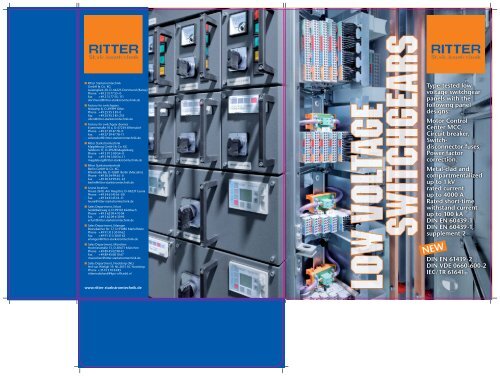
Type-tested low<br />
voltage switchgear<br />
panels with the<br />
following panel<br />
designs:<br />
Motor Control<br />
Center MCC,<br />
Circuit breaker,<br />
Switchdisconnector-fuses,<br />
Power factor<br />
correction.<br />
Metal-clad and<br />
compartmentalized<br />
up to 1 kV<br />
rated current<br />
up to 4000 A<br />
Rated short-time<br />
withstand current<br />
up to 100 kA<br />
DIN EN 60439-1<br />
DIN EN 60439-1,<br />
supplement 2<br />
NEW<br />
DIN EN 61439-2<br />
DIN VDE 0660-600-2<br />
IEC/TR 61641
LSF3001<br />
Circuit breaker panels<br />
LS-panels in withdrawable and fi xed<br />
assembly for 3-poles circuit breaker with<br />
rated current up to 4000 A.<br />
Rated peak current can be up to 100 kA.<br />
KFF 3001<br />
Coupler panels<br />
LS-panels in withdrawable and fi xed<br />
assembly for 3-poles circuit breaker with<br />
rated current up to 4000A.<br />
Rated peak current can be up to 100 kA.<br />
MCC 3001<br />
Motor control centre<br />
This is the panel with 11 tiers and max 44<br />
modules. Modules can be hardwired or<br />
bus interface design.<br />
SAS 3001<br />
Switch-disconnector with fuses<br />
This panel have horizontal integrated<br />
switch-disconnector with fuses.<br />
SLF 3001<br />
Switch-disconnector block with fuses<br />
This is panel have vertical integrated<br />
switch-disconnector with fuses.<br />
KPF 3001<br />
Compensations panel<br />
This is panel can be suitable to<br />
compensation up to 400 kVAr.<br />
KOF 3001<br />
Compensations panel<br />
This panel is open for different<br />
confi gurations, for example for<br />
control, frequency converter.<br />
Description<br />
Ritter Low Voltage Switchgear NS 3001<br />
is supplied in factory-assembled, typetested<br />
design.<br />
The switchgear is assembled with galvanised<br />
sheet-steel, bolted and rivetted.<br />
The doors and covers are painted in the<br />
RAL7035. The colour can be changed.<br />
Ritter low voltage switchgear assemblies<br />
of type NS 3001 have passed the test for<br />
resistance to internal accidental arcing.<br />
The main bus bar is arranged on the back<br />
side, in the middle of the switchgear.<br />
The bus bars are linked from panel to<br />
panel; this makes it possible for the<br />
system to be extended or to replace one<br />
panel in the system in a simple manner.<br />
All system variants can be located backto-back,<br />
free standing or against a wall.<br />
Installation and dismantling work can be<br />
carried out from the front of the system.<br />
Normen<br />
NEW: DIN EN 61439-2 Layout<br />
DIN VDE 0660-600-2 Layout<br />
NEU: IEC/TR 61641<br />
DIN EN 60439-1<br />
DIN EN 60439-1 Supplement 2<br />
General technical descripetion<br />
Types of Protection<br />
The encapsulation of the NS 3001<br />
switchgear assemblies is in accordance<br />
with IP31, but can also be executed in<br />
accordance with IP41. Higher protection<br />
types normally resulted with reductions<br />
in the rated value.<br />
The insides compartmentalisation and<br />
low-voltage niche are produced in with<br />
protections type IP2X.<br />
Equipment<br />
In the type-tested versions of the low<br />
voltage switchgear NS 3001 are following<br />
devices assembled:<br />
■ Circuit-breaker, Siemens, ABB<br />
■ Switch disconnector, Siemens, ABB<br />
■ NH-fuses, Wöhner<br />
■ Moulded-case circuit-breaker,<br />
Siemens, ABB<br />
■ Overload-protection-combination,<br />
Siemens, ABB<br />
■ Miniature circuit breaker MCB’s, ABB<br />
■ Indications instruments,<br />
Socomec, Tyco<br />
■ Control devices, Schlegel<br />
■ Transformer, Phoenix<br />
■ Undervoltage relays, Dold / Bender<br />
■ Isolations control, ABB<br />
■ Auxiliary relays, Siemens / Finder<br />
■ Coupler relays, Siemens<br />
■ Clamps, Phoenix<br />
The alternative producers of these devices<br />
are also possible.<br />
Industry / EVU Building services eng.<br />
Provided norms DIN EN 61439-2 (Layout)<br />
IEC/TR 61641 (Layout))<br />
DIN EN 60439-1<br />
DIN EN 60439-1; supp.sh. 2<br />
DIN EN 61439-2 (Layout))<br />
DIN EN 60439-1<br />
Rated voltage Ue 400 V, 500 V, 690 V 400 V, 500 V, 690 V<br />
Rated current In 4000 A 4000 A<br />
Rated short time duration 0,3 s No tested<br />
Frequency f 50/60 Hz 50/60 Hz<br />
Rated short time current Icw 100 kA 100 kA<br />
Rated peak withstand current Ipk 220 kA 220 kA<br />
Rated isolation voltage Ui 1000 V 1000 V<br />
Erection<br />
The low voltage switchgear panels<br />
are designed for use indoors in closed<br />
electro rooms in accordance with DIN<br />
EN 50110-1. They are erected against a<br />
wall or they are freestanding.<br />
The equipment should operate in the<br />
ambient temperature range from -5°C<br />
until 40°C and is designed for pollution<br />
degree 3, for operation in the industry.<br />
After consultation with the producer, it<br />
is possible in case of specifi c operating<br />
conditions to take measures to avoid<br />
problems with condensation, pollution<br />
and high ambient temperatures (for<br />
example heater, acclimatisation, removal<br />
of mildew and insects, improvement of<br />
heat dissipation and fi ltering of supply<br />
air). This apply specially for equipment<br />
in the clammy tropically area.<br />
The setting up classifi cation for low<br />
voltages equipment is given in the<br />
VDE 0100 part 729.<br />
The aisle width is specifi ed to be more<br />
then or equal 700 mm, so when the<br />
modules are in the park position more<br />
or equal 600 mm is required.<br />
All doors can be open up to approximately<br />
180°.<br />
For transport and delivery it is possible to<br />
pack up just one single or couple panel<br />
together.<br />
The panels can be screwed with special<br />
fastener in U-profi le in the existing<br />
ground or in the concrete ground.<br />
Ambient temperature min. - 5˚C<br />
max. + 40˚C<br />
50 % r. H.<br />
Highest value over 24 h + 35˚C<br />
Max altitude above sea level 2000 m<br />
Relativt humidity 5 % – 95 %<br />
no condensation<br />
Internal accidental arcing<br />
The low-voltage circuit breaker combination<br />
is tested according to the DIN<br />
EN 60439-1, supplementary sheet 2,<br />
proceeding the test under internal arcing<br />
conditions respectively IEC / TR 61641 /<br />
2008-01 second edition “Enclosed<br />
low-voltage switchgear and controlgearguide<br />
for testing under conditions of<br />
arcing due to internal fault.”<br />
The technical report present information<br />
about tests set-up, applying of the<br />
infl ammable, repeating of test, criteria to<br />
pass of test.<br />
During the tests indicators have be placed<br />
up to 2 m height, at all panel’s sides<br />
available to the operating personal.<br />
In the test report should be accredited<br />
that what’s concerning operating<br />
personal:<br />
■ The doors remained close,<br />
covering aren’t open.<br />
■ No dangerous parts fall a part.<br />
■ The force of internal, accidental arcing<br />
shouldn’t be able to brand holes in the<br />
free available sides.<br />
■ Vertical installed indicators should not<br />
brand.<br />
■ The earthing circuit for touchable parts<br />
of the outsides coating which are still<br />
functioning.<br />
Concerning construction and equipments<br />
protection additionally:<br />
■ The infl uence of the arcing on the area<br />
of ignition is limited, no expansion<br />
occur on that area or other areas.<br />
And additionally:<br />
■ After setting of arcing or isolation or<br />
demounting of parts which are from<br />
arcing affected should be possible for<br />
remaining low-voltages equipment<br />
to run emergency operations.<br />
Sizes and dimensions<br />
Sizes and dimensions are coordinate<br />
and can be matched to particular<br />
circumstances. The height of the panel<br />
types NS 3001 with protections degree<br />
IP31 is 2300 mm, with protections<br />
degree IP41 it is 2400 mm.<br />
The standardisation of the modules and<br />
operating devices provides a high degree<br />
of variability in respect of the opportunities<br />
for combination so that solutions for<br />
operating and handing can usually be<br />
found in the project-design phase or<br />
following the issuing of en order even<br />
where the spatial situation is very special.<br />
9/09 Subject to modifi cation