Operating Manual - ROPA Fahrzeug
Operating Manual - ROPA Fahrzeug
Operating Manual - ROPA Fahrzeug

You also want an ePaper? Increase the reach of your titles
YUMPU automatically turns print PDFs into web optimized ePapers that Google loves.
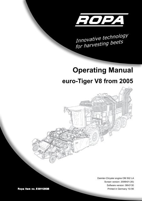
Innovative technology<br />
for harvesting beets<br />
<strong>Operating</strong> <strong>Manual</strong><br />
euro-Tiger V8 from 2005<br />
Daimler-Chrysler engine OM 502 LA<br />
Screen version: 2006h01(30)<br />
Software version: 06h0130<br />
Printed in Germany 10/06
Imprint<br />
All rights reserved<br />
© Copyright 2006 y y y<br />
<strong>ROPA</strong> <strong>Fahrzeug</strong>- und Maschinenau GmH<br />
Sittelsdorf 24<br />
D-84097 Herrngiersdorf<br />
Telephon + 49 – 87 85 – 96 01 0<br />
Telefax + 49 – 87 85 – 56 6<br />
Internet www.ropa-maschinenau.de<br />
E-mail: kundendienst@ropa-maschinenau.de<br />
These operating instructions may only e reprinted or otherwise reproduced<br />
– even in excerpts – with the express approval of <strong>ROPA</strong> GmH.<br />
Any type of reproduction, distriution or storage on data medium in any form and<br />
of any type not authorized y <strong>ROPA</strong> GmH forms a violation of current domestic and international copyright law<br />
and will e judicially prosecuted.<br />
Pulisher responsile for content: <strong>ROPA</strong> <strong>Fahrzeug</strong>- und Maschinenau GmH<br />
Editing: text und ild Redaktion, -tl-, Thomas-Schwarz-Straße 47, 85221 Dachau<br />
Layout: text und ild Redaktion, -kk-, Thomas-Schwarz-Straße 47, 85221 Dachau<br />
Printed in Germany 10/2006
3<br />
Table of contents<br />
0 Preface ............................................................................. 14<br />
0.2 Name plate and important data ...............................................................16<br />
0.1 Differences etween the models eT V8h and eT V8-3 ............................16<br />
0.3 Serial numers .........................................................................................17<br />
1 Safety ............................................................................... 21<br />
1.1 General ....................................................................................................21<br />
1.2 Oligations of the entrepreneur ...............................................................21<br />
1.3 General symols and instructions............................................................22<br />
1.4 Proper use ...............................................................................................22<br />
1.5 Hazard zone ............................................................................................23<br />
1.6 Safety stickers on the machine ................................................................26<br />
1.7 Safety and health protection ....................................................................27<br />
1.8 Requirements for operating and maintenance personnel ........................27<br />
1.9 Behaviour in case of accidents ................................................................28<br />
1.10 Handling of old parts, process materials..................................................28<br />
1.11 Residual risks ..........................................................................................28<br />
1.12 Hazards caused by mechanical influences..............................................29<br />
1.13 Hazards caused y process materials .....................................................29<br />
1.14 Hazards caused y noise ........................................................................30<br />
1.15 Hazards caused y the hydraulics system ..............................................30<br />
1.16 General hints on safety when handling acid atteries .............................31<br />
2 Road traffic ...................................................................... 35<br />
3 General view and specifications ................................... 43<br />
3.1 General view euro-Tiger .........................................................................43<br />
3.2 Specifications ...........................................................................................45<br />
3.3 Transport draft for low-loader transport<br />
euro-Tiger 2005-V8 including topper PBSh and PISh ............................47<br />
3.4 Transport draft for low-loader transport<br />
euro-Tiger 2005-V8 including topper PBSOh ..........................................48<br />
4 General description ........................................................ 51<br />
4.1 Function ...................................................................................................51<br />
4.2 Scope of delivery .....................................................................................52<br />
4.3 Model overview topper and lifter units .....................................................53<br />
Table of contents
Table of contents<br />
Table of contents<br />
5 <strong>Operating</strong> components .................................................. 57<br />
5.1 Steering column .......................................................................................57<br />
5.1.1 Steering column switch ............................................................................58<br />
5.2 Drivers‘ seat .............................................................................................59<br />
5.3 <strong>Operating</strong> components on the floor of the drivers‘ cabin .........................63<br />
5.4 <strong>Operating</strong> console right............................................................................63<br />
5.4.1 Switch section 1 .......................................................................................64<br />
5.4.2 <strong>Operating</strong> section I...................................................................................64<br />
5.4.3 <strong>Operating</strong> section II..................................................................................67<br />
5.4.4 Switch section 2 .......................................................................................70<br />
5.4.5 Switch section 3 .......................................................................................71<br />
5.4.6 Switch section 4 .......................................................................................72<br />
5.4.7 Joystick with multi-functional handle .......................................................73<br />
5.5 <strong>Operating</strong> section III – emptying the unker ............................................74<br />
5.6 <strong>Operating</strong> components cain ceiling........................................................75<br />
5.7 Air conditioning ........................................................................................76<br />
5.8 Pressure gauge on the front wall of the unker .......................................77<br />
5.9 Ground operation beet flow .....................................................................78<br />
5.10 Ground operation lifting unit.....................................................................79<br />
5.11 <strong>Operating</strong> components in the engine compartment .................................81<br />
6 Operation ......................................................................... 85<br />
6.1 First startup ..............................................................................................85<br />
6.2 Safety regulations for operation of euro-Tiger ........................................86<br />
6.2.1 Working in the vicinity of power lines .......................................................87<br />
6.2.2 Behaviour during or after contact to power lines .....................................88<br />
6.3 Color terminal ........................................................................................89<br />
6.3.1 Keyoard on the color terminal ................................................................89<br />
6.3.2 Selecting functional range .......................................................................92<br />
6.3.3 Main menu ...............................................................................................92<br />
6.3.3.1 Programmale keys P1, P2, P3 (menu code 1) .....................................93<br />
6.3.3.2 System menu (menu code 2)...................................................................96<br />
6.3.3.3 Service menu (menu code 3)...................................................................96<br />
6.3.3.4 Menu asic settings (menu code 4) .........................................................97<br />
6.3.3.5 Autopilot (menu code 5)...........................................................................97<br />
6.3.3.6 Sumenu special functions (menu code 6)..............................................98<br />
6.3.3.7 Empty menu (menu code 7) ....................................................................98<br />
6.3.4 Order management ..................................................................................99<br />
6.3.4.1 Adjusting numer of rows ........................................................................100<br />
6.3.4.2 Hiding display of fuel consumption ..........................................................100<br />
6.3.4.3 Mode of operation of order management. ...............................................101<br />
6.3.4.4 Order evaluation ......................................................................................102<br />
6.3.5 Adjusting warning thresholds ...................................................................103<br />
4
5<br />
Table of contents<br />
6.3.6 Warning and status indications on the color terminal ..............................104<br />
6.4 Air conditioning .....................................................................................107<br />
6.5 Joystick ..................................................................................................109<br />
6.6 Diesel engine ..........................................................................................114<br />
6.6.1 Starting the engine...................................................................................114<br />
6.6.2 Starting the engine without ooting the terminal......................................114<br />
6.6.3 Adjustment of the engine speed ..............................................................115<br />
6.7 Driving power .........................................................................................116<br />
6.7.1 Switching gears .......................................................................................116<br />
6.7.2 Switching process differential lock ...........................................................117<br />
6.8 Driving ....................................................................................................118<br />
6.8.1 Selection of the driving direction (forward+/ackward) ...........................118<br />
6.8.2 Cruise control ...........................................................................................119<br />
6.8.2.1 Switching on cruise control in operating mode „rait“ ............................119<br />
6.8.2.2 Switching off cruise control in operating mode „rait“ ............................120<br />
6.8.2.3 Quick description: cruise control in operating mode „rait“....................120<br />
6.8.2.4 Switching on cruise control in operating mode „turtle“ .............................121<br />
6.8.2.5 Adjusting the desired speed of cruise control<br />
(operating mode „turtle“) ..........................................................................122<br />
6.8.2.6 Switching off cruise control in operating mode „turtle“ .............................122<br />
6.8.2.7 Quick description: cruise control in operating mode „turtle“.....................123<br />
6.9 Braking system ........................................................................................124<br />
6.9.1 Service rake ...........................................................................................124<br />
6.9.2 Parking rake ...........................................................................................124<br />
6.9.3 Automatic parking rake ..........................................................................125<br />
6.10 Steering system .....................................................................................125<br />
6.10.1 Steering in operating mode „rait“ .........................................................125<br />
6.10.1.1 Moving rear axle into central position ......................................................126<br />
6.10.1.2 Synchronizing articulation<br />
(ONLY in case of machines with synchronized steering) .........................126<br />
6.10.1.3 Quick description: steering in operating mode „rait“ ............................127<br />
6.10.2 Steering in operating mode „turtle“ ..........................................................128<br />
6.10.2.1 Preselecting offset-steer 0-1-2 direction left/right .................................128<br />
6.10.2.2 Preselecting stage offset-steer 0-1-2 .....................................................129<br />
6.10.2.3 Activating offset-steer 0-1-2 ...................................................................129<br />
6.10.2.4 Total steer ................................................................................................130<br />
6.10.2.5 All-wheel steer ........................................................................................130<br />
6.10.2.6 Steering the rear axle using the joystick ..................................................131<br />
6.10.2.7 <strong>Manual</strong> control .........................................................................................132<br />
6.10.2.8 Quick description: steering modes in operating mode „turtle“ .................133<br />
Table of contents
Table of contents<br />
Table of contents<br />
6.10.3 Automatic steering (autopilot) ..................................................................134<br />
6.10.3.1 Activating autopilot front axle steering .....................................................134<br />
6.10.3.2 Quick description: activating only front axle autopilot ..............................136<br />
6.10.3.3 Activating autopilot rear axle steering ......................................................137<br />
6.10.3.4 Quick description: manual activation autopilot rear axles ........................139<br />
6.10.3.5 Quick description: automatic activation autopilot rear axles ....................140<br />
6.10.4 Setting steering ehaviour .......................................................................141<br />
6.11 Lifting ......................................................................................................141<br />
6.11.1 Preparation for lifting................................................................................141<br />
6.11.2 Lifting operation ....................................................................................142<br />
6.12 Lifting unit and topper (harvesting attachment) .................................143<br />
6.12.1 Topper .....................................................................................................143<br />
6.12.2 Leaf sensor ..............................................................................................144<br />
6.12.3 Topper shaft .............................................................................................146<br />
6.12.3.1 Setting topper shaft drive .........................................................................147<br />
6.12.3.2 Monitoring of the topper shaft ..................................................................147<br />
6.12.4 Depth-control wheels ..............................................................................148<br />
6.12.5 Setting topper relief pressure...................................................................150<br />
6.12.6 Leaf worm conveyor (ONLY for PBSh) ....................................................152<br />
6.12.7 Leaf disk ..................................................................................................152<br />
6.12.7.1 Swinging leaf disk ....................................................................................152<br />
6.12.7.2 Setting speed leaf disk.............................................................................153<br />
6.12.8 Retopper ..................................................................................................154<br />
6.12.8.1 Adjusting cutting depth ............................................................................155<br />
6.12.8.1 Adjusting cutting depth ............................................................................157<br />
6.12.8.3 Spring loading of the retopper .................................................................158<br />
6.12.9 Lifting unit ..............................................................................................159<br />
6.12.9.1 Setting speed depth-control shaft ............................................................161<br />
6.12.9.2 Depth control ...........................................................................................162<br />
6.12.9.3 Setting lifting depth ..................................................................................163<br />
6.12.9.4 Setting shaft movement height ................................................................164<br />
6.12.9.5 Setting the shear ar height.....................................................................166<br />
6.12.9.6 Shears .....................................................................................................168<br />
6.12.9.7 Setting the shaking frequency .................................................................168<br />
6.12.9.8 Stone protection.......................................................................................170<br />
6.12.9.9 Setting the stone protection pressure ......................................................172<br />
6.12.9.10 Shear ody guide (linear guide)...............................................................173<br />
6.12.9.11 Steering of the shear ody.......................................................................173<br />
6.12.9.12 Installing/uninstalling guide rod holders ..................................................174<br />
6.12.9.13 Setting the speed of the lifting shafts one to four.....................................174<br />
6.12.9.14 Reversing lifting shafts one to five ...........................................................175<br />
6.12.9.15 Setting the distance etween the 4th and 5th lifting shaft .......................177<br />
6.12.9.16 Rotating direction last lifting shaft (pinching roller) ..................................177<br />
6
7<br />
Table of contents<br />
6.12.9.17 Paddle speed ...........................................................................................178<br />
6.13.9.18 Side shift ..................................................................................................178<br />
6.12.9.19 <strong>Manual</strong> side shift ......................................................................................179<br />
6.12.9.20 Automatic side shift ..................................................................................180<br />
6.12.9.21 Setting row distance for the lifter PRh-V ..................................................181<br />
6.13 Cleaning ..................................................................................................186<br />
6.13.1 Infeed conveyor .....................................................................................186<br />
6.13.1.1 Reversing infeed conveyor ......................................................................188<br />
6.13.1.2 Ground operation infeed conveyor ..........................................................188<br />
6.13.2 Setting infeed conveyor – distance settings ............................................189<br />
6.13.2.1 Longitudinal direction ...............................................................................189<br />
6.13.2.2 Setting height front infeed conveyor ........................................................190<br />
6.13.2.3 Setting height rear infeed conveyor .........................................................191<br />
6.13.3 Strainer wheels ......................................................................................191<br />
6.13.3.1 Setting the strainer wheel speed .............................................................192<br />
6.13.3.2 Monitoring of the strainer wheels .............................................................193<br />
6.13.3.3 Ground operation strainer wheels .................................................................194<br />
6.13.3.4 Reamer ....................................................................................................195<br />
6.13.3.5 Pig tails (option) .......................................................................................195<br />
6.13.3.6 Wiper .......................................................................................................195<br />
6.13.3.7 Strainer wheel guide grids .......................................................................196<br />
6.14 Elevator ...................................................................................................197<br />
6.14.1 Swinging elevator ....................................................................................197<br />
6.14.2 Setting elevator speed .............................................................................198<br />
6.14.3 Monitoring of the elevator ........................................................................199<br />
6.15 Bunker ....................................................................................................199<br />
6.15.1 Raising/lowering auger ...........................................................................200<br />
6.15.2 Switching rotating direction auger............................................................201<br />
6.15.3 <strong>Manual</strong>ly switching auger ........................................................................202<br />
6.16 Unloading the bunker ............................................................................203<br />
6.16.1 Swinging articulation unload elevator ......................................................203<br />
6.16.2 <strong>Operating</strong> section III (unloading of the unker) ........................................204<br />
6.16.3 Setting the unload speed .........................................................................207<br />
6.17 Automatic axle load control ..................................................................208<br />
6.18 Diesel engine ..........................................................................................209<br />
6.18.1 Modifications respectively additions to the engine operating manual<br />
from DaimlerChrysler ...............................................................................211<br />
6.19 Pump power divider ..............................................................................212<br />
6.20 Hydraulics system .................................................................................213<br />
6.21 Compressed air system ........................................................................215<br />
6.22 Central lubricating system ....................................................................217<br />
6.22.1 Filling up the grease gun .........................................................................218<br />
6.22.2 Intermediate lurication ...........................................................................218<br />
Table of contents
Table of contents<br />
Table of contents<br />
6.23 Video monitoring ...................................................................................220<br />
6.24 Electric system ......................................................................................220<br />
6.24.1 Main attery switch ..................................................................................220<br />
6.24.2 Voltage monitoring ...................................................................................221<br />
6.24.3 Fuses .......................................................................................................221<br />
6.25 Printer .....................................................................................................223<br />
6.25.1 Description of the utton functions ..........................................................223<br />
6.25.2 Which thermo-sensitive paper is suitale ...............................................224<br />
6.26 Tire pressures ........................................................................................225<br />
6.27 Immobilization ........................................................................................226<br />
7 Maintenance and service ............................................... 229<br />
7.1 Engine .....................................................................................................229<br />
7.1.1 Dry air filter ..............................................................................................230<br />
7.1.2 Oil change on the engine .........................................................................234<br />
7.1.3 Fuel supply ..............................................................................................237<br />
7.1.3.1 Maintenance Separ filter (draining water and intermediate flushing).......238<br />
7.1.3.2 Pre-line filter (prefilter) .............................................................................240<br />
7.1.3.3 Microorganisms in the fuel system ..........................................................242<br />
7.1.3.4 Fuel fine filter on the engine ....................................................................243<br />
7.1.3.5 Other maintenance work on the Diesel engine ........................................244<br />
7.1.4 Cooling system ........................................................................................245<br />
7.1.4.1 Cleaning the radiator, charging air and transmission oil cooler ...............245<br />
7.1.4.2 Checking coolant .....................................................................................246<br />
7.1.4.3 Replacing coolant ....................................................................................248<br />
7.2 Air conditioning system ........................................................................249<br />
7.3 Pump distributor gears .........................................................................251<br />
7.4 Hydraulics system .................................................................................253<br />
7.4.1 Hydraulics fluid tank .................................................................................255<br />
7.4.1.1 Change of hydraulics fluid .......................................................................256<br />
7.4.1.2 Hydraulics: exchanging return duct filter and intake<br />
return duct filter elements ........................................................................258<br />
7.4.2 Pressure filter ...........................................................................................259<br />
7.5 Mechanical drive for the three steering axles ..........................................260<br />
7.5.1 Drive shafts from the distriutor gears to the steering axles....................260<br />
7.5.2 Maintenance universal joints of the axles ................................................261<br />
7.6 <strong>Manual</strong> transmission .............................................................................261<br />
7.7 Axles .......................................................................................................262<br />
7.7.1 Planetary gear (applies to all three axles) ...............................................262<br />
7.7.2 Differential gear rear axles .......................................................................264<br />
7.7.3 Differential gear front axles (portal axle) ..................................................266<br />
7.7.4 Portal drives front axle .............................................................................267<br />
8
9<br />
Table of contents<br />
7.8 Pneumatics system ...............................................................................268<br />
7.9 Topper and lifter .......................................................................................269<br />
7.9.1 Topper .....................................................................................................270<br />
7.9.1.1 Moving topper to maintenance position ...................................................270<br />
7.9.1.2 Moving topper from maintenance position to operating position .............275<br />
7.9.1.3 Setting the sensor of the row sensor (menu code 3202001) ...................276<br />
7.9.1.4 Topper wheels ..........................................................................................277<br />
7.9.1.5 Topper shaft .............................................................................................278<br />
7.9.1.6 Retopper ..................................................................................................279<br />
7.9.2 Lifter ........................................................................................................280<br />
7.9.2.1 Lifter gears for lifter shafts .......................................................................280<br />
7.9.2.2 Paddle gears............................................................................................282<br />
7.9.2.3 Shaking shear gears ................................................................................282<br />
7.9.2.4 Shaking shear drive for PRh-V ................................................................282<br />
7.9.2.5 Readjust eccentric earing shaking shear drive ......................................283<br />
7.9.2.6 Shear ody guide/suspension .................................................................284<br />
7.9.2.7 Lifting shafts .............................................................................................284<br />
7.10 Infeed conveyor .....................................................................................286<br />
7.10.1 Tension ....................................................................................................286<br />
7.10.2 Setting synchronism ................................................................................287<br />
7.11 Gear unit infeed conveyor........................................................................288<br />
7.12 Strainer wheels ......................................................................................289<br />
7.13 Elevator ...................................................................................................289<br />
7.14 Bunker ....................................................................................................291<br />
7.14.1 Auger .......................................................................................................291<br />
7.14.2 Ultrasound sensors ..................................................................................292<br />
7.14.3 Cross conveyors ....................................................................................292<br />
7.14.3.1 Tension cross conveyor chains ................................................................293<br />
7.14.3.2 Retensioning longitudinal cross conveyor ...............................................293<br />
7.14.3.3 Retensioning cross conveyor...................................................................294<br />
7.14.3.4 Driving chains ..........................................................................................294<br />
7.14.3.5 Storage of the cross conveyor drive shaft and cleaner shaft ...................295<br />
7.15 Unload elevator ......................................................................................296<br />
7.15.1 Retensioning elt .....................................................................................297<br />
7.16 Heating and ventilation system ............................................................298<br />
7.16.1 Fresh air intake filter ................................................................................298<br />
7.16.2 Circulating air filter ...................................................................................299<br />
7.17 Printer .....................................................................................................300<br />
7.18 Immobilization for a longer period of time ..........................................300<br />
Table of contents
Table of contents<br />
Table of contents<br />
8 Malfunction and remedies ............................................. 305<br />
8.1 Safety circuits ..........................................................................................305<br />
8.2 Elektric .....................................................................................................306<br />
8.2.1 Fuses .......................................................................................................306<br />
8.2.2 List of fuses (fuses) ..................................................................................307<br />
8.2.3 Electronic automatic cut-outs ..................................................................309<br />
8.2.4 List of fuses (electronic automatic) cut-outs ............................................310<br />
8.3 List of relays .............................................................................................311<br />
8.4 Color code for electrical wiring .................................................................311<br />
8.5 Searching for malfunctions using the color terminal ................................312<br />
8.5.1 Overview of diagnostics menus ...............................................................313<br />
8.6 Main attery switch ..................................................................................319<br />
8.7 Jump starting and charging the attery ...................................................319<br />
8.8 Welding on the machine ..........................................................................321<br />
8.9 Towing ......................................................................................................322<br />
8.10 Connecting of salvaging aids ...................................................................323<br />
8.11 <strong>Manual</strong>ly releasing the parking rake ......................................................324<br />
8.12 Setting respectively resetting of the rake ...............................................326<br />
8.13 Hydraulics valves .....................................................................................326<br />
8.14 Central lurication system – leeding and removal of locks ..................327<br />
8.15 Emergency operation ventilator drives ....................................................329<br />
8.16 Swing away fuel tank ...............................................................................330<br />
9 Lists and tables/plans and diagrams/<br />
maintenance slips .............................................................. 333<br />
9.1 Luricating and operating supplies euro-Tiger from 2005 V8 .................333<br />
9.2 Maintenance tale euro-Tiger from 2005 V8 ..........................................334<br />
9.3 Luricating plan euro-Tiger from 2005 V8 with lifter PRh .......................338<br />
9.4 Luricating supplies decoding tale for <strong>ROPA</strong> machines ........................340<br />
9.5 Excerpt from the Mercedes-Benz works standard operating supplies,<br />
engine oils and coolants/antifreeze agents..............................................341<br />
9.5.1 Multigrade oils (specification 228.5) .................................................................341<br />
9.5.2 Corrosion protection/antifreeze agents (specification 325.0) ....................... 344<br />
9.5.3 Premixed corrosion protection/antifreeze agents (specification 326.0) ..344<br />
9.6 Approved greases....................................................................................345<br />
9.6.1 Recommended greases for the central luricating system ......................345<br />
9.6.2 Recommended iologically-degradale greases for the central<br />
luricating system ....................................................................................345<br />
9.7 Filter cartridges, V-elts e-T from model year 2005 V8 with<br />
DC OM502 LA ..........................................................................................346<br />
10
11<br />
Table of contents<br />
9.8 General plans of the lifting shafts ............................................................347<br />
9.8.1 General plan for PR-45 ............................................................................347<br />
9.8.2 General plan for PR-50 ............................................................................348<br />
9.8.3 General plan for PR-V .............................................................................349<br />
9.9 Luricating plans......................................................................................350<br />
9.9.1 Luricating plan for <strong>ROPA</strong> euro-Tiger from 2005 V8<br />
„only asic machine“ including 60 luricating points................................350<br />
9.9.2 Luricating plan for PRh lifter including PBSh topper<br />
(only model year 2005) including 73 luricating points ............................351<br />
9.9.3 Luricating plan for PRh lifter including PISh topper<br />
(only model year 2005) including 71 luricating points ............................352<br />
9.9.4 Luricating plan for PRh lifter including PBSh topper<br />
(from model year 2006) including 73 luricating points ...........................353<br />
9.9.5 Luricating plan for PRh lifter including PISh topper<br />
(only model year 2005) including 71 luricating points ............................354<br />
9.10 Maintenance slips ....................................................................................355<br />
9.10.1 Maintenance slip oil change + filter change .............................................355<br />
9.10.2 Confirmation of maintenance ...................................................................357<br />
9.10.3 Software updates .....................................................................................357<br />
9.11 Confirmation about instructions given to the driver..................................358<br />
9.12 Instructions on safety ...............................................................................359<br />
Index ................................................................................ 363<br />
Table of contents
12<br />
0 Preface<br />
Chapter 0<br />
Preface<br />
Chapter 0<br />
Preface
0 Preface<br />
14<br />
0 Preface<br />
We congratulate you to your new <strong>ROPA</strong> machine. Please take the time and thoroughly<br />
read the operating manual. The operating manual is mainly directed at the machine<br />
operator. It contains all information required for safe operation of this machine, informs<br />
aout safe handling and gives hints on practical use as well as for self-help and<br />
servicing. The respective safety hints are ased on the safety, accident prevention and<br />
health protection regulations applicale at print of this operating manual. In case of<br />
questions aout the machine, on operation of the machine or on ordering of spare parts,<br />
please contact the dealer in your vicinity or the manufacturer directly:<br />
<strong>ROPA</strong> <strong>Fahrzeug</strong>- und Maschinenau GmH<br />
Sittelsdorf 24<br />
D-84097 Herrngiersdorf<br />
Telephone + 49 – 87 85 – 96 010<br />
Telefax + 49 – 87 85 – 566<br />
Internet www.ropa-maschinenau.de<br />
E-Mail Kundendienst@ropa-maschinenau.de<br />
Important information<br />
Original <strong>ROPA</strong> parts have een especially developed for your machine. They<br />
conform to the high <strong>ROPA</strong> standards for safety and reliaility. We would like to point<br />
out that parts and accessories not approved y <strong>ROPA</strong> may not e used on <strong>ROPA</strong><br />
machines, ecause otherwise the safety and operaility of the machine may e<br />
impaired. We cannot assume any responsiility for such installations, additions or<br />
reconstructions. In case of unauthorized modifications to the machine, any warranty<br />
claim lapses! This also applies if seals or sealing wax applied y the works are<br />
removed.<br />
Warning! In rare cases, massive interference of vehicle electronics or malfunctions of<br />
the machine may occur due to operation of improperly installed electronic appliances<br />
(for instance radios or other appliances emitting electromagnetic radiation). In case<br />
of such interference, the complete machine may suddenly stop operating or execute<br />
unwanted functions. In such cases, immediately shut off the sources for interference and<br />
immediately shut down the machine. In case of need, notify the company <strong>ROPA</strong> or the<br />
nearest authorized customer service of <strong>ROPA</strong>.<br />
Chapter 0<br />
Preface
0 Preface<br />
Chapter 0<br />
Preface<br />
Servicing and specific maintenance work on the engine may only be performed by<br />
companies or persons expressly authorized for this purpose y DaimlerChrysler.<br />
This work must e acknowledged accordingly in maintenance vouchers of<br />
DaimlerChrysler y these persons or companies. Without these maintenance<br />
vouchers properly completed, any warranty or statutory warranty of the engine<br />
manufacturer lapses.<br />
Technical modifications serving improvement of our machines or increasing the<br />
safety standards are expressly reserved by us – even without specific notification.<br />
All information aout directions given in this operating manual (front, rear, right, left)<br />
refer to the driving direction forward.<br />
If the terms rear axles or rear axle have een used, this always refers to the next<br />
to last and the last axle together, ecause these two axles are coupled in their<br />
functions. Differentiation etween the two axles must only e made for information<br />
aout the tire size and tire pressure.<br />
Please always state the chassis numer of the machine for any orders for spare<br />
parts and technical enquiries. You will find the chassis number on the name plate<br />
and on the vehicle chassis aove the name plate.<br />
Please have the machine serviced according to regulations. Comply with the<br />
information given in this operatings manual and have parts suject to wear replaced<br />
in due time respectively ensure timely repairs.<br />
Have the machine services respectively repaired according to regulations.<br />
Employ the decades of experience collected y <strong>ROPA</strong> in sugar eet lifting and<br />
loading technology and implemented in this machine, y correct operation of this<br />
machine. Rememer that any neglect in maintenance and servicing inevitaly leads<br />
to loss of performance and therefore to loss of time.<br />
Listen for suddenly occurring unusual noises and have their cause remedied efore<br />
the machine is operated further, since otherwise heavy damage or costly repairs to<br />
the machine may e caused.<br />
Generally comply with the respective applicable regulations for road traffic and the<br />
applicale regulations on employment safety and health protection.<br />
We expressly point out that any damage caused y the fact that this operating manual is<br />
not or not completely complied with is in no case covered y the guarantee respectively<br />
statutory warranty of <strong>ROPA</strong>. Even though this operating manual is comprehensive, in<br />
your own interest you should completely and carefully read it and slowly attain familiarity<br />
with the machine using this operating manual.<br />
15
0.1 Differences between the Models eT V8h and eT V8-3<br />
0.2 Name plate and important data<br />
16<br />
0 Preface<br />
The name plate (2) of euro-Tiger is located on the right side of the vehicle ehind<br />
the knuckle joint etween the front and central axle on the vehicle chassis, elow the<br />
chassis numer (1).<br />
eT V8h eT V8-3<br />
Name plate entry 436 KW 444 KW<br />
Cain furnishings dark light<br />
Diesel engine 2 turo chargers r<br />
Exhaust emission<br />
standard<br />
2 tail pipes<br />
Driving power 2 driving engines of<br />
1 turo charger<br />
1 tail pipes<br />
EuroMot 2 EuroMot 3a<br />
160 cm³ each<br />
1 driving engine of 125 cm³<br />
1 driving engine of 200 cm³<br />
1<br />
2<br />
Chapter 0<br />
Preface
0 Preface<br />
Chapter 0<br />
Preface<br />
Please enter the data for your machine in the following image of the name plate. You<br />
will need this data for ordering spare parts. If you have not yet exchanged the topper<br />
unit and/or the lifting unit, these may also be identified by the manufacturer using the<br />
chassis numer.<br />
0.3 Serial numbers<br />
The serial numer of the engine is located on the engine lock. It may found, starting<br />
from the bunker, in driving direction, on the left side (the flywheel side) of the engine,<br />
directly ehind the last cylinder.<br />
17
18<br />
0 Preface<br />
The serial numer (1) of the lifter is located at the front right on the upper shackle of the<br />
three-point suspension.<br />
The serial numer (2) of the topper is located on the left upper part of the side of the<br />
topper.<br />
PISh-Topper<br />
PBSh/PBSOh-Topper<br />
1<br />
2<br />
2<br />
Chapter 0<br />
Preface
19<br />
1 Safety<br />
Chapter 1<br />
Safety<br />
Chapter 1<br />
Safety
1 Safety<br />
1.1 General<br />
21<br />
1 Safety<br />
euro-Tiger has een manufactured according to the current state of technology and<br />
een tested for safety.<br />
The machine is CE compliant and therefore conforms to the respective European<br />
regulations for free movement of goods within the European Union respectively the<br />
European economic region.<br />
Modifications to this machine may only be performed with the express approval of the<br />
manufacturer, since otherwise the manufacturers‘ warranty lapses.<br />
In addition, the road traffic registration may lapse and other registrations of the machine<br />
may ecome invalid. The operating manual supplied must e strictly oserved. The<br />
manufacturer shall not e liale for damage caused y incorrect handling, inappropriate<br />
application or incorrect repairs respectively missing maintenance and service carried out<br />
y the customer. The machine may only e operated in a technically perfect condition,<br />
for its intended purpose and with due consideration of the risks involved<br />
1.2 Obligations of the entrepreneur<br />
The entrepreneur employing the machine respectively his agent are oliged:<br />
– to oserve the applicale European employment safety regulations.<br />
– to instruct the machine operators aout their special oligation for safe driving of the<br />
machine. These instructions must e given anew efore the start of each season.<br />
Records must e prepared aout giving of these instructions, which must e signed<br />
y the entrepreneur and the instructed machine operator. These records must e<br />
kept for at least one year y the entrepreneur.<br />
– before first use of the machine, to instruct the machine operators about operation<br />
respectively aout safe handling of the machine.<br />
Forms for these instructions may e found in Chapter 9 of this operating manual<br />
(documentation of instructions given to the driver). In case of need, please copy these<br />
forms efore completing them<br />
Chapter 1<br />
Safety
1 Safety<br />
Chapter 1<br />
Safety<br />
1.3 General symbols and instructions<br />
The following symols are used for safety instructions in this operating manual. They<br />
serve as a warning against possile personal injury or material damage, or provide help<br />
in facilitating work.<br />
Danger! This symol warns of imminent danger of fatal accident or serious injury. This<br />
hazard may always occur if the operating or work instructions are not complied with or<br />
only complied with unprecisely.<br />
Warning! This symol warns you of a possily dangerous situation which may lead<br />
to grave injury or to death. These hazards may occur if the operating or working<br />
instructions are not or only unprecisely oserved.<br />
Attention! This symol warns of possile hazardous situations which may lead to<br />
heavy injuries and of damage to the machine or other heavy damage. Non-oservance<br />
of these remarks may lead to loss of warranty. This hazard may always occur if the<br />
operating or working instructions are not or only unprecisely oserved.<br />
Note! This symol draws your attention to any special aspects. This helps to facilitate<br />
work.<br />
1.4 Proper use<br />
This machine is exclusively meant for:<br />
– lifting sugar eets and similar crops<br />
– depositing the lifted crops in a pile immediately on the edge of the field or for<br />
unloading of lifted crops to an accompanying vehicle driving alongside.<br />
Included in proper use is that the machine is driven under compliance with the applicale<br />
road traffic regulations on public roads. This includes driving forward and backward.<br />
Any other use of the machine is deemed improper and is therefore prohiited. We would<br />
expressly like to point out that this machine may not e used for pulling trailers, for<br />
towing or salvaging other vehicles or for pulling respectively pushing or transport of any<br />
loads or any goods.<br />
22
1.5 Hazard zone<br />
23<br />
1 Safety<br />
Noody may stay in the hazard zone during operation of the machine. The operator<br />
must immediately shut down the machine in case of any threatening hazard and request<br />
the people concerned to immediately leave the hazard zone. He may only restart the<br />
machine when no people are located in the hazard zone anymore.<br />
People wanting to come near the machine during operation must clearly signal their<br />
plans to the operator (for instance y calling or y means of agreed hand signals) to<br />
avoid misunderstanding.<br />
During lifting, a strip with a width of 6 meters to the left and right of the machine and<br />
100 meters in front of the machine is deemed to e the hazard zone. Around the lade<br />
disk, a space with a radius of 30 meters is deemed to e the hazard zone. As soon as a<br />
person enters this space, the machine must e immediately shut down and the person<br />
concerned must e requested to immediately exit the hazard zone. The machine may<br />
only e restarted when no people are located in the hazard zone anymore.<br />
Danger! There is a hazard of severest or even deadly injuries for people staying in the<br />
hazard zone. The operator is obliged to immediately shut down the machine as soon<br />
as people or animals enter the hazard zone or ingress into it with objects. It is expressly<br />
prohibited to place sugar beets not having been lifted by the machine into the machine<br />
manually or using tools, as long as the machine is running. The engine must be shut off<br />
before maintenance and repair work and the ignition key must be removed. Read the<br />
operating manual and observe safety information.<br />
Additional hazard zone<br />
only for PBS*<br />
Chapter 1<br />
Safety
1 Safety<br />
Chapter 1<br />
Safety<br />
We recommend that the operator of the macine informs all people present during lifting<br />
about the possible hazards. You will find an information sheet for this purpose in the<br />
appendix. In case of need, you should copy this sheet and hand it out to the people<br />
concerned. For your own safety and as protection against possile recourse (liaility)<br />
claims, you should obtain written confirmation about receipt of this sheet in the space<br />
provided.<br />
All parts of the machine which may cause specific hazards are additionally marked<br />
using warning laels (pictographs). These pictographs point out possile hazards.<br />
They form a part of this operating manual. They must always e kept in clean and well<br />
legile condition. Damaged or illegile safety stickers must immediately e replaced.<br />
The meaning of each individual pictograph is explained below. In addition, a six-figure<br />
numer is given for each pictograph. This is the <strong>ROPA</strong> order numer. Stating this<br />
numer, you may reorder the respective pictograph from <strong>ROPA</strong>. The numer stated<br />
in rackets is printed on the respective sticker. This enales simple allocation of the<br />
pictograph to the order numer and the explanation.<br />
24
355070 (34)<br />
Shut down the engine efore<br />
performing maintenance and repair<br />
work and pull off the ignition key.<br />
Read the operating manual and<br />
comply with remarks on safety.<br />
355069 (41)<br />
Burning hazard due to hot surfaces!<br />
Keep sufficient distance to hot<br />
surfaces!<br />
355071 (1)<br />
Before starting up, read the operating<br />
manual respectively the maintenance<br />
manual and oserve all remarks on<br />
safety.<br />
355073 (50)<br />
Hazard due to machine parts<br />
swinging down. Never step into the<br />
hazard zone of raised and unsecured<br />
machine parts.<br />
355065 (37)<br />
Falling hazard! Riding on steps or<br />
platforms is prohiited.<br />
355064 (52)<br />
Hazard due to the machine<br />
inadvertently rolling away. Secure<br />
machine against inadvertently<br />
rolling away using a wedge efore<br />
uncoupling or parking it.<br />
25<br />
1 Safety<br />
355068 (39)<br />
Hazard due to electrical current! Oserve<br />
a sufficiently safe distance to high-voltage<br />
power lines.<br />
355078 (11)<br />
Hazard of lowering machine parts! Staying in<br />
the hazard zone is only admissile when the<br />
safety lock for the lifting cylinder is engaged.<br />
355081 (40)<br />
The hazard of discharge of liquids under high<br />
pressure. Before performing maintenance<br />
and repair work, read the operating manual<br />
and comply with remarks on safety.<br />
355063 (33)<br />
Hazard from parts being flung away with<br />
the engine running. Keep a sufficient safety<br />
distance!<br />
355072 (15)<br />
Hazard from rotating<br />
parts. Never reach into the<br />
operating auger or pinching<br />
rollers. Hazard of clothing<br />
or ody parts eing pulled<br />
in. Do not open or remove<br />
protective equipment<br />
during operation.<br />
Chapter 1<br />
Safety
1 Safety<br />
21<br />
11<br />
24 33<br />
24<br />
Chapter 1<br />
Safety<br />
355080 (42)<br />
Explosion hazard. The<br />
pressure reservoir is under<br />
very high pressure. Perform<br />
removal and repair only<br />
following instructions from<br />
the manual.<br />
355075 (9)<br />
Chain drive! Hazard of ody<br />
parts or clothing eing pulled<br />
in with running drive. Before<br />
opening the cover, shut down<br />
the machine and secure it<br />
against inadvertent startup!<br />
355067 (44)<br />
Never step in<br />
the hazard area<br />
etween attached<br />
device and<br />
machine.<br />
1.6 Safety stickers on the machine<br />
42<br />
15<br />
44<br />
42 44 9 24 44<br />
11<br />
24<br />
42<br />
26<br />
9<br />
42<br />
(On the side covers)<br />
15<br />
15<br />
11<br />
44<br />
355076 (24)<br />
Only touch machine<br />
parts after they have<br />
come to a complete<br />
stop.<br />
355066 (9)<br />
Avoid serious odily injury from<br />
rotating machine parts.<br />
Do not enter this area until rotating<br />
parts have completey stopped.<br />
Stop engine and remove key.<br />
44<br />
37<br />
52<br />
44<br />
21<br />
44<br />
50<br />
41<br />
24<br />
37 25<br />
9<br />
39<br />
44 1 39 34<br />
50<br />
(Pump distributor<br />
gear)<br />
42<br />
9 50<br />
44<br />
40
1.7 Safety and accident protection<br />
27<br />
1 Safety<br />
The stipulations and regulations listed elow must e rigorously oserved in order<br />
to reduce the risk of personal injury and/or damage to materials. Furthermore, the<br />
regionally applicale regulations and instructions on safety at work and for safe<br />
handling of self-propelled processing machines must e oserved in any case. For<br />
safety reasons, anyone working with the machine must have read and understood the<br />
operating instructions at hand. He must also e familiar with the relevant laor protection<br />
and health protection regulations. For safe operation of the machine, the applicale<br />
health protection regulations, the relevant national laor protection regulations, or<br />
equivalent relevant national laor protection and health protection regulations of other<br />
memer states of the European Union or other states which have signed the agreement<br />
on the European Economic Area, must e rigorously applied.<br />
The operator is oliged to provide the applicale regulations in their current versions free<br />
of charge to the machine operator.<br />
The machine may only e used for its intendend purpose and in compliance with<br />
these operating instructions.<br />
The machine must e used and operated in such a manner that its staility is<br />
guaranteed at any time.<br />
The machine may not e operated in enclosures.<br />
The effectiveness of operating and adjusting elements may not be influenced or<br />
nullified in an impermissible manner.<br />
1.8 Requirements for operating and maintenance personnel<br />
The independent operation and maintenance of the machine is restricted exclusively to<br />
persons who are of age and:<br />
must have a required and valid drivers‘ license (when driving on pulic roads),<br />
are physically and mentally suitale,<br />
are not under the influence of drugs, alcohol or medicine, which may impair the<br />
reactions of the machine operator in any manner,<br />
have een instructed aout operation and maintenance of the machine and have<br />
proven their aility to the entrepreneur,<br />
have een instructed y the entrepreneur aout their special oligation for safe<br />
driving of the machine,<br />
are familiar with the vicinity and it may e expected that they will relialy discharge<br />
the tasks estowed on them, and<br />
who are specifically authorized by the entrepreneur.<br />
<strong>Operating</strong> personnel must have read and understood the operating instructions of the<br />
machine.<br />
Chapter 1<br />
Safety
1 Safety<br />
Chapter 1<br />
Safety<br />
All maintenance work which is not specifically the responsibility of the operator may only<br />
e carried out y instructed or trained maintenance personnel.<br />
Some activities may only e performed y people expressly authorized y <strong>ROPA</strong> for<br />
these activities. In case of dout, ask the manufacturer whether you may perform a<br />
specific activitiy yourself without hazard.<br />
Note! Forms for proof of proficiency and instruction on safety given for operating and<br />
maintenance personnel are included in this operating manual. In case of need, please<br />
copy these forms before completing them.<br />
1.9 In the event of accidents<br />
In the event of accidents involving personal injury, the machine must e shut down<br />
immediately. To the extent required, immediately necessary first aid measures must be<br />
initiated, medical assistance called in and possily the next accessile superior should<br />
e informed.<br />
1.10 Handling old parts, process materials<br />
When handling process materials the appropriate protective clothing must always e<br />
worn to prevent or reduce skin contact with these materials.<br />
Defective, dismantled parts shall e sorted according to material type and passed on<br />
for proper recycling.<br />
Residues of oil, grease, solvents or cleaning agents must e relialy and<br />
1.11 Residual risks<br />
environmentally compatily collected in suitale and prescried containers and<br />
stored efore eing disposed of in an environmentally compatile manner in<br />
accordance with the local regulations.<br />
Residual risks are special hazards involved in the use of the machine which cannot e<br />
fully eliminated despite of safety conscious design. These residual risks are not evidently<br />
recognizale and may result in injury or damage to health.<br />
In the event of such unforeseen residual risks ecoming apparent, the machine must e<br />
shut down immediately and possily the responsile supervisor informed accordingly.<br />
The supervisor then makes any further decisions and initiates the necessary measures<br />
for elimination of the hazard. If required, the machine manufacturer must e informed.<br />
28
1.12 Hazards caused by mechanical influences<br />
Attention! Hazard of damage to the environment by leaking fuel or oil! Hazard of<br />
pollution of ground or water bodies<br />
29<br />
1 Safety<br />
Danger! During operation of the machine, there is mortal danger from uncovered<br />
rotating machine parts (drive shafts, shafts rollers, and conveyor belts...) and attached<br />
parts jutting out. Rotating machine parts and breaking attached parts may cause the<br />
severest injuries like contusions, severing of body parts, broken bones. These injuries<br />
may be deadly in especially severe cases. During lifting, within range in front of the<br />
machine there is greatest danger to life from stones or other objects possibly flung away<br />
(for instance detaching metal parts).<br />
You can protect yourself against these hazards by keeping a sufficient safety distance,<br />
by constant attention and by wearing suitable protective clothing.<br />
1.13 Hazards caused by process materials<br />
Warning! Oil, fuel and grease can cause the following damage:<br />
Poisoning by inhalation of fuel vapors,<br />
Allergies due to skin contact with fuel, oil or grease,<br />
Fire and explosion hazard due to smoking or the use of fire or naked flame when<br />
handling fuel, oil or grease.<br />
Protective measures<br />
When handling fuel or oil, smoking or the use of open fire or naked flame is strictly<br />
foridden. Oil and fuel may only e kept in suitale, approved containers.<br />
Do not expose fuel containers to direct sunlight.<br />
Always keep fuel containers in the shade.<br />
Great caution must e exercised when handling fuel. The relevant safety regulations<br />
for handling of fuel must e strictly oserved.<br />
Clothing soaked in fuel must e removed immediately and ventilated in a suitale<br />
place.<br />
Rags soaked with fuel or oil must e kept in suitale, approved containers and<br />
disposed of in an environmentally compatile manner. Always use a suitale funnel<br />
for filling fuel or oil.<br />
Skin contact to fuel oil, oils or grease must e avoided in any case!<br />
In case of need, wear suitale protective gloves.<br />
Only decant fuel oil or oil in the open or in well ventilated rooms.<br />
Chapter 1<br />
Safety
1 Safety<br />
Chapter 1<br />
Safety<br />
Prevention<br />
Always close containers containing fuel or oil carefully.<br />
Dispose of empty containers in accordance with regulations and in an<br />
environmentally compatile manner.<br />
Keep a supply of a suitale inding agent and use immediately as required.<br />
1.14 Hazards caused by noise<br />
Warning! Noise can cause loss of hearing (deafness), hearing defects, health disorders<br />
such as loss of balance or consciousness disorders, as well as disorders of the heart<br />
and circulation. Noise may lead to reduction of the attention of people. In addition, noise<br />
may interfere with verbal communications among operating personnel as well as to the<br />
outside world. Perception of acoustic warning signals may be impaired or blocked.<br />
Possible causes:<br />
Pulse noise (< 0,2 s; > 90 dB(A))<br />
Machine noise in excess of 90 dB (A)<br />
Protection<br />
Wear ear protection (cotton wool, earplugs, capsules or helmets); keep sufficient<br />
distance to operating machines.<br />
1.15 Hazards caused by the hydraulics system<br />
Warning! Hydraulics fluid may cause irritation of the skin; emitting hydraulics fluid<br />
may damage the environment. High pressure and partially high temperatures exist<br />
within hydraulics systems. Hydraulics fluid emitting at high pressure may enter the<br />
body through the skin and cause the heaviest tissue damage and scalding. In case of<br />
improper working on the hydraulics system, tools or machine parts may be flung away<br />
with great power and cause heavy injuries.<br />
Protection<br />
Regularly check all hydraulics hoses for their condition and immediately have damaged<br />
hoses exchanged y trained specialist personnel. Have work on the hydraulics system<br />
performed only y especially trained personnel. When working on the hydraulics system,<br />
first render it pressureless! Avoid skin contact to hydraulics fluid. Have hydraulics<br />
hoses regularly checked following the recognized rules of technology and the regionally<br />
applicale safety regulations, and in case of need, have them replaced. Have work on<br />
the hydraulics system only performed y especially trained personnel. When working on<br />
the hydraulics system, first render it pressureless! Avoid skin contact to hydraulics fluid.<br />
30
1.16 General hints on safety when handling acid batteries<br />
31<br />
1 Safety<br />
1. Fire, sparks, smoking and open flames prohibited. Avoid generation of sparks<br />
formed y connecting and disconnecting electrical loads or measuring devices<br />
directly to attery terminals. Before connecting and disconnecting atteries, switch<br />
off the main attery switch. First remove the ground connection. Avoid short circuits<br />
y connecting false polarity and working with spanners. When connecting, connect<br />
the ground cale last.<br />
2. Wear eye/face protection!<br />
3. Keep children away from acids and atteries!<br />
4. Batteries contain corrosive acid. Wear appropriate protective clothing and acid-<br />
resistant ruer gloves. Do not tilt the attery, acid may emit from the ventilation<br />
opening.<br />
5. Comply with instructions from the attery manufacturer.<br />
Explosion hazard! Increased care is required after longer operation respectively<br />
charging the battery using a charging device. Charging may create highly explosive<br />
oxyhydrogen gas. Make sure of good ventilation. Make sure that acid batteries are only<br />
charged using the admissible charging current.<br />
Chapter 1<br />
Safety
33<br />
2 Road Traffic<br />
Chapter 2<br />
Road Traffic<br />
Chapter 2<br />
Road Traffic
2 Road Traffic<br />
35<br />
2 Road Traffic<br />
euro-Tiger is regarded to e a self-propellant processing machine within the territory<br />
of the European Union. This type of vehicle is subject to very specific regulations and<br />
conditions which may differ etween countries. Differences are also possile within<br />
a country in the individual conditions estalished y the respective competent road<br />
traffic authorities. Upon individual request, euro-Tiger may also e registered as a<br />
motor vehicle. In this case, partially regulations apply, which are different from those<br />
listed here. In any case, the operator must make sure that euro-Tiger is furnished with<br />
the regionally required equipment and aids for securing, for instance warning triangle,<br />
warning lamp, etc. and that these devices are always carried in functional condition.<br />
Note! <strong>ROPA</strong> expressly wants to point out that the driver and owner of euro-Tiger are<br />
always alone responsible for compliance with the respective regulations and conditions<br />
of the competent road traffic authorities.<br />
Generally applicable for the Federal Republic of Germany:<br />
Before driving on pulic roads:<br />
a) the unker must e emptied.<br />
) the auger must e fully lowered.<br />
c) the unloading conveyor must be swung into the vehicle profile.<br />
d) the articulation of the unloading conveyor must e swung to the inside and<br />
downward to the stop.<br />
e) the two upper parts of the elevator must e swung completely down.<br />
f) depth control must e swung up and secured using the safety hookl (1).<br />
1<br />
Chapter 2<br />
Road Traffic
2 Road Traffic<br />
Chapter 2<br />
Road Traffic<br />
g) the depth-control-wheels must e swung in and locked (does not apply to PBSOh).<br />
h) the red/white warning signs – as shown in the illustration – must e attached and<br />
secured using pins. In addition, all red/white warning signs and warning stripes must<br />
always e kept in clean and perfect condition. Before driving on pulic paths and<br />
roads, the warning signs and warning stripes must e cleaned in such a manner that<br />
the warning function is not impaired.<br />
i) the lower locks of the topper parallelogram guide must e released and e swung<br />
down to the stop (transport position).<br />
The illustration shows a machine from serial number 06-***;<br />
for better presentation without protective installations.<br />
36
37<br />
2 Road Traffic<br />
j) for machines with PBSh-topper, the lade disk must e completely swung in.<br />
k) the lifting unit must e completely lifted up to the stop.<br />
l) the lifting unit must e moved to central position.<br />
m) for the variale lifter, the roller position must e manually moved to center position.<br />
n) switch off support for the jointed cross-shaft axle.<br />
o) the road gear (marking „rait“) must e engaged.<br />
p) rear wheel steering must e set to 0° position, and in case of the version with<br />
synchonized steering, the articulation joint must e synchronized with the front<br />
axle (press activation switch). For the version without synchronized steering, the<br />
articulation must e set to central position,<br />
q) the switch for locking steering of oth rear axles must e pressed.<br />
r) check the operating and traffic safety of the vehicle,<br />
s) the vehicle must be sufficiently cleaned,<br />
t) all working floodlights must be switched off,<br />
u) both mounting ladders must be swung into the vehicle profile and be secured,<br />
v) the additional axle (this ONLY applies, if your euro-Tiger is furnished with an<br />
additional axle) must e lowered for driving on pulic roads and paths. In any case,<br />
make sure BEFORE lowering the additional axle that no people are present in the<br />
range of the additional axle.<br />
Additional axle, here in working position.<br />
Chapter 2<br />
Road Traffic
2 Road Traffic<br />
Chapter 2<br />
Road Traffic<br />
The axle may not e used for driving off roads, and must therefore e lifted up for driving<br />
off roads.<br />
For lifting or lowering the additional axle, select position 8 of the rotating selector switch<br />
of operating section II.<br />
If the additional axle is activated, then the icon appears on the color screen.<br />
key = lower<br />
key = lift up<br />
Further requirements for operating the machine:<br />
When driving on pulic roads and paths, oth yellow rotating eacons must e switched<br />
on independent of the time of day.<br />
Before driving on pulic roads and paths, the machine must e cleaned so far that:<br />
– the gross weight rating is not exceeded,<br />
– all warning signs are visile,<br />
– all direction indicators and lighting fixtures are clean and functional.<br />
As a self-propellant processing machine with a top speed of at max. 20 Km/h,<br />
euro-Tiger is not suject to the registration and license plate duty. But a sign must<br />
e fastened to the machine on its left side which contains the following information<br />
unoliterale and clearly legile:<br />
– First and last name of the owner as well as town of residence and the full address of<br />
the owner.<br />
38
39<br />
2 Road Traffic<br />
In the model variant with a top speed of 25 km/h, euro-Tiger is suject to registration<br />
and license plate duty. Furthermore, the vehicle must e insured against damage from<br />
vehicle owners‘ liaility according to the locally applicale regulations.<br />
For both variants, the following conditions must always be fulfilled:<br />
– A guide giving the directions required for safe driving of the vehicle to the driver must<br />
always e used, if otherwise safe driving of the vehicle (for instance at intersections<br />
and road junctions, when acking up, or in case of unfavorale weather conditions)<br />
cannot e ensured.<br />
– Rear wheel steering may only e switched on for a short time for passing narrow<br />
turns at low vehicle speed.<br />
– Only persons familiar with the vicinity, experienced and reliale may e used as<br />
driver and accompanying personnel.<br />
– The vehicle may only e moved on pulic roads and paths y drivers having the<br />
required and valid drivers‘ license. Besides the valid drivers‘ license, the driver also<br />
has to carry the general type approval of euro-Tiger and the existing and valid<br />
exceptional permit.<br />
– No people may ride on the platform in front of the drivers‘ cain.<br />
– case efore eginning a working period aout his special oligation for safe driving<br />
of the vehicle. The instructions given must e acknowledged y the drivers with their<br />
signature. The vehicle owner must keep these acknowledgements for at least one<br />
year.<br />
A form for these instructions is included in Chapter 9. <strong>ROPA</strong> reccommends copying<br />
this form efore completing it.<br />
– As already mentioned, the regionally competent road traffic authorities may establish<br />
additional conditions or conditions deviating from the regulations listed. It is the<br />
sole responsiility of the vehicle owner and the driver to gain knowledge of these<br />
regulations and to comply with them.<br />
– If parts or functions of the vehicle are subsequently modified, whose condition<br />
respectively sequence has een prescried, then „general type approval“ lapses<br />
and a new „general type approval“ must be applied for with the authorities specific to<br />
each country.<br />
Chapter 2<br />
Road Traffic
41<br />
3 General View And Specifications<br />
Chapter 3<br />
General View And<br />
Specifications<br />
Chapter 3<br />
General View And Specifications
Leaf sensor<br />
Central electric<br />
system<br />
3 General View And Specifications<br />
3.1 General view euro-Tiger<br />
Drivers‘ cabin<br />
Depth-control<br />
wheel<br />
43<br />
3 General View And Specifications<br />
This overview is to familiarize you with the most important components of<br />
your euro-Tiger.<br />
Topper unit<br />
Lifting unit<br />
Blade disk (not shown here, only for PBS)<br />
Auger<br />
Basket elevator<br />
Climbing ladder cabin<br />
Washer fluid container<br />
Strainer wheel cleaner<br />
Unload elevator<br />
Hydraulics<br />
fluid tank<br />
Bunker<br />
Engine<br />
compartment<br />
Storage compartment<br />
Climbing ladder bunker<br />
Chapter 3<br />
General View And Specifications
3 General View And Specifications<br />
Chapter 3<br />
General View And Specifications<br />
44
3.2 Specifications<br />
45<br />
3 General View And Specifications<br />
Vehicle type e-T V8h e-T V8 - 3<br />
Applicable to the models: 2005/2006 from 2006<br />
DaimlerChrysler engine model: DaimlerChrysler<br />
OM502LA.E2/1<br />
Certificate: E2/1 E 3A/2<br />
DaimlerChrysler<br />
OM502LA.E3A/2<br />
Exhaust gas category: Euromot 2 Euromot 3a<br />
Exhaust gas standard: 97/98/EG Stage 2 97/68/EG Stage 3a<br />
Performance: 436 kW at 1690 min -1 444 kW at 1690 min -1<br />
Max. torque: 2700 Nm / 1200 min -1<br />
Rated speed: 1600 min -1<br />
Maximum speed: 1690 min -1<br />
Engine type: Diesel engine 4-stroke, direct fuel injection<br />
Displacement: 15,928 cm³<br />
Drive: Continuous, hydrostatic, two operating modes<br />
<strong>Operating</strong> mode „turtle“: 0 - 13 km/h<br />
<strong>Operating</strong> mode „rait“: 0 - 20 km/h (respectively 25 km/h)<br />
Three mechanically driven axles with differential lock and axle load control for the third axle<br />
support jointed cross-shaft axle front. One additional axle (standard in FRG; optional in all other countries).<br />
Empty weight, depending on the equipment variant: 30,800 kg to 32,300 kg<br />
Gross weight rating /axle loads: see name plate<br />
Admissile axle load front (4 axles): see name plate<br />
Admissile axle load rear (doule axle): see name plate<br />
Tank capacity: 1440 l<br />
Chapter 3<br />
General View And Specifications
3 General View And Specifications<br />
Vehicle type e-T V8h e-T V8 - 3<br />
Fuel consumption: Average 35 - 60 l/h<br />
Tires: front<br />
Chapter 3<br />
General View And Specifications<br />
for PR-XL lifter<br />
800/65 R 32 172 A8 or 900/55 R 32 173 A8<br />
1050/50 R32 or 900/60 R 32 176 A8<br />
center 1050/50 R 32 178 A8<br />
rear 1000/50 R 25 172 A8<br />
Additional axle (option): 6,5 x 10<br />
Lifting performance: up to 1,5 ha/h<br />
Generators: 2 x 100 A<br />
System voltage: 24 V<br />
Battery capacity: 2 x 143 Ah<br />
Length (position driving on roads): 14950 mm<br />
Length (position driving on roads); ONLY version<br />
for Eastern Europe including PBSOh<br />
Width (position driving on roads):<br />
15650 mm<br />
Including lifting unit PRh-45: 3000 mm<br />
Including lifting unit PRh-50 or PRh-V: 3300 mm<br />
Height (position driving on roads): 4000 mm<br />
Height (position lifting): 5800 mm<br />
Noise level driving: 89 dB (A)<br />
Noise level standing still: 85 dB (A)<br />
Coolant air conditioning system: R134a<br />
Filling volume coolant, aout: 2.0 kg<br />
46
47<br />
3 General View And Specifications<br />
3.3 Transport draft for low-loader transport euro-Tiger 2006 PBSh<br />
and PISh<br />
Axle load rear<br />
max. 20000 kg<br />
Axle load front<br />
max. 12000 kg<br />
dim<br />
dim<br />
Machine width:<br />
RA45: dim. X and dim. Y: 3000mm<br />
RA50: dim. X: 3300 mm dim. Y:3260 mm<br />
Variale: dim. X: 3300 mm dim. Y: 3260 mm<br />
Chapter 3<br />
General View And Specifications
3 General View And Specifications<br />
Chapter 3<br />
General View And Specifications<br />
3.4 Transport draft for low-loader transport euro-Tiger 2006<br />
PBSOh<br />
48<br />
Axle load rear<br />
max. 20000 kg<br />
Axle load front<br />
max. 12000 kg<br />
dim<br />
dim<br />
Machine width:<br />
RA45: dim. X und dim. Y: 3000mm<br />
RA50: dim. X: 3300 mm dim. Y:3260 mm<br />
Variale: dim. X: 3300 mm dim. Y: 3260 mm
49<br />
4 General Description<br />
Chapter 4<br />
General Description<br />
Chapter 4<br />
General Description
4 General Description<br />
4.1 Function<br />
51<br />
4 General Description<br />
euro-Tiger is a self-propellant processing machine for lifting sugar eets.<br />
The lifted beets are collected in the bunker. When the bunker is filled up, the sugar beets<br />
may either e deposited in a pile or directly loaded onto an accomanying vehicle using<br />
the unload elevator.<br />
An autopilot steers euro-Tiger on the field, so that intervention of the operator is rarely<br />
required.<br />
The lifting process is performed in several stages. The hydraulically adjustale topping<br />
unit chops the eet leaf. Using a leaf auger and a rotating leaf disk, the chopped eet<br />
leaves are spread in the field over the desired width (not for PISh).<br />
Collecting leaves in accompanying transport vehicles is possile using a leaf recovery<br />
unit (optional only for PBSh-toppers).<br />
The retopper has an automatic cutting depth control, which always ensures a precise<br />
topping cut, no matter whether the eets are growing low in the ground or higher up. The<br />
topping thickness may e adjusted from the cain.<br />
The PR lifting unit may be moved to the right and left, to gain sufficient distance between<br />
the front wheel and the susequent row. The „Polder“ shears on the linear controlled<br />
shear body are fitted with NON-STOP stone protection. Due to the contra-rotating<br />
shaking movement of the shears, which may e switched on or off, the sugar eets<br />
are lifted from the ground in an especially careful manner. The lifting depth may e<br />
individually set for the left and right side from the cain.<br />
The roller path may e optimally viewed from the cain. Due to its dimensions, high<br />
performance with very good precleaning is warranted.<br />
The infeed conveyor is used to route the lifted sugar eets through the portal axle to<br />
the three strainer wheels. In case of need, spring dovetails may e installed here. The<br />
cleaning effect and the transport speed may easily e adjusted to the individual situation.<br />
The asket elevator moves the eets upwards into the unker. In the unker, a worm<br />
conveyor adjustale in height distriutes the sugar eets evenly over the complete<br />
space, so that maximum utilization of the loading capacity is possile. For this purpose,<br />
the rotating direction (and therefore the feed direction) of the unker auger is reversed<br />
fully automated.<br />
Chapter 4<br />
General Description
4 General Description<br />
Chapter 4<br />
General Description<br />
For unloading, the sugar eets are moved y the main tank conveyor and the cross<br />
conveyor to the unload elevator and from there either deposited in a pile or loaded onto<br />
an accompanying vehicle driving alongside.<br />
Up to ten computers are networked via a CAN us and supply all information to the<br />
driver on the large capacity color terminal. All functions of euro-Tiger are controlled and<br />
monitored y a single person from the cain.<br />
4.2 Scope of delivery<br />
The scope of delivery of euro-Tiger includes a fire extinguisher, a first-aid kit, two wheel<br />
chocks and a tool set with small parts package. The first-aid kit is located in the cabin,<br />
the fire extinguisher on the cabin platform on the bunker wall. The tool box containing the<br />
tool set is located in the engine compartment on the left vehicle side in a special racket;<br />
the spare parts package is located in the lockale storage compartment provided for this<br />
purpose on the left side of euro-Tiger.<br />
Attention! Injury hazard when opening the storage compartment; improperly stowed<br />
parts may fall out when opening the storage compartment without due care and cause<br />
injuries to bystanders. Therefore, stowe all objects with due care.<br />
Some of the accessories supplied are located in a storage compartment on the right<br />
unker wall.<br />
Storage compartment in the bunker. Storage compartment, outside on the side.<br />
52
4.3 Model overview topper and lifter units<br />
53<br />
4 General Description<br />
Classification of the topper designation y example of <strong>ROPA</strong> „PBSOh-45“:<br />
P P = Paintner version<br />
B B = Leaf disk topper including leaf auger, I = Integrated topper<br />
S S = Topper<br />
O O = Eastern version (leaf auger enlarged and rotating direction switch,<br />
4 depth-control wheels)<br />
h h = hydraulic topper drive; m = mechanical drive<br />
- - = Separating character<br />
45 45 = 45 cm row distance; 50 = 50 cm<br />
V = Variale, adjustale etween 45 cm and 50 cm<br />
XL = Wider version<br />
9x45 = rows with a row distance of 45 cm<br />
8x22 = 8 rows with a row distance of 22 Inch etc.<br />
In the operating manual, the aove designation is often shown incomplete. In this case,<br />
the description includes all variants of the production model.<br />
Examples:<br />
PISh Applies to all row distances (45 cm, 50 cm, variale, etc.)<br />
PSh Applies to all integrated toppers and topper including leaf disk and leaf<br />
auger for all row distances<br />
PS Applies to all <strong>ROPA</strong> toppers<br />
Classification of the lifter designation using the example of <strong>ROPA</strong> „PRh-45“:<br />
P P = Paintner version<br />
R R = Lifting unit<br />
h h = hydraulic topper drive; m = mechanical drive<br />
- - = Separating character<br />
45 45 = 45 cm row distance; 50 = 50 cm<br />
V = Variale, adjustale etween 45 cm and 50 cm<br />
XL = Wider version<br />
9x45 = rows with a row distance of 45 cm<br />
8x22 = 8 rows with a row distance of 22 Inch etc.<br />
In the operating manual, the aove designation is often shown incomplete. In this case,<br />
the description includes all variants of the production model.<br />
Beispiele:<br />
PRh Applies to <strong>ROPA</strong> lifting units with hydraulic drive<br />
PR Applies to all <strong>ROPA</strong> lifting units<br />
Chapter 4<br />
General Description
5 <strong>Operating</strong> Components<br />
Chapter 5<br />
<strong>Operating</strong> Components<br />
55<br />
Chapter 5<br />
<strong>Operating</strong> Components
5 <strong>Operating</strong> Components<br />
5.1 Steering column<br />
Danger! Hazard of deadly injuries if the steering column is moved while driving. In this<br />
case, the machine can go out of control and cause severest damage. Therefore, NEVER<br />
move the steering column while driving!<br />
Rotating handle (1) height adjustment<br />
Release rotating handle with Tiger icon (1) (turn to the left), move the steering column to<br />
the desired height, retighten the rotating handle (turn to the right) and lock the steering<br />
column. Check if the steering column is securely fixed in the desired position.<br />
Lever (2) tilt adjustment top<br />
Push lever (2) upward and pull or push steering column into the desired position.<br />
Release lever (2). Check if the steering column is securely fixed in the desired position.<br />
Lever (3) tilt adjustment bottom<br />
Push lever (3) using the foot, move the steering column into the desired position.<br />
Release the lever (3) again. Check if the steering column is securely fixed in the desired<br />
position.<br />
57<br />
5 <strong>Operating</strong> Components<br />
1<br />
2<br />
3<br />
Chapter 5<br />
<strong>Operating</strong> Components
5 <strong>Operating</strong> Components<br />
Chapter 5<br />
<strong>Operating</strong> Components<br />
5.1.1 Steering column switch<br />
– Press lever to the right: Turn indicator right (R)<br />
– Press lever to the left: Turn indicator left (L)<br />
– Lever up/down: Dimmed headlight/driving light/headlight flasher (F)<br />
– Pressure switch on the end: Horn (H)<br />
– Sliding sleever efore the horn:<br />
Washer system (W)<br />
– Turning the sliding sleeve to the first<br />
stop location: Interval switch window<br />
wiper front (S). The duration of the<br />
wiping interval may e set on the<br />
color terminal menu „asic settings“<br />
line „interval time window wiper“.<br />
– Turning the sliding sleeve to the<br />
second stop location: Uninterrupted<br />
operation window wiper front (S).<br />
58
5.2 Drivers’ seat<br />
Safety instructions:<br />
– To prevent damage to the driver’s ack, the seat must e adjusted for the driver’s<br />
weight efore use and efore every change of driver.<br />
– To prevent injury, no ojects should e placed within the moving area of the driver’s ’s<br />
seat.<br />
– To eliminate any risk of accident, the settings must e checked to ensure they are<br />
correctly engaged efore the vehicle is driven.<br />
– Adjustments must not e made while driving.<br />
– When the ackrest upholstery has een removed, the ackrest frame must e<br />
supported, for example held in place, efore the ackrest adjuster is operated. If you<br />
fail to do so, there is a danger that the ackrest frame may jerk forward and cause<br />
injury.<br />
– If you make any changes to the standard seat (e.g. not using original retrofitting and<br />
spare parts made y Grammer) it may no longer meet the safety standards to which<br />
it is tested. Functions may e impaired, threatening your safety. For this reason, any<br />
structural change to the driver‘s seat must e approved y Grammer.<br />
– Fasteners must e checked regularly for tightness. If the seat woles there may e<br />
loose olts or other faults.<br />
If the seat does not function correctly (for example the seat suspension), contact a<br />
specialist workshop immediately to arrange for repairs to e carried out.<br />
– The driver‘s seat may only e installed, maintained and repaired y specialist staff.<br />
If you fail to do so, your health may e affected and the risk of accident increased.<br />
Weight adjustment<br />
The seat should be adjusted for the driver’s weight by briefly<br />
pulling the actuator lever of the automatic weight and height<br />
adjuster (arrow) with the vehicle at a standstill and the driver<br />
sitting on the seat.<br />
The driver must sit asolutely still during adjustment.<br />
To prevent damage to the health, the setting for the driver’s<br />
weight must e checked and adjusted as necessary efore<br />
the vehicle is driven.<br />
59<br />
5 <strong>Operating</strong> Components<br />
Chapter 5<br />
<strong>Operating</strong> Components
5 <strong>Operating</strong> Components<br />
Chapter 5<br />
<strong>Operating</strong> Components<br />
Height adjustment<br />
The seat height can be set pneumatically and is infinitely<br />
adjustale.<br />
The seat height can e altered y pulling or pressing the<br />
actuator lever fully out or in (arrow). If the adjustment<br />
reaches the top or ottom end stop, the height is adjusted<br />
automatically in order to guarantee a minimum spring travel.<br />
In order to avoid damage, do not operate compressor for<br />
more than 1 minute.<br />
Seat depth adjustment<br />
The depth of the seat pan can e individually adjusted.<br />
To adjust the depth of the seat cushion, lift the R/H handle<br />
(see arrow). By moving the seat cushion ackwards or<br />
forwards the desired seating position can e reached.<br />
Seat pan angle adjustment<br />
The angle of the seat pan can e individually adjusted.<br />
To adjust the angle of the seat pan, lift the L/H handle (see<br />
arrow). By exerting pressure on or off the seat pan it can e<br />
moved to the desired angle position<br />
Longitudinal adjustment without control lever handle<br />
Lateral adjustment of the seat is released y pressing the<br />
locking lever upward.<br />
The locking lever must latch into the desired position. It<br />
should not e possile to move the driver’s ’s seat into another<br />
position when it is locked.<br />
60
Longitudinal adjustment with control lever handle<br />
Moving the locking lever upward releases lateral<br />
adjustment.<br />
The locking lever must latch into the desired position.<br />
It should not e possile to move the driver’s ’s seat into<br />
another position when it is locked.<br />
Headrest<br />
The headrest can e individually adjusted for height y<br />
pulling it upward over the various increments up the end<br />
stop.<br />
By pushing forward or rearward the angle of the headrest<br />
can e adjusted individually.<br />
To remove the headrest, pull it over the end stop.<br />
Lumbar support<br />
By turning the adjustment kno to the left or right, oth<br />
the height and curvature of the ackrest cushion can e<br />
individually adjusted.<br />
This increases oth the seating comfort and the<br />
performance of the driver.<br />
Armrests<br />
The armrests can e folded up if required and the height<br />
individually adjusted.<br />
To adjust the armrests for height, separate the round cap<br />
(see arrow) from the cover, loosen the hexagon nut (size<br />
13mm) and adjust the armrest to the desired position and<br />
tighten the nut again.<br />
61<br />
5 <strong>Operating</strong> Components<br />
Chapter 5<br />
<strong>Operating</strong> Components
5 <strong>Operating</strong> Components<br />
Chapter 5<br />
<strong>Operating</strong> Components<br />
Armrest adjustment<br />
The inclination of the armrests can be modified by turning the<br />
adjustment kno (arrow).<br />
Backrest adjustment<br />
The ackrest is adjusted using the locking lever (arrow).<br />
The locking lever must latch into the desired position. It<br />
should not e possile to move the ackrest into another<br />
position when it is locked.<br />
Front/rear attenuation<br />
Under certain driving conditions, it is useful to activate the<br />
front/rear attenuation. This means that shock impacts in the<br />
driving direction can e etter asored y the driver seat.<br />
Position 1 = front/rear attenuation on<br />
on<br />
Position 2 = front/rear attenuation off<br />
off<br />
Cleaning<br />
Dirt can impair the function of the seat, so make sure you<br />
keep your seat clean!<br />
Upholstery can e quickly and simply removed from the<br />
seat frame for easy cleaning, or replacement. To remove the<br />
upholstery, turn the clips (arrow) and remove the upholstery.<br />
Attention! Take care with the backrest frame – it may jerk forward and cause injury!<br />
Hold onto the backrest before adjusting.<br />
62
5.3 <strong>Operating</strong> components on the floor of the drivers‘ cabin<br />
5.4 <strong>Operating</strong> console right<br />
You will find comprehensive explanations in chapter 6 „operation“.<br />
The console is divided into different operating sections:<br />
(1) Switch section 1<br />
(2) <strong>Operating</strong> section I<br />
(3) <strong>Operating</strong> section II<br />
(4) Switch section 2<br />
(5) Switch section 3<br />
(6) Switch section 4<br />
(7) Joystick with multi-functional utton<br />
(8) Color terminal<br />
(9) Reading lamp<br />
1<br />
Opener<br />
cleaning flap<br />
7<br />
foot switch<br />
auto pilot<br />
8 2 3 4<br />
9<br />
6<br />
63<br />
Foot swich<br />
driving direction<br />
5 <strong>Operating</strong> Components<br />
Gas pedal<br />
Brake pedal<br />
5<br />
Chapter 5<br />
<strong>Operating</strong> Components
5 <strong>Operating</strong> Components<br />
Chapter 5<br />
<strong>Operating</strong> Components<br />
5.4.1 Switch section 1<br />
5.4.2 <strong>Operating</strong> section I<br />
1 Main steering switch<br />
– Unlock main steering switch<br />
(swung down): Steering of<br />
articulation and rear axle possile<br />
– Lock main steering switch<br />
(swung up): Steering of articulation<br />
and rear axle locked.<br />
2 Headlight monitor<br />
3 Direction indicator monitor<br />
<strong>Operating</strong> section I is mainly required for lifting (machine settings)<br />
1<br />
4<br />
5<br />
8<br />
64<br />
1<br />
2<br />
3<br />
2<br />
3<br />
6<br />
7<br />
9
(1) Reverse main lifter drive: refer to page 152/175.<br />
(2) Determine rotatting direction last lifter shaft (pinching roller):<br />
refer to page 177<br />
(3) Direct access special functions:<br />
Provided for direct access of the menu „special functions“ on the color terminal:<br />
refer to page 98.<br />
(4) Axle support ON/OFF:<br />
When this utton is pressed and the LED is lit, then axle support is switched on. In<br />
this operating mode, the front axle is not ale to pivot. If the utton is pressed again<br />
and the LED goes out, then axle support is switched off.<br />
(5) Axle support left:<br />
When this utton is pressed, then<br />
axle support is switched ON.<br />
Pressure on the left wheel is increased.<br />
(6) Axle support right:<br />
When this utton is pressed, then<br />
axle support is switched ON.<br />
Pressure on the right wheel is increased<br />
Note! Axle support should be switched on only in exceptional cases, for instance when<br />
working on slopes. If axle support is employed too often, then this may lead to damage<br />
to the front tire<br />
(7) key:<br />
This accelerates functions respectively speeds, pressures or driving speeds are<br />
increased, which have een selected using the rotating selector switch for this<br />
operating section.<br />
(8) key:<br />
This slows down functions respectively speeds, pressures or driving speeds are<br />
lowered, which have een selected using the rotating selector switch for this<br />
operating section.<br />
65<br />
5 <strong>Operating</strong> Components<br />
Chapter 5<br />
<strong>Operating</strong> Components
5 <strong>Operating</strong> Components<br />
Chapter 5<br />
<strong>Operating</strong> Components<br />
Attention! Hazard of heavy damage to the cabin roof! Before you move the topper into<br />
maintenance position, the leaf sensor must be moved to the position driving on roads<br />
and securely locked.<br />
(9) Rotating selector switch with 12 positions for selection:<br />
Pos. 6: Speed strainer wheels: refer to page 192.<br />
Pos. 5: Speed in-feed conveyor: refer to page 186.<br />
Pos. 4: Speed lifting rollers 1-4: refer to page 174.<br />
Pos. 3: Speed depth-control shaft: refer to page 161.<br />
Pos. 2: Speed shaking shears: refer to page 161.<br />
Pos. 1: Speed leaf disk (only for PBS toppers):<br />
refer to page 153.<br />
Pos. 7: Cutting height retopper: refer to page 155<br />
key pressed = increase cutting height,<br />
key pressed = decrease cutting height.<br />
Pos. 8: Guide grid height: refer to page 196.<br />
key pressed = lower guide grids,<br />
key pressed = raise guide grids.<br />
Pos. 9: Move depth-control shaft 45-50 (only for variale lifter):<br />
refer to page 181.<br />
key pressed = 45 cm,<br />
key pressed = 50 cm.<br />
Pos. 10: Topper relief right: refer to page 150.<br />
key pressed = reduce desired pressure,<br />
key pressed = increase desired pressure.<br />
Pos. 11: Topper relief left: refer to page 150.<br />
key pressed = reduce desired pressure,<br />
pressure,<br />
key pressed = increase desired pressure.<br />
Pos. 12: Topper maintenance position: refer to page 270.<br />
key pressed = swing topper downward,<br />
key pressed = swing topper upward.<br />
66
5.4.3 <strong>Operating</strong> section II<br />
The operating section II serves to set machine functions and cain air conditioning.<br />
1<br />
4<br />
5<br />
7<br />
9<br />
(1) Overdrive step to the left: Key for stepping of the overdrive step to the left:<br />
refer to page 129.<br />
(2) Overdrive step to the right: Key for stepping of the overdrive step to the right:<br />
refer to page 129.<br />
(3) <strong>Manual</strong>ly switch auger forward/backward<br />
When the LED is lit, then manual control is selected: refer to page 202.<br />
(4) Air conditioning system ON/OFF: refer to page 108.<br />
(5) Lifter side-shift left: refer to page 179.<br />
(6) Lifter side-shift right: refer to page 179.<br />
(7) key<br />
This accelerates functions respectively increases speeds, pressures or driving<br />
speeds, which have een selected using the rotary selector switch of this operating<br />
section.<br />
(8) key<br />
This slows down functions respectively reduces speeds, pressures or driving<br />
speeds, which have een selected using the rotary selector switch of this operating<br />
section.<br />
67<br />
5 <strong>Operating</strong> Components<br />
2<br />
3<br />
6<br />
8<br />
Chapter 5<br />
<strong>Operating</strong> Components
5 <strong>Operating</strong> Components<br />
Chapter 5<br />
<strong>Operating</strong> Components<br />
(9) Rotating selector switch with 12 positions for selection.<br />
Pos. 6: Raise/lower auger only at the front:<br />
refer to page 200.<br />
key pressed = lower,<br />
key pressed = raise.<br />
Pos. 5: Raise/lower auger rear and front simultaneously:<br />
refer to page 200.<br />
key pressed = lower,<br />
key pressed = raise.<br />
Pos. 4: Swing elevator in/out : refer to page 197.<br />
key pressed = swing in,<br />
key pressed = swing out.<br />
Pos. 3: Swing in/out articulation unload elevator: refer to page<br />
203.<br />
key pressed = swing in,<br />
key pressed = swing out.<br />
Pos. 2: Swing leaf disk: refer to page 152<br />
Pos. 1: unused<br />
key pressed = swing in,<br />
key pressed = swing out.<br />
Pos. 7: Raise/lower auger only rear:<br />
refer to page 200.<br />
key pressed = lower,<br />
key pressed = raise.<br />
Pos. 8: Additional axle (option) up/down: refer to page 38.<br />
key pressed = usatzachse usatzachse auf,<br />
key pressed = usatzachse usatzachse a. a.<br />
Pos. 9: Move row distance 45-50: refer to page 181.<br />
(only for variale lifter):<br />
Moves the shear ody and eccentric drives.<br />
key pressed = row distance 45 cm,<br />
68
key pressed = row distance 50 cm.<br />
Pos. 10: Set stone protection pressure: refer to page 172.<br />
key pressed = reduce desired pressure,<br />
key pressed = increase desired pressure.<br />
Pos. 11: Set desired temperature air conditioning system:<br />
refer to page 107.<br />
The setting range is etween 15 and 30 °C.<br />
key pressed = lower desired temperature,<br />
key pressed = increase desired temperature.<br />
Pos. 12: Ventilator speed for ventilation control: refer to page 107.<br />
Setting using the / key<br />
Note! As soon as the cabin door has been opened, the cooling function of the air<br />
conditioning system is shut off, until the cabin door is closed again.<br />
69<br />
5 <strong>Operating</strong> Components<br />
Chapter 5<br />
<strong>Operating</strong> Components
5 <strong>Operating</strong> Components<br />
Chapter 5<br />
<strong>Operating</strong> Components<br />
5.4.4 Switch section 2<br />
(1) Toggle switch differential lock<br />
(2) Selector switch for the operating mode<br />
Rabbit (= driving on roads).<br />
Turtle (= lifting)<br />
1<br />
2<br />
In the operating mode „turtle, „turtle, turtle, all wheel drive (front axle drive) is automatically switched<br />
on. In the operating mode rait, all wheel drive is automatically switched off<br />
(refer to page 116).<br />
Note! Hazard of heavy damage to the gear box. The selector switch for operating modes<br />
„turtle/„rabbit” may only be used when the machine is standing still (0.0 km/h). If you do<br />
not observe this note, then this may lead to destruction of the gear box.<br />
70
5.4.5 Switch section 3<br />
(1) Switch dimmed headlight/driving lightt<br />
(2) Switch lighting cleaning (strainer wheels)<br />
(3) Switch lighting unker inside<br />
(4) Switch lighting unker rear (unload elevator)<br />
(5) Switch hazard warning system<br />
(6) Switch lighting lifting unit<br />
(7) Switch lighting topper<br />
(8) Connector for USB stick<br />
1 2 3 4<br />
euro-Tiger V8-3<br />
71<br />
7 6 8<br />
5 <strong>Operating</strong> Components<br />
5<br />
Chapter 5<br />
<strong>Operating</strong> Components
5 <strong>Operating</strong> Components<br />
Chapter 5<br />
<strong>Operating</strong> Components<br />
5.4.6 Switch section 4<br />
(1) Set shear ar to higher/lower<br />
(2) Parking rake (hand rake)<br />
(3) Roller position shift ON/OFF (only for variale lifter)<br />
(4) <strong>Manual</strong>ly shift roller position (only for variale lifter):<br />
The roller position must e set to central position for driving on roads and for lifting<br />
through.<br />
(5) Ignition lock: refer to page 114<br />
(6) Connector for USB stick (for V8-3 moved to switch section 3):<br />
Use only the USB stick supplied y <strong>ROPA</strong> or such, which you have especially<br />
ought from <strong>ROPA</strong> for this connector. Third party rands are usually incompatile<br />
and will cause system faults. Damage caused due to use of incompatile USB sticks<br />
are covered neither y the guarantee nor y the statutory warranty. Connecting other<br />
USB devices may cause damage to the system and is therefore prohiited.<br />
(7) <strong>Manual</strong> switch etween rear view camera and optional strainer wheel camera or<br />
optional unload elevator camera.<br />
When reversing, the machine automatically switches to the image of the rearview<br />
camera.<br />
euro-Tiger V8h<br />
(8) Cruise control ON/OFF<br />
72<br />
1 2 3<br />
8<br />
7<br />
6<br />
4<br />
5
5.4.7 Joystick with multi-functional handle<br />
The joystick enales easy control of a multitude of functions of euro-Tigers with a<br />
single hand without distracting the attention of the operator. For etter orientation, a<br />
transparent sticker is located on the side window of the cain containing the following<br />
schematic overview of all functions of the joystick with multifunctional handle. A<br />
comprehensive description is found in the chapter 6 „Operation“ from page 109.<br />
11<br />
12<br />
13<br />
(1) X-Y key 3 point UP/DOWN, preselect offset steer 0-1-2 left/right<br />
(2) Activation total steer/all-wheel steer/syncrhonize articulation steer<br />
(3) Activation offset-steer 0-1-2/rear axles in central position for driving on roads<br />
(4) X-Y key topper depth<br />
(5) X-Y key lifting depth<br />
(6) Machine drive ON/OFF<br />
(7) Program key 1<br />
(8) Program key 2<br />
(9) Program key 3<br />
(10) TeachIn key (TI key)<br />
(11) Multi-functional handle<br />
(12) Diesel engine - manually increase speed<br />
(13) Diesel engine - manually decrease speed<br />
2<br />
3<br />
(14) Hand potentiometer (rear axle steering only for offset-steer 0-1-2 left or right)<br />
73<br />
14<br />
5 <strong>Operating</strong> Components<br />
1<br />
4 7 8 5 6<br />
9<br />
10<br />
Chapter 5<br />
<strong>Operating</strong> Components
5 <strong>Operating</strong> Components<br />
Chapter 5<br />
<strong>Operating</strong> Components<br />
Joystick-movements<br />
Press joystick forward → Increase speed of driving power/cruise control.<br />
ONLY for operating mode „turtle. „turtle. turtle.<br />
Pull joystick ackwards → Reduce speed of driving power/cruise control.<br />
ONLY for operating mode turtle „turtle. „turtle. turtle.<br />
See page 122.<br />
Pull joystick to the left → Rear axles steer to the left.<br />
Push joystick to the right → Rear axles steer to the right.<br />
See page 131/132.<br />
5.5 <strong>Operating</strong> section III – Emptying the bunker<br />
<strong>Operating</strong> section III serves to control emptying of the unker.<br />
(1) Potentiometer for continuous adjustment of speed of emptying of the bunker<br />
(6) STOP emptying of the bunker<br />
1<br />
6<br />
(4) Light emitting diodes to indicate the active stage of<br />
emptying of the bunker Stage 1-5: refer to page 205.<br />
(3) Emptying of the bunker : : : refer to page 205.<br />
This key is used to change the stage of emptying of the unker<br />
in stages in direction 5.<br />
(5) Emptying of the bunker – : refer to page 206.<br />
This key is used to switch emptying of the unker OFF in<br />
stages.<br />
(10) <strong>Manual</strong>ly lift unload elevator : refer to page 206.<br />
If this key is pressed for longer than 2 seconds, then a eep<br />
sounds and the unload elevator automatically moves up to the top.<br />
(9) <strong>Manual</strong>ly lower unload elevator: refer to page 206.<br />
As long as this utton is pushed, the unload elevator is<br />
lowered.<br />
74
5.6 <strong>Operating</strong> components cabin ceiling<br />
Radio-console on the cain ceiling<br />
1 2<br />
3 4 5<br />
(1) Power connector 24 V/8 A maximum<br />
(2) Radio (operation refer to separate operating manual)<br />
(3) Rotating switch for swing in/out of the left exterior rear view mirror<br />
(4) Switch spotlight on the mirror racket<br />
(5) Switch for rotating eacons<br />
(2) Row of light emitting diodes to indicate the speed<br />
currently set<br />
(7) Automatic mode emptying of the bunker:<br />
refer to page 206.<br />
(8) Reverse infeed conveyor ( ( switch operating direction):<br />
refer to page 188.<br />
5 <strong>Operating</strong> Components<br />
(11) Store key unload elevator height 2: refer to page 206.<br />
(12) Store key unload elevator height 1: refer to page 207.<br />
75<br />
Chapter 5<br />
<strong>Operating</strong> Components
5 <strong>Operating</strong> Components<br />
Chapter 5<br />
<strong>Operating</strong> Components<br />
5.7 Air conditioning<br />
Air vents in the radio console (view from below).<br />
Circulating air grate in the rear wall.<br />
Air vents in the footwell at the<br />
front side of the drivers‘ seat<br />
76<br />
By example, air vents in the right<br />
A column of the drivers‘ cabin
5.8 Pressure gauge on the front wall of the bunker<br />
A pressure gauge is located in the front right corner of the unker wall, showing the<br />
pressure supplied to the rear (last) axle y automated axle load control. The pressure<br />
gauge of axle load control must e checked at least daily during work.<br />
The desired value for empty bunker is at about 33 ± 3 bar. If the rear bunker is<br />
completely filled up (bunker auger changes direction), then the desired value is at<br />
about 80 ± 5 bar. If this value is exceeded or not achieved, then customer service<br />
must be contacted.<br />
77<br />
5 <strong>Operating</strong> Components<br />
Chapter 5<br />
<strong>Operating</strong> Components
5 <strong>Operating</strong> Components<br />
Chapter 5<br />
<strong>Operating</strong> Components<br />
5.9 Switch ground operation beet flow<br />
Switch ground operation on the left side of euro-Tiger<br />
These uttons are ONLY active, when noone is sitting in the drivers‘ seat. In addition,<br />
euro-Tiger must e in lifting mode. This means:<br />
- Lifter lowered,<br />
- unload elevator swung out,<br />
- operating mode turtle activated.<br />
Note! An soon as a switch ground operation is pressed, the reversing buzzer sounds to<br />
warn bystanders.<br />
When this key is pressed, the elevator and the auger<br />
run for as long as the key is pressed.<br />
When this key is pressed, the 3rd strainer wheel<br />
rotates. In addition, the elevator and the auger run for<br />
as long as the key is pressed.<br />
When this key is pressed, then the 2nd and 3rd<br />
strainer wheel rotate. In addition, the elevator and the<br />
auger run for as long as the key is pressed.<br />
When this key is pressed, then the 1st, 2nd and 3rd<br />
strainer wheel rotate. In addition, the elevator and<br />
auger run for as long as the key is pressed.<br />
When this key is pressed, then the infeed conveyor<br />
runs. In addition, the 1st, 2nd and 3rd strainer wheel<br />
rotate. In addition, the elevator and auger run for as<br />
long as the key is pressed.<br />
When this key is pressed, then the topper shaft - if existing,<br />
leaf worm conveyor and leaf disk - depth-control shaft, all<br />
lifting rollers, infeed conveyor and 1st, 2nd and 3rd strainer<br />
wheel rotate. In addition, the elevator and auger run for as<br />
long as the key is pressed.<br />
78
Ground operation on the right side of euro-Tiger.<br />
When this key is pressed, the 3rd strainer<br />
sheel rotates. In addition, the elevator<br />
and auger run for as long as the key is<br />
pressed.<br />
5.10 Ground operation lifting unit<br />
Selection of functions<br />
When this key is pressed, then the topper shaft - if<br />
existing, leaf worm conveyor and leaf disk - depthcontrol<br />
shaft, all lifting rollers, infeed conveyor and<br />
1st, 2nd and 3rd strainer wheel rotate. In addition,<br />
the elevator and auger run for as long as the key<br />
is pressed.<br />
Maintenance setting Move depth-control shaft Move shear body<br />
only for variable lifter<br />
For triggering a function, press the respective function selection key and in addition the<br />
or key, depending on the desired movement direction.<br />
79<br />
5 <strong>Operating</strong> Components<br />
Chapter 5<br />
<strong>Operating</strong> Components
5 <strong>Operating</strong> Components<br />
Chapter 5<br />
<strong>Operating</strong> Components<br />
6 7 8 9<br />
(6) Switch spotlight on the cain roof ottom<br />
(7) Switch spotlight on the cain roof top middle<br />
(8) Switch spotlight on the cain roof top outside<br />
(9) Fuses for the operating components on the radio console<br />
10 11 12 13 14<br />
(10) Switch heater exterior rearview mirror<br />
(11) X-Y switch for electrical adjustment of the right exterior rearview mirror<br />
(12) Rotating switch for swing in/out of the right exterior rearview mirror<br />
(13) Video monitor for the camera<br />
(14) 12 V outlet 5 A max (another 12 V outlet is located in the radio console)<br />
Note! If these outlets are overloaded, then this may lead to damage to the voltage<br />
transformer.<br />
80
5.11 <strong>Operating</strong> components in the engine compartment<br />
3<br />
2<br />
The switches for lighting of the engine compartment and an outlet 24 V are located in the<br />
engine compartment.<br />
The main attery switch (4) is located ehind the right side cover of the engine<br />
compartment. When this switch is switched off, the vehicle electric system is separated<br />
from the atteries.<br />
Attention! To avoid damage to the vehicle electric or electronics system, the main<br />
battery switch may never be switched off with the engine running or with the ignition<br />
switched on.<br />
Main battery switch (4);<br />
Ill. shows the variant V8h<br />
Light switch on the corner column<br />
rear right (2): 24 V outlet (3) Ill.<br />
shows the variant V8h<br />
81<br />
4<br />
5 <strong>Operating</strong> Components<br />
Light switch (1) behind the engine<br />
compartment flap in the bunker.<br />
Ill. shows the variant V8h<br />
1<br />
Chapter 5<br />
<strong>Operating</strong> Components
83<br />
6 Operation<br />
Chapter 6<br />
Operation<br />
Chapter 6<br />
Operation
6 Operation<br />
85<br />
6 Operation<br />
This chapter provides all information for operation of euro-Tiger. For most work in an<br />
agricultural operation, the mode of working and the work results are under the influence<br />
of many individual and different factors. The scope of this operating manual would e<br />
exceeded if we would consider all conceivale situations (ground condition, sugar eet<br />
varieties, weather, individual growing conditions, etc.). This operating manual cannot<br />
e instructions for lifting of sugar eets or replace driving instructions for driving on the<br />
road. Preconditions for operation of this machine and for optimum harvest results are,<br />
esides driver training offered y the manufacturer, sound asic agricultural knowledge<br />
and some experience with growing sugar eets and the associated work processes.<br />
This chapter provides information aout processes of operation and coherences during<br />
operation of the machine. You will find an exact description of adjusting work for the<br />
individual functional components in the respective chapters. The required maintenance<br />
work is descried in chapter 7, „Maintenance and Services“.<br />
Note! Obtain comprehensive information about the safety measures for operation of<br />
this machine before each operation of euro-Tiger. If people should be present, who are<br />
not informed about the applicable hazard zones and safety distances, then inform these<br />
people about safety distances and hazard zones. Indispensably inform these people that<br />
you will immediately shut down the machine as soon as anyone unauthorized comes<br />
close to the hazard zones.<br />
6.1 First startup<br />
For safety reasons, check all oil/fluid levels, the level of coolant fluid and the current fuel<br />
quantity. Otherwise, all work and measures are required for first startup as they must be<br />
performed for daily startup.<br />
All bolted connections must be checked for tightness after the first 10 operating hours<br />
and e retightened in case of need. In addition, the complete hydraulics system must e<br />
checked for leaks. Possily existing leaks must e repaired immediately. Furthermore,<br />
all hose clips on coolant hoses, charge air hoses and air intake hoses must e checked<br />
for tight fit and possibly retightened.<br />
Chapter 6<br />
Operation
6 Operation<br />
Chapter 6<br />
Operation<br />
6.2 Safety regulations for operation of euro-Tiger<br />
– Before starting work, familiarize yourself with the machine and the operating<br />
components. In case of need, otain instructions from a person already having<br />
sufficient experience in handling the machine.<br />
– Before each startup, check the machine for driving and operating safety.<br />
– Instruct all people staying in the vicinity of the machine aout the hazard zones and<br />
the applicale safety regulations for handling of the machine. Strictly prohiit all<br />
people to enter the hazard zones while the machine is running. The appendix to this<br />
operating manual contains a drawing showing the hazard zones of the machine. In<br />
case of need, copy this sheet and possily hand it out to all people present during<br />
operation of the machine. Obtain confirmation of receipt of this sheet from each<br />
person y their signature.<br />
– Generally, neither during driving on roads nor during lifting may people e carried<br />
on the escalation platform. A possily required accompanying person may, as soon<br />
as the engine is started or while the machine is moved, exclusively stay in the<br />
emergency seat. If this regulation is deviated from for training purposes, then this is<br />
done at your own risk and under the responsiility of each of those participating.<br />
– The effectiveness of operating or setting parts may in no way e impaired or<br />
defeated. Safety installations may neither e circumvented nor ridged or otherwise<br />
e rendered ineffective.<br />
– When working with and on the machine, always wear tightly fitting and suitable<br />
protective clothing respectively approved personal protective equipment.<br />
Depending on the activities, the following personal protective equipment is required:<br />
Warning vest, protective helmet, safety oots, hand protection, ear protection, face<br />
protection.<br />
– The unker may in no case e entered for as long as the engine is running.<br />
– Shut off the engine when refilling fuel. Smoking, fire and open flames are strictly<br />
prohiited when handling fuel. Explosion hazard! Do not use cell phones or radios<br />
while refuelling.<br />
– Always give a short signal with the horn efore starting up the engine. This draws<br />
the attention of all people in the vicinity to the need of exiting the hazard zones.<br />
Convince yourself that no people are located in the hazard zones when the machine<br />
is started.<br />
– Make sure of sufficient fire protection by keeping the machine free of dirt, grease<br />
residue and other comustile ojects. Immediately remove spilt fuel or oils using<br />
suitale inding agents.<br />
86
87<br />
6 Operation<br />
– Do not run the machine in enclosed rooms. There is a poisoning hazard due to<br />
poisonous engine exhaust gases. If the engine is to run in an enclosed room for<br />
maintenance or setting work, then the exhaust gases must e routed outside using<br />
suitale measures (evacuating device, exhaust hoses, exhaust pipe extensions,<br />
etc.).<br />
– When driving on pulic roads and paths, in your own interest, comply with the<br />
applicale laws and regulations. Safe operation of the machine requires the full<br />
concentration and attention of the driver. Do not wear headphones for listening to<br />
the radio or for monitoring radios, etc.<br />
– While driving, do not use radios, cell phones, etc. Should it e necessary, for<br />
operational reasons, to use such devices while driving, then always use a suitale<br />
hands-free device for this purpose.<br />
– Before starting up the machine, set the exterior rearview mirrors so that you<br />
can monitor and see the complete driving and working range. Before driving off,<br />
always check if there are people present in the immediate vicinity of the machine.<br />
Inform these people aout your plans and instruct these people to keep a safe<br />
distance. The individual vehicle handling of the machine always depends on the<br />
road condition respectively the ground. Always adjust your driving to the respective<br />
environmental and landscape conditions. Never leave the drivers‘ seat with the<br />
engine running.<br />
– When working in slopes and on hillsides, always make sure of sufficient stability of<br />
the machine.<br />
6.2.1 Working in the vicinity of power lines<br />
Danger! Hazard to life due to electrical current! Due to the dimensions of the machine,<br />
the landscape and the construction of power lines, the prescribed safety distance may<br />
be violated when passing under power lines or while working in the vicinity of power<br />
lines. This causes the greatest hazard to life for the driver and bystanders.<br />
– When working in the vicinity of power lines, indispensaly comply with the applicale<br />
minimum distances. These minimum distances etween the outside edge of the<br />
machine and the power line may amount to up to 8.5 m. The size of this minimum<br />
distance always depends on the voltage of the power line. The greater the voltage,<br />
the greater the prescried minimum distance. Otain information from the power<br />
company responsile aout the technical situation in due time efore starting loading<br />
work. In case of need, agree on temporary shutdown of the power line for the time,<br />
during which you are performing harvesting work.<br />
Chapter 6<br />
Operation
6 Operation<br />
Chapter 6<br />
Operation<br />
– Strictly aide with the agreements made etween the power company and you aout<br />
possile shutdown of power. Only egin your work after you have ensured yourself<br />
that shutdown has actually happened, for instance y calling the power company<br />
and enquiring aout this.<br />
– Especially when performing work at night or in vision-impairing weather, inform<br />
yourself exactly aout the routing of power lines. In case of need, have warning or<br />
safety marshals set up, who will warn you using suitale signaling equipment (visile<br />
or audile indications) aout hazardous proximity to power lines.<br />
– While lifting, make sure that you do not violate the prescried minimum distances.<br />
– When installing antennas or other auxiliary devices, always make sure that the total<br />
height of the machine in no case exceeds a dimension of 4 m.<br />
Well memorize the following ehavioural rules when you are working in the vicinity of<br />
power lines. Exact compliance with these rules may save your life.<br />
6.2.2 Behaviour during or after contact to power lines:<br />
– Immediately try to interrupt contact to the power line y acking up.<br />
– Try to swing down the unload elevator.<br />
– Stay seated in the drivers‘ seat – no matter what happens around you!<br />
– Do not walk around in the cain.<br />
– In case of electrical shock or after contact to a power line, in no case leave the<br />
drivers‘ cain. There is extreme hazard to life outside of the cain.<br />
– Wait until help arrives.<br />
– In no case use a cell phone or a radio connected to an external antenna.<br />
– Warn any people closing on the machine y means of hand signals and loud<br />
shouting of the danger.<br />
– Only leave the drivers‘ cain after you have een instructed to do so y rescue<br />
personnel.<br />
88
6.3 Color terminal<br />
89<br />
6 Operation<br />
The color terminal is the information and command center of euro-Tiger. This is<br />
where you monitor the overall machine, otain information aout operating status‘ and<br />
performance data and perform setting for parts of the machine.<br />
Before operating euro-Tiger, you should indispensaly familiarize yourself with the color<br />
terminal and the different warning and status indicators of the color terminal to e ale to<br />
use the machine safely and effectively.<br />
6.3.1 Keyboard of the color terminal<br />
The terminal is operated using the keyoard and the wheel (1). You can move up or<br />
down in all menus by turning the wheel. A blue bar or a field with blue backlight (cursor)<br />
in the menu or in the function selection shows your current position.<br />
By lightly pressing the middle of the wheel (Enter function), you confirm the current<br />
position of the cursor.<br />
Using the uttons „left arrow“ (3) respectively „right arrow“ (4), you move sideways in<br />
the menu or the line. In some menus, you may comfortaly modify the values displayed<br />
using these buttons or the wheel without having to input individual figures.<br />
You can leave the current menu or the selected line y pressing the ESC utton (5)<br />
(jump ack y one level).<br />
You may cancel an input y pressing the C utton (6).<br />
Using the numeric keys, you enter digits, special characters or letters, just like using the<br />
keys of your telephone.<br />
The F1 key (7) is programmed with differing functions, depending on the respective<br />
screen display. The respective function of this key is either directly stated on the screen<br />
or explained with the respective function in this manual, if needed.<br />
7<br />
3<br />
4<br />
1<br />
6<br />
5<br />
Chapter 6<br />
Operation
6 Operation<br />
Chapter 6<br />
Operation<br />
A Display range steering status (see page 125)<br />
B Display range operating parameters<br />
C Display range bunker management<br />
Display of the manually selected rotating direction of the auger and bunker filling<br />
level.<br />
H I J M<br />
G<br />
F<br />
Engine coolant temp.<br />
Hydraulics fluid temp.<br />
D Dialog fields operating sections<br />
These fields show the setting of the rotating selector switch of the two operating<br />
sections. In our example:<br />
Rotating selector switch operating section I switch position 5 = Infeed conveyor stage 4<br />
Rotating selector switch operating section II switch position 12 = ventilator stage auto<br />
90<br />
K<br />
L<br />
E<br />
C<br />
Kraftstoffvorrat<br />
Battery voltage<br />
A<br />
B<br />
D<br />
Engine<br />
oil level<br />
Pressure Drive
E Fields for status displays (see page 106)<br />
F Display range cleaning path<br />
Load infeed<br />
conveyor drive<br />
Load strainer<br />
wheel drive<br />
Display automatic<br />
speed adjustment<br />
Load elevator drive<br />
G Display range topper/lifter<br />
Topper depth left<br />
Shaft movement<br />
height left/right<br />
Cutting height retopper<br />
Shear bar height<br />
H Display range driving speed (see page 119-121)<br />
I Display range Diesel engine (see page 115)<br />
91<br />
6 Operation<br />
Topper depth right<br />
Guide grid height<br />
Topper relief pressure<br />
left/right<br />
Stone protection pressure<br />
Chapter 6<br />
Operation
6 Operation<br />
Chapter 6<br />
Operation<br />
L Display field for warning indicators and hints (see page 104-106)<br />
M Display range function selection<br />
6.3.2 Selecting function section<br />
6.3.3 Main menu<br />
J Display of lifted area<br />
K Quick overview lifting parameters<br />
Place the blue field on the desired function section using the wheel and confirm by<br />
pressing the middle of the wheel.<br />
Main menu<br />
selected<br />
All sumenus of the main menu may e directly accessed y entering the respective<br />
menu code.<br />
Topper shaft speed<br />
Stage shaking shear<br />
Stage depth-control shaft<br />
Stage lifting shafts<br />
Stage infeed conveyor<br />
Stage straining wheels<br />
Order management<br />
selected<br />
92<br />
Menu code 1<br />
Menu code 2<br />
Menu code 3<br />
Menu code 4<br />
Menu code 5<br />
Menu code 6<br />
Menu code 7<br />
Warning thresholds<br />
selected
6.3.3.1 Programmable buttons P1, P2, P3 (Menu code 1)<br />
93<br />
P1 P2 P3<br />
After confirmation of the selection, the following menu is displayed:<br />
TI<br />
6 Operation<br />
Move the blue selection field up and down using the wheel or left and right using the<br />
arrow keys.<br />
When you are in the desired position, confirm the selection by pressing the middle of the<br />
wheel.<br />
Now, you can change the setting either y turning the wheel or y input of values on the<br />
numeric pad.<br />
Confirm input by again pressing the middle of the wheel.<br />
Chapter 6<br />
Operation
The following four modes are availale to you in the column „mode“:<br />
94<br />
6 Operation<br />
Depending on the display in the columns Mode, machine settings may e stored on<br />
one of the programmale uttons P1/P2/P3 using the TeachIn key (taught) or directly<br />
entered into the tale (edited) and so allocated to a programmale utton.<br />
Modes:<br />
Without memory:<br />
In this mode, the programmale uttons P1/P2/P3 may not e allocated machine<br />
settings. Therefore, in this mode, no modification of this setting is performed after<br />
pressing one of the programmale uttons P1/P2/P3.<br />
Memory (teach):<br />
In this mode, the programmale uttons P1/P2/P3 may e allocated machine<br />
settings. The current setting for all functions in the mode „storage (teach)“ is allocated<br />
to a programmale utton after pressing the TI key and susequent pressing of<br />
a programmale utton. The values taught are automatically set after pressing a<br />
programmale utton P1/P2/P3.<br />
Memory (edit):<br />
In this mode, machine settings may e allocated to the programmale uttons<br />
P1/P2/P3. The settings are directly edited in the tale and stored y pressing the<br />
middle of the wheel. The values stored are automatically set after pressing one of the<br />
programmale uttons P1/P2/P3.<br />
Emergency operation:<br />
In this mode, no machine settings may e allocated to the programmale uttons<br />
P1/P2/P3. The respective automatic function is deactivated. The corresponding<br />
machine part may only e manually operated. This means, that you may continue to<br />
work when a sensor malfunctions.<br />
Using the function „export“, you may comfortaly store your personal machine settings<br />
(those are all settings displayed on the color terminal) on your specific USB stick. In<br />
case of a possile operator change, your personal settings are therefore not lost. When<br />
eginning the next working shift, you may retransfer these settings from the USB stick to<br />
the machine using the function „import“.<br />
You exit this menu using the ESC key.<br />
Chapter 6<br />
Operation
95<br />
6 Operation<br />
After pressing one of the programmale uttons P1, P2, or P3, the following display is<br />
made on the color terminal:<br />
The machine settings stored for a specific programmable button – in the above example,<br />
programmable button P2 – are displayed in the field with the green border.<br />
1<br />
2<br />
3<br />
4<br />
5<br />
6<br />
7<br />
1 Topper shaft speed<br />
2 Stage shaking shear<br />
8<br />
9<br />
10<br />
11<br />
12<br />
13<br />
14<br />
15<br />
3 Stage depth-control shaft<br />
4 Stage lifting shafts<br />
5 Stage infeed conveyor<br />
6 Stage strainer wheels<br />
7 Stage elevator<br />
8 Topper depth<br />
9 Topper relief<br />
10 Shaft movement height<br />
11 Cutting depth retopper<br />
12 Shear ar height<br />
13 Guide grid height<br />
14 Cruise control<br />
15 Lifting speed<br />
Values<br />
left side<br />
Values<br />
right side<br />
These values are automatically set on the machine on each pressing of the utton P2.<br />
Chapter 6<br />
Operation
6 Operation<br />
Chapter 6<br />
Operation<br />
6.3.3.2 System menu (menu code 2)<br />
The sumenus are largely self-explanatory.<br />
The option of switching etween standard display and expert mode is included in the<br />
sumenu display type. We generally recommend standard display, ecause this is<br />
much clearer. The expert mode does not offer any additional functions or advantages<br />
for everyday work, ut is mainly meant for maintenance personnel or development<br />
purposes, to display specific operating status‘ in greater detail.<br />
6.3.3.3 Service menu (menu code 3)<br />
For the operator, only the sumenus version and diagnostics (see chapter malfunction<br />
and remedies, starting from page 313) are of importance in the service menu. The<br />
sumenus reconciliation, TeachIn and axle load control are only accessile after input of<br />
a service code.<br />
96
97<br />
6 Operation<br />
Danger! Access to these menus is locked by a specific code for safety reasons. If<br />
wrong settings are made in these menus or the applicable safety regulations are not or<br />
not sufficiently observed, then this may lead to extreme accidents with deadly injuries.<br />
In many cases, severe damage may be caused to the machine, with the consequence<br />
of expensive repairs or long periods of standstill. Access to these menus is therefore<br />
authorized only with direct contact to the manufacturer by telephone or to people<br />
expressly authorized for this purpose by the manufacturer.<br />
6.3.3.4 Menu basic settings (menu code 4)<br />
Most sumenus are comprehensively descried under the respective function.<br />
6.3.3.5 Autopilot (menu code 5)<br />
For a comprehensive explanation, see chapter 6.10.3 from page 134.<br />
Chapter 6<br />
Operation
6 Operation<br />
Chapter 6<br />
Operation<br />
6.3.3.6 Submenu special functions (menu code 6)<br />
Central lurication see page 218<br />
<strong>Manual</strong> control see page 132<br />
Engine oil change see page 235<br />
6.3.3.7 Empty menu (menu code 7)<br />
This menu only serves to inform people working on further developments for the control<br />
program. No inputs of any kind are possile for the operator here. The information<br />
displayed may hardly e sensily used y the operator.<br />
You exit this menu respectively the function section using the ESC key.<br />
98
6.3.4 Order management<br />
99<br />
6 Operation<br />
Select order management using the wheel and confirm the selection by pressing the<br />
middle of the wheel.<br />
Order management<br />
selected<br />
The following quick overview is displayed after calling up order management:<br />
Chapter 6<br />
Operation
6 Operation<br />
Chapter 6<br />
Operation<br />
6.3.4.1 Setting the number of rows<br />
The numer of rows may only e set for machines, for which this option has een<br />
released by service personnel. This release is performed upon specific customer wish<br />
during initial commissioning of the machine. When the lifting unit has een lowered, only<br />
in the quick overview, the numer of rows may e reduced in steps using the „left arrow“<br />
key.<br />
Using the key „right arrow“, the numer of rows may e increased again in steps.<br />
When the lifter is raised, the numer of rows is automatically again set to the largest<br />
numer of rows.<br />
6.3.4.2 Hiding fuel consumption<br />
In every menu of order management, you may hide all data concerning fuel consumption<br />
y pressing the F1 key. By again pressing this key, this data is shown again. If your<br />
machine is fitted with a printer, then you may also suppress printing of fuel consumption<br />
data using this method.<br />
100
6.3.4.3 <strong>Operating</strong> mode of order management<br />
101<br />
6 Operation<br />
All orders for a season are stored y the color terminal using order management.<br />
For this purpose, you enter the following data in the fields provided before completion of<br />
an order, or modify the existing data:<br />
Customer name, field name, operator name. Optionally, you may input an additional<br />
piece of information of importance for this order.<br />
The automatically recorded values are generally evaluated separately for „field“<br />
and for „street“ .<br />
In the screen „all data“, all data recorded for the respective order y you are displayed.<br />
The „statistics season“ may only e deleted, if the keys 1 and 4 are pressed one after<br />
the other efore deleting. This avoids inadvertent deleting.<br />
When the statistics for a season are deleted, then all stored order data for the respective<br />
season is irreversily lost.<br />
In „statistics machine“, it is neither possile to enter data nor to delete or modify data.<br />
Chapter 6<br />
Operation
6 Operation<br />
Chapter 6<br />
Operation<br />
6.3.4.4 Evaluating orders<br />
1<br />
2<br />
16<br />
3<br />
4<br />
5<br />
6<br />
7<br />
8<br />
9<br />
10<br />
11<br />
Alle Daten<br />
17<br />
1 End of the last and start of the displayed order<br />
2 End of the displayed order<br />
3 Lifted area/distance on roads in kilometers<br />
4 Engine operating hours<br />
5 Fuel consumption on the field/fuel consumption on the road<br />
6 Fuel consumption per hour on the field respectively the road<br />
7 Average fuel consumption on the field per hectare/average fuel consumption on the<br />
road per kilometer<br />
8 Pure lifting time<br />
12<br />
13<br />
14<br />
15<br />
9 Pure unloading time (unload elevator is running)<br />
10 Engine operating hours on the field minus the time for lifting and unloading<br />
11 Average speed during lifting<br />
12 Lifting area per hour<br />
13 Empty driving on the field in meters per lifted hectare<br />
14 Total driving distance on the field<br />
15 Total lifting distance<br />
16 Display of additional information<br />
17 Number of bunker fillings for the order<br />
Correct display of this value is only possile if the unker is only emptied with depth<br />
control switched off.<br />
102
6.3.5 Readjusting warning thresholds<br />
103<br />
6 Operation<br />
Select the function section warning thresholds using the wheel and confirm the selection<br />
y pressing the middle of the wheel.<br />
Warning thresholds<br />
selected<br />
The warning thresholds for the infeed conveyor drive, strainer wheel drive and elevator<br />
drive may e adjusted in this function section.<br />
Warning<br />
threshold<br />
Select the display bar for the desired drive by turning the wheel and confirm the selection<br />
y pressing the middle of the wheel. Then adjust the warning threshold y turning the<br />
wheel and confirm the setting by pressing the middle of the wheel.<br />
You can exit the menu respectively the function section using the ESC key.<br />
Chapter 6<br />
Operation
6 Operation<br />
Chapter 6<br />
Operation<br />
6.3.6 Warning and status indications at the color terminal<br />
Warning indications<br />
Engine oil pressure too low<br />
104<br />
Infeed conveyor drive<br />
overloaded<br />
Engine oil level too low Strainer wheel drive overloaded<br />
Coolant level too low Elevator drive overloaded<br />
Coolant temperature too high<br />
Grave engine prolems,<br />
immediately switch off engine<br />
Lurication pump distriutor<br />
gears failed<br />
Generator 1 (lower generator)<br />
failed<br />
Generator 2 (upper generator)<br />
failed<br />
Fault in DaimlerChrysler engine<br />
control<br />
Hydraulic fluid level too low Fuel prefilter dirty<br />
Hydraulic fluid too hot Fuel fine filter dirty<br />
Automated engine STOP active Air filter dirty<br />
Brake-air pressure rake<br />
reservoir too low<br />
Release pressure parking park<br />
too low<br />
Battery voltage too low or too<br />
high (elow 24 V or aove 30 V)<br />
Differential lock 1st axle not<br />
released<br />
Differential lock 2nd axle not<br />
released<br />
Differential lock 3rd axle not<br />
released<br />
WARNING! Injury hazard Swing up climing ladder cain<br />
Axle load control switched off<br />
Topper shaft/main lifter drive<br />
overloade<br />
Lifting rollers 1-4 locked<br />
Swing up climing ladder<br />
unker<br />
Depth guide depth-control shaft<br />
left seized<br />
Depth guide depth-control shaft<br />
right seized
Hints on operation<br />
Please close left engine<br />
compartment cover<br />
Please close rear cover<br />
Please close unker door<br />
Protective cover main tank<br />
conveyor drive open<br />
Start engine respectively release<br />
ignition key<br />
105<br />
6 Operation<br />
Please occupy drivers‘ seat<br />
Put unload elevator into transport<br />
position<br />
Put unload elevator in lifting<br />
position<br />
Please switch on machine drive<br />
Please lower lifting unit<br />
Please close cain door Please raise lifting unit<br />
Please lock main steering switch<br />
Please unlock main steering<br />
switch<br />
Please synchronize articulation<br />
Please set rear axles to central<br />
position<br />
Please press gas pedal<br />
Please activate offset-steer<br />
0-1-2<br />
Please release parking rake<br />
Please release gas pedal for<br />
switching on the diff. lock<br />
Please release rake pedal<br />
Please release gas pedal for<br />
changing gears<br />
Please release gas pedal Please change gears<br />
Please driver slower<br />
Please drive faster<br />
Please leave cain<br />
Additional axle lowered<br />
(in position for driving on roads)<br />
Please monitor bunker filling<br />
level<br />
Please swing up and lock row<br />
sensor<br />
Chapter 6<br />
Operation
6 Operation<br />
Chapter 6<br />
Operation<br />
Status indicator<br />
Cruise control activated Central lurication running<br />
Depth control activated,<br />
hectare counter running<br />
Backup interlock ON<br />
Backup interlock OFF<br />
Parking rake engaged<br />
106<br />
Machine drive switched on<br />
Auger transport direction to the<br />
front manual<br />
Auger transport direction to the<br />
rear manual<br />
<strong>Manual</strong> control articulation<br />
activated<br />
Automatic parking rake active Please fill up fuel tank<br />
Unload elevator in transporting<br />
position<br />
Unload elevator in lifting position<br />
Hints on electronic problems<br />
Ready to store<br />
Fault gas pedal sensors Fault data ackup<br />
Analog signal outside admissile<br />
range<br />
Line reak or short circuit found<br />
Internal memory fault within<br />
EEPROM<br />
False machine configuration<br />
Communications prolem to the<br />
control device<br />
No connection to operating<br />
section I
6.4 Air conditioning<br />
107<br />
6 Operation<br />
The air conditioning system always ensures optimum climatic conditions in the drivers‘<br />
cain. For setting the desired temperature, select position 11 on operating section II<br />
using the rotating selector switch.<br />
The setting range is etween 15° and 30° C. Pressing the key lowers the desired<br />
temperature; pressing the key raises the desired temperature.<br />
You can read the respective set value on the color terminal.<br />
Setting the fan speed is performed using the and keys of operating section II. For<br />
this purpose, select position 12 using the rotating selector switch.<br />
Fan stage 0: STOP<br />
Fan stage 1: Cooling not activated<br />
Fan stage 2-5: Cooling activated<br />
Fan stage AUTO: The cain temperature is set to the preselected desired<br />
temperature. In case of need, the cain air is cooled or heated.<br />
Chapter 6<br />
Operation
6 Operation<br />
Chapter 6<br />
Operation<br />
Key EC = conditioning system ON/OFF<br />
Press key 1x: LED lit – no cooling, only fresh air respectively heating. Keep key pressed<br />
for several seconds: LED flashes, defroster function for clearing windows. Fan and<br />
heating system run at maximum power; simultaneously, the air is dried at maximum<br />
power.<br />
When the cain door is opened, then the cooling function of the air conditioning system<br />
is switched off until the door is closed again.<br />
air conditioning in the footwell<br />
To achieve the desired cain temperature as quickly as possile, open the circulating air<br />
grate in the rear wall at the right.<br />
In case of cold weather, open oth air vents in the ase of the drivers‘ seat to heat up<br />
the footwell.<br />
As soon as you have opened these air vents, the air volume at the other ventilation<br />
openings sustantially decreases.<br />
Please note that fogged windows are only defogged quickly if you keep oth air vents in<br />
the footwell closed for so long until the windows are defogged.<br />
108<br />
Circulating air grate in the rear wall
6.5 Joystick<br />
1<br />
2<br />
3<br />
14<br />
109<br />
6 Operation<br />
The joystick is the most important operating component of euro-Tiger. This ergonomically<br />
integrates control of essential functions of the machine in one operating component.<br />
Joystick front view<br />
Press joystick forward:<br />
ONLY applies in operating mode „turtle“:<br />
The desired speed of cruise control is increased.<br />
Pull joystick backward:<br />
ONLY applies in operating mode „turtle“:<br />
The desired speed of cruise control is reduced.<br />
Pull joystick to the left:<br />
Sticker cabin window<br />
Joystick rear view<br />
If the main steering switch is switched on, then the rear axles steer to the left.<br />
Push joystick to the right:<br />
4<br />
7 8 5 6<br />
If the main steering switch is switched on, then the rear axles steer to the right.<br />
9<br />
10<br />
11<br />
12<br />
13<br />
14<br />
Chapter 6<br />
Operation
6 Operation<br />
1<br />
Chapter 6<br />
Operation<br />
11<br />
(1) X-Y key (1) forward/ackward (lower/raise three-point suspension)<br />
FORWARD: Lower three-point suspension (lifter and topper) and<br />
activate depth control (ONLY in operating mode „turtle“).<br />
By shortly pressing the X-Y key (1) forward, you completely lower the lifter (three-point<br />
suspension) to the ottom (only with the engine running). The lifter remains in „lowered<br />
position“ until depth control is activated. To interrupt lowering, the X-Y key (1) must e<br />
pulled ack shortly and immediately released again.<br />
If the lifter is on the ground and depth control was shut off y shortly pulling on the X-Y<br />
key (1), then depth control may e reactivated y shortly pushing the X-Y key forward.<br />
BACKWARD: Lift three-point suspension (lifter and topper) and simultaneously<br />
switch off depth control.<br />
When you pull ack the X-Y key (1), then the lifter (three-point suspension) is raised.<br />
The raising process runs for as long as you pull the X-Y key ackward. As soon as<br />
the three-point suspension is shortly lifted y pulling the X-Y key (1), depth control is<br />
stopped.<br />
Automated shutdown machine drive<br />
If the lifting unit is raised with the machine driving, then single tip on the function „raise<br />
three-point suspension“ is sufficient, raises the three-point suspension automatically to<br />
the stop and the machine drive is simultaneously switched off. The following icon flashes<br />
on the color terminal .<br />
If lifting is to e continued – for instance after total steer – then the key for lowering the<br />
lifting unit must e pressed twice shortly (within aout 0.5 seconds) within a short time.<br />
Then, the lifting unit is lowered and the machine drive is automatically switched on.<br />
If the multi-functional handle (11) is pressed efore raising the lifting unit and held until<br />
the unit is raised, then automated shutdown is defeated. If the key is pressed only once<br />
or twice, ut with a too great time etween them, then the lifting unit is lowered, ut the<br />
machine drive is not automatically switched on, and must e manually switched on.<br />
110
1<br />
3<br />
2<br />
Move X-Y key (1) left/right and hold it for aout 2 sec.<br />
(preselect offset steer 0-1-2 left/right).<br />
Move X-Y key (1) to the left and hold it for aout 2 sec.<br />
preselection offset steer 0-1-2 left<br />
Move X-Y key (1) to the right and hold it for aout 2 sec.<br />
preselection offset steer 0-1-2 right.<br />
111<br />
6 Operation<br />
Set offset steer 0-1-2 in operating section II using the keys fl and activate by pressing<br />
key (3) on the joystick.<br />
A comprehensive description is found in chapter „steering“ page 128.<br />
(2) Key for activation of total steer/all-wheel steer and for synchronizing of<br />
articulation<br />
Total steer/all-wheel steer (only in operating mode turtle).<br />
The driving speed must e over 0.5 km/h!<br />
Total steer<br />
For this purpose, shortly tip on key (2).<br />
The articulation joint ends in matching the wheel angle of the front wheels and follows<br />
all steering movements of the front axle. The rear wheels steer counteractive to the<br />
steering wheel angle.<br />
Using this steering variant, you achieve the smallest turning clearance circle diameter.<br />
As the designation suggests, this is the optimum steering variant for making a U-turn<br />
with euro-Tiger (see page 130).<br />
Chapter 6<br />
Operation
6 Operation<br />
3<br />
Chapter 6<br />
Operation<br />
4<br />
5<br />
All-wheel steer<br />
For this purpose, press the key (2) for at least 2 seconds.<br />
When you activate this steering variant, the articulation joint automatically goes into<br />
0° position and remains in this position. The rear wheels steer simultaneously with the<br />
front wheels, ut in opposite direction. All-wheel steer largely corresponds to total steer.<br />
But the articulation does not co-steer (see page 130).<br />
Synchronize articulation:<br />
In operating mode „rait“, the key has the additional function of „synchronizing<br />
articulation steering“ see page 126.<br />
(3) Key for activation of offset-steer 0-1-2 in operating mode turtle and central<br />
position rear axles in operating mode „rabbit“<br />
The driving speed must exceed 0.5 km/h! For a comprehensive description, see page<br />
129/126.<br />
(4) X-Y key topper depth<br />
Push the key diagonally to the front left/right:<br />
Depth-control wheels left/right higher = leaves are topped lower.<br />
Pull the key diagonally to the rear left/right:<br />
Depth-control wheels left/right lower = leaves are topped higher.<br />
(5) X-Y key lifting depth<br />
Push key diagonally to the front left/right: Raise depth-control shaft left/right.<br />
Roller movement is lower then. The lifting depth increases, i.e. the shears are moved<br />
lower through the ground.<br />
Pull key diagonally to the rear left/right: Lower depth-control shaft left/right.<br />
This raises the shaft movement. The lifting depth is reduced, i.e. the shears are moved<br />
shallower.<br />
The keys (4) and (5) have the following dual function: When using the X-Y keys (4) and<br />
(5), and simultaneously pressing the multi key (11), then always oth sides of the topper<br />
respectively lifter are simultaneously adjusted, no matter in which direction you move the<br />
X-Y keys.<br />
112
13<br />
7 8 9<br />
12<br />
13<br />
6<br />
10<br />
(6) Button machine drive ON/OFF<br />
(10) TeachIn button<br />
113<br />
6 Operation<br />
Pressing this utton switches the drive for topper, lifter, infeed conveyor, strainer wheel,<br />
elevator and auger on. The color terminal displays the icon: .<br />
If the utton is pressed again, then the drive is turned off again.<br />
The machine drive may only be switched on if the following conditions are fulfilled:<br />
<strong>Operating</strong> mode „turtle“ switched on, articulation joint of the unload elevator swung out<br />
and drivers‘ seat occupied.<br />
If, efore pressing this utton (6), the utton (13) „gas “ is pressed, and held in this<br />
position, then setting to the minimum lifting speed is defeated.<br />
(7) (8) (9) Programmable buttons P1, P2 and P3<br />
Using these uttons, three different cominations of machine settings may e stored and<br />
called up y pressing one utton. One program may e stored for each utton. If a new<br />
program is stored for a utton, then the old one is replaced.<br />
The TeachIn utton, shortly referred to as TI utton, for instance serves to store the<br />
current settings for the machine for one of the programmale uttons (7) (8) (9). This<br />
enables you to store the optimum settings for specific - recurrent - lifting conditions or<br />
ground types and call them up y pressing just one utton.<br />
To store the current settings, press the TechIn utton (10) on the joystick for so long until<br />
the icon is displayed on the color terminal. Then release the TI utton, and while the<br />
icon is visile on the terminal, press the programmale utton, for which the current<br />
machine settings are to e stored.<br />
A detailed description of the TI utton is located in the section color terminal<br />
(see page 94).<br />
(12) Gas<br />
Increase speed Diesel engine.<br />
(13) Gas<br />
Decrease speed Diesel engine.<br />
Chapter 6<br />
Operation
6 Operation<br />
Chapter 6<br />
Operation<br />
6.6 Diesel engine<br />
6.6.1 Starting the engine<br />
If the gas pedal is not in resting position during starting, then for safety reasons, driving<br />
power is locked. The lock remains for so long until the gas pedal is completely<br />
released and pressed again.<br />
The engine is started and shut down using the ignition lock.<br />
The ignition lock has four switching positions:<br />
Position 0: Start/shut down engine/ignition off – the key may e removed<br />
Position I: Ignition on, the engine is ready for starting<br />
Position II: Not connected<br />
Position III: Start engine<br />
Position 0: Shut down engine.<br />
Let the engine run for a short time idling efore shutting it down. If the<br />
engine is shut down at high speed, then the turo charger runs on after<br />
the oil pressure has already fallen. This leads to lack of luricant and<br />
therefore to unnecessary wear on earings of the turo charger running<br />
at high speed.<br />
Attention! Use of chemical starting aids (for instance Startpilot, etc.) is expressly<br />
prohibited, because this may lead to injuries and to damage to the machine.<br />
If the engine cannot e started due to a starting lock, then the color terminal displays<br />
the following warning icon: .<br />
This warning icon and one of the following alternately flash on the color terminal:<br />
left side cover open rear cover open unker door open<br />
6.6.2 Starting the engine without booting the terminal<br />
When the parking rake is engaged (toggle switch pressed to the ack), then the engine<br />
may also e switched off y pressing the cruise control switch. Using this method, the<br />
color terminal continues to operate. The engine may e directly restarted.<br />
114
12<br />
13<br />
12<br />
13<br />
6.6.3 Adjustment of the engine speed<br />
<strong>Operating</strong> mode „turtle“, machine is not running<br />
115<br />
6 Operation<br />
Adjustment of the engine speed is performed using the gas pedal. When the vehicle is<br />
standing still, the engine speed may e manually adjusted using the gas (12)/gas<br />
utton (13) on the joystick.<br />
<strong>Operating</strong> mode „rabbit“<br />
Control of engine speed is only performed using the gas pedal. The gas /gas utton<br />
on the joystick is without function.<br />
<strong>Operating</strong> mode „turtle“, the machine is running<br />
After switching on the machine drive, the speed of the Diesel engine is automatically set<br />
to the value preset in the menu „asic settings“, line „min. lifting speed“. This activates<br />
automotive lifting.<br />
If the values for „min. lifting speed“ and the value „max. lifting speed“ should e set to<br />
the same value, then automotive lifting is deactivated.<br />
Automotive lifting means that the speed of the Diesel engine is automatically adjusted to<br />
different loads. The engine speed may increase so far until the value is reached, which<br />
is preset in the menu item „max. lifting speed“.<br />
Automotive lifting may e switched off at any time y pressing the gas /Gas utton<br />
Speed adjustment is then manually performed using the two uttons.<br />
If these two uttons are pressed simultaneously, then automotive lifting is once again<br />
activated.<br />
For as long as automotive lifting is performed using the machine, the engine speed is<br />
displayed with green acklighting on the color terminal.<br />
Actual<br />
engine<br />
speed<br />
Desired engine speed<br />
Chapter 6<br />
Operation
6 Operation<br />
Chapter 6<br />
Operation<br />
6.7 Driving power<br />
euro-Tiger may e operated in the following operating modes:<br />
1. „Rait“ = Driving on roads<br />
2. „Turtle“ = Lifting, cleaning and storing in the unker;<br />
6.7.1 Switching gears<br />
The operating modes turtle and rait, as well as all-wheel drive are switched using the<br />
gear ox. The icon („turtle“/„rait“) of the currently active operating mode is displayed<br />
on the color terminal.<br />
Driving speeds:<br />
<strong>Operating</strong> mode „rait“: max. 20 km/h (respectively 25 km/h)<br />
<strong>Operating</strong> mode „turtle“: max. 13 km/h<br />
Switching process „rabbit“/„turtle“:<br />
– Engage the parking rake.<br />
– Set the engine to idling speed.<br />
116<br />
possily unload to an accompanying vehicle driving<br />
alongside).<br />
– Select the desired operating mode (turtle or rait) using switch 2 in the switch<br />
section 2.<br />
– When switching to another operating mode, a sound may e heard („clack“).<br />
If not, then please release the rake and carefully and lightly step on the gas pedal,<br />
until the gears in the gearox audily engage. If the operating mode has een<br />
correctly switched, then the corresponding icon or is displayed on the color<br />
terminal.<br />
– If, after switching the operating mode, the icon on the color terminal does not<br />
change, then the gearox is locked up. Drive very carefully (!) and very slowly<br />
forward or ackward (max. 0.5 km/h). The gearox will now audily switch gears.<br />
Still, check if the icon for the desired operating mode is visile on the color terminal.<br />
Note! Hazard of severe damage to the gearbox.<br />
Please observe the above hints in any case! Damage to the gearbox caused because<br />
the above hints were not or only unprecisely complied with are excluded from any<br />
warranty!<br />
The switch for switching between the operating modes rabbit and turtle may ONLY be<br />
used when the machine is standing totally still (0.0 km/h). If you do not comply with this<br />
hint, then this may lead to destruction of the gearbox. Additionally, sufficient pressure<br />
must be present in the compressed air system. This is the case as soon as the following<br />
icon is no longer displayed on the color terminal.
117<br />
6 Operation<br />
After switching to the operating mode rait, all-wheel drive is automatically switched off.<br />
Should the clutch not separate due to locking up etween the front and rear axle, then<br />
the following warning icon is displayed on the color terminal.<br />
If the driver shortly presses the foot rake while driving, then these lockups are released.<br />
If it should not e possile to move the vehicle, then the cause for this is shown on the<br />
color terminal:<br />
Ignition key is in the position „start engine.<br />
Please release the parking rake y pushing the toggle switch „parking rake“.<br />
Please release the foot rake.<br />
Reservoir pressure of the raking system too low!<br />
Release pressure for the parking rake too low! Call customer service!<br />
Fault of the gas pedal sensors!<br />
6.7.2 Switching process differential lock<br />
Switching the differential lock on respectively off always has a simultaneous effect on all<br />
axles. The differential lock may not e switched separately for an individual axle. As soon<br />
as the differential lock is switched on, the color terminal displays the following icon: .<br />
If one of the following icons is displayed on the color terminal after switching off the<br />
differential lock: ,<br />
then an axle is locked and therefore the differential lock not yet completely released. The<br />
digit in the icon shows which axle is locked. This lock may e released y delierately<br />
steering this axle ack and forth.<br />
Note! Hazard of severe damage to the axles. The toggle switch differential lock may<br />
ONLY be pushed when the machine is at a complete standstill (0.0 km/h). If you do not<br />
observe this hint, then the claw clutches of the differential locks may be destroyed. The<br />
differential lock may only be switched on in exceptional cases and only for a short time.<br />
As long as the differential lock is switched on, no curves may be driven in any case!<br />
Should the differential lock e inadvertently e engaged while driving, then the warning<br />
icon is displayed on the color terminal: .<br />
For engaging the differential lock, totally release the gas pedal and stop the machine.<br />
Chapter 6<br />
Operation
6 Operation<br />
Chapter 6<br />
Operation<br />
6.8 Driving<br />
Electronic control relieves the driver and lightens the load on the environment y<br />
„automotive“ driving.<br />
Automotive driving means that the driving speed is preselected y the pressure on<br />
the gas pedal. The electronics controls the hydrostatic drive and the Diesel engine<br />
so that the preselected speed is always driven at the lowest possile engine speed,<br />
independent of the fact whether you are driving uphill or downhill.<br />
You control the driving speed of the machine using the gas pedal. The more you press<br />
on the pedal, the faster the machine drives. When you completely release the gas pedal,<br />
the machine strongly rakes due to the hydrostatic drive.<br />
If the vehicle should move only very slowly after switching to the operating mode rait,<br />
then the color terminal displays the icon: .<br />
Unload elevator – fully swing in the articulation joint.<br />
But do not forget to also lower the auger and to fully swing in the elevator<br />
6.8.1 Selection of the driving direction (forward/backward)<br />
Foot switch driving direction<br />
not pressed driving direction „forward“<br />
pressed driving direction „ackward“<br />
Foot switch<br />
driving<br />
118<br />
Gas pedal<br />
For driving ackward in the operating mode rait, the gas pedal must e released<br />
completely. Then, wait until the machine comes to a complete standstill (0.0 km/h). Only<br />
then may e „foot switch driving direction“ e pushed and held in this position. When the<br />
gas pedal is now pushed, then the macine drives ackward.<br />
If the lifting unit is still lowered (i.e. the retopped is still in the ground), then an automated<br />
reversing lock is in effect. This avoids damage which would otherwise e caused y<br />
driving ackward with the lifting unit lowered. The color terminal displays the icon .<br />
In the operating modes rait and turtle, a warning signal sounds while driving<br />
ackward, which draws the attention of other people to the reversing movement.
11<br />
6.8.2 Cruise control<br />
119<br />
6 Operation<br />
euro-Tiger is fitted with cruise control to take a load off the driver. Therefore, the driving<br />
speed may e preselected either y pressing the gas pedal or y switching on cruise<br />
control. Especially for longer drives or when lifting in long rows, the driver is relieved and<br />
etter ale to concentrate on essential matters.<br />
6.8.2.1 Switching on cruise control in operating mode „rabbit“<br />
Cruise control may only e switched on in operating mode „rait“, if the following<br />
conditions are met:<br />
– <strong>Operating</strong> mode rait switched on (displayed on the color terminal),<br />
– cain door closed,<br />
– driving speed in excess of 10 km/h.<br />
This is how you switch on cruise control:<br />
– Set the driving speed using the gas pedal.<br />
– Shortly press the toggle switch (8) „cruise control on/off“ or keep multi-functional<br />
handle (11) pressed and during this shortly push the joystick all the way forward. The<br />
color terminal displays the icon eside the indication of the driving speed.<br />
Cruise control assumes the speed set y the gas pedal at the time in which the toggle<br />
switch is pushed.<br />
This speed is not necessarily the speed just eing driven.<br />
Example: The currently driven speed is 11 km/h. The driver quickly presses the gas<br />
pedal to the stop – the gas pedal sets the machine to maximum speed. The<br />
machine egins to accelerate. In this moment, cruise control is switched on.<br />
Cruise control assumes the speed set y the gas pedal (= maximum speed).<br />
If you would like to increase the speed shortly during the drive, then you can<br />
override cruise control at any time y pressing on the gas pedal. If you drive<br />
faster than set y cruise control, then cruise control is switched on, ut the effect<br />
of cruise control during driving can only e detected when you reduce pressure<br />
on the gas pedal. When you release the gas pedal, then the machine will continue<br />
to drive at the speed assumed y cruise control.<br />
8<br />
Chapter 6<br />
Operation
6 Operation<br />
Chapter 6<br />
Operation<br />
6.8.2.2 Switching off cruise control in operating mode „rabbit“<br />
Before switching off cruise control, you should always press down the gas pedal for so<br />
far until you are assuming the speed driven y cruise control. Then, you prevent sudden<br />
raking effect of the machine after switching off cruise control.<br />
To switch off cruise control, shortly press the toggle switch „cruise control on/off“ or pull<br />
the joystick ackward. Further options for switching off cruise control are:<br />
Press the footrake pedal or press the foot switch driving direction.<br />
6.8.2.3 Quick description: cruise control in operating mode „rabbit“<br />
120<br />
Start engine.<br />
Select operating mode „rait“ .<br />
Close cain door.<br />
Drive faster than 10 km/h.<br />
Press toggle switch for cruise control<br />
(icon is displayed).<br />
Cruise control is switched off y pressing the toggle switch for cruise control, opening<br />
of the cain door, pressing the footrake pedal, pressing the foot switch driving<br />
direction or pulling ack the joystick.
11<br />
6.8.2.4 Switch on cruise control in operating mode „turtle“<br />
Cruise control may only e switched on if the following conditions are met:<br />
– <strong>Operating</strong> mode „turtle“ switched on (indicated on the color terminal),<br />
– Cain door closed,<br />
– Lifting unit lowered and depth control active,<br />
– Driving speed at least 0,5 km/h.<br />
This is how you switch on cruise control:<br />
– <strong>Manual</strong>ly steer the machine into the eet rows,<br />
– Begin lifting (refer to the section „lifting“),<br />
– Set the driving speed using the gas pedal.<br />
Shortly press the toggle switch (8) „cruise control on/off“ on the console.<br />
actual speed<br />
desired speed cruise<br />
control<br />
121<br />
6 Operation<br />
Or: Keep multi-functional handle (11) pressed and during this shortly press the joystick<br />
all the way forward. The color terminal displays the icon . Cruise control is switched<br />
on. From this time on, the speed of the machine is automatically controlled. The machine<br />
drives at the speed preset and displayed on the color terminal (desired speed).<br />
Note! If the speed set by the gas pedal before switching on cruise control was lower<br />
than the desired speed displayed on the color terminal, then the machine accelerates to<br />
the desired speed. If you want to shortly increase the speed while lifting, then you can<br />
override cruise control at any time by pressing on the gas pedal. If you are driving faster<br />
than the desired speed, then cruise contorl is switched on, but while driving, the effect of<br />
cruise control can only be detected when you reduce pressure on the gas pedal. When<br />
you release the gas pedal, then the machine continues to drive at the desired speed.<br />
8<br />
Chapter 6<br />
Operation
6 Operation<br />
Chapter 6<br />
Operation<br />
6.8.2.5 Change desired speed of cruise control (operating mode „turtle“)<br />
<strong>ROPA</strong> provides two different strategies for setting the desired speed of cruise control.<br />
1st strategy<br />
Adjusting the desired speed in steps of 0.2 km/h each. For this purpose:<br />
– Very shortly push the joystick forward to the stop and immediately let go of it.<br />
In each case, the desired speed is increased y 0.2 km/h.<br />
– Very shortly push the joystick ackward to the stop and immediately let go of it.<br />
n each case, the desired speed is decreased y 0.2 km/h.<br />
2nd strategy (driving lever mode)<br />
– Push the joystick forward to the stop and hold it in this position. Cruise control<br />
will increase the speed continuously until the joystick is released. Cruise control<br />
assumes the ACTUAL speed of the vehicle at the time the joystick is released as the<br />
DESIRED speed.<br />
- Pull the joystick ackward to the stop and hold it in this position. Cruise control<br />
will decrease the speed continuously until the joystick is released. Cruise control<br />
assumes the ACTUAL speed of the vehicle at the time the joystick is released as the<br />
DESIRED speed.<br />
6.8.2.6 Switch off cruise control in operating mode „turtle“<br />
Before switching off cruise control, you should always press the gas pedal down for<br />
so far until you take over the speed driven y cruise control using the gas pedal. This<br />
prevents sudden raking of the machine when switching off cruise control.<br />
To switch off cruise control, either shortly pull the X-Y key (1) „raise three-point<br />
suspension“ on the joystick or press the toggle switch (8) „cruise control on/off“ on the<br />
console next to the joystick.<br />
122
6.8.2.7 Quick description: cruise control in operating mode „turtle“<br />
123<br />
Start engine.<br />
Select operating mode „turtle“ .<br />
Close cain door.<br />
Switch on machine drive.<br />
Lower three-point suspension.<br />
Drive at a speed of at least 0.5 km/h.<br />
Press toggle switch cruise control<br />
(icon is displayed).<br />
6 Operation<br />
The speed for cruise control may e changed at any time y moving the joystick<br />
forward or ackward.<br />
Cruise control is switched off y pressing the toggle switch for cruise control,<br />
opening the cain door, switching to operating mode rait, raising of the three-point<br />
suspension, switching off machine drive, pressing the footrake pedal, pressing the<br />
foot switch driving direction or engaging the parking rake.<br />
Chapter 6<br />
Operation
6 Operation<br />
Chapter 6<br />
Operation<br />
6.9 Braking system<br />
The raking system of euro-Tiger is executed as a hydraulically activated wet full disk<br />
raking system.<br />
For safety reasons, the raking system consists of two independent rake circuits:<br />
The operating brake activated by the brake pedal on the cabin floor and the parking<br />
rake, which is activated y the toggle switch.<br />
Warning! Hazard to life in case of faulty brakes. Before each drive, check functioning<br />
of the brakes! The braking systems must regularly be thoroughly checked! Setting and<br />
repair work on the brakes may only be performed by trained specialist personnel.<br />
6.9.1 Service brake<br />
The service brake is activated using the left pedal on the cabin floor. It has an effect on<br />
the front wheels and works only if enough pressure has uilt up in the hydraulics system.<br />
If the service brake should not be sufficiently functional (for instance too low reservoir<br />
pressure), then the following warning icon is displayed on the color terminal .<br />
Danger! When a warning icon is displayed on the color terminal pointing at problems<br />
with the braking system, then there is the severest hazard to life for the driver and<br />
bystanders as well as other road users. Operation of euro-Tiger must then be<br />
immediately terminated. The machine must be parked in such a manner that nobody is<br />
endangered or impaired. Additionally, the machine must be secured against rolling using<br />
wheel chocks and by engaging the parking brake. It may only be moved again, after the<br />
cause for the brake fault has been repaired by specialist personnel and the machine has<br />
been released for operation by corresponding specialist personnel.<br />
The service rake is required only in exceptional cases. Normally, raking y<br />
hydraustatic drive is sufficient. The Diesel engine is fitted with a wear-free continuous<br />
retarder. The icon is displayed on the color terminal. This rake is activated<br />
automatically when releasing the gas pedal and increases the raking effect of the<br />
hydrostatic drive.<br />
6.9.2 Parking brake<br />
<strong>Operating</strong> of the parking rake is performed using the toggle switch on the console. The<br />
parking rake has effect on the front wheels. Even when the ignition is switched off and<br />
the hydraulics system is pressureless, the parking rake is automatically engaged and<br />
in effect. For safety reasons, the parking brake can only be released when sufficient<br />
pressure is present in the hydraulics system.<br />
When the parking rake is engaged, then the color terminal displays the icon .<br />
As long as the parking rake is engaged, pressure on the gas pedal is without effect.<br />
In an emergency, the spring-loaded actuator of the rakes may e manually<br />
mechanically released.<br />
Instructions on this is found in the chapter 8 „Faults and Remedies“.<br />
124
6.9.3 Automatic parking brake<br />
125<br />
6 Operation<br />
When the machine has een at a standstill for several seconds (gas pedal released),<br />
then the parking rake is automatically engaged. When the automatic parking rake is<br />
active, then the following icon is displayed on the color terminal:<br />
6.10 Steering system<br />
= automatic parking rake active.<br />
This avoids, in a slanted landscape, for safety reasons, inadvertent rolling away of the<br />
machine.<br />
When the gas pedal is pressed again, the automatic parking rake is released<br />
Before eginning to drive on pulic roads and paths, euro-Tiger must e prepared, as<br />
described in chapter 2, „road traffic“.<br />
Active<br />
steering<br />
Indication rear axle steering on the joystick<br />
Note! Due to country-specific regulations for road traffic, deviations may apply to<br />
individual items, depending on the country.<br />
6.10.1 Steering in operating mode „rabbit“<br />
In operating mode „rait“, the rear axles may e steered y moving the joystick ack<br />
and forth, if the main steering switch is unlocked. When driving on pulic roads and<br />
paths, the main steering switch must generally e locked. It may ONLY e unlocked for<br />
driving through narrow curves and at low speed (elow 8 km/h).<br />
Position indication articulation<br />
Indication of the preselected<br />
Offset-Steer 0-1-2 and direction<br />
Indication hand potentiometer setting<br />
Position indication<br />
rear axle<br />
Danger! Hazard of deadly injuries when driving with unlocked main steering switch. In<br />
case of speeds from 8 km/h, uncontrolled swinging movements of the vehicle may occur.<br />
This may seriously enganger or cause deadly injuries to other participants in traffic.<br />
Therefore, the main steering switch may only be unlocked on public roads and paths<br />
only under the conditions stated above and only for as long as indispensably required.<br />
Chapter 6<br />
Operation
6 Operation<br />
Chapter 6<br />
Operation<br />
6.10.1.1 Moving rear axle in central position<br />
- Switch on operating mode „rait“<br />
- Unlock main steering switch (switch 1 in operating section 1)<br />
- Drive at a speed of at least 0.5 km/h and shortly press utton (3) on the joystick and<br />
release it again.<br />
This sets the rear axles straight. In case of machines without synchronized steering, the<br />
articulation is also set straight.<br />
6.10.1.2 Synchronizing articulation (ONLY in case of machines with synchronized steering)<br />
Set operating mode „rait“ .<br />
Synchronize articulation, for this purpose:<br />
– Drive at a speed of aout 1-8 km/h.<br />
– On the joystick, press the uttons (2) and<br />
multi-functional handle (11) simultaneously and hold them.<br />
Note! If the button (2) and multi-functional button (11) are pressed simultaneously and<br />
held, then the articulation is immediately and automatically set straight.<br />
Move the steering wheel ack and forth<br />
at this time, so that the front axle is<br />
steered to the left or right eyond the<br />
straight position. When the following icon<br />
is displayed on the color terminal,<br />
then articulation and front axle are<br />
synchronized in straight position. Only<br />
then release the two uttons. Shortly<br />
release the uttons efore a new<br />
synchronizing process.<br />
– On the other hand, if this icon ,<br />
is displayed, then the front axle and<br />
articulation are not synchronized. The<br />
process as descried aove must then<br />
e repeated. Before starting a new<br />
synchronizing process, release the two<br />
uttons and unlock the main steering<br />
switch.<br />
– Lock main steering switch.<br />
126<br />
2<br />
3<br />
11
6.10.1.3 Quick description: steering in operating mode „rabbit“<br />
Start engine.<br />
Set operating mode „rait“ .<br />
Drive slowly (elow 8 km/h).<br />
Unlock main steering switch.<br />
Rear axles may e steered to<br />
the left (L) or right (R) using the<br />
joystick.<br />
Drive at least 0,5 km/h.<br />
Press utton (3) 1x.<br />
The rear wheels are set straight<br />
and remain in this position.<br />
Important: lock main steering switch<br />
127<br />
2<br />
6 Operation<br />
L R<br />
If the rear axles are not in 0° position or the articulation is not synchronized or<br />
the main steering switch has not een switched off, then corresponding warning<br />
messages are displayed on the color terminal:<br />
or or<br />
Drive etween 1 and 8 km/h.<br />
Activate synchronized steering. For this<br />
purpose, simultaneously press multi-<br />
functional handle (11) and utton (2)<br />
while driving and hold them. Move the<br />
steering wheel ack and forth a little and<br />
therefore steer the front axle across the<br />
central position from oth sides, until<br />
the articulation is in straight position<br />
and the icon y is displayed on the<br />
color terminal. Only then release oth<br />
uttons. Refer to the section synchronize<br />
articulation (page 126).<br />
11<br />
3<br />
Chapter 6<br />
Operation
6 Operation<br />
1<br />
Chapter 6<br />
Operation<br />
6.10.2 Steering in operating mode „turtle“<br />
Steering in operating mode „turtle“ euro-Tiger has three different steering variants,<br />
namely:<br />
Offset-steer 0-1-2 left or right – total steer – all-wheel steer<br />
For offset-steer 0-1-2, differentiation is made y different articulation values:<br />
– Offset-steer 0-1-2 0 left = no articulation<br />
– Offset-steer 0-1-2 1 left = light articulation to the left<br />
– Offset-steer 0-1-2 2 left = strong articulation to the left<br />
– Offset-steer 0-1-2 0 right = no articulation<br />
– Offset-steer 0-1-2 1 right = light articulation to the right<br />
– Offset-steer 0-1-2 2 right = strong articulation to the right<br />
Please take not that sensile lifting is only possile in offset-steer 0-1-2.<br />
Offset-steer 0-1-2 0 left or offset-steer 0-1-2 0 right, therefore offset-steer 0-1-2<br />
without articulation, is usually used for starting and through lifting.<br />
6.10.2.1 Preselecting offset-steer 0-1-2 direction left/right<br />
The direction of offset-steer 0-1-2 left or right is preselected using the X-Y key (1). For<br />
this purpose, slide X-Y key (1) left/right schieen and hold it for aout 2 sec. (preselect<br />
offset-steer 0-1-2 left/right).<br />
Slide X-Y key (1) to the left and hold it for aout 2 sec. preselect offset-steer 0-1-2 left.<br />
Slide X-Y key (1) to the right and hold it for aout 2 sec. preselect offset-steer 0-1-2 right.<br />
The direction of articulation for offset-steer 0-1-2 may either e preselected in standstill<br />
or set respectively reset while driving.<br />
In this case, the machine is articulated in such a manner (offset-steer 0-1-2 1/2) and<br />
the individual axles are steered in such a manner, that the tracks of the individual tires<br />
are offset.<br />
This increases the tire contact area of the machine and protects the arale soil etter.<br />
For offset-steer 0-1-2, the direction and stage of articulation may either e preselected<br />
during standstill or set respectively reset while driving.<br />
For practical purposes, the recommendation is to set the articulation value in standstill.<br />
To the extent required y the individual landscape situation, the offset-steer 0-1-2 stage<br />
may e adjusted to the respective situation while driving.<br />
128
3<br />
14<br />
6.10.2.2 Preselecting stage offset-steer 0-1-2<br />
Set the stage of offset-steer 0-1-2 on<br />
operating section II using the uttons<br />
offset-steer 0-1-2 left/offset-steer 0-1-2 right.<br />
To the left: offset-steer 0-1-2 left<br />
The articulation joint articulates into the position<br />
preselected in operating section II using the utton .<br />
To the right: offset-steer 0-1-2 right<br />
As soon as stage 1 or 2 of offset-steer 0-1-2 is activated, the people guard is<br />
automatically swung out.<br />
Note! For lifting through, offset-steer 0-1-2 0 left or 0 right must be used!<br />
129<br />
6 Operation<br />
The articulation joint articulates into the position preselected in operating section II using<br />
the utton as .<br />
Side shift of the lifter is performed automatically according to preselection of<br />
offset-steer 0-1-2. Precondition for this is that the lifting unit has een raised and the<br />
gas pedal is pressed.<br />
6.10.2.3 Activating offset-steer 0-1-2<br />
The preselected offset-steer 0-1-2 is activated y shortly pressing the utton (3) on the<br />
joystick. Condition for this is:<br />
– <strong>Operating</strong> mode „turtle“ switched on and unload elevator in lifting position.<br />
– Main steering switch unlocked.<br />
– The speed of the machine is at least 0.5 km/h.<br />
Only after activation does the articulation move into the preselected position.<br />
Simultaneously, the rear axle is switched to potentiometer steering and automatically<br />
moves to the position currently set y the hand potentiometer (14). When offset-steer<br />
0-1-2 is activated, the machine reacts to any change of the articulation value.<br />
Indication on the color terminal:<br />
– offset-steer 0-1-2 (2 left) active and<br />
– rear axle in potentiometer steering<br />
mode<br />
Chapter 6<br />
Operation
6 Operation<br />
2<br />
Chapter 6<br />
Operation<br />
6.10.2.4 Total steer<br />
The conditions already mentioned for activation of offset-steer 0-1-2 apply. As the<br />
(German) name suggests, the steering variant total steer almost exclusively serves to<br />
perform a U-turn of euro-Tiger in the smallest possile space.<br />
For this steering variant, euro-Tiger is programmed so that turning of the machine is<br />
relatively easy even under cramped conditions. When the steering variant „total steer“<br />
has een activated y shortly pressing utton (2) on the joystick, the articulation always<br />
articulates matching the steering movement of the front wheels. The articulation mimics<br />
every steering movement of the front wheels. Simultaneously, the rear wheels move<br />
contraactive to the front wheels. This decisively improves the maneuveraility<br />
of euro-Tiger.<br />
6.10.2.5 All-wheel steer<br />
The already stated conditions for activation of offset-steer 0-1-2 apply. When the<br />
steering variant „all-wheel steer“ is activated (press utton (2) on the joystick for 2<br />
seconds), then the articulation joint is automatically moved to 0° position and remains in<br />
this position. The rear wheels move contra-actively to the front wheels and so support<br />
the steering movement of the front wheels. The steering ehavior of euro-Tiger during<br />
all-wheel steer is therefore the same as for total steer, which the difference, that the<br />
articulation does not also steer during all-wheel steer.<br />
130
6.10.2.6 Steering the rear axle using the joystick<br />
131<br />
6 Operation<br />
After activation of offset-steer 0-1-2, total steer or all-wheel steer, the color terminal<br />
generally displays a „lack hand“.<br />
This icon indicates that the rear axles are steered counteractive to the front axle using<br />
the hand potentiometer (14) (only for offset-steer 0-1-2) or automatically (only for total<br />
steer and all-wheel steer) or y the autopilot.<br />
When the joystick is moved to the left or to the right, then the joystick automatically<br />
assumes steering of the rear axle. The lack hand disappears and instead, the color<br />
terminal displays the icon .<br />
When the rear axles are steered y the joystick, then the hand potentiometer as well as<br />
automatic tracking of the rear axles is switched off.<br />
L<br />
14<br />
R<br />
Chapter 6<br />
Operation
6 Operation<br />
Chapter 6<br />
Operation<br />
6.10.2.7 <strong>Manual</strong> control<br />
We refer to manual steering of the articulation joint using the joystick as manual control.<br />
This function is meant exclusively for maintenance and repair work on the machine.<br />
Preconditions:<br />
– <strong>Operating</strong> mode turtle switched on,<br />
– main steering switch unlocked,<br />
– in the menu „special functions“, the su-item „manual control steering“ is set to<br />
„active“. For as long as manual control is „active“, the color terminal displayed the<br />
following icon .<br />
<strong>Manual</strong> control active.<br />
When manual control is active, the articulation may e moved using the joystick, if the<br />
utton (2) or (3) is pressed on the joystick and held in this position. When you release<br />
the utton (2) or (3) on the joystick, the rear axles are once again steered using the<br />
joystick.<br />
To switch off manual contro, shortly lock the main steering switch.<br />
132<br />
L<br />
2<br />
3<br />
R
6.10.2.8 Quick description: steering modes in operating mode „turtle“<br />
Activate color terminal menu „special<br />
functions manual control“ .<br />
On the color terminal = manual control<br />
Using the joystick,<br />
steer the rear<br />
axles to the left (L)<br />
or right (R).<br />
active .<br />
Press utton (3)<br />
and hold it; using<br />
the joystick, steer<br />
the articulation to<br />
the left (L) or to the<br />
right (R).<br />
On the color terminal = manual control off,<br />
disappears.<br />
* Note: When the lifting unit is lowered,<br />
the steering mode may e activated,<br />
instead of using the utton (3),<br />
also y pressing on the foot switch<br />
„autopilot“.<br />
Start engine.<br />
Unlock main steering switch.<br />
Switch to operating mode „turtle“ .<br />
Unload elevator swung out: .<br />
X-Y key (1) to<br />
offset-steer<br />
0-1-2 left<br />
.<br />
Set hand potentiometer<br />
(14) to position „straight<br />
ahead“ efore activation.<br />
Shortly press * utton (3)<br />
offset-steer 0-1-2.<br />
<strong>Manual</strong> override using<br />
the joystick (L or R):<br />
Articulation remains in<br />
preselected position. The<br />
rear axles may e steered<br />
using the joystick.<br />
133<br />
Drive at a speed of at least 0,5 km/h. *<br />
X-Y key (1) to<br />
offset-steer<br />
0-1-2 right<br />
The rear is steered to the<br />
preselected articulation position.<br />
The rear axles may e corrected<br />
using the hand potentiometer (14).<br />
.<br />
<strong>Manual</strong> override<br />
using the joystick<br />
1<br />
Shortly press utton<br />
(2) total steer<br />
Articulation and rear<br />
axles steer like the<br />
front axle<br />
(smallest turning<br />
clearance circle).<br />
(L o. R): Articulation<br />
steers like the front<br />
axle. Rear axles are<br />
steered using the<br />
joystick.<br />
6 Operation<br />
Press utton (2) long<br />
all-wheel steer<br />
The icon „hand“ changes from dark to light for manual override of the<br />
rear axles. After activation of steering using the utton (2 or<br />
3), the hand turns dark again and the rear axles once again move in the same way<br />
as efore manual override.<br />
2<br />
L<br />
14 3<br />
Articulation is<br />
straightened and<br />
remains straight.<br />
Rear axles steer as<br />
<strong>Manual</strong> override<br />
using the joystick<br />
(L o. R): Articulation<br />
remains straight and<br />
locked. The rear<br />
axles are steered y<br />
.<br />
front axle.<br />
the joystick.<br />
R<br />
Chapter 6<br />
Operation
6 Operation<br />
Chapter 6<br />
Operation<br />
6.10.3 Automatic steering (autopilot)<br />
11<br />
3<br />
134<br />
oder oder<br />
During lifting, the front and rear axles may e steered fully automated using the row<br />
sensors and shear odies. This steering variant enales relaxed and precise lifting. But,<br />
if extremely deep tracks, extreme weed quantities, roughness of the ground, etc. occur,<br />
then the rear axle autopilot may not e ale to e used.<br />
6.10.3.1 Activating autopilot front axle steering<br />
The autopilot automatically steers the front axle. It is controlled either using the leaf<br />
sensor, the shear odies or the comination of leaf sensor + shear ody.<br />
If, in the menu Autopilot, in the line „signal from front axle“, the option „row“ is selected,<br />
then the front axtle is exclusively steered y the row sensor.<br />
If, in the menu Autopilot, in the line „signal from front axle“, the option „shears“ is<br />
selected, then the front axle is exclusively steered y the shear ody.<br />
If, in the menu Autopilot, in the line „signal from front axle“, the option „row + shears“ is<br />
selected, then the front axle is jointly steered y the leaf sensor and the shear ody. The<br />
values from the shear ody determine the steering ehaviour for aout two thirds and<br />
the values from the leaf sensor for aout one third. In addition, etter curve handling<br />
results.<br />
We recommend to always select the option „row + shears“, ecause this setting leads to<br />
sustantially improved steering ehaviour.<br />
Automatic front axle steering may e switched on y shortly pressing the footswitch<br />
autopilot after entering the field. Condition for this is that the three-point suspension is<br />
lowered and that automated deapth control is active.<br />
Alternately to the „footswitch autopilot“, the autopilot may e activated as follows.<br />
Keep multi-functional handle (11) pressed and simultaneously shortly press the utton<br />
(3) offset steer 0-1-2.
135<br />
6 Operation<br />
Note! If offset steer 0-1-2 has already been preselected when pressing the footswitch<br />
autopilot, then offset steer 0-1-2 is activated automatically with the front axle autopilot.<br />
When the front axle autopilot is switched on, the color terminal displays one of the<br />
following icons or .<br />
Footswitch autopilot<br />
When you override the autopilot front axle steering y manual activity on the steering<br />
wheel, automatic front axle steering is switched off.<br />
Front axle autopilot activated.<br />
Chapter 6<br />
Operation
6 Operation<br />
Chapter 6<br />
Operation<br />
6.10.3.2 Quick description: activating only front axle autopilot<br />
On the color terminal, in the menu autopilot, set<br />
„activation rear axles“ to „manual“.<br />
Select operating mode „turtle“.<br />
Unlock main steering switch.<br />
Press the footswitch autopilot 1x.<br />
Automated steering is switched off when the steering wheel is moved or the three-<br />
136<br />
Switch on machine.<br />
Lower three-point suspension.<br />
Drive at a speed of at least 1 km/h.<br />
Icon or is displayed<br />
only front axle autopilot active.<br />
point suspension is lifted<br />
(green icon or is removed).
6.10.3.3 Activating autopilot rear axle steering<br />
137<br />
6 Operation<br />
Automatic rear axle steering may e activated either manually or automatically.<br />
Precondition for activation is that on the color terminal, in the menu „autopilot“, line<br />
„signal from front axles“, the option „shears“ or „row shears“ is set.<br />
If, in the menu autopilot, line „signal from front axles“, the option „row“ is selected, then<br />
the rear axle autopilot cannot e activated.<br />
<strong>Manual</strong> activation of the rear axle autopilot is always possile, if at the color terminal,<br />
in the menu „autopilot“, line „activation rear axle“, the option „manual“ is selected and<br />
additionally the front axle autopilot has een activated y pressing on the footswitch<br />
autopilot. To check this, the color terminal displays the icon or (Autopilot only<br />
active for the front axle).<br />
If the footswitch „autopilot“ is then released for at least one half second, and then<br />
pressed for at least one second, then the rear axle autopilot is additionally activated. The<br />
color terminal displays the icon oder (autopilot active for front and rear axles).<br />
Autopilot active only front axle.<br />
Autopilot active for front and rear axles.<br />
Another method for switching the autopilot on or off is shortly pressing the F1 key on the<br />
color terminal. Condition for switching on the rear axle autopilot using the F1 key is that<br />
the front axle autopilot has already een activated.<br />
Chapter 6<br />
Operation
6 Operation<br />
Chapter 6<br />
Operation<br />
The rear axle autopilot may e switched off as follows:<br />
– y raising the three-point suspension,<br />
– y turning the steering wheel,<br />
– y moving the joystick to the right/left,<br />
– y jerky turning of the hand potentiometer (condition: the color terminal displays a<br />
lack hand) ,<br />
– y pressing the F1 key on the color terminal.<br />
If the rear axle autopilot is to e activated once more, then proceed as descried aove.<br />
Automatic activation of the rear axle autopilot is performed y selecting the option<br />
„auto“ in the menu „autopilot“, line „activation of the rear axle“. „Auto“ means that the<br />
rear axle autopilot is automatically activated in the moment, in which, after activation of<br />
the front axle autopilot, the rear axle has reached its final offset-steer 0-1-2 positiont.<br />
138
6.10.3.4 Quick description: manual activation autopilot rear axles<br />
On the color terminal, in the menu autopilot<br />
„signal from front axle“, switch to „shears“ or<br />
„row shears“, „switch activation rear axles“ to<br />
„manual“.<br />
Select operating mode „turtle“ .<br />
Unlock main steering switch.<br />
Switch on machine.<br />
Lower three-point suspension.<br />
Drive at a speed of at least 1 km/h.<br />
Press the footswitch for autopilot 1x<br />
(icon or is displayed).<br />
Only front axle autopilot active.<br />
Release footswitch autopilot for at least 0.5 Sec.<br />
Press the footswitch autopilot for at least 1 sec.<br />
The color terminal displays the icon or .<br />
Front and rear axle autopilot active.<br />
Automatic steering is switched off, for instance, y moving<br />
the steering wheel or y raising the three-point suspension.<br />
139<br />
6 Operation<br />
Chapter 6<br />
Operation
6 Operation<br />
Chapter 6<br />
Operation<br />
6.10.3.5 Quick description: automatically activate autopilot rear axles<br />
On the color terminal, in the menu autopilot, set „signal<br />
from front axle“ to „shears“ or „row shears“<br />
set „activation rear axles“ to „auto“.<br />
Select operating mode „turtle“ .<br />
Switch on main steering switch.<br />
Switch on machine.<br />
Lower three-point suspension.<br />
Drive at least 1 km/h.<br />
Preselect offset-steer 0-1-2.<br />
Press footswitch for autopilot 1x<br />
(icon or is displayed)<br />
Front axle autopilot active.<br />
Initiation automatic activation rear axle autopilot.<br />
The rear axle has reached the setting of the steering angle preset<br />
y the hand potentiometer.<br />
The autopilot rear axles assumes steering of the rear axles. The<br />
color terminal displays or .<br />
Automatic steering is, for instance, switched off y moving the<br />
steering wheel or raising the three-point suspension.<br />
140
6.10.4 Setting steering behaviour<br />
141<br />
6 Operation<br />
The reaction times – and therefore the steering ehaviour of the machine – for front axle<br />
and rear axle autopilot may e adjusted on the color terminal in the menu autopilot in the<br />
lines „stage front axle“ and „stage rear axles“ in 10 stages, optimally for the respective<br />
situation (value on the color terminal from 1 to 10).<br />
The value 1 represents a slow reaction and therefore sluggish steering ehaviour, the<br />
value 10 for aggressive reaction and therefore very direct steering ehaviour of the<br />
machine.<br />
6.11 Lifting<br />
Setting stage 11 is only sensile in direct contact to trained service personnel. The<br />
values set for stage 11 as a standard correspond to one of the stages 1-10.<br />
6.11.1 Preparation for lifting<br />
Familiarize yourself with the local ground and landscape efore starting to work.<br />
Get an overview of the field of beets to be lifted and determine the best place for setting<br />
up the pile.<br />
Instruct the people present efore starting to work aout the most important safety<br />
regulations, especially the required safety distances. In any case, instruct all people that<br />
you are oliged to immediately stop the machine and to immediately cease work if a<br />
person enters the hazard zones.<br />
– Switch on operating mode „turtle“.<br />
– Swing out depth-control wheels.<br />
– Swing down leaf sensor.<br />
– Swing out leaf disk (only for PBS).<br />
– Swing out articulation unload elevator.<br />
– Swing out elevator.<br />
– Raise auger front and rear all the way to the top.<br />
Chapter 6<br />
Operation
6 Operation<br />
Chapter 6<br />
Operation<br />
6.11.2 Lifting<br />
– Drive into the field slowly and carefully so that the machine is in line with the row<br />
counted.<br />
– Preselect offset steer 0-1-2 setting 0.<br />
– Switch on the machine drive.<br />
– Set the min. and max. lifting speed (menu „asic settings“).<br />
– Make the asic settings for the cleaning elements (infeed conveyor, strainer wheels).<br />
– Lower thee-point suspension and drive into the field.<br />
– Immediately adjust topper height and lifting depth to the situation. Make sure, that<br />
the eet leaf is correctly topped and that the sugar eets are completely lifted from<br />
the ground.<br />
– Check the setting of the retopper; in case of need, reset it.<br />
– Check, y looking into the eet unker, whether lifting is performed in the desired<br />
quality. If not, immediately correct the corresponding settings.<br />
– Check, y regularly looking into the lifting unit, whether the machine cleanly drives<br />
within the row. If this is not the case, resteer the rear axles to that the shear ody is<br />
always at the center of the possile shifting range, if possile.<br />
Normally, first the headland is lifted and room for the pile created. Then, the field is lifted<br />
through once (offset-steer 0-1-2 0) to otain enough maneuvering space. The exact<br />
procedure depends – as already mentioned several times – on the local conditions. In<br />
this case, the specialist knowledge and the aility of the driver alone decide the lifting<br />
results. During lifting, the sugar eets are stored in the unker. Two ultrasound sensors<br />
in the front wall of the bunker (1x) and the rear wall of the bunker (1x) detect the filling<br />
level of the bunker, and in case of need, switch the rotating direction of the auger to fill<br />
up the bunker as evenly as possible. When the bunker is filled up, the sugar beets must<br />
e unloaded either onto a transport vehicle driving alongside, or deposited in a suitale<br />
place in the form of a pile.<br />
142
6.12 Lifting unit and topper (harvesting attachment)<br />
6.12.1 Topper<br />
143<br />
6 Operation<br />
The topper unit is coupled to the lifting unit; connection to the lifter is performed on the<br />
left and right sides y means of a parallelogram. This ensures that the topper follows the<br />
landscape independent of the lifting unit.<br />
PBSOh topper<br />
PBSh-V topper<br />
PISh-V topper<br />
Chapter 6<br />
Operation
6 Operation<br />
Chapter 6<br />
Operation<br />
6.12.2 Leaf sensor<br />
The leaf sensor is at the very front of the topper unit. The leaf sensor is guided y the<br />
parallelogram and supplies the signal for the autopilot.<br />
Leaf sensor<br />
By means of the chain on the leaf sensor, the downward range of the leaf sensor is<br />
restricted. The chain length may e adjusted to the current requirements y pulling out<br />
the wedge (1).<br />
The 8 ruer suspension elements (6) must e set so that the skids (2) just still touch<br />
the ground, ut in no case rest on the ground with any weight.<br />
For this purpose:<br />
- Set the chain (3) shortened so far, that the skids (2) are aout 15cm aove the<br />
ground..<br />
144<br />
1
4<br />
4<br />
5<br />
6<br />
– Loosen four hexagonal olts (4) each on the left and right.<br />
145<br />
6 Operation<br />
– Check, if the ase frame of the row sensor is touching the stop olts (5) at the<br />
ottom of the frontal rail of the topper housing. In case of need, the ase frame must<br />
e pushed ack so far until it touches the stop olts.<br />
– Evenly strongly tighten four hexagonal olts (4) on the left as well as on the right<br />
side.<br />
– Lengthen the chain (3) for so long and hang the chain so that it lightly sags, when<br />
the leaf sensor is located so far down that it still securely senses the eet rows.<br />
In this position, the leaf sensor may exclusively e suspenses y the total of eight<br />
ruer suspension elements (6), which are located at the pivots<br />
The electronic steering angle transmitter is located at the front, on the leaf sensor. The<br />
settings of this component may not e changed in any case, ecause otherwise, the<br />
sensor must e recalirated.<br />
3<br />
4<br />
5<br />
4<br />
2<br />
Chapter 6<br />
Operation
6 Operation<br />
Chapter 6<br />
Operation<br />
6.12.3 Topper shaft<br />
The topper shaft knocks off the eet leaf and chops them into stock (for PISh)<br />
respectively drops it into the leaf duct (for PBSh). Always set the topper shaft so that the<br />
beets rising farthest fromt he ground are almost completely topped. For an average field<br />
of eets, after topping of the eet leaf, a eet leaf rest of aout 2-3 cm should remain on<br />
the eet. In any case avoid having the topper shaft touch large rocks or even the surface<br />
of the soil.<br />
PBSh topper from below<br />
Warning! Injury hazard from foreign objects flung away! Due to the great speed of the<br />
topper shaft, foreign objects are flung away with great power. Therefore, always keep<br />
the prescribed safety distance.<br />
146
6.12.3.1 Setting topper shaft drive<br />
147<br />
6 Operation<br />
The speed of the topper shaft is displayed on the color terminal. In the menu asic<br />
settings, it is possile to set the speed of the topper shaft.<br />
Recommended topper shaft speed: PBSh aout 800 - 900 min -1<br />
6.12.3.2 Monitoring of the topper shaft<br />
PISh aout 900 - 1000 min -1<br />
If the following icon is displayed on the color terminal, then the main lifter drive is<br />
overloaded. Besides aggravated lifting conditions (soil conditions, weed quantity, etc.),<br />
usually a too great lifting speed and very strong leaves form the cause for this indication.<br />
When you reduce the lifting speed, the warning icon is no longer displayed.<br />
Chapter 6<br />
Operation
6 Operation<br />
Chapter 6<br />
Operation<br />
6.12.4 Depth-control wheel<br />
The two depth-control wheels are located at the left and right front of the topper. These<br />
depth-control wheels assume depth control of the topper shaft.<br />
The topper depth set can e read from the scales (1) to the left and right of the topper<br />
and on the color terminal.<br />
1<br />
Locking lever for depth-control wheel in:<br />
<strong>Operating</strong> position (2 notch positions)<br />
Transport position<br />
148
11<br />
Depth-control wheel in lifting position.<br />
Set the topper depth using the X-Y key (4).<br />
149<br />
6 Operation<br />
Push the X-Y key diagonally to the front left/right: depth-control wheels left/right higher<br />
= leaves are topped lower.<br />
Pull the key diagonally to the rear left/right: depth-control wheels left/right lower<br />
= leaves are topped higher.<br />
If the X-Y key is only shortly touched, then adjustment is performed in stages y one<br />
stage up or down.<br />
To directly adjust for several stages at one time, the X-Y key may e moved to the<br />
required position and held for so long until the desired setting has een reached.<br />
The X-Y key (4) is programmed for the following dual functions:<br />
If the X-Y key (4) and multi-functional handle (11) are pressed simultaneously, then oth<br />
sides of the topper are adjusted simultaneously, no matter to which side you move the<br />
X-Y key.<br />
4<br />
In case of cramped space, always make sure that you do not push the depth-control<br />
wheels against a slope or aulk efore lifting the three-point suspension, ecause this<br />
causes damage to the suspension of the depth-control wheels.<br />
Chapter 6<br />
Operation
6 Operation<br />
Chapter 6<br />
Operation<br />
6.12.5 Setting topper relief pressure<br />
It is necessary, for even topping of the eets, that the topper shaft is always moved at<br />
the correct height. To avoid sinking in of the topper into the ground in case of wet soil or<br />
those with low load earing capacity, it may e hydraulically relieved so that the depth-<br />
control wheels hardly ear any load. This topper relief is performed using the topper<br />
relief cylinder and the associated pressure reservoir. The relief pressure can e read on<br />
the color terminal. The following guide values apply to setting of topper relief: for PBSh<br />
40-60 ar and for PISh 50-80 ar.<br />
Drawing lever must be in this<br />
position for lifting!<br />
Maintenance<br />
position cylinder<br />
Topper relief cylinder<br />
The illustration only applies to serial no. 05-*** and is without<br />
protective cover for clearer demonstration.<br />
150<br />
From serial no. 06-*** and for clearer<br />
demonstration without protective cover.<br />
Topper relief cylinder
Rotating selector switch to position 11 topper relief<br />
key = reduce desired pressure,<br />
key = increase desired pressure.<br />
Rotating selector switch to position 10 topper relief<br />
key = reduce desired pressure,<br />
key = increase desired pressure.<br />
151<br />
6 Operation<br />
To set the topper relief pressure, select position 10/11 with the rotating selector switch<br />
in operating section I. The topper relief pressure is set in steps of 5 ar each. The lower<br />
threshold is at aout 30 ar.<br />
If the relief pressure is to be totally reduced, then the desired pressure is at first set to<br />
30 ar. If you keep the key pressed for several seconds after reaching this value, then<br />
the relief pressure is lowered to 0 ar.<br />
The pressure set for the system during setting is adjusted only once. If a pressure loss<br />
occurs, then the relief pressure must e adjusted anew. For this purpose, select position<br />
10/11 using the rotating selector switch of the operating section I and set the relief<br />
pressure accordingly, pressing the key respectively the key. Adjusting must e<br />
performed during lifting on the field, when the topper is in correct operating position.<br />
When the topper relief pressure musst e readjusted, the display of the topper relief<br />
pressure on the color terminal is shown with orange acklight.<br />
Siehe Manuskript<br />
Chapter 6<br />
Operation
6 Operation<br />
Chapter 6<br />
Operation<br />
6.12.6 Leaf worm conveyor (ONLY for PBSh)<br />
Drive for the leaf worm conveyor is performed y a hydraulics motor on the right side.<br />
The speed of the leaf worm conveyor is automatically linked to the speed of the topper<br />
shaft.<br />
6.12.7 Leaf disk<br />
The leaf worm conveyor transports the eet leaf from the leaf duct to the leaf disk.<br />
When reversing the main lifter drive, the leaf worm conveyor also rotates ackward.<br />
6.12.7.1 Swinging leaf disk<br />
Leaf worm conveyor<br />
152<br />
Leaf disk<br />
Warning! Injury hazard when swinging the leaf disk up or down. When swinging the leaf<br />
disk, always make sure that no people are located in the swinging range of the leaf disk.<br />
Injury hazard due to foreign objects flung away! Due to the high speed of the leaf disk,<br />
foreign objects getting onto the leaf disk are flung away with great power. Always keep<br />
the prescribed safety distance (radius 30 m) to the leaf disk.
key = swing down in operating position,<br />
key = swing up in transport position.<br />
153<br />
6 Operation<br />
Using the rotating selector switch of operating section II, select position 2 for swinging<br />
the leaf disk.<br />
6.12.7.2 Setting speed leaf disk<br />
Drive for the leaf disk is performed using an oil motor. For setting the speed of the leaf<br />
disk, select position 1 using the rotating selector switch of operating section I.<br />
key = faster<br />
key = slower If the key is pressed in stage 1 and held in this<br />
position for several seconds, then the leaf disk drive is<br />
switched off.<br />
The handwheel of the volume controller for manual emergency adjustment of the<br />
leaf disk speed must always e completely turned out (opened), ecause otherwise<br />
automatic control is no longer functional.<br />
Handwheel emergency<br />
adjustment leaf disk speed<br />
only for PBSh<br />
Chapter 6<br />
Operation
6 Operation<br />
Chapter 6<br />
Operation<br />
6.12.8 Retopper<br />
Spring retopper load<br />
Crowning guide<br />
154<br />
Guiding<br />
spring<br />
Topper<br />
blades<br />
The retopper is a topper with flails set in parallel (parallel topper). It removes the leaf<br />
residue still remaining on the eet ody after topping of the leaves. Make sure that the<br />
retopper flails are always sufficiently sharpened.<br />
The retopper crowning guide is moved up and down y the eets jutting from the<br />
ground for different heights. The retopper flails are guided accordingly. These up and<br />
down movements automatically adjusts the cutting depth. The eets already completely<br />
topped y the topper shaft are not retopped with correct setting of the cutting depth<br />
PS-retopper – automatic cutting depth<br />
Retopper bracing tube
6.12.8.1 Adjusting cutting depth<br />
key = cutting depth up<br />
key = cutting depth down<br />
155<br />
Scale Cutting depth<br />
The illustration<br />
shows the version<br />
PBSOh.<br />
6 Operation<br />
For setting the cutting depth, select position 7 of the rotating selector switch of operating<br />
section I. Setting is performed using the and keys of operating section I. To<br />
facilitate setting for you, the cutting depth can e read from the drivers‘ seat on a scale<br />
on the topper unit and on the color terminal. The cutting angle automatically remains the<br />
same, since the flails are always guided level.<br />
Chapter 6<br />
Operation
6 Operation<br />
Chapter 6<br />
Operation<br />
If the adjusting range of cutting depth adjustment from the drivers‘ seat should e<br />
insufficient (for instance in case of beets being extremely high or extremely low,<br />
respectively in case of very worn retopper crowning guides), then this may e adjusted<br />
to these conditions y changing the asic setting.<br />
Oserve that the racing tue of the retopper may at maximum e raised so far that the<br />
retopper flail in the lowest position still reaches the soil.<br />
If the bracing tube of the retopper is raised further, then the retopper flail no longer<br />
reaches eets positioned low in the ground. This means that these eets are no longer<br />
completely topped. For optimum topping results, the crowning guide must e set so that<br />
the retopper racing tue is in the central range of the adjusting range during lifting.<br />
PS-retopper – adjustment of the cutting depth<br />
Retopper bracing tube<br />
156<br />
Max. height
6.12.8.2 Basic setting retopper crowning guide<br />
157<br />
6 Operation<br />
The retopper crowning guide may e adjusted upward or downward after loosening<br />
(SW 19) of the three hexagonal olts (1). To set all crowning guides evenly, please<br />
use the setting markers (grooves). When tightening the setting olts (1), the retopper<br />
crowning guide (3) must e pushed ackward strongly to the stop in direction of the<br />
arrow.<br />
Adjusting markers of<br />
the retopper crowning<br />
3<br />
2<br />
1<br />
Chapter 6<br />
Operation
6 Operation<br />
Chapter 6<br />
Operation<br />
6.12.8.3 Spring loading of the retopper<br />
The pressure on the retopper may e changed y resetting the spring (2) uilt into<br />
the retopper. This may e required, for instance, in case of very soft soil. If the spring<br />
pressure is too high for very soft or very loose soil, then the eets may e toppled over<br />
instead of topped y the retopper. In case of very high lifting speeds, on the other hand,<br />
the retopper must be loaded more to move the flail into the optimum cutting position fast<br />
enough.<br />
In eet crops with gaps, with eets sitting shallow and jutting from the ground very high,<br />
the pressure on the retopper may in no case e chosen too high, ecause then the<br />
eets are toppled over y the retopper. These eets are partially not picked up y the<br />
lifter. The consequence is lifting losses.<br />
The cutting angle may e changed slightly y turning on the rod end (1).<br />
158<br />
1
6.12.9 Lifting unit<br />
159<br />
6 Operation<br />
The lifting unit is attached to the chassis of euro-Tiger using two lower guide rods and<br />
one higher guide rod forming a coupling triangle.<br />
Lifting unit,<br />
Shown without protective cover to give a better overview.<br />
Depth-control<br />
shaft<br />
Shear body<br />
Lifting shafts<br />
Chapter 6<br />
Operation
6 Operation<br />
Chapter 6<br />
Operation<br />
The complete lifting unit (virating shears, paddle, depth-control shaft, lifting shafts,<br />
pinching roller) is driven hydraulically.<br />
The lifting shafts one to four are driven y the left front lifter gear unit. The two short<br />
lifting shafts on the right and the fifth lifting shaft are driven by the right lifter gear unit.<br />
The fifth lifting shaft transfers the drive power to the left rear lifter gear unit. This gear<br />
unit drives the two short left lifting shafts. The rotating direction of the last lifting shaft<br />
may e switched from the drivers‘ seat. It then assumes the function of a pinching roller<br />
and improves the cleaning effect. The operating depth of the lifting shears in the ground<br />
(shear shaft adjustment) and the distance of the lifting shafts from the ground (height<br />
adjustment of the shaft movement) can e comfortale set from the drivers‘ seat.<br />
Power transmission etween the lifter gear unit and the lifting shaft is performed y<br />
means of a nylon plug connector. This plug connector is screwed into all lifting shafts<br />
– with the exception of the fifth – into the left end of the shaft. On the fifth lifting shaft,<br />
there is one nylon plug connector each on the left and right ends.<br />
As optional equipment, the lifter may be fitted with lifting shafts having a larger diameter<br />
than the standard shafts. This largely avoids eet losses for small sugar eets. But,<br />
simultaneously, soil separation in the lifter is reduced.<br />
The depth-control shaft guides the lifting shears to the depth set and simultaneously,<br />
using the forced intake (three stale ruer paddles for each row of eets), supports the<br />
flow of sugar beets from the shears to the lifting shafts.<br />
The depth-control shaft is hydraulically driven on oth sides. The speed of the depth-<br />
control shaft depends on the driving speed, ut may e changed y the driver.<br />
160
6.12.9.1 Setting depth-control shaft speed<br />
161<br />
6 Operation<br />
To set the depth-control shaft speed, select position 3 on the rotating selector switch of<br />
operating section 1. The ratio fo depth-control shaft speed to driving speed may e set<br />
y pressing the key or the key of the operating section.<br />
key = depth-control shaft faster<br />
key = depth-control shaft slower<br />
In the stage „STOP“, the depth-control shaft freely runs on the ground without eing<br />
driven. In the stages 1-10, the depth-control shaft runs on the ground with increasingly<br />
higher speed than the current driving speed of the machine.<br />
To keep wear of the depth-control wheels as low as possile, the stage of the<br />
depth -control shaft should always e selected as low as possile.<br />
During lifting, the minimum speed of the depth-control shaft is always 3 km/h,<br />
independent of the driving speed of the machine, even for the lowest depth-control shaft<br />
stage.<br />
Hand wheels<br />
emergency setting<br />
depth-control shaft<br />
speed<br />
Note! For speed control of the depth-control shaft to take effect, the handwheels for<br />
emergency adjustment must always be open to the stop (turned out).<br />
Chapter 6<br />
Operation
6 Operation<br />
Chapter 6<br />
Operation<br />
6.12.9.2 Depth-control<br />
There are seven depth-control wheels on the depth-control shaft. As the name suggests,<br />
these wheels are not supposed to ear the load of the lifter, ut to just serve as sensors<br />
for the ground surface. For this reason, the lifting unit is largely supported y the two<br />
three-point cylinders located etween the chassis and the main lifting unit frame. These<br />
two cylinders are controlled via an electronically regulated valve lock.<br />
Depth-control is automatically activated when the depth-control shaft touches the<br />
ground. The color terminal displays . If the machine is stopped during lifting, then<br />
the automated system stops operation. When the machine starts driving once more,<br />
automatic depth-control restarts operation.<br />
The hectare counter always records the area lifted when depth control is active.<br />
The control characteristic for depth control may e<br />
modified in the menu basic settings of the color<br />
terminal.<br />
In the menu „asic settings“, line „mode depth<br />
control“, select from among the stages „ECO“ and<br />
„CONTOUR“. In the stage „ECO“, control ehaviour of<br />
depth control is less aggressive with slightly lower fuel<br />
consumption.<br />
In the line „stage depth control“, the sensitivity of<br />
control may e set.<br />
Note! If the rods (1) to the potentiometers on the lifting unit are adjusted in their length,<br />
then the electronic system receives wrong signals and is therefore no longer functional.<br />
If one of the two warning icons shown on the side is displayed on the color terminal<br />
during removal of the lifting unit, then the depth-control shaft cannot swing down. The<br />
cause for this is formed y foreign ojects near the depth-control shaft suspension.<br />
162
3 Pressure shaft<br />
163<br />
1 Never adjust!<br />
Cylinder shaft movement height adjustment<br />
6 Operation<br />
1 Never adjust!<br />
To the left and right eside this spindle, there are, on oth sides of the lifting unit,<br />
pressure springs (3), which may put an additional load on the depth-control shaft. In<br />
case of need, for instance for very wet ground, this spring pressure may e reduced<br />
down to zero (turn ack the lock nut).<br />
6.12.9.3 Setting lifting depth<br />
As already mentioned several times, <strong>ROPA</strong> cannot give any generally applicale<br />
recommendations for such work. Experience and specialist agricultural knowledge of<br />
the driver are decisive for the lifting results, ecause the machine setting exclusively<br />
depends on local conditions.<br />
The lifting depth should e set so that the sugar eets are lifted from the ground without<br />
damage. When you see sugar eets on the lifting shafts which are torn off at the ottom,<br />
then the lifter must e set deeper on the respective side (deeper lifting).<br />
In case of very loose and well strainale soil, you should lift deeper than indispensaly<br />
required. In this way, you achieve much more careful handling of the eets, ecause<br />
then there is sufficient soil present for strainer wheel cleaning. This soil ensures a<br />
damping effect and helps to avoid damage to the eets.<br />
In case of very sticky soil, you should keep the lifting depth as small as possile.<br />
This loads the cleaning installations sustantially less with the soil present in aundance<br />
anyway. In this case, a lifting depth which is too great may easily lead to an increased<br />
soil content of the eets and to reduced throughput of the machine.<br />
Setting of the lifting depth is performed in two different steps:<br />
1. Setting shaft movement height.<br />
2. Setting shear rod height.<br />
Chapter 6<br />
Operation
6 Operation<br />
Chapter 6<br />
Operation<br />
6.12.9.4 Setting shaft movement height<br />
The correct setting of the shaft movement height fulfills two purposes:<br />
1) Ensuring optimum beet flow. We recommend to always have shaft movement as<br />
high as possile aove ground. The maximum height has just een exceeded,<br />
when, during lifting, the beet flow falters from the lifting shears to the first lifting shaft.<br />
2) Guiding of the lifting shafts at the correct height. In case of soil of different hardness,<br />
the height adjustment of the depth-control shaft is ale to alance out sinking in of<br />
the depth-control shaft into the soil to different depths. The lifting shafts should e<br />
guided aove the soil at always the same height, which is no longer ensured for<br />
differing sinking in of the depth-control shaft.<br />
164<br />
Shaft movement deep
5<br />
165<br />
High shaft movement<br />
6 Operation<br />
Height adjustment of shaft movement is performed y diagonal pushing or pulling of the<br />
X-Y key (5) on the joystick.<br />
If the X-Y key is only shortly tipped on, then adjustment is performed in steps y one<br />
step up or down.<br />
To directly adjust for several steps at once, the X-Y key may e moved to the required<br />
position and held for so long until the desired setting is achieved.<br />
The X-Y key (5) is programmed for the following dual function: if, when pressing the<br />
X-Y key (5), simultaneously the multi-functional handle (11) is pressed, then oth sides<br />
of the lifter are adjusted simultaneously, no matter to which side you move the X-Y key.<br />
Display of the shaft movement height is performed on the color terminal.<br />
11<br />
Chapter 6<br />
Operation
6 Operation<br />
Chapter 6<br />
Operation<br />
6.12.9.5 Setting the shear bar height<br />
Shear bar adjustment sets the height of the lifting shears to the first lifting shaft. This<br />
setting detemines the depth of movement of the lifting shears in the soil.<br />
Adjustment is performed using the toggle switch (1) in switch section 4.<br />
1<br />
166<br />
Lifting shear flat
167<br />
6 Operation<br />
The lifting depth is displayed on the scale on the left outside on the lifting unit and on the<br />
color terminal.<br />
Scale shear bar height<br />
(lifting depth)<br />
Lifting shears deep<br />
Chapter 6<br />
Operation
6 Operation<br />
Chapter 6<br />
Operation<br />
6.12.9.6 Shears<br />
The shears are used to reak open the soil and lift the sugar eets from the ground.<br />
Each shear is fastened to the shear holder using two olts. Normally, the shears are<br />
fastened using the lower ore. Sometimes, fastening using the upper ore proves to e<br />
advantageous. No general recommendation may e given here. You had est determine<br />
optimum fastening by testing under conditions applying to your specific operating<br />
conditions.<br />
Note! Hazard of damage to the machine. Immediately exchange worn shears, because<br />
otherwise damage to the shear holder may occur.<br />
6.12.9.7 Setting the shaking frequency<br />
It is often sensile to set the shears to a shaking movement during lifting. This is<br />
performed from the drivers‘ seat. This shaking movement is created y a hydraulically<br />
driven eccentric shaft.<br />
To set the shaking shear frequency, select position 2 using the rotating selector switch of<br />
operating section I. The shaking frequency may e set using the key or the key.<br />
After reaching stage 1, shaking movement may e completely switched off y letting<br />
go of the key and renewed pressing of - key for several seconds. As soon as depth<br />
control is switched off, the shaking movement is also stopped. It egins only when depth<br />
control is working once more.<br />
168<br />
Shears<br />
lower<br />
bore<br />
upper<br />
bore
key = shaking frequency higher<br />
key = shaking frequency lower<br />
169<br />
6 Operation<br />
If the and keys are pressed simultaneously, then the shaking shear drive runs at<br />
maximum speed, even if the machine drive is switched off. This function serves to clean<br />
the shears.<br />
Make sure, that the scale on the handwheel of the volume regulator is set to „0“<br />
(handwheel totally turned out). Only applies to PBSh.<br />
Handwheel emergency<br />
adjustment shaking shear<br />
speed (only for PBSh)<br />
Handwheel emergency adjustment leaf disk speed<br />
(only for PBSh)<br />
Chapter 6<br />
Operation
6 Operation<br />
Chapter 6<br />
Operation<br />
The illustration shows the shaking shear drive of PRh-V.<br />
Note! To keep wear as low as possible, as low a shaking frequency as possible should<br />
be set.<br />
6.12.9.8 Stone protection<br />
Stone protection cylinder<br />
Tilting frame<br />
170<br />
Pressure reservoir
171<br />
6 Operation<br />
Each individual shear ody is suspended movale on a tilting frame. The tilting frame<br />
is constantly pressed against the lower stop y the stone protection cylinder. When<br />
the shears hit a stone in the ground, then the shear ody may move upward and so<br />
overcome the obstacle. During this process, the hydraulic fluid from the stone protection<br />
cylinder is displaced into a pressure reservoir. When the ostacle has een overcome,<br />
the oil from the pressure reservoir presses the shears ack into the ground.<br />
Tilting frame<br />
The indication on the color terminal shows the pressure prestressing stone protection.<br />
In case of soft ground, we recommend aout 80-90 ar; in case of hard ground, up to a<br />
maximum of 170 ar. This value should not e exceeded, ecause otherwise damage<br />
may e caused to the lifting unit.<br />
Note! Hazard of damage to the lifter. When lifting, the stone protection cylinders must be<br />
monitored. Should these cylinders move often on hard ground without stones, then the<br />
stone protection pressure must be increased.<br />
Stone protection cylinder<br />
Chapter 6<br />
Operation
6 Operation<br />
Chapter 6<br />
Operation<br />
6.12.9.9 Setting the stone protection pressure<br />
Select position 10 on the rotating selector switch of operating section II to set the stone<br />
protection pressure. You can set the desired value y pressing the key or the key.<br />
key = stone protection pressure higher<br />
key = stone protection pressure lower<br />
In case of possile loss of pressure, the stone protection pressure is automatically<br />
regulated during lifting, without any activity of the driver.<br />
To completely lower the stone protection pressure, the pressure must first be reduced<br />
to the minimum pressure (aout 80 ar). If, when reaching the minimum pressure, the<br />
key is released and then pressed for several seconds, then the stone protection<br />
pressure is completely reduced. The color terminal then displays the value „0 ar“.<br />
172
6.12.9.10 Shear body guide (linear guide)<br />
Oil level indication Linear guide<br />
173<br />
6 Operation<br />
The shear odies are each mounted in such a manner on a central shaft that they may<br />
individually make linear displacement movements. The displacement range is up to<br />
70 mm. This range is required to optimally adjust the shear odies to the rows of eets.<br />
The complete shear body guide has an oil filling. A transparent oil level indicator is<br />
located on each shear ody. During lifting, make sure that the oil level indicators are<br />
always filled up with oil. Refill oil when no oil is visible in the oil level indicator any more.<br />
6.12.9.11 Steering of the shear body<br />
A ar structure and a sensor record the exact position of the linear guides of the central<br />
four shear odies. Usually, the front axle of the machine may e steered y the autopilot<br />
using the signal transmitted y the sensor to the computer ased on the shear ody<br />
position (shear body steering). You will find a comprehensive explanation in the section<br />
steering (page 134).<br />
Sensor<br />
shear body<br />
steering<br />
Bar structure shear body steering<br />
Chapter 6<br />
Operation
6 Operation<br />
Chapter 6<br />
Operation<br />
6.12.9.12 Installing/uninstalling guide rod holders<br />
When the guide rods etween the shear odies clog up with weed residue or other<br />
foreign ojects in case of heavy ground, then these may easily e removed using the<br />
quick gripping device.<br />
For this purpose:<br />
- Push out the wedge (1) upward using a hammer and take off the guide rod holder<br />
(2) with the guide rods.<br />
For installing:<br />
- Slide guide rod holder (2) onto the shackle (3) carefully insert the wedge (1) from<br />
aove with light lows of the hammer.<br />
6.12.9.13 Setting the speed of the lifting shafts one to four<br />
The speed of the lifting shafts one to four may e adjusted in ten stages. For this<br />
purpose, select position 4 using the rotating selector switch of operating section I. You<br />
change the speed of the lifting shafts one to four y pressing the key or the key of<br />
operating section I.<br />
key = increase lifting shaft speed<br />
key = decrease lifting shaft speed<br />
174<br />
2<br />
3<br />
1
175<br />
6 Operation<br />
To completely stop the lifting shafts, first reduce the speed to stage 1. If, when reaching<br />
this stage, the key is released and then pressed for several seconds, then the lifting<br />
shafts stop. The stage „STOP“ is then displayed on the color terminal.<br />
The speed of the 5th and 6th lifting shaft cannot e adjusted y the driver.<br />
6.12.9.14 Reversing lifting shafts one to five<br />
If the lifting shafts one to five are blocked by a foreign object, then this indicated on<br />
the color terminal using the following warning icon: . An additional warning signal<br />
sounds.<br />
6 5 4 3 2 1<br />
The scale on the handwheel of the volume regulator vor emergency adjustment of the<br />
lifting shaft speed must indispensaly e set to „0“. In this position, the handwheel of the<br />
volume regulator is completely turned out and the valve therefore open.<br />
In this case, the main lifter drive and driving power are automatically stopped. to correct<br />
such a lock, press the utton „reverse main lifter drive“ of operating section I.<br />
Reverse main<br />
lifter drive<br />
For as long as this utton is pressed, the topper shaft, leaf worm conveyor and lifting<br />
shafts one to five rotate backward at reduced speed. When this button is released, the<br />
main lifter drive automatically switches ack to forward rotation.<br />
Emergency adjustment lifting<br />
shaft speed. (Handwheel must be<br />
completely turned out)<br />
Chapter 6<br />
Operation
6 Operation<br />
Chapter 6<br />
Operation<br />
The main lifter drive may e operated from the ground y pressing the ground operating<br />
utton (for instance for checking after remedy of a malfunction).<br />
If the foreign oject should not e removed y reversal, then the foreign oject must e<br />
removed using suitale tools (for instance a hammer).<br />
Danger! Hazard to life when working in or below the lifting unit. To remove the foreign<br />
object, completely lower the lifter, switch off the engine and secure it against inadvertent<br />
restarting (lock cabin door and keep the key „on the man“, for instance in the pants<br />
pocket). Only then remove the blocking stone.<br />
This utton in ONLY active when noody is sitting in the drivers‘ seat. Additionally, euro-<br />
Tiger must e in lifting mode.<br />
This means:<br />
– Lifter lowered,<br />
– Unload elevator swung out,<br />
– <strong>Operating</strong> mode „turtle“ activated.<br />
Note! When a button of ground operation is pressed, the reversing buzzer sounds to<br />
warn bystanders.<br />
When pressing this utton, then the topper shaft<br />
– if existing, the leaf worm conveyor and left disk – the<br />
depth-control shaft, all lifting shafts, infeed conveyor<br />
1, 2 and 3 start to operate. In addition, the elevator<br />
and the auger run for as long as the utton is pressed.<br />
176
6.12.9.15 Setting the distance between the 4th and 5th lifting shaft<br />
1<br />
2<br />
177<br />
6 Operation<br />
Proceed as follows for setting the distance etween the 4th and 5th lifting shaft:<br />
– Loosen two hexagonal olts (1) each on the right and left side.<br />
– Loosing the lock nut right/left on the spindle (2) and turn the spindle until the desired<br />
dinstance etween the 4th and 5th lifting shaft has een reached.<br />
Minimum distance: the 4th and 5th lifting shafts may not touch in any case!<br />
– Retighten lock nuts on the spindle (2) on the right/left sides<br />
– Retighten two hexagonal olts (1) each on the right/left sides<br />
6.12.9.16 Rotating direction last lifting shaft (pinching roller)<br />
The rotating direction of the last lifting shaft may also e reversed in operating section I.<br />
If the utton „rotating direction last lifting shaft“ is pressed shortly, then the rotating<br />
direction of the last lifting shaft is reversed.<br />
Rotating direction last<br />
lifting shaft<br />
When the LED of the utton is lit, then the lifting shaft is rotating forward. This achieves<br />
etter removal of soil and leaves.<br />
In case of stony ground, this leads to increased wear of this shaft<br />
If this shaft was in reverse mode efore raising the lifting unit, then the rotating direction<br />
will e switched for a short time during raising. During this short switching phase, the<br />
LED in button will flash.<br />
Chapter 6<br />
Operation
6 Operation<br />
Chapter 6<br />
Operation<br />
6.12.9.17 Paddle speed<br />
The paddle supports the beet flow from the lifting shaft to the infeed conveyor. The<br />
speed of the paddle is, from infeed conveyor stage 7, linked to the speed of the infeed<br />
conveyor.<br />
6.13.9.18 Side shift<br />
Starting from the infeed conveyor stage 7, the paddle cannot e set to a slower speed<br />
anymore than set y the infeed conveyor. A higher paddle speed is possile from infeed<br />
conveyor stage 7. In case of lower infeed conveyor speed (stages 1-6), the paddle<br />
speed may e set on the color terminal in the menu „asic settings“, line „stage paddle<br />
speed“.<br />
Side shift of topper and lifter enales a larger distance etween the front wheels and the<br />
next row of eets. Especially in case of wet soil, you avoid having the next row of eets<br />
pressed away and the soil being flung into the field.<br />
Note! Hazard of damage to the machine. Topper and lifter may only be side-shifted if<br />
they have been lifted completely off the ground.<br />
178
6.12.9.19 <strong>Manual</strong> side shift<br />
179<br />
6 Operation<br />
The complete topper and lifting unit may e shifted manually to the right or left from the<br />
drivers‘ seat. For this purpose, you press the utton „side shift left“ or „side shift right“ at<br />
the operating section II.<br />
Lifter side shift left:<br />
If this utton is pressed while driving with raised lifting unit, then the lifting unit moves all<br />
the way to the left. The LED is lit.<br />
Lifter side shift right:<br />
If this utton is pressed while driving with raised lifting unit, then the lifting unit moves all<br />
the way to the right. The LED is lit.<br />
If, while driving with raised lifting unit, the uttons „lifter side shift right“ (6) and „lifter side<br />
shift left“ (5) are pressed simultaneously, then the lifting unit moves to central position.<br />
Both LEDs are lit.<br />
Chapter 6<br />
Operation
6 Operation<br />
1<br />
Chapter 6<br />
Operation<br />
6.12.9.20 Automatic side shift<br />
Side shift of the lifter is performed automatically, if the following conditions are fulfilled:<br />
– <strong>Operating</strong> mode „turtle“.<br />
– Gas pedal of euro-Tiger pressed.<br />
– The lifter is raised.<br />
– Offset-steer 0-1-2 has een preselected.<br />
The shifting process egins as soon as the counteractive offset-steer 0-1-2 has een<br />
preselected.<br />
Example:<br />
The conditions stated above are fulfilled. Offset-steer 0-1-2 left was active. The lifter is<br />
side shifted to the right. Now, total steer is activated. The lifter remains in its position.<br />
Then, offset-steer 0-1-2 2 right is preselected. In this moment, the lifter is side-shifted<br />
to the left.<br />
In specific situations, for instance when starting to lift a field, this function is not desired.<br />
Switch off automatic side shift:<br />
– Using the X -Y key, preselect offset-steer 0-1-2 „left 0“ as well as offset-steer 0-1-<br />
2 „right 0“; .<br />
– Preselect offset-steer 0-1-2 „left“ using the X-Y key (1).<br />
– Set the stage of offset-steer 0-1-2 to offset-steer 0-1-2 „left 0“.<br />
– Preselect offset-steer 0-1-2 „right“ using the X-Y key 1.<br />
– Set the stage of offset-steer 0-1-2 to offset-steer 0-1-2 „right 0“.<br />
180
6.12.9.21 Setting row distance for the lifter PRh-V<br />
181<br />
Securing chain<br />
6 Operation<br />
For the lifting unit PRh-V, the row distance may e set to either 45 cm or to 50 cm.<br />
Switching is performed as follows:<br />
– Raise lifter and hang the securing chains onto the lifter.<br />
– Switch off machine drive, switch off engine and secure it against inadvertent starting<br />
(pull off the ignition key).<br />
Warning! Hazard of severest injuries due to the starting machine. Switch off the engine<br />
before switching and secure it against inadvertent starting (remove the ignition key)!<br />
– Take off the protective cover (1) from the vise couplings on the left side of the<br />
depth-control shaft.<br />
1<br />
2<br />
Chapter 6<br />
Operation
6 Operation<br />
Chapter 6<br />
Operation<br />
– Unscrew the hydraulics hoses (2) and screw them completely onto the free<br />
connectors of the depth-control shaft to the stop.<br />
Note! The couplings must be screwed on all the way to the stop, because otherwise<br />
malfunctions may occur.<br />
– The stone protection pressure automatically deteriorates efore side-shift, so that<br />
the clamping cylinders may e released.<br />
– If the row distance is switched form 45 cm to 50 cm, then the outer guide rod holder<br />
must e taken off and kept in the tool ox.<br />
Outer guide rods removed.<br />
To side-shift the depth-control shaft and the shear odies, we have two variants to offer:<br />
- Variant 1: Side-shift from the drivers‘ seat. The preferred method, ecause the<br />
driver, due to the etter general view, may optimally monitor and control side-shift of<br />
the individual components.<br />
- Variant 2: Side-shift using ground operation.<br />
Note! When the hydraulics hoses have been connected to the depth-control shaft, the<br />
function „adjust shaft movement height left“ used to side-shift the depth-control wheels<br />
on the depth-control shaft.<br />
182<br />
2
Variant1:<br />
– Start engine.<br />
183<br />
6 Operation<br />
– Select position 9 in oth operating sections (I and II) using the rotating selector<br />
switches.<br />
Note! Hazard of damage to the machine. During side-shift, exactly watch the individual<br />
components (depth-control shaft and shear bodies), to avoid collisions.<br />
– y alternating pressing of the two keys, slide the individual components together<br />
(reduce row distance) or:<br />
– y alternating pressing of the two keys, slide the individual components apart<br />
(increase row distance).<br />
Variant 2:<br />
– Start engine.<br />
– Select the desired function using the function selector switches of ground operation.<br />
Chapter 6<br />
Operation
6 Operation<br />
Chapter 6<br />
Operation<br />
Note! Hazard of damage to the machine. During side-shift, exactly observe the<br />
individual components (depth-control shaft and shear bodies), to avoid collisions.<br />
– Press the corresponding function selector utton and hold it in this position<br />
simultaneously<br />
– By pressing the key, slide the individual components together<br />
(reduce row distance) or:<br />
– By pressing the key, slide the individual components apart<br />
(increase row distance).<br />
184
For both variants:<br />
– Shut off engine.<br />
185<br />
6 Operation<br />
– Render depth-control wheel side-shift completely pressureless y pressing the<br />
ground operation uttons „side-shift depth-control shaft“ and simultaneously<br />
pressing the and key.<br />
– Unscrew the hydraulics hoses and screw them onto the dummy couplings on the<br />
side.<br />
– Reinstall the protective cover over the hose couplings on the depth-control shaft.<br />
– If the row distance was reset from 50 cm to 45 cm, then the outer guide rod holder<br />
must e hung in again and secured using a hexagonal screw, washer and nut.<br />
– Remove the securing chains on the lifter.<br />
– Start the engine. The stone protection pressure automatically rises to the value set<br />
efore after switching on the machine drive.<br />
– On the color terminal, in the menu „asic settings“, switch the row distance y<br />
turning the rotating siwtch, ecause otherwise the hectare counter would count false<br />
values.<br />
Chapter 6<br />
Operation
6 Operation<br />
Chapter 6<br />
Operation<br />
6.13 Cleaning<br />
Cleaning consists of infeed conveyor, strainer wheels and asket elevator.<br />
6.13.1 Infeed conveyor<br />
The infeed conveyor passes under the front axle and moves the eets from the lifting<br />
unit to the first strainer wheel.<br />
It is driven by an oil motor directly flanged to the infeed conveyor gear unit.<br />
The transitional pipe affixed to the transfer point infeed conveyor – strainer wheel is also<br />
driven y the infeed conveyor gear unit and is coupled to the infeed conveyor drive for<br />
speed and rotating direction.<br />
If the infeed conveyor suddenly stops, then the cause for this may for instance e<br />
locking of the last lifting shafts or of the paddle.<br />
To set the infeed conveyor speed, select position 5 using the rotating selector switch of<br />
operating section I. You can set the speed using the key and the key.<br />
key = faster<br />
key = slower<br />
If adjusting of the infeed conveyor should not e possile from the terminal ecause of<br />
a malfunction, then the speed of the infeed conveyor may e temporarily set using the<br />
handwheel of the volume controller on the infeed conveyor control lock.<br />
After remedying the malfunction, the handwheel of the volume controller must e<br />
completely turned out to the stop (open valve), ecause otherwise electronic infeed<br />
conveyor adjustment cannot take effect.<br />
Attention! Hazard of contusions and lacerations! The handwheel of the volume<br />
controller may only be adjusted if the strainer wheel drive has been shut off and the<br />
strainer wheels are standing completely still.<br />
186
187<br />
6 Operation<br />
Emergency adjustment<br />
infeed conveyor speed<br />
The pressure of the hydraulics drive of the infeed conveyor is constantly displayed and<br />
monitored on the terminal in load monitoring. When exceeding a warning threshold<br />
determined y the driver (adjustale etween 50% and 100%), the warning icon<br />
flashes. Simultaneously, a warning tone sounds. For setting the warning threshold see<br />
page 103.<br />
Warning<br />
threshold<br />
To spare the infeed conveyor, the roller (1) should generally fastened in the lower ore<br />
(2).<br />
1<br />
2<br />
Chapter 6<br />
Operation
6 Operation<br />
Chapter 6<br />
Operation<br />
6.13.1.1 Reversing infeed conveyor<br />
The operating direction of the infeed conveyor may e reversed y pressing the utton<br />
(8) „reverse infeed conveyor“ in operating section III.<br />
This offers the possiility of more easily loosening the dirt, which may collect etween<br />
the upper and the lower conveyor in case of very sticky ground, and therefore eing<br />
etter ale to remove it. For this purpose, with lifter raised and conveyor run empty,<br />
press the reversing utton (8) several times.<br />
Repeated reversing of a locked infeed conveyor leads to damage to the elt<br />
(sometimes even to the elt eing ripped off). There are no guarantee or warranty claims<br />
for such damage! In case of lockages, the reversing device may only e used very<br />
carefully.<br />
6.13.1.2 Ground operation infeed conveyor<br />
In addition, you can have the infeed conveyor run forward using ground operation.<br />
Ground operation on the left side of euro-Tiger.<br />
This utton is ONLY active when noody is sitting in the drivers‘ seat. In addition, euro-<br />
Tiger must e in operating position.<br />
This means:<br />
– Lifter lowered.<br />
– Unload elevator swung out.<br />
– <strong>Operating</strong> mode „turtle“ switched on.<br />
Note! When a button of ground operation is pressed, the reversing buzzer sounds to<br />
warn bystanders.<br />
When this utton is pressed, the infeed conveyor runs;<br />
in addition, the 1st, 2nd and 3rd strainer wheel are<br />
rotating. In addition, the elevator and auger run for as<br />
long as the utton is pressed.<br />
188<br />
8
6.13.2 Setting infeed conveyor – distance settings<br />
189<br />
6 Operation<br />
In case of eet losses at the transition lifting shaft/infeed conveyor/1st strainer wheel,<br />
the front and rear distance of the infeed conveyor must e set as descried elow.<br />
6.13.2.1 Longitudinal direction<br />
2 1<br />
The distance etween conveyor and the last lifting shaft may e set in front at the lifter<br />
on the left and right y turning the stop olt (1) and locknuts (2). To achieve good soil<br />
separation and easy passage of foreign ojects, the distance should always e set as<br />
large as possile.<br />
Make sure that the conveyor in no case touches the lifting shaft. This would cause<br />
severe damage to the conveyor.<br />
Chapter 6<br />
Operation
6 Operation<br />
Chapter 6<br />
Operation<br />
6.13.2.2 Setting height front infeed conveyor<br />
4<br />
The height position of the infeed conveyor with respect to the last lifting shaft may e set<br />
using the turnuckle (4) on the suspending cale rope. The conveyor should generally<br />
e set as high as possile to preserve space elow the conveyor for soil cleaned off.<br />
But the infeed conveyor may not be raised so far that the flow of beets from the lifting<br />
shafts to the conveyor is impaired y this. In no case may the suspension (5) for the<br />
tightening cale rope e set so that it touches the upper end of the slotted hole (6).<br />
190<br />
5<br />
6
6.13.2.3 Setting height rear infeed conveyor<br />
1<br />
2<br />
6.13.3 Strainer wheels<br />
191<br />
BILD IMG_7889<br />
To set the infeed conveyor height rear, first loosen both nuts (2) on the<br />
6 Operation<br />
threaded rod (1). Then, turn the threaded rod (1) so far that neither strainer wheel pig<br />
tails and infeed conveyor nor strainer wheel pig tails and infeed conveyor gear unit touch<br />
during operation.<br />
Lock the threaded rod again after setting y counteractive tightening of the two nuts (2).<br />
Note! Hazard of damage to the machine. The distance between the strainer wheel pig<br />
tails and the infeed conveyor must be so large, even with the lifter raised, that these<br />
parts in no case touch<br />
The three strainer wheels are driven y a separate hydraulics pump (pump strainer<br />
wheel drive) y means of one oil motor each.<br />
Chapter 6<br />
Operation
6 Operation<br />
Chapter 6<br />
Operation<br />
6.13.3.1 Setting the strainer wheel speed<br />
The speed of the strainer wheels must e individually adjusted to the respective<br />
operating conditions. Readjustment may e necessary several times during the lifting<br />
process. Set the speed so that the eets do not uild up at the strainer wheels, ut are<br />
still largely cleaned. To avoid undesired damage to the eets, you should set the speed<br />
of the strainer wheels only so high that an even flow of beets is ensured. If the speed of<br />
the strainer wheels is too high, then the eets are damaged. This causes a loss in value<br />
of the eets.<br />
Select position 6 using the rotating selector switch of operating section I to set the<br />
speed.<br />
key = faster<br />
key = slower<br />
The preselected speed of the strainer wheels 1, 2 and 3 may e read on the color<br />
terminal in an inserted tale. This tale is inserted for so long as position 6 is selected on<br />
the rotating selector switch of operating section I.<br />
When you have reached cleaning stage 1, release the key to press it again<br />
uninterrupted for several seconds. Then, the strainer wheels and infeed conveyor are<br />
switched off (stage STOP).<br />
On the other hand, if after reaching the cleaning stage 10, the key is released first<br />
and then pressed for several seconds, then the indication on the color terminal switches<br />
to stage „man“. In this stage, the driver may individually set the speed of each strainer<br />
wheel. This option should only e employed y especially experienced personnel.<br />
192
193<br />
6 Operation<br />
After reaching the cleaning stage „man“, the speed tale for the strainer wheels on<br />
the color terminal shows a lue selection ar. Using the rotating know on the terminal,<br />
the selection bar may be positioned on a specific strainer wheel. If the rotating knob is<br />
pressed in this position, then the selection ar jumps to the associated speed.<br />
The preselected speed can be modified by renewed rotating of the rotating knob.<br />
This selection is then assumed y the system, when the rotating kno is pressed again.<br />
6.13.3.2 Monitoring of the strainer wheels<br />
The pressure of the hydraulics drive of the strainer wheels is constantly monitored and<br />
indicated on the terminal in load monitoring. If a warning threshold set y the driver<br />
(adjustale to etween 50% and 100% drive pressure) is exceeded, then the warning<br />
icon flashes on the color terminal. Simultaneously, the buzzer sounds. Setting the<br />
warning threshold is descried on page 103.<br />
Warning<br />
threshold<br />
Chapter 6<br />
Operation
6 Operation<br />
Chapter 6<br />
Operation<br />
Automatic adjustment of the speed:<br />
Automatic speed adjustment increases the speed of the strainer wheels when the<br />
pressure indication for the strainer wheels is 20% elow the warning threshold.<br />
Increasing of the speed is visily indicated in the ar graph for automatic speed<br />
adjustment. If the automated system is to adjust the speed earlier, then only the warning<br />
threshold must e set to a lower level. If speed adjustment is to take effect later, then the<br />
warning threshold must e set to a higher level.<br />
If automatic speed adjustment should constantly indicate the maximum value, then a<br />
higher cleaning stage must e selected or the lifting speed must e reduced.<br />
6.13.3.3 Ground operation strainer wheels<br />
Ground operation for the strainer wheels on the left side of euro-Tiger.<br />
These uttons are ONLY active when noody is in the drivers‘ seat. In addition, euro-<br />
Tiger must e in lifting position.<br />
This means:<br />
Warning<br />
threshold<br />
Bar graph strainer<br />
wheel drive pressure<br />
– Lifter lowered.<br />
– Unload elevator swung out.<br />
– <strong>Operating</strong> mode turtle switched.<br />
Note! When a button of ground operation is pressed, the reversing buzzer sounds to<br />
warn bystanders.<br />
194<br />
Bar graph autom.<br />
speed adjustment<br />
When this utton is pressed, the 3rd strainer wheel<br />
rotates. In addition, the elevator and auger run for as<br />
long as the utton is pressed.<br />
When this key is pressed, then the 2nd and 3rd<br />
strainer wheel rotate. In addition, the elevator and<br />
auger run for as long as the key is pressed.<br />
When this key is pressed, then the 1st, 2nd and 3rd<br />
strainer wheel rotate. In addition, the elevator and<br />
auger run for as long as the key is pressed.
6.13.3.4 Reamer<br />
6.13.3.6 Wiper<br />
195<br />
Agitator option<br />
Reamer on the 1st strainer<br />
wheel<br />
6 Operation<br />
The strainer wheels contain gripper dovetails. They support the conveying effect of the<br />
strainer wheels. The first strainer wheel is fitted with reamer elements. These may be<br />
removed for level ground and very light soil, ecause then the eets are moved more<br />
carefully.<br />
6.13.3.5 Pig tails (option)<br />
Quick clamping<br />
device<br />
For very sticky soil, we offer, as optional equipment, specific pig tails for more intense<br />
cleaning of the eets. To treat the eets more carefully in case of light soil, a guide rod<br />
may e employed within the pig tails.<br />
If the guide rod is set lower, then the cleaning effect is less aggressive.<br />
If the guide rod is removed after loosening the fast clamping device, then the cleaning<br />
effect is much more aggressive.<br />
The illustration shows the strainer wheels<br />
with pig tails.<br />
Guide rod<br />
To avoid a uildup of a soil layer on the strainer wheel plates and the internal part of the<br />
strainer wheel dovetails in case of sticky soil, wipers are installed on all strainer wheels.<br />
These must e readjusted in case of need. The plates should always e wiped clean.<br />
Chapter 6<br />
Operation
6 Operation<br />
Chapter 6<br />
Operation<br />
6.13.3.7 Strainer wheel guide grids<br />
Setting of the strainer wheel guide grids has a sustantial effect on separation of soil and<br />
green plant material at the strainer wheels.<br />
The outside grinds of the 2nd and 3rd strainer wheels may e adjusted from the drivers‘<br />
seat. For this purpose, select position 8 using the rotating selector switch of operating<br />
section I.<br />
key = higher<br />
key = lower<br />
The guide grid height is indicated on the color terminal. Always set the distance etween<br />
the lowest rod of the grid and the strainer wheel pig tails as large as possile.<br />
The guide grids of the first strainer wheel may additionally be mechanically adjusted.<br />
2 2<br />
1<br />
For this purpose, four hexagonal olts (1) each must e loosened using a ring spanner<br />
SW 24. Then, tighten the nuts (2) (lift the grid) or loosen them (lower grid).<br />
Then, retighten the eight hexagonal olts (1).<br />
Note! A too great distance between the strainer wheels and the guide grids leads to the<br />
loss of small beets!<br />
196<br />
1
6.14 Elevator<br />
197<br />
6 Operation<br />
The revolving asket elevator is driven y two oil motors. These are located in a joint<br />
hydraulics circuit with the auger.<br />
6.14.1 Swing elevator<br />
The elevator is moved into transporting or operating position from the drivers‘ seat. For<br />
this purpose, select position 4 using the rotating selector switch in operating section II.<br />
key = swing out<br />
key = swing in<br />
For lifting, the elevator must generally e swung out to the stop. The elevator is then<br />
affixed in the top position by the two chucking cylinders (1). The two chucking cylinders<br />
are fed y the elevator drive and always extended to the stop after switching on the<br />
drive.<br />
The two unker connecting yokes (2) are always swung jointly with the elevator. When<br />
swinging out the elevator, in any case make sure that the two unker connecting yokes<br />
swing out with the elevator.<br />
Basket elevator<br />
Chapter 6<br />
Operation
6 Operation<br />
Chapter 6<br />
Operation<br />
2<br />
1<br />
To achieve the transporting height of 4 m, the elevator must, for driving on roads, e<br />
swung down all the way to the stop.<br />
Before swinging down the elevator, the auger must e lowered completely at the rear<br />
and front. During swinging of the elevator, the machine must e at a standstill. Only raise<br />
and lower the elevator if there are no longer any eets in the elevator. If the elevator<br />
is locked or if for any other reason there are still eets in the elevator and it is raised<br />
anyway, then this causes severe damage to the elevator rocker arm. Such damage is<br />
negligently caused and covered neither y warranty nor y accommodation.<br />
6.14.2 Setting elevator speed<br />
The elevator speed may e set on the color terminal, menu „asic settings“, line elevator<br />
stage in 10 steps.<br />
When adjusting the elevator speed, the speed of the auger is automatically adjusted<br />
synchronized with the elevator speed.<br />
In case of normal lifting conditions, the elevator stage 5 is almost always the optimum<br />
setting.<br />
198<br />
2<br />
1
6.14.3 Monitoring of the elevator<br />
6.15 Bunker<br />
199<br />
6 Operation<br />
The pressure of the hydraulics drive of the elevator is continuously indicated and<br />
monitored on the color terminal.<br />
When exceeded the warning threshold set y the driver, the following warning icon<br />
flashes on the color terminal. Simultaneously, the warning uzzer sounds. For<br />
details on this, see page 103.<br />
The unker exclusively serves as intermediate storage of the lifted sugar eets for so<br />
long until unloading into a pile at the edge of the field is possible. In case of very long<br />
fields, it is also possible to unload into a transport vehicle driving alongside. It is in no<br />
case meant as a freight compartment or for transporting goods or ojects.<br />
When the unker door is opened, the Diesel engine is switched off for safety reasons. As<br />
long as the unker door is opened, the Diesel engine cannot e started.<br />
Danger! Never enter the bunker when the engine is running. In this case, there is<br />
extreme hazard to life due to possibly starting cross conveyors. When working in the<br />
bunker, shut off the engine and secure it against inadvertent starting (for instance by<br />
removing the ignition key and securely holding it, secured against access by third parties<br />
(for instance by holding it in your pants pocket)). The safety switches may in no case be<br />
bridged or otherwise impaired in their function.<br />
The auger is located in the unker. Using this worm conveyor, the sugar eets are<br />
evenly distriuted in the unker. The auger may e separately lowered or raised at the<br />
front and rear. The auger at first conveys the beets to the rear.<br />
While driving on roads, the auger is lowered, the asket elevator is swung in, the<br />
unload elevator is standing vertically and articulation of the unload elevator is swung in.<br />
In lifting position, the asket elevator is swung out, the auger is set so that the sugar<br />
eets are evenly distriuted, the unload elevator is in vertical position and articulation of<br />
the unload elevator is swung up. Usually, the auger is raised to the stop in this case.<br />
Chapter 6<br />
Operation
6 Operation<br />
Chapter 6<br />
Operation<br />
6.15.1 Raise/lower auger<br />
Rotating selector switch in position 6,<br />
raise/lower auger only front<br />
key = raise auger<br />
key = lower auger<br />
Rotating selector switch in position 5 Indication on the color terminal<br />
raise/lower front and rear.<br />
200<br />
Rotating selector switch in position 7,<br />
raise/lower auger only rear.<br />
The auger may only e raised if oth unker connecting yokes and the asket elevator<br />
have een completely swung up. In addition, the unload elevator articulation must have<br />
een swung up. (see page 203). If this is not complied with, then collision of machine<br />
parts and therefore heavy damage to the machine will e caused.
6.15.2 Switching rotating direction auger<br />
201<br />
6 Operation<br />
Switching of the auger is performed automatically, controlled y an ultrasound sensor,<br />
which is located protected up in the rear unker wall. If the auger is switched to transport<br />
direction to the front, then the driver is informed aout this y a triple eeping sound and<br />
by flashing of the bunker icon on the terminal.<br />
Ultrasound sensor in the rear bunker wall.<br />
When the bunker is filled for 80% in the rear, the rotating direction of the auger is<br />
automatically switched after expiry of an adjustale delay period.<br />
Ultrasound sensor at the front of the bunker.<br />
This delay period may e set in the menu „asic settings“, line „delay auger“.<br />
Chapter 6<br />
Operation
6 Operation<br />
Chapter 6<br />
Operation<br />
This delay period is required to completely fill up the rear part of the bunker. After the<br />
auger has switched direction, the color terminal indicates a value of etween 80% and<br />
100% for filling level of the bunker.<br />
When the bunker is filled up (indication 100%), then the driver is informed by an 8-fold<br />
beeping sound and flashing of the bunker icon on the color terminal. The machine drive<br />
must then e switched off.<br />
When the bunker is completely filled up, then the elevator is no longer able to transfer<br />
the conveyed eets to the auger. This overloads the drive. The elevator conveyor is<br />
locked.<br />
6.15.3 <strong>Manual</strong>ly switching auger<br />
In case of need, the conveying direction of the auger may also e manually switched.<br />
If the conveying direction of the auger is manually switched, then the automatic system<br />
is inoperale. If the conveying direction is manually switched so that the rear part of the<br />
bunker is filled up, then every 5 seconds, a beeping sound and the flashing warning<br />
icon remind the driver of monitoring bunker filling by vision control. If the conveying<br />
direction of the auger is manually set to fill up the front part of the bunker, then the<br />
attentive driver should switch the conveying direction efore sugar eets fall out of the<br />
unker.<br />
<strong>Manual</strong> switching of the rotating direction of the auger is performed at the operating<br />
section y pressing the utton „manually switch auger forward/ackward“. If the<br />
LED in the utton is lit, then manual control has een selected.<br />
Indication at the terminal:<br />
= Conveying direction forward,<br />
= Conveying direction ackward<br />
(these indications are only displayed for manual control).<br />
If the utton is pressed 1 x, then the rotating direction of the auger is manually switched.<br />
If the utton is pressed again, then the current rotating direction of the auger is again<br />
reversed.<br />
Return to automatic rotating direction control is performed y pressing the utton of<br />
operating section III.<br />
202
203<br />
6 Operation<br />
If the bunker is already full, then it may be overfilled in case of normal shutdown of the<br />
machine drive y the eets present in the eet path.<br />
It is possible, that some beets fall onto the field from the bunker. To avoid this, the<br />
machine drive may e stopped y means of quick shutdown.<br />
You may trigger this quick shutdown as follows:<br />
On the joystick, press the yellow utton (6) „switch off machine drive“, while the shears<br />
are still in the soil.<br />
6.16 Unloading the bunker<br />
6.16.1 Swinging articulation unload elevator<br />
Before lowering the unload elevator, first swing out articulation of the unload elevator.<br />
For this purpose, select position 3 using the rotating selector switch of<br />
operating section II.<br />
key = swing out articulation (operating position),<br />
key = swing in articulation (transporting position).<br />
The unload elevator articulation may only e swung in after the auger has already een<br />
completely lowered. During lifting, the articulation is automatically swung into the vehicle<br />
profile; when lowering the unload elevator, it is automatically set totally straight.<br />
Chapter 6<br />
Operation
6 Operation<br />
Chapter 6<br />
Operation<br />
6.16.2 <strong>Operating</strong> section III (emptying of the bunker)<br />
To empty the unker, the longitudinal and cross conveyors move the eets via a cleaning<br />
roller to the unload elevator.<br />
The cleaning roller has the effect of additionally cleaning the eets.<br />
The unload elevator moves the eets from the unker to a vehicle driving alongside or<br />
onto a pile.<br />
Overall emptying of the unker is controlled using operating section III (emptying of the<br />
unker) at the right arm rest of the drivers‘ seat.<br />
1<br />
4<br />
3<br />
5<br />
10<br />
9<br />
204<br />
6<br />
2<br />
7<br />
8<br />
12<br />
11
TI button<br />
205<br />
6 Operation<br />
You can continuously control the speed of emptying of the unker (unload elevator +<br />
cross conveyors) using the potentiometer (1).<br />
The speed of the cross conveyors is linked to the speed of the unload elevator. If the<br />
speed of the unload elevator is changed using this potentiometer, then the speed of the<br />
cross conveyors switched on changes in the same ratio.<br />
Using the LED row (2), you can estimate the current speed for emptying of the unker.<br />
The greater the numer of lit LEDs, the greater the current speed of emptying of the<br />
unker.<br />
Switching on of emptying of the unker is performed y pressing the utton (3). Should,<br />
after pressing this utton, the longitudinal conveyor not start up, then the protective<br />
cover over the longitudinal conveyor drive is not completely closed. This protective cover<br />
is located on the right side of euro-Tiger aove the wheel of the second axle. The color<br />
terminal displays the icon .<br />
(3) emptying of the unker .<br />
Using this utton, you change the stage of emptying of the unker in steps in<br />
direction 5 (maximum speed).<br />
(4) Light emitting diodes to indicate the active stage of emptying of the unker.<br />
Stage 1:<br />
Press button (3) 1 x:<br />
Activate unload elevator (prestage unload elevator). The speed of the unload<br />
elevator may e continuously controlled using the potentiometer (1), from 0 to max.<br />
Press button (3) 2 x shortly in sequence:<br />
The unload elevator runs at the speed set at last shutdown.<br />
Stage 2:<br />
Press again, cross conveyor slow; the speed of the cross conveyor may e<br />
continuously controlled using the potentiometer (1), if simultaneously the TI utton<br />
on the joystick is pressed. The LED ar (2) indicates the speed stage of the cross<br />
conveyor set in this case y the TI utton. This speed indication is only performed for<br />
so long as the TI utton is pressed and held.<br />
Chapter 6<br />
Operation
6 Operation<br />
Chapter 6<br />
Operation<br />
Stage 3: Press again: cross conveyor fast.<br />
Stage 4: Press again: longitudinal conveyor slow.<br />
Stage 5: Press again: longitudinal conveyor fast.<br />
(5) Emptying of the unker .<br />
Using this utton, you switch OFF emptying of the unker in stages.<br />
(6) STOP emptying of the unker.<br />
Pressing this utton stops emptying of the unker and sets all functions to OFF. The<br />
speed of emptying of the unker active at pressing of the STOP utton is stored. If<br />
emptying of the unker is started y pressing the utton<br />
„emptying of the unker +“ (3) 2x, then emptying of the unker starts at the stored<br />
speed.<br />
(7) Automatic emptying of the unker.<br />
Pressing this utton, you activate automatic emptying of the unker. For this<br />
purpose, the system switches the stages one to five of emptying of the bunker<br />
without further activity of the driver.<br />
The speed may be modified at the potentiometer (1).<br />
(8) Reverse infeed conveyor (= switch operating direction).<br />
(9) <strong>Manual</strong>ly lower unload elevator.<br />
The unload elevator is lowered for as long as this utton is pressed.<br />
This utton is only active when the articulation of the unload elevator has een swung<br />
out almost completely into the end position.<br />
(10) <strong>Manual</strong>ly raise unload elevator.<br />
If this utton is pressed for more than 2 seconds, then a eep sounds and the<br />
unload elevator automatically moves all the way up.<br />
(11) Unload elevator height 1.<br />
When pressing this utton, then the unload elevator automatically moves to the<br />
height currently stored for this utton.<br />
Storing of the unload elevator height: manually set height. For this purpose, press<br />
the uttons (10) „raise unload elevator“ respectively (9) „lower unload elevator“,<br />
until the unload elevator has reached the desired height. Then, keep the TeachIn<br />
utton (TI utton) on the joystick pressed until the color terminal displays the icon<br />
erscheint. Then, release the TI utton and shortly press the storage utton<br />
„unload elevator height“ (11) while the icon is visile on the terminal. This stores<br />
206
TI button<br />
207<br />
6 Operation<br />
When the machine drive is switched off during unloading of the unker, then the speed<br />
of the Diesel engine is automatically set to 850 min -1 . Should you desire a different speed<br />
of the Diesel engine, then you may set it in the menu asic settings in the line „unload<br />
speed“.<br />
the current unload elevator height for so long for this utton, until you store a new<br />
unload elevator height for this utton.<br />
(12) Unload elevator height 2.<br />
When this utton is pressed, then the unload elevator automatically moves to the<br />
height currently stored for this utton.<br />
If a position is stored as unload elevator height in which the unload elevator is almost at<br />
the top, then additionally the complete emptying of the unker is switched off.<br />
The LEDs (4) go out. This corresponds to an automated kind of STOP utton.<br />
6.16.3 Setting the unload speed<br />
Chapter 6<br />
Operation
6 Operation<br />
Chapter 6<br />
Operation<br />
6.17 Automatic axle load control<br />
euro-Tiger is fitted with automatic axle load control for the third axle. This loads the third<br />
axle depending on the filling level of the bunker. The ultrasound sensor in the rear wall of<br />
the bunker monitors the bunker filling level in the rear bunker section. Using the signals<br />
from this sensor, the electronic system calculates the required pressure for automatic<br />
axle load control.<br />
When emptying the unker, this pressure is automatically reduced again. <strong>Manual</strong><br />
switching of the conveying direction of the auger has no effect on axle load control.<br />
Note! Hazard of damage to the machine. Never back up to slopes, then the bunker<br />
is filled up and the third axle is loaded with more than 40 bar. Never drive diagonally<br />
across ditches (not even small ditches) or deep furrows or rills, when the third axle bears<br />
a heavy load (pressure in excess of 40 bar). The axle load for the third axle may NEVER<br />
rest on a single wheel of this axle, because otherwise severe damage will be caused to<br />
the axle suspension.<br />
The gauge on the front unker wall must e checked at least daily during lifting. The<br />
desired value for empty bunker is at about 33 ± 3 bar. If the bunker is completely filled<br />
up at the rear (auger switches), then the desired value is at aout 80 ± 5 ar. If the value<br />
exceeds or falls elow this value, then contact customer service.<br />
In specific cases, for instance changing tires, working on the pressure reservoirs), it may<br />
e sensile to deactive automatic axle load control. You require a special service code<br />
for this purpose. This code is known only to authorized service personnel.<br />
Note! Hazard of severe damage to the machine, if automatic axle load control is<br />
switched off during lifting.<br />
208
6.18 Diesel engine<br />
209<br />
6 Operation<br />
When automatic axle load control is switched off, the color terminal displays the warning<br />
icon shown to the left.<br />
You will find a summary of required maintenance work on the engine in chapter 7<br />
and in the original operating manual and the original maintenance documentation of<br />
DaimlerChrysler.<br />
Notes aout which measures are to e taken in case of malfunctions can e found<br />
in chapter 8 „malfunctions and remedies“ and in the original operating manual of<br />
DaimlerChrysler.<br />
The content of the fuel tank is indicated on the color terminal in liters. When the engine<br />
has een shut down for at least one minute, the approximate engine oil level is indicated<br />
on the color terminal in % of the filling quantity. This indication is hidden with the engine<br />
running, ecause monitoring of the oil level is not possile with the engine running, for<br />
technical reasons.<br />
Actual speed<br />
- Info constant throttle intervention<br />
- Info automotive<br />
Lifting active<br />
Current fuel<br />
consumption<br />
Desired speed<br />
Coolant temperature<br />
App. tank<br />
content in<br />
liters<br />
Engine oil<br />
level<br />
Chapter 6<br />
Operation
6 Operation<br />
Chapter 6<br />
Operation<br />
In case of engine prolems, the color terminal displays the following warning messages:<br />
Engine oil pressure too low. IMMEDIATELY SHUT OFF and refill engine oil.<br />
Engine oil level too low. IMMEDIATELY refill engine oil.<br />
Coolant temperature too high. Shut off engine and determine and fix the cause.<br />
(for instance clean the radiator).<br />
Coolant level too low; shut off engine and immediately refill coolant.<br />
Grave engine prolems!<br />
IMMEDIATELY shut off engine and call the DaimlerChrysler customer service.<br />
Note! Hazard of severe engine damage. When one of the above warning icons is<br />
displayed on the color terminal, immediately shut off the engine and determine the cause<br />
fo the warning. Only after the cause has been removed, the engine may once again be<br />
started.<br />
Fault in DaimlerChrysler engine control.<br />
Air filter dirty! Immediately perform maintenance on the air filter!<br />
Primary fuel filter dirty! Exchange the filter, because soon loss of<br />
engine power is to e expected.<br />
Fuel fine filter blocked! Exchange the filter, because soon loss of<br />
engine power is to e expected.<br />
Spare fuel quantity reached!<br />
When this warning icon is displayed on the color terminal, the spare<br />
fuel quantity set y you has een reached.<br />
You can set the warning threshold for the spare fuel<br />
quantity in the menu „asic settings“, line „spare fuel<br />
quantity warning at (%)“. You state this value in percent<br />
of the total tank capacity.<br />
210
211<br />
6 Operation<br />
6.18.1 Modifications respectively additions to the engine operating manual from<br />
DaimlerChrysler<br />
The followings items listed elow must generally e considered for the engines from<br />
DaimlerChrysler, which are installed in <strong>ROPA</strong> machines:<br />
1. Currently, exclusively engines of the models OM 502 LA euroMOT 2 (variant 448<br />
kW at 1800 -1 /min) respectively OM 502 LA euroMOT 3a (variant 450 kW at 1800<br />
-1 /min) are installed. This means that only a part of the operating manual from<br />
DaimlerChrysler applies, namely those referring to these engine models, and those<br />
parts generally applying to all engine models.<br />
2. All engines are not fitted with a flame starter system, but with a constant throttle<br />
rake. Control is performed using the ADM2 control device using the CAN us. This<br />
control device is located in the switching cainet for the engine electrical system.<br />
3. The „warning lamp electronics“ and the „stop lamp“ mentioned in the operating<br />
manual from DaimlerChrysler are replaced y warning indications on the color<br />
terminal for the <strong>ROPA</strong> machines. But the meaning for these indications is identical to<br />
the lamps descried in the operating manual from DaimlerChrysler.<br />
As soon as the STOP indication is displayed on the color terminal, the engine must<br />
e IMMEDIATELY shut off, ecause there is a severe engine fault, which may lead<br />
to an engine reakdown in case of further operation.<br />
The „control lamp charging current“ is also replaced y a warning indication on the<br />
color terminal for <strong>ROPA</strong> machines.<br />
4. The diagnosis socket (X-340) for engine electronics is located in the cain, to the<br />
right next to the drivers‘ seat. It is installed in the fuse ox for the central electric<br />
system. It is closed y an aluminum lid.<br />
5. The starting utton and the stop utton on the engine are defeated y protection of<br />
the doors and flaps of the engine compartment.<br />
6. Instead of the original oil drain plug, the engine has an oil drain valve. This serves to<br />
make work easier during exchange of the engine oil.<br />
7. <strong>ROPA</strong> machines are fitted with two generators of a performance of 100 A each.<br />
8. If the engine is to e operated using iodiesel as fuel, then exclusively the following<br />
quality may e used:<br />
FAME ( fatty acid methyl ester) as per DIN EN 14214.<br />
When operating using iodiesel fuel, then directly efore terminating the harvesting<br />
campaign, at least two complete tank fillings of pure, unblended diesel fuel must be used<br />
up. If iodiesel remains in the fuel lines respectively injectors during the standstill time,<br />
then this may lead to far-reaching damage to the complete fuel system and the engine.<br />
Chapter 6<br />
Operation
6 Operation<br />
Chapter 6<br />
Operation<br />
10. Please have certifications for maintenance work performed by DaimlerChrysler<br />
customer service recorded in the enclosed original documentation of<br />
DaimlerChrysler.<br />
The operating manual from DaimlerChrysler is asolutely inding and the original was<br />
supplied with the machine.<br />
6.19 Pump power divider<br />
The pump power divider is connected directly to the Diesel engine and transfers the<br />
engine power to the hydraulics pumps.<br />
The pump power divider is fitted with pressure circulation lubrication. If lubrication is not<br />
sufficient, then a warning signal sounds.<br />
The color terminal displays the warning icon .<br />
Note! Hazard of severe damage to the machine. Immediately switch off the engine if the<br />
warning signal sounds with the engine running.<br />
The highest allowale Diesel engine speed for driving the hydraulics pumps may not e<br />
exceeded, not even for a short time.<br />
Maximum speed: 1690 min -1<br />
212
6.20 Hydraulics system<br />
213<br />
6 Operation<br />
The hydraulics system is operational after the Diesel engine has een started. To spare<br />
the hydraulics system, the engine speed during the first minutes (about 5 minuts)<br />
after a cold start should in no case exceed the value of 1000 min -1 .<br />
Even higher speeds for short times should be avoided. As long as the hydraulics fluid<br />
has not reached normal operating temperature (longer times of standstill, low outside<br />
temperature), proceed as follows:<br />
Let the engine warm up at 1000 min -1 for about five minutes, until the hydraulics fluid has<br />
reached a temperature of about 20° C. The temperature of the hydraulics fluid may be<br />
read at the terminal at any time.<br />
If the temperature of the hydraulics fluid should be 70° C or higher, then in any case<br />
clean the oil cooler. Immediately clean the hydraulics oil cooler, when the icon is<br />
displayed on the color terminal.<br />
Warning! The hydraulics system is under high pressure. Hot hydraulics fluid may emit<br />
from leaks and can cause severe injuries! Work on pressure reservoirs of the machine<br />
may only be performed by trained personnel. When working on the pressure reservoirs,<br />
the machine must first be rendered completely pressureless. The pressure reservoirs<br />
themselves may in no case be damaged or opened, because substantial injuries to<br />
people can occur due to the constant prestress. The prestress of the pressure reservoirs<br />
is present even when the remaining hydraulics system is already pressureless. During all<br />
work on the hydraulics system, ensure extreme cleanliness. When dirt – and even only<br />
in minute quantities – enters the hydraulics system, this may lead to heavy damage to<br />
the complete hydraulics system.<br />
Regularly check the hoses of the hydraulics system! Immediately exchange damaged<br />
or aged hoses. Use only original hoses from <strong>ROPA</strong> or hoses fully complying with the<br />
specifications of the original hoses! Observe the regionally applying safety regulations<br />
on the service life of hydraulics hoses.<br />
If the hydraulics fuel level is too low, then the color terminal displays the warning icon:<br />
hydraulics fluid level too low. IMMEDIATELY switch off the engine! Refill hydraulics<br />
fluid and determine the cause for the lack of fluid. In case of a burst hydraulics hose,<br />
in the most unfavorable case, the complete hydraulics fluid tank is empty within 30<br />
seconds.<br />
Chapter 6<br />
Operation
6 Operation<br />
Chapter 6<br />
Operation<br />
Hydraulics pumps:<br />
Pos Function<br />
101 Driving power<br />
102 Emptying of the unker<br />
103 <strong>Operating</strong> hydraulics<br />
104 Shaking shears/leaf disk<br />
105 Front axle steering<br />
106 Ventilator drive radiator and charging air cooler<br />
107 / 1 Prestress pump<br />
107 / 2 Ventilator drive oil cooler<br />
108 Main lifter drive, topper shaft, leaf worm conveyor,<br />
(only PBSh), depth-control shaft, lifting shafts<br />
109 Auxiliary drive lifter + infeed conveyor, last lifter shaft, 2-fold paddle, infeed conveyor<br />
110 Gear ox lurication PVG (uses PVG gear oil)<br />
111 Additional pump 8/9 row machine, option, installed etween 108 and 109<br />
112 Strainer wheel drive, also emptying the unker into a pile<br />
113 Auger/ elevator, elevator cover pipe, agitator in the strainer wheel (option)<br />
214
6.21 Compressed air system<br />
215<br />
6 Operation<br />
The following processes of euro-Tiger are performed y the pneumatic system:<br />
– Switching of the operating modes turtle/rait in the gear unit.<br />
– Switching off all-wheel drive.<br />
– Switching on differential locks.<br />
– Swinging of the people guard.<br />
– Swinging of oth exterior rear view mirrors.<br />
In addition, the compressed air compressor also supplies to:<br />
- Control for the constant throttle rake of the Diesel engine<br />
- Compressed air supply for the two compressed air service connectors on the<br />
machine.<br />
Compressed air coupling front<br />
In the position shown, the stop valve is open;<br />
rotate by 90° to close.<br />
In any case, make sure that the stop valve (1) of the pneumatic system is always open,<br />
ecause otherwise the pneumatic system is completely out of operation.<br />
All switching processes under pneumatic control may only e relialy performed if there<br />
is sufficient pressure in the compressed air system.<br />
If the pressure in the compressed air system should be insufficient, then the color<br />
terminal displays the following warning icon .<br />
The machine may not e moved in any case for as long as this icon is displayed on the<br />
color terminal.<br />
Attention! Injury hazard due to parts being flung away. In case of work on the<br />
compressed air system, it must be rendered pressureless before beginning work. As<br />
long as the system is under pressure, people may be injured due to parts being flung<br />
away. Work on the compressed air system may only be performed by people instructed<br />
about the specific hazards and risks in handling pneumatic systems and who have been<br />
trained accordingly.<br />
1<br />
Chapter 6<br />
Operation
6 Operation<br />
Chapter 6<br />
Operation<br />
The pneumatic system consists of the following components:<br />
Compressor<br />
The compressor is fastened directly to the Diesel engine. It is driven directly y the<br />
Diesel engine using a spur gear drive. It supplies the complete compressed air system.<br />
Air chamber<br />
The air chamer is to the right rear of the machine elow the cross conveyor and<br />
immediately in front of the engine compartment.<br />
Compressed air connectors<br />
There is one compressed air connector each directly at the air chamer and on the left<br />
side of the vehicle efore the elevator duct. Compressed air may e used from here for<br />
maintenance and repair work.<br />
Air chamber with compressed air connector rear.<br />
216
6.22 Central lubricating system<br />
217<br />
6 Operation<br />
The machine is fitted with a central lubricating system and has three lubricating circuits.<br />
Function of the outlets of the lubricating pump:<br />
Lubricating circuit 1<br />
chassis<br />
All luricating points connected (aout 140) are automatically supplied with grease. The<br />
luricating pump supplies the grease to the main distriutors; the main distriutors distriute<br />
the grease to su-distriutors, and these supply the individual luricating points. For as<br />
long as the luricating pump is running, a stirring paddle is rotating in the grease reservoir<br />
and the color terminal displays the icon . During operation, the luricating pump in<br />
asic setting is switched on for 18 minutes to then make a pause for 60 minutes. In<br />
case of need, this setting may at any time e adjusted to the individual requirements y<br />
authorized service personnel.<br />
In any case make sure that there is always a sufficient grease supply in the grease<br />
reservoir. In no case may the grease supply e used up so that air enters the pipe<br />
system!<br />
Lubricating circuit 2<br />
lifting shaft<br />
only eccentric drive<br />
Lubricating circuit 3<br />
Lifter (not eccentric<br />
drive) and topper<br />
Chapter 6<br />
Operation
6 Operation<br />
Chapter 6<br />
Operation<br />
The 2 kg supply reservoir of the grease pump is filled up using the lever on the large<br />
grease bucket. Never completely fill up the 2 kg supply reservoir of the grease pump.<br />
Only fill up the supply reservoir for the grease pump for 90 %. In this way, you avoid<br />
locking of the ventilation pipe on the 2 kg supply reservoir.<br />
6.22.1 Filling up the grease gun<br />
A stop valve with a plug-in connector is located in the supply hose to the luricating<br />
pump. This enables direct filling of the hand lever grease gun of on-board tools from the<br />
grease ucket. For this purpose, press the hand lever grease gun into the connecting<br />
nipple and close the stop valve. If you operate the pump lever of the grease ucket, then<br />
the hand lever grease gun is filled up with lubricating grease.<br />
6.22.2 Intermediate lubrication<br />
The lurication system may at any time e manually activated. For this purpose, press<br />
the utton without an icon of operating section II. The color terminal displays the menu<br />
„special functions“. For this purpose, change the selection in the line „central lurication“<br />
from „auto“ to „on“.<br />
218<br />
Nipple for filling up the hand<br />
lever grease gun<br />
Upon expiry of the luricating interval set (18 minutes), manual lurication is switched off<br />
again.
219<br />
6 Operation<br />
Regularly check the luricating pipe system. Check daily whether the luricating system<br />
works without fault. One option is checking the 3 main distriutors. An indicator pin<br />
is installed there for checking functioning. This indicator pin moves slowly when the<br />
grease flows through the main distributor. This shows whether the pump element of this<br />
luricating circuit is operating.<br />
Main distributor chassis.<br />
Main distributor at the eccentric drive shaking<br />
shear.<br />
Indicator pin<br />
Main distributor lifter and topper.<br />
Chapter 6<br />
Operation
6 Operation<br />
Chapter 6<br />
Operation<br />
6.23 Video monitoring<br />
euro-Tiger is by standard fitted with a video camera for driving in reverse. This camera<br />
is located on top at the rear of the vehicle and serves to provide a etter view when<br />
driving in reverse.<br />
Optionally, euro-Tiger may be fitted with up to two further cameras for monitoring<br />
strainer wheel cleaning and the vicinity of the unload elevator. Switching etween the<br />
two cameras is either performed automatically (while driving in reverse), or manually<br />
using the toggle switch 7 in the switching section 4.<br />
It is possile to switch etween the cameras at any time.<br />
The cameras are maintenance-free. When the image quality deteriorates, you should<br />
clean the lens cover using a soft, clean and lightly moistened cloth. During cleaning,<br />
make sure that you do not scratch the lens cover.<br />
6.24 Electric system<br />
6.24.1 Main battery switch<br />
7<br />
The electric system may e completely disconnected from the atteries using a main<br />
attery switch. The main attery switch is located in the engine compartment, to the right<br />
eside the atteries.<br />
Main battery switch<br />
Attention! Hazard of damage to the electric system and the electronics of the machine.<br />
The main battery switch may not be switched off as long as the engine is running and<br />
ignition is switched on.<br />
220
n<br />
6.24.2 Voltage monitoring<br />
6.24.3 Fuses<br />
221<br />
6 Operation<br />
The attery voltage is monitored y the system. If the voltage is too high or too low, then<br />
the warning icon is displayed on the color terminal.<br />
The attery voltage may not exceed 30 V and may not fall elow 23 V. As experience<br />
has shown, the machine cannot e started with a attery voltage of less than 23 Volts.<br />
When a generator fails, the color terminal displayes the following icon for generator<br />
1 (lower generator) and for generator 2 (upper generator).<br />
Most of the fuses are accessile from the drivers‘ cain.<br />
The fuses for the electric system are located on the radio console, in the ox of the<br />
central electrical system, on the right side of the cain (accessile from the drivers‘<br />
cain, y means of a lid on the right side wall), in the seat console and in the engine<br />
switching cainet on the right side of the vehicle in front of the fuel oil tank.<br />
Further fuses are located on the engine racket (main fuses).<br />
Laels on the inside of the sheet metal cover identify the fuses.<br />
In case of prolems with the electric or electronics systems, please contact customer<br />
service of <strong>ROPA</strong>.<br />
Fuses (F06 to F29), accessible from the right side<br />
wall of the drivers‘ cabin.<br />
Socket for DaimlerChrysler<br />
engine diagnostics<br />
Chapter 6<br />
Operation
6 Operation<br />
Chapter 6<br />
Operation<br />
Fuses (F40 to F48) in the seat console.<br />
Fuses (F31 to F38) in the radio console.<br />
Main fuses (F01and F02) in the engine compartment.<br />
222<br />
Fuses (F50 to F57) in the engine switching<br />
cabinet.
ïì Ì¿¬»²º«²µ¬·±²»² 6 Operation<br />
ç Ì¿¬»²º«²µ¬·±²»²<br />
Þ»½¸®»·¾«²¹ ¼»® Ì¿¬»²º«²µ¬·±²»²<br />
ÑÚÚ ñ ÒÛÈÌ Ì¿¬» øí÷<br />
Ü·» Ì¿¬»²º«²µ¬·±²»² ¸¿¾»² » ²¿½¸ Æ«¬¿²¼ P Ò±®³¿´ó Ü«®½¸ â í Í»µ«²¼»² ܮŽµ»² ¼»® ÑÚÚñÒÛÈÌ ©–¸® »²¼<br />
¾»¬®·»¾ ±¼»® Û·²¬»´´³»²Å ó ª»®½¸·»¼»²» Þ»¼»«¬«²¹ò ¼» Þ»¬®·»¾» ©·® ¼ ¼·» Þ¿¬½¸óÜ¿¬»· Ìî ¿«¹»ºÅ¸®¬ò ׳<br />
Ü¿¾»· ©·® ¼ ¿«½¸ ¼·» Ì¿¬»²¼®«½µ¼¿«»® ¾»©»®¬»¬ò<br />
kóÐóÚ´¿¸ ¬»¸¬ ·² ¼»® Þ¿¬½¸¼¿¬»· Ìî ¼»® Þ»º»¸´ ºÅ® бó<br />
6.25 Printer<br />
©»® Ѻ º ø²¿½¸ »·²»® Í»µ«²¼»÷ò Ü¿³·¬ ©·®¼ ¼·»» Ì¿¬»<br />
ÚÛÛÜ ñ ÛÒÌÛÎ øï÷<br />
¿´ ßËÍóͽ¸¿´¬»® ºÅ® ¼»² Ü®«½µ»® øݱ²¬® ±´´»® ³·¬ бó<br />
š¾»® ¼·»» Ì¿¬» µ¿²² ¼»® Ü®«½µ»® ¿« »·²»³ Í´»»°ó ©»®óѺºóÓ±¼»÷ °®±¹®¿³³·»®¬ò Ü·» ޮŽµ» ÞÎç ³«<br />
6.25.1 ³±¼» ¿«º¹»©»½µ¬ Description «²¼ of ¼¿ the п°·»® keyboard ª±®¹»½¸±¾»² functions ©»®ó ¼¿¦« ±º º»² »·²ò<br />
¼»²ò<br />
The keyoard functions differ depending on the status – normal operation or setup<br />
Ó·¬ ܮŽµ»² ¼»® Ú»»¼ Ì¿¬» ©·® ¼ ¦«²–½¸¬ »·²» Æ»·´» ×Î Ú»²¬»® øî÷å ͬ¿¬« ÔÛÜ øì÷ ò Õ¿°ò Í¿¬«³»´¼«²¹»²<br />
¼» ¿µ¬«»´´ menu. »·²¹»¬»´´¬»² This is also Ú±²¬ controlled ª±® ¹»½¸±¾»² y the «²¼ length ó ©»²² of time the key is pressed.<br />
´–²¹»® ¿´ FEED/ENTER(1)<br />
î Í»µ«²¼»² ¹»¼®Å½µ¬ ©·®¼ ó °»®³¿²»²¬ ª±®ó<br />
¹»½¸±¾»²ò<br />
Í»´¾¬¬»¬ This key may e used to wake the printer from sleep<br />
Ü»® Ü®«½µ»® mode ©·®¼ and ¼«® to ½¸ feed ͬ¿®¬»² paper. »·²» ß«¼®«½µ» ·³<br />
Í»´¾¬¬»¬ ¿«º »·²» ·²²»®» Ú«²µ¬·±² ¸·² ¹»°®Åº¬ò Ü¿¦«<br />
©·®¼ ¾»·³ When É»½µ»² the ¿« feed ¼»³ key б©»® is pressed, ÑÚÚ ³·¬¬»´ at first п°·»®ó one line of the<br />
ª±®½¸«¾¬¿¬» currently ¥ÚÛÛÜ£ set font øï÷ ¼·»» is fed ºÅ® and ³·²¼»¬»² – if it is pressed í for more<br />
Í»µ«²¼»² ¹»¼®Å½µ¬ ¹»¸¿´¬»²ò Ü·» ͽ¸²·¬¬¬»´´»² ©»®¼»²<br />
than 2 sec. – then feeding is performed constantly.<br />
¼¿¾»· ²·½¸¬ ¹»°®Åº¬ò ͱº¬©¿®»ª»®·±² «²¼ Æ»·½¸»²¿¬¦<br />
©»®¼»² ¹»¼®«½µ¬ò ÚÅ® ÑÛÓ µ†²²»² ¾»·³ Í»´¾¬¬»¬ ó íò<br />
¿«½¸ ͱ²¼»®¿«¼®«½µ»<br />
Self-test:<br />
¿µ¬·ª·»®¬ ©»®¼»²ò<br />
The printer is tested for functioning y starting a<br />
printout in self-test. For this purpose, when waking<br />
the printer from power OFF, the feed key {FEED} () is<br />
pressed for at least 3 sec.<br />
Ì¿¬» ÚÛÛ ÜñÛÒÌÛÎ Ì¿¬» ÑÚÚ ñÒÛÈÌ ßµ¬·±²<br />
¹»¼®Å½µ¬<br />
²·½¸¬ ¹»¼ ®Å½µ¬<br />
п°·»®ª±®½¸«¾ «³ »·²» Æ»·´ »<br />
Key ¹»¼®Å½µ¬ FEED/ENTER â î<br />
²·½¸¬ Key ¹»¼ OFF/NEXT ®Å½µ¬<br />
µ±²¬·²«·»®´·½¸»® Activityп°<br />
·»®ª±®½¸«¾<br />
pressed Ù»¼®Å½µ¬ ¾»· Û·² ½¸¿´¬»² ä ï not ²·½¸¬ pressed ¹»¼ ®Å½µ¬<br />
Paper ß«º©»½µ»²ô feed y one µ»·² line п° ·»®ª±®½¸«¾<br />
pressed ¹»¼®Å½µ¬ > 2 s ¾»· Û·²½¸¿´¬»² not ²·½¸¬ pressed ¹»¼ ®Å½µ¬<br />
Continuous Ìð ¿«º®«º»² paper øÍ» ´¾¬¬»¬÷ feed<br />
Gedrückt п°·»® ei »·²¹ Einschalten »´»¹¬ â î < 1 s not pressed Wake up, no paper feed<br />
pressed ¹»¼®Å½µ¬ on power ¾»· Û·²½¸¿´¬»² on<br />
±¸²» п° ·»® â î<br />
paper inserted > 2 s<br />
¹»¼®Å½µ¬ ·³ Ø»¨ ¼«²°óÓ±¼»<br />
not ²·½¸¬ pressed ¹»¼ ®Å½µ¬<br />
²·½¸¬ ¹»¼ ®Å½µ¬<br />
Call up ß«º®«º TO Ø»¨ (self-test) ¼«³°óÓ±¼»<br />
Ø»¨¼«³°óÓ±¼» Û²¼ »<br />
pressed ±¸²» on п° power ·»® on<br />
not pressed Call up hexdump mode<br />
without ²·½¸¬ paper ¹»¼ ®Å½µ¬ > 2 s<br />
Ì¿¬» ´±´ ¿»² ²¿½ ¸ ä ï ·³ Ò±®ó Ìï ¿«º®«º»²<br />
pressed in hexdunp mode<br />
³¿´°¿°·»®³±¼»<br />
not pressed<br />
øã ¼»º¿ «´¬ Ú±® ³º»»¼ ï Ô·²· »÷<br />
End hexdump mode<br />
²·½¸¬ ¹»¼ ®Å½µ¬<br />
without paper<br />
Ì¿¬» â í ¹»¼ ®Å½µ¬<br />
Ìî ¿«º®«º»² ø¼»º ¿«´¬ ã ß«½¸¿´¬»² ²¿½ ¸ »·ó<br />
²»® Í»µ «²¼»÷<br />
not pressed ¹»¼®Å½µ¬<br />
Release ¹»¼®Å½µ¬ key after < 1 s Call up Û·²¬»´´³»²Å T1 ¿«º ®«º»²<br />
in normal paper mode (= default form feed 1 line)<br />
not pressed Key pressed > 3 s Call up T2 (default = shutdown<br />
Ù»ÞÛ Û õ Ú Ù³ ¾Ø { ©© ©ò±»³ó°®·²¬»®ò½±³ { Ù» ÞÛ Ü± µòÒ®òæ ÍÓ ßÒóÜóìïîóÊíòð Û¿ §óÔ±¿¼·²¹ ̸»®³±¼®«½µ»® ÙÐÌóìíëî<br />
223<br />
îò<br />
after one second)<br />
pressed pressed Call up setup menu<br />
ïò<br />
ìò<br />
Chapter 6<br />
Operation
6 Operation<br />
Chapter 6<br />
Operation<br />
è Þ »¼·»²«²¹ «² ¼ É¿®¬«²¹<br />
èòï É»´½¸» ̸»®³±°¿°·»® ·¬ ¹»»·¹²»¬á<br />
6.25.2 Which thermally-sensitive paper is suitable<br />
The printer is designed for a paper width of 57.5 ± 0.5 mm,<br />
at 60 g/m 2 . <strong>ROPA</strong> offers the suitale paper roll as standard<br />
equipment ¹»»·¹²»¬»² (<strong>ROPA</strong> ̸»®³±°¿°·»® item no. 206068). ¹»® ²» ¾»¸·´º´·½¸ò Other paper may cause<br />
malfunctions. Thermally-sensitive paper is availale for<br />
specific tasks, which is water, grease and alcohol-resistant.<br />
We will gladly assist you in the selection of suitale<br />
thermally-sensitive paper.<br />
Which side ͬ¿²¼¿®¼æ of the ÙÐÎóÌðïóðëéóðíïóððéóð thermally-sensitive êðß paper can e printed<br />
on? On the paper roll, almost always the outside is the<br />
printale side. If you should still have douts, make the<br />
finger nail test: quickly run over the paper with the tip of a<br />
finger nail, exerting pressure. The thermally-sensitive side is<br />
lackened ¾»¼®«½µ»²ò due to the frictional heat.<br />
How is the paper inserted?<br />
1. Unwind aout 10 cm of paper from the roll. Keep the<br />
paper wound tight.<br />
2. Open the cover of the printer y lightly pressing the<br />
LEVER in the lid upward. The platen is levered out of the<br />
printing mechanism together with the lid. The lid may now<br />
e easily opened.<br />
3. Insert the paper roll into the paper owl in such a<br />
manner, ͬ»´´»² that ²·½¸ the ³»¸® outside ±®¼»²¬´·½¸ shows ¹»¼®«½µ¬ in ©»® direction ¼»²ò of the printing<br />
mechanism. { Ó·¬ »·²»² Only µ´»·²»² this з²»´ outer Ê»®½¸³«¬¦«²¹»² side may ¿² e п°·»®ô printed Í»²±® y ±©·» the ¼»® printer.<br />
4. Close the lid y strongly pressing on it. It audily engages, so that you can now rip<br />
off paper at the cutting edge, the lid opens again and slides through the printing<br />
head without the paper.<br />
Þ»¼·»²«²¹ «² ¼ É¿®¬«²¹<br />
Ü»® Ü®«½µ»® ·¬ ºÅ® »·²» п°·»®¾® »·¬» ª±² ëéôë o ðòë ³³ô ³·¬ êð ¹ñ³îô °»ó<br />
¦·º·¦·»®¬ò Ù»ÞÛ ¾·»¬»¬ ¬¿²¼¿® ¼³–y·¹ ¼·» °¿»²¼» п°·»®®±´´» ÙÐÎóÌðïó<br />
ðëéóðíïóððéóðêðß ¿²ò ß²¼»® » п°·»®» µ†²²»² ͬ†®«²¹»² ª»®«®¿½¸»²ò<br />
ÚÅ® ¾»±²¼»® » ß«º¹¿¾»² ·²¼ ̸»®³±°¿°·»® » »®¸–´¬´·½¸ô ¼·» ® »·¬»²¬ ¹»ó<br />
¹»² É¿»®ô Ú»¬¬ «²¼ ß´µ±¸±´ ·²¼ò É·® ·²¼ ׸²»² ¾»· ¼»® ß«©¿¸´ »·²»<br />
É»´½¸» Í»·¬» ¼» ̸»®³±°¿°·»® µ¿²² ¾»¼®«½µ¬ ©»®¼»²á<br />
ß«º ¼»® п°·»®®±´´» ·¬ º¿¬ ·³³»® ¼·» ß«y»²»·¬» ¼·» ¾»¼®«½µó<br />
¾¿®» Í»·¬»ò ͱ´´¬»² Í·» ¼»²²±½¸ Æ©»·º»´ ¸¿¾»²ô ³¿½¸»² Í·» ¼»²<br />
Ú·²¹»®²¿¹»´¬»¬æ Ó·¬ ¼»® Í°·¬¦» »·²» Ú·²¹»®²¿¹»´ «²¬»® Ü®«½µ<br />
½¸²»´´ ž»® ¼¿ п°·»® º¿¸® »²ò ß«º ¼»® ¬¸»®³±»²·¬·ª» Í»·¬»<br />
»®¹·¾¬ ·½¸ ± ¼«® ½¸ λ·¾«²¹©–®³» »·²» ͽ¸©–®¦«²¹ò<br />
É·» ©·® ¼ ¼¿ п°·»® »·²¹»´»¹¬á<br />
Ê»®©»²¼»¬ ©·® ¼ ¿«y»² ¾»½¸·½¸¬»¬» п°·»®ô ëéôë ³³ o ðôë³³ ¾® »·¬ ³·¬<br />
»·²»³ É·½µ»´¼«®½¸³»»® ª±² íï ³³ò<br />
ïò É·½µ»´² Í·» »¬©¿ ïð ½³ п°·»® ª±² ¼»® α´´» ¿¾ò Ø¿´¬»² Í·» ¼·» Ô¿¹»²<br />
¬®¿³³ ¹»©·½µ»´¬ò<br />
îò ›º º²»² ·» ¼»² Ü»½µ»´ ¼» Ü®«½µ»®ô ·²¼»³ Í·» ¼»² ÔÛÊÛÎ ·³ Ü»½µ»´<br />
´»·½¸¬ ²¿½¸ ±¾»² ¼®Å½µ»²ò Ü·» Ü®«½µ©¿´¦» ©·®¼ ¦«¿³³»² ³·¬ ¼»³ Ü»½µ»´<br />
¿« ¼»³ Ü®«½µ©»®µ ¹»¸»¾»´¬ò Ü»® Ü»½µ»´ ´–¬ ·½¸ »¬¦¬ ´»·½¸¬ †º º²»²ò<br />
íò Ô»¹»² Í·» ¼·» п°·»®®±´´» ± ·² ¼·» п°·»®ª±®®¿¬³«´¼»ô ¼¿ ¼·» ß«ó<br />
»²»·¬» ¦«³ Ü®«½µ©»®µ ¦»·¹¬ò Ò«® ¼·»» ß«y»²»·¬» ´–¬ ·½¸ ·³ Ü®«½µ»®<br />
ìò ͽ¸´·»y»² Í·» ¼»² Ü»½µ»´ ³·¬ »·²»³ µ®–º¬·¹»² Ü®«½µò Û® ½¸²¿°°¬ ¼¿²²<br />
¸†®¾¿® »·²ô ± ¼¿ Í·» »¬¦¬ ¼¿ п°·»® ¿² ¼»® ß¾®»·yµ¿²¬» ¿¾®»·»² µ†²ó<br />
²»²ô ±¸²» ¼¿ ·½¸ ¼»® Ü»½µ»´ ©·»¼»® †º º²»¬ «²¼ ±¸²» ¼¿ п°·»® ¼«® ½¸<br />
¼»² Ü®«½µµ±°º ®«¬½¸¬ò<br />
èòî É¿®¬«²¹ô λ·²·¹«²¹<br />
Ò¿½¸ ¹®†y»® »² Ü®«½µ´»·¬«²¹»²ô ¿¾¸–²¹·¹ ª±² ¼»® п°·»® ¯«¿´·¬–¬ «²¼<br />
©·¼®·¹»² ˳¹»¾«²¹»·º´Å»²ô ·¬ » «²¬»® ˳¬–²¼»² ²†¬·¹ ¼»² Ü®«½µó<br />
µ±°ºô Í»²±® «²¼ ¼·» ß²¬®·»¾©¿´¦» ¦« ®»·²·¹»²ô ·²¾»±²¼»® » ¼¿²² ©»²²<br />
{ п°·»®ª±®®¿¬óÜ»½µ»´ †º º²»² «²¼ п°·»®® ±´´» »²¬º»® ²»²ò<br />
ß¾® »·µ¿²¬» ´†»²ò<br />
{ Õ®–º¬·¹ ·² ¼·» п°·»®ª±®®¿¬óÓ«´¼» °«¬»²ô «³ ¼»² ¹®±¾»² ͬ¿«¾ ¦« »²¬ó<br />
º»® ²»²ò<br />
{ É¿¬¬»¬–¾½¸»² ³·¬ ×±°® ±°¿²±´ ß´µ±¸±´ ø×Ðß÷<br />
¬®–²µ»² «²¼ ¼·» Ü®«½µ´»·¬» ® »·²·¹»² ±¼»® Ü®«½µµ±°ºóλ·²·¹«²¹¬·º ¬ ñ<br />
λ·²·¹«²¹µ¿®¬» ª»®©»²¼»²ò<br />
{ É»·¬»®» ¬¿®µ» Ê»®½¸³«¬¦«²¹»² »¾»²º¿´´ ³·¬<br />
»·²»³ É ¿¬¬»¬–¾½¸»² ø×Ðß÷ »²¬º»® ²»²ò<br />
Ê»®©»²¼»² Í·» ²·»³¿´ ½¸¿®º» Ù»¹»²¬–²¼» ¦«® λ·²·ó<br />
¹«²¹ò Ü·» µ†²²¬» ¼»² Ü®«½µµ±°º ¾»½¸–¼·¹»²ò<br />
Ù»ÞÛ Û õ Ú Ù³ ¾Ø { ©© ©ò±»³ó°®·²¬»®ò½±³ { Ù» ÞÛ Ü± µòÒ®òæ ÍÓ ßÒóÜóìïîóÊíòð Û¿ §óÔ±¿¼·²¹ ̸»®³±¼®«½µ»® ÙÐÌóìíëî<br />
224<br />
ïò<br />
îò<br />
íò<br />
ìò<br />
ïí
6.26 Tire pressures<br />
Regularly check them during the harvesting campaign!<br />
5<br />
Tire model min.<br />
Good Year<br />
1 Front axle<br />
Michelin<br />
900/55R32<br />
1 Front axle<br />
800/65R32<br />
900/60R32<br />
1050/50R32<br />
2 Rear axle 1<br />
225<br />
Recommendation<br />
(level<br />
ground light<br />
slope) max.<br />
1,9 2,1 2,2<br />
1,9<br />
2,1<br />
2,1<br />
1050/50R32 2,2 2,5 2,7<br />
3 Rear axle 2<br />
1000/50R25 1,9 2,2 2,7<br />
Miscellaneous min.<br />
1<br />
4<br />
2<br />
2,2<br />
2,4<br />
2,4<br />
Recommendation<br />
6 Operation<br />
2,7<br />
2,7<br />
2,7<br />
(general) max.<br />
4 Additional axle (opt.) – 7,5 –<br />
5 Topper – 3,4 –<br />
3<br />
Chapter 6<br />
Operation
6 Operation<br />
Chapter 6<br />
Operation<br />
6.27 Immobilization<br />
Park euro-Tiger so that noody is impeded or endangered. Also make sure of a<br />
sufficient safety distance to freely suspenses power lines.<br />
– Completely lower the lifting unit.<br />
– Switch off engine.<br />
– Engage parking rake.<br />
– Switch off all loads for electrical power.<br />
– Pull off the ignition key.<br />
– Lock the drivers‘ cain and leave the machine.<br />
– Swing up oth mounting ladders and in case of need, secure them so that they<br />
cannot e swung down y unauthorized people (in case of need, secure using a lock<br />
and chain).<br />
– Switch off the main attery switch and pull it off.<br />
– Secure the machine against rolling away using wedges.<br />
Note! Please, in case of need, consider additional protection for children.<br />
226
227<br />
7 Maintenance and Service<br />
Chapter 7<br />
Maintenance and Service<br />
Chapter 7<br />
Maintenance and Service
7 Maintenance and Service<br />
7.1 Engine<br />
229<br />
7 Maintenance and Service<br />
Warning! During all maintenance work, there is the hazard of heavy or severe injury and<br />
the hazard of damage to the machine. Never climb over the rear bunker wall.<br />
During all maintenance work, make sure that nobody can inadvertently start the machine<br />
(pull off the ignition key, lock the drivers‘ cabin, always carry the ignition key and to the<br />
extent possible, switch off, pull off and also carry the main battery switch).<br />
Only perform maintenance work for which you have been trained and for which you have<br />
the required knowledge and tools. During all maintenance work, strictly comply with<br />
all regional regulations on safety, health protection and protection of the environment.<br />
Never forget: when you do not comply with the applicable regulations on safety, health<br />
protection or protection of the environment, you unnecessarily endanger yourself, other<br />
people and the environment. You may also lose your insurance cover. Always use<br />
approved and safe ladders and climbing aids<br />
Daily, with the machine standing on level ground and with cold engine, not running,<br />
check the engine oil level using the oil dipstick. You engine contains sufficient oil if the<br />
oil level is in the middle etween the minimum and the maximum mark. In case of need,<br />
refill the corresponding quantity of approved engine oil. Make sure that you do not fill in<br />
too much oil<br />
Below, you will find excerpts of a maintenance manual of DaimlerChrysler AG. To<br />
preserve guarantee and warranty claims with respect to DaimlerChrysler AG to their<br />
full extent, the operator of the engine must make sure that the maintenance work<br />
prescried y DaimlerChrysler AG are performed in due time and to their full extent y<br />
people expressly authorized y DaimlerChrysler AG for this purpose. These people are<br />
obliged to confirm correct and timely implementation of maintenance work in the original<br />
maintenance slips.<br />
Chapter 7<br />
Maintenance and Service
7 Maintenance and Service<br />
Chapter 7<br />
Maintenance and Service<br />
7.1.1 Dry air filter<br />
The motor is equipped with two dry air filters, each consisting of one main filter element<br />
and one safety cartridge. In case of cleaning or maintenance, always oth main<br />
elements and oth safety cartridges must e simultaneously maintained respectively<br />
exchanged.<br />
The filter elements (main elements) must be renewed:<br />
– once annually (urgently recommended), or,<br />
– when the icon is displayed on the terminal,<br />
– when one of the elements is damaged.<br />
The safety cartridge is accessile after uninstalling one of the main elements. It protects<br />
the engine from dirt during maintenance eing performed on the main element or when<br />
the main element is damaged. The safety cartridge cannot e cleaned, ut it must e<br />
replaced in case of need, at the latest every two years.<br />
Note! Hazard of engine damage. When exchanging filters, always make sure of utmost<br />
cleanliness. Additionally, the engine may in no case be operated without filter.<br />
The two dry air filters are located in the engine compartment and are accessible from the<br />
bunker. During installation and removal, make sure of utmost cleanliness and correct fit<br />
of the cartridged. Damaged air filter cartridges must immediately be exchanged for new<br />
and undamaged filter cartridges.<br />
The filter cartridges may only be removed when the engine is shut down.The safest,<br />
quickest and cleanest way of maintaining the filter cartridges is exchanging them for new<br />
cartridges. The main elements may, as descried elow, e cleaned. Because slight<br />
damage is often very difficult to detect or cannot be detected at all, we recommend, to<br />
protect the engine, to always use new filter cartridges. We do not assume any warranty<br />
for cleaned elements and the consequences caused y them.<br />
230
45 XXX XX XXX<br />
ent warten<br />
ng des Hauptelements nur bei<br />
rechen des Wartungsigers/-schalters<br />
bzw. nach<br />
tung des Geräte- oder<br />
renherstellers durchführen.<br />
ment ausbauen<br />
verschlüsse entriegeln und<br />
rteil abnehmen (siehe Bild 3).<br />
äuseunterteil abnehmen<br />
nt unter leichten Drehbewetändig<br />
vom inneren Stützrohr<br />
n (siehe Bild 4).<br />
231<br />
7 Maintenance and Service<br />
- Zur Reinigung Bild ein 4: Rohr Hauptelement auf eine Druckluft- entnehmen Bild 5: Hauptelement reinigen<br />
pistole – aufsetzen, Thoroughly dessen clean the Ende inside um of ca. the 90° housing using a moist cloth – especially the<br />
gebogen sealing ist. Das surface Rohr for muss the so filter lang cartridge. sein, Take great care that no dirt enters the pure air<br />
dass es side bis zum of the Boden filter. des Hauptelementes<br />
reicht. Hauptelement mit trockener<br />
– In no case rinse or rush out the main element. When lowing out, take great care<br />
Druckluft (maximal 5 bar) vorsichtig durch<br />
Auf- und that Abbewegen no dust reaches des Rohres the internal im Haupt- side of the main element.<br />
element – Blowing so lange out von using innen a compressed nach außen air gun. This gun must be fitted with a pipe having<br />
ausblasen, bis keine Staubentwicklung<br />
an angle of 90° at the lower end (see illustration).<br />
mehr auftritt (siehe Bild 5).<br />
MANN+HUMMEL Industriefilter 7<br />
uptelement entnehmen Bild 5: Hauptelement reinigen<br />
– This pipe is not commercially availale, ut may e self-manufactured without any<br />
prolem. It should e long enough to reach to the ottom of the cartridge.<br />
– Set the pressure reducer to at max. 5 bar and blow out the filter cartridge for so long<br />
using dry compressed air, until no dust emission occurs anymore.<br />
During lowing out, constantly move the compressed air gun up and down and<br />
constantlyrotate the filter.<br />
oft sehr schwer oder gar nicht<br />
erkennbar sind, empfehlen wir zum<br />
Schutz der Motoren oder Geräte<br />
stets neue Elemente zu verwenden.<br />
Für gereinigte Elemente können wir<br />
keine Gewährleistung übernehmen.<br />
- Zur Reinigung ein Rohr auf eine Druckluftpistole<br />
aufsetzen, dessen Ende um ca. 90°<br />
gebogen ist. Das Rohr muss so lang sein,<br />
Gehäuseinnenseite mit einem<br />
dass es bis zum Boden des Hauptelemen-<br />
feuchten Tuch sorgfältig auswites<br />
reicht. Hauptelement mit trockener<br />
schen. Dabei darauf achten, dass<br />
Druckluft (maximal 5 bar) vorsichtig durch<br />
When kein exchanging, Staub oder the Schmutz dirty filter auf cartridge die must be disposed Auf- und of in Abbewegen compliance des with Rohres the im Haupt-<br />
locally Reinluftseite applicale des environmental Filters gelangt. protection regulations: element so lange von innen nach außen<br />
Bild 3: Gehäuseunterteil abnehmen<br />
ausblasen, bis keine Staubentwicklung<br />
– Open filter housing.<br />
mehr auftritt (siehe Bild 5).<br />
5.2.2 Hauptelement – Carefully pull reinigen off the main element from the internal supporting pipe, with slight<br />
Hauptelement<br />
- Hauptelement unter leichten Drehbewe-<br />
rotating gungen movement, keinesfalls<br />
vollständig and vom deposit aus-<br />
inneren it so Stützrohr that it cannot e damaged.<br />
waschen oder ausbürsten.Beim<br />
herunterziehen (siehe Bild 4).<br />
Ausblasen darf kein Staub auf die<br />
Innenseite des Hauptelementes<br />
gelangen.<br />
Das Hauptelement kann wie nachfolgend<br />
beschrieben gereinigt<br />
werden. Da kleine Beschädigungen<br />
oft sehr schwer oder gar nicht<br />
erkennbar sind, empfehlen wir zum<br />
Schutz der Motoren oder Geräte<br />
stets neue Elemente zu verwenden.<br />
Für gereinigte Elemente können wir<br />
keine Gewährleistung übernehmen.<br />
dustriefilter 7<br />
Chapter 7<br />
Maintenance and Service
Europiclon Baureihe 45 XXX XX XXX<br />
Vor dem Wiedereinbau muss das<br />
gereinigte Hauptelement sorgfältig<br />
7 Maintenance and Service auf Beschädigungen am Papierbalg<br />
und an den Gummidichtungen<br />
geprüft werden.<br />
n Baureihe 45 XXX XX XXX<br />
bau<br />
r in die Halterung einsetzen und in die<br />
ünschte Einbaulage drehen/verschiedarauf<br />
achten, dass der Filter in der<br />
rung einrastet (siehe Bild 1).<br />
nnfeder zuklappen und auf der<br />
chlussseite einrasten.<br />
Die Spannfeder muss sich ohne<br />
Werkzeug mit der Hand einrasten<br />
lassen. Andernfalls nochmals Lage<br />
des Filters kontrollieren.<br />
Zum Öffnen der Spannfeder einen<br />
Schraubendreher auf der Verschlussseite<br />
zwischen Spannfeder<br />
und Halter einstecken und Spannfeder<br />
aushebeln (siehe Bild 2).<br />
Bei Ausführung mit Staubaustragsventil<br />
und waagrechter<br />
MANN+HUMMEL Industriefilter<br />
Einbaulage<br />
Chapter<br />
muss<br />
7<br />
das Staubaustragsventil<br />
Maintenance nach and unten Servicezeigen<br />
(± 15° Abweichung der „OBEN/<br />
TOP“-Markierung ist zulässig, siehe<br />
Bild 1); ggf. Gehäuseunterteil<br />
Jede Falte des Papierbalges mit<br />
Hilfe einer geeigneten Stablampe<br />
auf Risse und Löcher untersuchen<br />
(siehe Bild 6). Damit auch kleinere<br />
Beschädigungen erkennbar sind,<br />
sollte die Untersuchung nicht bei<br />
direkter Sonneneinstrahlung,<br />
sondern z.B. in einem abgedunkelten<br />
Raum durchgeführt werden.<br />
Bild 6: Hauptelement kontrollieren<br />
Carefully inspect each crease individually using a suitable flashlight. Damaged filter<br />
cartridges may never e reused in any case. Use only original MANN- + Hummel<br />
Unabhängig von der Einsatzdauer,<br />
müssen Hauptelemente spätestens<br />
nach 2 Jahren ausgewechselt werden.<br />
Beschädigte Hauptelemente<br />
auf keinen Fall weiterverwenden. Im<br />
Zweifelsfall immer ein neues Hauptelement<br />
einbauen.<br />
filter cartridges (main element <strong>ROPA</strong> item no. 301218; safety cartridge <strong>ROPA</strong> item no.<br />
301219). In no case install filter elements with metal outside sheathing.<br />
– Slide the main element with the open side first into the housing. Place the cover<br />
on it and oserve the position of the dust emission valve (see illustration). The<br />
dust emission valve must face downward (deviation ±15° of the „UP/TOP“ mark is<br />
admissile); in case of need, take off the lower part of housing and reinstall it after<br />
5.2.3 Hauptelement rotating. einbauen<br />
– Reclose wire spring closures.<br />
Nur Original MANN+HUMMEL<br />
Elemente verwenden! Auf keinen<br />
Fall Elemente mit Metallaußenmantel<br />
einbauen!<br />
– Close engine compartment.<br />
- Hauptelement mit der offenen Seite zuerst<br />
vorsichtig in das Gehäuseoberteil einschieben.<br />
- Bei Vakuumausführung Dichtung zwischen<br />
Gehäuseober- und Gehäuseunterteil auf<br />
Beschädigungen kontrollieren, ggfs.<br />
austauschen.<br />
232<br />
- Gehäuseunterteil aufsetzen (La<br />
Staubaustragventils beachten, sie<br />
Abschnitt 4).<br />
- Drahtspannverschlüsse in die Nut d<br />
sches am Gehäuseoberteil ansetz<br />
spannen (sinngemäß umgekehrt B<br />
– Then, check the cartridge for damage to the paper ellows and the ruer seals.<br />
5.3. Sekundärelement wechseln<br />
In case of damage (cracks, uckling, impressions, etc.), use a new cartridge. Rips<br />
or holes in the paper ellows can easily e found y transillumination using a hand<br />
lamp (see illustration). So that even small damage ecomes visile, you should<br />
not make this examination in direct sunlight or right daylight, ut if possile in a<br />
darkened room.<br />
Bild 1: Filter einsetzen<br />
Das Sekundärelement ist b<br />
5. Wartung des Haupteleme<br />
nach spätestens 2 Jahren z<br />
seln.<br />
5.3.1 Hauptelement ausbauen<br />
(siehe Abschnitt 5.2.1)<br />
5.3.2 Sekundärelement wechseln<br />
Das Sekundärelement da<br />
gereinigt und nach Ausba<br />
wiederverwendet werden.<br />
Je nach Ausführung Sekundärelem<br />
folgt ausbauen:<br />
Ausführung A:<br />
Siegel (Schwimmhaut) des Sek<br />
elements mit einem geeigneten W<br />
(z. B. Schraubendreher) von inne<br />
außen durchstoßen und die<br />
Laschen hochziehen (siehe Bild 7)<br />
(Schwimmhaut) nur öffnen, u<br />
Sekundärelement auszuwechsel<br />
Bild 7: Siegel öffnen (Ausführung
Exchanging the safety cartridge<br />
Storage of filter cartridges<br />
233<br />
7 Maintenance and Service<br />
The safety cartridge must be exchanged for every fifth maintenance for the main<br />
element or at the latest after two years for a new safety cartridge. The safety cartridge<br />
may not e cleaned or reused after uninstalling.<br />
– Uninstall the main element as descried aove.<br />
– Grip the safety cartridge at the grip recess and pull it out.<br />
– Slide in a new safety cartridge.<br />
Filter elements must e stored protected against dust and moisture in original<br />
packaging, so that they cannot be damaged. Best store filter elements standing up.<br />
We recommend to have at least one replacement filter element in stock for each filter<br />
element in use.<br />
Dust emission valve<br />
Dust emission valves are largely maintenance-free. Possile dust deposits are easily<br />
removed y multiple compression of the ruer valve. The valve must e installed so<br />
that it is always free and does not touch anything. A damaged dust emission valve must<br />
e immediately exchanged.<br />
Chapter 7<br />
Maintenance and Service
7 Maintenance and Service<br />
Chapter 7<br />
Maintenance and Service<br />
7.1.2 Oil change for the engine<br />
Note! Exclusively use approved high-performance engine oils complying with the<br />
DaimlerChrysler company standard 228.5.<br />
When using biodiesel (FAME), the oil change intervals must be reduced from 400 hours<br />
to 150 hours.<br />
The first oil change for the engine is required after 400 operating hours – when using<br />
FAME (RME iodiesel) after 150 operating hours. Further oil changes are required after,<br />
in each case, 400 operating hours – when using FAME (RME iodiesel) after every 150<br />
operating hours.<br />
The engine oil filter must be exchanged for each oil change. An oil change should only<br />
e performed with an engine warm from operation. Before performing the oil change,<br />
park the machine on level ground and secure it against rolling away.<br />
Attention! Burning hazard! When changing the engine oil, do not touch any hot<br />
components of the engine. Wear suitable and closely fitting protective clothing.<br />
To drain the old oil, place a sufficiently large, oil-resistant and temperature-resistant<br />
catching pan under the drain valve. Turn off the closing cap of the oil drain valve.<br />
Oil drain valve engine<br />
234<br />
Oil dipstick<br />
Oil filler neck<br />
Engine oil filter
235<br />
7 Maintenance and Service<br />
The valve opens up when you have installed the oil drain hose supplied on the valve.<br />
When the old oil has drained without remainder, reclose the oil drain valve y uninstalling<br />
the oil drain hose from the valve.<br />
Replacing the oil filter cartridge<br />
Unscrew the oil filter cover using a ratchet and socket wrench insert SW 36. When the<br />
oil has drained from the oil filter bowl, pull out the oil filter cover including the oil filter<br />
cartridge.<br />
Unclip the oil filter cartridge by laterally pressing at the lower edge and dispose of it in an<br />
environmentally compatile manner.<br />
Replace the gasket of the screw-on cover. Moisten the new gasket using engine oil<br />
efore inserting it.<br />
Insert the new oil filter cartridge in the oil filter cover and clip it into the cover by pressing<br />
laterally.<br />
Place the oil filter cover including oil filter cartridge onto the oil filter bowl and screw on<br />
tightly (tightening torque 40 Nm).<br />
Filling in engine oil<br />
Fill in fresh engine oil through the oil filler neck (1).<br />
Filling quantity aout 30-38 liters (min.- max. mark).<br />
From the drivers‘ seat, switch on the ignition and call up the sumenu „special functions“<br />
from the main menu on the color terminal. Here, in the line „engine oil change start/stop<br />
active“, select the option „yes“.<br />
Chapter 7<br />
Maintenance and Service
7 Maintenance and Service<br />
Chapter 7<br />
Maintenance and Service<br />
Start button<br />
Stop button<br />
From a ladder or platform eing safe to step onto and standing on a reliale ase, press<br />
the START and STOP uttons on the engine simultaneously for aout 10 seconds.<br />
During this time, the engine turns over without load and without starting. Close the<br />
engine compartment. When the ignition is switched off or the engine is started, the<br />
setting „oil change START/STOP active“ is automatically reset to the standard setting.<br />
Then, start the engine from the drivers‘ seat and let the engine idle without pressing the<br />
gas pedal for aout one minute. Then, shut off the engine.<br />
Aout 5 minutes, after the engine was shut off, check the oil level using the oil dipstick.<br />
When the oil has collected in the oil sump, the oil level should e in the middle etween<br />
the min. and the max. marking on the oil dipstick. Do not fill in too much engine oil.<br />
Check engine and oil filter for leaks (visual inspection).<br />
236
7.1.3 Fuel supply<br />
Separ-filter; only fitted to machines for the CIS states.<br />
237<br />
7 Maintenance and Service<br />
Note! Hazard of damage to the environment from leaking fuel. When working on the<br />
filter, first set up the catching pan and properly dispose of fuel caught.<br />
Attention! Burning hazard when handling diesel fuel. Smoking, fire and open flames<br />
are prohibited when handling diesel fuel, because fuels are easily combustible and fuel<br />
fumes cause an explosion hazard. Always make sure of sufficient supply of fresh air<br />
when handling fuels.<br />
Hazard of skin injuries and poisoning hazard. Diesel fuel may cause damage to the skin<br />
in case of direct contact. When handling diesel fuel, always wear suitable protective<br />
gloves, avoid inhaling fuel fumes, because this may lead to poisoning effects.<br />
Pressure filter operating<br />
hydraulics<br />
Separ filter<br />
Chapter 7<br />
Maintenance and Service
7 Maintenance and Service<br />
Chapter 7<br />
Maintenance and Service<br />
Diesel fuel is induced by the fuel pump through a coarse prefilter (Separ filter - only<br />
installed in machines for CIS states) and a pre-line filter (with integrated water separator<br />
and manual pump) and supplied to the fuel fine filter at the engine. The Separ filter is<br />
fitted with an extra large water separator.<br />
The filter cartridges must be cleaned respectively exchanged as shown in the<br />
maintenance plan. The fuel fine filter at the engine must be immediately exchanged,<br />
independent of operating hours, when the icon is displayed on the color terminal.<br />
On the other hand, when the color terminal displays the icon then the Separ filter<br />
must be cleaned respectively the filter cartridge for the pre-line filter must be exchanged.<br />
Before all work on the fuel system respectively the fuel filters, shortly open and<br />
immediately reclose the tank cap. This serves to relieve possile excess pressure in the<br />
fuel system. Only use original filters from DaimlerChrysler respectively <strong>ROPA</strong>.<br />
After all work on the fuel pre-filters, these must be bled using the manual pump on the<br />
pre-line prefilter.<br />
7.1.3.1 Maintenance Separ filter (drain water and intermediate flushing)<br />
Draining of the water collected is required, when<br />
the water collecting reservoir is full, frost threatens or the replaceable filter element is<br />
exchanged. For this purpose:<br />
1. Switch off engine.<br />
2. Close the stop cock at the filter intake.<br />
3. Open the bleeding bolt on top of the filter.<br />
4. Open the drain cock at the bottom of the filter, let water and dirt drain from the<br />
transparent bowl and properly dispose of it. Draining the water flushes the filter sieve<br />
and therefore cleans it.<br />
5. Close drain cock.<br />
6. Close leeding olt.<br />
7. Open stop cock.<br />
8. Start engine (the air in the fiilter is routed to the tank).<br />
238
Cover<br />
Drain cock for<br />
water<br />
Cleaning filter cartridge<br />
239<br />
Stop cock<br />
7 Maintenance and Service<br />
Cleaning of the filter cartridge (metal sieve with a filtering grade of 60 micron; <strong>ROPA</strong> item<br />
no. 301231) in the Separ filter is required annually or when the intake resistance is too<br />
great (the color terminal displays the icon ) and the engine shows deterioration of<br />
power.<br />
The filter cartridge must be cleaned as follows:<br />
1. Switch off engine.<br />
2. Close the stop cock to the filter.<br />
3. Loosen lid olts (4 pieces) and take off the lid.<br />
4. Take out the spring housing, take out the filter cartridge.<br />
5. Clean the filter cartridge using clean diesel fuel. Do not use other cleaning agents,<br />
because this may lead to damage to the filter.<br />
6. Reinsert the cleaned filter cartridge and place the spring housing onto the filter<br />
cartridge.<br />
7. Check the lid gasket and possily exchange it.<br />
8. Fill up the filter as much as possible using clean diesel fuel (shorter bleeding period).<br />
9. Place the lid on it and make sure of correct fit.<br />
10. Tighten the lid olts.<br />
11. Open stop cock.<br />
12. Start engine.<br />
Lid bolt<br />
Bleeding bolt<br />
Chapter 7<br />
Maintenance and Service
7 Maintenance and Service<br />
Chapter 7<br />
Maintenance and Service<br />
7.1.3.2 Pre-line filter (prefilter)<br />
An exchange of the filter cartridge of the pre-line prefilter is required annually or | when<br />
the intake resistance is too great (the color terminal displays the icon ) and the<br />
engine shows deterioration of power. The filter cartridge must be exchanged as follows:<br />
1. Shut off engine.<br />
2. Uninstall the old filter cartridge. The old filter cartridge may stick to the filter head.<br />
Intake (1)<br />
Filter head (2)<br />
<strong>Manual</strong> pump (3)<br />
Bleeding olt (4)<br />
Assembly flange (5)<br />
Outlet (7)<br />
Loosen it using suitale tools.<br />
3. Detach the owl.<br />
4. Dispose of the old filter cartridge in compliance with local disposal regulations.<br />
5. Oil the gasket.<br />
6. Screw on the filter manually until the gasket has contact.<br />
7. <strong>Manual</strong>ly continue to turn it, until the filter is tight (about 3/4 of a revolution).<br />
8. Bleed, until no air ules are visile anymore.<br />
9. Check for leaks (visual inspection).<br />
Filter cartridge(8)<br />
Water collecting reservoir (owl) (9)<br />
Water drain olt (10)<br />
Outlet (11)<br />
240
Draining water from the water collecting reservoir (bowl)<br />
241<br />
7 Maintenance and Service<br />
Draining of the water collected is required when the water collecting reservoir is full, frost<br />
threatens or the exchange filter cartridge is being exchanged.<br />
1. Unscrew drain olt (2) on the floor of the water collecting<br />
reservoir (1) and let the water drain.<br />
2. Close the drain olt again.<br />
Bleeding the prefilter using the manual pump<br />
Bleeding of the filter is required when work has been performed on the fuel system near<br />
the prefilter or the fuel tank has been driven completely empty.<br />
1. Switch off engine.<br />
2. Unscrew leeding olt (1).<br />
3. Pump so long using the manual pump (2) (arrow), until<br />
only fuel emits from the leeding olt.<br />
4. Retighten leeding olt.<br />
opening closing<br />
Chapter 7<br />
Maintenance and Service
7 Maintenance and Service<br />
Chapter 7<br />
Maintenance and Service<br />
7.1.3.3 Microorganisms in the fuel system<br />
Occasionally, at first unexplicable blocks in the fuel system filled with diesel or biodiesel<br />
fuels are found. These locks are often caused y microorganisms.<br />
These microorganisms (acteria, mushrooms, yeast) may multiply very much under<br />
conditions favorale to them. Needed for growth are water, which as condensing water<br />
is found in every storage or vehicle (fuel ) tank, and vital elements in chemically ound<br />
form, like sulfur, phosphor, nitrogen, oxygen and trace elements. Fuel additives may also<br />
contriute to microorganism growth.<br />
Depending on the temperature, growth is stronger or less strong, which leads to the<br />
formation of fiberous mushroom meshes and sludge.<br />
The consequences: blocks of the fuel prefilter by rust and fibers (mushroom mesh) and<br />
frequent filter exchange. This leads a loss of power of the engine and in extreme cases<br />
to reakdown of the vehicle:<br />
Remedial measures<br />
If infestation with microorganisms is found for storage or vehicle (fuel) tanks, then we<br />
recommend the following disinfecting agents to fight it:<br />
Product: GrotaMar 71 oder:<br />
Manufacture: Schülke & Mayr<br />
D-22840 Norderstedt<br />
0 40 / 5 21 00 - 0<br />
Fax: 0 40 / 5 21 00 - 244<br />
In case of need, please contact the manufacturers<br />
(for instance to enquire aout sources aroad).<br />
242<br />
Product: BAKZID<br />
Manufacture: Bodechemie Hamurg<br />
Melanchthonstr. 27<br />
D-22525 Hamurg<br />
0 40 / 5 40 06 - 0<br />
Fax: 0 40 / 5 40 06 - 200
7.1.3.4 Fuel fine filter at the engine<br />
243<br />
7 Maintenance and Service<br />
The fuel fine filter at the engine must be replaced after the first 400 operating hours,<br />
thereafter at least annually.<br />
When the warning icon is displayed on the color terminal, the fuel fine filter must<br />
also e replaced.<br />
To exchange the fuel fine filter, proceed as follows:<br />
– Park vehicle and shut off engine.<br />
Unscrew the screw-on lid (1) of the fuel filter using the socket wrench insert<br />
(SW 36).<br />
– Slightly pull the screw-on lid (1) including the filter cartridge from the filter housing<br />
and let the fuel drain.<br />
– Take off the screw-on lid including filter cartridge.<br />
– Unclip the filter cartridge by lateral pressure at the lower edge of the filter cartridge.<br />
In any case, make sure that no foreign objects ingress the filter housing. Do not wipe the<br />
inside of the filter housing. Avoid any ingress of water into the filter housing.<br />
– Replace the gasket for the fuel fine filter (slightly grease it).<br />
– Clip the new filter cartridge into the screw-on lid (1).<br />
– Screw on and tighten the screw-on lid (1) including filter cartridge:<br />
tightening torque 25 Nm.<br />
– Bleed the fuel system.<br />
Bleeding after filling up of a fuel system run empty before is performed when starting<br />
the engine. Automatic permanent bleeding is performed at the fine filter. Bleed the<br />
fuel prefilter by operating the manual pump at the fuel prefilter.<br />
1<br />
Chapter 7<br />
Maintenance and Service
7 Maintenance and Service<br />
Chapter 7<br />
Maintenance and Service<br />
Then:<br />
Sufficient battery capacity must be available during the starting process for bleeding<br />
of the fuel system.<br />
Let the engine run for aout 1 minute. The fuel system leeds itself automatically.<br />
– Check the fuel filter for leaks.<br />
7.1.3.5 Other maintenace work on the Diesel engine<br />
During each maintenance service on the Diesel engine, the following work must e<br />
carefully additionally performed in compliance with the DaimlerChrysler maintenance<br />
regulations (see maintenance ooklet for the engine):<br />
– Leak and condition examination of all pipes and hoses of the engine.<br />
– Checking the intake lines between the air filters and engine, cooling and heating<br />
system for condition and leaks.<br />
– Checking all lines and hoses for undamaged condition as well as chafe-free and<br />
proper routing and fastening.<br />
– Check all hose clamping collars, flanged connections and air intake manifold for tight<br />
seat.<br />
Checking respectively adjusting of valve-clearance is required after the first 400<br />
operating hours and then once annually respectively every 1200 operating hours.<br />
This work may only e performed y people expressly authorized for this work y<br />
DaimlerChrysler. The work process is descried in the DaimlerChrysler maintenance<br />
instructions.<br />
Valve-clearance for cold engine:<br />
Inlet valves 0.40 mm<br />
Outlet valves 0.60 mm<br />
244
7.1.4 Cooling system<br />
245<br />
7 Maintenance and Service<br />
All radiators must e regularly checked for cleanliness and, in case of need, e cleaned<br />
several times each day, also during the working shift.<br />
If the admissile maximum temperature is repeatedly exceeded during very high<br />
environmental temperature, the complete cooling system must e checked for<br />
cleanliness and, in case of need, e immediately cleaned.<br />
Always make sure that the air intake grids are free of dirt or adherent leaves, etc. When<br />
performing cleaning work on the air intake grids or on the radiators, always switch off<br />
the engine and secure it against inadvertent starting (pull off the ignition key). In case of<br />
prolems with a radiator, always also clean all other radiators/coolers.<br />
7.1.4.1 Cleaning the radiator, charge air and gear oil coolers<br />
The cooling system is located at the rear right of the engine compartment. It is installed<br />
in front of the Diesel engine.<br />
When the air conditioning condenser has een swung aside, the complete cooling<br />
system may e cleaned of dirt using compressed air or a water hose (NO high-pressure<br />
cleaner).<br />
A plug-in socket for connecting the compressed air hose is located in the right rear<br />
unker corner, directly next to the (compressed) air reservoir.<br />
When the color terminal displays the warning icon „cooling water temperature“ the<br />
cooling system must e cleaned.<br />
Charge air cooler<br />
Radiator<br />
Oil cooler<br />
Pump distributor gears<br />
Chapter 7<br />
Maintenance and Service
7 Maintenance and Service<br />
Chapter 7<br />
Maintenance and Service<br />
7.1.4.2 Checking coolant<br />
Warning! Poisoning hazard and hazard of damage to the skin. Corrosion protection<br />
and antifreeze agents contain hazardous materials. There is an acute poisoning hazard<br />
when swallowing. In case of contact to the skin, irritation or cauterization/burns may<br />
occur. Never fill corrosion protection/antifreeze agents into drinking vessels or beverage<br />
bottles. Always store these agents so that children do not have access to the agents.<br />
In any case, comply with the hints on safety of the manufacturer of these agents. Hazard<br />
of damage to the environment. Corrosion protection/antifreeze agents are hazardous for<br />
the environment. When handling these materials, always make sure that the corrosion<br />
protection/antifreeze agents do not enter the environment, but are disposed of in a<br />
manner compatible to the environment.<br />
Always make sure of sufficient antifreeze and only use corrosion protection/antifreeze<br />
agents expressly approved in the Mercedes-Benz company standards 325.0 or 326.0<br />
(refer to page 344).<br />
If the liquid level in the cooling-water expansion tank seems too low, then the warning<br />
icon is displayed on the color terminal.<br />
The cooling-water expansion tank is located aove the radiator.<br />
Warning! Falling hazard. Never step on the sheet metal sheathing for refilling coolant.<br />
In no case climb over the rear bunker wall. There is a falling hazard in this case. For<br />
climbing up, use a ladder safe to step on and on a safe base.<br />
The filler neck for the cooling system is located on top of the radiator housing.<br />
Coolant filler neck for e-T V8h.<br />
246
Coolant filler neck for e-T V8-3.<br />
247<br />
7 Maintenance and Service<br />
Warning! As long as the engine is warm, the cooling system is under pressure. There is<br />
a burning (scalding) hazard from emitting steam or spraying hot coolant! Wear protective<br />
gloves and protective goggles. Carefully open the radiator cap, when the engine<br />
temperature has fallen below 90 °C.<br />
Check liquid level and corrosion protection/antifreeze; in case of need, correct it. Only<br />
check the coolant level at a coolant temperature of elow 50 °C<br />
Before correcting the coolant level, check corrosion protection/antifreeze.<br />
To check the coolant level, slowly and carefully open the closure cap of the engine<br />
cooling system. Slowly relieve possile excess pressure.<br />
Check corrosion protection/antifreeze using a testing device.<br />
The correct component of 50 vol.-% corrosion protection/antifreeze agents in the<br />
coolant is warranted if it is frost-proof up to -37 °C. If less antifreeze is indicated, then<br />
correct the mixture ratio.<br />
If the concentration is too low, there is the hazard of damage to the engine due to<br />
corrosion/cavitation in the cooling system!<br />
Avoid concentrations of more than 55 vol.-% corrosion protection/antifreeze agents,<br />
ecause otherwise the maximum frost protection of up to -45 °C is not achieved.<br />
In case of higher concentrations, heat dissipation and frost protection are worsened.<br />
The cooling system is correctly filled if the coolant reaches to the lower edge of the filler<br />
neck.<br />
For refilling, only use prepared coolant with 50 vol.-% corrosion protection/antifreeze<br />
agents.<br />
Chapter 7<br />
Maintenance and Service
7 Maintenance and Service<br />
Chapter 7<br />
Maintenance and Service<br />
7.1.4.3 Replacing coolant<br />
Only use corrosion protection/antifreeze agents approved y Mercedes-Benz. The<br />
coolant must e exchanged every three years. In any case, comply with the regionally<br />
applicale regulations on environmentally compatile disposal of coolant.<br />
Before renewal of coolant, check the cooling and heating system for leaks and condition.<br />
– Slowly open the closure cap of the engine cooling system; relieve excess pressure<br />
and take off the closure cap.<br />
The drain valve for draining the coolant is located at the rear elow the radiator.<br />
– Screw draining hose onto the coolant drain cock of the radiator.<br />
– Drain coolant and catch coolant in a suitale vessel.<br />
– Fill in coolant.<br />
Filling volume 65 liters<br />
– Set the desired temperature for the air conditioning system to the maximum<br />
temperature, so that the control valve for the heating system is opened.<br />
– Fill in coolant in the prescribed combination up to the lower edge of the filling neck.<br />
– Start engine and let it run for aout 1 minute at differing speeds.<br />
– Check the coolant level, in case of need, fill up coolant and reclose the cooling<br />
system. In case of need, repeat the process several times.<br />
– Have replacement of coolant confirmed in service documentation.<br />
248<br />
Drain valve for<br />
coolantr
7.2 Air conditioning system<br />
249<br />
7 Maintenance and Service<br />
Attention! Hazard of damage to health and hazard of damage to the environment.<br />
Maintenance work on the air conditioning system requiring opening of the coolant<br />
circuit (for instance refilling of coolant, exchange of the collector dryer, etc.) may only be<br />
performed by an authorized specialist workshop.<br />
The air conditioning condenser is installed in front of the radiator. It may e cleaned<br />
using compressed air (in no case use a high-pressure cleaner!). The condenser may e<br />
swung out for cleaning. For this purpose, screw off two hexagonal nuts on the front part<br />
of the cooler frame and swing out the condenser.<br />
If the air conditioning system has a too low cooling performance, then the following<br />
causes may apply:<br />
– Air conditioning condenser dirty.<br />
Remedy: low out the air conditioning condenser using compressed air<br />
(max. 5 Bar). During blowing out, make sure that the fins of the condenser are not<br />
damaged.<br />
– Coolant circuit insufficiently filled.<br />
Remedy: Possile only y specialist personnel using the required specialist tools.<br />
Filling is sufficient, if at the inspection glass of the collector drier coolant without<br />
ules is visile. The collector drier is located in the engine compartment in the<br />
rear on the cooler racket.<br />
– Recirculating air grid in the cain not opened.<br />
Remedy: Open recirculating air grid.<br />
– Recirculating air filter in the cabin blocked.<br />
Remedy: Clean recirculating air filter.<br />
Condenser<br />
air conditioning system<br />
Chapter 7<br />
Maintenance and Service
7 Maintenance and Service<br />
Chapter 7<br />
Maintenance and Service<br />
Maintenance annually:<br />
– Have the air conditioning system checked y an authorized specialist workshop and,<br />
in case of need, have it repaired.<br />
Maintenance every two years:<br />
– Have the coolant and collector drier (<strong>ROPA</strong> item no. 301191) exchanged y an<br />
authorized specialist workshop, even if no ules can e seen in the inspection<br />
glass of the collector drier.<br />
Note for the specialist workshop! BIn case of an exchange or refilling of coolant, it<br />
must be mixed with the following oil: Fuchs Reniso PAG46 (<strong>ROPA</strong> item no. 435046).<br />
The air conditioning system may in no case be operated using other oil additives. Filling<br />
volume coolant about 2.0 kg.<br />
In the coolant circuit, for each 100 ml coolant, 10 ml oil must be circulating.<br />
From the model year 2006, the coolant will be added a fluorescing agent by <strong>ROPA</strong>.<br />
This enales quick and cost-effective detection of possile leaks of the air conditioning<br />
system.<br />
250
7.3 Pump distributor gears<br />
251<br />
7 Maintenance and Service<br />
The pump distributor gears are directly flanged to the engine and transfers engine power<br />
to the individual hydraulics pumps.<br />
The oil level of the pump distriutor gears must indispensaly e checked daily. Check<br />
the oil level, before you start the Diesel engine! When the Diesel engine has een<br />
started, checking of the oil level is no longer possile.<br />
To read the oil level, the machine must e standing on plane and level ground and the<br />
engine must have een shut off for at least 5 minutes. When the oil level rises or falls<br />
without evident reason, indispensaly call in a customer service mechanic.<br />
The oil level can e read at the inspection glass; it must e within the inspection glass<br />
range (in no case aove the top edge of the inspection glass!). The inspection glass is<br />
located on the left side of the pump distriutor gears.<br />
Filler neck<br />
Inspection glass<br />
Oil drain valve PDG<br />
Chapter 7<br />
Maintenance and Service
7 Maintenance and Service<br />
Chapter 7<br />
Maintenance and Service<br />
The first oil change is requird after 50 operating hours, the second oil change after 400<br />
operating hours. Thereafter annually.<br />
For each oil change, the intake filter of the pump distributor gears must be replaced.<br />
Proceed as follows for an oil and filter exchange:<br />
– Open the closing cap of the drain valve on the pump distriutor gears.<br />
– Screw on the oil drain hose supplied. The valve opens and the old oil drains.<br />
– Unscrew the screw cap of the intake hose from the filter connection. For this<br />
purpose, you need a fork spanner SW 32.<br />
– Loosen the hexagonal bolt connection on the filter flange. The bolt connection must<br />
only e loosened. In no case totally screw off this olt connection. For this purpose,<br />
you need a fork spanner SW 36.<br />
– Screw out the 4 hexagonal recess bolts on the filter connection (6 mm) and pull out<br />
the filter cartridge.<br />
– Exchange the filter cartridge for a new one. When installing, always use a new paper<br />
gasket and efore assemly, coat this gasket with oil.<br />
– Retighten the bolt connection of flange and hose.<br />
– Unscrew the oil drain hose again and screw on the screw cap again.<br />
– Open the oil filler screw and fill in fresh oil into the filler neck for so long, until the oil<br />
level is in the upper range of the inspection glass.<br />
Prescribed oil variants: ESSO ATF D 21611<br />
Filling volume: aout 12.5 liters<br />
252<br />
Filter connection<br />
Oil drain valve PDG
253<br />
7 Maintenance and Service<br />
– Start engine and watch the color terminal. The warning icon must disappear<br />
from the color terminal within 10 seconds.<br />
– Wait at least 10 minutes, then again check the oil level – as descried aove, in case<br />
of need, refill oil.<br />
7.4 Hydraulics system<br />
Danger! The pressure reservoirs of the hydraulics system are constantly under<br />
high internal pressure, even if the remaining hydraulics system is already rendered<br />
pressureless. Work on the pressure reservoirs may only be performed by especially<br />
trained people who are familiar with handling of pressure reservoirs. Render the system<br />
pressureless before all work on the hydraulics system or on the pressure reservoirs.<br />
Work on the hydraulics system may only be performed by people having been instructed<br />
about the special risks and hazards when working on hydraulics systems.<br />
Pressure reservoir brake system.<br />
Pressure reservoir axle load control.<br />
Chapter 7<br />
Maintenance and Service
7 Maintenance and Service<br />
Chapter 7<br />
Maintenance and Service<br />
Regularly check the hoses of the hydraulics system for aging and damage! Immediately<br />
exchange damaged or aged hoses. Only use hoses for replacements conforming to the<br />
specifications of the original hose!<br />
Hydraulics fluid cooler<br />
Consider that a soiled cooler achieves a clearly reduced cooling performance. This<br />
sustantially lowers the load earing capacity of the machine and therefore the lifting<br />
performance. In case of need, clean the hydraulics fluid cooler several times during a<br />
working shift. If the hydraulics fluid gets too hot, then switch off the engine and try to<br />
determine the cause. Usually, the hydraulics fluid cooler is soiled. When working under<br />
high dust load, esides the ventilator lades, also clean the hu of the ventilator wheel<br />
manually from the rear (for instance y knocking off using a suitale piece of wood).<br />
254
255<br />
7 Maintenance and Service<br />
Warning! Burning hazard! All coolers heat up during operation. Wear protective gloves!<br />
Before all work performed on the cooling systems, let the machine cool down sufficiently!<br />
7.4.1 Hydraulics fluid tank<br />
Attention! Falling hazard. For maintenance work on the hydraulics fluid tank, use a<br />
ladder standing on a safe base. In no case climb over the rear bunker wall and do not<br />
step on the roof of the engine compartment.<br />
The tank for the hydraulics fluid is located at the rear left on top of the engine<br />
compartment. The hydraulics fluid level must be checked daily before taking the machine<br />
into operation. The oil level and the oil temperature may e red at the inspection glass<br />
(on the left side of the hydraulics fluid tank). The hydraulics fluid level should always<br />
remain in the range etween the center of the inspection glass and the upper edge of<br />
the inspection glass. Always make sure of a correct fluid level in the hydraulics fluid tank.<br />
During all work on the hydraulics system, make sure of the utmost cleanliness!<br />
Please observe that different types of hydraulics fluid may not be mixed.<br />
Swing out the unload elevator and open the protective cover in the rear unker wall.<br />
For refilling hydraulics fluid, unscrew the black filling cap (bleeding head) from the lid of<br />
the fluid tank.<br />
When you open the filler lid for the hydraulics fluid, then it is possible that you hear a<br />
„hissing“ sound. This sound is normal.<br />
The filling and bleeding filter ensures the required air compensatoin in case of fluctuating<br />
fluid level (for instance due to the fluid temperature). Replace it when it is soiled, but at<br />
the latest every 2 years.<br />
Filling and<br />
bleeding filter<br />
Inspection glass<br />
Fluid level + fluid<br />
temperature<br />
Chapter 7<br />
Maintenance and Service
7 Maintenance and Service<br />
Chapter 7<br />
Maintenance and Service<br />
7.4.1.1 Changing hydraulics fluid<br />
When using a vacuum pump, do not set a vacuum of more than 0.2 ar.<br />
The hydraulics fluid must be changed annually – best shortly before start of the season.<br />
For this purpose, provide a barrel of sufficient size. Use the fluid drain hose provided to<br />
change the hydraulics fluid. Screw the fluid drain hose onto the valve in the bottom of the<br />
hydraulics fluid tank. The valve opens; the old fluid drains. This valve is accessible from<br />
the engine compartment.<br />
Approved fluid types: Hydraulics fluid HVLP 46 as per DIN 51524, part 3,<br />
Filling volume: aout 220 liters<br />
In no case use standard HLP fluids<br />
256<br />
Drain valve<br />
hydraulics fluid
Return filter<br />
257<br />
7 Maintenance and Service<br />
The intake sieves inside of the hydraulics fluid tank must be checked for soiling every<br />
two years before filling up the fresh hydraulics fluid by optical inspection. If the intake<br />
sieves are soiled, then they must e cleaned.<br />
– For this purpose, the metal lid of the hydraulics fluid container must be taken off.<br />
Flush the intake sieves from inside to the outside using sufficient cleaning agent.<br />
– Reinstall the intake sieves.<br />
Intake sieve inside of the<br />
hydraulics fluid tank.<br />
– Place the gasket and the metal lid onto them.<br />
– Before installing them, coat the olts for fastening the metal lid with sealing<br />
compound (<strong>ROPA</strong> item no. 017026) and tighten the olts.<br />
– Before filling up with fresh hydraulics fluid, replace all filters in the hydraulics system.<br />
These filters are non-reusable products. They may not e cleaned. Cleaning<br />
destroys the filters. The hydraulics system could sustain heavy damage.<br />
– Fill up the hydraulics system only using approved hydraulics fluid.<br />
Fluid filler cap with integrated bleeding and<br />
ventilation filter<br />
Intake return filter<br />
Metal lid<br />
Chapter 7<br />
Maintenance and Service
7 Maintenance and Service<br />
Chapter 7<br />
Maintenance and Service<br />
7.4.1.2 Hydraulics: exchange return filter and intake return filter elements<br />
Intake return filter<br />
The lid of the hydraulics fluid tank contains a return filter and an intake return filter.<br />
When exchanging the filter elements – as during all work on the hydraulics system<br />
– make sure of the utmost cleanliness. Make sure that the O-ring seals in the filter<br />
housing are neither damaged nor soiled. Before opening the filter housing, make sure<br />
that the hydraulics system is asolutely pressureless.<br />
A first exchange of all filter elements is required after the first 50 operating hours;<br />
thereafter, annually.<br />
To exchange the two filter elements in the fluid tank, unscrew the lid of the respective<br />
filter. Exchange the filter elements for new ones and screw the lids on again.<br />
The tightening torque for the fastening nuts of both filters is 45 Nm.<br />
258<br />
Return filter
7.4.2 Pressure filter<br />
259<br />
7 Maintenance and Service<br />
At the front left, at the articulation, there is a small pressure filter and at the back, in the<br />
rear of the engine switching cabinet, there is a large pressure filter.<br />
Pressure filter operating hydraulics.<br />
Maintenance pressure filter operating hydraulics<br />
The pressure filter for the operating hydraulics is located at the rear, on the back of the<br />
engine switching cainet.<br />
Besides a fluid-resistant and sufficiently large catchment barrel, you will need a ring<br />
spanner ox end wrench or fork wrench SW 32.<br />
The filter element must be exchanged annually.<br />
Filter exchange<br />
1. Shut off engine.<br />
2. Unscrew the filter bowl. Catch the liquid in a suitable container and clean it<br />
respectively dispose of it in an environmentally compatile manner.<br />
3. Pull the filter element from the element holding pin. Inspect the element surface for<br />
dirt residue and larger particles. These may point to damage to the components.<br />
4. Exchange the filter element.<br />
5. Clean the owl.<br />
6. Check the filter for physical damage, especially the sealing surfaces and threads.<br />
7. Exchange the O-ring on the filter bowl. Dirt or incomplete pressure relief during<br />
disassemly may lead to seizing of the owl screw thread.<br />
Pressure filter front axle steering<br />
Chapter 7<br />
Maintenance and Service
7 Maintenance and Service<br />
Chapter 7<br />
Maintenance and Service<br />
Element installation<br />
1. Coat thread and sealing surfaces of the filter bowl and head as well as the O-ring of<br />
the bowl and element with clean hydraulics fluid in case of need.<br />
2. Install new element (<strong>ROPA</strong> item no. 270430)<br />
3. Carefully install the filter element on the element holding pin.<br />
4. Screw in the filter bowl to the stop.<br />
5. Unscrew the filter bowl by one sixth revolution.<br />
6. Staret engine and for instance raise the three-point suspension to the stop (move<br />
against pressure); check the filter for leaks.<br />
Note! Filter element must be disposed of in compliance with regional environmental<br />
protection regulations!<br />
Pressure filter for front axle steering at the articulation front left<br />
Removal of the element is performed as described above in „filter exchange operating<br />
hydraulics“. The required tool is a ring spanner ox end wrench or fork wrench SW 24.<br />
7.5 Mechanical drive for the three steering axles<br />
7.5.1 Drive shafts from the distributor gears to the steering axles<br />
All drive shafts of euro-Tiger must e luricated after every 200 operating hours.<br />
Danger! Hazard to life due to rotating machine parts. When the engine is running, body<br />
parts or pieces of clothing may be caught by rotating drive shafts and be pulled into<br />
the machine. Before lubricating, immobilize euro-Tiger and switch off the engine. The<br />
machine must be secured against inadvertent starting of the engine.<br />
260
261<br />
7 Maintenance and Service<br />
Each simple joint ears one luricating nipple. Each doule joint contains two luricating<br />
nipples. For each doule joint, two luricating nipples must indispensaly e luricated.<br />
7.5.2 Maintenance knuckle joints of the axles<br />
The knuckle joints of the doule joint shafts in the stu axles of the three steering<br />
axles must e luricated every 200 operating hours. Each knuckle joint contains two<br />
luricating nipples. Both luricating nipples must e luricated.<br />
7.6 <strong>Manual</strong> transmission<br />
1<br />
The manual transmission is used to switch the operating modes „turtle“ and „rait“ and<br />
all-wheel drive.<br />
The oil level of the manual transmission must e checked weekly. Checking is performed<br />
using the checking olt. It is located on the front side of the manual transmission, next<br />
to the output for the drive shaft. The oil level is correct when the oil level is at the lower<br />
edge of the checking olt.<br />
The illustration shows the manual transmission of the series e-T V8-3.<br />
Oil control bolt (3)<br />
2<br />
Chapter 7<br />
Maintenance and Service
7 Maintenance and Service<br />
Chapter 7<br />
Maintenance and Service<br />
7.7 Axles<br />
The first oil change is required after 50 operating hours; further oil changes must be<br />
performed annually.<br />
Attention! Burning hazard. Hazard due to hot oil! The oil in the manual transmission<br />
may become very hot. Therefore, always wear gloves and suitable protective clothing<br />
during oil change for the manual transmission.<br />
Proceed as follows for changing the oil:<br />
– Place a sufficiently large catching pan underneath.<br />
– Open the oil drain olt (2) (it is located at the left lower corner of the transmission<br />
housing); the old oil drains.<br />
– Clean the magnetic oil drain bolt of metal filings. Then, reinsert the bolt and tighten it.<br />
– Screw out the oil filler bolt (1) and the oil control olt (3) and fill, through the opening,<br />
using a suitale oil pump, fresh oil for so long until the oil level reaches the lower<br />
edge of the oil control opening.<br />
– Reinsert the oil filling bolt and the oil control bolt.<br />
Prescribed oil types: Synthetic transmission oil Mobilube SHC-LS<br />
SAE 75W-90 as per API GL-5<br />
Other oils are not allowed!<br />
Filling volume: aout 8 liters<br />
7.7.1 Planetary gearing (applies to all three axles)<br />
The first oil change must be performed after the first 50 operating hours. Thereafter, oil<br />
change is required annually.<br />
Park euro-Tiger so that the respective wheel is sitting as shown in the illustration.<br />
Attention! Injury hazard. Before changing the oil of the individual planetary gears,<br />
euro-Tiger must each time be immobilized and the engine switched off. The machine<br />
musst be secured against inadvertent starting of the engine. All maintenance and repair<br />
work may only be performed by trained personnel. Hazard of hot oil emitting under<br />
pressure! The oil of the planetary gears may become very hot and – due to heating up<br />
– may be under some pressure. During oil change for the planetary gears, always wear<br />
glvoes and suitable protective clothing. Always, first unscrew the oil filler bolt very slowly<br />
and under the required precaution, so that the pressure, which may have built up in the<br />
planetary gears, can be relieved without danger.<br />
262
Oil level<br />
Proceed as follows for oil change:<br />
– Place a catching pan of sufficient size underneath.<br />
263<br />
7 Maintenance and Service<br />
– Change the oil only with gears warm after operation. Park the machine on level<br />
1<br />
ground. The oil level control olt („Oil Level“) (1) is horizontal (see illustration).<br />
Front and<br />
1st rear axle<br />
– Open the oil drain olt (2) and the oil level control olt and let the old oil drain.<br />
– Reinsert the oil drain olt.<br />
– Fill up the planetary gears using the <strong>ROPA</strong> planetary gear oil filler so far until the oil<br />
level reaches the lower edge of the oil filling opening.<br />
– Reinsert the oil level control olt.<br />
Note! The <strong>ROPA</strong> planetary gear oil filler should be used for filling up the oil (<strong>ROPA</strong><br />
special tool item no. 018143). Using this special tool, you can precisely and easily fill up<br />
the corresponding oil volume.<br />
2<br />
Prescribed gear oil: Hypoid gear oil as per API GL 5 SAE 85W-90<br />
Filling volume: each planetary gears front axle and 1st rear axle: aout 9.2 liters<br />
Filling volume: each planetary gears 2nd rear axle: aout 3.5 liters<br />
1<br />
2nd rear axle<br />
2<br />
Chapter 7<br />
Maintenance and Service
7 Maintenance and Service<br />
Chapter 7<br />
Maintenance and Service<br />
7.7.2 Differential gears rear axles<br />
The first oil change is required after the first 50 operating hours. Thereafter, the oil must<br />
e changed annually.<br />
Attention! Injury hazard. Before oil change, euro-Tiger must be immobilized and the<br />
engine switched off. The machine must be secured against inadvertent starting of the<br />
engine. All maintenance and repair work may only be performed by trained personnel.<br />
Differential gears on the rear axles:<br />
Proceed as follows for changing the oil:<br />
– Change the oil only with the gears warm from operation.<br />
– Place a catching pan of sufficient size underneath.<br />
Screw out the oil drain olt of the differential gears. It is located at the ottom, at the<br />
lowest position on the axle ody.<br />
– Open the oil level control olt and wait, until the oil has drained completely.<br />
– Reinsert the oil drain olt.<br />
– Fill in oil through the oil filler opening for so long, until the oil level has reached the<br />
lower edge of the oil filler opening.<br />
– Reinsert the oil level control olt.<br />
Prescribed gear oil: Hypoid gear oil as per API GL 5 SAE 85W-90<br />
Filling volumes: Differential gears of the 1st rear axle aout 20 liters<br />
2nd rear axle.<br />
Differential gears of the 2nd rear axle aout 18 liters<br />
264<br />
Differential gears<br />
Oil filler bolt and oil level<br />
control<br />
Oil drain bolt; View from below.
Reduction gears on the first rear axle<br />
265<br />
7 Maintenance and Service<br />
Reduction gears with their own separate oil quantity are flanged to the differential gears<br />
on the first rear axle.<br />
Oil change is performed as already descried for the differential gears.<br />
The oil drain bolt is located at the front underside of the reduction gears, the oil filling and<br />
oil control olt (one olt) is located on the right side of the reduction gears. Fill in oil for<br />
so long until the oil level has reached the center of the inspection glass.<br />
Prescribed gear oil: Hypoid gear oil as per API GL 5 SAE 85W-90<br />
Filling volume: Reduction gears 1st rear axle: aout 2.5 liters<br />
Oil filling bolt<br />
Reduction gears<br />
1st rear axle<br />
Inspection glass<br />
and oil level only<br />
reduction gears<br />
Oil drain reduction gears<br />
Inspection glass<br />
Oil drain<br />
Reduction gears version II<br />
Reduction gears version I<br />
Differential gears<br />
Oil filling bolt<br />
and oil level control<br />
only reduction gears (oil<br />
level)<br />
Chapter 7<br />
Maintenance and Service
7 Maintenance and Service<br />
Chapter 7<br />
Maintenance and Service<br />
7.7.3 Differential gears front axle (portal axle)<br />
The first oil change is required after the first 50 operating hours. Thereafter, perform<br />
annual oil change.<br />
Attention! Injury hazard. Before performing an oil change, euro-Tiger must be<br />
immobilized and the engine switched off. The machine must be secured against<br />
inadvertent starting of the engine. All maintenance and repair work may only be<br />
performed by trained personnel.<br />
Oil drain<br />
bolt<br />
Differential gears portal axle.<br />
Proceed as follows for performing an oil change:<br />
– Only change the oil with the gears heated up from operation.<br />
- Place a catching pan of sufficient size underneath.<br />
Screw out the oil drain olt of the differential gears. It is located at the ottom, at the<br />
lowest part of the axle ody.<br />
- Open the oil level control olt and wait until the oil has drained completely.<br />
- Reinsert the oil drain olt.<br />
- Fill in oil through the oil filling opening for so long until the oil level reaches the lower<br />
edge of the oil filling opening. The oil filling opening is located on the rear right of the<br />
front axle. Optionally, there is a filling opening on the left front side available.<br />
- Reinsert the oil level control olt.<br />
Prescribed gear oil: Hypoid gear oil as per API GL 5 SAE 85W-90 LS<br />
Filling volume: Differential gears portal axle: aout 23 liters<br />
For these differential gears, due to the installed multi-disk differential rake, a special oil<br />
quality is prescried. For this, exclusively use oils with LS additives (LS = limited slip).<br />
266<br />
filling bolt + control
7.7.4 Portal drives front axle<br />
267<br />
7 Maintenance and Service<br />
Attention! Injury hazard. Before changing the oil, euro-Tiger must be immobilized and<br />
the engine switched off. The machine must be secured against inadvertent starting of the<br />
engine. All maintenance and repair work may only be performed by trained personnel.<br />
Proceed as follows for the oil change:<br />
– Change the oil only with the gears heated up from operation.<br />
– Place a catching pan of sufficient size underneath.<br />
Unscrew the oil drain olt of the respective portal drive. It is located inside on the<br />
ottom of the portal gears.<br />
– Open one of the two oil filling bolts and wait until the oil has drained completely.<br />
– Reinsert the oil drain olt.<br />
– Fill in oil into the oil filling opening until the oil level has reached the lower edge of<br />
the opening.<br />
– Reinsert the oil filling bolt.<br />
Prescribed gear oil: Hypoid gear oil as per API GL 5 SAE 85W-90<br />
Filling volumes: Portal drive front axle: each aout 9.0 liters.<br />
Oil filling bolt +<br />
control<br />
Oil drain<br />
bolt<br />
Chapter 7<br />
Maintenance and Service
7 Maintenance and Service<br />
Chapter 7<br />
Maintenance and Service<br />
7.8 Pneumatics system<br />
On the pneumatics system, maintenance work is only required on the air reservoir. The<br />
compressor and the remainder of the system are maintenance-free.<br />
Condensing water must e drained from the air reservoir after each 100 operating hours.<br />
If the machine is to e immoilized for a longer period of time (more than one week),<br />
then also condensing water must e drained from the air reservoir.<br />
268<br />
Drain valve for condensing water
7.9 Topper and lifter<br />
269<br />
7 Maintenance and Service<br />
Warning! During all work on the raised lifting unit, there is the hazard of sudden lowering<br />
of the lifter and topper. People being in this range may sustain severe injuries due to<br />
this. Before beginning work, the lifter must be raised all the way, securely supported<br />
with materials of sufficient load bearing capacity and additionally secured using the two<br />
securing chains. Observe the applicable regulations on safety and health protection at<br />
work under raised loads. The topper must be moved to maintenance position for work on<br />
the bottom of the topper and secured by inserting the two safety bolts.<br />
Topper in maintenance positoin; version from model year 06-***.<br />
Chapter 7<br />
Maintenance and Service
7 Maintenance and Service<br />
Chapter 7<br />
Maintenance and Service<br />
7.9.1 Topper<br />
Warning! Hazard of extreme injuries when working on the raised topper. When the<br />
topper is swung up for maintenance purposes, both safety bolts must be inserted<br />
IMMEDIATELY. If this is not done, then the topper may suddenly come down; in this<br />
case, there is the hazard of extreme injuries for people beying between the lifter and<br />
the topper. Comply with the applicable regulations on safety and health protection when<br />
working under raised loads. Before beginning work, always switch off the engine, switch<br />
off the ignition, pull off the key and lock the drivers‘ cabin. The key must be securely kept<br />
by a reliable and trustworthy person during work (carried „on the man“).<br />
7.9.1.1 Moving topper into maintenance position<br />
Swing up the leaf sensor and secure it using safety hooks, ecause this may otherwise<br />
lead to heavy damage to the cain.<br />
To move the topper into maintenance position, push the uttons shown elow as<br />
descried in the text, either in the cain or at the lifting unit.<br />
key = Swing topper up<br />
key = Swing topper down<br />
Push key for maintenance position and, for swinging upward, simultaneously press the<br />
key respectively press the key for swinging downward.<br />
270<br />
Select button<br />
maintenance position
Moving into maintenance position for serial nos. 05-***<br />
271<br />
7 Maintenance and Service<br />
Pull the spring plug left/right from the olt (2). Also pull out the olt (2) and retain these<br />
parts for replugging.<br />
3<br />
4<br />
Press key on the operating section I for so long until the pulling lever (3) has een<br />
completely swung forward in arrow direction to the stop. Plug in the olt (4) left/right and<br />
secure using the spring plugs.<br />
3<br />
2<br />
Chapter 7<br />
Maintenance and Service
7 Maintenance and Service<br />
Chapter 7<br />
Maintenance and Service<br />
Slightly lift the topper, for this purpose press the key.<br />
Then, remove the front lower olt (6).<br />
Lower topper so far (press the key for this purpose), until the rear lower olt (7) can<br />
e pulled out.<br />
6<br />
272<br />
7
273<br />
7 Maintenance and Service<br />
Lift topper so far, until it is located as the way at the top in maintenance position. Press<br />
the key for this purpose.<br />
Safety bolt inserted; view from the front.<br />
Immediately insert safety olt (1) left/right from outside to the inside and secure y<br />
turning it.<br />
1<br />
Chapter 7<br />
Maintenance and Service
7 Maintenance and Service<br />
Chapter 7<br />
Maintenance and Service<br />
Move to maintenance position from serial nos. 06-***<br />
Swing topper all the way up y pushing the key on operating section I. Remove safety<br />
olt from storage position.<br />
Insert into the parallelogram support as shown and secure using the spring plug.<br />
Safety bolt in storage position.<br />
Safety bolt inserted.<br />
274
275<br />
7 Maintenance and Service<br />
7.9.1.2 Moving topper from maintenance position to operating position<br />
Warning! Hazard of deadly injuries due to lowering machine parts. Always make sure<br />
that no people are within the swinging range of the topper, before swinging down the<br />
topper. These may sustain deadly injuries in case of sudden lowering of the topper.<br />
Swinging down of the topper from the maintenance position is, in the same sense,<br />
performed in reciprocal sequence as descried aove.<br />
Note! Only applies to serial nos. 05-***: After the topper has been swung from the<br />
maintenance position to the operating position, the pulling lever (1) must be moved so<br />
that the bolt (2) may be inserted as shown in the illustration below. If this is omitted, then<br />
topper relief is not operating.<br />
1 2<br />
Only model year 05-***<br />
From model year 06-***<br />
Swinging down from maintenance position is, in the same sense, performed in reciprocal<br />
sequence. But efore swinging down for lifting, make sure that the gripping device (F)<br />
has in no case een swung ack. For lifting, the gripping device (F) must indispensaly<br />
have contact to the counter olt (G).<br />
G F<br />
Chapter 7<br />
Maintenance and Service
7 Maintenance and Service<br />
Chapter 7<br />
Maintenance and Service<br />
7.9.1.3 Setting the sensor of the row sensor (menu code 3202001)<br />
Before the start of each lifting season, adjustment of the row sensor must e checked as<br />
follows and, in case of need, e readjusted:<br />
Two people are required for this activity. One person moves the row sensor, the second<br />
person reads the values determined (1) on the color terminal.<br />
– Switch on ignition, ut do not start the engine.<br />
– On the color terminal, call up the menu „service“, sumenu „diagnostics“, sumenu<br />
„analog inputs“.<br />
The following values must e displayed:<br />
Left: 795 ± 5<br />
Center: 475 ± 5<br />
Right: 155 ± 5<br />
If these values are not displayed, then the central position must e set using the asic<br />
settings for the rod structure.<br />
From serial nos. 06-*** the correct values for left respectively right must e set y<br />
turning the stop screws (2) left/right so that the values for the left and right stop position<br />
are within the standard range. Then, move the sensor into central position and read the<br />
value on the terminal.<br />
276<br />
1<br />
2
7.9.1.4 Topper wheels<br />
277<br />
2<br />
3<br />
1<br />
7 Maintenance and Service<br />
Axial clearance of the wheel stalk of the sensor wheels must e readjusted as follows, in<br />
case of need:<br />
– Screw out the threaded rod (1) using a hexagonal recess wrench and keep it in a<br />
safe place.<br />
– Readjust the setting nut (2) so far until it axially touches the collar of the rass<br />
ushing. Then, turn ack the setting nut (2) so far until the threaded rod (1) can e<br />
screwed into the next groove (3).<br />
1<br />
Chapter 7<br />
Maintenance and Service
7 Maintenance and Service<br />
Chapter 7<br />
Maintenance and Service<br />
7.9.1.5 Topper shaft<br />
Topper shaft of PBSh.<br />
Flails and clamping shackle for PISh.<br />
After the first 10 operating hours of the lifter, all bolts of the clamping shackles on the<br />
topper shaft must be checked for tight fit and, in case of need, retightened!<br />
278<br />
for PBSh.
7.9.1.6 Retopper<br />
279<br />
7 Maintenance and Service<br />
To ensure smooth operation and to maximize the service life, the complete topper shaft<br />
was balanced before assembly. If a new flail is to be installed, then the new flail must be<br />
adjusted to the already existing flails, so that no unbalance is created.<br />
The original diameter of a new topper shaft for PBSh amounts to 20 mm and for PISh<br />
22 mm. When the shaft shows clearly visile signs of wear, it must e exchanged with a<br />
new original shaft. The shaft must e regularly visually inspected for wear. A worn topper<br />
shaft may only e replaced y an original <strong>ROPA</strong> part for safety reasons. Unalance in<br />
the topper shaft leads to cracks and reakage in all parts of the topper.<br />
Danger! Flails flung away mean acure hazard to life of all people in the vicinity.<br />
Warning! Hazard of severest injuries when working on the raised topper. When the<br />
topper is swung up for maintenance purposes, both safety bolts must be inserted<br />
IMMEDIATELY. If this is not done, then the topper may suddenly come down; in this<br />
case, there is the hazard of extreme injuries for people being between the lifter and the<br />
topper. Comply with the applicable regulations on safety and health protection when<br />
working under raised loads. Always switch off the engine, switch off the ignition, pull off<br />
the key and lock the drivers‘ cabin before beginning work. During work, the key must be<br />
securely kept by a reliable and trustworthy person (carried „on the man“).<br />
Chapter 7<br />
Maintenance and Service
7 Maintenance and Service<br />
Chapter 7<br />
Maintenance and Service<br />
7.9.2 Lifter<br />
Make sure that the retopper flails are always sharply ground. In case of need, regrind<br />
the retopper flails on the top side. During regrinding of the flails, make sure of as small a<br />
grinding angle as possile (aout 15°).<br />
Retopper bearings<br />
The 7 luricating nipples each for each retopper earing must e luricated after each<br />
50 operating hours.<br />
Warning! To exchange the retopper flails, always wear cut-proof working gloves to<br />
exclude the hazard of cut injuries.<br />
Regularly clean the retopper of sticking dirt, leaf residue and similar foreign ojects, so<br />
that the weight of the retoppers is not avoidaly increased.<br />
Warning! When working on the raised lifter, there is the hazard that the lifter suddenly<br />
comes down. People being in this range may be severely injured. Before beginning<br />
work, the lifter must – as already described at the beginning of this chapter – be lifted up,<br />
securely be supported with materials with sufficient load bearing capacity and secured<br />
using the two safety chains. Comply with the applicable regulations on safety at work<br />
and health protection when working under raised loads.<br />
7.9.2.1 Lifter gears for lifter shafts<br />
Check the oil level of these gear units (3 pieces) of the lifting unit daily. For this purpose,<br />
fully lower the lifting unit.<br />
Perform oil change for the first time after 50 lifter operating hours. Please find the further<br />
oil change intervals in the maintenance tale.<br />
Perform the oil change after the gear oil has reached operating temperature.<br />
For all gear units of the lifting unit:<br />
Lower the lifting unit as far as possile and let the oil drain from the oil drain olts into an<br />
oil-resistant container of sufficient size.<br />
Reinsert the oil drain olts and tighten them.<br />
Through the oil filling bolt, fill in fresh gear oil for so long until the inspection glasses are<br />
half filled up.<br />
Close the oil filling openings using the associated bolts.<br />
Oil type: Hypoid gear oil as per API GL 5<br />
SAE 85W-90 for instance Mobilube HD-A 85W-90 API GL 5<br />
280
Lifter gears left<br />
Filling volumes: front aout 4.3 liters<br />
Lifter gears right<br />
rear aout 1.2 liters<br />
Filling volume: aout 1.5 liters<br />
281<br />
7 Maintenance and Service<br />
Oil filling bolt<br />
Oil filling bolt<br />
Front Rear<br />
Oil drain bolt<br />
Oil filling bolt<br />
Inspection glasses<br />
oil level control<br />
Oil drain bolt<br />
Oil level control/inspection glass<br />
Oil drain bolt<br />
Right<br />
Chapter 7<br />
Maintenance and Service
7 Maintenance and Service<br />
Chapter 7<br />
Maintenance and Service<br />
7.9.2.2 Paddle gears<br />
Oil type: Hypoid gear oil as per API GL 5<br />
Filling volume: 0.5 liters<br />
7.9.2.3 Shaking shear gears<br />
Oil filling<br />
bolt<br />
Oil level<br />
control<br />
Oil drain<br />
bolt<br />
SAE 85W-90 for instance Mobilube HD-A 85W-90 API GL 5<br />
Oil type: Hypoid gear oil as per API GL 5<br />
Filling volume: aout 0.5 liters<br />
282<br />
Oil filling bolt<br />
Oil level control<br />
Oil drain bolt<br />
SAE 85W-90 for instance Mobilube HD-A 85W-90 API GL 5<br />
Luricating nipple for copper grease (1).<br />
7.9.2.4 Shaking shear drive for PRh-V<br />
For the lifter PRh-V, the internal gearing of the flanges for side-shift of the eccentric drive<br />
must e reluricated every 50 operating hours.<br />
Recommendation: Take a separate grease gun along for this purpose, which is filled up<br />
with copper grease. This should e used only for luricating these<br />
5 luricating points.<br />
1
7.9.2.5 Readjusting eccentric bearing shaking shear drive<br />
When you can find clearance by lateral<br />
movement of the fork-type joint of the<br />
eccentric earing, this earing must<br />
e readjusted.<br />
For serial nos. 05-***, you require the<br />
special <strong>ROPA</strong> tool hook spanner for the<br />
grooved nut M 120x2<br />
(<strong>ROPA</strong> part no. 018361).<br />
For serial nos. 06-*** you need the special<br />
<strong>ROPA</strong> tool hook spanner for grooved nut<br />
M 75x2 (<strong>ROPA</strong> part no. 018414).<br />
283<br />
7 Maintenance and Service<br />
This work may only be performed by people already having sufficient experience in<br />
adjusting tapered-roller earings.<br />
Readjust the earings so far until they are without any clearance. When the earing<br />
is without clearance, readjust the adjusting nut so far until the earing has minimal<br />
prestress.<br />
For the models with the serial nos. 05-***, proceed as follows:<br />
– Screw out 2 threaded rods (1).<br />
– Readjust earing.<br />
– Reinsert threaded rods (1).<br />
For the models with the serial nos. 06-***, proceed as follows<br />
– Push the tooth of the locking disk (2) out of the groove.<br />
– Readjust earing.<br />
– Bend the suitale tooth ack into the groove.<br />
1<br />
Version serial nos. 05-***<br />
Version serial nos. 06 - ***<br />
2<br />
Chapter 7<br />
Maintenance and Service
7 Maintenance and Service<br />
Chapter 7<br />
Maintenance and Service<br />
7.9.2.6 Shear body guide/suspension<br />
The complete shear body guide is filled up with oil. On each shear body, there is a<br />
transparent piece of hose (1) with bleeding filter. This piece of hose must always be filled<br />
up with oil. If no oil is visible anymore, then so much oil must be filled up, until the piece<br />
of hose is completely filled up with oil.<br />
Oil type:<br />
Hypoid gear oil as per API GL 5 SAE 85W-90<br />
7.9.2.7 Lifting shafts<br />
Maintenance<br />
Perform a daily check of the lines of the central lurication system leading to the lifting<br />
shaft earings (visual inspection).<br />
Exchanging lifting shafts<br />
If a stone jutting high up from the ground end a lifting shaft or if a shaft should e worn<br />
out, then the shaft must e exchanged for a new one.<br />
284<br />
1
Dismounting lifting shaft<br />
Mounting lifting shafts<br />
285<br />
7 Maintenance and Service<br />
2<br />
(1) Lock pins<br />
Separate the outer support of the lifting shaft concerned on the right side of the device<br />
from central lurication. Remove the cover cap of this earing and loosen the adjusting<br />
ring of the earing. Unscrew the earing housing from the lifter.<br />
The 2nd, 3rd and 6th lifting shaft may now e pulled off the lifter gears. To dismount the<br />
1st and the 4th lifting shaft, only the lock pins (see illustration) must e removed as well.<br />
To dismount the 5th lifting shaft, the lifter gears to the right at the gear suspension must<br />
e loosened (two clamping olts (2)) and the gears must e pushed outward aout<br />
80 mm.<br />
Note! The 5th lifting shaft is secured on both sides with two lock pins (1) each, which<br />
are pushed in from opposite sides.<br />
Then, the 5th lifting shaft may e removed.<br />
Amply grease the nylon socket efore plugging it into the lifting shaft. Slide the new<br />
lifting shaft with installed nylon socket onto the drive shaft from the lifter gears to the<br />
stop. For the 1st, 4th and 5th, the lock pins must e driven in. Do not forget to drive in<br />
two lock pins on oth ends for the 5th lifting shaft. Mount the complete outer support on<br />
the lifter.<br />
In any case, close all open lock pin holes using original Ropa plastic plugs (<strong>ROPA</strong> item<br />
no. 122803), to avoid ingress of dirt.<br />
Chapter 7<br />
Maintenance and Service
7 Maintenance and Service<br />
Chapter 7<br />
Maintenance and Service<br />
7.10 Infeed conveyor<br />
All rollers of the infeed conveyor must e checked daily for operational function and<br />
damage. Blocked or damaged rollers must immediately e exchanged for new rollers.<br />
Infeed conveyor and rollers must also e cleaned daily of jammed stones and other<br />
foreign ojects.<br />
7.10.1 Tension<br />
The straining chain of the infeed conveyor is driven y ruer-coated friction wheels. So<br />
that the conveyor does not slip on the slippery drive wheels, it is hydraulically tensioned<br />
y movement of the drive shaft.<br />
When the Diesel engine is running, the infeed conveyor is pretensioned y the hydraulics<br />
system with low pressure. When the drive is switched on, the pressure from the infeed<br />
conveyor drive generates the required operating tension for the infeed conveyor. In case<br />
of need, pretensioning of the infeed conveyor may be additionally, mechanically modified<br />
(2 ores (1) in the flap).<br />
The flap must be mounted so that the cylinder does not extend to the stop.<br />
286<br />
1
7.10.2 Setting synchronism<br />
287<br />
7 Maintenance and Service<br />
If the infeed conveyor should move onto the ar of the drive wheel more on the left or<br />
right side, then immediately set synchronism, ecause otherwise the strainer chain is<br />
suject to increased wear.<br />
– Loosen the four clamping olts (1).<br />
– Then, turn the nuts on the setting olt (2) for 1-2 revolutions.<br />
– Retighten the four clamping olts (1) and let the infeed conveyor run for several<br />
minutes. Check y visual inspection whether the conveyor runs evenly straight. If<br />
this is not the case, then repeat the setting process for so long until the conveyor<br />
runs evenly in the center.<br />
Setting hint<br />
Conveyor runs to the right → turn nut to the rear (arrow B).<br />
Conveyor runs to the left → turn nut to the front (arrow A).<br />
2<br />
A<br />
1<br />
B<br />
Chapter 7<br />
Maintenance and Service
7 Maintenance and Service<br />
Chapter 7<br />
Maintenance and Service<br />
7.11 Infeed conveyor gears<br />
1<br />
Checking oil level<br />
Check the oil level of the infeed conveyor gears daily. The filling volume is sufficient, if<br />
the oil level reaches the middle of the inspection glass.<br />
For this purpose:<br />
Lift up the lifter all the way, then switch off the machine and secure it against inadvertent<br />
starting and rolling away. Fasten the safety chain left/right.<br />
Oil change<br />
Perform an oil change for the first time after 50 lifter operating hours, then annually.<br />
Only perform the oil change when the gear oil has reached operating temperature.<br />
Completely lower the lifter.<br />
Let the oil drain through the oil drain opening (1) into an oil-resistant container of<br />
sufficient size.<br />
Reinsert the oil drain olt and tighten it.<br />
Carefully turn out the inspection glass.<br />
Fill up fresh gear oil through the inspection glass opening (2) for so long, until the lower<br />
edge of the opening has een reached.<br />
Reinstall the inspection glass and use a new seal<br />
(<strong>ROPA</strong> item no. 412261).<br />
Raise the lifter again.<br />
Check the oil level<br />
Oil type: Hypoid gear oil as per API GL 5 SAE 85W-90<br />
Filling volume: aout 2.5 liters<br />
288<br />
2
7.12 Strainer wheels<br />
7.13 Elevator<br />
289<br />
7 Maintenance and Service<br />
All strainer wheel prongs must be retightened after the first 50 operating hours. Check all<br />
strainer wheel prongs daily. Broken strainer wheel prongs must e replaced immediately;<br />
loose strainer wheel prongs must e tightened immediately.<br />
Should you find that on the already lifted spaces a larger quantity of beets are lying, then<br />
either a guide grid ar or a strainer wheel prong has roken. Immediately replace the<br />
damaged part!<br />
All strainer wheels and guide grids must e cleaned daily<br />
of foreign ojects like inder twine, jammed stones, etc.<br />
The strainer wheel drum at the center of the first strainer<br />
wheel must e cleaned weekly from elow,<br />
and also in case of need.<br />
Strainer wheel wiper<br />
Check weekly. In case of need, readjust or replace.<br />
Elevator belt correctly tensioned.<br />
The elevator elt must always e tensioned so in operating position that it sags y at<br />
maximum 3 cm at the eet intake with the elevator swung out. If the elevator elt should<br />
sag more, when the elevator is swung out, ut empty, then it must e retensioned.<br />
Attention! Hazard from piston shaft flung out. In no case tension the elevator belt using<br />
a method different from the one described here. If you completely swing out the elevator<br />
for tensioning the belt, then during tensioning, a safety ring in the elevator cylinder may<br />
be rendered disfunctional. The piston shaft may then be flung out of the pipe and injure<br />
bystanders.<br />
max. 3 cm<br />
Strainer wheel drum<br />
from below.<br />
Chapter 7<br />
Maintenance and Service
7 Maintenance and Service<br />
Chapter 7<br />
Maintenance and Service<br />
The elevator belt is tensioned after first switching on the machine drive. At the end of<br />
the tensioning cylinder, there are lug spindles, which limit the maximum lifting height<br />
of the elevator and therefore its tension. To retension the elt, these two lug spindles<br />
are screwed out. For retensioning, swing out the elevator aout halfway. Switch off the<br />
engine and secure the machine against inadvertent starting.<br />
On the two tensioning cylinders, loosen the lock nut (2) and extend the lug spindle (1) y<br />
rotating the protective pipe (3) y aout 5 mm each.<br />
Make sure that you extend oth lug spindles y the same length.<br />
Retighten the lock nuts (2).<br />
1<br />
2<br />
Leave the unker and make sure that no further people are present in the unker.<br />
Start the engine and swing out the elevator all the way.<br />
1<br />
290<br />
2<br />
3<br />
3
291<br />
7 Maintenance and Service<br />
Switch on the machine drive (the elevator egins to run) and let the elevator run for<br />
aout half a minute.<br />
Note! The tensioning cylinders are only completely filled when the machine is switched<br />
on and the elevator is running. If you do not take note of this, this may lead to damage to<br />
the elevator belt.<br />
Switch the machine drive and the engine off again and secure the machine against<br />
inadvertent starting.<br />
Check the tension of the elevator elt elow the machine. If the elevator elt should not<br />
be tensioned sufficiently, then the process must be repeated so often until the tension is<br />
sufficient.<br />
Maintenance<br />
The elevator shaft must e checked daily for sticking dirt and e cleaned in case of need<br />
(dirt scraper). In case of extreme conditions, intermediate cleaning during the working<br />
shift may e required.<br />
All rollers of the elevator must e checked daily, whether they still rotate without<br />
prolems. Rolls not rotating without prolems must e cleaned. Broken rolls must e<br />
exchanged.<br />
The lubricating nipple at the miter gear of the elevator (front right at the covering pipe)<br />
and the outer support of the drive shafts must e luricated after each 100 operating<br />
hours using the grease gun.<br />
The drive wheels of the elevator must e exchanged when the teeth have een worn<br />
down by five millimeters in diameter (original dimension from the upper edge of a tooth<br />
to the upper edge of the opposite tooth: 500 mm; wear limit: 495 mm).<br />
The scrapers of the elevator drive wheels must e exchanged as soon as they are worn<br />
out.<br />
7.14 Bunker<br />
7.14.1 Auger<br />
Body and turns of the auger must e regularly cleaned of sticking soil or other foreign<br />
ojects.<br />
The knuckle joint of the drive in the rear and the outer support in front must e luricated<br />
using the grease gun every 100 operating hours.<br />
Chapter 7<br />
Maintenance and Service
7 Maintenance and Service<br />
Chapter 7<br />
Maintenance and Service<br />
7.14.2 Ultrasound sensors<br />
The sound guide pipes (1) of the two ultrasound sensors must e cleaned inside if they<br />
are soiled. For optimum operation of the sensors, it is indispensaly necessary for the<br />
inside of the sound guide pipes to e completely smooth and clean.<br />
7.14.3 Cross conveyors<br />
Due to the process, the cross conveyor chains are unevenly worn. You may sustantially<br />
increase the service life of the cross conveyor chains if you change them around<br />
following the method shown elow.<br />
Longitudinal cross conveyor chains:<br />
After a lifting performance of aout<br />
1200 ha or annually.<br />
Cross conveyor chains:<br />
After a lifting performance of aout 600 ha<br />
or annually. When changing the chains around,<br />
turn each chain as shown in the schematic<br />
drawing on the right.<br />
Connector link cross conveyor<br />
chain.<br />
292<br />
Splint<br />
Check the splints annually for wear. Worn out splints must e indispensaly replaced.<br />
1
7.14.3.1 Tensioning cross conveyor chains<br />
293<br />
7 Maintenance and Service<br />
Regularly check the bunker floor. Soil sticking to the bunker floor must be scraped off at<br />
least daily. The soil may tension the cross conveyor too much. This may lead to reaking<br />
of the cross conveyor chain.<br />
Longitudinal cross conveyor and cross conveyor may not e tensioned tightly. Both<br />
cross conveyors should e tightened so much that the cross conveyor chains, when they<br />
have run over the drive wheel (rear), run cleanly etween the two plastic guide ars on<br />
the ottom. The chain should not have to move upward onto the guide ar from elow. If<br />
this should e the case, then the tension is too low. The corresponding cross conveyor<br />
chain must then e retensioned.<br />
7.14.3.2 Retensioning longitudinal cross conveyor<br />
The two longitudinal cross conveyors are tensioned in the front. They must e separately<br />
retensioned. The two tightener olts of each cross conveyor are located at the front, at<br />
the cross conveyor turn around under the bunker floor.<br />
For retensioning:<br />
– Loosen lock nuts.<br />
– By screwing in the tightening olts, slide the cross conveyor guide roller forward so<br />
far until the cross conveyor chains at the rear again cleanly enter the guide ars.<br />
– Make sure that you adjust oth tightening olts y the same distance each.<br />
– Retighten lock nuts.<br />
Tensioning bolts longitudinal cross conveyor<br />
Chapter 7<br />
Maintenance and Service
7 Maintenance and Service<br />
Chapter 7<br />
Maintenance and Service<br />
7.14.3.3 Retensioning cross conveyor<br />
The two halves of the cross conveyor are separately tensioned on the right side of the<br />
machine.<br />
The tensioning bolts are located at the right under the cross conveyor floor plate.<br />
To retension:<br />
– Loosen the lock nuts of the two tensioning olts.<br />
– Both tensioning olts must e adjusted y the same distance. Therefore, slide the<br />
cross conveyor guide roller evenly so far to the outside until the cross conveyor<br />
enters into the nylon ars from aove.<br />
– Retighten lock nuts.<br />
7.14.3.4 Drive chains<br />
Tensioning bolt<br />
The two drive chains of the cross conveyor drives and the drive chain of the cleaning<br />
roller<br />
must e oiled and checked for correct chain tension after each 100 operating hours.<br />
To retension these drive chains, loosen one fastening olt each of the plastic tensioning<br />
lock. Turn the tensioning lock so that the chain is tightly tensioned once more.<br />
Retighten the fastening olt.<br />
Drive chain longitudinal cross conveyor.<br />
294<br />
Tesioning block
Tensioning<br />
blocks<br />
Drive chain cross conveyor and cleaner roller.<br />
295<br />
7 Maintenance and Service<br />
7.14.3.5 Bearings of the cross conveyor drive shaft and cleaner roller longitudinal<br />
cross conveyors<br />
The three drive shaft earings (rear) must e luricated every 100 operating hours. Two<br />
earings may e luricated from inside the unker through a hole in teh cover of the<br />
longitudinal cross conveyor drive shaft. The third earing is located on the drive shaft<br />
ehind the chain wheel (accessile with open right protective cover).<br />
Cross conveyor<br />
The three drive shaft earings (on the left side of the machine) must also e luricated<br />
every 100 operating hours.<br />
You can luricate two earings from within the unker, through a hole in the cover of the<br />
cross conveyor drive shaft. The rear earing is luricated through a nipple lock, jointly<br />
with the cleaning roller earing.<br />
Nipple block on the left rear tank turning point. Lubricating nipple on the guide wheels.<br />
Cross conveyor guide wheels:<br />
The total of 8 cross conveyor guide wheels (4 longitudinal cross conveyors, 4 cross<br />
conveyors) must e luricated each 100 operating hours.<br />
Cleaning roller bearing:<br />
The two cleaning roller earings must e luricated every 100 operating hours.<br />
Chapter 7<br />
Maintenance and Service
7 Maintenance and Service<br />
Chapter 7<br />
Maintenance and Service<br />
7.15 Unload elevator<br />
If, at the lower direction change of the unload elevator, at the guide rollers or in the<br />
conveyor, dirt and weeds collect, then this soiling must e regularly removed, in case of<br />
need even several times during one working shift.<br />
Cleaning of the unload elevator is very easy, if you completely lower the unload elevator<br />
– as shown in the illustration elow – and completely swing in the articulation for this<br />
purpose.<br />
Warning! Hazard of severe injuries if the unload elevator should suddenly swing down.<br />
Only perform work under the unload elevator swung out, if the elevator is reliably<br />
supported by material with sufficient load bearing capacity.<br />
296
7.15.1 Retensioning belt<br />
297<br />
7 Maintenance and Service<br />
The unload elevator belt must be retensioned when the fingers of the cams hit the<br />
cleaning roller at the turn around.<br />
– Switch off engine and secure it against inadvertent starting.<br />
– To retension the elts, loosen the clamping olts on the two earing rackets and<br />
the oil motor racket.<br />
– Loosen lock nut.<br />
– Screw in the tensioning olts evenly; this evenly slides the drive shaft outward.<br />
– Retighten lock nuts.<br />
– Retighten clamping olts of the two earing rackets and the oil motor racket.<br />
Make sure that the two halves of the conveyor are evenly tensioned.<br />
Let the unload elevator run for a short time.<br />
Check the tension and, in case of need, repeat the tensioning process.<br />
Tensioning bolt Lock nut<br />
Clamping bolts<br />
The drive wheels of the unload elevator must e changed around crosswise after each<br />
season; this extends the service life of these drive wheels. In case of need, replace<br />
these wheels y new ones.<br />
Chapter 7<br />
Maintenance and Service
7 Maintenance and Service<br />
Chapter 7<br />
Maintenance and Service<br />
Check the drive wheels at least once each season for wear in the section marked with<br />
an arrow. Very worn drive wheels lead to premature reakage of the rivet ars.<br />
7.16 Heating and ventilation system<br />
If the heating and ventilation system should not e operating at full power, even when<br />
the recirculating air grid is fully opened, then the cause for this is usually found in<br />
clogged filters.<br />
Therefore, always clean both filters.<br />
7.16.1 Fresh air intake filter<br />
The fresh air intake filter for the cabin is located on the right outside of the rear cabin<br />
wall.<br />
This filter must be cleaned in case of need.<br />
For this purpose:<br />
- Open cover.<br />
- Screw out the knurled-head screw and take the filter<br />
from the holding frame.<br />
- Clean filter element using compressed air.<br />
- Reinserted the cleaned filter element in the holding<br />
frame and fasten it using the knurled-head screw.<br />
- Close cover.<br />
This filter element should in any case be renewed annually.<br />
298<br />
Rotating direction
7.16.2 Recirculating air filter<br />
299<br />
7 Maintenance and Service<br />
The recirculating air filter is located in the cabin floor behind the drivers‘ seat, under a<br />
covering hood.<br />
This filter should be cleaned at least annually using compressed air as follows:<br />
– Take off cover plate.<br />
– Pull out the filter mat upward.<br />
– Blow out filter mat using compressed air.<br />
– Reinsert the dry filter mat.<br />
– Reinstall cover plate.<br />
Regularly check the condensate drain of the air conditioning system. If you should not<br />
find any emitting water, then the condensate drain must be cleaned.<br />
Air conditioning system<br />
Filter mat<br />
Coolant air conditioning system: R134a<br />
Filling volume coolant, aout: 2.0 kg<br />
Chapter 7<br />
Maintenance and Service
7 Maintenance and Service<br />
Chapter 7<br />
Maintenance and Service<br />
7.17 Printer<br />
After greater printing jos, depending on the paper quality and unfavorale<br />
environmental effects, it may e necessary to clean the print head, sensor and the drive<br />
shaft, especially when some parts are no longer properly printed.<br />
– Open paper stock lid and remove the paper roll.<br />
– Using a small rush, remove soiling from paper, sensor as well as the tearing edge.<br />
– Strongly low into the paper stock recess to remove coarse dust.<br />
– Soak a cotton ud with pure isopropanol alcohol (IPA) and clean the printing line or<br />
use a print head cleaning rod/cleaning card.<br />
– Also remove further strong soiling using a cotton ud (IPA).<br />
Never use sharp ojects for cleaning. This could damage the print head.<br />
7.18 Immobilization for a longer period of time<br />
If euro-Tiger is to e immoilized for more than four weeks, then the following work<br />
must e performed:<br />
– Thoroughly wash the machine. Avoid directly spraying the earings and supporting<br />
rollers.<br />
– Thoroughly clean the strainer wheel drum in the middle of the first strainer wheel<br />
from elow using a high-pressure cleaner.<br />
Note! We would expressly like to point out that in case of damage to the machine<br />
caused by dried soil sticking to the strainer wheel drum, there is neither warranty<br />
coverage nor will accommodation repairs be performed.<br />
– Drain condensing water at the compressed air reservoir.<br />
– Luricate all luricating points of the machine.<br />
– Let the central luricating system run for at least 2 cycles with drive switched on.<br />
– -Spray the complete machine with corrosion-inhiiting oil. Make sure that no oil or<br />
grease touches the tires.<br />
– Grease all piston shafts and the collars for the hydraulics cylinders.<br />
– Park the machine in a dry and weather-protected place – if possile, within a hall.<br />
300
301<br />
7 Maintenance and Service<br />
Attention! Hazard of burns. Battery acid may cause dangerous burns on the skin and<br />
within the respiratory system. When handling acid batteries, always wear sufficient<br />
protective clothing (protective goggles, acid-resistant gloves, apron). Avoid skin contact<br />
to battery acid. Avoid inhaling acid vapors. When handling batteries, make sure of<br />
sufficient ventilation of the workplace. In case of skin contact to battery acid, immediately<br />
flush the skin sections concerned with ample water. Then, immediately consult a doctor.<br />
– Uninstall the atteries. The atteries should e stored cool and dry, ut protected<br />
against frost. Before storing, check the acid level and, in case of need, fill up using<br />
distilled water. Completely charge the atteries efore storing them. Check the<br />
attery voltage once each month during storage and, in case of need, recharge the<br />
batteries. Grease the batterie terminals using a specific terminal grease.<br />
Danger! If acid batteries are improperly charged using unsuitable charging devices<br />
or too high charging voltage, then this may lead to generation of oxyhydrogen gas.<br />
Oxyhydrogen gas is very easily combustible and may explode. Always make sure of the<br />
correct charging voltage. Make sure that the batteries are only charged in well ventilated<br />
locations. Smoking, fire or open flame are strictly prohibited.<br />
Service life of the batteries<br />
To preserve the starting aility of the atteries in case of a standstill period of more than<br />
2 weeks, the following hints must e oserved:<br />
– Check the liquid level. If it is too low, then exclusively fill up with distilled water to the<br />
maximum acid level mark.<br />
– The self-discharge rate amounts to aout 0.2% of the nominal capacity/day at<br />
20 °C.<br />
– To avoid deep discharge, the acid density must e checked at regular intervals.<br />
If the acid density is elow 1.21 kg/l, then the atteries must e recharged. The<br />
recommended charging current is 1/10th of the capacity.<br />
– Deep discharged atteries form lead sulfate. Regeneration y recharging is no<br />
longer possile.<br />
– In case of atteries forming sulfate, detectale y the silver-colored plate coating<br />
and turid attery acid, there are neither guarantee nor warranty claims. They are<br />
also excluded from any accommodation scheme, ecause this damage is caused y<br />
gross negligence during maintenance.<br />
Chapter 7<br />
Maintenance and Service
303<br />
8 Malfunction and Remedies<br />
Chapter 8<br />
Malfunction and Remedies<br />
Chapter 8<br />
Malfunction and Remedies
8 Malfunction and Remedies<br />
305<br />
8 Malfunction and Remedies<br />
Your attention is optically drawn to malfunctions and hazardous situations y warning<br />
indications on the color terminal and acoustically y warning sounds. Individual functions<br />
may e locked in case of hazardous situations.<br />
8.1 Safety circuits<br />
The machine provides the greatest possile safety to operator and materials. Safety<br />
switches in the cain lock individual functions of the machine when the operator leaves<br />
the cain. If any function cannot e executed from within the cain, or if switches are<br />
blocked, then first check if the cabin door, bunker door and the engine compartment<br />
cover are closed.<br />
If the malfunction cannot e remedied, then refer to the respective sections of<br />
this operating manual for the components concerned respectively non-functional<br />
components. You will find hints on safety circuits and possible reasons for a malfunction<br />
there.<br />
Warning! Hazard of extreme injuries or damage to the machine. Never defeat safety<br />
installations, safety locks or safety circuits. This may have the consequence of extreme<br />
injuries. Never perform functional tests, if you are not fully informed about the scope<br />
and consequences of such a test. Make sure, that when searching for the cause of<br />
the malfunction respectively when remedying malfunctions, in case of need, a second,<br />
reliable person is present, who is familiar with the machine to such an extent, that he<br />
is able to immediately shut down the machine, when a hazard threatens. In case of the<br />
slightest doubt, call in specialist personnel trained accordingly or enquire with service<br />
personnel from <strong>ROPA</strong>. Do not perform any repairs on the machine if you do not have the<br />
required specialist knowledge and experience.<br />
If you should e ale to contact your dealer or the manufacturer y radio or cell phone,<br />
then more extensive fault diagnostics is possible using specific diagnostic menus on<br />
the color terminal. For safety reasons, individual menus are locked for the operator.<br />
In case of improper handling, hazards to life may occur, or the machine may e heavily<br />
damaged, which would cause costly repairs.<br />
Chapter 8<br />
Malfunction and Remedies
8 Malfunction and Remedies<br />
Chapter 8<br />
Malfunction and Remedies<br />
8.2 Electric system<br />
8.2.1 Fuses<br />
The fuses for the electric system are located on the radio console, in the engine switch<br />
ox, in the seat console of the drivers‘ cain and in the ox for the central electric system<br />
on the right outside of the cain (accessile from the drivers‘ cain through a lid in the<br />
right side wall).<br />
For euro-Tiger, mainly commercially available flat plug-in fuses (melting fuses) are<br />
used. Laels on the inside of the metal cover designate the fuses.<br />
In addition, in the central electric system, the sockets F21, F22 and F23 contain<br />
electronic automatic cut-outs.<br />
Diagnostic socket DaimlerChrysler<br />
Fuses (F06 to F29) accessible from the right<br />
side wall of the drivers‘ cabin.<br />
Fuses (F31 to F38) in the radio console.<br />
306<br />
Electronic automatic cut-outs.<br />
The electronic automatic cut-outs are not integrated into the electric circuits and may<br />
therefore e used y you in searching for faults. For this purpose, plug in a suitale<br />
electronic automatic cut-out in the socket for the lown fuse. In case of overload (for<br />
instance short circuit), the automatic cut-out will e triggered. The electronic automatic<br />
cut-out can e reactivated y pressing on the reset utton.
8.2.2 List of fuses (melting fuses)<br />
List of fuses <strong>ROPA</strong> euro-Tiger V8 from model year 2005<br />
Status 23.06.2006<br />
307<br />
8 Malfunction and Remedies<br />
No. Ampere Function Pos. in the machine<br />
Main power supply, screw-in Littlefuse MEGA fuses<br />
F01 125<br />
Supply central electric system to cain X1<br />
supply engine switch ox<br />
F02 125 Supply lighting X2<br />
Cabin central electric system<br />
Diesel engine racket,<br />
left fuse<br />
Diesel engine racket,<br />
right fuse<br />
F06 15 Kl. 30 computer A (A01) in central electric cain<br />
F07 15 Kl. 30 computer A (A01) in central electric cain<br />
F08 15 Kl. 30 computer B (A02) in central electric cain<br />
F09 15 Kl. 30 computer B (A02) in central electric cain<br />
F10 15 Kl. 30 computer E (A15) in central electric cain<br />
F11 15 Kl. 30 computer E (A15) in central electric cain<br />
F12 7,5 Kl. 30 terminal, C2C, DC diagnostics in central electric cain<br />
F13 3 Kl. 30 internal lamp right in central electric cain<br />
F14 15 Window wiper drive motor in central electric cain<br />
F15 15 Heater ventilator EGS in central electric cain<br />
F16 10<br />
Sensors driving speed + tank sensor,<br />
generators, option GPS sensor, PVG oil turine<br />
only up to model year 05<br />
in central electric cain<br />
F17 10 Central lurication in central electric cain<br />
F18 10<br />
Steering column switch, horn, direction<br />
indicator, wiper control, windshield washer pump<br />
in central electric cain<br />
F19 3 Control A10 air conditioning, video in central electric cain<br />
F20 3 15 V voltage transformer for sensors in central electric cain<br />
F21 nc, terminal 15, here automatic cut-out 5 A in central electric cain<br />
F22 nc, terminal 15, here automatic cut-out 10 A in central electric cain<br />
F23 nc, terminal 15, here automatic cut-out 15 A in central electric cain<br />
F24 7,5 Parking light right in central electric cain<br />
F25 7,5 Parking light left instrument lighting in central electric cain<br />
F26 7,5 Dimmed headlight in central electric cain<br />
F27 7,5 Headlight in central electric cain<br />
F28 20 ASW lifter inside and topper in central electric cain<br />
F29 nc, terminal 30X2 in central electric cain<br />
Terminal 30<br />
from X1<br />
Terminal<br />
15<br />
from<br />
light<br />
from<br />
X2<br />
Chapter 8<br />
Malfunction and Remedies
8 Malfunction and Remedies<br />
Cabin radio console<br />
F31 15 Headlight left and right in radio console<br />
F32 15 Rotating eacons in radio console<br />
F33 15 ASW roof outside in radio console<br />
F34 15 ASW roof center in radio console<br />
F35 15 ASW roof ottom in radio console<br />
F36 7,5 Mirror heater, adjustment in radio console<br />
F37 15 Internal lamp, outlet 24 V, voltage transform. in radio console<br />
F38 5 12 V outlets in radio console<br />
Cabin seat console<br />
F40 7,5<br />
Chapter 8<br />
Malfunction and Remedies<br />
Kl. 15 EST, C2C, terminal, joystick, DC<br />
diagnostics, printer<br />
308<br />
in seat console<br />
F41 15 Steering lock, lead valves reserve in seat console<br />
F42 7,5 Air seat, video switcher in seat console<br />
F43 10 Hazard warning system in seat console<br />
F44 3 ASW lifter inside and topper (to relay) in seat console<br />
F45 15<br />
ASW strainer wheel, infeed conveyor,<br />
unker corner<br />
in seat console<br />
F46 15 ASW cleaning, unker inside in seat console<br />
F47 15 ASW unload elevator, engine compartment rear in seat console<br />
F48 15 ASW lifter outside in seat console<br />
In the engine switching cabinet<br />
F50 15 Kl. 30 computer C (A03) in engine switching cainet<br />
F51 15 Kl. 30 computer C (A03) in engine switching cainet<br />
F52 15 Kl. 30 computer D (A14) in engine switching cainet<br />
F53 15 Kl. 30 computer D (A14) in engine switching cainet<br />
F54 10 Kl. 30 ADM2 DaimlerChrysler (A403) in engine switching cainet<br />
F55 20 Kl. 30 MR DaimlerChrysler (A435) in engine switching cainet<br />
F56 15 engine compartment rear, outlet rear in engine switching cainet<br />
F57 nc, reserve in engine switching cainet<br />
Terminal 15<br />
Terminal<br />
30 from X2<br />
Terminal<br />
30 from X1
309<br />
8 Malfunction and Remedies<br />
The main fuses are located at the rear engine racket (mega fuses). F01 supplies<br />
the central electric system in the cain and the engine switching cainet, F02 lighting.<br />
Whether these fuses are functional can only e determined using a meter (circuit tester).<br />
8.2.3 Elektronic automatic cut-outs<br />
The fuses F70r to F116r are implemented as self-resetting electronic automatic<br />
cut-outs. If the light emitting diode (LED) of a fuse is lit, then the fuse is overloaded and<br />
power supply to the connected component interrupted. In case of prolems with the<br />
electric or electronic system, please contact your dealer or your <strong>ROPA</strong> service point.<br />
red LED<br />
Chapter 8<br />
Malfunction and Remedies
8 Malfunction and Remedies<br />
Chapter 8<br />
Malfunction and Remedies<br />
8.2.4 List of fuses (electronic) automatic cut-outs<br />
Self-resetting electronic automatic cut-outs with LED<br />
F70r 100 mA DS lifter auxiliary drive/infeed conveyor in central electric, 15 V<br />
F71r 100 mA DS additional axle, ultrasound front in central electric, 15 V<br />
F72r 100 mA DS topper/lifter drive in central electric, 15 V<br />
F73r 100 mA DS rake pressure in central electric, 15 V<br />
F74r 100 mA DS 3rd axle in central electric, 15 V<br />
F75r 100 mA DS driving power, DS fuel pressure engine switching cainet 15V<br />
F76r 100 mA DS driving power, DS fuel pressure engine switching cainet 15V<br />
F77r 100 mA<br />
DS strainer wheel pump pressure,<br />
DS strainer wheel engine speed<br />
310<br />
engine switching cainet 15V<br />
F78r 100 mA DS auger/elevator engine switching cainet 15V<br />
F79r 100 mA Sensor PVG oil turine from model year 2006 engine switching cainet 15V<br />
F80r 100 mA Speed infeed conveyor + elevator in central electric, 8,5 V<br />
F81r 100 mA Sensor gas pedal 2 + height three-point suspension in central electric, 8,5 V<br />
F82r 100 mA Sensor wheel angle 1st axle in central electric, 8,5 V<br />
F83r 100 mA Sensor gas pedal 1 in central electric, 8,5 V<br />
F84r 100 mA Sensor wheel angle 2nd axle in central electric, 8,5 V<br />
F85r 100 mA Sensor wheel angle 3rd axle in central electric, 8,5 V<br />
F86r 100 mA Sensor articulation anglel in central electric, 8,5 V<br />
F91r 100 mA<br />
Sensor guide grid height,<br />
sensor unload elevator articulation<br />
engine switching cainet 8,5V<br />
F92r 100 mA Speed strainer wheel 1, speed strainer wheel 2 engine switching cainet 8,5V<br />
F93r 100 mA<br />
Speed strainer wheel 3,<br />
sensor height unload elevator<br />
engine switching cainet 8,5V<br />
F101r 100 mA Sensor row sensor 8,5 V in lifter ox 8,5 V<br />
F102r 100 mA<br />
F103r 100 mA<br />
F104r 100 mA<br />
F105r 100 mA<br />
F106r 100 mA<br />
F107r 100 mA<br />
Sensor topper depth R 8,5 V,<br />
sensor topper depth L 8,5 V<br />
Sensor depth-control shaft height right 8,5 V,<br />
sensor depth-control shaft height left 8,5 V<br />
Sensor cutting depth NK 8,5 V,<br />
speed lifting shaft 1 - 4 8,5 V<br />
Sensor shear ody l. 8,5 V,<br />
speed depth-control shaft 8,5 V<br />
Sensor lifting depth R 8,5 V,<br />
sensor lifting depth L 8,5 V<br />
Sensor lifting depth shear ar,<br />
sensor side-shift lifter 8,5 V<br />
in lifter ox 8,5 V<br />
in lifter ox 8,5 V<br />
in lifter ox 8,5 V<br />
in lifter ox 8,5 V<br />
in lifter ox 8,5 V<br />
in lifter ox 8,5 V<br />
F115r 100 mA DS topper relief right + left 15 V in lifter ox 15 V<br />
F116r 100mA<br />
DS stone protection 15 V,<br />
speed topper shaft 15 V<br />
(DS = areviation for pressure sensor)<br />
in lifter ox 15 V
8.3 Relay list<br />
8.4 Color code for electrical wiring<br />
Color code for electrical wiring<br />
311<br />
8 Malfunction and Remedies<br />
No. Designation Position in the machine Remarks Item no.<br />
K01<br />
K03<br />
Relay main load<br />
Kl. 15<br />
Relay direction<br />
indicator<br />
Central electric (cain side)<br />
Power 70 A, load relay<br />
electric<br />
320099<br />
Seat console Flasher unit 320021<br />
K06 Relay wiper Central electric (cain side) Wiper motor 320573<br />
K07<br />
K15<br />
Relay central<br />
lurication<br />
Relay ASW lifter +<br />
topper<br />
brown Ground<br />
red Terminal 30<br />
pink Terminal 15<br />
yellow 5,5 Volt<br />
violet 12 Volt<br />
red/yellow 15 Volt<br />
Central electric (cain side) Central luricating pump 320154<br />
Central electric (cain side)<br />
blue Digital signal lines (ON/OFF)<br />
green Analog signal lines (changing sensor values)<br />
For switching 6 light uls<br />
E26 - E29<br />
grey All lamps (loads = light ul and warning device (uzzer „H“ + „E“)<br />
white Electrical motors and internal wiring, miscellaneous<br />
orange Control lines for all valves and solenoids (all „Y“)<br />
320573<br />
Chapter 8<br />
Malfunction and Remedies
8 Malfunction and Remedies<br />
Chapter 8<br />
Malfunction and Remedies<br />
8.5 Searching for malfunctions using the color terminal<br />
Some malfunctions are indicated on the color terminal y warning icons. In case of<br />
electrical or electronic prolems, the components concerned are displayed including the<br />
designation of the component.<br />
Example:<br />
= Communications prolem with control device<br />
A14 = computer EST D (refer to the tale elow).<br />
= Analog signal out of range.<br />
The sensor concerned is connected to the component A02<br />
(refer to the tale elow).<br />
On the color terminal, to the right of the warning icon, in the text field, an indication is<br />
made which sensor signal is out of range.<br />
= Line reak or short circuit found.<br />
The computer concerned A03 = computer EST E (refer to the tale aove).<br />
To the right, eside the warning icon, an indication is made on the color terminal whether<br />
this concerns a line reak or a short circuit.<br />
You are also informed aout which component connected to this computer A03 is<br />
concerned.<br />
= Internal memory fault EEPROM.<br />
Fault when reading parameters.<br />
312
8.5.1 Overview of diagnostic menus<br />
313<br />
8 Malfunction and Remedies<br />
DIN Component Location in the machine Remarks Item no.<br />
A01 Computer EST A in central electric on lid<br />
A02 Computer EST B in central electric on lid<br />
A03 Computer EST C<br />
in engine switching cainet<br />
on lid<br />
A07 Terminal in seat console top<br />
Below, please find illustrations of the available diagnostics menus on the color<br />
terminal. They facilitate malfunctions diagnostics for service personnel, if you call up<br />
the corresponding menu items after eing request y service personnel and notify the<br />
values or icons displayed to service personnel.<br />
Computer A,<br />
depth control, terminal<br />
Computer B,<br />
steering<br />
Computer C,<br />
driving power, engine<br />
Screen Müller-<br />
Elektronik, color<br />
320615<br />
320615<br />
320615<br />
320669<br />
A10 Joystick in seat console 320663<br />
A14 Computer EST D<br />
in engine switching cainet<br />
on lid<br />
A15 Computer EST E in lifting unit side wall right<br />
A16<br />
A17<br />
A18<br />
A19<br />
<strong>Operating</strong> section I<br />
machine setting<br />
<strong>Operating</strong> section III<br />
machine setting<br />
<strong>Operating</strong> section III<br />
emptying of the unker<br />
Air conditioning<br />
control device<br />
in the seat console right<br />
front operating section<br />
in the seat console right rear<br />
operating section<br />
at the drivers‘ seat left on<br />
the arm rest<br />
in central electric on the<br />
ase plate<br />
Computer D,<br />
cleaning control<br />
Computer E,<br />
lifter hydraulics<br />
320615<br />
320615<br />
with 12 stage switch 320682<br />
with 12 stage switch 320682<br />
with potentiometer 320681<br />
Control temperature in<br />
the cain<br />
320659<br />
Chapter 8<br />
Malfunction and Remedies
8 Malfunction and Remedies<br />
Chapter 8<br />
Malfunction and Remedies<br />
314
315<br />
8 Malfunction and Remedies<br />
Chapter 8<br />
Malfunction and Remedies
8 Malfunction and Remedies<br />
Chapter 8<br />
Malfunction and Remedies<br />
316
317<br />
8 Malfunction and Remedies<br />
Chapter 8<br />
Malfunction and Remedies
8 Malfunction and Remedies<br />
Chapter 8<br />
Malfunction and Remedies<br />
318
8.6 Main battery switch<br />
319<br />
8 Malfunction and Remedies<br />
The electrical system may e completely separated from the atteries using a main<br />
attery switch. The main attery switch is located in the engine compartment, to the right<br />
in front of the atteries.<br />
Attention! Hazard of damage to the electric and electronic systems of the machine. The<br />
main battery switch may not be switched off while the machine is running and ignition is<br />
switched on.<br />
Main battery switch<br />
8.7 Jump starting and charging the battery<br />
Should it become necessary to jump start euro-Tiger, then no charging or starting<br />
aid device connected to the mains or a generator may be used, because use of<br />
these devices will lead to irreparable damage to the electronics of euro-Tiger.<br />
Only other motor vehicles with a 24 V power system or vehicle batteries with a<br />
battery voltage of 24 V and sufficient capacity may be used for jump starting.<br />
We would expressly like to point out that quick charge devices and mains-<br />
connected jump start devices are expressly prohibited for starting euro-Tiger.<br />
Damage from excessive voltage caused by non-approved charging devices or<br />
jump start devices are covered neither by the guarantee nor by the warranty. No<br />
accommodation will be granted for such damage either.<br />
Chapter 8<br />
Malfunction and Remedies
8 Malfunction and Remedies<br />
Chapter 8<br />
Malfunction and Remedies<br />
Charging battery/jump starting/starting assistance<br />
Generally, for charging the atteries, the plus terminals must e disconnected and the<br />
main attery switch must e switched off. Only normal attery charging devices may e<br />
used for charging the attery. Quick charge devices are expressly prohibited!<br />
The charging current may at max. amount to one tenth of the nominal capacity of the<br />
attery.<br />
Because, in the past, damage has een caused several times due to improper charging<br />
of atteries or jump starting, we would like to expressly point out that euro-Tiger may<br />
only e jump started using the following method.<br />
Attention! Injury hazard. Please absolutely comply with the safety information from the<br />
battery manufacturer when handling acid batteries.<br />
Jump starting<br />
– Exclusively use standardized jump starting cables with actually sufficient cross<br />
section of the electrical conductors.<br />
– Only use atteries with the same rated voltage (24 V).<br />
– Make sure of sufficient battery capacity of the assisting vehicle.<br />
– Switch off the engines and switch off the ignition of oth vehicles.<br />
– Switch off the main attery switch of euro-Tiger.<br />
– Make sure that the two vehicles do not touch at any point.<br />
– First connect up the negative terminal of the attery of the assisting vehicle to the<br />
negative terminal of the attery of euro-Tiger. Alternately, a lank metallic and<br />
electrically conductive place (for instance grounding strip or engine lock) of the<br />
assisting vehicle may e connected to a similar place (grounding strip, engine lock<br />
or towing lug on the frame pipe at the rear) on the euro-Tiger to e started.<br />
– Connect the positive terminal of the attery of the assisting vehicle to the positive<br />
terminal of euro-Tiger.<br />
– Switch on the main attery switch of euro-Tiger.<br />
– Start the engine of the assisting vehicle and rev this engine up to a medium speed.<br />
– Start the engine of euro-Tiger and make sure, that a try to start may not take longer<br />
than 15 seconds.<br />
320
321<br />
8 Malfunction and Remedies<br />
– Before removing the jump start cale, in any case shut off the engine of the assisting<br />
vehicle, ecause otherwise the electronic system of the assisting vehicle may e<br />
damaged.<br />
– Remove the jump start cable from both vehicles in reverse order (first remove the<br />
positive cale, then the negative cale).<br />
assisting vehicle<br />
8.8 Welding on the machine<br />
When welding on the machine, always switch off the main attery switch. The ground<br />
cale of the welding transformer must e connected as close as possile to the welding<br />
position.<br />
i.e. frame pipe<br />
(towing lug)<br />
Main battery<br />
switch<br />
engine compartment<br />
Attention! Welding on the machine may only be performed by people sufficiently<br />
qualified for the respective work as per the regional regulations. Welding on structural<br />
parts or parts with a safety function may only be performed after enquiry with <strong>ROPA</strong>, to<br />
the extent as it is admissibly under the respective applicable regulations. All welding may<br />
only be performed as per applicable standards and the recognized rules of engineering.<br />
Always observe the increased fire hazard when welding near combustible parts or liquids<br />
(fuel oil, oils, greases, tires, etc.). We expressly point out that <strong>ROPA</strong> will not assume any<br />
warranty for damage to the machine caused by improper welding.<br />
Chapter 8<br />
Malfunction and Remedies
8 Malfunction and Remedies<br />
Chapter 8<br />
Malfunction and Remedies<br />
8.9 Towing<br />
If it should e necessary to tow the machine, then always oserve the regional<br />
regulations on the towing vehicle and on securing of the vehicle comination on pulic<br />
roads and paths. In any case, set the gear ox to neutral position. For this purpose, park<br />
the machine. Engage the parking rake and additionally secure the machine against<br />
inadvertent rolling way using the two wedges in the engine compartment ehind the fuel<br />
tank.<br />
1. Turn off compressed air supply. For this purpose, turn the red plastic stopcock (1)<br />
elow the right side lining to a right angle to the line.<br />
322<br />
In the position shown, the stopcock is open.<br />
To close it, turn it by 90°.<br />
2. Press respectively pull the gearshift rod (2) (left outside on the rear side of the gear<br />
ox) into central position. Neither of the two gears may e engaged.<br />
2<br />
1
323<br />
8 Malfunction and Remedies<br />
Warning! When the engine is shut off, the vehicle is very difficult to steer! Take care if<br />
the brake is not functional! Only use vehicles with sufficient braking power to tow euro-<br />
Tiger. For towing, use exclusively inflexible towing bars of sufficient dimensions. No<br />
other vehicles may be towed or loads drawn using euro-Tiger itself.<br />
It is impossible to start the engine of euro-Tiger by towing or rolling.<br />
8.10 Connecting of salvaging aids<br />
There is a salvaging lug (1) in the rear at the center of the engine compartment for<br />
connecting salvaging aids (towing ar, etc.).<br />
This is where you can properly connect suitale salvaging aids.<br />
1<br />
Connecting salvaging aids to the front of the machine extremely prolematic and may<br />
only e performed in extreme emergencies y experienced specialist personnel. In case<br />
of need, contact customer service of <strong>ROPA</strong>.<br />
Note! Always make sure of sufficient rigidity of the salvaging aids. Consider that the<br />
load caused on the salvaging aids during salvaging of a vehicle may amount to several<br />
times the normal vehicle weight. For salvaging of the machine, call in very experienced<br />
specialists and always use equipment with sufficient bearing capacity and load capacity<br />
and suitable vehicles.<br />
Chapter 8<br />
Malfunction and Remedies
8 Malfunction and Remedies<br />
Chapter 8<br />
Malfunction and Remedies<br />
8.11 <strong>Manual</strong>ly releasing the parking brake<br />
Sufficiently high pressure must be available in the hydraulics system for releasing the<br />
parking rake.<br />
In an emergency, the parking rake may even e manually released if there is<br />
insufficient pressure for the braking system. For this purpose, manually deactivate the<br />
spring-loaded actuator.<br />
Danger! Hazard to life by the machine rolling away. Before releasing the spring-loaded<br />
actuator, the machine must be secured against rolling away using the two wedges. Work<br />
on the vehicle brakes may only be performed by specialist personnel with corresponding<br />
training (for instance motor vehicle mechanics, agricultural machinery mechanics, brake<br />
service, etc.), in compliance with the applicable safety regulations.<br />
To deactivate the spring-loaded actuator, turn out the releasing screw (2) to the left<br />
and right on the front axle to the stop. The releasing screw is on the reverse side of the<br />
cylinder under an aluminum cover (1).<br />
Deactivating the spring-loaded actuator:<br />
Shut off the engine and secure it against inadvertent starting.<br />
Secure the vehicle against rolling away using the two wedges. Unscrew the aluminum<br />
cover left/right.<br />
1<br />
Using a ring spanner ox end wrench SW 13, turn the emergency release olts<br />
(hexagonal bolt in the middle of the cylinder) counterclockwise until a fixed stop can be<br />
felt. The spring-loaded actuators are released, the vehicle is totally without rakes. The<br />
vehicle may e towed to the next workshop or a secure parking place under compliance<br />
with the corresponding safety regulations.<br />
324<br />
2<br />
Aluminum cover removed
325<br />
8 Malfunction and Remedies<br />
Danger! Never park the vehicle unsecured, when the spring-loaded actuators are<br />
released. Secure the vehicle using wedges of sufficient size against rolling away. In<br />
the field of view of the driver, affix a conspicious sign bearing the text: „Danger! Vehicle<br />
has no brakes! Spring-loaded actuators have been released“. Keep the ignition key in a<br />
secure place.<br />
Working on the spring-loaded actuators is dangerous and may only e performed y<br />
people trained for this work and familiar with working on pre-stressed spring piles.<br />
Warning! Hazard of severe injuries from parts flung away with great force. Never open<br />
the spring-loaded actuator using force or improperly. The parts inside the spring-loaded<br />
actuator are pre-stressed with great spring force and may be flung away in case of<br />
improper opening and cause severe injuries to people. Maximum admissible release<br />
pressure 35 bar!<br />
When the repairs have een completed, the spring-loaded actuators must e activated<br />
as follows:<br />
Using the ring spanner ox end wrench SW 13, turn the emergency release olts<br />
(hexagonal olts at the center of the cylinder) clockwise so far into the housing, until a<br />
distance of 5 mm etween the plane surface of the housing and the upper edge of the<br />
emergency release device is reached. This condition may e felt, when the emergency<br />
release device can suddenly e turned easier.<br />
5<br />
Chapter 8<br />
Malfunction and Remedies
8 Malfunction and Remedies<br />
Chapter 8<br />
Malfunction and Remedies<br />
In this position, the emergency release device is once again active. The housing must e<br />
closed using the screw-on cover again.<br />
After completing all work, check the setting for the rake and perform a rake test.<br />
8.12 Setting respectively resetting of the brake<br />
Work on the vehicle brakes may only be performed by specialist personnel<br />
with corresponding training (for instance motor vehicle mechanics, agricultural<br />
machinery mechanics, brake service, etc.) in compliance with the applicable<br />
safety regulations.<br />
The setting olt (hexagonal recess olt) is located inside the rake cylinder.<br />
It is accessile through a ore at the center of the emergency release olts.<br />
Turn in the setting olt using a long hexagonal recess wrench (length at least 100 mm,<br />
SW 6 mm) for so far (clockwise), until an increase in the force required can e felt<br />
(tightening torque 8-10 Nm). This is usually the case after aout three revolutions.<br />
When this point has een reached, turn out the setting olt for aout two and a half to<br />
three revolutions (counterclockwise). These two and a half to three revolutions set the<br />
clearance for the rake.<br />
Then, raise the vehicle at the front axle and check if the wheels may e turned y hand.<br />
Then, lower the vehicle again and perform the rake test.<br />
8.13 Hydraulics valves<br />
All hydraulics valves are electrically controlled. Prolems with solenoid valves may e<br />
detected using specific test cables, which are supplied with each machine. These test<br />
cales may only e connected to the solenoid valves y trained and instructed specialist<br />
personnel.<br />
If an electrically controlled valve should malfunction, then in any case, without exception,<br />
call in a specialist. In no case should a try e made, y shaking the solenoid valve<br />
concerned, to remedy possile contact prolems or a possile line reak. If the valve<br />
is suddenly opened during such tries, then the person concerned may suffer deadly<br />
injuries.<br />
Warning! Searching for malfunctions and remedy of malfunctions on all components of<br />
the hydraulics system is exclusively the task of trained specialists. We expressly warn<br />
of tries to repair or own tests on hydraulics valves under electro-magnetic control. If,<br />
during such tests or tries to repair, parts of the hydraulics system are suddenly put under<br />
pressure, then this may trigger unwanted machine movement. This may pinch or even<br />
crush people or body parts.<br />
326
327<br />
8 Malfunction and Remedies<br />
8.14 Central lubrication system – bleeding and removal of blocks<br />
Lubrication pump<br />
During all work on the central lurication system, make sure of utmost cleanliness.<br />
In no case should dirt enter the lurication system. If the grease reservoir should,<br />
inadvertently, have een run empty, then the grease pump must e led. For this<br />
purpose, remove the main pipe from main distriution and switch on the pump for so<br />
long until air-free grease emits from the main pipe. Screw a luricating nipple into<br />
the input of the main distriutor and using the grease gun, pump grease into the main<br />
distriutor for so long until grease emits at the earings.<br />
Then, reconnect all pipes.<br />
If the pipe system should e locked, then the grease will e pressed out at the pressure<br />
relief valve (directly at the pipe output of the pump). To remove this lock, proceed as<br />
follows:<br />
Main distributor<br />
Subdistributor<br />
Pressure relief valve<br />
Lubrication point<br />
Chapter 8<br />
Malfunction and Remedies
8 Malfunction and Remedies<br />
Chapter 8<br />
Malfunction and Remedies<br />
1. Search for the locked place in the pipe system. Go along the stiffer grease pipe<br />
from the luricating pump through the main distriutor (the locked pipe is stiffer,<br />
ecause it is under pressure) further to the corresponding sudistriutor and from<br />
there to the locked luricating point. Please refer to the illustration elow for the<br />
organization of the central lurication system.<br />
You can find a detailed plan in chapter 9.<br />
2. Disconnect the pipe from the load and screw a luricating nipple into the<br />
corresponding (su) distriutor.<br />
3. Try to loosen the lock y strongly pressing grease into the distriutor using the<br />
hand lever grease gun.<br />
4. Proceed systematically: from the grease pump to the main distriutor, from there to<br />
the sudistriutor, etc.<br />
5. When you find that the pipe is once again passable, reconnect the pipe to the load.<br />
Check for free passage y performing intermediate lurication.<br />
6. If the method descried here should not lead to success for you, then please contact<br />
your <strong>ROPA</strong> service station.<br />
Function of outlets of the lubricating pump:<br />
Lubricating circuit 1<br />
chassis<br />
Lubricating pump on the front bunker wall.<br />
328<br />
Lubricating circuit 3<br />
lifter (not eccentric drive)<br />
and topper<br />
Lubricating circuit 2<br />
lifting shaft<br />
only eccentric drive
8.15 Emergency operation ventilator drives<br />
329<br />
8 Malfunction and Remedies<br />
To check whether the fan wheel of the hydraulic fluid cooler is actually running at<br />
maximum speed, the plug with the designation (Y 16) may e pulled off the hydraulics<br />
motor of the ventilator as a test. Then, the ventilator should e running at maximum<br />
speed.<br />
If the cooling performance is not improved y this measure, then the machine may only<br />
e operated at reduced load.<br />
The same applies to the ventilator of the engine radiator (water radiator/charge-air<br />
cooler).<br />
In this case, as a test, pull off the plug designated Y 99 from the hydraulics pump.<br />
Y 16<br />
Y 99<br />
Chapter 8<br />
Malfunction and Remedies
8 Malfunction and Remedies<br />
Chapter 8<br />
Malfunction and Remedies<br />
8.16 Swinging away fuel tank<br />
For etter access to the lower side of the hydraulics pumps in the engine compartment,<br />
it is possile to swing away the fuel tank as follows:<br />
– Screw out the holding olt (1) to the left eside the tank fuel feed pipe.<br />
– Slowly lower the tank y rotating the long threaded rod (2) to the right esides the<br />
rear apron racket.<br />
– When lowering the tank, always make sure that the front wall of the tank does not<br />
touch the engine switch ox, ecause the ox may e damaged otherwise.<br />
2<br />
330<br />
1
9 Lists and Tables/Plans and Diagrams/Maintenance Slips<br />
331<br />
Chapter 9<br />
Lists and Tables/<br />
Plans and Diagrams/<br />
Maintenance Slips<br />
Chapter 9<br />
Lists and Tables/Plans and Diagrams/<br />
Maintenance Slips
9 Lists and Tables/Plans and Diagrams/Maintenance Slips<br />
Component Lubricant type<br />
Dieselmotor<br />
Engine oil For instance Mobil Delvac XHP Extra 10W-40<br />
or engine oils as per DC standard 228.5<br />
Cooling system Corrosion/ antifreeze agent -40°<br />
DC-operating supply regulations MB325.0 u.326.0<br />
Axles<br />
Front axle<br />
Differential gears<br />
Front axle<br />
Planetary gears 2 pcs.<br />
Portal drives 2 pcs.<br />
1st rear axle<br />
Planetary gears 2 pcs.<br />
Differential gears<br />
Reduction gears<br />
2nd rear axle<br />
Planetary gears 2 pcs.<br />
Differential gears<br />
Reduction gears<br />
Gears on the lifter<br />
Shafts right<br />
Shafts left front<br />
Shafts left rear<br />
Paddle gears<br />
Shaking shear gears<br />
Shear body bearing<br />
Linear guide 6 rows<br />
Eccentric shaft earing 5x<br />
Other components<br />
9 Lists and Tables/Plans and Diagrams/Maintenance Slips<br />
9.1 Lubricating and operating supplies euro-Tiger from 2005 V8<br />
Decisive for the filling volumes are the oil level control bolts and inspection glasses!<br />
If the oil types stated should not e availale, then ONLY oils and greases from the recoding tale of <strong>ROPA</strong> may e used or agents fully<br />
equal to those prescried y <strong>ROPA</strong> ased on international recoding tales.<br />
333<br />
Fill.<br />
volume<br />
in liters Intervals<br />
aout 30-38<br />
(min-max)<br />
Mobilube LS 85W-90 API GL-5 aout 23<br />
Mobilube HD-A 85W-90 API GL5<br />
every 400 oper. hours, in<br />
case of operation using<br />
FAME/RME every 150<br />
aout 65 every 3 years<br />
each at. 9.2<br />
each at. 9.0<br />
each at. 9.2<br />
at. 20<br />
at. 2.5<br />
each at. 4.0<br />
each at. 18.0<br />
aout 1.5<br />
aout 4.3<br />
aout 1.2<br />
aout 0.5<br />
aout 0.5<br />
each at. 0.15<br />
each at. 0.25<br />
annually<br />
annually;<br />
all machines outside<br />
of the EU additionally<br />
every 750 ha., see<br />
maintenance tale<br />
none<br />
none<br />
Input conveyor gears aout 2.5 annually<br />
Pump distriutor gears ESSO/ATF D 21611 aout 12.5 annually<br />
<strong>Manual</strong> transmission 2 gears Mobilube SHC LS 75W-90 API GL-5 aout 8.0<br />
Hydraulics system ESSO/Mobil UNIVIS N HVLP 46<br />
as per DIN 51524 Teil 3<br />
aout 220 annually<br />
Steel roller chains Gear oil or grease apply when needed<br />
Fuel tank Diesel fuel DIN EN 590<br />
Rape oil methyl ester (FAME resp. RME)<br />
DIN EN 14214<br />
aout 1440<br />
Luricating points Multi-purpose grease NLGI class 2 as per luricating plan<br />
Eccentric gears (only PRh-V) Copper paste <strong>ROPA</strong> item no. 017334 when needed<br />
Chapter 9<br />
Lists and Tables/Plans and Diagrams/<br />
Maintenance Slips
9 Lists and Tables/Plans and Diagrams/Maintenance Slips<br />
9.2 Maintenance table euro-Tiger from 2005 V8<br />
Maintenance interval<br />
after the<br />
each 50 first 400<br />
when<br />
needed annually<br />
after the<br />
Maintenance work<br />
before<br />
first 50<br />
each 400<br />
harvest daily oper. hrs. oper. hrs. oper. hrs. oper. hrs.<br />
Diesel engine also see operating manual DaimlerChrysler<br />
Check oil level X<br />
Change engine oil and oil filter* X X* X* X*<br />
Check valve clearance, if needed, adjust X* every 1200 op. hrs.** X<br />
Change coolant every 3 years<br />
Check coolant level, if needed, fill up X X X X X<br />
Clean radiator fins X<br />
Replace air filter main element X X<br />
Replace air filter safety cartridge every 2 years or after 5x maintenance main element<br />
Leak and condition test of all pipes and hoses X X X<br />
Check V-ried elt for condition X X X<br />
Exchange V-ried elt see DaimlerChrysler maintenance instructions engine<br />
Pump distributor gears<br />
Check oil level X X<br />
Change oil X X X X<br />
Exchange intake filter X X X X<br />
<strong>Manual</strong> transmission<br />
Check oil level X X<br />
Change oil X X X<br />
Chapter 9<br />
Lists and Tables/Plans and Diagrams/<br />
Maintenance Slips<br />
334<br />
* When using FAME or RME/iodiesel, oil change after each 150 operating hours indispensaly required.<br />
** At least annually respectively at the latest after each 1200 operating hours.
9 Lists and Tables/Plans and Diagrams/Maintenance Slips<br />
Maintenance interval<br />
after the<br />
first 400<br />
after the<br />
first 50<br />
Maintenance work<br />
when<br />
needed annually<br />
each 400<br />
oper. hrs.<br />
oper. hrs.<br />
each 50<br />
oper. hrs.<br />
oper. hrs.<br />
before<br />
harvest daily<br />
Axles<br />
Check oil level X X<br />
Change oil X X X<br />
Hydraulics system<br />
Clean hydraulics fluid cooler X X X<br />
Check fluid level X<br />
Change hydraulics fluid X X<br />
335<br />
Clean intake sieves inside the fluid tank every 2 y.<br />
Hydraulics fluid filter (4 pieces) replace cartridges X X X X<br />
Exchange filling cap hydraulics fluid tank<br />
every 2 y.<br />
(ventilation and bleeding filter)<br />
X X X X<br />
Check hydraulics lines for damage and<br />
chafe marks<br />
Pneumatics<br />
Drain water from the air reservoir X<br />
Battery<br />
Check acid level, possibly fill up liquid X X<br />
Check voltage, possily recharge X<br />
Cabin<br />
Clean recirculating air filter X X<br />
Clean fresh air intake filter X X<br />
Renew fresh air intake filter X<br />
Chapter 9<br />
Lists and Tables/Plans and Diagrams/<br />
Maintenance Slips
9 Lists and Tables/Plans and Diagrams/Maintenance Slips<br />
Maintenance interval<br />
Chapter 9<br />
Lists and Tables/Plans and Diagrams/<br />
Maintenance Slips<br />
after the<br />
first 400<br />
after the<br />
first 50<br />
Maintenance work<br />
when<br />
needed annually<br />
each 400<br />
oper. hrs.<br />
oper. hrs.<br />
each 50<br />
oper. hrs.<br />
oper. hrs.<br />
before<br />
harvest daily<br />
Topper<br />
Grind retopper flails X<br />
Retighten flail fastening topper shaft after the first 10 lifting hours<br />
Lifter<br />
Check oil level all lifter gears (3 pcs.) X X<br />
Change oil all lifter gears (3 pcs.) X X when used outside of the EU, additionally after<br />
a lifting performance of at max. 750 ha<br />
336<br />
X<br />
X<br />
Check oil level shaking shear drive X X<br />
Oil change shaking shear drive X X when used outside of the EU, additionally after<br />
a lifting performance of at max. 750 ha<br />
X<br />
Check oil level paddle gears X X<br />
Oil change paddle gears X X when used outside of the EU, additionally after<br />
a lifting performance of at max. 750 ha<br />
Infeed conveyor<br />
Check gear oil level X<br />
Oil change X X X<br />
Check condition front guide rollers X<br />
Strainer wheels<br />
Retighten strainer wheel prongs X X
Maintenance interval<br />
after the<br />
first 50<br />
oper. hrs.<br />
Maintenance work<br />
when<br />
needed annually<br />
each 400<br />
oper. hrs.<br />
after the<br />
first 400<br />
oper. hrs.<br />
each 50<br />
oper. hrs.<br />
before<br />
harvest daily<br />
9 Lists and Tables/Plans and Diagrams/Maintenance Slips<br />
X X<br />
X X<br />
Elevator<br />
Check tension of the elevator elt,<br />
possily retension<br />
Cross conveyors<br />
Check tension cross conveyor chains, possily<br />
retension<br />
Check tension drive chains, possily retension X X<br />
Oil drive chains each 100 Oper. hrs.<br />
Unload elevator<br />
Retension elt X<br />
Bunker floor, all conveyors, elevator shafts, remaining machine<br />
Remove soiling and sticking dirt X X<br />
337<br />
Refill grease container X X<br />
Luricate luricating points According to the luricating plan<br />
Retighten wheel olts 450 Nm After the first 10 and the first 50 oper. hrs.<br />
Check tire pressure X X<br />
Air conditioning system<br />
Check air conditioning condenser for soiling,<br />
X<br />
possily clean<br />
Check hoses and lines for chafe marks (visual), X X<br />
possily have them exchanged<br />
Check coolant at the inspection glass of the<br />
X X<br />
collector drier, possibly have refilled<br />
Have the air conditioning system checked y a X X<br />
specialist workshop and, in case of need, repaired<br />
Replace collector drier every 2 y.<br />
Chapter 9<br />
Lists and Tables/Plans and Diagrams/<br />
Maintenance Slips
9 Lists and Tables/Plans and Diagrams/Maintenance Slips<br />
9.3 Lubricating plan euro-Tiger from 2005 V8 with lifter PRh<br />
Chapter 9<br />
Lists and Tables/Plans and Diagrams/<br />
Maintenance Slips<br />
Lubricating point<br />
Topper<br />
338<br />
Number<br />
nipples<br />
All oper.<br />
hrs.<br />
Retopper earing 42 50<br />
Outer support transfer pipe left (only PBSh) 1 50<br />
Pivot point swing leaf plate 2 100<br />
Lever mechanism swing leaf plate 2 100<br />
Joint head cylinder topper relief 2 100<br />
Locking lever topper wheels 2 200<br />
Lifter<br />
Teeth flange shaking shear gears (only for PRh-V) 5 50<br />
Cylinder shear ar adjustment 4 100<br />
Cylinder shaft movement height adjustment 2 200<br />
Pivot suspension swivel central arm 2 200<br />
Connector depth control shaft earing head outside 4 200<br />
Bearing heads lifter side shift 2 200<br />
Angle lever topper parallelogram; only serial nos. 05-*** 2 200<br />
Remaining beet path<br />
Miter-wheel gearing elevator elt cover pipe right/ottom 1 100<br />
Outer support elevator drive shafts 2 100<br />
Outer support auger 1 100<br />
Knuckle joint auger drive 1 100<br />
Longitudinal cross conveyor drive shaft earing 3 100<br />
Longitudinal cross conveyor drive chain guide wheel (center) 1 100<br />
Cross conveyor drive shaft 3 100<br />
Cross conveyors guide wheels on the chain tensioner 8 100<br />
Bearing cleaning roller 2 100<br />
Bearing unload elevator drive shaft 2 100<br />
Bar guide grid transfer 1st/2nd strainer wheel 2 200<br />
Pivot unload elevator up/down 1 200<br />
Chassis<br />
Ball joint racket 3rd axle front 1 100<br />
Swivel heads on cylinders load last axle 4 100<br />
Grease guide path last axle left and right - 100<br />
Carrying axles additional axle (only for additional axle le/ri) 4 200<br />
Cardan shafts from distriutor gears to the 3 axles<br />
for 20 km/h variant<br />
for 25 km/h variant<br />
Knuckle joints of the steering knuckles of the 3 drive axles 12 200<br />
Knuckle joints cylinder axle support front axle (V8-3) 4 200<br />
Ball earing activation shaft rake valve 2 500<br />
10<br />
12<br />
200<br />
200
9 Lists and Tables/Plans and Diagrams/Maintenance Slips<br />
All luricating points must also e luricated after each washing of the machine.<br />
After washing of the machine, the central lurication system must also luricate using at<br />
least 2 intermediate lurication cycles.<br />
No luricating greases containing solid luricants may e employed.<br />
Biologically degradale greases are also admissile.<br />
339<br />
Chapter 9<br />
Lists and Tables/Plans and Diagrams/<br />
Maintenance Slips
9 Lists and Tables/Plans and Diagrams/Maintenance Slips<br />
Schmierstoff-Umschlusselungstabelle fur <strong>ROPA</strong> Maschinen<br />
9.4 Lubricant recode table for <strong>ROPA</strong> machines<br />
Alternate Alternative oil manufacturers<br />
Olhersteller<br />
Shell BP Aral Fuchs<br />
Esso/Mobil<br />
material Material - no. Nr.<br />
Werksbefullung<br />
Works filling<br />
Esso/Mobil<br />
Version: Stand 23.08.2006<br />
<strong>ROPA</strong>- <strong>ROPA</strong><br />
Art.-Nr.: item no.<br />
Chapter 9<br />
Lists and Tables/Plans and Diagrams/<br />
Maintenance Slips<br />
111768 Tellus T 46 Energol SHF-HV 46 Vitan HF 46 RENOLIN HVI 46<br />
UNIVIS N / HVLP 46<br />
DIN 51524 Teil 3<br />
Hydraulics Hydraulikol fluid 435012<br />
Titan Cargo LDF<br />
10W-40<br />
MegaTuroral<br />
10W-40<br />
Vanellus C8 Ultima<br />
5W-30<br />
Remula Ultra<br />
10W-40<br />
5W-30<br />
----<br />
Moil Delvac XHP Extra<br />
10W-40<br />
435029<br />
Engine Motorol oil MAN M3277,<br />
DC 228.5, for fur all alle<br />
machines Maschinen from ab model Bj.<br />
year 2002 2002<br />
TITAN GEAR HYP 90<br />
(SAE 85W-90)<br />
---- Spirax MB 90 Energear Hypo90 Hyp 85W-90<br />
Moilue HD-A<br />
85W-90<br />
API GL-5<br />
Gear Getriebeol oil<br />
435020<br />
Gear Getriebeol oil front Vorder- axle only<br />
in achse diff. gears, nur im only<br />
for Differential, compre-hensive nur im<br />
harvester Vollernter<br />
Gear Getriebeol oil only nur manual<br />
transm. Schaltgetriebe drive<br />
Fahrantrieb<br />
Pump Pumpenverteiler-<br />
distributor<br />
gears getriebe<br />
340<br />
TITAN GEAR LS 90<br />
(SAE 85W-90)<br />
---- Spirax A 90LS Energear LS90 Hyp LS 85W-90<br />
Moilue LS<br />
85W-90<br />
API GL-5<br />
435043<br />
Moilue SHC LS<br />
435025 75W-90<br />
123832 nicht<br />
not<br />
freigegeen<br />
approved<br />
nicht not freigegeen approved nicht not freigegeen approved nicht not freigegeen<br />
approved<br />
API GL-5<br />
435037 ATF D 21611 111000 Shell Donax TA Autran DXII ATF 22 Titan ATF 3000<br />
435030 Spartan EP 150 111732 Omala oil Ol 150<br />
Energear GRXP 150 Degol BG 150 Renolin CLP 150<br />
Swivel Schwenkgetriebe gears only for nur<br />
loading bei Verlademaus<br />
„maus“<br />
FWR 220<br />
-30ü C is + 140üC<br />
Aralu HLP 2<br />
-30ü C is + 130üC<br />
Energrease LS-EP2<br />
-20ü C is + 120üC<br />
LX 2<br />
-25ü C is + 150üC<br />
Schmierfett Lubricating grease 435023 BEACON EP2 102896<br />
Titan Universal<br />
HD 15W-40<br />
Multi Turorral<br />
15 W 40<br />
Vanellus C4 Gloal<br />
Universal Engine Oil<br />
15W-40<br />
435019 MOBIL DELVAC MX 15W-40 121641<br />
Motorol nur fur<br />
Maschinen bis Bj.<br />
2001 zulassig<br />
:\TEXTE\LISTEN\Umschlusselung Schmierstofftaelle.xls
9 Lists and Tables/Plans and Diagrams/Maintenance Slips<br />
9.5 Excerpt from the Mercedes-Benz works standard operating<br />
supplies, engine oils and coolants/antifreeze agents<br />
9.5.1 Multigrade oils (specification 228.5)<br />
Version: 06.09.2005<br />
Product name 0W-30 10W-40 5W-30 5W-40 Company, town/country<br />
AD SDX 10W40 X AD Parts, S.L., Girona/Spanien<br />
ad-Super Cargo Leichtlauf-Oil X Carat GmH & Co. KG, Eschorn/Deutschland<br />
Addinol Super Truck MD 1048 X Addinol Lue Oil GmH, Leuna/Deutschland<br />
Addinol Ultra Truck MD 0538 X Addinol Lue Oil GmH, Leuna/Deutschland<br />
Agip Sigma Super TFE X ENI S.p.A. - Refining & Mark Rom/Italien<br />
Agip Sigma Trucksint TFE X ENI S.p.A. - Refining & Mark Rom/Italien<br />
Agip Sigma Ultra TFE X ENI S.p.A. - Refining & Mark Rom/Italien<br />
Antar Maxolia 10W-40 X Total Lubrifiants, Paris/Frankreich<br />
Antar Maxolia FE 5W-30 X Total Lubrifiants, Paris/Frankreich<br />
Aral GigaTuroral X Aral Aktiengesellschaft, Hamurg/Deutschland<br />
Aral MegaTuroral X Aral Aktiengesellschaft, Hamurg/Deutschland<br />
Aral SuperTuroral X Aral Aktiengesellschaft, Hamurg/Deutschland<br />
Ardea Semi Synthetic Special Diesel Oil X Peeters Brems S.A., Wijngem-Antwerpen/Areca Funaria<br />
Areca Funaria Syntex X Durand Production S.A., Harnes/Frankreich<br />
Armorine Diamant X Armorine S.A., Lanester Cedex/Frankreich<br />
Ashland A.P.B. Prefleet DDQ X Ashland Oil Nederland, Dordrecht/Niederlande<br />
Astris TNX X Astris S.A., Giornico/Schweiz<br />
Autol Valve Ultra FE X Agip Schmiertechnik GmH, Wurzurg/Deutschland<br />
Averoil TIR-UHP X Olipes, S.L., Arganda del Rey/Spanien<br />
Avia Turosynth HT-E X Avia Mineralo l-AG, Munchen/Deutschland<br />
Aviatic Super FEG X Wilhelm Scholten GmH, Munster/Deutschland<br />
Aviaticon FinkoTruck LD 10W-40 X Finke Mineralo lwerk GmH, Bremen/Deutschland<br />
Avilu Motorenöl WDB 10W-40 X Hermann Bantleon GmH, Ulm/Deutschland<br />
BayWa Motorenöl Super Truck 1040 MC X BayWa AG, Munchen/Deutschland<br />
BayWa Super Truck 1040 MC X BayWa AG, Munchen/Deutschland<br />
BayWa Super Truck 530 SL X BayWa AG, Munchen/Deutschland<br />
Blasol DHP 10W40 X Blaser Swisslue AG, Hasle-Ruegsau/Schweiz<br />
Blu Oil 5 X Rondine Azienda Petrochim (Milano)/Italien<br />
BP Vanellus C8 Ultima X BP p.I.c., London/England<br />
BP Vanellus E4 Plus X BP p.I.c., London/England<br />
BP Vanellus E7 Plus X BP p.I.c., London/England<br />
BP Vanellus E7 Supreme X BP p.I.c., London/England<br />
BP Vanellus E7 Ultra X BP p.I.c., London/England<br />
BP Vanellus E7 Ultra M X BP p.I.c., London/England<br />
BP Vanellus E8 Ultra X BP p.I.c., London/England<br />
BR-352-EX X Petroras Distriuidora S.A. Janeiro/Brasilien<br />
Calpam Turosynth X Calpam Mineralöl-Gesellscr Aschaffenurg/Deutschland<br />
Caltex Delo XLD X Chevron Texaco Technolog y Gent/wijnaarde/Belgien<br />
Carl Motorenöl Cargo X Coparts Autoteile GmH, Essen/Deutschland<br />
Castrol Dynamax X Castrol Ltd., Swindon/England<br />
Castrol Elixion X X Castrol Ltd., Swindon/England<br />
Castrol Enduron X Castrol Ltd., Swindon/England<br />
Castrol Enduron Plus X Castrol Ltd., Swindon/England<br />
Cepsa Eurotrans SHPD X Cepsa Luricantes, S.A., Madrid/Spanien<br />
Cepsa Eurotrans SHPD 5W30 X Cepsa Luricantes, S.A., Madrid/Spanien<br />
Champion Turbofleet UHPD X Wolf Oil Corporation N.V., Hemiksem/Belgien<br />
Chief Oil Name X Ruscoforce N.V., Lanaken/Belgien<br />
Classic Motorenöl Super X Christian Lühmann GmH & Hoya/Deutschland<br />
Classic Motorenöl Ultra X Christian Lühmann GmH & Hoya/Deutschland<br />
Condat Vicam Eurosynth X S.A., Chasse-sur-Rhône/Frankreich<br />
Dallas Power 5 X New-Process AG, Tuach SG/Schweiz<br />
Diesel Master 10W/40 X Freedom Lubricants Limited, Huddersfield<br />
Diesel Truck Performance X Meguin GmH & Co. KG Mineral Saarlouis<br />
Divinol Multimax Synth X eller + Gmelin GmH & Co Eislingen/Deutschland<br />
Divinol Multimax USHPD X eller + Gmelin GmH & Co Eislingen/Deutschland<br />
ECLA X C.F.C.L.., Merignac/Frankreich<br />
Econo-Veritas Truck FE X Oelwerke Julius Schindler G Hamurg/Deutschland<br />
Eldon’s Elona Syn X Eldon’s S.A.,Athen/Griechenland<br />
Elf Performance Experty 10W-40 X Total Lubrifiants, Paris/Frankreich<br />
Elf Performance Experty FE 5W30 X Total Lubrifiants, Paris/Frankreich<br />
Ellmotol Econo Plus HDC X Eller-Montan-Comp. GmH, Duisurg/Deutschland<br />
EMKA Cargo MC 10W40 X EMKA Schmiertechnik Gm Heilronn/Deutschland<br />
Engen Dieselue 3000 Super X Engen Petroleum Ltd., Kapstadt/Sudafrika<br />
ERG TD 501, SAE 10W-40 X ERG Petroli SpA, Savona/Italien<br />
ESA Multilu Freeway X ESA, Burgdorf/Schweiz<br />
Essolue XTS 5 10W-40 X Exxon Moil Corporation, Fairfax<br />
Essolue XTS 501 10W-40 X Exxon Moil Corporation, Fairfax<br />
Eurol Concept LD X Eurol Produktionsges.m..H Innkreis/Österreich<br />
Evva Truck Extra X Evva-Schmiermittel-Farik, Margarethen/Moos/Österreich<br />
Expert XH, SAE 10W40 X Swd Luricants GmH & Co Duisurg/Deutschland<br />
Fina Kappa First 5W30 X Total Lubrifiants, Paris/Frankreich<br />
Fina Kappa Ultra 10W-40 X Total Lubrifiants, Paris/Frankreich<br />
Freeway DBE4 X Nervol S.A., Montpouillan/Frankreich<br />
Fuchs Titan Cargo LDF X Fuchs Petrolu AG, Mannheim/Deutschland<br />
Fuchs Titan Cargo SL SAE 5W-30 X Fuchs Petrolu AG, Mannheim/Deutschland<br />
Galax Extra HPD X NIS - Rafinerija Nafte Beograd, Belgrad/Serien Montenegro<br />
Galp Galaxia Extreme X Petrogal S.A., Lissaon/Portugal<br />
Galp Galaxia LD S Ultra X Petrogal S.A., Lissaon/Portugal<br />
Galp Galaxia Ultra EC X Petrogal S.A., Lissaon/Portugal<br />
Gulf Superfleet ELD 10W-40 X Gulf Oil International, London<br />
Gulfleet Highway 10W-40 X S.A.E.L., Madrid/Spanien<br />
Gulfleet Supreme (EP) X S.A.E.L., Madrid/Spanien<br />
Hafa Eurodex X Hafa, Paris/Frankreich<br />
Hankook Shell Rimula Ultra X Hankook Shell Oil Company gu Seoul/Rep. Korea<br />
Hercules FE X FL Selenia s.p.a., Villastello<br />
Hercules SHTF X FL Selenia s.p.a., Villastello<br />
Hunold Multicargo X Hunold Schmierstoffe GmH, Eching/Deutschland<br />
341<br />
Chapter 9<br />
Lists and Tables/Plans and Diagrams/<br />
Maintenance Slips
9 Lists and Tables/Plans and Diagrams/Maintenance Slips<br />
Igol Trans Turo 6X X Igol France, Amiens - cedex 3/Frankreich<br />
Igol Trans Turo 8X X Igol France, Amiens - cedex 3/Frankreich<br />
INA Super 2000 X INA Maziva Rijeka, Rijeka/Kroatien<br />
INA Super EKO X INA Maziva Rijeka, Rijeka/Kroatien<br />
Inter Turo LD 5 X Ets A. Mauran & Fils S.A., Odars/Frankreich<br />
Jomo Delcion X Japan Energy Corporation, Tokyo/Japan<br />
Kennoco Eurosynth HP X Handel-Mij Noviol B.V., Nijmegen/Niederlande<br />
Kompressol-FX X Kompressol-Oel Verkaufs GmH, Ko ln/Deutschland<br />
Liqui Moly LKW Langzeit Motoröl X Liqui Moly GmH, Ulm/Deutschland<br />
Lukoil Prima X OOO Lukoil-Permnefteorgsi Perm/Osentsy/Rußland<br />
Madit Mistral X Slovnaft Vürup a.s., Bratislava / Repulik<br />
Mapetrol Motorol SHPD Ultra X d.o.o., Marior/Slowenien<br />
Master Truck X Kuttenkeuler GmH, Köln/Deutschland<br />
Max Raloy Diesel X Raloy Luricantes, Santiago<br />
Maxima HC Magnum XHPD X Oil Refinery Modrica, Modrica/Bosnien-Herzegowina<br />
Maxima XHPD X Oil Refinery Modrica, Modrica/Bosnien-Herzegowina<br />
MB 228.5 Motorenöl 000 989 60 01 12 X DaimlerChrysler AG, Stuttgart/Deutschland<br />
MB 228.5 Motorenöl 000 989 60 01 13 X DaimlerChrysler AG, Stuttgart/Deutschland<br />
Mega Truck X Raiffeisen Central-Genosse Münster/Deutschland<br />
Megasynt X Rilu S.p.A., Ottaviano (NA)/Italien<br />
megol Motorenoel Super Leichtlauf DIMO X Meguin GmH & Co. KG Mineral Saarlouis/Deutschland<br />
megol Motorenoel Super LL DIMO Premium X Meguin GmH & Co. KG Mineral Saarlouis/Deutschland<br />
MHT STL Extra X MHT Industrietechnische Pro Mayen/Deutschland<br />
Midland Synqron Diesel X Oel-Brack AG, Hunzenschwil/Schweiz<br />
Moil Delvac 1 5W-40 X Exxon Moil Corporation, Fairfax<br />
Moil Delvac 1 SHC X Exxon Moil Corporation, Fairfax<br />
Moil Delvac XHP Extra X Exxon Moil Corporation, Fairfax<br />
Moil Delvac XHP Extra 101 10W-40 X Exxon Moil Corporation, Fairfax<br />
Moil Delvac XHP Ultra X Exxon Moil Corporation, Fairfax<br />
Mogul Diesel Adut X Paramo, a.s., Parduice/Tschechische Repulik<br />
Mogul Diesel DTT Plus X Paramo, a.s., Parduice/Tschechische Repulik<br />
MOL Synt Diesel X MOL-LUB Ltd., Almasfuzito /Ungarn<br />
Molykote Synt 10W40 SHPD X Krafft S.A., Andoain (Guipuzcoa)/Spanien<br />
Morris Ringfree Ultra X Morris & Co. Ltd., Shrewsury/England<br />
Motorex Eco Power X Bucher AG, Langenthal/Schweiz<br />
Motorex MC Power 3 X Bucher AG, Langenthal/Schweiz<br />
Motorex MC Power Plus X Bucher AG, Langenthal/Schweiz<br />
Motul Tekma Optima 5W-30 X Motul, Auervilliers Cedex/Frankreich<br />
Motul Tekma Ultima X Motul, Auervilliers Cedex/Frankreich<br />
Multitruck FE X Wynn’s Italia S.p.a., Santa C (PI)/Italien<br />
New Process Motoroil Dallas Plus 3 X New-Process AG, Tuach SG/Schweiz<br />
Nils Stratos X Nils Italia GmH, Burgstall/Italien<br />
Noaloil Diam LD 100 10W40 X Noaloil, Noale (VE)/Italien<br />
Oest Dimo HT Super X Georg Oest Mineralölwerke, Freudenstadt/Deutschland<br />
OMV super truck X OMV Aktiengesellschaft, Wien/Österreich<br />
OMV truck lue SAE 10W-40 X OMV Aktiengesellschaft, Wien/Österreich<br />
OMV truck FE plus X OMV Aktiengesellschaft, Wien/Österreich<br />
One Hundred SAE 10W40 MB 228.5 X Oil Company Champion in the Worl (NA)/Italien<br />
ORLEN OIL Diesel (4) XHPDO CF 10W/40 X Orlen Oil Sp. z o.o, Krakow/Polen<br />
Orly Taurus 3002 X Orly International, Vieux-Thann/Frankreich<br />
Orol Gold Longmot SKSHPF X Amstutz Produkte AG, Eschenach LU/Schweiz<br />
OTP Plus Super-Leichtlauf-Motorenöl X Huert Math. Müller Handels Eschweiler/Deutschland<br />
Pakelo Goldenstar X Pakelo Motor Oil S.r.l., San Bonifacio (Vr)<br />
Pakelo Kentron Over MB 5 X Pakelo Motor Oil S.r.l., San Bonifacio (Vr)<br />
Panolin Diesel HTE X X Panolin AG, Madetswil/Schweiz<br />
Paramo Trysk Gloal X Paramo, a.s., Parduice/Tschechische Repulik<br />
Pennasol Performance Truck X Mineralöl-Raffinerie Dollberg Dollbergen/Deutschland<br />
Platinum Ultor Extreme 10W/40 X Orlen Oil Sp. z o.o., Krakow/Polen<br />
PO Maximus Diesel 10W/40 X Petrol Ofisi Anonim Sirketi, Istanbul/Turkei<br />
Power Truck 10W-40 X Raiffeisen Central-Genosse Münster/Deutschland<br />
Proton Turo Diesel Super X Petrol d.d., Ljuljana/Slowenien<br />
Q8 SuperTruck FE X Kuwait Petroleum, Hoogvliet RT/Niederlande<br />
Q8 T 850 X Kuwait Petroleum, Hoogvliet RT/Niederlande<br />
Quaker State Synquest Diesel X X Oel-Brack AG, Hunzenschwil/Schweiz<br />
Raff Maxi GRS X Raffineries Imperator, Baisieux/Frankreich<br />
Ravenol Performance Truck X Ravenserger Schmierstoff Werther/Deutschland<br />
Ravenol Super Performance Truck 5W-30 X Ravenserger Schmierstoff Werther/Deutschland<br />
Repsol Turo UHPD X Repsol YPF Luricantes y E Mostoles-Madrid/Spanien<br />
Ring Free Ultra plus FE 5W30 X Morris & Co. Ltd., Shrewsury/England<br />
Roadstar X Conqord Oil S.r.l., Lacchiare<br />
RTO Extensia RXD 10W-40 X Huiles Berliet S.A., Paris/Frankreich<br />
RTO Extensia RXD ECO 5W-30 X Huiles Berliet S.A., Paris/Frankreich<br />
Sasol Ruy X Sasol Oil (Pty) Ltd, Randurg/Sudafrika<br />
Shell Normina Extra X Shell International Petroleum Co., London<br />
Shell Rimula Ultra X X Shell International Petroleum Co., London<br />
Sips-TSL 4 X Sips-Dieter Docker GmH, Viersen/Deutschland<br />
Stamina LDS 100 X Greenway Luricants Limite Mid/England<br />
Statoil TruckWay X X Statoil Luricants, Stockholm/Schweden<br />
Stru Partsynt HC Ultra UHPD X Stru + Co AG, Reiden/Schweiz<br />
Sunoco Ultra HPD X Sun Oil Co. (Belgium) N.V., Aartselaar/Belgien<br />
SVG Esvaugol Premium SAE 10W-40 X Handelsges. für Kfz-Bedarf, Düsseldorf/Deutschland<br />
SVG Esvaugol SHPD-0 X Handelsges. für Kfz-Bedarf, Düsseldorf/Deutschland<br />
swd Expert PAO X Swd Luricants GmH & Co Duisurg/Deutschland<br />
Syneco K-E5 X Syneco S.p.A., S. Giuliano Mil./Italien<br />
Syneco Multirange X Syneco S.p.A., S. Giuliano Mil./Italien<br />
Tamoil Diesel Premium FE X Tamoil Petroli S.p.A., Mailand/Italien<br />
Tamoil Diesel Top Performance FE X Tamoil Petroli S.p.A., Mailand/Italien<br />
TCK EURO 5W30 X Gedol International S.R.L., Cerreto Guidi<br />
Teoil Super XLD X Suomen Petrooli Oy, Hamina/Finnland<br />
Tor Turosynth X X De Olieron B.V., wijndrecht/Niederlande<br />
Tor Turosynth 10W40 NF X De Olieron B.V., wijndrecht/Niederlande<br />
Total Ruia TIR 8600 10W-40 X Total Lubrifiants, Paris/Frankreich<br />
Total Ruia TIR 9200 FE 5W30 X Total Lubrifiants, Paris/Frankreich<br />
Triathlon Super Cargo X Adolf Würth GmH & Co. KG, Künzelsau/Deutschland<br />
Truckmaster XPFE X Adolf Wurth GmH & Co. KG, Kunzelsau/Deutschland<br />
Trucksynth X Adolf Wurth GmH & Co. KG, Kunzelsau/Deutschland<br />
Turo Ultra Long X Oktanoil, Bela Crkva/Serien und Montenegro<br />
Turdus Semisyntetic XHPDO X Grupa Lotos S.A., Gdansk/Polen<br />
Ultra SHPDO Synthetic X Krafft S.A., Andoain (Guipuzcoa)/Spanien<br />
Chapter 9<br />
Lists and Tables/Plans and Diagrams/<br />
Maintenance Slips<br />
342
9 Lists and Tables/Plans and Diagrams/Maintenance Slips<br />
Unil LCM XS X Unil S.A., Saumur/Frankreich<br />
Unil Opal LCM 800 X Unil S.A., Saumur/Frankreich<br />
Unil Opal LCM 850 X Unil S.A., Saumur/Frankreich<br />
Unil Unimot Truck LD X Unil Deutschland GmH, Stuttgart/Deutschland<br />
Unimot 5 X GB Luricants Limited, Gateshead/England<br />
Unimot Synth 5 X GB Luricants Limited, Gateshead/England<br />
Urania 100K X FL Selenia s.p.a., Villastellone (Torino)/Italien<br />
Urania FE X FL Selenia s.p.a., Villastellone (Torino)/Italien<br />
Ursa Premium FE X ChevronTexaco Technology Gent/wijnaarde/Belgien<br />
Ursa Super TDX X ChevronTexaco Technology Gent/wijnaarde/Belgien<br />
Ursa TDX X ChevronTexaco Technology Gent/wijnaarde/Belgien<br />
Usoco UHPD X N.V., Wijnegem/Belgien<br />
Valar Adut XL 053 X NOCC, a.s., Praha 8/Tschechische Repulik<br />
Valvoline ProFleet X The Valvoline Company, Dordrecht/Niederlande<br />
Valvoline ProFleet Extra X The Valvoline Company, Dordrecht/Niederlande<br />
Veedol Dynastar X Veedol International, Swindon/England<br />
Veedol Dynastar FS X Veedol International, Swindon/England<br />
Veritas Spezial HD Extra X Oelwerke Julius Schindler G Hamurg/Deutschland<br />
Verkol TD-Max X Verkol, S.A., Bera/Navarra/Spanien<br />
Wintershall TFG X SRS Schmierstoff Vertrie G Salzergen/Deutschland<br />
Wintershall TFL X SRS Schmierstoff Vertrie G Salzergen/Deutschland<br />
Wisura Cargo MC 10W-40 X Wisura Mineralo lwerk, Bremen/Deutschland<br />
Wladoil UHP Diesel Oil X Solda‘ Vladimiro S.p.A., Creazzo (VI)/Italien<br />
Wolf Masterlue Longdrain Ultra X Wolf Oil Corporation N.V., Hemiksem/Belgien<br />
Wunsch TSL-Diesel X Wunsch O le GmH, Ratingen/Deutschland<br />
York 845 X Ginouves Georges S.A., La Farl`de/Frankreich<br />
York 847 X Ginouves Georges S.A., La Farl`de/Frankreich<br />
343<br />
Chapter 9<br />
Lists and Tables/Plans and Diagrams/<br />
Maintenance Slips
9 Lists and Tables/Plans and Diagrams/Maintenance Slips<br />
9.5.2 Corrosion inhibition/antifreeze agents (specification 325.0)<br />
Chapter 9<br />
Lists and Tables/Plans and Diagrams/<br />
Maintenance Slips<br />
Version: 06.09.2005<br />
Product name Company, town/country<br />
Addinol Antifreeze Super Addinol Lue Oil GmH, Leuna/Deutschland<br />
Agip Antifreeze Extra D ENI S.p.A. - Refining & Marketing Division, Rom/Italien<br />
Agip Antifreeze Plus ENI S.p.A. - Refining & Marketing Division, Rom/Italien<br />
Agip Langzeit-Frostschutz Agip Schmiertechnik GmH, Wurzurg/Deutschland, Würzurg<br />
Anticongelante Diator Premium Diator de Mexico, S.A. de C.V., Le´ n, Guanajuato/Mexico<br />
Antifreeze RL-Plus Raloy Luricantes, Santiago Tianguistenco/Mexico<br />
Aral Antifreeze Extra Aral Aktiengesellschaft, Hamurg/Deutschland<br />
Aseol Antifreeze Shell Aseol AG, Bern/Schweiz<br />
Avia Antifreeze APN Avia Mineralol-AG, München/Deutschland<br />
Behran agros Behran Oil Company, Teheran/Iran<br />
BP Isocool BP Centre, Kapstadt/Südafrika<br />
Caltex CX Antifreeze Coolant ChevronTexaco Technology Ghent, Gent/wijnaarde<br />
Castrol Antifreeze NF Castrol Ltd., Swindon/England<br />
Dragon Power Coolant A S-Oil Corporation, Seoul/Rep. Korea<br />
Engen Antifreeze and Summer Coolant Petroleum Ltd., Kapstadt/Südafrika<br />
Engman’s - Super Antifreeze Coolant Unico Manufacturing Co., Duran/Südafrika<br />
ESA Frostschutz G05 ESA, Burgdorf/Schweiz<br />
ESA Frostschutz G48 ESA, Burgdorf/Schweiz<br />
Eurol Afrostin Eurol Produktionsges.m..H, Ried im Innkreis/Österreich<br />
EuroPeak Coolant/Antifreeze Old World Industries, Inc., Northrook, IL/USA<br />
Fricofin Kühlerfrostschutz Fuchs Petrolu AG, Mannheim/Deutschland<br />
Fridex G 48 Velvana, a.s., Velvary/Tschechische Repulik<br />
Genantin Super Clariant GmH, Frankfurt/Main/Deutschland<br />
Glacelf MDX Total Lubrifiants, Paris/Frankreich<br />
GlycoShell Deutsche Shell GmH, Hamurg/Deutschland<br />
GlycoShell N Deutsche Shell GmH, Hamurg/Deutschland<br />
Glysantin Anti Korrosion BASF AG, Ludwigshafen/Deutschland<br />
Glysantin G 48 BASF AG, Ludwigshafen/Deutschland<br />
Glysantin mit Protect Plus BASF AG, Ludwigshafen/Deutschland<br />
Hightec Antifreeze AN ROWE Mineralölwerk GmH, Buenheim/Deutschland<br />
INA Antifriz Al Super Maziva agre Ltd, agre/Kroatien<br />
Krafft Refrigerant ACU 2300 Krafft S.A., Andoain (Guipuzcoa)/Spanien<br />
MB 325.0 Korrosion-/Frostschutzmittel 000 989 08 25 DaimlerChrysler AG, Stuttgart/Deutschland<br />
MB 325.0 Korrosion-/Frostschutzmittel 000 989 21 25 DaimlerChrysler AG, Stuttgart/Deutschland<br />
Moil GS 333 Extra Exxon Moil Corporation, Fairfax, Virginia/USA<br />
Motorex Antifreeze G05 Bucher AG, Langenthal/Schweiz<br />
Motorex Antifreeze Protect G48 Bucher AG, Langenthal/Schweiz<br />
OMV Kühlerfrostschutz OMV Aktiengesellschaft, Wien/Österreich<br />
Panolin Anti-Frost MT-325 Panolin AG, Madetswil/Schweiz<br />
Permant 100 Oil Refinery Modrica, Modrica/Bosnien-Herzegowina<br />
PO Özel Antifriz Petrol Ofisi Anonim Sirketi, Istanbul/Türkei<br />
Powercooling Concentrate Antifreeze SMB, Passy/Frankreich<br />
Sasol Freezol Sasol Oil (Pty) Ltd, Randurg/Südafrika<br />
Shell Tri Guard Shell South Africa, Cape Town/Südafrika<br />
Total Antifreeze and Summer Coolant Total Lubrifiants, Paris/Frankreich<br />
Valvoline AntiFreeze Extra The Valvoline Company, Dordrecht/Niederlande<br />
Veedol AF Veedol International, Swindon/England<br />
Veedol Antifreeze MB Veedol International, Swindon/England<br />
Veedol Antifreeze NF Veedol International, Swindon/England<br />
erex G 05 The Valvoline Company, Lexington, Kentucky/USA<br />
erex G 48 The Valvoline Company, Lexington, Kentucky/USA<br />
9.5.3 Premixed corrosion inhibition/antifreeze agents (specification 326.0)<br />
Version: 06.09.2005<br />
Product name Company, town/country<br />
Coolelf MDX37 Elf Lubrifiants, Paris/Frankreich<br />
Kühlastoff G 05-23/50 BASF AG, Ludwigshafen<br />
344
9 Lists and Tables/Plans and Diagrams/Maintenance Slips<br />
9.6 Approved greases<br />
9.6.1 Recommended greases for the central lubricating system<br />
Manufacturer Type/lubricant designation Penetration<br />
345<br />
NLGI-Kl.<br />
<strong>Operating</strong> temperature DIN designation<br />
ARAL Langzeitfett HLP2 2 -30 °C to +130 °C KP2K-30<br />
Autol GRMU/EP 2 -30 °C to +130 °C KP2K-30<br />
Agip Schmiertechnik TOP 2000 2 -30 °C to +110 °C KP2K-30<br />
BECHEM RHUS L 474 2 -20 °C to +120 °C KP2K-20<br />
RHUS LT 2 EP 2 -25 °C to +120 °C KP2K-25<br />
RHUS L 474 MWK 2 -20° C to +120 °C KP2K-20<br />
RHUS L EP–2 2 -20 °C to +130 °C KP2K-20<br />
BP LS-EP2 2 -20 °C to +120 °C KP2K-20<br />
DIVINOL FETT L 283 2 -35 °C to +130 °C KP2K-30<br />
FETT L2 2 -35 °C to +130 °C KP2K-30<br />
FUCHS FWR 220 2 -30 °C to +140 °C KP2K-30<br />
KLÜBER CENTOPLEX CX 2 DL PF 2 -55 °C to +100° C<br />
Klüerplex BE11-462 2 -15 °C to +150° C<br />
MOBIL Moilux EP2 2 -20 °C to +120 °C KP2K-20<br />
OPTIMOL OLIT CLS 2 -30 °C to +120 °C<br />
OLIT 2EP 2 -35 °C to +130° C<br />
REINER LAGERMEISTER EP2 2 -20 °C to +145 °C KP2K-20<br />
Rhenus Norlith MP 2 2 -30 °C to +130 °C KP2K-30<br />
Shell LX 2 -25 °C to +150 °C KP2K-20<br />
ALvania EP 2 -20 °C to +125 °C KP2K-20<br />
SIPS 22EP 2 -30 °C to +130° C KP2K-30<br />
Manufacturer Type/lubricant designation Penetration<br />
NLGI-Kl.<br />
<strong>Operating</strong> temperature DIN designation<br />
ARAL ARALUB BAB EP2 2 -50 °C to +120 °C KPE2K-50<br />
AUTOL<br />
Agip Schmiertechnik<br />
9.6.2 Recommended biologically-degradable greases for the central lubricating system<br />
TOP 2000 BIO 2 -30 °C to +120 °C KE2K-30<br />
BECHEM UWS LFB–Super 2 -20 °C to +120 °C KPFE2K-20<br />
VE 4–2 -30 °C to +100 °C KE2G-30<br />
BP Biogrease EP2 2 -35 °C to +120 °C KPE2K-35<br />
DIVINOL Fett E2 2 -35 °C to +150 °C K2N-30<br />
FUCHS PLANTOGEL 2S 2 -30 °C to +120 °C KP2K-30<br />
PLANTOGEL 0120SS 2 -40 °C to +130 °C KPE2K-40<br />
Klüer Klüerio M32–82 2 -30 °C to +120 °C<br />
REINER STA BYL ECO EP2 2 -30 °C to +120 °C KPE2K-30<br />
Rhenus Norlith BSP 2 -30 °C to +130 °C KPE2K-30<br />
SIPS BIO–MULTI-GREASE 92 2 -30 °C to +120 °C KPE2K-30<br />
Triol 3020/1000-2 2 -30 °C to +120 °C KP2K-30<br />
3030/1000 2 -30 °C to +120 °C KP2K-30<br />
The luricants listed aove are recommendations of the individual luricant manufacturers, which are especially<br />
suited for automatic central luricating systems.<br />
Chapter 9<br />
Lists and Tables/Plans and Diagrams/<br />
Maintenance Slips
9 Lists and Tables/Plans and Diagrams/Maintenance Slips<br />
9.7 Filter cartridges, V-belts<br />
e-T from model year 2005 V8 with DC OM502 LA<br />
Engine<br />
Chapter 9<br />
Lists and Tables/Plans and Diagrams/<br />
Maintenance Slips<br />
346<br />
<strong>ROPA</strong> no.<br />
Oil filter for DC OM 502 engine, 1 pc. 303014<br />
Fuel filter cartridge fine,1 pc. 303013<br />
Air filter main cartridge, 2 pcs. 301218<br />
Air filter safety cartridge, 2 pcs. 301219<br />
Filter cartridge for prefilter pre-line (Diesel) 303028<br />
Hydraulics<br />
Return filter in the fluid tank<br />
O-Ring for this 1 pc. 180*6<br />
Intake return filter in the fluid tank<br />
O-Ring for this 1 pc. 151.76*5.33<br />
Pressure filter cartridge small front left<br />
O-Ring for this each 1 pc. 53.57*3.53 NBR 70<br />
Pressure filter cartridge large rear<br />
Including O-Ring 79*3, 412455<br />
270424<br />
412454<br />
270425<br />
270187<br />
270336<br />
412404<br />
270430<br />
Filling lid with integrated ventilation/bleeding filter 270389<br />
Pump distributor gears<br />
Intake filter pump distributor gears:<br />
Paper gasket for intake filter PDG:<br />
Intake filter fresh cabin air<br />
V-belt<br />
Flat elt 1st generator/air conditioning/water pump:<br />
1 pc. v-ried elt.<br />
O-20400010<br />
O-20350003<br />
352332<br />
226059<br />
2nd generator 100 A: 1 pc. v-ried elt.. 226057
9.8 General plans of the lifting shafts<br />
Overview Ubersicht– - Rodewalzen<br />
Lifting Shafts<br />
PR-45<br />
9.8.1 General plan for PR-45<br />
9 Lists and Tables/Plans and Diagrams/Maintenance Slips<br />
Standard Standardausfuhrung: versions:<br />
Special versions:<br />
Sonderausfuhrungen:<br />
Item Art. Nr.: no.: 122 935<br />
1. Shaft Walze DR 101,6<br />
Item Art. no.:<br />
Nr.: 122 649 nif<br />
2. Shaft Walze DR 101,6<br />
Item Art. no.: Nr.: 122 645 naf<br />
3.+4. Shaft Walze DR 101,6<br />
Item Art. Nr.: no.: 122 649<br />
2. Shaft Walze DR 114<br />
Item Art. no.: Nr.: 122 651 nif<br />
Item Art. Nr.: no.: 122 646 naf<br />
3. Shaft Walze DR 114<br />
Item Art. Nr.: no.: 122 651<br />
347<br />
4. Shaft Walze DR 114<br />
Item Art. Nr.: no.: 122 651<br />
Item Art. Nr.: no.: 122 653<br />
Item Art. Nr.: no.: 122 655<br />
Item Art. Nr.: no.: 122 657<br />
Item Art. Nr.: no.: 122 659<br />
nif nif = moving [n]ach to [i]nnen the inside [f]ordernd<br />
naf = moving [n]ach to [a]ussen the outside [f]ordernd<br />
Chapter 9<br />
Lists and Tables/Plans and Diagrams/<br />
Maintenance Slips<br />
83\683272.dwg, 23.08.2006 16:45:14, Tanja
9 Lists and Tables/Plans and Diagrams/Maintenance Slips<br />
9.8.2 General plan for PR-50<br />
Overview Ubersicht – - Rodewalzen<br />
Lifting Shafts<br />
PR-50<br />
Special versions: Standard versions:<br />
Sonderausfuhrungen: Standardausfuhrung:<br />
Chapter 9<br />
Lists and Tables/Plans and Diagrams/<br />
Maintenance Slips<br />
Item Art. no.: Nr.: 122 934<br />
2. Shaft Walze DR 101,6<br />
Item Art. no.: Nr.: 122 647 naf<br />
3.+4. Shaft Walze DR 101,6<br />
Item Art. no.: Nr.: 122 650<br />
1. Shaft Walze DR 101,6<br />
Item Art. no.: Nr.: 122 650 nif<br />
2. Shaft Walze DR 114<br />
Item Art. Nr.: no.: 122 652 nif<br />
Art. Item Nr.: no.: 122 648 naf<br />
3. Shaft Walze DR 114<br />
Art. Item Nr.: no.: 122 652<br />
348<br />
4. Shaft Walze DR 114<br />
Item Art. Nr.: no.: 122 652<br />
Item Art. no.: Nr.: 122 654<br />
Item Art. no.: Nr.: 122 656<br />
Item Art. no.: Nr.: 122 658<br />
Item Art. no.:<br />
Nr.: 122 660<br />
nif moving to the inside<br />
nif = [n]ach [i]nnen [f]ordernd<br />
naf moving to the outside<br />
naf = [n]ach [a]ussen [f]ordernd<br />
83\683271.dwg, 23.08.2006 16:43:38, Tanja
9.8.3 General plan for PR-V<br />
Overview Ubersicht– - Rodewalzen<br />
Lifting Shafts<br />
PR-V<br />
9 Lists and Tables/Plans and Diagrams/Maintenance Slips<br />
Special versions: Standard versions:<br />
Sonderausfuhrungen: Standardausfuhrung:<br />
Item Art. no.: Nr.: 124 467<br />
2. Shaft Walze DR 101,6<br />
Item Art. Nr.: no.: 122 647 naf<br />
3.+4. Shaft Walze DR 101,6<br />
Item Art. no.: Nr.: 122 650<br />
1. Shaft Walze DR 101,6<br />
Item Art. no.:<br />
Nr.: 122 650 nif<br />
2. Shaft Walze DR 114<br />
Item Art. no.: Nr.: 122 652 nif<br />
Item Art. no.: Nr.: 122 648 naf<br />
3. Shaft Walze DR 114<br />
Item Art. no.: Nr.: 122 652<br />
349<br />
4. Shaft Walze DR 114<br />
Item Art. no.: Nr.: 122 652<br />
Item Art. no.: Nr.: 122 654<br />
Item Art. no.: Nr.: 122 656<br />
Item Art. no.: Nr.: 122 658<br />
Item Art. no.: Nr.: 122 660<br />
nif nif = moving [n]ach to [i]nnen the inside [f]ordernd<br />
naf naf = moving [n]ach to [a]ussen the outside [f]ordernd<br />
Chapter 9<br />
Lists and Tables/Plans and Diagrams/<br />
Maintenance Slips<br />
83\683356.dwg, 23.08.2006 16:48:37, Tanja
9 Lists and Tables/Plans and Diagrams/Maintenance Slips<br />
9.9 Lubricating plans<br />
9.9.1 Lubricating plan for <strong>ROPA</strong> euro-Tiger from 2005 V8 „only basic machine“ with 60 lubricating points<br />
Steering cylinder left inside<br />
Steering cylinder left outside<br />
Steering column left<br />
Steering column left<br />
Steering knuckle left ottom<br />
Steering knuckle left top<br />
Steering cylinder right inside<br />
Steering lever central olt<br />
Steering cylinder right outside<br />
Steering column right<br />
Steering column right<br />
Steering knuckle right ottom<br />
Steering knuckle right top<br />
Steering cylinder left inside<br />
Distriutor 2nd rear axle<br />
Steering cylinder left outside<br />
Steering column left<br />
Steering column left<br />
Steering knuckle left ottom<br />
Steering knuckle left top<br />
Steering cylinder right inside<br />
Steering lever central olt<br />
Steering cylinder right outside<br />
Steering column right<br />
Steering column right<br />
Steering knuckle right ottom<br />
Steering knuckle right top<br />
Chapter 9<br />
Lists and Tables/Plans and Diagrams/<br />
Maintenance Slips<br />
Marking<br />
(hose tie)<br />
and<br />
Distriutor 1st rear axle<br />
Luricating circuit 3<br />
Lifter and topper<br />
All grease quantities in<br />
cmm3 /luricating cycle<br />
Main distriutor<br />
Luricating circuit 2<br />
Lifting shaft only<br />
eccentric drive<br />
End element with optical<br />
indicator pin control<br />
Articulation cylinder right front<br />
Steering cylinder left inside<br />
Steering cylinder left outside<br />
Steering knuckle left ottom<br />
Steering knuckle left top<br />
Swing axle earing<br />
Articulation cylinder left front<br />
Steering cylinder right inside<br />
Steering cylinder right outside<br />
Steering knuckle right ottom<br />
Steering knuckle right top<br />
350<br />
Upper arm front<br />
Upper arm rear<br />
Lifting cylinder right ottom<br />
Trailing arm right front<br />
Trailing arm right rear<br />
Infeed conveyor suspension right<br />
A-frame arm right rear<br />
Swing axle earing<br />
Distriutor front axle<br />
Lifting cylinder top right<br />
Lifting cylinder top left<br />
Lifting cylinder left ottom<br />
A-frame arm left front<br />
Infeed conveyor suspension left<br />
A-frame arm left rear<br />
Guide grid pivot top<br />
Infeed conveyor drive shaft<br />
Distriutor 3-point<br />
Transfer pipe infeed conveyor<br />
Radial articulation earing top<br />
Guide grid pivot ottom<br />
Articulation cylinder left rear<br />
Articulation cylinder right rear<br />
Axial articulation earing<br />
Radial articulation earing ottom<br />
Distriutor articulation<br />
Sealing olt removed<br />
Nonreturn valve<br />
Nylon pipe<br />
High-pressure hose
9 Lists and Tables/Plans and Diagrams/Maintenance Slips<br />
9.9.2 Lubricating plan for PRh lifter with PBSh topper (only model year 2005) with<br />
73 lubricating points<br />
Line marked with<br />
yellow conductor<br />
mark *S*<br />
Long hole depth control<br />
Parallelogram front ottom<br />
Parallelogram front top<br />
Lifting shaft 3<br />
Bearing forced intake<br />
To the pump element<br />
PE 120V of the pump<br />
(reduced y 2 steps)<br />
Depth control wheel hu right<br />
Depth control wheel left<br />
Depth control wheel hu left<br />
Supporting pipe height adjustment<br />
Topper shaft left<br />
351<br />
Distriutor topper<br />
Leaf worm conveyor<br />
Chain topper<br />
Leaf sensor right<br />
Leaf sensor left<br />
Depth-control wheel right<br />
Supporting pipe height adjustment<br />
Topper shaft right<br />
Distriutor eccentric shaft Distriutor eccentric shaft<br />
Main distriutor<br />
Steel pipe<br />
Nylon pipe<br />
Lifting shaft 1<br />
Distriutor letf<br />
Luricating circuit 3<br />
Line marked with yellow<br />
conductor mark *S*<br />
High-pressure hose<br />
Piston rod<br />
ASK<br />
Eccentric Bearing<br />
Piston rod<br />
ASK<br />
Eccentric Bearing<br />
Main distriutor<br />
Parallelogram rear ottom<br />
Topper relief cylinder<br />
Lifting shaft 4<br />
Lifting shaft 2<br />
Parallelogram rear ottom<br />
Topper relief cylinder<br />
Lifting shaft 4<br />
Lifting shaft 2<br />
Lifting shaft 1<br />
Sliding piece right<br />
Bearing paddle<br />
Lifting shaft 6<br />
Piston rod<br />
ASK<br />
Eccentric Bearing<br />
To the pump element<br />
PE 120V of the pump<br />
(reduced y 2 steps)<br />
Distriutor right<br />
Distriutor center<br />
Luricating circuit 2<br />
Line marked with yellow<br />
conductor mark *S*<br />
Long hole depth control<br />
Parallelogram front ottom<br />
Parallelogram front top<br />
Lifting shaft 3<br />
Bearing forced intake<br />
Sliding piece left<br />
Swivel arm center<br />
Chapter 9<br />
Lists and Tables/Plans and Diagrams/<br />
Maintenance Slips
9 Lists and Tables/Plans and Diagrams/Maintenance Slips<br />
9.9.3 Lubricating plan for PRh lifter with PISh topper (only model year 2005)<br />
Chapter 9<br />
Lists and Tables/Plans and Diagrams/<br />
Maintenance Slips<br />
with 71 lubricating points<br />
Line marked with<br />
yellow conductor<br />
mark *S*<br />
Long hole depth control<br />
Parallelogram front ottom<br />
Parallelogram front top<br />
Lifting shaft 3<br />
Bearing forced intake<br />
To the pump element<br />
PE 120V of the pump<br />
(reduced y 2 steps)<br />
Distriutor eccentric shaft<br />
Main distriutor<br />
Steel pipe<br />
Nylon pipe<br />
Distriutor left<br />
Luricating circuit 3<br />
Line marked with yellow<br />
conductor mark *S*<br />
High-pressure hose<br />
Topper shaft right<br />
Supporting pipe height adjustment<br />
Depth control wheel hu right<br />
Depth control wheel right<br />
Leaf sensor right<br />
352<br />
Piston rod<br />
ASK<br />
Eccentric Bearing<br />
Piston rod<br />
ASK<br />
Eccentric Bearing<br />
Main distriutor<br />
Parallelogram rear ottom<br />
Topper relief cylinder<br />
Lifting shaft 4<br />
Lifting shaft 2<br />
Lifting shaft 1<br />
Distriutor topper<br />
Distriutor eccentric shaft<br />
Piston rod<br />
ASK<br />
Eccentric Bearing<br />
Parallelogram rear ottom<br />
Topper relief cylinder<br />
Lifting shaft 4<br />
Lifting shaft 2<br />
Lifting shaft 1<br />
Sliding piece right<br />
Bearing paddle<br />
Lifting shaft 6<br />
Topper shaft left<br />
Supporting pipe height adjustment<br />
Depth control wheel hu left<br />
Depth control wheel left<br />
Leaf sensor left<br />
To the pump element<br />
PE 120V of the pump<br />
(reduced y 2 steps)<br />
Distriutor right<br />
Distriutor center<br />
Luricating circuit 2<br />
Line marked with yellow<br />
conductor mark *S*<br />
Long hole depth control<br />
Parallelogram front ottom<br />
Parallelogram front top<br />
Lifting shaft 3<br />
Bearing forced intake<br />
Sliding piece left<br />
Swivel arm center
9 Lists and Tables/Plans and Diagrams/Maintenance Slips<br />
9.9.4 Lubricating plan for PRh lifter with PBSh topper (from model year 2006)<br />
with 73 lubricating points<br />
Line marked with<br />
yellow conductor<br />
mark *S*<br />
Main distriutor<br />
Distriutor eccentric shaft<br />
Long hole depth control<br />
Parallelogram front ottom<br />
Topper relief cylinder<br />
Parallelogram front top<br />
Lifting shaft 3<br />
Bearing forced intake<br />
To the pump element<br />
PE 120V of the pump<br />
(reduced y 2 steps)<br />
Steel pipe<br />
Nylon pipe<br />
Distriutor left<br />
Luricating circuit 3<br />
Line marked with yellow<br />
conductor mark *S*<br />
High-pressure hose<br />
Depth control wheel hu right<br />
Depth control wheel left<br />
Depth control wheel hu left<br />
Supporting pipe height adjustment<br />
Topper shaft left<br />
353<br />
Piston rod<br />
ASK<br />
Eccentric Bearing<br />
Piston rod<br />
Main distriutor<br />
Distriutor topper PBSh<br />
ASK<br />
Eccentric Bearing<br />
Parallelogram rear ottom<br />
Topper relief cylinder<br />
Parallelogram rear top<br />
Lifting shaft 4<br />
Lifting shaft 2<br />
Lifting shaft 1<br />
All grease quantities in<br />
cmm 3 /luricating cycle<br />
Leaf worm conveyor<br />
Chain topper<br />
Leaf sensor right<br />
Leaf sensor left<br />
Depth-control wheel right<br />
Supporting pipe height adjustment<br />
Topper shaft right<br />
Distriutor eccentric shaft<br />
Piston rod<br />
ASK<br />
Eccentric Bearing<br />
Parallelogram rear ottom<br />
Topper relief cylinder<br />
Parallelogram rear top<br />
Lifting shaft 4<br />
Lifting shaft 2<br />
Lifting shaft 1<br />
To the pump element<br />
PE 120V of the pump<br />
(reduced y 2 steps)<br />
Distriutor right<br />
Luricating circuit 2<br />
Line marked with yellow<br />
conductor mark *S*<br />
Long hole depth control<br />
Parallelogram front ottom<br />
Topper relief cylinder<br />
Parallelogram front top<br />
Lifting shaft 3<br />
Bearing forced intake<br />
Sliding piece right<br />
Sliding piece left<br />
Bearing paddle<br />
Lifting shaft 6<br />
Swivel arm center<br />
Distriutor center<br />
Chapter 9<br />
Lists and Tables/Plans and Diagrams/<br />
Maintenance Slips
9 Lists and Tables/Plans and Diagrams/Maintenance Slips<br />
9.9.5 Lubricating plan for PRh lifter with PISh topper (only model year 2005)<br />
Chapter 9<br />
Lists and Tables/Plans and Diagrams/<br />
Maintenance Slips<br />
with 71 lubricating points<br />
Line marked with<br />
yellow conductor<br />
mark *S*<br />
Distriutor eccentric shaft Distriutor eccentric shaft<br />
Long hole depth control<br />
Parallelogram front ottom<br />
Topper relief cylinder<br />
Parallelogram front top<br />
Lifting shaft 3<br />
Bearing forced intake<br />
To the pump element<br />
PE 120V of the pump<br />
(reduced y 2 steps)<br />
Main distriutor<br />
Steel pipe<br />
Nylon pipe<br />
Distriutor left<br />
Luricating circuit 3<br />
Line marked with yellow<br />
conductor mark *S*<br />
High-pressure hose<br />
Topper shaft right<br />
Supporting pipe height adjustment<br />
Depth control wheel hu right<br />
Depth control wheel right<br />
Leaf sensor right<br />
354<br />
Piston rod<br />
ASK<br />
Eccentric Bearing<br />
Piston rod<br />
ASK<br />
Eccentric Bearing<br />
Main distriutor<br />
Parallelogram rear ottom<br />
Topper relief cylinder<br />
Parallelogram rear top<br />
Lifting shaft 4<br />
Lifting shaft 2<br />
Lifting shaft 1<br />
Distriutor integrated topper<br />
Parallelogram rear ottom<br />
Topper relief cylinder<br />
Parallelogram rear top<br />
Lifting shaft 4<br />
Lifting shaft 2<br />
Lifting shaft 1<br />
Piston rod<br />
ASK<br />
Eccentric Bearing<br />
Topper shaft left<br />
Supporting pipe height adjustment<br />
Depth control wheel hu left<br />
Depth control wheel left<br />
Leaf sensor left<br />
To the pump element<br />
PE 120V of the pump<br />
(reduced y 2 steps)<br />
Distriutor right<br />
Luricating circuit 2<br />
Line marked with yellow<br />
conductor mark *S*<br />
Long hole depth control<br />
Parallelogram front ottom<br />
Topper relief cylinder<br />
Parallelogram front top<br />
Lifting shaft 3<br />
Bearing forced intake<br />
Sliding piece right<br />
Sliding piece left<br />
Bearing paddle<br />
Lifting shaft 6<br />
Swivel arm center<br />
Distriutor center
9.10 Maintenance slips<br />
9.10.1 Maintenance slip oil change + filter exchange<br />
9 Lists and Tables/Plans and Diagrams/Maintenance Slips<br />
Date: Date: Date: Date: Date: Date:<br />
Oper. hrs. Oper. hrs. Oper. hrs. Oper. hrs. Oper. hrs. Oper. hrs.<br />
Diesel engine ok ok ok ok ok ok<br />
Engine oil<br />
Engine oil filter<br />
Fuel fine filter<br />
Preline-fuel prefilter<br />
Air filter main cartridge<br />
Air filter safety cartridge<br />
Antifreeze checked<br />
355<br />
Cooling liquid changed<br />
Date: Date: Date: Date: Date: Date:<br />
Oper. hrs. Oper. hrs. Oper. hrs. Oper. hrs. Oper. hrs. Oper. hrs.<br />
Diesel engine ok ok ok ok ok ok<br />
Engine oil<br />
Engine oil filter<br />
Fuel fine filter<br />
Preline-fuel prefilter<br />
Air filter main cartridge<br />
Air filter safety cartridge<br />
Antifreeze checked<br />
Cooling liquid changed<br />
Chapter 9<br />
Lists and Tables/Plans and Diagrams/<br />
Maintenance Slips
9 Lists and Tables/Plans and Diagrams/Maintenance Slips<br />
Date: Date: Date: Date: Date: Date:<br />
Oper. hrs. Oper. hrs. Oper. hrs. Oper. hrs. Oper. hrs. Oper. hrs.<br />
Axles/Gear units ok ok ok ok ok ok<br />
Front axle<br />
Differential gears<br />
Planetary gears 2 pcs.<br />
Chapter 9<br />
Lists and Tables/Plans and Diagrams/<br />
Maintenance Slips<br />
Portal drives 2 pcs.<br />
1st rear axle<br />
Planetary gears 2 pcs.<br />
Differential gears<br />
Reduction gears<br />
2nd rear axle<br />
Planetary gears 2 pcs.<br />
356<br />
Differential gears<br />
Lifter gears<br />
right<br />
left front<br />
left rear<br />
Paddle gears<br />
Shaking shear gears<br />
Infeed conveyor gears<br />
Pump distributor gear oil<br />
Oil filter exchange<br />
<strong>Manual</strong> transmission 2-gear<br />
Hydraulcs fluid change<br />
Hydraulics fluid filter exchange<br />
4 filter elements
9 Lists and Tables/Plans and Diagrams/Maintenance Slips<br />
9.10.2 Maintenance confirmation<br />
Plan 50 oper. hrs.<br />
May only be<br />
performed by<br />
<strong>ROPA</strong>-Service<br />
personnel.<br />
Maintenance after<br />
Plan 400 oper.hrs.<br />
May only be<br />
confirmed by DC-<br />
service.<br />
_____<br />
completely<br />
performed on:<br />
performed by:<br />
Signature: ______________________________________________<br />
_____<br />
completely<br />
performed on:<br />
performed by:<br />
Signature: ______________________________________________<br />
9.10.3 Software updates<br />
1st customer service <strong>ROPA</strong> machine<br />
1st customer service DC engine<br />
Version Date Name<br />
357<br />
Chapter 9<br />
Lists and Tables/Plans and Diagrams/<br />
Maintenance Slips
9 Lists and Tables/Plans and Diagrams/Maintenance Slips<br />
9.11 Confirmation about instructions given to the driver<br />
Mrs./ Mr. ......................................................................... orn on ..............<br />
I have received, read and understood the operating instructions:<br />
........................................................<br />
Place and date<br />
Last name and first name<br />
Was instructed on ............... aout safe handling of euro-Tiger<br />
von .......................................................................... .<br />
Has demonstrated the<br />
Last name and first name<br />
........................................................ ........................................................<br />
Signature of the vehicle owner Signature of the operator<br />
Chapter 9<br />
Lists and Tables/Plans and Diagrams/<br />
Maintenance Slips<br />
aout maintenance of euro-Tigers<br />
required knowledge for safe handling of euro-Tiger<br />
y presenting the following documents:<br />
for maintenance of euro-Tigers<br />
358<br />
Certificate/testimonial of (date)<br />
Certificate/testimonial of (date)<br />
She/he was given instructions y (last name, first name)................................................. on (date).................... aout the<br />
specific obligation of safe driving of euro-Tiger and the associated requirements. Suject of these instructions<br />
were: The chapter driving on roads of the operating manual of euro-Tiger, the applicale safety regulations and<br />
the specific requirements of the road traffic authority, in whose jurisdiction euro-Tiger is to e moved.<br />
I hereby confirm that I have given the above mentioned<br />
instructions to their full extent:<br />
I hereby confirm that I have received the above mentioned<br />
instructions for their full extent and have understood them:<br />
Signature<br />
Signature of the operator
9 Lists and Tables/Plans and Diagrams/Maintenance Slips<br />
9.12 Safety instructions<br />
Even though all <strong>ROPA</strong> machines are engineered and manufactured with safety in mind,<br />
there are generally certain hazard zones for all comprehensive sugar eet harvesters<br />
where people may e staying under no circumstances during operation. The operator is<br />
strictly ordered to immediately cease operation of the machine as soon as people enter<br />
these hazard zones.<br />
Danger! When people enter the zones around <strong>ROPA</strong> euro-Tiger designated in the<br />
following draft while the machine is lifting, then there is the hazard of severest injuries<br />
or even hazard to life for these people. The draft below shows these zones shaded. In<br />
any case, follow the instructions of the machine operator. Never enter the hazard zones!<br />
Should you have entered a hazard zone by mistake, then immediately and speedily<br />
leave this hazard zone, but without excessive haste. Keep minors and senior citizens<br />
away from the operating machine.<br />
In detail, the following areas are deemed hazard zones:<br />
– To the left and right up to a distance of 6 meters from the outside edges of the<br />
machine.<br />
– Behind the machine, 10 meters from the rear edge of the machine.<br />
– In front, 100 meters from the front edge of the topper unit.<br />
Please always make sure that during lifting no people are staying in front of the<br />
operating machine. Due to the high speed of the topper and lifting units, during lifting,<br />
stones or other objects may be flung away. These objects may be flung forward with<br />
such great power that people hit y them may sustain deadly injuries, especially if this<br />
concerns sharp-edged ojects.<br />
359<br />
additional hazard zone<br />
only for<br />
PBS*<br />
Please turn over!<br />
Chapter 9<br />
Lists and Tables/Plans and Diagrams/<br />
Maintenance Slips
9 Lists and Tables/Plans and Diagrams/Maintenance Slips<br />
Statement<br />
Chapter 9<br />
Lists and Tables/Plans and Diagrams/<br />
Maintenance Slips<br />
I (first name, last name)<br />
have een informed aout the hazard zones of euro-Tiger during lifting y the owner.<br />
I have completely received this information and understood it. I olige not to enter the<br />
hazard zones as long as the machine is running in lifting operation. I have een informed<br />
that I must immediately leave these hazard zones when I am directly requested to or y<br />
horn signals of the machine operator.<br />
_______________________________<br />
Date/Signature<br />
Please copy this form before completing it!<br />
360
361<br />
Index<br />
Index<br />
Index
A<br />
B<br />
C<br />
Accidents ..................................................................................................28<br />
Actual speed .............................................................................................121<br />
Additional axle ..........................................................................................37, 68<br />
363<br />
Index<br />
Air conditioning system .............................................................................67,69, 107, 108,<br />
Air filter .....................................................................................................104<br />
Air vents ....................................................................................................76<br />
Alcohol ......................................................................................................27<br />
Allocation of keys video terminal ..............................................................89<br />
All-wheel drive..........................................................................................117<br />
249,250<br />
All-wheel steer .........................................................................................73,111,112,130<br />
Arm rests ..................................................................................................61<br />
Articulation joint ........................................................................................111<br />
Attention ...................................................................................................22<br />
Auger ........................................................................................................67,68, 199-202,<br />
Automatic parking rake ...........................................................................125<br />
Automatic shutdown .................................................................................110<br />
Automotive ................................................................................................115<br />
Autopilot ....................................................................................................51,97,134-139<br />
Axle support ..............................................................................................65<br />
Axles .........................................................................................................262-268<br />
Axle load control .......................................................................................77,208<br />
Back cushion ............................................................................................59<br />
Backrest ....................................................................................................62<br />
Basic knowledge .......................................................................................85<br />
Basic settings ...........................................................................................97, 157<br />
Batteries ...................................................................................................31, 301<br />
Beet flow ...................................................................................................78<br />
Braking system .........................................................................................123, 326<br />
Bunker ......................................................................................................199-207,291<br />
Cain temperature ....................................................................................108<br />
Central luricating system ........................................................................217,218,327,328<br />
Central position .........................................................................................73, 126<br />
Charge attery ..........................................................................................319<br />
Circulating air grid .....................................................................................76, 108<br />
Commissioning .........................................................................................85<br />
Compressed air ........................................................................................215,216<br />
Coolant level .............................................................................................104,247<br />
291<br />
Index
Index<br />
Index<br />
D<br />
E<br />
Cooling system .........................................................................................245<br />
Coolant temperature .................................................................................10<br />
Cross conveyor chains .............................................................................293<br />
Cross conveyors .......................................................................................292-295<br />
Cruise control ...........................................................................................119-123<br />
Cutting angle ............................................................................................155<br />
Cutting height ...........................................................................................95, 155<br />
Damage to the ack .................................................................................59<br />
Damage to the environment .....................................................................29<br />
Danger ......................................................................................................22<br />
Depth-control wheels ...............................................................................148, 149<br />
Depth-control shaft...................................................................................160, 161<br />
Depth guide ..............................................................................................104, 162<br />
Desired speed ..........................................................................................121, 122<br />
Desired value ............................................................................................77<br />
Diesel engine ............................................................................................91, 114, 115,<br />
Differential gears.......................................................................................264<br />
Differential lock .........................................................................................117<br />
Driving ......................................................................................................118<br />
Driving ackward ......................................................................................72<br />
364<br />
209-212<br />
Driving on roads, regulations and requirements .......................................35-39<br />
Driving speed ............................................................................................91, 119-121<br />
Drugs ........................................................................................................27<br />
Dry air filter ...............................................................................................230<br />
Duties of the entrepreneur ........................................................................21<br />
Electromagnetic radiation .........................................................................14<br />
Elevator ....................................................................................................68, 197-199,<br />
289-291<br />
Emergency operation ...............................................................................94,329<br />
Emptying of the unker .............................................................................74, 75,203-205<br />
Engine ......................................................................................................229<br />
Engine compartment ................................................................................81<br />
Engine compartment cover .......................................................................81<br />
Engine oil change .....................................................................................234<br />
Engine oil level .........................................................................................104,236<br />
Engine oil pressure ...................................................................................104<br />
Engine speed adjustment .........................................................................115<br />
Engine prolems .......................................................................................104<br />
Experience ................................................................................................15
F<br />
G<br />
H<br />
I<br />
Factory numer ........................................................................................16<br />
Filter cartridges .........................................................................................230<br />
Front axle ..................................................................................................267<br />
Front axle steering ....................................................................................134<br />
Fuel fine filter ............................................................................................104,243<br />
365<br />
Index<br />
Fuel prefilter ..............................................................................................104,237-241<br />
Fuels .........................................................................................................29<br />
Fuel supply ...............................................................................................237<br />
Function ....................................................................................................51<br />
Function selection .....................................................................................79<br />
Function selection utton ..........................................................................79<br />
Fuses ........................................................................................................80, 221, 222,<br />
General view .............................................................................................43<br />
Generator .................................................................................................104<br />
Grease supply ..........................................................................................217<br />
306-310<br />
Ground operation ......................................................................................78, 79<br />
Guarantee/warranty .................................................................................15<br />
Guide ........................................................................................................39<br />
Hazard warning system ............................................................................71<br />
Hazard zone ............................................................................................23<br />
Headlights .................................................................................................80<br />
Headland ..................................................................................................142<br />
Head rest ..................................................................................................61<br />
Health protection ......................................................................................27<br />
Heating system .........................................................................................108,298<br />
Height adjustment .....................................................................................57<br />
Height setting ............................................................................................60<br />
Horn ..........................................................................................................58<br />
Hydraulics system ....................................................................................30,213,214,253<br />
255,258, 326<br />
Hydraulics fluid .........................................................................................104,255<br />
Hydraulics fluid level .................................................................................104<br />
Hydraulics fluid tank .................................................................................255<br />
Ignition lock ...............................................................................................72<br />
Infeed conveyor ........................................................................................186, 189-191,<br />
286,287<br />
Infeed conveyor gears ..............................................................................288<br />
Index
Index<br />
Index<br />
J<br />
K<br />
L<br />
M<br />
Information aout directions .....................................................................15<br />
Instructions to the driver ...........................................................................21<br />
Jointed cross-shaft axle support ..............................................................37<br />
Joystick .....................................................................................................63, 73, 109, 131<br />
Jump-starting ...........................................................................................319<br />
Keyoard ..................................................................................................89<br />
Knuckle joints ...........................................................................................261<br />
Leaf worm conveyor .................................................................................152<br />
Leaf sensor ...............................................................................................144<br />
Leaf disk ...................................................................................................68, 152, 153<br />
Lever .........................................................................................................57<br />
Light emitting diodes .................................................................................74<br />
Lighting .....................................................................................................71<br />
Light switch ...............................................................................................81<br />
Lifter ..........................................................................................................18, 159<br />
Lifter gears ................................................................................................281<br />
Lifting ........................................................................................................141, 142<br />
Lifting depth ..............................................................................................112, 163<br />
Lifting shaft ...............................................................................................65, 175, 177,<br />
366<br />
284,285<br />
Lifting unit .................................................................................................79, 118<br />
Longitudinal cross conveyor .....................................................................293, 295<br />
Lordose support ........................................................................................61<br />
Luricating interval ...................................................................................218<br />
Luricating pump ......................................................................................217<br />
Machine drive ...........................................................................................113<br />
Machine numer .......................................................................................17<br />
Main attery switch ...................................................................................81, 220, 319<br />
Main lifter drive .........................................................................................65<br />
Main menu ................................................................................................92<br />
Main steering switch .................................................................................64, 126, 127,<br />
132, 133<br />
Maintenance position ................................................................................270-275<br />
<strong>Manual</strong> control ..........................................................................................132<br />
<strong>Manual</strong> transmission .................................................................................261,262<br />
Material variants .......................................................................................28<br />
Mechanical effects ....................................................................................29
N<br />
O<br />
P<br />
Multi-functional handle .............................................................................63<br />
Multi-functional utton ..............................................................................110<br />
Name plate ...............................................................................................16<br />
Noise .......................................................................................................30<br />
Note ..........................................................................................................22<br />
Numer of rows ........................................................................................100<br />
Oligation .................................................................................................27<br />
Offset-steer 0-1-2 ...................................................................................73, 129<br />
Offset-steer 0-1-2 stage ..........................................................................67, 129<br />
Old parts ...................................................................................................28<br />
<strong>Operating</strong> rake ........................................................................................124<br />
<strong>Operating</strong> spotlight ...................................................................................37<br />
<strong>Operating</strong> supplies ....................................................................................29<br />
Order management ..................................................................................99, 101<br />
<strong>Operating</strong> components .............................................................................81<br />
<strong>Operating</strong> console, right ...........................................................................63<br />
<strong>Operating</strong> section I ...................................................................................63,64<br />
<strong>Operating</strong> section II ..................................................................................63,67<br />
<strong>Operating</strong> section III .................................................................................74,204<br />
Outlet ........................................................................................................75<br />
Oxyhydrogen gas .....................................................................................31<br />
Paddle speed ............................................................................................178<br />
Paddle gears ............................................................................................282<br />
Parking rake ...........................................................................................72, 124,324<br />
Pigtails ......................................................................................................195<br />
Planetary gears ........................................................................................262<br />
Pneumatics ...............................................................................................216<br />
Potentiometer ...........................................................................................74<br />
Power lines ...............................................................................................87, 88<br />
Power shutdown .......................................................................................88<br />
Pressure filter ...........................................................................................259<br />
Pressure gauge ........................................................................................77<br />
Pressure reservoir ....................................................................................213<br />
367<br />
Index<br />
Printer .......................................................................................................100,223,224,300<br />
Programmale uttons .............................................................................93-95, 113<br />
Proper use ................................................................................................22<br />
Protective clothing ....................................................................................68<br />
Pump distriutor gears .............................................................................104,212,251,252<br />
Index
Index<br />
Index<br />
R<br />
S<br />
Rait .......................................................................................................70<br />
Radiator antifreeze ...................................................................................246,344<br />
Radio ........................................................................................................75<br />
Radio console ...........................................................................................75<br />
Radio devices ...........................................................................................87,88<br />
Reading lamp ...........................................................................................63<br />
Reamer .....................................................................................................195<br />
Rear axle ..................................................................................................131<br />
Rear axle steering ....................................................................................137-140<br />
Rearview camera ......................................................................................72<br />
Rearview mirror ........................................................................................75<br />
Rearview mirror heater .............................................................................80<br />
Reconstructions ........................................................................................14<br />
Reduction gears .......................................................................................265, 266<br />
Registration ..............................................................................................21<br />
Relay ........................................................................................................311<br />
Requirements ...........................................................................................27<br />
Residual hazards ......................................................................................28<br />
Retopper ...................................................................................................154,279<br />
Reverse infeed conveyor ..........................................................................75, 188<br />
Road traffic ...............................................................................................21<br />
<strong>ROPA</strong>, address .........................................................................................2, 14<br />
Rotating handle ........................................................................................57<br />
Rotating selector switch ............................................................................66,68, 90<br />
Rotating switch .........................................................................................80<br />
Rotating wheel ..........................................................................................89<br />
Row distance ............................................................................................68, 181<br />
Row sensor ...............................................................................................35, 145,276<br />
Ruer suspension elements ...................................................................145<br />
Safety .......................................................................................................21<br />
Safety and health protection .....................................................................27<br />
Safety cartridge ........................................................................................232<br />
Safety at work ...........................................................................................24<br />
Safety regulations .....................................................................................68<br />
Seat ..........................................................................................................60<br />
Seat height setting ....................................................................................60<br />
Selection of driving direction .....................................................................118<br />
Serial numer ...........................................................................................17, 18<br />
Service menu ............................................................................................96<br />
Shaft position ............................................................................................164, 165<br />
368
T<br />
Shaft position side shift .............................................................................72<br />
Shaking shear drive ..................................................................................283<br />
Shaking shears .........................................................................................168<br />
Shaking shear gears .................................................................................282<br />
Shear ar ..................................................................................................72<br />
Shear ar height .......................................................................................95, 166 167<br />
Shear ody ...............................................................................................171, 173<br />
Shear ody guide/suspension..................................................................173, 284<br />
Shear ody steering .................................................................................173<br />
Shears ......................................................................................................168, 169<br />
369<br />
Index<br />
Side-shift ..................................................................................................129, 178-180<br />
Skids .........................................................................................................144<br />
Spare parts ...............................................................................................14<br />
Special functions ......................................................................................98<br />
Specifications ...........................................................................................45<br />
Spring load ...............................................................................................158<br />
Steering ....................................................................................................125,128,129<br />
Steering angle transmitter ........................................................................145<br />
Steering ehaviour ...................................................................................141<br />
Steering column ........................................................................................57<br />
Stone protection pressure ........................................................................69, 170, 172<br />
Storage utton unload elevator height ......................................................75, 206, 207<br />
Strainer wheels .........................................................................................95,192-194,289<br />
Strainer wheel camera ..............................................................................72<br />
Strainer wheel guide grids ........................................................................196<br />
Switch .......................................................................................................71,75,80<br />
Switch section 1 ........................................................................................63<br />
Switch section 2 ........................................................................................63,70<br />
Switch section 3 ........................................................................................63<br />
Switch section 4 ........................................................................................63,72<br />
Synchronizing articulation .........................................................................73, 111, 126<br />
System menu ............................................................................................96<br />
Teachln utton ..........................................................................................94, 113<br />
Tilt adjustment ..........................................................................................57<br />
Tire pressures ...........................................................................................225<br />
Topper .......................................................................................................18, 143,270<br />
Topper depth .............................................................................................73,95, 112<br />
Topper shaft ..............................................................................................104, 146,278<br />
Topper shaft drive .....................................................................................147<br />
Topper shaft speed ...................................................................................95<br />
Topper relief ..............................................................................................150<br />
Tool set .....................................................................................................52<br />
Index
Index<br />
Index<br />
U<br />
V<br />
W<br />
X<br />
Total steer .................................................................................................73, 111, 130<br />
Towing ......................................................................................................322<br />
Transmission ............................................................................................116<br />
Transport ..................................................................................................22<br />
Transport draft ..........................................................................................47, 48<br />
Turtle .........................................................................................................70<br />
Ultrasound sensors ...................................................................................292<br />
Unload elevator ........................................................................................68,74,206,<br />
Upper-eam headlamp ............................................................................75<br />
370<br />
296-298<br />
USB stick ..................................................................................................71,72<br />
Vehicle frame ............................................................................................16<br />
Ventilator speed ........................................................................................69, 107<br />
Ventilator stage .........................................................................................107<br />
Video monitor............................................................................................80<br />
Video monitoring .......................................................................................220<br />
Voltage monitoring ....................................................................................221<br />
Warning ....................................................................................................22<br />
Warning signs ...........................................................................................36<br />
Warning sticker .........................................................................................24-26<br />
Warning thresholds ...................................................................................103<br />
Weight setting ...........................................................................................59<br />
Welding .....................................................................................................321<br />
Wiper ........................................................................................................195<br />
X-Y switch ................................................................................................73, 110, 111,<br />
128,149