UseR INsTRUcTION MANUAl TRAM FAll PROTecTION sysTeMs
UseR INsTRUcTION MANUAl TRAM FAll PROTecTION sysTeMs
UseR INsTRUcTION MANUAl TRAM FAll PROTecTION sysTeMs

You also want an ePaper? Increase the reach of your titles
YUMPU automatically turns print PDFs into web optimized ePapers that Google loves.
12<br />
WARNING: This product is part of a personal fall arrest 1 or fall restraint 2 system. The user must read and follow the<br />
manufacturer’s instructions for each component or part of the complete system. These instructions must be provided to the<br />
user of this equipment. The user must read and understand these instructions or have them explained to them before using<br />
this equipment. Manufacturer’s instructions must be followed for proper use and maintenance of this product. Alterations or<br />
misuse of this product or failure to follow instructions may result in serious injury or death.<br />
IMPORTANT: If you have questions on the use, care, or suitability of this equipment for your application,<br />
contact Capital Safety.<br />
IMPORTANT: Record the product identification information from the ID label in the inspection and maintenance<br />
log in section 7.0 of this manual.<br />
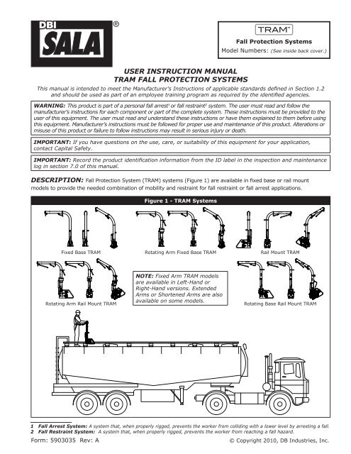
descRIPTION: Fall Protection System (<strong>TRAM</strong>) systems (Figure 1) are available in fixed base or rail mount<br />
models to provide the needed combination of mobility and restraint for fall restraint or fall arrest applications.<br />
Figure 1 - <strong>TRAM</strong> Systems<br />
Fixed Base <strong>TRAM</strong> Rotating Arm Fixed Base <strong>TRAM</strong> Rail Mount <strong>TRAM</strong><br />
Rotating Arm Rail Mount <strong>TRAM</strong><br />
<strong>UseR</strong> <strong>INsTRUcTION</strong> <strong>MANUAl</strong><br />
<strong>TRAM</strong> <strong>FAll</strong> <strong>PROTecTION</strong> <strong>sysTeMs</strong><br />
NOTe: Fixed Arm <strong>TRAM</strong> models<br />
are available in Left-Hand or<br />
Right-Hand versions. Extended<br />
Arms or Shortened Arms are also<br />
available on some models.<br />
Fall Protection Systems<br />
Model Numbers: (See inside back cover.)<br />
This manual is intended to meet the Manufacturer’s Instructions of applicable standards defined in Section 1.2<br />
and should be used as part of an employee training program as required by the identified agencies.<br />
Rotating Base Rail Mount <strong>TRAM</strong><br />
1 Fall Arrest system: A system that, when properly rigged, prevents the worker from colliding with a lower level by arresting a fall.<br />
2 Fall Restraint system: A system that, when properly rigged, prevents the worker from reaching a fall hazard.<br />
Form: 5903035 Rev: A<br />
© Copyright 2010, DB Industries, Inc.
Figure 2 illustrates key components of the <strong>TRAM</strong> system. The <strong>TRAM</strong> Arm (A) raises and lowers with the assistance<br />
of a Gas Strut (B); providing fall protection during transition from a ladder to a platform or walkway (access and<br />
egress). Rail Mounted <strong>TRAM</strong>s ride along Rail sections (C) to allow protected mobility as the operator moves along<br />
the walkway or platform. The <strong>TRAM</strong> Arm serves a hand-hold for the operator and is equipped with Anchor Points<br />
(D) for connecting the Hip D-Ring Lanyards (E) from a Capital Safety <strong>TRAM</strong> Full Body Harness (F). The <strong>TRAM</strong> Arm<br />
is also equipped with a Pivot Lock Pin Lever (G) to control vertical pivoting of the <strong>TRAM</strong> Arm. On Rail Mounted<br />
<strong>TRAM</strong>s, a Brake Release Lever (H) is included to control horizontal travel along the Rail. In the event the Brake<br />
Release Lever fails to function, the <strong>TRAM</strong> is equipped with a Brake Override Foot Lever (I) which unlocks the <strong>TRAM</strong><br />
Brake, allowing movement along the Rail.<br />
Rotating Base (J) and Rotating Arm (K) models of the <strong>TRAM</strong> system are equipped with a Rotary Joint (L) and<br />
Rotation Lever (M) to allow rotation of the <strong>TRAM</strong> Arm for access to a wider area of the work platform.<br />
D<br />
L<br />
B<br />
A<br />
B<br />
G<br />
C<br />
D<br />
Figure 2 - <strong>TRAM</strong> Components<br />
H<br />
A Arm B Gas Strut C Rail D Anchor Point E Hip D-Ring Lanyard F Full Body Harness G Pivot Lock Pin Lever<br />
H Brake Release Lever I Brake Override Foot Lever J Rotating Base <strong>TRAM</strong> K Rotating Arm <strong>TRAM</strong> L Rotary Joint M Rotation Lever<br />
2<br />
E<br />
M<br />
D<br />
F<br />
J<br />
L<br />
I<br />
D<br />
E<br />
K<br />
M<br />
L<br />
I
1.0 APPlIcATION<br />
1.1 PURPOSE: The <strong>TRAM</strong> Fall Protection System provides fall restraint 1 for transfer from a ladder to a platform or walkway.<br />
Where additional mobility is needed on the platform or walkway, rotating arm and/or rail mounted systems are<br />
available.<br />
For effective fall restraint, the <strong>TRAM</strong> should always be positioned so the combination of anchorage points<br />
and lanyards allows unrestricted performance of work tasks, but inhibits the operator from reaching a<br />
position where the risk of fall from height exists.<br />
1.2 FALL ARREST: Under special conditions of use, the <strong>TRAM</strong> system may be installed as an anchorage for fall<br />
arrest. Consult Capital Safety for more information.<br />
1.3 STAnDARDS: Refer to local, regional and national standards and regulations governing occupational safety<br />
for additional information regarding fall protection.<br />
1.4 TRAInInG: This equipment is intended to be used by persons trained in its correct application and use. Users must<br />
be familiar with these instructions. Users must be aware of the operating characteristics, application limits, and the<br />
consequences of improper use.<br />
2.0 sysTeM lIMITATIONs & ReqUIReMeNTs<br />
2.1 CAPACITy: This equipment is designed for use by a one person at a time. Combined weight of the individual<br />
(person, clothing, tools, etc.) should not exceed 310 lbs (141 kg).<br />
2.2 AnCHORAGE: The structure to which the <strong>TRAM</strong> base or rail is mounted must be capable of sustaining the loads<br />
given in the Installation Appendix.<br />
Figure 3 - Fall Restraint<br />
A Working Level B Two Restraint Limits, Hip D-Ring Lanyard. each 2 ft. (0.6 m) Max. per ANSI Z359.1<br />
2.7 EnvIROnMEnTAL HAzARDS: Use of this equipment in areas where environmental hazards exist may require<br />
additional precautions to reduce the possibility of injury to the user or damage to the equipment. Hazards may<br />
include, but are not limited to: high heat, caustic chemicals, corrosive environments, high voltage power lines,<br />
explosive or toxic gases, moving machinery, or sharp edges.<br />
2.8 BODy SUPPORT: A Capital Safety approved Full Body Harness with integrated Hip D-Ring Lanyards must be<br />
used with the <strong>TRAM</strong>. The harness connection point must be above the user’s center of gravity. A body belt is not<br />
authorized for use with the <strong>TRAM</strong>. If a fall occurs when using a body belt it may cause unintentional release and<br />
possible suffocation because of improper body support. Substitutions of equipment or system components must<br />
not be made without the written consent of Capital Safety.<br />
1 Fall Restraint system: A system that, when properly rigged, prevents the worker from reaching a fall hazard.<br />
3<br />
A<br />
B
2.9 COMPATIBILITy OF COMPOnEnTS: Unless otherwise noted, Capital Safety equipment is designed for use with<br />
DBI-SALA approved components and subsystems only. Substitutions or replacements made with non approved<br />
components or subsystems may jeopardize compatibility of equipment and may affect safety and reliability of the<br />
complete system.<br />
2.10 COMPATIBILITy OF COnnECTORS: Connectors are considered to be compatible with connecting<br />
elements when they have been designed to work together in such a way that their sizes and shapes do not<br />
cause their gate mechanisms to inadvertently open regardless of how they become oriented. Connectors<br />
(hooks, carabiners, and D-rings) must be capable of supporting at least 5,000 lbs. (22 kN). Connectors<br />
must be compatible with the anchorage or other system components. Do not use equipment that is not<br />
compatible. Non-compatible connectors may unintentionally disengage (see Figure 4). Connectors must<br />
be compatible in size, shape, and strength. Self-locking snap hooks and carabiners are required by ANSI<br />
Z359.1 and OSHA.<br />
2.11 MAKInG COnnECTIOnS: Use only self-locking snap hooks and carabiners with this equipment. Only use<br />
connectors that are suitable to each application. Ensure all connections are compatible in size, shape and<br />
strength. Do not use equipment that is not compatible. Ensure all connectors are fully closed and locked.<br />
DBI-SALA connectors (snap hooks and carabiners) are designed to be used only as specified in each<br />
product’s user’s instructions. Figure 5 shows inappropriate connections. As illustrated, DBI-SALA snap hooks<br />
and carabiners should not be connected:<br />
A.<br />
B.<br />
To a D-ring to which another connector is attached.<br />
In a manner that would result in a load on the gate.<br />
C. In<br />
a false engagement, where features that protrude from the snap hook or carabiner catch on the<br />
anchor and without visual confirmation seems to be fully engaged to the anchor point.<br />
D. To<br />
each other.<br />
E. Directly<br />
to webbing or rope lanyard or tie-back (unless the manufacturer’s instructions for both the<br />
lanyard and connector specifically allow such a connection).<br />
F. To<br />
any object which is shaped or dimensioned such that the snap hook or carabiner will not close and<br />
lock, or that roll-out could occur.<br />
NOTe: Other than 3,600 lb. (16 kN) gated hooks, large throat opening snap hooks should not be connected<br />
to standard size D-rings or similar objects which will result in a load on the gate if the hook or D-ring twists<br />
or rotates. Large throat snap hooks are designed for use on fixed structural elements such as rebar or cross<br />
members that are not shaped in a way that can contact the gate of the hook.<br />
Figure 4 - Unintentional Disengagement (Rollout)<br />
If the connecting element to which a snap hook (shown) or carabiner<br />
attaches is undersized or irregular in shape, a situation could occur<br />
where the connecting element applies a force to the gate of the snap<br />
hook or carabiner. This force may cause the gate (of either a selflocking<br />
or a non-locking snap hook) to open, allowing the snap hook<br />
or carabiner to disengage from the connecting point.<br />
7.<br />
Small ring or other<br />
non-compatibly<br />
shaped element<br />
Force is applied<br />
to the Snap<br />
Hook.<br />
8.<br />
The Gate<br />
presses against<br />
the Connecting<br />
Ring.<br />
9.<br />
The Gate opens<br />
allowing the<br />
Snap Hook to<br />
slip off.<br />
4<br />
Figure 5 - Inappropriate Connections
3.0 PRePARATION<br />
WARNING: Do not alter or intentionally misuse this equipment. Consult Capital Safety when using this<br />
equipment in combination with components or subsystems other than those described in this manual. Some<br />
subsystem and component combinations may interfere with the operation of this equipment. Use caution when<br />
using this equipment around moving machinery, electrical and chemical hazards, and sharp edges.<br />
3.1 PRE-USE CHECKS: Pre-Use checks are essential and should be carried out by the operator prior to each<br />
use of the <strong>TRAM</strong> system.<br />
Full Body Harness:<br />
1.<br />
Inspect the Full Body Harness per the inspection procedures defined in the User Instruction Manual<br />
shipped with the harness.<br />
<strong>TRAM</strong>:<br />
1. Inspect the <strong>TRAM</strong> and Rail System (if applicable) per the inspection procedures defined in the Inspection<br />
Schedules (see Section 5).<br />
IMPORTANT: Where fall risks exist during inspection of the Fall Protection System, the operator should<br />
attach to the <strong>TRAM</strong> system to complete pre-use checks (see Section 4).<br />
3.2 PLAnnInG: Plan out your <strong>TRAM</strong> application before use. Consider all factors that affect your safety during<br />
<strong>TRAM</strong> operation including the following aspects:<br />
• Installation: <strong>TRAM</strong> installation can be performed by your local Capital Safety <strong>TRAM</strong> dealer/<br />
representative, a licensed <strong>TRAM</strong> installer, or the owner of the <strong>TRAM</strong> system. Consult the <strong>TRAM</strong><br />
Installation Instructions for requirements and recommendations.<br />
• Sharp Edges: Avoid working where system components may contact or abrade against sharp edges.<br />
• Rescue: The employer must have a rescue plan in place and the ability to execute a rescue quickly and<br />
safely.<br />
• After a Fall:<br />
Any equipment which has been subject to the forces of arresting a fall, or exhibits damage<br />
consistent with the effect of fall arrest forces must be removed from service.<br />
3.3 TRAInInG: It is the responsibility of the user and purchaser of this equipment to assure they are familiar<br />
with the instructions, operating characteristics, application limits, and the consequences of improper use of<br />
this equipment. Users and purchasers of this equipment must be trained in the correct care and use of this<br />
equipment. Contact Capital Safety for additional training guidelines.<br />
4.0 OPeRATION<br />
4.1 <strong>TRAM</strong> Fall Protection System operation varies slightly with the <strong>TRAM</strong> model and its respective<br />
features (see Table 1). Where applicable, the following instructions differentiate feature specific<br />
actions:<br />
Step 1. Don and Adjust the Full Body Harness: Don and adjust the Full Body<br />
Harness as instructed in the manufacturer’s User Instruction Manual.<br />
Step 2. Connect Lanyard Snap Hooks in the “Carry Position”: The Full Body<br />
Harness is equipped with integrated Lanyards on the Hip D-Rings. Attach the<br />
Snap Hook on the free end of each Lanyard to its respective Hip D-Ring to<br />
prevent the Lanyards from tangling or catching on objects while climbing the<br />
ladder.<br />
5<br />
1
Step 3. Climb the Ladder: Climb up the ladder to the lowest point<br />
where the horizontal <strong>TRAM</strong> Arm can be reached and held.<br />
WARNING: Always maintain three points of contact with<br />
the ladder to reduce the potential for an unprotected fall.<br />
Step 4. Connect the Harness Lanyards to the <strong>TRAM</strong> Arm: Detach<br />
one of the Lanyard Snap Hooks from the “Carry Position” and<br />
attach it to the corresponding Anchor Point on the <strong>TRAM</strong> Arm.<br />
Repeat this process for the other Lanyard. Be sure Lanyards<br />
are connected to their respective Anchor Points and are not<br />
cross-connected.<br />
WARNING: While connecting the Lanyards to the <strong>TRAM</strong><br />
Arm, always maintain three points of contact with the<br />
ladder and <strong>TRAM</strong> Arm to reduce the potential for an<br />
unprotected fall.<br />
Step 5. Raise the <strong>TRAM</strong> Arm: Grasp the <strong>TRAM</strong> Arm with both hands<br />
and squeeze the Pivot Lock Pin Lever to allow the <strong>TRAM</strong> Arm<br />
to rotate upward to the 45 degree position. Lock the arm at<br />
this position.<br />
Step 6. Transfer from the Ladder to the Platform or Walkway:<br />
Ascend the remainder of the Ladder onto the Platform or<br />
Walkway while continuing to grasp the <strong>TRAM</strong> Arm.<br />
Step 7. Lock the <strong>TRAM</strong> Arm: After climbing onto the Platform or<br />
Walkway, squeeze the Pivot Lock Pin Lever to allow the <strong>TRAM</strong><br />
Arm to rotate upward to the vertical position.<br />
Step 8. Maneuver about the Work Area and Perform Required<br />
Tasks: Depending on your <strong>TRAM</strong> model, varied controls are<br />
available to assist movement to a safe, optimal work position<br />
(see Table 1):<br />
Step 9. Transfer from the Platform or Walkway to the Ladder:<br />
At the end of the walkway or platform, turn and face the<br />
<strong>TRAM</strong> Arm. Grasp the <strong>TRAM</strong> Arm with both hands, squeeze<br />
the Pivot Lock Pin Lever, and back onto and down the ladder<br />
while rotating the <strong>TRAM</strong> Arm to the 45 degree position. Lock<br />
the arm at this position. Continue down the ladder. Squeeze<br />
the Pivot Lock Pin Lever while rotating the <strong>TRAM</strong> Arm to the<br />
horizontal position. Release the Pivot Lock Pin Lever to lock<br />
the <strong>TRAM</strong> Arm in the horizontal position.<br />
WARNING: Grasp the <strong>TRAM</strong> Arm with both hands while<br />
transferring from the platform/walkway to the ladder to<br />
ensure three points of contact and reduce potential for an<br />
unprotected fall.<br />
Step 10. Detach the Lanyard Snap Hooks from the <strong>TRAM</strong> Arm: Detach one of the Lanyard Snap Hooks<br />
from the <strong>TRAM</strong> Arm Anchor Point and attach it to the Hip D-Ring on the Full Body Harness. Repeat<br />
this process for the other Lanyard<br />
WARNING: While detaching the Lanyards from the <strong>TRAM</strong> Arm, always maintain three points of<br />
contact with the ladder and <strong>TRAM</strong> Arm to reduce the potential for an unprotected fall.<br />
Step 11. Proceed down the Ladder: Climb the rest of the way down the ladder and then remove and<br />
store the Full Body Harness as instructed in the manufacturer’s User Instruction Manual.<br />
WARNING: While climbing down the ladder, always maintain three points of contact with the<br />
ladder to reduce potential for an unprotected fall.<br />
4.2 ISO<strong>TRAM</strong> (with ladder) Operation:<br />
6<br />
3<br />
4<br />
5<br />
6<br />
9<br />
10
Step 1. Pre Use Check: Always check the system before use.<br />
Step 2. Mount the ISO<strong>TRAM</strong>: Use a light forklift to mount the<br />
ISO<strong>TRAM</strong> on the container.<br />
Step 3. Protect the ladder Lanyard: Make sure that the Ladder<br />
Lanyard does not get caught while mounting the ISO<strong>TRAM</strong> on<br />
the container.<br />
Step 4. Align the ISO Connector and lower the ISO<strong>TRAM</strong>:<br />
Confirm that the ISO connector is properly aligned.<br />
Lower the ISO<strong>TRAM</strong> onto the container.<br />
Step 5. Pull the ladder down:<br />
Pull with mild force on the<br />
Ladder Lanyard to lower the<br />
Ladder.<br />
Step 6. Find a stable surface: Ensure that the Ladder feet are on a<br />
stable, level surface.<br />
7
Step 7. Refer to Steps 1 through 4 in Operation Section 4.1:<br />
4.1, Step 1. Don and adjust the Full Body Harness.<br />
4.1, Step 2. Connect Lanyard Snap Hooks.<br />
4.1, Step 3. Climb the ladder.<br />
4.1, Step 4. Connect the Harness Lanyards to the <strong>TRAM</strong> Arm.<br />
Step 8. Lock the ISO<strong>TRAM</strong> Frame to the container:<br />
While maintaining three points of contact, pull the interlocking<br />
lever toward the ladder to insert the ISO<strong>TRAM</strong> container pin lock<br />
into the corner casting of the container.<br />
Step 9. Refer to Steps 5 through 9 in Operation Section 4.1:<br />
4.1, Step 5. Raise the <strong>TRAM</strong> Arm.<br />
4.1, Step 6. Transfer from the Ladder to the Platform<br />
4.1, Step 7. Lock the <strong>TRAM</strong> Arm<br />
4.1, Step 8. Maneuver about the Work Area and Perform Required Tasks.<br />
4.1, Step 9. Transfer from the Platform to the Ladder.<br />
Step 10. If the ISO<strong>TRAM</strong> is to be removed from the container:<br />
Push the interlocking lever away from the ladder to release the<br />
ISO<strong>TRAM</strong> from the container and to lock down the <strong>TRAM</strong> arm.<br />
Step 11. Refer to Steps 10 and 11 in Operation Section 4.1:<br />
4.1, Step 10. Detach the Lanyard Snap Hooks from the <strong>TRAM</strong> Arm.<br />
4.1, Step 11. Proceed down the Ladder.<br />
If the ISO<strong>TRAM</strong> was unlocked for removal in Step 10, repeat the use of a light forklift to remove the<br />
ISO<strong>TRAM</strong> from the container.<br />
8
Controls:<br />
Table 1 - <strong>TRAM</strong> Controls<br />
A. Pivot Lock Pin Lever - To gain additional freedom of<br />
movement when kneeling, squatting, or sitting; squeeze<br />
the Pivot Lock Pin Lever and lower the <strong>TRAM</strong> arm to the<br />
45 degree or horizontal position. Release the Pivot Lock<br />
Pin Lever to lock the arm at the desired position.<br />
B. Base Rotation Lever - On <strong>TRAM</strong> installations where the<br />
Ladder is not in line with the direction of travel along the<br />
Rail, press down on the Rotation Lever with your foot<br />
and rotate the <strong>TRAM</strong> Base until the <strong>TRAM</strong> Arm is aligned<br />
for travel along the platform or walkway. Let up on the<br />
Rotation Lever to lock the Base in position.<br />
C. Arm Rotation Lever - Rotating <strong>TRAM</strong> Arms can rotate<br />
180° from their initial position. To position the <strong>TRAM</strong> Arm<br />
for work on the other side of the <strong>TRAM</strong> Rail, squeeze the<br />
Rotation Lever and rotate the <strong>TRAM</strong> Arm to the desired<br />
position. Release the Rotation lever to lock the <strong>TRAM</strong> Arm<br />
at the 90° or 180° position.<br />
D. Brake Lever - To move along the rail to a new position<br />
on the platform or walkway, squeeze the Brake Lever to<br />
release the Brake. Continue squeezing the Brake Lever<br />
while pushing the <strong>TRAM</strong> along the Rail. When the desired<br />
work position is reached, release the Brake Lever to lock<br />
the Brake.<br />
The Lanyards on the Harness are long enough to allow<br />
turning your back to the <strong>TRAM</strong>. To return to the ladder,<br />
turn and walk back toward the ladder while squeezing the<br />
Brake Lever and pulling the <strong>TRAM</strong> behind you.<br />
E. Brake Override Foot Lever - If the Brake fails to<br />
release when the Brake Lever is squeezed, press<br />
backwards on the Brake Override Foot Lever to release<br />
the Brake.<br />
9<br />
Fixed<br />
Base<br />
Rail<br />
Mount<br />
Rotating<br />
Base<br />
Rotating<br />
Arm<br />
X X X X<br />
X<br />
X<br />
X<br />
X
5.0 INsPecTION<br />
5.1 FREQUEnCy: Inspection Schedule 1 defines inspection procedures for the <strong>TRAM</strong> system. Inspections should<br />
be performed at the following intervals:<br />
• Before Each Use: Pre-Use checks are essential and should be carried out by the operator prior to each<br />
use of the <strong>TRAM</strong> system. Checks should consist of tactile and visual inspections to ensure the <strong>TRAM</strong><br />
system is ready for immediate use.<br />
• Semi-Annual Inspection: A formal inspection of the <strong>TRAM</strong> system must be performed at intervals of<br />
six months or less by a competent person other than the user.<br />
IMPORTANT: Extreme working conditions (harsh environments, prolonged use, etc.) may require<br />
increasing the frequency of inspections.<br />
• After a Fall: The <strong>TRAM</strong> system should be removed from service if it has been subjected to fall arrest<br />
forces.<br />
5.2 InSPECTIOn GUIDELInES: The Inspection Schedules define inspection procedures and their<br />
recommended frequencies. Where identified conditions may be rectified with routine maintenance,<br />
procedures are defined in the Inspection Schedules:<br />
Inspection Steps:<br />
Inspection Schedule 1 - <strong>TRAM</strong> Arm @<br />
Step 1. Inspect the following parts for any permanent deformation in shape or<br />
orientation:<br />
A <strong>TRAM</strong> Arm<br />
B Attachment Rings<br />
C Gas strut<br />
D Pivot Lock Pin Lever<br />
E Brake Lever (where fitted)<br />
F Pivot Lock Pin<br />
G Rotary Joint (where fitted)<br />
H Rotary Joint Lever (where fitted)<br />
I Rotary Joint Pin (where fitted)<br />
IMPORTANT: If any permanent deformation is detected, remove the<br />
<strong>TRAM</strong> from service immediately and consult Capital Safety for instructions.<br />
Step 2. Inspect the labels (J, K, L) on<br />
the <strong>TRAM</strong>. All labels should be<br />
attached and legible. If labels<br />
are missing or illegible, contact<br />
Capital Safety for replacements.<br />
Step 3. Inspect the <strong>TRAM</strong> Arm (A), including all welds, for evidence of corrosion.<br />
IMPORTANT: If corrosion is detected on the <strong>TRAM</strong> Arm, remove the<br />
<strong>TRAM</strong> from service and consult Capital Safety for instructions.<br />
10<br />
B<br />
E<br />
J<br />
K<br />
D<br />
G<br />
C<br />
B<br />
A<br />
I<br />
L<br />
F<br />
B<br />
H<br />
Before<br />
Each Use<br />
Every 6<br />
Months<br />
X X<br />
X X<br />
X X<br />
@ - capital safety Authorized competent Person: All inspection, maintenance, service, and repair work on the <strong>TRAM</strong> system must be<br />
performed by a Capital Safety Authorized Competent Person. Your Capital Safety <strong>TRAM</strong> Dealer is authorized to inspect, maintain, service, and repair the<br />
<strong>TRAM</strong> system. Your Capital Safety <strong>TRAM</strong> Dealer may also be contracted to train and authorize Competent Persons within your organization.
Inspection Steps:<br />
Inspection Schedule 1 - <strong>TRAM</strong> Arm @<br />
Step 4. Squeeze the Pivot Lock Pin Lever (D) and ensure that it operates smoothly<br />
and freely. The Split Pin retaining the Clevis Pin in the pivot joint should<br />
be securely in place and undamaged. When activating the Pivot Lock Pin<br />
Lever, the Pivot Lock Pin (F) should retract completely from the Location Slot<br />
allowing the <strong>TRAM</strong> Arm (A) to pivot. Pivot the <strong>TRAM</strong> Arm and ensure that the<br />
Lock Pin locks and retracts properly at each slot position.<br />
MAINTeNANce: If the Pivot Lock Pin is difficult to retract from the Location<br />
Slot, spray silicon base lubricant/release agent on the Pivot Lock Pin and<br />
Location Slot to free the Pivot Lock Pin. Also, spray each of the remaining<br />
Location Slots. If the Pivot Lock Pin Lever still fails to operate properly, the<br />
Pivot Lock Pin may require adjustment. See the <strong>TRAM</strong> Service & Repair<br />
Manual for instructions.<br />
Step 5. On <strong>TRAM</strong>s fitted with a Rotating <strong>TRAM</strong> Arm, squeeze the Rotary Joint Lever<br />
(H) and ensure that it operates smoothly and freely. The Split Pin retaining<br />
the Clevis Pin in the pivot joint should be securely in place and undamaged.<br />
When activating the Rotary Joint Lever, the Rotary Joint Pin (I) should<br />
retract completely from the Location Slot allowing the <strong>TRAM</strong> Arm (A) to<br />
rotate. Rotate the <strong>TRAM</strong> Arm and ensure that the Lock Pin locks and retracts<br />
properly at each slot position.<br />
MAINTeNANce: If the Latch Pin is difficult to retract from the Location Slot,<br />
spray silicon base lubricant/release agent on the Pivot Lock Pin and Location<br />
Slot to free the Pivot Lock Pin. Also, spray each of the remaining Location<br />
Slots. If the Rotary Joint Lever still fails to operate properly, remove the <strong>TRAM</strong><br />
from service and contact Capital Safety for further instructions.<br />
Step 6. To inspect the Gas Strut (C), move the <strong>TRAM</strong> Arm to the vertical position to<br />
fully extend the Gas Strut. The Gas Strut should be clean and free of dirt.<br />
Ensure Gas Strut Ends (M) are secured by a M8 Screw (N) and Nyloc Nut (O)<br />
and .02”-.04” (0.5 mm - 1 mm) of clearance (play) is present between each<br />
side of the Gas Strut End and the adjacent fastener (as illustrated). The<br />
clearance allows for potential misalignment and maximizes life of the Gas<br />
Strut.<br />
MAINTeNANce: To remove dirt<br />
from the Gas Strut, use a damp,<br />
clean, soft cloth. Do not scrub<br />
or apply heavy pressure to the<br />
polished rod.<br />
NOTe: The Gas Strut does not<br />
require greasing or lubrication.<br />
11<br />
.02” - .04”<br />
(0.5 mm - 1.0 mm)<br />
Step 7. Inspect for proper operation of the Gas Strut (C) by squeezing the Pivot Lock<br />
Pin Lever (D) and pivoting the Arm through all three positions. The Gas Strut<br />
should always exert a lifting force in the direction of extension when the Arm<br />
is pivoted.<br />
OveRhAUl seRvIce: If no lifting force is exerted by the Gas Strut while<br />
pivoting the Arm, the Gas Strut Should be replaced by authorized service<br />
personnel @ . See the "<strong>TRAM</strong> Service Manual" for detailed instructions.<br />
N<br />
M<br />
O<br />
Before<br />
Each Use<br />
Every 6<br />
Months<br />
X X<br />
X X<br />
X X<br />
X X<br />
@ - capital safety Authorized competent Person: All inspection, maintenance, service, and repair work on the <strong>TRAM</strong> system must be<br />
performed by a Capital Safety Authorized Competent Person. Your Capital Safety <strong>TRAM</strong> Dealer is authorized to inspect, maintain, service, and repair the<br />
<strong>TRAM</strong> system. Your Capital Safety <strong>TRAM</strong> Dealer may also be contracted to train and authorize Competent Persons within your organization.
Inspection Steps:<br />
Step 8. Check the Pivot Pin Set Screws<br />
(P) for proper torque. Correct<br />
torque range is 7-11 ft-lbs (9-<br />
15 Nm).<br />
Inspection Schedule 1 - <strong>TRAM</strong> Arm @<br />
Step 9. Record inspection and service activity in the Inspection & Maintenance Log<br />
(Section 9).<br />
12<br />
P<br />
P<br />
Before<br />
Each Use<br />
Every 6<br />
Months<br />
X<br />
X X<br />
@ - capital safety Authorized competent Person: All inspection, maintenance, service, and repair work on the <strong>TRAM</strong> system must be<br />
performed by a Capital Safety Authorized Competent Person. Your Capital Safety <strong>TRAM</strong> Dealer is authorized to inspect, maintain, service, and repair the<br />
<strong>TRAM</strong> system. Your Capital Safety <strong>TRAM</strong> Dealer may also be contracted to train and authorize Competent Persons within your organization.<br />
Inspection Steps:<br />
A Trolley Casting<br />
B Crash Guard<br />
C Brake Shoes<br />
D Upper Wheels<br />
E Lower Wheels<br />
F Upper Wheel Lock<br />
Screws<br />
G Lower Wheel Lock<br />
Screws<br />
C<br />
Inspection Schedule 2 - <strong>TRAM</strong> Trolley @<br />
F<br />
x4<br />
Step 1. Inspect the Trolley Casting (A) and Crash Guard (B) for any permanent<br />
deformation in shape or orientation.<br />
F<br />
x4<br />
IMPORTANT: If any permanent deformation is detected, remove the<br />
<strong>TRAM</strong> from service immediately and consult Capital Safety for instructions.<br />
Step 2. Inspect the Trolley Casting (A) and Crash Guard (B), including all welds, for<br />
evidence of corrosion.<br />
IMPORTANT: If corrosion is detected, remove the <strong>TRAM</strong> from service and<br />
consult Capital Safety for instructions.<br />
C<br />
A<br />
B<br />
x4<br />
D<br />
G<br />
x4<br />
B<br />
G<br />
x4<br />
F<br />
D<br />
E<br />
x4<br />
x4<br />
x4<br />
C<br />
Before<br />
Each Use<br />
Every 6<br />
Months<br />
X X<br />
X X<br />
@ - capital safety Authorized competent Person: All inspection, maintenance, service, and repair work on the <strong>TRAM</strong> system must be<br />
performed by a Capital Safety Authorized Competent Person. Your Capital Safety <strong>TRAM</strong> Dealer is authorized to inspect, maintain, service, and repair the<br />
<strong>TRAM</strong> system. Your Capital Safety <strong>TRAM</strong> Dealer may also be contracted to train and authorize Competent Persons within your organization.
Inspection Steps:<br />
Inspection Schedule 2 - <strong>TRAM</strong> Trolley @<br />
Step 3. Squeeze the <strong>TRAM</strong> Brake Lever to release the brake and check wheel<br />
adjustment and function by rolling the <strong>TRAM</strong> along the entire Rail assembly.<br />
If the <strong>TRAM</strong> Trolley does not roll smoothly along the Rail, it may be due to<br />
any of the following conditions:<br />
• The Brake System is not releasing properly.<br />
• The Rail and Rail Fixtures are damaged or in poor condition.<br />
• The Trolley Wheels (D & E) are not functioning properly.<br />
MAINTeNANce: The following diagnostics and corrective actions may be<br />
performed in the event of the Trolley does not roll smoothly on the Rail:<br />
• The Brake system is not releasing properly: If squeezing the Brake<br />
Lever does not completely disengage the Brake Shoes (C) from the Rail,<br />
the Brake Pads may be rubbing on the rail and impeding smooth travel.<br />
Inspect and service the <strong>TRAM</strong> Brake System per the recommendations<br />
in Inspection Schedule 3.<br />
• The Rail and Rail Fixtures are damaged or in poor condition: Inspect<br />
and service the Rail and Rail Fixtures per the recommendations in<br />
Inspection Schedule 4.<br />
• The Trolley Wheels are not functioning properly: The <strong>TRAM</strong> Wheels<br />
may require adjustment. Wheel adjustment should be performed<br />
by authorized service personnel@ . See the "<strong>TRAM</strong> Service Manual"<br />
(5901906) for detailed instructions.<br />
If Trolley travel along the Rail is still rough, contact your Capital Safety<br />
<strong>TRAM</strong> Dealer for further instruction.<br />
Step 4. While travelling along the Rail, a small<br />
amount of <strong>TRAM</strong> Arm ‘play’, relative to<br />
the Rail, is normal. Squeeze the Brake<br />
Lever and roll the <strong>TRAM</strong> along the Rail to<br />
observe the amount of play. The amount<br />
of play at the end of the <strong>TRAM</strong> Arm<br />
should not exceed 0.6” (15 mm).<br />
MAINTeNANce: If <strong>TRAM</strong> Arm play<br />
exceeds 0.6” (15 mm), The Trolley<br />
Wheels should be adjusted or replaced<br />
by authorized service personnel @ .<br />
See the "<strong>TRAM</strong> Service Manual" for<br />
detailed instructions.<br />
Step 5. Check all Wheel Lock Screws (F & G) for proper torque. Correct torque<br />
ranges are as follows:<br />
• Upper Wheel Lock Screws (F): 60-90 ft-lbs (80-120 Nm)<br />
• Lower Wheel Lock Screws (G): 15-25 ft-lbs (21-35 Nm)<br />
Step 6. Record inspection and service activity in the Inspection & Maintenance Log<br />
(Section 9).<br />
13<br />
>0.6”<br />
(15 mm)<br />
Before<br />
Each Use<br />
Every 6<br />
Months<br />
X X<br />
X X<br />
X<br />
X X<br />
@ - capital safety Authorized competent Person: All inspection, maintenance, service, and repair work on the <strong>TRAM</strong> system must be<br />
performed by a Capital Safety Authorized Competent Person. Your Capital Safety <strong>TRAM</strong> Dealer is authorized to inspect, maintain, service, and repair the<br />
<strong>TRAM</strong> system. Your Capital Safety <strong>TRAM</strong> Dealer may also be contracted to train and authorize Competent Persons within your organization.
Inspection Steps:<br />
A Brake Pads<br />
B Brake Shoes<br />
C Brake Support Arms<br />
D Brake Lever<br />
E Split Pin<br />
F Clevis Pin<br />
G Nyloc Nut<br />
H Brake Override Foot<br />
Lever<br />
Inspection Schedule 3 - <strong>TRAM</strong> Brake System @<br />
F<br />
E<br />
H<br />
14<br />
B<br />
G<br />
C<br />
A<br />
Before<br />
Each Use<br />
Step 1. Remove the <strong>TRAM</strong> from the Rail and clamp in an upright position. Per<br />
Schedule 2<br />
Step 2. Inspect the all components of the Brake System for any permanent<br />
deformation in shape or orientation.<br />
IMPORTANT: If any permanent deformation is detected, remove<br />
the <strong>TRAM</strong> from service immediately and consult Capital Safety for<br />
instructions.<br />
Step 3. Inspect the all parts of the Brake System, including all welds, for evidence<br />
of corrosion.<br />
IMPORTANT: If corrosion is detected, remove the <strong>TRAM</strong> from service<br />
and consult Capital Safety for instructions.<br />
Step 4. Inspect the Brake Pads (A) for evidence of damage, excessive wear, or<br />
contamination.<br />
MAINTeNANce: If damage, excessive wear, or permanent<br />
contamination are detected, the Brake Shoes (B) should be replaced<br />
by authorized service personnel @ . See the "<strong>TRAM</strong> Service Manual" for<br />
detailed instructions<br />
Step 5. Verify that the Brake Shoes (B) pivot freely in the Brake Support Arms (C).<br />
MAINTeNANce: If needed, apply silicon based lubricant spray to free<br />
the Brake Shoe. Do not allow lubricant to contaminate the Brake Pad<br />
surface as this will affect brake performance.<br />
Step 6. Squeeze the Brake Lever (D) and ensure that it operates smoothly and<br />
freely. Play in the Brake Lever should not exceed 0.2” (5 mm). The Split<br />
Pin (E) retaining the Clevis Pin (F) in the pivot joint should be securely in<br />
place and undamaged.<br />
MAINTeNANce: If the Brake Lever fails to operate properly or has<br />
excessive play, the Brake System should be adjusted, or parts replaced, by<br />
authorized service personnel @ . See the "<strong>TRAM</strong> Service Manual" for detailed<br />
instructions.<br />
D<br />
B<br />
Per<br />
Schedule 2<br />
Per<br />
Schedule 2<br />
Per<br />
Schedule 2<br />
Per<br />
Schedule 2<br />
Per<br />
Schedule 2<br />
Every 6<br />
Months<br />
@ - capital safety Authorized competent Person: All inspection, maintenance, service, and repair work on the <strong>TRAM</strong> system must be<br />
performed by a Capital Safety Authorized Competent Person. Your Capital Safety <strong>TRAM</strong> Dealer is authorized to inspect, maintain, service, and repair the<br />
<strong>TRAM</strong> system. Your Capital Safety <strong>TRAM</strong> Dealer may also be contracted to train and authorize Competent Persons within your organization.<br />
X<br />
X<br />
X<br />
X<br />
X<br />
X
Inspection Steps:<br />
Inspection Schedule 3 - <strong>TRAM</strong> Brake System @<br />
Step 7. Inspect all exposed fasteners on the Brake System and tighten if loose.<br />
IMPORTANT: The M6 Nyloc Nut (G) securing the Brake Override Foot<br />
Lever (H) should not be tightened. Up to .02” (0.5 mm) of clearance<br />
should be present to allow pivoting of the Foot Lever.<br />
Step 8. Reinstall the <strong>TRAM</strong> on the rail and verify that the <strong>TRAM</strong> stops and the<br />
brakes lock onto the rail when the Brake Lever is released. With the brakes<br />
locked onto the rail, apply a pushing force of 65-90 lbs (300-400 N) to the<br />
<strong>TRAM</strong> in either direction of rail travel. Verify that the brake system remains<br />
locked. Repeat the test in the other direction of rail travel.<br />
Step 9. Check that activation of the Brake Override Foot Lever (H) released the<br />
brake to allow Trolley travel along the Rail.<br />
Step 10. Record inspection and service activity in the Inspection & Maintenance Log<br />
(Section 9).<br />
15<br />
Before<br />
Each Use<br />
Per<br />
Schedule 2<br />
Per<br />
Schedule 2<br />
Per<br />
Schedule 2<br />
Per<br />
Schedule 2<br />
Every 6<br />
Months<br />
@ - capital safety Authorized competent Person: All inspection, maintenance, service, and repair work on the <strong>TRAM</strong> system must be<br />
performed by a Capital Safety Authorized Competent Person. Your Capital Safety <strong>TRAM</strong> Dealer is authorized to inspect, maintain, service, and repair the<br />
<strong>TRAM</strong> system. Your Capital Safety <strong>TRAM</strong> Dealer may also be contracted to train and authorize Competent Persons within your organization.<br />
Inspection Steps:<br />
A End Stops<br />
B Rail<br />
C Rail Cleats<br />
D Mounting Brackets<br />
Inspection Schedule 4 - <strong>TRAM</strong> Rail Installation @<br />
C<br />
D<br />
Step 1. Inspect the End Stops (A) at both ends of the <strong>TRAM</strong> Rail, Both End Stops<br />
must be present and securely attached to the <strong>TRAM</strong> Rail. Missing or loose<br />
End Stops can result in the <strong>TRAM</strong> Trolley separating from the rail and<br />
consequent loss of fall restraint function.<br />
A<br />
C<br />
D<br />
MAINTeNANce: An End Stop Kit (7302065) is available to replace<br />
missing or damaged End Stop components. Contact your Capital Safety<br />
<strong>TRAM</strong> Dealer.<br />
Step 2. Inspect the Rail (B), Rail Cleats (C), Mounting Brackets (D), and all<br />
associated fasteners for deformation or corrosion.<br />
IMPORTANT: If any permanent deformation or corrosion is detected,<br />
remove the <strong>TRAM</strong> from service immediately and consult Capital Safety for<br />
instructions.<br />
B<br />
C<br />
D<br />
A<br />
Before<br />
Each Use<br />
X<br />
X<br />
X<br />
X<br />
Every 6<br />
Months<br />
X X<br />
X X<br />
@ - capital safety Authorized competent Person: All inspection, maintenance, service, and repair work on the <strong>TRAM</strong> system must be<br />
performed by a Capital Safety Authorized Competent Person. Your Capital Safety <strong>TRAM</strong> Dealer is authorized to inspect, maintain, service, and repair the<br />
<strong>TRAM</strong> system. Your Capital Safety <strong>TRAM</strong> Dealer may also be contracted to train and authorize Competent Persons within your organization.
Inspection Steps:<br />
Inspection Schedule 4 - <strong>TRAM</strong> Rail Installation @<br />
Step 3. If the Rail System is configured with equipotential bonding, check Grounding<br />
Straps for correct, secure attachment and excessive deposits around the<br />
Grounding Strap Ends. Confirm continuity between the <strong>TRAM</strong> Rail and the<br />
vehicle, vessel, or structure to which the Rail is mounted. Resistance should<br />
not exceed 10 ohms.<br />
Step 4. Record inspection and service activity in the Inspection & Maintenance Log<br />
(Section 9).<br />
16<br />
Before<br />
Each Use<br />
Every 6<br />
Months<br />
X X<br />
X X<br />
@ - capital safety Authorized competent Person: All inspection, maintenance, service, and repair work on the <strong>TRAM</strong> system must be<br />
performed by a Capital Safety Authorized Competent Person. Your Capital Safety <strong>TRAM</strong> Dealer is authorized to inspect, maintain, service, and repair the<br />
<strong>TRAM</strong> system. Your Capital Safety <strong>TRAM</strong> Dealer may also be contracted to train and authorize Competent Persons within your organization.<br />
5.3 UnSAFE OR DEFECTIvE COnDITIOnS: If inspection reveals an unsafe or defective condition, remove the<br />
component or Detachable Sleeve from service and destroy it or contact an authorized service center for repair.<br />
5.4 I-Safe RFID TAG: The <strong>TRAM</strong> system includes an i-Safe Radio Frequency Identification (RFID) tag.<br />
The RFID tag can be used in conjunction with the i-Safe handheld reading device and web based portal to<br />
simplify inspection and inventory control and provide records for your fall protection equipment. If you are<br />
a first-time user, contact a Capital Safety Customer Service representative (see back cover); or if you have<br />
already registered, go to www.capitalsafety.com/isafe.html. Follow the instructions provided with your i-Safe<br />
handheld reader or on the web portal to transfer your data to your web log.
6.0 lABelING<br />
The following labels must be securely attached and fully legible:<br />
Point of Entry Instruction Label<br />
Identification Label, Arm and Base<br />
17<br />
Standards Label
7.0 INsPecTION ANd MAINTeNANce lOG<br />
SERIAL nUMBER:<br />
MODEL nUMBER:<br />
DATE PURCHASED: DATE OF FIRST USE:<br />
InSPECTIOn DATE InSPECTIOn ITEMS<br />
nOTED<br />
Approved By:<br />
Approved By:<br />
Approved By:<br />
Approved By:<br />
Approved By:<br />
Approved By:<br />
Approved By:<br />
Approved By:<br />
Approved By:<br />
Approved By:<br />
Approved By:<br />
Approved By:<br />
Approved By:<br />
Approved By:<br />
Approved By:<br />
Approved By:<br />
Approved By:<br />
Approved By:<br />
18<br />
CORRECTIvE ACTIOn MAInTEnAnCE<br />
PERFORMED
APPeNdIx<br />
RAIl MOUNT <strong>TRAM</strong> <strong>FAll</strong> <strong>PROTecTION</strong> sysTeM INsTAllATION<br />
Because of the wide variety of vehicles and structures on which the <strong>TRAM</strong> Fall Protection System can be used, it<br />
is not possible to provide installation procedures for all situations. Some installation situations may have specific,<br />
critical requirements, such as installation of the <strong>TRAM</strong> system on fuel tankers. The installer is responsible for<br />
confirmation of all applicable regulations for the installation and for compliance with those regulations.<br />
WARNING: Repairs involving welding on a cargo tank wall must be performed by a facility registered with<br />
the Department of Transportation and having a National Board Certificate of Authorization for the use of the<br />
“R” stamp. In addition, repairs must be performed in accordance with all applicable regulations, the National<br />
Board Inspection Code and the American Society of Mechanical Engineers (ASME) code. A registered inspector<br />
is required to determine if the cargo tank complies with the applicable specification. Any tank that is discovered<br />
not in compliance with the specification requirements shall be removed from specification service until<br />
appropriate repairs or modifications have been completed.<br />
The installer must always verify the adequacy of anchor points either by calculation or by carrying out a test on a<br />
sample of the material in compliance with the specifications of the appropriate Standard(s). <strong>TRAM</strong> installation may<br />
be performed by a Capital Safety <strong>TRAM</strong> Dealer or representative, a licensed <strong>TRAM</strong> Installer or by the owner of the<br />
<strong>TRAM</strong> System.<br />
Applied Load<br />
lbf (kn)<br />
Anchorage Strength Requirements, Rail Mount <strong>TRAM</strong>:<br />
Applied Moment<br />
ft lbf (nm)<br />
Applied Moment,<br />
Extended Arm ft lbf (nm)<br />
X ±2,700 (12) ±2,000 (2,700) ±2,000 (2,700)<br />
y 5,000 (22) ±1,000 (1,350) ±1,000 (1,350)<br />
z ±2,700 (12) ±1,000 (1,350) ±1,000 (1,350)<br />
NOTe: The strength requirement values above include a safety factor of two times the actual allowable applied<br />
loads.<br />
This section describes the requirements and procedures for installation of a Rail Mount <strong>TRAM</strong> system on a bulk<br />
tanker (as seen in Figure 1).<br />
InSTALLATIOn CHECK LIST:<br />
•<br />
•<br />
Before beginning any work on tank trailers, confirm the status of the trailer. Verify that the tank trailer<br />
has been thoroughly purged of all flammable/combustible product (fuel) and vapors in accordance with<br />
industry accepted safety practices, procedures and codes. Ensure that the tank atmosphere has been<br />
properly checked with a combustible gas meter to determine if any combustible gases are present and<br />
verify that the tank is properly ventilated. This will determine the type of hot work or cold work to be<br />
done on the trailer.<br />
Hot Work: Any activity likely to produce a source of ignition. This includes all forms of welding,<br />
gas cutting, soldering, blast cleaning and the use of spark producing tools such as non-flame<br />
proof electric equipment, both line voltage and battery operated.<br />
Cold Work: Repair or servicing work which will not result in the application of heat, the<br />
generation of a source of ignition or a dangerous rise in temperature.<br />
WARNING: If the tanker has not been purged, do not conduct any hot work on or around the trailer.<br />
Does the rail require welding? This includes Cleats welded to the Rail or the joining of Rail sections (if the<br />
trailer is longer than the longest rail stock available). If so, you must:<br />
•<br />
•<br />
Confirm that a “Gas Free” certificate or verified tank wash certificate has been issued by a<br />
competent authority.<br />
Ensure that a welding or hot work certificate has been issued.<br />
19<br />
Z<br />
Y<br />
X
COnFIRM THAT yOU HAvE:<br />
•<br />
•<br />
•<br />
•<br />
•<br />
•<br />
•<br />
•<br />
•<br />
•<br />
The correct <strong>TRAM</strong> unit model for the installation. Left or Right Hand (refer to product ID label).<br />
The correct number of Adjustable Mounting Blocks. The maximum spacing allowed between mounting<br />
blocks is 8 ft. (2.4m), distributed along trailer length.<br />
NOTe: Confirm the tanker material. The Mounting Blocks must be of the same material.<br />
(Example: An aluminum tanker requires aluminum Mounting Blocks.)<br />
An equal number of stainless steel Cleats, gaskets (one gasket per Cleat or adjustable Mounting Block)<br />
and required bolts, washers and nuts.<br />
NOTe: All Mounting Blocks for fuel carrying trailers require the attachment of a static bond strap.<br />
End Stop Kit. End Stops must be fitted securely to both ends of the <strong>TRAM</strong> Rail to prevent the <strong>TRAM</strong> from<br />
travelling past the ends of the <strong>TRAM</strong> Rail.<br />
<strong>TRAM</strong> Full Body Harness.<br />
Required length(s) of 2 inch X 2 inch, 11 gauge (50 X 50 x 5mm) stainless steel square tubing with no<br />
visible raised external seams.<br />
NOTe: Stock square tubing is supplied in standard lengths. Tankers/trailer length may exceed the<br />
stock square tubing length.<br />
Checked the installation area and identified positions for hazardous activity.<br />
Identified an area for nonhazardous activity.<br />
Determined working at height safety requirements.<br />
Completed Task Risk Analysis.<br />
Step 1. Preparation of the 2 inch X 2 inch (50 X 50 X 5mm)<br />
<strong>TRAM</strong> Rail<br />
•<br />
•<br />
•<br />
Measure the combing rail length of the tanker and cut the square<br />
Rail tubing to the same length. The Rail tubing should be cut to<br />
leave approximately 2 to 4 inches (50 to 100mm) at each end of the<br />
trailer.<br />
Position the Rail tubing in a safe environment where hot work can be<br />
performed.<br />
If the tanker/trailer is longer than the available Rail tubing length,<br />
the Rail must be extended. Procedure:<br />
1. Cut the required amount of additional Rail tubing.<br />
2. Prepare a Rail Joiner 1½” x 1½” x 1/8” (40 X 40 X 3mm)<br />
for insertion between the two Rail lengths. Grind both ends of<br />
the Rail Joiner.<br />
3. Insert the Rail Joiner between the two ends of the Rail<br />
tubing and complete a weld of the two lengths. The proper<br />
weld is a bevel groove weld.<br />
NOTe: For all welding required for <strong>TRAM</strong> system installation, refer to the American Welding Society’s most<br />
recent handbook for proper joint preparation and filler metal selection for the base metal being welded.<br />
Side View:<br />
Rail Joiner<br />
Added Rail Tubing Rail<br />
20<br />
Required Tubing Length
•<br />
•<br />
•<br />
•<br />
•<br />
•<br />
•<br />
Complete the joint by smoothing the weld with a grinder. Ensure<br />
that the joint is not scalloped, i.e. not enough weld to fill the joint.<br />
This photo illustrates an insufficient weld on the joint, resulting in<br />
scalloping. This must be corrected before installation.<br />
Spray the joint with a layer of liquid cold gal silver spray.<br />
Ensure the joint is positioned at the opposite end to the ladder. This<br />
reduces the number of times that the <strong>TRAM</strong> will have to cross the<br />
joint.<br />
Smooth and shave both ends of the Rail. This will allow easy<br />
transition of the <strong>TRAM</strong> onto the Rail.<br />
Place the <strong>TRAM</strong> onto the rail and test the maneuverability of the <strong>TRAM</strong> along the Rail. Confirm that the<br />
Trolley moves smoothly over the Rail joint.<br />
Remove the <strong>TRAM</strong> from the Rail after you have conducted this test.<br />
The Rail is ready for installation of the Cleats.<br />
Step 2. Position of the Cleats ( 6 inch x 6 inch x ½ inch flat stainless steel plate) onto the <strong>TRAM</strong> Rail.<br />
•<br />
•<br />
•<br />
Rail Cleats are to be positioned no more than 8ft apart.<br />
Trailer Coaming Maximum of 8 ft between Mounting Blocks<br />
Measure the rail and confirm it meets the required distance for the top of the trailer.<br />
Earth Cleat<br />
Earth Strap connected to<br />
Earth Cleat and Mounting Block<br />
21<br />
Working from the front of the<br />
trailer, mark the rail with the<br />
position of the first Cleat with<br />
ground strap adaptor (approx.<br />
2 ft from the rail end with a<br />
maximum of 3 ft permissible).<br />
NOTE: ensure that the first<br />
cleat is the appropriate<br />
ground cleat.<br />
Working from the rear of the trailer, mark the position of the rear Cleat. i.e. approx 2 ft from the rail<br />
end with a maximum of 3 ft permitted.<br />
NOTE: at a later stage of the installation you will be required to fit an End Stop Kit. The position of the rear cleat may<br />
impact the location of the end bump stop if the rear cleat is mounted any closer than 2ft from the end of the rail.<br />
Establish the distance between the front and rear Cleats and equally divide this distance ensuring<br />
that a maximum of 8 ft is not exceeded. This will determine the number and location of the remaining<br />
Cleats. In some cases, based on trailer design, Cleat placement will be determined by the necessary<br />
placement of Mounting Blocks on tank stiffening rings and not the tank wall or rollover protection. In<br />
this case, the placement of the Mount Blocks must still not exceed the 8 ft spacing maximum between<br />
blocks.<br />
Weld the stainless steel Cleats to the <strong>TRAM</strong> rail, ensuring that they are vertical to the rail corners (135<br />
degrees to the rail sides). A positioning fixture can speed the process and help ensure consistent weld<br />
results.
•<br />
•<br />
•<br />
•<br />
•<br />
•<br />
Rail<br />
Cleat<br />
Weld<br />
22<br />
Rail<br />
Cleat<br />
Spray the weld of the Cleats to the Rail with a layer of liquid cold gal silver spray.<br />
Fixture<br />
Attach the <strong>TRAM</strong> to the rail and test the maneuverability of the <strong>TRAM</strong> along the rail, paying particular<br />
attention to the path over the Cleats.<br />
The <strong>TRAM</strong> may be left attached to the rail if desired.<br />
Bolt the Mounting Brackets to the Cleats ensuring the insulation gasket is inserted between the each<br />
Cleat and the Mounting Brackets along with the white Top Hat Washer between the M16 galvanized<br />
bolts and Cleats.<br />
Move the Rail with <strong>TRAM</strong> attached to the top of the trailer.<br />
The Rail and <strong>TRAM</strong> are now ready to be attached to the Coaming of the trailer<br />
Setting out and Installing Coaming Mounting Brackets (Welded or Riveted Application)<br />
•<br />
•<br />
•<br />
•<br />
The Adjustable Alloy Combing Mounting<br />
Brackets have an adjuster bolt on each bracket.<br />
Torque these slightly to hold the block into<br />
position while establishing the position of the<br />
Inner Bracket.<br />
Inner Bracket is drilled after brackets are<br />
riveted to the coaming and the vertical plane is<br />
established.<br />
The Adjuster Bolt is used to hold the Inner<br />
Bracket secure prior to drilling. It is also used to<br />
secure the Ground Strap on the first Cleat.<br />
Predrilled Rivet Holes<br />
Inner Bracket<br />
Adjuster Bolt Location<br />
Position the rail with Mounting Blocks attached to the Coaming ensuring the Blocks are positioned<br />
as low as practical. Ensure that there is adequate room to position welder or riveter nozzle<br />
access to the bottom of the Adjustable Alloy Combing Mount Brackets, ideally no higher<br />
than 2 1/2” from the tanker walkway.<br />
Welded Application<br />
•<br />
•<br />
•<br />
Tack weld all Combing Mount Brackets into place ensuring uniformity of mounting bracket positioning<br />
to the trailer coaming.<br />
Weld the Adjustable Alloy Combing Mount Brackets to the trailer coaming ensuring that all sides of<br />
the blocks are welded in accordance with AS1554 or local jurisdiction equivalent; welds are to be a ¼”<br />
continuous fillet weld.<br />
Fasten the Earth Cable to the Alloy Combing Mount Bracket utilizing the Cleat – Earth (see illustration<br />
3) and fasteners provided.<br />
Riveted Application ( Huck 3/8” Air Operated Rivet Gun )<br />
•<br />
•<br />
•<br />
Rivets: MGLP-B12-12 with a hole size range of .392 to .408 are to be used, with a rivet hole<br />
size of 3/8 inch in diameter. The installation of rivets is to be in accordance with manufacturers’<br />
recommendations.<br />
Using appropriate air operated drill, drill through the outer top two mounting block holes into trailer<br />
coaming. Confirm the uniformity of all Alloy Combing Mounting Brackets to the trailer coaming prior to<br />
riveting all blocks into place.<br />
Drill and rivet all the Alloy Combing Mounting Brackets to the coaming.
Setting out and Installing Coaming Mounting Brackets (Welded or Riveted Application)<br />
•<br />
Fasten the Earth Cable to the Alloy Combing<br />
Mount Bracket utilizing the Cleat – Ground and<br />
fasteners provided.<br />
Install <strong>TRAM</strong> and Set Up<br />
•<br />
•<br />
•<br />
•<br />
•<br />
•<br />
•<br />
•<br />
With the <strong>TRAM</strong> mounted onto the rail, lift the rail to the top of the tanker walkway. Position the rail<br />
in line with the Mounting Brackets and insert bolts and torque to hold Rail into position. Do not insert<br />
washers or gasket at this time. Complete this procedure along the length of the Rail.<br />
Once the Rail is affixed to the Mounting Brackets ensure that the <strong>TRAM</strong> Rail Arm is square relative to<br />
the tanker both in the vertical and horizontal position.<br />
Return to each Mounting Block and insert the washers and gasket. Sequence as follows:<br />
1. Spring Washer onto bolt stem,<br />
2. Galvanized Washer onto bolt stem,<br />
3. Top Hat Washer (Polyester) onto bolt stem.<br />
Insert the bolt with washers through each bolt hole, ensuring the gasket is positioned between the<br />
Mount Block and the Rail Cleat, effectively separating the metals. On the inside of the Mount block<br />
ensure a second galvanized washer is inserted on the bolt stem then tighten nyloc nut.<br />
Tighten all remaining<br />
adjustable mount lock<br />
bolts<br />
Drill out inner Mounting Bracket and fit M12 galvanized bolts, washers and nylon lock nuts.<br />
Install the End Stop bracket approximately 2 inches from the front of the rail.<br />
The ladder may impede the position of the gantry<br />
arm in the rest position. If this is the case you<br />
may find it necessary to make an alteration to<br />
the top of the ladder to accommodate the <strong>TRAM</strong>.<br />
Generally it is sufficient to alter only one side of<br />
the ladder<br />
23
•<br />
With the <strong>TRAM</strong> Arm in the horizontal position,<br />
position the <strong>TRAM</strong> at the rear of the Rail ensuring<br />
that the Gantry Arm is to the front of the ladder<br />
rungs vertical plane.<br />
NOTE: Position of the <strong>TRAM</strong> in the rest position should allow the<br />
operator to attached to the “D” rings without having to reach too<br />
far forward when on the ladder or have to lean back on the ladder<br />
to attached to the “D” rings.<br />
•<br />
•<br />
•<br />
Install the End Stop Bracket with red rubber bump<br />
stops under the rail and firmly up against the<br />
<strong>TRAM</strong>.<br />
Install the <strong>TRAM</strong> Arm Rest bracket with black rubber rest so as it is positioned mid-way between the upper<br />
gas strut mount and upper section of the <strong>TRAM</strong> arm.<br />
Remove all aluminum drill debris from the top of the tanker.<br />
Post Installation Checklist<br />
•<br />
•<br />
•<br />
•<br />
•<br />
•<br />
•<br />
•<br />
•<br />
•<br />
•<br />
•<br />
Check all fasteners. Confirm that they are tight and secure.<br />
Check all welds ensuring they are in accordance with AS1554 or local jurisdiction equivalent. Welds are<br />
to be a ¼” continuous fillet weld.<br />
Check areas of coaming close to welds ensuring they are clean and free from obstructions such as weld<br />
splash.<br />
End Stop position (Red bumper stops).<br />
<strong>TRAM</strong> Arm rest block.<br />
Ensure all foreign matter such as tools and/or equipment are removed from the top of the tanker.<br />
Ensure the top of the tanker is cleaned (air hose) of all grind and/or weld material.<br />
Test the Ground Bonding Strap and Bracket.<br />
Confirm that the <strong>TRAM</strong> Arm is square and properly<br />
positioned over the rear of the Tanker.<br />
Confirm that the <strong>TRAM</strong> System freely operates along<br />
the full length of the <strong>TRAM</strong> rail.<br />
Confirm that the Tram System freely operates with an<br />
operator attached via the <strong>TRAM</strong> Safety Harness.<br />
Confirm that the Installer is satisfied with installation<br />
process.<br />
FIxed BAse <strong>TRAM</strong> <strong>FAll</strong> <strong>PROTecTION</strong> sysTeM INsTAllATION<br />
The Fixed Base <strong>TRAM</strong> system must be mounted on a surface that meets the requirements established for<br />
anchorages. Methods of mounting include the following:<br />
•<br />
•<br />
•<br />
Bolt the <strong>TRAM</strong> base directly to the mounting surface. This method requires 6 bolts with self-locking nuts,<br />
such as Nyloc nuts, or nuts in combination with lock washers.<br />
Install a backing plate behind the mounting surface. Bolt the <strong>TRAM</strong> base to the mounting surface<br />
and backing plate. This method requires 6 bolts with self-locking nuts, such as Nyloc nuts, or nuts in<br />
combination with lock washers.<br />
Tap mounting studs into a base plate and weld the plate to the mounting surface. In addition to the<br />
studs, this method requires 6 self-locking nuts, such as Nyloc nuts, or nuts in combination with lock<br />
washers.<br />
24
IMPORTANT: The material the Fixed Base <strong>TRAM</strong> is mounted to must be sufficient to meet the requirements set<br />
forth for anchorages.<br />
Anchorage Strength Requirements, Fixed Base <strong>TRAM</strong>:<br />
Applied Load lbf (kn) Applied Moment ft lbf (nm)<br />
X ±2,700 (12) ±3,000 (4,000)<br />
y 2,700 (12) ±3,000 (4,000)<br />
z ±2,700 (12) ±3,000 (4,000)<br />
NOTe: The strength requirement values above include a safety factor of two times the actual allowable applied<br />
loads.<br />
Two examples of mounting the Fixed Base<br />
<strong>TRAM</strong> are shown here. Contact Capital<br />
Safety if you have questions regarding<br />
proper mounting procedures for your specific<br />
application.<br />
25<br />
Z<br />
Studs in mounting plate. Bolted directly to<br />
mounting surface.<br />
Y<br />
X
<strong>TRAM</strong> MOdels<br />
Model <strong>TRAM</strong> Type Description<br />
7301101 Mobile (Rail Mount) Standard unit (Left Hand)<br />
7301102 Mobile (Rail Mount) Standard unit (Right Hand)<br />
7301103 Mobile (Rail Mount) Standard unit with extended arm (Left Hand)<br />
7301104 Mobile (Rail Mount) Standard unit with extended arm (Right Hand)<br />
7301105 Mobile (Rail Mount) Rotating base<br />
7301106 Mobile (Rail Mount) Rotating base with shortened arm<br />
7301107 Mobile (Rail Mount) Rotating arm<br />
7301108 Mobile (Rail Mount) Extended rotating arm<br />
7301200 Fixed Fixed base (Left Hand)<br />
7301201 Fixed Fixed base (Right Hand)<br />
7301202 Fixed Fixed base with rotating arm<br />
7301203 Fixed Fixed base with extended rotating arm<br />
7301204 Fixed Fixed base with extended arm (Left Hand)<br />
7301001 ISO<strong>TRAM</strong> ISO<strong>TRAM</strong> with 20 ft platform
WARRAnTy<br />
Equipment offered by Capital Safety is warranted against factory defects<br />
in workmanship and materials for a period of two years from date<br />
of installation or use by the owner, provided that this period shall not<br />
exceed two years from date of shipment. Upon notice in writing, Capital<br />
Safety will promptly repair or replace all defective items. Capital Safety<br />
reserves the right to elect to have any defective item returned to its plant<br />
for inspection before making a repair or replacement. This warranty does<br />
not cover equipment damages resulting from abuse, damage in transit,<br />
or other damage beyond the control of Capital Safety. This warranty applies<br />
only to the original purchaser and is the only one applicable to our<br />
products, and is in lieu of all other warranties, expressed or implied.<br />
CSG USA & Latin America<br />
3833 SALA Way<br />
Red Wing, MN 55066-5005<br />
Toll Free: 800.328.6146<br />
Phone: 651.388.8282<br />
Fax: 651.388.5065<br />
solutions@capitalsafety.com<br />
CSG EMEA<br />
(Europe, Middle East, Africa)<br />
Le Broc Center<br />
Z.I. 1ère Avenue<br />
5600 M B.P. 15 06511<br />
Carros<br />
Le Broc Cedex<br />
France<br />
Phone: + 33 4 97 10 00 10<br />
Fax: + 33 4 93 08 79 70<br />
information@capitalsafety.com<br />
A Capital Safety Company<br />
CSG Canada<br />
260 Export Boulevard<br />
Mississauga, ON L5S 1Y9<br />
Phone: 905.795.9333<br />
Toll-Free: 800.387.7484<br />
Fax: 888.387.7484<br />
info.ca@capitalsafety.com<br />
CSG Australia & new zealand<br />
95 Derby Street<br />
Silverwater<br />
Sydney NSW 2128<br />
AUSTRALIA<br />
Phone: +(61) 2 8753 7600<br />
Toll-Free : 1 800 245 002 (AUS)<br />
Toll-Free : 0800 212 505 (NZ)<br />
Fax: +(61) 2 8753 7603<br />
sales@capitalsafety.com.au<br />
www.capitalsafety.com<br />
I S O<br />
9001<br />
Certificate No. FM 39709<br />
CSG northern Europe<br />
Unit 7 Christleton Court<br />
Manor Park<br />
Runcorn<br />
Cheshire, WA7 1ST<br />
Phone: + 44 (0)1928 571324<br />
Fax: + 44 (0)1928 571325<br />
csgne@capitalsafety.com<br />
CSG Asia<br />
Singapore:<br />
16S, Enterprise Road<br />
Singapore 627666<br />
Phone: +65 - 65587758<br />
Fax: +65 - 65587058<br />
inquiry@capitalsafety.com<br />
Shanghai:<br />
Rm 1406, China Venturetech Plaza<br />
819 Nan Jing Xi Rd,<br />
Shanghai 200041, P R China<br />
Phone: +86 21 62539050<br />
Fax: +86 21 62539060