The XCaliber Hybrid Fixator - Orthofix.com
The XCaliber Hybrid Fixator - Orthofix.com
The XCaliber Hybrid Fixator - Orthofix.com

You also want an ePaper? Increase the reach of your titles
YUMPU automatically turns print PDFs into web optimized ePapers that Google loves.
Q U I C K R E F E R E N C E G U I D E<br />
19<br />
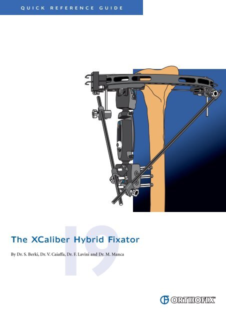
<strong>The</strong> <strong>XCaliber</strong> <strong>Hybrid</strong> <strong>Fixator</strong><br />
By Dr. S. Berki, Dr. V. Caiaffa, Dr. F. Lavini and Dr. M. Manca
GENERAL POINTS<br />
<strong>The</strong> <strong>XCaliber</strong> <strong>Fixator</strong> is made of radiolucent material for unobstructed X-ray visualization.<br />
<strong>The</strong> metallic bolts, and the cam and bush of each ball-joint are the only radio-opaque <strong>com</strong>ponents.<br />
Because it is radiolucent and made of a <strong>com</strong>posite material, the ball-joint deforms after repeated tightening. It can be<br />
adjusted on the patient if repositioning of the fracture is required, but will not be strong enough for use on a second patient.<br />
Also the joint is sealed and cannot be dismantled for cleaning.<br />
<strong>The</strong> <strong>XCaliber</strong> <strong>Fixator</strong> is strictly single patient use.<br />
Cams locked from either side.<br />
Torque wrench not required<br />
EQUIPMENT REQUIRED<br />
Straight clamp<br />
Ring<br />
Attachment<br />
99-91080 <strong>XCaliber</strong> <strong>Hybrid</strong> Kit, sterile<br />
81043 Supplementary Screw Holder Bar Radiolucent, 300 mm<br />
10038 Clamp for Supplementary Screw Holder Bar<br />
80042 Post, 50 mm<br />
or<br />
80044 Post, 100 mm<br />
Ring are available in the following diameters: 125 mm, 150 mm, 175 mm, 190 mm,<br />
220 mm. <strong>The</strong>y are available in aluminium or in a <strong>com</strong>posite radiolucent material.<br />
Standard Instrumentation for Wire and Screw Insertion<br />
STERILE R<br />
CAUTION: Federal (U.S.A.) law restricts this device to sale by or on the order of a physician. Contents sterile unless package opened or damaged;<br />
Do not use if package is opened or damaged.<br />
1<br />
Ball-joints move 22°<br />
in any direction
SAFE CORRIDORS FOR KIRSCHNER WIRE INSERTION<br />
PROXIMAL TIBIA<br />
DISTAL TIBIA<br />
DISTAL FEMUR<br />
2
003I<br />
3<br />
KIRSCHNER WIRE INSERTION<br />
•<br />
•<br />
•<br />
Choose appropriate ring. Full circumference rings may be<br />
made by joining 1/3 and 2/3 rings together with locking<br />
screws.<br />
Reference anatomically safe corridors on cross-section of<br />
limb. Insert wire closest to the joint first.<br />
Insert a two-hole securing pin into appropriate hole in<br />
ring.<br />
Introduce tip of K-wire with lateral olive through the<br />
two-hole securing pin.<br />
Push wire through soft tissues and drill through bone,<br />
while assistant maintains ring parallel to joint with limb<br />
centred within it. Avoid joint capsule.<br />
When wire has exited far cortex, stop drilling and ensure<br />
wire is parallel to ring and joint line.<br />
Continue to advance wire by tapping it with mallet, until<br />
lateral olive is against securing pin.<br />
Note: Wire may be drilled above, below or through the<br />
ring, for best position relative to fracture and joint capsule.<br />
Loosen all screws of three-hole wire clamp slider unit.<br />
Orient clamp in same direction as securing pin.<br />
Introduce wire into appropriate hole in slider unit.
003I<br />
003I<br />
003I<br />
4<br />
•<br />
•<br />
•<br />
If a K-wire without olive is used attach it to ring using<br />
a three-hole wire clamp slider unit at each end.<br />
Tighten both slider units to ring. Tighten wire clamp<br />
screw on one end of wire.<br />
Note: <strong>The</strong> first wire may be inserted free-hand.<br />
Insert parallel wire next through second hole in securing<br />
pin, using wire guide.<br />
Disconnect the slider unit temporarily from the ring and<br />
then insert it over both wires.<br />
Tighten slider unit on to ring fully, using 3 mm Allen<br />
wrench. Position limb in centre of ring.<br />
To tension wires, open handle of wire tensioning device<br />
to fullest extent.<br />
Insert wire through the device and position it against<br />
face of slider unit. Tension wire to minimum of 1200 N,<br />
in two stages if necessary. Tighten wire clamp screws with<br />
5 mm Allen wrench. Cut and/or bend wire and apply<br />
wire cover.<br />
Note: Where K-wires without olive have been used in<br />
conjunction with two three-hole wire clamp slider units,<br />
tighten wire clamp screws at one end, and tension at the<br />
other as above.
5<br />
•<br />
•<br />
Insert crossing wires at widest angle neurovascular<br />
structures will permit (usually between 50°-70°).<br />
For optimal ring stability wires should cross in the centre<br />
of the tibia. Insert the securing pin into the ring, upsidedown<br />
relative to the first securing pin to prevent wires<br />
from intersecting in bone.<br />
DIAPHYSEAL SCREW INSERTION<br />
•<br />
Reduce fracture further by manipulation of ring and<br />
limb.<br />
Attach fixator to ring using the nuts and washers.<br />
Tighten them with the Open End Wrench (81031).<br />
Position fixator parallel to long axis of bone with cams<br />
and all locking nuts accessible for tightening. Make sure<br />
fixator body is neither fully closed nor fully open.<br />
Clamp acts as its own template for screw insertion. Insert<br />
bone screws in standard manner (See Manual 1, “Basic<br />
Considerations”). Where two screws are inserted,<br />
use clamp seats 1 and 3. Generally in adults three screws<br />
are re<strong>com</strong>mended.<br />
Confirm fracture reduction. Accurate reduction is aided<br />
by the fact that the fixator is radiolucent, allowing<br />
unobstructed views on image intensification.<br />
Hold the reduction in a good position, while an assistant<br />
PARTIALLY tightens the cams and central body locking<br />
nut with the Allen wrench.<br />
Tighten the central body locking nut.<br />
Check reduction and lock the cams definitively with the<br />
Allen Wrench.<br />
Note: Final locking of the ball-joints is achieved with the<br />
Allen wrench; a torque wrench is not required. <strong>The</strong> cams<br />
can be locked from either side of the clamp. <strong>The</strong>y should be<br />
turned towards the thicker section of the coloured insert<br />
until tightly closed, and the cam is at least 50% of the way<br />
across the recess.
6<br />
•<br />
!<br />
Reinforcement bars may be added to increase stability,<br />
and are advised if the fracture is unstable.<br />
Insert post through ring and attach bar using a<br />
supplementary screw holder clamp.<br />
Attach opposite end of bar to bone screw using another<br />
supplementary screw holder clamp.<br />
As healing progresses, remove reinforcement bars to<br />
increase load sharing at the fracture site.<br />
<strong>The</strong> <strong>Orthofix</strong> Quality System has been certified to be in <strong>com</strong>pliance with the<br />
requirements of:<br />
• Medical Devices Directive 93/42/EEC, Annex II - (Full Quality System)<br />
• International Standards EN 46001/ISO 9001<br />
for orthopaedic external fixator systems including bone screws, nails and wires,<br />
sterile external and internal fixation systems.<br />
See “<strong>Orthofix</strong> External Fixation System” instruction leaflet (PQ EXF)<br />
prior to use.
<strong>Orthofix</strong> Srl wishes to thank:<br />
S. BERKI, MD<br />
Department of General, Trauma and Hand Surgery<br />
University and County Hospital<br />
Szentes, Hungary<br />
V. CAIAFFA, MD<br />
Clinica Ortopedica e Traumatologica<br />
Università degli Studi di Bari, Italy<br />
F. LAVINI, MD<br />
Clinica Ortopedica e Traumatologica<br />
Università degli Studi di Verona, Italy<br />
M. MANCA, MD<br />
Clinica Ortopedica e Traumatologica<br />
Ospedali di Massa e Carrara, Italy<br />
for their invaluable help in the preparation of this Quick<br />
Reference Guide and their contribution to the design and<br />
refinement of the equipment described.<br />
Your Distributor is:<br />
www.orthofix.<strong>com</strong><br />
ORTHOFIX - Wonersh House - <strong>The</strong> Guildway - Old Portsmouth Road<br />
Guildford - Surrey GU3 1LR - England<br />
Tel. 44 1483 468800 Fax 44 1483 468829<br />
PG 190 E0<br />
03B-05/03