

HELLRAISER SOLO 6 WIRING DIAGRAM - Schecter Guitars
HELLRAISER SOLO 6 WIRING DIAGRAM - Schecter Guitars
HELLRAISER SOLO 6 WIRING DIAGRAM - Schecter Guitars

Create successful ePaper yourself
Turn your PDF publications into a flip-book with our unique Google optimized e-Paper software.
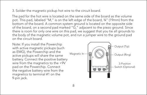
3. Solder the magnetic pickup hot wire to the circuit board.<br />
The pad for the hot wire is located on the same side of the board as the volume<br />
pot. This pad, labeled “M,” is on the left edge of the board, ¾” (19mm) from the<br />
bottom of the board. A common system ground is located on the opposite side<br />
of the board, on a second pad marked “G,” adjacent to the piezo ground. Since<br />
there is room for only one wire on this pad, we suggest that you tie all grounds to<br />
the body of the magnetic volume pot, and run a jumper wire to the ground pad<br />
on the circuit board.<br />
Note: If you install the Powerchip<br />
with active magnetic pickups (such<br />
as EMG), the Powerchip and the<br />
active pickups will share the same<br />
battery. Connect the positive battery<br />
wire from the magnetics to the +9V<br />
pad on the Powerchip. Connect<br />
the negative battery wire from the<br />
magnetics to terminal #1 on the<br />
9-pin jack.<br />
Magnetic In<br />
8<br />
Output (Tip)<br />
Output (Ring)<br />
3-Position<br />
Switch (Optional)