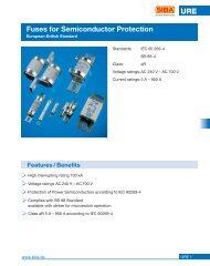
magazine article - SIBA - Fuses
magazine article - SIBA - Fuses
magazine article - SIBA - Fuses

Create successful ePaper yourself
Turn your PDF publications into a flip-book with our unique Google optimized e-Paper software.
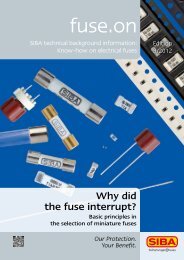
fuse.on<br />
Technical background information<br />
provided by <strong>SIBA</strong>:<br />
Know-how on Electrical <strong>Fuses</strong><br />
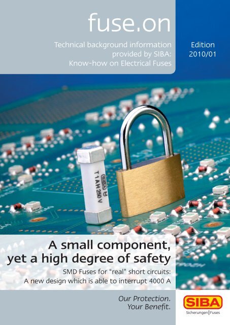
A small component,<br />
yet a high degree of safety<br />
SMD <strong>Fuses</strong> for “real” short circuits:<br />
A new design which is able to interrupt 4000 A<br />
Our Protection.<br />
Your Benefi t.<br />
Edition<br />
2010/01
By<br />
Heinz-Ulrich Haas<br />
Head of R & D<br />
<strong>SIBA</strong> GmbH & Co KG<br />
fuse.on page 2<br />
SMD <strong>Fuses</strong> for<br />
“real” short circuits<br />
A new design which is able to interrupt 4000 A<br />
Our Protection.<br />
Your Benefi t.<br />
2010/01<br />
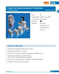
Compared with the established SMD fuses the new <strong>SIBA</strong> SMD fuses presented here appear quite<br />
large, even huge. The requirements for these components, however, are also huge: after all, they<br />
are intended to interrupt short-circuit currents of several hundred amperes and, in cases of faults,<br />
to isolate defective components or devices from the mains. How and why this works is described in<br />
this <strong>article</strong>. [1]<br />
The whole family<br />
Surface-mount fuses, i.e. SMD fuses, are used when it comes to monitoring and interrupting<br />
overcurrents on as small a space as possible. In order to achieve this, various constructions which<br />
make optimum use of the space available on a printed circuit board exist for the most diverse applications.<br />
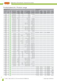
Table 1 gives an overview of the most commonly used SMD fuses from the collection<br />
of types offered worldwide.<br />
Table 1: Overview of SMD <strong>Fuses</strong><br />
Fuse type Sizes Characteristic Rated voltage Rated current Breaking capacity<br />
Chip-type SMD 0402 to 1206 FF 32 to 63 V 250 mA to 5 A 50 A<br />
Block-type SMD 2,6 x 6,1 mm F and T 125 V 62 mA to 15 A 50 A<br />
Block-type SMD 4,5 x 8 mm F and T 250 V 32 mA to 6,3 A 100 A<br />
cylindrical SMD 5 x 20 mm F and T 250 V 1 to 6,3 A 1500 A<br />
The smallest members of the SMD fuse family are the chip-type ones (Figure 1a). With widths of,<br />
e.g., less than 1 mm they are used in mobile phones, shavers and other small appliances. They serve<br />
as “saving anchors” in cases of faults in the lithium battery. Typical voltage classes are 10 V, 20 V,<br />
30 V or 40 V, partly for AC and partly for DC operation.<br />
<strong>Fuses</strong> for operating voltages of 100 V and more are slightly larger. Being designed as SMD block types<br />
(Figure 1b), in most cases they have a ceramic housing and, in comparison with the chip-type fuses,<br />
they are “hard to miss”, having an edge dimension of, e.g., 6 mm. This group comprises also fuses<br />
with a rated voltage of 250 V. Thanks to a maximum breaking capacity of 100 A at 250 V they are<br />
able to provide short-circuit protection in secondary circuits.<br />
As far as protection in cases of “real” short circuits of some hundred amperes is concerned, so<br />
far, specially prepared cylindrical fuses with dimensions of 5 mm × 20 mm (Figure 1c) for surface<br />
mounting have been available. As compared with the standard design, the temperature stability<br />
required for the refl ow soldering process is ensured by means of the solder in the fuse melting at
2010/01 page 3<br />
fuse.on<br />
higher temperatures. Instead of being nickel-plated, often the contact caps are gold-coated.<br />
These fuses are able, without any problems, to interrupt currents of 1500 A in accordance with<br />
the standardized classifi cation “H”, even at a mains voltage of 230 V; this is why they are preferably<br />
used in the primary circuits of power supply units.<br />
Figure 1: Basic types of SMD <strong>Fuses</strong><br />
Figure 1a<br />
Chip-Type SMD Fuse<br />
Figure 1b<br />
Block-Type SMD Fuse<br />
Figure 1c<br />
Cylindrical SMD Fuse<br />
with gold contact<br />
Our Protection.<br />
Your Benefi t.
fuse.on page 4<br />
The new big brother<br />
Cross-section of<br />
the new SMD fuse<br />
1 Insulating body<br />
2 Contact caps<br />
3 Fuse-element<br />
4 Quartz sand<br />
5 Solder<br />
Our Protection.<br />
Your Benefi t.<br />
1 2 3 4 5<br />
Figure 2: 250 V SMD Fuse with a high breaking capacity<br />
Size comparison<br />
Top: leaded fuse (5 x 20 mm)<br />
Centre: cylindrical SMD (5 x 20 mm)<br />
Bottom: new SMD fuse (4,5 x 16 mm)<br />
2010/01<br />
What had been missing until now was a fuse with the before-mentioned performance data which<br />
would “not roll away” during processing. Now this gap could be bridged by developing the rectangular<br />
250 V rated voltage fuse presented here which is even able to interrupt breaking currents exceeding<br />
1500 A.<br />
And all this is achieved by a fuse with dimensions of 4,5 mm × 16 mm (Figure 2). On the one hand,<br />
this fuse is by far larger than a chip-type SMD fuse; on the other hand, however, it is still quite smaller<br />
than a cylindrical SMD fuse with similar performance data.<br />
So far, leaded 5 mm × 20 mm fuses (Figure 2) have been used in many applications. Compared to<br />
this variant, the new rectangular SMD fuse offers considerable advantages for the production process<br />
in almost all cases. And there is a positive “side effect”, too: as the rated current is always clearly<br />
identifi able, no hard-to-decipher colour codes on the fuses are required any more.<br />
This fuse‘s construction principle is nothing new. Its materials are the same as those for the cylindrical<br />
fuses which have been in use for decades: the visible parts are the ceramic tube and the contact<br />
caps which tightly seal the room in which the fuse-element is located. In order to be able to contact<br />
the fuse-element inside the fuse, a solder melting at higher temperatures is used which, at the<br />
same time, provides for adherence between the contact caps and the insulating body.
2010/01 page 5<br />
fuse.on<br />
After all, all these parts have to withstand the high temperatures arising in refl ow soldering.<br />
The construction is designed to withstand a preheating temperature increasing from of 150 °C to<br />
200 °C within 60 s to 120 s as well as a refl ow temperature of > 217 °C over 60 s to 90 s, with a peak<br />
of 250 °C over approximately 30 s.<br />
In accordance with the standard on SMD fuses, VDE 0820, Part 4, these fuses exhibit a time-lag performance<br />
(T), i.e. they operate at ten times the rated current, within 10 ms to 100 ms: this makes<br />
them resistant to peak inrush currents on the transformer‘s primary side. In the case of overloads,<br />
on the other hand, they operate comparatively fast: they detect and interrupt currents of twice the<br />
rated current as fast as after approximately one minute. [2]<br />
Finally, the most important fact: the fuses have a “high breaking capacity”, identifi able by the letter<br />
“H”. In accordance with the relevant standards this means that they are able to interrupt a current<br />
of 1500 A at 250 V AC. Since, however, short circuits are known to be possible in the current range<br />
of up to 4000 A, this value has already been taken into consideration when designing the fuses. This<br />
way, any potential device short circuits should be covered and the fuse be suitable for all applications<br />
on the primary side of a power supply unit.<br />
“Real” short circuits<br />
But how can a component as small as this be able to “stand” short-circuit currents of 4000 A? The<br />
reason for this lies in the fuses‘ ability to interrupt any short-circuit currents as early as during their<br />
Key<br />
I k – prospective short-circuit current (r.m.s. value)<br />
I d – current limited by the fuse (instantaneous value)<br />
t s – pre-arcing time<br />
t a – operating time<br />
Figure 3: Current-limiting effect of <strong>Fuses</strong><br />
Our Protection.<br />
Your Benefi t.
fuse.on page 6<br />
Our Protection.<br />
Your Benefi t.<br />
2010/01<br />
rises – i.e. they operate in a “current-limiting” way. In Figure 3, this is illustrated using the<br />
example of a short-circuit current of 4000 A. If there was no fuse in the shorted circuit, the 4000 A<br />
would fl ow over some half-waves until the adoption of the breaking function by another upstream<br />
protective device, e.g., the circuit-breaker for household applications. By then, however, it would be<br />
too late for the device in which the short circuit had occurred: unless worse had happened, the accidental<br />
arc had, at least, already left its marks.<br />
In contrast to this, the fuse on the printed circuit board does not let this situation arise in the fi rst<br />
place. Due to the high current density associated with the breaking operation, the fi ne wire element<br />
in the fuse melts and evaporates within a few milliseconds.<br />
Table 2: Cut-Off Currents and Operating Times for 4000 A<br />
Rated current Pre-arcing integral Cut-off current Pre-arcing time Operating time<br />
In I 2 t Id ts ts<br />
1 A 4,5 A 2 s 200 A 0,2 ms 0,5 ms<br />
10 A 280 A 2 S 1100 A 0,65 ms 1,5 ms<br />
During this process the metal p<strong>article</strong>s of the fuse-element condense on the sand grains. The result<br />
is a small arc which lasts until the quartz sand/metal mixture has formed an isolating distance. Operation<br />
is of the current-limiting type: the fuse-element interrupts the fault current even before the<br />
maximum of the current half-wave is reached.<br />
In Table 2, the maximum cut-off currents to be expected and the operating times of fuses for rated<br />
currents of 1 A and 10 A are summarized as examples. In this example, the 1 A fuse interrupts a<br />
short-circuit current of 4000 A within 0,5 ms, thereby limiting the current during its rise, at 200 A.<br />
Now, what to do with them?<br />
Well, maybe one could “stack” them; after all, they cannot roll away … – the author apologizes for<br />
this lame joke. Of course, the purpose of the new SMDs is, e.g., to protect power supply units in<br />
primary circuit. The maximum rated current of 10 A enables also power supply units of a higher capacity<br />
to be protected effectively. With rated currents of up to 6,3 A, the fuses are even designed for<br />
an operating voltage of 277 V, i.e., for U.S. applications; so, of course, they have received the appropriate<br />
UL agency approval as well. [3]<br />
As early as when developing the fuses, their potential use in explosion protection was taken into consideration.<br />
In order to meet the requirements of the standard relevant for this fi eld, IEC 60079-11, a<br />
suffi ciently large distance between the caps of 10 mm on average was selected. Thus, the fuse additionally<br />
meets the requirements of the North American testing bodies. [4]<br />
Further possible applications are all those cases where high short-circuit currents are to be expected<br />
at a mains voltage of 230 V – that is, for example, in line adapters, control circuits, sensor technology,<br />
measuring fi elds, explosion proof, interfaces, controllers. Moreover, it makes DC rating of 1500 A<br />
at 250 V DC an allrounder.
2010/01 page 7<br />
fuse.on<br />
Bibliography<br />
[1] www.siba.de<br />
[2] DIN VDE 60127-4 (VDE 0820-4), Miniature fuses – Part 4: Universal modular fuse-links (UMF) –<br />
Through hole and surface-mount types<br />
[3] www.ul.com<br />
[4] IEC 60079-11:2006 or DIN IEC 60079-11 (VDE 0170-7), Draft standard 2008-04:<br />
Explosive atmospheres – Part 11: Equipment protection by intrinsic safety “i”<br />
Disclaimer:<br />
The fuses described in this document were developed to take over safety-relevant functions as part of a machine or complete installation. A<br />
safety-relevant system usually contains signalling devices, sensors, evaluation units and concepts for safe disconnection. The responsibility for<br />
ensuring the correct overall function lies with the manufacturer of the installation or machine. <strong>SIBA</strong> GmbH & Co. KG and its sales offi ces (in the<br />
following referred to as „<strong>SIBA</strong>“) are not in a position to guarantee all features of a complete installation or machine which was not designed by<br />
<strong>SIBA</strong>. Once a product has been selected, it should be tested by the user in all its possible applications. <strong>SIBA</strong> will not accept any liability for recommendations<br />
which are given, or respectively implied, by the above description. No guarantee, warranty or liability claims beyond <strong>SIBA</strong>‘s general<br />
terms of delivery can be derived from the description.<br />
State of the art/standards:<br />
Technologies and technical standards are permanently being developed. Therefore this brochure can only represent the state of the art<br />
commonly accepted at the time of printing. This has to be taken into consideration when using the information given and the types from the<br />
product programme listed.<br />
Our Protection.<br />
Your Benefi t.
Hauptsitz / Head Offi ce<br />
<strong>SIBA</strong> GmbH & Co. KG<br />
Borker Straße 20-22<br />
D-44534 Lünen<br />
Postfach 1940<br />
D-44509 Lünen<br />
Tel.: +49-2306-7001-0<br />
Fax: +49-2306-7001-10<br />
info@siba.de<br />
www.siba.de<br />
<strong>SIBA</strong> Unit Miniature <strong>Fuses</strong><br />
Tel.: +49-2306-7001-90<br />
Fax: +49-2306-7001-99<br />
elu@siba.de<br />
Deutschland / Germany<br />
<strong>SIBA</strong> Vertriebsbüro Freiberg<br />
Untergasse 12<br />
D-09599 Freiberg<br />
Tel.: +49-3731-202283<br />
Fax: +49-3731-202462<br />
alexander.kolbe@siba.de<br />
<strong>SIBA</strong> Vertriebsbüro Hannover<br />
Am Hüllfeld 5<br />
D-30952 Ronnenberg<br />
Tel.: +49-5109-562470<br />
Fax: +49-5109-562471<br />
andreas.koehler@siba.de<br />
<strong>SIBA</strong> Vertriebsbüro Rhein/Ruhr<br />
Veilchenweg 10<br />
D-59439 Holzwickede<br />
Tel.: +49-2301-298680<br />
Fax: +49-2301-298681<br />
joerg.mattusch@siba.de<br />
<strong>SIBA</strong> Vertriebsbüro Süd-West<br />
Germersheimer Str. 101a<br />
D-67360 Lingenfeld<br />
Tel.: +49-6344-937510<br />
Fax: +49-6344-937511<br />
erwin.leuthner@siba.de<br />
fuse.on page 8<br />
International<br />
<strong>SIBA</strong> Sicherungen- und Schalterbau-<br />
Ges.m.b.H & Co. KG (Austria)<br />
Ortsstraße 18 · A-2331 Vösendorf bei Wien<br />
Tel.: +43-1-6994053 und 6992592<br />
Fax: +43-1-699405316 und 699259216<br />
info.siba@aon.at<br />
www.siba-sicherungen.at<br />
<strong>SIBA</strong> GmbH & Co. KG Beijing<br />
Rep. Offi ce (China)<br />
Room 207A, Building B, He Qiao Mansion No. 8<br />
Guanghua Road, Chaoyang District,<br />
Beijing 100026<br />
Tel.: +86-10-65817776<br />
Fax: +86-10-65812979<br />
siba_china@sibafuse.cn<br />
www.sibafuse.cn<br />
<strong>SIBA</strong> Písek s.r.o. (Czech Rep.)<br />
U Vodárny 1506 · 397 01 Písek<br />
Tel.: +420-38-2265746<br />
Fax: +420-38-2265746<br />
sibacz@iol.cz · www.siba-pojistky.cz<br />
<strong>SIBA</strong> Sikringer Danmark A/S<br />
(Denmark)<br />
ehemals/former Ole Andersen A/S<br />
Naverland 26B · DK-2600 Glostrup<br />
Tel.: +45-86828175 · Fax: +45-86814565<br />
info@sikringer.dk · www.siba-sikringer.dk<br />
<strong>SIBA</strong> Nederland B.V. (Netherlands)<br />
Van Gentstraat 16<br />
NL-5612 KM Eindhoven<br />
Tel.: +31-40-2467071<br />
Fax: +31-40-2439916<br />
info@sibafuses.nl · www.siba-zekeringen.nl<br />
<strong>SIBA</strong> Polska sp. z o.o. (Poland)<br />
ul. Grzybowa 5G<br />
05-092 Łomianki Da˛browa Le´sna<br />
Tel.: +48-22-8321477<br />
Fax: +48-22-8339118<br />
siba@sibafuses.pl<br />
www.siba-bezpieczniki.pl<br />
Our Protection.<br />
Your Benefi t.<br />
Moskovskoye predstavitelstvo<br />
obshestva „<strong>SIBA</strong> GmbH & Co. KG“<br />
(Russia)<br />
125445, Moskva, ul. Smolnaja, Dom 24 A,<br />
Ofi s 804<br />
Tel.: +7-495-9871413<br />
Fax: +7-495-9871774<br />
info@siba-predohraniteli.ru<br />
www.siba-predohraniteli.ru<br />
2010/01<br />
<strong>SIBA</strong> <strong>Fuses</strong> SA PTY. LTD. (South Africa)<br />
P.O. Box 34261 · Jeppestown 2043<br />
Tel.: +27-11334-6560 / 4<br />
Fax: +27-11334-7140<br />
sibafuses@universe.co.za<br />
www.siba-fuses.co.za<br />
<strong>SIBA</strong> Far East Pte. LTD.<br />
(South East Asia)<br />
No. 3 Phillip Street, #12-02, Commerce Point<br />
Singapore 048693<br />
Tel.: +65-62239225<br />
Fax: +65-62341428<br />
info@sibafuse.com.sg<br />
www.sibafuse.com.sg<br />
<strong>SIBA</strong> LTD. (United Kingdom)<br />
19 Duke Street<br />
Loughborough LE11 1ED<br />
Tel.: +44-1509-269719<br />
Fax: +44-1509-236024<br />
siba.uk@btconnect.com<br />
www.sibauk.co.uk<br />
<strong>SIBA</strong> <strong>Fuses</strong> LLC (United States of America)<br />
29 Fairfi eld Place<br />
West Caldwell, NJ 07006<br />
Tel.: +1-973575-7422 (973-575-<strong>SIBA</strong>)<br />
Fax: +1-973575-5858<br />
info@sibafuses.com<br />
www.sibafuses.com<br />
Weitere Vertriebspartner weltweit /<br />
Further distribution partners worldwide:<br />
www.siba.de / www.siba-fuses.com<br />
Photographs: Barajas (Title page),<br />
<strong>SIBA</strong> Archive<br />
fuse.on 2010/02, Stand 2010/07