INSTALLATION AND OPERATING INSTRUCTIONS - SiG Solar GmbH
INSTALLATION AND OPERATING INSTRUCTIONS - SiG Solar GmbH
INSTALLATION AND OPERATING INSTRUCTIONS - SiG Solar GmbH

Create successful ePaper yourself
Turn your PDF publications into a flip-book with our unique Google optimized e-Paper software.
<strong>INSTALLATION</strong> <strong>AND</strong> <strong>OPERATING</strong> <strong>INSTRUCTIONS</strong><br />
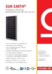
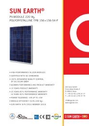
Sun Earth PV Modules<br />
monocrystalline/polycrystalline<br />
MA_01_2013_V1_EN_beta
Table of contents<br />
1 Introduction ............................................................................................................................................................ 4<br />
2 Disclaimer ............................................................................................................................................................... 4<br />
3 Norms and directives .............................................................................................................................................. 4<br />
4 Rules, laws and regulations .................................................................................................................................... 4<br />
5 Profession and skill requirements for installers ..................................................................................................... 4<br />
6 Sun Earth® PV module product description ........................................................................................................... 4<br />
7 Correct use .............................................................................................................................................................. 4<br />
8 Explanation of symbols used .................................................................................................................................. 5<br />
9 General information, hazards and safety information ........................................................................................... 5<br />
10 General information on handling ........................................................................................................................... 6<br />
11 Installation and wiring ............................................................................................................................................ 7<br />
12 Mounting ................................................................................................................................................................ 8<br />
13 Dimensions and clamping areas ............................................................................................................................. 9<br />
14 Grounding and potential equalisation .................................................................................................................. 12<br />
15 Regular inspections ............................................................................................................................................... 12<br />
16 Troubleshooting and maintenance ....................................................................................................................... 12<br />
17 Disposal ................................................................................................................................................................. 13<br />
18 Appendix ............................................................................................................................................................... 14<br />
18.1 Sun Earth® PV module family (monocrystalline) .................................................................................................. 14<br />
18.2 Sun Earth® PV module family (polycrystalline) ..................................................................................................... 15<br />
18.3 Declaration of Conformity I .................................................................................................................................. 16<br />
18.4 Declaration of Conformity II ................................................................................................................................. 17<br />
2
Table of figures<br />
Figure 1: MCT4-compatible plug and socket ............................................................................................................... 7<br />
Figure 2: Positioning of the module clamp between the module frames ................................................................... 8<br />
Figure 3: Dimensions and clamping areas for TDB 125x125-72-P ............................................................................... 9<br />
Figure 4: Dimensions and clamping areas for TDB 125x125-96-P ............................................................................... 9<br />
Figure 5: Dimensions and clamping areas for TPB 156x156-54-P.............................................................................. 10<br />
Figure 6: Dimensions and clamping areas for TPB 156x156-60-P.............................................................................. 10<br />
Figure 7: Dimensions and clamping areas for TPB 156x156-72-P.............................................................................. 11<br />
Figure 8: Installation with appropriate clamps .......................................................................................................... 11<br />
Figure 9: Installation in an appropriate insertion system .......................................................................................... 11<br />
Figure 10: Installation example for potential equalisation .......................................................................................... 12<br />
3
1 Introduction<br />
Thank you for choosing our Sun Earth® PV modules and for the confidence you have placed in us and our products.<br />
Please read this manual carefully before installing the modules. It is absolutely necessary to make yourself familiar<br />
with the safety, installation and operating instructions.<br />
2 Disclaimer<br />
<strong>SiG</strong> <strong>Solar</strong> disclaims all responsibility and liability for loss, damage and costs caused by erroneous installation,<br />
improper operation and incorrect use and maintenance. <strong>SiG</strong> <strong>Solar</strong> disclaims all responsibility for infringement upon<br />
patents or other third party rights resulting from module operation. No licences are granted; neither by implication<br />
nor under any patent or patent rights. The information contained in these instructions may be considered as reliable,<br />
yet do not constitute an independent guarantee. <strong>SiG</strong> <strong>Solar</strong> reserves the right to make modifications to the product,<br />
to specifications and to the operating instructions without prior notification.<br />
3 Norms and directives<br />
The CE mark documents that the module meets the fundamental requirements of the following guidelines:<br />
− IEC 61730-1 / IEC 61730-2: 2004<br />
− EN 61730-1 / EN 61730-2: 2007<br />
− IEC 61215: 2005<br />
− EN 61215: 2005<br />
− Low voltage direcve (direcve 2006/95/EC)<br />
4 Rules, laws and regulations<br />
When installing a solar power plant, all applicable state, national, European and international laws, ordinances and<br />
regulations have to be complied with.. Generally recognised technical principles apply, which are generally<br />
formulated as norms, guidelines, stipulations, provisions and the technical rules of state and national organisations,<br />
power supply companies and professional associations and committees for the respective technical discipline. It may<br />
be necessary to utilise security systems in order to comply with accident prevention requirements. These security<br />
systems are not included with the product and must be set-up at the operation site.<br />
5 Profession and skill requirements for installers<br />
<strong>SiG</strong> <strong>Solar</strong> requires that installation be performed only by technically qualified and authorised staff with proof of<br />
accredited training (from a state or national organisation) or with corresponding expertise.<br />
6 Sun Earth® PV module product description<br />
Sun Earth® PV modules generate electricity as soon as they are exposed to light, and thus electrical contacts are also<br />
energised. While one individual module will be below the safe voltage specification (50V AC or 120V DC), multiple<br />
modules connected in series or parallel could represent an increased hazard. When installing modules, please follow<br />
assembly and installation instructions of all system components. We disclaim all liability for damages resulting from<br />
non-compliance with these instructions.<br />
7 Correct use<br />
Sun Earth® PV modules are designed to be stationary power generators for photovoltaic power systems. Any use<br />
4
other than or beyond this will be considered as improper use. Improper use may result in physical and mortal<br />
hazards for users or third parties and may also impede the unit or system and other objects. The manufacturer as<br />
well as the supplier is not liable for the corresponding damage. The user assumes all risks. Proper use also includes<br />
observance of the installation and operating instructions.<br />
Modules are dimensioned for the use in application class A:<br />
Modules applicable for to this class can be used in systems with unrestricted access and hazardous voltages (IEC<br />
61730: greater 50V AC; EN 61730: greater 120V DC). Modules qualified for this application class under EN IEC 61730-<br />
1 and -2 are assumed to meet the specifications of Protection Class II. Efficient and safe operation of the modules<br />
requires proper transportation, storage, set-up and installation as well as careful operation and maintenance. During<br />
operation certain components are electrically active. Contact with these parts can lead to grave physical injury or<br />
death.<br />
It is imperative to observe the following handling instructions in order to minimise the risk of physical and mortal<br />
danger.<br />
8 Explanation of symbols used<br />
Caution!<br />
Hazard to body, life, environment or product<br />
Danger!<br />
Hazard to body and life due to electrical shock<br />
9 General information, hazards and safety information<br />
Do not place any electricity conducting components into plugs and sockets!<br />
Tools and work environment must be dry.<br />
Do not use damaged modules.<br />
Do not disassemble modules.<br />
Do not apply paint or adhesives to the back sheet.<br />
Do not use sharp objects.<br />
Never separate the solar generator from the inverter while it is grid connected.<br />
Make sure to comply with the time intervals stipulated by the manufacturer after<br />
turning off the inverter and prior to beginning further work!<br />
The PV module must not come close to open flames nor be mounted in the vicinity of flammable materials. It is not<br />
permissible to install the module in an environment that is chemically or biologically aggressive or corrosive.<br />
Due to the development of aggressive ammonia, the utilisation on top of livestock barns is only permissible with a<br />
written approval from <strong>SiG</strong> <strong>Solar</strong>. The solar cables and connectors must not be installed insides stalls or with direct<br />
exposure to ammonia gas.<br />
Transport damage!<br />
After the modules are delivered, they must be checked immediately for transport damag. Any damage found has to<br />
be noted on the delivery slip, described in details and documented with photos.<br />
5
Storage!<br />
The modules must be stored safely and protected against external influences such as humidity, light, shock, etc.<br />
10 General information on handling<br />
Do not disassemble the module or allow it to fall down!<br />
Do not bend the module!<br />
Carry with both hands! Do not lift on the junktion boxes!<br />
Keep all contacts dry and clean!<br />
Do not step on the module or apply improper weight to it!<br />
Do not work on the module using pointy or sharp objects!<br />
Observe the maximum load of the glass!<br />
Do not use mirrors or lenses to concentrate sunlight on the modules!<br />
6
11 Installation and wiring<br />
When installing modules appropriate precautionary measures must be undertaken because connectors may be<br />
live/electrically active/energised!<br />
Wiring must be realised in accordance with currently applicable rules.<br />
Observe the electrical rating data for all operating materials used in the system. In addition to a junction box with<br />
integrated bypass diodes, the module is also equipped with MC-T4 compatible plugs and sockets. Plug connections<br />
must be fully inserted and locked.<br />
Make sure that cables and connection sockets are not subjected to heavy tension. Damage to a cable or a cable inlet<br />
will destroy the protective insulation. This represents a higher risk for electrical problems.<br />
Figure 1: MCT4-compatible plug and socket<br />
Use only MC-T4 compatible plugs and special solar cables for extending the module connection. They should meet<br />
electrical requirements based on the PV modules' connection.<br />
Under general conditions, a PV module can deliver a current and/or voltage higher<br />
than that indicated under standardized test conditions. In order to determine the<br />
voltage values of components/voltage ratings of components, the current values<br />
of conductors/conductor ampacities, the fuse size and the size of control systems<br />
connected to the module output, the values of ISC and UOC indicated on the module<br />
should be multiplied by a factor of 1.25.<br />
When connected in series, make sure that the maximum system voltage is not exceeded. For parallel connection<br />
adhere to the maximum permissible current for the system components. Pay also attention to the electrical<br />
reference data for your inverter.<br />
In order to reduce indirect lightning strikes, keep the area of conductor loops as slow as possible when laying string<br />
lines. It is recommended to connect each module string with corresponding DC fuses.<br />
Electrical connection to a central building management system must only be<br />
performed by certified electricians.<br />
Never unplug or plug in the plug connection during operation.<br />
7
12 Mounting<br />
Sun Earth modules can be anchored along the long frame sides as well as on the short frame sides using form-fit<br />
clamps (see Figure 2). The maximum permissible torque on bolt M8 for the clamp is 16 Nm.<br />
Figure 2: Positioning of the module clamp between the module frames<br />
The clamps must be applied within the compulsory clamping areas. When placing the clamps, make sure that<br />
distances are symmetric.<br />
Figure 3 to Figure 7 illustrate the clamping areas on the modules and the position on the sub-structure (profiles).<br />
The sub-structure used and its connection to the roof or ground must be sufficiently dimensioned for the expected<br />
snow and wind loads. The load on the module expected to be caused by snow and wind must not exceed the<br />
module's permissible capacity.<br />
The sub-structure must be designed in such a way that the modules are sufficiently ventilated/ that enough air can<br />
circulate around the back of the module in order to avoid output losses and structural damage. It is recommended to<br />
have a clearance of at least 100 mm between the rooftop and the module frame.<br />
Do not damage the module's surface in any way.<br />
Do not drill any additional holes into the frame and/or other parts of the module.<br />
When installing the modules, make sure that the module edge with the junction box is on top.<br />
8
13 Dimensions and clamping areas 1<br />
Figure 3: Dimensions and clamping areas for TDB 125x125-72-P<br />
Figure 4: Dimensions and clamping areas for TDB 125x125-96-P<br />
1 all frame dimensions with a tolerance of ±3 mm<br />
9
Figure 5: Dimensions and clamping areas for TPB 156x156-54-P<br />
Figure 6: Dimensions and clamping areas for TPB 156x156-60-P<br />
10
Figure 7: Dimensions and clamping areas for TPB 156x156-72-P<br />
When using clamps, make sure the modules are not damaged or deformed. Clamps must not touch the glass surface<br />
and/or shade the PV cells.<br />
When using clamps on the short or on the long side of the module, the module may only be loaded with a max. front<br />
load of up to 5400 Pa and a max. back load of up to 2400 Pa. When clamping on the short side, clamps with a width<br />
of 100 mm have to be used. When using other clamping systems, please consult the company <strong>SiG</strong> <strong>Solar</strong>. The<br />
maximum load refers to the insertion system as well as to the installation using clamps.<br />
Note: TPB 156x156-72-P modules must only be clamped on the long side (see Figure 7).<br />
Figure 8: Installation with appropriate clamps<br />
11<br />
Figure 9: Installation in an appropriate insertion system
14 Grounding and potential equalisation<br />
Module frame and mounting systems must be connected with potential equalisation pursuant to regional and<br />
national norms and rules.<br />
Figure 10: Installation example for potential equalisation<br />
When using a nut with locking teeth, the module frame is conductively connected with the metal sub-structure.<br />
Establish a potential equalisation in the metal sub-structure!<br />
Connect lightning and surge protection equipment if applicable. If a building has a lightning protection system, the<br />
photovoltaic system must be implemented into the lightning protection concept by an expert.<br />
Grounding connections must be made in the corresponding grounding frame holes. Please make sure to follow the<br />
statutory requirements applicable to your country and region. Follow the recommendations from the inverter<br />
manufacturer and the insurance provider.<br />
15 Regular inspections<br />
• Check all plug connection lines and plug connectors for mechanical<br />
integrity and corrosion.<br />
• Check the earth resistance of the entire system pursuant to regional<br />
regulations.<br />
• Avoid contamination of the modules.<br />
• Check the state of the mounting system.<br />
• When performing routine maintenance on a module, grounding must not<br />
be interrupted or broken!<br />
16 Troubleshooting and maintenance<br />
Blocking and bypass diodes<br />
So-called hot-spots can arise when a module is partially covered by shade. This can lead to high voltages and damage<br />
to cells and modules. Bypass diodes installed in the modules prevent that effect. Defective diodes can be replaced<br />
but just through technical personnel authorised solely by <strong>SiG</strong> <strong>Solar</strong>.<br />
Locking diodes can prevent the current flow from a battery to the modules installed in off-grid plants when these are<br />
not producing electricity. Locking diodes are recommended especially when no charge controller is being used. For<br />
detailed information regarding the handling of charge controllers please contact the charge controller's<br />
manufacturer.<br />
Troubleshooting<br />
Prior to use, check all electrical and electronic components of the photovoltaic system. For information on the values<br />
to be measured, please refer to the current data sheets of the module. Follow the installation instructions of the<br />
individual components.<br />
12
Use a digital multimeter to check the open-circuit voltage on each module. The value measured should coincide with<br />
the given value in the date sheet.<br />
Also use a digital multimeter to check the short-circuit current of each module and each string. Ensure that the<br />
measurement range on the measuring devices shows 1.25 times the short-circuit current under standard conditions<br />
(STC).<br />
Maintenance<br />
<strong>SiG</strong> <strong>Solar</strong> recommends the following maintenance and service guidelines to guarantee optimum module<br />
performance:<br />
If there is a marginal roof slope (< 20°) in a dusty location, it may be advisable to clean the modules after a certain<br />
time. Cleaning must not be performed under direct sun radiation or at module temperatures of >80°C. Do not use<br />
calciferous tap water for cleaning. Chalk residues may remain on the modules. Do not step on the module! Please<br />
consult a competent specialist to solve any potential problems.<br />
CAUTION 2 : Always follow the maintenance information for all components used on the system.<br />
17 Disposal<br />
Under no circumstances should the modules be placed in domestic waste. We as <strong>SiG</strong> <strong>Solar</strong> <strong>GmbH</strong> and exclusive Sun<br />
Earth partner hereby declare that Sun Earth <strong>Solar</strong> Power Ltd. is a member of the organisation PV CYCLE. That means<br />
it is possible to dispose of Sun Earth® PV modules free of charge according the guidelines of PV CYCLE. Further<br />
information can be found at www.pvcycle.org.<br />
2 Make sure to follow all maintenance information for all components, such as the sub-structure, inverter, PV modules, etc.<br />
13
18 Appendix<br />
18.1 Sun Earth® PV module family 3 (monocrystalline)<br />
Module type TDB 125x125-72-P TDB 125x125-96-P<br />
Module power class 190 Wp / 195 Wp 250 Wp / 260 Wp<br />
General<br />
Composition 72 (125x125 mm) monocrystalline silicon solar cells<br />
per module; 3 bypass-diods; encapsulant EVA; rear<br />
cover TPT<br />
Glass highly transparent, anti-reflective solar safety glass;<br />
3,2 mm<br />
14<br />
96 (125x125 mm) monocrystalline silicon solar cells<br />
per module; 4 bypass-diods; encapsulant EVA; rear<br />
cover TPT<br />
highly transparent, anti-reflective solar safety glass;<br />
3,2 mm<br />
Frame anodised aluminum anodised aluminum<br />
Connection<br />
Junction Box plastic; IP65 plastic; IP65<br />
Cable 4 mm²; 900 mm 4 mm²; 1000 mm<br />
Conectors MC-T4 compatible MC-T4 compatible<br />
Mechanical Data<br />
Height [in mm] 1580 1596<br />
Width [in mm] 808 1065<br />
Thickness [in mm] 46 46<br />
Weight [in kg] 16 20,5<br />
Transport Information 4<br />
Packaging unit [in pcs per box 22 20<br />
Packaging unit size [in mm] 1620 x 1080 x 865 1630x1100x980<br />
Packaging unit weight [in kg] 370 430<br />
Packaging unit per 40" container 28 (616 modules) 28 (560 modules)<br />
Electrical data (STC) 5<br />
Max. power (Pmpp) [in W] 190 / 195 250 / 260<br />
Max. voltage (Umpp) [in V] 36,6 / 36,8 48,6 / 49,0<br />
Max. current (Impp) [in A] 5,20 / 5,30 5,15 / 5,31<br />
Open-circuit voltage (Uoc) [in V] 45,0/ 45,2 59,8 / 60,2<br />
Short-circuit current (ISC) [in A] 5,42 / 5,49 5,38 / 5,48<br />
Electrical data (general)<br />
Cell temperature (TNOCT) [in °C] 46 46<br />
Module efficiency [in %] 14,9 / 15,3 14,7 / 15,3<br />
Tollerance of performance [in W] -0 W bis +5 W -0 W bis +10 W<br />
Temperature coefficients<br />
Power [in %/°C] -0,45 -0,45<br />
Open-circuit voltage [in %/°C] -0,32 -0,32<br />
Short-circuit current [in %/°C] 0,05 0,05<br />
MPP-voltag e[in %/°C] -0,4 -0,4<br />
MPP-current [in %/°C] 0.045 0.045<br />
Limit values<br />
Max. system voltage (IEC) [in VDC] 1000 1000<br />
Max. reverse current IR [in A] 10 10<br />
Operating temerature (environment) [in °C] -40 bis +85 -40 bis +85<br />
Max. hail resistance 25 mm at 23 m/s 25 mm at 23 m/s<br />
Max. wind resistance [in Pa] 2400 2400<br />
Max. snow load (front) [in Pa] 5400 5400<br />
Application class A A<br />
Fire resistance class C C<br />
Safety class II II<br />
3 Status: January 2013.<br />
4 Current transportation information may differ!<br />
5 STC irradiance: 1000 W/m²; AM: 1,5; TC: 25°C | NOCT irradiance: 800 W/m²; TA: 20°C; wind speed: 1m/s<br />
[Average reduction of the module efficiency at decreasing irradiance from 1000 W/m² to 200 W/m² (at AM: 1,5 & TC: 25°C): ≤ 4,5% - according to EN 60904-1]
18.2 Sun Earth® PV module family 6 (polycrystalline)<br />
Module type TPB 156x156-54-P TPB 156x156-60-P TPB 156x156-72-P<br />
Module power class 220 Wp 235 Wp / 240 Wp /<br />
245 Wp / 250 Wp<br />
285 Wp / 295 Wp<br />
General<br />
Composition 54 (156x156mm) polycrystalline silicon<br />
solar cells per module;<br />
3 bypass-diods;<br />
encapsulant EVA;<br />
rear cover TPT<br />
15<br />
60 (156x156mm) polycrystalline<br />
silicon solar cells per module;<br />
3 bypass-diods;<br />
encapsulant EVA;<br />
rear cover TPT<br />
72 (156x156 mm)<br />
polycrystalline silicon solar cells<br />
per module;<br />
3 bypass-diods;<br />
encapsulant EVA;<br />
Glass highly transparent, anti-reflective solar highly transparent, anti-<br />
rear cover TPT<br />
highly transparent, anti-<br />
safety glass;<br />
reflective solar safety glass; reflective solar safety glass;<br />
3,2 mm<br />
3,2 mm<br />
3,2 mm<br />
Frame anodized aluminum anodized aluminum anodized aluminum<br />
Connection<br />
Junction Box plastic; IP64 plastic; IP65 plastic; IP66<br />
Cable 3 mm²; 9000 mm 4 mm²; 1000 mm 4 mm²; 1200 mm<br />
Conectors MC-T4 compatible MC-T4 compatible MC-T4 compatible<br />
Mechanical Data<br />
Height [in mm] 1482 1642 1958<br />
Width [in mm] 992 992 992<br />
Thickness [in mm] 46 46 46<br />
Weight [in kg] 18 20 23,5<br />
Transport Information 7<br />
Packaging Unit [in pcs per box] 20 20 20<br />
Packaging unit size [in mm] 1520x1030x980 1680x1030x980 1990x1030x980<br />
Packaging unit weight [in kg] 380 420 490<br />
Packaging unit per 40" container 28 (560 modules) 28 (560 modules) 22 1/2 (450 modules)<br />
Electrical data (STC) 8<br />
Max. power (Pmpp) [in W] 220 235 / 240 / 245 / 250 285 / 295<br />
Max. voltage (Umpp) [in V] 26,5 29,2 / 29,3 / 29,4 / 29,5 35,1 / 35,3<br />
Max. current (Impp) [in A] 8,31 8,05 / 8,19 / 8,34 / 8,47 8,12 / 8,36<br />
Open-circuit voltage (Uoc) [in V] 33,2 36,7 / 36,8 / 39,8 / 37,0 44,1 / 44,3<br />
Short-circuit current (ISC) [in A] 8,65 8,47 / 8,58 / 8,68 / 8,78 8,51 / 8,67<br />
Electrical data (general)<br />
Cell temperature (TNOCT) [in °C] 46 46 46<br />
Module efficiency [in %] 15,0 14,4 / 14,7 / 15 / 15,3 14,7 / 15,2<br />
Tollerance of performance [in W] -0 W bis +5 W -0 W up to +5 W -0 W up to +5 W<br />
Temperature coefficients<br />
Power [in %/°C] -0,45 -0,45 -0,45<br />
Open-circuit voltage [in %/°C] -0,32 -0,32 -0,32<br />
Short-circuit current [in %/°C] 0,05 0,05 0,05<br />
MPP-voltage[in %/°C] -0,4 -0,4 -0,4<br />
MPP-current [in %/°C] 0.045 0.045 0.045<br />
Limit values<br />
Max. system voltage (IEC) [in VDC] 1000 1000 1000<br />
Max. reverse current IR [in A] 16 16 16<br />
Operating temerature (environment) [in °C] -40 bis +85 -40 bis +85 -40 bis +85<br />
Max. hail resistance 25 mm bei 23 m/s 25 mm at 23 m/s 25 mm at 23 m/s<br />
Max. wind resistance [in Pa] 2400 2400 2400<br />
Max. snow load (front) [in Pa] 5400 5400 5400<br />
Application class A A A<br />
Fire resistance class C C C<br />
Safety class II II II<br />
6 Status: January 2013.<br />
7 Current transportation information may differ!<br />
8 STC irradiation: 1000 W/m²; AM: 1,5; TC: 25°C | NOCT irradiation: 800 W/m²; TA: 20°C; wind speed: 1m/s<br />
[Average reduction of the module efficiency at decreasing irradiation from 1000 W/m² to 200 W/m² (at AM: 1,5 & TC: 25°C): ≤ 4,5% - according to EN 60904-1]
18.3 Declaration of Conformity I<br />
EC Declaration of Conformity<br />
<strong>SiG</strong> <strong>Solar</strong> <strong>GmbH</strong>, Ernst Abbe Str. 6, 28816 Stuhr, Germany, hereby declares on the basis of<br />
TÜV Rheinland certificates that the standard modules:<br />
TDB 125x125-72-P (155-200 Wp)<br />
TPB 156x156-54-P (180-225 Wp)<br />
TPB 156x156-60-P (200-250 Wp)<br />
TPB 156x156-72-P (235-300 Wp)<br />
IEC 61730-1 / IEC 61730-2: 2004<br />
EN 61730-1 / EN 61730-2: 2007<br />
IEC 61215: 2005<br />
EN 61215: 2005<br />
meet the requirements of the norms:<br />
and therefore also comply with EC directive 2006/95/EC<br />
"Directive of the Council on the harmonisation of the laws of Member States relating to electrical<br />
equipment designed for use within certain voltage limits“.<br />
Stuhr, 01. January 2013<br />
Jan-Christian Schröder<br />
Geschäftsführer / General Manager<br />
16
18.4 Declaration of Conformity II<br />
EC Declaration of Conformity<br />
<strong>SiG</strong> <strong>Solar</strong> <strong>GmbH</strong>, Ernst Abbe Str. 6, 28816 Stuhr, Germany, hereby declares on the basis of<br />
VDE-certificates that the standard modules:<br />
TDB 125x125-72-P (220-270 Wp)<br />
meet the requirements of the norms:<br />
DIN EN 61215 ( VDE 0126-31):2006-02; EN 61215:2005-08<br />
DIN EN 61730-1 (VDE 0126 Teil 30-1):2007-10; EN 61730-1:2007-05<br />
DIN EN 61730-2 (VDE 0126 Teil 30-2):2007-10; EN 61730-2:2007-05<br />
IEC 61215(ed.2)<br />
IEC 61730-1(ed.1)<br />
IEC 61730-2(ed.1)<br />
and therefore also comply with EC directive 2006/95/EC<br />
"Directive of the Council on the harmonisation of the laws of Member States relating to electrical<br />
equipment designed for use within certain voltage limits“.<br />
Stuhr, 01. Januar 2013<br />
Jan-Christian Schröder<br />
Geschäftsführer / General Manager<br />
17