MANUTENZIONE E ISTRUZIONI D'USO - Kong
MANUTENZIONE E ISTRUZIONI D'USO - Kong
MANUTENZIONE E ISTRUZIONI D'USO - Kong
You also want an ePaper? Increase the reach of your titles
YUMPU automatically turns print PDFs into web optimized ePapers that Google loves.
KONG s.p.a.<br />
via XXV Aprile, 4 – (zona Industriale)<br />
23804 MONTE MARENZO (LC) - ITALY<br />
TEL. + 39 0341 630506<br />
FAX. + 39 0341 641550<br />
www.kong.it<br />
INFORMATIONS GIVEN BY THE MANUFACTURER<br />
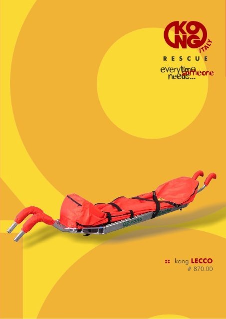
LECCO STRETCHER<br />
1 - INFORMATIVE NOTE on CE certified <strong>Kong</strong> products conforming to 89/686/EEC dir.<br />
Users must carefully read and understand the informative note and instructions for use before using<br />
the product.<br />
Warning: these manufacturer’s informations are not exhaustive and do not pretend to teach neither<br />
the practise of use and the procedures.<br />
Practical use and procedures, above all in natural environments, must be learned/thought by<br />
qualified, trained and skilled instructors.<br />
Warning: rock and ice-climbing, double-cord descent, klettersteig, speleology, alpine skiing,<br />
canoeing, exploration, rescue work, tree climbing and working at heights are all highly dangerous<br />
with possibilities of even lethal accidents. Train yourself to use this article and make sure you fully<br />
understand how it works, if you have any doubts, don't run any risks and ask.<br />
Remember that:<br />
• this article shall be used by a trained and or otherwise competent person or the user should<br />
be under the direct supervision of such a person,<br />
• you are personally responsible to know and understand this article, how to use it and safety<br />
measures to be taken, and that you alone are solely and totally liable for all damages,<br />
injuries or death eventually incurred by you or third parties from using all KONG Spa<br />
products, of any whatsoever kind.<br />
Avoid using this article if you are not able to undertake this responsibility and take these risks.<br />
2 - GENERAL INFORMATION<br />
2.1 - Carry out all the checks described in the specific "instructions for use" for all the products,<br />
before use and be particularly sure that the article is:<br />
• in top condition and working correctly,<br />
• suited for the use you intend to make of it: use the techniques shown without crosses only, all<br />
other usage is absolutely forbidden: risk of death!<br />
2.2 - Immediately replace the product if you have any doubts as to its safety and efficiency. Do not<br />
use the product after falling as its strength could be considerably impaired by eventual invisible<br />
breakage or deformations inside.<br />
1
Incorrect use, mechanical deformation, equipment accidentally dropped from a height, wear,<br />
chemical contamination, exposure to heat above normal climatic conditions (max 100°C for purely<br />
metallic articles and max. 50°C for articles with parts in fabric), are just some examples of other<br />
reasons possibly reducing, limiting and even terminating the service life of the article.<br />
2.3 - Users are responsible for using this article correctly.<br />
2.4 - This article may be used in combination with individual protective devices conforming to the<br />
89/686/EEC Directive, compatibly with relevant instructions for use.<br />
2.5 - The resistance of natural or not natural anchorages in the rocks is not a priori guaranteed, it is<br />
therefore essential that users carefully judge for themselves beforehand to ensure adequate<br />
protection.<br />
2.6 - For safety’s sake,<br />
• users shall evaluate all the possible risks and be sure that the whole safety system (anchor<br />
point, attachments, safety line, harness, etc. etc.) of which this equipment is a component, is<br />
reliable and safe, in addition to this, with systems blocking a fall check:<br />
• whenever possible the anchorage point is above the user,<br />
• use a full body harness,<br />
• organise the work with the purpose of reducing to a minimum any potential fall and its<br />
heights.<br />
2.7 - The anchorage position is essential for safely blocking a fall: carefully judge the height of the<br />
fall, length of cord and "pendulum" effect to avoid all possible obstacles (e.g. ground, articles<br />
scraping against the rocks, etc.).<br />
2.8 - Your life depends on the continual efficiency of your equipment (we thoroughly recommend<br />
personal use of equipment) and how it is kept (use, storage, controls, etc.).We strongly recommend<br />
having pre and post-use controls carried out by a qualified person. An accurate overhaul by a<br />
manufacturer's qualified technician at least once a year is also recommended. The user is<br />
responsible for recording and conserving the information given in the "Record" table together with<br />
the instructions.<br />
2.9 - KONG Spa shall not be held liable in any way for damages, injuries or death caused by:<br />
improper use, changes made to product, repairs by non-authorized persons or use of non-original<br />
spare parts.<br />
2.10 - No special precautions should be taken for transportation, do however avoid contact with<br />
chemical reagents or other corrosive substances and protect all the pointed, sharp parts<br />
adequately. Warning: never leave your equipment in cars parked in the sun!<br />
2.11 – Warning: it is compulsory for dealers to have these instructions for use translated for<br />
products sold in countries other than those selected by KONG Spa.<br />
3 - MAINTENANCE AND STORAGE<br />
No particular maintenance has to be done by the user, the article just has to be cleaned and<br />
lubricated, as explained below.<br />
3.1 - Cleaning: frequently rinse the product under lukewarm fresh water (max. 40°C), eventually<br />
adding a delicate detergent (neutral soap). Leave it to dry naturally away from direct sources of<br />
heat.<br />
3.2 - Lubrication: frequently lubricate the moving parts with silicone based oil. Avoid contact<br />
between oil and fabric parts. This operation must be done after cleaning and thoroughly drying.<br />
2
3.3 - Disinfection: submerge the product for an hour in lukewarm water adding disinfectant<br />
containing salts of quaternary ammonium, then rinse under fresh water, dry and lubricate.<br />
3.4 - Storage: after cleaning, drying and lubricating store the equipment loosely in a dry, cool, dark<br />
(avoid U.V. rays), chemically neutral (absolutely avoid saline environments) place, away from sharp<br />
corners, sources of heat, humidity, corrosive substances or other potentially harmful conditions. Do<br />
not store when wet!<br />
4 - TESTING AND CERTIFICATION<br />
This product has been certified by the notified register organization under n. 0123 - TUV Product<br />
Service GMBH, Ridlerstraße 65, 80339 Munchen, Germany in conformity to the norms given in the<br />
marking.<br />
All KONG products are tested/inspected piece by piece in conformity to the certified UNI EN ISO<br />
9001 standard Quality System procedures. The notified register organization n. 0426 - ITALCERT,<br />
v.le Sarca 336, 20126 Milan, Italy, supervises the manufacture of class III individual protection<br />
devices, in conformity to article 11B, 89/686/EEC Directive.<br />
Warning: laboratory tests, testing and inspection, instructions for use and standards are not always<br />
able to reproduce the case in practice, so that results achieved with the article under effective<br />
conditions of use in natural environments may sometimes differ to a considerable degree. The best<br />
instructions can be had from continuous use under the supervision of qualified skilled instructors.<br />
3
5. TECHNICAL FEATURES:<br />
STANDARD PACK:<br />
n. 1 RUCKSACK containing:<br />
n. 2 HEADS<br />
n. 4 LONGITUDINAL BARS<br />
# 870.00 n. 3 SPACING BARS Kg 14,3<br />
n. 2 PAIRS OF SHAFTS<br />
n. 1 CLOTH BAG<br />
n. 1 HEAD-REST PILLOW<br />
ACCESSORIES (on request):<br />
# 855.05 RESCUE BOARD Kg 7,8<br />
# 855.02 “TAYLAN” FASTEN WEBBING SYSTEM FOR RESCUE BOARD Kg 0,9<br />
# 871.00 “ORION” HANGING KIT Kg 0,8<br />
# 871.04 “EVOLUTION” HANGING KIT Kg 0,8<br />
# 871.01 “GEMINI” CABLEWAY HANGING KIT Kg 0,8<br />
# 871.02 “VIRGO” SAFETY WEBBING FOR VERTICAL DESCENT Kg 1<br />
# 871.50 HAND SHAFTS Kg 1,5<br />
# 871.20 SINGLE WHEEL Kg 5<br />
# 871.22 DOUBLE WHEEL Kg 7,3<br />
# 871.30 HEAD-REST PILLOW WITH VISOR Kg 1<br />
# 871.40 BACK PROTECTION Kg 4<br />
# 871.03 BLOCKING KIT HELICOPTER’S CABIN FLOOR Kg1,2<br />
N.B.: The cloth bag accepts vacuum-operated mattress or any other blocking system for an injured<br />
person.<br />
5.1 CLOTH BAG (INTERNAL HOOKING BELTS):<br />
If a rescue board or a vacuum-operated mattress is not used to block the injured person, the cloth<br />
bag is equipped with several internal hooking belts (fig. 01 - 02) for immobilization of injured.<br />
Special Velcro ® strips allow the correct fixation of the rescue board or of the vacuum mattress<br />
inside the cloth bag.<br />
The head-rest pillow is fixed by Velcro ® strips (fig. 03), and removable if necessary (i.e.: when a<br />
rescue board is used).<br />
5.2 CLOTH BAG (EXTERNAL HOOKING BELTS):<br />
The external hooking belts assure the optimal fixing of injured (fig. 04) and avoid wind effects on<br />
the bag (i.e.: rescue by helicopter).<br />
Two double zippers allow the complete opening of the cloth bag or only a partial lateral control<br />
(fig. 05) without completely uncover the injured.<br />
4
WARNING!<br />
Even if the zippers are not self-locking, do not open the cloth bag by pulling the cover; use the<br />
pullers on the zipper cursors (fig. 06).<br />
5.3 HAND SHAFTS:<br />
The two pairs of shafts (two front shafts and two rear shafts) are fitted with a comfortable padding:<br />
o The front shafts can be inserted in straight position for normal carrying (fig. 07) or in opposite<br />
position for extremely steep slopes or overhangs, giving a better control of stretcher drive (fig.<br />
08).<br />
o The shape of the rear shafts allows a good visibility of the ground (fig. 09).<br />
5.4 WORKING LOAD:<br />
The stretcher is designed and tested to support a max weight evenly distributed of 720 Kg.<br />
The safety working load (SWL) of the cloth bag is calculated with a safety factor 1:4 to support a<br />
weight evenly distributed of 180 Kg. The load shall never be applied in one only point.<br />
The hanging kits (for helicopters or cableways) have a SWL of 500 Kg (Safety factor 1:4 – breaking<br />
load 2000 Kg).<br />
The use of <strong>Kong</strong> Stretcher in hard conditions may cause an adjustment of the connections between<br />
heads and longitudinal bars with a play between the metallic parts: this is not prejudicial to the<br />
functionality of the stretcher provide it is correctly assembled with the lateral and longitudinal<br />
webbings correctly stretched (fig. 23 – 27).<br />
5.5 LIFE TIME OF THE STRETCHER:<br />
o The life time of the stretcher frame is technically unlimited, provided it is correctly stored and that<br />
after an intensive use (we suggest at least every two years) the stretcher is revised by <strong>Kong</strong> s.p.a.<br />
or persons authorized by <strong>Kong</strong> s.p.a.<br />
o The life time of the cloth bag, if correctly stored, is of ten years, provided that after an intensive<br />
use (we suggest at least every two years) the cloth is revised by <strong>Kong</strong> s.p.a. or persons<br />
authorized by <strong>Kong</strong> s.p.a.<br />
o Hanging kits “Orion” – “Gemini” – “Evolution” and “Virgo”, should be replaced every three<br />
years (even if not used).<br />
5
6. ASSEMBLING INSTRUCTIONS:<br />
6.1 HOW TO ASSEMBLY THE METAL FRAME<br />
The longitudinal bars with the same coloured adhesives shall be inserted each into the other (fig.<br />
10); the click of safety pins (fig. 11) will show the correct assembling of the two components.<br />
o lay on the ground the two longitudinal bars assembled (with three slots on the same side)<br />
and the head (follow the markers: red for the head part – close to the three slots; blue for<br />
the feet part) (fig. 12);<br />
o insert a longitudinal bar in the head, checking the right marking and pushing the safety pin<br />
(fig. 13). The click of safety pin (fig. 14) will show the correct assembling.<br />
o insert one of the three spacing bars in the holes of longitudinal bars; insert the longitudinal<br />
bar in the head and check the click of safety pin (fig. 15);<br />
o insert the other two spacing bars in the holes of longitudinal bars and connect the other<br />
head (feet side - blue markers) (fig. 16). Check the click of safety pins in the holes of<br />
longitudinal bars (fig. 17);<br />
IMPORTANT WARNING!<br />
o The safety pins are made only to assembly the metal frame; the strength of the stretcher is ONLY<br />
guaranteed by the correct assembly and stretching of the hooking belts (lateral and longitudinal)<br />
of the cloth bag.<br />
6.2 HOW TO FIX THE CLOTH BAG ON THE METAL FRAME:<br />
o Unfold the cloth upside-down with the lower part upwards and the hooking belts lying on the<br />
ground (fig. 18);<br />
o Put the metal frame on it, with the three hooking belts in correspondence to the three slots of<br />
the longitudinal bars (fig. 19);<br />
o Insert the hooking belts through the slots of the longitudinal bars (from external to internal);<br />
the buckle and ring shall be inserted through the slots one after the other (fig.20) (for safety<br />
reasons slots are narrow in order not to allow the simultaneous passage of buckle and ring)<br />
(fig.29);<br />
o Fasten without stretching the four transversal hooking belts (details of the buckle clasping<br />
system in fig. 21 - 22 – 23);<br />
o The longitudinal hooking belts overturn the transversal bar of the heads; fasten the first<br />
buckle (fig. 24). Stretch the webbings paying attention that the angle between longitudinal<br />
and lateral belts shall be 90° (fig. 25);<br />
o stretch definitely the transversal hooking belts (fig. 23) fixing the end part around the ring<br />
(fig. 26) in order to avoid accidental opening;<br />
o stretch definitely the longitudinal hooking belts, fastening the second safety buckle, then fix<br />
the end part as done for transversal hooking belts (fig. 27);<br />
6
WARNING!<br />
o The buckles of transversal hooking belts are alternated to grant a connection between cloth and<br />
frame in case of accidental release (fig. 28);<br />
o Due to the thickness of the buckle and ring together compared to slot width, is not possible an<br />
accidental complete release (fig. 29);<br />
o Don’t knot the end of hooking belts but fix them in the way shown in figure 26.<br />
6.3 HOW TO ASSEMBLY THE SHAFTS:<br />
o to fix the shafts (fitted with removable washable padding), insert the end into the hole of<br />
head, pulling the safety pin (fig. 30);<br />
o the shafts will be correctly inserted when you heard the clutch of the locking pin after<br />
releasing – check also visually;<br />
6.4 SHAFTS ASSEMBLING POSSIBILITIES IN DESCENDING TRANSPORT:<br />
Normally an injured should be carried with the head higher than the feet, (but in certain cases<br />
doctors may decide the opposite).<br />
o for normal down carrying, the two front shafts (feet side) can be inserted in straight position<br />
(fig. 31). The two rear shafts (head side) shall be inserted in the position shown in fig. 32;<br />
o for extremely steep slopes or overhang, the front shafts (feet side) can be inserted in the<br />
position shown in fig. 33. The rear shafts (head side) shall be inserted in the same position<br />
as before (fig. 32);<br />
o the normal position of shafts (for descent - with the head of injured higher than feet) is<br />
indicated by numbers marked on the heads and shafts (fig. 34);<br />
6.5 SHAFTS ASSEMBLING POSSIBILITIES IN ASCENDING TRANSPORT:<br />
o shafts shall be inserted in opposite heads (fig. 35) to keep the head of injured higher than<br />
feet.<br />
WARNING!<br />
o Shafts are not conceived for hard lateral strains: therefore, in the case of such stresses, they can<br />
have a permanent deformation – in such cases do not attempt to make them straight but<br />
change them.<br />
7
7. ACCESSORIES:<br />
7.1 RESCUE BOARD (# 855.05):<br />
Doctors say that the complete immobilization of a person with spine injuries is possible only using a<br />
spine rescue board.<br />
KONG S.P.A. has developed a rescue board foldable in three pieces, made of a special treated<br />
wood washable and disinfectable, easy to transport, with a special pillow to block the head of<br />
injured.<br />
The rescue board is radio-transparent for a first X-ray diagnosis without need to move the injured<br />
(fig. 36 - 37).<br />
7.2 “TAYLAN” BOARD BINDING (# 855.02):<br />
The complete immobilization of an injured is possible with the special adjustable board binding (fig.<br />
38).<br />
7.3 SAFETY WEBBING “VIRGO” (# 871.02):<br />
For lowering or lifting the stretcher on steep slopes or overhang, it is compulsory the use of the<br />
safety webbing “Virgo” to be inserted in and around the frame (better with empty stretcher) and then<br />
firmly connected to the belaying ropes.<br />
HOW TO ASSEMBLY “VIRGO”:<br />
o Insert one Virgo’s end into the head of the stretcher (head side) (fig. 39), then pull it between<br />
the spacing bars of the frame and the cloth bag (fig. 40);<br />
o Pull out Virgo from the feet head as shown in fig. 41;<br />
o insert Virgo under longitudinal hooking belts (feet side)(fig. 42);<br />
o repeat the same operations through the other side of the frame (fig. 43).<br />
o pull Virgo until the two ends are aligned (fig. 44);<br />
o Connect both belaying ropes to both Virgo’s end loops (fig. 45).<br />
WARNING - DANGER!<br />
Virgo shall go all around all the stretcher: don’t pass Virgo only in the rear head part (head side)<br />
otherwise the strength of the structure is not guaranteed.<br />
7.4 HEAD-REST PILLOW WITH LEXAN ® VISOR (# 871.30)<br />
Designed to improve protection of injured in case of rain, hail, debris and recovery with helicopter.<br />
HOW TO ASSEMBLY LEXAN VISOR:<br />
Insert the shaped visor into the lateral pockets of the pillow.<br />
Fix it with the two lateral Velcro ® strips (fig. 46).<br />
The pillow is equipped with a special Velcro ® front strip to retain the head of injured (fig. 47).<br />
7.5 BOTTOM PROTECTION (# 871.40)<br />
Designed to protect the back of the injured and to make easier the sliding/pulling of the stretcher in<br />
particular conditions (canyoning, rough, stones, etc…).<br />
8
HOW TO ASSEMBLY THE BOTTOM PROTECTION:<br />
The assembling of the two sheets shall be made with the stretcher empty.<br />
o Overturn the stretcher and place sheet n°1 (feet side) (fig. 48). Push it towards the feet head<br />
until the two blocks (“L” shaped) engage the spacing bars (fig. 49);<br />
o Lay it on the central spacing bar and pull it back towards the stretcher centre to engage the<br />
central “L” shaped blocks (fig. 50 e 51)<br />
o Lay sheet n°2 (head side) - it shall be overlapping sheet n°1- push it towards the centre to<br />
engage the blocks on the central spacing bar (fig. 52); pull it back until the two blocks<br />
engage the external spacing bar (fig. 53);<br />
o Now the four “U” shaped blocks of the two sheets shall be in correspondence to the vertical<br />
lateral bars of the heads;<br />
o Insert the two long “U” bars on to the blocks (fig. 54 e 55);<br />
o Secure the “U” long bars inserting the split pins supplied (fig. 56).<br />
7.6 HAND SHAFTS (# 871.50 – kit of 2 pairs)<br />
Hand shafts allow two rescuer to drive <strong>Kong</strong> Stretcher when fitted with a single and/or double wheel<br />
(fig. 57).<br />
This shafts can be used also for shoulder transport by four people.<br />
7.7 SINGLE WHEEL (# 871.20) AND DOUBLE WHEEL (# 871.22)<br />
Designed to make easier the injured transport on flat and not rough route. (fig. 58 e 59).<br />
HOW TO ASSEMBLY WHEEL(S)<br />
o Insert the hand shafts (# 871.50) into the heads (procedure is the same as shoulder shafts);<br />
o Lift the stretcher carrying it close to the head (fig. 60) and insert the profiles under the<br />
longitudinal bars;<br />
N.B. it might be necessary to slightly enlarge or to narrow the two longitudinal bars<br />
o It is possible to fix the wheel(s) in any position to find the correct barycentre (it is normally<br />
located where shown in fig. 61);<br />
o Screw or unscrew the threated hook to find the better snap position (fig. 62);<br />
o The high of the wheel(s) can be varied from mm 460 up to mm 570 unblocking the spring<br />
pins on the fork sides (fig. 63);<br />
WARNING!<br />
o A stretcher fitted with one wheel shall be driven and controlled by two rescuers.<br />
It is also possible a combined installation of a double wheel (preferably on the back side) and of<br />
one single wheel (preferably front side).<br />
N.B. to make a bent, it is necessary to lift the single wheel<br />
7.8 HOW TO USE HANGING KIT “ORION” (# 871.00):<br />
Hanging kit Orion has been studied to lower or lift <strong>Kong</strong> Stretcher by winches, fishing poles,<br />
tripods, helicopters, etc…<br />
• Fix hanging kit to stretcher by inserting the four screw sleeves connectors stitched on the four<br />
arms; insert the connectors from outside towards inside first onto the head and then into the<br />
webbing loop stitched on the cloth bag (fig.64). Follow reference colours (red: head side -<br />
9
lue: feet side).<br />
Fully close the connector screw sleeves<br />
• During the manoeuvres the rescuer shall hook himself to the suspension ring above the<br />
central bar and not over the webbing (fig.65).<br />
7.9 HOW TO USE HANGING KIT “EVOLUTION” (# 871.04):<br />
Hanging kit Evolution, made of two separate arms, has been conceive to make easier the use of<br />
<strong>Kong</strong> Stretcher when the injured is suspended in vertical or over hanging position. Better than Orion<br />
in case of a sturdy injured.<br />
The fixing of Evolution arms is identical to that of Orion (red with red – blue with blue – connectors<br />
from outside to inside, etc…).<br />
To lift (or to lower) the stretcher use a twist lock connector (# 962) to connect the two central rings.<br />
It is advisable to interpose between the hook and the Evolution a “Ciapin” (# 274S – multi-anchor<br />
static webbing) that minimizes the risks caused by rigid connections and rationalize the positioning<br />
of different loads (stretcher, first rescuer, second rescuer, safety longes, etc…) (fig. 67).<br />
If the “Ciapin” is not used it is advisable to insert both rings into the lifting hook – in this last case<br />
the twist lock connector it’s only for safety (fig. 66).<br />
7.10 HOW TO USE “GEMINI” HANGING KIT FOR CABLEWAYS (# 871.01)<br />
Hanging kit Gemini has been studied to keep the stretcher parallel to the bearing cable.<br />
The fixing of Gemini arms is identical to that of Orion (red with red – blue with blue – connectors<br />
from outside to inside).<br />
• The best sliding of <strong>Kong</strong> Stretcher fitted with Gemini is obtained by using two double pulleys<br />
Pamir (# 826)(fig. 68).<br />
• Otherwise two “Turbo Roll” pulleys (# 821) may be used as an alternative, connecting them<br />
to the two rings of the Gemini via a screw sleeve connector Oval Alu Classic (# 730) as<br />
shown in fig. 69<br />
• In case of “critical” environment, it is advisable to install two static bearing ropes and the<br />
use of two pulleys “Heavy duty” (# 819) inserted onto both ropes (fig. 70).<br />
WARNING!<br />
Hanging kit Gemini shall not be used for vertical lowering or lifting – in that occasions use only<br />
either Orion or Evolution.<br />
7.11 BLOCKING KIT HELICOPTER’S CABIN FLOOR (# 871.03)<br />
The kit is composed of four adjustable webbings fitted with a quick link and a stainless steel quick<br />
release connector. It allows to fix the stretcher to the cabin floor of helicopters or other vehicles (fig.<br />
71). The pulling of the red webbing makes possible the quick release of the connectors (fig. 72).<br />
10
WARNING!<br />
BEFORE THE FIRST USE OF THIS PRODUCT IT IS COMPULSARY TO READ AND UNDERSTAND<br />
INSTRUCTIONS AND FILL THIS CONTROL SHEET<br />
KONG LECCO<br />
Series number: Year of manufacture:<br />
User’s name: Buying place:<br />
Date of first use: Buying date:<br />
Control<br />
date<br />
Remarks on correction<br />
operations<br />
OK<br />
(Y/N)<br />
Signature<br />
11




![[alta visi ilitŕ] - Kong](https://img.yumpu.com/44572746/1/184x260/alta-visi-ilitr-kong.jpg?quality=85)
