IPC@CHIP Documentation - SC12 @CHIP-RTOS V1.10
IPC@CHIP Documentation - SC12 @CHIP-RTOS V1.10
IPC@CHIP Documentation - SC12 @CHIP-RTOS V1.10

Create successful ePaper yourself
Turn your PDF publications into a flip-book with our unique Google optimized e-Paper software.
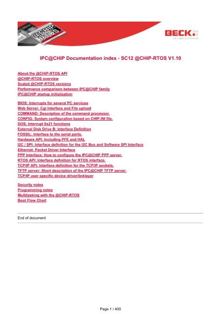
<strong>IPC<strong>@CHIP</strong></strong> <strong>Documentation</strong> index - <strong>SC12</strong> <strong>@CHIP</strong>-<strong>RTOS</strong> <strong>V1.10</strong><br />
About the <strong>@CHIP</strong>-<strong>RTOS</strong> API<br />
<strong>@CHIP</strong>-<strong>RTOS</strong> overview<br />
Scaled <strong>@CHIP</strong>-<strong>RTOS</strong> versions<br />
Performance comparison between <strong>IPC<strong>@CHIP</strong></strong> family<br />
<strong>IPC<strong>@CHIP</strong></strong> startup initialization<br />
BIOS: Interrupts for several PC services<br />
Web Server: Cgi Interface and File upload<br />
COMMAND: Description of the command processor.<br />
CONFIG: System configuration based on CHIP.INI file.<br />
DOS: Interrupt 0x21 functions<br />
External Disk Drive B: Interface Definition<br />
FOSSIL: Interface to the serial ports.<br />
Hardware API: Including PFE and HAL<br />
I2C / SPI: Interface definition for the I2C Bus and Software SPI Interface<br />
Ethernet: Packet Driver Interface<br />
PPP Interface: How to configure the <strong>IPC<strong>@CHIP</strong></strong> PPP server.<br />
<strong>RTOS</strong> API: Interface definition for <strong>RTOS</strong> interface.<br />
TCP/IP API: Interface definition for the TCP/IP sockets.<br />
TFTP server: Short description of the <strong>IPC<strong>@CHIP</strong></strong> TFTP server.<br />
TCP/IP user specific device driver/linklayer<br />
Security notes<br />
Programming notes<br />
Multitasking with the <strong>@CHIP</strong>-<strong>RTOS</strong><br />
Boot Flow Chart<br />
End of document<br />
Page 1 / 400
<strong>IPC<strong>@CHIP</strong></strong> <strong>Documentation</strong> Index<br />
Short general explanation<br />
General introduction - <strong>SC12</strong> <strong>@CHIP</strong>-<strong>RTOS</strong> <strong>V1.10</strong><br />
The name <strong>@CHIP</strong>-<strong>RTOS</strong> is used as the term for the operating system of the <strong>IPC<strong>@CHIP</strong></strong> (most of older<br />
versions and manuals are still using the term BIOS). For an overview of the provided features and the<br />
general architecture of the operating system see <strong>@CHIP</strong>-<strong>RTOS</strong> architecture.<br />
The operating system is able to execute multiple (up to 12) DOS programs simultaneous. Each program<br />
runs as a task of the <strong>RTOS</strong> kernel. These 16 bit DOS programs can be created with a variety of<br />
development tools. However, the instruction opcodes in these programs must be confined to the 80186<br />
instruction set. For C/C++ programming, Beck offers the Borland 5.02 development environment (see<br />
www.beck-ipc.com).<br />
This document describes the Application Programmers Interface (API) of the <strong>@CHIP</strong>-<strong>RTOS</strong>. It should<br />
be used as a reference manual for <strong>IPC<strong>@CHIP</strong></strong> application programmers. For a better understanding of<br />
this manual the reader should have some experience in programming DOS applications.<br />
The document explains how to call every provided function of the <strong>@CHIP</strong>-<strong>RTOS</strong> from user application<br />
programs. The API of the <strong>@CHIP</strong>-<strong>RTOS</strong> is structured into different sections (e.g. HARDWARE API,<br />
<strong>RTOS</strong> API, TCPIP API, ....). All sections are listed as HTML-links on the main index page of this<br />
document.<br />
For every API section the <strong>@CHIP</strong>-<strong>RTOS</strong> provides a software interrupt with different function numbers for<br />
every API call. The software interrupt mechanism is the standard way for DOS programs to call internal<br />
functions of the operating system (e.g. file operations, reading/printing characters, .....).<br />
Before calling the specified software interrupt with e.g. the standard C-Library call int86() or the<br />
Assembler instruction INT xx, every necessary function parameter must be loaded into the processor<br />
registers. Each API call description details which parameters are required in the registers. The <strong>@CHIP</strong>-<br />
<strong>RTOS</strong> uses the parameters from the processor registers and executes the corresponding function. After<br />
the software interrupt execution some specified processor registers contains the return result(s) from the<br />
function. The meaning of the return result(s) are also specified with each API call description.<br />
At our download page under www.beck-ipc.com, we provide a collection of program examples, where<br />
the usage of API calls is demonstrated.<br />
For a easier and more practical usage of the API, we provide a set of C-Libraries. This collection of C-<br />
Files and H-Files contains every API software interrupt call, implemented inside of a C-Function. The<br />
application programmer can integrate these files at his program project and then call the appropriate Cfunction<br />
instead of directly calling the software interrupt.<br />
You will find some useful general notes about programming DOS applications for the <strong>IPC<strong>@CHIP</strong></strong> under<br />
Programming notes.<br />
For some necessary knowledge about hardware details of the <strong>IPC<strong>@CHIP</strong></strong> see the hardware manual<br />
Page 2 / 400
available from the download area of www.beck-ipc.com.<br />
End of document<br />
Page 3 / 400
<strong>IPC<strong>@CHIP</strong></strong> <strong>Documentation</strong> Index<br />
<strong>RTOS</strong><br />
● Tasks: 35<br />
● Sum of Semaphores, Timers, Event groups: 60<br />
● Message exchanges: 10<br />
These are the entire <strong>RTOS</strong> resources. Some of<br />
them are used by the <strong>RTOS</strong> itself. See <strong>RTOS</strong> API<br />
documentation for available user resources.<br />
<strong>RTOS</strong> Filesystem for<br />
● Internal ramdisk<br />
● Internal flashdiskdrive<br />
● External drive<br />
TCP/IP Stack<br />
● TCP<br />
● UDP<br />
● ARP<br />
● ICMP<br />
● IGMP<br />
● Socket interface<br />
● Sockets: 64<br />
● Internal device interfaces: 4<br />
- Ethernet<br />
- PPP server<br />
- PPP client<br />
- Loopback<br />
TCP/IP applications<br />
● HTTP Webserver<br />
● FTP server<br />
● Telnet server<br />
● DHCP client<br />
● TFTP server (optional)<br />
● SNMP MIB variable support (optional)<br />
● UDP config server for <strong>@CHIP</strong>-<strong>RTOS</strong> upgrade<br />
DOS-EXE Loader<br />
● Up to 12 DOS application programms can run<br />
as tasks of the <strong>RTOS</strong><br />
DOS-like command shell<br />
● Supports a subset of DOS commands and<br />
<strong>@CHIP</strong>-<strong>RTOS</strong> specific commands via Telnet,<br />
serial devices or user specific stdio<br />
Scalable <strong>@CHIP</strong>-<strong>RTOS</strong><br />
● Support of 6 different versions, including various<br />
<strong>@CHIP</strong> <strong>RTOS</strong> features<br />
<strong>@CHIP</strong>-<strong>RTOS</strong> Upgrade via Ethernet/UDP or<br />
serial Bootstraploader<br />
<strong>@CHIP</strong>-<strong>RTOS</strong> Software overview<br />
Application Programmer Interface<br />
● <strong>RTOS</strong><br />
● TCP/IP socketinterface<br />
● DOS interrupt 21h and others<br />
● Webserver CGI<br />
● Hardware<br />
● I2C<br />
● Software SPI (optional)<br />
● Serial devices (Fossil interface)<br />
● Ethernet packet driver (Add. use of ethernet for NON-TCP/IP<br />
purposes)<br />
● Special <strong>@CHIP</strong>-<strong>RTOS</strong> services<br />
Serial filetransfer via xmodem<br />
DOS application examples<br />
● <strong>RTOS</strong> API examples<br />
● TCP/IP API examples<br />
- FTP client<br />
- HTTP client<br />
- Other TCP/IP examples<br />
● Webserver CGI examples<br />
● External IDE disk driver<br />
● Hardware API examples<br />
● I2C examples<br />
● Fossil examples<br />
● API examples written in Turbo Pascal<br />
● API C-Libraries<br />
● more<br />
Page 4 / 400
<strong>IPC<strong>@CHIP</strong></strong> <strong>Documentation</strong> Index<br />
Introduction<br />
Programming notes - <strong>SC12</strong> <strong>@CHIP</strong>-<strong>RTOS</strong> <strong>V1.10</strong><br />
Here are some useful notes for programming applications for the <strong>IPC<strong>@CHIP</strong></strong>.<br />
These notes contains general rules for programming DOS applications for the <strong>IPC<strong>@CHIP</strong></strong> and important<br />
information about internals of the <strong>@CHIP</strong>-<strong>RTOS</strong> which can prevent the programmers from making fatal<br />
errors.<br />
❍ Common notes for building <strong>IPC<strong>@CHIP</strong></strong> user applications<br />
❍ Using <strong>RTOS</strong> API<br />
❍ Programming CGI functions<br />
❍ Configure the FTP server<br />
❍ Usage of the TCP/IP API<br />
❍ General notes for the usage of the DOS and <strong>@CHIP</strong>-<strong>RTOS</strong> int API calls<br />
❍ Using Hardware API<br />
❍ Using Fossil API<br />
❍ Working with Float Data Types<br />
❍ Configure PPP client or server<br />
Common notes for building <strong>IPC<strong>@CHIP</strong></strong> user applications<br />
1. Limited Flash Write Cycles (of <strong>IPC<strong>@CHIP</strong></strong>s internal Flash):<br />
To open files on the flash disk drive A: for reading or writing, you can use the standard C<br />
functions fopen or open. We recommend the use of the fopen/fread/fwrite calls instead of<br />
open/read/write to reduce the flash write cycles, because these cycles are limited.<br />
For further information see the FlashWriteCycles document.<br />
2. Compiler option settings:<br />
We recommend the usage of large memory model for user applications.<br />
The compiler must produce 186 processor instruction code.<br />
The data alignment must be set to 8 Bit (Byte alignment), not to 16-Bit (Word alignment)!<br />
3. No "exception handling" at Borland C 4.x or 5.x projects:<br />
Users of Borland C-Compilers (which provides "exception handling libraries" as it's default setting<br />
for 4.5 or 5.02) should choose for their program project "No exceptions" at the "Target Expert"<br />
window. This setting saves Flash and RAM memory space.<br />
4. Do not select "Test stack overflow" at Borland C 4.x or 5.x project compiler settings:<br />
If "Test stack overflow" is selected a stack check is done at every function call. If stack overflow<br />
is recognized the program halts.<br />
This mechanism is not usable in user applications which are using several tasks inside their<br />
Page 5 / 400
Top of list<br />
Index page<br />
Using <strong>RTOS</strong> API<br />
application, because every task has its own stack and the Borland runtime library stack functions<br />
are not aware of this.<br />
5. Turbo Pascal programmers should include the example file <strong>SC12</strong>.INC (part of each <strong>IPC<strong>@CHIP</strong></strong><br />
Pascal example program). At the start of their program, they should install the procedure<br />
Terminate_Program as the default exit procedure of the program. Usage of the standard<br />
unit crt is not allowed.<br />
6. Before starting the first Turbo Pascal program at the <strong>IPC<strong>@CHIP</strong></strong> the memopt 1 command must<br />
be executed (e.g. in the autoexec.bat)<br />
7. If programs that depend on one another are started from a batch file (e.g. if a user program needs<br />
a previous driver program) the Batchmode 1 in chip.ini should be set.<br />
8. The old CLIB library (< V2.00) and some older examples are using the standard int86 and<br />
int86x calls from the Borland C standard library. We used these functions for more readable<br />
code. If developers need higher performance in their applications, it will be better to use the new<br />
CLIB library (>= V2.00) which implements the API calls with inline assembler code. With inline<br />
assembler instructions it is possible to load the processor registers directly with the needed<br />
parameters and directly invoke the appropriate software interrupt int xxh.<br />
9. For certain reasons it is not advisable to design an <strong>IPC<strong>@CHIP</strong></strong> application as a set of several<br />
DOS programs:<br />
1. It is more meaningful to run several tasks (built with the <strong>RTOS</strong> API) inside of one DOS program<br />
because this requires much less RAM and Flash memory space, than running several DOS<br />
programs as tasks of the <strong>@CHIP</strong>-<strong>RTOS</strong>.<br />
2. It can lead to high memory fragmentation and insufficient memory, if more than one or two<br />
DOS programs are running on the <strong>IPC<strong>@CHIP</strong></strong>, which will be often terminated and restarted again.<br />
10. Most of the used pointer variables and function parameters in the old CLIB library C files (<<br />
V2.00) are not declared as FAR pointer, because all of our test programs are using the memory<br />
model Large (at model Large all pointers become automatically FAR pointers). If you want to use<br />
e.g. memory model Small for your application you should use the new CLIB (>= V2.00) and<br />
declare the pointer variables and function parameters inside your program explicit as FAR<br />
pointers.<br />
11. It is not advisable to use in your application the Borland C-library malloc function with memory<br />
model Large. In that case the DOS program tries to increase its own memory block with int21h<br />
0x4A. If another program is loaded after that program the malloc call fails, because there is no<br />
memory space left between the two programs. It is possible to define a memory gap between<br />
two loaded programs at chip.ini but then you must know what maximum memory is required by<br />
your malloc calls. It is better to reserve inside of your application the memory by declaring an<br />
unsigned char array (or the type you require) with the needed memory size.<br />
12. The <strong>@CHIP</strong>-<strong>RTOS</strong> has its own memory strategy.<br />
The <strong>@CHIP</strong>-<strong>RTOS</strong> always allocates memory in the following way:<br />
DOS programs are always loaded at the first lowest free memory block. For memory blocks<br />
allocated inside of the <strong>@CHIP</strong>-<strong>RTOS</strong> or e.g. with DOS service 0x48 the <strong>@CHIP</strong>-<strong>RTOS</strong> always<br />
start searching for a free memory block from the highest possible RAM address. So the largest<br />
free memory block of the system is always located in the middle of the <strong>@CHIP</strong>-<strong>RTOS</strong> memory<br />
area. The shell command mem shows the state of the internal memory map.<br />
Page 6 / 400
1. Timer procedures must be implemented as short as possible, because they are executed in the<br />
Kernel task. Large timer procedures are blocking the kernel and other tasks of the <strong>@CHIP</strong>-<br />
<strong>RTOS</strong>. Do not use large Clib functions like printf inside of a timer procedure. This can cause<br />
a fatal stack overflow in the kernel task (stack size 1024 Bytes)<br />
2. Declaring of timer procedures with Borland C:<br />
void huge my_timer(void)<br />
3. Microsoft C:<br />
void far _saveregs _loadds my_timer(void)<br />
4. Turbo Pascal:<br />
procedure Timer1_Proc;interrupt;<br />
begin<br />
[... your code ...]<br />
(************************************************)<br />
(* This is needed at the end of the Timer Proc. *)<br />
asm<br />
POP BP<br />
POP ES<br />
POP DS<br />
POP DI<br />
POP SI<br />
POP DX<br />
POP CX<br />
POP BX<br />
POP AX<br />
RETF<br />
end;<br />
(************************************************)<br />
end;<br />
5. DOS applications are running as a task of the <strong>@CHIP</strong>-<strong>RTOS</strong> with a default priority of 25. If the<br />
users application doesn't go to sleep, lower priority tasks like the FTP server or the Web server<br />
will not work. In major loops within user applications, the programmer should insert sleep calls if<br />
the FTP server or Web server should work during the runtime of the user application.<br />
6. The stack of a task created inside of a DOS application should have a minimum stack size of<br />
1024 Bytes. Programmers of task functions who are using Microsoft C-Compilers with C-Library<br />
functions, e.g. sprintf, which requires a lot of stack space should increase this allocation to<br />
6144 (6 Kbytes). More stack space for the task is also required if your task function uses a large<br />
amount of stack for automatic data (local variables) declared inside the task function call.<br />
7. Declaring of task functions with Borland C:<br />
void huge my_task(void)<br />
8. Declaring of task functions with Microsoft C:<br />
void far _saveregs _loadds my_task(void)<br />
9. Before exiting an application, every task or timer procedure created inside of this application<br />
program must be removed.<br />
10. A sleep call with parameter 1 millisecond takes equal or less than one millisecond. If a user<br />
needs a minimal sleep time of 1 millisecond then RTX_SLEEP_TIME must be called with value 2<br />
milliseconds.<br />
11. It is possible to create tasks with a time slicing value in the taskdefblock structure.. Please<br />
note that the kernel executes time slicing only between tasks which have same priority. Other<br />
priority tasks are not affected.<br />
Page 7 / 400
Top of list<br />
Index page<br />
<strong>RTOS</strong> API<br />
Programming CGI functions<br />
Top of list<br />
Index page<br />
1. Avoid large loops inside of CGI functions. CGI functions must be executed<br />
as fast as possible. Large execution times in CGI functions block<br />
the Web server task preventing response to other http requests.<br />
2. Declaring of CGI functions with Borland C:<br />
void huge my_cgi_func(rpCgiPtr CgiRequest)<br />
3. Declaring of CGI functions with Microsoft C:<br />
void far _saveregs _loadds my_cgi_func(rpCgiPtr CgiRequest)<br />
4. Declaring of CGI functions with Borland Turbo Pascal:<br />
procedure my_cgi_func;interrupt;<br />
5. Turbo Pascal users must install their CGI functions with API call Install CGI Pascal function<br />
6. C-Programmers must use Install CGI function<br />
7. Avoid the declaration of large arrays as local variables inside<br />
of the CGI function to prevent stack overflows<br />
8. Users of Microsoft C should set Web server stacksize in chip.ini up to 6144 KBytes,<br />
to prevent stack overflows, if Microsoft CLib functions like sprintf are used.<br />
9. Dynamic HTML or text pages, which are created inside of a user CGI function should be as small<br />
as possible. The Web server inside must allocate a temporary buffer for storing this page before<br />
sending it to the browser. If your application builds large dynamic HTML page in RAM, your<br />
application should not use all available memory in the <strong>IPC<strong>@CHIP</strong></strong> because the Web server will<br />
need some memory for allocating temporary buffers for this page. How much memory should be<br />
left: This depends on the application and the sizes of the created dynamic HTML or CGI pages.<br />
10. Before exiting an application, every CGI function installed by the application must be removed<br />
with Remove CGI page<br />
CGI API<br />
Configure the FTP server<br />
1. The default FTP idle timeout is set to 300 seconds. This is a very long time for waiting, if FTP<br />
commands fail. The idletimeout can be reduced in chip.ini.<br />
Page 8 / 400
Top of list<br />
Index page<br />
Usage of the TCP/IP API<br />
Top of list<br />
Index page<br />
1. Processing of a socket callback functions (see Register callback) should be kept at a minimum<br />
to prevent stack overflows.<br />
2. Declaring of socket callback functions with Borland C:<br />
void huge my_callback(int socketdescriptor, int eventflagmask)<br />
3. Declaring of socket callback functions with Microsoft C:<br />
void far _saveregs _loadds my_callback(int sd, int eventmask)<br />
4. The internal TCP/IP stack of the <strong>IPC<strong>@CHIP</strong></strong> allocates memory for buffers smaller than 4096 bytes<br />
from a pre-allocated memory block. Larger buffers are allocated direct from the CHIP-<strong>RTOS</strong>. If<br />
user TCP/IP network communication sends/receives packets with a size larger than 4096 bytes,<br />
the user application should not use all available memory in the <strong>IPC<strong>@CHIP</strong></strong> because of these<br />
additional allocations. There should be in that case always a minimum of 30-40 KBytes of free<br />
available memory in the <strong>IPC<strong>@CHIP</strong></strong>. The mem command shows the whole memory list of the<br />
<strong>IPC<strong>@CHIP</strong></strong> at runtime. The maximum amount of TCP/IP memory can be configured at chip.ini<br />
(see Set TCP/IP memory size). The application programmer can reduce or increase this size in<br />
chip.ini. With the API call Get TCP/IP memory info it is possible to control the TCP/IP memory<br />
usage at the application runtime.<br />
TCP/IP API<br />
General notes for the usage of the DOS and <strong>@CHIP</strong>-<strong>RTOS</strong> int API calls<br />
1. At the start of a user program the Stdio focus should be set to USER. Before ending the<br />
application switch the focus back to SHELL or BOTH (see Set Stdio focus).<br />
2. If more than one user program runs in the <strong>IPC<strong>@CHIP</strong></strong>, only one of them should read characters<br />
from Stdin<br />
3. The functionality of most of the shell commands is also available through calls into the <strong>@CHIP</strong>-<br />
<strong>RTOS</strong> INT API. If not, use the <strong>@CHIP</strong>-<strong>RTOS</strong> INT call Execute a shell command. This call<br />
executes a shell command from inside the user application.<br />
4. Install a fatal user error handler, which does a reboot of the <strong>IPC<strong>@CHIP</strong></strong> with Install user fatal<br />
error handler<br />
5. Used software interrupts (all others are free for use):<br />
0x00 - Reserved (<strong>@CHIP</strong>-<strong>RTOS</strong> Divide Overflow Handler)<br />
0x01 - Reserved (Debugger Trace Interrupt)<br />
0x02 - Reserved (Hardware Non-Maskable Interrupt (NMI))<br />
0x03 - Reserved (Debugger Breakpoint Interrupt)<br />
0x04 - Reserved (<strong>@CHIP</strong>-<strong>RTOS</strong> INTO Overflow Handler)<br />
0x05 - Reserved (<strong>@CHIP</strong>-<strong>RTOS</strong> Array Bounds Exception Handler)<br />
Page 9 / 400
0x06 - Reserved (<strong>@CHIP</strong>-<strong>RTOS</strong> Invalid Opcode Exception Handler)<br />
0x07 - Reserved (<strong>@CHIP</strong>-<strong>RTOS</strong> ESC Opcode Exception Handler)<br />
0x08 - Reserved (Hardware, Timer #0 Handler)<br />
0x0A - Reserved (Hardware, DMA #0 / INT5 Handler)<br />
0x0B - Reserved (Hardware, DMA #1 / INT6 Handler)<br />
0x0C - Reserved (Hardware, INT0 Handler)<br />
0x0D - Reserved (Hardware, INT1 Ethernet Handler)<br />
0x0E - Reserved (Hardware, INT2 Handler)<br />
0x0F - Reserved (Hardware, INT3 Handler)<br />
0x10 - Biosint<br />
0x11 - Biosint<br />
0x12 - Reserved (Hardware, Timer #1 Handler)<br />
0x13 - Reserved (Hardware, Timer #2 Handler)<br />
0x14 - Fossil Interface<br />
0x16 - Biosint<br />
0x1A - Biosint<br />
0x1C - Timer Interrupt, see Set timer 1C interval<br />
0x20 - Terminate Program (Only for compatibility, instead use DOS service 0x4C)<br />
0x21 - DOSEmu Interrupt Interface<br />
0xA0 - Several 'chip' related services<br />
0xA1 - Hardware API (HAL)<br />
0xA2 - Hardware API (PFE)<br />
0xAA - I2C Interface<br />
0xAB - CGI Interface<br />
0xAC - TCP/IP API<br />
0xAD - <strong>RTOS</strong> API<br />
0xAE - Ethernet Packet Driver<br />
0xAF - Timer Interrupt, see Set timer AF interval<br />
0xB0 - External Disk API<br />
0xB1 - External Disk Driver<br />
0xBF - This vector is reserved to start a DOS executable<br />
If you are using a BIOS variant in which some modules are not included, then the interrupts<br />
corresponding to these modules are free for use.<br />
6. External hardware interrupts are enabled (STI opcode) during execution of the following API<br />
software interrupts:<br />
DOS ints 0x10, 0x14(Fossil), 0x16, 0x20, 0x21, <strong>@CHIP</strong>-<strong>RTOS</strong> int 0xA0, CGI<br />
int 0xAB, PFE int 0xA2, I2C int 0xAA, CGI int 0xAB, Pkt int 0xAE,<br />
Extdisk int 0xB0, Extdisk user int 0xB1<br />
The state of the interrupt flag is not changed during the execution on the following API software<br />
interrupts (If interrupts are disabled before the API call, they are kept disabled during execution of<br />
the call. If interrupts are enabled before the API call, they get reenabled during execution of the<br />
call.):<br />
TCPIP int 0xAC, <strong>RTOS</strong> int 0xAD<br />
External hardware interrupts are disabled during execution of the following API software<br />
interrupts:<br />
HAL int 0xA1<br />
BIOS ints<br />
Int21h<br />
Page 10 / 400
Top of list<br />
Index page<br />
Using Hardware API<br />
1. The HAL functions keep interrupts disabled, so you can call them inside an interrupt routine. The<br />
PFE functions are only for choosing and initializing a specific function on the selected pin. They<br />
should be called once in your application for initializing your hardware environment and not at<br />
runtime or inside interrupt routines.<br />
2. Do not use functions of the <strong>RTOS</strong> API inside of a normal HW API user ISR. For this purpose<br />
install a RTX user ISR, see Install ISR.<br />
3. The latency time of the user ISR (from generation of an interrupt until first line of code inside the<br />
user ISR) depends on the used <strong>IPC<strong>@CHIP</strong></strong>, see Performance comparision .<br />
4. Instead of HAL functions Read data bus and Write data bus you can call C-functions inportb<br />
and outportb from DOS.H for faster data bus accesses.<br />
5. Usage of DMA0/INT5 and DMA1/INT6:<br />
DMA0 and INT5 are served inside the <strong>@CHIP</strong>-<strong>RTOS</strong> with a single shared interrupt handler.<br />
(Likewise for DMA1 and INT6.)<br />
If an user application has activated serial EXT DMA mode and also wants to use external<br />
interrupt INT5, the DMA interrupt event is higher priority. (And again, likewise for COM DMA<br />
mode and INT6.)<br />
This means that if a DMA0/1 interrupt occurs simultaneous with an external INT5/6 interrupt, the<br />
installed user handler for the external interrupt is not called.<br />
See Hardware API<br />
6. Usage of NMI/Power fail detection:<br />
The NMI function of the multifunction pin 17 (RESET/NMI/LINK_LED) of the <strong>IPC<strong>@CHIP</strong></strong><br />
SC11/<strong>SC12</strong>/SC13 is for power fail purposes only. It is not possible to use NMI as a "normal"<br />
interrupt pin like e.g. INT0 for generating interrupts. It can only be used as described in the<br />
<strong>IPC<strong>@CHIP</strong></strong> hardware documentation.<br />
The flowchart below describes how the <strong>@CHIP</strong>-<strong>RTOS</strong> handles an incoming NMI interrupt.<br />
Page 11 / 400
Top of list<br />
Index page<br />
Using Fossil API<br />
See also:<br />
Install interrupt service routine<br />
Init non-volatile data<br />
Save non-volatile data<br />
1. The receive and send queue size can be configured over the CHIP.INI.<br />
2. If you want to use external DMA, you have to disable the serial DMA receive mode. Otherwise<br />
the DMA receive mode is recommended.<br />
Page 12 / 400
Top of list<br />
Index page<br />
3. Since <strong>@CHIP</strong>-<strong>RTOS</strong> 1.02B XON/XOFF mode is available also with the serial DMA receive mode<br />
in use.<br />
Please note: Because of the internal functionality of DMA it is not possible to immediately detect<br />
an XON or XOFF character from the connected peer. It is possible that an overrun situation at<br />
the peer (e.g. GSM modem) can occur. Nevertheless we enable this mode because some GSM<br />
modems (any??) support only XON/XOFF as serial flow control mechanism.<br />
4. The default serial receiver queue size is 1024 bytes. If the default DMA receive mode is used, it<br />
is advised to increase the receiver queue size in Chip.ini up to a minimum value of 2048 bytes to<br />
prevent a possible buffer overrun (even if hard handshake is used). This can only happen with<br />
the default queue size of 1024 bytes if the user doesn't call the Fossil API read block function<br />
frequently enough. If the application programmer does not increase this buffer size up to the<br />
recommended value, they should call the Fossil API read block function with sufficient buffer<br />
size in the CX-Register to flush the internal buffers and prevent a receive buffer overrun.<br />
5. Serial ports, running with IRQ receive mode:<br />
The two serial ports of the <strong>IPC<strong>@CHIP</strong></strong> have no hardware FIFO buffer. Only one incoming<br />
character can be stored direct by the ports. As a consequence of this behaviour, it is possible<br />
that incoming characters get lost because of missed or delayed receiver interrupt execution (see<br />
Operating mode of serial ports). E.g.: Writing a flash sector (e.g. happens when writing a file<br />
at Drive A:) disables all interrupt execution for about 15 ms. If the serial port is configured with a<br />
baud rate of 9600, incoming characters can be lost during this time.<br />
Loss or delayed execution of serial receiver interrupts depends on the number and the execution<br />
frequency of all enabled interrupts in the <strong>IPC<strong>@CHIP</strong></strong> system. It depends also on execution times<br />
of users interrupt service functions and the duration of interrupt masking periods (CLI / STI<br />
instruction sequences).<br />
6. For a given serial port the fossil functions are not reentrant. Do not call fossil functions for the<br />
same serial port from different tasks. However for different serial ports, the fossil functions are<br />
reentrant. E.g. task A can operate the COM port using fossil functions concurrently with task B<br />
operating the EXT port using the same fossil functions.<br />
Fossil API<br />
Working with Float Data Types<br />
1. The <strong>IPC<strong>@CHIP</strong></strong> does not provide a floating point co-processor. So if you want to use floating<br />
point data types you need to enable the math-emulation in your compiler. In Borland C++ 5.02<br />
see the option "Emulation" under the Target Expert's (right mouse click on your Exe-file in your<br />
project) "Math Support".<br />
2. The Borland Math Emulation libraries are not made for usage in a multitasking system like the<br />
<strong>@CHIP</strong>-<strong>RTOS</strong>. If you want to use float data types in tasks other than your main (DOS) task,<br />
please pay attention to the following work around solution (Using Borland 5.02, Memory model<br />
large):<br />
a) For floating point emulator usage, the current stack (the stack of the task) must have offset 0.<br />
To achieve this, the task stack must be far array located in a separate segment:<br />
unsigned int far task_stack[TASK_STACKSIZE];<br />
Note: The CGI callbacks execute on the Web server's stack, which satisifies this "offset 0<br />
present" requirement.<br />
Page 13 / 400
Top of list<br />
Index page<br />
b) The current stack must be pre-initialized for math emulation:<br />
void my_emu1st(void)<br />
{<br />
asm{<br />
mov word ptr ss:[0x2f],0x0065 // set end of FPU stack<br />
mov word ptr ss:[0x31],0x0125 // set start of FPU stack<br />
mov word ptr ss:[0x27],0 // no protected mode<br />
mov byte ptr ss:[0x26],0 // no 8087<br />
}<br />
}<br />
c) Before executing floating point arithmetic, call the Borland library function _fpreset, which<br />
initializes the stack for floating point emulation.<br />
Example for a task function:<br />
void huge my_task(void)<br />
{<br />
float a;<br />
my_emu1st();<br />
_fpreset();<br />
// ..... ready for executing floating point arithmetic<br />
}<br />
If you are interest in more details, take a look at the Borland 5.02 RTL sources (fpinit.asm).<br />
We will provide an example for using floating point arithmetic in separate tasks or within CGI<br />
callbacks.<br />
3. Using Math emulation with Borland C++ 5.02 (also for older versions of Borland C) produces a<br />
conflict between the NMI interrupt of the <strong>@CHIP</strong>-<strong>RTOS</strong> (Interrupt Vector 0x02) and the Borland<br />
floating exception handling. Borland C math emulation also uses INT 2 for generating floating<br />
point exceptions. Our internal NMI interrupt service function (normally called at power fail case)<br />
will no longer execute during the runtime of the user's application. We have provided a solution<br />
which moves the Borland exception function from INT 2 to another interrupt vector. We modified<br />
the Borland RTL source (fpinit.asm) and include the modifications directly into the application<br />
project. It is planned to provide an example in our Internet download area.<br />
Configure PPP client or server<br />
1. Connected modems should be configured in chip.ini with the modem command ATE0 INITCMD.<br />
This prevents the modem from echoing characters to the peer in command mode. The COM and<br />
the serial ports of the <strong>IPC<strong>@CHIP</strong></strong> have only 4 lines (TxD/RxD/CTS/RTS) and no line for detecting<br />
a hang-up of the modem. Because of this fact we provided the Idletimeout and the<br />
MODEMCTRL configuration features in chip.ini or in the PPP client init structure type. But the<br />
idletimeout and modemctrl detection can fail if a modem has switched its echo mode on. If<br />
the peer modem hangs up without correctly closing a PPP session, the IPC@chip modem also<br />
hangs up and goes into the command mode. Because of the missing line for detecting a modem<br />
hang-up, the PPP server doesn't know anything about the broken connection and still sends PPP<br />
frames to the modem. It can happen that the modem echoes these characters back to the<br />
<strong>IPC<strong>@CHIP</strong></strong> due to being in "Echo on" mode. This will cause the idletimeout to not work.<br />
2. We recommend that the PPP server or client and the connected modems should run (if possible)<br />
with RTS/CTS flow control (see chip.ini flow control mode or the PPP client init structure type).<br />
Page 14 / 400
Top of list<br />
Index page<br />
End of document<br />
Most modems use RTS/CTS flow control, if they get the AT command AT\Q3.<br />
3. The COM and EXT port of the <strong>IPC<strong>@CHIP</strong></strong> has only CTS, RTS, RxD and TxD lines,<br />
so you have to configure your modem with DTR always on.<br />
(e.g. AT cmd for a most modem types: AT&D0)<br />
4. If the option PPP_IPCP_PROTOCOL (VJ TCP/IP header compression) is set (see<br />
PPPCLIENT_SET_OPTIONS), it is possible that the FTP server of the <strong>IPC<strong>@CHIP</strong></strong> is not usable<br />
via the PPP interface. This was noticed at PPP sessions connected to a Linux PPP peer.<br />
PPP<br />
Page 15 / 400
Important information about the <strong>IPC<strong>@CHIP</strong></strong> drives and filesystem<br />
(Limited Number of Flash write cycles per sector)<br />
The sectors of the internal Flash of the <strong>IPC<strong>@CHIP</strong></strong> (used for drive A: and memory for <strong>@CHIP</strong>-<strong>RTOS</strong> Code) has<br />
limited write cycles. So you should avoid cyclic write access like writing into a logfile every hour.<br />
We guarantee 10.000 write cycles per sector. Note that one write access in your program (fwrite or write) could<br />
cause more than one write access on the <strong>@CHIP</strong>s flashdisc.<br />
Optimizations:<br />
To decrease the flash write accesses in your program, you should follow the hints below:<br />
1. Use fopen, fwrite, ...<br />
2. Use setvbuf with a size of 1024 bytes.<br />
Description:<br />
fopen internally works with a 512 byte stream buffer. The filesystem sectors have a size of 512 bytes. Flash<br />
physical sector size can be 256 or 1024 bytes, depending on the used flash memory. Setting the stream buffered<br />
size to 1024 helps to avoid additional flash writes. Note: The fwrite function in Borland C 5.02 has an unexpected<br />
behaviour when the size of data exceeds the buffered size (512 bytes default or size set with setvbuf). Then the<br />
data blocks execeeding the buffered size are always written unbuffered instead of splitting them to smaller<br />
packets.<br />
How will a flash defect detected:<br />
The damaging write access respectivly the return code tells you that the write access was not successful. That it<br />
is a flash defect can you see if you reboot your <strong>@CHIP</strong>. There you get an error message ("Flash error at sector:<br />
xx") on the boot text. Also the execution of the AUTOEXEC.BAT will be avoid.<br />
Workaround:<br />
If you need to generate logfile anyway, you should use the RAM Disc to store the file. To save the file when the<br />
power goes down, you could use the NMI feature (more about NMI is available in the API Docu -> Hardware<br />
API).<br />
Another option is to use an IDE Drive (Harddisc, Compactflash, ..) to store the log file. How to connect an IDE<br />
Drive to the <strong>IPC<strong>@CHIP</strong></strong> is explained in the API Docu.<br />
End of document<br />
Page 16 / 400
<strong>IPC<strong>@CHIP</strong></strong> <strong>Documentation</strong> Index<br />
COMMAND<br />
Command Processor - <strong>SC12</strong> <strong>@CHIP</strong>-<strong>RTOS</strong> <strong>V1.10</strong><br />
Command processor<br />
Interprets the commands in autoexec.bat and those issued at the console.<br />
New in version 1.10B: Modified IPCFG command<br />
New in version 1.10B: Display list of all detected errors.<br />
● DEL filename<br />
● DIR filename<br />
● TYPE file<br />
● COPY file1 file2<br />
● REN file1 file2<br />
● MD dir<br />
● XTRANS<br />
● MEMOPT 0/1<br />
● CD dir<br />
● RD dir<br />
● CON<br />
● IW<br />
● IB<br />
● OW<br />
● OB<br />
● PCS<br />
● ALE<br />
● ADR<br />
● PIO<br />
● IP address<br />
● NETMASK mask<br />
● GATEWAY address<br />
● DHCP 0/1<br />
● IPETH<br />
● TCPIPMEM<br />
● BATCHMODE<br />
● FTP 0/1<br />
● TFTP<br />
● IPCFG<br />
● REBOOT<br />
● WAIT secs<br />
Page 17 / 400
● FORMAT A: [/C:n] [/E] [/R:n]<br />
● VER<br />
● MEM<br />
● CGISTAT<br />
● CLOSETELNET<br />
● WEBSTAT<br />
● PING<br />
● TASKS<br />
● UTASKS<br />
● HELP<br />
● ERRORS<br />
In the autoexec.bat or any other batch file you can only list the internal commands<br />
and the names of any program files on the flash drive. A batch file must have the file<br />
extension .bat, e.g. test.bat.<br />
The commands are executed sequentially, with one difference to the 'normal' DOS:<br />
When the <strong>IPC<strong>@CHIP</strong></strong>'s BATCHMODE is configured for concurrent batch file execution,<br />
the next command is executed before a previous command has finished. The only<br />
exceptions are the WAIT and REBOOT commands.<br />
Please note that very little syntax checking is done.<br />
DEL filename<br />
Delete a file<br />
Example<br />
del *.dat<br />
Top of list<br />
Index page<br />
Delete a file or all files that match the wildcard.<br />
DIR filename<br />
List a directory.<br />
Comments<br />
Example<br />
dir *.exe<br />
Top of list<br />
List the directory entry or all entries that match the wildcard.<br />
If no argument is given, *.* is assumed.<br />
Page 18 / 400
Index page<br />
TYPE file<br />
Type a file.<br />
Top of list<br />
Index page<br />
Show contents of a file on the console.<br />
COPY file1 file2<br />
Copy a file.<br />
Top of list<br />
Index page<br />
Copy a file. The two file specifiers must be complete file names.<br />
Wildcards such as * or ? are not allowed.<br />
REN file1 file2<br />
Rename a file.<br />
Top of list<br />
Index page<br />
Rename a file. The two file specifiers must be complete file names.<br />
Wildcards such as * or ? are not allowed.<br />
Both files must reside in the same directory.<br />
MD dir<br />
Creates a directory.<br />
Example<br />
md temp<br />
Top of list<br />
Index page<br />
Creates a directory.<br />
XTRANS<br />
File transfer: Send/Receive file with Xmodem.<br />
Send/Receive file with XMODEM/CRC protocol. Possible devices are COM or EXT.<br />
Page 19 / 400
Example<br />
XTRANS COM R chip.ini ;Receive chip.ini file over COM<br />
XTRANS EXT S test.txt ;Send test.txt file over EXT<br />
Top of list<br />
Index page<br />
MEMOPT 0/1<br />
Disable or enable memory optimize when loading exe file.<br />
Comments<br />
Example<br />
MEMOPT 0<br />
Top of list<br />
Index page<br />
Use MEMOPT 1 to optimize memory usage when loading an exe file.<br />
By default, the memory optimization is disabled. An exe file will obtain almost all memory available at<br />
startup. In the startup code, the program will then resize this memory.<br />
When enabled, the program will obtain only the memory it defines as required in the header of the exe<br />
file. This can leave more memory to other programs, but it can result in errors when allocating memory<br />
from the heap.<br />
Users of Borland C/C++ will probably not need this command. Only users of Borland Pascal might need<br />
it since programs written in Pascal usually do not resize their memory at startup.<br />
With <strong>SC12</strong> <strong>@CHIP</strong>-<strong>RTOS</strong> version 0.67, the default for MEMOPT is disabled. Earlier versions had this<br />
feature enabled but this resulted in errors with malloc() .<br />
CD dir<br />
Change the current working directory.<br />
Example<br />
cd temp<br />
Top of list<br />
Index page<br />
Changes the current working directory.<br />
RD dir<br />
Removes a directory.<br />
Page 20 / 400
Example<br />
rd temp<br />
Top of list<br />
Index page<br />
Removes a directory. This command cannot be executed on directories containing data.<br />
CON<br />
Direct console I/O.<br />
Comments<br />
Example<br />
Define what device is used as the console. Possible devices are COM, EXT or TELNET. Multiple<br />
devices are possible.<br />
This setting is only valid until the next reboot.<br />
CON COM<br />
CON EXT<br />
CON COM TELNET<br />
Related Topics<br />
Top of list<br />
Index page<br />
Default input device STDIN initial value<br />
Default output device STDOUT initial value<br />
IW<br />
Input word.<br />
Example<br />
IW 600<br />
Top of list<br />
Index page<br />
IB<br />
Input byte.<br />
Perform a 16 bit input from a given I/O address.<br />
The address and the result are hexadecimal.<br />
Page 21 / 400
Example<br />
IB 600<br />
Top of list<br />
Index page<br />
Perform an 8 bit input from a given I/O address.<br />
The address and the result are hexadecimal.<br />
OW<br />
Output word.<br />
Example<br />
OW 600 F<br />
Top of list<br />
Index page<br />
Perform a 16 bit output on a given I/O address with given data.<br />
The address and the data are hexadecimal. The address is the first<br />
parameter followed by data.<br />
OB<br />
Output byte.<br />
Example<br />
OB 600 F<br />
Top of list<br />
Index page<br />
Perform an 8 bit output on a given I/O address with given data.<br />
The address and the data are hexadecimal. The address is the first<br />
parameter followed by data.<br />
PCS<br />
Enable chip select.<br />
Example<br />
PCS 6<br />
Enables a chip select line.<br />
The command expects only one parameter: the chip select line. Valid arguments are 0, 1, 2, 3, 5 or 6.<br />
Page 22 / 400
Top of list<br />
Index page<br />
ALE<br />
Enable/disable ALE pin.<br />
Example<br />
ALE 1<br />
Top of list<br />
Index page<br />
Enables the address latch enable (ALE) pin.<br />
The command expects only one parameter: 1 enable / 0 disable.<br />
ADR<br />
Enable non-multiplexed address bus pins.<br />
Example<br />
ADR 0<br />
Top of list<br />
Index page<br />
Enables the non-multiplexed address bus pins (A0/A1/A2).<br />
The command expects only one parameter: 0=enable A0 / 1=enable A1 / 2=enable A2<br />
PIO<br />
Enable and show PIO pins.<br />
Example<br />
Enables the programmable PIO pins (PIO0-13).<br />
The command expects two parameters: PIO MODE<br />
PIO: PIO number (0-13)<br />
MODE: PIO mode<br />
1 = Input without pullup/pulldown<br />
2 = Input with pullup (not PIO13)<br />
3 = Input with pulldown (only for PIO3 and PIO13)<br />
4 = Output value = High<br />
5 = Output value = Low<br />
When no command line argument is given, the PIO state is shown.<br />
PIO 3 5 = PIO3 Output low<br />
PIO = Shows PIO states<br />
Page 23 / 400
Top of list<br />
Index page<br />
IP address<br />
Sets the IP address of the Ethernet interface.<br />
Comments<br />
Example<br />
Sets the IP address of this device of the internal Ethernet interface.<br />
This command modifies the information stored in A:\chip.ini.<br />
The DHCP option is also switched off.<br />
The new address is not used until after a IPETH command or a restart of the system.<br />
Use the IPCFG command to verify your entry before restarting the system.<br />
IP 195.243.140.85<br />
Related Topics<br />
Top of list<br />
Index page<br />
IP address initial value<br />
Set IP Address API function<br />
PPP server initial IP address<br />
Initial DHCP setting<br />
NETMASK mask<br />
Set the network mask for IP addressing of the Ethernet interface.<br />
Comments<br />
Example<br />
Sets the subnet mask for IP addressing of the internal Ethernet interface.<br />
This command modifies the information stored in A:\chip.ini.<br />
The DHCP option is also switched off.<br />
The new subnet mask is not used until after a IPETH command or a restart of the system.<br />
Use the IPCFG command to verify your entry before restarting the system.<br />
NETMASK 255.255.255.192<br />
Page 24 / 400
Related Topics<br />
Top of list<br />
Index page<br />
IP subnet mask initial value<br />
Initial DHCP setting<br />
Set IP subnet mask API function<br />
GATEWAY address<br />
Define the IP address of the gateway<br />
Comments<br />
Example<br />
Sets the IP address of the default gateway to use.<br />
This command modifies the information stored in A:\chip.ini.<br />
The DHCP option is also switched off.<br />
The new gateway address is not used until after a IPETH command or a restart of the system.<br />
Use the IPCFG command to verify your entry before restarting the system.<br />
GATEWAY 195.243.140.1<br />
Related Topics<br />
Top of list<br />
Index page<br />
IP GATEWAY initial value<br />
Set gateway IP address API function<br />
ADD_DEFAULT_GATEWAY API function<br />
Initial DHCP setting<br />
DHCP 0/1<br />
Enable/Disable DHCP.<br />
Comments<br />
Enables or disables the use of DHCP for the internal Ethernet interface to obtain an IP configuration.<br />
DHCP is an abbreviation for "Dynamic Host Configuration Protocol".<br />
Using a DHCP Server, the network administrator can define the IP configuration of the network, without<br />
manually configuring each device on the network.<br />
Network servers and some ISDN routers offer a DHCP server.<br />
Page 25 / 400
Example<br />
dhcp 1<br />
Related Topics<br />
Top of list<br />
Index page<br />
Initial DHCP setting<br />
IPETH<br />
Restart the Ethernet interface<br />
Comments<br />
Top of list<br />
Index page<br />
Restart the internal Ethernet interface, e.g. after changing the IP configuration,<br />
without rebooting the system.<br />
If the restart command prints an error message, check your IP parameters.<br />
In most cases an invalid gateway IP address is the reason why the restart failed.<br />
The error code 237 signals that a Ethernet configuration was already in progress<br />
TCPIPMEM<br />
Display TCP/IP memory usage<br />
Top of list<br />
Index page<br />
Displays TCP/IP memory usage. This command shows the maximum reserved memory for the TCP/IP<br />
stack and the current TCP/IP stack memory used.<br />
BATCHMODE<br />
Set batch file execution mode<br />
Example<br />
Sets the batch file execution mode of DOS programs for either concurrent or sequential execution.<br />
See BATCHMODE initialization documentation for details.<br />
BATCHMODE 1 ; Selects sequential batch file processing mode<br />
BATCHMODE 0 ; Selects concurrent batch file processing mode<br />
Related Topics<br />
Page 26 / 400
Top of list<br />
Index page<br />
Initial BATCHMODE setting<br />
Run-time batch mode selection API<br />
FTP 0/1<br />
Enable/Disable FTP.<br />
Example<br />
FTP 1<br />
Enables or disables the start of the FTP server after a reboot.<br />
The file chip.ini contains the new value for FTP enable to be applied after rebooting the system.<br />
Related Topics<br />
Top of list<br />
Index page<br />
Initial FTP ENABLE setting<br />
TFTP<br />
Enable/Disable TFTP<br />
Comments<br />
Example<br />
TFTP 1<br />
Top of list<br />
Index page<br />
Enables or disables file transfers via TFTP server.<br />
0 disables the server, 1 enables TFTP file transfer.<br />
By default the TFTP server is disabled to avoid security leaks.<br />
IPCFG<br />
Display current IP configuration of all installed TCP/IP device interfaces.<br />
Displays for each installed TCP/IP device interface:<br />
Interface name<br />
Type: ETH(Ethernet), LPK(Internal loopback), PPP or Unknown<br />
Internal index number of the device interface<br />
IP address<br />
Page 27 / 400
Example<br />
IPCFG<br />
Top of list<br />
Index page<br />
Network mask<br />
MAC address<br />
Default gateway<br />
REBOOT<br />
Restart the system<br />
Example<br />
reboot<br />
Top of list<br />
Index page<br />
Restarts the system.<br />
First, the file system is closed, then the watchdog is configured to issue a reset.<br />
Please note that the tasks are not informed of this restart !<br />
WAIT secs<br />
Suspends the command interpreter.<br />
Example<br />
wait 1<br />
Top of list<br />
Index page<br />
Suspends execution of the command interpreter for the specified interval.<br />
The time interval is defined in seconds.<br />
FORMAT A: [/C:n] [/E] [/R:n]<br />
Format Flash disk A:.<br />
Format flash disk A:.<br />
All information on drive A: will be lost !<br />
The cluster size parameter /C: is optional, a value of 2 is default on A:, value 4 on B:.<br />
If the /E parameter is specified, the data area will be filled with null-data.<br />
With parameter /R you can select the number of root directory entries. Note: This must be a multiple of<br />
16.<br />
Page 28 / 400
Comments<br />
Example<br />
Make sure that other tasks do not access drive A: when formatting.<br />
Important : If you use retentive operators, only format flash disk with default cluster size!!<br />
FORMAT A: /C:2 /E<br />
FORMAT B: /C:4<br />
FORMAT B: /R:256<br />
Top of list<br />
Index page<br />
VER<br />
<strong>@CHIP</strong>-<strong>RTOS</strong> Version.<br />
Top of list<br />
Index page<br />
Output the <strong>IPC<strong>@CHIP</strong></strong> serial number, <strong>@CHIP</strong>-<strong>RTOS</strong> version and build date.<br />
MEM<br />
Display memory map.<br />
Comments<br />
Top of list<br />
Index page<br />
Displays a memory map, including the name of the task owning the memory.<br />
The size indicated is the actual usable size.<br />
One sector (16 bytes) is added for memory management.<br />
CGISTAT<br />
List Installed CGI handlers.<br />
This function will list all installed CGI handlers.<br />
Related Topics<br />
Top of list<br />
Index page<br />
CGI_INSTALL API function<br />
Page 29 / 400
CLOSETELNET<br />
Closing current telnet session.<br />
Top of list<br />
Index page<br />
This function will finish the current Telnet session.<br />
WEBSTAT<br />
Show the current settings of the Web server<br />
Top of list<br />
Index page<br />
This function will show the current settings of the Web server:<br />
e.g. root directory, root drive,...., default start page.<br />
See WEB config for the available chip.ini entries for the Web server.<br />
PING<br />
The ICMP echo request (ping)<br />
Example<br />
Test the network connection with the ICMP command ping.<br />
This command sends 4 ICMP echo requests (64 Bytes) to the remote host,<br />
with an interval of 1 second and shows the results.<br />
PING 192.168.200.10<br />
Related Topics<br />
Top of list<br />
Index page<br />
PING_OPEN API function<br />
TASKS<br />
Display list of tasks.<br />
Displays a lists of all tasks, including the CPU load caused by the task, the task status and the stack<br />
space usage.<br />
Sample output:<br />
task 1094 count 3515 MTSK prio= 12 stack=3000 used=35% state=0<br />
task 1606 count 81 ETH0 prio= 5 stack=2048 used=41% state=4<br />
task 256 count 4568 AMXK prio= 0<br />
task 2374 count 1072 WEBS prio= 41 stack=2048 used=24% state=81<br />
Page 30 / 400
Comments<br />
Top of list<br />
Index page<br />
task 2886 count 100 DOS1 prio= 25 stack=128 used=78% state=81<br />
task 3142 count 157 DOS2 prio= 25 stack=128 used=78% state=81<br />
task 1862 count 24 CFGS prio= 7 stack=1400 used=28% state=4<br />
At every one millisecond clock tick, the count for the active task is increased by one. After 10 seconds,<br />
the counters are copied and reset to zero.<br />
At the first call of TASKS, the timer interrupt routine of the <strong>RTOS</strong> is exchanged by a version for the task<br />
monitor. Only after 10 seconds will the TASKS command return usable results.<br />
The command shows for DOS applications only a task stack size of 128 Byte,<br />
since the DOS program at run time switches to its own internal stack which is<br />
is not visible to the Kernel.<br />
A maximum of 35 tasks can by monitored.<br />
Please be aware that using TASKS has a performance penalty. Use UTASKS command to<br />
shut off the task monitoring.<br />
The listed task state is only a one moment snapshot. The task state bit field is a 16 bit hexadecimal<br />
value defined as follows:<br />
Bit0 timer wait (used with other bits)<br />
Bit1 trigger wait (i.e. idle)<br />
Bit2 semaphore wait<br />
Bit3 event group wait<br />
Bit4 message exchange wait<br />
Bit5 message send wait<br />
Bit6 suspended (waiting for resume)<br />
Bit7 waiting for wake<br />
Bit8-15 internal use only<br />
Current running system tasks (if not disabled in chip.ini)<br />
Very high priority:<br />
AMXK prio= 00 Kernel task<br />
ETH0 prio= 05 Ethernet receiver task<br />
Normal:<br />
PPPS prio= 06 PPP server<br />
TCPT prio= 06 TCP/IP timer task<br />
CFGS prio= 07 UDP config server<br />
TELN prio= 11 Telnet server<br />
MTSK prio= 12 Console task (command shell)<br />
Low priority:<br />
WEBS prio= 41 Web server<br />
FTPS prio= 41 FTP server<br />
UTASKS<br />
Disables the Task Monitor.<br />
Disables the Task Monitor which was installed using TASKS command.<br />
Page 31 / 400
Top of list<br />
Index page<br />
If you do not need the Task Monitor anymore, you should disable it using this command because the<br />
Task Monitor has a performance penalty.<br />
HELP<br />
Display list of all console commands.<br />
Top of list<br />
Index page<br />
Displays a list of all available console commands.<br />
ERRORS<br />
Display list of all detected errors.<br />
Top of list<br />
Index page<br />
Displays a list of all detected errors.<br />
End of document<br />
Page 32 / 400
CHIP.INI <strong>Documentation</strong> - <strong>SC12</strong> <strong>@CHIP</strong>-<strong>RTOS</strong> <strong>V1.10</strong><br />
<strong>IPC<strong>@CHIP</strong></strong> <strong>Documentation</strong> Index Configuration News<br />
CONFIG<br />
The <strong>IPC<strong>@CHIP</strong></strong> system configuration is controlled via the CHIP.INI file.<br />
At startup, the system reads the file A:\chip.ini and uses the settings<br />
found here to initialize the system.<br />
CONFIG News<br />
● STDIO_STDIN<br />
● STDIO_STDOUT<br />
● STDIO_FOCUS<br />
● STDIO_FOCUSKEY<br />
● STDIO_CTRL_C<br />
● IP_ADDRESS<br />
● IP_NETMASK<br />
● IP_GATEWAY<br />
● IP_DHCP<br />
● IP_HOSTNAME_OPT<br />
● IP_TCPIPMEM<br />
● UDPCFG_LEVEL<br />
● PPPCLIENT_ENABLE<br />
● PPPSERVER_ENABLE<br />
● PPPSERVER_MODEMTRACE<br />
● PPPSERVER_COMPORT<br />
● PPPSERVER_ADDRESS<br />
● PPPSERVER_REMOTEADDRESS<br />
● PPPSERVER_NETMASK<br />
● PPPSERVER_GATEWAY<br />
● PPPSERVER_AUTH<br />
● PPPSERVER_IDLETIME<br />
● PPPSERVER_FLOWCTRL<br />
● PPPSERVER_MODEM<br />
● PPPSERVER_USERx<br />
● PPPSERVER_PASSWORDx<br />
● PPPSERVER_BAUD<br />
● PPPSERVER_INITCMDx<br />
● PPPSERVER_INITANSWERx<br />
● PPPSERVER_INITTIMEOUTx<br />
● PPPSERVER_INITRETRIESx<br />
Page 33 / 400
● PPPSERVER_MODEMCTRL<br />
● PPPSERVER_CTRLTIME<br />
● PPPSERVER_CTRLCMDx<br />
● PPPSERVER_CTRLANSWERx<br />
● PPPSERVER_CTRLTIMEOUTx<br />
● PPPSERVER_CTRLRETRIESx<br />
● PPPSERVER_CMDMODE<br />
● PPPSERVER_HANGUPDELAY<br />
● PPPSERVER_HANGUPCMDx<br />
● PPPSERVER_HANGUPANSWERx<br />
● PPPSERVER_HANGUPTIMEOUTx<br />
● PPPSERVER_HANGUPRETRIESx<br />
● PPPSERVER_CONNECTMSGx<br />
● PPPSERVER_CONNECTANSWERx<br />
● PPPSERVER_CONNECTTIMEOUTx<br />
● RAMDRIVE_SIZE<br />
● TIMER_1C<br />
● TIMER_AF<br />
● FTP_ENABLE<br />
● FTP_CMDPORT<br />
● FTP_LOGINDELAY<br />
● FTP_TIMEOUT<br />
● FTP_USERx<br />
● FTP_PASSWORDx<br />
● FTP_ACCESSRIGHTx<br />
● FTP_DRIVEx<br />
● FTP_ROOTDIRx<br />
● WEB_ENABLE<br />
● WEB_MAINPAGE<br />
● WEB_TEMPPATH<br />
● WEB_DRIVE<br />
● WEB_ROOTDIR<br />
● WEB_MAXCGIENTRIES<br />
● WEB_WEBSERVERSTACK<br />
● WEB_HTTPPORT<br />
● WEB_USER0<br />
● WEB_PASSWORD0<br />
● WEB_SECURE<br />
● WEB_SEC_URLx<br />
● WEB_SEC_USERx<br />
● WEB_SEC_PASSWORDx<br />
● TFTP_TFTPPORT<br />
● TELNET_TELNETPORT<br />
● TELNET_TIMEOUT<br />
● TELNET_LOGINDELAY<br />
● TELNET_LOGINRETRIES<br />
● TELNET_USERx<br />
● TELNET_PASSWORDx<br />
● TELNET_ENABLE<br />
● DEVICE_FILESHARING<br />
● DEVICE_NAME<br />
● TRACE_FLASHWRITE<br />
● TRACE_INTNOTSUPP<br />
Page 34 / 400
STDIO<br />
● SERIAL_EXT_DMA<br />
● SERIAL_COM_DMA<br />
● SERIAL_SEND_DMA<br />
● SERIAL_EXT_RECVQUEUE<br />
● SERIAL_EXT_SENDQUEUE<br />
● SERIAL_COM_RECVQUEUE<br />
● SERIAL_COM_SENDQUEUE<br />
● SERIAL_COM_BAUD<br />
● SERIAL_EXT_BAUD<br />
● DOSLOADER_MEMGAP<br />
● BATCH_BATCHMODE<br />
● BATCH_EXECTIMEOUT<br />
[STDIO]<br />
STDIN=Define standard input device<br />
Comments<br />
Top of list<br />
Index page<br />
STDIO<br />
Define your device for standard input.<br />
Valid devices are COM, EXT and TELNET. You can define several devices simultaneously.<br />
The following example defines both COM and TELNET for stdin:<br />
[STDIO]<br />
STDIN=COM TELNET<br />
By default, both COM and TELNET are used.<br />
[STDIO]<br />
STDOUT=Define standard output device<br />
Comments<br />
Top of list<br />
Index page<br />
Define your device for standard output.<br />
Valid devices are COM, EXT and TELNET. You can define several devices simultaneously.<br />
The following example defines both COM and TELNET for stdout:<br />
[STDIO]<br />
STDOUT=COM TELNET<br />
By default, both COM and TELNET are used.<br />
Page 35 / 400
STDIO<br />
[STDIO]<br />
FOCUS=Command shell and/or user executables<br />
Comments<br />
Set the stdio focus to the command shell and/or to the user executables.<br />
Valid entries are USER or SHELL<br />
.<br />
If only USER is defined, stdio in the command shell is suppressed.<br />
If only SHELL is defined, stdout and stdin in the user's DOS executables<br />
are disabled.<br />
The following example enables stdio for both USER and SHELL:<br />
[STDIO]<br />
FOCUS=SHELL USER<br />
By default, stdin and stdout for both SHELL and USER are enabled.<br />
Important : If stdio is enabled for both, there is a rivalry<br />
between USER and SHELL.<br />
At runtime, pressing of the focus key (default is Ctrl-F) toggles<br />
between these three modes and shows the current mode.<br />
Related Topics<br />
Top of list<br />
Index page<br />
STDIO<br />
FOCUS KEY configuration<br />
[STDIO]<br />
FOCUSKEY=Key<br />
Comments<br />
Defines the key that switches the stdio focus.<br />
The following example sets Ctrl-F (ASCII 6) as the current stdio focus key:<br />
[STDIO]<br />
FOCUSKEY=6<br />
By default, the focus key is set to CTRL-F (ASCII 6)<br />
At runtime pressing Ctrl-F keys on the console will then cycle the stdio between the three modes:<br />
Stdio: User<br />
Stdio: Shell<br />
Stdio: Both<br />
Page 36 / 400
The new mode is shown on the console.<br />
Key Range: 0..254<br />
If the key is set to zero, defines no focus key and the switching of stdio is disabled.<br />
The focus key is not usable by the command shell or DOS executable.<br />
Note:<br />
Related Topics<br />
Top of list<br />
Index page<br />
STDIO<br />
The focus key code is filtered out by the system, and will not be visible to either the command<br />
shell or a DOS executable.<br />
Initial FOCUS configuration<br />
[STDIO]<br />
CTRL_C=0/1<br />
Top of list<br />
Index page<br />
IP<br />
Disable/enable termination of the autoexec.bat execution via ctrl-c key.<br />
The following example disables the ctrl-c control.<br />
[STDIO]<br />
CTRL_C=0<br />
By default, CTRL_C is enabled.<br />
[IP]<br />
ADDRESS=IP Address of the Ethernet interface<br />
Comments<br />
Defines the IP address of the internal Ethernet interface, if no DHCP is used.<br />
Only numerical IP addresses are allowed here.<br />
Example: ADDRESS=192.168.200.1<br />
If no address entry was found, the IP address will be set to 1.1.1.1.<br />
Related Topics<br />
IP command line<br />
Set IP Address API function<br />
Page 37 / 400
Top of list<br />
Index page<br />
IP<br />
[IP]<br />
NETMASK=IP Address mask of the Ethernet interface<br />
Comments<br />
Defines the subnet mask of the internal Ethernet interface of <strong>IPC<strong>@CHIP</strong></strong>, if no DHCP is used.<br />
Example: NETMASK=255.255.255.224<br />
If no subnet mask entry was found, the subnet mask will be set to 255.255.255.0.<br />
Related Topics<br />
Top of list<br />
Index page<br />
IP<br />
NETMASK command line<br />
Set IP subnet mask API function<br />
[IP]<br />
GATEWAY=Gateway IP Address<br />
Comments<br />
Setting the default gateway.<br />
Example: GATEWAY=195.243.140.65<br />
The TCP/IP stack of the <strong>IPC<strong>@CHIP</strong></strong> supports only one valid default gateway for all device interfaces:<br />
Ethernet and PPP Interface.<br />
So see also PPP Server GATEWAY if you are using PPP.<br />
We provide some additional API functions for modifying the default gateway:<br />
Related Topics<br />
❍ Interrupt 0xAC, Service 0x80: add a default gateway<br />
❍ Interrupt 0xAC, Service 0x81: delete default gateway<br />
❍ Interrupt 0xAC, Service 0x82: get default gateway<br />
CHIP.INI entry PPPSERVER GATEWAY<br />
GATEWAY command line<br />
Set IP gateway API function<br />
Page 38 / 400
Top of list<br />
Index page<br />
IP<br />
ADD_DEFAULT_GATEWAY API function<br />
[IP]<br />
DHCP=0/1 Ethernet interface<br />
Comments<br />
Set to 1 if DHCP client should be used to get the IP configuration for the internal Ethernet interface from a<br />
DHCP server.<br />
If defined as 0, a static network configuration is used.<br />
Any settings for IP Address, subnet mask and gateway are ignored if DHCP is used.<br />
Related Topics<br />
Top of list<br />
Index page<br />
IP<br />
DHCP command line<br />
[IP]<br />
HOSTNAME_OPT=0/1 DHCP hostname option<br />
Comments<br />
Top of list<br />
Index page<br />
IP<br />
Set to 1 if DHCP client of the <strong>IPC<strong>@CHIP</strong></strong> should append the device name at the DHCP request option<br />
field with DHCP option number 0x0C.<br />
If set to 0 (default), the device name will not be appended to the DHCP request.<br />
This name feature can be used for the configuration of a DHCP server, e.g. to give a fixed IP to an<br />
<strong>IPC<strong>@CHIP</strong></strong> which is configured with a device name.<br />
[IP]<br />
TCPIPMEM=Size<br />
Set the size of the TCP/IP memory block in kBytes. This block is allocated at the start<br />
of the TCP/IP stack.<br />
Page 39 / 400
Comments<br />
Top of list<br />
Index page<br />
UDPCFG<br />
Valid Range: Between 30 kBytes and 160 kBytes (An out of range value for TCPIPMEM<br />
will be set to closest of these limit values.)<br />
Default value: 90 kBytes when <strong>@CHIP</strong>-<strong>RTOS</strong> configured without PPP capability (server or client)<br />
98 kBytes when <strong>@CHIP</strong>-<strong>RTOS</strong> configured with PPP capability<br />
Example: TCPIPMEM=60<br />
The TCP/IP API function 0x78, GET_MEMORY_INFO, reports the current used memory of the TCP/IP<br />
stack<br />
Since <strong>@CHIP</strong>-<strong>RTOS</strong> version 1.02B we allow configuring a maximum value of 160kBytes, because some<br />
application programmers may require more then the old limit of 132 kByte.<br />
[UDPCFG]<br />
LEVEL=mask<br />
Comments<br />
Defines the supported functions of the configuration server.<br />
Set LEVEL as a bit mask to define the functions that the configuration server should listen to.<br />
The bit assignments are as follows:<br />
BIT0: Allow detection on the network.<br />
BIT1: Allow change of IP configuration.<br />
BIT4: Allow programming of flash.<br />
If defined as 0, the configuration server task will not start.<br />
Example: LEVEL=0x03<br />
This would allow detection on the network and changing the IP configuration, but no <strong>@CHIP</strong>-<strong>RTOS</strong><br />
update.<br />
By default, all options are enabled (==0x13).<br />
Related Topics<br />
Top of list<br />
Index page<br />
PPPCLIENT<br />
Run-time adjustments to LEVEL<br />
[PPPCLIENT]<br />
ENABLE=0/1<br />
Disable/enable PPP client task<br />
Page 40 / 400
Top of list<br />
Index page<br />
[PPPCLIENT]<br />
ENABLE=1<br />
By default, PPP client is enabled.<br />
PPPSERVER<br />
[PPPSERVER]<br />
ENABLE=0/1<br />
Disable/enable PPP server<br />
[PPPSERVER]<br />
ENABLE=1<br />
By default, PPP server is enabled.<br />
Related Topics<br />
Top of list<br />
Index page<br />
PPP server configuration instructions<br />
PPPSERVER<br />
[PPPSERVER]<br />
MODEMTRACE=0/1<br />
Comments<br />
Top of list<br />
Index page<br />
Disable/enable the trace of the control communication between <strong>IPC<strong>@CHIP</strong></strong> and a connected modem.<br />
The modem strings (AT commands and answers) defined in chip.ini will be printed on STDOUT, if<br />
MODEM_TRACE=1.<br />
This can be useful for testing the modem configuration and debugging the PPP dial procedures.<br />
[PPPSERVER]<br />
MODEMTRACE=1<br />
By default, tracing is disabled.<br />
Received characters with an ASCII value smaller than 0x20 are printed as numbers.<br />
PPPSERVER<br />
[PPPSERVER]<br />
Page 41 / 400
COMPORT=Define serial device for the PPP server<br />
Comments<br />
Define your serial device for the PPP server.<br />
Valid devices are COM or EXT.<br />
The following example defines EXT as device for the PPP server:<br />
[PPPSERVER]<br />
COMPORT=EXT<br />
By default, no serial port is enabled.<br />
Related Topics<br />
Top of list<br />
Index page<br />
PPP server configuration instructions<br />
PPPSERVER<br />
[PPPSERVER]<br />
ADDRESS=IP Address of the PPP server interface<br />
Comments<br />
Defines the IP address for the PPP server.<br />
Only numerical IP addresses are allowed here.<br />
Example: ADDRESS=192.168.205.1<br />
If no address entry was found, the address will be set to 1.1.2.1.<br />
Related Topics<br />
Top of list<br />
Index page<br />
PPP server configuration instructions<br />
PPPSERVER<br />
[PPPSERVER]<br />
REMOTEADDRESS=IP Address for the remote PPP client<br />
Comments<br />
Defines the IP address for the remote PPP client.<br />
Only numerical IP addresses are allowed here.<br />
Page 42 / 400
Example: REMOTEADDRESS=192.168.205.2<br />
If no address entry was found, the remote address will be set to 1.1.2.2.<br />
Related Topics<br />
Top of list<br />
Index page<br />
PPP server configuration instructions<br />
PPPSERVER<br />
[PPPSERVER]<br />
NETMASK=IP Address subnet mask of the PPP server<br />
Comments<br />
Defines the IP address subnet mask of the PPP server.<br />
Example: NETMASK=255.255.255.0<br />
If no subnet mask entry was found, the subnet mask will be set to 255.255.255.0.<br />
Related Topics<br />
Top of list<br />
Index page<br />
PPP server configuration instructions<br />
PPPSERVER<br />
[PPPSERVER]<br />
GATEWAY=IP Address of gateway<br />
Comments<br />
Defines the IP address of the gateway if PPP Connection is established.<br />
Example: GATEWAY=195.243.140.65<br />
If no gateway entry was found, the gateway will be untouched.<br />
The TCP/IP stack of the <strong>IPC<strong>@CHIP</strong></strong> supports only one valid default gateway for all device interfaces:<br />
Ethernet, PPP Interface.<br />
If you define a gateway in the PPPSERVER section of the chip.ini, it becomes the default gateway for<br />
all interfaces when a PPP link to the server is established. The default gateway must be the same IP<br />
Address as the remote peer.<br />
It does not make sense to define a different IP, because the remote Peer is the only peer, which is<br />
reachable. If a different IP than the remote IP is defined, the remote IP will used for the gateway entry<br />
automatically.<br />
During a PPP server connection the command ipcfg indicates this default gateway. After the PPP<br />
session, the old gateway (if any was defined) will be restored.<br />
Page 43 / 400
Also we provide some functions for modifying the default gateway:<br />
Related Topics<br />
Top of list<br />
Index page<br />
❍ Interrupt 0xAC, Service 0x80: add a default gateway<br />
❍ Interrupt 0xAC, Service 0x81: delete default gateway<br />
❍ Interrupt 0xAC, Service 0x82: get default gateway<br />
CHIP.INI entry IP (Ethernet) GATEWAY<br />
PPP server configuration instructions<br />
PPPSERVER<br />
[PPPSERVER]<br />
AUTH=0/1/2<br />
Comments<br />
Set PPP authentication mode for the remote PPP client<br />
0: No authentication<br />
1: PAP authentication<br />
2: CHAP authentication<br />
The following example selects PAP authentication mode:<br />
[PPPSERVER]<br />
AUTH=1<br />
By default, authentication is disabled.<br />
If AUTH!=0 you must define two user name / password pairs used to<br />
authenticate the PPP client. The client must use one of these pairs<br />
to get connected to the <strong>IPC<strong>@CHIP</strong></strong> PPP server.<br />
Related Topics<br />
Top of list<br />
Index page<br />
PPP server configuration instructions<br />
PPPSERVER<br />
[PPPSERVER]<br />
IDLETIME=Seconds<br />
Sets the idle time, after which the PPP server closes the connection.<br />
[PPPSERVER]<br />
Page 44 / 400
IDLETIME=500<br />
By default, PPP server idle time is 120 seconds. A value of 0 means no idle timeout.<br />
Related Topics<br />
Top of list<br />
Index page<br />
PPP server configuration instructions<br />
PPPSERVER<br />
[PPPSERVER]<br />
FLOWCTRL=0/1/2<br />
Comments<br />
Set flow control mode of the PPP server's serial device:<br />
0: none<br />
1: XON/XOFF (See caution below!)<br />
2: RTS/CTS<br />
Example: Here XON/XOFF flow control is enabled<br />
[PPPSERVER]<br />
FLOWCTRL=1<br />
By default, FLOWCTRL=2 (RTS/CTS)<br />
Caution:<br />
If you use the default DMA mode for the selected COM port, it is not recommended to choose<br />
XON/XOFF flow control mode (see Fossil API Xon/XOff usage (Chap.3)).<br />
Related Topics<br />
Top of list<br />
Index page<br />
PPP server configuration instructions<br />
PPPSERVER<br />
[PPPSERVER]<br />
MODEM=0/1<br />
Disable/enable usage of a modem<br />
[PPPSERVER]<br />
MODEM=1<br />
By default, the usage of a modem is disabled.<br />
Page 45 / 400
Related Topics<br />
Top of list<br />
Index page<br />
PPP server configuration instructions<br />
PPPSERVER<br />
[PPPSERVER]<br />
USERx=user<br />
Comments<br />
Define the user name for PPP server, using PAP authentication<br />
You can define a USER0 and a USER1.<br />
Default user is 'ppps' , password is 'ppps' for both USER0 and USER1.<br />
You must specify both the user name and password.<br />
Neither user name nor password are case sensitive.<br />
The entries are only valid if AUTH=1 is specified.<br />
Maximum name size: 49 characters<br />
Important notice: To avoid security leaks you must define both user names and passwords.<br />
Related Topics<br />
Top of list<br />
Index page<br />
PPP server configuration instructions<br />
PPPSERVER<br />
[PPPSERVER]<br />
PASSWORDx=password<br />
Comments<br />
Define the password for a PPP server user, using PAP authentication.<br />
You can define a PASSWORD0 for USER0 and a PASSWORD1 for USER1<br />
Default user is 'ppps' , password is 'ppps'.<br />
Neither user name nor password are case sensitive.<br />
The entries are only valid if AUTH=1 is specified.<br />
Maximum password size: 49 characters<br />
Related Topics<br />
Page 46 / 400
Top of list<br />
Index page<br />
PPP server configuration instructions<br />
PPPSERVER<br />
[PPPSERVER]<br />
BAUD=BAUD Rate<br />
Comments<br />
Sets the BAUD rate of the PPP server serial port.<br />
The following example sets the PPP server serial port to 19,200 BAUD.<br />
[PPPSERVER]<br />
BAUD=19200<br />
By default, PPP server BAUD rate is 38400 (with 8 data bits, no parity, 1 stop bit).<br />
Related Topics<br />
Top of list<br />
Index page<br />
PPP server configuration instructions<br />
PPPSERVER<br />
[PPPSERVER]<br />
INITCMDx=modem command<br />
Comments<br />
Defines modem commands to initialize your modem connected to the <strong>IPC<strong>@CHIP</strong></strong><br />
at the start of the <strong>IPC<strong>@CHIP</strong></strong> PPP server and after a modem hang-up following a PPP session.<br />
You can define a maximum of 3 modem commands e.g. INITCMD0=ATZ .<br />
The entries are only valid if MODEM=1 is specified.<br />
The maximum length for each command string is 25 characters.<br />
Related Topics<br />
Top of list<br />
Index page<br />
PPP server configuration instructions<br />
Page 47 / 400
PPPSERVER<br />
[PPPSERVER]<br />
INITANSWERx=modems answer of init command x<br />
Comments<br />
Defines the expected modem answer x for the initialize command x.<br />
You can define a maximum of 3 modem answers e.g. INITANSWER0=OK .<br />
The entries are only valid, if MODEM=1 is specified.<br />
The maximum length for each answer string is 80 characters.<br />
Default for all answer strings: OK<br />
Related Topics<br />
Top of list<br />
Index page<br />
PPP server configuration instructions<br />
PPPSERVER<br />
[PPPSERVER]<br />
INITTIMEOUTx=timeout in seconds for wait an the modem's answer<br />
Comments<br />
Define the timeout value in seconds for waiting on an answer from the modem.<br />
A value of 0 means wait forever for the modem answer.<br />
Example: INITTIMEOUT0=2<br />
The entries are only valid if MODEM=1 is specified.<br />
Default value: 3 seconds<br />
Related Topics<br />
Top of list<br />
Index page<br />
PPP server configuration instructions<br />
PPPSERVER<br />
[PPPSERVER]<br />
INITRETRIESx=Retries, if the modem init answer failed<br />
Define the number of retries used when the modem initial answer fails.<br />
Page 48 / 400
Comments<br />
Example: INITRETRIES0=2<br />
This entry is only valid if MODEM=1 is specified.<br />
Default value: 1<br />
Related Topics<br />
Top of list<br />
Index page<br />
PPP server configuration instructions<br />
PPPSERVER<br />
[PPPSERVER]<br />
MODEMCTRL=0/1<br />
Allow modem online control by PPP server.<br />
[PPPSERVER]<br />
MODEMCTRL=1<br />
By default, the usage of a modem online control is disabled.<br />
Related Topics<br />
Top of list<br />
Index page<br />
PPP server configuration instructions<br />
PPPSERVER<br />
[PPPSERVER]<br />
CTRLTIME=Seconds<br />
Sets the idle interval time, at which the PPP server executes the configured control commands (see<br />
CTRLCMDx).<br />
[PPPSERVER]<br />
CTRLTIME=120<br />
By default, PPP server idle control time is 60 seconds.<br />
If the PPP server doesn't receive regular PPP data during this interval, it executes the control commands<br />
. If execution of one of the control commands fails, the PPP server then closes the connection.<br />
The CTRLTIME must be a smaller value than the IDLETIME of the PPP server.<br />
Related Topics<br />
PPP server configuration instructions<br />
Page 49 / 400
Top of list<br />
Index page<br />
PPPSERVER<br />
[PPPSERVER]<br />
CTRLCMDx=modem online control command<br />
Comments<br />
Defines modem command to control if modem is online or not at the start of the <strong>IPC<strong>@CHIP</strong></strong> PPP server<br />
and after a modem hang-up following a PPP session.<br />
You can define a maximum of 3 modem commands e.g. CTRLCMD0=+++ .<br />
The maximum length for each control command string is 25 characters.<br />
The entries are only valid, if MODEMCTRL=1 is specified.<br />
Related Topics<br />
Top of list<br />
Index page<br />
PPP server configuration instructions<br />
PPPSERVER<br />
[PPPSERVER]<br />
CTRLANSWERx=modems answer of ctrl command x<br />
Comments<br />
Defines the expected modem answer x for the online control command x.<br />
You can define a maximum of 3 modem answers e.g. INITANSWER0=OK .<br />
The entries are only valid, if MODEMCTRL=1 is specified.<br />
The maximum length for each answer string is 80 characters.<br />
Related Topics<br />
Top of list<br />
Index page<br />
PPP server configuration instructions<br />
PPPSERVER<br />
Page 50 / 400
[PPPSERVER]<br />
CTRLTIMEOUTx=timeout in seconds for wait on the modem's answer<br />
Comments<br />
Defines the timeout value in seconds for waiting on an answer from the modem.<br />
A value of 0 means wait forever for the modem answer.<br />
Example: CTRLTIMEOUT0=2<br />
The entries are only valid if MODEMCTRL=1 is specified.<br />
Default value: 3 seconds<br />
Related Topics<br />
Top of list<br />
Index page<br />
PPP server configuration instructions<br />
PPPSERVER<br />
[PPPSERVER]<br />
CTRLRETRIESx=Retries, if the modem online control answer failed<br />
Comments<br />
Defines the number of retries used when the modem control answer fails.<br />
Example: CTRLRETRIES0=2<br />
This entry is only valid if MODEMCTRL=1 is specified.<br />
Default value: 1<br />
Related Topics<br />
Top of list<br />
Index page<br />
PPP server configuration instructions<br />
PPPSERVER<br />
[PPPSERVER]<br />
CMDMODE=switch to modem command mode<br />
Comments<br />
Defines the string which switches the modem into the command mode.<br />
The entries are only valid if MODEM=1 is specified.<br />
Page 51 / 400
Default string for CMDMODE:+++<br />
Related Topics<br />
Top of list<br />
Index page<br />
PPP server configuration instructions<br />
PPPSERVER<br />
[PPPSERVER]<br />
HANGUPDELAY=Time in seconds for switching modem into command mode<br />
Comments<br />
Defines the time in seconds for switching modem into command mode for hang-up commands.<br />
The entries are only valid if MODEM=1 is specified.<br />
Default time: 2 seconds<br />
Related Topics<br />
Top of list<br />
Index page<br />
PPP server configuration instructions<br />
PPPSERVER<br />
[PPPSERVER]<br />
HANGUPCMDx=modem command<br />
Comments<br />
Defines modem commands to hang-up the modem connected to the <strong>IPC<strong>@CHIP</strong></strong>.<br />
You can define a maximum of 3 modem hang-up commands e.g. HANGUPCMD0=ATH ,<br />
which will be executed if the PPP connection is closed.<br />
The maximum length for each command string is 25 characters.<br />
Related Topics<br />
Top of list<br />
Index page<br />
PPP server configuration instructions<br />
Page 52 / 400
PPPSERVER<br />
[PPPSERVER]<br />
HANGUPANSWERx=modems answer for hang-up command x<br />
Comments<br />
Defines the expected modem answer x for the hang-up command x<br />
You can define a maximum of 3 modem answers e.g. HANGUPANSWER0=OK .<br />
The maximum length for each answer message is 80 characters.<br />
Default for all answer strings: OK<br />
Related Topics<br />
Top of list<br />
Index page<br />
PPP server configuration instructions<br />
PPPSERVER<br />
[PPPSERVER]<br />
HANGUPTIMEOUTx=timeout in seconds for wait on answer from modem<br />
Comments<br />
Defines the timeout value in seconds used when waiting on the modem's answer.<br />
A value of 0 means wait forever.<br />
Example: HANGUPTIMEOUT0=2<br />
Default value: 3 seconds<br />
Related Topics<br />
Top of list<br />
Index page<br />
PPP server configuration instructions<br />
PPPSERVER<br />
[PPPSERVER]<br />
HANGUPRETRIESx=Retries, if the modem hang-up answer failed<br />
Comments<br />
Defines the number of retries used if the modem hang-up answer fails.<br />
Page 53 / 400
Example: HANGUPRETRIES0=2<br />
Default value: 1 try<br />
Related Topics<br />
Top of list<br />
Index page<br />
PPP server configuration instructions<br />
PPPSERVER<br />
[PPPSERVER]<br />
CONNECTMSGx=modem message<br />
Comments<br />
Defines the expected modem message to get connected to a peer modem<br />
You can define a maximum of three modem messages e.g. CONNECTMSG0=RING .<br />
The maximum length for each connect message is 25 characters.<br />
Defaults:<br />
CONNECTMSG0=RING<br />
CONNECTMSG1=CONNECT<br />
Related Topics<br />
Top of list<br />
Index page<br />
PPP server configuration instructions<br />
PPPSERVER<br />
[PPPSERVER]<br />
CONNECTANSWERx=modem command for incoming connect message x<br />
Comments<br />
Defines the expected modem answer x for the incoming connect message x<br />
You can define a maximum of three modem answers e.g. CONNECTANSWER0=ATA .<br />
The maximum length for each answer string is 80 characters.<br />
Defaults: CONNECTANSWER0=ATA<br />
Related Topics<br />
PPP server configuration instructions<br />
Page 54 / 400
Top of list<br />
Index page<br />
PPPSERVER<br />
[PPPSERVER]<br />
CONNECTTIMEOUTx=timeout seconds for wait on the modem's connect message x<br />
Comments<br />
Defines the timeout value in seconds used when waiting on the modem connect message.<br />
A value of 0 means wait forever.<br />
Example: CONNECTTIMEOUT0=0<br />
Default values:<br />
CONNECTTIMEOUT0=0<br />
CONNECTTIMEOUT1=60<br />
Related Topics<br />
Top of list<br />
Index page<br />
RAMDRIVE<br />
PPP server configuration instructions<br />
[RAMDRIVE]<br />
SIZE=size<br />
Comments<br />
Top of list<br />
Index page<br />
TIMER<br />
[TIMER]<br />
1C=ms<br />
Set the size in KByte of the RAM drive C:.<br />
If defined as 0, no RAM drive is configured.<br />
Maximum size is 256 Kbyte<br />
Default size: 0 (no RAM drive C:)<br />
Sets the interval in milliseconds for timer interrupt 0x1C.<br />
Range: 1 to 32767, Default value=55 ms.<br />
Page 55 / 400
Related Topics<br />
Top of list<br />
Index page<br />
TIMER<br />
[TIMER]<br />
AF=ms<br />
BIOS Ints API Set timer interrupt 0x1C's interval<br />
Sets the interval in milliseconds for timer interrupt 0xAF.<br />
Range: 1 to 32767, Default value=4 ms.<br />
Related Topics<br />
Top of list<br />
Index page<br />
FTP<br />
BIOS Ints API Set timer interrupt 0xAF's interval<br />
[FTP]<br />
ENABLE=0/1<br />
Comments<br />
Define if the FTP server should be activated.<br />
Use 0 to disable, 1 to enable.<br />
By default, the FTP server is enabled.<br />
Related Topics<br />
Top of list<br />
Index page<br />
FTP<br />
FTP enable/disable command<br />
BIOS Ints API Call Suspend/Resume system servers<br />
[FTP]<br />
CMDPORT=port<br />
Set the command port number of the FTP server.<br />
Default FTP command port: 21<br />
Page 56 / 400
Example:<br />
Top of list<br />
Index page<br />
FTP<br />
[FTP]<br />
CMDPORT=5000<br />
[FTP]<br />
LOGINDELAY=0/1<br />
Comments<br />
Top of list<br />
Index page<br />
FTP<br />
Define if the delayed login of the FTP server should be (de)activated.<br />
Use 0 to deactivate, 1 to activate.<br />
By default, the delayed login is enabled.<br />
The delay time starts with 400 milliseconds.<br />
After each following failed login, the delay time will be doubled until it reaches 20 seconds.<br />
After a successful login the delay time will be set back to 400 milliseconds.<br />
[FTP]<br />
TIMEOUT=sec<br />
Comments<br />
Top of list<br />
Index page<br />
FTP<br />
Defines the inactivity timeout for the FTP server in seconds.<br />
The minimum value for the timeout is 20 seconds and maximum is 65535 seconds.<br />
Default FTP timeout is 300 seconds.<br />
RFC 1123 states that the minimum idle timeout should be 5 minutes.<br />
[FTP]<br />
USERx=user<br />
Comments<br />
Defines the user name for FTP.<br />
Page 57 / 400
You can define a USER0 and a USER1.<br />
Default users are: 'anonymous' (no password) and 'ftp' (password is 'ftp').<br />
You must specify both the user name and their password.<br />
Neither user name nor password are case sensitive.<br />
Maximum name size: 19 characters<br />
Important notice: To avoid security leaks you must define both user names and passwords.<br />
Related Topics<br />
Top of list<br />
Index page<br />
FTP<br />
FTP user write protection<br />
[FTP]<br />
PASSWORDx=password<br />
Comments<br />
Top of list<br />
Index page<br />
FTP<br />
Define the password for a FTP user<br />
You can define a PASSWORD0 for USER0 and a PASSWORD1 for USER1<br />
Default users are anonymous (no password) and ftp (password is 'ftp').<br />
Neither user name nor password are case sensitive.<br />
Maximum password size: 19 characters<br />
[FTP]<br />
ACCESSRIGHTx=Access rights for defined Users<br />
Comments<br />
This CHIP.INI entry allows you to deny write access to FTP USER0 or USER1.<br />
0 - write and read access enabled<br />
1 - write access denied, read access enabled<br />
Example which disables FTP write access for USER0:<br />
[FTP]<br />
USER0=otto<br />
PASSWORD0=otto53pass<br />
ACCESSRIGHT0=1<br />
You can only forbid write access if you have defined the respective user with the FTP USERx and<br />
Page 58 / 400
Top of list<br />
Index page<br />
FTP<br />
PASSWORDx entries.<br />
By default write access is enabled for both FTP users.<br />
[FTP]<br />
DRIVEx=Set user's FTP drive<br />
Comments<br />
Set user's FTP drive.<br />
Entries DRIVE0 or DRIVE1 can be made to specify a particular drive for use by FTP USER0 and USER1<br />
respectively. The drive numbers are coded as follows:<br />
0: Drive A (Default)<br />
1: Drive B<br />
2: Drive C<br />
If the drive does not exist, the default drive A will be set.<br />
The following example defines the root drive for USER0 to be on B: drive.<br />
[FTP]<br />
DRIVE0=1<br />
Related Topics<br />
Top of list<br />
Index page<br />
FTP<br />
FTP user's root directory<br />
[FTP]<br />
ROOTDIRx=Name of the user's FTP server root directory<br />
Comments<br />
Defines the name of user's FTP server root directory.<br />
The following example defines both root directory for USER1<br />
[FTP]<br />
ROOTDIR1=USERDIR<br />
The default FTP root directory is the drive root directory, "\". If the specified FTP directory doesn't exist,<br />
the FTP server closes the connection.<br />
Page 59 / 400
If ROOTDIRx is set you must also specify the FTP DRIVEx entry.<br />
Maximum ROOTDIRx path string length: 64 characters<br />
Important notice:<br />
To avoid security leaks you should define one "normal" user with a directory below the "\" root<br />
directory. The other user ROOTDIR should not be defined, allowing that "superuser" or "admin"<br />
to access all files on the drive.<br />
Related Topics<br />
Top of list<br />
Index page<br />
WEB<br />
FTP user's DRIVE<br />
[WEB]<br />
ENABLE=0/1<br />
Comments<br />
Define if the Web server should be activated.<br />
Use 0 to disable, 1 to enable.<br />
By default, the Web server is enabled.<br />
Related Topics<br />
Top of list<br />
Index page<br />
WEB<br />
BIOS Ints API Call Suspend/Resume system servers<br />
[WEB]<br />
MAINPAGE=Name of the main page<br />
Defines the name of Web server's main page. The Web server opens this page if a browser request like<br />
http://192.168.200.4/ is received. Typical names are "main.htm" (default) or "index.htm". The<br />
console command webstat shows the current main page.<br />
Related Topics<br />
Top of list<br />
Index page<br />
Set Web Server Main Page API Function<br />
Page 60 / 400
WEB<br />
[WEB]<br />
TEMPPATH=Name of a temporary Web server path<br />
Comments<br />
Defines a temporary path for finding files.<br />
If the Web server cannot find the file in its default directory, it will try to find it in this temporary path.<br />
Pathname should include the drive specification.<br />
This function allows the Web server to locate HTML files produced on the <strong>IPC<strong>@CHIP</strong></strong> RAMDISK by<br />
application programs.<br />
The maximum string length is 32.<br />
Example:<br />
Top of list<br />
Index page<br />
WEB<br />
[WEB]<br />
TEMPPATH=C:\web<br />
The webstat command shows the current temporary path.<br />
[WEB]<br />
DRIVE=Set Web server's disk drive<br />
Top of list<br />
Index page<br />
WEB<br />
Set Web server's disk drive.<br />
0: Drive A<br />
1: Drive B<br />
2: Drive C<br />
If the drive does not exist, the default drive A will be set.<br />
The console command webstat shows the current Web server drive.<br />
[WEB]<br />
ROOTDIR=Name of the root directory<br />
Comments<br />
Defines the name of Web server's root directory. If the directory does not exist, the Web server sets "\"<br />
as the default root directory.<br />
The console command webstat shows the current root directory.<br />
Page 61 / 400
Important notice: To avoid security leaks you should define a directory below the<br />
"\" directory. If you use "\" as web root directory, everybody can read all your files.<br />
Related Topics<br />
Top of list<br />
Index page<br />
WEB<br />
Set Web Server Root Directory API Function<br />
[WEB]<br />
MAXCGIENTRIES=Maximum number of available CGI entries<br />
Top of list<br />
Index page<br />
WEB<br />
Set the maximum number of entries for the Web server (Default: 10)<br />
Range: 2 to 128<br />
The console command cgistat shows the current number.<br />
[WEB]<br />
WEBSERVERSTACK=Stack size<br />
Top of list<br />
Index page<br />
WEB<br />
Sets the stack size (bytes) for the Web server task. The default and minimal stack size is 2048 Bytes.<br />
Programmers of CGI functions who are using Microsoft C-Compilers with C-Library functions such as<br />
sprintf, which require a lot of stack space, should increase the stack size to 6144 (6 KBytes).<br />
The maximum value is 10240 bytes.<br />
[WEB]<br />
HTTPPORT=port<br />
Sets the port number of the web server.<br />
Default HTTP port: 80<br />
Example:<br />
[WEB]<br />
HTTPPORT=81<br />
Page 62 / 400
Top of list<br />
Index page<br />
WEB<br />
The console command webstat shows the current HTTP port number.<br />
[WEB]<br />
USER0=User name for Web Server PUT method<br />
Comments<br />
Top of list<br />
Index page<br />
WEB<br />
Defines a user name for transferring files to the Web server's root directory using the HTTP Put method.<br />
The standard user name is 'WEB'.<br />
The console command webstat shows the user name and password.<br />
Important notice: To avoid security leaks you should define a user name and password.<br />
[WEB]<br />
PASSWORD0=Password for Web Server PUT method<br />
Comments<br />
Top of list<br />
Index page<br />
WEB<br />
Defines the password used to transfer files to the Web server's root directory using the HTTP Put<br />
method. The standard password is 'WEB'.<br />
The console command webstat shows the Password and Username.<br />
Important notice: To avoid security leaks you should define a user name and password.<br />
[WEB]<br />
SECURE=Activated the Web security feature for the Web Server<br />
Comments<br />
Defines whether the security feature for the Web Server is active or not.<br />
0 = security feature deactivated (default)<br />
1 = security feature activated<br />
Page 63 / 400
Top of list<br />
Index page<br />
WEB<br />
The Web Server security feature allows up to two paths to be protected with user name and<br />
password. When this security feature is activated, users must then authenticate themselves to get Web<br />
access to these paths.<br />
[WEB]<br />
SEC_URLx=Define a path for the security feature<br />
Comments<br />
Defines a specified URL for the Web security feature. The user can define SEC_URL0 and SEC_URL1.<br />
All sub URLs of SEC_URLx are then protected by user name and password. The SEC_URL0 path is<br />
protected by SEC_USER0 user name and SEC_PASSWORD0 password, and SEC_URL1 by SEC_USER1<br />
user name and SEC_PASSWORD1 password.<br />
The maximum length for the paths is 63 characters.<br />
If the security feature is activated, the user should define a path, user name and password.<br />
In the example below all sub URLs of "[IP]/sec" are protected (e.g. "192.168.200.4/sec/page.htm").<br />
Example:<br />
Top of list<br />
Index page<br />
WEB<br />
[WEB]<br />
SEC_USER0=otto<br />
SEC_PASSWORD0=web<br />
SEC_URL0=/sec<br />
[WEB]<br />
SEC_USERx=Define a user name for the security feature<br />
Comments<br />
Top of list<br />
Index page<br />
Defines a user name for the Web security feature.<br />
The user can define SEC_USER0 and SEC_USER1.<br />
The max length of the user name is 19 characters.<br />
If the security feature is activated, the user should define a path, user name and password.<br />
Page 64 / 400
WEB<br />
[WEB]<br />
SEC_PASSWORDx=Define a password for the security feature<br />
Comments<br />
Top of list<br />
Index page<br />
TFTP<br />
Defines a password for the Web security feature.<br />
The user can define SEC_PASSWORD0 and SEC_PASSWORD1.<br />
The max length of the password is 19 characters.<br />
If the security feature is activated, the user should define a path, user name and password.<br />
[TFTP]<br />
TFTPPORT=port<br />
Sets the port number of the TFTP server.<br />
Default TFTP port: 69<br />
Example:<br />
Top of list<br />
Index page<br />
TELNET<br />
[TFTP]<br />
TFTPPORT=4000<br />
[TELNET]<br />
TELNETPORT=port<br />
Sets the port number of the Telnet server.<br />
Default Telnet port: 23<br />
Example:<br />
Top of list<br />
Index page<br />
TELNET<br />
[TELNET]<br />
TELNETPORT=5000<br />
Page 65 / 400
[TELNET]<br />
TIMEOUT=Telnet timeout minutes<br />
Top of list<br />
Index page<br />
TELNET<br />
Telnet session will automatically close after TIMEOUT minutes without any<br />
characters received from the client. A TIMEOUT setting of zero means no timeout.<br />
Default Value: TIMEOUT=0 (no timeout)<br />
[TELNET]<br />
LOGINDELAY=0/1<br />
Comments<br />
Top of list<br />
Index page<br />
TELNET<br />
Define if the delayed login of the Telnet server should be activated.<br />
Use 0 to deactivate, 1 to activate.<br />
By default, the delayed login is enabled.<br />
The delay time starts with 400 milliseconds.<br />
After each following failed login the delay time will be doubled until it reached 20 seconds.<br />
After successful login the delay time will be set back to 400 milliseconds.<br />
[TELNET]<br />
LOGINRETRIES=number of login retries<br />
Defines the number of login retries until Telnet session will be closed.<br />
Example:<br />
Comments<br />
Top of list<br />
Index page<br />
TELNET<br />
[TELNET]<br />
[TELNET]<br />
LOGINRETRIES=3<br />
The default value is 5.<br />
Page 66 / 400
USERx=user<br />
Comments<br />
Top of list<br />
Index page<br />
TELNET<br />
Defines a user name for Telnet.<br />
You can define a USER0 and a USER1.<br />
Default user is 'tel', password is 'tel'.<br />
You must specify both the user name and their password.<br />
Neither user name nor password are case sensitive.<br />
Maximum user name size: 19 characters<br />
Important notice: To avoid security leaks you must define both user names and passwords.<br />
[TELNET]<br />
PASSWORDx=password<br />
Comments<br />
Top of list<br />
Index page<br />
TELNET<br />
Define the password for a Telnet user<br />
You can define a PASSWORD0 for USER0 and a PASSWORD1 for USER1.<br />
Default user is 'tel', password is 'tel'.<br />
Neither user name nor password are case sensitive.<br />
Maximum password size: 19 characters<br />
[TELNET]<br />
ENABLE=0/1<br />
Comments<br />
Define if the Telnet server should be activated.<br />
Use 0 to disable, 1 to enable.<br />
By default, the Telnet server is enabled.<br />
Related Topics<br />
BIOS Ints API Call Suspend/Resume system servers<br />
Page 67 / 400
Top of list<br />
Index page<br />
DEVICE<br />
[DEVICE]<br />
FILESHARING=0/1<br />
Comments<br />
Top of list<br />
Index page<br />
DEVICE<br />
Disable/Enable the file sharing. See also BIOS Interrupt service 0x37.<br />
0=disable (default), 1=enable<br />
[DEVICE]<br />
NAME=name<br />
Comments<br />
Top of list<br />
Index page<br />
TRACE<br />
Define the name of this device.<br />
This name will show up with the 'Chiptool' software when the network is scanned.<br />
Maximum name size: 20 characters<br />
[TRACE]<br />
FLASHWRITE=0/1<br />
Comments<br />
Top of list<br />
Index page<br />
Trace the activity of flash writes for debug purposes.<br />
Set to 1 to enable the debug output. On STDOUT a message is printed at every call to the low-level<br />
physical flash write routine.<br />
By default the debug output is disabled.<br />
Page 68 / 400
TRACE<br />
[TRACE]<br />
INTNOTSUPP=0/1<br />
Comments<br />
Top of list<br />
Index page<br />
SERIAL<br />
Trace the activity of calls to not supported interrupts or functions.<br />
Set to 0 to disable the debug output. On STDOUT a message is printed at every call to a not supported<br />
interrupt vector or not supported function.<br />
By default the debug output is enabled.<br />
[SERIAL]<br />
EXT_DMA=0/1<br />
Top of list<br />
Index page<br />
SERIAL<br />
Disable/enable DMA receive mode (DMA0 / INT5) on the EXT port. If DMA<br />
receive mode is disabled, the EXT port works with the standard serial interrupt.<br />
The recommended mode is the DMA receive mode. It is only necessary to disable the<br />
DMA receive mode for the EXT port if DMA0 is needed by an external device<br />
(in the future). In the IRQ receive mode, you may loose characters if the system<br />
gets lots of interrupts (e.g. network) or if you are writing to the flash disk (file system calls).<br />
See documentation of the Hardware API.<br />
Example which disables DMA receive mode on the EXT port.<br />
[SERIAL]<br />
EXT_DMA=0<br />
By default, DMA receive mode is enabled.<br />
[SERIAL]<br />
COM_DMA=0/1<br />
Disable/enable DMA receive mode (DMA1 / INT6) on the COM port. If DMA<br />
transfer is disabled, the COM port works with the standard serial interrupt.<br />
The recommended mode is the DMA receive mode. It is only necessary to disable the<br />
DMA receive mode for the COM port if DMA1 will be needed by an external device<br />
(in the future). In the IRQ receive mode, you may loose characters if the system<br />
gets lots of interrupts (e.g. network) or if you are writing to the flash disk (file system calls).<br />
See documentation of the Hardware API.<br />
Page 69 / 400
Top of list<br />
Index page<br />
SERIAL<br />
Example which disables DMA receive mode on the COM port.<br />
[SERIAL]<br />
COM_DMA=0<br />
By default, DMA receive mode is enabled.<br />
[SERIAL]<br />
SEND_DMA=0/1<br />
Comments<br />
Top of list<br />
Index page<br />
SERIAL<br />
Selects the DMA send mode for a serial port.<br />
Use 0 to enable the DMA send mode for the EXT port.<br />
Use 1 to enable the DMA send mode for the COM port.<br />
Example which enables the DMA send mode on the COM port.<br />
[SERIAL]<br />
SEND_DMA=1<br />
By default, DMA send is disabled.<br />
Important:<br />
The <strong>IPC<strong>@CHIP</strong></strong> has only two DMA channels. By default both are used for receiving characters from the<br />
COM and EXT ports. If you want to use the DMA send mode for one serial port (e.g. the EXT port), the<br />
second port (e.g. the COM port) automatically switches over to using the serial port's receiver interrupt.<br />
Note that RS485 is not available with serial send DMA.<br />
[SERIAL]<br />
EXT_RECVQUEUE=size<br />
Comments<br />
Sets the receive queue size of the EXT port. Minimum size is 1024.<br />
Maximum size is 10240 byte.<br />
Example:<br />
[SERIAL]<br />
EXT_RECVQUEUE=2048<br />
By default, the receive queue size is 1024 byte.<br />
If it is planned to use PPP server or PPP client the size should set to 4096.<br />
Page 70 / 400
Top of list<br />
Index page<br />
SERIAL<br />
[SERIAL]<br />
EXT_SENDQUEUE=size<br />
Comments<br />
Top of list<br />
Index page<br />
SERIAL<br />
Sets the send queue size of the EXT port. Minimum size is 1024.<br />
Maximum size is 10240 byte.<br />
Example:<br />
[SERIAL]<br />
EXT_SENDQUEUE=2048<br />
By default, the send queue size is 1024 byte.<br />
If it is planned to use PPP server or PPP client the size should set to 4096.<br />
[SERIAL]<br />
COM_RECVQUEUE=size<br />
Comments<br />
Top of list<br />
Index page<br />
SERIAL<br />
Sets the receive queue size of the COM port. Minimum size is 1024.<br />
Maximum size is 10240 byte.<br />
Example:<br />
[SERIAL]<br />
COM_RECVQUEUE=2048<br />
By default, the receive queue size is 1024 byte.<br />
If it is planned to use PPP server or PPP client the size should be set to 4096.<br />
[SERIAL]<br />
COM_SENDQUEUE=size<br />
Comments<br />
Sets the send queue size of the COM port. Minimum size is 1024.<br />
Maximum size is 10240 byte.<br />
Page 71 / 400
Top of list<br />
Index page<br />
SERIAL<br />
Example:<br />
[SERIAL]<br />
COM_SENDQUEUE=2048<br />
By default, the send queue size is 1024 byte.<br />
If it is planned to use PPP server or PPP client the size should be set to 4096.<br />
[SERIAL]<br />
COM_BAUD=BAUD Rate<br />
Comments<br />
Sets the BAUD rate of the COM port.<br />
Example:<br />
Top of list<br />
Index page<br />
SERIAL<br />
[SERIAL]<br />
COM_BAUD=9600<br />
By default, the BAUD rate of the COM port is 19200 (with 8 data bits, no parity, 1 stop bit).<br />
[SERIAL]<br />
EXT_BAUD=BAUD Rate<br />
Comments<br />
Sets the BAUD rate of the EXT port.<br />
Example:<br />
Top of list<br />
Index page<br />
[SERIAL]<br />
EXT_BAUD=9600<br />
By default, the BAUD rate of the EXT port is 19200 (with 8 data bits, no parity, 1 stop bit).<br />
DOSLOADER<br />
[DOSLOADER]<br />
Page 72 / 400
MEMGAP=Paragraphs<br />
Comments<br />
Sets a memory gap between the loaded DOS programs as a memory reserve.<br />
Some programs compiled with Borland C 5.02 (other compilers??) try to increase their program memory<br />
block at runtime. This can occur, for example, when opening a file with Borland C-library function<br />
fopen, where some additional memory is required. The Borland C-library fopen function calls int 21h<br />
0x4A, which is not directly visible to the application programmer. This memory resize call fails if another<br />
program is loaded after the previous one, because now there is no memory space left for increasing the<br />
memory size of the previously executed program. The program then returns from fopen with an error.<br />
In this case, the global program variable errno is set to value 8 (not enough memory).<br />
To prevent this error, the <strong>@CHIP</strong>-<strong>RTOS</strong> allows a memory gap of a defined size between loaded<br />
programs. This memory gap size is specified as a number of paragraphs (where 1 paragraph == 16<br />
Bytes).<br />
This strategy can fail when programs are terminated and restart again.<br />
Example:<br />
[DOSLOADER]<br />
MEMGAP=128<br />
By default, MEMGAP is set to 0. The maximum value is 2048 paragraphs, where any value larger than<br />
this is truncated to 2048<br />
Related Topics<br />
Set memory gap API function<br />
Developer Notes<br />
It is not necessary to set this entry if the application doesn't show the described error. Only if a C-library function<br />
call sets errno to 8, should this value be defined. We recommend in that case a value of 128 paragraphs (2048<br />
Bytes). The described problem was noticed when the Borland C-library function fopen was used. The same<br />
can happen with usage of C-library function malloc using memory model Large. The malloc returns a NULL<br />
pointer in this case.<br />
Top of list<br />
Index page<br />
BATCH<br />
[BATCH]<br />
BATCHMODE=0/1<br />
Sets the batch file execution mode of DOS programs.<br />
BATCHMODE=0 : (Default mode)<br />
The programs listed in the batch file will be executed concurrently, starting one after<br />
another, without waiting for completion (or going resident) of the predecessor program.<br />
The only exceptions are the WAITand REBOOTcommands.<br />
Page 73 / 400
BATCHMODE=1 :<br />
The listed programs will be executed sequentially, one at time (similar to DOS).<br />
The execution of the successor program will be delayed until the current program either<br />
finishes, terminates resident by calling DOS Interrupt 21h Service 0x31or makes<br />
the <strong>@CHIP</strong>-<strong>RTOS</strong> Interrupt 0xA0 Service 0x15batch file wakeup call.<br />
The maximum delay time for execution of the next listed program in the batch file is 15 seconds,<br />
unless this limit has been deactivated with the EXECTIMEOUT=0configurationcontrol.<br />
Important:<br />
If BATCHMODE=1take care that every program in your batch file which has a successor program<br />
either exits (int21h 0x4C)or terminates resident with int21h 0x31.<br />
A program which runs forever should call from the main function <strong>@CHIP</strong>-<strong>RTOS</strong> Interrupt<br />
0xA0 Service 0x15, which immediately enables the further batch file sequencing.<br />
Related Topics<br />
Top of list<br />
Index page<br />
BATCH<br />
BATCHMODE command<br />
Run-time batch mode selection API<br />
[BATCH]<br />
EXECTIMEOUT=0/1<br />
Comments<br />
Disable (=0) / enable (=1) the batch file DOS program execution delay time limit for BATCHMODE=1.<br />
EXECTIMEOUT=0 :<br />
The successor program in a batch file waits forever if the predecessor program neither finishes<br />
nor calls 0xA0 Service 0x15.<br />
EXECTIMEOUT=1 : (Default mode)<br />
The maximum delay time for execution of the next listed program in a batch file is 15 seconds.<br />
This Boolean control applies only to BATCHMODE=1.<br />
Example:<br />
[BATCH]<br />
EXECTIMEOUT=0<br />
Related Topics<br />
Top of list<br />
Index page<br />
BATCHMODE Configuration<br />
Page 74 / 400
<strong>IPC<strong>@CHIP</strong></strong> <strong>Documentation</strong> Index<br />
CONFIG Updates<br />
CHIP.INI Updates - <strong>SC12</strong> <strong>@CHIP</strong>-<strong>RTOS</strong> <strong>V1.10</strong><br />
The following changes to the system configuration initialization are in the indicated <strong>@CHIP</strong>-<strong>RTOS</strong> revisions.<br />
New in version 1.10B: Activate Web security feature<br />
New in version 1.10B: Define a path for the security feature<br />
New in version 1.10B: Define a user name for the security feature<br />
New in version 1.10B: Define a password for the security feature<br />
New in version 1.10: Enable/Disable trace of physical flash writes<br />
New in version 1.10: Enable/Disable output of INT not supported calls<br />
End of document<br />
Page 75 / 400
<strong>IPC<strong>@CHIP</strong></strong> <strong>Documentation</strong> Index<br />
BIOS Interrupts<br />
Here are the interface definition for the BIOS Interrupts<br />
BIOS Interface <strong>Documentation</strong> - <strong>SC12</strong> <strong>@CHIP</strong>-<strong>RTOS</strong> <strong>V1.10</strong><br />
The system BIOS in a regular PC offers many services, only a subset of which is required in embedded systems. This subset is described<br />
here.<br />
Unsupported BIOS functions are handled by a default handler which issues a message to the console.<br />
Some additional functions not found in a normal PC BIOS are provided for your convenience.<br />
For some useful comments see Programming notes<br />
New in version 1.10B: Extended: Get serial number<br />
New in version 1.10B: Extended: Get <strong>@CHIP</strong>-<strong>RTOS</strong> features<br />
New in version 1.10B: Extended: Install User Fatal Error Handler with Low Mem Error<br />
New in version 1.10B: Extended: Get the <strong>IPC<strong>@CHIP</strong></strong> device names<br />
New in version 1.10B: Read/Write persistent user data<br />
New in version 1.10B: Get IP address of the PPP Server<br />
New in version 1.10B: Get IP address of the PPP Client<br />
New in version 1.11B: Get sprintf address<br />
● Interrupt_0x1A_function_0x00:_Get clock count since midnight<br />
● Interrupt_0x11_function_0xXX:_Get equipment list<br />
● Interrupt_0x10_function_0x00:_Get char from standard input<br />
● Interrupt_0x10_function_0x01:_Check if a character is available from std in<br />
● Interrupt_0x10_function_0x08:_Read character at cursor<br />
● Interrupt_0x10_function_0x0E:_Teletype output<br />
● Interrupt_0x10_function_0x0F:_Get video state<br />
● Interrupt_0x10_function_0x12:_Video subsystem configuration<br />
● Interrupt_0x16_function_0x00:_Get char from standard input<br />
● Interrupt_0x16_function_0x01:_Check if a character is available from std in<br />
● Interrupt_0xA0_function_0x00:_Get serial number<br />
● Interrupt_0xA0_function_0x01:_Get IP address of the Ethernet interface<br />
● Interrupt_0xA0_function_0x02:_Set IP address of the Ethernet interface<br />
● Interrupt_0xA0_function_0x03:_Get IP subnet mask of the Ethernet interface<br />
● Interrupt_0xA0_function_0x04:_Set IP subnet mask<br />
● Interrupt_0xA0_function_0x05:_Get IP gateway<br />
● Interrupt_0xA0_function_0x06:_Set IP default gateway<br />
● Interrupt_0xA0_function_0x07:_Execute a command shell command<br />
● Interrupt_0xA0_function_0x08:_Set timer 0x1C's interval<br />
● Interrupt_0xA0_function_0x09:_Set timer interrupt 0xAF's interval<br />
● Interrupt_0xA0_function_0x11:_Set STDIO focus<br />
● Interrupt_0xA0_function_0x12:_Get bootstrap version number<br />
● Interrupt_0xA0_function_0x13:_Get <strong>@CHIP</strong>-<strong>RTOS</strong> version number<br />
● Interrupt_0xA0_function_0x14:_Set batch file execution mode.<br />
● Interrupt_0xA0_function_0x15:_Allow immediate further batch file execution in BATCHMODE 1.<br />
● Interrupt_0xA0_function_0x16:_Get information about the <strong>@CHIP</strong>-<strong>RTOS</strong> features<br />
● Interrupt_0xA0_function_0x17:_Get MAC address of the Ethernet interface<br />
● Interrupt_0xA0_function_0x18:_Power save<br />
Page 76 / 400
● Interrupt_0xA0_function_0x19:_Change level for configuration server.<br />
● Interrupt_0xA0_function_0x20:_Install a user fatal error handler<br />
● Interrupt_0xA0_function_0x21:_Rebooting the <strong>IPC<strong>@CHIP</strong></strong><br />
● Interrupt_0xA0_function_0x22:_Get version string<br />
● Interrupt_0xA0_function_0x23:_Insert an entry in chip.ini<br />
● Interrupt_0xA0_function_0x24:_Find an entry in chip.ini<br />
● Interrupt_0xA0_function_0x25:_Set the Stdio focus key<br />
● Interrupt_0xA0_function_0x26:_Get the <strong>IPC<strong>@CHIP</strong></strong> device names<br />
● Interrupt_0xA0_function_0x27:_Suspend/Resume System Servers<br />
● Interrupt_0xA0_function_0x28:_Fast Findfirst<br />
● Interrupt_0xA0_function_0x29:_Fast Findnext<br />
● Interrupt_0xA0_function_0x30:_Fast Finddone<br />
● Interrupt_0xA0_function_0x31:_Detect Ethernet link state<br />
● Interrupt_0xA0_function_0x32:_Set a memory gap between the loaded DOS programs<br />
● Interrupt_0xA0_function_0x33:_Set stdin/stdout channel<br />
● Interrupt_0xA0_function_0x34:_Get stdin/stdout settings<br />
● Interrupt_0xA0_function_0x35:_Install user specific stdio handlers<br />
● Interrupt_0xA0_function_0x36:_Install a System Server Connection Handler function<br />
● Interrupt_0xA0_function_0x37:_Enable/Disable File sharing<br />
● Interrupt_0xA0_function_0x38:_Get file name by handle<br />
● Interrupt_0xA0_function_0x40:_Install a UDP Cfg Callback<br />
● Interrupt_0xA0_function_0x45:_Write persistent User Data<br />
● Interrupt_0xA0_function_0x46:_Read persistent User Data<br />
● Interrupt_0xA0_function_0x50:_Get IP address of the PPP Server<br />
● Interrupt_0xA0_function_0x55:_Get IP address of the PPP Client<br />
● Interrupt_0xA0_function_0x56:_Get sprintf address<br />
Interrupt 0x1A service 0x00: Get clock count since midnight<br />
Returns the number of clock ticks since midnight.<br />
The frequency of the clock is 18.2 Hz (e.g. 54.945 ms per tick).<br />
Parameters<br />
AH<br />
Must be 0.<br />
Return Value<br />
Comments<br />
Top of list<br />
Index page<br />
Returns the 32 bit tick count in CX (high word) and DX (low word)<br />
If an overflow occurred since the last call, AX is set to 1.<br />
Please note that the overflow indication returned in register AX can not be relied upon if several tasks are using this service.<br />
Interrupt 0x11 service 0xXX: Get equipment list<br />
Get the BIOS equipment list<br />
Return Value<br />
Returns the equipment list in AX, currently 0x013C. This bit field indicates:<br />
bit 8: 1 : No DMA<br />
bit 6-7: 00: One floppy<br />
bit 4-5: 11: 80x25 mono<br />
bit 2-3: 11: system ram<br />
bit 1: 0 : no 8087<br />
bit 0: 0 : no disk drives<br />
Page 77 / 400
Comments<br />
Top of list<br />
Index page<br />
This function is needed to make sure an application finds no 8087 coprocessor so it can load a floating-point emulator.<br />
Interrupt 0x10 service 0x00: Get char from standard input<br />
Parameters<br />
AH<br />
Get a character from std in, wait if none available<br />
Must be 0.<br />
Return Value<br />
Comments<br />
Top of list<br />
Index page<br />
Returns input character in AL<br />
Return at DX the source stdin channel: 1: EXT, 2: COM, 4: Telnet, 8: User channel<br />
Please note that AH does not contain the scan code, but is always 0.<br />
Interrupt 0x10 service 0x01: Check if a character is available from std in<br />
Parameters<br />
AH<br />
Check if a character is available from standard input<br />
Must be 1.<br />
Return Value<br />
Comments<br />
Top of list<br />
Index page<br />
AX=1 if a character is available, AX=0 and zero-flag is cleared if no character is available.<br />
Please note that AH does not contain the scan code, but is instead always 0.<br />
Interrupt 0x10 service 0x08: Read character at cursor<br />
Parameters<br />
AH<br />
Read character at cursor position, always returns 0<br />
Must be 0x08<br />
Return Value<br />
Page 78 / 400
Top of list<br />
Index page<br />
AX = 0. (This function exists only for PC compatibility.)<br />
Interrupt 0x10 service 0x0E: Teletype output<br />
Parameters<br />
AH<br />
AL<br />
Write a character to the standard output.<br />
Must be 0x0E<br />
Character to write<br />
Return Value<br />
Comments<br />
Top of list<br />
Index page<br />
Returns nothing.<br />
This call returns immediately after space becomes available in the transmit ring buffer.<br />
(The data transfer from the transmit ring buffer to the hardware transmitter is interrupt driven.)<br />
Interrupt 0x10 service 0x0F: Get video state<br />
Parameters<br />
AH<br />
Get video state<br />
must be 0x0F<br />
Return Value<br />
Top of list<br />
Index page<br />
number of screen columns, 80 in AH<br />
mode currently set, 3 in AL<br />
mode currently display page ,0 in BH<br />
Interrupt 0x10 service 0x12: Video subsystem configuration<br />
Parameters<br />
AH<br />
Video subsystem configuration<br />
must be 0x12<br />
Return Value<br />
AX=0x0012<br />
BX=0<br />
CX=0<br />
Page 79 / 400
Top of list<br />
Index page<br />
Interrupt 0x16 service 0x00: Get char from standard input<br />
Parameters<br />
AH<br />
Get a character from std in, wait if none available<br />
Must be 0.<br />
Return Value<br />
Comments<br />
Top of list<br />
Index page<br />
Returns character in AL<br />
Returns at DX the source stdin channel of the character: 1: EXT , 2: COM , 4: Telnet<br />
Please note that AH does not contain the scan code, but is always 0.<br />
Interrupt 0x16 service 0x01: Check if a character is available from std in<br />
Parameters<br />
AH<br />
Check if a character is available from standard input<br />
Must be 1.<br />
Return Value<br />
Comments<br />
Top of list<br />
Index page<br />
AX=1 if a character is available, AX=0 and zero-flag is cleared if no character is available.<br />
Please note that AH does not contain the scan code, but is always 0.<br />
Interrupt 0xA0 service 0x00: Get serial number<br />
Parameters<br />
AH<br />
Get the serial number of the <strong>IPC<strong>@CHIP</strong></strong> device<br />
Must be 0.<br />
Return Value<br />
AX=low word, BX=high word of <strong>IPC<strong>@CHIP</strong></strong> serial number<br />
CX=low word, DX=high word of BECK product serial number (if not available CX=DX=0)<br />
SI contains BECK product hardware revision number HighByte and LowByte (if not available SI=0)<br />
Page 80 / 400
Comments<br />
Top of list<br />
Index page<br />
DI contains SCxxx hardware revision number HighByte and LowByte (if not available DI=0)<br />
The serial number is a 24 bit value.<br />
Interrupt 0xA0 service 0x01: Get IP address of the Ethernet interface<br />
Parameters<br />
AH<br />
Get the IP address as a string.<br />
Must be 1.<br />
ES:DX<br />
Pointer to a 16 byte memory area where the IP address is to be stored as a null terminated string.<br />
Related Topics<br />
Top of list<br />
Index page<br />
Ethernet IP address initial value<br />
Convert ASCII IP address to binary<br />
Interrupt 0xA0 service 0x02: Set IP address of the Ethernet interface<br />
Parameters<br />
AH<br />
Set the Ethernet interface's IP address based on the supplied string.<br />
Must be 2.<br />
ES:DX<br />
Pointer to a 16 byte memory area where the IP address is stored as a null terminated string.<br />
Comments<br />
A new IP configuration must be activated by calling the ipeth command<br />
or by calling the TCP/IP API interrupt 0xAC service 0x71 (RECONFIG_ETHERNET).<br />
Important:<br />
This API function writes to chip.ini and is not reentrant.<br />
Don't use in different tasks or in combination with <strong>@CHIP</strong>-<strong>RTOS</strong> commands,<br />
which are writing to chip.ini, e.g. DHCP. Avoid race conditions with<br />
any other API call which also writes or reads the chip.ini file.<br />
e.g. service 0x23<br />
Related Topics<br />
Top of list<br />
Index page<br />
TCP/IP API RECONFIG_ETHERNET service<br />
Ethernet IP address initial value<br />
IP command line<br />
Convert binary IP address to ASCII dotted decimal<br />
Page 81 / 400
Interrupt 0xA0 service 0x03: Get IP subnet mask of the Ethernet interface<br />
Parameters<br />
AH<br />
Get the IP subnet mask as a string.<br />
Must be 3.<br />
ES:DX<br />
Pointer to a 16 byte memory area where the IP subnet mask is to be stored as a null terminated string.<br />
Related Topics<br />
Top of list<br />
Index page<br />
Ethernet IP subnet mask initial value<br />
Interrupt 0xA0 service 0x04: Set IP subnet mask<br />
Parameters<br />
AH<br />
Set the IP subnet mask to the string supplied<br />
Must be 4.<br />
ES:DX<br />
Pointer to a 16 byte memory area where the IP subnet mask is stored as a null terminated string.<br />
Comments<br />
A new IP configuration must be activated by calling the ipeth command<br />
or by calling the TCP/IP API interrupt 0xAC service 0x71 (RECONFIG_ETHERNET).<br />
Important:<br />
This API function writes to chip.ini and is not reentrant.<br />
Don't use in different tasks or in combination with <strong>@CHIP</strong>-<strong>RTOS</strong> commands,<br />
which are writing to chip.ini, e.g. DHCP. Avoid race conditions with<br />
any other API call which also writes or reads the chip.ini file.<br />
e.g. service 0x23<br />
Related Topics<br />
Top of list<br />
Index page<br />
Ethernet IP subnet mask initial value<br />
NETMASK command line<br />
TCP/IP API documentation<br />
Interrupt 0xA0 service 0x05: Get IP gateway<br />
Parameters<br />
AH<br />
Get the IP gateway as a string.<br />
Must be 5.<br />
Page 82 / 400
ES:DX<br />
Pointer to a 16 byte memory area where the IP gateway is to be stored as a null terminated string.<br />
Top of list<br />
Index page<br />
Interrupt 0xA0 service 0x06: Set IP default gateway<br />
Parameters<br />
AH<br />
Set the IP gateway to the string supplied<br />
Must be 6.<br />
ES:DX<br />
Pointer to a 16 byte memory area where the IP gateway is stored as a null terminated string.<br />
Comments<br />
A new IP configuration must be activated by calling the ipeth command<br />
or by calling the TCP/IP API interrupt 0xAC service 0x71 (RECONFIG_ETHERNET).<br />
The TCP/IP stack of the <strong>IPC<strong>@CHIP</strong></strong> supports only one valid default gateway for all device interfaces:<br />
Ethernet, pppserver and pppclient.<br />
The ipcfg command shows the current default gateway.<br />
Important:<br />
This API function writes to chip.ini and is not reentrant.<br />
Don't use in different tasks or in combination with <strong>@CHIP</strong>-<strong>RTOS</strong> commands,<br />
which are writing to chip.ini, e.g. DHCP. Avoid race conditions with<br />
any other API call which also writes or reads the chip.ini file.<br />
e.g. service 0x23<br />
Related Topics<br />
Top of list<br />
Index page<br />
Ethernet default gateway initialization<br />
GATEWAY command line<br />
ADD_DEFAULT_GATEWAY API function<br />
PPP server default gateway initialization<br />
Interrupt 0xA0 service 0x07: Execute a command shell command<br />
Parameters<br />
AH<br />
Passes a command string to the command interpreter.<br />
Must be 7.<br />
ES:DX<br />
Pointer to a null terminated command line.<br />
Return Value<br />
Comments<br />
AX==0 success<br />
AX==-1 error (loading EXE file failed!)<br />
Page 83 / 400
Top of list<br />
Index page<br />
Internal commands are processed in the current task, external commands (.exe files) are loaded and executed in a new task.<br />
Interrupt 0xA0 service 0x08: Set timer 0x1C's interval<br />
Parameters<br />
AH<br />
BX<br />
Comments<br />
Defines the interval in milliseconds for timer interrupt 0x1C.<br />
Must be 0x08.<br />
Interval in milliseconds<br />
Use setvect(0x1c, my_function) to change the interrupt vector.<br />
Define your routine as:<br />
void interrupt my_function(void)<br />
You must restore the old timer interrupt vector before ending the program.<br />
Your interrupt routine must be as short as possible without any waiting or endless loops.<br />
Avoid the usage of large C-library functions such as printf.<br />
Related Topics<br />
Top of list<br />
Index page<br />
chip.ini TIMER 0x1C configuration<br />
Interrupt 0xA0 service 0x09: Set timer interrupt 0xAF's interval<br />
Parameters<br />
AH<br />
BX<br />
Comments<br />
Defines the interval in milliseconds for timer interrupt 0xAF.<br />
Must be 0x09.<br />
Interval in milliseconds<br />
Use setvect(0xAF, my_function) to change the interrupt vector.<br />
Define your routine as:<br />
void interrupt my_function(void)<br />
You must restore the old timer interrupt vector before ending the program.<br />
Your interrupt routine must be as short as possible without any waiting or endless loops.<br />
Avoid the usage of large C-library functions such as printf.<br />
Related Topics<br />
Top of list<br />
chip.ini TIMER 0xAF configuration<br />
Page 84 / 400
Index page<br />
Interrupt 0xA0 service 0x11: Set STDIO focus<br />
Parameters<br />
AH<br />
AL<br />
Comments<br />
Set the focus of STDIO to either console, application or both<br />
Must be 0x11<br />
1: command shell (console), 2: Application, 3: both<br />
If your application requires input from the user, you should set the focus to the application.<br />
You should assure that only one application requests input from STDIO.<br />
The user can change the focus by using the focus hot key (default Ctrl-F).<br />
Changing the focus clears the serial input and output queues immediately.<br />
Important :<br />
All buffered incoming and outgoing characters in the internal serial<br />
send and receive queues are lost after this call.<br />
Related Topics<br />
Top of list<br />
Index page<br />
Focus key definition<br />
Interrupt 0xA0 service 0x12: Get bootstrap version number<br />
Parameters<br />
AH<br />
Get the version number of the bootstrap loader.<br />
Must be 0x12<br />
Return Value<br />
Comments<br />
Top of list<br />
Index page<br />
AX=version number, AH is major version, AL is minor version.<br />
Example:<br />
If the function returns 0x0100 in AX, this means that you have version 1.00.<br />
Interrupt 0xA0 service 0x13: Get <strong>@CHIP</strong>-<strong>RTOS</strong> version number<br />
Parameters<br />
AH<br />
Get the version number of the <strong>@CHIP</strong>-<strong>RTOS</strong>.<br />
Must be 0x13<br />
Page 85 / 400
Return Value<br />
Comments<br />
Top of list<br />
Index page<br />
AX=version number, AH is major version, AL is minor version.<br />
If DX is set it is a Beta version.<br />
Example:<br />
If the function returns 0x0100 in AX, this means that you have version 1.00.<br />
Interrupt 0xA0 service 0x14: Set batch file execution mode.<br />
Sets the batch file execution mode of DOS programs for either concurrent or sequential execution.<br />
See BATCHMODE initialization documentation for details.<br />
Parameters<br />
AH<br />
AL<br />
BX<br />
Must be 0x14<br />
AL = 0: (Selects default BATCHMODE=0, = concurrent)<br />
AL = 1: (Sets BATCHMODE=1, = sequential)<br />
BX = 0: Disable the max. delayed execution timeout of DOS programs<br />
BX = 1: Enable the max. delayed execution timeout of DOS programs at a batchfile, if BATCHMODE=1<br />
Return Value<br />
Comments<br />
returns nothing<br />
Important:<br />
If BATCHMODE=1take care that every program in your batch file which has a successor<br />
program either exits (int21h 0x4C)or terminates resident with int21h 0x31.<br />
A program which runs forever should call BIOS Interrupt 0xA0 Service 0x15, which immediately enables the further batch file<br />
sequencing.<br />
By default the maximum delay time for execution of the next listed program in the batch file is 15 seconds.<br />
If BX is set to 0, the successor program in a batch file waits forever for execution, if the predecessor program<br />
does not finish or call 0xA0 Service 0x15<br />
Related Topics<br />
Top of list<br />
Index page<br />
Initial batch mode configuration<br />
BATCHMODE command<br />
Interrupt 0xA0 service 0x15: Allow immediate further batch file execution in BATCHMODE 1.<br />
This call allows the next program listed in a batch file to start execution.<br />
This is implemented by waking up a batch file execution task which dispatches any<br />
subsequent program listed in the batch file.<br />
Page 86 / 400
Parameters<br />
AH<br />
Must be 0x15<br />
Return Value<br />
returns nothing<br />
Related Topics<br />
Top of list<br />
Index page<br />
Initial batch mode configuration<br />
Run-time batch mode selection<br />
Interrupt 0xA0 service 0x16: Get information about the <strong>@CHIP</strong>-<strong>RTOS</strong> features<br />
Parameters<br />
AH<br />
Get information about running servers, interfaces and features of the <strong>@CHIP</strong>-<strong>RTOS</strong><br />
0x16<br />
Return Value<br />
Bits of AX, BX and DX indicate the services or devices available, coded as:<br />
Bit=0: service or device is not available.<br />
Bit=1: service or device is available.<br />
AX:<br />
BX:<br />
DX:<br />
Top of list<br />
Index page<br />
Bit 0: Ethernet device for TCP/IP<br />
Bit 1: PPP server<br />
Bit 2: PPP client<br />
Bit 3: Web server<br />
Bit 4: Telnet server<br />
Bit 5: FTP server<br />
Bit 6: TFTP server<br />
Bit 7: DHCP client<br />
Bit 0: SNMP MIB variables support (see TCP/IP API service 0x71)<br />
Bit 1: UDP config server<br />
Bit 2: Ping client (see TCP/IP API service 0x75)<br />
Bit 3: TCP/IP device driver API(see TCP/IP API service 0xA0 - 0xA7)<br />
Bit 4: Webfile upload (Webserver PUT method)<br />
Bit 0: I2C-Bus API<br />
Bit 1: Hardware API<br />
Bit 2: <strong>RTOS</strong> API<br />
Bit 3: Packet driver interface for Ethernet<br />
Bit 4: Serial XMODEM file transfer<br />
Bit 5: External disk interface<br />
Bit 6: Software SPI API<br />
Interrupt 0xA0 service 0x17: Get MAC address of the Ethernet interface<br />
Get the MAC address as a 6 Byte array.<br />
Page 87 / 400
Parameters<br />
AH<br />
Must be 0x17.<br />
ES:DX<br />
Pointer to a 6 byte memory area where the MAC address is to be stored.<br />
Comments<br />
Top of list<br />
Index page<br />
At <strong>IPC<strong>@CHIP</strong></strong> targets without internal Ethernet (e.g. SC11), this number represents a virtual ID.<br />
Interrupt 0xA0 service 0x18: Power save<br />
Slows down the internal timer for the <strong>RTOS</strong> and puts the CPU in a halt mode until the next interrupt occurs. Please note that the<br />
internal time/date will be affected.<br />
Parameters<br />
AH<br />
Comments<br />
Top of list<br />
Index page<br />
Must be 0x18.<br />
Call this function when your program is in idle state.<br />
Power savings are marginal since we use a DRAM. Please note that power consumption may differ slightly when the date code of<br />
the <strong>IPC<strong>@CHIP</strong></strong> is changed.<br />
Interrupt 0xA0 service 0x19: Change level for configuration server.<br />
Change the supported level for the configuration server. For a description of the possible levels, please refer to config.htm<br />
document.<br />
Parameters<br />
AH<br />
BX<br />
Comments<br />
Top of list<br />
Index page<br />
Must be 0x19.<br />
The supported level.<br />
Please note that if the level defined in the chip.ini is 0 (zero), the configuration server task is not started and changing the<br />
supported level does not have any effect. To avoid this, use a unlisted support level such as 0x1000 in the chip.ini.<br />
The entry in the chip.ini file is not changed by this call.<br />
Interrupt 0xA0 service 0x20: Install a user fatal error handler<br />
Parameters<br />
Install a user fatal error callback function. This installed function will be called by the system on execution of fatal errors.<br />
Page 88 / 400
AH<br />
ES:DI<br />
Comments<br />
Must be 0x20.<br />
Address of the user error handler function (or zero to remove a previously installed handler).<br />
The user is permitted to execute an error handler function if a fatal error occurs in either an application program or the <strong>@CHIP</strong>-<br />
<strong>RTOS</strong>.<br />
Note that this mechanism will (of course) fail if the user error handler code is itself overwritten (corrupt).<br />
Only one error handler callback per system is supported. An application can remove its handler by calling this install function with a<br />
zero (NULL) value in ES:DI, which is an advisable clean-up procedure at program exit.<br />
The callback function must be of type huge _pascal with an errorcode input parameter (see the example function below). The<br />
error codes conveyed by this input parameter are as follows:<br />
1: Invalid processor opcode (usually caused by corrupted memory). The current task will be suspended.<br />
2: Fatal kernel error (usually caused by corrupted memory or a task stack overflow)<br />
3: Fatal internal TCP/IP error, current task will be suspended<br />
4: TCP/IP stack reaches memory limit<br />
5: TCP/IP memory allocation error<br />
6: Ethernet bus error (hardware decfect)<br />
7: Ethernet link error detected (cable not connected?)<br />
8: Flash write error -> Flash defect ( Note: <strong>IPC<strong>@CHIP</strong></strong> is no longer usable)<br />
9: Low Memory error -> called if a memory allocation (system or user) failed.<br />
In all cases (except errorcode 6,7 and 9) we recommend a reboot with BIOS interrupt 0xA0 0x21.<br />
Important: Do not use any message printing inside your error handler if error code is 3 or 4,<br />
because when Telnet is part of your stdio, your exit handler will hang inside the print call.<br />
// Example for Borland C: This error handler reboots the system<br />
void huge _pascal user_error_handler(int errorcode)<br />
{<br />
union REGS inregs;<br />
union REGS outregs;<br />
}<br />
Top of list<br />
Index page<br />
// e.g. resetting outputs<br />
outportb(0x600,0x00);<br />
// rebooting the <strong>IPC<strong>@CHIP</strong></strong><br />
inregs.h.ah = 0x21;<br />
int86(0xA0,&inregs,&outregs);<br />
// Installing the error handler function from program's main function<br />
inregs.h.ah=0x20;<br />
sregs.es =FP_SEG(user_error_handler);<br />
inregs.x.di=FP_OFF(user_error_handler);<br />
int86x(0xA0,&inregs,&outregs,&sregs);<br />
Interrupt 0xA0 service 0x21: Rebooting the <strong>IPC<strong>@CHIP</strong></strong><br />
Parameters<br />
AH<br />
This function works in the same way as the reboot shell command<br />
0x21<br />
Return Value<br />
Page 89 / 400
Top of list<br />
Index page<br />
No return from this function occurs due to system reboot.<br />
Interrupt 0xA0 service 0x22: Get version string<br />
Parameters<br />
AH<br />
CX<br />
ES<br />
DI<br />
Copies the <strong>@CHIP</strong>-<strong>RTOS</strong> version information in to a text buffer. The string is null terminated.<br />
Must be 0x22<br />
Buffer length, including space for null terminator<br />
Segment of memory buffer for the string<br />
Offset of memory buffer for the string<br />
Related Topics<br />
Top of list<br />
Index page<br />
VER shell command<br />
Interrupt 0xA0 service 0x23: Insert an entry in chip.ini<br />
The functions 0x23 and 0x24 allows the user to modify/place and find/read<br />
your own chip.ini entries.<br />
Parameters<br />
AH<br />
BX:SI<br />
ES:DI<br />
Must be 0x23.<br />
Pointer to section string (max. 40 chars)<br />
Pointer to item name (max. 40 chars)<br />
DS:DX<br />
Pointer to item text (max. 128 chars)<br />
Return Value<br />
Comments<br />
AX=0 success , AX=-1 invalid string length<br />
Important: The API functions 0x23 and 0x24 are not reentrant.<br />
Don't use in different tasks or in combination with <strong>@CHIP</strong>-<strong>RTOS</strong> commands,<br />
which are writing to chip.ini e.g. DHCP. Avoid race conditions with<br />
any other API call, which writes or read also to/from chip.ini<br />
e.g. service 0x02<br />
Example (tested with Borland C/C++ 5.02):<br />
Page 90 / 400
int iniPutString(char *sectionName, char *itemName, char *text)<br />
{<br />
union REGS inregs;<br />
union REGS outregs;<br />
struct SREGS sregs;<br />
inregs.h.ah = 0x23;<br />
inregs.x.bx = FP_SEG(sectionName);<br />
inregs.x.si = FP_OFF(sectionName);<br />
sregs.es = FP_SEG(itemName);<br />
inregs.x.di = FP_OFF(itemName);<br />
sregs.ds = FP_SEG(text);<br />
inregs.x.dx = FP_OFF(text);<br />
int86x(0xA0,&inregs,&outregs,&sregs);<br />
return outregs.x.ax;<br />
}<br />
//Call of this function:<br />
iniPutString("MY_SECTION", "MY_ITEM", "VALUE_TEXT");<br />
//and produces the following chip.ini entry<br />
[MY_SECTION]<br />
MY_ITEM=VALUE_TEXT<br />
<br />
Developer Notes<br />
Keep in mind that this function writes to the chip.ini file. This generates flash write cycles and these cycles are limited.<br />
Top of list<br />
Index page<br />
Interrupt 0xA0 service 0x24: Find an entry in chip.ini<br />
Parameters<br />
AH<br />
CX<br />
BX:SI<br />
ES:DI<br />
Finds an entry in chip.ini configuration file.<br />
Must be 0x24.<br />
Maximum length of target string (without '\0').<br />
Pointer to section string<br />
Pointer to item name<br />
DS:DX<br />
Pointer to target<br />
Return Value<br />
Comments<br />
AX= 0 : Entry not found<br />
AX= -1: Could not open chip.ini<br />
else Success: pointer at DS:DX contains the found string AX contains length of the found string<br />
Important: API functions 0x23 and 0x24 are not reentrant.<br />
Don't use in different tasks or in combination with <strong>@CHIP</strong>-<strong>RTOS</strong> commands,<br />
which are writing to chip.ini, e.g. DHCP. Avoid race conditions with<br />
any other API call, which writes or read also to/from chip.ini<br />
e.g. 0xA0 0x02 Set IP address<br />
Page 91 / 400
Top of list<br />
Index page<br />
The maximum length value in CX specifies the number of characters which could be copied into the target string. You have to<br />
allocate one more character for the null termination.<br />
Example (tested with Borland C/C++ 5.02):<br />
int iniGetString(char *sectionName, char *itemName, char *target, int maxlen)<br />
{<br />
union REGS inregs;<br />
union REGS outregs;<br />
struct SREGS sregs;<br />
inregs.h.ah = 0x24;<br />
inregs.x.bx = FP_SEG(sectionName);<br />
inregs.x.si = FP_OFF(sectionName);<br />
sregs.es = FP_SEG(itemName);<br />
inregs.x.di = FP_OFF(itemName);<br />
inregs.x.cx = maxlen;<br />
sregs.ds = FP_SEG(target);<br />
inregs.x.dx = FP_OFF(target);<br />
int86x(0xA0,&inregs,&outregs,&sregs);<br />
return outregs.x.ax;<br />
}<br />
// Declare a target buffer to be filled by iniGetString().<br />
unsigned char target[101];<br />
iniGetString("MY_SECTION", "MY_ITEM", target, 100);<br />
// Now target contains the chip.ini text for this item<br />
Interrupt 0xA0 service 0x25: Set the Stdio focus key<br />
Parameters<br />
AH<br />
AL<br />
Set the Stdio focus key<br />
Must be 0x25.<br />
Focus key character (default CTRL-F, ASCII 6)<br />
Return Value<br />
Comments<br />
Returns nothing<br />
By default, the focus key is set to CTRL-F (ASCII 6)<br />
At runtime, the pressed key Ctrl-F toggles between these three modes<br />
and shows the current mode.<br />
Key Range: 0..254<br />
If the key is set to zero, the switching of stdio is disabled.<br />
The focus key is not usable by the command shell or dos executable.<br />
Related Topics<br />
Top of list<br />
Index page<br />
Focus key definition<br />
Interrupt 0xA0 service 0x26: Get the <strong>IPC<strong>@CHIP</strong></strong> device names<br />
Page 92 / 400
Get the <strong>IPC<strong>@CHIP</strong></strong> device names<br />
Parameters<br />
AH<br />
Must be 0x26.<br />
Return Value<br />
Comments<br />
AX=0<br />
ES:DI contains pointer to the fixed <strong>IPC<strong>@CHIP</strong></strong> device name stored at the <strong>IPC<strong>@CHIP</strong></strong> flash<br />
BX:SI contains pointer to the device name configured at chip.ini.<br />
DX:CX contains pointer to the fixed BECK product name stored in the <strong>IPC<strong>@CHIP</strong></strong> flash<br />
All returned strings are terminated by 0. These strings should be treated as read only.<br />
Related Topics<br />
Top of list<br />
Index page<br />
Device name definition<br />
Interrupt 0xA0 service 0x27: Suspend/Resume System Servers<br />
Parameters<br />
AH<br />
AL<br />
BX<br />
Suspend/Resume FTP, Telnet or Web Server<br />
Must be 0x27.<br />
0: Resume, 1: Suspend<br />
0: FTP Server, 1: Telnet Server, 2: Web Server<br />
Return Value<br />
Comments<br />
Top of list<br />
Index page<br />
AX= 0: Success<br />
AX= 1: Server was already in the postulated state<br />
AX= -1: Invalid Parameter<br />
If FTP, Telnet or WEB was disabled at startup with a CHIP.INI entry, you can enable it using this call.<br />
Interrupt 0xA0 service 0x28: Fast Findfirst<br />
Parameters<br />
AH<br />
Provide a faster access to the file system directories<br />
Page 93 / 400
CX<br />
BX:SI<br />
ES:DI<br />
Must be 0x28.<br />
File attribute<br />
Null terminated file specification<br />
Pointer to filefind structure<br />
Return Value<br />
Comments<br />
AL= 1 DX=0: Success<br />
AL= 0 DX=0: No file found<br />
DX= -1: Findfirst already active<br />
The three filefind functions (0x28 - 0x30) provide a faster Findfirst/next access than the DOS compatible functions at INT 21h. They<br />
work in a manner similar to the INT 21h Findfirst/next functions. You must first call Findfirst (0x28). After that call, you can call<br />
Findnext (0x29) as much as you need. To get the entire directory call repeatedly until Findnext returns an error. The directory<br />
being searched will be locked for exclusive access by the calling task. To unlock the directory you have to call Finddone (0x30).<br />
Note: Only a successful call of this function (file found) must be later terminated by a call of the Fast Finddone function!<br />
These functions (0x28 - 0x30) are not reentrant, do not call findfirst/findnext sequences from different tasks without semaphore<br />
protection.<br />
The filefind structure is defined as follows:<br />
typedef struct filefind<br />
{<br />
char filename[12]; // Null terminated filename<br />
char fileext[4]; // and extension<br />
unsigned short int fileattr; // MS-DOS file attributes<br />
short int reserved; // Reserved<br />
struct tag_filetimestamp<br />
{<br />
unsigned short int filedate; // Date = ((year - 80) shl 9) or (month shl 5)) or day<br />
unsigned short int filetime; // Time = (hour shl 11) or (min shl 5)) or (sec / 2)<br />
} filetimestamp; // Time & date last modified<br />
unsigned long filesize; // File size<br />
char private_field[180]; // Reserved, used internal<br />
}<br />
Related Topics<br />
Top of list<br />
Index page<br />
Fast Findnext<br />
Fast Finddone must be called at end of the search<br />
Interrupt 0xA0 service 0x29: Fast Findnext<br />
Parameters<br />
AH<br />
ES:DI<br />
Continues a search which was started by Fast Findfirst (0x28)<br />
Must be 0x29.<br />
Pointer to filefind structure<br />
Page 94 / 400
Return Value<br />
Comments<br />
AL= 1 DX=0: Success<br />
AX= 0 DX=0: no file found<br />
DX= -1: Findfirst not called before<br />
See Fast Findfirst function (0x28) for description.<br />
Note: Successful calls of this function (filefind) must be eventually terminated by a call to the Fast Finddone function!<br />
Related Topics<br />
Top of list<br />
Index page<br />
Fast Findfirst must be called to start the search<br />
Fast Finddone must be called at end of the search<br />
Interrupt 0xA0 service 0x30: Fast Finddone<br />
Parameters<br />
AH<br />
ES:DI<br />
Closes a find access started with Fast Findfirst, thereby allowing a subsequent Fast Findfirst operation.<br />
Must be 0x30.<br />
Pointer to filefind structure<br />
Return Value<br />
Comments<br />
AX=0 DX=0: Success<br />
DX= -1: Findfirst not active<br />
See Fast Findfirst function (0x28) for description.<br />
Note: This function must be called to close a find operation following a successful call to Fast FindFirst! Otherwise further attempts<br />
to use the Fast FindFirst function will fail.<br />
Related Topics<br />
Top of list<br />
Index page<br />
Fast Findfirst<br />
Fast Findnext<br />
Interrupt 0xA0 service 0x31: Detect Ethernet link state<br />
Parameters<br />
AH<br />
Detect Ethernet link state<br />
Must be 0x31.<br />
Return Value<br />
Page 95 / 400
Top of list<br />
Index page<br />
AX=0: Link ok<br />
AX!=0: No Link (no cable connected?)<br />
DX!=0: Initialization or reset procedure of Ethernet device failed<br />
SC13 only: CX holds the current Phy status<br />
CX register Phy status word bit definitions (SC13 only):<br />
Bit 14 1 = Link Not detected<br />
Bit 07 1 = 100Base-TX mode, 0=10Base-T mode<br />
Bit 06 1 = Device in Full Duplex mode<br />
Interrupt 0xA0 service 0x32: Set a memory gap between the loaded DOS programs<br />
Parameters<br />
AH<br />
BX<br />
Sets a memory gap between loaded DOS programs as a memory reserve.<br />
Must be 0x32.<br />
Number of paragraphs (range between 0 to 2048 paragraphs).<br />
Return Value<br />
Comments<br />
AX=0 DX=0: Success<br />
AX=-1: Invalid value found in BX<br />
Some programs compiled with Borland C 5.02 (other compilers??) try to increase their program memory block at runtime. This can<br />
occur, for example, when opening a file with Borland C-library function fopen, where some additional memory is required. The<br />
Borland C-library fopen function calls int 21h 0x4A, which is not directly visible to the application programmer. This memory resize<br />
call fails if another program is loaded after the previous one, because now there is no memory space left for increasing the memory<br />
size of the previously executed program. The program then returns from fopen with an error. In this case, the global program<br />
variable errno is set to value 8 (not enough memory).<br />
To prevent this error, the <strong>@CHIP</strong>-<strong>RTOS</strong> allows a memory gap of a defined size between loaded programs. This memory gap size is<br />
specified as a number of paragraphs (where 1 paragraph == 16 Bytes).<br />
This value can also be defined in chip.ini.<br />
Note: This strategy can fail when programs are terminated and restarted again.<br />
Developer Notes<br />
It is not necessary to set this entry if the application doesn't show the described error. Only if a C-library function call sets errno to 8, should<br />
this value be defined. We recommend in that case a value of 128 paragraphs (2048 Bytes). The described problem was noticed when the<br />
Borland C-library function fopen was used. The same can happen with usage of C-library function malloc using memory model Large.<br />
The malloc returns a NULL pointer in this case.<br />
Top of list<br />
Index page<br />
Interrupt 0xA0 service 0x33: Set stdin/stdout channel<br />
Set the stdin/stdout channel<br />
Page 96 / 400
Parameters<br />
AH<br />
AL<br />
BX<br />
Must be 0x33.<br />
Bit 0 = 1 set stdout, Bit 1 = 1 set stdin<br />
Channel bits, see comment<br />
Return Value<br />
Comments<br />
Top of list<br />
Index page<br />
AX=0 DX=0: Success<br />
AX=DX=-1: Invalid parameter<br />
Channel bits for BX register:<br />
Bit 0: Serial port 0 (PORT EXT)<br />
Bit 1: Serial port 1 (PORT COM)<br />
Bit 2: Telnet server<br />
Bit 3: User channel<br />
Setting a bit to zero deactivates this channel, setting a bit to one activates the specified channel<br />
Interrupt 0xA0 service 0x34: Get stdin/stdout settings<br />
Parameters<br />
AH<br />
Get the stdin/stdout settings<br />
Must be 0x34.<br />
Return Value<br />
Comments<br />
Top of list<br />
Index page<br />
AX=0, BX contains stdout settings, CX: stdin settings<br />
Return values<br />
Bit 0 == 1: Serial port 0 (EXT)<br />
Bit 1 == 1: Serial port 1 (COM)<br />
Bit 2 == 1: Telnet server<br />
Bit 3 == 1: User channel<br />
Interrupt 0xA0 service 0x35: Install user specific stdio handlers<br />
Installs user specific stdio channel handlers.<br />
This API call allows the user to install their own stdio handler functions, e.g. for a user developed input/output device connected to<br />
the <strong>IPC<strong>@CHIP</strong></strong> (e.g. a display and/or keyboard device) or a user TCP application similar to Telnet.<br />
The user must implement inside of their application four functions for reading and writing characters from/to their stdin/stdout device.<br />
After installing these functions with this API call and setting stdin and/or stdout to include the user channel with Set stdio channels,<br />
Page 97 / 400
the <strong>@CHIP</strong>-<strong>RTOS</strong> will call these user functions at each stdin and stdout operation. For further details on programming and<br />
installing these handler functions, see the comments below.<br />
Parameters<br />
AH<br />
ES:DI<br />
Must be 0x35.<br />
Pointer to User_Stdio_Funcs structure variable, see comments<br />
Return Value<br />
Comments<br />
AX=0 DX=0: Success<br />
Necessary type definitions:<br />
typedef int (huge *User_Kbhit)(void);<br />
typedef void (huge *User_PutCh)(char chr);<br />
typedef void (huge *User_PutStr)(char * pch, int n);<br />
typedef int (huge *User_Getch)(void);<br />
typedef struct tag_user_stdio<br />
{<br />
User_Kbhit user_kbhit;<br />
User_Getch user_getch;<br />
User_PutCh user_putch;<br />
User_PutStr user_putstr;<br />
}User_Stdio_Funcs;<br />
Functions to be implemented by the user:<br />
int huge user_kbhit(void); // returns 1 ,if a character is available, 0 if not<br />
int huge user_getch(void); // read a char from stdin (wait, if none available)<br />
void huge user_putch(char chr); // write a single char to stdout<br />
void huge user_putstr(char * pch, int n); // write a string with n chars to stdout<br />
The user must set the four callback function vectors in their User_Stdio_Funcs type variable and then call this API function with the<br />
address of the User_Stdio_Funcs structure in ES:DI.<br />
With ES = DI = 0, the user can later uninstall their stdio handlers.<br />
Important:<br />
1. If your applications exits, don't forget to uninstall your stdio handlers, by calling this API call with ES=DI=0.<br />
2. Do not call your implemented stdio functions from inside your application. These installed functions must be called only from<br />
inside the <strong>@CHIP</strong>-<strong>RTOS</strong>.<br />
Example (Borland C):<br />
User_Stdio_Funcs user_stdio_funcs; // global variable<br />
// Implementation of users stdio functions<br />
int huge my_kbhit(void)<br />
{<br />
//........<br />
}<br />
int huge my_getch(void)<br />
{<br />
//........<br />
}<br />
void huge my_putch(char chr)<br />
{<br />
//........<br />
}<br />
Page 98 / 400
void huge my_putstr(char * pch, int n)<br />
{<br />
//.......<br />
}<br />
void install_mystdio_channel(void)<br />
{<br />
union REGS inregs;<br />
union REGS outregs;<br />
struct SREGS sregs;<br />
}<br />
user_stdio_funcs.user_kbhit = my_kbhit;<br />
user_stdio_funcs.user_getch = my_getch;<br />
user_stdio_funcs.user_putch = my_putch;<br />
user_stdio_funcs.user_putstr = my_putstr;<br />
inregs.h.ah=0x35;<br />
sregs.es =FP_SEG(&user_stdio_funcs);<br />
inregs.x.di=FP_OFF(&user_stdio_funcs);<br />
int86x(0xA0,&inregs,&outregs,&sregs);<br />
void remove_mystdio_channel(void)<br />
{<br />
union REGS inregs;<br />
union REGS outregs;<br />
struct SREGS sregs;<br />
}<br />
inregs.h.ah=0x35;<br />
sregs.es = 0;<br />
inregs.x.di= 0;<br />
int86x(0xA0,&inregs,&outregs,&sregs);<br />
unsigned int set_stdio_channel(unsigned int channels)<br />
{<br />
union REGS inregs;<br />
union REGS outregs;<br />
}<br />
inregs.h.ah=0x33;<br />
inregs.h.al=3; //set both: stdin and stdout<br />
inregs.x.bx = channels;<br />
int86(0xA0,&inregs,&outregs);<br />
return outregs.x.ax;<br />
int main(void)<br />
{<br />
//......<br />
install_mystdio_channel();<br />
set_stdio_channel(0x0E); // COM,TELNET,USER<br />
//....<br />
}<br />
Top of list<br />
Index page<br />
// at the end of the program<br />
set_stdio_channel(0x06); // COM,TELNET<br />
remove_mystdio_channel():<br />
Interrupt 0xA0 service 0x36: Install a System Server Connection Handler function<br />
Installs a user specific System Server Connection Handler function.<br />
The handler function will be called if a client establishes a connection. This functions allows application programmers to implement<br />
their own callback functions for controlling access to the default <strong>@CHIP</strong>-<strong>RTOS</strong> servers.<br />
Parameters<br />
AH<br />
Must be 0x36.<br />
Page 99 / 400
BX<br />
ES:DI<br />
0: FTP Server, 1: Telnet Server, 2: Web Server<br />
Pointer to handler function<br />
Return Value<br />
Comments<br />
Top of list<br />
Index page<br />
AX=0: Success<br />
AX=-1: Invalid Parameter<br />
A connection handler function must be declared in the following manner:<br />
int huge UserConnectionHandler( struct sockaddr_in *sockptr );<br />
The connection handler will be called when a client establishes a connection to the server (FTP, WEB, Telnet). The handler can<br />
read the IP Address and the Port in the sockaddr_in struct . (If desired, the IP address in the sin_addr structure member can be<br />
converted to ASCII using the TCP/IP API_INETTOASCII function.) If the handler returns 0 the connection will be established. If it<br />
returns a nonzero value, the connection will be aborted.<br />
To uninstall a connection handler call this function with a null pointer (ES=DI=0).<br />
Example usage:<br />
The implemented handler function can check the source IP address (Clients IP), compare this IP with an application internal<br />
list of allowed IP addresses. The connection can then be rejected by returning a non-zero value if the source IP is not a<br />
member of the list.<br />
Interrupt 0xA0 service 0x37: Enable/Disable File sharing<br />
Parameters<br />
AH<br />
AL<br />
BX<br />
Enable disable File sharing of Int21h open/create<br />
Must be 0x37.<br />
0: set mode, 1: get mode<br />
0: disable, 1: enable (Sharing mode)<br />
Return Value<br />
Comments<br />
Top of list<br />
AX=0: Success, contains Sharing mode if al=1<br />
AX=-1: Invalid Parameter<br />
By default file sharing is disabled. This has the effect that a file which is opened for write access can't be opened a second time for<br />
read or write access. Also a file which is opened for read access can only be opened for read access a further time.<br />
To avoid this security feature you can enable file sharing. This can also be done with the CHIP.INI entry FILESHARING.<br />
NOTE: Be careful when opening a file multiple times with one or more of the openings done with write access!<br />
Page 100 / 400
Index page<br />
Interrupt 0xA0 service 0x38: Get file name by handle<br />
Parameters<br />
AH<br />
CX<br />
Returns the file name string corresponding to a specified file handle.<br />
Must be 0x38.<br />
File handle<br />
ES:BX<br />
pointer to string, must be 13 chars long (12 + Null termination)<br />
Return Value<br />
Top of list<br />
Index page<br />
AX=0: Success, contains Sharing mode if al=1<br />
AX=-1: Invalid file handle<br />
Interrupt 0xA0 service 0x40: Install a UDP Cfg Callback<br />
Parameters<br />
AH<br />
ES:DI<br />
Comments<br />
Top of list<br />
Install a UDP Config Server User Callback function.<br />
Must be 0x40.<br />
Pointer to the User Callback function<br />
This API Function installs a User Callback function for the UDP Config Server. If a UDP Cfg Request with the command number 06<br />
arrives, this User Callback function will be called. This allows you to realize your own UDP Config sub protocol and commands.<br />
The UDP Cfg Callback function receives an argument with information about the UDP Cfg Request and its requester. This<br />
information structure and the function must be declared as specified in the description below:<br />
typedef struct UdpCfgSrv_UserCBInfo<br />
{<br />
int length; // Length of this struct<br />
struct sockaddr_in *fromAddrPtr; // Sender address pointer<br />
int udpCfgSD; // UDP Config Server's Socket Descriptor<br />
char *dataPtr; // Data of Request package<br />
unsigned dataLength; // Length of request package<br />
};<br />
void huge MyUdpCfgSrvCB( struct UdpCfgSrv_UserCBInfo *infoPtr );<br />
If the callback function returns with the dataPtr and dataLength fields in the UdpCfgSrv_UserCBInfo structure both non-zero,<br />
the UDP Config Server will send the dataLength bytes from location referenced by dataPtr back to the requester. If the pointer<br />
is set to null or the dataLength field is set to 0, no data will be sent back to the requester.<br />
To remove an installed callback function, call this function with a null pointer.<br />
For more Information on the UDP Config Server and its protocol, refer to the UDP Config Server description available on our website.<br />
Note: The data sent and received is limited to 300 bytes maximum.<br />
Page 101 / 400
Index page<br />
Interrupt 0xA0 service 0x45: Write persistent User Data<br />
Parameters<br />
AH<br />
ES:SI<br />
CL<br />
Comments<br />
Writes persistent data into the Flash memory of the <strong>@CHIP</strong><br />
Must be 0x45.<br />
Pointer to the User data<br />
number of bytes to write (max 192)<br />
The user can use this function to save product specific persistent data (e.g. own serial number of the product).<br />
The function requires a pointer in [es:si] to memory block, which should be written into the flash memory.<br />
The 192 bytes array in the flash memory will be untouched on a format of the file system and also on an <strong>@CHIP</strong>-<strong>RTOS</strong> BIOS<br />
Update.<br />
Related Topics<br />
Top of list<br />
Index page<br />
Read persistent User Data<br />
Interrupt 0xA0 service 0x46: Read persistent User Data<br />
Parameters<br />
AH<br />
ES:DI<br />
CL<br />
Comments<br />
Reads persistent data from the Flash memory of the <strong>@CHIP</strong><br />
Must be 0x46.<br />
Pointer to the User buffer<br />
number of bytes to read (max 192)<br />
The user can use this function to read product specific persistent data written with function 0x45 (Write Persistent User Data).<br />
The function requires a pointer [es:di] to the memory block into which the read data will be stored.<br />
Related Topics<br />
Top of list<br />
Index page<br />
Write persistent User Data<br />
Interrupt 0xA0 service 0x50: Get IP address of the PPP Server<br />
Get the IP address as a string.<br />
Page 102 / 400
Parameters<br />
AH<br />
ES:DX<br />
Top of list<br />
Index page<br />
Must be 0x50.<br />
Pointer to a 16 byte memory area where the IP address is to be stored as a null terminated string. If no PPP IP address is set (e.g.<br />
no link is established) this function returns an empty string.<br />
Interrupt 0xA0 service 0x55: Get IP address of the PPP Client<br />
Parameters<br />
AH<br />
ES:DX<br />
Top of list<br />
Index page<br />
Get the IP address as a string.<br />
Must be 0x55.<br />
Pointer to a 16 byte memory area where the IP address is to be stored as a null terminated string. If no PPP IP address is set (e.g.<br />
no link is established) this function returns an empty string.<br />
Interrupt 0xA0 service 0x56: Get sprintf address<br />
Parameters<br />
AH<br />
Get the address of the internal <strong>RTOS</strong> sprintf function.<br />
Must be 0x56.<br />
Return Value<br />
Comments<br />
Top of list<br />
Index page<br />
AX=0<br />
ES:DI points to the internal sprintf function of the <strong>@CHIP</strong>-<strong>RTOS</strong><br />
This function is used by our Clib library to provide a printf function for user applications.<br />
End of document<br />
Page 103 / 400
TCP/IP Application Programmer's Interface - <strong>SC12</strong> <strong>@CHIP</strong>-<strong>RTOS</strong> <strong>V1.10</strong><br />
<strong>IPC<strong>@CHIP</strong></strong> <strong>Documentation</strong> Index TCP/IP API News<br />
TCP/IP API<br />
This interface provides access to the <strong>IPC<strong>@CHIP</strong></strong> TCP/IP stack's socket interface for programming TCP/IP<br />
applications. The TCP/IP API are all reached though software interrupt 0xAC. The desired service is selected with<br />
the high order byte of the AX register (AH).<br />
Please note, that we cannot explain the entire functionality of the TCP/IP protocol and the working of the socket<br />
interface in this document. Good books for understanding TCP/IP and the socket interface are:<br />
1. Internetworking with TCP/IP, Volume 1-3 from Douglas E.Comer<br />
2. TCP/IP Illustrated, Volume 1 from W. Richard Stevens<br />
For some useful comments see Programming notes.<br />
All needed constants (e.g. API_OPENSOCKET) and data structures are defined in the header file tcpipapi.h.<br />
TCP/IP API News<br />
TCP/IP API Error Codes Listing<br />
TCP/IP API Developer Notes<br />
TCP/IP API Data Structures<br />
TCP/IP API Client/Server applications<br />
Notes :<br />
● "Network byte order" is big endian (like Motorola machines, unlike Intel), where most significant byte appears at<br />
the lowest address byte of a multibyte integer.<br />
● At return of most API the DX-Register is used for error checking:<br />
DX: = 0 =API_ENOERROR ==>success<br />
DX: = -1 =API_ERROR ==>error, AX contains error code<br />
API Functions :<br />
● Interrupt_0xAC_function_0x01:_API_OPENSOCKET, open a socket<br />
● Interrupt_0xAC_function_0x02:_API_CLOSESOCKET, close a socket<br />
● Interrupt_0xAC_function_0x03:_API_BIND, bind TCP or UDP server socket<br />
● Interrupt_0xAC_function_0x04:_API_CONNECT, Connect to another socket<br />
● Interrupt_0xAC_function_0x05:_API_RECVFROM, Receive UDP message<br />
● Interrupt_0xAC_function_0x06:_API_SENDTO, Transmit a UDP datagram<br />
● Interrupt_0xAC_function_0x07:_API_HTONS, Convert byte order<br />
● Interrupt_0xAC_function_0x08:_API_INETADDR, Convert an IP-String to binary<br />
● Interrupt_0xAC_function_0x09:_API_SLEEP, Sleep<br />
● Interrupt_0xAC_function_0x0A:_API_MALLOC, Allocate memory<br />
Page 104 / 400
● Interrupt_0xAC_function_0x0B:_API_FREE, Free an allocated buffer<br />
● Interrupt_0xAC_function_0x0C:_API_GETRCV_BYTES, Get waiting bytes count<br />
● Interrupt_0xAC_function_0x0D:_API_ACCEPT, Accept the next incoming connection<br />
● Interrupt_0xAC_function_0x0E:_API_LISTEN, Listen for incoming connections<br />
● Interrupt_0xAC_function_0x0F:_API_SEND, Transmit TCP message<br />
● Interrupt_0xAC_function_0x10:_API_RECV, Receive TCP message<br />
● Interrupt_0xAC_function_0x11:_API_INETTOASCII, Convert IP address to IP string<br />
● Interrupt_0xAC_function_0x12:_API_RESETCONNECTION, Abort a connection on a socket<br />
● Interrupt_0xAC_function_0x13:_API_SETLINGER, Set linger time on close<br />
● Interrupt_0xAC_function_0x14:_API_SETREUSE, Set reuse option on a listening socket<br />
● Interrupt_0xAC_function_0x15:_API_SETIPTOS, Set IP Type-Of-Service<br />
● Interrupt_0xAC_function_0x16:_API_SETSOCKOPT, Set options on socket<br />
● Interrupt_0xAC_function_0x17:_API_GETSOCKOPT, Get options on socket<br />
● Interrupt_0xAC_function_0x18:_API_SETBLOCKINGMODE, Set socket mode<br />
● Interrupt_0xAC_function_0x19:_API_REGISTERCALLBACK, Register a user callback function<br />
● Interrupt_0xAC_function_0x20:_API_REGISTERCALLBACK_PASCAL, Pascal user callback<br />
● Interrupt_0xAC_function_0x21:_API_GET_SOCKET_ERROR, Get last socket error.<br />
● Interrupt_0xAC_function_0x22:_API_GET_TCP_STATE, Find TCP socket and return state.<br />
● Interrupt_0xAC_function_0x23:_API_FINDALL_SOCKETS, Get information about all open sockets.<br />
● Interrupt_0xAC_function_0x40:_PPPCLIENT_INSTALLED, Check if PPP client installed.<br />
● Interrupt_0xAC_function_0x41:_PPPCLIENT_OPEN, Open a PPP connection<br />
● Interrupt_0xAC_function_0x42:_PPPCLIENT_CLOSE, Close a PPP client connection<br />
● Interrupt_0xAC_function_0x43:_PPPCLIENT_GET_STATUS, Get PPP client status<br />
● Interrupt_0xAC_function_0x44:_PPPCLIENT_GET_DNSIP, Get DNS IP address<br />
● Interrupt_0xAC_function_0x45:_PPPCLIENT_SET_OPTIONS, Set options for the PPP client<br />
● Interrupt_0xAC_function_0x50:_PPPSERVER_INSTALLED, Check if PPP server installed<br />
● Interrupt_0xAC_function_0x51:_PPPSERVER_SUSPEND, Suspend PPP server task<br />
● Interrupt_0xAC_function_0x52:_PPPSERVER_ACTIVATE, Activate PPP server<br />
● Interrupt_0xAC_function_0x53:_PPPSERVER_GET_STATUS, Get server state<br />
● Interrupt_0xAC_function_0x54:_PPPSERVER_GET_CFG, Get PPP server configuration<br />
● Interrupt_0xAC_function_0x55:_PPPSERVER_SET_OPTIONS, Set options for PPP server<br />
● Interrupt_0xAC_function_0x60:_API_SNMP_GET, Get internal TCP/IP SNMP variables<br />
● Interrupt_0xAC_function_0x65:_API_FTP_GET_LOGIN, Get FTP server login counters<br />
● Interrupt_0xAC_function_0x66:_API_TELNET_GET_LOGIN, Get Telnet server login counters<br />
● Interrupt_0xAC_function_0x67:_API_GET_TELNET_STATE, Test Telnet session active<br />
● Interrupt_0xAC_function_0x70:_GET_INSTALLED_SERVERS and interfaces<br />
● Interrupt_0xAC_function_0x71:_RECONFIG_ETHERNET, Reconfigure Ethernet interface<br />
● Interrupt_0xAC_function_0x72:_DHCP_USE, Enable/Disable DHCP usage<br />
● Interrupt_0xAC_function_0x73:_DHCP_STAT, Get DHCP status of the Ethernet interface<br />
● Interrupt_0xAC_function_0x74:_TCPIP_STATISTICS, Access packet counters<br />
● Interrupt_0xAC_function_0x75:_PING_OPEN, Open and start ICMP echo requests<br />
● Interrupt_0xAC_function_0x76:_PING_CLOSE, Finish ICMP echo requests<br />
● Interrupt_0xAC_function_0x77:_PING_STATISTICS, Retrieve ping information<br />
● Interrupt_0xAC_function_0x78:_GETMEMORY_INFO, Report TCP/IP memory usage<br />
● Interrupt_0xAC_function_0x79:_SET_SERVER_IDLE_TIMEOUT, Control FTP/Telnet timeout<br />
● Interrupt_0xAC_function_0x7A:_IP_USER_CB, Install IP callback function<br />
● Interrupt_0xAC_function_0x7B:_ARP_USER_CB, Install ARP callback function<br />
● Interrupt_0xAC_function_0x80:_ADD_DEFAULT_GATEWAY, Add the default gateway<br />
● Interrupt_0xAC_function_0x81:_DEL_DEFAULT_GATEWAY, Delete the default gateway<br />
● Interrupt_0xAC_function_0x82:_GET_DEFAULT_GATEWAY, Get the current default gateway<br />
● Interrupt_0xAC_function_0x83:_ADD_STATIC_ROUTE, Add a route for an interface<br />
● Interrupt_0xAC_function_0x84:_DEL_STATIC_ROUTE, Delete a route for an interface<br />
● Interrupt_0xAC_function_0x88:_DEL_ARP_ENTRY_BY_PHYS, Delete by physical address<br />
● Interrupt_0xAC_function_0x89:_ADD_ARP_ENTRY, Add an entry to the ARP table<br />
● Interrupt_0xAC_function_0x8A:_GET_ARPROUTE_CACHE, Read ARP/Route cache table<br />
● Interrupt_0xAC_function_0x8D:_GET_IFACE_ENTRIES, Read table of TCP/IP device interfaces<br />
Page 105 / 400
● Interrupt_0xAC_function_0x90:_ADD_IGMP_MEMBERSHIP, Install an IP multicast address entry<br />
● Interrupt_0xAC_function_0x91:_DROP_IGMP_MEMBERSHIP, Delete an IP multicast address entry<br />
● Interrupt_0xAC_function_0x92:_MCASTIP_TO_MACADDR, Map IP multicast address to Ethernet<br />
● Interrupt_0xAC_function_0xA0:_DEV_OPEN_IFACE, Install user device driver<br />
● Interrupt_0xAC_function_0xA1:_DEV_CLOSE_IFACE, Close TCP/IP device driver/interface<br />
● Interrupt_0xAC_function_0xA2:_DEV_RECV_IFACE, Move received data<br />
● Interrupt_0xAC_function_0xA3:_DEV_RECV_WAIT, Wait for received data<br />
● Interrupt_0xAC_function_0xA4:_DEV_NOTIFY_ISR, Signal from ISR<br />
● Interrupt_0xAC_function_0xA5:_DEV_GET_BUF, Get a buffer from TCP/IP stack<br />
● Interrupt_0xAC_function_0xA6:_DEV_SND_COMPLETE, Signal message send complete<br />
● Interrupt_0xAC_function_0xA7:_DEV_WAIT_DHCP_COMPLETE, Wait for DHCP<br />
Interrupt 0xAC service 0x01: API_OPENSOCKET, open a socket<br />
Parameters<br />
AH<br />
AL<br />
Creates an end-point for communication and returns a socket descriptor (i.e. a handle).<br />
0x01 (= API_OPENSOCKET)<br />
type of socket :<br />
AL = 1 (= SOCK_STREAM) ==> TCP<br />
AL = 2 (= SOCK_DGRAM) ==> UDP<br />
Return Value<br />
Comments<br />
DX = 0 success AX: socket descriptor<br />
DX != 0 AX: contains error code<br />
This function provides the BSD socket() functionality.<br />
Related Topics<br />
Top of list<br />
Index page<br />
Close socket API_CLOSESOCKET<br />
Interrupt 0xAC service 0x02: API_CLOSESOCKET, close a socket<br />
Parameters<br />
AH<br />
BX<br />
Closes the socket indicated by BX and releases all of its associated resources.<br />
0x02 (= API_CLOSESOCKET)<br />
Page 106 / 400
Socket descriptor<br />
Return Value<br />
DX = 0 success AX: 0<br />
DX = -1 = API_ERROR AX: contains error code<br />
Related Topics<br />
Top of list<br />
Index page<br />
Open socket API_OPENSOCKET<br />
Interrupt 0xAC service 0x03: API_BIND, bind TCP or UDP server socket<br />
Parameters<br />
AH<br />
BX<br />
DX:SI<br />
Bind a unnamed socket with an IP address and port number.<br />
0x03 (= API_BIND)<br />
Socket descriptor<br />
Pointer to a sockaddr_in structure, the first three elements of which must be filled in by caller prior to<br />
calling.<br />
Return Value<br />
Comments<br />
DX = 0 success AX: 0<br />
DX != 0 AX: contains error code<br />
The bind call sets a specific port number as an application's source port number. Otherwise a random 16-bit<br />
source port number will be used when no bind call is made.<br />
The bind call is necessary for server applications in order that clients can connect to them at the agreed upon<br />
("well known") port number.<br />
The older TCP and UDP echo client examples also used a bind call, but this was not necessary. If you use<br />
the bind call in a client application, the client uses the given port number as its own source port number.<br />
Related Topics<br />
Top of list<br />
Index page<br />
Get IP address of the Ethernet interface<br />
Convert ASCII IP address to binary<br />
For proper port number byte order: htons function<br />
Page 107 / 400
Interrupt 0xAC service 0x04: API_CONNECT, Connect to another socket<br />
For TCP only. The connect call attempts to make a connection to another socket (either local or remote).<br />
This call is used by a TCP client.<br />
Parameters<br />
AH<br />
BX<br />
DX:SI<br />
0x04 (= API_CONNECT)<br />
Socket descriptor<br />
Pointer to a sockaddr_in structure containing host's IP address and port number.<br />
Return Value<br />
Comments<br />
Top of list<br />
Index page<br />
DX = 0 success AX: 0<br />
DX != 0 AX: contains error code<br />
The caller must fill in the first three elements of the sockaddr_in data structure at [DX:SI] prior to calling<br />
here.<br />
Interrupt 0xAC service 0x05: API_RECVFROM, Receive UDP message<br />
Parameters<br />
AH<br />
BX<br />
DX:SI<br />
For UDP only, receives message from another socket.<br />
0x05 (= API_RECVFROM)<br />
Socket descriptor<br />
Pointer to a recv_params data structure which caller must fill in prior to call.<br />
Return Value<br />
Comments<br />
DX = 0 success AX: number of received bytes where 0 bytes indicates a timeout<br />
DX != 0 AX: contains error code<br />
This function will output the received data to the buffer referenced by recv_params.bufferPtr pointer. Up<br />
to recv_params.bufferLength bytes will be accepted. The AX return value indicates the number of bytes<br />
Page 108 / 400
put into the buffer.<br />
The sender can be identified by the IP address and port number reported in the sockaddr_in structure<br />
API_RECVFROM can only return complete UDP datagrams at the user provided buffer. If the next waiting<br />
datagram at the internal socket receive queue has a higher size than the specified<br />
recv_param.bufferlength, API_RECVFROM returns errorcode 240 (Message too long) without writing<br />
the datagram into the user buffer. You can use API_GETRCV_BYTES to detect the size of the next waiting<br />
datagram at the internal receive queue of this socket.<br />
Related Topics<br />
Top of list<br />
Index page<br />
API_SENDTO - Send UDP datagram<br />
API_RECV - Receive TCP data<br />
API_GETRCV_BYTES - Get waiting bytes on a socket<br />
Interrupt 0xAC service 0x06: API_SENDTO, Transmit a UDP datagram<br />
Parameters<br />
AH<br />
BX<br />
DX:SI<br />
For UDP only, transmits message to another transport end-point.<br />
0x06 (= API_SENDTO)<br />
Socket descriptor<br />
Pointer to a send_params structure which caller must fill in prior to call.<br />
Return Value<br />
Comments<br />
DX = 0 success AX: number of bytes sent<br />
DX != 0 AX: contains error code<br />
This function will output up to send_params.bufferLength bytes from the buffer at<br />
send_params.bufferPtr to the IP address specified by the sockaddr_in structure referenced by the<br />
send_params.toPtr pointer. The return value indicates the actual number of bytes sent.<br />
Related Topics<br />
Top of list<br />
Index page<br />
API_RECVFROM - Receive UDP datagram<br />
API_SEND - Send TCP data<br />
Page 109 / 400
Interrupt 0xAC service 0x07: API_HTONS, Convert byte order<br />
Parameters<br />
AH<br />
BX<br />
Converts a short (16 bit) value from host byte order to network byte order.<br />
0x07 (= API_HTONS)<br />
short value<br />
Return Value<br />
Comments<br />
Top of list<br />
Index page<br />
DX = 0, AX contains converted value<br />
This is used to convert port numbers; e.g. htons(7).<br />
Interrupt 0xAC service 0x08: API_INETADDR, Convert an IP-String to binary<br />
Parameters<br />
AH<br />
BX:SI<br />
ES:DI<br />
Converts a dotted decimal IP address string to an unsigned long in network byte order.<br />
0x08 (= API_INETADDR)<br />
Pointer to the IP dotted decimal string set by caller. This ASCII string must be zero terminated.<br />
Pointer to a 32 bit unsigned long variable, where this function outputs the converted IP address value.<br />
Return Value<br />
DX = 0 AX = 0, [ES:DI] contains converted 32 bit binary value<br />
DX != 0 AX = error code, syntax error<br />
Related Topics<br />
Top of list<br />
Index page<br />
Get IP address of the Ethernet interface<br />
Convert binary IP address to ASCII dotted decimal<br />
Interrupt 0xAC service 0x09: API_SLEEP, Sleep<br />
Page 110 / 400
The application sleeps for a specified number of milliseconds.<br />
Parameters<br />
AH<br />
BX<br />
0x09 (= API_SLEEP)<br />
milliseconds<br />
Return Value<br />
Comments<br />
Top of list<br />
Index page<br />
DX = 0, AX = 0<br />
This call has been superceded by the similar <strong>RTOS</strong> API call RTX_SLEEP_TIME. This call here is maintained<br />
in the TCP/IP API for compatibility with earlier <strong>@CHIP</strong>-<strong>RTOS</strong> version.<br />
For new applications, the RTX function with more meaningful return values is recommended.<br />
Interrupt 0xAC service 0x0A: API_MALLOC, Allocate memory<br />
Parameters<br />
AH<br />
BX<br />
This function allocates memory direct from the <strong>@CHIP</strong>-<strong>RTOS</strong> heap.<br />
0x0A (= API_MALLOC)<br />
size in bytes<br />
Return Value<br />
Comments<br />
Top of list<br />
Index page<br />
DX = 0 , AX = 0, ES:DI points to the allocated buffer<br />
DX != 0 allocation error, ES:DI is a NULL-Pointer<br />
This function has been replaced by the DOS Int21h 0x48 API and is maintained here in the TCP/IP API only<br />
for compatibility with earlier <strong>@CHIP</strong>-<strong>RTOS</strong> versions (prior to version 1.00).<br />
For new applications, the DOS interrupt 0x21 function is recommended.<br />
Interrupt 0xAC service 0x0B: API_FREE, Free an allocated buffer<br />
Page 111 / 400
Releases a block of allocated memory.<br />
Parameters<br />
AH<br />
DX:SI<br />
0x0B (= API_FREE)<br />
Pointer to the buffer<br />
Return Value<br />
Comments<br />
Top of list<br />
Index page<br />
DX = 0 , AX = 0 success<br />
DX != 0 , AX = 0 free failed<br />
This out dated function releases memory allocated with API_MALLOC. It is maintained here only for<br />
compatibility with earlier <strong>@CHIP</strong>-<strong>RTOS</strong> versions (before version 1.00).<br />
For new applications, the DOS interrupt 0x21 memory allocate service 0x48 and release service 0x49 are<br />
recommended.<br />
Interrupt 0xAC service 0x0C: API_GETRCV_BYTES, Get waiting bytes count<br />
Parameters<br />
AH<br />
BX<br />
Get the number of bytes on a socket, waiting for read.<br />
0x0C (= API_GETRCV_BYTES)<br />
socket descriptor<br />
Return Value<br />
Comments<br />
DX = 0 success, AX contains the number of bytes ready<br />
DX != 0 failed, AX contains error code<br />
If the specified socket is an UDP socket, API_GETRCV_BYTES will return the size (in bytes) of the next<br />
waiting datagram at the internal socket receive queue.<br />
Related Topics<br />
API_RECVFROM - UDP Receive<br />
API_RECV - TCP Receive<br />
Page 112 / 400
Top of list<br />
Index page<br />
Interrupt 0xAC service 0x0D: API_ACCEPT, Accept the next incoming connection<br />
This API extracts the first connection on the queue of pending connections (from API_LISTEN) and creates a<br />
new socket for this connection.<br />
Parameters<br />
AH<br />
BX<br />
DX:SI<br />
0x0D (= API_ACCEPT)<br />
Socket descriptor (must be switched into listen mode using API_LISTEN)<br />
Output Parameter: Pointer to a sockaddr_in structure (see tcpipapi.h)<br />
Return Value<br />
Comments<br />
DX = 0 success, AX: contains new socket descriptor for the connection<br />
DX != 0 failure, AX: contains error code<br />
This call is used by a TCP server.<br />
On success, this function fills in the sockaddr_in structure at [DX:SI] with the IP address and port number of<br />
the accepted connection.<br />
The new socket will have the same socket options as the listening socket (BX).<br />
Related Topics<br />
Top of list<br />
Index page<br />
API_SETSOCKOPT - Set socket options<br />
Interrupt 0xAC service 0x0E: API_LISTEN, Listen for incoming connections<br />
Places the socket into passive mode and sets the number of incoming TCP connections that the system will<br />
queue.<br />
Parameters<br />
AH<br />
BX<br />
CX<br />
0x0E (= API_LISTEN)<br />
Socket descriptor<br />
Page 113 / 400
The maximum number (limited to 5) of allowed outstanding connections<br />
Return Value<br />
Comments<br />
DX = 0 success, AX: 0<br />
DX != 0 failure, AX: contains error code<br />
This call is used by a TCP server.<br />
Related Topics<br />
Top of list<br />
Index page<br />
API_ACCEPT - Accept the next incoming connection<br />
Interrupt 0xAC service 0x0F: API_SEND, Transmit TCP message<br />
Parameters<br />
AH<br />
BX<br />
DX:SI<br />
For TCP only, this API transmits a message to another transport end-point.<br />
0x0F (= API_SEND)<br />
Socket descriptor<br />
Pointer to a send_params structure which must be filled in by caller.<br />
Return Value<br />
Comments<br />
DX = 0 success, AX: number of bytes sent<br />
DX != 0 failure, AX: contains error code<br />
API_SEND may be used only if the socket is in a connected state.<br />
On success, the return value in AX contains the number of bytes which were successfully inserted into the<br />
socket's send queue.<br />
Related Topics<br />
API_RECV - Receive TCP data<br />
API_SENDTO - Send UDP datagram<br />
Developer Notes<br />
Since <strong>@CHIP</strong>-<strong>RTOS</strong> 1.00 the MSG_DONTWAIT option is available in the flag member of send_params structure<br />
Page 114 / 400
for the API_SEND function (or recv_params structure for API_RECV function). If flag is set to MSG_DONTWAIT<br />
the send call returns immediately. As much data as fits into the internal TCP buffer is accepted for transmission and<br />
the transmit byte count is returned in AX. If none of the data fits then -1 is returned in DX and error code 235 in AX.<br />
If flag is set to MSG_BLOCKING, the send call blocks until enough internal buffer space is available or a socket error<br />
occurs. By default the blocking mode is set for all sockets at the open call. If a socket has been set to non-blocking<br />
with the API_SETBLOCKINGMODE function, the MSG_BLOCKING flag is ignored and the call will be non-blocking.<br />
Top of list<br />
Index page<br />
Interrupt 0xAC service 0x10: API_RECV, Receive TCP message<br />
Parameters<br />
AH<br />
BX<br />
DX:SI<br />
For TCP only, this API receives a message from another socket.<br />
0x10 (= API_RECV)<br />
Socket Descriptor<br />
Pointer to recv_params structure which must be filled in by user.<br />
Return Value<br />
Comments<br />
DX = 0 success, AX: number of received bytes; 0 bytes implies timeout<br />
DX != 0 failure, AX: contains error code<br />
API_RECV may only be used when the socket is in a connected state.<br />
On success, the return value in AX contains the number of bytes which were successfully inserted into the<br />
caller's receive buffer at recv_params.bufferPtr.<br />
The length of the message returned could also be smaller than the parameter bufferlength of the recv_param<br />
structure. This is not an error.<br />
If flag member of recv_params structure is set to MSG_DONTWAIT, the API_RECV call returns<br />
immediately. If no data is available -1 is returned in DX with error code 235 in AX. If flag is set to<br />
MSG_BLOCKING, the API_RECV call waits for a message to arrive.<br />
By default the blocking mode is set for all sockets at the open call. If a socket was set to non-blocking with the<br />
API_SETBLOCKINGMODE function, the MSG_BLOCKING flag is ignored and the call will be non-blocking.<br />
Related Topics<br />
Top of list<br />
Index page<br />
API_SEND - Send TCP data<br />
API_RECVFROM - Receive UDP datagram<br />
Page 115 / 400
Interrupt 0xAC service 0x11: API_INETTOASCII, Convert IP address to IP string<br />
Parameters<br />
AH<br />
BX:SI<br />
ES:DI<br />
Converts an unsigned long IP address to an ASCII dotted decimal IP string.<br />
0x11 (= API_INETTOASCII)<br />
Input Parameter: Pointer to the 32 bit IP address in network byte order<br />
Output Parameter: Pointer to the string buffer, where this function outputs the converted dotted decimal IP<br />
string. This buffer must have space for 17 Bytes!<br />
Return Value<br />
Comments<br />
DX = 0, AX = 0, [ES:DI] buffer contains converted string value<br />
The dotted decimal IP address ASCII string output to [ES:DI] buffer is zero terminated.<br />
Related Topics<br />
Top of list<br />
Index page<br />
Convert ASCII dotted decimal IP address to binary<br />
Interrupt 0xAC service 0x12: API_RESETCONNECTION, Abort a connection on a socket<br />
Parameters<br />
AH<br />
BX<br />
Applies only to TCP sockets.<br />
0x12 (= API_RESETCONNECTION)<br />
Socket descriptor<br />
Return Value<br />
Comments<br />
DX = 0 success AX: 0<br />
DX != 0 failure, AX: contains error code<br />
This API_RESETCONNECTION API does not close the socket, which must be done with<br />
API_CLOSESOCKET.<br />
The reset socket can not be used for a new connection. You must close the socket and open a new one to get<br />
Page 116 / 400
a new connection.<br />
Related Topics<br />
Top of list<br />
Index page<br />
Close socket API_CLOSESOCKET<br />
Interrupt 0xAC service 0x13: API_SETLINGER, Set linger time on close<br />
Parameters<br />
AH<br />
BX<br />
CX<br />
Applies only to TCP sockets.<br />
0x13 (= API_SETLINGER)<br />
Socket descriptor<br />
Linger time in seconds, default: 60 seconds, 0 means linger turned off.<br />
Return Value<br />
Top of list<br />
Index page<br />
DX = 0 success<br />
DX != 0 failure, AX: contains error code<br />
Interrupt 0xAC service 0x14: API_SETREUSE, Set reuse option on a listening socket<br />
Parameters<br />
AH<br />
BX<br />
Sets SO_REUSEADDR socket option to '1'.<br />
0x14 (= API_SETREUSE)<br />
Socket descriptor<br />
Return Value<br />
Comments<br />
DX =0 success<br />
DX!=0 failure, AX: contains error code<br />
This API applies only to TCP sockets. The reuse option is necessary if a listening socket is closed and then a<br />
Page 117 / 400
new socket is opened and bound to the same port as the earlier socket.<br />
Developer Notes<br />
Since <strong>@CHIP</strong>-<strong>RTOS</strong> version 071, the API_OPENSOCKET call sets the SO_REUSEADDR option to '1' as default for<br />
all TCP sockets. So calling this API is no longer necessary.<br />
Top of list<br />
Index page<br />
Interrupt 0xAC service 0x15: API_SETIPTOS, Set IP Type-Of-Service<br />
Parameters<br />
AH<br />
AL<br />
BX<br />
Sets socket's default Type-Of-Service placed in the IP datagram header's TOS field.<br />
0x15 (= API_SETIPTOS)<br />
Type-Of-Service for IP datagrams<br />
Socket descriptor<br />
Return Value<br />
Comments<br />
Top of list<br />
Index page<br />
DX = 0 success<br />
DX != 0 failure, AX: contains error code<br />
The 8 bits in the IP datagram Type-Of-Service field are defined as follows:<br />
Bits 0: unused bit (must be 0)<br />
Bits 1-4: Type of Service, see TCP/IP documentation e.g.<br />
Section 3.2 of "TCP/IP Illustrated, Volume 1" by W. Richard Stevens.<br />
At most one of these four bits is set.<br />
Bits 5-7: "Precedence field" (unused today)<br />
Note: Many routers ignore this IP datagram header field.<br />
Interrupt 0xAC service 0x16: API_SETSOCKOPT, Set options on socket<br />
Parameters<br />
Controls option settings for specfied socket.<br />
Page 118 / 400
AH<br />
BX<br />
ES:DI<br />
0x16 (= API_SETSOCKOPT)<br />
Socket descriptor<br />
Pointer to SetSocketOption type that specifies the socket options (see tcpipapi.h)<br />
Return Value<br />
Comments<br />
DX=0 success<br />
DX!=0 AX: contains error code<br />
This API function makes it possible to manipulate options associated with a socket. Prior to calling this<br />
function the caller must fill in a SetSocketOption type data structure.<br />
The socket options of an incoming connection (using accept) will be the same as the socket options from its<br />
listening socket.<br />
See SetSocketOption type definition for example usage of this API function.<br />
Related Topics<br />
Top of list<br />
Index page<br />
GetSocketOption typedef with option names<br />
API_GETSOCKOPT - Get socket options<br />
Interrupt 0xAC service 0x17: API_GETSOCKOPT, Get options on socket<br />
Parameters<br />
AH<br />
BX<br />
ES:DI<br />
Reads out an option setting for a specified socket.<br />
0x17 (= API_GETSOCKOPT)<br />
Socket descriptor<br />
Pointer to GetSocketOption structure<br />
Return Value<br />
Comments<br />
DX = 0 success, Buffer pointed to by the optionValue member of the GetSocketOption<br />
structure at [ES:DI] contains the requested socket option value.<br />
DX != 0 failure, AX: contains error code<br />
Page 119 / 400
This API function makes it possible to read options associated with a socket.<br />
Prior to calling this function, the caller must fill in a GetSocketOption type data structure.<br />
The user must set the protocol_level and optionName members. Also the pointer optionValue must<br />
point to a valid buffer in the user application's memory.<br />
The optionLength member is both an input and an output parameter. The length of the buffer must be<br />
specified at the location referenced by optionLength and this length must be sufficient for the size of the<br />
requested option data. On success, this API writes to the optionLength location the number of bytes output<br />
to the optionValue buffer.<br />
The socket options of an incoming connection (using accept) will be the same as the socket options from its<br />
listening socket.<br />
Related Topics<br />
Top of list<br />
Index page<br />
GetSocketOption typedef with option names<br />
API_SETSOCKOPT - Set socket options<br />
Interrupt 0xAC service 0x18: API_SETBLOCKINGMODE, Set socket mode<br />
Parameters<br />
AH<br />
AL<br />
BX<br />
Sets a socket in blocking or non-blocking mode<br />
0x18 (= API_SETBLOCKINGMODE)<br />
0: switch blocking off, 1: switch blocking on<br />
Socket descriptor<br />
Return Value<br />
Comments<br />
Top of list<br />
Index page<br />
DX = 0 success<br />
DX != 0 failure, AX: contains error code<br />
By default all sockets are in blocking mode. If a socket is set to non-blocking mode, socket calls like<br />
CONNECT, ACCEPT, ... do not wait until full completion. They will instead return immediately.<br />
Example usage of non-blocking mode:<br />
The connectcall returns for a non-blocking socket with -1 in DX and error code 236 if the connection<br />
was not completed. The user can call connect within a loop, periodically polling for connection<br />
completion condition while performing some other activity.<br />
Page 120 / 400
Interrupt 0xAC service 0x19: API_REGISTERCALLBACK, Register a user callback function<br />
Parameters<br />
AH<br />
BX<br />
CX<br />
ES:DI<br />
Register a user callback function for events occurring on a TCP socket.<br />
0x19 (= API_REGISTERCALLBACK)<br />
Socket descriptor<br />
Event flag mask (see below)<br />
Pointer to callback function (see below)<br />
Return Value<br />
Comments<br />
DX = 0 success<br />
DX != 0 AX: contains error code<br />
The TCP/IP stack of the <strong>IPC<strong>@CHIP</strong></strong> is able to execute a registered user callback function, if one or more some<br />
specified events happens on a TCP socket connection.<br />
The callback function must be of the following type (Borland C):<br />
void huge socketCallBackFunc(int socketdescriptor,<br />
int eventFlags)<br />
Before closing a socket, you should remove the callback function. This is done by calling this API function with<br />
a null pointer in ES:DI and value 0 in register CX.<br />
The input parameter eventFlags to the callback is a bit field indicating the event(s) that have occurred.<br />
The set of events for either the CX event mask argument to this API or the eventFlags callback parameter<br />
are defined in TCPIPAPI.H as follows:<br />
#define CB_CONNECT_COMPLT 0x0001 // Connection complete<br />
#define CB_ACCEPT 0x0002 // Remote client has established<br />
// a connection to our listening server.<br />
#define CB_RECV 0x0004 // Incoming data arrived<br />
#define CB_SEND_COMPLT 0x0010 // Sending of data has been acked by the peer<br />
#define CB_REMOTE_CLOSE 0x0020 // Peer has shutdown the connection<br />
#define CB_SOCKET_ERROR 0x0040 // An error occurred on the connection<br />
#define CB_RESET 0x0080 // Peer has sent a rest on the connection<br />
#define CB_CLOSE_COMPLT 0x0100 // close has been completed<br />
Related Topics<br />
Top of list<br />
Index page<br />
API_REGISTERCALLBACK_PASCAL For Pascal callback functions<br />
Page 121 / 400
Interrupt 0xAC service 0x20: API_REGISTERCALLBACK_PASCAL, Pascal user callback<br />
Parameters<br />
AH<br />
BX<br />
CX<br />
ES:DI<br />
Registers a user callback function written in Pascal for events occurring on a TCP socket.<br />
0x20 (= API_REGISTERCALLBACK_PASCAL)<br />
Socket descriptor<br />
Event flag mask (see below)<br />
Pointer to callback function (see below)<br />
Return Value<br />
Comments<br />
DX = 0 success<br />
DX != 0 AX: contains error code<br />
The number of Pascal TCP callback functions is limited to 10.<br />
The first action required in your callback function is to read the pointer to the PacCallBack record passed in<br />
registers ES:DI. This can be accomplished by implementing the callback function as follows (Borland Pascal):<br />
procedure socketCallBackFunc; interrupt;<br />
var<br />
ESReg : Integer;<br />
DIReg : Integer;<br />
CBParamPtr : CallBackParamPtr;<br />
begin<br />
(*********************************)<br />
(* Required to get the Parameter *)<br />
asm<br />
mov ax, es<br />
mov ESReg, ax<br />
mov ax, di<br />
mov DIReg, ax<br />
end;<br />
(*********************************)<br />
end;<br />
[... your code ...]<br />
Before closing a socket, you should remove the callback function. This is done by calling this API function with<br />
a null pointer in ES:DI and value 0 in register CX.<br />
The event flags are defined as follows:<br />
const<br />
CB_CONNECT_COMPLT = $0001;<br />
CB_ACCEPT = $0002;<br />
CB_RECV = $0004;<br />
CB_SEND_COMPLT = $0010;<br />
CB_REMOTE_CLOSE = $0020;<br />
Page 122 / 400
Related Topics<br />
Top of list<br />
Index page<br />
CB_SOCKET_ERROR = $0040;<br />
CB_RESET = $0080;<br />
CB_CLOSE_COMPLT = $0100;<br />
API_REGISTERCALLBACK For C language callback functions<br />
Interrupt 0xAC service 0x21: API_GET_SOCKET_ERROR, Get last socket error.<br />
Parameters<br />
AH<br />
BX<br />
Returns the last error which occurred on the specified socket.<br />
0x21 (= API_GET_SOCKET_ERROR)<br />
Socket descriptor<br />
Return Value<br />
Top of list<br />
Index page<br />
DX =0: success AX: contains last socket error code<br />
Interrupt 0xAC service 0x22: API_GET_TCP_STATE, Find TCP socket and return state.<br />
Search for a TCP socket at a given local port number, returning the socket state, IP address and port number<br />
of the remote peer (if any).<br />
Parameters<br />
AH<br />
BX<br />
ES:DI<br />
0x22 (= API_GET_TCP_STATE)<br />
Local port (e.g. htons(23) for telnet)<br />
Pointer to storage 32 Bit remote IP address<br />
Return Value<br />
AL: contains last TCP socket state (see below)<br />
If AL!=20 and AL bigger or equal 2 (a TCP connection is established), the storage at ES:DI holds the 32 bit IP<br />
address of the connected remote peer<br />
CX contains remote peer port number<br />
Page 123 / 400
Comments<br />
Top of list<br />
Index page<br />
This function is only available in <strong>@CHIP</strong>-<strong>RTOS</strong> version which contain the SNMP MIB feature.<br />
Possible TCP socket states:<br />
0: CLOSED<br />
1: LISTEN<br />
2: SYN_SENT<br />
3: SYN_RECEIVED<br />
4: ESTABLISHED<br />
5: CLOSE_WAIT<br />
6: FIN_WAIT_1<br />
7: CLOSING<br />
8: LAST_ACK<br />
9: FIN_WAIT_2<br />
10: TIME_WAIT<br />
20: INVALID<br />
Interrupt 0xAC service 0x23: API_FINDALL_SOCKETS, Get information about all open sockets.<br />
Parameters<br />
AH<br />
ES:DI<br />
CX<br />
Find/return information about all open sockets at the internal socket table.<br />
0x23 (= API_FINDALL_SOCKETS)<br />
Output Parameter: Pointer to an array of CX SocketInfo structures in the user's memory space into which<br />
this API will report the socket information.<br />
Size of the array (maximum number of table entries reported).<br />
Return Value<br />
Comments<br />
AX holds the number of all open sockets. The user provided array at [ES:DI] holds the socket information for<br />
up to CX sockets (the lesser of two register counts: AX, CX).<br />
This function is only available in <strong>@CHIP</strong>-<strong>RTOS</strong> versions which contain the SNMP MIB feature.<br />
If CX >= AX then all sockets in the socket table have been reported.<br />
Below is an example of using API_FINDALL_SOCKETS with the FindAllOpenSockets C library wrapper<br />
function. This example lists up to 64 current entries in the TCP/IP socket table:<br />
Page 124 / 400
SocketInfo s[64];<br />
int avail, i;<br />
avail = FindAllOpenSockets(s, 64);<br />
if (avail > 64) avail = 64;<br />
for (i = 0; i < avail; i++)<br />
{<br />
printf("\r\nSocket index %d Protocol %d, LocalPort %d",<br />
s[i].socIndex, s[i].protocol, s[i].localport);<br />
}<br />
Related Topics<br />
Top of list<br />
Index page<br />
SocketInfo data structure<br />
Interrupt 0xAC service 0x40: PPPCLIENT_INSTALLED, Check if PPP client installed.<br />
Tests if PPP client services are available in this <strong>@CHIP</strong>-<strong>RTOS</strong> version and not disabled via CHIP.INI<br />
configuration.<br />
Parameters<br />
AH<br />
0x40 (= PPPCLIENT_INSTALLED)<br />
Return Value<br />
AX = 0: PPP client is not installed<br />
AX != 0: PPP client is installed<br />
Related Topics<br />
Top of list<br />
Index page<br />
PPPCLIENT_GET_STATUS API - PPP client status<br />
Interrupt 0xAC service 0x41: PPPCLIENT_OPEN, Open a PPP connection<br />
Parameters<br />
AH<br />
ES:DI<br />
Opens a PPP client connection.<br />
0x41 (= PPPCLIENT_OPEN)<br />
Pointer to a PPPClient_Init type data structure (declared at tcpipapi.h)<br />
Page 125 / 400
Return Value<br />
Comments<br />
DX: 0 AX: 0, success [ES:DI] contains the needed IP data for further TCP/IP socket communication<br />
DX: -1 AX: contains error code, open failed<br />
Refer to the PPPCLIE.C example for how to use this API. Also see the PPPClient_Init data structure<br />
documentation.<br />
Note: Only one PPP client connection can be open at a time!!<br />
Related Topics<br />
Top of list<br />
Index page<br />
PPPCLIENT_CLOSE - Closes PPP client connection<br />
Interrupt 0xAC service 0x42: PPPCLIENT_CLOSE, Close a PPP client connection<br />
Parameters<br />
AH<br />
Closes a PPP client connection.<br />
0x42 (= PPPCLIENT_CLOSE)<br />
Return Value<br />
Comments<br />
Top of list<br />
Index page<br />
DX: 0, AX =0: PPP client connection is closed<br />
DX: -1, AX contains error code, Connection close timed out<br />
At the close call the PPP client also executes after closing the PPP session the modem hang-up commands<br />
specified in the PPPClient_Init structure referenced at the PPPCLIENT_OPEN call.<br />
Therefore we recommend waiting approximately 10 seconds before opening a subsequent PPP connection.<br />
Interrupt 0xAC service 0x43: PPPCLIENT_GET_STATUS, Get PPP client status<br />
Parameters<br />
AH<br />
Gets PPP client's current status.<br />
0x43 (= PPPCLIENT_GET_STATUS)<br />
Return Value<br />
Page 126 / 400
Comments<br />
AX = -2 (=API_NOT_SUPPORTED), DX =- 2: PPP client task is not running<br />
AX = -1 (=API_ERROR), DX = PPP client status<br />
AX >= 0, then AX = PPP client status, DX unchanged<br />
If the PPP client is not supported in this <strong>@CHIP</strong>-<strong>RTOS</strong> version, then the value returned in AX is zero and DX is<br />
set to -1 (=API_ERROR). In this case an error message is issued to the console.<br />
Related Topics<br />
Top of list<br />
Index page<br />
PPPCLIENT_INSTALLED API - <strong>@CHIP</strong>-<strong>RTOS</strong> feature check<br />
Interrupt 0xAC service 0x44: PPPCLIENT_GET_DNSIP, Get DNS IP address<br />
Parameters<br />
AH<br />
BX<br />
ES:DI<br />
Returns the Domain Name System (DNS) addresses as negotiated by the remote PPP server.<br />
0x44 (= PPPCLIENT_GET_DNSIP)<br />
1: Get primary DNS address, 2: Get secondary address<br />
Output Parameter: Pointer to an unsigned long variable where the requested DNS IP address will be stored<br />
by this API.<br />
Return Value<br />
Comments<br />
Top of list<br />
Index page<br />
AX = -2 (=API_NOT_SUPPORTED), DX = -2: PPP client is not installed.<br />
AX = -1 (=API_ERROR) DX contains error code.<br />
AX = 0, then unsigned long at [ES:DI] holds the DNS IP address.<br />
The IP address output to [ES:DI] is in network byte order.<br />
Interrupt 0xAC service 0x45: PPPCLIENT_SET_OPTIONS, Set options for the PPP client<br />
Parameters<br />
Sets the PPP options for the PPP client.<br />
Page 127 / 400
AH<br />
ES:DI<br />
0x45 (= PPPCLIENT_SET_OPTIONS)<br />
Pointer to an array of PPP_Option data structures. This array is terminated by first PPP_Option structure<br />
with a null optionValuePtr member (see example below).<br />
Return Value<br />
Comments<br />
AX = -3 PPP Connection already established AX = -2 PPP client is not installed.<br />
AX = -1 Invalid Option(s) AX = 0 Success<br />
If you want to use this function, you have to call it before opening a connection (see related links below).<br />
Settings options during an established connection will not work!<br />
The settings are only valid for the next established connection. The data structures referenced here with<br />
ES:DI must persist until after the subsequent PPP client open function completes.<br />
A C-Library function is available in the CLIB file TCPIP.C. Here is an example which sets three PPP options<br />
using the C-Library wrapper functions:<br />
// Allow remote peer to set primary DNS IP.<br />
unsigned long DNS_Pri_IP = 0L;<br />
// Allow remote peer to set secondary DNS IP.<br />
unsigned long DNS_Sec_IP = 0L;<br />
// Allow remote peer to use VJ TCPIP header compression.<br />
unsigned int ipcp_comp = 1;<br />
PPP_Option My_Options[] = {<br />
{ PPP_IPCP_PROTOCOL, PPP_OPTION_ALLOW, PPP_IPCP_COMP_PROTOCOL,<br />
(const char *)&ipcp_comp, sizeof(ipcp_comp)},<br />
{ PPP_IPCP_PROTOCOL, PPP_OPTION_WANT, PPP_IPCP_DNS_PRI,<br />
(const char *)&DNS_Pri_IP, sizeof(DNS_Pri_IP)},<br />
{ PPP_IPCP_PROTOCOL, PPP_OPTION_WANT, PPP_IPCP_DNS_SEC,<br />
(const char *)&DNS_Sec_IP, sizeof(DNS_Sec_IP)},<br />
// This last PPP_Option is used to terminate array.<br />
{ 0, 0, 0, NULL, 0}<br />
} ;<br />
//***** Call the C-Library functions as follows ****<br />
// Install options with CLIB function<br />
PPP_Client_SetOptions(&My_Options[0]); // Point to first member of array<br />
PPP_Client_Open(&pppclient); // Open the connection<br />
Related Topics<br />
Top of list<br />
Index page<br />
PPPCLIENT_OPEN open a PPP connection<br />
PPPCLIENT_CLOSE close a PPP connection<br />
Interrupt 0xAC service 0x50: PPPSERVER_INSTALLED, Check if PPP server installed<br />
Page 128 / 400
Tests if PPP server is available in this <strong>@CHIP</strong>-<strong>RTOS</strong> version and not disabled via CHIP.INI configuration.<br />
Parameters<br />
AH<br />
0x50 (= PPPSERVER_INSTALLED)<br />
Return Value<br />
Top of list<br />
Index page<br />
AX = 0: PPP server is not installed<br />
AX != 0: PPP server is installed<br />
Interrupt 0xAC service 0x51: PPPSERVER_SUSPEND, Suspend PPP server task<br />
Parameters<br />
AH<br />
BX<br />
Suspends the PPP server task, "PPPS".<br />
0x51 (= PPPSERVER_SUSPEND)<br />
Timeout seconds<br />
Return Value<br />
Comments<br />
AX = 0, DX= 0 PPP server is suspended<br />
AX != 0, DX != 0 Suspending PPP server failed, PPP server is not installed or timeout<br />
Note that the timeout value in BX depends on your timeout entries for the modem commands specified in<br />
CHIP.INI. If this call returns with -1 in AX and DX, the most likely reason for this is that the modem commands<br />
were not finished within the timeout period the timeout specified in BX.<br />
Related Topics<br />
Top of list<br />
Index page<br />
PPPSERVER_ACTIVATE API - Reactivate PPP server<br />
PPPSERVER HANGUPTIMEOUTx - CHIP.INI timeout for wait on answer from modem<br />
Interrupt 0xAC service 0x52: PPPSERVER_ACTIVATE, Activate PPP server<br />
Parameters<br />
Re-activate suspended PPP server.<br />
Page 129 / 400
AH<br />
BX<br />
0x52 (= PPPSERVER_ACTIVATE)<br />
Timeout seconds<br />
Return Value<br />
Comments<br />
AX = 0, DX = 0 PPP server is activated<br />
AX != 0, DX != 0 Activating PPP server failed, PPP server is not installed or timeout<br />
This API will not activate the PPP server disabled from start up by the CHIP.INI configuration entry.<br />
On success, the PPP server is now able to serve a connection.<br />
Note that the timeout value in BX depends on your timeout entries for the modem commands specified in<br />
CHIP.INI. If this call returns with -1 in AX and DX, the most likely reason for this is that the modem commands<br />
were not finished within the timeout period specified in BX.<br />
Related Topics<br />
Top of list<br />
Index page<br />
PPPSERVER_SUSPEND API - Suspend PPP server<br />
PPPSERVER HANGUPTIMEOUTx - CHIP.INI timeout for wait on answer from modem<br />
Interrupt 0xAC service 0x53: PPPSERVER_GET_STATUS, Get server state<br />
Parameters<br />
AH<br />
Gets the current state of the PPP server.<br />
0x53 (= PPPSERVER_GET_STATUS)<br />
Return Value<br />
Comments<br />
Top of list<br />
DX != 0: PPP server is not installed<br />
DX = 0: AX contains the current PPP server state listed below<br />
PPP server states:<br />
-1 Error state, should not happen<br />
1 Server disabled<br />
2 Server enabled, waiting for connection<br />
3 PPP connection is established<br />
4 Server tries to hang up modem<br />
5 Server tries to initialize modem<br />
Page 130 / 400
Index page<br />
Interrupt 0xAC service 0x54: PPPSERVER_GET_CFG, Get PPP server configuration<br />
Parameters<br />
AH<br />
ES:DI<br />
Gets the current main configuration data of the PPP server.<br />
0x54 (= PPPSERVER_GET_CFG)<br />
Output Parameter: Pointer to PPP_IPCfg_Data data structure where this function will report the<br />
configuration data.<br />
Return Value<br />
DX != 0 AX != 0: PPP server is not installed<br />
DX = 0 The user PPP_IPCfg_Data structure at [ES:DI] is filled with the PPP server configuration data<br />
Related Topics<br />
Top of list<br />
Index page<br />
PPP_IPCfg_Data structure definition<br />
Interrupt 0xAC service 0x55: PPPSERVER_SET_OPTIONS, Set options for PPP server<br />
Parameters<br />
AH<br />
ES:DI<br />
Sets the PPP options for the PPP server.<br />
0x55 (= PPPSERVER_SET_OPTIONS)<br />
Pointer to an array of PPP_Option data structures. This array is terminated by first PPP_Option structure<br />
with a null optionValuePtr member. (see example below).<br />
Return Value<br />
Comments<br />
AX = -3: PPP Connection already established<br />
AX = -2: PPP server is not installed<br />
AX = -1: Invalid Option(s)<br />
AX = 0: Success<br />
It is only possible to set PPP options when the PPP server is suspended. PPP server must be at status 1.<br />
Setting options while the PPP server is active (state 2,3,4,5) has no effect. The installed options will be<br />
applied as the PPP server is re-activated. The data structures referenced by ES:DI must persists until that<br />
time.<br />
Page 131 / 400
If you want to reset the options, call this function with a null pointer in ES:DI.<br />
A C-Library function for this API is available in the CLIB file TCPIP.C. Here is an example which sets three<br />
PPP options using the C-Library wrapper functions:<br />
// Allow remote peer to set primary DNS IP.<br />
unsigned long DNS_Pri_IP = 0L;<br />
// Allow remote peer to set secondary DNS IP.<br />
unsigned long DNS_Sec_IP = 0L;<br />
// Allow remote peer to use VJ TCPIP header compression.<br />
unsigned int ipcp_comp = 1;<br />
PPP_Option My_Options[] = {<br />
{ PPP_IPCP_PROTOCOL, PPP_OPTION_ALLOW, PPP_IPCP_COMP_PROTOCOL,<br />
(const char *)&ipcp_comp, sizeof(ipcp_comp)},<br />
{ PPP_IPCP_PROTOCOL, PPP_OPTION_WANT, PPP_IPCP_DNS_PRI,<br />
(const char *)&DNS_Pri_IP, sizeof(DNS_Pri_IP)},<br />
{ PPP_IPCP_PROTOCOL, PPP_OPTION_WANT, PPP_IPCP_DNS_SEC,<br />
(const char *)&DNS_Sec_IP, sizeof(DNS_Sec_IP)},<br />
// This last PPP_Option is used to terminate array.<br />
{ 0, 0, 0, NULL, 0}<br />
} ;<br />
//***** Call the C-Library functions as follows ****<br />
// Suspend the PPP server<br />
PPP_Server_Suspend(20, &error);<br />
// Install options with CLIB function<br />
PPP_Server_SetOptions(&My_Options[0]); // Point to first member of array<br />
// Re-activate the server<br />
PPP_Server_Activate(20, &error);<br />
Related Topics<br />
Top of list<br />
Index page<br />
PPPSERVER_SUSPEND suspend PPP server task<br />
PPPSERVER_ACTIVATE activate PPP server<br />
PPPSERVER_GET_STATUS Get status of the PPP server<br />
Interrupt 0xAC service 0x60: API_SNMP_GET, Get internal TCP/IP SNMP variables<br />
Accesses Management Information Base (MIB) data structures residing inside the <strong>@CHIP</strong>-<strong>RTOS</strong> TCP/IP<br />
stack.<br />
Parameters<br />
AH<br />
AL<br />
0x60 (= API_SNMP_GET)<br />
1 Get pointer to IfMib data structure (only for the internal Ethernet device interface)<br />
2 Get pointer to IpMib data structure<br />
3 Get pointer to IcmpMib data structure<br />
4 Get pointer to TcpMib data structure<br />
5 Get pointer to UdpMib data structure<br />
Page 132 / 400
DS:SI<br />
CX<br />
6 Get pointer to AtEntry data structure (only of the internal Ethernet device interface)<br />
7 Get array of far pointers to IfMib entries of all current open TCP/IP device interfaces.<br />
(Local Loopback, Ethernet, PPP server, PPP client)<br />
8 Get far pointer to unsigned long sysuptime variable (10 Hz counter).<br />
If parameter AL==7, ES:DI must contain the address of a buffer into which up to CX far pointers to IpMib data<br />
structures can be reported by this API.<br />
If parameter AL==7, CX specifies the number of far pointers (capacity) which the user buffer at [DS:SI] can<br />
hold.<br />
Return Value<br />
Comments<br />
Top of list<br />
Index page<br />
DX != 0 AX != 0 : <strong>@CHIP</strong>-<strong>RTOS</strong> without internal SNMP MIB variables<br />
DX = AX = 0 ES:DI contains a pointer to the structure unless input parameter AH was 7,<br />
in which case the user provided array (still addressed by DS:SI) contains the far pointers to the<br />
IfMibentries of the currently installed device interfaces. CX is set to indicate the total number of<br />
currently installed devices. If CX is less than it was on entry, then the reported list of pointers is not<br />
complete due to lack of user buffer space.<br />
If this API call is used with AL==1-6, or 8, the pointers are granting direct access to the internal TCP/IP stack<br />
counters. It's recommended to execute these calls only one time at the start of your application.<br />
For AL=7, the API call returns the pointers to the interface variables for the currently installed device<br />
interfaces. To maintain an up to date array of pointers for all currently opened device interfaces, it is<br />
necessary to periodically request (e.g. every 10 seconds) the array of pointers.<br />
Note: These structures are only available in <strong>@CHIP</strong>-<strong>RTOS</strong> versions which contain the SNMP option.<br />
A SNMP agent is not part of the <strong>@CHIP</strong>-<strong>RTOS</strong>. But if a user is able to implement an agent based on<br />
the TCP/IP API, they need access to the internal TCP/IP SNMP variables. The SNMP MIB variables are<br />
not a part of our current official 6 <strong>@CHIP</strong>-<strong>RTOS</strong> versions. It is necessary to order directly a <strong>@CHIP</strong>-<br />
<strong>RTOS</strong> version which includes this feature.<br />
Interrupt 0xAC service 0x65: API_FTP_GET_LOGIN, Get FTP server login counters<br />
Parameters<br />
AH<br />
Accesses the FTP server login counters.<br />
0x65 (= API_FTP_GET_LOGIN)<br />
Return Value<br />
DX != 0 AX != 0 : <strong>@CHIP</strong>-<strong>RTOS</strong> doesn't support FTP server<br />
DX = AX = 0<br />
ES:DI contains the address of the 32 Bit (unsigned long) login counter<br />
DS:SI contains the address of the 32 Bit (unsigned long) login fail counter<br />
Page 133 / 400
Top of list<br />
Index page<br />
Interrupt 0xAC service 0x66: API_TELNET_GET_LOGIN, Get Telnet server login counters<br />
Parameters<br />
AH<br />
Accesses the Telnet server login counters.<br />
0x66 (= API_TELNET_GET_LOGIN)<br />
Return Value<br />
Top of list<br />
Index page<br />
DX != 0 AX != 0 : <strong>@CHIP</strong>-<strong>RTOS</strong> doesn't support Telnet server<br />
DX = AX = 0<br />
ES:DI contains the address of the 32 Bit (unsigned long) login counter<br />
DS:SI contains the address of the 32 Bit (unsigned long) login fail counter<br />
Interrupt 0xAC service 0x67: API_GET_TELNET_STATE, Test Telnet session active<br />
Parameters<br />
AH<br />
Check if the Telnet server is currently handling an active Telnet session.<br />
0x67 (= API_GET_TELNET_STATE)<br />
Return Value<br />
Top of list<br />
Index page<br />
DX = -1 AX = -1 : <strong>@CHIP</strong>-<strong>RTOS</strong> doesn't support Telnet server<br />
DX = 0 AX = 1: Telnet session is active<br />
DX = 0 AX = 0: No Telnet session<br />
Interrupt 0xAC service 0x70: GET_INSTALLED_SERVERS and interfaces<br />
Parameters<br />
AH<br />
Get information about running servers and interfaces of the <strong>IPC<strong>@CHIP</strong></strong> TCP/IP Stack<br />
0x70 (= GET_INSTALLED_SERVERS)<br />
Return Value<br />
Page 134 / 400
Bits of AX and DX contains the requested information<br />
AX:<br />
DX:<br />
Top of list<br />
Index page<br />
Bit=0 service or device is not available.<br />
Bit=1 service or device is available.<br />
Bit 0: Ethernet device<br />
Bit 1: PPP server<br />
Bit 2: PPP client<br />
Bit 3: Web server<br />
Bit 4: Telnet server<br />
Bit 5: FTP server<br />
Bit 6: TFTP server<br />
Bit 7: DHCP client<br />
Bit 0: SNMP MIB variables support<br />
Bit 1: UDP Config server<br />
Bit 2: Ping client<br />
Interrupt 0xAC service 0x71: RECONFIG_ETHERNET, Reconfigure Ethernet interface<br />
Parameters<br />
AH<br />
Reconfigures Ethernet interface, e.g. after changing the IP configuration<br />
0x71 (= RECONFIG_ETHERNET)<br />
Return Value<br />
Comments<br />
Top of list<br />
Index page<br />
AX:0 success<br />
else restart failed (should not happen). Error code 237 indicates<br />
that an Ethernet interface configuration was already in progress.<br />
A new IP configuration set with the prompt commands ip, netmask and gateway (or the corresponding<br />
<strong>@CHIP</strong>-<strong>RTOS</strong> API calls) becomes valid after a successful call to this function.<br />
If DHCP is changed from 1 to 0 then a new IP address, subnet mask and gateway should be set with the<br />
prompt commands ip, netmask and gateway or with the <strong>@CHIP</strong>-<strong>RTOS</strong> API interrupt 0xA0<br />
services 0x02, 0x04, 0x06 before using this function.<br />
Interrupt 0xAC service 0x72: DHCP_USE, Enable/Disable DHCP usage<br />
Parameters<br />
Set/Reset DHCP usage by the Ethernet interface.<br />
Page 135 / 400
AH<br />
AL<br />
0x72 (= DHCP_USE)<br />
0: DHCP not used, 1:DHCP_USE<br />
Return Value<br />
-- none --<br />
Comments<br />
Top of list<br />
Index page<br />
This entry becomes valid only after rebooting the system or after calling function 0x71.<br />
If DHCP is changed from 1 to 0 then a new IP address, subnet mask and gateway should be set with the<br />
prompt commands ip, netmask and gateway or with the <strong>@CHIP</strong>-<strong>RTOS</strong> API interrupt 0xA0 services 0x02,<br />
0x04, 0x06.<br />
Interrupt 0xAC service 0x73: DHCP_STAT, Get DHCP status of the Ethernet interface<br />
Parameters<br />
AH<br />
Gets the DHCP status of the Ethernet interface.<br />
0x73 (= DHCP_STAT)<br />
Return Value<br />
Comments<br />
Top of list<br />
Index page<br />
AX: 1 System uses DHCP, AX:0 DHCP is not used<br />
DX: 0 System is not configured (is in progress)<br />
DX: 1 System is configured by a DHCP Server<br />
DX: 2 System configure retry failed (or no retry started before)<br />
If DX == 1 ES:DI points to a UserEthDhcp_Entry data structure which contains the received DHCP<br />
configuration data.<br />
The returned DHCP configuration data must be treated by the user as read-only information. Do not write to<br />
this data structure!<br />
Interrupt 0xAC service 0x74: TCPIP_STATISTICS, Access packet counters<br />
This function returns the address of a structure which contains pointers to network packet counters.<br />
Page 136 / 400
Parameters<br />
AH<br />
0x74 (= TCPIP_STATISTICS)<br />
Return Value<br />
Comments<br />
AX: 0, DX:0<br />
ES:DI contains a pointer to the Packet_Count structure<br />
The counters count_all_packets and count_all_sended packets count only Ethernet packets. Other<br />
counters also count the packets from and to other devices, e.g. local loopback packets and PPP packets.<br />
The user is free to read and/or reset these counters.<br />
Related Topics<br />
Top of list<br />
Index page<br />
Packet_Count structure type definition<br />
Interrupt 0xAC service 0x75: PING_OPEN, Open and start ICMP echo requests<br />
This function opens and starts periodic Internet Control Message Protocol (ICMP) echo request (ping) to a<br />
specified remote host.<br />
Parameters<br />
AH<br />
ES:DI<br />
0x75 (= PING_OPEN)<br />
Pointer to user's Ping structure, four members of which must be set by caller prior to call.<br />
Return Value<br />
Comments<br />
DX: -1, AX contains error code, Ping open failed<br />
else<br />
DX: socket descriptor, AX: 0<br />
Important:<br />
If structure member count (set by user) is non-zero, the PING_STATISTICS call closes the ping socket<br />
automatically if structure member transmitted has reached the count value. If structure member count is<br />
zero, ping process runs until PING_CLOSE is called.<br />
Related Topics<br />
PING_CLOSE API<br />
PING_STATISTICS API<br />
Page 137 / 400
Top of list<br />
Index page<br />
Console PING command<br />
Interrupt 0xAC service 0x76: PING_CLOSE, Finish ICMP echo requests<br />
Parameters<br />
AH<br />
BX<br />
This function stops cyclic ICMP echo request (ping).<br />
0x76 (= PING_CLOSE)<br />
Socket descriptor from inside Ping structure from PING_OPEN call.<br />
Return Value<br />
Comments<br />
DX: -1, AX -1, Ping close failed, should not happen, only if socket descriptor is invalid<br />
else<br />
DX: 0, AX: 0: success<br />
The ping socket is closed here.<br />
Related Topics<br />
Top of list<br />
Index page<br />
PING_OPEN API<br />
Interrupt 0xAC service 0x77: PING_STATISTICS, Retrieve ping information<br />
Parameters<br />
AH<br />
ES:DI<br />
The user can retrieve ping information by calling PING_STATISTICS.<br />
0x77 (= PING_STATISTICS)<br />
Pointer to user's Ping structure from PING_OPEN call<br />
Return Value<br />
Comments<br />
DX = 0, AX = 0: Success<br />
DX = -1, AX = -1: Failure<br />
Page 138 / 400
Structure at [ES:DI] is filled with the ping statistics on success.<br />
Important:<br />
If structure member count (set by user) is non-zero, the PING_STATISTICS call closes the ping socket<br />
automatically if structure member transmitted has reached the count value. If structure member count is<br />
zero, ping process runs until PING_CLOSE is called.<br />
Related Topics<br />
Top of list<br />
Index page<br />
PING_OPEN API<br />
PING_CLOSE API<br />
Interrupt 0xAC service 0x78: GETMEMORY_INFO, Report TCP/IP memory usage<br />
Parameters<br />
AH<br />
ES:DI<br />
DS:SI<br />
This function reports the maximum available and the currently used memory of the TCP/IP stack.<br />
0x78 (= GETMEMORY_INFO)<br />
Output Parameter: Pointer to user's unsigned long where this API will report the maximum available TCP/IP<br />
memory byte count.<br />
Output Parameter: Pointer to user's unsigned long where this API will report the currently used TCP/IP<br />
memory byte count.<br />
Return Value<br />
Comments<br />
DX: 0, AX 0 (The described memory sizes are stored at [ES:DI] and [DS:SI])<br />
The maximum available memory for the TCP/IP stack can be configured in chip.ini (see TCPIPMEM).<br />
The amount of memory required by the TCP/IP stack depends on the number of open sockets and the size and<br />
number of transported data packets. For memory blocks equal or smaller than 4096 bytes, the TCP/IP stack<br />
allocates memory from this pre-allocated block. Once allocated, the TCP/IP stack does not release this<br />
memory back to the system. It will be internally recycled for further usage.<br />
The default size of this memory block is 90 kBytes in the <strong>IPC<strong>@CHIP</strong></strong> Large version and 98 kBytes in the<br />
<strong>@CHIP</strong>-<strong>RTOS</strong> version including PPP.<br />
Memory blocks larger than 4096 bytes are allocated directly from the <strong>@CHIP</strong>-<strong>RTOS</strong> memory. The TCP/IP<br />
stack releases these blocks back to the <strong>IPC<strong>@CHIP</strong></strong> memory management. If your application requires a lot of<br />
memory you should avoid sending and receiving frames larger than 2048 bytes. Larger packets should be<br />
split into some smaller ones prior to sending.<br />
With BIOS interrupt 0xA0 it is possible to install a user error handler function, which will be called if the memory<br />
limit is reached.<br />
Page 139 / 400
Related Topics<br />
Top of list<br />
Index page<br />
BIOSINT API Install a user fatal error handler<br />
<strong>IPC<strong>@CHIP</strong></strong> TCP/IP memory chip.ini Configuration<br />
Interrupt 0xAC service 0x79: SET_SERVER_IDLE_TIMEOUT, Control FTP/Telnet timeout<br />
Parameters<br />
AH<br />
AL<br />
BX<br />
DX<br />
Set/Get the Idle timeout for either the FTP or Telnet server.<br />
0x79 (= SET_SERVER_IDLE_TIMEOUT)<br />
0: Set Timeout, Non-zero: Get Timeout<br />
0: FTP Server, 1: Telnet Server<br />
Timeout value in seconds (If AL = 0 for set)<br />
Return Value<br />
Comments<br />
Set idle timeout -<br />
DX = AX = 0: Success<br />
AX = DX = -1: Server not provided<br />
Get idle timeout -<br />
AX = 0: DX contains timeout value<br />
AX = DX = -1: Server not provided<br />
If input parameter AL is zero, this API inserts the new timeout value in DX into the CHIP.INI. A reboot is not<br />
necessary for the new value to take affect.<br />
If AL is non-zero, this API returns the existing timeout for the specified server.<br />
Related Topics<br />
Top of list<br />
Index page<br />
FTP Timeout in chip.ini Configuration<br />
Telnet Timeout in chip.ini Configuration<br />
Interrupt 0xAC service 0x7A: IP_USER_CB, Install IP callback function<br />
This function allows the application programmer to install an IP callback function.<br />
Page 140 / 400
Parameters<br />
AH<br />
ES:DI<br />
0x7A (= IP_USER_CB)<br />
Pointer to IP callback function (or set to null to remove a previously installed callback)<br />
Return Value<br />
Comments<br />
Top of list<br />
Index page<br />
DX: 0, AX 0 success<br />
The application programmer can implement a function of the type (Borland C):<br />
typedef int (huge *MyIpCallbackFuncPtr)(<br />
IpUserCallbackInfo_t far *ipInfo );<br />
If a function of this type is installed by the user, the TCP/IP stack will call this function for any incoming IP<br />
packet. Inside of this function the user is able to check the given IP parameters (which are available through<br />
the IpUserCallbackInfo_t parameter) and decide whether the TCP/IP stack should process this packet or<br />
ignore it.<br />
If the callback function returns -1 the incoming packet will be ignored by the TCP/IP stack.<br />
To remove the callback function, this API call must be called with a null pointer in ES:DI. Do not forget to<br />
uninstall the callback, if your application exits!<br />
Interrupt 0xAC service 0x7B: ARP_USER_CB, Install ARP callback function<br />
Parameters<br />
AH<br />
ES:DI<br />
This function allows the application programmer to install an ARP callback function.<br />
0x7B (= ARP_USER_CB)<br />
Pointer to ARP callback function (or set to null to remove a previously installed callback)<br />
Return Value<br />
Comments<br />
DX: 0, AX 0 Success<br />
The application programmer can implement a function from the type described below:<br />
typedef int (huge *MyArpCallbackFuncPtr)(<br />
ArpUserCallbackInfo_t far *arpInfo );<br />
If a function of this type is installed by the user, the TCP/IP stack will call this function for any incoming ARP<br />
Page 141 / 400
Top of list<br />
Index page<br />
packet. The input parameter to the callback function allows access to the ARP packet. Inside of this function<br />
the user is able to check the content of the incoming ARP packet and decide whether the TCP/IP stack should<br />
process this packet or ignore it. If the callback function returns -1, the incoming packet will be ignored by the<br />
TCP/IP stack.<br />
For structure of an ARP packet see ArpHeader.<br />
To remove the callback function, this API call must be called with a null pointer in ES:DI. Do not forget to<br />
uninstall the callback, if your application exits!<br />
Interrupt 0xAC service 0x80: ADD_DEFAULT_GATEWAY, Add the default gateway<br />
Parameters<br />
AH<br />
BX<br />
ES:DI<br />
DX:SI<br />
This function is used to add the default gateway for all interfaces.<br />
0x80 (= ADD_DEFAULT_GATEWAY)<br />
Device entry of the gateway, 0: Ethernet, 1: PPP server, 2: PPP client, 3: User device driver<br />
Pointer to an unsigned long containing the gateway IP in network byte order.<br />
If BX == 3 DX:SI must contain User device handle pointer.<br />
Return Value<br />
Comments<br />
DX: 0, AX 0 success<br />
DX: -1, AX contains error code<br />
If this function is used, the gateway entry in the chip.ini becomes invalidated, but unchanged.<br />
If the PPP server or PPP client is specified in BX, the gateway is set to the remote peer IP address.<br />
Related Topics<br />
Top of list<br />
Index page<br />
DEL_DEFAULT_GATEWAY API function<br />
DEV_OPEN_IFACE API function<br />
IP Gateway chip.ini Configuration<br />
PPP server Gateway chip.ini Configuration<br />
Interrupt 0xAC service 0x81: DEL_DEFAULT_GATEWAY, Delete the default gateway<br />
Page 142 / 400
This function is used to delete the default gateway.<br />
Parameters<br />
AH<br />
ES:DI<br />
0x81 (= DEL_DEFAULT_GATEWAY)<br />
Pointer to an unsigned long containing the gateway IP to be deleted in network byte order.<br />
Return Value<br />
Comments<br />
DX: 0, AX 0 success<br />
DX:-1, AX contains error code<br />
If this function is used, the gateway entry in the chip.ini becomes invalidated, but unchanged.<br />
Related Topics<br />
Top of list<br />
Index page<br />
ADD_DEFAULT_GATEWAY API function<br />
IP Gateway chip.ini Configuration<br />
PPP server Gateway chip.ini Configuration<br />
Interrupt 0xAC service 0x82: GET_DEFAULT_GATEWAY, Get the current default gateway<br />
Parameters<br />
AH<br />
ES:DI<br />
This function is used to get the default gateway for all interfaces.<br />
0x82 (= GET_DEFAULT_GATEWAY)<br />
Output Parameter: Pointer to user's unsigned long variable where the gateway IP will be written.<br />
Return Value<br />
Top of list<br />
Index page<br />
DX = 0, AX = 0: Success. Location at [ES:DI] contains the gateway IP in network byte order.<br />
DX = -1: AX contains error code<br />
Interrupt 0xAC service 0x83: ADD_STATIC_ROUTE, Add a route for an interface<br />
Page 143 / 400
This function is used to add a route for an interface. It allows packets for a different network to be routed by<br />
the interface.<br />
Parameters<br />
AH<br />
BX<br />
DX:SI<br />
ES:DI<br />
0x83 (= ADD_STATIC_ROUTE)<br />
Device entry of the gateway, 0: Ethernet, 1: PPP server, 2: PPP client, 3: User device driver<br />
If BX = 3, DX:SI must contain User device handle pointer.<br />
Pointer to user Route_Entry structure<br />
Return Value<br />
Comments<br />
DX = 0, AX = 0: Success<br />
DX = -1: AX contains error code<br />
The Route_Entry structure is defined in tcpipapi.h:<br />
Related Topics<br />
Top of list<br />
Index page<br />
DEL_STATIC_ROUTE API function<br />
Interrupt 0xAC service 0x84: DEL_STATIC_ROUTE, Delete a route for an interface<br />
Parameters<br />
AH<br />
ES:DI<br />
This function is used to delete a route from an interface.<br />
0x84 (= DEL_STATIC_ROUTE)<br />
Pointer to user Route_Entry structure<br />
Return Value<br />
Comments<br />
DX: 0, AX 0 success<br />
DX:-1, AX contains error code<br />
Only structure members destIPAddress and destNetmask must be valid at the function's call.<br />
Page 144 / 400
Related Topics<br />
Top of list<br />
Index page<br />
ADD_STATIC_ROUTE API function<br />
Interrupt 0xAC service 0x88: DEL_ARP_ENTRY_BY_PHYS, Delete by physical address<br />
Parameters<br />
AH<br />
ES:DI<br />
This function deletes the entry from the ARP table by the given physical address.<br />
0x88 (= DEL_ARP_ENTRY_BY_PHYS)<br />
Pointer to physical address buffer (6 Byte)<br />
Return Value<br />
DX: 0, AX 0 success<br />
DX: -1, AX contains error code<br />
Related Topics<br />
Top of list<br />
Index page<br />
ADD_ARP_ENTRY Add ARP entry<br />
GET_ARPROUTE_CACHE Get ARP cache<br />
Interrupt 0xAC service 0x89: ADD_ARP_ENTRY, Add an entry to the ARP table<br />
Parameters<br />
AH<br />
BX:SI<br />
ES:DI<br />
This function adds an entry into the Address Resolution Protocol (ARP) table.<br />
0x89 (= ADD_ARP_ENTRY)<br />
Pointer to IP address (unsigned long)<br />
Pointer to physical address (6 Byte)<br />
Return Value<br />
DX = 0, AX = 0: Success<br />
DX = -1: Failure, AX contains error code<br />
Page 145 / 400
Related Topics<br />
Top of list<br />
Index page<br />
DEL_ARP_ENTRY_BY_PHYS Delete ARP entry by physical address<br />
GET_ARPROUTE_CACHE Get ARP/ROUTE cache<br />
Interrupt 0xAC service 0x8A: GET_ARPROUTE_CACHE, Read ARP/Route cache table<br />
Parameters<br />
AH<br />
BX:SI<br />
This function returns all valid entries in the internal ARP/Route cache table.<br />
0x89 (= GET_ARPROUTE_CACHE)<br />
Output Parameter: Pointer to a user provided array of 64 of ArpRouteCacheEntry data structures for<br />
storing ARP/Route cache table.<br />
Return Value<br />
Comments<br />
DX = 0, AX = 0, the user provided array at [BX:SI] contains the current ARP/Route cache table.<br />
CX holds the number of valid entries in table.<br />
The array must provide 64 entries. The API call returns only a copy of the current device interface variables.<br />
In order to always have the current table status, it is necessary to cyclically (e.g. every 10 seconds) request the<br />
table with this API.<br />
Related Topics<br />
Top of list<br />
Index page<br />
DEL_ARP_ENTRY_BY_PHYS Delete ARP entry by physical address<br />
ADD_ARP_ENTRY Add ARP entry<br />
Interrupt 0xAC service 0x8D: GET_IFACE_ENTRIES, Read table of TCP/IP device interfaces<br />
Parameters<br />
AH<br />
BX:SI<br />
This function returns information about all installed TCP/IP device interfaces.<br />
0x8D (= GET_IFACE_ENTRIES)<br />
Pointer to a user provided array of Iface_Entry data structures for storing the information.<br />
Page 146 / 400
CX<br />
Number of data structures in array at [BX:SI]. Up to this number of device interfaces will be reported.<br />
Return Value<br />
Top of list<br />
Index page<br />
DX = 0, the user provided array at [BX:SI] contains the current device interface information<br />
AX = Number of entries reported in array at [BX:SI].<br />
Interrupt 0xAC service 0x90: ADD_IGMP_MEMBERSHIP, Install an IP multicast address entry<br />
Parameters<br />
AH<br />
ES:DI<br />
DS:SI<br />
Install an IP multicast address entry to become a member of an IP multicast group.<br />
0x90 (= ADD_IGMP_MEMBERSHIP)<br />
Pointer to multicast IP address of type unsigned long<br />
Pointer to a 6 byte array that contains the corresponded Ethernet address<br />
Return Value<br />
Comments<br />
DX = 0, AX = 0: Success<br />
DX = -1: AX contains error code, invalid class D address, or no free entry in IGMP table available<br />
IP Multicasting is the Internet abstraction of hardware multicasting. It allows transmission of IP datagrams to a<br />
group of hosts that form a single multicast group. Membership in a multicast group is dynamic. Hosts may<br />
join or leave the group at any time. Each multicast group has unique IP multicast address (Class D address).<br />
The first four bits of an IP multicast address must match to binary 1110. IP multicast addresses range from<br />
224.0.0.0 through 239.255.255.255.<br />
For the usage of IP multicasting on an Ethernet interface, IP multicast addresses must be mapped to Ethernet<br />
hardware addresses. The Ethernet device of the <strong>IPC<strong>@CHIP</strong></strong> will be switched into the Ethernet multicast<br />
mode. In this mode it receives any incoming IP packet with the mapped Ethernet multicast address and<br />
forwards it to the TCP/IP layer. Each IP multicast packet will be sent with the mapped Ethernet multicast<br />
address.<br />
Because of the feature, that a multicast IP packet will be received by any member of a multicast group, sending<br />
and receiving of IP multicast packets is only usable with UDP sockets (datagram sockets).<br />
After installing a IP multicast address with this API, the application programmer is able use this address as a<br />
destination address when sending datagrams. A UDP socket is able to receive datagrams at the specified<br />
multicast address.<br />
The maximum number of supported IP multicast addresses in the <strong>IPC<strong>@CHIP</strong></strong> is limited to 15. Before installing<br />
an IP multicast address, you can find out the corresponding Ethernet multicast address with Map IP multicast<br />
address to Ethernet address API.<br />
Using multicast addresses is only possible on the Ethernet interface.<br />
Page 147 / 400
Related Topics<br />
API function DROP_IGMP_MEMBERSHIP - Delete an IP multicast address entry<br />
API function MCASTIP_TO_MACADDR - Map IP multicast address to Ethernet address<br />
Developer Notes<br />
This implementation does not support multicast routing. Sending and receiving multicast datagrams works only at<br />
local network.<br />
Top of list<br />
Index page<br />
Interrupt 0xAC service 0x91: DROP_IGMP_MEMBERSHIP, Delete an IP multicast address entry<br />
Parameters<br />
AH<br />
ES:DI<br />
Delete an IP multicast address entry, leaving a multicast host group.<br />
0x91 (= ADD_IGMP_MEMBERSHIP)<br />
Pointer to multicast IP address of type unsigned long.<br />
Return Value<br />
DX = 0, AX = 0: Success<br />
DX = -1, AX = -1: IP address entry not found<br />
Related Topics<br />
Top of list<br />
Index page<br />
API function ADD_IGMP_MEMBERSHIP - Install an IP multicast address entry<br />
API function MCASTIP_TO_MACADDR - Map IP multicast address to Ethernet address<br />
Interrupt 0xAC service 0x92: MCASTIP_TO_MACADDR, Map IP multicast address to Ethernet<br />
Parameters<br />
AH<br />
ES:DI<br />
Maps an IP multicast address to the corresponding Ethernet address.<br />
0x92 (= MCASTIP_TO_MACADDR)<br />
Pointer to multicast IP address of type unsigned long<br />
Page 148 / 400
DS:SI<br />
Output Parameter: Pointer to a 6 byte array where the generated Ethernet multicast address will be written.<br />
Return Value<br />
Comments<br />
DX = 0, AX = 0: Success, storage at DS:SI contains the generated Ethernet address<br />
DX = -1, AX = -1: Invalid IP address<br />
This API function computes the MAC address in the following manner: To map an IP multicast address to a<br />
corresponding Ethernet multicast address place the low-order 23 bits of the IP multicast address into the low<br />
order 23 bits of the special Ethernet multicast address 01 00 5E 00 00 00<br />
e.g. IP multicast address 224.0.0.1 becomes Ethernet address 01 00 5E 00 00 01<br />
Related Topics<br />
Top of list<br />
Index page<br />
API function ADD_IGMP_MEMBERSHIP - Install an IP multicast address entry<br />
API function DROP_IGMP_MEMBERSHIP - Delete an IP multicast address entry<br />
Interrupt 0xAC service 0xA0: DEV_OPEN_IFACE, Install user device driver<br />
Open and install a user TCP device driver/interface at the internal TCP/IP stack of the <strong>@CHIP</strong>-<strong>RTOS</strong>.<br />
Add a new link layer for TCP/IP communication.<br />
Parameters<br />
AH<br />
ES:DI<br />
0xA0 (=DEV_OPEN_IFACE)<br />
Pointer to user filled DevUserDriver structure, which contains all needed information (device driver functions,<br />
etc.) for the user's driver implementation.<br />
Return Value<br />
Comments<br />
DX = 0, AX = 0 (or =236): Success<br />
The IfaceHandlemember of DevUserDriverstructure at [ES:DI] contains the valid Device Handle,<br />
which will be required as a parameter for most of the other device interface API for this device.<br />
If member variables iface_typeand use_dhcpwere set to 1, AX should contain code 236. In this<br />
case, the user must make the additional call to DEV_WAIT_DHCP_COMPLETEAPI to wait for<br />
completion of the IP configuration by DHCP.<br />
DX = -1: AX contains error code. Installation failed<br />
This is the first function to use when adding your own interface to the TCP/IP stack of the <strong>@CHIP</strong>-<strong>RTOS</strong>.<br />
The TCP/IP API calls 0xA0 - 0xA7 allow the application developer to implement an additional TCP/IP driver<br />
interface for a connected hardware device (e.g. connected UART or an Ethernet controller). This new<br />
Page 149 / 400
interface has its own IP configuration and is used by the TCP/IP stack for IP communication in the same way<br />
as the pre-installed internal devices of the <strong>IPC<strong>@CHIP</strong></strong> (e.g. Internal Ethernet, PPP server or PPPclient).<br />
For more detailed description and a generic example see How to add an TCP/IP device driver/link layer<br />
interface.<br />
On the first DEV_OPEN_IFACE call for installing a TCP/IP device driver, the IfaceHandle member of the<br />
DevUserDriver structure at [ES:DI] must be NULL. If an interface is closed with DEV_CLOSE_IFACE and the<br />
user wants to reopen that device interface (e.g. for changing IP configuration) , the IfaceHandle value set<br />
by the system in the first DEV_OPEN_IFACE call must be preserved.<br />
You will find all needed types, constants and prototypes in the CLIB header files TCPIPAPI.H and TCPIP.H.<br />
Clib TCPIP.C implementation of this function:<br />
int Dev_Open_Interface( DevUserDriver far * DriverInfo,<br />
int * errorcode)<br />
Please note: The API calls 0xA0 through 0xA7 for implementing your own TCP/IP device drivers are<br />
not part of our six official <strong>@CHIP</strong>-<strong>RTOS</strong> versions. For ordering special version including this feature,<br />
please contact support@beck-ipc.com.<br />
Related Topics<br />
Top of list<br />
Index page<br />
DEV_CLOSE_IFACE - Close device driver interface<br />
DEV_WAIT_DHCP_COMPLETE - Wait for DHCP IP configuration<br />
Example - Installing device driver<br />
Interrupt 0xAC service 0xA1: DEV_CLOSE_IFACE, Close TCP/IP device driver/interface<br />
Parameters<br />
AH<br />
ES:DI<br />
Close a TCP device driver/interface, remove an added link layer from the internal TCP/IP stack.<br />
0xA1 (=DEV_CLOSE_IFACE)<br />
Device handle from the IfaceHandle member of the DevUserDriver structure used at the<br />
DEV_OPEN_IFACE call.<br />
Return Value<br />
Comments<br />
DX = 0, AX = 0: Success.<br />
DX = -1: AX contains error code<br />
222: Invalid parameter<br />
236: Closing already in progress<br />
237: Device already closed<br />
This function closes the device driver/interface. It calls the driver close function and deactivates the layer from<br />
the internal TCP/IP stack of the <strong>@CHIP</strong>-<strong>RTOS</strong>.<br />
Page 150 / 400
For more detailed description see How to add a user device driver/link layer interface<br />
Clib TCPIP.C implementation of this function:<br />
int Dev_Close_Interface(DevUserIfaceHandle DevHandlePtr,<br />
int * errorcode);<br />
Related Topics<br />
Top of list<br />
Index page<br />
DEV_OPEN_IFACE - Open device driver interface<br />
Interrupt 0xAC service 0xA2: DEV_RECV_IFACE, Move received data<br />
Parameters<br />
AH<br />
ES:DI<br />
Receive and process incoming data at the TCP/IP stack.<br />
0xA2 (=DEV_RECV_IFACE)<br />
Device handle from the IfaceHandle member of the DevUserDriver structure used at the<br />
DEV_OPEN_IFACE call.<br />
Return Value<br />
Comments<br />
DX = 0, AX = 0: Success.<br />
DX = -1: Failure, AX contains error code<br />
255: Insufficient memory to complete operation<br />
This function must be called to process incoming data on the TCP/IP stack. This function in turn calls the<br />
driver receive function (specified by the DevRecv member of the DevUserDriver structure at the<br />
DEV_OPEN_IFACE call) and inserts the received data into the receive queue of the matching socket (if there<br />
is one). Any tasks waiting on the socket (sleeping at RECV or RECVFROM ) are then signaled that there is<br />
new data available. Only IGMP and ARP requests are directly processed in the task which does this call.<br />
Do not call this API from inside of an ISR!<br />
This function should be used only in combination with the Wait for receive event API call in the user's receiver<br />
task for their device driver interface.<br />
For more detailed description see How to add an TCP/IP device driver/link layer interface<br />
Clib TCPIP.C implementation of this function:<br />
int Dev_Recv_Interface( DevUserIfaceHandle DevHandlePtr,<br />
int * errorcode);<br />
Related Topics<br />
Example - Receiver Task which calls this API<br />
Example Receiver function which would be called by this API<br />
Page 151 / 400
Top of list<br />
Index page<br />
Interrupt 0xAC service 0xA3: DEV_RECV_WAIT, Wait for received data<br />
Parameters<br />
AH<br />
ES:DI<br />
Waits for data received signal from Interrupt Service Routine.<br />
0xA3 (=DEV_RECV_WAIT)<br />
Device handle from the IfaceHandle member of the DevUserDriver structure used at the<br />
DEV_OPEN_IFACE call.<br />
Return Value<br />
Comments<br />
DX = 0, AX = 0: Success<br />
DX = -1: Failure, AX contains error code<br />
255: Insufficient memory to complete operation<br />
This function sleeps until a DEV_NOTIFY_ISR signal by the device's ISR indicates that received data is<br />
available. This function should be used in combination with the DEV_RECV_IFACE API within the user<br />
implemented receiver task.<br />
For more detailed description see How to add a user device driver/link layer interface<br />
Clib TCPIP.C implementation of this function:<br />
int Dev_Recv_Wait(DevUserIfaceHandle DevHandlePtr,<br />
int * errorcode);<br />
Related Topics<br />
Top of list<br />
Index page<br />
Example - Receiver Task<br />
Interrupt 0xAC service 0xA4: DEV_NOTIFY_ISR, Signal from ISR<br />
Notify the TCP/IP stack from inside of an Interrupt Service Routine that there is incoming data available and/or<br />
that the device has sent a frame successfully.<br />
Parameters<br />
AH<br />
0xA4 (=DEV_NOTIFY_ISR)<br />
Page 152 / 400
BX<br />
CX<br />
ES:DI<br />
Number of available received packets<br />
Number of sent packets completed (provisional)<br />
Device handle from the IfaceHandle member of the DevUserDriver structure used at the<br />
DEV_OPEN_IFACE call.<br />
Return Value<br />
Comments<br />
DX = 0, AX = 0<br />
This function should only be called from the device driver specific ISR. It can be used to signal a receiver task<br />
which is waiting at the DEV_RECV_WAIT call. In this case the number of received packets should be set in<br />
BX register.<br />
The current implementation does not support a transmit task. The sent packets count in CX is a provision for<br />
informing a transmit task about completion of packet transmission.<br />
For more detailed description see How to add a user device driver/link layer interface.<br />
CLIB TCPIP.C implementation of this function:<br />
int Dev_Notify_ISR( DevUserIfaceHandle DevHandlePtr,<br />
unsigned int rcvdPackets,<br />
unsigned int sentPackets);<br />
Related Topics<br />
Top of list<br />
Index page<br />
Example - User device ISR<br />
Interrupt 0xAC service 0xA5: DEV_GET_BUF, Get a buffer from TCP/IP stack<br />
Parameters<br />
AH<br />
CX<br />
ES:DI<br />
Get a buffer from TCP/IP stack's pre-allocated buffer for storing incoming data from this device<br />
0xA5 (=DEV_GET_BUF)<br />
Number of bytes buffer required<br />
Output Parameter: Pointer to a variable of type DevUserBufferHandle where the user buffer handle is<br />
stored. (This value is for internal use.)<br />
Return Value<br />
Page 153 / 400
Comments<br />
DX: 0, AX 0: Success. Returns in DS:SI a pointer to the beginning of the allocated buffer<br />
DX: -1, AX-1, DS=SI=0 (null pointer)<br />
This call should be only used inside the driver specific receive function (implemented by the user). It allocates<br />
a buffer from the internal TCP/IP memory pool which can be used for storing the incoming data.<br />
The usage of this function is optional. It is not required, but is recommended that a user work with these<br />
buffers from the TCP/IP memory pool.<br />
For more detailed description see How to add an TCP/IP device driver/link layer interface<br />
Clib TCPIP.C implementation of this function:<br />
int Dev_Get_Buffer( DevUserIfaceHandle DevHandlePtr,<br />
unsigned char far * far * buf,<br />
unsigned int len);<br />
Related Topics<br />
Top of list<br />
Index page<br />
Example Receiver function<br />
DevUserBufferHandle type definition<br />
<strong>IPC<strong>@CHIP</strong></strong> TCP/IP memory chip.ini Configuration<br />
Interrupt 0xAC service 0xA6: DEV_SND_COMPLETE, Signal message send complete<br />
This API signals the TCP/IP stack that the final frame in a message has been sent. (Note that a message can<br />
be fragmented into multiple link layer frames.)<br />
Parameters<br />
AH<br />
ES:DI<br />
0xA6 (=DEV_SND_COMPLETE)<br />
Device handle from the IfaceHandle member of the DevUserDriver structure used at the<br />
DEV_OPEN_IFACE call.<br />
Return Value<br />
Comments<br />
DX = 0, AX = 0<br />
This function must be called from the driver send function (implemented by the user) on completion of sending<br />
data. After this call, the TCP/IP stack of the <strong>@CHIP</strong>-<strong>RTOS</strong> is able to reuse the transmission data buffer.<br />
For more detailed description see How to add an TCP/IP device driver/link layer interface<br />
Clib TCPIP.C implementation of this function:<br />
int Dev_Send_Complete(DevUserIfaceHandle DevHandlePtr);<br />
Page 154 / 400
Related Topics<br />
Top of list<br />
Index page<br />
Example - User's Device Send Function<br />
Interrupt 0xAC service 0xA7: DEV_WAIT_DHCP_COMPLETE, Wait for DHCP<br />
Waits for completion of IP configuration process by DHCP ("Dynamic Host Configuration Protocol "). This call<br />
must be used if DEV_OPEN_IFACE API was called with DHCP enabled (see use_dhcp ) in DevUserDriver<br />
structure.<br />
Parameters<br />
AH<br />
CX<br />
ES:DI<br />
0xA7 (=DEV_WAIT_DHCP_COMPLETE)<br />
Timeout seconds. This value will depend on the DHCP server used. A minimum value of 15 seconds is<br />
recommended.<br />
Pointer to same DevUserDriver structure used at the DEV_OPEN_IFACE call.<br />
Return Value<br />
Comments<br />
DX = 0, AX = 0: Success<br />
The variables IPAddrand Netmaskin the DevUserDriver structure contain the valid IP<br />
configuration. The Dhcp_Datastructure member points to the full configuration dataprovided by the<br />
DHCP server.<br />
DX = -1: AX contains error code: 260 Timeout.<br />
Before calling this function, the device receiver task must be running.<br />
For more detailed description see How to add an TCP/IP device driver/link layer interface<br />
You will find all needed types, constants and prototypes in the CLIB header files TCPIPAPI.H and TCPIP.H.<br />
Clib TCPIP.C implementation of this function:<br />
int Dev_Wait_DHCP_Complete(<br />
DevUserDriver far * DriverInfo,<br />
unsigned int time_s,<br />
int * errorcode)<br />
Related Topics<br />
Top of list<br />
Index page<br />
Example - User's receiver task<br />
Page 155 / 400
<strong>IPC<strong>@CHIP</strong></strong> <strong>Documentation</strong> Index<br />
TCP/IP API News<br />
TCP/IP API Updates - <strong>SC12</strong> <strong>@CHIP</strong>-<strong>RTOS</strong> <strong>V1.10</strong><br />
The following extensions to the TCP/IP API are available in the indicated <strong>@CHIP</strong>-<strong>RTOS</strong> revisions.<br />
New in version 1.10B: ARP_USER_CB, Register an ARP callback function<br />
New in version 1.10B: GET_IFACE_ENTRIES, Read internal table of TCP/IP device interfaces<br />
New in version 1.10B: Modified: API_SNMP_GET<br />
New in version 1.10B: Modified: ADD_STATIC_ROUTE<br />
New in version 1.10B: GET_ARPROUTE_CACHE, Read internal ARP cache table<br />
New in version 1.10B: API_FINDALL_SOCKETS, Return list of open sockets.<br />
New in version 1.10B: DEL_ARP_ENTRY_BY_PHYS, Delete ARP entry by physical address<br />
New in version 1.10B: ADD_ARP_ENTRY, Add an entry in the ARP table<br />
New in version 1.10B: IP_USER_CB, Register an IP callback function<br />
New in version 1.10B: Modified: ADD_DEFAULT_GATEWAY<br />
New in version 1.10B: TCP/IP Device driver functions 0xA0-0xA7<br />
End of document<br />
Page 156 / 400
<strong>IPC<strong>@CHIP</strong></strong> <strong>Documentation</strong> Index<br />
TCP/IP API Error Codes<br />
TCP/IP Error Codes - <strong>SC12</strong> <strong>@CHIP</strong>-<strong>RTOS</strong> <strong>V1.10</strong><br />
Network API error codes returned by API calls (stated here in decimal):<br />
● PPPclient<br />
● PPPstatus<br />
201 Operation not permitted<br />
202 No such file or directory<br />
203 No such process<br />
204 Interrupted system call<br />
205 Input/output error<br />
206 Device not configured<br />
209 Bad file descriptor<br />
210 No child processes<br />
211 Cannot allocate memory<br />
213 Permission denied<br />
214 Bad address<br />
217 File exists<br />
219 Operation not supported by device<br />
220 Not a directory<br />
221 Is a directory<br />
222 Invalid argument<br />
224 No resource available<br />
235 Operation would block<br />
236 Operation now in progress<br />
237 Operation already in progress<br />
238 Socket operation on non-socket<br />
239 Destination address required<br />
240 Message too long<br />
241 Protocol wrong type for socket<br />
242 Protocol not available<br />
243 Protocol not supported<br />
244 Socket type not supported<br />
245 Operation not supported<br />
246 Protocol family not supported<br />
247 Address family not supported by protocol family<br />
248 Address already in use<br />
249 Can't assign requested address<br />
250 Network is down<br />
251 Network is unreachable<br />
252 Network dropped connection on reset<br />
253 Software caused connection abort<br />
254 Connection reset by peer<br />
255 No buffer space available<br />
256 Socket is already connected<br />
257 Socket is not connected<br />
258 Can't send after socket shutdown<br />
259 Too many references: can't splice<br />
260 Operation timed out<br />
261 Connection refused<br />
264 Host is down<br />
Page 157 / 400
265 No route to host<br />
-1 socket call failed<br />
0 no error<br />
PPP client error codes<br />
Top of list<br />
Index page<br />
// Possible client error codes<br />
#define PPP_INV_COMPORT -1 // Invalid port number or PPP server is active at this port.<br />
// This error code also occurs, if<br />
// the PPP client is interrupted while dialing<br />
// (e.g. user break by setting the flag modem_break<br />
// in the pppclient_init structure<br />
// or another modem error.<br />
#define PPP_INUSE -2 // Client is already active.<br />
#define PPP_INV_USER -3 // Invalid user or password<br />
#define PPP_OPEN_FAIL -4 // Opening the interface failed.<br />
#define PPP_INV_DEV -5 // Interface was not found.<br />
#define PPP_IPCFG_FAIL -6 // Got an invalid IP from the peer.<br />
#define PPP_CONNECT_FAIL -7 // Connection to the peer failed.<br />
#define PPP_CLOSETIMEOUT -8 // Closing connection timed out.<br />
PPP client status codes<br />
// Possible states of a PPP client connection<br />
#define PPP_NOTAVAIL -1 // Client is not running<br />
#define PPP_LNKDOWN 0 // Link is down<br />
#define PPP_LNKWILLOPEN 1 // Link opening in progress<br />
#define PPP_LNKUP 2 // Link is established<br />
Top of list<br />
Index page<br />
TCP/IP API Listing<br />
End of document<br />
Page 158 / 400
TCP/IP Application Developers Note - <strong>SC12</strong> <strong>@CHIP</strong>-<strong>RTOS</strong> <strong>V1.10</strong><br />
<strong>IPC<strong>@CHIP</strong></strong> <strong>Documentation</strong> Index TCP/IP API News<br />
TCP/IP Applications<br />
Developer Notes<br />
The given examples may be used and modified by the application programmer. The application programmer<br />
should know about how the socket-interface works and these examples can help with gaining that<br />
understanding.<br />
Some of the programs are using int86x calls with the CPU registers loaded as described. We also provide a<br />
C-Library (tcpip.c), which places C wrapper functions around the software interrupt calls.<br />
All program examples built with C-API functions use the files tcpip.c, tcpip.h and tcpipapi.h. The <strong>SC12</strong> Beta<br />
version contains revised TCP/IP API calls, so you should always use the current TCP/IP API C and H files<br />
(tcpipapi.h, tcpip.c, and tcpip.h). These files contain all available API calls.<br />
Available examples:<br />
1. UDPEchoClient, udpclie.c, built with int86x calls<br />
2. UDPEchoServer, udpserv.c, built with int86x calls<br />
3. TCPEchoClient, tcpclie.c, built with int86x calls<br />
4. TCPEchoServer, tcpserv.c, built with int86x calls<br />
5. TCPEchoClient, tcpclie.c, built with C-API functions, using tcpip.c<br />
6. TCPEchoServer, tcpserv.c, built with C-API functions, using tcpip.c<br />
7. Reconfigure Ethernet interface, cfgip.c<br />
8. TCP/IP recv packet counting, pkt_cnt.c<br />
9. PPP server API test, ppps.c<br />
10. PPP client example, pppclie.c<br />
TCP/IP API<br />
End of document<br />
Page 159 / 400
<strong>IPC<strong>@CHIP</strong></strong> <strong>Documentation</strong> Index<br />
Data Structures<br />
Data Structures used in TCP/IP API - <strong>SC12</strong> <strong>@CHIP</strong>-<strong>RTOS</strong> <strong>V1.10</strong><br />
Here are the BSD structures and other data types used by the TCP/IP API.<br />
All constants and data structures are defined in the TCPIPAPI.H header file.<br />
Notes:<br />
1. Byte alignment is required within all data structures used within the API.<br />
2. The phrase "network byte order" means big endian (like Motorola machines, unlike Intel).<br />
Contents :<br />
● typedef_ArpHeader<br />
● typedef_ArpRouteCacheEntry<br />
● typedef_ArpUserCallbackInfo<br />
● typedef_atEntry<br />
● typedef_DevUserBuffer<br />
● typedef_DevUserBufferHandle<br />
● typedef_DevUserDriver<br />
● typedef_DevUserIfaceHandle<br />
● typedef_DevUserLinkLayer<br />
● typedef_GetSocketOption<br />
● typedef_IcmpMib<br />
● typedef_Iface_Entry<br />
● typedef_IfMib<br />
● struct_in_addr<br />
● typedef_IpMib<br />
● struct_IpUserCallbackInfo<br />
● typedef_Packet_Count<br />
● typedef_PasCallBack<br />
● typedef_Ping<br />
● typedef_PPPClient_Init<br />
● typedef_PPPDial<br />
● typedef_PPP_IPCfg_Data<br />
● typedef_PPP_ModemHangup<br />
● typedef_PPP_Option<br />
● struct_recv_params<br />
● typedef_Route_Entry<br />
● struct_send_params<br />
● typedef_SetSocketOption<br />
● struct_sockaddr<br />
● struct_sockaddr_in<br />
● typedef_SocketInfo<br />
● typedef_TcpMib<br />
● typedef_UdpMib<br />
● typedef_UserEthDhcp_Entry<br />
Page 160 / 400
ArpHeader<br />
Address Resolution Protocol (ARP) packet header has following form.<br />
typedef struct tag_ArpHeader<br />
{<br />
unsigned int arpHardware;<br />
unsigned int arpProtocol;<br />
unsigned char arpHardwareLength;<br />
unsigned char arpProtocolLength;<br />
unsigned int arpOperation;<br />
unsigned char arpSendPhyAddress[6];<br />
unsigned char arpSendNetAddress[4];<br />
unsigned char arpTargetPhyAddress[6];<br />
unsigned char arpTargetNetAddress[4];<br />
} ArpHeader;<br />
Related Topics<br />
Top of list<br />
Index page<br />
API function ARP_USER_CB - Install ARP callback function<br />
ArpRouteCacheEntry<br />
Comments<br />
typedef struct tagArpRouteCacheEntry<br />
{<br />
unsigned int ifIndex; // Interface index for this entry<br />
unsigned long flags; // Type/state of entry (see below)<br />
unsigned long arpIpAddress; // Device IP address or network address<br />
unsigned long mask; // Ip network mask for cloned ARP entries<br />
long arpTtl; // TimeToLive in milliseconds<br />
long hops; // Number of routers between this host and route<br />
union<br />
{<br />
struct<br />
{<br />
// Device IP address for Local routing entry<br />
unsigned long DevIpAddress;<br />
} LocalNetRouteEntry;<br />
struct<br />
{<br />
// Device Ethernet address for ARP entry<br />
unsigned char MacAddress[6];<br />
unsigned char filler[2];<br />
} ArpEntry;<br />
struct<br />
{<br />
unsigned long GatewayIpAddress; // Indirect route<br />
} GatewayEntry;<br />
} ArpRouteGwayUnion;<br />
} ArpRouteCacheEntry;<br />
flags<br />
This bit field is defined as follows:<br />
Note: Bit 2, 3, and 4 select the view of the ArpRouteGwayUnionunion.<br />
Bit 2: Indirect route (GatewayEntrystructure)<br />
Bit 3: Valid ARP entry (ArpEntrystructure)<br />
Bit 4: Local route (LocalNetRouteEntrystructure)<br />
Page 161 / 400
Related Topics<br />
Top of list<br />
Index page<br />
Bit 5: Static route<br />
Bit 10, 11: Cloned ARP entry (e.g. ARP entry for default gateway)<br />
Bit 16: Route is up<br />
Bit 17: arpIpAddressentry is a host address, 0: network address<br />
API function GET_ARPROUTE_CACHE - Read internal ARP/Route cache table<br />
ArpUserCallbackInfo<br />
A structure of this type is passed as an input parameter to an ARP user callback handler.<br />
typedef struct ArpUserCallbackInfo<br />
{<br />
int size; // Size of this structure<br />
unsigned int dataLength; // Length of the data in the ARP package<br />
void far * dataPtr; // Pointer to the ARP data<br />
} ArpCallbackUserInfo_t;<br />
Related Topics<br />
Top of list<br />
Index page<br />
atEntry<br />
Comments<br />
ArpHeader data structure<br />
API function ARP_USER_CB - Install ARP callback function<br />
typedef struct tagAtEntry {<br />
long IfIndex; // Interface on which this entry maps<br />
unsigned char PhysAddress[11]; // Physical address of destination<br />
unsigned char PhysAddressLen; // Length of PhysAddress<br />
unsigned long NetAddress; // IP address of physical address<br />
} atEntry;<br />
These structures are only available in <strong>@CHIP</strong>-<strong>RTOS</strong> versions which contain the SNMP option. A SNMP agent is not part of<br />
the <strong>@CHIP</strong>-<strong>RTOS</strong>. But if a user is able to implement an agent based on the TCP/IP API, they need access to the internal<br />
TCP/IP SNMP variables.<br />
Related Topics<br />
Top of list<br />
Index page<br />
API function API_SNMP_GET - Get internal TCP/IP SNMP variables<br />
DevUserBuffer<br />
Page 162 / 400
Top of list<br />
Index page<br />
This buffer handle private type is used internally by the TCP/IP stack.<br />
typedef void far * DevUserBuffer; // Device buffer handle type<br />
DevUserBufferHandle<br />
This type references a buffer handle private type used internally by the TCP/IP stack.<br />
typedef DevUserBuffer far * DevUserBufferHandle; // Pointer to a device buffer handle<br />
Related Topics<br />
Top of list<br />
Index page<br />
DevUserBuffer type - Device buffer handle (private)<br />
API function DEV_GET_BUF - Get a buffer from TCP/IP stack<br />
DevUserDriver<br />
typedef struct tag_DevUserDriver<br />
{<br />
int DevIndex; // Internal device index, filled by <strong>@CHIP</strong>-<strong>RTOS</strong><br />
char far * DevName; // Unique device name, max. 13 chars + 0<br />
unsigned long IpAddr; // IP address<br />
unsigned long Netmask; // Netmask<br />
DevUserIfaceHandle IfaceHandle; // handle to identify the interface internal<br />
DevUserLinkLayer LinkLayerHandle; // handle to identify the link layer internal<br />
unsigned char iface_type, // Type of the device driver:<br />
// 0: unknown user specific device,<br />
// 1: device is an Ethernet controller,<br />
// 2: use PPP protocol as a server<br />
// (currently not supported).<br />
// 3: use PPP protocol as a client<br />
// (currently not supported).<br />
// 4: use SLIP protocol (currently not supported)<br />
unsigned char use_dhcp; // Boolean, set to 1 if you want to use<br />
// DHCP server IP configuration.<br />
UserEthDhcp_Entry far * Dhcp_Data; // Pointer to DHCP data set by<br />
// DEV_WAIT_DHCP_COMPLETE API<br />
// (only applies if use_dhcp=1<br />
// and iface_type=1 =Ethernet).<br />
//<br />
void far * Reserved1; // reserved for future extensions<br />
void far * Reserved2;<br />
void far * Reserved3;<br />
// Set of driver functions which user implements:<br />
void far * DevOpen; // Driver Open/initialize function,<br />
// optional (pass a Null pointer if not used).<br />
void far * DevClose; // Driver Close function,<br />
// optional (pass a Null pointer if not used).<br />
void far * DevSend; // Driver send function<br />
void far * DevRecv; // Driver recv function<br />
Page 163 / 400
Comments<br />
void far * DevGetPhysAddr; // Ethernet driver only, returns MAC address,<br />
// else pass a Null pointer.<br />
void far * DevFreeRecv; // Free own allocated buffer,<br />
// optional (pass a Null pointer if not used).<br />
void far * DevIoctl; // Currently not supported, pass a Null pointer.<br />
int far * ErrorCode; // Contains error code, if driver install<br />
// (API call 0xAC 0xA0) failed.<br />
void far * Reserved4; // reserved for future extensions<br />
void far * Reserved5;<br />
void far * Reserved6;<br />
} DevUserDriver;<br />
This is the main structure which is needed for installing your own device drivers/interfaces for the TCP/IP stack of the <strong>@CHIP</strong>-<br />
<strong>RTOS</strong>.<br />
Related Topics<br />
Top of list<br />
Index page<br />
API function DEV_OPEN_IFACE - Open/install a user TCP/IP device driver/interface<br />
DevUserIfaceHandle type - IfaceHandle structure member<br />
DevUserLinkLayer type - LinkLayerHandle structure member<br />
UserEthDhcp_Entry type - Dhcp_Data structure member<br />
DevUserIfaceHandle<br />
Comments<br />
A handle of this type is returned in the IfaceHandle member of the DevUserDriver structure used in the<br />
DEV_OPEN_IFACE API.<br />
typedef void far * DevUserIfaceHandle; // handle type, to identify a user interface<br />
The data referenced by this handle is private and internal to the <strong>@CHIP</strong>-<strong>RTOS</strong> TCP/IP stack.<br />
Related Topics<br />
Top of list<br />
Index page<br />
API function DEV_OPEN_IFACE - Open/install a user TCP/IP device driver/interface<br />
DevUserLinkLayer<br />
Top of list<br />
Index page<br />
typedef void far * DevUserLinkLayer; // handle type to identify link layer,<br />
// (needed for internal use)<br />
GetSocketOption<br />
Page 164 / 400
Comments<br />
This data structure and specified constants are defined in the TCPIPAPI.H library header file.<br />
typedef struct tag_getsockopt<br />
{<br />
int protocol_level; // Protocol level: IP level, TCP level or socket level<br />
int optionName; // Option's name<br />
char far *optionValue; // Pointer to the option value buffer (type varies)<br />
int far *optionLength; // Length of option value buffer<br />
} GetSocketOption;<br />
// protocol levels<br />
#define IP_PROTOIP_LEVEL 0<br />
#define IP_PROTOTCP_LEVEL 6<br />
#define SOCKET_LEVEL 0x7fff<br />
// Remaining constants apply to the .optionName field<br />
// IP level options<br />
#define IPO_TTL 0x0001<br />
#define IPO_TOS 0x0002<br />
// TCP level options<br />
#define TCP_NODELAY 0x0001<br />
#define TCP_NOPUSH 0x0004<br />
#define TCP_SLOW_START 0x0200<br />
#define TCP_KEEPALIVE 0x4001<br />
#define TCP_DELAY_ACK 0x4002<br />
#define TCP_KEEPALIVE_INTV 0x4004<br />
#define TCP_KEEPALIVE_CNT 0x4005<br />
#define TCP_FINWT2TIME 0x4006<br />
#define TCP_2MSLTIME 0x4007<br />
#define TCP_MAXRT 0x0010<br />
#define TCP_MAXREXMIT 0x4003<br />
// Socket level options<br />
#define SO_REUSEADDR 0x0004<br />
#define SO_KEEPALIVE 0x0008<br />
#define SO_SNDBUF 0x1001<br />
#define SO_RCVBUF 0x1002<br />
The type of data found at the location referenced by the optionValue member pointer varies depending on the particular<br />
socket option that is being dealt with.<br />
When manipulating socket options, the protocol_level at which the option resides and the name of the option<br />
(optionName member) must be specified. The size of the buffer (in bytes) pointed to by the optionValue member<br />
depends on the option, and this size must be specified in the optionLength field. These sizes are stated in the list of<br />
options below. The API uses the optionValue and optionLength members to report option values.<br />
The following list specifies the three different protocol levels and their valid socket options, including a short description and<br />
the length of the option value. Protocol level and optionName constants referred to here are defined in TCPIPAPI.H header<br />
file.<br />
protocol_level=IP_PROTOIP_LEVEL (IP level options)<br />
❍ optionName=IPO_TOS: Size: 8 bit, sizeof (char) - Set IP type of service, default 0<br />
❍ optionName=IPO_TTL: Size: 8 bit, sizeof (char) - Set IP time-to-live router hops, default 64<br />
protocol_level=IP_PROTOTCP_LEVEL (TCP level options)<br />
❍ optionName=TCP_NODELAY: Size: 16 bit , sizeof (int) - 1: Disable nagle algorithm, default is 0: nagle algorithm is<br />
enabled<br />
❍ optionName=TCP_NOPUSH: Size: 16 bit , sizeof (int) - 1: Force TCP to delay sending any TCP data until a full sized<br />
segment is buffered in the TCP buffers (useful if continuous large amount of data is sent as with FTP) default is 0<br />
❍ optionName=TCP_SLOW_START: Size: 16 bit, sizeof (int) - 1: Enable the TCP slow start algorithm (default), 0:<br />
disabled<br />
❍ optionName=TCP_KEEPALIVE: Size: 16 bit, sizeof (int) - Set idle time seconds before sending keep alive probes.<br />
Default 7200 seconds, minimum 10 seconds, maximum 32767 seconds<br />
Notes:<br />
1. The socket level option SO_KEEPALIVE (see below) must be enabled.<br />
2. The minimum value was changed in <strong>@CHIP</strong>-<strong>RTOS</strong> 070 to 10 seconds (was 7200 seconds in <strong>@CHIP</strong>-<strong>RTOS</strong><br />
Page 165 / 400
069).<br />
❍ optionName=TCP_DELAY_ACK: Size: 16 bit - Set the TCP delay ACK time in milliseconds. Default: 200<br />
milliseconds, minimum 0 ms, maximum 65535 ms<br />
❍ optionName=TCP_FINWT2TIME: Size: 16 bit - Set the maximum amount of time TCP will wait for the remote side<br />
to close. Default 600 seconds, minimum 0 seconds, maximum 32767 seconds<br />
❍ optionName=TCP_2MSLTIME: Size: 16 bit - Set the maximum amount of time TCP will wait in the TIME WAIT<br />
state, once it has initiated a close. Default 2 seconds, minimum 0 seconds, maximum 32767 seconds<br />
❍ optionName=TCP_MAXRT: Size: 16 bit - Set the TCP/IP timeout in seconds (0=System Default [75 Seconds], -1 =<br />
endless). Default 0, minimum 0, maximum 32767 seconds<br />
❍ optionName=TCP_MAXREXMIT: Size: 16 bit - Set the maximum number of TCP/IP send retries. Default 12,<br />
minimum 0, maximum 32767<br />
❍ optionName=TCP_KEEPALIVE_INTV: Size: 16 bit - Set keep alive interval probes. Default 75 seconds, minimum<br />
1 second, maximum 600 seconds<br />
Note:<br />
This value can not be changed after a connection is established. Also the socket must not be in listen mode.<br />
❍ optionName=TCP_KEEPALIVE_CNT: Size: 16 bit - Set maximum number of keep alive probes before TCP gives up<br />
and closes the connection. Default: 8, minimum 0, maximum 32767<br />
protocol_level=SOCKET_LEVEL<br />
Related Topics<br />
Top of list<br />
Index page<br />
IcmpMib<br />
❍ optionName=SO_REUSEADDR: Size: 16 bit - Enable/disable local address reuse, coding: 1=enable, 0=disable<br />
default: enable<br />
❍ optionName=SO_KEEPALIVE: Size: 16 bit - Keep connections alive, coding: 1=enable, 0=disable default: disable<br />
❍ optionName=SO_SNDBUF: Size: 32 bits, sizeof(long) - Socket send buffer size. Default TCP 4096, UDP 2048<br />
bytes. (We recommend a maximum size of 8192 Bytes.)<br />
❍ optionName=SO_RCVBUF: Size: 32 bits, sizeof(long) - Socket input buffer size. Default TCP 4096, UDP 2048<br />
bytes. (We recommend at maximum size of 8192 Bytes.)<br />
API function API_GETSOCKOPT - Get socket options<br />
SetSocketOption structure typedef<br />
typedef struct tagIcmpMib<br />
{<br />
unsigned long icmpInMsgs; // Total of ICMP msgs received<br />
unsigned long icmpInErrors; // Total of ICMP msgs received with errors<br />
unsigned long icmpInDestUnreachs;<br />
unsigned long icmpInTimeExcds;<br />
unsigned long icmpInParmProbs;<br />
unsigned long icmpInSrcQuenchs;<br />
unsigned long icmpInRedirects;<br />
unsigned long icmpInEchos;<br />
unsigned long icmpInEchoReps;<br />
unsigned long icmpInTimestamps;<br />
unsigned long icmpInTimestampReps;<br />
unsigned long icmpInAddrMasks;<br />
unsigned long icmpInAddrMaskReps;<br />
unsigned long icmpOutMsgs;<br />
unsigned long icmpOutErrors;<br />
unsigned long icmpOutDestUnreachs;<br />
unsigned long icmpOutTimeExcds;<br />
unsigned long icmpOutParmProbs;<br />
unsigned long icmpOutSrcQuenchs;<br />
unsigned long icmpOutRedirects;<br />
unsigned long icmpOutEchos;<br />
unsigned long icmpOutEchoReps;<br />
unsigned long icmpOutTimestamps;<br />
unsigned long icmpOutTimestampReps;<br />
unsigned long icmpOutAddrMasks;<br />
unsigned long icmpOutAddrMaskReps;<br />
} IcmpMib;<br />
Page 166 / 400
Comments<br />
These structures are only available in <strong>@CHIP</strong>-<strong>RTOS</strong> versions which contain the SNMP option. A SNMP agent is not part of<br />
the <strong>@CHIP</strong>-<strong>RTOS</strong>. But if a user is able to implement an agent based on the TCP/IP API, they will need access to these<br />
internal TCP/IP variables.<br />
Related Topics<br />
Top of list<br />
Index page<br />
Iface_Entry<br />
API function API_SNMP_GET - Get internal TCP/IP SNMP variables<br />
typedef struct tag_iface_device<br />
{<br />
unsigned int devIndex; // Internal index number<br />
char devName[14]; // Device name, terminated by zero<br />
unsigned long devIPAddr; // IP address for this interface<br />
unsigned long devNetmask; // Netmask for the route<br />
unsigned long devDestIpAddr; // Remote peer address for PPP<br />
unsigned char PhysAddr[6]; // Physical device address, max. 6 Bytes<br />
int devType; // Type of the device driver:<br />
// 0: unknown,<br />
// 1: Ethernet driver,<br />
// 2: PPP protocol<br />
// 4: SLIP protocol (not supported)<br />
// 5: Internal loopback<br />
int devDHCP; // Interface configured by DHCP? 1:0<br />
int devFlag; // Device status flag<br />
// Bit1 == 1 Device opened<br />
// Bit2 == 1 Device IP config in progress(PPP or DHCP)<br />
// Bit3 == 1 Device open completed<br />
int devMTU; // Max. Transfer Unit<br />
void far * reserved;<br />
} Iface_Entry;<br />
Related Topics<br />
Top of list<br />
Index page<br />
IfMib<br />
API function GET_IFACE_ENTRIES - Read table of TCP/IP device interfaces<br />
typedef struct tagIfMib // Interface table data<br />
{<br />
long ifIndex; // index of this interface<br />
char ifDescr[32]; // description of interface<br />
long ifType; // network device type<br />
long ifMtu; // maximum transfer unit<br />
unsigned long ifSpeed; // bandwidth in bits/sec<br />
unsigned char ifPhysAddress[11]; // interface's address<br />
unsigned char PhysAddrLen; // length of physAddr: 6<br />
long ifAdminStatus; // desired state of interface, not supported<br />
long ifOperStatus; // current operational status, not supported<br />
//counters<br />
unsigned long devLastChange; // value of sysUpTime when current state entered<br />
unsigned long devInOctets; // number of octets received on interface<br />
unsigned long devInUcastPkts; // number of unicast packets delivered<br />
unsigned long devInMulticastPkts; // number of multicast packets delivered,<br />
Page 167 / 400
Comments<br />
// not supported.<br />
unsigned long devInBroadcastPkts; // broadcasts delivered<br />
unsigned long devInDiscards; // number of broadcasts<br />
unsigned long devInErrors; // number of packets containing errors<br />
unsigned long devInUnknownProtos; // number of packets with unknown protocol<br />
unsigned long devOutOctets; // number of octets transmitted<br />
unsigned long devOutUcastPkts; // number of unicast packets sent<br />
unsigned long devOutMulticastPkts;// number of multicast packets sent<br />
unsigned long devOutBroadcastPkts;// broadcasts sent<br />
unsigned long devOutDiscards; // number of packets discarded with no error<br />
unsigned long devOutErrors; // number of pkts discarded with an error<br />
unsigned long devOutQLen; // number of packets in output queue<br />
unsigned long devSpecific;<br />
} IfMib;<br />
These structures are only available in <strong>@CHIP</strong>-<strong>RTOS</strong> versions which contain the SNMP option. A SNMP agent is not part of<br />
the <strong>@CHIP</strong>-<strong>RTOS</strong>. But if a user is able to implement an agent based on the TCP/IP API, they need access to the internal<br />
TCP/IP SNMP variables. The SNMP MIB variables are not a part of our current official 6 <strong>@CHIP</strong>-<strong>RTOS</strong> versions. It's<br />
necessary to order directly a <strong>@CHIP</strong>-<strong>RTOS</strong> version which includes this feature.<br />
Related Topics<br />
Top of list<br />
Index page<br />
in_addr<br />
API function API_SNMP_GET - Get internal TCP/IP SNMP variables<br />
struct in_addr<br />
{<br />
u_long s_addr; // 32 bit netid/hostid address in network byte order<br />
};<br />
Related Topics<br />
Top of list<br />
Index page<br />
IpMib<br />
sockaddr_in data structure<br />
typedef struct tagIpMib<br />
{<br />
long ipForwarding; // 1<br />
long ipDefaultTTL; // default TTL for pkts originating here<br />
unsigned long ipInReceives; // no. of IP packets received from interfaces<br />
unsigned long ipInHdrErrors; // number of pkts discarded due to header errors<br />
unsigned long ipInAddrErrors; // no. of pkts discarded due to bad address<br />
unsigned long ipForwDatagrams; // number pf pkts forwarded through this entity<br />
unsigned long ipInUnknownProtos; // no. of local-addressed pkts w/unknown proto<br />
unsigned long ipInDiscards; // number of error-free packets discarded<br />
unsigned long ipInDelivers; // number of datagrams delivered to upper level<br />
unsigned long ipOutRequests; // number of IP datagrams originating locally<br />
unsigned long ipOutDiscards; // number of error-free output IP pkts discarded<br />
unsigned long ipOutNoRoutes; // number of IP pkts discarded due to no route<br />
long ipReasmTimeout; // seconds fragment is held awaiting reassembly<br />
unsigned long ipReasmReqds; // no. of fragments needing reassembly (here)<br />
Page 168 / 400
Comments<br />
unsigned long ipReasmOKs; // number of fragments reassembled<br />
unsigned long ipReasmFails; // number of failures in IP reassembly<br />
unsigned long ipFragOKs; // number of datagrams fragmented here<br />
unsigned long ipFragFails; // no. pkts unable to be fragmented here<br />
unsigned long ipFragCreates; // number of IP fragments created here<br />
unsigned long ipRoutingDiscards;<br />
} IpMib;<br />
These structures are only available in <strong>@CHIP</strong>-<strong>RTOS</strong> versions which contain the SNMP option. A SNMP agent is not part of<br />
the <strong>@CHIP</strong>-<strong>RTOS</strong>. But if a user is able to implement an agent based on the TCP/IP API, they need access to these internal<br />
TCP/IP variables.<br />
Related Topics<br />
Top of list<br />
Index page<br />
API function API_SNMP_GET - Get internal TCP/IP SNMP variables<br />
IpUserCallbackInfo<br />
Comments<br />
A structure of this type is passed as an input parameter to an IP user callback handler.<br />
struct IpUserCallbackInfo<br />
{<br />
int size; // Size of this struct<br />
unsigned long srcAddr; // Source IP Address (in network byte order)<br />
unsigned long destAddr; // Destination IP Address (in network byte order))<br />
unsigned int srcPort; // Source Port (in network byte order)<br />
unsigned int destPort; // Destination Port (in network byte order)<br />
unsigned char protocol; // Protocol (see list below)<br />
int fragmented; // 0: it is an unfragmented package, 1: it is a fragment<br />
unsigned int dataLength; // Length of the data in the IP package<br />
// (only available if package is not fragmented!)<br />
void far * dataPtr; // Pointer to the IP data<br />
// (only available if package is not fragmented!)<br />
} IpCallbackUserInfo_t;<br />
Protocol types enumerated by the protocol member are coded as follows:<br />
1 ICMP (Internet Control Management Protocol)<br />
2 IGMP (Internet Group Management Protocol)<br />
6 TCP (Transmission Control Protocol)<br />
17 UDP (User Datagram Protocol)<br />
Note: The IP callback function will be called before defragmenting fragmented IP packages. So if we receive a fragmented<br />
package, the IP callback will be called for every received fragment.<br />
Related Topics<br />
Top of list<br />
Index page<br />
API function IP_USER_CB - Install IP callback function<br />
Packet_Count<br />
Page 169 / 400
Comments<br />
typedef struct tag_cnt_packet<br />
{<br />
unsigned int far * cnt_all_packets; // count all incoming Ethernet packets<br />
unsigned int far * cnt_ip_packets; // count incoming IP packets<br />
unsigned int far * cnt_arp_packets; // count incoming ARP packets<br />
unsigned int far * cnt_tcp_packets; // count incoming TCP packets<br />
unsigned int far * cnt_udp_packets; // count incoming UDP packets<br />
unsigned int far * cnt_icmp_packets; // count incoming ICMP packets<br />
unsigned int far * cnt_all_sended_packets; // count all sent Ethernet packets<br />
unsigned int far * cnt_ip_sended_packets; // count all sent IP packets<br />
unsigned int far * cnt_arp_sended_packets; // count all sent ARP packets<br />
unsigned int far * cnt_tcp_sended_packets; // count all sent TCP packets<br />
unsigned int far * cnt_udp_sended_packets; // count all sent UDP packets<br />
unsigned int far * cnt_icmp_sended_packets; // count all sent ICMP packets<br />
unsigned int far * cnt_ip_chksum_errs; // checksum errors on incoming IP packets<br />
unsigned int far * cnt_udp_chksum_errs; // checksum errors on incoming UDP packets<br />
unsigned int far * cnt_tcp_chksum_errs; // checksum errors on incoming TCP packets<br />
unsigned int far * cnt_eth_errs; // errors on incoming Ethernet packets<br />
} Packet_Count;<br />
The counters count_all_packets and count_all_sended_packets count only Ethernet packets.<br />
Other counters also count the packets from and to other devices e.g. local loopback packets and PPP packets.<br />
Related Topics<br />
Top of list<br />
Index page<br />
API function TCPIP_STATISTICS - Access packet counts.<br />
PasCallBack<br />
Comments<br />
typedef struct tag_PasCallBack<br />
{<br />
int sd; // socket descriptor<br />
int event; // occurred event<br />
} PasCallBack;<br />
The pointer to this structure will be passed to a Pascal callback function in the registers ES:DI. You can read out the<br />
information about the socket and the event which has triggered the callback function.<br />
Related Topics<br />
Top of list<br />
Index page<br />
Ping<br />
To register a Pascal callback function see API_REGISTER_CALLBACK_PASCAL<br />
Page 170 / 400
typedef struct tag_ping_command<br />
{<br />
int sd; // Socket descriptor, set by PING_OPEN<br />
// User must set following four values prior to PING_OPEN API call<br />
char far *remoteHostNamePtr; // Remote IP<br />
int pingInterval; // seconds<br />
int pingDataLength; // Maximum 1024 bytes<br />
unsigned long count; // Limit number of pings sent. Set to<br />
// zero if ping should run forever (until PING_CLOSE)<br />
unsigned char pingstate; // ping socket state, 1: open 0: closed<br />
// Statistics, filled in by system inside PING_STATISTICS API:<br />
unsigned long transmitted; // Sent ping requests count<br />
unsigned long received; // Received replies count<br />
unsigned int lastsenderr; // Last send error<br />
unsigned int lastrcverr; // Last receive error<br />
unsigned long maxRtt; // Maximum round trip time (ms), rounded off to 100 ms step<br />
unsigned long minRtt; // Minimum round trip time (ms), (100 ms steps)<br />
unsigned long lastRtt; // Round trip time (100 ms steps) of<br />
// the last ping request/reply.<br />
} Ping;<br />
Comments<br />
Caller to PING_OPEN API must initialize structure members:<br />
remoteHostNamePtr... who to "ping"<br />
pingInterval... block repetition rate in seconds<br />
pingDataLength... size of ping data blocks<br />
count... set to zero, if ping should run forever<br />
The remainder of the data structure is managed within the API functions.<br />
Related Topics<br />
Top of list<br />
Index page<br />
API function PING_OPEN - Start ICMP echo requests<br />
PPPClient_Init<br />
typedef struct tag_ppp_client<br />
{<br />
int port; // serial port (0:EXT 1:COM)<br />
int auth; // 0: no authentication<br />
// 1:PAP Client must send user name and password<br />
// for PAP authentication to the peer<br />
// 2:CHAP Client must send user name and password<br />
// for CHAP authentication to the peer<br />
// 3:PAP Client expects PAP user name and password<br />
// from the peer<br />
// 4:CHAP Client expects CHAP user name and password<br />
// from the peer<br />
int modem; // modem usage (0:nullmodem 1:modem)<br />
int flow; // serial flow control (0: none, 1:XON/XOFF, 2:RTS/CTS)<br />
long baud; // Serial port BAUD rate<br />
unsigned long idletimeout; // Closing PPP after idle time seconds<br />
// (0: no closing after idle time)<br />
char username[50]; // Used if .auth != 0<br />
char password[50]; // Used if .auth != 0<br />
void far * dptr; // dummy ptr<br />
char PPPClieipAddrStr[16]; // If IP is set to "0.0.0.0" client expect IP from<br />
// the peer, IP is filled in after successful connection<br />
Page 171 / 400
Comments<br />
// If IP is set to a string != "0.0.0.0" client<br />
// wants to use this IP during the ppp session<br />
char PPPClieRemipAddrStr[16]; // If RemoteIP is set to "0.0.0.0" client allow<br />
// the peer to use its own IP during the PPP session,<br />
// the RemoteIP is filled in after successful connection<br />
char PPPClienetMaskStr[16]; // subnet mask<br />
char PPPClieipGatewayStr[16]; // gateway<br />
// If RemoteIP is set to a string != "0.0.0.0"<br />
// client wants to configure the remote peer with this IP<br />
PPPDial pppdial[PPP_MAX_DIAL]; // modem/dial entries<br />
PPP_ModemHangup modem_hangup; // modem hang-up commands<br />
int break_modem; // Flag for breaking <strong>SC12</strong> - modem<br />
// control communication (dialing, waiting for connect)<br />
// Setting break_modem to 1 breaks current modem control communication<br />
// between <strong>IPC<strong>@CHIP</strong></strong> and the modem at a PPP client open or close call.<br />
// The PPP client reads this flag and breaks the dialing, if flag is set.<br />
// This flag can be set from another task. It will not break an established<br />
// PPP link! Don't forget to clear this flag to zero after breaking.<br />
} PPPClient_Init;<br />
The PPPClient_Init structure is used to open a PPP client session.<br />
The flow control mode XON/XOFF applied to PPP has not been tested. It is not advisable to use it. Since <strong>@CHIP</strong>-<strong>RTOS</strong><br />
1.02B XON/XOFF mode is also available if the DMA receive mode for the selected serial port is enabled, but due to the<br />
internal functionality of DMA it is not possible to immediately detect an XON or XOFF from the peer. Therefore it is possible<br />
that an overrun situation can occur at the connected peer (e.g. GSM modem). We now offer this mode because GSM<br />
modems (any??) support only XON/XOFF flow control.<br />
The PPPClient_Init structure contains an array of the PPPdial structures used for initializing and dialing a modem.<br />
These modem commands will be executed at the start of establishing a connection to a PPP server.<br />
The PPPClient_Init structure also contains a PPP_ModemHangup structures for closing the modem connection.<br />
For how to initialize and use these structures see the PPPCLIE.C example.<br />
Related Topics<br />
Top of list<br />
Index page<br />
PPPDial<br />
Comments<br />
API function PPPCLIENT_OPEN - Open PPP client session.<br />
PPPdial dial-up command data<br />
typedef struct tag_pppdial_init<br />
{<br />
char far * modemcmd; // modem command string<br />
char far * modemans; // modem answer string (max. 80 characters + '\0')<br />
int timeout; // seconds, 0 = no time out<br />
int retries; // Maximum number of dial attempts.<br />
char expect_send; // = 0: PPP client sends modem AT command<br />
// and expects modem answer (e.g. OK).<br />
// = 1: PPP client expects modem answer<br />
// (e.g. CONNECT) and sends modem command.<br />
} PPPDial;<br />
Page 172 / 400
The PPPDial structure is used during PPP client dial-up.<br />
Related Topics<br />
Top of list<br />
Index page<br />
API function PPPCLIENT_OPEN - Open PPP client session<br />
PPPClient_Init PPP client open data structure<br />
PPP_IPCfg_Data<br />
Comments<br />
typedef struct tag_pppipcfg_data<br />
{<br />
char IP[16]; // PPP server IP<br />
char RemIP[16]; // Remote IP (given to the client, if connected)<br />
char Netmask[16]; // Subnet mask<br />
char Gateway[16]; // Gateway<br />
unsigned int comport; // COM port: EXT=0, COM=1<br />
unsigned int papauth; // 0: no authentication 1:PAP 2:CHAP<br />
unsigned int modem; // Analog Modem=1, Null Modem cable=0<br />
unsigned int flow; // Flow control<br />
long baud; // BAUD rate<br />
} PPP_IPCfg_Data;<br />
The PPP_IPCfg_Data structure is used to read out the configuration of the PPP server.<br />
Related Topics<br />
Top of list<br />
Index page<br />
API function PPPSERVER_GET_CFG - Get PPP server configuration<br />
PPP_ModemHangup<br />
Comments<br />
typedef struct tag_pppclie_hangup<br />
{<br />
char far *modemcmdmode; // string for switching modem into command mode e.g. +++<br />
int delay; // delay time after switching in seconds<br />
PPPDial pppdial[PPP_MAX_DIAL]; // modem commands and answer for hang-up procedure<br />
}PPP_ModemHangup;<br />
The PPP_ModemHangup structure is used when closing a PPP modem connection.<br />
Related Topics<br />
Top of list<br />
API function PPPCLIENT_OPEN - Open PPP client session<br />
PPPClient_Init PPP client open data structure<br />
Page 173 / 400
Index page<br />
PPP_Option<br />
Comments<br />
This data structure and associated constants are defined in TCPIPAPI.H header file. It is used to control PPP options for<br />
both the PPP server and client.<br />
typedef struct tag_ppp_option<br />
{<br />
int protocolLevel; // PPP_LCP_PROTOCOL or PPP_IPCP_PROTOCOL<br />
int remoteLocalFlag; // PPP_OPTION_WANT or PPP_OPTION_ALLOW<br />
int optionName; // From constants defined below<br />
const char far *optionValuePtr; // To buffer provided by user<br />
int optionLength; // Number of bytes at *optionValuePtr<br />
} PPP_Option;<br />
// PPP Protocol levels<br />
#define PPP_LCP_PROTOCOL 0x21c0<br />
#define PPP_IPCP_PROTOCOL 0x2180<br />
// For .remoteLocalFlag<br />
#define PPP_OPTION_WANT 0<br />
#define PPP_OPTION_ALLOW 1<br />
// Protocol options for .optionName field<br />
// LCP protocol<br />
#define PPP_LCP_ACCM 2<br />
#define PPP_LCP_PROTO_COMP 7<br />
#define PPP_LCP_ADDRCTRL_COMP 8<br />
// IPCP protocol<br />
#define PPP_IPCP_COMP_PROTOCOL 2<br />
#define PPP_IPCP_DNS_PRI 29<br />
#define PPP_IPCP_DNS_SEC 31<br />
The type of data found at the location referenced by the optionValue member varies depending on the particular PPP<br />
option that is being dealt with.<br />
When manipulating socket options, the protocol_level at which the option resides and the name of the option<br />
(optionName member) must be specified.<br />
The size of the buffer required pointed to by the optionValue member depends on the option. These sizes (in bytes) are<br />
stated at the descriptions list below. The parameters optionValue and optionLength are used to access option values.<br />
The structure member remoteLocalFlag can have two possible values:<br />
PPP_OPTION_WANT or PPP_OPTION_ALLOW.<br />
With remoteLocalFlag set to PPP_OPTION_WANT, the <strong>IPC<strong>@CHIP</strong></strong> sends a PPP configuration request to the connected<br />
peer which contains the specified option.<br />
With remoteLocalFlag set to PPP_OPTION_ALLOW, the <strong>IPC<strong>@CHIP</strong></strong> accepts an incoming PPP configuration request from<br />
the connected peer for the specified option.<br />
The following list specifies the PPP options for the two different protocol levels, including a short description and the length of<br />
the option needed for setting the optionLength member. Protocol level and optionName constants referred to here are<br />
defined in TCPIPAPI.H<br />
protocolLevel=PPP_LCP_PROTOCOL (Link Control Protocol level options)<br />
❍ optionName=PPP_LCP_ADDRCONTROL_COMP: Size: 8 bit, sizeof(char) - Activate/Deactivate address control<br />
compression, default 0: Deactivated<br />
❍ optionName=PPP_LCP_PROTO_COMP: Size: 8 bit, sizeof(char) - Value 1: Protocol field compression, default 0: No<br />
compression<br />
❍ optionName=PPP_LCP_ACCM: Size: 32 bit, sizeof(long) - Set Async control character map. Each bit position of the<br />
unsigned long value represents the corresponding character which should be escaped or not during PPP session.<br />
protocolLevel=PPP_IPCP_PROTOCOL (IpCp level options)<br />
❍ optionName=PPP_IPCP_COMP_PROTOCOL: Size: 16 bit, sizeof(int) - Value 1: VJ TCP/IP header compression,<br />
default 0: No compression<br />
Page 174 / 400
Related Topics<br />
❍ optionName=PPP_IPCP_DNS_PRI: Size: 32 bit, sizeof(long) - Specifies the IP addresses of the primary DNS<br />
server we will allow the remote to use or the primary DNS server we want to use. If this option is called with the value<br />
0 and remotelocalflag==PPP_OPTION_WANT, then we allow the connected peer to report their primary DNS<br />
server IP.<br />
❍ optionName=PPP_IPCP_DNS_SEC: Size: 32 bit, sizeof(long) - Specifies the IP addresses of the secondary DNS<br />
server we will allow the remote to use or the secondary DNS server we want to use. If this option is called with the<br />
value 0 and remotelocalflag==PPP_OPTION_WANT, then we allow the connected peer to report their primary DNS<br />
server IP.<br />
API function PPPCLIENT_SET_OPTIONS - Set PPP client options<br />
API function PPPSERVER_SET_OPTIONS - Set PPP server options<br />
API function PPPCLIENT_GET_DNSIP - Get DNS IP<br />
Developer Notes<br />
If the option PPP_IPCP_PROTOCOL (VJ TCP/IP header compression) is set, it can be possible that the FTP server of the<br />
<strong>IPC<strong>@CHIP</strong></strong> is not usable via the PPP interface.<br />
Top of list<br />
Index page<br />
recv_params<br />
Comments<br />
struct recv_params<br />
{<br />
char far *bufferPtr; // Store incoming data here<br />
int bufferLength; // Maximum bytes to store<br />
int flags; // Blocking, timeout or no wait<br />
struct sockaddr far *fromPtr; // Only needed for UDP.<br />
int far *fromlengthPtr; // Only needed for UDP.<br />
unsigned long timeout; // timeout milliseconds<br />
};<br />
This structure is defined in tcpip.h.<br />
bufferPtr<br />
This output parameter specifies the user buffer into which the received data will be placed by the system.<br />
bufferLength<br />
Size of user buffer at bufferPtr, places upper limit on bytes transferred.<br />
flags<br />
Set to one of following constants defined in tcpip.h:<br />
MSG_BLOCKING: Sleep until data comes in<br />
MSG_TIMEOUT : The caller wakes up after timeout or if data comes in. The structure member timeoutmust<br />
be set.<br />
MSG_DONTWAIT: Return immediately<br />
fromPtr UDP only<br />
This is an output parameter. The referenced sockaddrstructureis cast to a sockaddr_instructureprior to<br />
usage. This field will be set by the system inside the API_RECVFROMcall to indicate the origin of the received UDP<br />
data.<br />
fromlengthPtr UDP only<br />
The 16 bit value referenced by this pointer is both an input and output parameter, which should be preset to:<br />
sizeof(struct sockaddr_in)<br />
prior to calling API_RECVFROM.<br />
Page 175 / 400
Top of list<br />
Index page<br />
timeout<br />
If flagsis set to MSG_TIMEOUT, then the maximum number of milliseconds to wait should be specified here.<br />
Route_Entry<br />
typedef struct tag_route_entry{<br />
unsigned long destIPAddress; // The IP address to add the route for<br />
unsigned long destNetmask; // The netmask for the route<br />
unsigned long gateway; // IP address of the gateway of the route<br />
int hops; // Number or routers between this host and route<br />
} Route_Entry;<br />
Related Topics<br />
Top of list<br />
Index page<br />
API function ADD_STATIC_ROUTE - Add a route for an interface<br />
API function DEL_STATIC_ROUTE - Delete a route from an interface<br />
send_params<br />
Comments<br />
struct send_params<br />
{<br />
char far *bufferPtr; // Pointer to send data<br />
int bufferLength; // Number of bytes to send<br />
int flags; // Blocking or no wait<br />
struct sockaddr far *toPtr; // only needed for UDP<br />
int far *tolengthPtr; // only needed for UDP<br />
};<br />
This structure is defined in tcpip.h. The elements are used as follows:<br />
bufferPtr<br />
Pointer to data to be sent.<br />
bufferLength<br />
Number of bytes to be sent from bufferPtr.<br />
flags<br />
Top of list<br />
Index page<br />
Set to one of following constants defined in tcpip.h:<br />
MSG_BLOCKING: Sleep until data is transferred into the socket transmit queue<br />
MSG_DONTWAIT: Return immediately after loading bytes into available transmit queue space<br />
toPtr UDP only<br />
The referenced structure is cast to a sockaddr_instructureprior to usage. The datagram destination IP address<br />
and port number is specified here by caller.<br />
tolengthPtr UDP only<br />
The 16 bit value referenced by this pointer must be: sizeof(struct sockaddr_in)<br />
Page 176 / 400
SetSocketOption<br />
Comments<br />
This data structure is defined in the TCPIPAPI.H library header file.<br />
typedef struct tag_setsockopt<br />
{<br />
int protocol_level; // Protocol level: IP level, TCP level or socket level<br />
int optionName; // Option's name constant<br />
const char far *optionValue; // Pointer to the option value (type varies)<br />
int optionLength; // Length of option value data<br />
} SetSocketOption;<br />
// Example usage of API_SETSOCKOPT and SetSocketOption type to set<br />
// IP Time-to-Live to 69 seconds (or router hops):<br />
union REGS inregs, outregs;<br />
struct SREGS segregs;<br />
unsigned char time_to_live = 69;<br />
int socketdescriptor; // You must initialize this (not shown here)<br />
SetSocketOption sockopt = {IP_PROTOIP_LEVEL, // .protocol_level<br />
IPO_TTL, // .optionName<br />
(const char far *)&time_to_live, // .optionValue<br />
sizeof(unsigned char)}; // .optionLength<br />
inregs.h.ah = API_SETSOCKOPT; // Interrupt 0xAC service index<br />
inregs.x.bx = socketdescriptor;<br />
segregs.h.es = FP_SEG(&sockopt); // Fill in ES:DI with a pointer to sockopt<br />
inregs.x.di = FP_OFF(&sockopt);<br />
int86x(TCPIPVECT, &inregs, &outregs, &segregs); // Call API int 0xAC API_SETSOCKOPT<br />
The type of data found at the location referenced by the optionValue member varies depending on the particular socket<br />
option that is being dealt with.<br />
Related Topics<br />
Top of list<br />
Index page<br />
sockaddr<br />
Comments<br />
Top of list<br />
Index page<br />
For list of options and sizes see GetSocketOption<br />
API function API_SETSOCKOPT - Set socket options<br />
struct sockaddr<br />
{<br />
u_char sa_len; // Total Length<br />
u_char sa_family; // Address Family AF_xxx<br />
char sa_data[14]; // up to 14 bytes of protocol specific address<br />
};<br />
This generic "one size fits all" BSD structure is treated as a sockaddr_in structure within the TCP/IP API functions.<br />
Page 177 / 400
sockaddr_in<br />
Comments<br />
Top of list<br />
Index page<br />
SocketInfo<br />
Comments<br />
Top of list<br />
Index page<br />
TcpMib<br />
struct sockaddr_in<br />
{<br />
short sin_family; // AF_INET<br />
u_short sin_port; // 16 bit Port Number in network byte order<br />
struct in_addr sin_addr; // 32 bit netid/hostid in network byte order<br />
char sin_zero[8]; // unused<br />
};<br />
The sin_family member should be set to AF_INET (=2).<br />
The sin_addr member's in_addr structure is simply a long IP address in big endian byte order.<br />
The htons function can be used to convert port numbers to network byte order.<br />
typedef struct tag_socket_info{<br />
unsigned int socIndex;<br />
unsigned char protocol; // 6: TCP 17: UDP<br />
unsigned int localPort;<br />
unsigned long IfIpAddress;<br />
unsigned int remotePort;<br />
unsigned long remoteIP;<br />
unsigned char tcpState;<br />
} SocketInfo;<br />
Possible TCP socket states:<br />
CLOSED 0<br />
LISTEN 1<br />
SYN_SENT 2<br />
SYN_RECEIVED 3<br />
ESTABLISHED 4<br />
CLOSE_WAIT 5<br />
FIN_WAIT_1 6<br />
CLOSING 7<br />
LAST_ACK 8<br />
FIN_WAIT_2 9<br />
TIME_WAIT 10<br />
INVALID 20<br />
Page 178 / 400
Top of list<br />
Index page<br />
UdpMib<br />
Comments<br />
typedef struct tagTcpMib<br />
{<br />
long tcpRtoAlgorithm; // retransmission timeout algorithm<br />
long tcpRtoMin; // minimum retransmission timeout (mS)<br />
long tcpRtoMax; // maximum retransmission timeout (mS)<br />
long tcpMaxConn; // maximum TCP connections possible<br />
unsigned long tcpActiveOpens; // number of SYN-SENT -> CLOSED transitions<br />
unsigned long tcpPassiveOpens; // number of SYN-RCVD -> LISTEN transitions<br />
unsigned long tcpAttemptFails; //(SYN-SENT,SYN-RCVD)->CLOSED or SYN-RCVD->LISTEN<br />
unsigned long tcpEstabResets; // (ESTABLISHED,CLOSE-WAIT) -> CLOSED<br />
unsigned long tcpCurrEstab; // number in ESTABLISHED or CLOSE-WAIT state<br />
unsigned long tcpInSegs; // number of segments received<br />
unsigned long tcpOutSegs; // number of segments sent<br />
unsigned long tcpRetransSegs; // number of retransmitted segments<br />
unsigned long tcpInErrs; // number of received errors<br />
unsigned long tcpOutRsts; // number of transmitted resets<br />
} TcpMib;<br />
typedef struct tagUdpMib<br />
{<br />
unsigned long udpInDatagrams; // UDP datagrams delivered to users<br />
unsigned long udpNoPorts; // UDP datagrams to port with no listener<br />
unsigned long udpInErrors; // UDP datagrams unable to be delivered<br />
unsigned long udpOutDatagrams;// UDP datagrams sent from this entity<br />
} UdpMib;<br />
These structures are only available in <strong>@CHIP</strong>-<strong>RTOS</strong> versions which contain the SNMP option. A SNMP agent is not part of<br />
the <strong>@CHIP</strong>-<strong>RTOS</strong>. But if a user is able to implement an agent based on the TCP/IP API, they need access to the internal<br />
TCP/IP SNMP variables.<br />
Related Topics<br />
Top of list<br />
Index page<br />
API function API_SNMP_GET - Get internal TCP/IP SNMP variables<br />
UserEthDhcp_Entry<br />
typedef struct tag_UserDhcpEthEntry<br />
{<br />
unsigned long BootSIpAddress; // BOOT Server (TFTP server), not supported<br />
unsigned long Dns1ServerIpAddress; // Domain name server<br />
unsigned long Dns2ServerIpAddress; // Second domain name server<br />
unsigned long Yiaddr; // Our (leased) IP address<br />
unsigned long NetMask; // Our subnet mask<br />
unsigned long DefRouter; // Default router<br />
unsigned long DhcpServerId; // DHCP selected server IP address<br />
unsigned long internal1; // Internal use only<br />
unsigned long internal2; // Internal use only<br />
unsigned long DhcpLeaseTime; // DHCP Address lease time in milliseconds<br />
unsigned long internal3; // internal use only<br />
unsigned long internal4; // internal use only<br />
unsigned char DomainName[64]; // Domain name<br />
unsigned char BootSname[64]; // TFTP server name, not used<br />
unsigned char BootFileName[128]; // Boot file name (for TFTP download),<br />
Page 179 / 400
Comments<br />
// not supported.<br />
unsigned short BootFileSize; // Boot file size in 512 Bytes blocks<br />
// (for TFTP download).<br />
unsigned short internal5; // internal use only<br />
} UserEthDhcp_Entry;<br />
Members of this structure hold the DHCP configuration data if the <strong>IPC<strong>@CHIP</strong></strong> is configured by a DHCP server.<br />
This is read only information!<br />
Related Topics<br />
Top of list<br />
Index page<br />
API function DHCP_STAT - Get DHCP status of the internal Ethernet interface of the <strong>IPC<strong>@CHIP</strong></strong><br />
API function DEV_WAIT_DHCP_COMPLETE - Get DHCP status for a user Ethernet interface<br />
End of document<br />
Page 180 / 400
Programming client server applications - <strong>SC12</strong> <strong>@CHIP</strong>-<strong>RTOS</strong> <strong>V1.10</strong><br />
<strong>IPC<strong>@CHIP</strong></strong> <strong>Documentation</strong> Index<br />
Client-Server<br />
Programming client/server applications<br />
Here is a short description for programming client/server applications with the TCP/IP API.<br />
The most used methods for programming TCP/IP applications are client or server applications.<br />
The term server applies to any process or program that offers a service that can be reached over the network.<br />
Servers accept request that arrive over the network, perform their service, and return the result to the requester.<br />
An example for the simplest service is the standard echo server application. The server echoes the received<br />
data over the network back to the requester. A process becomes a client when its sends a request to a server<br />
and waits for an answer. the client-server model is the standard model for interprocess communication. A<br />
TCP/IP stack provides two different methods for client-server connections:<br />
1.UDP protocol:<br />
This protocol realizes connectionless communication between a client and server, based on sending and<br />
receiving of single datagrams.<br />
TCP/IP API calls for an UDP client:<br />
● Open a socket<br />
● Send an outgoing datagram usually a prerecorded endpoint address.<br />
● Receive the next incoming datagram and record its source endpoint address.<br />
● Close a socket<br />
TCP/IP API calls for an UDP server:<br />
● Open a socket<br />
● Bind a socket, assign an address to an unnamed socket<br />
● Receive the next incoming datagram and record its source endpoint address.<br />
● Send an outgoing datagram usually a prerecorded endpoint address.<br />
2.TCP protocol:<br />
The TCP protocol is a connection- and byte stream-oriented protocol<br />
TCP/IP API calls for a TCP client:<br />
● Open a socket<br />
● Connect to a remote peer<br />
● Send an outgoing stream of characters<br />
Page 181 / 400
● Receive an outgoing stream of characters<br />
● Close a socket<br />
TCP/IP API calls for a TCP server:<br />
● Open a socket<br />
● Bind a socket, assign an address to an unnamed socket<br />
● Place the socket in a passive mode<br />
● Accept the next incoming connection<br />
● Receive an outgoing stream of characters<br />
● Send an outgoing stream of characters<br />
● Close a socket<br />
We provide several examples for programming client/server applications:<br />
● UDPEchoClient, udpclie.c, built with int86x calls<br />
● UDPEchoServer, udpserv.c, built with int86x calls<br />
● TCPEchoClient, tcpclie.c, built with int86x calls<br />
● TCPEchoServer, tcpserv.c, built with int86x calls<br />
● TCPEchoClient, tcpclie.c, built with C-API-functions, using tcpip.c<br />
● TCPEchoServer, tcpserv.c, built with C-API-functions, using tcpip.c<br />
Note:<br />
All program examples built with C-API-functions use the files TCPIP.C, TCPIP.H and TCPIPAPI.H.<br />
End of document<br />
Page 182 / 400
<strong>RTOS</strong> API - <strong>SC12</strong> <strong>@CHIP</strong>-<strong>RTOS</strong> <strong>V1.10</strong><br />
<strong>IPC<strong>@CHIP</strong></strong> <strong>Documentation</strong> Index <strong>RTOS</strong> API News<br />
<strong>RTOS</strong> API<br />
Here is the documentation for the <strong>RTOS</strong> API. This interface provides access to the <strong>RTOS</strong> of the <strong>IPC<strong>@CHIP</strong></strong>.<br />
For a general introduction about multitasking with the <strong>@CHIP</strong>-<strong>RTOS</strong> see Multitasking introduction. Please<br />
note that we cannot explain in detail all principles of a multitasking system in this document.<br />
A good book for understanding the architecture of Real-Time-Kernels is "MicroC/OS" from Jean.J.Labrosse.<br />
Topics<br />
<strong>RTOS</strong> API Overview<br />
<strong>RTOS</strong> API News<br />
<strong>RTOS</strong> API Error Codes<br />
<strong>RTOS</strong> API DeveloperNotes<br />
<strong>RTOS</strong> API ExamplesAvailable<br />
<strong>RTOS</strong> API Data Structures<br />
<strong>IPC<strong>@CHIP</strong></strong> System Tasks<br />
API Functions<br />
The <strong>RTOS</strong> API uses interrupt 0xAD with a service number in the high order byte of the AX register (AH). The<br />
implemented <strong>RTOS</strong> services are listed below.<br />
For some useful comments see also Programming notes.<br />
● Interrupt_0xAD_function_0x00:_RTX_SLEEP_TIME, Sleep for a specified time<br />
● Interrupt_0xAD_function_0x01:_RTX_TASK_CREATE, Create and start a task<br />
● Interrupt_0xAD_function_0x11:_RTX_TASK_CREATE_WITHOUT_RUN, Create a task<br />
● Interrupt_0xAD_function_0x02:_RTX_TASK_KILL, Stop and kill specified task.<br />
● Interrupt_0xAD_function_0x03:_RTX_TASK_DELETE, Remove a task from the system<br />
● Interrupt_0xAD_function_0x04:_RTX_GET_TASKID, Get ID of the current task<br />
● Interrupt_0xAD_function_0x05:_RTX_SLEEP_REQ, Sleep until wake request<br />
● Interrupt_0xAD_function_0x06:_RTX_WAKEUP_TASK, Wake up a task<br />
● Interrupt_0xAD_function_0x07:_RTX_END_EXEC, End execution of task<br />
● Interrupt_0xAD_function_0x08:_RTX_CHANGE_PRIO, Change priority of a task<br />
● Interrupt_0xAD_function_0x14:_RTX_CREATE_SEM, Create a semaphore<br />
● Interrupt_0xAD_function_0x15:_RTX_DELETE_SEM, Delete a semaphore<br />
● Interrupt_0xAD_function_0x16:_RTX_FREE_RES, Free a resource semaphore<br />
● Interrupt_0xAD_function_0x17:_RTX_GET_SEM, Get counting semaphore (no wait)<br />
● Interrupt_0xAD_function_0x18:_RTX_RELEASE_SEM, Release a resource semaphore<br />
● Interrupt_0xAD_function_0x19:_RTX_RESERVE_RES, Get use of a resource semaphore<br />
Page 183 / 400
● Interrupt_0xAD_function_0x1A:_RTX_SIGNAL_SEM, Signal a counting semaphore<br />
● Interrupt_0xAD_function_0x1B:_RTX_WAIT_SEM, Wait on a counting semaphore<br />
● Interrupt_0xAD_function_0x1C:_RTX_FIND_SEM, Find semaphore by name<br />
● Interrupt_0xAD_function_0x28:_RTX_GET_TIMEDATE, Get system time and date<br />
● Interrupt_0xAD_function_0x29:_RTX_SET_TIMEDATE, Set system time and date<br />
● Interrupt_0xAD_function_0x2A:_RTX_GET_TICKS, Get tick count of system clock<br />
● Interrupt_0xAD_function_0x09:_RTX_ACCESS_FILESYSTEM, Enable file access in task<br />
● Interrupt_0xAD_function_0x0A:_RTX_GET_TASK_STATE, Get state of a task<br />
● Interrupt_0xAD_function_0x0B:_RTX_GET_TASK_LIST, Get list of tasks<br />
● Interrupt_0xAD_function_0x0C:_RTX_START_TASK_MONITOR, Enable task monitoring<br />
● Interrupt_0xAD_function_0x0D:_RTX_STOP_TASK_MONITOR, Disable task monitoring<br />
● Interrupt_0xAD_function_0x0E:_RTX_SUSPEND_TASK, Suspend a task<br />
● Interrupt_0xAD_function_0x0F:_RTX_RESUME_TASK, Resume a task<br />
● Interrupt_0xAD_function_0x10:_RTX_RESTART_TASK, Start task<br />
● Interrupt_0xAD_function_0x12:_RTX_GET_TASK_STATE_EXT, Get task state<br />
● Interrupt_0xAD_function_0x20:_RTX_DISABLE_TASK_SCHEDULING, Task Lock<br />
● Interrupt_0xAD_function_0x21:_RTX_ENABLE_TASK_SCHEDULING, Release Task Lock<br />
● Interrupt_0xAD_function_0x30:_RTX_INSTALL_TIMER, Install a timer procedure<br />
● Interrupt_0xAD_function_0x31:_RTX_REMOVE_TIMER, Remove a timer procedure<br />
● Interrupt_0xAD_function_0x32:_RTX_START_TIMER, Start periodic timer procedure<br />
● Interrupt_0xAD_function_0x33:_RTX_STOP_TIMER, Stop execution of a timer procedure<br />
● Interrupt_0xAD_function_0x40:_RTX_CREATE_EVENTGROUP, Create an event group<br />
● Interrupt_0xAD_function_0x41:_RTX_DELETE_EVENTGROUP, Delete an event group<br />
● Interrupt_0xAD_function_0x42:_RTX_SIGNAL_EVENTS, Signal event(s) in a group<br />
● Interrupt_0xAD_function_0x43:_RTX_WAIT_EVENTS, Wait for events in a group<br />
● Interrupt_0xAD_function_0x44:_RTX_GET_EVENTGROUP_STATE, Read the event states<br />
● Interrupt_0xAD_function_0x45:_RTX_GET_EVENT_FLAGS, Get the saved event flags<br />
● Interrupt_0xAD_function_0x46:_RTX_FIND_EVENTGROUP, Find an event group<br />
● Interrupt_0xAD_function_0x50:_RTX_CREATE_MSG, Create a Message Exchange<br />
● Interrupt_0xAD_function_0x51:_RTX_DELETE_MSG, Delete a Message Exchange<br />
● Interrupt_0xAD_function_0x52:_RTX_SEND_MSG, Send message<br />
● Interrupt_0xAD_function_0x53:_RTX_GET_MSG, Poll Message Exchange<br />
● Interrupt_0xAD_function_0x54:_RTX_WAIT_MSG, Wait for a message<br />
● Interrupt_0xAD_function_0x55:_RTX_FIND_MSG, Find a Message Exchange<br />
At return from most of the API calls, the DX-Register is used for error checking as follows:<br />
DX: 0 RTX_ENOERROR... success<br />
DX: -1 RTX_ERROR ... error, AX contains error code<br />
DX: -2 RTX_NOT_SUPPORTED ... service is not supported by the API<br />
All needed constants and data structures for use with the <strong>RTOS</strong> API are defined in header file rtxapi.h. For a<br />
better understanding of the <strong>RTOS</strong> API, some example programs written in C are provided. The user should<br />
read these example and modify them for your own applications.<br />
Interrupt 0xAD service 0x00: RTX_SLEEP_TIME, Sleep for a specified time<br />
Parameters<br />
Page 184 / 400
AH<br />
BX<br />
0 (=RTX_SLEEP_TIME)<br />
Sleep time in milliseconds in range 1 to 32767, inclusive. Note this 16 bit value is treated as signed.<br />
Any non-positive values are translated within this API to 1 millisecond.<br />
Return Value<br />
Comments<br />
DX = 0 success AX: 0<br />
DX != 0 failure AX: contains error code<br />
The RTX_WAKEUP_TASK API (service 0x06) can wake up a sleeping task before its sleep timer has<br />
expired. In this case this API returns with error code -5 in AX.<br />
The system maintains a "Task Wakeup Pending " flag for each task. This flag is set when<br />
RTX_WAKEUP_TASK is called for a task which is not currently awaiting wakeup (i.e. when bit 7 in Task<br />
State is zero). In the case where "Task Wakeup Pending " flag had been set, this RTX_SLEEP_TIME<br />
API clears this flag and returns immediately with error code -5 in AX.<br />
Related Topics<br />
<strong>RTOS</strong> Task Control Services<br />
RTX_SLEEP_REQ Sleep until wake up call<br />
RTX_WAKEUP_TASK Wake up a task<br />
Developer Notes<br />
A sleep call with BX parameter 1 millisecond sleeps for less than or equal to one millisecond. If a user needs a<br />
minimum sleep time of 1 millisecond they must call RTX_SLEEP_TIME with value 2 in BX. In general with BX<br />
sleep time specified to be N milliseconds, the resulting sleep time will range from N-1 milliseconds up to N<br />
milliseconds (inclusive).<br />
Top of list<br />
Index page<br />
Interrupt 0xAD service 0x01: RTX_TASK_CREATE, Create and start a task<br />
Parameters<br />
AH<br />
BX:SI<br />
ES:DI<br />
0x01 (= RTX_TASK_CREATE)<br />
Pointer to 16 bit storage for the taskID, allocated by the caller<br />
Pointer to a TaskDefBlock type data structure<br />
Page 185 / 400
Return Value<br />
Comments<br />
DX =0 success AX: 0, task is running, location [BX:SI] contains the 16 bit taskID<br />
DX!=0 failure AX: contains error code<br />
The caller must fill in portions of the TaskDefBlock structure prior to making this call.<br />
The new task is immediately placed in the system's task ready queue. Execution begins if the task is<br />
higher priority than any other task currently ready (including task which called RTX_TASK_CREATE). The<br />
alternate API RTX_TASK_CREATE_WITHOUT_RUN can be used if it is not desired that the task be free<br />
to run immediately on creation.<br />
Related Topics<br />
Top of list<br />
Index page<br />
<strong>IPC<strong>@CHIP</strong></strong> System Tasks<br />
<strong>RTOS</strong> Task Control Services<br />
Interrupt 0xAD service 0x11: RTX_TASK_CREATE_WITHOUT_RUN, Create a task<br />
Parameters<br />
AH<br />
BX:SI<br />
ES:DI<br />
0x11 (= RTX_TASK_CREATE_WITHOUT_RUN)<br />
Pointer to 16 bit storage for the taskID, allocated by the caller<br />
Pointer to a TaskDefBlock type data structure<br />
Return Value<br />
Comments<br />
DX =0 success AX: 0, task is running, location [BX:SI] contains the 16 bit taskID<br />
DX!=0 failure AX: contains error code<br />
The caller must fill in portions of the TaskDefBlock structure prior to making this call.<br />
Unlike the alternative RTX_TASK_CREATE API, this API call does not start the new task. The new task<br />
can be started with a RTX_RESTART_TASK call.<br />
Related Topics<br />
<strong>IPC<strong>@CHIP</strong></strong> System Tasks<br />
<strong>RTOS</strong> Task Control Services<br />
Page 186 / 400
Top of list<br />
Index page<br />
Interrupt 0xAD service 0x02: RTX_TASK_KILL, Stop and kill specified task.<br />
Parameters<br />
AH<br />
BX<br />
Terminate a specified task, but do not remove it from system.<br />
0x02 (= RTX_TASK_KILL)<br />
taskID<br />
Return Value<br />
Comments<br />
DX =0 success AX: 0, task is terminated<br />
DX!=0 failure AX: contains error code<br />
You should not kill a task which is waiting for a semaphore, an event in an event group, or a message<br />
from a message exchange. Failure to observe this restriction can lead to unpredictable results.<br />
This function does not remove the task from the system. The task can be restarted by calling<br />
RTX_RESTART_TASK API function.<br />
Related Topics<br />
Top of list<br />
Index page<br />
<strong>RTOS</strong> Task Control Services<br />
RTX_TASK_DELETE Remove task from system<br />
RTX_END_EXEC Task terminates itself<br />
Interrupt 0xAD service 0x03: RTX_TASK_DELETE, Remove a task from the system<br />
Parameters<br />
AH<br />
BX<br />
Remove specified task from system.<br />
0x03 (= RTX_TASK_DELETE)<br />
taskID<br />
Page 187 / 400
Return Value<br />
Comments<br />
DX =0 success AX: 0, task is removed<br />
DX!=0 failure AX: contains error code<br />
You should not delete a task which is waiting for a semaphore, an event in an event group, or a message<br />
from a message exchange. Failure to observe this restriction can lead to unpredictable results.<br />
After making this call, the taskID is no longer valid. A task can delete itself.<br />
Related Topics<br />
Top of list<br />
Index page<br />
<strong>RTOS</strong> Task Control Services<br />
RTX_TASK_KILL Terminate task execution<br />
Interrupt 0xAD service 0x04: RTX_GET_TASKID, Get ID of the current task<br />
Parameters<br />
AH<br />
Returns ID of the calling task.<br />
0x04 (= RTX_GET_TASKID)<br />
Return Value<br />
DX=0 (success always) AX: contains the TaskID<br />
Related Topics<br />
Top of list<br />
Index page<br />
<strong>RTOS</strong> Task Control Services<br />
Interrupt 0xAD service 0x05: RTX_SLEEP_REQ, Sleep until wake request<br />
The calling task will be suspended until some other task issues a RTX_WAKEUP_TASK call to awake<br />
this calling task.<br />
Parameters<br />
AH<br />
0x05 (= RTX_SLEEP_REQ)<br />
Page 188 / 400
Return Value<br />
Comments<br />
DX=0 (always success) AX: 0<br />
The system maintains a "Task Wakeup Pending " flag for each task. This flag is set when<br />
RTX_WAKEUP_TASK is called for a task which is not currently awaiting wakeup (i.e. when bit 7 in Task<br />
State is zero). In the case where "Task Wakeup Pending " flag had been set, this RTX_SLEEP_REQ<br />
API clears this flag and returns immediately.<br />
Related Topics<br />
Top of list<br />
Index page<br />
<strong>RTOS</strong> Task Control Services<br />
RTX_WAKEUP_TASK Wake up a task<br />
RTX_SLEEP_TIME Timed sleep<br />
Interrupt 0xAD service 0x06: RTX_WAKEUP_TASK, Wake up a task<br />
Parameters<br />
AH<br />
BX<br />
To wake up a task known to be waiting because of a RTX_SLEEP_REQ or RTX_SLEEP_TIME call.<br />
0x06 (= RTX_WAKEUP_TASK)<br />
taskID<br />
Return Value<br />
Comments<br />
DX =0 success<br />
DX!=0 failure AX: contains error code<br />
An immediate task switch will occur if the task being wakened is of higher priority than the current task.<br />
If this API is called for a task which is not currently awaiting wakeup, error code -6 is returned. In this<br />
case a wakeup is left pending such that when the specified task eventually makes a call to<br />
RTX_SLEEP_REQ or RTX_SLEEP_TIME API, it will react (once) to this pending wakeup and return<br />
immediately without a sleep period.<br />
Related Topics<br />
<strong>RTOS</strong> Task Control Services<br />
RTX_SLEEP_REQ Sleep until wake up call<br />
RTX_SLEEP_TIME Timed sleep<br />
Page 189 / 400
Top of list<br />
Index page<br />
Interrupt 0xAD service 0x07: RTX_END_EXEC, End execution of task<br />
Parameters<br />
AH<br />
This call terminates the calling task.<br />
0x07 (= RTX_END_EXEC)<br />
Return Value<br />
Comments<br />
There is no return from this function<br />
This call is equivalent to returning to the system from a task's main procedure.<br />
The task can later be restarted with the RTX_RESTART_TASK API.<br />
Related Topics<br />
Top of list<br />
Index page<br />
<strong>RTOS</strong> Task Control Services<br />
RTX_TASK_KILL Kill specified task<br />
Interrupt 0xAD service 0x08: RTX_CHANGE_PRIO, Change priority of a task<br />
Parameters<br />
AH<br />
BX<br />
CX<br />
0x08 (= RTX_CHANGE_PRIO)<br />
taskID<br />
priority, range 3 to 127 inclusive (3 is highest priority)<br />
Return Value<br />
Comments<br />
DX =0 success AX: 0 DX!=0 failure AX: contains error code<br />
Page 190 / 400
An out of range priority value (CX) will be limited to range 3..127 inside this function.<br />
Note:<br />
Related Topics<br />
Top of list<br />
Index page<br />
Internally all tasks have a unique priority. When a task is createdor its priority is changed, that<br />
task is given a lower internal task priority than any other task in the system with the same user<br />
task priority.<br />
<strong>RTOS</strong> Task Control Services<br />
Interrupt 0xAD service 0x14: RTX_CREATE_SEM, Create a semaphore<br />
Parameters<br />
AH<br />
BX:SI<br />
CX<br />
ES:DI<br />
Create a resource or counting semaphore.<br />
0x14 (= RTX_CREATE_SEM)<br />
Pointer to 16 bit storage allocated by caller where this API will output a semaphoreID<br />
Initial value:<br />
Set to -1 for resource semaphore<br />
Set in range [0 .. 32767] (inclusive) for counting semaphore<br />
Pointer to 4 character unique name tag for the new semaphore, which need not be null terminated but<br />
must contain four bytes.<br />
Return Value<br />
Comments<br />
DX =0 success AX: 0, Location referenced by [BX:SI] contains the unique semaphoreID<br />
DX!=0 failure AX: contains error code<br />
A resource semaphore is created by setting CX = -1. A non-negative value in CX creates a counting<br />
semaphore.<br />
A resource semaphore is created in the free state, ready for use.<br />
A counting semaphore is initially available the number of times specified in CX. The<br />
RTX_SIGNAL_SEM API increments this count and semaphore access via RTX_GET_SEM or<br />
RTX_WAIT_SEM decrements the count. A counting semaphore is not available when its count reaches<br />
zero.<br />
Related Topics<br />
Page 191 / 400
Top of list<br />
Index page<br />
<strong>RTOS</strong> Semaphore Services<br />
Interrupt 0xAD service 0x15: RTX_DELETE_SEM, Delete a semaphore<br />
Parameters<br />
AH<br />
BX<br />
Removes specified semaphore from system.<br />
0x15 (= RTX_DELETE_SEM)<br />
ID of the semaphore acquired by RTX_CREATE_SEM<br />
Return Value<br />
Comments<br />
DX =0 success AX: 0<br />
DX!=0 failure AX: contains error code<br />
You must be certain that no other task, Interrupt Service Routine or Timer procedure is in any way using<br />
or about to use this semaphore. Failure to observe this restriction can lead to unpredictable faults.<br />
Related Topics<br />
Top of list<br />
Index page<br />
<strong>RTOS</strong> Semaphore Services<br />
Interrupt 0xAD service 0x16: RTX_FREE_RES, Free a resource semaphore<br />
Parameters<br />
AH<br />
BX<br />
The resource semaphore's use count is set to zero which unconditionally frees the resource.<br />
0x16 (= RTX_FREE_RES)<br />
ID of the resource semaphore acquired from RTX_CREATE_SEM<br />
Return Value<br />
DX =0 success AX: 0<br />
Page 192 / 400
Comments<br />
DX!=0 failure AX: contains error code<br />
Only the task owning the resource semaphore can make this call successfully. Error code -12 is returned<br />
if the calling task does not own the semaphore (or if the semaphore is a counting semaphore type which<br />
are not owned by tasks).<br />
This API is useful to unwind in one stroke N calls made to RTX_RESERVE_RES. Alternatively, the<br />
RTX_RELEASE_SEM API could be called N times to release the resource semaphore.<br />
After being freed, the resource will immediately be given to the task (if any) which is waiting at the head<br />
of this resource semaphore's wait queue. An immediate task switch occurs if this waiting task is higher<br />
priority than the calling task that just gave up ownership of this semaphore.<br />
Related Topics<br />
Top of list<br />
Index page<br />
RTX_RESERVE_RES Reserve resource semaphore<br />
RTX_RELEASE_SEM Release resource semaphore<br />
<strong>RTOS</strong> Semaphore Services<br />
Interrupt 0xAD service 0x17: RTX_GET_SEM, Get counting semaphore (no wait)<br />
Parameters<br />
AH<br />
BX<br />
Attempt acquisition of a counting semaphore without waiting.<br />
0x17 (= RTX_GET_SEM)<br />
ID of the semaphore acquired from RTX_CREATE_SEM<br />
Return Value<br />
Comments<br />
DX =0 success AX: 0<br />
DX!=0 failure AX: contains error code, semaphore is in use<br />
This call returns an error code -51, "semaphore busy", if the semaphore is not available.<br />
This function must not be called for resource type semaphores, as this will foul up the operation of the<br />
resource semaphore.<br />
Related Topics<br />
RTX_WAIT_SEM Wait for counting semaphore access<br />
RTX_SIGNAL_SEM Signal counting semaphore<br />
Page 193 / 400
Top of list<br />
Index page<br />
<strong>RTOS</strong> Semaphore Services<br />
Interrupt 0xAD service 0x18: RTX_RELEASE_SEM, Release a resource semaphore<br />
Parameters<br />
AH<br />
BX<br />
Down count (unwind) a resource semaphore's "use count".<br />
0x18 (= RTX_RELEASE_SEM)<br />
ID of the resource semaphore acquired from RTX_CREATE_SEM<br />
Return Value<br />
Comments<br />
DX =0 success AX: 0<br />
DX!=0 failure AX: contains error code<br />
The resource's use count is decremented by one if the calling task presently owns this resource<br />
semaphore (otherwise error code -12, "not owner"). The resource is not freed until the use count<br />
reaches zero, at which point the caller no longer "owns" this semaphore.<br />
Once freed, the resource will immediately be given to the task (if any) which is waiting at the head of this<br />
resource semaphore's wait queue. An immediate task switch occurs if this waiting task is higher priority<br />
than the calling task that just gave up ownership of this semaphore.<br />
Note: Attempting to use this function on a counting semaphore will fail with error code -12.<br />
Related Topics<br />
Top of list<br />
Index page<br />
RTX_FREE_RES Free resource semaphore<br />
RTX_RESERVE_RES Reserve resource semaphore<br />
<strong>RTOS</strong> Semaphore Services<br />
Interrupt 0xAD service 0x19: RTX_RESERVE_RES, Get use of a resource semaphore<br />
Parameters<br />
AH<br />
Reserves a resource semaphore.<br />
Page 194 / 400
BX<br />
ES:DI<br />
0x19 (= RTX_RESERVE_RES)<br />
ID of the semaphore acquired from RTX_CREATE_SEM<br />
Pointer to signed long buffer containing the timeout in milliseconds<br />
if timeout == 0, the caller waits forever for the resource<br />
if timeout < 0, value is illegal resulting in error code -48<br />
Return Value<br />
Comments<br />
DX =0 success AX: 0<br />
DX!=0 failure AX: contains error code, semaphore is in use<br />
This call waits for a defined time to reserve a semaphore and returns with an error code -27 if the<br />
semaphore is still in use by another task after the timeout period expires.<br />
The callers wait in FIFO order for the semaphore.<br />
On success, the calling task then owns the resource semaphore. A task which owns the semaphore is<br />
free to call here repeated times, reserving the same semaphore more than once. Each such call<br />
increments a "use count" internal to the semaphore. This use count must be restored to zero before any<br />
other task can be granted ownership of this resource semaphore.<br />
Related Topics<br />
Top of list<br />
Index page<br />
RTX_FREE_RES Free resource semaphore<br />
RTX_RELEASE_SEM Release resource semaphore<br />
<strong>RTOS</strong> Semaphore Services<br />
Interrupt 0xAD service 0x1A: RTX_SIGNAL_SEM, Signal a counting semaphore<br />
Parameters<br />
AH<br />
BX<br />
Make semaphore access available to one additional task.<br />
0x1A (= RTX_SIGNAL_SEM)<br />
ID of the semaphore acquired from RTX_CREATE_SEM<br />
Return Value<br />
DX =0 success AX: 0<br />
DX!=0 failure AX: contains error code<br />
Page 195 / 400
Comments<br />
Use this function to either surrender access to a counting semaphore, or to indicate that some resource<br />
guarded by this semaphore has become available.<br />
Upon this signal, the semaphore will be given to the task (if any) which is waiting at the head of this<br />
semaphore's wait queue. This can result in an immediate task switch if this waiting task is higher<br />
priority than the calling task.<br />
This function must not be called for resource semaphores, as this will cause the resource semaphore to<br />
malfunction.<br />
Related Topics<br />
Top of list<br />
Index page<br />
RTX_WAIT_SEM Wait for counting semaphore access<br />
RTX_GET_SEM Get counting semaphore without waiting<br />
<strong>RTOS</strong> Semaphore Services<br />
Interrupt 0xAD service 0x1B: RTX_WAIT_SEM, Wait on a counting semaphore<br />
Parameters<br />
AH<br />
BX<br />
ES:DI<br />
Wait up to a specified time for access to a counting semaphore.<br />
0x1B (= RTX_WAIT_SEM)<br />
ID of the semaphore acquired from RTX_CREATE_SEM<br />
Pointer to signed long buffer containing the timeout in milliseconds<br />
if timeout == 0, the caller waits forever for the resource<br />
if timeout < 0, value is illegal resulting in error code -48<br />
Return Value<br />
Comments<br />
DX =0 success AX: 0<br />
DX!=0 failure AX: contains error code<br />
This call waits for a defined time to acquire a counting semaphore and returns with an error code -27 if<br />
the semaphore is still not available after the timeout period expires.<br />
The callers wait in FIFO order for the semaphore.<br />
Related Topics<br />
RTX_SIGNAL_SEM Signal counting semaphore<br />
Page 196 / 400
Top of list<br />
Index page<br />
RTX_GET_SEM Get counting semaphore without waiting<br />
<strong>RTOS</strong> Semaphore Services<br />
Interrupt 0xAD service 0x1C: RTX_FIND_SEM, Find semaphore by name<br />
Parameters<br />
AH<br />
ES:DI<br />
Get Semaphore ID using 4-char name.<br />
0x1C (= RTX_FIND_SEM)<br />
Pointer to 4 character name tag (no zero terminator needed)<br />
Return Value<br />
Comments<br />
DX =0 success AX: contains the semaphore ID<br />
DX!=0 failure AX: contains error code<br />
The semaphore ID obtained here is the handle required for the semaphore API functions.<br />
A semaphore created in some other program can be accessed in this manner.<br />
If more than one semaphore was created with the same tag, you will get back the semaphore ID of one<br />
with this tag. But which one is not certain.<br />
Related Topics<br />
Top of list<br />
Index page<br />
<strong>RTOS</strong> Semaphore Services<br />
Interrupt 0xAD service 0x28: RTX_GET_TIMEDATE, Get system time and date<br />
Parameters<br />
AH<br />
BX:SI<br />
0x28 (= RTX_GET_TIMEDATE)<br />
Output parameter: Pointer to TimeDate_Structure type allocated by user.<br />
Return Value<br />
Page 197 / 400
DX=0 success AX: 0, Location at [BX:SI] contains system date and time<br />
Related Topics<br />
Top of list<br />
Index page<br />
Set Time/Date<br />
<strong>RTOS</strong> Time/Date Services<br />
TimeDate_Structure type definition<br />
Interrupt 0xAD service 0x29: RTX_SET_TIMEDATE, Set system time and date<br />
Parameters<br />
AH<br />
BX:SI<br />
0x29 (= RTX_SET_TIMEDATE)<br />
Pointer to TimeDate_Structure type filled in by user.<br />
Return Value<br />
Comments<br />
DX=0 success AX: 0<br />
The Day Of Week field (.dow) in TimeDate_Structure need not be set by caller. This API function<br />
computes this field based on the other member data.<br />
Caution: Values for time/date supplied by the caller are not checked for validity.<br />
Related Topics<br />
Top of list<br />
Index page<br />
Get Time/Date<br />
<strong>RTOS</strong> Time/Date Services<br />
TimeDate_Structure type definition<br />
Interrupt 0xAD service 0x2A: RTX_GET_TICKS, Get tick count of system clock<br />
Parameters<br />
AH<br />
Reads out the system millisecond clock tick count.<br />
0x2A (= RTX_GET_TICKS)<br />
Page 198 / 400
BX:SI<br />
Output Parameter: Pointer to an unsigned long where the tick count will be stored.<br />
Return Value<br />
Comments<br />
Caller's unsigned long at [BX:SI] contains system tick count.<br />
The system clock runs at 1000 Hz. So each tick represents 1 millisecond.<br />
Related Topics<br />
Top of list<br />
Index page<br />
<strong>RTOS</strong> Time/Date Services<br />
Interrupt 0xAD service 0x09: RTX_ACCESS_FILESYSTEM, Enable file access in task<br />
Parameters<br />
AH<br />
Enable file access for the calling task.<br />
0x09 (= RTX_ACCESS_FILESYSTEM)<br />
Return Value<br />
Comments<br />
DX =0 success AX: 0<br />
DX!=0 failure (Mostly to many processes with file access)<br />
This API call is only necessary for tasks created within applications with the RTX_TASK_CREATE or<br />
RTX_TASK_CREATE_WITHOUT_RUN API. DOS applications' main tasks already have access to the<br />
file system, so this call is not necessary for them.<br />
If DX is -3 then file access is enabled, but reserving a data entry for findfirst/findnext failed.<br />
Related Topics<br />
Top of list<br />
Index page<br />
<strong>RTOS</strong> Task Control Services<br />
Interrupt 0xAD service 0x0A: RTX_GET_TASK_STATE, Get state of a task<br />
Page 199 / 400
Get state information for a specified task.<br />
Parameters<br />
AH<br />
ES:DI<br />
DS:SI<br />
0x0A (= RTX_GET_TASK_STATE)<br />
Pointer to 4 character unique name tag of the task whose state information is desired. This need not be<br />
a null terminated, but must be four bytes.<br />
Output parameter: Pointer to Task_StateData type structure allocated by the user to be filled by this<br />
API<br />
Return Value<br />
Comments<br />
On Success:<br />
DX = 0<br />
AX = taskID<br />
Task_StateDatastructureat [DS:SI] contains the current task state data<br />
Failure:<br />
DX = -1<br />
IF AX is zero THEN<br />
"Task Monitoringis not enabled".<br />
ELSE<br />
"Specified task not found".<br />
ENDIF<br />
Task monitoring mode must first be enabled in order for this API to work.<br />
The alternative function, RTX_GET_TASK_STATE_EXT, can be used without starting the Task Monitor,<br />
but offers less information about the task.<br />
Related Topics<br />
Top of list<br />
Index page<br />
Task_StateData structure definition<br />
<strong>RTOS</strong> Task Control Services<br />
Start Task Monitor API<br />
Interrupt 0xAD service 0x0B: RTX_GET_TASK_LIST, Get list of tasks<br />
Parameters<br />
AH<br />
Get list of current tasks in the system.<br />
0x0B (= RTX_GET_TASK_LIST)<br />
Page 200 / 400
ES:DI<br />
CX<br />
Output Parameter: Pointer to array of TaskList type structures allocated by user.<br />
Length of the list, number of data structures in user's array at [ES:DI].<br />
Return Value<br />
Comments<br />
DX=0<br />
BX = number of tasks listed in [ES:DI] output array.<br />
For a full report, the caller must allocate sufficient buffer space at [ES:DI] to allow all tasks to be reported<br />
including those created by the system. At most, CX tasks will be reported.<br />
Related Topics<br />
Top of list<br />
Index page<br />
TaskList structure definition<br />
<strong>RTOS</strong> Task Control Services<br />
Interrupt 0xAD service 0x0C: RTX_START_TASK_MONITOR, Enable task monitoring<br />
Parameters<br />
AH<br />
Installs an alternate 1000 Hz timer interrupt which monitors task execution.<br />
0x0C (= RTX_START_TASK_MONITOR)<br />
Return Value<br />
Comments<br />
DX=0, AX=0<br />
This function installs a task timing function in the 0x13 timer interrupt which will poll at 1000 Hz to check<br />
which task is currently executing (or most recently if system is idle). Data collected by this timing<br />
function provides a coarse indication of which tasks are occupying the CPU.<br />
Note that the Task Monitor places a considerable load on the system.<br />
Related Topics<br />
Get Task state<br />
Stop Task Monitor API call<br />
<strong>RTOS</strong> Task Control Services<br />
Page 201 / 400
Top of list<br />
Index page<br />
Interrupt 0xAD service 0x0D: RTX_STOP_TASK_MONITOR, Disable task monitoring<br />
Remove special 1000 Hz timer interrupt service used by Task Monitor function and restore original<br />
handler.<br />
Parameters<br />
AH<br />
0x0D (= RTX_STOP_TASK_MONITOR)<br />
Return Value<br />
Comments<br />
DX=0, AX=0<br />
This function installs the system's normal timer 0x13 interrupt handler. This action is performed<br />
irrespective of whether or not the alternate 1000 Hz Task Monitor handler had been installed<br />
(RTX_START_TASK_MONITOR API).<br />
This API performs a reset of the 1000 Hz Timer #2 count which extends the period of the current one<br />
millisecond real-time interrupt period by up to one millisecond.<br />
Related Topics<br />
Top of list<br />
Index page<br />
<strong>RTOS</strong> Task Control Services<br />
Start Task Monitor API call<br />
Interrupt 0xAD service 0x0E: RTX_SUSPEND_TASK, Suspend a task<br />
Parameters<br />
AH<br />
BX<br />
Suspend the execution of a specified task until RTX_RESUME_TASK is called to resume the task.<br />
0x0E (= RTX_SUSPEND_TASK)<br />
taskID (value from RTX_TASK_CREATE call)<br />
Return Value<br />
DX =0 success AX: 0<br />
Page 202 / 400
Comments<br />
DX!=0 failure AX: contains error code, invalid taskID<br />
Note that the <strong>@CHIP</strong>-<strong>RTOS</strong> implementation maintains a separate Boolean representing "Suspended" for<br />
each task. Consequently, to suspend a task which is already waiting for some other reason (Trigger,<br />
Semaphore, Event Group, Message, or Sleep) means that the task will remain inactive after the other<br />
wait condition is released (e.g. after the task is granted a semaphore).<br />
Related Topics<br />
Top of list<br />
Index page<br />
<strong>RTOS</strong> Task Control Services<br />
Interrupt 0xAD service 0x0F: RTX_RESUME_TASK, Resume a task<br />
Parameters<br />
AH<br />
BX<br />
Re-enables the execution of a suspended task.<br />
0x0F (= RTX_RESUME_TASK)<br />
taskID (value from RTX_TASK_CREATE call)<br />
Return Value<br />
Comments<br />
DX =0 success AX: 0<br />
DX!=0 failure AX: contains error code, invalid taskID<br />
This can result in an immediate task switch if the suspended task is higher priority than the calling task.<br />
Related Topics<br />
Top of list<br />
Index page<br />
<strong>RTOS</strong> Task Control Services<br />
Interrupt 0xAD service 0x10: RTX_RESTART_TASK, Start task<br />
Parameters<br />
Start execution of a specified task which was in the "Trigger Wait" state.<br />
Page 203 / 400
AH<br />
BX<br />
0x10 (= RTX_RESTART_TASK)<br />
taskID<br />
Return Value<br />
Comments<br />
DX =0 success AX: 0<br />
DX!=0 failure AX: contains error code, invalid taskID<br />
A task is in the "Trigger Wait" state either before it has been started for the first time after being created<br />
by the RTX_TASK_CREATE_WITHOUT_RUN API, or after termination.<br />
A task termination results from either returning to the system from a task's entry procedure or due to API<br />
calls RTX_TASK_KILL or RTX_END_EXEC.<br />
Related Topics<br />
Top of list<br />
Index page<br />
<strong>RTOS</strong> Task Control Services<br />
Interrupt 0xAD service 0x12: RTX_GET_TASK_STATE_EXT, Get task state<br />
Parameters<br />
AH<br />
ES:DI<br />
Get state of specified task without task monitoring mode active.<br />
0x12 (= RTX_GET_TASK_STATE_EXT)<br />
Pointer to 4 character unique name tag of the task whose state information is desired<br />
Return Value<br />
Success:<br />
Comments<br />
DX = 0<br />
AX = taskID<br />
BX = task state bit field<br />
Failure (task not found)<br />
DX != 0<br />
Page 204 / 400
The task name is not a null terminated string. It must contain four bytes (not necessarily ASCII).<br />
The task state returned in BX is a bit field coded same as taskState member of the Task_StateData<br />
data structure.<br />
Related Topics<br />
Top of list<br />
Index page<br />
API function RTX_GET_TASK_STATE - Get state of a task<br />
Interrupt 0xAD service 0x20: RTX_DISABLE_TASK_SCHEDULING, Task Lock<br />
Task switching is inhibited until follow up call(s) to RTX_ENABLE_TASK_SCHEDULER is made.<br />
Interrupt service routines continue to execute, however Timer procedures will be delayed until task<br />
switching is re-enabled.<br />
Parameters<br />
AH<br />
Comments<br />
0x20 (= RTX_DISABLE_TASK_SCHEDULING)<br />
After making this call, the task must remain compute bound until it follows up with a call to<br />
RTX_ENABLE_TASK_SCHEDULER. The task must not call any API which waits or ends the task.<br />
Note that this is implemented as a spin lock, such that if for some reason the task calls here N times then<br />
N calls to RTX_ENABLE_TASK_SCHEDULER are required to unwind the spin lock and re-enable the<br />
task switching.<br />
Caution: This call must be followed by a call to RTX_ENABLE_TASK_SCHEDULER as soon as<br />
possible to re-enable the task switching. Should the task lock period be excessive, the system<br />
watchdog must be triggered by the user until the task switching is re-enabled.<br />
Related Topics<br />
Top of list<br />
Index page<br />
<strong>RTOS</strong> Task Control Services<br />
Interrupt 0xAD service 0x21: RTX_ENABLE_TASK_SCHEDULING, Release Task Lock<br />
Parameters<br />
AH<br />
Unwinds the task switching spin lock to re-enable task switching.<br />
0x21 (= RTX_ENABLE_TASK_SCHEDULING)<br />
Page 205 / 400
Comments<br />
This API reverses the affect of the RTX_DISABLE_TASK_SCHEDULER API.<br />
When task switching is re-enabled, an immediate task switch may result if there is an active task with<br />
higher priority than the task making this API call.<br />
Related Topics<br />
Top of list<br />
Index page<br />
API function RTX_DISABLE_TASK_SCHEDULER<br />
<strong>RTOS</strong> Task Control Services<br />
Interrupt 0xAD service 0x30: RTX_INSTALL_TIMER, Install a timer procedure<br />
Parameters<br />
AH<br />
ES:DI<br />
Install a timer procedure that will be periodically executed by the kernel.<br />
0x30 (= RTX_INSTALL_TIMER)<br />
Pointer to a TimerProc_Structure type<br />
Return Value<br />
Comments<br />
DX =0 success AX: 0<br />
DX!=0 failure AX: contains error code, no free timer available<br />
See the TimerProc_Structure type description for instructions on how to call this function.<br />
A timer ID is output to the 16 bit location referenced by timerID member of your<br />
TimerProc_Structure.<br />
You must call the RTX_START_TIMER API function to get the kernel to start calling your new timer<br />
procedure.<br />
Important:<br />
Timer procedures are executed on the stack of the kernel task at a high priority, so they should be<br />
as short as possible. Avoid calling large functions like printf().<br />
Related Topics<br />
TimerProc_Structure definition<br />
<strong>RTOS</strong> Timer Procedures<br />
Page 206 / 400
Top of list<br />
Index page<br />
Interrupt 0xAD service 0x31: RTX_REMOVE_TIMER, Remove a timer procedure<br />
Parameters<br />
AH<br />
BX<br />
Stop execution and remove a timer procedure.<br />
0x31 (= RTX_REMOVE_TIMER)<br />
timerID produced by the RTX_INSTALL_TIMER call<br />
Return Value<br />
Comments<br />
DX =0 success AX: 0<br />
DX!=0, failure AX contains error code, invalid timerID.<br />
It is safe to call this API from within the timer procedure being removed.<br />
It is possible to reinstall a timer procedure after removing it from the system.<br />
Related Topics<br />
Top of list<br />
Index page<br />
<strong>RTOS</strong> Timer Procedures<br />
Interrupt 0xAD service 0x32: RTX_START_TIMER, Start periodic timer procedure<br />
Parameters<br />
AH<br />
BX<br />
Starts the periodic execution of a timer procedure.<br />
0x32 (= RTX_START_TIMER)<br />
timerID produced by the RTX_INSTALL_TIMER call<br />
Return Value<br />
DX =0 success AX: 0<br />
DX!=0 failure AX: contains error code, invalid timerID.<br />
Page 207 / 400
Comments<br />
The first execution of this timer procedure will occur within one millisecond of this call, after the<br />
subsequent <strong>@CHIP</strong>-<strong>RTOS</strong> 1000 Hz real-time interrupt.<br />
The user is free to make this call on a timer which has already been started, the affect being that the<br />
phase of the periodic timer callback is shifted to within one millisecond of the call to this API.<br />
Related Topics<br />
Top of list<br />
Index page<br />
<strong>RTOS</strong> Timer Procedures<br />
Interrupt 0xAD service 0x33: RTX_STOP_TIMER, Stop execution of a timer procedure<br />
Parameters<br />
AH<br />
BX<br />
Stops execution of a timer procedure.<br />
0x33 (= RTX_STOP_TIMER)<br />
timerID produced by the RTX_INSTALL_TIMER call<br />
Return Value<br />
Comments<br />
DX =0 success AX: 0<br />
DX!=0 failure AX: contains error code, invalid timerID.<br />
The timer procedure can later be restarted.<br />
Related Topics<br />
Top of list<br />
Index page<br />
<strong>RTOS</strong> Timer Procedures<br />
Interrupt 0xAD service 0x40: RTX_CREATE_EVENTGROUP, Create an event group<br />
Parameters<br />
Creates a new event group of 16 user definable event flags.<br />
Page 208 / 400
AH<br />
BX<br />
ES:DI<br />
DS:SI<br />
0x40 (= RTX_CREATE_EVENTGROUP)<br />
Initial value of the 16 event flags of the group.<br />
Output Parameter: Pointer to 16 bit storage where Event Group ID is output by this API.<br />
Pointer to unique four character tag, which need not be a zero terminated string but must consists of four<br />
bytes.<br />
Return Value<br />
Comments<br />
DX = 0 success AX: 0 , location at [ES:DI] contains the unique group ID.<br />
DX != 0 failure AX: contains error code, no free event group entry available<br />
Each event group provides 16 Boolean event flags, encoded in a 16 bit word. Users are free to assign<br />
any meaning to these Booleans that suites their application.<br />
Event groups can provide control and communicate between programs. One program creates the event<br />
group and the other programs must know the event group's unique 4 character tag. The other programs<br />
can then obtain the handle to this event group following its creation using the RTX_FIND_EVENTGROUP<br />
API.<br />
Related Topics<br />
Top of list<br />
Index page<br />
<strong>RTOS</strong> Event Manager<br />
Interrupt 0xAD service 0x41: RTX_DELETE_EVENTGROUP, Delete an event group<br />
Parameters<br />
AH<br />
BX<br />
Deletes specified event group.<br />
0x41 (= RTX_DELETE_EVENTGROUP)<br />
Event group ID acquired by RTX_CREATE_EVENTGROUP call.<br />
Return Value<br />
DX = 0 success AX: 0<br />
DX != 0 failure AX: contains error code, event group still in use or invalid group ID<br />
Page 209 / 400
Comments<br />
You must not delete an event group which is in use by another task or timer procedure, as this can lead<br />
to unpredictable results.<br />
Related Topics<br />
Top of list<br />
Index page<br />
<strong>RTOS</strong> Event Manager<br />
Interrupt 0xAD service 0x42: RTX_SIGNAL_EVENTS, Signal event(s) in a group<br />
Parameters<br />
AH<br />
BX<br />
CX<br />
DX<br />
Set or clear up to 16 events under a mask in a group.<br />
0x42 (= RTX_SIGNAL_EVENTS)<br />
Event group ID acquired by RTX_CREATE_EVENTGROUP call.<br />
16-Bit event group editing mask. The '1' bits here mark event flags to be set or cleared based on the<br />
corresponding bit value supplied in DX. Other flags in the event group are unaffected.<br />
New event values for the 16 event flags. Only the bits marked '1' in the CX mask are relevant here.<br />
Return Value<br />
Comments<br />
DX = 0 success AX: 0<br />
DX != 0 failure AX: contains error code<br />
The Event Manager wakes up any tasks that are waiting on these events and satisfied with the resulting<br />
collection of event states (in case of AND waiting condition). This can lead to an immediate task switch if<br />
any of these released tasks are higher priority than the signaling task.<br />
Related Topics<br />
Top of list<br />
Index page<br />
<strong>RTOS</strong> Event Manager<br />
Page 210 / 400
Interrupt 0xAD service 0x43: RTX_WAIT_EVENTS, Wait for events in a group<br />
The calling task waits for up to a specified number of milliseconds for event(s) in an event group to<br />
assume specified value(s).<br />
Parameters<br />
AH<br />
BX<br />
ES:DI<br />
0x43 (= RTX_WAIT_EVENTS)<br />
Event group ID acquired by RTX_CREATE_EVENTGROUP call.<br />
Pointer to user RTX_Wait_Event type structure filled in by caller.<br />
Return Value<br />
Comments<br />
DX =0 success AX: 0<br />
DX!=0 failure AX: contains error code<br />
The user must fill in the RTX_Wait_Event structure before making this call.<br />
The caller can select whether to await all specified events or a single event.<br />
Related Topics<br />
Top of list<br />
Index page<br />
RTX_Wait_Event type definition<br />
<strong>RTOS</strong> Event Manager<br />
Interrupt 0xAD service 0x44: RTX_GET_EVENTGROUP_STATE, Read the event states<br />
Parameters<br />
AH<br />
BX<br />
ES:DI<br />
Returns the current state of the 16 event flags (bits) of a specified event group.<br />
0x44 (= RTX_GET_EVENTGROUP_STATE)<br />
Event group ID acquired by RTX_CREATE_EVENTGROUP call.<br />
Output Parameter: Pointer to 16 bit location to receive the current state of the event flags<br />
Return Value<br />
Page 211 / 400
Comments<br />
DX = 0 success AX: 0, Location at [ES:DI] contains the event states of the specified group<br />
DX != 0 failure AX: contains error code, invalid group ID<br />
Note that this API accesses the current event group states.<br />
If instead the states recorded at return from the most recent RTX_WAIT_EVENTS call are desired, the<br />
alternate RTX_GET_EVENT_FLAGS API can be used.<br />
Related Topics<br />
Top of list<br />
Index page<br />
<strong>RTOS</strong> Event Manager<br />
Interrupt 0xAD service 0x45: RTX_GET_EVENT_FLAGS, Get the saved event flags<br />
Return the state of the 16 event flags as they were at the time the calling task most recently completed a<br />
RTX_WAIT_EVENTS call.<br />
Parameters<br />
AH<br />
0x45 (= RTX_GET_EVENT_FLAGS)<br />
Return Value<br />
Comments<br />
DX =0 success AX: contains the saved event states<br />
The returned event flags apply to this task's most recent event wait wake up or timeout.<br />
Related Topics<br />
Top of list<br />
Index page<br />
<strong>RTOS</strong> Event Manager<br />
Interrupt 0xAD service 0x46: RTX_FIND_EVENTGROUP, Find an event group<br />
Parameters<br />
AH<br />
Find an event group by specified name tag and return the unique event group ID.<br />
Page 212 / 400
ES:DI<br />
0x46 (= RTX_FIND_EVENTGROUP)<br />
Pointer to 4 character name tag. This string need not be zero terminated but most be four bytes length.<br />
Return Value<br />
Comments<br />
DX = 0 success AX: contains the event group ID<br />
DX != 0 failure AX: contains error code, not found<br />
This function allows event groups to be accessed by another program which knows the agreed upon<br />
name for the group, thereby providing a communication and control mechanism between programs.<br />
Related Topics<br />
Top of list<br />
Index page<br />
<strong>RTOS</strong> Event Manager<br />
Interrupt 0xAD service 0x50: RTX_CREATE_MSG, Create a Message Exchange<br />
Parameters<br />
AH<br />
ES:DI<br />
Creates a new Message Exchange.<br />
0x50 (= RTX_CREATE_MSG)<br />
Pointer to user RTX_Msg type structure<br />
Return Value<br />
Comments<br />
DX = 0 success AX: 0, RTX_Msg structure contains the new msgID<br />
DX != 0 failure AX: contains error code<br />
The user must fill in portions of the RTX_Msg structure prior to calling here.<br />
The Message Exchange Manager returns a 16-Bit unique ID to the caller.<br />
You can provide a unique 4 character tag to identify the Message Exchange, thereby allowing other<br />
programs access to it by name.<br />
The maximum number of Message Exchanges supported by the system is ten.<br />
Related Topics<br />
Page 213 / 400
Top of list<br />
Index page<br />
RTX_Msg type definition<br />
<strong>RTOS</strong> Message Exchange Manager<br />
Interrupt 0xAD service 0x51: RTX_DELETE_MSG, Delete a Message Exchange<br />
Parameters<br />
AH<br />
BX<br />
Deletes specified Message Exchange.<br />
0x51 (= RTX_DELETE_MSG)<br />
Message Exchange ID acquired by RTX_CREATE_MSG call.<br />
Return Value<br />
Comments<br />
DX =0 success AX: 0<br />
DX!=0 failure AX: contains error code, Message Exchange still in use or invalid ID<br />
You must not delete a Message Exchange which is in use by another task or timer procedure, as this<br />
may result in unpredictable faults.<br />
Related Topics<br />
Top of list<br />
Index page<br />
<strong>RTOS</strong> Message Exchange Manager<br />
Interrupt 0xAD service 0x52: RTX_SEND_MSG, Send message<br />
Parameters<br />
AH<br />
BX<br />
CX<br />
Send provided message to a specified Message Exchange.<br />
0x52 (= RTX_SEND_MSG)<br />
Message Exchange ID acquired by RTX_CREATE_MSG call.<br />
Message priority (mailbox) 0 - 3 where 0 is highest priority<br />
Page 214 / 400
ES:DI<br />
Pointer to a 12 byte message to be sent<br />
Return Value<br />
Comments<br />
DX = 0 success AX: 0<br />
DX != 0 failure AX: contains error code<br />
If one or more tasks are waiting at the exchange for a message, the message will be immediately given<br />
to the task waiting at the head of the exchange's wait queue. This will result in an immediate task switch<br />
if the task receiving the message is higher priority than the task that is sending the message.<br />
The format of the 12 byte message being sent is defined by the application program. These 12 bytes<br />
can contain a pointer to further data, if required. This API copies these 12 bytes into an internal<br />
message envelope, so the message at [ES:DI] need not persist beyond the call to this API. (However,<br />
any data referenced by pointers contained in the message would, of course, need to be maintained until<br />
the message is received by some task.)<br />
The message mailbox priority in CX is applicable for cases where messages are accumulating on the<br />
exchange for which there are no immediate waiting message consumer tasks. In this case, a message<br />
from the highest priority non-empty mailbox FIFO queue will be given to the next caller of either<br />
RTX_GET_MSG or RTX_WAIT_MSG.<br />
Related Topics<br />
Top of list<br />
Index page<br />
<strong>RTOS</strong> Message Exchange Manager<br />
Interrupt 0xAD service 0x53: RTX_GET_MSG, Poll Message Exchange<br />
Parameters<br />
AH<br />
BX<br />
ES:DI<br />
Get an available message from a specified Message Exchange without waiting.<br />
0x53 (= RTX_GET_MSG)<br />
Message Exchange ID acquired by RTX_CREATE_MSG call.<br />
Output Parameter: Pointer to a 12 byte user buffer for storing the message (if any).<br />
Return Value<br />
Comments<br />
DX = 0 success AX: 0, Location at [ES:DI] holds the message<br />
DX != 0 failure AX: contains error code, invalid ID or -28: no message available<br />
Page 215 / 400
This function always returns immediately. If no message is currently available, DX is non-zero and AX = -<br />
28.<br />
On success, a message from the highest priority non-empty FIFO mailbox is copied into the 12 byte store<br />
at [ES:DI] and then this delivered message is removed from the mailbox.<br />
Related Topics<br />
Top of list<br />
Index page<br />
<strong>RTOS</strong> Message Exchange Manager<br />
Interrupt 0xAD service 0x54: RTX_WAIT_MSG, Wait for a message<br />
Parameters<br />
AH<br />
ES:DI<br />
Wait up to a specified number of milliseconds for a message from a Message Exchange.<br />
0x54<br />
Pointer to user RTX_Wait_Msg type structure<br />
Return Value<br />
Comments<br />
DX = 0 success AX: 0<br />
DX != 0 failure AX: contains error code<br />
The user must fill in the RTX_Wait_Msg structure prior to calling here.<br />
On success, the highest priority message available on the exchange is copied into your message<br />
container at location specified by the msg member of the RTX_Wait_Msg structure. Then the message<br />
is removed from the Message Exchange.<br />
Each caller to this API can specify their priority for access to messages. To wait in FIFO order, all callers<br />
have to wait with the same priority.<br />
Related Topics<br />
Top of list<br />
Index page<br />
RTX_Wait_Msg type definition<br />
<strong>RTOS</strong> Message Exchange Manager<br />
Page 216 / 400
Interrupt 0xAD service 0x55: RTX_FIND_MSG, Find a Message Exchange<br />
Parameters<br />
AH<br />
ES:DI<br />
Find a Message Exchange by specified name. tag and return the unique exchange ID.<br />
0x55 (= RTX_FIND_MSG)<br />
Pointer to 4 character name tag (no zero terminator needed)<br />
Return Value<br />
Comments<br />
DX = 0 success AX: contains the Message Exchange ID<br />
DX != 0 failure AX: contains error code, not found<br />
This API can be used to access a Message Exchange created with an agreed upon name by another<br />
program, thereby providing a communication path between programs.<br />
If more than one message exchange was created with the same tag, you will get back the message<br />
exchange ID of one with this tag, but which one is not certain.<br />
Related Topics<br />
Top of list<br />
Index page<br />
<strong>RTOS</strong> Message Exchange Manager<br />
End of document<br />
Page 217 / 400
<strong>IPC<strong>@CHIP</strong></strong> <strong>Documentation</strong> Index<br />
<strong>RTOS</strong> API News<br />
<strong>RTOS</strong> API Updates - <strong>SC12</strong> <strong>@CHIP</strong>-<strong>RTOS</strong> <strong>V1.10</strong><br />
The following extensions to the <strong>RTOS</strong> API are available in the indicated BIOS revisions.<br />
No changes since last version.<br />
End of document<br />
Page 218 / 400
Multitasking with @Chip-<strong>RTOS</strong><br />
Some common explanations about multitasking with the <strong>@CHIP</strong>-<strong>RTOS</strong><br />
MULTITASKING INTRODUCTION<br />
Abbreviations Used<br />
REASONS FOR USING MULTITASKING<br />
Different Priority Work<br />
Event Triggered Actions<br />
REASONS NOT TO USE MULTITASKING<br />
Resources Expended per Task<br />
Critical Sections<br />
PRIMARY TASK ATTRIBUTES<br />
TASK PRIORITY<br />
TASK STATE<br />
DOS PROGRAM TASKS<br />
SYSTEM TIMING<br />
TIME-SLICING<br />
PERIODIC TASKS<br />
Roughly Periodic<br />
Precisely Periodic<br />
CRITICAL SECTIONS IN PROGRAMS<br />
EXAMPLE CRITICAL SECTION<br />
PROTECTING CRITICAL SECTIONS<br />
Page 219 / 400
Semaphore Protection<br />
Interrupt Masking<br />
<strong>RTOS</strong> Task Switch Lock<br />
Critical Section Protection Methods Summary<br />
CONTROL AND COMMUNICATION BETWEEN TASKS<br />
<strong>IPC<strong>@CHIP</strong></strong> <strong>Documentation</strong> Index<br />
Multitasking Introduction<br />
The @Chip-<strong>RTOS</strong> provides for a multitasking operation. A task provides a thread of execution. Each task has its<br />
own context, including an instruction pointer and program stack. Each task in the @Chip-<strong>RTOS</strong> has a unique<br />
priority of execution, providing a preemptive form of multitasking. By executing multiple tasks at the same time,<br />
various activities can be performed concurrently.<br />
Abbreviations Used<br />
Acronym Stands For<br />
API Application Programmers Interface<br />
ISR Interrupt Service Routine<br />
RTI Real-Time Interrupt<br />
<strong>RTOS</strong> Real-Time Operating System<br />
TCP/IP Transport Control Protocol / Internet Protocol<br />
Table 1 ) Abbreviations<br />
Reasons for using Multitasking<br />
Here are some situations where multitasking can be helpful.<br />
Different Priority Work<br />
Probably the most compelling reason for using multitasking is when required activities have different<br />
priorities. For example, an application with a user interface may need to be responsive to keyboard<br />
entry from a user console while at the same time the program is conducting a time consuming<br />
calculation or data base search. A low priority task could perform the calculation/data base search<br />
while a high priority task periodically polls (or sleeps waiting) for keyboard input. Typically there would<br />
be some communication between these two tasks, such as having the keyboard task cancel the<br />
Page 220 / 400
ackground data base search in the event that the user presses the escape key.<br />
In more involved applications, there might be a complete spectrum of concurrent activity at different<br />
priorities. Just for an example, the set of tasks within a real-time application might be as follows.<br />
Listed in priority order:<br />
■ 50 Hz Data Acquisition Loop (top priority)<br />
■ 10 Hz Data Pre-processing Loop<br />
■ 1 Hz Data Processing Loop<br />
■ 0.1 Hz Kalman Filter<br />
■ Background Loop for Integrity Self-test<br />
Event Triggered Actions<br />
Sometimes an activity is required only upon an event such as some data becoming available. For<br />
these situations a task could be made to block, awaiting the event or data arrival. For example, a task<br />
could make a blocking call on a TCP/IP port with the recv() library function. The task sleeps until<br />
some data arrives at the respective socket, or until a prescribed time-out period expires.<br />
Note that polling can usually be an alternative software design approach, as opposed to applying a<br />
dedicated task to each event or data source.<br />
Reasons not to use Multitasking<br />
While multitasking can be an ideal solution for some applications, it also has its disadvantages. Some of<br />
these disadvantages are noted here. The point is that you should not complicate an application with<br />
multiple tasks unless to do so truly makes your application simpler.<br />
Resources Expended per Task<br />
Each task requires its own stack space. This stack must be made large enough to support the<br />
system's interrupt handlers, some of which operate without a switch to a system stack. A minimum<br />
stack space of 1024 bytes is recommended.<br />
Critical Sections<br />
Objects (memory or devices) shared between tasks can lead to critical sections. A critical section is a<br />
section of code in a task which is sensitive to order of execution relative to code in some other task,<br />
such that there is a possible (prior to adding the necessary protection) firing order of the two<br />
instruction streams which leads to incorrect results.<br />
When you design your application with only a single task, it is safe to say you have no critical<br />
sections. When more than one task is used, you must beware. Due to the importance of<br />
understanding and recognizing critical sections in multitasking systems, this topic is covered in more<br />
detail below on chapter Critical Sections in Programs.<br />
Page 221 / 400
Top of this document<br />
<strong>IPC<strong>@CHIP</strong></strong> <strong>Documentation</strong> Index<br />
Primary Task Attributes<br />
Two important attributes of each task are task priority and state.<br />
Task Priority<br />
Each task executing under the @Chip-<strong>RTOS</strong> has a unique internal task priority. This internal task priority is<br />
represented with a 16 bit value, the most significant byte of which is the user task priority which is set at<br />
task creation time or using the RTX_Change_Task_Prio() API (and is visible through the<br />
RTX_Get_Task_State() API). The hidden least significant byte of the task priority is used internally by the<br />
@Chip-<strong>RTOS</strong> to assign each task at a given user priority a unique priority by appending a sequence<br />
number to the upper byte.<br />
A task is assigned the lowest internal priority of all tasks with the same user priority whenever that task is<br />
appended to the list of tasks at that given user priority. This occurs when:<br />
a) the task is created<br />
b) the task's priority is changed<br />
c) the task's time-slice period times out (see chapter Time-Slicing).<br />
Application program tasks can range in user priority from 3 to 127 (inclusive), where 3 is higher priority.<br />
Generally, user task priorities between 20 and 30 are recommended. This recommendation is based on the<br />
priority assignments of the built-in system tasks. Too high a priority for an application task may block urgent<br />
system tasks: e.g. the Ethernet receiver task.<br />
Task State<br />
In Table 2 below, the possible states and sub-states for @Chip-<strong>RTOS</strong> tasks are summarized. There are<br />
three primary states: Active, Blocked and Suspended.<br />
State Sub-State Notes and State Transitions<br />
Active Executing Highest priority non-waiting task<br />
Pending In queue ordered by task priority<br />
Blocked Trigger Wait 1 RTX_Restart_Task() → Active<br />
Semaphore Wait 2 RTX_Signal_Sem(), RTX_Release_Sem() →<br />
Active<br />
Event Group Wait 2 RTX_Signal_Events() → Active<br />
Message Exchange Wait 2 RTX_Send_Msg() → Active<br />
Asleep 2 RTX_Wakeup() → Active<br />
Page 222 / 400
Suspended Free to run RTX_Resume_Task() → Active<br />
Trigger Wait 1 RTX_Resume_Task() → Blocked<br />
RTX_Restart_Task() → , Free to run 3<br />
Semaphore Wait 2 RTX_Resume_Task() → Blocked<br />
Granted semaphore → , Free to run 3<br />
Event Group Wait 2 RTX_Resume_Task() → Blocked<br />
RTX_Signal_Events() → , Free to run 3<br />
Message Exchange Wait 2 RTX_Resume_Task() → Blocked<br />
RTX_Send_Msg() → , Free to run 3<br />
Asleep2 RTX_Resume_Task() → Blocked<br />
RTX_Wakeup() → , Free to run3 1) - Trigger Wait sub-state is entered after RTX_Create_Task_Without_Start() or after a task has<br />
terminated.<br />
2) - A specified time-out period in milliseconds can be applied to these states.<br />
3) - Only the sub-state has changed here.<br />
Table 2 ) @Chip-<strong>RTOS</strong> Task States<br />
The set of active tasks we speak of as executing concurrently. However, only a single task (at most 1 ) is<br />
executing at any given time since the IPC@Chip contains only a single CPU. The task selected for<br />
execution by the @Chip-<strong>RTOS</strong> will always be the highest priority of the tasks that are in the active state.<br />
The C-library routines which force a task to exit the Blocked and Suspended states when called by some<br />
other task or Interrupt Service Routine (ISR) are stated in the table. The two inactive states, Blocked and<br />
Suspended, differ in their exit state transitions. The RTX_Suspend_Task() API transitions a task into the<br />
Suspended state.<br />
1 Hardware interrupt service routines can momentarily suspend the executing task.<br />
Top of this document<br />
<strong>IPC<strong>@CHIP</strong></strong> <strong>Documentation</strong> Index<br />
DOS Program Tasks<br />
Each DOS program is launched as a task under @Chip-<strong>RTOS</strong>. These tasks are created with initial priority 25<br />
and time-slicing disabled. Within these DOS programs, users can create additional tasks with the<br />
RTX_Task_Create() or RTX_Task_Create_Without_Run() API<br />
System Timing<br />
The @Chip-<strong>RTOS</strong> uses a 1000 Hz Real-Time Interrupt (RTI) for its time base. Therefore one millisecond is the<br />
lower resolution available for task timing.<br />
Users can install Timer Callback procedures with the RTX_Install_Timer() API. Your callback procedure is<br />
invoked within the top priority kernel task at a specified interval<br />
Page 223 / 400
Time-Slicing<br />
For the tasks created within DOS programs by the user, a time-slicing feature is available. This feature is<br />
enabled for a specific task by specifying a non-zero number of milliseconds in the time_slice member of the<br />
TaskDefBlock structure passed to the RTX_Task_Create() or RTX_Task_Create_Without_Run() functions.<br />
A time-sliced task will be permitted to execute for time_slice milliseconds (RTI ticks) after which time it will<br />
be cycled to the end of the list of tasks at this task's user priority. (The task is not charged for ticks during<br />
which it was blocked, suspended or active-pending preempted by some higher priority task.) In the special<br />
case where it is the only active task at that user priority, it would then on time-out immediately be given<br />
another time_slice milliseconds execution time budget and allowed to continue execution. Otherwise one of<br />
the other active tasks pending execution at this same user priority will begin execution and the previously<br />
executing task whose time-slice expired will be cycled to the end of the priority queue in a round-robin<br />
fashion. Note that the next task to execute may or may not be configured for time_slice operation.<br />
The time-slice operation would apply primarily to fully independent tasks which do not pass any data<br />
between each other. Time-slicing can introduce chaos into a program which could execute more orderly<br />
using explicit yields (e.g. RTX_Sleep_Time API). The extra task switching due to time-slice operation can<br />
cause critical sections to appear where they otherwise would not if the task was permitted to execute up to<br />
where the program yields voluntarily.<br />
There may be times where time-slicing is the graceful design solution, but reliance on this technique raises<br />
the suspicion that the software design was not thought out thoroughly. Also keep in mind that any task with<br />
lower user priority than the time-sliced tasks will never be executed so long as any of the time-sliced tasks<br />
are active. During execution of a time-sliced task, there is a very slight additional load placed on the<br />
system's 1000 Hz RTI.<br />
Periodic Tasks<br />
Periodic tasks can be created in either of two ways, depending on how accurate the execution period is<br />
required to be for the respective application.<br />
Roughly Periodic<br />
The simplest form for a periodic task uses a RTX_Sleep_Time call within a loop as shown below in<br />
Figure 1. The period of this loop will not be exact, but would be close enough for many applications.<br />
#define SLEEP_10HZ (90) // Assuming 10 ms CPU load per 100 ms<br />
void huge Task_Roughly_10Hz(void)<br />
{<br />
while (1)<br />
{<br />
Activity_10Hz() ; // Get here about each 100 ms<br />
RTX_Sleep_Time(SLEEP_10HZ) ;<br />
}<br />
}<br />
Page 224 / 400
Figure 1 ) Sleep Based Periodic Loop<br />
The SLEEP_10HZ constant used in this example is adjusted based on the expected system loading,<br />
including CPU dwell within the Activity_10Hz procedure. This would require some timing<br />
measurements to be made during the program's development.<br />
Precisely Periodic<br />
A precisely periodic loop can be controlled with an <strong>RTOS</strong> timer. This will result in a periodic loop<br />
which on average tracks the CPU quartz clock. A <strong>RTOS</strong> timer periodically wakes up the periodic task<br />
loop as illustrated below in Figure 2.<br />
static int TaskID_10Hz ;<br />
void huge Task_10Hz(void)<br />
{<br />
while (1) // 10 Hz loop<br />
{<br />
RTX_Sleep_Request () ;<br />
Activity_10Hz() ; // Get here each 100 ms.<br />
}<br />
}<br />
static void huge Timer_Callback(void) // Clean 10 Hz<br />
{<br />
RTX_Wakeup (TaskID_10Hz) ;<br />
}<br />
static TimerID ;<br />
static TimerProc_Structure Timer_Spec = {<br />
&TimerID,<br />
Timer_Callback,<br />
0,<br />
{ '1', '0', 'H', 'z'},<br />
100 // .interval = 100 milliseconds<br />
} ;<br />
void Initialize(void)<br />
{<br />
extern TaskDefBlock Task_10Hz_Def ;<br />
RTX_Create_Task (&TaskID_10Hz, &Task_10Hz_Def) ;<br />
RTX_Install_Timer (&Timer_Spec) ;<br />
RTX_Start_Timer (TimerID) ;<br />
}<br />
Figure 2 ) Timer Based Periodic Loop<br />
An alternative method here would be to use RTX_Suspend_Task in Task_10Hz and<br />
RTX_Resume_Task in Timer_Callback. However, the RTX_Wakeup has the advantage of a wakeup<br />
pending flag used in the implementation which covers for the case where, due to CPU loading, the<br />
Task_10Hz may not yet have reached the RTX_Sleep_Request call before the RTX_Wakeup is<br />
executed in the Timer_Callback. In this case when the RTX_Sleep_Request is later called in<br />
Task_10Hz, the API will return immediately after clearing the task's internal wakeup pending flag,<br />
which had been set when Timer_Callback called RTX_Wakeup before Task_10Hz reached its sleep.<br />
Page 225 / 400
Top of this document<br />
<strong>IPC<strong>@CHIP</strong></strong> <strong>Documentation</strong> Index<br />
Critical Sections in Programs<br />
When multitasking is used, the programmer must beware of critical sections which may occur between threads.<br />
Critical sections can be protected with proper design. The important step at program design time is to identify<br />
these code sections, which are not always obvious. Most programmers are well aware of what critical sections<br />
are. However, due to their importance when multitasking, a simple example is provided here for emphasis.<br />
Example Critical Section<br />
Data sharing between tasks leads to critical sections when the shared data object can not be read or<br />
written atomically, within a single non-interruptible machine instruction.<br />
static unsigned long My_Ticker = 1 ;<br />
void huge Task_A(void)<br />
{<br />
if (My_Ticker < 0x7FFFFFFFL)<br />
{<br />
My_Ticker++ ;<br />
// Borland compiler's machine code:<br />
// ADD My_Ticker,1H ; Increment LS 16 bits<br />
// → Sensitive to task switch here!<br />
// ADC My_Ticker+2,0H ; Carry into MS 16 bits<br />
}<br />
}<br />
void huge Task_B(void)<br />
{<br />
if (My_Ticker == 0)<br />
{<br />
Surprised_to_be_Here() ; // How did this happen?<br />
}<br />
}<br />
Figure 3 ) Critical Section Example<br />
After a brief review of the C code in the above example, the C programmer might suspect a hardware<br />
problem if the Surprised_to_be_Here() function was to ever execute. However, with a closer examination of<br />
the resulting machine assembly code and multitasking consideration, we will see that execution of the<br />
Surprised_to_be_Here() function is possible 2 .<br />
2 And "if something bad can happen, it will happen".<br />
All tasks in the @Chip-<strong>RTOS</strong> system have a unique task priority. So in the above example either Task_A<br />
Page 226 / 400
can potentially interrupt execution of Task_B, or visa-versa, depending on the assigned priorities. Consider<br />
the case where priority of Task_A is lower (higher numerically) than priority of Task_B, such that Task_B<br />
can preempt Task_A. This case can lead to execution of the Surprised_to_be_Here() function under the<br />
following circumstances.<br />
Let us say that Task_A has already executed 0xFFFE times and on its 0xFFFF'th execution it is preempted<br />
by Task_B at the indicated "Sensitive" point immediately after executing the ADD opcode which increments<br />
the lower half of the 32 bit up counter. At this exact point, the My_Ticker value will read zero due to the<br />
carry from the lower 16 bits not yet being applied to the upper half word. And thus Task_B lands in the<br />
Surprised_to_be_Here() function when it encounters the half updated My_Ticker reading.<br />
Protecting Critical Sections<br />
Three methods for protecting critical sections are presented here.<br />
1) Semaphore<br />
2) Interrupt Masking<br />
3) <strong>RTOS</strong> Task Switch Lock<br />
Each method has its advantages and limitations, which are summarized at the end of this discussion. The<br />
choice of which method to use will depend on the design situation.<br />
Semaphore Protection<br />
A common way to protect critical sections is with the use of semaphores. The @Chip-<strong>RTOS</strong> provides<br />
resource semaphores which provide a mutually exclusive access to a resource or data object.<br />
The example defective code from Figure 3 above can be corrected with the use of a resource<br />
semaphore as shown below.<br />
static unsigned long My_Ticker = 1 ;<br />
void huge Task_A(void)<br />
{<br />
RTX_Reserve_Sem(semID, 0) ;<br />
if (My_Ticker < 0x7FFFFFFFL)<br />
{<br />
My_Ticker++ ;<br />
}<br />
RTX_Release_Sem(semID) ;<br />
}<br />
void huge Task_B(void)<br />
{<br />
unsigned long ticker ;<br />
RTX_Reserve_Sem(semID, 0) ;<br />
ticker = My_Ticker ;<br />
RTX_Release_Sem(semID) ;<br />
if (ticker == 0)<br />
Page 227 / 400
}<br />
{<br />
}<br />
Surprised_to_be_Here() ; // How did this happen?<br />
Figure 4 ) Protected Critical Section with Semaphore<br />
Now the Surprised_to_be_Here() function will never be executed.<br />
A potential disadvantage to using semaphores is a possible task priority inversion, where a high<br />
priority task is blocked by a lower priority task as it awaits the semaphore. To illustrate this point,<br />
consider an example where task priorities are designed as follows:<br />
Task_A - Priority 60 (low priority)<br />
Task_B - Priority 4 (very high priority)<br />
If Task_A is suspended while it has possession of the semaphore, Task_B will have to wait if it then<br />
tries to access the same semaphore at that moment. This wait is effectively at the very low priority 60,<br />
which would mean that Task_B (priority 4) must sit waiting behind time consuming system activities<br />
such as FTP transfer (priority 41). In applications where this potential priority inversion is not<br />
acceptable, either the interrupt masking or task lock methods of protecting critical sections discussed<br />
below can be considered as an alternative to using semaphores.<br />
Interrupt Masking<br />
Interrupt masking can in some cases be a safe alternative to using semaphores to protect critical<br />
sections. This fast method places a minimum load on the system, so is most suitable where<br />
performance is a concern. The interrupt masking method is used in the example below.<br />
define MASK_INTERRUPTS asm{CLI}<br />
#define ENABLE_INTERRUPTS asm{STI}<br />
static unsigned long My_Ticker = 1 ;<br />
void huge Task_A(void)<br />
{<br />
MASK_INTERRUPTS ; // Needed if Task_A is lower priority<br />
if (My_Ticker < 0x7FFFFFFFL)<br />
{<br />
My_Ticker++ ;<br />
}<br />
ENABLE_INTERRUPTS ;<br />
}<br />
void huge Task_B(void)<br />
{<br />
unsigned long ticker ;<br />
MASK_INTERRUPTS ; // Needed if Task_B is lower priority<br />
ticker = My_Ticker ;<br />
ENABLE_INTERRUPTS ;<br />
if (ticker == 0)<br />
{<br />
Surprised_to_be_Here() ; // How did this happen?<br />
Page 228 / 400
}<br />
}<br />
Figure 5 ) Protected Critical Section with Interrupt Masking<br />
This method of protection is safe to use when the section being protected executes in very few<br />
machine cycles, as is the case in this example. The concern is the hardware interrupt latency created<br />
by this interrupt mask period. Masking interrupts for as long as 50 microseconds should be tolerable<br />
on most systems. Caution must be used to assure that interrupts are always quickly re-enabled when<br />
ever they are disabled!<br />
Note that when the nature of the two tasks competing for access to the resource (Task_A and<br />
Task_B in this example) dictates that one is higher priority than the other, only the lower priority task<br />
requires the interrupt masking. It is not possible that the lower priority task could preempt the higher<br />
priority task (unless the program design was to change task priorities dynamically somewhere).<br />
<strong>RTOS</strong> Task Switch Lock<br />
A further alternative to using semaphores to protect critical sections is to prevent task switching within<br />
the critical section. This method is shown in the example below.<br />
static unsigned long My_Ticker = 1 ;<br />
void huge Task_A(void)<br />
{<br />
// Disable needed if Task_A is lower priority<br />
RTX_Disable_Task_Scheduling() ; // Task switch lock<br />
if (My_Ticker < 0x7FFFFFFFL)<br />
{<br />
My_Ticker++ ;<br />
}<br />
RTX_Enable_Task_Scheduling() ; // Resume task switching<br />
}<br />
void huge Task_B(void)<br />
{<br />
unsigned long ticker ;<br />
// Disable needed if Task_B is lower priority<br />
RTX_Disable_Task_Scheduling() ; // Task switch lock<br />
ticker = My_Ticker ;<br />
RTX_Enable_Task_Scheduling() ; // Resume task switching<br />
if (ticker == 0)<br />
{<br />
Surprised_to_be_Here() ; // How did this happen?<br />
}<br />
}<br />
Figure 6 ) Protected Critical Section with Task Lock<br />
Hardware interrupts continue to be serviced during the task lock, so you can include more work now<br />
within the critical section than was possible with the interrupt masking method. However, the task lock<br />
Page 229 / 400
period should still be keep to some reasonable small amount of time. Note that task locks also inhibit<br />
all system timer activity.<br />
Critical Section Protection Methods Summary<br />
The design trade-offs for the three methods presented above for protecting critical sections are<br />
summarized in Table 3.<br />
Method Advantage Limitations<br />
Semaphore A long duration of critical section<br />
does not adversely affect portions of<br />
system not accessing the<br />
semaphore.<br />
Interrupt Mask Most efficient of all three methods.<br />
(Executes quickly!)<br />
No priority inversion<br />
Can result in a priority inversion.<br />
Impact on system operation becomes<br />
a concern if interrupt mask time can<br />
exceed around 50 us.<br />
Task Lock No priority inversion. Impact on system operation becomes<br />
questionable if task lock duration<br />
exceeds around 400 us.<br />
Table 3 ) Critical Section Protection Methods<br />
Top of this document<br />
<strong>IPC<strong>@CHIP</strong></strong> <strong>Documentation</strong> Index<br />
Control and Communication between Tasks<br />
The @Chip-<strong>RTOS</strong> provides the following mechanisms for tasks to control one another and to communicate.<br />
These interactions can either be between tasks within the same DOS application, or across applications.<br />
● Semaphores<br />
● Event Groups<br />
● Message Exchanges<br />
The usage of these @Chip-<strong>RTOS</strong> resources is covered in depth within the on-line HTML help.<br />
Top of this document<br />
<strong>IPC<strong>@CHIP</strong></strong> <strong>Documentation</strong> Index<br />
Page 230 / 400
<strong>RTOS</strong> Overview - <strong>SC12</strong> <strong>@CHIP</strong>-<strong>RTOS</strong> <strong>V1.10</strong><br />
<strong>IPC<strong>@CHIP</strong></strong> <strong>Documentation</strong> Index <strong>RTOS</strong> API News<br />
<strong>RTOS</strong> Overview<br />
The <strong>RTOS</strong> API services split into the following groups:<br />
● Task_Control Services<br />
● Semaphore_Services<br />
● Time_/ Date Services<br />
● Timer_Procedures<br />
● Event_Manager<br />
● Message_Exchange Manager<br />
Task Control Services<br />
Top of list<br />
Index page<br />
RTX_TASK_CREATE Create and start a task<br />
RTX_TASK_CREATE_WITHOUT_RUN Create a task<br />
RTX_END_EXEC End execution of a task by itself<br />
RTX_TASK_KILL Kill a task<br />
RTX_RESTART_TASK Trigger start of task execution<br />
RTX_TASK_DELETE Remove a task from the system<br />
RTX_GET_TASKID Get ID of the current task<br />
RTX_CHANGE_PRIO Change the priority of a task<br />
RTX_SLEEP_TIME Sleep for a specified time<br />
RTX_SLEEP_REQ Sleep until a wake request<br />
RTX_WAKEUP_TASK Wake a task which is sleeping<br />
RTX_SUSPEND_TASK Suspend a task<br />
RTX_RESUME_TASK Resume a task<br />
RTX_ACCESS_FILESYSTEM Enable file access for the calling task<br />
RTX_GET_TASK_STATE Get state of a task (task monitoring)<br />
RTX_GET_TASK_STATE_EXT Get state of a task (without task monitoring)<br />
RTX_GET_TASK_LIST Get list of tasks in system<br />
RTX_START_TASK_MONITOR Start task monitoring<br />
RTX_STOP_TASK_MONITOR Stop task monitoring<br />
Page 231 / 400
Semaphore Services<br />
Top of list<br />
Index page<br />
Semaphores are used to guarantee a task mutually exclusive access to a critical resource. Semaphores<br />
synchronize asynchronous occurring activities. They are an essential part of a multitasking system. A<br />
good description of multitasking systems and semaphores is available in the book "Operating systems"<br />
from Andrew Tanenbaum.<br />
The <strong>@CHIP</strong>-<strong>RTOS</strong> API provides two types of semaphores:<br />
❍ A counting semaphore is a semaphore with an associated counter, which can be incremented<br />
(signal) and decremented (wait). The resource controlled by the semaphore is free (available)<br />
when the counter is greater than 0.<br />
❍ A resource semaphore is a counting semaphore with a maximum of count of one. It can be<br />
used to provide mutually exclusive access to a single resource. A resource semaphore is also<br />
called a binary semaphore. It differs from a counting semaphore in one significant feature: The<br />
resource ownership is tied to a specific task. No other task except the task owning the resource<br />
is allowed to signal the associated semaphore to release the resource.<br />
The counting and resource semaphores provide automatic timeout. Tasks can specify the maximum time<br />
for waiting on a semaphore. The tasks wait in FIFO order for a resource. A semaphore is created with<br />
RTX_CREATE_SEMservice call. The <strong>@CHIP</strong>-<strong>RTOS</strong> needs a unique four byte semaphore name and on<br />
success returns a new semaphore ID (or handle) to the caller. This handle is needed for the other<br />
semaphore services.<br />
Using a counting semaphore:<br />
A counting semaphore is created by specifying an initial count greater or equal to zero in the call to<br />
RTX_CREATE_SEM. If a semaphore is initialized with a value n, it can be used to control access to n<br />
resources, e.g. a counting semaphore with the initial value three assures that no more than three tasks<br />
can own a resource at any one time. Access to a resource controlled by a counting semaphore is<br />
acquired with a call to RTX_WAIT_SEMor RTX_GET_SEM. If the resource is available the <strong>@CHIP</strong>-<br />
<strong>RTOS</strong> gives it to the task immediately. When the task is finished using the resource, it signals its release<br />
by calling RTX_SIGNAL_SEM.<br />
Using a resource semaphore:<br />
A resource semaphore is created by specifying an initial count of -1 in the call of<br />
RTX_CREATE_SEM. The <strong>@CHIP</strong>-<strong>RTOS</strong> creates a resource semaphore and automatically gives it an<br />
initial value of one indicating that the resource is free. A resource is reserved by calling<br />
RTX_RESERVE_RESwith the semaphore ID returned by RTX_CREATE_SEM. The resource is released<br />
with a call of RTX_RELEASE_SEM.<br />
Semaphore Services:<br />
RTX_CREATE_SEM Create a semaphore<br />
RTX_DELETE_SEM Delete a semaphore<br />
RTX_FREE_RES Free a resource semaphore<br />
RTX_GET_SEM Get use of a counting semaphore(no wait)<br />
RTX_RELEASE_SEM Release a resource semaphore<br />
RTX_RESERVE_RES Reserve a resource semaphore<br />
RTX_SIGNAL_SEM Signal a counting semaphore<br />
RTX_WAIT_SEM Wait on a counting semaphore (optional timeout)<br />
Page 232 / 400
Time / Date Services<br />
The following Time/Date services are available.<br />
RTX_GET_TIMEDATE Get system time and date<br />
RTX_SET_TIMEDATE Set system time and date<br />
RTX_GET_TICKS Get tick count of system clock<br />
Related Topics<br />
Top of list<br />
Index page<br />
TimeDate_Structure type definition<br />
Timer Procedures<br />
Top of list<br />
Index page<br />
The <strong>@CHIP</strong>-<strong>RTOS</strong> API provides four calls for the usage of timer procedures:<br />
RTX_INSTALL_TIMER Install a timer procedure<br />
RTX_REMOVE_TIMER Remove a timer procedure from the system<br />
RTX_START_TIMER Start periodic execution of a installed timer procedure<br />
RTX_STOP_TIMER Stop periodic execution of a timer procedure<br />
The <strong>@CHIP</strong>-<strong>RTOS</strong> implements timer procedures using kernel objects, of which there are 60 total. The<br />
sum of semaphores + event groups + timer procedures is limited to 60, since all three of these require<br />
use of a kernel object.<br />
The kernel can execute periodic user timer procedures at a specified time interval. Your timer procedure<br />
must be as short as practical without any waiting or endless loops. Avoid the usage of large C-library<br />
functions such as printf(). However, any of the following kernel services are reasonable to call from<br />
within a timer procedure:<br />
Event Manager<br />
❍ RTX_REMOVE_TIMER Service 0x31<br />
❍ RTX_START_TIMER Service 0x32<br />
❍ RTX_STOP_TIMER Service 0x33<br />
❍ RTX_WAKEUP_TASK Service 0x06<br />
❍ RTX_SIGNAL_SEM Service 0x1A<br />
❍ RTX_SIGNAL_EVENTS Service 0x42<br />
❍ RTX_SEND_MESSAGE Service 0x52<br />
❍ RTX_SUSPEND_TASK Service 0x0E<br />
❍ RTX_RESUME_TASK Service 0x0F<br />
The internal <strong>@CHIP</strong>-<strong>RTOS</strong> Event Manager provides a convenient mechanism for coordinating tasks<br />
waiting for events with tasks and/or timer procedures which can signal the events. The Event Manager<br />
Page 233 / 400
Top of list<br />
Index page<br />
allows more than one task to simultaneously wait for a particular event. Tasks can also wait for a<br />
particular combination of events or for any one in a set of events.<br />
The Event Manager provides a set of event flags which can be associated with specific events in your<br />
system. These event flags are provided in groups with 16 event flags per group. The number of event<br />
groups which can be created is limited by the 60 kernel objects available. One kernel object is expended<br />
to create a semaphore, event group or timer procedure.<br />
The Event Manager is useful when two or more tasks will wait for the same event, e.g. waiting for the<br />
start of a motor. An event flag is defined to represent the state of the motor (off or on). When tasks must<br />
wait for the motor, they do so by calling the Event Manager requesting a wait until the motor control event<br />
flag indicates that the motor is on. When the motor control task or timer procedure detects that the motor<br />
is on, it signals the event with a call to the Event Manager. The Event Manger wakes up all tasks which<br />
are waiting for the motor to be on. For further explanations read the function description in the API call<br />
specifications.<br />
Event Services:<br />
RTX_CREATE_EVENTGROUP Create an event group<br />
RTX_DELETE_EVENTGROUP Delete an event group<br />
RTX_SIGNAL_EVENTS Signal one or more events in a group<br />
RTX_WAIT_EVENTS Wait for all/any of a set of events in a group<br />
RTX_GET_EVENTGROUP_STATE Read current state of events in a group<br />
RTX_GET_EVENT_FLAGS Get saved event flags<br />
RTX_FIND_EVENTGROUP Find the group ID of an group with a specific name<br />
Message Exchange Manager<br />
The internal <strong>@CHIP</strong>-<strong>RTOS</strong> Message Exchange Manager provides a mechanism for interprocess<br />
communication and synchronization. In particular, it offers an instant solution to a common<br />
producer/consumer problem:<br />
One or more processes (producers) having to asynchronously deliver requests for service to one<br />
or more servers (consumers) whose identity is unknown to the producer.<br />
An often cited example of using message exchange is a print request queue. Assume that there are two<br />
different server tasks (consumers), each of which is connected to a different printer. There are some<br />
other tasks (producers) which want to asynchronously use one of the two servers for printing and they<br />
don't care which of the two printers is used. The solution is to synchronize those requests: The producer<br />
tasks send their requests (messages) to the Message Exchange Manager. The two server tasks waiting<br />
for messages take a message (if any) from the message queue and execute the requested print job.<br />
The internal Message Exchange Manager uses a message exchange to deliver messages. A message<br />
exchange consists of four mailboxes into which messages can be deposited. The mailboxes are ordered<br />
according to priority (0-3), where mailbox 0 has the highest priority. Maximum depth of a mailbox is four.<br />
Messages are delivered to the mailboxes of the message exchange in message envelopes. The<br />
system's maximum number of available messages envelopes is 64. The maximum number of message<br />
exchanges is ten. The maximum message length is 12 bytes. (Note: Larger messages can be<br />
implemented with a pointer and a length parameter in the message.) Any task or timer procedure can<br />
send a message to a Message Exchange. The sender indicates the priority of its message (0-3), thereby<br />
identifying the mailbox into which it will be delivered.<br />
Any task or timer procedure can request a message from a Message Exchange, but only tasks are<br />
allowed to wait for the arrival of a message, if none is available. A task can specify the priority at which it<br />
Page 234 / 400
Top of list<br />
Index page<br />
is willing to wait and the maximum time.<br />
Message Exchange Services:<br />
RTX_CREATE_MSG Create a message exchange<br />
RTX_DELETE_MSG Delete a message exchange<br />
RTX_SEND_MSG Send a message to a message exchange<br />
RTX_GET_MSG Get a message, if any (no wait)<br />
RTX_WAIT_MSG Wait for message to arrive (optional timeout)<br />
RTX_FIND_MSG Find a message exchange, specified by name<br />
End of document<br />
Page 235 / 400
Data Structures used in <strong>RTOS</strong> API - <strong>SC12</strong> <strong>@CHIP</strong>-<strong>RTOS</strong> <strong>V1.10</strong><br />
<strong>IPC<strong>@CHIP</strong></strong> <strong>Documentation</strong> Index<br />
Data Structures<br />
Here are the data structures used by the <strong>RTOS</strong> API. All constants and data structures are defined in the header file rtxapi.h<br />
Notes:<br />
Content :<br />
● Byte alignment is required for all data structures used within the API.<br />
● typedef_RTX_Msg<br />
● typedef_RTX_Wait_Event<br />
● typedef_RTX_Wait_Msg<br />
● typedef_TaskDefBlock<br />
● typedef_TaskList<br />
● typedef_Task_StateData<br />
● typedef_TimeDate_Structure<br />
● typedef_TimerProc_Structure<br />
RTX_Msg<br />
Comments<br />
typedef struct tag_rtx_msg{<br />
unsigned int msgID; // Unique Message Exchange ID<br />
char name[4]; // 4 characters, not null terminated<br />
int mb0; // Numbers of message envelopes which can reside<br />
int mb1; // in each of the four exchange mailboxes,<br />
int mb2; // maximum 4 envelopes.<br />
int mb3;<br />
} RTX_Msg;<br />
This structure is defined in the header file rtxapi.h.<br />
Prior to making the RTX_CREATE_MSG call, the caller must set the following members of the RTX_Msg data<br />
structure.<br />
name<br />
Here you can give the Message Exchange a unique four character name. This field is optional. If you plan to<br />
use the RTX_FIND_MSGAPI then you should provide a unique name here for all Message Exchanges.<br />
mb0 through mb3<br />
State here the number of message envelopes for each of this Message Exchange's four priority<br />
mailboxes. These counts are truncated to a maximum of 4 envelopes per mailbox inside this API. The<br />
Page 236 / 400
system's maximum number of available messages envelopes is 64 (since <strong>@CHIP</strong>-<strong>RTOS</strong> version 1.02B, else<br />
32).<br />
The msgID member is an output parameter from the RTX_CREATE_MSG API call.<br />
Related Topics<br />
Top of list<br />
Index page<br />
API function RTX_CREATE_MSG - Create a Message Exchange<br />
<strong>RTOS</strong> Message Exchange Manager<br />
RTX_Wait_Event<br />
Comments<br />
typedef struct tag_rtx_event_wait<br />
{<br />
unsigned int mask; // 16-Bit mask identifying the flags of interest of the group.<br />
unsigned int value; // 16 Bit value, which specifies the states of interest<br />
// for each flag selected by the mask.<br />
int match; // event match requirements, 0: only one flag must match<br />
// with value, !=0: all by mask specified flags must match<br />
long timeout; // Maximum time (milliseconds) for waiting for an event match<br />
} RTX_Wait_Event;<br />
This structure is defined in the header file rtxapi.h.<br />
Prior to making the RTX_WAIT_EVENTS call, the caller must set the members of the RTX_Wait_Event data<br />
structure.<br />
mask<br />
value<br />
match<br />
Event bits set to '1' in this mask indicate the events in valuewhich will be matched. All other event bits in the<br />
group are ignored.<br />
The desired event state for the event bits set to '1' in maskare stated here. User may wait on an event bit<br />
transition to either '1' or '0', as specified here.<br />
This is a Boolean value which indicates whether you require all indicated events to match (AND, match!= 0), or<br />
whether it is sufficient that only a single event of those specified match (OR, match=0).<br />
timeout<br />
Maximum time to wait for events, specified in milliseconds. Zero here indicates wait forever. This signed value<br />
must be non-negative.<br />
Related Topics<br />
Top of list<br />
Index page<br />
API function RTX_WAIT_EVENTS - Wait for events in a group<br />
<strong>RTOS</strong> Event Manager<br />
RTX_Wait_Msg<br />
Page 237 / 400
Comments<br />
typedef struct tag_rtx_wait_msg{<br />
unsigned int msgID; // ID of the message exchange<br />
unsigned int prio; // Priority for wait [0 .. 0xFFFF], 0 = highest<br />
char far *msg; // Pointer to user buffer to store the arrived message<br />
long timeout; // Maximum time (milliseconds) for waiting for a message<br />
} RTX_Wait_Msg;<br />
This structure is defined in the header file rtxapi.h.<br />
Prior to calling the RTX_WAIT_MSG ALI, the caller must set the following members of the RTX_Wait_Msg structure.<br />
msgID<br />
Here you put the message exchange ID acquired by the RTX_CREATE_MSGcall.<br />
prio<br />
msg<br />
Specify here the priority of the calling task's access to the messages. To wait in FIFO order, have all<br />
RTX_WAIT_MSGAPI callers use the same value here. A task can cut in line ahead of other waiting tasks by<br />
setting this field to a higher priority (lower number) than used by the other tasks. (Note that this priority has no<br />
connection to either taskpriority or Message send mailboxpriority.)<br />
Put here a far pointer to a 12 byte buffer allocated in your application program memory. The Message<br />
Exchange Manager will copy the message to this buffer if a message is available.<br />
timeout<br />
Here you can specify the maximum number of milliseconds you are willing to wait for a message. A value of<br />
zero indicates you will wait forever. Negative values are not permitted.<br />
Related Topics<br />
Top of list<br />
Index page<br />
API function RTX_WAIT_MSG - Wait for a message from a message exchange<br />
<strong>RTOS</strong> Message Exchange Manager<br />
TaskDefBlock<br />
Comments<br />
typedef struct tag_taskdefblock<br />
{<br />
void (far *proc)(); // Task entry vector (far)<br />
char name[4]; // Task name, 4 characters not null terminated<br />
unsigned int far *stackptr; // Task stack pointer (far)<br />
unsigned int stacksize; // size of stack (bytes)<br />
unsigned short attrib; // task attributes (not supported by the <strong>RTOS</strong> API)<br />
short int priority; // task priority, range: 3..127 inclusive<br />
unsigned short time_slice; // 0: none, !=0: number of milliseconds before task<br />
// is forced to relinquish processor<br />
short mailboxlevel1; // not used<br />
short mailboxlevel2; // not used<br />
short mailboxlevel3; // not used<br />
short mailboxlevel4; // not used<br />
} TaskDefBlock;<br />
This structure is defined in the header file rtxapi.h.<br />
Page 238 / 400
Prior to making the RTX_TASK_CREATE API call, the caller must set the following members of the TaskDefBlock<br />
structure.<br />
proc<br />
name<br />
Here you must set the far vector to your task's entry point. The task's main procedure should be declared<br />
(depending on compiler used) as:<br />
Borland C: void huge taskfunc(void)<br />
Microsoft C: void far _saveregs _loadds taskfunc(void)<br />
These assure that the data segment register (DS) is loaded on entry into your task.<br />
Make up a four letter name for your task by which it can be uniquely identified. Avoid names already occupied<br />
by the systemtasks.<br />
stackptr<br />
This far pointer should point to the top of you task's stack space (highest address). Your tasks stack pointer will<br />
be initialized to this value, which points to the first byte of memory following your actual stack space. (Note that<br />
x86 CPU decrements the stack pointer prior to pushing data onto the stack.) The stack memory space resides<br />
within your application program.<br />
stacksize<br />
Here you specify the size of your task's stack space in bytes. The amount of stack space required for your task<br />
depends on the nature of your task. If large automatic objects are declared in your task's procedures, a large<br />
amount of stack space will be needed. Caution:<br />
Some of the system's interrupts use your task's stack. Consequently we recommend a minimum stack<br />
space of 1024 bytes per task.<br />
Since the problems resulting from stack overflow are often difficult to diagnose and analyze, the following<br />
design steps are recommended:<br />
1. Initially allocate way more stack space then you believe you will need.<br />
2. When you have your task performing what it was designed to do, measure the amount of stack space<br />
being used by your task. The RTX_GET_TASK_STATE API can be used to obtain this measurement.<br />
3. Refine your stack allocation based on this measurement, arriving at a compromise between the<br />
conflicting requirements: efficiency on the one hand (small stack desired) and program maintainability<br />
and reliability on the other hand (big stack desired).<br />
Software maintainability becomes an issue here if you have the stack space wired so tight that the slightest<br />
code change will lead to stack overflow. Reliability is an issue when paths in your task (or interrupts) are<br />
executed that did not execute during your stack space measurement trials.<br />
priority<br />
Application program tasks can range in priority from 3 to 127 (inclusive), where 3 is higher priority. Generally,<br />
task priorities between 20 and 30 are recommended. This recommendation is based on the priority<br />
assignments of the built-in systemtasks. Too high a priority for an application task may block important system<br />
tasks: e.g. the Ethernet receiver task. However, in some cases higher priority application tasks are appropriate<br />
design, but in these cases you must keep the execution dwell of these high priority task very short. User DOS<br />
applications are started at priority 25.<br />
Note:<br />
Internally all tasks have a unique priority. When a task is createdor its priority is changed, that task is<br />
given a lower internal task priority than any other task in the system with the same user task priority.<br />
time_slice<br />
Set this value to zero if you do not want round-robin time slicing between this task and others at the same<br />
priority level. If you do want round-robin switching, then specify here the number of milliseconds of CPU time<br />
that this task should receive before the system switches to the next task at this same priority. System timing<br />
granularity is one millisecond. Time slicing is disabled on all DOS application main tasks.<br />
mailboxlevelN<br />
These provisional four values are not used in the current implementation.<br />
Related Topics<br />
API function RTX_TASK_CREATE - Create and start a task<br />
Page 239 / 400
Top of list<br />
Index page<br />
TaskList<br />
Comments<br />
typedef struct tagtasklist<br />
{<br />
unsigned int taskID; // Task handle<br />
char taskname[5]; // Four character string terminated with zero.<br />
} TaskList;<br />
This structure is defined in the header file rtxapi.h<br />
Related Topics<br />
Top of list<br />
Index page<br />
API function RTX_GET_TASK_LIST - Get list of current tasks in the system<br />
Task_StateData<br />
Comments<br />
typedef struct tag_task_statedata<br />
{<br />
unsigned int taskID; // Task handle<br />
unsigned int taskPrio; // Task priority<br />
unsigned int taskState; // Bit field<br />
unsigned int taskCount; // Duty cycle indicator<br />
unsigned int stackused; // Percentage of stack space used<br />
unsigned int stacksize; // Task's total stack size, in bytes<br />
} Task_StateData;<br />
This structure is defined in the header file rtxapi.h. Task Monitoring mode must be enabled to obtain all the data<br />
listed here.<br />
taskID<br />
Task handle used for the RTX API functions.<br />
taskPrio<br />
Current task priority.<br />
taskState<br />
This bit field is zero for active tasks. The reasons for an inactive task waiting are coded as follows:<br />
B0: Timer wait (used in combination with other bits: B2, B3, B4, B7)<br />
B1: Trigger wait (i.e. idle, see note)<br />
B2: Semaphore wait<br />
B3: Event Group wait<br />
Page 240 / 400
B4: Message Exchange wait<br />
B5: -- not implemented --<br />
B6: Suspended (waiting for resume)<br />
B7: Asleep waiting for wakeup<br />
B8 - B15 internal use only<br />
Notes:<br />
■ A task is in "trigger wait" state prior to starting (e.g. RTX_TASK_CREATE_WITHOUT_RUN) or after<br />
termination. A RTX_RESTART_TASK call exits this state.<br />
■ Where as B1, B2, B3, B4 and B7 are mutually exclusive wait conditions, B6 "Suspended" condition can<br />
be added (OR'ed in) to these other wait conditions.<br />
taskCount<br />
This value, ranging from 0 to 10000, provides a rough indication of the amount load placed on the system by<br />
this task. At each execution of the <strong>@CHIP</strong>-<strong>RTOS</strong> 1000 Hz real-time interrupt handler, this count is incremented<br />
if this particular task is either currently executing or if the CPU is idle and this task was the most recent task to<br />
be executed. The running count is recorded at 10 second intervals, so a task which is active 100% of the time<br />
would score a taskCountof 10000. (Same true if the task had been sleeping for the last 10 seconds, but it<br />
was the most recently active task ... oh well.)<br />
stackused<br />
This value is the percentage of the task's stack space used. The system presets stack space to all zeroes prior<br />
to starting tasks. The deepest (lowest address) non-zero value on the stack indicates the "high water<br />
mark". This value is only meaningful for tasks created within application programs. DOS programs normally<br />
switch stacks on entry, so this the stack space usage measurement is defeated.<br />
stacksize<br />
This is the total number of bytes in the task's stack space. This value is only meaningful for tasks created within<br />
application programs, due to that DOS programs normally switch stacks on entry.<br />
Related Topics<br />
Top of list<br />
Index page<br />
API function RTX_GET_TASK_STATE - Get state of a task<br />
TimeDate_Structure<br />
Comments<br />
typedef struct tag_time<br />
{<br />
unsigned char sec; // Seconds (0-59)<br />
unsigned char min; // Minutes (0-59)<br />
unsigned char hr; // Hours (0-23)<br />
unsigned char dy; // Day (1-31)<br />
unsigned char mn; // Month (1-12)<br />
unsigned char yr; // Year (0-99)<br />
unsigned char dow; // Day of week (Mon=1 to Sun=7)<br />
unsigned char dcen; // Century if time/date is correct<br />
} TimeDate_Structure;<br />
This structure is defined in the header file rtxapi.h.<br />
Related Topics<br />
API function RTX_GET_TIMEDATE - Get system time and date<br />
API function RTX_SET_TIMEDATE - Set system time and date<br />
Page 241 / 400
Top of list<br />
Index page<br />
TimerProc_Structure<br />
Comments<br />
typedef struct tag_timer_proc<br />
{<br />
unsigned int far *timerID; // pointer to storage the unique timerID<br />
void (far *proc)(); // pointer to the procedure to be executed<br />
void far *dummyptr; // Optional parameter to timer procedure<br />
char name[4]; // -- Field not used -long<br />
interval; // timer execution interval in milliseconds<br />
} TimerProc_Structure;<br />
This structure is defined in the header file rtxapi.h.<br />
Before calling the RTX_INSTALL_TIMER API function the caller must allocate a TimerProc_Structure with the<br />
following members set as specified here:<br />
timerID<br />
Put here a far pointer to a 16 bit location in your program's memory space. The RTX_INSTALL_TIMERAPI<br />
function will output a Timer ID to this referenced location. This Timer ID value is used as handle for this new<br />
timer procedure within the other Timer Procedure API functions.<br />
proc<br />
This is a far vector to your timer procedure. This routine will be called periodically from the kernel. Your timer<br />
procedure should be declared (depending on compiler used) as:<br />
Borland C: void huge MyTimerProc(void)<br />
Microsoft C: void far _saveregs _loadds MyTimerProc(void)<br />
Turbo Pascal:<br />
procedure Timer1_Proc;interrupt;<br />
begin<br />
[... your code ...]<br />
(************************************************)<br />
(* This is needed at the end of the Timer Proc. *)<br />
asm<br />
POP BP<br />
POP ES<br />
POP DS<br />
POP DI<br />
POP SI<br />
POP DX<br />
POP CX<br />
POP BX<br />
POP AX<br />
RETF<br />
end;<br />
(************************************************)<br />
end;<br />
so that the compiler will generate code to set the CPU's DS register, enabling access to your program's data.<br />
Have also a look to some important notesconcerning Timer Procedures.<br />
dummyptr<br />
This four byte value is pushed onto the stack by the system as an input parameter to your timer procedure. You<br />
are free to ignore this parameter as suggested by the above MyTimerProc(void)declarations. Alternatively<br />
you could also use, for example, either of the following timer procedure declarations (Borland):<br />
Page 242 / 400
name<br />
or<br />
void huge MyTimerProc(unsigned int timer_id,<br />
unsigned long lParam) ;<br />
void huge MyTimerProc(unsigned int timer_id, void far *ptr) ;<br />
The timer_idparameter will be the same as output to timerIDlocation in this data structure. In either case,<br />
the second parameter is a copy of the four byte dummyptr.<br />
This provisional field is not used by the system.<br />
interval<br />
Specify here the interval, in milliseconds, at which you want your timer procedure to be called.<br />
Related Topics<br />
Top of list<br />
Index page<br />
API function RTX_INSTALL_TIMER - Install a timer procedure<br />
<strong>RTOS</strong> Timer Procedures<br />
End of document<br />
Page 243 / 400
<strong>RTOS</strong> Tasks - <strong>SC12</strong> <strong>@CHIP</strong>-<strong>RTOS</strong> <strong>V1.10</strong><br />
<strong>IPC<strong>@CHIP</strong></strong> <strong>Documentation</strong> Index <strong>RTOS</strong> API News<br />
<strong>IPC<strong>@CHIP</strong></strong> System Tasks<br />
The <strong>RTOS</strong> itself creates a set of tasks used to support the <strong>IPC<strong>@CHIP</strong></strong> services. Your application programs will<br />
be executing concurrently with these built-in tasks. The fact that these <strong>RTOS</strong> tasks exists is particularly relevant<br />
when you choose priorities for your own application program's tasks.<br />
Each task in the <strong>IPC<strong>@CHIP</strong></strong> system must have a unique four letter task name. Consequently the user must<br />
take care to avoid the names used by these system tasks when naming tasks.<br />
System Task List<br />
The priorities stated here are in decimal, where 0 is highest priority. Some tasks may not be present in your<br />
system due to your system configuration specified in the chip.ini configuration file. For these tasks the<br />
relevant configuration file parameter is stated here with a hyper-link.<br />
AMXK priority= 0 Kernel task<br />
TCPT priority= 4 TCP/IP timer task<br />
ETH0 priority= 5 Ethernet receiver task<br />
PPPS priority= 6 PPP server (PPPSERVER ENABLE)<br />
PPPC priority= 6 PPP client (PPPCLIENT ENABLE)<br />
CFGS priority= 7 UDP config server<br />
TELN priority= 11 Telnet server (TELNET ENABLE)<br />
MTSK priority= 12 Console task (command shell)<br />
WEBS priority= 41 Web server (WEB ENABLE)<br />
FTPS priority= 41 FTP server (FTP ENABLE)<br />
Related Topics<br />
API function RTX_TASK_CREATE - Create and start a task<br />
End of document<br />
Page 244 / 400
<strong>IPC<strong>@CHIP</strong></strong> <strong>Documentation</strong> Index<br />
<strong>@CHIP</strong>-<strong>RTOS</strong> API Error Codes<br />
All error codes here are stated in decimal.<br />
<strong>RTOS</strong> Error Codes - <strong>SC12</strong> <strong>@CHIP</strong>-<strong>RTOS</strong> <strong>V1.10</strong><br />
<strong>RTOS</strong> error codes returned by <strong>RTOS</strong> API calls in the DX-Register<br />
0 call successful<br />
-1 <strong>RTOS</strong> call failed<br />
-2 <strong>RTOS</strong> API function number (AH input) is not supported<br />
<strong>RTOS</strong> specific error codes returned by <strong>RTOS</strong> API calls in the AX register<br />
3 task is still waiting<br />
2 task not waiting; wake is pending<br />
1 no buffer available<br />
0 no error<br />
-1 invalid taskid<br />
-2 If DX=-1, no free message available;<br />
If DX=-2, Bad API function number<br />
-3 no mailbox defined<br />
-4 mailbox full<br />
-5 wakened before timeout<br />
-6 task not waiting (after 2nd wake)<br />
-7 calling task not waiting<br />
-8 invalid message call<br />
-12 resource not owned by you (caller)<br />
-13 no such buffer pool (invalid ID)<br />
-14 not enough memory<br />
-15 memory error<br />
-16 memory error<br />
-17 invalid task priority<br />
-18 no free Task Control Block<br />
-19 no free interval timer<br />
-20 task abort (stop, kill, delete) not allowed<br />
-21 access error<br />
-22 invalid semaphore ID<br />
-23 semaphore already in use<br />
-24 invalid semaphore value<br />
-27 timed out<br />
-28 no message available<br />
Page 245 / 400
-29 calling task still waiting<br />
-30 no buffers defined<br />
-31 memory error<br />
-32 no free event group<br />
-33 event group in use<br />
-37 memory not available<br />
-38 invalid memory block<br />
-39 memory block not in use<br />
-40 memory block use count overflow<br />
-41 no such message exchange (invalid ID)<br />
-42 no free message exchange<br />
-43 message exchange in use<br />
-44 invalid message mailbox size<br />
-45 no free semaphore<br />
-46 no such event group (invalid ID)<br />
-47 no such timer (invalid ID)<br />
-48 invalid timing interval<br />
-49 invalid result status<br />
-50 memory fill exceeds segment limit<br />
-51 semaphore is busy<br />
-52 invalid task trap type<br />
End of document<br />
Page 246 / 400
<strong>RTOS</strong> Application Developers Note - <strong>SC12</strong> <strong>@CHIP</strong>-<strong>RTOS</strong> <strong>V1.10</strong><br />
<strong>IPC<strong>@CHIP</strong></strong> <strong>Documentation</strong> Index <strong>RTOS</strong> News<br />
<strong>@CHIP</strong>-<strong>RTOS</strong> Application Notes<br />
<strong>RTOS</strong> API Listing<br />
Developer Notes<br />
The provided services are a subset of the <strong>RTOS</strong> calls. If it should be necessary, we will add needed<br />
functions in the future. The given examples should be used and modified by the API programmer. The<br />
API programmer should know something about the basics of programming multitasking applications!!<br />
It's very important to declare large enough task stack. The example taskexp1 shows this problem.<br />
When the program is compiled with Microsoft C V1.52, we must set the stack size of the tasks to 3072<br />
words. The same program compiled with Borland 4.52 requires only a stack size of 512 words. It's not<br />
advised to use the printf functions in a task procedure because it requires a lot of stack space. In the<br />
example program taskexp1.exe, we use printf calls and it works, but there is no guarantee that it will<br />
work in other applications. Timer procedures are executed on the stack of the kernel task, so they<br />
should be as short as possible. Avoid the calling of large C-Library functions like printf.<br />
Task priorities:<br />
We recommend the usage of a task priority between 20 and 30, because a task with a higher priority is<br />
able to block other important tasks of our system. e.g. the serial and Ethernet receiver tasks.<br />
End of document<br />
Page 247 / 400
<strong>RTOS</strong> Examples Available - <strong>SC12</strong> <strong>@CHIP</strong>-<strong>RTOS</strong> <strong>V1.10</strong><br />
<strong>IPC<strong>@CHIP</strong></strong> <strong>Documentation</strong> Index <strong>RTOS</strong> News<br />
<strong>RTOS</strong> Examples<br />
Available <strong>RTOS</strong> API examples:<br />
1. taskexp1.c Creating and starting tasks and usage of a resource semaphore<br />
2. tcpservm.c tcpechoserver, which is able to serve a maximum of three clients at the same time<br />
3. timer.c Timer procedure example for DK40<br />
4. Pastimer.c Timer procedure example written in Turbo Pascal<br />
5. event.c Example of using event groups<br />
6. msg.c Example of using message exchange<br />
The examples are compiled with Borland C 4.5 or 5.02.<br />
Also we build a C-Library (rtos.c), which contains the described software interrupt calls.<br />
All example programs built with C API-functions use the files rtos.c, rtos.h and rtxapi.h.<br />
End of document<br />
Page 248 / 400
DOS Interface <strong>Documentation</strong> - <strong>SC12</strong> <strong>@CHIP</strong>-<strong>RTOS</strong> <strong>V1.10</strong><br />
<strong>IPC<strong>@CHIP</strong></strong> <strong>Documentation</strong> Index DOS API News<br />
DOS<br />
Here are the DOS interface definitions. DOS uses interrupt 0x21 with a service number in the high order byte of<br />
the AX register (AH).<br />
For some useful comments see also under Programming notes<br />
DOS API News<br />
All implemented DOS services are listed here:<br />
● Interrupt_0x21_function_0x00:_Terminate Program<br />
● Interrupt_0x21_function_0x02:_Output Character to standard output<br />
● Interrupt_0x21_function_0x06:_Direct Console Output<br />
● Interrupt_0x21_function_0x07:_Direct Console Input<br />
● Interrupt_0x21_function_0x08:_Read Keyboard<br />
● Interrupt_0x21_function_0x09:_Send string to standard output<br />
● Interrupt_0x21_function_0x0B:_Character Available Test<br />
● Interrupt_0x21_function_0x0E:_Set Default Drive<br />
● Interrupt_0x21_function_0x19:_Get Current Drive<br />
● Interrupt_0x21_function_0x1A:_Set Disk Transfer Area Address<br />
● Interrupt_0x21_function_0x25:_Set IRQ Vector<br />
● Interrupt_0x21_function_0x2A:_Get System Date<br />
● Interrupt_0x21_function_0x2B:_Set System Date<br />
● Interrupt_0x21_function_0x2C:_Get System Time<br />
● Interrupt_0x21_function_0x2D:_Set System Time<br />
● Interrupt_0x21_function_0x2F:_Get Disk Transfer Area Address<br />
● Interrupt_0x21_function_0x30:_Get DOS Version<br />
● Interrupt_0x21_function_0x31:_Keep Process<br />
● Interrupt_0x21_function_0x35:_Get IRQ Vector<br />
● Interrupt_0x21_function_0x36:_Get Disk Free Space<br />
● Interrupt_0x21_function_0x39:_Create Directory<br />
● Interrupt_0x21_function_0x3A:_Remove Directory<br />
● Interrupt_0x21_function_0x3B:_Set Current Working Directory<br />
● Interrupt_0x21_function_0x3C:_Create New File Handle<br />
● Interrupt_0x21_function_0x3D:_Open an Existing File<br />
● Interrupt_0x21_function_0x3E:_Close File Handle<br />
● Interrupt_0x21_function_0x3F:_Read from File<br />
● Interrupt_0x21_function_0x40:_Write to File<br />
Page 249 / 400
● Interrupt_0x21_function_0x41:_Delete File<br />
● Interrupt_0x21_function_0x42:_Set Current File Position<br />
● Interrupt_0x21_function_0x43:_Get/Set File Attributes<br />
● Interrupt_0x21_function_0x44:_IOCTL, Set/Get Device Information<br />
● Interrupt_0x21_function_0x47:_Get Current Working Directory<br />
● Interrupt_0x21_function_0x48:_Allocate Memory<br />
● Interrupt_0x21_function_0x49:_Free Allocated Memory<br />
● Interrupt_0x21_function_0x4A:_Resize Memory<br />
● Interrupt_0x21_function_0x4B:_EXEC<br />
● Interrupt_0x21_function_0x4C:_End Process<br />
● Interrupt_0x21_function_0x4E:_Find First File<br />
● Interrupt_0x21_function_0x4F:_Find Next File<br />
● Interrupt_0x21_function_0x50:_Debugger Support<br />
● Interrupt_0x21_function_0x51:_Get PSP Segment Address<br />
● Interrupt_0x21_function_0x56:_Change Directory Entry, Rename File<br />
● Interrupt_0x21_function_0x57:_Get/Set File Date and Time<br />
● Interrupt_0x21_function_0x58:_Get/Set memory strategy (dummy function)<br />
● Interrupt_0x21_function_0x62:_Get PSP Segment Address<br />
● Interrupt_0x21_function_0x63:_Get Leading Byte (stub)<br />
● Interrupt_0x21_function_0x68:_Flush DOS Buffers to Disk<br />
Any service not listed is not supported. A warning will be issued on the console when an unimplemented DOS<br />
interrupt 0x21 service is requested. If you need a function that is not supported, please let us know at<br />
mailto:atchip@beck-ipc.com<br />
A maximum of 12 DOS programs can be run simultaneously.<br />
All DOS tasks together can open a maximum of 10 files.<br />
Interrupt 0x21 service 0x00: Terminate Program<br />
Parameters<br />
AH<br />
Refer to interrupt 0x21, service 0x4C.<br />
0x00<br />
Comments<br />
Top of list<br />
Index page<br />
This service has been replaced by service 0x4C. The system treats both as the same function.<br />
Interrupt 0x21 service 0x02: Output Character to standard output<br />
Sends the character in DL to the standard output.<br />
Page 250 / 400
Parameters<br />
AH<br />
DL<br />
0x02<br />
Character to be output to stdout<br />
Return Value<br />
Comments<br />
Returns nothing<br />
Each potential output device has its own output buffer. This function queues the provided output<br />
character into each device's output buffer for which stdout is configured.<br />
The transmitters are interrupt driven buffered I/O. If space is available in the transmit buffer(s) when this<br />
call is made, the character is stored and control returned immediately to the caller. Otherwise a wait<br />
loop is entered, awaiting space in each configured transmit buffer.<br />
This function does not check for Ctrl-C.<br />
Related Topics<br />
Top of list<br />
Index page<br />
stdout configuration<br />
Interrupt 0x21 service 0x06: Direct Console Output<br />
If DL!=0xFF: Send the character in DL to the standard output.<br />
If DL==0xFF: read character from stdin if one is available.<br />
Parameters<br />
AH<br />
DL<br />
0x06<br />
Character to be output to stdout<br />
Return Value<br />
If call with DL!=0xFF then no return value (only output to stdout)<br />
If call with DL==0xFF then<br />
If input character is available at stdinthen<br />
Set BXregister to indicate the stdinchannel source of character,<br />
where: 1: EXT , 2: COM , 4: Telnet.<br />
Return input character in ALand reset CPU's zero flag<br />
Else<br />
Set CPU's zero flag to indicate no character available<br />
Page 251 / 400
Endif<br />
Comments<br />
Endif<br />
Output is buffered and interrupt driven. This function will return after placing output character into the<br />
transmit buffer when DL != 0xFF.<br />
This function does not check for Ctrl-C.<br />
Related Topics<br />
Top of list<br />
Index page<br />
stdin configuration<br />
stdout configuration<br />
Interrupt 0x21 service 0x07: Direct Console Input<br />
Parameters<br />
AH<br />
Wait for a character to be read from standard input.<br />
0x07<br />
Return Value<br />
Comments<br />
Returns the character read in AL.<br />
Returns in BX the source stdin channel of the character, where: 1: EXT , 2: COM , 4: Telnet<br />
This function is identical to interrupt 0x21, service 0x08.<br />
This function does not echo the received character and it does not check for Ctrl-C.<br />
Related Topics<br />
Top of list<br />
Index page<br />
stdin configuration<br />
Interrupt 0x21 service 0x08: Read Keyboard<br />
Parameters<br />
Wait for a character to be read from standard input.<br />
Page 252 / 400
AH<br />
0x08<br />
Return Value<br />
Comments<br />
Returns the character read in AL.<br />
Returns in BX the source stdin channel of the character, where: 1: EXT , 2: COM , 4: Telnet<br />
This function is identical to interrupt 0x21, service 0x07.<br />
This function does not echo the character and it does not check for Ctrl-C.<br />
Related Topics<br />
Top of list<br />
Index page<br />
stdin configuration<br />
Interrupt 0x21 service 0x09: Send string to standard output<br />
Parameters<br />
AH<br />
Sends a string to stdout ending with '$' or null terminated.<br />
0x09<br />
DS:DX<br />
Specifies a pointer to the first character of the string.<br />
Return Value<br />
Comments<br />
Returns nothing.<br />
This function does not check for Ctrl-C.<br />
Related Topics<br />
Top of list<br />
Index page<br />
stdout configuration<br />
Page 253 / 400
Interrupt 0x21 service 0x0B: Character Available Test<br />
Parameters<br />
AH<br />
Check if a character from standard input is available.<br />
0x0B<br />
Return Value<br />
Comments<br />
AL=0x00: No character is available.<br />
AL=0xFF: Character is available.<br />
This function does not check for Ctrl-C.<br />
Related Topics<br />
Top of list<br />
Index page<br />
stdin configuration<br />
Interrupt 0x21 service 0x0E: Set Default Drive<br />
Parameters<br />
AH<br />
DL<br />
Changes the default drive for the current task.<br />
0x0E<br />
New default drive (00h = A:, 01h = B:, etc)<br />
Related Topics<br />
Top of list<br />
Index page<br />
Get current drive<br />
Interrupt 0x21 service 0x19: Get Current Drive<br />
Parameters<br />
Returns the current drive for this process.<br />
Page 254 / 400
AH<br />
0x19<br />
Return Value<br />
AL = drive where 0 is A:, 1 is B:, ..., 4 is E:<br />
Related Topics<br />
Top of list<br />
Index page<br />
Set default drive<br />
Interrupt 0x21 service 0x1A: Set Disk Transfer Area Address<br />
Parameters<br />
AH<br />
Sets address of the Disk Transfer Area (DTA) needed for findfirst/findnext functions.<br />
0x2A<br />
DS:DX<br />
Pointer to DTA<br />
Comments<br />
The main task of your application has a standard pointer to a Disk Transfer Area of the program. Tasks<br />
created with the <strong>RTOS</strong> API inside of your application use a DTA from an internal list. A task, which gets<br />
access to the file system (via RTX_ACCESS_FILESYSTEM service) reserves an entry in this list.<br />
Only ten DTA entries for user tasks are available.<br />
Related Topics<br />
Top of list<br />
Index page<br />
DOS Get Disk Transfer Area address service<br />
<strong>RTOS</strong>'s RTX_ACCESS_FILESYSTEM Service<br />
Interrupt 0x21 service 0x25: Set IRQ Vector<br />
Parameters<br />
AH<br />
This function allows you to set an interrupt vector to your interrupt function.<br />
Page 255 / 400
AL<br />
0x25<br />
Specifies vector number.<br />
DS:DX<br />
Vector to your interrupt procedure.<br />
Return Value<br />
Comments<br />
No return value.<br />
You can use the following IRQ's<br />
0x0A DMA0 / INT5<br />
0x0B DMA1 / INT6<br />
0x0C INT0<br />
0x0E INT2<br />
0x0F INT3<br />
0x10 INT4<br />
IRQ 0x0D (Ethernet) and IRQ 0x13 (Timer) cannot be changed !<br />
Also this DOS service interrupt 0x21 vector cannot be changed using this service.<br />
Related Topics<br />
Top of list<br />
Index page<br />
Get IRQ vector<br />
Interrupt 0x21 service 0x2A: Get System Date<br />
Parameters<br />
AH<br />
Returns the system date.<br />
0x2A<br />
Return Value<br />
CX=Year (full 4 digits), DH=Month, DL=Day, AL=day of week (0=Sunday)<br />
Related Topics<br />
Set system date<br />
Get system time<br />
Page 256 / 400
Top of list<br />
Index page<br />
Interrupt 0x21 service 0x2B: Set System Date<br />
Parameters<br />
AH<br />
CX<br />
DH<br />
DL<br />
Sets the system date.<br />
0x2B<br />
Year (including century, e.g. 2001)<br />
Month (1..12)<br />
Day (1..31)<br />
Comments<br />
This function performs no error checking on entered date.<br />
Related Topics<br />
Top of list<br />
Index page<br />
Get system date<br />
Set system time<br />
Interrupt 0x21 service 0x2C: Get System Time<br />
Parameters<br />
AH<br />
Returns the system time.<br />
0x2C<br />
Return Value<br />
CH=Hour, CL=Minute, DH=Second, DL=0<br />
Related Topics<br />
Get system date<br />
Page 257 / 400
Top of list<br />
Index page<br />
Set system time<br />
Interrupt 0x21 service 0x2D: Set System Time<br />
Parameters<br />
AH<br />
CH<br />
CL<br />
DH<br />
Sets the system time.<br />
0x2D<br />
Hour<br />
Minute<br />
Second<br />
Related Topics<br />
Top of list<br />
Index page<br />
Set system date<br />
Get system time<br />
Interrupt 0x21 service 0x2F: Get Disk Transfer Area Address<br />
Parameters<br />
AH<br />
Gets address of the Disk Transfer Area (DTA) needed for findfirst/findnext.<br />
0x2F<br />
Return Value<br />
Comments<br />
Returns the address of the DTA in ES:BX<br />
The main task of your application has a standard pointer to a Disk Transfer Area of the program. Tasks<br />
created with the <strong>RTOS</strong> API inside of your application use a DTA from an internal list. A task, which gets<br />
access to the file system (via RTX_ACCESS_FILESYSTEM service) reserves an entry in this list.<br />
Page 258 / 400
Only ten DTA entries for user tasks are available.<br />
Related Topics<br />
Top of list<br />
Index page<br />
DOS Set Disk Transfer Area address service<br />
<strong>RTOS</strong>'s RTX_ACCESS_FILESYSTEM Service<br />
Interrupt 0x21 service 0x30: Get DOS Version<br />
Parameters<br />
AH<br />
Get the version number of DOS.<br />
0x30<br />
Return Value<br />
Comments<br />
Top of list<br />
Index page<br />
Returns the DOS version in AX.<br />
This function always returns 0x0003 (meaning DOS version 3.00).<br />
However, this does not mean that we have a full implementation of DOS 3.0 !<br />
Interrupt 0x21 service 0x31: Keep Process<br />
Parameters<br />
AH<br />
DX<br />
Makes a program remain resident after it terminates.<br />
0x31<br />
Memory size, in paragraphs, required by the program<br />
Return Value<br />
None<br />
Top of list<br />
Page 259 / 400
Index page<br />
Interrupt 0x21 service 0x35: Get IRQ Vector<br />
Parameters<br />
AH<br />
AL<br />
Gets the address of an interrupt service routine.<br />
0x35<br />
Specifies vector number.<br />
Return Value<br />
Returns the vector in ES:BX<br />
Related Topics<br />
Top of list<br />
Index page<br />
Set IRQ vector<br />
Interrupt 0x21 service 0x36: Get Disk Free Space<br />
Parameters<br />
AH<br />
DL<br />
DOS function for detecting disk free space.<br />
0x36<br />
Drive (0 current drive, 1=A, ...)<br />
Return Value<br />
Comments<br />
AX: -1 Invalid drive number<br />
else<br />
AX: number of sectors per cluster<br />
BX: number of free clusters<br />
CX: number of bytes per sector<br />
DX: number of clusters per drive<br />
When call is successful (AX=1), free disk space can be computed from the return values as:<br />
free disk space (bytes) = AX * BX * CX<br />
Page 260 / 400
Note:<br />
Top of list<br />
Index page<br />
In <strong>@CHIP</strong>-<strong>RTOS</strong> version 1.00, this function had a bug: Parameter 0 in DL was taken as drive A:,<br />
which should have meant the current drive.<br />
Interrupt 0x21 service 0x39: Create Directory<br />
Parameters<br />
AH<br />
Creates a new subdirectory.<br />
0x39<br />
DS:DX<br />
Pointer to null terminated path name.<br />
Return Value<br />
Carry flag is cleared on success, set on error.<br />
On error AX contains error code:<br />
2: File not found<br />
3: Path not found<br />
5: Path exists or access denied<br />
Related Topics<br />
Top of list<br />
Index page<br />
Remove Directory<br />
Interrupt 0x21 service 0x3A: Remove Directory<br />
Parameters<br />
AH<br />
Deletes a subdirectory.<br />
0x3A<br />
DS:DX<br />
Pointer to null terminated path name.<br />
Return Value<br />
Carry flag is cleared on success, set on error.<br />
On error AX contains error code:<br />
Page 261 / 400
Comments<br />
2: File not found<br />
3: Path not found<br />
5: access denied, not a directory, not empty, or in use<br />
The subdirectory must not contain any files.<br />
Related Topics<br />
Top of list<br />
Index page<br />
Create Directory<br />
Interrupt 0x21 service 0x3B: Set Current Working Directory<br />
Parameters<br />
AH<br />
Sets the current working directory.<br />
0x3B<br />
DS:DX<br />
Null terminated path of new current working directory<br />
Return Value<br />
Comments<br />
Carry flag is cleared on success, set on error.<br />
If the path contains a drive name, the current working directory of that drive is changed without changing<br />
the default drive. Otherwise, the current working directory is changed for the default drive.<br />
Each task has it's own current working directory.<br />
Related Topics<br />
Top of list<br />
Index page<br />
Get current working directory<br />
Interrupt 0x21 service 0x3C: Create New File Handle<br />
Creates a file of specified name. If a file by this name already exists, it is deleted. The returned file<br />
handle is for a new empty file.<br />
Page 262 / 400
Parameters<br />
AH<br />
CX<br />
0x3C<br />
File attributes (bit field):<br />
B0 - Read Only<br />
B1 - Hidden File<br />
B2 - System File<br />
B5 - Archive Flag<br />
DS:DX<br />
Pointer to a null terminated file name and path<br />
Return Value<br />
Comments<br />
Success: Carry flag cleared, AX = file handle<br />
Failure: Carry flag set, AX = error code:<br />
AX=2: Path not found<br />
AX=3: File name length exceeded 147 character limit<br />
AX=4: Too many files open<br />
AX=5: Invalid file name or access denied<br />
Files are always opened in a non-sharing mode.<br />
Related Topics<br />
Top of list<br />
Index page<br />
Open Existing File<br />
Close File Handle<br />
Get/Set File Date/Time<br />
Interrupt 0x21 service 0x3D: Open an Existing File<br />
Parameters<br />
AH<br />
AL<br />
DS:DX<br />
Opens an existing file.<br />
0x3D<br />
Open mode:<br />
AL=0: Open for read<br />
AL=1: Open for write<br />
AL=2: Open for read and write<br />
Page 263 / 400
Pointer to a null terminated file path.<br />
Return Value<br />
Comments<br />
Success: Carry flag cleared, AX = file handle<br />
Failure: Carry flag set, AX = error code:<br />
AX=2: Path or file not found<br />
AX=4: Too many files open<br />
AX=5: Access denied<br />
In write mode, files are always opened in a non-sharing mode.<br />
The file system does not distinguish between file not found or invalid path. The error return value in both<br />
cases is 2.<br />
Related Topics<br />
Top of list<br />
Index page<br />
Create New File Handle<br />
Close File Handle<br />
Get/Set File Attributes<br />
Get/Set File Date/Time<br />
Interrupt 0x21 service 0x3E: Close File Handle<br />
Parameters<br />
AH<br />
BX<br />
Closes an open file.<br />
0x3E<br />
File handle<br />
Return Value<br />
Success: Carry flag cleared<br />
Failure: Carry flag set, AX = error code:<br />
AX=6: file not open<br />
Related Topics<br />
Create New File Handle<br />
Open Existing File<br />
Get/Set File Date/Time<br />
Page 264 / 400
Top of list<br />
Index page<br />
Interrupt 0x21 service 0x3F: Read from File<br />
Parameters<br />
AH<br />
BX<br />
CX<br />
Reads a number of bytes from a file, the handle of which is specified in BX.<br />
0x3F<br />
File handle<br />
Number of bytes to read<br />
DS:DX<br />
Pointer to the destination data buffer.<br />
Return Value<br />
Success: Carry flag cleared, AX = number of bytes read into buffer from file<br />
Failure: Carry flag set, AX = error code:<br />
AX=5: Access denied<br />
AX=6: Invalid file handle<br />
Related Topics<br />
Top of list<br />
Index page<br />
Create New File Handle<br />
Open Existing File<br />
Write to File<br />
Set Current File Position<br />
Interrupt 0x21 service 0x40: Write to File<br />
Parameters<br />
AH<br />
BX<br />
CX<br />
Writes a number of bytes to a file, the handle of which is specified in BX.<br />
0x40<br />
File handle<br />
Page 265 / 400
Number of bytes to write<br />
DS:DX<br />
Pointer to the source data buffer.<br />
Return Value<br />
Comments<br />
Success: Carry flag cleared, AX = number of bytes written into the file<br />
Failure: Carry flag set, AX = error code:<br />
AX=5: Access denied<br />
AX=6: Invalid file handle<br />
Requesting zero bytes written to file (CX=0) truncates the file at the current position.<br />
Related Topics<br />
Top of list<br />
Index page<br />
Create New File Handle<br />
Open Existing File<br />
Read from File<br />
Set Current File Position<br />
Interrupt 0x21 service 0x41: Delete File<br />
Parameters<br />
AH<br />
Deletes a file. Wildcards are not allowed.<br />
0x41<br />
DS:DX<br />
Pointer to null terminated file name and path.<br />
Return Value<br />
Comments<br />
Success: Carry flag is cleared<br />
Failure: Carry flag is set, AX holds error code:<br />
AX=2: File not found<br />
AX=5: Access denied<br />
Files with read only attribute cannot be deleted.<br />
Related Topics<br />
Create New File Handle<br />
Page 266 / 400
Top of list<br />
Index page<br />
Get/Set File Attributes<br />
Interrupt 0x21 service 0x42: Set Current File Position<br />
The operating system maintains a 32 bit file pointer that it uses for read or write requests to the<br />
respective file. This service can be used to either read or set this file pointer. The file pointer<br />
associated with handle is set to a new byte position offset relative to the origin of the move.<br />
Parameters<br />
AH<br />
AL<br />
BX<br />
0x42<br />
Origin of move<br />
0x00: Relative to start of file<br />
0x01: Relative to current position<br />
0x02: Relative to end of file<br />
File handle<br />
CX,DX<br />
Offset of the displacement with higher order word in CX.<br />
Return Value<br />
Comments<br />
Success: Carry flag is cleared, DX,AX holds the new position relative to the start of the file with high word<br />
in DX.<br />
Failure: Carry flag is set, AX holds error code:<br />
AX = 0x06: Invalid handle<br />
AX = 0x19: Invalid displacement<br />
If you attempt to seek beyond the end of file, the file pointer will be positioned at the end of the file.<br />
To read current file position without changing it, call with AL=1, CX:DX = 0:0.<br />
Related Topics<br />
Top of list<br />
Index page<br />
Read from File<br />
Write to File<br />
Interrupt 0x21 service 0x43: Get/Set File Attributes<br />
Page 267 / 400
Use this function to inspect or change the attributes of a file.<br />
Parameters<br />
AH<br />
AL<br />
CX<br />
0x43<br />
0: get, 1: set<br />
File attributes (bit field):<br />
B0 - Read Only<br />
B1 - Hidden File<br />
B2 - System File<br />
B5 - Archive Flag<br />
DS:DX<br />
Pointer to a null terminated string holding the file path.<br />
Return Value<br />
Comments<br />
Success: Carry flag cleared, file attributes in CX (bit field):<br />
... same flag bits as CX input parameter with additional bits ...<br />
B3 - Volume<br />
B4 - Directory Entry<br />
Failure: Carry flag set, AX holds error code:<br />
AX=1: Invalid function (wrong value in AL)<br />
AX=2: File not found<br />
AX=5: Access denied<br />
Input parameter CX is not used when input parameter AL = 0.<br />
Related Topics<br />
Top of list<br />
Index page<br />
Delete File<br />
Interrupt 0x21 service 0x44: IOCTL, Set/Get Device Information<br />
Parameters<br />
AH<br />
AL<br />
Changes the data that DOS uses to control a device.<br />
0x44<br />
0: Get device data, 1: Set device data<br />
Page 268 / 400
BX<br />
DX<br />
Handle<br />
Device data<br />
Return Value<br />
Comments<br />
Top of list<br />
Index page<br />
Success: Carry flag cleared, Device data in DX.<br />
Failure: Carry flag set, AX holds error code<br />
AX=1: Invalid function (wrong value in AL)<br />
AX=6: Invalid handle<br />
If bit 7 of the data is 1, the handle refers to a device and data bit assignments are as follows:<br />
Bit Meaning when bit is set to '1'<br />
B15 Reserved<br />
B14 Device can handle function 0x44, codes 2 and 3<br />
B13 Device supports output until busy<br />
B12 Reserved<br />
B11 Device understands open/close<br />
B10-8 Reserved<br />
B7 '1' indicates handle refers to a device<br />
B6 Not "end of file" on input<br />
B5 Don't check for control characters<br />
B4 Reserved<br />
B3 Clock device<br />
B2 Null device<br />
B1 Console Output device<br />
B0 Console Input device<br />
If bit 7 of the data is 0, the handle refers to a file and data bit assignments are as follows:<br />
Bit Meaning<br />
B15-8 Reserved<br />
B7 Set to '0' to indicate handle refers to a file.<br />
B6 Set to '0' when the file has been written<br />
B0-5 Drive number (0=A, 1=B, etc)<br />
The first three file handles are used for the stdio devices:<br />
0: Input<br />
1: Output<br />
2: Error<br />
This service was implemented to be compatible with the older DOS compilers. The data is saved when<br />
you issue a write, but the data is not used by the <strong>@CHIP</strong>-<strong>RTOS</strong>. Control characters are not recognized<br />
as such. Function 0x44 codes 2 and 3 are not supported.<br />
Interrupt 0x21 service 0x47: Get Current Working Directory<br />
Gets the current working directory for a drive.<br />
Page 269 / 400
Parameters<br />
AH<br />
DS:SI<br />
DL<br />
0x47<br />
Pointer to a 64 byte memory area to receive null terminated path of current working directory (CWD).<br />
Drive number, 0 for current, 1 for A, ..<br />
Return Value<br />
Comments<br />
Success: Carry flag cleared, Buffer at [DS:SI] contains CWD path.<br />
Failure: Carry flag set, error code in AX=15<br />
Each task has it's own current working directory. When a program starts, its current drive and working<br />
directory will be set to the drive and directory that was current before the program started.<br />
Related Topics<br />
Top of list<br />
Index page<br />
Set current working directory<br />
Interrupt 0x21 service 0x48: Allocate Memory<br />
Parameters<br />
AH<br />
BX<br />
Allocates memory for the calling process.<br />
0x48<br />
Size counted in paragraphs<br />
Return Value<br />
Comments<br />
Success:<br />
Carry flag cleared, AX holds the segment of the memory area<br />
Failure:<br />
Carry flag set due to not enough memory available.<br />
AX = 0.<br />
BX holds the size of the largest free block available expressed by paragraph count.<br />
Page 270 / 400
A paragraph is 16 bytes in length.<br />
Related Topics<br />
Top of list<br />
Index page<br />
Free allocated memory<br />
Resize memory<br />
Interrupt 0x21 service 0x49: Free Allocated Memory<br />
Parameters<br />
AH<br />
ES<br />
Releases the specified allocated memory.<br />
0x49<br />
Segment of the memory area to be released, allocated with function 0x48<br />
Return Value<br />
Success: Carry flag cleared<br />
Failure: Carry flag set, AX holds the error code = 9.<br />
Related Topics<br />
Top of list<br />
Index page<br />
Allocate memory<br />
Resize memory<br />
Interrupt 0x21 service 0x4A: Resize Memory<br />
Parameters<br />
AH<br />
BX<br />
ES<br />
Increases or decreases the size of a memory allocation block.<br />
0x4A<br />
Desired new size expressed in paragraphs<br />
Segment address of memory block<br />
Page 271 / 400
Return Value<br />
Comments<br />
Success: Carry flag cleared<br />
Failure: Carry flag set due to not enough memory available and the size of the largest free block is<br />
returned in BX (paragraph count).<br />
A paragraph is 16 bytes in length.<br />
This call may fail if a user tries in their application to increase a memory block, allocated with int21h<br />
0x48. In that case it is only possible to decrease the size of the allocated memory block.<br />
Related Topics<br />
Top of list<br />
Index page<br />
Allocate memory<br />
Free memory<br />
Interrupt 0x21 service 0x4B: EXEC<br />
Load and/or execute a program. This function loads the program and builds its PSP (Program Segment<br />
Prefix) based on a parameter block that you provide.<br />
Parameters<br />
AH<br />
AL<br />
0x4B<br />
Type of load:<br />
00h - Load and execute<br />
01h - Load but do not execute<br />
DS:DX<br />
Null terminated program name (must include extension)<br />
ES:BX<br />
parameter block<br />
Offset Size Description 00h WORD Segment of environment to copy<br />
for child process<br />
(copy caller's environment if 0000h)<br />
02h DWORD Pointer to command tail to be copied into child's PSP<br />
06h DWORD Pointer to first FCB to be copied into child's PSP<br />
0Ah DWORD Pointer to second FCB to be copied into child's PSP<br />
0Eh DWORD (AL=01h) will hold subprogram's initial SS:SP on return<br />
12h DWORD (AL=01h) will hold entry point (CS:IP) on return<br />
Return Value<br />
Success:<br />
Carry flag cleared<br />
Page 272 / 400
Comments<br />
Top of list<br />
Index page<br />
AX = New program's taskID<br />
BX = segment of PSP (add sizeof PSP/16 for relocation offset)<br />
Failure:<br />
Carry flag set<br />
AX = 1<br />
Use 'Type of Load' AL = 0x00 to load and execute another program.<br />
'Type of Load' AL = 0x01 is used to load a program without executing it. This option is available for<br />
debuggers. The new task is waiting for it's trigger when started in this manner.<br />
For both functions, the calling process must ensure that there is enough unallocated memory available; if<br />
necessary, by releasing memory with services AH=0x49 or AH=0x4A.<br />
Interrupt 0x21 service 0x4C: End Process<br />
Parameters<br />
AH<br />
Terminates a DOS program.<br />
0x4C<br />
Comments<br />
The memory used by the process is released, with following exception. This function will not free system<br />
memory allocated by a task that was created within a program. Only memory allocated by the<br />
program's main task will be freed here.<br />
Related Topics<br />
Top of list<br />
Index page<br />
Delete <strong>@CHIP</strong>-<strong>RTOS</strong> task<br />
Interrupt 0x21 service 0x4E: Find First File<br />
Find first file matching file name specification and attribute. The results are stored in the Disk Transfer<br />
Area (DTA).<br />
Parameters<br />
AH<br />
0x4E<br />
Page 273 / 400
CX<br />
File attribute<br />
DS:DX<br />
Null terminated file specification (may include path and wildcards)<br />
Return Value<br />
Comments<br />
Success: Carry flag cleared, search results are in DTA<br />
Failure: Carry flag set<br />
The main task of your application has a standard pointer to a Disk Transfer Area of the program. This<br />
DTA address should be set with interrupt 0x21 function 0x1A before calling this findfirst function.<br />
The findfirst/findnext sequence is handled by your compiler library so the Disk Transfer Area is<br />
therefore not described here.<br />
Tasks created with the <strong>RTOS</strong> API inside of your application use a DTA from an internal list. A task<br />
which gets access to the file system reserves an entry in this list.<br />
Only ten DTA entries for user tasks are available.<br />
Related Topics<br />
Top of list<br />
Index page<br />
Find next file<br />
<strong>RTOS</strong> RTX_ACCESS_FILESYSTEM Service<br />
Fast Findfirst file<br />
Interrupt 0x21 service 0x4F: Find Next File<br />
Finds the next file in the findfirst/findnext sequence. The results are stored in the Disk Transfer<br />
Area (DTA).<br />
Parameters<br />
AH<br />
0x4F<br />
Return Value<br />
Comments<br />
Success: Carry flag cleared, search results are in DTA<br />
Failure: Carry flag set<br />
The task that calls findnext must be the same task that called findfirst.<br />
Since the entire state of a findfirst/findnext sequence is held in the DTA data block, other disk<br />
Page 274 / 400
operations such as renaming, moving, deleting, or creating files can cause inaccurate directory searches<br />
such as finding the same file twice. Please look at the findfirst function (Interrupt 0x21, function<br />
0x4E) for further restrictions.<br />
The findnext function is designed to be called in a loop until it fails, which indicates the last file has<br />
been found.<br />
Related Topics<br />
Top of list<br />
Index page<br />
Find first file<br />
Interrupt 0x21 service 0x50: Debugger Support<br />
Parameters<br />
AH<br />
Gets address of internal program task list and sets callback vector used for program startup notification.<br />
0x50<br />
DX:BX<br />
Callback vector<br />
CX<br />
Sanity Check = 0x8765<br />
Return Value<br />
Comments<br />
Top of list<br />
Index page<br />
DX:BX contains pointer to internal task list.<br />
AX = Task list length = 12<br />
CX = size of task list elements<br />
SI = <strong>RTOS</strong> Private Data Segment<br />
This function is intended only for debugger usage.<br />
Interrupt 0x21 service 0x51: Get PSP Segment Address<br />
Parameters<br />
AH<br />
Gets PSP (Program Segment Prefix) segment address<br />
0x51<br />
Page 275 / 400
Return Value<br />
Comments<br />
Top of list<br />
Index page<br />
BX contains the PSP segment address, if BX=0, PSP was not found<br />
This function will not work if called from tasks created within programs.<br />
This function is identical to interrupt 0x21 service 0x62.<br />
Interrupt 0x21 service 0x56: Change Directory Entry, Rename File<br />
Parameters<br />
AH<br />
Rename a file by changing its directory entry<br />
0x56<br />
DS:DX<br />
Pointer to null terminated old file name<br />
ES:DI<br />
Pointer to null terminated new file name (without path name!)<br />
Return Value<br />
Top of list<br />
Index page<br />
Success: Carry flag cleared<br />
Failure: Carry flag set, AX holds error code<br />
AX: 1 - File not found<br />
AX: 4 - New file name already exists<br />
AX: 5 - Internal error<br />
AX: 7 - Directory update failed<br />
Interrupt 0x21 service 0x57: Get/Set File Date and Time<br />
Parameters<br />
AH<br />
Get or set file date and time. The file is specified by file handle.<br />
0x57<br />
Page 276 / 400
AL<br />
BX<br />
CX<br />
DX<br />
AL=0 to get the date and time of the last modification.<br />
AL=1 to set the file date and time.<br />
File handle<br />
if AL==1: Time in the format described below<br />
if AL==1: Date in the format described below<br />
Return Value<br />
Comments<br />
Success: Carry flag cleared, if input parameter AL=0 then:<br />
CX = time of last modification<br />
DX = date of last modification<br />
Failure: Carry flag set<br />
The time/date registers are coded as follows:<br />
CX time of last modification<br />
bits 15-11: hours (0..23)<br />
bits 10-5: minutes<br />
bits 4-0: seconds/2<br />
Related Topics<br />
Top of list<br />
Index page<br />
DX date of last modification<br />
bits 15-9: year-1980<br />
bits 8-5: month<br />
bits 4-0: day<br />
Create New File Handle<br />
Open Existing File<br />
Interrupt 0x21 service 0x58: Get/Set memory strategy (dummy function)<br />
Parameters<br />
AH<br />
AL<br />
Get/Set memory strategy, only a dummy function for compatibility<br />
0x58<br />
AL=0 Get strategy<br />
AL=1 Set strategy.<br />
Page 277 / 400
BX<br />
(Al=1) Strategy 0: First fit, 1: Best fit, 2: Last fit<br />
Return Value<br />
Comments<br />
Top of list<br />
Index page<br />
If parameter AL == 0 (get strategy)<br />
AX contains the memory strategy dummy value<br />
Carry flag cleared<br />
If parameter AL == 1 (set strategy)<br />
IF input parameter BX >2 THEN<br />
AX = 1<br />
ELSE<br />
AX = input parameter BX<br />
This is only a dummy function, added for compatibility.<br />
The <strong>@CHIP</strong>-<strong>RTOS</strong> has its own fixed memory strategy. Memory is always allocated in the following<br />
manner:<br />
DOS programs are always loaded into the lowest free memory block in the <strong>@CHIP</strong>-<strong>RTOS</strong> heap<br />
memory area. For memory blocks allocated internally in the <strong>@CHIP</strong>-<strong>RTOS</strong> or with Int21h 0x48,<br />
the <strong>@CHIP</strong>-<strong>RTOS</strong> searches for a free memory block starting at the highest heap RAM<br />
address. So the largest free memory block of the system is always located in the middle of the<br />
<strong>@CHIP</strong>-<strong>RTOS</strong> heap memory area.<br />
The shell command mem shows the state of the internal memory map.<br />
Interrupt 0x21 service 0x62: Get PSP Segment Address<br />
Parameters<br />
AH<br />
Gets PSP (Program Segment Prefix) segment address<br />
0x62<br />
Return Value<br />
Comments<br />
BX contains the PSP segment address, if BX=0, PSP was not found<br />
This function will not work if called from tasks created within programs.<br />
This function is identical to interrupt 0x21 service 0x51.<br />
Page 278 / 400
Top of list<br />
Index page<br />
Interrupt 0x21 service 0x63: Get Leading Byte (stub)<br />
Parameters<br />
AH<br />
Dummy function, not supported by the <strong>IPC<strong>@CHIP</strong></strong> <strong>@CHIP</strong>-<strong>RTOS</strong><br />
0x63<br />
Return Value<br />
Top of list<br />
Index page<br />
Always returns with Carry flag set<br />
AL = 0xFF<br />
DS = 0<br />
SI = 0<br />
Interrupt 0x21 service 0x68: Flush DOS Buffers to Disk<br />
Parameters<br />
AH<br />
BX<br />
Flush DOS file buffers to disk for specified file.<br />
0x68<br />
file handle<br />
Return Value<br />
Success: Carry flag cleared<br />
Failure: Carry flag set, AX holds error code<br />
AX : 2 Invalid handle<br />
AX : 7 I/O error occurred<br />
Related Topics<br />
Top of list<br />
Index page<br />
Create New File Handle<br />
Open Existing File<br />
Close File Handle<br />
Page 279 / 400
<strong>IPC<strong>@CHIP</strong></strong> <strong>Documentation</strong> Index<br />
DOS API News<br />
DOS API Updates - <strong>SC12</strong> <strong>@CHIP</strong>-<strong>RTOS</strong> <strong>V1.10</strong><br />
The following extensions to the DOS API are available in the indicated <strong>@CHIP</strong>-<strong>RTOS</strong> revisions.<br />
No changes since last version.<br />
End of document<br />
Page 280 / 400
Hardware API - <strong>SC12</strong> <strong>@CHIP</strong>-<strong>RTOS</strong> <strong>V1.10</strong><br />
<strong>IPC<strong>@CHIP</strong></strong> <strong>Documentation</strong> Index Hardware API News<br />
Hardware API<br />
Here are the interface definitions for access to the <strong>IPC<strong>@CHIP</strong></strong>'s hardware.<br />
Topics<br />
Hardware API LayerModel<br />
Hardware API News<br />
API Functions<br />
The hardware API uses interrupts 0xA2 (PFE functions) and 0xA1 (HAL functions) with a service number in the<br />
high order byte of the AX register (AH). The implemented hardware services are listed below.<br />
For some useful comments see also under Programming notes<br />
● Interrupt_0xA2_function_0x80:_PFE: Enable Data Bus<br />
● Interrupt_0xA2_function_0x81:_PFE: Enable Non-Multiplexed Address Bus<br />
● Interrupt_0xA2_function_0x82:_PFE: Enable Programmable I/O Pins<br />
● Interrupt_0xA2_function_0x83:_PFE: Enable Programmable Chip Selects<br />
● Interrupt_0xA2_function_0x84:_PFE: Enable External Interrupt Requests<br />
● Interrupt_0xA2_function_0x85:_PFE: Enable External Timer Inputs/Outputs<br />
● Interrupt_0xA2_function_0x86:_PFE: Set Edge/Level Interrupt Mode<br />
● Interrupt_0xA2_function_0x87:_PFE: Enable PWD Mode<br />
● Interrupt_0xA2_function_0x88:_PFE: Enable External DMA<br />
● Interrupt_0xA2_function_0x89:_PFE: Enable INT0 / INTA cascade mode<br />
● Interrupt_0xA2_function_0x8A:_PFE: Set wait states for PCS0-3<br />
● Interrupt_0xA2_function_0x90:_PFE: Get Hardware API Function Pointers<br />
● Interrupt_0xA1_function_0x10:_HAL: Set int0 Vector<br />
● Interrupt_0xA1_function_0x80:_HAL: Read Data Bus<br />
● Interrupt_0xA1_function_0x81:_HAL: Write Data Bus<br />
● Interrupt_0xA1_function_0x82:_HAL: Read Programmable I/O Pins<br />
● Interrupt_0xA1_function_0x83:_HAL: Write Programmable I/O Pins<br />
● Interrupt_0xA1_function_0x84:_HAL: Install Interrupt Service Routine<br />
● Interrupt_0xA1_function_0x85:_HAL: Initialize Timer Settings<br />
● Interrupt_0xA1_function_0x86:_HAL: Start Timer<br />
● Interrupt_0xA1_function_0x87:_HAL: Stop timer<br />
Page 281 / 400
● Interrupt_0xA1_function_0x88:_HAL: Read Timer Count<br />
● Interrupt_0xA1_function_0x89:_HAL: Write Timer Count<br />
● Interrupt_0xA1_function_0x8A:_HAL: Get Frequencies<br />
● Interrupt_0xA1_function_0x8B:_HAL: Set Timer Duty Cycle Waveform<br />
● Interrupt_0xA1_function_0x8C:_HAL: Read Specific I/O Pin<br />
● Interrupt_0xA1_function_0x8D:_HAL: Write to Specific I/O Pin<br />
● Interrupt_0xA1_function_0x8E:_HAL: Give EOI<br />
● Interrupt_0xA1_function_0x8F:_HAL: Initialize Timer Settings Ext<br />
● Interrupt_0xA1_function_0x90:_HAL: Get/Set Watchdog Mode<br />
● Interrupt_0xA1_function_0x91:_HAL: Refresh Watchdog<br />
● Interrupt_0xA1_function_0x92:_HAL: Mask/Unmask Int<br />
● Interrupt_0xA1_function_0xA0:_HAL: Block Read Data Bus<br />
● Interrupt_0xA1_function_0xA1:_HAL: Block Write Data Bus<br />
● Interrupt_0xA1_function_0xB0:_HAL: Start DMA Mode<br />
● Interrupt_0xA1_function_0xB1:_HAL: Stop DMA Transfer<br />
● Interrupt_0xA1_function_0xB2:_HAL: Get DMA Info<br />
● Interrupt_0xA1_function_0xC0:_HAL: Initialize/Restore Non-Volatile Data<br />
● Interrupt_0xA1_function_0xC1:_HAL: Save Non-Volatile Data<br />
● Interrupt_0xA1_function_0xC2:_HAL: Get Reboot Reason<br />
Interrupt 0xA2 service 0x80: PFE: Enable Data Bus<br />
Parameters<br />
AH<br />
AL<br />
DX<br />
Initialize data bus I/O mask and ALE usage.<br />
Must be 0x80.<br />
0: Disable ALE, 1: Enable ALE<br />
Mask<br />
Return Value<br />
none<br />
Comments<br />
Bit 0 = 0: Data bus bit 0 is input, 1: is output<br />
Bit 1 = 0: Data bus bit 1 is input, 1: is output<br />
:<br />
:<br />
Bit 7 = 0: Data bus bit 7 is input, 1: is output<br />
Bit 8..15 not used (for future extensions)<br />
The I/O mask defines which data bits on the bus are inputs and which are outputs. The DX mask bit for<br />
bi-directional data bus lines (read/write) should be set to '1'.<br />
used pins:<br />
ALE, AD[0..7], RD#, WR#<br />
excluded pins:<br />
Page 282 / 400
Top of list<br />
Index page<br />
if ALE is used, then PCS0# is not available.<br />
Interrupt 0xA2 service 0x81: PFE: Enable Non-Multiplexed Address Bus<br />
The <strong>IPC<strong>@CHIP</strong></strong> has three non-multiplexed address bit outputs, A0 through A2. The enabling of these<br />
pins is done here.<br />
Parameters<br />
AH<br />
DX<br />
Must be 0x81.<br />
Mask<br />
Bit 0 = 1 Enable A0<br />
Bit 1 = 1 Enable A1<br />
Bit 2 = 1 Enable A2<br />
Bit 3..15 not used<br />
Return Value<br />
none<br />
Comments<br />
Top of list<br />
Index page<br />
used pins:<br />
A[0..2], AD[0..7], RD#, WR#<br />
excluded pins:<br />
If A0 is enabled then PCS1#, TMRIN0, PIO4 are not available<br />
If A1 is enabled then PCS[5..6]#, TMRIN1, TMROUT1, PIO3 are not available<br />
If A2 is enabled then PCS[5..6]#, PIO2 are not available.<br />
Interrupt 0xA2 service 0x82: PFE: Enable Programmable I/O Pins<br />
Parameters<br />
AH<br />
AL<br />
Enable used programmable I/O pins. Define which pins are inputs and which are outputs.<br />
Must be 0x82.<br />
Mode<br />
0 = Only read PIO state<br />
1 = Input without pullup/pulldown<br />
2 = Input with pullup (not PIO13)<br />
Page 283 / 400
DX<br />
3 = Input with pulldown (only for PIO3 and PIO13)<br />
4 = Output init value = High<br />
5 = Output init value = Low<br />
PIO pin<br />
Bit 0 = 1 Enable PIO0<br />
Bit 1 = 1 Enable PIO1<br />
:<br />
:<br />
Bit 13 = 1 Enable PIO13<br />
Bit 14..15 not used (for future extensions)<br />
Return Value<br />
Comments<br />
AX = wPIO<br />
Bit 0 = 1: PIO0 is PIO<br />
Bit 1 = 1: PIO1 is PIO<br />
:<br />
:<br />
Bit 13 = 1: PIO13 is PIO<br />
Bit 14..15 not used (for future extensions)<br />
DX = wINPUTS (all pins, including non-PIO pins)<br />
Bit 0 = 1: PIO0 is input<br />
Bit 1 = 1: PIO1 is input<br />
:<br />
:<br />
Bit 13 = 1: PIO13 is input<br />
Bit 14..15 not used (for future extensions)<br />
CX = wOUTPUTS (all pins, including non-PIO pins)<br />
Bit 0 = 1: PIO0 is output<br />
Bit 1 = 1: PIO1 is output<br />
:<br />
:<br />
Bit 13 = 0: PIO13 is output<br />
Bit 14..15 not used (for future extensions)<br />
AX = DX = CX = 0, Error: Wrong arguments<br />
This function can be called several times for definition of different PIO pins. With repeated selection of<br />
the same pin, the definition made last is valid. The selection of a PIO pin can be cancelled by calling the<br />
appropriate PFE function that causes the respective PIO pin to be used for another purpose (e.g. function<br />
0x83 for PIO[2..6] pins).<br />
used pins:<br />
PIO[0..13]<br />
excluded pins:<br />
All other functionality on the selected PIO pin.<br />
Related Topics<br />
Read Specific I/O Pin<br />
Write to Specific I/O Pin<br />
Read Programmable I/O Pins<br />
Write Programmable I/O Pins<br />
Initialize the I2C Bus<br />
Page 284 / 400
Top of list<br />
Index page<br />
Interrupt 0xA2 service 0x83: PFE: Enable Programmable Chip Selects<br />
Parameters<br />
AH<br />
DX<br />
Enable chip selects PCS[0..3]#, PCS[5..6]#.<br />
Must be 0x83.<br />
Mask<br />
Bit 0 = 1 Enable PCS0#, active when I/O address between 000h..0FFh<br />
Bit 1 = 1 Enable PCS1#, active when I/O address between 100h..1FFh<br />
Bit 2 = 1 Enable PCS2#, active when I/O address between 200h..2FFh<br />
Bit 3 = 1 Enable PCS3#, active when I/O address between 300h..3FFh<br />
Bit 4 = don't care<br />
Bit 5 = 1 Enable PCS5#, active when I/O address between 500h..5FFh<br />
Bit 6 = 1 Enable PCS6#, active when I/O address between 600h..6FFh<br />
Bit 7..15 = don't care<br />
Return Value<br />
none<br />
Comments<br />
Top of list<br />
Index page<br />
used pins:<br />
PCS[0..3]#, PCS[5..6]#<br />
excluded pins:<br />
if PCS0#: ALE (multiplexed address / data bus)<br />
if PCS1#: A0, PIO4, TMRIN0<br />
if PCS2#: PIO6, INT2, INTA#, PWD, hw flow control serial port 1,<br />
cascaded interrupt controller<br />
if PCS3#: PIO5, INT4, hw flow control serial port 1<br />
if PCS5#: A[1..2], PIO3, TMROUT1, TMRIN1<br />
if PCS6#: A[1..2], PIO2<br />
Interrupt 0xA2 service 0x84: PFE: Enable External Interrupt Requests<br />
Parameters<br />
AH<br />
Enable external interrupt requests INT[0], INT[2..6].<br />
Must be 0x84.<br />
Page 285 / 400
DX<br />
Mask<br />
Bit 0 = 1 Enable INT0<br />
Bit 1 = don't care<br />
Bit 2 = 1 Enable INT2<br />
Bit 3 = 1 Enable INT3<br />
Bit 4 = 1 Enable INT4<br />
Bit 5 = 1 Enable INT5<br />
Bit 6 = 1 Enable INT6<br />
Bit 7..15 = don't care<br />
Return Value<br />
none<br />
Comments<br />
used pins:<br />
INT0, INT[2..6]<br />
excluded pins:<br />
if INT0: PIO13, TMROUT0, cascaded interrupt controller<br />
if INT2: PIO6, PCS2#, INTA#, PWD, hw flow control serial port 1<br />
if INT3: PIO12, serial port 1<br />
if INT4: PIO5, PCS3#, hw flow control serial port 1<br />
if INT5: PIO1, DRQ0, default I²C-Bus pins<br />
if INT6: PIO0, DRQ1, default I²C-Bus pins<br />
Related Topics<br />
Top of list<br />
Index page<br />
Set Edge/Level Interrupt Mode<br />
Interrupt 0xA2 service 0x85: PFE: Enable External Timer Inputs/Outputs<br />
Parameters<br />
AH<br />
DX<br />
Enable external timer inputs (TMRIN0, TMRIN1) or timer outputs (TMROUT0, TMROUT1).<br />
Must be 0x85.<br />
Mode<br />
Return Value<br />
none<br />
Bit 0..1 = 10 Enable TMRIN0<br />
= 11 Enable TMROUT0<br />
Bit 2..3 = 10 Enable TMRIN1<br />
= 11 Enable TMROUT1<br />
Bit 4..15 = don't care<br />
Page 286 / 400
Comments<br />
If on a given timer the external input is selected, then that timer's external output is not available and viceversa.<br />
used pins:<br />
TMRIN[0..1], TMROUT[0..1]<br />
excluded pins:<br />
if TMRIN0: A0, PCS1#, PIO4, TMROUT0<br />
if TMRIN1: A[1..2], PCS5#, TMROUT1<br />
if TMROUT0: PIO13, INT0, cascaded interrupt controller, TMRIN0<br />
if TMROUT1: A[1..2], PCS5#, TMRIN1, PIO3<br />
Related Topics<br />
Top of list<br />
Index page<br />
HAL Initialize Timer Settings<br />
Interrupt 0xA2 service 0x86: PFE: Set Edge/Level Interrupt Mode<br />
Parameters<br />
AH<br />
AL<br />
DX<br />
Set edge/level interrupt mode for INT0, INT2, INT3, INT4.<br />
Must be 0x86.<br />
1 = active high, level-sensitive interrupt<br />
0 = low-to-high, edge-triggered interrupt<br />
Mask, bits set to designate interrupts affected:<br />
Bit 0 = INT0<br />
Bit 1 = don't care<br />
Bit 2 = INT2<br />
Bit 3 = INT3<br />
Bit 4 = INT4<br />
Bit 5..15 = don't care<br />
Return Value<br />
none<br />
Comments<br />
Default for all interrupts is edge-triggered mode. In each case (edge or level) the interrupt pins must<br />
remain high until they are acknowledged.<br />
Level-sensitive mode for INT5 / INT6 is not supported. The INT5 / INT6 interrupts operate only in edgetriggered<br />
mode.<br />
Page 287 / 400
Related Topics<br />
Top of list<br />
Index page<br />
Enable External Interrupt Requests<br />
Interrupt 0xA2 service 0x87: PFE: Enable PWD Mode<br />
Parameters<br />
AH<br />
Enable Pulse Width Demodulation (PWD)<br />
Must be 0x87.<br />
Return Value<br />
none<br />
Comments<br />
Top of list<br />
Index page<br />
In PWD mode, TMRIN0, TMRIN1, INT2 and INT4 are configured internal to the<br />
chip to support the detection of rising (INT2) and falling (INT4) edges on the PWD<br />
input pin and to enable either timer0 when the signal is high or timer1 when<br />
the signal is low. The INT4, TMRIN0 and TMRIN1 pins are not used in PWD mode<br />
and so are available for use as PIO's.<br />
The ISR for the INT2 and the INT4 interrupts should examine the current count of<br />
the associated timer, timer1 for INT2 and timer0 for INT4, in order to determine<br />
the pulse width. The ISR should then reset the timer count in preparation for the<br />
next pulse.<br />
Overflow conditions, where the pulse width is greater than the maximum count of the<br />
timer, can be detected by monitoring the MaxCount bit in the associated timer or by<br />
setting the timer to generated interrupt requests.<br />
used pins:<br />
PWD<br />
excluded pins:<br />
TMRIN0, TMRIN1, TMROUT0, TMROUT1, INT4, INT2<br />
PCS2#, INTA#, PIO6, hw flow control serial port 1<br />
Interrupt 0xA2 service 0x88: PFE: Enable External DMA<br />
Parameters<br />
Enables DRQ pin to start DMA transfer<br />
Page 288 / 400
AH<br />
AL<br />
Must be 0x88.<br />
DRQ channel:<br />
0 = DRQ0<br />
1 = DRQ1<br />
Return Value<br />
Comments<br />
Top of list<br />
Index page<br />
AX = 0 no error<br />
AX = -1 invalid DRQ channel<br />
AX = -2 DMA channel is used for serial interface<br />
You must disable the serial port DMA mode to use external DMA. This is done with a CHIP.INI entry.<br />
The COM port uses DRQ1 and the EXT port uses DRQ0.<br />
used pins:<br />
DRQ[0..1]<br />
excluded pins:<br />
if DRQ0: PIO1, INT5, default I²C-Bus pins<br />
if DRQ1: PIO0, INT6, default I²C-Bus pins<br />
Interrupt 0xA2 service 0x89: PFE: Enable INT0 / INTA cascade mode<br />
Parameters<br />
AH<br />
Enable INT0 / INTA cascade mode<br />
Must be 0x89.<br />
Return Value<br />
none<br />
Comments<br />
To install a service interrupt routine in cascade mode, the<br />
HAL function 0x84 "Install Interrupt Service Routine" can not be used, because<br />
the cascaded interrupt controller supply the interrupt type over the bus.<br />
Install a normal interrupt service routine (ISR) using the setvect function.<br />
At the end of your ISR, issue an EOI to both the cascaded controller and to<br />
the internal interrupt controller (INT0).<br />
used pins:<br />
INT0, INTA#<br />
excluded pins:<br />
PIO13, TMROUT0, INT0 in normal mode, PIO6, PCS2#, PWD, hw flow control serial port 1<br />
Page 289 / 400
Related Topics<br />
Top of list<br />
Index page<br />
HAL 0x8E Give EOI<br />
Interrupt 0xA2 service 0x8A: PFE: Set wait states for PCS0-3<br />
Parameters<br />
AH<br />
AL<br />
Set wait states for programmable chip selects PCS0#-PCS3#<br />
Must be 0x8A.<br />
Bit 0-3<br />
0000b = 0 wait states<br />
0001b = 1 wait states<br />
0010b = 2 wait states<br />
0011b = 3 wait states<br />
1000b = 5 wait states<br />
1001b = 7 wait states<br />
1010b = 9 wait states<br />
1011b = 15 wait states<br />
Bit 4-7<br />
don't care<br />
Return Value<br />
none<br />
Comments<br />
Default for PCS0#-PCS3# are 15 wait states.<br />
Related Topics<br />
Top of list<br />
Index page<br />
Enable programmable chip selects<br />
Interrupt 0xA2 service 0x90: PFE: Get Hardware API Function Pointers<br />
Get the Function Pointers to Hardware API Functions, so that the functions can be called directly (without<br />
Software Interrupt). This is much faster.<br />
Parameters<br />
Page 290 / 400
AH<br />
ES:DI<br />
Must be 0x90.<br />
Pointer to a HwApiFunctionStruct data structure which will be filled with vectors to <strong>@CHIP</strong>-<strong>RTOS</strong><br />
Hardware API Functions.<br />
Return Value<br />
Comments<br />
AX= -1 if size parameter was too large. The size field of the structure will be set in this case to the<br />
number of supported vectors.<br />
AX= 0 on success<br />
Note that the size member of the HwApiFunctionStruct serves as both an input and output<br />
parameter. The caller must set this value to the number of vectors to be filled into the data structure by<br />
this API call. In the event that this value exceeds the number of vectors available, the AX value returned<br />
will be -1 and this API will set the size to 2, which is the number of vectors available by this API's current<br />
implementation.<br />
In any case, the resulting count in size indicates the number of vectors output to the caller's<br />
HwApiFunctionStruct data structure at [ES:DI] by this API call.<br />
typedef struct<br />
{<br />
int size; // number of function entries<br />
unsigned (huge *readPios)(void);<br />
void (huge *writePios)(unsigned);<br />
} HwApiFunctionStruct;<br />
// Example for usage:<br />
int main()<br />
{<br />
HwApiFunctionStruct hwApi;<br />
unsigned pios;<br />
}<br />
Top of list<br />
Index page<br />
[...]<br />
hwApi.size = 2; // space for two functions in the struct<br />
pfe_get_hwapi_func_ptr(&hwApi);<br />
hwApi.writePios(0x55); // write something to the pios<br />
pios = hwApi.readPios(); // read something from the pios<br />
[...]<br />
Interrupt 0xA1 service 0x10: HAL: Set int0 Vector<br />
Parameters<br />
Define the interrupt handler for the hardware interrupt 0<br />
Page 291 / 400
AH<br />
Must be 0x10<br />
ES:DX<br />
Pointer to your interrupt handler<br />
Return Value<br />
none<br />
Comments<br />
The interrupt handler should be defined as<br />
void interrupt my_handler(void)<br />
Interrupts are enabled upon entry into your routine.<br />
There is no need to signal any end of interrupt. This is handled by the system after your handler<br />
performs it's return.<br />
The stack size must be at least 400 bytes.<br />
Do not use any floating point arithmetic in your interrupt service routine.<br />
Developer Notes<br />
This function is only for compatibility to older version of the hardware API.<br />
Please use interrupt 0xA2 function 0x84 and interrupt 0xA1 function 0x84 instead.<br />
Top of list<br />
Index page<br />
Interrupt 0xA1 service 0x80: HAL: Read Data Bus<br />
Parameters<br />
AH<br />
DI<br />
BX<br />
CX<br />
Read from specified address.<br />
Must be 0x80.<br />
Address<br />
wAND<br />
wXOR<br />
Return Value<br />
Page 292 / 400
Comments<br />
8 Bit data in ax, ax = (databus & wAND) ^ wXOR<br />
& = bit wise AND<br />
^ = bit wise XOR<br />
The result is combined with wAND and wXOR parameters. To read the data bus without change, set<br />
wAND=0xFFFF and wXOR=0x0000.<br />
Related Topics<br />
Top of list<br />
Index page<br />
Block Read Data Bus<br />
Write Data Bus<br />
Interrupt 0xA1 service 0x81: HAL: Write Data Bus<br />
Parameters<br />
AH<br />
DI<br />
DL<br />
BX<br />
CX<br />
Write to specified address.<br />
Must be 0x81.<br />
Address<br />
8 bit data<br />
wAND<br />
wXOR<br />
Return Value<br />
none<br />
Comments<br />
& = bit wise AND<br />
^ = bit wise XOR<br />
The provided parameters are combined as follows to form the output byte value:<br />
output value = (data & wAND) ^ wXOR<br />
To write the value in DL to the address without modification, set wAND=0xFFFF and wXOR=0x0000.<br />
Page 293 / 400
Related Topics<br />
Top of list<br />
Index page<br />
Block Write Data Bus<br />
Read Data Bus<br />
Interrupt 0xA1 service 0x82: HAL: Read Programmable I/O Pins<br />
Parameters<br />
AH<br />
BX<br />
CX<br />
Read the programmable I/O pins.<br />
Must be 0x82.<br />
wAND<br />
wXOR<br />
Return Value<br />
Comments<br />
ax = (PIO[0..13] & wAND) ^ wXOR.<br />
& = bit wise AND<br />
^ = bit wise XOR<br />
The result is combined with the wAND and wXOR parameters. To read the PIO pins without<br />
modification, set wAND=0xFFFF and wXOR=0x0000. To read only the input pins, set wAND = wPIO &<br />
wINPUTS. The wPIO and wINPUTS values are return values from PFE function 0x82.<br />
Related Topics<br />
Top of list<br />
Index page<br />
Read Specific I/O Pin<br />
Write Programmable I/O Pins<br />
PFE: Enable Programmable I/O Pins<br />
Interrupt 0xA1 service 0x83: HAL: Write Programmable I/O Pins<br />
Write to the programmable I/O pins.<br />
Page 294 / 400
Parameters<br />
AH<br />
DX<br />
BX<br />
CX<br />
Must be 0x83.<br />
data applied to PIO[0..13]<br />
where DX bit 0 maps to PIO[0]<br />
and DX bit 13 maps to PIO[13]<br />
wAND<br />
wXOR<br />
Return Value<br />
none<br />
Comments<br />
& = bit wise AND<br />
^ = bit wise XOR<br />
Before the value is written, the value is combined with the wAND and wXOR parameters as:<br />
PIO[0..13] = (data & wAND) ^ wXOR<br />
To write value in DX to the programmable I/O pins without change, set wAND=0xFFFF and<br />
wXOR=0x0000.<br />
Only PIO pins that are defined as outputs can be written.<br />
Related Topics<br />
Top of list<br />
Index page<br />
Write Specific I/O Pin<br />
Read Programmable I/O Pins<br />
PFE: Enable Programmable I/O Pins<br />
Interrupt 0xA1 service 0x84: HAL: Install Interrupt Service Routine<br />
Parameters<br />
AH<br />
DH<br />
Install user interrupt service routine to be invoked by system interrupt handler.<br />
Must be 0x84.<br />
Bit mask for the ISR type:<br />
BIT0..6 must be 0<br />
Page 295 / 400
DL<br />
CX<br />
ES:BX<br />
BIT7: 0=normal ISR, 1=RTX ISR (RTX ISR allow RTX Calls, e.g. wake a task), please notice the<br />
comment below!<br />
HAL interrupt number from following list:<br />
0 = INT0 (external)<br />
1 = Network controller (internal) (*)<br />
2 = INT2 (external)<br />
3 = INT3 (external)<br />
4 = INT4 (external)<br />
5 = INT5 (external) / DMA Interrupt Channel 0 (if DMA is used)<br />
6 = INT6 (external) / DMA Interrupt Channel 1 (if DMA is used)<br />
7 = reserved<br />
8 = Timer0 (internal)<br />
9 = Timer1 (internal)<br />
10 = Timer 1ms (internal) (*)<br />
11 = Serial port 0 (internal)(*)<br />
12 = Serial port 1 (internal)(*)<br />
13 = reserved<br />
14 = reserved<br />
15 = NMI (internal/external)<br />
(* = internal used by <strong>@CHIP</strong>-<strong>RTOS</strong>, not available for user interrupt service functions)<br />
Number of interrupts generated before new user interrupt service routine is called.<br />
CX = 0 disables the user ISR (same as a NULL in ES:BX).<br />
far pointer to user interrupt service routine<br />
if pointer is NULL user ISR is disabled<br />
Return Value<br />
Comments<br />
Far pointer to old handler in ES:BX<br />
The user-defined ISR is called from a system ISR with the interrupt identifier number in the BX CPU<br />
register, thus allowing for a single user ISR to handle multiple interrupt sources. The user ISR can be<br />
declared in either of the following forms:<br />
void huge My_ISR(void) ; // More efficient form<br />
void interrupt My_ISR(void) ; // Tolerated form<br />
The more efficient huge procedures are recommended. For assembly language ISR implementations, a<br />
far RET is recommended and a IRET on exit is tolerated. The user ISR function must preserve only the<br />
DS and BP registers, so there is no requirement for the full register save/restore provided by the<br />
interrupt declarations.<br />
Any required EOI signal is issued by the system ISR which calls your user ISR function. This EOI is<br />
issued after your function returns.<br />
If you install a RTX ISR you can use the following RTX calls in your ISR:<br />
RTX_RESTART_TASK<br />
RTX_WAKEUP_TASK<br />
RTX_SIGNAL_SEM<br />
Page 296 / 400
Top of list<br />
Index page<br />
RTX_SIGNAL_EVENTS<br />
RTX_SEND_MSG<br />
RTX_START_TIMER<br />
RTX_STOP_TIMER<br />
RTX_REMOVE_TIMER<br />
Important Notes:<br />
A RTX ISR is slower than a normal ISR. RTX ISR are not recommended for INT5 or INT6 if DMA is<br />
used by the Fossil serial ports interface, because the slower RTX ISR could result in UART receiver<br />
character loss.<br />
If you are using a RTX ISR for timer0, timer1, INT5 or INT6 there must not exist a normal ISR on the<br />
system which enables the interrupts during its execution! Do not install a RTX ISR for NMI.!<br />
Also important : The NMI function of the multifunction pin 17 (RESET/NMI/LINK_LED) of the<br />
<strong>IPC<strong>@CHIP</strong></strong> SC11/<strong>SC12</strong>/SC13 is for power fail purposes only. It is not possible to use NMI as a "normal"<br />
interrupt pin like INT0 for generating interrupts. It can only be used as described in the <strong>IPC<strong>@CHIP</strong></strong><br />
hardware documentation.<br />
Interrupt 0xA1 service 0x85: HAL: Initialize Timer Settings<br />
Parameters<br />
AH<br />
AL<br />
DX<br />
CX<br />
Initialize the timer settings of timer0 or timer1.<br />
Must be 0x85.<br />
Timer<br />
0=Timer0 / 1=Timer1<br />
Mode<br />
Bit 0: 0=run single time / 1=run continuous<br />
Bit 1: 0=disable timer interrupt / 1=enable timer interrupt<br />
Bit 2: 0=use internal clock / 1=use TMRIN pin as external clock<br />
Bit 3..15: not used<br />
Clock divider (maximum count value)<br />
Return Value<br />
none<br />
Comments<br />
The clock divider value serves as a comparator for the associated timer count. The timer count is a 16<br />
bit value that is incremented by the processor internal clock (see HAL function 0x8A) or can also be<br />
configured to increment based on the TMRIN0 or TMRIN1 external signals (see PFE function 0x85).<br />
The TMROUT0 und TMROUT1 signals can be used to generate waveforms of various duty cycles. The<br />
Page 297 / 400
default is a 50% duty cycle waveform (Change waveform with HAL function 0x8B).<br />
Note that TMRIN pin and TMROUT pin can not be used at the same time.<br />
If the clock divider value is set to 0000h, the timer will count from 0000h to FFFFh (maximum divider).<br />
When the timer reaches the clock divider value, it resets to 0 during the same clock cycle. The timer<br />
count never dwells equals to the clock divider value (except for special case when divider value is set to<br />
0000h).<br />
When the timer is configured to run in single time mode, the timer clears the count and then halts on<br />
reaching the maximum count (clock divider value).<br />
If the timer interrupt is enabled, the interrupt request is generated when the count equals the clock divider<br />
value. Use HAL function 0x84 to install your interrupt service routine.<br />
If "use internal clock" is selected the associated TMRIN pin serves as a gate. A "high" on the TMRIN pin<br />
keeps the timer counting. A "low" holds the timer value.<br />
Related Topics<br />
Initialize Timer Settings Ext<br />
HAL Start Timer function<br />
Read Timer Count<br />
Write Timer Count<br />
Developer Notes<br />
The timer output frequency is dependent on the internal processor clock.<br />
For compatibility with future versions of @Chip, please use the HAL function 0x8A, "Get frequencies", to<br />
compute the correct clock divider value.<br />
Available examples<br />
1. TimerIn example, timerin.c<br />
2. TimerOut example, timerout.c<br />
Top of list<br />
Index page<br />
Interrupt 0xA1 service 0x86: HAL: Start Timer<br />
Parameters<br />
AH<br />
AL<br />
Enable the specified timer to count.<br />
Must be 0x86.<br />
Timer<br />
0=Timer0 / 1=Timer1<br />
Return Value<br />
Page 298 / 400
none<br />
Related Topics<br />
Top of list<br />
Index page<br />
HAL Initialize Timer Settings<br />
Stop Timer function<br />
Interrupt 0xA1 service 0x87: HAL: Stop timer<br />
Parameters<br />
AH<br />
AL<br />
Stop the specified timer's counting<br />
Must be 0x87.<br />
Timer<br />
0=Timer0 / 1=Timer1<br />
Return Value<br />
none<br />
Comments<br />
The specified timer is disabled.<br />
Related Topics<br />
Top of list<br />
Index page<br />
Start Timer function<br />
Interrupt 0xA1 service 0x88: HAL: Read Timer Count<br />
Parameters<br />
AH<br />
AL<br />
Read the timer count.<br />
Must be 0x88.<br />
Timer<br />
0=Timer0 / 1=Timer1<br />
Page 299 / 400
Return Value<br />
Comments<br />
AX = Counter reading<br />
DX = 1=MaxCount reached / 0=MaxCount not reached<br />
AX contains the current count of the associated timer. The count is incremented by the processor<br />
internal clock (see HAL function 0x8A), unless the timer is configured for external clocking (then it is<br />
clocked by the TMRIN0 and TMRIN1 signals).<br />
Related Topics<br />
Top of list<br />
Index page<br />
HAL Initialize Timer Settings<br />
Stop Timer function<br />
Write Timer Count<br />
Interrupt 0xA1 service 0x89: HAL: Write Timer Count<br />
Parameters<br />
AH<br />
AL<br />
DX<br />
Preset the specified timer's count register to provided value.<br />
Must be 0x89.<br />
Timer<br />
0=Timer0 / 1=Timer1<br />
Value to write to 16 bit counter<br />
Return Value<br />
none<br />
Comments<br />
The timer count can be written at any time, regardless of whether the corresponding timer is running.<br />
Related Topics<br />
HAL Initialize Timer Settings<br />
Stop Timer function<br />
Read Timer Count<br />
Page 300 / 400
Top of list<br />
Index page<br />
Interrupt 0xA1 service 0x8A: HAL: Get Frequencies<br />
Parameters<br />
AH<br />
AL<br />
Get the system frequencies.<br />
Must be 0x8A.<br />
Which frequency to get:<br />
0 = Return processor frequency<br />
1 = Return timer base frequency<br />
2 = Return maximum baud rate<br />
3 = Return PWD timer frequency<br />
Return Value<br />
Comments<br />
DX:AX frequency [Hz]<br />
Use the timer base frequency to compute the correct timer clock divider value, where:<br />
Output frequency = timer base frequency / clock divider<br />
Use the maximum baud rate compute the correct baud rate for the processor specific baud rate initialize<br />
function (See Fossil Extended line control initialization function).<br />
Related Topics<br />
Top of list<br />
Index page<br />
Baud rate = maximum baud rate / baud rate divider<br />
HAL Initialize Timer Settings<br />
Interrupt 0xA1 service 0x8B: HAL: Set Timer Duty Cycle Waveform<br />
Parameters<br />
AH<br />
AL<br />
Set the duty cycle waveform of specified timer.<br />
Must be 0x8B.<br />
Page 301 / 400
DX<br />
CX<br />
Which Timer<br />
0=Timer0 / 1=Timer 1<br />
Mode<br />
0=disable duty cycle / 1=enable duty cycle<br />
Alternate clock divider (if DX = 1)<br />
Return Value<br />
none<br />
Comments<br />
Use this function to modify the timer waveform behavior. For example a 50% duty cycle waveform can<br />
be generated by specifying here an alternate clock divider value in CX that is the same value as was<br />
used for the main clock divider value set in the Timer Initialization function call.<br />
Please note that the timer frequency will change if you use this function. If you disable the duty cycle,<br />
the timer output will no longer generate a rectangle signal. When duty cycle mode is disabled, the<br />
TMROUT pin switches low for only one clock cycle after the maximum count is reached. If you want an<br />
alternate duty cycle waveform, compute it with the following formula:<br />
Output frequency = Timer base frequency * 2<br />
/ (divider high level + divider low level)<br />
The divider high level is the divider set by the Timer Initialization function. The divider low<br />
level is the alternate clock divider passed to this function in the CX register.<br />
Related Topics<br />
Top of list<br />
Index page<br />
HAL Initialize Timer Settings<br />
Interrupt 0xA1 service 0x8C: HAL: Read Specific I/O Pin<br />
Parameters<br />
AH<br />
AL<br />
Read specified programmable I/O pin.<br />
Must be 0x8C.<br />
<strong>IPC<strong>@CHIP</strong></strong> PIO No. [0..13]<br />
Return Value<br />
AX=0 PIO pin is low, AX!=0 PIO pin is high<br />
Page 302 / 400
Related Topics<br />
Top of list<br />
Index page<br />
Write to Specific I/O Pin<br />
Read Programmable I/O Pins<br />
PFE: Enable Programmable I/O Pins<br />
Interrupt 0xA1 service 0x8D: HAL: Write to Specific I/O Pin<br />
Parameters<br />
AH<br />
AL<br />
DX<br />
Write to a specified programmable I/O pin. Only PIO pins that are defined as outputs can be written.<br />
Must be 0x8D.<br />
<strong>IPC<strong>@CHIP</strong></strong> PIO No. [0..13]<br />
DX = 0 ==> set PIO to low<br />
DX non-zero ==> set PIO to high<br />
Return Value<br />
none<br />
Related Topics<br />
Top of list<br />
Index page<br />
Read Specific I/O Pin<br />
Write Programmable I/O Pins<br />
PFE: Enable Programmable I/O Pins<br />
Interrupt 0xA1 service 0x8E: HAL: Give EOI<br />
Parameters<br />
AH<br />
AL<br />
Give End-Of-Interrupt for INT0-INT4<br />
Must be 0x8E.<br />
Type (0=INT0 ... 4=INT4)<br />
Page 303 / 400
Return Value<br />
none<br />
Comments<br />
When installing a interrupt service routine through HW API, it's not<br />
necessary to call this function, because the HW API does it for you.<br />
This function is provided for writing your own interrupt service routines without<br />
the HAL function Install Interrupt Service Routine.<br />
This function is especially needed for generating an EOI for INT0 when using cascaded<br />
mode of the interrupt controller with INT0/INTA .<br />
Related Topics<br />
Top of list<br />
Index page<br />
Enable INT0/INTA cascade mode<br />
Interrupt 0xA1 service 0x8F: HAL: Initialize Timer Settings Ext<br />
Parameters<br />
AH<br />
AL<br />
DX<br />
Some more useful timer settings (extends the Initialize Timer Settings function)<br />
Must be 0x8F.<br />
Timer<br />
0=Timer0 / 1=Timer1<br />
Mode<br />
Bit 0..2: must be 0<br />
Bit 3: 0=disable prescale t2 / 1=enable prescale t2<br />
Bit 4: 0=disable retrigger / 1=enable retrigger<br />
Bit 5..15: must be 0<br />
Return Value<br />
none<br />
Comments<br />
The Initialize Timer Settings function must be called prior to this function!<br />
Prescale T2:<br />
If the Prescale feature is enabled, the timer (specified in AL) will use Timer2 output for its timer<br />
base (clock input), providing a 1000 Hz timer clock rate. (Timer2 is used internally by the <strong>@CHIP</strong>-<br />
<strong>RTOS</strong> as a one millisecond interval timer.) If this Prescale bit is disabled, the timer base will<br />
Page 304 / 400
instead be the frequency reported by the Get FrequenciesAPI function.<br />
Retrigger:<br />
If the retrigger setting is enabled, a 0 to 1 edge transition on TMRIN0 (or TMRIN1) resets the<br />
timer count. When retrigger is disabled (DX bit 4 set to 0), a High input on TMRIN0 (or TMRIN1)<br />
enables counting and a Low input holds the timer value.<br />
Related Topics<br />
Top of list<br />
Index page<br />
Initialize Timer Settings<br />
HAL Start Timer function<br />
Read Timer Count<br />
Write Timer Count<br />
Interrupt 0xA1 service 0x90: HAL: Get/Set Watchdog Mode<br />
Parameters<br />
AH<br />
AL<br />
Get or set the watchdog mode.<br />
Must be 0x90.<br />
Mode<br />
0 = only get mode<br />
2 = Watchdog will be triggered by user program<br />
3 = Watchdog will be triggered by <strong>@CHIP</strong>-<strong>RTOS</strong> (default)<br />
Return Value<br />
AX=mode<br />
Comments<br />
The watchdog timeout period is 800 ms.<br />
If you select the User Program mode, you must call the HAL Refresh Watchdog function 0x91 at least<br />
every 800 ms to prevent the watchdog from resetting the system. In <strong>@CHIP</strong>-<strong>RTOS</strong> mode, the <strong>@CHIP</strong>-<br />
<strong>RTOS</strong> performs the watchdog strobing provided that the system's timer interrupt is allowed to execute.<br />
Beware that excessive interrupt masking periods can lead to system resets.<br />
Related Topics<br />
Top of list<br />
Refresh Watchdog Function<br />
Page 305 / 400
Index page<br />
Interrupt 0xA1 service 0x91: HAL: Refresh Watchdog<br />
Parameters<br />
AH<br />
Strobe the hardware watchdog to reset its timeout period.<br />
Must be 0x91.<br />
Return Value<br />
none<br />
Comments<br />
If the watchdog is in User Program mode, this function must be called at least every 800 ms to prevent a<br />
CPU reset due to watchdog timeout.<br />
Related Topics<br />
Top of list<br />
Index page<br />
Get/Set Watchdog Mode<br />
Interrupt 0xA1 service 0x92: HAL: Mask/Unmask Int<br />
Parameters<br />
AH<br />
AL<br />
DX<br />
Mask or unmask an external Interrupt Request<br />
Must be 0x92.<br />
1=Mask, 0=Unmask<br />
HAL interrupt number from following list:<br />
0 = INT0 (external)<br />
1 = Network controller (internal)<br />
2 = INT2 (external)<br />
3 = INT3 (external)<br />
4 = INT4 (external)<br />
5 = INT5 (external) / Terminal Count DMA Channel 0 (if DMA is used)<br />
6 = INT6 (external) / Terminal Count DMA Channel 1 (if DMA is used)<br />
7 = reserved<br />
8 = Timer0 (internal)<br />
9 = Timer1 (internal)<br />
10 = Timer 1ms (internal)<br />
Page 306 / 400
Return Value<br />
none<br />
Comments<br />
Top of list<br />
Index page<br />
11 = Serial port 0 (internal)<br />
12 = Serial port 1 (internal)<br />
13 = reserved<br />
14 = reserved<br />
15 = NMI (Not maskable!)<br />
Some interrupts share the same mask bit. If you mask one of them, the other interrupts which are<br />
assigned to the same bit are also masked. Here are the groups which are masked together:<br />
Timer0, Timer1, Timer 1ms<br />
DMA0, INT5<br />
DMA1, INT6<br />
CAUTION:<br />
Masking any of the three timer interrupts will suspend the <strong>@CHIP</strong>-<strong>RTOS</strong> 1000 Hz real-time<br />
interrupt, essential for system operation. Consequently this mask period should be very brief, if<br />
used at all.<br />
Interrupt 0xA1 service 0xA0: HAL: Block Read Data Bus<br />
Parameters<br />
AH<br />
DI<br />
SI<br />
Read block of bytes from data bus into provided buffer.<br />
Must be 0xA0.<br />
First address<br />
Second address<br />
ES:BX<br />
Pointer to buffer<br />
CX<br />
Number of bytes to read into buffer<br />
Return Value<br />
none<br />
Comments<br />
Page 307 / 400
IF SI != DI, this function will alternate reads between the two addresses until CX bytes are read, starting<br />
at first address. Set SI == DI if you want to read from only a single address.<br />
Related Topics<br />
Top of list<br />
Index page<br />
Block Write Data Bus<br />
Read Data Bus<br />
Interrupt 0xA1 service 0xA1: HAL: Block Write Data Bus<br />
Parameters<br />
AH<br />
DI<br />
SI<br />
Output byte stream from buffer to specified address or addresses.<br />
Must be 0xA1.<br />
First address<br />
Second address<br />
ES:BX<br />
Pointer to buffer<br />
CX<br />
Number of bytes in buffer to output<br />
Return Value<br />
none<br />
Comments<br />
IF SI != DI, this function will alternate between writes to first and second address. Set SI == DI if you<br />
want all data written to a single address.<br />
Related Topics<br />
Top of list<br />
Index page<br />
Block Read Data Bus<br />
Write Data Bus<br />
Interrupt 0xA1 service 0xB0: HAL: Start DMA Mode<br />
Page 308 / 400
Starts the DMA mode. After calling this function, the DMA transfer will be started when the external<br />
DRQ pins is activated.<br />
Parameters<br />
AH<br />
AL<br />
CX<br />
DX<br />
BX:SI<br />
ES:DI<br />
Must be 0xB0<br />
DMA channel:<br />
0 = DRQ0<br />
1 = DRQ1<br />
Number of bytes which has to be transferred<br />
Control Register:<br />
Bit 0: 1=Priority for the channel / 0=Priority for the other channel<br />
Bit 1: 1=Source synchronized / 0=No source synchronization<br />
Bit 2: 1=Destination synchronized / 0=No destination synchronization<br />
Bit 3: 1=Use interrupt at end of transfer / 0=do not use an interrupt<br />
Bit 4: must be set to '1'<br />
Bit 5: 1=Source address increment / 0=No increment of source address<br />
Bit 6: 1=Source address decrement / 0=No decrement of source Address<br />
Bit 7: 1=Source is in memory space / 0=Source is in IO space<br />
Bit 8: 1=Destination address increment / 0=No increment of destination address<br />
Bit 9: 1=Destination address decrement / 0=No decrement of destination address<br />
Bit 10: 1=Destination is in memory space / 0=Destination is in IO space<br />
Bit 11: 1=Word Transfer / 0=Byte Transfer<br />
Bit1 and Bit2 can't be set at the same time.<br />
Pointer to unsigned long (20-Bit physical) source address<br />
Pointer to unsigned long (20-Bit physical) destination address<br />
Return Value<br />
Comments<br />
Success: AX = 0<br />
AX = -1 Invalid DMA channel<br />
AX = -2 DMA channel used for serial interface<br />
This function starts a DMA transfer. After calling this function the DMA controller is ready for transfer.<br />
Once the DRQ pin is activated the DMA transfer will be started. The number of bytes which will be<br />
transferred has to be specified in the CX register. Before calling this function you have to enable the<br />
DRQ pin for this channel (also the serial DMA mode must be disabled in the CHIP.INI).<br />
Related Topics<br />
Enable external DRQ Pin<br />
Page 309 / 400
Top of list<br />
Index page<br />
HAL Stop DMA Transfer<br />
Interrupt 0xA1 service 0xB1: HAL: Stop DMA Transfer<br />
Parameters<br />
AH<br />
AL<br />
Disables the DMA controller. A running DMA transfer will be halted.<br />
Must be 0xB1<br />
DMA channel:<br />
0 = DRQ0<br />
1 = DRQ1<br />
Return Value<br />
Comments<br />
Success: AX = 0<br />
AX = -1 Invalid DMA channel<br />
AX = -2 DMA channel used for serial interface<br />
Stops a DMA transfer (disables the DMA controller). The transfer could be continued by reading the<br />
current DMA values (using function Get DMA Info) and starting the DMA Transfer again with the read<br />
values (using function Start DMA Mode)<br />
Related Topics<br />
Top of list<br />
Index page<br />
Start DMA Transfer<br />
Interrupt 0xA1 service 0xB2: HAL: Get DMA Info<br />
Parameters<br />
AH<br />
AL<br />
Get the state of the DMA channel.<br />
Must be 0xB2<br />
DMA channel:<br />
0 = DRQ0<br />
Page 310 / 400
BX:SI<br />
ES:DI<br />
1 = DRQ1<br />
Output Parameter: Pointer to unsigned long where this function will write the (20-Bit physical) source<br />
address<br />
Output Parameter: Pointer to unsigned long where this function will write the (20-Bit physical)<br />
destination address<br />
Return Value<br />
Comments<br />
AX = 0 DMA channel disabled<br />
AX = 1 DMA channel (user mode) enabled for transfer<br />
AX = -1 Invalid DMA channel<br />
AX = -2 DMA channel used for serial interface<br />
CX = DMA counter (bytes which have yet to be transferred)<br />
DX = Control Register: Bit 0: 1=Priority for the channel / 0=Priority for the other channel<br />
Bit 1: 1=Source synchronized / 0=No source synchronization<br />
Bit 2: 1=Destination synchronized / 0=No destination synchronization<br />
Bit 3: 1=Use interrupt at end of transfer / 0=do not use an interrupt<br />
Bit 4: must be set to '1'<br />
Bit 5: 1=Source address increment / 0=No increment of source address<br />
Bit 6: 1=Source address decrement / 0=No decrement of source Address<br />
Bit 7: 1=Source is in memory space / 0=Source is in IO space<br />
Bit 8: 1=Destination address increment / 0=No increment of destination address<br />
Bit 9: 1=Destination address decrement / 0=No decrement of destination address<br />
Bit 10: 1=Destination is in memory space / 0=Destination is in IO space<br />
Bit 11: 1=Word Transfer / 0=Byte Transfer<br />
[BX:SI] = contains unsigned long (20-Bit physical) DMA source address<br />
[ES:DI] = contains unsigned long (20-Bit physical) DMA destination address<br />
This function returns the status of the DMA channel in AX.<br />
Related Topics<br />
Top of list<br />
Index page<br />
Start DMA Transfer<br />
Interrupt 0xA1 service 0xC0: HAL: Initialize/Restore Non-Volatile Data<br />
Initialize/Restore non-volatile data. Tell the <strong>@CHIP</strong>-<strong>RTOS</strong> where your variables are located, which<br />
should be saved and reload their saved values, if available.<br />
The non-volatile (remanent) data is stored in A:\rema.bin file.<br />
Parameters<br />
AH<br />
Must be 0xC0<br />
Page 311 / 400
ES:BX<br />
Pointer to a _REMOP structure:<br />
struct _REMOP<br />
{<br />
unsigned entries; // Number of entries in struct<br />
// REMOP_ENTRY x[].<br />
unsigned segment; // Common segment address<br />
};<br />
Return Value<br />
Comments<br />
struct REMOP_ENTRY<br />
{<br />
unsigned offs; // Address offset<br />
unsigned size; // Number of bytes<br />
unsigned maxsize; // Obsolete, set to 0<br />
unsigned elemsize; // Number of bytes per data<br />
// element<br />
unsigned distance; // Distance to next data element<br />
// (must be >= elemsize).<br />
}x[MAX_RETENTIVE_AREAS];<br />
Success: AX = 0<br />
Failure: AX < 0, Could not create file<br />
Call this function at the beginning of your program.<br />
The _REMOP structure reference by ES:BX must be static. (This function does not make a copy of the<br />
structure's content.)<br />
The number of entries in the x array of REMOP_ENTRY data structures can be defined by the user. This<br />
number must be specified in the entries field of the _REMOP data structure.<br />
All data saved / restored must reside in the same segment, specified by the segment field in _REMOP.<br />
The individual data item locations in this segment are then listed in the offs fields of the REMOP_ENTRY<br />
structure array.<br />
Related Topics<br />
Top of list<br />
Index page<br />
Save Non-Volatile Data<br />
Interrupt 0xA1 service 0xC1: HAL: Save Non-Volatile Data<br />
This function saves your non-volatile data listed in the _REMOP structure registered with HAL function<br />
0xC0. The data is stored in A:\rema.bin file.<br />
Parameters<br />
AH<br />
Must be 0xC1<br />
Page 312 / 400
Return Value<br />
none<br />
Comments<br />
Call this function on exit from your program and in your NMI (Non-Maskable Interrupt) handler. Your<br />
hardware around the <strong>IPC<strong>@CHIP</strong></strong> must support the Pfail signal, so that the <strong>IPC<strong>@CHIP</strong></strong> can generate an<br />
NMI sufficiently in advance of power loss to the CPU.<br />
Reminder : The DK40 does not support the Pfail signal.<br />
Related Topics<br />
Top of list<br />
Index page<br />
Initialize/Restore Non-Volatile Data<br />
Install Interrupt Service Routine<br />
Interrupt 0xA1 service 0xC2: HAL: Get Reboot Reason<br />
Parameters<br />
AH<br />
Check cause of most recent reboot.<br />
Must be 0xC2<br />
Return Value<br />
Comments<br />
AX = reason:<br />
0 = UNKNOWN<br />
3 = WATCHDOG<br />
4 = POWER FAIL<br />
This function only returns valid results if the init/restore function (0xC0) was called following the reboot.<br />
Related Topics<br />
Top of list<br />
Index page<br />
Initialize/Restore Non-Volatile Data<br />
End of document<br />
Page 313 / 400
<strong>IPC<strong>@CHIP</strong></strong> <strong>Documentation</strong> Index<br />
Hardware API Updates<br />
Hardware API Updates - <strong>SC12</strong> <strong>@CHIP</strong>-<strong>RTOS</strong> <strong>V1.10</strong><br />
The following extensions to the hardware API are available in the indicated <strong>@CHIP</strong>-<strong>RTOS</strong> revisions.<br />
New in version 1.10B: New HAL function for some more Timer features<br />
New in version 1.10B: Modified HAL 84h: Allow to install an RTX ISR<br />
New in version 1.10B: New HAL for mask/unmask external interrupts<br />
End of document<br />
Page 314 / 400
Hardware API Layers - <strong>SC12</strong> <strong>@CHIP</strong>-<strong>RTOS</strong> <strong>V1.10</strong><br />
<strong>IPC<strong>@CHIP</strong></strong> <strong>Documentation</strong> Index Hardware API News<br />
Hardware API Layers<br />
Layer model:<br />
1. INT 6Fh - Service Interrupt Handler<br />
The service interrupt provides software compatibility with the Beck FEC product line. This interrupt is used<br />
only in Beck products based on the <strong>IPC<strong>@CHIP</strong></strong> and is not part of the standard <strong>@CHIP</strong>-<strong>RTOS</strong>. These<br />
services use the PFE and HAL interfaces to contact the actual hardware.<br />
2. PFE - Pin Function Enabler<br />
This part of the hardware API provides functions to control the <strong>IPC<strong>@CHIP</strong></strong>'s multi-function I/O pins.<br />
3. HAL - Hardware Abstraction Layer<br />
This part of the hardware API provide an isolation layer between your application software and the<br />
<strong>IPC<strong>@CHIP</strong></strong> hardware (PIO pins, timers, etc.) which minimizes hardware dependencies.<br />
End of document<br />
Page 315 / 400
I2C Bus and SPI Interface - <strong>SC12</strong> <strong>@CHIP</strong>-<strong>RTOS</strong> <strong>V1.10</strong><br />
<strong>IPC<strong>@CHIP</strong></strong> <strong>Documentation</strong> Index I2C Bus / SPI API News<br />
I2C Bus / SPI API<br />
Here are the interface definitions for access to the <strong>IPC<strong>@CHIP</strong></strong>'s I2C bus and Software SPI.<br />
Philips was the inventor of the Inter-IC or I²C-bus, and it is now firmly established as the worldwide de-facto<br />
solution for embedded applications. It is used extensively in a variety of microcontroller-based professional,<br />
consumer and telecommunications applications as a control, diagnostic and power management bus. As a twowire<br />
serial bus, its inherently simple operation was crucial to its emergence as the worldwide de-facto standard.<br />
SPI is a serial bus standard established by Motorola. The Serial Peripheral Interface (SPI) is a synchronous<br />
serial interface useful for communicating with other peripheral or microcontroller devices. These peripheral<br />
devices may be Serial EEPROMs, shift registers, display drivers, A/D converters, etc.<br />
● I2C Bus / SPI API News<br />
API Functions<br />
The I2C Bus / SPI API provides interrupt 0xAA with a service number in the high order byte of the AX register<br />
(AH). This interface provides access to the I2C Bus and Software SPI of the <strong>IPC<strong>@CHIP</strong></strong> for application<br />
programs.<br />
● Interrupt_0xAA_function_0x80:_Initialize the I2C Bus<br />
● Interrupt_0xAA_function_0x81:_Scan I2C Devices<br />
● Interrupt_0xAA_function_0x82:_Transmit / Receive Character<br />
● Interrupt_0xAA_function_0x83:_Transmit/ Receive Block<br />
● Interrupt_0xAA_function_0x84:_Release I2C Bus<br />
● Interrupt_0xAA_function_0x8b:_Restart the I2C Bus<br />
● Interrupt_0xAA_function_0x8E:_Select I2C Clock Pin<br />
● Interrupt_0xAA_function_0x8F:_Select I2C Data Pin<br />
● Interrupt_0xAA_function_0x90:_SPI Init<br />
● Interrupt_0xAA_function_0x95:_SPI Write Block<br />
● Interrupt_0xAA_function_0x96:_SPI Read Block<br />
● Interrupt_0xAA_function_0x97:_SPI Read and Write Block<br />
Interrupt 0xAA service 0x80: Initialize the I2C Bus<br />
Page 316 / 400
This function initializes the I2C bus. It enables the two defined PIO pins for I2C usage (see also function<br />
8eh and 8fh).<br />
Parameters<br />
AH<br />
0x80<br />
Comments<br />
The user can specify which two PIO are used for I2C clock and data. After calling this initialization<br />
function, these two pins will no longer be available as PIO pins unless the PFE Enable function is called<br />
for these pins following this function call.<br />
Related Topics<br />
Top of list<br />
Index page<br />
Select I2C Clock Pin<br />
Select I2C Data Pin<br />
PFE: Enable Programmable I/O Pins<br />
Interrupt 0xAA service 0x81: Scan I2C Devices<br />
Parameters<br />
AH<br />
AL<br />
CL<br />
Report addresses of slave devices, one at a time.<br />
0x81<br />
First slave address (even address, LSB=0)<br />
Last slave address (even address, LSB=0)<br />
Return Value<br />
Comments<br />
Top of list<br />
Index page<br />
AL: 0 no slave found<br />
AL: -1 Timeout<br />
AL: address of the first found slave<br />
This is an iterator function which is called repetitively to determine all connected slaves. Specify on each<br />
successive call a new restricted slave address range until no further address is returned by this function.<br />
Page 317 / 400
Interrupt 0xAA service 0x82: Transmit / Receive Character<br />
Parameters<br />
AH<br />
AL<br />
CL<br />
Send or receive a single character.<br />
0x82<br />
Slave address, LSB:0 => Transmit, LSB:1 => Receive<br />
If Transmit: CL = Byte to transmit<br />
If Receive: CL = 0 for last char to be received<br />
Return Value<br />
Comments<br />
Success: Carry flag cleared and CH contains received byte (if receiving)<br />
Failure: Carry flag set and AL contains I2C error code<br />
The <strong>IPC<strong>@CHIP</strong></strong> is the I2C bus master.<br />
The least significant bit of the slave address determines the direction of the communication.<br />
Even address: Master sending to slave<br />
Odd address: Master receiving from slave<br />
If the direction or the slave address changes, this functions executes the I2C restart function<br />
automatically. This will insert a I2C start condition on the bus. After this, the I2C address is send again.<br />
I2C error codes:<br />
Related Topics<br />
Top of list<br />
Index page<br />
8: Timeout<br />
9: Slave faulty or not available<br />
I2C Transmit/Receive Block<br />
Interrupt 0xAA service 0x83: Transmit/ Receive Block<br />
Parameters<br />
AH<br />
0x83<br />
Page 318 / 400
AL<br />
CX<br />
Slave address, LSB:0 => Transmit, LSB:1 => Receive<br />
Number of bytes to transmit or receive<br />
ES:BX<br />
Buffer address<br />
Return Value<br />
Comments<br />
Success: Carry flag cleared<br />
Failure: Carry flag set and AL contains I2C error code<br />
If an odd slave address is specified in AL then this function will dwell here until either CX bytes are<br />
received and stored in user buffer at [ES:BX], or until an error occurs. For an even slave address this<br />
function will dwell here until CX bytes from user buffer at [ES:BX] are transmit or until an error occurs.<br />
If the direction or the slave address changes, this functions executes the I2C restart function<br />
automatically. This will insert a I2C start condition on the bus. After this, the I2C address is send again.<br />
Related Topics<br />
Top of list<br />
Index page<br />
I2C Transmit/Receive Character<br />
Interrupt 0xAA service 0x84: Release I2C Bus<br />
Parameters<br />
AH<br />
0x84<br />
Comments<br />
Top of list<br />
Index page<br />
This function generates an I2C stop condition. (The Bus will be released). At next call of transmit or<br />
receive functions, the address will be send again.<br />
Interrupt 0xAA service 0x8b: Restart the I2C Bus<br />
Parameters<br />
Page 319 / 400
AH<br />
0x8b<br />
Return Value<br />
CF: 0<br />
Comments<br />
Top of list<br />
Index page<br />
This function generates an I2C start condition. (The Bus will be reserved)<br />
Interrupt 0xAA service 0x8E: Select I2C Clock Pin<br />
Parameters<br />
AH<br />
AL<br />
Select <strong>IPC<strong>@CHIP</strong></strong> I/O pin to be used for I2CCLK signal.<br />
0x8E<br />
PIO pin number, [0..13]<br />
Return Value<br />
none<br />
Comments<br />
The default I2C clock pin is PIO 0<br />
To change the I2CCLK pin this function must be called before the I2C initialize function (0x80) is called.<br />
Related Topics<br />
Top of list<br />
Index page<br />
Initialize I2C Bus Function<br />
Select I2C Data Pin<br />
Interrupt 0xAA service 0x8F: Select I2C Data Pin<br />
Parameters<br />
Select <strong>IPC<strong>@CHIP</strong></strong> I/O pin to be used for I2CDAT signal.<br />
Page 320 / 400
AH<br />
AL<br />
0x8F<br />
PIO pin number, [0..13]<br />
Return Value<br />
none<br />
Comments<br />
The default I2C data pin is PIO 1<br />
To change the I2CDAT pin this function must be called before the I2C initialize function (0x80) is called.<br />
Related Topics<br />
Top of list<br />
Index page<br />
Initialize I2C Bus Function<br />
Select I2C Clock Pin<br />
Interrupt 0xAA service 0x90: SPI Init<br />
Init the SPI Interface.<br />
SPI specifies four signals: clock (SCLK); master data output, slave data input (MOSI); master data input,<br />
slave data output (MISO); and slave select (CSS). The slave select signal pin is not specified with the SPI<br />
init function and not activated with the SPI read and write functions. The user has to enable any other<br />
PIO pin for that purpose and should serve this pin manually.<br />
Parameters<br />
AH<br />
BX<br />
CL<br />
CH<br />
DL<br />
Must be 0x90<br />
Mode, must be 0<br />
Pio number for SPI Clock Pin (SCLK)<br />
Pio number for SPI Input Pin (MISO)<br />
Pio number for SPI Output Pin (MOSI)<br />
Return Value<br />
none<br />
Page 321 / 400
Comments<br />
none<br />
Related Topics<br />
Top of list<br />
Index page<br />
Read SPI Block<br />
Write SPI Block<br />
Interrupt 0xAA service 0x95: SPI Write Block<br />
Parameters<br />
AH<br />
ES:SI<br />
CX<br />
Write n bytes out to the SPI Output pin<br />
Must be 0x95.<br />
Pointer to write buffer<br />
Number of bytes in buffer to write<br />
Return Value<br />
none<br />
Comments<br />
None<br />
Related Topics<br />
Top of list<br />
Index page<br />
Init SPI<br />
Read Block SPI<br />
Interrupt 0xAA service 0x96: SPI Read Block<br />
Parameters<br />
Reads n bytes from the SPI Input pin<br />
Page 322 / 400
AH<br />
ES:DI<br />
CX<br />
Must be 0x96<br />
Pointer to buffer for storing read data<br />
Number of bytes to read<br />
Return Value<br />
none<br />
Comments<br />
None<br />
Related Topics<br />
Top of list<br />
Index page<br />
Init SPI<br />
Write SPI Block<br />
Interrupt 0xAA service 0x97: SPI Read and Write Block<br />
Parameters<br />
AH<br />
DS:DI<br />
ES:SI<br />
CX<br />
Reads n bytes from the SPI Input pin and write n bytes out to the SPI Output pin simultaneously.<br />
Must be 0x97<br />
Pointer to buffer for storing read data<br />
Pointer to buffer which stores write data<br />
Number of bytes to read and write<br />
Return Value<br />
none<br />
Comments<br />
None<br />
Page 323 / 400
Related Topics<br />
Top of list<br />
Index page<br />
Init SPI<br />
Write SPI Block<br />
Read SPI Block<br />
End of document<br />
Page 324 / 400
I2C Bus and SPI API Updates - <strong>SC12</strong> <strong>@CHIP</strong>-<strong>RTOS</strong> <strong>V1.10</strong><br />
<strong>IPC<strong>@CHIP</strong></strong> <strong>Documentation</strong> Index<br />
I2C Bus / SPI API News<br />
The following extensions to the I2C/SPI API are available in the indicated <strong>@CHIP</strong>-<strong>RTOS</strong> revisions.<br />
New in version 1.10B: Implemented SPI Functions<br />
New in version 1.10: Implemented a combined SPI read / write function<br />
End of document<br />
Page 325 / 400
<strong>IPC<strong>@CHIP</strong></strong> <strong>Documentation</strong> Index<br />
FOSSIL<br />
Fossil API - <strong>SC12</strong> <strong>@CHIP</strong>-<strong>RTOS</strong> <strong>V1.10</strong><br />
Here is the API definition for access to the COM and EXT serial ports.<br />
The @Chip-<strong>RTOS</strong> offers the Fossil API for serial port communication. The Fossil standard uses software<br />
interrupt 0x14. These functions provide access to the @Chip-<strong>RTOS</strong> internal serial port driver for receiving and<br />
sending data via the serial ports.<br />
Here is a short description how the @Chip-<strong>RTOS</strong> internal serial port driver operates:<br />
Each serial port has two software buffers (queues), one for data pending transmission and one for storing<br />
received data bytes. The default size of each queue is 1024 bytes. The size of these transmit and receive<br />
queues are configurable via chip.ini entries.<br />
Transfers between these software queues and the serial port hardware are carried out by either Direct Memory<br />
Access (DMA) hardware or by hardware interrupt (IRQ) driven software. By default, the two available DMA<br />
machines are applied to the two serial port receivers. This configuration reduces the likelihood of character loss<br />
at the receiver. This leaves the two serial port transmitters operating with hardware interrupt (IRQ) driven<br />
software. Alternately, receivers can be configured for interrupt driven mode (IRQ receive mode) with the<br />
chip.ini options, which frees up the DMA device for other usage. The DMA can be applied to transmitters with<br />
the SERIAL SEND_DMA option.<br />
The serial port hardware issues a signal to either software (IRQ hardware interrupt) or to the DMA when ever the<br />
serial port transmit register is empty or a receiver byte is ready. This signal initiates the next byte transfer<br />
between the appropriate software queue and the hardware register, in or out. (This discussion is slightly over<br />
simplified. The driver actually uses an additional intermediate RAM buffer for DMA transfers.)<br />
Note that the serial port hardware send/receive buffers are only one byte deep. So interrupt driven receivers (as<br />
opposed to DMA driven) can easily lose characters, particularly at higher baud rates.<br />
The COM / EXT serial ports may also be referred to as a UART (abbreviation for "Universal Asynchronous<br />
Receiver/Transmitter").<br />
For some useful comments see Programming notes<br />
New in version 1.10B: Install a user callback function<br />
New in version 1.10B: Enable/Disable UART receiver<br />
New in version 1.10B: Enable/Disable UART transmitter<br />
● Interrupt_0x14_function_0x00:_Set baud rate<br />
● Interrupt_0x14_function_0x01:_Put byte in output buffer, wait if needed.<br />
● Interrupt_0x14_function_0x02:_Get a byte from the serial port, wait if none available.<br />
● Interrupt_0x14_function_0x03:_Status request<br />
Page 326 / 400
● Interrupt_0x14_function_0x04:_Initialize fossil driver<br />
● Interrupt_0x14_function_0x05:_Deinitialize fossil driver<br />
● Interrupt_0x14_function_0x08:_Flush output buffer waiting until done.<br />
● Interrupt_0x14_function_0x09:_Purge output buffer.<br />
● Interrupt_0x14_function_0x0A:_Purge receive buffer.<br />
● Interrupt_0x14_function_0x0B:_Transmit byte, do not wait.<br />
● Interrupt_0x14_function_0x0C:_Peek if next byte is available.<br />
● Interrupt_0x14_function_0x0F:_Enable/disable flow control.<br />
● Interrupt_0x14_function_0x18:_Read block of data<br />
● Interrupt_0x14_function_0x19:_Write a block of data<br />
● Interrupt_0x14_function_0x1B:_Get driver info<br />
● Interrupt_0x14_function_0x1E:_Extended set baud rate<br />
● Interrupt_0x14_function_0x80:_Enable/Disable RS485 mode<br />
● Interrupt_0x14_function_0x81:_Extended line control initialization<br />
● Interrupt_0x14_function_0x82:_Select RS485 pin<br />
● Interrupt_0x14_function_0x83:_Send break<br />
● Interrupt_0x14_function_0x84:_Enable/disable UART receiver<br />
● Interrupt_0x14_function_0x85:_Enable/disable UART transmitter<br />
● Interrupt_0x14_function_0xA0:_Get number of Tx bytes in UART<br />
● Interrupt_0x14_function_0xA1:_Install a Fossil User Callback Function<br />
Interrupt 0x14 service 0x00: Set baud rate<br />
Parameters<br />
AH<br />
AL<br />
Set the baud rate of the serial port<br />
0x00<br />
Configuration parameter.<br />
Bits 7--5: Baud rate, 4--3: Parity, 2: Stop bits, 1--0 Word length.<br />
Bits 7--5: Baud rate<br />
000 19200<br />
001 38400<br />
010 300<br />
011 600<br />
100 1200<br />
101 2400<br />
110 4800<br />
111 9600<br />
Bits 4--3: Parity<br />
00 None<br />
01 Odd<br />
11 Even<br />
Bit 2: Stop bits<br />
0: 1 Stop bit<br />
1: 2 Stop bits (available only when no parity is set)<br />
Bits 1--0: Word length<br />
1 0: 7 bits<br />
Page 327 / 400
DX<br />
1 1: 8 bits<br />
Port number: 0 for EXT, 1 for COM<br />
Return Value<br />
Comments<br />
Top of list<br />
Index page<br />
AH: Status code (see service 0x03)<br />
For higher baud rates use service 0x81 "Extended line control initialization"<br />
Two stop bits are only available if no parity is set.<br />
Interrupt 0x14 service 0x01: Put byte in output buffer, wait if needed.<br />
Character is queued for transmission. If there is space in the transmitter buffer when this call is made,<br />
the character will be stored and control returned to caller. If the buffer is full, the driver will wait for<br />
space. (This can be dangerous when used in combination with flow control.)<br />
Parameters<br />
AH<br />
AL<br />
DX<br />
0x01<br />
Byte to be written<br />
Port number: 0 for EXT, 1 for COM<br />
Return Value<br />
Top of list<br />
Index page<br />
AH: Status code (see service 0x03)<br />
Interrupt 0x14 service 0x02: Get a byte from the serial port, wait if none available.<br />
Parameters<br />
AH<br />
Reads a byte from the receiver buffer. Wait for a byte to arrive if none is available.<br />
0x02<br />
Page 328 / 400
DX<br />
Port number: 0 for EXT, 1 for COM<br />
Return Value<br />
Top of list<br />
Index page<br />
AL: The byte received<br />
Interrupt 0x14 service 0x03: Status request<br />
Parameters<br />
AH<br />
DX<br />
Return the status of the serial port.<br />
0x03<br />
Port number: 0 for EXT, 1 for COM<br />
Return Value<br />
Comments<br />
Top of list<br />
Index page<br />
AH: Status code (bit field):<br />
bit 6: Set if output buffer is empty.<br />
bit 5: Set if output buffer is not full.<br />
bit 4: Line break detected<br />
bit 3: Framing error detected<br />
bit 2: Parity error detected<br />
bit 1: Set if overrun occurred on receiver.<br />
bit 0: Set if data is available in receiver buffer.<br />
Any reported UART error flags are cleared by hardware after the read is made for this call.<br />
Interrupt 0x14 service 0x04: Initialize fossil driver<br />
Parameters<br />
AH<br />
DX<br />
Initialize the fossil driver for specified port.<br />
0x04<br />
Port specifier: 0 for EXT, 1 for COM<br />
Page 329 / 400
Return Value<br />
Comments<br />
AX: 0x1954 if success<br />
Use this function to detect if the fossil driver is available for this port. The user must make sure that only<br />
one process opens a port. If this port is used for standard input or output (console), then stdin/stdout<br />
will be disabled for this port.<br />
Developer Notes<br />
If the DMA mode (send or receive mode) is enabled in chip.ini, the following port settings are not allowed:<br />
1. 8N2<br />
2. 8S2<br />
3. 8M2<br />
Top of list<br />
Index page<br />
Interrupt 0x14 service 0x05: Deinitialize fossil driver<br />
Parameters<br />
AH<br />
DX<br />
Deinitialize the fossil driver for specified port.<br />
0x05<br />
Port specifier: 0 for EXT, 1 for COM<br />
Return Value<br />
none<br />
Top of list<br />
Index page<br />
Interrupt 0x14 service 0x08: Flush output buffer waiting until done.<br />
Parameters<br />
AH<br />
Wait for all output in the output buffer to be transmitted.<br />
Page 330 / 400
DX<br />
0x08<br />
Port number: 0 for EXT, 1 for COM<br />
Return Value<br />
none<br />
Top of list<br />
Index page<br />
Interrupt 0x14 service 0x09: Purge output buffer.<br />
Parameters<br />
AH<br />
DX<br />
Remove all data from the output buffer.<br />
0x09<br />
Port number: 0 for EXT, 1 for COM<br />
Return Value<br />
none<br />
Top of list<br />
Index page<br />
Interrupt 0x14 service 0x0A: Purge receive buffer.<br />
Parameters<br />
AH<br />
DX<br />
Remove all data from the receive buffer.<br />
0x0A<br />
Port number: 0 for EXT, 1 for COM<br />
Return Value<br />
none<br />
Top of list<br />
Index page<br />
Page 331 / 400
Interrupt 0x14 service 0x0B: Transmit byte, do not wait.<br />
Place a byte into the transmit buffer if there is space available. Otherwise simply return with AX=0,<br />
without handling the transmit byte.<br />
Parameters<br />
AH<br />
AL<br />
DX<br />
0x0B<br />
Byte to transmit<br />
Port number: 0 for EXT, 1 for COM<br />
Return Value<br />
Top of list<br />
Index page<br />
AX=0 if byte was not accepted (no space in buffer)<br />
AX=1 if byte was placed in buffer<br />
Interrupt 0x14 service 0x0C: Peek if next byte is available.<br />
Parameters<br />
AH<br />
DX<br />
Returns the next byte available in the receive buffer, without removing it from the buffer.<br />
0x0C<br />
Port number: 0 for EXT, 1 for COM<br />
Return Value<br />
Top of list<br />
Index page<br />
AX=0xFFFF if no byte was available<br />
AH=0x00 and AL=next byte, if a byte was available.<br />
Interrupt 0x14 service 0x0F: Enable/disable flow control.<br />
Parameters<br />
Configure the flow control for a port.<br />
Page 332 / 400
AH<br />
AL<br />
DX<br />
0x0F<br />
Bit mask describing requested flow control.<br />
Port number: 0 for EXT, 1 for COM<br />
Return Value<br />
none<br />
Comments<br />
Bit fields for FOSSIL data flow control:<br />
B0: XON/XOFF on transmit (watch for XOFF while sending)<br />
B1: CTS/RTS (CTS on transmit/RTS on receive)<br />
B2: reserved<br />
B3: XON/XOFF on receive (send XOFF when buffer near full)<br />
B4-B7: Ignored<br />
Notes:<br />
Developer Notes<br />
❍ XON/XOFF and CTS/RTS are not allowed at the same time.<br />
XON/XOFF mode is also available if the DMA mode for the serial port is enabled but because of the internal<br />
functionality of DMA it is not possible to detect an XON or XOFF of the peer immediately. It is possible that an<br />
overrun situation at the connected peer (e.g. GSM modem) could occur. We now provide this mode because<br />
GSM modems (any??) support only XON/XOFF flow ctrl.<br />
Top of list<br />
Index page<br />
Interrupt 0x14 service 0x18: Read block of data<br />
Parameters<br />
AH<br />
CX<br />
DX<br />
Read up to a specified number of bytes from a serial port.<br />
0x18<br />
Maximum number of bytes to transfer.<br />
Port number: 0 for EXT, 1 for COM<br />
Page 333 / 400
ES:DI<br />
Pointer to user buffer.<br />
Return Value<br />
Top of list<br />
Index page<br />
AX= Number of bytes transferred.<br />
Interrupt 0x14 service 0x19: Write a block of data<br />
Parameters<br />
AH<br />
CX<br />
DX<br />
ES:DI<br />
Write a block of data to the serial port output buffer.<br />
0x19<br />
Maximum number of bytes to transfer.<br />
Port number: 0 for EXT, 1 for COM<br />
Pointer to user buffer.<br />
Return Value<br />
Top of list<br />
Index page<br />
AX= Number of bytes actually transferred.<br />
Interrupt 0x14 service 0x1B: Get driver info<br />
Parameters<br />
AH<br />
CX<br />
DX<br />
Get information about a serial port and driver<br />
0x1B<br />
Size of buffer<br />
Port number: 0 for EXT, 1 for COM<br />
Page 334 / 400
ES:DI<br />
Pointer to user buffer.<br />
Return Value<br />
Comments<br />
Top of list<br />
Index page<br />
AX=Number of bytes actually transferred.<br />
Offset 0 (word) = Structure size<br />
Offset 2 (byte) = FOSSIL spec version (not used)<br />
Offset 3 (byte) = Driver rev level (not used)<br />
Offset 4 (dword) = Pointer to ASCII ID (not used)<br />
Offset 8 (word) = Input buffer size<br />
Offset 0A (word) = Bytes available (input)<br />
Offset 0C (word) = Output buffer size<br />
Offset 0E (word) = Bytes available (output)<br />
Offset 10 (byte) = Screen width, chars (not used)<br />
Offset 11 (byte) = Screen height, chars (not used)<br />
Offset 12 (byte) = Baud rate mask (not used)<br />
This function was provided for compatibility with older Fossil applications.<br />
Interrupt 0x14 service 0x1E: Extended set baud rate<br />
Parameters<br />
AH<br />
BH<br />
BL<br />
CH<br />
CL<br />
Set the baud rate of the serial port<br />
0x1E<br />
Parity<br />
00h None<br />
01h Odd<br />
02h Even<br />
03h Mark<br />
04h Space<br />
Stop bits<br />
00h: 1 Stop bit<br />
01h: 2 Stop bits (available only when no parity is set)<br />
Word length<br />
02h: 7 bits<br />
03h: 8 bits<br />
Baud rate<br />
Page 335 / 400
DX<br />
00h: 110<br />
01h: 150<br />
02h: 300<br />
03h: 600<br />
04h: 1200<br />
05h: 2400<br />
06h: 4800<br />
07h: 9600<br />
08h: 19200<br />
80h: 28800<br />
81h: 38400<br />
82h: 57600<br />
83h: 76800<br />
84h: 115200<br />
Port number: 0 for EXT, 1 for COM<br />
Return Value<br />
Comments<br />
Top of list<br />
Index page<br />
AH: Status code (see service 0x03)<br />
Two stop bits are only available if no parity is set.<br />
Interrupt 0x14 service 0x80: Enable/Disable RS485 mode<br />
Parameters<br />
AH<br />
AL<br />
DX<br />
Enable the RS485 mode.<br />
0x80<br />
0=TxEnable low active<br />
1=TxEnable high active<br />
2=Disable RS485 mode<br />
Port number: 0 for EXT, 1 for COM<br />
Return Value<br />
none<br />
Comments<br />
By default the RTS0 and RTS1 signals (pins) are used to enable/disable the respective (EXT or COM)<br />
Page 336 / 400
Top of list<br />
Index page<br />
transmitter. (TxEnable)<br />
Note that RS485 is not available with serial send DMA!<br />
Interrupt 0x14 service 0x81: Extended line control initialization<br />
Parameters<br />
AH<br />
AL<br />
BH<br />
BL<br />
CX<br />
DX<br />
Extended line control initialization.<br />
0x81<br />
UART character data bits<br />
2: 7 bits<br />
3: 8 bits<br />
Parity<br />
0: no parity<br />
1: odd parity<br />
2: even parity<br />
3: mark parity (always 1)<br />
4: space parity (always 0)<br />
Stop bits<br />
0: 1 Stop bit<br />
1: 2 Stop bits (only available when no parity is selected)<br />
Baud rate divider<br />
(for maximum baud rate see HAL function 0x8A)<br />
Port number: 0 for EXT, 1 for COM<br />
Return Value<br />
none<br />
Comments<br />
Two stop bits are only available if no parity is set.<br />
Developer Notes<br />
Parity settings "Mark" and "Space", and two stop bits are not checked on received data by the @Chip (UART) or<br />
the API. This is due to these modes are not available in hardware. These modes are provided to communicate<br />
Page 337 / 400
with hardware that can operate only in these modes.<br />
If the DMA mode (send or receive mode) is enabled in chip.ini, the following port settings are not allowed:<br />
1. 8N2<br />
2. 8S2<br />
3. 8M2<br />
Top of list<br />
Index page<br />
Interrupt 0x14 service 0x82: Select RS485 pin<br />
Parameters<br />
AH<br />
AL<br />
DX<br />
Select the RS485 TxEnable pin<br />
0x82<br />
No of PIO pin [0..13]<br />
Port number: 0 for EXT, 1 for COM<br />
Return Value<br />
none<br />
Comments<br />
Top of list<br />
Index page<br />
By default the RTS0 and RTS1 signals (pins) are used to enable/disable the respective transmitter.<br />
(TxEnable) This function lets you select any PIO from 0-13 as TxEnable, but not all make sense. To<br />
change the default, call this function before you call the RS485 Enable function.<br />
Interrupt 0x14 service 0x83: Send break<br />
Parameters<br />
AH<br />
AL<br />
Send long or short break<br />
0x83<br />
1: long break (2,5 frames)<br />
Page 338 / 400
DX<br />
2: short break (1 frame)<br />
3: extra long break (3 frames)<br />
Port number: 0 for EXT, 1 for COM<br />
Return Value<br />
none<br />
Comments<br />
Top of list<br />
Index page<br />
A short break is a continuous Low on the TXD output for a duration of more than one frame transmission<br />
time M, where:<br />
M = startbit + data bits (+ parity bit) + stop bit<br />
A long break is a continuous Low on the TXD output for a duration of more than two frame transmission<br />
times plus the transmission time for three additional bits (2M+3).<br />
A extra long break is a continuous Low on the TXD output for a duration of more than three frame<br />
transmission times.<br />
Interrupt 0x14 service 0x84: Enable/disable UART receiver<br />
Parameters<br />
AH<br />
AL<br />
DX<br />
Enable/Disable UART receiver<br />
0x84<br />
0: disable receiver 1: enable receiver<br />
Port number: 0 for EXT, 1 for COM<br />
Return Value<br />
none<br />
Comments<br />
This function is useful when using the SM35 as RS485 adapter. Use this function to disable the receiver<br />
before transmitting data. Wait until all data is sent and then reenable the receiver. This prevents<br />
receiving your own transmitted data.<br />
By default the receiver is enabled.<br />
Page 339 / 400
Top of list<br />
Index page<br />
Interrupt 0x14 service 0x85: Enable/disable UART transmitter<br />
Parameters<br />
AH<br />
AL<br />
DX<br />
Enable/Disable UART transmitter<br />
0x85<br />
0: disable transmitter 1: enable transmitter<br />
Port number: 0 for EXT, 1 for COM<br />
Return Value<br />
none<br />
Comments<br />
Top of list<br />
Index page<br />
By default the transmitter is enabled.<br />
Interrupt 0x14 service 0xA0: Get number of Tx bytes in UART<br />
Parameters<br />
AH<br />
DX<br />
Returns the number of bytes which are currently in the UART transmitter hardware.<br />
0xA0<br />
Port number: 0 for EXT, 1 for COM<br />
Return Value<br />
Comments<br />
AX= Number of bytes in the UART transmitter hardware<br />
With this function you can check how many bytes are currently in the UART. This could be necessary to<br />
know if your communication pauses because of a handshake problem.<br />
The GetDriverInfo API (0x1B) reports the number of bytes remaining in the serial port driver's software<br />
Page 340 / 400
Top of list<br />
Index page<br />
send queue.<br />
This function reports the number of bytes currently in the UART transmit hardware. By adding this<br />
function's return value to the software transmit buffer byte count reported by the GetDriverInfo API, you<br />
can determine the total number of transmit data bytes still pending output.<br />
The maximum count returned here will be 2 bytes, accounting for the UART's transmit shift register (1<br />
byte) and transmit holding register (1 byte).<br />
Interrupt 0x14 service 0xA1: Install a Fossil User Callback Function<br />
Parameters<br />
AH<br />
DX<br />
ES:DI<br />
The user callback function will be called when a Fossil serial port event occurs.<br />
0xA1<br />
Comments<br />
Port number: 0 for EXT, 1 for COM<br />
Pointer to the User Callback function<br />
This call installs an user callback function for the specified serial port. The callback function must be<br />
very short! Long Fossil callback functions can lead to character loss.<br />
To use the Fossil callback functions, you have to switch the serial port into the IRQ Mode (see<br />
CHIP.INI). In DMA mode the callback functions will not work!<br />
The callback function must conform to this prototype:<br />
fossil_event_t far *(huge my_fossil_callback)(<br />
fossil_event_t far *e ) ;<br />
The fossil_event_t structure e passed in contains the event which has occurred. Following events<br />
are possible:<br />
#define FE_DATA_AVAIL 0x01 // New Data Received<br />
#define FE_READY_FOR_SEND 0x02 // (currently not supported)<br />
#define FE_ERROR_DETECTED 0x10 // (currently not supported)<br />
Newly received data_length bytes can be found at location referenced by data pointer in structure e.<br />
The callback function can also return a fossil_event_t structure. The returned structure contains an<br />
action event which the Fossil serial port driver will respond to as follows:<br />
#define FE_IGNORE_DATA 0x01 // Do not copy the received data<br />
// into the receive queue.<br />
#define FE_DATA_TO_SEND 0x02 // (currently not supported)<br />
If the callback does not return any event, the return value must be a null pointer (=0L).<br />
Page 341 / 400
Top of list<br />
Index page<br />
The definition of the fossil_event_t structure is as follows:<br />
typedef struct<br />
{<br />
int size; // size of the structure<br />
int port; // serial port (0=EXT, 1=COM)<br />
int event; // event (see above)<br />
void far *data; // data pointer<br />
unsigned data_length; // data length<br />
} fossil_event_t;<br />
The size element should be set to sizeof(fossil_event_t).<br />
End of document<br />
Page 342 / 400
User specific TCPIP Device driver - <strong>SC12</strong> <strong>@CHIP</strong>-<strong>RTOS</strong> <strong>V1.10</strong><br />
<strong>IPC<strong>@CHIP</strong></strong> <strong>Documentation</strong> Index<br />
Introduction<br />
Adding a user specific device driver/linklayer interface to the TCP/IP stack<br />
The <strong>@CHIP</strong>-<strong>RTOS</strong> of the <strong>IPC<strong>@CHIP</strong></strong> provides four internal TCP/IP device interfaces:<br />
1. Ethernet controller<br />
2. PPP server<br />
3. PPP client (PPP uses one of the serial ports of the <strong>IPC<strong>@CHIP</strong></strong>)<br />
4. Internal loopback (Virtual loopback device with IP address 127.0.0.1)<br />
For each of these internal devices the necessary specific driver functions are implemented inside of the <strong>@CHIP</strong>-<br />
<strong>RTOS</strong>.<br />
The provided TCP/IP API calls 0xA0 - 0xA7 allow the application developer to install an additional TCP/IP driver<br />
interface for a connected hardware device (e.g. an additional UART or an Ethernet controller). This new<br />
interface then has its own IP configuration and is used by the TCP/IP stack for IP communication in the same way<br />
as with the pre-installed internal devices.<br />
The following sections explain how to implement and install a user specific device driver for TCP/IP. The generic<br />
example code shown here uses C-library functions provided for the TCP/IP API, which can be found in source file<br />
TCPIP.C. We are also using several functions from the C-library files HWAPI.C and <strong>RTOS</strong>.C. The C-library files<br />
are available at www.beck-ipc.com in the Internet download area of the <strong>IPC<strong>@CHIP</strong></strong>. All needed TCP/IP related<br />
types and constants are declared in the C-library header files TCPIPAPI.H and TCPIP.H.<br />
Important notes:<br />
1. IP configuration of the user device is not adjustable with the settings in the IP section of chip.ini configuration<br />
file. You can create your own section in chip.ini for storing IP configuration of the new device interface with<br />
BIOSINT 0xA0 functions 0x23/0x24. For possible IP configuration via the <strong>@CHIP</strong>-<strong>RTOS</strong> UDP config server<br />
see Install UDP Config Server Callback.<br />
2. Setting the default gateway (reachable via the installed interface) is now possible with the expanded<br />
ADD_DEFAULT_GATEWAY API.<br />
In the following sections we describe the set of driver specific functions you may have to provide. Possible<br />
implementations of an interrupt service function and receiver task for the device interface are provided. These<br />
device driver functions must be installed with the API call DEVOPENIFACE. These a callback functions which<br />
are invoked by the internal TCP/IP stack of the <strong>@CHIP</strong>-<strong>RTOS</strong>. Do not call these functions directly from<br />
within your application!<br />
The driver functions are internally locked by semaphores and block every other device driver function. Because of<br />
this behavior, it's not advisable to wait (sleep) for long periods of time as this can lead to deadlock situations<br />
(primarily between the send and recv calls).<br />
❍ Device Open function<br />
❍ Device Close function<br />
❍ Device Send function<br />
Page 343 / 400
❍ Device Receive function<br />
❍ Device FreeReceive function<br />
❍ Device Get PhysicalAddress function<br />
❍ Implementation of an interrupt service routine (ISR) and receiver task<br />
❍ Install the device driver<br />
Device Open function<br />
Top of list<br />
Index page<br />
The TCP/IP stack calls this (optional) function to initialize the hardware and (optional) to install an Interrupt<br />
Service handler. If Borland C compilers are used the driver functions must be declared as huge (see below).<br />
Microsoft C users must declare driver functions as far _saveregs _loadds .<br />
The function should return 0 if initialization was successful. If initialization failed, return -1.<br />
Generic Example:<br />
int huge myDevOpen(DevUserIfaceHandle ifaceHandle)<br />
{<br />
// Install (if necessary) a <strong>RTOS</strong> Interrupt Service function with<br />
// HWAPI handler function 0xA1 service 0x84<br />
return 0;<br />
}<br />
Device Close function<br />
Top of list<br />
Index page<br />
The TCP/IP stack will execute this (optional) function when the device driver interface is closed with the<br />
DEV_CLOSE_IFACE API call.<br />
This callback function should return 0 if the closing of the device was successful, otherwise -1 on failure.<br />
Generic example:<br />
int huge myDevClose(DevUserIfaceHandle ifaceHandle)<br />
{<br />
// DeInitialize the hardware<br />
// Remove the ISR handler<br />
return 0;<br />
}<br />
Device Send function<br />
This callback function is used by the TCP/IP stack to send the data out the device. The TCP/IP stack does not<br />
call this function from within a separate transmit task. This callback executes in the thread which made the send<br />
call, e.g. API_SEND API.<br />
This callback function should return 0 if the sending of data was successful, otherwise -1 on error.<br />
Important:<br />
If the input parameter flaghas value 1 (this indicates this is last frame in block) you must call<br />
DEV_SND_COMPLETEto tell the TCP/IP stack that the send buffer is no longer in use.<br />
Page 344 / 400
Generic example:<br />
int huge myDevSend(DevUserIfaceHandle ifaceHandle,<br />
unsigned char far * dataPtr,<br />
int dataLength,<br />
int flag )<br />
{<br />
int errorcode;<br />
}<br />
Related Topics<br />
Top of list<br />
Index page<br />
// Hardware specific: Send the data (dataPtr) out the device<br />
// Do not wait(sleep) here for indefinite times,<br />
// to avoid blocking of other function calls.<br />
// Is this now the last frame in message block?<br />
if (flag & 0x1) // Bit0 flag set?<br />
{<br />
// Inform TCP/IP stack that transmit buffer is now free.<br />
Dev_Send_Complete(ifaceHandle, &errorcode); // C-Lib<br />
}<br />
return 0;<br />
DEV_SND_COMPLETE API - Dev_Send_Complete's implementation<br />
DevUserIfaceHandle type definition<br />
Device Receive function<br />
In this function, a received packet is passed back up into the protocol stack. The TCP/IP stack calls this function<br />
to receive a data frame from the device. TCP/IP calls this function from within your separate receiver task, which<br />
you are required to create (see final example).<br />
The receive callback should return 0 if receiving of data was successful, otherwise -1 on failure.<br />
Important :<br />
It's optional but recommended to store incoming data in a buffer from the TCP/IP pre-allocated memory<br />
pool (see TCPIPMEM). API call DEV_GET_BUFreturns you a buffer pointer for storing the incoming data<br />
(see example below).<br />
If you are using your own buffer allocation for storing the incoming data, you must null out the location referenced<br />
by the input parameter bufferHandle (see example). In this case, you should also implement and install the<br />
device driver callback function:<br />
int (far * DevFreeRecvFunc)(DevUserIfaceHandle ifaceHandle,<br />
unsigned char far * dataPtr);<br />
The TCP/IP stack calls this function to indicate that the receive buffer is no longer used by TCP/IP. The vector to<br />
this callback is placed in the DevFreeRecv member of the DevUserDriver structure at the DEV_OPEN_IFACE<br />
call.<br />
Two generic examples for receiver functions follow:<br />
myDevReceive1 : Using buffer from the TCP/IP memory pool<br />
myDevReceive2 : Using your own receive buffer<br />
Page 345 / 400
Generic example using TCP/IP memory pool receive buffer:<br />
int huge myDevReceive1(DevUserIfaceHandle ifaceHandle,<br />
unsigned char far * far * dataPtr,<br />
int far * dataLength,<br />
DevUserBufferHandle bufferHandle)<br />
{<br />
int errorCode;<br />
unsigned int rcvdLength;<br />
unsigned char far *tcp_buffer ;<br />
}<br />
// Hardware specific: Check how many incoming data bytes are available.<br />
rcvdLength = .....; // =byte count<br />
// Get a buffer from TCP/IP by calling API service 0xA5 and save at dataPtr<br />
Dev_Get_Buffer(bufferHandle, dataPtr, rcvdLength); // C-Lib call<br />
tcp_buffer = *dataPtr ; // Check if memory allocation successful<br />
if (tcp_buffer != (unsigned char far *)0)<br />
{<br />
// Hardware specific: Move received data from device to tcp_buffer<br />
// Do not wait (sleep) here for indefinite times,<br />
// to avoid blocking of other function calls.<br />
*dataLength = recvdLength; // Report number of bytes now in tcp_buffer<br />
return 0; // success<br />
}<br />
else<br />
{<br />
return -1; // out of memory<br />
}<br />
// Generic example for using your own receive buffer:<br />
int huge myDevReceive2(DevUserIfaceHandle ifaceHandle,<br />
unsigned char far * far * dataPtr,<br />
int far * dataLength,<br />
DevUserBufferHandle bufferHandle)<br />
{<br />
// Save the pointer to the beginning of the data<br />
*dataPtr = myBuffer; // myBuffer somehow allocated by the user<br />
}<br />
Related Topics<br />
Top of list<br />
Index page<br />
// Hardware specific: Read data from your device and store in myBuffer<br />
// Save the length (in bytes) of received data<br />
*dataLength = deviceDataLength;<br />
// IMPORTANT: Null out the bufferhandle pointer<br />
*bufferHandle = (DevUserBuffer)0;<br />
return 0;<br />
DEV_GET_BUF API - Dev_Get_Buffer's implementation<br />
DevUserIfaceHandle type definition<br />
Device FreeReceive function<br />
Page 346 / 400
Implementation of this function is necessary if you decide to use your own buffers for receiving incoming data.<br />
The TCP/IP stack will call this function to inform you that the receive buffer (input parameter dataPtr) is no<br />
longer used by TCP/IP.<br />
This callback should return 0 if ok, else -1 on failure.<br />
Generic example:<br />
int huge myDevFreeRecv(DevUserIfaceHandle ifaceHandle, unsigned char far *dataPtr )<br />
{<br />
// Somehow free your allocated buffer at dataPtr<br />
my_free(dataPtr);<br />
}<br />
Related Topics<br />
Top of list<br />
Index page<br />
return 0;<br />
DevUserIfaceHandle type definition<br />
Device Get PhysicalAddress function<br />
This function applies only to Ethernet controllers.<br />
The 6 byte array referenced by the PhysicalAddress input parameter should be filled with the MAC address of<br />
your connected Ethernet controller.<br />
Generic example:<br />
int huge myDevGetPhysAddr(DevUserIfaceHandle ifaceHandle,<br />
unsigned char far * physicalAddress)<br />
{<br />
// Hardware specific: copy MAC address into physicalAddress<br />
_fmemcpy(physicalAddress, myEthernet_MAC, 6) ;<br />
return 0;<br />
}<br />
Related Topics<br />
Top of list<br />
Index page<br />
DevUserIfaceHandle type definition<br />
Implementation of an interrupt service routine (ISR) and receiver task<br />
The implementation of a device specific ISR is optional. If your hardware device is able to generate interrupts on<br />
device events (e.g. incoming data available), you can implement an ISR like the example below. The CPU time<br />
spent within an ISR must be keep to a minimum, as the length of this interrupts masked period impacts the<br />
interrupt latency of the other critical system ISR's. Consequently, your ISR should only notify events (incoming<br />
data, error,..) at the device and not directly handle device events itself (e.g. retrieve incoming data) immediately<br />
Page 347 / 400
within the ISR.<br />
With API call DEV_NOTIFY_ISR the ISR should wakeup a user provided task, which receives the incoming data<br />
from the device and moves the data into the TCP/IP stack. This task should use API call DEV_RECV_WAIT and<br />
DEV_RECV_IFACE (see example below).<br />
Instead of a creating a new task, it is also possible to use your program's main thread for receiving by having it<br />
perform the MyReceiveTask() actions shown below.<br />
If your device doesn't support interrupts, you could create a polling task (or again, simply use your program's main<br />
thread for this purpose) which periodically checks your device for incoming data as illustrated in the<br />
MyReceiveTask_Polling example below.<br />
Important : An ISR must be installed as a <strong>RTOS</strong> ISR with the Install Interrupt Service Routine of the Hardware<br />
API.<br />
Generic examples for an ISR and a two forms of receiver task functions follow.<br />
// Interrupt Service Routine<br />
void interrupt MyDeviceISRHandler(void)<br />
{<br />
int receivedFrames;<br />
int errorCode;<br />
}<br />
// Hardware specific: Check if there are incoming data packets available<br />
// Wakeup receiver task<br />
Dev_Notify_ISR(MyDevHandle, receivedFrames, 0, &errorCode); // C-Lib call<br />
// Note: Issue no EOI here.<br />
// (EOI for the ISR is issued inside of the CHIP-<strong>RTOS</strong>.)<br />
// Generic example for a receiver task function, which waits for an event from ISR:<br />
void huge MyReceiveTask(void)<br />
{<br />
int errorCode;<br />
int statRecv;<br />
// Optional: do some initialization<br />
}<br />
while(1)<br />
{<br />
// Wait for a wakeup from ISR<br />
Dev_Recv_Wait(mydevdriver.IfaceHandle, &errorCode); // C-Lib call<br />
}<br />
// After wakeup received and move incoming data into the stack<br />
do<br />
{ // C-Lib call<br />
statRecv = Dev_Recv_Interface(mydevdriver.IfaceHandle, &errorCode);<br />
} while (statRecv != -1);<br />
// Generic example for receiver task, polling for incoming data:<br />
void huge MyReceiveTask_Polling(void)<br />
{<br />
int errorCode;<br />
// Optional: do some initialization<br />
// Wait for completion of interface installation (Intr 0xAC 0xA0)<br />
while (install_done == 0)<br />
{<br />
RTX_Sleep_Time(10); // Go to sleep for a defined time.<br />
Page 348 / 400
}<br />
}<br />
Related Topics<br />
Top of list<br />
Index page<br />
while(1)<br />
{<br />
// Check if there is data available inside of your device.<br />
if (myDeviceDataAvail())<br />
{<br />
// Receive and move incoming data into the stack<br />
Dev_Recv_Interface(mydevdriver.IfaceHandle, &errorCode);<br />
}<br />
RTX_Sleep_Time(10); // Go to sleep for a defined time.<br />
}<br />
DEV_NOTIFY_ISR API - Dev_Notify_ISR's implementation<br />
DEV_RECV_WAIT API - Dev_Recv_Wait's implementation<br />
DEV_RECV_IFACE API - Dev_Recv_Interface's implementation<br />
RTX_SLEEP_TIME API - RTX_Sleep_Time's implementation<br />
Install the device driver<br />
Based on the previous sections of this document, the following generic example should make clear the main<br />
steps required to install a user implemented device driver:<br />
#include "tcpip.h"<br />
#include "rtos.h"<br />
int huge myDevOpen(DevUserIfaceHandle ifaceHandle);<br />
int huge myDevClose(DevUserIfaceHandle ifaceHandle);<br />
int huge myDevSend(DevUserIfaceHandle ifaceHandle,<br />
unsigned char far * dataPtr,<br />
int dataLength, int flag);<br />
int huge myDevReceive1(DevUserIfaceHandle ifaceHandle,<br />
unsigned char far * far * dataPtr,<br />
int far * dataLength,<br />
DevUserBufferHandle bufferHandle);<br />
int huge myDevGetPhysAddr(DevUserIfaceHandle ifaceHandle,<br />
unsigned char far * physicalAddress);<br />
void interrupt MyDeviceISRHandler(void);<br />
void huge MyReceiveTask(void);<br />
unsigned int recvID; // task ID<br />
unsigned int myrecv_stack[1024]; // stack for receiver task<br />
unsigned char install_done = 0; // waiting flag for receiver task<br />
unsigned int errorCode;<br />
DevUserIfaceHandle MyDevHandle;<br />
TaskDefBlock myrecv_defblock =<br />
{<br />
MyReceiveTask, // task function<br />
{'D','E','V',' '}, // a name: 4 chars<br />
Page 349 / 400
};<br />
&myrecv_stack[1024], // top of stack<br />
1024*sizeof(int), // size of stack<br />
0, // attributes, not supported<br />
20, // priority 20(high) ... 127(low)<br />
0, // no time slicing<br />
0,0,0,0 // mailbox depth,<br />
char far * mydevicename = "MyDev";<br />
char far * IPString = "192.168.200.020";<br />
char far * NetmaskString = "255.255.255.000";<br />
DevUserDriver mydevdriver;<br />
int main(void)<br />
{<br />
//***********************************************************************<br />
// Initialize struct mydevdriver;<br />
//***********************************************************************<br />
mydevdriver.DevName = mydevicename; // Unique device name,<br />
// max. 13 chars + 0.<br />
inet_addr(IPString , &mydevdriver.IpAddr); // IP address<br />
inet_addr(NetmaskString, &mydevdriver.Netmask); // Netmask<br />
mydevdriver.iface_type = 1; // Ethernet device<br />
mydevdriver.use_dhcp = 0; // no DHCP<br />
//Important:<br />
// At the first DEV_OPEN_IFACE call for a device, IfaceHandle must be NULL.<br />
mydevdriver.IfaceHandle = 0 ;<br />
// Note: If the interface should be restarted by calling DEV_CLOSE_IFACE<br />
// and DEV_OPEN_IFACE (e.g. for changing IP configuration) the<br />
// IfaceHandle must contain at DEV_OPEN_IFACE the valid IfaceHandle handle<br />
// from the first DEV_OPEN_IFACE call.<br />
// Install your driver functions<br />
mydevdriver.DevOpen = (void far *)mydevOpen;<br />
mydevdriver.DevOpen = (void far *)mydevClose;<br />
mydevdriver.DevSend = (void far *)mydevSend;<br />
mydevdriver.DevRecv = (void far *)myDevReceive1;<br />
mydevdriver.DevFreeRecv = (void far *)0; // Since using TCP/IP buffers<br />
mydevdriver.DevGetPhysAddr = (void far *)myDevGetPhysAddr;<br />
mydevdriver.DevIoctl = (void far *)0; // Currently not supported,<br />
// pass a Null pointer.<br />
//***********************************************************************<br />
// Install the device driver interface<br />
//***********************************************************************<br />
result = Dev_Open_Interface(&mydevdriver, &errorCode); // C-Lib<br />
// if(result).....<br />
//***********************************************************************<br />
// Create the receiver task<br />
//***********************************************************************<br />
result = RTX_Create_Task(&recvID, &myrecv_defblock); // C-Lib<br />
// if(result).....<br />
// Optional, but recommended: Change priority of receiver task to high prio 4<br />
RTX_Change_TaskPrio(recvID, 4, &errorCode);<br />
//***********************************************************************<br />
//If device interface should be configured by DHCP, wait for completion<br />
//of the DHCP configuration process<br />
//***********************************************************************<br />
if (mydevdriver.use_dhcp == 1)<br />
Page 350 / 400
{<br />
result= Dev_Wait_DHCP_Complete(&mydevdriver, 20, &errorCode); // C-Lib<br />
// if(result)....<br />
}<br />
// Wait forever, or stay resident with int21h call 31h.<br />
// It is possible to close and restart the interface inside of an application.<br />
// But due to the internal architecture of the TCP/IP stack, it is not<br />
// possible to exit the driver program and restart the interface with the<br />
// same unique name.<br />
// Your driver program should run forever. Avoid killing the receiver task.<br />
while(1) RTX_Sleep_Time(100);<br />
}// End of main(void)<br />
Related Topics<br />
Top of list<br />
Index page<br />
API_INETADDR API - inet_addr's implementation<br />
DEV_OPEN_IFACE API - Dev_Open_Interface's implementation<br />
DEV_WAIT_DHCP_COMPLETE API - Dev_Wait_DHCP_Complete's implementation<br />
RTX_TASK_CREATE API - RTX_Create_Task's implementation<br />
RTX_SLEEP_TIME API - RTX_Sleep_Time's implementation<br />
DevUserDriver data structure type definition<br />
End of document<br />
Page 351 / 400
<strong>IPC<strong>@CHIP</strong></strong> <strong>Documentation</strong> Index<br />
Introduction<br />
About PPP<br />
Top of list<br />
PPP Interface - <strong>SC12</strong> <strong>@CHIP</strong>-<strong>RTOS</strong> <strong>V1.10</strong><br />
Here is a short description of how to configure the <strong>IPC<strong>@CHIP</strong></strong> PPP server.<br />
The PPP server is available starting with <strong>@CHIP</strong>-<strong>RTOS</strong> version <strong>SC12</strong>V0067PPP. (There also<br />
exists a <strong>@CHIP</strong>-<strong>RTOS</strong> version <strong>SC12</strong>V0067 without the PPP server.) The PPP client API is<br />
available starting with <strong>@CHIP</strong>-<strong>RTOS</strong> 070.<br />
The PPP client and server API calls are part of the TCP/IP API. These API calls are described<br />
in the TCP/IP API documentation. Only configuration of the PPP server is described here.<br />
Topics:<br />
❍ About PPP<br />
❍ Configuring the PPP Server<br />
❍ PPP Server API<br />
❍ PPP Client API<br />
❍ Available Examples<br />
Since <strong>SC12</strong> <strong>@CHIP</strong>-<strong>RTOS</strong> version 067 Beta a PPP server is available in the <strong>SC12</strong>.<br />
PPP (the Point to Point Protocol) is a mechanism for creating and running TCP/IP<br />
over a serial link - be that a direct serial connection (using a null-modem cable),<br />
or a link made using an analogue modem.<br />
Other computers can dial into the <strong>IPC<strong>@CHIP</strong></strong> PPP server and communicate via the TCP/IP link<br />
using FTP, Telnet, Web, etc. in the same manner as with an Ethernet TCP/IP link.<br />
One major difference between a PPP and an Ethernet connection is of course the speed.<br />
A standard Ethernet connection operates at 10 Mbs maximum theoretical throughput,<br />
whereas an analogue modem operates at speeds up to 56 kbps.<br />
PPP is strictly a peer to peer protocol; there is no difference between the machine<br />
that dials in and the machine that is dialed into. However, it is still useful to think<br />
in terms of servers and clients. When you dial into a site to establish a PPP connection,<br />
you are a considered the client. The machine to which you connect (e.g. the <strong>IPC<strong>@CHIP</strong></strong>) is<br />
considered the server.<br />
PPP on the <strong>IPC<strong>@CHIP</strong></strong> includes the subprotocols LCP and NCP(IPCP).<br />
Supported authentication protocols are PAP and CHAP.<br />
Page 352 / 400
Index page<br />
Configuring the PPP Server<br />
The PPP server must be configured using the chip.ini file sections [PPPSERVER]<br />
and [SERIAL]. All entries for configuring the PPP server are listed in the config.htm file.<br />
Here is an outline of the steps required to configure the PPP server.<br />
1. Disable/enable PPP server<br />
ENABLE=0 or ENABLE=1<br />
By default, PPP server is enabled.<br />
2. Select a serial port for the PPP server to use with the COMPORTdirective.<br />
Important :<br />
The COM and EXT port of the <strong>IPC<strong>@CHIP</strong></strong> has only CTS,RTS,RxD and TxD lines,<br />
so you have to configure your modem with DTR always on.<br />
(e.g. AT cmd for a ZyXEL modem: AT&D0)<br />
3. Increase the send and receive queue sizes of the chosen serial port (EXT or COM).<br />
Recommended size is 4096 Bytes.<br />
Example chip.ini settings for the EXT port:<br />
[SERIAL]<br />
EXT_RECVQUEUE=4096<br />
EXT_SENDQUEUE=4096<br />
4. Select the flow control mode for the PPP server serial port.<br />
5. Set the baud rate of PPP server's serial port e.g. BAUD =19200 (default is 38400)<br />
6. Select usage of an analogue modem: MODEM=1.<br />
The default is 0 (null modem cable).<br />
7. Set the IP Address of the PPP server interface e.g. ADDRESS=192.168.206.4<br />
8. Set the REMOTE IP Address for the connected host.<br />
There are three different possibilities for configuring PPP server IP addresses on the <strong>IPC<strong>@CHIP</strong></strong>:<br />
a) If valid addresses for IP Addressand REMOTE IP Addressare declared in chip.ini, the<br />
PPP server wants to use this configured IP for its own and wants to configure the remote<br />
peer with the defined remote address.<br />
b) If only IP Addressis declared in chip.ini and REMOTE IP Addressis set to 0.0.0.0, the<br />
PPP server wants to use this configured IP address and expects the client to use their<br />
own address.<br />
c) If both entries IP Addressand REMOTE IP Addressare set to 0.0.0.0, the PPP server<br />
expects an IP address from the peer.<br />
9. Define net mask and router default gateway, e.g.<br />
NETMASK=255.255.255.0<br />
GATEWAY=192.168.206.4<br />
Note about IP FORWARDING:<br />
Since <strong>@CHIP</strong>-<strong>RTOS</strong> version 067 the <strong>SC12</strong> has two network interfaces, Ethernet and<br />
PPP, so the <strong>IPC<strong>@CHIP</strong></strong> can forward IP packets between these interfaces. If you define a<br />
Page 353 / 400
gateway in the PPPSERVER section of the chip.inifor the PPP server interface, it<br />
becomes the default gateway for all interfaces when a PPP link to the server is<br />
established. During a PPP server connection the command ipcfg indicates this default<br />
gateway. After the PPP session, the old gateway (if any) for the Ethernet interface will be<br />
restored. As of <strong>@CHIP</strong>-<strong>RTOS</strong> version 070, the TCP/IP API supports adding and deleting<br />
a default gateway:<br />
10. Choose authentication mode with the AUTH directive.<br />
11. Initialize the analogue modem.<br />
You can define three sets of modem initialization parameters. These parameters are used to<br />
initialize the modem at the start of the <strong>IPC<strong>@CHIP</strong></strong> <strong>@CHIP</strong>-<strong>RTOS</strong> and after a modem hang-up<br />
following a PPP session.<br />
Each of the three parameter sets consists of the following four parameters:<br />
■ INITCMD string - Command sent to the modem to initialize it.<br />
■ INITANSWER string - Expected modem response to initialization command.<br />
■ INITTIMEOUT integer - Number of seconds to wait on answer from modem.<br />
■ INITRETRIES integer - Number of times to repeat modem initialization sequence if a<br />
previous attempt fails.<br />
Example:<br />
INITCMD0=ATZ<br />
INITANSWER0=OK<br />
INITTIMEOUT0=2<br />
INITRETRIES0=3<br />
INITCMD1=AT&D0<br />
INITANSWER1=OK<br />
INITTIMEOUT1=2<br />
INITRETRIES1=3<br />
INITCMD2=AT<br />
INITANSWER2=OK<br />
INITTIMEOUT2=2<br />
INITRETRIES2=2<br />
A timeout value 0 means wait forever for the modem's answer.<br />
If you enter the string NULL at an INITANSWER (e.g. INITANSWER0=NULL), the <strong>IPC<strong>@CHIP</strong></strong><br />
PPP server will not wait for an answer from the modem.<br />
12. Define a maximum of three modem commands for getting connected to the remote peer.<br />
Example:<br />
CONNECTMSG0=RING<br />
CONNECTANSWER0=ATA<br />
CONNECTTIMEOUT0=0<br />
CONNECTMSG1=CONNECT<br />
CONNECTTIMEOUT1=60<br />
These are the default values for modem connect commands.<br />
In this example the PPP server waits forever for the RING message and sends<br />
an ATA to the modem if it responds to the RING. After that the server waits<br />
a maximum of 60 seconds for a response to the CONNECT message. The modem link<br />
is established. The server now establishes the PPP connection to the remote<br />
client.<br />
Note:<br />
Do not use the AT command ATS0=1. This will cause the modem to automatically answer<br />
Page 354 / 400
the call without waiting for the PPP server. This is too fast for the PPP server.<br />
13. Hang-up the connection.<br />
The PPP server will attempt to hang-up the modem when either a connection<br />
is closed by a remote peer, or if the modem initialization failed during<br />
the <strong>IPC<strong>@CHIP</strong></strong> boot process.<br />
`. Switch the modem into the command mode (CMDMODE and HANGUPDELAY)<br />
Example:<br />
CMDMODE=+++<br />
HANGUPDELAY=2<br />
These are the default values.<br />
a. Define modem commands and expected answers for hang-up.<br />
Again, up to three sets of these parameters can be given here.<br />
Example:<br />
HANGUPCMD0=ATH0<br />
HANGUPANSWER0=OK<br />
HANGUPTIMEOUT0=2<br />
HANGUPRETRIES0=1<br />
If you enter the string NULL at an HANGUPANSWERx (e.g. HANGUPANSWER0=NULL),<br />
the <strong>IPC<strong>@CHIP</strong></strong> PPP<br />
server will not wait for an answer from the modem.<br />
14. Control the online state while PPP session is open.<br />
You can define three sets of modem control parameters. These parameters are<br />
used to check the online state of the modem at an open PPP connection.<br />
`. Enable online control sequence MODEMCTRL=1.<br />
The default is 0 (disabled).<br />
Example:<br />
MODEMCTRL=1<br />
Also you have to configure a control time interval (in seconds). After each time interval<br />
during which the PPP server receive no data, the server executes the configured modem<br />
commands. The server closes the connection, if one of the expected answers timed out.<br />
a. Define a CTRLTIME.<br />
E.g. CTRLTIME=120 default is 60 seconds<br />
Each of the three parameter sets consists of the following four parameters:<br />
■ CTRLCMD string - Command sent to the modem to initialize it.<br />
■ CTRLANSWER string - Expected modem response to control command.<br />
■ CTRLTIMEOUT integer - Number of seconds to wait on answer from modem.<br />
■ CTRLRETRIES integer - Number of times to repeat modem control sequence if a<br />
previous attempt fails.<br />
Example and default settings:<br />
CTRLCMD0=+++<br />
CTRLANSWER0=OK<br />
Page 355 / 400
Top of list<br />
Index page<br />
PPP Server API<br />
Top of list<br />
Index page<br />
CTRLTIMEOUT0=3<br />
CTRLRETRIES0=1<br />
CTRLCMD1=AT0<br />
CTRLANSWER1=NULL<br />
CTRLTIMEOUT1=1<br />
CTRLRETRIES1=0<br />
If you enter the string NULL at an CTRLANSWERx (e.g. CTRLANSWER0=NULL), the<br />
<strong>IPC<strong>@CHIP</strong></strong> PPP server will not wait for an answer from the modem.<br />
15. Define a time out value in seconds after which the PPP server hangs up<br />
the connection if no data comes in from client during this timeout period.<br />
E.g. IDLETIME=160 default is 120<br />
The TCP/IP API provides five calls that apply to the PPP server.<br />
PPP Client API<br />
1. Interrupt 0xAC, Service 0x50: Check if the PPP server is installed.<br />
2. Interrupt 0xAC, Service 0x51: Suspend PPP server task<br />
3. Interrupt 0xAC, Service 0x52: Activate PPP server<br />
4. Interrupt 0xAC, Service 0x53: Get current state of the PPP server<br />
5. Interrupt 0xAC, Service 0x54: Get the PPP server configuration<br />
6. Interrupt 0xAC, Service 0x55: Set the PPP negotiate options<br />
The TCP/IP API provides four calls that apply to the PPP client.<br />
1. Interrupt 0xAC, Service 0x40: Check if the PPP client is installed.<br />
2. Interrupt 0xAC, Service 0x41: Open a connection to PPP server<br />
3. Interrupt 0xAC, Service 0x42: Close connection<br />
4. Interrupt 0xAC, Service 0x43: Get current state of the PPP client<br />
5. Interrupt 0xAC, Service 0x44: Get PPP primary and secondary DNS IP addresses<br />
6. Interrupt 0xAC, Service 0x45: Set the PPP negotiate options<br />
Page 356 / 400
Top of list<br />
Index page<br />
Available Examples<br />
Top of list<br />
Index page<br />
The following example code is available:<br />
End of document<br />
❍ PPP server API test, PPPS.C<br />
❍ PPP client example, PPPCLIE.C<br />
Page 357 / 400
Web server CGI interface - <strong>SC12</strong> <strong>@CHIP</strong>-<strong>RTOS</strong> <strong>V1.10</strong><br />
<strong>IPC<strong>@CHIP</strong></strong> <strong>Documentation</strong> Index CGI API News<br />
CGI API<br />
The CGI ("Common Gateway Interface") API uses interrupt 0xAB with a service number in the high order byte of<br />
the AX register (AH). This interface provides access to the CGI implementation of the <strong>IPC<strong>@CHIP</strong></strong> Web server.<br />
CGI at the <strong>IPC<strong>@CHIP</strong></strong> provides the possibility to install at the <strong>IPC<strong>@CHIP</strong></strong> Web server own programmed CGI<br />
functions. These functions are bound with a fixed name and are executed by the Web server task, if a http<br />
request with such a fixed name comes in. This mechanism allows dynamic usage of the <strong>IPC<strong>@CHIP</strong></strong> Web server.<br />
For better understanding of CGI and possibilities for using, see description of available program examples at the<br />
example link below.<br />
File Upload:<br />
Also there is a possibility to upload files to the <strong>@CHIP</strong>'s disk. This does not use the CGI interface but the Web<br />
server. Therefore you only need a defined HTML formular which sends the required data to the <strong>@CHIP</strong> Web<br />
server. An example can be found in the CGI Example Zip file.<br />
Notes:<br />
1. For test and demonstration purpose two pages are preinstalled at the <strong>IPC<strong>@CHIP</strong></strong>:<br />
a)main.htm: Static html introduction page.<br />
b)chipcfg : Dynamic page with system time/date and configuration data of the requested <strong>IPC<strong>@CHIP</strong></strong>.<br />
2. For configuring the webserver and CGI, see the provided chip.ini entries.<br />
3. For some useful comments see also under Programming notes<br />
Topics<br />
Web Server Overview<br />
Web Server FileTypes<br />
CGI API News<br />
CGI API Error Codes<br />
CGI API DeveloperNotes<br />
CGI API ExamplesAvailable<br />
CGI API Data Structures<br />
API Functions Available<br />
● Interrupt_0xAB_function_0x01:_CGI_INSTALL, Install a CGI function<br />
● Interrupt_0xAB_function_0x02:_CGI_REMOVE, Remove a CGI function<br />
● Interrupt_0xAB_function_0x03:_CGI_SETMAIN, Set a new main page<br />
● Interrupt_0xAB_function_0x04:_CGI_SETROOTDIR, Set Web server's root directory<br />
● Interrupt_0xAB_function_0x05:_CGI_GETROOTDIR, Get Web server's root directory<br />
● Interrupt_0xAB_function_0x06:_CGI_GETMAIN, Get main page name<br />
Page 358 / 400
● Interrupt_0xAB_function_0x07:_CGI_GETFORMITEM, Split a formular into name and value<br />
● Interrupt_0xAB_function_0x08:_CGI_FINDNEXTITEM, Return the address of the next formular tag<br />
● Interrupt_0xAB_function_0x09:_CGI_INSTALL_PAS, Install a Turbo Pascal CGI procedure<br />
Interrupt 0xAB service 0x01: CGI_INSTALL, Install a CGI function<br />
Parameters<br />
AH<br />
DX:SI<br />
0x01 (= CGI_INSTALL)<br />
Pointer to a temporary CGI_Entry type structure.<br />
Return Value<br />
Comments<br />
DX =0 success AX: 0<br />
DX!=0 failure AX: contains error code CGI_NO_FREE_ENTRY or CGI_INVALID_METHOD<br />
This API function makes no copy of the information in the provided CGI_Entry structure, so your<br />
structure at [DX:SI] must be persistent. The maximum number of available CGI pages is configurable at<br />
the chip.ini file, see CGI entries.<br />
Related Topics<br />
Top of list<br />
Index page<br />
CGI API Error Codes<br />
cgistat command line<br />
CGI_INSTALL_PAS API Function, for Pascal CGI Procedures<br />
Interrupt 0xAB service 0x02: CGI_REMOVE, Remove a CGI function<br />
Parameters<br />
AH<br />
DX:SI<br />
0x02 (= CGI_REMOVE)<br />
Pointer to the null terminated URL path name<br />
Return Value<br />
DX =0 success AX: 0<br />
DX!=0 failure AX: contains error code CGI_NOT_FOUND<br />
Page 359 / 400
Comments<br />
The CGI function to be deleted is identified by the provided URL string. It is also possible to remove the<br />
two predefined cgi functions main.htm and chipcfg from the table.<br />
Related Topics<br />
Top of list<br />
Index page<br />
CGI API Error Codes<br />
cgistat command line<br />
Interrupt 0xAB service 0x03: CGI_SETMAIN, Set a new main page<br />
Parameters<br />
AH<br />
DX:SI<br />
0x03 (= CGI_SETMAIN)<br />
Pointer to name of new main page<br />
Return Value<br />
Comments<br />
DX =0 success AX: 0<br />
DX!=0 failure AX: error code CGI_INVALID_NAME<br />
The string at [DX:SI] is null terminated with a maximum length of 64 characters (not counting the<br />
terminating zero).<br />
Related Topics<br />
Top of list<br />
Index page<br />
CGI_GETMAIN API Function<br />
CGI API Error Codes<br />
Interrupt 0xAB service 0x04: CGI_SETROOTDIR, Set Web server's root directory<br />
Parameters<br />
AH<br />
DX:SI<br />
0x04 (= CGI_SETROOTDIR)<br />
Pointer to the name of new root directory<br />
Page 360 / 400
Return Value<br />
Comments<br />
DX =0 success AX: 0<br />
DX!=0 failure AX: error code CGI_INVALID_DIR<br />
The string at [DX:SI] is null terminated with a maximum length of 64 characters (not counting the<br />
terminating zero). The root directory is also configurable at the chip.ini file, see ROOTDIR and DRIVE.<br />
Related Topics<br />
Top of list<br />
Index page<br />
CGI_GETROOTDIR API Function<br />
CGI API Error Codes<br />
Interrupt 0xAB service 0x05: CGI_GETROOTDIR, Get Web server's root directory<br />
Parameters<br />
AH<br />
0x05 (= CGI_GETROOTDIR)<br />
Return Value<br />
Comments<br />
DX=0 AX=0 , ES:DI contains pointer to root directory name<br />
The string referenced by [ES:DI] is null terminated and is in the <strong>RTOS</strong>'s data space.<br />
Related Topics<br />
Top of list<br />
Index page<br />
CGI_SETROOTDIR API Function<br />
Interrupt 0xAB service 0x06: CGI_GETMAIN, Get main page name<br />
Parameters<br />
AH<br />
0x06 (= CGI_GETMAIN)<br />
Return Value<br />
Page 361 / 400
Comments<br />
DX=0 AX=0 , ES:DI contains pointer to current main page name<br />
The string referenced by [ES:DI] is null terminated and is in the <strong>RTOS</strong>'s data space.<br />
Related Topics<br />
Top of list<br />
Index page<br />
CGI_SETMAIN API Function<br />
Interrupt 0xAB service 0x07: CGI_GETFORMITEM, Split a formular into name and value<br />
Parameters<br />
AH<br />
BX:SI<br />
ES:DI<br />
Parse the argument buffer to obtain name and value.<br />
0x07 (= CGI_GETFORMITEM)<br />
Pointer to argument buffer to be parsed.<br />
Pointer to a FormItem type structure<br />
Return Value<br />
Comments<br />
DX=0 AX=0, User buffers referenced by pointers in FormItem structure at [ES:DI] are filled in with name<br />
and value<br />
On initial call, the argument buffer pointer provided by the caller in BX:SI is a copy of the<br />
fArgumentBufferPtr member of the rbCgi structure passed by the Web server to the CGI callback<br />
function. On subsequent calls here to pick up additional formular, the pointer returned from the<br />
CGI_FINDNEXTITEM API call can be used here.<br />
The caller must set the two members of the FormItem structure prior to calling here. Both pointers<br />
reference buffers allocated by the user, which will receive strings produced by this API call.<br />
For preventing internal buffer overruns, the user should provide 64 bytes of buffer addressed by<br />
FormItem.NamePtr and 256 bytes pointed by FormItem.ValuePtr. The max. size for a full<br />
pathname (pagename+complete argumentbuffer)<br />
e.g. "example?Name1=Value1&Name2=Value2"<br />
is 256 bytes. Because of this behaviour, the storage addressed by FormItem.ValuePtr must have the<br />
max. size of a full pathname (256 bytes).<br />
See example submit.c.<br />
Related Topics<br />
Page 362 / 400
Top of list<br />
Index page<br />
CGI_FINDNEXTITEM API Function<br />
Interrupt 0xAB service 0x08: CGI_FINDNEXTITEM, Return the address of the next formular<br />
tag<br />
Most formulars have more than one item, this function searches for the next form item in a CGI request<br />
argument string. This function can only be used after a CGIFORMITEM API call. (See example<br />
submit2.c)<br />
Parameters<br />
AH<br />
BX:SI<br />
0x08 (= CGI_FINDNEXTITEM)<br />
CGI request argument pointer<br />
Return Value<br />
Comments<br />
DX=0 AX=0, ES:DI: pointer to the found item<br />
DX=-1 AX=0, no next item was found<br />
The CGI request argument buffer pointer provided by the caller in BX:SI is initially taken from the rbCgi<br />
structure passed by the Web server to the CGI callback function.<br />
This function scans the buffer at [BX:SI] for an ampersand character, '&', and if found returns a pointer to<br />
the character in the string following the ampersand.<br />
The strings must be null terminated.<br />
Related Topics<br />
Top of list<br />
Index page<br />
CGI_GETFORMITEM API Function<br />
Interrupt 0xAB service 0x09: CGI_INSTALL_PAS, Install a Turbo Pascal CGI procedure<br />
Parameters<br />
AH<br />
Special install function for Turbo Pascal CGI procedures<br />
Page 363 / 400
DX:SI<br />
0x09 (= CGI_INSTALL_PAS)<br />
Pointer to a temporary CGI_Entry type structure.<br />
Return Value<br />
Comments<br />
DX =0 success AX: 0<br />
DX!=0 failure AX: contains error code CGI_NO_FREE_ENTRY or CGI_INVALID_METHOD<br />
This API function makes a copy of the information in the provided CGI_Entry structure, so your<br />
structure at [DX:SI] need not be persistent.<br />
Related Topics<br />
Top of list<br />
Index page<br />
CGI_INSTALL API Function, for C CGI Procedures<br />
End of document<br />
Page 364 / 400
<strong>IPC<strong>@CHIP</strong></strong> <strong>Documentation</strong> Index<br />
CGI API News<br />
CGI API Updates - <strong>SC12</strong> <strong>@CHIP</strong>-<strong>RTOS</strong> <strong>V1.10</strong><br />
The following extensions to the CGI API are available in the indicated <strong>@CHIP</strong>-<strong>RTOS</strong> revisions.<br />
No changes since last version.<br />
End of document<br />
Page 365 / 400
Web Server Overview - <strong>SC12</strong> <strong>@CHIP</strong>-<strong>RTOS</strong> <strong>V1.10</strong><br />
<strong>IPC<strong>@CHIP</strong></strong> <strong>Documentation</strong> Index CGI API News<br />
Web Server Overview<br />
The explanations here assume the reader is somewhat familiar with the HTTP protocol.<br />
Web Server / CGI topics:<br />
● CGI_API Functions<br />
● CGI_in the <strong>IPC<strong>@CHIP</strong></strong><br />
● Built-In_CGI Functions<br />
● Building_a CGI function using a C compiler<br />
● File_Upload<br />
CGI API Functions<br />
Top of list<br />
Index page<br />
The CGI APIuses interrupt 0xAB, enabling the application programmer to install their own DOS program<br />
CGI functions in the <strong>IPC<strong>@CHIP</strong></strong> Web server's CGI table. This makes it possible to visualize and control an<br />
application running in the <strong>IPC<strong>@CHIP</strong></strong> via an Internet browser, using all features of modern Internet<br />
technology.<br />
CGI in the <strong>IPC<strong>@CHIP</strong></strong><br />
Top of list<br />
Index page<br />
The Web server of the <strong>IPC<strong>@CHIP</strong></strong> uses an internal CGI table. The CGI table is an array of<br />
CGI_Entrytypestructures. Defined for each entry is the URL name, the expected HTTP method(Get,<br />
Head or Post) and a pointer to a functionwhich will be executed if a matching browser request arrives at the<br />
<strong>IPC<strong>@CHIP</strong></strong>.<br />
Built-In CGI Functions<br />
There are two pre-installed CGI functions in the <strong>IPC<strong>@CHIP</strong></strong>, one of them named "ChipCfg". The preset<br />
entry in the internal CGI table has the name "ChipCfg" (Note: Since <strong>SC12</strong> <strong>@CHIP</strong>-<strong>RTOS</strong> <strong>V1.10</strong> Beta, SC13<br />
Page 366 / 400
Top of list<br />
Index page<br />
<strong>@CHIP</strong> V0.92 Beta, URL names of CGI are no longer case sensitive!). A CGI callback function for this<br />
entry supports the method "Get" by producing a Web "file" in RAM. This function is executed if a browser<br />
makes the following request to an <strong>IPC<strong>@CHIP</strong></strong> device with an IP address of 192.168.205.4:<br />
http://192.168.205.4/ChipCfg<br />
The CGI function then produces a HTML page in memory which contains specific configuration data, like IP<br />
address, subnet mask, serial number, etc..<br />
Building a CGI function using a C compiler<br />
Top of list<br />
Index page<br />
A CGI function built with the Borland C compilers must be declared as:<br />
void huge _pascal CGI_Func(rpCgi far *CgiRequest);<br />
Using the Microsoft Visual C compilers the CGI functions are declared as:<br />
void far _saveregs _loadds _pascal<br />
CGI_Func(rpCgi far *CgiRequest);<br />
The Web server calls this function with the address of a rpCgitypedata structure, which contains all needed<br />
information about the browser request. Another part of this structure is the response fields. These fields<br />
must be set by the CGI function. They hold information needed by the Web server.<br />
Important: The max. length of a web page in RAM produced by a users CGI function is 65519<br />
characters.<br />
File Upload<br />
It is possible to upload a file to the Web server. This feature is not available with the standard <strong>@CHIP</strong>-<br />
<strong>RTOS</strong> variants (Tiny, Small, Medium, Large, ..). If you want a special <strong>@CHIP</strong>-<strong>RTOS</strong> variant with this<br />
feature, you have to request it from us via email.<br />
The Upload will be handled using a HTML Form. The form has to include the following field:<br />
DESTINATION-PATH (e.g. "A:\HELLO.EXE")<br />
REDIRECT-PATH (e.g. "A:\WEB\SUCCESS.HTM")<br />
FILE-CONTENT<br />
The DESTINATION-PATH defines the name and the location where the file will be stored on the<br />
<strong>IPC<strong>@CHIP</strong></strong>'s drive. REDIRECT-PATH links to a file, which will be returned on a successful upload to the<br />
Browser. The file must be located on an <strong>IPC<strong>@CHIP</strong></strong>'s drive. The value of the field FILE-CONTENT will be<br />
handled from your Web Browser automatically. It allows the user to choose a local file from the PC's drive<br />
using the browse button (which appears with the type "file").<br />
Password and user name for the File Upload are defined in the CHIP.INI(standard: web, web). For example<br />
your can use a form like the following one to upload a file to the <strong>IPC<strong>@CHIP</strong></strong>'s Web server:<br />
Page 367 / 400
Top of list<br />
Index page<br />
<br />
<br />
FileUpLoad to the <strong>IPC<strong>@CHIP</strong></strong> Web Server<br />
<br />
<br />
<br />
<br />
Choose file from your PC for Upload:<br />
Destination Filename:<br />
<br />
Linkto:<br />
<br />
Local File Path:<br />
<br />
<br />
<br />
<br />
<br />
<br />
Comment:<br />
You can also use the Type "hidden" if you want to hard code some value.<br />
e.g: <br />
End of document<br />
Page 368 / 400
<strong>IPC<strong>@CHIP</strong></strong> <strong>Documentation</strong> Index<br />
Data Structures<br />
Data Structures used in CGI API - <strong>SC12</strong> <strong>@CHIP</strong>-<strong>RTOS</strong> <strong>V1.10</strong><br />
Here are the data structures used by the CGI API.<br />
All constants and data structures are defined in the header file cgi.h<br />
Notes:<br />
● Byte alignment is required for all data structures used within the API.<br />
Contents :<br />
● _typedef CGI_Entry<br />
● _define CGI HTTP Request<br />
● _typedef FormItem<br />
● _typedef rpCgi<br />
typedef CGI_Entry<br />
Comments<br />
typedef struct tag_cgi_table<br />
{<br />
char *PathPtr; // Name of the page, URL<br />
int method; // http method: Get, Head or Post<br />
RpCgiFuncPtr CgiFuncPtr; // ptr to callback function for this page<br />
} CGI_Entry;<br />
The members of the CGI_Entry structure should be filled as follows.<br />
PathPtr<br />
This is a far pointer to a zero terminated URL address of the page. (URL's are case sensitive.)<br />
method<br />
This intis an enumeratorused to specify what HTTP method this CGI function supports.<br />
CgiFuncPtr<br />
This is a far vector to the CGI function for this Web page. For Borland C compilers the RpCgiFuncPtrtype is:<br />
typedef void (huge _pascal *RpCgiFuncPtr)<br />
(rpCgi far *CgiRequestPtr);<br />
... and therefore the CGI function itself is declared as ...<br />
void huge _pascal CGI_Func(rpCgi far *CgiRequest);<br />
For Microsoft Visual C compilers the RpCgiFuncPtrtype is:<br />
typedef void far _saveregs _loadds _pascal<br />
(*RpCgiFuncPtr)(rpCgi far *CgiRequestPtr);<br />
Page 369 / 400
Related Topics<br />
Top of list<br />
Index page<br />
... and the CGI function declared as ...<br />
void far _saveregs _loadds _pascal<br />
CGI_Func(rpCgi far *CgiRequest);<br />
API function CGI_INSTALL - Install a CGI function<br />
rpCgi structure type<br />
define CGI HTTP Request<br />
Comments<br />
#define CgiHttpGet 1 // Cgi request is HTTP GET<br />
#define CgiHttpHead 2 // Cgi request is HTTP HEAD<br />
#define CgiHttpPost 3 // Cgi request is HTTP POST<br />
These defines are used as enumeration names for request methods.<br />
Related Topics<br />
Top of list<br />
Index page<br />
method member of CGI_Entry type<br />
typedef FormItem<br />
Comments<br />
typedef struct tag_form_item<br />
{<br />
char *NamePtr; //Buffer, pointed by NamePtr should have 64 bytes length<br />
char *ValuePtr; //Buffer, pointed by ValuePtr should have 256 bytes length<br />
} FormItem;<br />
Both strings referenced here are null terminated.<br />
Related Topics<br />
Top of list<br />
Index page<br />
API function CGI_GETFORMITEM - Split a formular into name and value<br />
typedef rpCgi<br />
Page 370 / 400
Comments<br />
typedef struct {<br />
//******************************************************<br />
// Request fields (Read Only!!!!)<br />
//******************************************************<br />
unsigned char fConnectionId; // -- internal use only -int<br />
fHttpRequest; // get, post, head<br />
char *fPathPtr; // URL<br />
char *fHostPtr; // Host:<br />
char *fRefererPtr; // (at time not supported)<br />
char *fAgentPtr; // (at time not supported)<br />
char *fLanguagePtr; // (at time not supported)<br />
unsigned long fBrowserDate; // Date: (internal)<br />
char *fArgumentBufferPtr; // Pointer to argument buf<br />
long fArgumentBufferLength; // Length of argument buf<br />
char *fUserNamePtr; // Username from Authorization<br />
char *fPasswordPtr; // Password from Authorization<br />
long *fRemoteIPPtr; // new at V1.00 Beta, points to the remoteIP,<br />
// you must split the octets<br />
// For using the IP to etsablish TCP/IP<br />
// connections, you have to exchange<br />
// lowbyte and highbyte!<br />
//******************************************************<br />
// Response fields (Set by CGI function)<br />
//******************************************************<br />
int fResponseState; // -- internal, do not modify -int<br />
fHttpResponse; // Response httpmsg e.g. CgiHttpOk<br />
int fDataType; // Content type, e.g. text/HTML, text/plain<br />
char *fResponseBufferPtr; // Pointer to the created page<br />
long fResponseBufferLength; // Length of the page (max. length is 65519 chars)<br />
unsigned long fObjectDate; // -- internal, do not modify -unsigned<br />
int fHostIndex; // -- internal, do not modify --<br />
} rpCgi, *rpCgiPtr;<br />
fDataType<br />
This is an enumeration type that specifies the filetype.<br />
Related Topics<br />
Top of list<br />
Index page<br />
CGI Callback Function<br />
End of document<br />
Page 371 / 400
CGI File Types - <strong>SC12</strong> <strong>@CHIP</strong>-<strong>RTOS</strong> <strong>V1.10</strong><br />
<strong>IPC<strong>@CHIP</strong></strong> <strong>Documentation</strong> Index CGI API News<br />
CGI File Extensions<br />
Here is a mapping between values for the fDatatype member of the rpCGI type and file extensions supported<br />
by the <strong>IPC<strong>@CHIP</strong></strong> Web server.<br />
Top of list<br />
Index page<br />
fDatatype File<br />
Value Extension Web Server File Type<br />
_______ _________ _______________________<br />
0 *.htm text/HTML<br />
1 *.gif image/gif<br />
3 *.txt text/plain<br />
4 *.jpg image/jpeg<br />
5 *.pct image/pict<br />
6 *.tif image/tiff<br />
10 *.css text/css<br />
11 *.xml text/xml<br />
11 *.xsl text/xml<br />
12 *.wav audio/wav<br />
13 *.pdf application/pdf<br />
14 *.jar application/java-archive<br />
16 *.wml text/vnd.wap.wml<br />
17 *.wmp image/vnd.wap.wbmp<br />
18 *.wmc application/vnd.wap.wmlc<br />
19 *.wms text/vnd.wap.wmlscript<br />
20 *.wmx text/vnd.wap.wmlscriptc<br />
21 *.svg image/svg+xml<br />
7 image/png<br />
8 application/x-www-form-urlencoded<br />
9 application/ipp<br />
15 application/octet-stream<br />
The default type is application/octet-stream (fDatatype = 15)<br />
End of document<br />
Page 372 / 400
<strong>IPC<strong>@CHIP</strong></strong> <strong>Documentation</strong> Index<br />
CGI API Error Codes<br />
CGI Error Codes - <strong>SC12</strong> <strong>@CHIP</strong>-<strong>RTOS</strong> <strong>V1.10</strong><br />
All error codes listed here are defined in the header file, cgi.h.<br />
CGI error codes returned by CGI API calls in the DX-Register<br />
0 = CGI_ENOERROR -> success<br />
-1 = CGI_ERROR -> error, AX contains error code<br />
-2 = CGI_NOT_SUPPORTED -> invalid function number was in the AH-reg.<br />
CGI specific error codes returned by CGI API calls in the AX register when DX register was non-zero<br />
(error indication):<br />
-1 = CGI_INVALID_METHOD -> invalid method<br />
-2 = CGI_INVALID_NAME -> invalid URL name<br />
-3 = CGI_INVALID_DIR -> invalid directory<br />
-4 = CGI_NO_FREE_ENTRY -> no space in CGI table<br />
-5 = CGI_NOT_FOUND -> entry not found<br />
End of document<br />
Page 373 / 400
CGI Application Developers Note - <strong>SC12</strong> <strong>@CHIP</strong>-<strong>RTOS</strong> <strong>V1.10</strong><br />
<strong>IPC<strong>@CHIP</strong></strong> <strong>Documentation</strong> Index CGI News<br />
Developer Notes<br />
Since <strong>@CHIP</strong>-<strong>RTOS</strong> version 0.65, we added five new content types for CGI.<br />
Since <strong>@CHIP</strong>-<strong>RTOS</strong> version 0.65, it is possible to write CGI procedures with Turbo Pascal. Consequently the<br />
parameter passing mechanism for CGI functions has been changed to that used by Pascal. C programmers will<br />
now need to use the following forms of CGI functions.<br />
A CGI function using the Borland C compilers must be declared as follows:<br />
void huge _pascal CGI_Func(rpCgi far *CgiRequest);<br />
... and using the Microsoft Visual C compilers:<br />
void far _saveregs _loadds _pascal<br />
CGI_Func(rpCgi far *CgiRequest);<br />
CGI API Listing<br />
End of document<br />
Page 374 / 400
CGI Examples Available - <strong>SC12</strong> <strong>@CHIP</strong>-<strong>RTOS</strong> <strong>V1.10</strong><br />
<strong>IPC<strong>@CHIP</strong></strong> <strong>Documentation</strong> Index CGI News<br />
CGI Examples<br />
Available CGI API examples in C:<br />
1. minicgi.c - Builds an HTML page<br />
2. countcgi.c - Builds a dynamic HTML page<br />
3. dk40cgi.c - Reads DK40 I/O pins<br />
4. dk40_set.c - Reads and writes DK40 I/O pins<br />
5. secure.c - Example of password protected page<br />
6. submit.c - Building of formular<br />
7. submit2.c - Formulars with multiple items<br />
Also there are source files (cgiapi.c, cgiapi.h) containing wrapper functions which provide a C-Library interface to<br />
the assembly language/software interrupt based CGI API.<br />
Available Turbo Pascal examples:<br />
1. cgimini.pas - Builds an HTML page<br />
2. countcgi.pas - Builds a dynamic HTML page<br />
Examples in C<br />
For understanding CGI in the <strong>IPC<strong>@CHIP</strong></strong> we provide some example programs written in C. The examples are<br />
compiled with various versions of Borland and Microsoft compilers. Which compiler version was used for a<br />
particular example is stated within the example's source files. The include file cgi.h contains all the required<br />
type definitions and constants.<br />
1. minicgi.exe<br />
The CGI function installed by this program produces a HTML page which contains some of the browser's<br />
request parameters. This program was tested and compiled with Borland C 3.0 and Microsoft Visual C<br />
1.52 The compiler differences are described in the source files.<br />
Examples browser inputs:<br />
http://192.168.205.4/minicgi<br />
http://192.168.205.4/minicgi?Argument<br />
2. countcgi.exe<br />
We build a dynamic HTML page which contains the current value of a counter incremented in the main<br />
loop of the program. This program is tested and compiled with Borland C 3.0 and Microsoft Visual C<br />
1.52. The compilers differences are described in the source files.<br />
Example browser input:<br />
http://192.168.205.4/countcgi<br />
Page 375 / 400
3. dk40cgi.exe<br />
The CGI function of this program produces a HTML page which contains the current values of the DK40<br />
I/O pins.<br />
Example browser input:<br />
http://192.168.205.4/dk40<br />
4. dk40_set.exe<br />
Demonstrates set and reset control over the DK40 output pins via browser.<br />
Example browser input:<br />
http://192.168.205.4/dk40<br />
5. secure.exe<br />
This is an example of a protected page.<br />
The first browser input ...<br />
http://192.168.205.4/dk40_secure<br />
requires the input of a valid user name and password, e.g.:<br />
User name: user<br />
Password: password<br />
6. submit.exe<br />
The building of formulars is demonstrated here.<br />
7. submit2.exe<br />
The building of formulars with more than one item is demonstrated here.<br />
Important:<br />
1. The recommended memory model for DOS programs is "Large".<br />
2. CGI functions should be programmed as short as possible, without long or endless waits.<br />
3. CGI functions compiled with Borland C must be declared as "huge".<br />
4. CGI functions compiled with Microsoft C must be declared as " far _saveregs _loadds".<br />
5. Users of Microsoft Visual C must set the compiler option "struct member byte alignment" to "1 byte" or<br />
must use "#pragma pack(1)" in their source.<br />
6. The command cgistat at the <strong>IPC<strong>@CHIP</strong></strong> command prompt lists all CGI functions installed.<br />
7. URL names for CGI functions are case-sensitive.<br />
8. If you use Microsoft C-Compilers then increase the Web server's WEBSERVERSTACK stack size value<br />
in the chip.ini file. The default stack size of the Web server task is 2048 Bytes. Programmers of<br />
CGI functions who are using Microsoft C-Compilers with C-Library functions, e.g. sprintf, which<br />
requires a lot of stack space should increase this allocation to 6144 (6 Kbytes). More stack space for the<br />
Web server task is also required if your CGI function uses a large amount of stack for automatic data<br />
(local variables) declared inside the CGI function call.<br />
Building Turbo Pascal CGI procedures<br />
Since <strong>@CHIP</strong>-<strong>RTOS</strong> version 0.65, it is possible to write CGI procedures with Turbo Pascal<br />
This is a little bit different from writing a CGI function with the C compilers.<br />
A Turbo Pascal program which contain a CGI procedure uses the same data structures (records)<br />
as a C language CGI function.<br />
Declaration of Turbo Pascal CGI procedures<br />
A CGI procedure written with Turbo Pascal must be declared without any parameters and with the interrupt<br />
declaration, e.g.:<br />
procedure CgiMini_Proc;interrupt;<br />
Page 376 / 400
The interrupt declaration will motivate the compiler to emit code that sets the CPU's DS data segment register on<br />
entry to the procedure, thus allowing access to the Pascal program's data.<br />
The <strong>IPC<strong>@CHIP</strong></strong> Web server handles the call to a Pascal CGI function differently than it does the call to a C<br />
language CGI function. One input parameter is needed by all CGI functions, C or Pascal. This one parameter<br />
is a far pointer to a rpCgi type structure (or in Pascal, a record). When calling a C language CGI function this<br />
pointer is pushed onto the stack using a normal parameter passing mechanism. For Pascal CGI functions this<br />
pointer is instead passed in the CPU's ES:DI registers. Consequently this pointer must be recovered by the<br />
Pascal program. This can be done as follows:<br />
procedure CgiMini_Proc;interrupt;<br />
var<br />
ESreg : Integer;<br />
DIreg : Integer;<br />
CGIRequest : rpCGIptr;<br />
begin<br />
asm<br />
mov ax,es<br />
mov Esreg,ax<br />
mov ax,di<br />
mov DIreg,ax<br />
end;<br />
CGIRequest := ptr(ESreg,DIreg);<br />
............<br />
end;<br />
Installing a Pascal CGI procedure:<br />
Pascal CGI procedure must be installed at the start of the DOS program with the CGI_INSTALL_PAS API call.<br />
(CGI functions written in C must still be installed with the standard CGI_INSTALL API.)<br />
For better understanding of programming CGI with Turbo Pascal, we provide some example programs compiled<br />
with Borland Pascal 7.0.<br />
1. cgiMini.exe<br />
The CGI function installed by this program produces a HTML page which contains some of the request<br />
parameters.<br />
Examples for browser inputs:<br />
http://192.168.205.4/cgimini<br />
http://192.168.205.4/cgimini?Argument<br />
2. countcgi.exe<br />
We build a dynamic HTML page which contains the current value of a counter incremented in the main<br />
loop of the program.<br />
Browser input: http://192.168.205.4/countcgi<br />
End of document<br />
Page 377 / 400
<strong>IPC<strong>@CHIP</strong></strong> <strong>Documentation</strong> Index<br />
Ethernet: Packet Driver Interface<br />
Ethernet Packet Driver Interface - <strong>SC12</strong> <strong>@CHIP</strong>-<strong>RTOS</strong> <strong>V1.10</strong><br />
Packet driver interface definition for direct access to the <strong>IPC<strong>@CHIP</strong></strong> Ethernet device.<br />
Packet drivers provide a simple, common programming interface that allows multiple applications to share a network interface at<br />
the data link level. The packet driver demultiplex incoming packets among the applications by using the network media's standard<br />
packet type. The packet driver provides calls to initiate access to a specific packet type, to end access to it, to send a packet,and to<br />
get information about the interface. The implemented services are only a small subset of the common packet driver interface.<br />
The <strong>IPC<strong>@CHIP</strong></strong> <strong>RTOS</strong> uses interrupt 0xAE with a service number in the high order byte of the AX register (AH) to access the<br />
<strong>IPC<strong>@CHIP</strong></strong> Ethernet packet driver. All supported services are listed here.<br />
● Interrupt_0xAE_function_0x01:_DRIVER_INFO, Get Driver Information<br />
● Interrupt_0xAE_function_0x02:_ACCESS_TYPE, Install Access Handler<br />
● Interrupt_0xAE_function_0x03:_RELEASE_TYPE, Unload an Access Handler<br />
● Interrupt_0xAE_function_0x04:_SEND_PKT, Send an Ethernet packet<br />
● Interrupt_0xAE_function_0x06:_GET_ADDRESS, Get the <strong>IPC<strong>@CHIP</strong></strong> Ethernet address<br />
● Interrupt_0xAE_function_0x14:_SET_RCV_MODE, Set receive mode<br />
● Interrupt_0xAE_function_0x15:_GET_RCV_MODE, Get current receive mode<br />
● Interrupt_0xAE_function_0x16:_SET_MULTICAST, Set Ethernet multicast address<br />
● Interrupt_0xAE_function_0x27:_DEL_MULTICAST, Remove Ethernet multicast address<br />
● Interrupt_0xAE_function_0x28:_INSTALL_WILDCARD, Install wildcard access handler<br />
On return the CPU carry flag is set if an error has occurred. The DH register holds an error code:<br />
Important:<br />
0x00 NO_ERROR<br />
0x01 BAD_HANDLE // Invalid handle number<br />
0x05 BAD_TYPE // Bad packet type specified<br />
0x09 NO_SPACE // Insufficient space<br />
0x0A TYPE_INUSE // Type already in use<br />
0x0B BAD_COMMAND // Command not supported<br />
0x0C CANT_SEND // Packet couldn't be sent<br />
// (hardware error?).<br />
One important difference to other standard packet drivers is, that the software interrupt 0xAE does not have the typical<br />
PKTDRVR signature at offset 3 in the interrupt source code. So instead of looking for this signature, use BIOS interrupt<br />
0xA0 function0x16 to check if the packet driver interface is available in the <strong>IPC<strong>@CHIP</strong></strong> <strong>@CHIP</strong>-<strong>RTOS</strong>.<br />
The maximum number of installed packet handlers is five.<br />
Examples for the usage of the packet interface:<br />
1. PKTDRV.C: C-Source for the API calls<br />
2. PKTDRV.H: Defines, typedefs, prototypes, ... for the API calls<br />
3. REC.C : Example for a receiver handler function, installed with function ACCESS_TYPE<br />
4. SEND.EXE and RCV.EXE (with source): Simple program pair for sending and receiving of Ethernet packets<br />
Page 378 / 400
Interrupt 0xAE service 0x01: DRIVER_INFO, Get Driver Information<br />
Parameters<br />
AH<br />
Added only for compatibility<br />
0x01<br />
Return Value<br />
Carry flag: 0, Success:<br />
AL: 1, Basic functions present<br />
BX: 0x0B, Version<br />
CH: 0x01, Class<br />
CL: 0x00, Number<br />
DL: 0x36, Type<br />
DH: 0x00, Error code = NO_ERROR<br />
DS:SI : Pointer to the null terminated driver name string, "SC1xPKT"<br />
Related Topics<br />
Top of list<br />
Index page<br />
ACCESS_TYPE Install Access Handler<br />
Interrupt 0xAE service 0x02: ACCESS_TYPE, Install Access Handler<br />
Parameters<br />
AH<br />
AL<br />
CX<br />
DL<br />
DS:SI<br />
ES:DI<br />
0x02<br />
class, from DRIVER_INFO call<br />
type length, must be 2!<br />
number, from DRIVER_INFO call<br />
Pointer to the desired packet type, e.g. 0x800 for IP<br />
(The object pointed to here must be persistent, not a momentary value.)<br />
Vector to user's receiver handler function for this packet type<br />
Return Value<br />
Comments<br />
Carry flag: 0 Success, AX contains the handle number (needed for RELEASE_TYPE call)<br />
Carry flag :1 Failure, DH contains error code<br />
We support the following Ethernet frame format (802.3):<br />
48 Bits (6 Bytes) Destination address<br />
Page 379 / 400
48 Bits (6 Bytes) Source address<br />
16 Bits (2 Bytes) Type field e.g 0x0608 for ARP, 0x0008 for IP or user defined types<br />
46 to 1500 Bytes of user data.<br />
The maximum number of installed handlers is limited to five. In all BIOS versions except the TINY version, setting of ARP<br />
or IP handlers is not allowed here.<br />
When an Ethernet packet of the type specified here at [DS:SI] is received by the <strong>IPC<strong>@CHIP</strong></strong>'s network device driver, this<br />
driver will perform callbacks to the receiver handler function specified here in [ES:DI]. This callback will be done twice per<br />
accepted packet:<br />
❍ First call:<br />
Input parameters to your handler: AX = 0, CX = received packet length<br />
Return Value from your handler: ES:DI - Pointer to buffer where driver can load the CX received bytes.<br />
❍ Second call:<br />
Input parameters to your handler: AX = 1, data is now ready in your buffer<br />
Return Value from your handler: -- none --<br />
On the first call, your handler produces a buffer into which the driver can transfer the received packet. This byte transfer<br />
occurs between the two calls to your handler function.<br />
Important:<br />
Because of our Little Endian processor you must exchange the bytes for the packet types e.g. use 0x0008 for the IP<br />
type instead of 0x0800.<br />
Simple example of an receiver callback function:<br />
void interrupt receiver (unsigned bp, unsigned di, unsigned si,<br />
unsigned ds, unsigned es, unsigned dx,<br />
unsigned cx, unsigned bx, unsigned ax,<br />
unsigned ip, unsigned cs, unsigned flags )<br />
{<br />
if (ax == 0) // ax==0 -> Packet driver asks for a buffer, give it at es:di<br />
{<br />
es = FP_SEG(&receivepacket);<br />
di = FP_OFF(&receivepacket);<br />
}<br />
}<br />
Related Topics<br />
Top of list<br />
Index page<br />
if (ax == 1) //Packet driver has filled our provided buffer<br />
{<br />
//Call our external c-function packet_receive to process the received data<br />
packet_received(cx);<br />
}<br />
RELEASE_TYPE Unload an Access Handler<br />
INSTALL_WILDCARD Install wildcard access handler<br />
Interrupt 0xAE service 0x03: RELEASE_TYPE, Unload an Access Handler<br />
Parameters<br />
AH<br />
BX<br />
The user installed Ethernet packet type access handler is removed.<br />
0x03<br />
Page 380 / 400
Handle from ACCESS_TYPE call 0x02<br />
Return Value<br />
Carry: 0, AX:0, DX:0: success<br />
Carry: 1, DH contains error code<br />
Related Topics<br />
Top of list<br />
Index page<br />
ACCESS_TYPE Install Access Handler<br />
Interrupt 0xAE service 0x04: SEND_PKT, Send an Ethernet packet<br />
Parameters<br />
AH<br />
CX<br />
DS:SI<br />
Send bytes in provided packet buffer over Ethernet.<br />
0x04<br />
Length of packet<br />
Pointer to packet buffer<br />
Return Value<br />
Comments<br />
Carry flag:0, AX:0, DX:0: success<br />
Carry flag:1, DH contains error code<br />
The data packet buffer should have the Ethernet packet form defined by IEEE 802.3:<br />
typedef struct MY_PACKET_<br />
{<br />
unsigned char dest[6]; // Destination MAC address<br />
unsigned char src[6]; // Source MAC address<br />
unsigned int type; // Packet type (big endian)<br />
unsigned char data[DATA_SIZE];<br />
} MY_PACKET ;<br />
where DATA_SIZE can range up to 1500 bytes.<br />
The src field can be set using the GET_ADDRESS API.<br />
Related Topics<br />
Top of list<br />
Index page<br />
GET_ADDRESS Get the Ethernet address<br />
Interrupt 0xAE service 0x06: GET_ADDRESS, Get the <strong>IPC<strong>@CHIP</strong></strong> Ethernet address<br />
Page 381 / 400
Get the <strong>IPC<strong>@CHIP</strong></strong> Ethernet address.<br />
Parameters<br />
AH<br />
ES:DI<br />
0x06<br />
Pointer to user buffer (6 bytes), for storing the Ethernet address<br />
Return Value<br />
Top of list<br />
Index page<br />
Carry flag:0, AX:0, DX:0: success<br />
Location at [ES:DI] contains the six bytes of the Ethernet address.<br />
Interrupt 0xAE service 0x14: SET_RCV_MODE, Set receive mode<br />
Parameters<br />
AH<br />
CX<br />
Set receive mode of <strong>IPC<strong>@CHIP</strong></strong> Ethernet device.<br />
0x14<br />
Receive mode<br />
3: Receiving packets with own Ethernet address or broadcast address<br />
6: Promiscuous mode (receive all)<br />
Return Value<br />
Comments<br />
Carry flag:0, AX:0, DX:0: success<br />
Carry flag:1, AX:-1;DX:-1 Bad parameter in CX<br />
Default receive mode is 3.<br />
Receive mode 6 should only be used in the <strong>IPC<strong>@CHIP</strong></strong> Tiny version (@Chip-<strong>RTOS</strong> without the TCP/IP stack).<br />
Calling SET_MULTICAST overrides the current mode with mode 5.<br />
API call Get receive mode returns the current mode.<br />
Related Topics<br />
Top of list<br />
Index page<br />
GET_RCV_MODE Get receive mode<br />
Interrupt 0xAE service 0x15: GET_RCV_MODE, Get current receive mode<br />
Parameters<br />
Get current receive mode of the Ethernet device.<br />
Page 382 / 400
AH<br />
0x15<br />
Return Value<br />
Carry flag:0, AX:3 accept any incoming packet with own address or broadcast address<br />
AX:5 accept any incoming packet with own address, broadcast address or installed multicast addresses<br />
AX:6 accept all incoming packets Carry flag:1, DH contains error code<br />
Related Topics<br />
Top of list<br />
Index page<br />
SET_RCV_MODE Set receive mode<br />
SET_MULTICAST Set Ethernet multicast address<br />
Interrupt 0xAE service 0x16: SET_MULTICAST, Set Ethernet multicast address<br />
Parameters<br />
AH<br />
ES:DI<br />
CX<br />
Set Ethernet multicast address.<br />
0x16<br />
Pointer to multicast MAC address buffer 6 bytes<br />
length of ES:DI buffer, must be 6<br />
Return Value<br />
Carry flag:0, AX:0, DX:0: success<br />
Carry flag:1, DH contains error code<br />
Related Topics<br />
DEL_MULTICAST Remove Ethernet multicast address<br />
Developer Notes<br />
The address will be installed inside the Ethernet device of the <strong>IPC<strong>@CHIP</strong></strong>. A maximum of 64 addresses can be installed.<br />
Top of list<br />
Index page<br />
Interrupt 0xAE service 0x27: DEL_MULTICAST, Remove Ethernet multicast address<br />
Parameters<br />
AH<br />
Remove the Ethernet multicast address.<br />
0x27<br />
Page 383 / 400
ES:DI<br />
Pointer to multicast MAC address buffer 6 bytes<br />
CX<br />
length of ES:DI buffer, must be 6<br />
Return Value<br />
Carry flag:0, AX:0, DX:0: success<br />
Carry flag:1, DH contains error code<br />
Related Topics<br />
Top of list<br />
Index page<br />
SET_MULTICAST Set Ethernet multicast address<br />
Interrupt 0xAE service 0x28: INSTALL_WILDCARD, Install wildcard access handler<br />
Parameters<br />
AH<br />
AL<br />
CX<br />
DL<br />
DS:SI<br />
ES:DI<br />
Installs a wildcard packet type access handler.<br />
0x28<br />
class, from DRIVER_INFO call<br />
type length, must be 2!!<br />
number, from DRIVER_INFO call<br />
Pointer to the desired packet type, e.g. 0xFFFF for accepting any incoming Ethernet packet<br />
(The object pointed to here must be persistent, not a momentary value.)<br />
Vector to user's receiver handler function for this packet type<br />
Return Value<br />
Comments<br />
Carry flag: 0 Success, AX contains the handle number<br />
Carry flag :1 Failure, DH contains error code<br />
Any incoming Ethernet packet will be accepted for which one or more bits of the packet type matches to the bits of the<br />
installed wildcard packet type. If a packet type of 0xFFFF is installed, any incoming packet will be accepted.<br />
Only one wildcard can be installed at a time. Installing a new wildcard type overwrites the previous.<br />
Delete a wild card handle by installing a wildcard with the packet type 0x0000. "Normal" handlers installed with<br />
ACCESS_TYPE API are not overwritten by installing a wildcard<br />
Related Topics<br />
Page 384 / 400
Top of list<br />
Index page<br />
ACCESS_TYPE Install Access Handler<br />
End of document<br />
Page 385 / 400
<strong>IPC<strong>@CHIP</strong></strong> <strong>Documentation</strong> Index<br />
External Disk Drive<br />
External Disk Interface - <strong>SC12</strong> <strong>@CHIP</strong>-<strong>RTOS</strong> <strong>V1.10</strong><br />
Here is the interface definition for an external disk B: drive . This interface allows you to add an external B:<br />
drive. This drive must be block (sector) oriented. Each sector should be 512 bytes long. The application must<br />
provide a software interrupt 0xB1 function to read and write these sectors on this drive.<br />
Maximum disk size is about 2 Gigabytes.<br />
● Interrupt_0xB0_function_0x01:_Install External Disk<br />
● Interrupt_0xB0_function_0x02:_Deinstall External Disk<br />
Interrupt 0xB0 service 0x01: Install External Disk<br />
This function will logically install a B: drive.<br />
Prior to this call the application must provide a disk read/write function installed at interrupt 0xB1. This<br />
installed handler function should expect:<br />
Parameters<br />
AH<br />
AX 1 for write, 0 for read.<br />
BX,DX Sector number (BX is MSH of unsigned long)<br />
CX Number of sectors to read/write<br />
ES:DI Segment:Offset of memory area to read/write<br />
The handler should return 0 in AX if OK.<br />
0x01<br />
BX,DX<br />
An unsigned long with the total number of sectors. BX holds high word.<br />
Return Value<br />
Top of list<br />
Index page<br />
AX is 0 if OK.<br />
Page 386 / 400
Interrupt 0xB0 service 0x02: Deinstall External Disk<br />
Parameters<br />
AH<br />
Used to deinstall drive B: which was installed before with function 0x01 (above).<br />
0x02<br />
Return Value<br />
Top of list<br />
Index page<br />
AX =0 success<br />
AX !=0 failed (may be drive was not installed?)<br />
End of document<br />
Page 387 / 400
<strong>RTOS</strong> task switch time<br />
Performance comparision between <strong>IPC<strong>@CHIP</strong></strong> family<br />
The following diagramm and C code shows how the measured values were calculated.<br />
void huge taskA(void)<br />
{<br />
RTX_Sleep_Request();<br />
}<br />
void huge taskB(void)<br />
{<br />
RTX_Restart_Task (taskAID);<br />
RTX_Wakeup (taskAID);<br />
}<br />
void main (void)<br />
{<br />
//...<br />
result = RTX_Create_Task_Without_Run(&taskAID , &taskAdefblock);<br />
RTX_Sleep_Time(10);<br />
result = RTX_Create_Task(&taskBID , &taskBdefblock);<br />
//...<br />
}<br />
T1 T2 T3 T4<br />
<strong>SC12</strong> 104 µs 80 µs 100 µs 60 µs<br />
SC13/SC11 35 µs 35 µs 36 µs 26 µs<br />
Interrupt latency<br />
The interrupt handler latency is the time from the processor's first response to an interrupt request signal through to the first<br />
useful instruction inside of the user interrupt service procedure.<br />
The user interrupt service procedure can be of type HW API or RTX.<br />
Page 388 / 400
HW API handler latency RTX handler latency<br />
<strong>SC12</strong> 84 µs 90 µs<br />
SC13/SC11 21 µs 25 µs<br />
TCP echo<br />
A TCP Echo client application, running on Win2000 (AMD Athlon PC, 1GHz) establishes a TCP connection to an <strong>IPC<strong>@CHIP</strong></strong><br />
(<strong>SC12</strong> or SC13) TCP Echo server application. The TCP server echoes the incoming data back to the client. The client<br />
application measures the response time and calculates the amount of databytes in KBytes/sec, which the IPC@Chip is able<br />
to echo back to the client.<br />
The tests were made with a datasize of 10 MBytes.<br />
Echotest : Measure the throughput of sending and receiving echo data.<br />
Receive only: Measure the throughput only of receiving data from <strong>IPC<strong>@CHIP</strong></strong>.<br />
Send only : Measures the throughput, if the <strong>IPC<strong>@CHIP</strong></strong> only sends data.<br />
This test was made under special test conditions. We cannot guarantee that the measured performance results are<br />
achievable on other test environment and conditions.<br />
<strong>SC12</strong><br />
10 Mbit/s<br />
SC13<br />
100 Mbit/s<br />
Echo<br />
transfer rate<br />
KByte/s<br />
Receive only<br />
transfer rate<br />
KByte/s<br />
78 155 145<br />
212 443 406<br />
Page 389 / 400<br />
Send only<br />
transfer rate<br />
KByte/s
UDP echo<br />
An UDP Echo client application, running on Win2000 (AMD Athlon PC, 1GHz) sends UDP datagrams of different data sizes<br />
to an <strong>IPC<strong>@CHIP</strong></strong> (<strong>SC12</strong> or SC13) UDP Echo server application. The UDP server echoes the incoming datagramms back to<br />
the client. The client application measures the response time and calculates the amount of databytes in KBytes/sec, which<br />
the IPC@Chip is able to echo back to the client in dependency of the datagram size. The communication peers (Win2000 PC<br />
and <strong>IPC<strong>@CHIP</strong></strong>) are connected with a "Twisted pair crossover cable" to avoid disturbtion by other network traffic.<br />
This test was made under special test conditions. We cannot guarantee that the measured performance results are<br />
achievable on other test environment and conditions.<br />
End of document<br />
Page 390 / 400
Scalable <strong>@CHIP</strong>-<strong>RTOS</strong> variants for the <strong>SC12</strong> <strong>IPC<strong>@CHIP</strong></strong><br />
<strong>IPC<strong>@CHIP</strong></strong> <strong>Documentation</strong> Index<br />
<strong>@CHIP</strong>-<strong>RTOS</strong> for the <strong>IPC<strong>@CHIP</strong></strong> is provided by 6 official variants with a different set of included features. The<br />
variants with their provided features and the available RAM and Flash memory sizes are listed at the tables<br />
below. It is also possible to ask for special variants with other combinations of required <strong>@CHIP</strong>-<strong>RTOS</strong> features.<br />
Please contact support@beck-ipc.com.<br />
1. <strong>SC12</strong>Vxxxx_TINY.hex<br />
2 .<strong>SC12</strong>Vxxxx_SMALL.hex<br />
3 .<strong>SC12</strong>Vxxxx_MEDIUM.hex<br />
4. <strong>SC12</strong>Vxxxx_LARGE.hex<br />
5 .<strong>SC12</strong>Vxxxx_MEDIUM_PPP.hex<br />
6. <strong>SC12</strong>Vxxxx_LARGE_PPP.hex<br />
Tiny Small Medium<br />
Medium<br />
PPP<br />
Large Large PPP<br />
<strong>RTOS</strong> kernel x x x x x x<br />
Serial port fossil driver x x x x x x<br />
<strong>RTOS</strong> filesystem x x x x x x<br />
Ext Disk x x x x<br />
XMODEM filetransfer x x x x x x<br />
TCP/IP Ethernet driver x x x x x<br />
TCP/IP PPP Client/server x x<br />
Ethernet packet interface x x x x x x<br />
TCP/IP protocol stack x x x x x<br />
I2C x x x x x x<br />
Software SPI x x x x x x<br />
Hardware API x x x x x x<br />
CFG server x x x x x<br />
Webserver x x<br />
FTP server x x x x<br />
Telnet server x x x x<br />
Please note:<br />
The additional features of the <strong>@CHIP</strong>-<strong>RTOS</strong> (TFTP server, SNMP MIB support, Webfile upload,...) are not a part<br />
of the 6 official <strong>@CHIP</strong>-<strong>RTOS</strong> variants. Customers can ask for a special variant which includes the required<br />
<strong>@CHIP</strong>-<strong>RTOS</strong> features.<br />
Each <strong>@CHIP</strong>-<strong>RTOS</strong> variant with TCPIP protocol stack includes a DHCP client. It is possible to order a <strong>@CHIP</strong>-<br />
<strong>RTOS</strong> variant without DHCP.<br />
The IPC@Chip offers 512kB RAM and 512kB Flash disk.<br />
Page 391 / 400
Here are the sizes of available RAM and flash disk for the different variants of the current <strong>@CHIP</strong>-<strong>RTOS</strong> version<br />
Available RAM(kBytes) Available Flash memory(kBytes)<br />
Tiny 463 396<br />
Small 364 287<br />
Medium 358 256<br />
Medium_PPP 354 209<br />
Large 333 232<br />
Large_PPP 329 186<br />
End of document<br />
Page 392 / 400
<strong>IPC<strong>@CHIP</strong></strong> <strong>Documentation</strong> Index<br />
Programmable I/O Pins<br />
<strong>IPC<strong>@CHIP</strong></strong> Initialization - <strong>SC12</strong> <strong>@CHIP</strong>-<strong>RTOS</strong> <strong>V1.10</strong><br />
At turn-on the IPC@Chip I/O pins are configured as follows:<br />
Pin1: RXD0/PIO7 = RXD0<br />
Pin2: TXD0/PIO8 = TXD0<br />
Pin3: CTS0/PIO9 = Input pullup<br />
Pin4: RTS0/PIO10= Input pullup<br />
Pin5: TXD1/PIO11= TXD1<br />
Pin6: RXD1/PIO12= RXD1<br />
Pin7: TMROUT0/INT0/PIO13 = Input pulldown<br />
Pin17: RESET/PFAIL/LILED = Input<br />
Pin24: ALE/PCS0 = Output, value 1<br />
Pin25: CTS1/PCS2/PIO6/INT2 = Input pullup<br />
Pin26: RTS1/PCS3/PIO5/INT4 = Input pullup<br />
Pin27: PCS1/PIO4/TMRIN0/A0 = Input pullup<br />
Pin28: PCS5/PIO3/TMROUT1/TMRIN1/A1= Input pullup<br />
Pin29: PCS6/PIO2/A2= Input pullup<br />
Pin30: I2CDAT/INT5/PIO1 = Input<br />
Pin31: I2CCLK/INT6/PIO0 = Input<br />
Back to main index page<br />
End of document<br />
Page 393 / 400
<strong>IPC<strong>@CHIP</strong></strong> <strong>Documentation</strong> Index<br />
Introduction<br />
TFTP server - <strong>SC12</strong> <strong>@CHIP</strong>-<strong>RTOS</strong> <strong>V1.10</strong><br />
Here is a short description of the <strong>IPC<strong>@CHIP</strong></strong> TFTP server.<br />
The TFTP server is available starting with <strong>@CHIP</strong>-<strong>RTOS</strong> version <strong>SC12</strong>V0100. It allows only sending<br />
and receiving of files to a remote TFTP client. (Thus the term Trivial File Transfer Protocol , TFPT.)<br />
The TFTP server is not a part of our current six official <strong>@CHIP</strong>-<strong>RTOS</strong> versions. You must directly order<br />
a <strong>@CHIP</strong>-<strong>RTOS</strong> version with this feature.<br />
For security reasons, TFTP file transfers are disabled by default. You can enable/disable TFTP with the<br />
TFTP 0/1 shell command. This shell command can be executed from within an application using the<br />
Execute a shell command API.<br />
TFTP can be used as a simple alternative to FTP. TFTP does not provide extended file system features<br />
like listing directories or deleting files. If the user does not need these extended features of the FTP<br />
server, an <strong>IPC<strong>@CHIP</strong></strong> <strong>@CHIP</strong>-<strong>RTOS</strong> version with TFTP instead of the FTP may be useful. This saves<br />
13 KByte of flash memory.<br />
By default the server listens at the standard TFTP port 69 for incoming TFTP client requests. The TFTP<br />
port can be configured in chip.ini.<br />
The server is able to serve only one client at one time. Only the binary (octet) transfer mode is<br />
supported. The size of TFTP data packets must be 512 bytes.<br />
End of document<br />
Page 394 / 400
<strong>IPC<strong>@CHIP</strong></strong> <strong>Documentation</strong> Index<br />
Introduction<br />
Security notes - <strong>SC12</strong> <strong>@CHIP</strong>-<strong>RTOS</strong> <strong>V1.10</strong><br />
Here some notes how to protect the <strong>IPC<strong>@CHIP</strong></strong> against unauthorized access.<br />
By default most of the further described security features are disabled.<br />
This to enable every starting user to have access to them from the start<br />
for his <strong>IPC<strong>@CHIP</strong></strong> development.<br />
WEB server<br />
Top of list<br />
Index page<br />
❍ WEB server<br />
❍ TELNET server<br />
❍ FTP server<br />
❍ PPP server<br />
❍ Chiptool UDP config server<br />
❍ TFTP server<br />
❍ General TCPIP network security<br />
Steps to protect the <strong>IPC<strong>@CHIP</strong></strong> against unauthorized access via HTTP:<br />
TELNET server<br />
1. Webserver default drive: Set a webserver root drive at chip.ini<br />
2. Webserver root directory: Set a webserver root directory at chip.ini<br />
3. Remove CGI page ChipCfg: Delete this preconfigured page from the CGI table with the CGI API<br />
4. PUT Method User and Password: Define User and Password if you have a <strong>@CHIP</strong>-<strong>RTOS</strong><br />
Variant which provides the HTTP PUT method. Otherwise everyone can transfer files to your<br />
server with the standard password and user 'WEB'. The HTTP PUT method wont be provided by<br />
the standard CHIP-<strong>RTOS</strong> Variants LARGE, MEDIUM, SMALL, TINY.<br />
5. Additional protection of a specified path: Access is only, if the user authenticate himself by a<br />
defined username and password.<br />
Steps to protect the <strong>IPC<strong>@CHIP</strong></strong> against unauthorized access via Telnet:<br />
1. Telnet timeout minutes: Define telnet idle timeout minutes at chip.ini<br />
2. Telnet login delay: Enable telnet login delay at chip.ini<br />
Page 395 / 400
Comments<br />
Top of list<br />
Index page<br />
FTP server<br />
Comments<br />
Top of list<br />
Index page<br />
PPP server<br />
Top of list<br />
Index page<br />
3. Telnet login retries: Set telnet login retries at chip.ini<br />
4. Telnet user and passwords: Define both user and password names at chip.ini<br />
5. Set the Stdio Focuskey to zero: at chip.ini or inside of the application with Set Stdio focus key<br />
This disables the switching of stdio.<br />
Since CHIP-<strong>RTOS</strong> version 1.01B telnet doesn't tell if the input of the username or the password input<br />
was wrong.<br />
Steps to protect the <strong>IPC<strong>@CHIP</strong></strong> against unauthorized access via FTP:<br />
1. FTP timeout: Define FTP idle timeout seconds at chip.ini<br />
2. FTP login delay: Enable FTP login delay at chip.ini<br />
3. FTP user and passwords: You should define both user and password names at chip.ini<br />
4. FTP user root directory: For a "normal" user you should define a root directory above "\".<br />
5. FTP user drive: If you specify a rootdirectory you also must set a drive.<br />
6. Hide files with int21h 0x43: Hidden files are not visible at FTP sessions or by the DIR command<br />
Since <strong>@CHIP</strong>-<strong>RTOS</strong> version 1.01B FTP doesn't tell if the username input or the password input was<br />
wrong.<br />
Steps to protect the <strong>IPC<strong>@CHIP</strong></strong> against unauthorized access via PPP:<br />
1. PPP server idle timeout: Define PPP server idle timeout seconds at chip.ini<br />
2. PPP users and passwords: Define both user and password names for the the PPP server at<br />
chip.ini<br />
Chiptool UDP config server<br />
Protect the <strong>IPC<strong>@CHIP</strong></strong> against unauthorized access by using the Chiptool program:<br />
1. UDP config server: Set the UDP config server security level at chip.ini<br />
Page 396 / 400
Top of list<br />
Index page<br />
TFTP server<br />
Top of list<br />
Index page<br />
Protect the <strong>IPC<strong>@CHIP</strong></strong> against unauthorized access via TFTP:<br />
1. Disable/enable TFTP: Disable/enable TFTP with shell command<br />
General TCPIP network security<br />
Top of list<br />
Index page<br />
End of document<br />
1. Install System Server Connection Handlers provides the possibility to generate IP- and/or Port -<br />
filters and forbid connections to FTP, WEB or Telnet<br />
2. The BIOSINT API function Suspend System Servers allows you to Supend/Resume the FTP,<br />
Web and Telnet Server while runtime.<br />
3. TCPIP API function Register an IP callback filter function allows the application programmer to<br />
install a filter callback function on every incoming IP packet.<br />
4. TCPIP API function Register an ARP callback filter function allows the application programmer<br />
to install a filter callback function on every incoming ARP packet.<br />
Page 397 / 400
<strong>IPC<strong>@CHIP</strong></strong> <strong>Documentation</strong> Index<br />
Introduction<br />
Boot Flow chart <strong>SC12</strong> <strong>@CHIP</strong>-<strong>RTOS</strong> <strong>V1.10</strong><br />
This page describes the boot process and its error handling of the <strong>IPC<strong>@CHIP</strong></strong>. Also a list of all possible errors during boot up is attached.<br />
Boot Flow Chart<br />
❍ Boot Flow Chart<br />
❍ Possible errors during the boot process<br />
The boot process consists of two steps. In the first step the bootloader will be executed. It checks on the serial EXT port if an <strong>@CHIP</strong>-<strong>RTOS</strong> update<br />
request comes in (from CHIPTOOL). If not, the bootloader goes to the second step by jumping into the <strong>@CHIP</strong>-<strong>RTOS</strong> startup code. Below there are the<br />
flow charts of step one (bootloader) and step two (<strong>@CHIP</strong>-<strong>RTOS</strong>)<br />
The errors in the diagrams will be described in the next point (Possible Error while the boot process)<br />
1. Boot Flow chart of the <strong>@CHIP</strong>s bootloader:<br />
2. Boot Flow chart of the <strong>@CHIP</strong>-<strong>RTOS</strong>:<br />
Page 398 / 400
Top of list<br />
Index page<br />
Possible errors during the boot process<br />
During the boot process there could occur some errors. All possible errors are mentioned in the list below. They do prevent the start of the<br />
AUTOEXEC.BAT, so your application will not start automaticly (to prevent fatal errors while runtime). The error which occurs will be printed on the<br />
Page 399 / 400
Top of list<br />
Index page<br />
Command Shell via the COM port.<br />
End of document<br />
1. RAM Error:<br />
On startup of the <strong>@CHIP</strong>-<strong>RTOS</strong> a RAM test will be performed. If it fails, the <strong>@CHIP</strong> prints the error message "RAM ERROR" on the COM port<br />
(using 19200 Baud and 8N1, regardless the entry in the CHIP.INI). The <strong>@CHIP</strong>-<strong>RTOS</strong> freezes after the error message output (does not boot!).<br />
2. Checksum Error:<br />
During the boot process a checksum over the complete <strong>@CHIP</strong>-<strong>RTOS</strong> image in the flash will be generated. This checksum must be equal to the<br />
checksum which was written with the <strong>@CHIP</strong>-<strong>RTOS</strong> update (in a special sector on the flash). If the checksum is not equal, the error message<br />
"Fatal BIOS checksum error" will be shown on the serial console. The system will boot, but the execution of the AUTOEXEC.BAT will be<br />
prevented.<br />
3. Flash Error:<br />
Every flash write access of the <strong>@CHIP</strong>-<strong>RTOS</strong> will be verified. If the flash access fails, an internal flag will be set, to mark the sector which should<br />
be written as defect. On the next reboot the error message "Flash error at sector: xx" will be shown on the serial console. The system will boot,<br />
but the execution of the AUTOEXEC.BAT will be prevented.<br />
4. Network Error:<br />
During the init process of the TCP/IP it could be possible that a network error occurs (mostly it is a hardware defect). In this case the message<br />
"Fatal Network Error" will be printed on the serial console of the <strong>IPC<strong>@CHIP</strong></strong>. The system will boot, but the execution of the AUTOEXEC.BAT will<br />
be prevented.<br />
Page 400 / 400