Composites - Cutting Tool Engineering
Composites - Cutting Tool Engineering
Composites - Cutting Tool Engineering

You also want an ePaper? Increase the reach of your titles
YUMPU automatically turns print PDFs into web optimized ePapers that Google loves.
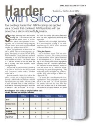
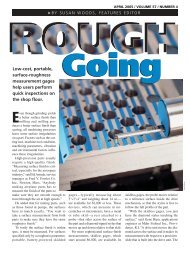
A ½"-dia., diamond-coated<br />
compression router from Amamco<br />
machines a 3 ⁄8"-thick test<br />
workpiece made of an organicmatrix<br />
composite, creating the<br />
dustlike chips characteristic<br />
of composite machining. In<br />
this application, the tool would<br />
typically run at 6,000 rpm and a<br />
feed rate of 75 ipm.<br />
Competently<br />
<strong>Cutting</strong><br />
If the 1967 movie “The Graduate”<br />
were remade today, the one<br />
word of career advice for the graduating<br />
Benjamin Braddock would be<br />
“composites,” not “plastics.” Composite<br />
workpiece materials offer<br />
high strength and stiffness, resistance<br />
to fatigue and corrosion, low<br />
weight and the ability to be formed<br />
into complex shapes. As such, they<br />
provide performance and energysaving<br />
advantages that make them<br />
excellent substitutes for traditional<br />
materials in applications ranging<br />
from aerospace and automotive<br />
components to sports equipment.<br />
However, the characteristics that<br />
boost a material’s performance can<br />
reduce its machinability. A composite<br />
represents a combination<br />
JULY 2008 / VOLUME 60 / ISSUE 7<br />
B. Kennedy<br />
By Bill Kennedy,<br />
<strong>Composites</strong><br />
Contributing Editor<br />
The variety of composite materials and their application requirements<br />
dictate an equally wide range of machining options.<br />
Learn more about<br />
cutting composites<br />
Read more commentary<br />
on cutting composites by<br />
visiting Bill Kennedy’s blog in the<br />
CTE Community section online at<br />
www.ctemag.com.
Competently <strong>Cutting</strong> <strong>Composites</strong> (continued)<br />
of material strengths, consisting of a<br />
continuous matrix material reinforced<br />
by particles or strands of another material<br />
(see sidebar on page 56). Both the<br />
matrix and the reinforcing elements can<br />
be highly abrasive, limiting tool life.<br />
Machining forces can promote workpiece<br />
failure such as composites laid<br />
in layers delaminating when drilled or<br />
otherwise cut. Heat generated during<br />
machining may melt the matrix material,<br />
and worn, chipped cutting edges<br />
will oftentimes cause additional damage<br />
to the material.<br />
Many Variations<br />
A major composite machining challenge<br />
is determining how the particular<br />
material being processed will behave<br />
when it’s cut. Glenn Sheffler, manager<br />
of new business development at the National<br />
Center for Defense Manufacturing<br />
and Machining<br />
(NCDMM),<br />
Latrobe, Pa., said,<br />
“When you say<br />
‘machining composites,’<br />
that’s like saying ‘machining<br />
metal.’ ” One shop may claim<br />
that composite machining is easy while<br />
another finds it nearly impossible. One<br />
composite material can be so different<br />
from another that the shops may be<br />
“comparing apples to oranges,” Sheffler<br />
said. “It’s like one guy machining<br />
aluminum and the other guy machining<br />
Inconel.”<br />
NCDMM works with Department<br />
of Defense organizations and their industrial<br />
supply base to develop solutions<br />
that boost manufacturing productivity<br />
and reduce costs. Despite extensive<br />
experience and full access to advanced<br />
machining technology, even NCDMM<br />
often has difficulty determining the best<br />
way to machine defense-related components<br />
made of proprietary composites<br />
when relevant material information is<br />
not available.<br />
The solution could be selecting the<br />
appropriate geometry, coating, tool<br />
substrate or cutting parameters or cutting<br />
techniques outside of traditional<br />
machining. The growing trend of subcontracting<br />
aerospace and other components<br />
to tiered suppliers and smaller<br />
manufacturers means that more shops<br />
are facing the challenge of machining<br />
composites. “Many times the small<br />
shops don’t know what they don’t know<br />
when facing tooling and techniques for<br />
composite machining,” Sheffler said.<br />
“So they rely on using standard metalcutting<br />
techniques and tools, changing<br />
parameters, adding operations or the<br />
“When you say<br />
‘machining composites,’<br />
that’s like saying<br />
‘machining metal.’ ” One<br />
shop may claim that<br />
composite machining is<br />
easy while another finds<br />
it nearly impossible.<br />
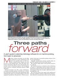
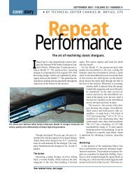
Amamco<br />
The multiple teeth on this ½"-dia. diamondcut<br />
router, resembling those on a bur<br />
or file, enable it to perform composite<br />
roughing operations even when a tooth is<br />
broken or worn.<br />
old trial-and-error method to make<br />
it work. Typically this adds time and<br />
requires additional tools to complete<br />
the job, which can be costly. Finding<br />
the best solutions takes time, which<br />
many of the smaller suppliers do not<br />
have. That’s why they engage with the<br />
NCDMM.”<br />
The Application at Hand<br />
Peter Diamantis, plant manager at<br />
toolmaker Amamco, Duncan, S.C.,<br />
often fields calls from shops seeking<br />
tools and advice regarding composite<br />
machining. “Number one, you want<br />
to know what they are actually using<br />
the cutters to do,” he said. <strong>Tool</strong> choice<br />
depends largely on customer requirements.<br />
For example, if a shop is simply<br />
trimming a panel edge or roughing a<br />
window, a router geometry that will
Competently <strong>Cutting</strong> <strong>Composites</strong> (continued)<br />
handle a rough cut and provide reasonable<br />
tool life is an effective choice.<br />
“Finish on the laminations is not important<br />
for that particular purpose,” he<br />
said. “A ½"-dia. diamond-cut router<br />
with a 15° rake on the flutes will do the<br />
job.” The teeth on that style of router<br />
resemble those on a bur or file. “It has<br />
about 15 crosscuts, so even if you break<br />
off a tooth, the tool is designed so it will<br />
still cut,” said Diamantis.<br />
The large size and irregular shape<br />
Composite composition<br />
<strong>Composites</strong> Can be categorized<br />
by their base matrix materials and the<br />
reinforcing material that produces specific<br />
performance characteristics.<br />
There are three basic classes of matrix<br />
material: organic (polymer or carbon),<br />
metal and ceramic. Reinforcement<br />
material usually is classified by its form,<br />
either particles, whiskers, continuous<br />
fibers or filaments, and woven reinforcing<br />
cloth. To determine part thickness,<br />
create contours and produce specific<br />
performance characteristics, the organic<br />
matrix composites (OMCs) used in<br />
aerospace structural components typically<br />
are built up from layers of fibers, tapes or<br />
cloth that have been impregnated with<br />
the matrix material. After being laid up<br />
dry, the components are cured (heated)<br />
in an autoclave at specified temperatures<br />
and pressures.<br />
<strong>Composites</strong> for aerospace structural<br />
components generally are OMCs that<br />
employ polymer matrices in which the<br />
molecules are chemically bonded or<br />
crosslinked with other molecules<br />
during curing. After curing, these<br />
“thermoset” polymers do not soften when<br />
subjected to heat in use. Early composites<br />
featured epoxy matrices that could<br />
withstand temperatures up to about<br />
250° F; while more recently developed<br />
bismaleimide- and polyimide-matrix<br />
composites can handle temperatures<br />
from 400° to 550° F.<br />
Reinforcement materials include glass,<br />
carbon, boron, polyamide (Aramid) or<br />
organic fibers. Tapes and fabrics generally<br />
range from 3" to 60" wide and are<br />
of many aerospace composite components<br />
dictate that machining operations<br />
often must be performed with motorized<br />
hand-held drills. Applied with a<br />
hand tool, “a diamond-cut router is a<br />
little more forgiving because it’s got a<br />
lot of teeth; the more teeth it has, the<br />
smoother the cut,” Diamantis said. “An<br />
operator will drill a hole to start and<br />
then go around a feature with a coarse,<br />
uncoated carbide router and cut it out.”<br />
He added that such a router typically is<br />
increasingly applied by CNC automated<br />
tape laying machines. State-of-theart<br />
machines, such as the Viper fiber<br />
placement systems from manufacturing<br />
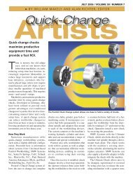
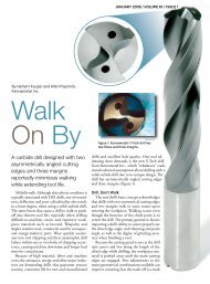
B. Kennedy<br />
NCDMM Project Engineer Jeff Poklembo (right)<br />
and John Winebrenner, manager of advanced<br />
manufacturing technology, check the quality of<br />
chamfered holes drilled in a composite workpiece.<br />
equipment and automation provider MAG<br />
Cincinnati, Hebron, Ky., are engineered<br />
to create complex parts such as huge<br />
fuselage sections of commercial airliners.<br />
The Viper system features 7-axis CNC<br />
run at about 15,000 rpm, and largerdiameter<br />
tools are preferred for handheld<br />
routing. Routers as small as 11 ⁄64" in<br />
diameter permit machining of small-radius<br />
corners, but, “If the part geometry<br />
allows it, you can push a ½"-dia. router<br />
a lot harder and don’t have to worry<br />
about it breaking,” Diamantis said.<br />
Compressive Forces<br />
For operations requiring a fine finish,<br />
fine-toothed diamond-cut routers<br />
control and can manipulate up to 32<br />
epoxy-impregnated “tows” (lengths of<br />
fiber, tape or cloth) in laying up concave<br />
or convex shapes in varying thicknesses<br />
around fixed or rotating molds.<br />
The variety of layup schemes<br />
possible with these sophisticated<br />
machines means the resulting<br />
component’s machining<br />
characteristics can change<br />
significantly from one section of<br />
the part to another.<br />
A high-performance variation<br />
in OMCs are carbon-carbon<br />
materials, which are reinforced<br />
with graphite fibers and whose<br />
matrix consists of a carbonbased<br />
polymer that is pyrolyzed<br />
to remove noncarbon elements.<br />
Carbon-carbon composites can<br />
operate at temperatures greater<br />
than 3,632° F and are therefore<br />
used for applications such<br />
as aircraft brake pads, rocket<br />
nozzles and missile nose cones.<br />
A drawback is that the materials<br />
can oxidize at about 1,110° to<br />
1,290° F, and must be protected<br />
in use by a coating, such as<br />
silicon carbide.<br />
Metal matrix composites<br />
(MMCs) are composed of a<br />
metallic matrix, commonly<br />
aluminum, but also other metals,<br />
including superalloys, magnesium and<br />
iron. Reinforcing materials include boron,<br />
graphite, silicon carbide and alumina, in<br />
particle, whisker and fiber forms. MMCs<br />
are generally produced by casting, where
with more than 15 crosscuts can suffice.<br />
“But where you need a really fine finish,<br />
everybody gravitates to the compression<br />
router,” Diamantis said.<br />
A compression router has separate<br />
sets of left- and right-hand flutes that<br />
overlap at about a third of the way up<br />
the router shaft from the tip. These<br />
routers were first developed for cutting<br />
wood and stacks of metals that include<br />
copper or aluminum layers.<br />
“When you cut copper or aluminum<br />
with an endmill, it smears against the<br />
edges of the stack,” Diamantis said.<br />
the base metal is remelted and the<br />
reinforcing material is introduced. MMCs<br />
resist wear and elevated temperatures<br />
more than polymer-matrix composites<br />
do and have higher stiffness and<br />
strength. Machining MMCs is much like<br />
machining the base metal, except for the<br />
abrasiveness of the reinforcing material,<br />
and PCD tools are often required to cut<br />
them. Typical applications include brake<br />
rotors, machinery components, golf clubs<br />
and various structural uses.<br />
Ceramic matrix composites (CMCs)<br />
are composed of a ceramic matrix<br />
and embedded fibers or particles of<br />
other ceramic material. According<br />
to John Winebrenner, manager of<br />
advanced manufacturing technology<br />
for NCDMM, CMCs are being developed<br />
as replacements for high-temperature<br />
alloys. In some cases, a CMC component<br />
can offer 10 times longer service life,<br />
weigh 80 percent less and withstand<br />
higher temperatures than an Inconel part.<br />
Typical applications are jet-engine exhaust<br />
nozzles, flaps and shields.<br />
Again, the material’s abrasive nature<br />
may require the use of PCD tools or<br />
grinding to achieve final dimensions.<br />
Winebrenner said while abrasive wear<br />
of a tool cutting composites is a problem,<br />
heat can also damage the tool. “The big<br />
downside is that a lot of these materials<br />
are heat resistant, like high-temp alloys.<br />
Your tool becomes a heat sink, which can<br />
be very detrimental to the tool, no matter<br />
what type of material you are machining,”<br />
he said.<br />
—B. Kennedy
Competently <strong>Cutting</strong> <strong>Composites</strong> (continued)<br />
With a compression router, “the left-hand flutes push the<br />
metal down and the overlapped right-hand flutes come past<br />
and pull it right back up, so it shaves it cleanly and gives you a<br />
perfect edge. It works with composites because many composites<br />
are all strands. One flute shaves the strands down and the<br />
other comes by and shaves the strands off. It’s almost like that<br />
TV commercial where the razor blade lifts up your beard.”<br />
Andrew Gilpin, Amamco’s business development manager,<br />
said the company engineers custom compression routers for<br />
machining composites “with tolerances of ±0.003" on some<br />
of the overlap.”<br />
Unlike the diamond-cut routers for roughing, compression<br />
routers are best applied on rigid CNC machine tools that can<br />
hold the tool and part in a consistent relationship to one another.<br />
“You program the machine to keep that overlap within<br />
a couple of thousandths of the center of the laminations,”<br />
Diamantis said.<br />
Gilpin described the development of a typical compression<br />
router application. Aerospace OEM Lockheed Martin Corp.<br />
was experiencing delamination and poor tool life when using<br />
a straight-flute PCD router to machine the edges of a composite<br />
wingskin for the F-35 Lightning II joint strike fighter.<br />
Working with NCDMM, Amamco engineered and provided<br />
an uncoated, solid-carbide compression router for tests. Following<br />
positive initial results, NCDMM sought to increase<br />
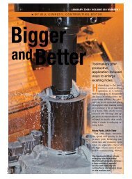
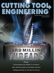
MegaDiamond<br />
This ½"-dia., 4-flute, 30°<br />
helix endmill from<br />
MegaDiamond has PCD sintered<br />
directly into contoured veins on a<br />
carbide tool body through the V-tec process,<br />
which permits the production of complex cutting<br />
edge geometries in PCD.<br />
tool life through application of a diamond coating from Diamond<br />
<strong>Tool</strong> Coating, North Tonawanda, N.Y. Unlike thick,<br />
single-layer, large-crystal diamond coatings, the company’s<br />
CVD DiaTiger coating is comprised of interlocking layers<br />
of polycrystalline and nanocrystalline diamond. In addition<br />
to resisting abrasive and adhesive wear, Diamond <strong>Tool</strong> Coating<br />
said the coating structure diverts the path of cracks and<br />
thereby slows their propagation, increasing tool life.
The coated compression router minimized delamination<br />
and extended tool life six fold. In addition, quality assurance<br />
reports on out-of-spec parts decreased by 90 percent. “Just<br />
being able to save on the quality reworks has been a huge savings<br />
for them,” Gilpin said. “The project is really starting to<br />
ramp up, and anything they can do to save time and produce<br />
more parts is a huge benefit.”<br />
Gilpin noted that because of the difficulties of developing<br />
tooling for machining composites, major manufacturers are<br />
beginning to share details of composite machining to their<br />
subcontractors handling similar jobs.<br />
Sharp and Complex<br />
Scott Horman, manager of cutting tool material product<br />
engineering at Sii MegaDiamond Inc., Provo, Utah, said the<br />
key to success in machining composite materials is maintaining<br />
a sharp cutting edge. As the composite’s abrasive elements<br />
dull the edge, it begins to push material rather than shear<br />
it, and cutting forces increase. High cutting forces lead to<br />
delamination, binder pullout and frayed edges. The tool edge<br />
may chip or break, and the higher cutting forces can pull the<br />
composite plies apart.<br />
PCD cutting edges provide excellent wear resistance, but<br />
a traditional disadvantage of these tools has been lack of<br />
flexibility in tool geometries. Most PCD cutting material is<br />
produced as a flat disk bonded to a tungsten-carbide backing<br />
plate during the high-pressure, high-temperature process used<br />
Diamond <strong>Tool</strong> Coating<br />
This micrograph of the DiaTiger coating shows its interlocking<br />
layers of polycrystalline and nanocrystalline diamond which,<br />
according to Diamond <strong>Tool</strong> Coating, resist abrasive and adhesive<br />
wear and divert the path of cracks, slowing their propagation.<br />
to sinter the diamond particles. Segments are cut from the<br />
disk via wire EDM and brazed to a tool body to form cutting<br />
edges. However, MegaDiamond said its V-tec process offers<br />
a solution to this problem by permitting PCD to be directly<br />
sintered into contoured veins on a tool body. “We are putting<br />
PCD exactly where it needs to be, within geometries more
Competently <strong>Cutting</strong> <strong>Composites</strong> (continued)<br />
complex than those possible with flat<br />
segments of PCD,” Horman said of the<br />
veined tools. He added that the V-tec<br />
process to make those tools causes the<br />
PCD to form a metallurgical bond with<br />
the carbide during sintering, eliminating<br />
the need for a braze between the cutting<br />
edge and the tool, thereby avoiding<br />
problems from heat during cutting that<br />
would weaken the braze joint.<br />
Horman said the veined tools are<br />
best applied on fixed machines, such as<br />
the large CNC units used to machine<br />
features on aircraft fuselage segments.<br />
He added that the tools typically are run<br />
fast—8,000 to 10,000 rpm—and have<br />
been applied at speeds up to 30,000<br />
rpm. “In composite cutting applica-<br />
tions, most of the heat has to go into<br />
the tool, since the chips are not very<br />
thermally conductive. The vein technology<br />
enables the tool to manage heat<br />
more effectively,” he said. Coolant can<br />
be used in some materials, but the coolant<br />
creates a disposal problem when<br />
mixed with the dustlike chips generated<br />
in composite machining. “A lot of<br />
people have vacuum systems right at<br />
the cutting head, sucking up the dust,”<br />
Horman said.<br />
To demonstrate the advantage provided<br />
by the veined tools’ complex<br />
geometries, Horman outlined a test<br />
comparison involving edge trimming of<br />
a 0.40"-thick, carbon fiber-reinforced<br />
composite panel. A straight-flute, ½"dia.<br />
PCD endmill ran at 12,000 rpm,<br />
a 0.001-ipt chip load, a feed rate of<br />
36 ipm and a finishing step-over of<br />
0.050". It machined 1,500 linear inches<br />
of composite before replacement was<br />
necessary. A ½"-dia., veined PCD tool<br />
with a 30° helix in the same application<br />
ran at 8,000 rpm, a 0.0045-ipt chip<br />
load, and a 144-ipm feed rate at the<br />
same 0.050" step-over. Running nearly<br />
75 percent faster than the straight-flute<br />
tool, the veined tool machined 10,000<br />
linear inches before replacement was<br />
necessary.<br />
A veined PCD tool may cost nearly<br />
three times as much as the straight-flute<br />
contributors<br />
Amamco<br />
(800) 833-2239<br />
www.amamcotool.com<br />
Diamond <strong>Tool</strong> Coating<br />
(716) 693-5050<br />
www.diamondtc.com<br />
MAG Cincinnati<br />
(859) 534-4600<br />
www.cinmach.mag-ias.com<br />
National Center for Defense<br />
Manufacturing and Machining<br />
(724) 539-8811<br />
www.ncdmm.org<br />
Sii MegaDiamond Inc.<br />
(800) 453.1370<br />
www.megadiamond.com
endmill. However, seven straight-flute<br />
tools were required to machine the same<br />
10,000 linear inches. Including savings<br />
in machine and tool-change time, the<br />
veined tool cut the cost of machining<br />
10,000 linear inches by nearly 70 percent,<br />
according to Horman.<br />
He said MegaDiamond’s initial focus<br />
B. Kennedy<br />
This bottom view of a 5 ⁄8"-thick composite<br />
test workpiece shows significant<br />
delamination at the exits of one set of<br />
holes drilled with a 0.251"-dia., 3-flute,<br />
uncoated, solid-carbide drill, but clean<br />
exits on holes drilled with an identical<br />
drill that featured a diamond coating. By<br />
maintaining cutting edge sharpness in the<br />
abrasive composite material, the coating<br />
enabled the drill to cleanly shear the<br />
composite matrix and fibers.<br />
has been on providing routers and endmills<br />
to cut and trim composite components,<br />
but the company is expanding<br />
the V-tec process for drills.<br />
No Best <strong>Tool</strong>?<br />
Amamco’s Gilpin said there’s no single<br />
answer regarding the best tool material<br />
for machining composites. He estimated<br />
that for about 20 percent of applications,<br />
uncoated carbide roughers may be<br />
the best choice. When the uneven cutting<br />
forces and impact associated with<br />
hand routing are absent, the high wear<br />
resistance of PCD tools may make them<br />
preferable another 20 percent of the<br />
time. For the 60 percent of applications<br />
between those two extremes, he said, “A<br />
shop will call three different experts and<br />
get three different answers.”<br />
The growing trend of composite material<br />
application, according to Gilpin,<br />
is “changing the tooling that is being<br />
used because you can’t go into com-<br />
posites with the same tools you use to<br />
punch holes in aluminum, titanium and<br />
other materials. Finding the right tooling<br />
for a particular application can give<br />
you a few extra gray hairs.” CTE<br />
About the Author: Bill Kennedy, based<br />
in Latrobe, Pa., is contributing editor for<br />
<strong>Cutting</strong> <strong>Tool</strong> <strong>Engineering</strong>.<br />
He has an extensive<br />
background as a technical<br />
writer. Contact him at<br />
(724) 537-6182 or by email<br />
at billk@jwr.com.<br />
CUTTING TOOL ENGINEERING Magazine is protected under U.S. and international copyright laws.<br />
Before reproducing anything from this Web site, call the Copyright Clearance Center Inc. at (978) 750-8400.