Electronic Standby Instrument System - Silvio Pini
Electronic Standby Instrument System - Silvio Pini
Electronic Standby Instrument System - Silvio Pini

You also want an ePaper? Increase the reach of your titles
YUMPU automatically turns print PDFs into web optimized ePapers that Google loves.
TP-560<br />
$20.00 U.S.<br />
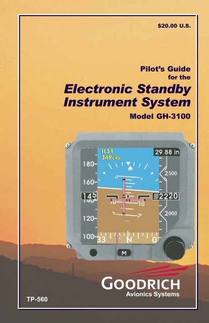
Pilot’s Guide<br />
for the<br />
<strong>Electronic</strong> <strong>Standby</strong><br />
<strong>Instrument</strong> <strong>System</strong><br />
Model GH-3100<br />
Avionics <strong>System</strong>s
GH-3100 Introduction<br />
Introduction<br />
WELCOME<br />
Pilot's Guide<br />
YOU HAVE AN IMAGE TO MAINTAIN!<br />
Congratulations on your new purchase of the Goodrich GH-3100 (Software<br />
version 1.x) <strong>Electronic</strong> <strong>Standby</strong> <strong>Instrument</strong> <strong>System</strong> (ESIS). We are pleased to<br />
welcome you to the Goodrich family of high quality avionics products that<br />
allow pilots to fly more safely and with greater confidence. Compact and<br />
lightweight, the GH-3100 enables you to add the latest safety innovations from<br />
Goodrich to today’s already overcrowded cockpit panels.<br />
BRIGHTER, TOUGHER, SMARTER, BETTER<br />
<strong>Standby</strong> instrumentation is taking on a whole new attitude – with advanced<br />
technologies; solid-state designs; reduced operating costs; and integrated<br />
instrumentation. The Goodrich GH-3100 ESIS combines all the important<br />
cues – attitude, altitude, airspeed, heading and navigation – in one easy-toread<br />
AMLCD. It’s like having a complete standby EFIS suite in a single 3-inch<br />
display. Designed by the world’s leader in standby instrumentation, the FAA<br />
TSO certified GH-3100 offers the ability to visually match the look and format<br />
of your aircraft’s primary EFIS.<br />
ONE OF THE BEST PARTS – NO MOVING PARTS<br />
The GH-3100 has easy-to-read symbology with digital simplicity assuring<br />
precise readings and high reliability. The self-contained inertial measurement<br />
cluster eliminates the need for a mechanical gyro. And best of all, it has<br />
absolutely no moving parts. The high-performance GH-3100 provides<br />
outstanding features such as precision attitude, altitude, airspeed, and heading;<br />
reduced pilot workload; and improved flight safety. It combines the strengths<br />
of flat panel technology with solid-state sensors to become one of the world’s<br />
most sophisticated standby instrument systems. The GH-3100 also features<br />
a full-color, active matrix LCD; dimmable fluorescent backlighting and a full<br />
range of navigation interface capabilities, and the MAG-3000 Magnetometer.<br />
A HISTORY OF LEADING EDGE INNOVATION<br />
In addition to the GH-3100 ESIS, Goodrich Avionics <strong>System</strong>s also develops<br />
and manufactures the RGC-250 Radar Graphics Computer, Stormscope®<br />
weather mapping systems, SkywatchTraffic Advisory <strong>System</strong>, TCAS I collision<br />
avoidance systems, electromechanical standby attitude indicators and power<br />
conversion products. Goodrich also maintains a global support network at a<br />
number of factory-authorized service centers worldwide. Goodrich Avionics<br />
<strong>System</strong>s is a division of Goodrich Corporation of Charlotte, NC.<br />
i
Table of Contents GH-3100<br />
Table of Contents<br />
Introduction .............................................................................. i<br />
Table of Contents ..................................................................... ii<br />
Purpose ..................................................................................... 1<br />
Equipment Description ........................................................... 2<br />
Screen Features<br />
Menu Access ............................................................................. 5<br />
Barometric Setting ................................................................... 8<br />
Attitude Information ............................................................... 9<br />
Air Data Information..............................................................11<br />
Navigational Information...................................................... 13<br />
Heading Information ............................................................. 16<br />
Start-Up and Self Test<br />
Power ON Self Test Mode ..................................................... 17<br />
Identification Mode ............................................................... 17<br />
Sensor Alignment Mode ........................................................ 19<br />
Normal Operating Mode (Invalidity Indications) .............. 20<br />
Troubleshooting ..................................................................... 25<br />
Specifications .......................................................................... 27<br />
Notes................................................................................... 28-29<br />
Pilot’s Guide for the GH-3100<br />
<strong>Electronic</strong> <strong>Standby</strong> <strong>Instrument</strong> <strong>System</strong><br />
(Software Version 1.x)<br />
Part No. 501-1860-xx01<br />
© Copyright 2001<br />
Goodrich Avionics <strong>System</strong>s, Inc.<br />
5353 52nd Street, S.E.<br />
Grand Rapids, MI USA 49512-9704<br />
Telephone (616) 949-6600 (800) 253-9525<br />
Fax (616) 285-4224<br />
Field Service (800) 453-0288<br />
www.goodrichavionics.com<br />
ii<br />
Pilot's Guide
GH-3100 Purpose<br />
Pilot's Guide<br />
Purpose<br />
This Pilot’s Guide provides the flight crew with operation instructions,<br />
quick reference troubleshooting assistance and typical display examples<br />
so the cockpit crew can quickly and easily operate the GH-3100. Actual<br />
appearance of display arrangements and colors are dependent on the unit’s<br />
specific configuration as it is applied in specific aircraft installations.<br />
The Model GH-3100 ESIS (<strong>Electronic</strong> <strong>Standby</strong> <strong>Instrument</strong> <strong>System</strong>)<br />
provides backup pitch, roll, and slip/skid information, and backup Air<br />
Data information (airspeed, altitude and vertical speed) using internal<br />
sensor systems. Also, the system contains interface capabilities that<br />
provides Heading and Navigation information.<br />
Bezel Ring<br />
Airspeed Display Area Altitude Display Area<br />
Attitude, Navigation and<br />
Heading Display Area<br />
Menu Access<br />
Button<br />
Adjustment<br />
Knob<br />
Display<br />
Screen<br />
Typical Display Screen<br />
1
Purpose GH-3100<br />
Equipment Description<br />
Goodrich GH-3000 series ESIS’s are the only electronic standby systems<br />
that include a Detachable Configuration Module (DCM), which stores<br />
the display’s format configuration. The DCM contains sufficient memory<br />
to retain information specific to the hardware and software configuration<br />
for each installation, such as panel angle, navigation interface, aircraft<br />
heading calibration, and display format. When the GH-3100 is removed<br />
from the aircraft, the DCM remains in the aircraft, attached to the aircraft<br />
wiring harness that mates with the GH-3100, eliminating the need to reconfigure<br />
a replaced GH-3100 Line Replaceable Unit (LRU).<br />
2<br />
MAGNETOMETER<br />
optional<br />
AIRCRAFT<br />
STATIC AND PITOT<br />
AIR INPUTS<br />
Optional Aircraft<br />
Interfaces<br />
FMS/GPS<br />
DME<br />
VOR/ILS<br />
TACAN<br />
DETACHABLE<br />
CONFIGURATION<br />
MODULE (DCM)<br />
Goodrich GH-3100 <strong>Electronic</strong> <strong>Standby</strong> <strong>Instrument</strong> <strong>System</strong><br />
Pilot's Guide
GH-3100 Purpose<br />
Equipment Description (cont.)<br />
The GH-3100 is packaged in a 3 ATI housing, which needs only 11 inches of<br />
length behind the instrument panel. At a maximum weight of 4 pounds, the<br />
GH-3100 offers exceptional weight savings by combining the functions of<br />
three existing instruments into one. The weight decrease is up to half the<br />
weight of today’s typical electromechanical<br />
systems.<br />
Pilot's Guide 3
Purpose GH-3100<br />
Equipment Description (cont.)<br />
For standby magnetic heading capabilities, the optional MAG-3000<br />
magnetometer can be added. The MAG-3000 is comprised of a 3axis<br />
magnetic sensor that converts magnetic field data into a digital<br />
format for the GH-3100 indicator. Heading information is<br />
displayed on a horizontal tape at the<br />
bottom of the GH-3100 display.<br />
The DCM-3100 is the memory device that stores the indicator’s display<br />
configuration. The device remains in the aircraft to allow the removal<br />
and replacement of the GH-3100 indicator unit,<br />
thus allowing automatic configuration<br />
to the replacement unit.<br />
4<br />
Pilot's Guide
GH-3100<br />
Pilot's Guide<br />
Screen Features<br />
Menu Access<br />
The Model GH-3100 ESIS, regardless of configuration, offers crew<br />
members the ability to toggle, adjust and initiate various display elements<br />
via a Menu.<br />
To access the Menu, press the Menu Access Button located below the<br />
Display Screen.<br />
M<br />
Push to<br />
Access<br />
Sub-Menu Available<br />
Highlighted Menu Item<br />
(Currently ON)<br />
A menu listing will appear along the bottom portion of the Display Screen<br />
with four line items visible at a time. Rotate the Adjustment Knob,<br />
located below and to the right of the Display Screen, to scroll through the<br />
Menu and highlight a Menu item.<br />
Rotate to Scroll<br />
Typical Menu Appearance<br />
Menu items that Toggle ON/OFF will indicate opposite the current<br />
condition.<br />
...<br />
Screen Features<br />
Menu Items that are followed by indicate that an associated Sub-<br />
Menu will appear when selected.<br />
5
Screen Features<br />
Menu Access (cont.)<br />
To select a highlighted Menu item, press the Adjustment Knob located<br />
below and to the right of the Display Screen.<br />
Typical Sub-Menu Appearance<br />
Push to Select<br />
GH-3100<br />
A Sub-Menu provides additional adjustments and selections. To select<br />
or adjust a value in the Sub-Menu, rotate the Adjustment Knob.<br />
Rotate to Adjust<br />
To Toggle ON/OFF, initiate a highlighted Menu item, or to finalize an<br />
adjusted value, press the Adjustment Knob.<br />
Push to Toggle, Initiate or Finish<br />
Adjustable Value<br />
Menu access will terminate when a setting is initiated or by pressing the<br />
Menu Access Button. Menu access termination will occur automatically<br />
after 15-20 seconds of inactivity.<br />
6<br />
Pilot's Guide
GH-3100<br />
Pilot's Guide<br />
Menu Access (cont.)<br />
Press Menu Access Button, Rotate Adjustment Knob to...<br />
FAST ERECT<br />
SET BRIGHTNESS OFFSET ...<br />
FAST ALIGN<br />
SET HEADING ...<br />
NAV [ON or OFF]<br />
NAV MODE ...<br />
SET CRS ...<br />
ILS [BC or NORMAL]<br />
CRS AUTO CENTER<br />
NAV DISPLAYS ...<br />
BARO TYPE ...<br />
IAS TAPE DIRECTION<br />
[UP or DOWN]<br />
...press knob to initiate<br />
...press knob for sub-menu, rotate knob<br />
to adjust, press knob to finish<br />
...press knob to initiate<br />
...press knob for sub-menu, rotate knob<br />
to set heading, press knob to finish<br />
...press knob to toggle for opposite of<br />
current condition<br />
...press knob for sub-menu, rotate knob<br />
to select mode, press knob to finish<br />
...press knob for sub-menu, rotate knob<br />
to set course, press knob to finish<br />
...press knob to toggle for opposite of<br />
current condition<br />
...press to initiate<br />
Screen Features<br />
...press knob for sub-menu, rotate knob<br />
to select, press knob to finish<br />
...press knob for sub-menu, rotate knob<br />
to select type, press knob to finish<br />
...press knob to toggle for opposite of<br />
current condition<br />
Note: Menu item appearance is dependent on the unit’s specific configuration. The<br />
last selected settings remain after power is cycled. FAST ERECT and FAST ALIGN<br />
commands are similar to CAGING an electromechanical attitude indicator. Both<br />
commands must be performed when the aircraft is stationary or in straight and level,<br />
non-accelerated flight. FAST ALIGN will require straight and level, non-accelerated<br />
flight sustained for 90 seconds.<br />
7
Screen Features<br />
Barometric Setting<br />
Typical Display Screen<br />
GH-3100<br />
The Barometric Setting is indicated at the uppermost, right-hand corner<br />
of the Display Screen.<br />
Rotate CW to Increase<br />
Rotate CCW to Decrease<br />
Barometric Setting adjustments are made by rotating the Adjustment<br />
Knob located below and to the right of the Display Screen.<br />
Push to STD<br />
(29.92 InHg / 1013 HPA or MB)<br />
Barometric Setting<br />
Adjustment<br />
Knob<br />
To establish Standard Pressure Barometric Setting, (29.92 InHg/1013<br />
HPA or MB), push the Adjustment Knob. STD will be indicated at the<br />
Barometric Setting window.<br />
Menu access will allow the flight crew to select barometric types as Inches<br />
of Mercury (in), Hectopascals (hPa), or Millibars (mb).<br />
See page 5.<br />
8<br />
Pilot's Guide
GH-3100<br />
Aircraft Attitude Information is<br />
provided in the center portion of the<br />
Display Screen. Pitch and roll data<br />
is generated by internal sensors that<br />
produce recognizable attitude<br />
indications.<br />
Horizon Line<br />
Roll Scale<br />
(10°, 20°, 30°,<br />
45° and 60° indications)<br />
Slip/Skid Indicator<br />
Pitch Ladder<br />
Aircraft Symbol<br />
Pilot's Guide<br />
Roll Pointer<br />
Excessive Attitude Display<br />
Red chevrons point to horizon when<br />
Zero Pitch Line approaches view limits.<br />
Sky<br />
Earth<br />
Screen Features<br />
Attitude Information<br />
Attitude, Heading and Navigation<br />
Display Area<br />
Typical Display Screen<br />
Attitude Information<br />
Attitude information is displayed in a manner similar to traditional<br />
Artificial Horizon and Slip/Skid Indicators.<br />
9
Screen Features<br />
Attitude Information (cont.)<br />
Typical Display Screen<br />
GH-3100<br />
An Extended Maneuver<br />
indication will appear as a<br />
message whenever the GH-3100<br />
detects a long-duration attitude<br />
event (e.g. flight for a duration<br />
exceeding 6 minutes at a roll angle<br />
>7° from level).<br />
Extended Maneuver<br />
Indication<br />
Also, the indication will appear when the unit senses it is not within ±8°<br />
of the magnetic heading provided by the Magnetometer for an extended<br />
period (when the unit is configured for Heading).<br />
These “extended” conditions may increase the possibility for erroneous<br />
Attitude and Heading displays.<br />
The GH-3100 will self-correct for small Attitude errors, or the flight<br />
crew may initiate a FAST ERECT from the Menu (page 7) when the<br />
aircraft has returned to straight and level, non-accelerated flight.<br />
If the GH-3100 continues to display erroneous attitude, the flight crew<br />
may then initiate a FAST ALIGN from the Menu (page 7) when the<br />
aircraft has returned to straight and level, non-accelerated flight sustained<br />
for 90 seconds. The GH-3100 will display the Alignment in Progess<br />
Screen (page 19) with a 90 second countdown.<br />
The GH-3100 will self-correct for minor Heading errors, or the flight<br />
crew can use the Menu access (page 7) to select “Set Heading...” option<br />
to align the Heading Tape to the cockpit compass.<br />
10<br />
EXT<br />
MANUV<br />
Pilot's Guide
GH-3100<br />
Pilot's Guide<br />
Air Data Information<br />
The GH-3100 has the capability to display Air Data Information. Air<br />
Data information includes aircraft Altitude, Airspeed, and Vertical Speed<br />
information. Airspeed and Altitude information is displayed in a scrolling<br />
“Tape” format with “Digital Readout” windows available for airspeed,<br />
altitude, vertical speed, and metric<br />
equivalent altitude (dependent<br />
on unit configuration).<br />
Typical Display Screen<br />
Altitude Tape<br />
and Readout<br />
Screen Features<br />
Altitude Information is located on the right side of the Display Screen.<br />
The appearance of the Digital Readouts and Altitude Tapes is dependent<br />
upon the specific configuration for the GH-3100.<br />
Possible Altitude Readouts<br />
11
Screen Features<br />
Air Data Information (cont.)<br />
Airspeed Tape<br />
and Readout<br />
Typical Display Screen<br />
GH-3100<br />
Airspeed Information is located on the left side of the Display Screen.<br />
The appearance of the Digital Readouts and Airspeed Tapes is dependent<br />
upon the specific configuration for the GH-3100.<br />
*<br />
12<br />
261<br />
V MO or M MO<br />
Exceeded Indication<br />
V MO (Red)<br />
Possible Airspeed Readouts<br />
Mach Speed Indicators<br />
* **<br />
Part 27/29<br />
Style Readout<br />
V Color Bars<br />
NE<br />
Red -V Power On airspeed and greater<br />
NE<br />
Yellow - between V and V Power On<br />
NO NE<br />
Green - V airspeed and less<br />
NO<br />
V Power Off<br />
NE<br />
(Barber Pole)<br />
V & greater NE between V & V NO NE<br />
** 163 143<br />
Pilot's Guide
GH-3100<br />
Pilot’s Guide<br />
Navigation Information<br />
Navigation Information is displayed in the center portion of the Display<br />
Screen, sharing space with the Attitude Information. Navigation displays<br />
are designed to visually match the look and format of the primary<br />
navigational systems in the cockpit.<br />
Crew member inputs, i.e. frequency and station selections, are made at<br />
the source navigational units, with exception to those Navigation items<br />
configured for and available through the Menu access (page 5).<br />
Navigation Mode Indicator:<br />
FMS, FMS1, FMS2, FMS3 or FMS4 (Flight Management <strong>System</strong>)<br />
NAVR or NAVL (Long Range Navigation <strong>System</strong>-Right or Left)<br />
VOR, VOR1, VOR2 or VOR3 (VHF Omnidirectional Range)<br />
ILS, ILS1, ILS2 or ILS3 (<strong>Instrument</strong> Landing <strong>System</strong>)<br />
ILSx BC (Back Course)<br />
TCN1 or TCN2 (Tactical Air Navigation)<br />
GPS, GPS1 or GPS2 (Global Positioning <strong>System</strong>)<br />
NAV TEST<br />
Course Setting<br />
Parallel Crosstrack<br />
Mode (FMS)<br />
Approach Mode<br />
(FMS)<br />
Way Point Information<br />
(FMS)<br />
Bearing to Waypoint (BRG)<br />
(FMS)<br />
Screen Features<br />
TO/FROM Indicator<br />
Distance-to-Waypoint<br />
or Station<br />
Message (notification of<br />
a message that originates<br />
from FMS)<br />
Typical FMS Mode Display Screen<br />
Note: Navigational Information appearance is dependent on the unit’s<br />
specific configuration.<br />
13
Screen Features<br />
Navigation Information (cont.)<br />
Course Deviation Line<br />
Localizer Indicator<br />
(ILS)<br />
14<br />
TACAN Mode Indicator<br />
Course Setting<br />
Full Scale Deviation<br />
Reference<br />
Ground Speed<br />
Time-to-Station<br />
TO/FROM Indicator<br />
ILS Mode Indicator<br />
Course Setting<br />
Glide Slope Indicator<br />
(ILS)<br />
Ground Speed<br />
(DME)<br />
Time-to-Station<br />
(DME)<br />
TO/FROM Indicator<br />
Marker Beacon Indicator<br />
(OM, MM, IM)<br />
Distance-to-Station<br />
(TACAN)<br />
Distance-to-Station<br />
(DME)<br />
GH-3100<br />
Typical TACAN Mode Display Screen<br />
Typical ILS Mode Display Screen<br />
Pilot's Guide
GH-3100<br />
Typical VOR (with DME) Mode Display Screen<br />
Pilot's Guide<br />
Navigation Information (cont.)<br />
TO/FROM Indicator<br />
VOR Mode Indicator DME Hold (H) Indicator<br />
Distance-to-Station<br />
(DME)<br />
Course Setting<br />
Full Scale Deviation<br />
Reference<br />
Course Deviation Line<br />
Time-to-Station<br />
Screen Features<br />
Ground Speed<br />
Attitude Declutter, the removal of Navigation Information from the<br />
screen, will occur when the aircraft exceeds ±65° of center in roll and/or<br />
+30°/-20° of center in pitch. Navigation Information will be restored<br />
when the aircraft no longer exceeds these conditions.<br />
15
Screen Features<br />
Heading Information<br />
When configured for Heading Information, the GH-3100 will display a<br />
Heading Tape at the bottom-center portion of the Display Screen.<br />
A DG (directional gyro) indication will appear above the Heading Tape<br />
Index Line when there is a temporary loss of the external magnetic source<br />
or (MAG-3000) or external heading source.<br />
Typical Display Screen<br />
Heading Index Line<br />
Course Arrow<br />
GH-3100<br />
If the DG indication continues,<br />
use the Menu access to select the<br />
“Set Heading...” option and align<br />
the Heading Tape to the cockpit<br />
reference compass. See page 7.<br />
DG Indicator<br />
Heading Tape<br />
If the GH-3100 is configured for Navigation capabilities and the Menu<br />
selections are made for VOR, ILS, FMS/NAV or TACAN, the Course<br />
Arrow is indicated on the Heading tape.<br />
The “To” arrow will point up on the Heading Tape at the selected<br />
course setting.<br />
The “From” arrow points down on the tape at 180° of the course<br />
setting. See page 7 for “Set CRS” and “CRS Auto Center” Menu options.<br />
16 Pilot's Guide
GH-3100<br />
Start-Up and Self Test<br />
Power ON Self Test Mode<br />
Power application to the GH-3100 starts an automatic process of selfdiagnostics<br />
prior to normal operations. After power application the<br />
Display Screen will be blank approximately 15 seconds while the tests<br />
are performed.<br />
Aircraft Type for which<br />
unit is configured<br />
Operation Counter<br />
Software ID Numbers<br />
Identification Mode<br />
If no failures were detected during the Power ON Self Test Mode, the<br />
Identification Screen will appear.<br />
Pilot's Guide<br />
Start-Up and Self Test<br />
Identification Screen<br />
17
Start-Up and Self Test<br />
Start-Up and Self Test (cont.)<br />
Identification Mode (cont.)<br />
Typical Failure Screen<br />
GH-3100<br />
Should the GH-3100 detect a failure, the Identification Screen will appear<br />
with either a clearly stated error message or an error code. Failures are<br />
either <strong>System</strong> Failures or Function Failures. <strong>System</strong> Failures will cease<br />
the start-up process, where<br />
Function Failures will complete<br />
start-up process and allow the<br />
system to operate despite the loss<br />
of the affected function. See<br />
Invalidities (page 20).<br />
Typical Failure Screen<br />
Error Message<br />
Error Code<br />
Note: Use the provided Notes pages (pages 28-29) to record the date and<br />
time and error message/code. Report the information to a Goodrich<br />
Avionics <strong>System</strong>s authorized dealer or Goodrich Field Service.<br />
18<br />
Pilot's Guide
GH-3100<br />
Pilot's Guide<br />
Start-Up and Self Test (cont.)<br />
Sensor Alignment Mode<br />
If no <strong>System</strong> Failures are detected, the unit will then display the ATT<br />
FAIL indication with the message ALIGNING and a completion timer/<br />
counter below the Aircraft Symbol.<br />
Sensor Alignment Mode will reach Normal Operation Mode within three<br />
minutes of applying power. During abnormal conditions, such as motion<br />
during the Sensor Alignment Mode, the indicator will reset and attempt<br />
to reach the Normal Operation Mode within six minutes of applying power.<br />
If sensor alignment is unsuccessful, the message will change to<br />
ALIGNMENT FAIL and the system will not enter the operational mode.<br />
See Troubleshooting (page 25)<br />
Message<br />
Start-Up and Self Test<br />
Alignment in Progress Screen<br />
Note: Use the provided Notes pages (pages 28-29) to record the date and<br />
time of failure. Report the information to a Goodrich Avionics <strong>System</strong>s<br />
authorized dealer or Goodrich Field Service as soon as possible.<br />
19
Start-Up and Self Test<br />
Start-Up and Self Test (cont.)<br />
Normal Operating Mode<br />
GH-3100<br />
While the GH-3100 is operating normally, the system continues to perform<br />
diagnostic self-tests to assure the crew of accurate information.<br />
Invalidities are display indications that reveal a loss of information from<br />
their associated sources. The invalidities are detected during the GH-<br />
3100’s Power ON Self-Test or by the continuous Background Self-Test.<br />
They may appear as either of the examples offered here dependent on<br />
unit configuration.<br />
Air Speed and Altitude Invalidity<br />
20<br />
Air Data information will revert to<br />
normal display when invalidity<br />
conditions no longer exist. The<br />
GH-3100 will continue to operate,<br />
displaying information from<br />
sources that are still valid.<br />
Alternative Appearance of Air Speed and Altitude Invalidity<br />
Pilot's Guide
GH-3100<br />
Pilot's Guide<br />
Start-Up and Self Test (cont.)<br />
Normal Operating Mode (cont.)<br />
The Attitude Failure indication will appear as ATT FAIL in the center<br />
of the Display Screen during the system start-up process (see page 19)<br />
and/or when the GH-3100’s Background Self-Test detect erroneous<br />
attitude information.<br />
Heading Tape Invalidity and Attitude Failure will appear as either of the<br />
examples offered here dependent upon unit configuration. The Heading<br />
Tape will always appear invalid<br />
simultaneously with ATT FAIL.<br />
Heading and Attitude Invalidities<br />
(internal sensor source) must be<br />
reported. Air Data and Navigation<br />
information will continue to<br />
display if those sources are still<br />
valid.<br />
Attitude Failure/Heading Invalidity<br />
Note: Use the provided Notes<br />
pages (pages 28-29) to record the<br />
date and time of the failure. Report<br />
the information to a Goodrich<br />
Avionics <strong>System</strong>s authorized<br />
dealer or Goodrich Field Service<br />
as soon as possible.<br />
Alternative Appearance of Attitude Failure/Heading Invalidity<br />
Start-Up and Self Test<br />
21
Start-Up and Self Test<br />
Start-Up and Self Test (cont.)<br />
Normal Operating Mode (cont.)<br />
Typical ILS Mode Invalidities<br />
GH-3100<br />
Navigation Invalidities detected using the GH-3100’s continuous<br />
Background Self-Test will cause Navigation Indicators to disappear or<br />
display with dashes (color dependent on unit configuration) in the<br />
navigation value field.<br />
Because Navigation information displayed on the GH-3100 originates<br />
from the aircraft’s primary navigational units, those units must be checked<br />
when invalidities occur.<br />
Note: Use the provided Notes pages (pages 28-29) to record the date and<br />
time of the failure. Report the information to a Goodrich Avionics <strong>System</strong>s<br />
authorized dealer or Goodrich Field Service as soon as possible.<br />
22<br />
Pilot's Guide
GH-3100<br />
Start-Up and Self Test<br />
Start-Up and Self Test (cont.)<br />
Normal Operating Mode (cont.)<br />
Self-testing will recognize and correct internal conditions that may result<br />
in Hazardously Misleading Information (HMI). When the GH-3100’s<br />
diagnostic capabilities sense these conditions, the unit will automatically<br />
intervene to prevent loss of display (blanking).<br />
This action will appear as a momentary flash of a Red X across the<br />
screen. No further intervention is required by the flight crew. The Red X<br />
will be visible only momentarily and may appear slightly different than<br />
illustrated below, depending on unit configuration.<br />
Typical Correction Display<br />
Note: Use the provided Notes pages (pages 28-29) to record the date and<br />
time of the failure. Report the information to a Goodrich Avionics <strong>System</strong>s<br />
authorized dealer or Goodrich Field Service as soon as possible.<br />
Pilot’s Guide 23
Start-Up and Self Test<br />
Start-Up and Self Test (cont.)<br />
Normal Operating Mode (cont.)<br />
GH-3100<br />
In the event that the GH-3100’s diagnostic capabilities detect an internal<br />
condition which cannot be corrected automatically, the system will prompt<br />
the flight crew to intervene to prevent any loss of display.<br />
WARNING<br />
Power Reset Needed<br />
will appear when the GH-3100 has<br />
recognized a need to recycle power. This should be done when the aircraft<br />
is in straight and level, non-accelerated flight.<br />
Power Reset Needed<br />
Note: Use the provided Notes pages (pages 28-29) to record the date and<br />
time of the failure. Report the information to a Goodrich Avionics <strong>System</strong>s<br />
authorized dealer or Goodrich Field Service as soon as possible.<br />
24<br />
Pilot's Guide
GH-3100 Start-Up and Self Test<br />
INVALIDITY indications appear in the AIR DATA and<br />
HEADING TAPES. These indications result from the loss of<br />
internal sensor information. Information will return when<br />
internal corrections occur. Report to Goodrich if invalidities<br />
continue or become persistent. See pages 20 and 21.<br />
INVALIDITY indications appear in<br />
Navigation data fields or disappear. - - - CRS<br />
Typically these indications result from the loss<br />
of information provided by the source units.<br />
Check those units for operation. Report to Goodrich if indications<br />
become persistent. See page 22.<br />
ATTITUDE FAILURE indication appears. The unit’s internal<br />
attitude sensors have unsuccessfully aligned or failed. Alignment<br />
can be attempted by recycling unit power, but this MUST be<br />
performed when the aircraft is stationary or in straight and level,<br />
Troubleshooting<br />
non-accelerated flight. The indication will also temporarily appear during<br />
unit start-up with an additional message “Aligning.” The unit’s Air Data and<br />
Navigational information will continue to operate. Report the failure to<br />
Goodrich. See page 21.<br />
Obvious discrepancy of pitch/roll indicators to that of trueflight.<br />
Initiate FAST ERECT (similar to Caging) when the<br />
aircraft is stationary or in straight and level, non-accelerated<br />
flight. If condition continues, perform FAST ALIGN (approx. 90 seconds).<br />
Initiate either action from the unit’s Menu Access, see page 10.<br />
Report to Goodrich if discrepancy becomes persistent.<br />
EXTENDED MANEUVER indication appears. The indication<br />
will appear when a long-duration maneuver has been sensed by<br />
the unit. See page 10.<br />
VERTICAL SPEED appears as RED digits or AMBER dashes.<br />
Red digits appear when the indicator reaches maximum display<br />
capability. Amber dashes appear when vertical speed exceeds<br />
measurable range of GH-3100.<br />
IAS<br />
ATT<br />
FAIL<br />
EXT<br />
MANUV<br />
Identification Screen continues to display at unit start-up. The unit has<br />
suffered a <strong>System</strong> Failure and will not operate. Attempt recycle of power at<br />
straight and level, non-accelerated flight to correct condition. See page 18.<br />
Pilot’s Guide 25<br />
or<br />
9900<br />
or<br />
- - - -
Specifications GH-3100<br />
Specifications<br />
GH-3100 ESIS and DCM-3100 Detachable Configuration Module<br />
TSO No.: C2d, C4c, C6d, C8d, C10b, C34e, C36e, C40c, C46a, C66c, C113,<br />
C115b<br />
MAG-3000 Magnetometer<br />
TSO No.: C6d<br />
26<br />
Pilot's Guide
GH-3100 Specifications<br />
Power<br />
Requirements<br />
GH3100 Indicator<br />
Starting: (warm up) 50.0 watts at +28.0 Vdc, continues for<br />
first five minutes of operation.<br />
Running: (with heaters, fan, and thermal electrical cooler off)<br />
will not exceed 23.5 watts at 28 Vdc input.<br />
Lighting Power: 0.708 watts at 5.0 Vac or Vdc or 0.9 watts at<br />
28.0 Vac or Vdc (dependent on model variant).<br />
Weight 4.00 Lbs. (1.81 Kg) maximum.<br />
Connector (J1) Goodrich P/N 563-1113-01 mates with MS3116F18-32S<br />
(solder contacts) or MS3126F18-32S (front crimp contacts) or<br />
MS3476L18-32S (rear crimp contacts) with M85049/52S18W<br />
strain relief.<br />
Connector (J2) Goodrich P/N 563-1013-21 for interface port to DCM-3100<br />
and diagnostic port.<br />
Static Air Port: IAW MS33649-05<br />
Pitot Air Port IAW MS33649-04<br />
Service Life Repairable by an authorized commercial instrument repair<br />
station. Service Life is unlimited.<br />
Schedules<br />
Maintenance<br />
Storage<br />
Operation<br />
Requirements<br />
Power<br />
Requirements<br />
No scheduled maintenance interval applicable. Unit is subject<br />
to bi-annual requirements of FAA CFR par FAR 91.411.<br />
Indicator performs satisfactorily after periods of up to 24<br />
months.<br />
DCM-3100 installed at J2 is required for unit to operate.<br />
DCM-3100<br />
5.0 Vdc Regulated from GH3100 via J2 Connector.<br />
Weight 0.05 Lbs. (0.023 Kg) maximum.<br />
Service Life Repairable by an authorized commercial instrument repair<br />
station. Service Life is unlimited. No scheduled maintenance<br />
interval is applicable. Module will perform satisfactorily after<br />
storage up to 60 months.<br />
Power<br />
Requirements<br />
MAG-3000<br />
1.5 watts max operating power at +28.0 Vdc. During poweron<br />
test, 2.5 watts max.<br />
Weight 0.5 pounds (0.187 kg) max<br />
Connector (P1) JT06RE-10-35P(SR) that mates with<br />
JT01RE-10-35S(SR) or JT07RE-10-35S(SR) Straight Strain<br />
Relief or equivalent.<br />
Service Life Repairable by an authorized commercial instrument repair<br />
station. Service Life is unlimited. No scheduled maintenance<br />
interval is applicable. Unit will perform satisfactorily after<br />
storage up to 24 months.<br />
Pilot's Guide<br />
Specifications<br />
27
28<br />
Notes<br />
Pilot's Guide
Notes<br />
Pilot's Guide 29
30<br />
LIMITED WARRANTY CERTIFICATE<br />
GOODRICH AVIONICS SYSTEMS<br />
Goodrich Avionics <strong>System</strong>s (hereinafter called Goodrich) warrants each item<br />
of new J.E.T. and Goodrich Flight<strong>System</strong>s brand equipment manufactured or<br />
sold by Goodrich to be free from defects in material and workmanship, under<br />
normal use as intended, for a period of thirty (30) months from date of shipment<br />
by Goodrich to an authorized facility, or twenty-four (24) months from<br />
date of installation by an authorized facility, whichever occurs first. Goodrich<br />
warrants each item of new AIM brand equipment manufactured or sold by<br />
Goodrich to be free from defects in material and workmanship, under normal<br />
use as intended, for a period of eighteen (18) months from date of shipment by<br />
Goodrich to an authorized facility, or twelve (12) months from date of installation<br />
by an authorized facility, whichever occurs first. No claim for breach of<br />
warranties will be allowed unless Goodrich is notified thereof, in writing,<br />
within thirty (30) days after the material or workmanship defect is found.<br />
The obligation of Goodrich shall be limited to replacing or repairing at its<br />
factory the equipment found defective under terms of this warranty certificate;<br />
providing that such equipment is returned in an approved shipping container,<br />
transportation charges prepaid, to Goodrich, Grand Rapids, Michigan,<br />
or such other location as Goodrich may authorize. Goodrich reserves the right<br />
to have necessary repairs performed by an authorized agency.<br />
This warranty shall not apply to any unit or part thereof which has not been<br />
operated, installed or maintained in accordance with Goodrich instructions,<br />
or has been repaired or altered in any way so as to adversely affect its performance<br />
or reliability, or which has been subjected to mishandling, misuse,<br />
negligence or accident.<br />
This warranty is exclusive and is accepted by buyer in lieu of all other guarantees<br />
or warranties expressed or implied, including without limitation the implied<br />
warranties of merchantability and fitness for a particular purpose. Buyer<br />
agrees that in no event will Goodrich's liability for all losses from any cause,<br />
whether based in contract, negligence, strict liability, other tort or otherwise,<br />
exceed buyer's net purchase price, nor will Goodrich be liable for any special,<br />
incidental, consequential or exemplary damages.<br />
Goodrich reserves the right to make changes in design, or additions to, or<br />
improvements in its equipment without the obligation to install such additions<br />
or improvements in equipment theretofore manufactured.<br />
A Division of Goodrich Corporation<br />
(Rev. 08/01)
Goodrich Avionics <strong>System</strong>s, Inc.<br />
5353 52nd Street, S.E.<br />
Grand Rapids, MI USA 49512-9704<br />
Telephone (616) 949-6600 (800) 253-9525<br />
Fax (616) 977-6898<br />
www.goodrichavionics.com<br />
TP-560 Rev. B (07/04/02)<br />
GH-3100<br />
Software Version 1.x