

1-Bit Bidirectional Voltage-Level Translator for Open-Drain and ...
1-Bit Bidirectional Voltage-Level Translator for Open-Drain and ...
1-Bit Bidirectional Voltage-Level Translator for Open-Drain and ...

Create successful ePaper yourself
Turn your PDF publications into a flip-book with our unique Google optimized e-Paper software.
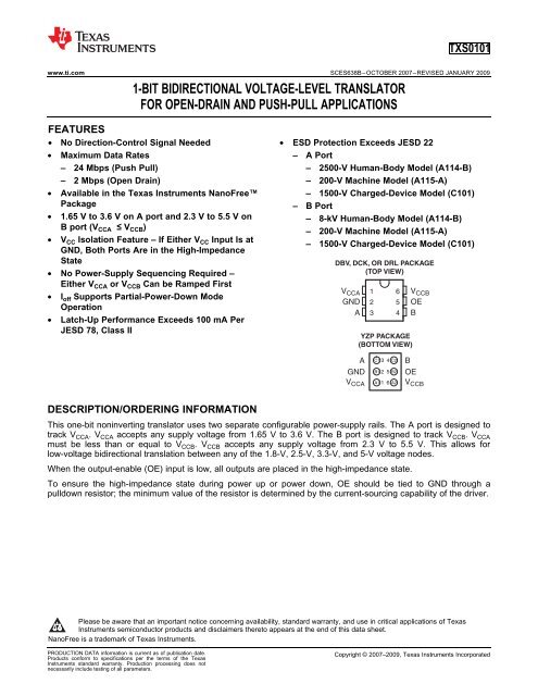
DESCRIPTION/ORDERING INFORMATION<br />
YZP PACKAGE<br />
(BOTTOM VIEW)<br />
A C1 3 4 C2 B<br />
GND B1 2 5 B2 OE<br />
VCCA A1 1 6 A2 VCCB TXS0101<br />
www.ti.com ............................................................................................................................................. SCES638B–OCTOBER 2007–REVISED JANUARY 2009<br />
1-BIT BIDIRECTIONAL VOLTAGE-LEVEL TRANSLATOR<br />
FOR OPEN-DRAIN AND PUSH-PULL APPLICATIONS<br />
1FEATURES<br />
2• No Direction-Control Signal Needed • ESD Protection Exceeds JESD 22<br />
• Maximum Data Rates – A Port<br />
– 24 Mbps (Push Pull) – 2500-V Human-Body Model (A114-B)<br />
– 2 Mbps (<strong>Open</strong> <strong>Drain</strong>) – 200-V Machine Model (A115-A)<br />
• Available in the Texas Instruments NanoFree – 1500-V Charged-Device Model (C101)<br />
Package – B Port<br />
•<br />
•<br />
1.65 V to 3.6 V on A port <strong>and</strong> 2.3 V to 5.5 V on<br />
B port (VCCA ≤ VCCB) VCC Isolation Feature – If Either VCC Input Is at<br />
GND, Both Ports Are in the High-Impedance<br />
–<br />
–<br />
–<br />
8-kV Human-Body Model (A114-B)<br />
200-V Machine Model (A115-A)<br />
1500-V Charged-Device Model (C101)<br />
State<br />
DBV, DCK, OR DRL PACKAGE<br />
• No Power-Supply Sequencing Required –<br />
(TOP VIEW)<br />
•<br />
•<br />
Either VCCA or VCCB Can be Ramped First<br />
Ioff Supports Partial-Power-Down Mode<br />
Operation<br />
Latch-Up Per<strong>for</strong>mance Exceeds 100 mA Per<br />
JESD 78, Class II<br />
VCCA GND<br />
A<br />
1<br />
2<br />
3<br />
6<br />
5<br />
4<br />
VCCB OE<br />
B<br />
This one-bit noninverting translator uses two separate configurable power-supply rails. The A port is designed to<br />
track V CCA. V CCA accepts any supply voltage from 1.65 V to 3.6 V. The B port is designed to track V CCB. V CCA<br />
must be less than or equal to V CCB. V CCB accepts any supply voltage from 2.3 V to 5.5 V. This allows <strong>for</strong><br />
low-voltage bidirectional translation between any of the 1.8-V, 2.5-V, 3.3-V, <strong>and</strong> 5-V voltage nodes.<br />
When the output-enable (OE) input is low, all outputs are placed in the high-impedance state.<br />
To ensure the high-impedance state during power up or power down, OE should be tied to GND through a<br />
pulldown resistor; the minimum value of the resistor is determined by the current-sourcing capability of the driver.<br />
1<br />
Please be aware that an important notice concerning availability, st<strong>and</strong>ard warranty, <strong>and</strong> use in critical applications of Texas<br />
Instruments semiconductor products <strong>and</strong> disclaimers thereto appears at the end of this data sheet.<br />
2NanoFree is a trademark of Texas Instruments.<br />
PRODUCTION DATA in<strong>for</strong>mation is current as of publication date. Copyright © 2007–2009, Texas Instruments Incorporated<br />
Products con<strong>for</strong>m to specifications per the terms of the Texas<br />
Instruments st<strong>and</strong>ard warranty. Production processing does not<br />
necessarily include testing of all parameters.
TXS0101<br />
SCES638B–OCTOBER 2007–REVISED JANUARY 2009 ............................................................................................................................................. www.ti.com<br />
T A<br />
–40°C to 85°C<br />
1.8 V<br />
1.8 V<br />
System<br />
Controller<br />
GND<br />
ORDERING INFORMATION<br />
PACKAGE (1)(2)<br />
NanoFree – WCSP (DSBGA)<br />
0.23-mm Large Bump – YZP (Pb-free)<br />
V CCA<br />
OE<br />
Data A B<br />
GND<br />
V CCB<br />
3.3 V<br />
System<br />
Data<br />
GND<br />
ORDERABLE TOP-SIDE<br />
PART NUMBER MARKING (3)<br />
Reel of 3000 TXS0101YZPR _ _ _2G_<br />
Reel of 3000 TXS0101DBVR<br />
SOT (SOT-23) – DBV NFF_<br />
Reel of 250 TXS0101DBVT<br />
Reel of 3000 TXS0101DCKR<br />
SOT (SC-70) – DCK 2G_<br />
Reel of 250 TXS0101DCKT<br />
Reel of 3000 TXS0101DRLR<br />
SOT (SOT-563) – DRL 2G_<br />
Reel of 250 TXS0101DRLT<br />
(1) For the most current package <strong>and</strong> ordering in<strong>for</strong>mation, see the Package Option Addendum at the end of this document, or see the TI<br />
web site at www.ti.com.<br />
(2) Package drawings, thermal data, <strong>and</strong> symbolization are available at www.ti.com/packaging.<br />
(3) DBV/DCK/DRL: The actual top-side marking has one additional character that designates the wafer fab/assembly site.<br />
YZP: The actual top-side marking has three preceding characters to denote year, month, <strong>and</strong> sequence code, <strong>and</strong> one following<br />
character to designate the wafer fab/assembly site. Pin 1 identifier indicates solder-bump composition (1 = SnPb, • = Pb-free).<br />
PIN DESCRIPTION<br />
NO. NAME FUNCTION<br />
1 V CCA A-port supply voltage. 1.65 V ≤ V CCA ≤ 3.6 V <strong>and</strong> V CCA ≤ V CCB<br />
2 GND Ground<br />
3 A Input/output A. Referenced to V CCA.<br />
4 B Input/output B. Referenced to V CCB.<br />
5 OE Output enable. Pull OE low to place all outputs in 3-state mode. Referenced to V CCA.<br />
6 V CCB B-port supply voltage. 2.3 V ≤ V CCB ≤ 5.5 V<br />
TYPICAL OPERATING CIRCUIT<br />
2 Submit Documentation Feedback Copyright © 2007–2009, Texas Instruments Incorporated<br />
Product Folder Link(s): TXS0101<br />
3.3 V
ABSOLUTE MAXIMUM RATINGS (1)<br />
over operating free-air temperature range (unless otherwise noted)<br />
THERMAL IMPEDANCE RATINGS<br />
TXS0101<br />
www.ti.com ............................................................................................................................................. SCES638B–OCTOBER 2007–REVISED JANUARY 2009<br />
MIN MAX UNIT<br />
V CCA Supply voltage range –0.5 4.6 V<br />
V CCB Supply voltage range –0.5 6.5 V<br />
A port –0.5 4.6<br />
V I Input voltage range (2) V<br />
B port, OE –0.5 6.5<br />
V O<br />
V O<br />
<strong>Voltage</strong> range applied to any output<br />
in the high-impedance or power-off state (2)<br />
<strong>Voltage</strong> range applied to any output in the high or low state (2)(3)<br />
A port –0.5 4.6<br />
B port –0.5 6.5<br />
A port –0.5 V CCA + 0.5<br />
B port –0.5 V CCB + 0.5<br />
I IK Input clamp current V I < 0 –50 mA<br />
I OK Output clamp current V O < 0 –50 mA<br />
I O Continuous output current ±50 mA<br />
Continuous current through V CCA, V CCB, or GND ±100 mA<br />
T stg Storage temperature range –65 150 °C<br />
(1) Stresses beyond those listed under "absolute maximum ratings" may cause permanent damage to the device. These are stress ratings<br />
only, <strong>and</strong> functional operation of the device at these or any other conditions beyond those indicated under "recommended operating<br />
conditions" is not implied. Exposure to absolute-maximum-rated conditions <strong>for</strong> extended periods may affect device reliability.<br />
(2) The input <strong>and</strong> output negative-voltage ratings may be exceeded if the input <strong>and</strong> output current ratings are observed.<br />
(3) The value of V CCA <strong>and</strong> V CCB are provided in the recommended operating conditions table.<br />
DBV package 165<br />
DCK package 259<br />
θ JA Package thermal impedance (1) °C/W<br />
DRL package 142<br />
(1) The package thermal impedance is calculated in accordance with JESD 51-7.<br />
YZP package 123<br />
Copyright © 2007–2009, Texas Instruments Incorporated Submit Documentation Feedback 3<br />
Product Folder Link(s): TXS0101<br />
V<br />
V<br />
UNIT
TXS0101<br />
SCES638B–OCTOBER 2007–REVISED JANUARY 2009 ............................................................................................................................................. www.ti.com<br />
RECOMMENDED OPERATING CONDITIONS (1)(2)<br />
ELECTRICAL CHARACTERISTICS (1)(2)(3)<br />
over recommended operating free-air temperature range (unless otherwise noted)<br />
V CCA V CCB MIN MAX UNIT<br />
VCCA 1.65 3.6<br />
Supply voltage (3)<br />
VCCB 2.3 5.5<br />
1.65 V to 1.95 V V CCI – 0.2 V CCI<br />
A-port I/Os 2.3 V to 5.5 V<br />
2.3 V to 3.6 V V CCI – 0.4 V CCI<br />
V IH High-level input voltage V<br />
B-port I/Os V CCI – 0.4 V CCI<br />
1.65 V to 3.6 V 2.3 V to 5.5 V<br />
OE input V CCA × 0.65 5.5<br />
A-port I/Os 0 0.15<br />
V IL Low-level input voltage B-port I/Os 1.65 V to 3.6 V 2.3 V to 5.5 V 0 0.15 V<br />
OE input 0 V CCA × 0.35<br />
A-port I/Os,<br />
push-pull driving<br />
10<br />
Δt/Δv<br />
Input transition rise or fall<br />
rate<br />
B-port I/Os,<br />
push-pull driving<br />
1.65 V to 3.6 V 2.3 V to 5.5 V<br />
10<br />
ns/V<br />
Control Input 10<br />
T A Operating free-air temperature –40 85 °C<br />
(1) V CCI is the supply associated with the input port.<br />
(2) V CCO is the supply associated with the output port.<br />
(3) V CCA must be less than or equal to V CCB, <strong>and</strong> V CCA must not exceed 3.6 V.<br />
TEST<br />
TA = 25°C –40°C to 85°C<br />
PARAMETER VCCA VCCB UNIT<br />
CONDITIONS MIN TYP MAX MIN MAX<br />
I OH = –20 μA,<br />
V OHA 1.65 V to 3.6 V 2.3 V to 5.5 V V CCA × 0.67 V<br />
V IB ≥ V CCB – 0.4 V<br />
I OL = 1 mA,<br />
V OLA 1.65 V to 3.6 V 2.3 V to 5.5 V 0.4 V<br />
V IB ≤ 0.15 V<br />
I OH = –20 μA,<br />
V OHB 1.65 V to 3.6 V 2.3 V to 5.5 V V CCB × 0.67 V<br />
V IA ≥ V CCA – 0.2 V<br />
I OL = 1 mA,<br />
V OLB 1.65 V to 3.6 V 2.3 V to 5.5 V 0.4 V<br />
V IA ≤ 0.15 V<br />
I I OE 1.65 V to 3.6 V 1.65 V to 5.5 V ±1 ±2 μA<br />
I off<br />
A port 0 V 0 to 5.5 V ±1 ±2 μA<br />
B port 0 to 3.6 V 0 V ±1 ±2 μA<br />
I OZ A or B port 1.65 V to 3.6 V 2.3 V to 5.5 V ±1 ±2 μA<br />
1.65 V to VCCB 2.3 V to 5.5 V 2.4<br />
ICCA VI = VO = open,<br />
IO = 0<br />
3.6 V<br />
0 V<br />
0 V<br />
5.5 V<br />
2.2<br />
-1<br />
μA<br />
1.65 V to VCCB 2.3 V to 5.5 V 12<br />
ICCB VI = VO = open,<br />
IO = 0<br />
3.6 V<br />
0 V<br />
0 V<br />
5.5 V<br />
-1<br />
1<br />
μA<br />
V I = V CCI,<br />
I CCA + I CCB 1.65 V to V CCB 2.3 V to 5.5 V 14.4 μA<br />
I O = 0<br />
C I OE 3.3 V 3.3 V 2.5 3.5 pF<br />
A port 5 6<br />
C io 3.3 V 3.3 V pF<br />
B port 6 7.5<br />
(1) V CCI is the V CC associated with the input port.<br />
(2) V CCO is the V CC associated with the output port.<br />
(3) V CCA must be less than or equal to V CCB, <strong>and</strong> V CCA must not exceed 3.6 V.<br />
4 Submit Documentation Feedback Copyright © 2007–2009, Texas Instruments Incorporated<br />
Product Folder Link(s): TXS0101<br />
V
TIMING REQUIREMENTS<br />
over recommended operating free-air temperature range, VCCA = 1.8 V ± 0.15 V (unless otherwise noted)<br />
TIMING REQUIREMENTS<br />
over recommended operating free-air temperature range, VCCA = 2.5 V ± 0.2 V (unless otherwise noted)<br />
TIMING REQUIREMENTS<br />
over recommended operating free-air temperature range, VCCA = 3.3 V ± 0.3 V (unless otherwise noted)<br />
TXS0101<br />
www.ti.com ............................................................................................................................................. SCES638B–OCTOBER 2007–REVISED JANUARY 2009<br />
V CCB = 2.5 V V CCB = 3.3 V V CCB = 5 V<br />
± 0.2 V ± 0.3 V ± 0.5 V UNIT<br />
MIN MAX MIN MAX MIN MAX<br />
Push-pull driving 21 22 24<br />
Data rate Mbps<br />
<strong>Open</strong>-drain driving 2 2 2<br />
Push-pull driving 47 45 41<br />
t w Pulse duration Data inputs ns<br />
<strong>Open</strong>-drain driving 500 500 500<br />
V CCB = 2.5 V V CCB = 3.3 V V CCB = 5 V<br />
± 0.2 V ± 0.3 V ± 0.5 V UNIT<br />
MIN MAX MIN MAX MIN MAX<br />
Push-pull driving 20 22 24<br />
Data rate Mbps<br />
<strong>Open</strong>-drain driving 2 2 1<br />
Push-pull driving 50 45 41<br />
t w Pulse duration Data inputs ns<br />
<strong>Open</strong>-drain driving 500 500 500<br />
V CCB = 3.3 V V CCB = 5 V<br />
± 0.3 V ± 0.5 V UNIT<br />
MIN MAX MIN MAX<br />
Push-pull driving 23 24<br />
Data rate Mbps<br />
<strong>Open</strong>-drain driving 2 2<br />
Push-pull driving 43 41<br />
t w Pulse duration Data inputs ns<br />
<strong>Open</strong>-drain driving 500 500<br />
Copyright © 2007–2009, Texas Instruments Incorporated Submit Documentation Feedback 5<br />
Product Folder Link(s): TXS0101
TXS0101<br />
SCES638B–OCTOBER 2007–REVISED JANUARY 2009 ............................................................................................................................................. www.ti.com<br />
SWITCHING CHARACTERISTICS<br />
over recommended operating free-air temperature range, VCCA = 1.8 V ± 0.15 V (unless otherwise noted)<br />
VCCB = 2.5 V VCCB = 3.3 V VCCB = 5 V<br />
FROM TO TEST<br />
PARAMETER ± 0.2 V ± 0.3 V ± 0.5 V UNIT<br />
(INPUT) (OUTPUT) CONDITIONS<br />
MIN MAX MIN MAX MIN MAX<br />
t PHL<br />
t PLH<br />
t PHL<br />
t PLH<br />
Push-pull driving 5.3 5.4 6.8<br />
<strong>Open</strong>-drain driving 2.3 8.8 2.4 9.6 2.6 10<br />
A B ns<br />
Push-pull driving 6.8 7.1 7.5<br />
<strong>Open</strong>-drain driving 45 260 36 208 27 198<br />
Push-pull driving 4.4 4.5 4.7<br />
<strong>Open</strong>-drain driving 1.9 5.3 1.1 4.4 1.2 4<br />
B A ns<br />
Push-pull driving 5.3 4.5 0.5<br />
<strong>Open</strong>-drain driving 45 175 36 140 27 102<br />
t en OE A or B 200 200 200 ns<br />
t dis OE A or B 50 40 35 ns<br />
Push-pull driving 3.2 9.5 2.3 9.3 2 7.6<br />
t rA A-port rise time ns<br />
<strong>Open</strong>-drain driving 38 165 30 132 22 95<br />
Push-pull driving 1.1 10.8 1 9.1 1 7.6<br />
t rB B-port rise time ns<br />
<strong>Open</strong>-drain driving 34 145 23 106 10 76<br />
t fA<br />
t fB<br />
A-port fall time<br />
B-port fall time<br />
Push-pull driving 1.9 5.9 1.9 6 1.4 13.3<br />
<strong>Open</strong>-drain driving 4.4 6.9 4.3 6.4 4.2 6.1<br />
Push-pull driving 2.2 13.8 2.2 16.2 2.6 16.2<br />
<strong>Open</strong>-drain driving 6.9 13.8 7.5 16.2 7 16.2<br />
Push-pull driving 21 22 24<br />
Max data rate Mbps<br />
<strong>Open</strong>-drain driving 2 2 2<br />
6 Submit Documentation Feedback Copyright © 2007–2009, Texas Instruments Incorporated<br />
Product Folder Link(s): TXS0101<br />
ns
SWITCHING CHARACTERISTICS<br />
over recommended operating free-air temperature range, VCCA = 2.5 V ± 0.2 V (unless otherwise noted)<br />
TXS0101<br />
www.ti.com ............................................................................................................................................. SCES638B–OCTOBER 2007–REVISED JANUARY 2009<br />
VCCB = 2.5 V VCCB = 3.3 V VCCB = 5 V<br />
FROM TO TEST<br />
PARAMETER ± 0.2 V ± 0.3 V ± 0.5 V UNIT<br />
(INPUT) (OUTPUT) CONDITIONS<br />
MIN MAX MIN MAX MIN MAX<br />
t PHL<br />
t PLH<br />
t PHL<br />
t PLH<br />
Push-pull driving 3.2 3.7 3.8<br />
<strong>Open</strong>-drain driving 1.7 6.3 2 6 2.1 5.8<br />
A B ns<br />
Push-pull driving 3.5 4.1 4.4<br />
<strong>Open</strong>-drain driving 43 250 36 206 27 190<br />
Push-pull driving 3 3.6 4.3<br />
<strong>Open</strong>-drain driving 1.8 4.7 1.6 4.2 1.2 4<br />
B A ns<br />
Push-pull driving 2.5 1.6 1<br />
<strong>Open</strong>-drain driving 44 170 37 140 27 103<br />
t en OE A or B 200 200 200 ns<br />
t dis OE A or B 50 40 35 ns<br />
Push-pull driving 2.8 7.4 2.1 6.6 0.9 5.6<br />
t rA A-port rise time ns<br />
<strong>Open</strong>-drain driving 34 149 28 121 24 89<br />
Push-pull driving 1.3 8.3 0.9 7.2 0.4 6.1<br />
t rB B-port rise time ns<br />
<strong>Open</strong>-drain driving 35 151 24 112 12 81<br />
Push-pull driving 1.9 5.7 1.4 5.5 0.8 5.3<br />
t fA A-port fall time ns<br />
<strong>Open</strong>-drain driving 4.4 6.9 4.3 6.2 4.2 5.8<br />
Push-pull driving 2.2 7.8 2.4 6.7 2.6 6.6<br />
t fB B-port fall time ns<br />
<strong>Open</strong>-drain driving 5.1 8.8 5.4 9.4 5.4 10.4<br />
Push-pull driving 20 22 24<br />
Max data rate Mbps<br />
<strong>Open</strong>-drain driving 2 2 2<br />
Copyright © 2007–2009, Texas Instruments Incorporated Submit Documentation Feedback 7<br />
Product Folder Link(s): TXS0101
TXS0101<br />
SCES638B–OCTOBER 2007–REVISED JANUARY 2009 ............................................................................................................................................. www.ti.com<br />
SWITCHING CHARACTERISTICS<br />
over recommended operating free-air temperature range, VCCA = 3.3 V ± 0.3 V (unless otherwise noted)<br />
VCCB = 3.3 V VCCB = 5 V<br />
FROM TO TEST<br />
PARAMETER ± 0.3 V ± 0.5 V UNIT<br />
(INPUT) (OUTPUT) CONDITIONS<br />
MIN MAX MIN MAX<br />
t PHL<br />
t PLH<br />
t PHL<br />
t PLH<br />
Applications<br />
Architecture<br />
PRINCIPLES OF OPERATION<br />
Push-pull driving 2.4 3.1<br />
<strong>Open</strong>-drain driving 1.3 4.2 1.4 4.6<br />
A B ns<br />
Push-pull driving 4.2 4.4<br />
<strong>Open</strong>-drain driving 36 204 28 165<br />
Push-pull driving 2.5 3.3<br />
<strong>Open</strong>-drain driving 1 124 1 97<br />
B A ns<br />
Push-pull driving 2.5 2.6<br />
<strong>Open</strong>-drain driving 3 139 3 105<br />
t en OE A or B 200 200 ns<br />
t dis OE A or B 40 35 ns<br />
Push-pull driving 2.3 5.6 1.9 4.8<br />
t rA A-port rise time ns<br />
<strong>Open</strong>-drain driving 25 116 19 85<br />
Push-pull driving 1.6 6.4 0.6 7.4<br />
t rB B-port rise time ns<br />
<strong>Open</strong>-drain driving 26 116 14 72<br />
Push-pull driving 1.4 5.4 1 5<br />
t fA A-port fall time ns<br />
<strong>Open</strong>-drain driving 4.3 6.1 4.2 5.7<br />
Push-pull driving 2.3 7.4 2.4 7.6<br />
t fB B-port fall time ns<br />
<strong>Open</strong>-drain driving 5 7.6 4.8 8.3<br />
Push-pull driving 23 24<br />
Max data rate Mbps<br />
<strong>Open</strong>-drain driving 2 2<br />
The TXS0101 can be used in level-translation applications <strong>for</strong> interfacing devices or systems operating at<br />
different interface voltages with one another. The TXS0101 is ideal <strong>for</strong> use in applications where an open-drain<br />
driver is connected to the data I/Os. The TXB0101 can also be used in applications where a push-pull driver is<br />
connected to the data I/Os, but the TXB0102 might be a better option <strong>for</strong> such push-pull applications.<br />
The TXS0101 architecture (see Figure 1) does not require a direction-control signal to control the direction of<br />
data flow from A to B or from B to A.<br />
8 Submit Documentation Feedback Copyright © 2007–2009, Texas Instruments Incorporated<br />
Product Folder Link(s): TXS0101
A<br />
Input Driver Requirements<br />
Power Up<br />
Enable <strong>and</strong> Disable<br />
VCCA<br />
Pullup or Pulldown Resistors on I/O Lines<br />
Oneshot<br />
Oneshot<br />
T1 T2<br />
Gate Bias<br />
VCCB VCCB<br />
10k 10k<br />
B<br />
TXS0101<br />
www.ti.com ............................................................................................................................................. SCES638B–OCTOBER 2007–REVISED JANUARY 2009<br />
Figure 1. Architecture of a TXS01xx Cell<br />
Each A-port I/O has an internal 10-kΩ pullup resistor to V CCA, <strong>and</strong> each B-port I/O has an internal 10-kΩ pullup<br />
resistor to V CCB. The output one-shots detect rising edges on the A or B ports. During a rising edge, the one-shot<br />
turns on the PMOS transistors (T1,T2) <strong>for</strong> a short duration, which speeds up the low-to-high transition.<br />
The fall time (t fA, t fB) of a signal depends on the output impedance of the external device driving the data I/Os of<br />
the TXS0101. Similarly, the t PHL <strong>and</strong> max data rates also depend on the output impedance of the external driver.<br />
The values <strong>for</strong> t fA, t fB, t PHL, <strong>and</strong> maximum data rates in the data sheet assume that the output impedance of the<br />
external driver is less than 50 Ω.<br />
During operation, ensure that V CCA ≤ V CCB at all times. During power-up sequencing, V CCA ≥ V CCB does not<br />
damage the device, so any power supply can be ramped up first.<br />
The TXS0101 has an OE input that is used to disable the device by setting OE low, which places all I/Os in the<br />
Hi-Z state. The disable time (t dis) indicates the delay between the time when OE goes low <strong>and</strong> when the outputs<br />
actually get disabled (Hi-Z). The enable time (t en) indicates the amount of time the user must allow <strong>for</strong> the<br />
one-shot circuitry to become operational after OE is taken high.<br />
Each A-port I/O has an internal 10-kΩ pullup resistor to V CCA, <strong>and</strong> each B-port I/O has an internal 10-kΩ pullup<br />
resistor to V CCB. If a smaller value of pullup resistor is required, an external resistor must be added from the I/O<br />
to V CCA or V CCB (in parallel with the internal 10-kΩ resistors).<br />
Copyright © 2007–2009, Texas Instruments Incorporated Submit Documentation Feedback 9<br />
Product Folder Link(s): TXS0101
TXS0101<br />
SCES638B–OCTOBER 2007–REVISED JANUARY 2009 ............................................................................................................................................. www.ti.com<br />
Input<br />
Input<br />
Output<br />
V CCI<br />
t PLH<br />
DUT<br />
IN OUT<br />
PARAMETER MEASUREMENT INFORMATION<br />
t w<br />
V CCO<br />
15 pF<br />
From Output<br />
Under Test<br />
50 k<br />
LOAD CIRCUIT FOR ENABLE/DISABLE<br />
TIME MEASUREMENT<br />
V CCI/2 V CCI/2<br />
VOLTAGE WAVEFORMS<br />
PULSE DURATION<br />
VOLTAGE WAVEFORMS<br />
PROPAGATION DELAY TIMES<br />
1 M<br />
DATA RATE, PULSE DURATION, PROPAGATION DELAY,<br />
OUTPUT RISE AND FALL TIME MEASUREMENT USING<br />
A PUSH-PULL DRIVER<br />
V CCI/2 V CCI/2<br />
V CCO/2<br />
t r<br />
0.9 V CCO<br />
0.1 V CCO<br />
t PHL<br />
V CCI<br />
0 V<br />
V CCI<br />
0 V<br />
VOH VCCO/2 VOL t f<br />
15 pF<br />
Output<br />
Control<br />
(low-level<br />
enabling)<br />
Output<br />
Wave<strong>for</strong>m 1<br />
S1 at 2 × V CCO<br />
(see Note B)<br />
Output<br />
Wave<strong>for</strong>m 2<br />
S1 at GND<br />
(see Note B)<br />
S1<br />
t PZL/t PLZ<br />
t PHZ/t PZH<br />
t PZL<br />
t PZH<br />
2 × V CCO<br />
<strong>Open</strong><br />
TEST S1<br />
2 × V CCO<br />
<strong>Open</strong><br />
V CCA/2<br />
0.1 V CCO<br />
0.9 V CCO<br />
V CCA/2<br />
t PLZ<br />
V CCO/2<br />
t PHZ<br />
V CCO/2<br />
VOLTAGE WAVEFORMS<br />
ENABLE AND DISABLE TIMES<br />
A. C L includes probe <strong>and</strong> jig capacitance.<br />
B. Wave<strong>for</strong>m 1 is <strong>for</strong> an output with internal conditions such that the output is low, except when disabled by the output control.<br />
Wave<strong>for</strong>m 2 is <strong>for</strong> an output with internal conditions such that the output is high, except when disabled by the output control.<br />
C. All input pulses are supplied by generators having the following characteristics: PRR10 MHz, Z O = 50 Ω, dv/dt ≥1 V/ns.<br />
D. The outputs are measured one at a time, with one transition per measurement.<br />
E. t PLZ <strong>and</strong> t PHZ are the same as t dis.<br />
F. t PZL <strong>and</strong> t PZH are the same as t en.<br />
G. t PLH <strong>and</strong> t PHL are the same as t pd.<br />
H. V CCI is the V CC associated with the input port.<br />
I. V CCO is the V CC associated with the output port.<br />
J. All parameters <strong>and</strong> wave<strong>for</strong>ms are not applicable to all devices.<br />
50 k<br />
V CCI<br />
DUT<br />
IN OUT<br />
Figure 2. Load Circuit <strong>and</strong> <strong>Voltage</strong> Wave<strong>for</strong>ms<br />
V CCO<br />
15 pF<br />
1 M<br />
DATA RATE, PULSE DURATION, PROPAGATION DELAY,<br />
OUTPUT RISE AND FALL TIME MEASUREMENT USING<br />
AN OPEN-DRAIN DRIVER<br />
10 Submit Documentation Feedback Copyright © 2007–2009, Texas Instruments Incorporated<br />
Product Folder Link(s): TXS0101<br />
V CCA<br />
0 V<br />
V CCO<br />
V OL<br />
V OH<br />
0 V
PACKAGING INFORMATION<br />
Orderable Device Status (1)<br />
Package<br />
Type<br />
Package<br />
Drawing<br />
Pins Package<br />
Qty<br />
TXS0101DBVR ACTIVE SOT-23 DBV 6 3000 Green (RoHS &<br />
no Sb/Br)<br />
TXS0101DBVRG4 ACTIVE SOT-23 DBV 6 3000 Green (RoHS &<br />
no Sb/Br)<br />
TXS0101DBVT ACTIVE SOT-23 DBV 6 250 Green (RoHS &<br />
no Sb/Br)<br />
TXS0101DBVTG4 ACTIVE SOT-23 DBV 6 250 Green (RoHS &<br />
no Sb/Br)<br />
TXS0101DCKR ACTIVE SC70 DCK 6 3000 Green (RoHS &<br />
no Sb/Br)<br />
TXS0101DCKRG4 ACTIVE SC70 DCK 6 3000 Green (RoHS &<br />
no Sb/Br)<br />
TXS0101DCKT ACTIVE SC70 DCK 6 250 Green (RoHS &<br />
no Sb/Br)<br />
TXS0101DCKTG4 ACTIVE SC70 DCK 6 250 Green (RoHS &<br />
no Sb/Br)<br />
TXS0101DRLR ACTIVE SOT DRL 6 4000 Green (RoHS &<br />
no Sb/Br)<br />
TXS0101DRLRG4 ACTIVE SOT DRL 6 4000 Green (RoHS &<br />
no Sb/Br)<br />
TXS0101YZPR ACTIVE DSBGA YZP 6 3000 Green (RoHS &<br />
no Sb/Br)<br />
Eco Plan (2) Lead/Ball Finish MSL Peak Temp (3)<br />
CU NIPDAU <strong>Level</strong>-1-260C-UNLIM<br />
CU NIPDAU <strong>Level</strong>-1-260C-UNLIM<br />
CU NIPDAU <strong>Level</strong>-1-260C-UNLIM<br />
CU NIPDAU <strong>Level</strong>-1-260C-UNLIM<br />
CU NIPDAU <strong>Level</strong>-1-260C-UNLIM<br />
CU NIPDAU <strong>Level</strong>-1-260C-UNLIM<br />
CU NIPDAU <strong>Level</strong>-1-260C-UNLIM<br />
CU NIPDAU <strong>Level</strong>-1-260C-UNLIM<br />
CU NIPDAU <strong>Level</strong>-1-260C-UNLIM<br />
CU NIPDAU <strong>Level</strong>-1-260C-UNLIM<br />
SNAGCU <strong>Level</strong>-1-260C-UNLIM<br />
(1) The marketing status values are defined as follows:<br />
ACTIVE: Product device recommended <strong>for</strong> new designs.<br />
LIFEBUY: TI has announced that the device will be discontinued, <strong>and</strong> a lifetime-buy period is in effect.<br />
NRND: Not recommended <strong>for</strong> new designs. Device is in production to support existing customers, but TI does not recommend using this part in<br />
a new design.<br />
PREVIEW: Device has been announced but is not in production. Samples may or may not be available.<br />
OBSOLETE: TI has discontinued the production of the device.<br />
(2) Eco Plan - The planned eco-friendly classification: Pb-Free (RoHS), Pb-Free (RoHS Exempt), or Green (RoHS & no Sb/Br) - please check<br />
http://www.ti.com/productcontent <strong>for</strong> the latest availability in<strong>for</strong>mation <strong>and</strong> additional product content details.<br />
TBD: The Pb-Free/Green conversion plan has not been defined.<br />
Pb-Free (RoHS): TI's terms "Lead-Free" or "Pb-Free" mean semiconductor products that are compatible with the current RoHS requirements<br />
<strong>for</strong> all 6 substances, including the requirement that lead not exceed 0.1% by weight in homogeneous materials. Where designed to be soldered<br />
at high temperatures, TI Pb-Free products are suitable <strong>for</strong> use in specified lead-free processes.<br />
Pb-Free (RoHS Exempt): This component has a RoHS exemption <strong>for</strong> either 1) lead-based flip-chip solder bumps used between the die <strong>and</strong><br />
package, or 2) lead-based die adhesive used between the die <strong>and</strong> leadframe. The component is otherwise considered Pb-Free (RoHS<br />
compatible) as defined above.<br />
Green (RoHS & no Sb/Br): TI defines "Green" to mean Pb-Free (RoHS compatible), <strong>and</strong> free of Bromine (Br) <strong>and</strong> Antimony (Sb) based flame<br />
retardants (Br or Sb do not exceed 0.1% by weight in homogeneous material)<br />
(3) MSL, Peak Temp. -- The Moisture Sensitivity <strong>Level</strong> rating according to the JEDEC industry st<strong>and</strong>ard classifications, <strong>and</strong> peak solder<br />
temperature.<br />
PACKAGE OPTION ADDENDUM<br />
www.ti.com 21-Aug-2008<br />
Important In<strong>for</strong>mation <strong>and</strong> Disclaimer:The in<strong>for</strong>mation provided on this page represents TI's knowledge <strong>and</strong> belief as of the date that it is<br />
provided. TI bases its knowledge <strong>and</strong> belief on in<strong>for</strong>mation provided by third parties, <strong>and</strong> makes no representation or warranty as to the<br />
accuracy of such in<strong>for</strong>mation. Ef<strong>for</strong>ts are underway to better integrate in<strong>for</strong>mation from third parties. TI has taken <strong>and</strong> continues to take<br />
reasonable steps to provide representative <strong>and</strong> accurate in<strong>for</strong>mation but may not have conducted destructive testing or chemical analysis on<br />
incoming materials <strong>and</strong> chemicals. TI <strong>and</strong> TI suppliers consider certain in<strong>for</strong>mation to be proprietary, <strong>and</strong> thus CAS numbers <strong>and</strong> other limited<br />
in<strong>for</strong>mation may not be available <strong>for</strong> release.<br />
In no event shall TI's liability arising out of such in<strong>for</strong>mation exceed the total purchase price of the TI part(s) at issue in this document sold by TI<br />
Addendum-Page 1
to Customer on an annual basis.<br />
PACKAGE OPTION ADDENDUM<br />
www.ti.com 21-Aug-2008<br />
Addendum-Page 2
TAPE AND REEL INFORMATION<br />
*All dimensions are nominal<br />
Device Package<br />
Type<br />
Package<br />
Drawing<br />
Pins SPQ Reel<br />
Diameter<br />
(mm)<br />
PACKAGE MATERIALS INFORMATION<br />
www.ti.com 10-Jan-2011<br />
Reel<br />
Width<br />
W1 (mm)<br />
A0<br />
(mm)<br />
B0<br />
(mm)<br />
K0<br />
(mm)<br />
P1<br />
(mm)<br />
W<br />
(mm)<br />
Pin1<br />
Quadrant<br />
TXS0101DBVR SOT-23 DBV 6 3000 180.0 9.2 3.23 3.17 1.37 4.0 8.0 Q3<br />
TXS0101DBVT SOT-23 DBV 6 250 180.0 9.2 3.23 3.17 1.37 4.0 8.0 Q3<br />
TXS0101DCKR SC70 DCK 6 3000 179.0 8.4 2.2 2.5 1.2 4.0 8.0 Q3<br />
TXS0101DCKT SC70 DCK 6 250 179.0 8.4 2.2 2.5 1.2 4.0 8.0 Q3<br />
TXS0101DRLR SOT DRL 6 4000 180.0 9.2 1.98 1.78 0.69 4.0 8.0 Q3<br />
TXS0101YZPR DSBGA YZP 6 3000 180.0 8.4 1.02 1.52 0.63 4.0 8.0 Q1<br />
Pack Materials-Page 1
*All dimensions are nominal<br />
PACKAGE MATERIALS INFORMATION<br />
www.ti.com 10-Jan-2011<br />
Device Package Type Package Drawing Pins SPQ Length (mm) Width (mm) Height (mm)<br />
TXS0101DBVR SOT-23 DBV 6 3000 202.0 201.0 28.0<br />
TXS0101DBVT SOT-23 DBV 6 250 202.0 201.0 28.0<br />
TXS0101DCKR SC70 DCK 6 3000 203.0 203.0 35.0<br />
TXS0101DCKT SC70 DCK 6 250 203.0 203.0 35.0<br />
TXS0101DRLR SOT DRL 6 4000 202.0 201.0 28.0<br />
TXS0101YZPR DSBGA YZP 6 3000 220.0 220.0 34.0<br />
Pack Materials-Page 2
IMPORTANT NOTICE<br />
Texas Instruments Incorporated <strong>and</strong> its subsidiaries (TI) reserve the right to make corrections, modifications, enhancements, improvements,<br />
<strong>and</strong> other changes to its products <strong>and</strong> services at any time <strong>and</strong> to discontinue any product or service without notice. Customers should<br />
obtain the latest relevant in<strong>for</strong>mation be<strong>for</strong>e placing orders <strong>and</strong> should verify that such in<strong>for</strong>mation is current <strong>and</strong> complete. All products are<br />
sold subject to TI’s terms <strong>and</strong> conditions of sale supplied at the time of order acknowledgment.<br />
TI warrants per<strong>for</strong>mance of its hardware products to the specifications applicable at the time of sale in accordance with TI’s st<strong>and</strong>ard<br />
warranty. Testing <strong>and</strong> other quality control techniques are used to the extent TI deems necessary to support this warranty. Except where<br />
m<strong>and</strong>ated by government requirements, testing of all parameters of each product is not necessarily per<strong>for</strong>med.<br />
TI assumes no liability <strong>for</strong> applications assistance or customer product design. Customers are responsible <strong>for</strong> their products <strong>and</strong><br />
applications using TI components. To minimize the risks associated with customer products <strong>and</strong> applications, customers should provide<br />
adequate design <strong>and</strong> operating safeguards.<br />
TI does not warrant or represent that any license, either express or implied, is granted under any TI patent right, copyright, mask work right,<br />
or other TI intellectual property right relating to any combination, machine, or process in which TI products or services are used. In<strong>for</strong>mation<br />
published by TI regarding third-party products or services does not constitute a license from TI to use such products or services or a<br />
warranty or endorsement thereof. Use of such in<strong>for</strong>mation may require a license from a third party under the patents or other intellectual<br />
property of the third party, or a license from TI under the patents or other intellectual property of TI.<br />
Reproduction of TI in<strong>for</strong>mation in TI data books or data sheets is permissible only if reproduction is without alteration <strong>and</strong> is accompanied<br />
by all associated warranties, conditions, limitations, <strong>and</strong> notices. Reproduction of this in<strong>for</strong>mation with alteration is an unfair <strong>and</strong> deceptive<br />
business practice. TI is not responsible or liable <strong>for</strong> such altered documentation. In<strong>for</strong>mation of third parties may be subject to additional<br />
restrictions.<br />
Resale of TI products or services with statements different from or beyond the parameters stated by TI <strong>for</strong> that product or service voids all<br />
express <strong>and</strong> any implied warranties <strong>for</strong> the associated TI product or service <strong>and</strong> is an unfair <strong>and</strong> deceptive business practice. TI is not<br />
responsible or liable <strong>for</strong> any such statements.<br />
TI products are not authorized <strong>for</strong> use in safety-critical applications (such as life support) where a failure of the TI product would reasonably<br />
be expected to cause severe personal injury or death, unless officers of the parties have executed an agreement specifically governing<br />
such use. Buyers represent that they have all necessary expertise in the safety <strong>and</strong> regulatory ramifications of their applications, <strong>and</strong><br />
acknowledge <strong>and</strong> agree that they are solely responsible <strong>for</strong> all legal, regulatory <strong>and</strong> safety-related requirements concerning their products<br />
<strong>and</strong> any use of TI products in such safety-critical applications, notwithst<strong>and</strong>ing any applications-related in<strong>for</strong>mation or support that may be<br />
provided by TI. Further, Buyers must fully indemnify TI <strong>and</strong> its representatives against any damages arising out of the use of TI products in<br />
such safety-critical applications.<br />
TI products are neither designed nor intended <strong>for</strong> use in military/aerospace applications or environments unless the TI products are<br />
specifically designated by TI as military-grade or "enhanced plastic." Only products designated by TI as military-grade meet military<br />
specifications. Buyers acknowledge <strong>and</strong> agree that any such use of TI products which TI has not designated as military-grade is solely at<br />
the Buyer's risk, <strong>and</strong> that they are solely responsible <strong>for</strong> compliance with all legal <strong>and</strong> regulatory requirements in connection with such use.<br />
TI products are neither designed nor intended <strong>for</strong> use in automotive applications or environments unless the specific TI products are<br />
designated by TI as compliant with ISO/TS 16949 requirements. Buyers acknowledge <strong>and</strong> agree that, if they use any non-designated<br />
products in automotive applications, TI will not be responsible <strong>for</strong> any failure to meet such requirements.<br />
Following are URLs where you can obtain in<strong>for</strong>mation on other Texas Instruments products <strong>and</strong> application solutions:<br />
Products Applications<br />
Audio www.ti.com/audio Communications <strong>and</strong> Telecom www.ti.com/communications<br />
Amplifiers amplifier.ti.com Computers <strong>and</strong> Peripherals www.ti.com/computers<br />
Data Converters dataconverter.ti.com Consumer Electronics www.ti.com/consumer-apps<br />
DLP® Products www.dlp.com Energy <strong>and</strong> Lighting www.ti.com/energy<br />
DSP dsp.ti.com Industrial www.ti.com/industrial<br />
Clocks <strong>and</strong> Timers www.ti.com/clocks Medical www.ti.com/medical<br />
Interface interface.ti.com Security www.ti.com/security<br />
Logic logic.ti.com Space, Avionics <strong>and</strong> Defense www.ti.com/space-avionics-defense<br />
Power Mgmt power.ti.com Transportation <strong>and</strong> www.ti.com/automotive<br />
Automotive<br />
Microcontrollers microcontroller.ti.com Video <strong>and</strong> Imaging www.ti.com/video<br />
RFID www.ti-rfid.com Wireless www.ti.com/wireless-apps<br />
RF/IF <strong>and</strong> ZigBee® Solutions www.ti.com/lprf<br />
TI E2E Community Home Page e2e.ti.com<br />
Mailing Address: Texas Instruments, Post Office Box 655303, Dallas, Texas 75265<br />
Copyright © 2011, Texas Instruments Incorporated