MAX5456/MAX5457 Stereo Audio Taper Potentiometers ... - Maxim
MAX5456/MAX5457 Stereo Audio Taper Potentiometers ... - Maxim
MAX5456/MAX5457 Stereo Audio Taper Potentiometers ... - Maxim

Create successful ePaper yourself
Turn your PDF publications into a flip-book with our unique Google optimized e-Paper software.
General Description<br />
The <strong>MAX5456</strong>/<strong>MAX5457</strong> dual, logarithmic taper digital<br />
potentiometers feature a simple pushbutton interface<br />
that controls volume and balance in audio applications.<br />
Each potentiometer has 32 tap points and replaces<br />
mechanical potentiometers. Refer to the MAX5408–<br />
MAX5411 data sheet for SPI versions of the <strong>MAX5456</strong>/<br />
<strong>MAX5457</strong>.<br />
Use the <strong>MAX5456</strong>/<strong>MAX5457</strong> digital inputs with momentary<br />
contact single-pole/single-throw (SPST) pushbutton<br />
switches. Each input includes internal debounce circuitry<br />
and a 50kΩ pullup resistor.<br />
The <strong>MAX5456</strong>/<strong>MAX5457</strong> advance the wiper setting once<br />
per button push. <strong>Maxim</strong>’s proprietary SmartWiper control<br />
eliminates the need for a microcomputer to increase<br />
the wiper transition rate. Holding the control input low for<br />
more than 1s advances the wiper at a rate of 4Hz for 4s<br />
and 16Hz per second thereafter.<br />
The <strong>MAX5456</strong>/<strong>MAX5457</strong> provide temperature coefficients<br />
of 50ppm/°C end-to-end and 5ppm/°C ratiometric<br />
and a nominal resistance of 10kΩ per potentiometer.<br />
An integrated click/pop suppression feature minimizes<br />
the audible noise generated by wiper transitions. The<br />
typical total harmonic distortion plus noise (THD+N) for<br />
these devices is 0.01%.<br />
The <strong>MAX5457</strong> features a 3-button interface with a<br />
MODE input that toggles between volume- and balancecontrol<br />
modes. An LED output indicates volume or balance<br />
mode. The <strong>MAX5456</strong> features a 4-button interface<br />
with separate inputs for up and down volume controls<br />
and left and right balance controls.<br />
The <strong>MAX5456</strong>/<strong>MAX5457</strong> is available in a 16-pin QSOP<br />
packages and specified over the extended (-40°C to<br />
+85°C) temperature range.<br />
<strong>Stereo</strong> Volume Control<br />
Fading and Balancing <strong>Stereo</strong> Signals<br />
<strong>Stereo</strong> Blending and Mixing<br />
Applications<br />
Typical Application Circuits and Selector Guide appear at<br />
end of data sheet.<br />
SmartWiper is a trademark of <strong>Maxim</strong> Integrated Products, Inc.<br />
EVALUATION KIT AVAILABLE<br />
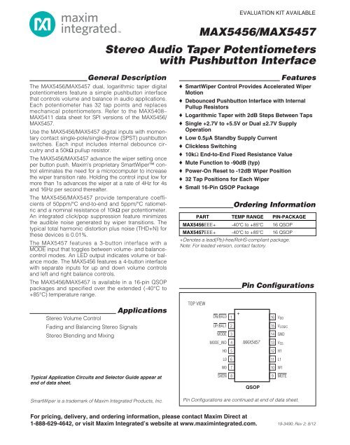
<strong>MAX5456</strong>/<strong>MAX5457</strong><br />
<strong>Stereo</strong> <strong>Audio</strong> <strong>Taper</strong> <strong>Potentiometers</strong><br />
with Pushbutton Interface<br />
Features<br />
♦ SmartWiper Control Provides Accelerated Wiper<br />
Motion<br />
♦ Debounced Pushbutton Interface with Internal<br />
Pullup Resistors<br />
♦ Logarithmic <strong>Taper</strong> with 2dB Steps Between Taps<br />
♦ Single +2.7V to +5.5V or Dual ±2.7V Supply<br />
Operation<br />
♦ Low 0.5µA Standby Supply Current<br />
♦ Clickless Switching<br />
♦ 10kΩ End-to-End Fixed Resistance Value<br />
♦ Mute Function to -90dB (typ)<br />
♦ Power-On Reset to -12dB Wiper Position<br />
♦ 32 Tap Positions for Each Wiper<br />
♦ Small 16-Pin QSOP Package<br />
For pricing, delivery, and ordering information, please contact <strong>Maxim</strong> Direct at<br />
1-888-629-4642, or visit <strong>Maxim</strong> Integrated’s website at www.maximintegrated.com.<br />
Ordering Information<br />
PART TEMP RANGE PIN-PACKAGE<br />
<strong>MAX5456</strong>EEE+ -40 o C to +85 o C 16 QSOP<br />
<strong>MAX5457</strong>EEE+ -40 o C to +85 o C 16 QSOP<br />
+Denotes a lead(Pb)-free/RoHS-compliant package.<br />
Note: For leaded version, contact factory.<br />
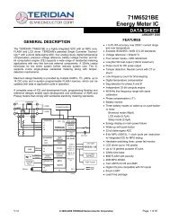
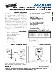
TOP VIEW<br />
1 16<br />
15<br />
14<br />
13<br />
12<br />
+<br />
DN/BAL0 VDD<br />
UP/BAL1 2<br />
VLOGIC<br />
MODE 3<br />
GND<br />
MODE_IND 4 <strong>MAX5457</strong> VSS<br />
H0 5<br />
H1<br />
L0<br />
W0<br />
SHDN<br />
6<br />
7<br />
8<br />
Pin Configurations<br />
QSOP<br />
11 L1<br />
10 W1<br />
9<br />
MUTE<br />
Pin Configurations are continued at end of data sheet.<br />
19-3490; Rev 2; 8/12
<strong>MAX5456</strong>/<strong>MAX5457</strong><br />
<strong>Stereo</strong> <strong>Audio</strong> <strong>Taper</strong> <strong>Potentiometers</strong><br />
with Pushbutton Interface<br />
ABSOLUTE MAXIMUM RATINGS<br />
(<strong>MAX5456</strong>) SHDN, MUTE, VOLUP, VOLDN,<br />
BAL_ to GND.....................................-0.3V to (VLOGIC + 0.3V)<br />
(<strong>MAX5457</strong>) SHDN, MUTE, UP/BAL1, DN/BAL0, MODE,<br />
MODE_IND to GND...........................-0.3V to (VLOGIC + 0.3V)<br />
H_, L_, and W_ to VSS ..............................-0.3V to (VDD + 0.3 V)<br />
VDD to GND..............................................................-0.3V to +6V<br />
VDD to VSS................................................................-0.3V to +6V<br />
VLOGIC to GND.........................................................-0.3V to +6V<br />
VLOGIC to VSS...........................................................-0.3V to +6V<br />
VSS to GND............................................................-3.0V to +0.3V<br />
ELECTRICAL CHARACTERISTICS<br />
Peak Current into H_, L_, and W_.......................................±1mA<br />
Average Current into H_, L_, and W_ ..............................±500µA<br />
Input and Output Latchup Immunity...............................±200mA<br />
Continuous Power Dissipation (TA = +70°C)<br />
16-Pin QSOP (derate 8.3mW/°C above +70°C)........666.7mW<br />
Operating Temperature Range ...........................-40°C to +85°C<br />
Junction Temperature......................................................+150°C<br />
Storage Temperature Range .............................-60°C to +150°C<br />
Lead Temperature (soldering, 10s) .................................+300°C<br />
Soldering Temperature (reflow) .......................................+260°C<br />
Stresses beyond those listed under “Absolute <strong>Maxim</strong>um Ratings” may cause permanent damage to the device. These are stress ratings only, and functional<br />
operation of the device at these or any other conditions beyond those indicated in the operational sections of the specifications is not implied. Exposure to<br />
absolute maximum rating conditions for extended periods may affect device reliability.<br />
(VDD = VLOGIC = +2.7V to +5.5V, VSS = 0V, GND = 0V, VH_ = VDD, VL_ = VSS, TA = TMIN to TMAX. Typical values are at TA = +25°C,<br />
unless otherwise specified.) (Note 1)<br />
PARAMETER SYMBOL CONDITIONS MIN TYP MAX UNITS<br />
End-to-End Resistance R Figures 1, 2 7 10 13 kΩ<br />
<strong>Maxim</strong>um Bandwidth fCUTOFF From H_ to W_, CLOAD = 10pF 100 kHz<br />
Absolute Ratio Tolerance N o l oad at the outp ut of the w i p er , W _ = - 6d B ±0.25 dB<br />
Tap-to-Tap Tolerance ±0.1 dB<br />
Total Harmonic Distortion Plus<br />
Noise<br />
VDD = 5V, VH_ = (VDD / 2) + 1VRMS,<br />
f = 1kHz, tap = -6dB, VL_ = VDD / 2, RL = ∞<br />
THD+N VDD = 3V, VSS = 0V, VL_ = 1.5V,<br />
VH_ = 1.5V + 1VRMS, f = 1kHz, RL = 10kΩ to<br />
(VDD / 2), CL = 5pF, tap = -6dB<br />
Channel-to-Channel Isolation -100 dB<br />
Interchannel Matching f = 20Hz to 20kHz, tap = -6dB ±0.5 dB<br />
Mute Attenuation -90 dB<br />
Power-Supply Rejection Ratio PSRR -80 dB<br />
Wiper Resistance RW 1000 1700 Ω<br />
Wiper Capacitance CW 10 pF<br />
H Terminal Capacitance CH 5 pF<br />
L Terminal Capacitance CL 7 pF<br />
End-to-End Resistance<br />
Temperature Coefficient<br />
Ratiometric Resistance<br />
Temperature Coefficient<br />
2 <strong>Maxim</strong> Integrated<br />
0.01<br />
0.23<br />
%<br />
50 ppm/°C<br />
5 ppm/°C<br />
Output Noise en 20Hz to 20kHz 0.95 µVRMS<br />
PUSHBUTTON CONTACT INPUTS (UP/BAL1, DN/BAL0, MUTE, VOLUP, VOLDN, BAL0, BAL1, MODE)<br />
Internal Pullup Resistor RPULLUP 32 50 65 kΩ<br />
Single Pulse-Width Input tlPW Figure 5 22.5 ms<br />
Repetitive Input Pulse High Time tHPW Figure 5 40 ms<br />
Timeout Period tWS Click/pop suppression inactive 32 ms
<strong>Stereo</strong> <strong>Audio</strong> <strong>Taper</strong> <strong>Potentiometers</strong><br />
with Pushbutton Interface<br />
ELECTRICAL CHARACTERISTICS (continued)<br />
<strong>MAX5456</strong>/<strong>MAX5457</strong><br />
(VDD = VLOGIC = +2.7V to +5.5V, VSS = 0V, GND = 0V, VH_ = VDD, VL_ = VSS, TA = TMIN to TMAX. Typical values are at TA = +25°C,<br />
unless otherwise specified.) (Note 1)<br />
PARAMETER SYMBOL CONDITIONS MIN TYP MAX UNITS<br />
First Autoincrement Point 1 s<br />
First Autoincrement Rate 4 Hz<br />
Second Autoincrement Point 4 s<br />
Second Autoincrement Rate 16 Hz<br />
DIGITAL INPUTS (VLOGIC > 4.5V)<br />
Input High Voltage VIH 2.4 V<br />
Input Low Voltage VIL 0.8 V<br />
Input Leakage Current Inputs floating ±1 µA<br />
Input Capacitance 5 pF<br />
DIGITAL INPUTS (VLOGIC < 4.5V)<br />
Input High Voltage VIH<br />
Input Low Voltage VIL<br />
0.7 x<br />
V L OGIC<br />
Note 1: Parameters are 100% production tested at +85°C and limits through temperature are guaranteed by design.<br />
Note 2: Supply current measured with the supply on and a button pushed.<br />
Note 3: Supply current measured with the power on, no button pushed, and the wiper position fixed.<br />
Note 4: This is the measured current with SHDN low and MODE_IND unconnected.<br />
0.3 x<br />
V L OGIC<br />
Input Leakage Current Inputs floating ±1 µA<br />
Input Capacitance 5 pF<br />
POWER SUPPLIES<br />
Supply Voltage VDD 2.7 5.5 V<br />
Negative Power Supply VSS -2.7 0 V<br />
Supply-Voltage Difference VDD - VSS 5.5 V<br />
Active Supply Current IDD (Note 2) 100 µA<br />
Standby Supply Current ISTBY<br />
V D D = + 5.5V , V S S = 0V , V LOGIC = 2.7V ( N ote 3) 2 10<br />
VLOGIC = VDD = +2.7V, VSS = -2.7V (Note 3) 0.5 1<br />
Shutdown Supply Current ISHDN (Note 4) 1 µA<br />
Power-Up Time tPU 10 ms<br />
Logic Standby Voltage VLOGIC 2.7 VDD V<br />
Logic Active Supply Current ILOGIC (Note 2) 160 µA<br />
Logic Standby Supply Current ILOGICSTBY (Note 3) 0.5 1 µA<br />
Logic Shutdown Current ILOGICSHDN (Note 4) 1 µA<br />
DIGITAL OUTPUT, MODE_IND<br />
Output Low Voltage VOL<br />
VLOGIC = 2.7V, ISINK = 10mA 0.4<br />
VLOGIC = 5.5V, ISINK = 10mA 0.2<br />
Output Leakage Current 0.1 10 µA<br />
Output Capacitance 3 pF<br />
<strong>Maxim</strong>um Sink Current 150 mA<br />
<strong>Maxim</strong> Integrated 3<br />
V<br />
V<br />
µA<br />
V
<strong>MAX5456</strong>/<strong>MAX5457</strong><br />
<strong>Stereo</strong> <strong>Audio</strong> <strong>Taper</strong> <strong>Potentiometers</strong><br />
with Pushbutton Interface<br />
Typical Operating Characteristics<br />
(VDD = VLOGIC = +2.7V to +5.5V, VSS = 0V, GND = 0V, VH_ = VDD, VL_ = VSS, TA = TMIN to TMAX. Typical values are at TA = +25°C,<br />
unless otherwise specified.)<br />
WIPER RESISTANCE (Ω)<br />
WIPER RESISTANCE vs. WIPER VOLTAGE<br />
1200<br />
1150 VDD = VLOGIC = 5V<br />
1100<br />
1050<br />
1000<br />
950<br />
900<br />
850<br />
800<br />
750<br />
700<br />
650<br />
600<br />
0.5 1.0 1.5 2.0 2.5 3.0 3.5 4.0 4.5 5.0<br />
ACTIVE SUPPLY CURRENT (µA)<br />
WIPER VOLTAGE (V)<br />
<strong>MAX5456</strong>/7 toc01<br />
ATTENUATION (dB)<br />
0<br />
-10<br />
-20<br />
-30<br />
-40<br />
-50<br />
-60<br />
ACTIVE SUPPLY CURRENT vs. TEMPERATURE<br />
220<br />
215<br />
210<br />
205<br />
200<br />
195<br />
190<br />
185<br />
180<br />
-40 -15 10 35 60 85<br />
5V/div<br />
2V/div<br />
VDD = VLOGIC = 5.5V,<br />
ILOGIC + IVDD<br />
TEMPERATURE (°C)<br />
WIPER SWITCHING TRANSIENT<br />
(SUPPRESSION CIRCUIT ACTIVE)<br />
<strong>MAX5456</strong>/7 toc05b<br />
VH_ = SQUARE WAVE FROM<br />
VDD TO VSS, VL_ = VDD / 2<br />
4ms/div<br />
ATTENUATION vs. TAP POSITION<br />
-70<br />
0 4 8 12 16 20 24 28 32<br />
<strong>MAX5456</strong>/7 toc04<br />
VOLUP<br />
WIPER TRANSITION<br />
FROM -2dB to 0dB<br />
TAP POSITION<br />
5V/div<br />
1V/div<br />
<strong>MAX5456</strong>/7 toc02<br />
END-TO-END RESISTANCE CHANGE (%)<br />
END-TO-END RESISTANCE % CHANGE<br />
vs. TEMPERATURE<br />
0.5<br />
0.4<br />
0.3<br />
0.2<br />
0.1<br />
0<br />
-0.1<br />
-0.2<br />
-0.3<br />
-0.4<br />
-0.5<br />
-40 -15 10 35 60 85<br />
TEMPERATURE (°C)<br />
WIPER SWITCHING TRANSIENT<br />
(TIMING OUT)<br />
<strong>MAX5456</strong>/7 toc05a<br />
10ms/div<br />
VH_ = VDD<br />
VL_ = 0<br />
LOGIC SUPPLY CURRENT<br />
vs. LOGIC SUPPLY VOLTAGE<br />
3.2 3.7 4.2 4.7<br />
LOGIC SUPPLY VOLTAGE (V)<br />
VOLUP<br />
WIPER TRANSITION<br />
FROM -2dB to 0dB<br />
4 <strong>Maxim</strong> Integrated<br />
LOGIC SUPPLY CURRENT (µA)<br />
200<br />
180<br />
160<br />
140<br />
120<br />
100<br />
80<br />
60<br />
40<br />
20<br />
0<br />
2.7<br />
ACTIVE LOGIC SUPPLY<br />
CURRENT<br />
<strong>MAX5456</strong>/7 toc06a<br />
5.2 5.5<br />
<strong>MAX5456</strong>/7 tpc03
Typical Operating Characteristics (continued)<br />
(VDD = VLOGIC = +2.7V to +5.5V, VSS = 0V, GND = 0V, VH_ = VDD, VL_ = VSS, TA = TMIN to TMAX. Typical values are at TA = +25°C,<br />
unless otherwise specified.)<br />
LOGIC SUPPLY CURRENT (µA)<br />
THD+N (%)<br />
0.30<br />
0.25<br />
0.20<br />
0.15<br />
0.10<br />
0.05<br />
TOTAL HARMONIC DISTORTION PLUS NOISE<br />
vs. FREQUENCY<br />
100<br />
VH_ = 2.5V ±1VP-P, VL_ = 2.5V,<br />
W_ SET TO -6dB,<br />
10 20Hz TO 20kHz BANDPASS<br />
1<br />
0.1<br />
0.01<br />
0.001<br />
0<br />
2.7<br />
LOGIC SUPPLY CURRENT<br />
vs. LOGIC SUPPLY VOLTAGE<br />
STANDBY LOGIC SUPPLY<br />
CURRENT<br />
3.2 3.7 4.2 4.7<br />
LOGIC SUPPLY VOLTAGE (V)<br />
LOAD = 10kΩ<br />
NO LOAD<br />
0.0001<br />
10 100 1000<br />
FREQUENCY (Hz)<br />
10,000 100,000<br />
LOGIC SUPPLY CURRENT (mA)<br />
<strong>MAX5456</strong>/<strong>MAX5457</strong><br />
<strong>Stereo</strong> <strong>Audio</strong> <strong>Taper</strong> <strong>Potentiometers</strong><br />
with Pushbutton Interface<br />
<strong>MAX5456</strong>/7 toc06b<br />
5.2 5.5<br />
<strong>MAX5456</strong>/7 toc09<br />
NOMINAL END-TO-END RESISTANCE (%RHL)<br />
DIGITAL SUPPLY CURRENT (µA)<br />
100<br />
1000<br />
900<br />
800<br />
700<br />
600<br />
500<br />
400<br />
300<br />
200<br />
100<br />
LOGIC SUPPLY CURRENT<br />
vs. TEMPERATURE<br />
150<br />
149<br />
148<br />
147<br />
VLOGIC = 5.5V<br />
146 ACTIVE LOGIC SUPPLY<br />
145<br />
144<br />
143<br />
142<br />
141<br />
140<br />
CURRENT<br />
-40 -15 10 35 60 85<br />
TEMPERATURE (°C)<br />
75<br />
50<br />
25<br />
WIPER-TO-END TERMINAL RESISTANCE<br />
vs. TAP POSITION<br />
DIGITAL SUPPLY CURRENT<br />
vs. DIGITAL INPUT VOLTAGE<br />
0<br />
0 1 2 3 4 5<br />
DIGITAL INPUT VOLTAGE (V)<br />
<strong>MAX5456</strong>/7 toc12<br />
RWH<br />
RWL<br />
0<br />
0 8 16<br />
TAP POSITION<br />
24 32<br />
<strong>MAX5456</strong>/7 toc10<br />
RESPONSE (dB)<br />
PSRR (dB)<br />
2<br />
0<br />
-2<br />
-4<br />
-6<br />
FREQUENCY RESPONSE<br />
VH_ = 2.5V ±1VP-P, VL_ = 2.5V,<br />
CL_ = 10pF<br />
W_ SET TO 0dB<br />
W_ SET TO -6dB<br />
-8<br />
0.01 0.1 1 10 100 1000<br />
0<br />
-10<br />
-20<br />
-30<br />
-40<br />
-50<br />
-60<br />
-70<br />
-80<br />
FREQUENCY (kHz)<br />
POWER-SUPPLY REJECTION RATIO<br />
vs. FREQUENCY<br />
VDD = 5V ±1VP-P, VH_ = 5V,<br />
VL_ = 2.5V, W_ SET TO -6dB<br />
-90<br />
1 10<br />
100<br />
1000<br />
FREQUENCY (kHz)<br />
<strong>Maxim</strong> Integrated 5<br />
NOISE (nVRMS/√Hz)<br />
10<br />
9<br />
8<br />
7<br />
6<br />
5<br />
4<br />
3<br />
2<br />
1<br />
<strong>MAX5456</strong>/7 toc07<br />
SPECTRAL NOISE DENSITY<br />
0<br />
0.01 0.1 1 10 100<br />
FREQUENCY (kHz)<br />
<strong>MAX5456</strong> toc13<br />
<strong>MAX5456</strong>/7 toc08<br />
<strong>MAX5456</strong>/7 toc11
<strong>MAX5456</strong>/<strong>MAX5457</strong><br />
<strong>Stereo</strong> <strong>Audio</strong> <strong>Taper</strong> <strong>Potentiometers</strong><br />
with Pushbutton Interface<br />
PIN<br />
<strong>MAX5457</strong> <strong>MAX5456</strong><br />
3 — MODE<br />
4 — MODE_IND<br />
NAME FUNCTION<br />
Pin Description<br />
Volume/Balance Control. Each transition from high to low toggles between volume and<br />
balance modes. MODE is pulled high internally with a 50kΩ resistor to VLOGIC. On<br />
power-up, the <strong>MAX5457</strong> is in volume-control mode.<br />
Volume-Control/Balance-Control Mode Indicator Open-Drain Output. Connect to<br />
an LED through a resistor to VLOGIC. When the LED is on, the <strong>MAX5457</strong> is in balancecontrol<br />
mode. When the LED is off, the <strong>MAX5457</strong> is in volume-control mode. See the<br />
Mode Indicator, MODE_IND section for more detail.<br />
5 5 H0 Potentiometer 0 High Terminal. H0 and L0 terminals can be reversed.<br />
6 6 L0 Potentiometer 0 Low Terminal. L0 and H0 terminals can be reversed.<br />
7 7 W0 Potentiometer 0 Wiper Terminal<br />
8 8 SHDN<br />
9 9 MUTE<br />
10 10 W1 Potentiometer 1 Wiper Terminal<br />
Active-Low Shutdown Input. In shutdown mode, the <strong>MAX5456</strong>/<strong>MAX5457</strong> store the last<br />
wiper settings. The wipers move to the L end of the resistor string, and the H end of<br />
the resistor string disconnects from the signal input. Terminating shutdown mode<br />
restores the wipers to their previous settings.<br />
Mute Input. When MUTE is low, the wiper goes to the highest attenuation setting (see<br />
Table 1). MUTE is internally pulled up with 50kΩ to VLOGIC.<br />
11 11 L1 Potentiometer 1 Low Terminal. L1 and H1 terminals can be reversed.<br />
12 12 H1 Potentiometer 1 High Terminal. H1 and L1 terminals can be reversed.<br />
13 13 VSS Negative Power Supply. Bypass with 0.1µF to ground.<br />
14 14 GND Ground<br />
15 15 VLOGIC Digital Logic Power Supply. Bypass with 0.1µF to ground.<br />
16 16 VDD Analog Power Supply. Bypass with 0.1µF to ground.<br />
1 — DN/BAL0<br />
2 — UP/BAL1<br />
— 3 BAL1<br />
— 4 BAL0<br />
— 1 VOLDN<br />
— 2 VOLUP<br />
Downward Volume/Channel 0 Balance-Control Input. In volume mode, pressing<br />
DN/BAL0 moves both wipers towards the L terminals. In balance mode, pressing<br />
DN/BAL0 moves the balance towards channel 0. DN/BAL0 is internally pulled up with<br />
50kΩ to VLOGIC.<br />
Upward Volume/Channel 1 Balance-Control Input. In volume mode, pressing UP/BAL1<br />
moves both wipers towards the H terminals. In balance mode, pressing UP/BAL1<br />
moves the balance towards channel 1. UP/BAL1 is internally pulled up with 50kΩ to<br />
VLOGIC.<br />
Channel 1 Balance-Control Input. Pressing BAL1 moves the balance towards channel<br />
1. BAL1 is internally pulled up with 50kΩ to VLOGIC.<br />
Channel 0 Balance-Control Input. Pressing BAL0 moves the balance towards channel<br />
0. BAL0 is internally pulled up with 50kΩ to VLOGIC.<br />
Downward Volume-Control Input. Pressing VOLDN moves both wipers towards<br />
the L terminals. VOLDN is internally pulled up with 50kΩ to VLOGIC.<br />
Upward Volume-Control Input. Pressing VOLUP moves both wipers towards the<br />
H terminals. VOLUP is internally pulled up with 50kΩ to VLOGIC.<br />
6 <strong>Maxim</strong> Integrated
Detailed Description<br />
The <strong>MAX5456</strong>/<strong>MAX5457</strong> dual, logarithmic taper digital<br />
potentiometers feature a simple pushbutton interface that<br />
controls volume and balance in audio applications. Each<br />
potentiometer has 32 tap points and replaces mechanical<br />
potentiometers (see the Functional Diagrams).<br />
Up and Down Interface<br />
The <strong>MAX5456</strong>/<strong>MAX5457</strong> interface with momentary contact<br />
SPST switches. All switch inputs are internally<br />
debounced and pulled up to VLOGIC through 50kΩ<br />
resistors. The wiper setting advances once per button<br />
press up to 1s. <strong>Maxim</strong>’s SmartWiper control circuitry<br />
allows the wiper to advance at a rate of 4Hz when an<br />
input is held low from 1s up to 4s, and at a rate of 16Hz<br />
if the contact is maintained for greater than 4s (see<br />
Table 2). The SmartWiper control eliminates the need for<br />
a microcomputer to increase the wiper transition rate.<br />
The <strong>MAX5456</strong> features independent control inputs for<br />
volume and balance control while the <strong>MAX5457</strong> MODE<br />
input toggles between volume and balance control.<br />
Each transition of MODE from high to low toggles the<br />
<strong>MAX5457</strong> between volume-control and balance-control<br />
modes. MODE is internally pulled high with a 50kΩ<br />
resistor to VLOGIC.<br />
Volume Control<br />
In volume-control mode, the <strong>MAX5456</strong>/<strong>MAX5457</strong>s’<br />
wipers move simultaneously, maintaining the balance<br />
separation between each wiper (Figure 3a).<br />
When either wiper reaches the maximum tap position<br />
(position closest to H_), further commands to increase<br />
the volume are ignored. Balance separation is maintained<br />
in the maximum volume configuration (Figure 3b).<br />
When either wiper reaches the minimum tap position<br />
(position closest to L_), further commands to decrease<br />
the volume adjust the other wiper until it also reaches<br />
the minimum tap position (Figure 3c).<br />
Increasing the volume from this minimum position<br />
restores the original balance separation of the wipers<br />
(Figure 3d).<br />
When both wipers are in the 31st tap position (-62dB<br />
attenuation), further commands to VOLDN place the<br />
wipers in the mute position (see Table 1). VOLUP or<br />
MUTE pulses return wipers to position 31.<br />
<strong>MAX5456</strong>/<strong>MAX5457</strong><br />
<strong>Stereo</strong> <strong>Audio</strong> <strong>Taper</strong> <strong>Potentiometers</strong><br />
with Pushbutton Interface<br />
<strong>Maxim</strong> Integrated 7<br />
W_<br />
<strong>MAX5456</strong><br />
<strong>MAX5457</strong><br />
CW<br />
RW<br />
Figure 1. Potentiometer Model (Active)<br />
W_<br />
<strong>MAX5456</strong><br />
<strong>MAX5457</strong><br />
CW<br />
Figure 2. Potentiometer Model (Shutdown)<br />
RW<br />
R<br />
R<br />
CH<br />
CL<br />
CH<br />
CL<br />
H_<br />
L_<br />
H_<br />
L_
<strong>MAX5456</strong>/<strong>MAX5457</strong><br />
<strong>Stereo</strong> <strong>Audio</strong> <strong>Taper</strong> <strong>Potentiometers</strong><br />
with Pushbutton Interface<br />
FROM 3c<br />
H_<br />
L_<br />
H_<br />
L_<br />
H_<br />
L_<br />
H_<br />
L_<br />
(a)<br />
(b)<br />
(c)<br />
(d)<br />
W0<br />
Figure 3. Volume-Control Operation<br />
BALANCE SEPARATION<br />
MAINTAINED<br />
W1<br />
PRESS VOLUP<br />
W0 W1<br />
PRESS VOLDN<br />
W0<br />
W1<br />
TWICE<br />
ONCE<br />
NO CHANGE<br />
W0 W1<br />
PRESS VOLUP<br />
ONCE<br />
W0 W1<br />
PRESS VOLUP<br />
W0<br />
W1<br />
W0 W1 W0 W1 W0<br />
W1<br />
PRESS VOLDN<br />
PRESS VOLDN<br />
ONCE<br />
ORIGINAL BALANCE SEPARATION<br />
MAINTAINED<br />
W0 W1<br />
PRESS VOLUP<br />
W0 W1<br />
PRESS VOLUP<br />
W0<br />
W1<br />
ONCE<br />
ONCE<br />
Table 1. Wiper Position and Attenuation<br />
POSITION ATTENUATION (dB)<br />
0 0<br />
1 2<br />
2 4<br />
…<br />
6 (POR) 12<br />
…<br />
…<br />
…<br />
30 60<br />
31 62<br />
32 (mute) >90<br />
8 <strong>Maxim</strong> Integrated<br />
TO 3d
Balance Control<br />
In balance-control mode, the <strong>MAX5456</strong>/<strong>MAX5457</strong><br />
adjust the balance between channel 0 and channel 1<br />
while maintaining the set volume. For example, if the<br />
volume of channel 0 equals the volume of channel 1,<br />
forcing the balance towards channel 1 increases the<br />
attenuation of channel 0 (Figure 4a). If channel 1 is at a<br />
higher attenuation than channel 0, adjusting the balance<br />
to channel 1 moves channel 1’s wiper up to the<br />
same wiper position as channel 0 before attenuating<br />
channel 0 (Figure 4b).<br />
To control the wiper quickly with a logic signal, maintain<br />
pulses at least 22.5ms wide and separated by at<br />
least 40ms.<br />
H_<br />
L_<br />
H_<br />
L_<br />
(a)<br />
(b)<br />
W0<br />
VOLUME LEVEL IS SET<br />
Figure 4. Balance-Control Operation<br />
<strong>MAX5456</strong>/<strong>MAX5457</strong><br />
<strong>Stereo</strong> <strong>Audio</strong> <strong>Taper</strong> <strong>Potentiometers</strong><br />
with Pushbutton Interface<br />
Table 2. Wiper Action vs. Pushbutton<br />
Contact Duration<br />
CONTACT DURATION WIPER ACTION<br />
t < 22.5ms No motion (debouncing).<br />
22.5ms < t ≤ 1s Wiper changes position once.<br />
1s < t ≤ 4s<br />
Wiper changes position<br />
at a rate of 4Hz.<br />
<strong>Maxim</strong> Integrated 9<br />
t > 4s<br />
Wiper changes position<br />
at a rate of 16Hz.<br />
VOLUME LEVEL MAINTAINED<br />
BALANCE SHIFTS TO W1<br />
W1<br />
PRESS BAL1<br />
W0 W1<br />
PRESS BAL1<br />
W0<br />
W1<br />
ONCE<br />
ONCE<br />
VOLUME LEVEL IS SET BY W0<br />
VOLUME LEVEL MAINTAINED<br />
BALANCE SHIFTS TO W1<br />
W0 W1<br />
PRESS BAL1<br />
W0 W1<br />
PRESS BAL1<br />
W0<br />
W1<br />
ONCE<br />
ONCE
<strong>MAX5456</strong>/<strong>MAX5457</strong><br />
<strong>Stereo</strong> <strong>Audio</strong> <strong>Taper</strong> <strong>Potentiometers</strong><br />
with Pushbutton Interface<br />
Click/Pop Suppression<br />
The click/pop suppression feature reduces the audible<br />
noise (clicks and pops) that result from wiper transitions.<br />
The <strong>MAX5456</strong>/<strong>MAX5457</strong> minimize this noise by allowing<br />
the wiper position changes only when VH_ = VL_. Thus,<br />
the wiper changes position only when the voltage at L_ is<br />
the same as the voltage at the corresponding H_. Each<br />
wiper has its own suppression and timeout circuitry (see<br />
Figure 5a). The <strong>MAX5456</strong>/<strong>MAX5457</strong> change wiper position<br />
after 32ms or when VH_ = VL, whichever occurs first<br />
(see Figure 5b).<br />
DN OR UP<br />
USER PRESSES PUSHBUTTON<br />
1<br />
0<br />
VH<br />
VL<br />
WIPER MOTION<br />
Figure 5a. Wiper Transition Timing Diagram<br />
SWITCH SWITCH<br />
CONTACT CONTACT<br />
IS BOUNCING IS STABLE<br />
tIPW<br />
DEBOUNCE BY<br />
WAITING FOR<br />
STABLE LOW, tIPW<br />
The suppression circuitry monitors left and right channels<br />
separately. In volume-control mode, when the first<br />
wiper changes position, the second wiper has 32ms to<br />
change or it will be forced to change.<br />
Power-On Reset<br />
The power-on comparators monitor VDD - VSS and<br />
VLOGIC - GND. A power-on reset is initiated when either<br />
of the supplies is brought back to normal operating<br />
voltage. The power-on-reset feature sets both wipers to<br />
-12dB. Power-on reset places the <strong>MAX5457</strong> in volumecontrol<br />
mode.<br />
INPUT ACCEPTED<br />
SWITCH<br />
CONTACT<br />
IS BOUNCING<br />
READY TO ACCEPT<br />
ANOTHER KEYPRESS<br />
10 <strong>Maxim</strong> Integrated<br />
tWS<br />
WAIT FOR<br />
FIRST ZERO<br />
CROSSING, tWS<br />
WIPER MOVES HERE<br />
2dB<br />
STEPS<br />
tHPW<br />
DEBOUNCE BY<br />
WAITING FOR<br />
STABLE HIGH, tHPW
Shutdown, SHDN<br />
Upon entering shutdown mode, the <strong>MAX5456</strong>/<strong>MAX5457</strong><br />
store the last wiper settings. The wipers move to the L_<br />
end of the resistor string, and the H_ end of the resistor<br />
string disconnects from the signal input. Terminating<br />
shutdown mode restores the wipers to their previous<br />
settings (see Figure 2). Shutdown does not affect the<br />
state of MODE_IND.<br />
Mute Function, MUTE<br />
The <strong>MAX5456</strong>/<strong>MAX5457</strong> feature a mute function. Successive<br />
pulses on MUTE toggle its setting. Activating the mute<br />
Figure 5b. Wiper Transition Timing Diagram<br />
1<br />
0<br />
VH<br />
VL<br />
<strong>MAX5456</strong>/<strong>MAX5457</strong><br />
<strong>Stereo</strong> <strong>Audio</strong> <strong>Taper</strong> <strong>Potentiometers</strong><br />
with Pushbutton Interface<br />
SWITCH SWITCH<br />
CONTACT CONTACT<br />
IS BOUNCING IS STABLE<br />
tIPW<br />
DEBOUNCE BY<br />
WAITING FOR<br />
STABLE LOW,<br />
tIPW<br />
(tIPW + tWS)<br />
INPUT ACCEPTED<br />
tWS<br />
WAIT FOR<br />
FIRST ZERO<br />
CROSSING OR<br />
TIMEOUT, tWS<br />
function forces both wipers to maximum attenuation (-<br />
90dB typ). Deactivating the mute function returns the<br />
wipers to their previous settings. Pressing VOLUP also<br />
deactivates mute, setting the wipers to their previous<br />
positions. MUTE is internally pulled high with a 50kΩ<br />
resistor to VLOGIC. When both wipers are in the 31st<br />
tap position (-62dB attenuation), further commands to<br />
VOLDN place the wipers in the mute position (see<br />
Table 1). VOLUP or MUTE pulses return the wipers to<br />
position 31.<br />
SWITCH<br />
CONTACT<br />
IS BOUNCING<br />
WIPER MOVES HERE<br />
READY TO ACCEPT<br />
ANOTHER KEYPRESS<br />
<strong>Maxim</strong> Integrated 11<br />
tHPW<br />
DEBOUNCE BY<br />
WAITING FOR<br />
STABLE HIGH, tHPW<br />
2dB<br />
STEPS
<strong>MAX5456</strong>/<strong>MAX5457</strong><br />
<strong>Stereo</strong> <strong>Audio</strong> <strong>Taper</strong> <strong>Potentiometers</strong><br />
with Pushbutton Interface<br />
Mode Control, MODE<br />
The <strong>MAX5457</strong> MODE input toggles between volumeand<br />
balance-control modes. Force MODE low to toggle<br />
between volume-control and balance-control modes.<br />
For example, driving MODE low once while in volumecontrol<br />
mode, switches the <strong>MAX5457</strong> to balance-control<br />
mode. Driving mode low once again, switches the<br />
<strong>MAX5457</strong> back to volume-control mode. MODE is internally<br />
pulled high with a 50kΩ resistor to VLOGIC. The<br />
<strong>MAX5457</strong> powers up in volume-control mode.<br />
Mode Indicator, MODE_IND<br />
MODE_IND is the volume-control and balance-control<br />
mode indicator with an open-drain output. Connect<br />
MODE_IND to an LED through a pullup resistor to<br />
VLOGIC. When the LED is on, the <strong>MAX5457</strong> is in balancecontrol<br />
mode. When the LED is off, the <strong>MAX5457</strong> is in<br />
volume-control mode. See the Mode Control, MODE section<br />
for more detail on switching between modes.<br />
Shutdown does not affect the state of MODE_IND.<br />
Multiple Button Pushes<br />
The <strong>MAX5456</strong>/<strong>MAX5457</strong> do not respond to simultaneous<br />
button pushes. Pushing more than one button at the<br />
same time stops the wipers in their present states. Only<br />
a single button push configures the device. Additionally,<br />
a 40ms blocking period affects all other inputs when<br />
releasing any input forced low. The <strong>MAX5456</strong>/<strong>MAX5457</strong><br />
do not respond to any logic input until the blocking period<br />
ends. If multiple wiper-control buttons are pressed,<br />
all wiper-control connections must be released before<br />
the part will respond to further commands.<br />
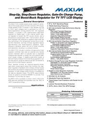
Applications Information<br />
<strong>Stereo</strong> Volume/Balance Control<br />
Figure 6 shows a volume/balance application using the<br />
<strong>MAX5457</strong>. The op amp is connected in a follower (noninverting<br />
gain) configuration to isolate the potentiometer’s<br />
wiper impedance from the load and provide drive<br />
capability. Connect the W_ of the <strong>MAX5457</strong> to the positive<br />
input of a noninverting gain amp. The pushbutton<br />
potentiometers attenuate the input signals. Use the<br />
MODE input to switch between volume-control and balance-control<br />
modes.<br />
12 <strong>Maxim</strong> Integrated
VDD<br />
<strong>MAX5456</strong>/<strong>MAX5457</strong><br />
<strong>Stereo</strong> <strong>Audio</strong> <strong>Taper</strong> <strong>Potentiometers</strong><br />
with Pushbutton Interface<br />
VDD<br />
<strong>MAX5457</strong><br />
GND VSS MUTE UP/BAL1 DN/BAL0 MODE<br />
<strong>Maxim</strong> Integrated 13<br />
VLOGIC<br />
H0<br />
H1<br />
LEFT CHANNEL IN RIGHT CHANNEL IN<br />
VDD / 2 VDD / 2<br />
LEFT AUDIO<br />
INPUT<br />
MAX4494 MAX4494<br />
VDD<br />
SVDD<br />
PGND<br />
Figure 6. Volume/Balance Control<br />
L0<br />
W0<br />
VDD<br />
SHDN<br />
MAX9722<br />
VLOGIC<br />
RIGHT AUDIO<br />
INPUT<br />
INL- INL+ SHDN INR+ INR-<br />
OUTL OUTR<br />
STEREO<br />
HEADPHONE<br />
MODE_IND<br />
L1<br />
W1<br />
VDD
<strong>MAX5456</strong>/<strong>MAX5457</strong><br />
<strong>Stereo</strong> <strong>Audio</strong> <strong>Taper</strong> <strong>Potentiometers</strong><br />
with Pushbutton Interface<br />
VPEAK<br />
VDD / 2<br />
VPEAK<br />
0V<br />
H_<br />
H_<br />
RH<br />
RL<br />
RH<br />
RL<br />
<strong>MAX5456</strong>/<strong>MAX5457</strong><br />
L_<br />
Typical Application Circuit (Single Supply)<br />
VDD<br />
<strong>MAX5456</strong>/<strong>MAX5457</strong><br />
L_<br />
VDD<br />
14 <strong>Maxim</strong> Integrated<br />
VPEAK<br />
VDD / 2<br />
W_<br />
W_<br />
RLOAD = ∞<br />
VDD<br />
VDD<br />
VDD<br />
VPEAK<br />
VDD / 2<br />
Typical Application Circuit (Dual Supplies)<br />
VSS = -VDD<br />
VPEAK<br />
0V<br />
RLOAD = ∞<br />
VSS<br />
VPEAK<br />
0V<br />
VDD
H0<br />
W0<br />
L0<br />
SHUTDOWN<br />
0<br />
1<br />
2<br />
3<br />
4<br />
28<br />
29<br />
30<br />
31<br />
32<br />
MUTE<br />
<strong>MAX5456</strong>/<strong>MAX5457</strong><br />
<strong>Stereo</strong> <strong>Audio</strong> <strong>Taper</strong> <strong>Potentiometers</strong><br />
with Pushbutton Interface<br />
VDD VLOGIC SHDN<br />
CLICK/POP<br />
SUPPRESSION<br />
CIRCUITRY<br />
<strong>MAX5456</strong><br />
POSITION COUNTER POSITION COUNTER<br />
DEBOUNCE DEBOUNCE DEBOUNCE DEBOUNCE<br />
VSS GND VOLUP VOLDN BAL0 BAL1<br />
CLICK/POP<br />
SUPPRESSION<br />
CIRCUITRY<br />
UP/DN UP/DN<br />
TIMING AND CONTROL<br />
DEBOUNCE<br />
<strong>Maxim</strong> Integrated 15<br />
T F-F<br />
MUTE<br />
VLOGIC<br />
Functional Diagrams<br />
SHUTDOWN<br />
0<br />
1<br />
2<br />
3<br />
4<br />
28<br />
29<br />
30<br />
31<br />
32<br />
MUTE<br />
H1<br />
W1<br />
L1
<strong>MAX5456</strong>/<strong>MAX5457</strong><br />
<strong>Stereo</strong> <strong>Audio</strong> <strong>Taper</strong> <strong>Potentiometers</strong><br />
with Pushbutton Interface<br />
H0<br />
W0<br />
L0<br />
SHUTDOWN<br />
0<br />
1<br />
2<br />
3<br />
4<br />
28<br />
29<br />
30<br />
31<br />
32<br />
MUTE<br />
VDD VLOGIC SHDN MODE_IND<br />
CLICK/POP<br />
SUPPRESSION<br />
CIRCUITRY<br />
<strong>MAX5457</strong><br />
POSITION COUNTER POSITION COUNTER<br />
TIMING AND CONTROL<br />
T F-F T F-F<br />
DEBOUNCE DEBOUNCE DEBOUNCE DEBOUNCE<br />
VSS GND DN/BAL0 UP/BAL1 MODE MUTE<br />
Functional Diagrams (continued)<br />
CLICK/POP<br />
SUPPRESSION<br />
CIRCUITRY<br />
UP/DN UP/DN<br />
16 <strong>Maxim</strong> Integrated<br />
VLOGIC<br />
SHUTDOWN<br />
0<br />
1<br />
2<br />
3<br />
4<br />
28<br />
29<br />
30<br />
31<br />
32<br />
MUTE<br />
H1<br />
W1<br />
L1
TOP VIEW<br />
1 16<br />
15<br />
14<br />
13<br />
12<br />
+<br />
VOLDN VDD<br />
VOLUP 2<br />
VLOGIC<br />
BAL1 3<br />
GND<br />
BAL0 4 <strong>MAX5456</strong> VSS<br />
H0 5<br />
H1<br />
6<br />
7<br />
8<br />
QSOP<br />
<strong>MAX5456</strong>/<strong>MAX5457</strong><br />
<strong>Stereo</strong> <strong>Audio</strong> <strong>Taper</strong> <strong>Potentiometers</strong><br />
with Pushbutton Interface<br />
Pin Configurations (continued) Chip Information<br />
L0<br />
W0<br />
SHDN<br />
11 L1<br />
10 W1<br />
9<br />
MUTE<br />
PROCESS: CMOS<br />
Package Information<br />
For the latest package outline information and land patterns (footprints),<br />
go to www.maximintegrated.com/packages. Note that a<br />
“+”, “#”, or “-” in the package code indicates RoHS status only.<br />
Package drawings may show a different suffix character, but the<br />
drawing pertains to the package regardless of RoHS status.<br />
PACKAGE<br />
TYPE<br />
PACKAGE<br />
CODE<br />
OUTLINE NO.<br />
LAND<br />
PATTERN NO.<br />
16 QSOP E16+1 21-0055 90-0167<br />
<strong>Maxim</strong> Integrated 17
<strong>MAX5456</strong>/<strong>MAX5457</strong><br />
<strong>Stereo</strong> <strong>Audio</strong> <strong>Taper</strong> <strong>Potentiometers</strong><br />
with Pushbutton Interface<br />
REVISION<br />
NUMBER<br />
REVISION<br />
DATE<br />
DESCRIPTION<br />
Revision History<br />
PAGES<br />
CHANGED<br />
0 11/04 Initial release —<br />
2 8/12<br />
Update Ordering Information, Absolute <strong>Maxim</strong>um Ratings, Pin Description,<br />
Pin Configuration. Removed Selector Guide and added Package<br />
Information table and Revision History.<br />
1, 2, 6, 14,<br />
18–20<br />
<strong>Maxim</strong> Integrated cannot assume responsibility for use of any circuitry other than circuitry entirely embodied in a <strong>Maxim</strong> Integrated product. No circuit patent<br />
licenses are implied. <strong>Maxim</strong> Integrated reserves the right to change the circuitry and specifications without notice at any time. The parametric values (min and<br />
max limits) shown in the Electrical Characteristics table are guaranteed. Other parametric values quoted in this data sheet are provided for guidance.<br />
18 <strong>Maxim</strong> Integrated 160 Rio Robles, San Jose, CA 95134 USA 1-408-601-1000<br />
© 2012 <strong>Maxim</strong> Integrated Products, Inc. <strong>Maxim</strong> Integrated and the <strong>Maxim</strong> Integrated logo are trademarks of <strong>Maxim</strong> Integrated Products, Inc.