A Software Defined Radio for the Masses, Part 4 - ARRL
A Software Defined Radio for the Masses, Part 4 - ARRL
A Software Defined Radio for the Masses, Part 4 - ARRL

You also want an ePaper? Increase the reach of your titles
YUMPU automatically turns print PDFs into web optimized ePapers that Google loves.
eflectors claiming measured IP3 in <strong>the</strong><br />
+40 dBm range <strong>for</strong> QSD detectors using<br />
5-V parts. With ultra-low-noise audio<br />
op amps, it is possible to achieve an<br />
analog noise figure on <strong>the</strong> order of 1 dB<br />
without an RF preamplifier. With appropriately<br />
designed analog AGC and<br />
careful gain distribution, it is <strong>the</strong>oretically<br />
possible to achieve over 150 dB of<br />
total dynamic range. The question is<br />
whe<strong>the</strong>r that much range is needed <strong>for</strong><br />
typical HF applications. In reality, <strong>the</strong><br />
answer is no. So how much is enough?<br />
Several QEX writers have done an<br />
excellent job of addressing <strong>the</strong> subject.<br />
20, 21, 22 Table 2 was originally published<br />
in an October 1975 ham radio<br />
article. 23 It provides a straight<strong>for</strong>ward<br />
summary of <strong>the</strong> acceptable receiver<br />
noise figure <strong>for</strong> terrestrial communication<br />
<strong>for</strong> each band from 160 m to<br />
2 m. Table 3 from <strong>the</strong> same article illustrates<br />
<strong>the</strong> acceptable noise figures<br />
<strong>for</strong> satellite communications on bands<br />
from 10 m to 70 cm.<br />
For my objective of dc-60 MHz coverage<br />
in <strong>the</strong> SDR-1000, Table 2 indicates<br />
that <strong>the</strong> acceptable noise figure<br />
ranges from 45 dB on 160 m to 9 dB on<br />
6 m. This means that a 1-dB noise figure<br />
is overkill until we operate near <strong>the</strong><br />
2-m band. Fur<strong>the</strong>r, to utilize a<br />
1-dB noise figure requires almost 70 dB<br />
of analog gain ahead of <strong>the</strong> sound card.<br />
This means that proper gain distribution<br />
and analog AGC design is critical<br />
to maximize IMD dynamic range.<br />
After reading <strong>the</strong> referenced articles<br />
and per<strong>for</strong>ming measurements on <strong>the</strong><br />
Turtle Beach Santa Cruz sound card, I<br />
determined that <strong>the</strong> complexity of an<br />
analog AGC circuit was unwarranted<br />
<strong>for</strong> my application. The Santa Cruz card<br />
has an input clipping level of 12 V (RMS,<br />
34.6 dBm, normalized to 50 Ω) when<br />
set to a gain of –10 dB. The maximum<br />
output available from my audio signal<br />
generator is 12 V (RMS). The SDR software<br />
can easily monitor <strong>the</strong> peak signal<br />
input and set <strong>the</strong> corresponding<br />
sound card input gain to effectively create<br />
a digitally controlled analog AGC<br />
with no external hardware. I measured<br />
<strong>the</strong> sound card’s 11-kHz SNR to be in<br />
<strong>the</strong> range of 96 dB to 103 dB, depending<br />
on <strong>the</strong> setting of <strong>the</strong> card’s input<br />
gain control. The input control is capable<br />
of attenuating <strong>the</strong> gain by up to<br />
60 dB from full scale. Given <strong>the</strong> large<br />
signal-handling capability of <strong>the</strong> QSD<br />
and sound card, <strong>the</strong> 1-dB compression<br />
point will be determined by <strong>the</strong> output<br />
saturation level of <strong>the</strong> instrumentation<br />
amplifier.<br />
Of note is <strong>the</strong> fact that DVD sales<br />
are driving improvements in PC sound<br />
cards. The newest 24-bit sound cards<br />
sample at a rate of up to 192 kHz. The<br />
Waveterminal 192X from EGO SYS is<br />
one example. 24 The manufacturer<br />
boasts of a 123 dB dynamic range, but<br />
that number should be viewed with<br />
caution because of <strong>the</strong> technical difficulties<br />
of achieving that many bits of<br />
true resolution. With a 192-kHz sampling<br />
rate, it is possible to achieve realtime<br />
reception of 192 kHz of spectrum<br />
(assuming quadrature sampling).<br />
Quadrature Sampling Detector/<br />
Exciter Design<br />
In <strong>Part</strong> 1 of this series (Note 3), I<br />
described <strong>the</strong> operation of a single-balanced<br />
version of <strong>the</strong> QSD. When <strong>the</strong> circuit<br />
is reversed so that a quadrature<br />
excitation signal drives <strong>the</strong> sampler, a<br />
SSB generator or exciter is created. It<br />
is a simple matter to reverse <strong>the</strong> SDR<br />
receiver software so that it trans<strong>for</strong>ms<br />
microphone input into filtered, quadrature<br />
output to <strong>the</strong> exciter.<br />
While <strong>the</strong> singly-balanced circuit<br />
described in <strong>Part</strong> 1 is extremely simple,<br />
I have chosen to use <strong>the</strong> double-balanced<br />
QSD as shown in Fig 1 because<br />
of its superior common mode and evenharmonic<br />
rejection. U1, U6 and U7 <strong>for</strong>m<br />
<strong>the</strong> receiver and U2, U3 and U8 <strong>for</strong>m<br />
<strong>the</strong> exciter. In <strong>the</strong> receive mode, <strong>the</strong><br />
QSD functions as a two-capacitor commutating<br />
filter, as described by Chen<br />
Ping in his article (Note 11). A commutating<br />
filter works like a comb filter,<br />
Table 3—Acceptable Noise Figure <strong>for</strong> Satellite Communications<br />
Frequency Galactic Noise Acceptable<br />
(MHz) Floor (dBm/Hz) NF (dB)<br />
28 –125 8<br />
50 –130 5<br />
144 –139 1<br />
220 –140 0.7<br />
432 –141 0.2<br />
wherein <strong>the</strong> circuit responds to harmonics<br />
of <strong>the</strong> commutation frequency. As he<br />
notes, “. . . it can be shown that signals<br />
having harmonic numbers equal to any<br />
of <strong>the</strong> integer factors of <strong>the</strong> number of<br />
capacitors may pass.” Since two capacitors<br />
are used in each of <strong>the</strong> I and Q<br />
channels, a two-capacitor commutating<br />
filter is <strong>for</strong>med. As Ping fur<strong>the</strong>r states,<br />
this serves to suppress <strong>the</strong> even-order<br />
harmonic responses of <strong>the</strong> circuit. The<br />
output of a two-capacitor filter is extremely<br />
phase-sensitive, <strong>the</strong>re<strong>for</strong>e allowing<br />
<strong>the</strong> circuit to per<strong>for</strong>m signal detection<br />
just as a CW demodulator does.<br />
When a signal is near <strong>the</strong> filter’s center<br />
frequency, <strong>the</strong> output amplitude<br />
would be modulated at <strong>the</strong> difference<br />
(beat) frequency. Unlike a typical filter,<br />
where phase sensitivity is undesirable,<br />
here we actually take advantage of that<br />
capability.<br />
The commutator, as described in<br />
<strong>Part</strong> 1, revolves at <strong>the</strong> center frequency<br />
of <strong>the</strong> filter/detector. A signal tuned exactly<br />
to <strong>the</strong> commutating frequency<br />
will result in a zero beat. As <strong>the</strong> signal<br />
is tuned to ei<strong>the</strong>r side of <strong>the</strong> commutation<br />
frequency, <strong>the</strong> beat note output will<br />
be proportional to <strong>the</strong> difference frequency.<br />
As <strong>the</strong> signal is tuned toward<br />
<strong>the</strong> second harmonic, <strong>the</strong> output will<br />
decrease until a null occurs at <strong>the</strong> harmonic<br />
frequency. As <strong>the</strong> signal is tuned<br />
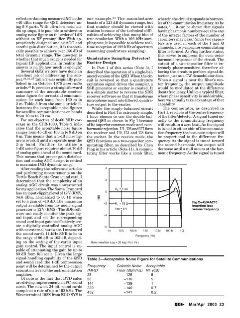
Fig 2—QS4A210<br />
insertion loss<br />
versus frequency<br />
Mar/Apr 2003 23