Safety Relay F127 - TESCH GmbH Wuppertal
Safety Relay F127 - TESCH GmbH Wuppertal
Safety Relay F127 - TESCH GmbH Wuppertal

You also want an ePaper? Increase the reach of your titles
YUMPU automatically turns print PDFs into web optimized ePapers that Google loves.
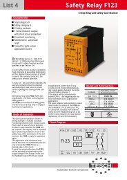
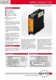
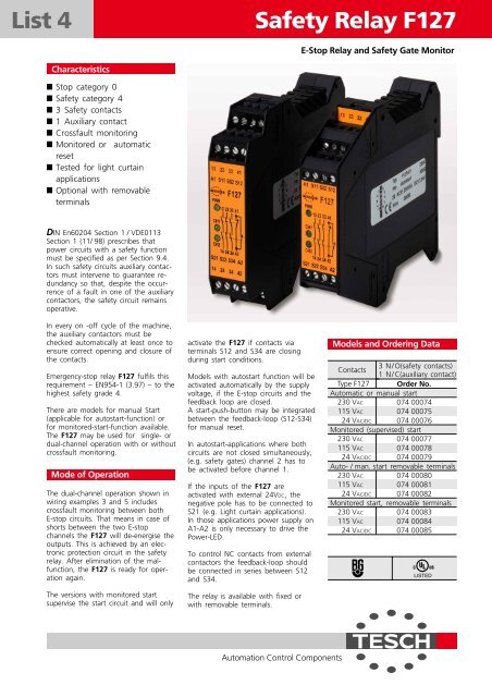
List 4 <strong>Safety</strong> <strong>Relay</strong> <strong>F127</strong><br />
Characteristics<br />
Stop category 0<br />
<strong>Safety</strong> category 4<br />
3 <strong>Safety</strong> contacts<br />
1 Auxiliary contact<br />
Crossfault monitoring<br />
Monitored or automatic<br />
reset<br />
Tested for light curtain<br />
applications<br />
Optional with removable<br />
terminals<br />
DIN En60204 Section 1 / VDE0113<br />
Section 1 (11/ 98) prescribes that<br />
power circuits with a safety function<br />
must be specified as per Section 9.4.<br />
In such safety circuits auxiliary contactors<br />
must intervene to guarantee redundancy<br />
so that, despite the occurrence<br />
of a fault in one of the auxiliary<br />
contactors, the safety circuit remains<br />
operative.<br />
In every on -off cycle of the machine,<br />
the auxiliary contactors must be<br />
checked automatically at least once to<br />
ensure correct opening and closure of<br />
the contacts.<br />
Emergency-stop relay <strong>F127</strong> fulfils this<br />
requirement – EN954-1 (3.97) – to the<br />
highest safety grade 4.<br />
There are models for manual Start<br />
(applicable for autostart-function) or<br />
for monitored-start-function available.<br />
The <strong>F127</strong> may be used for single- or<br />
dual-channel operation with or without<br />
crossfault monitoring.<br />
Mode of Operation<br />
The dual-channel operation shown in<br />
wiring examples 3 and 5 includes<br />
crossfault monitoring between both<br />
E-stop circuits. That means in case of<br />
shorts between the two E-stop<br />
channels the <strong>F127</strong> will de-energise the<br />
outputs. This is achieved by an electronic<br />
protection circuit in the safety<br />
relay. After elimination of the malfunction,<br />
the <strong>F127</strong> is ready for operation<br />
again.<br />
The versions with monitored start<br />
supervise the start circuit and will only<br />
activate the <strong>F127</strong> if contacts via<br />
terminals S12 and S34 are closing<br />
during start conditions.<br />
Models with autostart function will be<br />
activated automatically by the supply<br />
voltage, if the E-stop circuits and the<br />
feedback loop are closed.<br />
A start-push-button may be integrated<br />
between the feedback-loop (S12-S34)<br />
for manual reset.<br />
In autostart-applications where both<br />
circuits are not closed simultaneously,<br />
(e.g. safety gates) channel 2 has to<br />
be activated before channel 1.<br />
If the inputs of the <strong>F127</strong> are<br />
activated with external 24VDC, the<br />
negative pole has to be connected to<br />
S21 (e.g. Light curtain applications).<br />
In those applications power supply on<br />
A1-A2 is only necessary to drive the<br />
Power-LED.<br />
To control NC contacts from external<br />
contactors the feedback-loop should<br />
be connected in series between S12<br />
and S34.<br />
The relay is available with fixed or<br />
with removable terminals.<br />
Automation Control Components<br />
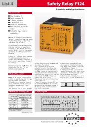
E-Stop <strong>Relay</strong> and <strong>Safety</strong> Gate Monitor<br />
Models and Ordering Data<br />
Contacts<br />
3 N / O(safety contacts)<br />
1 N / C(auxiliary contact)<br />
Type <strong>F127</strong> Order No.<br />
Automatic or manual start<br />
230 VAC 074 00074<br />
115 VAC 074 00075<br />
24 VAC/DC 074 00076<br />
Monitored (supervised) start<br />
230 VAC<br />
115 VAC<br />
24 VAC/DC<br />
230 VAC<br />
115 VAC<br />
24 VAC/DC<br />
230 VAC<br />
115 VAC<br />
24 VAC/DC<br />
074 00077<br />
074 00078<br />
074 00079<br />
Auto- / man. start removable terminals<br />
074 00080<br />
074 00081<br />
074 00082<br />
Monitored start, removable terminals<br />
074 00083<br />
074 00084<br />
074 00085<br />
LISTED
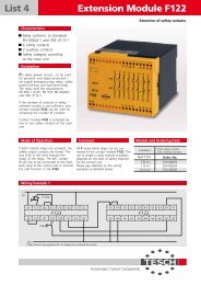
<strong>Safety</strong> <strong>Relay</strong> <strong>F127</strong> – <strong>Safety</strong> Gate Monitor and Emergency Stop <strong>Relay</strong><br />
Wiring Example 1 Wiring Example 2<br />
Wiring Example 3<br />
N<br />
Activation via semiconductor outputs<br />
Wiring Example 4 Wiring Example 5<br />
L1<br />
N<br />
L1<br />
A1<br />
<strong>F127</strong><br />
Light curtain, 24VDC<br />
Out1 Out2<br />
S11 S52 S12<br />
13 23 33 41<br />
14 24<br />
S21 S22 S34 A2<br />
E-Stop Start<br />
A1<br />
S11 S52 S12<br />
<strong>F127</strong><br />
S21 S22 S34 A2<br />
34 42<br />
Start<br />
<strong>F127</strong> with delayed release safety timer F128, single-channel activation<br />
Technical Data<br />
Rated voltage<br />
Voltage range<br />
Power consumption<br />
Rated insulation voltage<br />
Creep distance and gaps<br />
Test voltage<br />
Ambient temperature<br />
Mode of protection<br />
Switching capacity<br />
Thermic current Ith<br />
Utilisation categorie<br />
Response time<br />
Release time at rated voltage<br />
Recovery timet<br />
Output contacts<br />
Mechanical lifetime<br />
Switch material<br />
Terminals<br />
Line cross section<br />
Control circuit<br />
Contact protection<br />
Weight<br />
<strong>TESCH</strong> <strong>GmbH</strong> Automatic<br />
Control Components<br />
feedback-loop<br />
13 23 33<br />
14 24 34<br />
41<br />
42<br />
L1<br />
E-Stop<br />
A1<br />
<strong>F127</strong><br />
S11 S52 S12<br />
13 23 33 41<br />
14 24<br />
34 42<br />
S21 S22 S34 A2<br />
N<br />
Single channel application, Autostart (S12-S34)<br />
A1<br />
35 17 27 B11<br />
F128<br />
B12<br />
B21 36 B22 18 28 A2<br />
230 / 115 VAC; 24 VAC/DC<br />
0.8 to 1.1 x rated voltage<br />
Approx. 2 W<br />
250 V<br />
Overvoltage category III Pollution level 2 to<br />
DIN VDE 0110-1: (04 / 97)<br />
2.5 kV<br />
-5 ° C to + 55 ° C<br />
Terminals IP 20, IP 40 casing / DIN VDE 0470-1<br />
250 VAC; 1250 VA / 24 VDC; 120 W,<br />
preferably with spark arrest<br />
115V and 230V models: 3x3 A or 2x4 A<br />
24 V models: 3x4 A or 2x5 A<br />
Max. 5 A in one current path<br />
AC-15 250 V 5 A; DC-13 24 V 3 A<br />
Via reset button :