TF 1700-TF2700 Manual_EN.pdf - PACE Worldwide
TF 1700-TF2700 Manual_EN.pdf - PACE Worldwide
TF 1700-TF2700 Manual_EN.pdf - PACE Worldwide

You also want an ePaper? Increase the reach of your titles
YUMPU automatically turns print PDFs into web optimized ePapers that Google loves.
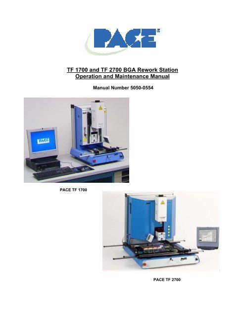
<strong>TF</strong> <strong>1700</strong> and <strong>TF</strong> 2700 BGA Rework Station<br />
Operation and Maintenance <strong>Manual</strong><br />
<strong>PACE</strong> <strong>TF</strong> <strong>1700</strong><br />
<strong>Manual</strong> Number 5050-0554<br />
<strong>PACE</strong> <strong>TF</strong> 2700
Table of Contents<br />
System Operations <strong>Manual</strong><br />
Packing Contents, Standard Items ..................................3<br />
Specifications ..................................................................3<br />
Parts Identification...........................................................4<br />
Safety Information ...........................................................5<br />
Features ..........................................................................5<br />
Set-Up .............................................................................7<br />
Connect ................................................................7<br />
Start up .................................................................8<br />
Inserting vacuum Changing nozzle pick ...............8<br />
Inserting nozzle.....................................................8<br />
Set up screen features..........................................9<br />
Alignment screen features ..................................10<br />
Production screen features.................................11<br />
Production Mode Record Manager .....................11<br />
Profile development screen features ..................13<br />
Inspection screen features..................................16<br />
Calibration...........................................................20<br />
Operation.......................................................................23<br />
Production...........................................................23<br />
Component removal ...........................................26<br />
Profile development ............................................26<br />
Temperature Control .....................................................28<br />
Maintenance..................................................................28<br />
Heater Replacement......................................................30<br />
Adjustments and Alignments .........................................37<br />
Regulation .....................................................................41<br />
Service and Warranty....................................................41<br />
Contact Information .......................................................42<br />
NOTE:<br />
This manual uses much of the <strong>TF</strong><strong>1700</strong> to demonstrate the features of the<br />
<strong>PACE</strong> BGA workstations. While most of the features are the same, the<br />
preheater array is unique to the <strong>TF</strong> 2700.<br />
www.paceworldwide.com Page 2 of 50
1. Specifications:<br />
Part Number 8007-0465<br />
8007-0466 (EXPORT)<br />
Dimensions 737 mm H x 686 mm W x<br />
737 mm D (29” x 27” x 29”)<br />
Weight (w/o computer) 45 kgs (100 lbs)<br />
Power Requirements 115 VAC, 60 hz or 230 VAC,<br />
50 Hz 2000 watts<br />
PC Pentium 4, 256M Ram, 3.5<br />
Floppy Drive, CD<br />
Top Heater Adjustable convective air (air<br />
or N2), Maximum 20 SLPM,<br />
1200 watts 100 to 400 °C,<br />
212 to 750 deg °F<br />
Bottom Heater IR, 400 watts,<br />
100 to 221 °C, 212 to 430<br />
deg °F<br />
Vacuum 5.9 inHg<br />
Optics High resolution, Vision<br />
Overlay System<br />
Positioning Accuracy +/- 25 umeters (0.001”)<br />
(Z travel)<br />
Video 2 Composite Video<br />
(external)<br />
1 “S” Video (Internal)<br />
15” Integrated color Flat<br />
Panel Monitor<br />
PC Board Size 305 x 305 mm, 12” x 12”<br />
Component Nest Size<br />
(Optional)<br />
<strong>TF</strong> <strong>1700</strong><br />
Packing Contents, Standard Items<br />
Description Part Number<br />
<strong>TF</strong> <strong>1700</strong> 8007-0465 (120V)<br />
8007-0466 (230V)<br />
<strong>TF</strong> 2700 8007-0467 (120V)<br />
8007-0469 (230V)<br />
PC -<br />
Monitor -<br />
Keyboard -<br />
Mouse -<br />
Pick Vac 7027-0001-P1<br />
Vacuum Pick Kit 6993-0276<br />
Suction Cups 6993-0202-P1<br />
Alignment Board 4018-0100-P1<br />
Mounting Platform Stencil 1321-0725<br />
Mounting Platform Flux Dip 1321-0735<br />
Hot Grip Removal Pad 1100-0307<br />
Thermocouples (4) 1340-0174-P1<br />
Hex Wrench Kit 6016-0034<br />
Power Cord 1332-0224<br />
Video Cable 3008-0168<br />
65 mm x 65mm, 255” x 2.55”<br />
max. See warning on page<br />
24<br />
System Operations <strong>Manual</strong><br />
<strong>TF</strong> 2700<br />
Part Number 8007-0467<br />
8007-0469 (EXPORT)<br />
Dimensions 737 mm H x 686 mm W x<br />
737 mm D (29” x 27” x 29”)<br />
Weight (w/o computer) 90 kg (200 lbs)<br />
Power Requirements 115 VAC, 60 hz or 230 VAC,<br />
50 Hz 2600 watts<br />
PC Pentium 4, 256M Ram,<br />
Floppy Drive, CD<br />
Top Heater Adjustable convective air (air<br />
or N2), Maximum 20 SLPM,<br />
1200 watts 100 to 400 deg<br />
C, 212 to 750 deg F<br />
Bottom Heater IR, One 400 Watts<br />
IR Six 150 Watts<br />
100 to 221 deg C, 212 to 430<br />
deg F<br />
Vacuum 450 mm Hg<br />
Optics High resolution, Dual Color<br />
Vision Overlay System<br />
Positioning Accuracy (Z +/- 25 umeters (0.001”)<br />
travel)<br />
Video 2 Composite Video (external)<br />
1 “S” Video (Internal)<br />
17” Integrated color Flat<br />
Panel Monitor<br />
PC Board Size 610mm x 610 mm, 24” x 24”<br />
Component Nest Size 65 mm x 65mm, 2.56” x<br />
2.56” max.<br />
www.paceworldwide.com Page 3 of 50
A<br />
B<br />
C<br />
D<br />
<strong>TF</strong> <strong>1700</strong> BGA Rework Station Parts Identification<br />
K<br />
Figure 1a<br />
System Operations <strong>Manual</strong><br />
A. Air Flow Meter This device is used to control and monitor the airflow<br />
through the reflow head.<br />
B. Sensor Inputs The sensor inputs are K-type thermo-couples.<br />
Measured temperatures are displayed through the PC<br />
software in real time for use in making profile graphs.<br />
C. LCD Display Monitor Displays PC software.<br />
D. Keyboard Used to enter information into software.<br />
E. Reflow Head Contains the top-side heater and moves up and down<br />
via an electric motor that is controlled through the<br />
software. The reflow head is clutched to control<br />
downward force.<br />
F. Cooling Fan The component and PCB are cooled by the cooling fan,<br />
and can be activated automatically after the reflow cycle<br />
is complete or operated manually.<br />
www.paceworldwide.com Page 4 of 50<br />
L<br />
E<br />
F<br />
G<br />
H<br />
I<br />
J
A<br />
B<br />
C<br />
D<br />
E<br />
System Operations <strong>Manual</strong><br />
G. Optics Housing Contains the camera and beam splitter (prism). The<br />
housing extends and retracts automatically during<br />
operation and the lights for the optics will turn on/off<br />
automatically when the housing is extended/retracted.<br />
H. Bottom Side Heater Used to warm the PCB from the underside. It is an IR<br />
type heating source.<br />
I. Board Holder Fine adjustment of both the X and Y direction is<br />
achieved by using the adjusting knobs on the end of the<br />
holder for X and on the front of the machine for Y.<br />
The right side of the holder is spring loaded to hold the<br />
PCB securely.<br />
J. On / Off Switch Used to turn the system on or off. When turning off the<br />
system, always turn off the PC using the windows<br />
interface first. When starting the system, always turn on<br />
<strong>TF</strong><strong>1700</strong> before starting the PC software.<br />
K. Mouse Used to enter information into software.<br />
L. Emergency Off Switch In case an emergency shut down is necessary, press<br />
this button.<br />
<strong>TF</strong> 2700 BGA Rework Station Parts Identification<br />
*Not pictured: PC, Keyboard, and Mouse<br />
www.paceworldwide.com Page 5 of 50<br />
F<br />
G<br />
H
Figure 1b<br />
System Operations <strong>Manual</strong><br />
A. Reflow Head Contains the top-side heater and moves up and down<br />
via an electric motor that is controlled through the<br />
software. The reflow head is clutched to control<br />
downward force. through the reflow head.<br />
B. Sensor Inputs Contains the camera and beam splitter (prism). The<br />
housing extends and retracts automatically during<br />
operation and the lights for the optics will turn on/off<br />
automatically when the housing is extended/retracted.<br />
C. Cooling Fan The component and PCB are cooled by the cooling fan,<br />
and can be activated automatically after the reflow cycle<br />
is complete or operated manually.<br />
D. Board Holder Fine adjustment of both the X and Y direction is<br />
achieved by using the adjusting knobs on the end of the<br />
holder for X and on the front of the machine for Y.<br />
The right side of the holder is spring loaded to hold the<br />
PCB securely.<br />
E. Emergency Off Switch In case an emergency shut down is necessary, press<br />
this button.<br />
.<br />
F. Sensor Inputs The sensor inputs are K-type thermo-couples.<br />
Measured temperatures are displayed through the PC<br />
software in real time for use in making profile graphs.<br />
G. Bottom Side Heater Used to warm the PCB from the underside. It is an IR<br />
type heating source.<br />
H. On / Off Switch Used to turn the system on or off. When turning off the<br />
system, always turn off the PC using the windows<br />
interface first. When starting the system, always turn on<br />
<strong>TF</strong><strong>1700</strong> before starting the PC software.<br />
2. Safety Information<br />
3. Features<br />
a. Do not contact the Heater or its peripheral parts during operation.<br />
b. Once turned off, let the unit cool completely before contacting. They are hot, you<br />
will get burned.<br />
c. When using fluxes, use fume extraction equipment or use in a well-ventilated<br />
area to minimize operator exposure to fumes.<br />
d. Do not use near combustible vapors.<br />
e. Do not leave the equipment unattended when in use.<br />
f. Do not open rear panel without disconnecting the main power cable.<br />
a. The <strong>TF</strong> <strong>1700</strong> and <strong>TF</strong> 2700 are ideal for post assembly rework, repair, and low<br />
volume/short run production operations. The <strong>TF</strong> <strong>1700</strong> and <strong>TF</strong> 2700 can remove<br />
and install PBGAs, CSPs, FCs, LGAs, LCC’s and other SMDs.<br />
b. Featuring unparalleled thermal performance, <strong>PACE</strong> BGA Rework Stations<br />
flexibility and state of the art process software means no other system is easier<br />
www.paceworldwide.com Page 6 of 50
System Operations <strong>Manual</strong><br />
to use. The <strong>TF</strong> <strong>1700</strong> and <strong>TF</strong>2700 are a PC driven, semi-automated system that<br />
requires a Pentium ® 4 PC featuring Windows XP® Professional OS. The unique<br />
standard software package offers much more than just an operator interface.<br />
<strong>PACE</strong> BGA Rework Stations advanced vision and placement system is highly<br />
accurate and can quickly magnify even the smallest components for easy<br />
alignment. <strong>TF</strong> <strong>1700</strong> and <strong>TF</strong> 2700 uses a combination of convective top heating<br />
coupled with powerful IR bottom heating for an effective, repeatable heating<br />
process.<br />
c. Economical and easy to use, <strong>PACE</strong> BGA Rework Systems deliver high-end<br />
BGA/CSP functionality, moving far beyond expensive, bulky rework machines by<br />
offering unparalleled performance at an affordable price.<br />
d. REFLOW FUNCTION<br />
i. Unequalled programmability and process control ensures successful,<br />
repeatable installation.<br />
ii. The powerful and responsive 1200 Watt top heater, with closed loop<br />
temperature control, coupled with proven nozzle design ensures uniform<br />
temperature distribution when heating.<br />
iii. High power bottom heater allow for successful and repeatable reflow at<br />
safe, low temperatures.<br />
iv. Profiles are programmed through the PC software.<br />
v. Creating the perfect profile is easy with real time adjustment of profile<br />
parameters through the PC.<br />
vi. Store and recall an infinite number of profiles.<br />
vii. Two pre-defined profiles for use as baselines when developing custom<br />
profiles are included.<br />
viii. Self contained, no external air supply or vacuum connections required.<br />
Can also be used with N2 from external source.<br />
ix. Semi-automated, motorized reflow head.<br />
x. Four thermo-couple sensor inputs ensure successful profile development<br />
and monitoring.<br />
xi. External fan to cool PCB and component to below solder melt<br />
temperatures after reflow.<br />
e. ALIGNM<strong>EN</strong>T AND PLACEM<strong>EN</strong>T FUNCTION<br />
i. The component is held by a precision vacuum placement pick, which is<br />
located within the heater assembly.<br />
ii. High resolution Color Vision Overlay System (VOS) with color camera<br />
and dichroic prism. VOS does not require routine calibration, eliminating<br />
costly downtime and operator frustration.<br />
iii. Color Camera with 72x zoom capability, featuring auto-focus.<br />
iv. Lighting system uses “Ultra Bright” White LEDs for maximum contrast of<br />
lands and solder balls on component.<br />
v. Independent lighting controls for component and PCB to maximize<br />
overlay contrast.<br />
vi. Retractable optics housing protects VOS from dirt and contamination.<br />
vii. Accurately places any array package up to 65mm (2.5") square and as<br />
small as 1 mm (.04”) square.<br />
viii. Precise micrometer adjustment for X, and Y axis with Theta adjustment<br />
ensures placement accuracy.<br />
ix. High-flow vacuum pick holds component securely.<br />
x. Images are viewed through the PC in standard or full screen viewing<br />
options.<br />
f. PRE-HEAT FUNCTION AND BOARD HOLDER<br />
www.paceworldwide.com Page 7 of 50
N2 Connection<br />
4. Set-Up<br />
System Operations <strong>Manual</strong><br />
i. Fully adjustable, precision, spring loaded board holder with top or bottom<br />
PCB registration. Precise micrometer adjustment for X and Y adjustment<br />
ensures placement accuracy for repeatability.<br />
ii. Rugged, stable board platform to hold and support the PCB.<br />
iii. Unique board holding fixtures that are able to hold very small and odd<br />
shaped PCBs.<br />
iv. Board supports are standard with the system.<br />
v. Integrated, powerful, IR pre-heater with closed loop temperature control<br />
ensures process integrity by delivering heat evenly, time after time.<br />
a. Connect<br />
i. The <strong>TF</strong> <strong>1700</strong> and <strong>TF</strong> 2700 come configured to use the internal air pump.<br />
Both BGA Rework Stations may also be operated with an external N2<br />
Supply. Select air or (nitrogen) source using the drop down box on the<br />
setup page. Warning: Do not operate the <strong>TF</strong> <strong>1700</strong> in N2 mode unless N2<br />
supply is connected and on.<br />
<strong>TF</strong>-<strong>1700</strong> Software shown<br />
www.paceworldwide.com Page 8 of 50
N2 Connection<br />
System Operations <strong>Manual</strong><br />
ii. Insert PC into brackets on back of BGA Rework Station.<br />
iii. Monitor<br />
1. Connect power cord.<br />
2. Connect video cable to the 9-pin connector of the PC.<br />
iv. Keyboard – connect cable to computer.<br />
v. Mouse – connect cable to computer.<br />
vi. Connect cables between PC and back of BGA Rework Station according<br />
to labels.<br />
vii. Connect power cords to BGA Rework Station and PC.<br />
b. Start up<br />
i. Turn on circuit breaker on back of unit.<br />
ii. Turn on power switch on front of unit.<br />
iii. Turn on computer.<br />
iv. Turn on monitor.<br />
v. Mouse click on software icon.<br />
vi. Read and accept license.<br />
c. Inserting/changing vacuum pick.<br />
i. Insert proper size vacuum pick. The diameter needs to be smaller than<br />
the top of the component. The pick screws into place. (Figure 3a)<br />
Warning: Use of tools to tighten vacuum pick may result in damage<br />
to system. Tighten vacuum pick by hand only.<br />
Vacuum pick<br />
www.paceworldwide.com Page 9 of 50
Figure 3a<br />
d. Inserting/changing nozzle. (Figure 3b)<br />
System Operations <strong>Manual</strong><br />
i. Insert proper size nozzle. The OD of the nozzle should be 3 mm larger<br />
than the outside of the component. If the proper nozzle size cannot fit<br />
onto the PCB due to adjacent components being to close, use a smaller<br />
nozzle or keep the nozzle approximately 1mm above the part. Align the<br />
nozzle under the square hole in the reflow head. The nozzle snaps into<br />
place. The nozzle can be positioned with the front surface parallel to the<br />
PCB or at a diagonal by moving the lever on the nozzle housing. To<br />
rotate the nozzle, first loosen the retention screw in front of the housing.<br />
Figure 3b<br />
Lever to rotate<br />
nozzle<br />
Nozzle<br />
www.paceworldwide.com Page 10 of 50
i<br />
ii<br />
iii<br />
iv<br />
v<br />
vi<br />
vii<br />
viii<br />
ix<br />
x<br />
a. Software set up screen features. (Figure 4a)<br />
Figure 4a<br />
System Operations <strong>Manual</strong><br />
i. Set Password. Setup and profile settings can be password protected.<br />
ii. Set Language. Software text language can be changed.<br />
iii. Set temperature for Celsius or Fahrenheit.<br />
iv. Set yellow temperature reference lines on the profile graph.<br />
v. Set setback time. Machine will go into setback after selected idle time.<br />
Setback reduces heater temperatures during extended idle times to<br />
extend heater life.<br />
vi. Set auto shutoff time. Machine will completely shut down after selected<br />
idle time.<br />
vii. Air Source selects internal pump or external N2 source.<br />
viii. Default location of saved profile files, records, image, and capture.<br />
ix. Changes title of Video Sources on inspection screen.<br />
x. Shows system communication error.<br />
xi. Initiate prism calibration sequence.<br />
xii. Initiate heater arm sensor test. Checks proper orientation and operation<br />
of heater arm position sensors.<br />
xiii. Initiate camera sensor test. Checks proper orientation and operation of<br />
camera position sensor..<br />
xiv. Initiate pick sensor test. Checks proper orientation and operation of pick<br />
position sensor.<br />
xv. Checks operation of heater blower, cooling fan, and vacuum pump.<br />
www.paceworldwide.com Page 11 of 50<br />
xi<br />
xii<br />
xiv<br />
xv<br />
xvi<br />
xvii<br />
xviii<br />
xix
System Operations <strong>Manual</strong><br />
xvi. Temperature sensors. Tests active thermocouple circuitry.<br />
xvii. Reset diagnostics. Must be clicked after any diagnostic test is performed<br />
to reset the tests to default settings.<br />
xviii. Run the activity log.<br />
Figure 4b shows the pre-heater indicator of the<br />
<strong>TF</strong> 2700. This feature indicates which preheater<br />
is on and the current temperature. To<br />
turn on or off individual secondary pre-heaters<br />
click on the graphic. While individual<br />
secondary pre-heaters can be turned on and<br />
off, they must all be set at the same<br />
temperature. They can be adjusted by<br />
dragging the yellow lines on the graph or<br />
through the profile manager.<br />
Figure 4b<br />
www.paceworldwide.com Page 12 of 50
i<br />
ii<br />
iii<br />
iv<br />
v<br />
b. Alignment Screen Features (Figure 5)<br />
Figure 5<br />
System Operations <strong>Manual</strong><br />
i. Full Screen. Click on here to view image full screen.<br />
ii. Flip Image. Allows operator to flip the image horizontally or vertically.<br />
iii. Component/PCB alignment image. Proper alignment is viewed here showing<br />
the PCB pads directly under the component pads.<br />
iv. Zoom bar. The image can be zoomed in or out using this bar.<br />
v. Focus bar. The image can be manually focused using the slider on this bar or<br />
it can be automatically focused by checking the box by “auto.”<br />
vi. Instructions. Follow these instructions to proceed through the alignment<br />
sequence.<br />
vii. Modify Instructions.<br />
1. Edit – Change current profile instructions.<br />
2. Load – Loads saved profile.<br />
3. Save – Saves changes made to instructions.<br />
4. Reset – Returns to factory set instructions.<br />
viii. Nozzle step adjustment. If component cannot be aligned nozzle height up or<br />
down with this option until better alignment or focus is achieved.<br />
www.paceworldwide.com Page 13 of 50<br />
vi<br />
vi<br />
viii
i<br />
ii<br />
iii<br />
c. Production Screen Features (Figure 6)<br />
Figure 6a<br />
System Operations <strong>Manual</strong><br />
i. Profile Name. Indicates currently selected profile. A new profile can be<br />
selected from a list of saved profiles by clicking on the arrow.<br />
ii. Record Manager. Profile information may be stored and exported in PDF file<br />
format. See figure 6a<br />
iii. Graph. A saved graph and, if thermocouples are used, an active trace graph<br />
are viewed here.<br />
iv. Fan On/Off Selector. <strong>Manual</strong> on/off switch for the cooling fan.<br />
v. Status Bar.<br />
1. System status – shows if system is “normal,” in “setback” or “shutdown.”<br />
2. Heater status – Shows “ready” if bottom heater is in range. Shows “not<br />
ready” if bottom heater is not in range. The software will not continue until<br />
it is in “ready” status.<br />
vi. Nozzle Step Indicator. Indicates how many steps the nozzle will lower to<br />
properly position itself for operation.<br />
vii. Abort Button. Click at any time to abort the process and return to the<br />
beginning.<br />
viii. Sequencing Button. Click here to proceed to next step in the operation.<br />
ix. Pre-Heater indicator. Indicates pre-heater is on or off .<br />
x. Sensor indicators. Real-time sensor readings can be viewed here if<br />
thermocouples are used.<br />
xi. Production Mode Record Manager Features (Figure 6c)<br />
www.paceworldwide.com Page 14 of 50<br />
iv<br />
v<br />
vi<br />
vii<br />
viii<br />
ix<br />
x
Figure 6b shows the pre-heater indicator of the<br />
<strong>TF</strong> 2700. This feature indicates which preheater<br />
is on and the current temperature. To<br />
turn on or off individual secondary pre-heaters<br />
click on the graphic. While individual<br />
secondary pre-heaters can be turned on and<br />
off, they must all be set at the same<br />
temperature. They can be adjusted by<br />
dragging the yellow lines on the graph or<br />
through the profile manager.<br />
d. Profile Development Screen Features (Figure 7)<br />
Figure 6c<br />
System Operations <strong>Manual</strong><br />
Figure 6b<br />
www.paceworldwide.com Page 15 of 50
i<br />
ii<br />
iii<br />
d. Profile Development Screen (Figure 7)<br />
Figure 7a<br />
System Operations <strong>Manual</strong><br />
i. Profile Name. Indicates currently selected profile.<br />
ii. Profile Manager. Temperature and time setting entered by the developer can<br />
be viewed managed here (Figure 7a).<br />
iii. Graph. A saved graph and, if thermocouples are used, an active trace graph<br />
are viewed here.<br />
iv. Fan On/Off Selector. <strong>Manual</strong> on/off switch for the cooling fan.<br />
v. Status Bar.<br />
1. System status – shows if system is “normal,” in “setback” or “shutdown.”<br />
2. Heater status – Shows “ready” if bottom heater is in range. Shows “not<br />
ready” if bottom heater is not in range. The software will not continue until<br />
it is in “ready” status.<br />
vi. Nozzle Step Indicator. Indicates how many steps the nozzle will lower to<br />
properly position itself for operation.<br />
vii. Abort Button. Click at any time to abort the process and return to the<br />
beginning.<br />
viii. Sequencing Button. Click here to proceed to next step in the operation.<br />
ix. Pre-Heater indicator. Indicates if pre-heater is on or off.<br />
x. Sensor indicators. Real-time sensor readings can be viewed here if<br />
thermocouples are used.<br />
www.paceworldwide.com Page 16 of 50<br />
v<br />
vi<br />
vii<br />
viii<br />
ix<br />
x<br />
iv
Figure 7b<br />
System Operations <strong>Manual</strong><br />
xi. Heater. Click on Heater button during profile development to deactivate<br />
heater.<br />
xii. Cycle Start. Click on button to run profile during development.<br />
<strong>TF</strong> 2700 Pre-heater Indicator<br />
<strong>TF</strong> 2700 Pre-Heater Indicator. Indicates which preheater<br />
is on and the current temperature. To turn on<br />
or off individual secondary pre-heaters click on the<br />
graphic. While individual secondary pre-heaters can<br />
be turned on and off, they must all be set at the same<br />
temperature. They can be adjusted by dragging the<br />
yellow lines on the graph or through the profile<br />
manager.<br />
Figure 7c<br />
www.paceworldwide.com Page 17 of 50<br />
xi<br />
xii
ii<br />
i<br />
iii<br />
iv<br />
v<br />
vi<br />
Profile Development Screen Features <strong>TF</strong> <strong>1700</strong> (Figure 7d)<br />
System Operations <strong>Manual</strong><br />
i. Profile Name. Indicates currently selected profile.<br />
ii. Profile Parameters. Change each zone temperature and time settings<br />
iii. Use Ramp. Enables or disables ramp phase.<br />
iv. Profile Instructions. Allows operator to make notations and instructions.<br />
v. Mode. Choose Installation or removal mode by clicking.<br />
vi. Placement. Choose manual or automatic while in installation mode by<br />
clicking.<br />
vii. Profile Management. Create, save, or recall profiles.<br />
viii. View selected reference images.<br />
ix. Liftoff. Select from Auto or <strong>Manual</strong> in removal mode by clicking.<br />
x. Flux Dip. Enable or disable flux dip operation by clicking.<br />
NOTE<br />
The <strong>TF</strong> <strong>1700</strong> airflow control is manual using the flow meter mounted on<br />
the front housing. The <strong>TF</strong> 2700 airflow control feature is operated using<br />
the PC software.<br />
www.paceworldwide.com Page 18 of 50<br />
vii<br />
viii<br />
ix<br />
x
ii<br />
i<br />
iii<br />
iv<br />
v<br />
vi<br />
Profile Development Screen Features <strong>TF</strong> 2700 (Figure 7e)<br />
System Operations <strong>Manual</strong><br />
i. Profile Name. Indicates currently selected profile.<br />
ii. Profile Parameters. Change each zone temperature and time settings<br />
iii. Use Ramp. Enables or disables ramp phase.<br />
iv. Profile Instructions. Allows operator to make notations and instructions.<br />
v. Mode. Choose Installation or removal mode by clicking.<br />
vi. Placement. Choose manual or automatic while in installation mode by clicking.<br />
vii. Profile Management. Create, save, or recall profiles.<br />
viii. View selected reference images.<br />
ix. Liftoff. Select from Auto or <strong>Manual</strong> in removal mode by clicking.<br />
x. Flux Dip. Enable or disable flux dip operation by clicking.<br />
NOTE<br />
The <strong>TF</strong> 2700 airflow control feature is operated using the PC software.<br />
The <strong>TF</strong> <strong>1700</strong> airflow control is manual using the flow meter mounted on<br />
the front housing.<br />
www.paceworldwide.com Page 19 of 50<br />
vii<br />
viii<br />
ix<br />
x
i<br />
ii<br />
iii<br />
iv<br />
e. Inspection Screen Features<br />
Inspection Screen (Figure 8a)<br />
System Operations <strong>Manual</strong><br />
i. Flip feature. Rotate or flip inspection image.<br />
ii. Inspection Image. The inspection image selected is viewed here.<br />
iii. (S) tab allows you to select video input source. (C) tab gives you access to<br />
<strong>TF</strong><strong>1700</strong> camera control when selected input source.<br />
iv. Focus. Select Auto or <strong>Manual</strong> Focus.<br />
v. Mode. Allows operator to review library images (Fig 8a), capture images (Fig<br />
8b), review saved images (Fig 8c), and create report (Fig 8d).<br />
vi. Takes a snapshot of the current camera image.<br />
vii. Save Image. Saves captured image to TIFF file format.<br />
www.paceworldwide.com Page 20 of 50<br />
v<br />
vi<br />
vii
viii<br />
Capture Mode Figure 8b<br />
System Operations <strong>Manual</strong><br />
viii. Video Source. Select whether the image is from the BGA workstation (C)<br />
camera or (S) alternate source.<br />
ix. Mode. Allows operator to review library images (Fig 8a), capture images (Fig<br />
8b), review saved images (Fig 8c), and create report (Fig 8d).<br />
x. Save Image. Save image in TIFF format Capture Image.<br />
xi. Takes a snapshot of the current camera image.<br />
www.paceworldwide.com Page 21 of 50<br />
ix<br />
x<br />
xi
Review Saved Images Mode Figure 8c<br />
System Operations <strong>Manual</strong><br />
xii. Mode. Allows operator to review library images (Fig 8a), capture<br />
images (Fig 8b), review saved images (Fig 8c), and create report<br />
(Fig 8d).<br />
xiii. Select Image File. Opens folder containing image library.<br />
www.paceworldwide.com Page 22 of 50<br />
xii<br />
xiii
Create Report Mode Figure 8d<br />
System Operations <strong>Manual</strong><br />
xiv. Mode Menu. Drop down menu revealing capture and image<br />
viewing options.<br />
xv. Create Report. Captured images are imbedded in a five-page<br />
Adobe PDF document. Page 1 shows four captured images.<br />
Remaining pages show individual images indicated by the red<br />
box on the right-hand side of the page. (See Fig. 8e)<br />
Create Report Mode Figure 8e<br />
www.paceworldwide.com Page 23 of 50<br />
xii<br />
xii
System Operations <strong>Manual</strong><br />
g. Prism Calibration – This step is required to ensure the prism is properly aligned<br />
so when the software shows the PCB and component visually aligned, they are<br />
actually physically aligned.<br />
i. Select setup screen. (Figure 9)<br />
Figure 9<br />
ii. Select prism calibration.<br />
iii. Monitor now shows calibration screen. (Figure 10)<br />
Figure 10<br />
iv. Place alignment board with BGA in place in mounting brackets.<br />
Prism Calibration<br />
www.paceworldwide.com Page 24 of 50
System Operations <strong>Manual</strong><br />
v. Align PCB so red laser sighting light is roughly centered on BGA.<br />
(Figure 10)<br />
Figure 11<br />
vi. Mouse click on green button, “Pickup.”<br />
vii. Mouse click “OK” when message prompt (Please load PCB into board<br />
holder) appears.<br />
Figure 11<br />
Camera Housing<br />
viii. Mouse click on green button, “Focus button.”<br />
ix. Align image of board with image of component and click the “place”<br />
button.<br />
x. Adjust focus and zoom with up and down arrows on keyboard or by<br />
moving slide on screen.<br />
xi. Image in the window should be aligned like figure 12.<br />
www.paceworldwide.com Page 25 of 50
Cover<br />
Screws<br />
Light<br />
Adjustment<br />
Knobs<br />
Figure 12<br />
System Operations <strong>Manual</strong><br />
xii. If solder ball on part do not line up with holes on test PCB, adjust prism<br />
until it is.<br />
1. Loosen the setscrews from the light adjustment knobs (Figure 14)<br />
2. Remove the knobs<br />
3. Remove the four screws (2 on each side) from the cameras’ sheet metal<br />
cover (Figure 14)<br />
4. Remove the cover<br />
5. Loosening the top screws (A) and tightening the bottom screws (B)<br />
adjusts the prism down. Figure 15<br />
6. Loosening the bottom screws (B) and tightening the top screws (A)<br />
adjusts the prism up.<br />
7. Loosening the right center screw (C) allows you to rotate the prism<br />
around the y-axis.<br />
8. When aligned, replace the cover<br />
9. Replace the four screws<br />
10. Replace the knobs<br />
11. Adjust the light adjustment knobs and tighten the setscrews<br />
xiii. Return to setup screen. Mouse click on button, “Return to Setup.”<br />
Figure 14 Figures 15<br />
www.paceworldwide.com Page 26 of 50<br />
A<br />
B<br />
C
6. Operation<br />
Retention Screw<br />
System Operations <strong>Manual</strong><br />
Note: It is recommended that the <strong>TF</strong> <strong>1700</strong> and <strong>TF</strong> 2700 be turned on for at least 10<br />
minutes before use to ensure the bottom side heater has reached its set temperature and<br />
stabilized. Once the bottom side heater is at operating temperature it will deliver<br />
consistent heating, ensuring highly repeatable heating from operation to operation.<br />
It is also advisable to conduct a trial operation each day to warm the top heater<br />
and ensure all systems are operating properly. It is important to verify the airflow of the<br />
unit with each profile to be run.<br />
Verify that the devices/parts being soldered to the PCB do not exceed the height<br />
limitations. Exceeding the limitations may interfere with the operation of the machine.<br />
The maximum height of any component or device on the top of the PCB is limited<br />
to 30mm (1.2”).<br />
The maximum height of any component or device on the bottom of the PCB is<br />
limited to 15 mm (0.6”).<br />
a. Production. Component alignment and installation – Note: If at any time you<br />
need to abort the process mouse click on the Red “Home” button.<br />
i. Mouse click on Production to switch to the production screen. (Figure 6)<br />
ii. Select a profile.<br />
iii. Install the proper vacuum pick. (Para. 5d)<br />
iv. Install the proper nozzle. (Para. 5e)<br />
v. Place the PCB between the arms on the <strong>TF</strong> <strong>1700</strong> and tighten the<br />
retention screw. (Figure 16)<br />
Figure 16<br />
Release Handle<br />
vi. Position the board so the red laser sighting light is roughly in the center<br />
of the placement site. To move the board forward and back simply<br />
move the PCB in the arms. To move the assembly left and right push<br />
the release handle away from you and move the assembly. Pull the<br />
release handle towards you to secure the assembly.<br />
vii. Mouse click on the green button to extend camera.<br />
www.paceworldwide.com Page 27 of 50
Figure 17<br />
System Operations <strong>Manual</strong><br />
viii. Place the component in the mounting plate on top of the camera<br />
housing. (Figure 18) The component needs to be oriented the same<br />
as the nozzle.<br />
Figure 18<br />
Component<br />
ix. Mouse click on the green button. The BGA workstation will pick up<br />
component.<br />
x. Slide component mount away from the top of the camera housing.<br />
xi. If Flux Dip option was selected, place the flux dip assembly on top of<br />
the camera housing. (Figure 19) Mouse click to dip, then remove flux<br />
dip assembly.<br />
xii. Mouse click on the green button to pick component from holder.<br />
xiii. Slide component nest / flux tray support back out of the way so optics<br />
are unobstructed.<br />
xiv. Mouse click on the green button again to switch to the alignment<br />
screen and lower component to focus point. (Figure 5)<br />
WARNING: <strong>TF</strong> <strong>1700</strong> USERS ONLY<br />
When using the optional 65mm x 65mm component nest, (P/N 6000-0285) Nest must be removed<br />
from camera housing before camera is allowed to retract. ALLOWING OPTIONAL NEST TO<br />
RETRACT WILL DAMAGE NEST AND POSSIBLY CAMERA HOUSING.<br />
www.paceworldwide.com Page 28 of 50
Flux<br />
Dip<br />
Tray<br />
System Operations <strong>Manual</strong><br />
Figure 19<br />
xv. Zoom in and align using the X, Y, and theta axis adjustments until the<br />
component is aligned. (Figures 5 & 20)<br />
Figure 20<br />
xvi. Mouse click on the green button, “Place” to lower the component.<br />
(Figure 21)<br />
Figure 21<br />
Theta<br />
xvii. Mouse click on the green button again, “Start.”<br />
Left and Right<br />
Forward and Back<br />
Nozzle on board<br />
ready to start<br />
heating<br />
www.paceworldwide.com Page 29 of 50
xviii. Allow the PCB to cool and remove.<br />
System Operations <strong>Manual</strong><br />
b. Component removal – Note: If at any time you need to abort the process mouse<br />
click on the Red Home button.<br />
i. Mouse click on Production to switch to the production screen. (Figure 6)<br />
ii. Select a removal profile from the “Load Profile” drop down box .<br />
iii. Install the proper vacuum pick. (Para. 5d)<br />
iv. Install the proper nozzle. (Para. 5e)<br />
v. Place the PCB between the arms on the board holder and tighten the<br />
retention screw. (Figure 16) Position the board so the red laser sighting<br />
light is roughly in the center of the component. To move the board<br />
forward and back simply move the PCB in the arms. To move the<br />
assembly left and right push the release handle away from you and<br />
move the assembly. Pull the release handle towards you to secure the<br />
assembly. (Figure 22)<br />
Figure 22<br />
vi. Mouse click on Start button.<br />
vii. Allow PCB and component to cool before removing.<br />
c. Profile development installation procedure.<br />
Note: General Information concerning the Profile Development Screen<br />
The Reflow Graph area displays a representation of the Reflow cycle profile.<br />
Time in minutes is graphed along the X-axis and temperature is plotted along the Yaxis.<br />
The time and temperature axes incorporate a dynamic scaling feature to<br />
optimize the display. Profile graphs can be saved with profiles to be used for process<br />
validation by operators while using the Operation screen. Profile graphs can also be<br />
stored as individual records for each rework job for quality control purposes. Colored<br />
lines are used to indicate profile parameters on the graph.<br />
Profile Creation<br />
There are 2 recommended methods for developing a profile. The first, involves an<br />
actual component installation, while the second uses a previously installed package.<br />
Either method can be used to develop a reliable profile. However, there are some<br />
issues and considerations to be aware of with each.<br />
When developing profiles through actual component installation, it is critical to make<br />
sure the thermocouples remain in contact with the solder throughout the entire<br />
process. Unreliable data could be collected should a thermocouple lose contact with<br />
the solder. If measuring the temperature on the top of the package, it is best to use<br />
www.paceworldwide.com Page 30 of 50
System Operations <strong>Manual</strong><br />
a preinstalled component, as the thermocouple wire will typically cause the<br />
component to not lay flat on the PCB.<br />
When using a previously installed package, the placement of the thermocouples is<br />
important. They must be in contact with the existing solder joints. This task can be<br />
accomplished by either (1) drilling through the bottom of the PCB into a solder joint<br />
and attaching the thermocouple or by (2) sliding the thermocouple under the<br />
package. When sliding a thermocouple under a component, it is critical that the<br />
thermocouple be in contact with the solder. Information from the thermocouples will<br />
assist in determining the proper time and temperature parameters. In general, the<br />
following guidelines should be adhered to when developing profiles.<br />
Ramp Rates<br />
Acceptable ramp rates and maximum temperatures should be obtained from the<br />
component manufacturer. Typical ramp rates are 2-5 ºC/s (4-9 ºF/s) for plastic parts<br />
and 1 ºC/s (2 ºF/s) for ceramic parts. It is recommended to select a maximum<br />
temperature below the manufacturer’s specification to provide for a margin of safety.<br />
Typically, 20 ºC below maximum specified temperature is selected.<br />
Pre-Heat Phase<br />
1. In a “step profile”, the PCB and package should reach a stable temperature of 95-<br />
105 ºC. If plotting the temperature curve, the trace will usually level off within this<br />
temperature range.<br />
2. If a “linear slope” profile is desired, pre-heat and soak phases are combined. Both<br />
the package and the PCB are warmed at a constant ramp rate (usually 2-4<br />
ºC/second) until the desired soak temperature is reached.<br />
Soak Phase<br />
The soak phase is a crucial part of the reflow process. During this period, the flux<br />
activates and drives off volatiles and excess flux. A temperature of 145-165 ºC<br />
(determined by the activation temperature of the flux used) should be maintained for<br />
approximately 20-40 seconds. This allows for uniform ramping across the entire<br />
package and PCB during reflow.<br />
Ramp Phase<br />
The ramp phase is variation to the soak phase. When using lead free solders, it is<br />
sometimes desirable to add a second “step” to the process as to not thermally shock<br />
the PCB or component while trying to reach the solder melt temps for lead free<br />
solders. If this is not desired, simply uncheck the “Use Ramp” check box on the<br />
profile manager on the profile development page of the PC software.<br />
Reflow Phase<br />
During this phase, the solder reaches solder melt and forms joints between the<br />
package and the lands. It is critical for all areas of the component to reach solder<br />
melt together and all solder joints remain in a liquid state for at least 10-20 seconds.<br />
Generally, plastic packages should not be exposed to temperatures higher than<br />
230 ºC. Always consult the device specifications for maximum temperature<br />
recommendations. As a rule of thumb, a safe “maximum temperature” is the<br />
maximum temp specified by the manufacturer minus 20ºC. Lower temperatures and<br />
shorter times are common in CSPs and FCs. The lowest heater set temperatures<br />
possible should always be used to ensure safety of the device and PCB.<br />
Cool Down Phase<br />
The cool down phase is necessary to bring the temperature of the package, solder<br />
joints and PCB under the package below solder melt temperatures. Cooling should<br />
be controlled. A good reference is to use the same cool down rate as for ramp up.<br />
The cooling fan on the <strong>TF</strong> <strong>1700</strong> and <strong>TF</strong> 2700 will remain on for a minimum of 50<br />
seconds from the start of the cool down cycle. Some types of components (like<br />
CBGAs) should be allowed to cool without external assistance from the cooling fan.<br />
When installing these packages, turn the fan away from the PCB so the air doesn’t<br />
blow on it.<br />
General<br />
www.paceworldwide.com Page 31 of 50
System Operations <strong>Manual</strong><br />
Using one of the two baseline (default) profiles will provide a good starting point for<br />
profile development. The reflow graph provides an excellent tool for monitoring<br />
profile parameters and fine tuning or perfecting the profile development process.<br />
When adjusting profile parameters “on-the-fly”, all changes are reflected immediately<br />
on the profile development screen and graph.<br />
Procedure<br />
i. Mouse click on Profile for the Profile Development Screen. (Figure 7)<br />
ii. Conduct steps vi thru v in paragraph 6a.<br />
iii. Position the board so the red laser sighting light is roughly in the center<br />
of the component. To move the board forward and back simply move<br />
the PCB in the arms. To move the assembly left and right push the<br />
release handle away from you and move the assembly. Pull the release<br />
handle towards you to secure the assembly.<br />
iv. Mouse click the cycle start button. Make adjustments as necessary.<br />
v. If you’re finished, allow the PCB to cool and remove.<br />
d. Profile Development Removal Procedure<br />
i. Click on Development button.<br />
ii. Install Vacuum tip and nozzle.<br />
iii. Open file manager and set profile parameters.<br />
iv. Save profile and close profile manager.<br />
v. Click on start removal process button.<br />
vi. Load PCB and align component with red laser light roughly in the center<br />
of the component.<br />
vii. Click on “OK” to Load PCB into board holder message.<br />
viii. Use the X, Y, and Theta adjustments to center the target componet in<br />
the camera screen.<br />
ix. Click on the alignment complete button.<br />
x. Click on the Lower Reflow Arm button.<br />
xi. Adjust the nozzle height using the up and down Nozzle Head arrows.<br />
xii. Click Start Heating button to begin profile.<br />
xiii. Adjust as necessary.<br />
Note – It is always good practice to run a new profile a second time without making any changes<br />
to verify your results<br />
7. Temperature Control<br />
a. Heater temperatures are adjusted by changing the numbers on the profile screen<br />
by clicking on the arrows, moving the temperature bars or using the up and down<br />
arrows on the keyboard.<br />
8. Available Nozzles/Accessories/Optional Items<br />
a. A complete list of nozzles and accessories is on our web site,<br />
www.paceworldwide.com<br />
9. Maintenance<br />
Caution: Disconnect the main power supply and computer cables before<br />
opening the BGA workstation door, replacing any component or before<br />
performing any routine maintenance.<br />
a. Cleaning the Blower Filter. Clean the filter every three months.<br />
i. Open the cover on the back of the <strong>TF</strong> <strong>1700</strong> or <strong>TF</strong> 2700. (Figure 21)<br />
ii. Identify the blower pump, mounted on the base of the machine.<br />
www.paceworldwide.com Page 32 of 50
Pump filter<br />
housing<br />
Screw<br />
iii. Loosen the screw fitted to the end of the filter housing.<br />
iv. Remove the housing, then the filter.<br />
v. Clean the filter using warm water.<br />
vi. Make sure the filter is dry before reassembly.<br />
Figure 23a<br />
System Operations <strong>Manual</strong><br />
b. Periodically inspect the power cords and other cables for signs of wear or<br />
damage. If wear or damage is found, replace the cord or cable immediately.<br />
c. The work surface and housing should be cleaned periodically with a soft damp<br />
cloth.<br />
d. The camera glass window should be cleaned periodically with glass cleaner and<br />
a soft cloth.<br />
Pump filter<br />
housing<br />
Screw<br />
<strong>TF</strong><strong>1700</strong> shown<br />
Figure 23b shows the <strong>TF</strong> 2700 blower<br />
pump. Maintenance instructions are the<br />
same for both the <strong>TF</strong> <strong>1700</strong> and the <strong>TF</strong><br />
2700.<br />
<strong>TF</strong>2700 shown<br />
Figure 23b<br />
www.paceworldwide.com Page 33 of 50
System Operations <strong>Manual</strong><br />
Maintenance beyond this should only be completed by a qualified <strong>PACE</strong> service technician.<br />
10. Heater Replacement<br />
It is recommended you return the machine to <strong>PACE</strong>, Inc. or call a <strong>PACE</strong> representative to replace<br />
the heater element.<br />
CAUTION: REMOVE POWER CORD FROM MACHINE.<br />
Removal Procedure<br />
1. Remove the nozzle and vacuum pick.<br />
2. Remove the 4 hex socket head screws on each rail cover on the left and right sides of the Requires 9/64”<br />
heater.<br />
hex wrench<br />
Figure 22<br />
3. Once the rail covers are removed, reinstall one of the<br />
hex head screws in the rails to avoid the accidental<br />
removal of the reflow head assembly from the rails.<br />
This will avoid the loss of the ball bearings. This may<br />
also be achieved by installing the metal retainers on<br />
the tops of the rails.<br />
Figure 23<br />
www.paceworldwide.com Page 34 of 50
System Operations <strong>Manual</strong><br />
4. Slide the metal retainers up the lower rail assemblies after the removal of the rail covers on<br />
the reflow head assembly. Be sure that the metal retainers are installed on the rails.<br />
Important Note:<br />
Failure to perform this operation may result<br />
in loss of the ball bearings that are contained<br />
within the rails.<br />
5. Remove the heater cover<br />
screws, 2 on each side.<br />
Figure 25<br />
6. In order to remove the heater cover, the fan wire and<br />
ty-wrap will need to be disconnected. First, cut the<br />
ties as shown here. There is 1 on each side.<br />
Requires 5/64” hex wrench<br />
Figure 24<br />
Requires 3/32”<br />
hex wrench<br />
www.paceworldwide.com Page 35 of 50
7. Now you can disconnect the cooling fan<br />
cables, 1 on each side. Once these two<br />
cables have been disconnected you can<br />
remove the cover.<br />
8. Disconnect the main heater wiring on the<br />
left side of the heater assembly.<br />
9. Disconnect the pick solenoid wiring on the<br />
left side of the heater assembly.<br />
Celsius<br />
Pick Solenoid<br />
Connector<br />
Figure 28<br />
Figure 29<br />
System Operations <strong>Manual</strong><br />
Figure 26<br />
Figure 27<br />
www.paceworldwide.com Page 36 of 50
10. Remove the four pick solenoid<br />
sensor cover screws.<br />
Requires 3/32” hex<br />
wrench<br />
11. Remove the pick solenoid sensor.<br />
Requires 3/32” hex<br />
wrench<br />
Figure 30<br />
12. Remove the ground wire that is located on the left side of the heater assembly.<br />
Requires 3/32” hex<br />
wrench<br />
System Operations <strong>Manual</strong><br />
Figure 31<br />
www.paceworldwide.com Page 37 of 50
13. Disconnect the hose on the top of the heater<br />
assembly.<br />
14. Disconnect the hose on the right of the heater<br />
assembly.<br />
15. Open the rear door (requires 4mm hex<br />
wrench) and disconnect the sensor flag as<br />
shown. The indicated ty-wrap must be cut.<br />
Cut ty-wrap<br />
Requires<br />
3/32” hex<br />
wrench<br />
Figure 35<br />
16. Locate the wire harness that is located in the back of<br />
the unit. Unwind the protective wire spiral covering to<br />
gain access to the wire connectors. Find the 2 sensor<br />
wires (i.e., brown with yellow stripe); they have dots on<br />
them. Cut the ties and disconnect them, DO NOT<br />
CUT THE WIRES. Pull these 2 wires through to the<br />
front. Identify and mark the wires so they are not<br />
reversed during reassembly.<br />
System Operations <strong>Manual</strong><br />
Figure 33<br />
Figure 34<br />
www.paceworldwide.com Page 38 of 50
17. From the back, pull the remaining disconnected wires<br />
through the heater mounting plate.<br />
18. Remove the 16 hex socket head screws holding the<br />
heater assembly to the rails. Be sure to hold the<br />
assembly or it will fall when the last screw is removed.<br />
Requires 3mm<br />
hex wrench<br />
19. Carefully remove the heater assembly from<br />
the rails. Guide the vacuum line and tubing<br />
through the mounting plate.<br />
Figure 39<br />
System Operations <strong>Manual</strong><br />
Figure 36<br />
Figure 37<br />
Figure 38<br />
www.paceworldwide.com Page 39 of 50
Installation<br />
System Operations <strong>Manual</strong><br />
1. Carefully install the new heater assembly on the rails. Guide the vacuum line and tubing<br />
through the mounting plate. Make sure that the hoses are not pinched. Refer to figure<br />
39.<br />
2. Make sure that the belt bracket rests on the lift bracket<br />
before installing the mounting screws.<br />
3. Install the 16 hex socket head screws holding the heater<br />
assembly to the rails. Continue holding the heater<br />
assembly until several of the screws are installed. Do<br />
not completely tighten any of the screws until all screws<br />
have been installed.<br />
Figure 40<br />
Figure 41<br />
www.paceworldwide.com Page 40 of 50
4. Pull the disconnected wires back through the heater<br />
mounting plate.<br />
5. Run the sensor wires through front panel the way<br />
they came out, reconnect and tie. Make sure they<br />
are connected to the appropriate one. Rewind the<br />
protective wire spiral covering over the wires.<br />
System Operations <strong>Manual</strong><br />
Figure 42<br />
Figure 43<br />
www.paceworldwide.com Page 41 of 50
6. Reconnect the vacuum line support bracket. Install a new<br />
ty-wrap.<br />
7. Reconnect the hose on the right of the heater assembly.<br />
8. Reconnect the hose on the top of the heater assembly.<br />
9. Reinstall the ground wire that is located on the left side of the heater<br />
assembly.<br />
System Operations <strong>Manual</strong><br />
Figure 44<br />
Figure 45<br />
Figure 46<br />
Figure 47<br />
www.paceworldwide.com Page 42 of 50
10. Reinstall the pick solenoid sensor.<br />
11. Install the solenoid pick sensor cover and four screws.<br />
12. Reconnect the pick solenoid wiring on the left side of the<br />
heater assembly.<br />
13. Reconnect the main heater wiring on the left side of the heater<br />
assembly. It does not matter which one is attached to which.<br />
14. Bring the heater cover up near the heater assembly.<br />
Reconnect the wires on each side and tie them back to their<br />
mounts. Be sure to pull the wires up taught so they do not<br />
contact the heater.<br />
System Operations <strong>Manual</strong><br />
Figure 48<br />
Figure 49<br />
Figure 50<br />
www.paceworldwide.com Page 43 of 50
15. Put the heater cover back on making sure not to pinch hoses or<br />
wires. Reinstall the four screws.<br />
17. Remove the metal retainers from the lower rail assemblies.<br />
18. Remove the installed hex head screw in the rails to avoid the<br />
accidental removal of the reflow head assembly.<br />
19. Reinstall the 4 hex socket head screws on each rail cover on<br />
the left and right sides of the heater.<br />
Figure 55<br />
System Operations <strong>Manual</strong><br />
Figure 51<br />
Figure 52<br />
Figure 53<br />
Figure 54<br />
www.paceworldwide.com Page 44 of 50
20. Reinstall the nozzle and vacuum pick.<br />
21. Test the heater.<br />
11. Adjustments and Alignments<br />
System Operations <strong>Manual</strong><br />
1. Platform planarity. This procedure is only necessary if the vacuum pick does not pick up the<br />
component.<br />
a. Insert the large vacuum pick.<br />
b. Insert a PCB into holder.<br />
c. Advance the production process to the 'place' step. Do not pick up a component.<br />
d. Lower the heater head to the PCB by clicking the green button during the place step.<br />
When the vacuum pick contacts the PCB click the heater stop button.<br />
e. Loosen the four large screws on the front of the platform.<br />
e.<br />
e.<br />
<strong>TF</strong><strong>1700</strong> shown<br />
<strong>TF</strong>2700 shown<br />
www.paceworldwide.com Page 45 of 50<br />
e.<br />
e.
System Operations <strong>Manual</strong><br />
f. Adjust the smaller four screws to bring the platform and PCB level with the vacuum pick.<br />
Loosening a screw will raise that portion of the platform. Tightening a screw will lower<br />
that portion of the platform. To keep the screws tight for every bit you loosen a screw,<br />
tighten the opposite screw equally as much.<br />
g. Once the platform is level, tighten the four large screws.<br />
h. Raise the heater by clicking the red button.<br />
2. Camera alignment. The camera must be aligned to the nozzle on the heater head.<br />
a. Insert a nozzle in the heater head.<br />
b. On the Profile screen, adjust all the heaters to minimum temperatures.<br />
c. Go to the setup screen and click on calibration. Advance to the focus step and click on<br />
the green focus button.<br />
d. Loosen the nozzle retention screw and rotate the nozzle so its 4 sides are aligned with<br />
the edges of the viewing window.<br />
e. Zoom in on the image so it fills the viewing area.<br />
f. If the nozzle edges are too far back:<br />
i. Open the back of the BGA workstation.<br />
WARNING: DO NOT TOUCH LIVE CIRCUITS!<br />
ii. With the camera pulled out, loosen the two screws on the top right of the<br />
camera.<br />
iii. Reposition the camera until the front and back edges are centered in the viewing<br />
window and tighten the screws.<br />
g. If the nozzle edges are off right to left:<br />
i. Open the back of the BGA workstation.<br />
WARNING: DO NOT TOUCH LIVE CIRCUITS!<br />
ii. In front, loosen the screw protruding under the camera housing.<br />
www.paceworldwide.com Page 46 of 50
System Operations <strong>Manual</strong><br />
iii. In the back, loosen the screw in the center on the back of the camera<br />
housing.<br />
iv. Rotate the camera until the left and right sides of the nozzle are centered<br />
between the sides of the viewing area.<br />
v. Tighten the screws.<br />
4. Component Nest Platform alignment. This adjustment is to align the nest to the nozzle.<br />
a. Loosen the 4 allens on the component nest base plate, the 2 allens on the left<br />
adjustment arm, and the one allen on the mechanical stop.<br />
b. Place the component nest platform on the camera housing.<br />
c. Adjust the component nest all the way open.<br />
d. Click on the pickup button. BE PREPARED TO CLICK ON THE STOP HEATER ARM<br />
BUTTON. You want to stop the nozzle above the nest.<br />
e. Now step the nozzle down using the arrows so the corners of the nozzle are just inside<br />
the corners of the nest where the component would normally be.<br />
f. Adjust the nest closed and adjust the nest position so the corners of the nest are<br />
contacting the corners of the nozzle, front and back.<br />
g. Tighten the allen screws on the base plate and on the left adjustment.<br />
h. Push the mechanical stop against the bearing sleeve and tight that allen.<br />
i. Click on home.<br />
Left adjustment arm<br />
Figure<br />
Base Plate<br />
Mechanical stop<br />
www.paceworldwide.com Page 47 of 50
System Operations <strong>Manual</strong><br />
5. Laser alignment. This adjustment is necessary if, after spotting the PCB with the laser, the<br />
PCB is grossly out of alignment with the nozzle and camera viewing area.<br />
a. Pull out the camera housing.<br />
b. Orient a component on the PCB so it is centered in the viewing area. Make sure the<br />
camera is aligned with the nozzle first. (Step 2)<br />
c. Open the back of the BGA workstation. WARNING: DO NOT TOUCH LIVE CIRCUITS!<br />
d. Loosen the two screws holding the laser mount. (Figure)<br />
e. Adjust the laser to a spot roughly in the center of the component and tighten screws.<br />
12. Regulation<br />
a. This product is CE approved.<br />
b. <strong>PACE</strong> products meet or exceed all applicable military and civilian EOS/ESD,<br />
temperature stability and other specifications, including ANSI-J-STD-001, IPC-<br />
7711, IPC-7721 and IPC-A-610.<br />
www.paceworldwide.com Page 48 of 50<br />
Nest<br />
Laser<br />
adjustment<br />
block
www.paceworldwide.com<br />
<strong>PACE</strong> USA <strong>PACE</strong> Europe<br />
9030 Junction Drive 13 Tanners Drive, Blakelands<br />
Annapolis Junction, MD 20701 Milton Keynes<br />
USA MK1 45BU<br />
United Kingdom<br />
Tel: (301) 490-9860 (44) 1908-277666<br />
(888)-535-<strong>PACE</strong><br />
Fax: (301) 498-3252 (44) 1908-277777<br />
System Operations <strong>Manual</strong><br />
<strong>PACE</strong> Incorporated retains the right to make changes to specifications contained herein at any<br />
time, without notice. Contact your local authorized <strong>PACE</strong> Distributor or <strong>PACE</strong> Incorporated to<br />
obtain the latest specifications.<br />
The following are trademarks and/or service marks of <strong>PACE</strong>, Incorporated, MD, USA.<br />
INSTACAL ® , FUMEFLO ® , HEATWISE ® , <strong>PACE</strong>WORLDWIDE ® , PERMAGROUND ® ,<br />
POWERMODULE ® , and TEMPWISE ®<br />
The following are registered trademarks and/or service marks of <strong>PACE</strong> Incorporated, Laurel<br />
Maryland U.S.A.<br />
ARM-EVAC ® , FLO-D-SODR ® , MINIWAVE®, <strong>PACE</strong> ® , S<strong>EN</strong>SATEMP ® , SNAPVAC ® ,<br />
SODRTEK ® , SODR-X-TRACTOR ® , THERMOFLO ® , THERMOJET ® , THERMOTWEEZ ® , and<br />
VISIFILTER ®<br />
<strong>PACE</strong> products meet or exceed all applicable military and civilian EOS/ESD, temperature stability<br />
and other specifications including MIL STD 2000, ANSI/JSTD 001, IPC7711, and IPC A-610.<br />
www.paceworldwide.com Page 50 of 50