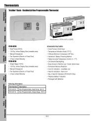
P374-2700 Heat & Cool Heat Pump Non-Programmable ... - Totaline
P374-2700 Heat & Cool Heat Pump Non-Programmable ... - Totaline
P374-2700 Heat & Cool Heat Pump Non-Programmable ... - Totaline

You also want an ePaper? Increase the reach of your titles
YUMPU automatically turns print PDFs into web optimized ePapers that Google loves.
OWNER’S OWNER’S<br />
MANUAL MANUAL<br />
AUTO<br />
74<br />
COOL<br />
27<br />
HEAT<br />
T IONTALE<br />
3 Configurable Outputs<br />
Control up to 2 <strong>Heat</strong> &<br />
2 <strong>Cool</strong> Stages<br />
Backlit Display & Button<br />
Legends<br />
Aux <strong>Heat</strong> Indicator<br />
Dry Contact Equipped<br />
Accepts the<br />
HEAT<br />
COOL<br />
TOTALINE<br />
Signature<br />
COMMERCIAL<br />
THERMOSTAT<br />
P/N <strong>P374</strong>- <strong>2700</strong><br />
HEAT<br />
PUMP<br />
NON-PROGRAMMABLE<br />
DIGITAL<br />
THERMOSTAT<br />
Set Point Limiting<br />
Remote Sensor Ready<br />
Outdoor Sensor Ready<br />
Accepts EZ Programmer<br />
Accepts Optional Humidity<br />
Module: Controls Humidification<br />
and Dehumidification<br />
Accepts Optional IR Remote Control<br />
OPTIONAL<br />
HUMIDITY MODULE<br />
Use with most Air Conditioning & <strong>Heat</strong>ing Systems including: 1 or 2 Stage<br />
Electric <strong>Cool</strong>ing & 2 Stage Gas <strong>Heat</strong>ing, <strong>Heat</strong> <strong>Pump</strong>, Electric or Hydronic <strong>Heat</strong>.<br />
Commercial Systems & Services Carrier Corporation 08/05
CAUTION<br />
Follow the Installation Instructions before proceeding.<br />
Set the thermostat mode to “OFF” prior to changing<br />
settings in setup or restoring Factory Defaults.<br />
CAUTION<br />
NEVER PUT MORE THAN ONE<br />
JUMPER ON THE SAME MISC<br />
JUMPER BLOCK!<br />
THIS MAY DAMAGE YOUR<br />
THERMOSTAT AND VOID<br />
YOUR WARRANTY.<br />
NOTE: Due to variations in environmental conditions, it is not<br />
always possible to achieve the desired humidification or<br />
dehumidification setpoint.<br />
This device complies with Part 15 of the FCC Rules. Operation is<br />
subject to the following two conditions: (1) this device may not cause<br />
harmful interference, and (2) this device must accept any interference<br />
received, including interference that may cause undesired operation.<br />
4Z95<br />
Thermostat <strong>P374</strong>-<strong>2700</strong><br />
F<br />
Cc<br />
FOR HOME OR OFFICE USE<br />
Page i<br />
MISC3 MISC3<br />
OK<br />
Tested to Comply<br />
with FCC Standards<br />
TOTALINE
How to Use This Manual TOTALINE<br />
The Table of Contents divides the thermostat features into sections<br />
making it easier to quickly find information.<br />
The first page of each section contains a more detailed Contents of each<br />
section, such as the example page shown below.<br />
SECTION 14<br />
Timers and Deadbands<br />
Section 14 Contents:<br />
Adjusting the <strong>Heat</strong>/<strong>Cool</strong><br />
Differential..............................14.2<br />
Adjusting the Cycles<br />
Per Hour..................................14.3<br />
Adjusting the Deadband..........14.4<br />
Adjusting the Minutes of<br />
Run-Time Before the<br />
14<br />
Next Stage...............................14.6<br />
Selecting 2nd Stage Turn<br />
Off Temperature.....................14.7<br />
Page 14.1<br />
TOTALINE<br />
In addition, this manual also has an Index to help you find any information<br />
regarding this thermostat quickly.<br />
Page ii<br />
Header shows section #<br />
and title of section<br />
Section and page #<br />
Section contents<br />
Visible section tab<br />
on the side of the<br />
page
Glossary of Terms<br />
Page iii<br />
TOTALINE<br />
Auto-Changeover: A mode in which the thermostat will turn on<br />
the heating or cooling based on room temperature demand.<br />
Configurable Output Jumper: Using jumpers on the thermostat<br />
you can configure the MISC1, MISC2, and MISC3 terminals to<br />
operate with regards to humidification, dehumidification, 2nd<br />
stage cooling, and economizer operation.<br />
<strong>Cool</strong> Setpoint: The warmest temperature that the space should<br />
rise to before cooling is turned on (without regards to<br />
deadband).<br />
Deadband: The number of degrees the thermostat will wait, once<br />
setpoint has been reached, before energizing heating or cooling.<br />
Dehumidify: To reduce the amount of moisture in the air.<br />
Differential: The forced temperature difference between the<br />
heat setpoint and the cool setpoint.<br />
<strong>Heat</strong> Setpoint: The coolest temperature that the space should<br />
drop to before heating is turned on (without regards to<br />
deadband).<br />
Humidify: To increase the amount of moisture in the air.<br />
Icon: The word or symbol that appears on the thermostat<br />
display.<br />
Mode: The current operating condition of the thermostat (i.e. Off,<br />
<strong>Heat</strong>, <strong>Cool</strong>, Auto).<br />
<strong>Non</strong>-<strong>Programmable</strong> Thermostat: A thermostat that does not<br />
have the capability of running the Time Period Programming.<br />
Temperature Swing: Same as Deadband.
Table of Contents<br />
Page iv<br />
Quick Start<br />
Getting to Know Your<br />
Thermostat<br />
Basic Operation<br />
Viewing Temperature<br />
and Humidity Sensors<br />
Programming the<br />
Fan Operation<br />
Thermostat Display<br />
Options<br />
Humidification<br />
Dehumidification<br />
Viewing Equipment<br />
Run-Times<br />
Electric <strong>Heat</strong> and<br />
<strong>Heat</strong> <strong>Pump</strong> Operation<br />
Timers and Deadbands<br />
Programming Remote<br />
Sensor Operation<br />
Programming the Dry<br />
Contact<br />
Programming the Run-<br />
Time Alarms<br />
Configuring the MISC<br />
Outputs<br />
Factory Defaults,<br />
Calibration, and Sensors<br />
Accessories<br />
TOTALINE<br />
Override Operation<br />
Advanced Setup Table<br />
1<br />
2<br />
3<br />
4<br />
5<br />
6<br />
7<br />
8<br />
9<br />
10<br />
11<br />
12<br />
13<br />
14<br />
15<br />
16<br />
17<br />
18<br />
19
SECTION 1<br />
Quick Start<br />
1<br />
Section 1 Contents:<br />
Selecting the <strong>Heat</strong> or <strong>Cool</strong><br />
Mode............................................1.2<br />
Selecting Your Desired<br />
Temperature................................1.3<br />
Using the Fan Button...................1.3<br />
Note: Following the instructions in this section will allow you to<br />
operate your thermostat using the factory default settings. These<br />
settings are depicted in the illustrations throughout this manual.<br />
Page 1.1<br />
TOTALINE
Selecting the <strong>Heat</strong> or <strong>Cool</strong> Mode<br />
Select Mode by Pressing the MODE Button<br />
<strong>Heat</strong>ing Only<br />
The HEAT setting indicates the<br />
temperature the room has to<br />
reach before the furnace will<br />
turn on to heat the room.<br />
<strong>Cool</strong>ing Only<br />
The COOL setting indicates the<br />
temperature the room has to<br />
reach before the air conditioner<br />
will turn on to cool the room.<br />
<strong>Heat</strong>ing or <strong>Cool</strong>ing<br />
AUTO will automatically select<br />
heat or cool based on room<br />
temperature demand.<br />
Off<br />
OFF indicates both heating<br />
and air conditioning<br />
systems are turned off.<br />
AUTO<br />
70 HEAT<br />
68<br />
70<br />
COOL 76<br />
76<br />
70<br />
COOL<br />
HEAT<br />
68<br />
OFF 70<br />
Page 1.2<br />
TOTALINE<br />
Press<br />
MODE<br />
Press<br />
MODE<br />
Press<br />
MODE<br />
1
1<br />
Selecting Your Desired Temperature<br />
(adjusting the setpoints)<br />
AUTO MODE<br />
Pressing the UP or DOWN buttons in Auto mode<br />
will adjust both the heat and cool set temperatures<br />
simultaneously.<br />
AUTO<br />
76<br />
70<br />
COOL<br />
HEAT<br />
68<br />
Adjust the desired<br />
set temperature with the<br />
buttons.<br />
HEAT OR COOL MODE<br />
Pressing the UP or DOWN buttons in <strong>Heat</strong> or <strong>Cool</strong> mode will<br />
adjust only the heat or cool set temperature.<br />
AUTO<br />
70<br />
COOL 76<br />
Using the Fan Button<br />
FanOn<br />
76<br />
70<br />
COOL<br />
HEAT<br />
68<br />
FAN<br />
Page 1.3<br />
Adjust the desired<br />
set temperature with the<br />
Press<br />
buttons.<br />
TOTALINE<br />
Fan On indicates constant fan operation.<br />
If Fan On is selected the fan will run<br />
continuously at all times, except in Off,<br />
and will only run if there is a heating or<br />
cooling demand in Unoccupied periods.<br />
Pressing the FAN button toggles this<br />
feature on or off.
SECTION 2<br />
Getting to Know Your Thermostat TOTALINE<br />
Section 2 Contents:<br />
Front Panel Buttons.....................2.2<br />
Display Features...........................2.3<br />
Page 2.1<br />
2
Front Panel<br />
2<br />
Backlit LCD Display<br />
AUTO<br />
TOTALINE<br />
74<br />
COOL<br />
HEAT<br />
72<br />
<strong>Heat</strong> or <strong>Cool</strong> Demand Indicator Override<br />
Red = <strong>Heat</strong>, Green = <strong>Cool</strong><br />
Button<br />
Commercial<br />
Thermostat<br />
AUTO<br />
MODE HUMIDITY FAN OUTSIDE RESET<br />
FILTER<br />
OVER<br />
RIDE<br />
MODE HUMIDITY FAN OUTSIDE RESET<br />
FILTER<br />
74<br />
COOL<br />
HEAT<br />
72<br />
Page 2.2<br />
TOTALINE<br />
[ ]<br />
Warmer Button sometimes referred<br />
(glows red) to as the UP button<br />
[ ]<br />
<strong>Cool</strong>er Button sometimes refer-<br />
(glows blue) red to as the<br />
DOWN button
Display Features<br />
2<br />
88<br />
DeHumidify<br />
Service Filter<br />
Pan UV Light<br />
COOL<br />
AUTO<br />
Outside<br />
OFFON<br />
Remote<br />
AUXHEAT<br />
Override<br />
FanOnI88Setup<br />
88<br />
TOTALINE<br />
Mode Indicators - Section 3<br />
Selects the operational mode of the equipment.<br />
HEAT - Indicates the heating mode.<br />
COOL - Indicates the air conditioning mode.<br />
AUTO - Indicates the system will automatically changeover<br />
between heat and cool modes as the temperature varies.<br />
OFF - Indicates heating and cooling is turned off.<br />
Room Temperature Display - Section 4<br />
Indicates the current room temperature and displays the outside<br />
temperature when selected.<br />
Desired Set Temperature - Section 3/4<br />
Indicates desired room temperature(s). Also displays the daily<br />
maximum and minimum outside temperatures.<br />
Outside icon - Section 4<br />
Indicates the temperature displayed is from the optional outside<br />
sensor.<br />
Override icon - Section 5<br />
Indicates that normal operation is currently being overridden for<br />
up to 4 hours.<br />
Page 2.3<br />
2
Display Features<br />
2<br />
2<br />
DeHumidify<br />
Service Filter<br />
Pan UV Light<br />
COOL<br />
AUTO<br />
Outside<br />
OFFON<br />
Remote<br />
AUXHEAT<br />
Override<br />
FanOnI88Setup<br />
Setup icon - Sections 6-15<br />
Indicates the thermostat is in the setup mode.<br />
icon - Section 7<br />
Indicates keypad has been locked.<br />
88<br />
88<br />
TOTALINE<br />
Fan On icon - Section 6<br />
Indicates constant, continuous fan operation. When Fan On is not<br />
lit - indicates the fan will only operate when necessary to heat or to<br />
cool.<br />
Service Filter icon - Section 15<br />
Appears when the filter should be serviced under normal conditions.<br />
Adjustable from 0 - 1950 hours of blower operation.<br />
UV Light icon - Section 10/15<br />
Appears when the UV bulb should be serviced under normal<br />
conditions. Adjustable from 0 - 1950 days of operation.<br />
Remote icon - Section 4<br />
Indicates the remote sensor reading of the thermostat is being<br />
viewed.<br />
Page 2.4
Display Features<br />
88<br />
DeHumidify<br />
Service Filter<br />
Pan UV Light<br />
COOL<br />
AUTO<br />
Outside<br />
OFFON<br />
Remote<br />
AUXHEAT<br />
Override<br />
FanOnI88Setup<br />
88<br />
TOTALINE<br />
Aux<strong>Heat</strong> icon - Section 11<br />
Indicates the <strong>Heat</strong> <strong>Pump</strong> is currently using 2nd stage electric<br />
strip heat.<br />
Humidify/DeHumidify icon - Sections 8-9<br />
Indicates the system is currently humidifying/dehumidifying the air.<br />
Service Pan icon - Section 14<br />
Indicates that a sensor (accessory) has detected the condensate<br />
drain pan is full and the compressor (Y1) has been locked out.<br />
Page 2.5<br />
2
SECTION 3<br />
Basic Operation<br />
3<br />
Section 3 Contents:<br />
Programming for Auto or<br />
Manual Operation......................3.2<br />
Selecting the Proper<br />
Operating Mode.........................3.3<br />
Selecting Your Desired<br />
Temperature...............................3.5<br />
Note: During setup & programming pressing the UP or DOWN<br />
buttons will modify the flashing selection.<br />
Page 3.1<br />
TOTALINE
Manual or Auto-Changeover<br />
Thermostat<br />
When the very simplest operation is desired, this thermostat may<br />
be configured to be a manual heat and cool thermostat. Follow the<br />
step below.<br />
The thermostat may be programmed to function as a <strong>Heat</strong> Only or<br />
<strong>Cool</strong> Only thermostat by selecting ‘NO’ in the setup screen below.<br />
This will lockout the Auto-Changeover screen and only allow the Off,<br />
<strong>Heat</strong>, and <strong>Cool</strong> screens to be accessed.<br />
MODE<br />
HUMIDITY<br />
MODE<br />
YES<br />
NO<br />
Press the MODE button. While holding<br />
the MODE, press the HUMIDITY button<br />
to enter Setup screens.<br />
Press the MODE button repeatedly<br />
until this setup screen appears.<br />
Select Yes if you would<br />
like the thermostat to<br />
be Auto-Changeover or<br />
No for a <strong>Heat</strong> Only and<br />
<strong>Cool</strong> Only Thermostat.<br />
AUTO<br />
Page 3.2<br />
Setup<br />
Press the HUMIDITY button to leave the Setup screens. If no buttons are<br />
pressed, the display will leave the setup screens after 30 seconds.<br />
I<br />
TOTALINE<br />
Note: Press the MODE<br />
button momentarily<br />
to move through the<br />
setup screens. Press<br />
and hold the MODE<br />
button to move back-<br />
wards through the<br />
setup screens.<br />
Press<br />
HUMIDITY<br />
3
Operating Mode when the Thermostat<br />
is Configured to be:<br />
3<br />
MANUAL-CHANGEOVER - If the thermostat is configured to be Manual-<br />
Changeover, the following screens will be available by pressing the<br />
MODE button.<br />
<strong>Heat</strong>ing Only<br />
The HEAT setting indicates the<br />
temperature the room has to<br />
reach before the furnace will<br />
turn on to heat the room.<br />
<strong>Cool</strong>ing Only<br />
The COOL setting indicates the<br />
temperature the room has to<br />
reach before the air conditioner<br />
will turn on to cool the room.<br />
Off<br />
OFF indicates both heating<br />
and air conditioning<br />
systems are turned off.<br />
70 HEAT<br />
68<br />
70<br />
COOL 76<br />
OFF 70<br />
Page 3.3<br />
TOTALINE<br />
Select the Mode by Pressing the MODE Button<br />
Press<br />
MODE<br />
Press<br />
MODE
Operating Mode when the Thermostat<br />
is Configured to be:<br />
AUTO-CHANGEOVER - If the thermostat is configured to be Auto-<br />
Changeover, the following screens will be available by pressing<br />
the MODE button.<br />
Select the Mode by Pressing the MODE Button<br />
<strong>Heat</strong>ing Only<br />
The HEAT setting indicates the<br />
temperature the room has to<br />
reach before the furnace will<br />
turn on to heat the room.<br />
<strong>Cool</strong>ing Only<br />
The COOL setting indicates the<br />
temperature the room has to<br />
reach before the air conditioner<br />
will turn on to cool the room.<br />
<strong>Heat</strong>ing or <strong>Cool</strong>ing<br />
AUTO will automatically select<br />
heat or cool based on room<br />
temperature demand.<br />
Off<br />
OFF indicates both heating<br />
and air conditioning<br />
systems are turned off.<br />
AUTO<br />
70 HEAT<br />
68<br />
70<br />
COOL 76<br />
76<br />
70<br />
COOL<br />
HEAT<br />
68<br />
OFF 70<br />
Page 3.4<br />
TOTALINE<br />
Press<br />
MODE<br />
Press<br />
MODE<br />
Press<br />
MODE<br />
3
Selecting Your Desired Temperature (adjusting setpoints)<br />
3<br />
AUTO MODE<br />
Pressing the UP or DOWN buttons in Auto mode<br />
will adjust both the heat and cool set temperatures<br />
simultaneously. For more information on this see page 12.2.<br />
Adjust the desired<br />
set temperature with the<br />
AUTO<br />
76<br />
70<br />
COOL<br />
HEAT<br />
68<br />
Page 3.5<br />
buttons.<br />
HEAT OR COOL MODE<br />
Pressing the UP or DOWN buttons in <strong>Heat</strong> or <strong>Cool</strong> modes will<br />
adjust only the heat or cool set temperature.<br />
70<br />
COOL 76<br />
Adjust the desired<br />
set temperature with the<br />
buttons.<br />
TOTALINE
SECTION 4<br />
Viewing the Temperature and Humidity Sensors<br />
Section 4 Contents:<br />
Viewing the Outside<br />
Temperature..............................4.2<br />
Viewing the Indoor<br />
Humidity....................................4.3<br />
Page 4.1<br />
TOTALINE<br />
4
Viewing the Outside Temperature<br />
4<br />
Requires an outside sensor (optional accessory) to be installed.<br />
To read the temperature from the Outside Sensor, press the<br />
OUTSIDE button. The display will then show the current outside<br />
temperature.<br />
AN OUTSIDE RESE<br />
FILTE<br />
The current outside<br />
temperature will be<br />
displayed.<br />
This reading is from the<br />
sensor connected to RS2. 83<br />
Press the OUTSIDE<br />
button to leave the<br />
Outside temperature<br />
screen.<br />
Press the OUTSIDE<br />
button to view<br />
the Outside<br />
temperature.<br />
Outside<br />
AN OUTSIDE RESE<br />
FILTE<br />
MODE HUMIDITY<br />
Page 4.2<br />
TOTALINE<br />
Current outside<br />
temperature.<br />
Note: If no sensors are connected 2 dashes [- -] will appear on the display.
Viewing the Indoor Humidity<br />
Requires the Humidity Module (optional accessory) to be<br />
installed. To display the current humidity at the thermostat,<br />
press the HUMIDITY button of the thermostat. The display will<br />
then show the current indoor humidity along with the<br />
humidification setpoint (Section 8).<br />
Note: The humidity reading will not appear unless the Humidity<br />
Module has been installed. If a sensor has not been installed<br />
dashes will appear in place of the humidity reading.<br />
HUMIDITY<br />
Current Room Humidity<br />
To view the indoor humidity<br />
reading, press the<br />
HUMIDITY button<br />
40<br />
Setup<br />
Humidify<br />
0<br />
Press the HUMIDITY button<br />
again to return the display<br />
to normal operation.<br />
Page 4.3<br />
I<br />
TOTALINE<br />
Press<br />
HUMIDITY<br />
NOTE: Due to variations in environmental conditions, it is not always possible<br />
to achieve the desired humidification or dehumidification setpoint.<br />
4
SECTION 5<br />
Override Operation<br />
Overriding the Normal Operation<br />
Unoccupied<br />
: 30<br />
Override<br />
85<br />
65<br />
COOL<br />
HEAT<br />
55<br />
74<br />
65<br />
COOL<br />
HEAT<br />
72<br />
Page 5.1<br />
OVERRIDE<br />
Press<br />
TOTALINE<br />
The OVERRIDE button may only be used when the Dry Contact has<br />
forced the thermostat into the Unoccupied mode.<br />
Unoccupied Operation - During a Dry Contact forced<br />
unoccupied period pressing the OVERRIDE button will<br />
temporarily force the thermostat into the mode it was in before<br />
the Dry Contact forced it into the Unoccupied mode.<br />
For example: If the thermostat was in the Auto mode and the<br />
Dry Contact forced the thermostat into the Unoccupied mode,<br />
then pressing the OVERRIDE button will force the thermostat<br />
back into the Auto mode.<br />
The remaining override time will be displayed in the upper left<br />
hand corner of the display. The override timer can be set up to a<br />
maximum of four (4:00) hours, in increments of 30 minutes. If the<br />
timer has been set for the maximum time, the next press of the<br />
OVERRIDE button will reset the timer, returning the thermostat to<br />
the Unoccupied mode.<br />
To adjust the setpoints for the Unoccupied mode, see page 15.4.<br />
AUTO
SECTION 6<br />
Programming the Fan Operation<br />
Section 6 Contents:<br />
TOTALINE<br />
Using the Fan Button.................6.2<br />
Setting the Fan-Off Time<br />
Delay..........................................6.3<br />
Page 6.1<br />
6
Using the Fan Button<br />
When the fan is set for automatic operation it will energize any time<br />
there is a call for heating or cooling, otherwise the fan will remain off.<br />
Pressing the FAN button will energize the fan and display the FanOn<br />
icon on the thermostat display. To operate the fan in the automatic<br />
mode, press the FAN button again and the FanOn icon will disappear.<br />
6<br />
AUTO<br />
FanOn<br />
FAN<br />
Press<br />
76<br />
70<br />
COOL<br />
HEAT<br />
68<br />
Page 6.2<br />
TOTALINE<br />
Fan On indicates constant fan operation.<br />
If Fan On is selected the fan will run<br />
continuously at all times, except in Off,<br />
and will only run if there is a heating or<br />
cooling demand in Unoccupied periods.<br />
Pressing the FAN button toggles this<br />
feature on or off.
Setting the Fan-Off Time Delay<br />
To increase cooling efficiency of your unit, the thermostat may be<br />
programmed to continue running the fan after a call for cooling has<br />
been satisfied. This delay may be set for 30, 60, or 90 seconds. If<br />
the Fan Off Delay is set for zero seconds, the fan will not energize<br />
after a call for cooling has been satisfied.<br />
MODE<br />
HUMIDITY<br />
MODE<br />
Press the MODE button. While holding<br />
the MODE, press the HUMIDITY button<br />
to enter Setup screens.<br />
Press the MODE button repeatedly<br />
until this setup screen appears.<br />
Set the Fan Off Delay<br />
to 0, 30, 60, or 90<br />
seconds.<br />
:00<br />
FanOn<br />
Setup<br />
Press the HUMIDITY button to leave the Setup screens. If no buttons are<br />
pressed, the display will leave the setup screens after 30 seconds.<br />
Page 6.3<br />
2<br />
TOTALINE<br />
Note: Press the MODE<br />
button momentarily<br />
to move through the<br />
setup screens. Press<br />
and hold the MODE<br />
button to move back-<br />
wards through the<br />
setup screens.<br />
Press<br />
HUMIDITY<br />
6
SECTION 7<br />
Thermostat Display Options<br />
Section 7 Contents:<br />
Turning On/Off the<br />
7<br />
TOTALINE<br />
Backlight...................................7.2<br />
Programming the Thermostat<br />
to Display Temperature in<br />
Fahrenheit or Celsius..............7.2<br />
Locking/Unlocking the<br />
Keypad......................................7.3<br />
Programming a Security<br />
Level..........................................7.4<br />
Page 7.1
Turning On/Off the Backlight<br />
MODE<br />
HUMIDITY<br />
MODE<br />
Select backlight operation:<br />
ON - Light continuously.<br />
OFF - Light for 8 seconds<br />
after a button press.<br />
C<br />
Select thermostat<br />
operation in degrees<br />
Fahrenheit or Centigrade.<br />
F f<br />
Press the MODE button. While holding<br />
the MODE, press the HUMIDITY button<br />
to enter Setup screens.<br />
Press the MODE button repeatedly<br />
until this setup screen appears.<br />
AUTO<br />
Press the HUMIDITY button to leave the Setup screens. If no buttons are<br />
pressed, the display will leave the setup screens after 30 seconds.<br />
Page 7.2<br />
Setup<br />
Programming the Thermostat to Display<br />
Temperature in Fahrenheit or Celsius<br />
3<br />
4<br />
Setup<br />
TOTALINE<br />
Note: Press the MODE<br />
button momentarily<br />
to move through the<br />
setup screens. Press<br />
and hold the MODE<br />
button to move back-<br />
wards through the<br />
setup screens.<br />
Press<br />
MODE<br />
Press<br />
HUMIDITY<br />
7
Locking/Unlocking the Keypad<br />
7<br />
To prevent unauthorized use of the thermostat, the front panel<br />
buttons may be disabled. To disable, or ‘lock’ the keypad, press<br />
and hold the MODE button. While holding the MODE button,<br />
press the UP and DOWN buttons together. The icon will<br />
appear on the display, then release the buttons.<br />
Press all three<br />
buttons in the order<br />
outlined above for<br />
keypad lockout<br />
MODE<br />
To unlock the keypad, press and hold the MODE button. While<br />
holding the MODE button, press the UP and DOWN buttons<br />
together. The icon will disappear from the display, then<br />
release the buttons.<br />
Page 7.3<br />
AUTO<br />
TOTALINE<br />
85<br />
65<br />
COOL<br />
HEAT<br />
55
Programming a Security Level<br />
When a security level has been programmed, the thermostat will allow<br />
limited adjustment to the setpoints (steps # 6 and 7) and, in security<br />
levels 2 and 3, the thermostat will be locked into the current mode (off,<br />
heat, cool, or auto). To disable the security feature, program step #5<br />
to 0; this will cause steps # 6 and 7 not to appear.<br />
MODE<br />
HUMIDITY<br />
MODE<br />
Step #6 appears only<br />
if step #5 is not 0.<br />
Step #7 appears only<br />
if step #5 is not 0.<br />
Press the MODE button. While holding<br />
the MODE, press the HUMIDITY button<br />
to enter Setup screens.<br />
Press the MODE button repeatedly<br />
until this setup screen appears.<br />
Select the security level:<br />
0=No security in effect<br />
1=Setpoint range limited<br />
2=1+ locked in current<br />
mode.<br />
3=2 + prohibits setpoint<br />
changes<br />
Adjust the maximum<br />
allowable heat setpoint<br />
when security is in effect.<br />
(35 - 99 )<br />
Adjust the minimum<br />
allowable cool setpoint<br />
when security is in effect.<br />
(35 - 99 )<br />
Press the HUMIDITY button to leave the Setup screens. If no buttons are<br />
pressed, the display will leave the setup screens after 30 seconds.<br />
Page 7.4<br />
0Setup<br />
80Setup<br />
55Setup<br />
5<br />
6<br />
HEAT<br />
7<br />
COOL<br />
TOTALINE<br />
Note: Press the MODE<br />
button momentarily<br />
to move through the<br />
setup screens. Press<br />
and hold the MODE<br />
button to move back-<br />
wards through the<br />
setup screens.<br />
Press<br />
MODE<br />
Press<br />
MODE<br />
Press<br />
HUMIDITY<br />
7
SECTION 8<br />
Humidification<br />
Section 8 Contents:<br />
Installing the Humidity<br />
8<br />
Module.......................................8.2<br />
Setting a Thermostat Jumper<br />
for Humidity Operation............8.3<br />
Adjusting the Humidification<br />
Setpoint.....................................8.4<br />
NOTE: The humidification functions described in this section will<br />
only be available if a Humidity Module has been properly installed.<br />
Disclaimer:<br />
The manufacturer of this thermostat cannot be liable for<br />
misinstallation, improper connection or improper programming of<br />
the humidity functions of this thermostat that may result in water<br />
damage or mold growth.<br />
Additionally, the manufacturer of this thermostat is not responsible<br />
for the fitness of the humidifier and/or installation of said humidifier<br />
connected to this thermostat. Furthermore, the maintenance of the<br />
humidifier components, including but not limited to, the filters and<br />
pads are not the responsibility of the thermostat manufacturer.<br />
The Humidifier Service icon is only a suggestive reminder and<br />
should not take the place of the humidifier manufacturer’s<br />
required maintenance requirements and schedule.<br />
Page 8.1<br />
TOTALINE
Installing the Humidity Module<br />
Back of <strong>P374</strong>-<strong>2700</strong><br />
Figure 2<br />
Page 8.2<br />
TOTALINE<br />
To install the Humidity Module the thermostat must be detached<br />
from the back plate. Plug the Humidity Module into the Humidity<br />
Module connector as shown in Figure 2 below. Follow the detailed<br />
instructions included with the Humidity Module accessory. Once the<br />
Humidity Module has been installed, you must adjust the Humidity<br />
jumper setting to HUM as shown in Figure 1 below. This will allow<br />
you to access the humidification and dehumidification setup steps.<br />
HUM<br />
DEHUM<br />
ECON<br />
Y2<br />
(MISC1<br />
MISC3 MISC2 MISC1 ONLY)<br />
W1<br />
Y1<br />
G<br />
MISC2<br />
CK1<br />
CKGND<br />
R<br />
C<br />
HUM<br />
NO HUM<br />
2<br />
4<br />
6<br />
8<br />
X<br />
Z<br />
INSTALL HUMIDITY<br />
MODULE WITH SENSING<br />
ELEMENT OUTWARD<br />
1<br />
3<br />
5<br />
7<br />
9<br />
Y<br />
1<br />
ELEC<br />
GAS<br />
HP<br />
GAS<br />
B<br />
O<br />
W2<br />
Humidity Module<br />
Thermostat Circuit<br />
Board.<br />
(FAN)<br />
MISC1<br />
RS2<br />
MISC3<br />
RS+5<br />
Rs1<br />
RSGND<br />
For proper humidity operation, this<br />
jumper must be set for HUM.<br />
Figure 1<br />
HUM<br />
OR<br />
NO HUM<br />
Humidity Module<br />
Plug located on<br />
the Thermostat<br />
Circuit Board.<br />
8<br />
Install the Humidity Module<br />
(see Humidity Module Instruction<br />
Sheet for more detailed information).
Setting a Thermostat Jumper for<br />
Humidity Operation<br />
To operate one of the MISC outputs using humidity-based operation,<br />
place the MISC1, MISC2, or MISC3 jumper on the terminal labeled<br />
HUM (see diagram below). This will supply 24VAC to the selected<br />
MISC terminal based on the humidification programming in the<br />
following pages. Only one of the three outputs (MISC1, MISC2, or<br />
MISC3) is required to have this jumper. For more information<br />
regarding the MISC1, MISC2, and MISC3 outputs, please see<br />
Section 16.<br />
8<br />
HUM<br />
DEHUM<br />
In the diagram below, the MISC3 jumper<br />
has been set for HUM (humidify) operation.<br />
ECON<br />
Y2<br />
(MISC1<br />
MISC3 MISC2 MISC1 ONLY)<br />
W1<br />
Y1<br />
G<br />
MISC2<br />
CK1<br />
CKGND<br />
R<br />
C<br />
MISC3 MISC3<br />
OK<br />
HUM<br />
NO HUM<br />
2<br />
4<br />
6<br />
8<br />
X<br />
Z<br />
INSTALL HUMIDITY<br />
MODULE WITH SENSING<br />
ELEMENT OUTWARD<br />
1<br />
3<br />
5<br />
7<br />
9<br />
Y<br />
1<br />
ELEC<br />
GAS<br />
HP<br />
GAS<br />
B<br />
O<br />
W2<br />
(FAN)<br />
MISC1<br />
RS2<br />
MISC3<br />
RS+5<br />
Rs1<br />
RSGND<br />
HUM<br />
DEHUM<br />
ECON<br />
NEVER PUT MORE THAN ONE JUMPER<br />
ON THE SAME MISC JUMPER BLOCK!<br />
THIS MAY DAMAGE THE THERMOSTAT<br />
AND VOID YOUR WARRANTY<br />
Page 8.3<br />
TOTALINE<br />
MISC3 MISC2 MISC1<br />
IMPORTANT CAUTION<br />
Y2<br />
(MISC1<br />
ONLY)
Adjusting the Humidification Setpoint<br />
If your HVAC unit is equipped with a humidification system and the<br />
Humidity Module has been installed, the thermostat will provide power<br />
to the appropriate terminal on the backplate of the thermostat when<br />
the humidity in the home falls below the setpoint you have chosen.<br />
The value for this setpoint ranges from 0% to 60%.<br />
HUMIDITY<br />
Current Room Humidity<br />
Adjust the desired<br />
humidification setpoint<br />
(0%-60%)<br />
Press the HUMIDITY<br />
button to enter the<br />
Humidity Setup screen.<br />
40<br />
0Setup<br />
Humidify<br />
Press the HUMIDITY button to leave the<br />
Humidity Control screens (if no buttons are<br />
pressed, the display will leave the Humidity<br />
Control screens after 30 seconds).<br />
Page 8.4<br />
NOTE: Each step # is located at<br />
the top right corner of the<br />
display for easy reference.<br />
I<br />
TOTALINE<br />
NOTE: Due to variations in environmental conditions, it is not always possible<br />
to achieve the desired humidification or dehumidification setpoint.<br />
Press<br />
HUMIDITY<br />
Humidification Notes: Press the button to set the humidity<br />
setpoint to 0% for no humidification operation.<br />
You cannot set the dehumidify setpoint any lower than the humidify setpoint; a<br />
5% differential is forced between the humidify and dehumidify setpoints.<br />
8
SECTION 9<br />
Dehumidification<br />
Page 9.1<br />
TOTALINE<br />
Section 9 Contents:<br />
Configuring a Thermostat Output<br />
Jumper for Dehumidification<br />
9<br />
Operation...................................9.2<br />
Adjusting the Dehumidification<br />
Setpoint......................................9.3<br />
Using Your Air Conditioner<br />
to Dehumidify............................9.4<br />
Using the DEHUM<br />
Terminal.....................................9.5<br />
NOTE: The dehumidification functions described in this section will<br />
only be available if a Humidity Module has been properly installed.<br />
For instructions on installing the Humidity Module please see page 8.2.
Setting a Thermostat Jumper for<br />
Dehumidification Operation<br />
To operate one of the MISC outputs using dehumidification-based<br />
operation, install the Humidity Module and place the Humidity Jumper<br />
on HUM (see page 8.2). Then place the MISC1, MISC2, or MISC3<br />
jumper on the terminal labeled DEHUM (see diagram below). This will<br />
supply 24VAC to the selected MISC terminal based on the programming<br />
in the following pages. Only one of the three outputs (MISC1,<br />
MISC2, or MISC3) is required to have a jumper. For more information<br />
regarding the MISC1, MISC2, and MISC3 outputs, please see<br />
section 16.<br />
In the diagram below, the MISC2 jumper has<br />
been set for DEHUM (dehumidification) operation.<br />
HUM<br />
DEHUM<br />
ECON<br />
Y2<br />
(MISC1<br />
MISC3 MISC2 MISC1 ONLY)<br />
W1<br />
Y1<br />
G<br />
MISC2<br />
CK1<br />
CKGND<br />
R<br />
C<br />
MISC3 MISC3<br />
OK<br />
HUM<br />
NO HUM<br />
2<br />
4<br />
6<br />
8<br />
X<br />
Z<br />
INSTALL HUMIDITY<br />
MODULE WITH SENSING<br />
ELEMENT OUTWARD<br />
1<br />
3<br />
5<br />
7<br />
9<br />
Y<br />
1<br />
ELEC<br />
GAS<br />
HP<br />
GAS<br />
B<br />
O<br />
W2<br />
(FAN)<br />
MISC1<br />
RS2<br />
MISC3<br />
RS+5<br />
Rs1<br />
RSGND<br />
HUM<br />
DEHUM<br />
ECON<br />
NEVER PUT MORE THAN ONE JUMPER<br />
ON THE SAME MISC JUMPER BLOCK!<br />
THIS MAY DAMAGE THE THERMOSTAT<br />
AND VOID YOUR WARRANTY<br />
Page 9.2<br />
TOTALINE<br />
MISC3 MISC2 MISC1<br />
IMPORTANT CAUTION<br />
9<br />
Y2<br />
(MISC1<br />
ONLY)
Adjusting the Dehumidification Setpoint<br />
If your HVAC unit is equipped with a dehumidification terminal and the<br />
Humidity Module has been installed, the thermostat will provide power<br />
to the appropriate terminal on the backplate of the thermostat when<br />
the humidity in the home is above the setpoint you have chosen.<br />
When the indoor humidity rises above the setpoint you have selected,<br />
the appropriate terminal will be de-energized (see page 9.5). The<br />
value for this setpoint ranges from 25% to 99%.<br />
NOTE: Due to variations in environmental conditions, it is not always possible<br />
to achieve the desired humidification or dehumidification setpoint.<br />
9<br />
HUMIDITY<br />
MODE<br />
ON / + Current Room Humidity<br />
OFF / -<br />
Adjust the desired<br />
dehumidification setpoint<br />
(25%-99%)<br />
Press the HUMIDITY button<br />
to enter the Humidification<br />
Setup screens.<br />
Press the MODE button once<br />
40 DeHumidify<br />
99Setup<br />
NOTE: Each step # is located at<br />
the top right corner of the<br />
display for easy reference.<br />
2<br />
Press the HUMIDITY button to leave the Humidity<br />
Control screens (if no buttons are pressed, the display<br />
will leave the Humidity Control screens after 30 seconds).<br />
Page 9.3<br />
TOTALINE<br />
Press<br />
HUMIDITY<br />
Dehumidification Notes: Press the button to set the<br />
dehumidification setpoint to 99% for no dehumidification operation.<br />
This will lockout Advanced Setup steps 8 and 9 (see page 9.4).<br />
You cannot set the dehumidify setpoint any lower than the humidify setpoint; a<br />
5% differential is forced between the humidify and dehumidify setpoints.
Using Your Air Conditioner to Dehumidify<br />
If <strong>Cool</strong> to Dehumidify is on and the Humidity Module is installed,<br />
the thermostat has the ability to initiate a cooling cycle for advanced<br />
dehumidification operation. When the thermostat detects the humidity<br />
percentage is above the setpoint for dehumidification, and heating or<br />
cooling is not on, the thermostat will force the compressor to run with<br />
the fan, thus reducing moisture in the air. This feature will also allow<br />
you to adjust the cooling overshoot of the setpoint, from 0 ° to 5 °<br />
(adjustable in step #9). For Example: If the cooling overshoot is set for<br />
3° F and the cooling setpoint is set for 74° F, then as long as the room<br />
temperature reads between 71° F and 74° F this feature will energize the<br />
compressor and fan to dehumidify the air.<br />
9<br />
MODE<br />
HUMIDITY<br />
On<br />
Off<br />
Press the MODE button. While holding<br />
the MODE, press the HUMIDITY button<br />
to enter Setup screens.<br />
Press the MODE button repeatedly<br />
MODE<br />
until this setup screen appears.<br />
Steps 8 and 9 only appear if the Dehumidification<br />
setpoint is not 99% (see page 9.3).<br />
Select <strong>Cool</strong> to<br />
Dehumidify feature.<br />
OFF<br />
Step 9 appears only if step 8 is set to “ON”<br />
Adjust the maximum<br />
overshoot of the set<br />
temperature in <strong>Cool</strong> to<br />
Dehumidify mode.<br />
(0 - 5 )<br />
Page 9.4<br />
DeHumidify<br />
DeHumidify<br />
Setup<br />
3Setup<br />
8<br />
9<br />
COOL<br />
TOTALINE<br />
Note: Press the MODE<br />
button momentarily<br />
to move through the<br />
setup screens. Press<br />
and hold the MODE<br />
button to move back-<br />
wards through the<br />
setup screens.<br />
Press<br />
MODE<br />
Press<br />
HUMIDITY<br />
Press the HUMIDITY button to leave the Setup screens. If no buttons are<br />
pressed, the display will leave the setup screens after 30 seconds.<br />
Dehumidification Notes: The thermostat must be in the <strong>Cool</strong> or Auto<br />
mode for the <strong>Cool</strong> to Dehumidify feature to be available.
Using the Dehum Terminal<br />
If you configure a MISC output jumper for DEHUM, it may be<br />
programmed to operate in one of two ways:<br />
1) Normally Closed (NC): The thermostat will de-energize the<br />
DEHUM terminal to allow the fan to run in low speed when there<br />
is a call for 1st stage cooling and the room humidity is greater than<br />
the dehumidification setpoint.<br />
2) Normally Open (NO): The thermostat will energize the DEHUM<br />
terminal to allow the fan to run in low speed when there is a call<br />
for 1st stage cooling only and the room humidity is greater<br />
than the dehumidification setpoint.<br />
MODE<br />
HUMIDITY<br />
MODE<br />
NC<br />
NO<br />
Press the MODE button. While holding<br />
the MODE, press the HUMIDITY button<br />
to enter Setup screens.<br />
Press the MODE button repeatedly<br />
until this setup screen appears.<br />
Normally Closed (NC) =<br />
DEHUM de-energized for<br />
low speed fan.<br />
Normally Open (NO) =<br />
DEHUM energized for<br />
low speed fan.<br />
Press the HUMIDITY button to leave the Setup screens. If no buttons are<br />
pressed, the display will leave the setup screens after 30 seconds.<br />
Page 9.5<br />
DeHumidify<br />
Setup<br />
I0<br />
TOTALINE<br />
Note: Press the MODE<br />
button momentarily<br />
to move through the<br />
setup screens. Press<br />
and hold the MODE<br />
button to move back-<br />
wards through the<br />
setup screens.<br />
Press<br />
HUMIDITY<br />
Dehumidification Notes: The DEHUM terminal will “release” and allow<br />
the fan to operate normally if there is call for 2nd stage cooling or if the call<br />
for <strong>Cool</strong>ing and/or <strong>Cool</strong> to Dehumidify has been satisfied.<br />
9
SECTION 10<br />
Viewing Equipment Run-Times<br />
Section 10 Contents:<br />
Viewing the Override<br />
Run-Time.................................10.2<br />
Viewing the Humidifier<br />
Run-Time................................ 10.3<br />
Viewing the UV Light<br />
10<br />
Run-Time.................................10.4<br />
Page 10.1<br />
TOTALINE
Viewing the Override Operation Run-Time<br />
This display will track the number of hours that your thermostat has<br />
been operating in the Override mode (see page 5.1). Press the FAN<br />
button to reset the counter.<br />
10<br />
MODE<br />
HUMIDITY<br />
MODE<br />
Press<br />
FAN<br />
Press the MODE button. While holding<br />
the MODE, press the HUMIDITY button<br />
to enter Setup screens.<br />
Press the MODE button repeatedly<br />
until this setup screen appears.<br />
Counts the number of<br />
hours Override has<br />
been active. Press FAN<br />
to reset the Override Run-<br />
Time counter.<br />
Override<br />
Setup 0 I i<br />
Press the HUMIDITY button to leave the Setup screens. If no buttons are<br />
pressed, the display will leave the setup screens after 30 seconds.<br />
Page 10.2<br />
TOTALINE<br />
Note: Press the MODE<br />
button momentarily<br />
to move through the<br />
setup screens. Press<br />
and hold the MODE<br />
button to move back-<br />
wards through the<br />
setup screens.<br />
Press<br />
HUMIDITY
Viewing the Humidification Run-Time<br />
After your humidification system has been operating for the number of<br />
days set in step #12 below, the Service Humidify icon will appear. This<br />
counter keeps track of the number of days since the Service Humidify<br />
icon was reset.<br />
MODE<br />
HUMIDITY<br />
MODE<br />
Press<br />
FAN<br />
Press the MODE button. While holding<br />
the MODE, press the HUMIDITY button<br />
to enter Setup screens.<br />
Press the MODE button repeatedly<br />
until this setup screen appears.<br />
Counts the number of<br />
days the humidifier has<br />
been running. Press<br />
FAN to reset the<br />
Service Humidify<br />
counter and remove the<br />
icon from the display.<br />
Service<br />
Press the HUMIDITY button to leave the Setup screens. If no buttons are<br />
pressed, the display will leave the setup screens after 30 seconds.<br />
0<br />
Page 10.3<br />
Humidify<br />
Setup<br />
I2<br />
TOTALINE<br />
Note: Press the MODE<br />
button momentarily<br />
to move through the<br />
setup screens. Press<br />
and hold the MODE<br />
button to move back-<br />
wards through the<br />
setup screens.<br />
10<br />
Press<br />
HUMIDITY
Viewing the UV Light Run-Time<br />
After the UV light has been operating for the number of days set in<br />
step #13 below, the Service UV Light icon will appear. This counter<br />
keeps track of the number of days since the UV light icon was last<br />
reset.<br />
10<br />
Press<br />
FAN<br />
MODE<br />
HUMIDITY<br />
MODE<br />
Press the MODE button. While holding<br />
the MODE, press the HUMIDITY button<br />
to enter Setup screens.<br />
Press the MODE button repeatedly<br />
until this setup screen appears.<br />
Counts the number of days<br />
since the UV Light was last<br />
reset. Press FAN to reset<br />
the Service UV Light counter<br />
and remove the icon from the<br />
display.<br />
Press the HUMIDITY button to leave the Setup screens. If no buttons are<br />
pressed, the display will leave the setup screens after 30 seconds.<br />
0<br />
Service<br />
UV Light<br />
Page 10.4<br />
Setup<br />
I3<br />
TOTALINE<br />
Note: Press the MODE<br />
button momentarily<br />
to move through the<br />
setup screens. Press<br />
and hold the MODE<br />
button to move back-<br />
wards through the<br />
setup screens.<br />
Press<br />
HUMIDITY
SECTION 11<br />
Electric <strong>Heat</strong> and <strong>Heat</strong> <strong>Pump</strong> Operation<br />
Section 11 Contents:<br />
Viewing the <strong>Heat</strong> <strong>Pump</strong> and<br />
Reversing Valve Jumper<br />
Setting.....................................11.2<br />
Viewing the Electric <strong>Heat</strong><br />
Jumper Setting.......................11.3<br />
Using Emergency <strong>Heat</strong>............11.4<br />
Page 11.1<br />
TOTALINE<br />
11
Viewing the <strong>Heat</strong> <strong>Pump</strong> and<br />
Reversing Valve Jumper Settings<br />
Steps 14 and 15 are ‘Read Only’ and may only be set with the<br />
jumpers on the circuit board of the thermostat.<br />
11<br />
MODE<br />
HUMIDITY<br />
MODE<br />
Press the MODE button. While holding<br />
the MODE, press the HUMIDITY button<br />
to enter Setup screens.<br />
Press the MODE button repeatedly<br />
until this setup screen appears.<br />
ON = <strong>Heat</strong> <strong>Pump</strong><br />
operation<br />
OFF = Gas Electric<br />
operation<br />
Indicates that the<br />
thermostat jumper<br />
is set for an O<br />
reversing valve<br />
(energize in cooling)<br />
or a b reversing valve<br />
(energize in heating). O<br />
OFF<br />
Page 11.2<br />
Setup<br />
I4<br />
I5<br />
Setup<br />
Press the HUMIDITY button to leave the Setup screens. If no buttons are<br />
pressed, the display will leave the setup screens after 30 seconds.<br />
TOTALINE<br />
Note: Press the MODE<br />
button momentarily<br />
to move through the<br />
setup screens. Press<br />
and hold the MODE<br />
button to move back-<br />
wards through the<br />
setup screens.<br />
Press<br />
MODE<br />
Press<br />
HUMIDITY
Viewing the Electric <strong>Heat</strong> Jumper Setting<br />
Placing the jumper on ELEC will cause the thermostat to turn on the<br />
fan immediately any time there is a heat demand. Since most gas<br />
furnaces control the fan, this feature should be off unless the heater is<br />
only electric.<br />
Step 16 is ‘Read Only’ and may only be set with the jumpers on the<br />
circuit board of the thermostat.<br />
MODE<br />
HUMIDITY<br />
MODE<br />
Press the MODE button. While holding<br />
the MODE, press the HUMIDITY button<br />
to enter Setup screens.<br />
Press the MODE button repeatedly<br />
until this setup screen appears.<br />
ON indicates that the<br />
thermostat jumper is<br />
set for Electric <strong>Heat</strong><br />
operation, or OFF for<br />
Gas/Electric or <strong>Heat</strong><br />
<strong>Pump</strong> operation. EH<br />
OFF<br />
Press the HUMIDITY button to leave the Setup screens. If no buttons are<br />
pressed, the display will leave the setup screens after 30 seconds.<br />
Page 11.3<br />
I6<br />
Setup<br />
TOTALINE<br />
Note: Press the MODE<br />
button momentarily<br />
to move through the<br />
setup screens. Press<br />
and hold the MODE<br />
button to move back-<br />
wards through the<br />
setup screens.<br />
11<br />
Press<br />
HUMIDITY
Using Emergency <strong>Heat</strong><br />
ENTER EMERGENCY HEAT: Only available if you have a <strong>Heat</strong> <strong>Pump</strong><br />
installed. To initiate the Emergency <strong>Heat</strong> feature, press the FAN<br />
button. While holding the FAN button press the UP button. The<br />
<strong>Cool</strong> setpoint display will read ‘EH’ (emergency heat).<br />
11<br />
Press for<br />
Emergency <strong>Heat</strong><br />
FAN<br />
Page 11.4<br />
73 HEAT<br />
74<br />
TOTALINE<br />
OPERATION: During Emergency <strong>Heat</strong> operation the<br />
thermostat will turn on the fan and the 2nd stage of heat<br />
when there is a demand for heat. Also during Emergency<br />
<strong>Heat</strong> the 1st stage of heating or cooling will be unavailable.<br />
EXIT EMERGENCY HEAT: Follow the same steps as entering<br />
Emergency <strong>Heat</strong> by pressing the FAN and UP buttons. During<br />
Emergency <strong>Heat</strong>, only OFF and HEAT modes are available by<br />
pressing the MODE button.
SECTION 12<br />
Timers and Deadbands<br />
Page 12.1<br />
TOTALINE<br />
Section 12 Contents:<br />
Adjusting the <strong>Heat</strong>/<strong>Cool</strong><br />
Differential..............................12.2<br />
Adjusting the Cycles<br />
Per Hour..................................12.3<br />
Adjusting the Deadband..........12.4<br />
Selecting 2nd Stage Turn<br />
Off Temperature.....................12.6<br />
12
Adjusting the <strong>Heat</strong>/<strong>Cool</strong> Differential<br />
The <strong>Heat</strong> and <strong>Cool</strong> setpoints will not be allowed to come any closer to<br />
each other than the value in this step. This minimum difference is<br />
enforced during Auto-Changeover operation.<br />
12<br />
MODE<br />
HUMIDITY<br />
MODE<br />
Press the MODE button. While holding<br />
the MODE, press the HUMIDITY button<br />
to enter Setup screens.<br />
Press the MODE button repeatedly<br />
until this setup screen appears.<br />
Adjust the minimum<br />
difference between<br />
cooling & heating<br />
setpoints.<br />
(0 - 6 )<br />
Press the HUMIDITY button to leave the Setup screens. If no buttons<br />
are pressed, the display will leave the setup screens after 30 seconds.<br />
Page 12.2<br />
2Setup<br />
I7<br />
COOL<br />
HEAT<br />
TOTALINE<br />
Note: Press the MODE<br />
button momentarily<br />
to move through the<br />
setup screens. Press<br />
and hold the MODE<br />
button to move back-<br />
wards through the<br />
setup screens.<br />
Press<br />
HUMIDITY<br />
Note: To increase the spread between the heating and cooling<br />
setpoints, press the MODE button until only the heat setpoint is<br />
displayed. Adjust the desired setpoint. Press the MODE button<br />
until only the cool setpoint is displayed. Adjust the desired setpoint.<br />
Press the MODE button again to enter the Auto-Changeover mode<br />
where both the heat and cool setpoints are displayed.
Adjusting the Cycles Per Hour<br />
The Cycles Per Hour setting may limit the number of times per hour<br />
your HVAC unit may energize. For example, at a setting of 6 cycles<br />
per hour the HVAC unit will only be allowed to energize once every 10<br />
minutes. The Cycles Per Hour limit may be overridden and reset by<br />
pressing any button on the thermostat.<br />
MODE<br />
HUMIDITY<br />
MODE<br />
Press the MODE button. While holding<br />
the MODE, press the HUMIDITY button<br />
to enter Setup screens.<br />
Press the MODE button repeatedly<br />
until this setup screen appears.<br />
Select the cycles per<br />
hour limit.<br />
d=cycles per hour<br />
limit defeated.<br />
d1=d + defeat 5 min.<br />
compressor lockout.<br />
(d1, d, 2 - 6)<br />
Press the HUMIDITY button to leave the Setup screens. If no buttons are<br />
pressed, the display will leave the setup screens after 30 seconds.<br />
Page 12.3<br />
6Setup<br />
I8<br />
Cy<br />
TOTALINE<br />
Note: Press the MODE<br />
button momentarily<br />
to move through the<br />
setup screens. Press<br />
and hold the MODE<br />
button to move back-<br />
wards through the<br />
setup screens.<br />
Press<br />
HUMIDITY<br />
12
Adjusting the Deadband<br />
MULTI-STAGE OPERATION - Controls up to two <strong>Heat</strong> and two <strong>Cool</strong><br />
stages.<br />
The 2nd Stage of heat or cool is turned on when:<br />
(A) The 1st Stage has been on for the two minutes.<br />
And<br />
12<br />
(B) The temperature spread from the setpoint is equal to or greater<br />
than: the setpoint plus the 1st stage deadband (step #19, next<br />
page), plus two degrees.<br />
2nd Stage<br />
turn on<br />
<strong>Heat</strong>ing <strong>Cool</strong>ing<br />
Deadband Deadband Deadband Deadband<br />
db 2 db 1 db 1 db 2<br />
(adj. 0-10 ) (adj. 1-6 )<br />
(adj. 1-6 ) (adj. 0-10 )<br />
1st Stage<br />
turn on<br />
<strong>Heat</strong><br />
Setpoint<br />
Page 12.4<br />
<strong>Cool</strong><br />
Setpoint<br />
DECREASE TEMPERATURE INCREASE<br />
1st Stage<br />
turn on<br />
TOTALINE<br />
2nd Stage<br />
turn on
Adjusting the Deadband<br />
For more detailed information, please see the explanation on the<br />
previous page.<br />
MODE<br />
HUMIDITY<br />
MODE<br />
Press the MODE button. While holding<br />
the MODE, press the HUMIDITY button<br />
to enter Setup screens.<br />
Press the MODE button repeatedly<br />
until this setup screen appears.<br />
Adjust the deadband<br />
for the 1st stage.<br />
(1 - 6 )<br />
Page 12.5<br />
2Setup<br />
I9<br />
Press the HUMIDITY button to leave the Setup screens. If no buttons are<br />
pressed, the display will leave the setup screens after 30 seconds.<br />
TOTALINE<br />
Note: Press the MODE<br />
button momentarily<br />
to move through the<br />
setup screens. Press<br />
and hold the MODE<br />
button to move back-<br />
wards through the<br />
setup screens.<br />
Press<br />
HUMIDITY<br />
12
Selecting 2nd Stage Turn<br />
Off Temperature<br />
If ON is selected, the second stage of cooling or heating will remain<br />
energized until the thermostat reaches the setpoint on the thermostat<br />
display.<br />
If OFF is selected, the second stage of cooling or heating will turn off<br />
after reaching the 1st stage deadband (see page 12.4 for more<br />
information).<br />
12<br />
MODE<br />
HUMIDITY<br />
MODE<br />
On<br />
Off<br />
Press the MODE button. While holding<br />
the MODE, press the HUMIDITY button<br />
to enter Setup screens.<br />
Press the MODE button repeatedly<br />
until this setup screen appears.<br />
Select On or Off:<br />
On - 2nd stage will<br />
remain on until<br />
setpoint is reached.<br />
Off - 2nd stage will<br />
turn off after reaching<br />
1st stage deadband.<br />
OFF<br />
Press the HUMIDITY button to leave the Setup screens. If no buttons are<br />
pressed, the display will leave the setup screens after 30 seconds.<br />
Page 12.6<br />
20<br />
2Setup<br />
TOTALINE<br />
Note: Press the MODE<br />
button momentarily<br />
to move through the<br />
setup screens. Press<br />
and hold the MODE<br />
button to move back-<br />
wards through the<br />
setup screens.<br />
Press<br />
HUMIDITY
SECTION 13<br />
Programming Remote Sensor Operation<br />
Section 13 Contents:<br />
Installing the Remote<br />
Sensors...................................13.2<br />
Controlling or Reading the<br />
Remote Temperature (RS1)...13.3<br />
Page 13.1<br />
TOTALINE<br />
13
Installing the Remote Sensors<br />
13<br />
Page 13.2<br />
TOTALINE<br />
Up to two wired remote sensors may be installed on the thermostat to<br />
read outside temp (RS2) and/or control the temperature in another<br />
room (RS1). The designators RS1 and RS2 refer to the terminal<br />
locations on the thermostat’s backplate. If a sensor is connected to<br />
RS1 and is programmed to control the thermostat, the degree icon on<br />
the thermostat will blink once per second to indicate that a remote<br />
sensor reading is being displayed. The wired sensor can be connected<br />
to the thermostat with up to 150’ of 18 ga., 300’ of 20 ga., or 450’ of<br />
22 ga. unshielded, thermostat wire.<br />
This wire MUST be completely separated from the thermostat or<br />
any other control wiring and must NOT be in the same conduit<br />
as high voltage wiring.<br />
RS-GND<br />
RS<br />
W2<br />
MISC1<br />
RS2<br />
MISC3<br />
RS+5<br />
RS1<br />
RSGND<br />
W1/O/B<br />
Y1<br />
G<br />
MISC2<br />
CK1<br />
CKGND<br />
R<br />
C<br />
RS-GND<br />
RS1 RS2<br />
See the Remote Sensor accessory for further details.<br />
RS
Controlling or Reading the<br />
Remote Temperature (RS (RS1) )<br />
The thermostat may be programmed to only READ the remote sensor,<br />
or to CONTROL to the remote sensor. Refer to Advanced Setup step<br />
#21, below.<br />
Read Only Sensor (RS1): If step #21 is set to only READ to the<br />
remote sensor, this temperature may be viewed by pressing the<br />
OUTSIDE button on the thermostat and then pressing the MODE<br />
button.<br />
Control Sensor (RS1): If step #21 is set to CONTROL to the remote<br />
sensor, the thermostat will ignore the reading of its internal<br />
temperature sensor and only display the temperature reading from<br />
the remote sensor. The degree icon on the thermostat will blink<br />
once per second to indicate that a remote sensor reading is being<br />
displayed. This is the factory default setting.<br />
MODE<br />
HUMIDITY<br />
MODE<br />
Press the MODE button. While holding<br />
the MODE, press the HUMIDITY button<br />
to enter Setup screens.<br />
YES<br />
Optional Remote Sensor:<br />
YES = Read Only Remote<br />
Sensor RS1.<br />
NO = Control to Remote<br />
Sensor RS1.<br />
NO<br />
Press the HUMIDITY button to leave the Setup screens. If no buttons are<br />
pressed, the display will leave the setup screens after 30 seconds.<br />
1<br />
Press the MODE button repeatedly<br />
until this setup screen appears.<br />
Page 13.3<br />
Setup<br />
2i<br />
Outside<br />
TOTALINE<br />
Note: Press the MODE<br />
button momentarily<br />
to move through the<br />
setup screens. Press<br />
and hold the MODE<br />
button to move back-<br />
wards through the<br />
setup screens.<br />
Press<br />
HUMIDITY<br />
13
SECTION 14<br />
Programming the Dry Contact<br />
14<br />
Page 14.1<br />
TOTALINE<br />
Section 14 Contents:<br />
Dry Contact Operation............ 14.2<br />
Dry Contact Polarity.................14.2<br />
Dry Contact Programming.......14.3<br />
Override Operation...................14.4<br />
Soft Start Operation..................14.5
Dry Contact Operation<br />
If the dry contact is going to be used, select YES in step #22 below; if<br />
the dry contact is not going to be used, select NO. in step #22 below.<br />
DRY CONTACT POLARITY - The terminals may be set to be<br />
Normally Open (NO) or Normally Closed (NC) in step #23.<br />
If NO is selected the dry contact will operate when it is forced<br />
closed. If NC is selected, the dry contact will operate until it is<br />
forced open.<br />
MODE<br />
HUMIDITY<br />
MODE<br />
YES<br />
NO<br />
NC<br />
NO<br />
Press the MODE button. While holding<br />
the MODE, press the HUMIDITY button<br />
to enter Setup screens.<br />
Press the MODE button repeatedly<br />
until this setup screen appears.<br />
Set to YES if the dry<br />
contact will be used.<br />
Set to NO if the dry<br />
contact will not be used.<br />
Dry Contact Polarity:<br />
Normally Open (NO)<br />
Normally Closed (NC).<br />
Page 14.2<br />
Setup<br />
22<br />
Setup<br />
23<br />
Press the HUMIDITY button to leave the Setup screens. If no buttons are<br />
pressed, the display will leave the setup screens after 30 seconds.<br />
TOTALINE<br />
Note: Press the MODE<br />
button momentarily<br />
to move through the<br />
setup screens. Press<br />
and hold the MODE<br />
button to move back-<br />
wards through the<br />
setup screens.<br />
Press<br />
MODE<br />
Press<br />
HUMIDITY<br />
14
Dry Contact Programming<br />
OVERRIDE OR SERVICE THE CONDENSATE DRAIN PAN - If<br />
Override is selected in step #24 (below), when the dry contact is<br />
energized the thermostat will be forced into or out of Unoccupied<br />
setpoints (next page) depending on the polarity of the Dry Contact.<br />
If Service Pan is selected, when the dry contact is energized the<br />
thermostat will lockout Y1 (compressor) and write Service Pan on<br />
the display.<br />
14<br />
MODE<br />
HUMIDITY<br />
MODE<br />
Press the HUMIDITY button to leave the Setup screens. If no buttons are<br />
pressed, the display will leave the setup screens after 30 seconds.<br />
W2<br />
MISC1<br />
RS2<br />
MISC3<br />
RS+5<br />
RS1<br />
RSGND<br />
W1/O/B<br />
Y1<br />
G<br />
MISC2<br />
CK1<br />
CKGND<br />
R<br />
C<br />
Connect wires to a time<br />
clock or other device to<br />
force the thermostat into<br />
or out of Unoccupied.<br />
Press the MODE button. While holding<br />
the MODE, press the HUMIDITY button<br />
to enter Setup screens.<br />
Press the MODE button repeatedly<br />
until this setup screen appears.<br />
Service Pan<br />
Select Override to enable<br />
Override setpoints when<br />
the dry contact is energized.<br />
Select Service Pan<br />
to lockout Y1 when the dry<br />
contact is energized.<br />
Override<br />
Override<br />
OR<br />
Page 14.3<br />
Setup<br />
W2<br />
MISC1<br />
RS2<br />
MISC3<br />
RS+5<br />
RS1<br />
RSGND<br />
24<br />
Press<br />
HUMIDITY<br />
Override Service Pan<br />
W1/O/B<br />
Y1<br />
G<br />
MISC2<br />
CK1<br />
CKGND<br />
R<br />
C<br />
Connect wires to a device<br />
that will energize when<br />
the Condensate Drain<br />
Pan is full.<br />
TOTALINE<br />
Note: Press the MODE<br />
button momentarily<br />
to move through the<br />
setup screens. Press<br />
and hold the MODE<br />
button to move back-<br />
wards through the<br />
setup screens.
Dry Contact Programming<br />
UNOCCUPIED SETPOINTS - If Override is selected in step #24 (see<br />
previous page), when the dry contact is energized the thermostat<br />
will be forced into or out of Unoccupied setpoints. To adjust the<br />
Unoccupied setpoints follow the setup steps below.<br />
MODE<br />
HUMIDITY<br />
MODE<br />
Press the MODE button. While holding<br />
the MODE, press the HUMIDITY button<br />
to enter Setup screens.<br />
Press the MODE button repeatedly<br />
until this setup screen appears.<br />
Adjust the cooling<br />
setpoint for unoccupied<br />
periods.<br />
(35 - 99, OF )<br />
Adjust the heating setpoint<br />
for Unoccupied<br />
periods.<br />
(OF, 35 - 99 )<br />
Unoccupied<br />
Unoccupied<br />
85Setup<br />
55Setup<br />
Press the HUMIDITY button to leave the Setup screens. If no buttons are<br />
pressed, the display will leave the setup screens after 30 seconds.<br />
Page 14.4<br />
25<br />
COOL<br />
26<br />
HEAT<br />
TOTALINE<br />
Note: Press the MODE<br />
button momentarily<br />
to move through the<br />
setup screens. Press<br />
and hold the MODE<br />
button to move back-<br />
wards through the<br />
setup screens.<br />
MODE<br />
Press<br />
HUMIDITY<br />
Press<br />
14
Random Start Operation<br />
This feature causes a 2 to 30 second delay before energizing<br />
the thermostat outputs after any of these events:<br />
14<br />
Loss of Power to the thermostat: When power to the thermostat<br />
is interrupted and then restored, Random Start will lockout the<br />
outputs of the thermostat for a random amount of time. This<br />
delay helps to keep multiple thermostats from energizing their<br />
outputs at the same time after a power outage.<br />
Changing from an Unoccupied time period to an Occupied<br />
time period: If the thermostat is running in the Program On mode<br />
and the start time for an Occupied period forces the thermostat<br />
from Unoccupied to Occupied 1, Random Start will lockout all<br />
outputs of the thermostat for a random amount of time. This<br />
delay helps to keep multiple thermostats from energizing their<br />
outputs at the same time each day.<br />
Closure of the Dry Contact to force Occupied 1 time period:<br />
If step #24 (previous page) is programmed for Occupied 1, then<br />
Random Start will lockout all outputs of the thermostat for a<br />
random amount of time when a Dry Contact closure occurs<br />
(depending on step #23). This delay helps to keep multiple<br />
thermostats from energizing their outputs each time the Dry<br />
Contact is used.<br />
Page 14.5
SECTION 15<br />
Programming Run-Time Alarms<br />
Page 15.1<br />
TOTALINE<br />
Section 15 Contents:<br />
Setting and Resetting the<br />
Service Filter (Fan Run-Time)<br />
Alarm........................................15.2<br />
Setting and Resetting the UV<br />
Light Run-Time Alarm.............15.3<br />
Setting and Resetting the<br />
Humidify Run-Time Alarm......15.4<br />
15
How to Set and Reset the Service Filter<br />
(Fan Run-Time) Alarm<br />
This counter keeps track of the number of hours of fan run-time<br />
whether the fan is energized in the <strong>Heat</strong>ing or <strong>Cool</strong>ing modes, or in<br />
stand alone fan operation. The Service Filter icon will appear after the<br />
preset number of hours of fan run-time in step #28 (below) has been<br />
achieved. Setting this counter to zero in step #28 will prevent the<br />
Service Filter icon from ever appearing.<br />
15<br />
RESET<br />
FILTER<br />
Press<br />
FAN<br />
Press the RESET FILTER button<br />
to enter this setup screen.<br />
Hours the fan has<br />
run since last reset<br />
Reset the counter to 0 to<br />
remove the Service Filter<br />
icon from the display.<br />
Adjust the number of<br />
hours in increments of<br />
50 the fan will run<br />
before the Service<br />
Filter icon appears on<br />
the display. 0 = off.<br />
(0 - 1950 hours)<br />
Press the HUMIDITY button to leave the Setup screens. If no buttons are<br />
pressed, the display will leave the setup screens after 30 seconds.<br />
0<br />
Service Filter<br />
0<br />
Service Filter<br />
Page 15.2<br />
Setup<br />
27<br />
Setup<br />
28<br />
TOTALINE<br />
Note: Press the MODE<br />
button momentarily<br />
to move through the<br />
setup screens. Press<br />
and hold the MODE<br />
button to move back-<br />
wards through the<br />
setup screens.<br />
Press<br />
MODE<br />
Press<br />
HUMIDITY
How to Set and Reset the UV Light<br />
Run-Time Alarm<br />
This counter keeps track of the number of days since the UV Light<br />
counter has been reset. The UV Light icon will appear after the<br />
number of days has been achieved, as shown in step #29 (below).<br />
Setting the counter to zero in Step #29 will prevent the Service UV<br />
Light icon from ever appearing.<br />
MODE<br />
HUMIDITY<br />
MODE<br />
Press<br />
FAN<br />
MODE<br />
Press the MODE button. While holding<br />
the MODE, press the HUMIDITY button<br />
to enter Setup screens.<br />
Press the MODE button repeatedly<br />
until this setup screen appears.<br />
Days since the UV Light<br />
icon has been reset<br />
Reset the counter to 0 to<br />
remove the Service UV<br />
Light icon from the display.<br />
(0 - 1990 days)<br />
Press the HUMIDITY button to leave the Setup screens. If no buttons are<br />
pressed, the display will leave the setup screens after 30 seconds.<br />
0<br />
Service<br />
UV Light<br />
Press the MODE button repeatedly<br />
until this setup screen appears.<br />
Adjust the number of days<br />
in increments of 10 before<br />
the UV Light icon appears<br />
on the display. 0 = off.<br />
0<br />
Service<br />
UV Light<br />
Page 15.3<br />
Setup<br />
Note: Press the MODE<br />
button momentarily<br />
to move through the<br />
setup screens. Press<br />
and hold the MODE<br />
button to move back-<br />
wards through the<br />
setup screens.<br />
I3<br />
Setup<br />
29<br />
TOTALINE<br />
Press<br />
HUMIDITY<br />
15
How to Set and Reset the Humidifier<br />
Run-Time Alarm<br />
This counter keeps track of the number of days since the Service<br />
Humidify icon was last reset; this icon will appear after the number of<br />
days set in step #30 (below) has elapsed. Setting this counter to zero<br />
in step #30 will prevent the Service Humidify icon from ever appearing.<br />
HUMIDITY<br />
Press<br />
FAN<br />
15<br />
MODE<br />
MODE<br />
Days since the last reset<br />
of the Service Humidify<br />
counter.<br />
MODE<br />
Press the MODE button. While holding<br />
the MODE, press the HUMIDITY button<br />
to enter Setup screens.<br />
Press the MODE button repeatedly<br />
until this setup screen appears.<br />
Reset the counter to 0 to<br />
remove the Service Humidify<br />
icon from the display.<br />
Adjust the number of days<br />
in increments of 10 before<br />
the Service Humidify icon<br />
appears.<br />
0 = Off<br />
(0 - 1990 days)<br />
Service<br />
Service<br />
Press the HUMIDITY button to leave the Setup screens. If no buttons are<br />
pressed, the display will leave the setup screens after 30 seconds.<br />
0<br />
0<br />
Humidify<br />
Press the MODE button repeatedly<br />
until this setup screen appears.<br />
Humidify<br />
Setup<br />
I2<br />
Setup<br />
30<br />
TOTALINE<br />
Note: Press the MODE<br />
button momentarily<br />
to move through the<br />
setup screens. Press<br />
and hold the MODE<br />
button to move back-<br />
wards through the<br />
setup screens.<br />
HUMIDITY<br />
Press<br />
The humidifier run-time alarm does not take the place of<br />
any humidifier manufacturer’s recommended maintenance<br />
plan; it only serves as a helpful reminder.<br />
Page 15.4
SECTION 16<br />
Configuring the MISC Outputs<br />
Page 16.1<br />
TOTALINE<br />
Section 16 Contents:<br />
Configuring the Jumpers........16.2<br />
Explanation of Jumper<br />
Settings..................................16.3<br />
16
Configuring the Jumpers<br />
For additional flexibility, your thermostat has three configurable<br />
outputs. These outputs are designed to have different functions<br />
depending on how the jumpers are set (below).<br />
Each output, labeled MISC1, MISC2, and MISC3 may be set for one<br />
of the four choices available.<br />
In the diagram below, the MISC3 jumper has been set for HUM*<br />
(humidification) operation, the MISC2 jumper has been set for<br />
DEHUM* (dehumidification) operation, and the MISC1 jumper has<br />
been set for Y2 (second stage cooling) operation.<br />
16<br />
HUM<br />
DEHUM<br />
ECON<br />
W1<br />
Y1<br />
G<br />
MISC2<br />
CK1<br />
CKGND<br />
R<br />
C<br />
Y2<br />
(MISC1<br />
MISC3 MISC2 MISC1 ONLY)<br />
CAUTION<br />
ELEC<br />
GAS<br />
HP<br />
GAS<br />
NEVER PUT MORE THAN<br />
ONE JUMPER ON THE SAME<br />
MISC JUMPER BLOCK!<br />
B<br />
O<br />
DOING SO MAY DAMAGE<br />
YOUR THERMOSTAT AND<br />
VOID THE WARRANTY.<br />
HUM<br />
NO HUM<br />
2<br />
4<br />
6<br />
8<br />
X<br />
Z<br />
INSTALL HUMIDITY<br />
MODULE WITH SENSING<br />
ELEMENT OUTWARD<br />
1<br />
3<br />
5<br />
7<br />
9<br />
Y<br />
1<br />
W2<br />
(FAN)<br />
MISC1<br />
RS2<br />
MISC3<br />
RS+5<br />
Rs1<br />
RSGND<br />
HUM<br />
DEHUM<br />
ECON<br />
Page 16.2<br />
MISC3 MISC2 MISC1<br />
*The Humidity Module (sold separately)<br />
must be installed to operate a humidification<br />
and/or dehumidification system.<br />
MISC3 MISC3<br />
TOTALINE<br />
Y2<br />
(MISC1<br />
ONLY)
Explanation of Jumper Settings<br />
HUM JUMPER SETTING<br />
If the jumper for MISC1, MISC2, or MISC3 is set to HUM, the corresponding MISC screw<br />
terminal on the backplate will control a humidification system.<br />
HUMIDIFICATION OPERATION - SECTION 8<br />
If your HVAC unit is equipped with a humidification system and the Humidity<br />
Module (sold separately) has been installed, the thermostat will provide power<br />
to the MISC1, MISC2, or MISC3 terminal of the thermostat when the humidity in<br />
the home falls below the humidity setpoint you have chosen. The value for this<br />
setpoint ranges from 0% to 60%. If no humidity is desired or if a humidification<br />
system has not been installed, set the value to OFF.<br />
DEHUM JUMPER SETTING<br />
If the jumper for MISC1, MISC2, or MISC3 is set to DEHUM, the corresponding MISC screw<br />
terminal on the backplate will be connected to the dehumidification terminal of a furnace board.<br />
NOTE: Not all furnaces have a dehumidification terminal.<br />
DEHUMIDIFICATION OPERATION - SECTION 9<br />
If your HVAC unit is equipped with a dehumidification system the thermostat will<br />
operate in one of two ways.<br />
1) Normally Closed (NC): The thermostat will de-energize the MISC1, MISC2,<br />
or MISC3 terminal of the thermostat (this MISC terminal is connected<br />
to the DEHUM terminal on your furnace) to allow the fan to run in low 16<br />
speed when the humidity in the home is above the dehumidify setpoint you<br />
have chosen and there is a call for 1st stage cooling.<br />
2) Normally Open (NO): The thermostat will energize the MISC1, MISC2, or<br />
MISC3 terminal of the thermostat (this MISC terminal is connected to the<br />
DEHUM terminal on your furnace) to allow the fan to run in low speed when<br />
the humidity in the home is above the dehumidify setpoint you have chosen<br />
and there is a call for 1st stage cooling.<br />
Page 16.3<br />
TOTALINE
Explanation of Jumper Settings (continued)<br />
ECON JUMPER SETTING<br />
If the jumper for MISC1, MISC2, or MISC3 is set to ECON, the corresponding MISC screw<br />
terminal on the backplate will be connected to an economizer.<br />
ECONOMIZER OPERATION - If your HVAC unit is equipped with an<br />
economizer system, the thermostat will provide power to the MISC1, MISC2,<br />
or MISC3 terminal of the thermostat when the thermostat is in an occupied<br />
time period. The MISC1, MISC2, or MISC3 terminal will be de-energized<br />
when the thermostat is in an unoccupied time period.<br />
Y2 JUMPER SETTING<br />
If the jumper for MISC1 is set to Y2 the MISC1 screw terminal on the backplate will control a<br />
second stage of cooling.<br />
Y2 OPERATION - SECTION 12<br />
The 2nd Stage of heat or cool is turned on when:<br />
(A) The 1st Stage has been on for the two minutes.<br />
And<br />
16<br />
(B) The temperature spread from the setpoint is equal to or greater<br />
than: the setpoint plus the 1st stage deadband (step #19, page<br />
12.5), plus two degrees.<br />
<strong>Cool</strong>ing<br />
Deadband Deadband<br />
db 1 db 2<br />
(adj. 1-6 ) (adj. 0-10 )<br />
<strong>Cool</strong><br />
Setpoint<br />
1st Stage<br />
turn on<br />
TEMPERATURE INCREASE<br />
Page 16.4<br />
2nd Stage<br />
turn on<br />
TOTALINE
SECTION 17<br />
Factory Defaults, Calibration, and Sensors<br />
Section 17 Contents:<br />
Resetting the Thermostat to the<br />
Factory Default Settings........17.2<br />
Calibrating the Temperature<br />
and Humidity Sensors...........17.3<br />
Page 17.1<br />
TOTALINE<br />
17
Resetting the Thermostat to the<br />
Factory Default Settings (for default values see page 19.1)<br />
If, for any reason, you desire to return all the stored settings back to<br />
the factory default settings, follow the instructions below.<br />
WARNING: This will reset all Advanced Programming to the<br />
default settings. Any information entered prior to this reset may<br />
be permanently lost.<br />
17<br />
MODE<br />
MODE<br />
FAN<br />
FAN<br />
MODE<br />
Place the thermostat in the<br />
OFF mode.<br />
Press and hold the MODE<br />
button. While holding the<br />
MODE button, press and hold<br />
the FAN button for 5 seconds.<br />
All icons will appear on the<br />
display.<br />
After all of the icons appear,<br />
release the MODE and FAN<br />
buttons. Then press and hold<br />
the FAN button for 5 seconds.<br />
After the letters Fd appear on<br />
the display (Factory Default),<br />
release the FAN button. Press<br />
the MODE button once to<br />
return to normal operation.<br />
OFF<br />
OFF<br />
Page 17.2<br />
72<br />
DeHumidify<br />
Service Filter<br />
Pan UV Light<br />
COOL<br />
AUTO<br />
Outside<br />
OFFON<br />
Remote<br />
AUXHEAT<br />
Override<br />
FanOnI88Setup<br />
72<br />
TOTALINE<br />
88<br />
88
Calibrating the Temperature and Humidity Sensors<br />
Under normal circumstances it will not be necessary to adjust the<br />
calibration of the temperature and humidity sensors. If calibration is<br />
required, please contact a trained HVAC technician to correctly<br />
perform the following procedure.<br />
MODE<br />
MODE<br />
MODE<br />
PRESS<br />
TWICE<br />
MODE<br />
FAN<br />
Place the thermostat in the<br />
OFF mode.<br />
Press and hold the MODE<br />
button. While holding the<br />
MODE button, press and hold<br />
the FAN button for 5 seconds.<br />
All icons will appear on the<br />
display.<br />
THERMOSTAT SENSOR<br />
Press the UP and DOWN buttons<br />
at the same time twice. The<br />
thermostat temperature will be<br />
displayed and may be calibrated<br />
using the UP or DOWN buttons.<br />
REMOTE SENSOR<br />
Press the MODE button once. The<br />
remote sensor temperature will be<br />
displayed and may be calibrated using the<br />
UP or DOWN buttons. If a remote sensor<br />
is not installed, only dashes will appear.<br />
HUMIDITY SENSOR<br />
Press the MODE button once. The<br />
relative humidity at the thermostat will be<br />
displayed and may be calibrated using the<br />
UP or DOWN buttons.<br />
I2:00<br />
After calibration is complete, press the MODE button once to return to<br />
normal operation.<br />
Page 17.3<br />
Su<br />
OFF<br />
Pm<br />
72<br />
TOTALINE<br />
88<br />
DeHumidify<br />
Service Filter<br />
Pan UV Light<br />
COOL<br />
AUTO<br />
Outside<br />
OFFON<br />
Remote<br />
AUXHEAT<br />
Override<br />
FanOnI88Setup<br />
88<br />
CALIBRATE<br />
Remote CALIBRATE<br />
CALIBRATE<br />
17
SECTION 18<br />
Accessories<br />
ACCESSORY PORT - The RJ11 Jack is used to connect the<br />
<strong>P374</strong>-<strong>2700</strong> to the IR Receiver P/N <strong>P374</strong>-0431 for wireless<br />
communication or the EZ Programmer P/N <strong>P374</strong>-0432 for<br />
easy downloading or uploading of thermostat information.<br />
The Accessory Port is located on<br />
the bottom of the thermostat.<br />
Page 18.1<br />
RJ11 Type Jack<br />
TOTALINE<br />
IR RECEIVER / REMOTE CONTROL (optional accessory) - When the<br />
IR Receiver is connected, the thermostat can be controlled using<br />
an IR Remote Control. The thermostat may also interface with<br />
other wireless systems in your home. For more information see the<br />
instruction sheet for the IR Receiver <strong>P374</strong>-0431.<br />
EZ PROGRAMMER (optional accessory) - When the EZ Programmer<br />
is connected, the thermostat Time Period Programming and<br />
Advanced Setup Programming can be stored into the EZ<br />
Programmer’s memory. This information can then be uploaded to<br />
other thermostats. For more information see the instruction sheet<br />
for the EZ Programmer P/N <strong>P374</strong>-0432.<br />
18<br />
WEB KIT (optional accessory) - The <strong>P374</strong>-<strong>2700</strong> Thermostat is capable<br />
of communication via the World Wide Web and phone by<br />
installing the optional Web Kit. <strong>Heat</strong>ing and cooling<br />
functionality may be accessed and controlled through the<br />
phone or internet. For more information contact your dealer.
SECTION 19<br />
Advanced Setup Table<br />
11<br />
12<br />
13<br />
14<br />
15<br />
16<br />
Thermoglow<br />
Backlight<br />
F or C<br />
Security Level<br />
Max <strong>Heat</strong> Setpoint<br />
Min <strong>Cool</strong> Setpoint<br />
<strong>Cool</strong> to Dehumidify<br />
Maximum Dehum<br />
Overshoot<br />
DEHUM Terminal<br />
Polarity<br />
Override Run-Time<br />
Reset Service<br />
Humidify Icon<br />
Reset UV Light Icon<br />
<strong>Heat</strong>pump Jumper<br />
Setting<br />
Reversing Valve<br />
Jumper Setting<br />
Electric <strong>Heat</strong><br />
10.2<br />
10.3<br />
10.5<br />
11.2<br />
11.2<br />
- -<br />
- -<br />
- -<br />
- -<br />
- -<br />
11.3 - -<br />
- -<br />
- -<br />
- -<br />
- -<br />
- -<br />
- -<br />
TOTALINE<br />
Step# Description Pg# Range Df* Step# Description Pg# Range<br />
1 Auto-Changeover<br />
Thermostat<br />
2 Fan Off Delay<br />
3<br />
4<br />
5<br />
6<br />
7<br />
8<br />
9<br />
10<br />
3.2<br />
6.3<br />
7.2<br />
7.2<br />
7.4<br />
7.4<br />
7.4<br />
9.4<br />
9.4<br />
9.5<br />
Yes/No Yes 17 Minimum <strong>Heat</strong>/<strong>Cool</strong><br />
Differential<br />
0, 30, 60, 0 18 Cycles Per Hour<br />
90<br />
19 Deadband/Temp.<br />
Auto/On/ Au- Swing 1st Stage<br />
Off to 20 2nd Stage turn off at<br />
F/C F setpoint<br />
0 - 3 0 21 Thermostat READ<br />
35 - 99 80 to RS1<br />
35 - 99 55 22 Dry Contact<br />
On/Off Off Operation<br />
0 - 5 3 23 Dry Contact Polarity<br />
24 Dry Contact<br />
NO/NC NO Programming<br />
12.2 0 - 6<br />
12.3 d1, d 2-6<br />
12.5 1 - 6<br />
12.6 On/Off<br />
13.3 Yes/No<br />
14.2 Yes/No<br />
14.2<br />
14.3<br />
*Df = Factory Default Setting<br />
25<br />
26<br />
27<br />
28<br />
29<br />
30<br />
Page 19.1<br />
Unoccupied <strong>Cool</strong><br />
Unoccupied <strong>Heat</strong><br />
Reset Service Filter<br />
Icon<br />
Service Filter Run<br />
Time Set<br />
UV Light Run-Time<br />
Set<br />
Service Humidify<br />
Run-Time Set<br />
14.4<br />
14.4<br />
15.2<br />
NO/NC<br />
Override/<br />
Service<br />
Pan<br />
35 - 99<br />
35 - 99<br />
- -<br />
15.2 0 - 1950<br />
15.3 0 - 1990<br />
15.4 0 - 1990<br />
Df*<br />
2<br />
6<br />
2<br />
On<br />
No<br />
No<br />
NO<br />
Ove<br />
rride<br />
85<br />
55<br />
- -<br />
0<br />
0<br />
0<br />
19
TOTALINE<br />
A<br />
Alarms<br />
see Run-Time<br />
Auto<br />
adjust temperature,<br />
1.4, 3.5<br />
changeover, 3.4,<br />
19.1<br />
differential, see<br />
Differential<br />
fan, 6.2<br />
icon, 2.3<br />
lockout, 3.2<br />
mode, 1.2<br />
Aux<strong>Heat</strong> icon, 2.4<br />
B<br />
b reversing valve, 12.2<br />
Buttons<br />
down, 2.2, 7.3,<br />
11.4<br />
fan, 1.3, 2.2, 6.2,<br />
11.4, 17.2<br />
front panel, 2.2<br />
humidity, 2.2, 4.3,<br />
7.3, 8.3<br />
mode, 1.2, 2.2, 7.3,<br />
17.2<br />
outside, 2.2, 4.2<br />
SECTION 20<br />
Override, 2.2, 5.1<br />
Reset Filter, 2.2, 15.2<br />
up, 1.2, 2.2, 7.3,<br />
11.4<br />
C<br />
C, 7.2, 19.1<br />
Calibration, 17.3<br />
Celsius/Centigrade,<br />
7.2<br />
Compressor Lockout,<br />
12.3<br />
<strong>Cool</strong><br />
1st stage<br />
deadband, see<br />
Deadband<br />
dehum, 9.5<br />
2nd stage<br />
deadband, see<br />
Deadband<br />
dehum, 9.5<br />
turn off<br />
temperature,<br />
12.6, 19.1<br />
Y2 operation,<br />
16.5<br />
deadband, see<br />
Deadband<br />
droop, see Deadband<br />
electric/heat pump,<br />
11.2<br />
icon, 2.3<br />
Page 20.1<br />
Index<br />
indicator, 2.2<br />
mode, 1.2<br />
run-time, see Run-Time<br />
setpoint, 1.2-1.3<br />
to dehumidify, see<br />
Dehumidify<br />
Condensate Drain Pan,<br />
2.4, 14.3<br />
Cycles Per Hour, 12.3,<br />
19.1<br />
D<br />
Deadband<br />
1st stage, 12.4-12.5,<br />
12.6, 16.4, 19.1<br />
2nd stage, 12.4, 12.6<br />
Dehumidify<br />
cool to, 9.3, 19.1<br />
DEHUM jumper,<br />
9.2<br />
icon, 2.4<br />
setpoint, 9.2<br />
Delay<br />
fan-off, see Fan<br />
Differential<br />
heat and cool, 12.2,<br />
19.1<br />
humidify and<br />
dehumidify, 8.3,<br />
9.2<br />
Disabled Keypad<br />
see Keypad Lockout
TOTALINE<br />
Dry Contact<br />
override, 14.3, 19.1<br />
operation, 14.2,<br />
19.1<br />
polarity, 14.2, 19.1<br />
random start, 14.5<br />
service pan, 14.3<br />
soft start, 14.5<br />
E<br />
Economizer<br />
ECON, 16.4<br />
operation, 16.4<br />
EH, 11.4<br />
Electric <strong>Heat</strong>ing<br />
Aux<strong>Heat</strong> icon, 2.4<br />
jumper setting, 11.3<br />
19.1<br />
Emergency <strong>Heat</strong>,<br />
11.4<br />
F<br />
F, 7.2, 19.1<br />
Factory Defaults<br />
caution, ii<br />
settings, 17.2<br />
resetting, 17.2<br />
Fahrenheit, 7.2<br />
Fan<br />
SECTION 20<br />
button function, see<br />
Buttons<br />
off time delay, 6.3,<br />
19.1<br />
on during heat, see<br />
Electric <strong>Heat</strong><br />
on icon, 1.3, 2.4, 6.2<br />
run-time, 15.2<br />
2nd stage heat, see<br />
Emergency <strong>Heat</strong><br />
speed, see<br />
Dehumidify<br />
unoccupied, 6.2<br />
Fd, 17.2<br />
Flashing Selection,1.2<br />
G<br />
Gas Furnace<br />
control the fan, 11.3<br />
jumper, 11.2<br />
Green Indicator, 2.2<br />
H<br />
<strong>Heat</strong><br />
1st stage<br />
deadband, see<br />
Deadband<br />
emergency heat,<br />
11.4<br />
Page 20.2<br />
Index<br />
2nd stage<br />
deadband, see<br />
Deadband<br />
emergency heat,<br />
11.4<br />
electric strip heat,<br />
2.4<br />
Aux<strong>Heat</strong> icon, 2.4<br />
deadband, see<br />
Deadband<br />
droop, see Deadband<br />
electric/heat pump,<br />
11.2<br />
icon, 2.3<br />
indicator, 2.2<br />
Mode, 1.2<br />
run-time, see Run-<br />
Time<br />
setpoint, 1.2-1.3<br />
<strong>Heat</strong> <strong>Pump</strong><br />
Aux<strong>Heat</strong>, 2.4<br />
emergency heat,<br />
11.4<br />
jumper setting, 11.2<br />
Humidify<br />
icon, 2.4<br />
service, 10.5, 15.4,<br />
19.1<br />
setpoint, 8.3<br />
Humidity Module<br />
connector, 8.2<br />
installation, 8.2
TOTALINE<br />
jumper setting, 8.2<br />
required for, 4.3,<br />
8.1, 8.3, 9.1-9.3,<br />
16.4, 17.3<br />
I<br />
IR Receiver, 18.1<br />
IR Remote Control,<br />
18.1<br />
J<br />
Jumpers<br />
DEHUM, 16.3<br />
ECON, 16.3<br />
ELEC, 11.3<br />
electric heat, 11.3<br />
gas electric, 11.2<br />
heat pump, 11.2, 19.1<br />
HUM, 8.2, 16.2-16.3<br />
reversing valve, 11.2,<br />
19.1<br />
Y2, 16.2-16.3<br />
K<br />
Keypad Lockout, 2.4,<br />
7.3<br />
SECTION 20<br />
L<br />
LCD<br />
see Display<br />
Locked Indication<br />
see Keypad Lockout<br />
M<br />
Manual<br />
changeover, 3.3<br />
cool, 3.2<br />
heat, 3.2<br />
MISC<br />
jumper, see Jumpers<br />
output, 16.2-16.3<br />
Mode icon, 1.2, 2.3<br />
Multi-stage<br />
Operation, 12.4<br />
N<br />
<strong>Non</strong>-<strong>Programmable</strong><br />
Thermostat, 3.3-3.4<br />
Normally<br />
Open/Closed,<br />
dry contact, 14.2<br />
dehum terminal,<br />
9.5<br />
Page 20.3<br />
Index<br />
O<br />
O Reversing Valve,<br />
12.2<br />
Off Mode, 1.2, 2.3<br />
Outdoor,<br />
see Outside<br />
Outside<br />
button, see Buttons<br />
icon, 2.3<br />
sensor, 2.3, 4.2, 12.1-<br />
12.2, 13.2, 17.3<br />
viewing temperature,<br />
2.3, 4.2, 13.2, 17.3<br />
Override<br />
button, see Buttons<br />
icon, 2.3<br />
timer, 5.1<br />
viewing run-time,<br />
10.2, 19.1<br />
P<br />
Pan, Service<br />
see Dry Contact
TOTALINE<br />
R<br />
Random Start, 14.5<br />
Red Indicator, 2.2<br />
Remote Sensor<br />
calibrate, 17.3<br />
control to, 13.3-<br />
13.4, 17.1<br />
degree icon blink,<br />
13.2-13.3<br />
icon, 2.4<br />
outside temperature,<br />
see Outside<br />
read to, 13.3<br />
wiring, 13.2<br />
RS1, see Remote<br />
Sensor<br />
RS2, see Outside<br />
Sensor<br />
Run-Time<br />
resetting, 15.2-15.4<br />
setting,<br />
humidifier, 15.4,<br />
19.1<br />
service filter, 15.2,<br />
19.1<br />
UV light, 15.3, 19.1<br />
viewing,<br />
Override, 10.2<br />
UV light, 10.4<br />
SECTION 20<br />
S<br />
2nd stage turn off<br />
temperature,<br />
12.6, 19.1<br />
Security<br />
level, 7.4, 19.1<br />
setpoints, 7.4, 19.1<br />
Sensor<br />
outside, see Outside<br />
remote, see Remote<br />
thermostat, see<br />
Thermostat<br />
Service<br />
filter icon, 15.2<br />
humidify icon, 15.4<br />
pan icon, see Dry<br />
Contact<br />
UV light, 15.3<br />
Setpoint<br />
cool, see <strong>Cool</strong><br />
dehumidification,<br />
8.4,<br />
9.3, 9.5<br />
heat, see <strong>Heat</strong><br />
humidification, 4.3,<br />
8.4, 9.3<br />
security, 7.4<br />
unoccupied, 5.1<br />
Setup Icon, 2.4<br />
Simplest Operation,<br />
3.2<br />
Page 20.4<br />
Index<br />
Soft Start, 14.5, 19.1<br />
T<br />
Terminal, MISC, see<br />
MISC<br />
Thermostat Sensor<br />
calibrate, 17.3<br />
Time Delay,<br />
compressor lockout,<br />
12.3<br />
cycles per hour,<br />
12.3, 19.1<br />
U<br />
Unoccupied<br />
icon, 2.3<br />
operation, 5.1<br />
override, see<br />
Override<br />
setpoints, 14.4<br />
UV Light<br />
icon, 2.4<br />
resetting, 15.3<br />
run-time, 15.3<br />
setting, 15.3
Section 21<br />
Warranty<br />
One-Year Warranty - This Product is warranted to be free from defects in material and<br />
workmanship. If it appears within one year from the date of original installation, whether or not<br />
actual use begins on that date, that the product does not meet this warranty, a new or<br />
remanufactured part, at the manufacturer’s sole option to replace any defective part, will be<br />
provided without charge for the part itself provided the defective part is returned to the<br />
distributor through a qualified servicing dealer.<br />
THIS WARRANTY DOES NOT INCLUDE LABOR OR OTHER COSTS incurred for diagnosing,<br />
repairing, removing, installing, shipping, servicing or handling of either defective parts or<br />
replacement parts. Such costs may be covered by a separate warranty provided by the installer.<br />
THIS WARRANTY APPLIES ONLY TO PRODUCTS IN THEIR ORIGINAL INSTALLATION<br />
LOCATION AND BECOMES VOID UPON REINSTALLATION.<br />
LIMITATIONS OF WARRANTIES – ALL IMPLIED WARRANTIES (INCLUDING IMPLIED<br />
WARRANTIES OF FITNESS FOR A PARTICULAR PURPOSE AND MERCHANTABILITY) ARE<br />
HEREBY LIMITED IN DURATION TO THE PERIOD FOR WHICH THE LIMITED WARRANTY<br />
IS GIVEN. SOME STATES DO NOT ALLOW LIMITATIONS ON HOW LONG AN IMPLIED<br />
WARRANTY LASTS, SO THE ABOVE MAY NOT APPLY TO YOU. THE EXPRESSED<br />
WARRANTIES MADE IN THIS WARRANTY ARE EXCLUSIVE AND MAY NOT BE ALTERED,<br />
ENLARGED, OR CHANGED BY ANY DISTRIBUTOR, DEALER, OR OTHER PERSON<br />
WHATSOEVER.<br />
ALL WORK UNDER THE TERMS OF THIS WARRANTY SHALL BE PERFORMED DURING<br />
NORMAL WORKING HOURS. ALL REPLACEMENT PARTS, WHETHER NEW OR<br />
REMANUFACTURED, ASSUME AS THEIR WARRANTY PERIOD ONLY THE REMAINING<br />
TIME PERIOD OF THIS WARRANTY.<br />
THE MANUFACTURER WILL NOT BE RESPONSIBLE FOR:<br />
1. Normal maintenance as outlined in the installation and servicing instructions or owner’s<br />
manual, including filter cleaning and/or replacement and lubrication.<br />
2. Damage or repairs required as a consequence of faulty installation, misapplication, abuse,<br />
improper servicing, unauthorized alteration or improper operation.<br />
3. Failure to start due to voltage conditions, blown fuses, open circuit breakers or other<br />
damages due to the inadequacy or interruption of electrical service.<br />
4. Damage as a result of floods, winds, fires, lightning, accidents, corrosive environments or<br />
other conditions beyond the control of the Manufacturer.<br />
5. Parts not supplied or designated by the Manufacturer, or damages resulting from their use.<br />
6. Manufacturer products installed outside the continental U.S.A., Alaska, Hawaii, and<br />
Canada.<br />
7. Electricity or fuel costs or increases in electricity or fuel costs for any reason whatsoever<br />
including additional or unusual use of supplemental electric heat.<br />
8. ANY SPECIAL INDIRECT OR CONSEQUENTIAL PROPERTY OR COMMERCIAL<br />
DAMAGE OF ANY NATURE WHATSOEVER. Some states do not allow the exclusion of<br />
incidental or consequential damages, so the above may not apply to you.<br />
This warranty gives you specific legal rights and you may also have other rights which may vary<br />
from state to state.<br />
Page 21.1<br />
TOTALINE<br />
P/N 88-469 Rev. 4